Embed Size (px)
Citation preview

Maintenance Manual
STI-471-6
A24-01451-000
WALK-IN VANCHASSIS
WALK-IN VAN CHASSIS MAINTENANCE MANUAL
Models: MT45MT45 GMT45 HEVMT55MT55 GMT55 HEVMT55 HHV
STI-471-6 (11/15) Published byDaimler Trucks North America LLC
4747 N. Channel Ave.Portland, OR 97217
Printed in U.S.A.

ForewordScheduled maintenance provides a key element for safe operation of your vehicle. A propermaintenance program also helps to minimize downtime and to safeguard warranties. This mainte-nance manual provides information necessary for years of safe, reliable, and cost-efficient vehicleoperation.
IMPORTANT: The maintenance operations in this manual are not all-inclusive. Also refer toother component and body manufacturers’ instructions for specific inspection and mainte-nance instructions.
Perform daily pretrip inspection and maintenance as outlined in the vehicle operator’s manual.Perform the operations in this maintenance manual at scheduled intervals based upon distancetraveled or months of operation. Your authorized servicing dealer has the qualified technicians andequipment to perform this maintenance for you. Your dealership can also set up a scheduledmaintenance program tailored specifically to your needs. Optionally, your dealership can assist you inlearning how to perform the maintenance procedures in this manual.
IMPORTANT: Descriptions and specifications in this manual were in effect at the time ofprinting. Freightliner Custom Chassis Corporation (FCCC) reserves the right to discontinuemodels and to change specifications or design at any time without notice and withoutincurring obligation. Descriptions and specifications contained in this publication provide nowarranty, expressed or implied, and are subject to revision and editions without notice.
Refer to www.Daimler-TrucksNorthAmerica.com and www.FreightlinerChassis.com for moreinformation, or contact Daimler Trucks North America LLC at the address below.
Environmental Concerns and RecommendationsWhenever you see instructions in this manual to discard materials, you should attempt to reclaim andrecycle them. To preserve our environment, follow appropriate environmental rules and regulationswhen disposing of materials.
NOTICE: Parts Replacement ConsiderationsDo not replace suspension, axle, or steering parts (such as springs, wheels, hubs, and steering gears)with used parts. Used parts may have been subjected to collisions or improper use and haveundetected structural damage.
© 1997–2016 Daimler Trucks North America LLC
All rights reserved. No part of this publication, in whole or in part, may be translated, reproduced,stored in a retrieval system, or transmitted in any form by any means, electronic, mechanical,photocopying, recording, or otherwise, without the prior written permission of Daimler Trucks NorthAmerica LLC. Daimler Trucks North America LLC is a Daimler company.
Daimler Trucks North America LLCService Systems and Documentation (CVI-SSD)
P.O. Box 3849Portland, OR 97208–3849

Daimler Trucks North America LLC distributes the following major service publications in paper and electronic(via ServicePro®) formats.
Workshop/ServiceManual
Workshop/service manuals contain service and repair information for all vehiclesystems and components, except for major components such as engines, trans-missions, and rear axles. Each workshop/service manual section is divided intosubjects that can include general information, principles of operation, removal,disassembly, assembly, installation, and specifications.
Maintenance Manual Maintenance manuals contain routine maintenance procedures and intervals forvehicle components and systems. They have information such as lubricationprocedures and tables, fluid replacement procedures, fluid capacities, specifica-tions, and procedures for adjustments and for checking the tightness of fasten-ers. Maintenance manuals do not contain detailed repair or service information.
Driver’s/Operator’sManual
Driver’s/operator’s manuals contain information needed to enhance the driver’sunderstanding of how to operate and care for the vehicle and its components.Each manual contains a chapter that covers pre-trip and post-trip inspections,and daily, weekly, and monthly maintenance of vehicle components.Driver’s/operator’s manuals do not contain detailed repair or service information.
Service Bulletins Service bulletins provide the latest service tips, field repairs, product improve-ments, and related information. Some service bulletins are updates to informa-tion in the workshop/service manual. These bulletins take precedence overworkshop/service manual information, until the latter is updated; at that time, thebulletin is usually canceled. The service bulletins manual is available only todealers. When doing service work on a vehicle system or part, check for a validservice bulletin for the latest information on the subject.
IMPORTANT: Before using a particular service bulletin, check the currentservice bulletin validity list to be sure the bulletin is valid.
Parts Technical Bulletins Parts technical bulletins provide information on parts. These bulletins containlists of parts and BOMs needed to do replacement and upgrade procedures.
Web-based repair, service, and parts documentation can be accessed using the following applications on theAccessFreightliner.com website.
ServicePro ServicePro® provides Web-based access to the most up-to-date versions of thepublications listed above. In addition, the Service Solutions feature provides di-agnostic assistance with Symptoms Search, by connecting to a large knowledgebase gathered from technicians and service personnel. Search results for bothdocuments and service solutions can be narrowed by initially entering vehicleidentification data.
PartsPro PartsPro® is an electronic parts catalog system, showing the specified vehicle’sbuild record.
EZWiring EZWiring™ makes Freightliner Custom Chassis Corporation, Freightliner, Ster-ling, Western Star, and Thomas Built Buses products’ wiring drawings and float-ing pin lists available online for viewing and printing. EZWiring can also be ac-cessed from within PartsPro.
IntroductionDescriptions of Service Publications
Walk-In Van Chassis Maintenance Manual, January 2011 I–1
Warranty-related service information available on the AccessFreightliner.com website includes the followingdocumentation.
Recall Campaigns Recall campaigns cover situations that involve service work or replacement ofparts in connection with a recall notice. These campaigns pertain to matters ofvehicle safety. All recall campaigns are distributed to dealers; customers receivenotices that apply to their vehicles.
Field Service Campaigns Field service campaigns are concerned with non-safety-related service work orreplacement of parts. All field service campaigns are distributed to dealers; cus-tomers receive notices that apply to their vehicles.
IntroductionDescriptions of Service Publications
I–2 Walk-In Van Chassis Maintenance Manual, January 2011

For a page example of a Maintenance Manual page, see Fig. 1.
f020085
A B C
D E10/27/98
A. Maintenance Operation Number consists of the Group Number followed by the Sequence NumberB. Group TitleC. Group NumberD. Release DateE. Group Number/Page Number
Fig. 1, Example of a Maintenance Manual Page
IntroductionPage Description
Walk-In Van Chassis Maintenance Manual, January 2011 I–3
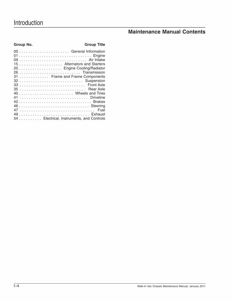
Group No. Group Title
00 . . . . . . . . . . . . . . . . . . . . . . General Information01 . . . . . . . . . . . . . . . . . . . . . . . . . . . . . . . . Engine09 . . . . . . . . . . . . . . . . . . . . . . . . . . . . . . Air Intake15 . . . . . . . . . . . . . . . . . . . Alternators and Starters20 . . . . . . . . . . . . . . . . . . . Engine Cooling/Radiator26 . . . . . . . . . . . . . . . . . . . . . . . . . . . Transmission31 . . . . . . . . . . . . . Frame and Frame Components32 . . . . . . . . . . . . . . . . . . . . . . . . . . . . Suspension33 . . . . . . . . . . . . . . . . . . . . . . . . . . . . . Front Axle35 . . . . . . . . . . . . . . . . . . . . . . . . . . . . . Rear Axle40 . . . . . . . . . . . . . . . . . . . . . . . . Wheels and Tires41 . . . . . . . . . . . . . . . . . . . . . . . . . . . . . . Driveline42 . . . . . . . . . . . . . . . . . . . . . . . . . . . . . . . . Brakes46 . . . . . . . . . . . . . . . . . . . . . . . . . . . . . . . Steering47 . . . . . . . . . . . . . . . . . . . . . . . . . . . . . . . . . Fuel49 . . . . . . . . . . . . . . . . . . . . . . . . . . . . . . . Exhaust54 . . . . . . . . . . Electrical, Instruments, and Controls
IntroductionMaintenance Manual Contents
I–4 Walk-In Van Chassis Maintenance Manual, January 2011
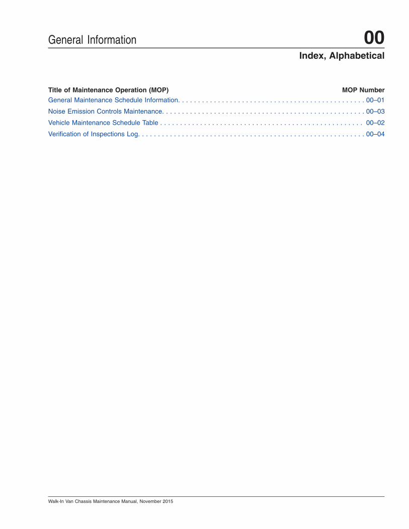
Title of Maintenance Operation (MOP) MOP Number
General Maintenance Schedule Information. . . . . . . . . . . . . . . . . . . . . . . . . . . . . . . . . . . . . . . . . . . . . . . 00–01
Noise Emission Controls Maintenance. . . . . . . . . . . . . . . . . . . . . . . . . . . . . . . . . . . . . . . . . . . . . . . . . . . 00–03
Vehicle Maintenance Schedule Table . . . . . . . . . . . . . . . . . . . . . . . . . . . . . . . . . . . . . . . . . . . . . . . . . . . 00–02
Verification of Inspections Log. . . . . . . . . . . . . . . . . . . . . . . . . . . . . . . . . . . . . . . . . . . . . . . . . . . . . . . . . 00–04
General Information 00Index, Alphabetical
Walk-In Van Chassis Maintenance Manual, November 2015
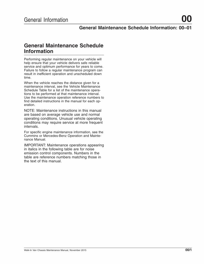
General Maintenance ScheduleInformationPerforming regular maintenance on your vehicle willhelp ensure that your vehicle delivers safe reliableservice and optimum performance for years to come.Failure to follow a regular maintenance program canresult in inefficient operation and unscheduled downtime.
When the vehicle reaches the distance given for amaintenance interval, see the Vehicle MaintenanceSchedule Table for a list of the maintenance opera-tions to be performed at that maintenance interval.Use the maintenance operation reference numbers tofind detailed instructions in the manual for each op-eration.
NOTE: Maintenance instructions in this manualare based on average vehicle use and normaloperating conditions. Unusual vehicle operatingconditions may require service at more frequentintervals.
For specific engine maintenance information, see theCummins or Mercedes-Benz Operation and Mainte-nance Manual.
IMPORTANT: Maintenance operations appearingin italics in the following table are for noiseemission control components. Numbers in thetable are reference numbers matching those inthe text of this manual.
General Information 00General Maintenance Schedule Information: 00–01
Walk-In Van Chassis Maintenance Manual, November 2015 00/1

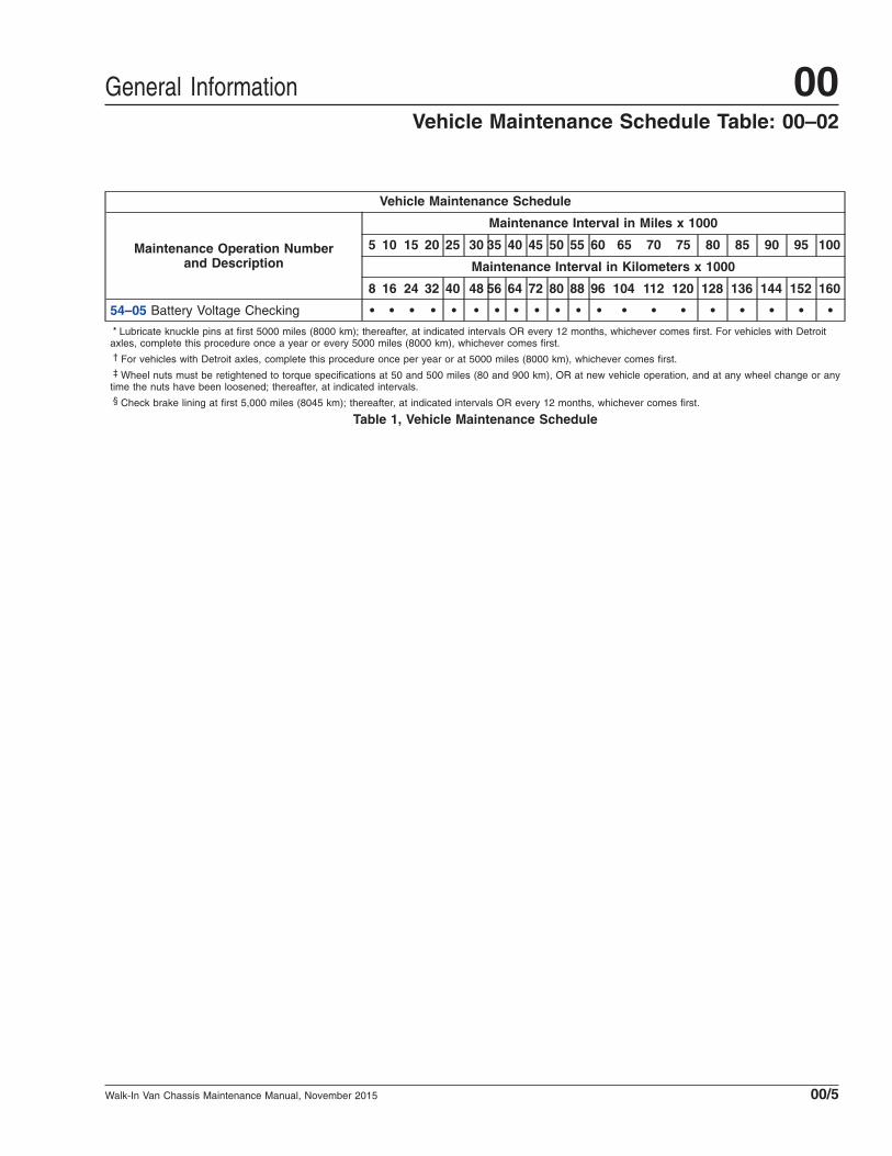
Vehicle Maintenance Schedule
Maintenance Operation Numberand Description
Maintenance Interval in Miles x 1000
5 10 15 20 25 30 35 40 45 50 55 60 65 70 75 80 85 90 95 100
Maintenance Interval in Kilometers x 1000
8 16 24 32 40 48 56 64 72 80 88 96 104 112 120 128 136 144 152 160
01–01 Engine-Support FastenersChecking • • • • •
01–02 Engine Drive Belt Inspecting • • • • •
01–03 Engine Oil Checking andChanging, Gasoline Engines Replace the engine oil every 3000 miles (4827 km).
01–04 Spark Plugs and Wires Inspectingand Replacing, Gasoline Engines
Inspect the spark plugs and wires every 12 months. Replace spark plugs andwires every 100,000 miles (160 900 km).
01–05 Evaporative Control SystemInspecting, Gasoline Engines • • • • • • • • • •
09–01 Air Cleaner Element Inspectingand Replacing
Inspect the air filter every six months. Replace the air filter every 12 months, orwhen filter restriction reaches 25 inH20 for diesel engines OR when the airrestriction indicator is completely red for gasoline engines (if equipped with anair restriction indicator).
09–02 Air Cleaner Filter Minder GaugeChecking, Diesel Engines • • • • • • • • • • • • • • • • • • • •
09–03 Air Intake System Inspecting • • • • • • • • • • • • • • • • • • • •
09–04 Charge Air Cooler Checking • • • • • • • • • • • • • • • • • • • •
13–01 Air Compressor Inspection • • • • • • • • • •
15–01 Alternator, Battery, and StarterConnections Check • • • • •
20–01 Coolant Replacement • •
20–02 Cooling Fan Inspection (NoiseEmission Control) • • • • •
20–03 Coolant Heater Check, Webasto Inspect the coolant heater every 12 months.
26–01 Transmission Breather Checking • • • • • • •
26–02 Allison Transmission Fluid LevelChecking For fluid level check intervals, see the applicable Allison Operator’s Manual.
26–03 Allison Transmission Fluid andFilter Changing For oil and filter change intervals, see the applicable Allison Operator’s Manual.
26–04 Hydraulic Hybrid MaintenanceOperations
Contact Parker Hannifin at 1-866-858-5600 for instructions concerning allhydraulic hybrid maintenance items listed under this heading.
31–01 Interlube Chassis LubricationSystem Inspecting • • • • • • • • • • • • • • • • • • • •
32–01 Suspension Inspecting • • • • • • • • • • • • • • • • • • • •
32–02 Freightliner Suspension Inspecting • • • • • • • • • • • • • • • • • • • •
32–03 Component Inspecting andOperation Checking, Freightliner AirLiner • • • • • • • • • • • • • • • • • • • •
General Information00Vehicle Maintenance Schedule Table: 00–02
Walk-In Van Chassis Maintenance Manual, November 201500/2

Vehicle Maintenance Schedule
Maintenance Operation Numberand Description
Maintenance Interval in Miles x 1000
5 10 15 20 25 30 35 40 45 50 55 60 65 70 75 80 85 90 95 100
Maintenance Interval in Kilometers x 1000
8 16 24 32 40 48 56 64 72 80 88 96 104 112 120 128 136 144 152 160
32–04 Suspension U-Bolt TorqueChecking • • • • • • • • • • • • • • • • • • • •
33–01 Grease-Lubricated Wheel BearingCleaning, Inspecting, Repacking, andAdjusting, Front Axle
• • • •
33–02 Knuckle Pin Lubricating* • • • • •
33–03 Tie-Rod End Lubricating andInspecting†
Lubricate twice each month. Lubricate the tie-rod ends each time the chassis ispower-washed.
33–04 All-Axle Alignment Checking • •
33–05 Oil-Filled Hubs Oil Level Checking • • • • • • • • • • • • • • • •
33–06 Oil-Filled Hubs Oil Changing • • • •
35–01 Axle Lubricant Changing
For Detroit™ rear axles with petroleum-based oil, change the lubricant every100,000 miles (160 900 km) or every 12 months, whichever comes first; ifsynthetic oil is used, change the lubricant every 250,000 miles (402 250 km) orevery 36 months, whichever comes first. For Meritor rear axles with petroleum-based oil, change the lubricant at 100,000 miles (160 900 km) or at 12 monthsof service, whichever comes first, and every 24 months thereafter; if synthetic oilis used, change the lubricant every 250,000 miles (402 250 km) or every 36months, whichever comes first.
35–02 Axle Lubricant Checking • • • • • • • • • • • • • • • • • • • •
35–03 Axle Breather Checking • • • • • • • • • • • • • • • • • • • •
40–01 Wheel Nut Checking‡ • • • • • • • • • • • • • • • • • • • •
41–01 Driveline Inspection andLubrication • • • • • • • • • • • • • • • • • • • •
42–01 Bendix Hydro-Max® Brake SystemInspection • • • • •
42–02 Brake Lines Check, Hydraulic DiscBrakes • • • • • • • • • • • • • • • • • • • •
42–03 Brake Lining Wear Check,Hydraulic Disc Brakes§ • • • • •
42–04 Brake Caliper Slide PinLubrication, Bosch Brakes
No specific lubrication interval. See the Bosch Pin Slide Disc Brakes ServiceManual for more information.
42–05 Brake Inspection • • • • • • • • • • • • • • • • • • • •
42–06 Slack Adjuster Lubrication • • • • • • • • • • • • • • • • • • • •
42–07 Air Dryer Desiccant andCoalescent Filter Replacement
Replace the Bendix AD9 filter and the Haldex PURest air dryer filter kit every 36months.
42–08 Air Dryer Check Perform the air dryer check every six months.
42–09 Versajust Slack Adjuster Inspectionand Lubrication
Complete this procedure every 25,000 miles (40 225 km), 3 months, or 500operating hours, whichever comes first.
General Information 00Vehicle Maintenance Schedule Table: 00–02
Walk-In Van Chassis Maintenance Manual, November 2015 00/3

Vehicle Maintenance Schedule
Maintenance Operation Numberand Description
Maintenance Interval in Miles x 1000
5 10 15 20 25 30 35 40 45 50 55 60 65 70 75 80 85 90 95 100
Maintenance Interval in Kilometers x 1000
8 16 24 32 40 48 56 64 72 80 88 96 104 112 120 128 136 144 152 160
46–01 Drag Link Lubricating Lubricate twice each month. Lubricate the drag link ends each time the chassisis power-washed.
46–02 Power Steering Hose Checking • • • • •
46–03 Steering Driveline Lubricating • • • • •
46–04 Steering Gear Bolts TorqueChecking • • •
46–05 Power Steering Reservoir Fluidand Filter Changing •
47–01 CNG High-Pressure Fuel FilterReplacement • • • • • • • • • • • • • • • • • • • •
47–02 CNG Fuel Leak Test • • • • • • • • • • • • • • • • • • • •
47–03 CNG High-Pressure Fuel FilterDraining Drain the high-pressure fuel filter every 2500 miles (4023 km).
47–04 CNG Fuel Block Housing Draining • • • •
47–05 CNG Low-Pressure Fuel FilterReplacement • • • •
47–06 CNG Low-Pressure Fuel FilterDraining • • • • • • • • • • • • • • • •
47–07 CNG Fuel Tank Visual Inspection Inspect the fuel tank every 25,000 miles (40 225 km) OR every 6 months,whichever comes first. The fuel tank must be replaced every 15 years.
47–08 Diesel Fuel Filter Replacement • • • • • • • • • •
47–09 Gasoline Fuel Filter Replacement Replace the fuel filter every five years or 150,000 miles (241 350 km),whichever comes first.
47–10 Fuel Tank and Line Inspection,Propane Engine • • •
47–11 Fuel Rail Fitting and InjectorInspection, Propane Engine • • •
47–12 Fuel Filter Replacement, PropaneEngine • • •
49–01 Exhaust System Inspecting (NoiseEmission Control) • • • • • •
54–01 Lighting System Checking • • • • • • • • • • • • • • • • • • • •
54–02 Battery, Battery Box, and CableChecking and Cleaning • • • • • • • • • • • • • • • • • • • •
54–03 Ground Cables Checking andCleaning • • • • • • • • • • • • • • • • • • • •
54–04 Electrical System Checking • • • • •
General Information00Vehicle Maintenance Schedule Table: 00–02
Walk-In Van Chassis Maintenance Manual, November 201500/4
Vehicle Maintenance Schedule
Maintenance Operation Numberand Description
Maintenance Interval in Miles x 1000
5 10 15 20 25 30 35 40 45 50 55 60 65 70 75 80 85 90 95 100
Maintenance Interval in Kilometers x 1000
8 16 24 32 40 48 56 64 72 80 88 96 104 112 120 128 136 144 152 160
54–05 Battery Voltage Checking • • • • • • • • • • • • • • • • • • • •* Lubricate knuckle pins at first 5000 miles (8000 km); thereafter, at indicated intervals OR every 12 months, whichever comes first. For vehicles with Detroit
axles, complete this procedure once a year or every 5000 miles (8000 km), whichever comes first.† For vehicles with Detroit axles, complete this procedure once per year or at 5000 miles (8000 km), whichever comes first.‡ Wheel nuts must be retightened to torque specifications at 50 and 500 miles (80 and 900 km), OR at new vehicle operation, and at any wheel change or any
time the nuts have been loosened; thereafter, at indicated intervals.§ Check brake lining at first 5,000 miles (8045 km); thereafter, at indicated intervals OR every 12 months, whichever comes first.
Table 1, Vehicle Maintenance Schedule
General Information 00Vehicle Maintenance Schedule Table: 00–02
Walk-In Van Chassis Maintenance Manual, November 2015 00/5

Noise Emission ControlsMaintenance
Federal Law, Part 205:Transportation Equipment NoiseEmission ControlsPart 205, Transportation Equipment Noise EmissionControls, requires the vehicle manufacturer to fur-nish, with each new vehicle, such written instructionsfor the proper maintenance, use, and repair of thevehicle by the ultimate purchaser to provide reason-able assurance of the elimination or minimization ofnoise-emission-control degradation throughout thelife of the vehicle. In compliance with the law, thenoise emission controls maintenance information ineach applicable group of this manual, in conjunctionwith the vehicle workshop manual, provides theseinstructions to owners.
Recommendations forReplacement PartsReplacement parts used for maintenance or repair ofnoise emission controls should be genuine Freight-liner Custom Chassis Corporation (FCCC) parts. Ifother than genuine FCCC parts are used for replace-ment or repair of components affecting noise emis-sion control, the owner should be sure that suchparts are warranted by their manufacturer to beequivalent to genuine FCCC parts in performanceand durability.
Freightliner Noise EmissionControls WarrantySee the vehicle owner’s warranty information bookfor warranty information concerning noise emissioncontrols.
Tampering With Noise Controls isProhibitedFederal law prohibits the following acts or the caus-ing thereof:
1. The removal or rendering inoperative by any per-son (other than for purposes of maintenance,repair, or replacement) of any device or element
of design incorporated into any new vehicle forthe purpose of noise control, prior to its sale ordelivery to the ultimate purchaser, or while it is inuse.
2. The use of the vehicle after such device or ele-ment of design has been removed or renderedinoperative by any person.
Among those acts presumed to constitute tam-pering are the acts listed below:
A. Removal of, or rendering inoperative, the en-gine speed governor so as to allow enginespeed to exceed manufacturer’s specifica-tions.
B. Removal of, or rendering inoperative, the fanclutch, including bypassing the control onany thermostatic fan drive to cause it to op-erate continuously.
C. Removal of the fan shroud.
D. Removal of, or rendering inoperative, ex-haust components, including exhaust pipeclamping.
E. Removal of air intake components.
Maintenance InstructionsScheduled intervals are in the maintenance table inthis group. A "Verification of Inspections Log (Groups20 and 49)" follows, and should be filled in each timenoise emission controls on the vehicle are main-tained or repaired.
General Information00Noise Emission Controls Maintenance: 00–03
Walk-In Van Chassis Maintenance Manual, November 201500/6

Verification of Inspections LogVerification of Inspections Log, Groups 20 and 49
Date Mileage Item Cost Maintenance Facility
Group 20 — Fan Clutch
Group 49 — Exhaust System Components
General Information 00Verification of Inspections Log: 00–04
Walk-In Van Chassis Maintenance Manual, November 2015 00/7

Title of Maintenance Operation (MOP) MOP Number
Engine Drive Belt Inspecting. . . . . . . . . . . . . . . . . . . . . . . . . . . . . . . . . . . . . . . . . . . . . . . . . . . . . . . . . . 01–02
Engine Oil Checking and Changing, Gasoline Engines . . . . . . . . . . . . . . . . . . . . . . . . . . . . . . . . . . . . . . 01–03
Engine-Support Fasteners Checking. . . . . . . . . . . . . . . . . . . . . . . . . . . . . . . . . . . . . . . . . . . . . . . . . . . . 01–01
Evaporative Control System Inspecting, Gasoline Engines. . . . . . . . . . . . . . . . . . . . . . . . . . . . . . . . . . . . 01–05
Safety Precautions. . . . . . . . . . . . . . . . . . . . . . . . . . . . . . . . . . . . . . . . . . . . . . . . . . . . . . . . . . . . . . . . . 01–00
Spark Plugs and Wires Inspecting and Replacing, Gasoline Engines . . . . . . . . . . . . . . . . . . . . . . . . . . . . 01–04
Engine 01Index, Alphabetical
Walk-In Van Chassis Maintenance Manual, July 2015

01–00 Safety PrecautionsSaftey Precautions in this section apply to allprocedures within this group.
DANGERWhen working on the vehicle, shut down the en-gine, set the parking brake, and chock the tires.Before working under the vehicle, always placejack stands under the frame rails to ensure thevehicle can not drop. Failure to follow these stepscould result in serious personal injury or death.
01–01 Engine-SupportFasteners Checking
Check the front and the rear engine-support fasten-ers for tightness. See Fig. 1. See Chapter 15 of theWalk-In Van Chassis Operator’s Manual for torquespecifications, or take the vehicle to an authorizedFreightliner dealer.
01–02 Engine Drive BeltInspecting
WARNINGThe engine and the belt must be cool before youcheck the belt. Handling a hot belt can cause per-sonal injury.
Worn or loose drive belts may cause prematurebearing failure or engine overheating. Excessive ten-sion, or too little tension on the belt may result in ex-cessive and premature belt wear. Poly-V belts, orserpentine belts, are retained by a belt tensioner thatrequires no tension adjustment. Replace the enginedrive belt if any conditions described in the visualdescription are found. V-belts are installed as indi-vidual belts, and as matched sets. When replacing amatched set of belts, always replace both belts at thesame time. Matched belts must be from the samemanufacturer. To inspect a belt, gently twist the beltto view the belt sidewalls and bottom. Visually in-spect all drive belts for the following conditions, thenperform the belt tension inspection.
Visual Inspection1. Inspect the belt for glazing. See Fig. 2, Ref. A.
Glazing is represented by shiny sidewalls, and iscaused by friction created when a loose belt slipsin the pulleys. It can also be caused by oil orgrease contamination on the pulleys.
2. Check the belt for ply separation. See Fig. 2,Ref. B. Oil, grease, or belt dressing can causethe belt to fall apart in layers. Repair any oil orcoolant leaks that are affecting the belts beforereplacing the drive belts. Do not use belt dress-ing on any belt.
3. Check the belt for a jagged or streaked sidewall.See Fig. 2, Ref. C. Jagged or streaked sidewallsare the result of foreign objects, such as sand orgravel in the pulley, or a rough pulley surface.
4. Check for tensile breaks (breaks in the cordbody). See Fig. 2, Ref. D. Cuts in a belt are usu-ally caused by foreign objects in the pulley, or byprying or forcing the belt during removal or instal-lation.
5. Check for uneven ribs on serpentine (poly-V)belts. See Fig. 2, Ref. E. Foreign objects in the
f220047a
1
2 3 4 5
6
2
10/05/94
1. Lower Isolator2. Engine Support
Washer3. Capscrew
4. Hexnut5. Engine Mount6. Upper Isolator
Fig. 1, Engine Mount (rear)
Engine 01
Walk-In Van Chassis Maintenance Manual, July 2015 01/1

pulley will erode the undercord ribs, causing thebelt to lose its gripping power.
6. Check the drive belts for cracks. See Fig. 2, Ref.F. Small irregular cracks are usually the signs ofan old belt.
7. Visually inspect the pulleys for excessive play orwobble. Excessive play or wobble indicates afailure of the pulley bearing. Check for beltsquealing or squeaking. Replace the bearings asnecessary.
NOTE: If it is difficult to distinguish the locationof a supposed bearing noise, obtain a stetho-scope and place it on the component beingchecked, not the pulley, to isolate the area fromoutside interference.
8. Inspect all pulleys for foreign objects, oil, orgrease in the grooves.
Belt Tension InspectionSpring-Tension TypeOn belts equipped with a spring tensioner, the belttension is automatically adjusted. Check that the ten-sioner is holding tension on the belt by inserting theend of a breaker bar in the 1/2-inch square hole onthe forward face of the tensioner, and rotating thetensioner down, away from the belt. When thebreaker bar is slowly released, the tensioner shouldreturn to its original position.
01–03 Engine Oil Checking andChanging, GasolineEngines
CheckingIt is important to check the oil regularly and keep it atthe proper level. In order to get an accurate reading,
f150010a
A
B
C
D
E
F11/21/94
A. GlazingB. Separating Layers
C. Streaked SidewallsD. Tensile Break
E. Uneven RibsF. Cracks
Fig. 2, Drive Belt Replacement Conditions
Engine01
Walk-In Van Chassis Maintenance Manual, July 201501/2

the oil must be warm and the vehicle must be onlevel ground.
1. Turn off the engine and give the oil several min-utes to drain back into the oil pan. If this is notdone, the oil dipstick may not show the actuallevel.
2. Pull out the dipstick and clean it with a papertowel or cloth, then push the dipstick back in allthe way. Remove it again, keeping the tip down,and check the level.
3. If the oil is below the cross-hatched area at thetip of the dipstick, add at least one quart (liter) ofthe recommended oil. See Fig. 3.
Changing1. Park the vehicle on a level surface, apply the
park brake, and shutdown the engine.
2. Place a drain pan under the oil pan.
3. Remove the oil drain plug and let the oil draininto the drain pan.
4. Clean the drain plug and set aside.
5. Remove the oil filter and clean the rim of the oilfilter housing.
6. Lubricate the O-ring of the new oil filter, then in-stall the oil filter. Tighten the filter by hand untilsnug, being careful not to overtighten.
7. Install the oil drain plug. Tighten the plug 18 lbf·ft(24 N·m).
8. Fill the engine with 6 quarts (5.6 L) of oil.
9. Pull out the dipstick, clean it and put the dipstickall the way back in. Remove the dipstick again tocheck that the correct amount of oil has beenadded.
01–04 Spark Plugs and WiresInspecting andReplacing, GasolineEngines
Visual Inspection1. Lift the four latches and remove the engine ac-
cess cover. See Fig. 4.
2. Inspect the spark plug wires for cracks and chaff-ing.
3. If the spark plug wires need to be replaced, seethe instructions under Replacement. If replace-ment is not needed, install the engine accesscover and lock the four latches.
ReplacementIMPORTANT: When replacing spark plugs andwires, remove and replace one plug and wire ata time. This will eliminate the possibility of incor-rectly installing the wires and having a misfireissue.
1. Hold both ends of the spark plug wire, and gentlypull one end of the wire off at a time.
08/05/2010 f012186
NOTE: Oil should be within the cross-hatched area ofthe dipstick.
Fig. 3, Oil Dipstick09/08/2010 f012188
1
3
2
1. Bottom Latch (two latches at the front)2. Top Latch (one on each side)3. Access Cover
Fig. 4, Engine Access Cover
Engine 01
Walk-In Van Chassis Maintenance Manual, July 2015 01/3

NOTE: Do not discard the insulation shields.The shields will be needed for the new wires.
2. Use a spark plug socket, a 3-inch extension, andratchet to remove the spark plug.
3. Install the new spark plug(s) and tighten just untilsnug.
4. Take a new spark plug wire and put the insula-tion shield at the plug-end of the wire.
5. Put a small amount of dielectric grease on eachend of the spark plug wire electrode, then installthe wire.
6. Repeat the above steps for the remaining sparkplugs and wires.
7. Install the engine access cover and lock the fourlatches.
01–05 Evaporative ControlSystem Inspecting,Gasoline Engines
Inspect the solenoid, evaporative control system can-ister, and lines. See Fig. 5. Look for damaged lines,leaking fuel, or any damage to the canister itself.Make certain the electrical connections are properlyconnected.
09/07/2010 f200737
1
2
1. Evaporative Control System Canister2. Solenoid
Fig. 5, Evaporative Control System
Engine01
Walk-In Van Chassis Maintenance Manual, July 201501/4

Title of Maintenance Operation (MOP) MOP Number
Air Cleaner Element Inspecting and Replacing . . . . . . . . . . . . . . . . . . . . . . . . . . . . . . . . . . . . . . . . . . . . 09–01
Air Cleaner Filter Minder Gauge Checking, Diesel Engines . . . . . . . . . . . . . . . . . . . . . . . . . . . . . . . . . . . 09–02
Air Intake System Inspecting. . . . . . . . . . . . . . . . . . . . . . . . . . . . . . . . . . . . . . . . . . . . . . . . . . . . . . . . . . 09–03
Charge Air Cooler Checking . . . . . . . . . . . . . . . . . . . . . . . . . . . . . . . . . . . . . . . . . . . . . . . . . . . . . . . . . . 09–04
Safety Precautions. . . . . . . . . . . . . . . . . . . . . . . . . . . . . . . . . . . . . . . . . . . . . . . . . . . . . . . . . . . . . . . . . 09–00
Air Intake 09Index, Alphabetical
Walk-In Van Chassis Maintenance Manual, July 2015

09–00 Safety PrecautionsSaftey Precautions in this section apply to allprocedures within this group.
DANGERWhen working on the vehicle, shut down the en-gine, set the parking brake, and chock the tires.Before working under the vehicle, always placejack stands under the frame rails to ensure thevehicle can not drop. Failure to follow these stepscould result in serious personal injury or death.
09–01 Air Cleaner ElementInspecting andReplacing
NOTICEAll air intake components and connections mustbe air- and water-tight. Dirt or dust entering theengine can cause internal engine damage. Most ofthe dirt and dust particles are silicates, which fuseinto abrasive glass-like particles when exposed toengine combustion. These particles can grind pis-ton rings, pistons, and cylinder liners. Do not op-erate the engine with the air filter element or anyair intake component removed.
IMPORTANT: Due to the variety of possible driv-ing conditions (dirt roads, paved roads, etc.), itis critical to check the air restriction indicator, ifso equipped. If the vehicle is not equipped withan air restriction indicator, inspect all compo-nents of the air intake system and air filter everysix months. Replace the air filter every 12months, or when filter restriction reaches 25inH2O for diesel engines, or when the air restric-tion indicator is completely red for gasoline en-gines (if equipped with an air restriction indica-tor). More frequent inspections and/or filterreplacement may be needed if the vehicle isbeing operated in a dusty environment, toavoid damaging the vehicle.
Inspecting
NOTICEUse the air intake restriction gauge rather thanvisual inspection to determine if servicing the airfilter element is necessary. Removal of the air fil-ter element can cause damage to the primary seal,which may allow contaminants into the engine,potentially causing engine damage.
IMPORTANT: Removal and visual inspection ofthe air filter should only occur if the vehicle isnot equipped with an air restriction indicator.
Remove and visually inspect the air filter for holes,tears, cracks, or other damage at the recommendedinterval. Remove loose debris, such as leaves orpine needles, from the filter housing. If the air filter isdamaged, replace it. See Group 09 of the Walk-InVan Workshop Manual for removal and installationinstructions, or take the vehicle to an authorizedFreightliner dealer.
Engine damage can occur if the air intake system isnot properly maintained. Use the air intake restrictionindicator to check for air intake system damage orleaks. See Fig. 1 and Fig. 2. Make sure the engineis off and note the existing reading on the indicator.Reset the indicator by pushing it down. See Fig. 1and Fig. 2. Start the engine and take a short testdrive. Check the indicator again and note the level ofrestriction on the indicator. A decrease from the pre-vious level of restriction or a very low air restrictionindicator reading (0 to 4 inH2O) could indicate anair intake system problem such as a damagedair filter, loose or disconnected air intake piping,or a disconnected or damaged air restrictionindicator.
Replacing
NOTICEDo not use aftermarket air-cleaner elements. After-market air-cleaner elements may not seal thehousing correctly, which can lead to engine dam-age and potentially the loss of warranty. When re-placing an air-cleaner element, use only the partlisted in PartsPro for the serial number of thevehicle.
Air Intake 09
Walk-In Van Chassis Maintenance Manual, July 2015 09/1

NOTICEDo not clean or reuse the air filter. Cleaning andreusing the the air filter increases the chances ofdirt entering the engine. Always replace with anew air filter.
Replace the air filter every 12 months, or when filterrestriction reaches 25 inH2O for diesel engines, orwhen the air restriction indicator is completelyred for gasoline engines (if equipped with an airrestriction indicator). See Group 09 of theWalk-In Van Workshop Manual for removal and
installation instructions, or take the vehicle to anauthorized Freightliner dealer.
09–02 Air Cleaner Filter MinderGauge Checking, DieselEngines
The filter minder gauge measures the amount of airrestriction (in inches or millimeters of water vacuum)in the air intake system. It is connected to the air in-take tube by a vacuum hose and a small vacuumfilter. The gauge takes its measurements when theengine is running at full load, and then locks in placeuntil reset. See Fig. 1 for depictions of how thegauge appears when the air intake is partially re-stricted and when it is fully restricted and should bereplaced.
09–03 Air Intake SystemInspecting
Check the air intake system for damaged or crackedhoses, and for loose clamps. Also check the air filter.
2H O VACUUM 2H O VACUUM
25201510
7
PUSH TO RESET
IN 2H O VACUUM 2H O VACUUM
25201510
7
PUSH TO RESET
IN
A Bf09016508/21/96
A. Partial Restriction B. Full Restriction
Fig. 1, Air Restriction Indicator, Diesel Engines
f09049512/02/2011
A B
A. Partial Restriction B. Full Restriction
Fig. 2, Air Restriction Indicator, Gasoline Engines
Air Intake09
Walk-In Van Chassis Maintenance Manual, July 201509/2

09–04 Charge Air CoolerChecking
Good airflow through the radiator and charge aircooler core is essential for proper engine cooling.The cores allow air passage, but form a barrier thattends to collect insects and airborne debris.
If the charge air cooler core fins are bent, use asmall pair of needle-nose pliers or a small screw-driver to straighten them. If the fins are clogged, usecompressed air or water directed from the fan side ofthe radiator core to backflush any material restrictingairflow.
Ensure that the hoses are not chafing and that thesystem is closed with no air leaks.
Air Intake 09
Walk-In Van Chassis Maintenance Manual, July 2015 09/3

Title of Maintenance Operation (MOP) MOP Number
Air Compressor Inspection . . . . . . . . . . . . . . . . . . . . . . . . . . . . . . . . . . . . . . . . . . . . . . . . . . . . . . . . . . . 13–01
Safety Precautions. . . . . . . . . . . . . . . . . . . . . . . . . . . . . . . . . . . . . . . . . . . . . . . . . . . . . . . . . . . . . . . . . 13–00
Air Compressor 13Index, Alphabetical
Walk-In Van Chassis Maintenance Manual, July 2015
13–00 Safety PrecautionsSaftey Precautions in this section apply to allprocedures within this group.
DANGERWhen working on the vehicle, shut down the en-gine, set the parking brake, and chock the tires.Before working under the vehicle, always placejack stands under the frame rails to ensure thevehicle can not drop. Failure to follow these stepscould result in serious personal injury or death.
13–01 Air CompressorInspection
1. Inspect the air compressor intake hoses andconnections at the air intake and air compressorfor physical damage. If needed, change thehoses, and/or tighten or replace the connections.
2. Inspect the coolant supply and return lines fortight connections. Tighten the connections andreplace the lines and fasteners if needed.
3. For the air governor, inspect the piping and con-nections for leaks. Replace gaskets and faultycomponents as needed.
Air Compressor 13
Walk-In Van Chassis Maintenance Manual, July 2015 13/1

Title of Maintenance Operation (MOP) MOP Number
Alternator, Battery, and Starter Connections Check . . . . . . . . . . . . . . . . . . . . . . . . . . . . . . . . . . . . . . . . . 15–01
Safety Precautions. . . . . . . . . . . . . . . . . . . . . . . . . . . . . . . . . . . . . . . . . . . . . . . . . . . . . . . . . . . . . . . . . 15–00
Alternators and Starters 15Index, Alphabetical
Walk-In Van Chassis Maintenance Manual, July 2015
15–00 Safety PrecautionsSaftey Precautions in this section apply to allprocedures within this group.
DANGERWhen working on the vehicle, shut down the en-gine, set the parking brake, and chock the tires.Before working under the vehicle, always placejack stands under the frame rails to ensure thevehicle can not drop. Failure to follow these stepscould result in serious personal injury or death.
15–01 Alternator, Battery, andStarter ConnectionsCheck
WARNINGBatteries release explosive gas as a by-product oftheir chemical activity. Do not smoke when work-ing around batteries. Put out all flames and re-move any source of sparks or intense heat. Makesure the battery compartment is completelyvented before disconnecting or connecting thebattery cables.
Battery acid is extremely harmful if splashed inthe eyes or on the skin. Always wear a face shieldand protective clothing when working around bat-teries.
Damaged, chafed, or kinked wiring can causeelectrical short-circuits and lead to fires, causingproperty damage, injury, or death. Clean, inspect,and maintain wiring and connections carefully.
1. Disconnect the batteries.
2. Check the tightness of the alternator bracket fas-teners and alternator mounting fasteners; tightenthe fasteners as needed. For torque values, seeGroup 15 of the vehicle Workshop Manual, ortake the vehicle to an authorized Freightlinerdealer.
3. Check that all electrical connections at the alter-nator and starter are clean. Clean and tighten allcharging system electrical connections asneeded. Spray each electrical connection at thealternator and starter with dielectric red enamel.
Trace and inspect all wiring and cables con-nected to:
• alternator
• starter and depopulation studs
• batteries
• magnetic switch
• cab
• jump-start studs
• battery isolation relays
• battery shutoff switches
4. Check wires and cables for wear, chafing, kinks,discolored insulation, or loose clamps or ties.Find the cause of any problems and repair, re-place, and reroute wires and clamps as neces-sary.
IMPORTANT: Ensure that wires and cables arenot near any heat sources; if they are, reroutethem.
5. Clean all circuit breakers and relays.
6. Check the alternator wiring for missing insulation,kinks, and heat damage. Replace or repair asneeded.
7. On the bundled cable that runs from the batteriesto the starter, ensure that tie straps are installedat least every 12 inches (30 cm). Replace anymissing tie straps, and add tie straps wherespacing between them exceeds 12 inches (30cm).
8. Ensure that all cables have sufficient slack toallow for engine movement, and that there is noforce on any wiring connectors.
9. If any convoluted tubing is damaged, check thewiring inside it. Replace any damaged or missingconvoluted tubing.
10. Inspect the battery cables for wear, and replaceas needed. Clean the cable connector terminalswith a wire brush. See Group 54 of the vehicleWorkshop Manual for troubleshooting instruc-tions, and for adjustment, repair, or replacementinstructions, or take the vehicle to an authorizedFreightliner dealer.
10.1 Clean and tighten the battery groundcable, terminal, and clamps.
Alternators and Starters 15
Walk-In Van Chassis Maintenance Manual, July 2015 15/1
10.2 Inspect the retainer assembly (or batteryhold-downs) and the battery box. Replaceworn or damaged parts. Remove any cor-rosion with a wire brush, and wash with aweak solution of baking soda and water.Rinse with clean water, then dry. Paintthe retainer assembly, if needed, to pre-vent rusting.
10.3 Check that foreign objects, such asstones, bolts, and nuts, are removed fromthe battery box.
10.4 After cleaning, connect the cables to thebatteries, and tighten them to the torquespecifications listed on the battery, gener-ally 10 to 15 lbf·ft (14 to 20 N·m).
10.5 Coat the battery terminals with dielectricgrease.
11. Check the terminals on the battery shut-offswitch and the starter relay. Make sure that theterminal connections are clean and tight. Coatthe terminal connections with dielectric redenamel after cleaning.
Alternators and Starters15
Walk-In Van Chassis Maintenance Manual, July 201515/2

Title of Maintenance Operation (MOP) MOP Number
Coolant Heater Check, Webasto. . . . . . . . . . . . . . . . . . . . . . . . . . . . . . . . . . . . . . . . . . . . . . . . . . . . . . . 20–03
Coolant Replacement. . . . . . . . . . . . . . . . . . . . . . . . . . . . . . . . . . . . . . . . . . . . . . . . . . . . . . . . . . . . . . . 20–01
Cooling Fan Inspection. . . . . . . . . . . . . . . . . . . . . . . . . . . . . . . . . . . . . . . . . . . . . . . . . . . . . . . . . . . . . . 20–02
Safety Precautions. . . . . . . . . . . . . . . . . . . . . . . . . . . . . . . . . . . . . . . . . . . . . . . . . . . . . . . . . . . . . . . . . 20–00
Engine Cooling/Radiator 20Index, Alphabetical
Walk-In Van Chassis Maintenance Manual, November 2015

20–00 Safety PrecautionsSaftey Precautions in this section apply to allprocedures within this group.
DANGERWhen working on the vehicle, shut down the en-gine, set the parking brake, and chock the tires.Before working under the vehicle, always placejack stands under the frame rails to ensure thevehicle can not drop. Failure to follow these stepscould result in serious personal injury or death.
20–01 Coolant ReplacementAt the intervals specified in the maintenance sched-ule, or whenever the coolant becomes dirty, flushand refill the cooling system as follows, based on thetype of engine installed in the vehicle.
Diesel Engine
WARNINGNever remove the surge tank cap while the engineis operating or while the engine and radiator arestill hot. Scalding fluid and steam can blow outunder pressure if the cap is taken off too soon.Failure to follow these precautions could result inserious personal injury from heated coolant spray.
1. When the engine is cool, remove the surge tankcap.
Turn the cap slowly counterclockwise until itreaches a "stop." Do not press down while turn-ing the cap. Wait until any remaining pressure(indicated by a hissing sound) is relieved, thenpress down on the cap and continue turning itcounterclockwise.
2. When the cap is removed, run the engine untilthe upper radiator hose is hot. This shows thatthe thermostat is open and that the coolant isflowing through the system.
3. Shut down the engine. Remove the lower radia-tor hose and drain the coolant. Draining may bespeeded up by removing the plug from the bot-tom of the water inlet.
NOTICEDuring filling, air must be vented from the enginecoolant passages. Any air trapped in the systemcan cause severe engine damage.
4. Connect the lower radiator hose and install theplug in the bottom of the water inlet. Add wateruntil the system is filled and run the engine untilthe upper radiator hose is hot again. The systemmust be filled slowly to prevent air locks. Wait 2to 3 minutes to allow air to be vented, then addwater to bring the level to the top.
5. Repeat the last two steps several times until thedrained liquid is nearly colorless.
6. Drain the system, then close the radiator andblock the drain valves.
7. Disconnect all hoses from the coolant surgetank. Remove the surge tank and pour out anyfluid. Scrub and clean the inside of the surgetank with soap and water. Flush it thoroughlywith clean water, then drain it. Reinstall the surgetank and hoses.
IMPORTANT: On vehicles with EPA07-compliantengines, the coolant capacity varies dependingon the engine and the accessory installation.After servicing the cooling system, always verifythat the coolant level is between the MIN andMAX lines on the surge tank.
8. Using an approved coolant, fill the system with a50/50 mixture of antifreeze and water to the baseof the filler neck. See Table 1.
Approved Coolants
Engine Type Coolant Manufacturer CoolantDesignation*
Diesel
Old World Industries Fleet Charge®
Shell Shell HD/NAntifreeze
Texaco JC04 Antifreeze
Van Waters andRogers Ltd. (Canada)
Diesel AntifreezeNo. 6038
Engine Cooling/Radiator 20
Walk-In Van Chassis Maintenance Manual, November 2015 20/1

Approved Coolants
Engine Type Coolant Manufacturer CoolantDesignation*
GasolinePropane GM GM DEX-
COOL®†
* Freightliner-approved antifreeze must meet one of the following condi-tions: A. Ethylene glycol solution that meets GM 6038–M Engineering Stan-dards. B. Ethylene glycol solution that has less than 0.1% anhydrous so-dium metasilicate and meets either GM 1825–M or GM 1899–MEngineering Standards.† GM DEX-COOL is approved for use in gasoline and propane engines
only.
Table 1, Approved Coolants
9. With the surge tank cap removed, start the en-gine and run it at low idle for 60 seconds. In-crease engine speed to 1200 rpm for 60 sec-onds, then decrease engine speed to low idle for60 seconds. Top off the coolant level to the MAXline on the surge tank. Install the surge tank cap,making sure that the arrows on the cap line upwith the overflow tube on the surge tank. Shutdown the engine.
Alternative Fuel Engine, 6.0 LRefer to Fig. 1 when performing the followingprocedure.
WARNINGNever remove the radiator cap while the engine isoperating or while the engine and radiator are stillhot. Scalding fluid and steam can blow out underpressure if the cap is taken off too soon. Failureto follow these precautions could result in seriouspersonal injury from heated coolant spray.
1. When the engine is cool, remove the radiatorcap.
Turn the cap slowly counterclockwise until itreaches a "stop." Do not press down while turn-ing the cap. Wait until any remaining pressure(indicated by a hissing sound) is relieved, thenpress down on the cap and continue turning itcounterclockwise.
2. When the cap is removed, run the engine untilthe upper radiator hose is hot. This shows thatthe thermostat is open and that the coolant isflowing through the system.
3. Shut down the engine. Remove the lower radia-tor hose and drain the coolant. Draining may be
speeded up by removing the plug from the bot-tom of the water inlet.
NOTICEDuring filling, air must be vented from the enginecoolant passages. Any air trapped in the systemcan cause severe engine damage.
NOTE: The maximum fill rate of a 6.0L engineradiator is 2 gallons per minute.
4. Connect the lower radiator hose and install theplug in the bottom of the water inlet. Add wateruntil the system is filled and run the engine untilthe upper radiator hose is hot again. The systemmust be filled slowly to prevent air locks. Wait 2to 3 minutes to allow air to be vented, then addwater to bring the level to the top.
5. Repeat the last two steps several times until thedrained liquid is nearly colorless.
6. Drain the system, then close the radiator andblock the drain valves.
07/07/2015 f200861
1
23
1. Overflow Bottle2. Overflow Bottle Fill Neck3. Radiator Fill Neck
Fig. 1, Overflow Bottle
Engine Cooling/Radiator20
Walk-In Van Chassis Maintenance Manual, November 201520/2

7. Disconnect the hose from the coolant overflowbottle. Remove the bottle and pour out any fluid.Scrub and clean the inside of the overflow bottlewith soap and water. Flush it thoroughly withclean water, then drain it. Reinstall the overflowbottle and hoses.
NOTE: The maximum fill rate of a 6.0L engineradiator is 2 gallons per minute.
8. Using an approved coolant, fill the system with a50/50 mixture of antifreeze and water to the baseof the filler neck. See Table 1.
9. With the radiator cap removed, start the engineand run it at low idle for 60 seconds. Increaseengine speed to 1200 rpm for 60 seconds, thendecrease engine speed to low idle for 60 sec-onds. Top off the coolant level to the base of theradiator fill neck. Install the radiator cap. Fill thecoolant overflow bottle to the COLD MAX line.Install the cap on the overflow bottle. Shut downthe engine.
20–02 Cooling Fan Inspection
WARNINGNever pull or pry on the fan. This can damage thefan blade(s) and cause fan failure. Fan failure cancause personal injury.
A visual inspection of the cooling fan is requireddaily. Check for cracks, loose rivets, and bent orloose blades. Check the fan to make sure that it issecurely mounted. Tighten the capscrews if neces-sary. Replace any fan that is damaged. Also checkthe fan recirculation shield, if so equipped.
20–03 Coolant Heater Check,Webasto
1. Using compressed air, clean any accumulateddebris or dust from the heater and enclosurebox. Inspect all components for wear or damage.
2. Check that the batteries are in good condition. Ifthe voltage is too low or too high, the heater willautomatically shut down. Check the wiring har-nesses for damage. Replace the harnesses ifnecessary.
3. Check the air intake port for obstructions. Care-fully check the air intake tube for any restrictionsor damage, and repair or replace the tube if nec-essary.
4. Check the exhaust system for restrictions or cor-rosion. Replace any damaged parts.
5. Change the fuel filter, if so equipped. Inspect thefuel line for damage, restrictions, or loose con-nections. Repair or replace the line if it is dam-aged.
6. Inspect all coolant lines and clamps for leakage,restrictions, or damage. Replace the lines asneeded. Inspect the coolant circulation pump forleakage. Repair or replace the pump if it is dam-aged.
7. Run the heater at least once a month for 10 min-utes.
8. Check the water and fuel connections for leak-age. Tighten the hose clamps if needed.
Engine Cooling/Radiator 20
Walk-In Van Chassis Maintenance Manual, November 2015 20/3

Title of Maintenance Operation (MOP) MOP Number
Allison Transmission Fluid Level Checking . . . . . . . . . . . . . . . . . . . . . . . . . . . . . . . . . . . . . . . . . . . . . . . 26–02
Allison Transmission Fluid and Filter Changing . . . . . . . . . . . . . . . . . . . . . . . . . . . . . . . . . . . . . . . . . . . . 26–03
Hydraulic Hybrid Maintenance Operations. . . . . . . . . . . . . . . . . . . . . . . . . . . . . . . . . . . . . . . . . . . . . . . . 26–04
Safety Precautions. . . . . . . . . . . . . . . . . . . . . . . . . . . . . . . . . . . . . . . . . . . . . . . . . . . . . . . . . . . . . . . . . 26–00
Transmission Breather Checking. . . . . . . . . . . . . . . . . . . . . . . . . . . . . . . . . . . . . . . . . . . . . . . . . . . . . . . 26–01
Transmission 26Index, Alphabetical
Walk-In Van Chassis Maintenance Manual, July 2015
26–00 Safety PrecautionsSaftey Precautions in this section apply to allprocedures within this group.
DANGERWhen working on the vehicle, shut down the en-gine, set the parking brake, and chock the tires.Before working under the vehicle, always placejack stands under the frame rails to ensure thevehicle can not drop. Failure to follow these stepscould result in serious personal injury or death.
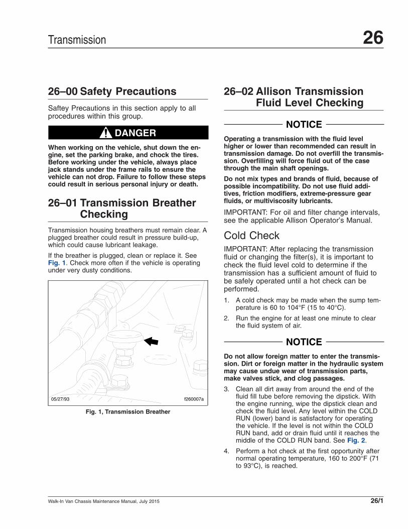
26–01 Transmission BreatherChecking
Transmission housing breathers must remain clear. Aplugged breather could result in pressure build-up,which could cause lubricant leakage.
If the breather is plugged, clean or replace it. SeeFig. 1. Check more often if the vehicle is operatingunder very dusty conditions.
26–02 Allison TransmissionFluid Level Checking
NOTICEOperating a transmission with the fluid levelhigher or lower than recommended can result intransmission damage. Do not overfill the transmis-sion. Overfilling will force fluid out of the casethrough the main shaft openings.
Do not mix types and brands of fluid, because ofpossible incompatibility. Do not use fluid addi-tives, friction modifiers, extreme-pressure gearfluids, or multiviscosity lubricants.
IMPORTANT: For oil and filter change intervals,see the applicable Allison Operator’s Manual.
Cold CheckIMPORTANT: After replacing the transmissionfluid or changing the filter(s), it is important tocheck the fluid level cold to determine if thetransmission has a sufficient amount of fluid tobe safely operated until a hot check can beperformed.
1. A cold check may be made when the sump tem-perature is 60 to 104°F (15 to 40°C).
2. Run the engine for at least one minute to clearthe fluid system of air.
NOTICEDo not allow foreign matter to enter the transmis-sion. Dirt or foreign matter in the hydraulic systemmay cause undue wear of transmission parts,make valves stick, and clog passages.
3. Clean all dirt away from around the end of thefluid fill tube before removing the dipstick. Withthe engine running, wipe the dipstick clean andcheck the fluid level. Any level within the COLDRUN (lower) band is satisfactory for operatingthe vehicle. If the level is not within the COLDRUN band, add or drain fluid until it reaches themiddle of the COLD RUN band. See Fig. 2.
4. Perform a hot check at the first opportunity afternormal operating temperature, 160 to 200°F (71to 93°C), is reached.
f260007a05/27/93
Fig. 1, Transmission Breather
Transmission 26
Walk-In Van Chassis Maintenance Manual, July 2015 26/1

Hot Check1. Operate the transmission in a drive range until
normal operating temperature, 160 to 200°F (71to 93°C), is reached.
NOTE: The fluid must be warm to ensure anaccurate check. The fluid level rises as tempera-ture increases.
2. Park the vehicle. Shift to neutral (N) and applythe parking brake. Let the engine run at idle.
3. Wipe the dipstick clean and check the fluid level.A safe operating level is any level within the HOTRUN (upper) band on the dipstick. See Fig. 2.
4. If the fluid is not within this range, add or drainfluid as needed to bring the level to the top ofthe HOT RUN band. See Table 1 for approvedtransmission lubricants, and Table 2 for lubricantcapacities.
26–03 Allison TransmissionFluid and FilterChanging
IMPORTANT: For oil and filter change intervals,see the applicable Allison Operator’s Manual. To
request a replacement Allison Operator’sManual, call 1-888-666-5799.
Oil and filter change intervals can also be foundon the Allison Transmission website at www.al-lisontransmission.com. Choose "Service", andclick "Service Tips". Then, select the appropriatetransmission to view fluid and filter change rec-ommendations.
26–04 Hydraulic HybridMaintenance Operations
IMPORTANT: Contact Parker Hannifin at 1-866-858-5600 for hydraulic hybrid maintenance in-structions.
Along with the other applicable maintenanceoperations in this manual, perform the mainte-nance items listed below
• hydraulic hose and fitting inspection
• hydraulic fluid leak checking
• hydraulic fluid level and pressure checking
• hydraulic fluid and filter changing
• gearbox fluid level checking
• gearbox fluid and filter changing
• gearbox and low pressure reservoir fluid sam-pling
• low pressure reservoir burst disc cap inspecting
• low pressure reservoir relief valve checking
Approved Allison Transmission Lubricants*
TES-295 ApprovalNumber Company Product Brand Name
AN-051005 ExxonMobil Lubricants and Petroleum Specialties Company Mobil Delvac Synthetic ATF
AN-011001 Castrol Heavy Duty Lubricants TranSynd
AN-031002 BP Autran Syn 295
08/27/96 f270007
1
2
1. COLD RUN Band 2. HOT RUN Band
Fig. 2, Dipstick Markings
Transmission26
Walk-In Van Chassis Maintenance Manual, July 201526/2
Approved Allison Transmission Lubricants*
TES-295 ApprovalNumber Company Product Brand Name
AN-031003 Cognis Corporation Emgard 2805
AN-031004 Fleetrite Synthetic ATF
AN-071006 John Deere & Company HD SynTran* To check the latest Allison approved fluids, go to the Allison Transmission website at www.allisontransmission.com. Lubricants listed in order of preference.
Do not mix types of oil.
Table 1, Approved Allison Transmission Lubricants
Transmission Lubricant Capacities
Model Refill Capacity*quarts (liters)
1000/2000/2400 Standard Sump 10.6 (10)
1000/2000/2400 Shallow Sump 7.4 (7)
* Quantities listed are approximate. Add the recommended amount of fluidas listed under refill capacity. Do not overfill.
Table 2, Transmission Lubricant Capacities
Transmission 26
Walk-In Van Chassis Maintenance Manual, July 2015 26/3
Title of Maintenance Operation (MOP) MOP Number
Interlube Chassis Lubrication System Inspecting . . . . . . . . . . . . . . . . . . . . . . . . . . . . . . . . . . . . . . . . . . . 31–01
Safety Precautions. . . . . . . . . . . . . . . . . . . . . . . . . . . . . . . . . . . . . . . . . . . . . . . . . . . . . . . . . . . . . . . . . 31–00
Frame 31Index, Alphabetical
Walk-In Van Chassis Maintenance Manual, July 2015

31–00 Safety PrecautionsSaftey Precautions in this section apply to allprocedures within this group.
DANGERWhen working on the vehicle, shut down the en-gine, set the parking brake, and chock the tires.Before working under the vehicle, always placejack stands under the frame rails to ensure thevehicle can not drop. Failure to follow these stepscould result in serious personal injury or death.
31–01 Interlube ChassisLubrication SystemInspecting
1. Inspect all lubrication points for signs of freshgrease.
2. Check the condition of all fittings and connec-tions. Tighten or replace loose or damaged fit-tings.
3. Check all lubrication lines; be sure there are nobreaks. Check for wear or chafing that may leadto leakage.
4. Confirm pump operation by pressing the manualoverride button (located on top of the reservoir)and check to see if the indicator light flashes.See Fig. 1.
5. Using clean grease, fill the reservoir every 2 to 3months as follows. See Table 1 for a list of ap-proved grease.
IMPORTANT: To avoid air pockets and con-taminants from entering the reservoir, usethe grease fill fitting when filling the reser-voir.
5.1 Remove the dirt cap from the grease fillfitting, then wipe the grease fill fitting toremove any dirt.
Approved Grease*
NLGI Grade Temperature Rating: Down to F° (C°)
2 10 (–12)
1 0 (–18)
0 –10 (–23)
00 –20 (–29)
000 –30 (–34)* Do not use heavy/tacky grease, or clay based high-temperature grease.
Table 1, Approved Grease
5.2 Using approved grease, fill the reservoirthrough the grease fill fitting to the maxi-mum level label on the reservoir.
5.3 Install the dirt cap on the grease fill fitting.
08/27/2008 f311074
12
1. Indicator Light2. Manual Override Button
Fig. 1, Interlube System Reservoir
Frame 31
Walk-In Van Chassis Maintenance Manual, July 2015 31/1
Title of Maintenance Operation (MOP) MOP Number
Component Inspecting and Operation Checking, Freightliner AirLiner . . . . . . . . . . . . . . . . . . . . . . . . . . . . 32–03
Freightliner Suspension Inspecting . . . . . . . . . . . . . . . . . . . . . . . . . . . . . . . . . . . . . . . . . . . . . . . . . . . . . 32–02
Safety Precautions. . . . . . . . . . . . . . . . . . . . . . . . . . . . . . . . . . . . . . . . . . . . . . . . . . . . . . . . . . . . . . . . . 32–00
Suspension Inspecting . . . . . . . . . . . . . . . . . . . . . . . . . . . . . . . . . . . . . . . . . . . . . . . . . . . . . . . . . . . . . . 32–01
Suspension U-Bolt Torque Checking . . . . . . . . . . . . . . . . . . . . . . . . . . . . . . . . . . . . . . . . . . . . . . . . . . . . 32–04
Suspension 32Index, Alphabetical
Walk-In Van Chassis Maintenance Manual, July 2015

32–00 Safety PrecautionsSaftey Precautions in this section apply to allprocedures within this group.
DANGERWhen working on the vehicle, shut down the en-gine, set the parking brake, and chock the tires.Before working under the vehicle, always placejack stands under the frame rails to ensure thevehicle can not drop. Failure to follow these stepscould result in serious personal injury or death.
32–01 Suspension Inspecting
Front and Rear SuspensionSpring AssembliesSome reverse bow in the suspension leaf springs isnormal. Deflection in the springs is affected by thecarrying capacity of the spring package furnishedwith the chassis and the load applied. If the springsappear to bow considerably more than normal, havea service dealer check for broken springs, or (con-sider) adding a heavier spring package.
Rear Air SuspensionFollow the procedure below to determine if a pres-sure drop in the rear air suspension system is withinthe allowable range.
Air-Consuming Devices Turned OffNOTE: With all air-consuming devices turned off(service brakes released and parking brake ap-plied [exhausted]), pressure drop must not ex-ceed 2 psi (14 kPa) in one minute.
1. Park the vehicle on a level surface, place thetransmission in Neutral (N), and apply the park-ing brake.
2. Turn off all air-consuming devices.
3. Run the engine until the air system reaches fullpressure.
NOTE: The minimum compressor cut-out pres-sure is 110 psi (758 kPa).
4. Shut down the engine and wait one minute forthe air pressure to stabilize. Note the reading onthe air pressure gauge.
5. Wait one additional minute and check the gaugereading again to see if there has been any pres-sure drop.
6. Pressure drop from air leakage must be lessthan 2 psi (14 kPa).
Air-Consuming Devices in UseNOTE: With the service brakes applied and theparking brake released (pressurized), pressuredrop must not exceed 3 psi (21 kPa) in oneminute.
1. Park the vehicle on a level surface, place thetransmission in Neutral (N), and chock the tiresto prevent the vehicle from rolling.
2. Turn off all air-consuming devices.
3. Run the engine until the air system reaches fullpressure.
NOTE: The minimum compressor cut-out pres-sure is 110 psi (758 kPa).
4. Release the parking brake.
5. Shut down the engine, apply the brake pedalfully, and wait one minute for the air pressure tostabilize. Note the reading on the air pressuregauge.
6. Wait one additional minute (with the brake pedalfully applied) and check the gauge reading againto see if there has been any pressure drop.
7. Pressure drop from air leakage must be lessthan 3 psi (21 kPa).
32–02 Freightliner SuspensionInspecting
Spring Front and RearSuspension Spring AssembliesInspectionInspect the front and rear suspension spring assem-blies for pitted, cracked, broken, or abnormally bentleaves and extreme rust. If any of these conditionsexist, replace the spring assembly. See Group 32 of
Suspension 32
Walk-In Van Chassis Maintenance Manual, July 2015 32/1

the Walk-In Van Chassis Workshop Manual for in-structions, or take the vehicle to an authorizedFreightliner dealer.
WARNINGDo not replace individual leaves of a damaged leafspring assembly; replace the complete spring as-sembly. Visible damage (cracks or breaks) to oneleaf causes hidden damage to other leaves. Re-placement of only the visibly damaged part(s) isno assurance that the spring is safe. On frontspring assemblies, if cracks or breaks exist in thetwo top leaves, a loss of vehicle control couldoccur. Failure to replace a damaged spring assem-bly could cause an accident resulting in propertydamage, serious personal injury, or death.
IMPORTANT: On multi-leaf suspensions, closelyinspect each component of the leaf spring as-semblies, including the brackets, U-bolts, andrelated parts.
Spring Shock Absorber CheckMake sure that the shock absorber brackets are tightand that the shock absorber is not striking or rubbingon the frame or some other part of the chassis.Check the rubber mounting bushings and replacethem if worn. Inspect the shock absorber for oil leak-age, which is defined as being drips of oil on thesides of the shock absorber.
If the shock absorber is worn or damaged, replace itwith a new one.
Single Spring and Radius RodBushing Check1. Without detaching the torque arms, use your
hand to attempt to move each of the radius rodends up, down, in, and out. If there is any move-ment, replace the torque arm.
2. Inspect the weld seams between the torque armtube and the shorter bushing tubes. If there arecracks, replace the torque arm. Do not weld thetorque arm for any reason.
3. Inspect the rubber bushing ends. See Fig. 1. Re-place the torque arm for any of the following rea-sons:
• There are gaps between the rubber bush-ing and the pin or the outer steel sleeve.
• Either bushing end contacts a torque armpin mounting bolt.
• There are cracks in the bushing.
• Part of the rubber bushing extends beyondthe outside diameter of the outer bushingsleeve.
56-Inch Multi-Leaf SpringComponent CheckNo lubrication is required on the 56-inch multi-leafspring rear suspension.
Inspect the stabilizer bar, if present, for irregularbushing wear or cracks in the brackets. Check therubber helper spring, if present, for cracks.
AirLiner Component ClearanceCheckCheck that the air line support brackets are posi-tioned so the air lines do not rub against anything.Reposition any configurations that could contact theair line and result in friction and wear. There must beat least 1 inch (25 mm) clearance around the rubberair spring when inflated. If the clearance is less than1 inch (25 mm), relocate the obstructing parts.
NOTICEFailure to relocate obstructing parts could resultin damage to the air spring.
f320021a05/27/93
Fig. 1, Torque Arm Bushings
Suspension32
Walk-In Van Chassis Maintenance Manual, July 201532/2

AirLiner Control Rod Check1. Without disconnecting the control rods, use your
hand to attempt to move each of the control rodends up, down, in, and out. If there is any move-ment, examine the control rods for wear or dam-age. Replace the control rod(s) if necessary.
2. Inspect the rubber bushings for cracks or cuts.
3. Check for any shifting of the barpin.
4. Check for cracks in the metal components andwelds.
32–03 Component Inspectingand Operation Checking,Freightliner AirLiner
WARNINGInspect the components and check their operationas described below. Failure to perform these in-spections and checks could result in separation ofworn suspension components and loss of vehiclecontrol, possibly causing personal injury andproperty damage.
1. Chock the front tires. Raise the rear of the ve-hicle so that the tires just clear the ground andso that the suspension is fully extended. Placesafety stands under the vehicle frame.
2. Squeeze all air springs to check for completedeflation. If any air springs remain partially orfully inflated, see Group 32 of the Walk-In VanChassis Workshop Manual, or take the vehicle toan authorized Freightliner dealer.
3. Inspect each air spring for wear at its connectionto the pedestal. Replace any worn air springs; forinstructions, see Group 32 of the Walk-In VanChassis Workshop Manual, or take the vehicle toan authorized Freightliner dealer.
4. Check the axle connection welds (beam-seat toequalizing-beam) and axle-adapter to axle forcracks. If welds are cracked, take the vehicle toan authorized Freightliner dealer for repair.
5. Move the axle up and down while checking forsigns of looseness due to worn parts at the frontpivot connections. Replace any worn parts byfollowing the procedures in Group 32 of theWalk-In Van Chassis Workshop Manual, or takethe vehicle to an authorized Freightliner dealer.
6. Inspect the shock absorbers for oil leaks andworn rubber bushings. Replace the shock ab-sorbers and/or rubber bushings if wear or dam-age is noted. For instructions, see Group 32 ofthe Walk-In Van Chassis Workshop Manual, ortake the vehicle to an authorized Freightlinerdealer.
7. Remove the safety stands and lower the rear ofthe vehicle to the ground. Run the engine untilair pressure of at least 100 psi (689 kPa) ismaintained throughout the system.
8. Check that all air springs are inflated. If the airsprings do not inflate, see Group 32 of theWalk-In Van Chassis Workshop Manual for pos-sible causes and corrections, or take the vehicleto an authorized Freightliner dealer.
32–04 Suspension U-BoltTorque Checking
Check the U-bolt torque of both the front and rearaxles where applicable.
NOTICEFailure to retorque the U-bolt nuts could result inspring breakage and abnormal tire wear.
1. Park the vehicle on a flat surface and apply theparking brake. Chock the tires.
2. Check the U-bolt torque in a diagonal pattern.Set a click-type torque wrench to the highesttorque value for the fastener being checked. SeeTable 1 for U-bolt torque specifications. Turn thewrench in a clockwise motion (looking up) untilthe torque wrench clicks.
3. Remove the chocks.
Suspension 32
Walk-In Van Chassis Maintenance Manual, July 2015 32/3

U-Bolt Torque Values
Description Size Torque: lbf·ft (N·m)*
Spring Assembly U-Bolt High Nuts
5/8–18
Stage 1: Hand tightenStage 2: 60 (81)Stage 3: 180 (244)Stage 4: 200 to 230 (271 to 312)
3/4–16
Stage 1: Hand tightenStage 2: 60 (81)Stage 3: 200 (271)Stage 4: 270 to 330 (367 to 449)
7/8–14
Stage 1: Hand tightenStage 2: 60 (81)Stage 3: 200 (271)Stage 4: 420 to 500 (571 to 680)
1–14
Stage 1: Hand tightenStage 2: 60 (81)Stage 3: 200 (271)Stage 4: 520 to 600 (707 to 816)
* Tighten in the sequence shown in Fig. 2.
Table 1, U-Bolt Torque Values
03/10/2011 f320783
1
2 3
4
Fig. 2, Tightening Sequence for U-Bolt High Nuts
Suspension32
Walk-In Van Chassis Maintenance Manual, July 201532/4

Title of Maintenance Operation (MOP) MOP Number
All-Axle Alignment Checking . . . . . . . . . . . . . . . . . . . . . . . . . . . . . . . . . . . . . . . . . . . . . . . . . . . . . . . . . . 33–04
Grease-Lubricated Wheel Bearing Cleaning, Inspecting, Repacking andAdjusting, Front Axle. . . . . . . . . . . . . . . . . . . . . . . . . . . . . . . . . . . . . . . . . . . . . . . . . . . . . . . . . . . . . . . 33–01
Knuckle Pin Lubricating . . . . . . . . . . . . . . . . . . . . . . . . . . . . . . . . . . . . . . . . . . . . . . . . . . . . . . . . . . . . . 33–02
Oil-Filled Hubs Oil Changing. . . . . . . . . . . . . . . . . . . . . . . . . . . . . . . . . . . . . . . . . . . . . . . . . . . . . . . . . . 33–06
Oil-Filled Hubs Oil Level Checking . . . . . . . . . . . . . . . . . . . . . . . . . . . . . . . . . . . . . . . . . . . . . . . . . . . . . 33–05
Safety Precautions. . . . . . . . . . . . . . . . . . . . . . . . . . . . . . . . . . . . . . . . . . . . . . . . . . . . . . . . . . . . . . . . . 33–00
Tie-Rod End Lubricating and Inspecting . . . . . . . . . . . . . . . . . . . . . . . . . . . . . . . . . . . . . . . . . . . . . . . . . 33–03
Front Axle 33Index, Alphabetical
Walk-In Van Chassis Maintenance Manual, July 2015
33–00 Safety PrecautionsSaftey Precautions in this section apply to allprocedures within this group.
DANGERWhen working on the vehicle, shut down the en-gine, set the parking brake, and chock the tires.Before working under the vehicle, always placejack stands under the frame rails to ensure thevehicle can not drop. Failure to follow these stepscould result in serious personal injury or death.
33–01 Grease-LubricatedWheel Bearing Cleaning,Inspecting, Repackingand Adjusting, FrontAxle
See Group 33 of the Walk-In Van Chassis WorkshopManual for grease-lubricated wheel bearing serviceprocedures, or take the vehicle to an authorizedFreightliner dealer.
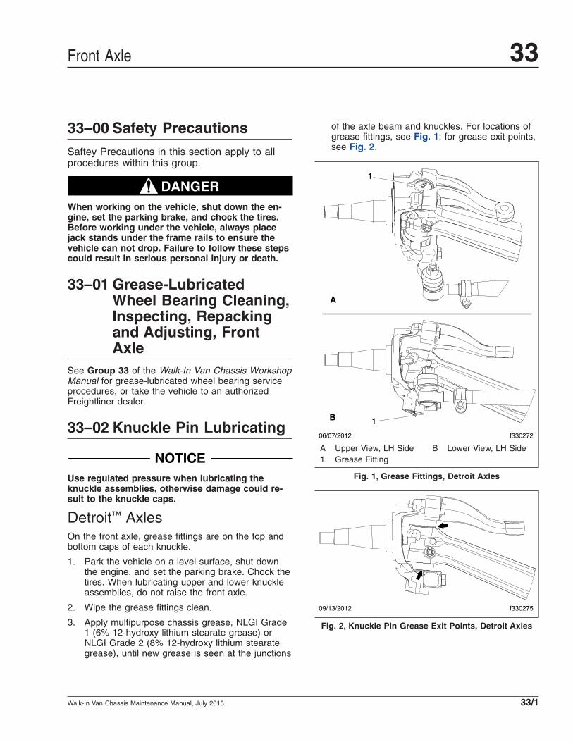
33–02 Knuckle Pin Lubricating
NOTICEUse regulated pressure when lubricating theknuckle assemblies, otherwise damage could re-sult to the knuckle caps.
Detroit™ AxlesOn the front axle, grease fittings are on the top andbottom caps of each knuckle.
1. Park the vehicle on a level surface, shut downthe engine, and set the parking brake. Chock thetires. When lubricating upper and lower knuckleassemblies, do not raise the front axle.
2. Wipe the grease fittings clean.
3. Apply multipurpose chassis grease, NLGI Grade1 (6% 12-hydroxy lithium stearate grease) orNLGI Grade 2 (8% 12-hydroxy lithium stearategrease), until new grease is seen at the junctions
of the axle beam and knuckles. For locations ofgrease fittings, see Fig. 1; for grease exit points,see Fig. 2.
06/07/2012 f330272
A
B
1
1
A Upper View, LH Side B Lower View, LH Side1. Grease Fitting
Fig. 1, Grease Fittings, Detroit Axles
09/13/2012 f330275
Fig. 2, Knuckle Pin Grease Exit Points, Detroit Axles
Front Axle 33
Walk-In Van Chassis Maintenance Manual, July 2015 33/1
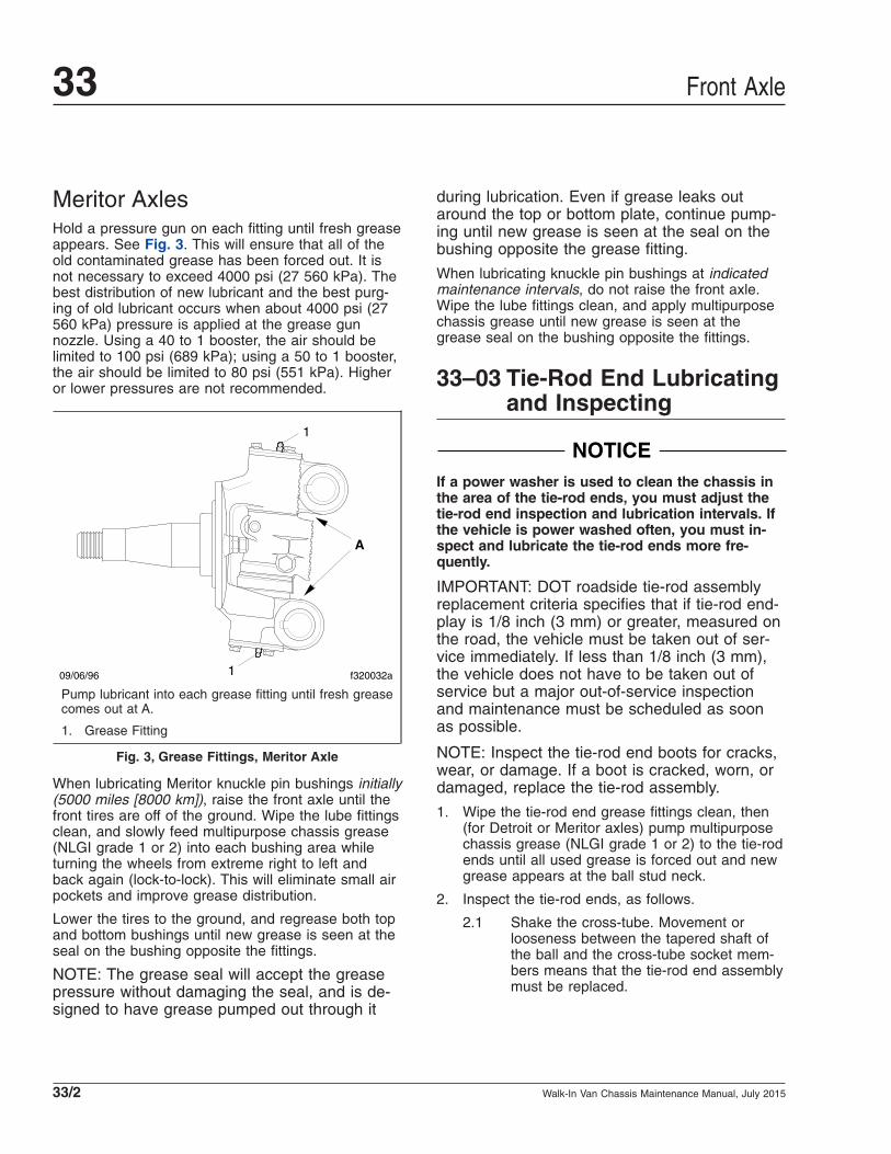
Meritor AxlesHold a pressure gun on each fitting until fresh greaseappears. See Fig. 3. This will ensure that all of theold contaminated grease has been forced out. It isnot necessary to exceed 4000 psi (27 560 kPa). Thebest distribution of new lubricant and the best purg-ing of old lubricant occurs when about 4000 psi (27560 kPa) pressure is applied at the grease gunnozzle. Using a 40 to 1 booster, the air should belimited to 100 psi (689 kPa); using a 50 to 1 booster,the air should be limited to 80 psi (551 kPa). Higheror lower pressures are not recommended.
When lubricating Meritor knuckle pin bushings initially(5000 miles [8000 km]), raise the front axle until thefront tires are off of the ground. Wipe the lube fittingsclean, and slowly feed multipurpose chassis grease(NLGI grade 1 or 2) into each bushing area whileturning the wheels from extreme right to left andback again (lock-to-lock). This will eliminate small airpockets and improve grease distribution.
Lower the tires to the ground, and regrease both topand bottom bushings until new grease is seen at theseal on the bushing opposite the fittings.
NOTE: The grease seal will accept the greasepressure without damaging the seal, and is de-signed to have grease pumped out through it
during lubrication. Even if grease leaks outaround the top or bottom plate, continue pump-ing until new grease is seen at the seal on thebushing opposite the grease fitting.
When lubricating knuckle pin bushings at indicatedmaintenance intervals, do not raise the front axle.Wipe the lube fittings clean, and apply multipurposechassis grease until new grease is seen at thegrease seal on the bushing opposite the fittings.
33–03 Tie-Rod End Lubricatingand Inspecting
NOTICEIf a power washer is used to clean the chassis inthe area of the tie-rod ends, you must adjust thetie-rod end inspection and lubrication intervals. Ifthe vehicle is power washed often, you must in-spect and lubricate the tie-rod ends more fre-quently.
IMPORTANT: DOT roadside tie-rod assemblyreplacement criteria specifies that if tie-rod end-play is 1/8 inch (3 mm) or greater, measured onthe road, the vehicle must be taken out of ser-vice immediately. If less than 1/8 inch (3 mm),the vehicle does not have to be taken out ofservice but a major out-of-service inspectionand maintenance must be scheduled as soonas possible.
NOTE: Inspect the tie-rod end boots for cracks,wear, or damage. If a boot is cracked, worn, ordamaged, replace the tie-rod assembly.
1. Wipe the tie-rod end grease fittings clean, then(for Detroit or Meritor axles) pump multipurposechassis grease (NLGI grade 1 or 2) to the tie-rodends until all used grease is forced out and newgrease appears at the ball stud neck.
2. Inspect the tie-rod ends, as follows.
2.1 Shake the cross-tube. Movement orlooseness between the tapered shaft ofthe ball and the cross-tube socket mem-bers means that the tie-rod end assemblymust be replaced.
09/06/96 f320032a
A
1
1
Pump lubricant into each grease fitting until fresh greasecomes out at A.
1. Grease Fitting
Fig. 3, Grease Fittings, Meritor Axle
Front Axle33
Walk-In Van Chassis Maintenance Manual, July 201533/2
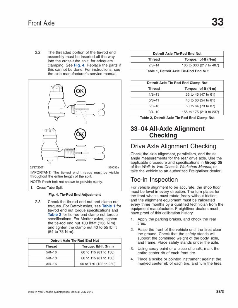
2.2 The threaded portion of the tie-rod endassembly must be inserted all the wayinto the cross-tube split, for adequateclamping. See Fig. 4. Replace the parts ifthis cannot be done. For instructions, seethe axle manufacturer’s service manual.
2.3 Check the tie-rod end nut and clamp nuttorques. For Detroit axles, see Table 1 fortie-rod end nut torque specifications andTable 2 for tie-rod end clamp nut torquespecifications. For Meritor axles, tightenthe tie-rod end nut 100 lbf·ft (136 N·m),and tighten the clamp nut 40 to 55 lbf·ft(54 to 75 N·m).
Detroit Axle Tie-Rod End Nut
Thread Torque: lbf·ft (N·m)
5/8–16 60 to 115 (81 to 156)
5/8–18 60 to 115 (81 to 156)
3/4–16 90 to 170 (122 to 230)
Detroit Axle Tie-Rod End Nut
Thread Torque: lbf·ft (N·m)
7/8–14 160 to 300 (217 to 407)
Table 1, Detroit Axle Tie-Rod End Nut
Detroit Axle Tie-Rod End Clamp Nut
Thread Torque: lbf·ft (N·m)
1/2–13 35 to 45 (47 to 61)
5/8–11 40 to 60 (54 to 81)
5/8–18 50 to 64 (73 to 87)
3/4–10 155 to 175 (210 to 237)
Table 2, Detroit Axle Tie-Rod End Clamp Nut
33–04 All-Axle AlignmentChecking
Drive Axle Alignment CheckingCheck the axle alignment, parallelism, and thrustangle measurements for the rear drive axle. Use theapplicable procedure and specifications in Group 35of the Walk-In Van Chassis Workshop Manual, ortake the vehicle to an authorized Freightliner dealer.
Toe-in InspectionFor vehicle alignment to be accurate, the shop floormust be level in every direction. The turn plates forthe front wheels must rotate freely without friction,and the alignment equipment must be calibratedevery three months by a qualified technician from theequipment manufacturer. Freightliner dealers musthave proof of this calibration history.
1. Apply the parking brakes, and chock the reartires.
2. Raise the front of the vehicle until the tires clearthe ground. Check that the safety stands willsupport the combined weight of the body, axle,and frame. Place safety stands under the axle.
3. Using spray paint or a piece of chalk, mark theentire center rib of each front tire.
4. Place a scribe or pointed instrument against themarked center rib of each tire, and turn the tires.
f320033a
1
OK
OK
02/27/2007
IMPORTANT: The tie-rod end threads must be visiblethroughout the entire length of the split.
NOTE: Pinch bolt not shown to provide clarity.
1. Cross-Tube Split
Fig. 4, Tie-Rod End Adjustment
Front Axle 33
Walk-In Van Chassis Maintenance Manual, July 2015 33/3
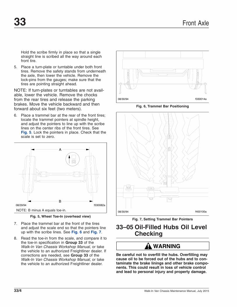
Hold the scribe firmly in place so that a singlestraight line is scribed all the way around eachfront tire.
5. Place a turn-plate or turntable under both fronttires. Remove the safety stands from underneaththe axle, then lower the vehicle. Remove thelock-pins from the gauges; make sure that thetires are pointing straight ahead.
NOTE: If turn-plates or turntables are not avail-able, lower the vehicle. Remove the chocksfrom the rear tires and release the parkingbrakes. Move the vehicle backward and thenforward about six feet (two meters).
6. Place a trammel bar at the rear of the front tires;locate the trammel pointers at spindle height,and adjust the pointers to line up with the scribelines on the center ribs of the front tires. SeeFig. 5. Lock the pointers in place. Check that thescale is set to zero.
7. Place the trammel bar at the front of the tiresand adjust the scale end so that the pointers lineup with the scribe lines. See Fig. 6 and Fig. 7.
8. Read the toe-in from the scale, and compare it tothe toe-in specification in Group 33 of theWalk-In Van Chassis Workshop Manual, or takethe vehicle to an authorized Freightliner dealer. Ifcorrections are needed, see Group 33 of theWalk-In Van Chassis Workshop Manual, or takethe vehicle to an authorized Freightliner dealer.
33–05 Oil-Filled Hubs Oil LevelChecking
WARNINGBe careful not to overfill the hubs. Overfilling maycause oil to be forced out of the hubs and to con-taminate the brake linings and other brake compo-nents. This could result in loss of vehicle controland lead to personal injury and property damage.
A
Bf330082a08/29/94
NOTE: B minus A equals toe-in.
Fig. 5, Wheel Toe-In (overhead view)
f330014a08/30/94
Fig. 6, Trammel Bar Positioning
f400100a08/30/94
Fig. 7, Setting Trammel Bar Pointers
Front Axle33
Walk-In Van Chassis Maintenance Manual, July 201533/4

1. With the vehicle on a level surface, rotate thefront wheels and allow the oil in the hubs tosettle.
2. Chock the tires.
IMPORTANT: The oil level should be at, or nomore than 1/4 inch (6 mm) above the level indi-cators on the hub caps.
3. If necessary, remove the filler caps (in the endsof the hub caps) and add enough oil (80W–90hypoid gear oil) to bring the oil to the properlevel.
4. Rotate the wheels, allow the oil to settle, andcheck the levels again.
5. Install the filler caps securely.
6. Remove the chocks from the tires.
33–06 Oil-Filled Hubs OilChanging
WARNINGBe careful not to overfill the hubs. Overfilling maycause oil to be forced out of the hubs and to con-taminate the brake linings and other brake compo-nents. This could result in loss of vehicle controland lead to personal injury and property damage.
1. With the vehicle on a level surface, rotate thefront wheels so that the front hub drain plugs arepositioned downward.
2. Chock the tires.
3. Place suitable containers under the hubs, re-move the filler caps (in the ends of the hub caps)and the drain plugs, and allow the hubs to draincompletely. See Fig. 8.
4. Install the drain plugs and tighten 25 lbf·in (282N·cm).
5. Add approximately 1 to 1-1/2 pints (0.5 to 0.7 L)of oil (80W–90 hypoid gear oil) to each hub.
6. Rotate the wheels, allow the oil to settle, andcheck the levels.
IMPORTANT: Fill the hubs to the level indicatorson the hub caps, or to no more than 1/4 inch (6mm) above the indicators. See Fig. 8.
7. Install the filler caps securely.
f330247b
A
1
2
07/09/2009
A. Hub Cavity Full1. Fill Plug/Magnetic Drain2. Drain Plug
Fig. 8, Oil-Filled Hub Cap
Front Axle 33
Walk-In Van Chassis Maintenance Manual, July 2015 33/5
Title of Maintenance Operation (MOP) MOP Number
Axle Breather Checking . . . . . . . . . . . . . . . . . . . . . . . . . . . . . . . . . . . . . . . . . . . . . . . . . . . . . . . . . . . . . 35–03
Axle Lubricant Changing. . . . . . . . . . . . . . . . . . . . . . . . . . . . . . . . . . . . . . . . . . . . . . . . . . . . . . . . . . . . . 35–01
Axle Lubricant Checking. . . . . . . . . . . . . . . . . . . . . . . . . . . . . . . . . . . . . . . . . . . . . . . . . . . . . . . . . . . . . 35–02
Safety Precautions. . . . . . . . . . . . . . . . . . . . . . . . . . . . . . . . . . . . . . . . . . . . . . . . . . . . . . . . . . . . . . . . . 35–00
Rear Axle 35Index, Alphabetical
Walk-In Van Chassis Maintenance Manual, July 2015

35–00 Safety PrecautionsSaftey Precautions in this section apply to allprocedures within this group.
DANGERWhen working on the vehicle, shut down the en-gine, set the parking brake, and chock the tires.Before working under the vehicle, always placejack stands under the frame rails to ensure thevehicle can not drop. Failure to follow these stepscould result in serious personal injury or death.
35–01 Axle Lubricant ChangingProcedures for Detroit™ and Meritor axles are pro-vided below.
Detroit AxleAxle Draining1. Park the vehicle on a level surface, shut down
the engine, and set the parking brake. Chock thetires.
2. Clean the fill plug and the area around it. Re-move the plug from the oil fill hole. See Fig. 1.
CAUTIONBe careful when draining the axle oil. It may bevery hot, and could cause personal injury if it con-tacts the skin.
3. Remove the plug at the bottom of the housingand drain the lubricant while the unit is warm.Allow enough time for all the old lubricant todrain completely.
4. Clean the drain plug. For magnetic drain plugs, apiece of key stock or any other convenient steelslug may be used to short the two magneticpoles and divert the magnetic field.
5. After cleaning the drain plug, install and tightenthe plug 30 lbf·ft (41 N·m).
Axle Filling1. With the vehicle on a level surface, fill the axle
housings to the bottom of the oil fill hole (in thecarrier or housing) with recommended lubricant;
see Table 1. Refer to Table 2 for Detroit driveaxle lubricant capacities.
2. Install the fill hole plug and tighten it 30 lbf·ft (41N·m).
3. After filling the carrier and housing assembly withlubricant, drive the vehicle unloaded for one ortwo miles (two or three kilometers) at speeds notto exceed 25 mph (40 km/h) to thoroughly circu-late the lubricant throughout the assembly.
11/07/2012 f350575
A
B
1
2
4
3
3
1
A. Front ViewB. Rear View1. Breather Hose2. Axle Housing Breather3. Oil Drain Plug4. Oil Fill Plug
Fig. 1, Component Locations, Detroit Axle
Rear Axle 35
Walk-In Van Chassis Maintenance Manual, July 2015 35/1

Detroit Drive Axle Lubricants*
IMPORTANT: Lubricant used in Detroit rear axles mustmeet Mercedes-Benz specification 235.20 (mineral) or
235.8 (synthetic). Mobil Delvac™ Gear Oil A 80W-90 andMobilube™ HD-A Plus 80W-90 meet specification 235.20.
Mobil Delvac 1 Gear Oil 75W-90 and Mobilube 1 SHC75W-90 meet specification 235.8. For more product
information, see http://bevo.mercedes-benz.com.
Type Ambient TemperatureSAE
ViscosityGrade
Mineral Oil –15°F (–26.1°C) and up† 80W–90
Synthetic Oil –40°F (–40°C) and up† 75W–90* Detroit rear axles do not require the use of friction modifiers.† There is no upper limit on the ambient temperature, but axle sump tem-
perature must never exceed 250°F (121°C).
Table 1, Detroit Drive Axle Lubricants
Detroit Drive Axle Lubricant Capacities
Axle Model* Capacity†: pints (L)
ARS–13.0–2 15 (7)
ARS–15.0–2 15 (7)
ARS–17.5–2 15 (7)
ARS–19.0–2 15 (7)
ARS–20.0–2 15 (7)
ARS–21.0–2 15 (7)
ARS–21.0–4 23 (11)
ARS–23.0–4 23 (11)
* Model code may have a "D" in the prefix (for example, DA–RS–13.0–2).† Quantities listed are approximate and include 1 pint (0.5 liter) for each
wheel end and with the drive pinion at 3 degrees.
Table 2, Detroit Drive Axle Lubricant Capacities
Meritor Axle1. Remove the filler plug, then the drain plug and
allow the differential to drain completely. See Fig.2.
2. Install and tighten the drain plug securely.
3. Fill the differential with an SAE 80W–90 multipur-pose gear lubricant, or an SAE 75W–90 multipur-pose synthetic gear lubricant. See Table 3 foraxle lubricant capacities. Either type of lubricantmust meet MIL L–2105–D and be suitable forAmerican Petroleum Institute service classifica-
tion GL–5. The lubricant level within the differen-tial must be even with the bottom of the fill hole.
4. Install and tighten the fill plug securely.
Meritor Drive Axle Lubricant Capacities (single axle)*
Axle Model Capacity†: pints (L)
RS-15-120 16 (7.6)
RS-17-145 33.6 (15.9)
RS-19-145 34.4 (16.3)
RS-21-145 32 (15.1)
RS-23-160 42 (19.9)
RC-23-165 42 (19.9)
* Single drive axles equipped with traction equalizers may require a "frictionmodifier" to correct a slip-stick condition, as described in the vehicle driver’smanual. Meritor’s experience shows that the following additives perform ad-equately: Add Elco No. 2 Friction Modifier (1 ounce [30 ml] of additive foreach 1 pint [0.5 liter] of lube capacity) or Lubrizol No. 797 or 762 (oneounce [30 mL] of additive for each 1 pint [0.5 liter] of lube capacity).† Quantities listed are approximate and include 1 pint (0.5 liter) for each
wheel end and with the drive pinion at 3 degrees.
Table 3, Meritor Drive Axle Lubricant Capacities(single axle)
35–02 Axle Lubricant Checking
NOTICEFailure to keep the rear axle filled to the properlevel with the recommended lubricant can result inrear axle damage.
f350150
1
7 8
5
3208/19/2009
4
6
1. Ratio Tag2. Drain Plug3. Limited Slip
Lubrication Tag4. Filler Plug
5. Model Number6. Axle Housing Breather7. Manufacturing Date8. Part Number
Fig. 2, Rear Axle Differential, Meritor Axle
Rear Axle35
Walk-In Van Chassis Maintenance Manual, July 201535/2

NOTE: If the vehicle is exposed to water deepenough to cover the hubs, disassemble and in-spect them for water damage and/or contamina-tion. See Group 35 of the Walk-In Van ChassisWorkshop Manual for instructions, or take thevehicle to an authorized Freightliner dealer.
1. Park the vehicle on a level surface, shut downthe engine, and set the parking brake. Chock thetires.
2. If the vehicle has just been driven, allow a fewminutes for the lubricant to settle.
3. Clean the fill plug and the area surrounding thefill plug on the side of the axle carrier. Removethe plug. Check lubricant level when the axle iscold, or near room temperature. See Fig. 1 for aDetroit axle, or Fig. 2 for a Meritor axle.
4. Check that the lubricant is level with the bottomof the fill hole. See Fig. 3. If low, check for oilleaks, and correct as needed. Add oil to the levelof the fill plug. For a Detroit axle, use the lubri-cant recommended in Table 1.
For a Meritor axle, add SAE 80W-90 multipur-pose gear lubricant, or an SAE 75W-90 multipur-pose synthetic gear lubricant. Either type of lubri-cant must meet MIL L-2105-D and be suitable forAmerican Petroleum Institute service classifica-tion GL-5.
IMPORTANT: A lubricant level close enough tobe seen or touched is not sufficient. It must belevel with the bottom of the fill hole.
5. Install the oil fill plug and tighten it 30 lbf·ft (41N·m) for Detroit axles or 35 lbf·ft (47 N·m) forMeritor axles.
6. Inspect the axle for signs of leakage. If leakageis indicated and the lubricant level is down, haveyour dealer perform any necessary maintenance.
35–03 Axle Breather CheckingNOTE: For component locations, see Fig. 1 fora Detroit axle or Fig. 2 for a Meritor axle.
The axle housing breather must remain unob-structed. Whenever the axle lubricant level ischecked, also check that the axle breather is open.
Check more often under poor operating conditions. Ifthe breather is plugged, clean or replace it asneeded.
f350061a
A
B
08/17/2009
A. Correct (lube level at bottom of fill hole)B. Incorrect (lube level below fill hole)
Fig. 3, Axle Lubricant Level Inspection
Rear Axle 35
Walk-In Van Chassis Maintenance Manual, July 2015 35/3

Title of Maintenance Operation (MOP) MOP Number
Wheel Nut Checking. . . . . . . . . . . . . . . . . . . . . . . . . . . . . . . . . . . . . . . . . . . . . . . . . . . . . . . . . . . . . . . . 40–01
Wheels and Tires 40Index, Alphabetical
Walk-In Van Chassis Maintenance Manual, January 2008

40–01 Wheel Nut CheckingIMPORTANT: In addition to the maintenanceinterval in this manual, check the wheel nuttorque the first 50 to 100 miles (80 to 160 km)of operation after a wheel has been removedand installed.
NOTE: For all stud-piloted wheels, on eachwheel stud, the end that faces away from thevehicle is stamped with an "L" or "R," dependingon which side of the vehicle the stud is installed.Studs stamped with an "L" are left-handthreaded and are installed on the driver’s side ofthe vehicle. Studs stamped with an "R" areright-hand threaded and are installed on thepassenger’s side of the vehicle.
For all stud-piloted wheels, when checking wheelnuts on a dual disc assembly, remove one outer nutat a time, tighten the inner nut, then reinstall theouter nut. Repeat this procedure for all of the innerwheel nuts in the sequence shown in Fig. 1, thentighten all of the outer wheel nuts in the same se-quence.
CAUTIONToo little wheel nut torque can cause wheelshimmy, resulting in wheel damage, stud break-age, and extreme tire tread wear. Too much wheelnut torque can break studs, damage threads, andcrack discs in the stud hole area.
Tighten the wheel nuts 450 to 500 lbf·ft (610 to 680N·m), and see Fig. 1 for the tightening sequence ofstud-piloted, 6-stud wheels.
For hub piloted, 8- and 10- stud wheels, torque val-ues vary with the stud size; consult the wheel manu-facturer for recommended torque values. See Fig. 2for the tightening sequence of hub-piloted, 8- and10-stud wheels. Before tightening, apply 2 drops ofSAE 30W oil to a point between the nuts andflanges.
1
1
2
2
3
34
4
5
56
6
A B
08/20/96 f400119
A. Front and Inner Rear DualB. Outer Rear Dual
Fig. 1, Wheel Nut Tightening Sequence (stud-piloted6-stud wheels)
09/18/2001
A Bf400164
110 8
63
5 4
92
7
1 2
4
6
7
5
83
A. 8-Stud Disc Wheel B. 10-Stud Disc Wheel
Fig. 2, Wheel Nut Tightening Sequence (8- and 10-studhub-mounted wheels)
Wheels and Tires 40
Walk-In Van Chassis Maintenance Manual, January 2008 40/1
Title of Maintenance Operation (MOP) MOP Number
Driveline Inspection and Lubrication . . . . . . . . . . . . . . . . . . . . . . . . . . . . . . . . . . . . . . . . . . . . . . . . . . . . 41–01
Safety Precautions. . . . . . . . . . . . . . . . . . . . . . . . . . . . . . . . . . . . . . . . . . . . . . . . . . . . . . . . . . . . . . . . . 41–00
Driveline 41Index, Alphabetical
Walk-In Van Chassis Maintenance Manual, July 2015

41–00 Safety PrecautionsSaftey Precautions in this section apply to allprocedures within this group.
DANGERWhen working on the vehicle, shut down the en-gine, set the parking brake, and chock the tires.Before working under the vehicle, always placejack stands under the frame rails to ensure thevehicle can not drop. Failure to follow these stepscould result in serious personal injury or death.
41–01 Driveline Inspection andLubrication
InspectionBefore lubricating the driveline U-joints and slip-joints, make the following checks.
1. Check that the yoke-strap capscrews are tight-ened 50 to 60 lbf·ft (68 to 81 N·m).
NOTICEDo not overtighten the yoke-strap capscrews, dueto the extreme load occurring at high-speed rota-tion. A loose or broken capscrew at any point inthe driveline weakens the driveline connection,which could eventually result in serious vehicledamage.
2. Check the slip-joints for spline wear by trying tobend the sleeve-yoke and splined shaft back andforth. If looseness is greater than 0.007 inch(0.18 mm), replace both the sleeve-yoke and thesplined shaft.
3. Check the driveshaft for missing balanceweights, and for debris buildup. Remove anybuildup. If any balance weights are missing, re-move the driveshaft and have it balanced. Forinstructions, see Group 41 of the vehicle Work-shop Manual, or take the vehicle to an autho-rized Freightliner dealer.
4. Check that the yoke plug is not loose or missing.Replace the yoke plug if needed. If the yoke plugis missing, the splined shaft may be hitting the
yoke plug and knocking it out; check the drive-shaft for proper length.
U-Joint Lubrication1. Wipe all old grease and dirt from each U-joint
grease fitting.
2. Use a hand-type grease gun, or a high-pressuregun with a low-pressure adaptor, to lubricate theU-joints. See Fig. 1.
NOTE: If a low-pressure adaptor is not usedwith the high-pressure gun, the U-joints may notreceive enough lubricant.
3. Using lithium 12-hydroxy stearate grease (NLGIgrade 1 or 2, with EP additives), lubricate untilnew grease can be seen at all four U-joint seals.
f410050a 10/20/93
1
1
2 3
3
3 4
5
6
7
8
A
A. After grease appears, cover the pressure-relief holewhile continuing to lubricate.
1. Slip-Joint GreaseFitting (with greasegun attached)
2. Yoke Plug3. Grease4. Half-Round Yoke
5. Yoke Plug Pressure-Relief-Hole
6. Slip-Joint Seal7. Full-Round Yoke8. U-Joint Grease Fitting
Fig. 1, Slip-Joint and U-Joint Lubricating
Driveline 41
Walk-In Van Chassis Maintenance Manual, July 2015 41/1

NOTICEFresh lubricant must be seen escaping from allfour of the bearing cup seals of each U-joint. Ifnot, the U-joint may fail prematurely.
4. If the bearing will not take grease, replace theU-joint assembly. For instructions, see Group 41of the vehicle Workshop Manual, or take the ve-hicle to an authorized Freightliner dealer.
5. Check the old grease. If it appears rusty, gritty, orburned, replace the U-joint assembly. For instruc-tions, see Group 41 of the vehicle WorkshopManual, or take the vehicle to an authorizedFreightliner dealer.
6. Wipe any excess grease from the seals andgrease fittings.
Slip-Joint Spline Lubrication1. Wipe all old grease and dirt from the slip-joint
grease fitting.
2. Use a hand-type grease gun or a high-pressuregun with a low-pressure adaptor, to lubricate theslip-joint. Using lithium 12-hydroxy stearategrease (NLGI grade 1 or 2, with EP additives),lubricate until fresh grease appears at thepressure-relief hole in the yoke plug. Then coverthe relief hole with your finger, as shown inFig. 1, while continuing to lubricate until freshgrease appears at the slip-joint seal. This en-sures complete lubrication of the splines.
3. Wipe any excess grease from the pressure-reliefhole, slip-joint seal, and grease fitting.
Driveline41
Walk-In Van Chassis Maintenance Manual, July 201541/2
Title of Maintenance Operation (MOP) MOP Number
Air Dryer Check . . . . . . . . . . . . . . . . . . . . . . . . . . . . . . . . . . . . . . . . . . . . . . . . . . . . . . . . . . . . . . . . . . . 42–08
Air Dryer Desiccant and Coalescent Filter Replacement. . . . . . . . . . . . . . . . . . . . . . . . . . . . . . . . . . . . . . 42–07
Bendix Hydro-Max® Brake System Inspection. . . . . . . . . . . . . . . . . . . . . . . . . . . . . . . . . . . . . . . . . . . . . 42–01
Brake Caliper Slide Pin Lubrication, Bosch Brakes . . . . . . . . . . . . . . . . . . . . . . . . . . . . . . . . . . . . . . . . . 42–04
Brake Inspection . . . . . . . . . . . . . . . . . . . . . . . . . . . . . . . . . . . . . . . . . . . . . . . . . . . . . . . . . . . . . . . . . . 42–05
Brake Lines Check, Hydraulic Disc Brakes . . . . . . . . . . . . . . . . . . . . . . . . . . . . . . . . . . . . . . . . . . . . . . . 42–02
Brake Lining Wear Check, Hydraulic Disc Brakes . . . . . . . . . . . . . . . . . . . . . . . . . . . . . . . . . . . . . . . . . . 42–03
Safety Precautions. . . . . . . . . . . . . . . . . . . . . . . . . . . . . . . . . . . . . . . . . . . . . . . . . . . . . . . . . . . . . . . . . 42–00
Slack Adjuster Lubrication. . . . . . . . . . . . . . . . . . . . . . . . . . . . . . . . . . . . . . . . . . . . . . . . . . . . . . . . . . . . 42–06
Versajust Slack Adjuster Inspection and Lubrication. . . . . . . . . . . . . . . . . . . . . . . . . . . . . . . . . . . . . . . . . 42–09
Brakes 42Index, Alphabetical
Walk-In Van Chassis Maintenance Manual, November 2015

42–00 Safety PrecautionsSaftey Precautions in this section apply to allprocedures within this group.
DANGERWhen working on the vehicle, shut down the en-gine, set the parking brake, and chock the tires.Before working under the vehicle, always placejack stands under the frame rails to ensure thevehicle can not drop. Failure to follow these stepscould result in serious personal injury or death.
42–01 Bendix Hydro-Max®Brake System Inspection
NOTE: If possible, remove both caps when fill-ing the reservoir. If only one cap can be re-moved, allow ample time for the reservoir to fill.
1. Check the fluid level in the hydraulic brake fluidreservoir. If needed, fill the reservoir up to theridge that surrounds the reservoir. See Fig. 1.Use only heavy-duty brake fluid, DOT 3.
2. Check all hydraulic lines and fittings for damage,leakage, or looseness.
Replace damaged or leaking components, andtighten loose fittings.
3. Check the brake module for leaks. If leaks arefound, repair or replace the brake module. SeeGroup 42 of the Walk-In Van Chassis WorkshopManual for replacement instructions, or take thevehicle to an authorized Freightliner dealer.
4. Check the electrical connections and harnesses.Make sure the connectors are fully seated andthe harnesses are not chafed or cut. Repair orreplace any damaged harness. Disconnect anyloose connectors and inspect the terminals forcorrosion. If corrosion is present, replace the ter-minals. If corrosion is not present, reconnect theconnector.
5. Check the operation of the Hydro-Max brakebooster, as follows.
5.1 With the ignition off, depress the brakepedal; listen for the back-up motor to en-gage. The operator should feel the pedalforce relieve and the pedal should de-press easily.
5.2 With the ignition on, engine running, andpark brake released; operator checks thatthe BRAKE warning indicator is not on.This is a dual indicator, and it indicatesthat the park brake is set, and it warns ifthere is a hydro-max failure conditionother than loss of back-up motor power.
6. Check the fuse for the hydraulic brake boosterpump, as follows.
6.1 Open the cover to the main power distri-bution module (PDM).
6.2 Pull the fuse in position F6 for the Hydro-Max relay.
6.3 Inspect the relay to make sure the fuse isnot damaged. If the fuse is damaged, in-stall a new fuse. If the fuse is not dam-aged, install the fuse in position F6.
6.4 Close the PDM cover.
42–02 Brake Lines Check,Hydraulic Disc Brakes
Check all hydraulic lines and fittings for damage,leakage, or looseness.
04/26/2012 f460513a
A
B
A. Open caps and check fluid level.B. Fill to this level.
Fig. 1, Hydraulic Brake Fluid Reservoir
Brakes 42
Walk-In Van Chassis Maintenance Manual, November 2015 42/1

Replace damaged or leaking components, andtighten loose fittings.
42–03 Brake Lining WearCheck, Hydraulic DiscBrakes
Before checking lining wear with the wheel removed,review the following brake lining exposure warnings.
WARNINGBreathing brake lining dust (asbestos or non-asbestos) could cause lung cancer or lung dis-ease. Unless exposure can be reduced below legallimits, wear an air purifying respirator approvedby MSHA or NIOSH at all times when servicing thebrakes, starting with removal of the wheels andcontinuing through assembly.
To minimize the possibility of creating airborne brakelining dust, clean the dust from the brake rotor, brakecaliper, and brake assembly, using an industrial-typevacuum cleaner equipped with a high-efficiency filtersystem. Then, using a rag soaked in water andwrung until nearly dry, remove any remaining dust.Do not use compressed air or dry brushing to cleanthe brake assembly.
1. Check lining wear.
1.1 Apply the parking brake and chock thetires to prevent vehicle movement.
1.2 On front and rear axles, replace liningsworn to less than 3/16 inch (4.8 mm).
1.3 Make sure that the brake rotor and liningsare free of oil and grease.
2. If the wheel and hub assembly is removed fromthe axle, check lining wear. Replace the liningson all brake assemblies if worn to less than 3/16inch (4.8 mm) at the thinnest point.
NOTE: To replace the brake linings, see the ap-plicable foundation brake section in Group 42 ofthe Walk-In Van Chassis Workshop Manual, ortake the vehicle to an authorized Freightlinerdealer.
42–04 Brake Caliper Slide PinLubrication, BoschBrakes
NOTE: There is no set maintenance interval forlubricating pin-slide hydraulic disc brake cali-pers.
Apply 1/8 oz (3.5 g) Aeroshell grade 5 grease toeach of the two guide pin and guide pin bore sets.See the Bosch Pin Slide Disc Brakes Service Manualfor additional information.
IMPORTANT: The later ZOH-T caliper has im-portant differences from the early ZOPS caliper.ZOPS calipers (since 1998) and ZOH-T calipers(since 2002) use different slide pins and bolts.See Fig. 4 and Fig. 3. The later trailing pin isidentified by notches and has a rubber bushing.Flange-head instead of hex-head bolts are usedwith the later caliper. The later bolts have a finethread rather than a coarse thread pitch, arelonger, differently colored, and are tightened to ahigher torque specification. Use only the ZOH-Tbolts to assemble a ZOH-T caliper. The ZOPScaliper bolts have a different thread pitch andwill not assemble correctly in a ZOH-T calipermounting. Also, the ZOH-T bolts will not as-semble correctly in a ZOPS caliper. Do not in-terchange parts. It is permissible to use bothZOH-T pins and ZOH-T bolts in a ZOPS anchorplate, but they must be replaced as sets. Boththe pins and the bolts must be changed.
f42235706/20/2002
12
34
1. Flange-Head Bolt2. Leading Pin
3. Trailing Pin4. Rubber Bushing
Fig. 2, ZOH-T Slide Pins and Bolts
Brakes42
Walk-In Van Chassis Maintenance Manual, November 201542/2
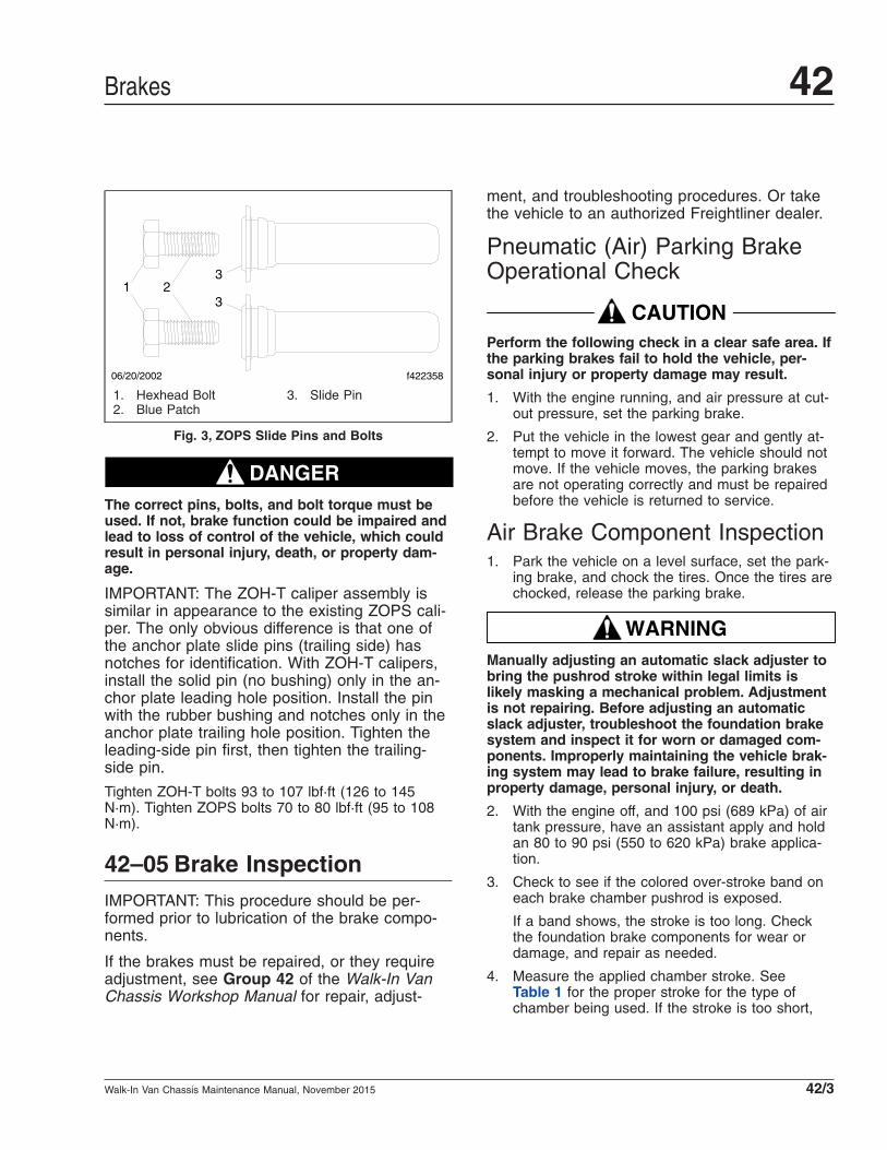
DANGERThe correct pins, bolts, and bolt torque must beused. If not, brake function could be impaired andlead to loss of control of the vehicle, which couldresult in personal injury, death, or property dam-age.
IMPORTANT: The ZOH-T caliper assembly issimilar in appearance to the existing ZOPS cali-per. The only obvious difference is that one ofthe anchor plate slide pins (trailing side) hasnotches for identification. With ZOH-T calipers,install the solid pin (no bushing) only in the an-chor plate leading hole position. Install the pinwith the rubber bushing and notches only in theanchor plate trailing hole position. Tighten theleading-side pin first, then tighten the trailing-side pin.
Tighten ZOH-T bolts 93 to 107 lbf·ft (126 to 145N·m). Tighten ZOPS bolts 70 to 80 lbf·ft (95 to 108N·m).
42–05 Brake InspectionIMPORTANT: This procedure should be per-formed prior to lubrication of the brake compo-nents.
If the brakes must be repaired, or they requireadjustment, see Group 42 of the Walk-In VanChassis Workshop Manual for repair, adjust-
ment, and troubleshooting procedures. Or takethe vehicle to an authorized Freightliner dealer.
Pneumatic (Air) Parking BrakeOperational Check
CAUTIONPerform the following check in a clear safe area. Ifthe parking brakes fail to hold the vehicle, per-sonal injury or property damage may result.
1. With the engine running, and air pressure at cut-out pressure, set the parking brake.
2. Put the vehicle in the lowest gear and gently at-tempt to move it forward. The vehicle should notmove. If the vehicle moves, the parking brakesare not operating correctly and must be repairedbefore the vehicle is returned to service.
Air Brake Component Inspection1. Park the vehicle on a level surface, set the park-
ing brake, and chock the tires. Once the tires arechocked, release the parking brake.
WARNINGManually adjusting an automatic slack adjuster tobring the pushrod stroke within legal limits islikely masking a mechanical problem. Adjustmentis not repairing. Before adjusting an automaticslack adjuster, troubleshoot the foundation brakesystem and inspect it for worn or damaged com-ponents. Improperly maintaining the vehicle brak-ing system may lead to brake failure, resulting inproperty damage, personal injury, or death.
2. With the engine off, and 100 psi (689 kPa) of airtank pressure, have an assistant apply and holdan 80 to 90 psi (550 to 620 kPa) brake applica-tion.
3. Check to see if the colored over-stroke band oneach brake chamber pushrod is exposed.
If a band shows, the stroke is too long. Checkthe foundation brake components for wear ordamage, and repair as needed.
4. Measure the applied chamber stroke. SeeTable 1 for the proper stroke for the type ofchamber being used. If the stroke is too short,
f42235806/20/2002
13
32
1. Hexhead Bolt2. Blue Patch
3. Slide Pin
Fig. 3, ZOPS Slide Pins and Bolts
Brakes 42
Walk-In Van Chassis Maintenance Manual, November 2015 42/3

the brakes may drag or will not fully apply. Checkfor improper operation or adjustment of the auto-matic slack adjuster.
5. Start the engine and build air pressure to at least100 psi (689 kPa). Shut down the engine.
6. Check all of the foundation brake components fordamage, wear, and loose or missing parts. Re-pair as needed.
Mechanical Parking BrakeComponent Inspection1. Park the vehicle on a level surface, set the park-
ing brake, and chock the tires. Once the tires arechocked, release the parking brake.
2. If more than 3/4 of the available travel of theparking brake is required to hold the vehicle, theparking brake lining should be checked and, ifneeded, repaired by an authorized Freightlinerdealer.
3. Inspect the parking brake shoes for lining wear. Ifthickness of any lining material is worn to within0.030 inch (0.79 mm) of the shoe table at thethinnest place, replace both of the shoe and lin-ing assemblies.
42–06 Slack AdjusterLubrication
IMPORTANT: Perform Maintenance Operation42–07 before lubricating the slack adjusters.
Automatic slack adjusters must be lubricated periodi-cally to ensure proper brake operation.
WARNINGFailure to lubricate slack adjusters could lead todragging brakes or a brake failure, resulting inproperty damage, personal injury, or death.
MeritorLubricate the slack adjuster at the grease fitting untilgrease is forced past the pressure-relief capscrew orpast the gear splines around the inboard snap ring.Use high-temperature, NLGI Grade 1 waterproofgrease. See Fig. 4.
Brake Chamber Stroke Specifications
ChamberMax Applied Stroke: inch (mm)
Manufacturer Type* Size†
Meritor
Standard Stroke
9Less than 1-1/2 (38)
12
16Less than 1-3/4 (44)
20
24 Less than 1-7/8 (48)
Long Stroke 24Less than 2 (51)
Standard Stroke 30* Long stroke design is indicated by a tag, or embossing, on the brake chamber.† Specifications are relative to a brake application with 80 to 90 psi (550 to 620 kPa) air pressure in the brake chambers.
Table 1, Brake Chamber Stroke Specifications
BendixUsing a quality multipurpose chassis lubricant, NLGIGrade 2, lubricate the automatic slack adjusterthrough the lube fitting. See Fig. 5. Lubricate the
slack adjuster until clean lubricant flows from thegrease relief opening in the boot.
Brakes42
Walk-In Van Chassis Maintenance Manual, November 201542/4

42–07 Air Dryer Desiccant andCoalescent FilterReplacement
Bendix AD-91. Park the vehicle on a level surface, shut down
the engine, and set the parking brake. Chock thetires.
2. Completely drain all air reservoirs. Air pressuregauges should read 0 psi (0 kPa).
3. Loosen the desiccant cartridge with a strapwrench at the base of the cartridge. Spin off thecartridge and discard it.
4. Remove the O-ring from the threaded neck anddiscard it.
5. Remove the coalescent filter and discard it.
IMPORTANT: Lubricate the new O-rings prior toinstallation.
6. Install the new small O-ring in the groove on thebottom of the new coalescent filter.
7. Insert the coalescent filter with the O-ring endgoing into the air dryer opening first. The end ofthe filter with the "X" will then be facing out.
8. Install the other new O-ring over the threadedneck of the desiccant cartridge.
9. Screw on the desiccant cartridge until resistanceis detected. Then, tighten the cartridge 1/4 to 3/4of a turn by hand.
10. Before placing the vehicle in service, perform thetest below.
10.1 Start the engine and build air pressure to120 psi (827 kPa).
10.2 Listen for the purge valve to open andrelease air. A large volume of air will beexpelled, followed by a slow flow of airlasting approximately 30 seconds.
10.3 Shut down the engine.
10.4 Perform the checks in Maintenance Op-eration 42–10.
Haldex PURest1
NOTE: The PURest cartridge contains both thedesiccant and filter in one piece.
1. Park the vehicle on a level surface, shut downthe engine, and set the parking brake. Chock thetires.
2. Remove the four mounting bolts and discard.See Fig. 6. Lift the canister about ½ inch andremove.
3. Place the assembly upside-down as shown inFig. 7. Press the cartridge down to compress therubber spring then rotate counterclockwise 45degrees to release the cartridge. The cartridgeitself contains no hazardous material, but theremay be a small amount of oil from thecompressor.
4. Clean the inside of the canister and aluminumhousing.
5. Remove the cartridge O-ring and discard.
6. Remove the new cartridge from the kit and makecertain the rubber spring is attached. See Fig. 8.
1Information in this section is provided by Haldex and is used with permis-sion.
06/17/2010 f430511
1
22 3
3
4
5
6
77
1. Yoke2. Yoke Pin3. Link Pin4. Link
5. Boot6. Lube Fitting7. Worm Gear
Fig. 5, Bendix Automatic Slack Adjuster
Brakes 42
Walk-In Van Chassis Maintenance Manual, November 2015 42/5
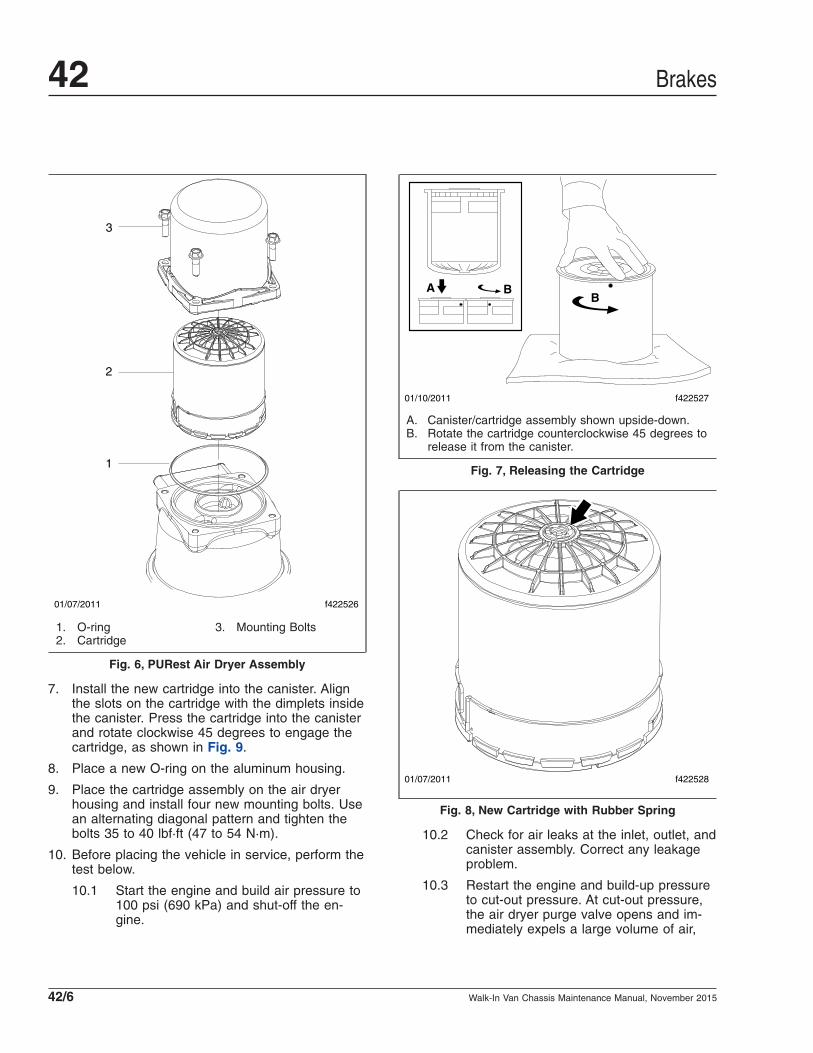
7. Install the new cartridge into the canister. Alignthe slots on the cartridge with the dimplets insidethe canister. Press the cartridge into the canisterand rotate clockwise 45 degrees to engage thecartridge, as shown in Fig. 9.
8. Place a new O-ring on the aluminum housing.
9. Place the cartridge assembly on the air dryerhousing and install four new mounting bolts. Usean alternating diagonal pattern and tighten thebolts 35 to 40 lbf·ft (47 to 54 N·m).
10. Before placing the vehicle in service, perform thetest below.
10.1 Start the engine and build air pressure to100 psi (690 kPa) and shut-off the en-gine.
10.2 Check for air leaks at the inlet, outlet, andcanister assembly. Correct any leakageproblem.
10.3 Restart the engine and build-up pressureto cut-out pressure. At cut-out pressure,the air dryer purge valve opens and im-mediately expels a large volume of air,
01/07/2011 f422526
1
2
3
1. O-ring2. Cartridge
3. Mounting Bolts
Fig. 6, PURest Air Dryer Assembly
01/10/2011 f422527
BBA
A. Canister/cartridge assembly shown upside-down.B. Rotate the cartridge counterclockwise 45 degrees to
release it from the canister.
Fig. 7, Releasing the Cartridge
01/07/2011 f422528
Fig. 8, New Cartridge with Rubber Spring
Brakes42
Walk-In Van Chassis Maintenance Manual, November 201542/6

followed by a slow flow of air lasting ap-proximately 30 seconds.
10.4 Perform the checks in Maintenance Op-eration 42–10.
42–08 Air Dryer CheckIMPORTANT: Review the warranty policy beforeperforming any intrusive maintenance proce-dures. An extended warranty may be voided ifintrusive maintenance is performed during thisperiod.
Because no two vehicles operate under identicalconditions, maintenance and maintenance intervals
will vary. Experience is a valuable guide in determin-ing the best maintenance interval for any one particu-lar operation.
Every six months:
1. Check for moisture in the air brake system byopening reservoir drain valves and checking forpresence of water. If moisture is present, thedesiccant cartridge may require replacement;however, the following conditions can also causewater accumulation and should be consideredbefore replacing the desiccant:
• An outside air source has been used tocharge the system. This air did not passthrough the drying bed.
• Air usage is exceptionally high and not nor-mal. This may be due to high air systemleakage.
• In areas where more than a 30-degreerange of temperature occurs in one day,small amounts of water can temporarilyaccumulate in the air brake system due tocondensation. Under these conditions, thepresence of small amounts of moisture isnormal.
NOTE: A small amount of oil in the system isnormal and should not be considered as a rea-son to replace the desiccant cartridge. Some oilat the dryer exhaust is normal.
2. Visually check for physical damage, such aschaffed or broken air and electrical lines and bro-ken or missing parts.
3. Check the mounting bolts for tightness. SeeTable 2 for torque values.
Torque Values
Vendor Size Torque:lbf·ft (N·m)
BendixGrade 5, 3/8–16 28 (38)
Grade 5, 5/8–11 135 (183)
Haldex 1/2–13 45 to 55 (61 to 75)
Table 2, Torque Values
4. Perform the operational and leakage tests listedbelow.
01/10/2011 f422529
B BA
A
A
A. Install the new cartridge into the canister.B. Press the cartridge into the canister and rotate
clockwise 45 degrees to engage the cartridge.
Fig. 9, Cartridge Rotation and Engagement
Brakes 42
Walk-In Van Chassis Maintenance Manual, November 2015 42/7

Operational and Leakage Tests1. Check all lines and fittings leading to and from
the air dryer for leakage and integrity. Repair anyleaks found.
2. Build system pressure to governor cutout andnote that the dryer purges with an audible es-cape of air. Watch the system pressure and notethe pressure fall-off for a 10-minute period. If thepressure drop exceeds 1 psi/minute from eitherservice reservoir, inspect the vehicle air systemsfor sources of leakage and repair them. Refer totroubleshooting information in Bendix or Haldexservice literature.
3. Check for excessive leakage around the purgevalve with the compressor in the loaded mode(compressing air). Apply a soap solution to thepurge valve exhaust port and observe that leak-age does not exceed a 1-inch (25-mm) bubble in1 second. If the leakage exceeds the maximumspecified, refer to troubleshooting information inthe Bendix or Haldex service literature.
4. Build system pressure to governor cutout andnote that the dryer purges with an audible es-cape of air. Fan the service brakes to reducesystem air pressure to governor cut-in. Note thatthe system once again builds to full pressure andis followed by a dryer purge. If the system doesnot follow this pattern, refer to troubleshootinginformation in the Bendix or Haldex service litera-ture.
5. Check the operation of the end cover heater andthermostat assembly during cold weather opera-tion as follows:
5.1 Electric Power to the Dryer: With the igni-tion in the ON position, check for voltageto the heater and thermostat assemblyusing a voltmeter or testlight. Unplug theelectrical connector at the air dryer andplace the test leads on each of the con-nections of the female connector on thevehicle power lead. If there is no voltage,look for a blown fuse, broken wires, orcorrosion in the vehicle wiring harness.Check to see if a good ground path ex-ists.
5.2 Thermostat and Heater Assembly Opera-tion: These tests are not possible exceptin cold weather operation. Turn off theignition switch and cool the thermostat
and heater assembly to below 40°F(4°C). Using an ohmmeter, check the re-sistance between the electrical pins in theair dryer connector half. The resistanceshould be 1.5 to 3.0 ohms for the 12-voltheater assembly and 6.0 to 9.0 ohms forthe 24-volt heater assembly.
NOTE: Some models of the AD–9 mayhave a resistance reading of 1.0 to 2.5ohms.
Warm the thermostat and heater assem-bly to approximately 90°F (32°C) andagain check the resistance. The resis-tance should exceed 1000 ohms. If theresistance values obtained are within thestated limits, the thermostat and heaterassembly is operating properly. If the re-sistance values obtained are outside thestated limits, replace the heater and ther-mostat assembly.
42–09 Versajust Slack AdjusterInspection andLubrication
IMPORTANT: Perform the Brake Inspectionmaintenance operation before lubricating theslack adjusters.
1. Visually check for physical damage, such as bro-ken air lines and broken or missing parts.
2. Using a quality multipurpose chassis lubricant,NLGI Grade 2, lubricate the slack adjusterthrough the grease fitting until clean lubricantflows from the grease relief opening in the boot.
3. Perform the "In Service Inspection."
In Service Inspection1. Apply and release the brakes several times while
observing the slack adjuster. The slack adjusterand brake actuator should move freely, withoutbinding or interference, and should return to thefull released position. Observe the looseness thatexists between the clevis and adapter bushingand the yoke and link pins and their mating parts(clevis, body, link). Replace these parts if loose-ness appears excessive. Make certain the brakeactuator pushrod jam nut is tightened securely.
Brakes42
Walk-In Van Chassis Maintenance Manual, November 201542/8

2. Inspect the slack adjuster for physical damage,paying attention to the link, boot, and clevis. Ifany components are damaged, repair or replacethem as necessary.
3. Measure the brake actuator pushrod stroke whilemaking an 80 to 90 psi (552 to 621 kPa) brakeapplication. Actuator pushrod strokes should notexceed the values shown in Table 3 andTable 4. To achieve the correct pressure for thistest, build the system pressure up to a 100 psi(690 kPa). Shut down the engine. Fan thebrakes to attain a 90 to 95 psi (621 to 655 kPa)reading. Make and hold a full brake applicationwhile the strokes are checked.
Actuator Stroke–Standard Stroke
Brake Actuator Size Recommended MaximumOperating Stroke (Inches)
30 2
24 1-3/4
20 1-3/4
16 1-3/4
12 1-3/8
Table 3, Actuator Stroke–Standard Stroke
Actuator Stroke–Long Stroke
Brake Actuator Size Recommended MaximumOperating Stroke (Inches)
30 Long Stroke 2-1/2
24 Long 2
24 Long Stroke 2-1/2
20 Long 2
16 Long 2
Table 4, Actuator Stroke–Long Stroke
Brakes 42
Walk-In Van Chassis Maintenance Manual, November 2015 42/9

Title of Maintenance Operation (MOP) MOP Number
Drag Link Lubricating . . . . . . . . . . . . . . . . . . . . . . . . . . . . . . . . . . . . . . . . . . . . . . . . . . . . . . . . . . . . . . . 46–01
Power Steering Hose Checking. . . . . . . . . . . . . . . . . . . . . . . . . . . . . . . . . . . . . . . . . . . . . . . . . . . . . . . . 46–02
Power Steering Reservoir Fluid and Filter Changing . . . . . . . . . . . . . . . . . . . . . . . . . . . . . . . . . . . . . . . . 46–05
Safety Precautions. . . . . . . . . . . . . . . . . . . . . . . . . . . . . . . . . . . . . . . . . . . . . . . . . . . . . . . . . . . . . . . . . 46–00
Steering Driveline Lubricating . . . . . . . . . . . . . . . . . . . . . . . . . . . . . . . . . . . . . . . . . . . . . . . . . . . . . . . . . 46–03
Steering Gear Bolts Torque Checking . . . . . . . . . . . . . . . . . . . . . . . . . . . . . . . . . . . . . . . . . . . . . . . . . . . 46–04
Steering 46Index, Alphabetical
Walk-In Van Chassis Maintenance Manual, July 2015
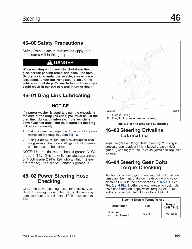
46–00 Safety PrecautionsSaftey Precautions in this section apply to allprocedures within this group.
DANGERWhen working on the vehicle, shut down the en-gine, set the parking brake, and chock the tires.Before working under the vehicle, always placejack stands under the frame rails to ensure thevehicle can not drop. Failure to follow these stepscould result in serious personal injury or death.
46–01 Drag Link Lubricating
NOTICEIf a power washer is used to clean the chassis inthe area of the drag link ends, you must adjust thedrag link lubrication intervals. If the vehicle ispower-washed often, you must lubricate the draglink more frequently.
1. Using a clean rag, wipe the dirt from both greasefittings on the drag link. See Fig. 1.
2. Using a pressure gun, apply multipurpose chas-sis grease at the grease fittings until old greaseis forced out of the socket.
NOTE: Use multipurpose chassis grease NLGIgrade 1 (6% 12-hydroxy lithium stearate grease)or NLGI grade 2 (8% 12-hydroxy lithium stear-ate grease). The grade 2 chassis grease ispreferred.
46–02 Power Steering HoseChecking
Check the power steering hoses for chafing. Also,check for leakage around the fittings. Replace anydamaged hoses, and tighten all fittings to stop leak-age.
46–03 Steering DrivelineLubricating
Wipe the grease fittings clean. See Fig. 2. Using apressure gun, apply a lithium-based grease (NLGIgrade 2) sparingly to the universal joints and slip-jointsplines.
46–04 Steering Gear BoltsTorque Checking
Tighten the steering gear mounting bolt nuts, pitmanarm pinch-bolt nut, and steering driveline end yokepinch-bolt nuts to the specifications in Table 1. SeeFig. 2 and Fig. 3. After the end yoke pinch-bolt nutshave been torqued, apply white Torque Seal F–900to the exposed pinch-bolt thread and locknut.
Steering System Torque Values
Description Size Torque:lbf·ft (N·m)
Pitman ArmPinch-Bolt Hexnut 5/8–11 190 (258)
12
08/21/96 f461098
1. Grease Fitting2. Drag Link (pitman arm end shown)
Fig. 1, Steering Drag Link Lubricating
Steering 46
Walk-In Van Chassis Maintenance Manual, July 2015 46/1
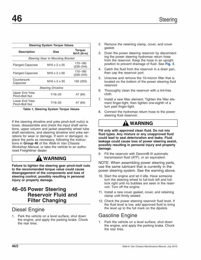
Steering System Torque Values
Description Size Torque:lbf·ft (N·m)
Steering Gear to Mounting Bracket
Flanged Capscrew M16 x 2 x 55 170–180(230–244)
Flanged Capscrew M16 x 2 x 60 170–180(230–244)
CountersunkCapscrew M16 x 2 x 50 150 (203)
Steering Driveline
Upper End YokePinch-Bolt Nut 7/16–20 47 (64)
Lower End YokePinch-Bolt Nut 7/16–20 47 (64)
Table 1, Steering System Torque Values
If the steering driveline end yoke pinch-bolt nut(s) isloose, disassemble and check the input shaft serra-tions, upper column and jacket assembly wheel tubeshaft serrations, and steering driveline end yoke ser-rations for wear or damage. If worn or damaged, re-place the parts as necessary, following the instruc-tions in Group 46 of the Walk-In Van ChassisWorkshop Manual, or take the vehicle to an autho-rized Freightliner dealer.
WARNINGFailure to tighten the steering gear pinch-bolt nutsto the recommended torque value could causedisengagement of the components and loss ofsteering control, possibly resulting in personalinjury or property damage.
46–05 Power SteeringReservoir Fluid andFilter Changing
Diesel Engine1. Park the vehicle on a level surface, shut down
the engine, and apply the parking brake. Chockthe rear tires.
2. Remove the retaining clamp, cover, and covergasket.
3. Drain the power steering reservoir by disconnect-ing the power steering hydromax return hosefrom the reservoir. Keep the hose in an uprightposition to prevent drainage of fluid. See Fig. 4.
4. Catch the fluid from the reservoir in a drain pan,then cap the reservoir port.
5. Unscrew and remove the 10-micron filter that islocated on the bottom of the power steering fluidreservoir.
6. Thoroughly clean the reservoir with a lint-freecloth.
7. Install a new filter element. Tighten the filter ele-ment finger-tight, then tighten one-eighth of aturn past finger-tight.
8. Connect the hydromax return hose to the powersteering fluid reservoir.
WARNINGFill only with approved clean fluid. Do not mixfluid types. Any mixture or any unapproved fluidcould lead to seal deterioration and leaks. Fluidleakage could cause loss of power steering assist,possibly resulting in personal injury and propertydamage.
9. Fill the reservoir with Dexron® III automatictransmission fluid (ATF), or an equivalent.
NOTE: When assembling power steering parts,use the same lubricant that is currently in thepower steering system. See the warning above.
10. Start the engine and let it idle. Have someoneturn the steering wheel to full-lock left and full-lock right until no bubbles are seen in the reser-voir. Turn off the engine.
11. Install a new cover gasket, cover, and retainingclamp until firmly seated.
12. Check the power steering reservoir fluid level. Ifthe fluid level is low, add approved fluid to bringthe level up to the full mark on the dipstick.
Gasoline Engine1. Park the vehicle on a level surface, shut down
the engine, and apply the parking brake. Chockthe rear tires.
Steering46
Walk-In Van Chassis Maintenance Manual, July 201546/2
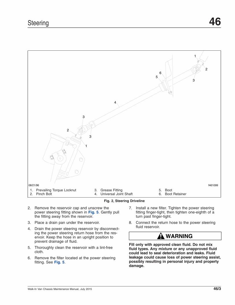
2. Remove the reservoir cap and unscrew thepower steering fitting shown in Fig. 5. Gently pullthe fitting away from the reservoir.
3. Place a drain pan under the reservoir.
4. Drain the power steering reservoir by disconnect-ing the power steering return hose from the res-ervoir. Keep the hose in an upright position toprevent drainage of fluid.
5. Thoroughly clean the reservoir with a lint-freecloth.
6. Remove the filter located at the power steeringfitting. See Fig. 5.
7. Install a new filter. Tighten the power steeringfitting finger-tight, then tighten one-eighth of aturn past finger-tight.
8. Connect the return hose to the power steeringfluid reservoir.
WARNINGFill only with approved clean fluid. Do not mixfluid types. Any mixture or any unapproved fluidcould lead to seal deterioration and leaks. Fluidleakage could cause loss of power steering assist,possibly resulting in personal injury and propertydamage.
08/21/96 f461099
1
2
3
65
4
3
3
2
1
1. Prevailing Torque Locknut2. Pinch Bolt
3. Grease Fitting4. Universal Joint Shaft
5. Boot6. Boot Retainer
Fig. 2, Steering Driveline
Steering 46
Walk-In Van Chassis Maintenance Manual, July 2015 46/3

9. Fill the reservoir with Dexron III automatic trans-mission fluid (ATF), or an equivalent and installthe reservoir cap.
10. Start the engine and let it idle. Have someoneturn the steering wheel to full-lock left and full-lock right until no bubbles are seen in the reser-voir. Turn off the engine.
11. Check the power steering reservoir fluid level. Ifthe fluid level is low, add approved fluid to bringthe level up to the full mark on the dipstick.
1
2
34
5
6
7
8 6
9
09/11/96 f461112
1. Pitman Arm2. Pitman Arm Pinch Bolt3. Pitman Arm Pinch-Bolt Nut4. Steering Gear5. Mounting Bracket
6. Flanged Capscrew, M16 x 2 x 607. Countersunk Capscrew, M16 x 2 x 508. Flanged Capscrew, M16 x 2 x 559. Frame Rail
Fig. 3, Saginaw Model 710 Steering Gear Installation
Steering46
Walk-In Van Chassis Maintenance Manual, July 201546/4

02/22/2005 f462008
1
2
1. Power Steering Fluid Reservoir2. Hydromax Return Hose
Fig. 4, Power Steering Reservoir
1
09/09/2010 f462193
2
1. Power Steering Fitting 2. Reservoir Cap
Fig. 5, Steering Reservoir, Gasoline Engine
Steering 46
Walk-In Van Chassis Maintenance Manual, July 2015 46/5

Title of Maintenance Operation (MOP) MOP Number
CNG Fuel Block Housing Draining . . . . . . . . . . . . . . . . . . . . . . . . . . . . . . . . . . . . . . . . . . . . . . . . . . . . . 47–04
CNG Fuel Leak Test. . . . . . . . . . . . . . . . . . . . . . . . . . . . . . . . . . . . . . . . . . . . . . . . . . . . . . . . . . . . . . . . 47–02
CNG Fuel Tank Visual Inspection . . . . . . . . . . . . . . . . . . . . . . . . . . . . . . . . . . . . . . . . . . . . . . . . . . . . . . 47–07
CNG High-Pressure Fuel Filter Draining . . . . . . . . . . . . . . . . . . . . . . . . . . . . . . . . . . . . . . . . . . . . . . . . . 47–03
CNG High-Pressure Fuel Filter Replacement. . . . . . . . . . . . . . . . . . . . . . . . . . . . . . . . . . . . . . . . . . . . . . 47–01
CNG Low-Pressure Fuel Filter Draining. . . . . . . . . . . . . . . . . . . . . . . . . . . . . . . . . . . . . . . . . . . . . . . . . . 47–06
CNG Low-Pressure Fuel Filter Replacement . . . . . . . . . . . . . . . . . . . . . . . . . . . . . . . . . . . . . . . . . . . . . . 47–05
Diesel Fuel Filter Replacement . . . . . . . . . . . . . . . . . . . . . . . . . . . . . . . . . . . . . . . . . . . . . . . . . . . . . . . . 47–08
Fuel Filter Replacement, Propane Engine . . . . . . . . . . . . . . . . . . . . . . . . . . . . . . . . . . . . . . . . . . . . . . . . 47–12
Fuel Rail Fitting and Injector Inspection, Propane Engine. . . . . . . . . . . . . . . . . . . . . . . . . . . . . . . . . . . . . 47–11
Fuel Tank and Line Inspection, Propane Engine . . . . . . . . . . . . . . . . . . . . . . . . . . . . . . . . . . . . . . . . . . . 47–10
Gasoline Fuel Filter Replacement . . . . . . . . . . . . . . . . . . . . . . . . . . . . . . . . . . . . . . . . . . . . . . . . . . . . . . 47–09
Safety Precautions. . . . . . . . . . . . . . . . . . . . . . . . . . . . . . . . . . . . . . . . . . . . . . . . . . . . . . . . . . . . . . . . . 47–00
Fuel 47Index, Alphabetical
Walk-In Van Chassis Maintenance Manual, July 2015
47–00 Safety PrecautionsSaftey Precautions in this section apply to allprocedures within this group.
DANGERWhen working on the vehicle, shut down the en-gine, set the parking brake, and chock the tires.Before working under the vehicle, always placejack stands under the frame rails to ensure thevehicle can not drop. Failure to follow these stepscould result in serious personal injury or death.
47–01 CNG High-Pressure FuelFilter Replacement
WARNINGCompressed natural gas is highly flammable. Seethe safety precautions listed in Chapter 10 of theWalk-In Van Chassis Operator’s Manual or Group47 of the Walk-In Van Chassis Workshop Manual,or take the vehicle to an authorized Freightlinerdealer. Failure to observe these precautions couldlead to the ignition of the natural gas, which couldcause severe bodily harm, or death, or propertydamage.
The high-pressure fuel filter is located inside of theleft-hand frame rail, near the rear of the fuel tank.
1. Shut off the fuel supply at the tanks.
2. Vent the fuel supply system.
3. After the system has been vented, remove thefilter housing. See Fig. 1.
4. Remove and discard the O-ring used to seal thefilter housing.
5. Remove and discard the filter element.
6. Install the new element and press it into place.
7. Install the new O-ring.
8. Apply a thread lubricant to the housing threads,and screw the filter housing onto the filter head.
9. Check for leaks using a natural gas detector.
10. Tighten the filter housing.
11. Turn the fuel supply back on at the tanks.
47–02 CNG Fuel Leak Test
WARNINGCompressed natural gas is highly flammable. Seethe safety precautions listed in Chapter 10 of theWalk-In Van Chassis Operator’s Manual or Group47 of the Walk-In Van Chassis Workshop Manual,or take the vehicle to an authorized Freightlinerdealer. Failure to observe these precautions couldlead to the ignition of the natural gas, which couldcause severe bodily harm, or death, or propertydamage.
Inspect and test the fuel tanks and the fuel lines. Usea natural gas detector to check for any leaks.
Replace leaking fuel tanks; repair or replace anylines or connections that are leaking. For procedures,see Group 47 of the Walk-In Van Chassis WorkshopManual, or take the vehicle to an authorized Freight-liner dealer.
Safety precautions are listed in Group 47 of theWalk-In Van Chassis Workshop Manual.
47–03 CNG High-Pressure FuelFilter Draining
WARNINGCompressed natural gas is highly flammable. Seethe safety precautions listed in Chapter 10 of theWalk-In Van Chassis Operator’s Manual or Group47 of the Walk-In Van Chassis Workshop Manual,or take the vehicle to an authorized Freightlinerdealer. Failure to observe these precautions couldlead to the ignition of the natural gas, which couldcause severe bodily harm, or death, or propertydamage.
Shut off the fuel supply at the fuel tanks. Vent thesystem.
Drain the fuel filters, which are mounted on the left-hand frame rail of the vehicle near the fuel regulator,by removing the drain nut located at the bottom ofthe housing of each filter.
Perform this maintenance procedure as indicated inthe maintenance interval chart in this manual.
Fuel 47
Walk-In Van Chassis Maintenance Manual, July 2015 47/1

47–04 CNG Fuel Block HousingDraining
WARNINGCompressed natural gas is highly flammable. Seethe safety precautions listed in Chapter 10 of theWalk-In Van Chassis Operator’s Manual or Group47 of the Walk-In Van Chassis Workshop Manual,or take the vehicle to an authorized Freightlinerdealer. Failure to observe these precautions couldlead to the ignition of the natural gas, which couldcause severe bodily harm, or death, or propertydamage.
Shut off the fuel supply at the fuel tanks. Vent thesystem.
Remove the drain nut at the bottom of the engineinternal fuel filter, which is mounted on the left-handside of the engine.
Perform this maintenance procedure as indicated inthe maintenance interval chart in this manual.
See the engine manufacturer’s operation and mainte-nance manual for further information.
47–05 CNG Low-Pressure FuelFilter Replacement
WARNINGCompressed natural gas is highly flammable. Seethe safety precautions listed in Chapter 10 of theWalk-In Van Chassis Operator’s Manual or Group47 of the Walk-In Van Chassis Workshop Manual,or take the vehicle to an authorized Freightlinerdealer. Failure to observe these precautions couldlead to the ignition of the natural gas, which couldcause severe bodily harm, or death, or propertydamage.
The low-pressure fuel filter is located inside of theleft-hand frame rail, near the center of the fuel tank.
Turn the valve counterclockwise to close the filterdrain.
1. Shut off the fuel supply at the tanks.
2. Vent the fuel supply system.
3. After the system has been vented, remove thefilter bowl. See Fig. 2. Using a 26-mm wrench,remove the bowl nut. Then remove the bowl, theelement retainer, and the filter element.
NOTE: Be sure that the O-ring is positionedproperly inside of the filter head.
08/26/96 f470239
1 2 3 4
5
1. Fuel Filter Head2. Filter Element
3. O-Ring4. Filter Housing
5. Filter Drain
Fig. 1, CNG High-Pressure Fuel Filter Assembly
Fuel47
Walk-In Van Chassis Maintenance Manual, July 201547/2
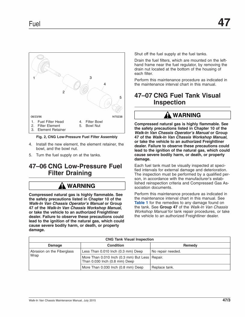
4. Install the new element, the element retainer, thebowl, and the bowl nut.
5. Turn the fuel supply on at the tanks.
47–06 CNG Low-Pressure FuelFilter Draining
WARNINGCompressed natural gas is highly flammable. Seethe safety precautions listed in Chapter 10 of theWalk-In Van Chassis Operator’s Manual or Group47 of the Walk-In Van Chassis Workshop Manual,or take the vehicle to an authorized Freightlinerdealer. Failure to observe these precautions couldlead to the ignition of the natural gas, which couldcause severe bodily harm, or death, or propertydamage.
Shut off the fuel supply at the fuel tanks.
Drain the fuel filters, which are mounted on the left-hand frame near the fuel regulator, by removing thedrain nut located at the bottom of the housing ofeach filter.
Perform this maintenance procedure as indicated inthe maintenance interval chart in this manual.
47–07 CNG Fuel Tank VisualInspection
WARNINGCompressed natural gas is highly flammable. Seethe safety precautions listed in Chapter 10 of theWalk-In Van Chassis Operator’s Manual or Group47 of the Walk-In Van Chassis Workshop Manual,or take the vehicle to an authorized Freightlinerdealer. Failure to observe these precautions couldlead to the ignition of the natural gas, which couldcause severe bodily harm, or death, or propertydamage.
Each fuel tank must be visually inspected at speci-fied intervals for external damage and deterioration.The inspection must be performed by a qualified per-son, in accordance with the manufacturer’s estab-lished reinspection criteria and Compressed Gas As-sociation documents.
Perform this maintenance procedure as indicated inthe maintenance interval chart in this manual. SeeTable 1 for the remedies to any damage found onthe tank. See Group 47 of the Walk-In Van ChassisWorkshop Manual for tank repair procedures, or takethe vehicle to an authorized Freightliner dealer.
CNG Tank Visual Inspection
Damage Condition Remedy
Abrasion on the FiberglassWrap
Less Than 0.010 Inch (0.3 mm) Deep No repair needed.
More Than 0.010 Inch (0.3 mm) But LessThan 0.030 Inch (0.8 mm) Deep
Repair.
More Than 0.030 Inch (0.8 mm) Deep Replace tank.
1
2
3
4
5
08/23/96 f470238
1. Fuel Filter Head2. Filter Element3. Element Retainer
4. Filter Bowl5. Bowl Nut
Fig. 2, CNG Low-Pressure Fuel Filter Assembly
Fuel 47
Walk-In Van Chassis Maintenance Manual, July 2015 47/3

CNG Tank Visual Inspection
Damage Condition Remedy
Cuts in the Fiberglass Wrap Less Than 0.020 Inch (0.5 mm) Deep No repair needed.
More Than 0.020 Inch (0.5 mm) But LessThan 0.030 Inch (0.8 mm) Deep
Repair if less than 8 inches (200 mm) long.
More Than 0.030 Inch (0.8 mm) Deep Replace tank.
Dents on Metal Ends Less Than 0.060 Inch (1.6 mm) Deep No repair needed
More Than 0.060 Inch (1.6 mm) Deep Replace tank.
Gouges on Metal Ends Bare Metal is Exposed Replace tank.
Chipped Paint on Tank Ends No Gray Primer Seen No repair is needed.
Gray Primer Seen, But Not Damaged Repair with two-part epoxy resin.
Gray Primer Damaged Repair. Sand and remove rust, clean with pre-paint solvent, apply cold-galvanizing zinc primerand apply two-part epoxy resin.
Stress Cracks from Acid Cracks in Fiberglass Remove tank for inspection if exposed to acid.Replace if cracks are seen. Replace strapgaskets if exposed to acid.
Strap Gaskets Gaskets Damaged or Missing Approved gaskets must be installed betweenstrap and tank. Replace strap gaskets ifexposed to acid.
Tank Shield Shield is Damaged Repair or replace shield.
Tank Is Old Tank is 15 Years Old Replace tank after 15 years from date on label.
Vehicle Was in Accident orFire
Tank Was Hot or Damaged From Impact. Replace tank or remove tank and test.
Table 1, CNG Tank Visual Inspection
47–08 Diesel Fuel FilterReplacement
Davco Fuel Pro® 382 Fuel/WaterSeparator Filter ReplacementReplace the fuel/water separator element only whenthe filter element is completely covered.
WARNINGDiesel fuel is flammable and can ignite if exposedto an open flame, intense heat, or other ignitionsource. Do not drain fuel near, or expose fuelvapor to open flame or intense heat. Exposure toopen flame or intense heat could start a fire, pos-sibly resulting in personal injury or property dam-age. When working on a fuel system, have a fireextinguisher within easy reach.
1. Place a suitable drain pan under the fuel/waterseparator and open the drain valve. Drainenough fuel to empty the filter, then close thedrain valve. See Fig. 3.
2. Using Davco wrench 380134 or 382002, removethe filter collar. Then remove the filter cover.
3. Remove the element and dispose of it properly.
4. Install a new element. Make sure the grommet isin place on the filter stud.
5. Install a new cover seal on the filter cover.
6. Using the collar, attach the filter cover with thespring to the base.
IMPORTANT: Tighten the collar by hand only.
7. Remove the filter vent. Then fill the fuel/waterseparator with fuel until the fuel level is 1 inch(2.5 cm) above the collar.
8. Install the filter vent on the fuel/water separator.
Fuel47
Walk-In Van Chassis Maintenance Manual, July 201547/4
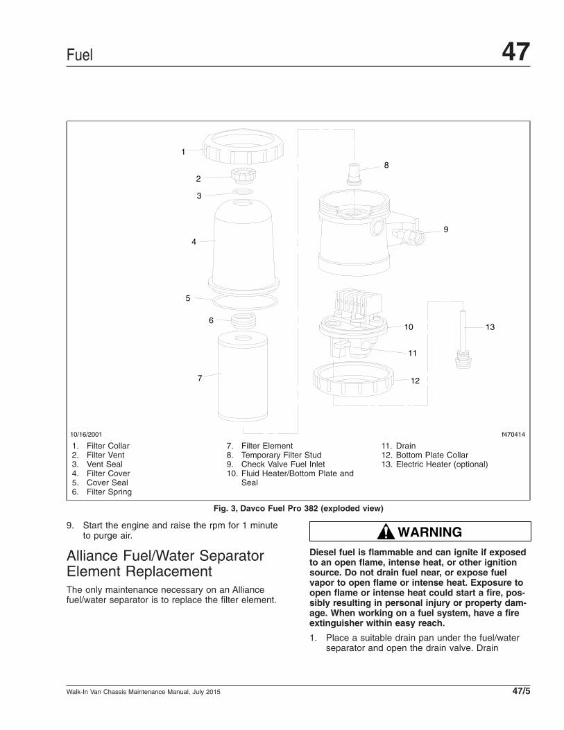
9. Start the engine and raise the rpm for 1 minuteto purge air.
Alliance Fuel/Water SeparatorElement ReplacementThe only maintenance necessary on an Alliancefuel/water separator is to replace the filter element.
WARNINGDiesel fuel is flammable and can ignite if exposedto an open flame, intense heat, or other ignitionsource. Do not drain fuel near, or expose fuelvapor to open flame or intense heat. Exposure toopen flame or intense heat could start a fire, pos-sibly resulting in personal injury or property dam-age. When working on a fuel system, have a fireextinguisher within easy reach.
1. Place a suitable drain pan under the fuel/waterseparator and open the drain valve. Drain
f470414
1
2
4
6
7
5
8
10
12
10/16/2001
9
13
11
3
1. Filter Collar2. Filter Vent3. Vent Seal4. Filter Cover5. Cover Seal6. Filter Spring
7. Filter Element8. Temporary Filter Stud9. Check Valve Fuel Inlet10. Fluid Heater/Bottom Plate and
Seal
11. Drain12. Bottom Plate Collar13. Electric Heater (optional)
Fig. 3, Davco Fuel Pro 382 (exploded view)
Fuel 47
Walk-In Van Chassis Maintenance Manual, July 2015 47/5

enough fuel to empty the filter, then close thedrain valve. See Fig. 4.
2. Disconnect the water sensor and heater connec-tions if equipped.
3. Remove the element and bowl together by turn-ing counterclockwise.
4. Remove the bowl from the element and cleanthe O-ring gland.
5. Apply a coating of clean fuel or motor oil to thenew O-ring and element seal.
6. Spin the bowl onto the new element, then spinthem both onto the filter head snugly by handonly.
IMPORTANT: Do not use tools to tighten thebowl and element.
7. Connect the water sensor and heater connectorsif equipped.
8. Start the engine and check for fuel leaks.
9. Shut down the engine and correct any fuel leaks.
47–09 Gasoline Fuel FilterReplacement
The gasoline fuel filter is installed inside the fueltank. It is recommended that the fuel filter bechanged every five years or 150,000 miles (241 350km), whichever comes first.
47–10 Fuel Tank and LineInspection, PropaneEngine
1. Inspect the tank and fuel lines for damage.
2. Inspect the brackets and fasteners to make surethe tank is securely fastened.
3. Ensure that all service valves and/or shut-offvales work properly.
4. Make certain the pressure relief valve vent isclear of any obstructions. If equipped with a dustcap, ensure that it is securely in place.
5. Use an electronic leak detector or a liquid-leakdetection solution to check the tank fittings, con-nections, and fuel lines for leaks.
6. Check the solenoid wiring and connectors, mak-ing certain they are securely attached andlocked.
47–11 Fuel Rail Fitting andInjector Inspection,Propane Engine
WARNINGLiquid propane can cause serious burns should itcontact the skin or eyes. When handling propane,always wear protective gloves and eye protectionto prevent contact.
Propane is extremely flammable, and can ignite ifan ignition source is present, causing burns andother serious injuries. Keep sparks and flames
4
21
05/06/2005 f470486
5
6
3
9
8
7
1. Fuel Outlet2. Fuel Inlet3. Filter Element4. Bowl O-ring5. Bowl Probe Plug
6. Water Sensor Probe7. Heater Connector8. Drain Plug9. Sight Bowl
Fig. 4, Alliance Fuel/Water Separator
Fuel47
Walk-In Van Chassis Maintenance Manual, July 201547/6

away from propane. Do not smoke near propaneor when refueling the vehicle.
The propane fuel system requires special tools tomake repairs. Service and repair of the propanefuel system should only be performed by trainedpropane service technicians. To prevent personalinjury or damage to the fuel system, do not at-tempt repairs yourself.
See the safety precautions listed in Chapter 17 ofthe Walk-In Van Operator’s Manual, or take thevehicle to an authorized Freightliner dealer. Failureto observe these precautions could lead to theignition of the liquid propane, which could causeproperty damage, severe bodily harm, or death.
NOTE: The fuel rails and injectors do not re-quire any adjustments.
1. Make certain that all electrical connections areconnected and locked.
2. Make certain the fuel rail is securely attached tothe engine.
3. Use an electronic leak detector or a liquid-leakdetection solution to check all injectors, rails, andfittings for fuel leaks.
47–12 Fuel Filter Replacement,Propane Engine
WARNINGLiquid propane can cause serious burns should itcontact the skin or eyes. When handling propane,always wear protective gloves and eye protectionto prevent contact.
Propane is extremely flammable, and can ignite ifan ignition source is present, causing burns andother serious injuries. Keep sparks and flamesaway from propane. Do not smoke near propaneor when refueling the vehicle.
The propane fuel system requires special tools tomake repairs. Service and repair of the propanefuel system should only be performed by trainedpropane service technicians. To prevent personalinjury or damage to the fuel system, do not at-tempt repairs yourself.
See the safety precautions listed in Chapter 17 ofthe Walk-In Van Operator’s Manual, or take the
vehicle to an authorized Freightliner dealer. Failureto observe these precautions could lead to theignition of the liquid propane, which could causeproperty damage, severe bodily harm, or death.
The propane system is equipped with two filters—one before the fuel enters the tank, and another be-fore it enters the engine. The replacement procedurethat follows applies to both filters. See Fig. 5.
NOTICEDamage may occur to the valve(s) if they are over-tightened.
1. Turn the fuel supply and return valves clockwiseto shut them off at the tank.
NOTE: Both the fuel supply and return linesmust be vented to ensure all pressure is re-moved from the fuel rails and lines.
WARNINGVenting the fuel supply and return lines must beperformed outside. Do not release propane insidea garage or building. Failure to do so could causeserious bodily injury or death.
2. Vent the system outside in an open area. Slowlycrack open the fuel supply and return lines thatare connected to the supply and return valvesuntil a white mist appears. Continue cracking thelines open until there is absolutely no pressure.
Once the system is vented, push the vehicle intothe shop.
3. Disconnect the fuel supply and return lines fromthe valves until all service work is finished.
4. Cover the open lines to prevent contaminantsfrom entering the system.
5. Remove and discard the filter.
6. Install the new filter, making certain the arrow onthe filter points toward the tank or engine as ap-plicable.
7. Remove the protective cover from the fuel lines.
8. Connect both ends of the filter to the fuel lineand tighten 28±10 lbf·ft (38±14 N·m).
9. Connect the fuel lines to their designated supplyand return valve. Tighten the fuel line flare nuts13 lbf·ft (18 N·m).
Fuel 47
Walk-In Van Chassis Maintenance Manual, July 2015 47/7

NOTICEDamage may occur to the valve(s) if they are over-tightened.
10. Turn the fuel supply and return valves counter-clockwise, then start the vehicle in order tocharge the fuel lines with propane.
11. Check for leaks using an electronic leak detectoror a liquid-leak detection solution.
07/22/2014 f611242
10
2
3 4
5
6
7 8
9
2
1
1. Fill Valve2. Fuel Filter3. Electrical Pass-Through4. Solenoid Valve, Supply
5. Return Shutoff Valve6. Bleeder Valve7. 80% Fill-Stop
8. Service Valve9. Pressure Relief Valve10. Propane Tank
Fig. 5, Propane Tank Assembly
Fuel47
Walk-In Van Chassis Maintenance Manual, July 201547/8
Title of Maintenance Operation (MOP) MOP Number
Exhaust System Inspecting (Noise Emission Control). . . . . . . . . . . . . . . . . . . . . . . . . . . . . . . . . . . . . . . . 49–01
Safety Precautions. . . . . . . . . . . . . . . . . . . . . . . . . . . . . . . . . . . . . . . . . . . . . . . . . . . . . . . . . . . . . . . . . 49–00
Exhaust 49Index, Alphabetical
Walk-In Van Chassis Maintenance Manual, November 2015

49–00 Safety PrecautionsSaftey Precautions in this section apply to allprocedures within this group.
DANGERWhen working on the vehicle, shut down the en-gine, set the parking brake, and chock the tires.Before working under the vehicle, always placejack stands under the frame rails to ensure thevehicle can not drop. Failure to follow these stepscould result in serious personal injury or death.
49–01 Exhaust SystemInspecting (NoiseEmission Control)
The exhaust system must be free of leaks, binding,grounding, and excessive vibrations. In addition toinspecting the exhaust system at the scheduledmaintenance interval, inspect the exhaust system ifthe noise level of the vehicle has increased. Replaceparts that show leakage, wear, or damage, withgenuine Freightliner parts.
These conditions are usually caused by loose, bro-ken, or misaligned clamps, brackets, or pipes. If anyof these conditions exist, check the exhaust systemcomponents and alignment. Align or replace as nec-essary. For alignment or adjustment instructions, seeGroup 49 of the Walk-In Van Chassis WorkshopManual, or take the vehicle to an authorized Freight-liner dealer.
EPA10 and Newer ExhaustSystemDefinitions of AftertreatmentSystem (ATS) TermsRefer to the following list of definitions of ATS termsand components.
• Aftertreatment System (ATS)—the entire ex-haust system from the turbocharger to the tailpipe, including the Selective Catalytic Reduction(SCR) components.
• Aftertreatment Device (ATD)—a device that re-moves pollutants from exhaust gas after the gasleaves the combustion chamber.
• BlueTec®—Daimler’s proprietary SCR technol-ogy.
• Diesel Oxidation Catalyst (DOC)—a flow-through device that enhances the oxidation ofhydrocarbons in the ATD.
• Diesel Particulate Filter (DPF)—a component inthe ATD that traps particulate matter from theexhaust gas.
• Diesel Exhaust Fluid (DEF)—the chemical agentthat reacts with the exhaust gases in the SCRto reduce NOx.
• DEF Pump—filters and supplies DEF to theDEF metering unit.
• DEF Tank—holds DEF and regulates its tem-perature.
• DEF Metering Unit—mixes DEF with com-pressed air, and meters this mixture into theexhaust flow via an injection nozzle.
• SCR Catalyst—the housing containing a treatedceramic flow-through block where the DEF andexhaust gases undergo selective catalytic re-duction.
• Selective Catalytic Reduction (SCR)—a processused to reduce NOx emissions.
InspectionIMPORTANT: The Environmental ProtectionAgency’s 2010 regulations mandate loweredexhaust emissions, thus requiring exhaust sys-tem components that reduce emissions. In par-ticular the aftertreatment device (ATD), which ispart of the aftertreatment system (ATS), requiresspecial attention during regularly scheduledmaintenance inspections. See Fig. 1 for Cum-mins ATD sensor locations. The side-by-sidemounting is shown, however, left inline and topside-by-side mountings are possible dependingon the chassis design. If any discrepancies arediscovered, refer to the engine manufacturer’sservice literature for repair instructions.
1. Check for leakage at the clamp that attaches theexhaust pipe to the turbocharger exhaust outlet.If leakage exists, tighten the nut on the clamp to
Exhaust 49
Walk-In Van Chassis Maintenance Manual, November 2015 49/1

the required torque. If leakage persists, install anew clamp.
2. Check the exhaust pipe, bellows, and each ex-haust seal clamp for leakage, wear, cracks, ordamage. Replace damaged components asneeded. If leakage exists at a clamp, tighten thenuts to the required torque. If leakage persists,install a new exhaust seal clamp. Do not reuseseal clamps. Once a seal clamp is loosened orremoved, it must be replaced.
3. If present, check the condition of the insulationmaterial around the exhaust pipe between theturbocharger and the ATD.
4. Check the ATD mounting bands for tightness.Tighten to 30 lbf·ft (41 N·m) if needed. Do notovertighten.
5. Check for leaks around the clamps that attachthe ATD in the ATS, and around the clamps thatretain the DPF in the ATD. No leaks are allowedanywhere in the system.
10/20/2009 f490387
12
3
4
56
1. SCR Inlet Temperature Sensor2. SCR Outlet Temperature Sensor3. SCR Outlet NOx Sensor
4. DPF Outlet Temperature Sensor5. DPF Catalyst Outlet Temperature Sensor6. DPF Outlet Temperature Sensor
Fig. 1, Cummins ATD Sensor Locations, Side-by-Side Mounting
Exhaust49
Walk-In Van Chassis Maintenance Manual, November 201549/2
6. Check all sensors attached to the ATD for leaksor damaged wires. No leaks are allowed.
7. Check the DPF exterior surface for dents orother damage. A dent over 3 inches (76 mm) indiameter and 1/4-inch (6-mm) deep could causeinternal damage to the DPF, causing it to mal-function.
8. Check the SCR catalyst for dents and otherdamage.
9. Check for heat discoloration on the surface ofthe ATD. Heat discoloration may indicate internaldamage; especially around the DPF.
NOTE: Diesel exhaust fluid creeps, causingwhite crystals to form around the line fittings.The presence of crystals does not mean thesystem has a leak. Replacing fittings or trouble-shooting components is not necessary unlessthere is a system failure or a fault code.
10. Check the DEF tank, pump, metering unit, andlines for leaks. See Group 49 of the Walk-In VanChassis Workshop Manual for repair procedures.
11. Check any wires, lines, or hoses within 4 inches(10 cm) of the exhaust system for heat damage.Repair or reroute as needed.
Diesel Exhaust Fluid (DEF) FilterReplacementThe Environmental Protection Agency’s 2010 regula-tions require lower nitrogen oxide (NOx) exhaustemissions. Selective catalytic reduction (SCR) usesdiesel exhaust fluid (DEF) to lower NOx emissions inthe vehicle exhaust. A filter in the DEF pump pre-vents clogging of the DEF metering unit injectionnozzle.
See the engine manufacturer’s maintenance manualfor DEF filter replacement instructions and mainte-nance intervals.
EPA07 Exhaust SystemInspectingDefinitions of ATS ComponentsRefer to the following list of definitions of ATS com-ponents.
• Aftertreatment System (ATS)—the entire ex-haust system from the turbocharger to the ex-haust stack or tail pipe.
• Aftertreatment Device (ATD)—a muffler-like can-ister that houses a DPF and sensors.
• Diesel Particulate Filter (DPF)—a filter that col-lects and holds particulate matter (soot andash).
• Diesel Oxidation Catalyst (DOC)—oxidizes hy-drocarbons and reduces NOx.
• Sensors—detect temperatures and pressurewithin the ATS.
• Diffuser—a device, used as a deflector, for dis-tributing, mixing, and reducing the velocity of airflow.
IMPORTANT: The Environmental ProtectionAgency’s 2007 regulations require lower ex-haust emissions, thus requiring new exhaustsystem components. See Fig. 2. In particularthe aftertreatment device (ATD), which is part ofthe aftertreatment system (ATS), requires spe-cial attention during regularly scheduled mainte-nance inspections. If any discrepancies are dis-covered, refer to the engine manufacturer’sservice literature for repair instructions.
Inspection1. Check for leakage at the clamp that attaches the
exhaust pipe to the turbocharger exhaust outlet.If leakage exists, tighten the nut on the clamp tothe required torque. If leakage persists, install anew clamp.
2. Check the exhaust pipe, bellows, and each ex-haust seal clamp for leakage, wear, cracks, ordamage. Replace damaged components asneeded. If leakage exists at a clamp, tighten thenuts to the required torque. If leakage persists,install a new exhaust seal clamp. Do not reuseseal clamps. Once a seal clamp is loosened orremoved, it must be replaced.
3. If present, check the condition of the insulationmaterial around the exhaust pipe between theturbocharger and the ATD.
4. Check the ATD mounting bands for tightness.Tighten to 30 lbf·ft (41 N·m) if needed. Do notovertighten.
Exhaust 49
Walk-In Van Chassis Maintenance Manual, November 2015 49/3

5. Check for leaks around all clamps that attach theATD in the ATS, and around the clamps that re-tain the DPF in the ATD. No leaks are allowedanywhere in the system.
6. Check all sensors attached to the ATD for leaksor damaged wires.
7. Check the DPF exterior surface for dents orother damage. See Fig. 2, Reference A. A dentover 3 inches (76 mm) in diameter and 1/4-inch
(6-mm) deep could cause internal damage to theDPF, causing it to malfunction.
8. Check for heat discoloration on the surface ofthe ATD. Heat discoloration may indicate internaldamage; especially around the DPF.
9. Check any wires, lines, or hoses within 4 inches(10 cm) of the exhaust system for heat damage.Repair or reroute as needed.
11/2/2006 f490284
A
1
23
4
67
8
9
4
4
B5
C
A. Inspect this area of the canister for dents.B. DOC Area
C. DPF Area
1. Inlet Temperature Sensor2. Marmon Fitting at Inlet from Turbocharger3. Sensor Housing4. DPF V-Band Mounting Clamps5. Inlet Temperature Sensor
6. Exhaust Outlet to Diffuser7. Outlet Temperature Sensor8. DPF Outlet Pressure Sensor9. DPF Intake Pressure Sensor
Fig. 2, Cummins Aftertreatment Device
Exhaust49
Walk-In Van Chassis Maintenance Manual, November 201549/4

Title of Maintenance Operation (MOP) MOP Number
Battery Voltage Checking . . . . . . . . . . . . . . . . . . . . . . . . . . . . . . . . . . . . . . . . . . . . . . . . . . . . . . . . . . . . 54–05
Battery, Battery Box, and Cable Checking and Cleaning . . . . . . . . . . . . . . . . . . . . . . . . . . . . . . . . . . . . . 54–02
Electrical System Checking. . . . . . . . . . . . . . . . . . . . . . . . . . . . . . . . . . . . . . . . . . . . . . . . . . . . . . . . . . . 54–04
Ground Cables Checking and Cleaning. . . . . . . . . . . . . . . . . . . . . . . . . . . . . . . . . . . . . . . . . . . . . . . . . . 54–03
Lighting System Checking. . . . . . . . . . . . . . . . . . . . . . . . . . . . . . . . . . . . . . . . . . . . . . . . . . . . . . . . . . . . 54–01
Safety Precautions. . . . . . . . . . . . . . . . . . . . . . . . . . . . . . . . . . . . . . . . . . . . . . . . . . . . . . . . . . . . . . . . . 54–00
Electrical, Instruments, and Controls 54Index, Alphabetical
Walk-In Van Chassis Maintenance Manual, July 2015

54–00 Safety PrecautionsSaftey Precautions in this section apply to allprocedures within this group.
DANGERWhen working on the vehicle, shut down the en-gine, set the parking brake, and chock the tires.Before working under the vehicle, always placejack stands under the frame rails to ensure thevehicle can not drop. Failure to follow these stepscould result in serious personal injury or death.
54–01 Lighting SystemChecking
Check all lighting units and wiring for loose connec-tions, corrosion, poor grounds, loose mountings, andpinched or damaged wires; repair or replace asneeded.
54–02 Battery, Battery Box,and Cable Checking andCleaning
WARNINGBatteries generate explosive gas as a by-productof their chemical process. Do not smoke whenworking around batteries. Put out all flames andremove any source of sparks or intense heat inthe vicinity of the battery compartment. Make surethe battery compartment has been completelyvented before disconnecting or connecting thebattery cables.
Battery acid is extremely harmful if splashed inthe eyes or on the skin. Always wear a face shieldand protective clothing when working aroundbatteries.
1. Remove any corrosion from the battery box andthe top of the battery. See Fig. 1.
Use distilled ammonia or a soda solution to neu-tralize any acid present. Flush off the ammoniaor soda solution with clear water.
2. Check the battery cases for cracks. Replace abattery if its case is cracked.
3. Disconnect the battery cables from the batteryposts, and check for corrosion.
If corrosion is found, clean the terminals andposts, using a wire brush and a solution of bak-ing soda and water. Use the solution sparingly.
4. Connect the cables to the batteries, and tightenthem 10 to 15 lbf·ft (14 to 20 N·m). Spray eachconnection terminal with dielectric red enamel.
5. Check the battery-to-starter cables. Look forkinking, corrosion, breaks in the insulation, andheat damage. Check that the cable clamps arenot bent, damaged, or stripped of insulation.
IMPORTANT: If a battery cable is damaged, re-place the entire cable. Never splice a batterycable.
6. Check the mounting fasteners for tightness, andtighten them 60 lbf·ft (81 N·m) if necessary. Thebattery box must be kept in good condition tosupport the batteries securely and to keep themlevel.
f545165
1
2
3
11/02/2007
1. Negative Terminal2. Positive Terminal
3. Clamp Assembly
Fig. 1, Battery Box
Electrical, Instruments, and Controls 54
Walk-In Van Chassis Maintenance Manual, July 2015 54/1

NOTICEFailure to keep the batteries held securely in placecould result in battery damage, such as looseplates or posts.
54–03 Ground CablesChecking and Cleaning
Check that the ground cables are clean, undamaged,and tight. If needed, disconnect them, clean the mat-ing surfaces with a soda solution, then connect themsecurely. Protect the ground cable connections withdielectric red enamel.
54–04 Electrical SystemChecking
Dash1. Uncover the electrical power center and remove
the fasteners. See Fig. 2.
2. Check the wiring harness for movement thatcould strain the electrical connections. Installmore clamps on the harness, if needed.
3. Check all the wiring for chafing, kinks, and dis-colored insulation. Find the cause of any prob-
lems, then repair, replace, or reroute the wires,as needed.
4. Check that all the relays are firmly seated in theirmounting plates.
5. Remove the instrument and control panels andcheck all the wiring behind them for kinks, chaf-ing, heat damage, and discolored insulation. Re-route, repair, or replace the wires as needed.
6. Check the tightness of all the electrical connec-tions behind the panels. Make sure that all maleand female connectors are firmly connected, andcheck the tightness of the nuts on the ring con-nectors. Tighten them 30 lbf·in (339 N·cm).
7. Test the electric horn. If it is not fully operational,use the schematics and troubleshooting informa-tion in Section 54.00 and Section 54.05 of theWalk-In Van Chassis Workshop Manual to iden-tify and repair any problems.
Chassis1. Check the main wiring harness. Check the wiring
insulation for damage from chafing or heat. Alsocheck for kinks. Reroute, repair, or replace thewires as needed.
2. Check all the tie straps for breakage or damage.Replace any broken or cracked tie straps.
NOTICEDo not use flat-strip aluminum tie straps for hold-ing electrical wiring. The sharp edges on these tiestraps may cause breaks in the wire insulation,allowing the aluminum tie strap to make contactwith the wire. This could cause a short circuit anddamage to the wiring.
3. Check all clamps, plastic connectors, and grom-mets. Replace any that are damaged. Make sureall grommets are fully seated.
4. Check the battery cable connections on thestarter for tightness. Make sure they are free ofcorrosion. Add dielectric grease as needed.
5. Check the magnetic switch terminals and con-nections for tightness. Protect the magneticswitch terminals with dielectric red enamel asneeded.
6. Check the wires of all sensors mounted on ornear the engine. Make sure no wires are closer
f545166
1
11/02/2007
1. Fuse, Relay, and Circuit Breaker
Fig. 2, Electrical Power Center
Electrical, Instruments, and Controls54
Walk-In Van Chassis Maintenance Manual, July 201554/2

than 6 inches (15 cm) to hot surfaces. If any are,and they cannot be rerouted, make sure they areprotected by heat shields. Check the sensor con-nectors. Make sure they are tight, clean, and un-damaged.
54–05 Battery VoltageChecking
Check the battery open circuit voltage using an accu-rate voltmeter. If the voltmeter registers 12.5V orbelow, fully charge the battery to 12.65V. A fullycharged battery will have a voltage of 12.65V withthe charger disconnected.
Electrical, Instruments, and Controls 54
Walk-In Van Chassis Maintenance Manual, July 2015 54/3