Embed Size (px)
Citation preview

Walk-In Cooler & Freezer Installation/Maintenance & Owner’s InstructionsFor All W. A. Brown & Son, Inc. Models
W.A. Brown & Son, Inc.209 Long Meadow Drive • Salisbury, NC 28147
Phone: 704-636-5131 • Fax: 704-637-0919Website: www.wabrown.com

Table of ContentsPage No.
Cam Lock Installation ............................................................................3Door Section Maintenance ............................................................17-19Drop Off (factory assembled) Walk-Ins................................................11Duro-Last Roof Cap Installation ............................................................8EZ Pack Refrigeration Installation ......................................................12Fiber Cement Panel Installation ............................................................9Final Check List & Cleaning ................................................................12Floor Preparation & Installation ............................................................2Treadplate Overlay ................................................................................2Floorless Walk-In Layout & Installation..................................................3How to Call for Service ........................................................................15Membrane Roof Cap for Outdoor Units ............................................7-8Multiple Compartment Installation ......................................................6-7Quick Set Roof Cap & Curb Installation ..............................................13Replacing a Pressure Relief Port ........................................................22Receiving and Uncrating........................................................................1Replacing Door Gasket........................................................................20Replacing Door Heater Cable..............................................................19Replacing the Digital Thermometer ....................................................22Replacement Parts Ordering ..............................................................15Terminology............................................................................................1Top Panel Installation ......................................................................6, 10Trouble Shooting Guide ......................................................................26Wall Panel Installation............................................................................5Wainscotting Installation ........................................................................5Warranty ..............................................................................................16What to do when there is Freight Damage............................................1Wind or Seismic Load Installation ........................................................4Wiring Diagrams ............................................................................23-25TAI200D Alarm ....................................................................................27
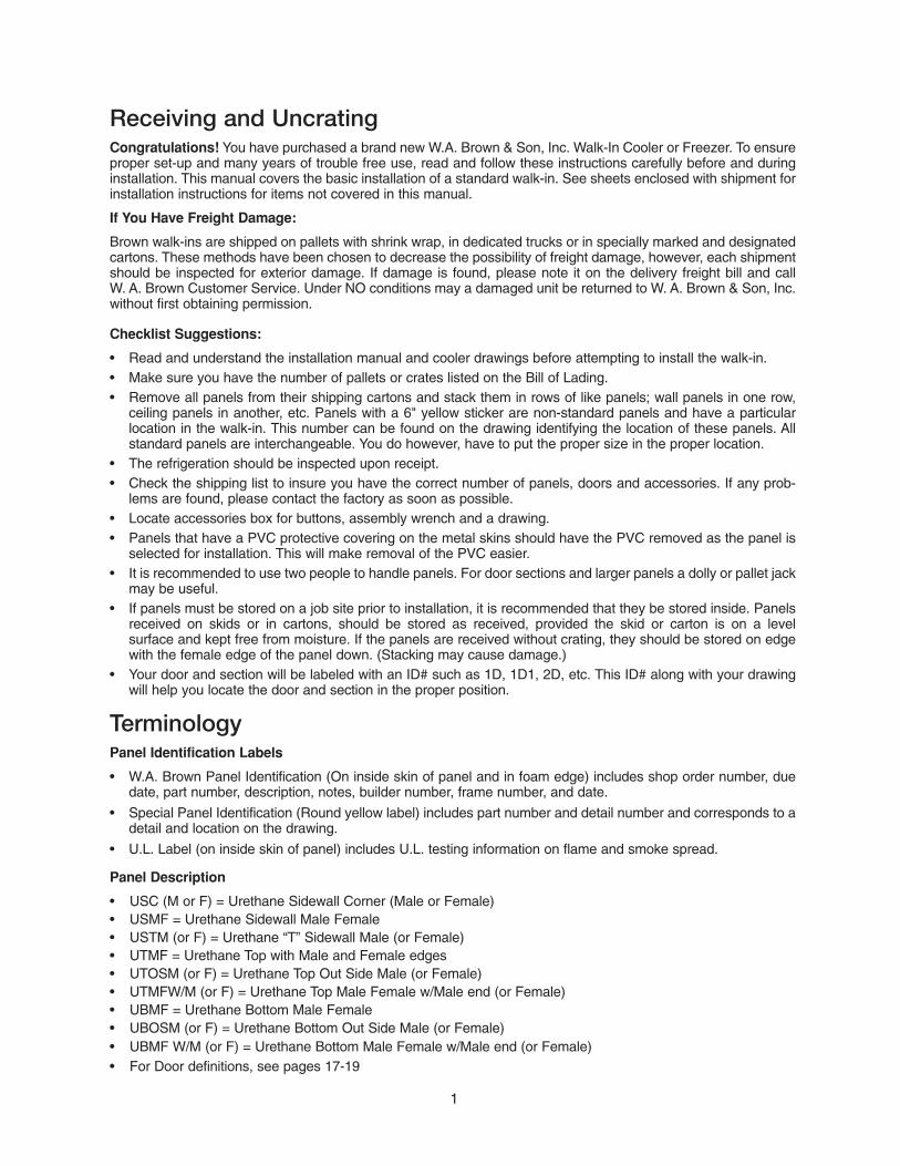
Receiving and UncratingCongratulations! You have purchased a brand new W.A. Brown & Son, Inc. Walk-In Cooler or Freezer. To ensureproper set-up and many years of trouble free use, read and follow these instructions carefully before and duringinstallation. This manual covers the basic installation of a standard walk-in. See sheets enclosed with shipment forinstallation instructions for items not covered in this manual.
If You Have Freight Damage:
Brown walk-ins are shipped on pallets with shrink wrap, in dedicated trucks or in specially marked and designatedcartons. These methods have been chosen to decrease the possibility of freight damage, however, each shipmentshould be inspected for exterior damage. If damage is found, please note it on the delivery freight bill and call W. A. Brown Customer Service. Under NO conditions may a damaged unit be returned to W. A. Brown & Son, Inc.without first obtaining permission.
Checklist Suggestions:
• Read and understand the installation manual and cooler drawings before attempting to install the walk-in.• Make sure you have the number of pallets or crates listed on the Bill of Lading.• Remove all panels from their shipping cartons and stack them in rows of like panels; wall panels in one row,
ceiling panels in another, etc. Panels with a 6" yellow sticker are non-standard panels and have a particular location in the walk-in. This number can be found on the drawing identifying the location of these panels. All standard panels are interchangeable. You do however, have to put the proper size in the proper location.
• The refrigeration should be inspected upon receipt.• Check the shipping list to insure you have the correct number of panels, doors and accessories. If any prob-
lems are found, please contact the factory as soon as possible.• Locate accessories box for buttons, assembly wrench and a drawing.• Panels that have a PVC protective covering on the metal skins should have the PVC removed as the panel is
selected for installation. This will make removal of the PVC easier.• It is recommended to use two people to handle panels. For door sections and larger panels a dolly or pallet jack
may be useful.• If panels must be stored on a job site prior to installation, it is recommended that they be stored inside. Panels
received on skids or in cartons, should be stored as received, provided the skid or carton is on a level surface and kept free from moisture. If the panels are received without crating, they should be stored on edgewith the female edge of the panel down. (Stacking may cause damage.)
• Your door and section will be labeled with an ID# such as 1D, 1D1, 2D, etc. This ID# along with your drawingwill help you locate the door and section in the proper position.
TerminologyPanel Identification Labels
• W.A. Brown Panel Identification (On inside skin of panel and in foam edge) includes shop order number, duedate, part number, description, notes, builder number, frame number, and date.
• Special Panel Identification (Round yellow label) includes part number and detail number and corresponds to adetail and location on the drawing.
• U.L. Label (on inside skin of panel) includes U.L. testing information on flame and smoke spread.
Panel Description
• USC (M or F) = Urethane Sidewall Corner (Male or Female)• USMF = Urethane Sidewall Male Female• USTM (or F) = Urethane “T” Sidewall Male (or Female)• UTMF = Urethane Top with Male and Female edges• UTOSM (or F) = Urethane Top Out Side Male (or Female)• UTMFW/M (or F) = Urethane Top Male Female w/Male end (or Female)• UBMF = Urethane Bottom Male Female• UBOSM (or F) = Urethane Bottom Out Side Male (or Female)• UBMF W/M (or F) = Urethane Bottom Male Female w/Male end (or Female)• For Door definitions, see pages 17-19
1
Floor Preparation and InstallationInstallation instructions are provided for walk-ins with insulated floor panels or walk-ins set on spline. Instructionsare also provided for the application of walk-ins in areas requiring adherence to wind or seismic loads.
Warning! A level walk-in is essential. If the floor is not level, the verticalpanels will not be plumb and the hinged door will not operate properly and panels will not seal properly.
Layout of the Floor
Check the floor plan of the walk-in for the exact location of the floor panels as indicated on the floor panel layout drawing which is furnished with each walk-in. The building area on which the walk-in is to be erected should be chalked to the base of the box. If the walk-in is to be erected next to an existing wall a 2" clearance should be allowed for surface irregularity. Set-up ‘Builders Level’ per instructions. Take readings at selected intervals on a story pole to determine the highest point of floor assembly. Mark the high point and shim to this level.
Shims of 24 to 12 gauge sheet metal or cedar wood are recommended. Shims should be cut a minimum 4" x 4". Shims must extend under the whole section, not just the edges. Shims should be at each end, at all wall seams and at each floor seam. All shims should be no further than 12" apart. Shimming will reduce load limits. Shims are not supplied with shipment. An alternate method of leveling is to level the unit by filling in with a level bed ofsand. Cover the sand with a poly film or asphalt paper before installing the floor. See Figure #1.
Installation of floor panels
Installation of the floor may begin when the floor leveling is complete. Refer to the floor panel layout drawing which hasbeen furnished with the walk-in. Begin installing the floor with an end panel. Continue until all panels are set and arelevel. Engage all cam locks as the panels are installed. Recheck levelness of the floor panels after all are complete.
Warning! Position the floor panels per the drawing to ensure that the doorwill be properly placed. In multiple compartment walk-ins with a partition section, it is imperative that the panels be located in proper position and turnedcorrectly so that walls and tops will lock securely.
Warning! Attention Floor Contractors: Some chemicals and vapors in fieldapplied floor materials can cause metal corrosion. Use extreme care to keepthese materials off of metal surfaces and to keep doors open fully and the cooler ventilated until inside flooring is cured.
Diamond Aluminum Treadplate Overlay InstructionsAll treadplate material will be cut to size, to match the entire interior surface less 1/2" on all four sides.
1. Clean and dry subsurface2. Apply silicone to underside of treadplate3. Begin laying first row of Treadplate Overlay 1/2" away from the edge of the floor according to the Drawing and
secure the subsurface with sheet metal screw/anchor.4. All sheets must be flush as possible with one another.5. All sheets can be secured using a sheet metal screw every 24".6. Continue to follow the layout of treadplate according to the drawing until all sheets are flush and secure to the
subsurface.7. Caulk all seams and edges of treadplate layout.8. Allow 1-3 hours to dry before resuming use of walk-in.
Shim
Level
Level
2
Figure #1
U = UrethaneB = BottomO = OutS = SideM = MaleF = Female

3
Floorless Walk-In LayoutFloor Spline Layout and Installation
Warning! When W. A. Brown does not provide the insulated floor, checkcarefully before installing the walk-in for appropriate thermal breaks. Severefloor heaving problems occur when floors are not adequately insulated. Consultthe W. A. Brown Working Data Catalog for details.
1. Mark on the building floor the exact area the walk-in will occupy.2. Lay the spline out as indicated on the spline layout drawing (See Figure #2) which is furnished with each walk-
in. Each section is numbered and must be layed out as shown in order for the wall panels to lock down properly. Measure diagonally from corner to corner to be sure the floor spline is square.
3. The entire floor spline must be leveled from the highest point.
Warning! On walk-ins larger than 10' x 10' it is recommended that a transit level be used to level the floor spline rather than a spirit level.
4. Determine where shims are needed for leveling, and cut them to the width of the spline. (W. A. Brown does not furnish these shims.)
5. Fasten the spline to the floor using ramset studs, screws, expansion bolts, etc. (See Figure #3)
6. Seal all open areas between the spline and floor using grout or a siliconesealant. (Not provided by WAB.)
7. Seal all joints between sections of spline, similarly to above.
8. Locate and install metal NSF cove molding afterwalls are installed.
Figure #2
Figure #3
RamsetStuds
or Screws
NSF Cove Moldingis either 5 1/2" highor 2 1/2" high
Floor spline is either 4 1/4"high or 1 5/8" high
Cam Lock InstallationAll panels are connected with a mechanical Cam lock which is activated by using a hexwrench (included with your shipment). There are both a male section, and a female section. The locks are foamed in place and securely anchored to provide a solid connection, when the locking arm is tightened around the locking pin which is located inthe female section.
To operate the latch, insert the wrench through the access hole which is located on theinside of each panel. Turn the wrench counter-clockwise to fully unlock and retrieve thelocking arm. Pushing together the two panels you wish joined, you will then turn thewrench one quarter turn clockwise. Continue to turn the wrench until you feel the panelslock together. You should feel the lock hit the stop position. Some custom panels may have specialized lock locations. They will be so marked. Follow those markings whenconnecting these panels.Make sure you have the panels in the correct and final position before locking, as continued locking and unlock-ing may result in less than satisfactory operation.

Installation of floor panels secured for seismic and wind - exterior applicationsAfter the floor is installed per the instructions above, obtain the hardware and tools for the application of “Tapcon”anchors.
1. 1/4" “Tapcon” Phillips flat head anchors or equal2. “Tapcon” drill bit; 3/16" x 6 1/2" (No. 790-1036 or equal)
Drill through the female cam lock located in the floor panel into the concrete pad to a depth of 2" or more to insurethe anchor does not bottom out. (If leveling shims are required, locate shims close to the location of the anchors)Space holes around the perimeter of the floor system at each cam lock location (eliminate anchors when spaceis less than 15" from previous anchor) spaced no further than 24". Insert and tighten the “Tapcon” anchors intoeach hole. DO NOT OVER TIGHTEN. Recheck floor for level and square prior to installation of walls.
PVC Panel Track Installation for Floorless Walk-In
Warning! When W. A. Brown does not provide the insulated floor, checkcarefully before installing the walk-in for appropriate thermal breaks. Severe floorheaving problems occur when floors are not adequately insulated. Consult theW. A. Brown Working Data Catalog for details.
PVC Panel Track Layout (Required where no insulated floor is ordered from Brown)
1. Mark the exact area the walk-in will occupy on the building floor.2. Field cut 12' pieces of the PVC panel track to size for your particular walk-in. Cut ends on a 45 degree
angle to accommodate corner panels. A hack saw will work well for this cut. (See Figure #4)3. Mark and cut door opening location.4. Fasten track to the floor using ramset studs, screws or other fasteners (not supplied by WAB.) (See Figure #5)5. Determine where shims are needed for leveling, cut them so they will fit in the channel of the track.
The wall panels are leveled during the installation process.6. Seal all open areas around the track using silicone sealant (not provided by WAB.)7. The wall panels do not lock to the track in this application.
Figure #4 Figure #5
4
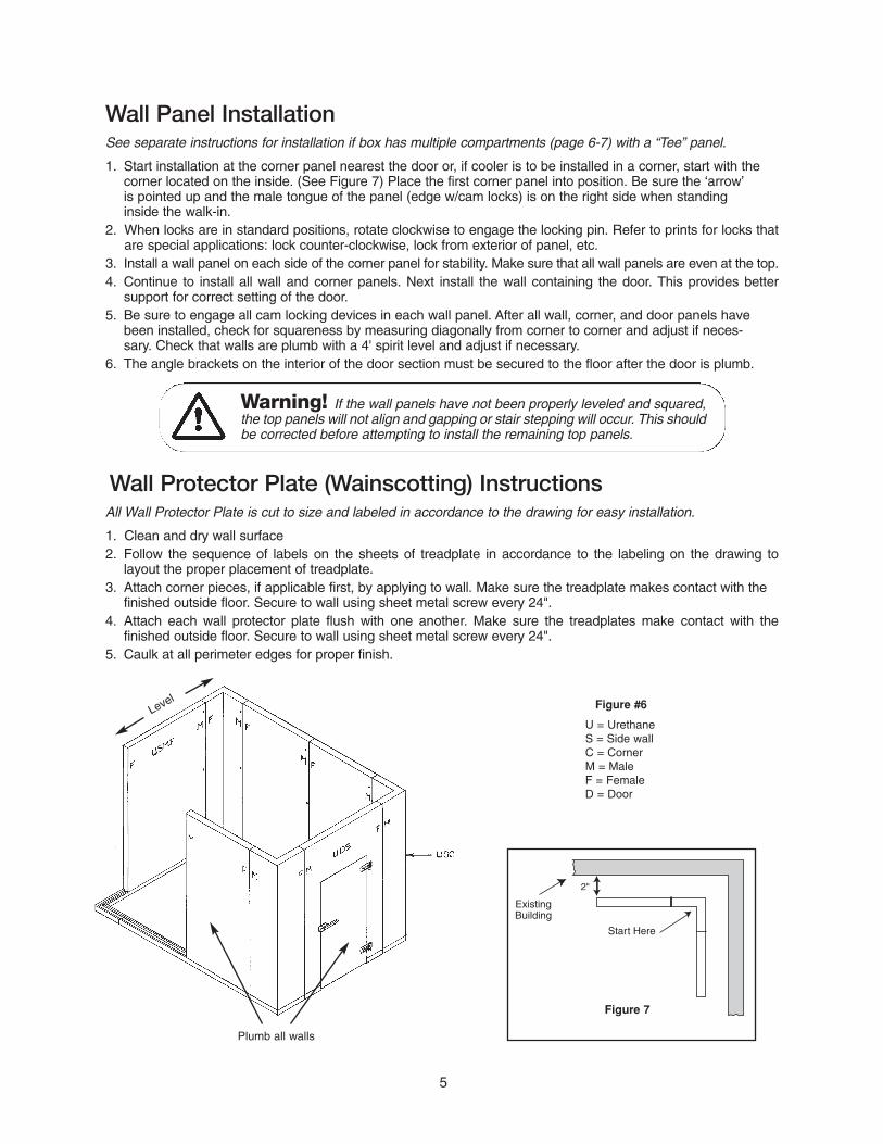
Wall Panel InstallationSee separate instructions for installation if box has multiple compartments (page 6-7) with a “Tee” panel.
1. Start installation at the corner panel nearest the door or, if cooler is to be installed in a corner, start with the corner located on the inside. (See Figure 7) Place the first corner panel into position. Be sure the ‘arrow’is pointed up and the male tongue of the panel (edge w/cam locks) is on the right side when standing inside the walk-in.
2. When locks are in standard positions, rotate clockwise to engage the locking pin. Refer to prints for locks thatare special applications: lock counter-clockwise, lock from exterior of panel, etc.
3. Install a wall panel on each side of the corner panel for stability. Make sure that all wall panels are even at the top.4. Continue to install all wall and corner panels. Next install the wall containing the door. This provides better
support for correct setting of the door.5. Be sure to engage all cam locking devices in each wall panel. After all wall, corner, and door panels have
been installed, check for squareness by measuring diagonally from corner to corner and adjust if neces-sary. Check that walls are plumb with a 4' spirit level and adjust if necessary.
6. The angle brackets on the interior of the door section must be secured to the floor after the door is plumb.
Warning! If the wall panels have not been properly leveled and squared,the top panels will not align and gapping or stair stepping will occur. This shouldbe corrected before attempting to install the remaining top panels.
Wall Protector Plate (Wainscotting) InstructionsAll Wall Protector Plate is cut to size and labeled in accordance to the drawing for easy installation.
1. Clean and dry wall surface2. Follow the sequence of labels on the sheets of treadplate in accordance to the labeling on the drawing to
layout the proper placement of treadplate.3. Attach corner pieces, if applicable first, by applying to wall. Make sure the treadplate makes contact with the
finished outside floor. Secure to wall using sheet metal screw every 24".4. Attach each wall protector plate flush with one another. Make sure the treadplates make contact with the
finished outside floor. Secure to wall using sheet metal screw every 24".5. Caulk at all perimeter edges for proper finish.
5
Figure #6
U = UrethaneS = Side wallC = CornerM = MaleF = FemaleD = Door
Start Here
ExistingBuilding
2"
Figure 7
Level
Plumb all walls

Top Panel InstallationStandard Walk-In: Begin installation of top panels at either end. 1. Check the drawing sent with the walk-in and assemble the top as indicated on this drawing. See Figure #8
for typical top layout.2. Do not lock the top panels to the wall panels until all panels are positioned and aligned. If top is
too large to shift (on larger boxes), go ahead and align, then lock.
Warning! If the wall panels have not been properly leveled and squaredthe top panels will not align and gapping or stair stepping will occur. This shouldbe corrected before attempting to install the remaining top panels.
Multiple Compartment with a Partition Floor and Partition Top Panel Installation
1. Be sure the floor panels are installed with the male edge in the proper position.2. Place the first “Tee” panel into position noting the position of the male edge. (Reference drawing)3. Install the partition wall and lock into place. Make sure that all wall panels are even at the top.4. Continue to install all wall and corner panels. Panels should be installed so that a corner panel is the last
wall panel to be installed. Be sure to engage all cam locking devices in each wall panel.5. After all wall, corner, and door panels have been installed, check for squareness by measuring diagonally
from corner to corner and adjust if necessary. Check that walls are plumb with a 4' spirit level and adjust if necessary.
Multiple Compartment Walk-Ins With A "Tee" Panel
1. These walk-ins have a special divider for the top, floor, and wall panels. They must be placed in the proper location for the walk-in to assemble correctly.
2. Be sure the floor panels are installed with the male edge in the proper position (See Figure #9 for typical combination)
6
Figure #8
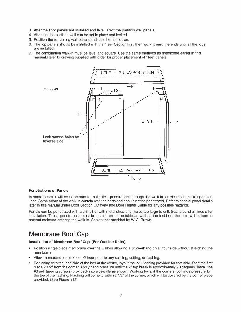
3. After the floor panels are installed and level, erect the partition wall panels. 4. After this the partition wall can be set in place and locked.5. Position the remaining wall panels and lock them all down.6. The top panels should be installed with the “Tee” Section first, then work toward the ends until all the tops
are installed.7. The combination walk-in must be level and square. Use the same methods as mentioned earlier in this
manual.Refer to drawing supplied with order for proper placement of “Tee” panels.
Penetrations of Panels
In some cases it will be necessary to make field penetrations through the walk-in for electrical and refrigerationlines. Some areas of the walk-in contain working parts and should not be penetrated. Refer to special panel detailslater in this manual under Door Section Cutaway and Door Heater Cable for any possible hazards.
Panels can be penetrated with a drill bit or with metal shears for holes too large to drill. Seal around all lines afterinstallation. These penetrations must be sealed on the outside as well as the inside of the hole with silicon to prevent moisture entering the walk-in. Sealant not provided by W. A. Brown.
Membrane Roof CapInstallation of Membrane Roof Cap (For Outside Units)
• Position single piece membrane over the walk-in allowing a 6" overhang on all four side without stretching themembrane.
• Allow membrane to relax for 1/2 hour prior to any splicing, cutting, or flashing.• Beginning with the long side of the box at the center, layout the 2x6 flashing provided for that side. Start the first
piece 2 1/2" from the corner. Apply hand pressure until the 2" top break is approximately 90 degrees. Install the#6 self tapping screws (provided) into sidewalls as shown. Working toward the corners, continue pressure to the top of the flashing. Flashing will come to within 2 1/2" of the corner, which will be covered by the corner pieceprovided. (See Figure #13)
7
Figure #9
Lock access holes onreverse side
• Repeat this procedure on all four sides.
• Trim extra material prior to sealing.• Cut, fold, and glue roof membrane using contact cement (not provided) • Position flashing to corner and form to fit by applying hand pressure to outside edges. Secure the corner
flashing to the sidewalls.
Install to existing wall• Allow membrane to extend up the existing wall approximately 6".• Position 2 1/2" cove and fasten.
Apply contact cement or caulk (not provided by W. A. Brown) along the top joint where the cove joins the wall,down the edge at each end of the cove and down the edge of flashing at the wall.
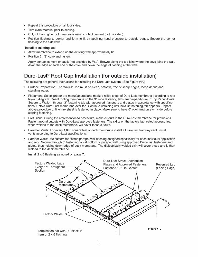
Duro-Last® Roof Cap Installation (for outside installation)The following are general instructions for installing the Duro-Last system. (See Figure #10)
• Surface Preparation: The Walk-In Top must be clean, smooth, free of sharp edges, loose debris and standing water.
• Placement: Select proper pre-manufactured and marked rolled sheet of Duro-Last membrane according to rooflay-out diagram. Orient roofing membrane so the 3" wide fastening tabs are perpendicular to Top Panel Joints.Secure to Walk-In through 3" fastening tab with approved fasteners and plates in accordance with specifica-tions. Unfold Duro-Last membrane over tab. Continue unfolding until next 3" fastening tab appears. Repeat above procedure until entire sheet is fastened in place. Make sure to have 6" overhang on each side before starting fastening.
• Protusions: During the aforementioned procedure, make cutouts in the Duro-Last membrane for protusions. Fasten around cutouts with Duro-Last approved fasteners. The skirts on the factory fabricated accessories, when welded to the deck membrane, will cover these cutouts.
• Breather Vents: For every 1,000 square feet of deck membrane install a Duro-Last two way vent. Install vents according to Duro-Last specifications.
• Parapet Walls: Use custom fabricated parapet wall flashing designed specifically for each individual applicationand roof. Secure through 3" fastening tab at bottom of parapet wall using approved Duro-Last fasteners and plates, thus holding down edge of deck membrane. The dielectrically welded skirt will cover these and is thenwelded to the deck membrane.
Install 2 x 6 flashing as noted on page 7.
8
Factory Welded LapsEvery 57" ThroughoutSection
Duro-LastMembrane
Factory Welds
Duro-Last Stress DistributionPlates and Approved FastenersFastened 12" On-Center
30"
Figure #10Termination bar with Durolast® inhem of 2 x 6 flashing
Reversed Lap(Facing Edge)
9
Fiber Cement Finish Panels InstallationFiber Cement panels are available in vertical siding and smooth styles. Smooth Fiber Cement is designed tohave a Stucco finish applied in the field or to be painted. Vertical siding style is meant to be field painted tomore closely match existing construction. See instructions below on painting Fiber Cement.
Inspect all panels as outlined on page 1. All door sections and Buck Openings on Fiber Cement Walk-Ins are constructed using W.A. Brown traditional metal finishes.
Set out panels as outlined on page 1. Fiber Cement panels have a gasket on one side (the inside) and requirecaulking at the joint between the outside skins. Use only the approved ChemCaulk 2000 sealant manufactured byBostik to seal these joints. This construction grade sealant is specifically designed for fiber cement and HardieBoard materials. If the include caulk option was chosen at the time of quotation and purchase, ample materialwill be supplied with the shipment. If not, this material can be purchased locally.
Caulk all wall to wall, wall to ceiling and wall to floor or floor screed joints with a .25” or 1/4” bead of material beforelocking the panels together. This will assure a good seal. Complete this process with the installation of each panel.Only the exterior fiber cement skins need to be caulked. No caulking is required on the interior gasketed surfaces.
Painting Fiber CementFlashing for Fiber Cement coolers and freezers will be factory primed, and will require on site final painting. Doorsections and the door leaf can be primed at the factory for an optional charge if noted at time of order entry.If you have not ordered factory priming, it can be accomplished on site. Latex paint is suitable for Fiber Cement,however it may not adhere properly to certain vinyl trim pieces.After your Fiber Cement Walk-In has been fully assembled, it will be necessary to apply a finished coat of paint toall exposed surfaces. It is recommended that primed siding must be painted within 180 days of installation. Applya high-quality, 100% acrylic paint. Solid or semi-transparent stains should be used only on unprimed Fiber Cement.Never use oil-based paints on Fiber Cement. For further questions on priming and painting Fiber Cement, feel freeto contact W. A. Brown, or call Duck Back, Woodperfect Fiber Cement Coating at 800-825-5382. Ask about theirwater based, alkaline resistant, acrylic Latex primer and paint.
10
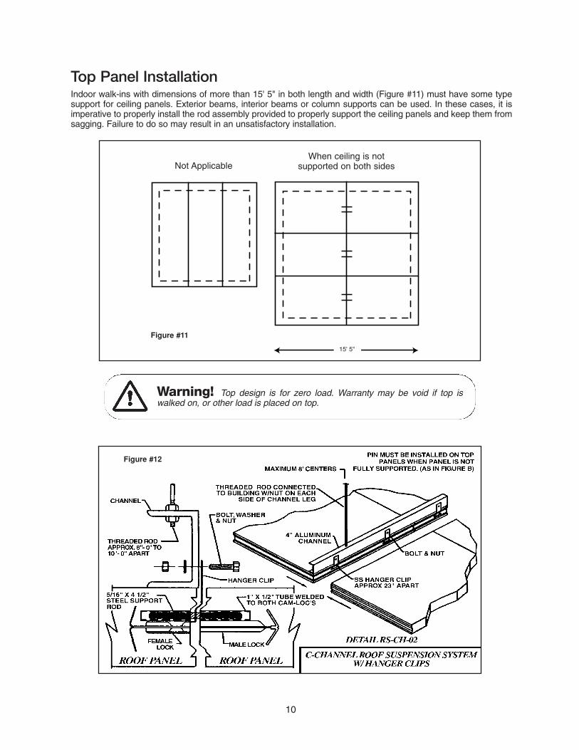
Top Panel InstallationIndoor walk-ins with dimensions of more than 15' 5" in both length and width (Figure #11) must have some typesupport for ceiling panels. Exterior beams, interior beams or column supports can be used. In these cases, it isimperative to properly install the rod assembly provided to properly support the ceiling panels and keep them fromsagging. Failure to do so may result in an unsatisfactory installation.
15' 5"
Not ApplicableWhen ceiling is not
supported on both sides
Figure #12
Warning! Top design is for zero load. Warranty may be void if top iswalked on, or other load is placed on top.
Figure #11
11
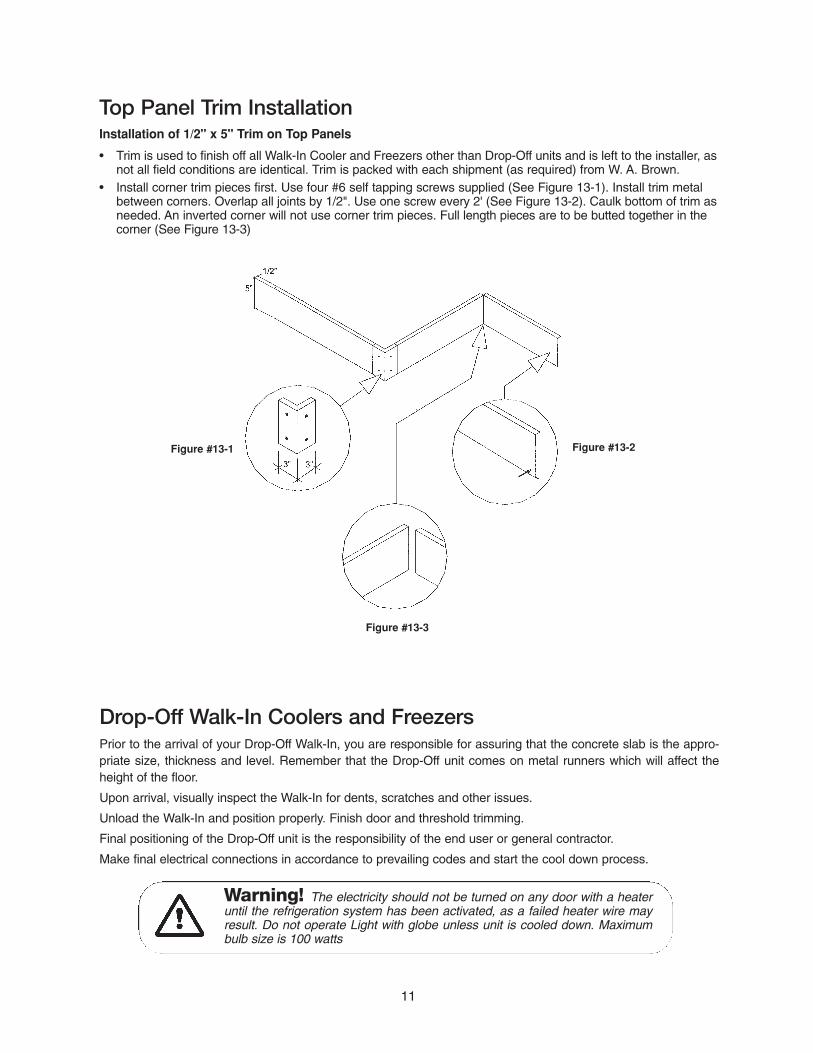
Top Panel Trim InstallationInstallation of 1/2" x 5" Trim on Top Panels
• Trim is used to finish off all Walk-In Cooler and Freezers other than Drop-Off units and is left to the installer, asnot all field conditions are identical. Trim is packed with each shipment (as required) from W. A. Brown.
• Install corner trim pieces first. Use four #6 self tapping screws supplied (See Figure 13-1). Install trim metal between corners. Overlap all joints by 1/2". Use one screw every 2' (See Figure 13-2). Caulk bottom of trim asneeded. An inverted corner will not use corner trim pieces. Full length pieces are to be butted together in the corner (See Figure 13-3)
Figure #13-1 Figure #13-2
Figure #13-3
Drop-Off Walk-In Coolers and FreezersPrior to the arrival of your Drop-Off Walk-In, you are responsible for assuring that the concrete slab is the appro-priate size, thickness and level. Remember that the Drop-Off unit comes on metal runners which will affect theheight of the floor.
Upon arrival, visually inspect the Walk-In for dents, scratches and other issues.
Unload the Walk-In and position properly. Finish door and threshold trimming.
Final positioning of the Drop-Off unit is the responsibility of the end user or general contractor.
Make final electrical connections in accordance to prevailing codes and start the cool down process.
Warning! The electricity should not be turned on any door with a heateruntil the refrigeration system has been activated, as a failed heater wire mayresult. Do not operate Light with globe unless unit is cooled down. Maximumbulb size is 100 watts
EZ Pack Installation Instructions(See Installation Guide taped to top of each unit.)
Installing the Refrigeration SystemA qualified technician should install the refrigeration. Contact the dealer from who you purchased your Walk-In fora qualified technician.Carefully raise refrigeration system to top of walk-in. Insert projecting sleeve of evaporator box in to cut out of panel.Install louvered grill on interior side of top panel. Grill should be installed with fan motors.NOTE: On smaller systems unit can be installed on top panel before panel is installed on walk-in.
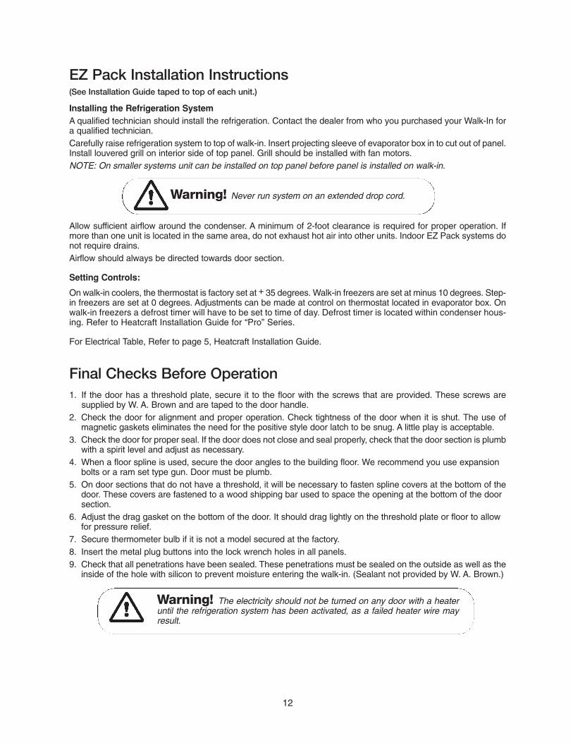
Warning! Never run system on an extended drop cord.
Allow sufficient airflow around the condenser. A minimum of 2-foot clearance is required for proper operation. Ifmore than one unit is located in the same area, do not exhaust hot air into other units. Indoor EZ Pack systems donot require drains.Airflow should always be directed towards door section.
Setting Controls:
On walk-in coolers, the thermostat is factory set at + 35 degrees. Walk-in freezers are set at minus 10 degrees. Step-in freezers are set at 0 degrees. Adjustments can be made at control on thermostat located in evaporator box. Onwalk-in freezers a defrost timer will have to be set to time of day. Defrost timer is located within condenser hous-ing. Refer to Heatcraft Installation Guide for “Pro” Series.
For Electrical Table, Refer to page 5, Heatcraft Installation Guide.
Final Checks Before Operation1. If the door has a threshold plate, secure it to the floor with the screws that are provided. These screws are
supplied by W. A. Brown and are taped to the door handle.2. Check the door for alignment and proper operation. Check tightness of the door when it is shut. The use of
magnetic gaskets eliminates the need for the positive style door latch to be snug. A little play is acceptable.3. Check the door for proper seal. If the door does not close and seal properly, check that the door section is plumb
with a spirit level and adjust as necessary.4. When a floor spline is used, secure the door angles to the building floor. We recommend you use expansion
bolts or a ram set type gun. Door must be plumb.5. On door sections that do not have a threshold, it will be necessary to fasten spline covers at the bottom of the
door. These covers are fastened to a wood shipping bar used to space the opening at the bottom of the door section.
6. Adjust the drag gasket on the bottom of the door. It should drag lightly on the threshold plate or floor to allow for pressure relief.
7. Secure thermometer bulb if it is not a model secured at the factory.8. Insert the metal plug buttons into the lock wrench holes in all panels.9. Check that all penetrations have been sealed. These penetrations must be sealed on the outside as well as the
inside of the hole with silicon to prevent moisture entering the walk-in. (Sealant not provided by W. A. Brown.)
Warning! The electricity should not be turned on any door with a heateruntil the refrigeration system has been activated, as a failed heater wire mayresult.
12
Roof Cap & Curb Installation (Figure #14)
Wiring the Door Heater, Lights & WindowsAll freezers and some coolers are shipped with a 120V peripheral heater around the door to eliminate condensate and keep the door frame and jamb from “sweating”. Likewise most freezer windows are alsodesigned with a 120V heater for the same reason.
Vapor Proof LightThis light is internally wired to the light switch. Only source power needs to be wired into the junction box powering the light. Maximum bulb size is 100 watts. Do not operate with globe until walk-in is at operatingtemperature.
Fluorescent LightsThese lights are field installed and will require both source power and internal wiring by a qualified electrician.
The above will be wired to door switch via “J” Box on interior of door section in most cases.
All installation should be in accordance with NSF and prevailing electrical code.
Warning! When installing your Walk-in cooler or freezer, always use aqualified electrician for all your wiring needs. Refer to wiring diagram includedin this manual.
Warning! Never penetrate rubber roof cap, (with exception of rubbergrommet unit mounting screws.)
13
. . . . . . . . . . . . .. . . .. . . .
. . . ..
Cut-OutOpening
2nd Piece
Wood Curb
Rubber Roof Cap
BaseHandles
Refrig-eration
Unit
Copper DrainLine Outlet
3/4" PVC Drain Line
with Armor Flex
DrainLine
Clamps
1. Make sure Walk-in top is completely clean ofany debris.
2. Run bead of Silicone around cut-out opening.
3. Install 2 piece Wood Curb (provided) onto Walk-in top with counter sink screws (provided).
4. Follow procedures for installing Membrane RoofCap over Wood curb, page 7.
5. Cut rubber roof cap over opening in X shape.
6. Roll rubber roof cap inside opening.
7. Run bead of Silicone around cut-out opening.
8. Set refrigeration unit in place.
9. Install protruding sleeve of unit into cut out opening of walk-in.
10. Screw unit base handles down with rubber grommet screws.
11. Install 3/4" PVC drain line with armor flex insulation over copper drain line. (Optional)
12. Install clamps over drain line on side of walk-in.
13. Run bead of silicone around unit base, rubber grommet screws and drain line.
Figure #14
14
Housekeeping and SafetyHousekeeping and Safety Recommendations
Please use caution when inside any walk-in. The floor may become slippery if allowed to become wet or greasy.To provide user safety, to maintain optimum performance and long life of this product, we recommend regularlyreviewing the following procedures with anyone that may enter the walk-in:
• Keep all walkway surfaces clean and free of spilled liquids and food particles. All aisles must be kept clear forpassage.
• Inspect the condition of the anti-skid strips monthly. Replace or add additional strips as needed.
• Keep door closed to prevent the accumulation of condensation on floor and other surfaces.
• Inspect refrigeration equipment frequently for proper functioning of evaporator drain pans, defrost controls anddrain line heaters.
• Condensate water must never be allowed to drip on the walk-in floor. Refer to the refrigeration instructions forproper condensate line installation.
• Frost or condensation appearing around the door jamb indicates that the heater cable is inoperative or that thedoor gasket may need to be replaced, or that the door has not been properly closed.
• Hinges used on the doors are self closing with a nylon cam and bushing. The hinges are lubricated at the factory for ease of operation. They should be lubricated every three months with petroleum jelly. Care shouldbe used to keep dirt and trash out of the hinge.
• To help prevent moisture accumulating in the insulation, be sure to replace missing plug buttons. Additional buttons are shipped with each order.
Warning! If you observe any abnormal or unsafe conditions, you shouldcontact your maintenance manager to have this condition corrected.
Cleaning of Stucco Aluminum & Galvalume Plus
The ceiling, walls and floors of Brown walk-ins are covered with a metal finish. Cleaning of this surface can beaccomplished by the use of a mild detergent, warm water and a soft cleaning cloth.
The use of an abrasive type cleaner can scratch the surface of the metal. The use of any form of cleaning agentthat contains any form of acid may cause a discoloring or darkening of the metal finishes. Markings made by felttip pens or “Magic Markers” can be removed by use of lacquer thinner, varsol, or naphtha. After using these clean-ers, wash the space with soap and warm water to remove any chemical residue.
Cleaning Stainless Steel Finishes
1. Always clean in the direction of the grain.2. Use alkaline, alkaline chlorinated or non-chloride containing cleaners. If you are unsure, check with your
cleaner supplier.3. Rinse, Rinse, Rinse.
Cleaning of Door Gaskets
Magnetic door gaskets should be cleaned with mild detergents and hot water. Remove all soap film and dry thoroughly with a clean cloth. Strong cleaners are corrosive and should not be allowed to come in contact. Neveruse acids (hydrochloric or muriatic for example) on door gaskets.
15
How To Call for Service Repair
After your W. A. Brown & Son, Inc. Walk-in has been correctly installed, and the refrigeration system properly connect-ed your new Walk-in should provide you years of uninterrupted service. Should your Walk-In ever require service,please have the following information available upon initiating a service call. Determine the date your walk-in was placed into service and enter it here. ______________________________
Locate the serial number located on the door of your unit and enter it here. ____________________________
Determine the dealer from whom you purchased your walk-in and enter it here. __________________________
Should you feel your Walk-in refrigeration system is not operating properly and your unit is covered under warranty,please contact W. A. Brown & Son, Inc. by calling 800-438-2316 and ask for Refrigeration Service. Provide the dateyour unit was installed for use and the serial number, along with the name of the dealer from which you purchasedyour unit. Describe the nature of the problem, and our qualified technicians will refer you to the appropriate trainedservicer, or, you may use your preferred local refrigeration technician. See exact detail regarding labor warranty if youhave purchased the optional one year labor warranty. Of course repairs that are covered under warranty will be handled at no charge to you. Expenses that result from calls not covered under warranty (such as fuses blown or a unitnot plugged in) will be invoiced to the person asking for the service call.
Replacement Parts
For best operation, always use official replacement parts for items such as hinges, gaskets, and latches. Thesecan be purchased directly from W. A. Brown by calling Service Parts at 800-640-0593 or visit us on the web atwww.wabrown.com. Minimum orders and order handling charges may apply.
Replacement door latch keys are available at a minimum charge.
Data Plate - Located on inside of main door.
Serial No. (5 digits w/dash for door number ex: 90117-1D2)(This number is the same as the Order Number)
Size (Size of box and year mfg’d ex: 16X17-01)
UL Model (This number UDS-4 can not be used to identify order - it means there is 4" of urethane foamed in panels)
W.A. BROWN &B SON, INC.Since 1910
Salisbury, NC
REFRIGERATION REQUIREMENTSFor Storage Temperature of 0 ˚ F
Evaporator: 6578 BTU / HR at 10˚ TD
Condensing Unit: 6578 BTU / HR at -10 ˚Suction Temperature. in 100˚ Ambient
SERIAL NO. 98949-1D2UL MODEL: UDS-4
SIZE: 9X13 04
UL® NSFCOMPONENT
LISTED 480EDOOR PANEL ASSEMBLY120 V. A. C. 300 WATTS
16
LIFETIME LIMITED CABINET WARRANTY
W. A Brown & Son, Inc. warrants to the original purchaser, the full foamed-in-place aluminum and stainless steel panels manufactured and sold by it, to be free from defects in material and workmanship under normal use and service for life from the date of original installation by an authorized representative. All other panels manufactured byW. A. Brown & Son, Inc. shall be warranted against delaminating and/or insulation decay for life from the date of original installation by an authorized representative. Oxidation of panels other than aluminum and stainless steel isexpressly excepted from this warranty. All door hardware shall be warranted for a period of five (5) years. W. A. Brownshall warrant all gaskets, and electrical components, which are reasonable and proper, for a period of one (1) yearfrom the date of original installation. This warranty does not apply to equipment, which has been subjected to abuse,misuse, or acts of God and is exclusive of all freight and labor charges unless a labor warranty has been purchased.
ONE (1) YEAR LIMITED REFRIGERATION SYSTEM PARTS WARRANTY
W. A. Brown & Son, Inc. warrants to the original purchaser all parts of the refrigeration system for a period of one (1)year commencing forty-five (45) days after shipment from the W. A Brown & Son, Inc. factory..
W. A Brown & Son, Inc. shall be liable for the wholesale cost of these parts. This warranty shall not apply to the refrig-erant gas loss from the refrigeration system. W. A Brown & Son, Inc. deems a refrigerant gas loss warranty, if any, tobe the responsibility of the installing dealer or contractor.
ONE (1) YEAR LIMITED REFRIGERATION LABOR WARRANTY
W. A Brown & Son, Inc.warrants to the original end user the labor for service work on the refrigeration systems fora period of one (1) year commencing forty-five (45) days after shipment from the W. A Brown & Son, Inc. factory.
This warranty when purchased as an optional item at the time of the original equipment purchase will cover reason-able and proper labor charges in the repair of the refrigeration system.
The refrigerant gas is also covered under this warranty, but shall be limited to the wholesale cost, plus up to a 100%mark-up. The amount of refrigerant is limited to an amount which is ten (10%) percent above maximum pump downcapacities. W. A Brown & Son, Inc. will furnish a list of these capacities to the end user upon request.
This warranty does not apply to drains, drain heaters, electrical circuits which are external to the refrigeration equip-ment, fuses, adjustments to temperature controls, pressure controls or time clocks.
This warranty does not cover travel time, truck charges, mileage charges, or waiting time.
It is the responsibility of the end user to select or contract the service company to effect the above mentioned repairs.However, W. A Brown & Son, Inc. retains the right to approve or disapprove any refrigeration service company at itssole discretion.
FOUR (4) YEAR LIMITED CONDENSING UNIT COMPRESSOR WARRANTY
W. A. Brown & Son, Inc. warrants the condensing unit compressor only for four (4) years parts warranty if purchasedwith at the time of initial order. W. A. Brown & Son, Inc. warrants this compressor to be free from defects in materialand workmanship under normal use and service. W. A. Brown & Son, Inc. obligation shall be limited to repairing orreplacing the compressor, which proves to be defective upon purchase. This warranty shall not apply to any refriger-ant gas loss from the refrigeration system. W. A. Brown & Son, Inc. deems a refrigerant gas loss warranty, if any, tobe the responsibility of the installing dealer or contractor.
THE FOREGOING WARRANTIES ARE EXPRESSLY IN LIEU OF ALL OTHER WARRANTIES, EXPRESSED ORIMPLIED AND THERE ARE NO WARRANTIES WHICH EXTEND BEYOND THE DESCRIPTION SET FORTHABOVE. W. A. Brown & Son, Inc. NEITHER ASSUMES NOR AUTHORIZES ANY OTHER PERSON TO ASSUMEFOR IT ANY OTHER OBLlGATIONS OR LIABILITIES IN CONNECTION WITH THE SALE OF ITS WALK-IN COOL-ER OR FREEZER CABINETS, REFRIGERATION SYSTEM, CONDENSING UNIT COMPRESSOR OR ANY PARTOF PARTS THEREOF. W. A. Brown & Son, Inc. shall not be responsible for damage caused in transit, alterations byunauthorized service, negligence, abuse, misuse, damage by war, flood, fire or acts of God.
W. A. Brown & Son, Inc. shall not be responsible for any food spoilage, product loss, transportation charges, labor orother costs in the replacement of any part or parts, or consequential damages of any kind, and the obligation to repairor replace as stated in the applicable warranty or warranties states the entire liability of W. A. Brown & Son, Inc.whether based on tort, contract, warranty or implied warranty. Any and all parts replaced under any of all of the abovewarranties shall be F. 0. B. Salisbury, North Carolina, and the maximum liability by W. A. Brown & Son, Inc., shall bethe wholesale value of said part or parts only.
The warranties herein stated shall not be assignable and shall be operative only in favor of the original purchaser-user.
17
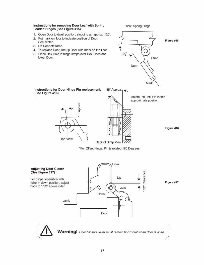
Instructions for removing Door Leaf with SpringLoaded Hinges (See Figure #15)
1. Open Door to dwell position, stopping at approx. 120˚.2. Put mark on floor to indicate position of Door.
See sketch.3. Lift Door off frame.4. To replace Door, line up Door with mark on the floor.5. Place Hex Hole in hinge straps over Hex Rods and
lower Door.120˚
Door
Strap
Mark
1248 Spring Hinge
Instructions for Door Hinge Pin replacement,(See Figure #16)
Top View
10˚ A
ppro
x.
Rotate Pin until it is in thisapproximate position.
45˚ Approx.
Back of Strap View
*For Offset Hinge, Pin is rotated 180 Degrees
Adjusting Door Closer(See Figure #17)
Jamb
Roller
Hook
Lip
Lever
Door
1/32
” C
lear
ance
Warning! Door Closure lever must remain horizontal when door is open.
Figure #15
Figure #16
Figure #17For proper operation withroller in down position, adjusthook to 1/32" above roller.
18
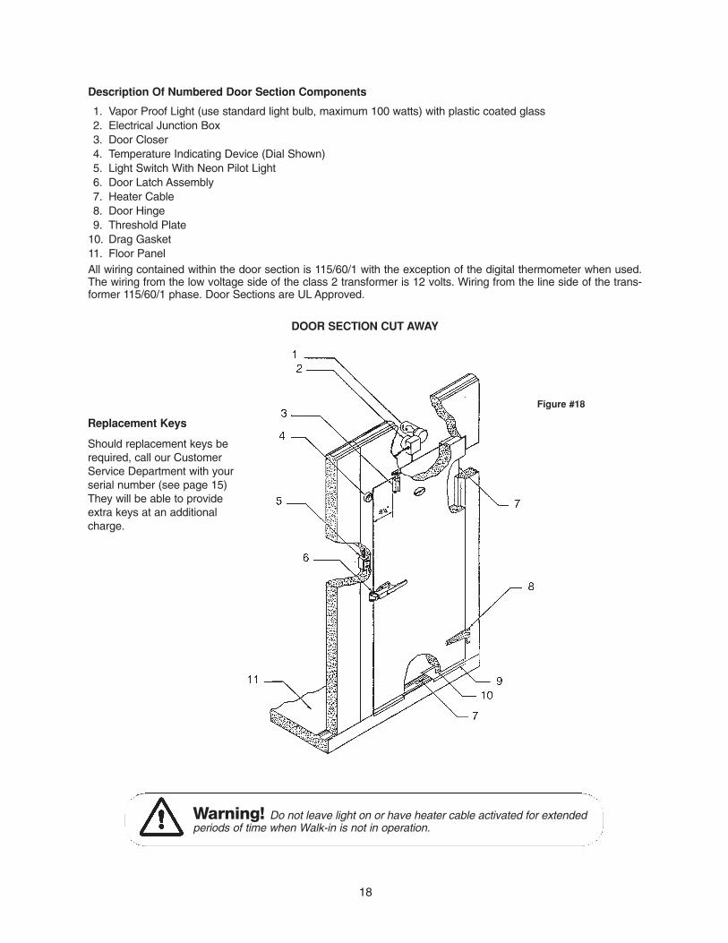
Description Of Numbered Door Section Components
1. Vapor Proof Light (use standard light bulb, maximum 100 watts) with plastic coated glass2. Electrical Junction Box3. Door Closer4. Temperature Indicating Device (Dial Shown)5. Light Switch With Neon Pilot Light6. Door Latch Assembly7. Heater Cable8. Door Hinge9. Threshold Plate
10. Drag Gasket11. Floor PanelAll wiring contained within the door section is 115/60/1 with the exception of the digital thermometer when used.The wiring from the low voltage side of the class 2 transformer is 12 volts. Wiring from the line side of the trans-former 115/60/1 phase. Door Sections are UL Approved.
DOOR SECTION CUT AWAY
Figure #18
Replacement Keys
Should replacement keys berequired, call our CustomerService Department with yourserial number (see page 15)They will be able to provideextra keys at an additionalcharge.
Warning! Do not leave light on or have heater cable activated for extendedperiods of time when Walk-in is not in operation.
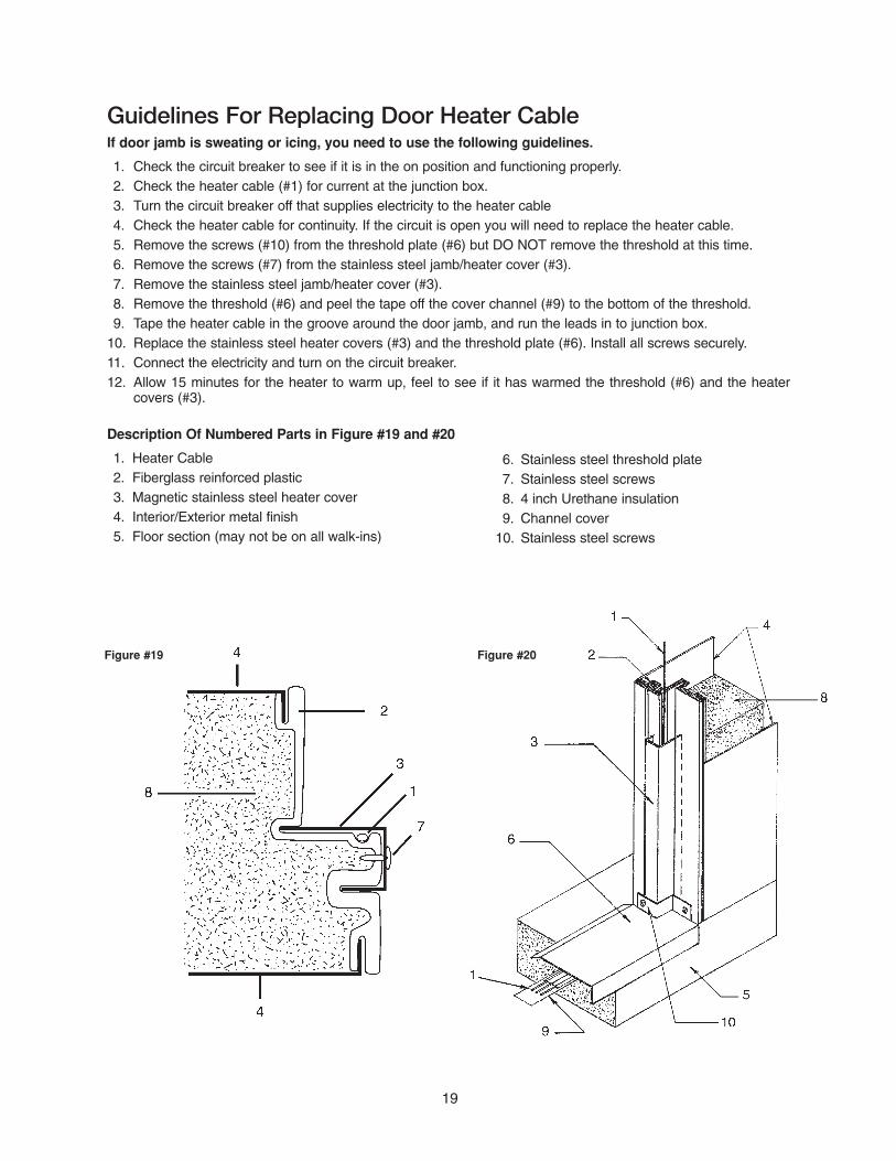
Guidelines For Replacing Door Heater CableIf door jamb is sweating or icing, you need to use the following guidelines.
1. Check the circuit breaker to see if it is in the on position and functioning properly.2. Check the heater cable (#1) for current at the junction box.3. Turn the circuit breaker off that supplies electricity to the heater cable4. Check the heater cable for continuity. If the circuit is open you will need to replace the heater cable.5. Remove the screws (#10) from the threshold plate (#6) but DO NOT remove the threshold at this time.6. Remove the screws (#7) from the stainless steel jamb/heater cover (#3).7. Remove the stainless steel jamb/heater cover (#3).8. Remove the threshold (#6) and peel the tape off the cover channel (#9) to the bottom of the threshold.9. Tape the heater cable in the groove around the door jamb, and run the leads in to junction box.
10. Replace the stainless steel heater covers (#3) and the threshold plate (#6). Install all screws securely.11. Connect the electricity and turn on the circuit breaker.12. Allow 15 minutes for the heater to warm up, feel to see if it has warmed the threshold (#6) and the heater
covers (#3).
Description Of Numbered Parts in Figure #19 and #20
1. Heater Cable2. Fiberglass reinforced plastic3. Magnetic stainless steel heater cover4. Interior/Exterior metal finish5. Floor section (may not be on all walk-ins)
19
6. Stainless steel threshold plate7. Stainless steel screws8. 4 inch Urethane insulation9. Channel cover
10. Stainless steel screws
Figure #19 Figure #20
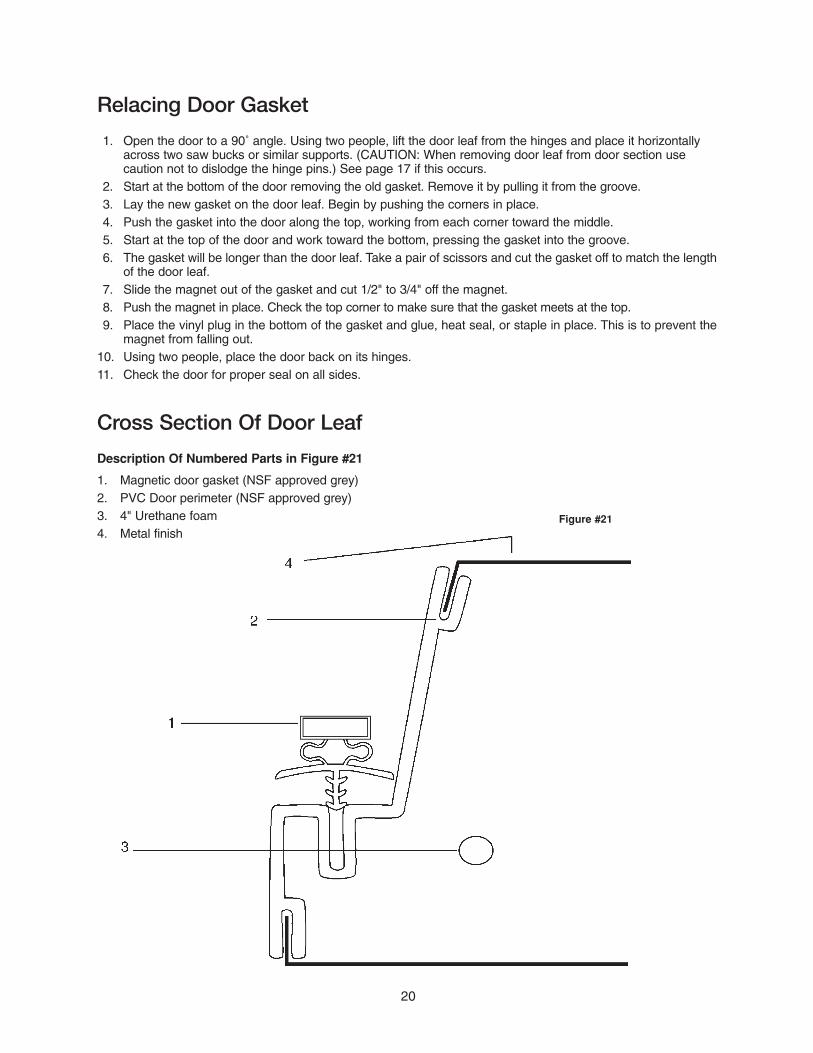
Relacing Door Gasket
1. Open the door to a 90˚ angle. Using two people, lift the door leaf from the hinges and place it horizontally across two saw bucks or similar supports. (CAUTION: When removing door leaf from door section use caution not to dislodge the hinge pins.) See page 17 if this occurs.
2. Start at the bottom of the door removing the old gasket. Remove it by pulling it from the groove.3. Lay the new gasket on the door leaf. Begin by pushing the corners in place.4. Push the gasket into the door along the top, working from each corner toward the middle.5. Start at the top of the door and work toward the bottom, pressing the gasket into the groove.6. The gasket will be longer than the door leaf. Take a pair of scissors and cut the gasket off to match the length
of the door leaf.7. Slide the magnet out of the gasket and cut 1/2" to 3/4" off the magnet.8. Push the magnet in place. Check the top corner to make sure that the gasket meets at the top.9. Place the vinyl plug in the bottom of the gasket and glue, heat seal, or staple in place. This is to prevent the
magnet from falling out.10. Using two people, place the door back on its hinges.11. Check the door for proper seal on all sides.
Cross Section Of Door Leaf
Description Of Numbered Parts in Figure #21
1. Magnetic door gasket (NSF approved grey)2. PVC Door perimeter (NSF approved grey)3. 4" Urethane foam4. Metal finish
20
Figure #21
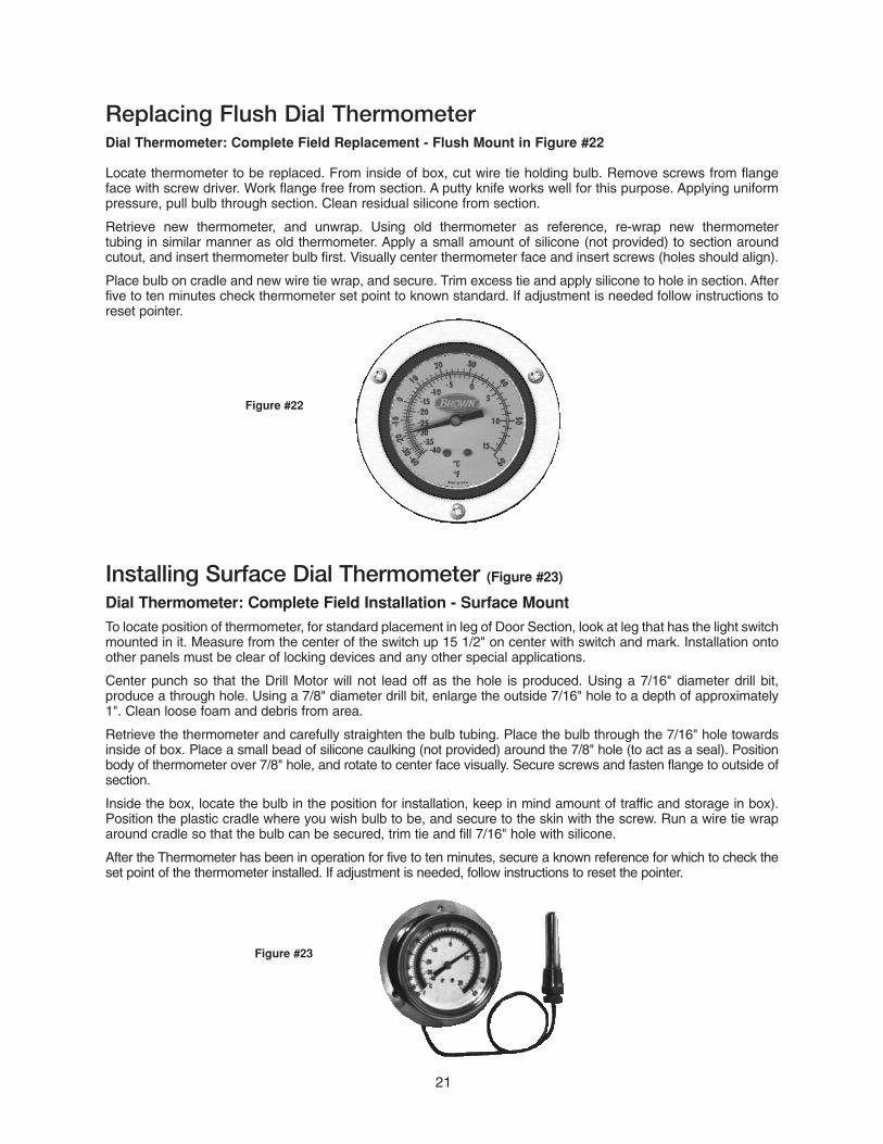
Replacing Flush Dial Thermometer Dial Thermometer: Complete Field Replacement - Flush Mount in Figure #22
Locate thermometer to be replaced. From inside of box, cut wire tie holding bulb. Remove screws from flangeface with screw driver. Work flange free from section. A putty knife works well for this purpose. Applying uniform pressure, pull bulb through section. Clean residual silicone from section.
Retrieve new thermometer, and unwrap. Using old thermometer as reference, re-wrap new thermometer tubing in similar manner as old thermometer. Apply a small amount of silicone (not provided) to section aroundcutout, and insert thermometer bulb first. Visually center thermometer face and insert screws (holes should align).
Place bulb on cradle and new wire tie wrap, and secure. Trim excess tie and apply silicone to hole in section. Afterfive to ten minutes check thermometer set point to known standard. If adjustment is needed follow instructions toreset pointer.
21
Figure #22
Installing Surface Dial Thermometer (Figure #23)
Dial Thermometer: Complete Field Installation - Surface MountTo locate position of thermometer, for standard placement in leg of Door Section, look at leg that has the light switchmounted in it. Measure from the center of the switch up 15 1/2" on center with switch and mark. Installation ontoother panels must be clear of locking devices and any other special applications.
Center punch so that the Drill Motor will not lead off as the hole is produced. Using a 7/16" diameter drill bit, produce a through hole. Using a 7/8" diameter drill bit, enlarge the outside 7/16" hole to a depth of approximately1". Clean loose foam and debris from area.
Retrieve the thermometer and carefully straighten the bulb tubing. Place the bulb through the 7/16" hole towardsinside of box. Place a small bead of silicone caulking (not provided) around the 7/8" hole (to act as a seal). Positionbody of thermometer over 7/8" hole, and rotate to center face visually. Secure screws and fasten flange to outside ofsection.
Inside the box, locate the bulb in the position for installation, keep in mind amount of traffic and storage in box).Position the plastic cradle where you wish bulb to be, and secure to the skin with the screw. Run a wire tie wraparound cradle so that the bulb can be secured, trim tie and fill 7/16" hole with silicone.
After the Thermometer has been in operation for five to ten minutes, secure a known reference for which to check theset point of the thermometer installed. If adjustment is needed, follow instructions to reset the pointer.
Figure #23

Replacing The Digital ThermometerTurn off breaker before disconnecting wires.If the thermometer does not register correctly you will need to check the following:
1. Check the voltage on the load side of the transformer. It should be 12 volts.2. If the voltage is not 12 volts on the load side of the transformer, check the
line side to confirm that proper voltage is reaching the transformer.3. If you have 115 volts on the line side and nothing on the load side you will
need to change the transformer.4. If the transformer checks good you will need to change the digital display.
This is done by removing the two screws from the front of the display andpulling out the whole module. Take the two wire nuts off the incoming power located behind the display. Pull the probe out through the insulatedsection. Push the new probe through the same hole in the insulated section and secure. Hook the two wires back to the incoming power fromthe transformer. Replace the display on the door section and secure with the screws. Turn the power on and check the display.
Description Of Numbered Parts, Figure #24 and #25
1. Junction Box2. Optional wire guard for vapor proof light3. Plastic coated glass globe for vapor proof light
Replacing A Pressure Relief PortAfter determining the pressure relief port is defective use the following guidelines:(NOTE: THE HEATER IS NOT AVAILABLE SEPARATELY.)
1. Turn off the electrical supply to the pressure relief port.2. Remove the inside and outside louvers and remove any sealant
that might be holding the port in place.3. Open square J. Box and disconnect two small white wires and one
green wire to PRP.4. Pull out the PVC portion of the port along with the wiring.5. Feed the wire from the new port through the hole up to the junction box.6. Put the PVC portion back into the wall section making sure that the heater
is in the interior of the walk-in.7. Seal around the interior with silicone (not provided) then install the
interior louvered flange.8. Push the vent in tight against the interior flange.9. Seal around the exterior PVC portion with silicone (not provided) and
install the exterior louver.10. Connect the electrical wires and turn the electricity on.11. After 15 minutes check to see if the heater is working on the new port.
Description Of Numbered Parts, Figure #27, and #28
1. 4" Urethane wall2. 45 degree 1/2" hole3. 1/2" groove to hole4. Wire5. Junction Box at header of door6. 2 1/2" hole
22
Figure #25
2 1/2" Pressure Relief Port
Figure #27
Figure #28

Electrical Hook-Up to Junction Box
23
Figure #26
Inside of Junction Box
Electrical Hook-Up to Junction Box1. Connect incoming conduit to 3/4 diameter hole on right side of junction box.
2. Selection of conduit type, connection method and wire type in accordance with local codes. Responsibility ofinstalling contractor.
3. Once 120 volt power is pulled to the junction box, insert a sharp pointed tool into the box marked 1 . Apply pressure downward to open the wire termination opening in the box marked "Black". Insert Black wire and release tool. The spring loaded insert should now have a tight connection on the wire. If the wire pulls out, repeat procedure until the wire will not pull out under hand pulled pressure.
4. Repeat step 3 except for box marked 2 and "White" wire location.5. Land ground wire on either the post on the lid or within the junction box.6. Make final check before energizing panel and securing the junction box lid.
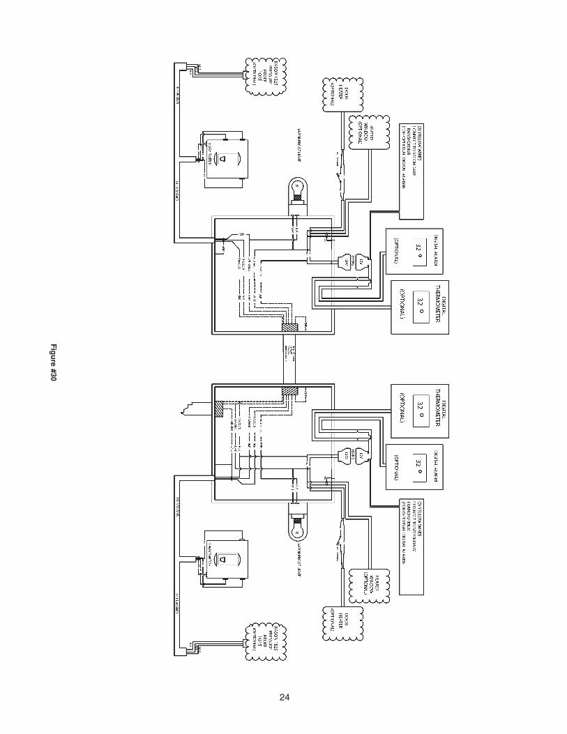
Fig
ure #30
24

25
Possible Cause
Service cord unpluggedFuse blown or removedOverload trippedControl stuck openWiring incorrect
Improperly wiredLow voltage to unitStaring capacitor defectiveRelay failing to close
Low voltage to unitOverload defectiveExcessive head pressureCompressor very hot-return hot gas
Short of refrigerantControl contact stuckEvaporator coil icedRestriction in refrigeration systemDirty condenser
Overload protectorCold controlOverchargeAir in systemUndercharge
Relay contacts stuckLow voltage to unitImproper relay
Incorrect relayVoltage too high or low
Control setting too highRefrigerant overchargeDirty condenserEvaporator coil iced
Control setting is too lowControl points stuck
Fan blade hitting shroudTube raffleVibrating fan bladeCondenser fan motor rafflesGeneral vibrationWorn fan motor bearings
Solution
Plug in service cordReplace fuseDetermine reasons and correctRepair or replaceCheck wiring against diagram
Check wiring against the diagramDetermine reason and correctDetermine reason and replaceDetermine reason, correct or replace
Determine reason and correctCheck current, replace overload protectorCheck ventilation or restriction in systemCheck refrigerant charge, fix leak if req ‘d
Fix leak, add chargeRepair or replaceDetermine cause, defrost manuallyDetermine location & removeClean condenser
Check wiring diagramDifferential too close-widenReduce chargeRecover and rechargeFix leak, add refrigerant
Clean contacts or replace relayDetermine reason and correctReplace
Check and replaceDetermine reason and correct
Reset controlRecover refrigerantClean condenserDetermine reason and defrost
Reset the controlReplace the control
Reform/cut away small section of shroudLocate and reformReplace fan bladeCheck motor bracket mounting, tightenCompressor suspension bolts too tightReplace fan motor
Malfunction
Compressor will not start - no hum
Compressor will not start - hums but trips on overload protector
Compressor starts & runs, but short cycles on overload protector
Compressor operates long or continuously
Compressor runs fine, but short cycles
Starting capacitor open, shorted or blown
Relay defective or burned out
Refrigerated space too warm
Standard temperature system freezes the product
Objectionable noise
Refrigeration Trouble Shooting GuideAlways use a certified trained Refrigeration Technician when repair of your refrigeration system is required.
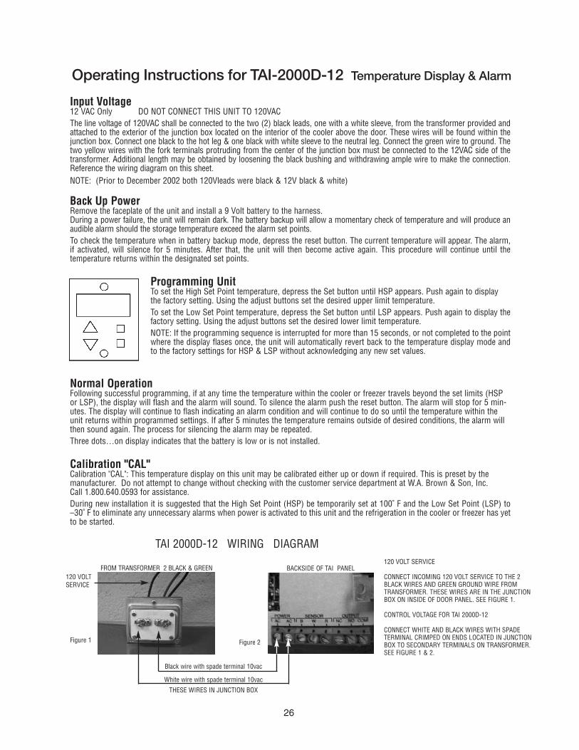
Input Voltage12 VAC Only DO NOT CONNECT THIS UNIT TO 120VACThe line voltage of 120VAC shall be connected to the two (2) black leads, one with a white sleeve, from the transformer provided andattached to the exterior of the junction box located on the interior of the cooler above the door. These wires will be found within thejunction box. Connect one black to the hot leg & one black with white sleeve to the neutral leg. Connect the green wire to ground. Thetwo yellow wires with the fork terminals protruding from the center of the junction box must be connected to the 12VAC side of thetransformer. Additional length may be obtained by loosening the black bushing and withdrawing ample wire to make the connection.Reference the wiring diagram on this sheet.NOTE: (Prior to December 2002 both 120Vleads were black & 12V black & white)
Back Up PowerRemove the faceplate of the unit and install a 9 Volt battery to the harness.During a power failure, the unit will remain dark. The battery backup will allow a momentary check of temperature and will produce anaudible alarm should the storage temperature exceed the alarm set points.To check the temperature when in battery backup mode, depress the reset button. The current temperature will appear. The alarm,if activated, will silence for 5 minutes. After that, the unit will then become active again. This procedure will continue until the temperature returns within the designated set points.
Programming UnitTo set the High Set Point temperature, depress the Set button until HSP appears. Push again to displaythe factory setting. Using the adjust buttons set the desired upper limit temperature.To set the Low Set Point temperature, depress the Set button until LSP appears. Push again to display thefactory setting. Using the adjust buttons set the desired lower limit temperature.NOTE: If the programming sequence is interrupted for more than 15 seconds, or not completed to the pointwhere the display flases once, the unit will automatically revert back to the temperature display mode andto the factory settings for HSP & LSP without acknowledging any new set values.
Normal OperationFollowing successful programming, if at any time the temperature within the cooler or freezer travels beyond the set limits (HSPor LSP), the display will flash and the alarm will sound. To silence the alarm push the reset button. The alarm will stop for 5 min-utes. The display will continue to flash indicating an alarm condition and will continue to do so until the temperature within theunit returns within programmed settings. If after 5 minutes the temperature remains outside of desired conditions, the alarm willthen sound again. The process for silencing the alarm may be repeated.Three dots…on display indicates that the battery is low or is not installed.
Calibration "CAL"Calibration "CAL": This temperature display on this unit may be calibrated either up or down if required. This is preset by the manufacturer. Do not attempt to change without checking with the customer service department at W.A. Brown & Son, Inc. Call 1.800.640.0593 for assistance.During new installation it is suggested that the High Set Point (HSP) be temporarily set at 100˚ F and the Low Set Point (LSP) to–30˚ F to eliminate any unnecessary alarms when power is activated to this unit and the refrigeration in the cooler or freezer has yetto be started.
120 VOLT SERVICE
CONNECT INCOMING 120 VOLT SERVICE TO THE 2BLACK WIRES AND GREEN GROUND WIRE FROMTRANSFORMER. THESE WIRES ARE IN THE JUNCTIONBOX ON INSIDE OF DOOR PANEL. SEE FIGURE 1.
CONTROL VOLTAGE FOR TAI 2000D-12
CONNECT WHITE AND BLACK WIRES WITH SPADETERMINAL CRIMPED ON ENDS LOCATED IN JUNCTIONBOX TO SECONDARY TERMINALS ON TRANSFORMER. SEE FIGURE 1 & 2.
Figure 1 Figure 2
TAI 2000D-12 WIRING DIAGRAM
120 VOLTSERVICE
FROM TRANSFORMER 2 BLACK & GREEN BACKSIDE OF TAI PANEL
Black wire with spade terminal 10vac
White wire with spade terminal 10vac
THESE WIRES IN JUNCTION BOX
Operating Instructions for TAI-2000D-12 Temperature Display & Alarm
26