Embed Size (px)
Citation preview

Waking the Sleeping Giant: Introducing New Heat Exchanger Technology into theResidential Air-Conditioning Marketplace
Terry Chapp, P.E., A4ixline A4iwtufacturing Company, Racine, B?lh4ark Voss, A4bdine Manufacturing Compmy, Racine, K?
Charlie Stephens, Oregon Ener~ O#ce, OR
ABSTRACT
The Air Conditioning Industry has made tremendous strides in improvements to the energyefficiency and reliability of its product offerings over the past 40 years. These improvement can beattributed to enhancements of components, optimization of the energy cycle, and modernized andrefined manufacturing techniques.
During this same period, energy consumption for space cooling has grown significantly. InJanumy of 1992, the minimum efficiency requirement for central air conditioning equipment was raisedto 10 SEER. This efficiency level is likely to increase firther under the auspices of the NationalAppliance Energy Conservation Act (NAECA). A new type of heat exchanger was developed for airconditioning equipment by Modine Manufacturing Company in the early 1990’s. Despite significantadvantages in terms of energy efficiency, dehumidification, durability, and refrigerant charge there hasbeen little interest expressed by the air conditioning industry. A cooperative effort between Modine,various utilities, and several state energy offices has been organized to test and demonstrate the viabilityof this heat exchanger design throughout the nation. This paper will review the fi.mdamentals of heatexchanger design and document this simple, yet novel technology. Test experiences involving
equipment retrofits have been documented with respect to the petiormance potential of air conditioningsystems constructed with PFm Heat Exchangers (generically referred to as microchannel heat
exchangers) ffom both an ener~ efficiency as well as a cofiort perspective. The paper will also detailthe current plan to introduce 16 to 24 systems into an extended field test throughout the U. S whichcommenced in the Fall of 1997.
Background
How Does a Heat Exchanger Work?
In any kind of space conditioning (heating or cooling) applicatio~ the primary objective of theprocess is to change the temperature of the conditioned space and, in the case of cooling, to lower therelative humidity. There are numerous ways in which this can be accomplished:
● air passing over cold water tubes : chilled water system● air passing over tubes containing cold refi-igerant : typical air conditioning system● air passing over hot water tubes :hydronic heating system● air passing over tubes containing hot refrigerant : heat pump system● air passing over “shells” within which fiel is combusted : warm air fbrnace systemIn almost all cases, however, the main transfer agent for this process is a heat exchanger. While
there are numerous categories of heat exchangers, space conditioning typically involves a processreferred to as indirect contact heat transfer. Indirect heat transfer requires the use of a heat exchanger
Waking the Sleeping Giant: Introducing New Heat Exchanger Technology -1.19

in which the two fluids (e.g. air, combustion products, water, or refrigerant) are separated from eachother by some sort of surface (usually a metal tube surface or plate). Heat always flows from a hotregion to a colder region in this process.
wannerFluid
Ic!OOkIFkid
Air,Wstu,rlebigemt, *. Air.Watu,Refrigemntetc.
~~Dileoiimof ti
Figure 1.
The larger the difference in temperature between the warm and cold fluids, the larger the drivingforce for heat transfer and (with all else being equal) the larger the quantity of heat transferred.Unfortunately, in virtually all thermodynamic cycles and the associated heat transfer processes used inspace conditioning, there is an ever-increasing energy penalty to be paid as this temperature differenceincreases. Therefore, from an efficiency perspective, it is a fimdamental objective to transfer as muchheat with as small of a temperature difference as possible.
While there are many factors which intluence the efficiency (usuidly termed effectiveness) of thisprocess, the essence of the process can be reduced to a small number of fa~ors:
● the ability of the warm fluid to transfer its heat to the intermediate surface● the ability of the intermediate sufiace to transfer heat across it to the colder fluid● the ability of the colder fluid to extract the heat from the intermediate surfaceIn general, the faster the fluids are moving, the greater the potential to move heat to or from the
intermediate sufiace. Once again however, it is an unfortunate law of nature that usually places anenergy penalty on the means by which this fluid velocity is increased (fas, pumps, etc.). Therefore, thechoice of fluids by which heat is transferred is extremely important. It is also unfortunate that the veryfluid we are Usuaily trying to change the temperature of air, is a relatively poor heat transfer medium.Almost as important as the fluid, is the type and amount of intermediate surface which is used toconduct heat between fluids. The more surface placed between the hot and cold fluids along with thepropensity of the surface to transfer heat (the thermaZ conductivity), the greater the amount of heattransfer and, usually, the smaller the temperature gradient required to transfer this heat. Figure 1illustrates the most fundamental of heat transfer processes in which heat is transferred indirectly fromone fluid to the next through an intermediate surface. This intermediate surface is called primary
surjiace because it makes contact with both fluids.The ability to increase heat transfer can be enhanced by adding a conductive surface to each side
of the primary surface as shown in Figure 2.
1.20- Cbapp, et. al.

Surface se
r
ing two fluids(Prinmy)
Wanner Fluid
Air, Water, Refiigera@ etc. h(2001er Fluid
Air, Water, Refkigcrantetc.
.-SecondaryStiace o
: ,0=Directionof HeatTransfer
il
SecondarySurface
Figure 2.
This additional surface, known as secondary surface, does not make contact with both fluids.Instead, the secondruy surface must first conduct heat from one of the fluids to the primary surface.Once the heat has moved into the primary suflace it is then conducted into the second fluid eitherdirectly from the primary surface or indirectly via a secondary surface in the second fluid stream. Thereis a resistance to heat movement at the point where the primary and secondary surface come intocontact known as contact resistance. In order for any secondruy surface to be usefi,d, it must not onlypossess good thermal conductivity but must also make intimate contact with the primary surilace inorder to minimize this contact resistance. As heat moves from the hottest point in the fluid streamthrough the surface, the temperature in that surface decreases as a result of the inherent resistance toheat flow. This decrease in temperature takes the form of a thermal gradient. This is an extremelyimportant concept in heat transfer especially when secondary surilace is employed as an agent foreffecting heat transfer. The steeper the thermal gradient (and, thus the greater the temperature dropthrough that surface), the less effective the secondary surface will be. From a material and sufiacegeometry perspective, the effectiveness of the secondary surface is a fimction ofl
● the length of the path that the heat must flow down● the thermal conductivity of the material from which the secondary surface is composed● the means by which the seconda~ suflace is attached to the prima~ surface● the thickness of the secondary sutiace or fin
How Do We Improve the Performance of a Heat Exchanger?
From the preceding discussion it can be seen that there are a number of fundamental ways inwhich the petiormance of a heat exchanger can be improved:
● Use as much primary surface as possible (to minimize the thermal gradient)● Heat transfer surfaces should be constructed of materials with good thermal conductivity● If secondary surface is used, fins should be short and thick (to minimize the thermal
gradient) and bonded tightly to the primary surface (to minimize the contact resistance).One additional point is highly relevant to any discussion concerning space cooling applications.
In many, if not most, geographic regions of the world, dehumidification of the conditioned air is asimportant, if not more important, than the objective of lowering the temperature. The temperaturedisplayed on a typical thermometer is a measurement of what is called dry bulb temperature. When air
Waking the Sleeping Giant: Introdwing New Heat Exchanger Technology -1.21
is cooled without dehumidificatio~ the process is called sensible cooling. A second measurementwhich is not normally a control point in air conditioning measures a value referred to as the wet bulbtemperature. The process by which air is dehumidified is called latent coding. While the HVACindustry recognizes the need for dehumidificatio~ the primary driver in the cooling process has beensensible cooling. In most areas of the country, however, comfort is far more a finction of how muchdehumidification has been performed rather than by how much the temperature has been lowered.Dehumidification is typically achieved by forcing the relatively damp air to come in contact with a heattransfer surface (tubes, fins) which has a temperature below the dew point of the air to be cooled.Primary sutiace and secondary sufiace can be an excellent means by which this can be accomplished.However, while both surfaces have inherent thermal gradients, the thermal gradient in the secondarysurface often leaves much of that surface above the dewpoint of the air. Any region of this seconda~surface with a temperature higher than the dew point of the air passing over it will be incapable ofproviding dehumidification.
Introduction to Microchannel Heat Exchangers
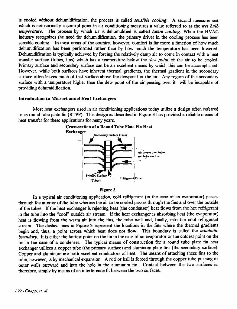
Most heat exchangers used in air conditioning applications today utilize a design often referredto as round tube plate fin @’ITF). This design as described in Figure 3 has provided a reliable means ofheat transfer for these applications for many years.
Cross-section of a Round Tube Plate Fin HeatExcban er
IL - +
SecondarySurface (Fins)
—# \
4’.
AJhsses over IIIbes
end ~ween fins
FTimq Surfatx
(Tubes)-- Re6igeran Flow
Figure 3.
In a typical air condhioning applicatio~ cold refrigerant (in the case of an evaporator) passesthrough the interior of the tube whereas the air to be cooled passes through the fins and over the outsideof the tubes. If the heat exchanger is rejecting heat (the condenser) heat flows from the hot refrigerantin the tube into the “cool” outside air stream. If the heat exchanger is absorbing heat (the evaporator)heat is flowing from the warm air into the fins, the tube wall and, finally, into the cool refrigerantstream. The dashed lines in Figure 3 represent the locations in the fins where the thermal gradientsbegin and, thus, a point across which heat does not flow. This boundary is called the adiabatic
bounakrry. It is either the hottest point on the fin in the case of an evaporator or the coldest point on thefin in the case of a condenser. The typical means of construction for a round tube plate fin heat
exchanger utilizes a copper tube (the primary surface) and aluminum plate fins (the secondary surface).Copper and aluminum are both excellent conductors of heat. The means of attaching these fins to thetube, however, is by mechanical expansion. A rod or ball is forced through the copper tube pushing itsouter walls outward and into the hole in the aluminum fin. Contact between the two surfaces is,
therefore, simply by means of an intefierence fit between the two surfaces.
1.22- Cbupp, et. al.

The microchannel heat exchanger was invented by Modine researchers during the mid 1980’s.At the time, the objective of this development effort was to improve on the fimdarnentals of heatexchanger pefiorrnance by reducing the cavity size of refrigerant flow passages, improving the brazingtechniques traditionally used in radiator constructio~ improving the ability of secondaty surface on theair side of the heat exchanger to extract or reject heat and reducing the air side pressure drop. Thetubes used in this construction are flat and segmented into very small flow channels as seen in Figure 4.
Representative Cross-section of Microchannel Heat ExchangerCore Tube
Typical Tube Depths - 13.5mm., 18.8mm.,
El ~S~HO.=-.thrU
T
Tube Height
Figure 4.
These flat tubes have a dual effect of reducing the air side pressure drop while maximizing thesurface contact area of the tube (when compared to a round tube). This new design significantlyreduced the overall size of the heat exchanger while actually enhancing heat transfer performance andminimizing the power required to move the air through the heat exchanger.
Cross-section of a Microchannel HeatExchanger
,4irpassesovertubesand
Finsbrazed to tubes
Secondhy S&face (Fins)
Figsire 5.
Although not to scale, the relative proportions of Figures 3 and 5 are representative. Themicrochannel heat exchanger utilizes fins which are considerably shorter than those found in a typicalround tube plate fin heat exchanger. There is a higher percentage of primary surface in a microchannelheat exchanger than what is found typically in a round tube plate fin heat exchanger. And, mostsignificantly, the fins in a rnicrochannel heat exchanger are metallurgically bonded to the primarysurface. A cross-section of a portion of a microchannel heat exchanger is shown in Figure 6.
Waking tbe Sleeping Giant: Introducing New Heat Exchanger Technology -1.23

CROSS-SECTION OF MICROCHANNEL HEAT EXCHANGER
FIGURE 6
/
If the two heat exchanger technologies are compared with respect to the preceding discussionon the findarnentals of good heat exchanger desigq it is noted that:
● the thermal gradients are significantly reduced in a microchannel heat exchanger● the contact resistance between the fins and tubes is generally insignificant in a
microchannel heat exchangerFrom an environmental perspective, there are two additional advantages inherent in
microchannel heat exchangers:1. The heat exchanger is all aluminum. When the product must be scrapped it is filly
recyclable.2. Because of the reduced internal volume of the heat exchanger, the amount of refrigerant
used in an air condhioning system equipped with microchannel heat exchangers istypically reduced by 50’Mo.
From a system performance perspective, there are two significant advantages:1. The transient response time of the system is sharply reduced over that of a conventional
system due to the low mass of reiligerant in the system as well as the low mass ofmaterial in the heat exchangers. This means that the system will reach operatingtemperature (and therefore, do more cooling for a given time period) than in aconventional system.
2. As noted earlier in the discussion on dehumidificatio~ reduced thermal gradients andlarge amounts of primary surface lead to a lower average metal temperatures in themicrochannel heat exchanger. This lower metal temperature means more air comes incontact with metal temperatures below the dew point of the air, thus improvingdehumidification by a factor of 20% to 30Y0.
1.24- Cbapp, et. al.
Impact of the Microchannel Heat Exchanger on the Automotive Industry
During the 1980’s and into the 90’s, the U.S. Automotive Industry was faced with two majorexternal challenges:
1. Improve fbel economy2. Eliminate CFC’S from the automobile air conditioning systemMany approaches were taken to improve fiel economy including a restyling of the exterior of
the automobile in an effort to improve the aerodynamics of the vehicle. A major outcome of this effortwas to slope the automobile’s hood. Utiortunately, this caused a significant reduction in the spaceavailable for the automobile’s air conditioning condenser. At the same time, the new refrigerant ofchoice, R1 34a, required more petiormance out of the condenser in order to maintain the same level ofefficiency.
Over the past 10 years, virtually every automobile manufacturer has either adopted themicrochannel heat exchanger design or created a “clone” to provide a similar level of performance asthe rnicrochannel heat exchanger. The overwhelming acceptance and success of this style of heatexchanger is based on:
● significant performance improvements● cost effective manufacturing● proven durability in severe environments● proven reliability
The Building HVAC Industry
Application of Microchannel Heat Exchanger Technology to the Building HVAC Industry
With the success of the rnicrochannel heat exchanger design in the automotive world, our researchersbegan to investigate the potential for applying this same technology to the building heating, ventilating,and air conditioning @VAC) industty. The results of these efforts have been a mixture of technicalsuccesses and market iiustrations.
Back in the early 1990’s, investigations into the suitability of the microcharmel heat exchanger inbuilding HVAC applications were launched. The first application objective was to replace a standard“A” coil evaporator with a bent microchannel heat exchanger slab. A sketch of this bent microchannel
heat exchanger (now known as the PFVW Heat Exchanger) is shown Figure 7.
Waking the Sleeping Giant: Introducing New Heat Exchanger Technology -1.25

The PFV w Heat Exchanger
Thesimpler,
Figure 7.
motivation behind this effort was to replace a labor intensive, complicated component with acleaner design. The bent microchannel heat exchanger appeared to not only meet the cost
objectives but also improved dehumidification with lower power requirements to move the air acrossthe surface. The product clearly has the potential to be a cost effective replacement for the currenttechnology as well as significantly improving comfort in the vast majority of the United States and withless power required from the blower. This significant first step led to a decision to test the designfurther. Since the original test work the bent microchannel heat exchanger has been:
● tested successfi,dly in heat pump systems (laboratory and field tests)● tested successfully for water disentrainment (in a more challenging horizontal air handler
configuration)● tested successfully in laborato~ corrosion testse tested successfidly in system level field tests
Experimental Work
Despite all of the apparent design and cost advantages of the technology, the response by theHVAC Industry has been “lukewarm”, at best. In order to continue the development effort, researchersconstructed a modified central air conditioning system. A commercially available small condensing unit(outdoor unit) was purchased in which the condenser was replaced with a microchannel condenser. Theoriginal compressor was replaced with a smaller compressor. The original condensing unit began as a10 SEEK 3 ton unit. Due to the unique applicatio~ it was not known at the time how the newcondenser would pefiorm. The modified syste~ therefore, was configured as a 2.5 ton system. Theresults of this effort were impressive. The new system was small, lightweight, delivered 30 ‘Yomoredehumidificatio~ and achieved a SEER of 13.3. Tests petiormed at an independent laboratory
confirmed the following results:
1.26- Cbapp, et. al.

Table 1. Test Results from Prototype Air Conditioning System using Microchannel Heat Exchangers
Total Condensing Evaporator AirCooling Latent Power Unit Suction Side Pressure
DOE Test Capacity Cooling Input EER Pressure Pressure Drop@m 0?0 (Watis) (JMu/W-hr) (P d
.(P g)
. (in. H20)A 31350 35 2800 11.20 2~5 ;; 0.12
B 33390 37 2460 13.57 187 81 0.12c 29570 0 2455 11.51 181 71 0.10
Energy CoolingLoad Degradation Part badDOE Test Cooling Input EER Factor Coefficient Factor SEER
(mm) (W-hr) (Btu/W-hr) (CLF) (CD) PLF(O.5) (MuiW-hr)D 2722 246 11.07 0.192 0.048 0.976 13.25
Over the past several years, the bent microchannel evaporator has been tested extensively for itsdehumidification characteristics. In comparison with typical round tube plate fin evaporators, the bentmicrochannel evaporator has consistently shown higher levels of dehumidification. A summary of anumber of these tests is shown in Figure 8.
1.41.31.21.1
10.90.8
0.7
0.6
Comparison of Dehumidification Performance
RTPF “A” Coils Vs. Bent Microchannel Evaporators
Frn Microchannel
Evaporator
— Linear(McrochannelEvaporator
A— Linear(RT FEvaporator)
I
600 800 1000 1200 1400llir Flow(scfm) DOE B Test Conditions
Figure 8 Entering Air 8CPDB,6P WB
A limited number of field tests have been conducted. Four systems were built and placed in 3locations around the countty (Milwaukee, Wiscons~ Charleston South Carolin~ and Laredo, Texas)in the summer of 1994. One system used R-134a refrigerant, the others used R-22 refrigerant. Today,all of the systems are still in operation except the R-134a system. This unit was removed from servicedue to a vibration ftilure (unrelated to the heat exchangers).
Preliminary efforts have also been undertaken to develop a heat pump utilizing microchannelheat exchangers. Rather than retrofitting an existing heat pump, however, researchers chose to
construct an entirely new system in order to exploit some of the basic characteristics of microchannel
Waking the Sleeping Giant: Introducing New Heat Exchanger Technology -1.27

heat exchanger design.
Efficiency levels for this 2.5 ton heat pump system are as follows:● 11.02 SEER ●7.53 HSPFThe test results for this first prototype design were considered satisfactory and many
desigrdperformance enhancements were identified in the process. Work is ongoing at the time of thiswriting to incorporate these enhancements into the second generation of heat pump designs.
Once design and pefiormance parameters have been satisfied, the next (and in some cases, theprimary) focus is the durability and reliability of the heat exchangers. Controlled laborato~ testingprovides an ongoing means of product evaluation. The laboratory tests performed on microchannelheat exchangers to date include:
● neutral salt spray● CASS (Copper Accelerated Salt Spray)● SWAAT (Sea Water Acidified Accelerated Test)● various proprietary test proceduresIn an effort to evaluate microchannel heat exchangers in an aggressive but controlled field test
for corrosion and durability, 31 window air conditioners were retrofitted with microchannel condensersearly in 1997. Control and experimental units were placed in an industry-recognized field test site inKure Beac~ North Carolina. Kure Beach is considered to be one of the more aggressive corrosion testsites in North America. The condensers used in these experimental units were constructed with avariety of materials and different methods of corrosion protection in order to determine the bestcombination of alloys and brazing techniques. At the time of this writing, no units have experiencedfailure. This work is expected to be completed by the end of 1999.
Cost Analysis
For a new technology to gain acceptance in the marketplace, costs (or more realistically, selling
price) of that new technology must be affordable to the average consumer. In order to assess thisaspect of the problem in more detail, system cost estimates were generated comparing central airconditioning systems constructed with microchannel heat exchangers to those constructed withconventional heat exchangers. While it is clear that there are many ways to achieve high SEER values,the systems evaluated in this analysis were relatively straightforward utilizhg single speed compressors,single speed fans, and basic electro-mechanical controls. Of significance in this evaluation is the effect ofmark-up on the final pricing to the consumer. Following is a summary of the cost evaluation along witha chart (Figure 9) examining the impact of these costs and subsequent payback in light of various mark-ups to the consumer. This last point is especially important today since high SEER products aregenerally marketed at premium pricing levels.
1.28- Cbdpp, et. al.

Tab1e2. EstimatedFactory Costs fora Residentia12.5Ton CentralAir Conditioning
Efficiency Level Typical System constructed with Advanced SystemRound Tube Plate Fin Heat constructed with PFW
Exchangers Heat Exchangers10 SEER $298 $27612 SEER $349 $31914 SEER $379 $347
System*
*System is defined as the condensing unit and evaporator assembly (not the complete air handler)
Estimated Payback Period for Conventional Systems and Systems Constructed of Microchannel HeatExchangers as a Function of Mark-up
54.5
0.5
0
1 I I I I2 2.5 3 3.5 4
MARK-UP FACTOR TO CONSUMER
Figure9
+12 SEER SystemConstructed withcomentionsl heatexchangers
+12 SEER SystemConstructed withMicmchannel liedExchangers
+14 SEER SystemConstructed withconvetilonal heatexchangers
+14 SEER SystemConstructed withMicmchannel HeatExchengem
The Regulatory Process
A point of contention between the DOE and the I-WAC industry has been the Design Optionsselected for each product class. Design Options typically represent new technology which is believed tobe relevant and appropriate for inclusion in the rulemaking process. However, most Design Optionscome with a price tag to industry. Adoption of new technology can result in:
● stranded assets● advanced in-house technology expertise needed● the requirement for new sales and marketing tools● higher product costs
Waking the Sleeping Giant: Introducing New Heat Exchanger Technology -1.29

h short, to some manufacturers Design Options are a threat to the way they prefer to dobusiness. Because of the controversy surrounding this criterio~ the DOE in cooperation withrepresentative manufacturers of the U.S. appliance industry developed a set of criteria to be used in theevaluation process. It is worth reviewing these rules as they relate to the state of rnicrochannel heatexchanger developments:
Criteria Microchannel Heat Exchanger Relevance
Technically Feasible ● Application into Worldwide automotive market
. Development work in HVAC&R markets
Practical to ● Design is simple and straightfonvardmanufacture, install ● Worldwide manufacturing facilities exist todayand semice . Extensive laboratory and field test experiences
. Connections and repairs are similar to or simplified from currenttechnology
Have no adverse ● Integration of microchannel heat exchangers into residential airimpacts on product condhioning is virtually transparent to the consumerutility to the . Differences between microchannel and round tube plate fin heatconsumer exchangers provide pefiorrnance advantages to the consumer
● Durability is greater than the current technology
Have no adverse . No dangers to the consumer from the productimpacts on health . Reduced charge lessens any potential for danger even if flammable or toxicand safety refrigerants are ever employed
● The product is completely recyclable
. No chlorinated solvents or lubricants used in the manufacturing process
National Field Test Program Initiative
Modine introduced the microchannel heat exchanger technology to the DOE, various stateenergy offices, the U.S. Environmental Protection Awociatio~ and various electric utilities beginning in1994. Following these presentations and an expressed high level of interest in the technology, aprogram to develop a national field test program was established. The original objective of the programwas to place up to 24 different central air condhioning systems around the country over the ensuing 6months. It was believed that this approach would give fimdamental credibility to the tenet that themicrochannel heat exchanger was appropriate for the central air conditioning market. This program hasgotten off to a slower than expected start but continues forward. Today, Southern California Edison
has installed 2 units in their service territory. Viiginia Power has fimded the testing of a unit at theFlorida Solar Energy Center. Programs are expected to be initiated in Wisconsin Electric’s territory aswell as regions of North Carolina under the auspices of the Energy Office of the Department ofCommerce in North Carolina. This program is expected to last for three years. Due to the delays in the
program startup, however, it is anticipated that the overall timeline will last well beyond the three yearperiod.
1.30- Chdpp, et. di.
Independent Evaluations
The microcharmel heat exchanger has also generated interest in the academic sector over thepast decade. In addition to the National Field Test Program, additional work continues at variousresearch centers around the nation.
University of Illinois - ACRC
The Air Conditioning and Refrigeration Center located at the University of Illinois (Urbana) istesting a 2.5 ton residential split system heat pump using microcharmel heat exchanger technology whichis optimized around minimum TEWI (Total Equivalent Warming Impact). The system, designed tooperate with HFC R410~ has been optimized to minimize the ratio of T’Ew’f/~d (kg COJton-hr). Inthis challenging prograq not only is cycle efficiency a key parameter (indirect equivalent warmingimpact), but also the design of the system is centered around a goal of minimal reiligerant charge (directequivalent warming impact). The objective of the ACRC program is to develop a heat pump systemwith an EER of 12.8 or greater combined with a 67 to 75 percent reduction in refi-igerant charge.
Argonne National Laboratory
In an effort aimed at gaining a better understanding of the physics involved in microcharmel heattransfer and to characterize refrigerant condensation phenomena in microcharmel tubes, extensivetestwork was conducted through a Cooperative Research & Development Agreement (CRADA) atArgonne National Laboratory. The condenser test facility was designed and developed in order tomeasure the condensation characteristics of R- 12, R-22, R1 34a & R4 10a in microchannel condensertubes.
Independent Laboratory Tests
In addhion to the original central air conditioning system constructed in 1993, a second systemequipped with a microchannel condenser and a bent microchannel evaporator has since been constructedand tested. The condensing unit used in the retrofit was selected on the basis of minimal footprint.Although a 3 ton system was chose% no effort was made to achieve 3 tons of cooling. Because thegoal of the test work was to achieve as high of an efficiency as possible in as small of a footprint aspossible, the framework of the 3 ton unit was selected as the retrofit size target. It should be noted thatthe footprint of the 3 ton system was the same as the 2.5 ton test system and the compressor capacitywas lowered to 2.5 tons. The only difference in the 3 ton commercial system and the 2.5 toncommercial system was a decrease in condenser height of about 4 inches for the 2.5 ton system.
Waking the Sleeping Giant: Introdti~”ng New Heat Excb~nger Technology -1.31

Following is a comparison summa~ of the test system and the original system.
Modified Central AirMeasured Parameter Conditioning System using
PFW Heat Exchangers Original SystemCapacity 30,000 BTUH 36,000 BTUH
SEER 13.1 10.0
Refrigerant R-22 R-22
Sensible Heat Ratio 0.64 0.724
(@ DOE A condition)Refrigerant Charge 82 OUnmS 123 ounces
Conclusions
The microchannel heat exchanger represents a significant advance in heat exchanger design overthat of the round tube plate fin heat exchanger when used in refrigerant to air heat transfer equipment.The fimdamentals of the technology are straightforward and “attack” the inherent weak spots of thecurrent technology through basic improvements. These improvements have been demonstrated to
achieve unexpected pefiormance improvements in virtually every aspect of the heat transfer system.The rnicrochannel heat exchanger has had a short but phenomenally successful history in the
automotive air conditioning market. This same basic technology has been demonstrated to be applicableto the Building I-WAC market in the United States. Laboratory and field test work have demonstratedthe suitability of the product in virtually every aspect of importance including but not limited to:
● heat transfer● pressure drops● dehumidification● reduced refrigerant charge● weight● recyclability● corrosion resistance● durabilityThe product can be integrated into the same basic system and package used today with ve~
little modification. The product is cost-effective and available to the indust~ as either a purchasedcomponent or a (non-exclusive) licensed technology.
1.32- Cbapp, et. al.


![Eusocial ant nest management, template for land development · Latter strategy resembles the waking up of sleeping plant buds by herbivory [37]. Harvester ants and termites farming](https://img.dokumen.tips/doc/110x75/5fa11eff0a2e8f10542b04e4/eusocial-ant-nest-management-template-for-land-development-latter-strategy-resembles.jpg)