Embed Size (px)
Citation preview
Software Version 5.44 / 4.44 OM-20000015 Rev. 2.0
NovAtel Inc.
WAAS / GUS RECEIVER SUBSYSTEM
Installation and Operation Manual

ii WAAS / GUS Receiver Subsystem Installation and Operation Manual – Rev. 2.0
WAAS / GUS Receiver Subsystem
Installation and Operation Manual
Publication Number: OM-20000015
Revision Level: 2.0 97/11/18
This manual reflects WAAS / GUS firmware revision level 5.44 / 4.44.
Proprietary NoticeInformation in this document is subject to change without notice and does not represent a commitment on the part ofNovAtel Inc. The software described in this document is furnished under a license agreement or non-disclosureagreement. The software may be used or copied only in accordance with the terms of the agreement. It is against thelaw to copy the software on any medium except as specifically allowed in the license or non-disclosure agreement.
No part of this manual may be reproduced or transmitted in any form or by any means, electronic or mechanical,including photocopying and recording, for any purpose without the express written permission of a duly authorizedrepresentative of NovAtel Inc.
The information contained within this manual is believed to be true and correct at the time of publication.
P-Code Delayed Correlation Technology, GPSAntenna, GPSCard, MEDLL, MET, MiLLennium and NarrowCorrelator are trademarks of NovAtel Inc.
Belden is a registered trademark of Belden Inc.
© 1997 NovAtel Inc. All rights reservedUnpublished rights reserved under International copyright laws.Printed in Canada on recycled paper. Recyclable.

Table of Contents
WAAS / GUS Receiver Subsystem Installation and Operation Manual – Rev. 2.0 iii
TABLE OF CONTENTSForeword ....................................................................................................................... ..... xi
Scope........................................................................................................................................................................ xiPrerequisites ............................................................................................................................................................. xiCompliance with GPS Week Rollover..................................................................................................................... xiCompliance with Year 2000 Rollover..................................................................................................................... xiiWhat’s New in this Edition? ................................................................................................................................... xii
1 Introduction............................................................................................................... 13WAAS Overview .....................................................................................................................................................13The NovAtel WAAS / GUS Receiver ......................................................................................................................14
Operational Overview .......................................................................................................................................15MEDLL .........................................................................................................................................................16GEO Processing.............................................................................................................................................16Dual Frequency L1/L2 I ................................................................................................................................16Dual Frequency L1/L2 II...............................................................................................................................16Other Outputs & Inputs .................................................................................................................................17
2 Installation of WAAS Receiver ................................................................................ 18Minimum Configuration ..........................................................................................................................................18Connecting the External Frequency Reference........................................................................................................19Connecting Data Communications Equipment ........................................................................................................20Using the 1PPS Output.............................................................................................................................................21Connecting the GPS Antenna...................................................................................................................................21Connecting the External Power Input ......................................................................................................................22Using the 20.473 MHz Output Signal......................................................................................................................22Accessing the Strobe Signals ...................................................................................................................................23
3 Operation .................................................................................................................. 24Pre-Start Check List .................................................................................................................................................24
Serial Ports - Default Settings ...........................................................................................................................24Boot-Up.............................................................................................................................................................24
Initial Communications With the WAAS / GUS Receiver.......................................................................................25
4 Firmware Updates .................................................................................................... 26Contact Customer Service........................................................................................................................................26Download Compressed Files....................................................................................................................................27Decompress Files .....................................................................................................................................................27Run LOADER..........................................................................................................................................................27
Menu Mode.......................................................................................................................................................28Command-Line Mode.......................................................................................................................................29
Updating Individual GPSCards .....................................................................................................................29Updating the GPSCards in the MEDLL Subsystem......................................................................................29
Entire Receiver Update Mode...........................................................................................................................31Updating Remotely Over a Network (PROPOSED)................................................................................................31
5 Command Descriptions ........................................................................................... 32$AGC .......................................................................................................................................................................35ASSIGN ...................................................................................................................................................................37$ASSIGNG2TOPRN ...............................................................................................................................................38$CCRATIO ..............................................................................................................................................................39
Table of Contents
iv WAAS / GUS Receiver Subsystem Installation and Operation Manual – Rev. 2.0
CLOCKADJUST..................................................................................................................................................... 40COMn...................................................................................................................................................................... 40CONFIG.................................................................................................................................................................. 41CSMOOTH ............................................................................................................................................................. 41$DLLORDER.......................................................................................................................................................... 42ECUTOFF............................................................................................................................................................... 42FIX POSITION ....................................................................................................................................................... 43$JAMMODE........................................................................................................................................................... 43LOG ........................................................................................................................................................................ 44$PLLBW ................................................................................................................................................................. 45RESET..................................................................................................................................................................... 46$SETFRAMETYPE................................................................................................................................................ 46$THRESHOLD ....................................................................................................................................................... 46UNASSIGN............................................................................................................................................................. 47UNASSIGNALL..................................................................................................................................................... 47$UNASSIGNG2TOPRN......................................................................................................................................... 48UNDULATION ...................................................................................................................................................... 48UNFIX..................................................................................................................................................................... 49UNLOG................................................................................................................................................................... 49UNLOGALL ........................................................................................................................................................... 49VERSION ............................................................................................................................................................... 50
6 Output Logging .........................................................................................................51
7 NovAtel Format Data Logs.......................................................................................54ASCII Log Structure ............................................................................................................................................... 54Binary Log Structure............................................................................................................................................... 54Time Conventions ................................................................................................................................................... 55Log Descriptions ..................................................................................................................................................... 55
$ACPA/B AGC Control Parameter Information............................................................................................ 55$AGCA/B AGC and A/D Information........................................................................................................... 58ALMA/B Decoded Almanac.......................................................................................................................... 60CDSA/B Communication and Differential Decode Status............................................................................. 61CLKA/B Receiver Clock Offset Data ............................................................................................................ 63DOPA/B Dilution of Precision....................................................................................................................... 65ETSA/B Extended Tracking Status................................................................................................................ 67FRMA/B Framed Raw Navigation Data ........................................................................................................ 71IONA/B Ionospheric Model Parameters ........................................................................................................ 72POSA/B Computed Position .......................................................................................................................... 73RBTA/B Satellite Broadcast Data: Raw Bits ................................................................................................. 75RCCA Receiver Configuration ...................................................................................................................... 76REPA/B Raw Ephemeris................................................................................................................................ 77RGEA/B Channel Range Measurements........................................................................................................ 77
Receiver Status – Detailed Bit Descriptions of Self-Test Word ................................................................... 80RVSA/B Receiver Status................................................................................................................................ 84SATA/B Satellite Specific Data ..................................................................................................................... 85SBTA/B Satellite Broadcast Data: Raw Symbols .......................................................................................... 87TM1A/B Time of 1PPS.................................................................................................................................. 88UTCA/B UTC Time Parameters .................................................................................................................... 89WRCA/B Wide Band Range Correction (Grouped Format).......................................................................... 90

Table of Contents
WAAS / GUS Receiver Subsystem Installation and Operation Manual – Rev. 2.0 v
AppendicesA Installation of GUS Receiver................................................................................................................91
Minimum Configuration......................................................................................................................91Connecting the External Frequency Reference ...................................................................................92Connecting Data Communications Equipment ...................................................................................94Using the 1PPS Output ........................................................................................................................94Connecting the Antennas.....................................................................................................................95Connecting the External Power Input..................................................................................................95Using the 20.473 MHz Output Signal .................................................................................................96Accessing the Strobe Signals...............................................................................................................96
B WAAS Receiver - Technical Specifications.........................................................................................98
C GUS Receiver - Technical Specifications ..........................................................................................103
D Information Messages ........................................................................................................................108
E Associated Suppliers...........................................................................................................................113
Index ................................................................................................................................ 114
TABLES
1 WAAS / GUS Commands by Category ............................................................................................................332 WAAS / GUS Command Summary..................................................................................................................343 Obsolete Commands .........................................................................................................................................344 WAAS / GUS Logs by Category ......................................................................................................................525 WAAS / GUS Log Summary............................................................................................................................536 Obsolete Logs ...................................................................................................................................................537 GPSCard Solution Status ..................................................................................................................................698 Channel Tracking Status Bits............................................................................................................................699 Range Reject Codes ..........................................................................................................................................7010 Receiver Self-Test Status Codes....................................................................................................................7911 Additional information about WAAS / GUS Receiver Self-Test Status word ..............................................8312 Type 1 !ERRA Messages ............................................................................................................................10913 Type 1 !MSGA Messages............................................................................................................................10914 Type 2 Information Messages .....................................................................................................................110
Table of Contents
vi WAAS / GUS Receiver Subsystem Installation and Operation Manual – Rev. 2.0
FIGURES
1 The WAAS Concept......................................................................................................................................... 132 The NovAtel WAAS / GUS Receiver .............................................................................................................. 143 WAAS / GUS Receiver Functional Block Diagram......................................................................................... 154 WAAS Minimum System Configuration ........................................................................................................ 185 Rear Panel of WAAS Receiver ........................................................................................................................ 196 10 MHz In (External Frequency Reference) - WAAS ..................................................................................... 197 Lights on Front Panel of WAAS Receiver ....................................................................................................... 208 Pinout for L1-C/A, L1/L2 I, & L1/L2 II Ports - WAAS .................................................................................. 219 Pinout for TIME Port - WAAS ........................................................................................................................ 2110 1 PPS Output - WAAS ................................................................................................................................. 2111 Antenna Input - WAAS ................................................................................................................................ 2212 External Power Connections - WAAS.......................................................................................................... 2213 20.473 MHz Output – WAAS ...................................................................................................................... 2314 Strobe 9-pin D-Connector Pinout - WAAS .................................................................................................. 2315 Main screen of LOADER program............................................................................................................... 2816 Height Relationships..................................................................................................................................... 4817 GUS Minimum System Configuration ........................................................................................................ 9118 Rear Panel of GUS Receiver ........................................................................................................................ 9219 10 MHz In (External Frequency Reference) - GUS ..................................................................................... 9320 Lights on Front Panel of GUS Receiver ....................................................................................................... 9321 Pinout for L1-C/A, L1/L2 I, & L1/L2 II Ports - GUS .................................................................................. 9422 Pinout for TIME Port - GUS ........................................................................................................................ 9423 1 PPS Output - GUS ..................................................................................................................................... 9424 Antenna Input - GUS.................................................................................................................................... 9525 External Power Connections - GUS ............................................................................................................. 9626 20.473 MHz Output - GUS........................................................................................................................... 9627 Strobe 9-pin D-Connector Pinout - GUS...................................................................................................... 96
Warranty Policy
WAAS / GUS Receiver Subsystem Installation and Operation Manual – Rev. 2.0 vii
WARRANTY POLICY
Warranty Period: one (1) year from the date of delivery. NovAtel warrants that during the Warranty Period the WAAS /GUS Receiver (Part No. 01016247) will be free from defects in material and workmanship, will conform to applicablespecifications, and the software will be free from errors which materially affect performance. These warranties areexpressly in lieu of all other warranties, expressed or implied, including, without limitation, all implied warranties ofmerchantability and fitness for a particular purpose. NovAtel shall in no event be liable for special, indirect, incidentalor consequential damages of any kind or nature due to any cause.
The Customer’s exclusive remedy for a claim under this warranty shall be limited to the repair or replacement, atNovAtel’s option, of defective or nonconforming materials, part or components. The foregoing warranties do not extendto (i) nonconformities, defects or errors in the WAAS / GUS Receivers (Part No. 01016247) due to accidents, abuse,misuse or negligent use of the WAAS / GUS Receivers (Part No. 01016247) or use in other than a normal andcustomary manner, environmental conditions not conforming to applicable specifications, or failure to follow prescribedinstallation, operating and maintenance procedures, (ii) defects, errors or nonconformities in the WAAS / GUS Receiver(Part No. 01016247) due to modifications, alterations, additions or changes not made in accordance with applicablespecifications or authorized by NovAtel, (iii) normal wear and tear, (iv) damages caused by force of nature or act of anythird person, (v) service or repair of the WAAS / GUS Receiver (Part No. 01016247 by the Customer without priorwritten consent from NovAtel, (vi) units with serial numbers or other factory identification removed or made illegible,(vii) shipping damage not applicable to improper packaging.
There are no user serviceable parts in the WAAS / GUS Receiver and no maintenance is required. When the status codeor the lights on the front panel indicate that a unit is faulty, call NovAtel Customer Service to confirm the faultdiagnosis.
You must obtain a RETURN MATERIAL AUTHORIZATION (RMA ) number by calling GPS CustomerService at 800-280-2242 before shipping any product to NovAtel.
Once you have obtained an RMA number, you will be advised of proper shipping procedures to return any defectiveproduct. When returning any product to NovAtel, please return the defective product in the original packaging to avoidESD and shipping damage.

Customer Service
viii WAAS / GUS Receiver Subsystem Installation and Operation Manual – Rev. 2.0
CUSTOMER SERVICE
If you require customer service, please provide the following information along with a detailed description of theproblem when you call or write:
Serial No. _____________________________________ Model No. ________________________________________
Software Release No.____________________________ Authorization No. __________________________________
Date Purchased: ________________________________
Purchased from: __________________________________________________________________________________
User name: ____________________________________ Title: ____________________________________________
Company:_______________________________________________________________________________________
Address: ________________________________________________________________________________________
City: _________________________________________ Prov/State:________________________________________
Zip/Postal Code:________________________________ Country: _________________________________________
Phone #: ______________________________________ Fax #:____________________________________________
Receiver interface: Computer type: __________________________Operating Shell: _____________________
Other interface used: ______________________________________________________________________________
Please provide a complete description of any problems you may be experiencing, or the nature of your inquiry (attachadditional sheets if needed):
_______________________________________________________________________________________________
_______________________________________________________________________________________________
_______________________________________________________________________________________________
_______________________________________________________________________________________________
_______________________________________________________________________________________________
You may photocopy and fax this page, call, or mail the above information to the address listed below.
For customer support, contact the NovAtel GPS Hotline by phone at 1-800-280-2242 (in North America) or 1-403-295-4900 (world-wide); by fax at 1-403-295-4901; by e-mail at [email protected]; over the World Wide Web at http://www.novatel.ca; or bymail at:
NovAtel Inc.GPS Customer Service1120 – 68 Avenue N.E.Calgary, Alberta, CanadaT2E 8S5

Notice
WAAS / GUS Receiver Subsystem Installation and Operation Manual – Rev. 2.0 ix
NOTICE
The United States Federal Communications Commission (in 47 CFR 15) has specified that the following notices bebrought to the attention of users of this product.
“This equipment has been tested and found to comply with the limits for a class A digital device, pursuant to Part 15 ofthe FCC rules. These limits are designed to provide reasonable protection against harmful interference when theequipment is operated in a commercial environment. This equipment generates, uses, and can radiate radio frequencyenergy and, if not installed and used in accordance with the instruction manual, may cause harmful interference to radiocommunications. Operation of this equipment in a residential area is likely to cause harmful interference in which casethe user will be required to correct the interference at his own risk.”
“Equipment changes or modifications not expressly approved by the party responsible for compliance could void theuser’s authority to operate the equipment.”
IMPORTANT: In order to maintain compliance with the limits of a Class A digital device, it is required to useproperly shielded interface cables when using the Serial Ports, such as Belden #9539, or equivalent, double-shieldedcables when using the Strobe Port, such as Belden #9945, or equivalent, and Belden #8770 cable for input power source(ensuring the shield is connected to the protection ground).
Foreword
WAAS / GUS Receiver Subsystem Installation and Operation Manual – Rev. 2.0 xi
FOREWORD
SCOPE
The WAAS / GUS Receiver Subsystem Installation and Operation Manual is written for users of the WAAS / GUSReceiver Subsystem. The manual describes both the WAAS and GUS receivers. Except for those cases where a sectionstates that it specifically applies to a WAAS receiver or a GUS receiver, everything else applies to both receivers.
This manual describes the NovAtel WAAS / GUS Receiver Subsystem in sufficient detail to allow effective integrationand operation. The manual is organized into sections, which allow easy access to appropriate information. From hereon, the WAAS / GUS Receiver Subsystem shall be referred to as the “WAAS / GUS receiver”.
It is beyond the scope of this manual to provide service or repair details. Please contact your NovAtel Service Center forany customer service inquiries.
PREREQUISITES
The WAAS / GUS receiver is a stand-alone fully functional GPS and WAAS receiver. Refer to Chapter 2 Installationof WAAS receiver or Appendix A Installation of GUS receiver for more information on installation requirements andconsiderations.
The NovAtel WAAS / GUS receiver module utilizes a comprehensive user interface command structure which requirescommunications through its serial (COM) ports. To utilize the built-in command structure to its fullest potential, it isrecommended that some time be taken to review and become familiar with Chapters 5-7 of this manual before operatingthe WAAS / GUS receiver.
COMPLIANCE WITH GPS WEEK ROLLOVER
The GPS week rollover issue refers to the way GPS receivers store information regarding the current GPS week.According to the official GPS system specifications document (ICD-GPS-200, paragraph 20.3.3.3.1.1), “… 10 bits shallrepresent the number of the current GPS week…”. This means the GPS week is represented by an integer numberbetween 0 and 1023. As GPS time started on Sunday January 6, 1980 at 0:00 hours, week 1023 will end on SaturdayAugust 21, 1999 at 23:59:59.
As of yet, there is no consensus regarding what will happen after that moment. According to the ICD-GPSspecifications, the receiver should reset the GPS week number. This means that the week number should not advance to1024, but start back at 0. However, another way to handle this issue is to extend the number of bits used to represent theGPS week number. This way, the GPS week would be able to increment as per usual and would not have to be reset.
As per the GPS system specifications document, NovAtel firmware will reset the receiver’s GPS week number back tozero. Different manufacturers will no doubt handle this situation differently. This issue will not be fully resolved untilthe U.S. Department of Defense, which controls GPS, issues a clear and definitive statement regarding the GPS weekrollover issue. Therefore, users should be aware of this issue and keep in mind that there may be a compatibility issuewhen purchasing and using different makes of GPS receivers.

Foreword
xii WAAS / GUS Receiver Subsystem Installation and Operation Manual – Rev. 2.0
COMPLIANCE WITH YEAR 2000 ROLLOVER
There has been significant concern about the impact of the year 2000 on computer systems because some applicationsand operating systems use two digits rather than four digits to represent and store the year in a date field (e.g., January 1,2011). Software relying on two-digit identifiers for dates may not work as expected after December 31, 1999.
The software used in the WAAS / GUS receivers accurately represents the date information. Testing shows that thissoftware will be unaffected by the change to the year 2000.
WHAT’S NEW IN THIS EDITION?
This edition now documents the features of the GUS receiver, in addition to those of the standard WAAS receiver.
Also, this manual incorporates revisions due to the latest version of software (5.44 / 4.44). There are descriptions of newcommands ($AGC, $DLLORDER, $JAMMODE, $PLLBW, $SETFRAMETYPE, $THRESHOLD, ECUTOFF) andnew logs ($ACPA/B, $AGCA/B, ALMA/B, DOPA/B, IONA/B, POSA/B, RBTA/B, RCCA/B, REPA/B, SATA/B,SBTA/B, UTCA/B, WRCA/B). Notice is given that the DYNAMICS command has been replaced by the $PLLBWcommand, and that the WBRB log has been replaced by the WRCA/B log. Obsolete commands and logs will not besupported in future releases of software.
1 - Introduction
WAAS / GUS Receiver Subsystem Installation and Operation Manual – Rev. 2.0 13
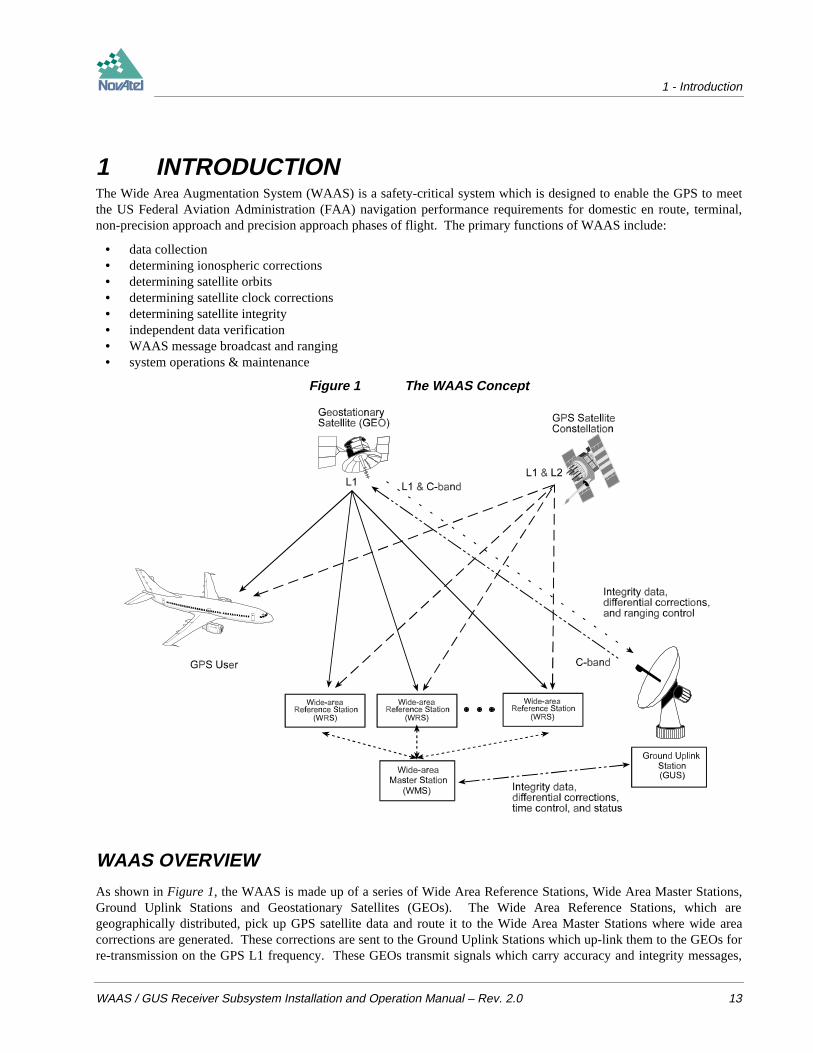
1 INTRODUCTIONThe Wide Area Augmentation System (WAAS) is a safety-critical system which is designed to enable the GPS to meetthe US Federal Aviation Administration (FAA) navigation performance requirements for domestic en route, terminal,non-precision approach and precision approach phases of flight. The primary functions of WAAS include:
• data collection• determining ionospheric corrections• determining satellite orbits• determining satellite clock corrections• determining satellite integrity• independent data verification• WAAS message broadcast and ranging• system operations & maintenance
Figure 1 The WAAS Concept
WAAS OVERVIEW
As shown in Figure 1, the WAAS is made up of a series of Wide Area Reference Stations, Wide Area Master Stations,Ground Uplink Stations and Geostationary Satellites (GEOs). The Wide Area Reference Stations, which aregeographically distributed, pick up GPS satellite data and route it to the Wide Area Master Stations where wide areacorrections are generated. These corrections are sent to the Ground Uplink Stations which up-link them to the GEOs forre-transmission on the GPS L1 frequency. These GEOs transmit signals which carry accuracy and integrity messages,

1 - Introduction
14 WAAS / GUS Receiver Subsystem Installation and Operation Manual – Rev. 2.0
and which also provide additional ranging signals for added availability, continuity and accuracy. These GEO signalsare available over a wide area and can be received and processed by ordinary GPS receivers. GPS user receivers arethus able to receive WAAS data in-band and use not only differential corrections, but also integrity, residual errors andionospheric information for each monitored satellite.
The signal broadcast via the WAAS GEOs to the WAAS users is designed to minimize modifications to standard GPSreceivers. As such, the GPS L1 frequency (1575.42 MHz) is used, together with GPS-type modulation - e.g. aCoarse/Acquisition (C/A) pseudorandom (PRN) code. In addition, the code phase timing is maintained close to GPStime to provide a ranging capability.
THE NOVATEL WAAS / GUS RECEIVER
In this context, the NovAtel WAAS Receiver Subsystem (see Figure 2) is designed to be used in a Wide Area ReferenceStation. The NovAtel WAAS Receiver Subsystem is designed to provide the GPS monitoring function for the groundinstallations in the WAAS network. As such, a number of significant, customized functions have been designed into thereceiver. The principal function is to provide GPS outputs which are virtually free from multipath effects. This isparticularly important for roof-top installations where signal reflections are likely to result in significant multipatheffects.
By comparison, the NovAtel GUS Receiver Subsystem is designed to be used in the Ground Uplink Station.
Figure 2 The NovAtel WAAS / GUS Receiver
There are many similarities between the WAAS Receiver Subsystem and the GUS Receiver Subsystem. For example,the user interface - the commands by which you can enter information, and the logs by which you can extract data - iscommon to both receivers. Therefore, throughout this manual they are both referred to as the “WAAS / GUS receiver”whenever the text is sufficiently general to refer to either one. However, in those sections of the manual where one orthe other is being specifically described, “WAAS receiver” or “GUS receiver” is used.
1 - Introduction
WAAS / GUS Receiver Subsystem Installation and Operation Manual – Rev. 2.0 15
The NovAtel WAAS / GUS receiver is a high-performance GPS & WAAS receiver that automatically achieve a highlevel of multipath reduction, without any user intervention. NovAtel has developed a multipath elimination technologythat approaches the theoretical limits of multipath-free GPS signal reception. This patented technology, known as“Multipath Estimation Delay-Lock-Loop” (MEDLL), uses a combination of hardware and software techniques whichtogether are capable of reducing the combined effects of pseudorange and carrier-phase multipath errors by as much as90% compared to a system using Narrow Correlator alone. The MEDLL technology takes advantage of NovAtel’sparallel channel Narrow Correlator sampling techniques. MEDLL uses a proprietary coupled correlator samplingtechnique combined with “maximum likelihood estimation” techniques to break down the received signals into directpath and reflected path components. MEDLL determines the amplitude, delay, and phase angle of both the direct andmultipath signals and analyses the signal with the least delay to determine the direct path. All other signals with greaterdelay are considered to be multipath components and are removed. To do this, MEDLL utilizes a multi-cardconfiguration. Each L1 GPSCard in the MEDLL receiver is linked to one common RF deck and an OCXO whichminimizes inter-channel biases.
The WAAS / GUS receiver also incorporates two L1/L2 GPSCards, which incorporate NovAtel’s P-Code DelayedCorrelation Technology, providing superior performance even in the presence of P-code encryption. Each GPSCard isan independent GPS receiver.
The WAAS / GUS receiver is packaged in a standard 4U x 19” sub-rack . Easy I/O access is provided by the rearpanel’s 9-pin D connectors as well as the antenna and external oscillator connectors.
OPERATIONAL OVERVIEW
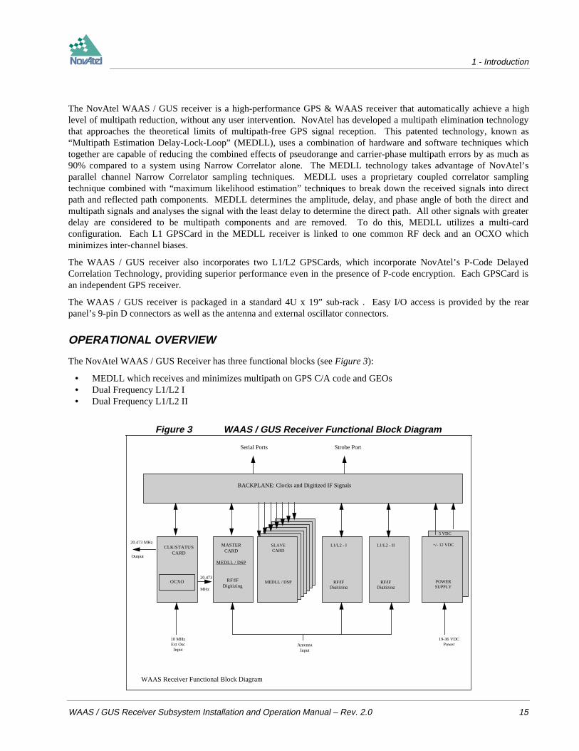
The NovAtel WAAS / GUS Receiver has three functional blocks (see Figure 3):
• MEDLL which receives and minimizes multipath on GPS C/A code and GEOs• Dual Frequency L1/L2 I• Dual Frequency L1/L2 II
Figure 3 WAAS / GUS Receiver Functional Block Diagram
RF/IFDigitizing
BACKPLANE: Clocks and Digitized IF Signals
Serial Ports Strobe Port
CLK/STATUSCARD
OCXO
20.473 MHz
Output
MASTERCARD
MEDLL / DSP
RF/IFDigitizing
20.473
MHz
10 MHzExt OscInput
AntennaInput
SLAVECARD
MEDLL / DSP
+/- 12 VDC
POWERSUPPLY
5 VDC
19-36 VDCPower
WAAS Receiver Functional Block Diagram
SLAVECARD
MEDLL / DSP
SLAVECARD
MEDLL / DSP
L1/L2 - I
RF/IFDigitizing
L1/L2 - II
RF/IFDigitizing
1 - Introduction
16 WAAS / GUS Receiver Subsystem Installation and Operation Manual – Rev. 2.0
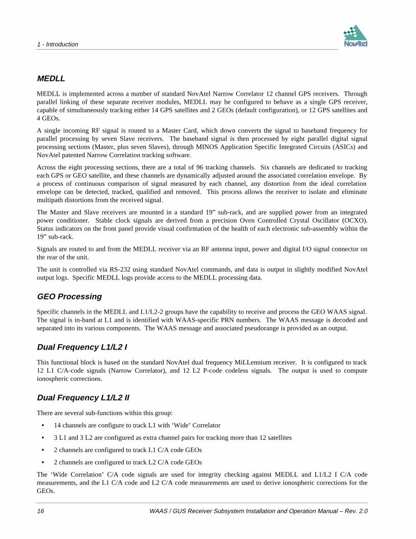
MEDLL
MEDLL is implemented across a number of standard NovAtel Narrow Correlator 12 channel GPS receivers. Throughparallel linking of these separate receiver modules, MEDLL may be configured to behave as a single GPS receiver,capable of simultaneously tracking either 14 GPS satellites and 2 GEOs (default configuration), or 12 GPS satellites and4 GEOs.
A single incoming RF signal is routed to a Master Card, which down converts the signal to baseband frequency forparallel processing by seven Slave receivers. The baseband signal is then processed by eight parallel digital signalprocessing sections (Master, plus seven Slaves), through MINOS Application Specific Integrated Circuits (ASICs) andNovAtel patented Narrow Correlation tracking software.
Across the eight processing sections, there are a total of 96 tracking channels. Six channels are dedicated to trackingeach GPS or GEO satellite, and these channels are dynamically adjusted around the associated correlation envelope. Bya process of continuous comparison of signal measured by each channel, any distortion from the ideal correlationenvelope can be detected, tracked, qualified and removed. This process allows the receiver to isolate and eliminatemultipath distortions from the received signal.
The Master and Slave receivers are mounted in a standard 19” sub-rack, and are supplied power from an integratedpower conditioner. Stable clock signals are derived from a precision Oven Controlled Crystal Oscillator (OCXO).Status indicators on the front panel provide visual confirmation of the health of each electronic sub-assembly within the19” sub-rack.
Signals are routed to and from the MEDLL receiver via an RF antenna input, power and digital I/O signal connector onthe rear of the unit.
The unit is controlled via RS-232 using standard NovAtel commands, and data is output in slightly modified NovAteloutput logs. Specific MEDLL logs provide access to the MEDLL processing data.
GEO Processing
Specific channels in the MEDLL and L1/L2-2 groups have the capability to receive and process the GEO WAAS signal.The signal is in-band at L1 and is identified with WAAS-specific PRN numbers. The WAAS message is decoded andseparated into its various components. The WAAS message and associated pseudorange is provided as an output.
Dual Frequency L1/L2 I
This functional block is based on the standard NovAtel dual frequency MiLLennium receiver. It is configured to track12 L1 C/A-code signals (Narrow Correlator), and 12 L2 P-code codeless signals. The output is used to computeionospheric corrections.
Dual Frequency L1/L2 II
There are several sub-functions within this group:
• 14 channels are configure to track L1 with ‘Wide’ Correlator
• 3 L1 and 3 L2 are configured as extra channel pairs for tracking more than 12 satellites
• 2 channels are configured to track L1 C/A code GEOs
• 2 channels are configured to track L2 C/A code GEOs
The ‘Wide Correlation’ C/A code signals are used for integrity checking against MEDLL and L1/L2 I C/A codemeasurements, and the L1 C/A code and L2 C/A code measurements are used to derive ionospheric corrections for theGEOs.

1 - Introduction
WAAS / GUS Receiver Subsystem Installation and Operation Manual – Rev. 2.0 17
Other Outputs & Inputs
• A 1PPS strobe output is available for synchronization with the time port receiver time message.
• A 20.473 MHz output is available for use with an external GEO receiver.
• Three serial ports provide: - raw satellite measurements (pseudorange, carrier & time)
- receiver status data (communications & tracking)
- raw satellite data (ephemeris & almanac)
- fast code corrections for signal stability monitoring
• The receiver accepts an external input from a 10MHz atomic clock for synchronization.
2 - Installation of WAAS Receiver
18 WAAS / GUS Receiver Subsystem Installation and Operation Manual – Rev. 2.0
2 INSTALLATION OF WAAS RECEIVER
This chapter provides sufficient information to allow you to set up and prepare the WAAS receiver for initial operation.The corresponding information for the GUS receiver is contained in Appendix A Installation of GUS receiver.
MINIMUM CONFIGURATION
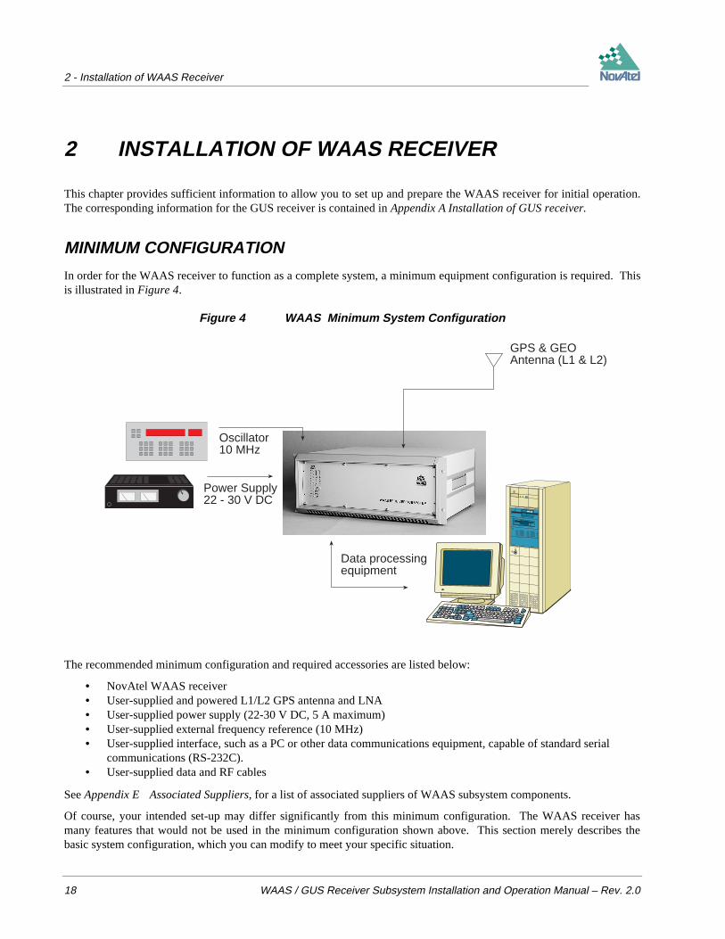
In order for the WAAS receiver to function as a complete system, a minimum equipment configuration is required. Thisis illustrated in Figure 4.
Figure 4 WAAS Minimum System Configuration
Data processingequipment
GPS & GEOAntenna (L1 & L2)
Power Supply22 - 30 V DC
Oscillator10 MHz
The recommended minimum configuration and required accessories are listed below:
• NovAtel WAAS receiver• User-supplied and powered L1/L2 GPS antenna and LNA• User-supplied power supply (22-30 V DC, 5 A maximum)• User-supplied external frequency reference (10 MHz)• User-supplied interface, such as a PC or other data communications equipment, capable of standard serial
communications (RS-232C).• User-supplied data and RF cables
See Appendix E Associated Suppliers, for a list of associated suppliers of WAAS subsystem components.
Of course, your intended set-up may differ significantly from this minimum configuration. The WAAS receiver hasmany features that would not be used in the minimum configuration shown above. This section merely describes thebasic system configuration, which you can modify to meet your specific situation.
2 - Installation of WAAS Receiver
WAAS / GUS Receiver Subsystem Installation and Operation Manual – Rev. 2.0 19
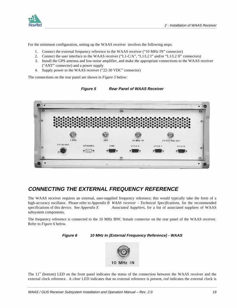
For the minimum configuration, setting up the WAAS receiver involves the following steps:
1. Connect the external frequency reference to the WAAS receiver (“10 MHz IN” connector)2. Connect the user interface to the WAAS receiver (“L1-C/A”, “L1/L2 I” and/or “L1/L2 II” connectors)3. Install the GPS antenna and low-noise amplifier, and make the appropriate connections to the WAAS receiver
(“ANT” connector) and a power supply4. Supply power to the WAAS receiver (“22-30 VDC” connector)
The connections on the rear panel are shown in Figure 5 below:
Figure 5 Rear Panel of WAAS Receiver
CONNECTING THE EXTERNAL FREQUENCY REFERENCE
The WAAS receiver requires an external, user-supplied frequency reference; this would typically take the form of ahigh-accuracy oscillator. Please refer to Appendix B WAAS receiver - Technical Specifications, for the recommendedspecifications of this device. See Appendix E Associated Suppliers, for a list of associated suppliers of WAASsubsystem components.
The frequency reference is connected to the 10 MHz BNC female connector on the rear panel of the WAAS receiver.Refer to Figure 6 below.
Figure 6 10 MHz In (External Frequency Reference) - WAAS
The 11th (bottom) LED on the front panel indicates the status of the connection between the WAAS receiver and theexternal clock reference. A clear LED indicates that no external reference is present, red indicates the external clock is

2 - Installation of WAAS Receiver
20 WAAS / GUS Receiver Subsystem Installation and Operation Manual – Rev. 2.0
not locked (undergoing the locking process, or the signal is not within the capture range), and green indicates that theclock is locked and stabilized. Refer to Figure 7 below.
Figure 7 Lights on Front Panel of WAAS Receiver
CONNECTING DATA COMMUNICATIONS EQUIPMENTThere are four serial ports on the back panel of the WAAS receiver; all are configured for RS-232C protocol. Theseports make it possible for external data communications equipment - such as a personal computer - to communicatewith the WAAS receiver. Each of these ports has a DE9P connector.
• The L1-C/A, L1/L2 I and L1/L2 II ports (see Figure 8) allow two-way communications. Each one is configuredas COM1 if you attempt to communicate directly with it. The L1/L2 I and L1/L2 II ports are each connected to anL1/L2 GPSCard within the WAAS receiver unit; the L1-C/A port is connected to the L1-only GPSCard whichcontrols the MEDLL subsystem. Each of these ports can be addressed independently of the other.
• The TIME port (see Figure 9) allows only output from the receiver; note that it is not possible to transmit data tothis port. It is configured as COM2 if you attempt to communicate directly with it. Data is available on this port at arate of 0.1 Hz, and is synchronized to the clock signal available at the 1 PPS connector. The data transfer rate isfixed at 9600 bps, with one stop bit.

2 - Installation of WAAS Receiver
WAAS / GUS Receiver Subsystem Installation and Operation Manual – Rev. 2.0 21
Figure 8 Pinout for L1-C/A, L1/L2 I, & L1/L2 II Ports - WAAS
DCD RXD TXD DTR GND
DSR RTS CTS NC
Figure 9 Pinout for TIME Port - WAAS
NC NC TXD DTR GND
NC RTS NC NC
USING THE 1PPS OUTPUT
The clock signal available on the 1 PPS port (see Figure 10) is synchronized to the data available on the Time port. Thespecifications and electrical characteristics of this signal are described in Appendix B WAAS receiver - TechnicalSpecifications. The pulse train is accessed from the BNC female connector on the back of the WAAS receiver.
Figure 10 1 PPS Output - WAAS
CONNECTING THE GPS ANTENNA
Selecting and installing an appropriate antenna system is crucial to the proper operation of the WAAS receiver. SeeAppendix E Associated Suppliers, for a list of associated suppliers of WAAS subsystem components.
Keep these points in mind when installing the antenna system:
2 - Installation of WAAS Receiver
22 WAAS / GUS Receiver Subsystem Installation and Operation Manual – Rev. 2.0
• Ideally, select an antenna location with a clear view of the sky to the horizon so that each satellite above the horizoncan be tracked without obstruction.
• Ensure that the antenna is mounted on a secure, stable structure capable of withstanding relevant environmentalloading forces (e.g. due to wind or ice).
Use high-quality coaxial cables to minimize signal attenuation. When using active antennas, remember that you alsoneed to connect each low-noise amplifier (LNA) to a suitable power source. The gain of the LNA must be sufficient tocompensate for the cabling loss.
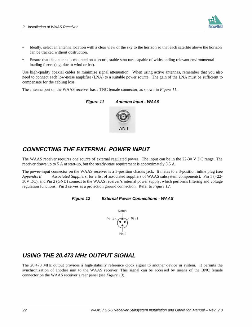
The antenna port on the WAAS receiver has a TNC female connector, as shown in Figure 11.
Figure 11 Antenna Input - WAAS
CONNECTING THE EXTERNAL POWER INPUT
The WAAS receiver requires one source of external regulated power. The input can be in the 22-30 V DC range. Thereceiver draws up to 5 A at start-up, but the steady-state requirement is approximately 3.5 A.
The power-input connector on the WAAS receiver is a 3-position chassis jack. It mates to a 3-position inline plug (seeAppendix E Associated Suppliers, for a list of associated suppliers of WAAS subsystem components). Pin 1 (+22-30V DC), and Pin 2 (GND) connect to the WAAS receiver’s internal power supply, which performs filtering and voltageregulation functions. Pin 3 serves as a protection ground connection. Refer to Figure 12.
Figure 12 External Power Connections - WAAS
Pin 1
Pin 2
Pin 3
Notch
USING THE 20.473 MHz OUTPUT SIGNAL
The 20.473 MHz output provides a high-stability reference clock signal to another device in system. It permits thesynchronization of another unit to the WAAS receiver. This signal can be accessed by means of the BNC femaleconnector on the WAAS receiver’s rear panel (see Figure 13).

2 - Installation of WAAS Receiver
WAAS / GUS Receiver Subsystem Installation and Operation Manual – Rev. 2.0 23
Figure 13 20.473 MHz Output – WAAS
ACCESSING THE STROBE SIGNALS
The WAAS receiver’s output strobe lines are available on the rear panel from the DE9S connector (see Figure 14). Thespecifications and electrical characteristics of these signals are described in Appendix B WAAS receiver - TechnicalSpecifications. These signals are provided for diagnostic purposes.
The L1/L2 I and L1/L2 II ports are each connected to an L1/L2 GPS receiver within the WAAS receiver unit; the L1-C/A port is connected to the L1 GPS receiver which controls the MEDLL subsystem.
Figure 14 Strobe 9-pin D-Connector Pinout - WAAS
MSR L1/L2 IIMSR L1/L2 I
MSR L1-C/A1 PPS L1/L2 II
1 PPS L1-C/A
1 PPS L1/L2 I
GNDGND
GND
3 - Operation
24 WAAS / GUS Receiver Subsystem Installation and Operation Manual – Rev. 2.0
3 OPERATIONBefore operating the WAAS receiver for the first time, ensure that you have followed the installation instructions inChapter 2 Installation of WAAS receiver. Or, before operating the GUS receiver for the first time, ensure thatyou have followed the installation instructions in Appendix A Installation of GUS receiver.
From here on, it will be assumed that testing and operation of the WAAS / GUS receiver will be performed while usinga personal computer (PC); this will allow the greatest ease and versatility.
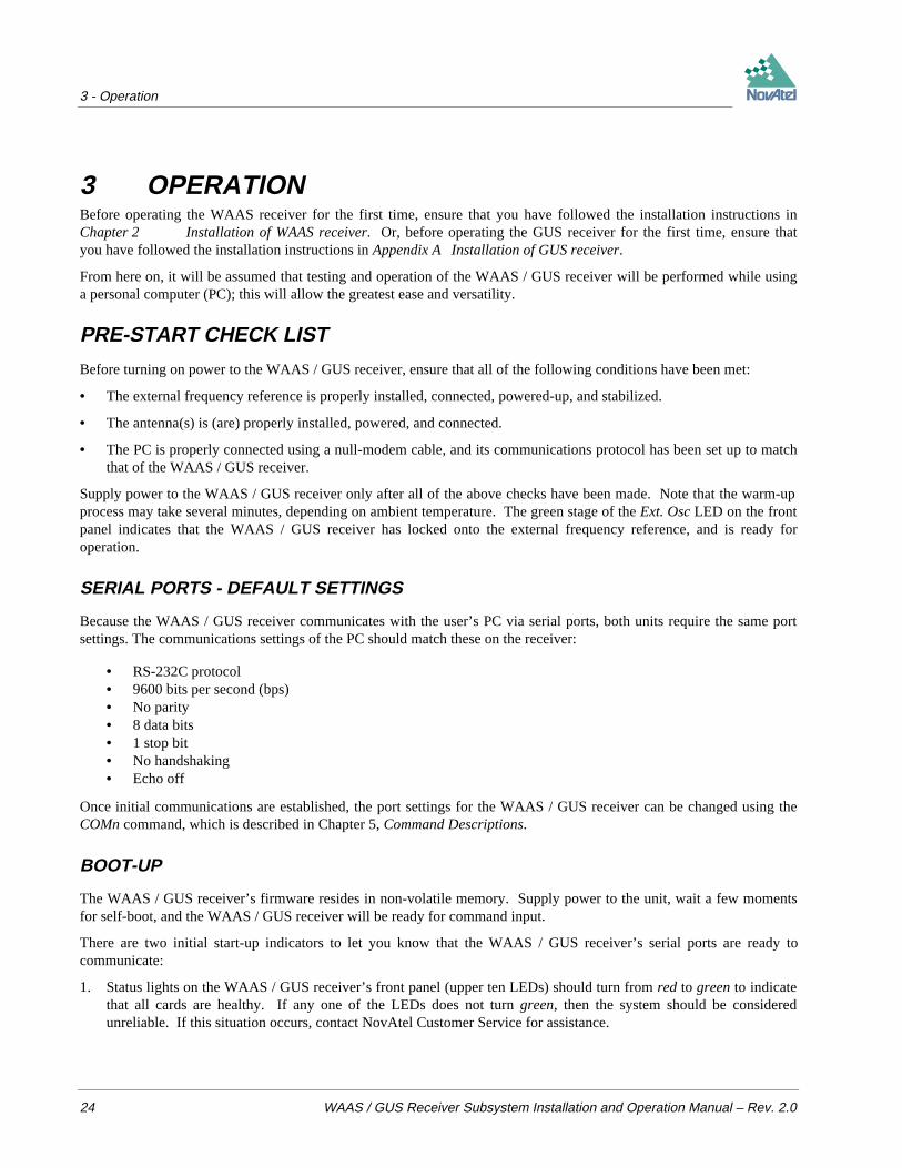
PRE-START CHECK LIST
Before turning on power to the WAAS / GUS receiver, ensure that all of the following conditions have been met:
• The external frequency reference is properly installed, connected, powered-up, and stabilized.
• The antenna(s) is (are) properly installed, powered, and connected.
• The PC is properly connected using a null-modem cable, and its communications protocol has been set up to matchthat of the WAAS / GUS receiver.
Supply power to the WAAS / GUS receiver only after all of the above checks have been made. Note that the warm-upprocess may take several minutes, depending on ambient temperature. The green stage of the Ext. Osc LED on the frontpanel indicates that the WAAS / GUS receiver has locked onto the external frequency reference, and is ready foroperation.
SERIAL PORTS - DEFAULT SETTINGS
Because the WAAS / GUS receiver communicates with the user’s PC via serial ports, both units require the same portsettings. The communications settings of the PC should match these on the receiver:
• RS-232C protocol• 9600 bits per second (bps)• No parity• 8 data bits• 1 stop bit• No handshaking• Echo off
Once initial communications are established, the port settings for the WAAS / GUS receiver can be changed using theCOMn command, which is described in Chapter 5, Command Descriptions.
BOOT-UP
The WAAS / GUS receiver’s firmware resides in non-volatile memory. Supply power to the unit, wait a few momentsfor self-boot, and the WAAS / GUS receiver will be ready for command input.
There are two initial start-up indicators to let you know that the WAAS / GUS receiver’s serial ports are ready tocommunicate:
1. Status lights on the WAAS / GUS receiver’s front panel (upper ten LEDs) should turn from red to green to indicatethat all cards are healthy. If any one of the LEDs does not turn green, then the system should be consideredunreliable. If this situation occurs, contact NovAtel Customer Service for assistance.
3 - Operation
WAAS / GUS Receiver Subsystem Installation and Operation Manual – Rev. 2.0 25
2. Your external terminal screen will display one of the following prompts:
Com1> if you are connected to the L1-C/A, L1/L2 I or L1/L2 II serial port.
Com2> if you are connected to the TIME serial port.
The WAAS / GUS receiver is now ready for command input from any of the three COM1 ports. Data output from theTIME COM2 port is restricted for special use.
INITIAL COMMUNICATIONS WITH THE WAAS / GUS RECEIVER
Communicating with the WAAS / GUS receiver is a straightforward process and is accomplished by issuing desiredcommands to the COM1 ports from an external serial communications device. For your initial testing andcommunications, you will probably be using either a remote terminal or a personal computer that is directly connected toa WAAS / GUS receiver’s serial port by means of a null modem cable.
To change the default communication settings, such as bit rate, use COMn command, which is described in Chapter 5,Command Descriptions.
It is to your advantage to become thoroughly familiar with Chapters 5 through 7 of this manual to ensure maximumutilization of the WAAS / GUS receiver’s capabilities.
When the WAAS / GUS receiver is first powered up, no activity information is transmitted from the serial ports exceptfor the COM1> or COM2> prompt described in the Boot-Up section above.
Commands are directly input to WAAS / GUS receiver using the external terminal. It should be noted that mostcommands do not echo a response to a command input. Your indicator that the command has actually been accepted is areturn of the COM1> prompt from WAAS / GUS receiver. Note that VERSION is the only command that does providean echo response other than the port prompt.
Examples:
1. If you type VERSION <Enter> from a terminal, this will cause the WAAS / GUS receiver to echo the firmwareversion information.
2. An example of a no-echo response to an input command is the FIX POSITION command. It can be input asfollows:
COM1>fix position 51.113 -114.043 1060 <Enter>
This example illustrates command input to the COM1 port which sets the WAAS / GUS receiver’s position.However, your only confirmation that the command was actually accepted is the return of the COM1> prompt.
If a command is erroneously input, the WAAS / GUS receiver will respond with the “Invalid Command Option”response followed by the COM1> prompt.
4 - Firmware Updates
26 WAAS / GUS Receiver Subsystem Installation and Operation Manual – Rev. 2.0
4 FIRMWARE UPDATESAs described in the Introduction, the WAAS / GUS receiver comprises single and dual frequency GPSCards. AllGPSCards store their firmware (program software) in on-board, non-volatile memory. This unique feature allows areceiver’s firmware to be updated in the field. Thus, a procedure such as updating software model WAASMEDLL rev.5.43 to WAASMEDLL rev. 5.44 takes only a few minutes instead of the several days which would be required if thereceiver had to be sent to a service depot.
When updating the firmware on the GPSCards, it is recommended that all the cards be updated together. The MEDLLsubsystem is updated by means of a serial connection to the host PC using the L1–C/A port, while each of the L1/L2cards are updated using their respective L1/L2 I and L1/L2 II ports. Therefore three separate operations are required toupdate the entire WAAS / GUS receiver. However, software provided along with the firmware update may be used toautomate this procedure.
NOTE: Updating the firmware versions of these GPSCards is based on approved combinations of MEDLL andL1/L2 software that have been tested to work together. For example, WAAS software release 5.44/4.44 implies that thesingle-frequency GPSCards in the MEDLL subsystem will be updated to 5.44 revision firmware, while the dual-frequency GPSCards will be updated to 4.44 revision firmware.
When updating to a higher revision level, you will need to transfer the new firmware to the appropriate GPSCard withthe aid of the NovAtel-supplied utility program, “LOADER” . To update firmware while using LOADER, you will needa personal computer with the following features:
• MS-DOS 6.0 or later• one available RS-232 serial port• null-modem cable• at least 1 MB of available hard drive space
Below is shown an outline of the procedure for updating your receiver’s firmware:
1. Contact NovAtel Customer Service2. Download compressed files3. Decompress files4. Run LOADER in one of three modes: Menu, Command Line, or Entire Receiver Update.
CONTACT CUSTOMER SERVICE
The first step in updating the receiver is to contact NovAtel GPS Customer Service via any of the methods described inthe Customer Service section at the beginning of this manual.
When you call, be sure to have available the WAAS / GUS receiver’s serial number, and program revision level. Thisinformation is printed on the rear panel of the WAAS / GUS receiver. You can also verify the information by poweringup the receiver and issuing the “VERSION” command for the serial port you are connected to. Remember that the L1-C/A serial port is connected to the L1-only GPSCard controlling the MEDLL subsystem, and the L1/L2 I and L1/L2 IIserial ports are each connected to an L1/L2 GPSCard. The firmware for the L1 GPSCard is different than that of theL1/L2 GPSCards.
After conferring with Customer Service to establish the required revision level, (as well as the terms and conditions ofyour firmware update), Customer Service will issue you up to three authorization codes (auth-codes), one for theMEDLL subsystem and one each for the two L1/L2 cards. The auth-code is required to unlock the WAAS / GUSfeatures according to your authorized model type.
4 - Firmware Updates
WAAS / GUS Receiver Subsystem Installation and Operation Manual – Rev. 2.0 27
If it is determined that you will be updating to a higher revision level with the use of the LOADER utility, CustomerService will confirm with you as to the procedures, files, and methods required for using LOADER. As the LOADERand update programs are generally provided in a compressed file format, you will also be given a file decompressionpassword. The LOADER and update files are available from Customer Service by FTP, e-mail, or diskette.
DOWNLOAD COMPRESSED FILES
Typically, there are two files required when performing software revision updates on a particular GPSCard:LOADER.EXE (the LOADER utility program) and XXX.BIN (the firmware update file). Typical WAAS / GUSfirmware files might be named 444.BIN (for the L1/L2 GPSCards), M544.BIN (for the MEDLL Master GPSCard) andS544.BIN (for the MEDLL Slave GPSCards).
To proceed with your program update, you will first need to download the appropriate files from NovAtel’s FTP site(ftp://ftp.novatel.ca), or via e-mail ([email protected]). If downloading is not possible, the files can be mailed to youon diskette.
The files are available in compressed, password-protected file format. The compressed form of the files will havediffering names; Customer Service will advise you as to the exact names of the files you need. As well, CustomerService will provide you with a file de-compression password.
DECOMPRESS FILES
After copying the compressed files to an appropriate directory on your PC, each file must be decompressed. The syntaxfor decompression is as follows:
Syntax:
[filename] -s[password]
Where:
filename: is the name of the compressed file (excluding the extension)
-s: is the password command switch
password: is the password required to allow decompression
Example:
m544 -s12345678<Enter>
RUN LOADER
LOADER should be copied to the hard drive of your personal computer and run from the command (DOS) prompt.Once LOADER is installed and running, it allows you to select and configure a PC serial port, as well as choose thedirectory path and file name of the new program software to be transferred to the GPSCard. After the LOADERparameters have been selected and the auth-code entered, the actual file transfer only takes a few minutes, depending onthe data transfer rate selected. LOADER also contains built-in terminal software.
LOADER can be run in one of three different modes:
1. Menu mode – contains a graphical interface to facilitate the procedure of updating one GPSCard at a time. This isthe preferred method to update individual L1/L2 GPSCards in the WAAS / GUS receiver.

4 - Firmware Updates
28 WAAS / GUS Receiver Subsystem Installation and Operation Manual – Rev. 2.0
2. Command-Line mode – allows you to update either one GPSCard at a time, or set up a batch process. Use thismode to update the multiple cards within the MEDLL subsystem. Or, use this as an alternate method to updateindividual L1/L2 GPSCards.
3. Entire Receiver Update mode – use this if you wish to update all of the GPSCards (L1/L2 & MEDLL subsystems)within an entire WAAS / GUS receiver in a single operation.
Choose the mode which best suits the task which needs to be done.
MENU MODE
The procedure shown below can be used to update the firmware on either of the two L1/L2 GPSCards in the WAAS /GUS receiver. This procedure will not work to update the MEDLL subsystem firmware; for that, see the next section.
LOADER can operate from the DOS prompt of any directory or drive on your PC. The program is comprised of threeparts: Program Card (authorization procedure), Setup (communications configuration) and Terminal (terminalemulator). The main screen is shown in Figure 15.
Figure 15 Main screen of LOADER program
If you are running LOADER for the first time, be sure to access the Setup menu (step 3 below) before proceeding toProgram Card (step 4 below); otherwise, you can go directly from step 2 below to step 4. To update the firmware on aGPSCard, follow this procedure:
1. Turn off power to the WAAS / GUS receiver.
2. Start LOADER.
3. From the main menu screen, select Setup to configure the PC’s serial port over which communication will occur(default: COM1), and the data transfer rates for both programming (default: 115 200 bits per second) and terminalemulation (default: 9600 bps). To minimize the time required, select the highest serial bit rate your PC can reliablysupport. LOADER will verify and save your selections in a file named LOADER.SET, and return to the main menuscreen.
4. From the main screen, select Program Card .
5. Select the disk drive (e.g. A, B, C, D) in which the update file (e.g. M544.BIN) is located. Select the path where theupdate file is located (e.g. C:\WAAS\LOADER\BINFILES); the directory from which you started LOADER is thedefault path. Select the required update file (e.g. M544.BIN).

4 - Firmware Updates
WAAS / GUS Receiver Subsystem Installation and Operation Manual – Rev. 2.0 29
6. At the prompt, enter your update auth-code (e.g. 17b2,32df,6ba0,92b5,e5b9,waasmedll ).
7. When prompted by the program, turn on power to the WAAS / GUS receiver. LOADER will automaticallyestablish communications with it, and begin the file transfer. The time required to transfer the new program datawill depend on the bit rate that was selected earlier.
8. When the file transfer is complete, use the terminal emulator in LOADER (select Terminal ), or any other one, toissue the VERSION command; this will verify your new program version number. When using the terminalemulator in LOADER, a prompt does not initially appear; you need to enter the command first, which then producesa response, after which a prompt will appear.
9. Exit LOADER (select Quit ).
COMMAND-LINE MODE
LOADER may also be used by entering parameters directly at the command prompt. In this mode of operation thefilename and authorization code can be specified on the command line. When the program detects a filename andauthorization code, it immediately proceeds to read the specified file, authorize it and send it to the WAAS / GUSreceiver.
When this mode is used, the current setup parameters are used. If different port settings are desired, LOADER should berun in Menu mode (see previous section) to change the default settings.
There are two syntactical forms. The first is for updating individual GPSCards, while the second one is for updating theGPSCards in the MEDLL subsystem.
Updating Individual GPSCards
Syntax #1:
LOADER -f<filename.bin> -a<auth code> -c<card>
-f<filename.bin> Specifies BIN file to be loaded.
-a<auth code> Specifies authorization code to insert in file.
-c<card> (optional) Specifies a target card. This option is used on units with multiple GPSCards tospecify which particular card is to be programmed. The default is 1.
-h Requests on-line help.
Examples:loader -h
loader -fc:\work\m544.bin -a120a,26dc,ae75,a344,9859,waasmedllThe second example causes LOADER to read and authorize C:\WORK\M544.BIN with the specified authorization code,then transfer the update file to the WAAS / GUS receiver using the port settings previously defined. It is important toensure that no spaces exist in the entry of the authorization code. Ensure that the WAAS / GUS receiver is turned off.Once the program has been started, you are prompted to turn the WAAS / GUS receiver back on, at which point thescreen will display the progress.
Updating the GPSCards in the MEDLL Subsystem
A batch file can be used to provide a convenient way to program multiple GPSCards with the same or different loads ofsoftware. Rather than having to run LOADER once for each card, you can specify the card number, firmware filenameand an optional authorization code in a batch file.
4 - Firmware Updates
30 WAAS / GUS Receiver Subsystem Installation and Operation Manual – Rev. 2.0
NOTE: This is the only way to update the GPSCards in the MEDLL subsystem of the WAAS / GUS receiver, otherthan the proposed software that would allow remote reprogramming over a network.
The batch file is a simple ASCII text file and should be formatted as shown in the example below. In this example, Card#1 is to be loaded with software in the M544.BIN file, and remaining cards with the S544.BIN file. Cards #2-#8 haveno authorization codes. The batch file should be in the same directory as the LOADER program.
Syntax #2:
LOADER -b<batchfile>
-b<batchfile> Specifies file with multiple load commands.
-h Requests on-line help.
Examples:loader –h
loader -bmedll.txt
In the second example, this would be the listing of the MEDLL.TXT file for a MEDLL subsystem consisting of onemaster card and seven slave cards:
1 m544.bin 1234,5678,9012,3456,waasmedll2 s544.bin3 s544.bin4 s544.bin5 s544.bin6 s544.bin7 s544.bin8 s544.bin
The LOADER program will only initialize the number of cards required to complete the programming. Once the cardshave been initialized, the screen will show this:
Programming card: 1 with M544.BIN
As the card is being programmed, a character to the right of the filename will spin indicating programming activity.When the first card has been programmed, the screen will show this:
Programming card: 1 with M544.BIN OkayErasing card: 2 \
This process will continue until all of the requested cards are programmed and the screen will look similar to this:
Programming card: 1 with M544.BIN OkayProgramming card: 2 with S544.BIN Okay..Programming card: 8 with S544.BIN OkayDone. Resetting CardsInitialization took: 27 seconds Programming took: 114 seconds Total Time: 141 secondsPress ENTER to exit
Once all of the cards have been programmed, they will be reset. Using PC communication software or the terminalemulator in the Menu mode of LOADER, issue the VERSION command to verify your new program version number.
4 - Firmware Updates
WAAS / GUS Receiver Subsystem Installation and Operation Manual – Rev. 2.0 31
ENTIRE RECEIVER UPDATE MODE
If you wish to perform an update of all the GPSCards in a WAAS / GUS receiver, this mode of LOADER will guide youthrough the process and simplify the operation considerably. Together with the LOADER program and the update fileswhich you received from Customer Service, there will also be a file with a name such as UPDATE.BAT. This is a batchfile which runs LOADER in Command Line mode as described above, with all the commands already prepared.
To run the software, you will need to issue the following command :-
Syntax:
UPDATE <serial port> <data transfer rate>
<serial port> Specifies which serial port (COM port) on your computer is to be used
<data transfer rate> Specifies the data transfer rate which is to be used
Examples:update 2 115200
This example instructs the UPDATE utility to upgrade the GPSCard which is connected to the PC's serial port 2 (COM2)at 115,200 bits per second. The utility will prompt you to turn the power to the WAAS / GUS receiver on or off; it willalso prompt you to connect your personal computer to a specific port on the WAAS / GUS receiver.
By the time this utility completes its task, you will have connected your computer to the L1-C/A, L1/L2 1, and L1/L2 IIports on the WAAS / GUS receiver and updated all the GPSCards inside.
UPDATING REMOTELY OVER A NETWORK (PROPOSED)
NovAtel has proposed software that would allow an authorized individual to establish communication with a remoteWAAS / GUS receiver. Once the communication session is connected, the user would be required to log in beforegaining access to the system. Then, the user could connect to any GPSCard within a remote WAAS / GUS unit.
This application would allow an operator, at a central location, to send files and issue commands to GPSCards in remoteWAAS / GUS units. This would greatly simplify the updating of a nation-wide system of WAAS / GUS receivers byeliminating the time and expense associated with having someone travel to each site to perform the update.
More information on this subject will be available as details are finalized.

5 – Command Descriptions
32 WAAS / GUS Receiver Subsystem Installation and Operation Manual – Rev. 2.0
5 COMMAND DESCRIPTIONSThis chapter describes the commands accepted by the WAAS / GUS receiver. They are listed in alphabetical order.
The WAAS / GUS receiver is capable of responding to many different input commands. You will find that once youbecome familiar with these commands, the WAAS / GUS receiver offers a wide range in operational flexibility.Commands can be sent to the WAAS / GUS receiver through the L1-C/A, L1/L2 I and L1/L2 II serial ports. Each ofthese ports can be addressed independently of the other.
You can issue these commands to control the following:
1. Overall status of the WAAS / GUS receiver2. Input & output functions3. Configuration of a specific channel of the WAAS / GUS receiver
Table 1 shows the list of commands, clustered according to these three categories; Table 2 shows the list of commands,arranged alphabetically. Table 3 shows which commands have been obsoleted since the last version of this manual.
When the WAAS / GUS receiver is first powered up, all commands revert to the factory default settings. Eachcommand description in this chapter also lists its default setting. The RCCA log can be used to view the instantaneoussettings of all commands.
The following rules apply when communicating with the card:
1. The commands are not case sensitive.• e.g. VERSION or version• e.g. FIX POSITION or fix position
2. All commands and required entries can be separated by a space or a comma.• e.g. fix,position,51.3455323,-117.289534,1002• e.g. fix position 51.3455323 -117.289534 1002• e.g. com1,9600,n,8,1,n,off• e.g. com1 9600 n 8 1 n off• e.g. log,com1,frmb,onnew• e.g. log com1 frmb onnew
3. At the end of a command or command string, press <Enter>.
4. Most command entries do not provide a response to the entered command. The exception to this statement isthe VERSION command. Otherwise, successful entry of a command is verified by receipt of the COM portprompt (i.e. COM1>).

5 – Command Descriptions
WAAS / GUS Receiver Subsystem Installation and Operation Manual – Rev. 2.0 33
Table 1 WAAS / GUS Commands by Category
Overall status of the WAAS / GUS receiver
Command Description Syntax
$*& &RQWUROV VHOHFWHG $*& FRQWURO PHFKDQLVP DJF DJFVWDWH>JDLQ@
&21),* ,PSOHPHQWV SUHGHILQHG FRQILJXUDWLRQV FRQILJ NH\ZRUG
&60227+ 6HWV FDUULHU VPRRWKLQJ FVPRRWK YDOXH>YDOXH@
(&872)) 6HW HOHYDWLRQ FXWRII DQJOH HFXWRII DQJOH
),; 326,7,21 6HW DQWHQQD FRRUGLQDWHV IRU PRQLWRU VWDWLRQ IL[ SRVLWLRQ ODWORQKHLJKW >VWDWLRQ LG@ >KHDOWK@
-$002'( &RQWUROV WKH VWDWH RI MDPPLQJ MDPPRGH DJFVWDWH
3//%: 6HW UHFHLYHU¶V SKDVHORFNORRS EDQGZLGWKV SOOEZ OBEZ>OBEZ@
5(6(7 3HUIRUPV D KDUGZDUH UHVHW UHVHW
6(7)5$0(7<3( 6HWV WKH W\SH RI QDYLJDWLRQ IUDPH GDWD RXWSXW LQ
WKH )50$% ORJVHWIUDPHW\SH W\SH
81'8/$7,21 &KRRVH XQGXODWLRQ XQGXODWLRQ VHSDUDWLRQ
81),; 5HPRYH DOO UHFHLYHU ),; FRQVWUDLQWV XQIL[
9(56,21 &XUUHQW VRIWZDUH OHYHO YHUVLRQ
Input & output functions
Command Description Syntax&/2&.$'-867 $GMXVW 336 FRQWLQXRXVO\ FORFNDGMXVW VZLWFK
&20Q ,QLWLDOL]H 6HULDO 3RUW RU FRPQ EDXGSDULW\GDWDELWVVWRSELWV
KDQGVKDNHHFKR
/2* &KRRVH GDWD ORJJLQJ W\SH ORJ SRUWGDWDW\SHWULJJHU>SHULRGRIIVHW@
81/2* &HDVH ORJJLQJ D GDWD ORJ XQORJ SRUWGDWD W\SH
81/2*$// &HDVH ORJJLQJ DOO GDWD ORJV XQORJDOO
Configuration of a specific channel of the WAAS / GUS receiver
Command Description Syntax$66,*1 $VVLJQ D 351 WR D FKDQQHO DVVLJQ FKDQQHOSUQGRSSOHU VHDUFK ZLQGRZ
$66,*1*72351 $VVLJQ D * GHOD\ WR D 351 DVVLJQJWRSUQ SUQ JBGHOD\
&&5$7,2 &DUULHU WR &RGH 5DWLR GLIIHUHQW V\QWDFWLFDO IRUPV
'//25'(5 &RQWUROV WKH ILOWHU RUGHU RI WKH 'HOD\/RFN /RRS GOORUGHU FKDQQHORUGHU>RUGHU@
7+5(6+2/' &RQWUROV VLJQDO DFTXLVLWLRQ DQG ORFN WKUHVKROGV WKUHVKROGFKDQQHODFTXLVLWLRQORFNDFTXLVLWLRQORFN
81$66,*1 8QDVVLJQ D FKDQQHO XQDVVLJQ FKDQQHO
81$66,*1$// 8QDVVLJQ DOO FKDQQHOV XQDVVLJQDOO
81$66,*1*72351 8QDVVLJQ D* GHOD\ XQDVVLJQJWRSUQ SUQ

5 – Command Descriptions
34 WAAS / GUS Receiver Subsystem Installation and Operation Manual – Rev. 2.0
Table 2 WAAS / GUS Command Summary
Command Description Syntax$*& &RQWUROV VHOHFWHG $*& FRQWURO PHFKDQLVP GLIIHUHQW V\QWDFWLFDO IRUPV
$66,*1 $VVLJQ D 351 WR D FKDQQHO DVVLJQ FKDQQHOSUQGRSSOHU VHDUFK ZLQGRZ
$66,*1*72351 $VVLJQ D * GHOD\ WR D 351 DVVLJQJWRSUQ SUQ JBGHOD\
&&5$7,2 &DUULHU WR &RGH 5DWLR GLIIHUHQW V\QWDFWLFDO IRUPV
&/2&.$'-867 $GMXVW 336 FRQWLQXRXVO\ FORFNDGMXVW VZLWFK
&20Q ,QLWLDOL]H 6HULDO 3RUW RU FRPQ EDXGSDULW\GDWDELWVVWRSELWV
KDQGVKDNHHFKR
&21),* ,PSOHPHQWV SUHGHILQHG FRQILJXUDWLRQV FRQILJ NH\ZRUG
&60227+ 6HWV FDUULHU VPRRWKLQJ FVPRRWK YDOXH>YDOXH@
'//25'(5 &RQWUROV WKH ILOWHU RUGHU RI WKH 'HOD\/RFN /RRS GOORUGHU FKDQQHORUGHU>RUGHU@
(&872)) 6HW HOHYDWLRQ FXWRII DQJOH HFXWRII DQJOH
),; 326,7,21 6HW DQWHQQD FRRUGLQDWHV IRU PRQLWRU VWDWLRQ IL[ SRVLWLRQ ODWORQKHLJKW >VWDWLRQ LG@ >KHDOWK@
-$002'( &RQWUROV WKH VWDWH RI MDPPLQJ MDPPRGH DJFVWDWH
/2* &KRRVH GDWD ORJJLQJ W\SH ORJ SRUWGDWDW\SHWULJJHU>SHULRGRIIVHW@
3//%: 6HW UHFHLYHU¶V SKDVHORFNORRS EDQGZLGWKV SOOEZ OBEZ>OBEZ@
5(6(7 3HUIRUPV D KDUGZDUH UHVHW UHVHW
6(7)5$0(7<3( 6HWV WKH W\SH RI QDYLJDWLRQ IUDPH GDWD RXWSXW LQ
WKH )50$% ORJVHWIUDPHW\SH W\SH
7+5(6+2/' &RQWUROV VLJQDO DFTXLVLWLRQ DQG ORFN WKUHVKROGV WKUHVKROGFKDQQHODFTXLVLWLRQORFNDFTXLVLWLRQORFN
81$66,*1 8QDVVLJQ D FKDQQHO XQDVVLJQ FKDQQHO
81$66,*1$// 8QDVVLJQ DOO FKDQQHOV XQDVVLJQDOO
81$66,*1*72351 8QDVVLJQ D FKDQQHO XQDVVLJQJWRSUQ SUQ
81'8/$7,21 &KRRVH XQGXODWLRQ XQGXODWLRQ VHSDUDWLRQ
81),; 5HPRYH DOO UHFHLYHU ),; FRQVWUDLQWV XQIL[
81/2* &HDVH ORJJLQJ D GDWD ORJ XQORJ SRUWGDWD W\SH
81/2*$// &HDVH ORJJLQJ DOO GDWD ORJV XQORJDOO
9(56,21 &XUUHQW VRIWZDUH OHYHO YHUVLRQ
Table 3 Obsolete Commands
Command Description
'<1$0,&6 6HWV UHFHLYHU¶V G\QDPLFV
For backwards compatibility, it is still possible to use this command; however, the use of the $PLLBW command in itsplace is recommended. Obsolete commands will not be supported in future software releases.
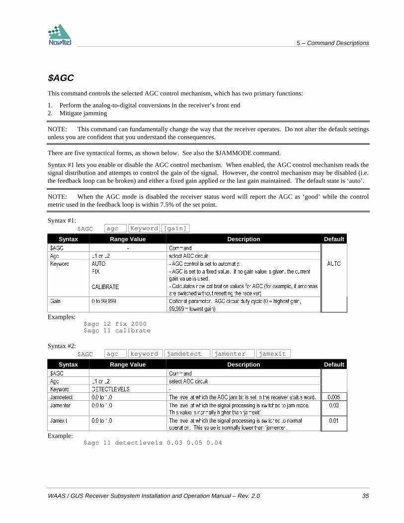
5 – Command Descriptions
WAAS / GUS Receiver Subsystem Installation and Operation Manual – Rev. 2.0 35
$AGC
This command controls the selected AGC control mechanism, which has two primary functions:
1. Perform the analog-to-digital conversions in the receiver’s front end2. Mitigate jamming
NOTE: This command can fundamentally change the way that the receiver operates. Do not alter the default settingsunless you are confident that you understand the consequences.
There are five syntactical forms, as shown below. See also the $JAMMODE command.
Syntax #1 lets you enable or disable the AGC control mechanism. When enabled, the AGC control mechanism reads thesignal distribution and attempts to control the gain of the signal. However, the control mechanism may be disabled (i.e.the feedback loop can be broken) and either a fixed gain applied or the last gain maintained. The default state is ‘auto’.
NOTE: When the AGC mode is disabled the receiver status word will report the AGC as ‘good’ while the controlmetric used in the feedback loop is within 7.5% of the set point.
Syntax #1:$AGC agc Keyword [gain]
Syntax Range Value Description Default
$*& &RPPDQG
$JF / RU / VHOHFW $*& FLUFXLW
.H\ZRUG $872
),;
&$/,%5$7(
$*& FRQWURO LV VHW WR DXWRPDWLF
$*& LV VHW WR D IL[HG YDOXH ,I QR JDLQ YDOXH LV JLYHQ WKH FXUUHQW
JDLQ YDOXH LV XVHG
&DOFXODWHV QHZ FDOLEUDWLRQ YDOXHV IRU $*& IRU H[DPSOH LI DQWHQQDV
DUH VZLWFKHG ZLWKRXW UHVHWWLQJ WKH UHFHLYHU
$872
*DLQ WR 2SWLRQDO SDUDPHWHU $*& FLUFXLW GXW\ F\FOH KLJKHVW JDLQ
ORZHVW JDLQ
Examples:$agc l2 fix 2000$agc l1 calibrate
Syntax #2:$AGC agc keyword jamdetect jamenter jamexit
Syntax Range Value Description Default
$*& &RPPDQG
$JF / RU / VHOHFW $*& FLUFXLW
.H\ZRUG '(7(&7/(9(/6
-DPGHWHFW WR 7KH OHYHO DW ZKLFK WKH $*& MDP ELW LV VHW LQ WKH UHFHLYHU VWDWXV ZRUG
-DPHQWHU WR 7KH OHYHO DW ZKLFK WKH VLJQDO SURFHVVLQJ LV VZLWFKHG WR MDP PRGH
7KLV YDOXH LV QRUPDOO\ KLJKHU WKDQ µMDPH[LW
-DPH[LW WR 7KH OHYHO DW ZKLFK WKH VLJQDO SURFHVVLQJ LV VZLWFKHG WR QRUPDO
RSHUDWLRQ 7KLV YDOXH LV QRUPDOO\ ORZHU WKDQ µMDPHQWHU
Example:$agc l1 detectlevels 0.03 0.05 0.04
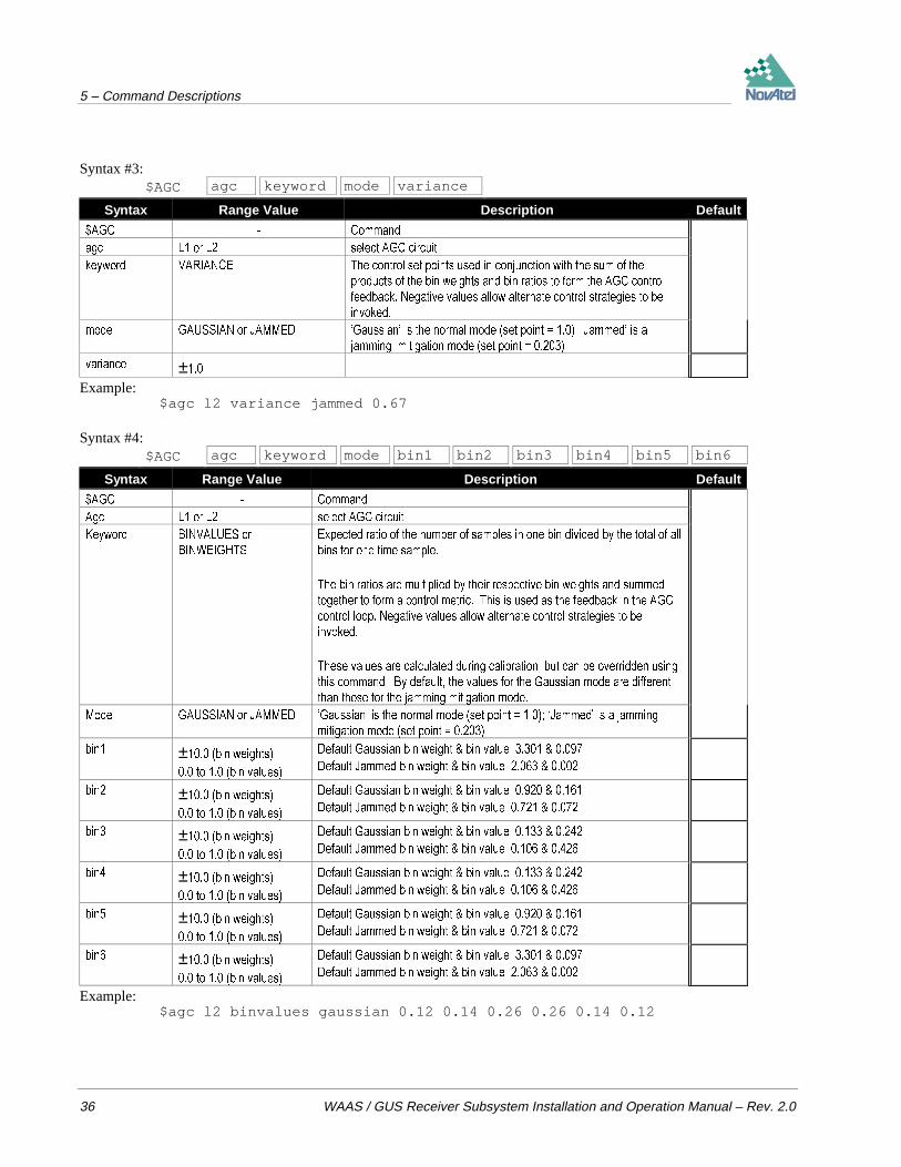
5 – Command Descriptions
36 WAAS / GUS Receiver Subsystem Installation and Operation Manual – Rev. 2.0
Syntax #3:$AGC agc keyword mode variance
Syntax Range Value Description Default
$*& &RPPDQG
DJF / RU / VHOHFW $*& FLUFXLW
NH\ZRUG 9$5,$1&( 7KH FRQWURO VHW SRLQWV XVHG LQ FRQMXQFWLRQ ZLWK WKH VXP RI WKH
SURGXFWV RI WKH ELQ ZHLJKWV DQG ELQ UDWLRV WR IRUP WKH $*& FRQWURO
IHHGEDFN 1HJDWLYH YDOXHV DOORZ DOWHUQDWH FRQWURO VWUDWHJLHV WR EH
LQYRNHG
PRGH *$866,$1 RU -$00(' µ*DXVVLDQ¶ LV WKH QRUPDO PRGH VHW SRLQW µ-DPPHG¶ LV D
MDPPLQJ PLWLJDWLRQ PRGH VHW SRLQW
YDULDQFH ±
Example:$agc l2 variance jammed 0.67
Syntax #4:$AGC agc keyword mode bin1 bin2 bin3 bin4 bin5 bin6
Syntax Range Value Description Default
$*& &RPPDQG
$JF / RU / VHOHFW $*& FLUFXLW
.H\ZRUG %,19$/8(6 RU
%,1:(,*+76
([SHFWHG UDWLR RI WKH QXPEHU RI VDPSOHV LQ RQH ELQ GLYLGHG E\ WKH WRWDO RI DOO
ELQV IRU RQH WLPH VDPSOH
7KH ELQ UDWLRV DUH PXOWLSOLHG E\ WKHLU UHVSHFWLYH ELQ ZHLJKWV DQG VXPPHG
WRJHWKHU WR IRUP D FRQWURO PHWULF 7KLV LV XVHG DV WKH IHHGEDFN LQ WKH $*&
FRQWURO ORRS 1HJDWLYH YDOXHV DOORZ DOWHUQDWH FRQWURO VWUDWHJLHV WR EH
LQYRNHG
7KHVH YDOXHV DUH FDOFXODWHG GXULQJ FDOLEUDWLRQ EXW FDQ EH RYHUULGGHQ XVLQJ
WKLV FRPPDQG %\ GHIDXOW WKH YDOXHV IRU WKH *DXVVLDQ PRGH DUH GLIIHUHQW
WKDQ WKRVH IRU WKH MDPPLQJ PLWLJDWLRQ PRGH
0RGH *$866,$1 RU -$00(' µ*DXVVLDQ¶ LV WKH QRUPDO PRGH VHW SRLQW µ-DPPHG¶ LV D MDPPLQJ
PLWLJDWLRQ PRGH VHW SRLQW
ELQ ± ELQ ZHLJKWV
WR ELQ YDOXHV
'HIDXOW *DXVVLDQ ELQ ZHLJKW ELQ YDOXH
'HIDXOW -DPPHG ELQ ZHLJKW ELQ YDOXH
ELQ ± ELQ ZHLJKWV
WR ELQ YDOXHV
'HIDXOW *DXVVLDQ ELQ ZHLJKW ELQ YDOXH
'HIDXOW -DPPHG ELQ ZHLJKW ELQ YDOXH
ELQ ± ELQ ZHLJKWV
WR ELQ YDOXHV
'HIDXOW *DXVVLDQ ELQ ZHLJKW ELQ YDOXH
'HIDXOW -DPPHG ELQ ZHLJKW ELQ YDOXH
ELQ ± ELQ ZHLJKWV
WR ELQ YDOXHV
'HIDXOW *DXVVLDQ ELQ ZHLJKW ELQ YDOXH
'HIDXOW -DPPHG ELQ ZHLJKW ELQ YDOXH
ELQ ± ELQ ZHLJKWV
WR ELQ YDOXHV
'HIDXOW *DXVVLDQ ELQ ZHLJKW ELQ YDOXH
'HIDXOW -DPPHG ELQ ZHLJKW ELQ YDOXH
ELQ ± ELQ ZHLJKWV
WR ELQ YDOXHV
'HIDXOW *DXVVLDQ ELQ ZHLJKW ELQ YDOXH
'HIDXOW -DPPHG ELQ ZHLJKW ELQ YDOXH
Example:$agc l2 binvalues gaussian 0.12 0.14 0.26 0.26 0.14 0.12

5 – Command Descriptions
WAAS / GUS Receiver Subsystem Installation and Operation Manual – Rev. 2.0 37
Syntax #5:$AGC agc keyword setting
Syntax Range Value Description Default
$*& &RPPDQG
$JF / RU / VHOHFW $*& FLUFXLW
.H\ZRUG '($'%$1' (QDEOH GLVDEOH RU VHW WKH UDWLR PDJQLWXGH RI WKH GHYLDWLRQ DZD\ IURP
WKH YDULDQFH FRQWURO VHW SRLQW IRU WKH GHDG EDQG FRQWURO RI WKH $*&
6HWWLQJ 21
2))
WR
(QDEOH GHDG EDQG FRQWURO ZLWK WKH FXUUHQW PDJQLWXGH VHWWLQJ
'LVDEOH GHDG EDQG FRQWURO
5DWLR PDJQLWXGH XVHG WR GHWHUPLQH WKH VL]H RI WKH GHDG EDQG HJ D
YDOXH RI ZLOO DOORZ D YDULDWLRQ RI ± LQ WKH DJF YDULDQFH YDOXH IRUD FRQWURO VHW SRLQW RI 6HWWLQJ WKLV YDOXH DXWRPDWLFDOO\ HQDEOHV
GHDG EDQG FRQWURO 'HIDXOW
Example:$agc l1 deadband 0.2
ASSIGN
At startup, the WAAS / GUS receiver automatically searches for GPS satellites (PRN 1-32). However, the PRN forWAAS GEO satellites must be manually assigned using the ASSIGN command.
This command may be used to aid in the initial acquisition of a satellite by allowing you to override the automaticsatellite/channel assignment and reacquisition processes with manual instructions. The command specifies that theindicated tracking channel searches for a specified satellite at a specified Doppler frequency within a specified Dopplerwindow. The instruction will remain in effect for the specified channel and PRN, even if the assigned satellitesubsequently sets. If the satellite Doppler offset of the assigned channel exceeds that specified by the ‘search-window’parameter of the ASSIGN command, the satellite may never be acquired or re-acquired. To cancel the effects ofASSIGN, you must issue the UNASSIGN or UNASSIGNALL command, or reboot the WAAS / GUS receiver.
When using this command, NovAtel recommends that you monitor the channel tracking status of the assigned channeland then use the UNASSIGN or UNASSIGNALL commands to cancel the command once the L1 channel has reachedchannel tracking state 4, the Phase Lock Loop (PLL) state. Refer to Table 8 in the ETSB log description for anexplanation of the various channel states.
NOTES: Assigning a PRN to a channel does not remove the PRN from the search space of the automatic searcher;only the channel is removed.
By default, the automatic searcher only searches for the GPS satellites (PRNs 1-32).
See also the $ASSIGNG2TOPRN command.
There are two syntactical forms of this command, as shown below.

5 – Command Descriptions
38 WAAS / GUS Receiver Subsystem Installation and Operation Manual – Rev. 2.0
Syntax #1:ASSIGN channel prn Doppler Search-window
Syntax Range Value Description Default Example
$66,*1 &RPPDQG XQDVVLJQDOO DVVLJQ
&KDQQHO KLJKHVW
FKDQQHO QXPEHU
'HVLUHG FKDQQHO QXPEHU IURP WR PD[LPXP FKDQQHO QXPEHU
LQFOXVLYH
3UQ $ VDWHOOLWH 351 LQWHJHU QXPEHU IURP WR LQFOXVLYH IRU *36
WR LQFOXVLYH IRU :$$6 RU WR LQFOXVLYH LI 351V DUH
DVVLJQHG XVLQJ WKH $66,*1*72351 FRPPDQG
'RSSOHU WR
+]
&XUUHQW 'RSSOHU RIIVHW RI WKH VDWHOOLWH
1RWH 6DWHOOLWH PRWLRQ UHFHLYHU DQWHQQD PRWLRQ DQG UHFHLYHU
FORFN IUHTXHQF\ HUURU PXVW EH LQFOXGHG LQ WKH FDOFXODWLRQ IRU
'RSSOHU IUHTXHQF\
6HDUFKZLQGRZ (UURU RU XQFHUWDLQW\ LQ WKH 'RSSOHU HVWLPDWH DERYH LQ +]
1RWH $Q\ SRVLWLYH YDOXH IURP WR ZLOO EH DFFHSWHG
([DPSOH LPSOLHV +]
Example:assign 0 29 0 2000
Syntax #2:ASSIGN channel keyword
Syntax Range Value Description Default Example
$66,*1 &RPPDQG XQDVVLJQDOO DVVLJQ
&KDQQHO KLJKHVW FKDQQHO
QXPEHU
'HVLUHG FKDQQHO QXPEHU IURP PD[LPXP FKDQQHO QXPEHU
LQFOXVLYH
.H\ZRUG ,'/( ,GOHV FKDQQHO QRW FDVH VHQVLWLYH ,'/(
Example 1:assign 0,29,0,2000
In Example 1, the first channel will try to acquire satellite PRN 29 in a range from -2000 Hz to 2000 Hz until thesatellite signal has been detected.
Example 2:assign 11,idle
In Example 2, Channel 11 will be idled and will not attempt to search for satellites.
$ASSIGNG2TOPRN
This command allows you to link a satellite PRN with a particular G2 delay. This delay is then added to a user-definedtable which allows up to 100 entries. Hence, when an ASSIGN command is issued, the receiver will check the user-defined table first and if the PRN is listed there, it will use that G2 delay. Otherwise it will use the default values forGPS and WAAS satellites. This command affects the C/A code tracking only.
Use the $UNASSIGNG2TOPRN command to delete a G2 delay assignment for a particular PRN from the user-definedtable.
Syntax:
$ASSIGNG2TOPRN prn G2 delay

5 – Command Descriptions
WAAS / GUS Receiver Subsystem Installation and Operation Manual – Rev. 2.0 39
Syntax Range Value Description Example
$66,*1*72351 &RPPDQG DVVLJQJWRSUQ
3UQ ± 351 1XPEHU
* GHOD\ ± &$ FRGH * GHOD\
Example:$assigng2toprn 32 862
$CCRATIO
This command is used to set the number of carrier cycles in each code chip. It is available on the L1/L2 II port only.There are three different syntactical forms permitted.
NOTE: The $CCRATIO is meant for use in very specialized applications. In normal operation, the use of thiscommand can cause the receiver to malfunction.
Syntax #1:$CCRATIO Channel cycles
Syntax Range Value Description Example
&&5$7,2 &RPPDQG FFUDWLR
&KDQQHO ± KLJKHVW FKDQQHO QXPEHU 'HVLUHG FKDQQHO QXPEHU IURP WR PD[LPXP FKDQQHO DYDLODEOH
&\FOHV ± &DUULHU WR FRGH UDWLR LQ F\FOHV SHU FRGH FKLS 7KLV YDOXH FDQ EH
HQWHUHG ZLWK XS WR GHFLPDO SODFHV
Example:$ccratio 3 1540.0
Syntax #2:$CCRATIO Channel keyword
Syntax Range Value Description Example
&&5$7,2 &RPPDQG FFUDWLR
&KDQQHO KLJKHVW FKDQQHO QXPEHU 'HVLUHG FKDQQHO QXPEHU IURP WR PD[LPXP FKDQQHO DYDLODEOH
.H\ZRUG 5(6(7 5HVHWV VSHFLILHG FKDQQHO UHVHW
Example:$ccratio 3 reset
Syntax #3:$CCRATIO Keyword
Syntax Range Value Description Example
&&5$7,2 &RPPDQG FFUDWLR
.H\ZRUG 5(6(7 5HVHWV DOO FKDQQHOV 5HVHW
Example:$ccratio reset

5 – Command Descriptions
40 WAAS / GUS Receiver Subsystem Installation and Operation Manual – Rev. 2.0
CLOCKADJUST
All oscillators have some inherent drift characterization. This command, if enabled, permits software to model theselong-term drift characteristics of the clock. The correction is applied to the 1PPS strobe as well. The clock adjustmentis performed digitally. As a result, the 1PPS Strobe (on an L1 card) will have a 49 ns jitter on it due to the receiver'sattempts to keep it as close as possible to GPS time. Jitter on an L1/L2 card is 50 ns.
CLOCKADJUST must be disabled (which it is by default) if you wish to measure the drift rate of the oscillator using theCLKA/B data log. Under normal conditions, it is recommended that the command be left in a disabled state.
NOTES: 1. If you enable this command, do not disable it after 30 seconds from power-up: unpredictable clock driftsmay result.
2. When disabled, the range measurement bias errors will continue to accumulate with clock drift.3. This feature should only be changed by advanced users.
Syntax:CLOCKADJUST switch
Syntax Range Value Description Default
&/2&.$'-867 &RPPDQG
VZLWFK (QDEOH RU GLVDEOH $OORZV RU GLVDOORZV DGMXVWPHQW WR WKH LQWHUQDO FORFN GLVDEOH
Example:clockadjust disable
COMn
This command permits you to configure the COM ports’ asynchronous drivers.
The L1-C/A, L1/L2 I and L1/L2 II ports allow two-way communications. Each one is configured as COM1. Thus,regardless of which of these three ports your data communications equipment is physically connected to, you wouldenter COM1 as the command name. It is not possible to alter any of the communications parameters associated with theTIME port.
Syntax:COMn bps parity Databits stopbits Handshake echo FIFO
Syntax Value Description Default Example
&20Q Q 2QO\ &20 LV DOORZHG FRP FRP
ESV RU 6SHFLI\ ELW UDWH
SDULW\ 1 QRQH 2 RGG RU ( HYHQ 6SHFLI\ SDULW\ 1 (
GDWDELWV RU 6SHFLI\ QXPEHU RI GDWD ELWV
VWRSELWV RU 6SHFLI\ QXPEHU RI VWRS ELWV
KDQGVKDNH 1 QRQH ;21 ;RQ;RII RU &76 &76576 6SHFLI\ KDQGVKDNLQJ 1 1
HFKR 21 RU 2)) 6SHFLI\ HFKR 2)) 21
),)2 21 RU 2)) (QDEOH RU GLVDEOH WKH
8$57¶V WUDQVPLW
),)2
21 2))
Examples:com1 19200,e,7,1,n,on, offcom1 1200,e,8,1,n,on, off

5 – Command Descriptions
WAAS / GUS Receiver Subsystem Installation and Operation Manual – Rev. 2.0 41
CONFIG
This command switches the channel configuration of the L1-C/A code receiver between pre-defined configurations.When the command is issued the receiver resets with the new configuration.
Syntax:CONFIG keyword
Syntax Range Description Default
&21),* &RPPDQG
NH\ZRUG *: &RQILJXUHV WKH /&$ FRGH SRUWLRQ RI WKH UHFHLYHU WR WUDFN XS WR *36 VDWHOOLWHV :$$6 VDWV *:
*: &RQILJXUHV WKH /&$ FRGH SRUWLRQ RI WKH UHFHLYHU WR WUDFN XS WR *36 VDWHOOLWHV :$$6 VDWV
Example:config g14w2
CSMOOTH
This command sets the amount of carrier smoothing to be performed on the pseudorange measurements carrier. The‘value’ field sets the L1 channel portion and the optional ‘value2’ field sets the L2 channel portion. An input value of100 corresponds to approximately 100 seconds of smoothing. Upon issuing the command, the locktime for all trackingsatellites is reset to zero, and each pseudorange smoothing filter is restarted. You must wait for at least the length ofsmoothing time for the new smoothing constant to take full effect. 20 seconds is the default smoothing constant used inthe WAAS / GUS receiver. The optimum setting for this command depends on your application and thus cannot bespecified.
On port L1-C/A, ‘value2’ is ignored since the MEDLL subsystem is L1-only.
NOTES: The CSMOOTH command should only be used by advanced users. It may not be suitable for every GPSapplication. When using CSMOOTH in a differential mode, the same setting should be used at both the monitor andremote station.
The lower the smoothing constant, the more noise there will be.
Syntax:CSMOOTH value [value2]
Syntax Range Value Description Default
&60227+ &RPPDQG
9DOXH WR / FDUULHU VPRRWKLQJ FRQVWDQW LQ VHFRQGV
9DOXH WR / FDUULHU VPRRWKLQJ FRQVWDQW LQ VHFRQGV
Example:csmooth 20 500
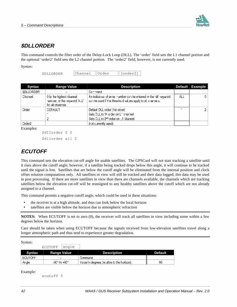
5 – Command Descriptions
42 WAAS / GUS Receiver Subsystem Installation and Operation Manual – Rev. 2.0
$DLLORDER
This command controls the filter order of the Delay-Lock Loop (DLL). The ‘order’ field sets the L1 channel portion andthe optional ‘order2’ field sets the L2 channel portion. The ‘order2’ field, however, is not currently used.
Syntax:
$DLLORDER Channel Order [order2]
Syntax Range Value Description Default Example
'//25'(5 &RPPDQG
&KDQQHO WR WKH KLJKHVW FKDQQHO
QXPEHU RU WKH NH\ZRUG µ$//
IRU DOO FKDQQHOV
$Q LQGLYLGXDO FKDQQHO QXPEHU FDQ EH HQWHUHG RU WKH µDOO¶ NH\ZRUG
FDQ EH XVHG LI WKH WKUHVKROG YDOXHV DSSO\ WR DOO FKDQQHOV
$//
2UGHU '()$8/7
'HIDXOW '// RUGHU VW RUGHU
6HWV '// WR VW RUGHU RQ / FKDQQHO
6HWV '// WR QG RUGHU RQ / FKDQQHO
2UGHU QRW FXUUHQWO\ XVHG
Examples:$dllorder 0 2
$dllorder all 2
ECUTOFF
This command sets the elevation cut-off angle for usable satellites. The GPSCard will not start tracking a satellite untilit rises above the cutoff angle; however, if a satellite being tracked drops below this angle, it will continue to be trackeduntil the signal is lost. Satellites that are below the cutoff angle will be eliminated from the internal position and clockoffset solution computations only. All satellites in view will still be tracked and their data logged; this data may be usedin post processing. If there are more satellites in view than there are channels available, the channels which are trackingsatellites below the elevation cut-off will be reassigned to any healthy satellites above the cutoff which are not alreadyassigned to a channel.
This command permits a negative cutoff angle, which could be used in these situations:
• the receiver is at a high altitude, and thus can look below the local horizon• satellites are visible below the horizon due to atmospheric refraction
NOTES: When ECUTOFF is set to zero (0), the receiver will track all satellites in view including some within a fewdegrees below the horizon.
Care should be taken when using ECUTOFF because the signals received from low-elevation satellites travel along alonger atmospheric path and thus tend to experience greater degradation.
Syntax:ECUTOFF angle
Syntax Range Value Description Default(&872)) &RPPDQG
$QJOH ° WR ° 9DOXH LQ GHJUHHV UHODWLYH WR WKH KRUL]RQ
Example:ecutoff 5
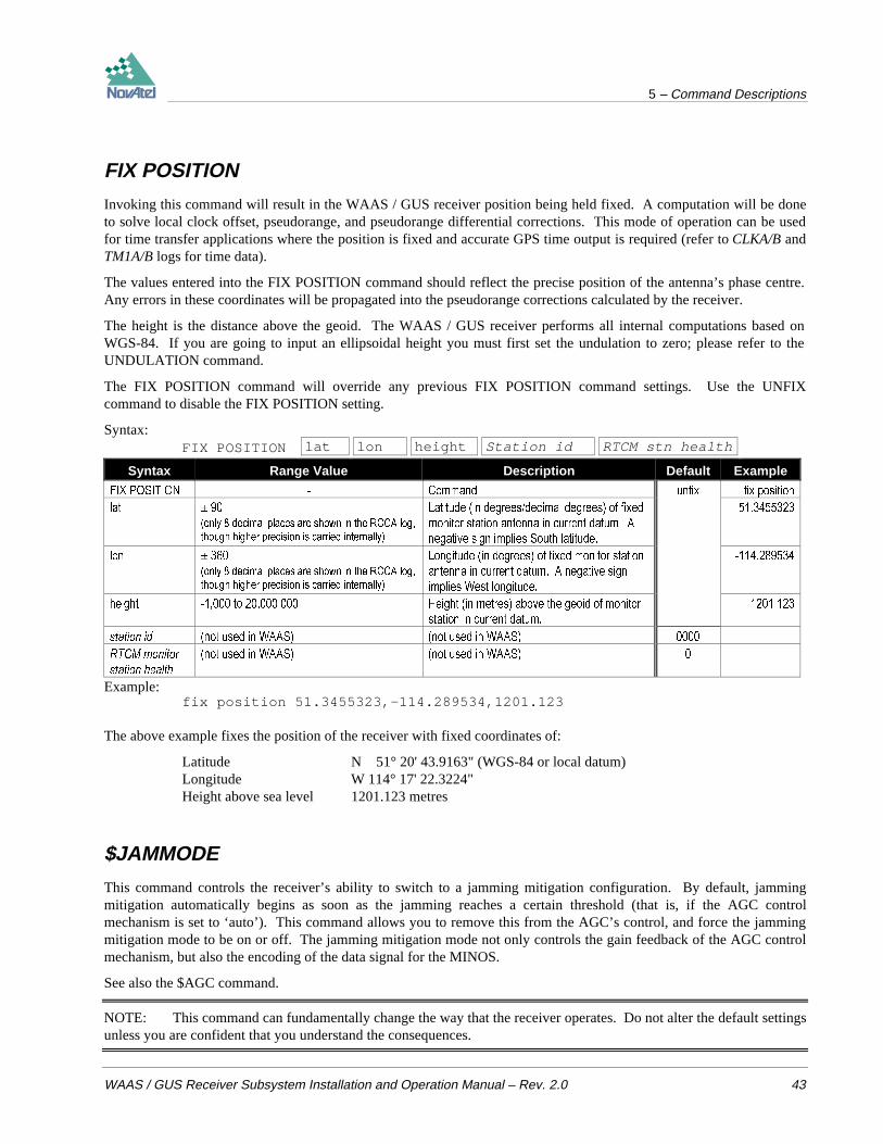
5 – Command Descriptions
WAAS / GUS Receiver Subsystem Installation and Operation Manual – Rev. 2.0 43
FIX POSITION
Invoking this command will result in the WAAS / GUS receiver position being held fixed. A computation will be doneto solve local clock offset, pseudorange, and pseudorange differential corrections. This mode of operation can be usedfor time transfer applications where the position is fixed and accurate GPS time output is required (refer to CLKA/B andTM1A/B logs for time data).
The values entered into the FIX POSITION command should reflect the precise position of the antenna’s phase centre.Any errors in these coordinates will be propagated into the pseudorange corrections calculated by the receiver.
The height is the distance above the geoid. The WAAS / GUS receiver performs all internal computations based onWGS-84. If you are going to input an ellipsoidal height you must first set the undulation to zero; please refer to theUNDULATION command.
The FIX POSITION command will override any previous FIX POSITION command settings. Use the UNFIXcommand to disable the FIX POSITION setting.
Syntax:FIX POSITION lat lon height Station id RTCM stn health
Syntax Range Value Description Default Example
),; 326,7,21 &RPPDQG XQIL[ IL[ SRVLWLRQ
ODW RQO\ GHFLPDO SODFHV DUH VKRZQ LQ WKH 5&&$ ORJ
WKRXJK KLJKHU SUHFLVLRQ LV FDUULHG LQWHUQDOO\
/DWLWXGH LQ GHJUHHVGHFLPDO GHJUHHV RI IL[HG
PRQLWRU VWDWLRQ DQWHQQD LQ FXUUHQW GDWXP $
QHJDWLYH VLJQ LPSOLHV 6RXWK ODWLWXGH
ORQ RQO\ GHFLPDO SODFHV DUH VKRZQ LQ WKH 5&&$ ORJ
WKRXJK KLJKHU SUHFLVLRQ LV FDUULHG LQWHUQDOO\
/RQJLWXGH LQ GHJUHHV RI IL[HG PRQLWRU VWDWLRQ
DQWHQQD LQ FXUUHQW GDWXP $ QHJDWLYH VLJQ
LPSOLHV :HVW ORQJLWXGH
KHLJKW WR +HLJKW LQ PHWUHV DERYH WKH JHRLG RI PRQLWRU
VWDWLRQ LQ FXUUHQW GDWXP
VWDWLRQ LG QRW XVHG LQ :$$6 QRW XVHG LQ :$$6
57&0 PRQLWRU
VWDWLRQ KHDOWK
QRW XVHG LQ :$$6 QRW XVHG LQ :$$6
Example:fix position 51.3455323,-114.289534,1201.123
The above example fixes the position of the receiver with fixed coordinates of:
Latitude N 51° 20' 43.9163" (WGS-84 or local datum)Longitude W 114° 17' 22.3224"Height above sea level 1201.123 metres
$JAMMODE
This command controls the receiver’s ability to switch to a jamming mitigation configuration. By default, jammingmitigation automatically begins as soon as the jamming reaches a certain threshold (that is, if the AGC controlmechanism is set to ‘auto’). This command allows you to remove this from the AGC’s control, and force the jammingmitigation mode to be on or off. The jamming mitigation mode not only controls the gain feedback of the AGC controlmechanism, but also the encoding of the data signal for the MINOS.
See also the $AGC command.
NOTE: This command can fundamentally change the way that the receiver operates. Do not alter the default settingsunless you are confident that you understand the consequences.

5 – Command Descriptions
44 WAAS / GUS Receiver Subsystem Installation and Operation Manual – Rev. 2.0
Syntax:$JAMMODE agc state
Syntax Range Value Description Default Example
-$002'( &RPPDQG
$JF / RU / VHOHFW $*& FLUFXLW /
6WDWH 21
2))
$872
IRUFH MDPPLQJ PLWLJDWLRQ PRGH RQ
IRUFH MDPPLQJ PLWLJDWLRQ PRGH RII
$*& GHWHFWV MDPPLQJ DQG VZLWFKHV WR MDPPLQJ PLWLJDWLRQ
PRGH DXWRPDWLFDOO\
DXWR 21
Example:$jammode l1 on
LOG
Many different types of data can be logged using several different methods of triggering the log events. Every logelement can be directed to the COM1 port. The ONTIME trigger option requires the addition of the period parameterand optionally allows input of the offset parameter. See the beginning of Chapter 7 NovAtel Format Data Logs, forfurther information about the ASCII and binary data log structures.
The ‘port’ parameter is optional. If ‘port’ is not specified, ‘port’ is defaulted to the port that the command was receivedon. This feature eliminates the need for you to know which port you are communicating on if you want logs to comeback to you on the same port by which you are sending commands.
If the LOG syntax does not include a ‘trigger’ type, it will be output only once following execution of the LOGcommand. If ‘trigger’ type is specified in the LOG syntax, the log will continue to be output based on the ‘trigger’specification.
The optional parameter ‘hold’ will prevent a log from being removed when the UNLOGALL command is issued. Toremove a log which was invoked using the ‘hold’ parameter requires the specific use of the UNLOG command.
The L1-C/A, L1/L2 I and L1/L2 II ports allow two-way communications; each one is configured as COM1. Thus,regardless of which of these three ports your data communications equipment is physically connected to, you wouldenter COM1 as the port name. It is not possible to log data to the TIME port.
Specific logs can be disabled using the UNLOG command, whereas all enabled logs will be disabled by using theUNLOGALL command (except for those issued with the ‘hold’ parameter).
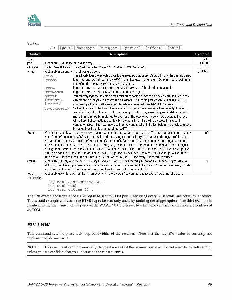
5 – Command Descriptions
WAAS / GUS Receiver Subsystem Installation and Operation Manual – Rev. 2.0 45
Syntax:LOG [port] datatype [trigger] [period] [offset] [hold]
Syntax Description Example/2* /2*
SRUW 2SWLRQDO &20 LV WKH RQO\ YDOLG HQWU\ &20
GDWDW\SH (QWHU RQH RI WKH YDOLG GDWD ORJ QDPHV VHH &KDSWHU 1RY$WHO )RUPDW 'DWD /RJV (76%
WULJJHU 2SWLRQDO (QWHU RQH RI WKH IROORZLQJ WULJJHUV 217,0(
ONCE ,PPHGLDWHO\ ORJV WKH VHOHFWHG GDWD WR WKH VHOHFWHG SRUW RQFH 'HIDXOW LI WULJJHU ILHOG LV OHIW EODQN
ONMARK /RJV WKH VHOHFWHG GDWD ZKHQ D 0$5.,1 HOHFWULFDO HYHQW LV GHWHFWHG 2XWSXWV LQWHUQDO EXIIHUV DW
WLPH RI PDUN ± GRHV QRW H[WUDSRODWH WR PDUN WLPH
ONNEW /RJV WKH VHOHFWHG GDWD HDFK WLPH WKH GDWD LV QHZ HYHQ LI WKH GDWD LV XQFKDQJHG
ONCHANGED /RJV WKH VHOHFWHG GDWD RQO\ ZKHQ WKH GDWD KDV FKDQJHG
ONTIME[ period ] ,[ offset ]
,PPHGLDWHO\ ORJV WKH VHOHFWHG GDWD DQG WKHQ SHULRGLFDOO\ ORJV WKH VHOHFWHG GDWD DW D IUHTXHQF\
GHWHUPLQHG E\ WKH SHULRG DQG RIIVHW SDUDPHWHUV 7KH ORJJLQJ ZLOO FRQWLQXH XQWLO DQ 81/2*
FRPPDQG SHUWDLQLQJ WR WKH VHOHFWHG GDWD LWHP LV UHFHLYHG VHH 81/2* &RPPDQG
CONTINUOUSLY :LOO ORJ WKH GDWD DOO WKH WLPH 7KH *36&DUG ZLOO JHQHUDWH D QHZ ORJ ZKHQ WKH RXWSXW EXIIHU
DVVRFLDWHG ZLWK WKH FKRVHQ SRUW EHFRPHV HPSW\ 7KLV PD\ FDXVH XQSUHGLFWDEOH UHVXOWV LIPRUH WKDQ RQH ORJ LV DVVLJQHG WR WKH SRUW 7KH FRQWLQXRXVO\ RSWLRQ ZDV GHVLJQHG IRU XVH
ZLWK GLIIHUHQWLDO FRUUHFWLRQV RYHU ORZ ELW UDWH GDWD OLQNV 7KLV ZLOO SURYLGH RSWLPDO UHFRUG
JHQHUDWLRQ UDWHV 7KH QH[W UHFRUG ZLOO QRW EH JHQHUDWHG XQWLO WKH ODVW E\WH RI WKH SUHYLRXV UHFRUG
LV ORDGHG LQWR WKH RXWSXW EXIIHU RI WKH 8$57
3HULRG 2SWLRQDO 8VH RQO\ ZLWK WKH Ontime WULJJHU 8QLWV IRU WKLV SDUDPHWHU DUH VHFRQGV 7KH VHOHFWHG SHULRG PD\ EH DQ\
YDOXH IURP VHFRQG WR VHFRQGV 6HOHFWHG GDWD LV ORJJHG LPPHGLDWHO\ DQG WKHQ SHULRGLF ORJJLQJ RI WKH GDWD
ZLOO VWDUW DW WKH QH[W HYHQ PXOWLSOH RI WKH SHULRG ,I D SHULRG RI VHF LV FKRVHQ WKHQ GDWD ZLOO EH ORJJHG ZKHQ WKH
UHFHLYHU WLPH LV DW WKH DQG WKH QH[W VHFRQG PDUNV ,I WKH SHULRG LV VHFRQGV WKHQ WKH ORJJHU
ZLOO ORJ WKH GDWD ZKHQ WKH UHFHLYHU WLPH LV DW HYHQ PLQXWH PDUNV 7KH VDPH UXOH DSSOLHV HYHQ LI WKH FKRVHQ SHULRG
LV QRW GLYLVLEOH LQWR LWV QH[W VHFRQG RU PLQXWH PDUNV ,I D SHULRG RI VHFRQGV LV FKRVHQ WKHQ WKH ORJJHU ZLOO ORJ DW WKH
PXOWLSOHV RI VHFRQGV OHVV WKDQ WKDW LV DQG HYHU\ VHFRQGV WKHUHDIWHU
2IIVHW 2SWLRQDO 8VH RQO\ ZLWK WKH Ontime WULJJHU DQG ZLWK 3HULRG 8QLWV IRU WKLV SDUDPHWHU DUH VHFRQGV ,W SURYLGHV WKH
DELOLW\ WR RIIVHW WKH ORJJLQJ HYHQWV IURP WKH DERYH VWDUWXS UXOH ,I \RX ZLVKHG WR ORJ GDWD DW VHFRQG DIWHU HYHU\ PLQXWH
\RX ZRXOG VHW WKH SHULRG WR VHFRQGV DQG WKH RIIVHW WR VHFRQG 7KH GHIDXOW LV
+ROG 2SWLRQDO 3UHYHQWV D ORJ IURP EHLQJ UHPRYHG ZKHQ WKH 81/2*$// FRPPDQG LV LVVXHG 81/2* PXVW EH XVHG
Examples:log com1,etsb,ontime,60,1log com1 etsblog etsb ontime 60 1
The first example will cause the ETSB log to be sent to COM port 1, recurring every 60 seconds, and offset by 1 second.The second example will cause the ETSB log to be sent only once, by omitting the trigger option. The third example isidentical to the first , since all the ports on the WAAS / GUS receiver to which one can issue commands are configuredas COM1.
$PLLBW
This command sets the phase-lock-loop bandwidths of the receiver. Note that the ‘L2_BW’ value is currently notimplemented; do not use it.
NOTE: This command can fundamentally change the way that the receiver operates. Do not alter the default settingsunless you are confident that you understand the consequences.

5 – Command Descriptions
46 WAAS / GUS Receiver Subsystem Installation and Operation Manual – Rev. 2.0
Syntax:$PLLBW L1_BW [L2_BW]
Syntax Range Value Description Default
SOOEZ &RPPDQG
/B%: +] WR +] / &$ RU / &$ SKDVHORFNORRS EDQGZLGWK
/B%: 2SWLRQDO / 3 FRGHOHVV SKDVHORFNORRS
EDQGZLGWK &XUUHQWO\ QRW LPSOHPHQWHG
Example:$pllbw 12
RESET
This command performs a hardware reset. Following a RESET command, the WAAS / GUS receiver will initiate acold-start bootup. Therefore, the receiver configuration will revert to the factory default.
Syntax:RESET
$SETFRAMETYPE
This command controls the type of navigation frame data that is output in the FRMA/B logs.
Syntax:
$SETFRAMETYPE Type
Syntax Range Value Description Default Example
6(7)5$0(7<3( &RPPDQG
7\SH $//
*36
*/21$66
:$$6
,QGLYLGXDO QDYLJDWLRQ IUDPH GDWD FDQ EH HQWHUHG RU WKH µDOO
NH\ZRUG FDQ EH XVHG LI WKH DOO W\SHV DUH QHHGHG
$// *36
Example:$setframetype gps
$THRESHOLD
This command controls signal acquisition and steady-state-lock signal thresholds. The ‘acquisition’, and ‘lock’ fieldsmust have values. The ‘acquisition2’ and ‘lock2’ fields are used if the channel is L1/L2. In this case, the ‘acquisition’and ‘lock’ fields set the thresholds for the L1 portion of the channel, and the ‘acquisition2’, and ‘lock2’ fields set thethresholds for the L2 portion of the channel.
The ‘acquisition2’ and ‘lock2’ fields (that is, the L2 portion) may be entered, are reported in the RCCA log, but are notcurrently used by the receiver.
There are two different syntactical forms, as shown below.
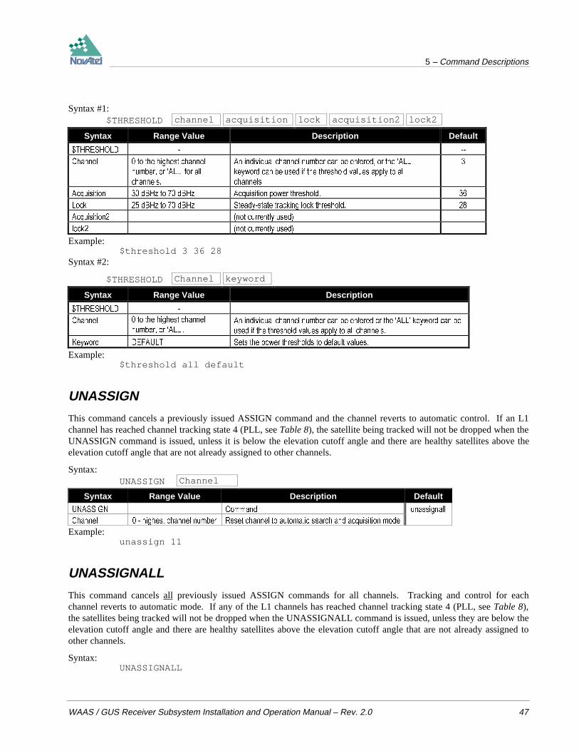
5 – Command Descriptions
WAAS / GUS Receiver Subsystem Installation and Operation Manual – Rev. 2.0 47
Syntax #1:$THRESHOLD channel acquisition lock acquisition2 lock2
Syntax Range Value Description Default
7+5(6+2/'
&KDQQHO WR WKH KLJKHVW FKDQQHO
QXPEHU RU µ$//¶ IRU DOO
FKDQQHOV
$Q LQGLYLGXDO FKDQQHO QXPEHU FDQ EH HQWHUHG RU WKH µ$//
NH\ZRUG FDQ EH XVHG LI WKH WKUHVKROG YDOXHV DSSO\ WR DOO
FKDQQHOV
$FTXLVLWLRQ G%+] WR G%+] $FTXLVLWLRQ SRZHU WKUHVKROG
/RFN G%+] WR G%+] 6WHDG\VWDWH WUDFNLQJ ORFN WKUHVKROG
$FTXLVLWLRQ QRW FXUUHQWO\ XVHG
ORFN QRW FXUUHQWO\ XVHG
Example:$threshold 3 36 28
Syntax #2:
$THRESHOLD Channel keyword
Syntax Range Value Description
7+5(6+2/'
&KDQQHO WR WKH KLJKHVW FKDQQHO
QXPEHU RU µ$//¶$Q LQGLYLGXDO FKDQQHO QXPEHU FDQ EH HQWHUHG RU WKH µ$//¶ NH\ZRUG FDQ EH
XVHG LI WKH WKUHVKROG YDOXHV DSSO\ WR DOO FKDQQHOV
.H\ZRUG '()$8/7 6HWV WKH SRZHU WKUHVKROGV WR GHIDXOW YDOXHV
Example:$threshold all default
UNASSIGN
This command cancels a previously issued ASSIGN command and the channel reverts to automatic control. If an L1channel has reached channel tracking state 4 (PLL, see Table 8), the satellite being tracked will not be dropped when theUNASSIGN command is issued, unless it is below the elevation cutoff angle and there are healthy satellites above theelevation cutoff angle that are not already assigned to other channels.
Syntax:UNASSIGN Channel
Syntax Range Value Description Default
81$66,*1 &RPPDQG XQDVVLJQDOO
&KDQQHO KLJKHVW FKDQQHO QXPEHU 5HVHW FKDQQHO WR DXWRPDWLF VHDUFK DQG DFTXLVLWLRQ PRGH
Example:unassign 11
UNASSIGNALL
This command cancels all previously issued ASSIGN commands for all channels. Tracking and control for eachchannel reverts to automatic mode. If any of the L1 channels has reached channel tracking state 4 (PLL, see Table 8),the satellites being tracked will not be dropped when the UNASSIGNALL command is issued, unless they are below theelevation cutoff angle and there are healthy satellites above the elevation cutoff angle that are not already assigned toother channels.
Syntax:UNASSIGNALL

5 – Command Descriptions
48 WAAS / GUS Receiver Subsystem Installation and Operation Manual – Rev. 2.0
$UNASSIGNG2TOPRN
This command deletes a G2 delay assignment for a particular PRN from the user-defined table. It reverses a previous$ASSIGNG2TOPRN command. There are two syntactical forms, as shown below.
Syntax #1:$UNASSIGNG2TOPRN prn
Syntax Range Value Description Example
81$66,*1*72351 &RPPDQG XQDVVLJQJWRSUQ
3UQ ± 351 1XPEHU
Example:$unassigng2toprn 101
Syntax #2:
$UNASSIGNG2TOPRN Keyword
Syntax Range Value Description Example
81$66,*1*72351 &RPPDQG XQDVVLJQJWRSUQ
.H\ZRUG $// .H\ZRUG DOO LV WKH RQO\ GHILQHG NH\ZRUG DW WKLV
WLPH
DOO
Example:$unassigng2toprn all
UNDULATION
This command permits you to either enter a specific geoidal undulation value or use the internal table of geoidalundulations. The separation values only refer to the separation between the WGS-84 ellipsoid and the geoid at yourlocation, regardless of the datum chosen. When you are going to input the ellipsoidal height using the FIX POSITIONcommand you must first set the UNDULATION to zero.
Figure 16 illustrates the various terms used in describing height relationships. In this figure,
1 = topography N = undulation2 = geoid = mean sea level h = ellipsoidal height = height above ellipsoid3 = ellipsoid H = height above mean sea level.
Figure 16 Height Relationships
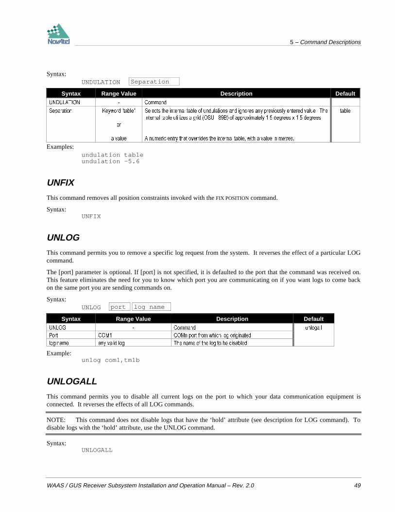
5 – Command Descriptions
WAAS / GUS Receiver Subsystem Installation and Operation Manual – Rev. 2.0 49
Syntax:UNDULATION Separation
Syntax Range Value Description Default
81'8/$7,21 &RPPDQG
6HSDUDWLRQ .H\ZRUG ³WDEOH´
RU
D YDOXH
6HOHFWV WKH LQWHUQDO WDEOH RI XQGXODWLRQV DQG LJQRUHV DQ\ SUHYLRXVO\ HQWHUHG YDOXH 7KH
LQWHUQDO WDEOH XWLOL]HV D JULG 268 % RI DSSUR[LPDWHO\ GHJUHHV [ GHJUHHV
$ QXPHULF HQWU\ WKDW RYHUULGHV WKH LQWHUQDO WDEOH ZLWK D YDOXH LQ PHWUHV
WDEOH
Examples:undulation tableundulation -5.6
UNFIX
This command removes all position constraints invoked with the FIX POSITION command.
Syntax:UNFIX
UNLOG
This command permits you to remove a specific log request from the system. It reverses the effect of a particular LOGcommand.
The [port] parameter is optional. If [port] is not specified, it is defaulted to the port that the command was received on.This feature eliminates the need for you to know which port you are communicating on if you want logs to come backon the same port you are sending commands on.
Syntax:UNLOG port log name
Syntax Range Value Description Default
81/2* &RPPDQG XQORJDOO
3RUW &20 &20Q SRUW IURP ZKLFK ORJ RULJLQDWHG
ORJ QDPH DQ\ YDOLG ORJ 7KH QDPH RI WKH ORJ WR EH GLVDEOHG
Example:unlog com1,tm1b
UNLOGALL
This command permits you to disable all current logs on the port to which your data communication equipment isconnected. It reverses the effects of all LOG commands.
NOTE: This command does not disable logs that have the ‘hold’ attribute (see description for LOG command). Todisable logs with the ‘hold’ attribute, use the UNLOG command.
Syntax:UNLOGALL
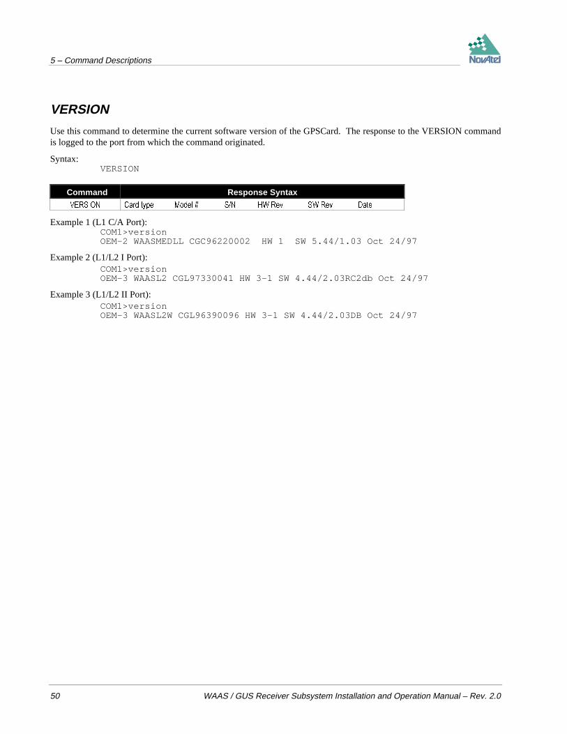
5 – Command Descriptions
50 WAAS / GUS Receiver Subsystem Installation and Operation Manual – Rev. 2.0
VERSION
Use this command to determine the current software version of the GPSCard. The response to the VERSION commandis logged to the port from which the command originated.
Syntax:VERSION
Command Response Syntax
9(56,21 &DUG W\SH 0RGHO 61 +: 5HY 6: 5HY 'DWH
Example 1 (L1 C/A Port):COM1>versionOEM-2 WAASMEDLL CGC96220002 HW 1 SW 5.44/1.03 Oct 24/97
Example 2 (L1/L2 I Port):COM1>versionOEM-3 WAASL2 CGL97330041 HW 3-1 SW 4.44/2.03RC2db Oct 24/97
Example 3 (L1/L2 II Port):COM1>versionOEM-3 WAASL2W CGL96390096 HW 3-1 SW 4.44/2.03DB Oct 24/97

6 - Output Logging
WAAS / GUS Receiver Subsystem Installation and Operation Manual – Rev. 2.0 51
6 OUTPUT LOGGINGWhen logging data from the WAAS / GUS receiver, the logs must be sent to the COM1 serial port; the COM2 port isreserved for special use. Logging to COM2 may interfere with or damage the effective operation of the receiver.
Table 4 shows the list of logs, clustered according to several categories; Table 5 shows the list of logs, arrangedalphabetically. Table 6 shows which logs have been obsoleted since the last version of this manual.
The data logs available are in NovAtel ASCII and binary format, and are described in Chapter 7 NovAtel Format DataLogs. They can be logged using several methods of triggering each log event. Each log is initiated using the LOGcommand. The LOG command and syntax are described in Chapter 5, Command Descriptions; they are of the form logport,datatype,trigger,[period,offset,hold].
If the LOG syntax does not include a trigger type, it will be output only once following execution of the LOGcommand. If trigger type is specified in the LOG syntax, the log will continue to be output based on the triggerspecification. Specific logs can be disabled using the UNLOG command, whereas all enabled logs will be disabled byusing the UNLOGALL command.
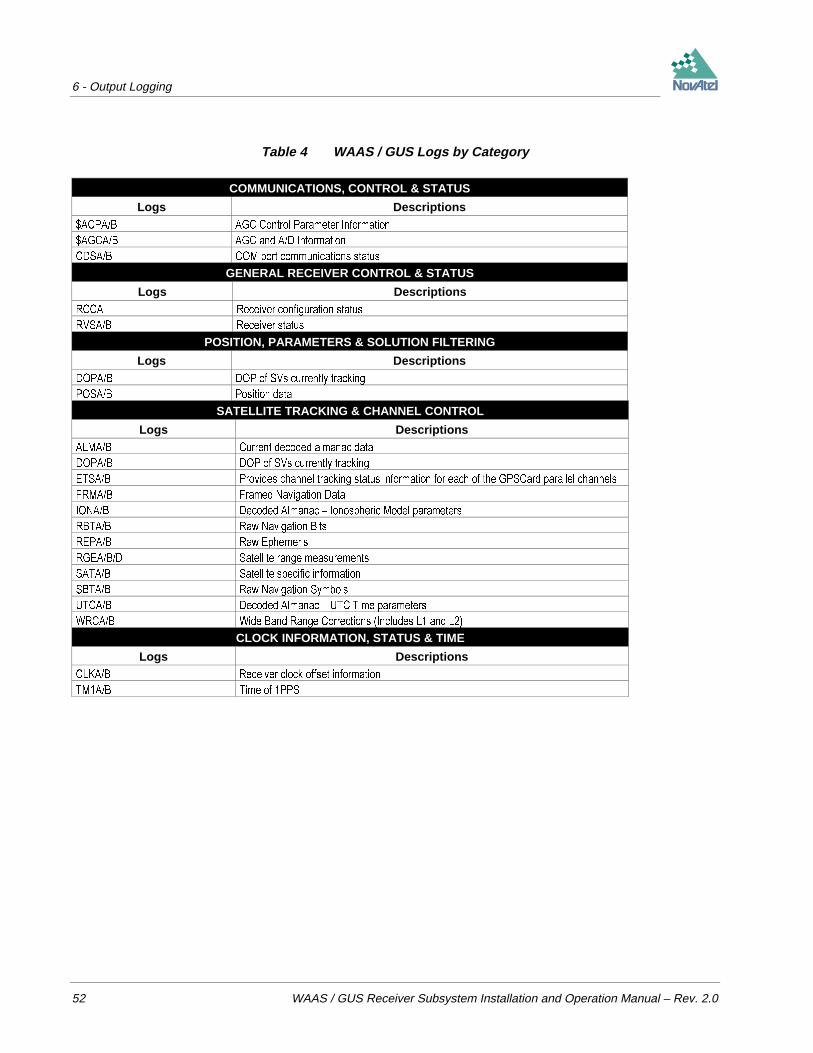
6 - Output Logging
52 WAAS / GUS Receiver Subsystem Installation and Operation Manual – Rev. 2.0
Table 4 WAAS / GUS Logs by Category
COMMUNICATIONS, CONTROL & STATUS
Logs Descriptions$&3$% $*& &RQWURO 3DUDPHWHU ,QIRUPDWLRQ
$*&$% $*& DQG $' ,QIRUPDWLRQ
&'6$% &20 SRUW FRPPXQLFDWLRQV VWDWXV
GENERAL RECEIVER CONTROL & STATUS
Logs Descriptions5&&$ 5HFHLYHU FRQILJXUDWLRQ VWDWXV
596$% 5HFHLYHU VWDWXV
POSITION, PARAMETERS & SOLUTION FILTERING
Logs Descriptions'23$% '23 RI 69V FXUUHQWO\ WUDFNLQJ
326$% 3RVLWLRQ GDWD
SATELLITE TRACKING & CHANNEL CONTROL
Logs Descriptions$/0$% &XUUHQW GHFRGHG DOPDQDF GDWD
'23$% '23 RI 69V FXUUHQWO\ WUDFNLQJ
(76$% 3URYLGHV FKDQQHO WUDFNLQJ VWDWXV LQIRUPDWLRQ IRU HDFK RI WKH *36&DUG SDUDOOHO FKDQQHOV
)50$% )UDPHG 1DYLJDWLRQ 'DWD
,21$% 'HFRGHG $OPDQDF ± ,RQRVSKHULF 0RGHO SDUDPHWHUV
5%7$% 5DZ 1DYLJDWLRQ %LWV
5(3$% 5DZ (SKHPHULV
5*($%' 6DWHOOLWH UDQJH PHDVXUHPHQWV
6$7$% 6DWHOOLWH VSHFLILF LQIRUPDWLRQ
6%7$% 5DZ 1DYLJDWLRQ 6\PEROV
87&$% 'HFRGHG $OPDQDF ± 87& 7LPH SDUDPHWHUV
:5&$% :LGH %DQG 5DQJH &RUUHFWLRQV ,QFOXGHV / DQG /
CLOCK INFORMATION, STATUS & TIME
Logs Descriptions&/.$% 5HFHLYHU FORFN RIIVHW LQIRUPDWLRQ
70$% 7LPH RI 336
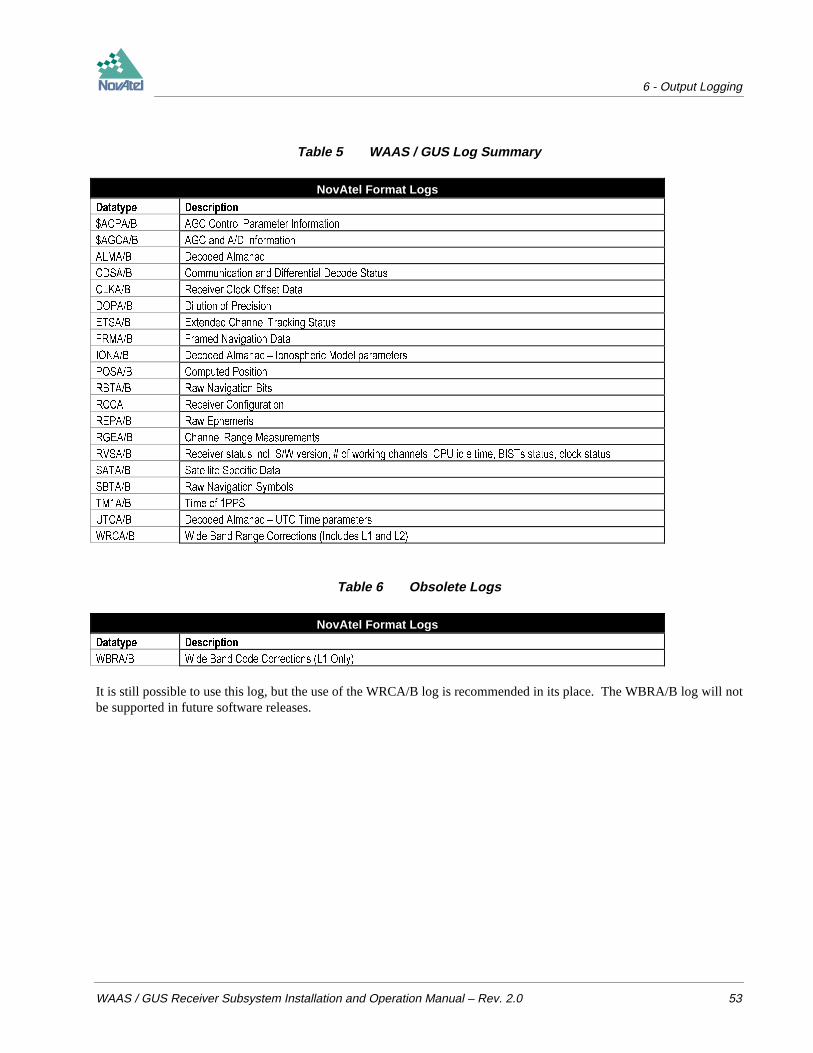
6 - Output Logging
WAAS / GUS Receiver Subsystem Installation and Operation Manual – Rev. 2.0 53
Table 5 WAAS / GUS Log Summary
NovAtel Format Logs'DWDW\SH 'HVFULSWLRQ
$&3$% $*& &RQWURO 3DUDPHWHU ,QIRUPDWLRQ
$*&$% $*& DQG $' ,QIRUPDWLRQ
$/0$% 'HFRGHG $OPDQDF
&'6$% &RPPXQLFDWLRQ DQG 'LIIHUHQWLDO 'HFRGH 6WDWXV
&/.$% 5HFHLYHU &ORFN 2IIVHW 'DWD
'23$% 'LOXWLRQ RI 3UHFLVLRQ
(76$% ([WHQGHG &KDQQHO 7UDFNLQJ 6WDWXV
)50$% )UDPHG 1DYLJDWLRQ 'DWD
,21$% 'HFRGHG $OPDQDF ± ,RQRVSKHULF 0RGHO SDUDPHWHUV
326$% &RPSXWHG 3RVLWLRQ
5%7$% 5DZ 1DYLJDWLRQ %LWV
5&&$ 5HFHLYHU &RQILJXUDWLRQ
5(3$% 5DZ (SKHPHULV
5*($% &KDQQHO 5DQJH 0HDVXUHPHQWV
596$% 5HFHLYHU VWDWXV LQFO 6: YHUVLRQ RI ZRUNLQJ FKDQQHOV &38 LGOH WLPH %,67V VWDWXV FORFN VWDWXV
6$7$% 6DWHOOLWH 6SHFLILF 'DWD
6%7$% 5DZ 1DYLJDWLRQ 6\PEROV
70$% 7LPH RI 336
87&$% 'HFRGHG $OPDQDF ± 87& 7LPH SDUDPHWHUV
:5&$% :LGH %DQG 5DQJH &RUUHFWLRQV ,QFOXGHV / DQG /
Table 6 Obsolete Logs
NovAtel Format Logs'DWDW\SH 'HVFULSWLRQ
:%5$% :LGH %DQG &RGH &RUUHFWLRQV / 2QO\
It is still possible to use this log, but the use of the WRCA/B log is recommended in its place. The WBRA/B log will notbe supported in future software releases.
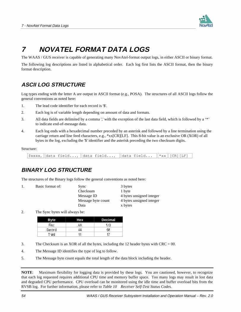
7 - NovAtel Format Data Logs
54 WAAS / GUS Receiver Subsystem Installation and Operation Manual – Rev. 2.0
7 NOVATEL FORMAT DATA LOGSThe WAAS / GUS receiver is capable of generating many NovAtel-format output logs, in either ASCII or binary format.
The following log descriptions are listed in alphabetical order. Each log first lists the ASCII format, then the binaryformat description.
ASCII LOG STRUCTURE
Log types ending with the letter A are output in ASCII format (e.g., POSA). The structures of all ASCII logs follow thegeneral conventions as noted here:
1. The lead code identifier for each record is '$'.
2. Each log is of variable length depending on amount of data and formats.
3. All data fields are delimited by a comma ',' with the exception of the last data field, which is followed by a ‘*’to indicate end-of-message data.
4. Each log ends with a hexadecimal number preceded by an asterisk and followed by a line termination using thecarriage return and line feed characters, e.g., *xx[CR][LF]. This 8-bit value is an exclusive OR (XOR) of allbytes in the log, excluding the '$' identifier and the asterisk preceding the two checksum digits.
Structure:
$xxxx, data field..., data field..., data field... *xx [CR][LF]
BINARY LOG STRUCTURE
The structures of the Binary logs follow the general conventions as noted here:
1. Basic format of: Sync 3 bytesChecksum 1 byteMessage ID 4 bytes unsigned integerMessage byte count 4 bytes unsigned integerData x bytes
2. The Sync bytes will always be:
Byte Hex Decimal
)LUVW $$
6HFRQG
7KLUG
3. The Checksum is an XOR of all the bytes, including the 12 header bytes with CRC = 00.
4. The Message ID identifies the type of log to follow.
5. The Message byte count equals the total length of the data block including the header.
NOTE: Maximum flexibility for logging data is provided by these logs. You are cautioned, however, to recognizethat each log requested requires additional CPU time and memory buffer space. Too many logs may result in lost dataand degraded CPU performance. CPU overload can be monitored using the idle time and buffer overload bits from theRVSB log. For further information, please refer to Table 10 Receiver Self-Test Status Codes.

7 - NovAtel Format Data Logs
WAAS / GUS Receiver Subsystem Installation and Operation Manual – Rev. 2.0 55
The following describes the format types used in the description of binary logs.
Type Size (bytes) Size (bits) Description
FKDU 7KH FKDU W\SH LV XVHG WR VWRUH WKH LQWHJHU YDOXH RI D PHPEHU RI WKH UHSUHVHQWDEOH FKDUDFWHU VHW
7KDW LQWHJHU YDOXH LV WKH $6&,, FRGH FRUUHVSRQGLQJ WR WKH VSHFLILHG FKDUDFWHU
LQW 7KH VL]H RI D VLJQHG RU XQVLJQHG LQW LWHP LV WKH VWDQGDUG VL]H RI DQ LQWHJHU RQ D SDUWLFXODU
PDFKLQH 2Q D ELW SURFHVVRU VXFK DV WKH 1RY$WHO *36&DUG WKH LQW W\SH LV ELWV RU
E\WHV 7KH LQW W\SHV DOO UHSUHVHQW VLJQHG YDOXHV XQOHVV VSHFLILHG RWKHUZLVH 6LJQHG LQWHJHUV DUH
UHSUHVHQWHG LQ WZRVFRPSOHPHQW IRUP 7KH PRVWVLJQLILFDQW ELW KROGV WKH VLJQ IRU QHJDWLYH
IRU SRVLWLYH DQG ]HUR
GRXEOH 7KH GRXEOH W\SH FRQWDLQV ELWV IRU VLJQ IRU WKH H[SRQHQW DQG IRU WKH PDQWLVVD ,WV
UDQJH LV ( ZLWK DW OHDVW GLJLWV RI SUHFLVLRQ
IORDW 7KH IORDW W\SH FRQWDLQV ELWV IRU WKH VLJQ IRU WKH H[SRQHQW DQG IRU WKH PDQWLVVD ,WV
UDQJH LV ( ZLWK DW OHDVW GLJLWV RI SUHFLVLRQ
Each byte within an int has its own address, and the smallest of the addresses is the address of the int. The byte at thislowest address contains the eight least significant bits of the double word, while the byte at the highest address containsthe eight most significant bits. Similarly the bits of a "double" type are stored least significant byte first. This is thesame data format used by personal computers.
TIME CONVENTIONS
All logs report GPS time expressed in GPS weeks and seconds into the week. The time reported is not corrected for thelocal receiver’s clock error. To derive the closest GPS time, one must subtract the clock offset shown in the CLKB log(field 4) from GPS time reported.
GPS time is based on an atomic time scale. Universal Time Coordinated (UTC) time is also based on an atomic timescale, with an offset of seconds applied to coordinate Universal Time to GPS time. GPS time is designated as beingcoincident with UTC at the start date of January 6, 1980 (00 hours). GPS time does not count leap seconds, andtherefore an offset exists between UTC and GPS time (at this date: approximately 11 seconds). The GPS week consistsof 604800 seconds, where 000000 seconds is at Saturday midnight. Each week at this time, the week numberincrements by one, and the seconds into the week resets to 0.
LOG DESCRIPTIONS
$ACPA/B AGC CONTROL PARAMETER INFORMATION
The ACPA/B log contains AGC related information. This information includes information about the AGC controllerbin values, bin weights, variances, and detect levels.
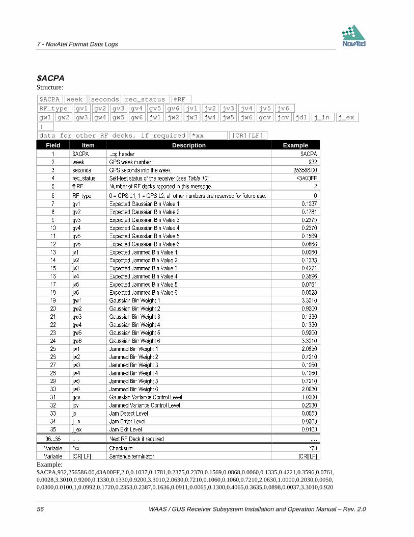
7 - NovAtel Format Data Logs
56 WAAS / GUS Receiver Subsystem Installation and Operation Manual – Rev. 2.0
$ACPAStructure:
$ACPA week seconds rec_status #RF
RF_type gv1 gv2 gv3 gv4 gv5 gv6 jv1 jv2 jv3 jv4 jv5 jv6
gw1 gw2 gw3 gw4 gw5 gw6 jw1 jw2 jw3 jw4 jw5 jw6 gcv jcv jdl j_in j_ex
:
data for other RF decks, if required *xx [CR][LF]
Field Item Description Example $&3$ /RJ KHDGHU $&3$
ZHHN *36 ZHHN QXPEHU
VHFRQGV *36 VHFRQGV LQWR WKH ZHHN
UHFBVWDWXV 6HOIWHVW VWDWXV RI WKH UHFHLYHU VHH 7DEOH $))
5) 1XPEHU RI 5) GHFNV UHSRUWHG LQ WKLV PHVVDJH
5)BW\SH *36 / *36 / DOO RWKHU QXPEHUV DUH UHVHUYHG IRU IXWXUH XVH
JY ([SHFWHG *DXVVLDQ %LQ 9DOXH
JY ([SHFWHG *DXVVLDQ %LQ 9DOXH
JY ([SHFWHG *DXVVLDQ %LQ 9DOXH
JY ([SHFWHG *DXVVLDQ %LQ 9DOXH
JY ([SHFWHG *DXVVLDQ %LQ 9DOXH
JY ([SHFWHG *DXVVLDQ %LQ 9DOXH
MY ([SHFWHG -DPPHG %LQ 9DOXH
MY ([SHFWHG -DPPHG %LQ 9DOXH
MY ([SHFWHG -DPPHG %LQ 9DOXH
MY ([SHFWHG -DPPHG %LQ 9DOXH
MY ([SHFWHG -DPPHG %LQ 9DOXH
MY ([SHFWHG -DPPHG %LQ 9DOXH
JZ *DXVVLDQ %LQ :HLJKW
JZ *DXVVLDQ %LQ :HLJKW
JZ *DXVVLDQ %LQ :HLJKW
JZ *DXVVLDQ %LQ :HLJKW
JZ *DXVVLDQ %LQ :HLJKW
JZ *DXVVLDQ %LQ :HLJKW
MZ -DPPHG %LQ :HLJKW
MZ -DPPHG %LQ :HLJKW
MZ -DPPHG %LQ :HLJKW
MZ -DPPHG %LQ :HLJKW
MZ -DPPHG %LQ :HLJKW
MZ -DPPHG %LQ :HLJKW
JFY *DXVVLDQ 9DULDQFH &RQWURO /HYHO
MFY -DPPHG 9DULDQFH &RQWURO /HYHO
MGO -DP 'HWHFW /HYHO
MBLQ -DP (QWHU /HYHO
MBH[ -DP ([LW /HYHO
« 1H[W 5) 'HFN LI UHTXLUHG «
9DULDEOH [[ &KHFNVXP
9DULDEOH >&5@>/)@ 6HQWHQFH WHUPLQDWRU >&5@>/)@
Example:$ACPA,932,256586.00,43A00FF,2,0,0.1037,0.1781,0.2375,0.2370,0.1569,0.0868,0.0060,0.1335,0.4221,0.3596,0.0761,0.0028,3.3010,0.9200,0.1330,0.1330,0.9200,3.3010,2.0630,0.7210,0.1060,0.1060,0.7210,2.0630,1.0000,0.2030,0.0050,0.0300,0.0100,1,0.0992,0.1720,0.2353,0.2387,0.1636,0.0911,0.0065,0.1300,0.4065,0.3635,0.0898,0.0037,3.3010,0.920
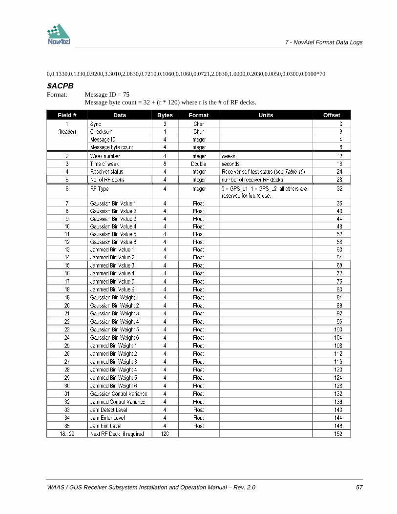
7 - NovAtel Format Data Logs
WAAS / GUS Receiver Subsystem Installation and Operation Manual – Rev. 2.0 57
0,0.1330,0.1330,0.9200,3.3010,2.0630,0.7210,0.1060,0.1060,0.0721,2.0630,1.0000,0.2030,0.0050,0.0300,0.0100*70
$ACPBFormat: Message ID = 75
Message byte count = 32 + (r * 120) where r is the # of RF decks.
Field # Data Bytes Format Units Offset
6\QF &KDU
KHDGHU &KHFNVXP &KDU
0HVVDJH ,' ,QWHJHU
0HVVDJH E\WH FRXQW ,QWHJHU
:HHN QXPEHU ,QWHJHU ZHHNV
7LPH RI ZHHN 'RXEOH VHFRQGV
5HFHLYHU VWDWXV ,QWHJHU 5HFHLYHU VHOIWHVW VWDWXV VHH 7DEOH
1R RI 5) GHFNV ,QWHJHU QXPEHU RI UHFHLYHU 5) GHFNV
5) 7\SH ,QWHJHU *36B/ *36B/ DOO RWKHUV DUH
UHVHUYHG IRU IXWXUH XVH
*DXVVLDQ %LQ 9DOXH )ORDW
*DXVVLDQ %LQ 9DOXH )ORDW
*DXVVLDQ %LQ 9DOXH )ORDW
*DXVVLDQ %LQ 9DOXH )ORDW
*DXVVLDQ %LQ 9DOXH )ORDW
*DXVVLDQ %LQ 9DOXH )ORDW
-DPPHG %LQ 9DOXH )ORDW
-DPPHG %LQ 9DOXH )ORDW
-DPPHG %LQ 9DOXH )ORDW
-DPPHG %LQ 9DOXH )ORDW
-DPPHG %LQ 9DOXH )ORDW
-DPPHG %LQ 9DOXH )ORDW
*DXVVLDQ %LQ :HLJKW )ORDW
*DXVVLDQ %LQ :HLJKW )ORDW
*DXVVLDQ %LQ :HLJKW )ORDW
*DXVVLDQ %LQ :HLJKW )ORDW
*DXVVLDQ %LQ :HLJKW )ORDW
*DXVVLDQ %LQ :HLJKW )ORDW
-DPPHG %LQ :HLJKW )ORDW
-DPPHG %LQ :HLJKW )ORDW
-DPPHG %LQ :HLJKW )ORDW
-DPPHG %LQ :HLJKW )ORDW
-DPPHG %LQ :HLJKW )ORDW
-DPPHG %LQ :HLJKW )ORDW
*DXVVLDQ &RQWURO 9DULDQFH )ORDW
-DPPHG &RQWURO 9DULDQFH )ORDW
-DP 'HWHFW /HYHO )ORDW
-DP (QWHU /HYHO )ORDW
-DP ([LW /HYHO )ORDW
1H[W 5) 'HFN LI UHTXLUHG
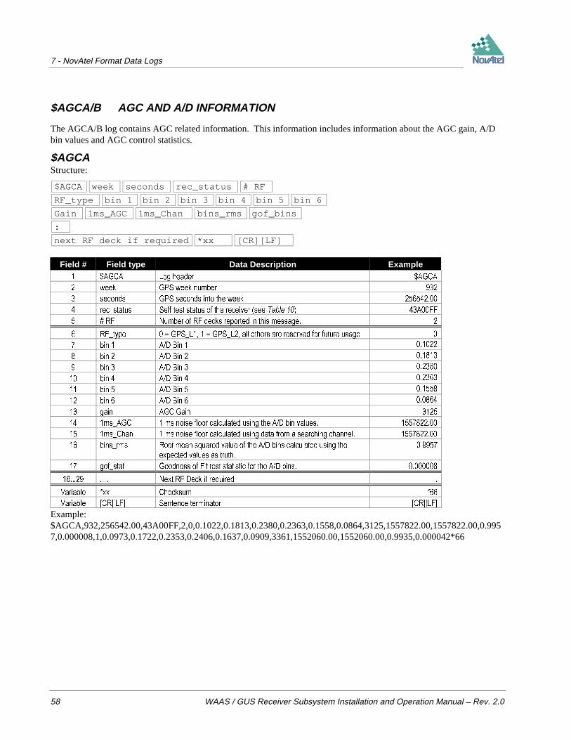
7 - NovAtel Format Data Logs
58 WAAS / GUS Receiver Subsystem Installation and Operation Manual – Rev. 2.0
$AGCA/B AGC AND A/D INFORMATION
The AGCA/B log contains AGC related information. This information includes information about the AGC gain, A/Dbin values and AGC control statistics.
$AGCAStructure:
$AGCA week seconds rec_status # RF
RF_type bin 1 bin 2 bin 3 bin 4 bin 5 bin 6
Gain 1ms_AGC 1ms_Chan bins_rms gof_bins
:
next RF deck if required *xx [CR][LF]
Field # Field type Data Description Example $*&$ /RJ KHDGHU $*&$
ZHHN *36 ZHHN QXPEHU
VHFRQGV *36 VHFRQGV LQWR WKH ZHHN
UHFBVWDWXV 6HOIWHVW VWDWXV RI WKH UHFHLYHU VHH 7DEOH $))
5) 1XPEHU RI 5) GHFNV UHSRUWHG LQ WKLV PHVVDJH
5)BW\SH *36B/ *36B/ DOO RWKHUV DUH UHVHUYHG IRU IXWXUH XVDJH
ELQ $' %LQ
ELQ $' %LQ
ELQ $' %LQ
ELQ $' %LQ
ELQ $' %LQ
ELQ $' %LQ
JDLQ $*& *DLQ
PVB$*& PV QRLVH IORRU FDOFXODWHG XVLQJ WKH $' ELQ YDOXHV
PVB&KDQ PV QRLVH IORRU FDOFXODWHG XVLQJ GDWD IURP D VHDUFKLQJ FKDQQHO
ELQVBUPV 5RRW PHDQ VTXDUHG YDOXH RI WKH $' ELQV FDOFXODWHG XVLQJ WKH
H[SHFWHG YDOXHV DV WUXWK
JRIBVWDW *RRGQHVV RI )LW WHVW VWDWLVWLF IRU WKH $' ELQV
« 1H[W 5) 'HFN LI UHTXLUHG «
9DULDEOH [[ &KHFNVXP
9DULDEOH >&5@>/)@ 6HQWHQFH WHUPLQDWRU >&5@>/)@
Example:$AGCA,932,256542.00,43A00FF,2,0,0.1022,0.1813,0.2380,0.2363,0.1558,0.0864,3125,1557822.00,1557822.00,0.9957,0.000008,1,0.0973,0.1722,0.2353,0.2406,0.1637,0.0909,3361,1552060.00,1552060.00,0.9935,0.000042*66

7 - NovAtel Format Data Logs
WAAS / GUS Receiver Subsystem Installation and Operation Manual – Rev. 2.0 59
$AGCBFormat: Message ID = 74
Message byte count = 32 + (r * 48) where r is the # of RF decks.
Field # Data Bytes Format Units Offset
6\QF &KDU
KHDGHU &KHFNVXP &KDU
0HVVDJH ,' ,QWHJHU
0HVVDJH E\WH FRXQW ,QWHJHU
:HHN QXPEHU ,QWHJHU ZHHNV
7LPH RI ZHHN 'RXEOH VHFRQGV
5HFHLYHU VWDWXV ,QWHJHU 6HH 7DEOH
1R RI 5) GHFNV ,QWHJHU QXPEHU RI UHFHLYHU 5) GHFNV
5) 7\SH ,QWHJHU *36B/ *36B/ DOO RWKHUV
DUH UHVHUYHG IRU IXWXUH XVDJH
$' %LQ 0RVW 1HJ )ORDW SHUFHQWDJH
$' %LQ )ORDW SHUFHQWDJH
$' %LQ )ORDW SHUFHQWDJH
$' %LQ )ORDW SHUFHQWDJH
$' %LQ )ORDW SHUFHQWDJH
$' %LQ 0RVW 3RV )ORDW SHUFHQWDJH
$*& *DLQ ,QWHJHU WR LV PD[
PV 1RLVH )ORRU )URP $*& )ORDW
PV 1RLVH )ORRU )URP &KDQQHOV )ORDW
$' %LQV 506 )ORDW
$' *RRGQHVV RI )LW 7HVW 6WDWLVWLF )ORDW
1H[W 5) 'HFN LI UHTXLUHG

7 - NovAtel Format Data Logs
60 WAAS / GUS Receiver Subsystem Installation and Operation Manual – Rev. 2.0
ALMA/B DECODED ALMANAC
This log contains the decoded almanac parameters from sub-frames four and five as received from the satellite with theparity information removed and appropriate scaling applied. Multiple messages are transmitted, one for each SValmanac collected.
The Ionospheric Model parameters (IONA/B) and the UTC Time parameters (UTCA/B) are also provided, following thelast almanac record. These cannot be logged individually or independently of the ALMA/B message. They are,however, described separately under their respective names.
For more information on Almanac data, refer to the GPS SPS Signal Specification.
ALMAStructure:
$ALMA Prn ecc seconds week rate-ra ra w Mo af0 af1 cor-mean-motion
A Incl-angle health-4 health-5 health-alm *xx [CR][LF]
Field # Field type Data Description Example $/0$ /RJ KHDGHU $/0$
SUQ 6DWHOOLWH 351 QXPEHU IRU FXUUHQW PHVVDJH
HFF (FFHQWULFLW\ (
VHFRQGV $OPDQDF UHIHUHQFH WLPH VHFRQGV LQWR WKH ZHHN
ZHHN $OPDQDF UHIHUHQFH ZHHN *36 ZHHN QXPEHU
UDWHUD 5DWH RI ULJKW DVFHQVLRQ UDGLDQV (
UD 5LJKW DVFHQVLRQ UDGLDQV (
Z $UJXPHQW RI SHULJHH UDGLDQV (
0R 0HDQ DQRPDO\ UDGLDQV (
DI &ORFN DJLQJ SDUDPHWHU VHFRQGV (
DI &ORFN DJLQJ SDUDPHWHU VHFRQGVVHFRQG (
FRUPHDQPRWLRQ &RUUHFWHG PHDQ PRWLRQ UDGLDQVVHFRQG (
$ 6HPLPDMRU D[LV PHWUHV (
LQFODQJOH $QJOH RI LQFOLQDWLRQ UDGLDQV (
KHDOWK $QWLVSRRILQJ DQG 69 FRQILJ IURP VXEIUDPH SDJH
KHDOWK 69 KHDOWK ELWV69 VXEIUDPH RU SDJH
KHDOWKDOP 69 KHDOWK ELWV DOPDQDF
[[ &KHFNVXP
>&5@>/)@ 6HQWHQFH WHUPLQDWRU >&5@>/)@
$/0$ /DVW VDWHOOLWH 351 DOPDQDF PHVVDJH
,21$ ,RQRVSKHULF 0RGHO 3DUDPHWHUV
87&$ 87& 7LPH 3DUDPHWHUV
Example:$ALMA,1,3.55577E-003,32768,745,-7.8860E-009,-6.0052951E-002,-1.1824254E+000,1.67892137E+000,-1.8119E-005,-3.6379E-012,1.45854965E-004,2.65602281E+007,9.55576E-001,1,0,0*20[CR][LF]:$ALMA, 31,4.90665E-003,32768,745,-8.0460E-009,3.05762855E+000,6.14527459E-001,1.69958217E+000,6.67572E-006,3.63797E-012,1.45861888E-004,2.65593876E+007,9.61664E-001,1,0,0*13[CR][LF]

7 - NovAtel Format Data Logs
WAAS / GUS Receiver Subsystem Installation and Operation Manual – Rev. 2.0 61
ALMBFormat: Message ID = 18 Message byte count = 120
Field # Field Type Bytes Format Units Offset 6\QF
KHDGHU &KHFNVXP
0HVVDJH ,'
0HVVDJH E\WH FRXQW
6DWHOOLWH 351 QXPEHU LQWHJHU GLPHQVLRQOHVV
(FFHQWULFLW\ GRXEOH GLPHQVLRQOHVV
$OPDQDF UHI WLPH GRXEOH VHFRQGV
$OPDQDF UHI ZHHN LQWHJHU ZHHNV
2PHJDGRW UDWH RI ULJKW DVFHQVLRQ GRXEOH UDGLDQVVHFRQG
5LJKW DVFHQVLRQ GRXEOH UDGLDQV
$UJXPHQW RI SHULJHH Z GRXEOH UDGLDQV
0HDQ DQRPDO\ 0R GRXEOH UDGLDQV
&ORFN DJLQJ SDUDPHWHU DI GRXEOH VHFRQGV
&ORFN DJLQJ SDUDPHWHU DI GRXEOH VHFRQGVVHFRQG
&RUUHFWHG PHDQ PRWLRQ GRXEOH UDGLDQVVHFRQG
6HPLPDMRU D[LV $ GRXEOH PHWUHV
$QJOH RI LQFOLQDWLRQ GRXEOH UDGLDQV
6Y KHDOWK IURP VXEIUDPH LQWHJHU
6Y KHDOWK IURP VXEIUDPH ,QWHJHU
6Y KHDOWK IURP DOPDQDF ,QWHJHU
CDSA/B COMMUNICATION AND DIFFERENTIAL DECODE STATUS
The WAAS / GUS receiver maintains a running count of a variety of status indicators of the data link. This log outputs areport of those indicators.
Parity and framing errors will occur if poor transmission lines are encountered or if there is an incompatibility in the dataprotocol. If errors occur, you may need to confirm the bit rate, number of data bits, number of stop bits, and parity ofboth the transmit and receiving ends. Overrun errors will occur if more characters are sent to the UART that can beremoved by the on-board microprocessor.

7 - NovAtel Format Data Logs
62 WAAS / GUS Receiver Subsystem Installation and Operation Manual – Rev. 2.0
CDSAStructure:
$CDSA week seconds xon1 cts1 parity1 overrun1 framing1 rx1 tx1
Xon2 cts2 parity2 overrun2 framing2 rx2 tx2
Rtcacrc
rtcaachk
rtcagood
rtcmpar
rtcmachk
rtcmgood
dcsachk
dcsagood
dcsbchk
dcsbgood
Res’d res’d res’d *xx [CR][LF]
Field # Field type Data Description Example &'6$ /RJ KHDGHU &'6$
ZHHN *36 ZHHN QXPEHU
VHFRQGV *36 VHFRQGV LQWR WKH ZHHN
[RQ )ODJ WR LQGLFDWH WKDW WKH FRP LV XVLQJ ;21;2)) KDQGVKDNLQJ SURWRFRO DQG SRUW KDV UHFHLYHG DQ
;2)) DQG ZLOO ZDLW IRU DQ ;21 EHIRUH VHQGLQJ DQ\ PRUH GDWD
FWV )ODJ WR LQGLFDWH WKDW FRP LV XVLQJ &76576 KDQGVKDNH SURWRFRO DQG &76 OLQH SRUW KDV EHHQ
DVVHUWHG 7KH SRUW ZLOO ZDLW IRU WKH OLQH WR GHDVVHUW EHIRUH VHQGLQJ DQ\ PRUH GDWD
SDULW\ $ UXQQLQJ FRXQW RI FKDUDFWHU SDULW\ HUURUV IURP WKH 8$57 RI &20
RYHUUXQ $ UXQQLQJ FRXQW RI 8$57 EXIIHU RYHUUXQ HUURUV RI &20
IUDPLQJ $ UXQQLQJ FRXQW RI FKDUDFWHU IUDPLQJ HUURU IURP WKH 8$57 RI &20
U[ $ UXQQLQJ FRXQW RI WKH FKDUDFWHUV UHFHLYHG IURP &20
W[ $ UXQQLQJ FRXQW RI WKH FKDUDFWHUV VHQW RXW &20
[RQ )ODJ WR LQGLFDWH WKDW WKH &20 LV XVLQJ ;21;2)) KDQGVKDNLQJ SURWRFRO DQG SRUW KDV UHFHLYHG DQ
;2)) DQG ZLOO ZDLW IRU DQ ;21 EHIRUH VHQGLQJ DQ\ PRUH GDWD
FWV )ODJ WR LQGLFDWH WKDW &20 LV XVLQJ &76576 KDQGVKDNH SURWRFRO DQG &76 OLQH SRUW KDV EHHQ
DVVHUWHG 7KH 3RUW ZLOO ZDLW IRU WKH OLQH WR GHDVVHUW EHIRUH VHQGLQJ DQ\ PRUH GDWD
SDULW\ $ UXQQLQJ FRXQW RI FKDUDFWHU SDULW\ HUURUV IURP WKH 8$57 RI &20
RYHUUXQ $ UXQQLQJ FRXQW RI 8$57 EXIIHU RYHUUXQ HUURUV RI &20
IUDPLQJ $ UXQQLQJ FRXQW RI FKDUDFWHU IUDPLQJ HUURU IURP WKH 8$57 RI &20
U[ $ UXQQLQJ FRXQW RI WKH FKDUDFWHUV UHFHLYHG IURP &20
W[ $ UXQQLQJ FRXQW RI WKH FKDUDFWHUV VHQW RXW &20
UWFDFUF $ UXQQLQJ FRXQW RI 57&$ &5& IDLOXUHV
UWFDDFKN $ UXQQLQJ FRXQW RI LQYDOLG $6&,, 57&$ [[ UHFRUGV LQGLFDWLQJ WKDW WKH $6&,, FKHFNVXP [[ IDLOHG
UWFDJRRG $ UXQQLQJ FRXQW RI 57&$ UHFRUGV WKDW SDVV HUURU FKHFNLQJ
UWFPSDU $ UXQQLQJ FRXQW RI ELW 57&0 SDULW\ IDLOXUHV
UWFPDFKN $ UXQQLQJ FRXQW RI LQYDOLG $6&,, 57&0 [[ UHFRUGV LQGLFDWLQJ WKDW WKH $6&,, FKHFNVXP [[ IDLOHG
UWFPJRRG $ UXQQLQJ FRXQW RI 57&0 UHFRUGV WKDW SDVV HUURU FKHFNLQJ
GFVDFKN $ UXQQLQJ FRXQW RI LQYDOLG $6&,, '&6$ [[ UHFRUGV
GFVDJRRG $ UXQQLQJ FRXQW RI '&6$ UHFRUGV WKDW SDVV HUURU FKHFNLQJ
GFVEFKN $ UXQQLQJ FRXQW RI LQYDOLG ELQDU\ '&6% UHFRUGV
GFVEJRRG $ UXQQLQJ FRXQW RI '&6% UHFRUGV WKDW SDVV HUURU FKHFNLQJ
5HVHUYHG IRU IXWXUH XVH
5HVHUYHG IRU IXWXUH XVH
5HVHUYHG IRU IXWXUH XVH
[[ &KHFNVXP
>&5@>/)@ 6HQWHQFH WHUPLQDWRU >&5@>/)@
Note: Fields 18-27 will be 0 if differential corrections are not used.
Example:
$CDSA,787,500227,0,0,0,0,0,0,9,0,0,0,0,0,0,9,0,0,0,0,0,0,0,0,0,0,0,0,0*33[CR][LF]
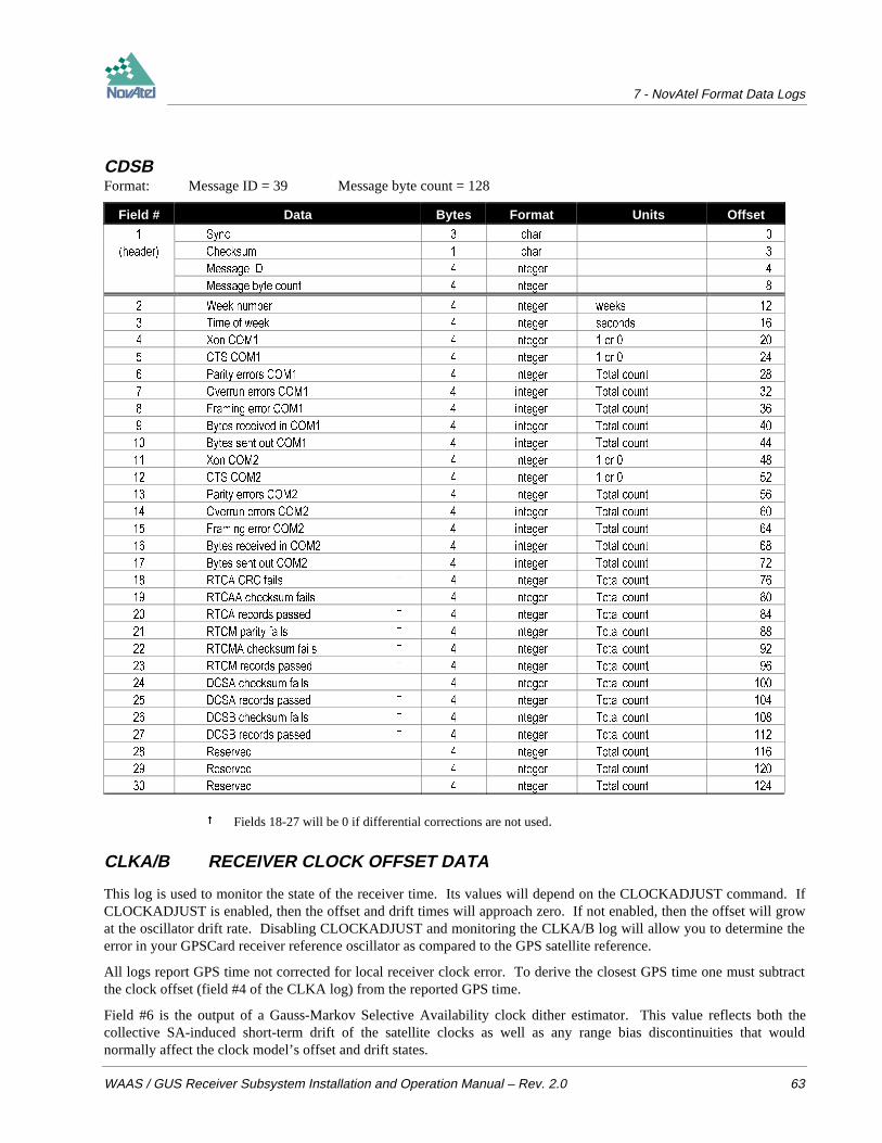
7 - NovAtel Format Data Logs
WAAS / GUS Receiver Subsystem Installation and Operation Manual – Rev. 2.0 63
CDSBFormat: Message ID = 39 Message byte count = 128
Field # Data Bytes Format Units Offset
6\QF FKDU
KHDGHU &KHFNVXP FKDU
0HVVDJH ,' LQWHJHU
0HVVDJH E\WH FRXQW LQWHJHU
:HHN QXPEHU LQWHJHU ZHHNV
7LPH RI ZHHN LQWHJHU VHFRQGV
;RQ &20 LQWHJHU RU
&76 &20 LQWHJHU RU
3DULW\ HUURUV &20 LQWHJHU 7RWDO FRXQW
2YHUUXQ HUURUV &20 LQWHJHU 7RWDO FRXQW
)UDPLQJ HUURU &20 LQWHJHU 7RWDO FRXQW
%\WHV UHFHLYHG LQ &20 LQWHJHU 7RWDO FRXQW
%\WHV VHQW RXW &20 LQWHJHU 7RWDO FRXQW
;RQ &20 LQWHJHU RU
&76 &20 LQWHJHU RU
3DULW\ HUURUV &20 LQWHJHU 7RWDO FRXQW
2YHUUXQ HUURUV &20 LQWHJHU 7RWDO FRXQW
)UDPLQJ HUURU &20 LQWHJHU 7RWDO FRXQW
%\WHV UHFHLYHG LQ &20 LQWHJHU 7RWDO FRXQW
%\WHV VHQW RXW &20 LQWHJHU 7RWDO FRXQW
57&$ &5& IDLOV LQWHJHU 7RWDO FRXQW
57&$$ FKHFNVXP IDLOV LQWHJHU 7RWDO FRXQW
57&$ UHFRUGV SDVVHG LQWHJHU 7RWDO FRXQW
57&0 SDULW\ IDLOV LQWHJHU 7RWDO FRXQW
57&0$ FKHFNVXP IDLOV LQWHJHU 7RWDO FRXQW
57&0 UHFRUGV SDVVHG LQWHJHU 7RWDO FRXQW
'&6$ FKHFNVXP IDLOV LQWHJHU 7RWDO FRXQW
'&6$ UHFRUGV SDVVHG LQWHJHU 7RWDO FRXQW
'&6% FKHFNVXP IDLOV LQWHJHU 7RWDO FRXQW
'&6% UHFRUGV SDVVHG LQWHJHU 7RWDO FRXQW
5HVHUYHG LQWHJHU 7RWDO FRXQW
5HVHUYHG LQWHJHU 7RWDO FRXQW
5HVHUYHG LQWHJHU 7RWDO FRXQW
Fields 18-27 will be 0 if differential corrections are not used.
CLKA/B RECEIVER CLOCK OFFSET DATA
This log is used to monitor the state of the receiver time. Its values will depend on the CLOCKADJUST command. IfCLOCKADJUST is enabled, then the offset and drift times will approach zero. If not enabled, then the offset will growat the oscillator drift rate. Disabling CLOCKADJUST and monitoring the CLKA/B log will allow you to determine theerror in your GPSCard receiver reference oscillator as compared to the GPS satellite reference.
All logs report GPS time not corrected for local receiver clock error. To derive the closest GPS time one must subtractthe clock offset (field #4 of the CLKA log) from the reported GPS time.
Field #6 is the output of a Gauss-Markov Selective Availability clock dither estimator. This value reflects both thecollective SA-induced short-term drift of the satellite clocks as well as any range bias discontinuities that wouldnormally affect the clock model’s offset and drift states.
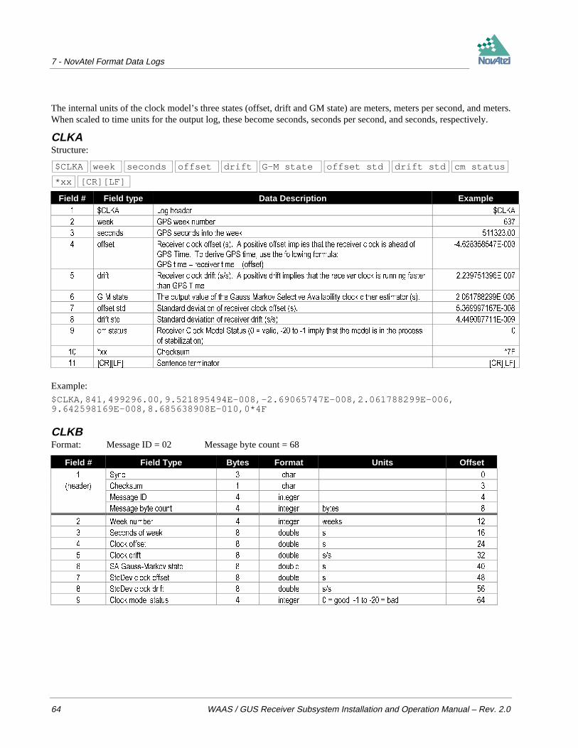
7 - NovAtel Format Data Logs
64 WAAS / GUS Receiver Subsystem Installation and Operation Manual – Rev. 2.0
The internal units of the clock model’s three states (offset, drift and GM state) are meters, meters per second, and meters.When scaled to time units for the output log, these become seconds, seconds per second, and seconds, respectively.
CLKAStructure:
$CLKA week seconds offset drift G-M state offset std drift std cm status
*xx [CR][LF]
Field # Field type Data Description Example &/.$ /RJ KHDGHU &/.$
ZHHN *36 ZHHN QXPEHU
VHFRQGV *36 VHFRQGV LQWR WKH ZHHN
RIIVHW 5HFHLYHU FORFN RIIVHW V $ SRVLWLYH RIIVHW LPSOLHV WKDW WKH UHFHLYHU FORFN LV DKHDG RI
*36 7LPH 7R GHULYH *36 WLPH XVH WKH IROORZLQJ IRUPXOD
*36 WLPH UHFHLYHU WLPH ± RIIVHW
(
GULIW 5HFHLYHU FORFN GULIW VV $ SRVLWLYH GULIW LPSOLHV WKDW WKH UHFHLYHU FORFN LV UXQQLQJ IDVWHU
WKDQ *36 7LPH
(
*0 VWDWH 7KH RXWSXW YDOXH RI WKH *DXVV0DUNRY 6HOHFWLYH $YDLODELOLW\ FORFN GLWKHU HVWLPDWRU V (
RIIVHW VWG 6WDQGDUG GHYLDWLRQ RI UHFHLYHU FORFN RIIVHW V (
GULIW VWG 6WDQGDUG GHYLDWLRQ RI UHFHLYHU GULIW VV (
FP VWDWXV 5HFHLYHU &ORFN 0RGHO 6WDWXV YDOLG WR LPSO\ WKDW WKH PRGHO LV LQ WKH SURFHVV
RI VWDELOL]DWLRQ
[[ &KHFNVXP )
>&5@>/)@ 6HQWHQFH WHUPLQDWRU >&5@>/)@
Example:
$CLKA,841,499296.00,9.521895494E-008,-2.69065747E-008,2.061788299E-006,9.642598169E-008,8.685638908E-010,0*4F
CLKBFormat: Message ID = 02 Message byte count = 68
Field # Field Type Bytes Format Units Offset 6\QF FKDU
KHDGHU &KHFNVXP FKDU
0HVVDJH ,' LQWHJHU
0HVVDJH E\WH FRXQW LQWHJHU E\WHV
:HHN QXPEHU LQWHJHU ZHHNV
6HFRQGV RI ZHHN GRXEOH V
&ORFN RIIVHW GRXEOH V
&ORFN GULIW GRXEOH VV
6$ *DXVV0DUNRY VWDWH GRXEOH V
6WG'HY FORFN RIIVHW GRXEOH V
6WG'HY FORFN GULIW GRXEOH VV
&ORFN PRGHO VWDWXV LQWHJHU JRRG WR EDG

7 - NovAtel Format Data Logs
WAAS / GUS Receiver Subsystem Installation and Operation Manual – Rev. 2.0 65
DOPA/B DILUTION OF PRECISION
The dilution of precision data is calculated using the geometry of only those satellites that are currently being trackedand used in the position solution by the GPSCard and updated once every 60 seconds or whenever a change in theconstellation occurs. Therefore, the total number of data fields output by the log is variable, depending on the number ofsatellites being tracked. Twelve is the maximum number of satellite PRNs contained in the list.
NOTE: Satellites that are locked out using the LOCKOUT command, although still shown in the PRN list), aresignificantly de-weighted in the DOP calculation.
DOPAStructure:
$DOPA week sec gdop pdop htdop hdop tdop #sats prns *xx [CR][LF]
Field # Field type Data Description Example '23$ /RJ KHDGHU '23$
ZHHN *36 ZHHN QXPEHU
VHF *36 VHFRQGV LQWR WKH ZHHN
JGRS *HRPHWULF GLOXWLRQ RI SUHFLVLRQ DVVXPHV ' SRVLWLRQ DQG UHFHLYHU FORFN RIIVHW DOO
SDUDPHWHUV DUH XQNQRZQ
SGRS 3RVLWLRQ GLOXWLRQ RI SUHFLVLRQ DVVXPHV ' SRVLWLRQ LV XQNQRZQ DQG UHFHLYHU FORFN RIIVHW LV
NQRZQ
KWGRS +RUL]RQWDO SRVLWLRQ DQG WLPH GLOXWLRQ RI SUHFLVLRQ
KGRS +RUL]RQWDO GLOXWLRQ RI SUHFLVLRQ
WGRS 7LPH GLOXWLRQ RI SUHFLVLRQ DVVXPHV ' SRVLWLRQ LV NQRZQ DQG RQO\ UHFHLYHU FORFN RIIVHW LV
XQNQRZQ
VDWV 1XPEHU RI VDWHOOLWHV XVHG LQ SRVLWLRQ VROXWLRQ
SUQV 351 OLVW RI 69 351V WUDFNLQJ QXOO ILHOG XQWLO ILUVW SRVLWLRQ VROXWLRQ DYDLODEOH
YDULDEOH [[ &KHFNVXP
YDULDEOH >&5@>/)@ 6HQWHQFH WHUPLQDWRU >&5@>/)@
Example:
$DOPA,637,512473.00,2.9644,2.5639,2.0200,1.3662,1.4880,6, 18 , 6, 11 , 2, 16 , 19*29[CR][LF]

7 - NovAtel Format Data Logs
66 WAAS / GUS Receiver Subsystem Installation and Operation Manual – Rev. 2.0
DOPBFormat: Message ID = 07 Message byte count = 68+(sats*4)
Field # Data Bytes Format Units Offset 6\QF FKDU
KHDGHU &KHFNVXP FKDU
0HVVDJH ,' LQWHJHU
0HVVDJH E\WH FRXQW LQWHJHU E\WHV
:HHN QXPEHU LQWHJHU ZHHNV
6HFRQGV RI ZHHN GRXEOH VHFRQGV
JGRS GRXEOH
SGRS GRXEOH
KWGRS GRXEOH
KGRS GRXEOH
WGRS GRXEOH
1XPEHU RI VDWHOOLWHV XVHG LQWHJHU
VW 351 LQWHJHU
1H[W VDWHOOLWH 351
2IIVHW VDWV ZKHUH VDWV WR QXPEHU RI VDWV
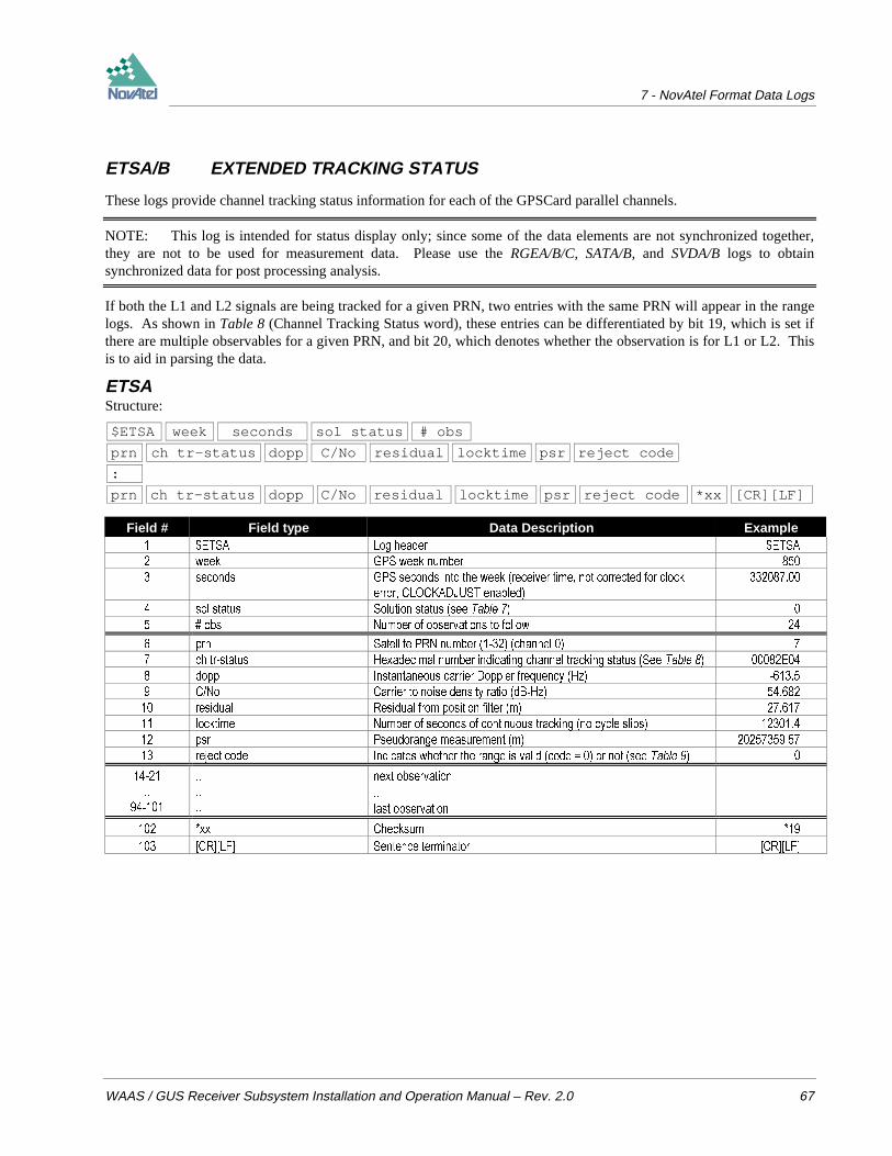
7 - NovAtel Format Data Logs
WAAS / GUS Receiver Subsystem Installation and Operation Manual – Rev. 2.0 67
ETSA/B EXTENDED TRACKING STATUS
These logs provide channel tracking status information for each of the GPSCard parallel channels.
NOTE: This log is intended for status display only; since some of the data elements are not synchronized together,they are not to be used for measurement data. Please use the RGEA/B/C, SATA/B, and SVDA/B logs to obtainsynchronized data for post processing analysis.
If both the L1 and L2 signals are being tracked for a given PRN, two entries with the same PRN will appear in the rangelogs. As shown in Table 8 (Channel Tracking Status word), these entries can be differentiated by bit 19, which is set ifthere are multiple observables for a given PRN, and bit 20, which denotes whether the observation is for L1 or L2. Thisis to aid in parsing the data.
ETSAStructure:
$ETSA week seconds sol status # obs
prn ch tr-status dopp C/No residual locktime psr reject code
:
prn ch tr-status dopp C/No residual locktime psr reject code *xx [CR][LF]
Field # Field type Data Description Example (76$ /RJ KHDGHU (76$
ZHHN *36 ZHHN QXPEHU
VHFRQGV *36 VHFRQGV LQWR WKH ZHHN UHFHLYHU WLPH QRW FRUUHFWHG IRU FORFN
HUURU &/2&.$'-867 HQDEOHG
VRO VWDWXV 6ROXWLRQ VWDWXV VHH 7DEOH
REV 1XPEHU RI REVHUYDWLRQV WR IROORZ
SUQ 6DWHOOLWH 351 QXPEHU FKDQQHO
FK WUVWDWXV +H[DGHFLPDO QXPEHU LQGLFDWLQJ FKDQQHO WUDFNLQJ VWDWXV 6HH 7DEOH (
GRSS ,QVWDQWDQHRXV FDUULHU 'RSSOHU IUHTXHQF\ +]
&1R &DUULHU WR QRLVH GHQVLW\ UDWLR G%+]
UHVLGXDO 5HVLGXDO IURP SRVLWLRQ ILOWHU P
ORFNWLPH 1XPEHU RI VHFRQGV RI FRQWLQXRXV WUDFNLQJ QR F\FOH VOLSV
SVU 3VHXGRUDQJH PHDVXUHPHQW P
UHMHFW FRGH ,QGLFDWHV ZKHWKHU WKH UDQJH LV YDOLG FRGH RU QRW VHH 7DEOH
QH[W REVHUYDWLRQ
ODVW REVHUYDWLRQ
[[ &KHFNVXP
>&5@>/)@ 6HQWHQFH WHUPLQDWRU >&5@>/)@

7 - NovAtel Format Data Logs
68 WAAS / GUS Receiver Subsystem Installation and Operation Manual – Rev. 2.0
Example (carriage returns have been added between observations for clarity):
$ETSA,850,332087.00,0,24,7,00082E04,-613.5,54.682,27.617,12301.4,20257359.57,0,7,00582E0B,-478.1,46.388,0.000,11892.0,20257351.96,13,5,00082E14,3311.2,35.915,1.037,1224.4,24412632.47,0,5,00582E1B,2580.4,39.563,0.000,1186.7,24412629.40,13,9,00082E24,1183.1,53.294,-29.857,7283.8,21498303.67,0,9,00582E2B,921.9,44.422,0.000,7250.2,21498297.13,13,2,00082E34,-2405.2,50.824,-20.985,19223.6,22047005.47,0,2,00582E3B,-1874.1,41.918,0.000,19186.7,22046999.44,13,4,00082E44,3302.8,47.287,7.522,3648.1,22696783.36,0,4,00582E4B,2573.6,37.341,0.000,3191.2,22696778.15,13,14,00082E54,2132.7,41.786,-22.388,541.3,25117182.07,0,14,00582E5B,1661.7,33.903,0.000,500.7,25117179.63,13,26,00082E64,-3004.3,43.223,2.928,14536.2,25074382.19,0,26,00582E6B,-2340.9,33.019,0.000,14491.7,25074378.01,13,15,00082E74,-3037.7,43.669,0.508,12011.5,24104788.88,0,15,00582E7B,-2367.0,34.765,0.000,11842.4,24104781.53,13,24,00082E84,3814.0,37.081,7.511,95.7,25360032.49,0,24,00582E8B,2972.0,24.148,0.000,5.2,25360030.13,13,28,00082A90,-9800.9,0.000,0.000,0.0,0.00,9,28,00382A90,-7637.0,0.000,0.000,0.0,0.00,9,3,000822A0,-3328.3,0.000,0.000,0.0,0.00,9,3,005828A0,-2593.5,0.000,0.000,0.0,0.00,9,27,000822B0,-3851.7,0.000,0.000,0.0,0.00,9,27,005828B0,-3001.7,0.000,0.000,0.0,0.00,9*41[CR][LF]
ETSBFormat: Message ID = 48
Message byte count = 32 + (n*52) where n is number of channels in receiver
Field # Data Bytes Format Units Offset
6\QF FKDU
KHDGHU &KHFNVXP FKDU
0HVVDJH ,' LQWHJHU
0HVVDJH E\WH FRXQW LQWHJHU
:HHN QXPEHU LQWHJHU ZHHNV
7LPH RI ZHHN GRXEOH VHFRQGV
6ROXWLRQ VWDWXV LQWHJHU 6HH 7DEOH
1R RI FKDQQHOV LQWHJHU QXPEHU RI FKDQQHOV LQ UHFHLYHU
351 QXPEHU FKDQ LQWHJHU
&KDQQHO WUDFNLQJ VWDWXV LQWHJHU 6HH 7DEOH
'RSSOHU GRXEOH +]
&1 GE+] GRXEOH GE+]
5HVLGXDO GRXEOH PHWUHV
/RFNWLPH GRXEOH VHFRQGV
3VHXGRUDQJH GRXEOH PHWUHV
5HMHFWLRQ FRGH LQWHJHU 6HH 7DEOH
2IIVHW FKDQ ZKHUH FKDQ YDULHV IURP KLJKHVW FKDQQHO QXPEHU

7 - NovAtel Format Data Logs
WAAS / GUS Receiver Subsystem Installation and Operation Manual – Rev. 2.0 69
Table 7 GPSCard Solution Status
Value Description 6ROXWLRQ FRPSXWHG
,QVXIILFLHQW REVHUYDWLRQV
1R FRQYHUJHQFH
6LQJXODU $W3$ 0DWUL[
&RYDULDQFH WUDFH H[FHHGV PD[LPXP WUDFH ! P
7HVW GLVWDQFH H[FHHGHG PD[LPXP RI UHM LI GLVWDQFH ! .P
1RW \HW FRQYHUJHG IURP FROG VWDUW
+LJKHU QXPEHUV DUH UHVHUYHG IRU IXWXUH XVH
Table 8 Channel Tracking Status Bits
N 7 N 6 N 5 N 4 N 3 N 2 N 1 N 0 <- <- Nibble Number31 30 29 28 27 26 25 24 23 22 21 20 19 18 17 16 15 14 13 12 11 10 9 8 7 6 5 4 3 2 1 0 Bit Description Range Values Hex.
lsb = 0 1
1 Tracking state 0 - 11 See below 2
2 4
3 8
4 10
5 0 - n (0 = first, n = last) 20
6 Channel number (n depends on GPSCard model) 40
7 80
8 100
9 Phase lock flag 1 = Lock, 0 = Not locked 200
10 Parity known flag 1 = Known, 0 = Not known 400
11 Code locked flag 1 = Lock, 0 = Not locked 800
12 1000
13 Correlator spacing 0 - 7 See below 2000
14 4000
15 0=GPS 3= Pseudolite GPS 8000
16 Satellite system 1=GLONASS 4-7 Reserved 10000
17 2=WAAS 20000
18 Antenna 1 = Secondary, 0 = Primary 40000
19 Grouping 1 = Grouped, 0 = Not grouped 80000
20 Frequency 1 = L2, 0 = L1 100000
21 Code type 0 = C/A 2 = P-codeless 200000
22 1 = P 3 = Reserved 400000
23 Forward error correction 1 = FEC enabled, 0 = no FEC 800000
24
: Reserved
29
30 External range 1 = Ext. range, 0 = Int. range
31 Channel assignment 1 = Forced, 0 = Automatic
Table 8, Bits 0 - 3 : Channel Tracking State
State Description State Description
/ ,GOH / 6WHHULQJ
/ 6N\ VHDUFK / )UHTXHQF\ORFN ORRS
/ :LGH IUHTXHQF\ EDQG SXOOLQ / ,GOH
/ 1DUURZ IUHTXHQF\ EDQG SXOOLQ / 3FRGH DOLJQPHQW
/ 3KDVHORFN ORRS / 6HDUFK
/ 5HDFTXLVLWLRQ / 3KDVHORFN ORRS
+LJKHU QXPEHUV DUH UHVHUYHG IRU IXWXUH XVH

7 - NovAtel Format Data Logs
70 WAAS / GUS Receiver Subsystem Installation and Operation Manual – Rev. 2.0
Table 8, Bits 12-14 : Correlator Spacing
State Description
8QNQRZQ WKLV RQO\ DSSHDUV LQ YHUVLRQV RI VRIWZDUH SUHYLRXV WR [[ ZKLFK GLGQ¶W XVH WKLV ILHOG
6WDQGDUG FRUUHODWRU VSDFLQJ FKLS
1DUURZ &RUUHODWRU VSDFLQJ < FKLS
0(7 XVHV (DUO\/DWH 6ORSH 7HFKQLTXH WR LPSURYH 1DUURZ &RUUHODWRU SHUIRUPDQFH LQ UHGXFLQJ HUURUV GXH WR PXOWLSDWK
5HVHUYHG IRU IXWXUH XVH
0('// GHFRPSRVHV WKH LQFRPLQJ VLJQDO LQWR GLUHFWSDWK DQG UHIOHFWHGSDWK FRPSRQHQWV WR UHGXFH HUURUV GXH WR PXOWLSDWK
+LJKHU QXPEHUV DUH UHVHUYHG IRU IXWXUH XVH
Table 9 Range Reject Codes
Value Description 2EVHUYDWLRQV DUH JRRG
%DG VDWHOOLWH KHDOWK LV LQGLFDWHG E\ HSKHPHULV GDWD
2OG HSKHPHULV GXH WR GDWD QRW EHLQJ XSGDWHG GXULQJ ODVW KRXUV
(FFHQWULF DQRPDO\ HUURU GXULQJ FRPSXWDWLRQ RI WKH VDWHOOLWH¶V SRVLWLRQ
7UXH DQRPDO\ HUURU GXULQJ FRPSXWDWLRQ RI WKH VDWHOOLWH¶V SRVLWLRQ
6DWHOOLWH FRRUGLQDWH HUURU GXULQJ FRPSXWDWLRQ RI WKH VDWHOOLWH¶V SRVLWLRQ
(OHYDWLRQ HUURU GXH WR WKH VDWHOOLWH EHLQJ EHORZ WKH FXWRII DQJOH
0LVFORVXUH WRR ODUJH GXH WR H[FHVVLYH JDS EHWZHHQ HVWLPDWHG DQG DFWXDO SRVLWLRQV
1R GLIIHUHQWLDO FRUUHFWLRQ LV DYDLODEOH IRU WKLV SDUWLFXODU VDWHOOLWH
(SKHPHULV GDWD IRU WKLV VDWHOOLWH KDV QRW \HW EHHQ UHFHLYHG
,QYDOLG ,2'( GXH WR PLVPDWFK EHWZHHQ GLIIHUHQWLDO VWDWLRQV
/RFNHG 2XW VDWHOOLWH LV H[FOXGHG E\ XVHU /2&.287 FRPPDQG
/RZ 3RZHU VDWHOOLWH UHMHFWHG GXH WR ORZ VLJQDOQRLVH UDWLR
/ PHDVXUHPHQWV DUH QRW FXUUHQWO\ XVHG LQ WKH ILOWHU
+LJKHU QXPEHUV DUH UHVHUYHG IRU IXWXUH XVH

7 - NovAtel Format Data Logs
WAAS / GUS Receiver Subsystem Installation and Operation Manual – Rev. 2.0 71
FRMA/B FRAMED RAW NAVIGATION DATA
This message contains the raw framed navigation data. An individual message is sent for each PRN being tracked. Themessage is updated with each new frame, therefore it is best to log the data with the ‘onnew’ trigger activated.
The types of navigation frame data which are output by this log are defined using the $SETFRAMETYPE command.
FRMA
$FRMA week seconds prn cstatus # of bits framed raw data
*xx [CR][LF]
Field # Field type Data Description Example )50$ /RJ KHDGHU )50$
ZHHN *36 ZHHN QXPEHU
VHFRQGV *36 VHFRQGV LQWR WKH ZHHN
SUQ 351 RI VDWHOOLWH IURP ZKLFK GDWD RULJLQDWHG
FVWDWXV &KDQQHO 7UDFNLQJ 6WDWXV )
RI ELWV 1XPEHU RI ELWV WUDQVPLWWHG LQ WKH PHVVDJH
IRU :$$6 IRU *36 DQG IRU
*/21$66
IUDPHG UDZ GDWD 2QH ILHOG RI UDZ IUDPHG QDYLJDWLRQ GDWD $)(&(
)(
%( )
[[ &KHFNVXP
>&5@>/)@ 6HQWHQFH WHUPLQDWRU >&5@>/)@
FRMBFormat: Message ID = 54 Message byte count = variable
Field # Data Bytes Format Units Offset
6\QF FKDU
KHDGHU &KHFNVXP FKDU
0HVVDJH ,' LQWHJHU
0HVVDJH E\WH FRXQW LQWHJHU E\WHV
:HHN QXPEHU LQWHJHU ZHHNV
6HFRQGV RI ZHHN GRXEOH VHFRQGV
351 QXPEHU LQWHJHU
&KDQQHO 6WDWXV LQWHJHU QD
1XPEHU RI %LWV LQWHJHU IRU :$$6
IRU *36
IRU */21$66
'DWD 6XEIUDPH YDULDEOH FKDU 1$

7 - NovAtel Format Data Logs
72 WAAS / GUS Receiver Subsystem Installation and Operation Manual – Rev. 2.0
IONA/B IONOSPHERIC MODEL PARAMETERS
The Ionospheric Model parameters (IONA/B) are provided following the last almanac records when an ALMA/Bmessage has been logged. The IONA/B message cannot be logged individually or independently of the ALMA/Bmessage.
For more information on Almanac data, refer to the GPS SPS Signal Specification.
IONAStructure:
$IONA act a1ot a2ot a3ot bct b1ot b2ot b3ot *xx [CR][LF]
Field # Field type Data Description Example ,21$ /RJ KHDGHU ,21$
DFW $OSKD FRQVWDQW WHUP VHFRQGV (
DRW $OSKD VW RUGHU WHUP VHFVHPLFLUFOH (
DRW $OSKD QG RUGHU WHUP VHFVHPLF (
DRW $OSKD UG RUGHU WHUP VHFVHPLF (
EFW %HWD FRQVWDQW WHUP VHFRQGV (
ERW %HWD VW RUGHU WHUP VHFVHPLFLUFOH (
ERW %HWD QG RUGHU WHUP VHFVHPLF (
ERW %HWD UG RUGHU WHUP VHFVHPLF (
[[ &KHFNVXP
>&5@>/)@ 6HQWHQFH WHUPLQDWRU >&5@>/)@
Example:
$IONA,1.0244548320770265E-008,1.4901161193847656E-008,-5.960464477539061E-008,-1.192092895507812E-007,8.8064000000000017E+004,3.2768000000000010E+004,-1.966080000000001E+005,-1.966080000000001E+005*02[CR][LF]
IONBFormat Message ID = 16 Message byte count = 76
Field # Field Type Bytes Format Units Offset 6\QF FKDU
KHDGHU &KHFNVXP FKDU
0HVVDJH ,' LQWHJHU
0HVVDJH E\WH FRXQW LQWHJHU E\WHV
$OSKD FRQVWDQW WHUP GRXEOH VHFRQGV
$OSKD VW RUGHU WHUP GRXEOH VHFVHPLFLUFOH
$OSKD QG RUGHU WHUP GRXEOH VHFVHPLF
$OSKD UG RUGHU WHUP GRXEOH VHFVHPLF
%HWD FRQVWDQW WHUP GRXEOH VHFRQGV
%HWD VW RUGHU WHUP GRXEOH VHFVHPLF
%HWD QG RUGHU WHUP GRXEOH VHFVHPLF
%HWD UG RUGHU WHUP GRXEOH VHFVHPLF

7 - NovAtel Format Data Logs
WAAS / GUS Receiver Subsystem Installation and Operation Manual – Rev. 2.0 73
POSA/B COMPUTED POSITION
This log will contain the last valid position and time calculated referenced to the antenna phase centre. The position is ingeographic coordinates in degrees based on your specified datum (default is WGS-84). The height is referenced to meansea level. The receiver time is in GPS weeks and seconds into the week. The estimated standard deviations of thesolution and current filter status are also included.
POSAStructure:
$POSA week seconds lat lon hgt undulation datum ID lat std lon std
hgt std sol status *xx [CR][LF]
Field # Field type Data Description Example 326$ /RJ KHDGHU 326$
ZHHN *36 ZHHN QXPEHU
VHFRQGV *36 VHFRQGV LQWR WKH ZHHN
ODW /DWLWXGH RI SRVLWLRQ LQ FXUUHQW GDWXP LQ GHJUHHV ''GGGGGGGG
$ QHJDWLYH VLJQ LPSOLHV 6RXWK ODWLWXGH
ORQ /RQJLWXGH RI SRVLWLRQ LQ FXUUHQW GDWXP LQ GHJUHHV '''GGGGGGGG $ QHJDWLYH
VLJQ LPSOLHV :HVW ORQJLWXGH
KJW +HLJKW RI SRVLWLRQ LQ FXUUHQW GDWXP LQ PHWUHV DERYH PHDQ VHD OHYHO 06/
XQGXODWLRQ *HRLGDO VHSDUDWLRQ LQ PHWUHV ZKHUH SRVLWLYH LV DERYH VSKHURLG DQG QHJDWLYH LV
EHORZ VSKHURLG
GDWXP ,' &XUUHQW GDWXP ,'
ODW VWG 6WDQGDUG GHYLDWLRQ RI ODWLWXGH VROXWLRQ HOHPHQW LQ PHWUHV
ORQ VWG 6WDQGDUG GHYLDWLRQ RI ORQJLWXGH VROXWLRQ HOHPHQW LQ PHWUHV
KJW VWG 6WDQGDUG GHYLDWLRQ RI KHLJKW VROXWLRQ HOHPHQW LQ PHWUHV
VRO VWDWXV 6ROXWLRQ VWDWXV DV OLVWHG LQ 7DEOH
[[ &KHFNVXP
>&5@>/)@ 6HQWHQFH WHUPLQDWRU >&5@>/)@
Example:
$POSA,637,511251.00,51.11161847,-114.03922149,1072.436,-16.198,61,26.636,6.758,78.459,0*12[CR][LF]

7 - NovAtel Format Data Logs
74 WAAS / GUS Receiver Subsystem Installation and Operation Manual – Rev. 2.0
POSBFormat: Message ID = 01 Message byte count = 88
Field # Data Bytes Format Units Offset 6\QF FKDU
KHDGHU &KHFNVXP FKDU
0HVVDJH ,' LQWHJHU
0HVVDJH E\WH FRXQW LQWHJHU E\WHV
:HHN QXPEHU LQWHJHU ZHHNV
6HFRQGV RI ZHHN GRXEOH VHFRQGV
/DWLWXGH GRXEOH GHJUHHV LV 1RUWK LV 6RXWK
/RQJLWXGH GRXEOH GHJUHHV LV (DVW LV :HVW
+HLJKW GRXEOH PHWUHV ZLWK UHVSHFW WR 06/
8QGXODWLRQ GRXEOH PHWUHV
'DWXP ,' LQWHJHU
6WG'HY RI ODWLWXGH GRXEOH PHWUHV
6WG'HY RI ORQJLWXGH GRXEOH PHWUHV
6WG'HY RI KHLJKW GRXEOH PHWUHV
6ROXWLRQ VWDWXV LQWHJHU
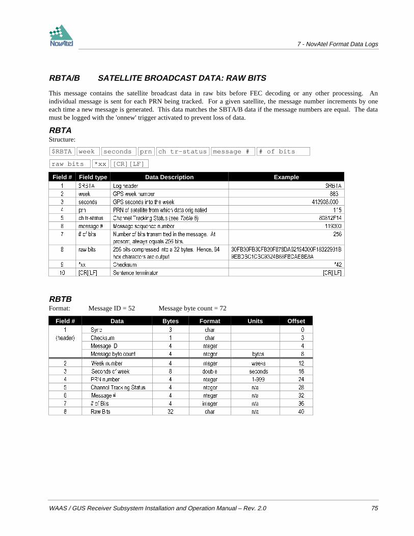
7 - NovAtel Format Data Logs
WAAS / GUS Receiver Subsystem Installation and Operation Manual – Rev. 2.0 75
RBTA/B SATELLITE BROADCAST DATA: RAW BITS
This message contains the satellite broadcast data in raw bits before FEC decoding or any other processing. Anindividual message is sent for each PRN being tracked. For a given satellite, the message number increments by oneeach time a new message is generated. This data matches the SBTA/B data if the message numbers are equal. The datamust be logged with the 'onnew' trigger activated to prevent loss of data.
RBTAStructure:
$RBTA week seconds prn ch tr-status message # # of bits
raw bits *xx [CR][LF]
Field # Field type Data Description Example 5%7$ /RJ KHDGHU 5%7$
ZHHN *36 ZHHN QXPEHU
VHFRQGV *36 VHFRQGV LQWR WKH ZHHN
SUQ 351 RI VDWHOOLWH IURP ZKLFK GDWD RULJLQDWHG
FK WUVWDWXV &KDQQHO 7UDFNLQJ 6WDWXV VHH 7DEOH )
PHVVDJH 0HVVDJH VHTXHQFH QXPEHU
RI ELWV 1XPEHU RI ELWV WUDQVPLWWHG LQ WKH PHVVDJH $W
SUHVHQW DOZD\V HTXDOV ELWV
UDZ ELWV ELWV FRPSUHVVHG LQWR D E\WHV +HQFH
KH[ FKDUDFWHUV DUH RXWSXW
)%)%)%)'$)%
(%'%&&%&%)%'$(%($
[[ &KHFNVXP
>&5@>/)@ 6HQWHQFH WHUPLQDWRU >&5@>/)@
RBTBFormat: Message ID = 52 Message byte count = 72
Field # Data Bytes Format Units Offset 6\QF FKDU
KHDGHU &KHFNVXP FKDU
0HVVDJH ,' LQWHJHU
0HVVDJH E\WH FRXQW LQWHJHU E\WHV
:HHN QXPEHU LQWHJHU ZHHNV
6HFRQGV RI ZHHN GRXEOH VHFRQGV
351 QXPEHU LQWHJHU
&KDQQHO 7UDFNLQJ 6WDWXV LQWHJHU QD
0HVVDJH LQWHJHU QD
RI %LWV LQWHJHU QD
5DZ %LWV FKDU QD
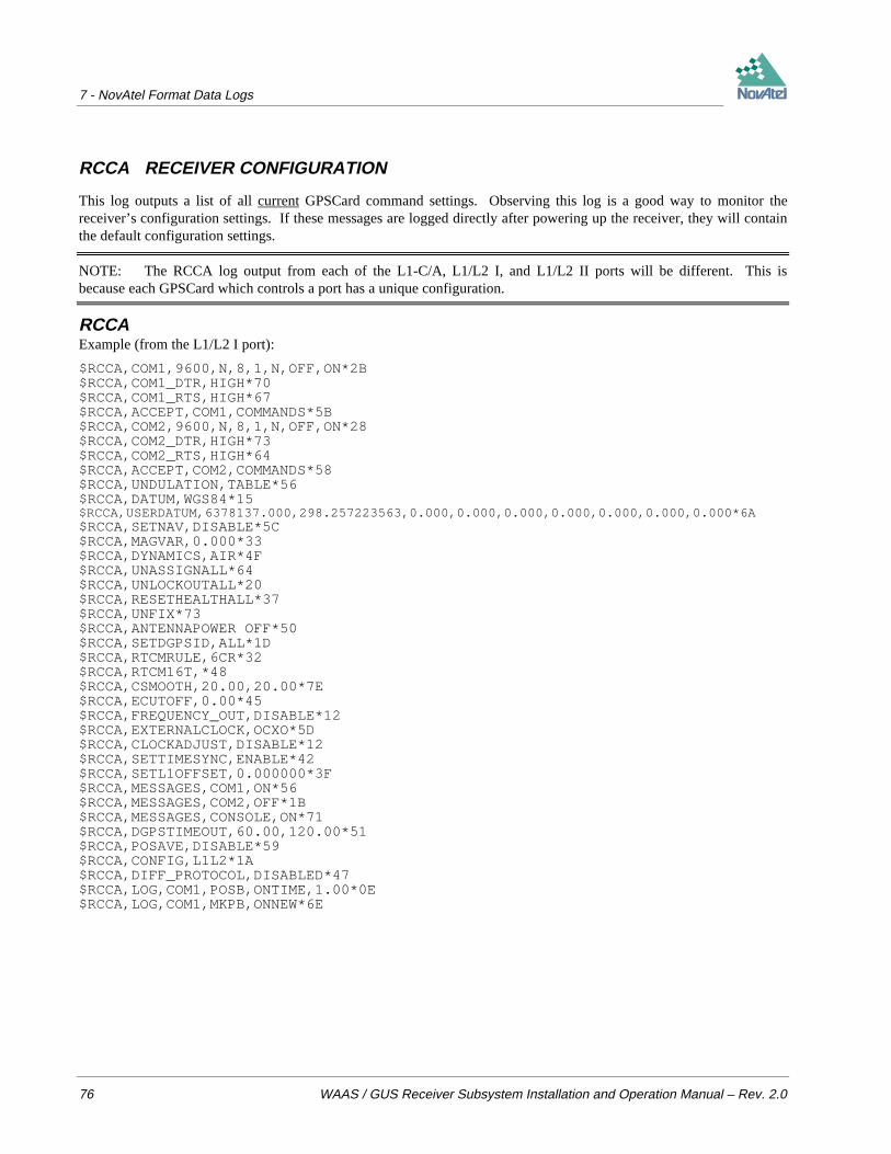
7 - NovAtel Format Data Logs
76 WAAS / GUS Receiver Subsystem Installation and Operation Manual – Rev. 2.0
RCCA RECEIVER CONFIGURATION
This log outputs a list of all current GPSCard command settings. Observing this log is a good way to monitor thereceiver’s configuration settings. If these messages are logged directly after powering up the receiver, they will containthe default configuration settings.
NOTE: The RCCA log output from each of the L1-C/A, L1/L2 I, and L1/L2 II ports will be different. This isbecause each GPSCard which controls a port has a unique configuration.
RCCAExample (from the L1/L2 I port):
$RCCA,COM1,9600,N,8,1,N,OFF,ON*2B$RCCA,COM1_DTR,HIGH*70$RCCA,COM1_RTS,HIGH*67$RCCA,ACCEPT,COM1,COMMANDS*5B$RCCA,COM2,9600,N,8,1,N,OFF,ON*28$RCCA,COM2_DTR,HIGH*73$RCCA,COM2_RTS,HIGH*64$RCCA,ACCEPT,COM2,COMMANDS*58$RCCA,UNDULATION,TABLE*56$RCCA,DATUM,WGS84*15$RCCA,USERDATUM,6378137.000,298.257223563,0.000,0.000,0.000,0.000,0.000,0.000,0.000*6A$RCCA,SETNAV,DISABLE*5C$RCCA,MAGVAR,0.000*33$RCCA,DYNAMICS,AIR*4F$RCCA,UNASSIGNALL*64$RCCA,UNLOCKOUTALL*20$RCCA,RESETHEALTHALL*37$RCCA,UNFIX*73$RCCA,ANTENNAPOWER OFF*50$RCCA,SETDGPSID,ALL*1D$RCCA,RTCMRULE,6CR*32$RCCA,RTCM16T,*48$RCCA,CSMOOTH,20.00,20.00*7E$RCCA,ECUTOFF,0.00*45$RCCA,FREQUENCY_OUT,DISABLE*12$RCCA,EXTERNALCLOCK,OCXO*5D$RCCA,CLOCKADJUST,DISABLE*12$RCCA,SETTIMESYNC,ENABLE*42$RCCA,SETL1OFFSET,0.000000*3F$RCCA,MESSAGES,COM1,ON*56$RCCA,MESSAGES,COM2,OFF*1B$RCCA,MESSAGES,CONSOLE,ON*71$RCCA,DGPSTIMEOUT,60.00,120.00*51$RCCA,POSAVE,DISABLE*59$RCCA,CONFIG,L1L2*1A$RCCA,DIFF_PROTOCOL,DISABLED*47$RCCA,LOG,COM1,POSB,ONTIME,1.00*0E$RCCA,LOG,COM1,MKPB,ONNEW*6E

7 - NovAtel Format Data Logs
WAAS / GUS Receiver Subsystem Installation and Operation Manual – Rev. 2.0 77
REPA/B RAW EPHEMERIS
This log contains the raw binary information for sub-frames one, two and three from the satellite with the parityinformation removed. Each sub-frame is 240 bits long (10 words – 24 bits each) and the log contains a total 720 bits (90bytes) of information (240 bits x 3 sub-frames). This information is preceded by the PRN number of the satellite fromwhich it originated. This message will not be generated unless all 10 words from all 3 frames have passed parity.
Ephemeris data whose time of ephemeris is older than six hours will not be shown.
REPAStructure:
$REPA prn subframe1 subframe2 subframe3 *xx [CR][LF]
Field # Field type Data Description Example 5(3$ /RJ KHDGHU 5(3$
SUQ 351 RI VDWHOOLWH IURP ZKLFK GDWD RULJLQDWHG
VXEIUDPH 6XEIUDPH RI HSKHPHULV GDWD KH[ FKDUDFWHUV %'&%''''($%'
&)&)'
VXEIUDPH 6XEIUDPH RI HSKHPHULV GDWD KH[ FKDUDFWHUV %'&%$)))%'
))$($%())
VXEIUDPH 6XEIUDPH RI HSKHPHULV GDWD KH[ FKDUDFWHUV %'&%)($))')&
)($%))$')
[[ &KHFNVXP
>&5@>/)@ 6HQWHQFH WHUPLQDWRU >&5@>/)@
Example:
$REPA,14,8B09DC17B9079DD7007D5DE404A9B2D04CF671C6036612560000021804FD,8B09DC17B98A66FF713092F12B359DFF7A0254088E1656A10BE2FF125655,8B09DC17B78F0027192056EAFFDF2724C9FE159675A8B468FFA8D066F743*57[CR][LF]
REPBFormat: Message ID = 14 Message byte count = 108
Field # Data Bytes Format Units Offset 6\QF FKDU
KHDGHU &KHFNVXP FKDU
0HVVDJH ,' LQWHJHU
0HVVDJH E\WH FRXQW LQWHJHU E\WHV
351 QXPEHU LQWHJHU
(SKHPHULV GDWD FKDU GDWD >@
)LOOHU E\WHV FKDU
RGEA/B CHANNEL RANGE MEASUREMENTS
RGEA/B contain the channel range measurements for the currently observed satellites. These logs contain all of theextended tracking status bits. The receiver self-test status word also indicates L2, OCXO and new almanac status.
It is important to ensure that the receiver clock has been set and can be monitored by the bits in the rec-status field.Large jumps in range as well as ADR will occur as the clock is being adjusted. If the ADR measurement is being usedin precise phase processing it is important not to use the ADR if the "parity known" flag in the tr-status field is not set asthere may exist a half (1/2) cycle ambiguity on the measurement. The tracking error estimate of the pseudorange andcarrier phase (ADR) is the thermal noise of the receiver tracking loops only. It does not account for possible multipatherrors or atmospheric delays.

7 - NovAtel Format Data Logs
78 WAAS / GUS Receiver Subsystem Installation and Operation Manual – Rev. 2.0
If both the L1 and L2 signals are being tracked for a given PRN, two entries with the same PRN will appear in the rangelogs. As shown in Table 8 for the Channel Tracking Status word, these entries can be differentiated by bit 19, which isset if there are multiple observables for a given PRN, and bit 20, which denotes whether the observation is for L1 or L2.This is to aid in parsing the data.
RGEAStructure:
$RGEA week seconds # obs rec status
prn psr psr std adr adr std dopp S/No locktime ch tr-status
:
prn psr psr std adr adr std dopp S/No locktime ch tr-status
*xx [CR][LF]
Field # Field type Data Description Example 5*($ /RJ KHDGHU 5*($
ZHHN *36 ZHHN QXPEHU
VHFRQGV *36 VHFRQGV LQWR WKH ZHHN UHFHLYHU WLPH QRW FRUUHFWHG IRU FORFN HUURU
REV 1XPEHU RI VDWHOOLWH REVHUYDWLRQV ZLWK LQIRUPDWLRQ WR IROORZ
UHF VWDWXV 5HFHLYHU VHOIWHVW VWDWXV VHH 7DEOH %))
SUQ 6DWHOOLWH 351 QXPEHU RI UDQJH PHDVXUHPHQW
SVU 3VHXGRUDQJH PHDVXUHPHQW P
SVU VWG 3VHXGRUDQJH PHDVXUHPHQW VWDQGDUG GHYLDWLRQ P
DGU &DUULHU SKDVH LQ F\FOHV DFFXPXODWHG 'RSSOHU UDQJH
DGU VWG (VWLPDWHG FDUULHU SKDVH VWDQGDUG GHYLDWLRQ F\FOHV
GRSS ,QVWDQWDQHRXV FDUULHU 'RSSOHU IUHTXHQF\ +]
&1 6LJQDO WR QRLVH GHQVLW\ UDWLR &1 >ORJ61@ G%+]
ORFNWLPH 1XPEHU RI VHFRQGV RI FRQWLQXRXV WUDFNLQJ QR F\FOH VOLSSLQJ
FK WUVWDWXV &KDQQHO WUDFNLQJ VWDWXV KH[DGHFLPDO QXPEHU LQGLFDWLQJ SKDVH ORFN FKDQQHO
QXPEHU DQG FKDQQHO VWDWH DV VKRZQ LQ 7DEOH
(
1H[W 351 UDQJH PHDVXUHPHQW
1H[W 351 UDQJH PHDVXUHPHQW
YDULDEOH [[ &KHFNVXP
YDULDEOH >&5@>/)@ 6HQWHQFH WHUPLQDWRU >&5@>/)@
Example (carriage returns have been added between observations for clarity):
$RGEA,845,511089.00,14,000B20FF4,23907330.296,0.119,-125633783.992,0.010,3714.037,44.8,1928.850,82E04,4,23907329.623,1.648,-97896180.284,0.013,2894.285,35.0,1746.760,582E0B,2,21298444.942,0.040,-111954153.747,0.006,-1734.838,54.2,17466.670,82E14,2,21298444.466,0.637,-87236867.557,0.006,-1351.607,43.3,17557.260,582E1B,9,22048754.383,0.063,-115874135.450,0.006,2174.006,50.4,5489.100,82E24,9,22048754.424,0.641,-90291443.071,0.006,1694.238,43.2,5489.100,582E2B,15,23191384.847,0.261,-121887295.980,0.017,-2069.744,38.0,9924.740,82E34,15,23191384.663,0.596,-94977002.452,0.010,-1612.587,43.8,9881.830,582E3B,26,24063897.737,0.199,-126477739.189,0.014,-2654.682,40.3,12821.640,82E54,26,24063898.913,1.043,-98553986.239,0.013,-2068.380,39.0,12793.280,582E5B,7,20213352.139,0.037,-106237901.461,0.005,439.943,55.0,10313.040,82E74,7,20213351.196,0.498,-82782498.454,0.007,343.020,45.4,9977.400,582E7B,27,24393726.829,0.123,-128229016.323,0.012,-4047.338,44.5,22354.119,82E94,27,24393728.057,1.805,-99918535.513,0.013,-3153.559,34.2,22301.830,582E9B*30

7 - NovAtel Format Data Logs
WAAS / GUS Receiver Subsystem Installation and Operation Manual – Rev. 2.0 79
RGEBFormat: Message ID = 32 Message byte count = 32 + (obs x 44)
Field # Data Bytes Format Units Offset
6\QF FKDU
KHDGHU &KHFNVXP FKDU
0HVVDJH ,' LQWHJHU
0HVVDJH E\WH FRXQW LQWHJHU
:HHN QXPEHU LQWHJHU ZHHNV
6HFRQGV RI ZHHN GRXEOH V
1XPEHU RI REVHUYDWLRQV REV LQWHJHU
5HFHLYHU VHOIWHVW VWDWXV LQWHJHU
351 LQWHJHU
3VHXGRUDQJH GRXEOH P
6WG'HY SVHXGRUDQJH IORDW P
&DUULHU SKDVH ± DFFXPXODWHG 'RSSOHU UDQJH GRXEOH F\FOHV
6WG'HY ± DFFXPXODWHG 'RSSOHU UDQJH IORDW F\FOHV
'RSSOHU IUHTXHQF\ IORDW +]
&1 IORDW G%+]
/RFNWLPH IORDW V
&KDQQHO 7UDFNLQJ VWDWXV LQWHJHU
1H[W 351 RIIVHW REV [
Table 10 Receiver Self-Test Status Codes
N7 N 6 N 5 N 4 N 3 N 2 N 1 N 0 <- <- Nibble Number27 26 25 24 23 22 21 20 19 18 17 16 15 14 13 12 11 10 9 8 7 6 5 4 3 2 1 0 Bit Description Range Values Hex Value
lsb = 0 ANTENNA 1 = good, 0 = bad 00000001
1 L1 PLL 1 = good, 0 = bad 00000002
2 RAM 1 = good, 0 = bad 00000004
3 ROM 1 = good, 0 = bad 00000008
4 DSP 1 = good, 0 = bad 00000010
5 L1 AGC 1 = good, 0 = bad 00000020
6 COM 1 1 = good, 0 = bad 00000040
7 COM 2 1 = good, 0 = bad 00000080
8 WEEK 1 = not set, 0 = set 00000100
9 NO COARSETIME 1 = not set, 0 = set 00000200
10 NO FINETIME 1 = not set, 0 = set 00000400
11 L1 JAMMER 1 = present, 0 = normal 00000800
12 BUFFER COM 1 1 = overrun, 0 = normal 00001000
13 BUFFER COM 2 1 = overrun, 0 = normal 00002000
14 BUFFER CONSOLE 1 = overrun, 0 = normal 00004000
15 CPU OVERLOAD 1 = overload, 0 = normal 00008000
16 ALMANAC SAVED IN NVM 1 = yes, 0 = no 00010000
17 L2 AGC 1 = good, 0 = bad 00020000
18 L2 JAMMER 1 = present, 0 = normal 00040000
19 L2 PLL 1 = good, 0 = bad 00080000
20 OCXO PLL 1 = good, 0 = bad 00100000
21 SAVED ALMA. NEEDS UPDATE 1 = yes, 0 = no 00200000
22 ALMANAC INVALID 1 = invalid, 0 = valid 00400000
23 POSITION SOLUTION INVALID 1 = invalid, 0 = valid 00800000
24 POSITION FIXED 1 = yes, 0 = no 01000000
25 CLOCK MODEL INVALID 1 = invalid, 0 = valid 02000000
26 CLOCK STEERING DISABLED 1 = disabled, 0 = enabled 04000000
27 RESERVED
28-31 RESERVED
GPSCard examples:
OEM2: All OK = 0000 0000 0000 0000 0000 0000 1111 1111 (binary) = 000000FF (hexadecimal)

7 - NovAtel Format Data Logs
80 WAAS / GUS Receiver Subsystem Installation and Operation Manual – Rev. 2.0
MiLLennium: All OK = 0000 0000 0000 1010 0000 0000 1111 1111 (binary) = 000B00FF (hexadecimal) ; osc. = VCTCXO
Notes:
1. Bit 3: For WAAS / GUS, “ROM” includes all forms of non-volatile memory.2. Bits 2, 3, 4, 6, 7: these are set only once when the GPSCard is first powered up. All other bits are set by internal test processes each time the
RVSB log is output.3. Bits 12-15: Flag is reset to 0 five minutes after the last overrun/overload condition has occurred.4. Bits 17-20: These bits are always set to 0 for OEM2 GPSCards
Receiver Status – Detailed Bit Descriptions of Self-Test Word
What follows is a detailed description of each bit setting in the Receiver Self-Test Status word (see Table 10).Additional information is also included in Table 11, below.
Bit 0 Antenna
1 This bit will be set good if the antenna is drawing the appropriate amount of current from the GPSCard jack.0 If the antenna connections are shorted together, open, or otherwise not an drawing appropriate current, then this
bit will be clear (0) indicating a possible antenna port problem.
Bit 1 L1 PLL1 When the L1 RF down-converter passes self-test, the bit will be set to 1.0 If a fault is detected in the L1 RF down-converter, this bit is set to 0.
Bit 2 RAM1 When this bit is set to 1, the receiver’s RAM has passed the self-test requirements.0 If the bit has been set to 0, then RAM test has failed; please contact NovAtel Customer Service.
Bit 3 ROM (Note: “ROM” includes all forms of non-volatile memory (NVM))1 When this bit is set to 1, the receiver’s ROM test has passed the self test requirements.0 A zero bit indicates the receiver has failed the ROM test.
Bit 4 DSP1 This bit will be set to 1 when the digital signal processors (DSP) have passed the self-test requirements.0 If this bit is set to 0, one or both of the DSP chips has failed self-test; please contact NovAtel Customer Service.
Bit 5 L1 AGC1 When set to 1, the L1AGC circuits are operating within normal range of control.0 This bit will be set clear if the L1AGC is operating out of normal range. Failure of this test could be the result
of various possibilities, such as: bad antenna LNA, excessive loss in the antenna cable, faulty RF down-converter, or a pulsating or high power jamming signal causing interference. If this bit is continuously setclear, and you cannot identify an external cause for the failed test, please contact NovAtel Customer Service.
Bit 6 COM 11 When set to 1, the COM1 UART has passed the self-test requirements.0 If set to 0, the COM1 UART has failed self-test and cannot be used for reliable communications.
Bit 7 COM 21 When set to 1, the COM2 UART has passed the self-test requirements.0 If set to 0, the COM2 UART has failed self-test and cannot be used for reliable communications.
Bits 8, 9, 10 Week / No Coarsetime / No Finetime0 These bits indicate the state of the receiver’s time and are set only once, generally in the first few minutes of
operation, in the presence of adequate numbers of satellite signals to compute position and time.

7 - NovAtel Format Data Logs
WAAS / GUS Receiver Subsystem Installation and Operation Manual – Rev. 2.0 81
1 If these bits are not all set to zero, then the observation data, pseudorange, carrier phase, and Dopplermeasurements may jump as the clock adjusts itself.
Bit 11 L1 Jammer Detection0 Normal operation is indicated when this bit is 0.1 If set to 1, the receiver has detected a high power signal causing interference. When this happens, the receiver
goes into a special anti-jamming mode where it re-maps the A/D decode values as well as special L1AGCfeedback control. These adjustments help to minimize the loss that will occur in the presence of a jammingsignal. You should monitor this bit, and if set to 1, do your best to remedy the cause of the jamming signal.Nearby transmitters or other electronic equipment could be the cause of interference; you may find it necessaryto relocate your antenna position if the problem persists.
Bits 12, 13, 14 Buffer COM 1 / COM 2 / Console0 Normal operation is indicated by a 0 value.1 These bits are set to 1 when any of the 8-Kbyte output buffers has reached an over-run condition (COM1,
COM2, or console). Over-run is caused by requesting more log data than can be taken from the GPSCardbecause of bit rate limitations or slow communications equipment. If this happens, the new data attempting tobe loaded into the buffer will be discarded. The receiver will not load a partial data record into an outputbuffer. The flag resets to 0 five minutes after the last overrun occurred.
Bit 15 CPU Overload0 Normal operation is indicated by a 0 value.1 A value of 1 indicates that the CPU is being over-taxed. Requesting an excessive amount of information from
the receiver may cause this. If this condition is occurring, limit redundant data logging or change to usingbinary data output formats, or both. You should attempt to tune the logging requirements to keep the idle timeabove 20% for best operation. If the average idle % drops below 10% for prolonged periods of time (2-5seconds), critical errors may result in internal data loss and the over-load bit will be set to 1. You can monitorthe CPU % idle time by using the RVSA log message. The flag resets to 0 five minutes after the last overloadoccurred.
NOTE: As the amount of CPU power becomes limited, the software will begin to slow down the positioncalculation rate. If the CPU becomes further limited, the software will begin to skip range measurementprocessing. Priority processing goes to the tracking loops.
Bit 16 Almanac Saved0 Almanac not saved in non-volatile memory.1 Almanac saved in non-volatile memory.
Bit 17 L2AGC (on an OEM2 GPSCard: this bit is unused, i.e. it would be set to 0 = bad)1 For an L1/L2 MiLLennium GPSCard: When set to 1, the L2AGC circuits are operating within normal range of
control.0 For an L1/L2 MiLLennium GPSCard: This bit will be set clear if the L2AGC is operating out of normal range.
Failure of this test could be the result of various possibilities, such as: bad antenna LNA, excessive loss in theantenna cable, faulty RF down-converter, or a pulsating or high power jamming signal causing interference. Ifthis bit is continuously set clear, and you cannot identify an external cause for the failed test, please contactNovAtel Customer Service.
Bit 18 L2Jammer Detection (on an OEM2 GPSCard: this bit is unused, i.e. it would be set to 0 = normal)0 For the L1/L2 MiLLennium GPSCard: Normal operation is indicated when this bit is 0.1 For the L1/L2 MiLLennium GPSCard: If set to 1, the receiver has detected a high power signal causing
interference. When this happens, the receiver goes into a special anti-jamming mode where it re-maps the A/Ddecode values as well as special L2AGC feedback control. These adjustments help to minimize the loss thatwill occur in the presence of a jamming signal. You should monitor this bit, and if set to 1, do your best to

7 - NovAtel Format Data Logs
82 WAAS / GUS Receiver Subsystem Installation and Operation Manual – Rev. 2.0
remedy the cause of the jamming signal. Nearby transmitters or other electronic equipment could be the causeof interference; you may find it necessary to relocate your antenna position if the problem persists.
Bit 19 L2PLL (on an OEM2 GPSCard: this bit is unused, i.e. it would be set to 0 = bad)1 For an L1/L2 MiLLennium GPSCard: When the L2 RF down-converter passes self-test, the bit will be set to 1.0 For an L1/L2 MiLLennium GPSCard: If a fault is detected in the L2 RF down-converter, this bit is set to 0.
Bit 20 OCXOPLL (on an OEM2 GPSCard: this bit is unused, i.e. it would be set to 0 = bad)1 For an L1/L2 MiLLennium GPSCard: When the OCXOPLL bit passes self-test, the bit will be set to 1.0 For the L1/L2 MiLLennium GPSCard: If a fault is detected in the OCXOPLL bit, this bit is set to 0.
Bit 21 Saved Almanac Needs Update1 When the almanac received is newer that the one currently stored in NVM (non-volatile memory), the bit will
be set to 1.0 This bit will be set to 0 if an almanac has not been received that is newer than the one stored in memory.
Bit 22 Almanac Invalid1 No almanac in use0 Valid almanac in use
Bit 23 Position Solution Invalid1 Position solution is not valid0 Valid position computed
Bit 24 Position Fixed1 A fix position command has been accepted0 Position has not been fixed
Bit 25 Clock Model Invalid1 Clock model has not stabilised0 Clock model is valid
Bit 26 Clock Steering Disabled1 Clockadjust disable command has been accepted0 Clockadjust is enabled
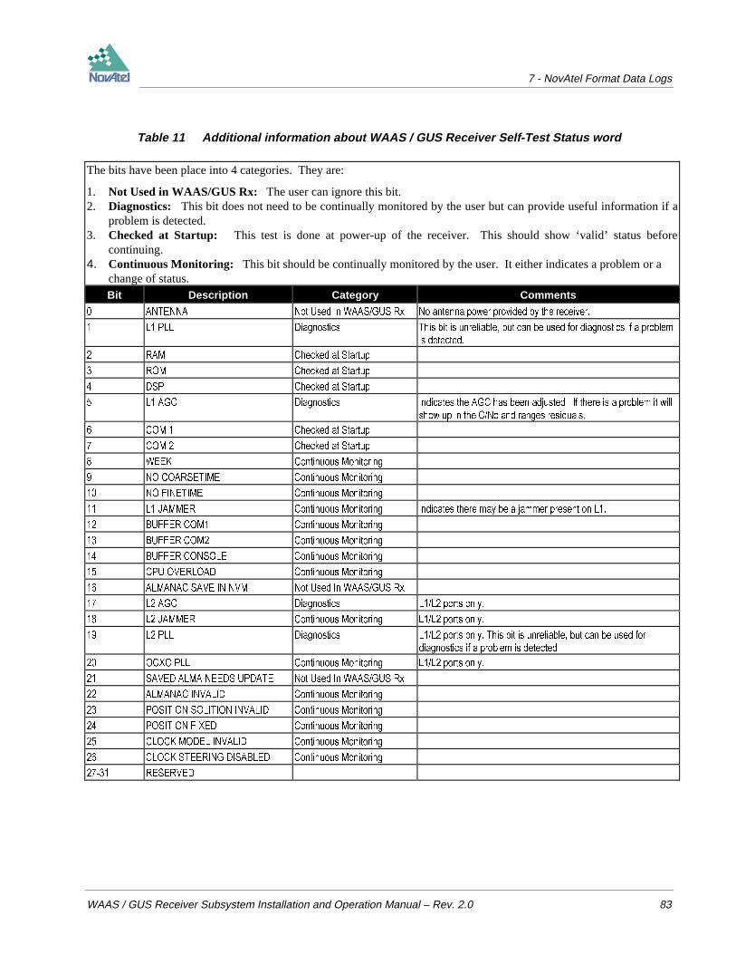
7 - NovAtel Format Data Logs
WAAS / GUS Receiver Subsystem Installation and Operation Manual – Rev. 2.0 83
Table 11 Additional information about WAAS / GUS Receiver Self-Test Status word
The bits have been place into 4 categories. They are:
1. Not Used in WAAS/GUS Rx: The user can ignore this bit.2. Diagnostics: This bit does not need to be continually monitored by the user but can provide useful information if a
problem is detected.3. Checked at Startup: This test is done at power-up of the receiver. This should show ‘valid’ status before
continuing.4. Continuous Monitoring: This bit should be continually monitored by the user. It either indicates a problem or a
change of status.Bit Description Category Comments
$17(11$ 1RW 8VHG ,Q :$$6*86 5[ 1R DQWHQQD SRZHU SURYLGHG E\ WKH UHFHLYHU
/ 3// 'LDJQRVWLFV 7KLV ELW LV XQUHOLDEOH EXW FDQ EH XVHG IRU GLDJQRVWLFV LI D SUREOHP
LV GHWHFWHG
5$0 &KHFNHG DW 6WDUWXS
520 &KHFNHG DW 6WDUWXS
'63 &KHFNHG DW 6WDUWXS
/ $*& 'LDJQRVWLFV ,QGLFDWHV WKH $*& KDV EHHQ DGMXVWHG ,I WKHUH LV D SUREOHP LW ZLOO
VKRZ XS LQ WKH &1R DQG UDQJHV UHVLGXDOV
&20 &KHFNHG DW 6WDUWXS
&20 &KHFNHG DW 6WDUWXS
:((. &RQWLQXRXV 0RQLWRULQJ
12 &2$56(7,0( &RQWLQXRXV 0RQLWRULQJ
12 ),1(7,0( &RQWLQXRXV 0RQLWRULQJ
/ -$00(5 &RQWLQXRXV 0RQLWRULQJ ,QGLFDWHV WKHUH PD\ EH D MDPPHU SUHVHQW RQ /
%8))(5 &20 &RQWLQXRXV 0RQLWRULQJ
%8))(5 &20 &RQWLQXRXV 0RQLWRULQJ
%8))(5 &2162/( &RQWLQXRXV 0RQLWRULQJ
&38 29(5/2$' &RQWLQXRXV 0RQLWRULQJ
$/0$1$& 6$9( ,1 190 1RW 8VHG ,Q :$$6*86 5[
/ $*& 'LDJQRVWLFV // SRUWV RQO\
/ -$00(5 &RQWLQXRXV 0RQLWRULQJ // SRUWV RQO\
/ 3// 'LDJQRVWLFV // SRUWV RQO\ 7KLV ELW LV XQUHOLDEOH EXW FDQ EH XVHG IRU
GLDJQRVWLFV LI D SUREOHP LV GHWHFWHG
2&;2 3// &RQWLQXRXV 0RQLWRULQJ // SRUWV RQO\
6$9(' $/0$ 1(('6 83'$7( 1RW 8VHG ,Q :$$6*86 5[
$/0$1$& ,19$/,' &RQWLQXRXV 0RQLWRULQJ
326,7,21 62/,7,21 ,19$/,' &RQWLQXRXV 0RQLWRULQJ
326,7,21 ),;(' &RQWLQXRXV 0RQLWRULQJ
&/2&. 02'(/ ,19$/,' &RQWLQXRXV 0RQLWRULQJ
&/2&. 67((5,1* ',6$%/(' &RQWLQXRXV 0RQLWRULQJ
5(6(59('

7 - NovAtel Format Data Logs
84 WAAS / GUS Receiver Subsystem Installation and Operation Manual – Rev. 2.0
RVSA/B RECEIVER STATUS
This log conveys various status parameters of the receiver system. If the system is a multiple-GPSCard unit with amaster card, certain parameters are repeated for each individual GPSCard. If the system is composed of only oneGPSCard, then only the parameters for that unit are listed.
Note that the number of satellite channels (the number of satellites the receiver is capable of tracking) is not necessarilythe same as the number of signal channels. This is because one L1/L2 satellite channel requires two signal channels.Therefore the 12-channel MiLLennium GPSCard will report 24 signal channels in this field. This number represents themaximum number of channels reporting information in logs such as ETSA/B and RGEA/B/C.
RVSAStructure:
$RVSA week seconds sat_chan sig_chan num reserve
idle status
:
idle status
*xx [CR][LF]
Field # Field type Data Description Example 596$ /RJ KHDGHU 596$
ZHHN *36 ZHHN QXPEHU
VHFRQGV *36 VHFRQGV LQWR WKH ZHHN
VDWBFKDQ 1XPEHU RI VDWHOOLWH FKDQQHOV
VLJBFKDQ 1XPEHU RI VLJQDO FKDQQHOV
QXP 1XPEHU RI FDUGV
UHVHUYH 5HVHUYHG ILHOG
LGOH )LUVW *36&DUG &38 LGOH WLPH SHUFHQW
VWDWXV )LUVW *36&DUG 6HOIWHVW VWDWXV VHH 7DEOH %))
1H[W *36&DUG &38 LGOH WLPH VHOIWHVW VWDWXV
1H[W *36&DUG &38 LGOH WLPH VHOIWHVW VWDWXV
YDULDEOH [[ &KHFNVXP
YDULDEOH >&5@>/)@ 6HQWHQFH WHUPLQDWRU >&5@>/)@
Example:
$RVSA,847,318923.00,12,24,1,,16.00,000B00FF*42[CR][LF]
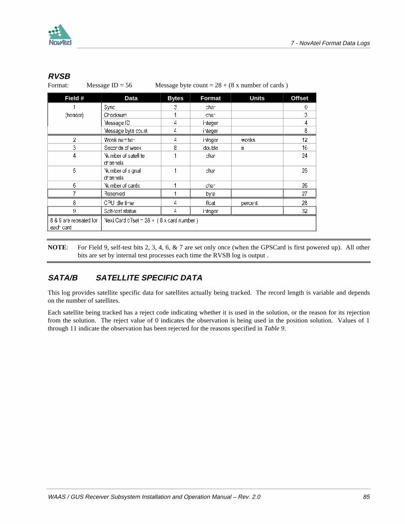
7 - NovAtel Format Data Logs
WAAS / GUS Receiver Subsystem Installation and Operation Manual – Rev. 2.0 85
RVSBFormat: Message ID = 56 Message byte count = 28 + (8 x number of cards )
Field # Data Bytes Format Units Offset
6\QF FKDU
KHDGHU &KHFNVXP FKDU
0HVVDJH ,' LQWHJHU
0HVVDJH E\WH FRXQW LQWHJHU
:HHN QXPEHU LQWHJHU ZHHNV
6HFRQGV RI ZHHN GRXEOH V
1XPEHU RI VDWHOOLWH
FKDQQHOV
FKDU
1XPEHU RI VLJQDO
FKDQQHOV
FKDU
1XPEHU RI FDUGV FKDU
5HVHUYHG E\WH
&38 LGOH WLPH IORDW SHUFHQW
6HOIWHVW VWDWXV LQWHJHU
DUH UHSHDWHG IRU
HDFK FDUG
1H[W &DUG RIIVHW [ FDUG QXPEHU
NOTE: For Field 9, self-test bits 2, 3, 4, 6, & 7 are set only once (when the GPSCard is first powered up). All otherbits are set by internal test processes each time the RVSB log is output .
SATA/B SATELLITE SPECIFIC DATA
This log provides satellite specific data for satellites actually being tracked. The record length is variable and dependson the number of satellites.
Each satellite being tracked has a reject code indicating whether it is used in the solution, or the reason for its rejectionfrom the solution. The reject value of 0 indicates the observation is being used in the position solution. Values of 1through 11 indicate the observation has been rejected for the reasons specified in Table 9.
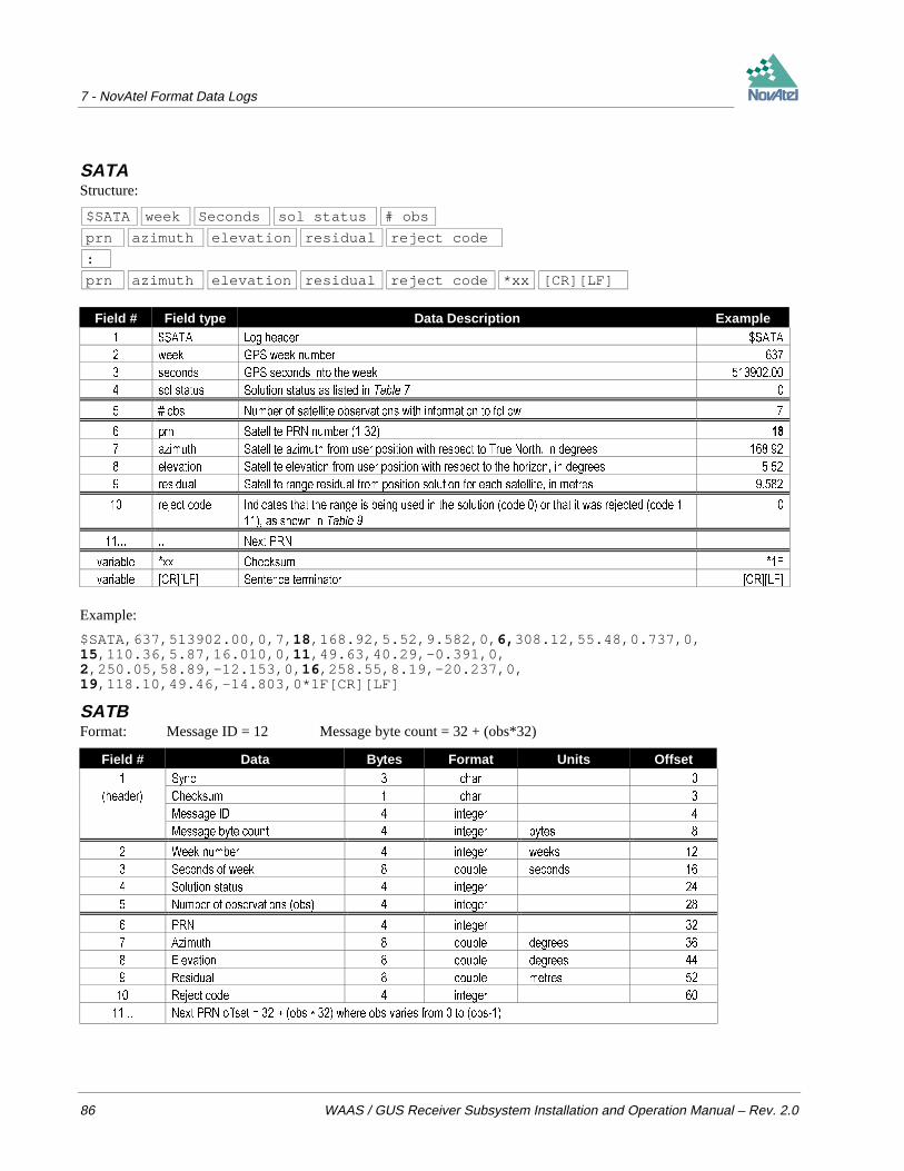
7 - NovAtel Format Data Logs
86 WAAS / GUS Receiver Subsystem Installation and Operation Manual – Rev. 2.0
SATAStructure:
$SATA week Seconds sol status # obs
prn azimuth elevation residual reject code
:
prn azimuth elevation residual reject code *xx [CR][LF]
Field # Field type Data Description Example 6$7$ /RJ KHDGHU 6$7$
ZHHN *36 ZHHN QXPEHU
VHFRQGV *36 VHFRQGV LQWR WKH ZHHN
VRO VWDWXV 6ROXWLRQ VWDWXV DV OLVWHG LQ 7DEOH
REV 1XPEHU RI VDWHOOLWH REVHUYDWLRQV ZLWK LQIRUPDWLRQ WR IROORZ
SUQ 6DWHOOLWH 351 QXPEHU
D]LPXWK 6DWHOOLWH D]LPXWK IURP XVHU SRVLWLRQ ZLWK UHVSHFW WR 7UXH 1RUWK LQ GHJUHHV
HOHYDWLRQ 6DWHOOLWH HOHYDWLRQ IURP XVHU SRVLWLRQ ZLWK UHVSHFW WR WKH KRUL]RQ LQ GHJUHHV
UHVLGXDO 6DWHOOLWH UDQJH UHVLGXDO IURP SRVLWLRQ VROXWLRQ IRU HDFK VDWHOOLWH LQ PHWUHV
UHMHFW FRGH ,QGLFDWHV WKDW WKH UDQJH LV EHLQJ XVHG LQ WKH VROXWLRQ FRGH RU WKDW LW ZDV UHMHFWHG FRGH
DV VKRZQ LQ 7DEOH
1H[W 351
YDULDEOH [[ &KHFNVXP )
YDULDEOH >&5@>/)@ 6HQWHQFH WHUPLQDWRU >&5@>/)@
Example:
$SATA,637,513902.00,0,7, 18 ,168.92,5.52,9.582,0, 6, 308.12,55.48,0.737,0,15 ,110.36,5.87,16.010,0, 11 ,49.63,40.29,-0.391,0,2,250.05,58.89,-12.153,0, 16 ,258.55,8.19,-20.237,0,19 ,118.10,49.46,-14.803,0*1F[CR][LF]
SATBFormat: Message ID = 12 Message byte count = 32 + (obs*32)
Field # Data Bytes Format Units Offset 6\QF FKDU
KHDGHU &KHFNVXP FKDU
0HVVDJH ,' LQWHJHU
0HVVDJH E\WH FRXQW LQWHJHU E\WHV
:HHN QXPEHU LQWHJHU ZHHNV
6HFRQGV RI ZHHN GRXEOH VHFRQGV
6ROXWLRQ VWDWXV LQWHJHU
1XPEHU RI REVHUYDWLRQV REV LQWHJHU
351 LQWHJHU
$]LPXWK GRXEOH GHJUHHV
(OHYDWLRQ GRXEOH GHJUHHV
5HVLGXDO GRXEOH PHWUHV
5HMHFW FRGH LQWHJHU
1H[W 351 RIIVHW REV ZKHUH REV YDULHV IURP WR REV

7 - NovAtel Format Data Logs
WAAS / GUS Receiver Subsystem Installation and Operation Manual – Rev. 2.0 87
SBTA/B SATELLITE BROADCAST DATA: RAW SYMBOLS
This message contains the satellite broadcast data in raw symbols before FEC decoding or any other processing. Anindividual message is sent for each PRN being tracked. For a given satellite, the message number increments by oneeach time a new message is generated. This data matches the RBTA/B data if the message numbers are equal. The datamust be logged with the 'onnew' trigger activated to prevent loss of data.
SBTAStructure:
$SBTA week seconds prn cstatus message # # of symbols
raw symbols *xx [CR][LF]
Field # Field type Data Description Example 6%7$ /RJ KHDGHU 6%7$
ZHHN *36 ZHHN QXPEHU
VHFRQGV *36 VHFRQGV LQWR WKH ZHHN
SUQ 351 RI VDWHOOLWH IURP ZKLFK GDWD RULJLQDWHG
FVWDWXV &KDQQHO 7UDFNLQJ 6WDWXV )
PHVVDJH 0HVVDJH VHTXHQFH QXPEHU
RI V\PEROV 1XPEHU RI V\PEROV WUDQVPLWWHG LQ WKH PHVVDJH
$W SUHVHQW DOZD\V HTXDOV ELWV
UDZ V\PEROV V\PEROV FRPSUHVVHG LQWR D E\WHV LH
ELWVV\PERO +HQFH KH[ FKDUDFWHUV DUH
RXWSXW ,I )(& GHFRGLQJ LV HQDEOHG VRIW V\PEROV
DUH RXWSXW ZLWK YDOXHV UDQJLQJ IURP WR
2WKHUZLVH V DQG V DUH RXWSXW
((((((((((((((((((((
((((((((((((((((((((((
((((((((((((((((((((((((((((((
((((((((((((((((((
(((((((((((((((((((((((
(((((((((((((((
[[ &KHFNVXP &
>&5@>/)@ 6HQWHQFH WHUPLQDWRU >&5@>/)@
SBTBFormat: Message ID = 53 Message byte count = 168
Field # Data Bytes Format Units Offset 6\QF FKDU
KHDGHU &KHFNVXP FKDU
0HVVDJH ,' LQWHJHU
0HVVDJH E\WH FRXQW LQWHJHU E\WHV
:HHN QXPEHU LQWHJHU ZHHNV
6HFRQGV RI ZHHN GRXEOH VHFRQGV
351 QXPEHU LQWHJHU
&KDQQHO 6WDWXV LQWHJHU QD
0HVVDJH LQWHJHU QD
RI 6\PEROV LQWHJHU QD
5DZ 6\PEROV FKDU QD

7 - NovAtel Format Data Logs
88 WAAS / GUS Receiver Subsystem Installation and Operation Manual – Rev. 2.0
TM1A/B TIME OF 1PPS
This log provides the time of the GPSCard 1PPS in GPS week number and seconds into the week. It also includes thereceiver clock offset, the standard deviation of the receiver clock offset and clock model status. This log will output at amaximum rate of 1 Hz.
TM1AStructure:
$TM1A week seconds offset offset std utc offset cm status *xx [CR][LF]
Field # Field type Data Description Example 70$ /RJ KHDGHU 70$
ZHHN *36 ZHHN QXPEHU
VHFRQGV *36 VHFRQGV LQWR WKH ZHHN DW WKH HSRFK FRLQFLGHQW ZLWK WKH 336 RXWSXW VWUREH UHFHLYHU
WLPH
RIIVHW 5HFHLYHU FORFN RIIVHW LQ VHFRQGV $ SRVLWLYH RIIVHW LPSOLHV WKDW WKH UHFHLYHU FORFN LV
DKHDG RI *36 7LPH 7R GHULYH *36 WLPH XVH WKH IROORZLQJ IRUPXOD
*36 WLPH UHFHLYHU WLPH ± RIIVHW
RIIVHW VWG 6WDQGDUG GHYLDWLRQ RI UHFHLYHU FORFN RIIVHW LQ VHFRQGV
XWF RIIVHW 7KLV ILHOG UHSUHVHQWV WKH RIIVHW RI *36 WLPH IURP 87& WLPH FRPSXWHG XVLQJ DOPDQDF
SDUDPHWHUV 7R UHFRQVWUXFW 87& WLPH DOJHEUDLFDOO\ VXEWUDFW WKLV FRUUHFWLRQ IURP ILHOG
DERYH *36 VHFRQGV
87& WLPH *36 WLPH ± XWF RIIVHW
FP VWDWXV 5HFHLYHU &ORFN 0RGHO 6WDWXV ZKHUH LV YDOLG DQG YDOXHV IURP WR LPSO\ WKDW WKH
PRGHO LV LQ WKH SURFHVV RI VWDELOL]DWLRQ
[[ &KHFNVXP
>&5@>/)@ 6HQWHQFH WHUPLQDWRU >&5@>/)@
Example:
$TM1A,794,414634.999999966,-0.000000078,0.000000021,-9.999999998,0*57[CR][LF]
TM1BFormat: Message ID = 03 Message byte count = 52
Field # Data Bytes Format Units Offset 6\QF FKDU
KHDGHU &KHFNVXP FKDU
0HVVDJH ,' LQWHJHU
0HVVDJH E\WH FRXQW LQWHJHU E\WHV
:HHN QXPEHU LQWHJHU ZHHNV
6HFRQGV RI ZHHN GRXEOH VHFRQGV
&ORFN RIIVHW GRXEOH VHFRQGV
6WG'HY FORFN RIIVHW GRXEOH VHFRQGV
87& RIIVHW GRXEOH VHFRQGV
&ORFN PRGHO VWDWXV LQWHJHU JRRG WR EDG

7 - NovAtel Format Data Logs
WAAS / GUS Receiver Subsystem Installation and Operation Manual – Rev. 2.0 89
UTCA/B UTC TIME PARAMETERS
The UTC time parameters (UTCA/B) are provided following the last almanac records when an ALMA/B message hasbeen logged. The UTCA/B message cannot be logged individually or independently of the ALMA/B message.
For more information on Almanac data, refer to the GPS SPS Signal Specification.
UTCAStructure:
$UTCA pct p1ot data-ref wk#-utc wk#-lset delta-time lsop day #-lset
*xx [CR][LF]
Field # Field type Data Description Example 87&$ /RJ KHDGHU 87&$
SFW 3RO\QRPLDO FRQVWDQW WHUP VHFRQGV (
SRW 3RO\QRPLDO VW RUGHU WHUP VHFRQGVVHFRQG (
GDWDUHI 87& GDWD UHIHUHQFH WLPH VHFRQGV
ZN XWF :HHN QXPEHU RI 87& UHIHUHQFH ZHHNV
ZN OVHW :HHN QXPEHU IRU OHDS VHF HIIHFW WLPH ZHHNV
GHOWDWLPH 'HOWD WLPH GXH WR OHDS VHF VHFRQGV
OVRS )RU XVH ZKHQ OHDS VHF RQ SDVW VHFRQGV
GD\ OVHW 'D\ QXPEHU IRU OHDS VHF HIIHFW WLPH GD\V
[[ &KHFNVXP
>&5@>/)@ 6HQWHQFH WHUPLQDWRU >&5@>/)@
Example:
$UTCA,-2.235174179077148E-008,-1.243449787580175E-014,32768,745,755,9,10,5*37[CR][LF]
UTCB Format: Message ID = 17 Message byte count = 52
Field # Field Type Bytes Format Units Offset 6\QF FKDU
KHDGHU &KHFNVXP FKDU
0HVVDJH ,' LQWHJHU
0HVVDJH E\WH FRXQW LQWHJHU E\WHV
3RO\QRPLDO FRQVWDQW WHUP GRXEOH VHFRQGV
3RO\QRPLDO VW RUGHU WHUP GRXEOH VHFRQGVVHFRQG
87& GDWD UHIHUHQFH WLPH LQWHJHU VHFRQGV
:HHN QXPEHU 87& UHIHUHQFH LQWHJHU ZHHNV
:HHN QXPEHU IRU OHDS VHF HIIHFW WLPH LQWHJHU ZHHNV
'HOWD WLPH GXH WR OHDS VHF LQWHJHU VHFRQGV
)RU XVH ZKHQ OHDS VHF RQ SDVW LQWHJHU VHFRQGV
'D\ QXPEHU IRU OHDS VHF HIIHFW WLPH LQWHJHU GD\V
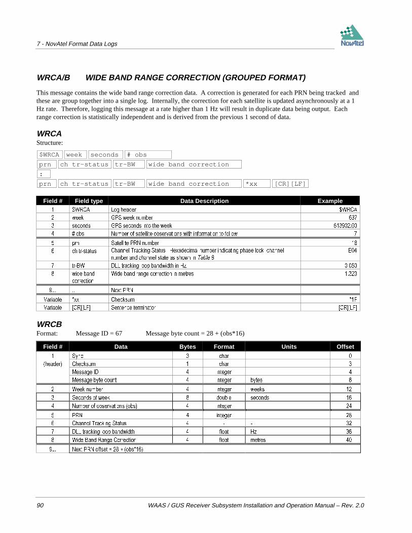
7 - NovAtel Format Data Logs
90 WAAS / GUS Receiver Subsystem Installation and Operation Manual – Rev. 2.0
WRCA/B WIDE BAND RANGE CORRECTION (GROUPED FORMAT)
This message contains the wide band range correction data. A correction is generated for each PRN being tracked andthese are group together into a single log. Internally, the correction for each satellite is updated asynchronously at a 1Hz rate. Therefore, logging this message at a rate higher than 1 Hz will result in duplicate data being output. Eachrange correction is statistically independent and is derived from the previous 1 second of data.
WRCAStructure:
$WRCA week seconds # obs
prn ch tr-status tr-BW wide band correction
:
prn ch tr-status tr-BW wide band correction *xx [CR][LF]
Field # Field type Data Description Example :5&$ /RJ KHDGHU :5&$
ZHHN *36 ZHHN QXPEHU
VHFRQGV *36 VHFRQGV LQWR WKH ZHHN
REV 1XPEHU RI VDWHOOLWH REVHUYDWLRQV ZLWK LQIRUPDWLRQ WR IROORZ
SUQ 6DWHOOLWH 351 QXPEHU
FK WUVWDWXV &KDQQHO 7UDFNLQJ 6WDWXV +H[DGHFLPDO QXPEHU LQGLFDWLQJ SKDVH ORFN FKDQQHO
QXPEHU DQG FKDQQHO VWDWH DV VKRZQ LQ 7DEOH
(
WU%: '// WUDFNLQJ ORRS EDQGZLGWK LQ +]
ZLGH EDQG
FRUUHFWLRQ
:LGH EDQG UDQJH FRUUHFWLRQ LQ PHWUHV
1H[W 351
9DULDEOH [[ &KHFNVXP )
9DULDEOH >&5@>/)@ 6HQWHQFH WHUPLQDWRU >&5@>/)@
WRCBFormat: Message ID = 67 Message byte count = 28 + (obs*16)
Field # Data Bytes Format Units Offset
6\QF FKDU
KHDGHU &KHFNVXP FKDU
0HVVDJH ,' LQWHJHU
0HVVDJH E\WH FRXQW LQWHJHU E\WHV
:HHN QXPEHU LQWHJHU ZHHNV
6HFRQGV RI ZHHN GRXEOH VHFRQGV
1XPEHU RI REVHUYDWLRQV REV LQWHJHU
351 LQWHJHU
&KDQQHO 7UDFNLQJ 6WDWXV
'// WUDFNLQJ ORRS EDQGZLGWK IORDW +]
:LGH %DQG 5DQJH &RUUHFWLRQ IORDW PHWUHV
1H[W 351 RIIVHW REV
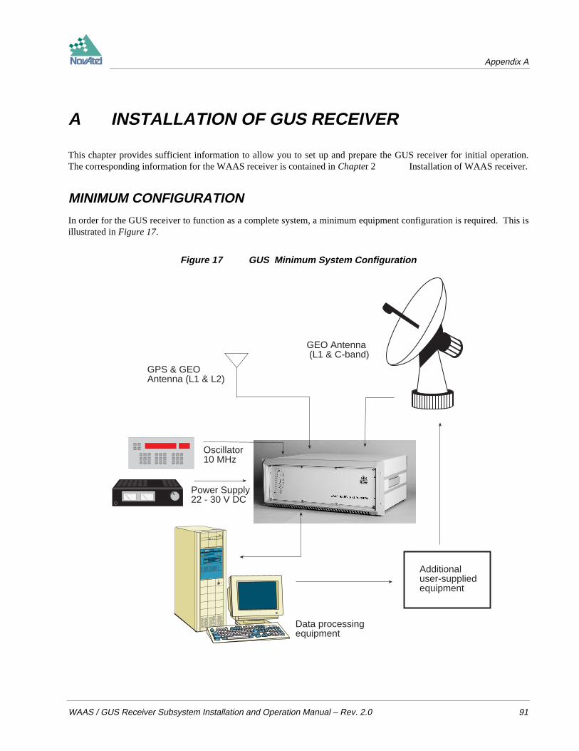
Appendix A
WAAS / GUS Receiver Subsystem Installation and Operation Manual – Rev. 2.0 91
A INSTALLATION OF GUS RECEIVER
This chapter provides sufficient information to allow you to set up and prepare the GUS receiver for initial operation.The corresponding information for the WAAS receiver is contained in Chapter 2 Installation of WAAS receiver.
MINIMUM CONFIGURATION
In order for the GUS receiver to function as a complete system, a minimum equipment configuration is required. This isillustrated in Figure 17.
Figure 17 GUS Minimum System Configuration
Additionaluser-suppliedequipment
Data processingequipment
GPS & GEOAntenna (L1 & L2)
GEO Antenna (L1 & C-band)
Power Supply22 - 30 V DC
Oscillator10 MHz
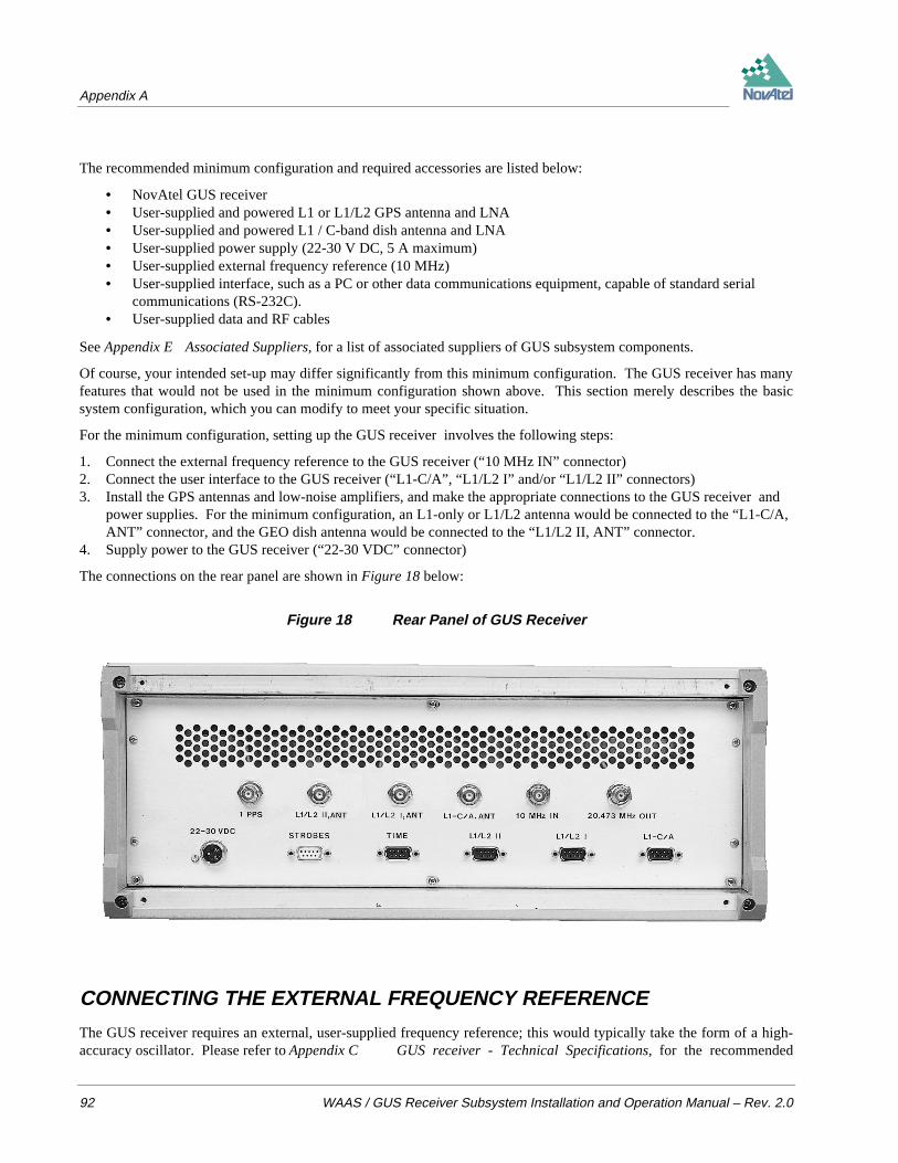
Appendix A
92 WAAS / GUS Receiver Subsystem Installation and Operation Manual – Rev. 2.0
The recommended minimum configuration and required accessories are listed below:
• NovAtel GUS receiver• User-supplied and powered L1 or L1/L2 GPS antenna and LNA• User-supplied and powered L1 / C-band dish antenna and LNA• User-supplied power supply (22-30 V DC, 5 A maximum)• User-supplied external frequency reference (10 MHz)• User-supplied interface, such as a PC or other data communications equipment, capable of standard serial
communications (RS-232C).• User-supplied data and RF cables
See Appendix E Associated Suppliers, for a list of associated suppliers of GUS subsystem components.
Of course, your intended set-up may differ significantly from this minimum configuration. The GUS receiver has manyfeatures that would not be used in the minimum configuration shown above. This section merely describes the basicsystem configuration, which you can modify to meet your specific situation.
For the minimum configuration, setting up the GUS receiver involves the following steps:
1. Connect the external frequency reference to the GUS receiver (“10 MHz IN” connector)2. Connect the user interface to the GUS receiver (“L1-C/A”, “L1/L2 I” and/or “L1/L2 II” connectors)3. Install the GPS antennas and low-noise amplifiers, and make the appropriate connections to the GUS receiver and
power supplies. For the minimum configuration, an L1-only or L1/L2 antenna would be connected to the “L1-C/A,ANT” connector, and the GEO dish antenna would be connected to the “L1/L2 II, ANT” connector.
4. Supply power to the GUS receiver (“22-30 VDC” connector)
The connections on the rear panel are shown in Figure 18 below:
Figure 18 Rear Panel of GUS Receiver
CONNECTING THE EXTERNAL FREQUENCY REFERENCE
The GUS receiver requires an external, user-supplied frequency reference; this would typically take the form of a high-accuracy oscillator. Please refer to Appendix C GUS receiver - Technical Specifications, for the recommended

Appendix A
WAAS / GUS Receiver Subsystem Installation and Operation Manual – Rev. 2.0 93
specifications of this device. See Appendix E Associated Suppliers, for a list of associated suppliers of GUSsubsystem components.
The frequency reference is connected to the 10 MHz BNC female connector on the rear panel of the GUS receiver.Refer to Figure 19 below.
Figure 19 10 MHz In (External Frequency Reference) - GUS
The 11th (bottom) LED on the front panel indicates the status of the connection between the GUS receiver and theexternal clock reference. A clear LED indicates that no external reference is present, red indicates the external clock isnot locked (undergoing the locking process, or the signal is not within the capture range), and green indicates that theclock is locked and stabilized. Refer to Figure 20 below.
Figure 20 Lights on Front Panel of GUS Receiver

Appendix A
94 WAAS / GUS Receiver Subsystem Installation and Operation Manual – Rev. 2.0
CONNECTING DATA COMMUNICATIONS EQUIPMENTThere are four serial ports on the back panel of the GUS receiver; all are configured for RS-232C protocol. These portsmake it possible for external data communications equipment - such as a personal computer - to communicate with theGUS receiver. Each of these ports has a DE9P connector.
• The L1-C/A, L1/L2 I and L1/L2 II ports (see Figure 21) allow two-way communications. Each one is configuredas COM1 if you attempt to communicate directly with it. The L1/L2 I and L1/L2 II ports are each connected to anL1/L2 GPSCard within the GUS receiver unit; the L1-C/A port is connected to the L1-only GPSCard which controlsthe MEDLL subsystem. Each of these ports can be addressed independently of the other.
• The TIME port (see Figure 22) allows only output from the receiver; note that it is not possible to transmit data tothis port. It is configured as COM2 if you attempt to communicate directly with it. Data is available on this port at arate of 0.1 Hz, and is synchronized to the clock signal available at the 1 PPS connector. The data transfer rate isfixed at 9600 bps, with one stop bit.
Figure 21 Pinout for L1-C/A, L1/L2 I, & L1/L2 II Ports - GUS
DCD RXD TXD DTR GND
DSR RTS CTS NC
Figure 22 Pinout for TIME Port - GUS
NC NC TXD DTR GND
NC RTS NC NC
USING THE 1PPS OUTPUT
The clock signal available on the 1 PPS port (see Figure 23) is synchronized to the data available on the Time port. Thespecifications and electrical characteristics of this signal are described in Appendix C GUS receiver - TechnicalSpecifications. The pulse train is accessed from the BNC female connector on the back of the GUS receiver.
Figure 23 1 PPS Output - GUS
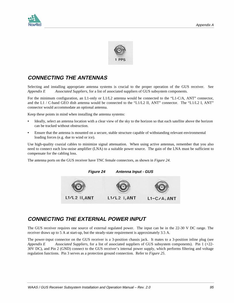
Appendix A
WAAS / GUS Receiver Subsystem Installation and Operation Manual – Rev. 2.0 95
CONNECTING THE ANTENNAS
Selecting and installing appropriate antenna systems is crucial to the proper operation of the GUS receiver. SeeAppendix E Associated Suppliers, for a list of associated suppliers of GUS subsystem components.
For the minimum configuration, an L1-only or L1/L2 antenna would be connected to the “L1-C/A, ANT” connector,and the L1 / C-band GEO dish antenna would be connected to the “L1/L2 II, ANT” connector. The “L1/L2 I, ANT”connector would accommodate an optional antenna.
Keep these points in mind when installing the antenna systems:
• Ideally, select an antenna location with a clear view of the sky to the horizon so that each satellite above the horizoncan be tracked without obstruction.
• Ensure that the antenna is mounted on a secure, stable structure capable of withstanding relevant environmentalloading forces (e.g. due to wind or ice).
Use high-quality coaxial cables to minimize signal attenuation. When using active antennas, remember that you alsoneed to connect each low-noise amplifier (LNA) to a suitable power source. The gain of the LNA must be sufficient tocompensate for the cabling loss.
The antenna ports on the GUS receiver have TNC female connectors, as shown in Figure 24.
Figure 24 Antenna Input - GUS
CONNECTING THE EXTERNAL POWER INPUT
The GUS receiver requires one source of external regulated power. The input can be in the 22-30 V DC range. Thereceiver draws up to 5 A at start-up, but the steady-state requirement is approximately 3.5 A.
The power-input connector on the GUS receiver is a 3-position chassis jack. It mates to a 3-position inline plug (seeAppendix E Associated Suppliers, for a list of associated suppliers of GUS subsystem components). Pin 1 (+22-30V DC), and Pin 2 (GND) connect to the GUS receiver’s internal power supply, which performs filtering and voltageregulation functions. Pin 3 serves as a protection ground connection. Refer to Figure 25.

Appendix A
96 WAAS / GUS Receiver Subsystem Installation and Operation Manual – Rev. 2.0
Figure 25 External Power Connections - GUS
Pin 1
Pin 2
Pin 3
Notch
USING THE 20.473 MHz OUTPUT SIGNAL
The 20.473 MHz output provides a high-stability reference clock signal to another device in system. It permits thesynchronization of another unit to the GUS receiver. This signal can be accessed by means of the BNC female connectoron the GUS receiver’s rear panel (see Figure 26).
Figure 26 20.473 MHz Output - GUS
ACCESSING THE STROBE SIGNALS
The GUS receiver’s output strobe lines are available on the rear panel from the DE9S connector (see Figure 27). Thespecifications and electrical characteristics of these signals are described in Appendix C GUS receiver - TechnicalSpecifications. These signals are provided for diagnostic purposes.
The L1/L2 I and L1/L2 II ports are each connected to an L1/L2 GPS receiver within the GUS receiver unit; the L1-C/Aport is connected to the L1 GPS receiver which controls the MEDLL subsystem.
Figure 27 Strobe 9-pin D-Connector Pinout - GUS
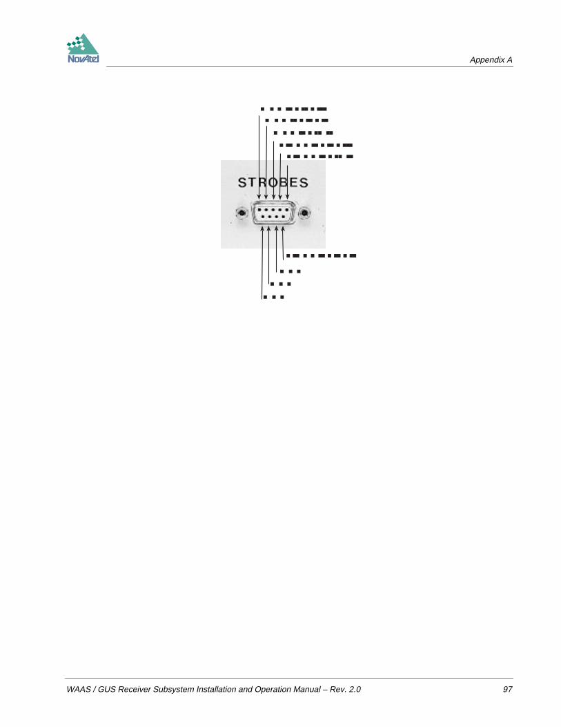
Appendix A
WAAS / GUS Receiver Subsystem Installation and Operation Manual – Rev. 2.0 97
MSR L1/L2 IIMSR L1/L2 I
MSR L1-C/A1 PPS L1/L2 II
1 PPS L1-C/A
1 PPS L1/L2 I
GNDGND
GND
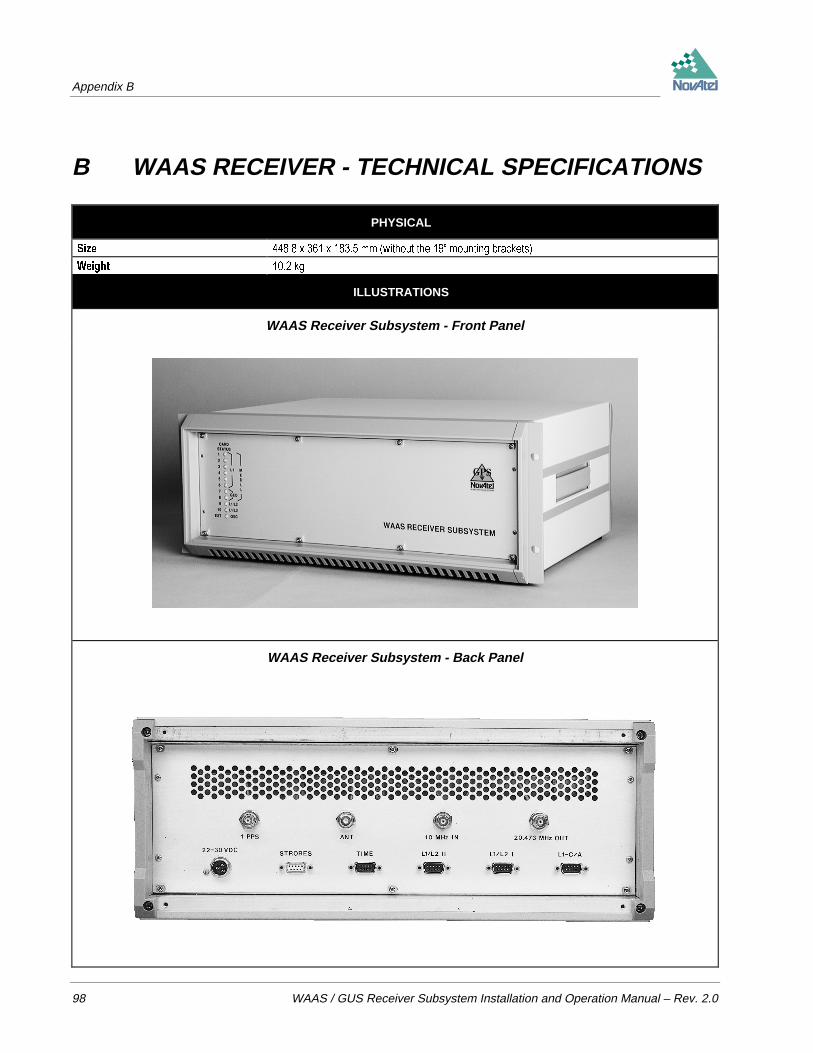
Appendix B
98 WAAS / GUS Receiver Subsystem Installation and Operation Manual – Rev. 2.0
B WAAS RECEIVER - TECHNICAL SPECIFICATIONS
PHYSICAL
6L]H [ [ PP ZLWKRXW WKH ´ PRXQWLQJ EUDFNHWV
:HLJKW NJ
ILLUSTRATIONS
WAAS Receiver Subsystem - Front Panel
WAAS Receiver Subsystem - Back Panel

Appendix B
WAAS / GUS Receiver Subsystem Installation and Operation Manual – Rev. 2.0 99
ENVIRONMENTAL
2SHUDWLQJ 7HPSHUDWXUH & WR & ZLWK P PLQXWH DLU IORZ
6WRUDJH 7HPSHUDWXUH & WR &
+XPLGLW\
$OWLWXGH PHWUHV
>0D\ RSHUDWH DERYH P LQ D FRQWUROOHG HQYLURQPHQW KRZHYHU LV QRW FHUWLILHG DV VXFK@
POWER INPUT
&RQQHFWRU SRVLWLRQ FKDVVLV MDFN
9ROWDJH 9 '&
&XUUHQW PD[LPXP $ FRQWLQXRXV SHDN $
WAAS RECEIVER SUBSYSTEM PERFORMANCE (Subject To GPS System Characteristics)
)UHTXHQF\ / 0+] / 0+]
&RGH WUDFNHG *36 /&$ &RGH *36 / 3 &RGHOHVV :$$6 *(2 /&$ &RGH *36 691 351 DQG
*(2 691 351
6DWHOOLWH 7UDFNLQJ 0('// /&$ /&$ :$$6
RU
/&$ /&$ :$$6
&KDQQHOV // , /&$ 1DUURZ / &RGHOHVV
// ,, /&$ :LGH /&$ 1DUURZ / &RGHOHVV
RU
/&$ :$$6 :LGH /&$ :$$6 :LGH
3RVLWLRQ $FFXUDF\ 6WDQGDORQH PHWUHV &(3 6$ RQ *'23
7LPH $FFXUDF\ UHODWLYH QDQRVHFRQGV 6$ RII
QDQRVHFRQGV 6$ RQ
3VHXGRUDQJH 0('// &$ FP 506 &1R ! G%+] %:
0HDVXUHPHQW / &$ 1DUURZ FP 506 &1R ! G%+] %:
$FFXUDF\ / &$ :LGH P 506 &1R ! G%+] %:
/ FP 506 &1R ! G%+] %:
6LQJOH &KDQQHO / PP 506 &1R ! G%+] /RRS %: +]
3KDVH $FFXUDF\ / PP 506 &1R ! G%+] /RRS %: +]
0('// SKDVH DQG FRGH PHDVXUHPHQWV SHU VHFRQG P6HF
5DZ 'DWD //, SKDVH DQG FRGH PHDVXUHPHQWV SHU VHFRQG
$YDLODELOLW\ 5DWH //,, SKDVH DQG FRGH PHDVXUHPHQWV SHU VHFRQG
7LPH PHVVDJH SHU VHFRQGV
$OPDQDF GDWD PLQXWHV DIWHU UHVHW
7LPH WR )LUVW )L[ VHFRQGV ZLWK VWDELOL]HG LQWHUQDO DQG H[WHUQDO RVFLOODWRUV
PLQXWHV PD[LPXP IURP VWDUW RI FROG UHFHLYHU 1R LQLWLDO WLPH DOPDQDF RU SRVLWLRQ UHTXLUHG
5HDFTXLVLWLRQ / 0('// VHFRQGV &1R G%+] VHFRQGV &1R G%+]
/ VHFRQGV &1R G%+] VHFRQGV &1R G%+]
*(2 VHFRQGV &1R G%+]
+HLJKW 0HDVXUHPHQWV 8S WR PHWUHV IHHW PD[LPXP
>,Q DFFRUGDQFH ZLWK H[SRUW OLFHQVLQJ WKH FDUG LV UHVWULFWHG WR OHVV WKDQ IHHW@
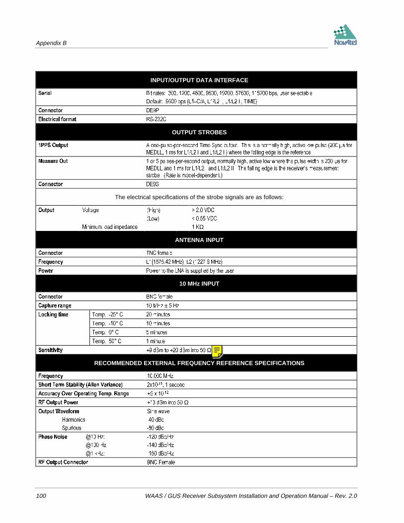
Appendix B
100 WAAS / GUS Receiver Subsystem Installation and Operation Manual – Rev. 2.0
INPUT/OUTPUT DATA INTERFACE
6HULDO %LW UDWHV ESV XVHU VHOHFWDEOH
'HIDXOW ESV /±&$ // , // ,, 7,0(
&RQQHFWRU '(3
(OHFWULFDO IRUPDW 56&
OUTPUT STROBES
336 2XWSXW $ RQHSXOVHSHUVHFRQG 7LPH 6\QF RXWSXW 7KLV LV D QRUPDOO\ KLJK DFWLYH ORZ SXOVH V IRU
0('// PV IRU // , DQG // ,, ZKHUH WKH IDOOLQJ HGJH LV WKH UHIHUHQFH
0HDVXUH 2XW RU SXOVHVSHUVHFRQG RXWSXW QRUPDOO\ KLJK DFWLYH ORZ ZKHUH WKH SXOVH ZLGWK LV V IRU
0('// DQG PV IRU // , DQG // ,, 7KH IDOOLQJ HGJH LV WKH UHFHLYHU¶V PHDVXUHPHQW
VWUREH 5DWH LV PRGHOGHSHQGHQW
&RQQHFWRU '(6
The electrical specifications of the strobe signals are as follows:
2XWSXW 9ROWDJH +LJK ! 9'&
/RZ 9'&
0LQLPXP ORDG LPSHGDQFH .Ω
ANTENNA INPUT
&RQQHFWRU 71& IHPDOH
)UHTXHQF\ / 0+] / 0+]
3RZHU 3RZHU WR WKH /1$ LV VXSSOLHG E\ WKH XVHU
10 MHz INPUT
&RQQHFWRU %1& IHPDOH
&DSWXUH UDQJH 0+] ± +]
/RFNLQJ WLPH 7HPS & PLQXWHV
7HPS & PLQXWHV
7HPS & PLQXWHV
7HPS & PLQXWH
6HQVLWLYLW\ G%P WR G%P LQWR Ω
RECOMMENDED EXTERNAL FREQUENCY REFERENCE SPECIFICATIONS
)UHTXHQF\ 0+]
6KRUW 7HUP 6WDELOLW\ $OOHQ 9DULDQFH [ VHFRQG
$FFXUDF\ 2YHU 2SHUDWLQJ 7HPS 5DQJH [
5) 2XWSXW 3RZHU G%P LQWR Ω2XWSXW :DYHIRUP
+DUPRQLFV
6SXULRXV
6LQH ZDYH
G%F
G%F
3KDVH 1RLVH # +]
# +]
# N+]
G%F+]
G%F+]
G%F+]
5) 2XWSXW &RQQHFWRU %1& )HPDOH

Appendix B
WAAS / GUS Receiver Subsystem Installation and Operation Manual – Rev. 2.0 101
20.473 MHz OUTPUT
&RQQHFWRU %1& IHPDOH
)UHTXHQF\ 0+] ORFNHG
0+] ± +] XQORFNHG
2XWSXW OHYHO PLQLPXP P9 SS Ω
1PPS OUTPUT
&RQQHFWRU %1& IHPDOH
6LJQDO GHVFULSWLRQ $ RQHSXOVHSHUVHFRQG 7LPH 6\QF RXWSXW 7KLV LV D QRUPDOO\ KLJK DFWLYH ORZ SXOVH V
ZKHUH WKH IDOOLQJ HGJH LV WKH UHIHUHQFH
2XWSXW OHYHO 9ROWDJH +LJK ! 9'&
/RZ 9'&
0LQLPXP ORDG
LPSHGDQFH .Ω
DEFAULT CHANNEL ASSIGNMENTS – WAAS RECEIVER SUBSYSTEM
Port Channel SV Type Code DLL Type Frame Nav Type Symbol Rate FEC Sky Search/&$ *36 / &$ 0('// *36 *36 1R $XWRPDWLF
*36 / &$ 0('// *36 *36 1R $XWRPDWLF
*36 / &$ 0('// *36 *36 1R $XWRPDWLF
*36 / &$ 0('// *36 *36 1R $XWRPDWLF
*36 / &$ 0('// *36 *36 1R $XWRPDWLF
*36 / &$ 0('// *36 *36 1R $XWRPDWLF
*36 / &$ 0('// *36 *36 1R $XWRPDWLF
*36 / &$ 0('// *36 *36 1R $XWRPDWLF
*36 / &$ 0('// *36 *36 1R $XWRPDWLF
*36 / &$ 0('// *36 *36 1R $XWRPDWLF
*36 / &$ 0('// *36 *36 1R $XWRPDWLF
*36 / &$ 0('// *36 *36 1R $XWRPDWLF
*36 / &$ 0('// *36 *36 1R $XWRPDWLF
:$$6 / &$ 0('// :$$6 :$$6 <HV ,GOH
:$$6 / &$ 0('// :$$6 :$$6 <HV ,GOH
Port Channel SV Type Code DLL Type Frame Nav Type Symbol Rate FEC Sky Search// , *36 / &$ / 3 1DUURZ &RUU *36 *36 1R $XWRPDWLF
*36 / &$ / 3 1DUURZ &RUU *36 *36 1R $XWRPDWLF
*36 / &$ / 3 1DUURZ &RUU *36 *36 1R $XWRPDWLF
*36 / &$ / 3 1DUURZ &RUU *36 *36 1R $XWRPDWLF
*36 / &$ / 3 1DUURZ &RUU *36 *36 1R $XWRPDWLF
*36 / &$ / 3 1DUURZ &RUU *36 *36 1R $XWRPDWLF
*36 / &$ / 3 1DUURZ &RUU *36 *36 1R $XWRPDWLF
*36 / &$ / 3 1DUURZ &RUU *36 *36 1R $XWRPDWLF
*36 / &$ / 3 1DUURZ &RUU *36 *36 1R $XWRPDWLF
*36 / &$ / 3 1DUURZ &RUU *36 *36 1R $XWRPDWLF
*36 / &$ / 3 1DUURZ &RUU *36 *36 1R $XWRPDWLF
*36 / &$ / 3 1DUURZ &RUU *36 *36 1R $XWRPDWLF
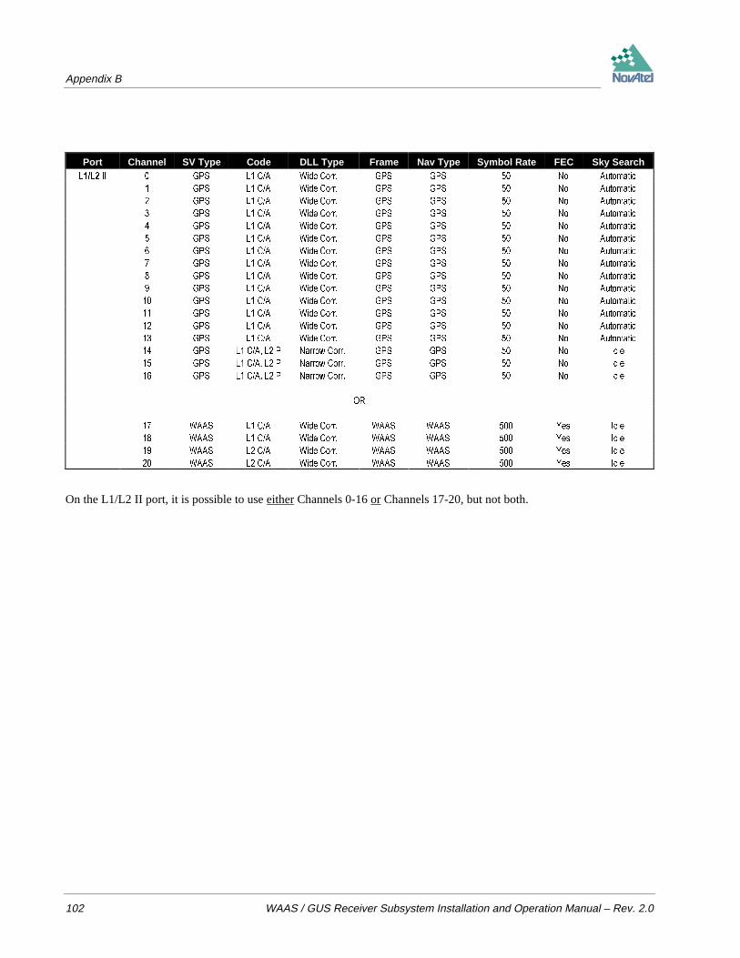
Appendix B
102 WAAS / GUS Receiver Subsystem Installation and Operation Manual – Rev. 2.0
Port Channel SV Type Code DLL Type Frame Nav Type Symbol Rate FEC Sky Search// ,, *36 / &$ :LGH &RUU *36 *36 1R $XWRPDWLF
*36 / &$ :LGH &RUU *36 *36 1R $XWRPDWLF
*36 / &$ :LGH &RUU *36 *36 1R $XWRPDWLF
*36 / &$ :LGH &RUU *36 *36 1R $XWRPDWLF
*36 / &$ :LGH &RUU *36 *36 1R $XWRPDWLF
*36 / &$ :LGH &RUU *36 *36 1R $XWRPDWLF
*36 / &$ :LGH &RUU *36 *36 1R $XWRPDWLF
*36 / &$ :LGH &RUU *36 *36 1R $XWRPDWLF
*36 / &$ :LGH &RUU *36 *36 1R $XWRPDWLF
*36 / &$ :LGH &RUU *36 *36 1R $XWRPDWLF
*36 / &$ :LGH &RUU *36 *36 1R $XWRPDWLF
*36 / &$ :LGH &RUU *36 *36 1R $XWRPDWLF
*36 / &$ :LGH &RUU *36 *36 1R $XWRPDWLF
*36 / &$ :LGH &RUU *36 *36 1R $XWRPDWLF
*36 / &$ / 3 1DUURZ &RUU *36 *36 1R ,GOH
*36 / &$ / 3 1DUURZ &RUU *36 *36 1R ,GOH
*36 / &$ / 3 1DUURZ &RUU *36 *36 1R ,GOH
25
:$$6 / &$ :LGH &RUU :$$6 :$$6 <HV ,GOH
:$$6 / &$ :LGH &RUU :$$6 :$$6 <HV ,GOH
:$$6 / &$ :LGH &RUU :$$6 :$$6 <HV ,GOH
:$$6 / &$ :LGH &RUU :$$6 :$$6 <HV ,GOH
On the L1/L2 II port, it is possible to use either Channels 0-16 or Channels 17-20, but not both.
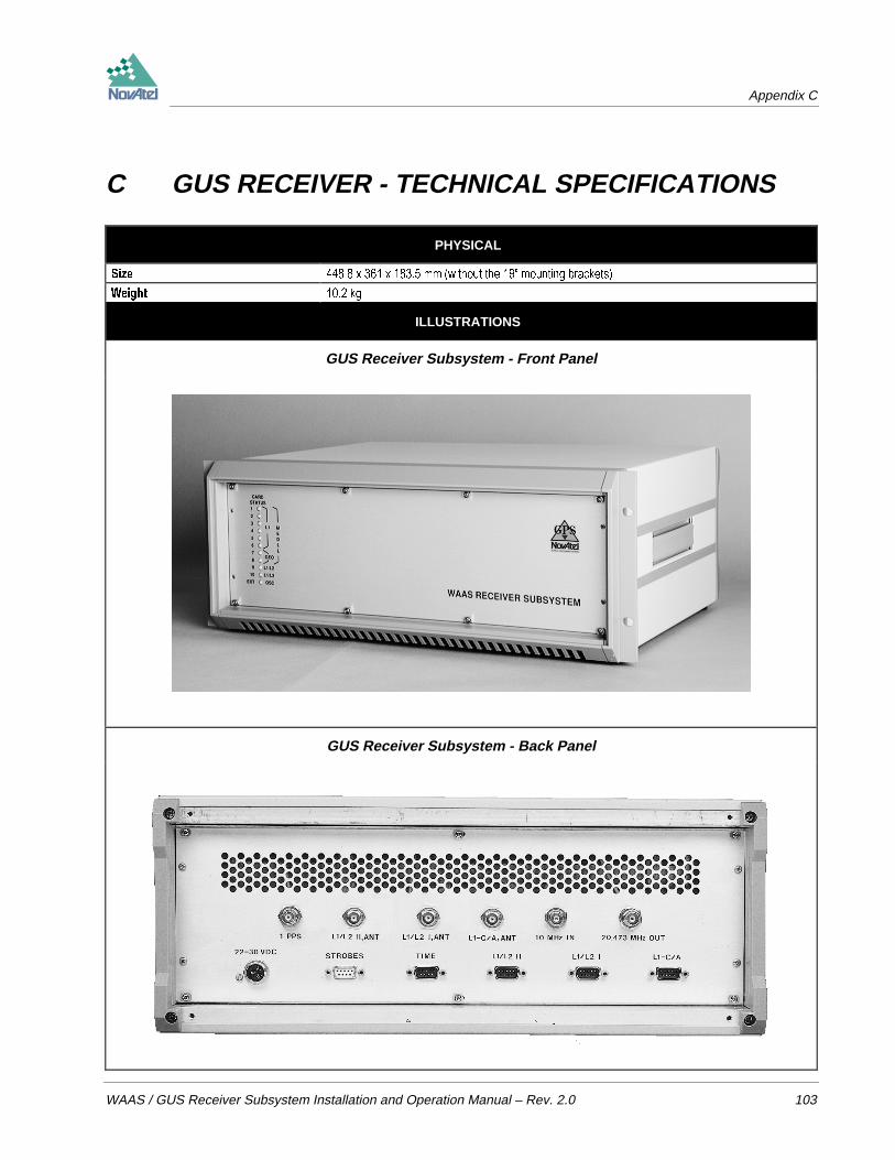
Appendix C
WAAS / GUS Receiver Subsystem Installation and Operation Manual – Rev. 2.0 103
C GUS RECEIVER - TECHNICAL SPECIFICATIONS
PHYSICAL
6L]H [ [ PP ZLWKRXW WKH ´ PRXQWLQJ EUDFNHWV
:HLJKW NJ
ILLUSTRATIONS
GUS Receiver Subsystem - Front Panel
GUS Receiver Subsystem - Back Panel
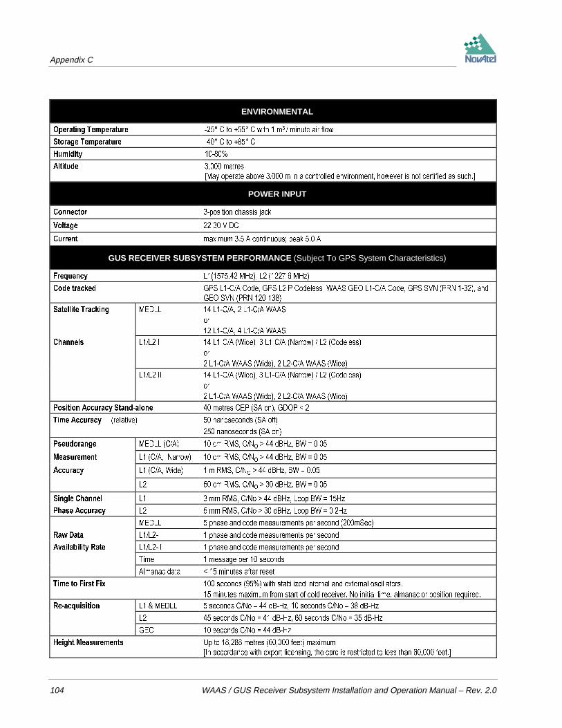
Appendix C
104 WAAS / GUS Receiver Subsystem Installation and Operation Manual – Rev. 2.0
ENVIRONMENTAL
2SHUDWLQJ 7HPSHUDWXUH & WR & ZLWK P PLQXWH DLU IORZ
6WRUDJH 7HPSHUDWXUH & WR &
+XPLGLW\
$OWLWXGH PHWUHV
>0D\ RSHUDWH DERYH P LQ D FRQWUROOHG HQYLURQPHQW KRZHYHU LV QRW FHUWLILHG DV VXFK@
POWER INPUT
&RQQHFWRU SRVLWLRQ FKDVVLV MDFN
9ROWDJH 9 '&
&XUUHQW PD[LPXP $ FRQWLQXRXV SHDN $
GUS RECEIVER SUBSYSTEM PERFORMANCE (Subject To GPS System Characteristics)
)UHTXHQF\ / 0+] / 0+]
&RGH WUDFNHG *36 /&$ &RGH *36 / 3 &RGHOHVV :$$6 *(2 /&$ &RGH *36 691 351 DQG
*(2 691 351
6DWHOOLWH 7UDFNLQJ 0('// /&$ /&$ :$$6
RU
/&$ /&$ :$$6
&KDQQHOV // , /&$ :LGH /&$ 1DUURZ / &RGHOHVV
RU
/&$ :$$6 :LGH /&$ :$$6 :LGH
// ,, /&$ :LGH /&$ 1DUURZ / &RGHOHVV
RU
/&$ :$$6 :LGH /&$ :$$6 :LGH
3RVLWLRQ $FFXUDF\ 6WDQGDORQH PHWUHV &(3 6$ RQ *'23
7LPH $FFXUDF\ UHODWLYH QDQRVHFRQGV 6$ RII
QDQRVHFRQGV 6$ RQ
3VHXGRUDQJH 0('// &$ FP 506 &1R ! G%+] %:
0HDVXUHPHQW / &$ 1DUURZ FP 506 &1R ! G%+] %:
$FFXUDF\ / &$ :LGH P 506 &1R ! G%+] %:
/ FP 506 &1R ! G%+] %:
6LQJOH &KDQQHO / PP 506 &1R ! G%+] /RRS %: +]
3KDVH $FFXUDF\ / PP 506 &1R ! G%+] /RRS %: +]
0('// SKDVH DQG FRGH PHDVXUHPHQWV SHU VHFRQG P6HF
5DZ 'DWD //, SKDVH DQG FRGH PHDVXUHPHQWV SHU VHFRQG
$YDLODELOLW\ 5DWH //,, SKDVH DQG FRGH PHDVXUHPHQWV SHU VHFRQG
7LPH PHVVDJH SHU VHFRQGV
$OPDQDF GDWD PLQXWHV DIWHU UHVHW
7LPH WR )LUVW )L[ VHFRQGV ZLWK VWDELOL]HG LQWHUQDO DQG H[WHUQDO RVFLOODWRUV
PLQXWHV PD[LPXP IURP VWDUW RI FROG UHFHLYHU 1R LQLWLDO WLPH DOPDQDF RU SRVLWLRQ UHTXLUHG
5HDFTXLVLWLRQ / 0('// VHFRQGV &1R G%+] VHFRQGV &1R G%+]
/ VHFRQGV &1R G%+] VHFRQGV &1R G%+]
*(2 VHFRQGV &1R G%+]
+HLJKW 0HDVXUHPHQWV 8S WR PHWUHV IHHW PD[LPXP
>,Q DFFRUGDQFH ZLWK H[SRUW OLFHQVLQJ WKH FDUG LV UHVWULFWHG WR OHVV WKDQ IHHW@

Appendix C
WAAS / GUS Receiver Subsystem Installation and Operation Manual – Rev. 2.0 105
INPUT/OUTPUT DATA INTERFACE
6HULDO %LW UDWHV ESV XVHU VHOHFWDEOH
'HIDXOW ESV /±&$ // , // ,, 7,0(
&RQQHFWRU '(3
(OHFWULFDO IRUPDW 56&
OUTPUT STROBES
336 2XWSXW $ RQHSXOVHSHUVHFRQG 7LPH 6\QF RXWSXW 7KLV LV D QRUPDOO\ KLJK DFWLYH ORZ SXOVH V IRU
0('// PV IRU // , DQG // ,, ZKHUH WKH IDOOLQJ HGJH LV WKH UHIHUHQFH
0HDVXUH 2XW RU SXOVHVSHUVHFRQG RXWSXW QRUPDOO\ KLJK DFWLYH ORZ ZKHUH WKH SXOVH ZLGWK LV V IRU
0('// DQG PV IRU // , DQG // ,, 7KH IDOOLQJ HGJH LV WKH UHFHLYHU¶V PHDVXUHPHQW
VWUREH 5DWH LV PRGHOGHSHQGHQW
&RQQHFWRU '(6
The electrical specifications of the strobe signals are as follows:
2XWSXW 9ROWDJH +LJK ! 9'&
/RZ 9'&
0LQLPXP ORDG LPSHGDQFH .Ω
ANTENNA INPUT
&RQQHFWRUV 71& IHPDOH
)UHTXHQF\ / 0+] / 0+]
3RZHU 3RZHU WR WKH /1$ LV VXSSOLHG E\ WKH XVHU
10 MHz INPUT
&RQQHFWRU %1& IHPDOH
&DSWXUH UDQJH 0+] ± +]
/RFNLQJ WLPH 7HPS & PLQXWHV
7HPS & PLQXWHV
7HPS & PLQXWHV
7HPS & PLQXWHV
6HQVLWLYLW\ G%P WR G%P LQWR Ω
RECOMMENDED EXTERNAL FREQUENCY REFERENCE SPECIFICATIONS
)UHTXHQF\ 0+]
6KRUW 7HUP 6WDELOLW\ $OOHQ 9DULDQFH [ VHFRQG
$FFXUDF\ 2YHU 2SHUDWLQJ 7HPS 5DQJH [
5) 2XWSXW 3RZHU G%P LQWR Ω2XWSXW :DYHIRUP
+DUPRQLFV
6SXULRXV
6LQH ZDYH
G%F
G%F
3KDVH 1RLVH # +]
# +]
# N+]
G%F+]
G%F+]
G%F+]
5) 2XWSXW &RQQHFWRU %1& )HPDOH

Appendix C
106 WAAS / GUS Receiver Subsystem Installation and Operation Manual – Rev. 2.0
20.473 MHz OUTPUT
&RQQHFWRU %1& IHPDOH
)UHTXHQF\ 0+] ORFNHG
0+] ± +] XQORFNHG
2XWSXW OHYHO PLQLPXP P9 SS Ω
1PPS OUTPUT
&RQQHFWRU %1& IHPDOH
6LJQDO GHVFULSWLRQ $ RQHSXOVHSHUVHFRQG 7LPH 6\QF RXWSXW 7KLV LV D QRUPDOO\ KLJK DFWLYH ORZ SXOVH V
ZKHUH WKH IDOOLQJ HGJH LV WKH UHIHUHQFH
2XWSXW OHYHO 9ROWDJH +LJK ! 9'&
/RZ 9'&
0LQLPXP ORDG
LPSHGDQFH Ω

Appendix C
WAAS / GUS Receiver Subsystem Installation and Operation Manual – Rev. 2.0 107
DEFAULT CHANNEL ASSIGNMENTS – GUS RECEIVER SUBSYSTEM
Port Channel SV Type Code DLL Type Frame Nav Type Symbol Rate FEC Sky Search/&$ *36 / &$ 0('// *36 *36 1R $XWRPDWLF
*36 / &$ 0('// *36 *36 1R $XWRPDWLF
*36 / &$ 0('// *36 *36 1R $XWRPDWLF
*36 / &$ 0('// *36 *36 1R $XWRPDWLF
*36 / &$ 0('// *36 *36 1R $XWRPDWLF
*36 / &$ 0('// *36 *36 1R $XWRPDWLF
*36 / &$ 0('// *36 *36 1R $XWRPDWLF
*36 / &$ 0('// *36 *36 1R $XWRPDWLF
*36 / &$ 0('// *36 *36 1R $XWRPDWLF
*36 / &$ 0('// *36 *36 1R $XWRPDWLF
*36 / &$ 0('// *36 *36 1R $XWRPDWLF
*36 / &$ 0('// *36 *36 1R $XWRPDWLF
*36 / &$ 0('// *36 *36 1R $XWRPDWLF
:$$6 / &$ 0('// :$$6 :$$6 <HV ,GOH
:$$6 / &$ 0('// :$$6 :$$6 <HV ,GOH
Port Channel SV Type Code DLL Type Frame Nav Type Symbol Rate FEC Sky Search// , *36 / &$ :LGH &RUU *36 *36 1R $XWRPDWLF
*36 / &$ :LGH &RUU *36 *36 1R $XWRPDWLF
// ,, *36 / &$ :LGH &RUU *36 *36 1R $XWRPDWLF
*36 / &$ :LGH &RUU *36 *36 1R $XWRPDWLF
*36 / &$ :LGH &RUU *36 *36 1R $XWRPDWLF
*36 / &$ :LGH &RUU *36 *36 1R $XWRPDWLF
*36 / &$ :LGH &RUU *36 *36 1R $XWRPDWLF
*36 / &$ :LGH &RUU *36 *36 1R $XWRPDWLF
*36 / &$ :LGH &RUU *36 *36 1R $XWRPDWLF
*36 / &$ :LGH &RUU *36 *36 1R $XWRPDWLF
*36 / &$ :LGH &RUU *36 *36 1R $XWRPDWLF
*36 / &$ :LGH &RUU *36 *36 1R $XWRPDWLF
*36 / &$ :LGH &RUU *36 *36 1R $XWRPDWLF
*36 / &$ :LGH &RUU *36 *36 1R $XWRPDWLF
*36 / &$ / 3 1DUURZ &RUU *36 *36 1R ,GOH
*36 / &$ / 3 1DUURZ &RUU *36 *36 1R ,GOH
*36 / &$ / 3 1DUURZ &RUU *36 *36 1R ,GOH
25
:$$6 / &$ :LGH &RUU :$$6 :$$6 <HV ,GOH
:$$6 / &$ :LGH &RUU :$$6 :$$6 <HV ,GOH
:$$6 / &$ :LGH &RUU :$$6 :$$6 <HV ,GOH
:$$6 / &$ :LGH &RUU :$$6 :$$6 <HV ,GOH
On the L1/L2 I and L1/L2 II ports, it is possible to use either Channels 0-16 or Channels 17-20, but not both.

Appendix D
108 WAAS / GUS Receiver Subsystem Installation and Operation Manual – Rev. 2.0
D INFORMATION MESSAGES
While operating the WAAS / GUS receiver, there may be additional messages output by the receiver that you mayobserve. This information is in addition to typical log data as described in this manual, and falls into two categories:
Type 1: Messages that occur as a result of an operational error within the receiver, over which you have no control.These appear in typical NovAtel log format.
Type 2: Messages that occur in response to your input. These are not in typical log format.
The following sections describe these messages.
TYPE 1 INFORMATION MESSAGESAs mentioned, Type 1 information messages indicate that there is a problem with the operation of the on-boardfirmware. To date, the only Type 1 messages in use are the !ERRA and the !MSGA logs.
If you receive the !ERRA message, it may be useful to reload the software using the correct authorization code; seeTable 12 for a list of !ERRA message types. Each of these messages causes a “severity fatal” condition to be set,causing the card to be reset. To reload the software, power down the receiver and follow the procedure outlined inChapter 4 FIRMWARE Updates. Under certain of the error conditions, the card will reset itself and resolve thedifficulty.
If, after verifying that the software has been correctly loaded, and the receiver cannot reset itself to function normally,contact NovAtel Customer Service.
The !MSGA log would be output if the software is a time-limited version. The log will provide the expiry date of thesoftware. See Table 13 for a list of !MSGA message types.
!ERRA
!ERRA type severity error string opt desc *xx [CR][LF]
Field # Field type Data Description Example
(55$ /RJ KHDGHU (55$
W\SH /RJ W\SH QXPEHUHG VHH 7DEOH
VHYHULW\ 2QO\ RQH LV GHILQHG WR GDWH VHYHULW\BIDWDO QXPEHU FDXVHV WKH UHFHLYHU
WR EH UHVHW
HUURU VWULQJ (UURU PHVVDJH VHH 7DEOH $XWKRUL]DWLRQ FRGH LQYDOLG
RSW GHVF 2SWLRQDO DGGLWLRQDO GHVFULSWLRQ
[[ &KHFNVXP
>&5@>/)@ 6HQWHQFH WHUPLQDWRU >&5@>/)@
Example:
!ERRA,1,0,Authorization Code Invalid,*22[CR][LF]

Appendix D
WAAS / GUS Receiver Subsystem Installation and Operation Manual – Rev. 2.0 109
Table 12 Type 1 !ERRA Messages
Log type Error String
8QNQRZQ (55$ 7\SH
$XWKRUL]DWLRQ &RGH ,QYDOLG
1R $XWKRUL]DWLRQ &RGH )RXQG
,QYDOLG ([SLU\ ,Q $XWKRUL]DWLRQ &RGH
8QDEOH 7R 5HDG (61
&DUG +DV 6WRSSHG 8QH[SHFWHGO\
,QFRUUHFW 1XPEHU RI &DUGV )RXQG
6RIWZDUH 9HUVLRQ 0LVPDWFK
!MSGA
!MSGA type message opt desc *xx [CR][LF]
Field # Field type Data Description Example
06*$ /RJ KHDGHU 06*$
W\SH /RJ W\SH QXPEHUHG IURP VHH 7DEOH
PHVVDJH 0HVVDJH VHH 7DEOH $XWKRUL]DWLRQ &RGH LV 7LPH /LPLWHG
RSW GHVFULSWLRQ 2SWLRQDO GHVFULSWLRQ 0RGHO 5 H[SLUHV RQ
[[ &KHFNVXP &
>&5@>/)@ 6HQWHQFH WHUPLQDWRU >&5@>/)@
Example:
!MSGA,1001,Authorization Code Is Time Limited, Model 3951R Expires on 960901*6C[CR][LF]
Table 13 Type 1 !MSGA Messages
Log type Message String
8QNQRZQ 06*$ 7\SH
$XWKRUL]DWLRQ &RGH ,V 7LPH /LPLWHG
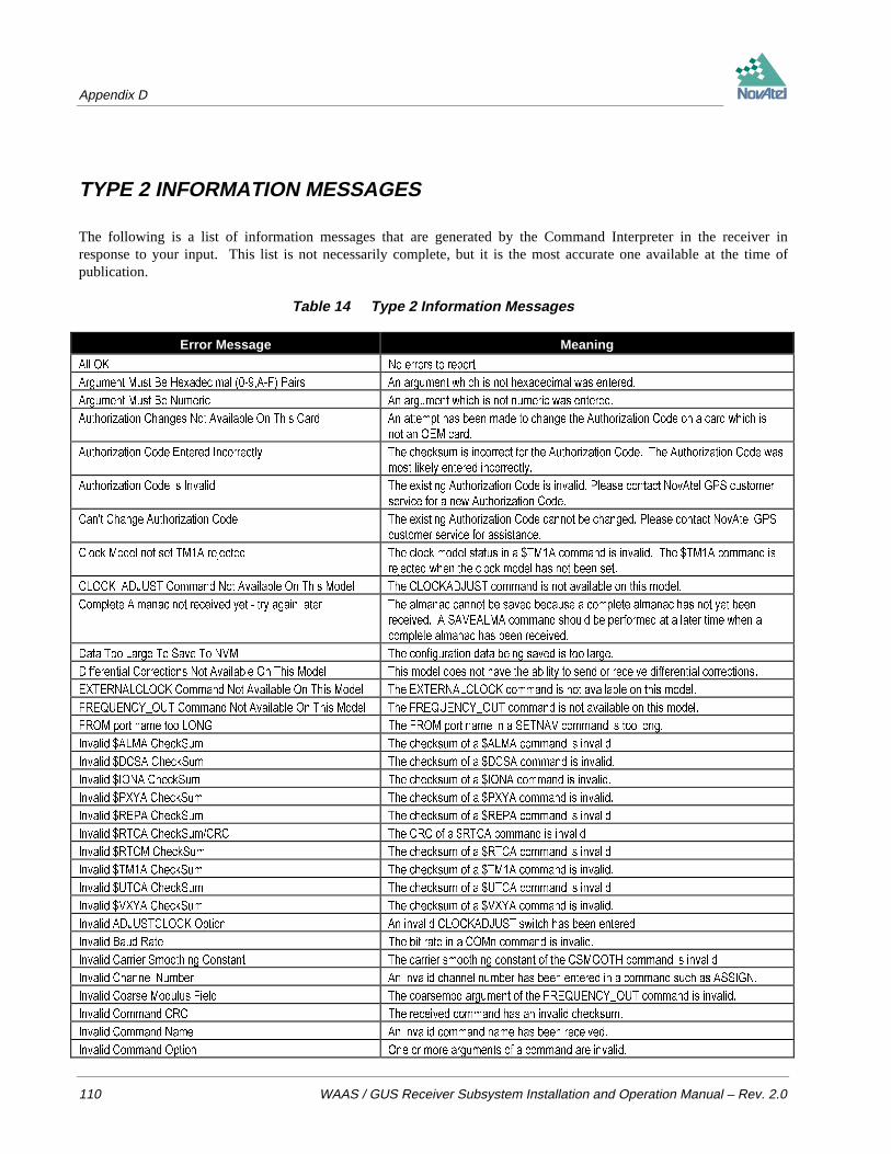
Appendix D
110 WAAS / GUS Receiver Subsystem Installation and Operation Manual – Rev. 2.0
TYPE 2 INFORMATION MESSAGES
The following is a list of information messages that are generated by the Command Interpreter in the receiver inresponse to your input. This list is not necessarily complete, but it is the most accurate one available at the time ofpublication.
Table 14 Type 2 Information Messages
Error Message Meaning
$OO 2. 1R HUURUV WR UHSRUW
$UJXPHQW 0XVW %H +H[DGHFLPDO $) 3DLUV $Q DUJXPHQW ZKLFK LV QRW KH[DGHFLPDO ZDV HQWHUHG
$UJXPHQW 0XVW %H 1XPHULF $Q DUJXPHQW ZKLFK LV QRW QXPHULF ZDV HQWHUHG
$XWKRUL]DWLRQ &KDQJHV 1RW $YDLODEOH 2Q 7KLV &DUG $Q DWWHPSW KDV EHHQ PDGH WR FKDQJH WKH $XWKRUL]DWLRQ &RGH RQ D FDUG ZKLFK LV
QRW DQ 2(0 FDUG
$XWKRUL]DWLRQ &RGH (QWHUHG ,QFRUUHFWO\ 7KH FKHFNVXP LV LQFRUUHFW IRU WKH $XWKRUL]DWLRQ &RGH 7KH $XWKRUL]DWLRQ &RGH ZDV
PRVW OLNHO\ HQWHUHG LQFRUUHFWO\
$XWKRUL]DWLRQ &RGH ,V ,QYDOLG 7KH H[LVWLQJ $XWKRUL]DWLRQ &RGH LV LQYDOLG 3OHDVH FRQWDFW 1RY$WHO *36 FXVWRPHU
VHUYLFH IRU D QHZ $XWKRUL]DWLRQ &RGH
&DQW &KDQJH $XWKRUL]DWLRQ &RGH 7KH H[LVWLQJ $XWKRUL]DWLRQ &RGH FDQQRW EH FKDQJHG 3OHDVH FRQWDFW 1RY$WHO *36
FXVWRPHU VHUYLFH IRU DVVLVWDQFH
&ORFN 0RGHO QRW VHW 70$ UHMHFWHG 7KH FORFN PRGHO VWDWXV LQ D 70$ FRPPDQG LV LQYDOLG 7KH 70$ FRPPDQG LV
UHMHFWHG ZKHQ WKH FORFN PRGHO KDV QRW EHHQ VHW
&/2&.B$'-867 &RPPDQG 1RW $YDLODEOH 2Q 7KLV 0RGHO 7KH &/2&.$'-867 FRPPDQG LV QRW DYDLODEOH RQ WKLV PRGHO
&RPSOHWH $OPDQDF QRW UHFHLYHG \HW WU\ DJDLQ ODWHU 7KH DOPDQDF FDQQRW EH VDYHG EHFDXVH D FRPSOHWH DOPDQDF KDV QRW \HW EHHQ
UHFHLYHG $ 6$9($/0$ FRPPDQG VKRXOG EH SHUIRUPHG DW D ODWHU WLPH ZKHQ D
FRPSOHWH DOPDQDF KDV EHHQ UHFHLYHG
'DWD 7RR /DUJH 7R 6DYH 7R 190 7KH FRQILJXUDWLRQ GDWD EHLQJ VDYHG LV WRR ODUJH
'LIIHUHQWLDO &RUUHFWLRQV 1RW $YDLODEOH 2Q 7KLV 0RGHO 7KLV PRGHO GRHV QRW KDYH WKH DELOLW\ WR VHQG RU UHFHLYH GLIIHUHQWLDO FRUUHFWLRQV
(;7(51$/&/2&. &RPPDQG 1RW $YDLODEOH 2Q 7KLV 0RGHO 7KH (;7(51$/&/2&. FRPPDQG LV QRW DYDLODEOH RQ WKLV PRGHO
)5(48(1&<B287 &RPPDQG 1RW $YDLODEOH 2Q 7KLV 0RGHO 7KH )5(48(1&<B287 FRPPDQG LV QRW DYDLODEOH RQ WKLV PRGHO
)520 SRUW QDPH WRR /21* 7KH )520 SRUW QDPH LQ D 6(71$9 FRPPDQG LV WRR ORQJ
,QYDOLG $/0$ &KHFN6XP 7KH FKHFNVXP RI D $/0$ FRPPDQG LV LQYDOLG
,QYDOLG '&6$ &KHFN6XP 7KH FKHFNVXP RI D '&6$ FRPPDQG LV LQYDOLG
,QYDOLG ,21$ &KHFN6XP 7KH FKHFNVXP RI D ,21$ FRPPDQG LV LQYDOLG
,QYDOLG 3;<$ &KHFN6XP 7KH FKHFNVXP RI D 3;<$ FRPPDQG LV LQYDOLG
,QYDOLG 5(3$ &KHFN6XP 7KH FKHFNVXP RI D 5(3$ FRPPDQG LV LQYDOLG
,QYDOLG 57&$ &KHFN6XP&5& 7KH &5& RI D 57&$ FRPPDQG LV LQYDOLG
,QYDOLG 57&0 &KHFN6XP 7KH FKHFNVXP RI D 57&$ FRPPDQG LV LQYDOLG
,QYDOLG 70$ &KHFN6XP 7KH FKHFNVXP RI D 70$ FRPPDQG LV LQYDOLG
,QYDOLG 87&$ &KHFN6XP 7KH FKHFNVXP RI D 87&$ FRPPDQG LV LQYDOLG
,QYDOLG 9;<$ &KHFN6XP 7KH FKHFNVXP RI D 9;<$ FRPPDQG LV LQYDOLG
,QYDOLG $'-867&/2&. 2SWLRQ $Q LQYDOLG &/2&.$'-867 VZLWFK KDV EHHQ HQWHUHG
,QYDOLG %DXG 5DWH 7KH ELW UDWH LQ D &20Q FRPPDQG LV LQYDOLG
,QYDOLG &DUULHU 6PRRWKLQJ &RQVWDQW 7KH FDUULHU VPRRWKLQJ FRQVWDQW RI WKH &60227+ FRPPDQG LV LQYDOLG
,QYDOLG &KDQQHO 1XPEHU $Q LQYDOLG FKDQQHO QXPEHU KDV EHHQ HQWHUHG LQ D FRPPDQG VXFK DV $66,*1
,QYDOLG &RDUVH 0RGXOXV )LHOG 7KH FRDUVHPRG DUJXPHQW RI WKH )5(48(1&<B287 FRPPDQG LV LQYDOLG
,QYDOLG &RPPDQG &5& 7KH UHFHLYHG FRPPDQG KDV DQ LQYDOLG FKHFNVXP
,QYDOLG &RPPDQG 1DPH $Q LQYDOLG FRPPDQG QDPH KDV EHHQ UHFHLYHG
,QYDOLG &RPPDQG 2SWLRQ 2QH RU PRUH DUJXPHQWV RI D FRPPDQG DUH LQYDOLG

Appendix D
WAAS / GUS Receiver Subsystem Installation and Operation Manual – Rev. 2.0 111
,QYDOLG &RRUGLQDWHV ,QYDOLG FRRUGLQDWHV UHFHLYHG LQ D FRPPDQG VXFK DV 39&$ 3;<$ HWF
,QYDOLG 'DWDW\SH 7KH GDWD W\SH LQ DQ $&&(37 FRPPDQG LV LQYDOLG
,QYDOLG 'DWXP 2IIVHW 7KH GDWXP RIIVHW LQ D 86(5'$780 FRPPDQG LV LQYDOLG
,QYDOLG '$780 2SWLRQ $Q RSWLRQ LQ D '$780 FRPPDQG LV LQYDOLG
,QYDOLG 'DWXP 5RWDWLRQ 7KH GDWXP URWDWLRQ DQJOH LQ D 86(5'$780 FRPPDQG LV LQYDOLG
,QYDOLG 'HJUHH )LHOG $Q LQYDOLG GHJUHH ILHOG KDV EHHQ HQWHUHG LQ D FRPPDQG VXFK DV ),; 326,7,21 RU
6(71$9
,QYDOLG '*36 WLPHRXW YDOXH $Q LQYDOLG WLPHRXW YDOXH ZDV HQWHUHG LQ WKH '*367,0(287 FRPPDQG
,QYDOLG 'RSSOHU $Q LQYDOLG 'RSSOHU KDV EHHQ HQWHUHG LQ DQ $66,*1 FRPPDQG
,QYDOLG 'RSSOHU :LQGRZ $Q LQYDOLG 'RSSOHU ZLQGRZ KDV EHHQ HQWHUHG LQ DQ $66,*1 FRPPDQG
,QYDOLG '75 FKRLFH $Q LQYDOLG RSWLRQ ZDV HQWHUHG LQ WKH &20QB'75 FRPPDQG
,QYDOLG '75 7RJJOH 2SWLRQ 7KH DFWLYH RSWLRQ LQ WKH &20QB '75 FRPPDQG LV LQYDOLG
,QYDOLG '75 7RJJOH 6HWXS 7LPH 7KH OHDG WLPH RSWLRQ LQ WKH &20QB '75 FRPPDQG LV LQYDOLG
,QYDOLG '75 7RJJOH 7HUPLQDWH 7LPH 7KH WDLO WLPH RSWLRQ LQ WKH &20QB '75 FRPPDQG LV LQYDOLG
,QYDOLG '<1$0,&6 2SWLRQ 7KH RSWLRQ LQ D '<1$0,&6 FRPPDQG LV LQYDOLG
,QYDOLG (FKR 2SWLRQ 7KH HFKR RSWLRQ LQ D &20Q FRPPDQG LV LQYDOLG
,QYDOLG (OHYDWLRQ &XWRII $QJOH 7KH HOHYDWLRQ FXWRII DQJOH LQ DQ (&872)) FRPPDQG LV LQYDOLG
,QYDOLG (5506* )ODJ 7KH RSWLRQ RQRII VSHFLILHG LQ D 0(66$*( FRPPDQG LV LQYDOLG
,QYDOLG (5506* 3RUW 7KH SRUW VSHFLILHG LQ D 0(66$*( FRPPDQG LV LQYDOLG
,QYDOLG (;7(51$/&/2&. 2SWLRQ $Q LQYDOLG H[WHUQDO FORFN ZDV HQWHUHG LQ WKH (;7(51$/&/2&. FRPPDQG
,QYDOLG (;7(51$/&/2&. 86(5 $UJXPHQWV $Q LQYDOLG DUJXPHQW ZDV HQWHUHG LQ WKH (;7(51$/&/2&. FRPPDQG
,QYDOLG )LQH 0RGXOXV )LHOG 7KH ILQHPRG DUJXPHQW RI WKH )5(48(1&<B287 FRPPDQG LV LQYDOLG
,QYDOLG ),; 2SWLRQ $Q RSWLRQ RWKHU WKDQ KHLJKW SRVLWLRQ RU YHORFLW\ ZDV VSHFLILHG LQ D ),; FRPPDQG
,QYDOLG )ODWWHQLQJ 7KH IODWWHQLQJ LQ D 86(5'$780 FRPPDQG LV LQYDOLG
,QYDOLG +DQGVKDNH 2SWLRQ 7KH KDQGVKDNH RSWLRQ LQ D &20Q FRPPDQG LV LQYDOLG
,QYDOLG +($/7+ 2YHUULGH $Q LQYDOLG KHDOWK KDV EHHQ HQWHUHG LQ D 6(7+($/7+ RU ),; FRPPDQG
,QYDOLG +HLJKW 7KH KHLJKW LQ D ),; +(,*+7 FRPPDQG LV LQYDOLG
,QYDOLG /RJJHU 'DWDW\SH $Q LQYDOLG ORJ KDV EHHQ VSHFLILHG LQ D /2*81/2* FRPPDQG
,QYDOLG /RJJHU 2IIVHW $Q LQYDOLG RIIVHW KDV EHHQ VSHFLILHG LQ D /2* FRPPDQG
,QYDOLG /RJJHU 3HULRG $Q LQYDOLG SHULRG KDV EHHQ VSHFLILHG LQ D /2* FRPPDQG
,QYDOLG /RJJHU 3RUW 2SWLRQ $Q LQYDOLG SRUW QXPEHU KDV EHHQ VSHFLILHG LQ D /2*81/2* FRPPDQG
,QYDOLG /RJJHU 7ULJJHU $Q LQYDOLG WULJJHU KDV EHHQ VSHFLILHG LQ D /2* FRPPDQG
,QYDOLG 0DJQHWLF 9DULDWLRQ 7KH PDJQHWLF YDULDWLRQ LQ D 0$*9$5 FRPPDQG LV LQYDOLG
,QYDOLG 1XPEHU RI $/0$ $UJXPHQWV 7KH QXPEHU RI DUJXPHQWV LQ D $/0$ FRPPDQG LV LQYDOLG
,QYDOLG 1XPEHU RI '&6$ $UJXPHQWV 7KH QXPEHU RI DUJXPHQWV LQ D '&6$ FRPPDQG LV LQYDOLG
,QYDOLG 1XPEHU RI ,21$ $UJXPHQWV 7KH QXPEHU RI DUJXPHQWV LQ D ,21$ FRPPDQG LV LQYDOLG
,QYDOLG 1XPEHU RI 3;<$ $UJXPHQWV 7KH QXPEHU RI DUJXPHQWV LQ D 3;<$ FRPPDQG LV LQYDOLG
,QYDOLG 1XPEHU RI 5(3$ $UJXPHQWV 7KH QXPEHU RI DUJXPHQWV LQ D 5(3$ FRPPDQG LV LQYDOLG
,QYDOLG 1XPEHU RI 70$ $UJXPHQWV 7KH QXPEHU RI DUJXPHQWV LQ D 70$ FRPPDQG LV LQYDOLG
,QYDOLG 1XPEHU RI 87&$ $UJXPHQWV 7KH QXPEHU RI DUJXPHQWV LQ D 87&$ FRPPDQG LV LQYDOLG
,QYDOLG 1XPEHU RI 9;<$ $UJXPHQWV 7KH QXPEHU RI DUJXPHQWV LQ D 9;<$ FRPPDQG LV LQYDOLG
,QYDOLG 1XPEHU RI $UJXPHQWV $ FRPPDQG KDV EHHQ UHFHLYHG ZKLFK KDV DQ LQYDOLG QXPEHU RI DUJXPHQWV
,QYDOLG 1XPEHU RI 'DWDELWV 7KH QXPEHU RI GDWD ELWV LQ D &20Q FRPPDQG LV LQYDOLG
,QYDOLG 1XPEHU RI 6WRS%LWV 7KH QXPEHU RI VWRS ELWV LQ D &20Q FRPPDQG LV LQYDOLG
,QYDOLG 3DULW\ 2SWLRQ 7KH SDULW\ LQ D &20Q FRPPDQG LV LQYDOLG
,QYDOLG 3RUW 7KH SRUW LQ D 6(1' FRPPDQG LV LQYDOLG
,QYDOLG 3RUW QXPEHU 7KH SRUW QXPEHU LQ DQ $&&(37 FRPPDQG LV LQYDOLG
,QYDOLG 336 0RGXOXV )LHOG 7KH SSVPRG DUJXPHQW RI WKH )5(48(1&<B287 FRPPDQG LV LQYDOLG
,QYDOLG 5,1(; 2SWLRQ $Q RSWLRQ RI D 5,1(; FRPPDQG LV LQYDOLG
,QYDOLG 57&$ RSWLRQ $Q LQYDOLG 57&$ UXOH KDV EHHQ HQWHUHG

Appendix D
112 WAAS / GUS Receiver Subsystem Installation and Operation Manual – Rev. 2.0
,QYDOLG 57&$ VWDWLRQ 1DPH ?;;;;? 7KH 57&$ VWDWLRQ QDPH LQ D ),; 326,7,21 PHVVDJH LV LQYDOLG
,QYDOLG 57&0 %LW 5XOH $Q LQYDOLG 57&0 UXOH KDV EHHQ HQWHUHG
,QYDOLG 57&0 VWDWLRQ 1DPH 7KH 57&0 VWDWLRQ QDPH LQ D ),; 326,7,21 PHVVDJH LV LQYDOLG
,QYDOLG 57&07 VWULQJ OHQJWK PD[LPXP 7KH 57&07 VWULQJ H[FHHGV FKDUDFWHUV
,QYDOLG 576 FKRLFH $Q LQYDOLG RSWLRQ ZDV HQWHUHG LQ WKH &20QB576 FRPPDQG
,QYDOLG 576 7RJJOH 2SWLRQ 7KH DFWLYH RSWLRQ LQ WKH &20QB576 FRPPDQG LV LQYDOLG
,QYDOLG 576 7RJJOH 6HWXS 7LPH 7KH OHDG WLPH RSWLRQ LQ WKH &20QB576 FRPPDQG LV LQYDOLG
,QYDOLG 576 7RJJOH 7HUPLQDWH 7LPH 7KH WDLO WLPH RSWLRQ LQ WKH &20QB576 FRPPDQG LV LQYDOLG
,QYDOLG 6DWHOOLWH 1XPEHU $Q LQYDOLG VDWHOOLWH QXPEHU KDV EHHQ HQWHUHG LQ DQ $66,*1 6(7+($/7+
/2&.287 RU 81/2&.287 FRPPDQG
,QYDOLG 6FDOLQJ 7KH VFDOH YDOXH LQ D 86(5'$780 FRPPDQG LV LQYDOLG
,QYDOLG 6HFRQGV ,QWR :HHN LQ 70$ 7KH WLPH LQ D 70$ FRPPDQG LV LQYDOLG
,QYDOLG 6HPL0DMRU $[LV 7KH VHPLPDMRU D[LV LQ D 86(5'$780 FRPPDQG LV LQYDOLG
,QYDOLG 6WDQGDUG 'HYLDWLRQ /LPLW P $ VWDQGDUG GHYLDWLRQ LQ D 3266( FRPPDQG LV LQYDOLG
,QYDOLG 6\PERO 3HULRG 7KH V\PERO SHULRG LV LQYDOLG IRU DQ $66,*1 RQ D SVHXGROLWH FKDQQHO
,QYDOLG 7LPH /LPLW KRXUV 7KH DYHUDJLQJ WLPH LQ D 326$9( FRPPDQG LV LQYDOLG
,QYDOLG 7RNHQ 7KLV HUURU VKRXOG QHYHU RFFXU ,I LW GRHV SOHDVH FRQWDFW 1RY$WHO *36 FXVWRPHU
VHUYLFH
,QYDOLG 7UDFN 2IIVHW 7KH WUDFN RIIVHW LQ WKH 6(71$9 FRPPDQG LV LQYDOLG
,QYDOLG 9HORFLW\ $Q LQYDOLG YHORFLW\ KDV EHHQ UHFHLYHG HLWKHU LQ D ),; 9(/2&,7< FRPPDQG RU LQ D
FRPPDQG VXFK DV 39&$ 39&%
,QYDOLG :HHN 1XPEHU LQ 70$ 7KH ZHHN LQ D 70$ FRPPDQG LV LQYDOLG
0(7 &RPPDQG 1RW $YDLODEOH 2Q 7KLV 0RGHO 7KH 0(7 FRPPDQG LV QRW DYDLODEOH RQ WKLV PRGHO
0RGHO ,QYDOLG 7KH $XWKRUL]DWLRQ &RGH KDV DQ LQYDOLG 0RGHO 3OHDVH FRQWDFW 1RY$WHO *36
FXVWRPHU VHUYLFH IRU DVVLVWDQFH
190 (UURU 8QDEOH 7R 6DYH 7KH 6$9( RSHUDWLRQ GLG QRW FRPSOHWH VXFFHVVIXOO\
5,1(; VWULQJ WRR /21* ,QGLFDWHV WKDW WKH HQWHUHG 5,1(; FRPPDQG LV WRR ORQJ
57 /RJV 1RW $YDLODEOH 2Q 7KLV 0RGHO 7KLV PRGHO GRHV QRW KDYH WKH DELOLW\ WR VHQG RU UHFHLYH 57 GLIIHUHQWLDO
FRUUHFWLRQV
57&0 /RJV 1RW $YDLODEOH 2Q 7KLV 0RGHO 7KLV PRGHO GRHV QRW KDYH WKH DELOLW\ WR VHQG RU UHFHLYH 57&0 ORJV
6$9( &RPPDQG 1RW $YDLODEOH 2Q 7KLV 0RGHO $ 6$9( RSHUDWLRQ ZDV DWWHPSWHG ZKLFK LV QRW DYDLODEOH RQ WKLV PRGHO
6DYH &RPSOHWH 7KH 6$9( RSHUDWLRQ FRPSOHWHG VXFFHVVIXOO\
6(7&/2&. GLVDEOHG 70$ UHMHFWHG 7KH 70$ FRPPDQG LV UHMHFWHG EHFDXVH WKH XVHU KDV QRW HQDEOHG FORFN
V\QFKURQL]DWLRQ XVLQJ WKH 6(7&/2&. FRPPDQG
6WDQGDUG 'HYLDWLRQ QRW DOORZHG ZLWK VPDOO WLPH OLPLWV ,Q D 326$9( FRPPDQG D VWDQGDUG GHYLDWLRQ FDQQRW EH HQWHUHG ZLWK D VPDOO WLPH
(QWHU D ODUJHU DYHUDJLQJ WLPH LI VWDQGDUG GHYLDWLRQV DUH GHVLUHG
72 3RUWQDPH WRR /21* 7KH 72 SRUW QDPH LQ D 6(71$9 FRPPDQG LV WRR ORQJ
8VHU 'HILQHG '$780 1RW 6HW 7KLV HUURU VKRXOG QRW RFFXU %\ GHIDXOW WKH XVHU GHILQHG '$780 LV VHW WR :*6
,I \RX JHW WKLV HUURU PHVVDJH SOHDVH FRQWDFW 1RY$WHO *36 FXVWRPHU VHUYLFH
9DOLG 2SWLRQ EXW 0LVVLQJ 3URFHVV 7KLV PHVVDJH LQGLFDWHV DQ HUURU LQ WKH VRIWZDUH $ FRPPDQG RSWLRQ LV YDOLG EXW
VRIWZDUH FDQQRW SURFHVV LW

Appendix E
WAAS / GUS Receiver Subsystem Installation and Operation Manual – Rev. 2.0 113
E ASSOCIATED SUPPLIERSThe following is a list of associated suppliers of WAAS / GUS subsystem components. NovAtel does not endorse anyof these suppliers and in no way assumes any responsibility for or liabilities associated with any of these suppliers. TheCustomer assumes sole and full responsibility for selection of suppliers for WAAS / GUS receiver accessories.
Accessory Supplier (s):$$6 $QWHQQD 6XEV\VWHP 31 1:
0LFUR 3XOVH ,QF
&DOOH 6DQ 3DEOR
&DPDULOOR &$ 86$
$WWQ 7RP .RVWHU
3KRQH H[W
)D[
(PDLO WRPN#PLFURSXOVHFRP
:$$6 5HFHLYHU $WRPLF &ORFN 31 )76 $56 +XJKHV :$$6 VWDQGDUG
'DWXP )UHTXHQF\ 7LPH 6\VWHPV
7R]HU 5RDG
%HYHUO\ 0$ 86$
$WWQ 'DYLG %ULJJV
3KRQH
)D[
(PDLO PDUNHWLQJ#IWVGDWXPFRP
3RZHU FRQQHFWRU SRVLWLRQ LQOLQH SOXJ
WR PDWH WR WKH RQH RQ WKH :$$6 *86
UHFHLYHU
31
02'( (OHFWURQLFV /WG
5R\DO 2DN $YHQXH
%XUQDE\ %& &DQDGD 9- -
3KRQH RU
)D[
(PDLO LQIR#PRGHHOHFFRP
:HE VLWH KWWSZZZPRGHHOHFFRP
7KH VDPH 02'( SURGXFW FDQ DOVR EH RUGHUHG
IURP
)DUQHOO (OHFWURQLFV ,QF
7HFKQRORJ\ 'ULYH
,UYLQH &DOLIRUQLD 86$
3KRQH
)D[
:HE VLWH KWWSZZZIDUQHOOFRP
:$$6 6\VWHP 6XSSOLHU +XJKHV ,QIRUPDWLRQ 7HFKQRORJ\ 6\VWHPV
/RF )8 %OGJ 7& 06 %
+XJKHV 'ULYH
32 %R[
)XOOHUWRQ &$
$WWQ (ODLQH %UHUHWRQ
3KRQH
)D[
(PDLO HEUHUHWRQ#FFJDWHKDFFRP
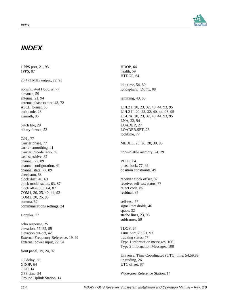
Index
114 WAAS / GUS Receiver Subsystem Installation and Operation Manual – Rev. 2.0
INDEX
1 PPS port, 21, 931PPS, 87
20.473 MHz output, 22, 95
accumulated Doppler, 77almanac, 59antenna, 21, 94antenna phase centre, 43, 72ASCII format, 53auth-code, 26azimuth, 85
batch file, 29binary format, 53
C/N0, 77Carrier phase, 77carrier smoothing, 41Carrier to code ratio, 39case sensitive, 32channel, 77, 89channel configuration, 41channel state, 77, 89checksum, 53clock drift, 40, 63clock model status, 63, 87clock offset, 63, 64, 87COM1, 20, 25, 40, 44, 93COM2, 20, 25, 93comma, 32communications settings, 24
Doppler, 77
echo response, 25elevation, 57, 85, 89elevation cut-off, 42External Frequency Reference, 19, 92External power input, 22, 94
front panel, 19, 24, 92
G2 delay, 38GDOP, 64GEO, 14GPS time, 54Ground Uplink Station, 14
HDOP, 64health, 59HTDOP, 64
idle time, 54, 80ionospheric, 59, 71, 88
jamming, 43, 80
L1/L2 I, 20, 23, 32, 40, 44, 93, 95L1/L2 II, 20, 23, 32, 40, 44, 93, 95L1-C/A, 20, 23, 32, 40, 44, 93, 95LNA, 22, 94LOADER, 27LOADER.SET, 28locktime, 77
MEDLL, 23, 26, 28, 30, 95
non-volatile memory, 24, 79
PDOP, 64phase lock, 77, 89position constraints, 49
receiver clock offset, 87receiver self-test status, 77reject code, 85residual, 85
self-test, 77signal thresholds, 46space, 32strobe lines, 23, 95subframes, 59
TDOP, 64Time port, 20, 21, 93tracking status, 77Type 1 information messages, 106Type 2 Information Messages, 108
Universal Time Coordinated (UTC) time, 54,59,88upgrading, 26UTC offset, 87
Wide-area Reference Station, 14

WAAS / GUS Receiver Subsystem Installation and Operation Manual – Rev. 2.0 115

OM-20000015 Rev. 2.0 97/11/18 Software Version 5.44 / 4.44
NovAtel Inc.1120 - 68 Avenue N.E.
Calgary, Alberta, Canada T2E 8S5
GPS Hotline: 1-403-295-4900GPS Fax: 1-403-295-4901E-mail: [email protected]
Web site: http://www.novatel.ca
Recyclable
Printed in Canadaon recycled paper