Embed Size (px)
Citation preview

WA789000 8967 Part III, Operating Unit Group 4 242-A Evaporator
Part III, Operating Unit Group 4-C.i
1
ADDENDUM C 2
PROCESS INFORMATION 3
4

WA789000 8967 Part III, Operating Unit Group 4 242-A Evaporator
Part III, Operating Unit Group 4-C.ii
1 2
This page intentionally left blank. 3 4

WA789000 8967 Part III, Operating Unit Group 4 242-A Evaporator
Part III, Operating Unit Group 4-C.iii
ADDENDUM C 1
PROCESS INFORMATION 2
3
Contents 4 C PROCESS INFORMATION ......................................................................................................C.1 5
C.1 Tank Systems .............................................................................................................................C.3 6 C.1.1 Design Requirements .................................................................................................................C.3 7 C.1.2 Vapor-Liquid Separator (C-A-1) and Ancillary Equipment ......................................................C.3 8 C.1.3 Condensate Collection Tank (C-100) and Ancillary Equipment................................................C.6 9 C.1.4 PC-5000 ......................................................................................................................................C.8 10 C.1.5 Secondary Containment and Release Detection for Tank Systems ............................................C.9 11 C.1.6 Variances from Secondary Containment Requirements ...........................................................C.13 12 C.1.7 Integrity Assessments ...............................................................................................................C.14 13 C.1.8 Additional Requirements for Existing Tanks ...........................................................................C.15 14 C.1.9 Tank Management Practices ....................................................................................................C.15 15 C.1.10 Labels or Signs .........................................................................................................................C.16 16 C.1.11 Air Emissions ...........................................................................................................................C.16 17 C.1.12 Management of Ignitable or Reactive Wastes in Tank Systems ..............................................C.16 18 C.1.13 Management of Incompatible Wastes in Tank Systems ...........................................................C.16 19
C.2 Air Emissions Control ..............................................................................................................C.16 20
C.3 Engineering Drawings ..............................................................................................................C.16 21 22
23
FIGURES AND TABLES 24
Table C.1. Process and Instrumentation Diagrams ................................................................................ C.17 25 Table C.2. 242-A Evaporator Secondary Containment Systems Drawings ........................................... C.17 26 Figure C.1. 242-A Evaporator Simplified Process Flow Diagram ........................................................ C.18 27 Figure C.2. 242-A Evaporator Process Loop ......................................................................................... C.19 28 Figure C.3. 242-A Evaporator Slurry System ........................................................................................ C.20 29 Figure C.4. 242-A Evaporator Process Condensate System .................................................................. C.21 30 Figure C.5. 242-A Evaporator Vacuum Condenser System .................................................................. C.22 31 Figure C.6. 242-A Evaporator Drain System ......................................................................................... C.22 32
33
34

WA789000 8967 Part III, Operating Unit Group 4 242-A Evaporator
Part III, Operating Unit Group 4-C.iv
1 2 3
This page intentionally left blank.4

WA789000 8967 Part III, Operating Unit Group 4 242-A Evaporator
Part III, Operating Unit Group 4-C.1
C PROCESS INFORMATION 1
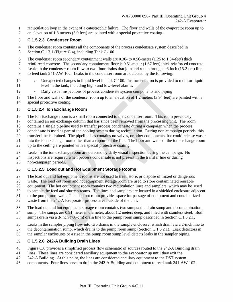
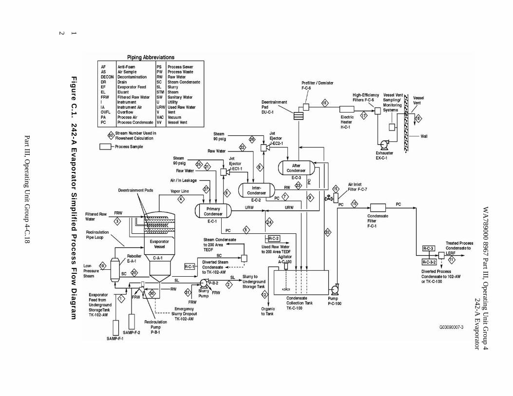
This chapter provides a detailed discussion of the 242-A Evaporator processes and equipment. The 2 242-A Evaporator receives mixed waste from the DST System that contains inorganic and organic 3 constituents and radionuclides. A 242-A Evaporator simplified process flow diagram is given in 4 Figure C.1, illustrating the following basic functions of the 242-A Evaporator. 5
The 242-A Evaporator separates the mixed waste received from the DST System into two 6 dangerous/mixed waste streams: 7
• A concentrated aqueous waste stream (slurry) containing most of the radionuclides, inorganic 8 constituents and nonvolatile organics components such as tri-butyl phosphate. 9
• A dilute aqueous waste stream (process condensate) containing the volatile components, 10 primarily water with low concentrations of radionuclides, inorganic constituents, and volatile 11 constituents such as ammonia and acetone. 12
The slurry is routed back to the DST System for storage pending further treatment. The process 13 condensate is transferred to the LERF and 200 Area ETF for treatment and final disposal at the State 14 Authorized Land Disposal Site (SALDS). 15
The 242-A Evaporator process employs a conventional forced circulation, vacuum evaporation system to 16 concentrate the DST System waste solution. The major components of this system include the reboiler, 17 vapor-liquid separator, recirculation pump and pipe loop, slurry product pump, condensers, jet vacuum 18 system, and condensate collection tank (Figure C.1). 19
The vapor-liquid separator, C-A-1, also called the evaporator vessel, and the condensate collection 20 tank C-100, meet the definition of a tank in WAC 173-303-040. Other process equipment associated with 21 these tank systems is considered ancillary equipment. Drawings that aid in understanding the systems are 22 provided in Section C.3. 23
The 242-A Evaporator receives waste from a DST System, tank 241-AW-102, which serves as the 24 242-A Evaporator feed tank with typical feed flow rates of 260 to 450 liters (68.7 to 119 gallons) per 25 minute. The feed enters the recirculation line and blends with the main process slurry stream, which is 26 pumped to the reboiler. 27
In the reboiler, the mixture is heated to the specified operating temperature, normally 38 to 68oC, (100 to 28 155 ºF) using 21 to 69 kilopascals (3 to 10 pounds per square inch (psi)) gauge pressure steam. The low-29 pressure steam provides adequate heat input, and the resulting low temperature differential across the 30 reboiler minimizes scale formation on the heat transfer surfaces. The static liquid head of the waste in the 31 reboiler is sufficiently high that boiling does not occur in the reboiler tubes. Boiling occurs only near or 32 at the liquid surface in the vapor-liquid separator where the static liquid head is zero and the heated waste 33 is at the reduced pressure of the evaporator vessel. The heat input to the reboiler, and the slurry flow rate 34 are adjusted as process control parameters to achieve the desired target slurry specific gravity and waste 35 volume reduction (WVR). The waste feed rate is a dependent process variable, not directly controlled by 36 operations. Rather, the waste feed rate is automatically controlled to maintain the proper operating level 37 in the reboiler. If the evaporation rate cannot achieve the desired endpoints, slurry is transferred back to 38 the feed tank for one or more passes through the 242-A Evaporator. 39
The heated slurry stream is discharged from the reboiler to the vapor-liquid separator (C-A-1), or 40 evaporator vessel, that typically is maintained at an absolute pressure of 5.3 to 10.7 kilopascals (0.77 to 41 1.55 psi). Under this reduced pressure, a fraction of the water in the heated slurry flashes to steam and the 42 steam is drawn through two wire mesh deentrainer pads, then into a 42-inch diameter vapor line that leads 43 to the primary condenser. The concentrated slurry solution remains in the vapor-liquid separator. 44
After a brief residence time in the vapor-liquid separator, the slurry exits from the bottom through the 45 lower portion of the recirculation line and is recirculated by the recirculation pump (P-B-1). The pump 46 discharges the slurry back to the reboiler via the upper portion of the recirculation line, thus completing 47 the recirculation loop. The slurry flow rates are typically 110 to 230 liters (29 to 60.8 gallons) per minute. 48

WA789000 8967 Part III, Operating Unit Group 4 242-A Evaporator
Part III, Operating Unit Group 4-C.2
Operations monitor the specific gravity of the waste liquid and adjust process variables to stay within an 1 acceptable range of the target specific gravity. As part of the process control, the target specific gravity is 2 determined before the campaign begins. Slurry samples may be obtained during the campaign and the 3 target specific gravity updated during the campaign consistent with campaign objectives as slurry sample 4 results are received. Slurry is transferred from the recirculation line using the slurry pump (P-B-2) or 5 gravity, and transferred through an encased underground pipeline (pipe-within-a-pipe) to a designated 6 slurry receiver tank in the DST System. 7
The vapors are drawn from the vapor-liquid separator, through a 42-inch diameter vapor line and enter a 8 series of three shell and tube condensers, where the vapors are condensed using raw water as cooling 9 water. The condensed vapors, called process condensate, are collected in tank C-100. Steam jets are used 10 to create a vacuum on the vapor-liquid separator drawing the process vapors into and through the 11 condensers. Noncondensable vapors are drawn from the condensers, then through a series of particulate 12 filters and vented to the atmosphere. 13
The air discharges are monitored continuously when the 242-A Evaporator is operating to verify that 14 emission standards for radionuclide met according to requirements of other environmental permits 15 applicable to the 242-A Evaporator. These other environmental permits identified in Addendum A, 16 Section X. 17
Process condensate contains the volatile constituents of the waste and trace quantities of inorganic 18 materials and radionuclides. The process condensate is pumped from tank C-100 through the PC-5000 19 encased underground pipeline (pipe-within-a-pipe) to the LERF at process condensate flow rates of 150 to 20 230 liters (39.6 to 60.8 gallons) per minute. 21
At the end of each campaign, the 242-A Evaporator process equipment and transfer lines are shutdown, 22 emptied, and flushed with raw water, with the exception of the C-100 tank The majority of maintenance 23 activities are performed during this shutdown period when waste is not present in the processing 24 equipment with the exception of the C-100 tank which continues to store a small amount of process 25 condensate from the last campaign. 26
Other discharges during 242-A Evaporator processing include condensate from the steam used to heat the 27 waste and cooling water used to condense the vapors. The 242-A Evaporator is designed to prevent 28 contamination of these streams. The fluids on the uncontaminated side of the heat exchangers are 29 maintained at a higher pressure than the waste stream so that uncontaminated fluid migrates toward the 30 contaminated waste if a leak were to occur. 31
The steam condensate and cooling water streams were assessed in the stream specific reports 32 (WHC 1990a and WHC 1990b) and are not dangerous waste in accordance with WAC 173-303. The 33 steam condensate and the cooling water are monitored to support TEDF processing parameters. This 34 monitoring is outside the scope of this permit and not specific to waste acceptance at TEDF. 35
The 242-A Evaporator process is controlled by trained and qualified operators using a monitor control 36 system (MCS). Training requirements applicable to operators and other personnel are documented in 37 Addendum G, pursuant to Permit Condition III.4.I. The MCS provides the capability to operate some 38 components (e.g. pumps, valves) in a manual mode. Operations personnel monitor the function of the 39 MCS and process equipment, and operate equipment in a manual mode when required to maintain safe 40 facility operations. Additionally, the MCS computer enables trained operators to monitor process 41 parameters and control the parameters where required. Once the configuration parameters and other 42 process control inputs are set, the MCS maintains the process parameters within the unit operating 43 parameters by sending output signals that operate specific pieces of equipment (e.g., control valves, flow 44 rates, temperatures, and pressures). 45
WA789000 8967 Part III, Operating Unit Group 4 242-A Evaporator
Part III, Operating Unit Group 4-C.3
C.1 Tank Systems 1
The design requirements for tanks used to treat and store mixed waste in the 242-A Evaporator is 2 discussed briefly in this section are detailed in the IQRPE Integrity Assessment Report (IAR) for the 3 242-A Evaporator Tank System : 4
The 242-A Evaporator is divided into four major subsystems that store, treat of transport, Washington 5 State Dangerous Wastes. The four subsystems are as follows: 6
Vapor-Liquid Separator (C-A-1) and Ancillary Equipment (Section C.1.2) 7 Condensate Collection Tank (C-100) and Ancillary Equipment (Section C.1.3) 8 PC-5000 transfer line (Section C.1.4) 9 Building and Secondary Containment Subsystem (Section C.1.5) 10
C.1.1 Design Requirements 11
The following sections provide an overview of the design specifications for the major subsystems and 12 tanks within the 242-A Evaporator. In accordance with the tank system requirements of 13 WAC 173-303-640(2), an independent qualified registered professional engineer (IQRPE) certifies an 14 integrity assessment. The review of the following design requirements are addressed in more detail in the 15 latest 242-A Evaporator and PC-5000 Integrity Assessment Reports (IAR): 16
Minimum design wall thicknesses and measured wall thicknesses at various points throughout the 17 tank systems 18
Design standards used in construction, including references 19 Waste characteristics 20 Materials of construction and compatibility of materials with the waste being processed 21 Corrosion protection 22 Seismic design basis evaluation 23
The conclusion of the latest integrity assessment report is that the 242-A Evaporator and associated 24 PC-5000 transfer line are not leaking and are fit for use. The inspections, tests, and analyses performed 25 provide assurance that the tank system has adequate design, sufficient structural strength, and sufficient 26 compatibility with the waste to not collapse, rupture, or fail during operation. The reports also states that 27 a review of construction files indicates that the building structure was designed and constructed to 28 withstand a design basis earthquake and recommends a frequency of future integrity assessments. The 29 codes and standards applicable to the design, construction, and testing of the 242-A Evaporator tank 30 system are included in each subsystems. 31
C.1.2 Vapor-Liquid Separator (C-A-1) and Ancillary Equipment 32
The following sections describe the vapor-liquid separator (C-A-1) and ancillary equipment. 33
Waste Feed System 34
Feed to the 242-A Evaporator is supplied via a pump located in the 241-AW-102 feed tank. The feed 35 pump transfers the waste to the 242-A Evaporator through a 3-inch (7.6-cm) diameter carbon steel 36 transfer pipeline encased in a 6-inch (15.2-cm) diameter carbon steel pipe to provide secondary 37 containment. The feed pipeline is equipped with a leak detection system. The waste feed system is part 38 of the DST System, Operating Unit Group 12. 39
Samples can be taken from the waste feed when needed. The feed sampler (SAMP-F-1) is located in a 40 sample enclosure located in the hot equipment storage room. 41
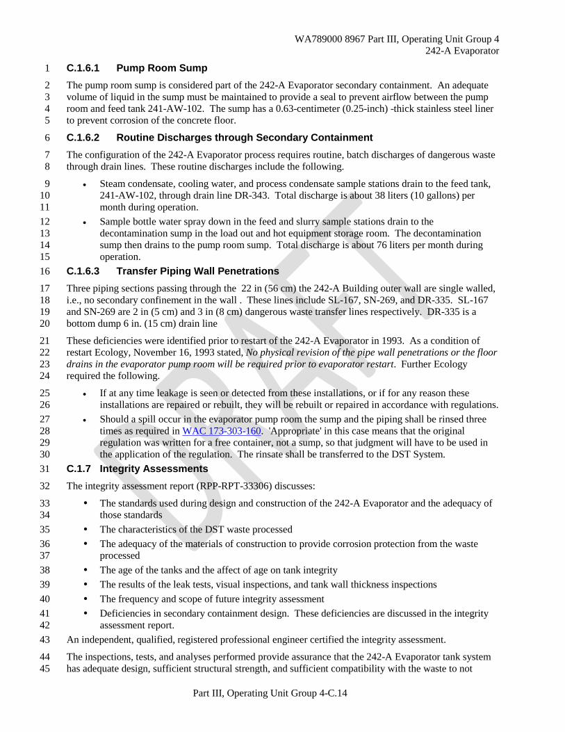
Evaporator Process Loop 42
The 242-A Evaporator process loop equipment components are as follows: 43
Reboiler (E-A-1) 44
WA789000 8967 Part III, Operating Unit Group 4 242-A Evaporator
Part III, Operating Unit Group 4-C.4
Vapor-liquid separator (C-A-1) 1 Recirculation pump (P-B-1) 2 Recirculation loop 3
Figure C.2 is a simplified process flow diagram showing the major components of the process loop. 4
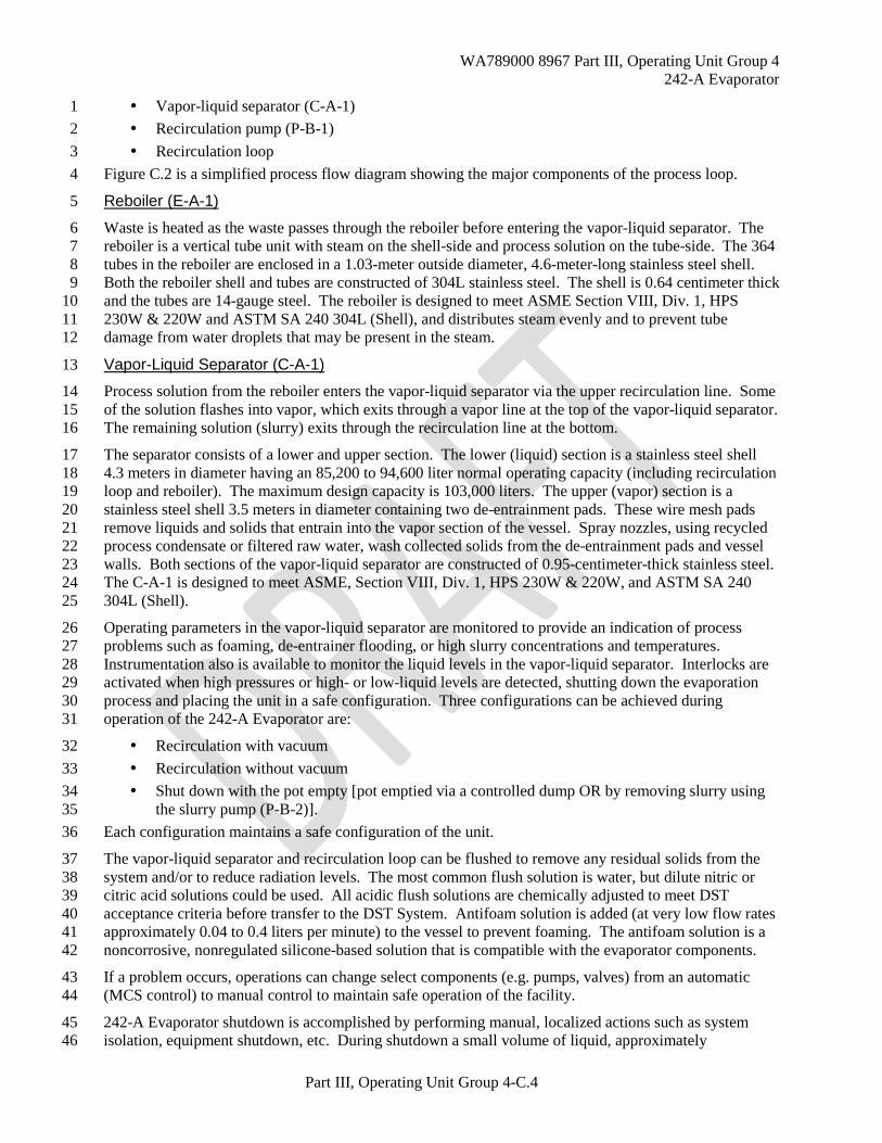
Reboiler (E-A-1) 5
Waste is heated as the waste passes through the reboiler before entering the vapor-liquid separator. The 6 reboiler is a vertical tube unit with steam on the shell-side and process solution on the tube-side. The 364 7 tubes in the reboiler are enclosed in a 1.03-meter outside diameter, 4.6-meter-long stainless steel shell. 8 Both the reboiler shell and tubes are constructed of 304L stainless steel. The shell is 0.64 centimeter thick 9 and the tubes are 14-gauge steel. The reboiler is designed to meet ASME Section VIII, Div. 1, HPS 10 230W & 220W and ASTM SA 240 304L (Shell), and distributes steam evenly and to prevent tube 11 damage from water droplets that may be present in the steam. 12
Vapor-Liquid Separator (C-A-1) 13
Process solution from the reboiler enters the vapor-liquid separator via the upper recirculation line. Some 14 of the solution flashes into vapor, which exits through a vapor line at the top of the vapor-liquid separator. 15 The remaining solution (slurry) exits through the recirculation line at the bottom. 16
The separator consists of a lower and upper section. The lower (liquid) section is a stainless steel shell 17 4.3 meters in diameter having an 85,200 to 94,600 liter normal operating capacity (including recirculation 18 loop and reboiler). The maximum design capacity is 103,000 liters. The upper (vapor) section is a 19 stainless steel shell 3.5 meters in diameter containing two de-entrainment pads. These wire mesh pads 20 remove liquids and solids that entrain into the vapor section of the vessel. Spray nozzles, using recycled 21 process condensate or filtered raw water, wash collected solids from the de-entrainment pads and vessel 22 walls. Both sections of the vapor-liquid separator are constructed of 0.95-centimeter-thick stainless steel. 23 The C-A-1 is designed to meet ASME, Section VIII, Div. 1, HPS 230W & 220W, and ASTM SA 240 24 304L (Shell). 25
Operating parameters in the vapor-liquid separator are monitored to provide an indication of process 26 problems such as foaming, de-entrainer flooding, or high slurry concentrations and temperatures. 27 Instrumentation also is available to monitor the liquid levels in the vapor-liquid separator. Interlocks are 28 activated when high pressures or high- or low-liquid levels are detected, shutting down the evaporation 29 process and placing the unit in a safe configuration. Three configurations can be achieved during 30 operation of the 242-A Evaporator are: 31
Recirculation with vacuum 32 Recirculation without vacuum 33 Shut down with the pot empty [pot emptied via a controlled dump OR by removing slurry using 34
the slurry pump (P-B-2)]. 35 Each configuration maintains a safe configuration of the unit. 36
The vapor-liquid separator and recirculation loop can be flushed to remove any residual solids from the 37 system and/or to reduce radiation levels. The most common flush solution is water, but dilute nitric or 38 citric acid solutions could be used. All acidic flush solutions are chemically adjusted to meet DST 39 acceptance criteria before transfer to the DST System. Antifoam solution is added (at very low flow rates 40 approximately 0.04 to 0.4 liters per minute) to the vessel to prevent foaming. The antifoam solution is a 41 noncorrosive, nonregulated silicone-based solution that is compatible with the evaporator components. 42
If a problem occurs, operations can change select components (e.g. pumps, valves) from an automatic 43 (MCS control) to manual control to maintain safe operation of the facility. 44
242-A Evaporator shutdown is accomplished by performing manual, localized actions such as system 45 isolation, equipment shutdown, etc. During shutdown a small volume of liquid, approximately 46

WA789000 8967 Part III, Operating Unit Group 4 242-A Evaporator
Part III, Operating Unit Group 4-C.5
37.8 kiloliters (10, 000 gallons) may be present in the vessel. This liquid is generally raw water and used 1 for maintenance activities. 2
Recirculation Pump 3
The stainless steel recirculation pump (P-B-1), is constructed as part of the recirculation loop to the 4 reboiler. The 28-inch diameter axial flow pump has 60,900 liters per minute output. The recirculation 5 pump is designed to handle slurry up to 30 percent undissolved solids by volume at specific gravities up 6 to 1.8 and is compliant with ASTM A296 GrCF-8 and GrGF-8. 7
The recirculation pump moves waste at high velocities through the reboiler to improve heat transfer, keep 8 solids in suspension, and reduce fouling of the heat transfer surfaces. The recirculation pump is equipped 9 with shaft seals with high-pressure recycled process condensate (or water) introduced between the seals to 10 prevent the waste solution from leaking out of the system. Seal water pressure and flow are monitored 11 and controlled to shut down the recirculation pump if conditions are not adequate to prevent waste liquid 12 from migrating into the seal water. The used seal water is routed to the feed tank. 13
Recirculation Loop 14
The recirculation loop consists of a 28-inch diameter stainless steel pipe that connects the vapor-liquid 15 separator to the recirculation pump and reboiler. The lower loop runs from the bottom of the vapor-liquid 16 separator to the recirculation pump inlet. The upper loop connects the pump discharge to the reboiler and 17 the reboiler to the vapor-liquid separator. The feed line from the feed tank and the slurry line to 18 underground storage tanks are connected to the upper recirculation line. 19
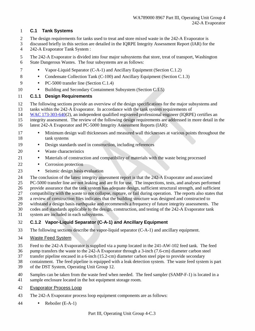
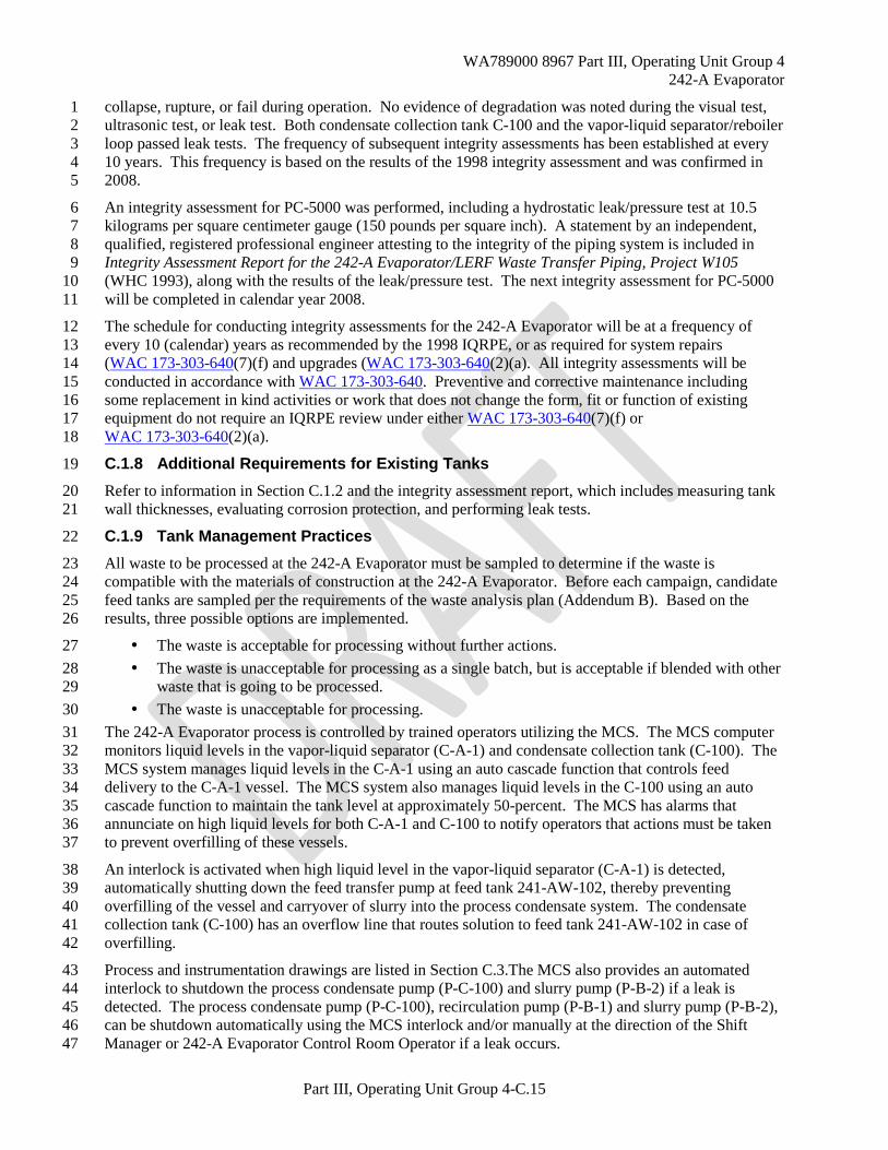
Slurry System 20
The slurry system draws a portion of the concentrated waste from the upper recirculation loop and 21 transfers it to the DST System. The major components of the slurry system are the slurry pump and the 22 slurry transfer pipelines. Figure C.3 shows a simplified flow diagram of the slurry system. These 23 components are described in the following paragraphs. 24
The slurry pump (P-B-2) is used to transfer slurry from the recirculation loop to the DST system. The 25 pump is driven by a variable speed motor and is constructed of 304L stainless steel. 26
(P-B-2) pump is shutdown by interlocks if any of the following occur: 27
Excessive pressure is detected in the slurry lines to 241-AW Tank Farm 28 A leak is detected in the slurry transfer lines secondary containment by an encasement leak 29
detector 30 A leak is detected in the 241-AW Tank Farm process pits where the transfer lines enter the 31
DST System. 32 The slurry pump uses a shaft seal with recycled process condensate (or water) and pressure and flow 33 controls similar to the system described above for the recirculation pump. 34
Transfer pipelines are 2- or 3-inch (7.6-cm) diameter, carbon steel encased lines which route slurry to a 35 designated underground DST within the 200 East Area. All transfer pipelines are encased in a secondary 36 containment pipe and drain to an encasement leak detector or pit with active leak detection. Detection of 37 any leak automatically shuts off the slurry pump. In lieu of the MCS automated shutdown, the slurry 38 pump (P-B-2) can be manually shutdown at the direction of the Shift manager or 242-A Evaporator 39 Control Room operator if a leak is detected. 40
The flow rate of the slurry transfer to the DST System is monitored and a decrease in flow below a 41 specified value automatically will shut down the slurry pump (P-B-2) and initiate a line flush with water. 42 The objective of flushing the transfer line is to prevent settling of solids, which precludes plugging the 43 slurry transfer lines. 44
Samples can be taken from the a 3-inch slurry by-pass line when needed via a sampler (SAMP-F-2) that 45 is located near the feed sampler in the load out and hot equipment storage room. 46
WA789000 8967 Part III, Operating Unit Group 4 242-A Evaporator
Part III, Operating Unit Group 4-C.6
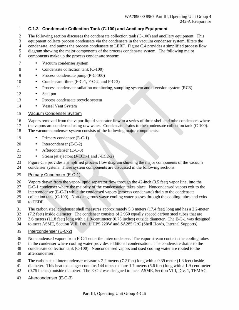
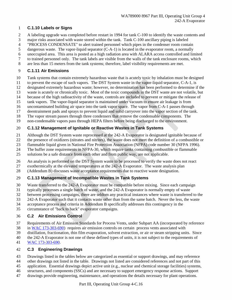
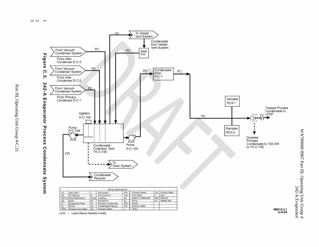
C.1.3 Condensate Collection Tank (C-100) and Ancillary Equipment 1
The following section discusses the condensate collection tank (C-100) and ancillary equipment. This 2 equipment collects process condensate via the condensers in the vacuum condenser system, filters the 3 condensate, and pumps the process condensate to LERF. Figure C.4 provides a simplified process flow 4 diagram showing the major components of the process condensate system. The following major 5 components make up the process condensate system: 6
Vacuum condenser system 7 Condensate collection tank (C-100) 8 Process condensate pump (P-C-100) 9 Condensate filters (F-C-1, F-C-2, and F-C-3) 10 Process condensate radiation monitoring, sampling system and diversion system (RC3) 11 Seal pot 12 Process condensate recycle system 13 Vessel Vent System 14
Vacuum Condenser System 15
Vapors removed from the vapor-liquid separator flow to a series of three shell and tube condensers where 16 the vapors are condensed using raw water. Condensate drains to the condensate collection tank (C-100). 17 The vacuum condenser system consists of the following major components: 18
Primary condenser (E-C-1) 19 Intercondenser (E-C-2) 20 Aftercondenser (E-C-3) 21 Steam jet ejectors (J-EC1-1 and J-EC2-2) 22
Figure C.5 provides a simplified process flow diagram showing the major components of the vacuum 23 condenser system. These system components are discussed in the following sections. 24
Primary Condenser (E-C-1) 25
Vapors drawn from the vapor-liquid separator flow through the 42-inch (3.5 feet) vapor line, into the 26 E-C-1 condenser where the majority of the condensation takes place. Noncondensed vapors exit to the 27 intercondenser (E-C-2) while the condensed vapors (process condensate) drain to the condensate 28 collection tank (C-100). Non-dangerous waste cooling water passes through the cooling tubes and exits 29 to TEDF. 30
The carbon steel condenser shell measures approximately 5.3 meters (17.4 feet) long and has a 2.2-meter 31 (7.2 feet) inside diameter. The condenser consists of 2,950 equally spaced carbon steel tubes that are 32 3.6 meters (11.8 feet) long with a 1.9-centimeter (0.75 inches) outside diameter. The E-C-1 was designed 33 to meet ASME, Section VIII, Div. 1, HPS 220W and SA285 GrC (Shell Heads, Internal Supports). 34
Intercondenser (E-C-2) 35
Noncondensed vapors from E-C-1 enter the intercondenser. The vapor stream contacts the cooling tubes 36 in the condenser where cooling water provides additional condensation. The condensate drains to the 37 condensate collection tank (C-100). Noncondensed vapors and used cooling water are routed to the 38 aftercondenser. 39
The carbon steel intercondenser measures 2.2 meters (7.2 feet) long with a 0.39 meter (1.3 feet) inside 40 diameter. This heat exchanger contains 144 tubes that are 1.7 meters (5.6 feet) long with a 1.9-centimeter 41 (0.75 inches) outside diameter. The E-C-2 was designed to meet ASME, Section VIII, Div. 1, TEMAC. 42
Aftercondenser (E-C-3) 43
WA789000 8967 Part III, Operating Unit Group 4 242-A Evaporator
Part III, Operating Unit Group 4-C.7
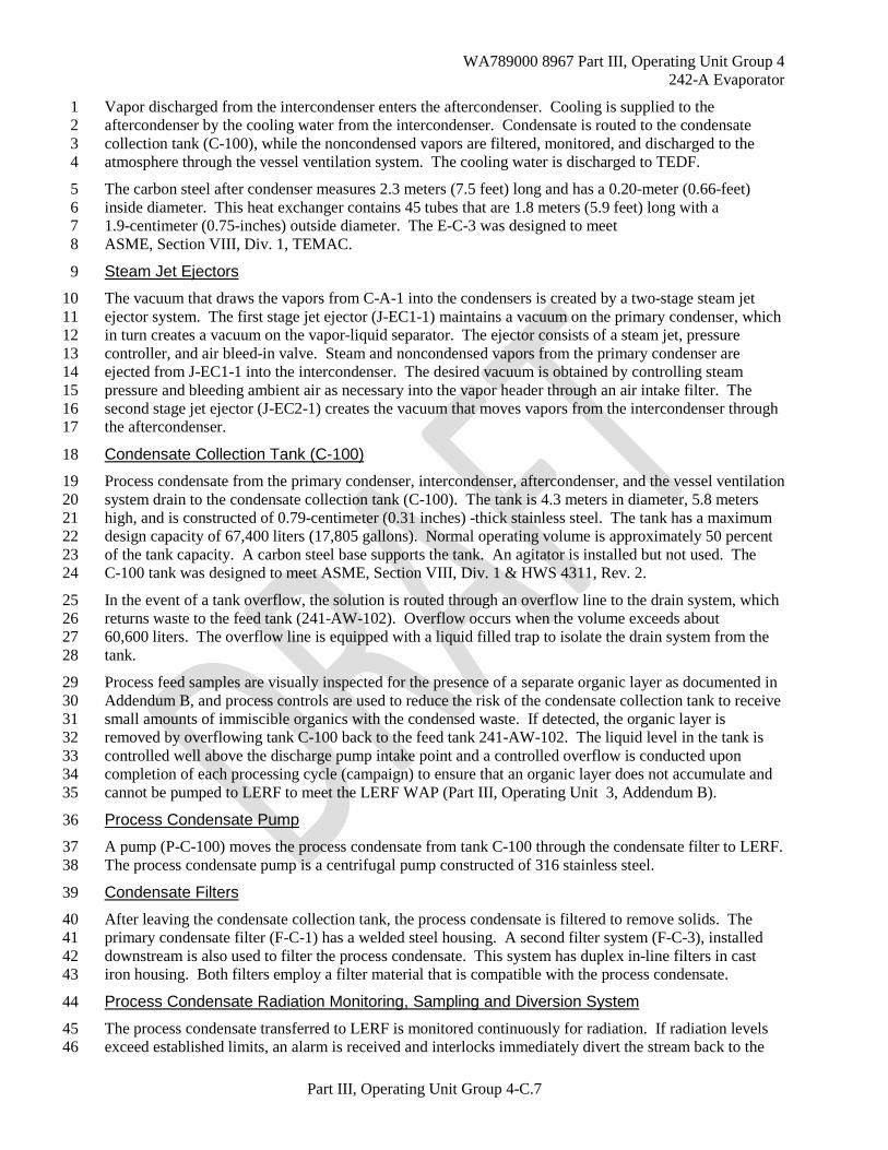
Vapor discharged from the intercondenser enters the aftercondenser. Cooling is supplied to the 1 aftercondenser by the cooling water from the intercondenser. Condensate is routed to the condensate 2 collection tank (C-100), while the noncondensed vapors are filtered, monitored, and discharged to the 3 atmosphere through the vessel ventilation system. The cooling water is discharged to TEDF. 4
The carbon steel after condenser measures 2.3 meters (7.5 feet) long and has a 0.20-meter (0.66-feet) 5 inside diameter. This heat exchanger contains 45 tubes that are 1.8 meters (5.9 feet) long with a 6 1.9-centimeter (0.75-inches) outside diameter. The E-C-3 was designed to meet 7 ASME, Section VIII, Div. 1, TEMAC. 8
Steam Jet Ejectors 9
The vacuum that draws the vapors from C-A-1 into the condensers is created by a two-stage steam jet 10 ejector system. The first stage jet ejector (J-EC1-1) maintains a vacuum on the primary condenser, which 11 in turn creates a vacuum on the vapor-liquid separator. The ejector consists of a steam jet, pressure 12 controller, and air bleed-in valve. Steam and noncondensed vapors from the primary condenser are 13 ejected from J-EC1-1 into the intercondenser. The desired vacuum is obtained by controlling steam 14 pressure and bleeding ambient air as necessary into the vapor header through an air intake filter. The 15 second stage jet ejector (J-EC2-1) creates the vacuum that moves vapors from the intercondenser through 16 the aftercondenser. 17
Condensate Collection Tank (C-100) 18
Process condensate from the primary condenser, intercondenser, aftercondenser, and the vessel ventilation 19 system drain to the condensate collection tank (C-100). The tank is 4.3 meters in diameter, 5.8 meters 20 high, and is constructed of 0.79-centimeter (0.31 inches) -thick stainless steel. The tank has a maximum 21 design capacity of 67,400 liters (17,805 gallons). Normal operating volume is approximately 50 percent 22 of the tank capacity. A carbon steel base supports the tank. An agitator is installed but not used. The 23 C-100 tank was designed to meet ASME, Section VIII, Div. 1 & HWS 4311, Rev. 2. 24
In the event of a tank overflow, the solution is routed through an overflow line to the drain system, which 25 returns waste to the feed tank (241-AW-102). Overflow occurs when the volume exceeds about 26 60,600 liters. The overflow line is equipped with a liquid filled trap to isolate the drain system from the 27 tank. 28
Process feed samples are visually inspected for the presence of a separate organic layer as documented in 29 Addendum B, and process controls are used to reduce the risk of the condensate collection tank to receive 30 small amounts of immiscible organics with the condensed waste. If detected, the organic layer is 31 removed by overflowing tank C-100 back to the feed tank 241-AW-102. The liquid level in the tank is 32 controlled well above the discharge pump intake point and a controlled overflow is conducted upon 33 completion of each processing cycle (campaign) to ensure that an organic layer does not accumulate and 34 cannot be pumped to LERF to meet the LERF WAP (Part III, Operating Unit 3, Addendum B). 35
Process Condensate Pump 36
A pump (P-C-100) moves the process condensate from tank C-100 through the condensate filter to LERF. 37 The process condensate pump is a centrifugal pump constructed of 316 stainless steel. 38
Condensate Filters 39
After leaving the condensate collection tank, the process condensate is filtered to remove solids. The 40 primary condensate filter (F-C-1) has a welded steel housing. A second filter system (F-C-3), installed 41 downstream is also used to filter the process condensate. This system has duplex in-line filters in cast 42 iron housing. Both filters employ a filter material that is compatible with the process condensate. 43
Process Condensate Radiation Monitoring, Sampling and Diversion System 44
The process condensate transferred to LERF is monitored continuously for radiation. If radiation levels 45 exceed established limits, an alarm is received and interlocks immediately divert the stream back to the 46
WA789000 8967 Part III, Operating Unit Group 4 242-A Evaporator
Part III, Operating Unit Group 4-C.8
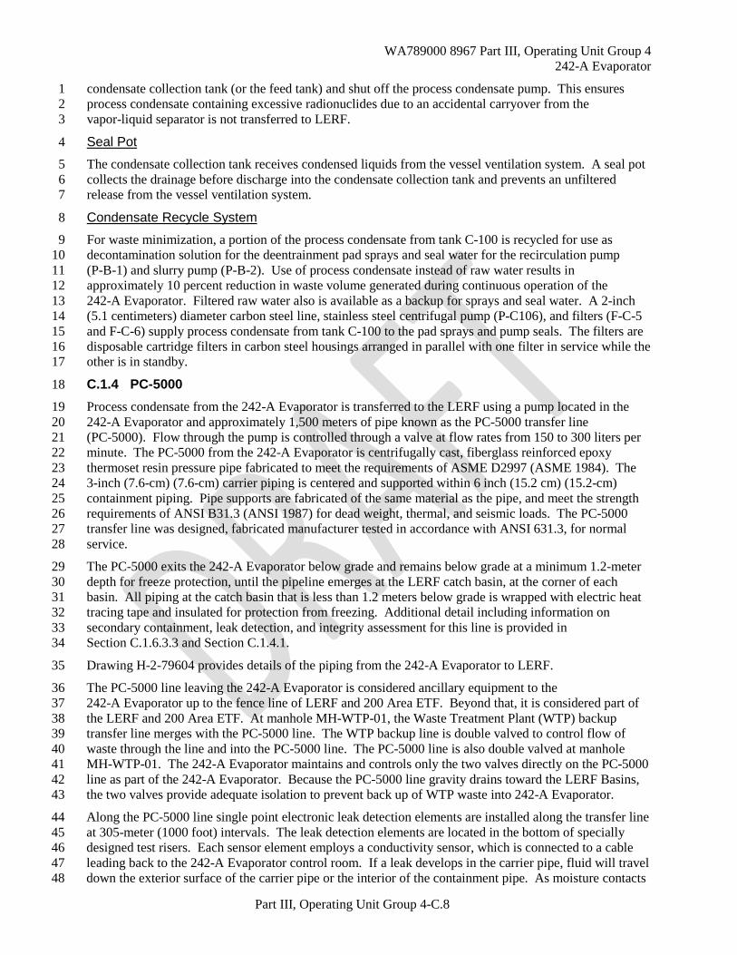
condensate collection tank (or the feed tank) and shut off the process condensate pump. This ensures 1 process condensate containing excessive radionuclides due to an accidental carryover from the 2 vapor-liquid separator is not transferred to LERF. 3
Seal Pot 4
The condensate collection tank receives condensed liquids from the vessel ventilation system. A seal pot 5 collects the drainage before discharge into the condensate collection tank and prevents an unfiltered 6 release from the vessel ventilation system. 7
Condensate Recycle System 8
For waste minimization, a portion of the process condensate from tank C-100 is recycled for use as 9 decontamination solution for the deentrainment pad sprays and seal water for the recirculation pump 10 (P-B-1) and slurry pump (P-B-2). Use of process condensate instead of raw water results in 11 approximately 10 percent reduction in waste volume generated during continuous operation of the 12 242-A Evaporator. Filtered raw water also is available as a backup for sprays and seal water. A 2-inch 13 (5.1 centimeters) diameter carbon steel line, stainless steel centrifugal pump (P-C106), and filters (F-C-5 14 and F-C-6) supply process condensate from tank C-100 to the pad sprays and pump seals. The filters are 15 disposable cartridge filters in carbon steel housings arranged in parallel with one filter in service while the 16 other is in standby. 17
C.1.4 PC-5000 18
Process condensate from the 242-A Evaporator is transferred to the LERF using a pump located in the 19 242-A Evaporator and approximately 1,500 meters of pipe known as the PC-5000 transfer line 20 (PC-5000). Flow through the pump is controlled through a valve at flow rates from 150 to 300 liters per 21 minute. The PC-5000 from the 242-A Evaporator is centrifugally cast, fiberglass reinforced epoxy 22 thermoset resin pressure pipe fabricated to meet the requirements of ASME D2997 (ASME 1984). The 23 3-inch (7.6-cm) (7.6-cm) carrier piping is centered and supported within 6 inch (15.2 cm) (15.2-cm) 24 containment piping. Pipe supports are fabricated of the same material as the pipe, and meet the strength 25 requirements of ANSI B31.3 (ANSI 1987) for dead weight, thermal, and seismic loads. The PC-5000 26 transfer line was designed, fabricated manufacturer tested in accordance with ANSI 631.3, for normal 27 service. 28
The PC-5000 exits the 242-A Evaporator below grade and remains below grade at a minimum 1.2-meter 29 depth for freeze protection, until the pipeline emerges at the LERF catch basin, at the corner of each 30 basin. All piping at the catch basin that is less than 1.2 meters below grade is wrapped with electric heat 31 tracing tape and insulated for protection from freezing. Additional detail including information on 32 secondary containment, leak detection, and integrity assessment for this line is provided in 33 Section C.1.6.3.3 and Section C.1.4.1. 34
Drawing H-2-79604 provides details of the piping from the 242-A Evaporator to LERF. 35
The PC-5000 line leaving the 242-A Evaporator is considered ancillary equipment to the 36 242-A Evaporator up to the fence line of LERF and 200 Area ETF. Beyond that, it is considered part of 37 the LERF and 200 Area ETF. At manhole MH-WTP-01, the Waste Treatment Plant (WTP) backup 38 transfer line merges with the PC-5000 line. The WTP backup line is double valved to control flow of 39 waste through the line and into the PC-5000 line. The PC-5000 line is also double valved at manhole 40 MH-WTP-01. The 242-A Evaporator maintains and controls only the two valves directly on the PC-5000 41 line as part of the 242-A Evaporator. Because the PC-5000 line gravity drains toward the LERF Basins, 42 the two valves provide adequate isolation to prevent back up of WTP waste into 242-A Evaporator. 43
Along the PC-5000 line single point electronic leak detection elements are installed along the transfer line 44 at 305-meter (1000 foot) intervals. The leak detection elements are located in the bottom of specially 45 designed test risers. Each sensor element employs a conductivity sensor, which is connected to a cable 46 leading back to the 242-A Evaporator control room. If a leak develops in the carrier pipe, fluid will travel 47 down the exterior surface of the carrier pipe or the interior of the containment pipe. As moisture contacts 48

WA789000 8967 Part III, Operating Unit Group 4 242-A Evaporator
Part III, Operating Unit Group 4-C.9
a sensor unit, a general alarm sounds in the 242-A Evaporator control room on the Monitoring Control 1 System. In addition, the zone of the sensor unit causing the general alarm can be determined using the 2 automated leak detection-monitoring panel. 3
The pump located in the 242-A Evaporator is shut down, stopping the flow of aqueous waste through the 4 transfer line. A low volume air purge of the annulus between the carrier pipe and the containment pipe is 5 provided to prevent condensation buildup and minimize false alarms by the leak detection elements. 6
If a leak is detected using visual inspection of the PC-5000 transfer line encasement at LERF Valve 7 HV-43-2, the shift manager is notified. The Shift Manger will direct shutdown of the aqueous waste 8 through the PC-5000 transfer line. 9
C.1.5 Secondary Containment and Release Detection for Tank Systems 10
This section describes the design and operation of secondary containment sumps, drain lines, and leak 11 detection systems for the 242-A Evaporator. 12
C.1.5.1 Requirements for All Tank Systems 13
The Construction Specification for 242-A Evaporator Crystallizer Facilities Project B-100 (Vitro 1974) 14 was used during preparation, design, and construction of the tank and secondary containment systems. 15 The unit was designed to standards for severe natural phenomenon’s including winds to 113 km/h 16 (70 mi/h) and a 0.25 g seismic event. As a result of design requirements for seismic loads and radiation 17 shielding, the process areas of the unit were designed to withstand winds in excess of 193 km/h 18 (120 mi/h). 19
Constructing the building and vessels per this specification ensures that foundations are capable of 20 supporting tank and secondary containment systems and that uneven settling and failures from pressure 21 gradients do not occur. The latest integrity assessment report states that the 242-A Evaporator has 22 adequate design, sufficient structural strength, and sufficient compatibility with the wastes to not collapse, 23 rupture, or fail during service loads associated with normal operations and that the building structure was 24 designed and constructed to withstand a design basis earthquake". 25
The integrity assessment report describes the building and secondary containment system. This system is 26 designed to ensure any release is detected within 24 hours. The secondary containment system also is 27 designed to contain 100 percent of the maximum operating capacity of the vapor-liquid separator/reboiler 28 loop, and the drain systems are sloped to allow collection of solution and have sufficient capacity to drain 29 this volume in less than the required 24 hours. 30
The integrity assessment report describes the protective coating material and sealant used to protect 31 concrete and joints from attack by leaks to the secondary containment. The materials of construction for 32 the sump and drain lines are also compatible with the waste processed at the 242-A Evaporator. 33
C.1.5.2 242-A Building Secondary Containment 34
The 242-A Building serves as a secondary containment vault for the vapor-liquid separator (C-A-1); 35 condensate collection tank (C-100), and ancillary equipment used for transferring mixed waste at the 36 242-A Evaporator. The concrete for the operating area was poured to form a monolithic structure. Where 37 needed, joints in the concrete were fabricated with preformed filler conforming to the standards of the 38 American Society of Testing and Materials. Joint filler is sealed with a polysulfide sealant per the 39 requirements of the construction specifications (Vitro 1974). 40
Before restart in 1994, a new acrylic special protective coating was applied to the concrete in the pump, 41 evaporator, and condenser rooms. The coating meets the requirements of the construction specifications 42 (Vitro 1974), including resistance to very high radiations doses, temperatures of 77o C (171ºF) and spills 43 of 25 percent caustic solution. 44
The following four rooms contain equipment used to process or store mixed waste: 45
• Pump room 46

WA789000 8967 Part III, Operating Unit Group 4 242-A Evaporator
Part III, Operating Unit Group 4-C.10
• Evaporator room 1 • Condenser room 2 • Ion exchange room 3
C.1.5.2.1 Pump Room 4
The pump room contains pipe jumpers that support the transport of feed and slurry solutions between the 5 vapor-liquid separator and the DST System, and the process recirculation loop, recirculation pump 6 (P-B-1), and slurry pump (P-B-2). 7
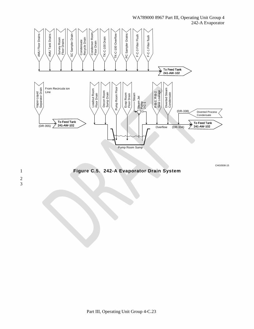
The pump room secondary containment walls are 0.38 to 0.56-meter (1.25 to 1.84-feet) thick reinforced 8 concrete. The secondary containment floor is 0.51-meter (1.67-feet) thick reinforced concrete. The pump 9 room floor is lined with 0.64-centimeter (0.25-inch) stainless steel. Above this level, the concrete walls 10 and ceiling cover blocks are painted with a special protective coating. While this protective coating is not 11 a necessary component of secondary component, it is noted here since this coating will help ensure that 12 any spills or releases that contact concrete outside of secondary containment can be easily decontaminated 13 as necessary to meet closure performance standards at the time of closure. Leaks in the pump room 14 collect in the pump room sump, a 1.5-meter (4.9-feet) by 1.5-meter (4.9-feet) by 1.8-meter (5.9 feet) deep 15 sump with a 0.64-centimeter (0.25-inch) stainless steel liner. The pump room sump as part of the 16 secondary containment collects spills from various sources for transfer to the feed tank, 241-AW-102. 17 Figure C.6 provides a simplified process flow schematic of sources, which drain to the pump room sump. 18 Drainage to the sump includes: 19
• Leaks to the pump room floor from equipment in the pump room 20 • Evaporator room floor drain 21 • Hot equipment storage room floor drain 22 • Loadout room floor drain 23 • Raw water backflow preventer drain 24
Solution in the pump room sump is transferred to the feed tank (241-AW-102) using a steam jet. 25 A 10-inch (25.4-cm) secondary containment overflow line is provided for draining large volumes of 26 solution should a catastrophic failure occur. Because the overflow line provides a direct path between the 27 air space of tank 241-AW-102 and the pump room, a minimum level of water must be maintained in the 28 sump to prevent cross ventilation. Leaks in the pump room are detected by the following: 29
• A rise in the sump level resulting in instrumentation alarms on high sump level. 30 • Daily visual inspections of the ancillary equipment and floor in the pump room. 31
The recirculation and slurry pumps in the pump room are equipped with mechanical seals having 32 pressurized water introduced between the seals. The seal water is maintained at a pressure that exceeds 33 the process pressure at the seal to ensure water leaks into the process solution, but waste solution does not 34 leak out. Water from seal leakage is collected in funnels in the pump room and routed to feed 35 tank 241-AW-102 via the 10-inch (25.4-cm) overflow line described previously. 36
C.1.5.2.2 Evaporator Room 37
The evaporator room contains the vapor-liquid separator vessel (C-A-1), part of the recirculation loop, the 38 reboiler, the 42-inch vapor line, and the line used to empty the vapor-liquid separator to feed tank 39 241-AW-102. 40
The evaporator room secondary containment walls are 0.56-meter (1.8 feet) -thick reinforced concrete. 41 The secondary containment floor is 0.51-meter (1.7 feet) -thick reinforced concrete. Leaks in the 42 evaporator room flow to a floor drain that routes through a 3-inch (7.6-cm) line to the pump room sump 43 described in Section C.1.6.2.1. A leak in the evaporator room would be detected by a rise in the pump 44 room sump level. The floor of the evaporator room and a portion of the pump room floor are 3.0 meters 45 (9.8 feet) below grade to contain the entire contents of the vapor-liquid separator, reboiler, and 46
WA789000 8967 Part III, Operating Unit Group 4 242-A Evaporator
Part III, Operating Unit Group 4-C.11
recirculation loop in the event of a catastrophic failure. The floor and walls of the evaporator room up to 1 an elevation of 1.8 meters (5.9 feet) are painted with a special protective coating. 2
C.1.5.2.3 Condenser Room 3
The condenser room contains all the components of the process condensate system described in 4 Section C.1.3.1 (Figure C.4), including Tank C-100. 5
The condenser room secondary containment walls are 0.36- to 0.56-meter (1.25 to 1.84-feet) thick 6 reinforced concrete. The secondary containment floor is 0.51-meter (1.67 feet) thick reinforced concrete. 7 Leaks in the condenser room flow to two floor drains that join and route through a 6-inch (15.2-cm) line 8 to feed tank 241-AW-102. Leaks in the condenser room are detected by the following: 9
• Unexpected changes in liquid level in tank C-100. Instrumentation is provided to monitor liquid 10 level in the tank, including high- and low-level alarms. 11
• Daily visual inspections of process condensate system components and piping 12 The floor and walls of the condenser room up to an elevation of 1.2 meters (3.94 feet) are painted with a 13 special protective coating. 14
C.1.5.2.4 Ion Exchange Room 15
The Ion Exchange room is a small room connected to the Condenser room. This room previously 16 contained an ion exchange column that has since been removed from the processing unit. The room 17 contains a single pipeline used to transfer process condensate during a campaign when the process 18 condensate is used as part of the cooling system during recirculation. During non-campaign periods, this 19 transfer line is drained. The pipeline has contains no valves, or other components that could release waste 20 into the ion exchange room other than a rupture of the line. The floor and walls of the ion exchange room 21 up to the ceiling are painted with a special protective coating. 22
Leaks in the ion exchange room are detected by daily visual inspection during the campaign. No 23 inspections are required when process condensate is not present in the transfer line or during 24 non-campaign periods. 25
C.1.5.2.5 Load out and Hot Equipment Storage Rooms 26
The load out and hot equipment rooms are not used to treat, store, or dispose of mixed or dangerous 27 waste. The load out room and hot equipment storage room are used to store contaminated reusable 28 equipment. The hot equipment room contains two recirculation lines and samplers, which may be used 29 to sample the feed and slurry streams. The lines and samplers are located in a shielded enclosure adjacent 30 to the pump room wall. The load out room provides space for passage of equipment and containerized 31 waste from the 242-A Evaporator process area outside of the unit. 32
The load out and hot equipment storage room contains two sumps: the drain sump and decontamination 33 sump. The sumps are 0.91 meter in diameter, about 1.2 meters deep, and lined with stainless steel. Both 34 sumps drain via a 3-inch (7.6-cm) drain line to the pump room sump described in Section C.1.6.2.1. 35
Leaks in the sampler piping flow into two drains in the sample enclosure, which drain via a 2-inch line to 36 the decontamination sump, which drains to the pump room sump (Section C.1.6.2.1). Leak detectors in 37 the sampler enclosures or a rise in the pump room sump level detects leaks in the sampler piping. 38
C.1.5.2.6 242-A Building Drain Lines 39
Figure C.6 provides a simplified process flow schematic of sources routed to the 242-A Building drain 40 lines. These lines are considered ancillary equipment to the evaporator up until they exit the 41 242-A Building. At this point, the lines are considered ancillary equipment to the DST system 42 components. Four lines serve to drain the 242-A Building and equipment to feed tank 241-AW-102: 43

WA789000 8967 Part III, Operating Unit Group 4 242-A Evaporator
Part III, Operating Unit Group 4-C.12
Pump room sump drain line (DR-334): a 10 inch (25.4 cm) carbon steel line that transfers 1 process condensate overflow/diverted liquids and empty out of the pump room sump to the feed 2 tank 3
Vapor-liquid separator vessel drain line (DR-335): a 10 inch (25.4 cm) carbon steel line that 4 allows gravity drain of the vessel to the feed tank (Section C.1.6) 5
Condenser room drain line (DR-343): a 6-inch (15.2-cm) carbon steel line that drains potential 6 leakage from the condenser room. 7
Diverted process condensate drain line (DR-338): process condensate liquid drains through 8 DR-338 into sump drain line (DR-334) which drains to 241-AW-102. 9
The four lines are sloped to drain about 170 meters (558 feet) to feed tank 241-AW-102 via the drain pit 10 (241-AW-02D). Although WAC 173-303-640(1)(c) exempts systems that serve as secondary 11 containment from requiring secondary containment, drain lines DR-334, DR-335, and DR-338 have outer 12 encasement piping. 13
External to the Evaporator Unit, the drain lines are connected to a cathodic protection system to prevent 14 external corrosion from contact with the soil. The cathodic protection system consists of: 15
• A rectifier that converts supplied alternating current voltage to an adjustable direct current 16 voltage 17
• Numerous anodes buried near the underground piping and connected to the rectifier. 18 • Return wiring that connects the piping to the rectifier, completing the circuit. 19
The rectifiers are inspected to ensure component degradation has not occurred. Test stations along the 20 system are checked annually to verify 0.85 volt is maintained on the system, as required by the National 21 Association of Corrosion Engineers. 22
Further detail regarding design and construction of DR-334, -335, -338 and -343 is provided in 23 DOE/RL-90-39, the Double-Shell Tank System Part B permit application. Further detail regarding the 24 design, operation, maintenance, and inspection of the cathodic protect system for these lines is also 25 provided in DOE/RL-90-39. Piping, once it leaves the 242-A Evaporator is part of the DST System. 26
C.1.5.3 Transfer Line Containment 27
This section describes the design and operation of secondary containment and leak detection systems for 28 transfer lines between the DST System and the 242-A Evaporator, and from 242-A Evaporator to LERF 29 (one line only, PC-5000). In the case of the DST transfer lines, this information is provided for 30 completeness. The 242-A Evaporator TSD boundary for lines running between 242-A Evaporator and the 31 DST System ends at exterior wall of 242-A Building. At this point, these lines (e.g., feed and slurry line 32 piping) are DST System components. For further detail regarding SN-269, SN-270, SL-167, and SL-168 33 refer to DOE/RL-90-39. 34
The PC-5000 transfer line transfers process condensate (Section C.1.4) from the 242-A Building to 35 LERF. The 242-A Evaporator TSD unit boundary includes PC-5000 up to the LERF and 200 Area ETF 36 fence line (Addendum A, Part A Form topographic map, and Section C.1.4, for the TSD unit boundary) 37
C.1.5.3.1 Feed Line Piping 38
Two feed lines (SN-269 and SN-270) (one in service and one spare), each consist of 3-inch (7.6-cm) 39 transfer piping within a 6 inch (15.2 cm) secondary containment encasement piping. Both the transfer 40 and encasement pipes are constructed of Schedule 40 carbon steel. The lines run below grade about 41 120 meters (394 feet) from pump pit 241-AW-02E (above feed tank 241-AW-102) to the 242-A Building. 42
To detect transfer-piping failures, leak detector risers equipped with conductivity probes are installed on 43 the encasement lines. The transfer piping and encasements are sloped towards the conductivity probe, 44 which, on leak detection, annunciates an alarm in the 242-A Evaporator control room. A valve in the 45

WA789000 8967 Part III, Operating Unit Group 4 242-A Evaporator
Part III, Operating Unit Group 4-C.13
pump pit (241-AW-02E) can be opened to drain solution from the encasement pipe into the pit, which 1 drains to feed tank 241-AW-102. 2
C.1.5.3.2 Slurry Line Piping 3
The slurry pump (P-B-2) transfers solution through one of two transfer lines: SL-167, for transfer to 4 valve pit 241-AW-B (standard configuration), or SL-168 for transfer to valve pit 241-AW-A (alternate 5 configuration). The SL-168 transfer line is currently considered non-compliant and will not be used to 6 manage dangerous/mixed wastes. A process blank is installed at the 242-A Evaporator end of the line. 7 Slurry solution can be routed via double encased piping from these valve pits to any designated DST 8 slurry receiver. Both slurry transfer lines consist of 2-inch (5 cm) transfer piping within a 4-inch (10-cm) 9 secondary containment encasement piping. Both the transfer and encasement pipes are constructed of 10 Schedule 40 carbon steel. The lines run below grade about 73 meters (240 feet) between the 11 242-A Building and the valve pits. 12
These slurry lines contain leak detector risers and conductivity probes similar to the feed line piping 13 described in Section C.1.6.3.1. 14
C.1.5.4 Additional Requirements for Specific Types of Systems 15
Addressed in this section are additional requirements in WAC 173-303-640 for vault systems like the 16 242-A Building to prevent buildup of ignitable vapors and precipitation intrusion. This section also 17 addresses secondary containment for ancillary equipment and piping associated with the tank systems. 18
C.1.5.4.1 Vault Systems 19
The 242-A Building is a vault constructed partially below ground, providing secondary containment for 20 the tank systems. The DST System waste processed at the 242-A Evaporator is designated ignitable and 21 reactive because of the presence of nitrite and nitrate salts, which are considered oxidizers per 22 49 CFR 173. Because of their low volatility, these compounds are unlikely to be present in the vapor 23 phase of the tank systems at the 242-A Evaporator. However, to prevent the spread of contamination, the 24 vapor-liquid separator (C-A-1) is ventilated and maintained at lower air pressure than the building air 25 space. This ensures air leakage is from uncontaminated building air space into the tank vapor space. 26 Vapors from the vapor-liquid separator flow to the vacuum condenser system described in Section C.0. 27
The condensate collection tank (C-100), collects process condensate that is not designated ignitable or 28 reactive. 29
The tank systems and ancillary equipment are located within the 242-A Building, which is completely 30 enclosed to prevent run-on and infiltration of precipitation into the secondary containment system. 31
C.1.5.4.2 Ancillary Equipment 32
The 242-A Building provides secondary containment for ancillary equipment. Double containment is 33 provided for the feed and slurry transfer lines between the 242-A Building and the AW Tank Farm by 34 pipe-in-pipe arrangements. Therefore, all ancillary equipment has secondary containment and the daily 35 inspection requirements in WAC 173-303-640(4)(f) are not applicable. 36
C.1.6 Variances from Secondary Containment Requirements 37
The IAR discusses the following three deficiencies associated with the secondary containment system: 38
WA789000 8967 Part III, Operating Unit Group 4 242-A Evaporator
Part III, Operating Unit Group 4-C.14
C.1.6.1 Pump Room Sump 1
The pump room sump is considered part of the 242-A Evaporator secondary containment. An adequate 2 volume of liquid in the sump must be maintained to provide a seal to prevent airflow between the pump 3 room and feed tank 241-AW-102. The sump has a 0.63-centimeter (0.25-inch) -thick stainless steel liner 4 to prevent corrosion of the concrete floor. 5
C.1.6.2 Routine Discharges through Secondary Containment 6
The configuration of the 242-A Evaporator process requires routine, batch discharges of dangerous waste 7 through drain lines. These routine discharges include the following. 8
• Steam condensate, cooling water, and process condensate sample stations drain to the feed tank, 9 241-AW-102, through drain line DR-343. Total discharge is about 38 liters (10 gallons) per 10 month during operation. 11
• Sample bottle water spray down in the feed and slurry sample stations drain to the 12 decontamination sump in the load out and hot equipment storage room. The decontamination 13 sump then drains to the pump room sump. Total discharge is about 76 liters per month during 14 operation. 15
C.1.6.3 Transfer Piping Wall Penetrations 16
Three piping sections passing through the 22 in (56 cm) the 242-A Building outer wall are single walled, 17 i.e., no secondary confinement in the wall . These lines include SL-167, SN-269, and DR-335. SL-167 18 and SN-269 are 2 in (5 cm) and 3 in (8 cm) dangerous waste transfer lines respectively. DR-335 is a 19 bottom dump 6 in. (15 cm) drain line 20
These deficiencies were identified prior to restart of the 242-A Evaporator in 1993. As a condition of 21 restart Ecology, November 16, 1993 stated, No physical revision of the pipe wall penetrations or the floor 22 drains in the evaporator pump room will be required prior to evaporator restart. Further Ecology 23 required the following. 24
• If at any time leakage is seen or detected from these installations, or if for any reason these 25 installations are repaired or rebuilt, they will be rebuilt or repaired in accordance with regulations. 26
• Should a spill occur in the evaporator pump room the sump and the piping shall be rinsed three 27 times as required in WAC 173-303-160. 'Appropriate' in this case means that the original 28 regulation was written for a free container, not a sump, so that judgment will have to be used in 29 the application of the regulation. The rinsate shall be transferred to the DST System. 30
C.1.7 Integrity Assessments 31
The integrity assessment report (RPP-RPT-33306) discusses: 32
The standards used during design and construction of the 242-A Evaporator and the adequacy of 33 those standards 34
The characteristics of the DST waste processed 35 The adequacy of the materials of construction to provide corrosion protection from the waste 36
processed 37 The age of the tanks and the affect of age on tank integrity 38 The results of the leak tests, visual inspections, and tank wall thickness inspections 39 The frequency and scope of future integrity assessment 40 Deficiencies in secondary containment design. These deficiencies are discussed in the integrity 41
assessment report. 42 An independent, qualified, registered professional engineer certified the integrity assessment. 43
The inspections, tests, and analyses performed provide assurance that the 242-A Evaporator tank system 44 has adequate design, sufficient structural strength, and sufficient compatibility with the waste to not 45
WA789000 8967 Part III, Operating Unit Group 4 242-A Evaporator
Part III, Operating Unit Group 4-C.15
collapse, rupture, or fail during operation. No evidence of degradation was noted during the visual test, 1 ultrasonic test, or leak test. Both condensate collection tank C-100 and the vapor-liquid separator/reboiler 2 loop passed leak tests. The frequency of subsequent integrity assessments has been established at every 3 10 years. This frequency is based on the results of the 1998 integrity assessment and was confirmed in 4 2008. 5
An integrity assessment for PC-5000 was performed, including a hydrostatic leak/pressure test at 10.5 6 kilograms per square centimeter gauge (150 pounds per square inch). A statement by an independent, 7 qualified, registered professional engineer attesting to the integrity of the piping system is included in 8 Integrity Assessment Report for the 242-A Evaporator/LERF Waste Transfer Piping, Project W105 9 (WHC 1993), along with the results of the leak/pressure test. The next integrity assessment for PC-5000 10 will be completed in calendar year 2008. 11
The schedule for conducting integrity assessments for the 242-A Evaporator will be at a frequency of 12 every 10 (calendar) years as recommended by the 1998 IQRPE, or as required for system repairs 13 (WAC 173-303-640(7)(f) and upgrades (WAC 173-303-640(2)(a). All integrity assessments will be 14 conducted in accordance with WAC 173-303-640. Preventive and corrective maintenance including 15 some replacement in kind activities or work that does not change the form, fit or function of existing 16 equipment do not require an IQRPE review under either WAC 173-303-640(7)(f) or 17 WAC 173-303-640(2)(a). 18
C.1.8 Additional Requirements for Existing Tanks 19
Refer to information in Section C.1.2 and the integrity assessment report, which includes measuring tank 20 wall thicknesses, evaluating corrosion protection, and performing leak tests. 21
C.1.9 Tank Management Practices 22
All waste to be processed at the 242-A Evaporator must be sampled to determine if the waste is 23 compatible with the materials of construction at the 242-A Evaporator. Before each campaign, candidate 24 feed tanks are sampled per the requirements of the waste analysis plan (Addendum B). Based on the 25 results, three possible options are implemented. 26
The waste is acceptable for processing without further actions. 27 The waste is unacceptable for processing as a single batch, but is acceptable if blended with other 28
waste that is going to be processed. 29 The waste is unacceptable for processing. 30
The 242-A Evaporator process is controlled by trained operators utilizing the MCS. The MCS computer 31 monitors liquid levels in the vapor-liquid separator (C-A-1) and condensate collection tank (C-100). The 32 MCS system manages liquid levels in the C-A-1 using an auto cascade function that controls feed 33 delivery to the C-A-1 vessel. The MCS system also manages liquid levels in the C-100 using an auto 34 cascade function to maintain the tank level at approximately 50-percent. The MCS has alarms that 35 annunciate on high liquid levels for both C-A-1 and C-100 to notify operators that actions must be taken 36 to prevent overfilling of these vessels. 37
An interlock is activated when high liquid level in the vapor-liquid separator (C-A-1) is detected, 38 automatically shutting down the feed transfer pump at feed tank 241-AW-102, thereby preventing 39 overfilling of the vessel and carryover of slurry into the process condensate system. The condensate 40 collection tank (C-100) has an overflow line that routes solution to feed tank 241-AW-102 in case of 41 overfilling. 42
Process and instrumentation drawings are listed in Section C.3.The MCS also provides an automated 43 interlock to shutdown the process condensate pump (P-C-100) and slurry pump (P-B-2) if a leak is 44 detected. The process condensate pump (P-C-100), recirculation pump (P-B-1) and slurry pump (P-B-2), 45 can be shutdown automatically using the MCS interlock and/or manually at the direction of the Shift 46 Manager or 242-A Evaporator Control Room Operator if a leak occurs. 47
WA789000 8967 Part III, Operating Unit Group 4 242-A Evaporator
Part III, Operating Unit Group 4-C.16
C.1.10 Labels or Signs 1
A labeling upgrade was completed before restart in 1994 for tank C-100 to identify the waste contents and 2 major risks associated with waste stored within the tank. Tank C-100 ancillary piping is labeled 3 "PROCESS CONDENSATE" to alert trained personnel which pipes in the condenser room contain 4 dangerous waste. The vapor-liquid separator (C-A-1) is located in the evaporator room, a normally 5 unoccupied area. This area is posted as a high radiation area with ALARA access controlled and limited 6 to trained personnel only. The tank labels are visible from the walls of the tank enclosure rooms, which 7 are less than 15 meters from the tank systems; therefore, label visibility requirements are met. 8
C.1.11 Air Emissions 9
Tank systems that contain extremely hazardous waste that is acutely toxic by inhalation must be designed 10 to prevent the escape of such vapors. The DST System waste in the vapor-liquid separator, C-A-1, is 11 designated extremely hazardous waste; however, no determination has been performed to determine if the 12 waste is acutely or chronically toxic. Most of the toxic compounds in the DST waste are not volatile, but 13 because of the high radioactivity of the waste, controls are included to prevent or mitigate the release of 14 tank vapors. The vapor-liquid separator is maintained under vacuum to ensure air leakage is from 15 uncontaminated building air space into the tank vapor space. The vapor from C-A-1 passes through 16 deentrainment pads and sprays to prevent liquid and solid carryover into the vapor section of the tank. 17 The vapor stream passes through three condensers that remove the condensable components. The 18 non-condensable vapors pass through HEPA filters before being discharged to the environment. 19
C.1.12 Management of Ignitable or Reactive Wastes in Tank Systems 20
Although the DST System waste reprocessed at the 242-A Evaporator is designated ignitable because of 21 the presence of oxidizers (nitrates and nitrites), the waste does not meet the definition of a combustible or 22 flammable liquid given in National Fire Protection Association (NFPA) code number 30 (NFPA 1996). 23 The buffer zone requirements in NFPA-30, which require tanks containing combustible or flammable 24 solutions be a safe distance from each other and from public way, are not applicable. 25
An analysis is performed on the DST System waste to be processed to verify the waste does not react 26 exothermically at the elevated temperatures at the 242-A Evaporator. The waste analysis plan 27 (Addendum B) discusses waste acceptance requirements due to reactive waste designation. 28
C.1.13 Management of Incompatible Wastes in Tank Systems 29
Waste transferred to the 242-A Evaporator must be compatible before mixing. Since each campaign 30 typically processes a single batch of waste, and the 242-A Evaporator is normally empty of waste 31 between processing campaigns, there are seldom any practical instances where waste is transferred to the 32 242-A Evaporator such that it contacts waste other than from the same batch. Never the less, the waste 33 acceptance process and criteria in Addendum B specifically addresses this contingency in the 34 circumstance of "back to back" evaporator campaigns. 35
C.2 Air Emissions Control 36
Requirements of Air Emission Standards for Process Vents, under Subpart AA (incorporated by reference 37 in WAC 173-303-690) requires air emission controls on certain process vents associated with 38 distillation, fractionation, thin film evaporation, solvent extraction, or air or steam stripping units. Since 39 the 242-A Evaporator is not one of these defined types of units, it is not subject to the requirements of 40 WAC 173-303-690. 41
C.3 Engineering Drawings 42
Drawings listed in the tables below are categorized as essential or support drawings, and may reference 43 other drawings not listed in the table. Drawings not listed are considered references and not part of this 44 application. Essential drawings depict active unit (e.g., nuclear and chemical storage facilities) systems, 45 structures, and components (SSCs) and are necessary to support emergency response actions. Support 46 drawings provide engineering, maintenance, and operations the details necessary for plant operations. 47
WA789000 8967 Part III, Operating Unit Group 4 242-A Evaporator
Part III, Operating Unit Group 4-C.17
Essential and support drawings are revised using an engineering change notice (ECN) process. 1 Timeliness of revision of drawings is based on drawing categorization. 2
Upon completion of a construction projects, as built drawings of the project, which incorporate the design 3 and construction modifications resulting from all project design change documentation and 4 nonconformance documentation, as well as modifications, made pursuant to WAC 173-303-830. 5 Drawings will be placed into the Hanford Facility Operating Record, 242-A Evaporator file within twelve 6 (12) months of completing construction, or will be submitted annually to Ecology, for current revisions. 7
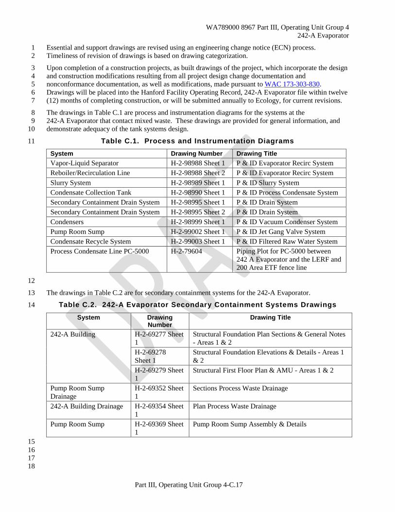
The drawings in Table C.1 are process and instrumentation diagrams for the systems at the 8 242-A Evaporator that contact mixed waste. These drawings are provided for general information, and 9 demonstrate adequacy of the tank systems design. 10
Table C.1. Process and Instrumentation Diagrams 11
System Drawing Number Drawing Title Vapor-Liquid Separator H-2-98988 Sheet 1 P & ID Evaporator Recirc System Reboiler/Recirculation Line H-2-98988 Sheet 2 P & ID Evaporator Recirc System Slurry System H-2-98989 Sheet 1 P & ID Slurry System Condensate Collection Tank H-2-98990 Sheet 1 P & ID Process Condensate System Secondary Containment Drain System H-2-98995 Sheet 1 P & ID Drain System Secondary Containment Drain System H-2-98995 Sheet 2 P & ID Drain System Condensers H-2-98999 Sheet 1 P & ID Vacuum Condenser System Pump Room Sump H-2-99002 Sheet 1 P & ID Jet Gang Valve System Condensate Recycle System H-2-99003 Sheet 1 P & ID Filtered Raw Water System Process Condensate Line PC-5000 H-2-79604 Piping Plot for PC-5000 between
242 A Evaporator and the LERF and 200 Area ETF fence line
12
The drawings in Table C.2 are for secondary containment systems for the 242-A Evaporator. 13
Table C.2. 242-A Evaporator Secondary Containment Systems Drawings 14
System Drawing Number
Drawing Title
242-A Building H-2-69277 Sheet 1
Structural Foundation Plan Sections & General Notes - Areas 1 & 2
H-2-69278 Sheet 1
Structural Foundation Elevations & Details - Areas 1 & 2
H-2-69279 Sheet 1
Structural First Floor Plan & AMU - Areas 1 & 2
Pump Room Sump Drainage
H-2-69352 Sheet 1
Sections Process Waste Drainage
242-A Building Drainage H-2-69354 Sheet 1
Plan Process Waste Drainage
Pump Room Sump H-2-69369 Sheet 1
Pump Room Sump Assembly & Details
15 16 17 18
W
A789000 8967 Part III, O
perating Unit G
roup 4 242-A
Evaporator
Part III, Operating U
nit Group 4-C
.18
Figure C
.1. 242-A E
vaporator Sim
plified Process Flow
Diagram
1
2
Pioina Abbreviations
AF Anti·FO!Ill PS Process Sewer AS Air Sample PW Process Waste DEC ON Decontamination RW Raw Water OR Drain sc Steam Condensate EF Evaporator Feed SL Slurry EL Eluant STM Steam FRW Filtered Raw Water sw Sanitary Water I Instrument u Utility lA Instrument Air URW Used Raw Water OVFL Overflow v Vent PA Process AIr V/IC Vacuum PC Process Condensate vv Vessel Vent
~Stream Number Used In Rowsheet Calculation
D-Process Sample
Steam 90pslg
""·~~· ·11 I ... ' ,
15 11
11 &.iii:::
LOW·
Pressure Steam
SAMP·F·1
, Emergency --- --- Slurry Dropout
TK·102·AW
Steam 90pslg
Raw Wtl.er
Prefilter /Oernister
Oeentrainment Pad ........... OU·C·1 ........_
4
t§l •
Used Raw Water to 200 Area TEOF
Agitator A·C.l.OO
F·r
Organic to Tank
Condensate Collection Tank TK-C·100
High-Efficiency Fillers F-C·S
Electric Heater H·C·1
Pump P·C·100
Air Inlet Filter F·C-7
"
Exhauster EX-C·1
PC
" --Wall
Treated Process
01 verted Process Condensate to 1 02-AW or TK·C·1 00
G03090007 ·3

W
A789000 8967 Part III, O
perating Unit G
roup 4 242-A
Evaporator
Part III, Operating U
nit Group 4-C
.19
Figure C.2. 242-A
Evaporator P
rocess Loop
1
AF AS
PC I Process Condensate CF! I Condensate Recvcle
From Condensate ecycle or Filtered
Raw Water System
Process Sewer Process Wasta
Water
Water
From Steam System
Feed Sampler
A lia:l Samp-F-1
<UE -<U
~~ E-o o<U ,_<1) 1.1..1.1..
Sample Bottle
CR
~ Reboiler E-A-1
42-in Vapor Line To Vacuum
.---------~Condenser System
Deentrainment Pads
AF From Antifoam System
SC ~oSteam 1 .. a )lc: ,..1 > I ondensate Syste
Recirculation Loop
( SL ~ To Slurry System > I; .,--- Recirculation
Line
EF Evaporator
Recircu I a lion Pump P-8-1
Dumpline ) > : ............ ~~.!~:J.~?;.~~ ...... = To DralnSystem ·
Pump Seal /II DR ~Seal Leakage Water to Drain System
CR Condensate Recycle or Filtered Raw Water
2 G96080167.3

WA789000 8967 Part III, Operating Unit Group 4 242-A Evaporator
Part III, Operating Unit Group 4-C.20
1
2
Figure C.2. 242-A Evaporator Slurry System 3
4 5
W
A789000 8967 Part III, O
perating Unit G
roup 4 242-A
Evaporator
Part III, Operating U
nit Group 4-C
.21
Figure C.3. 242-A
Evaporator P
rocess Condensate S
ystem
1
2 3
From Vacuum ~ PC Condenser System
From After Condenser E-C-3
From Vacuum Condenser System
From Inter Condenser E-C-2
From Vacuum Condenser System
From Primary Condenser E-C-1
Agitator A-C-100
Pump P-C-106
C R
PC
Condensate Collection Tank TK-C- 100
Pump P-C-100
PC 1 Condensate 1 ._ Filter
F-C-1
:_ _----~b~ain System)
1 --~ Condensate Recycle
Piping Abbreviations
AF Anti-Foam Instrument PW Process waste ~w Coo/inn water
AS AirSamcle lA Instrument Air RW AawV\Iater v Vent
DECO Decontamination OVF Over11ow sc Steam Condensate VAC Vacuum DR Drain PA Process Air SL Slurry vv Vessel Vent
EF Evaporator Feed PC Process Condensate STM Steam EL Eluant I CR Cordensate Recycle sw Sanitarv water FRW Filtered Raw Water P'< Process Sewer u Utititv
LEAF Liquid Eflluent Retention Facility.
PC
PC
T Diverted Process
Treated Process Condensate to s L~RF
Condensate to 102-AW orTK-C-100
M0312-2.1 12-9-03

W
A789000 8967 Part III, O
perating Unit G
roup 4 242-A
Evaporator
Part III, Operating U
nit Group 4-C
.22
Figure C.4. 242 -A
Evaporator V
acuum C
ondenser System
1 2
Condensate Recvcle
From Raw Water System
Process Sewer
Wat11r
WatCir
Vacuum Vessel Vent
RW
From \ STM • • Steam System 1 1
Air In-bleed~
Vapor from Separator. C-A-1 42-in. Vapor
· Une
Primary Condenser
E-C-1
Jet Ejector J-EC1•1
PC
E-C-3
cw
cw
-1:
~ Q) en en
~~
PC
I ·1 To Cooling
1 1 ~ ! Water System
~ Process Condensate ToTankC-100
2G96080167.6
WA789000 8967 Part III, Operating Unit Group 4 242-A Evaporator
Part III, Operating Unit Group 4-C.23
Figure C.5. 242-A Evaporator Drain System 1
2 3
AMU
Flo
or D
rain
s
AMU
Tan
k D
rain
s
Surv
ey R
oom
Floo
r Dra
ins
SC S
ampl
er D
rain
Con
dens
ate
Rec
ycle
Dra
in
Con
dens
er R
oom
Floo
r Dra
in
TK-C
-100
Dra
in
TK-C
-100
Ove
rflow
PC S
ampl
er D
rain
s
F-C
-3 F
ilter
Flu
sh
F-C
-1 F
ilter
flus
h
To Feed Tank241-AW-102To Feed Tank241-AW-102
Vapo
r-Li
quid
Sepa
rato
r Dra
in
To Feed Tank241-AW-102To Feed Tank241-AW-102
Load
outR
oom
Floo
r Dra
in
Dec
onR
oom
Sum
p D
rain
Pum
p R
oom
Flo
or
Evap
Roo
mFl
oor D
rain
P-B-
1, P
-B-2
Seal
Lea
kage
Div
erte
d St
eam
Con
dens
ate
Diverted ProcessCondensate
To Feed Tank241-AW-102To Feed Tank241-AW-102
From Recircula ionLine
(DR-355) Overflow (DR-334)
Pump Room Sump
Stea
m J
etPu
mp
J-C
-1
Stea
m
CHG0508-15
(DR-338)

WA789000 8967 Part III, Operating Unit Group 4 242-A Evaporator
Part III, Operating Unit Group 4-C.24
1 2 3
This page intentionally left blank. 4