Embed Size (px)
Citation preview

/w/)7NzyP’”)ii’jyj“............>.>.:,..........,
58701-30-105
Grazing Incidence Neutron Diffraction from Large Scale 2D Structures
B.P. Topervergl’3, G.P. Felche~, V.V. Metlushko2, V. Leiner4, R. Siebrecht4, O. Nikonovl’5
*Institut Laue - Langevin, B.P. 156,38042 Grenoble Cedex 9 France
2Argonne National Laboratory, 9700 S. Cass Ave., Argonne, IL 60439 USA
3Petersburg Nuclear Physics Institute, Gatchina, St. Petersburg 188350, Russia
41nstitut fiir Experimetalphysik IV, Ruhr-Universitat, D-44780 Bochum, Germany
5Joint Institute for Nuclear Research, 141980 Dubna, Moscow Region, Russia
6* Conference on Scattering of X-rays and Neutrons from Surfaces, Noordwij, Netherlands,October 8, 1999, to be published in Physics B
The submitted manuscript has been createdby the University of Chicago as Operator ofArgonne National Laboratory (“Argonne”)under Contract No. W-31 -109-ENG-38 withthe U.S. Department of Energy, The U.S.Government retains for itself, and others act-ing on its behalf, a paid-up, nonexclusive,irrevocable worldwide Iicenee in said articleto reproduce, prepare derivative works, dis-tribute copies to the public, and perform pub-licly and display publicly, by or on behalf ofthe Government.
This work was supported by the U.S. Department of Energy, OffIce of Basic Energy SciencesDivision of Materials Sciences, under contract #W-31- 109-ENG-38, Russian State Program“Neutron Research of Condensed Matter” and RFFI-Grant No. L-EN-96-15-96775.

DISCLAIMER
This report was prepared as an account of work sponsored
by an agency of the United States Government. Neither
the United States Government nor any agency thereof, nor
any of their employees, make any warranty, express orimplied, or assumes any legal liability or responsibility for
the accuracy, completeness, or usefulness of anyinformation, apparatus, product, or process disclosed, orrepresents that its use would not infringe privately owned
rights. Reference herein to any specific commercialproduct, process, or service by trade name, trademark,manufacturer, or otherwise does not necessarily constitute
or imply its endorsement, recommendation, or favoring by
the United States Government or any agency thereof. Theviews and opinions of authors expressed herein do not
necessarily state or reflect those of the United States
Government or any agency thereof.

DISCLAIMER
Portions of this document may be illegiblein electronic image products. Images areproduced from the bestdocument.
available original

Grazing Incidence Neutron Diffraction from
Large Scale 2D Structures
13 G P. Felcher2, V.V, Metlushko2, V. Leiner4, R. Siebrecht4, O. Nikonovl~5B.P. Toperverg ~ , .
1 Institut Laue - Langevin, B.P.156, 38042 Grenoble Cedex 9, France
2 Argonne National Laboratory, 9700 South Cass Avenue, Argonne, IL, USA
3 Petersburg Nuclear Physics Institute, Gatchina, St .Petersburg 188350, Russia
4 Inst itut fiir Experiment alphysik IV, Ruhr–Universit at, D–44780 Bochum, Germany
5Joint Inst utut e for Nuclear Research, 141980 Dubna, Moscow region, Russia
(October 30, 1999)
Abstract
The distorted wave Born approximation (DWBA) is applied to evaluate the
diffraction pattern of neutrons (or X-rays) from a 2D array of dots deposited
onto a dissimilar substrate. With the radiation impinging on the surface at a
grazing incidence angle a, the intensities diffracted both in and out the plane
of specular reflection are calculated as a function of the periodicity of the
array, height and diameter of the dots. The results are presented in the form
of diffracted intensity contours in a plane with coordinates a and a’, the latter
being the glancing angle of scattering. The optimization of the experimental
conditions for polarized neutron experiments on submicron dots is discussed.
The feasibility of such measurements is confirmed by a test experiment.
Keywords Neutron diffraction, Dot array, Grazing incidence
61.12.Ex,75.70.Ak,75 .70.Cn
1
Typeset using REV~

L DIFFRACTION GEOMETRY
In the last few years it has become possible to produce periodic arrays of submicron
“dots” [1–3] and nano–scale [4,5], two dimensional (2D) structures on flat surfaces or em-
bedded in metallic, semiconducting or superconducting films and multilayers. High precision
control of the size, period and symmetry of the micro and nano structures enables the fabri-
cation of systems of great interest for optical and magnetic storage applications. In order to
check the fabrication parameters a number of different techniques, such as optical, electron
and atomic force microscopy, as well as optical and electron diffraction are widely employed.
Recently, the magnetic properties of a 2D lattice of holes (antidots) in a Fe film have been
studied [6] by means of magneto–optic Kerr effect in combination with Brillouin scattering
and magnetic force microscopy. However, these methods can hardly be useful if the structure
is buried under a non transparent film. If the film is not too thick grazing incidence diffrac-
tion (GID) of X-rays [7] may deliver rather complete information on the dot arrangement,
while the use of polarized neutron GID is most suited to study the magnetic structures
implanted into thick films. In the present paper the equations for GID from 2D artificial
structure will be derived and analyzed with the aim of optimizing forthcoming experiments.
Conventionally it is assumed that the optimal conditions for the diffraction on a lattice
are satisfied if the wavelength A of X-rays or neutrons is scaled with the reciprocal lattice
spacing a. Therefore, at first sight it seems that neutron or X -ray diffractometry is not the
proper choice to study a lattice with a spacing a of the order of microns. This statement,
however does not always hold for the case of 2D structures on a flat surface when viewed at
grazing incidence. Let us consider the case in which the incoming radiation is at a grazing
angle a with respect to the basic plane and the 2D structure is defined by reciprocal lattice
vectors T.
If R, R’ are the wave
basal plane, Qll = R’ – K
vector projections of the incoming and scattered beams onto the
is the lateral wave vector transfer, and w is the in–plane scattering
angle between the vectors R and K!, then the Bragg law Qll = r is fulfilled at d = aT and
2

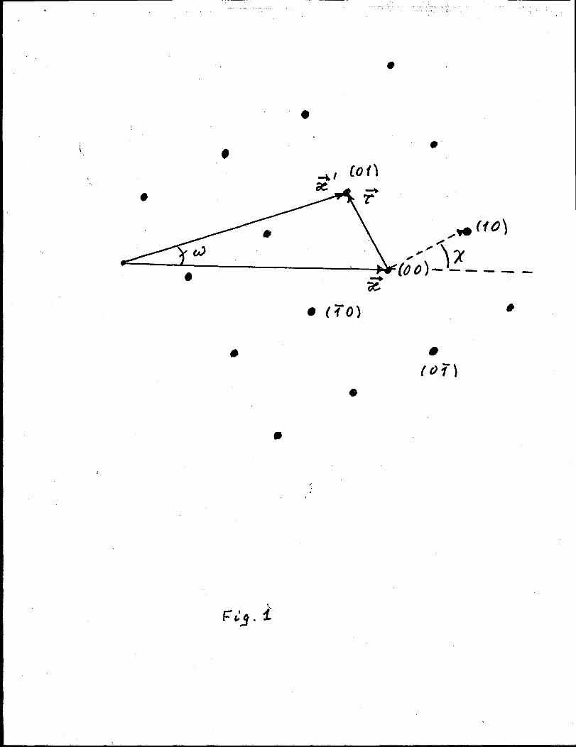
w = WT, where
COS2o!~ = COS2a + 2er CosXT Cosa + e: (1)
sin WTcos ar = @r sin Xr, (2)
X7 is the angle between the directions of R and the vector T (see Fig.1), and @T= ~/k. At
A << a the amplitudes of the Bragg peaks may have appreciable values only at CM<<1 and
a’ <<1, and then:
a~ R {az – 2@TCosXT <<1, (3)
UT c @sinXr <<1, (4)
where ~~ = -r/k. As these equations determine the peak positions as functions of a and
a’, the scattered intensity may conveniently be represented as a contour plot in the {Q!,a}–
plane. Let us for instance consider a square lattice (Fig.1) in the symmetrical case in
which the basic reciprocal vector 710 is directed along E, and thus, Ulo = ~io = O. Then
the representation of the equation a’2 = a% (CM)in {a, o?}–plane is that of on hyperbola
cutting the a axis at ~: neutrons incident at smaller values of a are unable to excite
this diffraction lines. Similarly, ~io gives rise at a diffraction line at loci defined by an
hyperbolas that cuts the d axis at +=.
The diffraction effects of the reciprocal vectors -rOl and ~oi are significantly different.
For w = +@l the diffracted beams Ioci in {cm’}–pIane are coincident with the reflected or
transmitted beam: this is because they occure for a modulation of the in–plane potential
exactly perpendicular to the incoming wave. However, turning the reciprocal lattice into
asymmetric position has dramatic effect on the Bragg peaks at +aol and ~~oi. The de-
generacy for these Bragg lines is lifted: then one can, in principle, observe all four peaks
corresponding to the curves a’z – a2 = +2@1x. In Fig.2 is presented an example, when
x = 0.4°.
The example shown indicates that the Bragg law Qll = T defines not only the in–plane
scattering angle w, but also the angle o? # a between the outgoing wave vector and the
3
....

basic 2D plane. In this geometry small lateral momentum transfers result in appreciable
changes in Ql: for instance, a resolution in Q1 of N 10-3~ provides a sensitivity to Qll
down to 10-G~-l, a range well matched with lattice spacings of the order of microns. We
want to calculate now the intensities expected for the diffraction from such a 2D structure.
II. SCATTERING AMPLITUDE
Let us consider a set of ferromagnetic particles forming a periodic 2D lattice in the
XY–plane. For instance, the particles may have height d and be deposited on a thick flat
substrate. The neutron wave incident on such a sample is reflected and refracted by the
optical potential of the substrate, and also diffracted by the lattice. If the angle of incidence
is low, the optical effect should be accounted for exactly. However, as the diffracted intensity
is usually weak its effect can be regarded as a perturbation. The potenti~ V(r) representing
the neutron interaction with the system may be decomposed into a sum
V(r) = VO(Z) + Vd(r), (5)
where the first term depends solely on the coordinate z normal to the surface and may
be approximated by the optical potential: VO(Z) = O at z <0, and VO= ?i2p~/2m in the
substrate. Here p? = 4m~b~; p~ is the critical wave number of the total reflection and n~b~
is the neutron scattering length density (SLD) for the substrate.
The second term in the Eq. (5) is due to the dots with SLD ndbd, and can be written in
the form:
V~(r) = ~~F(p-pi, z-d),a
(6)
where p~ = 4mdbd, z is a running index which indicates the particle position on the substrate
surface, and F(p, z) is the particle shape function.
Since Vd(r) depends on the 3D coordinate r = {p, z}, itcauses diffraction in off-specular
directions. Within the first order of the distorted wave Born approximation (DWBA) the
diffraction amplitude ~(k’, k) is proportional to the matrix element of the potential Vd(r)
4

~(k’, k) = -&/~rfi(k’)r)~d(r)~(k2r)) (7)
where the wave functions @(k’, r) and W(k, r) are the exact solutions for the potential V.
with the proper initial and boundary conditions. Thus in free space V (k, r) is a plane wave
approaching the sample surface from the neutron source, while @(k’, r) is a wave approaching
the sample in the direction opposite to the direction of observation: IJ?(k,r) = ei%~+(po, z)
V(p:, Z), Where PO = k sin ~, pi = k sin d are perpendicular to theand fi(k’, r) = e–iK’p -
surface components of k, k’, @(p., z) and @(pi, z) are the exact solutions of the one dimen-
sional Schrodinger equation with the potential V.(z). Due to the factorization of the wave
functions,
where F(QII; pi, PO) is
~(QII,P&,Po) = –~ ~ e’Q1lPi~(Qll; pl,pO),a
the matrix element:
(8)
F(QII; PhPo) = /dz~(Pl>z)F(Q\,) z)@(Po>z)> (9)
and F(QII, z) is the 2D Fourier transform of the scatterer shape function l’(p, z). In the case
the scatterers have columnar character F(QII; pj, Po) = ~1 (QII)~L(PL, Po}, with
(lo)
~11(Qll, z) depends on the actual cross section of the column, and d is the column height
The wave functions 10(po,z) and ~(p~, z) are linear combinations of plane waves incident
and reflected from the substrate: ~(po, ,z) = e@@+ re–@O%,where r = (p —po)/(p + po) is
the Fresnel reflectance, p = ~p~ – p: is the neutron wave number within the substrate. If
scattering occurs in the reflection hemisphere, i.e. above the sample “horizon”, then the
wave function ~(p~, ~) has exactly the same form as given by Eqs.(11 ) with the argument
POsubstituted by p&. The explicit equation for Fl(p{, po) is
FJ- (p~,pi)) = F; + T-’F: + ?-F. + ?-’rF+. (11)
This equation contains four terms, and each of them corresponds to one of the possible
scattering processes of incident or reflected waves. The “transverse” form–factors are:
5

F+ =exp[i(p~+po)dj – 1
qP~+Po)
~_ _ exp[i(p~–po)~–l—
@~ –Po) ‘
(12)
(13)
where r’ = r(p~).
It is important to note that the “transverse” form-factor FL(P~, PO) is a function of two
variables, i.e. the normal to the surface components p: and p. of the outgoing and incoming
wave vector, rather than the transverse component of the wave vector transfer QL = pi +po.
The latter variable is the proper choice only in the Born (kinematic) approximation, which
is valid for values of pj and p. far beyond the range of the total reflection. In the kinematic
approximation p’ N PL, P = PO, all reflected waves are neglected and the transverse form
factor takes the more easily recognizable form
F1(Q1) x eiQ*~/2‘in(QLd’2),QJ2
(14)
which at low angles depends only upon the scattering angle @= a’ + a. However, even in
this simplest case the total form–factor F(QII; pi, po) lineshape is a function not only of the
scattering angle 0, but also of the angle of incidence: it may show a maximum not only at
O= O, but also at 0 R 2a, which corresponds to “specular reflection” from the disc faces.
III. AN EXAMPLE: FE DOTS ON S1
In accordance with Eq. (4) the equation for the differential scattering cross section reads:
% = *~P&(QI)l~(QII; Pl,PO)12 (15)
S(QII) = (1/SO)& J(QII – T), (16)
where Af is the number of scatterers illuminated by the incoming beam, and so is the unit
cell area. For cylindrical particles the form–factor
lNQII;Pk PO)12= ~~(QII)l ~~f’(Pj>Po)12, (17)pv
with Ff (pi, po) given by Eqs. (11–13), and
6

WQII) = ~,,‘WOQII), (18)
for an array of cylindrical particles of radius PO,corresponding to a particle shape function
F’(p, z) = 1 at p s p. and 1 ~ z ~ d, and zero otherwise.
In terms of the angles of incidence and scattering the conditions of occurrence of the
Bragg reflection can be expressed as
In estimating the Bragg peak positions in the {o!, a} plane it was assumed that the equation
for azimuthal angles w = Ur = @TXTis satisfied for each of the discussed reciprocal vectors
r. Usually this is satisfied automatically because reflectometers have poor resolution with
respect to the azimuthal angles,
just summed up. In accordance
it decays as ~‘3/2 at Qllpo >> 1.
and all the Bragg lines for w’s in the range of interest are
with Eq. (19) the form factor ~1 (~) s np~ at ~po s 1, and
Therefore this sum is well convergent and approaches the
summation of WT to infinite limits. However, only relatively small number n N a/p. of terms
bring appreciable contribution to this sum and small factor (47r2~2/sea) <1 in Eq.(20) is
not compensated: the diffraction effect remains quite weak even at X7 <<1. At higher angles
o!, a and/or z. the Bragg diffraction is addit ionaly suppressed by the transverse form factor
given in Eq.(12).
Numerical calculations were made for the diffraction pattern of square 1 x lpm2 lattice
of iron dots with diameter 3000 ~ and height 800 ~ deposited on a Si02 wafer. Neutrons
have a wave length of A = 4.41 ~, and fall on the dot pattern at an angle x = 0.4°
from the lattice edge. For SLD were taken: for Si02 n,b~ R 03.9 x 10⁻⁶ A-2, for iron
ndbd % 13 X 10–6 A–2, as expected for fully magnetized iron and for neutro& polarized
parallel to the direction of magnetization. With a resolution Ad = 0.02°, we find that
the maximum intensity of the (O,+1) peaks may amount up to 2% of the total reflection.
Much lower is the intensity of the (+1, O) reflections, which is suppresed by the form factor
7

~L(PL,fJo) at P~,PO 2 d-l. The results of calculations are presented in Fig.2a, while in
order to experimental results are depicted in Figs.3b. The experiment carried out at the
polarized neutron reflectometer ADAM [8] at the Institut Laue–Langevin (Grenoble) shows
that indeed the diffraction experiments on submicron size dot systems are feasible. However,
the amount of intensity diffracted is such that such experiments can provide a satisfactory
amount of physical information only for very selective problems and systems with sufficiently
large area.
*Work is supported by US-DOE, BES-MS contract #W-31-109-ENG-38, Russian State Program
“Neutron Research of Condensed Matter” and RFFI-Grant No. L-EN-96-15-96775.
8

REFERENCES
[I] J.I. Martinet cd., Phys. Rev. Lett. 79,1929 (1997)
[2] Y. Ja,cca,rd et ai., Phys. Rev. B 58,8232 (1998).
[3] D.J. Morgan et al., Phys. Rev. Lett. 80,3614 (1998).
[4] V. HoI-j et al., Phys. Rev. Lett. 83,356 (1999).
[5] M. Grassi Alessi et uZ.,Phys. Rev. B 59,7620 (1999).
[6] P. Vavassori et al., Phys. Rev. . B 59, 6337 (1999).
[7] M.Tolan et al., Physics B 221 (1996) 53.
[8] A. Schreyer et al., Physics B 248 (1998) 349.

FIGURE CAPTIONS
FIG.1 Geometry of the (0,1) diffraction process from square lattice of dots.
FIG.2 a.) Schematic contour plots of the reflected and diffracted intensity as a function
of the scattering angles a’ and the incidence ‘angles a; Sample is 1 x l~m2 lattice of
iron dots with diameter 3000 ~ and height 800 ~ deposited onto Si02 wafer, neutrons
wave length A = 4.41 & and the angle x = 0.4°,
b) experimental results for neutrons polarized along the dot magnetization.
10
.
.
.,

...
11, ,, ,, ‘ /2/%‘$3
12 -----j-~------i------------i ------ ‘-- ? ‘- ----
10 -------
u~
“Q-> --+%+-5’%7-?2%/+-”k’----------’i----------0“
6
4
,------
4 6 8 10 12 14
u’, rad x 10-3

14
12
10
8
6
4
-3XI(3. ..-
4 6 8 10 12 14
et’, rad x 10-3
IVq 2.4’