Embed Size (px)
Citation preview
Einbauhinweis Notice d'utilisation istruzioni per 'installazione
Installation Instructions InstalIatievoorschrift Instrucciones de montaje
® Lotfreier Brenner für Thermen® Solderless Burner for gas water heaters
® Brüleur sans apport pour chaudières
@ Brander zonder soldeer voor geisers
( Bruciatori senza saldature per caldaie
® Quemador para calentadóres, sin soldadura
JUNKERSBosch Gruppe
W 125/135W 250 ab 1967 WR 250W325 WR325W400 WR400
IL,
C.J
0Co0('S
(p
© Die einwandfreie Funktion ist nur gewährleistet, wenn diese Vorschrift eingehalten wird.- Anderungen vorbehalten -
® Proper working of these appliances is ensured only if the following instructions are carriedout in every detail. - Modifications reserved -
® Le bon fonctionnement de l'appareil ne peut être assure que si ces prescriptions sontbien respectées. - Sous reserve de modifications -
Het juist funktioneren van de geiSer wordt slechts gewaardborgd als dit voorschrift wordtopgevolgd. - Wijzigingen voorbehouden -
II perfetto funzionamento è garantito solo se si rispettano queste istruzioni. - Con riservadi apportare modifiche -
® El funcionamiento perfecto queda ünicamente garantizado si se complen lasprescriptiones siguientes, sujetas a modificaciones.
® Achtung!Bei Einbau des neuen, Iotfreien Brenners sind nachfolgende Punkte zubeachten:Bei Gasart-Umbau sind die Punkte 9 und 10 zusätzlich zu beachten.
1. Brennerzentrierbügel entfernen und beide Innenkörper-Halteble-che nach oben biegen. *)
2. Brennerschale entfernen. *)3. Bei Flüssiggasgeräten für 50 mbar Anschlußdruck beiliegende
Drosselscheibe mit Dichtungen zwischen Gasarmatur und Bren-ner einbauen.
4. Brenner zu lnnenkörper so ausrichten, daß Flammen nicht anBrennkammerwände anbrennen.
5. Zündgasrohr an Gerät anpassen.6. Gaseinstellung nach Tabelle vornehmen und plombieren (Stadt-
und Erdgas).7. Klebeschild gut sichtbar in Typenschildnähe aufkleben.8. Brenner- und Zündbrennerverbindungen auf Gasdichtheit prüfen.9. Beiliegenden Überzündbolzen einbauen.
10. Gasart-Klebeschild auf Typschild anbringen.
Bei Teilebestellung zur Typbezeichnung ”Iotfreier Brenner" angeben*) entfällt bei W 125
® Caution!The following points must be observed when installing the new solder-less burner:See also 9. and 10. below in case of gas type conversion.
1. Remove the burner centering bracket and bend both inner-bodyholding plates upward. *)
2. Remove the burner shell.")3. In the case of LPG units for 50 mbar connection pressure, install
the enclosed throttling disc with seals between gas fitting and ur-ner.
4. Align the burner in relation to the inner body so that flames do notattack the burner chamber walls.
5. Adapt the pilot gas pipe to the unit.6. Set the gas as pertable and make lead seal (town and natural gas).7. Stick the adhesive label in the vicinity of the nameplate so that it is
easily visible.8. Check that the burner and pilot burner connections are gas-tight.9. Install the enclosed over-ignition pin.
10. Attach gas-type adhesive label on nameplate.
When ordering parts, add "solderless burner" to the type designation.*) Does not apply in the case of W 125
® Attention!Respecter les points suivants lors du montage du nouveau brüleursans apport:En cas de modification du type de gaz, respecter impérativement les in-dications complementaires aux points 9 et 10.
1. Retirer l'étrier de centrage du brüleur et plier vers le haut les deuxplaques de maintien du corps intérieur. ")
2. Retirer le carter du brüleur.")3. Sur les appareils ä gaz liquide et pression de raccordement de 50
mbar, incorporer le ciapet d'etranglement fourni et les joints entrei'armature gaz et le brüleur.
4. Ajuster le brüleur par rapport au corps intérleur de facon que lesflammes n'atteignent pas les parois du brüleur.
5. Ajuster Ia tubulure de veilleuse ä i'appareil.6. Procéder au reglage du gaz d'après le tableau et effectuer le plom-
bage (gaz de yule et gaz naturel).7. Apposer l'autocollant de façon trés visible ä proximité de Ia plaque
signaletique.8. ContrOler l'étanchéité au gaz des raccords du brüleur et de Ia veil-
leuse.9. Monter l'aliumeur piezoelectrique auxiiiaire fourni.
10. Apposer i'autocollant indiquant le type de gaz sur Ia plaque signa-letique.
Lors de Ia commande des piäces, indiquer "brüleur sans apport" avecIa designation du type.*) supprimé sur W 125
@ Attentie!Bij het inbouwen van de nieuwe branders zonder soldeer moet op devolgende punten worden gelet:Bij ombouw voor een andere gassoort moet bovendien op de punten 9en 10 worden gelet.
1. Bevestigingsbeugei van de brander verwijderen en de twee beve-stigingsstrips aan de binnenkant naar boven buigen.")
2. Branderschotel verwijderen. *)3. Bij LPG -geisers met een aansluitdruk van 50 mbar moet de bijbe-
horende smoorschijf met de afdichtingen tussen de gasarmatuuren de brander worden ingebouwd.
4. De brander moet zodanig worden bevestigd, dat de viammen nietfegen de wanden van de verbrandingskamer aan siaan.
5. Waakvlamgasieiding aan het apparaat aanbrengen.6. Gasinstelling overeenkomstig de tabel doorvoeren en plomberen
(stad- en aardgas).7. Sticker op een duidelijk zichtbare plaats vlakbij het typebordje
plakken.8. Brander- en waakvlamgasleiding op gasdichtheid kontroleren.9. Bijbehorende overontstekingspen inbouwen.
10. Gassoort-sticker op het typeplaatje aanbrengen.Bij het bestellen van onderdelen moet samen met de type-aanduiding"brander zonder soideer" worden vermeid.") Niet nodig bij W 125
c Attenzione!Per l'installazione del nuovo bruciatore senza saldature, si devono ri-spettare i punti seguenti:Nelia trasformazione del tipo del gase necessario inoitre fare attenzioneai punti 9 e 10.
1. Togliere Ia staffa di centraggio del bruciatore e piegare verso i'aito ilamierini di fissaggio del corpo interno.")
2. Togliere ii mantello del bruciatore.")3. Nei bruciatori a gas liquido con pressione d'attacco di 50 mbar, si
deve montare i'acciuso disco riduttore con guarnizioni tra raccor-do del gas e bruciatore.
4. Orientare ii bruciatore rispetto al corpo interno in modo che lefiamme non lambiscano le pareti della sua camera.
5. Sagomare ii tubo del gas della fiamma-spia secondo i'apparec-chio.
6. Registrare Ia portata del gas in base aila tabelia e piombare (gas dicittä e metano).
7. lncoliare l'autoadesivo vicino alla targhetta dell'apparecchio, in unpunto ben visibile.
8. Controllare Ia tenuta stagna degli attacchi del bruciatore e dellafiamma-spia.
9. Montare i poli piezoeiettrici acciusi alia confezione.10. Applicare suila targhetta l'adesivo relativo al tipo del gas.
Neue ordinazioni del ricambi, accanto aila sigia del bruciatore riportareIa dicitura "bruciatore senza saldature,,.")viene eliminato per W 125
® Atención!Para ei montaje del nuevo quemador sin soidadura deben observarselos siguientes puntos:En caso de cambio del tipo de gas, deberän observarse ademäs lospuntos 9 y 10.
1. Quitar ei estribo de centrado del quemador y doblar ambas cha-
pas de retenciOn del cuerpo interior hacia arriba.")2. Quitar le bandeja del quemador.")3. En los aparatos de gas licuado para presiOn de empaime de 50
mbar, montar Ia arandela de estrangulaciön incluida junto con lasjuntas entre Ia armadura de gas y ei quemador.
4. Alinear ei quemador con respecto al cuerpo interior de modo quelas llamas no estén dirigidas hacia las paredes de Ia cämara decorn bustiön.
5. Adaptar ei tubo del gas de encendido al aparato.6. Efectuar ei ajuste del gas segün Ia tabla y seilar ei dispositivo (gas
ciudad y natural).7. Pegar Ia etiqueta adhesiva de modo bien visible en Ia proximidad
de Ia placa de caracteristicas.8. Comprobar Ia estanqueidad del gas en las uniones del quemador
principal y del quemador de encendido.9. Instalar ei perno piezoelèctrico adjurito.
10. Pegar sobre Ia piaca de caracteristicas ei rOtulo adhesivo con eI ti -p0 de gas.
Para ei pedido, indicar al lado de Ia designacion de tipo "quemador sinsoldadura".*) se suprirne para W 125
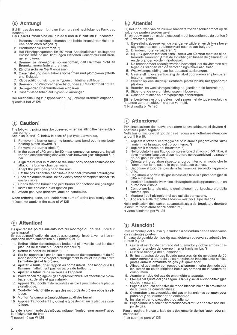
Gaswerte - Gas rate - Debit de gaz - Gasregeling - Tipo di gas - RegulatiOn de gas
Stadtgas - Erdgas, Town gas - Natural gas, Gaz de ville - Gaz naturel, Stadtgas - Aardgas, Gas cittä - Gas metano, Gas ciudad - Gas natural
1 mbar10mmWS
S -Nr. Gas Wo-Index
W125
Düsen-Kennz.Injectororifice
G icleu rsSpuitstuk
UgelliInjector mbar
W/WR 250
Düsen-Kennz.Injectororifice
G icleu rsSpuitstuk
UgelliInjector mbar
W/WR 325
Düsen-Kennz.Injectororifice
G icleu rsSpuitstuk
UgelliInjector mbar
W/WR 400
Düsen -
Kennz.Injectororifice
G icleursSpuitstuk
UgelliInjector mbar
-
- Stadtgas A 6700 225 3,5 225 3,5 245 3,3 260 3,0
StadtgasB 7600 200 3,8 200 3,8 215 3,8 215 4,0
Butan-Luft 5850 225 3,4 225 3,4 240 3,4 245 3,5-
ErdgasL 10700 135 7,7 140 7,4 140 9,4 145 9,4
Erdgas H 12900 125 8,0 120 10,4 125 10,2 125 11,2-
C
0)
_________
StadtgasTown gasGaz de ville
StadtgasGas cittä
Gas ciudad
0404 6200 225 3,5 225 3,5 245 3,3___________
0800 6200 225 3,5 225 3,5 245 3,3___________
1400 6200 225 3,5 225 3,5 245 3,3__________
2400 6200 225 3,5 215 4,2 225 4,6_________
2700 6200 225 3,5 225 3,5 245 3,3___________
2800 6200___________
2900 6200 225 3,5 225 3,5 245 3,3 260 3,0
3341 6200 225 3,5 225 3,5 245 3,3 260 3,0
3500 6200 225 3,5 225 3,5 245 3,3___________
____________
____________
____________
____________
ErdgasNatural gasGaznaturel
AardgasGas metanoGaz natural
02001) 12900 125 8,0 121 9,0 121 10,4_________
0200/Serie 67 12900 125 8,0 120 10,4 125 10,2__________
0404 12900 125 8,0 120 10,4 125 10,2_________
0700 10500 135 9,0 150 6,3 155 6,4 150 7,5
0800 12900 125 8,0 120 10,4 125 10,2__________
1400 12900 120 8,9 120 10,4 125 10,2 125 11,2
2400 12900 125 8,0 120 10,4 130 8,7 130 9,6
2800 12900 125 8,0 120 10,4 125 10,2 130 9,6
3600 10500 1202) 13,3 125 9,5 125 12,3 130 12,2
3600 12900 1202) 10,3 125 7,6 125 9,9 130 9,8
I) f. W/WR...F FA, T, TA, Ti, TAl
2) Drosselblende Ø 3,6Throttling discDisque d'etranglementLijster plaatDisco di strozzamentoDisco de estrangulation
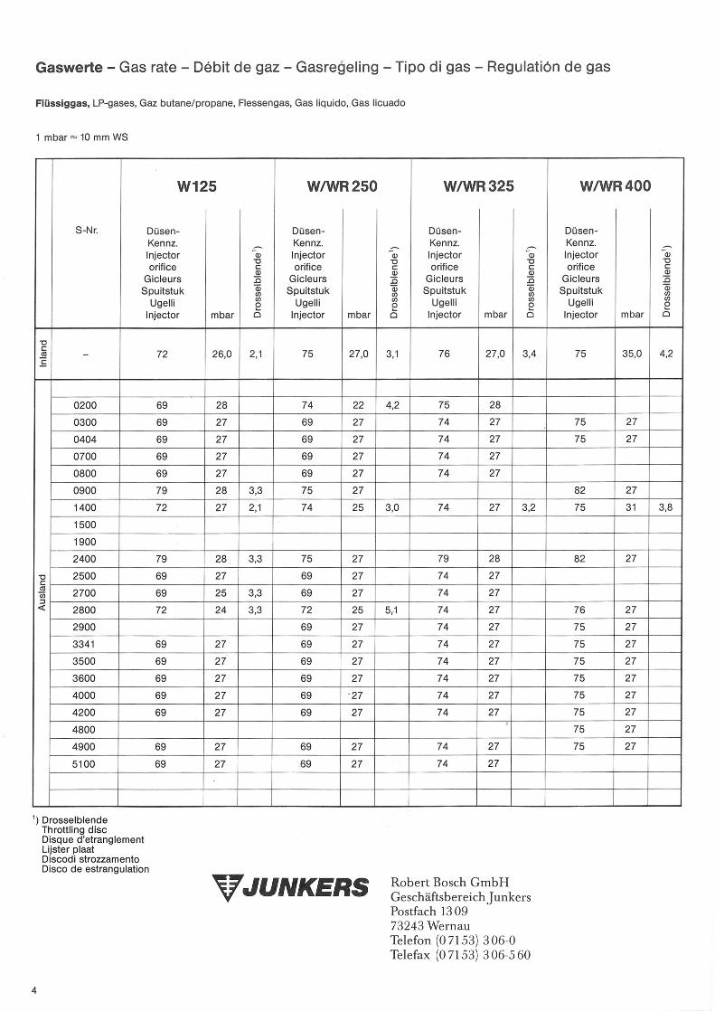
Gaswerte - Gas rate - Debit de gaz - Gasregeling - Tipo di gas - RegulatiOn de gas
Flüssiggas, LP-gases, Gaz butane/propane, Flessengas, Gas liquido, Gas licuado
1 mbar10mmWS
S -Nr.
W125
Düsen-Kennz.Injectororifice c
GicleursSpuitstuk
UgelliInjector mbar a
W/WR 250
Düsen-Kennz.Injector 'corifice
C)
GicleursSpuitstuk
UgelliInjector mbar a
W/WR 325
Düsen-Kennz.Injector 'iorifice
C)
GicleursSpuitstuk
UgelliInjector mbar a
W/WR 400
Düsen -
Kennz.Injectororifice C
-GicleursSpuitstuk
UgelliInjector mbar a
V
- 72 26,0 2,1 75 27,0 3,1 76 27,0 3,4 75 35,0 4,2
0200 69 28 74 22 4,2 75 28
0300 69 27 69 27 74 27 75 27
0404 69 27 69 27 74 27 75 27
0700 69 27 69 27 74 27
0800 69 27 69 27 74 27
0900 79 28 3,3 75 27 82 27
1400 72 27 2,1 74 25 0 74 27 3,2 75 31 3,8
1500
1900
2400 79 28 3,3 75 27 79 28 82 27
2500 69 27 69 27 74 27
2700 69 25 3,3 69 27 74 27< 2800 72 24 3,3 72 25 5,1 74 27 76 27
2900 69 27 74 27 75 27
3341 69 27 69 27 74 27 75 27
3500 69 27 69 27 74 27 75 27
3600 69 27 69 27 74 27 75 27
4000 69 27 69 27 74 27 75 27
4200 69 27 69 27 74 27 75 27
4800 75 27
4900 69 27 69 27 74 27 75 27
5100 69 27 69 27 74 27
1) DrosselblendeThrottling discDisque d'etranglementLuster plaatDiscodi strozzamentoDisco de estrangulation
JUNKERS Robert Bosch GmbHGeschäftsbereich JunkersPostfach 130973243 WernauTelefon (07153) 306-0Telefax (07153) 306-5 60