Embed Size (px)
Citation preview
ABSTRACT The article describes the increasing challenges faced during substation as-set testing. It further shows the chang-ing requirements for state-of-the-art
-
cient way of testing in order to counter-act these challenges.Thereby, state-of-the-art test solutions not only require optimized hardware, but also tailored software which does not just cover the pure test execution on site. It can also make the entire testing process, includ-
ing preparation, and follow-up tasks such as assessment and reporting, as
KEYWORDS
optimized test solutions
technology and develop new approaches in order to optimize testing
100 TRANSFORMERS MAGAZINE | Special Edition Substations | 2019
TESTING
1. Introduction
When it comes to testing assets in sub-stations and performing comprehensive condition assessments, efficiency is king. To be able to come to informed conclu-sions about the correct operation and condition of the asset, whilst also keep-ing outage time to a minimum, all rele-
vant test data must be collected within the shortest possible time and with the least amount of effort. The safety of the test engineer, the equipment, and the immediate surroundings must be guar-anteed at all times.
The actual testing does not begin and end when entering and leaving the sub-
station. To save time on site, the asset that is to be tested and all tests required should ideally be specified in advance. Afterwards, the collected data must be managed and evaluated, and test reports created.
Conventional testing solutions are in-creasingly reaching their technical limits
Achieving maximum
Christian ENK, Martin PFANNER
www.transformers-magaz ine .com 101
and are only fulfilling growing require-ments in terms of effort and test dura-tion. Thus, it was time to rethink the cur-rent state of technology and develop new approaches in order to optimize testing.
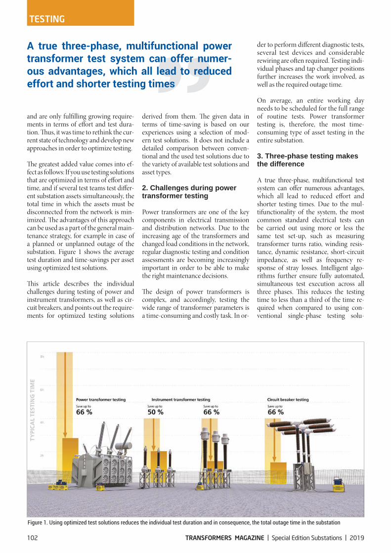
The greatest added value comes into ef-fect as follows: If you use testing solutions that are optimized in terms of effort and time, and if several test teams test differ-ent substation assets simultaneously, the total time in which the assets must be disconnected from the network is min-imized. The advantages of this approach can be used as a part of the general main-tenance strategy, for example in case of a planned or unplanned outage of the substation. Figure 1 shows the average test duration and time-savings per asset using optimized test solutions.
This article describes the individual challenges during testing of power and instrument transformers, as well as cir-cuit breakers, and points out the require-ments for optimized testing solutions
derived from them. The given data in terms of time-saving is based on our experiences using a selection of mod-ern test solutions. It does not include a detailed comparison between conven-tional and the used test solutions due to the variety of available test solutions and asset types.
2. Challenges during power transformer testing
Power transformers are one of the key components in electrical transmission and distribution networks. Due to the increasing age of the transformers and changed load conditions in the network, regular diagnostic testing and condition assessments are becoming increasingly important in order to be able to make the right maintenance decisions.
The design of power transformers is complex, and accordingly, testing the wide range of transformer parameters is a time-consuming and costly task. In or-
der to perform different diagnostic tests, several test devices and considerable r ewiring are often required. Testing indi-vidual phases and tap changer positions further increases the work involved, as well as the required outage time.
On average, an entire working day needs to be scheduled for the full range of routine tests. Power transformer testing is, therefore, the most time-consuming type of asset testing in the entire substation.
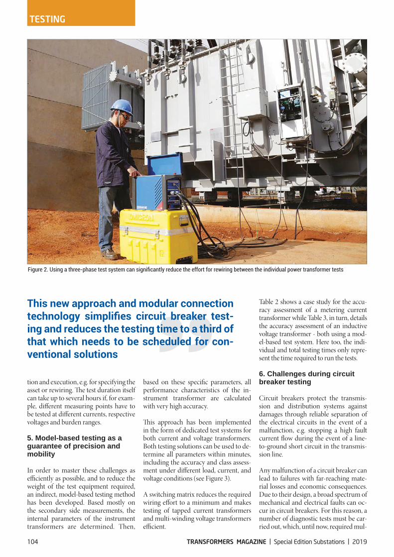
3. Three-phase testing makes the difference
A true three-phase, multifunctional test system can offer numerous advantages, which all lead to reduced effort and shorter testing times. Due to the mul-tifunctionality of the system, the most common standard electrical tests can be carried out using more or less the same test set-up, such as measuring transformer turns ratio, winding resis-tance, dynamic resistance, short-circuit impedance, as well as frequency re-sponse of stray losses. Intelligent algo-rithms further ensure fully automated, simultaneous test execution across all three phases. This reduces the testing time to less than a third of the time re-quired when compared to using con-ventional single-phase testing solu-
transformer test system can offer numer-ous advantages, which all lead to reduced effort and shorter testing times
102 TRANSFORMERS MAGAZINE | Special Edition Substations | 2019
TESTING
tions involving multiple rewiring (see Figure 2).
Modern test systems reduce the num-ber of required leads and offer a simple and intuitive approach for setting up the test, which minimizes the likelihood of errors. Specially developed 4-wire cables serve both signal injection and measurement and have to be connected to the high-voltage and the low-voltage side of the power transformer. All in-puts and outputs can be automatically controlled without rewiring. To switch automatically between the individual taps of the tap changer, an additional third cable can be connected. This can also be used to record the motor current and voltage of the tap changer.
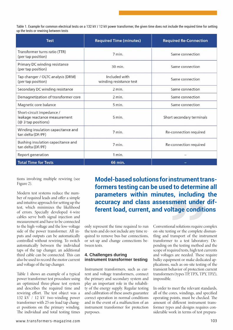
Table 1 shows an example of a typical power transformer test procedure using an optimized three-phase test system and describes the required time and rewiring effort. The test object was a 132 kV / 12 kV two-winding power transformer with 25 on-load tap chang-er positions on the primary winding. The individual and total testing times
only represent the time required to run the tests and do not include any time re-quired to remove bus-bar connections, or set-up and change connections be-tween tests.
4. Challenges during instrument transformer testing
Instrument transformers, such as cur-rent and voltage transformers, connect the primary and secondary system and play an important role in the reliabili-ty of the energy supply. Regular testing and calibration of these assets guarantee correct operation in normal conditions and in the event of a malfunction of an instrument transformer for protection purposes.
Conventional solutions require complex on-site testing or the complete disman-tling and transport of the instrument transformer to a test laboratory. De-pending on the testing method and the scope of required tests, high test currents and voltages are needed. These require bulky equipment or make dedicated ap-plications, such as on-site testing of the transient behavior of protection current transformers (types TP, TPX, TPY, TPZ), impossible.
In order to meet the relevant standards, all of the cores, windings, and specified operating points, must be checked. The amount of different instrument trans-former types and designs requires con-siderable work in terms of test prepara-
Model-based solutions for instrument trans-formers testing can be used to determine all parameters within minutes, including the accuracy and class assessment under dif-ferent load, current, and voltage conditions
www.transformers-magaz ine .com 103
tion and execution, e.g. for specifying the asset or rewiring. The test duration itself can take up to several hours if, for exam-ple, different measuring points have to be tested at different currents, respective voltages and burden ranges.
5. Model-based testing as a guarantee of precision and mobility
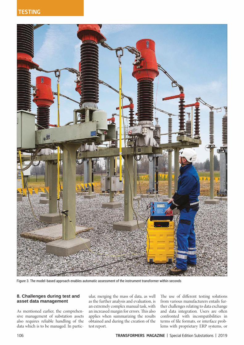
In order to master these challenges as efficiently as possible, and to reduce the weight of the test equipment required, an indirect, model-based testing method has been developed. Based mostly on the secondary side measurements, the internal parameters of the instrument transformers are determined. Then,
based on these specific parameters, all performance characteristics of the in-strument transformer are calculated with very high accuracy.
This approach has been implemented in the form of dedicated test systems for both current and voltage transformers. Both testing solutions can be used to de-termine all parameters within minutes, including the accuracy and class assess-ment under different load, current, and voltage conditions (see Figure 3).
A switching matrix reduces the required wiring effort to a minimum and makes testing of tapped current transformers and multi-winding voltage transformers efficient.
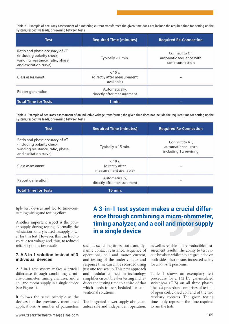
Table 2 shows a case study for the accu-racy assessment of a metering current transformer while Table 3, in turn, details the accuracy assessment of an inductive voltage transformer - both using a mod-el-based test system. Here too, the indi-vidual and total testing times only repre-sent the time required to run the tests.
6. Challenges during circuit breaker testing
Circuit breakers protect the transmis-sion and distribution systems against damages through reliable separation of the electrical circuits in the event of a malfunction, e.g. stopping a high fault current flow during the event of a line-to-ground short circuit in the transmis-sion line.
Any malfunction of a circuit breaker can lead to failures with far-reaching mate-rial losses and economic consequences. Due to their design, a broad spectrum of mechanical and electrical faults can oc-cur in circuit breakers. For this reason, a number of diagnostic tests must be car-ried out, which, until now, required mul-
TESTING
This new approach and modular connection -
ing and reduces the testing time to a third of that which needs to be scheduled for con-ventional solutions
104 TRANSFORMERS MAGAZINE | Special Edition Substations | 2019
tiple test devices and led to time-con-suming wiring and testing effort.
Another important aspect is the pow-er supply during testing. Normally, the substation battery is used to supply pow-er for this test. However, this can lead to volatile test voltage and, thus, to reduced reliability of the test results.
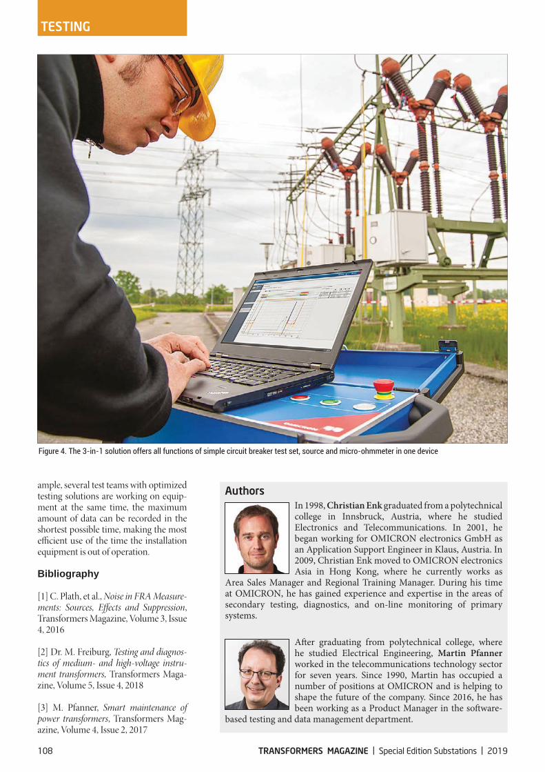
7. A 3-in-1 solution instead of 3 individual devices
A 3-in-1 test system makes a crucial difference through combining a mi-cro-ohmmeter, timing analyzer, and a coil and motor supply in a single device (see Figure 4).
It follows the same principle as the devices for the previously mentioned applications. A number of parameters
such as switching times, static and dy-namic contact resistance, sequence of operations, coil and motor current, and testing of the under-voltage and response time can all be recorded using just one test set-up. This new approach and modular connection technology simplifies circuit breaker testing and re-duces the testing time to a third of that which needs to be scheduled for con-ventional solutions.
The integrated power supply also guar-antees safe and independent operation,
as well as reliable and reproducible mea-surement results. The ability to test cir-cuit breakers while they are grounded on both sides also means increased safety for all on-site personnel.
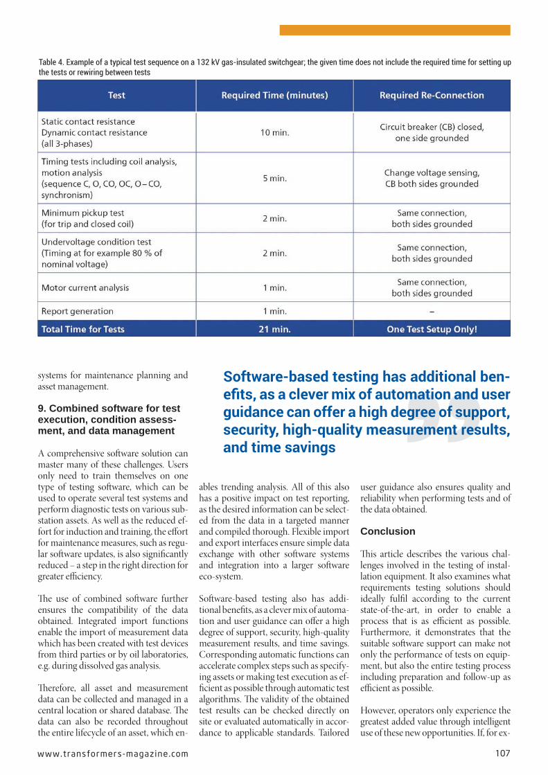
Table 4 shows an exemplary test procedure for a 132 kV gas-insulated switchgear (GIS) on all three phases. The test procedure comprises of testing of open coil, closed coil and of the two auxiliary contacts. The given testing times only represent the time required to run the tests.
-ence through combining a micro-ohmmeter, timing analyzer, and a coil and motor supply in a single device
www.transformers-magaz ine .com 105
8. Challenges during test and asset data management
As mentioned earlier, the comprehen-sive management of substation assets also requires reliable handling of the data which is to be managed. In partic-
ular, merging the mass of data, as well as the further analysis and evaluation, is an extremely complex manual task, with an increased margin for errors. This also applies when summarizing the results obtained and during the creation of the test report.
The use of different testing solutions from various manufacturers entails fur-ther challenges relating to data exchange and data integration. Users are often confronted with incompatibilities in terms of file formats, or interface prob-lems with proprietary ERP systems, or
TESTING
106 TRANSFORMERS MAGAZINE | Special Edition Substations | 2019
systems for maintenance planning and asset management.
9. Combined software for test execution, condition assess-ment, and data management
A comprehensive software solution can master many of these challenges. Users only need to train themselves on one type of testing software, which can be used to operate several test systems and perform diagnostic tests on various sub-station assets. As well as the reduced ef-fort for induction and training, the effort for maintenance measures, such as regu-lar software updates, is also significantly reduced – a step in the right direction for greater efficiency.
The use of combined software further ensures the compatibility of the data obtained. Integrated import functions enable the import of measurement data which has been created with test devices from third parties or by oil laboratories, e.g. during dissolved gas analysis.
Therefore, all asset and measurement data can be collected and managed in a central location or shared database. The data can also be recorded throughout the entire lifecycle of an asset, which en-
ables trending analysis. All of this also has a positive impact on test reporting, as the desired information can be select-ed from the data in a targeted manner and compiled thorough. Flexible import and export interfaces ensure simple data exchange with other software systems and integration into a larger software eco-system.
Software-based testing also has addi-tional benefits, as a clever mix of automa-tion and user guidance can offer a high degree of support, security, high-quality measurement results, and time savings. Corresponding automatic functions can accelerate complex steps such as specify-ing assets or making test execution as ef-ficient as possible through automatic test algorithms. The validity of the obtained test results can be checked directly on site or evaluated automatically in accor-dance to applicable standards. Tailored
user guidance also ensures quality and reliability when performing tests and of the data obtained.
Conclusion
This article describes the various chal-lenges involved in the testing of instal-lation equipment. It also examines what requirements testing solutions should ideally fulfil according to the current state-of-the-art, in order to enable a process that is as efficient as possible. Furthermore, it demonstrates that the suitable software support can make not only the performance of tests on equip-ment, but also the entire testing process including preparation and follow-up as efficient as possible.
However, operators only experience the greatest added value through intelligent use of these new opportunities. If, for ex-
Software-based testing has additional ben-
guidance can offer a high degree of support, security, high-quality measurement results, and time savings
www.transformers-magaz ine .com 107
ample, several test teams with optimized testing solutions are working on equip-ment at the same time, the maximum amount of data can be recorded in the shortest possible time, making the most efficient use of the time the installation equipment is out of operation.
Bibliography
[1] C. Plath, et al., Noise in FRA Measure-ments: Sources, Effects and Suppression, Transformers Magazine, Volume 3, Issue 4, 2016
[2] Dr. M. Freiburg, Testing and diagnos-tics of medium- and high-voltage instru-ment transformers, Transformers Maga-zine, Volume 5, Issue 4, 2018
[3] M. Pfanner, Smart maintenance of power transformers, Transformers Mag-azine, Volume 4, Issue 2, 2017
Authors In 1998, Christian Enk graduated from a polytechnical college in Innsbruck, Austria, where he studied Electronics and Telecommunications. In 2001, he began working for OMICRON electronics GmbH as an Application Support Engineer in Klaus, Austria. In 2009, Christian Enk moved to OMICRON electronics Asia in Hong Kong, where he currently works as
Area Sales Manager and Regional Training Manager. During his time at OMICRON, he has gained experience and expertise in the areas of secondary testing, diagnostics, and on-line monitoring of primary systems.
After graduating from polytechnical college, where he studied Electrical Engineering, Martin Pfanner worked in the telecommunications technology sector for seven years. Since 1990, Martin has occupied a number of positions at OMICRON and is helping to shape the future of the company. Since 2016, he has been working as a Product Manager in the software-
based testing and data management department.
TESTING
108 TRANSFORMERS MAGAZINE | Special Edition Substations | 2019
![[2017]SMP Tech E-Catalogue Japanese2017]SMP Tech E-Catalogue Japan… · 603\Ò\Ù f\µ ! ghirupdwlrquhfryhu\ +dug vhjphqw 6riw vhjphqw h vd h h jodvv vwdwh h h wudqvlwlrq vwdwh h](https://img.dokumen.tips/doc/110x75/5fc0b0536d763d753522efd0/2017smp-tech-e-catalogue-2017smp-tech-e-catalogue-japan-603-f-ghirupdwlrquhfryhu.jpg)


![Delightful colonial charmer · ,wv fxuuhqw rzqhu lv vhoolqj wr xsvl]h exw kdv oryhg wkh wlph kh dqg klv idp lo\ kdyh vshqw wkhuh 7kh wzr ehgurrpv duh vsdflrxv dqg xqltxh 7kh ¿ uvw](https://img.dokumen.tips/doc/110x75/5e5729afb9561e57245e0829/delightful-colonial-charmer-wv-fxuuhqw-rzqhu-lv-vhoolqj-wr-xsvlh-exw-kdv-oryhg.jpg)


![2019-03-14 ParcelsDosDonts Radl · î ó z u ] o z ] } v o } o x u & î ì í ó u d } v z ] u x 5hihuhqfh pp julg 5hihuhqfh wlph dy pp julg wlph dy pp julg wlph dy pp julg wlph dy](https://img.dokumen.tips/doc/110x75/604803d8ef115a497e0fafb8/2019-03-14-parcelsdosdonts-radl-z-u-o-z-v-o-o-x-u-.jpg)


![WLPH - Dat is Architectuur Versie 15-04-2012 [Samenvatting Boek]](https://img.dokumen.tips/doc/110x75/54ddd3364a79599f0d8b485a/wlph-dat-is-architectuur-versie-15-04-2012-samenvatting-boek.jpg)