Embed Size (px)
Citation preview

COOPERATIVE NATIONAL PARK RESOURCES STUDIES UNIT
UNIVERSITY OF HAWAII AT MANOA
Department of Botany
Honolulu, Hawaii 96822
(808) 948-8218
Clifford w. Smith, Unit Director Associate Professor of Botany
Technical Report 37
A PORTABLE METAL BOX TRAP FOR LIVE-CAPTURE OF FERAL PIGS
c. H. Diong
c. H. Diong Department of Zoology
University of Hawaii at Manoa Honolulu, Hawaii 96822
May 1981
UNIVERSITY OF HAWAII AT MANOA
NATIONAL PARK SERVICE Contract No. CX 8000 8 0011
Contribution Number CPSU/UH 025/8
i
ABSTRACT
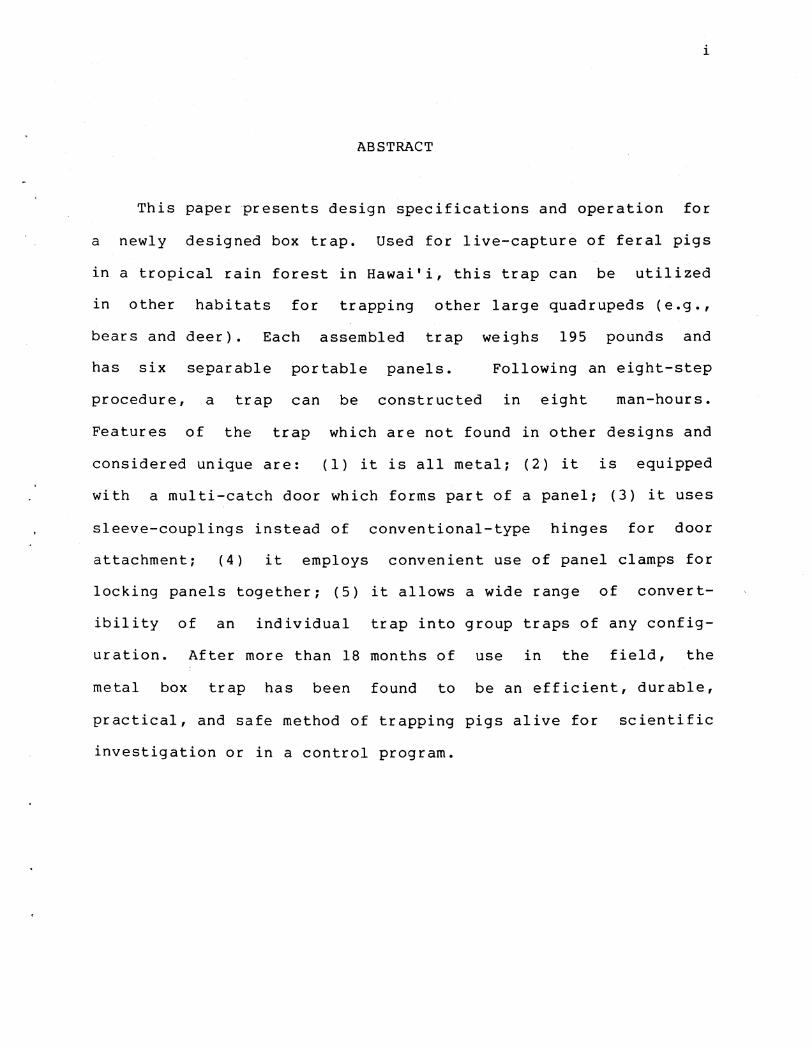
This paper presents design specifications and operation for
a newly designed box trap. Used for live-capture of feral pigs
in a tropical rain forest in Hawai'i, this trap can be utilized
in other habitats for trapping other large quadrupeds (e.g.,
bears and deer). Each assembled trap weighs 195 pounds and
has six separable portable panels. Following an eight-step
procedure, a trap can be constructed in eight man-hours.
Features of the trap which are not found in other designs and
considered unique are: (1) it is all metal; (2) it is equipped
with a multi-catch door which forms part of a panel; (3) it uses
sleeve-couplings instead of conventional-type hinges for door
attachment; (4) it employs convenient use of panel clamps for
locking panels together; (5) it allows a wide range of convert
ibility of an individual trap into group traps of any config
uration. After more than 18 months of use in the field, the
metal box trap has been found to be an efficient, durable,
practical, and safe method of trapping pigs alive for scientific
investigation or in a control program.

TABLE OF CONTENTS
ABSTRACT .•.•• . . . . . . . . . . . . . . . . . . . LIST OF TABLES.
LIST OF FIGURES . . . . . . . . . . . . . . . . . . . . . . . . . . . . . . . . . INTRODUCTION .••
LITERATURE REVIEW
MATERIALS AND METHODS .
. . . . . . . . . . . . .
(1) Sectioning. • • ••••••••.•••
(2) Bevelling . • • • • • . . • • • • • ••
(3::) Coping. . .................. .
(4) Burring •.
ii
i
iii
iii
1
2
3
4
4
4
5
(5) Framework Welding • . . • • • • • . • . . . • • • . 5
(6) Cross-piece Welding 5
(7) Sleeve-coupling . . • • . • • • • • • • • • • • • • 5
(8) Attachment of Door Bracket and Pull-pins .•
RESULTS AND DISCUSSION.
ACKNOWLEDGMENTS .
LITERATURE CITED. .
. . . . . . . . . . . .
. . . . . . . . . . . . . . . . . . . . . . . . . . . .
5
5
9
10

iii
Table
1
LIST OF TABLES
Summary of major design features for some commonly used box and panel traps in the live-trapping of the free-ranging pig
LIST OF FIGURES
Figure
1 Schematic diagram o£ the side and bottom panels
12
for the portable metal box trap (side-view). . . . 13
2 Schematic diagram of the top panel (not requiring chain-link fabric) for the portable metal box trap (plan view). . • . • . 14
3 Schematic diagram of the end piece of the portable metal box trap (end view). . . • . . . 15
4 Schematic diagrams showing multiple-entry swing door.
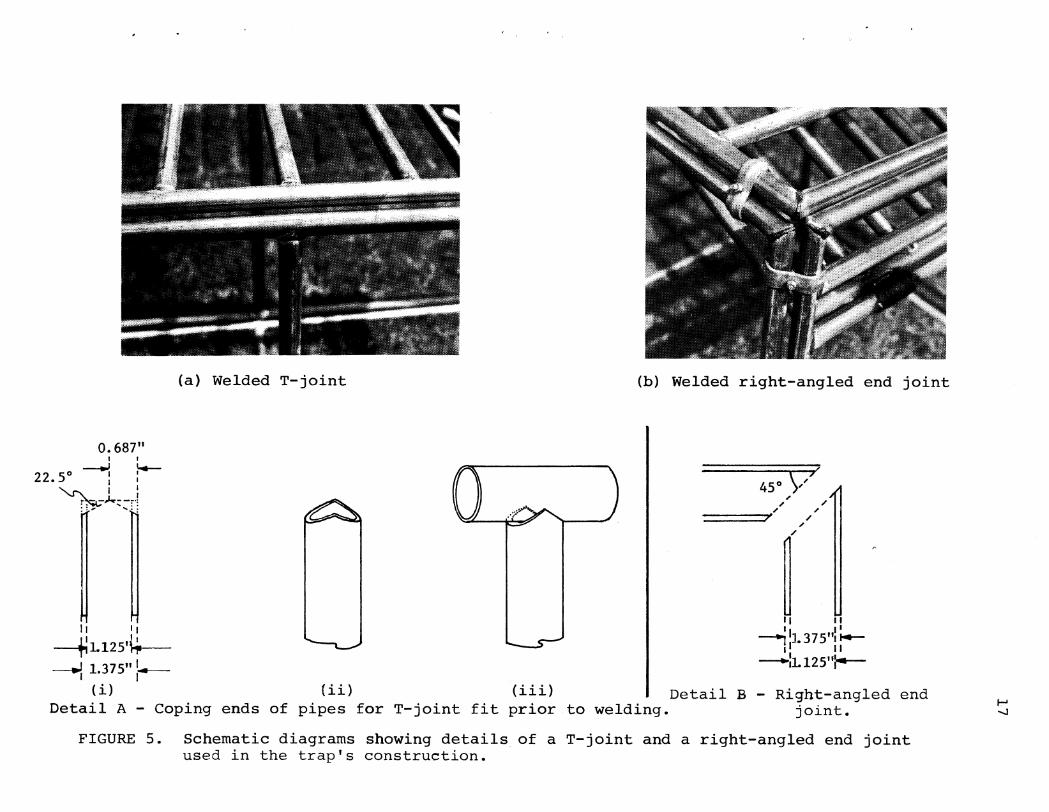
5 Schematic diagrams showing details (A & B) of a T-joint and a right-angled end joint
. . . . . . 16
used in the trap's construction. . . . . . . . . • 17
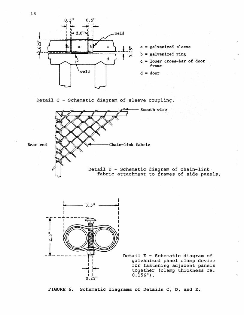
6 Schematic diagrams of Details C, D, and E. . . . . 18
7 Dual triggering capabilities of the portable metal box trap
8 Assembly sequence for the portable metal box trap.
9 Convertibility of the portable metal box trap
19
20
into multiple trap configuration • . . . . . . . . • 21

1
INTRODUCTION
In ecological studies of the wild pig (Sus scrofa L.), live, rather than dead animals, are often necessary for a variety of reasons. Live-capture of the animal with chemical methods has been attempted using carbon dioxide powered projectile syringes loaded with various immobilizing compounds. However, mechanical methods of obtaining the animal alive using devices such as corrals, traps, snares, nylon nets, and pitfalls have been used more commonly. Among more conventional capture methods, the box trap has been widely used in research and control programs.
Technically, a box trap should have the configuration of a square or a rectangle consisting of a top cover, a bottom, two sides, and two end pieces, with any one side or end piece containing an entry device or becoming the door or entry itself. Among box traps used to trap free-ranging pigs, considerable variation exists in design, size, weight, construction materials, capture capabilities, and trap movability. An opportunity to critically review past and existing box traps for live-cap~ure of free-ranging pigs arose during a study of feral pigs in Kipahulu Valley, Haleakala National Park on the island of Maui, Hawai'i, in 1978. One object of the study was to estimate pig abundance with a mark-recapture method and to evaluate the feasibility and effectiveness of live-trapping as a method to control feral pigs. Therefore, it became necessary to use a suitable live-trap for the study.
The design and construction of the box trap, described herein and subsequently referred to as the metal box trap, took into consideration three sets of factors:
(1) the physical characteristics of the environment in which the traps were to be used. Kipahulu Valley is a remote, inaccessible, and protected wilderness area within Haleakala National Park. The sub-tropical montane rain forest receives about 400 inches of rain a year and the rugged terrain is dissected by many gulches. This rain forest supports a rich array of arthropods, including termites. Four wooden box traps constructed for use here earlier were found to have problems such as warpage, swelling, rusting, dislodgement of nuts and bolts, and breakage of hinges.
(2) the basic requirements of live-traps. According to Gilmore (1943), the characteristics of a useful live-trap include catching efficiency, portability, and durability. In the study area, where the pig is the only large quadruped, capture of animals other than the pig--a source of inefficiency--is of little importance. Consequently, the ability of a trap to catch and its catching capability (single or multiple) were important

2
in influencing trap efficiency. Because traps could only be air-dropped by helicopter into this remote wilderness area, it was necessary to make the box trap sectional so that individual components could be handcarried away from drop-sites. This flexibility was important because experience had shown that the closed canopy forest prevented airdrops to be made at previously ground-marked sites. Finally, to be durable, the box trap should be able to withstand the local weather conditions and the abuses and escape efforts by the captured animals as well as be relatively maintenance free and long-lasting.
{3) the operator's ease and safety of handling captured animals. Since captured animals were to be man-handled, considerations were given to a design that would allow efficient, safe restraint of one or more animals in such a box trap.
Based on the above factors, it was decided to design and construct a portable, durable, efficient metal box trap with multi-catch capability.
LITERATURE REVIEW
Documentation on the scientific use of box traps for capturing wild pigs in the United States began in 1959 when a life history study on the animal was initiated in the Tellico Wildlife Management Area in Tennessee. A portable 7 x 3 x 4.5 foot box trap with a vertical sliding door and a pen trap was used by Matschke {1962) in the study. Used extensively by research biologists in Tennessee and the Southeast, the box trap became known as Matschke's trap and the door mechanism was variously referred to as single-release action door, guillotine door, and single-catch door. Although called portable, Matschke's trap was in fact only transportable by a wagon or pick-up truck. Such transportable, rigid, and non-dismountable box traps were also used by Barrett {1971), in addition to other panel traps and corrals, in an ecological study of feral pigs in Northern California. Typically, wagon-portable box traps are not dismountable. They have sides which are rigidly nailed, bolted, or welded together. They are constructed to load onto the bed of a vehicle and are used in areas where there is road access.
To enhance trap portability, several workers have designed box traps which can be disassembled into its component parts. The parts then can be conveniently reassembled at another location. Sweeney {1970) live-trapped feral pigs in South Carolina with an 8 x 3 x 4 foot dismountable box trap made from slats of pine and cypress. The trap can be disassembled into five major components for ease of transportation. Confronted with problems of erecting pig traps in more inaccessible areas in the Great Smoky Mountains National Park, Williamson and Pelton {1971)

3
re-designed the widely used Matschke trap by making it sectional and, thereby, portable.
Box traps vary physically in dimensions; construction materials (raw lumber, construction timber, plywood, iron or rust-free metal, bull wire, chain-link fabric); degree of portability; trigger mechanism; and door design. Operationally, some designs incorporate features which allow easier and safer handling of live animals and better capture efficiencies and capabilities. Both Williamson and Pelton's (1971) and Matschke's (1962) designs have their top panels netted with chain-link fabric. Roping of live pigs in such traps, a necessary procedure in physical restraint of the animal, is more difficult than in traps with evenly spaced cross-pieces on the top panel, for example, Barrett's (1971 & pers. comm. 1979).
Variations in a box trap include designs of box-like traps where one or more panels are missing. Such open-top or open-topand-open-bottom box-like traps have been used by the Game and Fresh Water Fish Commission in Florida (Belden & Frankeriberger 1979); So'uth' Carolina (Wood, pers. comm.); California (Barrett 1971); and Australia (Hone & O'Grady 1980). Any box-like trap with one or more panels missing should be termed panel traps, not box traps. Characteristic of these panel traps are their greater height (especially in open-top designs); larger dimensions; higher escape frequencies; and difficulties in physically restraining the animal.
Some differences and similarities between box and panel traps may be seen in Table 1. Unlike panel traps, box traps are escape-proof and can be moved about as a single unit in a vehicle. Their transportability, portability, and effectiveness over pen- and corral-type traps and their easy physical restraint of live-captures make box traps a superior catching device over other mechanical devices. Multi-catch doors, entry devices which permit entry of subsequent animals, are more commonly used in panel and corral traps but not in box traps.
MATERIALS AND METHODS
Construction of the metal box traps was done in Maui Community College Welding Technology Workshop equipped with standard power supply units for arc and gas metal-arc welding. Galvanized pipe was the main construction material. The materials needed for the construction of each trap were as follows:
176 ft. galvanized pipe (O.D. = 1.375 ins.; I.D. = 1.125 ins.)
80 ft. smooth wire (12 guage) 24 sets panel clamps 9 ft. chain-link fabric, 6 ft. wide (9 guage) 4 0.5-in. length galvanized pipes
(O.D. = 1.625 ins.; I.D. = 1.437 ins.)
4
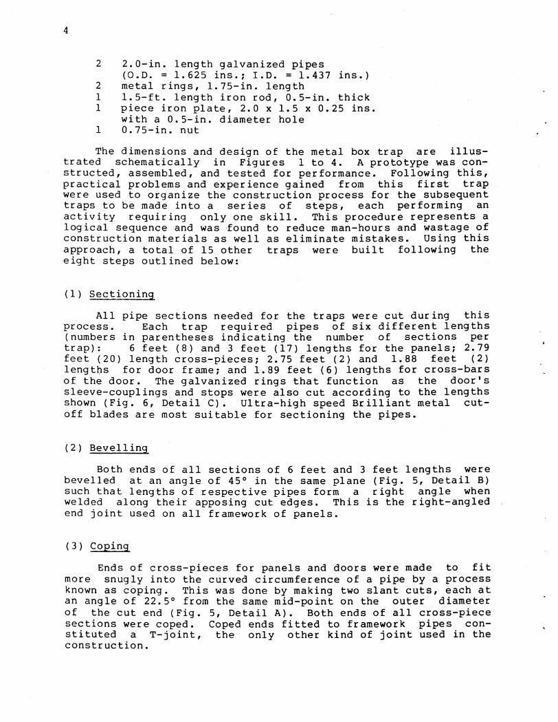
2 2.0-in. length galvanized pipes (O.D. = 1.625 ins.; I.D. = 1.437 ins.}
2 metal rings, 1.75-in. length 1 1.5-ft. length iron rod, 0.5-in. thick 1 piece iron plate, 2.0 x 1.5 x 0.25 ins.
with a 0.5-in. diameter hole 1 0.75-in. nut
The dimensions and design of the metal box trap are illustrated schematically in Figures 1 to 4. A prototype was constructed, assembled, and tested for performance. Following this, practical problems and experience gained from this first trap were used to organize the construction process for the subsequent traps to be made into a series of steps, each performing an activity requiring only one skill. This procedure represents a logical sequence and was ·found to reduce man-hours and wastage of construction materials as well as eliminate mistakes. Using this approach, a total of 15 other traps were built following the eight steps outlined below:
(1} Sectioning
All pipe sections needed for the traps were cut during this process. Each trap required pipes of six different lengths (numbers in parentheses indicating the number of sections per trap}: 6 feet (8} and 3 feet (17} lengths for the panels; 2.79 feet (20} length cross-pieces; 2.75 feet (2} and 1.88 feet (2} lengt~s for door frame; and 1.89 feet (6} lengths for cross-bars of the door. The galvanized rings that function as the door's sleeve-couplings and stops were also cut according to the lengths shown (Fig. 6, Detail C). Ultra-high speed Brilliant metal cutoff blades are most suitable for sectioning the pipes.
(2} Bevelling
Both ends of all sections of 6 feet and 3 feet lengths were bevelled at an angle of 45° in the same plane (Fig. 5, Detail B) such that lengths of respective pipes form a right angle when welded along their apposing cut edges. This is the right-angled end joint used on all framework of panels.
(3} Coping
Ends of cross-pieces for panels and doors were made to fit more snugly into the curved circumference of a pipe by a process known as coping. This was done by making two slant cuts, each at an angle of 22.5° from the same mid-point on the outer diameter of the cut end (Fig. 5, Detail A}. Both ends of all cross-piece sections were coped. Coped ends fitted to f~amework pipes constituted a T-joint, the only other kind of joint used in the construction.

5
(4) Burring_
Ends of all sections, as well as coped ends were cleaned of any burr on a belt sanding machine prior to welding.
(5) Framework Welding
With two right-angled bars as guides, corner frames of panels were first tack-welded and then arc-welded together using 3/32-inch E 6010 electrodes.
(6) Cross-piece Welding
Cross-pieces for the rear end, sides, top, bottom, and door panels were spaced out at intervals as shown in Figures 1 to 4. All cross-pieces which form a T-joint with the frame were arcwelded in place along the coped edge of the pipe. Sleeves and sleeve stops for the door (Fig. 6, Detail C) were inserted into the lower cross-piece of the door panel before they were welded to their respective attachments as shown.
(7) Sleeve-coupling
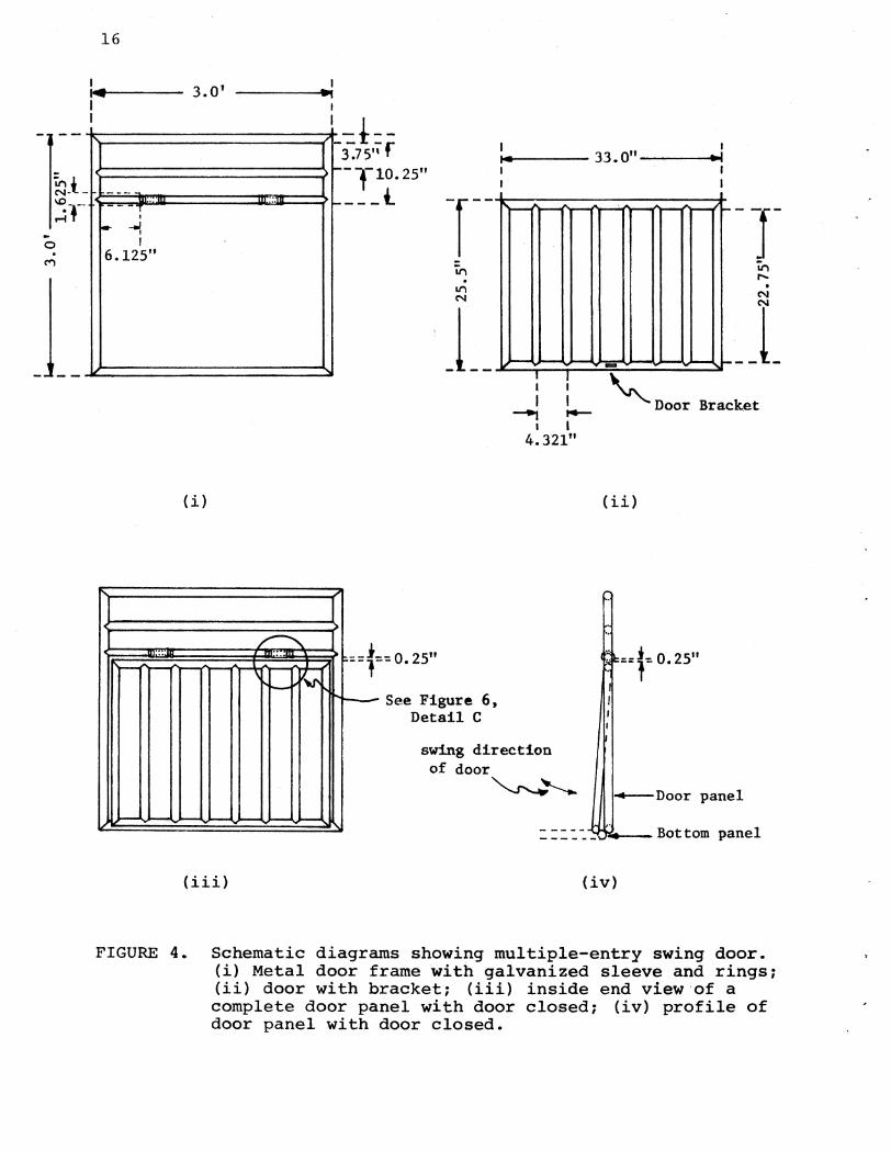
The door (Fig. 4-ii) was attached to the door frame (Fig. 4-i) by means of two sleeve-couplings. This was done by positioning the door at approximately 0.25 inch below the lower cross-piece of the door frame (Fig. 4-iii). The sleeves then came in close proximity to the door to which they were arc-welded (Fig. 6, Detail C). Galvanized rings acting as sleeve stops were tack-welded to the lower cross-piece of the door frame to prevent any lateral movement of the sleeves and door.
(8) Attachment of Door Bracket and Pull-pin
The door bracket was welded to the inside bottom door frame. It was aligned such that when the door was swung up as far as it could go, the pull-pin would catch on the bracket (Fig. 7-a). The bracket, pull-pin, and metal rings on the top-piece cross-bar were all in line.
RESULTS AND DISCUSSION
Each completed metal box trap measures 6 x 3 x 3 feet and has a total of six separable panels--top, rear, door, bottom, and two side panels. The cost of materials per trap is about $145.00. Total construction time is eight man-hours. With a labor charge of $30.00 per man-hour for a professional welder in Hawai'i, the work cost per trap, excluding materials, will be $240.00. The bottom and two side panels are identical in design

6
and are completely interchangeable. The assembly sequence of the metal box trap is as shown in Figure 8. All panels are held together along adjacent edges by two sets of panel clamps, except for the rear and door panels. The clamps are positioned at about 6 inches from the corners of the panels. The chain-link fabric is wired with smooth wire (Fig. 6, Detail D) to the two upper and end frames of the two side panels and the front and rear end frames of the bottom panel. The center cross-piece on each side panel is secured to the fabric by twisting short lengths of smooth wire with a pair of pliers. Trap assembly requires only a 0.5-inch socket wrench and can be done by one person in 20 minutes.
Although wires can fasten fabric to the frame, Punch Lok Hose Clamps can also be used. Belden and Frankenberger (1979) found clamps suitable.
When a box trap is made sectional, devices to hold component panels of the trap rigidly together become essential. Strings and other ties have been used to fasten adjacent panels of sectional traps (Belden & Frankenberger 1979; Hone & O'Grady 1980). Such ties can be clumsy and do not make the traps rigid. Williamson and Pelton (1971) used a system of pins and connecting rods to hold panels together. Panel clamps used in this metal box trap are superior to other fastening devices that have been used. The clamps are rust free, lock panels in place, give the trap rigidity, and are convenient to use.
One of the problems often encountered in any long-term livetrapping program is that some animals become trap wary. Accordingly, some box traps provide design features which allow the researcher to counteract such a behavior. The box trap designed by Foreyt and Glazener (1979) has two doors and both can be opened to trap wary animals. The metal box trap has a dual triggering--pull-pin and root-bar--capability to counteract trap wariness. In the pull-pin trigger mechanism, the trap is activated by leading the trigger rope from the bait (e.g., hapu'u or tree fern, coconut) which is tied to the other end of the trigger string. Here the animal has to pull the bait to disengage the pull-pin from the door bracket, releasing the door. In the rootbar trigger mechanism, two sticks about 18 inches in length are notched (with a machete) about 3 inches from one end of each stick. The longer ends are driven into the ground 18 inches apart, with the notches facing the rear of the trap 6 inches above the ground. A stick serving as a cross-bar is inserted horizontally into the notches. A rope fastened to the cross-bar at one end is passed over the trap's top panel cross-piece, before being secured to the bottom frame of the trap door. The trigger system used here is similar to the root-peg system described by Matschke (1962), except that staples on the pegs are not used. The term root-bar is used here in preference to the more commonly used term root-peg because the animal has to root over the horizontal bar and not the pegs to release the door.
7
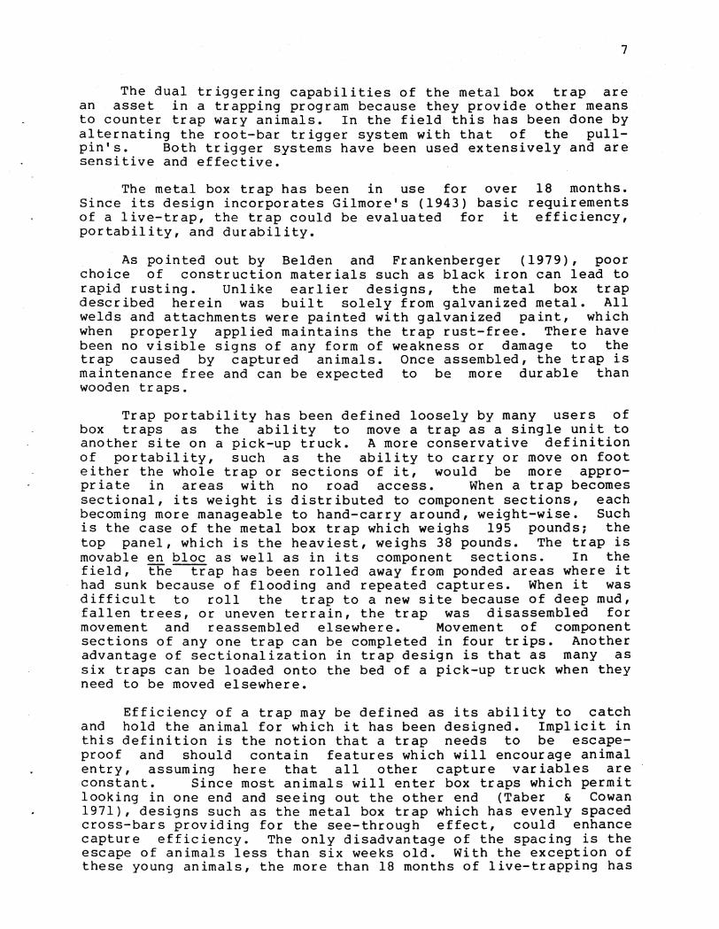
The dual triggering capabilities of the metal box trap are an asset in a trapping program because they provide other means to counter trap wary animals. In the field this has been done by alternating the root-bar trigger system with that of the pullpin's. Both trigger systems have been used extensively and are sensitive and effective.
The metal box trap has been in use for over Since its design incorporates Gilmore's (1943) basic of a live-trap, the trap could be evaluated for it portability, and durability.
18 months. requirements efficiency,
As pointed out by Belden and Frankenberger (1979), poor choice of construction materials such as black iron can lead to rapid rusting. Unlike earlier designs, the metal box trap described herein was built solely from galvanized metal. All welds and attachments were painted with galvanized paint, which when properly applied maintains the trap rust-free. There have been no visible signs of any form of weakness or damage to the trap caused by captured animals. Once assembled, the trap is maintenance free and can be expected to be more durable than wooden traps.
Trap portability has been defined loosely by many users of box traps as the ability to move a trap as a single unit to another site on a pick-up truck. A more conservative definition of portability, such as the ability to carry or move on foot either the whole trap or sections of it, would be more appropriate in areas with no road access. When a trap becomes sectional, its weight is distributed to component sections, each becoming more manageable to hand-carry around, weight-wise. Such is the case of the metal box trap which weighs 195 pounds~ the top panel, which is the heaviest, weighs 38 pounds. The trap is movable en bloc as well as in its component sections. In the field, the~ap has been rolled away from ponded areas where it had sunk because of flooding and repeated captures. When it was difficult to roll the trap to a new site because of deep mud, fallen trees, or uneven terrain, the trap was disassembled for movement and reassembled elsewhere. Movement of component sections of any one trap can be completed in four trips. Another advantage of sectionalization in trap design is that as many as six traps can be loaded onto the bed of a pick-up truck when they need to be moved elsewhere.
Efficiency of a trap may be defined as its ability to catch and hold the animal for which it has been designed. Implicit in this definition is the notion that a trap needs to be escapeproof and should contain features which will encourage animal entry, assuming here that all other capture variables are constant. Since most animals will enter box traps which permit looking in one end and seeing out the other end (Taber & Cowan 1971), designs such as the metal box trap which has evenly spaced cross-bars providing for the see-through effect, could enhance capture efficiency. The only disadvantage of the spacing is the escape of animals less than six weeks old. With the exception of these young animals, the more than 18 months of live-trapping has
8
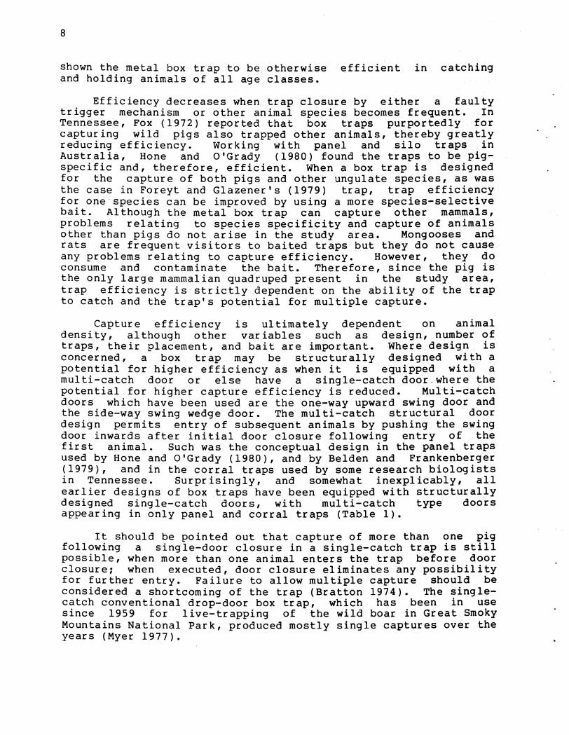
shown the metal box trap to be otherwise efficient in catching and holding animals of all age classes.
Efficiency decreases when trap closure by either a faulty trigger mechanism or other animal species becomes frequent. In Tennessee, Fox (1972) reported that box traps purportedly for capturing wild pigs also trapped other animals, thereby greatly reducing efficiency. Working with panel and silo traps in Australia, Hone and O'Grady (1980) found the traps to be pigspecific and, therefore, efficient. When a box trap is designed for the capture of both pigs and other ungulate species, as was the case in Foreyt and Glazener's (1979) trap, trap efficiency for one species can be improved by using a more species-selective bait. Although the metal box trap can capture other mammals, problems relating to species specificity and capture of animals other than pigs do not arise in the study area. Mongooses and rats are frequent visitors to baited traps but they do not cause any problems relating to capture efficiency. However, they do consume and contaminate the bait. Therefore, since the pig is the only large mammalian quadruped present in the study area, trap efficiency is strictly dependent on the ability of the trap to catch and the trap's potential for multiple capture.
Capture efficiency is ultimately dependent on animal density, although other variables such as design, number of traps, their placement, and bait are important. Where design is concerned, a box trap may be structurally designed with a potential for higher efficiency as when it is equipped with a multi-catch door or else have a single-catch door.where the potential for higher capture efficiency is reduced. Multi-catch doors which have been used are the one-way upward swing door and the side-way swing wedge door. The multi-catch structural door design permits entry of subsequent animals by pushing the swing door inwards after initial door closure following entry of the first animal. Such was the conceptual design in the panel traps used by Hone and O'Grady (1980), and by Belden and Frankenberger (1979), and in the corral traps used by some research biologists in Tennessee. Surprisingly, and somewhat inexplicably, all earlier designs of box traps have been equipped with structurally designed single-catch doors, with multi-catch type doors appearing in only panel and corral traps (Table 1).
It should be pointed out that capture of more than one pig following a single-door closure in a single-catch trap is still possible, when more than one animal enters the trap before door closure: when executed, door closure eliminates any possibility for further entry. Failure to allow multiple capture should be considered a shortcoming of the trap (Bratton 1974). The singlecatch conventional drop-door box trap, which has been in use since 1959 for live-trapping of the wild boar in Great Smoky Mountains National Park, produced mostly single captures over the years (Myer 1977).

9
The metal box trap can be converted into box traps of larger cages or into group traps of other configurations as shown in Figure 9(a-f). Completely interchangeable panels and the use of panel clamps allow end-to-end, side-to-side, side-to-end extensions, and group trap arrangement as in Figure 9(f). This convertibility has more flexibility than Williamson and Pelton's (1971) trap which only permits end-to-end extensions. In areas of high animal density, larger cage traps or group traps, as shown in Figure 9(a-f), are desirable because a larger percentage of those animals near the traps can be caught.
Continuous use of the metal box trap in a rain forest for over 18 months has shown that the trap is an efficient, practical, and safe way to catch free-ranging pigs for direct examination, population sampling, and mark-recapture studies. In a control program emphasizing reduction, the trap can be used to harvest animals for their relocation from areas where they are considered noxious into other game or hunting areas. In addition, the trap described herein is an improvement in structural design and operation over earlier designs. The features of this trap which are not found in other designs and considered unique are: (1) it is all-metal; (2) it is equipped with a multi-catch door which forms part of a panel; (3) it uses sleeve-coupling rather than conventional-type hinges for attachment of the door; {4) it employs convenient use of panel clamps for locking panels together; and (5) it allows a wide range of convertibility of the individual trap into group traps of any configuration.
ACKNOWLEDGMENTS
I thank Maui Community College for permission to use the facilities at its Welding Workshop. Raymond Texeira, Welding Instructor at the College, reviewed my trap design and suggested some useful changes. I am very grateful to him for his enthusiasm, cooperation, and assistance, without which this project would not have been possible or completed so readily. The assistance and advice given to me by Rediwelders Inc., Kahului, Maui, is gratefully acknowledged.
Several students from the Basic and Intermediate Welding Class of Spring and Fall 1979 assisted in building the traps. I thank all of them for their help. Deserving special mention are the following: Robert Victers, Barry Aoki, Irvin Cabacurgen, Roy Delatori, Wendall Owara, and M. S. Tang. I trust these and others, as students, have learned and benefited from the experience, just as I have.
Fred Ventura, transport manager at the College, personally serviced and saw to the roadworthiness of the Chevy pickup truck which he loaned me on three_different occasions to transport the traps from the College to Kipahulu; for that I am thankful.

10
I thank Dr. Clifford Smith for much encouragement and advice throughout this project, and Drs. Dennis Fenn and Reginald Barrett for field encouragement and interest in my work.
Finally, I need to acknowledge the following for their review and helpful suggestions for improvement of this manuscript during its draft stage: Dr. Clifford Smith, Dr. Dennis Fenn and maintenance staff in the Western Region, staff at the Haleakala National Park, and June Saito.
LITERATURE CITED
Barrett, R. H. 1971. Ecology of the feral hog in Tehama County, California. Ph.D. Dissertation, University of California, Berkeley (Unpublished). 368 pp.
Belden, R. c., and w. B. Frankenberger. 1979. A portable root-door hog trap. Proc. Ann. Conf. Southeast. Assoc. Fish Wildl. Agencies 31: 123-125.
Bratton, s. P. 1974. An integrated ecological approach to the management of the European wild boar (Sus scrofa) in Great Smoky Mountains National Park. Grea~Smoky Mountains National Park, Management Report No. 3. 49 pp.
Foreyt, W. J., and W. C. Glazener. 1979. A modified for capturing feral hogs and white-tailed deer. Nat. 24: 377-380.
box trap Southwest.
Fox, J. R. 1972. An evaluation of control techniques for the European wild hog (Sus scrofa) in the Great Smoky Mountains National Park of Tennessee. M.S. Thesis, University of Tennessee, Knoxville (Unpublished). 76 pp.
Gilmore, R. M. 1943. Mammalogy in an epidemiological study of jungle yellow fever in Brazil. J. Mamm. 24: 144-162.
Hone, J., and J. O'Grady. 1980. rmer Bulletin) A 4 .1.1, riculture. 23 pp. \)) V; HdY\ t.f flNt\ w- 4 l f\-v )N c.flllY\
Matschke, G. H. 1962. Trapping Proc. Ann. Conf. Southeast. 16: 21-24.
Feral pigs and their control. New South Wales, Department of
13ull-t-h~ and handling European wild hogs. Assoc. of Game and Fish Comm.
Myer, M. W. 1977. Trap and door design. Great Smoky 4 pp.
Mountains National Park. Mimeo. (Unpublished).
Sweeney, J. M. 1970. Preliminary investigations of a feral hog (Sus scrofa) population on the Savannah River plant, South Carolina. M.S. Thesis, University of Georgia (Unpublished). 58 pp.

11
Taber, R. D., and I. M. Cowan. 1971. Capturing and marking wild animals. Pages 277-318 in R. H. Giles, ed. Wildlife Management Techniques. 3rd Edition. The Wildlife Society, Washington, D.C. 633 pp.
Williamson, M. J., and M. R. Pelton. 1971. New design for a large portable mammal trap. Proc. Ann. Conf. Southeast. Assoc. Game and Fish Comm. 25: 315-322.
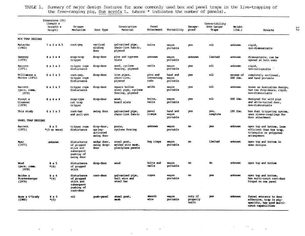
TABlE 1.
BOX TRAP DESIQIS
Matschke (1962)
Sweeney (1970)
Barrett (1971)
Williamson & Pelton (1971)
Barrett (pers. cama.
1979)
Foreyt & Glazener (1979)
'lllis stlrly
Sumnary of ITB.jor design features for sorre comronly used box ai1d panel traps in the live-trapping of the free-ranging pig, Sus scrofa L. (where * indicates the nunber of panels).
Dimensions (ft) (length x breooth x height)
7 X 3 X 4.5
8 X 3 X 4
6 X 3 X 3
6 X 3 X 3
6 X 3 X 3
8 X 4 X 4
6 X 3 X 3
Trigger Mechanisn D:xlr Type
root-peg vertical sliding door
snap-trap drop-door trigger
trigger rope drop-door disturbance
root-peg , drop-door trigger rope disturbance
trigger rope drop-door disturbance
snap-type drop-door rat trap trigger
root-bar swing door and pull-pin
Construction Material
galvanized pipe, chain-link fabric, plY\>'O(ld
pine and cypress slats
..uod, cyclone fencing , pl Y\>'O(ld
iron pipes, chain-link, plY\>'O(ld
square hollow steel pipe, cyclone fencing, plY\>'O(ld
wood, board slats
galvanized pipe, chain-link fabric
Panel Escape-Attachment Portability proof
bolts
unknown
nails
pins and connecting rods
welds
bolts, nails
panel clamps
wagon portable
wagon portable
wagon portable
hand and wagon portable
wagon portable
wagon portable
hand and wagon portable
yes
unknown
yes
yes
yes
yes
yes
Convertibility into Larger
Traps
nil
limited
nil
nil
nil
nil
yes, canplete
Weight (lbs.)
unknown rigid,
Remarks
non-disnountable
unknown disnountable, can be opened at both ends
unknown rigid, non-collapsible
excess of canpletely sectional, 200 lbs. and hand portable
unknown known as Australian design, has two drop-doors, rigid, non-disnountable
200 lbs. designed for wild pigs and lo'hi te-ta iled deer, non-disnountable
195 lbs. has dual triggering system, uses sleeve-couplin3s for door attacl"ment
PANEL TRAP DESIQIS
Barrett ( 1971)
Myer (1977)
lobld {pers. cama.
1978)
Belden & Frankenberger (1979)
Bone & O'Grady (1980)
8 X 5 *(3 or more)
l.nlaxMl
8 X 5 *(4)
8 X 4 *(4)
8 II: 5 *(5)
trigger rope disturbance
disturbance of propped stick and subsequent pushing of swing door
disturbance of propped stick
disturbance of propped stick and stbsequent pushing of root-door
nil
drop-door, springactivated swing door
wedge door, swing dropdoor
drop-door
root-door
push-panel
posts, cyclone fencing
steel post, welded wire mesh, plexiglass panels
wood
galvanized pipe, bull wire and steel bar
steel post, mesh
lnknown
hog rings
bolts and nails
ropes
smooth wire
wagon portable
wagon portable
wagon portable
wagon portable
wagon portable
00
00
00
00
only if properly brllt
yes
limited
00
yes
yes
lnlaxMl
unknown
Ll'llaxMl
l.nlaxMl
lnknown
open top and bottom, less efficient than box trap, triangular or pol:rgonal arrangement
open top and bottom in sane designs
open top and bottcm
open top and bottom, has multi-catch root-door hinged on one panel
f~.nnel entrance to door effective, trap is pigspecific, has good multicatch capabilities
I-' [\.)

0 . ('I')
I '--
~See Figure 6, Detail D
6 • 0 I
~See Figure 5, Detail A
_,
-- --~-------f~--------------------------------------------------,_---------------------------------------------------» I I
I 3 0' 1"4 • I
__.
FIGURE 1. Schematic diagram of the side and bottom panels for the portable metal box trap (side view).
~see Figure 5, Detail B
1-' w

Rear end
0
M
I I
I I
"' A
r--
~ ·.-! ll:.t
~ Ul
oW
'V v
I 1 I I I I
-----... -16. 925 ..... .__ __ I I I I
6.0'
A. A
r--
~ ·.-! ll:.t
~ (';:::.. In~~
""
"' 'V
A: A -.;.
In I"
( ~ 'V v
'\ /
~ See Figure 5,
Detail A
....
I ~ _,
~
r ~ '
"
~-See F1.gure 5, Detail B
FIGURE 2. Schematic diagram of the top panel {not requiring chain-link fabric) for the portable metal box trap (plan view).
Front end
1-' ~

-0
C"')
I ,_ I I 3.0• ~,
I I
~----------------------------~~
~----------------------------~~ J
~----------------------------~~
l ~ ~------------------------~,
(jr-1
"-J~ ;1-r-
IL___ ________ -- I
__ t__ 5.437"
--f--j __ _ 4.750" -f--
(.See Figure 5, Detail A
~see Figure 5, Detail B
FIGURE 3. Schematic diagram of the end piece of the portable metal box trap (end view).
,_, 1.11
-
.. 0 . t"')
16
I ... I_..,_ ___ 3. 0' I .. I I
I I
--- ... ---, I
1-- -! I
6.125"
(i)
~ ..
' f\; 1'-
(iii)
I
I-t--1-i7s•lf ~
~
-Tlo.25" ___ i_
__ J --l =-= o. 25"
. 11"1 N
_l __
t--- See Figure 6, Detail C
I 14----- 33. 0" ___ ......... I
I I I I
I I ~ ..
I l 4.321''
- I-
I I
~
1-
~Door Bracket
(ii)
.. j " ==r 0.25
swing direction of door
~....__ ---Door panel
______ uo;e-- Bot tom panel
(iv)
FIGURE 4. Schematic diagrams showing multiple-entry swing door. (i) Metal door frame with galvanized sleeve and rings; (ii) door with bracket; (iii) inside end view·of a complete door panel with door closed; (iv) profile of door panel with door closed.
(a) Welded T-joint
0.687" I I
22.5° 4 !--I I
~.L:::-:-i ~=
II It ---+: L125'\.1.--
--ll.375" :-
(b) Welded right-angled end joint
450 );~7
======:::7' , ,
[ , /
/ ,
,, il 1 tl
--., 11. 3 7 5 "t .,._ ,t II
-:L125"l--
(i) {ii) (iii) I Detail B - Right-angled end Detail A - Coping ends of pipes for T-joint fit prior to welding. joint.
FIGURE 5. Schematic diagrams showing details of a T-joint and a right-angled end joint used in the trap's construction.
~ -....1
18
0.-~11 0.5" ~I loot- --...: :...,_
I ., ,• I
I l~oe-2 ou...>' r I II ·• II I
a = galvanized sleeve
b = galvanized ring
c • lower cross-bar of door frame
d = door
Detail C - Schematic diagram of sleeve coupling.
Rear end
I I
Detail D- Schematic diagram of chain-link· fabric attachment to frames of side panels.
3.511
-r-r -~-~-~:B:::::;;;;~ • I Ln . N
I
I I
~~ I I
0.2511
Detail E - Schematic diagram of galvanized panel clamp device for fastening adjacent panels together (clamp thickness ca. 0.156").
FIGURE 6. Schematic diagrams of Details C, D, and E.

FIGURE 7(a). Pull-pin trigger.
·-····----· ,.,. " "'"':; ~
1[. ~ .• , ' ,, 1 ' l
" ·'·"'··~'·"""""' <i· .· ' • (' • p rr . •
(i) Pull-pin trigger mechanism (ii) Root-bar trigger mechanism
FIGURE 7(b). Dual-triggering capabilities of the portable metal box trap.
1-' IJ)

20
(a) (b)
(c) (d)
(e) (f)
FIGURE 8. Assembly sequence for the portable metal box trap.

(a) (b) (c)
(d) (e) (f)
FIGURE 9. Convertibility of the portable metal box trap into multiple trap configuration.
1\J 1-'