Embed Size (px)
Citation preview
VYSOKÉ UČENÍ TECHNICKÉ V BRNĚ BRNO UNIVERSITY OF TECHNOLOGY
FAKULTA STROJNÍHO INŽENÝRSTVÍ LETECKÝ ÚSTAV FACULTY OF MECHANICAL ENGINEERING INSTITUTE OF AEROSPACE ENGINEERING
NÁVRH A PEVNOSTNÍ KONTROLA SYSTÉMU ŘÍZENÍ LETOUNU TL 4000 DESIGN OF THE CONTROL SYSTEM OF TL 4000 AIRCRAFT
DIPLOMOVÁ PRÁCE MASTER’S THESIS
AUTOR PRÁCE Bc. MARTIN GREŇ AUTHOR
VEDOUCÍ PRÁCE Ing. JAN ŠPLÍCHAL SUPERVISOR BRNO 2015

Vysoké učení technické v Brně, Fakulta strojního inženýrství Letecký ústav Akademický rok: 2014/2015
ZADÁNÍ DIPLOMOVÉ PRÁCE student(ka): Bc. Martin Greň který/která studuje v magisterském navazujícím studijním programu obor: Stavba letadel (2301T039) Ředitel ústavu Vám v souladu se zákonem č.111/1998 o vysokých školách a se Studijním a zkušebním řádem VUT v Brně určuje následující téma diplomové práce:
Návrh a pevnostní kontrola systému řízení letounu TL 4000
v anglickém jazyce:
Design of the control system of TL 4000 aircraft
Stručná charakteristika problematiky úkolu: Proveďte konstrukční návrh systému podélného, příčného a směrové řízení letounu TL 4000. Vypracujte kinematický mechanismus jednotlivých tras řízení pomocí modulu „DMU Kinematics“ systému CATIA V5 a proveďte podrobný konstrukční návrh jednotlivých součástí tras podélného, příčného a směrové řízení. Dále pak stanovte zatížení jednotlivých tras řízení od sil vyvozených pilotem a proveďte jejich pevnostní kontrolu na toto zatížení. Na závěr stanovte převodové poměry jednotlivých tras v závislosti na výchylce jednotlivých řididel.
Cíle diplomové práce: 1.Vytvoření kinematického modelu systémů řízení letounu TL 4000 2.Vytvoření podrobného konstrukčního návrhu jednotlivých součástí řízení 3.Stanovení zatížení a pevnostní kontrola tras řízení 4.Stanovení převodových poměrů tras řízení

Seznam odborné literatury: [1] Stavební předpis CS-23 [2] Michael Chun-Yung Niu, Airframe structural Design [3] V. Mertl,Konstrukce a projektování letadel [4] M.N.Šulženko, Konstrukce letadel
Vedoucí diplomové práce: Ing. Jan Šplíchal. PhD.
Termín odevzdání diplomové práce je stanoven časovým plánem akademického roku 2014/2015. V Brně, dne 14.11.2014
L.S.
_______________________________ _______________________________
doc. Ing. Jaroslav Juračka, Ph.D. doc. Ing. Jaroslav Katolický, Ph.D. Ředitel ústavu Děkan fakulty

Abstrakt
Tato diplomová práce se zabývá návrhem mechanismu řízení letounu TL 4000, určení sil
působících na jednotlivé součásti řízení a jejich pevnostní analýzou. V této práci jsou
vypracovány všechny tři složky řízení a to tak, aby vyhovovaly stavebnímu předpisu CS 23.
Klíčová slova
Mechanismus, řízení, optimalizace, pružnost pevnost, FEM, CATIA, CAD
Abstract
This master’s thesis deals with design of control system for TL 4000 plane, determination of
forces acting on individual parts of this system and their stress analysis. In this thesis all three
control routes are worked out in a way that they will meet CS 23 regulations.
Keywords
Mechanism, control system, solid mechanics, optimization, FEM, CATIA, CAD

Bibliografická citace
GREŇ, M., Návrh a pevnostní kontrola systému řízení letounu TL 4000, Vysoké učení technické
v Brně, Fakulta strojního inženýrství, 2015, 78 s. Vedoucí diplomové práce Ing. Jan Šplíchal, PhD.

Prohlášení
Prohlašuji, že jsem tuto diplomovou práci vypracoval samostatně pod vedením Ing. Jana
Šplíchala, PhD. a uvedl jsem všechny literární prameny, publikace a elektronické zdroje, ze
kterých jsem čerpal.
..................................
Martin Greň
29. 5. 2015
Poděkování
Chtěl bych tímto především poděkovat svým rodičům, kteří mě podporovali po celou dobu
tohoto studia až do jeho zdárného ukončení. Dále bych chtěl poděkovat Ing. Janu Šplíchalovi,
PhD. za trpělivost, cenné rady a vedení v průběhu tvorby této práce. Ing. Tomášovi Uríkovi, PhD.
patří mé poděkování za uvedení do problematiky mechanismu v softwaru CATIA V5 a
Ing. Michalu Mališovi, PhD. za konzultace ohledně výpočtu pružnosti a pevnosti.
List of content
1 Introduction ........................................................................................................................................................... 11
2 Thesis goals ............................................................................................................................................................ 11
3 About TL-4000 ...................................................................................................................................................... 11
3.1 Control mechanism design requirements and challenges ........................................................ 12
4 CS-23 regulation extract ................................................................................................................................... 14
4.1 Used specification ...................................................................................................................................... 14
4.2 Comments to regulations appliance ................................................................................................... 19
5 Similar planes in regards to the control mechanism and the certification category ............... 20
5.1 Cirrus SR22G5 ............................................................................................................................................. 20
6 Process of designing control routes ............................................................................................................. 23
6.2 CATIA design process ............................................................................................................................... 24
6.3 CATIA CAD model description .............................................................................................................. 25
6.4 Basic Kinematics Scheme ........................................................................................................................ 26
6.5 FEM role in kinematic design ................................................................................................................ 27
7 FEM model description ..................................................................................................................................... 28
7.1 Process of building a model ................................................................................................................... 28
7.2 Forces .............................................................................................................................................................. 31
7.3 Load cases ..................................................................................................................................................... 31
7.4 Element properties .................................................................................................................................... 34
7.5 Analysis properties .................................................................................................................................... 35
8 Analysis results ..................................................................................................................................................... 36
8.1 Elevator route results ............................................................................................................................... 36
8.2 Aileron route results ................................................................................................................................. 37
8.3 Rudder route results ................................................................................................................................. 38
8.4 Buckling calculations ................................................................................................................................ 38
8.5 Tension calculations ................................................................................................................................. 41
9 Resultant rods and cables dimensions ........................................................................................................ 42
9.1 Elevator system ........................................................................................................................................... 42
9.2 Aileron system ............................................................................................................................................. 43
9.3 Rudder system ............................................................................................................................................. 43
10 Structural assemblies ......................................................................................................................................... 44
10.1 Sidestick assembly ..................................................................................................................................... 44
10.2 Torsion Tube assembly ............................................................................................................................ 45

10.3 60x60 lever assembly ............................................................................................................................... 51
10.4 Triangle lever assembly........................................................................................................................... 51
10.5 50x50 lever assembly ............................................................................................................................... 52
10.6 Elevator-Aileron Mid fuselage assembly .......................................................................................... 52
10.7 Fuselage wall assembly ........................................................................................................................... 53
10.8 Elevator-rudder assembly ...................................................................................................................... 53
10.9 Pedal lever assembly ................................................................................................................................ 54
11 Levers........................................................................................................................................................................ 54
11.1 Design solution ............................................................................................................................................ 54
11.2 Lever calculations ...................................................................................................................................... 54
11.3 100x70 lever ................................................................................................................................................ 56
11.4 60x60 lever ................................................................................................................................................... 59
11.5 Aileron lever assembly............................................................................................................................. 61
11.6 Aileron route mid subassembly ........................................................................................................... 62
11.7 Pedal lever ..................................................................................................................................................... 63
12 Bearings check ...................................................................................................................................................... 64
13 Fork heads analysis ............................................................................................................................................. 65
13.1 Fork head stress calculation .................................................................................................................. 66
14 Fasteners ................................................................................................................................................................. 68
14.1 Stress calculations ..................................................................................................................................... 69
15 Pulleys ...................................................................................................................................................................... 70
16 Gear ratios ............................................................................................................................................................... 71
16.1 Lateral gear ratios ...................................................................................................................................... 71
16.2 Longitudinal gear ratios .......................................................................................................................... 72
16.3 Rudder gear ratio ....................................................................................................................................... 73
17 Sidestick movement rotation diagrams ...................................................................................................... 74
18 Conclusion ............................................................................................................................................................... 76
19 List of sources ........................................................................................................................................................ 77
19.1 Literature sources ...................................................................................................................................... 77
19.2 Internet sources .......................................................................................................................................... 77
20 List of attachments .............................................................................................................................................. 78

P a g e | 11
1 INTRODUCTION
This thesis looks into a solution for control system of TL 4000 prototype plane which was made
to order by TL Ultralight Company and created in close cooperation under their supervision.
Nevertheless more often was the designing process discussed and supervised by BUT
employees involved in this project as well. Further chapters deals with TL4000’s details and
technical specification including certification regulations.
2 THESIS GOALS
The goal of this thesis is to design a complete control system of TL 4000 including CS 23
regulation extract together with its explanation, mechanism sketch, force calculations together
with sufficient part sizing and complete CAD model of this whole system prepared to be
manufactured and used in the real TL4000 prototype. Every aspect of this design process will be
thoroughly described and explained in order to be as close to a technical report as possible.
From the beginning of this project the control system is designed to be authorized, certified,
directly manufactured and used in a real plane.
This thesis’ goals are namely:
1. Creation of kinematic model of control system of TL4000 aircraft
2. Creation of thorough design of individual parts of the system.
3. Load determination and stress analysis of individual system’s routes.
4. Determination of gear ratios of individual system’s routes.
3 ABOUT TL-4000
TL-4000 is a single engine, fully composite airplane for European and North American private
market developed in cooperation between TL Ultralight co. and Brno University of Technology.
TL4000 falls within CS 23 and FAR 23 regulations which beside among others means more strict
criterions for the plane to fulfil.
This plane is meant to carry a pilot and 3 passengers including baggage stashed in luggage area.
Because this class market is overfilled with similar aircrafts of this category, TL4000 has to offer
various positive operational and maintenance properties.
The main TL4000’s design features are:
seat configuration for a pilot and 3 passengers
cruise speed of 300 kph
non-treacherous and pleasant flight behaviour
possibility of using grass landing strips (minimal length of 700 m)
P a g e | 12
maximum possible comfort for pilot and passengers
The plane will be certified in CS 23 NORMAL category and it’s limited to non-acrobatic usage.
These manoeuvres are allowed:
Normal flight manoeuvres
Over pull (except steep over pull)
Lazy eights (horizontal eights), bell manoeuvres or similar with the longitudinal angle
smaller than 60°
Table 3-1: TL 4000 expected weights
Weights Value [kg] Maximum take-off weight 1550 Maximum landing weight 1500 Empty weight 900÷1000 Maximum payload 600 Maximum luggage weight 60 Maximum weight of fuel in wing fuel tanks 216 (300 l)
TL-4000 has a low-wing configuration. Trapezoidal tapered wing with a small dihedral angle
and low aspect ratio are the main geometrical characteristics of the wing.
In regards to material and manufacturing process, the wing has a cantilever structure (front
beam is continuous) and its main structure is made of composite.
Table of technical details-dimensions extracted from CATIA CAD model provided by BUT.
Table 3-2: TL4000's relevant data table
Length 7915 mm Wingspan 10788 mm Dihedral angle 3,6 ° Maximum take-off weight 1550 kg
Empty weight 900 kg
Engine performance 231 kW
3.1 Control mechanism design requirements and challenges TL4000 uses a pair of sidesticks instead of regular stick or wheel used in most planes. This
arrangement is trending on today’s market and should ensure TL4000’s attractiveness for
future customers. This decision was made by TL Ultralight’s executive director Mr. Tlustý.
3.1.1 CONTROL BY SIDESTICK There are 2 types of sidestick. One is used in the newest airbus airliners and f.e. jet fighters and
they’re using fly-by-wire system which is much more complicated for use in CS 23 category. The
other sidestick conception is used in VLA category, such as SR22 by Cirrus Aircraft. Naturally,
the second option is used in TL4000.

P a g e | 13
Figure 3-1: SR22 cabin source: [6]
The pilot operates the sidestick with his left hand (co-pilot with his right). The basic motions
are: To deflect the elevator down, he pushes forward and to deflect the elevator up he pulls
backward. The ailerons control is managed by turning the stick with pilot’s wrist clockwise
(rolling right) or counter-clockwise (rolling left).
The range of forward/backward displacement is +59/-60 mm. The angle range is -27/+30° left
and right respectively. The neutral position of sidestick is approximately 45° tilted. This is
important so the pilot’s hand will not collide with inner cockpit skin while manoeuvring.
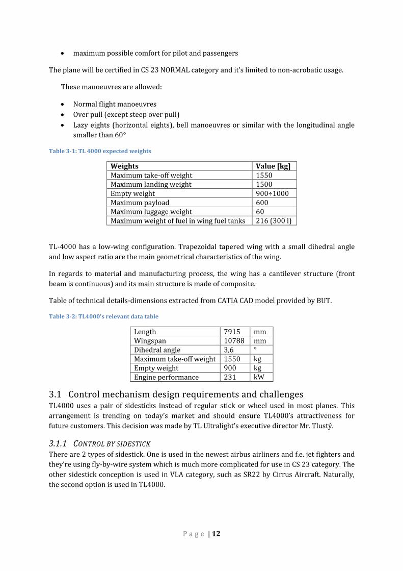
3.1.2 CONTROL BY PEDALS The yaw controls are manipulated by regular glider pedals. This set of pedals is provided
directly from TL Ultralight. The pedals are adjustable in range of 200 mm (fig 3-2.) This distance
is measured between the most distant pin holes in the leading tube.
The pilot’s force is transferred from pedals to rudder via system of cables, levers and pushrods.
Rotation of pedals is set to 20 degrees both directions and it’s linked to the other pedal of the
pilot and to co-pilot’s set of pedals as well.
P a g e | 14
Figure 3-2: Set of pedals
4 CS-23 REGULATION EXTRACT This thesis fulfils following regulations:
CS 23.143, CS 23.301 a), CS 23.303, CS 23.305, CS 23.307, 23.395, 23.397, 23.399, 23.607,
23.619, 23.625, 23.685, 23.777
4.1 Used specification 4.1.1.1 CS 23.143 General (a) The aeroplane must be safely controllable and maneuverable during all flight phases
including –
(1) Take-off;
(2) Climb;
(3) Level flight;
(4) Descent;
(5) Go-around; and
(6) Landing (power on and power off) with the wing flaps extended and retracted.
(b) It must be possible to make a smooth transition from one flight condition to another
(including turns and slips) without danger of exceeding the limit load factor, under any

P a g e | 15
probable operating condition, (including, for multi-engine aeroplanes, those conditions
normally encountered in the sudden failure of any engine).
(c) If marginal conditions exist with regard to required pilot strength, the control forces
required must be determined by quantitative tests. In no case may the control forces under the
conditions specified in sub-paragraphs (a) and (b), exceed those prescribed in the following
table:
Table 4-1: Maximum controlling forces [3]
4.1.1.2 23.301 Loads (a) Strength requirements are specified in terms of limit loads (the maximum loads to be
expected in service) and ultimate loads (limit loads multiplied by prescribed factors of safety).
Unless otherwise provided, prescribed loads are limit loads.
4.1.1.3 CS 23.303 Factor of safety Unless otherwise provided, a factor of safety of 1,5 must be used.
4.1.1.4 CS 23.305 Strength and deformation (a) The structure must be able to support limit loads without detrimental, permanent
deformation. At any load up to limit loads, the deformation may not interfere with safe
operation.
(b) The structure must be able to support ultimate loads without failure for at least three
seconds, except local failures or structural instabilities between limit and ultimate load are
acceptable only if the structure can sustain the required ultimate load for at least three seconds.
However, when proof of strength is shown by dynamic tests simulating actual load conditions,
the three second limit does not apply.

P a g e | 16
4.1.1.5 CS 23.307 Proof of structure (a) Compliance with the strength and deformation requirements of CS 23.305 must be shown
for critical load condition. Structural analysis may be used only if the structure conforms to
those for which experience has shown this method to be reliable. In other cases, substantiating
load tests must be made. Dynamic tests, including structural flight tests, are acceptable if the
design load conditions have been simulated.
(b) Certain parts of the structure must be tested as specified in Subpart D of CS-23.
4.1.1.6 CS 23.395 Control system loads (a) Each flight control system and its supporting structure must be designed for loads
corresponding to at least 125% of the computed hinge moments of the movable control surface
in the conditions prescribed in CS 23.391 to 23.459. In addition, the following apply:
(1) The system limit loads need not exceed the higher of the loads that can be produced
by the pilot and automatic devices operating the controls. However, autopilot forces
need not be added to pilot forces. The system must be designed for the maximum effort
of the pilot or autopilot, whichever is higher. In addition, if the pilot and the autopilot act
in opposition, the part of the system between them may be designed for the maximum
effort of the one that imposes the lesser load. Pilot forces used for design need not
exceed the maximum forces prescribed in CS 23.397 (b).
(2) The design must, in any case, provide a rugged system for service use, considering
jamming, round gusts, taxying downwind, control inertia and friction. Compliance with
this sub-paragraph may be shown by designing for loads resulting from application of
the minimum forces prescribed in CS 23.397 (b).
(b) A 125% factor on computed hinge movements must be used to design elevator, aileron and
rudder systems. However, a factor as low as 1,0 may be used if hinge moments are based on
accurate flight test data, the exact reduction depending upon the accuracy and reliability of the
data.
(c) Pilot forces used for design are assumed to act at the appropriate control grips or pads as
they would in flight and to react at the attachments of the control system to the control surface
horns.
4.1.1.7 CS 23.397 Limit control forces and torques (a) In the control surface flight loading condition, the air loads on movable surfaces and the
corresponding rotations need not exceed those that would result in flight from the application
of any pilot force within the ranges specified in sub-paragraph (b) . In applying this criterion,
the effects of control system boost and servo-mechanisms and the effects of tabs must be
considered. The automatic pilot effort must be used for design if it alone can produce higher
control surface loads than the human pilot.

P a g e | 17
(b) The limit pilot forces and torques are as follows:
Table 4-2: Limit control forces and torques [3]
1 For design weight (W) more than 2 268 kg (5 000 lb), the specified maximum values must be increased
linearly with weight to 1,18 times the specified values at a design weight of 5 670 kg (12 500 lb), and for
commuter category aeroplanes, the specified values must be increased linearly with weight to 1,35 times the
specified values at a design weight of 8 618 kg (19 000 lb).
2 If the design of any individual set of control systems or surfaces makes these specified minimum forces or
torques inapplicable, values corresponding to the present hinge moments obtained under CS 23.415, but not less
than 0,6 of the specified minimum forces or torques, may be used.
3 The critical parts of the aileron control system must also be designed for a single tangential force with a limit
value of 1,25 times the couple force determined from the above criteria.
4 D = wheel diameter ((meters)/(inches)).
5 The unsymmetrical force must be applied at one of the normal handgrip points on the control wheel.
4.1.1.8 CS 23.399 Dual control system (a) Each dual control system must be designed to withstand the force of the pilots operating in
opposition, using individual pilot forces not less than the greater of –
(1) 0,75 times those obtained under CS 23.395; or
(2) The minimum forces specified in CS 23.397 (b).
(b) Each dual control system must be designed to withstand the forces of the pilots applied
together in the same direction, using individual pilot forces not less than 0,75 times those
obtained under CS 23.395.
4.1.1.9 CS 23.607 Fasteners (See AMC 23.607 (b))
(a) Each removable fastener must incorporate two retaining devices if the loss of such fastener
would preclude continued safe flight and landing.
P a g e | 18
(b) Fasteners and their locking devices must not be adversely affected by the environmental
conditions associated with the particular installation.
(c) No self-locking nut may be used on any bolt subject to rotation in operation unless a
nonfriction
locking device is used in addition to the self-locking device.
4.1.1.10 CS 23.619 Special factors The factor of safety prescribed in CS 23.303 must be multiplied by the highest pertinent special
factors of safety prescribed in CS 23.621 to 23.625 for each part of the structure whose strength
is –
(1) Uncertain;
(2) Likely to deteriorate in service before normal replacement; or
(3) Subject to appreciable variability because of uncertainties in manufacturing
processes or inspection methods.
4.1.1.11 CS 23.623 Bearing factors (a) Each part that has clearance (free fit) and that is subject to pounding or vibration, must have
a bearing factor large enough to provide for the effects of normal relative motion.
(b) For control surface hinges and control system joints, compliance with the factors prescribed
in CS 23.657 and 23.693 respectively, meets paragraph (a) .
4.1.1.12 CS 23.625 Fitting factors For each fitting (a part or terminal used to join one structural member to another), the following
applies:
(a) For each fitting whose strength is not proven by limit and ultimate load tests in which actual
stress conditions are simulated in the fitting and surrounding structures, a fitting factor of at
least 1,15 must be applied to each part of –
(1) The fitting;
(2) The means of attachment; and
(3) The bearing on the joined members.
(b) No fitting factor need be used for joint designs based on comprehensive test data (such as
continuous joints in metal plating, welded joints and scarf joints in wood).
(c) For each integral fitting, the part must be treated as a fitting up to the point at which the
section properties become typical of the member.
(d) For each seat, berth, safety belt and harness, its attachment to the structure must be shown,
by analysis, tests, or both, to be able to withstand the inertia forces prescribed in CS 23.561
multiplied by a fitting factor of 1,33.
P a g e | 19
CS 23.685 Control system details (a) Each detail of each control system must be designed and installed to prevent jamming,
chafing and interference from cargo, passengers, loose objects, or the freezing of moisture.
(b) There must be means in the cockpit to prevent the entry of foreign objects into places where
they would jam the system.
(c) There must be means to prevent the slapping of cables or tubes against other parts.
(d) Each element of the flight control system must have design features, or must be distinctively
and permanently marked, to minimize the possibility of incorrect assembly that could result in
malfunctioning of the control system.
4.2 Comments to regulations appliance Even though the regulation orders the maximum pilot’s force to be according to CS 23.143, this
regards only permanent pilot load during a flight. The structure of control routes has to
withstand the loads from regulation CS 23.397 which are considerably higher. Because in the
time of designing this control system, there wasn’t clear if the route will be tested in actual
stress conditions, another safety factor of 1,15 according to CS 23.625 was used. The resultant
forces will be calculated and shown later in this thesis.
As TL4000 uses a sidestick instead of a regular pilot stick, it’s possible to consider it as a wheel-
type control system with restriction of maximum forces taken from 23.397b. Particularly 890 N
to pitch, torque of 2220 Nm to roll and 890 N to yaw as maximum forces acting in individual
routes.
There is a restriction for minimum forces also. §23.155 reflects on this in respect to elevator
control forces and for TL4000‘s case the minimum force is 155 N. But these forces have to be
compared with aerodynamic data which weren’t available during creating of this thesis.

P a g e | 20
5 SIMILAR PLANES IN REGARDS TO THE CONTROL MECHANISM
AND THE CERTIFICATION CATEGORY
5.1 Cirrus SR22G5
Figure 5-1: Cirrus SR22; source [7]
In regards to the control mechanism it uses the same stick mechanism which is used in TL4000.
According to Illustrated Parts Catalogue and a close examination during an inspection, similar
sidestick system was developed for TL4000. From the measured data was the approximate
range of sidestick movement taken. The range is in the following table (tab. 5-1)
Table 5-1: SR22's control system's deflections
System Values Position Unit Elevator -67/+65 Pushed/pulled mm Aileron -34/34 Left/right ° Rudder -20/20 Left/right °
The pedals rotation wasn’t measured but after a discussion with BUT and TL Ultralight, an angle
of 20° was considered and used as a reasonable value.
5.1.1 EXPLANATION OF CIRRUS SR22 SIDESTICK MECHANISM In SR22 is used a cable system leading from sidestick assembly to various construction
subassemblies which operate control surfaces. It could be said that Cirrus SR22 is cable
operated only.
5.1.1.1 Principle of working The following chapter will concern the principle of working of SR22 sidestick system. The
following picture (fig. 5-2) will be used for explanation.

P a g e | 21
Figure 5-2: Sidestick system in SR22 source: [8]
In this system the sidestick square rod (brown ellipse) is connected to the diagonal rod (yellow)
via collar (dark blue circle). The tube rolls in the two sets of pulleys (viola ellipses) which are
attached to the vertical cantilever (green).
The pilot’s roll force is lead through the stick to the pulleys (viola) and to the cantilever (green).
The “hook” (light blue ellipse) in the end of the cantilever secures transfer of force further to the
aileron control system. The whole cantilever (green) then rotates around the axis but doesn’t
translate forward and backwards.
5.1.1.2 Movements separation On figure 5-3 we can find a solution to separated movements of elevator and ailerons routes.
That is the lateral axis of the cantilever (dashed yellow line) intersects the axis of collar’s
attachment pin (dashed green line). This figure is not taken from SR22’s mechanism, but almost
finished TL4000’s.
It is guaranteed that for this setup the individual movements will not interfere with each other.

P a g e | 22
Figure 5-3: Longitudinal and lateral axis' intersection
In a case of not intersecting axes, one movement would affect the other and it would result in a
non-accurate control and higher control forces.
Figure 5-4: SR22's control system scheme source: [8]
P a g e | 23
6 PROCESS OF DESIGNING CONTROL ROUTES
After the discussion with the client, there was a decision to create a full rod system for
longitudinal axis (roll) and lateral axis (pitch) control and wire system for vertical movement
(yaw) control.
The first draft was made but after presenting this design to the customer the route and lever
system had to been changed. The route changed from “under the beam” to “over the cantilever”
because TL Ultralight intends to sell this airplane as a kit and therefore they need the plane to
be able to dismantle with the least effort as possible. The main beam goes to the fuselage from
the bottom and the control system would be a time consuming process and a safety threat in a
case that the systems would be faulty assembled.
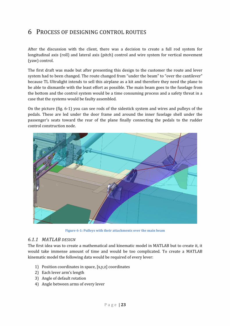
On the picture (fig. 6-1) you can see rods of the sidestick system and wires and pulleys of the
pedals. These are led under the door frame and around the inner fuselage shell under the
passenger’s seats toward the rear of the plane finally connecting the pedals to the rudder
control construction node.
Figure 6-1: Pulleys with their attachments over the main beam
6.1.1 MATLAB DESIGN The first idea was to create a mathematical and kinematic model in MATLAB but to create it, it
would take immense amount of time and would be too complicated. To create a MATLAB
kinematic model the following data would be required of every lever:
1) Position coordinates in space, [x,y,z] coordinates
2) Each lever arm’s length
3) Angle of default rotation
4) Angle between arms of every lever

P a g e | 24
Later these levers would be mathematically described via kinematic equations. This describes
only the kinematics. To code a force calculation script there would be needed to input force
values, acting lever and through this the rod forces could be calculated. But the biggest issue
with this MATLAB script would be to connect and link with CATIA both ways. It would be very
complicated and impeding to create working kinematics scheme which would work, fit into
fuselage and later imported to CATIA to design it in details. In a case of adjusting the kinematics,
this whole loop would repeat. After evaluating these issues, the idea of a MATLAB script was
dropped and designing by CATIA only prevailed.
6.2 CATIA design process The control route design was mostly created by CATIA CAD system. Following steps describe
the process of marking the individual routes.
1) Simplifying the geometry to simple surfaces and planes. Creating new assemblies in
CATIA to accelerate work with the model.
2) Thinking-through the route with possible attachment to the fuselage walls and not
exceeding recommended length of 1.8 m per rod.
3) Drawing a kinematic sketch in CATIA to study the resultant rotation of a particular
surface in respect to a movement of a stick.
4) Using CATIA’s DMU Kinematics module to create a rod-like model. For this step there
were used simple lines to simulate levers and rods. This was sufficient enough tough.
Each line in the assembly was represented as a single product (fig 6-2). This enables to
add more parts (f.e. rod which consists of two endings and a tube) to a single product and
not to lose any mechanism functionality.
5) Evaluate the motion and interference with other parts and surrounding structure so
there is a sufficient amount of space between the system’s components and the inner
fuselage skin.
After this designing phase was complete, there was a need to evaluate acting forces in rods and
system components. To analyse acting forces completely, the mechanism was set to 5 different
elevator positions and 3 aileron positions. These positions were set up using sidestick
movement. For the rudder there were used 3 positions as well. Following tables describe
positions for individual routes.
Table 6-1: Lateral axis route motion values
Position # Position description Sidestick shift [mm] Elevator rotation [°] 1 Fully pushed +60 25,3 2 Mid pushed +30 12,7 3 Neutral 0 0 4 Mid pulled -30 -13,3 5 Fully pulled -61 -29,8

P a g e | 25
Table 6-2: Longitudinal route motion values
Position # Position description Sidestick rotation [°] Right aileron rotation [°] 1 Fully left -30 16,1 2 Mid left -14 9,4 3 Neutral 0 0 4 Mid right 14 -11 5 Fully pulled 29 -25,3
Table 6-3: Yaw route motion values
Position # Position description Pedal rotation [°] Rudder rotation [°] 1 Fully left 20 29,8 2 Neutral 0 0 3 Fully right -20 -29,7
6.3 CATIA CAD model description
It was important to create first assembly named “system” (fig. 6-2) in which basic coordinate
planes were created. The issue with received model was that the original coordinate system had
its origin located outside the plane and therefore wasn’t used. The new coordinate system
which was placed in the intersection of plane’s firewall and plane of symmetry was much more
appropriate. This coordinate system was later copied to each part of the assembly and fixed in
the position by constraints. In a case of that a part wasn’t fixed properly there was a problem
that the part’s geometry moved and update errors happened.
Figure 6-2: Assembly arranging system
Another reason why the fixing was important is because maximum number of parts is “cross-
linked”. This means that to create one part, neighbouring part’s basic geometry was copied with
link to this part and was created partially together with that component. This maybe more time
consuming and computational performance demanding process was very useful later, especially
during kinematic creations. If a component’s kinematic model was adjusted (length for
example), the cross links ensured that after clicking Update button all parts were updated
TL 4000 assembly
Subassembly_1.CATProduct
•system.CATPart
•Assembly-product.CATProduct
•Part1.CATPart
•Part2.CATPart
P a g e | 26
according to this adjustment, connected together and the mechanism working properly. During
part’s models creation other, more detailed, geometry was linked so collisions between parts
could’ve been avoided.
Unfortunately all parts couldn’t have been cross linked because of loop errors.
6.4 Basic Kinematics Scheme
6.4.1 ELEVATOR ROUTE To create working elevator kinematics and to simulate it, there was used a sketch drawn on the
TL 4000’s symmetry plane. The sketch contained pushrods together with levers and their fixing
points. These fixing points were constrained to basic fixed elements (intersection line of two
basic planes) and adjusted accordingly to fulfil given control surfaces rotation.
The next step was to create new CATIA products and parts within these products. Inside all of
newly created products, there was a part called “system” (fig 6-2), which contained cross linked
geometry and simple line geometry which represented the simplest component model (yellow
line) (fig 7-4 f.e.). But because the elevator route doesn’t lie in the symmetry plane only there
was a problem to tune the kinematics of sidesticks and their belonging levers and pushrods, so
the rotation corresponds. This fine tuning took a long time to finish. Later, because of potential
future collisions the kinematics had to been changed and further adjusted several times.
6.4.2 AILERON ROUTE The design sequence was almost the same except there wasn’t used any sketch to design the
whole route. Because of its complexity in 3D space this wouldn’t be justifying the effort. From
that reason is the route copying the elevator route where possible. From the functional and
designing point of view is the aileron route very similar to the elevator one.
Because of different aileron aerodynamic efficiency are ailerons designed as differentiated. For
TL4000 is this differentiation set as +16° down, -25° up and is implemented in the last route’s
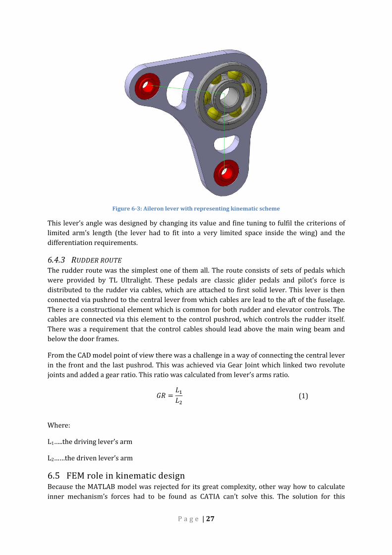
component. This component is “L shape” with precisely given angle of 106° (fig. 6-3).
P a g e | 27
Figure 6-3: Aileron lever with representing kinematic scheme
This lever’s angle was designed by changing its value and fine tuning to fulfil the criterions of
limited arm’s length (the lever had to fit into a very limited space inside the wing) and the
differentiation requirements.
6.4.3 RUDDER ROUTE The rudder route was the simplest one of them all. The route consists of sets of pedals which
were provided by TL Ultralight. These pedals are classic glider pedals and pilot’s force is
distributed to the rudder via cables, which are attached to first solid lever. This lever is then
connected via pushrod to the central lever from which cables are lead to the aft of the fuselage.
There is a constructional element which is common for both rudder and elevator controls. The
cables are connected via this element to the control pushrod, which controls the rudder itself.
There was a requirement that the control cables should lead above the main wing beam and
below the door frames.
From the CAD model point of view there was a challenge in a way of connecting the central lever
in the front and the last pushrod. This was achieved via Gear Joint which linked two revolute
joints and added a gear ratio. This ratio was calculated from lever’s arms ratio.
𝐺𝑅 =𝐿1
𝐿2 (1)
Where:
L1…..the driving lever’s arm
L2……the driven lever’s arm
6.5 FEM role in kinematic design Because the MATLAB model was rejected for its great complexity, other way how to calculate
inner mechanism’s forces had to be found as CATIA can’t solve this. The solution for this

P a g e | 28
problem is in usage of special software. Today’s market offers various software solutions but a
pre-processor PATRAN and processor NASTRAN were chosen for their simple use, availability
and verification.
The model’s task was to simplify the design by calculating forces acting in rods. These forces
were important for three reasons.
1) Buckling stability of rods themselves
2) From the rod forces could be via force equilibrium calculated forces acting on levers
3) Determination of bearing static loads
7 FEM MODEL DESCRIPTION
7.1 Process of building a model
The FEM model was created from an STP file containing geometrical data of the mechanism.
This file contained basic geometry only such as lines, surfaces and fixing points. For importing
the geometry there was used the neutral position case.
Figure 7-1: Geometry exported from CATIA
After the STP file was imported to PATRAN, set of BAR2 elements was created for the whole
mechanism.

P a g e | 29
Figure 7-2: FEM model in PATRAN, the blue arrows are SPCs
The only exception was the connection between a sidestick rod and pulleys which transmit
forces from the sticks rotation to deviate ailerons. These connections were replaced by RBE2
elements with setting which ensured it didn’t transmit the longitudinal force from the stick and
therefore simulated the real function of the sidestick construction joint.
1) Exporting the model in certain kinematic position from CATIA in STP file and importing
it into PATRAN.
2) From the imported geometry particular elements were created by using this geometry.
3) Forces were applied to the sidestick to the spots which correspond to the real usage of
the stick. These forces were applied to the middle of the grip (fig 7-3).
4) Boundary conditions were added to particular nodes providing levers and tubes to have
correct degrees of freedom (DOF).
5) The control surface’s rotational joints were fixed in particular positions by removing all
6 DOFs.
6) Material was defined. Duralumin was used for all elements (E=72 000 MPa; µ=0,3).
7) Properties were assigned to each element. For the levers and torsional tube it was BEAM
properties with reasonable geometrical dimensions. Material and area were defined for
rods. Area is 176 mm2 which corresponds to a cross section of Ø30-2 tube. The reason
the properties weren’t defined exactly is that the expected result was a list of acting
forces but no stresses. Forces are not influenced by geometrical characteristics like cross
section area etc. and therefore this method was sufficient.

P a g e | 30
Figure 7-3: Force application on the left sidestick
8) 4 load cases were created to assign correct forces. These cases were created to simplify
and to accelerate computational analysis together with a faster evaluation of the results.
The load cases are described further in this thesis.
9) Evaluating the results of different positions and cases.
10) In a case of a force greater than a buckling force acting in a particular rod, the geometry
was analysed and modified, then imported to PATRAN and nodes of changed geometry
were shifted and analysed again.
P a g e | 31
7.2 Forces
According to regulation 23.397b the limit loads are given as seen in table 4-2. These loads were
applied to certain controlling elements as sticks and pedals. Later, the reaction forces in the
control route will be examined and the system altogether will be designed according to these
forces and resulting stresses.
There were no aerodynamic data such as aileron loading available during the design process but
nevertheless the control system has to be designed for above mentioned force values.
7.3 Load cases
According to certification regulation several load cases were determined for each control
system.
These load cases are applied to the sidestick in five positions:
Lateral control load cases:
1) 1 pilot pushing/pulling towards
2) 2 pilots pushing/pulling towards
Longitudinal control load cases:
1) 1 pilot turning left/right
2) 2 pilots turning left/right
From these loading cases were several designated as critical and focused on these for further
calculations.
“One pilot acting” force is applied to the left sidestick only.
“Two pilots acting” force is applied to both sidesticks at the same time.
Lateral axis control:
For the “one pilot acting” scenario there was an ultimate force of:
𝐹1𝑝𝑖𝑙𝑜𝑡 = 𝐹𝑙𝑖𝑚𝑖𝑡 . 𝑓𝐹𝑂𝐹 . 𝑓𝐹𝐹 = 890.1,5.1,15 = 1535,7 𝑁 (2)
For the “two pilots acting” scenario there was an ultimate force of:
𝐹2𝑝𝑖𝑙𝑜𝑡𝑠 = 𝐹𝑙𝑖𝑚𝑖𝑡 . 𝑓𝐹𝑂𝐹. 𝑓𝐷𝐶𝑆. 𝑓𝐹𝐹 = 890.1,5.0,75.1,15 = 1151,3 𝑁 (3)
P a g e | 32
Where:
Flim…limit load taken from CS 23.397b
fFOF…factor of safety taken from CS 23.303
fDCS…dual control system factor taken from CS 23.399
fFF…fitting factor taken from CS 23.625
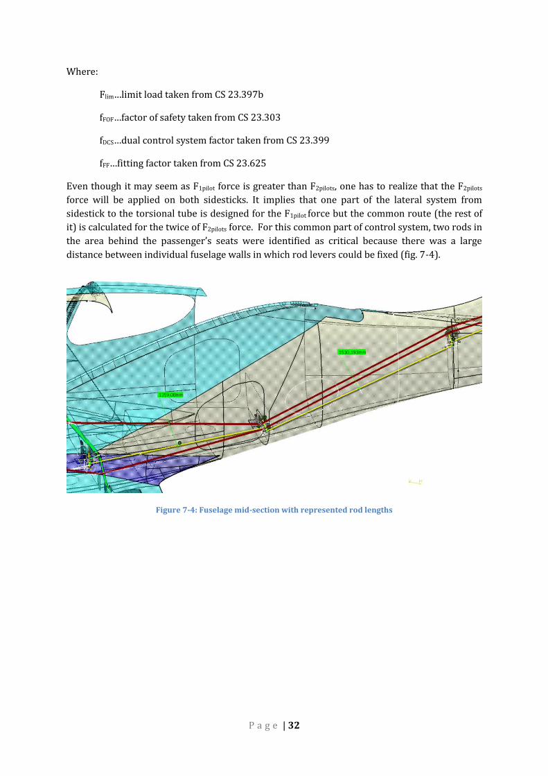
Even though it may seem as F1pilot force is greater than F2pilots, one has to realize that the F2pilots
force will be applied on both sidesticks. It implies that one part of the lateral system from
sidestick to the torsional tube is designed for the F1pilot force but the common route (the rest of
it) is calculated for the twice of F2pilots force. For this common part of control system, two rods in
the area behind the passenger’s seats were identified as critical because there was a large
distance between individual fuselage walls in which rod levers could be fixed (fig. 7-4).
Figure 7-4: Fuselage mid-section with represented rod lengths
P a g e | 33
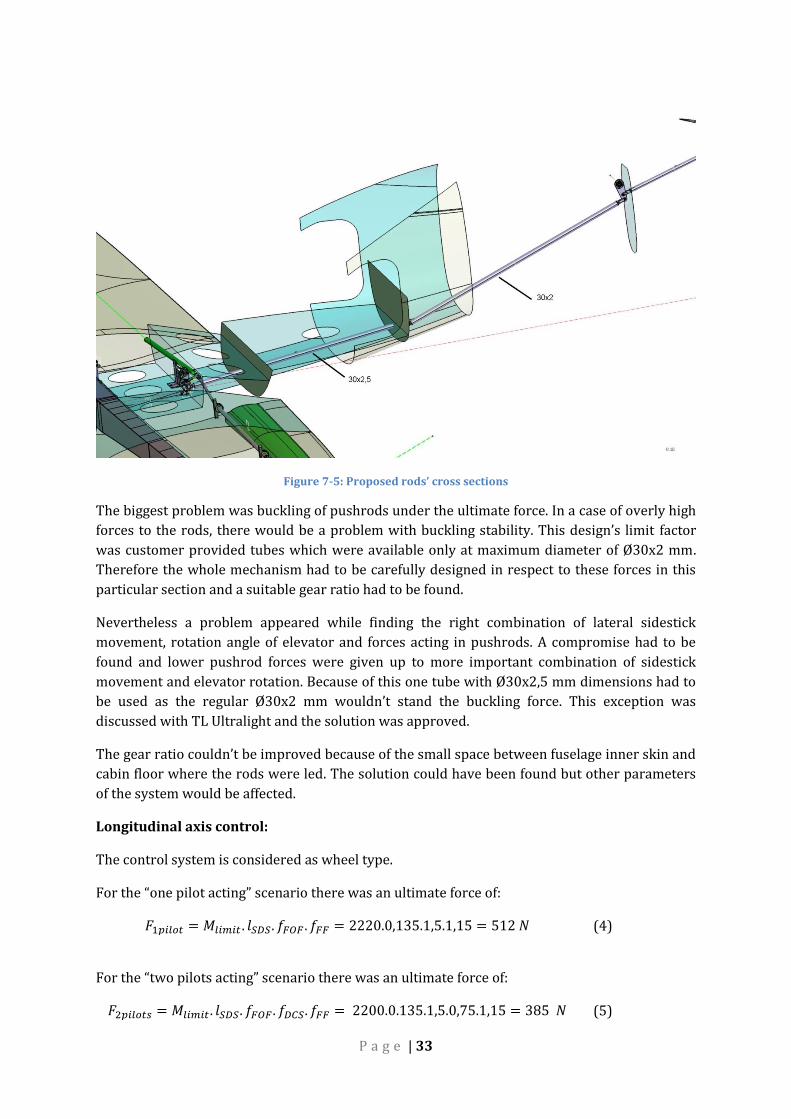
Figure 7-5: Proposed rods’ cross sections
The biggest problem was buckling of pushrods under the ultimate force. In a case of overly high
forces to the rods, there would be a problem with buckling stability. This design’s limit factor
was customer provided tubes which were available only at maximum diameter of Ø30x2 mm.
Therefore the whole mechanism had to be carefully designed in respect to these forces in this
particular section and a suitable gear ratio had to be found.
Nevertheless a problem appeared while finding the right combination of lateral sidestick
movement, rotation angle of elevator and forces acting in pushrods. A compromise had to be
found and lower pushrod forces were given up to more important combination of sidestick
movement and elevator rotation. Because of this one tube with Ø30x2,5 mm dimensions had to
be used as the regular Ø30x2 mm wouldn’t stand the buckling force. This exception was
discussed with TL Ultralight and the solution was approved.
The gear ratio couldn’t be improved because of the small space between fuselage inner skin and
cabin floor where the rods were led. The solution could have been found but other parameters
of the system would be affected.
Longitudinal axis control:
The control system is considered as wheel type.
For the “one pilot acting” scenario there was an ultimate force of:
𝐹1𝑝𝑖𝑙𝑜𝑡 = 𝑀𝑙𝑖𝑚𝑖𝑡 . 𝑙𝑆𝐷𝑆. 𝑓𝐹𝑂𝐹 . 𝑓𝐹𝐹 = 2220.0,135.1,5.1,15 = 512 𝑁 (4)
For the “two pilots acting” scenario there was an ultimate force of:
𝐹2𝑝𝑖𝑙𝑜𝑡𝑠 = 𝑀𝑙𝑖𝑚𝑖𝑡 . 𝑙𝑆𝐷𝑆. 𝑓𝐹𝑂𝐹. 𝑓𝐷𝐶𝑆. 𝑓𝐹𝐹 = 2200.0.135.1,5.0,75.1,15 = 385 𝑁 (5)
P a g e | 34
Where:
Mlim…limit load taken from CS 23.397b
lSDS…grip of the handle, taken as 13,5 cm
fFOF…factor of safety taken from CS 23.303
fDCS…dual control system factor taken from CS 23.399
fFF…fitting factor taken from CS 23.625
Vertical axis control:
For rudder control the forces are:
𝐹1𝑝𝑖𝑙𝑜𝑡 = 𝐹𝑙𝑖𝑚𝑖𝑡 . 𝑓𝐹𝑂𝐹. 𝑓𝐹𝐹 = 890.1,5.1,15 = 1535,7 𝑁 (6)
𝐹2𝑝𝑖𝑙𝑜𝑡𝑠 = 𝐹𝑙𝑖𝑚𝑖𝑡 . 𝑓𝐹𝑂𝐹 . 𝑓𝐷𝐶𝑆. 𝑓𝐹𝐹 = 890.1,5.0,75.1,15 = 1151,3 𝑁 (7)
Where:
Flim…limit load taken from CS 23.397b
fFOF…factor of safety taken from CS 23.303
fDCS…dual control system factor taken from CS 23.399
fFF…fitting factor taken from CS 23.625
7.4 Element properties
7.4.1 MATERIAL For all of the calculations was used duralumin as the default material. Young’s modulus
E=72 000 MPa, µ=0,3.
7.4.2 PUSHRODS For the actual pushrods, ROD elements were used because in this case the rods transmit
translational forces only and without any unwanted bending of the route. If BEAM elements
were used instead, the actual rod would transmit bending and torque moments also which
doesn’t apply for this case.
Regarding to input properties, only material and cross section area was given. This area equals
to cross section of Ø35-1,5 mm tube. Again, the purpose of this calculation wasn’t to calculate
stresses but forces only and de facto every dimension would suffice.
7.4.3 LEVERS For levers BEAM elements were used to transmit bending moments resulting from individual
forces. Therefore in contrary to ROD elements, BEAM elements are suitable for this case.

P a g e | 35
Material, cross section area of 20x5 mm and orientation of BEAM elements were entered as
BEAM properties. Because of the BEAM elements orientation, several BEAM properties needed
to be created with respect to the orientation of any particular element so the 20x5 dimension is
a real cross section area perpendicular to an axis.
More accurate FEM calculations were calculated later from a particular solid STP model
imported to PATRAN.
7.4.4 TORSIONAL TUBES There is one torsional tube (fig 10-3) which was created as an element with BEAM properties to
transmit torque. The reason for this was to create a rigid element.
7.4.5 SIDESTICK PULLEYS, ROTATIONAL AXIS Because the whole sidestick system was designed in the same time and individual lateral and
longitudinal control systems are not separated from each other, a system which ensures not
interfering these two system had to be created. In real design this is achieved by sidestick
pulleys and pivot joints. In FEM was this goal achieved via RBE2 elements which properties
were set not to transfer an X-axis force from the sidestick tube.
7.5 Analysis properties
Linear static analysis was chosen because forces and stresses are expected lower then yield
stress and therefore without any plastic deformation.
The linear static analysis should follow these rules [4]:
1. Rotations should be small relative to structure.
2. Rotations should be less than 10 degrees to 15 degrees.
3. Material should be linear elastic.
4. Boundary conditions should be constant.
All these recommendations were fulfilled.
P a g e | 36
8 ANALYSIS RESULTS This chapter will introduce to forces acting in elevator and aileron routes.
8.1 Elevator route results
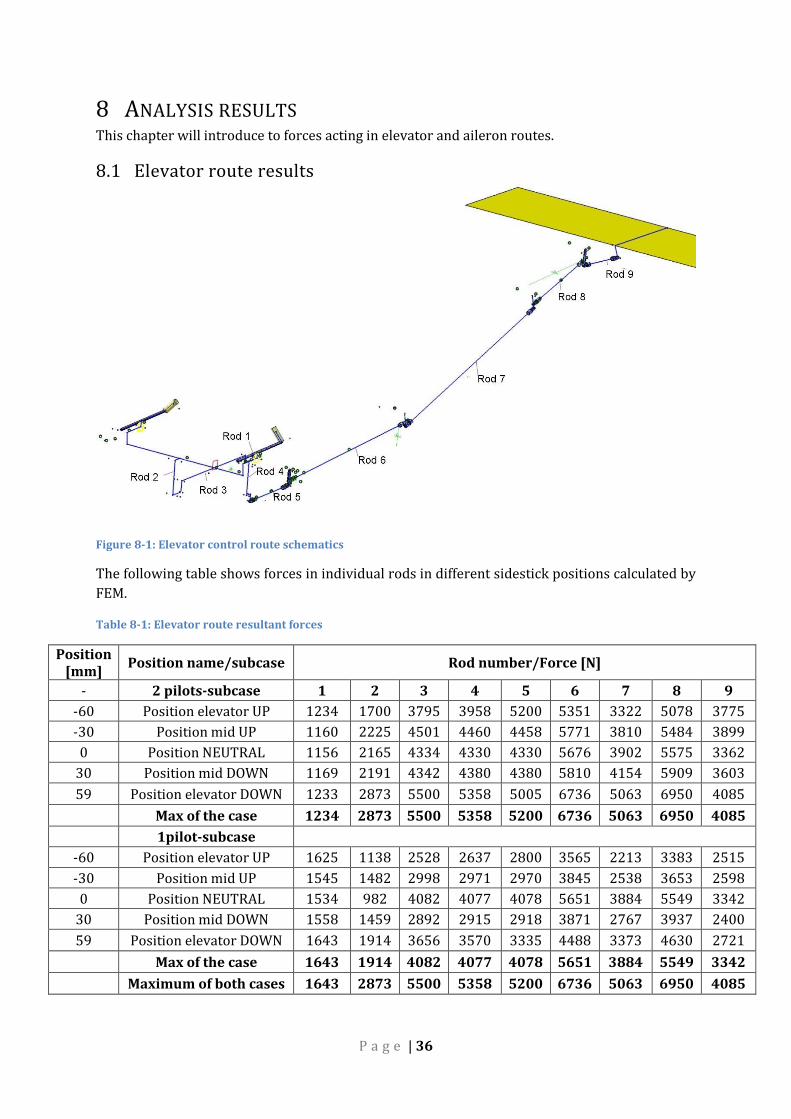
Figure 8-1: Elevator control route schematics
The following table shows forces in individual rods in different sidestick positions calculated by
FEM.
Table 8-1: Elevator route resultant forces
Position [mm]
Position name/subcase Rod number/Force [N]
- 2 pilots-subcase 1 2 3 4 5 6 7 8 9
-60 Position elevator UP 1234 1700 3795 3958 5200 5351 3322 5078 3775
-30 Position mid UP 1160 2225 4501 4460 4458 5771 3810 5484 3899
0 Position NEUTRAL 1156 2165 4334 4330 4330 5676 3902 5575 3362
30 Position mid DOWN 1169 2191 4342 4380 4380 5810 4154 5909 3603
59 Position elevator DOWN 1233 2873 5500 5358 5005 6736 5063 6950 4085
Max of the case 1234 2873 5500 5358 5200 6736 5063 6950 4085
1pilot-subcase
-60 Position elevator UP 1625 1138 2528 2637 2800 3565 2213 3383 2515
-30 Position mid UP 1545 1482 2998 2971 2970 3845 2538 3653 2598
0 Position NEUTRAL 1534 982 4082 4077 4078 5651 3884 5549 3342
30 Position mid DOWN 1558 1459 2892 2915 2918 3871 2767 3937 2400
59 Position elevator DOWN 1643 1914 3656 3570 3335 4488 3373 4630 2721
Max of the case 1643 1914 4082 4077 4078 5651 3884 5549 3342
Maximum of both cases 1643 2873 5500 5358 5200 6736 5063 6950 4085
P a g e | 37
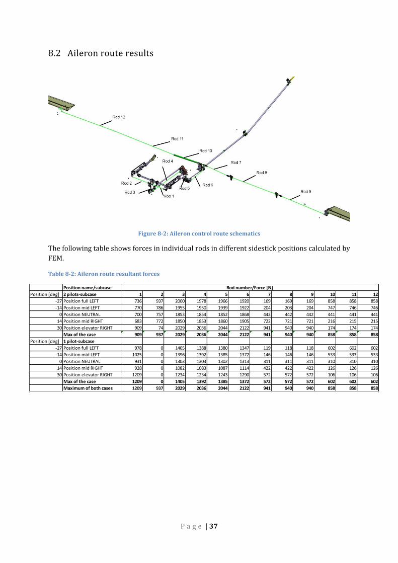
8.2 Aileron route results
Figure 8-2: Aileron control route schematics
The following table shows forces in individual rods in different sidestick positions calculated by
FEM.
Table 8-2: Aileron route resultant forces
Position name/subcase
Position [deg] 2 pilots-subcase 1 2 3 4 5 6 7 8 9 10 11 12
-27 Position full LEFT 736 937 2000 1978 1966 1920 169 169 169 858 858 858
-14 Position mid LEFT 770 786 1955 1950 1939 1922 204 203 204 747 746 746
0 Position NEUTRAL 700 757 1853 1854 1852 1868 442 442 442 441 441 441
14 Position mid RIGHT 683 772 1850 1853 1860 1905 722 721 721 216 215 215
30 Position elevator RIGHT 909 74 2029 2036 2044 2122 941 940 940 174 174 174
Max of the case 909 937 2029 2036 2044 2122 941 940 940 858 858 858
Position [deg] 1 pilot-subcase
-27 Position full LEFT 978 0 1405 1388 1380 1347 119 118 118 602 602 602
-14 Position mid LEFT 1025 0 1396 1392 1385 1372 146 146 146 533 533 533
0 Position NEUTRAL 931 0 1303 1303 1302 1313 311 311 311 310 310 310
14 Position mid RIGHT 928 0 1082 1083 1087 1114 422 422 422 126 126 126
30 Position elevator RIGHT 1209 0 1234 1234 1243 1290 572 572 572 106 106 106
Max of the case 1209 0 1405 1392 1385 1372 572 572 572 602 602 602
Maximum of both cases 1209 937 2029 2036 2044 2122 941 940 940 858 858 858
Rod number/Force [N]

P a g e | 38
8.3 Rudder route results
Figure 8-3: Rudder control route schematics
Table 8-3: Rudder route resultant forces
Position
name/subcase Element name/Force [N]
Position [deg]
2 pilots-subcase Wire 1 Rod 1 Wire 2 Rod 2
20 Position full LEFT 1151 1284 11300 7533
1 pilot-subcase
20 Position full LEFT 1535 1713 7634 5084
Max of the case 1535 1713 11300 7533
8.4 Buckling calculations Buckling is the very limiting factor of this design. Because of different gear ratios, great forces
act in rod trying them to buckle. In FEM chapter of this thesis were calculated forces acting in
these rods. Of course if a pilot pushes the sidestick, some rods are pulled and some pushed.
Nevertheless the rods could find themselves in both situations. For this reason each rod is
examined for both forces orientations-pulled and pushed. In this chapter, buckling will be
further examined.
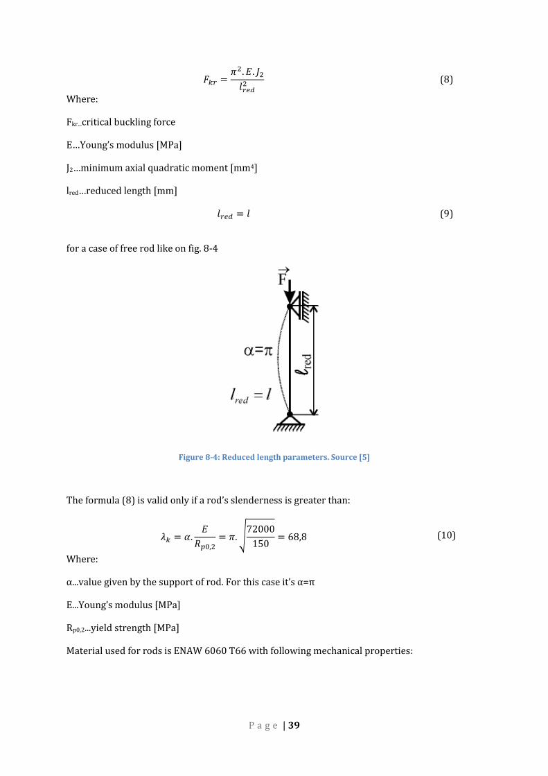
8.4.1 EULER THEORY From these forces and the rods lengths could be calculated their geometrical dimensions. The
deciding factor was the buckling case. This case was calculated by a formula:
P a g e | 39
𝐹𝑘𝑟 =𝜋2. 𝐸. 𝐽2
𝑙𝑟𝑒𝑑2 (8)
Where:
Fkr...critical buckling force
E…Young’s modulus [MPa]
J2…minimum axial quadratic moment [mm4]
lred…reduced length [mm]
𝑙𝑟𝑒𝑑 = 𝑙 (9)
for a case of free rod like on fig. 8-4
Figure 8-4: Reduced length parameters. Source [5]
The formula (8) is valid only if a rod’s slenderness is greater than:
𝜆𝑘 = 𝛼.𝐸
𝑅𝑝0,2= 𝜋. √
72000
150= 68,8 (10)
Where:
α...value given by the support of rod. For this case it’s α=π
E...Young’s modulus [MPa]
Rp0,2...yield strength [MPa]
Material used for rods is ENAW 6060 T66 with following mechanical properties:

P a g e | 40
Table 8-4: ENAW 6060 T66 mechanical properties
Material EN AW 6060 T66 Rm 370 MPa Rp0,2 250 MPa
From the critical force Fkr could be calculated a reserve factor RF:
𝑅𝐹 =𝐹𝑘𝑟
𝐹
(11)
Where:
F…acting force in rod
8.4.1.1 Johnson theory
All rods but three have their slenderness values greater than critical values, therefore the Euler
theory is usable.
But for the 3 rods has to be used a different theory as their slenderness is smaller than the
critical values. These 3 rods are number 1 and 2 from elevator route and number 3 from aileron
control route. For these 3 rods had to be used a different theory and Johnson-Euler was used.
This theory corrects Euler theory for the material strength. Its formula taken from Niu [1]
follows:
𝐹𝑐 = 𝐹𝑐𝑐 −
𝐹𝑐𝑐 . (𝐿
𝜌. √𝑐)
2
4. 𝜋2. 𝐸
(12)
Where:
Fcc...crippling stress, Rp0,2=150 MPa
Fc…Critical stress [MPa]
E…Young’s modulus [MPa]
L…length of the rod [mm]
c…restrain coefficient [-]
ρ…radius of gyration [mm]
Restrain coefficient c is according to Niu [1] c=1.
Radius of gyration:
𝜌 = √𝐽
𝑆 (13)

P a g e | 41
Where:
J…axial quadratic moment [mm4]
S…rod tube cross section area [mm2]
From the critical stress Fc could be calculated a critical buckling force Fkr using simple equation
(14)
𝐹𝑘𝑟 = 𝐹𝑐 . 𝑆 (14)
Again, a reserve factor is calculated by:
𝑅𝐹 =𝐹𝑘𝑟
𝐹 (15)
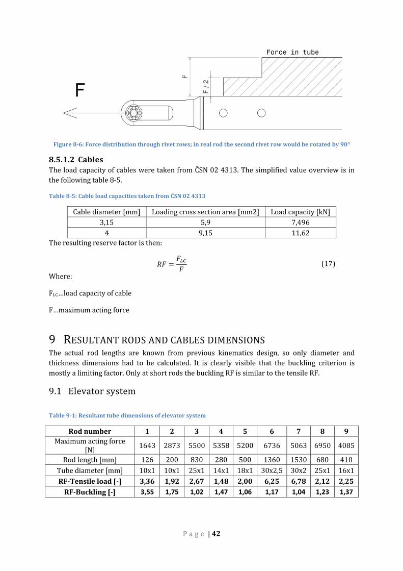
8.5 Tension calculations
8.5.1.1 Rods Rods were calculated for tension in their critical spots. These spots are where the tube is
weakened by rivet holes.
Figure 8-5: Cross section area of critical spot
On the figure is displayed a cut through tail section of a rod. Because the outer diameter is much
greater than tube thickness, the area of this section can be calculated by:
𝐴 = 𝜋. 𝐷. 𝑡 − 𝑛. 𝑑𝑛 (16) Where:
n…number of rivets
In this design is calculated with only one rivet row. In a case of using two rivet rows, the force
distribution would look like on fig 8-6.
P a g e | 42
Figure 8-6: Force distribution through rivet rows; in real rod the second rivet row would be rotated by 90°
8.5.1.2 Cables The load capacity of cables were taken from ČSN 02 4313. The simplified value overview is in
the following table 8-5.
Table 8-5: Cable load capacities taken from ČSN 02 4313
Cable diameter [mm] Loading cross section area [mm2] Load capacity [kN]
3,15 5,9 7,496
4 9,15 11,62
The resulting reserve factor is then:
𝑅𝐹 =𝐹𝐿𝐶
𝐹 (17)
Where:
FLC…load capacity of cable
F…maximum acting force
9 RESULTANT RODS AND CABLES DIMENSIONS The actual rod lengths are known from previous kinematics design, so only diameter and
thickness dimensions had to be calculated. It is clearly visible that the buckling criterion is
mostly a limiting factor. Only at short rods the buckling RF is similar to the tensile RF.
9.1 Elevator system
Table 9-1: Resultant tube dimensions of elevator system
Rod number 1 2 3 4 5 6 7 8 9
Maximum acting force [N]
1643 2873 5500 5358 5200 6736 5063 6950 4085
Rod length [mm] 126 200 830 280 500 1360 1530 680 410
Tube diameter [mm] 10x1 10x1 25x1 14x1 18x1 30x2,5 30x2 25x1 16x1
RF-Tensile load [-] 3,36 1,92 2,67 1,48 2,00 6,25 6,78 2,12 2,25
RF-Buckling [-] 3,55 1,75 1,02 1,47 1,06 1,17 1,04 1,23 1,37

P a g e | 43
9.2 Aileron system
Table 9-2: Resultant tube dimensions of aileron system
Rod number 1 2 3 4 5 6
Maximum acting force [N] 1209 937 2029 2036 2044 2122
Rod length [mm] 463 463 84 1081 280 503
Tube diameter [mm] 16x1 16x1 14x1 25x1 10x1 14x1
RF-Tensile load [-] 13,61 17,56 7,07 12,96 4,84 6,76
RF-Buckling [-] 3,65 4,45 43 1,62 1,28 1,15
Rod number 7 8 9 10 11 12
Maximum acting force [N] 941 940 940 858 858 858
Rod length [mm] 744 1576 1414 744 1576 1414
Tube diameter [mm] 14x1 25x1 25x1 14x1 25x1 25x1
RF-Tensile load [-] 15,25 28,07 28,07 16,72 30,76 30,76
RF-Buckling [-] 1,18 1,65 2,05 8,13 1,81 2,25
9.3 Rudder system
Table 9-3: Resultant elements dimension of rudder system
Element name/number
Wire 1 Rod 1 Wire 2 Rod 2
Max of the case 1535 1713 11300 7533
Length [mm] 620 253 4970 494
Characteristic dimension [mm]
3,15 10x1 4 25x1
RF-Tensile load [-] 4,88 3,52 1,03 1,72
RF-Buckling - 1,72 - 1,87
P a g e | 44
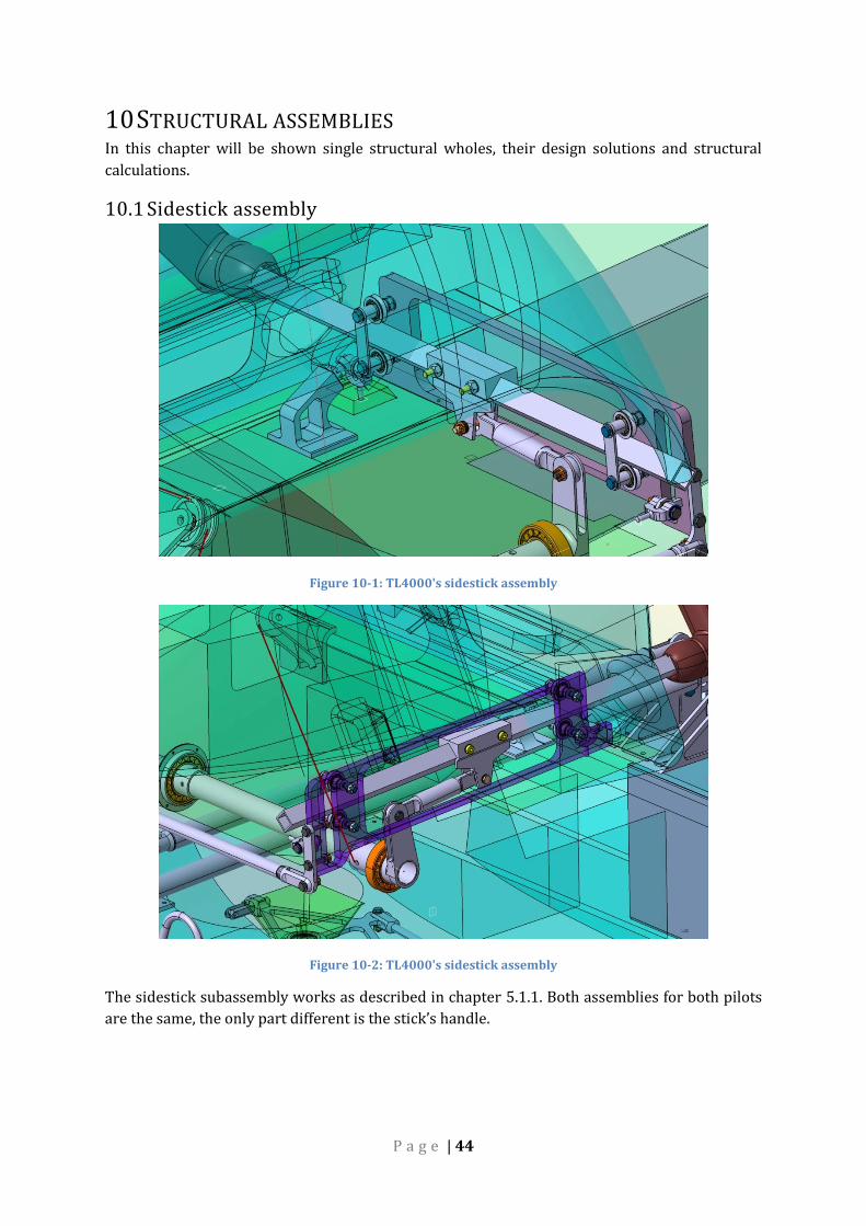
10 STRUCTURAL ASSEMBLIES In this chapter will be shown single structural wholes, their design solutions and structural
calculations.
10.1 Sidestick assembly
Figure 10-1: TL4000's sidestick assembly
Figure 10-2: TL4000's sidestick assembly
The sidestick subassembly works as described in chapter 5.1.1. Both assemblies for both pilots
are the same, the only part different is the stick’s handle.
P a g e | 45
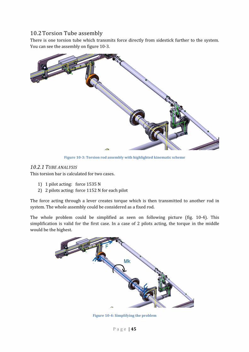
10.2 Torsion Tube assembly There is one torsion tube which transmits force directly from sidestick further to the system.
You can see the assembly on figure 10-3.
Figure 10-3: Torsion rod assembly with highlighted kinematic scheme
10.2.1 TUBE ANALYSIS This torsion bar is calculated for two cases.
1) 1 pilot acting: force 1535 N
2) 2 pilots acting: force 1152 N for each pilot
The force acting through a lever creates torque which is then transmitted to another rod in
system. The whole assembly could be considered as a fixed rod.
The whole problem could be simplified as seen on following picture (fig. 10-4). This
simplification is valid for the first case. In a case of 2 pilots acting, the torque in the middle
would be the highest.
Figure 10-4: Simplifying the problem

P a g e | 46
For one pilot acting case applies following:
𝑀𝑘 = 𝐹. 𝑙 (18) Where:
F...applied force
l...lever length
Because the lever is moving and rotates with the tube, the torque changes for different sidestick
positions. The largest torque will be then when there is the biggest force acting on the lever.
This happens in elevator DOWN position and this particular value could be found in a table 8-1.
Therefore:
𝑀𝑘 = 𝐹. 𝑙 = 1643.75 = 123225 𝑁𝑚𝑚 (19)
Figure 10-5: Inner stress resultants of torsion bar, 1 pilot
For 2 pilots acting:
𝑀𝑘 = 2. 𝐹. 𝑙 = 2.1156.75 = 186450 𝑁𝑚𝑚 (20)
Figure 10-6: Inner stress resultants of torsion bar, 2 pilots
Because of a fact that the tube is made of one piece, it has to withstand stress from 2 pilots
simultaneously. A 30x1,5 tube was chosen. Stress calculations for this tube are:
𝑊𝑘 = 2. 𝜋. 𝑟2. 𝑠 = 2. 𝜋. (13,5)2. 1,5 = 1717 𝑚𝑚3 (21)

P a g e | 47
Figure 10-7: Geometry of tube’s cross section
𝐷 = 2. 𝑟 = 25 𝑚𝑚 (22)
𝜏𝑘 =𝑀𝑘
𝑊𝑘=
173400
1717= 108,6 𝑀𝑃𝑎 (23)
The ultimate shear stress of the material could be calculated from:
𝜏𝑢 = 0,65. 𝑅𝑚 = 0,65.190 = 123,5 𝑀𝑃𝑎 (24)
And reserve factor:
𝑹𝑭 =𝜏𝑢
𝜏𝑘=
123,5
108,6= 𝟏, 𝟏𝟒 (25)
10.2.2 TWIST OF THE TUBE It is important to calculate twist of the torsional tube. If it is too high it will have negative
outcome in imprecise control properties. This twist is calculated for two cases.
1) Both pilots acting in different directions, ultimate load
2) Both pilots acting in different directions, limit load
The equations used are:
𝐽𝑝 = 𝜋.𝐷4 − 𝑑4
32= 𝜋.
304 − 274
32= 27347 𝑚𝑚4 (26)
𝜃 =𝑀𝑘
𝐺. 𝐽𝑝 (27)
𝜑 = 𝜃. 𝑙 (28) Where:
Mk…torque used [N.mm]
G…shear modulus [MPa]
Jp…polar quadratic moment [mm4]
l…length of the torsional tube [m]

P a g e | 48
Shear modulus is calculated using:
𝐺 =𝐸
2. (1 + 𝜇)=
72000
2. (1 + 0,3)= 27700 𝑀𝑃𝑎
(29)
Where:
μ…Poisson constant
For the case 1):
𝜃 =𝑀𝑘
𝐺. 𝐽𝑝=
173400
27700.27347= 2,29.10−4 𝑟𝑎𝑑 = 0,013° (30)
𝜑 = 𝜃. 𝑙 = 0,013.0,932 = 0,012° (31)
For the more realistic case 2):
Torque is lowered by factors 1,5 and 1,15.
𝑀𝑘 =173400
1,5.1,15= 100522 𝑁𝑚𝑚 (32)
𝜃 =𝑀𝑘
𝐺. 𝐽𝑝=
100522
27700.27347= 1,327.10−4 𝑟𝑎𝑑 = 0,008° (33)
𝜑 = 𝜃. 𝑙 = 0,008.0,932 = 0,007° (34)
10.2.3 SIDE LEVER-TUBE CONNECTION
Figure 10-8: Side lever-tube connection detail
The connection between the side lever and tube is secured by 4 rivets Ø6 mm.
P a g e | 49
The force at rivets may be calculated from the torque originated in sidestick force. A critical
scenario is when only pilot pushes as seen on figure 10-5. From this torque value a force on tube
circumference could be calculated using:
𝐹 =𝑀𝑘
𝐷=
115050
30= 3835 𝑁 (35)
Thicknesses of both tube and lever’s shaft are 1,5 mm. According to table 10-1, one rivet Ø6 mm
can carry force of FR=7159 N.
Reserve factor of this rivet connection is:
𝑅𝐹 =𝐹𝑅
𝐹4
=7159
38354
= 7,46 (36)
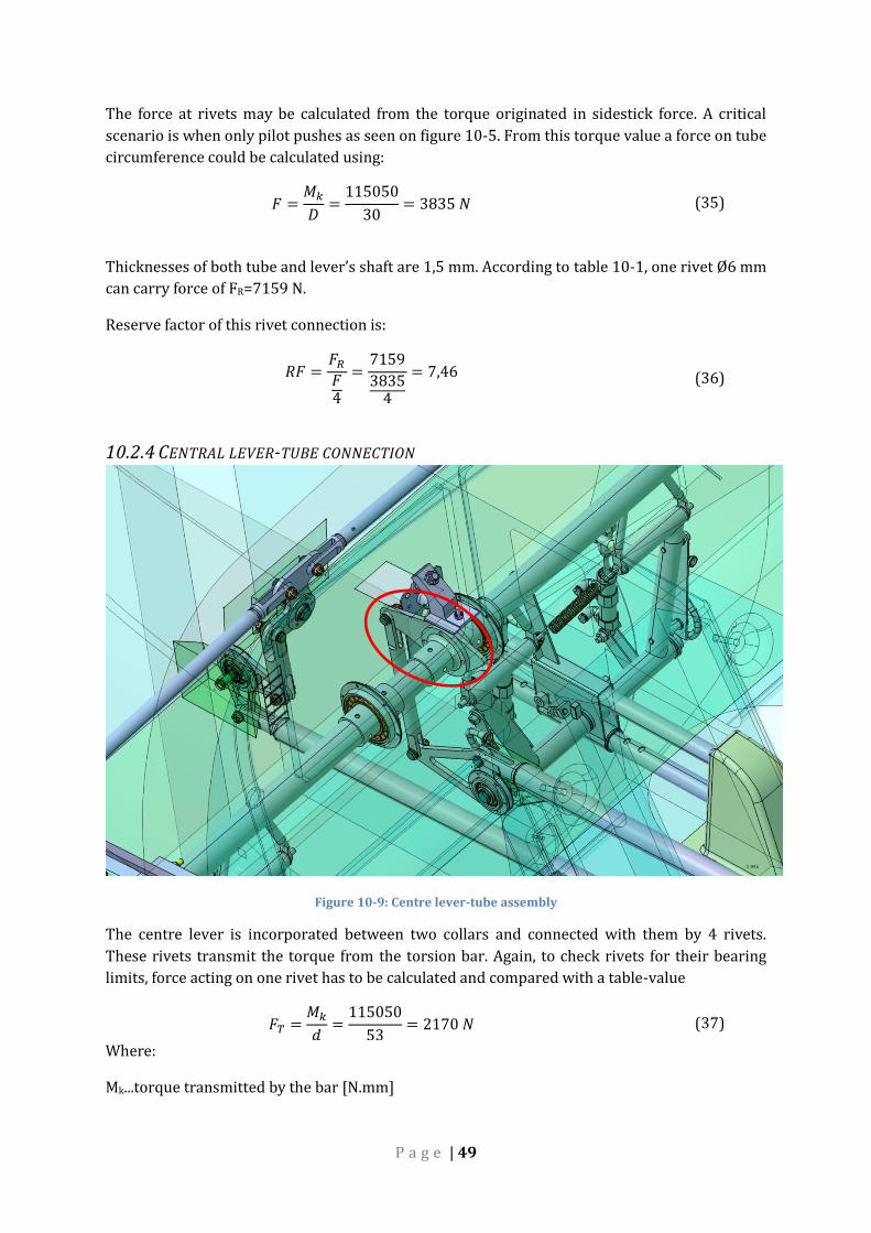
10.2.4 CENTRAL LEVER-TUBE CONNECTION
Figure 10-9: Centre lever-tube assembly
The centre lever is incorporated between two collars and connected with them by 4 rivets.
These rivets transmit the torque from the torsion bar. Again, to check rivets for their bearing
limits, force acting on one rivet has to be calculated and compared with a table-value
𝐹𝑇 =𝑀𝑘
𝑑=
115050
53= 2170 𝑁 (37)
Where:
Mk...torque transmitted by the bar [N.mm]
P a g e | 50
d...the hole circular pattern’s diameter [mm]
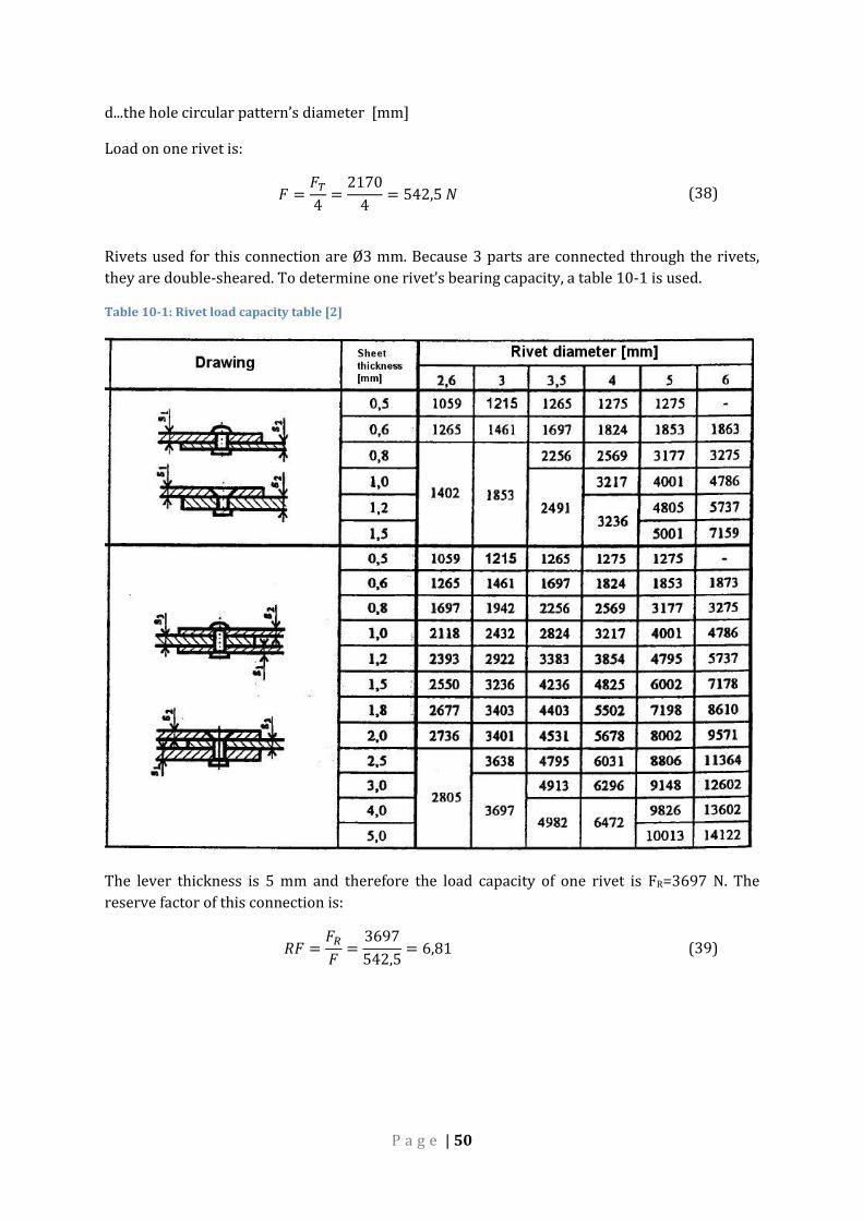
Load on one rivet is:
𝐹 =𝐹𝑇
4=
2170
4= 542,5 𝑁 (38)
Rivets used for this connection are Ø3 mm. Because 3 parts are connected through the rivets,
they are double-sheared. To determine one rivet’s bearing capacity, a table 10-1 is used.
Table 10-1: Rivet load capacity table [2]
The lever thickness is 5 mm and therefore the load capacity of one rivet is FR=3697 N. The
reserve factor of this connection is:
𝑅𝐹 =𝐹𝑅
𝐹=
3697
542,5= 6,81 (39)

P a g e | 51
10.3 60x60 lever assembly This lever belongs to aileron control system and finds itself in the front area. It connects rod 3
and 4 you can find on figure 8.2-1.
Figure 10-10: 60x60 lever assembly
10.4 Triangle lever assembly
Figure 10-11: Triangle lever assembly

P a g e | 52
10.5 50x50 lever assembly
Figure 10-12: 50x50 assembly with one of its attachment
10.6 Elevator-Aileron Mid fuselage assembly
Figure 10-13: Elevator-Aileron Mid fuselage assembly
P a g e | 53
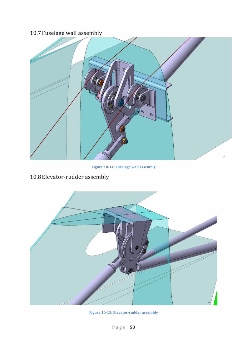
10.7 Fuselage wall assembly
Figure 10-14: Fuselage wall assembly
10.8 Elevator-rudder assembly
Figure 10-15: Elevator-rudder assembly
P a g e | 54
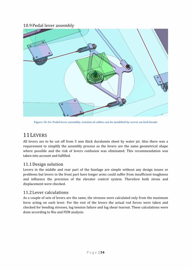
10.9 Pedal lever assembly
Figure 10-16: Pedal lever assembly, tension of cables can be modified by screw-on fork heads
11 LEVERS All levers are to be cut off from 5 mm thick duralumin sheet by water jet. Also there was a
requirement to simplify the assembly process so the levers are the same geometrical shape
where possible and the risk of levers confusion was eliminated. This recommendation was
taken into account and fulfilled.
11.1 Design solution Levers in the middle and rear part of the fuselage are simple without any design issues or
problems but levers in the front part have longer arms could suffer from insufficient toughness
and influence the precision of the elevator control system. Therefore both stress and
displacement were checked.
11.2 Lever calculations As a couple of sets of levers are the same, the stresses were calculated only from the maximum
force acting on each lever. For the rest of the levers the actual rod forces were taken and
checked for bending stresses, lug tension failure and lug shear tearout. These calculations were
done according to Niu and FEM analysis.
P a g e | 55
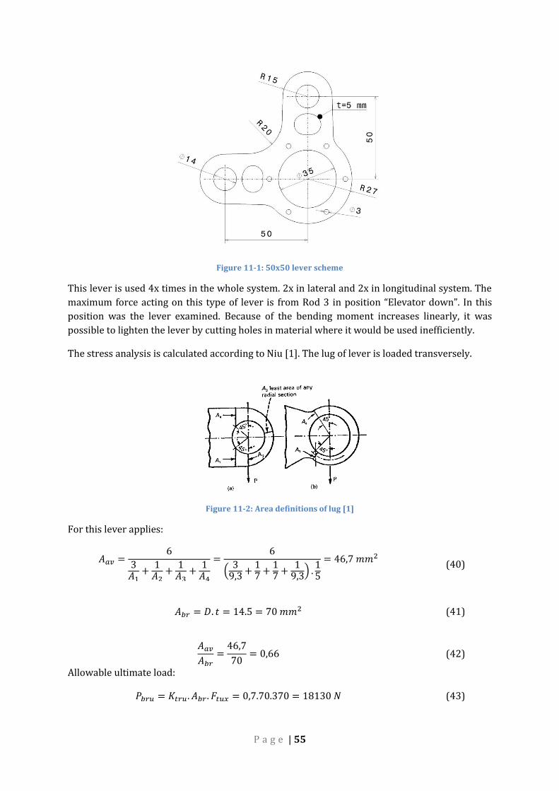
Figure 11-1: 50x50 lever scheme
This lever is used 4x times in the whole system. 2x in lateral and 2x in longitudinal system. The
maximum force acting on this type of lever is from Rod 3 in position “Elevator down”. In this
position was the lever examined. Because of the bending moment increases linearly, it was
possible to lighten the lever by cutting holes in material where it would be used inefficiently.
The stress analysis is calculated according to Niu [1]. The lug of lever is loaded transversely.
Figure 11-2: Area definitions of lug [1]
For this lever applies:
𝐴𝑎𝑣 =6
3𝐴1
+1
𝐴2+
1𝐴3
+1
𝐴4
=6
(3
9,3 +17 +
17 +
19,3) .
15
= 46,7 𝑚𝑚2 (40)
𝐴𝑏𝑟 = 𝐷. 𝑡 = 14.5 = 70 𝑚𝑚2 (41)
𝐴𝑎𝑣
𝐴𝑏𝑟=
46,7
70= 0,66 (42)
Allowable ultimate load:
𝑃𝑏𝑟𝑢 = 𝐾𝑡𝑟𝑢. 𝐴𝑏𝑟. 𝐹𝑡𝑢𝑥 = 0,7.70.370 = 18130 𝑁 (43)

P a g e | 56
Where:
Ptru...Allowable ultimate load as determined for transverse loading
Ktru…Efficiency factor for transverse load (ultimate) (fig 11-4), curve 2024-T3-T4 plate t<0,5 in
Abr…Projected bearing area
Ftux…Ultimate tensile strength of lug material across grain, 370 MPa
𝑅𝐹 =𝑃𝑏𝑟𝑢
𝐹=
18130
5500= 3,3 (44)
Figure 11-3: Efficiency factor for transverse load Ktru [1]
11.3 100x70 lever This lever is quite simple with pin holes in 70 and 100 mms. A lever in between rod 5 and 6 is
the most stressed and therefore checked. The force acting from rod 8 is 6950 N, the other forces
are calculated from moment equilibrium.
P a g e | 57
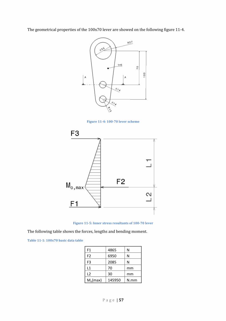
The geometrical properties of the 100x70 lever are showed on the following figure 11-4.
Figure 11-4: 100-70 lever scheme
Figure 11-5: Inner stress resultants of 100-70 lever
The following table shows the forces, lengths and bending moment.
Table 11-1: 100x70 basic data table
F1 4865 N
F2 6950 N
F3 2085 N
L1 70 mm
L2 30 mm
Mo(max) 145950 N.mm

P a g e | 58
The critical section regarding bending moment is section A where the axial quadratic moment is
calculated according to Steiner theorem.
Figure 11-6: Geometry values of section A-A
𝐽𝑜 = 2. (1
12. 𝑏. ℎ3 + 𝑆. 𝑦2) = 2. (
1
12. 5.11,753 + 11,75.5. (
11,75
2+
14
2)
2
)
= 20829 𝑚𝑚4
(45)
𝜎𝑜,𝑚𝑎𝑥 =𝑀𝑜,𝑚𝑎𝑥
𝐽𝑜. (ℎ1 +
𝑑
2) =
145950
20829. (11,75 +
14
2) = 131 𝑀𝑃𝑎 (46)
𝑹𝑭 =𝑹𝒎
𝝈𝒐,𝒎𝒂𝒙=
𝟑𝟕𝟎
𝟏𝟑𝟏= 𝟐, 𝟖 (47)
11.3.1 FEM ANALYSIS
Figure 11-7: Lever 100x70 FEM analyses; σmax=123 MPa
P a g e | 59
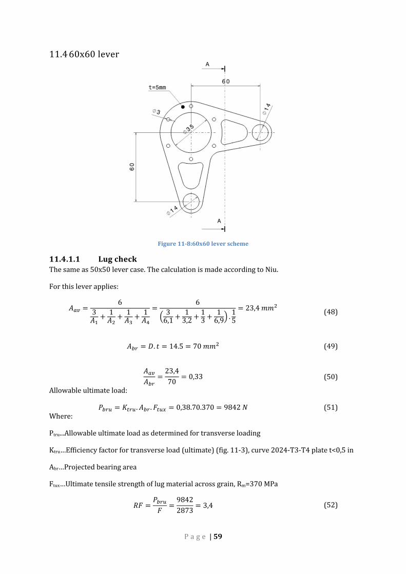
11.4 60x60 lever
Figure 11-8:60x60 lever scheme
11.4.1.1 Lug check The same as 50x50 lever case. The calculation is made according to Niu.
For this lever applies:
𝐴𝑎𝑣 =6
3𝐴1
+1
𝐴2+
1𝐴3
+1
𝐴4
=6
(3
6,1+
13,2
+13
+1
6,9) .
15
= 23,4 𝑚𝑚2 (48)
𝐴𝑏𝑟 = 𝐷. 𝑡 = 14.5 = 70 𝑚𝑚2 (49)
𝐴𝑎𝑣
𝐴𝑏𝑟=
23,4
70= 0,33 (50)
Allowable ultimate load:
𝑃𝑏𝑟𝑢 = 𝐾𝑡𝑟𝑢. 𝐴𝑏𝑟. 𝐹𝑡𝑢𝑥 = 0,38.70.370 = 9842 𝑁 (51) Where:
Ptru...Allowable ultimate load as determined for transverse loading
Ktru…Efficiency factor for transverse load (ultimate) (fig. 11-3), curve 2024-T3-T4 plate t<0,5 in
Abr…Projected bearing area
Ftux…Ultimate tensile strength of lug material across grain, Rm=370 MPa
𝑅𝐹 =𝑃𝑏𝑟𝑢
𝐹=
9842
2873= 3,4 (52)
P a g e | 60
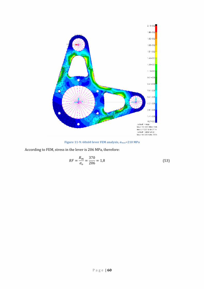
Figure 11-9: 60x60 lever FEM analysis, σmax=210 MPa
According to FEM, stress in the lever is 206 MPa, therefore:
𝑅𝐹 =𝑅𝑚
𝜎𝑜=
370
206= 1,8 (53)
P a g e | 61
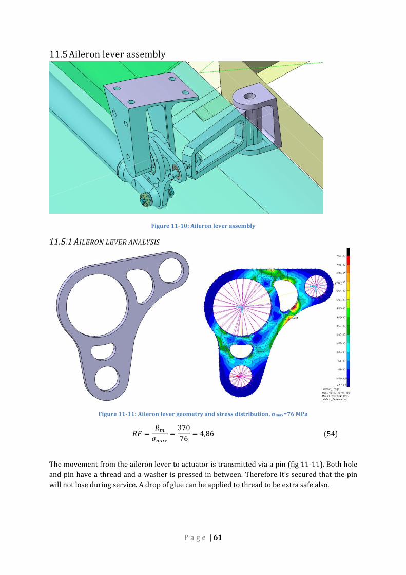
11.5 Aileron lever assembly
Figure 11-10: Aileron lever assembly
11.5.1 AILERON LEVER ANALYSIS
Figure 11-11: Aileron lever geometry and stress distribution, σmax=76 MPa
𝑅𝐹 =𝑅𝑚
𝜎𝑚𝑎𝑥=
370
76= 4,86 (54)
The movement from the aileron lever to actuator is transmitted via a pin (fig 11-11). Both hole
and pin have a thread and a washer is pressed in between. Therefore it’s secured that the pin
will not lose during service. A drop of glue can be applied to thread to be extra safe also.

P a g e | 62
Figure 11-12: Aileron actuator geometry and stress analysis, σmax=326 MPa
𝑅𝐹 =𝑅𝑚
𝜎𝑚𝑎𝑥=
370
326= 1,13 (55)
11.6 Aileron route mid subassembly
Figure 11-13: Mid aileron lever subassembly
The challenge for this construction assembly was mostly to fit both lateral and longitudinal
elements in to very limit space and design it to not to obstruct each other in motion. That is the
reason why the lateral lever has a T-shape. It’s enhanced by stiffener on its right side. It cannot
be on the left side too because of the previously mentioned problem with obstructing. The
minimum distance between both levers is 13 mm while ailerons and elevator are deflected to
their maximum deflections.

P a g e | 63
On the following picture (fig. 11-15) is clearly visible the force redistribution via the stiffener.
The highest stress is 530 MPa and it is located in the rivet hole. This lever would need to be
strengthened or redesigned to avoid this problem. In the time of analysing this lever, it was too
late to make change as this change a model’s kinematics in a great way.
Figure 11-14: Mid aileron lever geometry and analysis, σmax=530 MPa
𝑅𝐹 =𝑅𝑚
𝜎𝑚𝑎𝑥=
370
530= 0,70 (56)
11.7 Pedal lever
Figure 11-15: Pedal lever geometry and FEM analysis, σmax=197 MPa
𝑅𝐹 =𝑅𝑚
𝜎𝑚𝑎𝑥=
370
197= 1,88 (57)

P a g e | 64
12 BEARINGS CHECK Several bearing types were chosen to guarantee smooth motion of all control system’s parts. All
bearings except of one are made by SKF. A plain bearing is used in all lever arms. Because the
system is moving with minimal speeds, the deciding factor has been maximal allowable static
load. This bearing’s load value was taken from table 12-2. A bearing with d=6 mm for movable
joints (ČSN 02 3512) was chosen. The maximum load for this bearing is in rod #8 of lateral
system.
The list of used bearings follows (tab .12-1). For each bearing is directly calculated reserve
factor by:
𝑅𝐹 =𝐶0
𝐹𝑠𝑡𝑎𝑡 (58)
Where:
Co…bearing maximal static load
Fstat…force acting on lever’s bearing taken from FEM analysis
Table 12-1: Used bearing list
Manufacturer Marking Type Outer diameter
[mm] Max allowable
static load C0 [kN] RF [-]
SKF NU 202 roller 35 10,2 1,4
SKF 6200-Z ball 26 1,96 1,3
SKF NU 1007
ECP roller 62 35,8 29,8
SKF 626 ball 22 1,37 2,3
SKF 6300-RSL ball 35 3,4 2,7
SKF 624 ball 13
Igubal KSTM 25-
1 pillow-block
54 - 2,3
- - plain 14 18 2,58
Table 12-2: Plain bearing load table

P a g e | 65
13 FORK HEADS ANALYSIS There are 5 different types of fork heads used. All fork heads are designed to connect to levers
by Ø6 mm and by pins to rods. To protect the pin hole against bushing, steel insertions are used
with outer diameter of 8 mm.
Figure 13-1: Insertion
Stress analysis for every type is calculated for each one’s maximum loading case. The methods
of calculations come from Niu [1].
Fork head types:
Figure 13-2: Fork head types
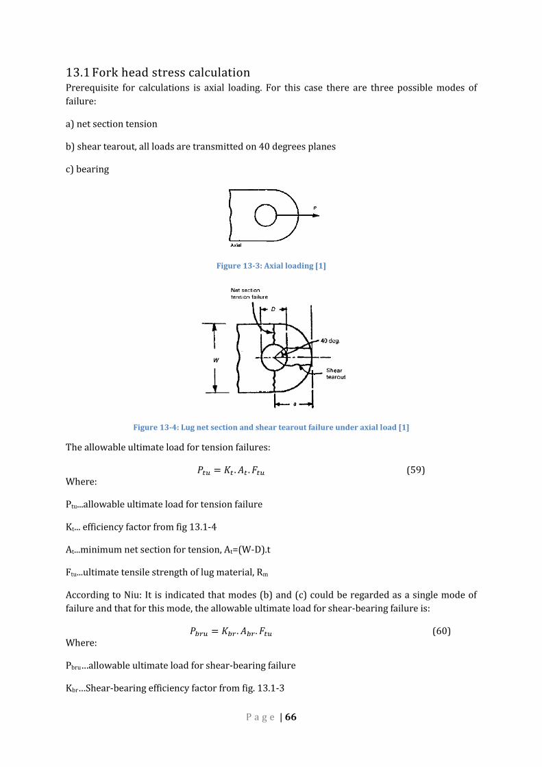
P a g e | 66
13.1 Fork head stress calculation Prerequisite for calculations is axial loading. For this case there are three possible modes of
failure:
a) net section tension
b) shear tearout, all loads are transmitted on 40 degrees planes
c) bearing
Figure 13-3: Axial loading [1]
Figure 13-4: Lug net section and shear tearout failure under axial load [1]
The allowable ultimate load for tension failures:
𝑃𝑡𝑢 = 𝐾𝑡 . 𝐴𝑡 . 𝐹𝑡𝑢 (59) Where:
Ptu...allowable ultimate load for tension failure
Kt... efficiency factor from fig 13.1-4
At...minimum net section for tension, At=(W-D).t
Ftu...ultimate tensile strength of lug material, Rm
According to Niu: It is indicated that modes (b) and (c) could be regarded as a single mode of
failure and that for this mode, the allowable ultimate load for shear-bearing failure is:
𝑃𝑏𝑟𝑢 = 𝐾𝑏𝑟. 𝐴𝑏𝑟. 𝐹𝑡𝑢 (60) Where:
Pbru…allowable ultimate load for shear-bearing failure
Kbr…Shear-bearing efficiency factor from fig. 13.1-3

P a g e | 67
Abr…Projected bearing area (Abr=D.t)
Ftu…Ultimate tensile strength of lug material with grain
Figure 13-5: Shear-bearing efficiency factor, Kbr [1]
Figure 13-6: Efficiency factor for tension, Kt [1]
Limiting factor for all fork heads was shear-bearing failure.

P a g e | 68
Table 13-13-1: Fork head analysis resulting table
Fork head name 14x1 16x1 18x1 25x1 30x1,5 30x2,5 30x2 Aileron
Pbru [N] 10064 10656 13024 17908 14652 14652 14652 7281,6
RF 9,49 5,22 5,01 5,15 3,89 4,35 2,00 15,48
14 FASTENERS All fasteners are chosen according to ČSN ONL 3120.14 or ISO 4762.
Figure 14-1: 6x47 ONL 3120
ONL 3120 fasteners were chosen for their smooth shank favourable for application as pins.
Thread is present only in the very end of thread and has a hole for safety pin. Pins’ material is
LROL.7 with following mechanical properties:
Table 14-1: L.ROL7 mechanical properties
Material L.ROL7
Rm 1080 MPa Rp0,2 930 MPa
Typical fastener connection can be seen on fig 14-2
Figure 14-2: Typical fastener connection

P a g e | 69
14.1 Stress calculations Most of the pins are Ø6mm and the biggest stress is applied to rod nr. 8 of lateral control (see
table 8-1). According to fig 14-3 the biggest bending moment, bending stress respectively, is in
the middle of the pin. The shear is for its small scale negligible.
Figure 14-3: Shear force and bending moment distribution on a pin
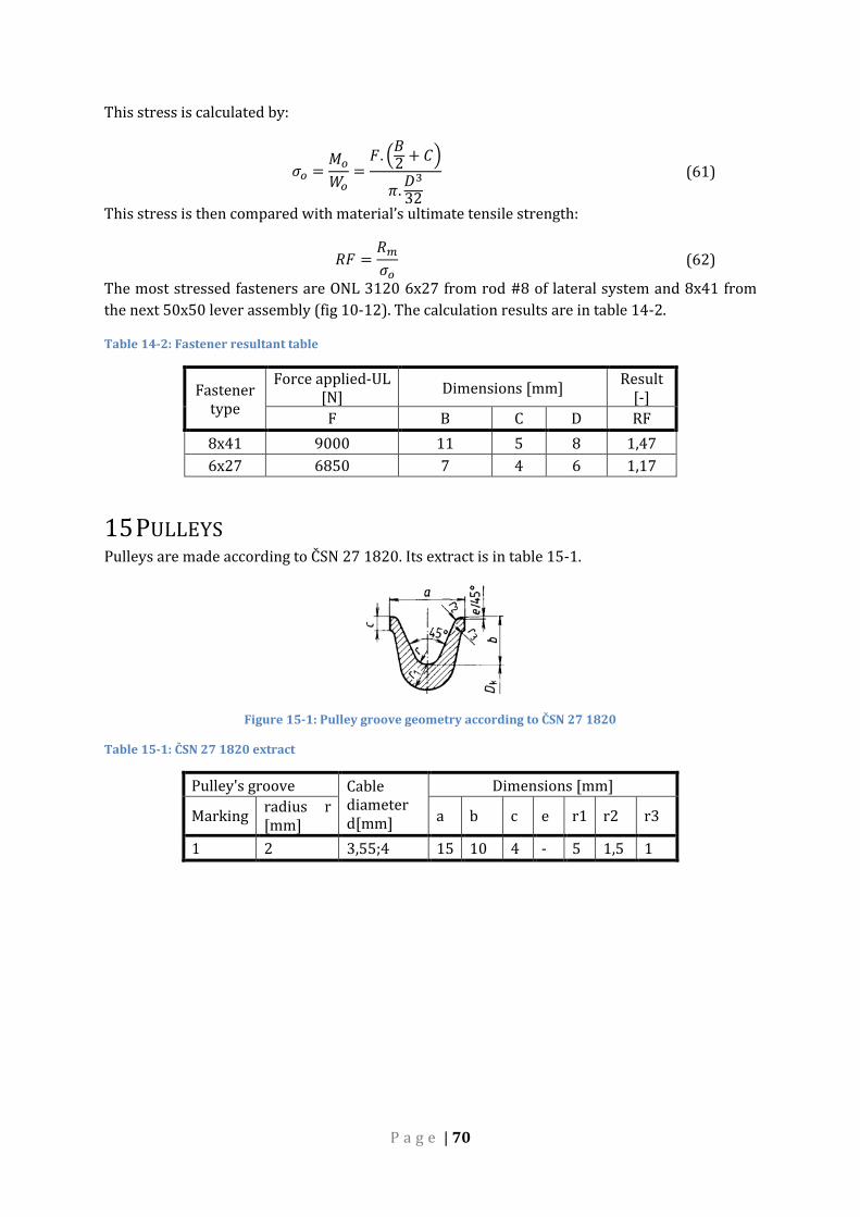
P a g e | 70
This stress is calculated by:
𝜎𝑜 =𝑀𝑜
𝑊𝑜=
𝐹. (𝐵2
+ 𝐶)
𝜋.𝐷3
32
(61)
This stress is then compared with material’s ultimate tensile strength:
𝑅𝐹 =𝑅𝑚
𝜎𝑜 (62)
The most stressed fasteners are ONL 3120 6x27 from rod #8 of lateral system and 8x41 from
the next 50x50 lever assembly (fig 10-12). The calculation results are in table 14-2.
Table 14-2: Fastener resultant table
Fastener type
Force applied-UL [N]
Dimensions [mm] Result
[-]
F B C D RF
8x41 9000 11 5 8 1,47
6x27 6850 7 4 6 1,17
15 PULLEYS Pulleys are made according to ČSN 27 1820. Its extract is in table 15-1.
Figure 15-1: Pulley groove geometry according to ČSN 27 1820
Table 15-1: ČSN 27 1820 extract
Pulley's groove Cable diameter d[mm]
Dimensions [mm]
Marking radius r [mm]
a b c e r1 r2 r3
1 2 3,55;4 15 10 4 - 5 1,5 1

P a g e | 71
16 GEAR RATIOS Gear ratios are important to calculate possible efficiency of control surfaces. Gear ratios are
calculated for every route and in different positions.
A value of hinge moment is read from FEM model for each position. A pilot’s input force is then
divided by this value. The result is gear ratio of concrete route and position. The exact way of
calculations and their results are explained and showed further on.
16.1 Lateral gear ratios
Following tables show results for both cases (1 pilot, 2 pilots) to demonstrate, the gear ratios
remain the same. Again the gear ratio is calculated by:
𝐺𝑅 =𝐹𝑎𝑝𝑝𝑙𝑖𝑒𝑑
𝑀ℎ𝑖𝑛𝑔𝑒 (63)
Table 16-1: Lateral gear ratio values for 1 pilot
1 pilot Force applied F = 1536 N
Sidestick position Pulled Neutral Pushed
Sidestick displacement [mm]
-60,00 -30,00 0,00 30,00 60,00
Hinge moment Mhinge[Nm] 139,00 188,00 202,00 231,00 236,00
Elevator deflection [°] -30,00 -13,50 0,00 12,80 25,00
Gear ratio [-] 11,05 8,17 7,60 6,65 6,51
Table 16-2: Lateral gear ratio values for 2 pilots
2 pilots Force applied F = 2.1151,00 N
Sidestick position Pulled Neutral Pushed
Sidestick displacement [mm] -60,00 -30,00 0,00 30,00 60,00
Hinge moment Mhinge [Nm] 209,00 282,00 303,00 346,00 355,00
Elevator deflection [°] -30,00 -13,50 0,00 12,80 25,00
Gear ratio [-] 11,01 8,16 7,60 6,65 6,48

P a g e | 72
Figure 16-1: Gear ratio lateral system diagram; both curves for both cases are almost completely overlapping
16.2 Longitudinal gear ratios This case is calculated for case of 2 pilots only for the reason, the results are almost identical.
Gear ratio of aileron route is calculated by:
𝐺𝑅 =𝐹𝑎𝑝𝑝𝑙𝑖𝑒𝑑
𝑀ℎ𝑖𝑛𝑔𝑒 𝐿 + 𝑀ℎ𝑖𝑛𝑔𝑒 𝑅 (64)
Where:
MhingeL…is hinge moment of left aileron
MhingeR…is hinge moment of right aileron
Table 16-3: Longitudinal gear ratios
2 pilots Force applied F = 2.385 N
Sidestick position Left Neutral Right
Sidestick displacement [°] -27,00 -14,00 0,00 14,00 30,00
Hinge moment MhingeL [Nm] 10,50 17,13 43,00 81,00 127,00
Hinge moment MhingeR [Nm] 115,00 83,00 43,00 18,20 10,30
Left aileron deflection [°] -25,00 -11,60 0,00 9,00 -24,90
Right aileron deflection [°] 16,00 9,40 0,00 -11,00 16,10
Gear ratio [-] 6,14 7,69 8,95 7,76 5,61
6,00
7,00
8,00
9,00
10,00
11,00
12,00
-70,00 -50,00 -30,00 -10,00 10,00 30,00 50,00 70,00
Ge
ar r
atio
[-]
Stick displacement [mm]
Gear ratios lateral system
1 pilot
2 pilots

P a g e | 73
Figure 16-2: Gear ratio longitudinal system diagram
16.3 Rudder gear ratio
Table 16-4: Yaw gear ratios
2 pilots Force applied F = 2.1151 N
Pedal position Full left Neutral Full right
Pedal deflection [°] 20 0 -20
Rudder deflection [°] 29,7 0 -29,8
Hinge moment [Nm] 182 225 198
Gear ratio [-] 12,64 10,23 11,62
5,00
5,50
6,00
6,50
7,00
7,50
8,00
8,50
9,00
9,50
-35,00 -25,00 -15,00 -5,00 5,00 15,00 25,00 35,00
Ge
ar r
atio
[-]
Stick rotation [°]
Gear ratio longitudinal system
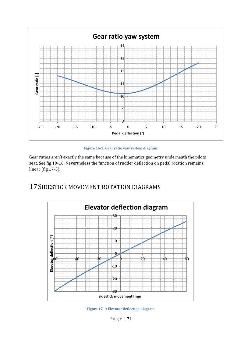
P a g e | 74
Figure 16-3: Gear ratio yaw system diagram
Gear ratios aren’t exactly the same because of the kinematics geometry underneath the pilots
seat. See fig 10-16. Nevertheless the function of rudder deflection on pedal rotation remains
linear (fig 17-3).
17 SIDESTICK MOVEMENT ROTATION DIAGRAMS
Figure 17-1: Elevator deflection diagram
8
9
10
11
12
13
14
-25 -20 -15 -10 -5 0 5 10 15 20 25
Ge
ar r
atio
[-]
Pedal deflection [°]
Gear ratio yaw system
-30
-20
-10
0
10
20
30
-60 -40 -20 0 20 40 60
Ele
vato
r d
efl
ect
ion
[°]
sidestick movement [mm]
Elevator deflection diagram

P a g e | 75
Figure 17-2: Aileron deflection diagram
Figure 17-3: Rudder deflection diagram
-30
-20
-10
0
10
20
30
-35 -25 -15 -5 5 15 25 35
Aile
ron
de
fle
ctio
n [°]
Sidestick rotation [°]
Ailerons deflection diagram
Left Aileron
Right Aileron
-35
-25
-15
-5
5
15
25
35
-25 -15 -5 5 15 25
Ru
dd
er
de
fle
ctio
n [°]
Pedal deflection [°]
Rudder deflection diagram

P a g e | 76
18 CONCLUSION The thesis’ task was to design a fully working and producible control system for TL 4000 plane.
This goal has to been achieved without exception. This work took into account certification
specification CS 23, various recommendations by thesis’ supervisor and TL Ultralight
representatives. Following objectives were fulfilled:
1. Creation of kinematic model of control system of TL4000 aircraft
2. Creation of thorough design of individual parts of the system.
3. Load determination and stress analysis of individual system’s routes.
4. Determination of gear ratios of individual system’s routes.
However there are two drawbacks in this design. The first is concerning the design of a part of
aileron system subassembly (fig. 11-15) for being unnecessarily complicated, heavy and not
strength enough. The second one is having the cables not lead directly from the pedal lever (fig.
10-16) instead of this the cables are lead through another lever which creates an unfavourable
gear ratio. These drawbacks couldn’t be removed because the solution was found soon before
the thesis’ deadline.
Except of these drawbacks the route is fully functional and all parts are checked according to
Niu or classical solid mechanics methodology. Strong emphasis was given to manufacturability
together with stress analysis and mass optimization of single parts.
The biggest challenge of them all was to fine tune the lateral-longitudinal mechanism itself to
give requested surfaces deflection in combination with reasonable sidestick movement and
forces in rods. This problem showed as crucial during the whole design phase and proper effort
was put to solve it.
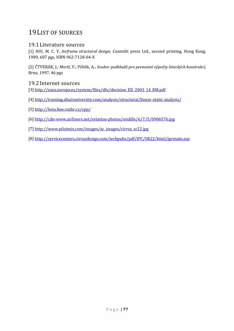
P a g e | 77
19 LIST OF SOURCES
19.1 Literature sources [1] NIU, M. C. Y, Airframe structural design, Conmilit press Ltd., second printing, Hong Kong,
1989, 607 pgs, ISBN 962-7128-04-X
[2] ČTVERÁK, J.; Mertl, V.; Píštěk, A.; Soubor podkladů pro pevnostní výpočty leteckých konstrukcí,
Brno, 1997, 46 pgs
19.2 Internet sources [3] http://easa.europa.eu/system/files/dfu/decision_ED_2003_14_RM.pdf
[4] http://training.altairuniversity.com/analysis/structural/linear-static-analysis/
[5] http://beta.fme.vutbr.cz/cpp/
[6] http://cdn-www.airliners.net/aviation-photos/middle/6/7/5/0906576.jpg
[7] http://www.pilotmix.com/images/ac_images/cirrus_sr22.jpg
[8] http://servicecenters.cirrusdesign.com/techpubs/pdf/IPC/SR22/html/ipcmain.asp
P a g e | 78
20 LIST OF ATTACHMENTS Attachment nr.1: DVD with CAD and PATRAN model
Attachment nr.2: A3 sized mechanism overview


![VYSOKÉ UENÍ TECHNICKÉ V BRNĚ - core.ac.uk · 2.2 Mechanika plastů [2], [5], [14], [15] ... ztratil kontrolu nad jízdou a při svém pádu rozbil velké zrcadlo oceněné na](https://img.dokumen.tips/doc/110x75/5ad572837f8b9a075a8ce725/vysok-uen-technick-v-brne-coreacuk-mechanika-plastu-2-5-14-15-.jpg)


