Embed Size (px)
Citation preview

VxWorks
DEVICE DRIVER DEVELOPER'S GUIDEVolume 1: Fundamentals of Writing Device Drivers
6.8
®
VxWorks Device Driver Developer's Guide, 6.8

Copyright © 2009 Wind River Systems, Inc.
All rights reserved. No part of this publication may be reproduced or transmitted in any form or by any means without the prior written permission of Wind River Systems, Inc.
Wind River, Tornado, and VxWorks are registered trademarks of Wind River Systems, Inc. The Wind River logo is a trademark of Wind River Systems, Inc. Any third-party trademarks referenced are the property of their respective owners. For further information regarding Wind River trademarks, please see:
www.windriver.com/company/terms/trademark.html
This product may include software licensed to Wind River by third parties. Relevant notices (if any) are provided in your product installation at the following location: installDir/product_name/3rd_party_licensor_notice.pdf.
Wind River may refer to third-party documentation by listing publications or providing links to third-party Web sites for informational purposes. Wind River accepts no responsibility for the information provided in such third-party documentation.
Corporate HeadquartersWind River500 Wind River WayAlameda, CA 94501-1153U.S.A.
Toll free (U.S.A.): 800-545-WINDTelephone: 510-748-4100Facsimile: 510-749-2010
For additional contact information, see the Wind River Web site:
www.windriver.com
For information on how to contact Customer Support, see:
www.windriver.com/support
VxWorksDevice Driver Developer's Guide6.8
29 Oct 09

iii
Contents
1 Getting Started with Device Driver Development .................................... 1
1.1 About Device Drivers ..................................................................................................... 1
1.2 About this Documentation Set .................................................................................... 2
1.2.1 Intended Audience ........................................................................................... 2
1.2.2 Navigating this Documentation Set .............................................................. 2
Experienced VxWorks Device Driver Developers ........................................ 3Novice VxWorks Device Driver Developers ................................................. 3
1.2.3 Documentation Conventions .......................................................................... 3
1.3 Additional Documentation Resources ....................................................................... 4
2 VxBus and VxBus Device Drivers ............................................................. 5
2.1 Introduction ...................................................................................................................... 5
2.2 About VxBus ................................................................................................................... 5
2.3 VxBus Device Drivers ................................................................................................... 6
2.4 Design Goals ................................................................................................................... 9
2.4.1 Performance ....................................................................................................... 10
2.4.2 Maintenance and Readability .......................................................................... 10
2.4.3 Ease of Configuration ....................................................................................... 10
2.4.4 Performance Testing ......................................................................................... 11
2.4.5 Code Size ............................................................................................................ 11
3 Device Driver Fundamentals ..................................................................... 13
3.1 Introduction ...................................................................................................................... 13
VxWorksDevice Driver Developer's Guide, 6.8
iv
3.2 Driver Classes ................................................................................................................. 14
3.2.1 General Classes .................................................................................................. 14
Serial Drivers .................................................................................................... 14Storage Drivers ................................................................................................. 14Network Interface Drivers .............................................................................. 15Non-Volatile RAM Drivers ............................................................................. 15Timer Drivers .................................................................................................... 16DMA Controller Drivers ................................................................................. 16Bus Controller Drivers ..................................................................................... 16USB Drivers ....................................................................................................... 17Interrupt Controller Drivers ........................................................................... 17Multifunction Drivers ...................................................................................... 17Remote Processing Element Drivers ............................................................. 18Console Drivers ................................................................................................ 18Resource Drivers .............................................................................................. 19
3.2.2 Other Classes .................................................................................................... 19
3.3 Driver Organization ....................................................................................................... 19
3.3.1 File Location ...................................................................................................... 20
Wind River Drivers ........................................................................................... 20Third-Party Drivers .......................................................................................... 20
3.3.2 Sample Driver Files: wrsample ....................................................................... 20
3.3.3 Required Files ................................................................................................... 21
Driver Source File ............................................................................................. 21Component Description File ........................................................................... 23Driver Configuration Stub Files ..................................................................... 28README File .................................................................................................... 30Device Driver Makefiles .................................................................................. 31
3.4 VxBus Driver Methods .................................................................................................. 32
3.4.1 Representing Driver Methods in the Documentation ................................ 32
3.4.2 Parts of a Driver Method ................................................................................. 33
3.4.3 Calling Driver Methods ................................................................................... 33
3.4.4 Advertising Driver Methods .......................................................................... 34
3.4.5 Driver Method Limitations ............................................................................. 35
3.5 Driver Run-time Life Cycle .......................................................................................... 36
3.5.1 Driver Initialization Sequence ........................................................................ 36
Making Assumptions About Initialization Order ....................................... 37Early in the Boot Process ................................................................................. 37sysHwInit( ), PLB, and Hardware Discovery ............................................... 37Driver Registration ........................................................................................... 38Driver Initialization Phase 1 ........................................................................... 38Kernel Startup ................................................................................................... 38Driver Initialization Phase 2 ........................................................................... 39Driver Initialization Phase 3 ........................................................................... 39
3.5.2 Invoking a Driver Method .............................................................................. 39

Contents
v
3.5.3 Run-time Operation ......................................................................................... 39
Unloading a Driver .......................................................................................... 39Removing a Device from the System ............................................................ 40Dissociating a Device from a Driver .............................................................. 40
3.5.4 Handling a System Shutdown Notification ................................................. 40
3.5.5 Handling Late Driver Registration ................................................................ 41
3.5.6 Driver Registration Order Considerations ................................................... 41
3.5.7 Driver-to-Device Matching and Hardware Availability ............................. 42
PLB ..................................................................................................................... 42Other Bus Types ................................................................................................ 43
3.6 Services Available to Drivers ....................................................................................... 43
3.6.1 Configuration .................................................................................................... 44
Determining Driver Configuration Information ......................................... 44Responding to Changes in Device Parameters ............................................ 46
3.6.2 Memory Allocation .......................................................................................... 47
Allocating Memory During System Startup ................................................ 47Allocating Memory During Normal System Operation ............................. 48Intermixing Memory Allocation Methods within a Single Driver ........... 48
3.6.3 Non-Volatile RAM Support ............................................................................. 49
3.6.4 Hardware Access .............................................................................................. 49
Finding the Address of the Hardware Registers ......................................... 49Reading and Writing to the Hardware Registers ........................................ 51Special Requirements for Hardware Register Access ................................. 52VxBus Version Considerations ........................................................................ 52
3.6.5 Interrupt Handling ........................................................................................... 53
Overview of Interrupt Handling .................................................................... 53Interrupt Indexes .............................................................................................. 54Minimizing Work Performed Within an ISR ................................................ 55
3.6.6 Synchronization ................................................................................................ 55
Task-Level Synchronization ............................................................................ 56Interrupt-Level Synchronization .................................................................... 56
3.6.7 Direct Memory Access (DMA) ....................................................................... 58
vxbDmaBufLib .................................................................................................. 58DMA Considerations ........................................................................................ 59Allocating External DMA Engines ................................................................ 62
3.6.8 Atomic Operators ............................................................................................. 64
3.7 BSP Configuration ......................................................................................................... 65
3.7.1 Requirements for PLB Devices ....................................................................... 65
3.7.2 Configuring Device Parameters in the BSP .................................................. 67
3.8 SMP Considerations ...................................................................................................... 68
3.8.1 Lack of Implicit Locking ................................................................................. 68
VxWorksDevice Driver Developer's Guide, 6.8
vi
3.8.2 True Task-to-Task Contention ......................................................................... 69
3.8.3 Interrupt Routing ............................................................................................. 69
3.8.4 Deferring Interrupt Processing ...................................................................... 69
4 Development Strategies ............................................................................. 73
4.1 Introduction ...................................................................................................................... 73
4.2 Writing New VxBus Drivers ........................................................................................ 73
4.2.1 Creating the VxBus Infrastructure ................................................................. 74
Writing Driver Source Files ............................................................................. 74Writing Header Files (Optional) .................................................................... 74Writing the Component Description File (CDF) .......................................... 74Writing the Configuration Stub Files ............................................................ 75Verifying the Infrastructure ............................................................................ 76
4.2.2 Modifying the BSP (Optional) ........................................................................ 76
4.2.3 Adding Debug Code ........................................................................................ 77
4.2.4 Adding the VxBus Driver Methods ............................................................... 77
4.2.5 Removing Global Variables ............................................................................ 78
4.3 VxBus Show Routines ................................................................................................... 79
4.3.1 Available Show Routines ................................................................................ 79
vxBusShow( ) ..................................................................................................... 79vxbDevStructShow( ) ........................................................................................ 81vxbDevPathShow( ) .......................................................................................... 82
4.3.2 PCI Show Routines .......................................................................................... 82
pciDevShow( ) ................................................................................................... 83vxbPciDeviceShow( ) ........................................................................................ 83vxbPciHeaderShow( ) ....................................................................................... 84vxbPciFindDeviceShow( ) ................................................................................ 85vxbPciFindClassShow( ) ................................................................................... 85vxbPciConfigTopoShow( ) ............................................................................... 86
4.3.3 Using Show Routines from Software ............................................................ 87
4.3.4 Configuring Show Routines into VxWorks .................................................. 88
4.4 Debugging ....................................................................................................................... 90
4.4.1 Configuring Show Routines ........................................................................... 90
4.4.2 Deferring Driver Registration ........................................................................ 91
4.4.3 Including Debug Code .................................................................................... 91
4.4.4 Confirming Register Access ............................................................................ 92
4.4.5 Increasing the Size of HWMEM_POOL ........................................................ 92
4.4.6 Confirming Device and Driver Name Matches ........................................... 92

Contents
vii
5 Driver Release Procedure .......................................................................... 93
5.1 Introduction ..................................................................................................................... 93
5.2 Driver Source Location .................................................................................................. 94
5.3 Driver-Specific Directories ............................................................................................ 94
5.4 Driver Installation and the README File ................................................................ 95
5.5 Driver Packaging ............................................................................................................ 97
5.6 Driver Release Procedure ............................................................................................. 97
A Glossary ...................................................................................................... 99
B Checklist for Device Drivers ...................................................................... 103
Index ..................................................................................................................... 105

VxWorksDevice Driver Developer's Guide, 6.8
viii

1
1Getting Started with
Device Driver Development
1.1 About Device Drivers 1
1.2 About this Documentation Set 2
1.3 Additional Documentation Resources 4
1.1 About Device Drivers
In the simplest terms, VxWorks device drivers are a means of communication between a hardware device and the VxWorks operating system. However, Wind River currently supports two device driver models for accomplishing this task.
In later VxWorks 6.x releases, device drivers can be implemented in one of two ways: as VxBus-enabled device drivers or as legacy (pre-VxBus) device drivers. Each method is described briefly below:
■ VxBus-Enabled Device Drivers
The preferred method for new development uses the VxBus device driver infrastructure. This infrastructure supports device drivers by defining standard interfaces for the driver to interact with the operating system and device hardware.
■ Legacy (Pre-VxBus) Device Drivers
The term legacy device drivers is used to describe pre-VxBus device drivers as implemented in early VxWorks 6.x and in VxWorks 5.x releases. Legacy drivers do not share a common interface to the operating system or hardware.
NOTE: If you are developing for a symmetric multiprocessing (SMP) system, Wind River recommends that you use VxBus-enabled device drivers. Wind River does not provide legacy model drivers that are SMP safe. If you wish to use a legacy model device driver in an SMP system, you must ensure that the driver is SMP safe. (For information on SMP support, see the VxWorks Kernel Programmer’s Guide: VxWorks SMP).
VxWorksDevice Driver Developer's Guide, 6.8
2
Wind River strongly recommends that you develop new VxWorks device drivers according to the VxBus model whenever possible. The VxWorks Device Driver Developer’s Guide (Vol. 3): Migrating to VxBus includes information on migrating an existing legacy-model driver to the VxBus model.
1.2 About this Documentation Set
This section provides information on the intended audience for this documentation, including the level of expertise expected from the developer. It also provides a map of this documentation to help you get the information you need regarding device driver development quickly and efficiently.
1.2.1 Intended Audience
This documentation is primarily designed for the experienced device driver developer. In general, the documentation does not assume specific experience with VxWorks device drivers or with the VxBus or legacy VxWorks device driver model. However, it does assume general experience writing device drivers for embedded hardware systems (for example, a basic understanding of reading and writing device registers).
For specific information on navigating this documentation set based on your experience level, see 1.2.2 Navigating this Documentation Set, p.2.
1.2.2 Navigating this Documentation Set
The VxWorks Device Driver Developer’s Guide includes three volumes:
Volume 1: Fundamentals of Writing Device Drivers (this document) This volume provides information and concepts that are fundamental to the development of most VxBus model device drivers. It serves as a foundation for the class-specific information presented in Volume 2.
Volume 2: Writing Class-Specific Device Drivers Volume 2 provides specific information and requirements for class-specific device drivers for all driver classes supported by VxWorks (for example, network drivers, bus controller drivers, USB drivers, and so forth). It also includes some guidelines for developing drivers for classes that are not currently supported.
Volume 3: Legacy Drivers and Migration Although Volumes 1 and 2 may provide information that is generic to all VxWorks device drivers, they should not generally be used as a reference for legacy model device drivers. Volume 3 provides legacy model driver information for the purpose of maintaining existing legacy device drivers.
NOTE: In VxWorks 6.6 and later, the legacy device driver implementation is recommended only for uniprocessor (UP) systems. (For information on SMP and UP systems, see the VxWorks Kernel Programmer’s Guide).

1 Getting Started with Device Driver Development1.2 About this Documentation Set
3
Wind River strongly recommends that all new device driver development be done according to the VxBus device driver model. Volume 3 also provides guidelines for migrating legacy model device drivers to the VxBus model, including specific migration information for certain driver classes.
Experienced VxWorks Device Driver Developers
Your level of experience with VxWorks device driver development will influence how you approach Volume 1 (this document). If your experience is limited to legacy model VxWorks device driver development, the majority of the concepts described in this document will be new to you. Understanding these concepts is critical before beginning any VxBus model driver development. If you are an experienced VxBus device driver developer, some of the information in Volume 1 is likely to be familiar to you. However, you may still need to carefully review the requirements for your driver class in Volume 2 and may even need to review certain concepts in Volume 1.
If you are an experienced legacy model device driver developer, the legacy driver chapters of Volume 3 are likely to be familiar to you. However, if you plan to migrate any existing drivers to the VxBus model, or you have plans to use the optional VxWorks symmetric multiprocessing (SMP) product, you should carefully review the migration information in Volume 3. It is also critical that you carefully examine Volume 1 (this document) and relevant chapters of VxWorks Device Driver Developer’s Guide, Volume 2: Writing Class-Specific Drivers before beginning any VxBus model driver development.
Novice VxWorks Device Driver Developers
If you are fairly new to VxWorks device driver development and you are not interested in migrating an existing device driver, you should focus your attention on Volume 1 (this document) and Volume 2 of this documentation set. The fundamentals presented in Volume 1 are critical for most VxBus model device drivers. Once you have a basic understanding of these fundamentals, you can move on to the class-specific information in Volume 2 that is appropriate for your device class.
If you are new to device driver development in general (not specific to VxWorks), you may need to consult some third-party information in order to better understand the basic concepts associated with all device driver development. However, if you are fairly experienced with embedded development and have some hardware experience, you should find that the information in Volume 1 is sufficient to get you started.
1.2.3 Documentation Conventions
The following conventions are used in this document:
installDir Within this document, file paths are typically expressed as a full path; this practice maintains consistency between this and other Wind River documentation. For example:
installDir/vxworks-6.x/target/src/hwif/sio/Makefile

VxWorksDevice Driver Developer's Guide, 6.8
4
bspname In several places within this document, there are references to filenames that are based on the BSP. These filenames have the string bspname substituted. For example, if you are working on a BSP called acmeBSP, change any reference bspname to acmeBSP. For example, bspname.h would become acmeBSP.h.
class Drivers for specific devices are grouped by device class. For example, serial drivers are located at:
installDir/vxworks-6.x/target/src/hwif/sio
For the general case, class represents the device type. For example:
installDir/vxworks-6.x/target/src/hwif/class
dev Where this document refers to devices in general, these devices are generically referred to as dev. In such cases, substitute the name of each device or device type for dev. For example, if your driver supports ncr810, the general file devInit.c becomes ncr810Init.c.
1.3 Additional Documentation Resources
Before beginning any device-driver development, you should have a good understanding of the overall VxWorks I/O system. For more information, see the VxWorks Kernel Programmer's Guide: I/O System.
In addition, you may want to refer to the VxWorks BSP Developer’s Guide. This document discusses VxWorks BSP development. In particular, it provides guidelines for writing a custom BSP based on an existing reference BSP.
5
2VxBus and VxBus Device Drivers
2.1 Introduction 5
2.2 About VxBus 5
2.3 VxBus Device Drivers 6
2.4 Design Goals 9
2.1 Introduction
This chapter explains some of the key concepts and terms associated with VxBus and VxBus device drivers including the term VxBus itself, instances, and driver method advertisement. This chapter is intended as a system overview only. The concepts and terms introduced here are explained further in 3. Device Driver Fundamentals.
Class-specific driver information for all supported VxBus classes is provided in VxWorks Device Driver Developer’s Guide, Volume 2: Writing Class-Specific Device Drivers.
2.2 About VxBus
The term VxBus generally refers to one of two things. In general, it refers to a specific infrastructure for support of device drivers in VxWorks, with minimal BSP support. This includes functionality to allow device drivers to be matched up with devices, mechanisms for drivers to gain access to device hardware, a mechanism for other parts of the software environment to gain access to device functionality, and other functionality required in order for device drivers to be functional in a VxWorks system.
In addition, the term VxBus sometimes refers to a set of components of the VxWorks operating system for use with Workbench, the vxprj command-line utility, and VxWorks image projects (VIPs). The core VxBus functionality is one
VxWorksDevice Driver Developer's Guide, 6.8
6
component, each VxWorks VxBus driver is a component, and the VxBus support modules are components. Each of these components can be selected individually from within Workbench.
Before the first release of VxBus with VxWorks 6.2, device drivers were not integrated with VxWorks project configuration, and to add and remove support for specific devices required significant knowledge of the BSP and of the driver, as well as requiring extra effort to manage VxWorks projects when drivers needed to be added or removed. As a set of components, VxBus eliminates most of that by allowing various drivers and support modules to be selected from within Workbench, without requiring knowledge of the BSP and driver, and without requiring extra effort for management of VxWorks projects when drivers are added or removed.
Many BSPs are released in a format in which VxBus is required. If you remove the VxBus component from projects based on these BSPs, your project does not build.
2.3 VxBus Device Drivers
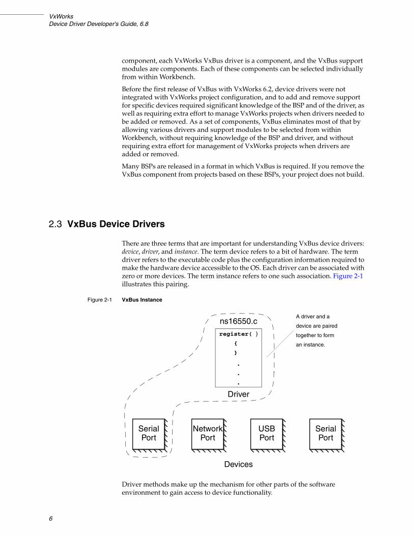
There are three terms that are important for understanding VxBus device drivers: device, driver, and instance. The term device refers to a bit of hardware. The term driver refers to the executable code plus the configuration information required to make the hardware device accessible to the OS. Each driver can be associated with zero or more devices. The term instance refers to one such association. Figure 2-1 illustrates this pairing.
Driver methods make up the mechanism for other parts of the software environment to gain access to device functionality.
Figure 2-1 VxBus Instance
USBPort
SerialPort
SerialPort
NetworkPort
ns16550.c
register( )
{
}
.
.
.
Driver
Devices
A driver and a
device are paired
together to form
an instance.

2 VxBus and VxBus Device Drivers2.3 VxBus Device Drivers
7
When using a driver method, the module making the request can query a single instance or all instances. And the query can either ask for information on how to accomplish an action or it can be a request for the driver to perform some action. At the top level, then, the query can consist of a question of whether a specific instance can support an action, a question of what instances can support an action, or a request to perform an action.
Figure 2-2 illustrates device/driver/operating system communication in a subset of a VxWorks system. The system shown includes two middleware modules or VxWorks subsystems (in this case, the network stack and the auxiliary timer) which are attempting to communicate with a hardware device on the system. Note that an actual system is likely to have several instances and many middleware modules, Figure 2-2 is a subset only.
An instance makes itself available to the overall VxWorks system by advertising the driver methods it supports. In Figure 2-2, the network stack uses the vxbDevMethodGet( ) routine to query each instance (device/driver pairing) known to the system. In the example, the network stack module is searching for an instance that supports the {muxDevConnect}( ) driver method. If the instance supports the method, it returns a pointer to the driver’s routine implementing that method. If an instance does not support the requested method, it returns NULL. In the example shown, the stack finds a Yukon II network interface advertising support for the required method.
The system also shows an auxiliary timer making a similar query. In this case, the timer looks for the {vxbTimerFuncGet}( ) method and gets a positive response from the OpenPic timer instance in the system.
Note that although this example shows only a single instance making a positive response in each case, any number of instances (or none at all) can include the necessary support.

VxWorksDevice Driver Developer's Guide, 6.8
8
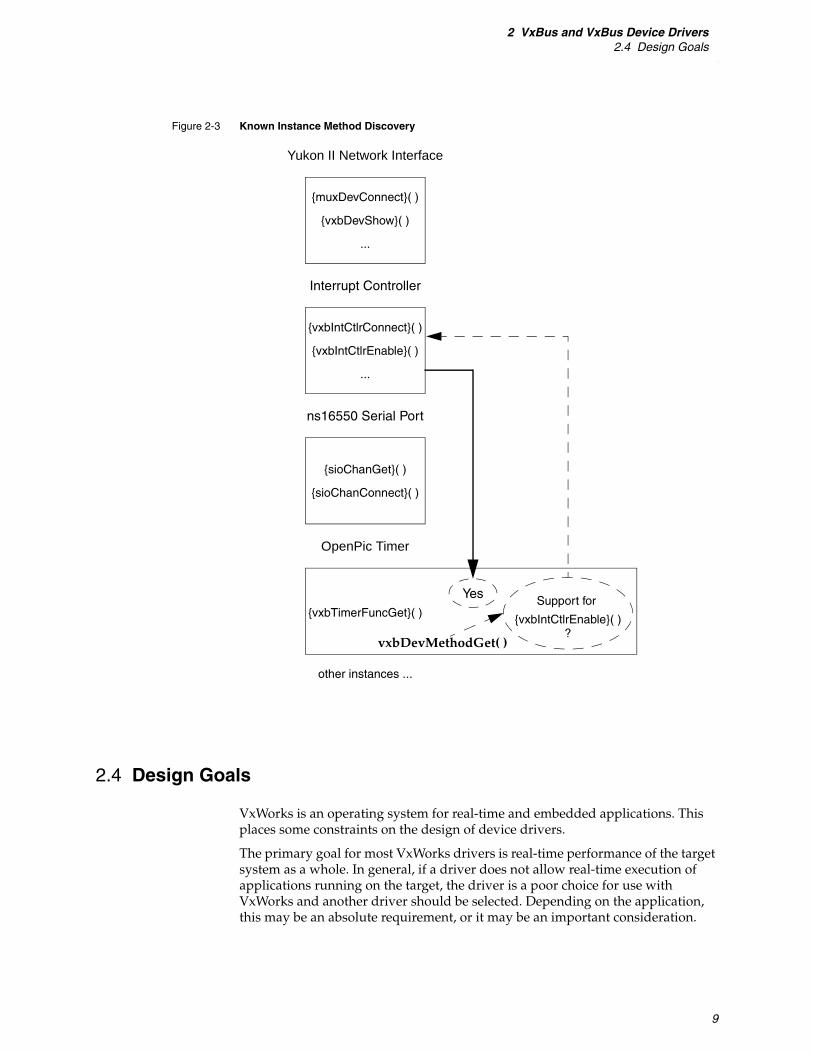
Figure 2-3 shows the OpenPic timer instance (as seen in Figure 2-2) querying the interrupt controller instance directly. The interrupt controller includes support for {vxbIntCtlrEnable}( ) and therefore responds to the timer request.
Figure 2-2 Method Advertising
ns16550 Serial Port
OpenPic Timer
{sioChanGet}( )
{sioChanConnect}( )
{vxbTimerFuncGet}( )
Yukon II Network Interface
{muxDevConnect}( )
{vxbDevShow}( )
...
{vxbIntCtlrConnect}( )
{vxbIntCtlrEnable}( )
...
Interrupt Controller
Support for
{vxbTimerFuncGet}( )
Support for
{muxDevConnect}( )
Network Stack Auxiliary Clock
vxbDevMethodGet( )vxbDevMethodGet( )
Yes
Device Driver Pairings (instances) Middleware ModuleMiddleware Module
other instances ... other modules...other modules...
??
Yes
2 VxBus and VxBus Device Drivers2.4 Design Goals
9
2.4 Design Goals
VxWorks is an operating system for real-time and embedded applications. This places some constraints on the design of device drivers.
The primary goal for most VxWorks drivers is real-time performance of the target system as a whole. In general, if a driver does not allow real-time execution of applications running on the target, the driver is a poor choice for use with VxWorks and another driver should be selected. Depending on the application, this may be an absolute requirement, or it may be an important consideration.
Figure 2-3 Known Instance Method Discovery
ns16550 Serial Port
OpenPic Timer
{sioChanGet}( )
{sioChanConnect}( )
{vxbTimerFuncGet}( )
Yukon II Network Interface
{muxDevConnect}( )
{vxbDevShow}( )
...
{vxbIntCtlrConnect}( )
{vxbIntCtlrEnable}( )
...
Interrupt Controller
other instances ...
Support for
{vxbIntCtlrEnable}( )
vxbDevMethodGet( )
Yes
?

VxWorksDevice Driver Developer's Guide, 6.8
10
Memory footprint is another constraint for VxWorks drivers. Many embedded applications have limited memory and because demand paging to disk is not compatible with real-time operation, memory constraints are extremely important.
Standard software requirements are also important in the VxWorks environment. This includes requirements such as driver flexibility, code maintainability, code readability, and driver configurability.
2.4.1 Performance
Drivers must perform well enough to match the real-time kernel's abilities. Designing for performance implies many things. First, it requires using direct memory access (DMA) and interrupts in an efficient manner. This requires you to keep your routine nesting at an optimum level. For example, too many routine calls and restore operations can increase process dispatch latency and reduce performance. However, performance requirements must be balanced against proper use of routines for keeping code size small and making your driver design easy to follow and understand.
Designing for performance also means keeping interrupt latency to a minimum. Interrupt handlers must receive the greatest care in any design. Overall system performance is just as important as the specific driver's performance.
For specific applications, you may consider it acceptable to write a VxWorks driver that sacrifices one or more of these goals. For example, when writing a driver for a system that is expected to be used only for a specific non-real-time application, you may be tempted to sacrifice real-time system performance in your driver design. However, because of issues such as code re-use, Wind River strongly discourages this approach. Real-time performance and memory footprint are an important concern for all VxWorks drivers.
2.4.2 Maintenance and Readability
Most of the effort involved in software engineering is maintenance. Therefore, any effort that reduces the maintenance burden is valuable. By adhering to coding standards and producing quality documentation, you make your code easy to read, understand, and maintain. Poor quality documentation is just as detrimental to the maintenance process as insufficient documentation. Any new device driver documentation should be reviewed by at least one person in addition to the author of the code.
2.4.3 Ease of Configuration
Your driver should not limit the end user’s options or requirements. Do not impose limits on the number of devices that can be supported or on other features. You may not be able to support all device features or operating modes in your original driver, but your design should not preclude expanded device support at a later time.

2 VxBus and VxBus Device Drivers2.4 Design Goals
11
2.4.4 Performance Testing
All drivers must be tested for expected behavior, and all drivers should be tested for performance. In addition to writing the driver functionality, you must also consider writing test routines. This involves inserting debug information into your code as well as supporting benchmark tests. If a standard benchmark test is not available, you must consider writing one. You should consider testing for both performance and expected behavior regardless of your driver type (Ethernet, serial, timers, interrupt controllers, and so forth).
In general, high-level debug code such as that used during performance testing should be well-written, surrounded by #ifdef/#endif statements, and left in the source code in order to ease future debugging efforts.
2.4.5 Code Size
In the embedded real-time operating system (RTOS) market, code size (footprint) is important. Code size should be minimized through structured design. However, reducing code size can hurt performance. As a developer, you must balance your design such that you provide adequate performance without excessive code size.

VxWorksDevice Driver Developer's Guide, 6.8
12

13
3Device Driver Fundamentals
3.1 Introduction 13
3.2 Driver Classes 14
3.3 Driver Organization 19
3.4 VxBus Driver Methods 32
3.5 Driver Run-time Life Cycle 36
3.6 Services Available to Drivers 43
3.7 BSP Configuration 65
3.8 SMP Considerations 68
3.1 Introduction
This chapter discusses the key concepts related to VxWorks device drivers that use the VxBus driver model. In particular, it provides detailed information about the anatomy of the VxBus device driver ecosystem including information on driver-related file locations and directory structure, an explanation of VxBus methods, a description of the services available to VxBus device drivers, and the general life cycle of a VxBus device driver. In addition, this chapter provides guidelines for developing device drivers for use with the optional VxWorks symmetric multiprocessing (SMP) product.
In general the concepts explained in this chapter apply to many (or all) types of device-specific drivers. Volume 2 of the VxWorks Device Driver Developer’s Guide provides information about specific driver classes and is intended to supplement the information provided in this volume.

VxWorksDevice Driver Developer's Guide, 6.8
14
3.2 Driver Classes
One of the most basic pieces of information about a device, and about the driver that manages it, is what function the device performs. Different devices perform different tasks. There are devices that read and write data on magnetic disk or other long-term data storage, devices that print text and graphics to paper or to a video display, and still other devices that control the location of robotic arms, pens, and so forth.
For each type of functionality, there may be many different devices that perform similar tasks. For example, when displaying graphical information on a video device, the display controller may be a simple VGA controller (like those found on older PCs), or it may be a modern display controller running on PCI Express, with several megabytes of graphics RAM buffers. However, in each case, the underlying purpose of the device is the same.
Because of this similarity of function, device drivers can be divided into several different classes based on the tasks that the associated device performs.
3.2.1 General Classes
This section gives an overview of the different driver classes as defined by Wind River, along with a brief description of the functionality provided by each class. For more information about an individual driver class, refer to the appropriate chapter of VxWorks Device Driver Development Guide, Volume 2: Writing Class-Specific Drivers.
Serial Drivers
Serial drivers manage interfaces to terminals and other devices with serial interface such as RS-232 or RS-422. These devices are connected to the I/O system, and may be configured as the VxWorks system console. Software can gain access to these devices by making a call to open( ), read( ), write( ), ioctl( ), and so forth.
Within the VxBus framework, serial driver source files are located in the following directory:
installDir/vxworks-6.x/target/src/hwif/sio
The primary operations they support are connection to the I/O system and fetching channel-specific data.
Storage Drivers
Storage drivers manage interfaces to magnetic disks, tape drives, flash disks (also known as flash keys), and on-board flash devices. Some general characteristics of these devices are:
■ The storage contents are maintained when power is turned off.
■ Access to the data is slow compared to RAM.
■ Typically, the per-byte cost of these devices is low compared to RAM.

3 Device Driver Fundamentals3.2 Driver Classes
15
These devices include ATA disks, Serial ATA disks, SCSI disks, USB flash disks, floppy disks, and so forth.
Within the VxBus framework, storage driver source files are located in the following directory:
installDir/vxworks-6.x/target/src/hwif/storage
The primary operation they support is connecting to an extended block device (XBD), which occurs during the instConnect( ) phase of VxBus initialization. (For information on device driver initialization phases, see 3.5 Driver Run-time Life Cycle, p.36.)
For more information on XBD, see VxWorks Device Driver Developer’s Guide (Vol. 2): Storage Drivers.
Network Interface Drivers
Network interface drivers manage interfaces to network hardware. Ethernet is the most common type of network hardware supported by network drivers, though drivers for other types of network hardware are also included in this class.
Ethernet network devices typically are separated into two main parts: the media access controller (MAC), and physical layer support (PHY). PHY devices reside on a bus type called the media independent interface (MII).
Within the VxBus framework, MAC drivers are typically located in the following directory:
installDir/vxworks-6.x/target/src/hwif/end
And PHY drivers are located in:
installDir/vxworks-6.x/target/src/hwif/mii
The primary operation that MAC drivers support is connection to the MUX. (For information on the MUX, see the Wind River Network Stack Programmer’s Guide, Volume 3: Interfaces and Drivers.) Both PHY and MAC drivers provide mechanisms to coordinate between the MAC and the PHY.
Non-Volatile RAM Drivers
Non-Volatile RAM (NVRAM) devices provide data storage that is not erased when power is turned off. There is some overlap between NVRAM devices and storage devices (see Storage Drivers, p.14). The primary distinction is that NVRAM devices generally allow random byte-sized access to the data, while storage devices typically do not allow random byte-sized access to the data. However, this is not always the case and exceptions occur in both directions. Functionally, NVRAM devices store small amounts of data for use during system configuration, and storage devices store application data.
Within the VxBus framework, NVRAM driver source files are located in the following directory:
installDir/vxworks-6.x/target/src/hwif/nvram
The primary operations supported by these drivers are reading and writing to and from the media according to specified allocation.

VxWorksDevice Driver Developer's Guide, 6.8
16
Timer Drivers
Timer devices can provide two services. They provide a counter that increments or decrements periodically that an application can read to determine elapsed time. They can also provide a mechanism to notify the CPU that a given time period has elapsed. This is done using an interrupt.
Within the VxBus framework, timer driver source files are located in the following directory:
installDir/vxworks-6.x/target/src/hwif/timer
The primary operations supported are allocation of a timer to a specific purpose, attaching an interrupt service routine (ISR) to the timer interrupt, reading the current value of the timer, and enabling or disabling counting and interrupt generation.
DMA Controller Drivers
DMA engines allow data to be copied from one location in RAM to another without the overhead of using the CPU to perform the data copy. They are typically used to copy data between a device buffer and system RAM.
Many devices have built-in DMA engines to help increase performance. This is typical in devices such as network interfaces (MACs) and storage devices. However, many systems include DMA engines available for general purpose use. With respect to VxWorks device drivers, devices with built-in DMA engines are not considered to be DMA controller drivers. Rather, they are part of another class such as network or storage. Only drivers for the general-purpose DMA engines are considered to be in the DMA controller driver class.
Within the VxBus framework, DMA controller driver source files are located in the following directory:
installDir/vxworks-6.x/target/src/hwif/dma
The primary operations supported are allocation of a DMA engine to a specific purpose, and copying data.
Bus Controller Drivers
Bus controller devices provide an interface between different types of computer buses. Every CPU design includes the interface from the CPU to the outside world. In the VxBus context, this bus—regardless of CPU type—is called the processor local bus (PLB). Many devices are connected directly to the PLB. However, other devices are connected to other bus types, which are then connected to the PLB through a bus controller. In some cases, additional bus controller devices provide a bridge from one device bus type to another, such as from the PCI to VME.
Within the VxBus framework, bus controller driver source code is kept in the following directory or its subdirectories, regardless of the type of bus the device manages:
installDir/vxworks-6.x/target/src/hwif/busCtlr
Bus controller drivers manage the devices present on the bus in several ways. First, the bus controller driver is responsible for determining what devices are present

3 Device Driver Fundamentals3.2 Driver Classes
17
on the subordinate bus. Second, bus controller drivers are responsible for configuring downstream devices so that their drivers can access device registers properly. Third, bus controller drivers are responsible for managing any address mapping that might be required.
USB Drivers
USB functionality is split into two different types. USB host adaptors are a kind of bus controller device, usually providing a bridge between the PLB or a PCI bus and a USB bus. USB class drivers provide the functionality of storage drivers, network drivers, and so on.
Within the VxBus framework, USB host adaptor drivers are located in subdirectories under:
installDir/vxworks-6.x/target/src/hwif/busCtlr/usb/hcd
As of this release, USB class drivers are not integrated with the VxBus framework, therefore their source files are located in the following directory:
installDir/vxworks-6.x/target/src/drv/usb
For more information on USB class drivers, see Wind River USB Programmer’s Guide: USB Class Drivers.
Interrupt Controller Drivers
Interrupt controller devices allow management of interrupt input sources, usually fine-grained control. When devices assert interrupts, the interrupt controller hardware passes the interrupt to the processor at an appropriate time, preventing some interrupts from occurring while allowing other interrupt sources to be delivered to the CPU.
Within the VxBus framework, interrupt controller driver source code is kept in the following directory:
installDir/vxworks-6.x/target/src/hwif/intCtlr
Interrupt controller drivers are responsible for determining what devices are connected to each of the interrupt controller's inputs, and enabling or disabling each input according to whether any device connected to that input should be enabled. They are also responsible for configuring interrupt characteristics such as trigger type (edge versus level), activation (high versus low), and other interrupt characteristics.
Multifunction Drivers
Many physical devices contain multiple logical devices. That is, a single chip can include several timers, several DMA engines, one or more network interfaces, a USB host adaptor, a PCI bus controller device, and various other devices.
Because many of the devices on a chip are identical copies of devices available elsewhere, it is not practical to create a single driver that supports all the functions of a chip. A single driver targeted at a specific device can be used to control a
VxWorksDevice Driver Developer's Guide, 6.8
18
device on a given multifunction chip or a device that is not on the chip. This eliminates duplication of code.
Having a single driver to manage the entire chip also reduces your ability to configure the final system. For example, if you do not require USB for your application, using a single driver to manage an entire multifunction chip containing a USB host adaptor results in the entire USB stack being included in your application. This can cost several hundred kilobytes of unnecessary memory overhead.
Because of this, the recommended device driver development strategy for multifunction devices is to have multiple drivers to support a single chip, one driver for each functional component. In addition, you should create a multifunction driver that manages the functional blocks on the chip. The multifunction driver leaves management of the functional blocks to the individual drivers for each functional block. The multifunction driver’s job is to announce to VxBus that each functional component part is available, what the register base address of each functional component is, and to manage other high level information about the chip as a whole and about how it is divided into the individual functional components.
Remote Processing Element Drivers
Many modern computers provide general purpose processors other than the primary CPU. These processors can be similar to the primary CPU, or a different processor type. They can also be custom processing elements such as digital signal processors (DSPs). These remote processing elements can be dedicated to specific tasks, depending on the application, and controlled by the primary CPU, or they can be autonomous or semi-autonomous systems running their own operating system.
Within the VxBus framework, processing element driver source code is kept in the following directory:
installDir/vxworks-6.x/target/src/hwif/cpu
Processing element drivers are responsible for establishing communication with the remote processing element. Each VxBus processing element instance (see 2.3 VxBus Device Drivers, p.6) is responsible for establishing and maintaining communication with one remote processor.
Console Drivers
Console devices are those devices that can be used as a graphical system console when the console is not a terminal connected to a serial port. This includes keyboards, mouse devices, and display devices.
Within the VxBus framework, console driver source code is kept in the following directory:
installDir/vxworks-6.x/target/src/hwif/console
Each type of console driver provides management features specific to the device.

3 Device Driver Fundamentals3.3 Driver Organization
19
Resource Drivers
Many modern processor designs include hardware resources that are used by, and shared among, several peripheral devices. The types of services provided by these resources include things such as data routing and address translation. Sometimes, each peripheral device has enough dedicated resources, that those resources can be considered part of the device. However, when the available resources must be shared among several peripheral devices, there may not be enough of these resources available in the running system to enable full functionality of all the peripheral devices available. In this case, you must create a resource management driver to allocate the resources to other peripheral devices.
Within the VxBus framework, resource driver source code is kept in the following directory:
installDir/vxworks-6.x/target/src/hwif/resource
The primary function of resource drivers is allocation of the available resources to other peripheral devices. It can also be used for configuring the resources.
3.2.2 Other Classes
There are classes of common devices for which Wind River does not define a driver class. These classes include devices such as digital-to-analog converters and analog-to-digital converters (D/A and A/D), robot control systems, and so forth. In the future, Wind River may define driver classes for these device types.
Highly-specialized hardware is not likely to be supported by any of the pre-defined Wind River device classes.
For more information on developing drivers for non-standard classes, see VxWorks Device Driver Developer’s Guide (Vol. 2): Other Driver Classes.
3.3 Driver Organization
A key part of your driver implementation is the driver source code file. This file conveys the basic information that allows your device to communicate with the VxBus infrastructure and the VxWorks operating system. However, VxWorks device drivers require a number of other files in addition to the driver source file. These additional files enable you to fully integrate your driver into the VxWorks build environment, a key step in preparing your device driver for distribution.
This chapter discusses how to find (and place) device driver files in the VxWorks source tree. It also provides specific details regarding each of the required files that make up a VxWorks (VxBus-enabled) device driver.
Ultimately, the goal of this section is to show how the various pieces of a driver fit together in a VxWorks system.
VxWorksDevice Driver Developer's Guide, 6.8
20
3.3.1 File Location
Before beginning your development, it is important to understand the placement of device driver files in the VxWorks source tree. There are three distinct places in the source tree where device driver files are located. These are:
installDir/vxworks-6.x/target/3rdparty VxBus model device drivers written by third party developers that are installed as add-ons to an existing VxWorks installation.
installDir/vxworks-6.x/target/src/hwif Drivers written in compliance with the VxBus device model, distributed and supported by Wind River, and provided as part of a standard product installation or patch.
installDir/vxworks-6.x/target/src/drv Wind River legacy drivers (not in VxBus compliance).
Wind River Drivers
Drivers underneath installDir/vxworks-6.x/target/src/hwif are organized into different subdirectories based on their driver class. For example, the source code for timer drivers is found in installDir/vxworks-6.x/target/src/hwif/timer. Similar subdirectories exist for each driver class that is supported by Wind River. For more information on class-specific driver files, see Volume 2 of the VxWorks Device Driver Developer’s Guide.
Third-Party Drivers
Third-party drivers are organized in a way that allows individual driver vendors and developers to create third-party drivers without worrying about namespace collisions between files created by different vendors. Each vendor wishing to write a device driver for VxWorks should first create a vendor-specific subdirectory in installDir/vxworks-6.x/target/3rdparty. For example, if a developer for the Acme Corporation plans to create a third-party driver for VxWorks, the first step for the driver developer is to create a new subdirectory to store the new driver files as follows:
installDir/vxworks-6.x/target/3rdparty/acme
Within this subdirectory, each individual driver is created within its own subdirectory. For example, use the following subdirectory to store the foo driver provided by the Acme Corporation:
installDir/vxworks-6.x/target/3rdparty/acme/acmeFoo
3.3.2 Sample Driver Files: wrsample
Wind River provides sample VxBus driver files in the following directory:
installDir/vxworks-6.x/target/3rdparty/windriver/wrsample
These files are provided as a model for you to use when developing a third-party driver. Detailed information about how to use this model is provided in the README file located in the wrsample directory.

3 Device Driver Fundamentals3.3 Driver Organization
21
For more information about wrsample and the driver release procedure, see 5. Driver Release Procedure.
3.3.3 Required Files
Although a driver can include many files (including multiple source files and a header file), there is a minimum set of files that make up a standard VxWorks driver. For most VxWorks device drivers, a minimum of six separate files are required. These include:
■ a driver source file—implements the runtime logic of the driver
■ a component description file (CDF)—allows you to integrate the driver with the VxWorks development tools
■ a driverName.dc file—provides the prototype for the driver registration routine
■ a driverName.dr file—provides a fragment of C code to call the driver registration routine
■ a README file—provides versioning information
■ a makefile (Makefile)—provides the make rules used to build the driver
The following sections describe each of these file types in greater detail.
Driver Source File
The driver source file contains the logic that implements the functionality of the device driver. As stated previously, VxWorks device drivers are found under the following directory:
installDir/vxworks-6.x/target/src/hwif
Third-party drivers are found under:
installDir/vxworks-6.x/target/3rdparty
The example in this section discusses the file locations for a Wind River driver.
While many VxWorks device drivers consist of a single source file, this is not a requirement. A driver can include one or more optional header files in order to allow for a cleaner presentation of the driver source code. A driver can also include multiple source files, with makefile rules to build a single driver object module for installation in the VxWorks library.
In the following example, fragments from the Wind River device driver file vxbCn3xxxTimer.c are used to illustrate the structure of a VxWorks device driver.
Example 3-1 Device Driver Structure
The first part of a device driver (following the driver header lines) is a data structure describing the routines that VxWorks must call during the VxBus initialization phases. (For more information on VxBus initialization phases, see 3.5.1 Driver Initialization Sequence, p.36.)
NOTE: Collectively, the CDF file (40driverName.cdf), driverName.dc, and driverName.dr are referred to as driver configuration files.
VxWorksDevice Driver Developer's Guide, 6.8
22
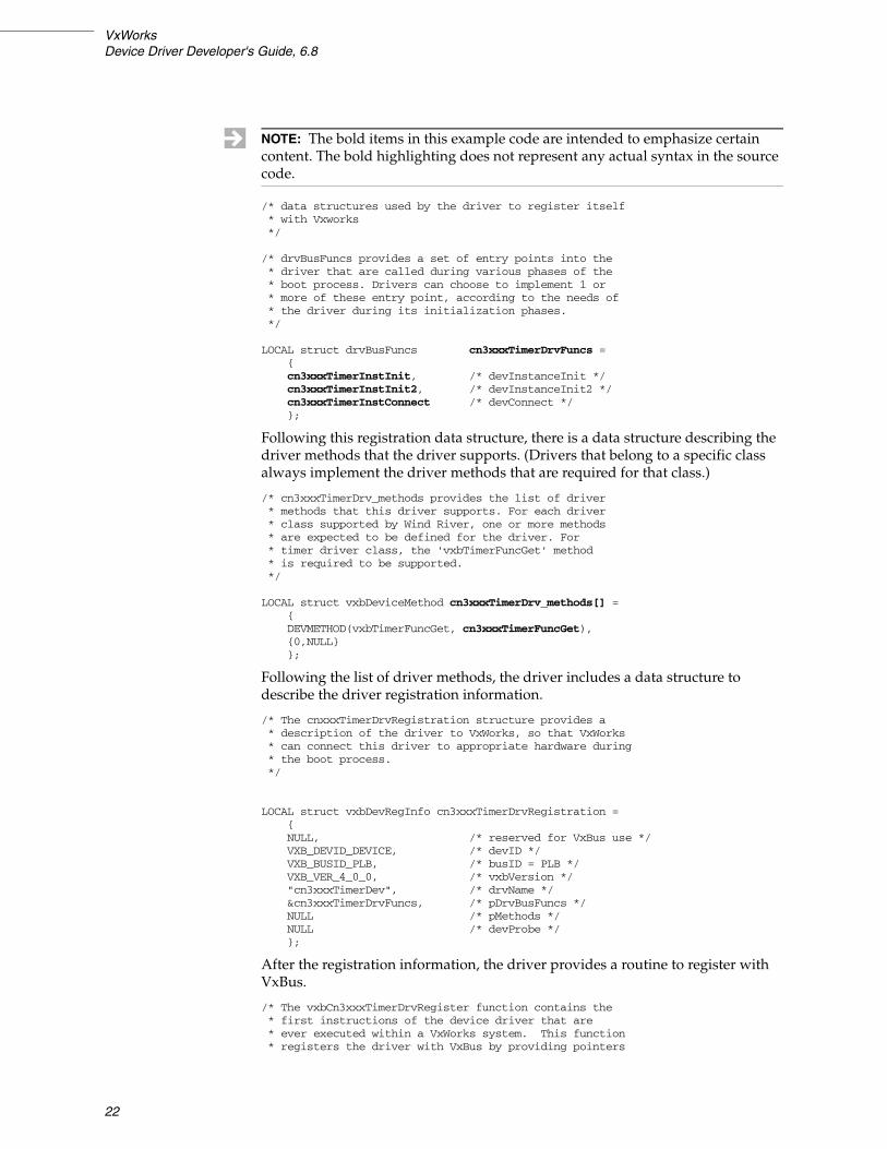
/* data structures used by the driver to register itself* with Vxworks*/
/* drvBusFuncs provides a set of entry points into the* driver that are called during various phases of the* boot process. Drivers can choose to implement 1 or* more of these entry point, according to the needs of* the driver during its initialization phases.*/
LOCAL struct drvBusFuncs cn3xxxTimerDrvFuncs ={cn3xxxTimerInstInit, /* devInstanceInit */cn3xxxTimerInstInit2, /* devInstanceInit2 */cn3xxxTimerInstConnect /* devConnect */};
Following this registration data structure, there is a data structure describing the driver methods that the driver supports. (Drivers that belong to a specific class always implement the driver methods that are required for that class.)
/* cn3xxxTimerDrv_methods provides the list of driver* methods that this driver supports. For each driver* class supported by Wind River, one or more methods* are expected to be defined for the driver. For* timer driver class, the 'vxbTimerFuncGet' method * is required to be supported.*/
LOCAL struct vxbDeviceMethod cn3xxxTimerDrv_methods[] ={DEVMETHOD(vxbTimerFuncGet, cn3xxxTimerFuncGet),{0,NULL}};
Following the list of driver methods, the driver includes a data structure to describe the driver registration information.
/* The cnxxxTimerDrvRegistration structure provides a* description of the driver to VxWorks, so that VxWorks* can connect this driver to appropriate hardware during* the boot process.*/
LOCAL struct vxbDevRegInfo cn3xxxTimerDrvRegistration ={NULL, /* reserved for VxBus use */VXB_DEVID_DEVICE, /* devID */VXB_BUSID_PLB, /* busID = PLB */VXB_VER_4_0_0, /* vxbVersion */"cn3xxxTimerDev", /* drvName */&cn3xxxTimerDrvFuncs, /* pDrvBusFuncs */NULL /* pMethods */NULL /* devProbe */};
After the registration information, the driver provides a routine to register with VxBus.
/* The vxbCn3xxxTimerDrvRegister function contains the* first instructions of the device driver that are * ever executed within a VxWorks system. This function* registers the driver with VxBus by providing pointers
NOTE: The bold items in this example code are intended to emphasize certain content. The bold highlighting does not represent any actual syntax in the source code.
3 Device Driver Fundamentals3.3 Driver Organization
23
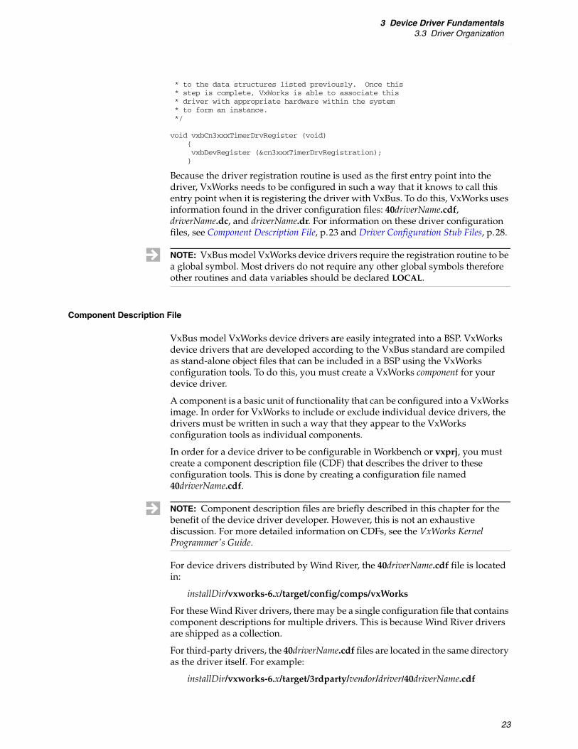
* to the data structures listed previously. Once this* step is complete, VxWorks is able to associate this* driver with appropriate hardware within the system * to form an instance.*/
void vxbCn3xxxTimerDrvRegister (void){vxbDevRegister (&cn3xxxTimerDrvRegistration);}
Because the driver registration routine is used as the first entry point into the driver, VxWorks needs to be configured in such a way that it knows to call this entry point when it is registering the driver with VxBus. To do this, VxWorks uses information found in the driver configuration files: 40driverName.cdf, driverName.dc, and driverName.dr. For information on these driver configuration files, see Component Description File, p.23 and Driver Configuration Stub Files, p.28.
Component Description File
VxBus model VxWorks device drivers are easily integrated into a BSP. VxWorks device drivers that are developed according to the VxBus standard are compiled as stand-alone object files that can be included in a BSP using the VxWorks configuration tools. To do this, you must create a VxWorks component for your device driver.
A component is a basic unit of functionality that can be configured into a VxWorks image. In order for VxWorks to include or exclude individual device drivers, the drivers must be written in such a way that they appear to the VxWorks configuration tools as individual components.
In order for a device driver to be configurable in Workbench or vxprj, you must create a component description file (CDF) that describes the driver to these configuration tools. This is done by creating a configuration file named 40driverName.cdf.
For device drivers distributed by Wind River, the 40driverName.cdf file is located in:
installDir/vxworks-6.x/target/config/comps/vxWorks
For these Wind River drivers, there may be a single configuration file that contains component descriptions for multiple drivers. This is because Wind River drivers are shipped as a collection.
For third-party drivers, the 40driverName.cdf files are located in the same directory as the driver itself. For example:
installDir/vxworks-6.x/target/3rdparty/vendor/driver/40driverName.cdf
NOTE: VxBus model VxWorks device drivers require the registration routine to be a global symbol. Most drivers do not require any other global symbols therefore other routines and data variables should be declared LOCAL.
NOTE: Component description files are briefly described in this chapter for the benefit of the device driver developer. However, this is not an exhaustive discussion. For more detailed information on CDFs, see the VxWorks Kernel Programmer's Guide.

VxWorksDevice Driver Developer's Guide, 6.8
24
Writing a CDF File
To create a CDF file for a new driver, copy an existing CDF (extension for this file type is .cdf) from the standard VxWorks installation tree to the directory where you are creating your driver and then modify the CDF to suit the needs of your driver. The CDFs for device drivers shipped with VxWorks are located in the following directory:
installDir/vxworks-6.x/target/config/comps/vxWorks
Example 3-2 shows the contents of a CDF for a PCI bus controller. This file is located in:
installDir/vxworks-6.x/target/config/comps/vxWorks/40m85xxPci.cdf
Example 3-2 Device Driver Component Description File
/* 40m85xxPci.cdf - Component configuration file */
Component DRV_PCIBUS_M85XX {NAME M85xx PCI busSYNOPSIS M85xx PCI bus controller DriverMODULES m85xxPci.oSOURCE $(WIND_BASE)/target/src/hwif/busCtlr_CHILDREN FOLDER_DRIVERS_INIT_ORDER hardWareInterFaceBusInitINIT_RTN m85xxPciRegister();PROTOTYPE void m85xxPciRegister (void);REQUIRES DRV_RESOURCE_M85XXCCSR \
INCLUDE_PARAM_SYS \INCLUDE_PCI_BUS \INCLUDE_PLB_BUS \INCLUDE_VXBUS
INIT_AFTER INCLUDE_PCI_BUS}
The individual lines of this example can be broken down as follows:
Component DRV_PCIBUS_M85XX {
Each component in VxWorks is described using a component identifier, designated using the keyword Component. Device driver component identifiers always begin with DRV_ and include information to describe the named device driver. Each class of driver uses a similar naming convention for component identifiers. In this example, DRV_PCIBUS_M85XX informs the reader that this is a component for a PCI bus controller driver.
The standard naming convention for a device driver component is DRV_CLASS_NAME. The name of the driver component must be unique therefore it is important that the NAME portion of the identifier be specified uniquely. When you are writing a third-party driver, include both the vendor and driver name in the NAME portion of the component identifier (for example, DRV_CLASS_VENDORANDDRIVERNAME). This avoids name conflicts with other drivers in the system.
NOTE: The kernel configuration tool does not automatically search for files in the installDir/vxworks-6.x/target/3rdparty/ directories. In order for the kernel configuration tool to be able to read the component definitions in the CDF files, the CDF files from the third-party directories must be manually copied to the following location:
installDir/vxworks-6.x/target/config/comps/vxWorks

3 Device Driver Fundamentals3.3 Driver Organization
25
Component identifiers are displayed in the Workbench kernel configuration editor under the Name column in Component Configuration. Figure 3-1 shows the display in Workbench.
NAME M85xx PCI bus
The NAME field is used to provide a human-readable description of the component. In Workbench, this appears as the description in the kernel configuration editor (see Figure 3-1).
SYNOPSIS M85xx PCI bus controller Driver
The SYNOPSIS field is used to provide a short human-readable description of the component. In Workbench, this appears in the Synopsis field in the kernel configuration editor (see Figure 3-1).
MODULES m85xxPci.o
The MODULES field lists the names of the object files that are created when the driver is built. In this example, only a single module is included. When a driver is included in a project, the VxWorks configuration services parse the contents of the object files that are listed on the MODULES line in order to determine
NOTE: Driver component identifiers for some older drivers continue to follow the standard VxWorks component naming convention and begin with INCLUDE_ (for example, INCLUDE_FEI8255X_VXB_END). For new development, use the DRV_ convention for your driver components.
Figure 3-1 Workbench CDF Field Display
SYNOPSIS field
NAME field COMPONENT field

VxWorksDevice Driver Developer's Guide, 6.8
26
what other components are needed to build this driver into the VxWorks image.
For example, if a driver makes use of the routine strlen( ), the symbol name strlen appears as an unresolved external in the driver's object file. Using this information, the VxWorks project configuration services automatically create a dependency on the component that provides strlen( ). This simplifies the REQUIRES field, because many of the dependencies that a driver has on other components are inferred from the direct dependencies parsed from the object modules.
The MODULES field and the files listed in MODULES, in conjunction with the REQUIRES field, provide all of the information necessary for VxWorks to determine which components need to be included to support a given driver.
_CHILDREN FOLDER_DRIVERS
The _CHILDREN field is used to group a component with other similar components for display in Workbench. Workbench displays all of the components that are contained within the same folder together in the kernel configuration tool dialog, allowing easy selection of individual components within the folder. All device drivers should be added to the FOLDER_DRIVERS folder. Therefore, this line can be copied to your driver without modification.
_INIT_ORDER hardWareInterFaceBusInit
The _INIT_ORDER field is used to describe when in the VxWorks boot process this driver needs to be initialized. All VxBus device drivers must be initialized in the hardWareInterFaceBusInit initialization group. Therefore, copy this line into your driver without change.
INIT_RTN m85xxPciRegister();
The INIT_RTN field is used to perform the preliminary initialization of the device driver. Device drivers must provide the name of their driver registration routine in this field. Subsequent initialization of the driver occurs when VxWorks finds appropriate hardware and then binds the hardware and device driver together to form an instance.
PROTOTYPE void m85xxPciRegister (void);
The PROTOTYPE field is used to provide a forward declaration of the routine specified by INIT_RTN, if no forward declaration of that routine is provided in the header files listed in HDR_FILES.
REQUIRES …
The REQUIRES field lists the components that must also be used in order for this driver to work correctly within VxWorks.
This field is necessary because not all device driver dependencies can be determined by examining the unresolved externals that are present in a driver. The REQUIRES field, in conjunction with the MODULES field, is used to determine the set of components that must be included to support the driver.
NOTE: Be sure to include the leading underscore on the keywords of the CDF file (where shown in the example above). The underscore reverses the meaning. For example, a _CHILDREN entry indicates that this component (in this case, your driver) is a child of the specified folder. If the underscore is not present, the folder (FOLDER_DRIVERS) is configured as a child of your driver, which is not correct.

3 Device Driver Fundamentals3.3 Driver Organization
27
For example, the PowerPC 85XX PCI bus controller driver requires services from the CCSR resource driver. (For more information on resource drivers, see Resource Drivers, p.19.) In this case, none of the public symbols of the CCSR driver appear as unresolved references in the network driver. Therefore, the MODULES method of determining component dependencies does not work. Instead, you must use explicit entries in the REQUIRES field of your CDF to describe the indirect dependencies.
Another more common example of this, is the use of PHY driver services from some network drivers. Some network drivers can use one of several PHY drivers, but others require a specific PHY driver. The network driver uses driver lookup services to locate the PHY instance to which it is attached. Again, no public symbols of the PHY driver are used by the network driver. Therefore, if a specific PHY driver is required, that PHY driver must be explicitly listed in the REQUIRES field.
INIT_AFTER INCLUDE_PCI_BUS
The INIT_AFTER and INIT_BEFORE (not shown in the example) fields are used to indicate any initialization dependencies within the initialization group specified by _INIT_ORDER. The component listed here must belong to the same initialization group as specified by _INIT_ORDER. In this example, this line indicates that this driver should not be initialized until after the PCI bus driver is initialized.
HDR_FILES $(WIND_BASE)/target/src/hwif/h/end/fei8255xVxbEnd.h
The above line is not shown in the example. However, your driver may require a HDR_FILES field. This field is used to list the driver header file that provides the routine prototype for the driver registration routine. This field works in conjunction with the INIT_RTN field. When VxWorks is configured, the header file provided by HDR_FILES is added to the generated C code for the VxWorks image. This allows the C code provided by INIT_RTN to compile without errors such as undefined references. By default, the project facility searches for HDR_FILES in the directory installDir/vxworks-6.x/target/h. To access files that are located in directories outside of installDir/vxworks-6.x/target/h, the complete path to the desired header file should be used, starting with the installation directory (installDir).
For a complete description of the component description language (CDL) used to create CDFs, see the VxWorks Kernel Programmer’s Guide.
CFG_PARAMS
Drivers sometimes need configuration information during initialization. If the required information is specific to the driver, but not specific to each instance, then it is suitable to provide this information at compile time as a parameter. This can be represented with the CDF keywords CFG_PARAMS and Parameter. CFG_PARAMS is used to indicate that the specified parameters are used by a component. The Parameter keyword is used to define a parameter.
The component should specify each parameter in the CFG_PARAMS section.
For example, a driver for a network device that supports jumbo frames might use a parameter to specify the maximum size of the jumbo frames that the driver can

VxWorksDevice Driver Developer's Guide, 6.8
28
accept. An example of the relevant fields of the Component and Parameter blocks is:
Component DRV_NET_SAMPLE {NAME network device supporting jumbo frames...CFG_PARAMS SAMPLE_JUMBO_MTU_VALUE
}
Parameter SAMPLE_JUMBO_MTU_VALUE {NAME Jumbo frame MTU sizeSYNOPSIS max num of bytes in a jumbo MTUTYPE intDEFAULT 9000
}
Each parameter consists of four keywords: NAME, SYNOPSIS, TYPE, and DEFAULT.
NAME Jumbo frame MTU sizeSYNOPSIS max num of bytes in a jumbo MTU
The NAME and SYNOPSIS fields in a parameter are similar to the same fields in a component.
TYPE int
The TYPE keyword describes the type of data in the parameter. The valid types include any valid C language type, as well as the string, bool, and exists types.
The string type is a NULL terminated ASCII string.
The bool type indicates a logical true/false variable. This can be either all uppercase or all lowercase, bool or BOOL.
The exists type is used when the parameter name, as a C macro, is either defined or not defined. When used, the default value can be TRUE or FALSE.
DEFAULT 9000
The DEFAULT keyword indicates the default value if the user does not change it.
For more information about driver parameters, see Configuring Resources, p.45 and Configuring Parameters, p.45.
Driver Configuration Stub Files
For some BSPs, VxWorks supports two distinct ways of building run-time images:
■ Using Workbench or the vxprj command-line facility to create an image (as described in Component Description File, p.23).
■ Invoking the make command directly in the BSP directory.
The first method (using Workbench or vxprj) is supported for all BSPs.
The second method allows you to create a VxWorks image by invoking the make command from within a BSP directory.
NOTE: Although the facility for building your BSP using the make command is available for most BSPs, it is not supported for all VxWorks development scenarios or for the optional VxWorks SMP product. For more information, see the VxWorks Command-Line Tools User’s Guide.

3 Device Driver Fundamentals3.3 Driver Organization
29
When a BSP is built directly from its makefile, the information that is contained in the driver component (.cdf file) is not used to configure the BSP. Instead, the BSP author includes or excludes components directly within the source files of the BSP, by creating lines in the BSP config.h file that specify which components to include or exclude.
For example, if you want to include the Cn3xxx timer driver in the run-time image created using your BSP, you can add the following line to your BSP config.h file:
#define DRV_TIMER_CN3XXX
After adding the appropriate define to the BSP config.h file, you can invoke make in the BSP directory to rebuild the BSP. Once the BSP is rebuilt, the component (in this case, the timer driver) is included in the VxWorks run-time image generated using this BSP.
To support direct BSP builds for your driver, you must create two additional configuration stub files, the driverName.dc and driverName.dr file. These files connect the device driver to the BSP command-line build.
The driverName.dc file is created using the same base name as the driver source file, but with a .dc extension instead of a .c extension. Again, using the Cn3xxx timer driver as an example, here is the vxbCn3xxxTimer.dc file:
IMPORT void vxbCn3xxxTimerDrvRegister();
The purpose of the driverName.dc file is to provide a function prototype for the device driver registration routine. The prototype may be surrounded in an #ifdef/#endif construct using the driver component identifier (DRV_CLASS_NAME) but this is not required.
The vxbCn3xxTimer.dr file is similarly brief:
#ifdef DRV_TIMER_CN3XXXvxbCn3xxxTimerDrvRegister ();
#endif /* DRV_TIMER_CN3XXX */
The purpose of the driverName.dr file is to call the driver registration routine that announces the driver to the VxWorks operating system. This code must be surrounded in an #ifdef/#endif construct in order to ensure the registration routine for the driver is run only when the component is included using the BSP config.h file.
For Wind River drivers, both the driverName.dc and driverName.dr files are located in the following directory:
installDir/vxworks-6.x/target/config/comps/src/hwif
NOTE: For simplicity, this example ignores the fact that the Cn3xxx timer driver has dependencies on other components, and that these other components must also be added to the BSP config.h file in order to satisfy the device driver dependencies.
NOTE: BSP builds are not supported for VxWorks SMP BSPs. For more information on working with the optional VxWorks SMP product, see the VxWorks Kernel Programmer’s Guide.
NOTE: The macro used on the #ifdef line must match the component name used in the CDF file (see Component Description File, p.23).

VxWorksDevice Driver Developer's Guide, 6.8
30
For third-party drivers, these files are located in the same directory as the driver source file.
For these files to be useful, they must be merged into an initialization file that is linked into a VxWorks run-time image. The VxWorks makefile environment contains all of the necessary commands to create this initialization file. If a new driver is added to the VxWorks source tree, the initialization file must be recreated as follows:
% cd installDir/vxworks-6.x/target/config/comps/src/hwif % make vxbUsrCmdLine.c
When these commands are run, the VxWorks makefile environment searches all of the locations where driver configuration stub files are found, and merges the files into the initialization file located in the following directory:
installDir/vxworks-6.x/target/config/all/vxbUsrCmdLine.c
README File
While not required by the makefile environment, each device driver should include a README file that describes the driver to a user. Third-party vendors may wish to include driver version information, a list of all files that make up the driver (source files, configuration files, and so forth), any known defects, driver version information, and perhaps even a URL where an end user might go to find an updated copy of the driver.
The driver README includes three sections of data as well as separation lines as follows:
■ A one-line statement that this is the README file for a VxWorks driver and stating the device for which the driver is intended. For example:
README: VxWorks/VxBus driver for device device
■ A line of dashes separating the first and second sections.
■ One or more paragraphs showing what devices the driver is suitable for, as well as the specific devices that have been tested with the driver. This section also lists which version of VxWorks and VxBus the driver has been developed for. This section may also list the files that make up the driver, provide a list of known bugs, or provide other information to the user.
Optionally, you can include instructions for the installation procedure in this section. (For more information, see 5.6 Driver Release Procedure, p.97.)
■ A line of dashes separating the second and third sections.
NOTE: The vxbUsrCmdLine.c file is not updated if the timestamp on the existing vxbUsrCmdLine.c file is newer than the timestamp on driverName.dc, driverName.dr, and the files in:
installDir/vxworks-6.x/target/config/comps/src/hwif
In this case, remove or rename the existing vxbUsrCmdLine.c and re-run the make vxbUsrCmdLine.c command.

3 Device Driver Fundamentals3.3 Driver Organization
31
■ A list of version numbers, along with a description of the changes between each version.
An example README file is available as part of the wrsample driver. For more information, see the following:
installDir/vxworks-6.x/target/3rdparty/windriver/wrsample
Device Driver Makefiles
In order for a device driver to build correctly under VxWorks, you must provide the appropriate makefiles so that your device driver can be incorporated into an object file that can be linked into a VxWorks image. There are two makefiles that are used to address this issue. These files are:
■ The vendor makefile located in:
installDir/vxworks-6.x/target/3rdparty/vendor/Makefile
■ The driver makefile located in:
installDir/vxworks-6.x/target/3rdparty/vendor/driver/Makefile
The contents of these makefiles can be complex because the makefiles need to be correctly integrated into the overall makefile hierarchy used by VxWorks. To create these makefiles properly, copy the appropriate sample makefiles from the following directories:
installDir/vxworks-6.x/target/3rdparty/windriverinstallDir/vxworks-6.x/target/3rdparty/windriver/wrsample
Modify the sample files to match your vendor and driver names, as needed.
Vendor Makefile
The vendor makefile is created in the following location:
installDir/vxworks-6.x/target/3rdparty/vendor/Makefile
The vendor makefile is shared for all drivers provided as a subdirectory to a given vendor directory. The makefile uses wildcards to determine what drivers are installed underneath the vendor directory (vendor), and to launch appropriate make commands for each driver.
To create a vendor makefile, copy the example Makefile from:
installDir/vxworks-6.x/target/3rdparty/windriver
And add it to:
installDir/vxworks-6.x/target/3rdparty/vendor
Where vendor is the designated name for your company. The sample makefile provides guidelines for making the necessary updates for your driver.
NOTE: Driver version numbers consist of two parts (for example, 7.4). Do not use three-part version numbers, and do not use slashes to separate version fields.

VxWorksDevice Driver Developer's Guide, 6.8
32
Driver Makefile
The driver makefile is created in the following directory:
installDir/vxworks-6.x/target/3rdparty/vendor/driver
This makefile is used exclusively to compile the driver located within the driver subdirectory (driver). Like the vendor makefile, this file should be copied from the example Makefile located in the following directory:
installDir/vxworks-6.x/target/3rdparty/windriver/wrsample
Unlike the vendor makefile, the driver makefile does not use wildcards to find the driver source files. Instead, this makefile includes a specific list of object files that are built from the source files in the driver subdirectory (driver).
Use the makefile included with the wrsample driver as a reference for creating your driver makefile. The comments in the wrsample makefile provide specific guidance for updating the makefile to suit your driver. However, in general, the primary modifications include changing the LIB_BASE_NAME (which should be your company name) and listing the driver object file in OBJS_COMMON.
If you want your driver to be available on a single CPU type only, specify the driver object file in the macro specific to that CPU type (for example OBJS_PPC32 for PowerPC). In this case, the driver should not be listed in OBJS_COMMON.
3.4 VxBus Driver Methods
This section discusses VxBus driver methods. In order for a device and driver to be useful to a VxWorks system, there must be a way for the application, middleware, or VxWorks kernel module to gain access to the device and cause the device to perform some function. The most basic way of doing this within the VxWorks framework is by using a VxBus driver method. In simple terms, a driver method is a published entry point into a driver made available to an API in VxBus.
3.4.1 Representing Driver Methods in the Documentation
This section discusses the representation used to discuss driver methods in this documentation (and elsewhere in the VxWorks documentation set).
The basic convention is that a driver method is represented as a name surrounded by braces and followed by parenthesis. For example, as in {thisDriverMethod}( ). This syntax refers to the driver method and all its parts as a single callable item.
Driver methods resolve to a callable routine published by a device driver. When referring to this called routine, the standard driver method syntax is prepended with the string func to get func{thisDriverMethod}( ).

3 Device Driver Fundamentals3.4 VxBus Driver Methods
33
To explicitly indicate specification of the arguments and return value of func{thisDriverMethod}( ), the callable routine is treated as a pseudo-C function and includes prototype information. For example:
STATUS func{thisDriverMethod}(VXB_DEVICE_ID devID,void * pArg)
3.4.2 Parts of a Driver Method
This section describes the basic concepts associated with a driver method. Specific definitions of the functionality provided by each supported driver method are provided in the class-specific chapters of Volume 2 of the VxWorks Device Driver Developer’s Guide.
In the most basic sense, a driver method defines a set of actions to be performed by a hardware device, and provides an API that allows the software to gain access to the hardware that performs those actions. Within the VxWorks VxBus framework, a driver method is represented as a pair of data:
■ a method ID which is a data value the size of a pointer1
■ a pointer to a routine that can be called to perform the actions defined by the method
The routine associated with a driver method must be a valid executable routine. Every routine for a given driver method must use the same prototype.
Most driver methods use a standard prototype because there are mechanisms to call driver methods in VxWorks that assume the driver method routine being called conforms to this standard.
The standard driver method prototype is as follows:
STATUS func{driverMethod}(VXB_DEVICE_ID devID, void * pArg )
For more information on these calling mechanisms, see 3.4.3 Calling Driver Methods, p.33.
3.4.3 Calling Driver Methods
As a driver developer, you do not normally call driver methods. However, you must be aware of what is involved in calling a driver method so you can avoid performance and functionality problems in your driver.
There are certain macros required when referring to driver methods. These macros are defined in the following directory:
installDir/vxworks-6.x/target/h/hwif/vxBus.h
1. For performance reasons, VxBus methods are searched using pointer comparisons. The data pointed to by the pointer is never dereferenced.

VxWorksDevice Driver Developer's Guide, 6.8
34
The macros available to applications that need to call driver methods are:
METHOD_DECL( ) Provides a forward reference to the driver method.
DEVMETHOD_CALL( )Provides the method ID in a form suitable to pass to a routine.
The vxbDevMethodRun( ) routine can be used to call a specific driver method within each driver in the system that has published the method. This routine iterates through all instances on the system and checks each one to see whether it publishes the specified method. If a given instance publishes the specified method, vxbDevMethodRun( ) invokes the method routine, func{driverMethod}( ). For example:
vxbDevMethodRun(DEVMETHOD_CALL(driverMethod), pArg);
To avoid iterating through all instances on the system, you must know the device ID for every instance containing the desired driver method. However, given the device ID of an instance, vxbDevMethodGet( ) can be used to discover the driver routine associated with the desired driver method, so that it can then be invoked.
The routine vxbDevMethodGet( ) returns either a pointer to the function within the driver, func{driverMethod}( ), or NULL if the driver does not publish the specified method.
When the func{driverMethod}( ) is known, it can be called directly. For example:
STATUS (*methodFunc)(VXB_DEVICE_ID devID, void * pArg);
methodFunc = vxbDevMethodGet(devID, DEVMETHOD_CALL(driverMethod)); if ( methodFunc != NULL )
(*methodFunc)(devID, pArg);
There is a performance impact for each of these mechanisms. Whenever vxbDevMethodGet( ) is called, it performs a linear search through the published driver methods for the instance specified, stopping when it finds a match or when it reaches the end of the table of advertised driver methods. It performs this search first on the table advertised in the instance's device structure, then through the table advertised in the driver's registration structure.
Whenever vxbDevMethodRun( ) is called, it iterates through all the devices on the system, regardless of bus topology. For each device, it performs the same linear search that vxbDevMethodGet( ) uses.
3.4.4 Advertising Driver Methods
Each driver maintains one or more tables of driver methods that are supported by the driver or the instance. The table contains the method ID and the function pointer to call when invoking the driver method. You can choose to have a separate method table for each instance on the system, a single method table for all instances involving your driver, or a combination of both.
Drivers can choose to replace the table dynamically to change what methods are advertised.
Most often, a driver includes only a single method table, which is allocated statically by the compiler. There is a macro that you must use when creating the

3 Device Driver Fundamentals3.4 VxBus Driver Methods
35
method table at compile time. The macro, DEVMETHOD( ), is available in the following directory:
installDir/vxworks-6.x/target/h/hwif/vxBus.h
This macro accepts two arguments: the method ID of the method, and the routine associated with the method in the driver. In addition, your driver must use DEVMETHOD_END to terminate the table.
The following is an example of a statically defined method table. (This is a modified version of a table from the NS16550 SIO driver.)
LOCAL device_method_t ns16550vxb_methods[] ={DEVMETHOD(sioChanGet, ns16550vxbSioChanGet),DEVMETHOD(sioChanConnect, ns16550vxbSioChanConnect),
#ifdef NS16550_DEBUG_ONDEVMETHOD(busDevShow, ns16550vxbSioShow),
#endif /* NS16550_DEBUG_ON */
DEVMETHOD_END};
To make the driver methods available to the rest of the system, there are two places that the driver can put a pointer to its method table. Each device in a VxWorks system, in the device structure, provides a field called pMethods that contains a pointer to a table of methods relevant to the instance. This is the preferred location to advertise driver methods. As mentioned previously, the driver can have a single table pointed to by each instance, or it can allocate a separate table for each instance, or it can set up groups of instances sharing a table each.
Although Wind River does not recommend this option, you can also advertise methods in the driver's registration structure. This method table is intended to be used for methods that do not require the driver to be paired with a device. Putting a pointer to the same table in both places does not cause the system to fail, but it doubles the time to perform method calls.
3.4.5 Driver Method Limitations
Driver methods are the most primitive form of communication between drivers and other parts of the system. Methods are not designed to be efficient in the run-time sense nor are they designed to be deterministic. The design goal of driver methods is to provide a mechanism that can be used during system startup to provide information needed for high-performance communication in the later running system.
You should limit the number of times that methods are looked up. Storing the function pointer for a method is a useful optimization. The user saves the pointer or other returned information, and then calls the appropriate routines through the table of function pointers.

VxWorksDevice Driver Developer's Guide, 6.8
36
3.5 Driver Run-time Life Cycle
This section describes the run-time life cycle for a VxWorks (VxBus) device driver, starting from the point at which the VxWorks target boots and ending when the driver is no longer relevant to the system.
3.5.1 Driver Initialization Sequence
A high level overview of the VxWorks boot process is described in VxWorks BSP Developer's Guide: Porting a BSP to Custom Hardware. This section provides a more detailed discussion of the driver initialization sequence than that provided in the BSP documentation.
At the most basic level, there are five initialization phases.
The following sections provide more information about each of these phases, along with context of what the overall system is doing during each phase. The overall initialization process includes the following states:
■ early boot process (see Early in the Boot Process, p.37)
■ hardware discovery (sysHwInit( ), PLB, and Hardware Discovery, p.37)
■ driver registration with the OS (Driver Registration, p.38)
■ phase 1, pre-kernel initialization (Driver Initialization Phase 1, p.38)
■ kernel startup (Kernel Startup, p.38)
NOTE: This section does not document the device driver development life cycle or how to configure the driver into a VxWorks bootable image. For more information on the device driver development cycle, see 4. Development Strategies. For more information on configuring a driver into a bootable image, see Component Description File, p.23.
NOTE: This version of VxWorks continues to support legacy device drivers as well as BSPs that are not enabled to support VxBus. Note that the initialization sequence described in this section does not represent the initialization sequence for legacy drivers or BSPs that do not support VxBus.
Table 3-1 Device Driver Initialization Phases
Phase Description Comments
Registration
Match/Probe Device and driver pairing routine.
Optional.
Phase 1 devInstanceInit( ) Pre-kernel initialization.
Phase 2 devInstanceInit2( ) Post-kernel initialization.
Phase 3 devInstanceConnect( ) Asynchronous initialization.

3 Device Driver Fundamentals3.5 Driver Run-time Life Cycle
37
■ phase 2, post-kernel initialization (Driver Initialization Phase 2, p.39)
■ phase 3, asynchronous initialization (Driver Initialization Phase 3, p.39)
Making Assumptions About Initialization Order
At each phase of initialization, VxBus executes this initialization phase level for all instances before moving to the next phase. The order in which instances are initialized within a phase is not specified. The only assumption your driver can make is that its parent bus controller instance has initialized to the point where the driver can get access to the hardware.
Early in the Boot Process
Device drivers do not play any role in the early boot process. Depending on which processor architecture you are working with, the CPU typically jumps to a specified address at power-on and starts executing instructions. Those instructions typically come from ROM or flash.
These early instructions initialize the memory controller and CPU, then start the procedure for initializing VxWorks.
sysHwInit( ), PLB, and Hardware Discovery
Early in the VxWorks initialization process the BSP routine sysHwInit( ) is executed. It is during this step that device drivers first become active.
The sysHwInit( ) routine, provided by the BSP, performs some early initialization (typically restricted to CPU initialization) and then makes a call to hardWareInterFaceInit( ). The first task performed by hardWareInterFaceInit( ) is to initialize the hardware memory allocation mechanism, INCLUDE_HWMEM_ALLOC. This step allows limited memory allocation for device drivers before the system memory pool is initialized. The hardWareInterFaceInit( ) routine then calls hardWareInterFaceBusInit( ). At this point, individual drivers become active by registering with VxBus.
One of the first drivers to become active is the driver for the processor local bus (PLB). The PLB2 is a special driver in the sense that some of the first parts of initialization occur in this driver.
Bus controller drivers, including the PLB driver, are responsible for determining what hardware is present on the system. The PLB hardware does not include support for device discovery, but the PLB driver is able to read a BSP-provided table containing information about devices connected directly to the bus. For each table entry, the PLB driver notifies VxWorks of the device.
2. Silicon vendors do not use the acronym PLB consistently. While some silicon vendors use the acronym PLB to describe the peripheral bus connected directly to the processor, others use a different definition. In this document, the term processor local bus (and the acronym PLB) describe the peripheral bus described above regardless of the terms used by the processor vendor.

VxWorksDevice Driver Developer's Guide, 6.8
38
In this way, VxWorks discovers what devices are connected directly to the PLB. However, at this time, devices on other buses are not yet known. These devices are discovered later in the initialization sequence.
Driver Registration
The next step—and main function of hardWareInterFaceBusInit( )—is driver and utility module registration. During this phase, each driver calls a registration routine, vxbDevRegister( ), which notifies VxWorks that the driver is available and provides the required information about the driver.
Recall that when the PLB driver is initialized, it discovers the devices connected directly to the processor local bus. VxWorks knows how to match a given driver to a device (see 3.5.7 Driver-to-Device Matching and Hardware Availability, p.42) therefore, registering the PLB driver is enough to set the condition where a driver can be attached to hardware.
Driver Initialization Phase 1
Immediately after the driver and device are associated to form an instance, VxWorks examines the registration structure provided when the driver calls vxbDevRegister( ) (see Driver Registration, p.38).
This structure contains several initialization entry points into the driver. The first of these is the devInstanceInit( ) routine.
The devInstanceInit( ) routine that is called during phase 1 of VxBus initialization, is the first chance the driver has to initialize the hardware in any meaningful way. However, there are severe restrictions on what can be performed because no operating system services of any kind are available at this point.
Some driver classes, such as interrupt controller drivers and serial drivers, have special requirements for what must be ready after the devInstanceInit( ) routine is complete. However, for most drivers, the devInstanceInit( ) routine is relatively simple. At a minimum, your driver devInstanceInit( ) routine should ensure the device interrupts are disabled.
Kernel Startup
After all drivers have registered with VxWorks, the hardWareInterFaceBusInit( ) and hardWareInterFaceInit( ) routines return, sysHwInit( ) completes any non-VxBus driver initialization and returns. After sysHwInit( ) is complete, the VxWorks kernel is initialized. The next phase of VxBus initialization occurs in sysHwInit2( ).
NOTE: Bus controller hardware is managed by the VxWorks device drivers for the bus controller class. For more information on bus controller device drivers, see VxWorks Device Driver Developer's Guide (Vol. 2): Bus Controller Drivers.

3 Device Driver Fundamentals3.5 Driver Run-time Life Cycle
39
Driver Initialization Phase 2
In sysHwInit2( ), the BSP calls vxbDevInit( ). From the point of view of a driver, this is the next available window for additional initialization. At this second phase of VxBus initialization, the devInstanceInit2( ) routine for each instance is called.
By this point, kernel services are initialized and are accessible to your driver. However, middleware services (such as network MUX) may not be available.
Driver Initialization Phase 3
At the end of sysHwInit2( ), a task is created that runs the third and final phase of VxBus driver initialization. During phase 3, the devInstanceConnect( ) routine for each instance is called.
This phase is available for drivers that take a long time to perform their initialization, and where it is not appropriate to slow the system boot time in order to wait for a driver to initialize.
Execution of devInstanceConnect( ) can occur simultaneously with additional system and application configuration and startup.
3.5.2 Invoking a Driver Method
Middleware modules can invoke driver methods at any time, either during initialization or afterward. Drivers must advertise their methods before any middleware module or application attempts to invoke the driver method. Otherwise, the middleware, application, or VxWorks kernel module may not realize the device exists. Volume 2 of the VxWorks Device Driver Developer’s Guide provides information on which driver methods the relevant middleware modules use and about what part of the initialization phase the method must be advertised in.
3.5.3 Run-time Operation
During normal system operation, there are a number of state transitions that can occur that relate to drivers and to instances. These are related to one of two situations: removal of a device from the system, or unloading a driver from the system. In each case, the instance must be broken down into a driver and device. That is, the driver must be dissociated from the device as described in Dissociating a Device from a Driver, p.40.
Unloading a Driver
To unload a driver, some entity on the system makes a call to vxbDriverUnregister( ). This routine requires the driver registration structure pointer as a parameter, therefore drivers supporting this operation must provide some mechanism for an application to discover the registration structure pointer. However, if the driver is unloaded manually from the command line, the output of vxBusShow( ) can be used to find the necessary information.
VxWorksDevice Driver Developer's Guide, 6.8
40
The flow of execution is as follows:
1. Call vxbDriverUnregister( ).
2. Iterate through relevant devices.
3. Call func{vxbDrvUnlink}( ) for the driver.
For information on the {vxbDrvUnlink}( ) method, see Dissociating a Device from a Driver, p.40.
Removing a Device from the System
Normally, bus controller drivers are responsible for managing device discovery and device removal. Wind River does not currently support a bus-independent high-level interface for device removal while the system is running. This functionality is one aspect of the feature known as hot swap.
When an application handles removal of a device, it must know the exact VxBus device ID of the device being removed. The application makes a call to vxbDevRemovalAnnounce( ). This routine requires a VxBus device ID as a parameter. The application can find the VxBus device ID by using vxbDevIterate( ). The helper routine passed to vxbDevIterate( ) can look at any parameter of each device or instance, and choose the one (or more) parameters that should be removed, based on criteria defined by the application.
Dissociating a Device from a Driver
Unlinking a device from a device driver is handled by the VxBus driver method, {vxbDrvUnlink}( ).
The func{vxbDrvUnlink}( ) routine shuts down a device instance in response to an unlink event from VxBus. This event occurs when a VxBus instance is terminated, or when an associated device driver is unloaded. When an unlink event occurs, your driver must shut down and unload any connection to the operating system, middleware, or an application that is associated with the affected device instance. You must also release all of the resources that were allocated during the instance creation.
3.5.4 Handling a System Shutdown Notification
Some BSPs provide a mechanism to notify specific drivers that the system is about to shut down. This is currently done as needed in individual BSPs.
NOTE: Drivers supporting device removal must not make use of the u.pDevPrivate field of the device structure.
NOTE: VxWorks does not currently support a uniform mechanism to notify drivers during system shutdown. For the latest information on this feature, see the online support Web site.
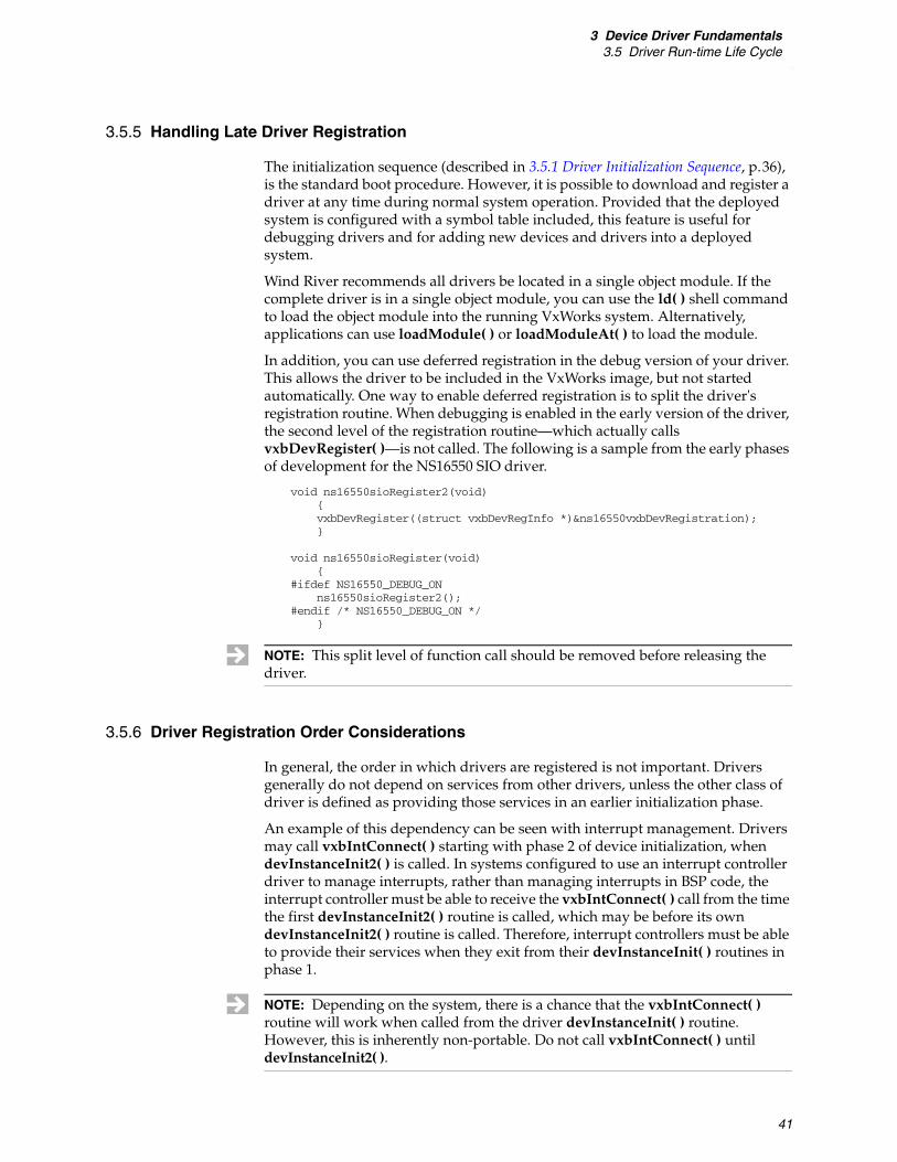
3 Device Driver Fundamentals3.5 Driver Run-time Life Cycle
41
3.5.5 Handling Late Driver Registration
The initialization sequence (described in 3.5.1 Driver Initialization Sequence, p.36), is the standard boot procedure. However, it is possible to download and register a driver at any time during normal system operation. Provided that the deployed system is configured with a symbol table included, this feature is useful for debugging drivers and for adding new devices and drivers into a deployed system.
Wind River recommends all drivers be located in a single object module. If the complete driver is in a single object module, you can use the ld( ) shell command to load the object module into the running VxWorks system. Alternatively, applications can use loadModule( ) or loadModuleAt( ) to load the module.
In addition, you can use deferred registration in the debug version of your driver. This allows the driver to be included in the VxWorks image, but not started automatically. One way to enable deferred registration is to split the driver's registration routine. When debugging is enabled in the early version of the driver, the second level of the registration routine—which actually calls vxbDevRegister( )—is not called. The following is a sample from the early phases of development for the NS16550 SIO driver.
void ns16550sioRegister2(void){vxbDevRegister((struct vxbDevRegInfo *)&ns16550vxbDevRegistration);}
void ns16550sioRegister(void){
#ifdef NS16550_DEBUG_ONns16550sioRegister2();
#endif /* NS16550_DEBUG_ON */}
3.5.6 Driver Registration Order Considerations
In general, the order in which drivers are registered is not important. Drivers generally do not depend on services from other drivers, unless the other class of driver is defined as providing those services in an earlier initialization phase.
An example of this dependency can be seen with interrupt management. Drivers may call vxbIntConnect( ) starting with phase 2 of device initialization, when devInstanceInit2( ) is called. In systems configured to use an interrupt controller driver to manage interrupts, rather than managing interrupts in BSP code, the interrupt controller must be able to receive the vxbIntConnect( ) call from the time the first devInstanceInit2( ) routine is called, which may be before its own devInstanceInit2( ) routine is called. Therefore, interrupt controllers must be able to provide their services when they exit from their devInstanceInit( ) routines in phase 1.
NOTE: This split level of function call should be removed before releasing the driver.
NOTE: Depending on the system, there is a chance that the vxbIntConnect( ) routine will work when called from the driver devInstanceInit( ) routine. However, this is inherently non-portable. Do not call vxbIntConnect( ) until devInstanceInit2( ).

VxWorksDevice Driver Developer's Guide, 6.8
42
However, despite the general lack of requirements, the order of device discovery can sometimes affect driver behavior for devices downstream from the bus controller.
During hardware discovery and driver match (see sysHwInit( ), PLB, and Hardware Discovery, p.37), the bus controller driver is responsible for discovery of devices located on its bus. One implication of this is that devices located downstream from the bus controller do not show up in the system until after the bus controller driver is associated with the device, and the instance is given a chance to initialize the device and discover the devices located on the bus.
For this reason, while PLB devices may be associated with the driver during the devInstanceInit( ) phase of initialization (immediately after the driver registers), devices on any other bus may not be available this early in the boot process.
When developing a new driver, this behavior can result in insufficient testing. For example, if the bus controller driver used on the board initializes the bus during the devInstanceInit2( ) initialization phase, the downstream driver's initialization code is not called until after the operating system is running. However, other bus controller drivers for the same bus type may initialize the device and discover devices during the devInstanceInit( ) phase (when operating system services are not yet available). Therefore, moving a driver that has been tested only on a late-configuration system can crash the system. The solution to this issue is to avoid using services that are not always available in an initialization phase (see 3.5.1 Driver Initialization Sequence, p.36).
3.5.7 Driver-to-Device Matching and Hardware Availability
This section describes the mechanisms used to match devices to the drivers that control them. This process is, in some ways, specific to the type of bus on which the device resides, but there are many similarities among the various types.
The basic flow is a three stage process:
1. First, VxBus verifies that the driver's registered bus type is the same as the bus on which the device actually resides.
2. Second, VxBus runs a match routine provided by the code specific to the bus type.
3. Third, if a driver has provided a probe routine, this routine is called to give the driver a chance to verify it will work correctly with the discovered hardware.
The first and third stages are always followed with no variation. However, what happens during the second phase of driver-to-device matching varies depending on the bus type. This is based on the fact that the driver registration information includes a component that is specific to the bus type for which the driver registers.
PLB
The most basic mechanism used to match a driver and a device is used when the bus type does not support dynamic discovery of devices present on the bus. In this case, a BSP-provided table is used to determine what devices are present. The table contains an identifier for each device, and the driver provides an identifier for those devices it can manage. When a bus type match is identified, the bus-specific
3 Device Driver Fundamentals3.6 Services Available to Drivers
43
match code compares the two identifiers and succeeds or fails depending on whether or not they match.
Other Bus Types
For other bus types, the device provides a mechanism to identify hardware. The driver must provide bus-specific information in its registration structure that can be compared against the information provided by the device (for example, PCI vendor and device registers).
PCI
The information used to match a driver and device consists of the 16-bit device ID and the 16-bit vendor ID. The device driver registration structure contains a pointer to a table containing these value-pairs.
Note that PCI provides additional configuration space fields that can be helpful to the driver when deciding whether to accept or reject a device. These fields include the class field and subclass field, the sub vendor ID and sub system ID, as well as other fields.
The driver can include valid information in its registration structure and also provide a match or probe routine that checks these additional fields. Alternatively, the driver can specify values of all-ones (0xFFFF) for both the device ID and the vendor ID fields of the registration structure and provide a match or probe routine that checks all of the configuration space fields.
RapidIO
RapidIO provides device ID and vendor ID fields. VxWorks uses a mechanism similar to the PCI case for matching drivers with their devices. Namely, the driver of a RapidIO device specifies a table containing the device ID and vendor ID in its registration structure. However, with RapidIO, there is currently no wildcard mechanism to force the driver's probe routine to be called regardless of the device ID and vendor ID that are made available by the hardware.
3.6 Services Available to Drivers
VxBus and VxWorks provide a rich set of services that make it easier to develop device drivers. Examples of these services include:
■ Retrieval of various types of configuration information for the driver, including the hardware environment that the driver is running in, the set of installed devices that are present in the system, individual device or instance properties, and other types of configuration information that are relevant in driver context.
■ Handling the exchange of data between a driver and its device, including routines to read and write data to device registers, routines to probe memory within the address space of a device, routines to transfer blocks of data to and from drivers through DMA channels, and so forth.

VxWorksDevice Driver Developer's Guide, 6.8
44
■ Allocating and freeing memory buffers, both during system startup and during normal system operation.
■ Synchronizing access to driver shared resources, including semaphores, spinlocks, and a full set of atomic operators.
■ Managing interrupts, including interrupt connection and disconnection, masking and unmasking interrupts, and deferral of interrupt processing to the task level.
■ Handling data management within the driver, such as single-linked lists, double-linked lists, and lock-free ring buffers.
■ Handling device timeout conditions through the use of watchdog timers.
■ Displaying useful diagnostic information about the drivers, hardware devices, and device instances that are present in a running system.
This section provides an overview of these services to give you a feel for the type of services that are available to you as a device driver developer. Because this information is designed as an overview, it is necessarily brief, and favors simplicity and brevity over detail. For detailed information about any of the services described in this section, see the related reference documentation.
3.6.1 Configuration
When a driver is initialized in VxWorks, the driver sometimes needs to learn about the properties of the hardware and software run-time environment. For example, a serial driver for the NS16550 serial port can to be written to support densely packed device registers, or to support registers that have 2, 4, 8, or more bytes of offset between them. Because this type of information cannot always be determined by inspecting the hardware itself, the driver must determine the information for itself during initialization. This allows the driver to conform to the exact hardware and software requirements of the system.
Determining Driver Configuration Information
Drivers within VxWorks are configured using two broad types of driver configuration information, resources and parameters. Resources provide the information that the driver needs about its hardware run-time environment, such as hardware register spacing, availability of optional hardware services within a device, and so forth. Parameters provide the information that the driver needs to know about its software run-time environment, such as the size of memory buffers to allocate for transmit and receive, whether or not to support Ethernet jumbo frames, and so forth.
VxWorks provides routines that are used to determine both the hardware and software configuration information required by the driver at runtime. The routines that are used to query (and in some cases modify) the configuration information are described later in this section.
VxWorks driver resources and driver parameters are easily confused because both deal with querying configuration information from outside the driver. In general, a driver uses resources when the property being configured determines whether or not the driver functions correctly in a given run-time system, and uses

3 Device Driver Fundamentals3.6 Services Available to Drivers
45
parameters when the property being configured has more to do with driver performance, memory usage, or other software properties.
Working with the BSP Configuration File
Both resources and parameters can be set in a file in the BSP directory called hwconf.c. This file lists all devices that reside on the PLB bus, resource information about each such device, and, potentially, parameter information about all devices on any bus type. For more information, see 3.7 BSP Configuration, p.65 and the VxWorks BSP Developer's Guide.
Configuring Resources
To retrieve run-time initialization information from its environment, a device driver can use the devResourceGet( ) routine. This routine is used to query the run-time environment information provided by a BSP in order to determine the desired configuration for the driver.
Resources are restricted to three types: integer, string, and address. These types are denoted by HCF_RES_INT, HCF_RES_STRING, and HCF_RES_ADDR, respectively. The value associated with an integer resource is simply a 32-bit numeric value. The value associated with a string resource is a null-terminated ASCII string. The value associated with an address resource is the address of a memory location. This can be a function pointer, a pointer to a table, or any other pointer value.
For example, the following is taken from the ns83902VxbEnd.c device driver:
devResourceGet (pHcf, "regWidth", HCF_RES_INT, (void *) ®isterWidth);
In this call, the device driver queries the BSP to determine what value to use for register width. Elsewhere in the driver, the driver uses the queried value for the register width when performing register I/O operations, rather than using a hard-coded assumed value for the register width.
Well written drivers make judicious use of devResourceGet( ) to maximize the portability of the driver. However, if a driver requires an excessive number of resources from the BSP, the driver becomes less portable because the work required by the BSP developer to incorporate the driver into the BSP increases significantly.
For information on creating BSP resource entries, see the VxWorks BSP Developer’s Guide. For further information on using devResourceGet( ), refer to the reference entry for the routine.
Configuring Parameters
To retrieve parameter information from its environment, the driver uses the vxbInstParamByNameGet( ) routine. Use of this routine is similar to devResourceGet( ), as shown in the following example:
vxbInstParamByNameGet (pInst, "jumboEnable", VXB_PARAM_INT32, &val);
In this example, a driver queries the run-time environment to determine what value to use for the parameter jumboEnable. Depending on the return value, the driver can change its behavior to enable or disable support for (in this case) jumbo Ethernet frames.
While vxbInstParamByNameGet( ) behaves similarly to devResourceGet( ), the parameter configuration services in VxWorks are more flexible than those offered for resource configuration. Unlike the situation with resources, a parameter can be given an initial value by the device driver. When a device driver registers with

VxWorksDevice Driver Developer's Guide, 6.8
46
VxWorks, it can optionally provide a set of parameters, along with their default values, to VxWorks.
The following table is extracted from rtl8169VxbEnd.c:
LOCAL VXB_PARAMETERS rtgParamDefaults[] = {
{"rxQueue00", VXB_PARAM_POINTER, {(void *)&rtgRxQueueDefault}}, {"txQueue00", VXB_PARAM_POINTER, {(void *)&rtgTxQueueDefault}}, {"jumboEnable", VXB_PARAM_INT32, {(void *)0}}, {NULL, VXB_PARAM_END_OF_LIST, {NULL}}
};
In this table, the rtl8169VxbEnd driver declares that it supports three parameters, named rxQueue00, txQueue00, and jumboEnable. When the driver registers with VxWorks, it provides a pointer to these parameters as part of its driver registration data structure. For example:
LOCAL struct vxbPciRegister rtgDevPciRegistration = {
{ /* . */rtgParamDefaults /* pParamDefaults *//* . */}
};
Using this information, VxWorks stores the driver's default values for each of its parameters. Unless the parameters are changed by the BSP or application, the default driver values are the values that are returned when the driver calls vxbInstParamByNameGet( ).
There are two methods that can be used to override the default value of a parameter for a driver:
■ The BSP can provide a different default value in its hwconf.c file.
or
■ A call can be made to vxbInstParamSet( ), to change the value of the parameter at runtime.
When the BSP provides a different default value for a parameter, the BSP default value replaces the driver-provided value for the parameter. This replacement occurs as soon as the driver registers with VxWorks, therefore there is no period of time where the driver default can be returned using vxbInstParamByNameGet( ).
In addition to the BSP override method, the default value of a parameter can also be changed at runtime through a call to vxbInstParamSet( ). vxbInstParamSet( ) can be used to modify the default values for a driver parameter.
For complete information on vxbInstParamByNameGet( ) and vxbInstParamSet( ), see the reference entries for these routines.
Responding to Changes in Device Parameters
When a call is made to vxbInstParamSet( ), the parameter value for a driver is altered. However, unless special steps are taken by the device driver, the updated value may not be noticed by the driver. For example, consider the following steps:
1. The driver registers with VxWorks, its default parameter values are stored by VxWorks.
3 Device Driver Fundamentals3.6 Services Available to Drivers
47
2. The driver is bound to a device, creating a hardware instance. The driver uses the stored values for its parameters to configure the instance.
3. An application calls vxbInstParamSet( ) to change the parameters used by the driver. However, because the driver is already initialized when vxbInstParamSet( ) occurs, the call to vxbInstParamSet( ) has no effect within the driver.
To address this scenario, device drivers are given the option to be informed of any changes to their parameter list that occur through a call to vxbInstParamSet( ). VxWorks provides a special driver method that can be implemented for any device driver that needs to monitor changes to its parameter list. To implement this method in your driver, the driver must publish the {instParamModify}( ) driver method. If the driver publishes this method, the method's callback function is invoked whenever a change occurs to the driver parameters.
Support for the {instParamModify}( ) method is optional, and is not required for most drivers. In practice, driver parameters are generally expected to be overridden by the BSP hwconf.c file, rather than at runtime.
3.6.2 Memory Allocation
When a VxBus model device driver is connected to a device to form an instance, the driver typically stores information about this instance in a memory-resident data structure. This data structure can be declared statically within the driver source file, or the driver can allocate the structure dynamically at runtime using one of the available memory allocation libraries offered by VxWorks. For example, a simple driver might declare the following data structure to allocate memory for its data structures:
LOCAL simpleDriver_t simpleDriverInstanceStore[MAX_INSTANCES];
While a driver can use this method to reserve the memory for its instance data, this method is not recommended for two reasons:
■ The number of simultaneous instances that the driver can support is artificially restricted.
■ When the driver is used less than the maximum number of instances, the memory for the unused instances is wasted.
Well-written drivers should use one of the two memory allocation strategies that are available to dynamically allocate instance data structures, to avoid the problems listed above.
Allocating Memory During System Startup
When the VxWorks operating system is booting, some device drivers must initialize themselves early in the boot process. For example, a serial driver is initialized early in the VxWorks bootstrap process so that it can be used for console messages during the remainder of system startup. This early initialization also allows the serial driver to be used with WDB before the kernel is initialized. When a driver instance is initialized early in system startup, the standard application-level memory allocation strategies—such as malloc( ), calloc( ), memPartAlloc( ), and so forth—cannot be used because these routines use

VxWorksDevice Driver Developer's Guide, 6.8
48
semaphores, which are not available for use until the operating system is booted, to protect the memory allocation data area.
To allow device drivers to allocate memory during system boot, a special set of memory allocation services are provided to device drivers. This includes:
hwMemAlloc( ) Allocate n bytes of storage from a static pool and zero clear the storage.
hwMemFree( ) Return allocated storage to the static pool.
As their names imply, hwMemAlloc( ) and hwMemFree( ) perform memory allocation services. These routines are useful to driver writers because they can be called at any time during system startup, even when the multitasking services of VxWorks are not available.
hwMemAlloc( ) allocates its memory from a pool of memory that is reserved for hwMemAlloc( ). The size of this pool of memory defaults to 50,000 bytes for most BSPs, and is configurable by adjusting the HWMEM_POOL_SIZE parameter associated with the INCLUDE_HWMEM_ALLOC component.
Because this pool size is adjustable, the size can be configured downward on systems that want to minimize wasted memory. For this reason, device drivers must always take special care with hwMemAlloc( ) to ensure that any requested memory allocation is successful. Even on systems with large amounts of available memory, the pool of memory that is reserved for hwMemAlloc( ) may not be sufficient to support all the requirements for all the device drivers that are configured in a VxWorks image.
When debugging is not enabled and hwMemAlloc( ) fails, the system is rebooted. When debugging instrumentation is enabled and HWMEM_ALLOC_FAIL_DEBUG is defined, hwMemAlloc( ) returns NULL when memory cannot be allocated. When successful, it returns a pointer to the allocated memory.
For complete descriptions of hwMemAlloc( ) and hwMemFree( ), see the reference entries for these routines.
Allocating Memory During Normal System Operation
Once VxWorks completes its initialization, the standard memory allocation routines (malloc( ), calloc( ), memPartAlloc( ), and so forth) can be used by device drivers. For more information, see the reference entries for these routines.
Intermixing Memory Allocation Methods within a Single Driver
Drivers that use both hwMemAlloc( ) and the standard memory allocation routines must be sure to use the corresponding memory free routine. For example, do not use hwMemFree( ) to free memory that has been allocated using the standard memory allocation routines, and do not use the standard memory free routine to free memory that has been allocated using hwMemAlloc( ).
To eliminate potential mismatching of memory allocation and memory free routines in your driver, you may wish to use the same type of memory allocation
NOTE: hwMemAlloc( ) can only allocate blocks of 2032 bytes or smaller.

3 Device Driver Fundamentals3.6 Services Available to Drivers
49
routine for each example of a particular data type. For example, if your driver allocates some objects of type FOO before the standard memory allocation routines are available, and other objects of type FOO after the system is up and those routines are available, continue using hwMemAlloc( ) for all objects of type FOO, regardless of when they are allocated.
However, if the driver also allocates objects of type BAR, but not until the standard memory allocation routines are available, then all objects of type BAR should be allocated using the standard memory allocation routines, and not hwMemAlloc( ).
3.6.3 Non-Volatile RAM Support
When non-volatile storage is required, VxBus drivers can make use of the non-volatile RAM library. This occurs when some part of device initialization requires information that is board-specific, such as the Ethernet addresses of network interfaces.
There are two routines available in this library:
vxbNonVolGet( ) This routine retrieves data from non-volatile memory, which is dedicated to the caller, and copies it into a buffer provided by the caller.
vxbNonVolSet( ) This routine takes a data buffer provided by the caller, finds the data buffer allocated to the caller, and copies the data from the caller's buffer into the non-volatile memory.
3.6.4 Hardware Access
At the lowest level, a driver communicates with its associated hardware by reading to, and writing from, the specific registers that are available within the hardware. When a VxWorks device driver is connected to a specific piece of hardware to form an instance, VxWorks provides the necessary information to the driver so that it can locate the hardware registers within the address space of the system. This section discusses how a driver accesses its hardware registers.
Finding the Address of the Hardware Registers
Whenever a call is made to a VxWorks device driver, a pointer to the driver instance state is provided as the first parameter. For example, the following code is excerpted from the fei8255xVxbEnd.c device driver, located in installDir/vxworks-6.x/target/src/hwif/end:
LOCAL void feiInstInit2(VXB_DEVICE_ID pInst){…}
The VXB_DEVICE data structure contains information that is useful for a specific instance of the driver (that is, a specific device and driver pairing). In order for the driver to learn where its hardware registers are located within the system address

VxWorksDevice Driver Developer's Guide, 6.8
50
space, the driver refers to the regBase[ ] array of pointers that is located within the pInst structure, and uses the corresponding regBaseFlags[ ] array to determine what type of address space is present at each location. Figure 3-2 illustrates the regBase[ ] and regBaseFlags[ ] data structures.
In Figure 3-2, VxWorks provides the driver with two windows into the hardware address space. The first window is defined by the base address contained within pInst->regBase[0], and is used for I/O mapped transactions, as shown in Figure 3-2 by the value of VXB_REG_IO found in pInst->regBaseFlags[0]. In addition, a second window is defined by the base address contained within pInst->regBase[1]. This second address range is used for memory-mapped register access, as shown in Figure 3-2 by the value of VXB_REG_MEM in pInst->regBaseFlags[1].
When a device driver initializes itself, it must inspect the various register windows that are provided by the device and then determine which windows must be used and which windows can be safely ignored. For example, if a hardware device provides two windows into its hardware registers, one that is mapped into the I/O space of the system and another symmetric window that is mapped into the memory space of the system, the device driver can choose to use only the I/O space for its interaction with the hardware.
Once the driver decides which of the available windows to use for its interaction with the hardware, the instance must create a mapping between the driver and the hardware so that transactions in this memory window are performed correctly in
Figure 3-2 regBase[ ] and regBaseFlags[ ] Data Structures
pInst
.
.
.
.
.
.
.
.
.
regBaseFlags[ ]
regBase[ ]
VXB_REG_IO
VXB_REG_MEM
0
entry 0
entry 1
NULL
Device I/O Registers(VXB_REG_IO)
Device Memory-Mapped Registers
(VXB_REG_MEM)

3 Device Driver Fundamentals3.6 Services Available to Drivers
51
the system. This mapping is created by a call to vxbRegMap( ). The following example is from the fei8255xVxbEnd.c driver:
/* find the memory mapped window for the device registers */
for (i = 0; i < VXB_MAXBARS; i++){if (pInst->regBaseFlags[i] == VXB_REG_MEM)
break;}
pDrvCtrl->feiBar = pInst->pRegBase[i]; /* store the base address */vxbRegMap (pInst, i, &pDrvCtrl->feiHandle); /* map the window */
In this example, the device driver searches the available register windows until it finds a register window of type VXB_REG_MEM. Once the window is located, the driver stores the base address of the window in its driver control structure (pDrvCtrl), and then maps in the address space using vxbRegMap( ). The routine vxbRegMap( ) performs the necessary operations to ensure that subsequent writes to, or reads from, this window of the address space are performed correctly. It also returns a handle for the address space that the driver can use for subsequent reads and writes to the device.
Reading and Writing to the Hardware Registers
Once the hardware registers are located and mapped by the driver, the driver can perform read and write transactions to the register space using any of the following routines:
■ vxbRead8( )
■ vxbRead16( )
■ vxbRead32( )
■ vxbRead64( )
■ vxbWrite8( )
■ vxbWrite16( )
■ vxbWrite32( )
■ vxbWrite64( )
All of the read routines have essentially identical semantics, differing only in the size of the data element read during the transaction. Likewise, all of the write routines have equivalently identical semantics.
In later sections, the interfaces to these routines are described collectively because the concepts are the same for all of the read routines, and for all of the write routines.
Reading from the Hardware Registers
A device driver can read either 8-, 16-, 32-, or 64-bit quantities from a hardware register using a single function call. The interface to each of the vxbReadxx( ) routines is essentially the same. For example:
UINT8 value = vxbRead8 (handle, UINT8 *);UINT16 value = vxbRead16 (handle, UINT16 *);UINT32 value = vxbRead32 (handle, UINT32 *);UINT64 value = vxbRead64 (handle, UINT64 *);
VxWorksDevice Driver Developer's Guide, 6.8
52
In this example, handle is used to hold a handle to a portion of the device address space. This handle is generated when the driver calls vxbRegMap( ). The address represents the absolute address of the hardware register to be read. For example, if a device provides three 32-bit registers in one of its mapped areas, a device driver can read the middle 32-bit value by performing pointer arithmetic to generate the address for the register as follows:
value = vxbRead32 (handle, (UINT32 *) ((char *)pDrvCtrl->feiBar + sizeof(UINT32)));
When making calls into any of the vxbReadxx( ) routines, use a base address value for the appropriate register window, and then add the appropriate offset into the register window to access the desired hardware register. The handle value does not encode any type of pointer offset for the window therefore the pointer arithmetic must always be performed explicitly by the driver.
Writing to the Hardware Registers
A device driver can write either 8-, 16-, 32-, or 64-bit quantities to a hardware register using a single function call. The interface to each of the vxbWritexx( ) routines is essentially the same. The only significant difference is the data types for the parameter values. For example:
void vxbWrite8 (handle, UINT8 *, UINT8); void vxbWrite16 (handle, UINT16 *, UINT16);void vxbWrite32 (handle, UINT32 *, UINT32);void vxbWrite64 (handle, UINT64 *, UINT64);
As with read routines, you are responsible for any pointer arithmetic required to access registers located in the mapped register window.
Special Requirements for Hardware Register Access
When a device driver writes to or reads from a hardware register, the vxbReadxx( ) and vxbWritexx( ) routines perform whatever memory or I/O transactions are required in order to deliver the data to (or read the data from) the underlying hardware. On some processor architectures, this task involves the execution of special instructions (such as eieio on PowerPC processors), or a read-after-write transaction to flush any write buffers that exist between the CPU and the target hardware. The special operations that are required for each memory region are encoded as part of the state that is contained in the handle for each of the memory regions that are mapped by vxbDevMap( ). Because of this, you do not need to perform any additional operations in your driver to ensure data that is read or written is transferred correctly.
VxBus Version Considerations
Beginning with VxWorks 6.7, the version of the VxBus subsystem was incremented from VxBus version 3 to VxBus version 4. This version update includes one significant change, related to device register access.
In VxBus version 3, device drivers can access device registers by calling function pointers in the VxBus device structure's pAccess field. For example, to read a 32-bit register, the driver would call through the function pointer at pAccess->registerRead32.
3 Device Driver Fundamentals3.6 Services Available to Drivers
53
In addition, drivers can access device registers by making direct calls to the routines vxbRead8( ), vxbRead16( ), vxbRead32( ), vxbRead64( ), and the corresponding write routines (as described previously in this section).
With VxBus version 4, the same functionality is available. However, by default, the routines in the pAccess structure are not available. If you have purchased a product that includes VxWorks source, you can change this functionality by rebuilding the libraries after defining the VXB_LEGACY_ACCESS macro in the following file:
installDir/vxworks-6.x/target/src/hwif/h/vxbus/vxbAccess.h
After defining the macro in vxbAccess.h, complete the following steps to rebuild the libraries:
% cd installDir/vxworks-6.x/target/src % make CPU=cpu TOOL=tool other_options
3.6.5 Interrupt Handling
This section describes how VxWorks device drivers work with hardware interrupts. The following topics are covered:
■ overview of interrupt handling
■ interrupt indexes
■ services available to drivers to manage interrupts
■ minimizing work performed within an interrupt service routine
■ additional interrupt requirements for VxWorks SMP
Overview of Interrupt Handling
In previous versions of VxWorks, device drivers connected driver interrupt service routines (ISRs) by calling intConnect( ) and providing the necessary interrupt vector information, this is referred to as the interrupt vector model. This interrupt vector model worked well for hardware architectures that provided a straightforward mapping of device interrupts onto interrupt vectors. However, with the growth of hardware complexity and interrupt routing through multiple interrupt controllers, this simple interrupt vector model has become unwieldy and difficult to maintain.
To address this issue, device drivers now use a different set of operating system services to connect interrupt service routines to the operating system. Device drivers now only need to be aware of how many individual interrupt sources are generated by the supported device hardware, so that the driver can connect appropriate ISRs to each hardware interrupt source. The individual interrupt sources that are generated by a device are assigned individual interrupt index values.
NOTE: In addition to this behavior change, you should note that VxBus drivers that register as using VxBus version 3 services or earlier are not allowed to register with VxBus, unless the VXB_LEGACY_ACCESS macro is defined.

VxWorksDevice Driver Developer's Guide, 6.8
54
These interrupt index values are used to describe the interrupt to the operating system. Interrupt index values are described in greater detail in the following section.
Interrupt Indexes
VxWorks provides a set of services that you can use to manage interrupts from devices. These services allow you to:
■ Connect a driver-specific handler routine to any device interrupt.
■ Enable and disable delivery of the device interrupt.
■ Disconnect from the device interrupt.
Each of the separate interrupt signals a device generates is identified by its interrupt index. Most hardware devices only generate a single interrupt, which in VxWorks is identified as interrupt index 0. For more complex devices, additional interrupt signals are generated. These are assigned increasing interrupt indexes, starting at index 0.
When a device can generate more than one interrupt signal, the interrupt signal is assigned an interrupt index that describes the type of information that is delivered implicitly with the arrival of the interrupt. For example, high performance network devices often have three interrupt sources; a transmit interrupt, a receive interrupt, and an error interrupt. Each interrupt represents a different type of hardware event. For a given driver class, each type of interrupt index is assigned to a specific event and the same interrupt index is used for all device drivers in that driver class. For example, for all network device drivers, interrupt index 0 is assigned to the hardware device's transmit interrupt, interrupt index 1 is assigned to the hardware device's receive interrupt, and interrupt index 2 is assigned to the hardware device's error interrupt.
For information on the interrupt index conventions for any particular driver class, see the appropriate class-specific documentation in VxWorks Device Driver Developer’s Guide, Volume 2.
Device drivers need to be able to connect device interrupts to ISRs, enable and disable delivery of these interrupts, and (for removable device drivers) disconnect an ISR from its device interrupt. VxWorks provides the following routines to support these services:
vxbIntConnect( ) This routine connects an ISR to a device interrupt. Once an ISR has been connected using vxbIntConnect( ), vxbIntEnable( ) must also be called to enable delivery of the device interrupt to the CPU.
vxbIntDisconnect( ) This routine disconnects an ISR from a device interrupt.
vxbIntEnable( ) This routine enables delivery of a device interrupt by programming the appropriate hardware devices between the interrupting device and the CPU.
vxbIntDisable( )This routine disables delivery of a device interrupt by programming the appropriate hardware devices between the interrupting device and the CPU.
For more information on these routines, see the corresponding reference entries.

3 Device Driver Fundamentals3.6 Services Available to Drivers
55
Minimizing Work Performed Within an ISR
When an ISR is started by VxWorks as a result of interrupt handling, all task processing is suspended while the ISR is executing3. Because task processing is suspended for the duration of the ISR, ISRs should be structured to be as fast as possible, to minimize overall system interrupt latency.
One method for minimizing the time spent in an ISR is to defer any processing so that it is performed within a task context instead of within an interrupt context using the functionality provided by isrDeferLib. When an ISR is structured to support ISR deferral, the ISR does the following:
1. Disables interrupts from the device by programming device-specific registers so that interrupts are disabled. (Note that calling vxbIntDisable( ) may not disable interrupts if the interrupt line is shared by some other device.)
2. Prepares a data structure to describe the work that needs to be deferred. This data structure is then provided as an input parameter to the routine that performs the deferred work at task level.
3. Unblocks a task that is waiting on a semaphore. This task handles the deferred work once the ISR completes execution.
4. Returns from the ISR. This signals the operating system to schedule the task to handle the deferred work.
VxWorks provides a support library to make the process of deferring interrupts to the task level easier for you. The following routines are available to support ISR deferral:
isrDeferQueueGet( ) Returns a handle to an ISR deferral queue. This handle is used to defer work from an ISR to task level. The deferral queue returned by this function can be a shared queue (used by more than one device driver), or it can be an exclusive queue.
isrDeferJobAdd( ) Adds a data structure describing the deferred work to be performed onto an ISR deferral queue. This work is performed once the ISR enqueuing the work terminates and task processing resumes.
For more information on these routines, see the corresponding reference entries.
3.6.6 Synchronization
VxWorks device drivers have unique synchronization requirements when compared with VxWorks application code. A typical device driver receives requests from user tasks to perform various forms of I/O. In addition, the driver must service device interrupts from the hardware that the driver is controlling. These requests create a fairly chaotic environment within the driver because it must ensure that all of the individual threads and interrupts that are competing for
3. For the optional VxWorks SMP product, all task processing is suspended on the core that is executing the ISR; other cores continue to execute tasks.
NOTE: If this step is not performed, VxWorks immediately resumes interrupt processing after the ISR exits because the original interrupt is still pending.
VxWorksDevice Driver Developer's Guide, 6.8
56
the driver's resources do not corrupt the driver's data structures. Simultaneous access to shared data structures can lead to data corruption, incorrect driver behavior, and possibly system crashes. As a driver developer, you must take active steps to ensure that the data structures maintained by your driver are protected from corruption by these competing threads of execution.
Task-Level Synchronization
When a driver is running in task context, it can use the full suite of available operating system services to perform synchronization operations. These services include:
■ taking and releasing mutexes
■ sending data to, or receiving data from, a message queue
■ adding and removing items from ring buffers
■ taking and giving spinlocks
■ locking and unlocking interrupts (uniprocessor VxWorks only)
You can choose any of these synchronization methods, depending on the data flow needs of your device and the I/O interface between your device driver and its calling tasks. However, your overall goal is to ensure the data structures maintained by the driver remain consistent.
For example, a common task-level synchronization scenario would be to have a single driver instance allocate and initialize a semaphore then store that semaphore as part of the per-instance data structure maintained by the driver. The semaphore can then be used to protect all access to the shared data structures that the driver maintains.
However, while semaphores provide a useful method to protect driver data structures from corruption by competing tasks, they have a significant drawback that prevents them from being a good general-purpose solution—they cannot be used from the interrupt context. If your device driver maintains data structures that must be accessed from both task context and interrupt context, you must employ a different synchronization method.
Interrupt-Level Synchronization
When a VxWorks device driver is servicing an interrupt from a hardware device, the driver can no longer use any synchronization primitives that could cause the interrupt service routine to block. For example, an interrupt service routine cannot:
■ Take a mutex.
■ Add an item to a message queue.
Because these operations are not allowed in interrupt context, another method to provide mutual exclusion is required to resolve the shared data contention issues between task context and interrupt context.
NOTE: This is not true in all cases. You can add an item to a message queue from an ISR. However, when calling msgQSend( ) from an ISR, the timeout option must be zero.

3 Device Driver Fundamentals3.6 Services Available to Drivers
57
In interrupt context, there are two methods you can employ to gain exclusive access to a shared resource:
■ interrupt locking using intCpuLock( ) and intCpuUnlock( )
■ spinlocks using isrSpinLockTake( ) and isrSpinLockGive( )
These two methods are each discussed in the following sections.
Interrupt-Level Synchronization Using Interrupt Locking
Interrupt locking is the traditional method used to protect device driver data structures from being modified simultaneously in both task and interrupt context, and this method works well in uniprocessor VxWorks environments, provided the code executed while interrupts are locked is short. Using interrupt locking, any piece of code running in task context that wants to gain access to a shared data structure must surround the code in an intCpuLock( ) and intCpuUnlock( ) pair of function calls. For example:
key = intCpuLock ();/* access shared data structures. */intCpuUnlock (key);
By locking out interrupts for the duration of the access to any shared data structures, you can guarantee that no interrupts occur while the driver shared data structures are accessed in task context.
Within the interrupt service routine of your driver, the driver shared data structures can be accessed without explicitly locking interrupts in a UP environment. Because an ISR cannot be preempted in order to run any task-level code, explicit locking is not required within the ISR. An ISR can infer from the very fact that it is running that no tasks are executing in any regions bracketed by intCpuLock( ) and intCpuUnlock( ).
Despite the simplicity and efficiency offered by interrupt locking, Wind River discourages the use of interrupt locking in modern device drivers. There are two reasons for this:
■ Interrupt locking increases system latency because no interrupts for any device in the system can be serviced while interrupts are locked.
■ Interrupt locking does not work if more than one processor is present in the system, as is the case for the optional VxWorks SMP product.
In place of interrupt locking, you can use spinlocks in modern device drivers that need to provide protection between task and interrupt context. This service is available in both uniprocessor VxWorks and VxWorks SMP systems (see Interrupt-Level Synchronization Using Spinlocks, p.57).
Interrupt-Level Synchronization Using Spinlocks
When you use interrupt locking to protect a shared data structure, each task that wants to access the shared data structure must first lock interrupts, and then access the shared data. In a uniprocessor VxWorks system, your driver can safely access shared data in this context because it knows it will not be preempted, whether by another task of higher priority, or by any type of ISR. This is guaranteed in
NOTE: A complete discussion of spinlocks is beyond the scope of this document. For more information on spinlocks, see the VxWorks Kernel Programmer’s Guide: VxWorks SMP.

VxWorksDevice Driver Developer's Guide, 6.8
58
uniprocessor systems because only one processing unit is available to execute instructions.
However, in a symmetric multiprocessing (SMP) system, more than one processing unit is available, and instructions that access shared data can be executed on any (or even all) cores in the system. As a result, a core in a VxWorks SMP system that executes intCpuLock( ) cannot make any assumptions about code that is running on any other core in the system. A second core could be executing code that is accessing the shared driver resources, while a third core could be executing an ISR for the driver. Unless you take positive steps in your driver to ensure that only one of these entities can gain access to the driver shared data structures, data corruption of the shared data structures is inevitable.
To address this need, the optional VxWorks SMP product provides spinlocks that can be used to provide exclusive access to a shared resource, even when the resource is being contended for by multiple cores in a multiprocessor system.
Spinlocks can be taken and given. After spinlock is taken, the driver that holds the spinlock can access any data structures that are protected by the spinlock. For example:
isrSpinLockTake (pSpinlock);/* access shared data structures */isrSpinLockGive (pSpinLock);
Unlike interrupt locking, spinlocks must be used in both task context and in interrupt context to ensure exclusive access to a driver shared resource. An ISR must use a spinlock because it cannot know whether or not a task on another core in the system will try to access the driver shared resources while the ISR is running. That is, an ISR cannot depend upon the implicit locking that is available in a uniprocessor system. You must use an explicit lock to ensure data integrity.
3.6.7 Direct Memory Access (DMA)
This section describes the facilities provided by VxBus for management of devices which read and write system memory directly.
When data transfer is involved, reading and writing system memory is referred to as direct memory access (DMA). However, the same operations used for DMA are also used for other operations, such as management of tables that describe what operations are to be performed. These tables are known as descriptors.
Address translation and cache present some issues related to DMA. These are discussed in DMA Considerations, p.59.
vxbDmaBufLib
VxBus provides the vxbDmaBufLib library as a solution to both address translation and cache operations, as required by device drivers that control devices that use DMA. This library uses a construct known as a DMA tag to identify restrictions on DMA, including address translation. After a DMA tag is created, a DMA map is created to perform address translation. The caller creates a tag with the vxbDmaBufTagCreate( ) call. For buffers, the driver creates a DMA map, using the tag created earlier and other information.

3 Device Driver Fundamentals3.6 Services Available to Drivers
59
When setting up for a write operation (where the CPU writes to RAM and the device reads the data), the driver calls vxbDmaBufMapLoad( ) or a variant of it4. At the appropriate time, the driver calls vxbDmaBufSync( ) with appropriate arguments to cause cache flush or cache invalidate. For more information on these routines, see the corresponding reference entries and the reference entry for vxbDmaBufLib.
When processing incoming data, the driver first finds what buffers contain data, the DMA tag, and the DMA map associated with each buffer. For each buffer, the driver calls vxbDmaBufSync( ) to invalidate any cache entries, followed by vxbDmaBufMapLoad( ), followed by another call to vxbDmaBufSync( ) with a different operation flag. At this point, it is safe to read the data from the buffer.
When processing outgoing data already in a buffer, the driver calls vxbDmaBufMapLoad( ) followed by vxbDmaBufSync( ). Once this occurs, it is safe to initiate the write operation.
For more information on vxbDmaBufLib, see the library reference entry as well as the reference entries for vxbDmaBufTagCreate( ) and other routines provided by vxbDmaBufLib.
DMA Considerations
There are several issues related to these operations. Both data operations and operations on descriptors have similar issues, and the same mechanism is used to manage both types. The mechanisms used to manage these operations are address translation and cache.
Address Translation
First, the memory address used by the device may not be the same as the memory address used by the CPU. That is, if the bus controller performs address translation, the same memory addresses are known by one address from the CPU and a different address from the device. Figure 3-3 illustrates this situation. In this example, the driver allocates a buffer from RAM at 0xC0001000. The CPU uses this address to read and write the buffer. However, because the bus controller translates the address, the device must read and write at 0x00001000 in order to manipulate the same RAM locations.
NOTE: When writing data to a disk, the disk controller device reads the data from RAM as the first step. Similarly, when reading data from a disk, the last step for the disk controller device is to write the data into RAM. Thus, the terms read and write are ambiguous, depending on whether the application or the device is performing the operation. In this documentation, unless otherwise noted, these terms should be considered relative to the application.
4. Variants of vxbDmaBufMapLoad( ) are available for mBlk and uio structures so that multiple buffers can be mapped with the same call. The basic version maps a single buffer. Unless otherwise noted, references to vxbDmaBufMapLoad( ) indicate all variants.

VxWorksDevice Driver Developer's Guide, 6.8
60
Bus Controller Address Conversion
There are two types of address conversion that are relevant to device drivers. These are the conversion of device register addresses and the conversion of buffer addresses.
In most cases, drivers do not need to handle address conversion directly because utility routines perform the mapping on behalf of the driver. However, as a driver writer, you must be aware of the mappings that are performed. The following sections discuss mappings of device register addresses and mappings of data buffer addresses.
Device Registers
Device registers reside on the device itself, and are therefore subject to the rules and restrictions of the bus type on which the device resides. Often, device registers are not seen at the same address on the CPU as on the bus that the device resides on. Because of this, most drivers need to use the device register management routines to manipulate register contents. For more information on the register management routines, see 3.6.4 Hardware Access, p.49.
Data Buffers
Data buffers typically reside in system RAM. In most systems, there is a bus controller device of some sort between the device and RAM. The bus controller device performs address conversion between the CPU and the downstream devices, as shown in Figure 3-3. The driver, which is running on the CPU, needs to use one address to access a particular location in RAM. However, the device on the downstream bus needs to use a different address to access the same location in RAM.
In most cases, drivers for devices that use system memory rely on the routines in vxbDmaBufLib to manage buffers, and these routines allow the driver to handle the address translation.
The RAM addresses are passed to the appropriate vxbDmaBufLib routines, and the converted addresses—as seen by the device—are available from the returned structures.
Figure 3-3 Bus Address Translation
CPU
RAM
bus controller
device
0xc0001000
0xc0001000
translate: CPU 0xc0000000 <-> device 0x00000000
0x00001000
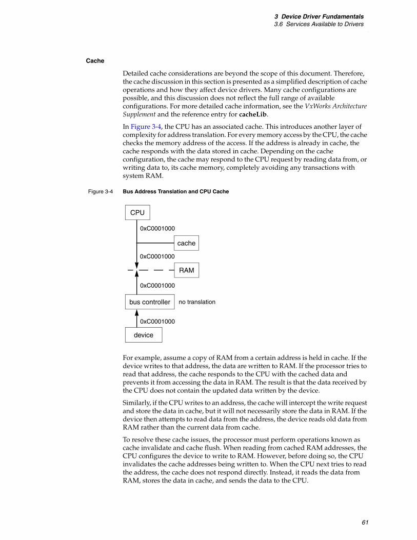
3 Device Driver Fundamentals3.6 Services Available to Drivers
61
Cache
Detailed cache considerations are beyond the scope of this document. Therefore, the cache discussion in this section is presented as a simplified description of cache operations and how they affect device drivers. Many cache configurations are possible, and this discussion does not reflect the full range of available configurations. For more detailed cache information, see the VxWorks Architecture Supplement and the reference entry for cacheLib.
In Figure 3-4, the CPU has an associated cache. This introduces another layer of complexity for address translation. For every memory access by the CPU, the cache checks the memory address of the access. If the address is already in cache, the cache responds with the data stored in cache. Depending on the cache configuration, the cache may respond to the CPU request by reading data from, or writing data to, its cache memory, completely avoiding any transactions with system RAM.
For example, assume a copy of RAM from a certain address is held in cache. If the device writes to that address, the data are written to RAM. If the processor tries to read that address, the cache responds to the CPU with the cached data and prevents it from accessing the data in RAM. The result is that the data received by the CPU does not contain the updated data written by the device.
Similarly, if the CPU writes to an address, the cache will intercept the write request and store the data in cache, but it will not necessarily store the data in RAM. If the device then attempts to read data from the address, the device reads old data from RAM rather than the current data from cache.
To resolve these cache issues, the processor must perform operations known as cache invalidate and cache flush. When reading from cached RAM addresses, the CPU configures the device to write to RAM. However, before doing so, the CPU invalidates the cache addresses being written to. When the CPU next tries to read the address, the cache does not respond directly. Instead, it reads the data from RAM, stores the data in cache, and sends the data to the CPU.
Figure 3-4 Bus Address Translation and CPU Cache
CPU
RAM
bus controller
device
0xC0001000
0xC0001000
no translation
0xC0001000
cache
0xC0001000

VxWorksDevice Driver Developer's Guide, 6.8
62
Provided the CPU does not read from the address until after the device writes to it, the operation is performed as expected.
In the second situation, the CPU writes into an address and then notifies the device that the device should read the data there. Before notifying the device to perform the read, the CPU flushes the cache. This instructs the cache to write any pending data from cache into RAM. After this has happened, the device can read the latest information directly from RAM.
Recall that before configuring the device to write into the buffer, the cache invalidate operation is performed, which causes the entire contents of the cache line to be discarded. However, in some cases, it is possible that valid data have been written into the cache line but not written to RAM. In this case, the valid data are discarded along with the invalid cached buffer contents.
To prevent this, driver writers must ensure that all data buffers used for DMA are cache aligned.
Allocating External DMA Engines
Most devices that manipulate large amounts of data have DMA engines included in the device. This allows data to be copied without requiring the CPU to perform the copies, resulting in better overall system performance. However, some devices that manage large amounts of data do not include built-in DMA hardware. VxWorks provides a way for device drivers for such devices to allocate an external DMA engine, also known as a slave DMA engine, if one is available. This allows drivers to eliminate the CPU data copy operations.
This functionality is achieved with vxbDmaLib. The driver calls vxbDmaChanAlloc( ) to allocate a DMA channel, and then calls one of the data copy routines made available when you allocate the channel. There are two variants of the copy. One variant copies the data and waits for the copy operation to complete before returning to the caller, the other variant initiates the copy operation and returns immediately. When the copy is complete, the caller is notified. Both variants are called through function pointers made available when a DMA channel is allocated.
By default, when vxbDmaChanAlloc( ) is called and no DMA engine is available, the routine allocates a software entity that performs the operations using CPU cycles. This allows a driver to request a DMA channel, but use the same interface whether one is available or not. The driver can specify not to use software copy by specifying the DMA_COPY_MODE_NO_SOFT flag.
vxbDmaChanAlloc( )
This routine allocates and initializes a DMA channel for use by a device instance. It searches the system for DMA controller drivers that have dedicated channels, and if found, calls the {vxbDmaResDedicatedGet}( ) method to allocate the dedicated channel. If no dedicated channels are available, this routine searches through the system for any DMA controller drivers that can allocate a channel satisfying the parameters passed to the routine. If a channel is allocated, the routine returns an ID for the channel.

3 Device Driver Fundamentals3.6 Services Available to Drivers
63
VXB_DMA_RESOURCE_ID vxbDmaChanAlloc(VXB_DEVICE_ID pInst,UINT32 minQueueDepth,UINT32 flags,void * pDedicatedChanInfo)
pInst refers to the VXB_DEVICE_ID associated with the device requesting the DMA channel. DMA device drivers normally select a DMA channel based upon minQueueDepth and flags. Device drivers can optionally pass a pointer to DMA device-specific information in pDedicatedChanInfo, which signals the DMA library to call the {vxbDmaResDedicatedGet}( ) method.
minQueueDepth refers to the minimum queue depth required by the device, in transaction units. The DMA model expects a chained DMA command mode, where multiple DMA transactions can be initiated and a single interrupt occurs when the DMA command chain is completed and no further transactions are available to be performed. If the device uses a direct mode, where one transaction is performed at a time, then the DMA driver should reject requests containing a minQueueDepth of any value other than 1.
flags allows drivers to specify any options in configuring the DMA channel. The acceptable values for flags are defined in vxbDmaLib.h and are described as follows:
■ DMA_COPY_MODE_DEVBUF (0x00000000)—this flag indicates that the device provides a data buffer which is fully accessible as memory.
■ DMA_COPY_MODE_FIFO (0x00000100)—this flag indicates that the mechanism used by the device for presenting its data buffers is a register. Successive reads or writes to this register are required to complete a transfer to or from CPU memory.
■ DMA_COPY_MODE_NO_SOFT (0x00000200)—be default, vxbDmaChanAlloc( ) will assign a software copy routine if no hardware DMA channel is available. If this flag is set, vxbDmaChanAlloc( ) will instead return ERROR.
■ DMA_COPY_MODE_NO_HW (0x00000300)—in cases where the driver developer wishes to use the API, but knows that there will not be adequate DMA hardware to provide appropriate performance, this flag can be specified. It indicates that the library should return a software copy routine to the driver.
■ DMA_TRANSFER_TYPE_RD (0x00001000)—this flag indicates to the DMA driver that the DMA channel is requested for read operations, that is, data is read from the device into memory.
■ DMA_TRANSFER_TYPE_WR (0x00002000)—this flag indicates to the DMA driver that the DMA channel is requested for write operations, that is, data is written to the device from memory.
vxbDmaChanFree( )
This routine frees the DMA channel identified by dmaChan, by calling the DMA device driver through the {vxbDmaResourceRelease}( ) method.
void vxbDmaChanFree(VXB_DMA_RESOURCE_ID dmaChan)

VxWorksDevice Driver Developer's Guide, 6.8
64
3.6.8 Atomic Operators
Device driver writers often need to update internal data structures to reflect changes in driver state. If they are simultaneously updated by more than one thread of execution, driver data structures can become corrupt. Therefore, you must take specific steps to ensure that corruption does not occur due to contention for the driver data structures.
Traditionally, some type of synchronization primitive is used to ensure that a data structure is updated atomically. Common synchronization primitives include:
■ semaphores
■ spinlocks
■ interrupt locking
In this release, atomic operators have been added to this set of synchronization primitives. As their name implies, atomic operators can be used to atomically modify a data structure. Atomic operators guarantee that their update to a data structure is atomic, even when more than one thread of execution is contending for the shared data structure. In VxWorks, atomic operators are divided into four logical groups:
■ arithmetic
■ logical
■ read/write
■ compare/swap
All the atomic operators act upon a variable of type atomic_t. The atomic_t type is an architecture-dependent integral type, guaranteed to be at least 32 bits in size.
The atomic arithmetic operators are:
atomicVal_t vxAtomicAdd (atomic_t * pTarget, atomicVal_t value); atomicVal_t vxAtomicDec (atomic_t * pTarget); atomicVal_t vxAtomicInc (atomic_t * pTarget); atomicVal_t vxAtomicSub (atomic_t * pTarget, atomicVal_t value);
Each of the arithmetic operators take as input a pointer to a variable of type atomic_t, which is atomically updated by the operator. In all cases, the atomic arithmetic operators return the original value of *pTarget.
The atomic logical operators are:
atomicVal_t vxAtomicAnd (atomic_t * target, atomicVal_t value); atomicVal_t vxAtomicNand (atomic_t * target, atomicVal_t value); atomicVal_t vxAtomicOr (atomic_t * target, atomicVal_t value); atomicVal_t vxAtomicXor (atomic_t * target, atomicVal_t value);
Each of the logical operators take as input a pointer to a variable of type atomic_t, which is atomically updated by the operator. In all cases, the atomic logical operators return the original value of *pTarget.
The atomic read/write operators are:
atomicVal_t vxAtomicClear (atomic_t * target); atomicVal_t vxAtomicGet (atomic_t * target); atomicVal_t vxAtomicSet (atomic_t * target, atomicVal_t value);
Each of the read/write operators take as input a pointer to a variable of type atomic_t, which is atomically updated by the operator. In all cases, the atomic logical operators return the original value of *pTarget.
3 Device Driver Fundamentals3.7 BSP Configuration
65
The atomic compare/swap operator is:
BOOL vxCas (atomic_t * target, atomicVal_t oldValue, atomicVal_t newValue);
The vxCas operator is the most complex of the atomic operators. It is designed to be used to update a data structure by:
■ reading a value from a data structure
■ updating the value, according to the needs of the algorithm
■ writing the value back, but only if the data structure has been left unchanged since the original read from the data structure occurred
vxCas can be useful in cases where a data structure is accessed intermittently, so that it is highly likely that a single thread of execution can read a value from the data structure, modify it, and then write it back, without another thread of execution making a simultaneous attempt to update the structure. This is useful for data structures that have low contention.
If atomic operators are used within a device driver, they must be used consistently. Data elements of type atomic_t should never be directly accessed using simple pointer indirection. The atomic operators perform other operations aside from simple memory operations to ensure that the atomic operations occur as designed. If the atomic operators are not used consistently, correct behavior is not assured.
For further information about the atomic operators, see the reference entry for vxAtomicLib.
3.7 BSP Configuration
One of the goals of the VxBus model is to minimize the need to modify a BSP in order to support new devices. Where BSP support is required, the Vxbus model reduces the effort required to integrate a driver with a new BSP. However, the amount of BSP work required in order for a new driver to work on an existing BSP depends on the type of bus on which the device resides.
If the device resides on a bus such as PCI, which allows the system to probe the device to find out what devices are present and what kind of devices they are, then typically, no BSP modifications are required. In this case, the bus controller finds the devices on the bus and ensures that VxBus knows about them.
For PLB devices, and for other bus types that do not allow the system to discover what devices are present, the system needs some way to determine what devices are present, and to determine the characteristics of those devices. This is normally accomplished by reading an array of devices provided by the BSP.
3.7.1 Requirements for PLB Devices
For PLB-type devices, the BSP typically provides the required array of devices in a table called hcfDeviceList[ ]. This table is usually provided in a hwconf.c file in the BSP. Each entry in hcfDeviceList[ ] contains the name and unit number of a device, the bus type and unit number on which the device resides (which is usually

VxWorksDevice Driver Developer's Guide, 6.8
66
VXB_BUSID_PLB unit 0), and a reference to an array of resources associated with the device. For example, the following data structures are typically present in the BSP hwconf.c file in order to incorporate a D1643 timer driver into the BSP, and to configure the timer driver so that it is accessible through the PLB:
const struct hcfResource d16430Resources[] = {/* entries describing resources tailored to the D1643 timer on PLB */
};
const struct hcfDevice hcfDeviceList[] = { {"d1643", 0, VXB_BUSID_PLB, 0, d16430Num, d16430Resources},
};const int hcfDeviceNum = NELEMENTS(hcfDeviceList);
The hcfDevice structure and hcfResource structure are defined in the following file:
installDir/vxworks-6.x/target/h/hwif/vxbus/hwConf.h
There are already many resource names defined in a standardized way as well as a naming convention for resources. When an existing resource name is available for a resource that your driver needs, use the existing resource name. The standard names are as follows:
Device drivers may also require resources that have not been previously named by another driver. In this case, you can assign a name to the resource.
The one required resource is regBase, which is of type HCF_RES_INT. This resource represents the base address of the device registers, or the base address of the first bank of device registers. It must be present and non-zero in order for a device to be associated with a driver. Other regBase entries can optionally exist as well. These entries are identified as regBaseN, where N is a value between 1 and 9. Drivers do not need to read the regBase and regBaseN entries. The system reads those entries and stores the results in the pRegBase[ ] entries in the VXB_DEVICE structure.
When your system is configured with interrupt controller support provided by a VxBus model device driver, interrupt routing information is provided with the interrupt controller driver resources. However, when the BSP provides the code to manage the interrupt controller devices, interrupt information is listed as a resource for each device. In this case, there are two required interrupt resources for each interrupt the device can generate.
Each interrupt requires two resources, an interrupt number and an interrupt level. To ease BSP development, the resources have several aliases. These aliases are:
irq and irqLevelThese aliases can be used to represent the first interrupt that a device generates.
intrN and intrNLevel These aliases can be used to represent multiple interrupts. The character N is replaced either by a decimal number, or it is deleted. For example, valid values can include intr, intr0, intr1, intr2, and so on, along with the corresponding intrLevel, intr0Level, and so on.
regBase intrNLevel rxIntLevelregBaseN txInt errIntLevelirq rxInt regIntervalirqLevel errInt regWidthintrN txIntLevel regDelayclkFreq
3 Device Driver Fundamentals3.7 BSP Configuration
67
txInt, rxInt, and errInt txIntLevel, rxIntLevel, and errIntLevel
These resource names can be used for a device that generates three interrupts for transmit events, receive events, and error events. Note that txInt always refers to interrupt 0, rxInt always refers to interrupt 1, and errInt always refers to interrupt 2.
There are two additional generic resources that are required in some cases and may be used by your driver:
regInterval Describes the amount of space between registers. For example, sometimes a device uses four 8-bit registers, and the board maps the register addresses so that they appear to be located at 32-bit boundaries. In this case, the value of regInterval must be specified as 4.
regWidth Describes the size that must be used to access a register. For example, sometimes a device uses four 8-bit registers, and the board maps the register addresses so that they appear to be located at 32-bit boundaries, and in addition, the device is located on a bus that allows only 32-bit transactions. In this case, the driver needs to access each register with 32-bit transactions or a bus error results. Therefore, the value of regWidth must be specified as 4.
regDelay Describes the delay required between accesses to registers, in milliseconds.
clkFreqDescribes the frequency of an oscillator in Hz.
Resource names should follow the conventions for variable names. For example, if you need to represent a minimum clock rate as a resource, the resource name should be clkRateMin. Where another driver uses a given resource name for a specific kind of information, you should use the same name.
3.7.2 Configuring Device Parameters in the BSP
In addition to resources, each instance can have parameters associated with it. Each parameter has a default value that is provided by the driver, but the BSP can override the value on a per-instance basis. This is done in the parameter table in hwconf.c. The parameter table is terminated by an entry with VXB_PARAM_END_OF_LIST specified as follows:
VXB_INST_PARAM_OVERRIDE sysInstParamTable[] ={...{ NULL, 0, NULL, VXB_PARAM_END_OF_LIST, {(void *)0} }};
Parameters are driver specific. There may be conventions for a given driver class, but many parameters are specific to an individual device. Unlike resources, which have required generic entries for all device classes, there are no generic parameters.
Parameter names should follow the conventions for variable names.

VxWorksDevice Driver Developer's Guide, 6.8
68
3.8 SMP Considerations
When writing a device driver, you must decide whether or not the device driver is written to handle the unique challenges presented by symmetric multiprocessing (SMP), or is written to support only a uniprocessor VxWorks system.
If your driver is only planned to run on a uniprocessor system for initial development, you may be tempted to take advantage of the simpler environment that uniprocessor VxWorks presents, and defer any consideration of multiprocessing until the driver is actually required on an SMP platform.
Because the silicon industry is moving inexorably to multicore processors, regardless of vendor, it is difficult to predict what the future requirements will be for any driver. And while it is simpler to write a device driver for a uniprocessor system, you can save yourself a great deal of time in the future by writing a driver to be “SMP-ready” when compared with the cost of retrofitting SMP support into a previously uniprocessor-only driver.
This section describes some of the unique device driver challenges posed by an SMP system, and provides you with some possible solutions to the challenges.
For more information on VxWorks SMP, see the VxWorks Kernel Programmer’s Guide: VxWorks SMP.
3.8.1 Lack of Implicit Locking
As described in Interrupt-Level Synchronization, p.56, the most significant difference between a VxWorks SMP system and a uniprocessor system occurs in the area of mutual exclusion. In a uniprocessor VxWorks system, only one core can execute instructions at any one time, so it is relatively simple to keep track of all of the possible sources of contention. For example:
■ If a driver for a uniprocessor system is executing an ISR, no other task can possibly be competing for the shared resource.
■ If a driver for a uniprocessor system is executing in task context, the driver can lock interrupts in order to prevent any other thread of execution or ISR from gaining control of the CPU, and thus guarantee itself exclusive access to device driver resources.
Given this knowledge, you can construct small areas in the driver where interrupts must be locked, and can guarantee that within these locked regions any driver shared resources cannot be accessed simultaneously by more than one thread of execution.
In a VxWorks SMP system, the simple mutual exclusion model used for a uniprocessor system does not work because multiple cores within the system can execute instructions simultaneously on more than one core. Because of this “true multiprocessing”, your driver must use explicit locking to ensure the driver's shared data structures are protected from corruption by competing threads of execution.
NOTE: VxWorks SMP is an optional product. Depending on what options you have purchased, you may or may not have it available in your installation. The suggestions and issues documented in this section generally apply to SMP systems only.

3 Device Driver Fundamentals3.8 SMP Considerations
69
For details about methods than can be used to protect data structures against simultaneous access on VxWorks SMP systems, see 3.6.6 Synchronization, p.55.
3.8.2 True Task-to-Task Contention
When you write a driver for a uniprocessor VxWorks system, you can ensure only one task is competing for a shared driver resource by judicious use of the taskLock( ) routine. When taskLock( ) is called, the VxWorks scheduler only schedules the task that invoked taskLock( ), regardless of its relative priority when compared with other ready-to-run tasks. The only way in which a task that has called taskLock( ) can be preempted is using an interrupt.
However, in VxWorks SMP, the taskLock( ) routine is not supported. If your device driver uses the taskLock( ) routine, it will not compile correctly for VxWorks SMP. Therefore, instead of using task locking to avoid task-to-task contention, you must again use synchronization methods that are appropriate for VxWorks SMP.
For more information on using synchronization methods to avoid task-to-task contention, see the VxWorks Kernel Programmer’s Guide.
3.8.3 Interrupt Routing
In VxWorks SMP, interrupts from hardware devices can be routed to specific CPUs within the system. At any given time, each hardware interrupt can be routed to at most one CPU in the system. When an interrupt is delivered in an SMP system, the ISR that is attached to the interrupt is executed on the core that the device interrupt is routed to. While this ISR is executing, all task processing is suspended on the core that is handling the interrupt. However, tasks can continue to run on all of the other enabled cores within the system.
Because tasks can run in parallel with ISRs in VxWorks SMP, device drivers that are structured to work correctly in an SMP system must be designed to explicitly protect any data structures that are shared between the ISR and those portions of the driver that run from task context. There are two methods that you can employ to explicitly protect these shared data structures. The methods are:
■ ISR-callable spinlocks
■ ISR deferral of work to a task context
3.8.4 Deferring Interrupt Processing
There are two methods that a device driver can use to protect driver shared resources while a driver is executing in interrupt context. These are:
■ Use a spinlock to protect the shared resource.
■ Defer processing of the interrupt to a specialized deferral task.
In a VxWorks SMP system, you cannot always use a spinlock within an ISR to protect a driver shared resource. For example, this can be because the driver's data structures are part of a protocol stack, and access to the protocol stack is protected using a semaphore. Because your driver cannot take a semaphore within an ISR, the ISR must find another way to manipulate the shared data structures.

VxWorksDevice Driver Developer's Guide, 6.8
70
ISRs commonly use a deferral task to modify data that is protected by a semaphore. A deferral task is a dedicated task within VxWorks that pends on a binary semaphore, waiting to be unblocked by an ISR. Within an interrupt service routine, if your driver needs to defer work, you can perform a set of steps to defer the necessary work to task context:
1. Block further interrupt delivery from the hardware. This is necessary because the driver may not be able to clear the interrupt condition from the interrupting device. If your device driver's interrupt service routine returns while the device interrupt is still pending, the pending interrupt is serviced immediately following the ISR return which causes an infinite loop of interrupt processing.
2. Prepare a data buffer that describes the work to be performed. This data buffer needs to be private to the ISR so that it can modify its contents without worrying about contention with other threads of execution.
3. Deliver the data buffer to a waiting deferral task so that the task knows what required work to perform.
4. Unblock the deferral task so that it can then perform the deferred work.
VxWorks provides a utility library to simplify the deferral of interrupt processing. This library, isrDeferLib, is introduced in 3.6.5 Interrupt Handling, p.53. In addition to the services outlined in that section, isrDeferLib provides additional services to support deferred interrupt processing in an SMP environment.
isrDeferLib supports two distinct models of interrupt deferral:
■ individual deferral tasks, dedicated to a specific driver instance
■ shared deferral tasks, which are (potentially) used by more than one driver instance
The choice of deferral model is made when VxWorks is configured. The ISR deferral library (INCLUDE_ISR_DEFER) is typically included in a VxWorks system when a driver that uses the library is included. This is because the driver's use of the deferral library creates a dependency on the deferral library that causes the component to be pulled into the VxWorks system. The deferral library uses its ISR_DEFER_MODE parameter to configure its run-time queue sharing behavior as follows:
■ ISR_DEFER_MODE_PER_CPU—One deferral task is created per CPU that receives deferred interrupts. This deferral task processes all deferred interrupts for a specific CPU within the system.
■ ISR_DEFER_MODE_PER_SOURCE—One deferral task is created for each driver instance that requires a deferral queue.
When device drivers defer interrupts, it is much more efficient to defer interrupts to a task that is running on the same CPU as the CPU where the interrupt is first received. When VxWorks first boots, all interrupts are delivered to CPU 0, but this can be changed at run time by reconfiguring the routing of interrupts through the various interrupt controllers. If an interrupt is migrated from CPU 0 to another CPU in the SMP system, the deferral library must be informed of the change, so that it can adapt to the new interrupt routing. The library uses two methods to adapt to the change in routing:
■ For shared deferral tasks, the ISR deferral library locates a preexisting deferral task (or creates one, if necessary) running on the CPU receiving the rerouted
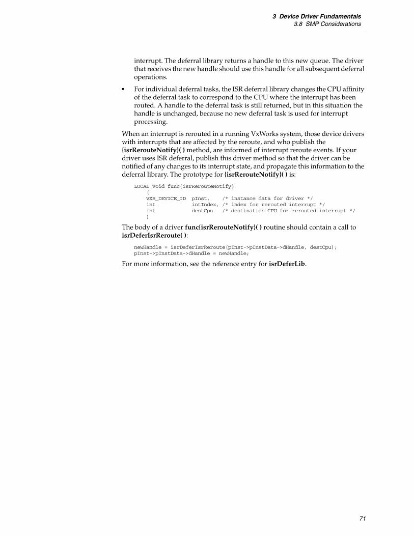
3 Device Driver Fundamentals3.8 SMP Considerations
71
interrupt. The deferral library returns a handle to this new queue. The driver that receives the new handle should use this handle for all subsequent deferral operations.
■ For individual deferral tasks, the ISR deferral library changes the CPU affinity of the deferral task to correspond to the CPU where the interrupt has been routed. A handle to the deferral task is still returned, but in this situation the handle is unchanged, because no new deferral task is used for interrupt processing.
When an interrupt is rerouted in a running VxWorks system, those device drivers with interrupts that are affected by the reroute, and who publish the {isrRerouteNotify}( ) method, are informed of interrupt reroute events. If your driver uses ISR deferral, publish this driver method so that the driver can be notified of any changes to its interrupt state, and propagate this information to the deferral library. The prototype for {isrRerouteNotify}( ) is:
LOCAL void func{isrRerouteNotify}(VXB_DEVICE_ID pInst, /* instance data for driver */int intIndex, /* index for rerouted interrupt */int destCpu /* destination CPU for rerouted interrupt */)
The body of a driver func{isrRerouteNotify}( ) routine should contain a call to isrDeferIsrReroute( ):
newHandle = isrDeferIsrReroute(pInst->pInstData->dHandle, destCpu); pInst->pInstData->dHandle = newHandle;
For more information, see the reference entry for isrDeferLib.

VxWorksDevice Driver Developer's Guide, 6.8
72

73
4Development Strategies
4.1 Introduction 73
4.2 Writing New VxBus Drivers 73
4.3 VxBus Show Routines 79
4.4 Debugging 90
4.1 Introduction
This chapter outlines development strategies for creating a VxBus model device driver. The chapter presents an overall methodology for creating a new device driver (where no previous VxWorks driver exists). It also presents several suggestions for debugging those aspects of a device driver that are relevant to the interface between the device driver and other modules such as the VxBus core features and middleware.
4.2 Writing New VxBus Drivers
The steps to create a new VxBus driver generally include the following:
1. Create the VxBus infrastructure needed for your driver.
2. Modify your BSP, if necessary.
3. Add debug code based on conditional compilation.
4. Add the VxBus driver methods required by your driver class.
5. Remove all global variables.
VxWorksDevice Driver Developer's Guide, 6.8
74
4.2.1 Creating the VxBus Infrastructure
There are several elements required in every VxBus device driver. Start by adding the empty driver framework that interacts with VxBus. The required parts of this framework include the driver source file itself, one or more optional header files, a component description file (CDF) which allows the driver to be visible in Workbench and the vxprj command-line utility, and configuration stub files so that the driver can be included in BSP command-line builds (executed using the make command). (For more information on CDF and configuration stub files, see 3.3.3 Required Files, p.21).
Once all the elements of the driver are present in the correct places, configure the BSP for the development effort.
Writing Driver Source Files
To create the driver source file, start with a template file or an existing driver from the same driver class. Currently, template files are available for network interface (END), PCI bus controller, timer, and serial drivers.
Templates, when available, are kept in the same directory as other drivers of the same class. For example, the template for timer drivers can be found at:
installDir/vxworks-6.x/target/src/hwif/timer/vxbTemplateTimer.c
Writing Header Files (Optional)
Many VxBus device drivers have all source code located in a single source file, with no external header file. However, if your driver includes a number of device-specific macros or other driver-specific information, you can put this information in an optional header file.
Writing the Component Description File (CDF)
The CDF for your driver allows the driver to be configured and included in a project using standard Wind River tools (Workbench and the vxprj command-line utility).
Wind River driver CDF files are located in the following directory:
installDir/vxworks-6.x/target/config/comps/vxWorks
And in the architecture specific directories under this directory. Third-party driver CDF files are located in the following directory:
installDir/vxworks-6.x/target/3rdparty/vendor/driver
By convention, driver files use the prefix 40, for example 40g64120a.cdf.
In most cases, the CDF file for a driver is simple. You must supply a value for Component.
NOTE: This section provides an overview of the component description file requirements for adding a driver. For detailed information, see Component Description File, p.23 and VxWorks Kernel Programmer’s Guide: Kernel.

4 Development Strategies4.2 Writing New VxBus Drivers
75
For example:
Component DRV_CLASS_NAME { NAME DriverName SYNOPSIS Description Of Driver _CHILDREN FOLDER_DRIVERS REQUIRES INCLUDE_VXBUS \
INCLUDE_PLB_BUS \ other requirements
INIT_RTN sampleDriverRegister(); INIT_AFTER INCLUDE_PLB_BUS _INIT_ORDER hardWareInterFaceBusInit _CHILDREN FOLDER_DRIVERS
}
Many drivers have configuration options. For more information on how the driver manages configuration options internally, see VxWorks Kernel Programmer’s Guide. Configuration options that are specified as parameters should be configurable from within Workbench and in vxprj. To do this, provide Parameter entries for each parameter and link the parameters to your Component with the CFG_PARAMS keyword. For more information, see CFG_PARAMS, p.27.
Writing the Configuration Stub Files
Configuration stub files provide similar functionality to the CDF file, but are used when building the VxWorks image from the BSP directory using the make command (this is known as the bspDir/config.h build method).
In most cases, each driver requires two stub files. The stub files are named according to the convention for your driver, with the extensions .dc and .dr.
The driverName.dc file usually contains a forward reference to the driver registration routine, and nothing else. Use the Wind River macro IMPORT to declare this routine. (Note that all registration routines return a void value.)
The following is a sample driver .dc file:
IMPORT void sampleDriverRegister(void);
The .dr file contains a call to the driver registration routine. This call must be surrounded by #ifdef and #endif.
The last line must be terminated with a newline (be sure that your editor does not strip it off).
The following is a sample driver .dr file:
#ifdef DRV_CLASS_NAME sampleDriverRegister();
#endif /* DRV_CLASS_NAME */
Wind River driver .dc and .dr files are located in the following directory:
installDir/vxworks-6.x/target/config/comps/src/hwif
NOTE: In general, you should build your project files using Workbench or the vxprj command-line utility. However, the BSP build method described in this section may be useful in certain development scenarios including early BSP and driver development. For more information on this build method, see the VxWorks Command-Line Tools User’s Guide.

VxWorksDevice Driver Developer's Guide, 6.8
76
Third-party driver .dc and .dr files are located in:
installDir/vxworks-6.x/target/3rdparty/vendor/driver
Verifying the Infrastructure
Once you have created your driver, compiled it, added it to a library, and configured your BSP, verify that what you have done so far is correct.
To do this, first build the VxWorks image from the BSP directory. Verify that the driver file is included by using the nmarch command and searching for the registration routine.
Next, verify that the CDF file is correct by starting Workbench and configuring the VxWorks image. If everything is correct, your driver should be available in the drivers folder (not greyed out).
Finally, boot the image and run vxBusShow( ). Your driver should show up in the list of drivers and the target device should show up in the list of devices.
One common problem—frequently encountered when creating drivers for PLB devices—is that the name of the driver does not match the name you provided in the hcfDeviceList[ ] table. When this happens, the output of vxBusShow( ) displays the entry as an orphan rather than a device. If this happens, you must get the driver and device to match up before proceeding.
VxBus matches a driver to its hardware by using strcmp( ) to compare the driver name with the hcfDeviceList[ ] entries. The comparison is case sensitive, and the match must be exact. Check that the driver name and the name listed in the hcfDeviceList[ ] table in hwconf.c are identical and correct as necessary.
The second most common problem at this stage is related to the device's register base address. For PLB devices, the first register base address must be non-null. You can verify this by running vxBusShow( ) with a verbose level argument greater than 1. This displays the full set of pRegBase[ ] entries for each device (instance and orphan) known by VxBus. If the pRegBase[0] entry for your device is zero, correct the problem by supplying the correct base address.
Before moving on to the next step, be sure that your device and driver are connected to each other.
4.2.2 Modifying the BSP (Optional)
Depending on the bus type, VxBus may be able to discover your device automatically. For example, when the device is on a PCI bus or variant of PCI, information about the device is available from PCI configuration space. VxBus
NOTE: In some cases, you may not want to supply the register base address in hwconf.c. In this is the case for your driver, use ERROR or TRUE, both of which are non-null. If you choose this option, your driver must not attempt to read or write registers using the VxBus register access mechanism.
NOTE: Before you start working on your VxBus-enabled driver, you must make sure that your BSP is also VxBus compliant. If your BSP is not enabled for use with VxBus, see the VxWorks BSP Developer’s Guide.

4 Development Strategies4.2 Writing New VxBus Drivers
77
reads this information and compares it against PCI configuration information provided by a driver for a PCI device. If the information matches, the driver is paired with the device.
However, with the PLB bus type, devices are not discovered automatically. In this case, you must add an entry for your device in the hcfDeviceList[ ] array in the BSP hwconf.c file.
For easier debugging, configure your VxWorks Image Project so that the show routines are included. Be sure to include the VxBus show routines in addition to the standard show routines. For example, add the following components:
■ INCLUDE_SHOW_ROUTINES
■ INCLUDE_VXBUS_SHOW
Also include your own driver component:
■ DRV_CLASS_NAME
4.2.3 Adding Debug Code
After the old driver source code is consolidated into a VxBus driver file, you can add additional debug code.
For example, adding debug code is often useful when the driver provides a way to show contents of the driver-specific data area, often referred to as pDrvCtrl.
Most drivers benefit by having debug and other diagnostic information available based on a compile-time macro. If the macro is defined, and a flag is set to the desired debug level, debug code is available at run time.
For most new driver development, you should defer registration of your driver with VxBus. You can manually run your driver registration routine after the system has booted and you are ready to debug your driver. This allows the system to come up without your driver, and you can use the debug facilities from a fully-functional VxWorks image for debugging.
The type of debug information that can be added to a driver is discussed in 4.4 Debugging, p.90.
4.2.4 Adding the VxBus Driver Methods
The next step in your driver development is to find what external interface is used. Typically, this involves finding the VxBus driver methods used by the driver class and then adding the routines that provide the required functionality.
In the early stages of development, you may not want to publish the driver methods. Deferring this step allows you to test the external interface manually without having to worry about whether the middleware or other modules are going to cause undesirable results when the new driver's empty routines are called.
NOTE: When releasing a driver, much of the debug information used during development continues to be valuable. Therefore, leaving the code in the source file can be beneficial in the future, as long as it can be omitted from the object file. For more information on releasing a driver, see 5. Driver Release Procedure.

VxWorksDevice Driver Developer's Guide, 6.8
78
Once the functionality used by the required driver methods is available, add the methods to the table of methods in your driver and make sure the table is published in the pMethods field of the VXB_DEVICE_ID.
Note that the general collection of driver-specific method IDs are provided in the following directory:
installDir/vxworks-6.x/target/src/hwif/methods
If your driver requires a new driver method ID (one that does not exist in the general collection of driver-specific method IDs), you can create the new method ID under the above directory.
The following is an example of the busCtlrAccessOverride method ID given in the following directory:
installDir/vxworks-6.x/target/src/hwif/methods
To build the new method ID object file and archive it into a library, you must create a .c file that contains the definition of the driver method ID and a .mk file that can be included by the following makefile:
installDir/vxworks-6.x/target/src/hwif/methods/Makefile
The busCtlrAccessOverride.c is as follows:
#include <vxWorks.h>#include <vxBusLib.h>#include <hwif/vxbus/vxBus.h>
DEVMETHOD_DEF(busCtlrAccessOverride, "busCtlrAccessOverride");
The busCtlrAccessOverride.mk is as follows:
OBJS_COMMON += busCtlrAccessOverride.o
4.2.5 Removing Global Variables
One of the important goals of a generic driver is that it support multiple devices of the same type. Earlier in the development process, you may have chosen to create global variables specific to an instance (that is, a given device and driver paired together). These global variables should be removed.
In VxBus, the main identification of a device is the VXB_DEVICE_ID. The structure VXB_DEVICE_ID points to has a field for pDrvCtrl. pDrvCtrl is owned by the driver and can be used for any purpose. Most drivers define a structure containing all instance-specific information.
During initialization, this structure is allocated using hwMemAlloc( ), filled in with the data, and a pointer to the structure is saved in the pDrvCtrl field. Later, when the driver is called for any reason, the VXB_DEVICE_ID is passed as a parameter, from which the driver can extract the pDrvCtrl field to get access to the instance-specific data.
In many cases, it is necessary to rewrite the prototype of some routines to pass the pDrvCtrl or VXB_DEVICE_ID as a parameter.
NOTE: In this step, you are expected to create the actual device management code which is a time-consuming step in the device driver development process.

4 Development Strategies4.3 VxBus Show Routines
79
4.3 VxBus Show Routines
There are a number of show routines available for use with VxBus. This section describes some of the show routines, demonstrates how they can be used to assist driver development, and explains how to configure them into the system.
4.3.1 Available Show Routines
This section lists and describes the available VxBus show routines.
vxBusShow( )
The most basic show routine in the VxBus framework is vxBusShow( ). This routine provides a list of information related to drivers and devices.
There are several levels of detail available when using this routine. The level of detail is specified by the value of the argument. A value of 0 provides the following basic information:
■ bus types that are available on the system
■ drivers that are registered, and the bus types they use
■ buses that are present on the system
■ devices that are present on each bus
■ whether each device has been paired with a driver
Example 4-1 shows the output for a typical vxBusShow( ) routine run on a Pentium target.
Example 4-1 Basic vxBusShow( ) Output
-> vxBusShow() Registered Bus Types: MII_Bus @ 0x004531d4 PCI_Bus @ 0x0044fbcc Local_Bus @ 0x0044f98c
Registered Device Drivers:yn at 0x00452ef8 on bus PCI_Bus, funcs @ 0x00452e18fei at 0x00452d98 on bus PCI_Bus, funcs @ 0x00452c68geiHEnd at 0x004530c4 on bus PCI_Bus, funcs @ 0x004530a8genericPhy at 0x0045322c on bus MII_Bus, funcs @ 0x00453220miiBus at 0x0045318c on bus PCI_Bus, funcs @ 0x0045312cmiiBus at 0x00453148 on bus Local_Bus, funcs @ 0x0045312cns16550 at 0x0044f4e4 on bus Local_Bus, funcs @ 0x0044f474ns16550 at 0x0044f49c on bus PCI_Bus, funcs @ 0x0044f474pentiumPci at 0x0044fbf4 on bus Local_Bus, funcs @ 0x0044fbe8plbCtlr at 0x0044f9b4 on bus Local_Bus, funcs @ 0x0044f9a8
Busses and Devices Present:Local_Bus @ 0x00466790 with bridge @ 0x0044f9f4Device Instances:
pentiumPci unit 0 on Local_Bus @ 0x00467a50 with busInfo 0x004669d0ns16550 unit 1 on Local_Bus @ 0x004678d0 with busInfo 0x00000000ns16550 unit 0 on Local_Bus @ 0x00467750 with busInfo 0x00000000
Orphan Devices:i8042Mse unit 0 on Local_Bus @ 0x00469350 with busInfo 0x00000000i8042Kbd unit 0 on Local_Bus @ 0x00469250 with busInfo 0x00000000
PCI_Bus @ 0x004669d0 with bridge @ 0x00467a50

VxWorksDevice Driver Developer's Guide, 6.8
80
Device Instances:miiBus unit 1 on PCI_Bus @ 0x004747d0 with busInfo 0x0046be10miiBus unit 0 on PCI_Bus @ 0x00469450 with busInfo 0x00469cd0fei unit 0 on PCI_Bus @ 0x00468e50 with busInfo 0x00000000ns16550 unit 3 on PCI_Bus @ 0x00468c50 with busInfo 0x00000000yn unit 0 on PCI_Bus @ 0x00468350 with busInfo 0x00000000geiHEnd unit 0 on PCI_Bus @ 0x00467e50 with busInfo 0x00000000
Orphan Devices:(null) unit 0 on PCI_Bus @ 0x00469150 with busInfo 0x00000000(null) unit 0 on PCI_Bus @ 0x00469050 with busInfo 0x00000000(null) unit 0 on PCI_Bus @ 0x00468f50 with busInfo 0x00000000(null) unit 0 on PCI_Bus @ 0x00468b50 with busInfo 0x00000000(null) unit 0 on PCI_Bus @ 0x00468a50 with busInfo 0x00000000(null) unit 0 on PCI_Bus @ 0x00468950 with busInfo 0x00000000(null) unit 0 on PCI_Bus @ 0x00468850 with busInfo 0x00000000(null) unit 0 on PCI_Bus @ 0x00468750 with busInfo 0x00000000(null) unit 0 on PCI_Bus @ 0x00468650 with busInfo 0x00000000(null) unit 0 on PCI_Bus @ 0x00468550 with busInfo 0x00000000(null) unit 0 on PCI_Bus @ 0x00468450 with busInfo 0x00000000(null) unit 0 on PCI_Bus @ 0x00468250 with busInfo 0x00000000(null) unit 0 on PCI_Bus @ 0x00468150 with busInfo 0x00000000(null) unit 0 on PCI_Bus @ 0x00468050 with busInfo 0x00000000(null) unit 0 on PCI_Bus @ 0x00467f50 with busInfo 0x00000000(null) unit 0 on PCI_Bus @ 0x00467d50 with busInfo 0x00000000(null) unit 0 on PCI_Bus @ 0x00467c50 with busInfo 0x00000000(null) unit 0 on PCI_Bus @ 0x00467b50 with busInfo 0x00000000
MII_Bus @ 0x0046be10 with bridge @ 0x004747d0Device Instances:
genericPhy unit 0 on MII_Bus @ 0x00474850 with busInfo 0x00000000Orphan Devices:
MII_Bus @ 0x00469cd0 with bridge @ 0x00469450Device Instances:
genericPhy unit 0 on MII_Bus @ 0x004694d0 with busInfo 0x00000000Orphan Devices:
Many VxBus routines require that the VxBus device ID be provided as an argument. The most commonly used part of the vxBusShow( ) output is the device ID for individual devices. The device ID is the field after the bus type, indicated with the @ symbol. For example, the device ID of the mouse device, i8042Mse, is 0x00469350, as shown in:
i8042Mse unit 0 on Local_Bus @ 0x00469350 with busInfo 0x00000000
Higher verbose level values result in the display of additional information. Each driver can publish a show routine that is integrated into vxBusShow( ) (see 4.4.1 Configuring Show Routines, p.90). The amount and format of the information that is displayed depends on the driver and the information that the driver chooses to display based upon a given verbose level.
For all devices, vxBusShow(1) displays non-null values of pRegBase[ ], in addition to the information displayed at verbose level 0.
When the verbose level is greater than 1000, vxBusShow( ) displays all values of pRegBase[ ], even if they are NULL. Because the output with non-zero verbose levels is long, the following examples show only an excerpt of the outputs.
NOTE: The remainder of this section discusses only the generic format used when the driver does not publish a show routine.
NOTE: The following examples are displayed from a different system than shown in Example 4-1.

4 Development Strategies4.3 VxBus Show Routines
81
Example 4-2 vxBusShow( ) Verbose Output
-> vxBusShow(1) ...
iaTimestamp unit 0 on Local_Bus @ 0x0042ff48 with busInfo 0x00000000pDrvCtrl @ 0x00430048
fileNvRam unit 0 on Local_Bus @ 0x00430148 with busInfo 0x00000000BAR0 @ 0xffffffff (IO space)pDrvCtrl @ 0x0042cb48
Orphan Devices:PCI_Bus @ 0x0042bec8 with bridge @ 0x0042d048Device Instances:
fei unit 0 on PCI_Bus @ 0x0042d848 with busInfo 0x00000000BAR0 @ 0xfc9bf000 (memory mapped)BAR1 @ 0x0000bc00 (IO space)BAR2 @ 0xfc800000 (memory mapped)pDrvCtrl @ 0x04419284
... (null) unit 0 on PCI_Bus @ 0x0042d648 with busInfo 0x00000000
BAR2 @ 0x00030300 (memory mapped)BAR3 @ 0x200000f0 (memory mapped)BAR4 @ 0x0000fff0 (memory mapped)BAR5 @ 0x0001fff0 (IO space)pDrvCtrl @ 0x00000000
...
-> vxBusShow(1001) ...PCI_Bus @ 0x0042bec8 with bridge @ 0x0042d048Device Instances:
fei unit 0 on PCI_Bus @ 0x0042d848 with busInfo 0x00000000BAR0 @ 0xfc9bf000 (memory mapped)BAR1 @ 0x0000bc00 (IO space)BAR2 @ 0xfc800000 (memory mapped)BAR3 @ 0x00000000 (none)BAR4 @ 0x00000000 (none)BAR5 @ 0x00000000 (none)BAR6 @ 0x00000000 (none)BAR7 @ 0x00000000 (none)BAR8 @ 0x00000000 (none)BAR9 @ 0x00000000 (none)pDrvCtrl @ 0x04419284
...
vxbDevStructShow( )
The prototype for vxbDevStructShow( ) is as follows:
STATUS vxbDevStructShow(VXB_DEVICE_ID devID)
The vxbDevStructShow( ) routine displays the fields of the device structure. When developing bus controller and multifunction drivers, this routine is often useful to display the information contained in the child devices created by the bus controller driver or multifunction driver. For general driver development, this routine is used to find the characteristics of a given device, such as pRegBase[ ] values. For example:
-> fei0 = 0x00468350
-> vxbDevStructShow(fei0) vxbDev fei @ 0x00468350
pNext -> 0x00468c50pParentBus -> 0x004669d0pMethods @ 0x00000000pAccess @ 0x0042e0c8pRegBase[0] @ 0xfc9bf000pRegBase[1] @ 0x0000bc00pRegBase[2] @ 0xfc800000

VxWorksDevice Driver Developer's Guide, 6.8
82
pRegBase[3] @ 0x00000000pRegBase[4] @ 0x00000000pRegBase[5] @ 0x00000000pRegBase[6] @ 0x00000000pRegBase[7] @ 0x00000000pRegBase[8] @ 0x00000000pRegBase[9] @ 0x00000000pSubordinateBus @ 0x00000000pBusSpecificDevInfo @ 0x0042c348busID = PCI_Bus (3)pIntrInfo @ 0x0042c908pDriver @ 0x0041f7dcpDrvCtrl @ 0x04419430u.pDevPrivate @ 0x00000000
vxbDevPathShow( )
The prototype for vxbDevPathShow( ) is as follows:
void vxbDevPathShow(VXB_DEVICE_ID devID)
The vxbDevPathShow( ) routine indicates the bus controllers upstream from the specified device to the PLB. For example:
-> sio3 = 0x00468c50
-> vxbDevPathShow(sio3) device ns16550 @ 0x00468c50device pentiumPci @ 0x00467a50device plbCtlr @ 0x0044f9f4
4.3.2 PCI Show Routines
The PCI show routines available in VxWorks prior to the introduction of the VxBus driver infrastructure are still available in this release. However, the older PCI show routines may not always work exactly as expected. In VxWorks 6.6, the PCI configuration was enhanced to support logically separate PCI buses. That is, a single system can have two or more PCI buses that are not related to each other in any way. When this occurs, there are two primary implications for the device driver developer.
First, there is a default PCI bus, and any given device may not be reachable from the default bus. The older PCI show routines use only the default bus, therefore if the device you are looking for is not present on the default bus, it is not listed by the older show routines.
The next consideration is that the [bus,device,function] triple no longer uniquely identifies a single device. This means that older PCI show routines cannot be used.
Many of the older PCI show routines have corresponding show routines specific to VxBus. In general, the first argument to a new routine is the VxBus device ID of the bus controller immediately upstream from the device. The VxBus routines are discussed in the following sections.
NOTE: When pRegBase[0] is NULL on PLB devices, the device is not matched with a driver, but instead remains an orphan.

4 Development Strategies4.3 VxBus Show Routines
83
pciDevShow( )
The prototype for pciDevShow( ) is as follows:
void pciDevShow(VXB_DEVICE_ID devID)
The pciDevShow( ) routine displays PCI information about the specified device. This includes the [bus,device,function] triple, and the device ID and vendor ID, that were read from PCI configuration space when the device was created. For example:
-> yn0 = 0x00468350
-> pciDevShow(yn0) pDev @ 0x00468350 [3,0,0]
devID = 0x4b00vendID = 0x1186
The devID and vendID fields shown by pciDevShow( ) are used when matching PCI devices and drivers. If the information displayed by pciDevShow( ) does not match the values listed in your driver, you may need to modify your driver to get an exact match.
vxbPciDeviceShow( )
The prototype for vxbPciDeviceShow( ) is as follows:
STATUS vxbPciDeviceShow(VXB_DEVICE_ID busCtrlID,int busNo)
The vxbPciDeviceShow( ) routine displays information about devices found on the PCI bus downstream of the specified PCI bus controller device. Only information about the PCI bus numbered busNo is listed.
-> pentiumPci = 0x0044fbf4
-> vxbPciDeviceShow(pentiumPci,0) Scanning functions of each PCI device on bus 0 Using configuration mechanism 1bus device function vendorID deviceID class/rev
0 0 0 0x8086 0x3590 0x0600000c0 2 0 0x8086 0x3595 0x0604000c0 4 0 0x8086 0x3597 0x0604000c0 6 0 0x8086 0x3599 0x0604000c0 28 0 0x8086 0x25ae 0x060400020 30 0 0x8086 0x244e 0x0604000a0 31 0 0x8086 0x25a1 0x060100020 31 1 0x8086 0x25a2 0x01018a020 31 3 0x8086 0x25a4 0x0c050002
NOTE: The following output is displayed from a different system than the vxBusShow( ) output in vxBusShow( ), p.79.

VxWorksDevice Driver Developer's Guide, 6.8
84
vxbPciHeaderShow( )
The prototype for vxbPciHeaderShow( ) is as follows:
STATUS vxbPciHeaderShow(VXB_DEVICE_ID busCtrlID,int busNo, /* bus number */int deviceNo, /* device number */int funcNo /* function number */)
The vxbPciHeaderShow( ) routine displays the full contents of the PCI header for an individual device. Note that the device is specified by four values: the bus controller device, and the PCI triple [bus,device,function]. This means that vxbPciHeaderShow( ) is usable even when the BSP excludes a particular device from being configured. (For information about excluding a particular device within the BSP, see the reference entry for vxbPciAutoConfig( ).)
The following sample shows the PCI header for the Yukon II network interface device. Notice that the VxBus device ID for the yn0 device is not used as an argument to vxbPciHeaderShow( ). Instead, use the [bus,device,function] triple as provided in the output of pciDevShow( ).
-> yn0 = 0x00468350
-> pciDevShow(yn0) pDev @ 0x00468350 [3,0,0]
devID = 0x4b00vendID = 0x1186
-> pciCtlr = 0x004669d0
-> vxbPciHeaderShow pciCtlr,3,0,0 vendor ID = 0x1186device ID = 0x4b00command register = 0x0007status register = 0x4010revision ID = 0x11class code = 0x02sub class code = 0x00programming interface = 0x00cache line = 0x08latency time = 0x00header type = 0x00BIST = 0x00base address 0 = 0xfe3fc004base address 1 = 0x00000000base address 2 = 0x0000b801base address 3 = 0x00000000base address 4 = 0x00000000base address 5 = 0x00000000cardBus CIS pointer = 0x00000000sub system vendor ID = 0x1186sub system ID = 0x4b00expansion ROM base address = 0xfe3c0000interrupt line = 0x0binterrupt pin = 0x01min Grant = 0x00max Latency = 0x00Capabilities - Power ManagementCapabilities - Vital Product DataCapabilities - Message Signaled Interrupts: Disabled, 64-bit, MMC: 0 MME: 1
Address: 0082e0050082e005 Data: 0xe005 Capabilities - PCIe: Legacy Endpoint, IRQ 0
Device: Max Payload: 128 bytes, Extended Tag: 5-bitAcceptable Latency: L0 - >4us, L1 - >64usErrors Enabled: AUX Pwr PMMax Read Request 512 bytes
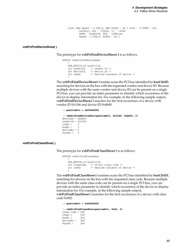
4 Development Strategies4.3 VxBus Show Routines
85
Link: MAX Speed - 2.5Gb/s, MAX Width - by 1 Port - 0 ASPM - L0sLatency: L0s - <256ns, L1 - >64usASPM - Disabled, RCB - 128bytesSpeed - 2.5Gb/s, Width - by 1
vxbPciFindDeviceShow( )
The prototype for vxbPciFindDeviceShow( ) is as follows:
STATUS vxbPciFindDeviceShow(VXB_DEVICE_ID busCtrlID,int vendorId, /* vendor ID */int deviceId, /* device ID */int index /* desired instance of device */)
The vxbPciFindDeviceShow( ) routine scans the PCI bus identified by busCtlrID, searching for devices on the bus with the requested vendor and device ID. Because multiple devices with the same vendor and device ID can be present on a single PCI bus, you can provide an index parameter to identify which occurrence of the device to display information for. For example, in the following sample output, vxbPciFindDeviceShow( ) searches for the first occurrence of a device with vendor ID 0x1186 and device ID 0x4b00:
-> pentiumPci = 0x0044fbf4
-> vxbPciFindDeviceShow(pentiumPci, 0x1186, 0x4b00, 0) deviceId = 0x4b00vendorId = 0x1186index = 0busNo = 3deviceNo = 0funcNo = 0
vxbPciFindClassShow( )
The prototype for vxbPciFindClassShow( ) is as follows:
STATUS vxbPciFindClassShow (VXB_DEVICE_ID busCtrlID,int classCode, /* 24-bit class code */int index /* desired instance of device */)
The vxbPciFindClassShow( ) routines scans the PCI bus identified by busCtlrID, searching for devices on the bus with the requested class code. Because multiple devices with the same class code can be present on a single PCI bus, you can provide an index parameter to identify which occurrence of the device to display information for. For example, in the following sample output, vxbPciFindClassShow( ) searches for the first occurrence of a device with class code 0x002:
-> pentiumPci = 0x0044fbf4
-> vxbPciFindClassShow(pentiumPci, 0x02, 0) class code = 0x2index = 0x0busNo = 0x3deviceNo = 0x0funcNo = 0x0
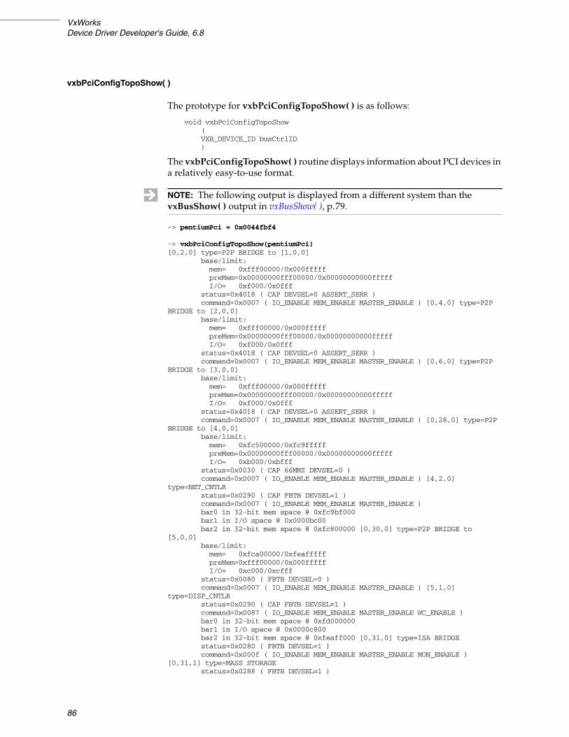
VxWorksDevice Driver Developer's Guide, 6.8
86
vxbPciConfigTopoShow( )
The prototype for vxbPciConfigTopoShow( ) is as follows:
void vxbPciConfigTopoShow(VXB_DEVICE_ID busCtrlID)
The vxbPciConfigTopoShow( ) routine displays information about PCI devices in a relatively easy-to-use format.
-> pentiumPci = 0x0044fbf4
-> vxbPciConfigTopoShow(pentiumPci) [0,2,0] type=P2P BRIDGE to [1,0,0]
base/limit:mem= 0xfff00000/0x000fffffpreMem=0x00000000fff00000/0x00000000000fffffI/O= 0xf000/0x0fff
status=0x4018 ( CAP DEVSEL=0 ASSERT_SERR )command=0x0007 ( IO_ENABLE MEM_ENABLE MASTER_ENABLE ) [0,4,0] type=P2P
BRIDGE to [2,0,0]base/limit:mem= 0xfff00000/0x000fffffpreMem=0x00000000fff00000/0x00000000000fffffI/O= 0xf000/0x0fff
status=0x4018 ( CAP DEVSEL=0 ASSERT_SERR )command=0x0007 ( IO_ENABLE MEM_ENABLE MASTER_ENABLE ) [0,6,0] type=P2P
BRIDGE to [3,0,0]base/limit:mem= 0xfff00000/0x000fffffpreMem=0x00000000fff00000/0x00000000000fffffI/O= 0xf000/0x0fff
status=0x4018 ( CAP DEVSEL=0 ASSERT_SERR )command=0x0007 ( IO_ENABLE MEM_ENABLE MASTER_ENABLE ) [0,28,0] type=P2P
BRIDGE to [4,0,0]base/limit:mem= 0xfc500000/0xfc9fffffpreMem=0x00000000fff00000/0x00000000000fffffI/O= 0xb000/0xbfff
status=0x0030 ( CAP 66MHZ DEVSEL=0 )command=0x0007 ( IO_ENABLE MEM_ENABLE MASTER_ENABLE ) [4,2,0]
type=NET_CNTLRstatus=0x0290 ( CAP FBTB DEVSEL=1 )command=0x0007 ( IO_ENABLE MEM_ENABLE MASTER_ENABLE )bar0 in 32-bit mem space @ 0xfc9bf000bar1 in I/O space @ 0x0000bc00bar2 in 32-bit mem space @ 0xfc800000 [0,30,0] type=P2P BRIDGE to
[5,0,0]base/limit:mem= 0xfca00000/0xfeafffffpreMem=0xfff00000/0x000fffffI/O= 0xc000/0xcfff
status=0x0080 ( FBTB DEVSEL=0 )command=0x0007 ( IO_ENABLE MEM_ENABLE MASTER_ENABLE ) [5,1,0]
type=DISP_CNTLRstatus=0x0290 ( CAP FBTB DEVSEL=1 )command=0x0087 ( IO_ENABLE MEM_ENABLE MASTER_ENABLE WC_ENABLE )bar0 in 32-bit mem space @ 0xfd000000bar1 in I/O space @ 0x0000c800bar2 in 32-bit mem space @ 0xfeaff000 [0,31,0] type=ISA BRIDGEstatus=0x0280 ( FBTB DEVSEL=1 )command=0x000f ( IO_ENABLE MEM_ENABLE MASTER_ENABLE MON_ENABLE )
[0,31,1] type=MASS STORAGEstatus=0x0288 ( FBTB DEVSEL=1 )
NOTE: The following output is displayed from a different system than the vxBusShow( ) output in vxBusShow( ), p.79.
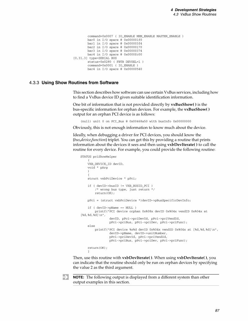
4 Development Strategies4.3 VxBus Show Routines
87
command=0x0007 ( IO_ENABLE MEM_ENABLE MASTER_ENABLE )bar0 in I/O space @ 0x000001f0bar1 in I/O space @ 0x000003f4bar2 in I/O space @ 0x00000170bar3 in I/O space @ 0x00000374bar4 in I/O space @ 0x0000fc00
[0,31,3] type=SERIAL BUSstatus=0x0280 ( FBTB DEVSEL=1 )command=0x0001 ( IO_ENABLE )bar4 in I/O space @ 0x00000540
4.3.3 Using Show Routines from Software
This section describes how software can use certain VxBus services, including how to find a VxBus device ID given suitable identification information.
One bit of information that is not provided directly by vxBusShow( ) is the bus-specific information for orphan devices. For example, the vxBusShow( ) output for an orphan PCI device is as follows:
(null) unit 0 on PCI_Bus @ 0x00468a50 with busInfo 0x00000000
Obviously, this is not enough information to know much about the device.
Ideally, when debugging a driver for PCI devices, you should know the [bus,device,function] triplet. You can get this by providing a routine that prints information about the devices it sees and then using vxbDevIterate( ) to call the routine for every device. For example, you could provide the following routine:
STATUS pciShowHelper(VXB_DEVICE_ID devID,void * pArg){struct vxbPciDevice * pPci;
if ( devID->busID != VXB_BUSID_PCI )/* wrong bus type, just return */return(OK);
pPci = (struct vxbPciDevice *)devID->pBusSpecificDevInfo;
if ( devID->pName == NULL )printf("PCI device orphan 0x%08x devID 0x%04x vendID 0x%04x at
[%d,%d,%d]\n",devID, pPci->pciDevId, pPci->pciVendId,pPci->pciBus, pPci->pciDev, pPci->pciFunc);
else printf("PCI device %s%d devID 0x%04x vendID 0x%04x at [%d,%d,%d]\n",
devID->pName, devID->unitNumber,pPci->pciDevId, pPci->pciVendId,pPci->pciBus, pPci->pciDev, pPci->pciFunc);
return(OK);}
Then, use this routine with vxbDevIterate( ). When using vxbDevIterate( ), you can indicate that the routine should only be run on orphan devices by specifying the value 2 as the third argument.
NOTE: The following output is displayed from a different system than other output examples in this section.

VxWorksDevice Driver Developer's Guide, 6.8
88
-> vxbDevIterate(pciShowHelper,0,2) PCI device orphan 0x0042d348 devID 0x3590 vendID 0x8086 at [0,0,0] PCI device orphan 0x0042d448 devID 0x3595 vendID 0x8086 at [0,2,0] PCI device orphan 0x0042d548 devID 0x3597 vendID 0x8086 at [0,4,0] PCI device orphan 0x0042d648 devID 0x3599 vendID 0x8086 at [0,6,0] PCI device orphan 0x0042d748 devID 0x25ae vendID 0x8086 at [0,28,0] PCI device orphan 0x0042d948 devID 0x244e vendID 0x8086 at [0,30,0] PCI device orphan 0x0042da48 devID 0x4c52 vendID 0x1002 at [5,1,0] PCI device orphan 0x0042db48 devID 0x25a1 vendID 0x8086 at [0,31,0] PCI device orphan 0x0042fc48 devID 0x25a2 vendID 0x8086 at [0,31,1] PCI device orphan 0x0042fd48 devID 0x25a4 vendID 0x8086 at [0,31,3]
It is possible to use the show routines from test code or other software. However, to do this, your code needs to find the VxBus device ID of the desired device. This can be accomplished by requiring the user to provide the VxBus device ID. However, it may be more convenient to provide the driver name and unit number.
struct devNameAndUnit{VXB_DEVICE_ID devID;char * devName;int devUnit;};
STATUS pciDevByNameUnitHelper(VXB_DEVICE_ID devID,struct devNameAndUnit * pDev){struct vxbPciDevice * pPci;
if ( pDev->devID != NULL )/* already found, just return */return(OK);
if ( ( strcmp(devID->pName,pDev->devName) == 0 ) &&( devID->unitNumber == pDev->devUnit ) )/* found it */pDev->devID = devID;
return(OK);}
VXB_DEVICE_ID pciDevByNameUnitFind(char * devName, int devUnit){struct devNameAndUnit nmUnit;
nmUnit.devID = NULL;nmUnit.devName = devName;nmUnit.devUnit = devUnit;
vxbDevIterate(pciDevByNameUnitHelper, &nmUnit, 1)
return(nmUnit.devID);}
The pciDevByNameUnitFind( ) routine can be used within the code to find the VxBus device ID of the desired device.
-> pciDevByNameUnitFind("fei",0) value = 4623952 = 0x00468e50
4.3.4 Configuring Show Routines into VxWorks
This section describes how to include the necessary components for VxBus show routines in your VxWorks image.

4 Development Strategies4.3 VxBus Show Routines
89
Configuring Generic VxBus Show Routines
To include the generic Vxbus show routines, include the following macros or components when building your VxWorks image:
■ INCLUDE_SHOW_ROUTINES
■ INCLUDE_PCI_BUS_SHOW
■ INCLUDE_VXBUS_SHOW
Configuring Interrupt Show Routines
If you are concerned with interrupt routing information, additional information may be available from the interrupt controller driver. This information is more difficult to configure, due to the fact that interrupt controller drivers and the interrupt controller driver support library are compiled outside the context of a project or BSP.
Several source files need to be recompiled and archived into the driver library. The files are all located in the following directory:
installDir/vxworks-6.x/target/src/hwif/intCtlr
The interrupt controller driver support library provides show routines when the INTCTLR_LIB_SHOW macro is defined. Individual interrupt controller drivers are configured with additional show routines by defining driver-specific macros.
To determine which macros you need to define, you must determine which interrupt controller driver is included with your system, and check for preprocessor macros containing any of the following strings:
■ _DEBUG_
■ _DBG_
■ _SHOW
For example, if the EPIC interrupt controller driver, vxbEpicIntCtlr.c is used, the macro VXB_EPICINTCTLR_DBG_ON determines whether debug information is included.
Once you have determined which macros need to be defined, run a make command to build the files, specifying ADDED_CFLAGS to define the macros. You must also specify the appropriate CPU and TOOL values for your hardware.
For example:
% make CPU=PPC32 TOOL=diab \ADDED_CFLAGS="-DVXB_EPICINTCTLR_DBG_ON -DINTCTLR_LIB_SHOW"
The names and parameters that are required by the interrupt controller driver show routines are driver-dependent.
NOTE: You may need to update the timestamp on the files in order to build the object modules. Also, be sure to restore the non-debug versions of these files before creating your final release code.

VxWorksDevice Driver Developer's Guide, 6.8
90
4.4 Debugging
This section provides general information on debugging VxBus device drivers. In addition to the information in this section, you should also review any class-specific debugging hints which are provided in the class-specific chapters of volume 2 of the VxWorks Device Driver Developer’s Guide. (For information on debugging legacy device drivers, see volume 3 of the VxWorks Device Driver Developer’s Guide.)
The general debugging hints discussed in this section include:
■ Configuring the vxBusShow( ) routine. (4.4.1 Configuring Show Routines, p.90)
■ Deferring driver registration. (4.4.2 Deferring Driver Registration, p.91)
■ Including debug code in the driver. (4.4.3 Including Debug Code, p.91)
■ Confirming register access. (4.4.4 Confirming Register Access, p.92)
■ Adjusting the size of HWMEM_POOL. (4.4.5 Increasing the Size of HWMEM_POOL, p.92)
■ Confirming the driver and device names match for PLB devices. (4.4.6 Confirming Device and Driver Name Matches, p.92)
4.4.1 Configuring Show Routines
When debugging, you may want to integrate a show routine into your driver with the VxBus show module. This is done by advertising the {busDevShow}( ) driver method. The func{busDevShow}( ) routine must have the following prototype:
STATUS sampleDriverpDrvCtrlShow (VXBUS_DEVICE_ID devID,int verboseLevel)
When verboseLevel is zero, the func{busDevShow}( ) routine prints the name, unit number, and device ID in a manner similar to that displayed for the vxBusShow( ) output for other devices.
When verboseLevel is non-zero, additional information is displayed. The information displayed varies depending on the specific needs of your driver. Larger verboseLevel values produce a wider range of information.
Table 4-1 lists recommended values for verboseLevel.
Table 4-1 Recommended Values for verboseLevel
Level Description
0 Print only the driver name and unit, VXB_DEVICE_ID, and bus type.
1 Print level 0 information, plus non-null pRegBase[ ] values.
2 Print level 1 information, plus all pRegBase[ ] values.
3 ... 8 Reserved, print only level 0 information.

4 Development Strategies4.4 Debugging
91
4.4.2 Deferring Driver Registration
Another simple debug modification is to defer the driver registration with VxBus. When registration is deferred, VxBus is unaware of the driver at boot time. For debugging purposes, you register the driver from the VxWorks shell (either the host shell or the target shell). When VxBus finds that a new driver is available, it searches the list of orphan devices (devices not associated with a driver) for any device that matches the new driver. If it finds one, it pairs the driver with the device and runs through the normal initialization sequence.
For some driver classes, additional work may need to be done in order for the device to be fully recognized by the available middleware modules. This is explained further in the class-specific chapters in volume 2 of the VxWorks Device Driver Developer's Guide.
4.4.3 Including Debug Code
Most VxBus drivers can be configured at compile time to include or exclude status and debug code based on a compile-time option.
If the option is specified, a debug output macro is used, which depends on a run-time debug level variable. For example:
#ifdef SAMPLE_DRIVER_DEBUG_ENABLEint sampleDriverDebugLevel = 0;#define SAMPLE_DRV_DBG_MSG(level,fmt,a,b,c,d,e,f) \
if ( sampleDriverDebugLevel >= level ) \logMsg(fmt,a,b,c,d,e,f)
9 Print level 1 information, plus the address of the instance-specific data area pDrvCtrl. When multiple channels are available (such as in a timer driver, DMA driver, or serial driver), list which channels are available but do not give details about them.
10 ... 49 Print level 9 information, but expand details about one channel. For example, if four timers are available in a particular timer device, then:
verboseLevel 10 lists details about timer 0 verboseLevel 11 lists details about timer 1 verboseLevel 12 lists details about timer 2 verboseLevel 13 lists details about timer 3
and verboseLevel 14 through 49 lists details of all four timers.
50 Print level 9 information, plus the full contents of the instance-specific data area pDrvCtrl.
51 ... 499 Reserved, print only level 0 information.
500+ Print all information available.
Table 4-1 Recommended Values for verboseLevel (cont’d)
Level Description

VxWorksDevice Driver Developer's Guide, 6.8
92
#else /* SAMPLE_DRIVER_DEBUG_ENABLE */#define SAMPLE_DRV_DBG_MSG(level,fmt,a,b,c,d,e,f)#endif /* SAMPLE_DRIVER_DEBUG_ENABLE */
This allows the driver to include the debug code available if required, but without any overhead for a normal configuration.
4.4.4 Confirming Register Access
During development, you can choose to write routines that do nothing more than read and write device registers. These routines can be called from a shell prompt. This allows you to check that register access works correctly and that the contents of the registers are as expected.
4.4.5 Increasing the Size of HWMEM_POOL
During driver development, the hardware memory pool can get exhausted. When this happens, the behavior of the target system is unpredictable. To guard against this situation, or to help resolve system crashes during development, increase the size of the hardware memory pool, possibly doubling it or more.
4.4.6 Confirming Device and Driver Name Matches
When creating drivers for PLB devices, one frequently encountered problem is that the name of the driver does not match the device name. When this happens, the output of vxBusShow( ) displays the entry as an orphan rather than a device. If the output shows an orphan, you must get the driver and device name to match before proceeding.
For PLB devices, VxBus uses the name to match a driver to the hardware. The name is compared using strcmp( ). Therefore, the name must be identical (the comparison is case sensitive). When an orphan appears and the driver is available, the first thing to check is that the driver name and the name listed in the hcfDeviceList[ ] table (in hwconf.c) are identical.
The second most common problem at this stage is related to the device's register base address. For PLB devices, the first register base address must be non-null. You can verify this by running vxBusShow( ) with a verbose level argument greater than 1.
This displays the full set of pRegBase[ ] entries for each device (instance and orphan) known by VxBus. If the pRegBase[0] entry for your device is zero, fix the problem by supplying the correct base address.
NOTE: In some cases, you may not want to supply the register base address in hwconf.c. If this is the case for your driver, use ERROR or TRUE, both of which are non-null. If you choose this option, your driver must not attempt to read or write registers using the VxBus register access mechanism.
93
5Driver Release Procedure
5.1 Introduction 93
5.2 Driver Source Location 94
5.3 Driver-Specific Directories 94
5.4 Driver Installation and the README File 95
5.5 Driver Packaging 97
5.6 Driver Release Procedure 97
5.1 Introduction
This chapter documents a procedure for releasing VxBus model VxWorks device drivers. The information in this chapter applies to developers that are releasing a device driver within their organization for use with custom hardware and applications as well as developers releasing a VxWorks device driver for general distribution.
Following the release procedure in this chapter allows you to integrate your driver with Workbench and the vxprj command-line utility so that it is configurable in a manner similar to that of a standard Wind River supplied driver. This procedure also allows your driver to be included in a BSP command-line build (using make). The only significant difference between this method of packaging and that done internally at Wind River is the way the driver files are packaged.
If you plan to distribute your driver independently, you can consider the instructions in this chapter as suggestions rather than as requirements. However, if you plan to provide your driver to Wind River for distribution as a standard product, you must follow the guidelines in this chapter as well as the checklist provided in B. Checklist for Device Drivers.
This discussion is presented in conjunction with a sample driver, provided by Wind River, which is located in the following directory:
installDir/vxworks-6.x/target/3rdparty/windriver/wrsample
VxWorksDevice Driver Developer's Guide, 6.8
94
5.2 Driver Source Location
In VxWorks 6.6 and later, a typical VxWorks installation includes the following directory:
installDir/vxworks-6.x/target/3rdparty
When releasing a driver, you must create a unique vendor-specific subdirectory in the third-party directory (3rdparty). This directory is typically named for your company or organization. For example, the sample driver provided by Wind River is located in:
installDir/vxworks-6.x/target/3rdparty/windriver/wrsample
The company-specific directory should contain a makefile (Makefile) and one subdirectory for each driver released by the organization. Each driver-specific subdirectory should also contain a makefile (also named Makefile). The driver-specific subdirectory also contains all of the required files for your driver (see 3.3.3 Required Files, p.21).
When creating the driver-specific makefile for your driver releases, copy the file from the Wind River sample directory (installDir/vxworks-6.x/target/3rdparty/windriver/wrsample) to your driver-specific directory (installDir/vxworks-6.x/target/3rdparty/vendor/driver), and make the modifications suggested in comments for the code. The primary modification is to change the LIB_BASE_NAME from windriver to your company name. Do not modify the makefile in the following directory:
installDir/vxworks-6.x/target/3rdparty/vendor
5.3 Driver-Specific Directories
Each third-party VxBus model device driver is located in a separate directory. The name of the directory should be identical to the name of the driver, except that all characters should be lowercase.
There are several required files in each driver specific directory. These include:
■ README
■ Makefile
■ 40driverName.cdf
■ driverName.dr
■ driverName.dc
In addition, one or more source or object files must be present. You may also have header files or other supporting files included in this directory. For more information on each of the required files, see 3.3.3 Required Files, p.21.
Without the required files, your driver cannot be correctly integrated with Workbench, the vxprj command-line utility, or BSP command-line builds.

5 Driver Release Procedure5.4 Driver Installation and the README File
95
You can choose to release your driver as source or as binary only. The driver source files (or binary files for a binary-only release) must be located in the driver-specific directory.
A source release is the easiest release form. When producing a source release, you can copy and rename the files from the Wind River sample driver (see 5.2 Driver Source Location, p.94) into your driver directory, add your source file and any required driver-specific header files, and update the makefile and configuration files as necessary.
To make the modifications correctly, use the wrsample driver as a reference. Follow the instructions in README, Makefile, and in this chapter, to integrate your driver with your installation.
Modify the driver configuration files, 40driverName.cdf, driverName.dc, and driverName.dr as follows:
■ In all the driver configuration files, change the driver registration routine from wrsampleRegister( ) to the registration routine used by your driver.
■ In all driver configuration files, replace the name DRV_DEMO_WRSAMPLE with a component name suitable for your driver.
■ Modify other fields in the 40driverName.cdf file, as appropriate.
If you choose to release in binary-only format, the filenames for your driver should include the supported architecture and the tool used to build the driver. The driver directory should not contain any files ending in a .o extension, as those files can be accidentally removed when other drivers are installed. Use driverName.obj format instead. For example, for the myDriver object file for the PowerPC architecture using the Wind River Compiler toolchain with software floating-point (sfdiab), you might name the file myDriver_PPC32_sfdiab.obj. You must modify the makefile so that it copies the object files to the correct locations and causes the correct object file archive to be updated.
5.4 Driver Installation and the README File
When releasing your driver, you must include instructions in the README file to indicate how the user installs the new driver. The sequence of required commands for manual installation—after the driver files are extracted from the ZIP file or tarball—is:
For Linux and Solaris hosts:
% cd installDir/vxworks-6.x/target/config/comps/src/hwif % make vxbUsrCmdLine.c % cd installDir/vxworks-6.x/target/src/hwif/methods % make vxbMethodDecl.h
NOTE: A binary-only driver release is possible. However, the makefile modifications needed to release a driver this way are not supported by Wind River. In particular, you must be sure that object files are not given a .o extension. Otherwise, object files may be removed when a user cleans object files.

VxWorksDevice Driver Developer's Guide, 6.8
96
For each processor (CPU) and tool (TOOL) combination used by the installer, run the following commands from the installDir/vxworks-6.x/target/src/hwif/methods directory:
% make CPU=cpuName TOOL=tool % cd installDir/vxworks-6.x/target/3rdparty/vendor/driver % cp 40driverName.cdf installDir/vxworks-6.x/target/config/comps/vxWorks
Again, for each processor (CPU) and tool (TOOL) combination used by the installer, run the following command from the installDir/vxworks-6.x/target/3rdparty/vendor/driver directory:
% make CPU=cpuName TOOL=tool
For Windows hosts:
C:\> cd installDir\vxworks-6.x\target\config\comps\src\hwif C:\> make vxbUsrCmdLine.c C:\> cd installDir\vxworks-6.x\target\src\hwif\methods C:\> make vxbMethodDecl.h
For each processor (CPU) and tool (TOOL) combination used by the installer, run the following commands from the installDir/vxworks-6.x/target/src/hwif/methods directory:
C:\> make CPU=cpuName TOOL=tool C:\> cd installDir\vxworks-6.x\target\3rdparty\vendor\driver C:\> copy 40driverName.cdf installDir\vxworks-6.x\target\config\comps\vxWorks
Again, for each processor (CPU) and tool (TOOL) combination used by the installer, run the following command from the installDir/vxworks-6.x/target/3rdparty/vendor/driver directory:
% make CPU=cpuName TOOL=tool
Note the following:
■ The vxbUsrCmdLine.c update is required only when new driver configuration stub files, driverName.dc and driverName.dr, are created, or when the existing driver configuration stub files are modified. All contents of the stub files under the following directories:
installDir/vxworks-6.x/target/config/comps/src/hwifinstallDir/vxworks-6.x/target/3rdparty/*/*
Are redirected into the following file for the traditional BSP command-line build:
installDir/vxworks-6.x/target/config/all/vxbUsrCmdLine.c
■ The driver method ID build and the vxbMethodDecl.h update are required only when new driver method IDs are created under the following directory:
installDir/vxworks-6.x/target/src/hwif/methods
The declarations of the new driver method IDs need to be added into the following file:
installDir/vxworks-6.x/target/h/hwif/vxbus/vxbMethodDecl.h
■ The kernel configuration tool does not automatically search for files in the installDir/vxworks-6.x/target/3rdparty directories. The CDF files from these directories must be manually copied to the following directory:
installDir/vxworks-6.x/target/config/comps/vxWorks

5 Driver Release Procedure5.5 Driver Packaging
97
5.5 Driver Packaging
Your driver is considered complete when:
■ All associated driver files are properly located in:
installDir/vxworks-6.x/target/3rdparty/vendor/driver
■ The driver is thoroughly tested.
■ The driver checklist is complete (see B. Checklist for Device Drivers).
■ The release procedure is described in the driver README file.
■ The driver can be packaged for release.
You can now release your driver in an archive such as a ZIP file or tarball.
5.6 Driver Release Procedure
Once you have satisfied the requirements in this section, you can distribute your driver to internal or external customers using your standard release procedure.
As of this writing, Wind River does not include driver release pages as part of the Wind River online support Web site. For the latest information, see the online support Web site or contact your Wind River representative.
NOTE: The packaging procedure documented in this section is an alternative to the formal practice used within Wind River. The internal driver release procedure uses custom tools that are not currently available outside of Wind River. When installed with the Wind River packaging, the installation updates the setup.log file to indicate that the driver is installed, builds the driver, and causes several files to be updated with the contents of the driver configuration files for integration with the build process. This packaging is currently available from the Wind River Professional Services organization. For more information, see your Wind River representative.

VxWorksDevice Driver Developer's Guide, 6.8
98

99
AGlossary
access routine
A routine provided by VxBus that a driver calls in order to access or manipulate a device register.
advertise
Make available to VxBus, as with a driver method.
BAR
Base address register.
bus
A hardware mechanism for communication between the processor and a device, or between different devices. This term can also apply to processor-to-processor communication, such as with RapidIO or the processor local bus (PLB) on SMP and AMP systems.
bus controller
The hardware device that controls signals on a bus. The bus controller hardware must be associated with a bus controller device driver in order for VxBus to make use of the device. The service that a bus controller device driver provides is to support the devices downstream from the controller. The bus controller driver is also responsible for enumerating devices present on the bus. See also device, driver, enumeration, and instance.
bus discovery
See enumeration.
bus match
A VxBus procedure to create an instance whenever a new device or driver is made available. This procedure is used to determine if a given driver and device should be paired to form an instance.
bus type
A kind of bus, such as PCI or RapidIO. See also bus controller.

VxWorksDevice Driver Developer's Guide, 6.8
100
child
A device that is attached to a bus.
cluster
Buffers used by netBufLib to hold packet data. See also mBlk.
descriptor
For direct memory access (DMA), a descriptor is a data structure shared by the device and driver, which communicates the size, location, and other characteristics of data buffers used to hold transmit and receive data. The data format is defined by the design of the device.
device
A hardware module that performs some specific action, usually visible (in some way) outside the processor or to the external system. See also bus, driver, and instance.
downstream
From the perspective of a device, downstream refers to a point farther from the CPU on the bus hierarchy. See also child.
driver
A compiled software module along with the infrastructure required to make the driver visible to Workbench and BSPs. The software module usually includes a text segment containing the executable driver code plus a small, static data segment containing information that is required to recognize whether the driver can manage a particular device. The infrastructure typically includes a CDF that allows integration with Workbench and vxprj, and stub files for integration with a BSP.
driver method
A driver method is a published entry point into a driver made available to an API in VxBus. Examples of methods include functionality such as connecting network interfaces to the MUX and discovery of interrupt routing. See also method ID.
enumeration
Enumeration refers to the discovery of devices present on a bus. For some bus types such as PCI, the bus contains information about devices that are present. For those bus types, dynamic discovery is performed during the enumeration phase. For bus types such as VME, which do not have such functionality, tables that describe the devices that may be present on the system are maintained in the BSP.
instance
A driver and device that are associated with each other. This is the minimal unit that is accessible to higher levels of the operating system. See also bus, device, and driver.
mBlk
Structure used to organize data buffers. See also cluster.

A Glossary
101
method ID
A method ID is the identification of a specific driver method that may be provided by a driver. This must be unique for each method (that is, specific functionality module) on the system. See also driver method.
parameter
Information about some aspect of device software configuration. For further discussion, see 3.6.1 Configuration, p.44. See also resource.
parent
The bus to which a device is attached, or the bus controller of that bus.
probe
See enumeration and probe routine.
probe routine
An entry point into drivers. After the system has tentatively identified a device as being associated with a driver, VxBus gives the driver a chance to verify that the driver is suitable to control the device. The driver registers the probe routine to perform this comparison. This routine is optional. If specified, it is normally safe and acceptable for the routine to simply indicate acceptance.
processor local bus (PLB)
The bus connected directly to a processor. This term is used in a processor-agnostic way in this documentation.
resource
information about some aspect of device hardware configuration. For further discussion, see 3.6.1 Configuration, p.44. See also parameter.
serial bitbang
Serial bitbang describes a scenario where software writes the individual bits of a word out on a serial line, often with a corresponding clock, rather than writing the entire value into a register and allowing the underlying hardware to take care of the delivery of the word.
service driver
A device driver that provides a service to the operating system or to middleware, instead of a service for another device driver. Examples of service drivers include drivers for serial and network devices.
stall
A condition that occurs when a network interface device stops operating due to momentary lack of resources.
upstream
From the perspective of a device, upstream refers to a point closer to the CPU on the bus hierarchy. See also parent.

VxWorksDevice Driver Developer's Guide, 6.8
102
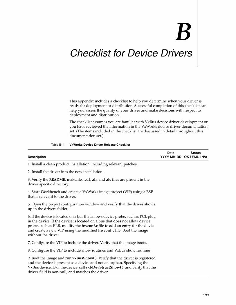
103
BChecklist for Device Drivers
This appendix includes a checklist to help you determine when your driver is ready for deployment or distribution. Successful completion of this checklist can help you assess the quality of your driver and make decisions with respect to deployment and distribution.
The checklist assumes you are familiar with VxBus device driver development or you have reviewed the information in the VxWorks device driver documentation set. (The items included in the checklist are discussed in detail throughout this documentation set.)
Table B-1 VxWorks Device Driver Release Checklist
Description Date
YYYY-MM-DDStatus
OK | FAIL | N/A
1. Install a clean product installation, including relevant patches.
2. Install the driver into the new installation.
3. Verify the README, makefile, .cdf, .dr, and .dc files are present in the driver specific directory.
4. Start Workbench and create a VxWorks image project (VIP) using a BSP that is relevant to the driver.
5. Open the project configuration window and verify that the driver shows up in the drivers folder.
6. If the device is located on a bus that allows device probe, such as PCI, plug in the device. If the device is located on a bus that does not allow device probe, such as PLB, modify the hwconf.c file to add an entry for the device and create a new VIP using the modified hwconf.c file. Boot the image without the driver.
7. Configure the VIP to include the driver. Verify that the image boots.
8. Configure the VIP to include show routines and VxBus show routines.
9. Boot the image and run vxBusShow( ). Verify that the driver is registered and the device is present as a device and not an orphan. Specifying the VxBus device ID of the device, call vxbDevStructShow( ), and verify that the driver field is non-null, and matches the driver.

VxWorksDevice Driver Developer's Guide, 6.8
104
10. Repeat steps 4 through 7 for a boot ROM image. With the device present and the driver configured into the image, verify that the boot ROM loads and boots a VxWorks image.
11. Generate a list of all files installed by the driver product.
12. Verify that all files in the release are contained in the directory:
installDir/vxworks-6.x/target/3rdparty/vendor
13. Use the nmarch command to verify that there is only one global symbol present. The symbol should be the registration routine for the driver.
14. Verify that the VxBus version in the driver's registration structure matches the current VxBus version.
15. If the VxTest test suite is available, verify that all VxTest tests applicable to the driver class of this driver are successful.
Table B-1 VxWorks Device Driver Release Checklist (cont’d)
Description Date
YYYY-MM-DDStatus
OK | FAIL | N/A

105
Index
Symbols{busDevShow}( ) 90{instParamModify}( ) 47{isrRerouteNotify}( ) 71{vxbDmaResDedicatedGet}( ) 62{vxbDmaResourceRelease}( ) 63{vxbDrvUnlink}( ) 40
see also dissociating a device from a driver
NumericspRegBase 8240driverName.cdf 94
Aaccess routine 99accessing hardware 49adding
debug code 77driver methods 77
addressconversion for bus controllers 60translation, considerations for DMA 59
address spacemapping 51
advertise 99advertising driver methods 34allocating
external DMA engines 62memory 47, 48
during system operation 48during system startup 47
ATA 14atomic operators 64atomic_t 64
BBAR 99base address register 99boot process 36
early phase 37BSP
configuration 45, 65device parameter configuration 67hwconf.c 92modifications for drivers 76
busdefinition 99discovery 99match 99
bus controlleraddress conversion 60definition 99drivers 16
bus type 99PCI 43PLB 42RapidIO 43
Ccache
considerations for DMA 61cacheLib 61calling driver methods 33CDF, see component description fileCFG_PARAMS 27changes in device parameters 46child 100classes, see driver classesclkFreq 67cluster 100command-line builds
using make 28communication
between device, driver, and OS 7

VxWorksDevice Driver Developer's Guide, 6.8
106
comparingdevice and driver names 92
component 5, 23DRV_DEMO_WRSAMPLE 95INCLUDE_ISR_DEFER 70INCLUDE_PCI_BUS_SHOW 89INCLUDE_SHOW_ROUTINES 77, 89INCLUDE_VXBUS_SHOW 77, 89parameters
ISR_DEFER_MODE 70component description file 23, 74, 94
example 24fields
CFG_PARAMS 27CHILDREN 26Component 24HDR_FILES 27INIT_AFTER 27INIT_BEFORE 27INIT_ORDER 26INIT_RTN 26MODULES 25NAME 25Parameter 27PROTOTYPE 26REQUIRES 26SYNOPSIS 25
parameter keywordsDEFAULT 28NAME 28SYNOPSIS 28TYPE 28
writing 24configuration
driver services 44in hwconf.c 45information 44resource 45
configuration stub files 28, 75, 94configuring
BSPs 45, 65device parameters in a BSP 67interrupt show routines 89parameters 45show routines into VxWorks 88VxBus show routines 90
confirming register access 92console drivers 18creating the VxBus infrastructure 74
Ddata buffers
address mapping 60data structures
VXB_DEVICE 49VXB_DEVICE_ID 78
debugging 77, 90, 91register access 92
deferral task 69deferring
driver registration 91interrupt processing in an SMP system 69
descriptor 100design goals 9developing new VxBus drivers 73development life cycle 36device
ATA 14bus controllerdefinition 100display 18DMA engines 16Ethernet 15floppy disks 14interrupt controller 17keyboard 18MAC 15matching to a driver 42, 76mouse 18multifunction 17network interface 15non-volatile RAM 15parameter configuration in BSP 67PHY 15PLB 65responding to changes in parameters 46SCSI 14serial 14serial ATA 14timer 16USB 17
device driver modellegacy 1VxBus 1
device registersaddress mapping 60
devInstanceConnect( ) 36, 39see also initialization – VxBus phases
devInstanceInit( ) 36, 38see also initialization – VxBus phases
devInstanceInit2( ) 36, 39, 41see also initialization – VxBus phases
DEVMETHOD( ) 35DEVMETHOD_CALL( ) 34DEVMETHOD_END 35devResourceGet( ) 45direct memory access, see DMAdiscovering hardware 42dissociating a device from a driver 40
see also {vxbDrvUnlink}( )distributing drivers 93DMA 58
address translation 59allocating external DMA engines 62

Index
107
cache considerations 61DMA tag 58
DMA controller drivers 16DMA_COPY_MODE_DEVBUF 63DMA_COPY_MODE_FIFO 63DMA_COPY_MODE_NO_HW 63DMA_COPY_MODE_NO_SOFT 62, 63DMA_TRANSFER_TYPE_RD 63DMA_TRANSFER_TYPE_WR 63documentation
about 2additional 4class-specific device drivers 2conventions 3intended audience 2legacy drivers 2migrating device drivers 2navigating 2VxBus device drivers 2
downstream 100driver
bus controller 16console 18definition 100DMA controller 16file location 20for Ethernet devices 15initialization 36interrupt controller 17legacy file location 20MAC 15makefile 32matching to a device 42, 76multifunction 17network interface 15non-volatile RAM 15organization 19PHY 15registration order 41remote processing element 18required files 21resource 19run-time life cycle 36run-time operation 39serial 14services available to 43source file 21, 74
example 21storage 14synchronization 55third-party 20timer 16USB 17wrsample 20, 95
driver class 14bus controller 16console 18DMA controller 16documentation for class-specific drivers 2
interrupt controller 17multifunction 17network interface 15non-volatile RAM 15other 19remote processing element 18resource 19serial 14storage 14timer 16USB 17
driver methods 6, 32{busDevShow}( ) 90{instParamModify}( ) 47{isrRerouteNotify}( ) 71{vxbDmaResDedicatedGet}( ) 62{vxbDmaResourceRelease}( ) 63{vxbDrvUnlink}( ) 40adding 77advertising 34calling 33definition 100invoking 39limitations 35parts of 33routine prototype 33syntax 32
driverName.dc 29, 75, 94driverName.dr 29, 75, 94DRV_DEMO_WRSAMPLE 95
Eenumeration 100errInt 67errIntLevel 67Ethernet 15examples
VxBus show routine output 79VxBus show routine verbose output 81
Ffiles
40driverName.cdf 94component description file 23, 74, 94configuration stub files 28, 75driver source 74driverName.dc 29, 75, 94driverName.dr 29, 75, 94in a device driver 19initialization 30location 20
for third-party drivers 94makefile 31, 32, 94
VxWorksDevice Driver Developer's Guide, 6.8
108
README 30, 94, 95required 21third-party drivers 20vendor makefile 31vxbMethodDecl.h 96vxbUsrCmdLine.c 30, 96wrsample driver 20
finding the address of hardware registers 49floppy disks 14
Gglobal symbols 23global variables
removing 78
Hhardware
access 49discovery 37, 42memory pool size 92registers
finding the address of 49reading and writing 51special requirements 52
hardWareInterFaceBusInit( ) 37, 38hardWareInterFaceInit( ) 37HCF_RES_ADDR 45HCF_RES_INT 45HCF_RES_STRING 45header files 74
hwConf.h 66vxBus.h 33
hwconf.c 45, 46, 65supplying a register base address 92
hwConf.h 66HWMEM_ALLOC_FAIL_DEBUG 48HWMEM_POOL 92hwMemAlloc( ) 48
see also memory allocationhwMemFree( ) 48
see also memory allocation
IINCLUDE_HWMEM_ALLOC 37
see also memory allocationINCLUDE_ISR_DEFER 70INCLUDE_PCI_BUS_SHOW 89INCLUDE_SHOW_ROUTINES 77, 89INCLUDE_VXBUS_SHOW 77, 89including debug code 91
initializationdriver 36driver registration 38early boot process 37file 30hardware discovery 37kernel startup 38order 37PLB 37sysHwInit( ) 37VxBus phases 36
phase 1 36, 38phase 2 36, 39phase 3 36, 39
instance 6definition 100
intConnect( ) 53intCpuLock( ) 57intCpuUnlock( ) 57INTCTLR_LIB_SHOW 89integration
with vxprj 5with Workbench 5
interruptdeferring processing in an SMP system 69handling 53index 54locking 57
in an SMP system 68minimizing work in an ISR 55routing
in an SMP system 69vector model 53
interrupt controller drivers 17interrupt index 53interrupt service routine, see ISRinterrupt show routines
configuring 89interrupt-level synchronization 56
using interrupt locking 57using spinlocks 57
intrN 66intrNLevel 66invoking driver methods 39irq 66irqLevel 66ISR
deferral 55deferral library component 70minimizing work in 55
ISR_DEFER_MODE 70ISR_DEFER_MODE_PER_CPU 70ISR_DEFER_MODE_PER_SOURCE 70isrDeferIsrReroute( ) 71isrDeferJobAdd( ) 55isrDeferLib 55, 71isrDeferQueueGet( ) 55

Index
109
Kkernel configuration tool 96kernel startup 38
Llate driver registration 41ld( ) 41legacy device driver model 1legacy drivers
documentation 2file location 20
LIB_BASE_NAME 32, 94libraries
cacheLib 61isrDeferLib 55, 71vxAtomicLib 64vxbDmaBufLib 58vxbDmaLib 62
loadingan object module 41drivers after boot time 41
loadModule( ) 41loadModuleAt( ) 41
MMAC drivers 15
see also network interface driversmacros
DEVMETHOD( ) 35DEVMETHOD_CALL( ) 34DEVMETHOD_END 35INTCTLR_LIB_SHOW 89METHOD_DECL( ) 34VXB_LEGACY_ACCESS 53
makefile 31, 32, 94vendor 31
mappingaddress space 51data buffer addresses 60device registers 60
matchingdevices and drivers 42, 76, 92
mBlk 100media independent interface, see MIImemory allocation 37, 47
during system operation 48during system startup 47mixing methods within a driver 48see also INCLUDE_HWMEM_ALLOC
memory pool 92method ID 101METHOD_DECL( ) 34
methods, see driver methodsmigrating legacy drivers 2MII 15minimizing work in an ISR 55modifying the BSP 76msgQSend( ) 56multifunction drivers 17
Nnetwork interface drivers 15non-volatile RAM 15, 49
drivers 15notifying a driver of system shutdown 40NVRAM, see non-volatile RAM
Oobject module
loading 41OBJS_COMMON 32order of initialization 37organization
driver 19
Ppackaging a driver for release 93, 97pairing a device with a driver 42, 76, 92parameter
configuration 45definition 101
parent 101PCI 16, 43
PCI triple 82show routines 82
pciDevByNameUnitFind( ) 88pciDevShow( ) 83pDrvCtrl 78performance testing 11PHY drivers 15
see also network driversPLB 16, 37, 42
BSP configuration 65definition 101
probe 101probe routine 101processor local bus, see PLB
Qqueue sharing 70

VxWorksDevice Driver Developer's Guide, 6.8
110
RRapidIO 43reading
hardware registers 51README 30, 94, 95regDelay 67regInterval 67register access
debugging 92register base address
supplying in hwconf.c 92registering
a driver 38a driver after boot time 41registration order 41registration routine 38
regWidth 67releasing
drivers 93in binary format 95in source format 95
providing driver installation instructions 95third-party drivers 97
remote processing element drivers 18removing a device from the system 40
see also vxbDevRemovalAnnounce( )removing global variables 78required files 21resource
clkFreq 67configuration 45definition 101drivers 19errInt 67errIntLevel 67intrN 66intrNLevel 66irq 66irqLevel 66names 66regDelay 67regInterval 67regWidth 67rxInt 67rxIntLevel 67txInt 67txIntLevel 67
resource typesaddress 45integer 45string 45
routinesdevInstanceConnect( ) 36, 39devInstanceInit( ) 36, 38devInstanceInit2( ) 36, 39, 41devResourceGet( ) 45driver registration 38
hardWareInterFaceBusInit( ) 37, 38hardWareInterFaceInit( ) 37hwMemAlloc( ) 48hwMemFree( ) 48intConnect( ) 53intCpuLock( ) 57intCpuUnlock( ) 57isrDeferIsrReroute( ) 71isrDeferJobAdd( ) 55isrDeferQueueGet( ) 55msgQSend( ) 56pciDevByNameUnitFind( ) 88pciDevShow( ) 83sysHwInit( ) 37, 38sysHwInit2( ) 39taskLock( ) 69vxbDevInit( ) 39vxbDevIterate( ) 40, 87vxbDevMethodGet( ) 7, 34vxbDevMethodRun( ) 34vxbDevPathShow( ) 82vxbDevRegister( ) 38vxbDevRemovalAnnounce( ) 40vxbDevStructShow( ) 81vxbDmaBufMapLoad( ) 59vxbDmaBufSync( ) 59vxbDmaBufTagCreate( ) 58vxbDmaChanAlloc( ) 62vxbDmaChanFree( ) 63vxbDriverUnregister( ) 39vxbInstParamByNameGet( ) 45vxbInstParamSet( ) 46vxbIntConnect( ) 41, 54vxbIntDisable( ) 54, 55vxbIntDisconnect( ) 54vxbIntEnable( ) 54vxbNonVolGet( ) 49vxbNonVolSet( ) 49vxbPciConfigTopoShow( ) 86vxbPciDeviceShow( ) 83vxbPciFindClassShow( ) 85vxbPciFindDeviceShow( ) 85vxbPciHeaderShow( ) 84vxbReadxx( ) 51vxbRegMap( ) 51vxBusShow( ) 76, 79, 90vxbWritexx( ) 52wrsampleRegister( ) 95
rxInt 67rxIntLevel 67
Ssample driver 95sample driver files 20SATA, see serial ATASCSI 14

Index
111
serial ATA 14serial bitbang 101serial drivers 14service driver 101services 43
atomic operators 64configuration 44DMAhardware access 49interrupt handling 53memory allocation 47synchronization 55
show routines 79, 90configuring into VxWorks 88generic 79PCI 82using from software 87verbose level 80, 90
shutdown notification 40SMP, see VxWorks SMPsource file 21
example 21structure 21
stall 101storage drivers 14symmetric multiprocessing, see VxWorks SMPsynchronization 55
interrupt-level 56task-level 56
sysHwInit( ) 37, 38sysHwInit2( ) 39system startup
memory allocation at 47
Ttask-level synchronization 56taskLock( ) 69terms
access routine 99advertise 99BAR 99bus 99bus controller 99bus discovery 99bus match 99bus type 99child 100cluster 100descriptor 100device 6, 100downstream 100driver 6, 100driver method 100enumeration 100instance 6, 100mBlk 100
method ID 101parameter 101parent 101PLB 101probe 101probe routine 101resource 101serial bitbang 101service driver 101stall 101upstream 101VxBus 5
third-party drivers 20, 94file location 20packaging for release 97releasing 97
timer drivers 16txInt 67txIntLevel 67
Uu.pDevPrivate 40unloading a driver 39
see also vxbDriverUnregister( )updating vxbMethodDecl.h 96updating vxbUsrCmdLine.c 96upstream 101USB drivers 17using show routines from software 87using spinlocks 57
Vvendor makefile 31verbose level 90
vxBusShow( ) 80vxAtomicLib 64VXB_DEVICE 49VXB_DEVICE_ID 78VXB_LEGACY_ACCESS 53VXB_REG_MEM 51vxbDevInit( ) 39vxbDevIterate( ) 40, 87vxbDevMethodGet( ) 7, 34vxbDevMethodRun( ) 34vxbDevPathShow( ) 82vxbDevRegister( ) 38vxbDevRemovalAnnounce( ) 40
see also removing a device from the systemvxbDevStructShow( ) 81vxbDmaBufLib 58vxbDmaBufMapLoad( ) 59vxbDmaBufSync( ) 59vxbDmaBufTagCreate( ) 58

VxWorksDevice Driver Developer's Guide, 6.8
112
vxbDmaChanAlloc( ) 62vxbDmaChanFree( ) 63vxbDmaLib 62vxbDriverUnregister( ) 39
see also unloading a drivervxbInstParamByNameGet( ) 45vxbInstParamSet( ) 46vxbIntConnect( ) 41, 54vxbIntDisable( ) 54, 55vxbIntDisconnect( ) 54vxbIntEnable( ) 54vxbMethodDecl.h 96vxbNonVolGet( ) 49vxbNonVolSet( ) 49vxbPciConfigTopoShow( ) 86vxbPciDeviceShow( ) 83vxbPciFindClassShow( ) 85vxbPciFindDeviceShow( ) 85vxbPciHeaderShow( ) 84vxbReadxx( ) 51vxbRegMap( ) 51VxBus
about 5creating infrastructure 74driver components 5driver model 6initialization phases 36instance 6show routines 90
example 79, 81verbose level 80
vxBus.h 33vxbUsrCmdLine.c 30, 96vxBusShow( ) 76, 79, 90vxbWritexx( ) 52vxCas 65vxprj
device driver integration with 5VxWorks
components 23VxWorks SMP 1
considerations for device drivers 68deferring interrupt processing 69interrupt routing 69lack of implicit locking in 68task-to-task contention 69
WWorkbench
device driver integration with 5writing
hardware registers 51, 52new VxBus drivers 73
wrsample 20, 95DRV_DEMO_WRSAMPLE component 95makefile 32wrsampleRegister( ) routine 95
wrsampleRegister( ) 95


![cifX Device Driver - hilscher.com€¦ · cifX Device Driver VxWorks ... 6.3 Contacts ... VxWorks Kernel Programmers Guide 6.2 Section 5.9 Virtual Memory Management [3]](https://img.dokumen.tips/doc/110x75/5aef9c357f8b9abc788c361d/cifx-device-driver-cifx-device-driver-vxworks-63-contacts-vxworks-kernel.jpg)