Embed Size (px)
Citation preview
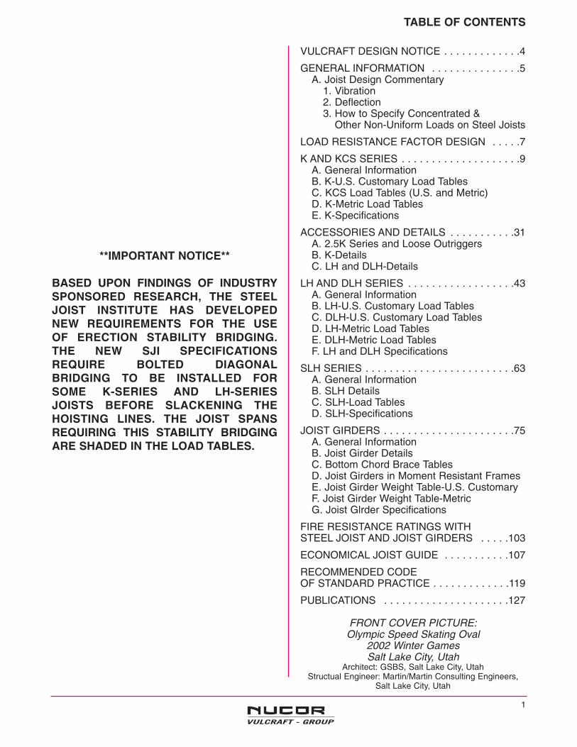
TABLE OF CONTENTS
VULCRAFT DESIGN NOTICE . . . . . . . . . . . . .4
GENERAL INFORMATION . . . . . . . . . . . . . . .5A. Joist Design Commentary
1. Vibration2. Deflection3. How to Specify Concentrated &
. . . . .Other Non-Uniform Loads on Steel Joists
LOAD RESISTANCE FACTOR DESIGN . . . . .7
K AND KCS SERIES . . . . . . . . . . . . . . . . . . . .9A. General InformationB. K-U.S. Customary Load TablesC. KCS Load Tables (U.S. and Metric)D. K-Metric Load TablesE. K-Specifications
ACCESSORIES AND DETAILS . . . . . . . . . . .31A. 2.5K Series and Loose OutriggersB. K-DetailsC. LH and DLH-Details
LH AND DLH SERIES . . . . . . . . . . . . . . . . . .43A. General InformationB. LH-U.S. Customary Load TablesC. DLH-U.S. Customary Load TablesD. LH-Metric Load TablesE. DLH-Metric Load TablesF. LH and DLH Specifications
SLH SERIES . . . . . . . . . . . . . . . . . . . . . . . . .63A. General InformationB. SLH DetailsC. SLH-Load TablesD. SLH-Specifications
JOIST GIRDERS . . . . . . . . . . . . . . . . . . . . . .75A. General InformationB. Joist Girder DetailsC. Bottom Chord Brace TablesD. Joist Girders in Moment Resistant FramesE. Joist Girder Weight Table-U.S. CustomaryF. Joist Girder Weight Table-MetricG. Joist Glrder Specifications
FIRE RESISTANCE RATINGS WITH STEEL JOIST AND JOIST GIRDERS . . . . .103
ECONOMICAL JOIST GUIDE . . . . . . . . . . .107
RECOMMENDED CODE OF STANDARD PRACTICE . . . . . . . . . . . . .119
PUBLICATIONS . . . . . . . . . . . . . . . . . . . . .127
FRONT COVER PICTURE:Olympic Speed Skating Oval
2002 Winter GamesSalt Lake City, Utah
Architect: GSBS, Salt Lake City, UtahStructual Engineer: Martin/Martin Consulting Engineers,
Salt Lake City, Utah
**IMPORTANT NOTICE**
BASED UPON FINDINGS OF INDUSTRYSPONSORED RESEARCH, THE STEELJOIST INSTITUTE HAS DEVELOPED NEW REQUIREMENTS FOR THE USE OF ERECTION STABILITY BRIDGING. THE NEW SJI SPECIFICATIONS REQUIRE BOLTED DIAGONALBRIDGING TO BE INSTALLED FOR SOME K-SERIES AND LH-SERIES JOISTS BEFORE SLACKENING THEHOISTING LINES. THE JOIST SPANSREQUIRING THIS STABILITY BRIDGINGARE SHADED IN THE LOAD TABLES.
1

ALABAMA7205 Gault Avenue N.Fort Payne, Alabama 35967P.O. Box 680169Fort Payne, Alabama 35968(256) 845-2460Fax: (256) 845-2823e-mail: [email protected]
ISO 9001 CertifiedJoists & Deck
NEBRASKA1601 West Omaha Avenue Norfolk, Nebraska 68701P.O. Box 59 Norfolk, Nebraska 68702(402) 644-8500Fax: (402) 644-8528e-mail: [email protected]
ISO 9001 CertifiedISO 14001 CertifiedJoists & Deck
INDIANA6610 County Road 60
P.O. Box 1000 St. Joe, Indiana 46785
(260) 337-1800Fax: (260) 337-1801
e-mail: [email protected]
ISO 9001 CertifiedJoists & Deck
VULCRAFT LOCATIONS
2

3
SOUTH CAROLINA1501 West Darlington Street
P.O. Box 100520Florence, South Carolina 29501
(843) 662-0381Fax: (843) 662-3132
e-mail: [email protected]
ISO 9001 CertifiedJoists & Deck
UTAH1875 West Highway 13 South
P.O. Box 637Brigham City, Utah 84302
(435) 734-9433Fax: (435) 723-5423
e-mail: [email protected]
ISO 9001 CertifiedJoists
TEXAS287 North Main ExtensionP.O. Box 186 Grapeland, Texas 75844(936) 687-4665Fax: (936) 687-4290e-mail: [email protected]
ISO 9001 CertifiedJoists & Deck
VULCRAFT OF NEW YORK, INC. LOCATION NOW OPEN (not pictured)P.O. Box 280 • Chemung, New York 14825 • (607) 529-9000 • Fax: (607) 529-9001 • e-mail: [email protected]
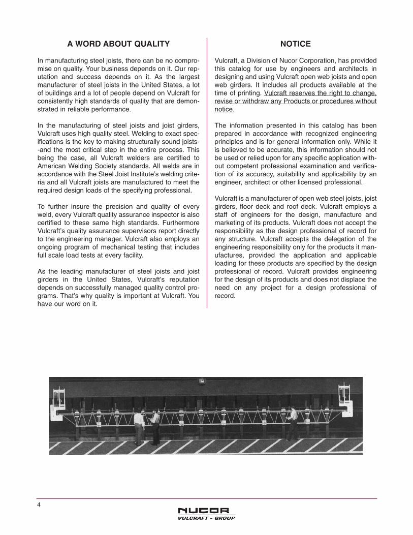
A WORD ABOUT QUALITY
In manufacturing steel joists, there can be no compro-mise on quality. Your business depends on it. Our rep-utation and success depends on it. As the largestmanufacturer of steel joists in the United States, a lotof buildings and a lot of people depend on Vulcraft forconsistently high standards of quality that are demon-strated in reliable performance.
In the manufacturing of steel joists and joist girders,Vulcraft uses high quality steel. Welding to exact spec-ifications is the key to making structurally sound joists--and the most critical step in the entire process. Thisbeing the case, all Vulcraft welders are certified toAmerican Welding Society standards. All welds are inaccordance with the Steel Joist Institute’s welding crite-ria and all Vulcraft joists are manufactured to meet therequired design loads of the specifying professional.
To further insure the precision and quality of everyweld, every Vulcraft quality assurance inspector is alsocertified to these same high standards. FurthermoreVulcraft’s quality assurance supervisors report directlyto the engineering manager. Vulcraft also employs anongoing program of mechanical testing that includesfull scale load tests at every facility.
As the leading manufacturer of steel joists and joistgirders in the United States, Vulcraft’s reputationdepends on successfully managed quality control pro-grams. That’s why quality is important at Vulcraft. Youhave our word on it.
NOTICE
Vulcraft, a Division of Nucor Corporation, has providedthis catalog for use by engineers and architects indesigning and using Vulcraft open web joists and openweb girders. It includes all products available at thetime of printing. Vulcraft reserves the right to change,revise or withdraw any Products or procedures withoutnotice.
The information presented in this catalog has beenprepared in accordance with recognized engineeringprinciples and is for general information only. While itis believed to be accurate, this information should notbe used or relied upon for any specific application with-out competent professional examination and verifica-tion of its accuracy, suitability and applicability by anengineer, architect or other licensed professional.
Vulcraft is a manufacturer of open web steel joists, joistgirders, floor deck and roof deck. Vulcraft employs astaff of engineers for the design, manufacture andmarketing of its products. Vulcraft does not accept theresponsibility as the design professional of record forany structure. Vulcraft accepts the delegation of theengineering responsibility only for the products it man-ufactures, provided the application and applicableloading for these products are specified by the designprofessional of record. Vulcraft provides engineeringfor the design of its products and does not displace theneed on any project for a design professional ofrecord.
4

JOIST DESIGN COMMENTARY
FLOOR VIBRATION Floor vibration occurs, in varying degrees, in all typesof building construction. Unlike steady state vibration,which can be isolated, vibration due to human impactis inconsistent in amplitude and frequency and there-fore, more difficult to control.
The Steel Joist Institute and Nucor Research andDevelopment have studied this phenomenon for manyyears. Laboratory research has been performed andnumerous buildings, exhibiting both good and badcharacteristics, were tested using seismic recordinginstruments. SJI Technical Digest #5 (1988) and AISC/ CISC Steel Design Guide 11 (1997) discuss in detailmethods for calculating vibrational properties for joistsupported floors.
The vast majority of structures, including those utilizingsteel joists, do not exhibit floor vibrations severeenough to be considered objectionable. However,human sensitivity to vibratory motion varies, and a sat-isfactory framing solution is dependent upon the soundjudgment of qualified structural engineers.
DEFINITIONS Floor vibration is measured in terms of accelerationamplitude, displacement amplitude, and frequency.These factors are not objectionable to all people at thesame level since human sensitivity varies.
Acceleration amplitude is the maximum accelerationcaused by a force excitation.
Displacement amplitude is defined as the magnitudeor total distance traveled by each oscillation of thevibration.
Frequency is the term used to describe the speed ofthe oscillations and is expressed in cycles per secondor Hz.
Acceleration is the only vibration factor which humanscan sense.
Damping is defined as the rate of decay of amplitude.
The following observations, which were determinedfrom research data to be beneficial in reducing vibra-tion levels, are recommended only as a guide.
OPEN FLOOR AREAS are most subject to vibrationalproblems. Modern “electronic offices” tend to havelower live loading and damping, and hence can poten-tially be more prone to floor vibration. Partitions, filecabinets, book stacks, heavy furnishings and evencrowds of people provide additional damping and min-imize complaints.
THICKER FLOOR SLABS are an economical solutionto floor vibration. Additional thickness increases floorsystem stiffness transverse to the joists, thus reducingthe vibration. The additional mass of the system willreduce the objectionable vibration.
WIDER JOIST SPACINGS improve vibrational charac-teristics only when combined with thicker floor slabs.The resulting increase in joist size does not contribute
significantly to the composite section. When used witha thicker slab, greater resistance to vibration can beachieved, and, since fewer pieces must be installed,may be more economical.
PARTITIONS introduce damping and usually eliminatevibration problems. They will be effective either aboveor below a floor as long as they are connected to thefloor. Partitions below a joist supported floor ideallyshould be in direct contact with the steel deck. If parti-tions below a joist supported floor are in direct contactwith the joists, the joist bottom chord and webs mustbe designed for such intermediate support conditions.
SUPPORT FRAMING BEAMS sometimes contributeto floor vibration. The natural frequency and amplitudefor both the joist and supporting joist girders or hot-rolled girders need to be calculated. In this manner theresulting system acceleration or displacement and fre-quency can be determined from which the perfor-mance of the system can be predicted.
INCREASING JOIST STIFFNESS above that which isrequired by live load deflection may be beneficial. Ahigher frequency floor is generally a better floor formost applications. Increasing the stiffness of the steeljoists themselves results in increasing the frequencyand slightly decreasing the acceleration or displace-ment of the floor vibration.
BRIDGING of all standard types provide equal floorvibrational characteristics.
LONGER FLOOR SPANS have many advantagesover shorter spans, both in construction cost and invibrational response. Floor spans over 40 feet with a 2-1/2" thick concrete slab give a vibrational frequencyin the 3 - 5 cycles per second range. There are manylong spanning joist supported floors that perform satis-factorily.
PC-based software to evaluate vibration of joist sup-ported floor systems is available from the
STEEL JOIST INSTITUTE 3127 10th Ave. North Ext. Myrtle Beach, SC 29577phone (843) 626-1995
and
STRUCTURAL ENGINEERS, INC. 537 Wisteria DriveRadford, VA 24141phone (540) 731-3330
CONCLUSIONS: Partitions eliminate vibration problems. When a floorarea cannot have partitions, increasing the slab thick-ness and/or increasing the joist stiffness are the mosteconomical and effective ways to reduce objectionablevibrations.
For more information refer to Steel Joist Institute Technical Digest No. 5"Vibration of Steel Joist-Concrete Slab Floors", and the AISC / CISC SteelDesign Guide 11 “Floor Vibrations Due to Human Activity”.
5
DEFLECTION OF STEEL JOISTS The deflection of a steel joist when loaded with a uniformly-distributed load depends upon the followingfactors: w= uniformly-distributed load carried by the joist (plf) L= (span of the joist -.33)(ft.) E= modulus of elasticity of steel (29,000,000 psi) I= 26.767 WLL (L3) (10-6) where WLL=red figure in load
table
Tests have shown that deflection at mid-span may be determined with reasonable accuracy using the following formula: Deflection (inches)=1.15x5wL4 (123) =
384El
25.88wL4El
Example: Determine the approximate total load deflec-tion of a 24K8 for the following conditions: W=280 plf L=40.0 ft WLL= 161 plf E=29,000,000 psiI=26.767(161) (40-.33)3 (10-6)= 269.0 in.4
Deflection=25.88(280)(40-.33)4 =2.30 in.29,000,000(269)
HOW TO SPECIFY JOISTS FOR CONCENTRATEDLOADS ON STEEL JOISTS
When specifying joists for concentrated loads, thespecifying professional should first attempt to specify alarger standard joist or a KCS series joist. The joistspecified must have adequate moment and shearresistance throughout the length of the joist.
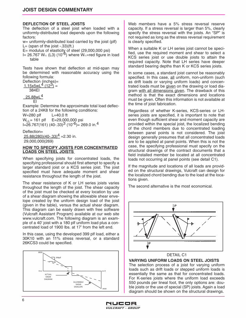
The shear resistance of K or LH series joists variesthroughout the length of the joist. The shear capacityof the joist must be checked at every location by useof a shear diagram showing the allowable shear enve-lope created by the uniform design load of the joist(given in the table), versus the actual shear diagram.This diagram can be easily drawn with free software(Vulcraft Assistant Program) available at our web sitewww.vulcraft.com. The following diagram is an exam-ple of a 40’ joist with a 180 plf uniform load plus a con-centrated load of 1900 lbs. at 17’ from the left end.
In this case, using the developed 399 plf load, either a30K10 with an 11% stress reversal, or a standard26KCS3 could be specified.
Web members have a 5% stress reversal reservecapacity. If a stress reversal is larger than 5%, clearlyspecify the stress reversal with the joists. An “SP” isnot required as long as the stress reversal requirementis clearly specified.
When a suitable K or LH series joist cannot be speci-fied, use the required moment and shear to select aKCS series joist or use double joists to attain therequired capacity. Note that LH series have deeperstandard bearing depths than K or KCS series joists.
In some cases, a standard joist cannot be reasonablyspecified. In this case, all uniform, non-uniform (suchas drift loads or varying uniform loads) and concen-trated loads must be given on the drawing or load dia-gram with all dimensions given. The drawback of thismethod is that the exact dimensions and locationsmust be given. Often this information is not available atthe time of joist fabrication.
Regardless of whether K-series, KCS-series or LH-series joists are specified, it is important to note thateven though sufficient shear and moment capacity areprovided within the special joist, the localized bendingof the chord members due to concentrated loadingbetween panel points is not considered. The joistdesign generally presumes that all concentrated loadsare to be applied at panel points. When this is not thecase, the specifying professional must specify on thestructural drawings of the contract documents that afield installed member be located at all concentratedloads not occurring at panel points (see detail C1).
If the magnitude and locations of all loads are provid-ed on the structural drawings, Vulcraft can design forthe localized chord bending due to the load at the loca-tions given.
The second alternative is the most economical.
6
JOIST DESIGN COMMENTARY
VARYING UNIFORM LOADS ON STEEL JOISTS The selection process of a joist for varying uniformloads such as drift loads or stepped uniform loads isessentially the same as that for concentrated loads.For K-series joists where the uniform load exceeds550 pounds per lineal foot, the only options are: dou-ble joists or the use of special (SP) joists. Again a loaddiagram should be shown on the structural drawings.
DETAIL C1

The following method may be used to convert the Steel Joist
Institute’s Specifications for use in Load and Resistance
Factor Design ( LRFD )
Method:
WU = 1.65 Wsji, or Wsji = WU /1.65
Where, WU = ultimate joist capacityWsji = SJI Load Table Load (black figure)
Load tables for LRFD can be obtained directly from the current SJI Load Tables by using the formula:
Wn = Wsji x 0.9 x 1.65
Where, Wn = nominal joist capacity0.9 = Resistance Factor ( 0 )
“K” Series Example:
Given: WU = 1.2 WD + 1.6 WLProblem: Select a joist from the current load tables for Wsji ≥ Wu/1.65( 0 )
L = 40 ft.WD = 50 plfWL = 150 plfUse Roof Live load deflection ≤ L/240
WU = 1.2 x 50 + 1.6 x 150 = 300 plf
Wsji ≥ 300/(1.65 x 0.9) = 202 plf
Select 22K6: Wsji @ 40 ft. span = 207 plf > 202 plf. O’K’
Deflection Live Load ≤ L/240
WsjiLL = 1.5 x 111 = 166 plf > 150 plf O’K’
The above procedure outlines the specification of a “K” Series Joist to support a uniform gravity load utilizingLRFD. When loads other than uniform gravity loads (such as wind uplift loads, concentrated loads, endmoments or non-uniform loads) are a design consideration, the Specifying Professional shall clearly indicate onthe structural drawings whether these loads are factored or unfactored. To remain consistent with establishedLRFD design procedures it is recommended that factored loads be specified.
The above procedure is also applicable to the LH/DLH Series Joists and Joist Girders.
LOAD AND RESISTANCE FACTOR DESIGN
7

8
NOTES
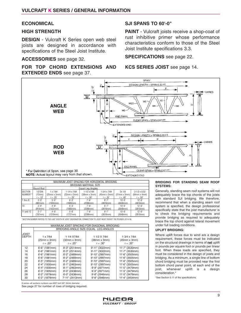
MAXIMUM JOIST SPACING FOR DIAGONAL BRIDGINGBRIDGING ANGLE SIZE-EQUAL LEG ANGLES
JOISTDEPTH 1 x 7/64 1 1/4 X7/64 1 1/2 X 7/64 1 3/4 x 7/64
(25mm x 3mm) (32mm x 3mm) (38mm x 3mm) (45mm x 3mm)r = .20" r = .25" r = .30" r = .35"
12 6'-6" (1981mm) 8'-3" (2514mm) 9'-11" (3022mm) 11'-7" (3530mm)14 6'-6" (1981mm) 8'-3" (2514mm) 9'-11" (3022mm) 11'-7" (3530mm)16 6'-6" (1981mm) 8'-2" (2489mm) 9'-10" (2997mm) 11'-6" (3505mm)18 6'-6" (1981mm) 8'-2" (2489mm) 9'-10" (2997mm) 11'-6" (3505mm)20 6'-5" (1955mm) 8'-2" (2489mm) 9'-10" (2997mm) 11'-6" (3505mm)22 6'-4" (1930mm) 8'-1" (2463mm) 9'-10" (2997mm) 11'-6" (3505mm)24 6'-4" (1930mm) 8'-1" (2463mm) 9'-9" (2971mm) 11'-5" (3479mm)26 6'-3" (1905mm) 8'-0" (2438mm) 9'-9" (2971mm) 11'-5" (3479mm)28 6'-2" (1879mm) 8'-0" (2438mm) 9'-8" (2946mm) 11'-5" (3479mm)30 6'-2" (1879mm) 7'-11" (2413mm) 9'-8" (2946mm) 11'-4" (3454mm)
VULCRAFT K SERIES / GENERAL INFORMATION
ECONOMICAL
HIGH STRENGTH
DESIGN - Vulcraft K Series open web steeljoists are designed in accordance withspecifications of the Steel Joist Institute.
ACCESSORIES see page 32.
FOR TOP CHORD EXTENSIONS ANDEXTENDED ENDS see page 37.
SJI SPANS TO 60'-0"
PAINT - Vulcraft joists receive a shop-coat ofrust inhibitive primer whose performancecharacteristics conform to those of the SteelJoist Institute specifications 3.3.
SPECIFICATIONS see page 22.
KCS SERIES JOIST see page 14.
9
BRIDGING FOR STANDING SEAM ROOFSYSTEMS:
Generally, standing seam roof systems will notadequately brace the top chords of the joistswith standard SJI bridging. We therefore,recommend that when a standing seam roofsystem is specified, the design professionalspecifically state that the joist manufacturer isto check the bridging requirements andprovide bridging as required to adequatelybrace the top chord against lateral movementunder full loading conditions.
UPLIFT BRIDGING:
Where uplift forces due to wind are a designrequirement, these forces must be indicatedon the structural drawings in terms of net upliftin pounds per square foot or pounds per linearfoot. When these loads are specified, theymust be considered in the design of joists andbridging. As a minimum, a single line of bottomchord bridging must be provided near the firstbottom chord panel point, at each end of thejoist, whenever uplift is a designconsideration.**See Section 5.11 of the specifications.
MAXIMUM JOIST SPACING FOR HORIZONTAL BRIDGINGBRIDGING MATERIAL SIZE
Round Rod Equal Leg AnglesSECTION 1/2"DIA 1 x 7/64 1-1/4 x 7/64 1-1/2 x7/64 1-3/4 x 7/64 2x 1/8 2-1/2 x 5/32NUMBER** (13mm) (25mm x 3mm) (32mm x 3mm) (38mm x 3mm) (45mm x 3mm) (51mm x 3mm) (64mm x 4mm)
r = .13" r = .25" r = .25" r = .30" r = .35" r = .40" r = .50"1 thru 9 3'-3" 5'-0" 6'-3" 7'-6" 8'-7" 10'-0" 12'-6"
(991mm) (1524mm) (1905mm) (2286mm) (2616mm) (3048mm) (3810mm)10 3'-0" 4'-8" 6'-3" 7'-6" 8'-7" 10'-0" 12'-6"
(914mm) (1422mm) (1905mm) (2286mm) (2616mm) (3048mm) (3810mm)11 and 12 2'-7" 4'-0" 5'-8" 7'-6" 8'-7" 10'-0" 12'-6"
(787mm) (1219mm) (1727mm) (2286mm) (2616mm) (3048mm) (3810mm)
*SECTION NUMBER REFERS TO THE LAST DIGITS OF JOIST DESIGNATION, CONNECTION TO JOIST MUST RESIST 700 POUNDS (3114 N)
K-series--all sections numbers use A307 bolt 3/8" (9mm) diameter.
See page 27 for number of rows of bridging required.
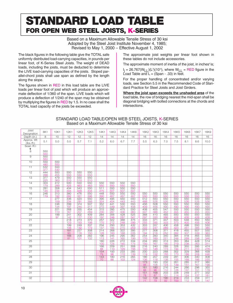
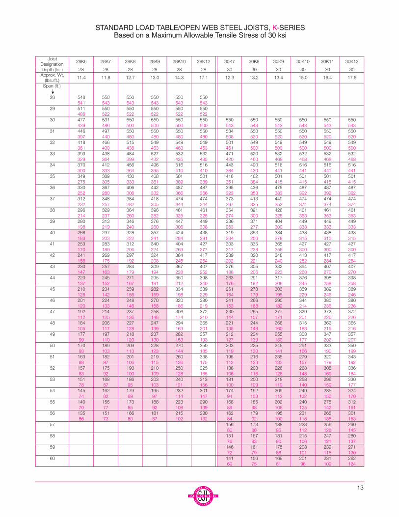
The black figures in the following table give the TOTAL safeuniformly distributed load-carrying capacities, in pounds perlinear foot, of K-Series Steel Joists. The weight of DEADloads, including the joists, must be deducted to determinethe LIVE load-carrying capacities of the joists. Sloped par-allel-chord joists shall use span as defined by the lengthalong the slope.
The figures shown in RED in this load table are the LIVEloads per linear foot of joist which will produce an approxi-mate deflection of 1/360 of the span. LIVE loads which willproduce a deflection of 1/240 of the span may be obtainedby multiplying the figures in RED by 1.5. In no case shall theTOTAL load capacity of the joists be exceeded.
The approximate joist weights per linear foot shown inthese tables do not include accessories.
The approximate moment of inertia of the joist, in inches4 is;
Ij = 26.767(WLL)(L3)(10-6), where WLL = RED figure in theLoad Table and L = (Span - .33) in feet.
For the proper handling of concentrated and/or varyingloads, see Section 5.5 in the Recommended Code of Stan-dard Practice for Steel Joists and Joist Girders.
Where the joist span exceeds the unshaded area of theload table, the row of bridging nearest the mid-span shall bediagonal bridging with bolted connections at the chords andintersections.
STANDARD LOAD TABLEFOR OPEN WEB STEEL JOISTS, K-SERIES
Based on a Maximum Allowable Tensile Stress of 30 ksiAdopted by the Steel Joist Institute November 4, 1985;
Revised to May 1, 2000 – Effective August 1, 2002
STANDARD LOAD TABLE/OPEN WEB STEEL JOISTS, K-SERIESBased on a Maximum Allowable Tensile Stress of 30 ksi
10
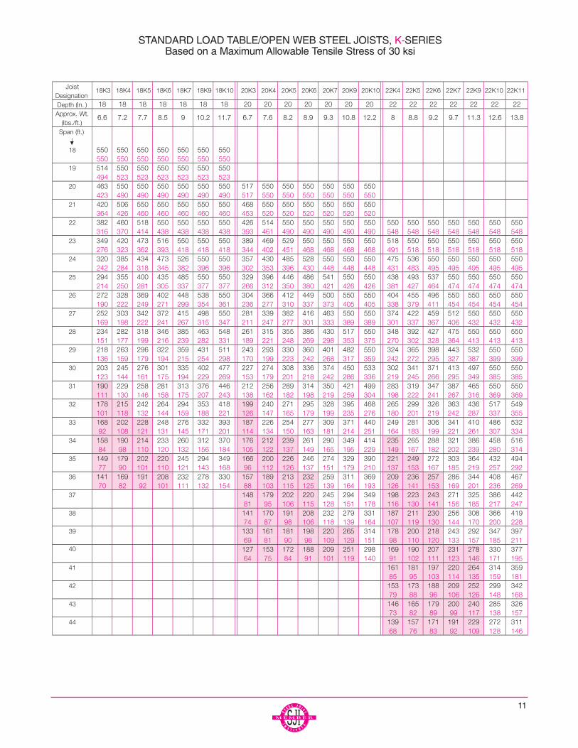
STANDARD LOAD TABLE/OPEN WEB STEEL JOISTS, K-SERIESBased on a Maximum Allowable Tensile Stress of 30 ksi
11
12
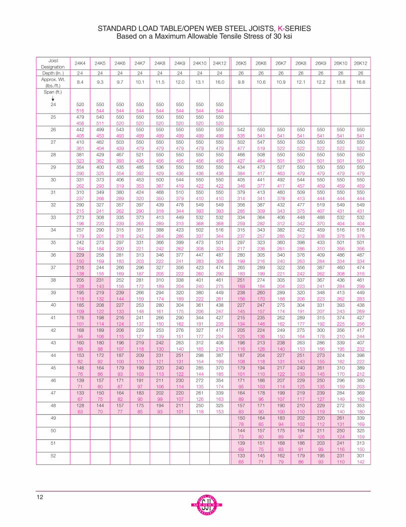
STANDARD LOAD TABLE/OPEN WEB STEEL JOISTS, K-SERIESBased on a Maximum Allowable Tensile Stress of 30 ksi
13
STANDARD LOAD TABLE/OPEN WEB STEEL JOISTS, K-SERIESBased on a Maximum Allowable Tensile Stress of 30 ksi
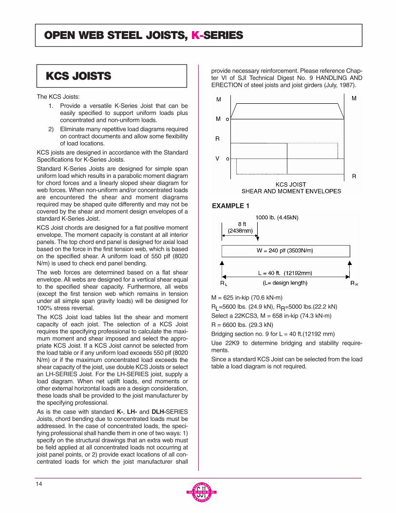
The KCS Joists:
1. Provide a versatile K-Series Joist that can beeasily specified to support uniform loads plusconcentrated and non-uniform loads.
2) Eliminate many repetitive load diagrams requiredon contract documents and allow some flexibilityof load locations.
KCS joists are designed in accordance with the StandardSpecifications for K-Series Joists.
Standard K-Series Joists are designed for simple spanuniform load which results in a parabolic moment diagramfor chord forces and a linearly sloped shear diagram forweb forces. When non-uniform and/or concentrated loadsare encountered the shear and moment diagramsrequired may be shaped quite differently and may not becovered by the shear and moment design envelopes of astandard K-Series Joist.
KCS Joist chords are designed for a flat positive momentenvelope. The moment capacity is constant at all interiorpanels. The top chord end panel is designed for axial loadbased on the force in the first tension web, which is basedon the specified shear. A uniform load of 550 plf (8020N/m) is used to check end panel bending.
The web forces are determined based on a flat shearenvelope. All webs are designed for a vertical shear equalto the specified shear capacity. Furthermore, all webs(except the first tension web which remains in tensionunder all simple span gravity loads) will be designed for100% stress reversal.
The KCS Joist load tables list the shear and momentcapacity of each joist. The selection of a KCS Joistrequires the specifying professional to calculate the maxi-mum moment and shear imposed and select the appro-priate KCS Joist. If a KCS Joist cannot be selected fromthe load table or if any uniform load exceeds 550 plf (8020N/m) or if the maximum concentrated load exceeds theshear capacity of the joist, use double KCS Joists or selectan LH-SERIES Joist. For the LH-SERIES joist, supply aload diagram. When net uplift loads, end moments orother external horizontal loads are a design consideration,these loads shall be provided to the joist manufacturer bythe specifying professional.
As is the case with standard K-, LH- and DLH-SERIESJoists, chord bending due to concentrated loads must beaddressed. In the case of concentrated loads, the speci-fying professional shall handle them in one of two ways: 1)specify on the structural drawings that an extra web mustbe field applied at all concentrated loads not occurring atjoist panel points, or 2) provide exact locations of all con-centrated loads for which the joist manufacturer shall
provide necessary reinforcement. Please reference Chap-ter Vl of SJI Technical Digest No. 9 HANDLING ANDERECTION of steel joists and joist girders (July, 1987).
EXAMPLE 1
M = 625 in-kip (70.6 kN-m)
RL=5600 lbs. (24.9 kN), RR=5000 lbs.(22.2 kN)
Select a 22KCS3, M = 658 in-kip (74.3 kN-m)
R = 6600 lbs. (29.3 kN)
Bridging section no. 9 for L = 40 ft.(12192 mm)
Use 22K9 to determine bridging and stability require-ments.
Since a standard KCS Joist can be selected from the loadtable a load diagram is not required.
14
OPEN WEB STEEL JOISTS, K-SERIES
KCS JOISTS
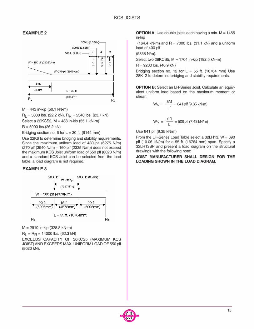
EXAMPLE 2
M = 443 in-kip (50.1 kN-m)
RL = 5000 lbs. (22.2 kN), RR = 5340 lbs. (23.7 kN)
Select a 22KCS2, M = 488 in-kip (55.1 kN-m)
R = 5900 lbs.(26.2 kN)
Bridging section no. 6 for L = 30 ft. (9144 mm)
Use 22K6 to determine bridging and stability requirements.Since the maximum uniform load of 430 plf (6275 N/m)(270 plf (3940 N/m) + 160 plf (2335 N/m)) does not exceedthe maximum KCS Joist uniform load of 550 plf (8020 N/m)and a standard KCS Joist can be selected from the loadtable, a load diagram is not required.
EXAMPLE 3
M = 2910 in-kip (328.8 kN-m)
RL = RR = 14000 lbs. (62.3 kN)
EXCEEDS CAPACITY OF 30KCS5 (MAXIMUM KCSJOIST) AND EXCEEDS MAX. UNIFORM LOAD OF 550 plf(8020 kN).
OPTION A: Use double joists each having a min. M = 1455in-kip
(164.4 kN-m) and R = 7000 lbs. (31.1 kN) and a uniformload of 400 plf
(5838 N/m).
Select two 28KCS5, M = 1704 in-kip (192.5 kN-m)
R = 9200 lbs. (40.9 kN)
Bridging section no. 12 for L = 55 ft. (16764 mm) Use28K12 to determine bridging and stability requirements.
OPTION B: Select an LH-Series Joist. Calculate an equiv-alent uniform load based on the maximum moment orshear:
Use 641 plf (9.35 kN/m)
From the LH-Series Load Table select a 32LH13. W = 690plf (10.06 kN/m) for a 55 ft. (16764 mm) span. Specify a32LH13SP and present a load diagram on the structuraldrawings with the following note:
JOIST MANUFACTURER SHALL DESIGN FOR THELOADING SHOWN IN THE LOAD DIAGRAM.
15
KCS JOISTS

16
KCS JOISTS LOAD TABLE(U.S. CUSTOMARY)
* MAXIMUM UNIFORMLY DISTRIBUTED LOAD CAPACITY IS 550 PLF AND SINGLE CONCENTRATEDLOAD CANNOT EXCEED SHEAR CAPACITY.
** DOES NOT INCLUDE ACCESSORIES
17
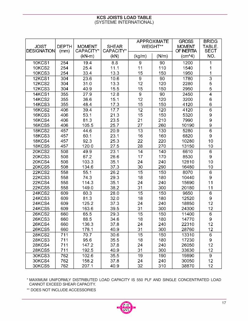
KCS JOISTS LOAD TABLE(SYSTEME INTERNATIONAL)
* MAXIMUM UNIFORMLY DISTRIBUTED LOAD CAPACITY IS 550 PLF AND SINGLE CONCENTRATED LOADCANNOT EXCEED SHEAR CAPACITY.
** DOES NOT INCLUDE ACCESSORIES

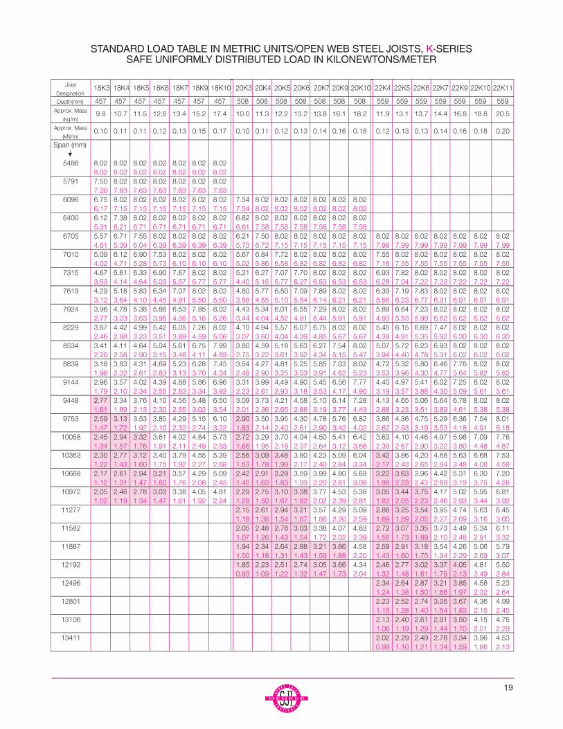
The black figures in the following table give the TOTALsafe uniformly distributed load-carrying capacities, in kilo-Newtons per meter (kN/m) of K-Series Steel Joists. Theweight (kN/m) of the DEAD loads, including the joists,must be deducted to determine the LIVE load-carryingcapacities of the joists. Sloped parallel-chord joists shalluse span as defined by the length along the slope.
The figures shown RED in this load table are the LIVEloads per linear meter of joist which will produce anapproximate deflection of L/360 of the span. LIVE loadswhich produce a deflection of L/240 of the span may beobtained by multiplying the figures in RED by 1.5. In nocase shall the TOTAL load capacity of the joists beexceeded.
The approximate joist weights, in kiloNewtons per meter(kN/m), shown in these tables do not include accessories.
The approximate moment of inertia of the joist, in mm4 is:
Ij = 2.6953(WLL)(L3)(10-5), where WLL = RED figure inthe Load Table:
L = (span-102) in millimeters.
For the proper handling of concentrated and/or varyingloads, see Section 5.5 in the Recommended Code ofStandard Practice.
Where the joist span exceeds the unshaded area of theload table, the row of bridging nearest the mid-span shallbe diagonal bridging with bolted connections at the chordsand intersections.
METRIC LOAD TABLEOPEN WEB STEEL JOISTS, K-SERIES
Based on a Maximum Allowable Tensile Stress of 207 MPaAdopted by the Steel Joist Institute May 2, 1994
Revised to May 1, 2000 – Effective August 1, 2002
18
19
STANDARD LOAD TABLE IN METRIC UNITS/OPEN WEB STEEL JOISTS, K-SERIESSAFE UNIFORMLY DISTRIBUTED LOAD IN KILONEWTONS/METER

STANDARD LOAD TABLE IN METRIC UNITS/OPEN WEB STEEL JOISTS, K-SERIESSAFE UNIFORMLY DISTRIBUTED LOAD IN KILONEWTONS/METER
20

STANDARD LOAD TABLE IN METRIC UNITS/OPEN WEB STEEL JOISTS, K-SERIESSAFE UNIFORMLY DISTRIBUTED LOAD IN KILONEWTONS/METER
21
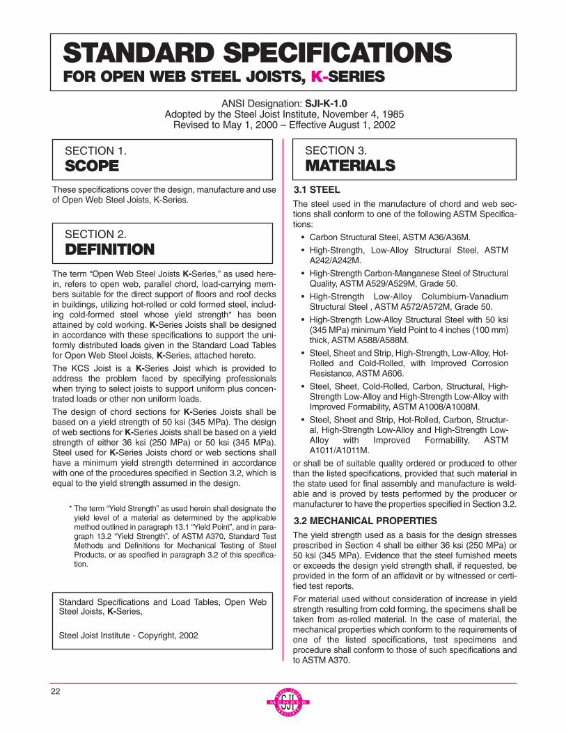
These specifications cover the design, manufacture and useof Open Web Steel Joists, K-Series.
The term “Open Web Steel Joists K-Series,” as used here-in, refers to open web, parallel chord, load-carrying mem-bers suitable for the direct support of floors and roof decksin buildings, utilizing hot-rolled or cold formed steel, includ-ing cold-formed steel whose yield strength* has beenattained by cold working. K-Series Joists shall be designedin accordance with these specifications to support the uni-formly distributed loads given in the Standard Load Tablesfor Open Web Steel Joists, K-Series, attached hereto.
The KCS Joist is a K-Series Joist which is provided toaddress the problem faced by specifying professionalswhen trying to select joists to support uniform plus concen-trated loads or other non uniform loads.
The design of chord sections for K-Series Joists shall bebased on a yield strength of 50 ksi (345 MPa). The designof web sections for K-Series Joists shall be based on a yieldstrength of either 36 ksi (250 MPa) or 50 ksi (345 MPa).Steel used for K-Series Joists chord or web sections shallhave a minimum yield strength determined in accordancewith one of the procedures specified in Section 3.2, which isequal to the yield strength assumed in the design.
* The term “Yield Strength” as used herein shall designate theyield level of a material as determined by the applicablemethod outlined in paragraph 13.1 “Yield Point”, and in para-graph 13.2 “Yield Strength”, of ASTM A370, Standard TestMethods and Definitions for Mechanical Testing of SteelProducts, or as specified in paragraph 3.2 of this specifica-tion.
3.1 STEELThe steel used in the manufacture of chord and web sec-tions shall conform to one of the following ASTM Specifica-tions:
• Carbon Structural Steel, ASTM A36/A36M.
• High-Strength, Low-Alloy Structural Steel, ASTMA242/A242M.
• High-Strength Carbon-Manganese Steel of StructuralQuality, ASTM A529/A529M, Grade 50.
• High-Strength Low-Alloy Columbium-VanadiumStructural Steel , ASTM A572/A572M, Grade 50.
• High-Strength Low-Alloy Structural Steel with 50 ksi(345 MPa) minimum Yield Point to 4 inches (100 mm)thick, ASTM A588/A588M.
• Steel, Sheet and Strip, High-Strength, Low-Alloy, Hot-Rolled and Cold-Rolled, with Improved CorrosionResistance, ASTM A606.
• Steel, Sheet, Cold-Rolled, Carbon, Structural, High-Strength Low-Alloy and High-Strength Low-Alloy withImproved Formability, ASTM A1008/A1008M.
• Steel, Sheet and Strip, Hot-Rolled, Carbon, Structur-al, High-Strength Low-Alloy and High-Strength Low-Alloy with Improved Formability, ASTMA1011/A1011M.
or shall be of suitable quality ordered or produced to otherthan the listed specifications, provided that such material inthe state used for final assembly and manufacture is weld-able and is proved by tests performed by the producer ormanufacturer to have the properties specified in Section 3.2.
3.2 MECHANICAL PROPERTIESThe yield strength used as a basis for the design stressesprescribed in Section 4 shall be either 36 ksi (250 MPa) or50 ksi (345 MPa). Evidence that the steel furnished meetsor exceeds the design yield strength shall, if requested, beprovided in the form of an affidavit or by witnessed or certi-fied test reports.
For material used without consideration of increase in yieldstrength resulting from cold forming, the specimens shall betaken from as-rolled material. In the case of material, themechanical properties which conform to the requirements ofone of the listed specifications, test specimens andprocedure shall conform to those of such specifications andto ASTM A370.
22
SECTION 1.
SCOPE
SECTION 2.
DEFINITION
SECTION 3.
MATERIALS
Standard Specifications and Load Tables, Open WebSteel Joists, K-Series,
Steel Joist Institute - Copyright, 2002
STANDARD SPECIFICATIONSFOR OPEN WEB STEEL JOISTS, K-SERIES
ANSI Designation: SJI-K-1.0Adopted by the Steel Joist Institute, November 4, 1985
Revised to May 1, 2000 – Effective August 1, 2002
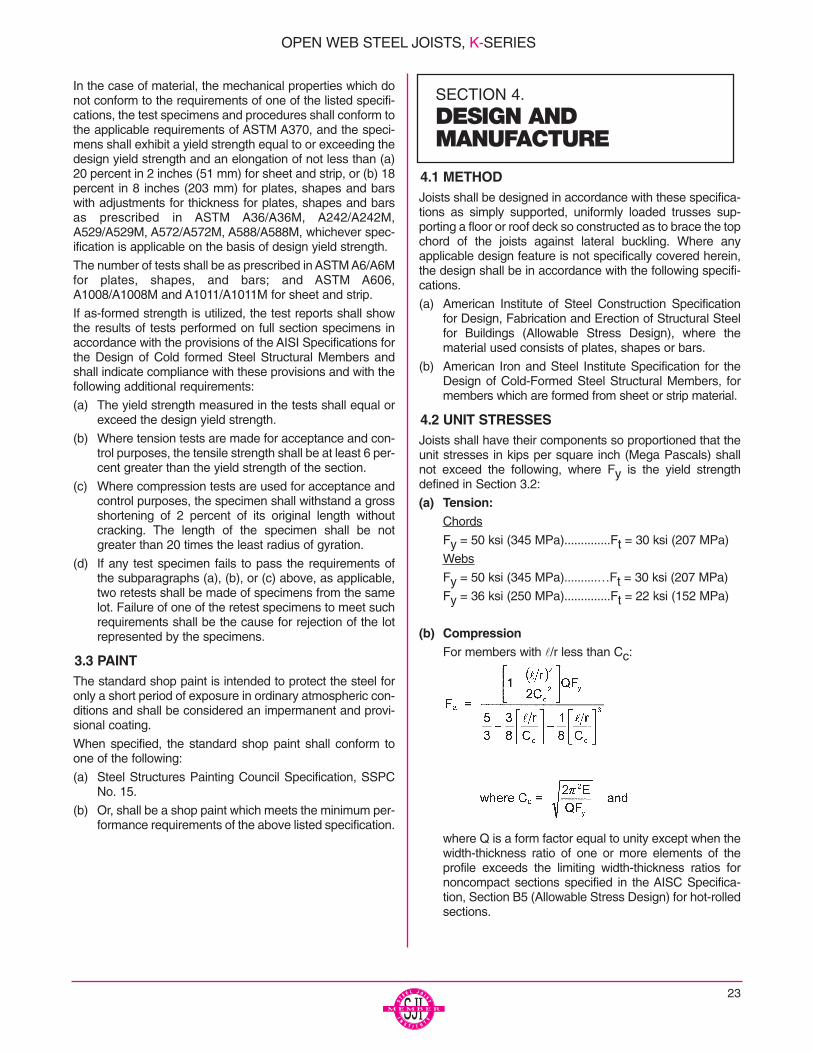
In the case of material, the mechanical properties which donot conform to the requirements of one of the listed specifi-cations, the test specimens and procedures shall conform tothe applicable requirements of ASTM A370, and the speci-mens shall exhibit a yield strength equal to or exceeding thedesign yield strength and an elongation of not less than (a)20 percent in 2 inches (51 mm) for sheet and strip, or (b) 18percent in 8 inches (203 mm) for plates, shapes and barswith adjustments for thickness for plates, shapes and barsas prescribed in ASTM A36/A36M, A242/A242M,A529/A529M, A572/A572M, A588/A588M, whichever spec-ification is applicable on the basis of design yield strength.
The number of tests shall be as prescribed in ASTM A6/A6Mfor plates, shapes, and bars; and ASTM A606,A1008/A1008M and A1011/A1011M for sheet and strip.
If as-formed strength is utilized, the test reports shall showthe results of tests performed on full section specimens inaccordance with the provisions of the AISI Specifications forthe Design of Cold formed Steel Structural Members andshall indicate compliance with these provisions and with thefollowing additional requirements:
(a) The yield strength measured in the tests shall equal orexceed the design yield strength.
(b) Where tension tests are made for acceptance and con-trol purposes, the tensile strength shall be at least 6 per-cent greater than the yield strength of the section.
(c) Where compression tests are used for acceptance andcontrol purposes, the specimen shall withstand a grossshortening of 2 percent of its original length withoutcracking. The length of the specimen shall be notgreater than 20 times the least radius of gyration.
(d) If any test specimen fails to pass the requirements ofthe subparagraphs (a), (b), or (c) above, as applicable,two retests shall be made of specimens from the samelot. Failure of one of the retest specimens to meet suchrequirements shall be the cause for rejection of the lotrepresented by the specimens.
3.3 PAINTThe standard shop paint is intended to protect the steel foronly a short period of exposure in ordinary atmospheric con-ditions and shall be considered an impermanent and provi-sional coating.
When specified, the standard shop paint shall conform toone of the following:
(a) Steel Structures Painting Council Specification, SSPCNo. 15.
(b) Or, shall be a shop paint which meets the minimum per-formance requirements of the above listed specification.
4.1 METHODJoists shall be designed in accordance with these specifica-tions as simply supported, uniformly loaded trusses sup-porting a floor or roof deck so constructed as to brace the topchord of the joists against lateral buckling. Where anyapplicable design feature is not specifically covered herein,the design shall be in accordance with the following specifi-cations.
(a) American Institute of Steel Construction Specificationfor Design, Fabrication and Erection of Structural Steelfor Buildings (Allowable Stress Design), where thematerial used consists of plates, shapes or bars.
(b) American Iron and Steel Institute Specification for theDesign of Cold-Formed Steel Structural Members, formembers which are formed from sheet or strip material.
4.2 UNIT STRESSESJoists shall have their components so proportioned that theunit stresses in kips per square inch (Mega Pascals) shallnot exceed the following, where Fy is the yield strengthdefined in Section 3.2:
(a) Tension:Chords
Fy = 50 ksi (345 MPa)..............Ft = 30 ksi (207 MPa)
Webs
Fy = 50 ksi (345 MPa)..........…Ft = 30 ksi (207 MPa)
Fy = 36 ksi (250 MPa)..............Ft = 22 ksi (152 MPa)
(b) CompressionFor members with l/r less than Cc:
where Q is a form factor equal to unity except when thewidth-thickness ratio of one or more elements of theprofile exceeds the limiting width-thickness ratios fornoncompact sections specified in the AISC Specifica-tion, Section B5 (Allowable Stress Design) for hot-rolledsections.
23
SECTION 4.
DESIGN AND MANUFACTURE
OPEN WEB STEEL JOISTS, K-SERIES
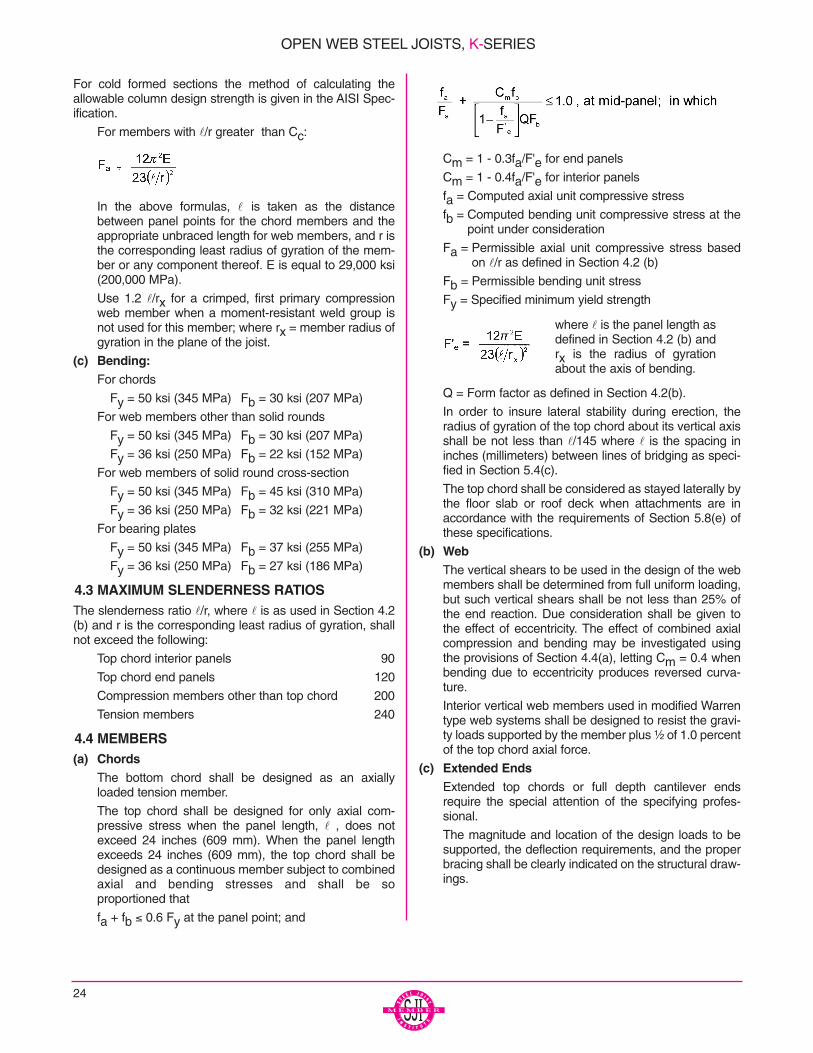
For cold formed sections the method of calculating theallowable column design strength is given in the AISI Spec-ification.
For members with l/r greater than Cc:
In the above formulas, l is taken as the distancebetween panel points for the chord members and theappropriate unbraced length for web members, and r isthe corresponding least radius of gyration of the mem-ber or any component thereof. E is equal to 29,000 ksi(200,000 MPa).
Use 1.2 l/rx for a crimped, first primary compressionweb member when a moment-resistant weld group isnot used for this member; where rx = member radius ofgyration in the plane of the joist.
(c) Bending:For chords
Fy = 50 ksi (345 MPa) Fb = 30 ksi (207 MPa)
For web members other than solid rounds
Fy = 50 ksi (345 MPa) Fb = 30 ksi (207 MPa)
Fy = 36 ksi (250 MPa) Fb = 22 ksi (152 MPa)
For web members of solid round cross-section
Fy = 50 ksi (345 MPa) Fb = 45 ksi (310 MPa)
Fy = 36 ksi (250 MPa) Fb = 32 ksi (221 MPa)
For bearing plates
Fy = 50 ksi (345 MPa) Fb = 37 ksi (255 MPa)
Fy = 36 ksi (250 MPa) Fb = 27 ksi (186 MPa)
4.3 MAXIMUM SLENDERNESS RATIOSThe slenderness ratio l/r, where l is as used in Section 4.2(b) and r is the corresponding least radius of gyration, shallnot exceed the following:
Top chord interior panels 90
Top chord end panels 120
Compression members other than top chord 200
Tension members 240
4.4 MEMBERS(a) Chords
The bottom chord shall be designed as an axiallyloaded tension member.
The top chord shall be designed for only axial com-pressive stress when the panel length, l , does notexceed 24 inches (609 mm). When the panel lengthexceeds 24 inches (609 mm), the top chord shall bedesigned as a continuous member subject to combinedaxial and bending stresses and shall be so proportioned that
fa + fb ≤ 0.6 Fy at the panel point; and
Cm = 1 - 0.3fa/F'e for end panels
Cm = 1 - 0.4fa/F'e for interior panels
fa = Computed axial unit compressive stress
fb = Computed bending unit compressive stress at thepoint under consideration
Fa = Permissible axial unit compressive stress basedon l/r as defined in Section 4.2 (b)
Fb = Permissible bending unit stress
Fy = Specified minimum yield strength
Q = Form factor as defined in Section 4.2(b).
In order to insure lateral stability during erection, theradius of gyration of the top chord about its vertical axisshall be not less than l/145 where l is the spacing ininches (millimeters) between lines of bridging as speci-fied in Section 5.4(c).
The top chord shall be considered as stayed laterally bythe floor slab or roof deck when attachments are inaccordance with the requirements of Section 5.8(e) ofthese specifications.
(b) WebThe vertical shears to be used in the design of the webmembers shall be determined from full uniform loading,but such vertical shears shall be not less than 25% ofthe end reaction. Due consideration shall be given tothe effect of eccentricity. The effect of combined axialcompression and bending may be investigated usingthe provisions of Section 4.4(a), letting Cm = 0.4 whenbending due to eccentricity produces reversed curva-ture.
Interior vertical web members used in modified Warrentype web systems shall be designed to resist the gravi-ty loads supported by the member plus ¹⁄₂ of 1.0 percentof the top chord axial force.
(c) Extended EndsExtended top chords or full depth cantilever endsrequire the special attention of the specifying profes-sional.
The magnitude and location of the design loads to besupported, the deflection requirements, and the properbracing shall be clearly indicated on the structural draw-ings.
where l is the panel length asdefined in Section 4.2 (b) andrx is the radius of gyrationabout the axis of bending.
24
OPEN WEB STEEL JOISTS, K-SERIES

25
4.5 CONNECTIONS(a) Methods
Joist connections and splices shall be made byattaching the members to one another by arc orresistance welding or other approved method.
1) Welded Connections
a) Selected welds shall be inspected visuallyby the manufacturer. Prior to this inspection,weld slag shall be removed.
b) Cracks are not acceptable and shall berepaired.
c) Thorough fusion shall exist between weldand base metal for the required designlength of the weld; such fusion shall be ver-ified by visual inspection.
d) Unfilled weld craters shall not be included inthe design length of the weld.
e) Undercut shall not exceed ¹⁄₁₆ inch (2mm)for welds oriented parallel to the principalstress.
f) The sum of surface (piping) porosity diame-ters shall not exceed ¹⁄₁₆ inch (2mm) in any1 inch (25 mm) of design weld length.
g) Weld spatter that does not interfere withpaint coverage is acceptable.
2) Welding Program
Manufacturers shall have a program for estab-lishing weld procedures and operator qualifica-tion, and for weld sampling and testing. (SeeTechnical Digest #8 - Welding of Open WebSteel Joists.)
3) Weld Inspection by Outside Agencies (See Sec-tion 5.12 of these specifications)
The agency shall arrange for visual inspection todetermine that welds meet the acceptance stan-dards of Section 4.5(a)(1) above. Ultrasonic, X-Ray, and magnetic particle testing areinappropriate for joists due to the configurationsof the components and welds.
(b) StrengthJoint connections shall be capable of withstandingforces due to an ultimate load equal to at least twotimes the design load shown in the applicable Stan-dard Load Table.
(c) SplicesSplices may occur at any point in chord or web mem-bers. Members containing a butt weld splice shalldevelop an ultimate tensile force of at least 57 ksi(393 MPa) times the full design area of the chord orweb. The term “member” shall be defined as all com-ponent parts comprising the chord or web, at thepoint of splice.
(d) EccentricityMembers connected at a joint shall have their cen-troidal axes meet at a point if practical. Otherwise,due consideration shall be given to the effect ofeccentricity. In no case shall eccentricity of any webmember at a joint exceed ³⁄₄ of the over-all dimen-sion, measured in the plane of the web, of thelargest member connected. The eccentricity of anyweb member shall be the perpendicular distancefrom the centroidal axis of that web member to thepoint on the centroidal axis of the chord which is ver-tically above or below the intersection of the cen-troidal axes of the web members forming the joint.Ends of joists shall be proportioned to resist bendingproduced by eccentricity at the support.
4.6 VERIFICATION OF DESIGN AND MANUFACTURE(a) Design Calculations
Companies manufacturing K-Series Joists shall sub-mit design data to the Steel Joist Institute (or an inde-pendent agency approved by the Steel Joist Institute)for verification of compliance with the SJI Specifica-tions. Design Data shall be submitted in detail and inthe format specified by the Institute.
(b) Tests of Chord and Web MembersEach manufacturer shall, at the time of design reviewby the Steel Joist Institute or other independentagency, verify by tests that the design, in accordancewith Sections 4.1 through 4.5 of this specification, willprovide a minimum factor of safety of 1.65 on the the-oretical design capacity of critical members. Suchtests shall be evaluated considering the actual yieldstrength of the members of the test joists.
Material tests for determining mechanical propertiesof component members shall be conducted.
(c) Tests of Joints and ConnectionsEach manufacturer shall verify by shear tests on rep-resentative joints of typical joists that connections willmeet the provision of Section 4.5(b). Chord and webmembers may be reinforced for such tests.
(d) In-Plant InspectionsEach manufacturer shall verify his ability to manufac-ture K-Series Joists through periodic In-Plant Inspec-tions. Inspections shall be performed by anindependent agency approved by the Steel JoistInstitute. The frequency, manner of inspection, andmanner of reporting shall be determined by the SteelJoist Institute. The plant inspections are not a guar-anty of the quality of any specific joists or Joist Gird-ers; this responsibility lies fully and solely with theindividual manufacturer.
OPEN WEB STEEL JOISTS, K-SERIES

4.7 CAMBERCamber is optional with the manufacturer but, whenprovided, recommended approximate camber is as fol-lows:
Top Chord Length Approximate Camber
20'-0" (6096 mm) ¹⁄₄" (6 mm)
30'-0" (9144 mm) ³⁄₈" (10 mm)
40'-0" (12192 mm) ⁵⁄₈" (16 mm)
50'-0" (15240 mm) 1" (25 mm)
60'-0" (18288 mm) 1¹⁄₂" (38 mm)
In no case will joists be manufactured with negative camber.
5.1 USAGEThese specifications shall apply to any type of structurewhere floors and roofs are to be supported directly by steeljoists installed as hereinafter specified. Where joists areused other than on simple spans under uniformly distributedloading as prescribed in Section 4.1, they shall be investi-gated and modified if necessary to limit the unit stresses tothose listed in Section 4.2.
CAUTION: If a rigid connection of the bottom chord is to bemade to the column or other support, it shall be made onlyafter the application of the dead loads. The joist is then nolonger simply supported, and the system must be investi-gated for continuous frame action by the specifying profes-sional.
The designed detail of a rigid type connection and momentplates shall be shown on the structural drawings by thespecifying professional. The moment plates shall be fur-nished by other than the joist manufacturer.
5.2 SPANThe span of a joist shall not exceed 24 times its depth.
5.3 END SUPPORTS(a) Masonry and Concrete
K-Series Joists supported by masonry or concrete areto bear on steel bearing plates and shall be designed assteel bearing. Due consideration of the end reactionsand all other vertical or lateral forces shall be taken bythe specifying professional in the design of the steelbearing plate and the masonry or concrete. The ends ofK-Series Joists shall extend a distance of not less than4 inches (102 mm) over the masonry or concrete sup-port and be anchored to the steel bearing plate. Theplate shall be located not more than ¹⁄₂ inch (13 mm)from the face of the wall and shall be not less than 6inches (152 mm) wide perpendicular to the length of thejoist. It is to be designed by the specifying professionalin compliance with the allowable unit stresses in Sec-
tion A5.1 (Allowable Stress Design) of the A.I.S.C.Specification. The steel bearing plate shall be furnishedby other than the joist manufacturer.
Where it is deemed necessary to bear less than 4 inch-es (102 mm) over the masonry or concrete support,special consideration is to be given to the design of thesteel bearing plate and the masonry or concrete by thespecifying professional. The joists must bear a mini-mum of 2¹⁄₂ inches (64 mm) on the steel bearing plate.
(b) SteelDue consideration of the end reactions and all othervertical and lateral forces shall be taken by the specify-ing professional in the design of the steel support. Theends of K-Series Joists shall extend a distance of notless than 2¹⁄₂ inches (64 mm) over the steel supports.
5.4 BRIDGINGBridging is required and shall consist of one of the fol-lowing types.
(a) HorizontalHorizontal bridging shall consist of two continuous hor-izontal steel members, one attached to the top chordand the other attached to the bottom chord. Eachattachment to the joists shall be made by welding ormechanical means and shall be capable of resisting ahorizontal force of not less than 700 pounds (3114 N).
The ratio of unbraced length to least radius of gyrationl/r of the bridging member shall not exceed 300, wherel is the distance in inches (millimeters) between attach-ments and r is the least radius of gyration of the bridg-ing member.
(b) DiagonalDiagonal bridging shall consist of cross-bracing with anl/r ratio of not more than 200, where l is the distance ininches (millimeters) between connections and r is theleast radius of gyration of the bracing member. Wherecross-bracing members are connected at their point ofintersection, the l distance shall be taken as the dis-tance in inches (millimeters) between connections atthe point of intersection of the bracing members and theconnections to the chord of the joists. Connections tothe chords of steel joists shall be made by positivemechanical means or by welding.
26
SECTION 5.APPLICATION
OPEN WEB STEEL JOISTS, K-SERIES

27
NUMBER OF ROWS OF BRIDGING**Refer to the K-Series Load Table and Specification Section 6. for required bolted diagonal bridging.
Distances are Joist Span lengths - See "Definition of Span" on page 30.
*Section One Two Three Four FiveNumber Row Rows Rows Rows Rows
#1 Up thru 16' Over 16' thru 24' Over 24' thru 28'#2 Up thru 17' Over 17' thru 25' Over 25’ thru 32'#3 Up thru 18' Over 18 thru 28' Over 28’ thru 38' Over 38' thru 40'#4 Up thru 19' Over 19' thru 28' Over 28’ thru 38' Over 38' thru 48'#5 Up thru 19' Over 19' thru 29' Over 29’ thru 39' Over 39' thru 50' Over 50' thru 52'#6 Up thru 19 Over 19' thru 29' Over 29’ thru 39' Over 39' thru 51' Over 51' thru 56'#7 Up thru 20' Over 20' thru 33' Over 33’ thru 45' Over 45' thru 58' Over 58' thru 60'#8 Up thru 20' Over 20' thru 33' Over 33’ thru 45' Over 45' thru 58' Over 58' thru 60'#9 Up thru 20' Over 20' thru 33’ Over 33’ thru 46' Over 46’ thru 59' Over 59' thru 60' #10 Up thru 20' Over 20' thru 37’ Over 37’ thru 51' Over 51’ thru 60'#11 Up thru 20' Over 20' thru 38’ Over 38’ thru 53' Over 53’ thru 60'#12 Up thru 20' Over 20' thru 39’ Over 39’ thru 53' Over 53’ thru 60'
* Last digit(s) of joist designation shown in Load Table** See Section 5.11 for additional bridging required for uplift design.
METRIC NUMBER OF ROWS OF BRIDGING**Refer to the K-Series Metric Load Table and Specification Section 6. for required bolted diagonal bridging.
Distances are Joist Span lengths in Millimeters (mm) - See “Definition of Span” on page 30.
*Section One Two Three Four Five Number Row Rows Rows Rows Rows
#1 up thru 4877 Over 4877 thru 7315 Over 7315 thru 8534#2 up thru 5182 Over 5182 thru 7620 Over 7620 thru 9754#3 up thru 5486 Over 5486 thru 8534 Over 8534 thru 11582 Over 11582 thru 12192#4 up thru 5791 Over 5791 thru 8534 Over 8534 thru 11582 Over 11582 thru 14630#5 up thru 5791 Over 5791 thru 8839 Over 8839 thru 11887 Over 11887 thru 15240 Over 15240 thru 15850#6 up thru 5791 Over 5791 thru 8839 Over 8839 thru 11887 Over 11887 thru 15545 Over 15545 thru 17069#7 up thru 6096 Over 6096 thru 10058 Over 10058 thru 13716 Over 13716 thru 17678 Over 17678 thru 18288#8 up thru 6096 Over 6096 thru 10058 Over 10058 thru 13716 Over 13716 thru 17678 Over 17678 thru 18288#9 up thru 6096 Over 6096 thru 10058 Over 10058 thru 14021 Over 14021 thru 17983 Over 17983 thru 18288#10 up thru 6096 Over 6096 thru 11278 Over 11278 thru 15545 Over 15545 thru 18288#11 up thru 6096 Over 6096 thru 11582 Over 11582 thru 16154 Over 16154 thru 18288#12 up thru 6096 Over 6096 thru 11887 Over 11887 thru 16154 Over 16154 thru 18288
* Last digit(s) of joist designation shown in Load Table** See Section 5.11 for additional bridging required for uplift design.
OPEN WEB STEEL JOISTS, K-SERIES
28
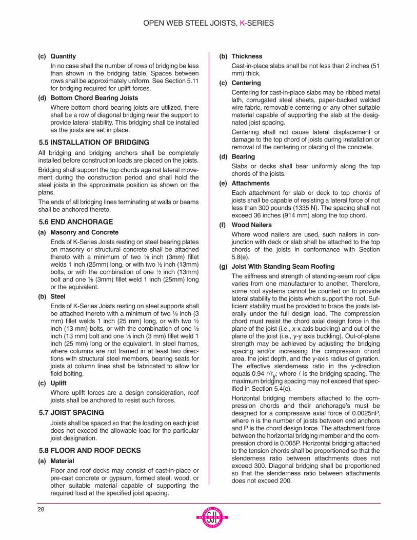
(c) QuantityIn no case shall the number of rows of bridging be lessthan shown in the bridging table. Spaces betweenrows shall be approximately uniform. See Section 5.11for bridging required for uplift forces.
(d) Bottom Chord Bearing JoistsWhere bottom chord bearing joists are utilized, thereshall be a row of diagonal bridging near the support toprovide lateral stability. This bridging shall be installedas the joists are set in place.
5.5 INSTALLATION OF BRIDGINGAll bridging and bridging anchors shall be completelyinstalled before construction loads are placed on the joists.
Bridging shall support the top chords against lateral move-ment during the construction period and shall hold thesteel joists in the approximate position as shown on theplans.
The ends of all bridging lines terminating at walls or beamsshall be anchored thereto.
5.6 END ANCHORAGE(a) Masonry and Concrete
Ends of K-Series Joists resting on steel bearing plateson masonry or structural concrete shall be attachedthereto with a minimum of two ¹⁄₈ inch (3mm) filletwelds 1 inch (25mm) long, or with two ¹⁄₂ inch (13mm)bolts, or with the combination of one ¹⁄₂ inch (13mm)bolt and one ¹⁄₈ (3mm) fillet weld 1 inch (25mm) longor the equivalent.
(b) SteelEnds of K-Series Joists resting on steel supports shallbe attached thereto with a minimum of two ¹⁄₈ inch (3mm) fillet welds 1 inch (25 mm) long, or with two ¹⁄₂
inch (13 mm) bolts, or with the combination of one ¹⁄₂inch (13 mm) bolt and one ¹⁄₈ inch (3 mm) fillet weld 1inch (25 mm) long or the equivalent. In steel frames,where columns are not framed in at least two direc-tions with structural steel members, bearing seats forjoists at column lines shall be fabricated to allow forfield bolting.
(c) UpliftWhere uplift forces are a design consideration, roofjoists shall be anchored to resist such forces.
5.7 JOIST SPACINGJoists shall be spaced so that the loading on each joistdoes not exceed the allowable load for the particularjoist designation.
5.8 FLOOR AND ROOF DECKS(a) Material
Floor and roof decks may consist of cast-in-place orpre-cast concrete or gypsum, formed steel, wood, orother suitable material capable of supporting therequired load at the specified joist spacing.
(b) ThicknessCast-in-place slabs shall be not less than 2 inches (51mm) thick.
(c) CenteringCentering for cast-in-place slabs may be ribbed metallath, corrugated steel sheets, paper-backed weldedwire fabric, removable centering or any other suitablematerial capable of supporting the slab at the desig-nated joist spacing.
Centering shall not cause lateral displacement ordamage to the top chord of joists during installation orremoval of the centering or placing of the concrete.
(d) BearingSlabs or decks shall bear uniformly along the topchords of the joists.
(e) AttachmentsEach attachment for slab or deck to top chords ofjoists shall be capable of resisting a lateral force of notless than 300 pounds (1335 N). The spacing shall notexceed 36 inches (914 mm) along the top chord.
(f) Wood NailersWhere wood nailers are used, such nailers in con-junction with deck or slab shall be attached to the topchords of the joists in conformance with Section5.8(e).
(g) Joist With Standing Seam RoofingThe stiffness and strength of standing-seam roof clipsvaries from one manufacturer to another. Therefore,some roof systems cannot be counted on to providelateral stability to the joists which support the roof. Suf-ficient stability must be provided to brace the joists lat-erally under the full design load. The compressionchord must resist the chord axial design force in theplane of the joist (i.e., x-x axis buckling) and out of theplane of the joist (i.e., y-y axis buckling). Out-of-planestrength may be achieved by adjusting the bridgingspacing and/or increasing the compression chordarea, the joist depth, and the y-axis radius of gyration.The effective slenderness ratio in the y-directionequals 0.94 l/ry; where l is the bridging spacing. Themaximum bridging spacing may not exceed that spec-ified in Section 5.4(c).
Horizontal bridging members attached to the com-pression chords and their anchorage’s must bedesigned for a compressive axial force of 0.0025nP,where n is the number of joists between end anchorsand P is the chord design force. The attachment forcebetween the horizontal bridging member and the com-pression chord is 0.005P. Horizontal bridging attachedto the tension chords shall be proportioned so that theslenderness ratio between attachments does notexceed 300. Diagonal bridging shall be proportionedso that the slenderness ratio between attachmentsdoes not exceed 200.
OPEN WEB STEEL JOISTS, K-SERIES
29
5.9 DEFLECTIONThe deflection due to the design live load shall not exceedthe following:
Floors: ¹⁄₃₆₀ of span.
Roofs: ¹⁄₃₆₀ of span where a plaster ceiling is attachedor suspended.¹⁄₂₄₀ of span for all other cases.
The specifying professional shall give due consideration tothe effects of deflection and vibration* in the selection ofJoists.
* For further reference, refer to Steel Joist Institute TechnicalDigest #5, “Vibration of Steel Joist-Concrete Slab Floors”and the Institute’s Computer Vibration Program.
5.10 PONDINGUnless a roof surface is provided with sufficient slopetowards points of free drainage, or adequate individualdrains to prevent the accumulation of rain water, the roofsystem shall be investigated to assure stability under pond-ing conditions in accordance with Section K2 of the AISCSpecification (Allowable Stress Design).*
The ponding investigation shall be performed by the speci-fying professional.
* For further reference, refer to Steel Joist Institute TechnicalDigest #3, “Structural Design of Steel Joist Roofs to ResistPonding Loads”.
5.11 UPLIFTWhere uplift forces due to wind are a design requirement,these forces must be indicated on the contract drawings interms of net uplift in pounds per square foot (Pascals).When these forces are specified, they must be consideredin the design of joists and/or bridging. A single line of bot-tom chord bridging must be provided near the first bottomchord panel points whenever uplift due to wind forces is adesign consideration.*
* For further reference, refer to Steel Joist Institute TechnicalDigest #6, “Structural Design of Steel Joist Roofs to ResistUplift Loads.
5.12 INSPECTIONJoists shall be inspected by the manufacturer before ship-ment to insure compliance of materials and workmanshipwith the requirements of these specifications. If the pur-chaser wishes an inspection of the steel joists by someoneother than the manufacturer’s own inspectors, he mayreserve the right to do so in his “Invitation to Bid” or theaccompanying “Job Specifications”.
Arrangements shall be made with the manufacturer for suchinspection of the joists at the manufacturing shop by the pur-chaser’s inspectors at purchaser’s expense.
5.13 PARALLEL CHORD SLOPED JOISTSThe Span of a parallel chord sloped joist shall be defined bythe length along the slope. Minimum depth, load-carryingcapacity, and bridging requirements shall be determined bythe sloped definition of span. The Standard Load Tablecapacity shall be the component normal to the joist.
OPEN WEB STEEL JOISTS, K-SERIES
SECTION 6.ERECTION STABILITY AND HANDLING
When it is necessary for the erector to climb on the joists,extreme caution must be exercised since unbridged joists mayexhibit some degree of instability under the erector’s weight.
During the construction period, the contractor shall providemeans for adequate distribution of concentrated loads so thatthe carrying capacity of any joist is not exceeded.
a) Stability Requirements1) One end of all joists shall be attached to its support in
accordance with Section 5.6 – End Anchorage,before allowing the weight of an erector on the joists.When a bolted seat connection is used for erectionpurposes, as a minimum, the bolts must be snugtightened. The snug tight condition is defined as thetightness that exists when all plies of a joint are in firmcontact. This may be attained by a few impacts of animpact wrench or the full effort of an employee usingan ordinary spud wrench.
2) Where the span of the joist exceeds the erectionstability span as indicated by the Red shaded areaof the load table, the row of bridging nearest the midspan of the joist shall be installed as bolted diagonalbridging.
Hoisting cables shall not be released until thisbolted diagonal bridging is completely installed.
3) No loads other than the weight of one erector areallowed on the joist until all bridging is completelyinstalled and all joist ends are attached.
4) In the case of bottom chord bearing joists, the endsof the joist must be restrained laterally per Section5.4(d) before releasing the hoisting cables.
5) After the joist is straightened and plumbed, and allbridging is completely installed and anchored, theends of the joists shall be fully connected to thesupports in accordance with Section 5.6 EndAnchorage.
b) Field Welding1) All field welding shall be performed in a workman-like
manner to insure that the joists are not damaged bysuch welding.
2) On cold-formed members whose yield strength hasbeen attained by cold working, and whose as-formedstrength is used in the design, the total length of weldat any one point shall not exceed 50 percent of theoverall developed width of the cold-formed section.
c) HandlingCare shall be exercised at all times to avoid damage tothe joists and accessories through careless handlingduring unloading, storing and erecting.*For a thorough coverage of this topic, refer to SJI TechnicalDigest #9, “Handling and Erection of Steel Joists and JoistGirders”.
30
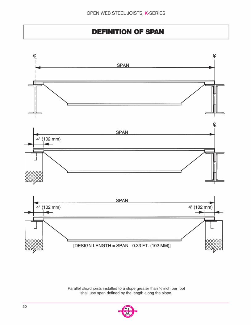
DEFINITION OF SPAN
Parallel chord joists installed to a slope greater than ¹⁄₂ inch per footshall use span defined by the length along the slope.
OPEN WEB STEEL JOISTS, K-SERIES
ACCESSORIES AND DETAILS
31
NOTE: 2.5K SERIES NOT U.L. APPROVED.
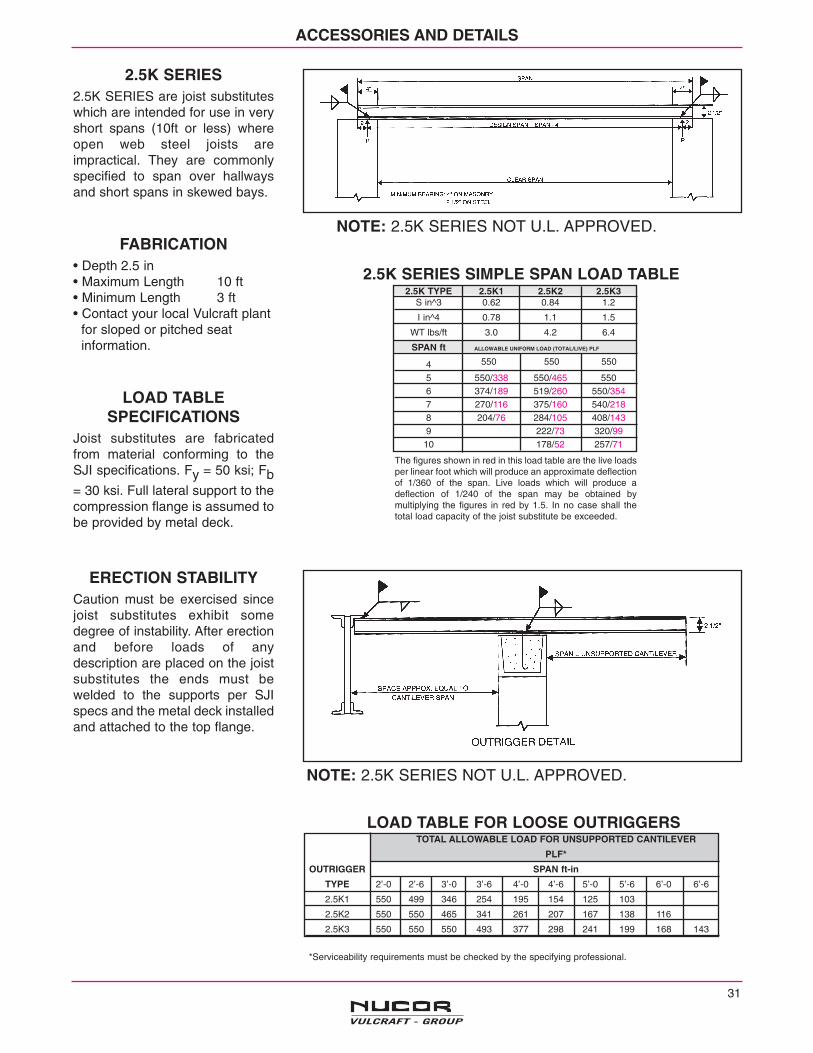
2.5K SERIES SIMPLE SPAN LOAD TABLE
The figures shown in red in this load table are the live loadsper linear foot which will produce an approximate deflectionof 1/360 of the span. Live loads which will produce adeflection of 1/240 of the span may be obtained bymultiplying the figures in red by 1.5. In no case shall thetotal load capacity of the joist substitute be exceeded.
NOTE: 2.5K SERIES NOT U.L. APPROVED.
LOAD TABLE FOR LOOSE OUTRIGGERS
*Serviceability requirements must be checked by the specifying professional.
TOTAL ALLOWABLE LOAD FOR UNSUPPORTED CANTILEVER
PLF*
OUTRIGGER SPAN ft-in
TYPE 2’-0 2’-6 3’-0 3’-6 4’-0 4’-6 5’-0 5’-6 6’-0 6’-6
2.5K1 550 499 346 254 195 154 125 103
2.5K2 550 550 465 341 261 207 167 138 116
2.5K3 550 550 550 493 377 298 241 199 168 143
2.5K SERIES2.5K SERIES are joist substituteswhich are intended for use in veryshort spans (10ft or less) whereopen web steel joists areimpractical. They are commonlyspecified to span over hallwaysand short spans in skewed bays.
FABRICATION• Depth 2.5 in• Maximum Length 10 ft• Minimum Length 3 ft• Contact your local Vulcraft plant
for sloped or pitched seatinformation.
LOAD TABLESPECIFICATIONS
Joist substitutes are fabricatedfrom material conforming to theSJI specifications. Fy = 50 ksi; Fb= 30 ksi. Full lateral support to thecompression flange is assumed tobe provided by metal deck.
ERECTION STABILITYCaution must be exercised sincejoist substitutes exhibit somedegree of instability. After erectionand before loads of anydescription are placed on the joistsubstitutes the ends must bewelded to the supports per SJIspecs and the metal deck installedand attached to the top flange.
2.5K TYPE 2.5K1 2.5K2 2.5K3S in^3 0.62 0.84 1.2
I in^4 0.78 1.1 1.5
WT lbs/ft 3.0 4.2 6.4
SPAN ft ALLOWABLE UNIFORM LOAD (TOTAL/LIVE) PLF
45 550/338 550/465 5506 374/189 519/260 550/3547 270/116 375/160 540/2188 204/76 284/105 408/1439 222/73 320/9910 178/52 257/71
550 550 550

ACCESSORIES AND DETAILS
JOISTDEPTH ROUND SQUARE RECTANGLE
8 inches 5 inches 4x4 inches 3x8 inches10 inches 6 inches 5x5 inches 3x8 inches12 inches 7 inches 6x6 inches 4x9 inches14 inches 8 inches 6x6 inches 5x9 inches16 inches 9 inches 7 1/2x 71/2 inches 6X10 inches18 inches 11 inches 8x8 inches 7x11 inches20 inches 11 inches 9x9 inches 7x12 inches22 inches 12 inches 9 1/2 x9 1/2 inches 8x12 inches24 inches 13 inches 10x10 inches 8x13 inches26 inches 151/2 inches 12x12 inches 9x18 inches28 inches 16 inches 13x13 inches 9x18 inches30 inches 17 inches 14x14 inches 10x18 inches
32
K SERIES OPEN WEB STEEL JOISTS
ANCHORAGE TO STEELSEE SJI SPECIFICATION 5.3 (b) AND5.6
ANCHORAGE TO MASONARYSEE SJI SPECIFICATION 5.3 (a) AND5.6
BOLTED CONNECTION*TYPICALLY REQUIRED AT COLUMNS
CEILING EXTENSION BOTTOM CHORD STRUT HEADERSNote: If header does not bear at a Joist Panel Point
add extra web in field as shown. EW or Panel Point by Vulcraft
SEE SJI SPECIFICATION - SECTION 6.FOR HANDLING AND ERECTION OF K-SERIES OPEN WEB STEEL JOISTS ANDSJI TECHNICAL DIGEST NO. 9.
*FOR LH SERIES CONSULT WITH VULCRAFT
SPECIFYING PROFESSIONAL MUST INDICATE ON STRUCTURAL DRAWINGS SIZE AND LOCATION OFANY DUCT THAT IS TO PASS THRU JOIST.
MAXIMUM DUCT OPENING SIZES (K SERIES)*
ACCESSORIES AND DETAILS
33
K SERIES OPEN WEB STEEL JOISTS
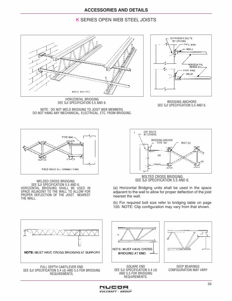
BRIDGING ANCHORSSEE SJI SPECIFICATION 5.5 AND 6.
WELDED CROSS BRIDGINGSEE SJI SPECIFICATION 5.5 AND 6.
HORIZONTAL BRIDGING SHALL BE USED INSPACE ADJACENT TO THE WALL TO ALLOW FORPROPER DEFLECTION OF THE JOIST NEARESTTHE WALL.
BOLTED CROSS BRIDGINGSEE SJI SPECIFICATION 5.5 AND 6.
(a) Horizontal Bridging units shall be used in the spaceadjacent to the wall to allow for proper deflection of the joistnearest the wall.
(b) For required bolt size refer to bridging table on page120. NOTE: Clip configuration may vary from that shown.
HORIZONTAL BRIDGINGSEE SJI SPECIFICATION 5.5 AND 6.
NOTE: DO NOT WELD BRIDGING TO JOIST WEB MEMBERS.DO NOT HANG ANY MECHANICAL, ELECTRICAL, ETC. FROM BRIDGING.
FULL DEPTH CANTILEVER ENDSEE SJI SPECIFICATION 5.4 (d) AND 5.5 FOR BRIDGING
REQUIREMENTS.
SQUARE ENDSEE SJI SPECIFICATION 5.4 (d)
AND 5.5 FOR BRIDGINGREQUIREMENTS.
DEEP BEARINGSCONFIGURATION MAY VARY
EXP. BOLTSBY OTHERS
BOLT (b)
(a)
BRIDGING ANCHORTYPE "SA"

High EndRecommended
Slope SeatRate Depth
d3/8:12 3 1/2"1/2:12 3 1/2"1:12 4"
1 1/2:12 4"2:12 4"
2 1/2:12 4 1/2"3:12 4 1/2"
3 1/2:12 5"4:12 5"
4 1/2:12 5"5 1/2"12 5 1/2"
6:12 5 1/2"6:12 SEE
& OVER BELOW
ACCESSORIES AND DETAILS
K SERIES OPEN WEB STEEL JOISTS
SLOPED SEAT REQUIREMENTS FOR SLOPES 3/8:12 AND GREATER
LOW END HIGH END
BARTLE HALLCONVENTION CENTER
Kansas City, Missouri
Architect-Engineer: HNTB Corp.General Contractor: Watson GeneralContractors, Inc.Steel Fabricator: Havens Steel, Inc.Steel Erector: Danny's Construction Co., Inc.
34
NOTES:(1) Depths shown are the minimums required for fabrication of sloped bearing seats. Depths may vary depending on actual
bearing conditions.(2) d = 5/8 + 2.5 / cos θ + 4 tan θ(3) Clearance must be checked at outer edge of support as shown in detail B. Increase bearing depth as required to permit
passage of 2 1/2" deep extension.(4) If extension depth greater than 2 1/2" is required (see details B and D) increase bearing depths accordingly. (5) If slope is 1/4:12 or less sloped seats are not required.
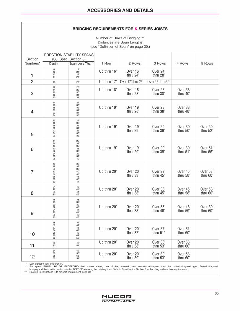
BRIDGING REQUIREMENTS FOR K-SERIES JOISTS
Number of Rows of Bridging***Distances are Span Lengths
(see "Definition of Span" on page 30.)
ACCESSORIES AND DETAILS
35
ERECTION STABILITY SPANSSection (SJI Spec. Section 6)
Numbers* Depth Span Less Than** 1 Row 2 Rows 3 Rows 4 Rows 5 Rows
8 17’10 21’12 23’14 27’
16 29’
12 25’14 29’16 30’18 31’20 32’
14 29’16 32’18 32’20 34’22 34’24 36’
12 25’16 32’18 33’20 34’22 35’24 38’26 38’
14 29’16 33’18 35’20 36’22 36’24 39’26 39’28 40’
16 33’18 37’20 39’22 40’24 43’26 43’28 43’30 44’
24 43’26 44’28 44’30 45’
16 33’18 37’20 39’22 40’24 44’26 44’28 45’30 45’
18 37’20 41’22 45’24 49’26 49’28 49’30 50’
22 45’30 52’
24 49’26 53’28 53’30 54’
12
3
4
5
6
7
8
9
10
11
12
Up thru 16’ Over 16’ Over 24’thru 24’ thru 28’
Up thru 17’ Over 17’ thru 25’ Over25’thru32’
Up thru 18’ Over 18’ Over 28’ Over 38’thru 28’ thru 38’ thru 40’
Up thru 19’ Over 19’ Over 28’ Over 38’thru 28’ thru 38’ thru 48’
Up thru 19’ Over 19’ Over 29’ Over 39’ Over 50’thru 29’ thru 39’ thru 50’ thru 52’
Up thru 19’ Over 19’ Over 29’ Over 39’ Over 51’thru 29’ thru 39’ thru 51’ thru 56’
Up thru 20’ Over 20’ Over 33’ Over 45’ Over 58’thru 33’ thru 45’ thru 58’ thru 60’
Up thru 20’ Over 20’ Over 33’ Over 45’ Over 58’thru 33’ thru 45’ thru 58’ thru 60’
Up thru 20’ Over 20’ Over 33’ Over 46’ Over 59’thru 33’ thru 46’ thru 59’ thru 60’
Up thru 20’ Over 20’ Over 37’ Over 51’thru 37’ thru 51’ thru 60’
Up thru 20’ Over 20’ Over 38’ Over 53’thru 38’ thru 53’ thru 60’
Up thru 20’ Over 20’ Over 39’ Over 53’thru 39’ thru 53’ thru 60’
* Last digit(s) of joist designation.** For spans EQUAL TO OR EXCEEDING that shown above, one of the required rows, nearest mid-span, must be bolted diagonal type. Bolted diagonal
bridging shall be installed and connected BEFORE releasing the hoisting lines. Refer to Specification Section 6 for handling and erection requirements.*** See SJI Specifications 5.11 for uplift requirement, page 29.
ACCESSORIES AND DETAILS
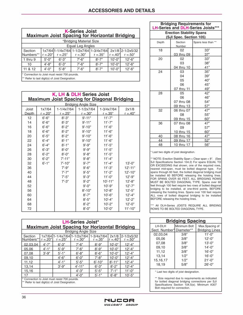
Bridging Requirements for LH-Series and DLH-Series Joists***
Erection Stability Spans(SJI Spec. Section 105)
Depth Section Spans less than **Number
18 02 33”03 thru 09 37”
20 02 33”03 38”
04 thru 10 41”24 03 35”
04 39”05 40”06 45”
07 thru 11 49”28 05 42”
06 46”07 thru 08 54”09 thru 13 57”
32 06 thru 07 47”08 55”
09 thru 15 60”36 07 thru 08 47”
09 57”10 thru 15 60”
40 08 thru 16 47”44 09 thru 17 52”48 10 thru 17 56”
* Last two digits of joist designation.
** NOTE: Erection Stability Span = Clear span + 8". (SeeSJI Specifications Section 104.2) For spans EQUAL TOOR EXCEEDING that shown, one of the required rows,nearest mid-span, must be bolted diagonal type. Forspans through 60 feet, the bolted diagonal bridging mustbe installed 60 BEFORE releasing the hoisting lines.FOR SPANS OVER 60 FEET, ALL BRIDGING ROWSMUST BE BOLTED DIAGONAL TYPE. Spans over 60feet through 100 feet require two rows of bolted diagonalbridging to be installed, at one-third points, BEFOREreleasing the hoisting lines. Spans over 100 feet requireALL rows of bolted diagonal bridging to be installedBEFORE releasing the hoisting lines.
*** All DLH-Series JOISTS REQUIRE ALL BRIDINGROWS TO BE BOLTED DIAGONAL TYPE.
LH-Series Joist*Maximum Joist Spacing for Horizontal Bridging
Bridging Angle SizeSection 1x7/64 1-1/4x7/64 1-1/2x7/64 1-3/4x7/64 2x1/8 2-1/2x5/32
Numbers** r =.20" r =.25" r =.30" r =.35" r =.40" r =.50"02,03,04 4'-7" 6'-3" 7'-6" 8'-9" 10'-0" 12'-4"05,06 4'-1" 5'-9" 7'-6" 8'-9" 10'-0" 12'-4"07,08 3'-9" 5'-1" 6'-8" 8'-6" 10'-0" 12'-4"09,10 4'-6" 6'-0" 7'-8" 10'-0" 12'-4"11,12 4'-1" 5'-5" 6'-10" 8'-11" 12'-4"13,14 3'-9" 4'-11" 6'-3" 8'-2" 12'-4"15,16 4'-3" 5'-5" 7'-1" 11'-0"17 4'-0" 5'-1" 6'-8" 10'-5"
* Connection to Joist must resist 700 pounds.** Refer to last digit(s) of Joist Designation.
36
K-Series JoistMaximum Joist Spacing for Horizontal Bridging
*Bridging Material SizeEqual Leg Angles
Section 1x7/64 1-1/4x7/64 1-1/2x7/64 1-3/4x7/64 2x1/8 2-1/2x5/32Numbers** r =.20" r =.25" r =.30" r =.35" r =.40" r =.50"1 thru 9 5'-0" 6'-3" 7'-6" 8'-7" 10'-0" 12'-6"
10 4'-8" 6'-3" 7'-6" 8'-7" 10'-0" 12'-6"11 & 12 4'-0" 5'-8" 7'-6" 8'-7" 10'-0" 12'-6"
* Connection to Joist must resist 700 pounds.** Refer to last digit(s) of Joist Designation.
K, LH & DLH Series JoistMaximum Joist Spacing for Diagonal Bridging
Bridging Angle SizeJoist 1x7/64 1-1/4x7/64 1-1/2x7/64 1-3/4x7/64 2x1/8
Depth r =.20" r =.25" r =.30" r =.35" r =.40"12 6'-6" 8'-3" 9'-11" 11'-7"14 6'-6" 8'-3" 9'-11" 11'-7"16 6'-6" 8'-2" 9'-10" 11'-6"18 6'-6" 8'-2" 9'-10" 11'-6"20 6'-5" 8'-2" 9'-10" 11'-6"22 6'-4" 8'-1" 9'-10" 11'-6"24 6'-4" 8'-1" 9'-9" 11'-5"26 6'-3" 8'-0" 9'-9" 11'-5"28 6'-2" 8'-0" 9'-8" 11'-5"30 6'-2" 7'-11" 9'-8" 11'-4"32 6'-1" 7'-10" 9'-7" 11'-4" 13'-0"36 7'-9" 9'-6" 11'-3" 12'-11"40 7'-7" 9'-5" 11'-2" 12'-10"44 7'-5" 9'-3" 11'-0" 12'-9"48 7'-3" 9'-2" 10'-11" 12'-8"52 9'-0" 10'-9" 12'-7"56 8'-10" 10'-8" 12'-5"60 8'-7" 10'-6" 12'-4"64 8'-5" 10'-4" 12'-2"68 8'-2" 10'-2" 12'-0"72 8'-0" 10'-0" 11'-10"
Bridging SpacingLH-DLH Minimum Bolt Max.Spacing of
Sect. Number* Diameter** Bridging Lines02,03,04 3/8" 11'-0"
05,06 3/8" 12'-0"07,08 3/8" 13'-0"09,10 3/8" 14'-0"11,12 3/8" 16'-0"13,14 1/2" 16'-0"
15,16,17 1/2" 21'-0"18,19 5/8" 26'-0"
* Last two digits of joist designation.
** Size required due to requirements as indicatedfor bolted diagonal bridging connections per SJISpecifications Section 104.5(e). Minimum A307Bolt required for connection.

37
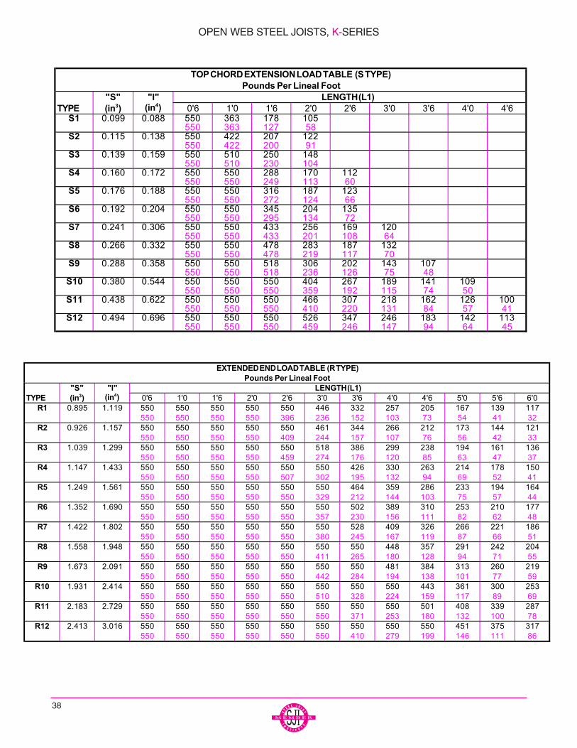
Joist extensions are commonly furnished to support avariety of overhang conditions. The two types are picturedbelow. The first is the TOP CHORD EXTENSION or “S”TYPE, which has only the top chord angles extended. Thesecond is the EXTENDED END or “R” TYPE in which thestandard 2¹⁄₂, (64 mm) end bearing depth is maintainedover the entire length of the extension. The “S” TYPEextension is so designated because of its Simple naturewhereas the “R” TYPE involves Reinforcing the top chordangles. The specifying professional should be aware thatan “S” TYPE is more economical and should be specifiedwhenever possible.
The following load tables for K-Series TOP CHORDEXTENSIONS and EXTENDED ENDS have been devel-oped as an aid to the specifying professional. The blacknumber in the tables is the maximum allowable uniformload in pounds per linear foot (KiloNewton/Meter). The rednumber is the uniform load which will produce an approx-imate deflection of L1/240, where L1 is the length of theextension. The load tables are applicable for uniformloads only. If there are concentrated loads and/or
non-uniform loads, a loading diagram must be providedby the specifying professional on the structural drawings.In cases where it is not possible to meet specific jobrequirements with a 2¹⁄₂" (64 mm) deep “R” type extension(refer to “S” and “I” values in the Extended End LoadTable), the depth of the extension must be increased toprovide greater load-carrying capacity. If the loading dia-gram for any condition is not shown. the joist manufactur-er will design the extension to support the uniform loadindicated in the K-Series Joist Load Table for the span ofthe joist.
When TOP CHORD EXTENSIONS or EXTENDEDENDS are specified, the allowable deflection and thebracing requirements must be considered by the specify-ing professional.
It should be noted that an “R” TYPE extension must bespecified when building details dictate a 2¹⁄₂, (64 mm)depth at the end of the extension. In the absence of spe-cific instructions. the joist manufacturer may provide eithertype.
TOP CHORD EXTENSIONS AND EXTENDED ENDS
OPEN WEB STEEL JOISTS, K-SERIES
38
"S" "I"TYPE (in3) (in4) 0'6 1'0 1'6 2'0 2'6 3'0 3'6 4'0 4'6
S1 0.099 0.088 550 363 178 105550 363 127 58
S2 0.115 0.138 550 422 207 122550 422 200 91
S3 0.139 0.159 550 510 250 148550 510 230 104
S4 0.160 0.172 550 550 288 170 112550 550 249 113 60
S5 0.176 0.188 550 550 316 187 123550 550 272 124 66
S6 0.192 0.204 550 550 345 204 135550 550 295 134 72
S7 0.241 0.306 550 550 433 256 169 120550 550 433 201 108 64
S8 0.266 0.332 550 550 478 283 187 132550 550 478 219 117 70
S9 0.288 0.358 550 550 518 306 202 143 107550 550 518 236 126 75 48
S10 0.380 0.544 550 550 550 404 267 189 141 109550 550 550 359 192 115 74 50
S11 0.438 0.622 550 550 550 466 307 218 162 126 100550 550 550 410 220 131 84 57 41
S12 0.494 0.696 550 550 550 526 347 246 183 142 113550 550 550 459 246 147 94 64 45
LENGTH (L1)
TOP CHORD EXTENSION LOAD TABLE (S TYPE)Pounds Per Lineal Foot
"S" "I"TYPE (in3) (in4) 0'6 1'0 1'6 2'0 2'6 3'0 3'6 4'0 4'6 5'0 5'6 6'0
R1 0.895 1.119 550 550 550 550 550 446 332 257 205 167 139 117550 550 550 550 396 236 152 103 73 54 41 32
R2 0.926 1.157 550 550 550 550 550 461 344 266 212 173 144 121550 550 550 550 409 244 157 107 76 56 42 33
R3 1.039 1.299 550 550 550 550 550 518 386 299 238 194 161 136550 550 550 550 459 274 176 120 85 63 47 37
R4 1.147 1.433 550 550 550 550 550 550 426 330 263 214 178 150550 550 550 550 507 302 195 132 94 69 52 41
R5 1.249 1.561 550 550 550 550 550 550 464 359 286 233 194 164550 550 550 550 550 329 212 144 103 75 57 44
R6 1.352 1.690 550 550 550 550 550 550 502 389 310 253 210 177550 550 550 550 550 357 230 156 111 82 62 48
R7 1.422 1.802 550 550 550 550 550 550 528 409 326 266 221 186550 550 550 550 550 380 245 167 119 87 66 51
R8 1.558 1.948 550 550 550 550 550 550 550 448 357 291 242 204550 550 550 550 550 411 265 180 128 94 71 55
R9 1.673 2.091 550 550 550 550 550 550 550 481 384 313 260 219550 550 550 550 550 442 284 194 138 101 77 59
R10 1.931 2.414 550 550 550 550 550 550 550 550 443 361 300 253550 550 550 550 550 510 328 224 159 117 89 69
R11 2.183 2.729 550 550 550 550 550 550 550 550 501 408 339 287550 550 550 550 550 550 371 253 180 132 100 78
R12 2.413 3.016 550 550 550 550 550 550 550 550 550 451 375 317550 550 550 550 550 550 410 279 199 146 111 86
EXTENDED END LOAD TABLE (R TYPE)Pounds Per Lineal Foot
LENGTH (L1)
OPEN WEB STEEL JOISTS, K-SERIES
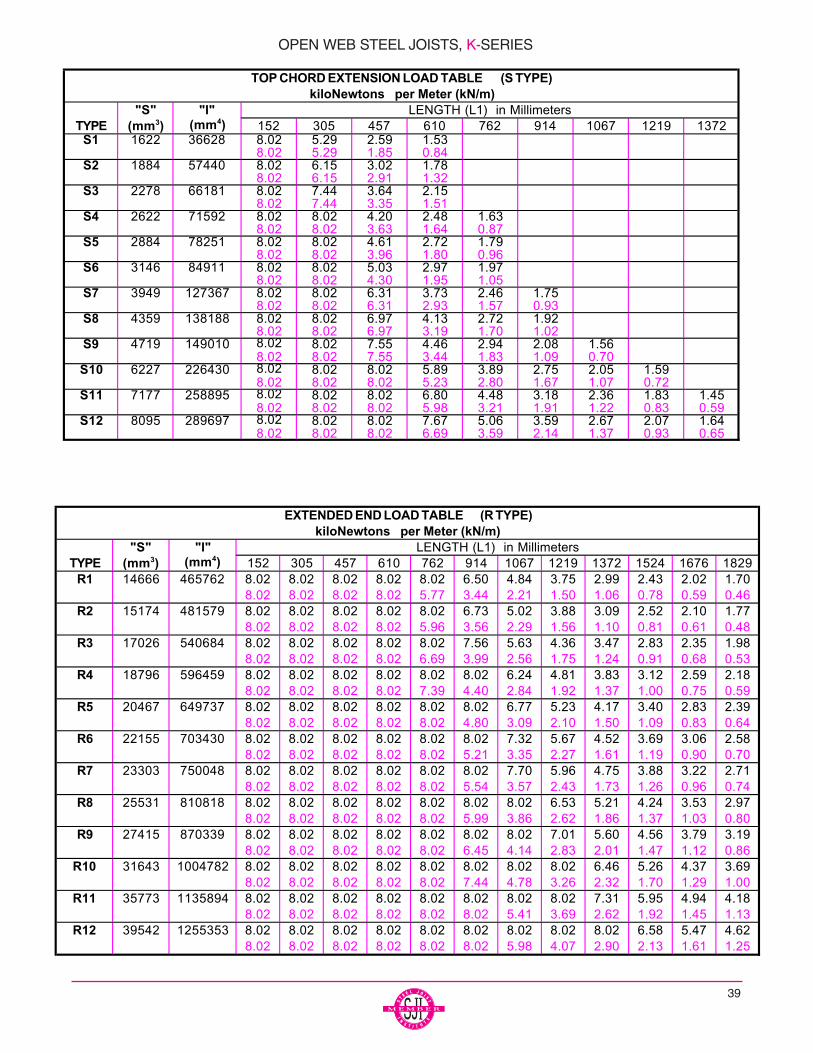
39
"S" "I"TYPE (mm3) (mm4) 152 305 457 610 762 914 1067 1219 1372
S1 1622 36628 8.02 5.29 2.59 1.538.02 5.29 1.85 0.84
S2 1884 57440 8.02 6.15 3.02 1.788.02 6.15 2.91 1.32
S3 2278 66181 8.02 7.44 3.64 2.158.02 7.44 3.35 1.51
S4 2622 71592 8.02 8.02 4.20 2.48 1.638.02 8.02 3.63 1.64 0.87
S5 2884 78251 8.02 8.02 4.61 2.72 1.798.02 8.02 3.96 1.80 0.96
S6 3146 84911 8.02 8.02 5.03 2.97 1.978.02 8.02 4.30 1.95 1.05
S7 3949 127367 8.02 8.02 6.31 3.73 2.46 1.758.02 8.02 6.31 2.93 1.57 0.93
S8 4359 138188 8.02 8.02 6.97 4.13 2.72 1.928.02 8.02 6.97 3.19 1.70 1.02
S9 4719 149010 8.02 8.02 7.55 4.46 2.94 2.08 1.568.02 8.02 7.55 3.44 1.83 1.09 0.70
S10 6227 226430 8.02 8.02 8.02 5.89 3.89 2.75 2.05 1.598.02 8.02 8.02 5.23 2.80 1.67 1.07 0.72
S11 7177 258895 8.02 8.02 8.02 6.80 4.48 3.18 2.36 1.83 1.458.02 8.02 8.02 5.98 3.21 1.91 1.22 0.83 0.59
S12 8095 289697 8.02 8.02 8.02 7.67 5.06 3.59 2.67 2.07 1.648.02 8.02 8.02 6.69 3.59 2.14 1.37 0.93 0.65
LENGTH (L1) in Millimeters
TOP CHORD EXTENSION LOAD TABLE (S TYPE)kiloNewtons per Meter (kN/m)
"S" "I"TYPE (mm3) (mm4) 152 305 457 610 762 914 1067 1219 1372 1524 1676 1829
R1 14666 465762 8.02 8.02 8.02 8.02 8.02 6.50 4.84 3.75 2.99 2.43 2.02 1.708.02 8.02 8.02 8.02 5.77 3.44 2.21 1.50 1.06 0.78 0.59 0.46
R2 15174 481579 8.02 8.02 8.02 8.02 8.02 6.73 5.02 3.88 3.09 2.52 2.10 1.778.02 8.02 8.02 8.02 5.96 3.56 2.29 1.56 1.10 0.81 0.61 0.48
R3 17026 540684 8.02 8.02 8.02 8.02 8.02 7.56 5.63 4.36 3.47 2.83 2.35 1.988.02 8.02 8.02 8.02 6.69 3.99 2.56 1.75 1.24 0.91 0.68 0.53
R4 18796 596459 8.02 8.02 8.02 8.02 8.02 8.02 6.24 4.81 3.83 3.12 2.59 2.188.02 8.02 8.02 8.02 7.39 4.40 2.84 1.92 1.37 1.00 0.75 0.59
R5 20467 649737 8.02 8.02 8.02 8.02 8.02 8.02 6.77 5.23 4.17 3.40 2.83 2.398.02 8.02 8.02 8.02 8.02 4.80 3.09 2.10 1.50 1.09 0.83 0.64
R6 22155 703430 8.02 8.02 8.02 8.02 8.02 8.02 7.32 5.67 4.52 3.69 3.06 2.588.02 8.02 8.02 8.02 8.02 5.21 3.35 2.27 1.61 1.19 0.90 0.70
R7 23303 750048 8.02 8.02 8.02 8.02 8.02 8.02 7.70 5.96 4.75 3.88 3.22 2.718.02 8.02 8.02 8.02 8.02 5.54 3.57 2.43 1.73 1.26 0.96 0.74
R8 25531 810818 8.02 8.02 8.02 8.02 8.02 8.02 8.02 6.53 5.21 4.24 3.53 2.978.02 8.02 8.02 8.02 8.02 5.99 3.86 2.62 1.86 1.37 1.03 0.80
R9 27415 870339 8.02 8.02 8.02 8.02 8.02 8.02 8.02 7.01 5.60 4.56 3.79 3.198.02 8.02 8.02 8.02 8.02 6.45 4.14 2.83 2.01 1.47 1.12 0.86
R10 31643 1004782 8.02 8.02 8.02 8.02 8.02 8.02 8.02 8.02 6.46 5.26 4.37 3.698.02 8.02 8.02 8.02 8.02 7.44 4.78 3.26 2.32 1.70 1.29 1.00
R11 35773 1135894 8.02 8.02 8.02 8.02 8.02 8.02 8.02 8.02 7.31 5.95 4.94 4.188.02 8.02 8.02 8.02 8.02 8.02 5.41 3.69 2.62 1.92 1.45 1.13
R12 39542 1255353 8.02 8.02 8.02 8.02 8.02 8.02 8.02 8.02 8.02 6.58 5.47 4.628.02 8.02 8.02 8.02 8.02 8.02 5.98 4.07 2.90 2.13 1.61 1.25
EXTENDED END LOAD TABLE (R TYPE)kiloNewtons per Meter (kN/m)
LENGTH (L1) in Millimeters
OPEN WEB STEEL JOISTS, K-SERIES

ACCESSORIES AND DETAILS
40
STANDARD TYPES
Longspan steel joists can be furnished with eitherunderslung or square ends, with parallel chords or withsingle or double pitched top chords to provide suffi-cient slope for roof drainage.
The Longspan joist designation is determined byits nominal depth at the center of the span, exceptfor offset double pitched joists, where the depthshould be given at the ridge. A part of the designa-tion should be either the section number or the totaldesign load over the design live load (TL/LL given inplf).
All pitched joists will be cambered in addition to thepitch unless specified otherwise.
Top Chord Approx.
Length Camber
20”-0" (6096 mm) 1/4" (6 mm)
30”-0" (9144 mm) 3/8" (10 mm)
40”-0" (12192 mm) 5/8" (16 mm)
50”-0" (15240 mm) 1" (25 mm)
60”-0" (18288 mm) 1 1/2" (38 mm)
70”-0" (21336 mm) 2" (51 mm)
80”-0" (24384 mm) 2 3/4" (70 mm)
90”-0" (27432 mm) 3 1/2" (89 mm)
100”-0" (30480 mm) 4 1/4" (108 mm)
110”-0" (33528 mm) 5" (127 mm)
120”-0" (36576 mm) 6" (152 mm)
130”-0" (39621 mm) 7" (178 mm)
140”-0" (42672 mm) 8" (203 mm)
144”-0" (43890 mm) 8 1/2" (216 mm)
*** NOTE: If full camber is not desired near walls or otherstructural members please note on the structural drawings.
CAMBER
Non-Standard Types: The design professionalshall provide on the structural drawings the amount ofcamber desired as a percent of live load and as a per-cent of dead load.
Standard Types: The camber listed in the table willbe fabricated into the joists unless the design profes-sional specifically states otherwise on the structuraldrawings.
NON-STANDARD TYPES
The following joists can also be supplied by Vulcraft,however, THE DISTRICT SALES OFFICE OR MAN-UFACTURING FACILITY NEAREST YOU SHOULDBE CONTACTED FOR ANY LIMITATIONS INDEPTH OR LENGTH.
**Contact Vulcraft for minimum depth at ends.
CAMBER FOR STANDARD TYPES
LH &DLH series joists shall have camber in accordancewith the following table:***
LH & DLH SERIES LONGSPAN STEEL JOISTS
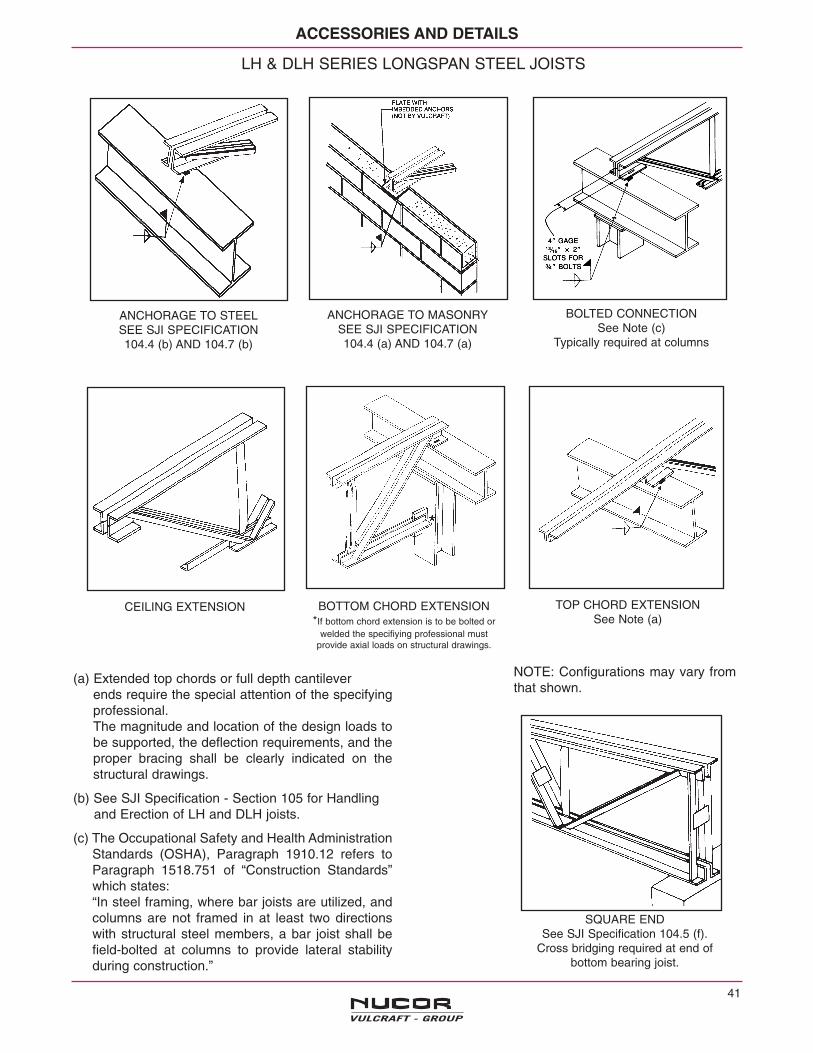
ACCESSORIES AND DETAILS
41
(a) Extended top chords or full depth cantileverends require the special attention of the specifyingprofessional.The magnitude and location of the design loads tobe supported, the deflection requirements, and theproper bracing shall be clearly indicated on thestructural drawings.
(b) See SJI Specification - Section 105 for Handlingand Erection of LH and DLH joists.
(c) The Occupational Safety and Health AdministrationStandards (OSHA), Paragraph 1910.12 refers toParagraph 1518.751 of “Construction Standards”which states:“In steel framing, where bar joists are utilized, andcolumns are not framed in at least two directionswith structural steel members, a bar joist shall befield-bolted at columns to provide lateral stabilityduring construction.”
LH & DLH SERIES LONGSPAN STEEL JOISTS
ANCHORAGE TO STEELSEE SJI SPECIFICATION104.4 (b) AND 104.7 (b)
BOLTED CONNECTIONSee Note (c)
Typically required at columns
ANCHORAGE TO MASONRYSEE SJI SPECIFICATION104.4 (a) AND 104.7 (a)
CEILING EXTENSION TOP CHORD EXTENSIONSee Note (a)
BOTTOM CHORD EXTENSION*If bottom chord extension is to be bolted or
welded the specifiying professional mustprovide axial loads on structural drawings.
NOTE: Configurations may vary fromthat shown.
SQUARE ENDSee SJI Specification 104.5 (f).
Cross bridging required at end ofbottom bearing joist.
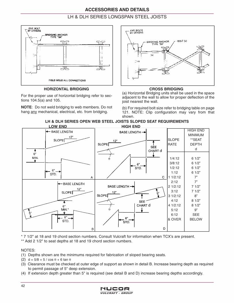
ACCESSORIES AND DETAILS
42
LH & DLH SERIES LONGSPAN STEEL JOISTS
For the proper use of horizontal bridging refer to sec-tions 104.5(a) and 105.
NOTE: Do not weld bridging to web members. Do nothang any mechanical, electrical, etc. from bridging.
(a) Horizontal Bridging units shall be used in the spaceadjacent to the wall to allow for proper deflection of thejoist nearest the wall.
(b) For required bolt size refer to bridging table on page121. NOTE: Clip configuration may vary from thatshown.
LH & DLH SERIES OPEN WEB STEEL JOISTS SLOPED SEAT REQUIREMENTS
HIGH ENDMINIMUM
SLOPE **SEATRATE DEPTH
d
1/4:12 6 1/2”3/8:12 6 1/2”1/2:12 6 1/2”1:12 6 1/2”
1 1/2:12 7”2:12 7”
2 1/2:12 7 1/2”3:12 7 1/2”
3 1/2:12 8”4:12 8 1/2”
4 1/2:12 8 1/2”5:12 9”6:12 SEE
& OVER BELOW
* 7 1/2" at 18 and 19 chord section numbers. Consult Vulcraft for information when TCX’s are present.** Add 2 1/2" to seat depths at 18 and 19 chord section numbers.
NOTES:(1) Depths shown are the minimums required for fabrication of sloped bearing seats.(2) d = 5/8 + 5 / cos θ + 6 tan θ(3) Clearance must be checked at outer edge of support as shown in detail B. Increase bearing depth as required
to permit passage of 5" deep extension.(4) If extension depth greater than 5" is required (see detail B and D) increase bearing depths accordingly.
HORIZONTAL BRIDGING CROSS BRIDGING
LOW END HIGH END
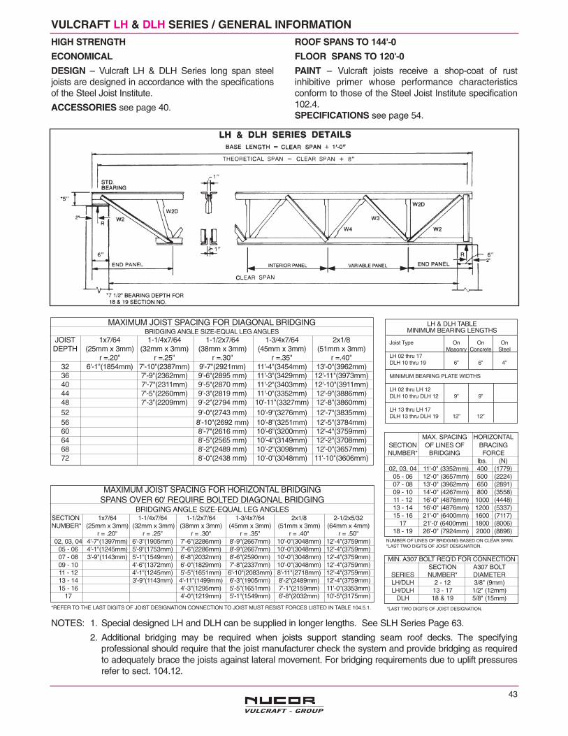
43
VULCRAFT LH & DLH SERIES / GENERAL INFORMATION
MAXIMUM JOIST SPACING FOR HORIZONTAL BRIDGINGSPANS OVER 60' REQUIRE BOLTED DIAGONAL BRIDGING
BRIDGING ANGLE SIZE-EQUAL LEG ANGLESSECTION 1x7/64 1-1/4x7/64 1-1/2x7/64 1-3/4x7/64 2x1/8 2-1/2x5/32NUMBER* (25mm x 3mm) (32mm x 3mm) (38mm x 3mm) (45mm x 3mm) (51mm x 3mm) (64mm x 4mm)
r = .20" r = .25" r = .30" r = .35" r = .40" r = .50"02, 03, 04 4'-7"(1397mm) 6'-3"(1905mm) 7'-6"(2286mm) 8'-9"(2667mm) 10'-0"(3048mm) 12'-4"(3759mm)
05 - 06 4'-1"(1245mm) 5'-9"(1753mm) 7'-6"(2286mm) 8'-9"(2667mm) 10'-0"(3048mm) 12'-4"(3759mm)07 - 08 3'-9"(1143mm) 5'-1"(1549mm) 6'-8"(2032mm) 8'-6"(2590mm) 10'-0"(3048mm) 12'-4"(3759mm)09 - 10 4'-6"(1372mm) 6'-0"(1829mm) 7'-8"(2337mm) 10'-0"(3048mm) 12'-4"(3759mm)11 - 12 4'-1"(1245mm) 5'-5"(1651mm) 6'-10"(2083mm) 8'-11"(2718mm) 12'-4"(3759mm)13 - 14 3'-9"(1143mm) 4'-11"(1499mm) 6'-3"(1905mm) 8'-2"(2489mm) 12'-4"(3759mm)15 - 16 4'-3"(1295mm) 5'-5"(1651mm) 7'-1"(2159mm) 11'-0"(3353mm)
17 4'-0"(1219mm) 5'-1"(1549mm) 6'-8"(2032mm) 10'-5"(3175mm)
*REFER TO THE LAST DIGITS OF JOIST DESIGNATION CONNECTION TO JOIST MUST RESIST FORCES LISTED IN TABLE 104.5.1.
MAXIMUM JOIST SPACING FOR DIAGONAL BRIDGINGBRIDGING ANGLE SIZE-EQUAL LEG ANGLES
JOIST 1x7/64 1-1/4x7/64 1-1/2x7/64 1-3/4x7/64 2x1/8DEPTH (25mm x 3mm) (32mm x 3mm) (38mm x 3mm) (45mm x 3mm) (51mm x 3mm)
r =.20" r =.25" r =.30" r =.35" r =.40"32 6'-1"(1854mm) 7'-10"(2387mm) 9'-7"(2921mm) 11'-4"(3454mm) 13'-0"(3962mm)36 7'-9"(2362mm) 9'-6"(2895 mm) 11'-3"(3429mm) 12'-11"(3973mm)40 7'-7"(2311mm) 9'-5"(2870 mm) 11'-2"(3403mm) 12'-10"(3911mm)44 7'-5"(2260mm) 9'-3"(2819 mm) 11'-0"(3352mm) 12'-9"(3886mm)48 7'-3"(2209mm) 9'-2"(2794 mm) 10'-11"(3327mm) 12'-8"(3860mm)52 9'-0"(2743 mm) 10'-9"(3276mm) 12'-7"(3835mm)56 8'-10"(2692 mm) 10'-8"(3251mm) 12'-5"(3784mm)60 8'-7"(2616 mm) 10'-6"(3200mm) 12'-4"(3759mm)64 8'-5"(2565 mm) 10'-4"(3149mm) 12'-2"(3708mm)68 8'-2"(2489 mm) 10'-2"(3098mm) 12'-0"(3657mm)72 8'-0"(2438 mm) 10'-0"(3048mm) 11'-10"(3606mm)
NOTES: 1. Special designed LH and DLH can be supplied in longer lengths. See SLH Series Page 63.
2. Additional bridging may be required when joists support standing seam roof decks. The specifyingprofessional should require that the joist manufacturer check the system and provide bridging as requiredto adequately brace the joists against lateral movement. For bridging requirements due to uplift pressuresrefer to sect. 104.12.
MIN. A307 BOLT REQ'D FOR CONNECTIONSECTION A307 BOLT
SERIES NUMBER* DIAMETERLH/DLH 2 - 12 3/8" (9mm)LH/DLH 13 - 17 1/2" (12mm)
DLH 18 & 19 5/8" (15mm)
*LAST TWO DIGITS OF JOIST DESIGNATION.
MAX. SPACING HORIZONTALSECTION OF LINES OF BRACINGNUMBER* BRIDGING FORCE
lbs. (N)02, 03, 04 11'-0" (3352mm) 400 (1779)
05 - 06 12'-0" (3657mm) 500 (2224)07 - 08 13'-0" (3962mm) 650 (2891)09 - 10 14'-0" (4267mm) 800 (3558)11 - 12 16'-0" (4876mm) 1000 (4448)13 - 14 16'-0" (4876mm) 1200 (5337)15 - 16 21'-0" (6400mm) 1600 (7117)
17 21'-0' (6400mm) 1800 (8006)18 - 19 26'-0" (7924mm) 2000 (8896)
NUMBER OF LINES OF BRIDGING BASED ON CLEAR SPAN.*LAST TWO DIGITS OF JOIST DESIGNATION.
LH & DLH TABLEMINIMUM BEARING LENGTHS
Joist Type On On OnMasonry Concrete Steel
LH 02 thru 17DLH 10 thru 19 6” 6” 4”
MINIMUM BEARING PLATE WIDTHS
LH 02 thru LH 12DLH 10 thru DLH 12 9” 9”
LH 13 thru LH 17DLH 13 thru DLH 19 12” 12”
HIGH STRENGTH
ECONOMICAL
DESIGN – Vulcraft LH & DLH Series long span steeljoists are designed in accordance with the specificationsof the Steel Joist Institute.
ACCESSORIES see page 40.
ROOF SPANS TO 144'-0
FLOOR SPANS TO 120'-0
PAINT – Vulcraft joists receive a shop-coat of rustinhibitive primer whose performance characteristicsconform to those of the Steel Joist Institute specification102.4.SPECIFICATIONS see page 54.
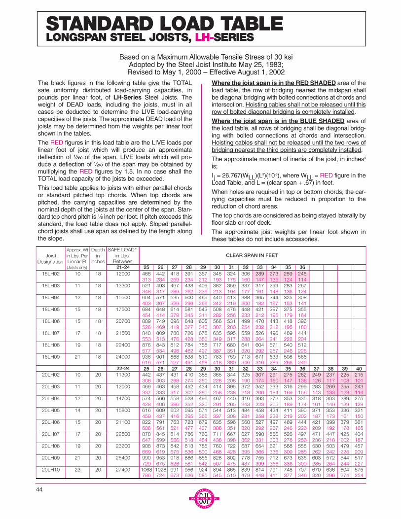
44
The black figures in the following table give the TOTALsafe uniformly distributed load-carrying capacities, inpounds per linear foot, of LH-Series Steel Joists. Theweight of DEAD loads, including the joists, must in allcases be deducted to determine the LIVE load-carryingcapacities of the joists. The approximate DEAD load of thejoists may be determined from the weights per linear footshown in the tables.
The RED figures in this load table are the LIVE loads perlinear foot of joist which will produce an approximatedeflection of ¹⁄₃₆₀ of the span. LIVE loads which will pro-duce a deflection of ¹⁄₂₄₀ of the span may be obtained bymultiplying the RED figures by 1.5. In no case shall theTOTAL load capacity of the joists be exceeded.
This load table applies to joists with either parallel chordsor standard pitched top chords. When top chords arepitched, the carrying capacities are determined by thenominal depth of the joists at the center of the span. Stan-dard top chord pitch is ¹⁄₈ inch per foot. If pitch exceeds thisstandard, the load table does not apply. Sloped parallel-chord joists shall use span as defined by the length alongthe slope.
Where the joist span is in the RED SHADED area of theload table, the row of bridging nearest the midspan shallbe diagonal bridging with bolted connections at chords andintersection. Hoisting cables shall not be released until thisrow of bolted diagonal bridging is completely installed.
Where the joist span is in the BLUE SHADED area ofthe load table, all rows of bridging shall be diagonal bridg-ing with bolted connections at chords and intersection.Hoisting cables shall not be released until the two rows ofbridging nearest the third points are completely installed.
The approximate moment of inertia of the joist, in inches4
is;
I j = 26.767(WLL)(L3)(10-6), where WLL = RED figure in theLoad Table, and L = (clear span + .67) in feet.
When holes are required in top or bottom chords, the car-rying capacities must be reduced in proportion to thereduction of chord areas.
The top chords are considered as being stayed laterally byfloor slab or roof deck.
The approximate joist weights per linear foot shown inthese tables do not include accessories.
STANDARD LOAD TABLELONGSPAN STEEL JOISTS, LH-SERIES
Based on a Maximum Allowable Tensile Stress of 30 ksiAdopted by the Steel Joist Institute May 25, 1983;Revised to May 1, 2000 – Effective August 1, 2002
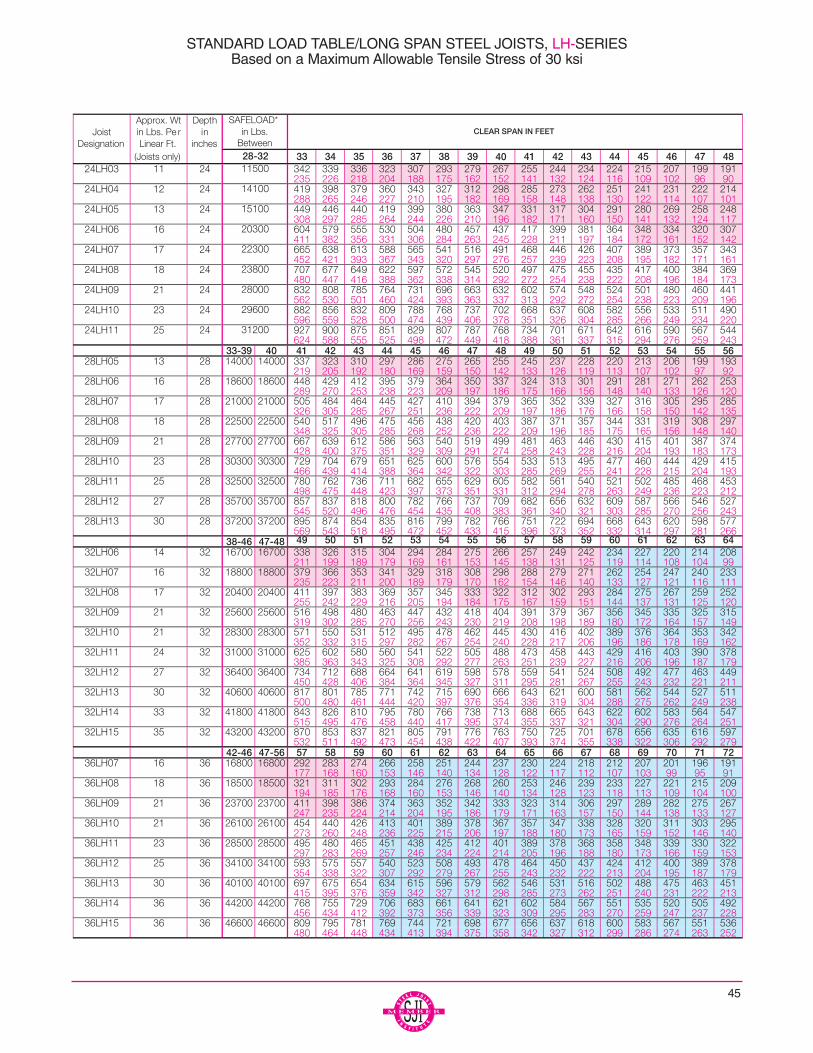
45
STANDARD LOAD TABLE/LONG SPAN STEEL JOISTS, LH-SERIESBased on a Maximum Allowable Tensile Stress of 30 ksi

46
* The safe uniform load for the clear spans shown in theSafe Load Column is equal to (Safe Load)/(Clear span+ 0.67). (The added 0.67 feet (8 inches) is required toobtain the proper length on which the Load Tables weredeveloped).
* In no case shall the safe uniform load, for clear spansless than the minimum clear span shown in the SafeLoad Column, exceed the uniform load calculated forthe minimum clear span listed in the Safe Load Column.
* To solve for live loads for clear spans shown in the SafeLoad Column (or lesser clear spans), multiply the liveload of the shortest clear span shown in the Load Tableby the (the shortest clear span shown in the Load Table+ 0.67 feet)2 and divide by (the actual clear span + 0.67feet)2. The live load shall not exceed the safe uniformload.
STANDARD LOAD TABLE/LONG SPAN STEEL JOISTS, LH-SERIESBased on a Maximum Allowable Tensile Stress of 30 ksi

47
The black figures in the following table give the TOTALsafe uniformly distributed load-carrying capacities, inpounds per linear foot, of DLH-Series Steel Joists. Theweight of DEAD loads, including the joists, must in allcases be deducted to determine the LIVE load-carryingcapacities of the joists. The approximate DEAD load of thejoists may be determined from the weights per linear footshown in the tables. All loads shown are for roof construc-tion only.
The RED figures in this load table are the LIVE loads perlinear foot of joist which will produce an approximatedeflection of ¹⁄₃₆₀ of the span. LIVE loads which will producea deflection of ¹⁄₂₄₀ of the span may be obtained by multi-plying the RED figures by 1.5. In no case shall the TOTALload capacity of the joists be exceeded.
This load table applies to joists with either parallel chordsor standard pitched top chords. When top chords arepitched, the carrying capacities are determined by thenominal depth of the joists at the center of the span. Stan-dard top chord pitch is ¹⁄₈ inch per foot. If pitch exceeds thisstandard, the load table does not apply. Sloped parallel-chord joists shall use span as defined by the length alongthe slope.
All rows of bridging shall be diagonal bridging with boltedconnections at the chords and intersections.
Where the joist span is in the BLUE SHADED area of theload table hoisting cables shall not be released until thetwo rows of bridging nearest the third points are complete-ly installed.
Where the joist span is in the GRAY SHADED area of theload table hoisting cables shall not be released until allrows of bridging are completely installed.
The approximate moment of inertia of the joist, in inches4
is;
I j = 26.767(WLL)(L3)(10-6), where WLL = RED figure in theLoad Table, and L = (clear span + .67) in feet.
When holes are required in top or bottom chords, the car-rying capacities must be reduced in proportion to thereduction of chord areas.
The top chords are considered as being stayed laterally byfloor slab or roof deck.
The approximate joist weights per linear foot shown inthese tables do not include accessories.
STANDARD LOAD TABLEDEEP LONGSPAN STEEL JOISTS, DLH-SERIES
Based on a Maximum Allowable Tensile Stress of 30 ksiAdopted by the Steel Joist Institute May 25, 1983;Revised to May 1, 2000 – Effective August 1, 2002

48
* The safe uniform load for the clear spans shown in the SafeLoad Column is equal to (Safe Load)/(Clear span + 0.67).(The added 0.67 feet (8 inches) is required to obtain theproper length on which the Load Tables were developed).
* In no case shall the safe uniform load, for clear spans lessthan the minimum clear span shown in the Safe Load Col-umn, exceed the uniform load calculated for the mini-mum clear span listed in the Safe Load Column.
* To solve for live loads for clear spans shown in the SafeLoad Column (or lesser clear spans), multiply the live loadof the shortest clear span shown in the Load Table by (theshortest clear span shown in the Load Table + 0.67 feet)2
and divide by (the actual clear span + 0.67 feet)2 . The liveload shall not exceed the safe uniform load.
STANDARD LOAD TABLE/DEEP LONGSPAN STEEL JOISTS, DLH-SERIESBased on a Maximum Allowable Tensile Stress of 30 ksi

49
The black figures in the following table give the TOTALsafe uniformly distributed load-carrying capacities, in kilo-Newtons per meter (kN/m) of LH-Series Steel Joists. Theweight (kN/m) of the DEAD loads, including the joists, mustin all cases be deducted to determine the LIVE load-carry-ing capacities of the joists. The approximate DEAD load ofthe joist may be determined from the weights shown in thetables.
The RED figures this load table are the LIVE loads (kilo-Newtons per meter) of joist which will produce an approxi-mate deflection of ¹⁄₃₆₀ of the span. LIVE loads whichproduce a deflection of ¹⁄₂₄₀ of the span may be obtained bymultiplying the red figures by 1.5. In no case shall theTOTAL load capacity of the joists be exceeded.
This load table applies to joists with either parallel chordsor standard pitched top chords. When top chords arepitched, the carrying capacities are determined by thenominal depth of the joist at center of the span. Standardtop chord pitch is 1:96. If pitch exceeds this standard, theload table does not apply. Sloped parallel-chord joists shalluse span as defined by the length along the slope.
Where the joist span is in the RED SHADED area of theload table, the row of bridging nearest the mid span shallbe diagonal bridging with bolted connections at chords andintersection. Hoisting cables shall not be released until thisrow of bolted diagonal bridging is completely installed.
Where the joist span is in the BLUE SHADED area ofthe load table, all rows of bridging shall be diagonal bridg-ing with bolted connections at chords and intersection.Hoisting cables shall not be released until the two rows ofbridging nearest the third points are completely installed.
When holes are required in top or bottom chords, the car-rying capacities must be reduced in proportion to thereduction of chord areas.
The top chords are considered as being stayed laterally byfloor slab or roof deck.
The approximate joist weights (kg/m) and mass (kN/m)shown in these tables do not include accessories.
The approximate moment of inertia of the joist, in mm4 is:
I j = 2.6953(WLL)(L3)(10-5), where WLL = RED figure in theLoad Table: L = (span + 204) in millimeters.
METRIC LOAD TABLELONGSPAN STEEL JOISTS, LH-SERIES
Based on a Maximum Allowable Tensile Stress of 207 MPaAdopted by the Steel Joist Institute May 2, 1994;
Revised to May 1, 2000 – Effective August 1, 2002
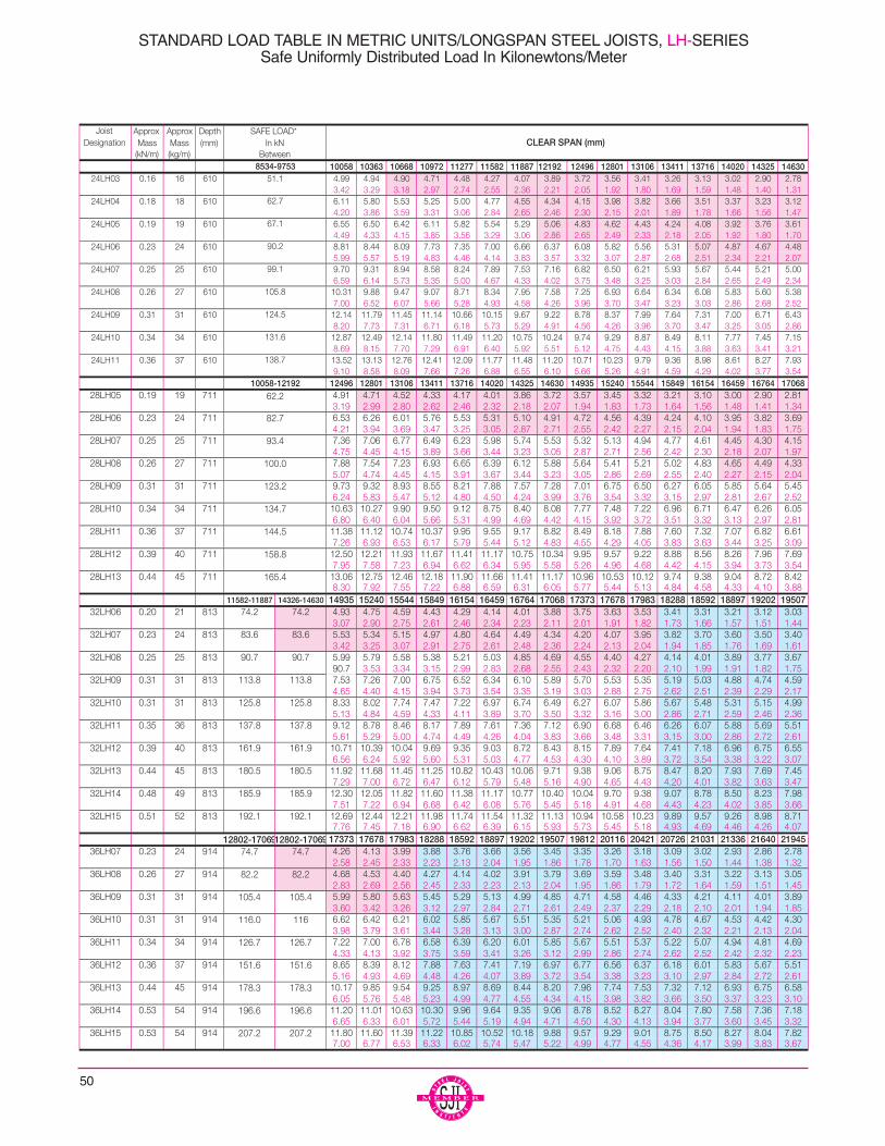
50
STANDARD LOAD TABLE IN METRIC UNITS/LONGSPAN STEEL JOISTS, LH-SERIESSafe Uniformly Distributed Load In Kilonewtons/Meter

51
* The safe uniform load for the clear spans shown in theSafe Load Column is equal to (Safe Load)/(Clear span+ 204). (The added 204 millimeters is required to obtainthe proper length on which the Load Tables were devel-oped).
* In no case shall the safe uniform load, for clear spansless than the minimum clear span shown in the SafeLoad Column, exceed the uniform load calculated forthe minimum clear span listed in the Safe Load Column.
* To solve for live loads for clear spans shown in the SafeLoad Column (or lesser clear spans), multiply the liveload of the shortest clear span shown in the Load Tableby the (the shortest clear span shown in the Load Table+ 204 mm)2 and divide by (the actual clear span + 204mm)2. The live load shall not exceed the safe uniformload.
STANDARD LOAD TABLE IN METRIC UNITS/LONGSPAN STEEL JOISTS, LH-SERIESSafe Uniformly Distributed Load In Kilonewtons/Meter

52
The black figures in the following table give the TOTAL safeuniformly distributed load-carrying capacities, in kiloNew-tons per meter (kN/m) of DLH-Series Steel Joists. Theweight (kN/m) of the DEAD loads, including the joists, mustin all cases be deducted to determine the LIVE load-carry-ing capacities of the joists. The approximate DEAD load ofthe joist may be determined from the weights shown in thetables. All loads shown are for roof construction only.
The RED figures this load table are the LIVE loads (kilo-Newtons per meter) of joist which will produce an approxi-mate deflection of ¹⁄₃₆₀ of the span. LIVE loads whichproduce a deflection of ¹⁄₂₄₀ of the span may be obtained bymultiplying the RED figures by 1.5. In no case shall theTOTAL load capacity of the joists be exceeded.
This load table applies to joists with either parallel chords orstandard pitched top chords. When top chords are pitched,the carrying capacities are determined by the nominaldepth of the joist at center of the span. Standard top chordpitch is 1:96. If pitch exceeds this standard, the load tabledoes not apply. Sloped parallel-chord joists shall use spanas defined by the length along the slope.
All rows of bridging shall be diagonal bridging with boltedconnections at the chords and intersections.
Where the joist span is in the BLUE SHADED area of theload table hoisting cables shall not be released until the tworows of bridging nearest the third points are completelyinstalled.
Where the joist span is in the GRAY SHADED area ofthe load table hoisting cables shall not be released until allrows of bridging are completely installed.
When holes are required in top or bottom chords, the car-rying capacities must be reduced in proportion to the reduc-tion of chord areas.
The top chords are considered as being stayed laterally bythe roof deck.
The approximate joist weights (kN/m) and mass (kg/m)shown in these tables do not include accessories.
The approximate moment of inertia of the joist, in mm4 is:
I j = 2.6953(WLL)(L3)10-5), where WLL = RED figure in theLoad Table; L = (span + 204) in millimeters.
METRIC LOAD TABLEDEEP LONGSPAN STEEL JOISTS, DLH-SERIES
Based on a Maximum Allowable Tensile Stress of 207 MPaAdopted by the Steel Joist Institute May 2, 1994;
Revised to May 1, 2000 – Effective August 1, 2002

53
CLEAR SPAN (mm)
* The safe uniform load for the clear spans shown in theSafe Load Column is equal to (Safe Load)/(Clear span +204). (The added 204 millimeters is required to obtain theproper length on which the Load Tables were developed).
* In no case shall the safe uniform load, for clear spans lessthan the minimum clear span shown in the Safe Load Col-umn, exceed the uniform load calculated for the minimumclear span listed in the Safe Load Column.
* To solve for live loads for clear spans shown in the SafeLoad Column (or lesser clear spans), multiply the live loadof the shortest clear span shown in the Load Table by the(the shortest clear span shown in the Load Table + 204mm)2 and divide by (the actual clear span + 204 mm)2 .The live load shall not exceed the safe uniform load.
STANDARD LOAD TABLE IN METRIC UNITS/LONGSPAN STEEL JOISTS, DLH-SERIESSafe Uniformly Distributed Load In Kilonewtons/Meter
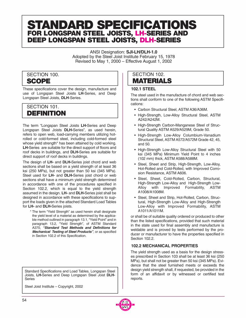
These specifications cover the design, manufacture anduse of Longspan Steel Joists LH-Series, and DeepLongspan Steel Joists, DLH-Series.
The term “Longspan Steel Joists LH-Series and DeepLongspan Steel Joists DLH-Series”, as used herein,refers to open web, load-carrying members utilizing hot-rolled or cold-formed steel, including cold-formed steelwhose yield strength* has been attained by cold working.LH-Series are suitable for the direct support of floors androof decks in buildings, and DLH-Series are suitable fordirect support of roof decks in buildings.
The design of LH- and DLH-Series joist chord and websections shall be based on a yield strength of at least 36ksi (250 MPa), but not greater than 50 ksi (345 MPa).Steel used for LH- and DLH-Series joist chord or websections shall have a minimum yield strength determinedin accordance with one of the procedures specified inSection 102.2, which is equal to the yield strengthassumed in the design. LH- and DLH-Series joist shall bedesigned in accordance with these specifications to sup-port the loads given in the attached Standard Load Tablesfor LH- and DLH-Series joists.
* The term “Yield Strength” as used herein shall designatethe yield level of a material as determined by the applica-ble method outlined in paragraph 13.1, “Yield Point” and inparagraph 13.2, “Yield Strength”, of ASTM StandardA370, “Standard Test Methods and Definitions forMechanical Testing of Steel Products”, or as specifiedin Section 102.2 of this Specification.
102.1 STEELThe steel used in the manufacture of chord and web sec-tions shall conform to one of the following ASTM Specifi-cations:
• Carbon Structural Steel, ASTM A36/A36M.
• High-Strength, Low-Alloy Structural Steel, ASTMA242/A242M.
• High-Strength Carbon-Manganese Steel of Struc-tural Quality ASTM A529/A529M, Grade 50.
• High-Strength Low-Alloy Columbium-VanadiumStructural Steel, ASTM A572/A572M Grade 42, 45,and 50.
• High-Strength Low-Alloy Structural Steel with 50ksi (345 MPa) Minimum Yield Point to 4 inches(102 mm) thick, ASTM A588/A588M.
• Steel, Sheet and Strip, High-Strength, Low-Alloy,Hot-Rolled and Cold-Rolled, with Improved Corro-sion Resistance, ASTM A606.
• Steel, Sheet, Cold-Rolled, Carbon, Structural,High-Strength Low-Alloy and High-Strength Low-Alloy with Improved Formability, ASTMA1008/A1008M.
• Steel, Sheet and Strip, Hot-Rolled, Carbon, Struc-tural, High-Strength Low-Alloy and High-StrengthLow-Alloy with Improved Formability, ASTMA1011/A1011M.
or shall be of suitable quality ordered or produced to otherthan the listed specifications, provided that such materialin the state used for final assembly and manufacture isweldable and is proved by tests performed by the pro-ducer or manufacturer to have the properties specified inSection 102.2.
102.2 MECHANICAL PROPERTIESThe yield strength used as a basis for the design stress-es prescribed in Section 103 shall be at least 36 ksi (250MPa), but shall not be greater than 50 ksi (345 MPa). Evi-dence that the steel furnished meets or exceeds thedesign yield strength shall, if requested, be provided in theform of an affidavit or by witnessed or certified testreports.
54
SECTION 100.
SCOPE
SECTION 101.
DEFINITION
Standard Specifications and Load Tables, Longspan SteelJoists, LH-Series and Deep Longspan Steel Joist DLH-Series
Steel Joist Institute – Copyright, 2002
SECTION 102.
MATERIALS
STANDARD SPECIFICATIONSFOR LONGSPAN STEEL JOISTS, LH-SERIES AND DEEP LONGSPAN STEEL JOISTS, DLH-SERIES
ANSI Designation: SJI-LH/DLH-1.0Adopted by the Steel Joist Institute February 15, 1978
Revised to May 1, 2000 – Effective August 1, 2002

55
For material used without consideration of increase in yieldstrength resulting from cold forming, the specimens shall betaken from as-rolled material. In the case of material, themechanical properties which conform to the requirementsof one of the listed specifications, test specimens and pro-cedure shall conform to those of such specifications and toASTM A370.
In the case of material, the mechanical properties which donot conform to the requirements of one of the listed specifi-cations, the test specimens and procedures shall conformto the applicable requirements of ASTM A370, and thespecimens shall exhibit a yield strength equal to or exceed-ing the design yield strength and an elongation of not lessthan (a) 20 percent in 2 inches (51 mm) for sheet and strip,or (b) 18 percent in 8 inches (203 mm) for plates, shapesand bars with adjustments for thickness for plates, shapesand bars as prescribed in ASTM A36/A36M, A242/A242M,A529/A529M, A572/A572M, A588/A588M, whichever spec-ification is applicable on the basis of design yield strength.
The number of tests shall be as prescribed in ASTMA6/A6M for plates, shapes, and bars; and ASTMA570/A570M, A606, A607, and A611 for sheet and strip.
If as-formed strength is utilized, the test reports shall showthe results of tests performed on full section specimens inaccordance with the provisions of the AISI Specifications forthe Design of Cold formed Steel Structural Members andshall indicate compliance with these provisions and with thefollowing additional requirements:
(a) The yield strength measured in the tests shall equal orexceed the design yield strength.
(b) Where tension tests are made for acceptance and con-trol purposes, the tensile strength shall be at least 6percent greater than the yield strength of the section.
(c) Where compression tests are used for acceptance andcontrol purposes, the specimen shall withstand a grossshortening of 2 percent of its original length withoutcracking. The length of the specimen shall be notgreater than 20 times its least radius of gyration.
(d) If any test specimen fails to pass the requirements ofsubparagraphs a, b, and c above, as applicable, tworetests shall be made of specimens from the same lot.Failure of one of the retest specimens to meet suchrequirements shall be the cause for rejection of the lotrepresented by the specimens.
102.3 WELDING ELECTRODESThe following electrodes shall be used for arc welding:
(a) For connected members both having a specified mini-mum yield strength greater than 36 ksi (250 MPa).
AWS A5.1 or A5.5, E70XXAWS A5.17, F7XX -EXXX flux electrode combination AWS A5.18, E70S-X or E7OU-1AWS A5.20, E7OT-X
(b) For connected members both having a specified mini-mum yield strength of 36 ksi (250 MPa) or one havinga specified minimum yield strength of 36 ksi (250 MPa),and the other having a specified minimum yieldstrength greater than 36 ksi (250 MPa).
AWS A5.1, E60XXAWS A5.17, FXX-EXXX flux electrode combination AWS A5.20, E60T-X
or any of those listed in Section 102.3(a).
Other welding methods, providing equivalent strength asdemonstrated by tests, may be used.
102.4 PAINTThe standard shop paint is intended to protect the steel foronly a short period of exposure in ordinary atmosphericconditions and shall be considered an impermanent andprovisional coating.
When specified, the standard shop paint shall conform toone of the following:
(a) Steel Structures Painting Council Specification, SSPCNo. 15
(b) Or, shall be a shop paint which meets the minimumperformance requirements of the above listed specifi-cation.
103.1 METHODJoists shall be designed in accordance with these specifi-cations as simply supported, uniformly loaded trusses sup-porting a floor or roof deck so constructed as to brace thetop chord of the joists against lateral buckling. Where anyapplicable design feature is not specifically covered herein,the design shall be in accordance with the following specifi-cations.
(a) American Institute of Steel Construction Specificationfor Design, Fabrication and Erection of Structural Steelfor Buildings (Allowable Stress Design), where thematerial used consists of plates, shapes or bars.
(b) American Iron and Steel Institute Specification for theDesign of Cold-Formed Steel Structural Members, formembers which are formed from sheet or strip materi-al.
103.2 UNIT STRESSESJoists shall have their components so proportioned that theunit stresses in kips per square inch (Mega Pascals) shallnot exceed the following, where Fy is the yield strengthdefined in Section 102.2:
(a) Tension:All members.......................................Ft = 0.6Fy
SECTION 103.
DESIGN AND MANUFACTURE
LONGSPAN AND DEEP LONGSPAN STEEL JOISTS, LH- AND DLH-SERIES
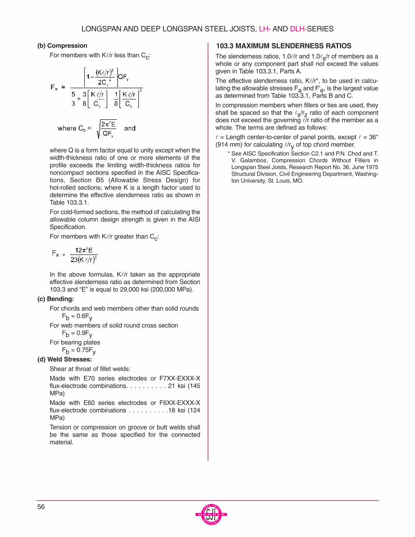
(b) CompressionFor members with Kl/r less than Cc:
where Q is a form factor equal to unity except when thewidth-thickness ratio of one or more elements of theprofile exceeds the limiting width-thickness ratios fornoncompact sections specified in the AISC Specifica-tions, Section B5 (Allowable Stress Design) forhot-rolled sections; where K is a length factor used todetermine the effective slenderness ratio as shown inTable 103.3.1.
For cold-formed sections, the method of calculating theallowable column design strength is given in the AISISpecification.
For members with Kl/r greater than Cc:
In the above formulas, Kl/r taken as the appropriateeffective slenderness ratio as determined from Section103.3 and “E” is equal to 29,000 ksi (200,000 MPa).
(c) Bending:For chords and web members other than solid rounds
Fb = 0.6FyFor web members of solid round cross section
Fb = 0.9FyFor bearing plates
Fb = 0.75Fy(d) Weld Stresses:
Shear at throat of fillet welds:
Made with E70 series electrodes or F7XX-EXXX-Xflux-electrode combinations. . . . . . . . . . 21 ksi (145MPa)
Made with E60 series electrodes or F6XX-EXXX-Xflux-electrode combinations . . . . . . . . . .18 ksi (124MPa)
Tension or compression on groove or butt welds shallbe the same as those specified for the connectedmaterial.
103.3 MAXIMUM SLENDERNESS RATIOSThe slenderness ratios, 1.0l/r and 1.0ls/r of members as awhole or any component part shall not exceed the valuesgiven in Table 103.3.1, Parts A.
The effective slenderness ratio, Kl/r*, to be used in calcu-lating the allowable stresses Fa and F'e, is the largest valueas determined from Table 103.3.1, Parts B and C.
In compression members when fillers or ties are used, theyshall be spaced so that the ls/rz ratio of each componentdoes not exceed the governing l/r ratio of the member as awhole. The terms are defined as follows:
l = Length center-to-center of panel points, except l = 36"(914 mm) for calculating l/ry of top chord member.
* See AISC Specification Section C2.1 and P.N. Chod and T.V. Galambos, Compression Chords Without Fillers inLongspan Steel Joists, Research Report No. 36, June 1975Structural Division, Civil Engineering Department, Washing-ton University, St. Louis, MO.
56
LONGSPAN AND DEEP LONGSPAN STEEL JOISTS, LH- AND DLH-SERIES
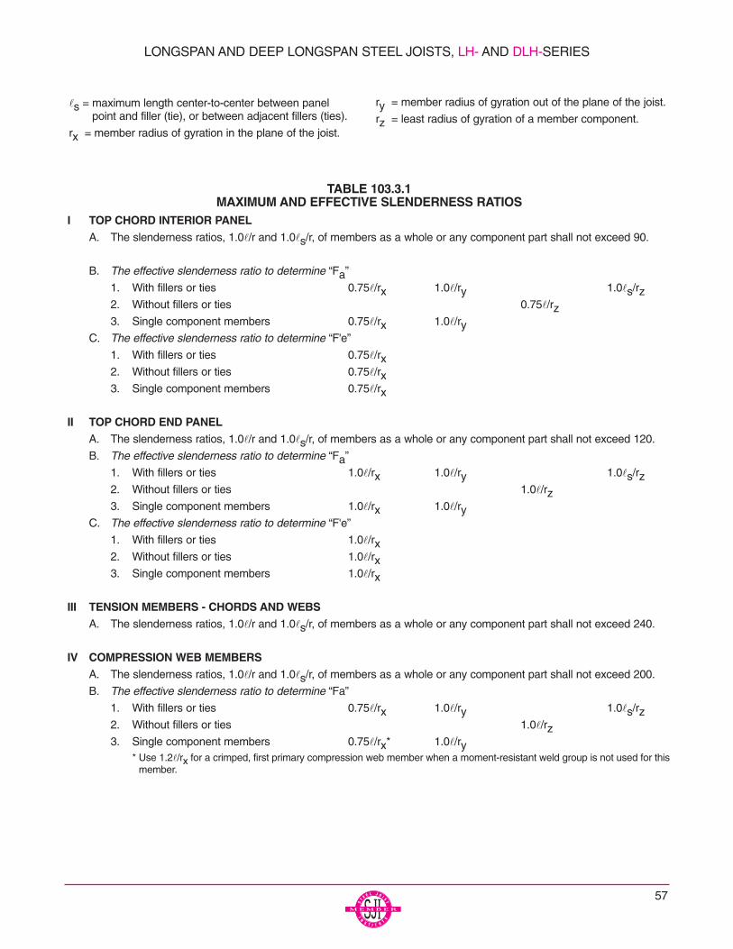
TABLE 103.3.1MAXIMUM AND EFFECTIVE SLENDERNESS RATIOS
I TOP CHORD INTERIOR PANELA. The slenderness ratios, 1.0l/r and 1.0ls/r, of members as a whole or any component part shall not exceed 90.
B. The effective slenderness ratio to determine “Fa”
1. With fillers or ties 0.75l/rx 1.0l/ry 1.0ls/rz2. Without fillers or ties 0.75l/rz3. Single component members 0.75l/rx 1.0l/ry
C. The effective slenderness ratio to determine “F'e”
1. With fillers or ties 0.75l/rx2. Without fillers or ties 0.75l/rx3. Single component members 0.75l/rx
II TOP CHORD END PANELA. The slenderness ratios, 1.0l/r and 1.0ls/r, of members as a whole or any component part shall not exceed 120.
B. The effective slenderness ratio to determine “Fa”
1. With fillers or ties 1.0l/rx 1.0l/ry 1.0ls/rz2. Without fillers or ties 1.0l/rz3. Single component members 1.0l/rx 1.0l/ry
C. The effective slenderness ratio to determine “F'e”
1. With fillers or ties 1.0l/rx2. Without fillers or ties 1.0l/rx3. Single component members 1.0l/rx
III TENSION MEMBERS - CHORDS AND WEBSA. The slenderness ratios, 1.0l/r and 1.0ls/r, of members as a whole or any component part shall not exceed 240.
IV COMPRESSION WEB MEMBERSA. The slenderness ratios, 1.0l/r and 1.0ls/r, of members as a whole or any component part shall not exceed 200.
B. The effective slenderness ratio to determine “Fa”
1. With fillers or ties 0.75l/rx 1.0l/ry 1.0ls/rz2. Without fillers or ties 1.0l/rz3. Single component members 0.75l/rx* 1.0l/ry
* Use 1.2l/rx for a crimped, first primary compression web member when a moment-resistant weld group is not used for thismember.
ls = maximum length center-to-center between panel point and filler (tie), or between adjacent fillers (ties).
rx = member radius of gyration in the plane of the joist.
ry = member radius of gyration out of the plane of the joist.
rz = least radius of gyration of a member component.
LONGSPAN AND DEEP LONGSPAN STEEL JOISTS, LH- AND DLH-SERIES
57
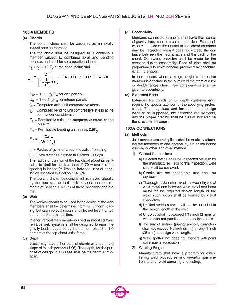
58
103.4 MEMBERS(a) Chords
The bottom chord shall be designed as an axiallyloaded tension member.
The top chord shall be designed as a continuousmember subject to combined axial and bendingstresses and shall be so proportioned that
fa + fb ≤ 0.6 Fy at the panel point; and
Cm = 1 - 0.3fa/F'e for end panels
Cm = 1 - 0.4fa/F'e for interior panels
fa = Computed axial unit compressive stress
fb = Computed bending unit compressive stress at thepoint under consideration
Fa = Permissible axial unit compressive stress basedon Kl/r.
Fb = Permissible bending unit stress; 0.6Fy
F'e =
rx = Radius of gyration about the axis of bending
Q = Form factor as defined in Section 103.2(b).
The radius of gyration of the top chord about its verti-cal axis shall be not less than l/170 where l is thespacing in inches (millimeter) between lines of bridg-ing as specified in Section 104.5(d).
The top chord shall be considered as stayed laterallyby the floor slab or roof deck provided the require-ments of Section 104.9(e) of these specifications aremet.
(b) WebThe vertical shears to be used in the design of the webmembers shall be determined from full uniform load-ing, but such vertical shears shall be not less than 25percent of the end reaction.
Interior vertical web members used in modified War-ren type web systems shall be designed to resist thegravity loads supported by the member plus ¹⁄₂ of 1.0percent of the top chord axial force.
(c) Depth Joists may have either parallel chords or a top chordslope of ¹⁄₈ inch per foot (1:96). The depth, for the pur-pose of design, in all cases shall be the depth at mid-span.
(d) EccentricityMembers connected at a joint shall have their centerof gravity lines meet at a point, if practical. Eccentrici-ty on either side of the neutral axis of chord membersmay be neglected when it does not exceed the dis-tance between the neutral axis and the back of thechord. Otherwise, provision shall be made for thestresses due to eccentricity. Ends of joists shall beproportioned to resist bending produced by eccentric-ity at the support.
In those cases where a single angle compressionmember is attached to the outside of the stem of a teeor double angle chord, due consideration shall begiven to eccentricity.
(e) Extended EndsExtended top chords or full depth cantilever endsrequire the special attention of the specifying profes-sional. The magnitude and location of the designloads to be supported, the deflection requirements,and the proper bracing shall be clearly indicated onthe structural drawings.
103.5 CONNECTIONS(a) Methods
Joist connections and splices shall be made by attach-ing the members to one another by arc or resistancewelding or other approved method.
1) Welded Connections
a) Selected welds shall be inspected visually bythe manufacturer. Prior to this inspection, weldslag shall be removed.
b) Cracks are not acceptable and shall berepaired.
c) Thorough fusion shall exist between layers ofweld metal and between weld metal and basemetal for the required design length of theweld; such fusion shall be verified by visualinspection.
d) Unfilled weld craters shall not be included inthe design length of the weld.
e) Undercut shall not exceed 1/16 inch (2 mm) forwelds oriented parallel to the principal stress.
f) The sum of surface (piping) porosity diametersshall not exceed ¹⁄₁₆ inch (2mm) in any 1 inch(25 mm) of design weld length.
g) Weld spatter that does not interfere with paintcoverage is acceptable.
2) Welding Program
Manufacturers shall have a program for estab-lishing weld procedures and operator qualifica-tion, and for weld sampling and testing.
LONGSPAN AND DEEP LONGSPAN STEEL JOISTS, LH- AND DLH-SERIES
59
3) Weld Inspection by Outside Agencies (See Sec-tion 104.13 of these specifications).
The agency shall arrange for visual inspection todetermine that welds meet the acceptance stan-dards of Section 103.5(a)(1) above. Ultrasonic,X-Ray, and magnetic particle testing are inappro-priate for joists due to the configurations of thecomponents and welds.
(b) StrengthJoint connections shall develop the maximum forcedue to any of the design loads, but not less than 50percent of the allowable strength of the member intension or compression, whichever force is the con-trolling factor in the selection of the member.
(c) Shop SplicesShop splices may occur at any point in chord or webmembers. Splices shall be designed for the memberforce but not less than 50 percent of the allowablemember strength. Members containing a butt weldsplice shall develop an ultimate tensile force of atleast 57 ksi (393 MPa) times the full design area ofthe chord or web. The term “member” shall bedefined as all component parts comprising the chordor web, at the point of splice.
(d) Field SplicesField Splices shall be designed by the manufacturerand may be either bolted or welded. Splices shall bedesigned for the member force, but not less than 50percent of the allowable member strength.
103.6 CAMBERJoists shall have approximate cambers in accordancewith the following:
Top Chord Length Approximate Camber
20'-0" (6096 mm) ¹⁄₄" (6mm)
30'-0" (9144 mm) ³⁄₈" (10 mm)
40'-0" (12192 mm) ⁵⁄₈" (16 mm)
50'-0" (15240 mm) 1" (25 mm)
60'-0" (18288 mm) 1¹⁄₂" (38 mm)
70'-0" (21336 mm) 2" (51 mm)
80'-0" (24384 mm) 2³⁄₄" (70 mm)
90'-0" (27432 mm) 3¹⁄₂" (89 mm)
100'-0" (30480 mm) 4¹⁄₄" (108 mm)
110'-0" (33528 mm) 5" (127 mm)
120'-0" (36576 mm) 6" (152 mm)
130-0" (39621 mm) 7" (178 mm)
140'-0" (42672 mm) 8" (203 mm)
144'-0" (43890 mm) 8¹⁄₂" (216 mm)
The specifying professional shall give due considerationto coordinating joist camber with adjacent framing.
103.7 VERIFICATION OF DESIGN AND MANUFACTURE
(a) Design CalculationsCompanies manufacturing any LH- or DLH-SeriesJoists shall submit design data to the Steel Joist Insti-tute (or an independent agency approved by the SteelJoist Institute) for verification of compliance with the SJISpecifications.
(d) In-Plant InspectionsEach manufacturer shall verify his ability to manufac-ture LH- and DLH-Series Joists through periodicIn-Plant Inspections. Inspections shall be performed byan independent agency approved by the Steel JoistInstitute. The frequency, manner of inspection, andmanner of reporting shall be determined by the SteelJoist Institute. The plant inspections are not a guaran-ty of the quality of any specific joists; this responsibilitylies fully and solely with the individual manufacturer.
104.1 USAGEThese specifications shall apply to any type of structurewhere floors and roofs are to be supported directly by steeljoists installed as hereinafter specified. Where joists areused other than on simple spans under uniformly distrib-uted loading as prescribed in Section 103.1, they shall beinvestigated and modified if necessary to limit the unitstresses to those listed in Section 103.2.CAUTION: If a rigid connection of the bottom chord is to bemade to the column or other support, it shall be made onlyafter the application of the dead loads. The joist is then nolonger simply supported, and the system must be investi-gated for continuous frame action by the specifying profes-sional.The designed detail of a rigid type connection and momentplates shall be shown on the structural drawings by thespecifying professional. The moment plates shall be fur-nished by other than the joist manufacturer.
104.2 SPANThe clear span of a joist shall not exceed 24 times its depth.The term “Span” as used herein is defined as the clear spanplus 8 inches (203mm).
104.3 DEPTHThe nominal depth of pitched chord joists shall be the depthat mid-span. The standard slope of the top chord shall be ¹⁄₈inch per foot (1:96).
104.4 END SUPPORTS(a) Masonry and Concrete
LH- and DLH-Series Joists supported by masonry orconcrete are to bear on steel bearing plates and shallbe designed as steel bearing. Due consideration of theend reactions and all other vertical and lateral forcesshall be taken by the specifying professional in thedesign of the steel bearing plate and the masonry orconcrete. The ends of LH- and DLH-Series Joists shallextend a distance of not less than 6 inches (152 mm)over the masonry or concrete support and be
SECTION 104.
APPLICATION
LONGSPAN AND DEEP LONGSPAN STEEL JOISTS, LH- AND DLH-SERIES
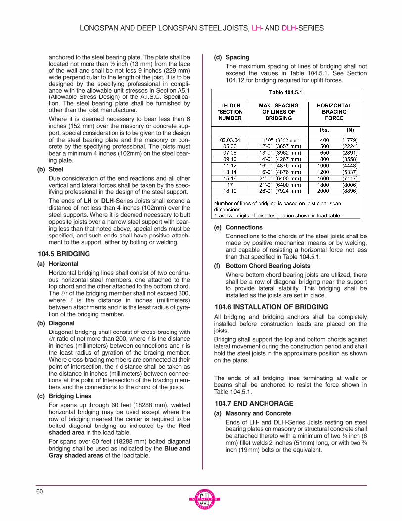
60
anchored to the steel bearing plate. The plate shall belocated not more than ¹⁄₂ inch (13 mm) from the faceof the wall and shall be not less 9 inches (229 mm)wide perpendicular to the length of the joist. It is to bedesigned by the specifying professional in compli-ance with the allowable unit stresses in Section A5.1(Allowable Stress Design) of the A.I.S.C. Specifica-tion. The steel bearing plate shall be furnished byother than the joist manufacturer. Where it is deemed necessary to bear less than 6inches (152 mm) over the masonry or concrete sup-port, special consideration is to be given to the designof the steel bearing plate and the masonry or con-crete by the specifying professional. The joists mustbear a minimum 4 inches (102mm) on the steel bear-ing plate.
(b) SteelDue consideration of the end reactions and all othervertical and lateral forces shall be taken by the spec-ifying professional in the design of the steel support.The ends of LH or DLH-Series Joists shall extend adistance of not less than 4 inches (102mm) over thesteel supports. Where it is deemed necessary to buttopposite joists over a narrow steel support with bear-ing less than that noted above, special ends must bespecified, and such ends shall have positive attach-ment to the support, either by bolting or welding.
104.5 BRIDGING(a) Horizontal
Horizontal bridging lines shall consist of two continu-ous horizontal steel members, one attached to thetop chord and the other attached to the bottom chord.The l/r of the bridging member shall not exceed 300,where l is the distance in inches (millimeters)between attachments and r is the least radius of gyra-tion of the bridging member.
(b) DiagonalDiagonal bridging shall consist of cross-bracing withl/r ratio of not more than 200, where l is the distancein inches (millimeters) between connections and r isthe least radius of gyration of the bracing member.Where cross-bracing members are connected at theirpoint of intersection, the l distance shall be taken asthe distance in inches (millimeters) between connec-tions at the point of intersection of the bracing mem-bers and the connections to the chord of the joists.
(c) Bridging LinesFor spans up through 60 feet (18288 mm), weldedhorizontal bridging may be used except where therow of bridging nearest the center is required to bebolted diagonal bridging as indicated by the Redshaded area in the load table.For spans over 60 feet (18288 mm) bolted diagonalbridging shall be used as indicated by the Blue andGray shaded areas of the load table.
(d) SpacingThe maximum spacing of lines of bridging shall notexceed the values in Table 104.5.1. See Section104.12 for bridging required for uplift forces.
(e) ConnectionsConnections to the chords of the steel joists shall bemade by positive mechanical means or by welding,and capable of resisting a horizontal force not lessthan that specified in Table 104.5.1.
(f) Bottom Chord Bearing JoistsWhere bottom chord bearing joists are utilized, thereshall be a row of diagonal bridging near the supportto provide lateral stability. This bridging shall beinstalled as the joists are set in place.
104.6 INSTALLATION OF BRIDGINGAll bridging and bridging anchors shall be completelyinstalled before construction loads are placed on thejoists. Bridging shall support the top and bottom chords againstlateral movement during the construction period and shallhold the steel joists in the approximate position as shownon the plans.
The ends of all bridging lines terminating at walls orbeams shall be anchored to resist the force shown inTable 104.5.1.
104.7 END ANCHORAGE(a) Masonry and Concrete
Ends of LH- and DLH-Series Joists resting on steelbearing plates on masonry or structural concrete shallbe attached thereto with a minimum of two ¹⁄₄ inch (6mm) fillet welds 2 inches (51mm) long, or with two ³⁄₄inch (19mm) bolts or the equivalent.
LONGSPAN AND DEEP LONGSPAN STEEL JOISTS, LH- AND DLH-SERIES
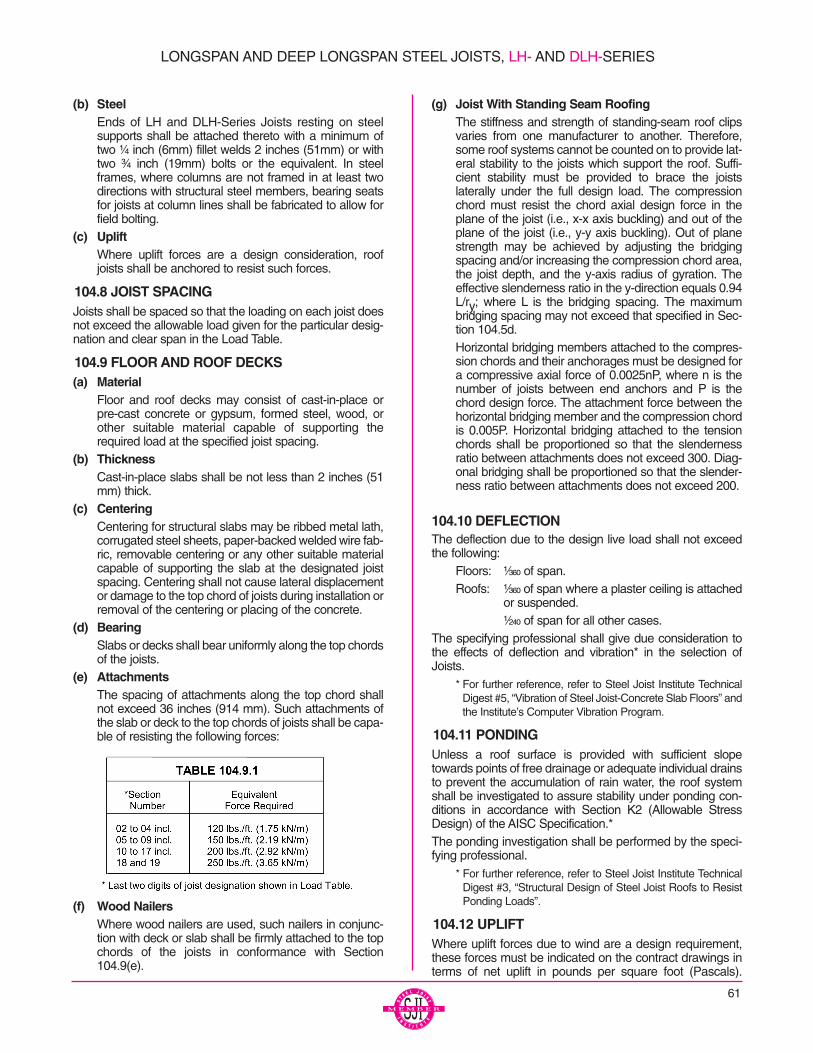
(b) SteelEnds of LH and DLH-Series Joists resting on steelsupports shall be attached thereto with a minimum oftwo ¹⁄₄ inch (6mm) fillet welds 2 inches (51mm) or withtwo ³⁄₄ inch (19mm) bolts or the equivalent. In steelframes, where columns are not framed in at least twodirections with structural steel members, bearing seatsfor joists at column lines shall be fabricated to allow forfield bolting.
(c) UpliftWhere uplift forces are a design consideration, roofjoists shall be anchored to resist such forces.
104.8 JOIST SPACINGJoists shall be spaced so that the loading on each joist doesnot exceed the allowable load given for the particular desig-nation and clear span in the Load Table.
104.9 FLOOR AND ROOF DECKS(a) Material
Floor and roof decks may consist of cast-in-place orpre-cast concrete or gypsum, formed steel, wood, orother suitable material capable of supporting therequired load at the specified joist spacing.
(b) ThicknessCast-in-place slabs shall be not less than 2 inches (51mm) thick.
(c) CenteringCentering for structural slabs may be ribbed metal lath,corrugated steel sheets, paper-backed welded wire fab-ric, removable centering or any other suitable materialcapable of supporting the slab at the designated joistspacing. Centering shall not cause lateral displacementor damage to the top chord of joists during installation orremoval of the centering or placing of the concrete.
(d) BearingSlabs or decks shall bear uniformly along the top chordsof the joists.
(e) AttachmentsThe spacing of attachments along the top chord shallnot exceed 36 inches (914 mm). Such attachments ofthe slab or deck to the top chords of joists shall be capa-ble of resisting the following forces:
(f) Wood NailersWhere wood nailers are used, such nailers in conjunc-tion with deck or slab shall be firmly attached to the topchords of the joists in conformance with Section104.9(e).
(g) Joist With Standing Seam RoofingThe stiffness and strength of standing-seam roof clipsvaries from one manufacturer to another. Therefore,some roof systems cannot be counted on to provide lat-eral stability to the joists which support the roof. Suffi-cient stability must be provided to brace the joistslaterally under the full design load. The compressionchord must resist the chord axial design force in theplane of the joist (i.e., x-x axis buckling) and out of theplane of the joist (i.e., y-y axis buckling). Out of planestrength may be achieved by adjusting the bridgingspacing and/or increasing the compression chord area,the joist depth, and the y-axis radius of gyration. Theeffective slenderness ratio in the y-direction equals 0.94L/ry; where L is the bridging spacing. The maximumbridging spacing may not exceed that specified in Sec-tion 104.5d. Horizontal bridging members attached to the compres-sion chords and their anchorages must be designed fora compressive axial force of 0.0025nP, where n is thenumber of joists between end anchors and P is thechord design force. The attachment force between thehorizontal bridging member and the compression chordis 0.005P. Horizontal bridging attached to the tensionchords shall be proportioned so that the slendernessratio between attachments does not exceed 300. Diag-onal bridging shall be proportioned so that the slender-ness ratio between attachments does not exceed 200.
104.10 DEFLECTIONThe deflection due to the design live load shall not exceedthe following:
Floors: ¹⁄₃₆₀ of span.Roofs: ¹⁄₃₆₀ of span where a plaster ceiling is attached
or suspended.¹⁄₂₄₀ of span for all other cases.
The specifying professional shall give due consideration tothe effects of deflection and vibration* in the selection ofJoists.
* For further reference, refer to Steel Joist Institute TechnicalDigest #5, “Vibration of Steel Joist-Concrete Slab Floors” andthe Institute’s Computer Vibration Program.
104.11 PONDINGUnless a roof surface is provided with sufficient slopetowards points of free drainage or adequate individual drainsto prevent the accumulation of rain water, the roof systemshall be investigated to assure stability under ponding con-ditions in accordance with Section K2 (Allowable StressDesign) of the AISC Specification.*The ponding investigation shall be performed by the speci-fying professional.
* For further reference, refer to Steel Joist Institute TechnicalDigest #3, “Structural Design of Steel Joist Roofs to ResistPonding Loads”.
104.12 UPLIFTWhere uplift forces due to wind are a design requirement,these forces must be indicated on the contract drawings interms of net uplift in pounds per square foot (Pascals).
LONGSPAN AND DEEP LONGSPAN STEEL JOISTS, LH- AND DLH-SERIES
61
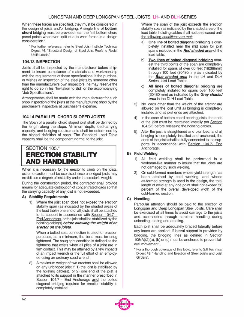
When these forces are specified, they must be considered inthe design of joists and/or bridging. A single line of bottomchord bridging must be provided near the first bottom chordpanel points whenever uplift due to wind forces is a designconsideration.*
* For further reference, refer to Steel Joist Institute TechnicalDigest #6, “Structural Design of Steel Joist Roofs to ResistUplift Loads.”
104.13 INSPECTIONJoists shall be inspected by the manufacturer before ship-ment to insure compliance of materials and workmanshipwith the requirements of these specifications. If the purchas-er wishes an inspection of the steel joists by someone otherthan the manufacturer’s own inspectors, he may reserve theright to do so in his “Invitation to Bid” or the accompanying“Job Specifications”. Arrangements shall be made with the manufacturer for suchshop inspection of the joists at the manufacturing shop by thepurchaser’s inspectors at purchaser’s expense.
104.14 PARALLEL CHORD SLOPED JOISTSThe Span of a parallel chord sloped joist shall be defined bythe length along the slope. Minimum depth, load-carryingcapacity, and bridging requirements shall be determined bythe sloped definition of span. The Standard Load Tablecapacity shall be the component normal to the joist.
When it is necessary for the erector to climb on the joists,extreme caution must be exercised since unbridged joists mayexhibit some degree of instability under the erector’s weight.During the construction period, the contractor shall providemeans for adequate distribution of concentrated loads so thatthe carrying capacity of any joist is not exceeded.A) Stability Requirements
1) Where the joist span does not exceed the erectionstability span (as indicated by the shaded areas ofthe load table) one end of all joists shall be attachedto its support in accordance with Section 104.7 –End Anchorage, or the joist shall be stabilized by thehoisting cable(s) before allowing the weight of anerector on the joists.When a bolted seat connection is used for erectionpurposes, as a minimum, the bolts must be snugtightened. The snug tight condition is defined as thetightness that exists when all plies of a joint are infirm contact. This may be attained by a few impactsof an impact wrench or the full effort of an employ-ee using an ordinary spud wrench.
2) A maximum weight of two erectors shall be allowedon any unbridged joist if: 1) the joist is stabilized bythe hoisting cable(s), or 2) one end of the joist isattached to its support in the manner prescribed inSection 104.7 - End Anchorage and the bolteddiagonal bridging required for erection stability iscompletely installed.
Where the span of the joist exceeds the erectionstability span as indicated by the shaded area of theload table, hoisting cables shall not be released untilthe following conditions are met:a) One line of bolted diagonal bridging is com-
pletely installed near the mid span for joistspans included in the Red shaded area of theload table.
b) Two lines of bolted diagonal bridging near-est the third points of the span are completelyinstalled for spans of over 60 feet (18288mm)through 100 feet (30480mm) as indicated bythe Blue shaded area in the LH and DLHSeries Joist Load Tables.
c) All lines of bolted diagonal bridging arecompletely installed for spans over 100 feet(30480 mm) as indicated by the Gray shadedarea in the DLH Load Table.
3) No loads other than the weight of the erector areallowed on the joist until all bridging is completelyinstalled and all joist ends are attached.
4) In the case of bottom chord bearing joists, the endsof the joist must be restrained laterally per Section104.5(f) before releasing the hoisting cables.
5) After the joist is straightened and plumbed, and allbridging is completely installed and anchored, theends of the joists shall be fully connected to the sup-ports in accordance with Section 104.7- EndAnchorage.
B) Field Welding1) All field welding shall be performed in a
workman-like manner to insure that the joists arenot damaged by such welding.
2) On cold-formed members whose yield strength hasbeen attained by cold working, and whoseas-formed strength is used in the design, the totallength of weld at any one point shall not exceed 50percent of the overall developed width of thecold-formed section.
C) HandlingParticular attention should be paid to the erection ofLongspan and Deep Longspan Steel Joists. Care shallbe exercised at all times to avoid damage to the joistsand accessories through careless handling duringunloading, storing and erecting.
Each joist shall be adequately braced laterally beforeany loads are applied. If lateral support is provided bybridging, the bridging lines as defined in Section105(A)(2)(a), (b) or (c) must be anchored to prevent lat-eral movement.* For a thorough coverage of this topic, refer to SJI Technical
Digest #9, “Handling and Erection of Steel Joists and JoistGirders”.
62
LONGSPAN AND DEEP LONGSPAN STEEL JOISTS, LH- AND DLH-SERIES
SECTION 105.*
ERECTION STABILITYAND HANDLING
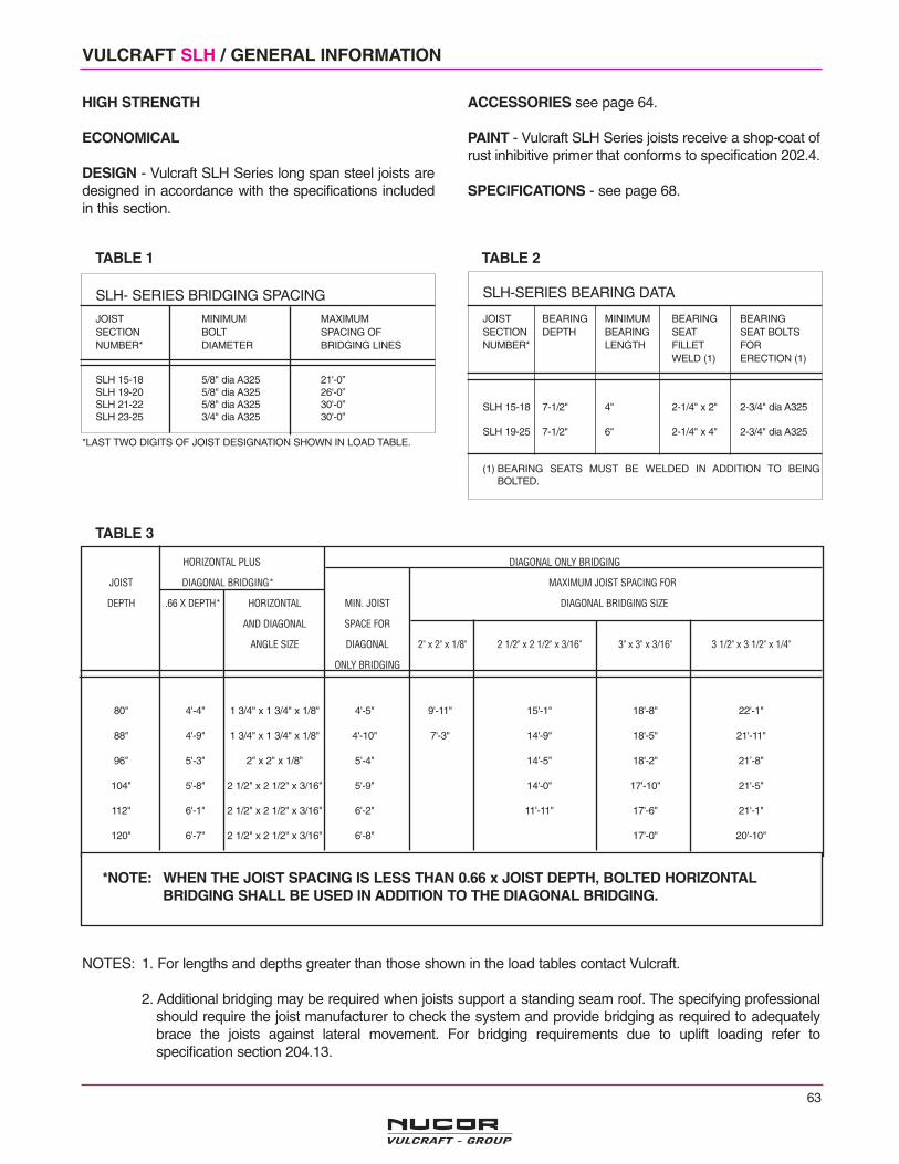
63
VULCRAFT SLH / GENERAL INFORMATION
HIGH STRENGTH
ECONOMICAL
DESIGN - Vulcraft SLH Series long span steel joists aredesigned in accordance with the specifications includedin this section.
ACCESSORIES see page 64.
PAINT - Vulcraft SLH Series joists receive a shop-coat ofrust inhibitive primer that conforms to specification 202.4.
SPECIFICATIONS - see page 68.
NOTES: 1. For lengths and depths greater than those shown in the load tables contact Vulcraft.
2. Additional bridging may be required when joists support a standing seam roof. The specifying professionalshould require the joist manufacturer to check the system and provide bridging as required to adequatelybrace the joists against lateral movement. For bridging requirements due to uplift loading refer tospecification section 204.13.
SLH- SERIES BRIDGING SPACING
JOIST MINIMUM MAXIMUMSECTION BOLT SPACING OFNUMBER* DIAMETER BRIDGING LINES
SLH 15-18 5/8" dia A325 21'-0”SLH 19-20 5/8" dia A325 26'-0”SLH 21-22 5/8" dia A325 30'-0”SLH 23-25 3/4" dia A325 30'-0”
SLH-SERIES BEARING DATA
JOIST BEARING MINIMUM BEARING BEARINGSECTION DEPTH BEARING SEAT SEAT BOLTSNUMBER* LENGTH FILLET FOR
WELD (1) ERECTION (1)
SLH 15-18 7-1/2" 4" 2-1/4" x 2" 2-3/4" dia A325
SLH 19-25 7-1/2" 6" 2-1/4" x 4" 2-3/4" dia A325
(1) BEARING SEATS MUST BE WELDED IN ADDITION TO BEINGBOLTED.
TABLE 1 TABLE 2
*LAST TWO DIGITS OF JOIST DESIGNATION SHOWN IN LOAD TABLE.
TABLE 3
HORIZONTAL PLUS DIAGONAL ONLY BRIDGING
JOIST DIAGONAL BRIDGING* MAXIMUM JOIST SPACING FOR
DEPTH .66 X DEPTH* HORIZONTAL MIN. JOIST DIAGONAL BRIDGING SIZE
AND DIAGONAL SPACE FOR
ANGLE SIZE DIAGONAL 2" x 2" x 1/8" 2 1/2" x 2 1/2" x 3/16" 3" x 3" x 3/16" 3 1/2" x 3 1/2" x 1/4"
ONLY BRIDGING
80" 4'-4" 1 3/4" x 1 3/4" x 1/8" 4'-5" 9'-11" 15'-1" 18'-8" 22'-1"
88" 4'-9" 1 3/4" x 1 3/4" x 1/8" 4'-10" 7'-3" 14'-9" 18'-5" 21'-11"
96" 5'-3" 2" x 2" x 1/8" 5'-4" 14'-5" 18'-2" 21’-8"
104" 5'-8" 2 1/2" x 2 1/2" x 3/16" 5'-9" 14'-0" 17'-10" 21'-5"
112" 6'-1" 2 1/2" x 2 1/2" x 3/16" 6'-2" 11'-11" 17'-6" 21'-1"
120" 6'-7" 2 1/2" x 2 1/2" x 3/16" 6'-8" 17'-0" 20'-10"
*NOTE: WHEN THE JOIST SPACING IS LESS THAN 0.66 x JOIST DEPTH, BOLTED HORIZONTALBRIDGING SHALL BE USED IN ADDITION TO THE DIAGONAL BRIDGING.
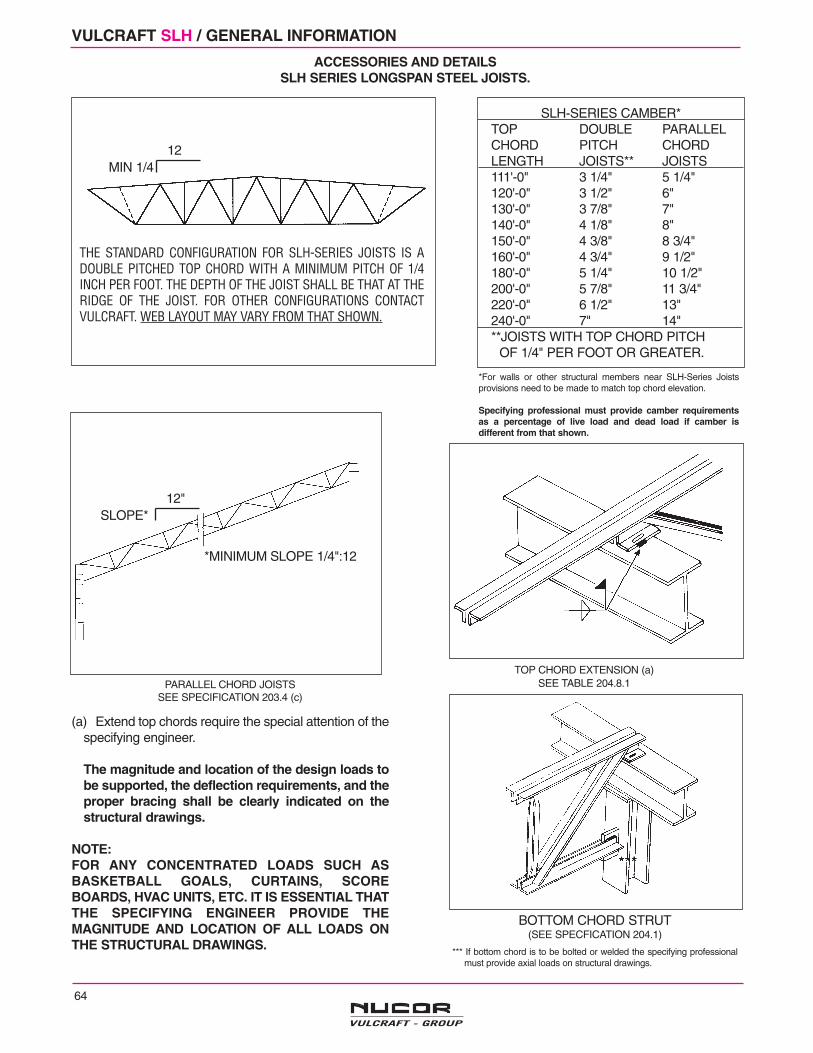
64
VULCRAFT SLH / GENERAL INFORMATION
ACCESSORIES AND DETAILSSLH SERIES LONGSPAN STEEL JOISTS.
SLH-SERIES CAMBER*TOP DOUBLE PARALLELCHORD PITCH CHORDLENGTH JOISTS** JOISTS111'-0" 3 1/4" 5 1/4"120'-0" 3 1/2" 6"130'-0" 3 7/8" 7"140'-0" 4 1/8" 8"150'-0" 4 3/8" 8 3/4"160'-0" 4 3/4" 9 1/2"180'-0" 5 1/4" 10 1/2"200'-0" 5 7/8" 11 3/4"220'-0" 6 1/2" 13"240'-0" 7" 14"**JOISTS WITH TOP CHORD PITCH
OF 1/4" PER FOOT OR GREATER.
*For walls or other structural members near SLH-Series Joistsprovisions need to be made to match top chord elevation.
Specifying professional must provide camber requirementsas a percentage of live load and dead load if camber isdifferent from that shown.
THE STANDARD CONFIGURATION FOR SLH-SERIES JOISTS IS ADOUBLE PITCHED TOP CHORD WITH A MINIMUM PITCH OF 1/4INCH PER FOOT. THE DEPTH OF THE JOIST SHALL BE THAT AT THERIDGE OF THE JOIST. FOR OTHER CONFIGURATIONS CONTACTVULCRAFT. WEB LAYOUT MAY VARY FROM THAT SHOWN.
(a) Extend top chords require the special attention of thespecifying engineer.
The magnitude and location of the design loads tobe supported, the deflection requirements, and theproper bracing shall be clearly indicated on thestructural drawings.
NOTE:FOR ANY CONCENTRATED LOADS SUCH ASBASKETBALL GOALS, CURTAINS, SCOREBOARDS, HVAC UNITS, ETC. IT IS ESSENTIAL THATTHE SPECIFYING ENGINEER PROVIDE THEMAGNITUDE AND LOCATION OF ALL LOADS ONTHE STRUCTURAL DRAWINGS.
BOTTOM CHORD STRUT(SEE SPECFICATION 204.1)
*** If bottom chord is to be bolted or welded the specifying professionalmust provide axial loads on structural drawings.
TOP CHORD EXTENSION (a)SEE TABLE 204.8.1
*MINIMUM SLOPE 1/4":12
SLOPE*12"
PARALLEL CHORD JOISTSSEE SPECIFICATION 203.4 (c)
MIN 1/412

65
ACCESSORIES AND DETAILSSLH SERIES LONGSPAN STEEL JOISTS
BOLTED CONNECTION (b)
SEE TABLE 2, PAGE 63.TYPICALLY USED AT COLUMNS
The Occupation Safety and Health AdministrationStandards (OSHA), Paragraph 1910.12 refers to Paragraph1518.751 of "Construction Standards" which states:
"In steel framing, where bar joists are utilized, and columnsare not framed in at least two directions with structural steelmembers, a bar joist shall be field-bolted at columns toprovide lateral stability during construction."
CROSS BRIDGING
A) HORIZONTAL BRIDGING IS TO BE USED IN THE SPACE ADJACENT TO THEWALL TO ALLOW FOR PROPER DEFLECTION OF THE JOIST NEAREST THEWALL. SEE TABLES 1 AND 3 PAGE 63.B) FOR REQUIRED BOLT SIZE REFER TO BRIDGING TABLE ON PAGE 63. NOTE:CLIP CONFIGURATION MAY VARY FROM THAT SHOWN.
BOLTED, HORIZONTAL PLUS DIAGONAL, BRIDGING
SEE TABLE 3, PAGE 63 AND SPECIFICATION 204.6.NOTE: CLIP CONFIGURATION MAY VARY FROM THAT SHOWN.NOTE: DO NOT HANG ANY MECHANICAL, ELECTRICAL, ETC. FROMBRIDGING.
ANCHORAGE TO STEELSEE TABLE 2, PAGE 63.
ANCHORAGE TO MASONRYSEE SPECIFICATION 204.5 (a)SEE TABLE 2, PAGE 63.
EXP. BOLTSBY OTHERS
BOLT (b)
(a)
BRIDGING ANCHORTYPE "SA"
ForGage
(ContactVulcraft) PLATE WITH
IMBEDDED ANCHORS(NOT BY VULCRAFT)
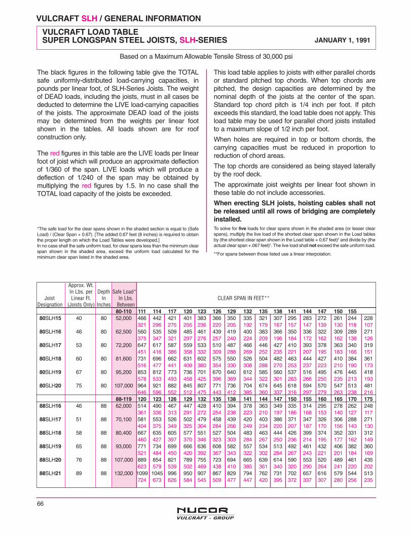
VULCRAFT SLH / GENERAL INFORMATION
66
Approx. Wt.In Lbs. per Depth Safe Load*
Joist Linear Ft. In In Lbs. CLEAR SPAN IN FEET**Designation (Joists Only) Inches Between
80-110 111 114 117 120 123 126 129 132 135 138 141 144 147 150 15580SLH15 40 80 52,000 466 442 421 401 383 366 350 335 321 307 295 283 272 261 244 228
321 296 275 255 236 220 205 192 179 167 157 147 139 130 118 10780SLH16 46 80 62,500 560 535 509 485 461 439 419 400 383 366 350 336 322 309 289 271
375 347 321 297 276 257 240 224 209 196 184 172 162 162 138 12680SLH17 53 80 72,200 647 617 587 559 533 510 487 466 446 427 410 393 378 363 340 319
451 416 386 358 332 309 288 269 252 235 221 207 195 183 166 15180SLH18 60 80 81,600 731 696 662 631 602 575 550 526 504 482 463 444 427 410 384 361
516 477 441 409 380 354 330 308 288 270 253 237 223 210 190 17380SLH19 67 80 95,200 853 812 773 736 701 670 640 612 585 560 537 516 495 476 445 418
578 533 493 458 425 396 369 344 322 301 283 266 250 235 213 19380SLH20 75 80 107,000 964 921 882 845 807 771 736 704 674 645 618 594 570 547 513 481
646 596 552 512 475 443 412 385 360 337 316 297 279 263 238 21688-119 120 123 126 129 132 135 138 141 144 147 150 155 160 165 170 175
88SLH16 46 88 62,000 514 490 467 447 428 410 394 378 363 349 335 314 295 278 262 248361 336 313 291 272 254 238 223 210 197 186 168 153 140 127 117
88SLH17 51 88 70,100 581 553 526 502 479 458 439 420 403 386 371 347 326 306 288 271404 375 349 325 304 284 266 249 234 220 207 187 170 156 143 130
88SLH18 58 88 80,400 667 635 605 577 551 527 504 483 463 444 426 399 374 352 331 312460 427 397 370 346 323 303 284 267 250 236 214 195 177 162 149
88SLH19 65 88 93,000 771 734 699 666 636 608 582 557 534 513 492 461 432 406 382 360521 484 450 420 392 367 343 322 302 284 267 243 221 201 184 169
88SLH20 76 88 107,000 889 854 821 789 755 723 694 665 639 614 590 553 520 489 461 435623 579 539 502 469 438 410 385 361 340 320 290 264 241 220 202
88SLH21 89 88 132,000 1099 1045 996 950 907 867 829 794 762 731 702 657 616 579 544 513724 673 626 584 545 509 477 447 420 395 372 337 307 280 256 235
The black figures in the following table give the TOTALsafe uniformly-distributed load-carrying capacities, inpounds per linear foot, of SLH-Series Joists. The weightof DEAD loads, including the joists, must in all cases bededucted to determine the LIVE load-carrying capacitiesof the joists. The approximate DEAD load of the joistsmay be determined from the weights per linear footshown in the tables. All loads shown are for roofconstruction only.
The red figures in this table are the LIVE loads per linearfoot of joist which will produce an approximate deflectionof 1/360 of the span. LIVE loads which will produce adeflection of 1/240 of the span may be obtained bymultiplying the red figures by 1.5. In no case shall theTOTAL load capacity of the joists be exceeded.
*The safe load for the clear spans shown in the shaded section is equal to (SafeLoad) / (Clear Span + 0.67). [The added 0.67 feet (8 inches) is required to obtainthe proper length on which the Load Tables were developed.]In no case shall the safe uniform load, for clear spans less than the minimum clearspan shown in the shaded area, exceed the uniform load calculated for theminimum clear span listed in the shaded area.
This load table applies to joists with either parallel chordsor standard pitched top chords. When top chords arepitched, the design capacities are determined by thenominal depth of the joists at the center of the span.Standard top chord pitch is 1/4 inch per foot. If pitchexceeds this standard, the load table does not apply. Thisload table may be used for parallel chord joists installedto a maximum slope of 1/2 inch per foot.
When holes are required in top or bottom chords, thecarrying capacities must be reduced in proportion toreduction of chord areas.
The top chords are considered as being stayed laterallyby the roof deck.
The approximate joist weights per linear foot shown inthese table do not include accessories.
When erecting SLH joists, hoisting cables shall notbe released until all rows of bridging are completelyinstalled.To solve for live loads for clear spans shown in the shaded area (or lesser clearspans), multiply the live load of the shortest clear span shown in the Load tablesby (the shortest clear span shown in the Load table + 0.67 feet)2 and divide by (theactual clear span +.067 feet)2. The live load shall not exceed the safe uniform load.
**For spans between those listed use a linear interpolation.
VULCRAFT LOAD TABLESUPER LONGSPAN STEEL JOISTS, SLH-SERIES JANUARY 1, 1991
Based on a Maximum Allowable Tensile Stress of 30,000 psi
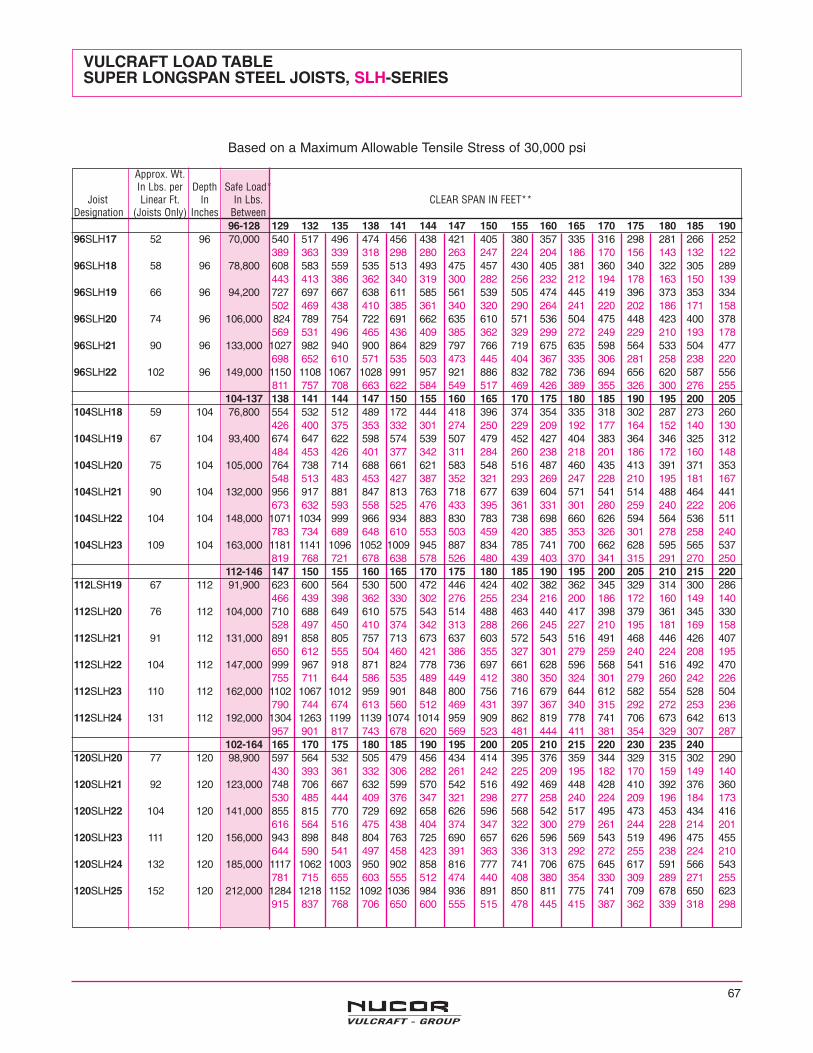
67
Based on a Maximum Allowable Tensile Stress of 30,000 psi
VULCRAFT LOAD TABLESUPER LONGSPAN STEEL JOISTS, SLH-SERIES
Approx. Wt.In Lbs. per Depth Safe Load*
Joist Linear Ft. In In Lbs. CLEAR SPAN IN FEET**Designation (Joists Only) Inches Between
96-128 129 132 135 138 141 144 147 150 155 160 165 170 175 180 185 19096SLH17 52 96 70,000 540 517 496 474 456 438 421 405 380 357 335 316 298 281 266 252
389 363 339 318 298 280 263 247 224 204 186 170 156 143 132 12296SLH18 58 96 78,800 608 583 559 535 513 493 475 457 430 405 381 360 340 322 305 289
443 413 386 362 340 319 300 282 256 232 212 194 178 163 150 13996SLH19 66 96 94,200 727 697 667 638 611 585 561 539 505 474 445 419 396 373 353 334
502 469 438 410 385 361 340 320 290 264 241 220 202 186 171 15896SLH20 74 96 106,000 824 789 754 722 691 662 635 610 571 536 504 475 448 423 400 378
569 531 496 465 436 409 385 362 329 299 272 249 229 210 193 17896SLH21 90 96 133,000 1027 982 940 900 864 829 797 766 719 675 635 598 564 533 504 477
698 652 610 571 535 503 473 445 404 367 335 306 281 258 238 22096SLH22 102 96 149,000 1150 1108 1067 1028 991 957 921 886 832 782 736 694 656 620 587 556
811 757 708 663 622 584 549 517 469 426 389 355 326 300 276 255104-137 138 141 144 147 150 155 160 165 170 175 180 185 190 195 200 205
104SLH18 59 104 76,800 554 532 512 489 172 444 418 396 374 354 335 318 302 287 273 260426 400 375 353 332 301 274 250 229 209 192 177 164 152 140 130
104SLH19 67 104 93,400 674 647 622 598 574 539 507 479 452 427 404 383 364 346 325 312484 453 426 401 377 342 311 284 260 238 218 201 186 172 160 148
104SLH20 75 104 105,000 764 738 714 688 661 621 583 548 516 487 460 435 413 391 371 353548 513 483 453 427 387 352 321 293 269 247 228 210 195 181 167
104SLH21 90 104 132,000 956 917 881 847 813 763 718 677 639 604 571 541 514 488 464 441673 632 593 558 525 476 433 395 361 331 301 280 259 240 222 206
104SLH22 104 104 148,000 1071 1034 999 966 934 883 830 783 738 698 660 626 594 564 536 511783 734 689 648 610 553 503 459 420 385 353 326 301 278 258 240
104SLH23 109 104 163,000 1181 1141 1096 1052 1009 945 887 834 785 741 700 662 628 595 565 537819 768 721 678 638 578 526 480 439 403 370 341 315 291 270 250
112-146 147 150 155 160 165 170 175 180 185 190 195 200 205 210 215 220112LSH19 67 112 91,900 623 600 564 530 500 472 446 424 402 382 362 345 329 314 300 286
466 439 398 362 330 302 276 255 234 216 200 186 172 160 149 140112SLH20 76 112 104,000 710 688 649 610 575 543 514 488 463 440 417 398 379 361 345 330
528 497 450 410 374 342 313 288 266 245 227 210 195 181 169 158112SLH21 91 112 131,000 891 858 805 757 713 673 637 603 572 543 516 491 468 446 426 407
650 612 555 504 460 421 386 355 327 301 279 259 240 224 208 195112SLH22 104 112 147,000 999 967 918 871 824 778 736 697 661 628 596 568 541 516 492 470
755 711 644 586 535 489 449 412 380 350 324 301 279 260 242 226112SLH23 110 112 162,000 1102 1067 1012 959 901 848 800 756 716 679 644 612 582 554 528 504
790 744 674 613 560 512 469 431 397 367 340 315 292 272 253 236112SLH24 131 112 192,000 1304 1263 1199 1139 1074 1014 959 909 862 819 778 741 706 673 642 613
957 901 817 743 678 620 569 523 481 444 411 381 354 329 307 287102-164 165 170 175 180 185 190 195 200 205 210 215 220 230 235 240
120SLH20 77 120 98,900 597 564 532 505 479 456 434 414 395 376 359 344 329 315 302 290430 393 361 332 306 282 261 242 225 209 195 182 170 159 149 140
120SLH21 92 120 123,000 748 706 667 632 599 570 542 516 492 469 448 428 410 392 376 360530 485 444 409 376 347 321 298 277 258 240 224 209 196 184 173
120SLH22 104 120 141,000 855 815 770 729 692 658 626 596 568 542 517 495 473 453 434 416616 564 516 475 438 404 374 347 322 300 279 261 244 228 214 201
120SLH23 111 120 156,000 943 898 848 804 763 725 690 657 626 596 569 543 519 496 475 455644 590 541 497 458 423 391 363 336 313 292 272 255 238 224 210
120SLH24 132 120 185,000 1117 1062 1003 950 902 858 816 777 741 706 675 645 617 591 566 543781 715 655 603 555 512 474 440 408 380 354 330 309 289 271 255
120SLH25 152 120 212,000 1284 1218 1152 1092 1036 984 936 891 850 811 775 741 709 678 650 623915 837 768 706 650 600 555 515 478 445 415 387 362 339 318 298
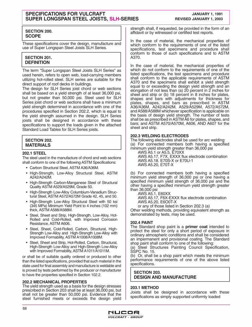
68
These specifications cover the design, manufacture anduse of Super Longspan Steel Joists SLH Series.
The term "Super Longspan Steel Joists SLH Series" asused herein, refers to open web, load-carrying membersutilizing hot-rolled steel. SLH series are suitable for thedirect support of roof decks in buildings.The design for SLH Series joist chord or web sectionsshall be based on a yield strength of at least 36,000 psi,but not greater than 50,000 psi. Steel used for SLHSeries joist chord or web sections shall have a minimumyield strength determined in accordance with one of theprocedures specified in Section 202.2, which is equal tothe yield strength assumed in the design. SLH Seriesjoists shall be designed in accordance with thesespecifications to support the loads given in the attachedStandard Load Tables for SLH Series joists.
202.1 STEELThe steel used in the manufacture of chord and web sectionsshall conform to one of the following ASTM Specifications:
• Carbon Structural Steel, ASTM A36/A36M.• High-Strength, Low-Alloy Structural Steel, ASTM
A242/A242M.• High-Strength Carbon-Manganese Steel of Structural
Quality ASTM A529/A529M, Grade 50.• High-Strength Low-Alloy Columbium-Vanadium Struc-
tural Steel, ASTM A572/A572M Grade 42, 45, and 50.• High-Strength Low-Alloy Structural Steel with 50 ksi
(345 MPa) Minimum Yield Point to 4 inches (102 mm)thick, ASTM A588/A588M.
• Steel, Sheet and Strip, High-Strength, Low-Alloy, Hot-Rolled and Cold-Rolled, with Improved CorrosionResistance, ASTM A606.
• Steel, Sheet, Cold-Rolled, Carbon, Structural, High-Strength Low-Alloy and High-Strength Low-Alloy withImproved Formability, ASTM A1008/A1008M.
• Steel, Sheet and Strip, Hot-Rolled, Carbon, Structural,High-Strength Low-Alloy and High-Strength Low-Alloywith Improved Formability, ASTM A1011/A1011M.
or shall be of suitable quality ordered or produced to otherthan the listed specifications, provided that such material in thestate used for final assembly and manufacture is weldable andis proved by tests performed by the producer or manufacturerto have the properties specified in Section 102.2.
202.2 MECHANICAL PROPERTIESThe yield strength used as a basis for the design stressesprescribed in Section 203 shall be at least 36,000 psi, butshall not be greater than 50,000 psi. Evidence that thesteel furnished meets or exceeds the design yield
strength shall, if requested, be provided in the form of anaffidavit or by witnessed or certified test reports.
In the case of material, the mechanical properties ofwhich conform to the requirements of one of the listedspecifications, test specimens and procedure shallconform to those of such specifications and to ASTMA370.
In the case of material, the mechanical properties ofwhich do not conform to the requirements of one of thelisted specifications, the test specimens and procedureshall conform to the applicable requirements of ASTMA370 and the specimens shall exhibit a yield strengthequal to or exceeding the design yield strength and anelongation of not less than (a) 20 percent in 2 inches forsheet and strip or (b) 18 percent in 8 inches for plates,shapes and bars with adjustments for thickness forplates, shapes, and bars as prescribed in ASTMA36/A36M, A242/A242M, A529/A529M, A572/A572M,and A588/A588M whichever specification is applicable onthe basis of design yield strength. The number of testsshall be as prescribed in ASTM A6 for plates, shapes, andbars; and ASTM A570/A570M, A606, AND A607 for thesheet and strip.
202.3 WELDING ELECTRODESThe following electrodes shall be used for arc welding:(a) For connected members both having a specifiedminimum yield strength greater than 36,000 psi
AWS A5.1 or A5.5, E70XXAWS A5.17, F7X, EXXX flux electrode combinationAWS A5.18. E70S-X or E70U-1AWS A5.20, E70T-X
(b) For connected members both having a specifiedminimum yield strength of 36,000 psi or one having aspecified minimum yield strength of 36,000 psi and theother having a specified minimum yield strength greaterthan 36,000 psi
AWS A5.1, E60XXAWS A5.17, F6X-EXXX flux electrode combinationAWS A5.20, E6O0T-Xor any of those listed in Section 202.3 (a)
Other welding methods, providing equivalent strength asdemonstrated by tests, may be used.
202.4 PAINTThe Standard shop paint is a primer coat intended toprotect the steel for only a short period of exposure inordinary atmospheric conditions and shall be consideredan impermanent and provisional coating. The Standardshop paint shall conform to one of the following:(a) Steel Structures Painting Council Specification,SSPC No. 15.(b) Or, shall be a shop paint which meets the minimumperformance requirements of one of the above listedspecifications.
203.1 METHODJoists shall be designed in accordance with thesespecifications as simply supported uniformly loaded
SPECIFICATIONS FOR VULCRAFT JANUARY 1, 1991SUPER LONGSPAN STEEL JOISTS, SLH-SERIES REVISED JANUARY 1, 2003
SECTION 200.SCOPE
SECTION 201.DEFINITION
SECTION 202.MATERIALS
SECTION 203.DESIGN AND MANUFACTURE
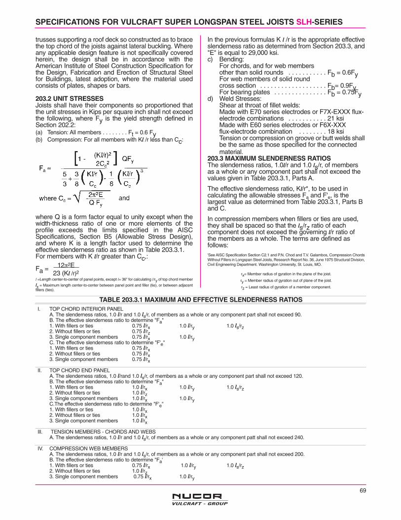
69
SPECIFICATIONS FOR VULCRAFT SUPER LONGSPAN STEEL JOISTS SLH-SERIES
trusses supporting a roof deck so constructed as to bracethe top chord of the joists against lateral buckling. Whereany applicable design feature is not specifically coveredherein, the design shall be in accordance with theAmerican Institute of Steel Construction Specification forthe Design, Fabrication and Erection of Structural Steelfor Buildings, latest adoption, where the material usedconsists of plates, shapes or bars.
203.2 UNIT STRESSESJoists shall have their components so proportioned thatthe unit stresses in Kips per square inch shall not exceedthe following, where Fy is the yield strength defined inSection 202.2:(a) Tension: All members . . . . . . . . Ft = 0.6 Fy(b) Compression: For all members with Kl /r less than Cc:
where Q is a form factor equal to unity except when thewidth-thickness ratio of one or more elements of theprofile exceeds the limits specified in the AISCSpecifications, Section B5 (Allowable Stress Design),and where K is a length factor used to determine theeffective slenderness ratio as shown in Table 203.3.1.For rnembers with K l/r greater than Cc,:
Fa =
l =Length center-to-center of panel points, except l= 36" for calculating l/ry of top chord member
ls = Maximum length center-to-center between panel point and filler (tie), or between adjacentfillers (ties).
In the previous formulas K l /r is the appropriate effectiveslenderness ratio as determined from Section 203.3, and"E" is equal to 29,000 ksi.c) Bending:
For chords, and for web membersother than solid rounds . . . . . . . . . . . Fb = 0.6FyFor web members of solid roundcross section . . . . . . . . . . . . . . . . . . . Fb= 0.9FyFor bearing plates . . . . . . . . . . . . . . . Fb = 0.75Fy
d) Weld Stresses:Shear at throat of fillet welds:Made with E70 series electrodes or F7X-EXXX flux-electrode combinations . . . . . . . . . . . 21 ksiMade with E60 series electrodes or F6X-XXXflux-electrode combination . . . . . . . . 18 ksiTension or compression on groove or butt welds shallbe the same as those specified for the connectedmaterial.
203.3 MAXIMUM SLENDERNESS RATIOSThe slenderness ratios, 1.0l/r and 1.0 ls/r, of membersas a whole or any component part shall not exceed thevalues given in Table 203.3.1, Parts A.
The effective slenderness ratio, Kl/r*, to be used incalculating the allowable stresses Fa and F'e, is thelargest value as determined from Table 203.3.1, Parts Band C.
In compression members when fillers or ties are used,they shall be spaced so that the ls/rz ratio of eachcomponent does not exceed the governing l/r ratio ofthe members as a whole. The terms are defined asfollows:'See AISC Specification Section C2.1 and P.N. Chod and T.V. Galambos, Compression ChordsWithout Fillers in Longspan Steel Joists, Research Report No. 36, June 1975 Structural Division,Civil Engineering Department. Washington University, St. Louis, MO.
rx= Member radius of gyration in the plane of the joist.
ry = Member radius of gyration out of plane of the joist.
rz = Least radius of gyration of a member component.
TABLE 203.3.1 MAXIMUM AND EFFECTIVE SLENDERNESS RATIOSI. TOP CHORD INTERIOR PANEL
A. The slenderness ratios, 1.0 l/r and 1.0 ls/r, of members as a whole or any component part shall not exceed 90.B. The effective slenderness ratio to determine "Fa"1. With fillers or ties 0.75 l/rx 1.0 l/ry 1.0 ls/rz2. Without fillers or ties 0.75 l/rz3. Single component members 0.75 l/rx 1.0 l/ryC. The effective slenderness ratio to determine "F'e"1. With fillers or ties 0.75 l/rx2. Without fillers or ties 0.75 l/rx3. Single component members 0.75 l/rx
II. TOP CHORD END PANELA. The slenderness ratios, 1.0 l/rand 1.0 ls/r, of members as a whole or any component part shall not exceed 120.B. The effective slenderness ratio to determine "Fa"1. With fillers or ties 1.0 l/rx 1.0 l/ry 1.0 ls/rz2. Without fillers or ties 1.0 l/rz3. Single component members 1.0 l/rx 1.0 l/ryC.The effective slenderness ratio to determine "F'e"1. With fillers or ties 1.0 l/rx2. Without fillers or ties 1.0 l/rx3. Single component members 1.0 l/rx
Ill. TENSION MEMBERS - CHORDS AND WEBSA. The slenderness ratios, 1.0 l/r and 1.0 ls/r, of members as a whole or any component patt shall not exceed 240.
IV. COMPRESSION WEB MEMBERSA. The slenderness ratios, 1.0 l/r and 1.0 ls/r, of members as a whole or any component part shall not exceed 200.B. The effective slenderness ratio to determine "Fa'1. With fillers or ties 0.75 l/rx 1.0 l/ry 1.0 ls/rz2. Without fillers or ties 1.0 l/rz3. Single component members 0.75 l/rx 1.0 l/ry
12π2E23 (Kl /r)2
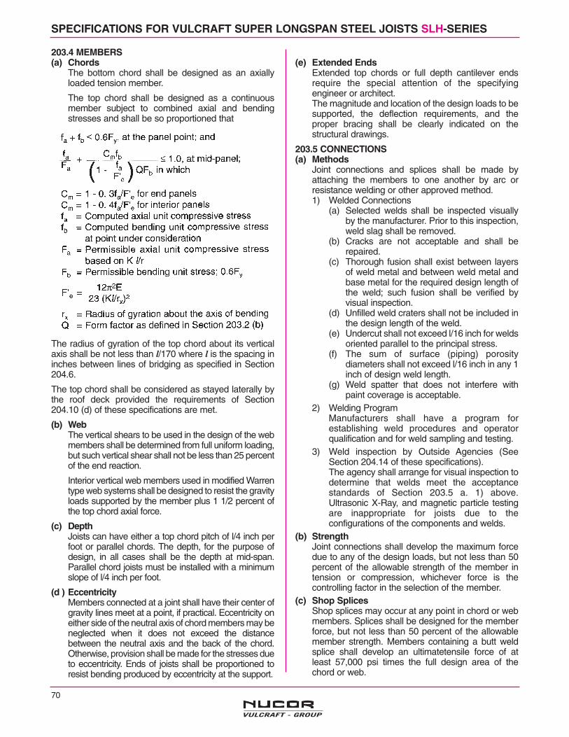
70
SPECIFICATIONS FOR VULCRAFT SUPER LONGSPAN STEEL JOISTS SLH-SERIES
203.4 MEMBERS(a) Chords
The bottom chord shall be designed as an axiallyloaded tension member.
The top chord shall be designed as a continuousmember subject to combined axial and bendingstresses and shall be so proportioned that
The radius of gyration of the top chord about its verticalaxis shall be not less than l/170 where l is the spacing ininches between lines of bridging as specified in Section204.6.
The top chord shall be considered as stayed laterally bythe roof deck provided the requirements of Section204.10 (d) of these specifications are met.
(b) WebThe vertical shears to be used in the design of the webmembers shall be determined from full uniform loading,but such vertical shear shall not be less than 25 percentof the end reaction.
Interior vertical web members used in modified Warrentype web systems shall be designed to resist the gravityloads supported by the member plus 1 1/2 percent ofthe top chord axial force.
(c) DepthJoists can have either a top chord pitch of l/4 inch perfoot or parallel chords. The depth, for the purpose ofdesign, in all cases shall be the depth at mid-span.Parallel chord joists must be installed with a minimumslope of l/4 inch per foot.
(d ) EccentricityMembers connected at a joint shall have their center ofgravity lines meet at a point, if practical. Eccentricity oneither side of the neutral axis of chord members may beneglected when it does not exceed the distancebetween the neutral axis and the back of the chord.Otherwise, provision shall be made for the stresses dueto eccentricity. Ends of joists shall be proportioned toresist bending produced by eccentricity at the support.
(e) Extended EndsExtended top chords or full depth cantilever endsrequire the special attention of the specifyingengineer or architect.The magnitude and location of the design loads to besupported, the deflection requirements, and theproper bracing shall be clearly indicated on thestructural drawings.
203.5 CONNECTIONS(a) Methods
Joint connections and splices shall be made byattaching the members to one another by arc orresistance welding or other approved method.1) Welded Connections
(a) Selected welds shall be inspected visuallyby the manufacturer. Prior to this inspection,weld slag shall be removed.
(b) Cracks are not acceptable and shall berepaired.
(c) Thorough fusion shall exist between layersof weld metal and between weld metal andbase metal for the required design length ofthe weld; such fusion shall be verified byvisual inspection.
(d) Unfilled weld craters shall not be included inthe design length of the weld.
(e) Undercut shall not exceed l/16 inch for weldsoriented parallel to the principal stress.
(f) The sum of surface (piping) porositydiameters shall not exceed l/16 inch in any 1inch of design weld length.
(g) Weld spatter that does not interfere withpaint coverage is acceptable.
2) Welding ProgramManufacturers shall have a program forestablishing weld procedures and operatorqualification and for weld sampling and testing.
3) Weld inspection by Outside Agencies (SeeSection 204.14 of these specifications).The agency shall arrange for visual inspection todetermine that welds meet the acceptancestandards of Section 203.5 a. 1) above.Ultrasonic X-Ray, and magnetic particle testingare inappropriate for joists due to theconfigurations of the components and welds.
(b) StrengthJoint connections shall develop the maximum forcedue to any of the design loads, but not less than 50percent of the allowable strength of the member intension or compression, whichever force is thecontrolling factor in the selection of the member.
(c) Shop SplicesShop splices may occur at any point in chord or webmembers. Splices shall be designed for the memberforce, but not less than 50 percent of the allowablemember strength. Members containing a butt weldsplice shall develop an ultimatetensile force of atleast 57,000 psi times the full design area of thechord or web.
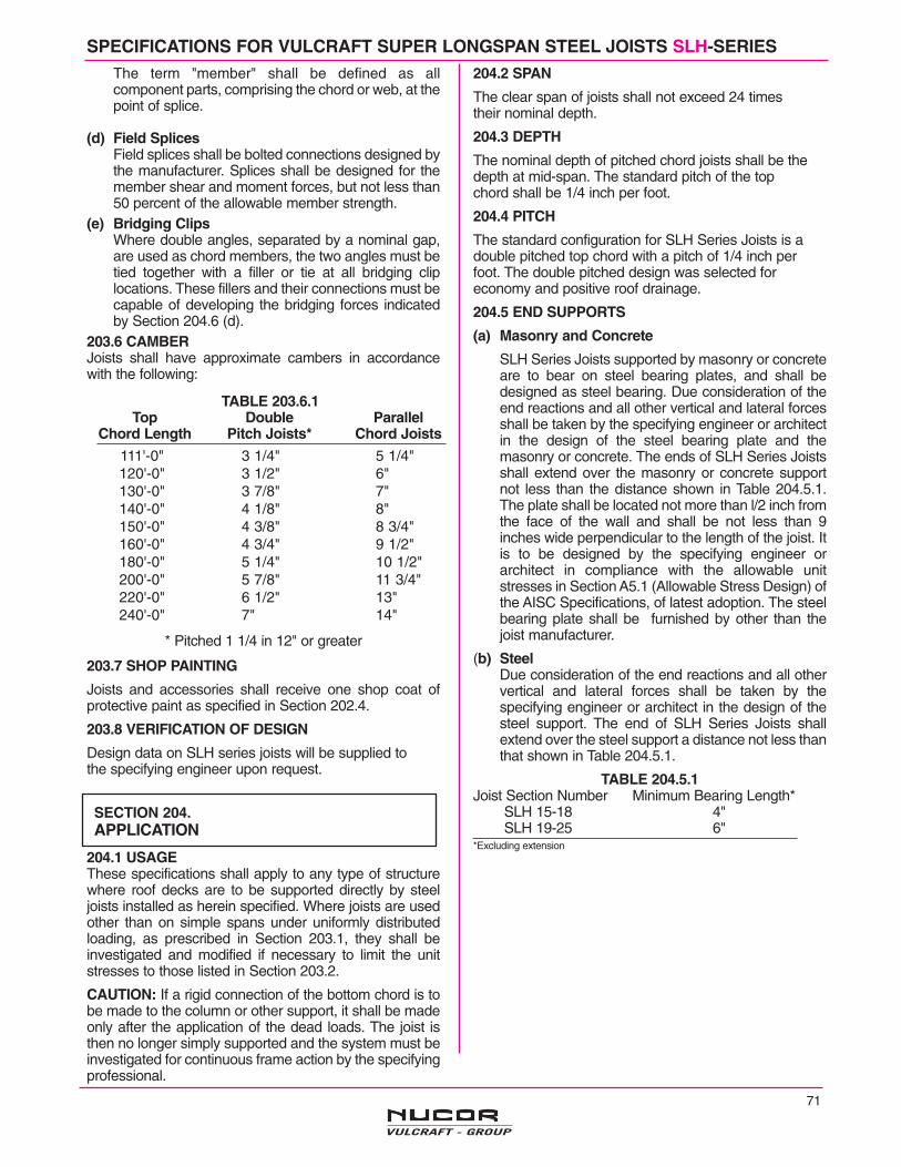
SPECIFICATIONS FOR VULCRAFT SUPER LONGSPAN STEEL JOISTS SLH-SERIESThe term "member" shall be defined as allcomponent parts, comprising the chord or web, at thepoint of splice.
(d) Field SplicesField splices shall be bolted connections designed bythe manufacturer. Splices shall be designed for themember shear and moment forces, but not less than50 percent of the allowable member strength.
(e) Bridging ClipsWhere double angles, separated by a nominal gap,are used as chord members, the two angles must betied together with a filler or tie at all bridging cliplocations. These fillers and their connections must becapable of developing the bridging forces indicatedby Section 204.6 (d).
203.6 CAMBERJoists shall have approximate cambers in accordancewith the following:
* Pitched 1 1/4 in 12" or greater
203.7 SHOP PAINTING
Joists and accessories shall receive one shop coat ofprotective paint as specified in Section 202.4.
203.8 VERIFICATION OF DESIGN
Design data on SLH series joists will be supplied tothe specifying engineer upon request.
204.1 USAGEThese specifications shall apply to any type of structurewhere roof decks are to be supported directly by steeljoists installed as herein specified. Where joists are usedother than on simple spans under uniformly distributedloading, as prescribed in Section 203.1, they shall beinvestigated and modified if necessary to limit the unitstresses to those listed in Section 203.2.
CAUTION: If a rigid connection of the bottom chord is tobe made to the column or other support, it shall be madeonly after the application of the dead loads. The joist isthen no longer simply supported and the system must beinvestigated for continuous frame action by the specifyingprofessional.
204.2 SPAN
The clear span of joists shall not exceed 24 timestheir nominal depth.
204.3 DEPTH
The nominal depth of pitched chord joists shall be thedepth at mid-span. The standard pitch of the topchord shall be 1/4 inch per foot.
204.4 PITCH
The standard configuration for SLH Series Joists is adouble pitched top chord with a pitch of 1/4 inch perfoot. The double pitched design was selected foreconomy and positive roof drainage.
204.5 END SUPPORTS
(a) Masonry and Concrete
SLH Series Joists supported by masonry or concreteare to bear on steel bearing plates, and shall bedesigned as steel bearing. Due consideration of theend reactions and all other vertical and lateral forcesshall be taken by the specifying engineer or architectin the design of the steel bearing plate and themasonry or concrete. The ends of SLH Series Joistsshall extend over the masonry or concrete supportnot less than the distance shown in Table 204.5.1.The plate shall be located not more than l/2 inch fromthe face of the wall and shall be not less than 9inches wide perpendicular to the length of the joist. Itis to be designed by the specifying engineer orarchitect in compliance with the allowable unitstresses in Section A5.1 (Allowable Stress Design) ofthe AISC Specifications, of latest adoption. The steelbearing plate shall be furnished by other than thejoist manufacturer.
(b) SteelDue consideration of the end reactions and all othervertical and lateral forces shall be taken by thespecifying engineer or architect in the design of thesteel support. The end of SLH Series Joists shallextend over the steel support a distance not less thanthat shown in Table 204.5.1.
TABLE 204.5.1Joist Section Number Minimum Bearing Length*
SLH 15-18 4"SLH 19-25 6"
*Excluding extension
SECTION 204.APPLICATION
TABLE 203.6.1Top Double Parallel
Chord Length Pitch Joists* Chord Joists
111'-0"120'-0"130'-0"140'-0"150'-0"160'-0"180'-0"200'-0"220'-0"240'-0"
3 1/4"3 1/2"3 7/8"4 1/8"4 3/8"4 3/4"5 1/4"5 7/8"6 1/2"7"
5 1/4"6"7"8"8 3/4"9 1/2"10 1/2"11 3/4"13"14"
71

72
SPECIFICATIONS FOR VULCRAFT SUPER LONGSPAN STEEL JOISTS SLH-SERIES
204.6 BRIDGING
(a) HorizontalHorizontal bridging lines shall consist of twocontinuous horizontal steel members, one attachedto the top chord and the other attached to the bottomchord. The l/r ratio of the bridging member shall notexceed 300, where l is the distance in inchesbetween attachments and r is the least radius ofgyration of the bridging member.
(b) DiagonalDiagonal bridging lines shall consist of cross-bracingwith l/r ratio of not more than 200, where l is thedistance in inches between connections and r is theleast radius of gyration of the bracing member.Where cross-bracing members are connected attheir point of intersection, the l distance shall be takenas the distance in inches between connections at thepoint of intersection of the bracing members and theconnections to the chords of the joists.
(c) Bridging LinesBolted diagonal bridging shall be used except whenthe joist spacing is less than .66 x joist depth, thenbolted horizontal bridging shall be used in addition todiagonal bridging.
(d) SpacingThe maximum spacing of lines of bridging shall notexceed the values in Table 204.6.1. Bridging shall beinstalled near a bottom chord panel point or an extraweb member shall be furnished to brace the bottomchord for the vertical component of the bridging forceequal to the horizontal bracing force. See Section204.13 for bridging required for uplift forces.
TABLE 204.6.1
Joist-Section Max. Spac. Of HorizontalNumber* Lines Of Bridging Bracing Force**15 to 17 21'-0" 2,700 Ibs
18 21'-0" 3,400 Ibs19 26'-0" 3,400 Ibs20 26'-0" 3,700 Ibs21 30'-0" 4,200 Ibs22 30'-0" 5,000 Ibs23 30'-0" 5,500 Ibs24 30'-0" 6,300 Ibs25 30'-0" 7,100 Ibs
The number of lines of bridging is based on the joistsclear span dimensions. * Last two digits of designation shown in load table.
** Each connection to the chord shall resist one-half ofthis force.
(e) ConnectionsConnections to the chords of the steel joists andbridging anchors shall be made by positivemechanical means and capable of resisting ahorizontal force not less than that specified in Table204.6.1.
(f) Bottom Chord Bearing JoistsIt is not recommended that SLH-Series joists beused in bottom chord bearing configuration.
204.7 INSTALLATION OF BRIDGINGAll bridging and bridging anchors shall be completelyinstalled before construction loads are placed on thejoists. Bridging shall support the top and bottom chordsagainst lateral movement during the construction periodand shall hold the steel joists in the approximate positionas shown on the plans.
The ends of all bridging lines terminating at walls orbeams shall be anchored thereto.
204.8 END ANCHORAGE(a) Masonry and Concrete
Ends of SLH Series Joists resting on steel bearingplates on masonry or structural concrete shall beattached thereto as shown Table 204.8.1.
(b) SteelEnds of SLH Series Joists resting on steel supportsshall be attached thereto as shown in Table 204.8.1.In steel frames, where columns are not framed in atleast two directions with structural steel members,joists at column lines shall be field bolted at thecolumns to provide lateral stability duringconstruction.
TABLE 204.8.1 END ANCHORAGEJoist Section No.* Fillet Weld Bearing Seat Bolts
For ErectionSLH 15-18 2 - 1/4" x 2" 2 - 3/4" A325SLH 19-25 2 - 1/4" x 4" 2 - 3/4" A325
*Last two digits of designation shown in load table.
(c) UpliftWhere uplift forces are a design consideration, roofjoists shall be anchored to resist such forces.
204.9 JOIST SPACINGJoists shall be spaced so that the loading on each joistdoes not exceed the allowable load given for theparticular designation and span in the Load Table.
204.10 ROOF DECKS(a) Material
Decks may consist of cast-in-place or precastconcrete or gypsum, formed steel, wood or othersuitable material capable of supporting the requiredload at the specified joist spacing.
(b) ThicknessCast-in-place slabs shall not be less than 2 inchesthick.
(c) BearingSlabs or decks shall bear uniformly along the topchords of the joist.

73
SPECIFICATIONS FOR VULCRAFT SUPER LONGSPAN STEEL JOISTS, SLH-SERIES
(d) AttachmentsThe spacing of attachments along the top chordshall not exceed 36 inches. Such attachments of theslab or deck to the top chords of joists shall becapable of resisting the following forces:
TABLE 204.10.1Joist Section Number* Equivalent Force Required
15 - 16 incl. 300 Ibs./ft.17 - 19 incl. 300 Ibs./ft.20 - 21 incl. 300 Ibs./ft.22 - 24 incl 420 Ibs./ft.25 520 Ibs./ft.
*Last two digits of designation shown in load table.
(e) Wood NailersIt is not recommended that SLH-Series joists be usedin conjunction with wood nailers.
(f) Joist With Standing Seam RoofingThe stiffness and strength of standing-seam roof clipsvaries from one manufacturer to another. Therefore,some roof systems cannot be counted on to providelateral stability to the joists which support the roof. Suf-ficient stability must be provided to brace the joists lat-erally under the full design load. The compressionchord must resist the chord axial design force in theplane of the joist (i.e., x-x axis buckling) and out of theplane of the joist (i.e., y-y axis buckling). Out of planestrength may be achieved by adjusting the bridgingspacing and/or increasing the compression chord area,the joist depth, and the y-axis radius of gyration. Theeffective slenderness ratio in the y-direction equals0.94 L/ry; where L is the bridging spacing. The maxi-mum bridging spacing may not exceed that specified inSection 204.6d.
204.11 DEFLECTIONThe deflection due to the design live load shall notexceed the following:Roofs
l/360 of span where plaster ceiling is attached orsuspended.
l/240 of span for all other cases.The specifying engineer or architect shall give dueconsideration to the effects of deflection in selection ofjoists.
204.12 PONDINGUnless a roof surface is provided with sufficient slopetoward points of free drainage or adequate individualdrains to prevent the accumulation of rain water, the roofsystem shall be investigated to assure stability underponding conditions in accordance with Section K2(Allowable Stress Design) of the AISC Specifications.* A top chord pitch of 1/4" or more per foot isrecommended to minimize ponding.The ponding investigation shall be performed by thespecifying engineer or architect.* For further information, refer to Steel Joist Institute Technical Digest
#3, "Structural Design of Steel Joist Roofs to Resist Ponding Loads".
204.13 UPLIFTWhere uplift forces due to wind are a designrequirement, these forces must be indicated on thestructural drawings in terms of net uplift in pounds persquare foot. When these forces are specified, they mustbe considered in the design of joists and bridging. Asingle line of bottom chord bridging must be providednear the first bottom chord panel points, whenever upliftdue to wind forces is a design consideration.**
** For further information, refer to Steel Joist Institute Technical Digest#6, "Structural Design of Steel Joist Roofs to Resist Uplift Loads".
204.14 INSPECTIONJoists shall be inspected by the manufacturer beforeshipment to insure compliance of materials andworkmanship with the requirements of thesespecifications. If the purchaser wishes an inspection ofthe steel joists by someone other than themanufacturer's own inspectors, he may reserve the rightto do so in the "Invitation to Bid" or the accompanying"Job Specifications". Arrangements shall be made withthe manufacturer for such inspection of the joists at themanufacturing facility by the purchaser's inspectors atpurchaser's expense.
Particular attention should be paid to the erection ofSuper Longspan Steel Joists.Care shall be exercised at all times to avoid damagethrough careless handling during unloading, storing, anderecting. Dropping of joists shall not be permitted.Each joist shall be adequately braced laterally before anyloads are applied. If lateral support is provided by bridging,the bridging lines must be anchored to prevent lateralmovement.Hoisting cables attached at a panel point approximately 1/5of the span from each end will minimize erection stressesin the steel joist. The angle of the hoisting cables fromthe vertical shall not exceed 30 degrees. Two cranesare recommended for spans greater than 150 feet.
Hoisting cables shall not be released until allbridging lines are installed. For ease of alignment,anchorage of joist ends in accordance with Section 204.8should follow the installation of bridging. During theconstruction period, the contractor shall provide meansfor the adequate distribution of concentrated loads so thecarrying capacity of any joist is not exceeded.
* For thorough coverage of this topic, refer to the Steel Joist InstituteTechnical Digest #9, "Handling and Erection of Steel Joists andGirders”.
SECTION 205.HANDLING AND ERECTION*

74
NOTES
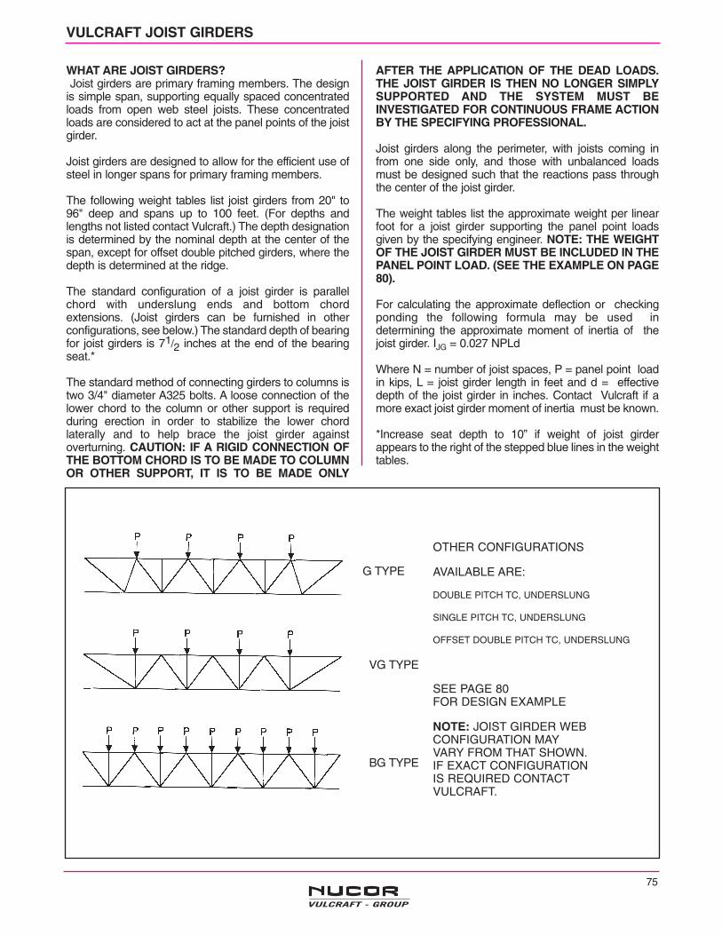
75
VULCRAFT JOIST GIRDERS
WHAT ARE JOIST GIRDERS?Joist girders are primary framing members. The design
is simple span, supporting equally spaced concentratedloads from open web steel joists. These concentratedloads are considered to act at the panel points of the joistgirder.
Joist girders are designed to allow for the efficient use ofsteel in longer spans for primary framing members.
The following weight tables list joist girders from 20" to96" deep and spans up to 100 feet. (For depths andlengths not listed contact Vulcraft.) The depth designationis determined by the nominal depth at the center of thespan, except for offset double pitched girders, where thedepth is determined at the ridge.
The standard configuration of a joist girder is parallelchord with underslung ends and bottom chordextensions. (Joist girders can be furnished in otherconfigurations, see below.) The standard depth of bearingfor joist girders is 71/2 inches at the end of the bearingseat.*
The standard method of connecting girders to columns istwo 3/4" diameter A325 bolts. A loose connection of thelower chord to the column or other support is requiredduring erection in order to stabilize the lower chordlaterally and to help brace the joist girder againstoverturning. CAUTION: IF A RIGID CONNECTION OFTHE BOTTOM CHORD IS TO BE MADE TO COLUMNOR OTHER SUPPORT, IT IS TO BE MADE ONLY
AFTER THE APPLICATION OF THE DEAD LOADS.THE JOIST GIRDER IS THEN NO LONGER SIMPLYSUPPORTED AND THE SYSTEM MUST BEINVESTIGATED FOR CONTINUOUS FRAME ACTIONBY THE SPECIFYING PROFESSIONAL.
Joist girders along the perimeter, with joists coming infrom one side only, and those with unbalanced loadsmust be designed such that the reactions pass throughthe center of the joist girder.
The weight tables list the approximate weight per linearfoot for a joist girder supporting the panel point loadsgiven by the specifying engineer. NOTE: THE WEIGHTOF THE JOIST GIRDER MUST BE INCLUDED IN THEPANEL POINT LOAD. (SEE THE EXAMPLE ON PAGE80).
For calculating the approximate deflection or checkingponding the following formula may be used indetermining the approximate moment of inertia of thejoist girder. IJG = 0.027 NPLd
Where N = number of joist spaces, P = panel point loadin kips, L = joist girder length in feet and d = effectivedepth of the joist girder in inches. Contact Vulcraft if amore exact joist girder moment of inertia must be known.
*Increase seat depth to 10” if weight of joist girderappears to the right of the stepped blue lines in the weighttables.
OTHER CONFIGURATIONS
AVAILABLE ARE:
DOUBLE PITCH TC, UNDERSLUNG
SINGLE PITCH TC, UNDERSLUNG
OFFSET DOUBLE PITCH TC, UNDERSLUNG
SEE PAGE 80 FOR DESIGN EXAMPLE
NOTE: JOIST GIRDER WEBCONFIGURATION MAYVARY FROM THAT SHOWN.IF EXACT CONFIGURATION IS REQUIRED CONTACTVULCRAFT.
G TYPE
VG TYPE
BG TYPE

(a) All Joist Girder dimensions shown are subject tochange when required by the physical size of largeJoist Girders. If changes are necessary Vulcraft willso note on the placing plans,
(b) The standard connection for Joist Girders to columnsis 13/16 inch slots for 3/4 inch bolts in girder bearings.The girder erection bolts are by others. If thespecifying professional wishes to use the Joist Girderbearing to transmit horizontal loads, the requiredamount of weld to connect the Joist Girder seat to thecolumn should be specified. For additionalinformation see the section of this catalog "JOISTGIRDERS IN MOMENT RESISTIVE FRAMES."(page 78)
(c) Stabilizer plates between bottom chord anglesstabilize the bottom chord laterally and brace theJoist Girder against overturning during erection.(Refer to 1004.4)
(d) Joist Girder bottom chord struts do not requirewelding to the stabilizer plate unless required bydesign to transmit horizontal forces. When welding isrequired, the amount of weld should be specified bythe specifying professional. UNLESS OTHERWISESPECIFIED, BOTTOM CHORD STRUTS SHOULDNOT BE WELDED.
(e) Joists are connected to the girder by welding exceptthat the joists at (or nearest) the column shall bebolted (O.S.H.A. Sec. 1910.12 ConstructionStandards Sec 1518.751).
(f) The l/ry of the bottom chord of the Joist Girder cannotexceed 240. For STANDARD Joist Girders, thespecifying engineer can use the "Joist Girder BottomChord Brace Chart" in conjunction with the "DesignGuide Weight Table/Joist Girders, G Series" to selectthe correct number of bottom chord braces. JoistGirders which must resist uplift, end moments, oraxial bottom chord forces may require additionalbraces.
SEE PAGE 79 FOR MOMENT CONNECTION DETAILS
JOIST GIRDER NOTES
JOIST GIRDER DETAIL (a)
BOTTOM CHORD BRACE
76
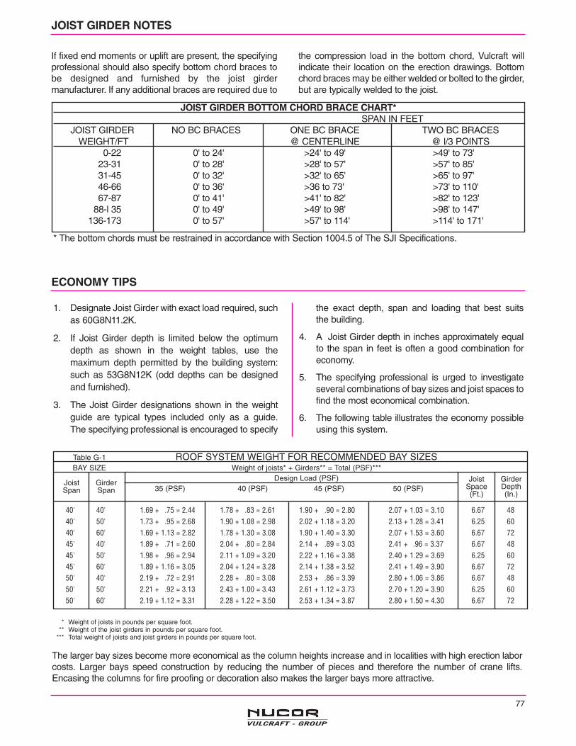
77
Table G-1 ROOF SYSTEM WEIGHT FOR RECOMMENDED BAY SIZESBAY SIZE Weight of joists* + Girders** = Total (PSF)***
Design Load (PSF)35 (PSF) 40 (PSF) 45 (PSF) 50 (PSF)
40' 40' 1.69 + .75 = 2.44 1.78 + .83 = 2.61 1.90 + .90 = 2.80 2.07 + 1.03 = 3.10 6.67 4840' 50' 1.73 + .95 = 2.68 1.90 + 1.08 = 2.98 2.02 + 1.18 = 3.20 2.13 + 1.28 = 3.41 6.25 6040' 60' 1.69 + 1.13 = 2.82 1.78 + 1.30 = 3.08 1.90 + 1.40 = 3.30 2.07 + 1.53 = 3.60 6.67 7245' 40' 1.89 + .71 = 2.60 2.04 + .80 = 2.84 2.14 + .89 = 3.03 2.41 + .96 = 3.37 6.67 4845' 50' 1.98 + .96 = 2.94 2.11 + 1.09 = 3.20 2.22 + 1.16 = 3.38 2.40 + 1.29 = 3.69 6.25 6045' 60' 1.89 + 1.16 = 3.05 2.04 + 1.24 = 3.28 2.14 + 1.38 = 3.52 2.41 + 1.49 = 3.90 6.67 7250' 40' 2.19 + .72 = 2.91 2.28 + .80 = 3.08 2.53 + .86 = 3.39 2.80 + 1.06 = 3.86 6.67 4850' 50' 2.21 + .92 = 3.13 2.43 + 1.00 = 3.43 2.61 + 1.12 = 3.73 2.70 + 1.20 = 3.90 6.25 6050' 60' 2.19 + 1.12 = 3.31 2.28 + 1.22 = 3.50 2.53 + 1.34 = 3.87 2.80 + 1.50 = 4.30 6.67 72
JOIST GIRDER NOTES
If fixed end moments or uplift are present, the specifyingprofessional should also specify bottom chord braces tobe designed and furnished by the joist girdermanufacturer. If any additional braces are required due to
the compression load in the bottom chord, Vulcraft willindicate their location on the erection drawings. Bottomchord braces may be either welded or bolted to the girder,but are typically welded to the joist.
JOIST GIRDER BOTTOM CHORD BRACE CHART*SPAN IN FEET
JOIST GIRDER NO BC BRACES ONE BC BRACE TWO BC BRACESWEIGHT/FT @ CENTERLINE @ l/3 POINTS
0-22 0' to 24' >24' to 49' >49' to 73'23-31 0' to 28' >28' to 57' >57' to 85'31-45 0' to 32' >32' to 65' >65' to 97'46-66 0' to 36' >36 to 73' >73' to 110'67-87 0' to 41' >41' to 82' >82' to 123'
88-l 35 0' to 49' >49' to 98' >98' to 147'136-173 0' to 57' >57' to 114' >114' to 171'
ECONOMY TIPS
1. Designate Joist Girder with exact load required, suchas 60G8N11.2K.
2. If Joist Girder depth is limited below the optimumdepth as shown in the weight tables, use themaximum depth permitted by the building system:such as 53G8N12K (odd depths can be designedand furnished).
3. The Joist Girder designations shown in the weightguide are typical types included only as a guide. The specifying professional is encouraged to specify
the exact depth, span and loading that best suits the building.
4. A Joist Girder depth in inches approximately equalto the span in feet is often a good combination foreconomy.
5. The specifying professional is urged to investigateseveral combinations of bay sizes and joist spaces tofind the most economical combination.
6. The following table illustrates the economy possibleusing this system.
The larger bay sizes become more economical as the column heights increase and in localities with high erection laborcosts. Larger bays speed construction by reducing the number of pieces and therefore the number of crane lifts.Encasing the columns for fire proofing or decoration also makes the larger bays more attractive.
* The bottom chords must be restrained in accordance with Section 1004.5 of The SJI Specifications.
* Weight of joists in pounds per square foot.** Weight of the joist girders in pounds per square foot.
*** Total weight of joists and joist girders in pounds per square foot.
JoistSpan
GirderSpan
JoistSpace(Ft.)
GirderDepth(In.)
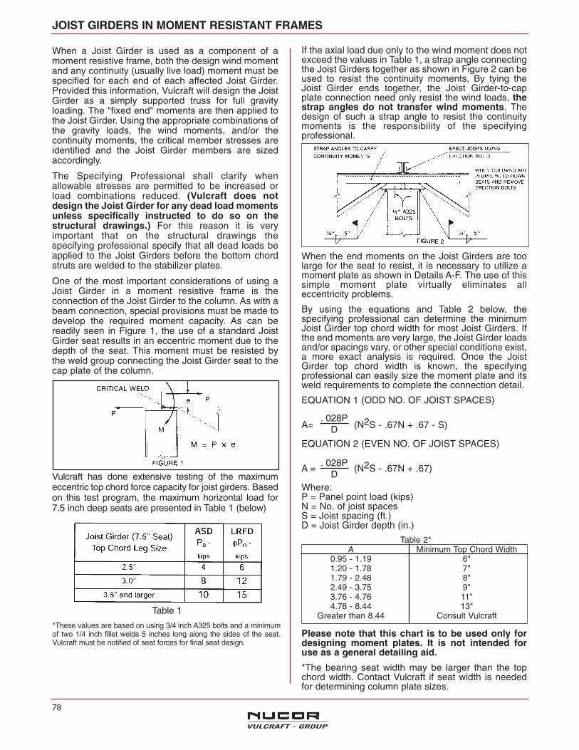
JOIST GIRDERS IN MOMENT RESISTANT FRAMES
Table 2*A Minimum Top Chord Width
0.95 - 1.19 6"1.20 - 1.78 7" 1.79 - 2.48 8"2.49 - 3.75 9"3.76 - 4.76 11"4.78 - 8.44 13"
Greater than 8.44 Consult Vulcraft
When a Joist Girder is used as a component of amoment resistive frame, both the design wind momentand any continuity (usually live load) moment must bespecified for each end of each affected Joist Girder.Provided this information, Vulcraft will design the JoistGirder as a simply supported truss for full gravityloading. The "fixed end" moments are then applied tothe Joist Girder. Using the appropriate combinations ofthe gravity loads, the wind moments, and/or thecontinuity moments, the critical member stresses areidentified and the Joist Girder members are sizedaccordingly.
The Specifying Professional shall clarify whenallowable stresses are permitted to be increased orload combinations reduced. (Vulcraft does notdesign the Joist Girder for any dead load momentsunless specifically instructed to do so on thestructural drawings.) For this reason it is veryimportant that on the structural drawings thespecifying professional specify that all dead loads beapplied to the Joist Girders before the bottom chordstruts are welded to the stabilizer plates.
One of the most important considerations of using aJoist Girder in a moment resistive frame is theconnection of the Joist Girder to the column. As with abeam connection, special provisions must be made todevelop the required moment capacity. As can bereadily seen in Figure 1, the use of a standard JoistGirder seat results in an eccentric moment due to thedepth of the seat. This moment must be resisted bythe weld group connecting the Joist Girder seat to thecap plate of the column.
Vulcraft has done extensive testing of the maximumeccentric top chord force capacity for joist girders. Basedon this test program, the maximum horizontal load for7.5 inch deep seats are presented in Table 1 (below)
*These values are based on using 3/4 inch A325 bolts and a minimumof two 1/4 inch fillet welds 5 inches long along the sides of the seat.Vulcraft must be notified of seat forces for final seat design.
If the axial load due only to the wind moment does notexceed the values in Table 1, a strap angle connectingthe Joist Girders together as shown in Figure 2 can beused to resist the continuity moments, By tying theJoist Girder ends together, the Joist Girder-to-capplate connection need only resist the wind loads, thestrap angles do not transfer wind moments. Thedesign of such a strap angle to resist the continuitymoments is the responsibility of the specifyingprofessional.
When the end moments on the Joist Girders are toolarge for the seat to resist, it is necessary to utilize amoment plate as shown in Details A-F. The use of thissimple moment plate virtually eliminates alleccentricity problems.
By using the equations and Table 2 below, thespecifying professional can determine the minimumJoist Girder top chord width for most Joist Girders. Ifthe end moments are very large, the Joist Girder loadsand/or spacings vary, or other special conditions exist,a more exact analysis is required. Once the JoistGirder top chord width is known, the specifyingprofessional can easily size the moment plate and itsweld requirements to complete the connection detail.
EQUATION 1 (ODD NO. OF JOIST SPACES)
A= (N2S - .67N + .67 - S)
EQUATION 2 (EVEN NO. OF JOIST SPACES)
A = (N2S - .67N + .67)
Where:P = Panel point load (kips)N = No. of joist spacesS = Joist spacing (ft.)D = Joist Girder depth (in.)
Please note that this chart is to be used only fordesigning moment plates. It is not intended foruse as a general detailing aid.
*The bearing seat width may be larger than the topchord width. Contact Vulcraft if seat width is neededfor determining column plate sizes.
. 028PD
. 028PD
78
Table 1

79
MOMENT CONNECTION DETAILS
Presented below are six suggested details for a momentresistive connection involving roof Joist Girders. Similardetails should be utilized for longspan joists with endmoments. In all cases, the bottom chord is to beconnected to the column with a vertical stabilizer plate
which is to be sized to carry the required load and obtainrequired weld (use 6 x 6 x 3/4 plate minimum for JoistGirders).
N O T E S :(1) Connections type B & C would also be recommended for floor girder details.(2) Where a backer bar is required for groove welds, additional clearance must be provided when determining girder hold back dimension.(3) Similar details would apply at other types of columns.(4) Additional stiffener plates as required not shown for clarity.(5) In all details, moment plate design and material is not by Vulcraft.
3 1/2" MIN. FORSHORTSPAN. VARIES
FOR LONGSPAN
AS REQ'D TOPROVIDE 1/2" CLEAR
TO CAP PLATE
GIRDER SEAT NOTSHOWN FOR CLARITY
MOMENT PLATE
MOMENTPLATE
KNIFE PLATEA
A
A—A
*WELD WIDTH &PLATE MUST NOTEXCEED 1"
FED
CBA
TOP CHORD EXTENSIONFOR DECK SUPPORT
OVER MOMENT PLATE

HOW TO SPECIFY VULCRAFT JOIST GIRDERS
1. Determine number of actual joist spaces (N).In this example, N = 8
2. Joist Selectiona) Span = 40'-0b) T.L. = 6.25 x 35 = 219 plfc) from K-Series load tables select a 22K7
(T.L. = 231 > 219; L.L. = 185 > 125)123 x 1.5 = 185 (l/240 limit applies sinceceiling is not plastered)
3. Joist Girder Selectiona) compute the concentrated load at top chord
panel points P = 219 x 40 = 8,760 Ibs. = 8.8kips (use 9K for depth selection) Live loaddeflection rarely governs in Joist Girderselection because of their depth.
b) Select girder depthThe 50'-0 span 8 panel Joist Girder table onpage 86 indicates that the rule of about one
inch of depth for each foot of span is a goodcompromise of limited depth and economy.Therefore select depth of 48 inches.
c) the Joist Girder will then be designated48G8N8.8K
d) the Joist Girder table shows the weight fora 48G8N9K is 40 pounds per lineal foot
e) total weight of this Joist Girder system persquare foot is:Joists 9.7 plf/6.25 = 1.55Girder 40 plf/40 = 1.00
2.55 psf
4. For rectangular bays check economy with joistsand girders spanning the opposite way
Joists (26K10) 13.8 plf/6.67 = 2.07Girder (40G6N12K) 47 plf/50 = .94
3.01 psf
For a given joist girder span, the specifying professional first determines the number of joist spaces, Then the panelpoint loads are calculated and a depth is selected. The following tables gives the Joist Girder weight per linear footfor various depths and loads.
STANDARD DESIGNATION
48G** 8N 8.8KDepth in Inches Number of Kip Load on Each Panel Point
Joist Spaces (One Kip = 1000 Ibs.)
Example: Given : 50'-0 x 40'-0 bay Joists spaced on 6'-3 centersLive Load = 20 psf
Dead Load = 15 psf *Total Load = 35 psf
* Includes the approximate Joist Girder weight in panel point loads.** See page 75\ for other Girder Types.
*** Increase to 10" if to the right of the stepped blue lines in the weight tables.
NOTES: 1. When it is required to have joists bear only at vertical web members to gain space for duct work,the Joist Girder should be labeled as a "VG" in lieu of a "G".
2. The following tables serve as a design guide only. Odd size joist girder lengths, depths, kiploadings, and panel lengths are available.
CL CLJOIST GIRDER SPAN ( COLUMN TO COLUMN)
Note: Web configuration may vary fromthat shown. Contact Vulcraft if exactlayout must be known.
80
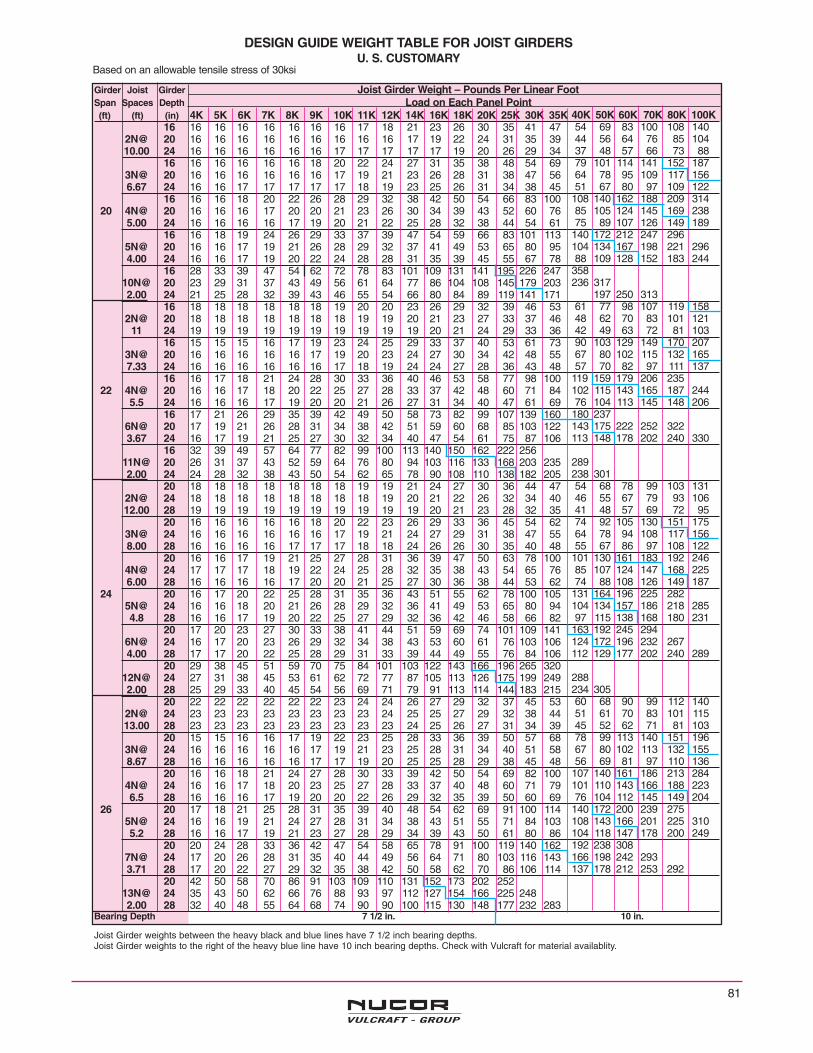
81
Girder Joist Girder Joist Girder Weight – Pounds Per Linear FootSpan Spaces Depth Load on Each Panel Point(ft) (ft) (in) 4K 5K 6K 7K 8K 9K 10K 11K 12K 14K 16K 18K 20K 25K 30K 35K
16 16 16 16 16 16 16 16 17 18 21 23 26 30 35 41 472N@ 20 16 16 16 16 16 16 16 16 16 17 19 22 24 31 35 3910.00 24 16 16 16 16 16 16 17 17 17 17 17 19 20 26 29 34
16 16 16 16 16 16 18 20 22 24 27 31 35 38 48 54 693N@ 20 16 16 16 16 16 16 17 19 21 23 26 28 31 38 47 566.67 24 16 16 17 17 17 17 17 18 19 23 25 26 31 34 38 45
16 16 16 18 20 22 26 28 29 32 38 42 50 54 66 83 10020 4N@ 20 16 16 16 17 20 20 21 23 26 30 34 39 43 52 60 76
5.00 24 16 16 16 16 17 19 20 21 22 25 28 32 38 44 54 6116 16 18 19 24 26 29 33 37 39 47 54 59 66 83 101 113
5N@ 20 16 16 17 19 21 26 28 29 32 37 41 49 53 65 80 954.00 24 16 16 17 19 20 22 24 28 28 31 35 39 45 55 67 78
16 28 33 39 47 54 62 72 78 83 101 109 131 141 195 226 24710N@ 20 23 29 31 37 43 49 56 61 64 77 86 104 108 145 179 2032.00 24 21 25 28 32 39 43 46 55 54 66 80 84 89 119 141 171
16 18 18 18 18 18 18 19 20 20 23 26 29 32 39 46 532N@ 20 18 18 18 18 18 18 18 19 19 20 21 23 27 33 37 46
11 24 19 19 19 19 19 19 19 19 19 19 20 21 24 29 33 3616 15 15 15 16 17 19 23 24 25 29 33 37 40 53 61 73
3N@ 20 16 16 16 16 16 17 19 20 23 24 27 30 34 42 48 557.33 24 16 16 16 16 16 16 17 18 19 24 24 27 28 36 43 48
16 16 17 18 21 24 28 30 33 36 40 46 53 58 77 98 10022 4N@ 20 16 16 17 18 20 22 25 27 28 33 37 42 48 60 71 84
5.5 24 16 16 16 17 19 20 20 21 26 27 31 34 40 47 61 6916 17 21 26 29 35 39 42 49 50 58 73 82 99 107 139 160
6N@ 20 17 19 21 26 28 31 34 38 42 51 59 60 68 85 103 1223.67 24 16 17 19 21 25 27 30 32 34 40 47 54 61 75 87 106
16 32 39 49 57 64 77 82 99 100 113 140 150 162 222 25611N@ 20 26 31 37 43 52 59 64 76 80 94 103 116 133 168 203 2352.00 24 24 28 32 38 43 50 54 62 65 78 90 108 110 138 182 205
20 18 18 18 18 18 18 18 19 19 21 24 27 30 36 44 472N@ 24 18 18 18 18 18 18 18 18 19 20 21 22 26 32 34 4012.00 28 19 19 19 19 19 19 19 19 19 19 20 21 23 28 32 35
20 16 16 16 16 16 18 20 22 23 26 29 33 36 45 54 623N@ 24 16 16 16 16 16 16 17 19 21 24 27 29 31 38 47 558.00 28 16 16 16 16 17 17 17 18 18 24 26 26 30 35 40 48
20 16 16 17 19 21 25 27 28 31 36 39 47 50 63 78 1004N@ 24 17 17 17 18 19 22 24 25 28 32 35 38 43 54 65 766.00 28 16 16 16 16 17 20 20 21 25 27 30 36 38 44 53 62
24 20 16 17 20 22 25 28 31 35 36 43 51 55 62 78 100 1055N@ 24 16 16 18 20 21 26 28 29 32 36 41 49 53 65 80 944.8 28 16 16 17 19 20 22 25 27 29 32 36 42 46 58 66 82
20 17 20 23 27 30 33 38 41 44 51 59 69 74 101 109 1416N@ 24 16 17 20 23 26 29 32 34 38 43 53 60 61 76 103 1064.00 28 17 17 20 22 25 28 29 31 33 39 44 49 55 76 84 106
20 29 38 45 51 59 70 75 84 101 103 122 143 166 196 265 32012N@ 24 27 31 38 45 53 61 62 72 77 87 105 113 126 175 199 2492.00 28 25 29 33 40 45 54 56 69 71 79 91 113 114 144 183 215
20 22 22 22 22 22 22 23 24 24 26 27 29 32 37 45 532N@ 24 23 23 23 23 23 23 23 23 24 25 25 27 29 32 38 4413.00 28 23 23 23 23 23 23 23 23 23 24 25 26 27 31 34 39
20 15 15 16 16 17 19 22 23 25 28 33 36 39 50 57 683N@ 24 16 16 16 16 16 17 19 21 23 25 28 31 34 40 51 588.67 28 16 16 16 16 16 17 17 19 20 25 25 28 29 38 45 48
20 16 16 18 21 24 27 28 30 33 39 42 50 54 69 82 1004N@ 24 16 16 17 18 20 23 25 27 28 33 37 40 48 60 71 796.5 28 16 16 16 17 19 20 20 22 26 29 32 35 39 50 60 69
26 20 17 18 21 25 28 31 35 39 40 48 54 62 69 91 100 1145N@ 24 16 16 19 21 24 27 28 31 34 38 43 51 55 71 84 1035.2 28 16 16 17 19 21 23 27 28 29 34 39 43 50 61 80 86
20 20 24 28 33 36 42 47 54 58 65 78 91 100 119 140 1627N@ 24 17 20 26 28 31 35 40 44 49 56 64 71 80 103 116 1433.71 28 17 20 22 27 29 32 35 38 42 50 58 62 70 86 106 114
20 42 50 58 70 86 91 103 109 110 131 152 173 202 25213N@ 24 35 43 50 62 66 76 88 93 97 112 127 154 166 225 2482.00 28 32 40 48 55 64 68 74 90 90 100 115 130 148 177 232 283
Bearing Depth 7 1/2 in. 10 in.
DESIGN GUIDE WEIGHT TABLE FOR JOIST GIRDERSU. S. CUSTOMARY
Based on an allowable tensile stress of 30ksi
40K 50K 60K 70K 80K 100K54 69 83 100 108 14044 56 64 76 85 10437 48 57 66 73 8879 101 114 141 152 18764 78 95 109 117 15651 67 80 97 109 122
108 140 162 188 209 31485 105 124 145 169 23875 89 107 126 149 189
140 172 212 247 296104 134 167 198 221 29688 109 128 152 183 244
358236 317
197 250 31361 77 98 107 119 15848 62 70 83 101 12142 49 63 72 81 10390 103 129 149 170 20767 80 102 115 132 16557 70 82 97 111 137
119 159 179 206 235102 115 143 165 187 24476 104 113 145 148 206
180 237143 175 222 252 322113 148 178 202 240 330
289238 30154 68 78 99 103 13146 55 67 79 93 10641 48 57 69 72 9574 92 105 130 151 17564 78 94 108 117 15655 67 86 97 108 122
101 130 161 183 192 24685 107 124 147 168 22574 88 108 126 149 187
131 164 196 225 282104 134 157 186 218 28597 115 138 168 180 231
163 192 245 294124 172 196 232 267112 129 177 202 240 289
288234 30560 68 90 99 112 14051 61 70 83 101 11545 52 62 71 81 10378 99 113 140 151 19667 80 102 113 132 15556 69 81 97 110 136
107 140 161 186 213 284101 110 143 166 188 22376 104 112 145 149 204
140 172 200 239 275108 143 166 201 225 310104 118 147 178 200 249192 238 308166 198 242 293137 178 212 253 292
Joist Girder weights between the heavy black and blue lines have 7 1/2 inch bearing depths.Joist Girder weights to the right of the heavy blue line have 10 inch bearing depths. Check with Vulcraft for material availablity.
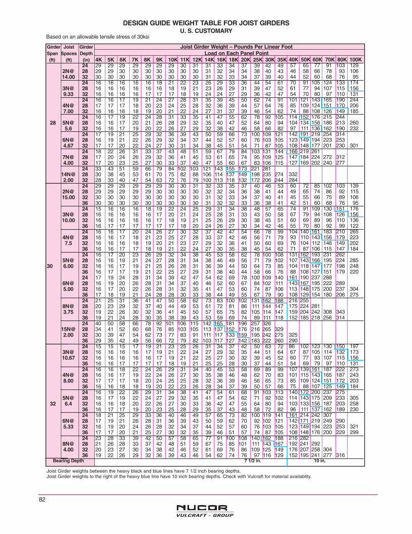
Girder Joist Girder Joist Girder Weight – Pounds Per Linear FootSpan Spaces Depth Load on Each Panel Point(ft) (ft) (in) 4K 5K 6K 7K 8K 9K 10K 11K 12K 14K 16K 18K 20K 25K 30K 35K
24 29 29 29 29 29 29 29 30 31 31 33 34 37 39 42 492N@ 28 29 29 30 30 30 30 30 30 30 31 32 34 34 38 40 4314.00 32 30 30 30 30 30 30 30 30 30 31 32 33 34 37 39 40
24 16 16 16 16 16 18 21 22 23 26 29 33 36 44 54 613N@ 28 16 16 16 16 16 16 18 19 21 23 26 29 31 39 47 529.33 32 16 16 16 16 17 17 17 18 19 24 24 27 29 36 42 47
24 16 16 17 19 21 24 27 28 31 35 39 45 50 62 74 914N@ 28 17 17 17 18 20 23 24 25 28 32 36 39 44 57 64 767.00 32 16 16 16 18 19 20 21 22 24 27 31 37 39 46 54 62
24 16 17 19 22 24 28 31 33 35 41 47 55 62 78 92 10528 5N@ 28 16 16 17 20 21 26 28 29 32 35 40 47 52 64 80 94
5.6 32 16 16 17 19 20 22 26 27 29 32 38 42 46 58 66 8224 17 19 21 25 29 32 36 39 43 50 59 66 73 100 109 121
6N@ 28 16 19 21 22 26 29 32 34 37 44 52 57 60 76 103 1054.67 32 17 17 20 22 24 27 30 31 34 38 45 51 54 71 87 105
24 18 22 26 31 33 37 43 48 51 59 67 79 84 103 131 1447N@ 28 17 20 24 26 29 32 36 41 45 53 61 65 74 95 109 1254.00 32 17 20 23 25 27 30 33 37 40 47 55 60 67 83 106 115
24 33 43 51 59 66 79 84 102 103 121 143 155 173 221 28114N@ 28 30 38 45 53 61 70 75 82 88 106 114 137 149 198 235 2742.00 32 28 33 40 47 54 63 72 76 79 100 113 118 132 172 206 244
24 29 29 29 29 29 29 30 30 31 32 33 35 37 40 46 532N@ 28 29 29 29 29 29 30 30 30 30 32 32 34 36 38 41 4415.00 32 30 30 30 30 30 30 30 30 30 31 32 33 34 37 40 41
36 30 30 30 30 30 30 30 30 30 31 32 32 33 36 38 4124 15 16 16 16 18 19 22 24 25 29 31 34 38 48 57 65
3N@ 28 16 16 16 16 16 17 20 21 24 25 28 31 33 43 50 5810.00 32 16 16 16 16 16 17 18 19 21 25 26 29 30 38 45 51
36 16 17 17 17 17 17 17 18 20 24 26 27 30 34 42 4624 16 16 17 20 24 26 27 30 32 37 42 47 54 66 78 99
4N@ 28 16 16 17 18 21 23 25 27 28 33 37 42 46 56 71 797.5 32 16 16 16 18 19 20 21 23 27 29 32 36 41 50 60 69
36 16 16 17 17 18 19 21 22 24 27 30 35 38 45 54 6224 16 17 20 23 26 29 32 34 38 45 53 58 62 78 100 108
5N@ 28 16 16 19 21 24 27 28 31 34 38 46 49 56 71 79 10230 6.00 32 16 16 17 19 21 25 26 28 31 36 39 44 50 64 73 85
36 16 17 17 19 21 22 25 27 29 31 38 40 44 58 66 7624 17 19 24 28 31 34 39 42 47 54 62 69 78 100 109 140
6N@ 28 16 19 20 26 28 31 34 37 40 46 52 60 67 84 102 1115.00 32 16 17 20 22 26 28 31 32 35 41 47 53 60 74 87 106
36 17 18 19 21 24 28 28 30 33 38 44 49 55 67 79 9024 21 25 31 36 41 47 50 58 62 73 83 100 102 131 162 188
8N@ 28 20 23 29 32 37 40 44 49 53 61 72 81 86 111 144 1473.75 32 19 22 26 30 32 36 41 45 50 57 65 75 82 105 114 147
36 19 21 24 28 30 35 38 39 43 53 59 69 74 89 111 11824 40 50 58 66 78 92 101 106 115 142 165 181 196 257 326
15N@ 28 34 41 52 60 68 76 85 103 105 113 137 152 176 216 265 3292.00 32 30 39 47 54 62 73 77 83 91 111 117 133 159 195 242 275
36 29 35 42 49 56 66 72 79 82 103 117 127 142 183 222 26024 15 15 15 17 19 21 23 25 26 31 34 37 42 50 63 72
3N@ 28 16 16 16 16 17 19 21 22 24 27 29 32 35 44 51 6410.67 32 16 16 16 16 16 17 19 21 22 25 27 30 32 39 45 52
36 16 16 17 17 17 17 18 19 21 25 25 28 30 37 44 5124 16 16 18 22 24 26 29 31 34 40 45 53 58 69 89 99
4N@ 28 16 16 17 19 22 24 26 27 30 35 38 46 48 62 70 838.00 32 17 17 17 18 20 24 25 25 28 32 36 39 46 56 65 73
36 16 16 18 18 19 20 22 23 26 28 34 37 39 50 57 6624 16 19 22 26 29 31 34 38 41 47 54 61 68 91 103 113
5N@ 28 16 17 19 22 24 27 29 32 35 41 47 54 62 71 92 10232 6.4 32 16 16 18 20 22 26 27 30 33 36 42 47 55 64 80 94
36 16 17 17 19 20 23 25 28 29 35 37 43 48 58 72 8224 18 21 25 29 33 36 40 46 49 57 65 73 82 100 119 141
6N@ 28 17 19 21 26 28 31 36 39 43 50 59 62 70 92 102 1215.33 32 16 19 20 24 26 28 32 34 37 44 52 57 60 76 103 105
36 17 17 20 21 25 27 30 32 35 39 46 51 57 74 87 10524 23 28 33 39 42 50 57 58 65 77 91 100 108 140 162 188
8N@ 28 21 26 28 33 37 42 48 51 59 67 75 85 101 111 143 1674.00 32 20 23 27 30 34 38 42 46 52 61 69 76 86 109 125 149
36 19 22 26 29 32 36 39 43 46 54 62 74 76 97 116 129Bearing Depth 7 1/2 in. 10 in.
40K 50K 60K 70K 80K 100K57 65 77 91 103 12946 58 66 78 93 10644 52 60 68 76 9570 91 105 124 133 17461 77 94 107 115 15654 70 80 97 110 131101 121 143 165 190 24485 109 124 151 170 20674 88 108 126 149 185114 152 176 215 244104 134 156 186 213 26097 111 136 162 190 232142 191 219 254 314123 149 194 223 253108 148 177 201 230 301166 219 261147 184 224 272 312127 169 202 240 277
33228460 72 85 102 103 13949 65 74 86 92 11545 55 66 75 89 10642 51 60 68 76 9574 91 109 130 151 17667 79 94 108 126 15660 69 89 96 110 13655 70 80 92 99 122104 140 161 183 210 26593 110 143 156 179 22376 104 112 146 149 20271 87 106 115 147 184131 162 193 231 262107 143 166 195 224 285104 118 147 177 198 24888 108 127 151 179 220161 190 237 288143 167 195 222 289113 148 175 200 237 304108 129 154 180 206 275216 255175 224 281159 204 242 308 343152 185 218 256 314
32529086 102 123 130 150 19767 87 105 114 132 17360 77 93 107 115 15654 69 79 97 110 131107 139 161 187 222 273101 115 143 165 187 24385 109 124 151 172 20375 88 107 125 149 184140 172 200 237 275114 143 175 209 233 305103 133 156 187 203 25896 111 137 162 189 230161 214 242 307142 171 219 249 290123 149 194 223 253 321108 148 176 200 229 299216 282192 241 292176 207 258 304152 195 241 277 316
DESIGN GUIDE WEIGHT TABLE FOR JOIST GIRDERSU. S. CUSTOMARY
Based on an allowable tensile stress of 30ksi
Joist Girder weights between the heavy black and blue lines have 7 1/2 inch bearing depths.Joist Girder weights to the right of the heavy blue line have 10 inch bearing depths. Check with Vulcraft for material availablity.
82

83
Girder Joist Girder Joist Girder Weight – Pounds Per Linear FootSpan Spaces Depth Load on Each Panel Point(ft) (ft) (in) 4K 5K 6K 7K 8K 9K 10K 11K 12K 14K 16K 18K 20K 25K 30K 35K
28 18 18 18 18 19 20 22 23 25 28 31 34 40 48 57 653N@ 32 18 18 18 19 19 19 20 22 23 26 28 32 35 42 49 5811.33 36 18 19 19 19 19 19 20 20 22 26 27 29 31 39 45 51
40 19 19 19 19 19 19 20 20 21 25 27 28 32 37 44 4628 16 16 18 20 23 26 27 29 32 36 40 47 54 62 78 91
4N@ 32 16 16 17 19 20 24 24 27 30 32 37 42 47 56 71 798.50 36 16 17 18 18 19 21 23 26 27 29 33 38 41 50 61 69
40 16 18 18 18 19 20 21 23 26 28 33 35 39 45 54 6234 28 16 17 21 23 26 29 32 35 38 45 47 54 62 77 99 106
5N@ 32 16 17 18 21 24 27 30 32 34 39 46 48 55 70 79 1016.80 36 16 16 17 20 21 25 28 28 33 36 39 47 50 64 73 85
40 17 17 18 19 21 23 26 29 29 35 38 40 48 58 66 8028 17 20 24 28 30 33 36 41 44 54 58 65 73 100 108 130
6N@ 32 17 19 21 25 28 31 34 37 40 48 52 59 67 83 102 1105.67 36 17 18 20 22 26 28 31 32 36 41 50 53 60 74 86 105
40 17 18 19 22 24 27 29 30 33 39 42 51 54 67 83 9728 19 23 27 31 34 39 43 47 54 62 70 78 91 105 131 152
7N@ 32 18 20 26 27 31 35 38 42 47 56 64 71 79 102 111 1344.86 36 17 20 22 27 29 32 36 38 42 50 57 65 69 86 105 118
40 17 20 23 25 28 30 33 36 39 45 53 59 63 79 99 10928 25 28 34 39 43 51 58 63 67 78 92 101 109 142 164 194
9N@ 32 21 26 30 35 40 44 49 56 60 70 80 95 103 124 148 1753.78 36 20 25 28 32 36 41 45 50 53 62 72 81 88 113 127 150
40 19 23 28 30 34 38 43 46 51 59 68 76 84 107 116 14228 18 18 18 18 19 21 23 25 27 30 33 40 41 48 60 69
3N@ 32 18 18 18 18 18 19 21 23 25 27 30 33 36 44 54 6112.00 36 18 18 19 19 19 19 20 21 22 26 28 31 34 43 48 55
40 19 19 19 19 19 19 19 20 22 26 26 29 32 40 44 5128 16 16 19 21 23 27 29 31 34 39 45 50 54 69 81 99
4N@ 32 16 16 17 20 23 24 26 28 31 35 40 46 48 62 70 839.00 36 17 17 17 18 21 24 25 27 28 33 37 40 46 57 65 73
40 16 18 18 18 19 21 23 23 26 28 32 38 40 50 58 6628 16 18 21 25 26 31 34 36 40 45 54 61 68 81 100 114
5N@ 32 16 17 20 22 24 27 30 34 35 41 46 54 59 70 91 1017.20 36 16 16 18 21 23 26 28 30 33 37 42 47 55 63 79 93
40 17 17 17 20 21 24 26 28 31 36 39 43 49 57 73 8136 28 18 20 25 27 33 36 39 42 47 57 62 69 77 99 113 140
6N@ 32 17 20 23 25 28 31 35 39 42 48 55 62 70 83 102 1216.00 36 16 18 21 24 26 29 32 36 37 44 52 56 63 80 102 106
40 17 18 20 22 26 27 30 33 35 41 46 53 58 71 86 10528 19 24 28 33 37 40 47 50 54 62 77 82 99 113 140 162
7N@ 32 18 21 26 28 32 37 40 43 49 56 64 71 80 102 116 1435.14 36 18 20 25 28 31 33 36 41 44 53 57 65 73 94 109 125
40 17 20 24 26 29 31 34 37 41 49 55 62 66 82 106 11328 24 31 36 41 46 54 57 65 69 82 99 104 113 141 173 205
9N@ 32 23 27 31 37 40 48 52 59 63 73 84 102 103 133 157 1854.00 36 21 26 29 33 37 41 50 52 56 65 74 85 95 113 146 160
40 20 24 27 30 35 39 43 46 51 62 68 76 87 107 121 15132 22 23 23 23 23 24 25 26 26 29 33 36 40 47 57 65
3N@ 36 23 23 23 23 23 24 25 26 26 27 28 32 36 43 50 6112.67 40 23 23 23 23 24 24 24 25 26 29 28 31 33 43 48 55
44 23 24 24 24 24 24 24 25 26 28 29 29 33 39 44 5032 16 16 18 21 23 26 28 30 32 36 41 46 54 62 78 91
4N@ 36 16 17 17 19 23 24 26 26 29 34 38 42 47 56 71 799.50 40 17 17 18 18 20 23 24 26 28 31 35 38 41 51 61 72
44 18 18 18 18 19 21 23 24 27 29 34 36 39 48 58 6632 16 17 20 23 26 29 32 35 37 44 47 55 62 77 91 105
5N@ 36 16 17 18 22 24 27 29 31 34 38 46 49 56 71 79 937.60 40 16 16 17 20 22 25 28 30 33 37 41 47 50 63 74 93
44 17 17 18 20 21 23 26 28 30 35 39 42 49 57 69 8138 32 17 20 23 27 31 34 36 39 43 51 58 65 73 99 106 121
6N@ 36 17 19 21 26 28 32 34 37 40 48 52 59 64 83 102 1106.33 40 17 18 20 23 26 29 32 33 36 42 50 56 61 73 86 105
44 17 18 20 22 26 28 30 33 34 39 46 51 58 70 82 9732 20 26 30 35 39 43 49 55 59 67 79 92 101 121 143 167
8N@ 36 20 24 28 32 36 41 44 50 53 61 69 81 86 106 125 1474.75 40 20 25 28 31 34 37 43 48 51 58 66 74 82 106 115 139
44 19 23 27 29 32 36 39 43 49 54 60 72 76 98 111 12332 27 32 38 45 48 55 62 70 78 91 102 107 121 155 191 212
10N@ 36 25 30 35 39 47 49 56 64 71 79 93 103 108 145 173 1963.80 40 23 28 33 37 42 48 50 57 64 76 81 95 106 120 150 176
44 22 26 31 35 38 44 49 53 58 67 76 83 97 113 139 168Bearing Depth 7 1/2 in. 10 in.
40K 50K 60K70K 80K 100K73 91 109 124 150 17366 87 91 112 126 15660 73 89 99 115 13654 70 79 92 110 132
100 130 152 174 199 24392 108 134 155 177 22376 104 113 146 149 20074 87 106 115 148 182
120 153 185 212 248107 133 156 197 214 267104 119 146 170 198 24196 111 137 151 181 227
142 190 220 248 307123 167 193 224 252113 148 177 199 228 298108 128 153 187 216 269175 219 255155 193 223 268136 176 203 241 285122 154 196 225 258 332220 284198 265 325178 227 275 330159 206 250 29981 94 109 130 151 18671 87 104 112 132 16463 76 93 107 115 15657 69 89 97 110 131
104 140 161 183 211 265101 115 143 165 188 23085 109 125 150 172 21276 96 111 126 149 183
130 162 196 231 262112 143 177 199 233 300104 133 156 186 200 25895 111 137 162 188 230
160 191 236 282142 167 199 241 285123 147 193 214 252 317111 148 177 200 228 296188 225 291166 196 246 297147 183 213 256 306127 167 200 231 274236 293215 268187 236 298178 207 270 30774 91 109 124 142 17367 85 97 112 126 15663 73 89 99 115 14558 70 88 96 110 131
100 120 152 175 190 24493 108 134 155 177 22380 104 113 146 149 19974 88 106 121 148 182
115 152 177 207 233107 134 158 184 213 274104 118 147 171 197 23996 111 137 161 188 221
142 189 218 251 305123 167 192 222 260113 148 176 199 228 298108 127 163 189 210 272191 239 309175 224 258 325168 202 240 292 333153 184 222 272 309260214 282203 264 314192 239 288
DESIGN GUIDE WEIGHT TABLE FOR JOIST GIRDERSU. S. CUSTOMARY
Based on an allowable tensile stress of 30ksi
Joist Girder weights between the heavy black and blue lines have 7 1/2 inch bearing depths.Joist Girder weights to the right of the heavy blue line have 10 inch bearing depths. Check with Vulcraft for material availablity.

Girder Joist Girder Joist Girder Weight – Pounds Per Linear FootSpan Spaces Depth Load on Each Panel Point(ft) (ft) (in) 4K 5K 6K 7K 8K 9K 10K 11K 12K 14K 16K 18K 20K 25K 30K 35K
32 22 23 23 23 24 24 25 26 27 30 34 38 40 51 60 6936 23 23 23 23 23 24 25 25 27 27 32 34 39 46 54 61
3N@ 40 23 23 23 23 23 23 24 25 27 27 28 32 35 43 49 5513.33 44 23 23 23 24 24 24 24 26 26 28 28 32 33 42 47 55
48 23 24 24 24 24 24 24 26 26 29 29 29 32 38 44 5132 16 16 19 22 25 26 28 30 33 39 45 50 53 68 77 9036 16 17 18 21 25 25 26 29 31 34 40 44 48 62 71 79
4N@ 40 17 17 17 19 23 25 26 27 29 32 38 41 46 56 68 7710.00 44 16 16 18 18 20 21 23 24 28 30 34 37 40 51 57 66
48 17 17 18 18 19 20 23 25 26 28 32 34 37 49 58 6632 16 18 22 25 28 31 34 37 40 46 54 58 65 78 100 10636 16 17 20 23 25 27 31 34 35 41 46 54 59 71 91 102
5N@ 40 16 16 18 21 23 27 28 30 33 37 42 47 53 64 80 938.00 44 17 17 17 20 23 24 28 29 31 35 39 46 49 60 73 81
48 17 17 17 19 23 25 25 28 29 33 37 41 47 57 67 8032 17 20 24 28 32 35 39 42 47 54 62 69 77 99 108 14036 17 20 23 26 28 31 35 38 41 48 55 62 70 83 102 115
40 6N@ 40 17 18 21 25 28 29 32 36 38 44 49 56 64 79 94 1056.67 44 17 18 21 22 27 29 30 33 36 42 49 53 58 74 86 105
48 17 18 20 24 25 28 29 31 33 40 44 52 55 72 79 9832 19 24 28 32 34 40 45 47 54 62 70 77 91 105 130 15236 18 21 26 28 32 35 40 43 48 56 63 71 79 102 115 143
7N@ 40 18 20 25 28 31 33 36 41 45 51 57 65 72 94 108 1185.71 44 18 21 23 27 29 31 34 37 41 50 58 63 67 82 106 113
48 18 22 24 27 30 33 37 39 42 48 57 63 71 81 99 11432 21 27 31 36 39 47 50 58 62 70 83 100 101 121 152 17536 21 25 29 32 37 40 48 51 56 64 72 84 93 111 144 156
8N@ 40 20 23 27 30 35 38 41 46 51 61 69 76 86 105 119 1485.00 44 20 24 29 30 34 38 41 45 50 58 66 75 78 98 113 129
48 19 24 26 29 32 35 40 43 46 55 60 72 76 90 111 11832 27 33 40 43 51 58 63 70 78 92 103 110 122 168 190 21836 27 30 35 41 48 55 62 64 72 79 94 107 116 145 181 199
10N@ 40 25 28 33 39 43 50 56 57 65 74 86 95 109 134 160 1864.00 44 23 28 31 37 40 48 51 57 59 74 81 88 98 120 150 175
48 22 26 29 34 38 42 50 54 59 67 76 83 98 114 140 15732 29 29 29 30 31 31 32 33 34 35 38 40 45 53 60 6936 29 29 30 30 30 31 32 34 33 35 36 38 40 47 57 64
3N@ 40 30 30 30 30 30 30 31 34 34 34 35 37 39 46 53 6114.00 44 30 30 30 30 30 30 32 32 33 35 35 36 37 43 48 56
48 30 30 30 30 31 31 32 32 33 35 35 36 39 43 48 5332 16 17 20 23 25 28 30 33 35 42 45 50 57 68 89 9936 16 16 18 21 23 25 28 30 33 37 44 46 52 66 75 91
4N@ 40 17 17 18 21 22 24 26 28 30 34 38 45 47 59 68 7910.50 44 17 17 18 19 21 25 25 27 29 32 36 42 46 54 65 74
48 18 18 18 18 20 25 27 25 28 31 35 39 43 50 63 7132 17 20 23 26 28 33 36 39 44 47 54 61 68 90 103 11336 16 17 21 23 26 28 32 34 37 44 48 54 62 74 91 105
5N@ 40 16 18 20 22 24 27 29 32 34 40 45 52 55 67 79 938.40 44 16 18 19 21 25 26 28 30 32 38 41 47 53 64 77 93
48 17 18 18 20 24 24 27 29 30 36 39 43 49 57 70 8132 18 21 26 29 33 37 40 45 47 57 65 73 81 99 119 14036 17 20 24 27 30 34 36 39 43 51 58 62 70 91 106 121
42 6N@ 40 17 19 21 26 28 32 34 36 40 47 55 59 64 79 103 1097.00 44 17 18 21 24 26 29 32 34 36 43 50 57 60 76 95 105
48 17 18 21 24 26 29 30 33 35 41 46 52 58 70 83 10632 20 24 29 34 37 42 47 53 54 68 77 90 99 113 140 16236 20 23 27 30 35 38 41 46 51 59 70 78 83 102 122 142
7N@ 40 18 22 25 28 32 35 39 42 47 56 63 71 79 95 109 1346.00 44 18 21 24 27 30 32 36 40 43 51 57 65 73 87 106 119
48 18 20 24 26 29 32 34 37 41 47 52 59 67 83 98 11332 22 28 33 38 43 47 54 58 65 77 83 100 105 140 163 18836 20 26 29 34 40 43 49 55 59 67 79 84 101 116 143 167
8N@ 40 20 24 28 33 36 41 45 50 53 61 69 81 86 107 126 1515.25 44 21 23 28 31 34 37 43 47 52 58 66 79 83 107 116 141
48 21 25 28 29 32 35 39 44 48 56 64 69 78 100 111 13032 31 37 45 53 61 69 77 82 91 104 114 130 151 189 218 26736 27 35 41 48 55 62 70 72 79 92 106 115 132 166 197 232
11N@ 40 27 32 37 42 49 56 64 65 73 84 103 108 117 149 182 2093.82 44 25 31 35 40 48 51 58 65 66 81 95 106 111 139 167 190
48 24 29 34 38 45 50 54 60 67 76 84 98 108 122 154 180Bearing Depth 7 1/2 in. 10 in.
40K 50K 60K70K 80K 100K81 94 108 124 150 18570 87 104 111 126 16462 84 93 107 125 15663 73 89 99 115 13157 70 80 92 102 131
104 129 152 173 202 25293 115 143 166 179 23093 109 119 150 172 21276 104 111 126 150 18974 87 108 116 139 178
130 157 188 227 255107 143 167 196 230 298104 128 159 182 210 26296 116 138 161 186 24593 111 122 152 178 217
151 189 220 266142 167 197 232 275118 147 185 215 245 313111 148 177 199 227 294108 130 156 180 204 271175 218 255155 197 232 276145 184 214 255 300127 167 199 237 272125 169 195 234 267197 241182 222 277171 203 257 294153 193 240 278 320144 183 218 261 295246240 306212 277190 255 302182 230 277 32481 94 118 140 160 18570 87 109 122 141 17371 85 97 112 126 15663 73 89 99 115 14661 74 88 99 110 132
104 140 161 186 214 274101 115 143 175 191 24094 109 134 159 177 21482 106 120 138 164 20281 98 114 139 153 192
130 172 197 225 256115 152 177 207 233107 133 156 186 210 266104 119 148 171 200 23896 111 137 162 187 220
160 190 236 289142 177 209 240 293123 167 192 222 253113 148 176 202 227 303108 139 163 188 208 270187 226 289166 205 248 292147 182 222 272 303137 176 202 246 283122 164 191 220 255216 268190 231 290175 215 264 326157 201 239 291 333156 182 214 278 315
270243 310218 281205 259 318
DESIGN GUIDE WEIGHT TABLE FOR JOIST GIRDERSU. S. CUSTOMARY
Based on an allowable tensile stress of 30ksi
Joist Girder weights between the heavy black and blue lines have 7 1/2 inch bearing depths.Joist Girder weights to the right of the heavy blue line have 10 inch bearing depths. Check with Vulcraft for material availablity.
84

85
Girder Joist Girder Joist Girder Weight – Pounds Per Linear FootSpan Spaces Depth Load on Each Panel Point(ft) (ft) (in) 4K 5K 6K 7K 8K 9K 10K 11K 12K 14K 16K 18K 20K 25K 30K 35K
36 30 30 30 30 31 31 32 34 35 36 38 39 44 52 60 6940 30 30 30 30 31 31 32 33 35 35 37 38 39 51 59 62
3N@ 44 30 30 30 31 31 31 32 33 34 34 36 37 38 46 53 5915.00 48 30 30 30 31 31 31 32 32 33 36 36 38 37 41 48 58
54 30 30 30 32 32 32 32 32 33 36 36 37 39 41 48 5336 18 19 20 23 25 27 29 31 34 42 43 50 57 65 77 9040 19 19 20 21 24 25 28 30 32 37 43 46 51 65 75 87
4N@ 44 19 19 20 21 23 26 26 28 30 34 40 44 47 59 68 7611.25 48 19 20 20 21 22 25 25 26 29 32 35 40 42 54 64 73
54 20 20 20 21 22 24 25 26 27 30 33 38 41 50 58 6636 16 18 23 25 28 30 33 36 39 46 54 58 65 78 99 11040 16 18 21 23 26 28 31 34 37 44 46 54 58 75 91 105
5N@ 44 16 17 20 23 24 27 29 32 34 39 45 48 56 67 79 949.00 48 17 18 19 24 25 26 28 30 32 37 41 46 53 64 78 89
54 17 18 18 21 24 26 26 29 31 33 40 43 47 58 70 7936 17 22 24 29 32 35 39 43 47 54 62 69 78 99 109 14040 17 20 24 27 30 33 35 38 42 49 55 62 71 92 102 116
45 6N@ 44 17 19 23 26 28 31 33 36 39 47 52 56 64 80 103 1097.50 48 17 19 22 24 27 29 31 34 37 43 50 57 61 74 87 105
54 17 18 21 24 25 28 30 33 35 38 45 52 55 68 83 9836 20 24 28 32 36 40 46 47 54 62 70 77 91 105 130 15240 19 22 27 30 34 38 41 46 49 56 63 71 79 102 116 143
7N@ 44 18 22 25 28 31 36 39 42 47 56 63 65 72 94 109 1236.43 48 18 21 24 27 29 33 37 40 43 50 57 65 73 82 105 119
54 24 24 26 30 32 35 39 41 45 49 57 63 72 83 100 11436 25 30 35 39 47 54 58 63 70 78 92 101 109 141 164 19440 22 28 32 37 42 48 52 56 64 72 84 93 103 123 156 179
9N@ 44 23 28 31 36 39 45 50 53 57 66 76 86 130 113 146 1755.00 48 22 26 29 34 37 41 46 51 54 63 74 81 88 109 129 152
54 21 24 28 31 35 39 43 46 51 60 69 76 84 108 116 14436 32 39 48 55 62 70 78 83 100 106 121 142 155 191 225 27240 30 35 42 49 56 64 71 79 84 103 108 123 145 171 198 246
12N@ 44 28 33 40 48 53 57 65 74 81 95 105 111 125 163 196 2163.75 48 27 31 37 43 52 58 63 68 75 83 97 108 116 153 179 201
54 25 30 36 40 47 52 58 62 73 79 86 101 112 133 158 18436 18 19 21 24 26 29 31 34 37 43 48 56 57 73 89 10240 19 19 20 22 24 27 29 32 35 41 44 49 57 65 77 91
4N@ 44 19 19 20 21 25 27 29 30 32 36 43 45 50 63 75 8712.00 48 19 20 20 20 24 27 27 30 31 33 40 44 46 60 68 77
54 20 20 21 21 24 25 26 26 29 32 37 41 43 49 61 7036 17 21 24 27 30 33 36 39 44 50 57 64 68 90 103 11340 17 19 24 25 27 31 33 37 39 44 51 57 65 77 91 106
5N@ 44 17 18 23 25 26 29 31 34 36 43 47 52 59 71 87 1019.60 48 17 17 22 24 24 27 30 32 35 39 45 47 53 67 78 90
54 18 18 21 22 24 26 28 30 32 37 41 46 49 61 70 8136 18 23 26 30 34 37 40 45 50 61 68 76 81 99 119 14040 17 22 24 27 32 35 38 41 46 54 62 69 77 92 106 130
6N@ 44 17 20 24 27 30 33 36 39 42 48 55 63 71 84 103 1118.00 48 17 20 24 25 28 31 34 36 39 47 50 57 64 80 94 108
54 17 20 22 24 27 29 32 35 38 40 49 52 58 74 83 10648 36 24 28 33 39 43 50 54 61 65 77 91 100 105 140 163 188
40 21 27 31 35 40 46 49 55 59 71 79 92 101 116 143 1678N@ 44 21 27 29 33 37 41 47 50 56 64 72 81 94 109 135 1596.00 48 21 24 29 32 36 39 43 49 51 61 67 76 82 107 120 150
54 23 26 28 33 37 40 43 49 51 59 67 75 81 98 114 13036 27 31 37 42 47 54 61 69 70 91 99 105 114 151 174 20640 24 29 35 38 43 49 55 63 67 78 92 101 107 142 165 191
9N@ 44 25 28 33 36 42 48 52 57 64 73 80 94 104 118 147 1755.33 48 23 28 31 35 40 43 49 53 57 66 74 82 96 111 138 161
54 23 26 29 33 37 41 45 50 52 60 68 76 84 108 122 15336 34 41 50 58 68 76 82 91 100 109 130 142 164 192 243 29440 32 38 46 55 62 70 74 79 92 102 116 132 144 180 219 258
12N@ 44 30 35 42 50 56 64 71 73 81 103 108 117 134 173 198 2394.00 48 29 34 40 46 51 57 66 72 75 86 105 111 120 151 187 215
54 27 32 38 42 51 54 61 68 73 84 98 108 114 141 167 201Bearing Depth 7 1/2 in. 10 in.
40K 50K 60K 70K 80K 100K81 95 120 134 151 18770 88 110 122 141 16667 85 98 113 126 15763 82 90 101 117 14860 71 89 97 104 132
104 130 152 174 199 252101 115 143 165 178 23093 109 134 156 178 21181 104 114 136 151 19874 97 108 116 140 176
131 152 194 228 254112 143 176 206 231 295107 133 156 182 209 26596 118 148 162 186 23892 112 131 153 166 217
151 189 217 261142 168 196 246 281123 159 192 222 250113 148 175 199 227 295108 128 155 178 202 266175 217 255155 196 231 290147 182 213 257 299136 175 201 238 278125 165 195 231 263226 282197 250187 244 295177 226 269 313159 193 243 280 321
294264240 301218 274 333109 139 171 195 221 273104 130 152 174 200 25393 113 134 155 177 23189 109 129 157 172 21279 97 112 128 149 188
130 171 197 228 266125 153 177 206 234107 133 156 195 222 278108 128 157 184 207 26696 116 137 163 185 229
160 201 236 288143 176 218 250 292132 168 195 231 265118 148 182 213 251 313111 139 163 195 216 279216 278191 246 300174 223 280175 203 249 301154 191 229 268 314237219 266199 235 284186 235 284165 204 254 301
301276 288248 318227 288
DESIGN GUIDE WEIGHT TABLE FOR JOIST GIRDERSU. S. CUSTOMARY
Based on an allowable tensile stress of 30ksi
Joist Girder weights between the heavy black and blue lines have 7 1/2 inch bearing depths.Joist Girder weights to the right of the heavy blue line have 10 inch bearing depths. Check with Vulcraft for material availablity.
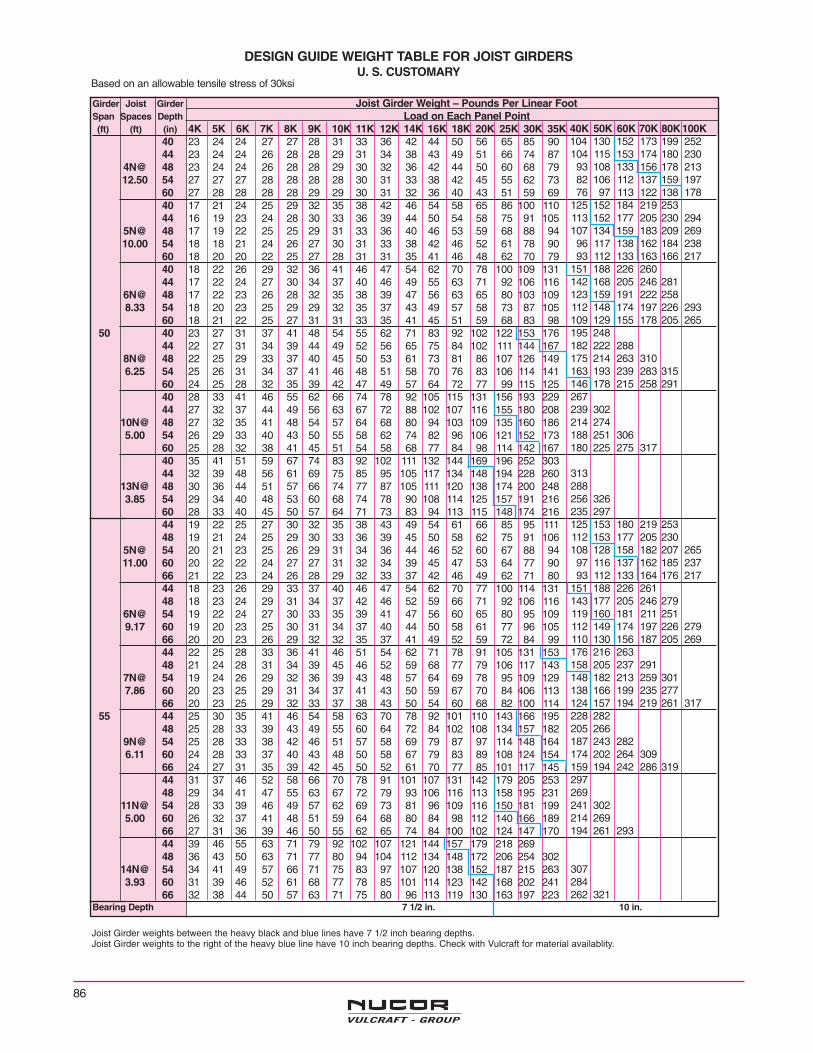
Girder Joist Girder Joist Girder Weight – Pounds Per Linear FootSpan Spaces Depth Load on Each Panel Point(ft) (ft) (in) 4K 5K 6K 7K 8K 9K 10K 11K 12K 14K 16K 18K 20K 25K 30K 35K
40 23 24 24 27 27 28 31 33 36 42 44 50 56 65 85 9044 23 24 24 26 28 28 29 31 34 38 43 49 51 66 74 87
4N@ 48 23 24 24 26 28 28 29 30 32 36 42 44 50 60 68 7912.50 54 27 27 27 28 28 28 28 30 31 33 38 42 45 55 62 73
60 27 28 28 28 28 29 29 30 31 32 36 40 43 51 59 6940 17 21 24 25 29 32 35 38 42 46 54 58 65 86 100 11044 16 19 23 24 28 30 33 36 39 44 50 54 58 75 91 105
5N@ 48 17 19 22 25 25 29 31 33 36 40 46 53 59 68 88 9410.00 54 18 18 21 24 26 27 30 31 33 38 42 46 52 61 78 90
60 18 20 20 22 25 27 28 31 31 35 41 46 48 62 70 7940 18 22 26 29 32 36 41 46 47 54 62 70 78 100 109 13144 17 22 24 27 30 34 37 40 46 49 55 63 71 92 106 116
6N@ 48 17 22 23 26 28 32 35 38 39 47 56 63 65 80 103 1098.33 54 18 20 23 25 29 29 32 35 37 43 49 57 58 73 87 105
60 18 21 22 25 27 31 31 33 35 41 45 51 59 68 83 9850 40 23 27 31 37 41 48 54 55 62 71 83 92 102 122 153 176
44 22 27 31 34 39 44 49 52 56 65 75 84 102 111 144 1678N@ 48 22 25 29 33 37 40 45 50 53 61 73 81 86 107 126 1496.25 54 25 26 31 34 37 41 46 48 51 58 70 76 83 106 114 141
60 24 25 28 32 35 39 42 47 49 57 64 72 77 99 115 12540 28 33 41 46 55 62 66 74 78 92 105 115 131 156 193 22944 27 32 37 44 49 56 63 67 72 88 102 107 116 155 180 208
10N@ 48 27 32 35 41 48 54 57 64 68 80 94 103 109 135 160 1865.00 54 26 29 33 40 43 50 55 58 62 74 82 96 106 121 152 173
60 25 28 32 38 41 45 51 54 58 68 77 84 98 114 142 16740 35 41 51 59 67 74 83 92 102 111 132 144 169 196 252 30344 32 39 48 56 61 69 75 85 95 105 117 134 148 194 228 260
13N@ 48 30 36 44 51 57 66 74 77 87 105 111 120 138 174 200 2483.85 54 29 34 40 48 53 60 68 74 78 90 108 114 125 157 191 216
60 28 33 40 45 50 57 64 71 73 83 94 113 115 148 174 21644 19 22 25 27 30 32 35 38 43 49 54 61 66 85 95 11148 19 21 24 25 29 30 33 36 39 45 50 58 62 75 91 106
5N@ 54 20 21 23 25 26 29 31 34 36 44 46 52 60 67 88 9411.00 60 20 22 22 24 27 27 31 32 34 39 45 47 53 64 77 90
66 21 22 23 24 26 28 29 32 33 37 42 46 49 62 71 8044 18 23 26 29 33 37 40 46 47 54 62 70 77 100 114 13148 18 23 24 29 31 34 37 42 46 52 59 66 71 92 106 116
6N@ 54 19 22 24 27 30 33 35 39 41 47 56 60 65 80 95 1099.17 60 19 20 23 25 30 31 34 37 40 44 50 58 61 77 96 105
66 20 20 23 26 29 32 32 35 37 41 49 52 59 72 84 9944 22 25 28 33 36 41 46 51 54 62 71 78 91 105 131 15348 21 24 28 31 34 39 45 46 52 59 68 77 79 106 117 143
7N@ 54 19 24 26 29 32 36 39 43 48 57 64 69 78 95 109 1297.86 60 20 23 25 29 31 34 37 41 43 50 59 67 70 84 406 113
66 20 23 25 29 32 33 37 38 43 50 54 60 68 82 100 11455 44 25 30 35 41 46 54 58 63 70 78 92 101 110 143 166 195
48 25 28 33 39 43 49 55 60 64 72 84 102 108 134 157 1829N@ 54 25 28 33 38 42 46 51 57 58 69 79 87 97 114 148 1646.11 60 24 28 33 37 40 43 48 50 58 67 79 83 89 108 124 154
66 24 27 31 35 39 42 45 50 52 61 70 77 85 101 117 14544 31 37 46 52 58 66 70 78 91 101 107 131 142 179 205 25348 29 34 41 47 55 63 67 72 79 93 106 116 113 158 195 231
11N@ 54 28 33 39 46 49 57 62 69 73 81 96 109 116 150 181 1995.00 60 26 32 37 41 48 51 59 64 68 80 84 98 112 140 166 189
66 27 31 36 39 46 50 55 62 65 74 84 100 102 124 147 17044 39 46 55 63 71 79 92 102 107 121 144 157 179 218 26948 36 43 50 63 71 77 80 94 104 112 134 148 172 206 254 302
14N@ 54 34 41 49 57 66 71 75 83 97 107 120 138 152 187 215 2633.93 60 31 39 46 52 61 68 77 78 85 101 114 123 142 168 202 241
66 32 38 44 50 57 63 71 75 80 96 113 119 130 163 197 223Bearing Depth 7 1/2 in. 10 in.
40K 50K 60K 70K 80K 100K104 130 152 173 199 252104 115 153 174 180 23093 108 133 156 178 21382 106 112 137 159 19776 97 113 122 138 178
125 152 184 219 253113 152 177 205 230 294107 134 159 183 209 26996 117 138 162 184 23893 112 133 163 166 217
151 188 226 260142 168 205 246 281123 159 191 222 258112 148 174 197 226 293109 129 155 178 205 265195 248182 222 288175 214 263 310163 193 239 283 315146 178 215 258 291267239 302214 274188 251 306180 225 275 317
313288256 326235 297125 153 180 219 253112 153 177 205 230108 128 158 182 207 26597 116 137 162 185 23793 112 133 164 176 217
151 188 226 261143 177 205 246 279119 160 181 211 251112 149 174 197 226 279110 130 156 187 205 269176 216 263158 205 237 291148 182 213 259 301138 166 199 235 277124 157 194 219 261 317228 282205 266187 243 282174 202 264 309159 194 242 286 319297269241 302214 269194 261 293
307284262 321
DESIGN GUIDE WEIGHT TABLE FOR JOIST GIRDERSU. S. CUSTOMARY
Based on an allowable tensile stress of 30ksi
Joist Girder weights between the heavy black and blue lines have 7 1/2 inch bearing depths.Joist Girder weights to the right of the heavy blue line have 10 inch bearing depths. Check with Vulcraft for material availablity.
86

87
Girder Joist Girder Joist Girder Weight – Pounds Per Linear FootSpan Spaces Depth Load on Each Panel Point(ft) (ft) (in) 4K 5K 6K 7K 8K 9K 10K 11K 12K 14K 16K 18K 20K 25K 30K 35K
48 21 23 26 28 31 34 37 42 43 50 55 62 66 85 96 11154 21 21 24 27 30 32 35 38 42 44 51 56 62 75 88 106
5N@ 60 21 22 23 26 28 30 33 35 38 44 46 51 57 68 86 9512.00 66 22 22 23 25 28 29 33 34 36 40 46 47 53 65 78 91
72 22 23 23 24 27 29 31 34 35 38 44 47 52 62 72 8148 21 23 26 31 34 38 40 46 47 58 66 70 77 100 114 13154 19 23 25 29 32 35 38 41 45 53 59 67 71 92 106 117
6N@ 60 19 22 26 28 31 34 36 39 42 48 55 61 68 81 95 11010.00 66 20 22 25 27 30 32 34 67 41 47 50 58 62 77 96 106
72 20 21 24 27 29 32 33 35 38 43 50 52 60 72 84 9948 24 28 32 38 41 48 54 55 62 70 78 92 101 121 152 17654 23 26 31 35 39 43 47 55 56 64 72 81 94 109 134 158
8N@ 60 23 26 29 32 38 41 44 49 52 59 66 76 83 106 120 1497.50 66 29 31 34 36 40 46 48 50 56 64 72 76 82 101 116 142
72 30 31 33 34 38 43 47 49 51 59 69 74 83 102 118 12660 48 30 36 43 50 58 65 66 75 78 92 106 116 132 157 193 229
54 29 34 40 46 51 59 60 68 76 88 95 107 144 147 180 20510N@ 60 27 33 38 41 47 53 61 61 70 79 90 97 110 136 162 1836.00 66 27 32 36 40 46 49 55 62 64 75 81 97 99 120 143 165
72 27 32 35 39 43 48 53 58 61 73 77 86 100 116 137 16948 35 41 49 55 63 71 79 92 93 107 116 142 156 191 229 26654 33 39 46 50 57 65 73 80 81 104 109 118 135 172 197 238
12N@ 60 32 37 41 50 56 59 67 74 79 96 107 112 121 163 187 2195.00 66 31 36 40 47 53 60 61 68 76 85 99 110 115 145 177 201
72 30 35 40 44 52 54 63 64 75 80 89 104 114 130 160 19448 39 49 62 70 78 92 101 106 110 132 155 167 189 228 28954 37 47 56 64 73 81 94 95 105 118 135 158 171 208 254 298
15N@ 60 35 42 51 59 68 76 83 88 98 112 122 141 164 197 229 2764.00 66 36 44 54 57 65 73 80 88 94 113 118 130 158 193 221 261
72 36 43 49 57 67 75 77 84 91 107 121 126 143 178 219 24054 22 25 28 31 34 38 43 45 47 55 66 69 75 92 107 132
6N@ 60 22 24 26 31 32 36 38 42 46 53 60 67 71 92 107 11610.83 66 22 24 26 29 31 34 36 40 43 49 54 61 68 80 96 110
72 23 24 26 29 30 33 35 39 43 47 50 56 63 75 92 10754 24 28 33 38 42 47 52 55 63 70 78 92 101 116 143 166
8N@ 60 23 26 32 36 39 43 48 50 57 65 72 80 94 109 135 1588.13 66 32 34 41 43 44 48 53 55 61 68 73 81 93 114 133 151
72 32 34 34 42 45 47 49 54 57 69 74 82 83 106 121 14354 31 37 44 50 56 63 67 75 76 92 107 113 127 156 182 220
10N@ 60 30 35 41 46 52 58 64 68 77 88 95 109 115 136 180 19665 6.50 66 28 34 39 44 47 54 61 65 70 82 91 98 112 132 163 184
72 28 34 37 41 47 50 56 63 63 72 81 94 100 120 143 16854 32 39 45 52 59 66 71 77 87 101 107 126 133 176 205 230
11N@ 60 32 36 45 48 54 61 69 73 78 94 108 110 118 160 181 2085.91 66 30 36 41 46 50 56 62 70 71 83 97 111 113 141 166 200
72 29 34 39 43 50 55 60 65 73 81 93 100 114 167 166 18754 36 42 50 57 65 72 80 92 102 108 123 144 158 192 229 269
13N@ 60 34 40 49 57 61 70 74 81 94 105 111 125 148 182 209 2525.00 66 33 38 45 52 60 67 72 75 83 99 109 116 129 167 199 234
72 32 38 43 51 55 62 70 77 78 88 110 116 120 158 182 210Bearing Depth 7 1/2 in. 10 in.
40K 50K 60K 70K 80K 100K125 153 189 218 252112 144 168 204 221 281108 128 158 182 208 25697 117 139 162 188 22893 113 135 164 177 217
152 188 227 262119 169 204 229 269134 160 181 209 242112 140 175 198 216 278114 142 166 188 206 266192 241180 221 268163 199 239 290165 191 230 280 313147 190 228 255 191265232 296210 272190 254 296191 225 283
274247 316228 288219 273 319
307294283152 177 207 250 288133 169 195 231 262119 159 184 209 236113 141 166 196 218 276192 229 284180 210 259167 212 246 296167 194 241 277243222 283210 263193 247 295264243215 287214 257
286263253 309
DESIGN GUIDE WEIGHT TABLE FOR JOIST GIRDERSU. S. CUSTOMARY
Based on an allowable tensile stress of 30ksi
Joist Girder weights between the heavy black and blue lines have 7 1/2 inch bearing depths.Joist Girder weights to the right of the heavy blue line have 10 inch bearing depths. Check with Vulcraft for material availablity.
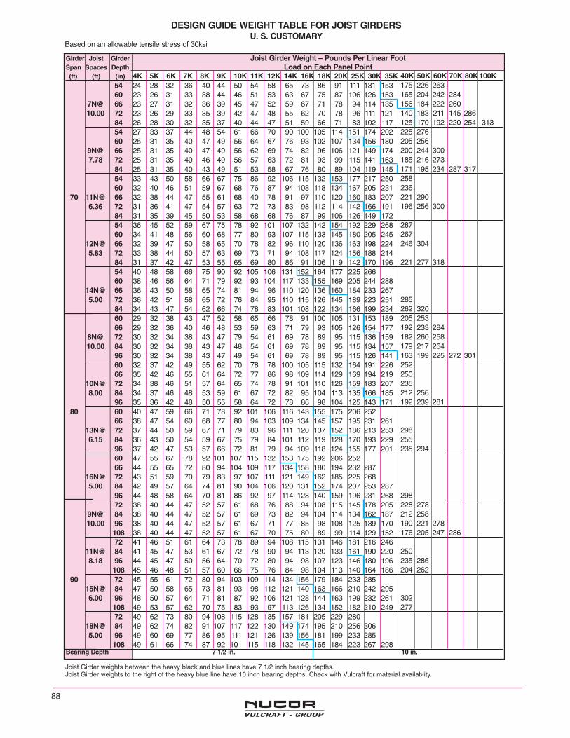
88
Girder Joist Girder Joist Girder Weight – Pounds Per Linear FootSpan Spaces Depth Load on Each Panel Point(ft) (ft) (in) 4K 5K 6K 7K 8K 9K 10K 11K 12K 14K 16K 18K 20K 25K 30K 35K
54 24 28 32 36 40 44 50 54 58 65 73 86 91 111 131 15360 23 26 31 33 38 44 46 51 53 63 67 75 87 106 126 153
7N@ 66 23 27 31 32 36 39 45 47 52 59 67 71 78 94 114 13510.00 72 23 26 29 33 35 39 42 47 48 55 62 70 78 96 111 121
84 26 28 30 32 35 37 40 44 47 51 59 66 71 83 102 11754 27 33 37 44 48 54 61 66 70 90 100 105 114 151 174 20260 25 31 35 40 47 49 56 64 67 76 93 102 107 134 156 180
9N@ 66 25 31 35 40 47 49 56 62 69 74 82 96 106 121 149 1747.78 72 25 31 35 40 46 49 56 57 63 72 81 93 99 115 141 163
84 25 31 35 40 43 49 51 53 58 67 76 80 89 104 119 14554 33 43 50 58 66 67 75 86 92 106 115 132 153 177 217 25060 32 40 46 51 59 67 68 76 87 94 108 118 134 167 205 231
70 11N@ 66 32 38 44 47 55 61 68 40 78 91 97 110 120 160 183 2076.36 72 31 36 41 47 54 57 63 72 73 83 98 112 114 142 166 191
84 31 35 39 45 50 53 58 68 68 76 87 99 106 126 149 17254 36 45 52 59 67 75 78 92 101 107 132 142 154 192 229 26860 34 41 48 56 60 68 77 80 93 107 115 133 145 180 205 245
12N@ 66 32 39 47 50 58 65 70 78 82 96 110 120 136 163 198 2245.83 72 33 38 44 50 57 63 69 73 71 94 108 117 124 156 188 214
84 31 37 42 47 53 55 65 69 80 86 91 106 119 142 170 19654 40 48 58 66 75 90 92 105 106 131 152 164 177 225 26660 38 46 56 64 71 79 92 93 104 117 133 155 169 205 244 288
14N@ 66 36 43 50 58 65 74 81 94 96 110 120 136 160 184 233 2675.00 72 36 42 51 58 65 72 76 84 95 110 115 126 145 189 223 251
84 34 43 47 54 62 66 74 78 83 101 108 122 134 166 199 23460 29 32 38 43 47 52 58 65 66 78 91 100 105 131 153 18966 29 32 36 40 46 48 53 59 63 71 79 93 105 126 154 177
8N@ 72 30 32 34 38 43 47 79 54 61 69 78 89 95 115 136 15910.00 84 30 32 34 38 43 47 48 54 61 69 78 89 95 115 134 157
96 30 32 34 38 43 47 49 54 61 69 78 89 95 115 126 14160 32 37 42 49 55 62 70 78 78 100 105 115 132 164 191 22666 35 42 46 55 61 64 72 77 86 98 109 114 129 169 194 219
10N@ 72 34 38 46 51 57 64 65 74 78 91 101 110 126 159 183 2078.00 84 34 37 46 48 53 59 61 67 72 82 95 104 113 135 166 185
96 35 36 42 48 50 55 58 64 72 78 86 98 104 125 143 17180 60 40 47 59 66 71 78 92 101 106 116 143 155 175 206 252
66 38 47 54 60 68 77 80 94 103 109 134 145 157 195 231 26113N@ 72 37 44 50 59 67 71 79 83 96 111 120 137 152 186 213 2536.15 84 36 43 50 54 59 67 75 79 84 101 112 119 128 170 193 229
96 37 42 47 53 57 66 72 81 79 94 109 118 124 155 177 20160 47 55 67 78 92 101 107 115 132 153 175 192 206 25266 44 55 65 72 80 94 104 109 117 134 158 180 194 232 287
16N@ 72 43 51 59 70 79 83 97 107 111 121 149 162 185 225 2685.00 84 42 49 57 64 74 81 90 104 106 120 131 152 174 207 253 287
96 44 48 58 64 70 81 86 92 97 114 128 140 159 196 231 26872 38 40 44 47 52 57 61 68 76 88 94 108 115 145 178 205
9N@ 84 38 40 44 47 52 57 61 69 73 82 94 104 114 134 162 18710.00 96 38 40 44 47 52 57 61 67 71 77 85 98 108 125 139 170
108 38 40 44 47 52 57 61 67 70 75 80 89 99 114 129 15272 41 46 51 61 64 73 78 89 94 108 115 131 146 181 216 246
11N@ 84 41 45 47 53 61 67 72 78 90 94 113 120 133 161 190 2208.18 96 44 45 47 50 56 64 70 72 80 94 98 107 123 146 180 196
108 45 46 48 51 57 60 66 75 76 84 98 104 113 140 164 18690 72 45 55 61 72 80 94 103 109 114 134 156 179 184 233 285
15N@ 84 47 50 58 65 73 81 93 98 112 121 140 163 166 210 242 2956.00 96 48 50 57 64 71 81 87 92 106 121 128 144 163 199 232 261
108 49 53 57 62 70 75 83 93 97 113 126 134 152 182 210 24972 49 62 73 80 94 108 115 128 135 157 181 205 229 280
18N@ 84 49 62 74 82 91 107 117 122 130 149 174 195 210 256 3065.00 96 49 60 69 77 86 95 111 121 126 139 156 181 199 233 285
108 49 61 66 74 87 92 101 115 118 132 145 165 184 223 267 298Bearing Depth 7 1/2 in. 10 in.
40K 50K 60K 70K 80K 100K175 226 263165 204 242 284156 184 222 260140 183 211 145 286125 170 192 220 254 313225 276205 256200 244 300185 216 273171 195 234 287 317258236221 290196 256 300
287267246 304
221 277 318
285262 320205 253192 233 284182 260 258179 217 264163 199 225 272 301252250235212 256192 239 281
298255235 294
298228 278212 258190 221 278176 205 247 286
250235 286204 262
302277
DESIGN GUIDE WEIGHT TABLE FOR JOIST GIRDERSU. S. CUSTOMARY
Based on an allowable tensile stress of 30ksi
Joist Girder weights between the heavy black and blue lines have 7 1/2 inch bearing depths.Joist Girder weights to the right of the heavy blue line have 10 inch bearing depths. Check with Vulcraft for material availablity.

89
Girder Joist Girder Joist Girder Weight – Pounds Per Linear FootSpan Spaces Depth Load on Each Panel Point(ft) (ft) (in) 4K 5K 6K 7K 8K 9K 10K 11K 12K 14K 16K 18K 20K 25K 30K 35K
84 56 57 58 62 64 72 76 88 90 103 118 129 142 172 200 22510N@ 96 58 58 59 61 64 67 70 78 88 94 106 120 131 152 180 20410.00 108 58 60 60 61 63 68 70 73 77 93 96 111 111 139 170 188
120 60 60 62 64 66 67 68 71 74 85 99 108 113 139 157 18884 50 54 58 66 70 75 89 92 101 112 129 138 159 187 221 257
12N@ 96 50 54 57 61 68 70 80 84 96 106 116 123 137 179 205 2288.33 108 52 54 58 62 65 72 74 79 89 101 110 121 128 164 193 221
120 54 57 60 62 66 69 77 79 86 92 107 117 126 151 178 20684 55 60 71 76 83 96 110 112 119 139 161 184 199 235 288
16N@ 96 56 60 67 75 79 88 102 105 119 128 145 168 191 218 265 301100 6.25 108 58 63 67 72 81 87 93 106 111 125 136 157 180 204 251 292
120 60 65 68 74 79 90 93 98 110 117 134 147 166 208 248 27584 57 65 73 82 92 98 112 114 123 151 164 187 203 250
17N@ 96 60 65 72 81 89 103 110 123 123 145 177 179 198 256 2855.88 108 64 67 72 76 86 96 108 113 123 135 158 172 182 231 264 308
120 67 68 73 80 85 90 99 112 119 133 143 167 178 214 250 28184 67 77 87 105 115 122 132 148 159 193 208 226 246
20N@ 96 67 73 82 95 111 120 126 135 152 177 199 211 227 2795.00 108 66 72 79 91 101 116 125 130 131 162 184 197 207 267 316
120 71 75 82 88 96 106 120 123 136 149 170 193 205 246 289 332Bearing Depth 7 1/2 in. 10 in.
40K 50K 60K 70K 80K 100K257228209 258201 242 289
271246 299239 283
304
330
DESIGN GUIDE WEIGHT TABLE FOR JOIST GIRDERSU. S. CUSTOMARY
Based on an allowable tensile stress of 30ksi
Joist Girder weights between the heavy black and blue lines have 7 1/2 inch bearing depths.Joist Girder weights to the right of the heavy blue line have 10 inch bearing depths. Check with Vulcraft for material availablity.

90
Joist Girder design example using MetricUnits:
Given 15.24 m x 12.19 m bay. Joists spaced on 1.905 mcenters.
Live Load = .958 kN/m2
Dead Load = .718 kN/m2 Includes approximateJoist Girder Weight
Total Load = 1.676 kN/m2
NOTE: Web configuration may vary from that shown.Contact Joist Girder manufacturer if exact layoutmust be known.
1. Determine number of actual joist spaces (N).
In this example N = 8.
2. Compute total load:
T.L.= 1.905 m x 1.676 kN/m2 = 3.193 kN/m
3. Joist Girder Selection: (Interior)
a) Compute the concentrated load at top chordpanel points
P = 3.193 kN/m x 12.19 m = 38.92 kN (use 39.0kN).
b) Select Joist Girder depth:
Refer to the Joist Girder Design Guide WeightTable for the 15240 mm span, 8 panel, 40.0 kNJoist Girder. The rule of about one millimeter ofdepth for each 12 millimeters of span is a goodcompromise of limited depth and economy.Therefore, select a depth of 1219 mm from thetable.
c) The Joist Girder will then be designated1219G8N39.0 kN.
d) The Joist Girder table shows the weight for a1219G8N40K as 64 kg/m. To convert mass mul-tiply 64 x .0098 = .627 kN/m. The designershould verify that the weight is not greater thanthe weight assumed in the dead load above.
e) Check live load deflection:
Live load = .958 kN/m2 x 12.19 m = 11.68 kN/m
Approximate Joist Girder moment of inertia:
IJG = 0.3296NPLd where d = effective depth
= 0.3296 x 8 x 39.0 x 15240 x 1219
= 1910 x 106 mm4
Allowable deflection
for plastered ceilings = L/360 = = 42.33 mm
= 24.70 mm < 42.33 mm - Okay
1. The purpose of the Design Guide Weight Table forJoist Girders is to assist the specifying professional inthe selection of a roof or floor support system.
2. It is not necessary to use only the depths, spans, orloads shown in the tables.
3. Holes in chord elements present special problemswhich must be considered by both the specifying pro-fessional and the Joist Girder Manufacturer. Thesizes and locations of such holes shall be clearly indi-cated on the structural drawings.
JOIST GIRDERS
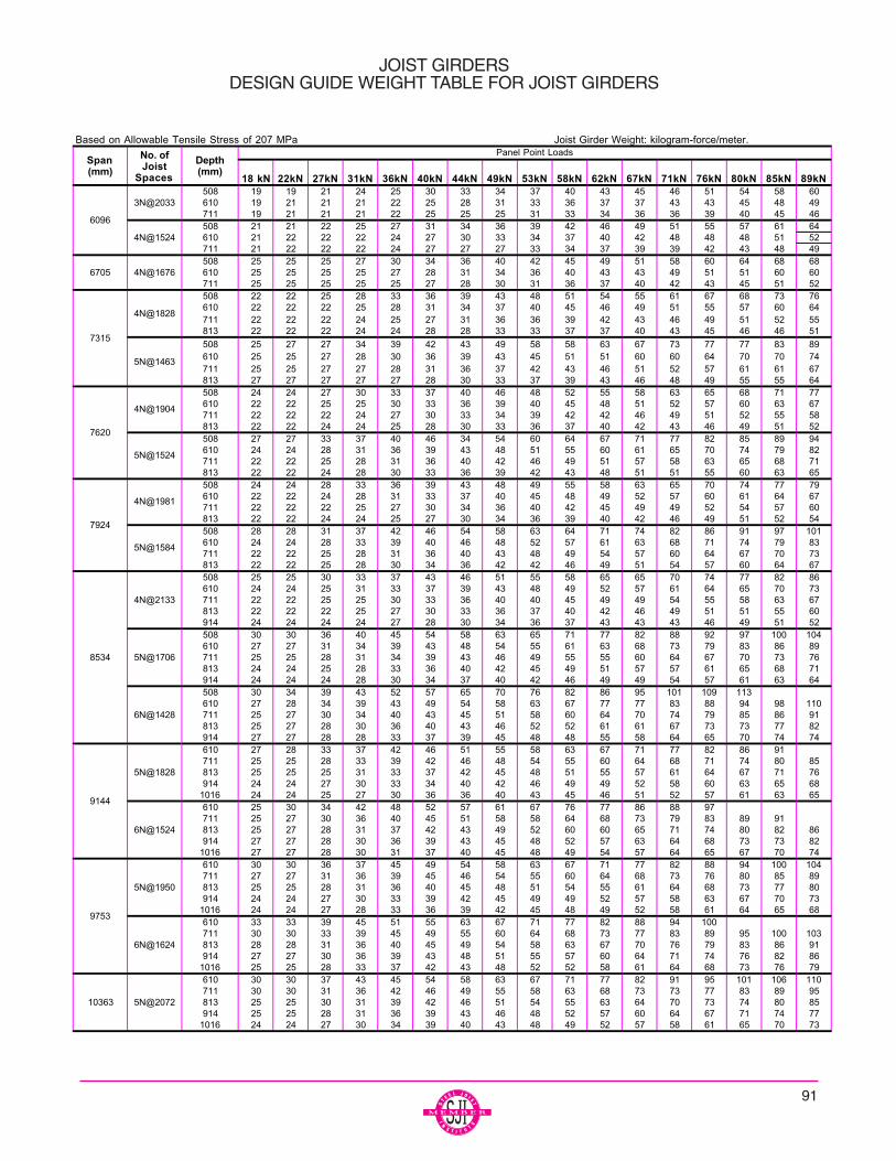
91
JOIST GIRDERSDESIGN GUIDE WEIGHT TABLE FOR JOIST GIRDERS
Based on Allowable Tensile Stress of 207 MPa Joist Girder Weight: kilogram-force/meter.
18 kN 22kN 27kN 31kN 36kN 40kN 44kN 49kN 53kN 58kN 62kN 67kN 71kN 76kN 80kN 85kN 89kN508 19 19 21 24 25 30 33 34 37 40 43 45 46 51 54 58 60610 19 21 21 21 22 25 28 31 33 36 37 37 43 43 45 48 49711 19 21 21 21 22 25 25 25 31 33 34 36 36 39 40 45 46508 21 21 22 25 27 31 34 36 39 42 46 49 51 55 57 61 64610 21 22 22 22 24 27 30 33 34 37 40 42 48 48 48 51 52711 21 22 22 22 24 27 27 27 33 34 37 39 39 42 43 48 49508 25 25 25 27 30 34 36 40 42 45 49 51 58 60 64 68 68610 25 25 25 25 27 28 31 34 36 40 43 43 49 51 51 60 60711 25 25 25 25 25 27 28 30 31 36 37 40 42 43 45 51 52508 22 22 25 28 33 36 39 43 48 51 54 55 61 67 68 73 76610 22 22 22 25 28 31 34 37 40 45 46 49 51 55 57 60 64711 22 22 22 24 25 27 31 36 36 39 42 43 46 49 51 52 55813 22 22 22 24 24 28 28 33 33 37 37 40 43 45 46 46 51
508 25 27 27 34 39 42 43 49 58 58 63 67 73 77 77 83 89610 25 25 27 28 30 36 39 43 45 51 51 60 60 64 70 70 74711 25 25 27 27 28 31 36 37 42 43 46 51 52 57 61 61 67813 27 27 27 27 27 28 30 33 37 39 43 46 48 49 55 55 64508 24 24 27 30 33 37 40 46 48 52 55 58 63 65 68 71 77610 22 22 25 25 30 33 36 39 40 45 48 51 52 57 60 63 67711 22 22 22 24 27 30 33 34 39 42 42 46 49 51 52 55 58813 22 22 24 24 25 28 30 33 36 37 40 42 43 46 49 51 52508 27 27 33 37 40 46 34 54 60 64 67 71 77 82 85 89 94610 24 24 28 31 36 39 43 48 51 55 60 61 65 70 74 79 82711 22 22 25 28 31 36 40 42 46 49 51 57 58 63 65 68 71813 22 22 24 28 30 33 36 39 42 43 48 51 51 55 60 63 65508 24 24 28 33 36 39 43 48 49 55 58 63 65 70 74 77 79610 22 22 24 28 31 33 37 40 45 48 49 52 57 60 61 64 67711 22 22 22 25 27 30 34 36 40 42 45 49 49 52 54 57 60813 22 22 24 24 25 27 30 34 36 39 40 42 46 49 51 52 54508 28 28 31 37 42 46 54 58 63 64 71 74 82 86 91 97 101610 24 24 28 33 39 40 46 48 52 57 61 63 68 71 74 79 83711 22 22 25 28 31 36 40 43 48 49 54 57 60 64 67 70 73813 22 22 25 28 30 34 36 42 42 46 49 51 54 57 60 64 67508 25 25 30 33 37 43 46 51 55 58 65 65 70 74 77 82 86610 24 24 25 31 33 37 39 43 48 49 52 57 61 64 65 70 73711 22 22 25 25 30 33 36 40 40 45 49 49 54 55 58 63 67813 22 22 22 25 27 30 33 36 37 40 42 46 49 51 51 55 60914 24 24 24 24 27 28 30 34 36 37 43 43 43 46 49 51 52508 30 30 36 40 45 54 58 63 65 71 77 82 88 92 97 100 104610 27 27 31 34 39 43 48 54 55 61 63 68 73 79 83 86 89711 25 25 28 31 34 39 43 46 49 55 55 60 64 67 70 73 76813 24 24 25 28 33 36 40 42 45 49 51 57 57 61 65 68 71914 24 24 24 28 30 34 37 40 42 46 49 49 54 57 61 63 64508 30 34 39 43 52 57 65 70 76 82 86 95 101 109 113610 27 28 34 39 43 49 54 58 63 67 77 77 83 88 94 98 110711 25 27 30 34 40 43 45 51 58 60 64 70 74 79 85 86 91813 25 27 28 30 36 40 43 46 52 52 61 61 67 73 73 77 82914 27 27 28 28 33 37 39 45 48 48 55 58 64 65 70 74 74610 27 28 33 37 42 46 51 55 58 63 67 71 77 82 86 91711 25 25 28 33 39 42 46 48 54 55 60 64 68 71 74 80 85813 25 25 25 31 33 37 42 45 48 51 55 57 61 64 67 71 76914 24 24 27 30 33 34 40 42 46 49 49 52 58 60 63 65 68
1016 24 24 25 27 30 36 36 40 43 45 46 51 52 57 61 63 65610 25 30 34 42 48 52 57 61 67 76 77 86 88 97711 25 27 30 36 40 45 51 58 58 64 68 73 79 83 89 91813 25 27 28 31 37 42 43 49 52 60 60 65 71 74 80 82 86914 27 27 28 30 36 39 43 45 48 52 57 63 64 68 73 73 82
1016 27 27 28 30 31 37 40 45 48 49 54 57 64 65 67 70 74610 30 30 36 37 45 49 54 58 63 67 71 77 82 88 94 100 104711 27 27 31 36 39 45 46 54 55 60 64 68 73 76 80 85 89813 25 25 28 31 36 40 45 48 51 54 55 61 64 68 73 77 80914 24 24 27 30 33 39 42 45 49 49 52 57 58 63 67 70 73
1016 24 24 27 28 33 36 39 42 45 48 49 52 58 61 64 65 68610 33 33 39 45 51 55 63 67 71 77 82 88 94 100711 30 30 33 39 45 49 55 60 64 68 73 77 83 89 95 100 103813 28 28 31 36 40 45 49 54 58 63 67 70 76 79 83 86 91914 27 27 30 36 39 43 48 51 55 57 60 64 71 74 76 82 86
1016 25 25 28 33 37 42 43 48 52 52 58 61 64 68 73 76 79610 30 30 37 43 45 54 58 63 67 71 77 82 91 95 101 106 110711 30 30 31 36 42 46 49 55 58 63 68 73 73 77 83 89 95813 25 25 30 31 39 42 46 51 54 55 63 64 70 73 74 80 85914 25 25 28 31 36 39 43 46 48 52 57 60 64 67 71 74 77
1016 24 24 27 30 34 39 40 43 48 49 52 57 58 61 65 70 73
6N@1624
5N@2072
7315
5N@1828
6N@1524
5N@1950
5N@1584
4N@2133
5N@1706
6N@1428
9753
10363
4N@1524
3N@2033
4N@1676
4N@1828
5N@1463
4N@1904
5N@1524
4N@1981
Depth(mm)
Panel Point Loads
8534
9144
Span(mm)
No. ofJoist
Spaces
7620
6096
6705
7924
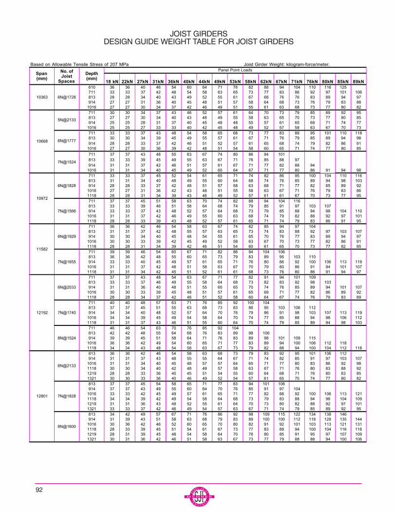
JOIST GIRDERSDESIGN GUIDE WEIGHT TABLE FOR JOIST GIRDERS
Based on Allowable Tensile Stress of 207 MPa Joist Girder Weight: kilogram-force/meter.
18 kN 22kN 27kN 31kN 36kN 40kN 44kN 49kN 53kN 58kN 62kN 67kN 71kN 76kN 80kN 85kN 89kN610 36 36 40 46 54 60 64 71 76 82 88 94 104 110 116 125 711 33 33 37 42 48 54 58 63 65 73 77 83 86 92 97 101 106813 28 28 34 40 43 49 52 55 61 67 68 76 76 83 89 94 97914 27 27 31 36 40 45 48 51 57 58 64 68 73 76 79 83 88
1016 27 27 30 34 37 42 46 49 51 55 61 63 68 73 77 80 82711 30 30 34 37 43 46 52 57 61 64 70 73 79 85 89 92 95813 27 27 30 34 40 43 48 49 55 58 63 65 70 73 77 80 85914 25 25 28 31 37 40 45 48 48 55 57 61 65 68 71 74 77
1016 25 25 27 33 33 40 42 45 48 49 52 57 58 63 67 70 73711 33 33 37 43 48 54 58 65 68 73 77 83 89 95 101 110 118813 30 30 34 39 45 49 55 57 61 67 71 76 79 85 89 94 98914 28 28 33 37 42 46 51 52 57 61 65 68 74 79 82 86 91
1016 27 27 30 36 39 42 48 51 54 58 60 65 71 74 77 80 85
711 37 37 43 48 55 63 67 74 80 86 94 101 813 33 33 39 45 49 55 63 67 71 76 85 88 97 914 31 31 37 42 46 51 57 61 67 71 77 82 88 94
1016 31 31 34 40 45 49 52 60 64 67 71 77 80 86 91 94 98711 33 33 37 45 52 54 61 65 71 74 82 86 95 100 104 110 116813 31 31 34 40 48 49 55 60 64 68 74 76 85 89 94 98 103914 28 28 33 37 42 48 51 57 58 63 68 71 77 82 85 89 92
1016 27 27 31 36 42 43 48 51 55 58 63 67 71 76 79 83 861118 28 28 31 34 39 43 46 49 52 57 61 61 67 70 73 77 95711 37 37 45 51 58 63 70 74 82 88 94 104 116 813 33 33 39 46 51 58 64 68 74 79 85 91 97 103 107 914 33 33 37 43 48 52 57 64 68 73 79 85 88 94 98 104 110
1016 31 31 37 42 46 49 55 60 63 68 74 79 82 88 92 97 1011118 28 28 33 39 43 48 52 57 61 65 71 74 79 83 86 91 95711 36 36 42 46 54 58 63 67 74 82 85 94 97 104 813 31 31 37 42 48 55 57 63 65 73 74 83 88 92 97 103 107914 30 30 34 40 45 48 54 55 61 65 70 76 77 83 89 94 97
1016 30 30 33 39 42 45 49 52 58 63 67 70 73 77 82 86 911118 28 28 31 34 39 42 46 51 54 60 61 65 70 73 77 82 85711 39 39 46 54 60 67 71 82 86 94 104 106 813 36 36 42 48 55 60 65 73 79 83 89 95 103 110 914 33 33 40 45 49 57 61 65 71 76 80 86 92 100 106 113 119
1016 31 31 37 42 48 51 58 63 67 70 79 80 86 91 94 101 1071118 31 31 34 42 45 51 52 61 61 68 73 76 80 86 91 94 97711 37 37 43 48 54 63 67 71 77 82 91 94 101 109 813 33 33 37 46 49 55 58 64 68 73 82 83 92 98 103 914 31 31 36 40 48 51 55 60 65 70 74 76 85 89 94 101 107
1016 30 30 33 39 45 48 51 57 61 65 68 71 77 82 86 89 921118 28 28 34 37 42 46 51 52 58 60 64 67 74 76 79 83 89711 40 40 48 57 63 71 76 85 92 100 104 813 37 37 45 51 55 63 68 73 83 86 95 103 106 112 914 34 34 40 48 52 57 64 70 76 79 86 91 98 103 107 113 119
1016 34 34 39 45 49 54 58 64 70 74 77 85 88 94 98 106 1121118 31 31 37 43 46 51 55 60 64 70 74 79 85 89 94 98 103711 46 46 54 63 70 76 85 92 104 813 42 42 48 55 64 68 76 83 89 98 106 914 39 39 45 51 58 64 71 76 83 89 98 101 109 115
1016 36 36 42 49 54 60 65 71 77 83 89 94 100 106 112 118 1118 34 34 43 48 54 58 63 67 73 79 82 88 94 100 104 112 118813 36 36 42 46 54 58 63 68 73 79 83 92 95 101 106 112 914 31 31 37 43 48 55 55 64 67 71 74 82 85 91 97 103 107
1016 31 31 34 40 45 48 57 57 64 65 71 77 80 83 86 92 981118 30 30 34 40 42 48 49 57 58 63 67 71 76 80 83 88 921219 28 28 33 36 40 45 51 54 55 60 64 68 71 76 80 83 851321 30 30 33 36 40 46 49 52 54 57 61 65 70 74 77 80 82813 37 37 45 54 58 65 71 77 83 94 101 106 914 37 37 43 49 55 60 64 70 76 85 91 97 104
1016 33 33 42 45 49 57 61 65 71 77 82 88 92 100 106 113 1211118 34 34 39 42 49 54 58 64 68 73 79 83 88 94 98 104 1091219 31 31 36 43 48 52 55 61 64 70 73 80 82 88 92 97 1011321 33 33 37 42 46 49 54 57 63 67 71 74 79 85 89 92 95813 34 42 49 57 67 71 76 86 92 98 109 115 122 134 138 146 914 31 39 43 51 58 63 68 79 83 89 100 100 112 118 128 135 144
1016 30 36 42 46 52 60 65 70 80 82 91 92 101 103 113 121 1311118 28 33 39 45 51 54 61 67 73 77 83 89 94 100 104 116 1161219 28 31 39 45 48 54 58 64 70 76 80 85 91 95 97 107 1091321 30 31 36 42 46 51 58 63 67 73 77 79 88 88 94 100 106
7N@1828
8N@1600
6N@2033
7N@1740
8N@1524
6N@2133
12192
12801
6N@1728
5N@2133
6N@1777
7N@1524
6N@1828
7N@1566
6N@1929
7N@1655
10363
10668
10972
11582
Depth(mm)
Panel Point LoadsSpan(mm)
No. ofJoist
Spaces
92
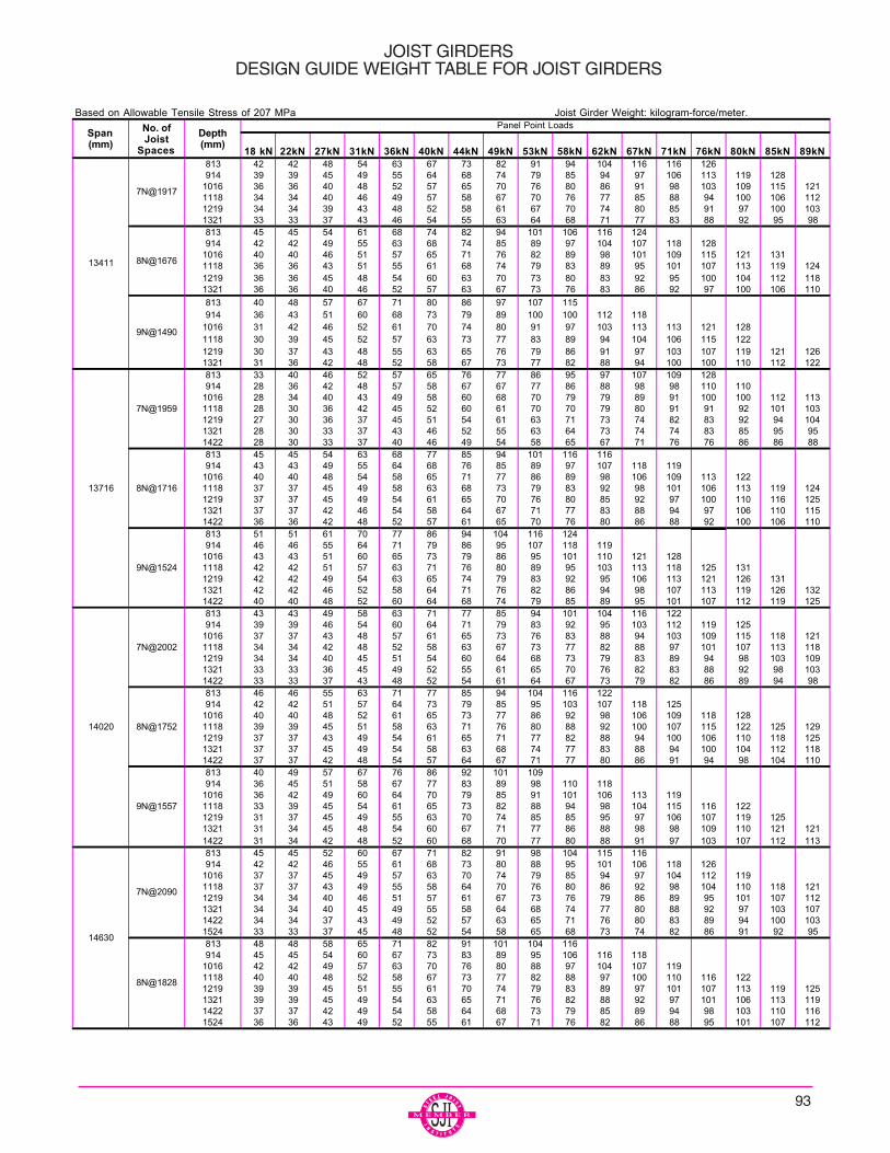
JOIST GIRDERSDESIGN GUIDE WEIGHT TABLE FOR JOIST GIRDERS
Based on Allowable Tensile Stress of 207 MPa Joist Girder Weight: kilogram-force/meter.
18 kN 22kN 27kN 31kN 36kN 40kN 44kN 49kN 53kN 58kN 62kN 67kN 71kN 76kN 80kN 85kN 89kN813 42 42 48 54 63 67 73 82 91 94 104 116 116 126914 39 39 45 49 55 64 68 74 79 85 94 97 106 113 119 128
1016 36 36 40 48 52 57 65 70 76 80 86 91 98 103 109 115 1211118 34 34 40 46 49 57 58 67 70 76 77 85 88 94 100 106 1121219 34 34 39 43 48 52 58 61 67 70 74 80 85 91 97 100 1031321 33 33 37 43 46 54 55 63 64 68 71 77 83 88 92 95 98813 45 45 54 61 68 74 82 94 101 106 116 124914 42 42 49 55 63 68 74 85 89 97 104 107 118 128
1016 40 40 46 51 57 65 71 76 82 89 98 101 109 115 121 1311118 36 36 43 51 55 61 68 74 79 83 89 95 101 107 113 119 1241219 36 36 45 48 54 60 63 70 73 80 83 92 95 100 104 112 1181321 36 36 40 46 52 57 63 67 73 76 83 86 92 97 100 106 110
813 40 48 57 67 71 80 86 97 107 115914 36 43 51 60 68 73 79 89 100 100 112 118
1016 31 42 46 52 61 70 74 80 91 97 103 113 113 121 1281118 30 39 45 52 57 63 73 77 83 89 94 104 106 115 1221219 30 37 43 48 55 63 65 76 79 86 91 97 103 107 119 121 1261321 31 36 42 48 52 58 67 73 77 82 88 94 100 100 110 112 122813 33 40 46 52 57 65 76 77 86 95 97 107 109 128914 28 36 42 48 57 58 67 67 77 86 88 98 98 110 110
1016 28 34 40 43 49 58 60 68 70 79 79 89 91 100 100 112 1131118 28 30 36 42 45 52 60 61 70 70 79 80 91 91 92 101 1031219 27 30 36 37 45 51 54 61 63 71 73 74 82 83 92 94 1041321 28 30 33 37 43 46 52 55 63 64 73 74 74 83 85 95 951422 28 30 33 37 40 46 49 54 58 65 67 71 76 76 86 86 88813 45 45 54 63 68 77 85 94 101 116 116914 43 43 49 55 64 68 76 85 89 97 107 118 119
1016 40 40 48 54 58 65 71 77 86 89 98 106 109 113 1221118 37 37 45 49 58 63 68 73 79 83 92 98 101 106 113 119 1241219 37 37 45 49 54 61 65 70 76 80 85 92 97 100 110 116 1251321 37 37 42 46 54 58 64 67 71 77 83 88 94 97 106 110 1151422 36 36 42 48 52 57 61 65 70 76 80 86 88 92 100 106 110813 51 51 61 70 77 86 94 104 116 124 914 46 46 55 64 71 79 86 95 107 118 119
1016 43 43 51 60 65 73 79 86 95 101 110 121 1281118 42 42 51 57 63 71 76 80 89 95 103 113 118 125 1311219 42 42 49 54 63 65 74 79 83 92 95 106 113 121 126 1311321 42 42 46 52 58 64 71 76 82 86 94 98 107 113 119 126 1321422 40 40 48 52 60 64 68 74 79 85 89 95 101 107 112 119 125813 43 43 49 58 63 71 77 85 94 101 104 116 122914 39 39 46 54 60 64 71 79 83 92 95 103 112 119 125
1016 37 37 43 48 57 61 65 73 76 83 88 94 103 109 115 118 1211118 34 34 42 48 52 58 63 67 73 77 82 88 97 101 107 113 1181219 34 34 40 45 51 54 60 64 68 73 79 83 89 94 98 103 1091321 33 33 36 45 49 52 55 61 65 70 76 82 83 88 92 98 1031422 33 33 37 43 48 52 54 61 64 67 73 79 82 86 89 94 98813 46 46 55 63 71 77 85 94 104 116 122914 42 42 51 57 64 73 79 85 95 103 107 118 125
1016 40 40 48 52 61 65 73 77 86 92 98 106 109 118 1281118 39 39 45 51 58 63 71 76 80 88 92 100 107 115 122 125 1291219 37 37 43 49 54 61 65 71 77 82 88 94 100 106 110 118 1251321 37 37 45 49 54 58 63 68 74 77 83 88 94 100 104 112 1181422 37 37 42 48 54 57 64 67 71 77 80 86 91 94 98 104 110813 40 49 57 67 76 86 92 101 109914 36 45 51 58 67 77 83 89 98 110 118
1016 36 42 49 60 64 70 79 85 91 101 106 113 1191118 33 39 45 54 61 65 73 82 88 94 98 104 115 116 1221219 31 37 45 49 55 63 70 74 85 85 95 97 106 107 119 1251321 31 34 45 48 54 60 67 71 77 86 88 98 98 109 110 121 1211422 31 34 42 48 52 60 68 70 77 80 88 91 97 103 107 112 113813 45 45 52 60 67 71 82 91 98 104 115 116914 42 42 46 55 61 68 73 80 88 95 101 106 118 126
1016 37 37 45 49 57 63 70 74 79 85 94 97 104 112 1191118 37 37 43 49 55 58 64 70 76 80 86 92 98 104 110 118 1211219 34 34 40 46 51 57 61 67 73 76 79 86 89 95 101 107 1121321 34 34 40 45 49 55 58 64 68 74 77 80 88 92 97 103 1071422 34 34 37 43 49 52 57 63 65 71 76 80 83 89 94 100 1031524 33 33 37 45 48 52 54 58 65 68 73 74 82 86 91 92 95813 48 48 58 65 71 82 91 101 104 116914 45 45 54 60 67 73 83 89 95 106 116 118
1016 42 42 49 57 63 70 76 80 88 97 104 107 1191118 40 40 48 52 58 67 73 77 82 88 97 100 110 116 1221219 39 39 45 51 55 61 70 74 79 83 89 97 101 107 113 119 1251321 39 39 45 49 54 63 65 71 76 82 88 92 97 101 106 113 1191422 37 37 42 49 54 58 64 68 73 79 85 89 94 98 103 110 1161524 36 36 43 49 52 55 61 67 71 76 82 86 88 95 101 107 112
Depth(mm)
Panel Point LoadsSpan(mm)
No. ofJoist
Spaces
7N@1917
8N@1676
9N@1490
13411
13716
7N@1959
8N@1716
9N@1524
14630
7N@2090
8N@1828
14020
7N@2002
8N@1752
9N@1557
93

94
JOIST GIRDERSDESIGN GUIDE WEIGHT TABLE FOR JOIST GIRDERS
Based on Allowable Tensile Stress of 207 MPa Joist Girder Weight: kilogram-force/meter.
18 kN 22kN 27kN 31kN 36kN 40kN 44kN 49kN 53kN 58kN 62kN 67kN 71kN 76kN 80kN 85kN 89kN813 54 54 65 71 82 92 103 115 122 914 48 48 60 67 74 83 95 103 107 118
1016 46 46 57 61 70 77 85 92 100 109 119 126 1118 45 45 52 58 67 73 80 88 94 100 112 122 124 1219 45 45 51 55 63 70 76 82 89 94 103 110 115 121 126 1321 42 42 49 55 63 67 73 79 85 94 97 106 109 119 128 132 1371422 42 42 48 54 60 65 71 77 83 88 94 100 109 115 121 126 1321524 40 40 49 54 58 63 68 74 80 85 89 97 103 109 113 119 125813 51 51 58 67 76 85 92 103 115 122 914 46 46 55 64 68 77 83 94 101 106 116 124 135
1016 43 43 51 57 64 70 80 85 94 97 107 118 119 1118 40 40 49 55 61 67 73 79 86 92 98 106 110 116 122 131 1219 40 40 46 52 60 64 68 76 80 88 95 101 107 115 124 126 1311321 39 39 43 52 57 61 65 73 80 83 91 95 100 106 112 119 1261422 37 37 45 49 54 61 64 71 76 83 85 92 94 101 107 113 1191524 37 37 43 49 55 58 65 70 74 77 85 86 91 97 103 107 112
813 57 57 65 76 85 92 103 116 914 51 51 60 68 77 86 94 106 116 124
1016 48 48 57 65 73 80 88 97 104 119 119 1118 46 46 52 61 67 77 82 91 98 107 110 122 128 137 144 1219 43 43 51 60 64 71 80 85 91 101 104 113 124 128 132 141 1321 45 45 49 55 63 70 74 82 86 94 101 106 116 122 128 138 1422 42 42 49 55 60 68 73 79 85 89 95 101 107 115 121 126 1321524 42 42 48 55 60 67 70 76 82 88 92 98 104 112 119 125 131813 65 65 76 91 101 113 914 63 63 70 82 92 101 115 119
1016 55 55 65 73 83 94 103 118 121 1118 52 52 61 68 77 85 97 104 112 122 1219 51 51 58 65 74 82 89 98 107 113 124 126 1321 49 49 55 64 71 77 83 91 101 109 112 122 128 137 1422 49 49 55 61 68 73 80 86 95 103 110 113 124 132 141 146 1491524 49 49 52 58 68 70 79 83 92 97 104 113 115 124 131 141 152914 48 48 55 63 73 80 88 94 104
1016 45 45 52 60 67 74 82 89 95 103 113 1118 43 43 49 57 63 70 76 80 86 95 106 109 121 1219 42 42 48 54 60 67 73 77 83 89 98 100 107 115 122 1321 39 39 46 51 58 64 70 74 79 85 91 100 103 109 113 119 1251422 39 39 45 52 55 63 67 71 77 82 88 92 98 106 113 119 1251524 37 37 45 51 54 58 65 68 73 79 85 89 95 101 107 112 116914 55 55 64 73 82 88 101 106
1016 49 49 57 64 74 83 91 97 107 1118 48 48 55 61 68 77 86 92 98 109 121 1219 46 46 52 60 68 74 79 89 94 101 109 113 1321 45 45 52 57 65 71 76 82 91 97 103 112 115 122 1422 43 43 51 57 64 68 76 79 85 94 100 107 115 121 129 134 1371524 42 42 48 55 61 67 74 77 85 91 97 100 109 115 121 126 134914 45 57 67 76 86 97 107 115 125 137
1016 43 51 60 68 77 88 98 110 112 129 137 147 1118 40 46 55 64 70 80 91 97 103 113 119 129 146 1219 39 46 54 61 71 76 83 94 100 104 115 124 138 152 1321 37 45 49 60 64 74 79 85 97 101 107 119 119 138 150 1422 36 42 49 57 65 71 77 86 89 98 104 110 122 122 128 140 1524 34 42 49 54 60 68 79 82 91 97 103 107 113 124 125 134 150914 49 49 58 67 58 83 91 101 112 116
1016 46 46 55 61 68 74 85 92 100 106 118 1191118 43 43 51 57 65 71 76 85 94 97 106 115 1211219 42 42 49 57 63 67 74 79 86 94 100 107 110 116 1221321 40 40 46 52 60 64 70 76 83 89 95 101 109 115 121 122 1251422 40 40 45 52 57 63 68 74 80 86 92 97 100 106 112 119 126
1524 37 37 46 51 54 61 67 73 77 83 88 94 97 103 107 113 1191626 40 40 46 52 55 60 65 70 74 80 85 91 97 101 106 112 118914 55 55 63 73 82 94 104 116 122 135
1016 51 51 60 68 76 85 95 103 118 118 137 1118 48 48 57 65 71 80 86 97 104 109 121 128 1219 46 46 52 63 68 77 83 88 100 107 112 122 124 1321 43 43 51 60 64 73 80 85 91 100 104 113 125 128 132 1422 45 45 52 57 63 71 76 82 88 94 101 106 116 122 128 138 1524 43 43 51 55 64 68 74 79 85 89 95 104 109 115 121 126 1321626 43 43 51 57 61 67 71 76 82 88 98 98 109 113 119 126 135
Panel Point LoadsSpan(mm)
No. ofJoist
Spaces
8N@1904
14630
15240 9N@1694
10N@1524
Depth(mm)
9N@1828
9N@1624
15850
16459
8N@1981
9N@1761
10N@1584
8N@2057

95
JOIST GIRDERSDESIGN GUIDE WEIGHT TABLE FOR JOIST GIRDERS
Based on Allowable Tensile Stress of 207 MPa Joist Girder Weight5/8/2002 kilogram-force/meter.
18 kN 22kN 27kN 31kN 36kN 40kN 44kN 49kN 53kN 58kN 62kN 67kN 71kN 76kN 80kN 85kN 89kN914 67 67 76 86 100 113 119
1016 60 60 70 79 91 101 115 1191118 60 60 65 74 83 92 104 116 1221219 51 51 61 70 80 85 97 106 116 1241321 52 52 63 67 74 83 89 100 107 110 121 1261422 51 51 58 65 71 79 85 94 101 110 113 122 1281524 51 51 55 65 68 74 83 91 95 107 112 115 1251626 51 51 57 60 68 74 82 89 94 98 110 113 116 125 132914 51 51 60 67 76 83 94 101 116 116
1016 46 46 55 64 68 79 83 92 103 106 118 1251118 46 46 51 60 65 73 80 85 94 103 109 119 1191219 42 42 49 57 63 67 74 82 88 97 100 107 116 119 1221321 40 40 48 54 60 65 73 79 83 89 98 101 107 116 1241422 39 39 48 52 58 64 70 76 80 85 91 97 103 109 115 121 1261524 37 37 46 52 55 63 68 73 77 83 89 92 100 106 110 116 1211626 39 39 46 52 55 60 65 71 74 80 85 91 97 101 106 112 1181727 40 40 46 51 55 60 65 71 76 79 85 88 94 100 104 109 112914 55 55 65 74 82 94 104 116
1016 51 51 60 68 79 88 95 106 118 1251118 48 48 57 65 73 80 89 97 104 119 1211219 48 48 54 63 67 77 83 91 100 107 112 122 1291321 46 46 52 61 67 74 80 86 94 103 109 113 1251422 45 45 52 57 63 71 76 82 92 95 104 112 116 122 1281524 45 45 52 57 64 68 74 79 86 94 98 107 116 121 129 134 1381626 43 43 51 57 61 67 74 79 86 92 98 101 110 116 122 129 1351727 43 43 51 55 61 68 73 77 83 89 94 100 107 112 115 122 128914 67 67 76 89 100 113 131
1016 61 61 71 82 94 101 115 121
1118 60 60 68 74 83 95 104 118 1221219 55 55 64 70 80 88 97 106 119 1241321 52 52 61 68 76 83 92 104 107 119 1251422 54 54 58 67 71 79 88 94 106 110 122 128 1311524 52 52 55 65 70 77 85 91 100 109 112 125 1291626 51 51 55 60 70 76 82 89 95 101 110 115 126 129 1321727 52 52 55 57 70 73 79 86 95 100 106 115 116 125 132914 68 68 80 97 106 119
1016 67 67 74 86 101 109 1211118 61 61 70 79 89 104 110 1221219 57 57 65 76 86 97 106 119 1221321 55 55 63 71 83 88 100 107 121 1251422 54 54 64 68 76 85 94 103 110 122 1281524 54 54 60 68 74 82 91 97 109 115 125 129 1311626 52 52 58 68 71 80 89 94 106 113 116 126 1321727 52 52 58 65 71 79 86 94 100 109 116 119 131914 52 52 60 67 77 83 94 104 116 116
1016 46 46 55 64 71 79 83 95 103 113 1181118 46 46 52 61 65 74 80 85 94 104 109 119 1211219 45 45 49 58 64 71 77 83 88 97 104 110 1161321 42 42 48 54 60 68 73 79 86 89 98 101 109 116 1241422 40 40 48 52 58 65 70 76 80 88 91 100 103 109 115 121 1261524 39 39 46 52 57 63 68 71 77 83 89 94 103 107 112 119 1251626 39 39 46 52 55 63 65 71 76 82 85 92 97 103 107 113 1181727 40 40 48 51 57 61 67 70 76 82 85 88 95 101 107 112 118914 58 58 67 77 85 94 104 116
1016 54 54 64 68 79 89 95 106 118 1241118 49 49 57 65 76 80 91 97 107 119 1211219 48 48 57 63 70 77 88 92 100 107 121 1221321 46 46 54 61 68 74 79 89 95 101 109 113 1241422 45 45 52 60 65 71 76 83 92 97 104 112 116 122 128
1524 45 45 51 57 64 68 76 83 88 95 100 107 115 121 129 134 1381626 46 46 51 57 61 67 74 80 86 91 98 103 110 116 122 129 1351727 43 43 51 57 61 68 71 77 83 89 94 100 107 115 122 128 132914 67 67 77 89 101 113 131
1016 63 63 71 82 94 101 115 1321118 60 60 68 79 86 100 104 118 1221219 55 55 64 71 80 89 103 107 119 1241321 52 52 63 70 76 86 95 103 110 121 1251422 54 54 58 67 71 82 88 97 106 112 122 1281524 52 52 55 65 70 80 85 94 100 112 113 124 1291626 52 52 57 63 70 76 82 91 97 104 113 116 1261727 52 52 57 61 70 74 79 89 94 100 107 116 118 126 134
Depth(mm)
Panel Point LoadsSpan(mm)
No. ofJoist
Spaces
16459 10N@1645
16764
8N@2097
9N@1862
11N@1524
10N@1676
17068
8N@2133
9N@1895
10N@1706

JOIST GIRDERSDESIGN GUIDE WEIGHT TABLE FOR JOIST GIRDERS
Based on Allowable Tensile Stress of 207 MPa Joist Girder Weigh: kilogram-force/meter.
18 kN 22kN 27kN 31kN 36kN 40kN 44kN 49kN 53kN 58kN 62kN 67kN 71kN 76kN 80kN 85kN 89kN914 52 70 79 89 100 110
1016 51 61 71 80 91 101 1131118 46 58 67 77 88 94 104 115 1221219 46 55 64 74 83 91 97 107 118 1251321 45 52 63 71 77 86 98 104 110 121 1281422 43 51 60 68 79 83 91 101 107 112 124 1311524 43 51 57 65 71 82 92 94 104 110 116 126 1321626 42 51 57 64 73 80 86 95 101 107 118 119 129 1321727 40 49 58 64 70 77 88 92 98 104 110 122 124 134 135 143914 58 58 67 79 91 100 115 122
1016 55 55 64 73 83 92 101 112 1181118 51 51 61 67 76 85 94 104 107 1191219 48 48 57 64 71 79 86 95 106 110 121 1281321 48 48 54 63 68 77 83 89 98 107 112 124 1241422 45 45 52 61 65 73 80 86 92 100 109 115 126 1371524 46 46 52 58 64 71 77 82 91 94 103 112 118 124 129 1401626 46 46 54 57 65 70 74 79 86 92 100 106 113 122 129 132 1341727 48 48 51 57 63 67 73 79 88 92 98 101 109 115 121 128 1351829 46 46 52 58 63 70 73 79 85 91 95 101 109 113 116 122 128914 71 71 82 97 103 118
1016 65 65 74 85 98 104 1191118 60 60 68 79 91 103 112 1211219 58 58 67 74 85 94 104 115 1221321 55 55 64 70 79 88 98 106 116 1211422 54 54 63 68 77 83 91 104 109 119 122 1311524 55 55 60 67 71 79 89 95 107 110 121 124 1321626 54 54 55 65 71 74 88 92 100 109 113 122 126 1381727 54 54 57 60 71 76 83 91 95 101 112 115 125 129 1321829 52 52 57 60 70 74 80 89 95 98 107 115 118 125 132 140914 61 70 80 91 101 118
1016 54 63 73 86 97 107 1191118 49 63 73 83 94 100 115 1161219 49 57 65 74 85 95 106 118 1191321 48 57 67 71 82 88 98 110 121 1211422 45 52 61 68 80 89 97 103 113 122 1251524 45 54 60 70 76 83 94 98 106 115 126 128 1351626 45 54 58 65 74 85 89 95 107 109 118 129 131 1381727 43 51 58 67 76 83 89 97 100 110 116 122 132 135 1431829 43 52 58 67 73 80 91 92 101 109 115 119 126 137 138 1461016 57 60 65 73 83 92 101 112 1191118 57 57 63 70 79 85 95 104 119 1191219 55 57 58 67 74 82 89 97 106 116 1211321 54 55 57 65 70 74 80 91 94 103 109 1151422 54 54 54 63 68 73 80 86 94 101 104 113 116 1221524 52 52 54 60 67 73 80 86 92 101 104 113 116 116 1291626 52 52 52 55 64 70 76 77 88 89 97 100 109 109 121 1221727 51 51 51 55 64 70 74 79 86 88 97 101 109 112 121 124 1381829 49 49 51 57 64 68 74 79 86 89 97 101 110 116 122 131 1381016 48 63 73 82 92 103 1161118 46 61 73 82 91 103 116 122 140 1431219 45 55 67 77 86 101 104 119 122 141 1441321 43 52 63 71 77 86 97 107 112 119 129 1371422 42 51 63 70 74 85 95 100 110 116 126 132 1431524 42 49 61 68 73 82 92 98 107 113 124 129 1411626 37 48 58 64 71 77 86 95 98 110 116 119 126 1261727 36 45 58 63 71 76 86 94 97 107 115 113 124 125 134 1341829 36 57 58 61 71 76 85 91 95 104 113 116 119 125 134 1341016 49 63 76 86 97 109 1151118 49 60 68 79 89 100 110 118
1219 45 54 65 71 82 92 103 113 1211321 45 52 63 71 82 88 97 106 116 1221422 43 51 60 68 76 85 97 98 109 118 1261524 42 49 58 67 76 82 89 98 106 113 122 1281626 42 49 58 67 70 82 89 95 103 113 116 125 1321727 42 49 55 63 71 82 83 92 100 106 116 118 129 1351829 42 48 57 63 73 76 86 91 97 107 109 121 122 132 1401016 58 70 79 95 109 1211118 57 70 79 95 104 121 138 1401219 55 64 76 86 98 110 122 140 1431321 48 58 68 77 85 95 106 118 1251422 46 57 65 77 85 92 101 112 124 1281524 46 57 65 77 85 92 101 112 124 128 1471626 45 52 60 70 80 86 97 104 115 116 126 1351727 45 52 61 71 79 85 95 101 109 119 129 132 1381829 45 55 61 71 79 86 92 98 109 118 125 135 137
Depth(mm)
Panel Point LoadsSpan(mm)
No. ofJoist
Spaces
18288
9N@2033
10N@1828
11N@1661
12N@1524
9N@1962
17068 11N@1554
17678
11N@1606
10N@1767
96
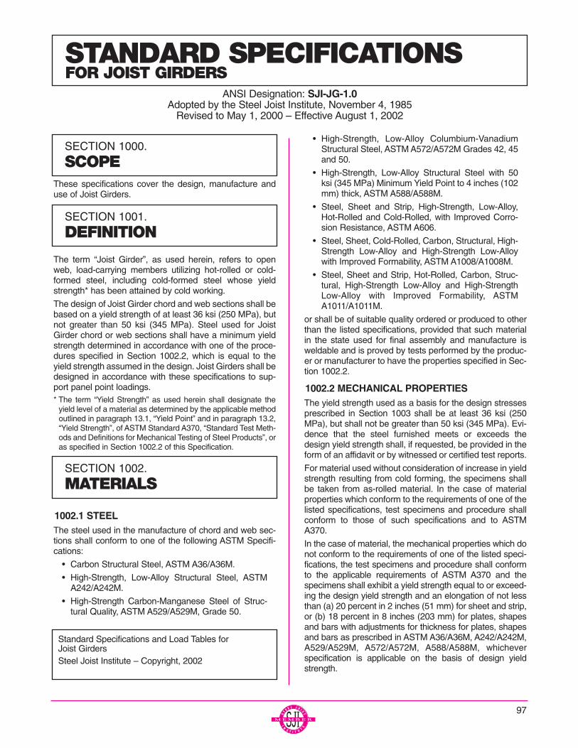
These specifications cover the design, manufacture anduse of Joist Girders.
The term “Joist Girder”, as used herein, refers to openweb, load-carrying members utilizing hot-rolled or cold-formed steel, including cold-formed steel whose yieldstrength* has been attained by cold working.
The design of Joist Girder chord and web sections shall bebased on a yield strength of at least 36 ksi (250 MPa), butnot greater than 50 ksi (345 MPa). Steel used for JoistGirder chord or web sections shall have a minimum yieldstrength determined in accordance with one of the proce-dures specified in Section 1002.2, which is equal to theyield strength assumed in the design. Joist Girders shall bedesigned in accordance with these specifications to sup-port panel point loadings.* The term “Yield Strength” as used herein shall designate the
yield level of a material as determined by the applicable methodoutlined in paragraph 13.1, “Yield Point” and in paragraph 13.2,“Yield Strength”, of ASTM Standard A370, “Standard Test Meth-ods and Definitions for Mechanical Testing of Steel Products”, oras specified in Section 1002.2 of this Specification.
1002.1 STEELThe steel used in the manufacture of chord and web sec-tions shall conform to one of the following ASTM Specifi-cations:
• Carbon Structural Steel, ASTM A36/A36M.
• High-Strength, Low-Alloy Structural Steel, ASTMA242/A242M.
• High-Strength Carbon-Manganese Steel of Struc-tural Quality, ASTM A529/A529M, Grade 50.
• High-Strength, Low-Alloy Columbium-VanadiumStructural Steel, ASTM A572/A572M Grades 42, 45and 50.
• High-Strength, Low-Alloy Structural Steel with 50ksi (345 MPa) Minimum Yield Point to 4 inches (102mm) thick, ASTM A588/A588M.
• Steel, Sheet and Strip, High-Strength, Low-Alloy,Hot-Rolled and Cold-Rolled, with Improved Corro-sion Resistance, ASTM A606.
• Steel, Sheet, Cold-Rolled, Carbon, Structural, High-Strength Low-Alloy and High-Strength Low-Alloywith Improved Formability, ASTM A1008/A1008M.
• Steel, Sheet and Strip, Hot-Rolled, Carbon, Struc-tural, High-Strength Low-Alloy and High-StrengthLow-Alloy with Improved Formability, ASTMA1011/A1011M.
or shall be of suitable quality ordered or produced to otherthan the listed specifications, provided that such materialin the state used for final assembly and manufacture isweldable and is proved by tests performed by the produc-er or manufacturer to have the properties specified in Sec-tion 1002.2.
1002.2 MECHANICAL PROPERTIESThe yield strength used as a basis for the design stressesprescribed in Section 1003 shall be at least 36 ksi (250MPa), but shall not be greater than 50 ksi (345 MPa). Evi-dence that the steel furnished meets or exceeds thedesign yield strength shall, if requested, be provided in theform of an affidavit or by witnessed or certified test reports.
For material used without consideration of increase in yieldstrength resulting from cold forming, the specimens shallbe taken from as-rolled material. In the case of materialproperties which conform to the requirements of one of thelisted specifications, test specimens and procedure shallconform to those of such specifications and to ASTMA370.
In the case of material, the mechanical properties which donot conform to the requirements of one of the listed speci-fications, the test specimens and procedure shall conformto the applicable requirements of ASTM A370 and thespecimens shall exhibit a yield strength equal to or exceed-ing the design yield strength and an elongation of not lessthan (a) 20 percent in 2 inches (51 mm) for sheet and strip,or (b) 18 percent in 8 inches (203 mm) for plates, shapesand bars with adjustments for thickness for plates, shapesand bars as prescribed in ASTM A36/A36M, A242/A242M,A529/A529M, A572/A572M, A588/A588M, whicheverspecification is applicable on the basis of design yieldstrength.
STANDARD SPECIFICATIONSFOR JOIST GIRDERS
ANSI Designation: SJI-JG-1.0Adopted by the Steel Joist Institute, November 4, 1985
Revised to May 1, 2000 – Effective August 1, 2002
SECTION 1000.
SCOPE
SECTION 1001.
DEFINITION
Standard Specifications and Load Tables for Joist GirdersSteel Joist Institute – Copyright, 2002
SECTION 1002.
MATERIALS
97
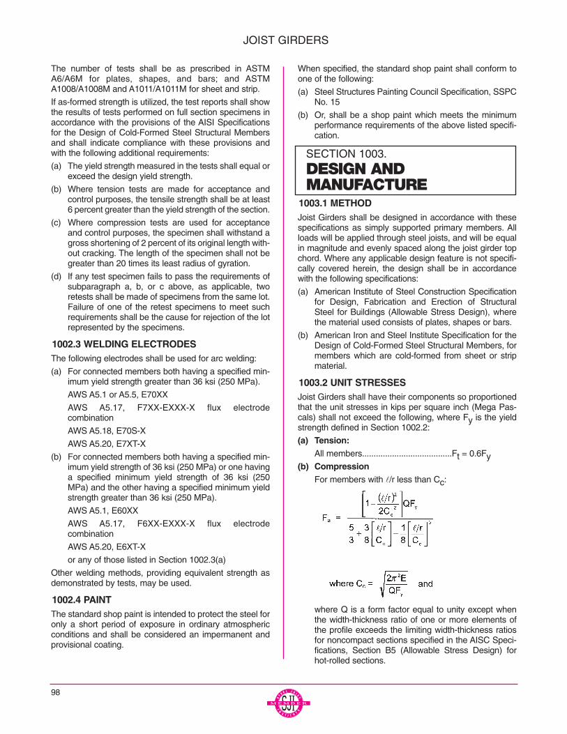
The number of tests shall be as prescribed in ASTMA6/A6M for plates, shapes, and bars; and ASTMA1008/A1008M and A1011/A1011M for sheet and strip.
If as-formed strength is utilized, the test reports shall showthe results of tests performed on full section specimens inaccordance with the provisions of the AISI Specificationsfor the Design of Cold-Formed Steel Structural Membersand shall indicate compliance with these provisions andwith the following additional requirements:
(a) The yield strength measured in the tests shall equal orexceed the design yield strength.
(b) Where tension tests are made for acceptance andcontrol purposes, the tensile strength shall be at least6 percent greater than the yield strength of the section.
(c) Where compression tests are used for acceptanceand control purposes, the specimen shall withstand agross shortening of 2 percent of its original length with-out cracking. The length of the specimen shall not begreater than 20 times its least radius of gyration.
(d) If any test specimen fails to pass the requirements ofsubparagraph a, b, or c above, as applicable, tworetests shall be made of specimens from the same lot.Failure of one of the retest specimens to meet suchrequirements shall be the cause for rejection of the lotrepresented by the specimens.
1002.3 WELDING ELECTRODESThe following electrodes shall be used for arc welding:
(a) For connected members both having a specified min-imum yield strength greater than 36 ksi (250 MPa).
AWS A5.1 or A5.5, E70XX
AWS A5.17, F7XX-EXXX-X flux electrode combination
AWS A5.18, E70S-X
AWS A5.20, E7XT-X
(b) For connected members both having a specified min-imum yield strength of 36 ksi (250 MPa) or one havinga specified minimum yield strength of 36 ksi (250MPa) and the other having a specified minimum yieldstrength greater than 36 ksi (250 MPa).
AWS A5.1, E60XX
AWS A5.17, F6XX-EXXX-X flux electrode combination
AWS A5.20, E6XT-X
or any of those listed in Section 1002.3(a)
Other welding methods, providing equivalent strength asdemonstrated by tests, may be used.
1002.4 PAINTThe standard shop paint is intended to protect the steel foronly a short period of exposure in ordinary atmosphericconditions and shall be considered an impermanent andprovisional coating.
When specified, the standard shop paint shall conform toone of the following:
(a) Steel Structures Painting Council Specification, SSPCNo. 15
(b) Or, shall be a shop paint which meets the minimumperformance requirements of the above listed specifi-cation.
1003.1 METHODJoist Girders shall be designed in accordance with thesespecifications as simply supported primary members. Allloads will be applied through steel joists, and will be equalin magnitude and evenly spaced along the joist girder topchord. Where any applicable design feature is not specifi-cally covered herein, the design shall be in accordancewith the following specifications:
(a) American Institute of Steel Construction Specificationfor Design, Fabrication and Erection of StructuralSteel for Buildings (Allowable Stress Design), wherethe material used consists of plates, shapes or bars.
(b) American Iron and Steel Institute Specification for theDesign of Cold-Formed Steel Structural Members, formembers which are cold-formed from sheet or stripmaterial.
1003.2 UNIT STRESSESJoist Girders shall have their components so proportionedthat the unit stresses in kips per square inch (Mega Pas-cals) shall not exceed the following, where Fy is the yieldstrength defined in Section 1002.2:
(a) Tension:All members.......................................Ft = 0.6Fy
(b) CompressionFor members with l/r less than Cc:
where Q is a form factor equal to unity except whenthe width-thickness ratio of one or more elements ofthe profile exceeds the limiting width-thickness ratiosfor noncompact sections specified in the AISC Speci-fications, Section B5 (Allowable Stress Design) forhot-rolled sections.
98
JOIST GIRDERS
SECTION 1003.
DESIGN AND MANUFACTURE
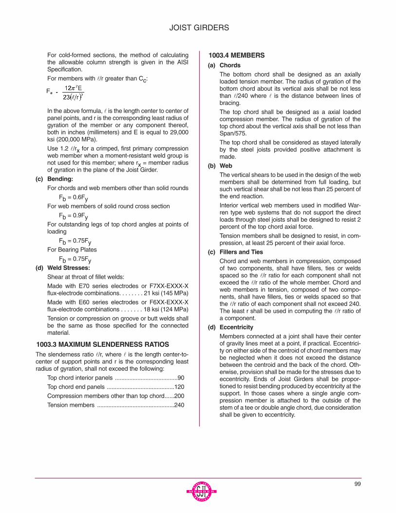
99
For cold-formed sections, the method of calculatingthe allowable column strength is given in the AISISpecification.
For members with l/r greater than Cc:
In the above formula, l is the length center to center ofpanel points, and r is the corresponding least radius ofgyration of the member or any component thereof,both in inches (millimeters) and E is equal to 29,000ksi (200,000 MPa).
Use 1.2 l/rx for a crimped, first primary compressionweb member when a moment-resistant weld group isnot used for this member; where rx = member radiusof gyration in the plane of the Joist Girder.
(c) Bending:For chords and web members other than solid rounds
Fb = 0.6FyFor web members of solid round cross section
Fb = 0.9FyFor outstanding legs of top chord angles at points ofloading
Fb = 0.75FyFor Bearing Plates
Fb = 0.75Fy(d) Weld Stresses:
Shear at throat of fillet welds:
Made with E70 series electrodes or F7XX-EXXX-Xflux-electrode combinations. . . . . . . . 21 ksi (145 MPa)
Made with E60 series electrodes or F6XX-EXXX-Xflux-electrode combinations . . . . . . . 18 ksi (124 MPa)
Tension or compression on groove or butt welds shallbe the same as those specified for the connectedmaterial.
1003.3 MAXIMUM SLENDERNESS RATIOSThe slenderness ratio l/r, where l is the length center-to-center of support points and r is the corresponding leastradius of gyration, shall not exceed the following:
Top chord interior panels .......................................90
Top chord end panels ..........................................120
Compression members other than top chord......200
Tension members ................................................240
1003.4 MEMBERS(a) Chords
The bottom chord shall be designed as an axiallyloaded tension member. The radius of gyration of thebottom chord about its vertical axis shall be not lessthan l/240 where l is the distance between lines ofbracing.
The top chord shall be designed as a axial loadedcompression member. The radius of gyration of thetop chord about the vertical axis shall be not less thanSpan/575.
The top chord shall be considered as stayed laterallyby the steel joists provided positive attachment ismade.
(b) WebThe vertical shears to be used in the design of the webmembers shall be determined from full loading, butsuch vertical shear shall be not less than 25 percent ofthe end reaction.
Interior vertical web members used in modified War-ren type web systems that do not support the directloads through steel joists shall be designed to resist 2percent of the top chord axial force.
Tension members shall be designed to resist, in com-pression, at least 25 percent of their axial force.
(c) Fillers and TiesChord and web members in compression, composedof two components, shall have fillers, ties or weldsspaced so the l/r ratio for each component shall notexceed the l/r ratio of the whole member. Chord andweb members in tension, composed of two compo-nents, shall have fillers, ties or welds spaced so thatthe l/r ratio of each component shall not exceed 240.The least r shall be used in computing the l/r ratio ofa component.
(d) EccentricityMembers connected at a joint shall have their centerof gravity lines meet at a point, if practical. Eccentrici-ty on either side of the centroid of chord members maybe neglected when it does not exceed the distancebetween the centroid and the back of the chord. Oth-erwise, provision shall be made for the stresses due toeccentricity. Ends of Joist Girders shall be propor-tioned to resist bending produced by eccentricity at thesupport. In those cases where a single angle com-pression member is attached to the outside of thestem of a tee or double angle chord, due considerationshall be given to eccentricity.
JOIST GIRDERS
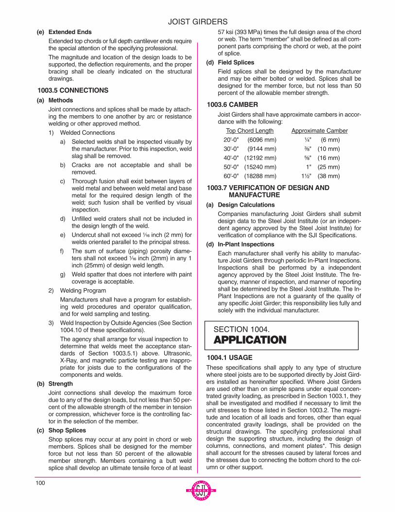
(e) Extended EndsExtended top chords or full depth cantilever ends requirethe special attention of the specifying professional.
The magnitude and location of the design loads to besupported, the deflection requirements, and the properbracing shall be clearly indicated on the structuraldrawings.
1003.5 CONNECTIONS(a) Methods
Joint connections and splices shall be made by attach-ing the members to one another by arc or resistancewelding or other approved method.
1) Welded Connections
a) Selected welds shall be inspected visually bythe manufacturer. Prior to this inspection, weldslag shall be removed.
b) Cracks are not acceptable and shall beremoved.
c) Thorough fusion shall exist between layers ofweld metal and between weld metal and basemetal for the required design length of theweld; such fusion shall be verified by visualinspection.
d) Unfilled weld craters shall not be included inthe design length of the weld.
e) Undercut shall not exceed ¹⁄₁₆ inch (2 mm) forwelds oriented parallel to the principal stress.
f) The sum of surface (piping) porosity diame-ters shall not exceed ¹⁄₁₆ inch (2mm) in any 1inch (25mm) of design weld length.
g) Weld spatter that does not interfere with paintcoverage is acceptable.
2) Welding Program
Manufacturers shall have a program for establish-ing weld procedures and operator qualification,and for weld sampling and testing.
3) Weld Inspection by Outside Agencies (See Section1004.10 of these specifications).
The agency shall arrange for visual inspection to determine that welds meet the acceptance stan-dards of Section 1003.5.1) above. Ultrasonic,X-Ray, and magnetic particle testing are inappro-priate for joists due to the configurations of thecomponents and welds.
(b) StrengthJoint connections shall develop the maximum forcedue to any of the design loads, but not less than 50 per-cent of the allowable strength of the member in tensionor compression, whichever force is the controlling fac-tor in the selection of the member.
(c) Shop SplicesShop splices may occur at any point in chord or webmembers. Splices shall be designed for the memberforce but not less than 50 percent of the allowablemember strength. Members containing a butt weldsplice shall develop an ultimate tensile force of at least
57 ksi (393 MPa) times the full design area of the chordor web. The term “member” shall be defined as all com-ponent parts comprising the chord or web, at the pointof splice.
(d) Field SplicesField splices shall be designed by the manufacturerand may be either bolted or welded. Splices shall bedesigned for the member force, but not less than 50percent of the allowable member strength.
1003.6 CAMBERJoist Girders shall have approximate cambers in accor-dance with the following:
Top Chord Length Approximate Camber
20'-0" (6096 mm) ¹⁄₄" (6 mm)
30'-0" (9144 mm) ³⁄₈" (10 mm)
40'-0" (12192 mm) ⁵⁄₈" (16 mm)
50'-0" (15240 mm) 1" (25 mm)
60'-0" (18288 mm) 1¹⁄₂" (38 mm)
1003.7 VERIFICATION OF DESIGN AND MANUFACTURE
(a) Design CalculationsCompanies manufacturing Joist Girders shall submitdesign data to the Steel Joist Institute (or an indepen-dent agency approved by the Steel Joist Institute) forverification of compliance with the SJI Specifications.
(d) In-Plant InspectionsEach manufacturer shall verify his ability to manufac-ture Joist Girders through periodic In-Plant Inspections.Inspections shall be performed by a independentagency approved by the Steel Joist Institute. The fre-quency, manner of inspection, and manner of reportingshall be determined by the Steel Joist Institute. The In-Plant Inspections are not a guaranty of the quality ofany specific Joist Girder; this responsibility lies fully andsolely with the individual manufacturer.
1004.1 USAGEThese specifications shall apply to any type of structurewhere steel joists are to be supported directly by Joist Gird-ers installed as hereinafter specified. Where Joist Girdersare used other than on simple spans under equal concen-trated gravity loading, as prescribed in Section 1003.1, theyshall be investigated and modified if necessary to limit theunit stresses to those listed in Section 1003.2. The magni-tude and location of all loads and forces, other than equalconcentrated gravity loadings, shall be provided on thestructural drawings. The specifying professional shalldesign the supporting structure, including the design ofcolumns, connections, and moment plates*. This designshall account for the stresses caused by lateral forces andthe stresses due to connecting the bottom chord to the col-umn or other support.
100
JOIST GIRDERS
SECTION 1004.
APPLICATION
101
The designed detail of a rigid type connection and momentplates shall be shown on the structural drawings by the spec-ifying professional. The moment plates shall be furnished byother than the joist manufacturer.
* For further reference, refer to Steel Joist Institute TechnicalDigest #11, “Design of Joist-Girder Frames”
1004.2 SPANThe span of a Joist Girder shall not exceed 24 times its depth.
1004.3 DEPTH
Joist Girders may have either parallel top chords or a topchord pitch of ¹⁄₈ inch per foot (1:96). The nominal depth ofpitched chord Joist Girders shall be the depth at mid-span.
1004.4 END SUPPORTS(a) Masonry and Concrete
Joist Girders supported by masonry or concrete are tobear on steel bearing plates and shall be designed assteel bearing. Due consideration of the end reactions andall other vertical and lateral forces shall be taken by thespecifying professional in the design of the steel bearingplate and the masonry or concrete. The ends of JoistGirders shall extend a distance of not less than 6 inches(152 mm) over the masonry or concrete support and beanchored to the steel bearing plate. The plate shall belocated not more than ¹⁄₂ inch (13 mm) from the face ofthe wall and shall be not less 9 inches (229 mm) wideperpendicular to the length of the girder. It is to bedesigned by the specifying professional in compliance with the allowable unit stresses in SectionA5.1 (Allowable Stress Design) of the AISC Specifica-tions. The steel bearing plate shall be furnished by otherthan the joist manufacturer.
Where it is deemed necessary to bear less than 6 inches(152 mm) over the masonry or concrete support, specialconsideration is to be given to the design of the steelbearing plate and the masonry or concrete by the speci-fying professional. The girders must bear a minimum of 4inches (102mm) on the steel bearing plate.
(b) SteelDue consideration of the end reactions and all other ver-tical and lateral forces shall be taken by the specifyingprofessional in the design of the steel support. The endsof Joist Girders shall extend a distance of not less than 4inches (102mm) over the steel supports and shall havepositive attachment to the support, either by bolting orwelding.
1004.5 BRACINGJoist Girders shall be proportioned such that they can beerected without bridging (See Section 1004.9 for bracingrequired for uplift forces). Therefore, the following require-ments must be met:
a) The ends of the bottom chord are restrained from lateralmovement to brace the girder from overturning.
b) No other loads shall be placed on the Joist Girder until thesteel joists bearing on the girder are in place and weldedto the girder.
1004.6 END ANCHORAGEa) Masonry and Concrete
Ends of Joist Girders resting on steel bearing plates onmasonry or structural concrete shall be attached theretowith a minimum of two ¹⁄₄ inch (6mm) fillet welds 2 inches(51mm) long, or with two ³⁄₄ inch (19mm) bolts, or theequivalent.
b) Steel
Ends of Joist Girders resting on steel supports shall beattached thereto with a minimum of two ¹⁄₄ inch (6mm) fil-let welds 2 inches (51mm) long, or with two ³⁄₄ inch(19mm) bolts, or the equivalent. In steel frames, bearingseats for Joist Girders shall be fabricated to allow for fieldbolting.
c) Uplift
Where uplift forces are a design consideration, roof JoistGirders shall be anchored to resist such forces.
1004.7 DEFLECTIONThe deflections due to the design live load shall not exceedthe following:
Floors: ¹⁄₃₆₀ of span.
Roofs: ¹⁄₃₆₀ of span where a plaster ceiling is attachedor suspended.
¹⁄₂₄₀ of span for all other cases.
The specifying professional shall give due consideration to theeffects of deflection and vibration* in the selection of JoistGirders.
* For further reference, refer to Steel Joist Institute TechnicalDigest #5, “Vibration of Steel Joist-Concrete Slab Floors” andthe Institute’s Computer Vibration Program.
1004.8 PONDINGUnless a roof surface is provided with sufficient slope towardpoints of free drainage or adequate individual drains to pre-vent the accumulation of rain water, the roof system shall beinvestigated to assure stability under ponding conditions inaccordance with Section K2 (Allowable Stress Design) of theAISC Specification.*
The ponding investigation shall be performed by the specify-ing professional.
* For further reference, refer to Steel Joist Institute TechnicalDigest #3, “Structural Design of Steel Joist Roofs to ResistPonding Loads”.
1004.9 UPLIFTWhere uplift forces due to wind are a design requirement,these forces must be indicated on the contract drawings interms of net uplift in pounds per square foot (Pascals). Whenthese forces are specified, they must be considered in thedesign of Joist Girders and/or bracing. If the ends of the bot-tom chord are not strutted, bracing must be provided near thefirst bottom chord panel points whenever uplift due to windforces is a design consideration.*
* For further reference, refer to Steel Joist Institute TechnicalDigest #6, “Structural Design of Steel Joist Roofs to ResistUplift Loads”.
JOIST GIRDERS
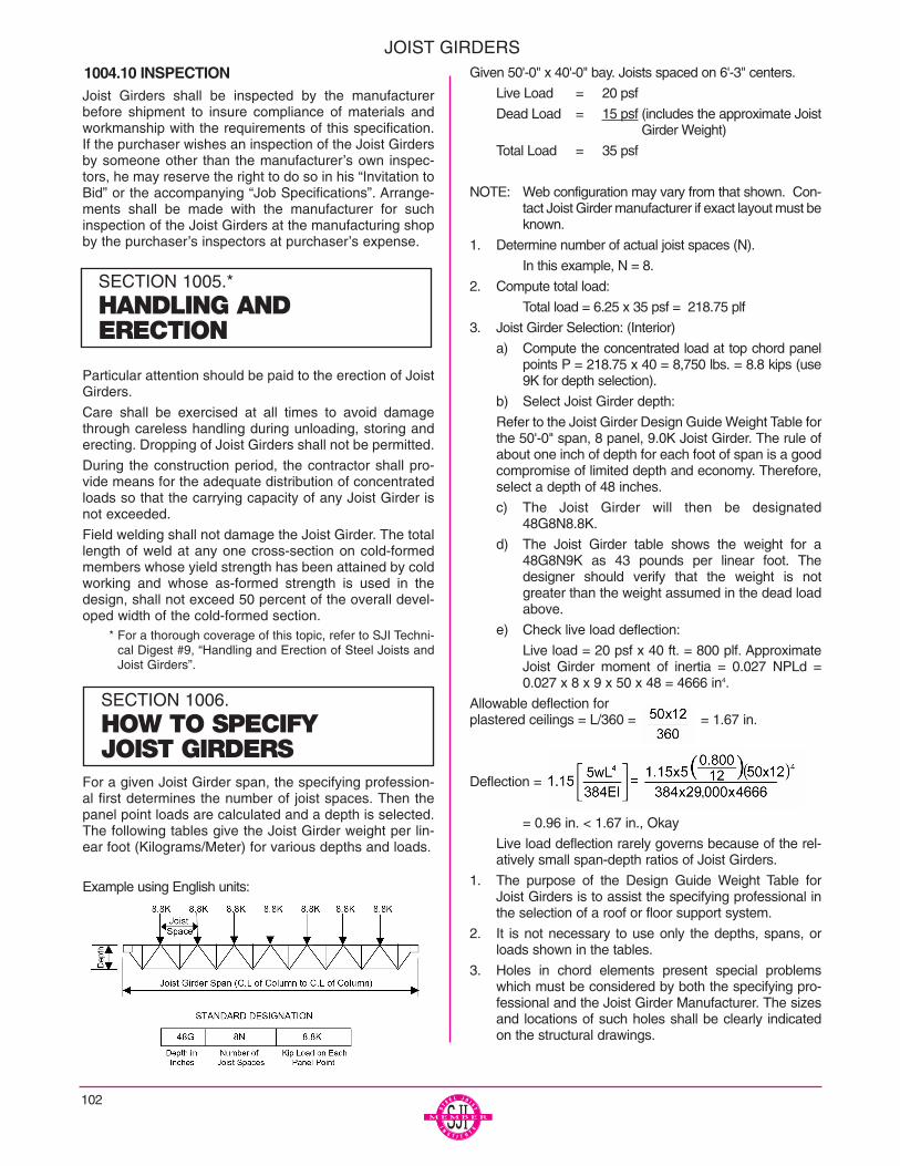
1004.10 INSPECTIONJoist Girders shall be inspected by the manufacturerbefore shipment to insure compliance of materials andworkmanship with the requirements of this specification.If the purchaser wishes an inspection of the Joist Girdersby someone other than the manufacturer’s own inspec-tors, he may reserve the right to do so in his “Invitation toBid” or the accompanying “Job Specifications”. Arrange-ments shall be made with the manufacturer for suchinspection of the Joist Girders at the manufacturing shopby the purchaser’s inspectors at purchaser’s expense.
Particular attention should be paid to the erection of JoistGirders.
Care shall be exercised at all times to avoid damagethrough careless handling during unloading, storing anderecting. Dropping of Joist Girders shall not be permitted.
During the construction period, the contractor shall pro-vide means for the adequate distribution of concentratedloads so that the carrying capacity of any Joist Girder isnot exceeded.
Field welding shall not damage the Joist Girder. The totallength of weld at any one cross-section on cold-formedmembers whose yield strength has been attained by coldworking and whose as-formed strength is used in thedesign, shall not exceed 50 percent of the overall devel-oped width of the cold-formed section.
* For a thorough coverage of this topic, refer to SJI Techni-cal Digest #9, “Handling and Erection of Steel Joists andJoist Girders”.
For a given Joist Girder span, the specifying profession-al first determines the number of joist spaces. Then thepanel point loads are calculated and a depth is selected.The following tables give the Joist Girder weight per lin-ear foot (Kilograms/Meter) for various depths and loads.
Example using English units:
Given 50'-0" x 40'-0" bay. Joists spaced on 6'-3" centers.
Live Load = 20 psf
Dead Load = 15 psf (includes the approximate JoistGirder Weight)
Total Load = 35 psf
NOTE: Web configuration may vary from that shown. Con-tact Joist Girder manufacturer if exact layout must beknown.
1. Determine number of actual joist spaces (N).
In this example, N = 8.
2. Compute total load:
Total load = 6.25 x 35 psf = 218.75 plf
3. Joist Girder Selection: (Interior)
a) Compute the concentrated load at top chord panelpoints P = 218.75 x 40 = 8,750 lbs. = 8.8 kips (use9K for depth selection).
b) Select Joist Girder depth:
Refer to the Joist Girder Design Guide Weight Table forthe 50'-0" span, 8 panel, 9.0K Joist Girder. The rule ofabout one inch of depth for each foot of span is a goodcompromise of limited depth and economy. Therefore,select a depth of 48 inches.
c) The Joist Girder will then be designated48G8N8.8K.
d) The Joist Girder table shows the weight for a48G8N9K as 43 pounds per linear foot. Thedesigner should verify that the weight is notgreater than the weight assumed in the dead loadabove.
e) Check live load deflection:
Live load = 20 psf x 40 ft. = 800 plf. ApproximateJoist Girder moment of inertia = 0.027 NPLd =0.027 x 8 x 9 x 50 x 48 = 4666 in4.
Allowable deflection for plastered ceilings = L/360 = = 1.67 in.
Deflection =
= 0.96 in. < 1.67 in., Okay
Live load deflection rarely governs because of the rel-atively small span-depth ratios of Joist Girders.
1. The purpose of the Design Guide Weight Table forJoist Girders is to assist the specifying professional inthe selection of a roof or floor support system.
2. It is not necessary to use only the depths, spans, orloads shown in the tables.
3. Holes in chord elements present special problemswhich must be considered by both the specifying pro-fessional and the Joist Girder Manufacturer. The sizesand locations of such holes shall be clearly indicatedon the structural drawings.
102
JOIST GIRDERS
SECTION 1005.*
HANDLING ANDERECTION
SECTION 1006.
HOW TO SPECIFY JOIST GIRDERS
103
Hundreds of fire tests on steel joist-supported assemblieshave been conducted at nationally recognized testing lab-oratories in accordance with ASTM Standard E119, ANSIA2.1/UL 263, and NFPA 251. Because of practical load-ing restrictions and limitations of furnace dimensions, thevast majority of these tests were run using lightweightjoists – normally from 8 inches to 14 inches deep. Thispractice was advantageous in that it established the min-imum acceptable joists at the shallow and lightweight endof the joist load tables.
The specified minimum size joist as listed in Underwrit-ers Laboratories (U.L.) Fire Resistance Designs is thejoist which combines the required minimum depth andminimum weight per foot. Joists, of the same series,which meet, or exceed the specified minimums may beused provided the accessories are compatible. Thedimension from the bottom chord of joists to the ceiling,whether given or calculated, is a minimum.
K-Series Joists, LH Series Joists and Joist Girdersspecified in floor- or roof-ceiling assemblies, shall bedesigned and manufactured in accordance with the SteelJoist Institute’s Specifications adopted November 4,1985, revised to May 1, 2000.
Many of U.L.’s Fire Rated Assemblies now specifically listK-Series Joists. When a K-Series Joist is specified in aparticular U.L. assembly the K-Series Joist shall have itsdesign stress limited only if the assembly specifically lim-its the design stress of the K-Series Joist.K-Series Joists may be substituted for S-, J-, and/or H-Series Joists specified in U.L. floor-, or roof-ceilingdesigns as follows:
Floor-Ceiling Assemblies:
K-Series Steel Joists of equal or greater depthweight per foot may be substituted for any S-, J-,and/or H-Series Joist in any floor-ceiling designwhich employs a structural concrete floor and sus-pended membrane ceiling.
Roof-Ceiling Assemblies:
K-Series Steel Joists of equal or greater depth andweight per foot may be substituted for any S-, J-,and/or H-Series Joists in any roof-ceiling design withthe following restrictions:
a) Minimum Nominal Depth = 10 inches (254mm)
b) Maximum Tensile Stress = 26 KSI (179 MPa)
Any stress limitation specified in a U.L. floor or roof firerated assembly containing S, J and/or H Series Joistsshall remain applicable when a K-Series Joist is substi-tuted. Also, certain U.L. assembly designs contain restric-tions regarding minimum allowable joist member sizes,areas of steel, and/or bridging material sizes. Theserestrictions remain applicable when a K-Series Joist issubstituted and it is the responsibility of the specifyingprofessional to list all such restrictions on the contractdrawings.
The following procedure may be used to substitute theproper K-Series Joist for any S-, J-, and/or H-Series Joistlisted in a U.L. design assembly.
1. Determine the uniform load per foot the joist isrequired to support.
2. Select a design from the U.L. “Fire Resistance Direc-tory” that matches the building construction and hasthe required fire rating.
3. a) Floor Assemblies: x x x x x x x x x x x x x x x xAdjust the design load per foot calculated in step#1 for any required reduction in stress level bymultiplying the load by a factor of 30 ksi(207MPa) divided by the specified stress level,i.e. [30/24 (207/165), 30/22 (207/152) etc.].
b) Roof Assemblies: x x x x x x x x x x x x x x x x Adjust the design load per foot calculated in step#1 by multiplying by the factor of 30/26(207/179), or a greater factor if the particularassembly design requires a lessor stress level.
4. Enter the K-Series Economy Table and select theproper joist for the calculated load requirement.
5. Insure that the K-Series Joist selected has a depthand load table weight per foot equal to, or greaterthan, the S-, J- and/or H-Series joist listed in the U.L.Design. Joists used in roof assemblies must have aminimum depth of 10 inches (254mm).
So that the proper K-Series Joist can be selected for U.L.Designs not presently containing a K-Series designationthe weights of various S-, J-, and H-Series Joists used inthe U.L. Fire Resistance Designs are listed below:
FIRE-RESISTANCE RATINGS WITH STEEL JOISTS
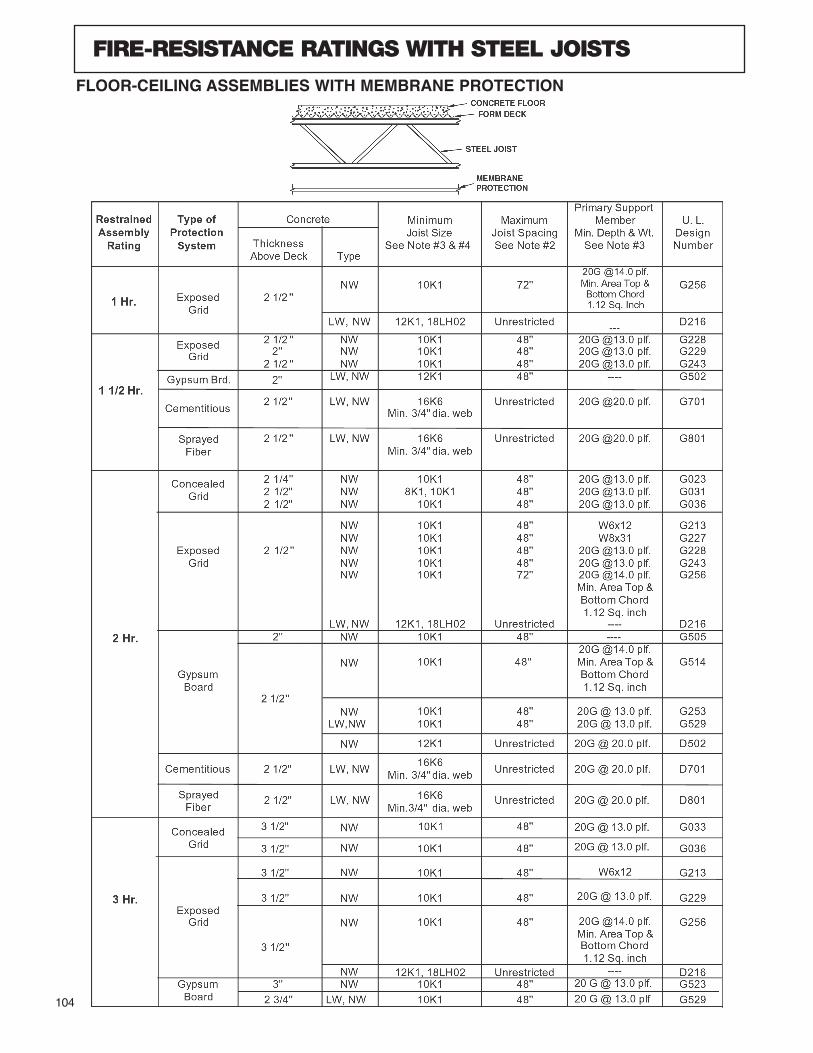
104
FIRE-RESISTANCE RATINGS WITH STEEL JOISTS
FLOOR-CEILING ASSEMBLIES WITH MEMBRANE PROTECTION
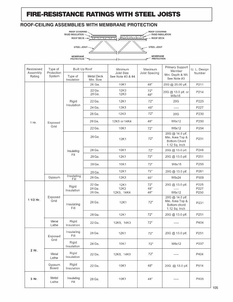
105
FIRE-RESISTANCE RATINGS WITH STEEL JOISTS
ROOF-CEILING ASSEMBLIES WITH MEMBRANE PROTECTION
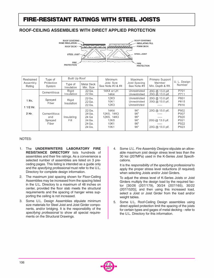
NOTES:
1. The UNDERWRITERS LABORATORY FIRERESISTANCE DIRECTORY lists hundreds ofassemblies and their fire ratings. As a convenience aselected number of assemblies are listed on 3 pre-ceding pages. This listing is intended as a guide onlyand the specifying professional must refer to the U.L.Directory for complete design information.
2. The maximum joist spacing shown for Floor-CeilingAssemblies may be increased from the spacing listedin the U.L. Directory to a maximum of 48 inches oncenter, provided the floor slab meets the structuralrequirements and the spacing of hanger wires sup-porting the ceiling is not increased.
3. Some U.L. Design Assemblies stipulate minimumsize materials for Steel Joist and Joist Girder compo-nents, and/or bridging. It is the responsibility of thespecifying professional to show all special require-ments on the Structural Drawings.
4. Some U.L. Fire Assembly Designs stipulate an allow-able maximum joist design stress level less than the30 ksi (207MPa) used in the K-Series Joist Specifi-cations.
It is the responsibility of the specifying professional toapply the proper stress level reductions (if required)when selecting Joists and/or Joist Girders.
To adjust the stress level of K-Series Joists or JoistGirders multiply the design load by the required fac-tor [30/26 (207/179), 30/24 (207/165), 30/22(207/1520)], and then using this increased load,select a Joist or Joist Girder from the load and/orweight tables.
5. Some U.L. Roof-Ceiling Design assemblies usingdirect applied protection limit the spacing of the joistsfor certain types and gages of metal decking - refer tothe U.L. Directory for this information.
FIRE-RESISTANT RATINGS WITH STEEL JOISTS
ROOF-CEILING ASSEMBLIES WITH DIRECT APPLIED PROTECTION
106
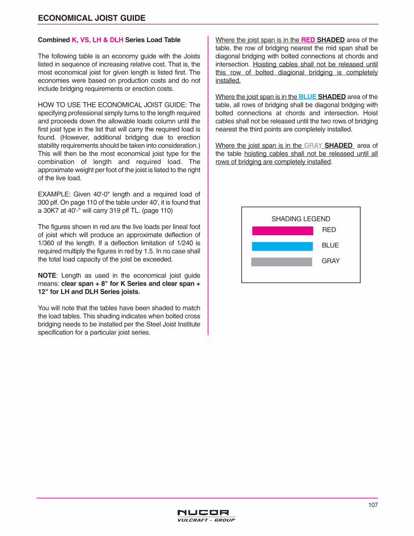
107
ECONOMICAL JOIST GUIDE
Combined K, VS, LH & DLH Series Load Table
The following table is an economy guide with the Joistslisted in sequence of increasing relative cost. That is, themost economical joist for given length is listed first. Theeconomies were based on production costs and do notinclude bridging requirements or erection costs.
HOW TO USE THE ECONOMICAL JOIST GUIDE: Thespecifying professional simply turns to the length requiredand proceeds down the allowable loads column until thefirst joist type in the list that will carry the required load isfound. (However, additional bridging due to erectionstability requirements should be taken into consideration.)This will then be the most economical joist type for thecombination of length and required load. Theapproximate weight per foot of the joist is listed to the rightof the live load.
EXAMPLE: Given 40'-0" length and a required load of300 plf. On page 110 of the table under 40', it is found thata 30K7 at 40'-" will carry 319 plf TL. (page 110)
The figures shown in red are the live loads per lineal footof joist which will produce an approximate deflection of1/360 of the length. If a deflection limitation of 1/240 isrequired multiply the figures in red by 1.5. In no case shallthe total load capacity of the joist be exceeded.
NOTE: Length as used in the economical joist guidemeans: clear span + 8" for K Series and clear span +12" for LH and DLH Series joists.
You will note that the tables have been shaded to matchthe load tables. This shading indicates when bolted crossbridging needs to be installed per the Steel Joist Institutespecification for a particular joist series.
Where the joist span is in the RED SHADED area of thetable, the row of bridging nearest the mid span shall bediagonal bridging with bolted connections at chords andintersection. Hoisting cables shall not be released untilthis row of bolted diagional bridging is completelyinstalled.
Where the joist span is in the BLUE SHADED area of thetable, all rows of bridging shall be diagonal bridging withbolted connections at chords and intersection. Hoistcables shall not be released until the two rows of bridgingnearest the third points are completely installed.
Where the joist span is in the GRAY SHADED area ofthe table hoisting cables shall not be released until allrows of bridging are completely installed.
SHADING LEGEND
RED
BLUE
GRAY

108
10' LENGTH
10K 1 550 550 5.0
11' LENGTH
10K 1 550 542 5.0
12' LENGTH
10K 1 550 455 5.0
13' LENGTH
10K 1 479 363 5.012K 1 550 510 5.0
14' LENGTH
10K 1 412 289 5.014K 1 550 550 5.2
15' LENGTH
10K 1 358 234 5.012K 1 434 344 5.014K 1 511 475 5.214K 3 550 507 5.9
16' LENGTH
10K 1 313 192 5.012K 1 380 282 5.014K 1 448 390 5.212K 3 476 351 5.714K 3 550 467 5.9
17' LENGTH
10K 1 277 159 5.012K 1 336 234 5.014K 1 395 324 5.212K 3 420 291 5.716K 2 512 488 5.516K 3 550 526 6.3
18' LENGTH
10K 1 246 134 5.012K 1 299 197 5.014K 1 352 272 5.212K 3 374 245 5.514K 3 441 339 5.816K 2 456 409 5.516K 3 508 456 6.314K 4 530 397 6.714K 6 550 408 6.9
19' LENGTH
10K1 221 113 5.012K1 268 167 5.014K1 315 230 5.212K3 335 207 5.616K2 408 347 5.516K3 455 386 6.318K3 514 494 6.616K4 547 452 7.016K5 550 455 7.2
20' LENGTH
12K 1 241 142 5.014K 1 284 197 5.212K 3 302 177 5.5
20' LENGTH (Cont.)
16K2 368 297 5.516K3 410 330 6.218K3 463 423 6.516K4 493 386 7.016K5 550 426 7.5
21' LENGTH
12K1 218 123 5.014K1 257 170 5.212K3 273 153 5.514K3 322 212 5.716K2 333 255 5.516K3 371 285 6.318K3 420 364 6.616K4 447 333 7.020K3 468 453 6.716K5 503 373 7.518K4 506 426 7.220K4 550 520 7.6
22' LENGTH
12K1 199 106 5.014K1 234 147 5.112K3 249 132 5.514K3 293 184 5.616K2 303 222 5.516K3 337 247 6.218K3 382 316 6.516K4 406 289 6.920K3 426 393 6.718K4 460 370 7.220K4 514 461 7.618K5 518 414 7.722K6 550 548 7.518LH2 554 439 8.818LH3 614 488 1018LH4 715 566 1118LH5 808 637 1218LH6 955 738 1418LH7 992 776 1518LH8 1034 810 1518LH9 1108 864 16
23' LENGTH
14K1 214 128 5.112K3 227 116 5.516K2 277 194 5.516K3 308 216 6.018K3 349 276 6.616K4 371 252 7.020K3 389 344 6.718K4 420 323 7.220K4 469 402 7.618K5 473 362 7.722K6 550 518 7.718LH3 587 446 1018LH4 684 517 1120LH5 697 589 1118LH5 772 582 1318LH6 913 674 1518LH7 949 709 1520LH8 1024 858 1518LH9 1059 790 1620LH9 1121 935 1620LH10 1209 1008 17
24' LENGTH
14K1 196 113 5.112K3 208 101 5.6
24' LENGTH (Cont.)
16K2 254 170 5.516K3 283 189 6.118K3 320 242 6.516K4 340 221 6.920K3 357 302 6.718K4 385 284 7.220K4 430 353 7.618K5 434 318 7.718K6 473 345 8.520K5 485 396 8.224K6 550 544 7.718LH3 562 409 1020LH4 621 503 1018LH4 655 474 1120LH5 668 540 1118LH5 739 534 1218LH6 875 619 1520LH6 892 713 1518LH7 908 650 1518LH8 946 679 1620LH7 951 761 1520LH8 980 787 1618LH9 1014 725 1720LH9 1073 857 1620LH10 1158 924 17
25' LENGTH
14K1 180 100 5.116K2 234 150 5.516K3 260 167 5.918K3 294 214 6.316K4 313 195 6.920K3 329 266 6.718K4 355 250 7.116K6 384 238 8.118K5 400 281 7.716K7 428 263 8.618K6 435 305 8.520K5 446 350 8.218K7 485 337 9.020K6 486 380 8.916K9 514 311 1024K6 550 520 8.620LH4 596 463 1018LH4 628 436 1120LH5 641 497 1118LH5 709 492 1320LH6 855 656 1518LH7 872 599 1618LH8 908 625 1620LH7 912 701 1620LH8 941 724 1618LH9 973 667 1720LH9 1030 789 1720LH10 1111 851 18
26' LENGTH
14K1 166 83 5.116K2 216 133 5.516K3 240 148 5.918K3 272 190 6.416K4 289 173 6.820K3 304 236 6.718K4 328 222 7.220K4 366 277 7.618K5 369 249 7.722K4 404 338 8.020K5 412 310 8.220K6 449 337 8.922K5 455 379 8.826K5 542 535 8.8
26' LENGTH (Cont.)
24K6 543 493 8.924K7 550 499 9.220LH4 574 428 1118LH4 604 403 1220LH5 616 459 1118LH5 684 454 1320LH6 822 606 1518LH7 840 553 1618LH8 876 577 1620LH7 878 647 1618LH9 936 616 1720LH9 990 729 1720LH10 1068 786 18
27' LENGTH
14K1 154 79 5.116K2 200 119 5.516K3 223 132 5.918K3 252 169 6.316K4 268 155 6.820K3 281 211 6.618K4 303 198 7.020K4 339 247 7.418K5 342 222 7.722K4 374 301 8.020K5 382 277 8.220K6 416 301 8.822K5 422 337 8.724K6 503 439 8.626K6 547 519 8.926K7 550 522 9.120LH4 566 406 1118LH4 571 367 1220LH5 609 437 1218LH5 648 414 1420LH6 791 561 1520LH7 845 599 1620LH8 873 619 1620LH9 953 675 1720LH10 1028 724 19
28' LENGTH
14K1 143 70 5.116K2 186 106 5.516K3 207 118 5.818K3 234 151 6.216K4 249 138 6.620K3 261 189 6.716K5 281 155 7.418K4 282 177 7.220K4 315 221 7.518K5 318 199 7.718K6 346 216 8.520K5 355 248 8.222K5 392 302 8.826K5 466 427 8.124K6 467 393 8.522K7 475 364 9.226K6 508 464 8.928K6 548 541 9.228K7 550 543 9.220LH4 558 386 1220LH5 602 416 1318LH5 614 378 1420LH6 763 521 1520LH7 814 556 1620LH8 842 575 1720LH9 918 626 1820LH10 991 673 20
ECONOMICAL JOIST GUIDECombined K, VS, LH & DLH Series Load Table
Allowable JoistJoist Loads (PLF) WeightType Total Live (lbs./ft.)
Allowable JoistJoist Loads (PLF) WeightType Total Live (lbs./ft.)
Allowable JoistJoist Loads (PLF) WeightType Total Live (lbs./ft.)
Allowable JoistJoist Loads (PLF) WeightType Total Live (lbs./ft.)
108

109
29' LENGTH
16K3 193 106 5.918K3 218 136 6.216K4 232 124 6.720K3 243 170 6.618K4 263 159 7.020K4 293 199 7.418K5 296 179 7.722K4 324 242 7.820K5 330 223 8.122K5 365 272 8.726K5 434 384 8.024K6 435 354 8.428K6 511 486 9.128K7 550 522 9.518LH5 581 345 1420LH5 595 395 1318LH6 648 377 1524LH6 708 567 1424LH7 778 623 1520LH7 786 518 1624LH8 830 662 1624LH9 977 775 1824LH10 1033 822 1924LH11 1088 861 20
30' LENGTH
18K3 203 123 6.116K4 216 112 6.620K3 227 153 6.518K4 245 144 6.920K4 274 179 7.318K5 276 161 7.720K5 308 201 8.020K6 336 218 8.722K6 371 266 8.226K5 405 346 8.024K6 406 319 8.426K6 441 377 8.828K6 477 439 9.026K7 492 417 9.228K7 531 486 9.526K8 544 457 1026K9 550 459 1020LH5 571 366 1318LH6 605 340 1524LH6 684 529 1424LH7 752 582 1524LH8 802 618 1624LH9 944 724 1824LH10 998 768 1924LH11 1052 804 21
31' LENGTH
16K4 203 101 6.620K3 212 138 6.618K4 229 130 6.920K4 256 162 7.418K5 258 146 7.722K4 283 198 7.820K5 289 182 8.124K4 310 237 8.420K6 314 198 8.822K5 319 222 8.722K6 347 241 8.326K5 379 314 8.124K6 380 289 8.622K7 387 267 8.828K6 446 397 9.022K9 465 316 1028K8 550 480 1024LH6 662 495 14
31' LENGTH (Cont.)
24LH7 727 545 1524LH8 776 579 1624LH9 913 677 1924LH10 965 718 2024LH11 1017 752 21
32' LENGTH
16K2 142 71 5.516K3 158 79 5.818K3 178 101 6.120K4 240 147 7.218K5 242 132 7.620K5 271 165 7.924K4 290 215 8.122K5 299 201 8.422K6 326 219 8.426K5 356 285 8.024K6 357 262 8.526K6 387 309 8.628K6 418 361 8.922K9 436 287 1028K7 466 400 9.526K8 477 375 9.928K8 515 433 1028K9 549 463 1124LH6 641 465 1424LH7 704 511 1524LH8 752 543 1624LH9 884 635 1924LH10 935 674 2024LH11 985 705 20
33' LENGTH
18K3 168 92 6.120K4 226 134 7.322K4 249 164 7.920K5 254 150 8.124K4 273 196 8.320K6 277 163 8.722K5 281 183 8.526K5 334 259 8.024K6 335 239 8.326K6 364 282 8.628K6 393 329 8.826K7 406 312 9.128K7 438 364 9.428K8 484 399 1026K9 488 370 1128K9 527 432 1128K10 532 435 1124LH6 621 437 1524LH7 683 480 1624LH8 729 510 1624LH9 857 597 1924LH10 906 633 2024LH11 955 663 22
34' LENGTH
18K3 158 84 6.120K3 176 105 6.418K4 190 98 6.918K6 233 120 8.224K4 257 179 8.120K6 261 149 8.622K5 265 167 8.426K5 315 237 7.926K6 343 257 8.528K6 370 300 8.826K7 382 285 9.128K7 412 333 9.4
34' LENGTH (Cont.)
24K9 423 286 1028K8 456 364 1028K9 496 395 1128K10 516 410 1128LH6 552 443 1328LH7 624 499 1428LH8 668 533 1524LH8 707 480 1728LH9 823 656 1724LH9 832 562 2028LH10 900 714 1928LH11 965 763 2028LH12 1060 835 2328LH13 1105 872 23
35' LENGTH
18K3 149 77 6.120K3 166 96 6.518K4 179 90 6.920K4 200 112 7.320K6 246 137 8.726K5 297 217 7.926K6 323 236 8.528K6 349 275 8.726K7 360 261 9.028K7 389 305 9.428K8 430 333 9.926K9 433 310 1028K9 468 361 1128K10 501 389 1128LH6 537 417 1328LH7 606 471 1428LH8 649 503 1524LH8 677 447 1728LH9 799 618 1828LH10 874 673 2028LH11 938 719 2128LH12 1030 787 2328LH13 1073 822 24
36' LENGTH
18K3 141 70 6.120K3 157 88 6.418K4 169 82 6.920K4 189 103 7.218K5 191 92 7.524K6 281 183 8.322K7 286 169 8.724K7 313 203 8.828K6 330 252 8.826K7 340 240 9.124K8 346 222 9.528K7 367 280 9.426K8 376 263 9.830K7 395 323 9.628K9 442 332 1128K10 487 366 1228LH6 521 394 1328LH7 589 445 1428LH8 631 475 1524LH8 649 416 1728LH9 777 584 1828LH10 850 636 1928LH11 911 680 2128LH12 1001 744 2328LH13 1043 777 24
37' LENGTH
20K3 148 81 6.420K4 179 95 7.3
37' LENGTH (Cont.)
26K5 265 183 7.924K6 266 169 8.328K6 312 232 8.726K7 322 221 9.128K7 348 257 9.330K7 373 297 9.528K8 384 282 9.926K9 387 262 1030K8 413 325 1028K9 418 305 1130K9 449 352 1130K10 474 374 1228LH6 507 373 1324LH6 530 331 1528LH7 573 421 1524LH7 588 367 1628LH8 614 449 1624LH8 622 388 1728LH9 755 553 1828LH10 826 602 2128LH11 886 643 2128LH12 974 704 2328LH13 1015 735 25
38' LENGTH
20K3 141 74 6.320K4 170 87 7.224K6 252 156 8.328K6 296 214 8.626K7 305 204 9.028K7 329 237 9.230K7 354 274 9.528K8 364 260 9.926K9 367 241 1030K8 391 300 1028K9 396 282 1130K9 426 325 1130K10 461 353 1128LH6 494 354 1324LH6 504 306 1528LH7 558 399 1524LH7 565 343 1628LH8 597 426 1628LH9 735 524 1928LH10 804 570 2028LH11 863 609 2228LH12 948 667 2328LH13 988 696 26
39' LENGTH
20K3 133 69 6.420K4 161 81 7.320K5 181 90 7.928K6 280 198 8.626K7 289 188 9.028K7 313 219 9.130K7 336 253 9.528K8 346 240 9.926K9 348 223 1030K8 371 277 1028K9 376 260 1130K9 404 300 1126K10 413 262 1230K10 449 333 1232LH7 486 388 1332LH8 528 421 1428LH7 543 379 1532LH9 662 526 1732LH10 732 581 1832LH11 802 635 2028LH11 841 578 22
ECONOMICAL JOIST GUIDECombined K, VS, LH & DLH Series Load Table
Allowable JoistJoist Loads (PLF) WeightType Total Live (lbs./ft.)
Allowable JoistJoist Loads (PLF) WeightType Total Live (lbs./ft.)
Allowable JoistJoist Loads (PLF) WeightType Total Live (lbs./ft.)
Allowable JoistJoist Loads (PLF) WeightType Total Live (lbs./ft.)
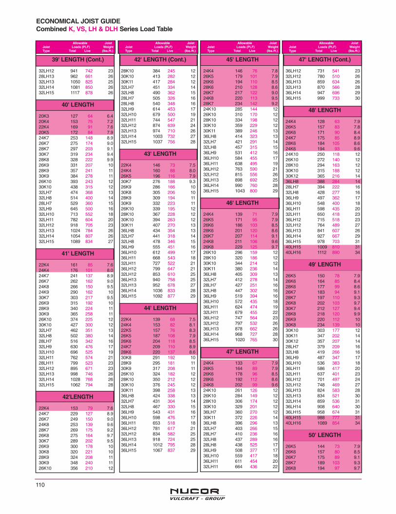
110
39' LENGTH (Cont.)
32LH12 941 742 2328LH13 962 661 2632LH13 1050 825 2532LH14 1081 850 2632LH15 1117 878 26
40' LENGTH
20K3 127 64 6.420K4 153 75 7.222K4 169 91 7.620K5 172 84 7.924K7 253 148 8.926K7 275 174 9.028K7 297 203 9.130K7 319 234 9.428K8 328 222 9.926K9 331 207 1028K9 357 241 1130K9 384 278 1126K10 393 243 1230K10 438 315 1232LH7 474 368 1332LH8 514 400 1428LH7 529 360 1532LH9 645 500 1632LH10 713 552 1832LH11 782 604 2032LH12 918 705 2332LH13 1024 784 2632LH14 1054 807 2632LH15 1089 834 27
41' LENGTH
22K4 161 85 7.624K4 176 101 8.024K7 241 137 8.926K7 262 162 9.024K8 266 150 9.524K9 290 162 1030K7 303 217 9.526K9 315 192 1028K9 340 224 1130K9 365 258 1126K10 374 225 1230K10 427 300 1232LH7 462 351 1332LH8 502 380 1428LH7 516 342 1632LH9 630 476 1732LH10 696 525 1932LH11 762 574 2128LH11 799 523 2332LH12 895 671 2332LH13 998 746 2632LH14 1028 768 2632LH15 1062 794 28
42'LENGTH
22K4 153 79 7.624K7 229 127 8.926K7 249 150 9.024K8 253 139 9.628K7 269 175 9.226K8 275 164 9.730K7 289 202 9.526K9 300 178 1030K8 320 221 1028K9 324 208 1130K9 348 240 1126K10 356 210 12
42' LENGTH (Cont.)
28K10 384 245 1230K10 413 282 1230K11 417 284 1232LH7 451 334 1432LH8 490 362 1528LH7 505 326 1628LH8 540 348 1632LH9 614 453 1732LH10 679 500 1932LH11 744 547 2132LH12 874 639 2432LH13 974 710 2632LH14 1003 732 2732LH15 1037 756 28
43' LENGTH
22K4 146 73 7.524K4 160 88 8.026K5 196 116 7.930K7 276 188 9.326K9 286 166 1030K8 305 206 1028K9 309 194 1130K9 332 223 1126K10 339 195 1228K10 367 228 1230K10 394 263 1230K11 407 270 1336LH8 434 354 1332LH7 441 318 1432LH8 478 346 1536LH9 555 451 1636LH10 612 499 1736LH11 668 543 1832LH11 727 522 2136LH12 799 647 2132LH12 853 610 2536LH13 940 758 2532LH13 952 678 2736LH14 1036 833 2836LH15 1092 877 29
44' LENGTH
22K4 139 68 7.524K4 153 82 8.122K5 157 76 8.326K5 187 108 7.926K6 204 118 8.524K7 209 110 8.928K6 220 137 8.630K8 291 192 1028K9 295 181 1130K9 317 208 1126K10 324 182 1228K10 350 212 1230K10 376 245 1230K11 398 258 1336LH8 424 338 1332LH7 431 304 1432LH8 467 330 1536LH9 543 431 1636LH10 598 476 1736LH11 653 518 1836LH12 781 617 2132LH12 834 582 2536LH13 918 724 2536LH14 1012 795 2836LH15 1067 837 29
45' LENGTH
24K4 146 76 7.826K5 179 101 7.926K6 194 110 8.528K6 210 128 8.626K7 217 122 9.024K8 220 113 9.528K7 234 142 9.224K10 285 144 1226K10 310 170 1228K10 334 198 1230K10 359 229 1230K11 389 246 1336LH8 414 323 1332LH7 421 291 1432LH8 457 315 1536LH9 531 412 1636LH10 584 455 1736LH11 638 495 1936LH12 763 590 2132LH12 815 556 2636LH13 898 692 2536LH14 990 760 2836LH15 1043 800 29
46' LENGTH
24K4 139 71 7.926K5 171 95 7.926K6 186 103 8.528K6 201 120 8.626K7 207 114 9.124K8 211 106 9.626K8 229 125 9.726K10 296 159 1228K10 320 186 1230K10 344 214 1230K11 380 236 1436LH8 405 309 1332LH7 412 278 1428LH7 427 251 1632LH8 447 302 1636LH9 519 394 1636LH10 572 435 1836LH11 624 474 1932LH11 679 455 2236LH12 747 564 2332LH12 797 532 2636LH13 878 662 2636LH14 968 727 2836LH15 1020 765 30
47' LENGTH
24K4 133 67 7.926K5 164 89 7.926K6 178 96 8.528K6 192 112 8.624K8 202 99 9.624K10 261 126 1226K10 284 149 1228K10 306 174 1230K10 329 201 1236LH7 360 270 1230K11 372 226 1436LH8 396 296 1332LH7 403 266 1528LH7 410 236 1632LH8 437 289 1628LH8 438 525 1736LH9 508 377 1736LH10 559 417 1836LH11 611 454 2032LH11 664 436 22
47' LENGTH (Cont.)
36LH12 731 541 2332LH12 780 510 2636LH13 859 634 2632LH13 870 566 2836LH14 947 696 2936LH15 999 733 30
48' LENGTH
24K4 128 63 7.926K5 157 83 7.826K6 171 90 8.424K7 175 85 8.928K6 184 105 8.624K6 194 93 9.624K10 250 118 1226K10 272 140 1228K10 294 163 1230K10 315 188 1230K12 365 216 1436LH8 388 284 1428LH7 394 222 1632LH8 428 277 1636LH9 497 362 1736LH10 548 400 1836LH11 598 435 2032LH11 650 418 2336LH12 715 518 2332LH12 764 489 2736LH13 841 607 2636LH14 927 667 2936LH15 978 703 3140LH15 1009 810 3140LH16 1112 890 34
49' LENGTH
26K5 150 78 7.926K6 164 85 8.428K6 177 99 8.626K7 183 94 9.128K7 197 110 9.326K8 202 103 9.730K7 212 127 9.428K8 218 120 9.926K9 220 112 1030K8 234 139 1030K10 303 177 1230K11 347 202 1430K12 357 207 1428LH7 379 209 1632LH8 419 266 1636LH9 487 347 1736LH10 536 383 1836LH11 586 417 2032LH11 637 401 2336LH12 701 497 2432LH12 748 469 2736LH13 824 583 2832LH13 834 521 3032LH14 859 536 3136LH14 908 640 3036LH15 958 674 3140LH15 988 777 3140LH16 1089 854 34
50' LENGTH
26K5 144 73 7.926K6 157 80 8.526K7 175 89 9.128K7 189 103 9.326K8 194 97 9.7
ECONOMICAL JOIST GUIDECombined K, VS, LH & DLH Series Load Table
Allowable JoistJoist Loads (PLF) WeightType Total Live (lbs./ft.)
Allowable JoistJoist Loads (PLF) WeightType Total Live (lbs./ft.)
Allowable JoistJoist Loads (PLF) WeightType Total Live (lbs./ft.)
Allowable JoistJoist Loads (PLF) WeightType Total Live (lbs./ft.)

111
Allowable JoistJoist Loads (PLF) WeightType Total Live (lbs./ft.)
Allowable JoistJoist Loads (PLF) WeightType Total Live (lbs./ft.)
Allowable JoistJoist Loads (PLF) WeightType Total Live (lbs./ft.)
Allowable JoistJoist Loads (PLF) WeightType Total Live (lbs./ft.)
50' LENGTH (Cont.)
30K7 203 119 9.426K9 211 105 1028K9 228 123 1130K9 245 141 1126K10 250 124 1228K10 270 144 1230K11 333 190 1430K12 350 199 1436LH8 372 262 1432LH8 411 255 1636LH9 477 333 1736LH10 526 368 1836LH11 574 400 2132LH11 625 385 2336LH12 687 477 2336LH13 807 559 2836LH14 890 615 3036LH15 938 647 3240LH15 968 746 3140LH16 1067 820 34
51' LENGTH
26K5 139 69 7.926K6 151 75 8.528K6 163 88 8.626K7 168 83 9.128K7 182 97 9.326K8 186 91 9.826K9 203 99 1028K9 219 115 1130K9 235 133 1126K10 241 116 1228K10 260 136 1230K10 279 157 1230K11 320 179 1430K12 343 192 1528LH7 352 186 1636LH8 365 251 1432LH8 397 242 1636LH9 468 320 1736LH10 515 354 1936LH11 563 385 2132LH11 602 363 2336LH12 673 459 2436LH13 791 538 2832LH13 801 480 3036LH14 872 591 3136LH15 920 622 3340LH15 949 717 3140LH16 1046 788 33
52' LENGTH
26K5 133 65 7.926K6 145 71 8.428K6 157 83 8.626K7 162 79 9.128K7 175 92 9.326K8 179 86 9.726K9 195 93 1028K9 210 109 1130K9 226 126 1126K10 231 110 1228K10 250 128 1230K10 268 148 1228K12 325 165 1530K12 336 184 1528LH7 339 176 1632LH8 383 229 1636LH9 459 308 1836LH10 505 340 1936LH11 552 370 21
52' LENGTH (Cont.)
32LH11 580 343 2336LH12 660 441 2536LH13 776 517 2836LH14 855 568 3136LH15 902 598 3340LH15 931 690 3140LH16 1026 758 34
53' LENGTH
28K6 151 78 8.628K7 168 87 9.230K7 181 100 9.428K8 186 95 9.928K9 203 103 1130K9 218 119 1128K10 240 121 1230K10 258 140 1240LH8 315 233 1230K12 330 177 1644LH9 380 309 1436LH9 450 296 1844LH11 454 368 1632LH9 463 270 1936LH10 496 327 1936LH11 541 356 2144LH12 562 454 1936LH12 647 424 2536LH13 761 498 2844LH14 767 616 2636LH14 839 547 3136LH15 885 575 3444LH15 892 716 3140LH15 913 664 3244LH16 1029 824 3444LH17 1105 880 37
54' LENGTH
28K6 145 74 8.728K7 162 82 9.230K7 174 94 9.428K8 179 89 9.928K9 195 97 1130K9 209 112 1128K10 232 114 1230K10 249 132 1230K11 285 150 1440LH8 309 225 1336LH7 313 204 1330K12 324 170 1644LH9 373 298 1436LH9 442 285 1844LH11 445 354 1632LH9 447 256 1936LH10 486 315 1940LH11 488 350 1836LH11 531 343 2244LH12 552 437 1936LH12 635 409 2544LH13 654 518 2336LH13 747 479 2944LH14 753 594 2636LH14 824 527 3236LH15 868 554 3444LH15 876 690 3140LH15 896 639 3344LH16 1010 793 3444LH17 1084 848 37
55' LENGTH
28K6 140 70 8.6
55' LENGTH (Cont.)
28K7 156 77 9.330K7 168 89 9.428K8 173 85 9.930K8 185 98 1028K9 188 92 1130K9 202 106 1128K10 223 108 1230K10 240 125 1240LH8 304 216 1336LH7 307 197 1330K12 312 161 1644LH9 366 287 1536LH9 434 275 1840LH10 439 312 1736LH10 477 304 2036LH11 521 330 2232LH11 522 292 2444LH12 541 421 2036LH12 624 394 2544LH13 642 499 2336LH13 734 462 2944LH14 739 572 2636LH14 809 507 3236LH15 852 534 3444LH15 860 665 3140LH15 880 616 3344LH16 991 765 3444LH17 1065 817 36
56' LENGTH
28K6 135 66 8.628K7 151 73 9.230K7 162 84 9.428K8 166 80 9.930K8 179 92 1028K9 181 87 1130K9 195 100 1128K10 215 102 1230K10 231 118 1230K11 265 135 1440LH8 298 209 1330K12 301 153 1644LH9 359 277 1536LH9 426 265 1844LH11 429 329 1740LH10 431 301 1736LH10 469 293 2140LH11 471 326 1936LH11 512 319 2344LH12 532 406 2036LH12 613 380 2544LH13 631 482 2340LH13 675 465 2636LH13 720 445 3044LH14 726 552 2732LH14 738 395 3336LH14 794 489 3436LH15 837 515 3544LH15 844 641 3040LH15 864 594 3344LH16 974 737 3544LH17 1046 788 37
57' LENGTH
30K7 156 80 9.430K8 173 88 1030K9 188 95 1130K10 223 112 1230K11 256 128 1440LH8 293 201 1348LH10 353 293 15
57' LENGTH (Cont.)
48LH11 383 316 1536LH9 418 256 1844LH11 422 318 1740LH10 424 290 1736LH10 461 283 2136LH11 503 308 2236LH12 602 367 2544LH13 619 465 2340LH13 664 449 2636LH13 708 430 3032LH14 713 374 3336LH14 780 472 3436LH15 822 497 3644LH14 829 619 3140LH15 849 573 3348LH16 905 737 3144LH16 956 711 3644LH17 1027 761 38
58' LENGTH
30K7 151 76 9.430K8 167 83 1030K9 181 90 1130K10 215 106 1230K11 247 121 1440LH8 288 195 1344LH9 347 258 1548LH11 376 305 1540LH9 378 254 1744LH10 383 284 1632LH9 391 208 1944LH11 414 307 1740LH10 416 280 1836LH10 454 273 2136LH11 495 297 2236LH12 593 354 2544LH13 609 449 2336LH13 697 415 3044LH14 701 514 2836LH14 768 456 3536LH15 809 480 3644LH15 815 597 3148LH16 890 712 3140LH16 919 608 3744LH16 940 687 3748LH17 999 796 3744LH17 1009 734 40
59' LENGTH
30K7 146 72 9.430K8 161 79 1030K9 175 86 1130K10 208 101 1240LH8 283 188 1348LH10 341 273 1444LH10 377 274 1632LH9 379 198 1944LH11 407 296 1736LH10 440 260 2036LH11 480 283 2336LH12 575 338 2544LH13 598 434 2436LH13 675 395 3044LH14 689 497 2836LH14 755 434 3536LH15 795 464 3644LH15 801 577 3140LH15 820 535 3448LH16 874 688 3240LH16 903 588 3744LH16 924 664 37
ECONOMICAL JOIST GUIDECombined K, VS, LH & DLH Series Load Table

112
ECONOMICAL JOIST GUIDECombined K, VS, LH & DLH Series Load Table
Allowable JoistJoist Loads (PLF) WeightType Total Live (lbs./ft.)
Allowable JoistJoist Loads (PLF) WeightType Total Live (lbs./ft.)
Allowable JoistJoist Loads (PLF) WeightType Total Live (lbs./ft.)
Allowable JoistJoist Loads (PLF) WeightType Total Live (lbs./ft.)
59' LENGTH (Cont.)
48LH17 982 769 3744LH17 992 710 39
60' LENGTH
30K7 141 69 9.430K8 156 75 1030K9 169 81 1130K10 201 96 1230K11 231 109 1440LH8 278 182 1348LH10 335 264 1544LH10 370 265 1644LH11 401 287 1736LH10 426 248 2040LH11 439 283 1936LH11 465 269 2336LH12 557 322 2544LH13 588 419 2536LH13 654 376 3044LH14 677 480 2836LH14 729 412 3448LH15 746 577 2836LH15 781 448 3644LH15 788 558 3148LH16 860 665 3244LH16 908 642 3648LH17 965 744 3744LH17 975 686 39
61' LENGTH
40LH8 274 176 1348LH10 330 256 1544LH10 364 257 1644LH11 394 277 1740LH10 396 253 1836LH10 413 236 2140LH11 432 274 2136LH11 451 257 2344LH12 488 342 2140LH12 526 334 2544LH13 579 405 2540LH13 620 391 2848LH14 638 487 2644LH14 666 464 2848LH15 734 558 2944LH15 775 540 3140LH15 793 500 3648LH16 846 643 3344LH16 893 621 3748LH17 949 719 3744LH17 959 664 39
62' LENGTH
40LH8 269 170 1448LH10 324 247 1544LH10 358 248 1744LH11 388 268 1840LH10 389 245 1936LH10 401 225 2140LH11 425 265 2136LH11 438 246 2344LH12 480 331 2140LH12 517 323 2544LH13 569 392 2540LH13 610 379 2948LH14 628 472 2644LH14 655 450 2952DLH14 736 584 2944LH15 762 522 3152DLH15 827 658 32
62' LENGTH (Cont.)
48LH16 832 623 3344LH16 879 601 3752DLH16 892 732 3448LH17 934 696 3744LH17 944 642 4152DLH17 1026 835 40
63' LENGTH
40LH8 265 165 1448LH10 319 239 1540LH9 348 215 1844LH10 353 240 1744LH11 381 260 1840LH10 383 237 1936LH10 389 215 2140LH11 418 257 2136LH11 425 234 2344LH12 472 321 2240LH12 509 313 2544LH13 560 380 2540LH13 600 367 2852DLH13 634 506 2644LH14 645 435 2952DLH14 724 565 2944LH15 750 506 3152DLH15 814 637 3248LH16 819 603 3344LH16 865 582 3752DLH16 878 708 3548LH17 919 674 3844LH17 929 622 4052DLH17 1010 809 40
64' LENGTH
40LH8 261 160 1548LH10 314 232 1540LH9 342 209 1844LH10 347 233 1744LH11 375 252 1840LH10 377 230 1936LH10 378 206 2140LH11 412 249 2148LH12 430 314 1944LH12 465 311 2236LH12 493 267 2544LH13 551 368 2540LH13 591 355 2852DLH13 625 490 2644LH14 635 422 2952DLH14 713 547 2944LH15 738 490 3152DLH15 801 617 3248LH16 806 584 3452DLH16 864 686 3548LH17 905 653 3944LH17 914 602 4352DLH17 994 783 40
65' LENGTH
40LH8 257 155 1548LH10 309 225 1544LH10 342 226 1744LH11 370 244 1840LH10 371 223 1940LH11 405 241 2148LH12 424 305 2044LH12 458 301 2336LH12 478 255 2540LH12 493 294 2552DLH12 506 392 22
65' LENGTH (Cont.)
44LH13 543 357 2640LH13 581 344 2852DLH13 614 475 2644LH14 625 409 2952DLH14 702 531 3044LH15 727 475 3152DLH15 789 598 3352DLH16 851 665 3444LH17 900 584 4352DLH17 979 759 40
66' LENGTH
40LH8 254 150 1548LH10 305 216 1644LH10 337 219 1744LH11 364 237 1840LH10 367 216 2040LH11 399 234 2248LH12 417 295 2044LH12 451 292 2340LH12 486 285 2552DLH12 498 380 2344LH13 535 346 2652DLH13 605 461 2644LH14 615 396 3152DLH14 691 515 3044LH15 716 461 3140LH15 734 427 3652DLH15 777 580 3448LH16 781 549 3552DLH16 838 645 3744LH17 886 566 4352DLH17 964 736 40
67' LENGTH
40LH8 247 144 1544LH9 300 193 1640LH9 323 188 1844LH10 332 212 1844LH11 359 230 1856DLH11 422 363 2044LH12 444 283 2336LH12 450 232 2540LH12 472 273 2552DLH12 491 369 2344LH13 527 336 2648LH14 581 404 2752DLH13 596 447 2744LH14 606 385 3040LH14 638 367 3448LH15 668 462 3152DLH14 681 499 3144LH15 705 447 3140LH15 712 408 3652DLH15 765 563 3448LH16 770 533 3552DLH16 825 626 3748LH17 864 596 4044LH17 873 549 4452DLH17 950 715 40
68' LENGTH
40LH8 241 138 1544LH9 296 187 1740LH9 315 180 1844LH10 327 206 1856DLH11 415 352 2044LH12 437 275 2340LH12 459 261 2544LH13 519 326 26
68' LENGTH (Cont.)
48LH14 572 392 2852DLH13 587 434 2744LH14 597 373 3048LH15 658 449 3252DLH14 671 485 3144LH15 695 434 3152DLH15 754 546 3448LH16 758 517 3652DLH16 813 608 3748LH17 851 578 4144LH17 860 533 4552DLH17 935 694 42
69' LENGTH
40LH8 234 132 1544LH9 291 182 1740LH9 306 173 1844LH10 322 200 1840LH10 338 190 2044LH11 348 216 2056DLH11 409 342 2144LH12 431 267 2340LH12 447 251 2548LH13 478 323 2444LH13 511 317 2952DLH13 578 421 2744LH14 588 363 3148LH15 648 436 3252DLH14 661 471 3144LH15 684 421 3156DLH15 735 568 3252DLH15 743 530 3448LH16 747 502 3652DLH16 801 590 3848LH17 839 562 4144LH17 848 518 4552DLH17 922 674 44
70' LENGTH
40LH8 228 127 1540LH9 298 166 1844LH10 317 195 1840LH10 329 183 2044LH11 343 210 2036LH11 348 173 2340LH11 358 198 2256DLH11 403 332 2144LH12 425 259 2440LH12 435 241 2552DLH12 469 338 2448LH13 471 313 2444LH13 504 307 2748LH14 556 370 2952DLH13 570 409 2944LH14 580 352 3148LH15 639 423 3252DLH14 652 457 3144LH15 675 409 3152DLH15 732 515 3448LH16 736 488 3652DLH16 789 573 3748LH17 827 546 4144LH17 835 503 4556DLH17 901 700 4052DLH17 909 654 44
71' LENGTH
40LH8 222 122 1544LH9 283 172 1740LH9 291 160 18
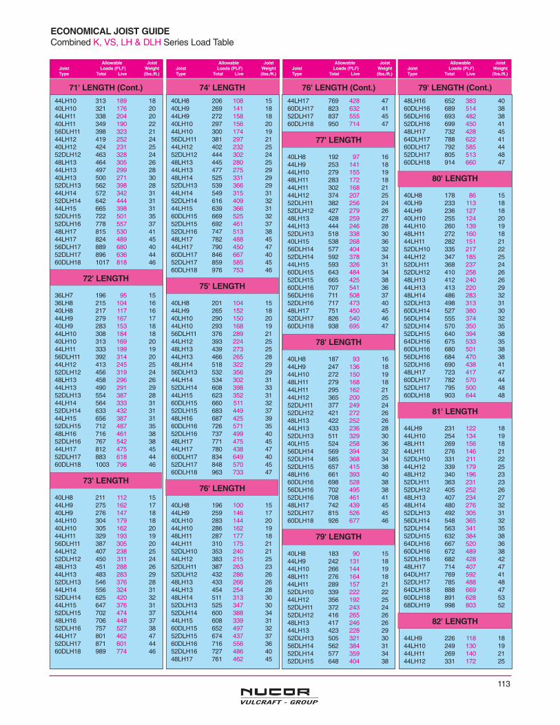
113
Allowable JoistJoist Loads (PLF) WeightType Total Live (lbs./ft.)
Allowable JoistJoist Loads (PLF) WeightType Total Live (lbs./ft.)
Allowable JoistJoist Loads (PLF) WeightType Total Live (lbs./ft.)
Allowable JoistJoist Loads (PLF) WeightType Total Live (lbs./ft.)
ECONOMICAL JOIST GUIDECombined K, VS, LH & DLH Series Load Table
71' LENGTH (Cont.)
44LH10 313 189 1840LH10 321 176 2044LH11 338 204 2040LH11 349 190 2256DLH11 398 323 2144LH12 419 252 2440LH12 424 231 2552DLH12 463 328 2448LH13 464 305 2644LH13 497 299 2840LH13 500 271 3052DLH13 562 398 2844LH14 572 342 3152DLH14 642 444 3144LH15 665 398 3152DLH15 722 501 3552DLH16 778 557 3748LH17 815 530 4144LH17 824 489 4556DLH17 889 680 4052DLH17 896 636 4460DLH18 1017 818 46
72' LENGTH
36LH7 196 95 1536LH8 215 104 1640LH8 217 117 1644LH9 279 167 1740LH9 283 153 1844LH10 308 184 1840LH10 313 169 2044LH11 333 199 1956DLH11 392 314 2044LH12 413 245 2552DLH12 456 319 2448LH13 458 296 2644LH13 490 291 2952DLH13 554 387 2844LH14 564 333 3152DLH14 633 432 3144LH15 656 387 3152DLH15 712 487 3548LH16 716 461 3852DLH16 767 542 3844LH17 812 475 4552DLH17 883 618 4460DLH18 1003 796 46
73' LENGTH
40LH8 211 112 1544LH9 275 162 1740LH9 276 147 1844LH10 304 179 1840LH10 305 162 2044LH11 329 193 1956DLH11 387 305 2044LH12 407 238 2552DLH12 450 311 2448LH13 451 288 2644LH13 483 283 2952DLH13 546 376 2844LH14 556 324 3152DLH14 625 420 3244LH15 647 376 3152DLH15 702 474 3748LH16 706 448 3752DLH16 757 527 3844LH17 801 462 4752DLH17 871 601 4460DLH18 989 774 46
74' LENGTH
40LH8 206 108 1540LH9 269 141 1844LH9 272 158 1840LH10 297 156 2044LH10 300 174 1956DLH11 381 297 2144LH12 402 232 2552DLH12 444 302 2448LH13 445 280 2544LH13 477 275 2948LH14 525 331 2952DLH13 539 366 2944LH14 549 315 3152DLH14 616 409 3244LH15 639 366 3160DLH15 669 525 3252DLH15 692 461 3752DLH16 747 513 3848LH17 782 488 4544LH17 790 450 4760DLH17 846 667 4052DLH17 859 585 4560DLH18 976 753 46
75' LENGTH
40LH8 201 104 1544LH9 265 152 1840LH10 290 150 2044LH10 293 168 1956DLH11 376 289 2144LH12 393 224 2548LH13 439 273 2544LH13 466 265 2848LH14 518 322 2956DLH13 532 356 2944LH14 534 302 3152DLH14 608 398 3344LH15 623 352 3160DLH15 660 511 3252DLH15 683 449 3748LH16 687 425 3960DLH16 726 571 3552DLH16 737 499 4048LH17 771 475 4544LH17 780 438 4760DLH17 834 649 4052DLH17 848 570 4560DLH18 963 733 47
76' LENGTH
40LH8 196 100 1544LH9 259 146 1740LH10 283 144 2044LH10 286 162 1948LH11 287 177 1844LH11 310 175 2152DLH10 353 240 2144LH12 383 215 2552DLH11 387 263 2352DLH12 432 286 2648LH13 433 266 2644LH13 454 254 2848LH14 511 313 3052DLH13 525 347 3052DLH14 600 388 3444LH15 608 339 3160DLH15 652 497 3252DLH15 674 437 3760DLH16 716 556 3652DLH16 727 486 4048LH17 761 462 45
76' LENGTH (Cont.)
44LH17 769 428 4760DLH17 823 632 4152DLH17 837 555 4560DLH18 950 714 47
77' LENGTH
40LH8 192 97 1644LH9 253 141 1844LH10 279 155 1948LH11 283 172 1844LH11 302 168 2144LH12 374 207 2552DLH11 382 256 2452DLH12 427 279 2648LH13 428 259 2744LH13 444 246 2852DLH13 518 338 3040LH15 538 268 3656DLH14 577 404 3252DLH14 592 378 3444LH15 593 326 3160DLH15 643 484 3452DLH15 665 425 3860DLH16 707 541 3656DLH16 711 508 3752DLH16 717 473 4048LH17 751 450 4552DLH17 826 540 4660DLH18 938 695 47
78' LENGTH
40LH8 187 93 1644LH9 247 136 1844LH10 272 150 1948LH11 279 168 1844LH11 295 162 2144LH12 365 200 2552DLH11 377 249 2452DLH12 421 272 2648LH13 422 252 2644LH13 433 236 2852DLH13 511 329 3040LH15 524 258 3656DLH14 569 394 3252DLH14 585 368 3452DLH15 657 415 3848LH16 661 393 4060DLH16 698 528 3856DLH16 702 495 3852DLH16 708 461 4148LH17 742 439 4552DLH17 815 526 4560DLH18 926 677 46
79' LENGTH
40LH8 183 90 1544LH9 242 131 1844LH10 266 144 1948LH11 276 164 1844LH11 289 157 2152DLH10 339 222 2244LH12 356 192 2552DLH11 372 243 2452DLH12 416 265 2648LH13 417 246 2644LH13 423 228 2952DLH13 505 321 3056DLH14 562 384 3152DLH14 577 359 3452DLH15 648 404 38
79' LENGTH (Cont.)
48LH16 652 383 4060DLH16 689 514 3856DLH16 693 482 3852DLH16 699 450 4148LH17 732 428 4564DLH17 788 622 4160DLH17 792 585 4452DLH17 805 513 4860DLH18 914 660 47
80' LENGTH
40LH8 178 86 1540LH9 233 113 1844LH9 236 127 1840LH10 255 124 2044LH10 260 139 1948LH11 272 160 1844LH11 282 151 2152DLH10 335 217 2244LH12 347 185 2552DLH11 368 237 2452DLH12 410 258 2648LH13 412 240 2644LH13 413 220 2948LH14 486 283 3252DLH13 498 313 3160DLH14 527 380 3056DLH14 555 374 3252DLH14 570 350 3552DLH15 640 394 3864DLH16 675 533 3560DLH16 680 501 3856DLH16 684 470 3852DLH16 690 438 4148LH17 723 417 4760DLH17 782 570 4452DLH17 795 500 4860DLH18 903 644 48
81' LENGTH
44LH9 231 122 1844LH10 254 134 1948LH11 269 156 1844LH11 276 146 2152DLH10 331 211 2244LH12 339 179 2548LH12 340 196 2352DLH11 363 231 2352DLH12 405 252 2648LH13 407 234 2748LH14 480 276 3252DLH13 492 305 3156DLH14 548 365 3252DLH14 563 341 3552DLH15 632 384 3864DLH16 667 520 3660DLH16 672 489 3852DLH16 682 428 4248LH17 714 407 4764DLH17 769 592 4152DLH17 785 488 4864DLH18 888 669 4760DLH18 891 628 5368DLH19 998 803 52
82' LENGTH
44LH9 226 118 1844LH10 249 130 1944LH11 269 140 2144LH12 331 172 25
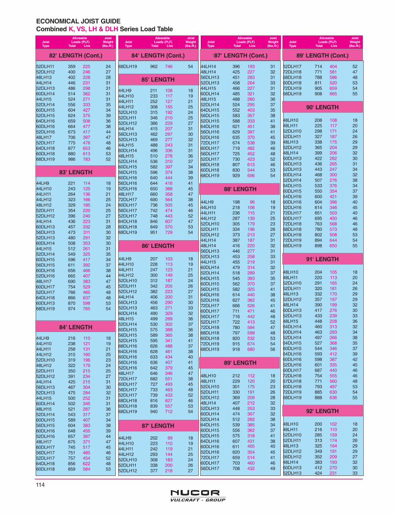
114
ECONOMICAL JOIST GUIDECombined K, VS, LH & DLH Series Load Table
Allowable JoistJoist Loads (PLF) WeightType Total Live (lbs./ft.)
Allowable JoistJoist Loads (PLF) WeightType Total Live (lbs./ft.)
Allowable JoistJoist Loads (PLF) WeightType Total Live (lbs./ft.)
Allowable JoistJoist Loads (PLF) WeightType Total Live (lbs./ft.)
82' LENGTH (Cont.)
52DLH11 359 225 2452DLH12 400 246 2748LH13 402 228 2844LH14 446 231 3152DLH13 486 298 3160DLH14 514 362 3144LH15 524 271 3152DLH14 556 333 3560DLH15 604 427 3452DLH15 624 375 3964DLH16 659 508 3660DLH16 664 477 3852DLH16 673 417 4448LH17 706 397 4752DLH17 775 476 4864DLH18 877 653 4660DLH18 880 613 5368DLH19 986 783 52
83' LENGTH
44LH9 221 114 1844LH10 243 125 1944LH11 264 136 2144LH12 323 166 2548LH12 329 185 2452DLH11 354 220 2552DLH12 396 240 2744LH14 436 223 3160DLH13 457 332 2856DLH13 473 311 3052DLH13 480 291 3260DLH14 508 353 3044LH15 512 261 3152DLH14 549 325 3560DLH15 596 417 3456DLH15 611 392 3760DLH16 656 466 3852DLH16 665 407 4448LH17 690 383 4760DLH17 754 529 4552DLH17 766 465 4864DLH18 866 637 4860DLH13 870 598 5368DLH19 974 765 54
84' LENGTH
44LH9 216 110 1844LH10 238 121 1944LH11 258 131 2144LH12 315 160 2552DLH10 319 196 2348LH12 322 179 2452DLH11 350 215 2552DLH12 391 234 2744LH14 425 215 3156DLH13 467 304 3052DLH13 475 284 3244LH15 500 252 3160DLH14 502 345 3148LH15 521 287 3652DLH14 543 317 3760DLH15 589 407 3456DLH15 604 383 3860DLH16 648 455 3952DLH16 657 397 4448LH17 675 371 4760DLH17 745 517 4556DLH17 751 485 4652DLH17 757 454 5264DLH18 856 622 4860DLH18 859 584 53
84' LENGTH (Cont.)
68DLH19 962 746 54
85' LENGTH
44LH9 211 108 1844LH10 233 117 1944LH11 252 127 2144LH12 308 155 2552DLH10 315 192 2452DLH11 346 210 2552DLH12 386 229 2744LH14 415 207 3156DLH13 462 297 3052DLH13 469 277 3244LH15 488 243 3160DLH14 496 336 3148LH15 510 278 3652DLH14 536 310 3760DLH15 582 397 3456DLH15 596 374 3860DLH16 640 444 3956DLH16 644 416 4152DLH16 650 388 4548LH17 660 358 4772DLH17 690 564 3860DLH17 736 505 4556DLH17 742 474 4652DLH17 748 443 5264DLH18 846 607 4760DLH18 849 570 5368DLH19 951 729 54
86' LENGTH
44LH9 207 103 1844LH10 228 113 1944LH11 247 123 2144LH12 300 149 2552DLH10 312 187 2452DLH11 342 205 2652DLH12 382 223 2744LH14 406 200 3156DLH13 456 290 3052DLH13 463 271 3360DLH14 490 329 3248LH15 499 269 3652DLH14 530 302 3760DLH15 575 388 3656DLH15 589 365 3852DLH15 595 341 4168DLH16 626 488 3764DLH16 628 461 3860DLH16 633 434 4056DLH16 636 407 4152DLH16 642 379 4548LH17 646 346 4772DLH17 682 551 3860DLH17 727 493 4556DLH17 733 463 4852DLH17 739 433 5268DLH18 816 627 4660DLH18 839 557 5368DLH19 940 712 54
87' LENGTH
44LH9 202 99 1844LH10 223 110 1944LH11 242 119 2144LH12 293 144 2552DLH10 308 183 2452DLH11 338 200 2652DLH12 377 218 27
\87' LENGTH (Cont.)
44LH14 396 193 3148LH14 425 227 3256DLH13 451 283 3152DLH13 458 264 3344LH15 466 227 3160DLH14 485 321 3248LH15 488 260 3652DLH14 524 295 3764DLH15 552 403 3556DLH15 583 357 3852DLH15 588 333 4164DLH16 621 451 3856DLH16 629 397 4152DLH16 635 370 4572DLH17 674 538 3960DLH17 719 482 4656DLH17 725 452 4852DLH17 730 423 5268DLH18 807 613 4660DLH18 830 544 5368DLH19 929 696 54
88' LENGTH
44LH9 198 96 1844LH10 218 106 1944LH11 236 115 2144LH12 287 139 2552DLH10 305 179 2352DLH11 334 196 2652DLH12 373 213 2744LH14 387 187 3148LH14 416 220 3256DLH13 446 277 3152DLH13 453 258 3344LH15 455 219 3160DLH14 479 314 3252DLH14 518 289 3764DLH15 545 393 3560DLH15 562 370 3756DLH15 582 325 4164DLH16 614 440 3852DLH16 627 362 4572DLH17 666 526 4160DLH17 711 471 4656DLH17 716 442 4852DLH17 722 413 5272DLH18 780 594 4768DLH18 797 599 4860DLH18 820 532 5372DLH19 915 674 5468DLH19 918 680 56
89' LENGTH
48LH10 212 112 1848LH11 229 120 2052DLH10 301 175 2352DLH11 330 191 2652DLH12 369 209 2848LH14 407 212 3252DLH13 448 253 3360DLH14 474 307 3252DLH14 512 282 3864DLH15 539 385 3460DLH15 556 362 3752DLH15 575 318 4164DLH16 607 431 3860DLH16 611 405 4052DLH16 620 354 4572DLH17 659 514 4160DLH17 703 460 4656DLH17 708 432 49
89' LENGTH (Cont.)
52DLH17 714 404 5272DLH18 771 581 4768DLH18 788 586 4860DLH18 811 520 5372DLH19 905 659 5468DLH19 908 665 55
90' LENGTH
48LH10 208 108 1848LH11 225 117 2052DLH10 298 171 2452DLH11 327 187 2648LH13 338 175 2952DLH12 365 204 2948LH14 399 206 3260DLH13 422 282 3056DLH13 436 265 3152DLH13 443 247 3460DLH14 468 300 3252DLH14 507 276 3864DLH15 533 376 3460DLH15 550 354 3764DLH16 600 421 3960DLH16 604 396 4052DLH16 614 346 4572DLH17 651 503 4060DLH17 695 450 4672DLH18 763 568 4668DLH18 780 573 4860DLH18 802 508 5372DLH19 894 644 5468DLH19 898 650 55
91' LENGTH
48LH10 204 105 1848LH11 220 113 2052DLH10 291 165 2452DLH11 320 181 2648LH13 332 170 2952DLH12 357 197 2948LH14 390 199 3260DLH13 417 276 3052DLH13 433 239 3348LH15 448 228 3664DLH14 460 313 3260DLH14 463 293 3452DLH14 497 266 3864DLH15 527 368 3560DLH15 544 346 3764DLH16 593 412 3960DLH16 598 387 4252DLH16 601 335 4560DLH17 687 440 4672DLH18 754 555 4667DLH18 771 560 4860DLH18 793 497 5372DLH19 885 630 5468DLH19 888 636 55
92' LENGTH
48LH10 200 102 1848LH11 216 110 2052DLH10 285 159 2452DLH11 313 174 2648LH13 325 164 2952DLH12 349 191 2956DLH12 352 209 2748LH14 383 193 3260DLH13 412 270 3052DLH13 424 231 33

115
ECONOMICAL JOIST GUIDECombined K, VS, LH & DLH Series Load Table
Allowable JoistJoist Loads (PLF) WeightType Total Live (lbs./ft.)
Allowable JoistJoist Loads (PLF) WeightType Total Live (lbs./ft.)
Allowable JoistJoist Loads (PLF) WeightType Total Live (lbs./ft.)
Allowable JoistJoist Loads (PLF) WeightType Total Live (lbs./ft.)
92' LENGTH (Cont.)
56DLH13 427 253 3248LH15 439 221 3660DLH14 458 287 3452DLH14 486 258 3864DLH15 521 360 3560DLH15 538 339 3852DLH15 545 291 4256DLH15 551 319 4160DLH16 591 379 4256DLH16 595 355 4560DLH17 680 431 4672DLH18 746 543 4668DLH18 763 548 4860DLH18 784 486 5368DLH19 878 622 55
93' LENGTH
48LH10 196 99 1848LH11 212 106 2052DLH10 279 154 2352DLH11 306 169 2648LH13 318 159 2952DLH12 342 185 2956DLH12 349 204 2748LH14 375 187 3252DLH13 414 224 3348LH15 430 214 3660DLH14 453 281 3452DLH14 476 249 3856DLH14 477 277 3760DLH15 532 332 3852DLH15 533 282 4256DLH15 545 312 4168DLH16 578 417 3860DLH16 585 371 4256DLH16 588 348 4564DLH17 669 448 4660DLH17 672 421 4956DLH17 678 395 5168DLH18 754 536 4864DLH18 773 507 5360DLH18 776 476 5668DLH19 869 609 54
94' LENGTH
48LH10 192 96 1848LH11 208 103 2052DLH10 273 150 2352DLH11 299 164 2648LH13 312 154 2952DLH12 334 179 2956DLH12 345 200 2748LH14 367 181 3252DLH13 406 216 3348LH15 422 208 3660DLH14 448 275 3452DLH14 466 242 3752DLH14 472 271 3760DLH15 526 325 3856DLH15 539 306 4168DLH16 572 408 3860DLH16 579 363 4156DLH16 582 340 4572DLH17 623 461 4260DLH17 665 412 4956DLH17 670 387 5172DLH18 730 520 4760DLH18 768 466 5572DLH19 856 590 5568DLH19 859 596 58
95' LENGTH
48LH10 188 93 1848LH11 204 100 2052DLH10 267 145 2352DLH11 293 158 2652DLH12 327 173 2956DLH12 341 196 2748LH14 360 176 3252DLH13 397 209 3360DLH13 399 253 3148LH15 413 201 3660DLH14 444 269 3452DLH14 457 234 3756DLH14 467 265 3768DLH15 477 340 3460DLH15 521 318 3856DLH15 533 299 4168DLH16 566 400 3864DLH16 568 378 4160DLH16 573 355 4456DLH16 576 333 4572DLH17 617 451 4260DLH17 658 404 4856DLH17 663 379 5172DLH18 723 509 4860DLH18 760 456 5672DLH19 847 578 5568DLH19 850 583 60
96' LENGTH
48LH10 185 90 1848LH11 200 91 2052DLH10 261 140 2452DLH11 287 153 2648LH13 300 145 2952DLH12 320 168 2960DLH12 325 205 2756DLH12 338 192 2948LH14 353 171 3252DLH13 389 203 3360DLH13 395 248 3248LH15 405 195 3664DLH14 436 281 3260DLH14 439 264 3452DLH14 447 227 3856DLH14 462 260 3860DLH15 515 311 3848LH17 525 252 4764DLH16 562 370 4160DLH16 567 348 4456DLH16 570 326 4572DLH17 610 442 4264DLH17 648 421 4660DLH17 651 395 4956DLH17 656 371 5172DLH18 715 499 4864DLH18 748 476 5360DLH18 752 447 5772DLH19 838 566 5568DLH19 841 571 60
97' LENGTH
52DLH10 256 136 2452DLH11 281 149 2652DLH12 314 163 2960DLH12 322 201 2756DLH12 334 188 2852DLH13 381 197 3360DLH13 391 243 3260DLH14 434 258 3452DLH14 438 220 3856DLH14 457 254 38
97' LENGTH (Cont.)
64DLH15 494 324 3760DLH15 510 305 4072DLH16 537 380 3864DLH16 557 362 4260DLH16 561 341 4472DLH17 604 433 4264DLH17 641 412 4656DLH17 650 363 5172DLH18 708 488 4864DLH18 741 466 5360DLH18 744 437 5972DLH19 830 554 5568DLH19 833 559 60
98' LENGTH
52DLH10 251 132 2452DLH11 275 144 2652DLH12 307 158 2960DLH12 318 197 2756DLH12 331 184 3052DLH13 373 191 3360DLH13 387 238 3256DLH13 401 223 3460DLH14 430 253 3456DLH14 453 249 3864DLH15 489 317 3760DLH15 505 298 4072DLH16 531 373 3964DLH16 551 355 4260DLH16 555 334 4456DLH16 559 313 4672DLH17 598 424 4364DLH17 635 404 4656DLH17 643 356 5172DLH18 700 478 4864DLH18 733 456 5360DLH18 736 428 5972DLH19 821 543 5568DLH19 824 548 60
99' LENGTH
52DLH10 246 128 2452DLH11 270 140 2652DLH12 301 153 2960DLH12 315 193 2756DLH12 324 178 2952DLH13 366 185 3360DLH13 383 233 3356DLH13 394 216 3360DLH14 426 248 3456DLH14 444 242 3864DLH15 484 311 3760DLH15 500 292 4064DLH16 545 348 4260DLH16 549 327 4472DLH17 592 415 4364DLH17 628 395 4656DLH17 630 345 5172DLH18 693 469 4864DLH18 726 447 5360DLH18 729 420 5972DLH19 813 532 5868DLH19 816 537 61
100' LENGTH
52DLH10 241 124 2452DLH11 264 135 2652DLH12 295 149 2960DLH12 312 189 2756DLH12 318 173 29
100' LENGTH (Cont.)
52DLH13 358 180 3360DLH13 379 228 3256DLH13 386 209 3352DLH14 413 201 3760DLH14 421 243 3556DLH14 435 234 3864DLH15 480 304 3760DLH15 495 287 4172DLH16 521 358 3960DLH16 544 320 4572DLH17 586 407 4464DLH17 622 388 4972DLH18 686 459 4864DLH18 718 438 5560DLH18 721 411 5972DLH19 805 521 5868DLH19 808 526 61
101' LENGTH
52DLH10 236 120 2352DLH11 259 132 2656DLH12 289 144 2960DLH12 309 185 2756DLH12 312 168 2952DLH13 351 174 3360DLH13 375 224 3256DLH13 379 204 3352DLH14 405 194 3760DLH14 417 238 3556DLH14 427 228 3768DLH15 449 301 3564DLH15 475 298 3960DLH15 490 281 4160DLH16 538 314 4672DLH17 580 399 4464DLH17 616 380 4960DLH17 619 357 5272DLH18 679 450 5164DLH18 711 430 5660DLH18 714 403 5972DLH19 797 511 6068DLH19 800 516 61
102' LENGTH
52DLH10 231 116 2352DLH11 254 128 2652DLH12 284 140 2956DLH12 306 163 2952DLH13 344 170 3364DLH13 358 232 3160DLH13 372 219 3452DLH14 397 189 3760DLH14 413 233 3556DLH14 419 221 3868DLH15 445 295 3564DLH15 470 292 3960DLH15 485 275 4160DLH16 533 308 4672DLH17 574 391 4564DLH17 610 372 4960DLH17 613 350 5272DLH18 673 442 5160DLH18 707 395 5972DLH19 789 501 6068DLH19 792 506 61
103' LENGTH
52DLH10 227 114 2452DLH11 249 124 2652DLH12 278 135 29

116
ECONOMICAL JOIST GUIDECombined K, VS, LH & DLH Series Load Table
Allowable JoistJoist Loads (PLF) WeightType Total Live (lbs./ft.)
Allowable JoistJoist Loads (PLF) WeightType Total Live (lbs./ft.)
Allowable JoistJoist Loads (PLF) WeightType Total Live (lbs./ft.)
Allowable JoistJoist Loads (PLF) WeightType Total Live (lbs./ft.)
103' LENGTH (Cont.)
60DLH12 303 178 2852DLH13 338 164 3364DLH13 355 228 3260DLH13 368 215 3452DLH14 390 184 3864DLH14 406 244 3460DLH14 409 229 3756DLH14 411 214 3868DLH15 440 289 3564DLH15 466 287 3960DLH15 480 270 4168DLH16 522 340 4160DLH16 528 302 4672DLH17 569 384 4568DLH17 588 386 4760DLH17 607 343 5264DLH18 697 413 5660DLH18 700 388 5972DLH19 781 491 6068DLH19 784 496 61
104' LENGTH
52DLH10 223 110 2452DLH11 244 120 2652DLH12 273 132 2956DLH12 295 153 3060DLH12 300 175 2952DLH13 331 159 3364DLH13 351 224 3256DLH13 358 186 3460DLH13 365 211 3452DLH14 382 178 3864DLH14 402 239 3460DLH14 405 224 3764DLH15 461 281 3960DLH15 476 265 4372DLH16 501 331 4068DLH16 517 333 4160DLH16 523 296 4672DLH17 563 376 4568DLH17 583 379 4660DLH17 601 337 5272DLH18 660 425 5368DLH18 674 428 5360DLH18 694 380 5968DLH19 777 486 61
105' LENGTH
56DLH11 253 136 2656DLH12 289 150 2960DLH12 297 171 2964DLH13 348 219 3256DLH13 351 181 3460DLH13 361 207 3464DLH14 398 235 3460DLH14 401 220 3768DLH15 432 278 3764DLH15 457 276 4060DLH15 471 260 4372DLH16 496 324 4068DLH16 512 327 4260DLH16 518 290 4568DLH17 577 372 4660DLH17 595 330 5268DLH18 668 420 5360DLH18 687 373 5968DLH19 769 477 61
106' LENGTH
56DLH11 248 133 26
106' LENGTH (Cont.)
56DLH12 284 145 2960DLH12 295 168 2956DLH13 344 175 3460DLH13 358 203 3464DLH14 395 230 3460DLH14 398 216 3768DLH15 428 273 3764DLH15 452 271 4060DLH15 467 255 4372DLH16 491 318 4164DLH16 509 303 4560DLH16 513 285 4668DLH17 572 365 4660DLH17 590 324 5268DLH18 662 412 5360DLH18 681 366 5968DLH19 762 468 60
107' LENGTH
56DLH11 244 129 3656DLH12 278 141 2960DLH12 289 163 2960DLH13 351 197 3464DLH14 391 226 3468DLH15 424 268 3864DLH15 448 266 4060DLH15 458 248 4372DLH16 487 312 4164DLH16 504 298 4672DLH17 548 355 4668DLH17 566 358 4960DLH17 579 315 5264DLH17 581 338 5268DLH18 655 405 5360DLH18 668 357 5964DLH18 671 383 5968DLH19 755 459 61
108' LENGTH
56DLH11 239 125 2656DLH12 273 137 2960DLH12 284 158 2960DLH13 345 191 3460DLH14 383 205 3764DLH14 387 222 3672DLH15 417 260 3668DLH15 420 263 3864DLH15 444 261 4060DLH15 450 242 4372DLH16 482 307 4164DLH16 500 292 4672DLH17 542 349 4660DLH17 569 306 5264DLH17 576 332 5260DLH18 656 346 5964DLH18 665 376 5972DLH19 745 447 6168DLH19 748 451 61
109' LENGTH
56DLH11 235 122 2656DLH12 268 133 2960DLH12 279 154 2956DLH13 325 161 3360DLH13 339 187 3460DLH14 376 199 3764DLH14 384 218 3772DLH15 413 255 3668DLH15 416 258 3864DLH15 440 256 41
109' LENGTH (Cont.)
60DLH15 442 235 4372DLH16 478 301 4164DLH16 495 287 4672DLH17 537 342 4760DLH17 558 298 5264DLH17 571 326 5260DLH18 644 337 5964DLH18 659 369 5972DLH19 738 439 6168DLH19 741 443 67
110' LENGTH
56DLH11 231 118 2660DLH12 274 150 2960DLH13 333 181 3460DLH14 370 193 3764DLH14 380 214 3772DLH15 409 251 3668DLH15 412 254 3860DLH15 434 228 4364DLH15 436 251 4172DLH16 473 295 4160DLH16 476 255 4664DLH16 491 281 4672DLH17 533 336 4760DLH17 548 290 5268DLH17 551 338 4964DLH17 565 320 5260DLH18 632 327 5968DLH18 637 383 5664DLH18 653 362 5972DLH19 731 431 6168DLH19 734 434 67
111' LENGTH
56DLH11 227 115 2656DLH12 259 126 3060DLH12 270 146 2964DLH12 271 161 2856DLH13 314 152 3460DLH13 327 176 3464DLH13 329 196 3360DLH14 363 189 3764DLH14 377 210 3768DLH15 408 249 3864DLH15 432 247 4156DLH16 436 214 4664DLH16 486 276 4672DLH17 528 330 4768DLH17 546 332 4964DLH17 560 314 5272DLH18 618 373 5360DLH18 621 319 5964DLH18 647 356 5972DLH19 725 423 6168DLH19 727 427 67
112' LENGTH
56DLH11 223 113 2656DLH12 254 123 2960DLH12 265 142 2964DLH12 269 159 2956DLH13 308 149 3360DLH13 322 171 3464DLH13 326 193 3460DLH14 356 183 3764DLH14 373 206 3768DLH15 405 245 3864DLH15 428 242 4164DLH16 482 271 46
112' LENGTH (Cont.)
72DLH17 523 324 4764DLH17 555 309 5272DLH18 613 366 5364DLH18 641 349 5972DLH19 718 415 6168DLH19 721 419 67
113' LENGTH
60DLH12 261 138 2964DLH12 266 156 2960DLH13 316 167 3464DLH13 323 189 3460DLH14 350 178 3764DLH14 370 203 3768DLH15 401 240 3964DLH15 424 238 4160DLH16 451 235 4672DLH16 461 280 4368DLH16 476 282 4572DLH17 518 318 4760DLH17 519 267 5264DLH17 550 303 5272DLH18 607 360 5364DLH18 636 343 5972DLH19 712 408 6268DLH19 714 412 67
114' LENGTH
60DLH12 256 134 2964DLH12 264 153 2960DLH13 311 163 3464DLH13 321 186 3460DLH14 344 173 3764DLH14 367 199 3768DLH15 398 236 3960DLH15 405 205 4364DLH15 421 234 4360DLH16 444 228 4672DLH16 457 275 4368DLH16 472 277 4664DLH16 474 262 4672DLH17 514 313 5064DLH17 546 298 5260DLH18 589 394 5964DLH18 630 337 5972DLH19 706 401 6468DLH19 708 404 67
115' LENGTH
60DLH12 252 131 2964DLH12 259 150 2960DLH13 306 158 3464DLH13 315 181 3460DLH14 338 170 3764DLH14 360 193 3768DLH15 394 232 3960DLH15 398 200 4364DLH15 414 228 4372DLH16 453 270 4368DLH16 467 272 4672DLH17 509 307 5064DLH17 536 290 5260DLH18 578 286 5972DLH18 597 347 5464DLH18 619 328 5968DLH19 702 397 66
116' LENGTH
60DLH12 248 128 29
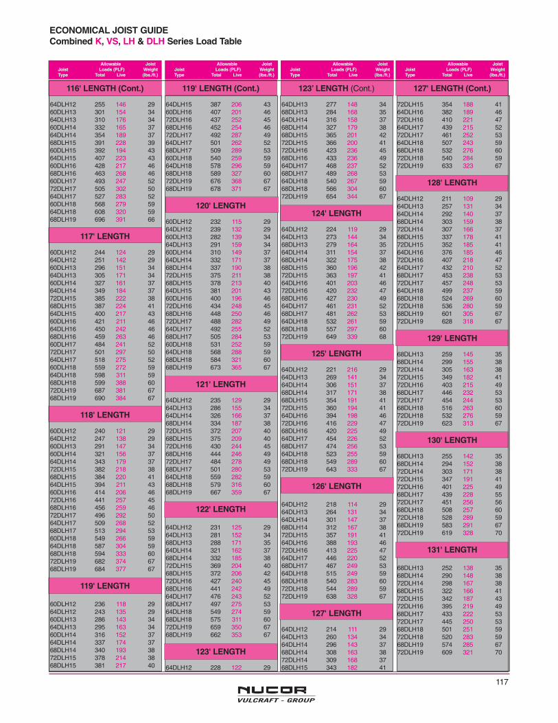
117
ECONOMICAL JOIST GUIDECombined K, VS, LH & DLH Series Load Table
Allowable JoistJoist Loads (PLF) WeightType Total Live (lbs./ft.)
Allowable JoistJoist Loads (PLF) WeightType Total Live (lbs./ft.)
Allowable JoistJoist Loads (PLF) WeightType Total Live (lbs./ft.)
Allowable JoistJoist Loads (PLF) WeightType Total Live (lbs./ft.)
116' LENGTH (Cont.)
64DLH12 255 146 2960DLH13 301 154 3464DLH13 310 176 3460DLH14 332 165 3764DLH14 354 189 3768DLH15 391 228 3960DLH15 392 194 4364DLH15 407 223 4360DLH16 428 217 4668DLH16 463 268 4660DLH17 493 247 5272DLH17 505 302 5064DLH17 527 283 5260DLH18 568 279 5964DLH18 608 320 5968DLH19 696 391 66
117' LENGTH
60DLH12 244 124 2964DLH12 251 142 2960DLH13 296 151 3464DLH13 305 171 3460DLH14 327 161 3764DLH14 349 184 3772DLH15 385 222 3868DLH15 387 224 4164DLH15 400 217 4360DLH16 421 211 4664DLH16 450 242 4668DLH16 459 263 4660DLH17 484 241 5272DLH17 501 297 5064DLH17 518 275 5260DLH18 559 272 5964DLH18 598 311 5968DLH18 599 388 6072DLH19 687 381 6768DLH19 690 384 67
118' LENGTH
60DLH12 240 121 2964DLH12 247 138 2960DLH13 291 147 3460DLH14 321 156 3764DLH14 343 179 3772DLH15 382 218 3868DLH15 384 220 4164DLH15 394 211 4360DLH16 414 206 4672DLH16 441 257 4568DLH16 456 259 4672DLH17 496 292 5064DLH17 509 268 5268DLH17 513 294 5360DLH18 549 266 5964DLH18 587 304 5968DLH18 594 333 6072DLH19 682 374 6768DLH19 684 377 67
119' LENGTH
60DLH12 236 118 2964DLH12 243 135 2960DLH13 286 143 3464DLH13 295 163 3460DLH14 316 152 3764DLH14 337 174 3768DLH14 340 193 3872DLH15 378 214 3868DLH15 381 217 40
119' LENGTH (Cont.)
64DLH15 387 206 4360DLH16 407 201 4672DLH16 437 252 4568DLH16 452 254 4672DLH17 492 287 4964DLH17 501 262 5268DLH17 509 289 5360DLH18 540 259 5964DLH18 578 296 5968DLH18 589 327 6072DLH19 676 368 6768DLH19 678 371 67
120' LENGTH
60DLH12 232 115 2964DLH12 239 132 2960DLH13 282 139 3464DLH13 291 159 3460DLH14 310 149 3764DLH14 332 171 3768DLH14 337 190 3872DLH15 375 211 3868DLH15 378 213 4064DLH15 381 201 4360DLH16 400 196 4672DLH16 434 248 4568DLH16 448 250 4672DLH17 488 282 4964DLH17 492 255 5268DLH17 505 284 5360DLH18 531 252 5964DLH18 568 288 5968DLH18 584 321 6068DLH19 673 365 67
121' LENGTH
64DLH12 235 129 2964DLH13 286 155 3464DLH14 326 166 3768DLH14 334 187 3872DLH15 372 207 4068DLH15 375 209 4072DLH16 430 244 4568DLH16 444 246 4972DLH17 484 278 4968DLH17 501 280 5364DLH18 559 282 5968DLH18 579 316 6068DLH19 667 359 67
122' LENGTH
64DLH12 231 125 2964DLH13 281 152 3468DLH13 288 171 3564DLH14 321 162 3768DLH14 332 185 3872DLH15 369 204 4068DLH15 372 206 4272DLH16 427 240 4568DLH16 441 242 4964DLH17 476 243 5268DLH17 497 275 5364DLH18 549 274 5968DLH18 575 311 6072DLH19 659 350 6768DLH19 662 353 67
123' LENGTH
64DLH12 228 122 29
123’ LENGTH (Cont.)
64DLH13 277 148 3468DLH13 284 168 3564DLH14 316 158 3768DLH14 327 179 3868DLH15 365 201 4272DLH15 366 200 4172DLH16 423 236 4568DLH16 433 236 4964DLH17 468 237 5268DLH17 489 268 5364DLH18 540 267 5968DLH18 566 304 6072DLH19 654 344 67
124' LENGTH
64DLH12 224 119 2964DLH13 273 144 3468DLH13 279 164 3564DLH14 311 154 3768DLH14 322 175 3868DLH15 360 196 4272DLH15 363 197 4164DLH16 401 203 4672DLH16 420 232 4768DLH16 427 230 4964DLH17 461 231 5268DLH17 481 262 5364DLH18 532 261 5968DLH18 557 297 6072DLH19 649 339 68
125' LENGTH
64DLH12 221 216 2964DLH13 269 141 3464DLH14 306 151 3768DLH14 317 171 3868DLH15 354 191 4172DLH15 360 194 4164DLH16 394 198 4672DLH16 416 229 4768DLH16 420 225 4964DLH17 454 226 5268DLH17 474 256 5364DLH18 523 255 5968DLH18 549 289 6072DLH19 643 333 67
126' LENGTH
64DLH12 218 114 2964DLH13 264 131 3464DLH14 301 147 3768DLH14 312 167 3872DLH15 357 191 4164DLH16 388 193 4672DLH16 413 225 4764DLH17 446 220 5268DLH17 467 249 5364DLH18 515 249 5968DLH18 540 283 6072DLH18 544 289 5972DLH19 638 328 67
127' LENGTH
64DLH12 214 111 2964DLH13 260 134 3464DLH14 296 143 3768DLH14 308 163 3872DLH14 309 168 3768DLH15 343 182 41
127' LENGTH (Cont.)
72DLH15 354 188 4164DLH16 382 189 4672DLH16 410 221 4764DLH17 439 215 5272DLH17 461 252 5364DLH18 507 243 5968DLH18 532 276 6072DLH18 540 284 5972DLH19 633 323 67
128' LENGTH
64DLH12 211 109 2964DLH13 257 131 3464DLH14 292 140 3768DLH14 303 159 3872DLH14 307 166 3768DLH15 337 178 4172DLH15 352 185 4164DLH16 376 185 4672DLH16 407 218 4764DLH17 432 210 5268DLH17 453 238 5372DLH17 457 248 5364DLH18 499 237 5968DLH18 524 269 6072DLH18 536 280 5968DLH19 601 305 6772DLH19 628 318 67
129' LENGTH
68DLH13 259 145 3568DLH14 299 155 3872DLH14 305 163 3872DLH15 349 182 4172DLH16 403 215 4968DLH17 446 232 5372DLH17 454 244 5368DLH18 516 263 6072DLH18 532 276 5972DLH19 623 313 67
130' LENGTH
68DLH13 255 142 3568DLH14 294 152 3872DLH14 303 171 3872DLH15 347 191 4172DLH16 401 225 4968DLH17 439 228 5572DLH17 451 256 5668DLH18 508 257 6072DLH18 528 289 5968DLH19 583 291 6772DLH19 619 328 70
131' LENGTH
68DLH13 252 138 3568DLH14 290 148 3872DLH14 298 167 3868DLH15 322 166 4172DLH15 342 187 4372DLH16 395 219 4968DLH17 433 222 5372DLH17 445 250 5368DLH18 501 251 5972DLH18 520 283 5968DLH19 574 285 6772DLH19 609 321 70
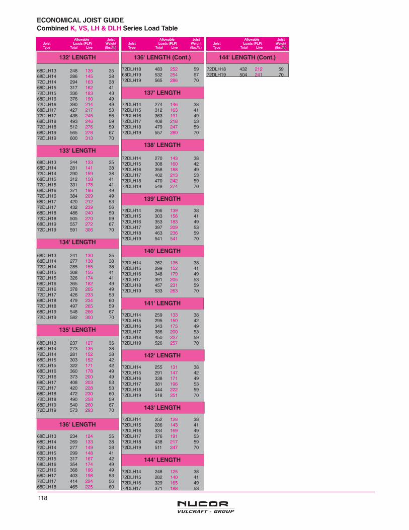
118
ECONOMICAL JOIST GUIDECombined K, VS, LH & DLH Series Load Table
Allowable JoistJoist Loads (PLF) WeightType Total Live (lbs./ft.)
Allowable JoistJoist Loads (PLF) WeightType Total Live (lbs./ft.)
Allowable JoistJoist Loads (PLF) WeightType Total Live (lbs./ft.)
132' LENGTH
68DLH13 248 135 3568DLH14 286 145 3872DLH14 294 163 3868DLH15 317 162 4172DLH15 336 183 4368DLH16 376 190 4972DLH16 390 214 4968DLH17 427 217 5372DLH17 438 245 5668DLH18 493 246 5972DLH18 512 276 5968DLH19 565 278 6772DLH19 600 313 70
133' LENGTH
68DLH13 244 133 3568DLH14 281 141 3872DLH14 290 159 3868DLH15 312 158 4172DLH15 331 178 4168DLH16 371 186 4972DLH16 384 209 4968DLH17 420 212 5372DLH17 432 239 5668DLH18 486 240 5972DLH18 505 270 5968DLH19 557 272 6772DLH19 591 306 70
134' LENGTH
68DLH13 241 130 3568DLH14 277 138 3872DLH14 285 155 3868DLH15 308 155 4172DLH15 326 174 4168DLH16 365 182 4972DLH16 378 205 4972DLH17 426 233 5368DLH18 479 234 6072DLH18 497 265 5968DLH19 548 266 6772DLH19 582 300 70
135' LENGTH
68DLH13 237 127 3568DLH14 273 135 3872DLH14 281 152 3868DLH15 303 152 4272DLH15 322 171 4268DLH16 360 178 4972DLH16 373 200 4968DLH17 408 203 5372DLH17 420 228 5368DLH18 472 230 6072DLH18 490 258 5968DLH19 540 260 6772DLH19 573 293 70
136' LENGTH
68DLH13 234 124 3568DLH14 269 133 3872DLH14 277 149 3868DLH15 299 148 4172DLH15 317 167 4268DLH16 354 174 4972DLH16 368 196 4968DLH17 403 198 5372DLH17 414 224 5668DLH18 465 225 60
136' LENGTH (Cont.)
72DLH18 483 252 5968DLH19 532 254 6772DLH19 565 286 70
137' LENGTH
72DLH14 274 146 3872DLH15 312 163 4172DLH16 363 191 4972DLH17 408 218 5372DLH18 479 247 5972DLH19 557 280 70
138' LENGTH
72DLH14 270 143 3872DLH15 308 160 4272DLH16 358 188 4972DLH17 402 213 5372DLH18 470 242 5972DLH19 549 274 70
139' LENGTH
72DLH14 266 139 3872DLH15 303 156 4172DLH16 353 183 4972DLH17 397 209 5372DLH18 463 236 5972DLH19 541 541 70
140' LENGTH
72DLH14 262 136 3872DLH15 299 152 4172DLH16 348 179 4972DLH17 391 205 5372DLH18 457 231 5972DLH19 533 263 70
141' LENGTH
72DLH14 259 133 3872DLH15 295 150 4272DLH16 343 175 4972DLH17 386 200 5372DLH18 450 227 5972DLH19 526 257 70
142' LENGTH
72DLH14 255 131 3872DLH15 291 147 4272DLH16 338 171 4972DLH17 381 196 5372DLH18 444 222 5972DLH19 518 251 70
143' LENGTH
72DLH14 252 128 3872DLH15 286 143 4172DLH16 334 169 4972DLH17 376 191 5372DLH18 438 217 5972DLH19 511 247 70
144' LENGTH
72DLH14 248 125 3872DLH15 282 140 4172DLH16 329 165 4972DLH17 371 188 53
144' LENGTH (Cont.)
72DLH18 432 212 5972DLH19 504 241 70
119
1.1 SCOPEThe practices and customs set forth herein are in accor-dance with good engineering practice, tend to insure safe-ty in steel joist and Joist Girder construction, and arestandard within the industry. There shall be no conflictbetween this code and any legal building regulation. Thiscode shall only supplement and amplify such laws.Unless specific provisions to the contrary are made in acontract for the purchase of steel joists or Joist Girders,this code is understood to govern the interpretation ofsuch a contract.
1.2 APPLICATIONThis Code of Standard Practice is to govern as a standardunless otherwise covered in the architects’ and engineers’plans and specifications.
1.3 DEFINITIONa) The term Seller as used herein is defined as a compa-ny engaged in the manufacture and distribution of steeljoists, Joist Girders and accessories.
b) The term Material as used herein is defined as steeljoists, Joist Girders and accessories.
c) Bay dimensions for the purpose of steel joist erectionare defined in Appendix "A":
1.4 DESIGNIn the absence of ordinances or specifications to the con-trary, all designs prepared by the specifying professionalshall be in accordance with the applicable Steel JoistInstitute Specifications and Load Table of latest adoption.
1.5 RESPONSIBILITY FOR DESIGN ANDERECTION
When Material requirements are specified, the seller shallassume no responsibility other than to furnish the itemslisted in Section 5.2 (a). When Material requirements arenot specified, the Seller shall furnish the items listed inSection 5.2 (a) in accordance with applicable Steel JoistInstitute Specifications of latest adoption, and this code.The Seller shall identify material by showing size andtype. In no case shall the Seller assume any responsibili-ty for the erection of the item furnished.
1.6 PERFORMANCE TEST FOR K-SERIESSTEEL JOIST CONSTRUCTION
When job tests on a structure are required, joists shallhave bridging and top deck applied as used. In addition tothe full dead load, the test panel shall sustain for one houra test load of 1.65 times the design live load. After this testload has been removed for a minimum of 30 minutes, theremaining deflection shall not exceed 20% of the deflec-tion caused by the test load. The weight of the test panelitself shall constitute the dead load of the construction andshall include the weight of the joists, bridging, top deck,slab, ceiling materials, etc. The design live load shall bethe live load specified and in no case shall it be more thanthe published joist capacity less the dead load. The costof such tests shall be borne by the purchaser.
2.1 STEEL JOISTS AND JOIST GIRDERSSteel joists and Joist Girders shall carry the designationsand meet the requirements of the applicable Steel JoistInstitute Specification and Table of latest adoption.
K-Series joists are furnished with parallel chords only, andwith minimum standard end bearing depth of 2¹⁄₂ inches(64 mm).
LH- and DLH-Series joists are furnished either under-slung or square ended, with top chords either parallel,pitched one way or pitched two ways. Underslung typesare furnished with standard end bearing depth of 5 inch-es (127 mm) for LH-Series. DLH-Series are furnishedwith standard end bearing depths of 5 inches (127 mm)for section numbers thru 17 and 7¹⁄₂ inches (191 mm) forsection numbers 18 and 19. The standard pitch is ¹⁄₈ inchin 12 inches (1:96). The nominal depth of a pitchedLongspan Joist is taken at the center of the span.
Joist Girders are furnished either underslung or squareended with top chords either parallel, pitched one way orpitched two ways. Under-slung types are furnished with astandard end bearing depth of 7¹⁄₂ inches (191mm). Thestandard pitch is ¹⁄₈ inch in 12 inches (1:96). The nominaldepth of a pitched Joist Girder is taken at the center of thespan.
Because Longspan and Deep Long Span Joists mayhave exceptionally high end reactions, it is recommendedthat the supporting structure be designed to provide aminimum unit bearing pressure of 750 pounds per squareinch (5171 kilo Pascal).
RECOMMENDED CODE OF STANDARD PRACTICE FOR STEEL JOISTS AND JOIST GIRDERS
Adopted by the Steel Joist Institute April 7, 1931Revised to May 1, 2001 – Effective August 1, 2002
SECTION 1.
GENERAL
SECTION 2.
JOISTS AND ACCESSORIES
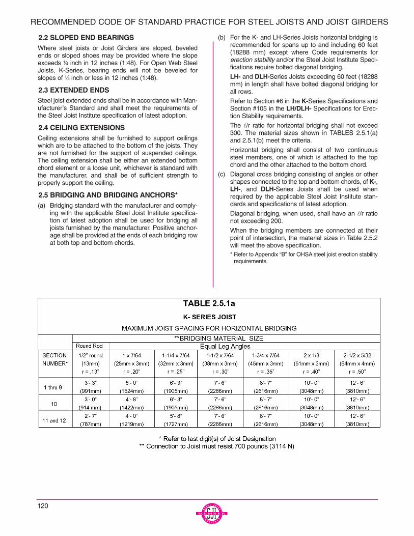
120
RECOMMENDED CODE OF STANDARD PRACTICE FOR STEEL JOISTS AND JOIST GIRDERS
2.2 SLOPED END BEARINGSWhere steel joists or Joist Girders are sloped, beveledends or sloped shoes may be provided where the slopeexceeds ¹⁄₄ inch in 12 inches (1:48). For Open Web SteelJoists, K-Series, bearing ends will not be beveled forslopes of ¹⁄₄ inch or less in 12 inches (1:48).
2.3 EXTENDED ENDSSteel joist extended ends shall be in accordance with Man-ufacturer’s Standard and shall meet the requirements ofthe Steel Joist Institute specification of latest adoption.
2.4 CEILING EXTENSIONSCeiling extensions shall be furnished to support ceilingswhich are to be attached to the bottom of the joists. Theyare not furnished for the support of suspended ceilings.The ceiling extension shall be either an extended bottomchord element or a loose unit, whichever is standard withthe manufacturer, and shall be of sufficient strength toproperly support the ceiling.
2.5 BRIDGING AND BRIDGING ANCHORS*(a) Bridging standard with the manufacturer and comply-
ing with the applicable Steel Joist Institute specifica-tion of latest adoption shall be used for bridging alljoists furnished by the manufacturer. Positive anchor-age shall be provided at the ends of each bridging rowat both top and bottom chords.
(b) For the K- and LH-Series Joists horizontal bridging isrecommended for spans up to and including 60 feet(18288 mm) except where Code requirements forerection stability and/or the Steel Joist Institute Speci-fications require bolted diagonal bridging.
LH- and DLH-Series Joists exceeding 60 feet (18288mm) in length shall have bolted diagonal bridging forall rows.
Refer to Section #6 in the K-Series Specifications andSection #105 in the LH/DLH- Specifications for Erec-tion Stability requirements.
The l/r ratio for horizontal bridging shall not exceed300. The material sizes shown in TABLES 2.5.1(a)and 2.5.1(b) meet the criteria.
Horizontal bridging shall consist of two continuoussteel members, one of which is attached to the topchord and the other attached to the bottom chord.
(c) Diagonal cross bridging consisting of angles or othershapes connected to the top and bottom chords, of K-,LH-, and DLH-Series Joists shall be used whenrequired by the applicable Steel Joist Institute stan-dards and specifications of latest adoption.
Diagonal bridging, when used, shall have an l/r rationot exceeding 200.
When the bridging members are connected at theirpoint of intersection, the material sizes in Table 2.5.2will meet the above specification.* Refer to Appendix “B” for OHSA steel joist erection stability
requirements.
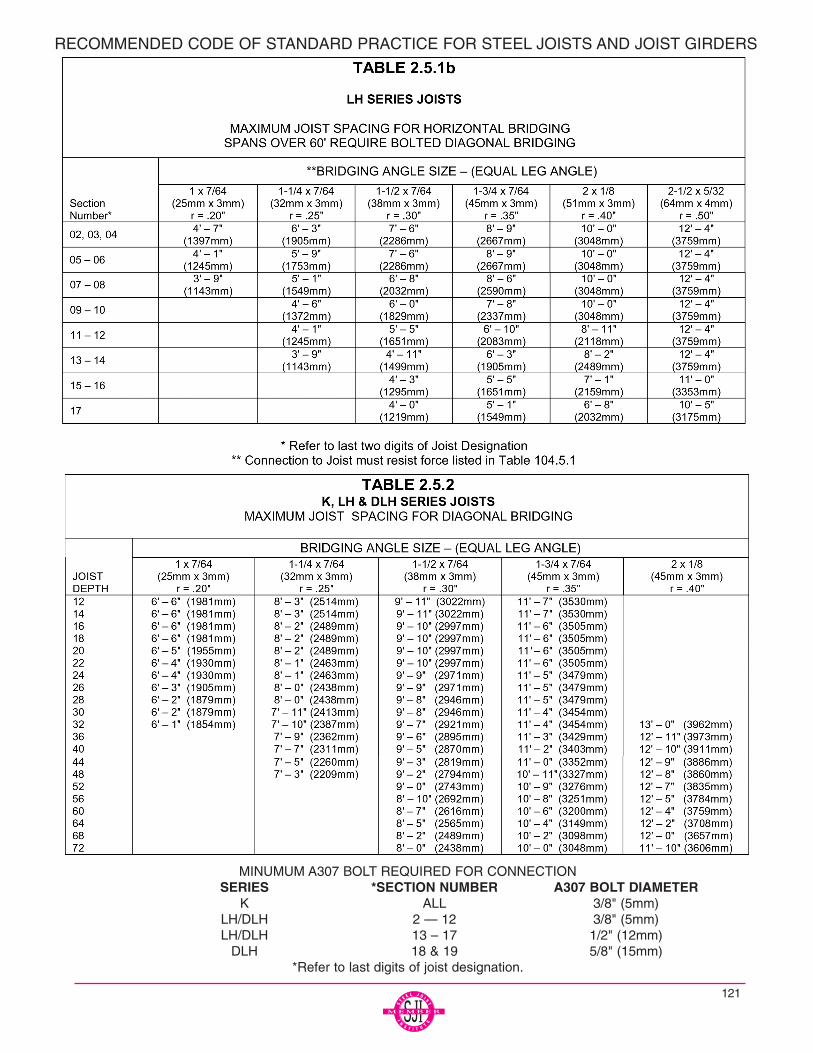
121
MINUMUM A307 BOLT REQUIRED FOR CONNECTIONSERIES *SECTION NUMBER A307 BOLT DIAMETER
K ALL 3/8" (5mm)LH/DLH 2 — 12 3/8" (5mm)LH/DLH 13 – 17 1/2" (12mm)
DLH 18 & 19 5/8" (15mm)*Refer to last digits of joist designation.
RECOMMENDED CODE OF STANDARD PRACTICE FOR STEEL JOISTS AND JOIST GIRDERS

2.6 HEADERSHeaders for Open Web Steel Joists, K-Series as outlinedand defined in Section 5.2 (a) shall be furnished by theSeller. Such headers shall be any type standard with themanufacturer. Conditions involving headers shall be inves-tigated and, if necessary, provisions made to provide asafe condition. Headers are not provided for LongspanSteel Joists, LH-Series, and Deep Longspan Steel Joists,DLH-Series.
2.7 BOTTOM CHORD LATERAL BRACING FORJOIST GIRDERS
Bottom chord lateral bracing shall be furnished when l/ry ofthe bottom chord exceeds 240. The lateral bracing shall bethat which is standard with the manufacturer, and shall beof sufficient strength to properly resist any lateral forceexerted by the bottom chord of the Joist Girder.
3.1 STEELThe steel used in the manufacture of joists and Joist Gird-ers shall comply with the applicable Steel Joist Institutespecification of latest adoption.
3.2 PAINT(a) Standard Shop Paint – The shop coat of paint, when
specified, shall comply with the applicable Steel JoistInstitute specification of latest adoption.
(b) Disclaimer – The typical shop applied paint that isused to coat steel joists and joist girders is a dipapplied, air dried paint. The paint is intended to be animpermanent and provisional coating which will pro-tect the steel for only a short period of exposure inordinary atmospheric conditions.
Since most steel joists and joist girders are paintedusing a standard dip coating, the coating may not beuniform and may include drips, runs, and sags. Com-patibility of any coating including fire protective coat-ings applied over a standard shop paint shall be theresponsibility of the specifier and or painting contrac-tor.
The shop applied paint may require field touch-up/repair as a result of, but not limited to, the following:
1. Abrasions from: Bundling, banding, loading andunloading, chains, dunnage during shipping,cables and chains during erection, bridging,installation, and other handling at the jobsite
NOTE: Rusting should be expected at any abrasion.
2. Dirt
3. Diesel smoke
4. Road salt
5. Weather conditions during storage
The joist manufacturer shall not be responsible for the con-dition of the paint if it is not properly protected after delivery.
All joist and Joist Girder inspections shall be made inaccordance with the provision for inspection in the applic-able Steel Joist Institute specification of latest adoption.
5.1 PLANS FOR BIDDINGPlans to serve as the basis for bids shall show the charac-ter of the work with sufficient clarity to permit making anaccurate estimate and shall show the following:
Designation and location of Materials (See Section 5.2[a] )
Locations and elevations of all steel and concretesupporting members and bearing walls.
Location and length of joist extended ends.
Location and size of all openings in floors and roofs.
Location of all partitions.
Location and magnitude of concentrated loads asdefined in Section 5.5.
Construction and thickness of floor slabs, roof deck,ceilings and partitions.
Joists or Joist Girders requiring extended bottomchords.
Paint, if other than manufacturer’s standard.
5.2 SCOPE OF ESTIMATE(a) Unless otherwise specified, the following items shall
be included in the estimate, and requirements shall bedetermined as outlined in Section 5.3 through 5.5.
Steel Joists
Joist Girders
Joist Extended Ends
Ceiling Extensions.
Extended bottom chord used as strut.
Bridging and bridging anchors.
Joist Girder bottom chord bracing.
Headers which are defined as members supported byand carrying Open Web Steel Joists, K-Series.
One shop coat of paint, when specified, shall be inaccordance with Section 3.2.
RECOMMENDED CODE OF STANDARD PRACTICE FOR STEEL JOISTS AND JOIST GIRDERS
SECTION 3.
MATERIALS
SECTION 4.
INSPECTION
SECTION 5.
ESTIMATING
122
123
(b) The following items shall not be included in the esti-mate but may be quoted and identified as separateitems:
Headers for Longspan Steel Joists, LH-Series.
Headers for Deep Longspan Steel Joists, DLH-Series.
Reinforcement in slabs over joists.
Centering material and attachments.
Miscellaneous framing between joists for openings atducts, dumbwaiters, ventilators, skylights, etc.
Loose individual or continuous bearing plates andbolts or anchors for such plates.
Erection bolts for joist and Joist Girder end anchorage.
Horizontal bracing in the plane of the top and bottomchords from joist to joist or joist to structural framingand walls.
Wood nailers.
Moment plates.
5.3 JOIST LOCATION AND SPACINGThe maximum joist spacing shall be in accordance with therequirements of the applicable SJI specification and loadtable of latest adoption.
Where sidewalls, wall beams or tie beams are capable ofsupporting the floor slab or roof deck, the first adjacentjoists may be placed one full space from these members.Longspan Steel Joists and Deep Longspan Steel Joistsare provided with camber. These joists may have a signif-icant difference in elevation with respect to the adjacentstructure because of this camber. This difference in eleva-tion should be given consideration when locating the firstjoist adjacent to a sidewall, wall beam or tie beam. There-fore, it is recommended that this joist be located one fullspace away from these members.
Open Web Steel Joists, K-Series, should be no closer than6 inches (152 mm) to these supporting walls or members.Where partitions occur parallel to joists, there shall be atleast one typical joist provided under each such partition,and more than one such joist shall be provided if neces-sary to safely support the weight of such partition and theadjacent floor, less the live load, on a strip of floor one foot(305 mm) in width. Where such partitions extend less thanone-third (¹⁄₃) of the span from the support, special spacingor additional joists shall not be required provided the loadsdo not exceed those in Section 5.5. When partitions occurnormal to the joists, they shall be treated as concentratedloads, and joists shall be investigated as indicated in Sec-tion 5.5.
5.4 ACCESSORIESJoist accessories standard with the manufacturer shallcomply with applicable Steel Joist Institute specifications oflatest adoption and shall be in accordance with Section 2of this Code.
5.5 LOADSThe Steel Joist Institute Load Tables are based on uniformloading conditions and are valid for use in selecting joistsizes for gravity loads that can be expressed in terms of“Pounds per lineal foot” (Newtons per Meter) of joist. TheSteel Joist Institute Weight Tables are based on uniformlyspaced panel point loading conditions and are valid for usein selecting Joist Girder sizes for gravity conditions that canbe expressed in kips (Kilo Newton) per panel point on theJoist Girder. When Joist Girders are required to supportunequal panel point loads or other special loads, aJoist Girder load diagram shall be provided by thespecifying professional on the structural drawingswith these point loads clearly shown.Loads such as Bulb “T”s, purlins, partitions, heavy pipes,monorail or tramrail type carrier, etc., running normal to thelength of the joist, or a mechanical unit mounted on thejoist, are concentrated loads. Where concentrated loadsoccur, the joist must be selected to carry the full combina-tion of uniform load plus concentrated load. The magnitudeand location of these concentrated loads shall be shownon the structural drawings when, in the opinion of thespecifying professional, they may require special con-sideration by the manufacturer. Such joists shall be labeled“Special” on the structural drawings.
When Steel Joists are subjected to concentrated and/orvarying loads, the specifying professional shall use the fol-lowing procedure which will allow the:
1. Estimator to price the joists.
2. Joist manufacturer to design the joists properly.
3. Owner to obtain the most economical joists.
A. Sketch the joist(s) on the structural drawings showingall loads to be supported.
B. Determine the maximum moment in the joist andderive the uniform load that will produce thatmoment.
C. Determine the maximum end reaction and derive theuniform load that will produce that reaction.
D. Using the largest of the 2 uniform loads in B and Cselect a joist from the load table and add an “SP” afterthe joist designation.
E. Place the designation under the sketch with the fol-lowing note:
“Joist supplier to design joist to support loads asshown above.”
RECOMMENDED CODE OF STANDARD PRACTICE FOR STEEL JOISTS AND JOIST GIRDERS
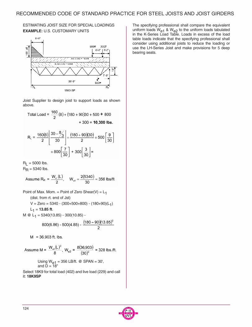
124
RECOMMENDED CODE OF STANDARD PRACTICE FOR STEEL JOISTS AND JOIST GIRDERS
ESTIMATING JOIST SIZE FOR SPECIAL LOADINGS
EXAMPLE: U.S. CUSTOMARY UNITS
Joist Supplier to design joist to support loads as shownabove.
RL = 5000 lbs.
RR = 5340 lbs.
Point of Max. Mom. = Point of Zero Shear(V) = L1(dist. from rt. end of Jst)
V = Zero = 5340 - (300+500+800) - (180+90)(L1)
L1 = 13.85 ft.M @ L1 = 5340(13.85) - 300(10.85) -
Using We1 = 356 LB/ft. @ SPAN = 30', and D = 18"
Select 18K9 for total load (402) and live load (229) and callit: 18K9SP
The specifying professional shall compare the equivalentuniform loads We1 & We2 to the uniform loads tabulatedin the K-Series Load Table. Loads in excess of the loadtable loads indicate that the specifying professional shallconsider using additional joists to reduce the loading oruse the LH-Series Joist and make provisions for 5 deepbearing seats.

125
ESTIMATING JOIST SIZE FOR SPECIAL LOADINGS:EXAMPLE: METRIC UNITS
Joist supplier to design joist to support loads as shownabove.
RL = (2.86 x .91) + 18.01 + .67 + .83 +.13 = 22.24 kN
RR = 45.98 - 22.24 = 23.74 kN
Point of Max. Mom. = Point of Zero Shear(V) = L1(dist. from rt. end of Jst)
V = Zero = 23.75 - (1.31+2.22+3.56)) - (2.63+1.31)(L1)
L1 = 4.23 m.M @ L1 = 23.75(4.23) - 1.33(3.32) -
Moment @ L1 = 50.01 kN/m
Assume M = ,
Where We2 = = 4.79N/m
Using We1 = 5.20 kN/m. @ SPAN = 9.14 m,
and d = 457 mm
Select 18K9 for total load (5.86 kN/m) and live load (3.34kN/m)
Call it: 18K9SPThe specifying professional shall compare the equivalentuniform loads We1 & We2 to the uniform loads tabulatedin the K-Series Load Table. Loads in excess of the loadtable loads indicate that the specifying professional shallconsider using additional joists to reduce the loading oruse an LH-Series Joist and make provisions for 127 mmdeep bearing seats.
Due consideration by the specifying professional shall begiven to live loads due to:
1. Ponded rain water.
2. Excessive accumulation of snow in the vicinity ofobstructions such as penthouses, signs, para-pets, adjacent buildings, etc.
3. Wind uplift.
4. End moments at the joist end supports due to liveand/or wind/seismic loads shall be shown on thestructural drawings by the specifying professional.
For moment resisting joists framing near the endof a column, due consideration shall be given toextend the column length to allow a plate typeconnection between the top of the joist top chordand the column. Preferably, avoid resolving joistend moment forces through the joist bearing seatconnection.
The structural drawings shall specify that allmoment resisting joists shall have all dead loadsapplied to the joist before the bottom chord strutsare welded to the column.
The top and bottom chord moment connectiondetails shall be designed by the specifying pro-fessional. The joist designer shall furnish thespecifying professional with the joist detail infor-mation if requested.
The design loads, as determined by the specify-ing professional, shall not be less than that spec-ified in the applicable building codes.
6.1 PLANS FURNISHED BY BUYERThe Buyer shall furnish the Seller plans and specificationsshowing all Material requirements, the layout of walls,columns, beams, girders and other supports, as well asfloor and roof openings and partitions correctly dimen-sioned. The live loads to be used, the wind uplift if any, theweights of partitions and the location and amount of anyspecial loads, such as monorails, fans, blowers, tanks,etc., shall be indicated. The elevation of finished floors androofs and bearings shall be shown.
RECOMMENDED CODE OF STANDARD PRACTICE FOR STEEL JOISTS AND JOIST GIRDERS
SECTION 6.
PLANS AND SPECIFICATIONS
6.2 PLANS FURNISHED BY SELLERThe Seller shall furnish the Buyer with detailed plans andlists showing the number, type, locations, spacing, anchor-age and mark of all Material as may be required for properinstallation. All Material shall be identified with its markwhich also appears on the bill of material. The type of shoppaint, when required, shall be indicated on the drawings.
6.3 DISCREPANCIESThe specifying professional’s bid plans and specificationswill be assumed to be correct in the absence of writtennotice from the Buyer to the contrary. When plans are fur-nished by the Buyer which do not agree with the Architect’sbid plans, such detailed plans shall be considered as a writ-ten notice of change of plans. However, it shall be theBuyer’s responsibility to advise the Seller of those changeswhich affect the joists or Joist Girders.
6.4 APPROVALWhen joist placement plans are furnished by the Seller,prints thereof are submitted to the Buyer and owner forexamination and approval. The Seller allows a maximum offourteen (14) calendar days in his schedule for the return ofplacement plans noted with the owner’s and customer’sapproval, or approval subject to corrections as noted. TheSeller makes the corrections, furnishes corrected prints forfield use to the owner/customer and is released by theowner/customer to start joist manufacture.
Approval by the owner/customer of the placement plans,sections, notes and joist schedule prepared by the Sellerindicates that the Seller has correctly interpreted the con-tract requirements, and is released by the owner/customerto start joist manufacture. This approval constitutes theowner’s/customer’s acceptance of all responsibility for thedesign adequacy of any detail configuration of joist supportconditions shown by the Seller as part of his preparation ofthese placement plans.
Approval does not relieve the Seller of the responsibility foraccuracy of detail dimensions on the plans, nor the gener-al fit-up of joists to be placed in the field.
6.5 CHANGESWhen any changes in plans are made by the buyer (orArchitect) either prior to or after approval of detailed plans,or when any Material is required and was not shown onplans used as the basis of the bid, the cost of such changesand/or extra Material shall be paid by the Buyer at a priceto be agreed upon between Buyer and Seller.
The Buyer and/or Erector shall check all materials onarrival at job site and promptly report to Seller any discrep-ancies and/or damages. The Buyer and/or Erector shallcomply with the requirements of the applicable Steel JoistInstitute specification of latest adoption in the handling anderection of Material.
The Seller shall not be responsible for the condition of paintfinish on Material if it is not properly protected after delivery.
The Seller shall not be responsible for improper fit of Mate-rial in the case in inaccurate finish dimensions of field con-struction work.
* For thorough coverage of this topic, refer to SJI TechnicalDigest #9, “Handling and Erection of Steel Joists and JoistGirders”.
8.1 PRESENTATION OF PROPOSALSAll proposals for furnishing Material shall be made on aSales Contract Form. After acceptance by the Buyer, theseproposals must be approved or executed by a qualified offi-cial of the Seller. Upon such approval the proposalbecomes a contract.
8.2 ACCEPTANCE OF PROPOSALSAll proposals are intended for prompt acceptance and aresubject to change without notice.
8.3 BILLINGContracts on a lump sum basis are to be billed proportion-ately as shipments are made.
8.4 PAYMENTPayments shall be made in full on each invoice withoutretention.
8.5 ARBITRATIONAll business controversies which cannot be settled by directnegotiations between Buyer and Seller shall be submittedto arbitration. Both parties shall sign a submission to arbi-tration and if possible agree upon an arbitrator. If they areunable to agree, each shall appoint an arbitrator and thesetwo shall appoint a third arbitrator. The expenses of thearbitration shall be divided equally between the parties,unless otherwise provided for in the agreements to submitto arbitration. The arbitrators shall pass finally upon allquestions, both of law and fact, and their findings shall beconclusive.
126
RECOMMENDED CODE OF STANDARD PRACTICE FOR STEEL JOISTS AND JOIST GIRDERS
SECTION 7.*
HANDLING AND ERECTION
SECTION 8.
BUSINESS RELATIONS

127
PUBLICATIONSVulcraft (Refer to back cover for address and telephone number of division nearest you)
STEEL JOISTS AND JOIST GIRDERS 2003
VULCRAFT COMPOSITE AND NONCOMPOSITE FLOOR JOISTS 1996
DESIGNING WITH VULCRAFT JOIST, STEEL JOIST GIRDERS AND STEEL DECK, 2nd ed.James Fisher, Ph.D., P.E., Michael West, P.E., AIA, Juius P. Van de Pas, P.E.(A 168 page book provided to engineers and architects for help in designing with steeljoists, joist girders and steel deck)
STEEL DECK INSTITUTE - P.O. Box 25, Fox River Grove, IL 60021 Phone: (847) 458-4647 Fax (847) 458-4648e-mail [email protected]
DESIGN MANUAL FOR COMPOSITE DECKS, FORM DECKS AND ROOF DECKS - NO. 30
ROOF DECK CONSTRUCTION HANDBOOK - NO. RDCH1
DIAPHRAGM DESIGN MANUAL SECOND EDITION NO. DDMO2
COMPREHENSIVE STEEL DECK INSTITUTE BINDER - NO. BF
SDI MANUAL OF CONSTRUCTION WITH STEEL DECK - NO. MOC1 (650KB)
COMPOSITE STEEL DECK DESIGN HANDBOOK. NO. CDD2
STANDARD PRACTICE DETAILS. - NO. SPD2
DECK DAMAGE & PENETRATIONS - NO. DDP
HOW TO UPDATE DIAPHRAGM TABLES - NO. HUDT
METAL DECK & CONCRETE QUANTITIES - NO. MDCQ
A RATIONAL APPROACH TO STEEL DECK CORROSION PROTECTION - NO. SDCP (278 KB)
Steel Joist Institute - 3127 10th Ave. North Ext., Myrtle Beach, SC 29577-6760(843) 626-1995 Fax: 843-626-5565, e-mail: [email protected], web site: www.steeljoist.com
STANDARD SPECIFICATIONS, LOAD TABLES AND WEIGHT TABLES FOR STEEL JOISTS AND JOIST GIRDERS41ST Edition (1994)
75-YEAR MANUAL (AVAILABLE IN SUMMER 2003)
TECHNICAL DIGEST #3 - Ponding (1971)
TECHNICAL DIGEST #5 - Vibration (1988)
TECHNICAL DIGEST #6 - Uplift Loading (1998)
TECHNICAL DIGEST #8 - Welding of Open Web Steel Joist (1983)
TECHNICAL DIGEST #9 - Handling and Erection (1987)
TECHNICAL DIGEST #11 - Design of Joist - Girder Frames (1999)
GUIDE FOR SPECIFYING STEEL JOISTS WITH LOAD AND RESISTANCE FACTOR DESIGN (2002)
NEW LRFD GUIDE (2000)
COMPUTER VIBRATION PROGRAM Ver1.2 (Used in Conjunction with Technical Digest #5)
SJI VIDEO - Introduction to Steel Joists
VIDEO - SAFE ERECTION OF OPEN WEB STEEL JOISTS AND JOIST GIRDERS (English & Spanish)

128
NOTES