Embed Size (px)
Citation preview
VTRAK 15200USER MANUAL
Version 1.5
PROMISE VTrak 15200
VTrak 15200 User Manual
Copyright© 2004 Promise Technology, Inc. All Rights Reserved.
Copyright by Promise Technology, Inc. (Promise Technology). No part of this manual may be reproduced or transmitted in any form without the expressed, written permission of Promise Technology.
TrademarksPromise, and the Promise logo are registered in U.S. Patent and Trademark Office. All other product names mentioned herein may be trademarks or registered trademarks of their respective companies.
Important data protection informationYou should back up all data before installing any drive controller or storage peripheral. Promise Technology is not responsible for any loss of data resulting from the use, disuse or misuse of this or any other Promise Technology product.
NoticeAlthough Promise Technology has attempted to ensure the accuracy of the content of this manual, it is possible that this document may contain technical inaccuracies, typographical, or other errors. Promise Technology assumes no liability for any error in this publication, and for damages, whether direct, indirect, incidental, consequential or otherwise, that may result from such error, including, but not limited to loss of data or profits.
Promise Technology provides this publication “as is” without warranty of any kind, either express or implied, including, but not limited to implied warranties of merchantability or fitness for a particular purpose.
The published information in the manual is subject to change without notice. Promise Technology reserves the right to make changes in the product design, layout, and driver revisions without notification to its users.
This version of the User Manual supersedes all previous versions.
RecommendationsThe appearance in this manual of products made by other companies, including, but not limited to software, servers and disk drives, is for the purpose of illustration and explanation only. Promise Technology does not recommend, endorse, prefer or support any product made by another manufacturer.
ii
ContentsChapter 1: Introduction . . . . . . . . . . . . . . . . . . . . . . . . . . . . . . . . . . . . .1
About This Manual . . . . . . . . . . . . . . . . . . . . . . . . . . . . . . . . . . . . . . .1Overview . . . . . . . . . . . . . . . . . . . . . . . . . . . . . . . . . . . . . . . . . . . . . .2Architectural Description . . . . . . . . . . . . . . . . . . . . . . . . . . . . . . . . . .3
Features and Benefits . . . . . . . . . . . . . . . . . . . . . . . . . . . . . . . .3Specifications . . . . . . . . . . . . . . . . . . . . . . . . . . . . . . . . . . . . . . . . . .5
FCC Statement . . . . . . . . . . . . . . . . . . . . . . . . . . . . . . . . . . . . . .6
Chapter 2: Installation . . . . . . . . . . . . . . . . . . . . . . . . . . . . . . . . . . . . . .7Unpack the VTrak . . . . . . . . . . . . . . . . . . . . . . . . . . . . . . . . . . . . . . .7Mount VTrak in a Rack . . . . . . . . . . . . . . . . . . . . . . . . . . . . . . . . . . .8Install Disk Drives . . . . . . . . . . . . . . . . . . . . . . . . . . . . . . . . . . . . . . .9
Serial ATA Disk Drives . . . . . . . . . . . . . . . . . . . . . . . . . . . . . . .12Parallel ATA Disk Drives . . . . . . . . . . . . . . . . . . . . . . . . . . . . . .13Drive Numbering . . . . . . . . . . . . . . . . . . . . . . . . . . . . . . . . . . . .14
Set Up Network Connections . . . . . . . . . . . . . . . . . . . . . . . . . . . . .15Storage Area Network . . . . . . . . . . . . . . . . . . . . . . . . . . . . . . . .15Direct Attached Storage . . . . . . . . . . . . . . . . . . . . . . . . . . . . . .16
Set Up RS-232 Connection . . . . . . . . . . . . . . . . . . . . . . . . . . . . . . .17Connect the Power . . . . . . . . . . . . . . . . . . . . . . . . . . . . . . . . . . . . .18Set IP Addresses . . . . . . . . . . . . . . . . . . . . . . . . . . . . . . . . . . . . . . .20
Set Up CLU . . . . . . . . . . . . . . . . . . . . . . . . . . . . . . . . . . . . . . . .20Assign IP Addresses and Subnet Mask . . . . . . . . . . . . . . . . . .21
Set Up Telnet Connection . . . . . . . . . . . . . . . . . . . . . . . . . . . . . . . .23Install WebPAM PRO Management Software . . . . . . . . . . . . . . . . .25
Utility Server Installation Locations . . . . . . . . . . . . . . . . . . . . . .25Operating System Support . . . . . . . . . . . . . . . . . . . . . . . . .25
CIMOM Agent . . . . . . . . . . . . . . . . . . . . . . . . . . . . . . . . . . . . . .26Internet Browser . . . . . . . . . . . . . . . . . . . . . . . . . . . . . . . . . . . .27Before you start… . . . . . . . . . . . . . . . . . . . . . . . . . . . . . . . . . . .27Install WebPAM PRO . . . . . . . . . . . . . . . . . . . . . . . . . . . . . . . .28Uninstall WebPAM PRO . . . . . . . . . . . . . . . . . . . . . . . . . . . . . .33
Chapter 3: Setup . . . . . . . . . . . . . . . . . . . . . . . . . . . . . . . . . . . . . . . . .35iSCSI Initiator Required . . . . . . . . . . . . . . . . . . . . . . . . . . . . . . . . . .35VTrak Setup with WebPAM PRO . . . . . . . . . . . . . . . . . . . . . . . . . .36
Log-in to WebPAM PRO . . . . . . . . . . . . . . . . . . . . . . . . . . . . . .36Add a Subsystem (VTrak) . . . . . . . . . . . . . . . . . . . . . . . . . . . . .39Access a Subsystem (VTrak) . . . . . . . . . . . . . . . . . . . . . . . . . .40iSCSI Configuration . . . . . . . . . . . . . . . . . . . . . . . . . . . . . . . . .41
iii
VTrak 15200 User Manual
iSCSI Node Information . . . . . . . . . . . . . . . . . . . . . . . . . . .41iSCSI Port Information . . . . . . . . . . . . . . . . . . . . . . . . . . . .43iSCSI SLP Settings . . . . . . . . . . . . . . . . . . . . . . . . . . . . . . .44iSCSI CHAP Settings . . . . . . . . . . . . . . . . . . . . . . . . . . . . .45Verify Port Connections . . . . . . . . . . . . . . . . . . . . . . . . . . .46
Create a Logical Drive . . . . . . . . . . . . . . . . . . . . . . . . . . . . . . .47Log-out of WebPAM PRO . . . . . . . . . . . . . . . . . . . . . . . . . . . . .49Internet Connection using WebPAM PRO . . . . . . . . . . . . . . . .49
VTrak Setup with the CLU . . . . . . . . . . . . . . . . . . . . . . . . . . . . . . . .50CLU Connection. . . . . . . . . . . . . . . . . . . . . . . . . . . . . . . . . . . . 50iSCSI Configuration . . . . . . . . . . . . . . . . . . . . . . . . . . . . . . . . .51
iSCSI Node . . . . . . . . . . . . . . . . . . . . . . . . . . . . . . . . . . . . .51Network Ports . . . . . . . . . . . . . . . . . . . . . . . . . . . . . . . . . . .52SLP Port . . . . . . . . . . . . . . . . . . . . . . . . . . . . . . . . . . . . . . .53CHAP . . . . . . . . . . . . . . . . . . . . . . . . . . . . . . . . . . . . . . . . .54iSNS . . . . . . . . . . . . . . . . . . . . . . . . . . . . . . . . . . . . . . . . . 56
Create a Logical Drive . . . . . . . . . . . . . . . . . . . . . . . . . . . . . . .57Create a Logical Drive Automatically . . . . . . . . . . . . . . . . .57Create a Logical Drive Manually . . . . . . . . . . . . . . . . . . . .58
Exit the CLU . . . . . . . . . . . . . . . . . . . . . . . . . . . . . . . . . . . . . . .60
Chapter 4: Management with WebPAM PRO . . . . . . . . . . . . . . . . . . .61VTrak Status Indicators . . . . . . . . . . . . . . . . . . . . . . . . . . . . . . . . . .61Drive Status Indicators . . . . . . . . . . . . . . . . . . . . . . . . . . . . . . . . . .62Audible Alarm . . . . . . . . . . . . . . . . . . . . . . . . . . . . . . . . . . . . . . . . . 63Log-in/Log-out . . . . . . . . . . . . . . . . . . . . . . . . . . . . . . . . . . . . . . . . .64Subsystem Management . . . . . . . . . . . . . . . . . . . . . . . . . . . . . . . . 67
Add a Subsystem (VTrak) . . . . . . . . . . . . . . . . . . . . . . . . . . . . 67Subsystem User Rights . . . . . . . . . . . . . . . . . . . . . . . . . . . . . .68Access a Subsystem 69Subsystem Management Window . . . . . . . . . . . . . . . . . . . . . .70View Event Log . . . . . . . . . . . . . . . . . . . . . . . . . . . . . . . . . . . . .70Delete a Subsystem . . . . . . . . . . . . . . . . . . . . . . . . . . . . . . . . .71
User Management . . . . . . . . . . . . . . . . . . . . . . . . . . . . . . . . . . . . . .72Add a User . . . . . . . . . . . . . . . . . . . . . . . . . . . . . . . . . . . . . . . .72
Event Notification . . . . . . . . . . . . . . . . . . . . . . . . . . . . . . . .74Delete a User . . . . . . . . . . . . . . . . . . . . . . . . . . . . . . . . . . . . . .77Manage User Rights . . . . . . . . . . . . . . . . . . . . . . . . . . . . . . . . .78Change Password . . . . . . . . . . . . . . . . . . . . . . . . . . . . . . . . . . .80Setup Email Alert Notification . . . . . . . . . . . . . . . . . . . . . . . . . .81
Utility Configuration . . . . . . . . . . . . . . . . . . . . . . . . . . . . . . . . . . . . .82
iv
Contents
Restart Tomcat Service (Windows) . . . . . . . . . . . . . . . . . . . . .83Security . . . . . . . . . . . . . . . . . . . . . . . . . . . . . . . . . . . . . . . . . . . . . .84Controller Management . . . . . . . . . . . . . . . . . . . . . . . . . . . . . . . . . .85
Set / Release Lock . . . . . . . . . . . . . . . . . . . . . . . . . . . . . . . . . .86Change Management Port IP Address . . . . . . . . . . . . . . . . . .87iSCSI Node Information . . . . . . . . . . . . . . . . . . . . . . . . . . . . . .88
iSCSI Parameters . . . . . . . . . . . . . . . . . . . . . . . . . . . . . . . .89iSCSI Port Information . . . . . . . . . . . . . . . . . . . . . . . . . . . . . . .90iSCSI SLP Settings . . . . . . . . . . . . . . . . . . . . . . . . . . . . . . . . . 92iSCSI CHAP Settings . . . . . . . . . . . . . . . . . . . . . . . . . . . . . . . .93Verify iSCSI Port Connections . . . . . . . . . . . . . . . . . . . . . . . . .95iSCSI iSNS . . . . . . . . . . . . . . . . . . . . . . . . . . . . . . . . . . . . . . . .95Media Patrol . . . . . . . . . . . . . . . . . . . . . . . . . . . . . . . . . . . . . . .96PDM . . . . . . . . . . . . . . . . . . . . . . . . . . . . . . . . . . . . . . . . . . . . .97Silence Audible Alarm . . . . . . . . . . . . . . . . . . . . . . . . . . . . . . . .98
Physical Drive Management . . . . . . . . . . . . . . . . . . . . . . . . . . . . .100Physical Drive View . . . . . . . . . . . . . . . . . . . . . . . . . . . . . . . .100Physical Drive Information . . . . . . . . . . . . . . . . . . . . . . . . . . .101
Logical Drive Management . . . . . . . . . . . . . . . . . . . . . . . . . . . . . .103Create a Logical Drive . . . . . . . . . . . . . . . . . . . . . . . . . . . . . .103Delete a Logical Drive . . . . . . . . . . . . . . . . . . . . . . . . . . . . . . .106Logical Drive Critical Status . . . . . . . . . . . . . . . . . . . . . . . . . .107Logical Drive LUN Setting . . . . . . . . . . . . . . . . . . . . . . . . . . . .109Migrate Logical Drive . . . . . . . . . . . . . . . . . . . . . . . . . . . . . . .110Logical Drive Functions . . . . . . . . . . . . . . . . . . . . . . . . . . . . . .113Synchronization Schedule . . . . . . . . . . . . . . . . . . . . . . . . . . .115Rebuild a Logical Drive . . . . . . . . . . . . . . . . . . . . . . . . . . . . . .117Synchronize a Logical Drive . . . . . . . . . . . . . . . . . . . . . . . . . .118Redundancy Check . . . . . . . . . . . . . . . . . . . . . . . . . . . . . . . . .119PDM on Demand . . . . . . . . . . . . . . . . . . . . . . . . . . . . . . . . . .119
Enclosure Management . . . . . . . . . . . . . . . . . . . . . . . . . . . . . . . . .121Enclosure View . . . . . . . . . . . . . . . . . . . . . . . . . . . . . . . . . . . .121Enclosure Information . . . . . . . . . . . . . . . . . . . . . . . . . . . . . . .122
Chapter 5: Management with the CLU . . . . . . . . . . . . . . . . . . . . . . .123VTrak Status Indicators . . . . . . . . . . . . . . . . . . . . . . . . . . . . . . . . .123Drive Status Indicators . . . . . . . . . . . . . . . . . . . . . . . . . . . . . . . . .124Audible Alarm . . . . . . . . . . . . . . . . . . . . . . . . . . . . . . . . . . . . . . . .125CLU Connection . . . . . . . . . . . . . . . . . . . . . . . . . . . . . . . . . . . . . .125
Exit the CLU . . . . . . . . . . . . . . . . . . . . . . . . . . . . . . . . . . . . . .127Index to CLU Functions . . . . . . . . . . . . . . . . . . . . . . . . . . . . . . . . .127
v
VTrak 15200 User Manual
CLU Index . . . . . . . . . . . . . . . . . . . . . . . . . . . . . . . . . . . . . . . .129Controller Management . . . . . . . . . . . . . . . . . . . . . . . . . . . . . . . . .134Enclosure Management . . . . . . . . . . . . . . . . . . . . . . . . . . . . . . . . .135
Fan Speed . . . . . . . . . . . . . . . . . . . . . . . . . . . . . . . . . . . . . . .135Buzzer . . . . . . . . . . . . . . . . . . . . . . . . . . . . . . . . . . . . . . . . . . .136Temperature . . . . . . . . . . . . . . . . . . . . . . . . . . . . . . . . . . . . . .136Voltage . . . . . . . . . . . . . . . . . . . . . . . . . . . . . . . . . . . . . . . . . .136Battery . . . . . . . . . . . . . . . . . . . . . . . . . . . . . . . . . . . . . . . . . . .137
Physical Drive Management . . . . . . . . . . . . . . . . . . . . . . . . . . . . .138View Parameters . . . . . . . . . . . . . . . . . . . . . . . . . . . . . . . . . . .139Enable/Disable Write Cache . . . . . . . . . . . . . . . . . . . . . . . . . .139Wipe Out Boot Sector . . . . . . . . . . . . . . . . . . . . . . . . . . . . . . .140Wipe Out Reserve Sector . . . . . . . . . . . . . . . . . . . . . . . . . . . .140Blink LED . . . . . . . . . . . . . . . . . . . . . . . . . . . . . . . . . . . . . . . .141Diagnostics . . . . . . . . . . . . . . . . . . . . . . . . . . . . . . . . . . . . . . .141I/O Statistics . . . . . . . . . . . . . . . . . . . . . . . . . . . . . . . . . . . . . .142
Logical Drive Management . . . . . . . . . . . . . . . . . . . . . . . . . . . . . .143Logical Drive Auto Creation . . . . . . . . . . . . . . . . . . . . . . . . . .144Create New Logical Drive . . . . . . . . . . . . . . . . . . . . . . . . . . . .145Delete Logical Drive . . . . . . . . . . . . . . . . . . . . . . . . . . . . . . . .147Modify Logical Drive Parameters . . . . . . . . . . . . . . . . . . . . . .147
SCSI Assignment . . . . . . . . . . . . . . . . . . . . . . . . . . . . . . .148Cache Policy . . . . . . . . . . . . . . . . . . . . . . . . . . . . . . . . . . .149Retry Count . . . . . . . . . . . . . . . . . . . . . . . . . . . . . . . . . . .149Enable/Disable SMART . . . . . . . . . . . . . . . . . . . . . . . . . .149Logical Drive Name . . . . . . . . . . . . . . . . . . . . . . . . . . . . .149Priority . . . . . . . . . . . . . . . . . . . . . . . . . . . . . . . . . . . . . . .149Hot Spare Policy . . . . . . . . . . . . . . . . . . . . . . . . . . . . . . . .150Auto Rebuilding . . . . . . . . . . . . . . . . . . . . . . . . . . . . . . . .151
PDM Auto Start . . . . . . . . . . . . . . . . . . . . . . . . . . . . . . . . . . . .151Logical Drive Operations under the Maintenance Menu . . . . . . . .152
Maintenance Activity Monitor . . . . . . . . . . . . . . . . . . . . . . . . .153Migrate Logical Drive . . . . . . . . . . . . . . . . . . . . . . . . . . . . . . .154Manual Rebuild . . . . . . . . . . . . . . . . . . . . . . . . . . . . . . . . . . . .155
Manual PDM . . . . . . . . . . . . . . . . . . . . . . . . . . . . . . . . . .156Synchronize Logical Drive . . . . . . . . . . . . . . . . . . . . . . . .156Redundancy Check . . . . . . . . . . . . . . . . . . . . . . . . . . . . .157Media Patrol . . . . . . . . . . . . . . . . . . . . . . . . . . . . . . . . . . .157
Network Management . . . . . . . . . . . . . . . . . . . . . . . . . . . . . . . . . .158TFTP Server . . . . . . . . . . . . . . . . . . . . . . . . . . . . . . . . . . . . . .161SNMP . . . . . . . . . . . . . . . . . . . . . . . . . . . . . . . . . . . . . . . . . . .161
vi
Contents
Ping . . . . . . . . . . . . . . . . . . . . . . . . . . . . . . . . . . . . . . . . . . . . .163iSCSI Management . . . . . . . . . . . . . . . . . . . . . . . . . . . . . . . . . . . .164
Node . . . . . . . . . . . . . . . . . . . . . . . . . . . . . . . . . . . . . . . . . . . .164Network Port . . . . . . . . . . . . . . . . . . . . . . . . . . . . . . . . . . . . . .166SLP Port . . . . . . . . . . . . . . . . . . . . . . . . . . . . . . . . . . . . . . . . .167CHAP . . . . . . . . . . . . . . . . . . . . . . . . . . . . . . . . . . . . . . . . . . .168Ping . . . . . . . . . . . . . . . . . . . . . . . . . . . . . . . . . . . . . . . . . . . . .169iSNS . . . . . . . . . . . . . . . . . . . . . . . . . . . . . . . . . . . . . . . . . . . .170Restore to Default Settings . . . . . . . . . . . . . . . . . . . . . . . . . . .171
Event Viewer . . . . . . . . . . . . . . . . . . . . . . . . . . . . . . . . . . . . . . . . .171Buzzer . . . . . . . . . . . . . . . . . . . . . . . . . . . . . . . . . . . . . . . . . . . . . .172
Chapter 6: Maintenance . . . . . . . . . . . . . . . . . . . . . . . . . . . . . . . . . .173Firmware Update – Network . . . . . . . . . . . . . . . . . . . . . . . . . . . . .174Firmware Update – Serial Port . . . . . . . . . . . . . . . . . . . . . . . . . . .177Replace Power Supply . . . . . . . . . . . . . . . . . . . . . . . . . . . . . . . . .179Replace Cooling Unit Fan . . . . . . . . . . . . . . . . . . . . . . . . . . . . . . .180Replace Cache Battery . . . . . . . . . . . . . . . . . . . . . . . . . . . . . . . . .185Replace SEP . . . . . . . . . . . . . . . . . . . . . . . . . . . . . . . . . . . . . . . . .187Replace RAID Controller . . . . . . . . . . . . . . . . . . . . . . . . . . . . . . . .188
Chapter 7: Technology Background . . . . . . . . . . . . . . . . . . . . . . . .189Introduction to RAID . . . . . . . . . . . . . . . . . . . . . . . . . . . . . . . . . . .189
RAID 0 – Striping . . . . . . . . . . . . . . . . . . . . . . . . . . . . . . . . . .190RAID 1 – Mirroring . . . . . . . . . . . . . . . . . . . . . . . . . . . . . . . . .191RAID 3 – Block Striping with Dedicated Parity . . . . . . . . . . . .192RAID 5 – Block Striping with Distributed Parity . . . . . . . . . . . .193RAID 10 – Mirroring / Striping . . . . . . . . . . . . . . . . . . . . . . . . .194RAID 50 – Striping of Distributed Parity Logical Drives . . . . .195
Choosing a RAID Level . . . . . . . . . . . . . . . . . . . . . . . . . . . . . . . . .196RAID 0 . . . . . . . . . . . . . . . . . . . . . . . . . . . . . . . . . . . . . . . . . .196RAID 1 . . . . . . . . . . . . . . . . . . . . . . . . . . . . . . . . . . . . . . . . . .196RAID 3 . . . . . . . . . . . . . . . . . . . . . . . . . . . . . . . . . . . . . . . . . .197RAID 5 . . . . . . . . . . . . . . . . . . . . . . . . . . . . . . . . . . . . . . . . . .197RAID 10 . . . . . . . . . . . . . . . . . . . . . . . . . . . . . . . . . . . . . . . . .197RAID 50 . . . . . . . . . . . . . . . . . . . . . . . . . . . . . . . . . . . . . . . . .198
Choosing Stripe Block Size . . . . . . . . . . . . . . . . . . . . . . . . . . . . . .199Gigabyte Boundary . . . . . . . . . . . . . . . . . . . . . . . . . . . . . . . . . . . .199Initialization . . . . . . . . . . . . . . . . . . . . . . . . . . . . . . . . . . . . . . . . . .199Hot Spare Drive(s) . . . . . . . . . . . . . . . . . . . . . . . . . . . . . . . . . . . . .200Partition and Format the Logical Drive . . . . . . . . . . . . . . . . . . . . .200
vii
VTrak 15200 User Manual
Cache Settings . . . . . . . . . . . . . . . . . . . . . . . . . . . . . . . . . . . . . . .201Where to Make Settings . . . . . . . . . . . . . . . . . . . . . . . . . . . . .201
RAID Level Migration . . . . . . . . . . . . . . . . . . . . . . . . . . . . . . . . . . .201Ranges of Logical Drive Expansion . . . . . . . . . . . . . . . . . . . .203
Chapter 8: Troubleshooting . . . . . . . . . . . . . . . . . . . . . . . . . . . . . . .205VTrak is Beeping . . . . . . . . . . . . . . . . . . . . . . . . . . . . . . . . . . . . . .205CLU Reports a Problem . . . . . . . . . . . . . . . . . . . . . . . . . . . . . . . .205WebPAM PRO Reports a Problem . . . . . . . . . . . . . . . . . . . . . . . .206LEDs Display Amber or Red . . . . . . . . . . . . . . . . . . . . . . . . . . . . .208
Front Panel . . . . . . . . . . . . . . . . . . . . . . . . . . . . . . . . . . . . . . .208Drive Status Indicators . . . . . . . . . . . . . . . . . . . . . . . . . . . . . .209Back of Enclosure . . . . . . . . . . . . . . . . . . . . . . . . . . . . . . . . . 210
Event Notification Response . . . . . . . . . . . . . . . . . . . . . . . . . . . . .211Critical & Offline Logical Drives . . . . . . . . . . . . . . . . . . . . . . . . . . .215
When a Disk Drive Fails . . . . . . . . . . . . . . . . . . . . . . . . . . . . .215Rebuild . . . . . . . . . . . . . . . . . . . . . . . . . . . . . . . . . . . . . . . . . .215With a Hot Spare Drive . . . . . . . . . . . . . . . . . . . . . . . . . . . . . .216Without a Hot Spare Drive . . . . . . . . . . . . . . . . . . . . . . . . . . .216
Enclosure Problems . . . . . . . . . . . . . . . . . . . . . . . . . . . . . . . . . . .216Connection Problems . . . . . . . . . . . . . . . . . . . . . . . . . . . . . . . . . .219
Serial Connections . . . . . . . . . . . . . . . . . . . . . . . . . . . . . . . . .220Network Connections . . . . . . . . . . . . . . . . . . . . . . . . . . . . . . .220
Chapter 9: Support . . . . . . . . . . . . . . . . . . . . . . . . . . . . . . . . . . . . . .221Frequently Asked Questions . . . . . . . . . . . . . . . . . . . . . . . . . . . . .221Contacting Technical Support . . . . . . . . . . . . . . . . . . . . . . . . . . . .225Limited Warranty . . . . . . . . . . . . . . . . . . . . . . . . . . . . . . . . . . . . . .227Returning Product For Repair . . . . . . . . . . . . . . . . . . . . . . . . . . . .229
Appendix A: Serial Connector Pinout . . . . . . . . . . . . . . . . . . . . . . .231
Index. . . . . . . . . . . . . . . . . . . . . . . . . . . . . . . . . . . . . . . . . . . . . . . . . . .233
viii
Chapter 1: Introduction• About This Manual, page 1
• Overview, page 2
• Architectural Description, page 3
• Features and Benefits, page 3
Thank you for purchasing Promise Technology’s VTrak external disk array subsystem.
About This ManualThis User Manual describes how to setup, use and maintain the VTrak 15200 external disk array subsystem. It also describes how to use the built-in command-line utility (CLU) and Web-based Promise Array Management—Professional (WebPAM PRO) software.
This manual includes a full table of contents, index, chapter task lists and numerous cross-references to help you find the specific information you are looking for.
Also included are four levels of notices:
Note
A Note provides helpful information such as hints or alternative ways of doing a task.
Important
An Important calls attention to an essential step or point required to complete a task. Important items include things often missed.
Caution
A Caution informs you of possible equipment damage or loss of data and how to avoid them.
Warning
A Warning notifies you of probable equipment damage or loss of data, or the possibility of physical injury, and how to avoid them.
1
VTrak 15200 User Manual
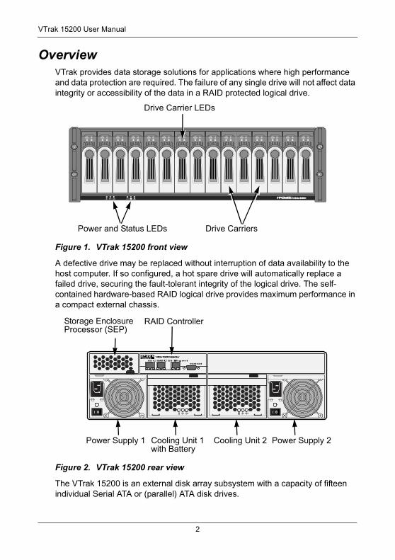
OverviewVTrak provides data storage solutions for applications where high performance and data protection are required. The failure of any single drive will not affect data integrity or accessibility of the data in a RAID protected logical drive.
Figure 1. VTrak 15200 front view
A defective drive may be replaced without interruption of data availability to the host computer. If so configured, a hot spare drive will automatically replace a failed drive, securing the fault-tolerant integrity of the logical drive. The self-contained hardware-based RAID logical drive provides maximum performance in a compact external chassis.
Figure 2. VTrak 15200 rear view
The VTrak 15200 is an external disk array subsystem with a capacity of fifteen individual Serial ATA or (parallel) ATA disk drives.
PROMISEVTrak 15200
Drive Carrier LEDs
Power and Status LEDs Drive Carriers
iSCSI 1iSCSI 2MgmtIOIOI
PROMISETECHNOLOGY, INC.
VTrak 15200 Controller
Storage EnclosureProcessor (SEP)
RAID Controller
Power Supply 1 Cooling Unit 1with Battery
Power Supply 2Cooling Unit 2
2
Chapter 1: Introduction
The two-port iSCSI interface provides compatibility with any system that has an iSCSI interface. No vendor unique commands are required for the operation of the VTrak subsystem.
Architectural Description The VTrak 15200 is a Direct Attached Storage (DAS) subsystem that can also function in a Storage Area Network (SAN). It consists of 15 disk drive bays, a 3U enclosure with mid-plane, RAID controller, power and cooling units, and enclosure processor all in one cable-less chassis design. Multiple fans and power supplies provide redundancy to ensure continued usage during component failure. The RAID controller is hardware based and controls all logical drive functions transparently to the host system. VTrak appears to the computer’s operating system as a standard SCSI drive or drives.
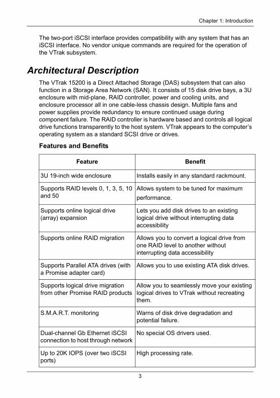
Features and Benefits
Feature Benefit
3U 19-inch wide enclosure Installs easily in any standard rackmount.
Supports RAID levels 0, 1, 3, 5, 10 and 50
Allows system to be tuned for maximum
performance.
Supports online logical drive (array) expansion
Lets you add disk drives to an existing logical drive without interrupting data accessibility
Supports online RAID migration Allows you to convert a logical drive from one RAID level to another without interrupting data accessibility
Supports Parallel ATA drives (with a Promise adapter card)
Allows you to use existing ATA disk drives.
Supports logical drive migration from other Promise RAID products
Allow you to seamlessly move your existing logical drives to VTrak without recreating them.
S.M.A.R.T. monitoring Warns of disk drive degradation and potential failure.
Dual-channel Gb Ethernet iSCSI connection to host through network
No special OS drivers used.
Up to 20K IOPS (over two iSCSI ports)
High processing rate.
3
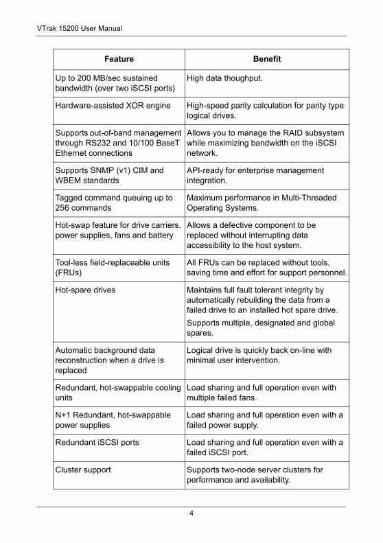
VTrak 15200 User Manual
Up to 200 MB/sec sustained bandwidth (over two iSCSI ports)
High data thoughput.
Hardware-assisted XOR engine High-speed parity calculation for parity type logical drives.
Supports out-of-band management through RS232 and 10/100 BaseT Ethernet connections
Allows you to manage the RAID subsystem while maximizing bandwidth on the iSCSI network.
Supports SNMP (v1) CIM and WBEM standards
API-ready for enterprise management integration.
Tagged command queuing up to 256 commands
Maximum performance in Multi-Threaded Operating Systems.
Hot-swap feature for drive carriers, power supplies, fans and battery
Allows a defective component to be replaced without interrupting data accessibility to the host system.
Tool-less field-replaceable units (FRUs)
All FRUs can be replaced without tools, saving time and effort for support personnel.
Hot-spare drives Maintains full fault tolerant integrity by automatically rebuilding the data from a failed drive to an installed hot spare drive.
Supports multiple, designated and global spares.
Automatic background data reconstruction when a drive is replaced
Logical drive is quickly back on-line with minimal user intervention.
Redundant, hot-swappable cooling units
Load sharing and full operation even with multiple failed fans.
N+1 Redundant, hot-swappable power supplies
Load sharing and full operation even with a failed power supply.
Redundant iSCSI ports Load sharing and full operation even with a failed iSCSI port.
Cluster support Supports two-node server clusters for performance and availability.
Feature Benefit
4
Chapter 1: Introduction
SpecificationsDrive Capacity: 15 SATA and PATA disk drives (3.5" x 1" form factor only)
External I/O Ports: Dual iSCSI Gb Ethernet connections
Sustained Throughput: Up to 200 MBps (over two iSCSI ports)
Sustained I/Os: Up to 20,000 I/Os per second
Data Cache: Up to 512MB predictive data cache with automatic write cache destaging and 72-hour battery backup protection (256 MB, standard)
Supported RAID Levels:
Any combination of these RAID levels can exist at once on separate logical drives. See page 189 for more information on RAID.
RAID Flexibility: Configurable RAID stripe size – 4,8,16,32 or 64 sectors per disk.
Rebuild priority tuning: Adjustment of minimum I/O reserved for server use during rebuild.
Hot-spares: Multiple global and designated hot spares.
Maximum Disks & LUNs: 15 in any combination of RAID levels and drive types.
Supported Disk Interfaces: Serial ATA (SATA), Parallel ATA (with optional Promise adapter).
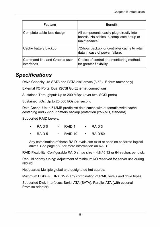
Complete cable-less design All components easily plug directly into boards. No cables to complicate setup or maintenance.
Cache battery backup 72-hour backup for controller cache to retain data in case of power failure.
Command-line and Graphic-user interfaces
Choice of control and monitoring methods for greater flexibility.
• RAID 0 • RAID 1 • RAID 3
• RAID 5 • RAID 10 • RAID 50
Feature Benefit
5
VTrak 15200 User Manual
Supported Operating Systems:
Current: 8 A @ 100 VAC; 4 A @ 200 VAC (max. rating with two power cords)
Power Consumption: 440 watts
Power Supply: Dual 500W, 100–240 VAC auto-ranging, 50–60 Hz, dual hot swap and redundant with PFC, N+1 design
Thermal Output: 1590 BTU/hour (max current)
Operating Temperature: 41° to 104°F (5° to 40°C)
Non-operational Temperature: -40° to 140°F (-40° to 60°C)
Relative Humidity: Maximum 90%
Vibration: Random, 0.21 grms, 5 to 500Hz, 30Mins, X, Y, Z axis
Management Tools: WebPAM Professional, Command Line Utility
Management Interfaces: Ethernet, RS232 (Serial)
Management Protocols: SNMP, SSL, WBEM, Telnet
Notification: Email, audible, and visible alarms
Dimensions: Height, 5.0 in (12.7 cm); Width, 17.6 in (44.8 cm); Depth, 26.0 in (66.0 cm)
Weight: 66 lbs (30 Kg) without drives; Approximately 84 lbs (38 Kg) with 15 drives installed
Safety Certifications: CE, FCC Class A, BSMI, VCCi, cUL, TUV, MIC
Limited Warranty: 3 Years (See page 227 for details)
FCC StatementThis device complies with Part 15 of the FCC Rules. Operation is subject to the following two conditions: (1) this device may not cause harmful interference, and (2) this device must accept any interference received, including interference that may cause undesired operation.
• Windows 2000 • Windows 2003
• RedHat Linux • SuSE Linux
6
Chapter 2: Installation• Unpack the VTrak storage subsystem (below)
• Mount VTrak 15200 in a rack (page 8)
• Install disk drives (page 9)
• Set Up Network Connections (page 15)
• Set Up Serial Connections (page 17)
• Connect the Power (page 18)
• Set IP Address with the CLU (page 20)
• Set up Telnet Connection (page 23)
• Install WebPAM PRO (page 25)
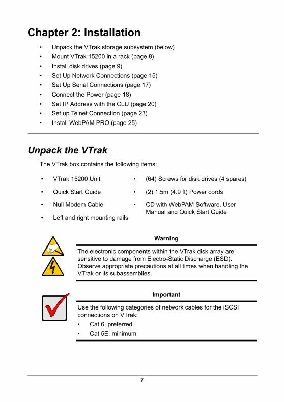
Unpack the VTrak The VTrak box contains the following items:
• VTrak 15200 Unit • (64) Screws for disk drives (4 spares)
• Quick Start Guide • (2) 1.5m (4.9 ft) Power cords
• Null Modem Cable • CD with WebPAM Software, User Manual and Quick Start Guide
• Left and right mounting rails
Warning
The electronic components within the VTrak disk array are sensitive to damage from Electro-Static Discharge (ESD). Observe appropriate precautions at all times when handling the VTrak or its subassemblies.
Important
Use the following categories of network cables for the iSCSI connections on VTrak:
• Cat 6, preferred
• Cat 5E, minimum
7
VTrak 15200 User Manual
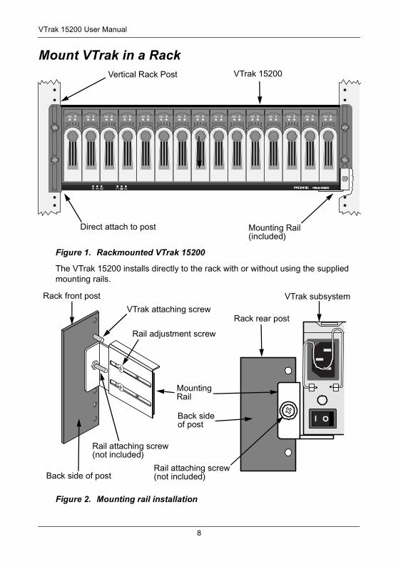
Mount VTrak in a Rack
Figure 1. Rackmounted VTrak 15200
The VTrak 15200 installs directly to the rack with or without using the supplied mounting rails.
Figure 2. Mounting rail installation
PROMISE VTrak 15200
Vertical Rack Post
Direct attach to post
VTrak 15200
Mounting Rail(included)
VTrak attaching screw
Back side of post
Rack front post
Rail attaching screw(not included)
Rail adjustment screw
MountingRail
Rail attaching screw(not included)
Back sideof post
Rack rear post
VTrak subsystem
8
Chapter 2: Installation
If you plan to use the mounting rails, follow this procedure to install them:
1. Attach one end of the rail to the back side of the rack’s front post.
2. Reposition the adjusting screws as needed to fit the rail to the rack properly.
3. Attach the other end of the rail to the back side of the rack’s rear post.
4. Repeat steps 1 through 3 to attach the other rail.
5. Square the rails in the rack and tighten the attaching screws.
6. Set the VTrak onto the rails.
7. Attach the VTrak to the rack’s front posts with the screws provided.
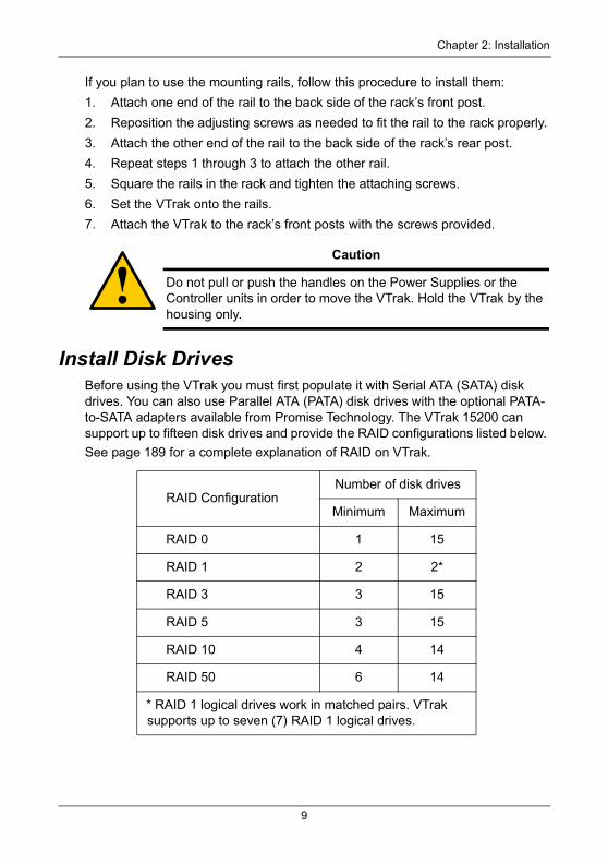
Install Disk Drives Before using the VTrak you must first populate it with Serial ATA (SATA) disk drives. You can also use Parallel ATA (PATA) disk drives with the optional PATA-to-SATA adapters available from Promise Technology. The VTrak 15200 can support up to fifteen disk drives and provide the RAID configurations listed below.
See page 189 for a complete explanation of RAID on VTrak.
Caution
Do not pull or push the handles on the Power Supplies or the Controller units in order to move the VTrak. Hold the VTrak by the housing only.
RAID ConfigurationNumber of disk drives
Minimum Maximum
RAID 0 1 15
RAID 1 2 2*
RAID 3 3 15
RAID 5 3 15
RAID 10 4 14
RAID 50 6 14
* RAID 1 logical drives work in matched pairs. VTrak supports up to seven (7) RAID 1 logical drives.
9
VTrak 15200 User Manual
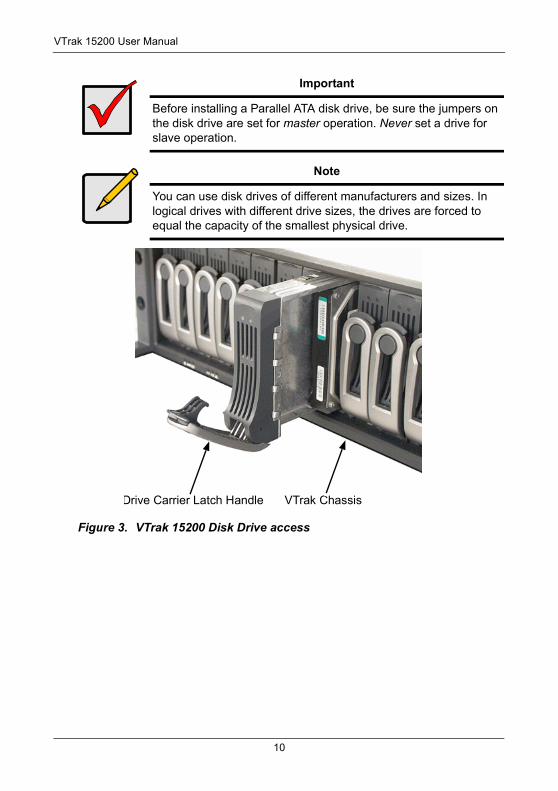
Figure 3. VTrak 15200 Disk Drive access
Important
Before installing a Parallel ATA disk drive, be sure the jumpers on the disk drive are set for master operation. Never set a drive for slave operation.
Note
You can use disk drives of different manufacturers and sizes. In logical drives with different drive sizes, the drives are forced to equal the capacity of the smallest physical drive.
VTrak ChassisDrive Carrier Latch Handle
10
Chapter 2: Installation
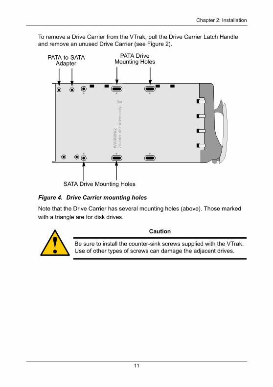
To remove a Drive Carrier from the VTrak, pull the Drive Carrier Latch Handle and remove an unused Drive Carrier (see Figure 2).
Figure 4. Drive Carrier mounting holes
Note that the Drive Carrier has several mounting holes (above). Those marked
with a triangle are for disk drives.
Caution
Be sure to install the counter-sink screws supplied with the VTrak. Use of other types of screws can damage the adjacent drives.
PATA-to-SATA Adapter
SATA Drive Mounting Holes
PATA DriveMounting Holes
11
VTrak 15200 User Manual
Serial ATA Disk Drives
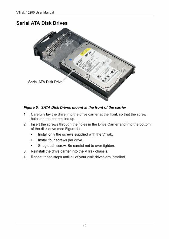
Figure 5. SATA Disk Drives mount at the front of the carrier
1. Carefully lay the drive into the drive carrier at the front, so that the screw holes on the bottom line up.
2. Insert the screws through the holes in the Drive Carrier and into the bottom of the disk drive (see Figure 4).
• Install only the screws supplied with the VTrak.
• Install four screws per drive.
• Snug each screw. Be careful not to over tighten.
3. Reinstall the drive carrier into the VTrak chassis.
4. Repeat these steps until all of your disk drives are installed.
Serial ATA Disk Drive
12
Chapter 2: Installation
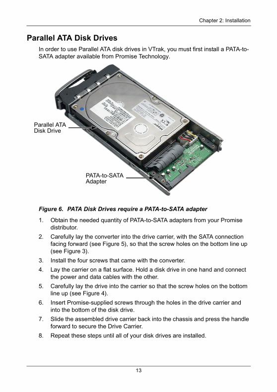
Parallel ATA Disk DrivesIn order to use Parallel ATA disk drives in VTrak, you must first install a PATA-to-SATA adapter available from Promise Technology.
Figure 6. PATA Disk Drives require a PATA-to-SATA adapter
1. Obtain the needed quantity of PATA-to-SATA adapters from your Promise distributor.
2. Carefully lay the converter into the drive carrier, with the SATA connection facing forward (see Figure 5), so that the screw holes on the bottom line up (see Figure 3).
3. Install the four screws that came with the converter.
4. Lay the carrier on a flat surface. Hold a disk drive in one hand and connect the power and data cables with the other.
5. Carefully lay the drive into the carrier so that the screw holes on the bottom line up (see Figure 4).
6. Insert Promise-supplied screws through the holes in the drive carrier and into the bottom of the disk drive.
7. Slide the assembled drive carrier back into the chassis and press the handle forward to secure the Drive Carrier.
8. Repeat these steps until all of your disk drives are installed.
Parallel ATA Disk Drive
PATA-to-SATA Adapter
13
VTrak 15200 User Manual
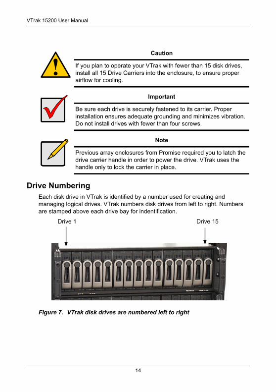
Drive NumberingEach disk drive in VTrak is identified by a number used for creating and managing logical drives. VTrak numbers disk drives from left to right. Numbers are stamped above each drive bay for indentification.
Figure 7. VTrak disk drives are numbered left to right
Caution
If you plan to operate your VTrak with fewer than 15 disk drives, install all 15 Drive Carriers into the enclosure, to ensure proper airflow for cooling.
Important
Be sure each drive is securely fastened to its carrier. Proper installation ensures adequate grounding and minimizes vibration. Do not install drives with fewer than four screws.
Note
Previous array enclosures from Promise required you to latch the drive carrier handle in order to power the drive. VTrak uses the handle only to lock the carrier in place.
Drive 1 Drive 15
14
Chapter 2: Installation
Set Up Network ConnectionsVTrak’s RJ-45 network or Ethernet connectors are on RAID Controller at the back of the unit. There is one management connection and two iSCSI data connections.
The following procedures mention a Host PC. The Host PC is the PC you select to directly control the VTrak through network and serial connections.
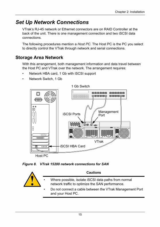
Storage Area NetworkWith this arrangement, both management information and data travel between the Host PC and VTrak over the network. The arrangement requires:
• Network HBA card, 1 Gb with iSCSI support
• Network Switch, 1 Gb
Figure 8. VTrak 15200 network connections for SAN
Cautions
• Where possible, isolate iSCSI data paths from normal network traffic to optimize the SAN performance.
• Do not connect a cable between the VTrak Management Port and your Host PC.
iSCSI 1 iSCSI 2 Mgmt
IO IOI
PROMISETECHNOLOGY, INC.
VTrak 15200 Controller
Host PC
VTrak
1 Gb Switch
ManagementPortiSCSI Ports
iSCSI HBA Card
15
VTrak 15200 User Manual
Connect the following to the network switch using Ethernet cables:
• VTrak management port
• VTrak iSCSI (data) ports
• Host PC
The VTrak management cable has a separate connection to a switch on your regular network.
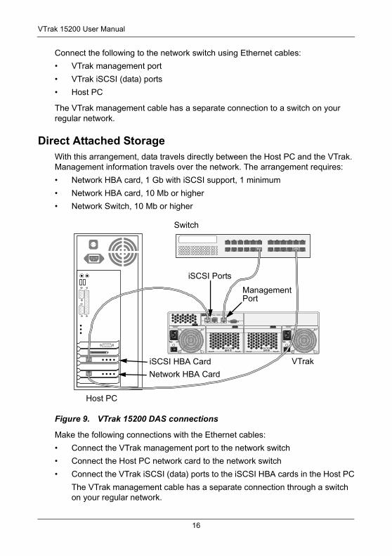
Direct Attached StorageWith this arrangement, data travels directly between the Host PC and the VTrak. Management information travels over the network. The arrangement requires:
• Network HBA card, 1 Gb with iSCSI support, 1 minimum
• Network HBA card, 10 Mb or higher
• Network Switch, 10 Mb or higher
Figure 9. VTrak 15200 DAS connections
Make the following connections with the Ethernet cables:
• Connect the VTrak management port to the network switch
• Connect the Host PC network card to the network switch
• Connect the VTrak iSCSI (data) ports to the iSCSI HBA cards in the Host PC
The VTrak management cable has a separate connection through a switch on your regular network.
iSCSI 1 iSCSI 2 Mgmt
IO IOI
PROMISETECHNOLOGY, INC.
VTrak 15200 Controller
Host PC
VTrak
Switch
iSCSI HBA Card
ManagementPort
iSCSI Ports
Network HBA Card
16
Chapter 2: Installation
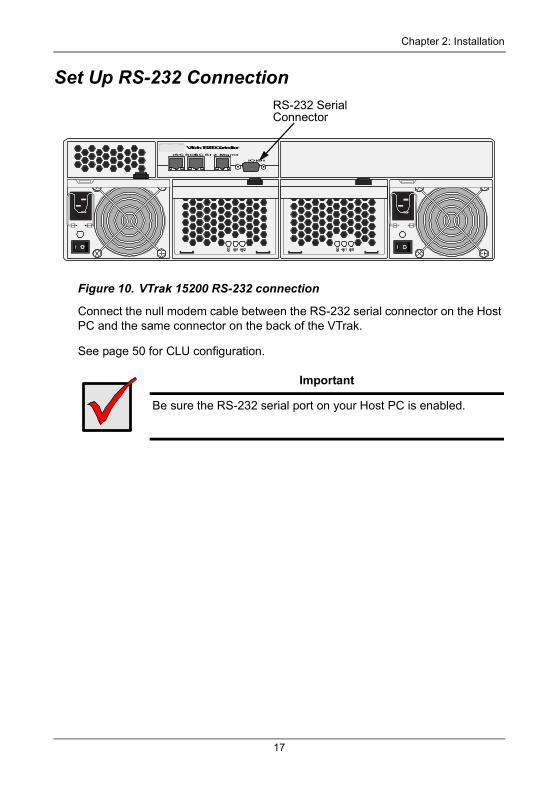
Set Up RS-232 Connection
Figure 10. VTrak 15200 RS-232 connection
Connect the null modem cable between the RS-232 serial connector on the Host PC and the same connector on the back of the VTrak.
See page 50 for CLU configuration.
Important
Be sure the RS-232 serial port on your Host PC is enabled.
iSCSI 1iSCSI 2 Mgmt
IOIOI
PROMISETECHNOLOGY, INC.VTrak 15200 Controller
RS-232 Serial Connector
17
VTrak 15200 User Manual
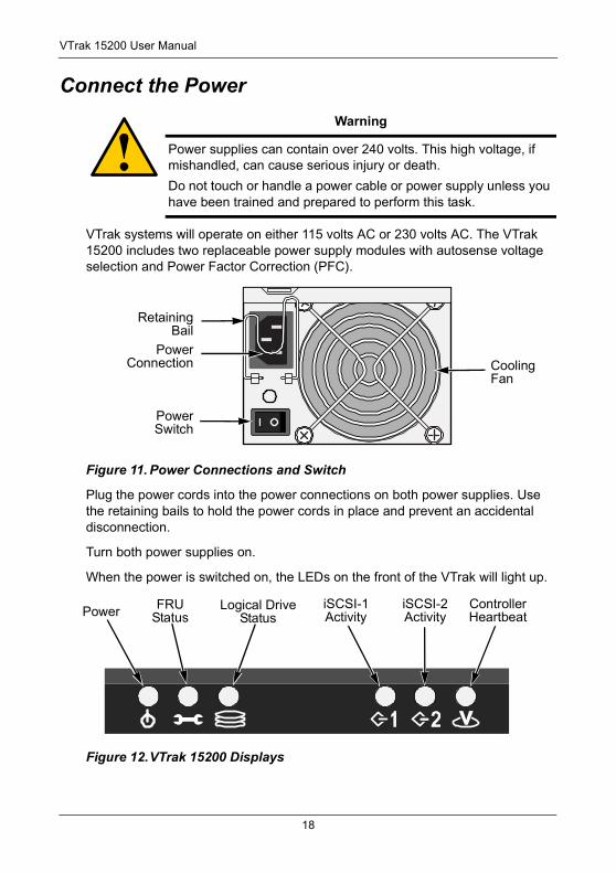
Connect the Power
VTrak systems will operate on either 115 volts AC or 230 volts AC. The VTrak 15200 includes two replaceable power supply modules with autosense voltage selection and Power Factor Correction (PFC).
Figure 11. Power Connections and Switch
Plug the power cords into the power connections on both power supplies. Use the retaining bails to hold the power cords in place and prevent an accidental disconnection.
Turn both power supplies on.
When the power is switched on, the LEDs on the front of the VTrak will light up.
Figure 12.VTrak 15200 Displays
Warning
Power supplies can contain over 240 volts. This high voltage, if mishandled, can cause serious injury or death.
Do not touch or handle a power cable or power supply unless you have been trained and prepared to perform this task.
PowerSwitch
CoolingFan
PowerConnection
RetainingBail
Power FRUStatus
Logical DriveStatus
iSCSI-1Activity
iSCSI-2Activity
ControllerHeartbeat
18
Chapter 2: Installation
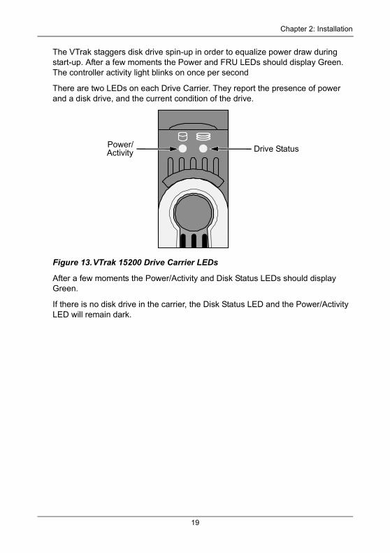
The VTrak staggers disk drive spin-up in order to equalize power draw during start-up. After a few moments the Power and FRU LEDs should display Green. The controller activity light blinks on once per second
There are two LEDs on each Drive Carrier. They report the presence of power and a disk drive, and the current condition of the drive.
Figure 13.VTrak 15200 Drive Carrier LEDs
After a few moments the Power/Activity and Disk Status LEDs should display Green.
If there is no disk drive in the carrier, the Disk Status LED and the Power/Activity LED will remain dark.
Drive StatusPower/Activity
19
VTrak 15200 User Manual
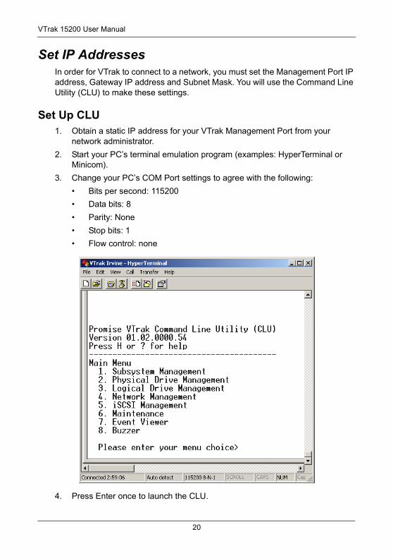
Set IP AddressesIn order for VTrak to connect to a network, you must set the Management Port IP address, Gateway IP address and Subnet Mask. You will use the Command Line Utility (CLU) to make these settings.
Set Up CLU1. Obtain a static IP address for your VTrak Management Port from your
network administrator.
2. Start your PC’s terminal emulation program (examples: HyperTerminal or Minicom).
3. Change your PC’s COM Port settings to agree with the following:
• Bits per second: 115200
• Data bits: 8
• Parity: None
• Stop bits: 1
• Flow control: none
4. Press Enter once to launch the CLU.
20
Chapter 2: Installation
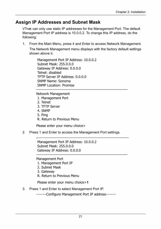
Assign IP Addresses and Subnet MaskVTrak can only use static IP addresses for the Management Port. The default Management Port IP address is 10.0.0.2. To change this IP address, do the following:
1. From the Main Menu, press 4 and Enter to access Network Management.
The Network Management menu displays with the factory default settings shown above it.
Management Port IP Address: 10.0.0.2 Subnet Mask: 255.0.0.0 Gateway IP Address: 0.0.0.0 Telnet: disabled TFTP Server IP Address: 0.0.0.0 SNMP Name: Sonoma SNMP Location: Promise-------------------------------------------------------------------------Network Management 1. Management Port 2. Telnet 3. TFTP Server 4. SNMP 5. Ping R. Return to Previous Menu
Please enter your menu choice>
2. Press 1 and Enter to access the Management Port settings.
-------------------------------------------------------------------------- Management Port IP Address: 10.0.0.2 Subnet Mask: 255.0.0.0 Gateway IP Address: 0.0.0.0-------------------------------------------------------------------------Management Port 1. Management Port IP 2. Subnet Mask 3. Gateway R. Return to Previous Menu
Please enter your menu choice>1
3. Press 1 and Enter to select Management Port IP.
--------Configure Management Port IP address--------
21
VTrak 15200 User Manual
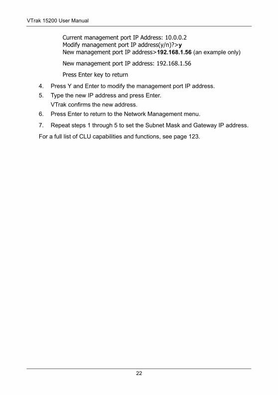
Current management port IP Address: 10.0.0.2Modify management port IP address(y/n)?>yNew management port IP address>192.168.1.56 (an example only)
New management port IP address: 192.168.1.56
Press Enter key to return
4. Press Y and Enter to modify the management port IP address.
5. Type the new IP address and press Enter.
VTrak confirms the new address.
6. Press Enter to return to the Network Management menu.
7. Repeat steps 1 through 5 to set the Subnet Mask and Gateway IP address.
For a full list of CLU capabilities and functions, see page 123.
22
Chapter 2: Installation
Set Up Telnet ConnectionA Telnet connection allows you to access VTrak’s CLU over the network. This allows RAID management over a greater distance from the VTrak itself.
This procedure is required for a Host PC that does not have an available RS-232 serial port.
The CLU screen looks and works exactly the same over a Telnet connection as it does over a serial connection.
Enable Telnet on VTrakVTrak’s Telnet service is disabled by default. Follow these instructions to enable Telnet.
1. Connect the RS-232 cable between the Host PC and VTrak.
Refer to Step 7 on page 20 for the RS-232 settings and setup.
2. Launch HyperTerminal or Minicom.
3. In the CLU Main Menu, select Network Management > Telnet and choose Enable/disable Telnet.
This action enables the Telnet support.
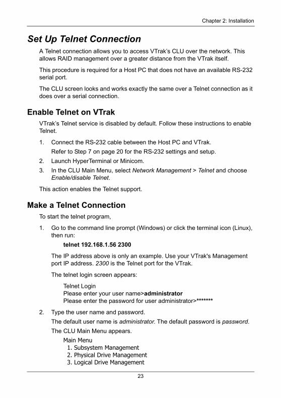
Make a Telnet ConnectionTo start the telnet program,
1. Go to the command line prompt (Windows) or click the terminal icon (Linux), then run:
telnet 192.168.1.56 2300
The IP address above is only an example. Use your VTrak's Management port IP address. 2300 is the Telnet port for the VTrak.
The telnet login screen appears:
Telnet LoginPlease enter your user name>administratorPlease enter the password for user administrator>*******
2. Type the user name and password.
The default user name is administrator. The default password is password.
The CLU Main Menu appears.
Main Menu 1. Subsystem Management 2. Physical Drive Management 3. Logical Drive Management
23
VTrak 15200 User Manual
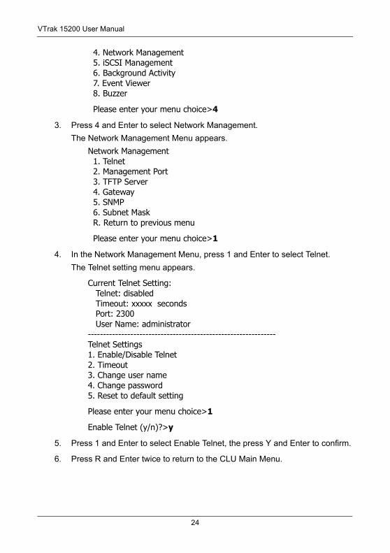
4. Network Management 5. iSCSI Management 6. Background Activity 7. Event Viewer 8. Buzzer
Please enter your menu choice>4
3. Press 4 and Enter to select Network Management.
The Network Management Menu appears.
Network Management 1. Telnet 2. Management Port 3. TFTP Server 4. Gateway 5. SNMP 6. Subnet Mask R. Return to previous menu
Please enter your menu choice>1
4. In the Network Management Menu, press 1 and Enter to select Telnet.
The Telnet setting menu appears.
Current Telnet Setting: Telnet: disabled Timeout: xxxxx seconds Port: 2300 User Name: administrator--------------------------------------------------------------Telnet Settings1. Enable/Disable Telnet2. Timeout3. Change user name4. Change password5. Reset to default setting
Please enter your menu choice>1
Enable Telnet (y/n)?>y
5. Press 1 and Enter to select Enable Telnet, the press Y and Enter to confirm.
6. Press R and Enter twice to return to the CLU Main Menu.
24
Chapter 2: Installation
Install WebPAM PRO Management SoftwareWeb-Based Promise Array Management—Professional (WebPAM PRO) software provides a browser-based graphic user interface used to monitor and manage VTrak and its logical drives. Because it works over your network, it can monitor and control multiple VTraks. WebPAM PRO consists of two components:
• Utility Server – WebPAM PRO software you install
• CIMOM Agent – WebPAM PRO component preinstalled on the VTrak
Utility Server Installation LocationsWhen you install WebPAM PRO, you are installing the Utility Server. There are three possible locations to install Web PAM PRO.
• A networked PC
• A network file server
• The Host PC
When you install WebPAM PRO, follow these rules.
• Install the Utility Server only on a PC or Server that is permanently connected to your network.
• Install only one instance of the Utility Server on your network.
Operating System SupportOn the PC or server where you install WebPAM PRO, Promise Technology recommends:
• Windows 2000
• Windows 2003
• RedHat Linux
• SuSE Linux
The Utility Server supports these operating systems. Choose one of them to take full advantage of all the features of WebPAM PRO.
25
VTrak 15200 User Manual
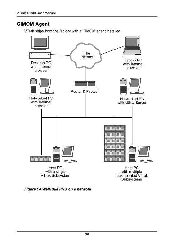
CIMOM AgentVTrak ships from the factory with a CIMOM agent installed.
Figure 14.WebPAM PRO on a network
Desktop PCwith Internet
browser
Laptop PCwith Internet
browser
TheInternet
Networked PCwith Internet
browser
Networked PC with Utility Server
Router & Firewall
Host PCwith multiple
rackmounted VTrak Subsystems
Host PCwith a single
VTrak Subsystem
26
Chapter 2: Installation
Internet BrowserTypically an Internet browser comes with your operating system. WebPAM PRO does not include a browser. For computers that will remotely monitor and manage the RAID, the Internet Browser is the only software required.
Your Internet Browser provides the means for you to monitor and configure your Promise RAID products using WebPAM PRO. You can use the most recent versions of either Internet Explorer or Netscape Navigator.
Before you start…1. Obtain the IP addresses of these devices:
• The PC or server where you plan to install WebPAM PRO
• The Management Port(s) of the VTrak(s) you plan to monitor
2. If you currently have either of these on your computer:
• Promise Array Manager (Windows PAM)
• An earlier version of WebPAM
Completely remove them before installing WebPAM PRO. Failure to do so could result in compatibility problems. For uninstall instructions, see page 33.
3. If you are planning to use other applications that rely on JRE or JDK, always install them first before you install WebPAM PRO. WebPAM PRO will use the existing JRE rather than installing a second one.
WebPAM PRO will install JRE 1.4 on your system unless you already have JRE or JDK versions 1.3.0 or 1.4.
27
VTrak 15200 User Manual
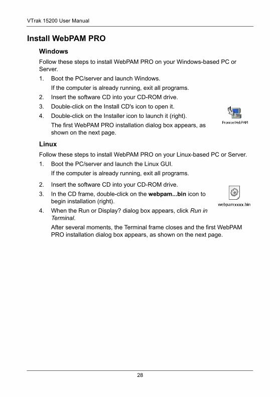
Install WebPAM PROWindowsFollow these steps to install WebPAM PRO on your Windows-based PC or Server.
1. Boot the PC/server and launch Windows.
If the computer is already running, exit all programs.
2. Insert the software CD into your CD-ROM drive.
3. Double-click on the Install CD's icon to open it.
4. Double-click on the Installer icon to launch it (right).
The first WebPAM PRO installation dialog box appears, as shown on the next page.
LinuxFollow these steps to install WebPAM PRO on your Linux-based PC or Server.
1. Boot the PC/server and launch the Linux GUI.
If the computer is already running, exit all programs.
2. Insert the software CD into your CD-ROM drive.
3. In the CD frame, double-click on the webpam...bin icon to begin installation (right).
4. When the Run or Display? dialog box appears, click Run in Terminal.After several moments, the Terminal frame closes and the first WebPAM PRO installation dialog box appears, as shown on the next page.
28
Chapter 2: Installation
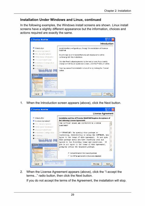
Installation Under Windows and Linux, continuedIn the following examples, the Windows install screens are shown. Linux install screens have a slightly different appearance but the information, choices and actions required are exactly the same.
1. When the Introduction screen appears (above), click the Next button.
2. When the License Agreement appears (above), click the “I accept the terms...” radio button, then click the Next button.
If you do not accept the terms of the Agreement, the installation will stop.
29
VTrak 15200 User Manual
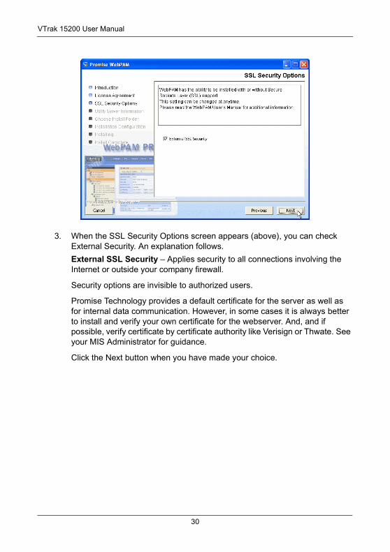
3. When the SSL Security Options screen appears (above), you can check External Security. An explanation follows.
External SSL Security – Applies security to all connections involving the Internet or outside your company firewall.
Security options are invisible to authorized users.
Promise Technology provides a default certificate for the server as well as for internal data communication. However, in some cases it is always better to install and verify your own certificate for the webserver. And, and if possible, verify certificate by certificate authority like Verisign or Thwate. See your MIS Administrator for guidance.
Click the Next button when you have made your choice.
30
Chapter 2: Installation
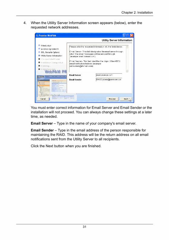
4. When the Utility Server Information screen appears (below), enter the requested network addresses.
You must enter correct information for Email Server and Email Sender or the installation will not proceed. You can always change these settings at a later time, as needed.
Email Server – Type in the name of your company's email server.
Email Sender – Type in the email address of the person responsible for maintaining the RAID. This address will be the return address on all email notifications sent from the Utility Server to all recipients.
Click the Next button when you are finished.
31
VTrak 15200 User Manual
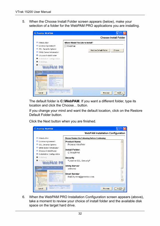
5. When the Choose Install Folder screen appears (below), make your selection of a folder for the WebPAM PRO applications you are installing.
The default folder is C:\WebPAM. If you want a different folder, type its location and click the Choose... button.
If you change your mind and want the default location, click on the Restore Default Folder button.
Click the Next button when you are finished.
6. When the WebPAM PRO Installation Configuration screen appears (above), take a moment to review your choice of install folder and the available disk space on the target hard drive.
32
Chapter 2: Installation
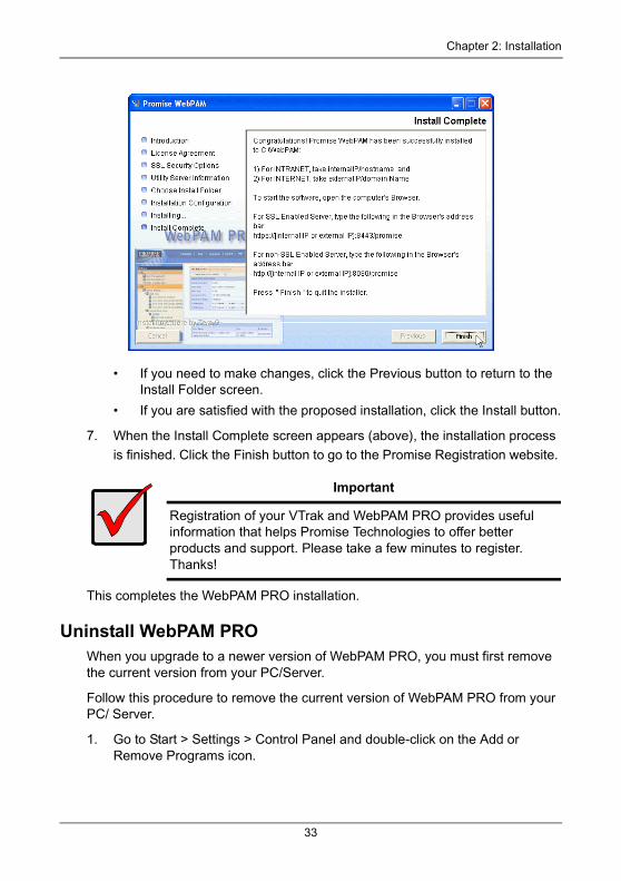
• If you need to make changes, click the Previous button to return to the Install Folder screen.
• If you are satisfied with the proposed installation, click the Install button.
7. When the Install Complete screen appears (above), the installation process
is finished. Click the Finish button to go to the Promise Registration website.
This completes the WebPAM PRO installation.
Uninstall WebPAM PROWhen you upgrade to a newer version of WebPAM PRO, you must first remove the current version from your PC/Server.
Follow this procedure to remove the current version of WebPAM PRO from your PC/ Server.
1. Go to Start > Settings > Control Panel and double-click on the Add or Remove Programs icon.
Important
Registration of your VTrak and WebPAM PRO provides useful information that helps Promise Technologies to offer better products and support. Please take a few minutes to register. Thanks!
33
VTrak 15200 User Manual
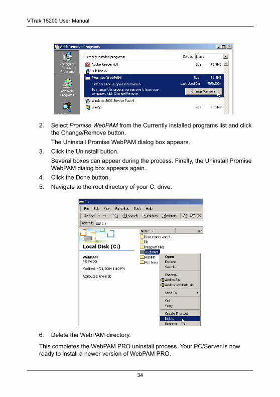
2. Select Promise WebPAM from the Currently installed programs list and click the Change/Remove button.
The Uninstall Promise WebPAM dialog box appears.
3. Click the Uninstall button.
Several boxes can appear during the process. Finally, the Uninstall Promise WebPAM dialog box appears again.
4. Click the Done button.
5. Navigate to the root directory of your C: drive.
6. Delete the WebPAM directory.
This completes the WebPAM PRO uninstall process. Your PC/Server is now ready to install a newer version of WebPAM PRO.
34
Chapter 3: Setup• iSCSI Initiator (below)
• VTrak Setup with WebPAM PRO (page 36)
• VTrak Setup with the CLU (page 50)
After installation, the next step is to configure VTrak. You can do this with WebPAM PRO or the Command Line Utility (CLU), whichever you prefer.
This Chapter only deals with basic functions needed to setup a new VTrak. For a full discussion of VTrak functions, refer to page 123 and page 61.
iSCSI Initiator RequiredTo access VTrak15200 you must have the iSCSI Initiator installed on the Host PC. You can choose a hardware or a software iSCSI Initiator.
HardwareUse a Gigabit Ethernet network interface card (GbE NIC) with hardware-based iSCSI initiator from such vendors as:
• QLogic (QLA4010C)
• Intel (Pro/1000T IP)
• Alacretech (100x1 TNIC)
Follow the installation and setup instructions that come with the card.
SoftwareUse a software-based iSCSI initiator in combination with a GbE NIC. If you choose a Microsoft software iSCSI initiator, download it from:
http://www.microsoft.com/windowsserversystem/storage/technologies/iscsi/default.mspx
Install the iSCSI initiator on your system then proceed with the following steps.
1. Go to Start > Settings > Control Panel and double-click on iSCSI Initiator. The iSCSI Initiator Properties dialog box displays.
2. On the Target Portals tab, click on Add button.
3. In the Add Target Portal dialog box, type in the IP address of one of the VTrak’s iSCSI ports and click OK.
4. Go to Available Targets tab. The iSCSI name should appear. It looks like:
iqn.1994-12.com.promise.vtrak15200.20.00.00.01.55.00.xx.xx.
35
VTrak 15200 User Manual
Highlight this name and click the Logon button. Click OK on the confirmation dialog box.
5. Go to Active Sessions tab. The status of selected iSCSI name should display connected.
6. Click OK button on iSCSI Initiator Properties dialog box to close it.
7. To logoff from Vtrak15200, bring up Microsoft iSCSI Initiator again. Go to the Active Sessions tab and click the Log Off button.
For more information on setting up iSCSI, see page 41 and page 51.
VTrak Setup with WebPAM PROSet up with WebPAM consists of the following steps:
1. Log-in to WebPAM (below)
2. Add a Subsystem (page 39)
3. Access a Subsystem (page 40)
4. iSCSI Configuration (page 41)
5. Create a Logical Drive (page 47)
6. Log-out of WebPAM PRO (page 49)
7. Internet connection using WebPAM PRO (page 49)
Log-in to WebPAM PRO1. Launch your Browser.
2. In the Browser address field, type in the IP address of the Host PC or Server where you installed WebPAM PRO, as explained below.
Note that the IP address shown below is only an example. The IP address you type into your browser will be different
If you chose the External Security option during WebPAM PRO installation (see page 30), use the Secure connection. Otherwise use the Regular connection.
Regular Connection• WebPAM PRO uses an HTTP connection. . . . . . . . . . . . . . . . .http://
• Enter the Utility Server’s IP address . . . . . . . . . . . . . .192.168.1.118
• Enter the Port number . . . . . . . . . . . . . . . . . . . . . . . . . . . . . . . :8080
• Add promise to launch WebPAM PRO . . . . . . . . . . . . . . . . /promise
Together, your entry looks like this:
http://192.168.1.118:8080/promise
36
Chapter 3: Setup
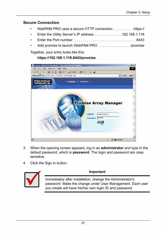
Secure Connection• WebPAM PRO uses a secure HTTP connection . . . . . . . . . . .https://
• Enter the Utility Server’s IP address . . . . . . . . . . . . . .192.168.1.118
• Enter the Port number . . . . . . . . . . . . . . . . . . . . . . . . . . . . . . . :8443
• Add promise to launch WebPAM PRO . . . . . . . . . . . . . . . . /promise
Together, your entry looks like this:
https://192.168.1.118:8443/promise.
3. When the opening screen appears, log in as administrator and type in the default password, which is password. The login and password are case sensitive.
4. Click the Sign in button.
Important
Immediately after installation, change the Administrator's password. Make the change under User Management. Each user you create will have his/her own login ID and password.
37
VTrak 15200 User Manual
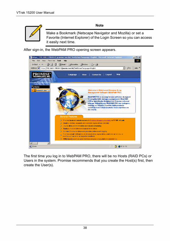
After sign-in, the WebPAM PRO opening screen appears.
The first time you log in to WebPAM PRO, there will be no Hosts (RAID PCs) or Users in the system. Promise recommends that you create the Host(s) first, then create the User(s).
Note
Make a Bookmark (Netscape Navigator and Mozilla) or set a Favorite (Internet Explorer) of the Login Screen so you can access it easily next time.
38
Chapter 3: Setup
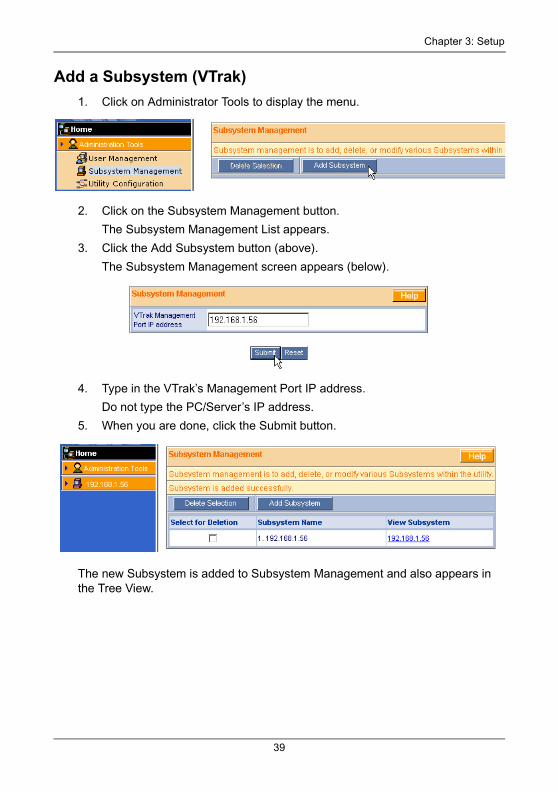
Add a Subsystem (VTrak)1. Click on Administrator Tools to display the menu.
2. Click on the Subsystem Management button.
The Subsystem Management List appears.
3. Click the Add Subsystem button (above).
The Subsystem Management screen appears (below).
4. Type in the VTrak’s Management Port IP address.
Do not type the PC/Server’s IP address.
5. When you are done, click the Submit button.
The new Subsystem is added to Subsystem Management and also appears in the Tree View.
39
VTrak 15200 User Manual
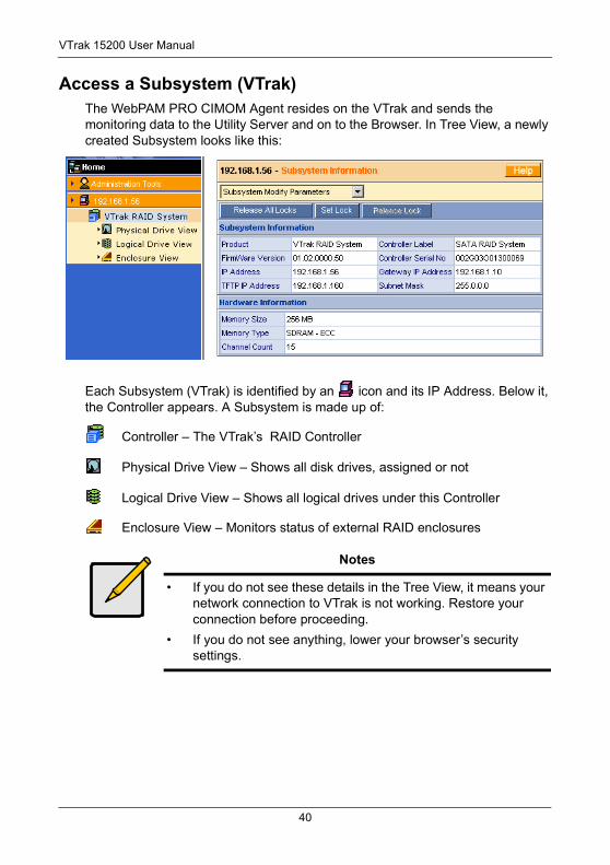
Access a Subsystem (VTrak)The WebPAM PRO CIMOM Agent resides on the VTrak and sends the monitoring data to the Utility Server and on to the Browser. In Tree View, a newly created Subsystem looks like this:
Each Subsystem (VTrak) is identified by an icon and its IP Address. Below it, the Controller appears. A Subsystem is made up of:
Controller – The VTrak’s RAID Controller
Physical Drive View – Shows all disk drives, assigned or not
Logical Drive View – Shows all logical drives under this Controller
Enclosure View – Monitors status of external RAID enclosures
Notes
• If you do not see these details in the Tree View, it means your network connection to VTrak is not working. Restore your connection before proceeding.
• If you do not see anything, lower your browser’s security settings.
40
Chapter 3: Setup
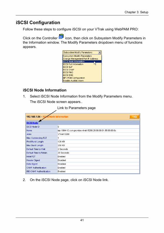
iSCSI ConfigurationFollow these steps to configure iSCSI on your VTrak using WebPAM PRO:
Click on the Controller icon, then click on Subsystem Modify Parameters in the Information window. The Modify Parameters dropdown menu of functions appears.
iSCSI Node Information1. Select iSCSI Node Information from the Modify Parameters menu.
The iSCSI Node screen appears..
2. On the iSCSI Node page, click on iSCSI Node link.
Link to Parameters page
41
VTrak 15200 User Manual
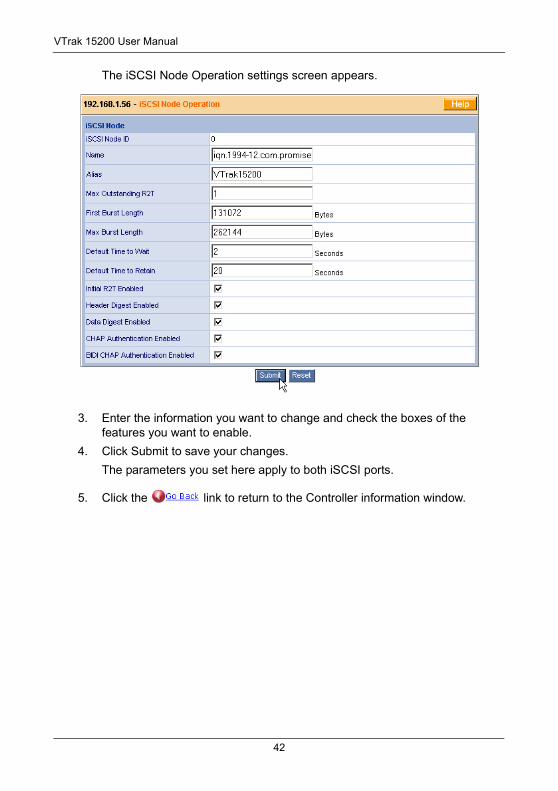
The iSCSI Node Operation settings screen appears.
3. Enter the information you want to change and check the boxes of the features you want to enable.
4. Click Submit to save your changes.
The parameters you set here apply to both iSCSI ports.
5. Click the link to return to the Controller information window.
42
Chapter 3: Setup
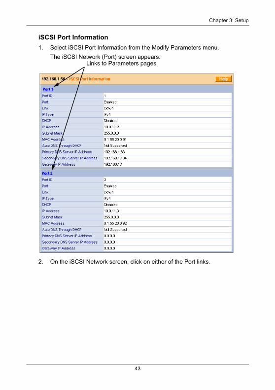
iSCSI Port Information1. Select iSCSI Port Information from the Modify Parameters menu.
The iSCSI Network (Port) screen appears.
2. On the iSCSI Network screen, click on either of the Port links.
Links to Parameters pages
43
VTrak 15200 User Manual
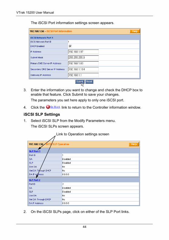
The iSCSI Port information settings screen appears.
3. Enter the information you want to change and check the DHCP box to enable that feature. Click Submit to save your changes.
The parameters you set here apply to only one iSCSI port.
4. Click the link to return to the Controller information window.
iSCSI SLP Settings1. Select iSCSI SLP from the Modify Parameters menu.
The iSCSI SLPs screen appears.
2. On the iSCSI SLPs page, click on either of the SLP Port links.
Link to Operation settings screen
44
Chapter 3: Setup
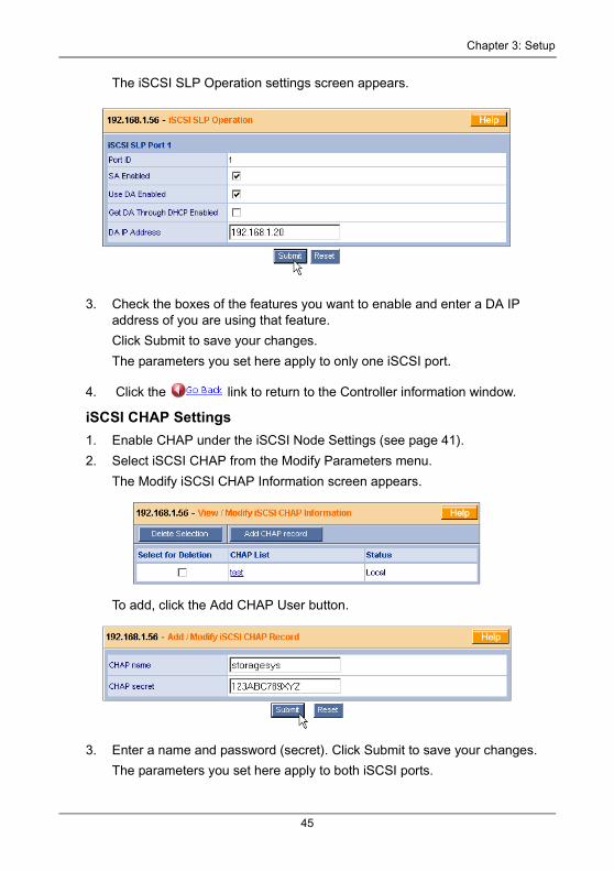
The iSCSI SLP Operation settings screen appears.
3. Check the boxes of the features you want to enable and enter a DA IP address of you are using that feature.
Click Submit to save your changes.
The parameters you set here apply to only one iSCSI port.
4. Click the link to return to the Controller information window.
iSCSI CHAP Settings1. Enable CHAP under the iSCSI Node Settings (see page 41).
2. Select iSCSI CHAP from the Modify Parameters menu.
The Modify iSCSI CHAP Information screen appears.
To add, click the Add CHAP User button.
3. Enter a name and password (secret). Click Submit to save your changes.
The parameters you set here apply to both iSCSI ports.
45
VTrak 15200 User Manual
Click the link to return to the Controller information window.
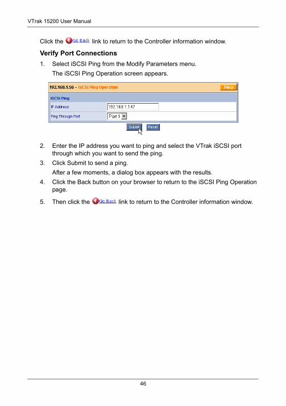
Verify Port Connections1. Select iSCSI Ping from the Modify Parameters menu.
The iSCSI Ping Operation screen appears.
2. Enter the IP address you want to ping and select the VTrak iSCSI port through which you want to send the ping.
3. Click Submit to send a ping.
After a few moments, a dialog box appears with the results.
4. Click the Back button on your browser to return to the iSCSI Ping Operation page.
5. Then click the link to return to the Controller information window.
46
Chapter 3: Setup
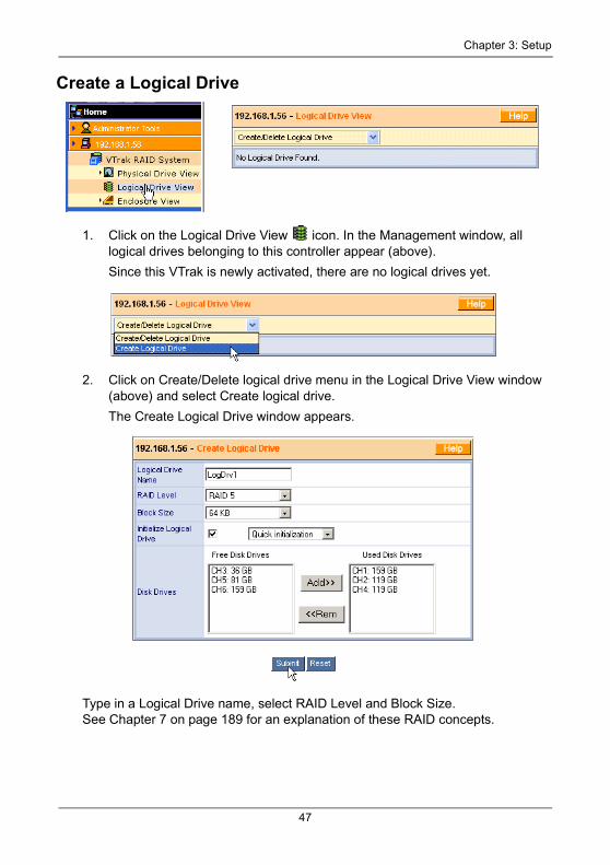
Create a Logical Drive
1. Click on the Logical Drive View icon. In the Management window, all logical drives belonging to this controller appear (above).
Since this VTrak is newly activated, there are no logical drives yet.
2. Click on Create/Delete logical drive menu in the Logical Drive View window (above) and select Create logical drive.
The Create Logical Drive window appears.
Type in a Logical Drive name, select RAID Level and Block Size. See Chapter 7 on page 189 for an explanation of these RAID concepts.
47
VTrak 15200 User Manual
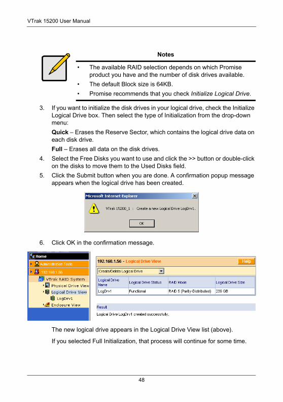
3. If you want to initialize the disk drives in your logical drive, check the Initialize Logical Drive box. Then select the type of Initialization from the drop-down menu:
Quick – Erases the Reserve Sector, which contains the logical drive data on each disk drive.
Full – Erases all data on the disk drives.
4. Select the Free Disks you want to use and click the >> button or double-click on the disks to move them to the Used Disks field.
5. Click the Submit button when you are done. A confirmation popup message appears when the logical drive has been created.
6. Click OK in the confirmation message.
The new logical drive appears in the Logical Drive View list (above).
If you selected Full Initialization, that process will continue for some time.
Notes
• The available RAID selection depends on which Promise product you have and the number of disk drives available.
• The default Block size is 64KB.
• Promise recommends that you check Initialize Logical Drive.
48
Chapter 3: Setup
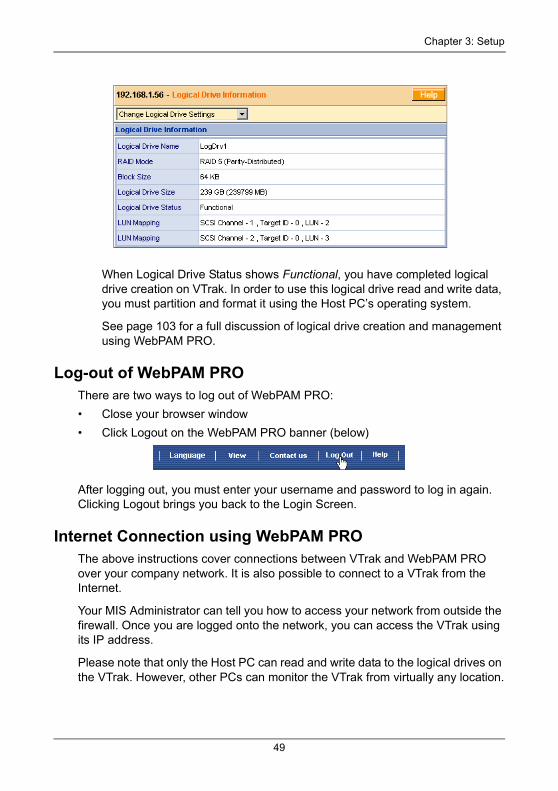
When Logical Drive Status shows Functional, you have completed logical drive creation on VTrak. In order to use this logical drive read and write data, you must partition and format it using the Host PC’s operating system.
See page 103 for a full discussion of logical drive creation and management using WebPAM PRO.
Log-out of WebPAM PROThere are two ways to log out of WebPAM PRO:
• Close your browser window
• Click Logout on the WebPAM PRO banner (below)
After logging out, you must enter your username and password to log in again. Clicking Logout brings you back to the Login Screen.
Internet Connection using WebPAM PROThe above instructions cover connections between VTrak and WebPAM PRO over your company network. It is also possible to connect to a VTrak from the Internet.
Your MIS Administrator can tell you how to access your network from outside the firewall. Once you are logged onto the network, you can access the VTrak using its IP address.
Please note that only the Host PC can read and write data to the logical drives on the VTrak. However, other PCs can monitor the VTrak from virtually any location.
49
VTrak 15200 User Manual
VTrak Setup with the CLU
Set up with the CLU consists of the following steps:
1. CLU Connection (below)
2. iSCSI Configuration (page 51)
3. Create a Logical Drive
• Automatically (page 57)
• Manually (page 58)
4. Exit the CLU (page 60)
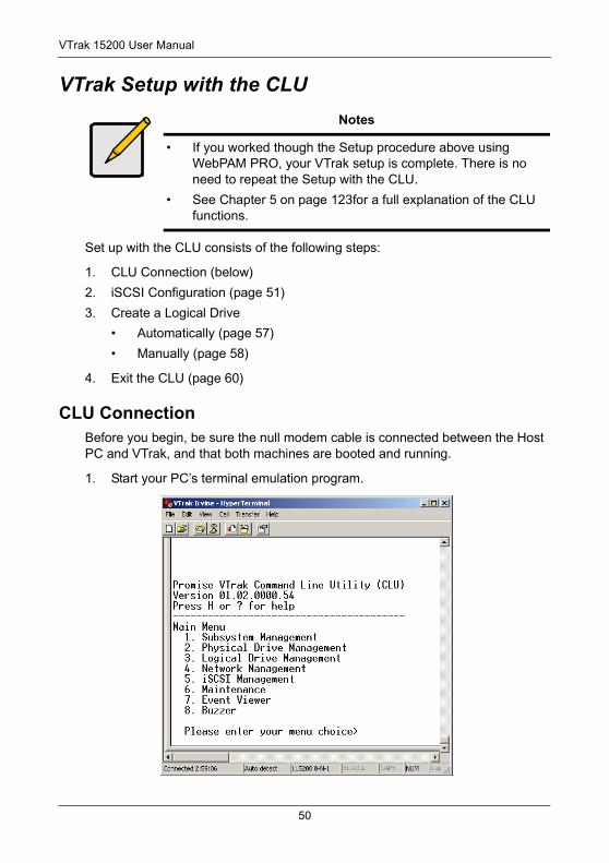
CLU ConnectionBefore you begin, be sure the null modem cable is connected between the Host PC and VTrak, and that both machines are booted and running.
1. Start your PC’s terminal emulation program.
Notes
• If you worked though the Setup procedure above using WebPAM PRO, your VTrak setup is complete. There is no need to repeat the Setup with the CLU.
• See Chapter 5 on page 123for a full explanation of the CLU functions.
50
Chapter 3: Setup
2. Press Enter once to launch the CLU.
iSCSI ConfigurationConfigure iSCSI on your VTrak using the CLU
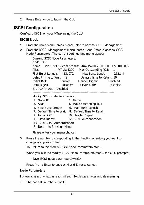
iSCSI Node1. From the Main menu, press 5 and Enter to access iSCSI Management.
2. From the iSCSI Management menu, press 1 and Enter to access iSCSI Node Parameters. The current settings and menu appear:
Current iSCSI Node Parameters:Node ID: 0Name: iqn.1994-12.com.promise.vtrak15200.20.00.00.01.55.00.00.55Alias: VTrak15200 Max Outstanding R2T: 1First Burst Length: 131072 Max Burst Length: 262144Default Time to Wait: 2 Default Time to Retain: 20Initial R2T: Enabled Header Digest: DisabledData Digest: Disabled CHAP Auth: DisabledBIDI CHAP Auth: Disabled-------------------------------------------------------------------------Modify iSCSI Node Parameters 1. Node ID 2. Name 3. Alias 4. Max Outstanding R2T 5. First Burst Length 6. Max Burst Length 7. Default Time to Wait 8. Default Time to Retain 9. Initial R2T 10. Header Digest 11. Data Digest 12. CHAP Authentication 13. BIDI CHAP Authentication R. Return to Previous Menu
Please enter your menu choice>
3. Press the number corresponding to the function or setting you want to change and press Enter.
You return to the Modify iSCSI Node Parameters menu.
When you exit the Modify iSCSI Node Parameters menu, the CLU prompts:
Save iSCSI node parameters(y/n)?>
Press Y and Enter to save or N and Enter to cancel.
Node Parameters
Following is a brief explanation of each Node parameter and its meaning.
• The node ID number (0 or 1)
51
VTrak 15200 User Manual
• The node's name. An iSCSI node is identified by its name
• The node's alias. A user-friendly string associated with an iSCSI Node. Not a substitute for the iSCSI Name
• Max outstanding R2T. Sets the maximum number of outstanding ready to transfer PDUs (a number)
• First burst length. Maximum length of an unsolicited data sequence (kb)
• Maximum burst length. Maximum length of a solicited data sequence (kb)
• Maximum number of connections. Initiator and target negotiate the actual number (default is 1, maximum is 65535)
• Default time to wait. After a dropped connection, the number of seconds to wait before attempting to reconnect
• Default time to retain. Number of seconds after time to wait (above) before reassigning outstanding commands
• Initial R2T. Allows initiator to begin sending data to a target without receiving a ready to transfer command.
• Header Digest. Enables the use of Header Digest (CRC)
• Data Digest. Enables the use of a Data Digest (CRC)
• CHAP Authentication. Enables Challenge Handshake Authentication Protocol
• BIDI CHAP Authentication. Enables bi-directional CHAP authentication
A detailed explanation of these iSCSI functions, how and when they are used, and their relationship to one another is beyond the scope of this document. For more information, contact the Internet Engineering Task Force at http://www.itef.org/.
Network Ports1. Press 2 and Enter to access iSCSI Network settings.
iSCSI Network Port Settings 1. Port 1 2. Port 2 R. Return to Previous Menu
Please enter your menu choice>1
2. Press 1 or 2 to select an iSCSI Port then press Enter.
Current iSCSI Port #1 Network Settings:TCP Port Number: 3260DHCP: disabledIP address: 10.0.11.2Subnet Mask: 255.0.0.0Default Gateway: 0.0.0.0
52
Chapter 3: Setup
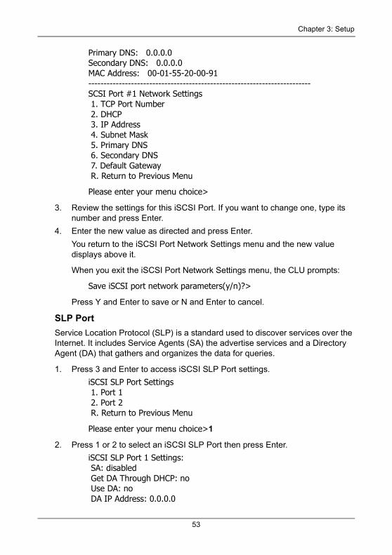
Primary DNS: 0.0.0.0Secondary DNS: 0.0.0.0MAC Address: 00-01-55-20-00-91-------------------------------------------------------------------------SCSI Port #1 Network Settings 1. TCP Port Number 2. DHCP 3. IP Address 4. Subnet Mask 5. Primary DNS 6. Secondary DNS 7. Default Gateway R. Return to Previous Menu
Please enter your menu choice>
3. Review the settings for this iSCSI Port. If you want to change one, type its number and press Enter.
4. Enter the new value as directed and press Enter.
You return to the iSCSI Port Network Settings menu and the new value displays above it.
When you exit the iSCSI Port Network Settings menu, the CLU prompts:
Save iSCSI port network parameters(y/n)?>
Press Y and Enter to save or N and Enter to cancel.
SLP PortService Location Protocol (SLP) is a standard used to discover services over the Internet. It includes Service Agents (SA) the advertise services and a Directory Agent (DA) that gathers and organizes the data for queries.
1. Press 3 and Enter to access iSCSI SLP Port settings.
iSCSI SLP Port Settings 1. Port 1 2. Port 2 R. Return to Previous Menu
Please enter your menu choice>1
2. Press 1 or 2 to select an iSCSI SLP Port then press Enter.
iSCSI SLP Port 1 Settings: SA: disabled Get DA Through DHCP: no Use DA: no DA IP Address: 0.0.0.0
53
VTrak 15200 User Manual
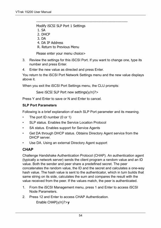
-------------------------------------------------------------------------Modify iSCSI SLP Port 1 Settings 1. SA 2. DHCP 3. DA 4. DA IP Address R. Return to Previous Menu
Please enter your menu choice>
3. Review the settings for this iSCSI Port. If you want to change one, type its number and press Enter.
4. Enter the new value as directed and press Enter.
You return to the iSCSI Port Network Settings menu and the new value displays above it.
When you exit the iSCSI Port Settings menu, the CLU prompts:
Save iSCSI SLP Port new settings(y/n)?>
Press Y and Enter to save or N and Enter to cancel.
SLP Port Parameters
Following is a brief explanation of each SLP Port parameter and its meaning.
• The port ID number (0 or 1)
• SLP status. Enables the Service Location Protocol
• SA status. Enables support for Service Agents
• Get DA through DHCP status. Obtains Directory Agent service from the DHCP server.
• Use DA. Using an external Directory Agent support
CHAPChallenge Handshake Authentication Protocol (CHAP). An authentication agent (typically a network server) sends the client program a random value and an ID value. Both the sender and peer share a predefined secret. The peer concatenates the random value, the ID and the secret and calculates a one-way hash value. The hash value is sent to the authenticator, which in turn builds that same string on its side, calculates the sum and compares the result with the value received from the peer. If the values match, the peer is authenticated.
1. From the iSCSI Management menu, press 1 and Enter to access iSCSI Node Parameters.
2. Press 12 and Enter to access CHAP Authentication.
Enable CHAP(y/n)?>y
54
Chapter 3: Setup
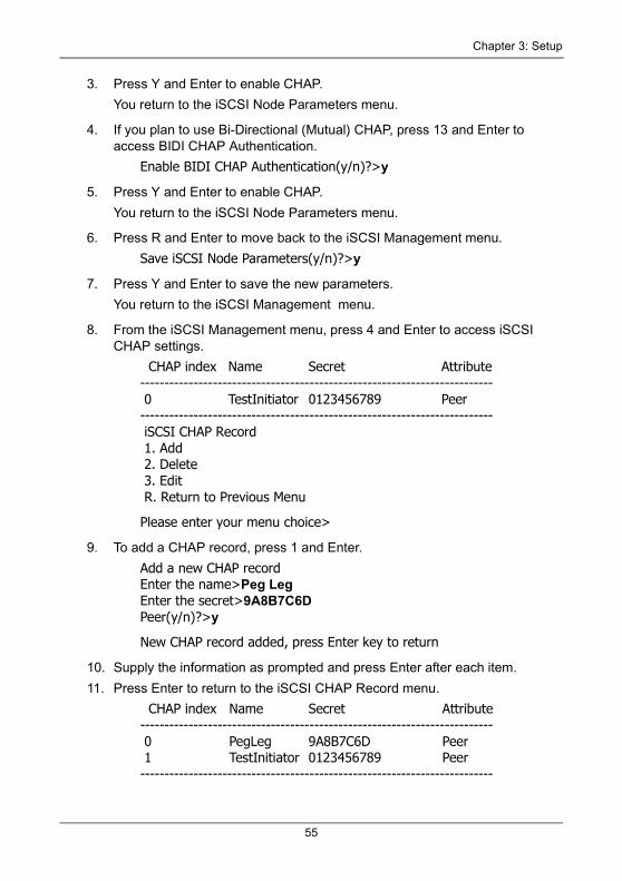
3. Press Y and Enter to enable CHAP.
You return to the iSCSI Node Parameters menu.
4. If you plan to use Bi-Directional (Mutual) CHAP, press 13 and Enter to access BIDI CHAP Authentication.
Enable BIDI CHAP Authentication(y/n)?>y
5. Press Y and Enter to enable CHAP.
You return to the iSCSI Node Parameters menu.
6. Press R and Enter to move back to the iSCSI Management menu.
Save iSCSI Node Parameters(y/n)?>y
7. Press Y and Enter to save the new parameters.
You return to the iSCSI Management menu.
8. From the iSCSI Management menu, press 4 and Enter to access iSCSI CHAP settings.
CHAP index Name Secret Attribute------------------------------------------------------------------------- 0 TestInitiator 0123456789 Peer------------------------------------------------------------------------- iSCSI CHAP Record 1. Add 2. Delete 3. Edit R. Return to Previous Menu
Please enter your menu choice>
9. To add a CHAP record, press 1 and Enter.
Add a new CHAP recordEnter the name>Peg LegEnter the secret>9A8B7C6DPeer(y/n)?>y
New CHAP record added, press Enter key to return
10. Supply the information as prompted and press Enter after each item.
11. Press Enter to return to the iSCSI CHAP Record menu.
CHAP index Name Secret Attribute------------------------------------------------------------------------- 0 PegLeg 9A8B7C6D Peer 1 TestInitiator 0123456789 Peer-------------------------------------------------------------------------
55
VTrak 15200 User Manual
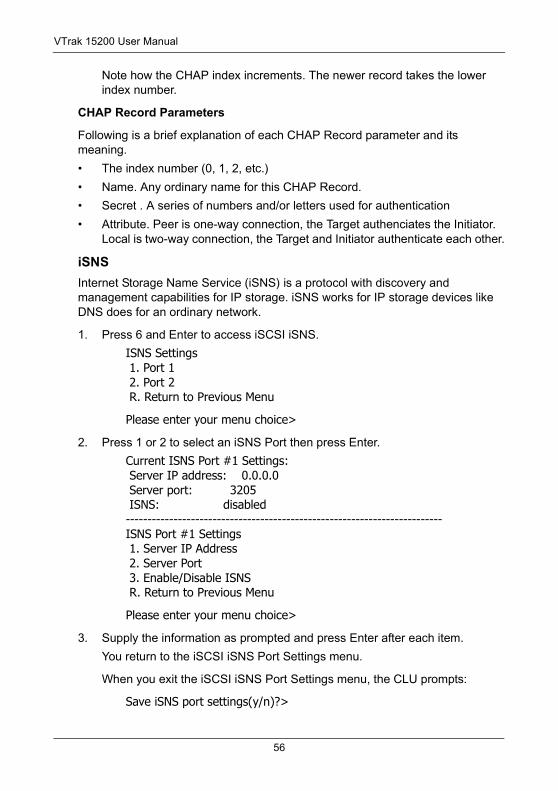
Note how the CHAP index increments. The newer record takes the lower index number.
CHAP Record Parameters
Following is a brief explanation of each CHAP Record parameter and its meaning.
• The index number (0, 1, 2, etc.)
• Name. Any ordinary name for this CHAP Record.
• Secret . A series of numbers and/or letters used for authentication
• Attribute. Peer is one-way connection, the Target authenciates the Initiator. Local is two-way connection, the Target and Initiator authenticate each other.
iSNSInternet Storage Name Service (iSNS) is a protocol with discovery and management capabilities for IP storage. iSNS works for IP storage devices like DNS does for an ordinary network.
1. Press 6 and Enter to access iSCSI iSNS.
ISNS Settings 1. Port 1 2. Port 2 R. Return to Previous Menu
Please enter your menu choice>
2. Press 1 or 2 to select an iSNS Port then press Enter.
Current ISNS Port #1 Settings: Server IP address: 0.0.0.0 Server port: 3205 ISNS: disabled-------------------------------------------------------------------------ISNS Port #1 Settings 1. Server IP Address 2. Server Port 3. Enable/Disable ISNS R. Return to Previous Menu
Please enter your menu choice>
3. Supply the information as prompted and press Enter after each item.
You return to the iSCSI iSNS Port Settings menu.
When you exit the iSCSI iSNS Port Settings menu, the CLU prompts:
Save iSNS port settings(y/n)?>
56
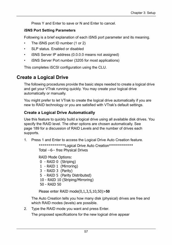
Chapter 3: Setup
Press Y and Enter to save or N and Enter to cancel.
iSNS Port Setting Parameters
Following is a brief explanation of each iSNS port parameter and its meaning.
• The iSNS port ID number (1 or 2)
• SLP status. Enabled or disabled
• iSNS Server IP address (0.0.0.0 means not assigned)
• iSNS Server Port number (3205 for most applications)
This completes iSCSI configuration using the CLU.
Create a Logical DriveThe following procedures provide the basic steps needed to create a logical drive and get your VTrak running quickly. You may create your logical drive automatically or manually.
You might prefer to let VTrak to create the logical drive automatically if you are new to RAID technology or you are satisfied with VTrak’s default settings.
Create a Logical Drive AutomaticallyUse this feature to quickly build a logical drive using all available disk drives. You specify the RAID level. The other options are chosen automatically. See page 189 for a discussion of RAID Levels and the number of drives each supports.
1. Press 1 and Enter to access the Logical Drive Auto Creation feature.
*************Logical Drive Auto Creation************Total --6-- free Physical Drives
RAID Mode Options: 0 - RAID 0 (Striping) 1 - RAID 1 (Mirroring) 3 - RAID 3 (Parity) 5 - RAID 5 (Parity Distributed) 10 - RAID 10 (Striping/Mirroring) 50 - RAID 50
Please enter RAID mode(0,1,3,5,10,50)>50
The Auto Creation tells you how many disk (physical) drives are free and which RAID modes (levels) are possible.
2. Type the RAID mode you want and press Enter.
The proposed specifications for the new logical drive appear
57
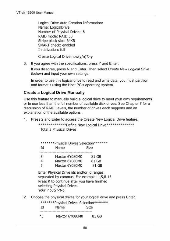
VTrak 15200 User Manual
Logical Drive Auto Creation Information:Name: LogicalDriveNumber of Physical Drives: 6RAID mode: RAID 50Stripe block size: 64KBSMART check: enabledInitialization: full
Create Logical Drive now(y/n)?>y
3. If you agree with the specifications, press Y and Enter.
If you disagree, press N and Enter. Then select Create New Logical Drive (below) and input your own settings.
In order to use this logical drive to read and write data, you must partition and format it using the Host PC’s operating system.
Create a Logical Drive Manually Use this feature to manually build a logical drive to meet your own requirements or to use less than the full number of available disk drives. See Chapter 7 for a discussion of RAID Levels, the number of drives each supports and an explanation of the available options.
1. Press 2 and Enter to access the Create New Logical Drive feature.
**************Define New Logical Drive************** Total 3 Physical Drives
*******Physical Drives Selection******* Id Name Size ---------------------------------------- 3 Maxtor 6Y080M0 81 GB 4 Maxtor 6Y080M0 81 GB 5 Maxtor 6Y080M0 81 GB
Enter Physical Drive ids and/or id rangesseparated by commas. For example: 1,5,8-15.Press R to continue after you have finishedselecting Physical Drives.Your input?>3-5
2. Choose the physical drives for your logical drive and press Enter.
*******Physical Drives Selection******* Id Name Size ---------------------------------------- *3 Maxtor 6Y080M0 81 GB
58
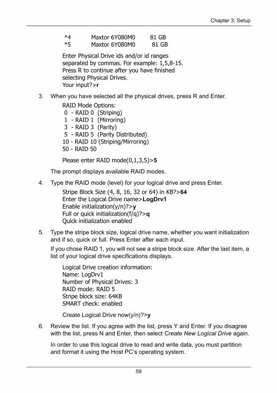
Chapter 3: Setup
*4 Maxtor 6Y080M0 81 GB *5 Maxtor 6Y080M0 81 GB
Enter Physical Drive ids and/or id rangesseparated by commas. For example: 1,5,8-15.Press R to continue after you have finishedselecting Physical Drives.Your input?>r
3. When you have selected all the physical drives, press R and Enter.
RAID Mode Options: 0 - RAID 0 (Striping) 1 - RAID 1 (Mirroring) 3 - RAID 3 (Parity) 5 - RAID 5 (Parity Distributed)10 - RAID 10 (Striping/Mirroring)50 - RAID 50
Please enter RAID mode(0,1,3,5)>5
The prompt displays available RAID modes.
4. Type the RAID mode (level) for your logical drive and press Enter.
Stripe Block Size (4, 8, 16, 32 or 64) in KB?>64Enter the Logical Drive name>LogDrv1Enable initialization(y/n)?>yFull or quick initialization(f/q)?>qQuick initialization enabled
5. Type the stripe block size, logical drive name, whether you want initialization and if so, quick or full. Press Enter after each input.
If you chose RAID 1, you will not see a stripe block size. After the last item, a list of your logical drive specifications displays.
Logical Drive creation information:Name: LogDrv1Number of Physical Drives: 3RAID mode: RAID 5Stripe block size: 64KBSMART check: enabled
Create Logical Drive now(y/n)?>y
6. Review the list. If you agree with the list, press Y and Enter. If you disagree with the list, press N and Enter, then select Create New Logical Drive again.
In order to use this logical drive to read and write data, you must partition and format it using the Host PC’s operating system.
59

VTrak 15200 User Manual
Exit the CLUClose the terminal emulation window to exit the CLU.
60
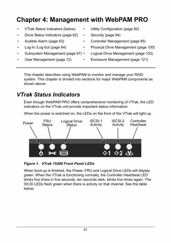
Chapter 4: Management with WebPAM PRO
This chapter describes using WebPAM to monitor and manage your RAID system. This chapter is divided into sections for major WebPAM components as shown above.
VTrak Status IndicatorsEven though WebPAM PRO offers comprehensive monitoring of VTrak, the LED indicators on the VTrak unit provide important status information.
When the power is switched on, the LEDs on the front of the VTrak will light up.
Figure 1. VTrak 15200 Front Panel LEDs
When boot-up is finished, the Power, FRU and Logical Drive LEDs will display green. When the VTrak is functioning normally, the Controller Heartbeat LED blinks five times in five seconds, ten seconds dark, blinks five times again. The iSCSI LEDs flash green when there is activity on that channel. See the table below.
• VTrak Status Indicators (below) • Utility Configuration (page 82)
• Drive Status Indicators (page 62) • Security (page 84)
• Audible Alarm (page 63) • Controller Management (page 85)
• Log-In /Log-0ut (page 64) • Physical Drive Management (page 100)
• Subsystem Management (page 67) • Logical Drive Management (page 103)
• User Management (page 72) • Enclosure Management (page 121)
Power FRUStatus
Logical DriveStatus
iSCSI-1Activity
iSCSI-2Activity
ControllerHeartbeat
61
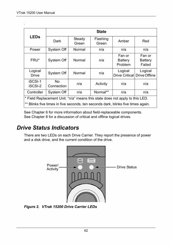
VTrak 15200 User Manual
.
See Chapter 6 for more information about field-replaceable components. See Chapter 8 for a discussion of critical and offline logical drives.
Drive Status IndicatorsThere are two LEDs on each Drive Carrier. They report the presence of power and a disk drive, and the current condition of the drive.
Figure 2. VTrak 15200 Drive Carrier LEDs
LEDsState
DarkSteady Green
Flashing Green
Amber Red
Power System Off Normal n/a n/a n/a
FRU* System Off Normal n/aFan or Battery Problem
Fan or Battery Failed
Logical Drive
System Off Normal n/aLogical
Drive CriticalLogical
Drive Offline
iSCSI-1iSCSI-2
No Connection
n/a Activity n/a n/a
Controller System Off n/a Normal** n/a n/a
* Field Replacement Unit. “n/a” means this state does not apply to this LED.
** Blinks five times in five seconds, ten seconds dark, blinks five times again.
Drive StatusPower/Activity
62
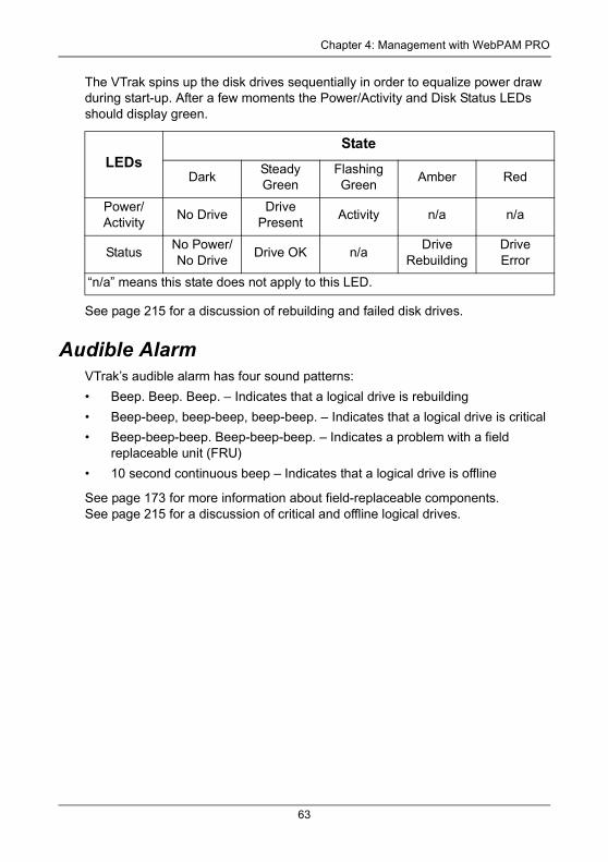
Chapter 4: Management with WebPAM PRO
The VTrak spins up the disk drives sequentially in order to equalize power draw during start-up. After a few moments the Power/Activity and Disk Status LEDs should display green.
See page 215 for a discussion of rebuilding and failed disk drives.
Audible AlarmVTrak’s audible alarm has four sound patterns:
• Beep. Beep. Beep. – Indicates that a logical drive is rebuilding
• Beep-beep, beep-beep, beep-beep. – Indicates that a logical drive is critical
• Beep-beep-beep. Beep-beep-beep. – Indicates a problem with a field replaceable unit (FRU)
• 10 second continuous beep – Indicates that a logical drive is offline
See page 173 for more information about field-replaceable components. See page 215 for a discussion of critical and offline logical drives.
LEDsState
DarkSteady Green
Flashing Green
Amber Red
Power/Activity
No DriveDrive
PresentActivity n/a n/a
StatusNo Power/No Drive
Drive OK n/aDrive
RebuildingDriveError
“n/a” means this state does not apply to this LED.
63
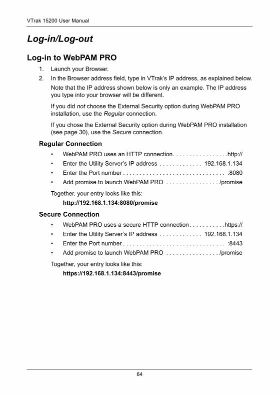
VTrak 15200 User Manual
Log-in/Log-out
Log-in to WebPAM PRO1. Launch your Browser.
2. In the Browser address field, type in VTrak’s IP address, as explained below.
Note that the IP address shown below is only an example. The IP address you type into your browser will be different.
If you did not choose the External Security option during WebPAM PRO installation, use the Regular connection.
If you chose the External Security option during WebPAM PRO installation (see page 30), use the Secure connection.
Regular Connection• WebPAM PRO uses an HTTP connection. . . . . . . . . . . . . . . . .http://
• Enter the Utility Server’s IP address . . . . . . . . . . . . . 192.168.1.134
• Enter the Port number . . . . . . . . . . . . . . . . . . . . . . . . . . . . . . . :8080
• Add promise to launch WebPAM PRO . . . . . . . . . . . . . . . . /promise
Together, your entry looks like this:
http://192.168.1.134:8080/promise
Secure Connection• WebPAM PRO uses a secure HTTP connection . . . . . . . . . . .https://
• Enter the Utility Server’s IP address . . . . . . . . . . . . . 192.168.1.134
• Enter the Port number . . . . . . . . . . . . . . . . . . . . . . . . . . . . . . . :8443
• Add promise to launch WebPAM PRO . . . . . . . . . . . . . . . . /promise
Together, your entry looks like this:
https://192.168.1.134:8443/promise
64
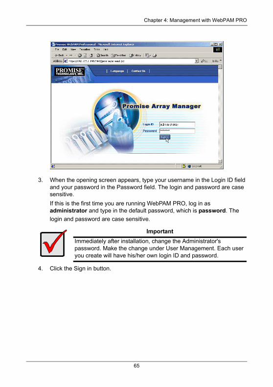
Chapter 4: Management with WebPAM PRO
3. When the opening screen appears, type your username in the Login ID field and your password in the Password field. The login and password are case sensitive.
If this is the first time you are running WebPAM PRO, log in as administrator and type in the default password, which is password. The
login and password are case sensitive.
4. Click the Sign in button.
ImportantImmediately after installation, change the Administrator's password. Make the change under User Management. Each user you create will have his/her own login ID and password.
65
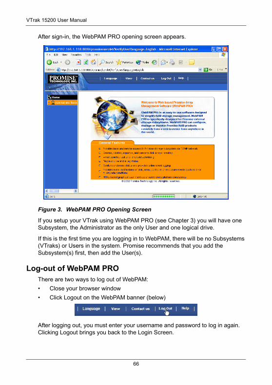
VTrak 15200 User Manual
After sign-in, the WebPAM PRO opening screen appears.
Figure 3. WebPAM PRO Opening Screen
If you setup your VTrak using WebPAM PRO (see Chapter 3) you will have one Subsystem, the Administrator as the only User and one logical drive.
If this is the first time you are logging in to WebPAM, there will be no Subsystems (VTraks) or Users in the system. Promise recommends that you add the Subsystem(s) first, then add the User(s).
Log-out of WebPAM PROThere are two ways to log out of WebPAM:
• Close your browser window
• Click Logout on the WebPAM banner (below)
After logging out, you must enter your username and password to log in again. Clicking Logout brings you back to the Login Screen.
66
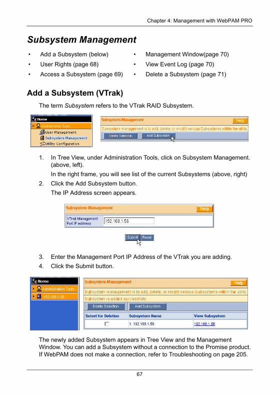
Chapter 4: Management with WebPAM PRO
Subsystem Management
Add a Subsystem (VTrak)The term Subsystem refers to the VTrak RAID Subsystem.
1. In Tree View, under Administration Tools, click on Subsystem Management. (above, left).
In the right frame, you will see list of the current Subsystems (above, right)
2. Click the Add Subsystem button.
The IP Address screen appears.
3. Enter the Management Port IP Address of the VTrak you are adding.
4. Click the Submit button.
The newly added Subsystem appears in Tree View and the Management Window. You can add a Subsystem without a connection to the Promise product. If WebPAM does not make a connection, refer to Troubleshooting on page 205.
• Add a Subsystem (below) • Management Window(page 70)
• User Rights (page 68) • View Event Log (page 70)
• Access a Subsystem (page 69) • Delete a Subsystem (page 71)
67
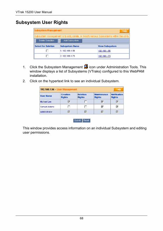
VTrak 15200 User Manual
Subsystem User Rights
1. Click the Subsystem Management icon under Administration Tools. This window displays a list of Subsystems (VTraks) configured to this WebPAM installation.
2. Click on the hypertext link to see an individual Subsystem.
This window provides access information on an individual Subsystem and editing user permissions.
68
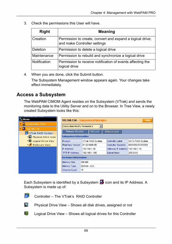
Chapter 4: Management with WebPAM PRO
3. Check the permissions this User will have.
4. When you are done, click the Submit button.
The Subsystem Management window appears again. Your changes take effect immediately.
Access a SubsystemThe WebPAM CIMOM Agent resides on the Subsystem (VTrak) and sends the monitoring data to the Utility Server and on to the Browser. In Tree View, a newly created Subsystem looks like this:
Each Subsystem is identified by a Subsystem icon and its IP Address. A Subsystem is made up of:
Controller – The VTrak’s RAID Controller
Physical Drive View – Shows all disk drives, assigned or not
Logical Drive View – Shows all logical drives for this Controller
Right Meaning
Creation Permission to create, convert and expand a logical drive; and make Controller settings
Deletion Permission to delete a logical drive
Maintenance Permission to rebuild and synchronize a logical drive
Notification Permission to receive notification of events affecting the logical drive
69
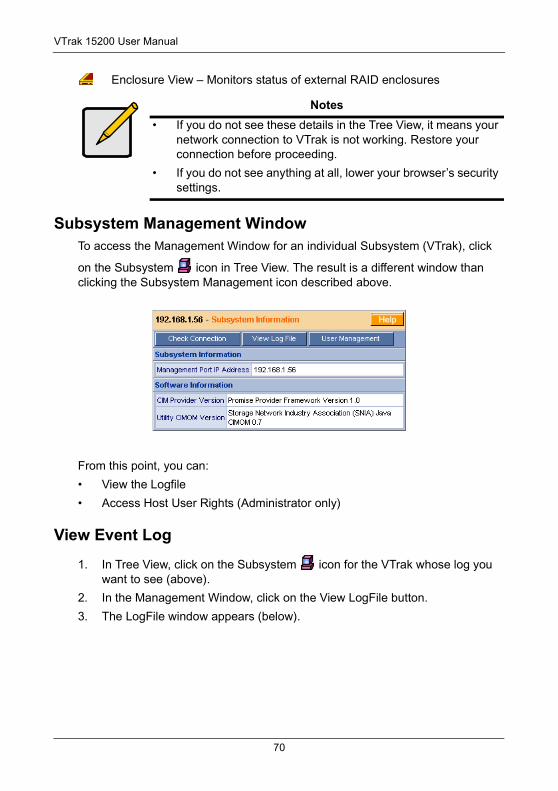
VTrak 15200 User Manual
Enclosure View – Monitors status of external RAID enclosures
Subsystem Management WindowTo access the Management Window for an individual Subsystem (VTrak), click
on the Subsystem icon in Tree View. The result is a different window than clicking the Subsystem Management icon described above.
From this point, you can:
• View the Logfile
• Access Host User Rights (Administrator only)
View Event Log
1. In Tree View, click on the Subsystem icon for the VTrak whose log you want to see (above).
2. In the Management Window, click on the View LogFile button.
3. The LogFile window appears (below).
Notes• If you do not see these details in the Tree View, it means your
network connection to VTrak is not working. Restore your connection before proceeding.
• If you do not see anything at all, lower your browser’s security settings.
70
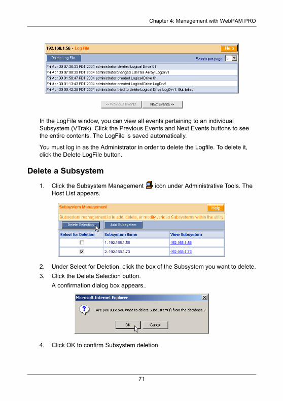
Chapter 4: Management with WebPAM PRO
In the LogFile window, you can view all events pertaining to an individual Subsystem (VTrak). Click the Previous Events and Next Events buttons to see the entire contents. The LogFile is saved automatically.
You must log in as the Administrator in order to delete the Logfile. To delete it, click the Delete LogFile button.
Delete a Subsystem
1. Click the Subsystem Management icon under Administrative Tools. The Host List appears.
2. Under Select for Deletion, click the box of the Subsystem you want to delete.
3. Click the Delete Selection button.
A confirmation dialog box appears..
4. Click OK to confirm Subsystem deletion.
71
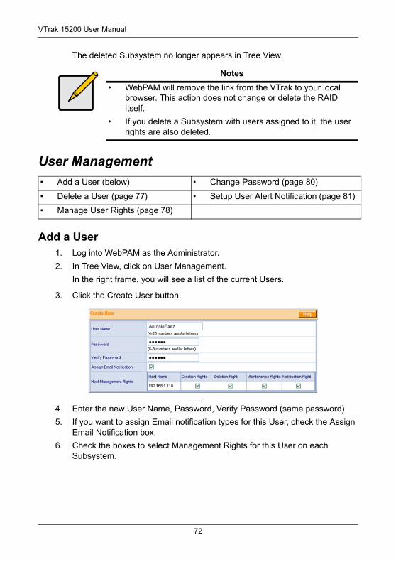
VTrak 15200 User Manual
The deleted Subsystem no longer appears in Tree View.
User Management
Add a User1. Log into WebPAM as the Administrator.
2. In Tree View, click on User Management.
In the right frame, you will see a list of the current Users.
3. Click the Create User button.
4. Enter the new User Name, Password, Verify Password (same password).
5. If you want to assign Email notification types for this User, check the Assign Email Notification box.
6. Check the boxes to select Management Rights for this User on each Subsystem.
Notes• WebPAM will remove the link from the VTrak to your local
browser. This action does not change or delete the RAID itself.
• If you delete a Subsystem with users assigned to it, the user rights are also deleted.
• Add a User (below) • Change Password (page 80)
• Delete a User (page 77) • Setup User Alert Notification (page 81)
• Manage User Rights (page 78)
72
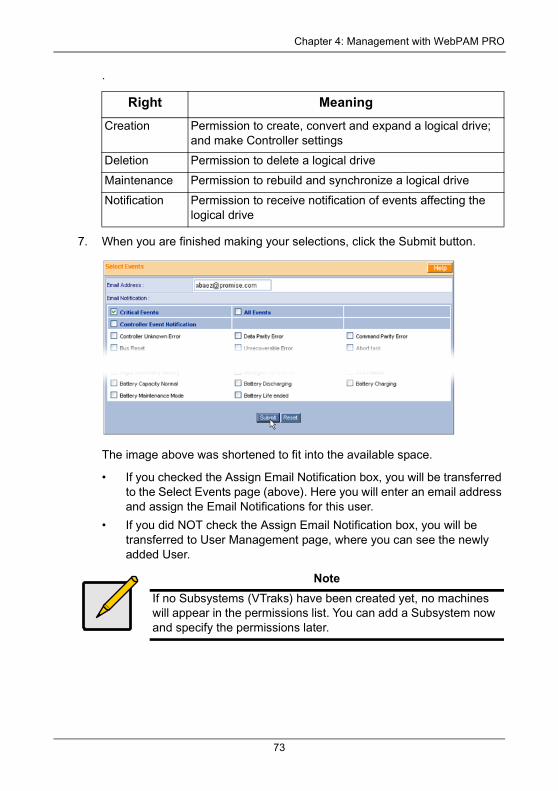
Chapter 4: Management with WebPAM PRO
.
7. When you are finished making your selections, click the Submit button.
The image above was shortened to fit into the available space.
• If you checked the Assign Email Notification box, you will be transferred to the Select Events page (above). Here you will enter an email address and assign the Email Notifications for this user.
• If you did NOT check the Assign Email Notification box, you will be transferred to User Management page, where you can see the newly added User.
Right Meaning
Creation Permission to create, convert and expand a logical drive; and make Controller settings
Deletion Permission to delete a logical drive
Maintenance Permission to rebuild and synchronize a logical drive
Notification Permission to receive notification of events affecting the logical drive
NoteIf no Subsystems (VTraks) have been created yet, no machines will appear in the permissions list. You can add a Subsystem now and specify the permissions later.
73
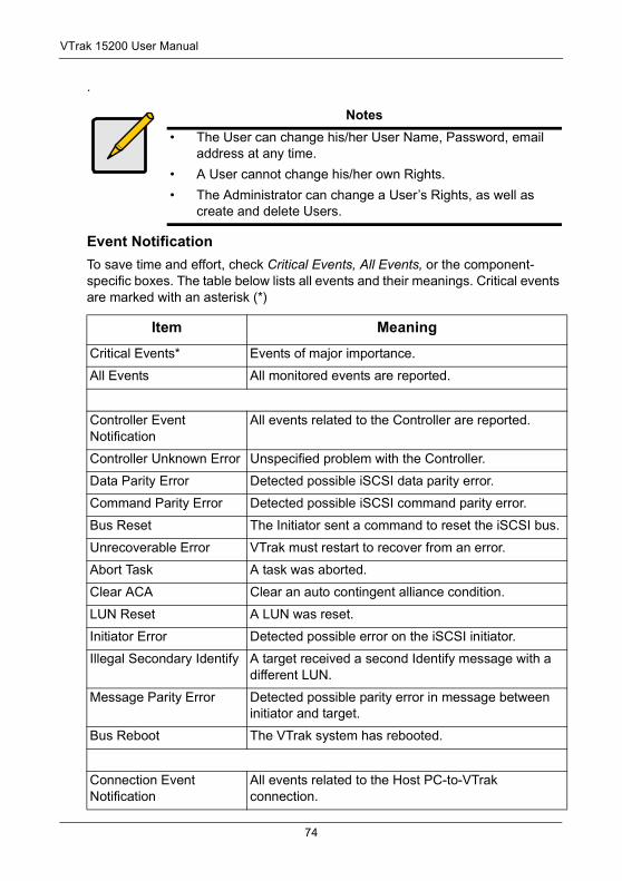
VTrak 15200 User Manual
.
Event NotificationTo save time and effort, check Critical Events, All Events, or the component-specific boxes. The table below lists all events and their meanings. Critical events are marked with an asterisk (*)
Notes• The User can change his/her User Name, Password, email
address at any time.
• A User cannot change his/her own Rights.
• The Administrator can change a User’s Rights, as well as create and delete Users.
Item Meaning
Critical Events* Events of major importance.
All Events All monitored events are reported.
Controller Event Notification
All events related to the Controller are reported.
Controller Unknown Error Unspecified problem with the Controller.
Data Parity Error Detected possible iSCSI data parity error.
Command Parity Error Detected possible iSCSI command parity error.
Bus Reset The Initiator sent a command to reset the iSCSI bus.
Unrecoverable Error VTrak must restart to recover from an error.
Abort Task A task was aborted.
Clear ACA Clear an auto contingent alliance condition.
LUN Reset A LUN was reset.
Initiator Error Detected possible error on the iSCSI initiator.
Illegal Secondary Identify A target received a second Identify message with a different LUN.
Message Parity Error Detected possible parity error in message between initiator and target.
Bus Reboot The VTrak system has rebooted.
Connection Event Notification
All events related to the Host PC-to-VTrak connection.
74
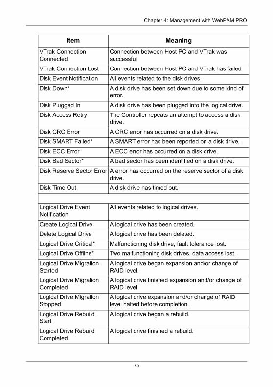
Chapter 4: Management with WebPAM PRO
VTrak Connection Connected
Connection between Host PC and VTrak was successful
VTrak Connection Lost Connection between Host PC and VTrak has failed
Disk Event Notification All events related to the disk drives.
Disk Down* A disk drive has been set down due to some kind of error.
Disk Plugged In A disk drive has been plugged into the logical drive.
Disk Access Retry The Controller repeats an attempt to access a disk drive.
Disk CRC Error A CRC error has occurred on a disk drive.
Disk SMART Failed* A SMART error has been reported on a disk drive.
Disk ECC Error A ECC error has occurred on a disk drive.
Disk Bad Sector* A bad sector has been identified on a disk drive.
Disk Reserve Sector Error A error has occurred on the reserve sector of a disk drive.
Disk Time Out A disk drive has timed out.
Logical Drive Event Notification
All events related to logical drives.
Create Logical Drive A logical drive has been created.
Delete Logical Drive A logical drive has been deleted.
Logical Drive Critical* Malfunctioning disk drive, fault tolerance lost.
Logical Drive Offline* Two malfunctioning disk drives, data access lost.
Logical Drive Migration Started
A logical drive began expansion and/or change of RAID level.
Logical Drive Migration Completed
A logical drive finished expansion and/or change of RAID level
Logical Drive Migration Stopped
A logical drive expansion and/or change of RAID level halted before completion.
Logical Drive Rebuild Start
A logical drive began a rebuild.
Logical Drive Rebuild Completed
A logical drive finished a rebuild.
Item Meaning
75
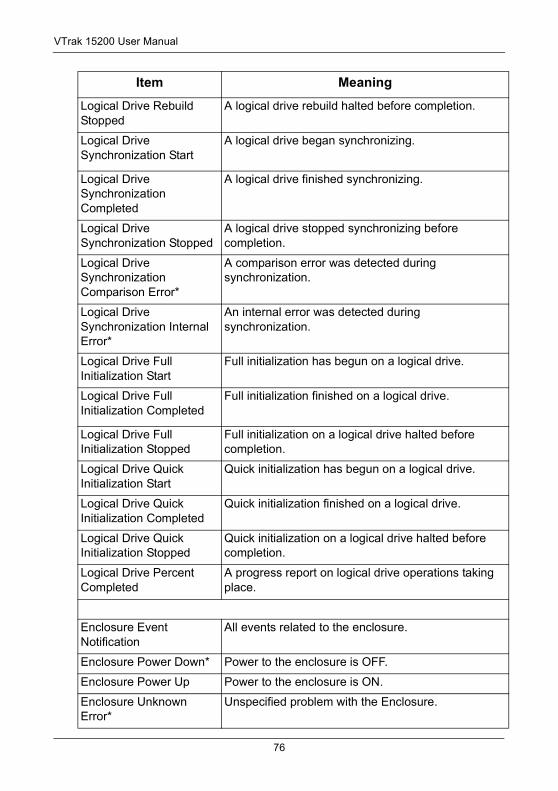
VTrak 15200 User Manual
Logical Drive Rebuild Stopped
A logical drive rebuild halted before completion.
Logical Drive Synchronization Start
A logical drive began synchronizing.
Logical Drive Synchronization Completed
A logical drive finished synchronizing.
Logical Drive Synchronization Stopped
A logical drive stopped synchronizing before completion.
Logical Drive Synchronization Comparison Error*
A comparison error was detected during synchronization.
Logical Drive Synchronization Internal Error*
An internal error was detected during synchronization.
Logical Drive Full Initialization Start
Full initialization has begun on a logical drive.
Logical Drive Full Initialization Completed
Full initialization finished on a logical drive.
Logical Drive Full Initialization Stopped
Full initialization on a logical drive halted before completion.
Logical Drive Quick Initialization Start
Quick initialization has begun on a logical drive.
Logical Drive Quick Initialization Completed
Quick initialization finished on a logical drive.
Logical Drive Quick Initialization Stopped
Quick initialization on a logical drive halted before completion.
Logical Drive Percent Completed
A progress report on logical drive operations taking place.
Enclosure Event Notification
All events related to the enclosure.
Enclosure Power Down* Power to the enclosure is OFF.
Enclosure Power Up Power to the enclosure is ON.
Enclosure Unknown Error*
Unspecified problem with the Enclosure.
Item Meaning
76
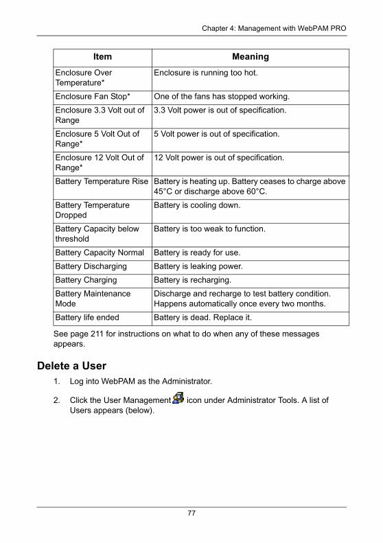
Chapter 4: Management with WebPAM PRO
See page 211 for instructions on what to do when any of these messages appears.
Delete a User1. Log into WebPAM as the Administrator.
2. Click the User Management icon under Administrator Tools. A list of Users appears (below).
Enclosure Over Temperature*
Enclosure is running too hot.
Enclosure Fan Stop* One of the fans has stopped working.
Enclosure 3.3 Volt out of Range
3.3 Volt power is out of specification.
Enclosure 5 Volt Out of Range*
5 Volt power is out of specification.
Enclosure 12 Volt Out of Range*
12 Volt power is out of specification.
Battery Temperature Rise Battery is heating up. Battery ceases to charge above 45°C or discharge above 60°C.
Battery Temperature Dropped
Battery is cooling down.
Battery Capacity below threshold
Battery is too weak to function.
Battery Capacity Normal Battery is ready for use.
Battery Discharging Battery is leaking power.
Battery Charging Battery is recharging.
Battery Maintenance Mode
Discharge and recharge to test battery condition. Happens automatically once every two months.
Battery life ended Battery is dead. Replace it.
Item Meaning
77
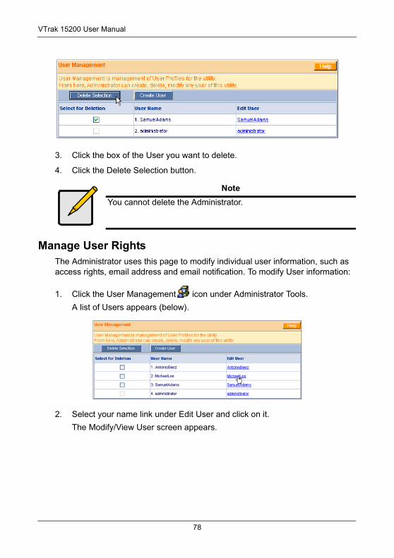
VTrak 15200 User Manual
3. Click the box of the User you want to delete.
4. Click the Delete Selection button.
Manage User RightsThe Administrator uses this page to modify individual user information, such as access rights, email address and email notification. To modify User information:
1. Click the User Management icon under Administrator Tools.
A list of Users appears (below).
2. Select your name link under Edit User and click on it.
The Modify/View User screen appears.
NoteYou cannot delete the Administrator.
78
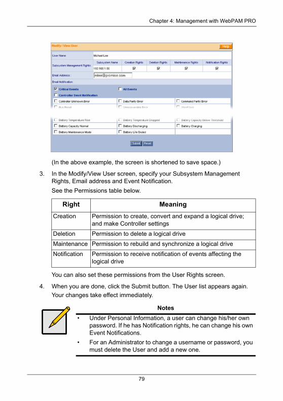
Chapter 4: Management with WebPAM PRO
(In the above example, the screen is shortened to save space.)
3. In the Modify/View User screen, specify your Subsystem Management Rights, Email address and Event Notification.
See the Permissions table below.
You can also set these permissions from the User Rights screen.
4. When you are done, click the Submit button. The User list appears again.
Your changes take effect immediately.
Right Meaning
Creation Permission to create, convert and expand a logical drive; and make Controller settings
Deletion Permission to delete a logical drive
Maintenance Permission to rebuild and synchronize a logical drive
Notification Permission to receive notification of events affecting the logical drive
Notes• Under Personal Information, a user can change his/her own
password. If he has Notification rights, he can change his own Event Notifications.
• For an Administrator to change a username or password, you must delete the User and add a new one.
79
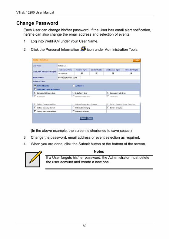
VTrak 15200 User Manual
Change PasswordEach User can change his/her password. If the User has email alert notification, he/she can also change the email address and selection of events.
1. Log into WebPAM under your User Name.
2. Click the Personal Information icon under Administration Tools.
(In the above example, the screen is shortened to save space.)
3. Change the password, email address or event selection as required.
4. When you are done, click the Submit button at the bottom of the screen.
NotesIf a User forgets his/her password, the Administrator must delete the user account and create a new one.
80
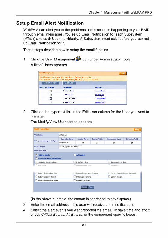
Chapter 4: Management with WebPAM PRO
Setup Email Alert NotificationWebPAM can alert you to the problems and processes happening to your RAID through email messages. You setup Email Notification for each Subsystem (VTrak) and each User individually. A Subsystem must exist before you can set-up Email Notification for it.
These steps describe how to setup the email function.
1. Click the User Management icon under Administrator Tools.
A list of Users appears.
2. Click on the hypertext link in the Edit User column for the User you want to manage.
The Modify/View User screen appears.
(In the above example, the screen is shortened to save space.)
3. Enter the email address if this user will receive email notifications.
4. Select the alert events you want reported via email. To save time and effort, check Critical Events, All Events, or the component-specific boxes.
81
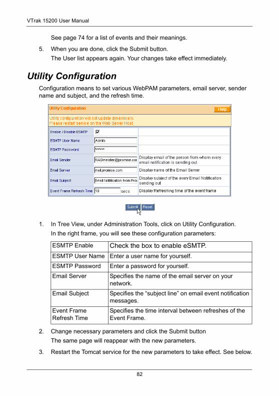
VTrak 15200 User Manual
See page 74 for a list of events and their meanings.
5. When you are done, click the Submit button.
The User list appears again. Your changes take effect immediately.
Utility ConfigurationConfiguration means to set various WebPAM parameters, email server, sender name and subject, and the refresh time.
1. In Tree View, under Administration Tools, click on Utility Configuration.
In the right frame, you will see these configuration parameters:
2. Change necessary parameters and click the Submit button
The same page will reappear with the new parameters.
3. Restart the Tomcat service for the new parameters to take effect. See below.
ESMTP Enable Check the box to enable eSMTP.
ESMTP User Name Enter a user name for yourself.
ESMTP Password Enter a password for yourself.
Email Server Specifies the name of the email server on your network.
Email Subject Specifies the “subject line” on email event notification messages.
Event Frame Refresh Time
Specifies the time interval between refreshes of the Event Frame.
82
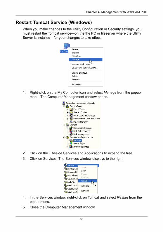
Chapter 4: Management with WebPAM PRO
Restart Tomcat Service (Windows)When you make changes to the Utility Configuration or Security settings, you must restart the Tomcat service—on the the PC or fileserver where the Utility Server is installed—for your changes to take effect.
1. Right-click on the My Computer icon and select Manage from the popup menu. The Computer Management window opens.
2. Click on the + beside Services and Applications to expand the tree.
3. Click on Services. The Services window displays to the right.
4. In the Services window, right-click on Tomcat and select Restart from the popup menu.
5. Close the Computer Management window.
83
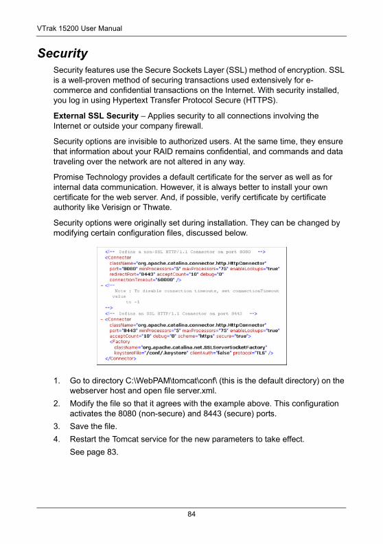
VTrak 15200 User Manual
SecuritySecurity features use the Secure Sockets Layer (SSL) method of encryption. SSL is a well-proven method of securing transactions used extensively for e-commerce and confidential transactions on the Internet. With security installed, you log in using Hypertext Transfer Protocol Secure (HTTPS).
External SSL Security – Applies security to all connections involving the Internet or outside your company firewall.
Security options are invisible to authorized users. At the same time, they ensure that information about your RAID remains confidential, and commands and data traveling over the network are not altered in any way.
Promise Technology provides a default certificate for the server as well as for internal data communication. However, it is always better to install your own certificate for the web server. And, if possible, verify certificate by certificate authority like Verisign or Thwate.
Security options were originally set during installation. They can be changed by modifying certain configuration files, discussed below.
1. Go to directory C:\WebPAM\tomcat\conf\ (this is the default directory) on the webserver host and open file server.xml.
2. Modify the file so that it agrees with the example above. This configuration activates the 8080 (non-secure) and 8443 (secure) ports.
3. Save the file.
4. Restart the Tomcat service for the new parameters to take effect.
See page 83.
84
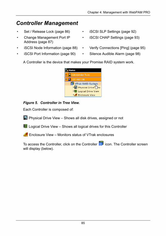
Chapter 4: Management with WebPAM PRO
Controller Management
A Controller is the device that makes your Promise RAID system work.
Figure 5. Controller in Tree View.
Each Controller is composed of:
Physical Drive View – Shows all disk drives, assigned or not
Logical Drive View – Shows all logical drives for this Controller
Enclosure View – Monitors status of VTrak enclosures
To access the Controller, click on the Controller icon. The Controller screen will display (below).
• Set / Release Lock (page 86) • iSCSI SLP Settings (page 92)
• Change Management Port IP Address (page 87)
• iSCSI CHAP Settings (page 93)
• iSCSI Node Information (page 88) • Verify Connections [Ping] (page 95)
• iSCSI Port Information (page 90) • Silence Audible Alarm (page 98)
85
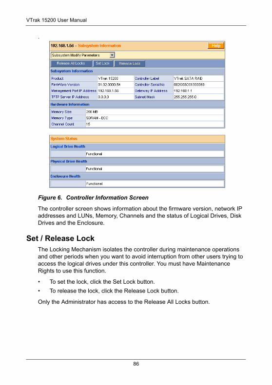
VTrak 15200 User Manual
.
Figure 6. Controller Information Screen
The controller screen shows information about the firmware version, network IP addresses and LUNs, Memory, Channels and the status of Logical Drives, Disk Drives and the Enclosure.
Set / Release LockThe Locking Mechanism isolates the controller during maintenance operations and other periods when you want to avoid interruption from other users trying to access the logical drives under this controller. You must have Maintenance Rights to use this function.
• To set the lock, click the Set Lock button.
• To release the lock, click the Release Lock button.
Only the Administrator has access to the Release All Locks button.
86
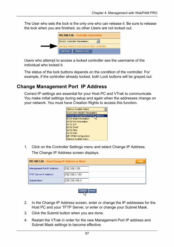
Chapter 4: Management with WebPAM PRO
The User who sets the lock is the only one who can release it. Be sure to release the lock when you are finished, so other Users are not locked out.
Users who attempt to access a locked controller see the username of the individual who locked it.
The status of the lock buttons depends on the condition of the controller. For example, if the controller already locked, both Lock buttons will be grayed out.
Change Management Port IP AddressCorrect IP settings are essential for your Host PC and VTrak to communicate. You make initial settings during setup and again when the addresses change on your network. You must have Creation Rights to access this function.
1. Click on the Controller Settings menu and select Change IP Address.
The Change IP Address screen displays.
2. In the Change IP Address screen, enter or change the IP addresses for the Host PC and your TFTP Server, or enter or change your Subnet Mask.
3. Click the Submit button when you are done.
4. Restart the VTrak in order for the new Management Port IP address and Subnet Mask settings to become effective.
87
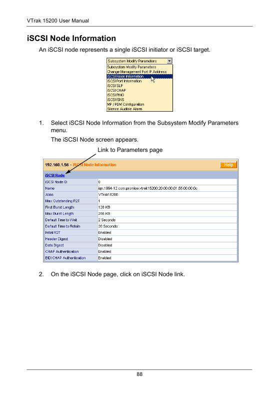
VTrak 15200 User Manual
iSCSI Node InformationAn iSCSI node represents a single iSCSI initiator or iSCSI target.
1. Select iSCSI Node Information from the Subsystem Modify Parameters menu.
The iSCSI Node screen appears.
2. On the iSCSI Node page, click on iSCSI Node link.
Link to Parameters page
88
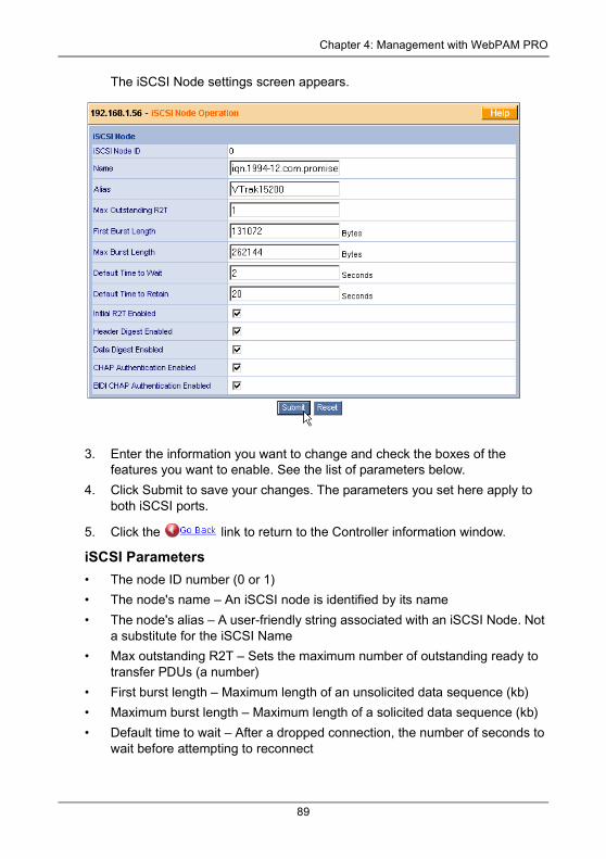
Chapter 4: Management with WebPAM PRO
The iSCSI Node settings screen appears.
3. Enter the information you want to change and check the boxes of the features you want to enable. See the list of parameters below.
4. Click Submit to save your changes. The parameters you set here apply to both iSCSI ports.
5. Click the link to return to the Controller information window.
iSCSI Parameters • The node ID number (0 or 1)
• The node's name – An iSCSI node is identified by its name
• The node's alias – A user-friendly string associated with an iSCSI Node. Not a substitute for the iSCSI Name
• Max outstanding R2T – Sets the maximum number of outstanding ready to transfer PDUs (a number)
• First burst length – Maximum length of an unsolicited data sequence (kb)
• Maximum burst length – Maximum length of a solicited data sequence (kb)
• Default time to wait – After a dropped connection, the number of seconds to wait before attempting to reconnect
89
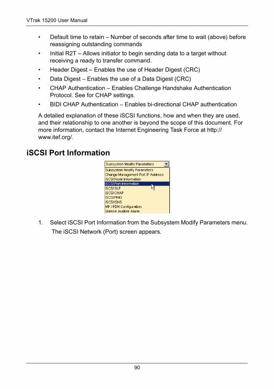
VTrak 15200 User Manual
• Default time to retain – Number of seconds after time to wait (above) before reassigning outstanding commands
• Initial R2T – Allows initiator to begin sending data to a target without receiving a ready to transfer command.
• Header Digest – Enables the use of Header Digest (CRC)
• Data Digest – Enables the use of a Data Digest (CRC)
• CHAP Authentication – Enables Challenge Handshake Authentication Protocol. See for CHAP settings.
• BIDI CHAP Authentication – Enables bi-directional CHAP authentication
A detailed explanation of these iSCSI functions, how and when they are used, and their relationship to one another is beyond the scope of this document. For more information, contact the Internet Engineering Task Force at http://www.itef.org/.
iSCSI Port Information
1. Select iSCSI Port Information from the Subsystem Modify Parameters menu.
The iSCSI Network (Port) screen appears.
90
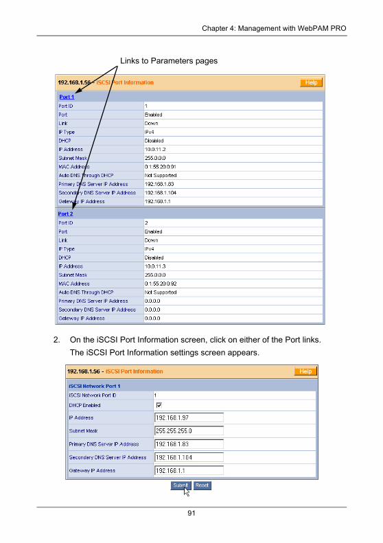
Chapter 4: Management with WebPAM PRO
2. On the iSCSI Port Information screen, click on either of the Port links.
The iSCSI Port Information settings screen appears.
Links to Parameters pages
91
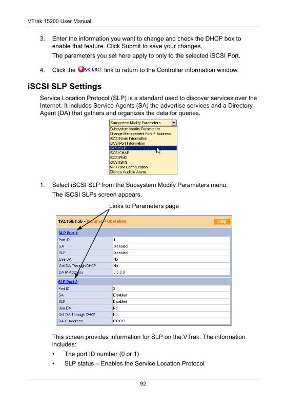
VTrak 15200 User Manual
3. Enter the information you want to change and check the DHCP box to enable that feature. Click Submit to save your changes.
The parameters you set here apply to only to the selected iSCSI Port.
4. Click the link to return to the Controller information window.
iSCSI SLP SettingsService Location Protocol (SLP) is a standard used to discover services over the Internet. It includes Service Agents (SA) the advertise services and a Directory Agent (DA) that gathers and organizes the data for queries.
1. Select iSCSI SLP from the Subsystem Modify Parameters menu.
The iSCSI SLPs screen appears.
This screen provides information for SLP on the VTrak. The information includes:
• The port ID number (0 or 1)
• SLP status – Enables the Service Location Protocol
Links to Parameters page
92
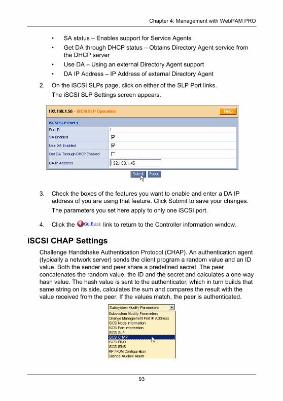
Chapter 4: Management with WebPAM PRO
• SA status – Enables support for Service Agents
• Get DA through DHCP status – Obtains Directory Agent service from the DHCP server
• Use DA – Using an external Directory Agent support
• DA IP Address – IP Address of external Directory Agent
2. On the iSCSI SLPs page, click on either of the SLP Port links.
The iSCSI SLP Settings screen appears.
3. Check the boxes of the features you want to enable and enter a DA IP address of you are using that feature. Click Submit to save your changes.
The parameters you set here apply to only one iSCSI port.
4. Click the link to return to the Controller information window.
iSCSI CHAP SettingsChallenge Handshake Authentication Protocol (CHAP). An authentication agent (typically a network server) sends the client program a random value and an ID value. Both the sender and peer share a predefined secret. The peer concatenates the random value, the ID and the secret and calculates a one-way hash value. The hash value is sent to the authenticator, which in turn builds that same string on its side, calculates the sum and compares the result with the value received from the peer. If the values match, the peer is authenticated.
93
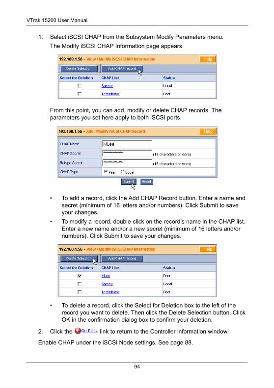
VTrak 15200 User Manual
1. Select iSCSI CHAP from the Subsystem Modify Parameters menu.
The Modify iSCSI CHAP Information page appears.
From this point, you can add, modify or delete CHAP records. The parameters you set here apply to both iSCSI ports.
• To add a record, click the Add CHAP Record button. Enter a name and secret (minimum of 16 letters and/or numbers). Click Submit to save your changes.
• To modify a record, double-click on the record’s name in the CHAP list. Enter a new name and/or a new secret (minimum of 16 letters and/or numbers). Click Submit to save your changes.
• To delete a record, click the Select for Deletion box to the left of the record you want to delete. Then click the Delete Selection button. Click OK in the confirmation dialog box to confirm your deletion.
2. Click the link to return to the Controller information window.
Enable CHAP under the iSCSI Node settings. See page 88.
94
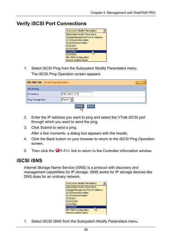
Chapter 4: Management with WebPAM PRO
Verify iSCSI Port Connections
1. Select iSCSI Ping from the Subsystem Modify Parameters menu.
The iSCSI Ping Operation screen appears.
2. Enter the IP address you want to ping and select the VTrak iSCSI port through which you want to send the ping.
3. Click Submit to send a ping.
After a few moments, a dialog box appears with the results.
4. Click the Back button on your browser to return to the iSCSI Ping Operation screen.
5. Then click the link to return to the Controller information window.
iSCSI iSNSInternet Storage Name Service (iSNS) is a protocol with discovery and management capabilities for IP storage. iSNS works for IP storage devices like DNS does for an ordinary network.
1. Select iSCSI iSNS from the Subsystem Modify Parameters menu.
95
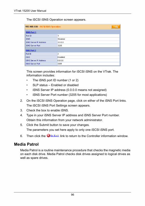
VTrak 15200 User Manual
The iSCSI iSNS Operation screen appears.
This screen provides information for iSCSI iSNS on the VTrak. The information includes:
• The iSNS port ID number (1 or 2)
• SLP status – Enabled or disabled
• iSNS Server IP address (0.0.0.0 means not assigned)
• iSNS Server Port number (3205 for most applications)
2. On the iSCSI iSNS Operation page, click on either of the iSNS Port links.
The iSCSI iSNS Port Settings screen appears.
3. Check the box to enable iSNS.
4. Type in your iSNS Server IP address and iSNS Server Port number.
Obtain this information from your network administrator.
5. Click the Submit button to save your changes.
The parameters you set here apply to only one iSCSI iSNS port.
6. Then click the link to return to the Controller information window.
Media PatrolMedia Patrol is a routine maintenance procedure that checks the magnetic media on each disk drive. Media Patrol checks disk drives assigned to logical drives as well as spare drives.
96
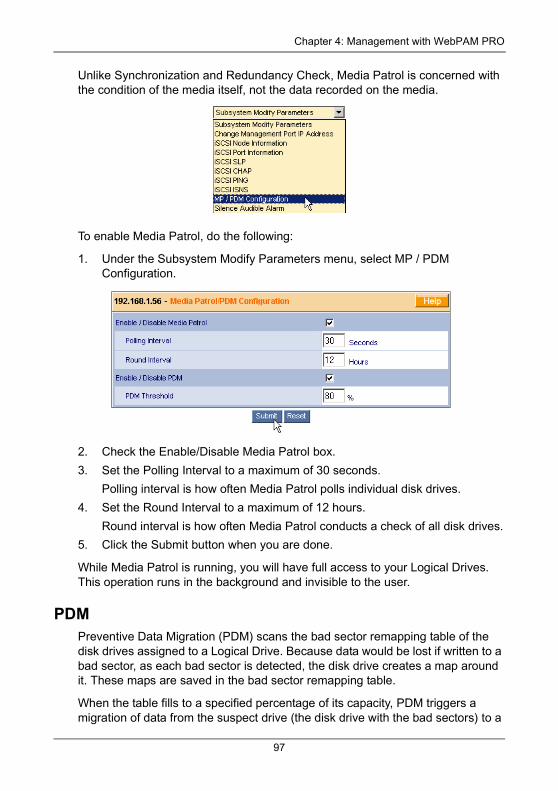
Chapter 4: Management with WebPAM PRO
Unlike Synchronization and Redundancy Check, Media Patrol is concerned with the condition of the media itself, not the data recorded on the media.
To enable Media Patrol, do the following:
1. Under the Subsystem Modify Parameters menu, select MP / PDM Configuration.
2. Check the Enable/Disable Media Patrol box.
3. Set the Polling Interval to a maximum of 30 seconds.
Polling interval is how often Media Patrol polls individual disk drives.
4. Set the Round Interval to a maximum of 12 hours.
Round interval is how often Media Patrol conducts a check of all disk drives.
5. Click the Submit button when you are done.
While Media Patrol is running, you will have full access to your Logical Drives. This operation runs in the background and invisible to the user.
PDMPreventive Data Migration (PDM) scans the bad sector remapping table of the disk drives assigned to a Logical Drive. Because data would be lost if written to a bad sector, as each bad sector is detected, the disk drive creates a map around it. These maps are saved in the bad sector remapping table.
When the table fills to a specified percentage of its capacity, PDM triggers a migration of data from the suspect drive (the disk drive with the bad sectors) to a
97
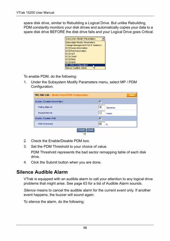
VTrak 15200 User Manual
spare disk drive, similar to Rebuilding a Logical Drive. But unlike Rebuilding, PDM constantly monitors your disk drives and automatically copies your data to a spare disk drive BEFORE the disk drive fails and your Logical Drive goes Critical.
To enable PDM, do the following:
1. Under the Subsystem Modify Parameters menu, select MP / PDM Configuration.
2. Check the Enable/Disable PDM box.
3. Set the PDM Threshold to your choice of value.
PDM Threshold represents the bad sector remapping table of each disk drive.
4. Click the Submit button when you are done.
Silence Audible AlarmVTrak is equipped with an audible alarm to call your attention to any logical drive problems that might arise. See page 63 for a list of Audible Alarm sounds.
Silence means to cancel the audible alarm for the current event only. If another event happens, the buzzer will sound again.
To silence the alarm, do the following:
98
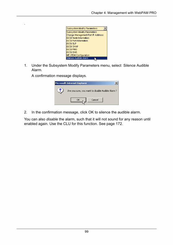
Chapter 4: Management with WebPAM PRO
.
1. Under the Subsystem Modify Parameters menu, select Silence Audible Alarm.
A confirmation message displays.
2. In the confirmation message, click OK to silence the audible alarm.
You can also disable the alarm, such that it will not sound for any reason until enabled again. Use the CLU for this function. See page 172.
99
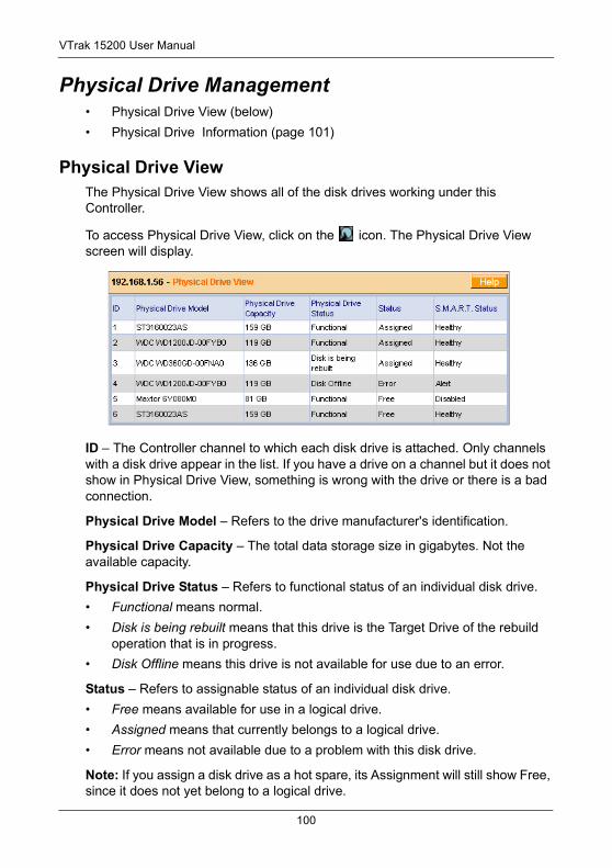
VTrak 15200 User Manual
Physical Drive Management• Physical Drive View (below)
• Physical Drive Information (page 101)
Physical Drive ViewThe Physical Drive View shows all of the disk drives working under this Controller.
To access Physical Drive View, click on the icon. The Physical Drive View screen will display.
ID – The Controller channel to which each disk drive is attached. Only channels with a disk drive appear in the list. If you have a drive on a channel but it does not show in Physical Drive View, something is wrong with the drive or there is a bad connection.
Physical Drive Model – Refers to the drive manufacturer's identification.
Physical Drive Capacity – The total data storage size in gigabytes. Not the available capacity.
Physical Drive Status – Refers to functional status of an individual disk drive.
• Functional means normal.
• Disk is being rebuilt means that this drive is the Target Drive of the rebuild operation that is in progress.
• Disk Offline means this drive is not available for use due to an error.
Status – Refers to assignable status of an individual disk drive.
• Free means available for use in a logical drive.
• Assigned means that currently belongs to a logical drive.
• Error means not available due to a problem with this disk drive.
Note: If you assign a disk drive as a hot spare, its Assignment will still show Free, since it does not yet belong to a logical drive.
100
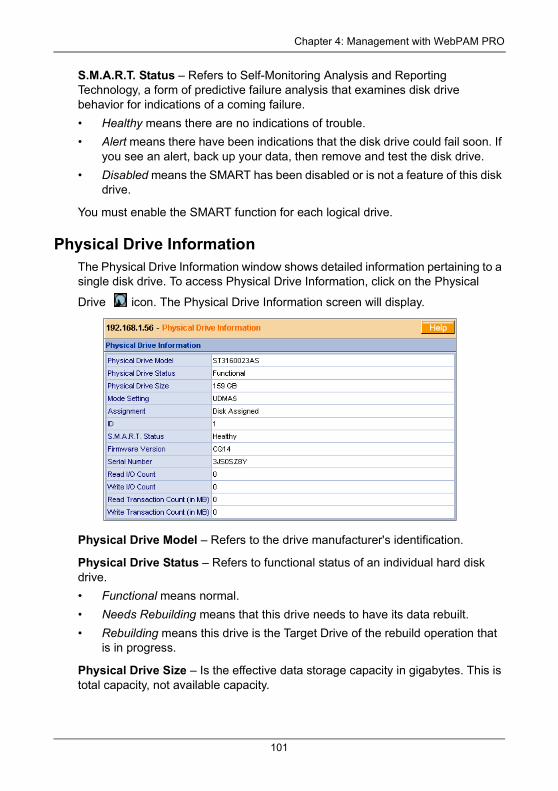
Chapter 4: Management with WebPAM PRO
S.M.A.R.T. Status – Refers to Self-Monitoring Analysis and Reporting Technology, a form of predictive failure analysis that examines disk drive behavior for indications of a coming failure.
• Healthy means there are no indications of trouble.
• Alert means there have been indications that the disk drive could fail soon. If you see an alert, back up your data, then remove and test the disk drive.
• Disabled means the SMART has been disabled or is not a feature of this disk drive.
You must enable the SMART function for each logical drive.
Physical Drive InformationThe Physical Drive Information window shows detailed information pertaining to a single disk drive. To access Physical Drive Information, click on the Physical
Drive icon. The Physical Drive Information screen will display.
Physical Drive Model – Refers to the drive manufacturer's identification.
Physical Drive Status – Refers to functional status of an individual hard disk drive.
• Functional means normal.
• Needs Rebuilding means that this drive needs to have its data rebuilt.
• Rebuilding means this drive is the Target Drive of the rebuild operation that is in progress.
Physical Drive Size – Is the effective data storage capacity in gigabytes. This is total capacity, not available capacity.
101
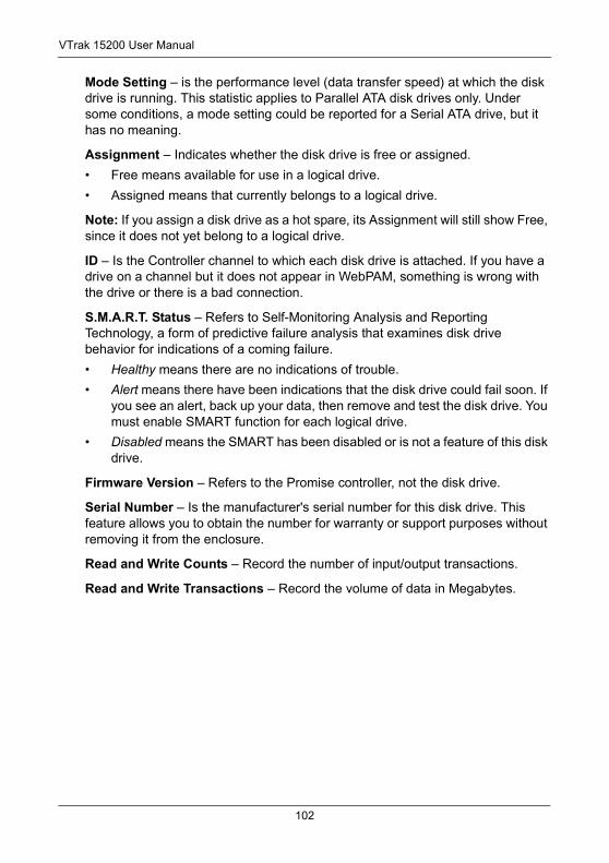
VTrak 15200 User Manual
Mode Setting – is the performance level (data transfer speed) at which the disk drive is running. This statistic applies to Parallel ATA disk drives only. Under some conditions, a mode setting could be reported for a Serial ATA drive, but it has no meaning.
Assignment – Indicates whether the disk drive is free or assigned.
• Free means available for use in a logical drive.
• Assigned means that currently belongs to a logical drive.
Note: If you assign a disk drive as a hot spare, its Assignment will still show Free, since it does not yet belong to a logical drive.
ID – Is the Controller channel to which each disk drive is attached. If you have a drive on a channel but it does not appear in WebPAM, something is wrong with the drive or there is a bad connection.
S.M.A.R.T. Status – Refers to Self-Monitoring Analysis and Reporting Technology, a form of predictive failure analysis that examines disk drive behavior for indications of a coming failure.
• Healthy means there are no indications of trouble.
• Alert means there have been indications that the disk drive could fail soon. If you see an alert, back up your data, then remove and test the disk drive. You must enable SMART function for each logical drive.
• Disabled means the SMART has been disabled or is not a feature of this disk drive.
Firmware Version – Refers to the Promise controller, not the disk drive.
Serial Number – Is the manufacturer's serial number for this disk drive. This feature allows you to obtain the number for warranty or support purposes without removing it from the enclosure.
Read and Write Counts – Record the number of input/output transactions.
Read and Write Transactions – Record the volume of data in Megabytes.
102
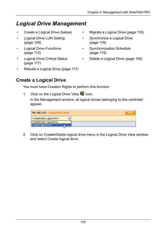
Chapter 4: Management with WebPAM PRO
Logical Drive Management
Create a Logical DriveYou must have Creation Rights to perform this function.
1. Click on the Logical Drive View icon.
In the Management window, all logical drives belonging to this controller appear..
2. Click on Create/Delete logical drive menu in the Logical Drive View window and select Create logical drive.
• Create a Logical Drive (below) • Migrate a Logical Drive (page 110)
• Logical Drive LUN Setting (page 109)
• Synchronize a Logical Drive (page 118)
• Logical Drive Functions (page 113)
• Synchronization Schedule (page 115)
• Logical Drive Critical Status (page 117)
• Delete a Logical Drive (page 106)
• Rebuild a Logical Drive (page 117)
103
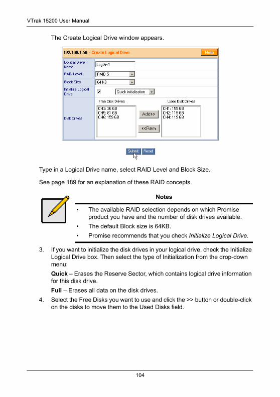
VTrak 15200 User Manual
The Create Logical Drive window appears.
Type in a Logical Drive name, select RAID Level and Block Size.
See page 189 for an explanation of these RAID concepts.
3. If you want to initialize the disk drives in your logical drive, check the Initialize Logical Drive box. Then select the type of Initialization from the drop-down menu:
Quick – Erases the Reserve Sector, which contains logical drive information for this disk drive.
Full – Erases all data on the disk drives.
4. Select the Free Disks you want to use and click the >> button or double-click on the disks to move them to the Used Disks field.
Notes
• The available RAID selection depends on which Promise product you have and the number of disk drives available.
• The default Block size is 64KB.
• Promise recommends that you check Initialize Logical Drive.
104
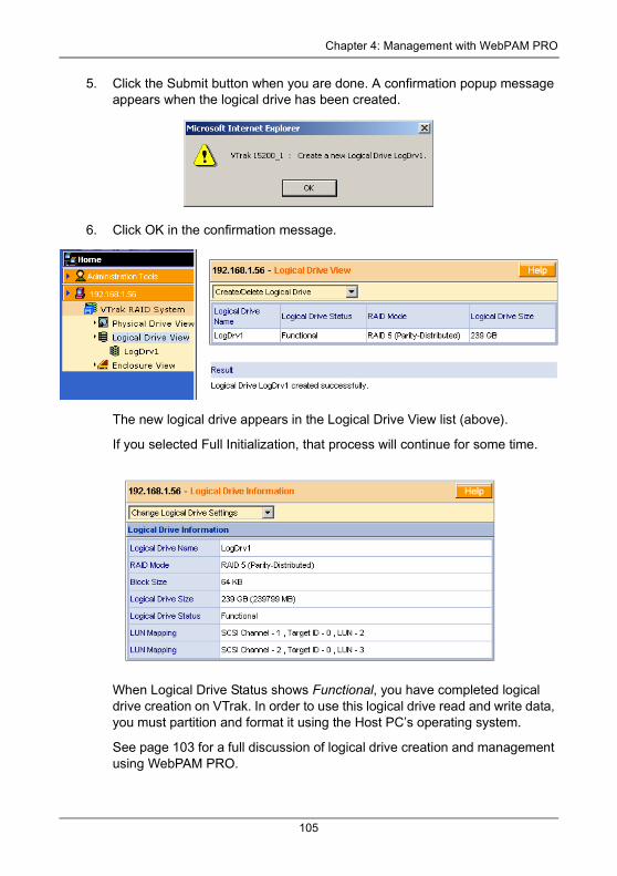
Chapter 4: Management with WebPAM PRO
5. Click the Submit button when you are done. A confirmation popup message appears when the logical drive has been created.
6. Click OK in the confirmation message.
The new logical drive appears in the Logical Drive View list (above).
If you selected Full Initialization, that process will continue for some time.
When Logical Drive Status shows Functional, you have completed logical drive creation on VTrak. In order to use this logical drive read and write data, you must partition and format it using the Host PC’s operating system.
See page 103 for a full discussion of logical drive creation and management using WebPAM PRO.
105
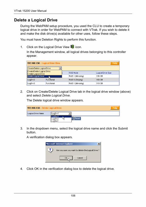
VTrak 15200 User Manual
Delete a Logical DriveDuring the WebPAM setup procedure, you used the CLU to create a temporary logical drive in order for WebPAM to connect with VTrak. If you wish to delete it and make the disk drive(s) available for other uses, follow these steps.
You must have Deletion Rights to perform this function.
1. Click on the Logical Drive View icon.
In the Management window, all logical drives belonging to this controller appear.
2. Click on Create/Delete Logical Drive tab in the logical drive window (above) and select Delete Logical Drive.
The Delete logical drive window appears.
3. In the dropdown menu, select the logical drive name and click the Submit button.
A verification dialog box appears.
4. Click OK in the verification dialog box to delete the logical drive.
106
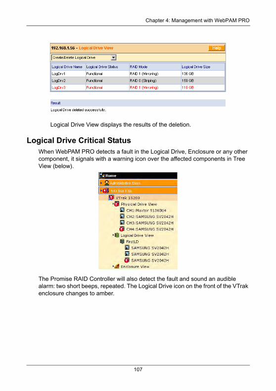
Chapter 4: Management with WebPAM PRO
Logical Drive View displays the results of the deletion.
Logical Drive Critical StatusWhen WebPAM PRO detects a fault in the Logical Drive, Enclosure or any other component, it signals with a warning icon over the affected components in Tree View (below).
The Promise RAID Controller will also detect the fault and sound an audible alarm: two short beeps, repeated. The Logical Drive icon on the front of the VTrak enclosure changes to amber.
107
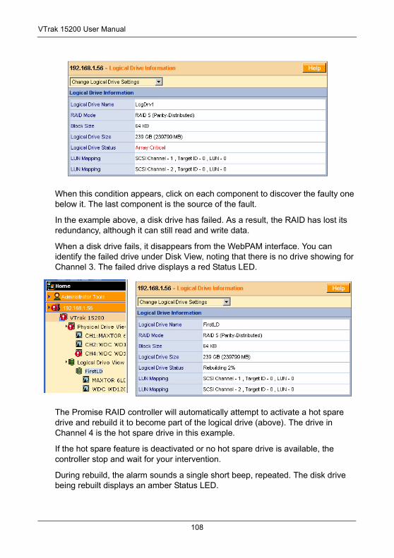
VTrak 15200 User Manual
When this condition appears, click on each component to discover the faulty one below it. The last component is the source of the fault.
In the example above, a disk drive has failed. As a result, the RAID has lost its redundancy, although it can still read and write data.
When a disk drive fails, it disappears from the WebPAM interface. You can identify the failed drive under Disk View, noting that there is no drive showing for Channel 3. The failed drive displays a red Status LED.
The Promise RAID controller will automatically attempt to activate a hot spare drive and rebuild it to become part of the logical drive (above). The drive in Channel 4 is the hot spare drive in this example.
If the hot spare feature is deactivated or no hot spare drive is available, the controller stop and wait for your intervention.
During rebuild, the alarm sounds a single short beep, repeated. The disk drive being rebuilt displays an amber Status LED.
108
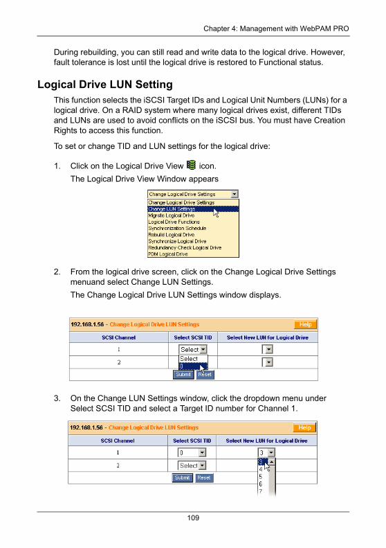
Chapter 4: Management with WebPAM PRO
During rebuilding, you can still read and write data to the logical drive. However, fault tolerance is lost until the logical drive is restored to Functional status.
Logical Drive LUN SettingThis function selects the iSCSI Target IDs and Logical Unit Numbers (LUNs) for a logical drive. On a RAID system where many logical drives exist, different TIDs and LUNs are used to avoid conflicts on the iSCSI bus. You must have Creation Rights to access this function.
To set or change TID and LUN settings for the logical drive:
1. Click on the Logical Drive View icon.
The Logical Drive View Window appears
2. From the logical drive screen, click on the Change Logical Drive Settings menuand select Change LUN Settings.
The Change Logical Drive LUN Settings window displays.
3. On the Change LUN Settings window, click the dropdown menu under Select SCSI TID and select a Target ID number for Channel 1.
109
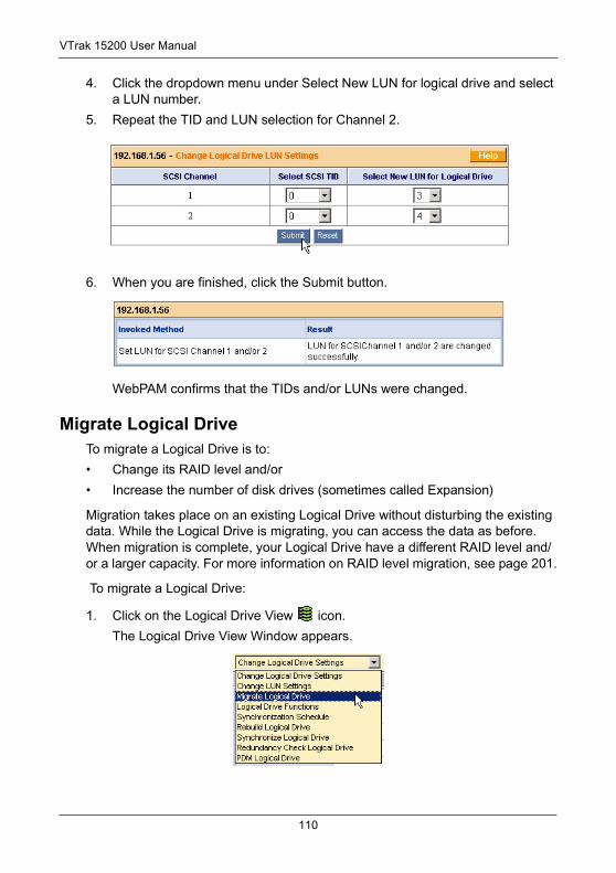
VTrak 15200 User Manual
4. Click the dropdown menu under Select New LUN for logical drive and select a LUN number.
5. Repeat the TID and LUN selection for Channel 2.
6. When you are finished, click the Submit button.
WebPAM confirms that the TIDs and/or LUNs were changed.
Migrate Logical DriveTo migrate a Logical Drive is to:
• Change its RAID level and/or
• Increase the number of disk drives (sometimes called Expansion)
Migration takes place on an existing Logical Drive without disturbing the existing data. While the Logical Drive is migrating, you can access the data as before. When migration is complete, your Logical Drive have a different RAID level and/or a larger capacity. For more information on RAID level migration, see page 201.
To migrate a Logical Drive:
1. Click on the Logical Drive View icon.
The Logical Drive View Window appears.
110
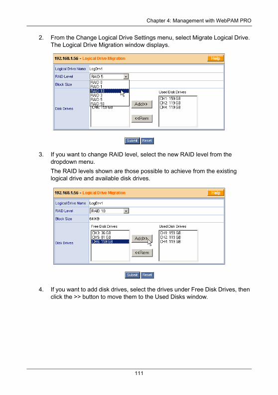
Chapter 4: Management with WebPAM PRO
2. From the Change Logical Drive Settings menu, select Migrate Logical Drive. The Logical Drive Migration window displays.
3. If you want to change RAID level, select the new RAID level from the dropdown menu.
The RAID levels shown are those possible to achieve from the existing logical drive and available disk drives.
4. If you want to add disk drives, select the drives under Free Disk Drives, then click the >> button to move them to the Used Disks window.
111
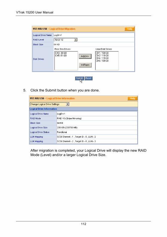
VTrak 15200 User Manual
5. Click the Submit button when you are done.
After migration is completed, your Logical Drive will display the new RAID Mode (Level) and/or a larger Logical Drive Size.
112
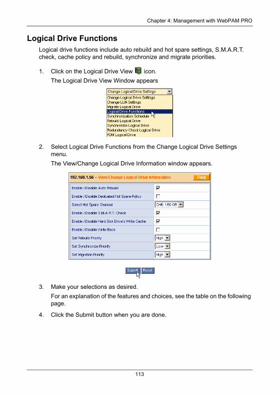
Chapter 4: Management with WebPAM PRO
Logical Drive FunctionsLogical drive functions include auto rebuild and hot spare settings, S.M.A.R.T. check, cache policy and rebuild, synchronize and migrate priorities.
1. Click on the Logical Drive View icon.
The Logical Drive View Window appears
2. Select Logical Drive Functions from the Change Logical Drive Settings menu.
The View/Change Logical Drive Information window appears.
3. Make your selections as desired.
For an explanation of the features and choices, see the table on the following page.
4. Click the Submit button when you are done.
113
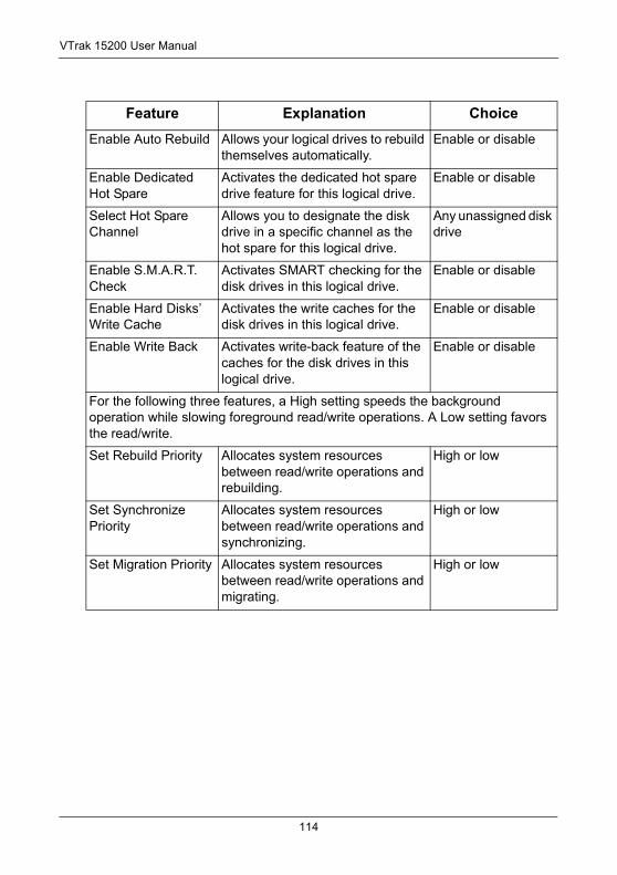
VTrak 15200 User Manual
Feature Explanation Choice
Enable Auto Rebuild Allows your logical drives to rebuild themselves automatically.
Enable or disable
Enable Dedicated Hot Spare
Activates the dedicated hot spare drive feature for this logical drive.
Enable or disable
Select Hot Spare Channel
Allows you to designate the disk drive in a specific channel as the hot spare for this logical drive.
Any unassigned disk drive
Enable S.M.A.R.T. Check
Activates SMART checking for the disk drives in this logical drive.
Enable or disable
Enable Hard Disks’ Write Cache
Activates the write caches for the disk drives in this logical drive.
Enable or disable
Enable Write Back Activates write-back feature of the caches for the disk drives in this logical drive.
Enable or disable
For the following three features, a High setting speeds the background operation while slowing foreground read/write operations. A Low setting favors the read/write.
Set Rebuild Priority Allocates system resources between read/write operations and rebuilding.
High or low
Set Synchronize Priority
Allocates system resources between read/write operations and synchronizing.
High or low
Set Migration Priority Allocates system resources between read/write operations and migrating.
High or low
114
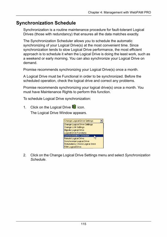
Chapter 4: Management with WebPAM PRO
Synchronization ScheduleSynchronization is a routine maintenance procedure for fault-tolerant Logical Drives (those with redundancy) that ensures all the data matches exactly.
The Synchronization Scheduler allows you to schedule the automatic synchronizing of your Logical Drive(s) at the most convenient time. Since synchronization tends to slow Logical Drive performance, the most efficient approach is to schedule it when the Logical Drive is doing the least work, such as a weekend or early morning. You can also synchronize your Logical Drive on demand.
Promise recommends synchronizing your Logical Drive(s) once a month.
A Logical Drive must be Functional in order to be synchronized. Before the scheduled operation, check the logical drive and correct any problems.
Promise recommends synchronizing your logical drive(s) once a month. You must have Maintenance Rights to perform this function.
To schedule Logical Drive synchronization:
1. Click on the Logical Drive icon.
The Logical Drive Window appears.
2. Click on the Change Logical Drive Settings menu and select Synchronization Schedule.
115

VTrak 15200 User Manual
3. Click on the button corresponding to the unit of time that best fits your schedule: By Minute, By Hour, By Day, By Week or By Month.
In the fields to the right of the button you clicked, enter the appropriate value(s).
• By Minute, type the number of minutes from 30 to 59.
• By Hour, type the number of hours from 1 to 23.
• By Week, type the a hours as above, then select a day of the week from the drop-down menu.
• By Month, type the a hours as above, then select a day of the month (through the 28th) from the drop-down menu.
4. For By Week and By Month, select the day of the week or the day of the month (through the 28th) from the dropdown menu.
5. When you are done, click the Submit button.
116
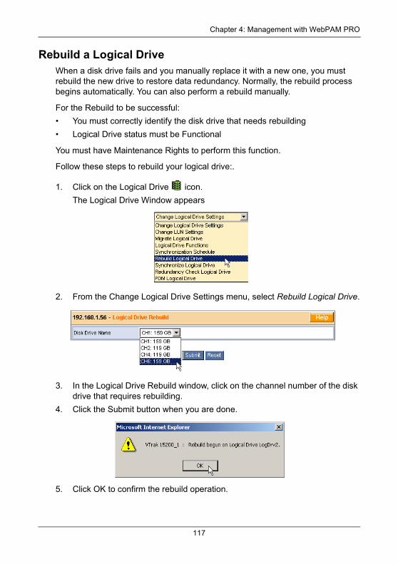
Chapter 4: Management with WebPAM PRO
Rebuild a Logical DriveWhen a disk drive fails and you manually replace it with a new one, you must rebuild the new drive to restore data redundancy. Normally, the rebuild process begins automatically. You can also perform a rebuild manually.
For the Rebuild to be successful:
• You must correctly identify the disk drive that needs rebuilding
• Logical Drive status must be Functional
You must have Maintenance Rights to perform this function.
Follow these steps to rebuild your logical drive:.
1. Click on the Logical Drive icon.
The Logical Drive Window appears
2. From the Change Logical Drive Settings menu, select Rebuild Logical Drive.
3. In the Logical Drive Rebuild window, click on the channel number of the disk drive that requires rebuilding.
4. Click the Submit button when you are done.
5. Click OK to confirm the rebuild operation.
117
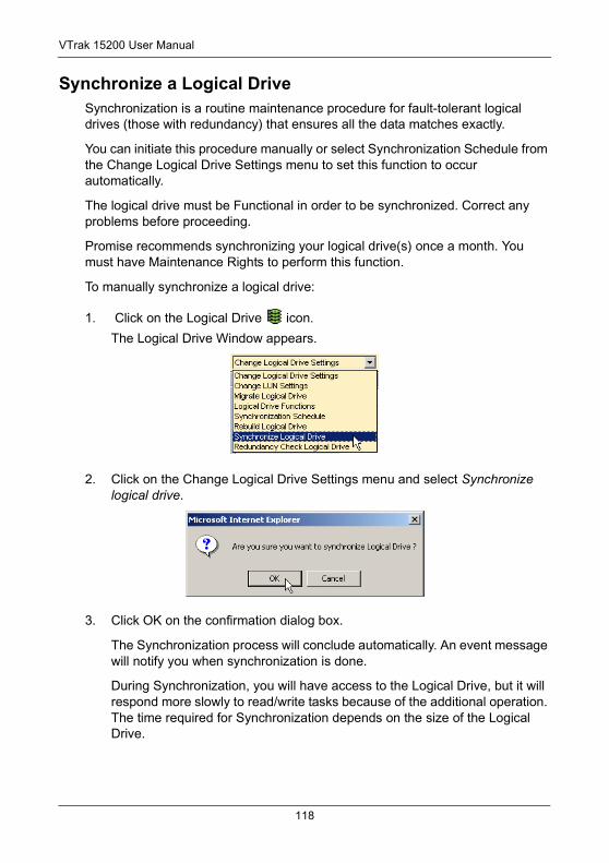
VTrak 15200 User Manual
Synchronize a Logical DriveSynchronization is a routine maintenance procedure for fault-tolerant logical drives (those with redundancy) that ensures all the data matches exactly.
You can initiate this procedure manually or select Synchronization Schedule from the Change Logical Drive Settings menu to set this function to occur automatically.
The logical drive must be Functional in order to be synchronized. Correct any problems before proceeding.
Promise recommends synchronizing your logical drive(s) once a month. You must have Maintenance Rights to perform this function.
To manually synchronize a logical drive:
1. Click on the Logical Drive icon.
The Logical Drive Window appears.
2. Click on the Change Logical Drive Settings menu and select Synchronize logical drive.
3. Click OK on the confirmation dialog box.
The Synchronization process will conclude automatically. An event message will notify you when synchronization is done.
During Synchronization, you will have access to the Logical Drive, but it will respond more slowly to read/write tasks because of the additional operation. The time required for Synchronization depends on the size of the Logical Drive.
118
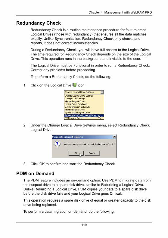
Chapter 4: Management with WebPAM PRO
Redundancy CheckRedundancy Check is a routine maintenance procedure for fault-tolerant Logical Drives (those with redundancy) that ensures all the data matches exactly. Unlike Synchronization, Redundancy Check only checks and reports, it does not correct inconsistencies.
During a Redundancy Check, you will have full access to the Logical Drive. The time required for Redundancy Check depends on the size of the Logical Drive. This operation runs in the background and invisible to the user.
The Logical Drive must be Functional in order to run a Redundancy Check. Correct any problems before proceeding
To perform a Redundancy Check, do the following:
1. Click on the Logical Drive icon.
2. Under the Change Logical Drive Settings menu, select Redundancy Check Logical Drive.
3. Click OK to confirm and start the Redundancy Check.
PDM on DemandThe PDM feature includes an on-demand option. Use PDM to migrate data from the suspect drive to a spare disk drive, similar to Rebuilding a Logical Drive. Unlike Rebuilding a Logical Drive, PDM copies your data to a spare disk drive before the disk drive fails and your Logical Drive goes Critical.
This operation requires a spare disk drive of equal or greater capacity to the disk drive being replaced.
To perform a data migration on-demand, do the following:
119
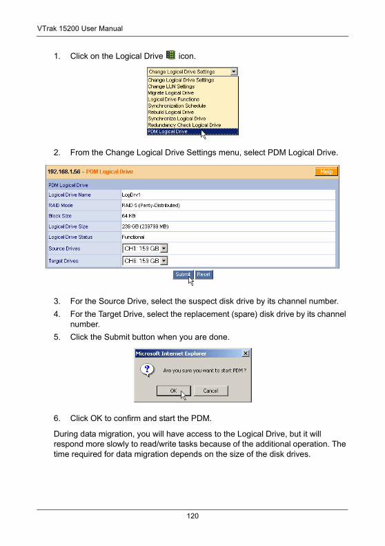
VTrak 15200 User Manual
1. Click on the Logical Drive icon.
2. From the Change Logical Drive Settings menu, select PDM Logical Drive.
3. For the Source Drive, select the suspect disk drive by its channel number.
4. For the Target Drive, select the replacement (spare) disk drive by its channel number.
5. Click the Submit button when you are done.
6. Click OK to confirm and start the PDM.
During data migration, you will have access to the Logical Drive, but it will respond more slowly to read/write tasks because of the additional operation. The time required for data migration depends on the size of the disk drives.
120
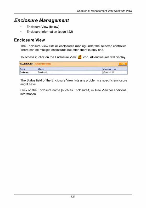
Chapter 4: Management with WebPAM PRO
Enclosure Management• Enclosure View (below)
• Enclosure Information (page 122)
Enclosure ViewThe Enclosure View lists all enclosures running under the selected controller. There can be multiple enclosures but often there is only one.
To access it, click on the Enclosure View icon. All enclosures will display.
The Status field of the Enclosure View lists any problems a specific enclosure might have.
Click on the Enclosure name (such as Enclosure1) in Tree View for additional information.
121
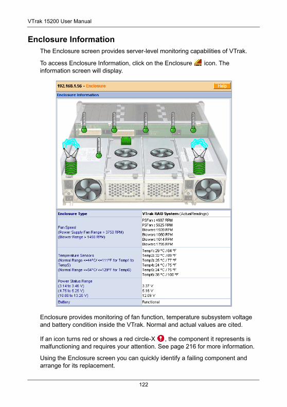
VTrak 15200 User Manual
Enclosure InformationThe Enclosure screen provides server-level monitoring capabilities of VTrak.
To access Enclosure Information, click on the Enclosure icon. The information screen will display.
Enclosure provides monitoring of fan function, temperature subsystem voltage and battery condition inside the VTrak. Normal and actual values are cited.
If an icon turns red or shows a red circle-X , the component it represents is malfunctioning and requires your attention. See page 216 for more information.
Using the Enclosure screen you can quickly identify a failing component and arrange for its replacement.
122
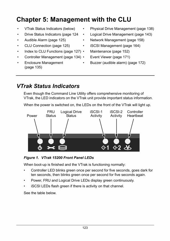
Chapter 5: Management with the CLU
VTrak Status IndicatorsEven though the Command Line Utility offers comprehensive monitoring of VTrak, the LED indicators on the VTrak unit provide important status information.
When the power is switched on, the LEDs on the front of the VTrak will light up.
Figure 1. VTrak 15200 Front Panel LEDs
When boot-up is finished and the VTrak is functioning normally:
• Controller LED blinks green once per second for five seconds, goes dark for ten seconds, then blinks green once per second for five seconds again.
• Power, FRU and Logical Drive LEDs display green continuously.
• iSCSI LEDs flash green if there is activity on that channel.
See the table below.
• VTrak Status Indicators (below)
• Drive Status Indicators (page 124
• Audible Alarm (page 125)
• CLU Connection (page 125)
• Index to CLU Functions (page 127)
• Controller Management (page 134)
• Enclosure Management (page 135)
• Physical Drive Management (page 138)
• Logical Drive Management (page 143)
• Network Management (page 158)
• iSCSI Management (page 164)
• Maintenance (page 152)
• Event Viewer (page 171)
• Buzzer (audible alarm) (page 172)
PoweriSCSI-2Activity
FRUStatus
Logical DriveStatus
iSCSI-1Activity
ControllerHeartbeat
123
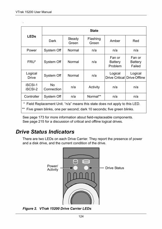
VTrak 15200 User Manual
.
See page 173 for more information about field-replaceable components. See page 215 for a discussion of critical and offline logical drives.
Drive Status IndicatorsThere are two LEDs on each Drive Carrier. They report the presence of power and a disk drive, and the current condition of the drive.
Figure 2. VTrak 15200 Drive Carrier LEDs
LEDsState
DarkSteady Green
Flashing Green
Amber Red
Power System Off Normal n/a n/a n/a
FRU* System Off Normal n/aFan or Battery Problem
Fan or Battery Failed
Logical Drive
System Off Normal n/aLogical
Drive CriticalLogical
Drive Offline
iSCSI-1iSCSI-2
No Connection
n/a Activity n/a n/a
Controller System Off n/a Normal** n/a n/a
* Field Replacement Unit. “n/a” means this state does not apply to this LED.
** Five green blinks, one per second; dark 10 seconds; five green blinks.
Drive StatusPower/Activity
124
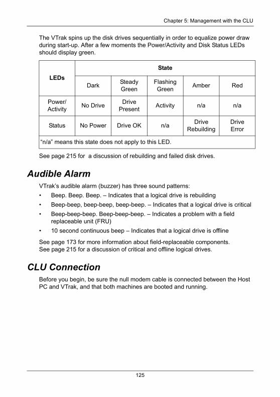
Chapter 5: Management with the CLU
The VTrak spins up the disk drives sequentially in order to equalize power draw during start-up. After a few moments the Power/Activity and Disk Status LEDs should display green.
See page 215 for a discussion of rebuilding and failed disk drives.
Audible Alarm VTrak’s audible alarm (buzzer) has three sound patterns:
• Beep. Beep. Beep. – Indicates that a logical drive is rebuilding
• Beep-beep, beep-beep, beep-beep. – Indicates that a logical drive is critical
• Beep-beep-beep. Beep-beep-beep. – Indicates a problem with a field replaceable unit (FRU)
• 10 second continuous beep – Indicates that a logical drive is offline
See page 173 for more information about field-replaceable components. See page 215 for a discussion of critical and offline logical drives.
CLU ConnectionBefore you begin, be sure the null modem cable is connected between the Host PC and VTrak, and that both machines are booted and running.
LEDsState
DarkSteady Green
Flashing Green
Amber Red
Power/Activity
No DriveDrive
PresentActivity n/a n/a
Status No Power Drive OK n/aDrive
RebuildingDriveError
“n/a” means this state does not apply to this LED.
125
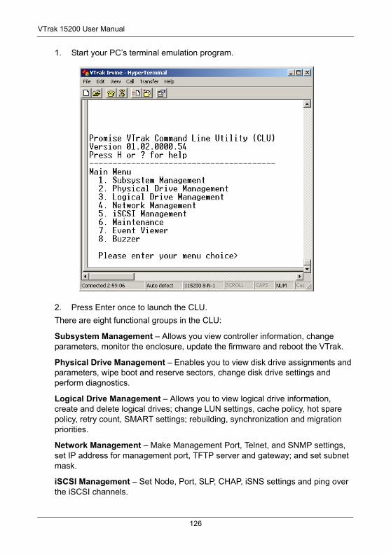
VTrak 15200 User Manual
1. Start your PC’s terminal emulation program.
2. Press Enter once to launch the CLU.
There are eight functional groups in the CLU:
Subsystem Management – Allows you view controller information, change parameters, monitor the enclosure, update the firmware and reboot the VTrak.
Physical Drive Management – Enables you to view disk drive assignments and parameters, wipe boot and reserve sectors, change disk drive settings and perform diagnostics.
Logical Drive Management – Allows you to view logical drive information, create and delete logical drives; change LUN settings, cache policy, hot spare policy, retry count, SMART settings; rebuilding, synchronization and migration priorities.
Network Management – Make Management Port, Telnet, and SNMP settings, set IP address for management port, TFTP server and gateway; and set subnet mask.
iSCSI Management – Set Node, Port, SLP, CHAP, iSNS settings and ping over the iSCSI channels.
126
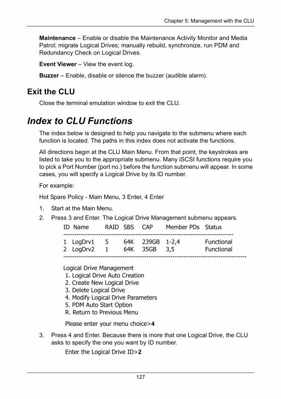
Chapter 5: Management with the CLU
Maintenance – Enable or disable the Maintenance Activity Monitor and Media Patrol; migrate Logical Drives; manually rebuild, synchronize, run PDM and Redundancy Check on Logical Drives.
Event Viewer – View the event log.
Buzzer – Enable, disable or silence the buzzer (audible alarm).
Exit the CLUClose the terminal emulation window to exit the CLU.
Index to CLU FunctionsThe index below is designed to help you navigate to the submenu where each function is located. The paths in this index does not activate the functions.
All directions begin at the CLU Main Menu. From that point, the keystrokes are listed to take you to the appropriate submenu. Many iSCSI functions require you to pick a Port Number (port no.) before the function submenu will appear. In some cases, you will specify a Logical Drive by its ID number.
For example:
Hot Spare Policy - Main Menu, 3 Enter, 4 Enter
1. Start at the Main Menu.
2. Press 3 and Enter. The Logical Drive Management submenu appears.
ID Name RAID SBS CAP Member PDs Status------------------------------------------------------------------------------1 LogDrv1 5 64K 239GB 1-2,4 Functional2 LogDrv2 1 64K 35GB 3,5 Functional------------------------------------------------------------------------------------
Logical Drive Management 1. Logical Drive Auto Creation 2. Create New Logical Drive 3. Delete Logical Drive 4. Modify Logical Drive Parameters 5. PDM Auto Start Option R. Return to Previous Menu
Please enter your menu choice>4
3. Press 4 and Enter. Because there is more that one Logical Drive, the CLU asks to specify the one you want by ID number.
Enter the Logical Drive ID>2
127
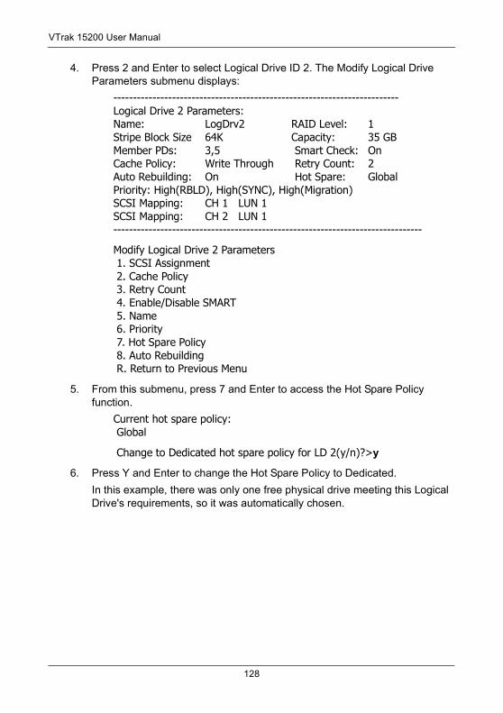
VTrak 15200 User Manual
4. Press 2 and Enter to select Logical Drive ID 2. The Modify Logical Drive Parameters submenu displays:
-------------------------------------------------------------------------Logical Drive 2 Parameters:Name: LogDrv2 RAID Level: 1Stripe Block Size 64K Capacity: 35 GBMember PDs: 3,5 Smart Check: OnCache Policy: Write Through Retry Count: 2Auto Rebuilding: On Hot Spare: GlobalPriority: High(RBLD), High(SYNC), High(Migration)SCSI Mapping: CH 1 LUN 1SCSI Mapping: CH 2 LUN 1-------------------------------------------------------------------------------
Modify Logical Drive 2 Parameters 1. SCSI Assignment 2. Cache Policy 3. Retry Count 4. Enable/Disable SMART 5. Name 6. Priority 7. Hot Spare Policy 8. Auto Rebuilding R. Return to Previous Menu
5. From this submenu, press 7 and Enter to access the Hot Spare Policy function.
Current hot spare policy: Global
Change to Dedicated hot spare policy for LD 2(y/n)?>y
6. Press Y and Enter to change the Hot Spare Policy to Dedicated.
In this example, there was only one free physical drive meeting this Logical Drive's requirements, so it was automatically chosen.
128
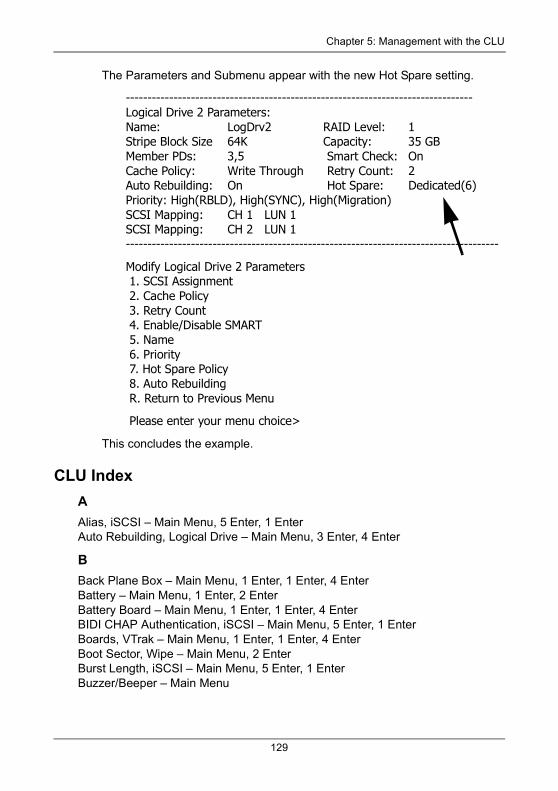
Chapter 5: Management with the CLU
The Parameters and Submenu appear with the new Hot Spare setting.
--------------------------------------------------------------------------------Logical Drive 2 Parameters:Name: LogDrv2 RAID Level: 1Stripe Block Size 64K Capacity: 35 GBMember PDs: 3,5 Smart Check: OnCache Policy: Write Through Retry Count: 2Auto Rebuilding: On Hot Spare: Dedicated(6)Priority: High(RBLD), High(SYNC), High(Migration)SCSI Mapping: CH 1 LUN 1SCSI Mapping: CH 2 LUN 1--------------------------------------------------------------------------------------
Modify Logical Drive 2 Parameters 1. SCSI Assignment 2. Cache Policy 3. Retry Count 4. Enable/Disable SMART 5. Name 6. Priority 7. Hot Spare Policy 8. Auto Rebuilding R. Return to Previous Menu
Please enter your menu choice>
This concludes the example.
CLU IndexAAlias, iSCSI – Main Menu, 5 Enter, 1 EnterAuto Rebuilding, Logical Drive – Main Menu, 3 Enter, 4 Enter
BBack Plane Box – Main Menu, 1 Enter, 1 Enter, 4 EnterBattery – Main Menu, 1 Enter, 2 EnterBattery Board – Main Menu, 1 Enter, 1 Enter, 4 EnterBIDI CHAP Authentication, iSCSI – Main Menu, 5 Enter, 1 EnterBoards, VTrak – Main Menu, 1 Enter, 1 Enter, 4 EnterBoot Sector, Wipe – Main Menu, 2 EnterBurst Length, iSCSI – Main Menu, 5 Enter, 1 EnterBuzzer/Beeper – Main Menu
129
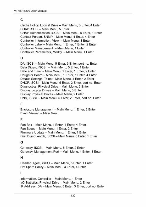
VTrak 15200 User Manual
CCache Policy, Logical Drive – Main Menu, 3 Enter, 4 EnterCHAP, iSCSI – Main Menu, 5 EnterCHAP Authentication, iSCSI – Main Menu, 5 Enter, 1 EnterContact Person, SNMP – Main Menu, 4 Enter, 4 EnterController Information, View – Main Menu, 1 EnterController Label – Main Menu, 1 Enter, 1 Enter, 2 EnterController Management – Main Menu, 1 EnterController Parameters, Modify – Main Menu, 1 Enter
DDA, iSCSI – Main Menu, 5 Enter, 3 Enter, port no. EnterData Digest, iSCSI – Main Menu, 5 Enter, 1 EnterDate and Time – Main Menu, 1 Enter, 1 Enter, 2 EnterDaughter Board – Main Menu, 1 Enter, 1 Enter, 4 EnterDefault Settings, Telnet - Main Menu, 4 Enter, 2 EnterDHCP, iSCSI – Main Menu, 5 Enter, 2 Enter, port no. EnterDiagnostics, Physical Drive – Main Menu, 2 EnterDisplay Logical Drives – Main Menu, 3 EnterDisplay Physical Drives – Main Menu, 2 EnterDNS, iSCSI – Main Menu, 5 Enter, 2 Enter, port no. Enter
EEnclosure Management – Main Menu, 1 Enter, 2 EnterEvent Viewer – Main Menu
FFan Box – Main Menu, 1 Enter, 1 Enter, 4 EnterFan Speed – Main Menu, 1 Enter, 2 EnterFirmware Update – Main Menu, 1 Enter, 1 EnterFirst Burst Length, iSCSI – Main Menu, 5 Enter, 1 Enter
GGateway, iSCSI – Main Menu, 5 Enter, 2 EnterGateway, Management Port – Main Menu, 4 Enter, 1 Enter
HHeader Digest, iSCSI – Main Menu, 5 Enter, 1 EnterHot Spare Policy – Main Menu, 3 Enter, 4 Enter
IInformation, Controller – Main Menu, 1 EnterI/O Statistics, Physical Drive – Main Menu, 2 EnterIP Address, DA – Main Menu, 5 Enter, 3 Enter, port no. Enter
130
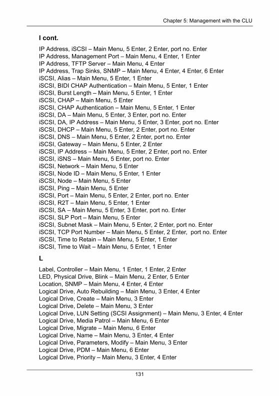
Chapter 5: Management with the CLU
I cont.IP Address, iSCSI – Main Menu, 5 Enter, 2 Enter, port no. EnterIP Address, Management Port – Main Menu, 4 Enter, 1 EnterIP Address, TFTP Server – Main Menu, 4 EnterIP Address, Trap Sinks, SNMP – Main Menu, 4 Enter, 4 Enter, 6 EnteriSCSI, Alias – Main Menu, 5 Enter, 1 EnteriSCSI, BIDI CHAP Authentication – Main Menu, 5 Enter, 1 EnteriSCSI, Burst Length – Main Menu, 5 Enter, 1 EnteriSCSI, CHAP – Main Menu, 5 EnteriSCSI, CHAP Authentication – Main Menu, 5 Enter, 1 EnteriSCSI, DA – Main Menu, 5 Enter, 3 Enter, port no. EnteriSCSI, DA, IP Address – Main Menu, 5 Enter, 3 Enter, port no. EnteriSCSI, DHCP – Main Menu, 5 Enter, 2 Enter, port no. EnteriSCSI, DNS – Main Menu, 5 Enter, 2 Enter, port no. EnteriSCSI, Gateway – Main Menu, 5 Enter, 2 EnteriSCSI, IP Address – Main Menu, 5 Enter, 2 Enter, port no. EnteriSCSI, iSNS – Main Menu, 5 Enter, port no. EnteriSCSI, Network – Main Menu, 5 EnteriSCSI, Node ID – Main Menu, 5 Enter, 1 EnteriSCSI, Node – Main Menu, 5 EnteriSCSI, Ping – Main Menu, 5 EnteriSCSI, Port – Main Menu, 5 Enter, 2 Enter, port no. EnteriSCSI, R2T – Main Menu, 5 Enter, 1 EnteriSCSI, SA – Main Menu, 5 Enter, 3 Enter, port no. EnteriSCSI, SLP Port – Main Menu, 5 EnteriSCSI, Subnet Mask – Main Menu, 5 Enter, 2 Enter, port no. EnteriSCSI, TCP Port Number – Main Menu, 5 Enter, 2 Enter, port no. EnteriSCSI, Time to Retain – Main Menu, 5 Enter, 1 EnteriSCSI, Time to Wait – Main Menu, 5 Enter, 1 Enter
LLabel, Controller – Main Menu, 1 Enter, 1 Enter, 2 EnterLED, Physical Drive, Blink – Main Menu, 2 Enter, 5 EnterLocation, SNMP – Main Menu, 4 Enter, 4 EnterLogical Drive, Auto Rebuilding – Main Menu, 3 Enter, 4 EnterLogical Drive, Create – Main Menu, 3 EnterLogical Drive, Delete – Main Menu, 3 EnterLogical Drive, LUN Setting (SCSI Assignment) – Main Menu, 3 Enter, 4 EnterLogical Drive, Media Patrol – Main Menu, 6 EnterLogical Drive, Migrate – Main Menu, 6 EnterLogical Drive, Name – Main Menu, 3 Enter, 4 EnterLogical Drive, Parameters, Modify – Main Menu, 3 EnterLogical Drive, PDM – Main Menu, 6 EnterLogical Drive, Priority – Main Menu, 3 Enter, 4 Enter
131
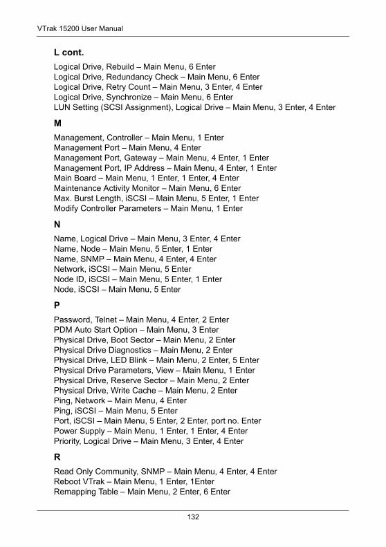
VTrak 15200 User Manual
L cont.Logical Drive, Rebuild – Main Menu, 6 EnterLogical Drive, Redundancy Check – Main Menu, 6 EnterLogical Drive, Retry Count – Main Menu, 3 Enter, 4 EnterLogical Drive, Synchronize – Main Menu, 6 EnterLUN Setting (SCSI Assignment), Logical Drive – Main Menu, 3 Enter, 4 Enter
MManagement, Controller – Main Menu, 1 EnterManagement Port – Main Menu, 4 EnterManagement Port, Gateway – Main Menu, 4 Enter, 1 EnterManagement Port, IP Address – Main Menu, 4 Enter, 1 EnterMain Board – Main Menu, 1 Enter, 1 Enter, 4 EnterMaintenance Activity Monitor – Main Menu, 6 EnterMax. Burst Length, iSCSI – Main Menu, 5 Enter, 1 EnterModify Controller Parameters – Main Menu, 1 Enter
NName, Logical Drive – Main Menu, 3 Enter, 4 EnterName, Node – Main Menu, 5 Enter, 1 EnterName, SNMP – Main Menu, 4 Enter, 4 EnterNetwork, iSCSI – Main Menu, 5 EnterNode ID, iSCSI – Main Menu, 5 Enter, 1 EnterNode, iSCSI – Main Menu, 5 Enter
PPassword, Telnet – Main Menu, 4 Enter, 2 EnterPDM Auto Start Option – Main Menu, 3 EnterPhysical Drive, Boot Sector – Main Menu, 2 EnterPhysical Drive Diagnostics – Main Menu, 2 EnterPhysical Drive, LED Blink – Main Menu, 2 Enter, 5 EnterPhysical Drive Parameters, View – Main Menu, 1 EnterPhysical Drive, Reserve Sector – Main Menu, 2 EnterPhysical Drive, Write Cache – Main Menu, 2 EnterPing, Network – Main Menu, 4 EnterPing, iSCSI – Main Menu, 5 EnterPort, iSCSI – Main Menu, 5 Enter, 2 Enter, port no. EnterPower Supply – Main Menu, 1 Enter, 1 Enter, 4 EnterPriority, Logical Drive – Main Menu, 3 Enter, 4 Enter
RRead Only Community, SNMP – Main Menu, 4 Enter, 4 EnterReboot VTrak – Main Menu, 1 Enter, 1EnterRemapping Table – Main Menu, 2 Enter, 6 Enter
132
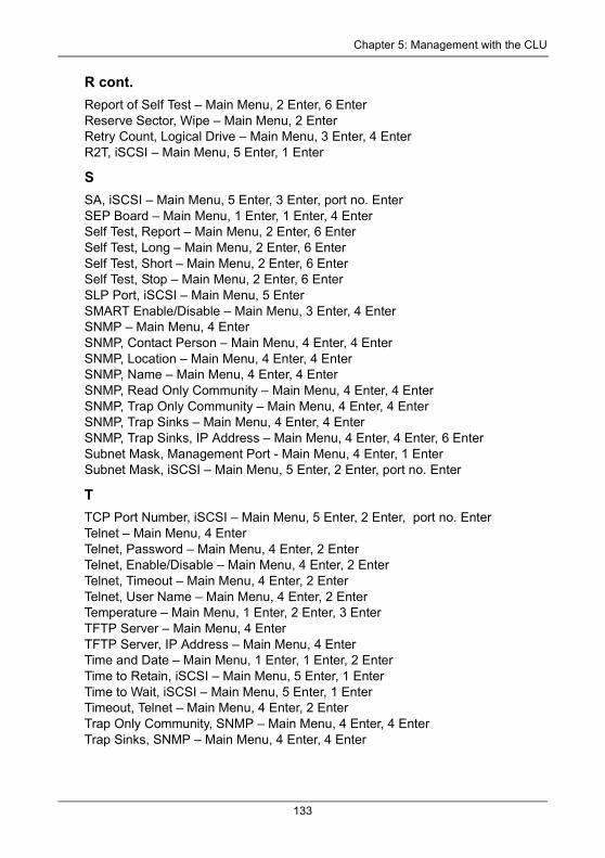
Chapter 5: Management with the CLU
R cont.Report of Self Test – Main Menu, 2 Enter, 6 EnterReserve Sector, Wipe – Main Menu, 2 EnterRetry Count, Logical Drive – Main Menu, 3 Enter, 4 EnterR2T, iSCSI – Main Menu, 5 Enter, 1 Enter
SSA, iSCSI – Main Menu, 5 Enter, 3 Enter, port no. EnterSEP Board – Main Menu, 1 Enter, 1 Enter, 4 EnterSelf Test, Report – Main Menu, 2 Enter, 6 EnterSelf Test, Long – Main Menu, 2 Enter, 6 EnterSelf Test, Short – Main Menu, 2 Enter, 6 EnterSelf Test, Stop – Main Menu, 2 Enter, 6 EnterSLP Port, iSCSI – Main Menu, 5 EnterSMART Enable/Disable – Main Menu, 3 Enter, 4 EnterSNMP – Main Menu, 4 EnterSNMP, Contact Person – Main Menu, 4 Enter, 4 EnterSNMP, Location – Main Menu, 4 Enter, 4 EnterSNMP, Name – Main Menu, 4 Enter, 4 EnterSNMP, Read Only Community – Main Menu, 4 Enter, 4 EnterSNMP, Trap Only Community – Main Menu, 4 Enter, 4 EnterSNMP, Trap Sinks – Main Menu, 4 Enter, 4 EnterSNMP, Trap Sinks, IP Address – Main Menu, 4 Enter, 4 Enter, 6 EnterSubnet Mask, Management Port - Main Menu, 4 Enter, 1 EnterSubnet Mask, iSCSI – Main Menu, 5 Enter, 2 Enter, port no. Enter
TTCP Port Number, iSCSI – Main Menu, 5 Enter, 2 Enter, port no. EnterTelnet – Main Menu, 4 EnterTelnet, Password – Main Menu, 4 Enter, 2 EnterTelnet, Enable/Disable – Main Menu, 4 Enter, 2 EnterTelnet, Timeout – Main Menu, 4 Enter, 2 EnterTelnet, User Name – Main Menu, 4 Enter, 2 EnterTemperature – Main Menu, 1 Enter, 2 Enter, 3 EnterTFTP Server – Main Menu, 4 EnterTFTP Server, IP Address – Main Menu, 4 EnterTime and Date – Main Menu, 1 Enter, 1 Enter, 2 EnterTime to Retain, iSCSI – Main Menu, 5 Enter, 1 EnterTime to Wait, iSCSI – Main Menu, 5 Enter, 1 EnterTimeout, Telnet – Main Menu, 4 Enter, 2 EnterTrap Only Community, SNMP – Main Menu, 4 Enter, 4 EnterTrap Sinks, SNMP – Main Menu, 4 Enter, 4 Enter
133
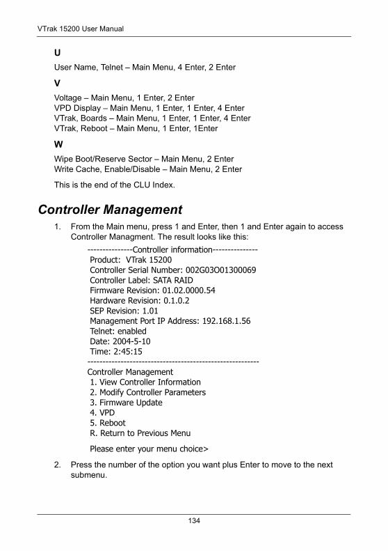
VTrak 15200 User Manual
UUser Name, Telnet – Main Menu, 4 Enter, 2 Enter
VVoltage – Main Menu, 1 Enter, 2 EnterVPD Display – Main Menu, 1 Enter, 1 Enter, 4 EnterVTrak, Boards – Main Menu, 1 Enter, 1 Enter, 4 EnterVTrak, Reboot – Main Menu, 1 Enter, 1Enter
WWipe Boot/Reserve Sector – Main Menu, 2 EnterWrite Cache, Enable/Disable – Main Menu, 2 Enter
This is the end of the CLU Index.
Controller Management1. From the Main menu, press 1 and Enter, then 1 and Enter again to access
Controller Managment. The result looks like this:
---------------Controller information--------------- Product: VTrak 15200 Controller Serial Number: 002G03O01300069 Controller Label: SATA RAID Firmware Revision: 01.02.0000.54 Hardware Revision: 0.1.0.2 SEP Revision: 1.01 Management Port IP Address: 192.168.1.56 Telnet: enabled Date: 2004-5-10 Time: 2:45:15---------------------------------------------------------Controller Management 1. View Controller Information 2. Modify Controller Parameters 3. Firmware Update 4. VPD 5. Reboot R. Return to Previous Menu
Please enter your menu choice>
2. Press the number of the option you want plus Enter to move to the next submenu.
134
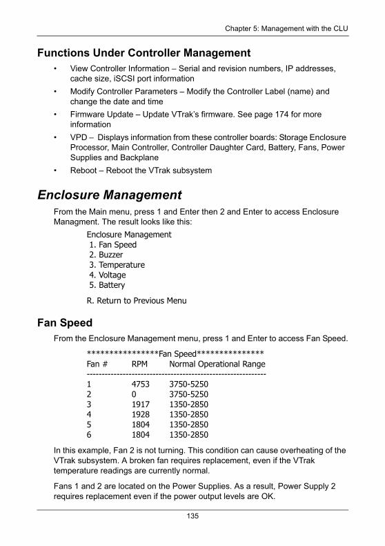
Chapter 5: Management with the CLU
Functions Under Controller Management• View Controller Information – Serial and revision numbers, IP addresses,
cache size, iSCSI port information
• Modify Controller Parameters – Modify the Controller Label (name) and change the date and time
• Firmware Update – Update VTrak’s firmware. See page 174 for more information
• VPD – Displays information from these controller boards: Storage Enclosure Processor, Main Controller, Controller Daughter Card, Battery, Fans, Power Supplies and Backplane
• Reboot – Reboot the VTrak subsystem
Enclosure ManagementFrom the Main menu, press 1 and Enter then 2 and Enter to access Enclosure Managment. The result looks like this:
Enclosure Management 1. Fan Speed 2. Buzzer 3. Temperature 4. Voltage 5. Battery
R. Return to Previous Menu
Fan SpeedFrom the Enclosure Management menu, press 1 and Enter to access Fan Speed.
****************Fan Speed***************Fan # RPM Normal Operational Range------------------------------------------------------------1 4753 3750-52502 0 3750-52503 1917 1350-28504 1928 1350-28505 1804 1350-28506 1804 1350-2850
In this example, Fan 2 is not turning. This condition can cause overheating of the VTrak subsystem. A broken fan requires replacement, even if the VTrak temperature readings are currently normal.
Fans 1 and 2 are located on the Power Supplies. As a result, Power Supply 2 requires replacement even if the power output levels are OK.
135
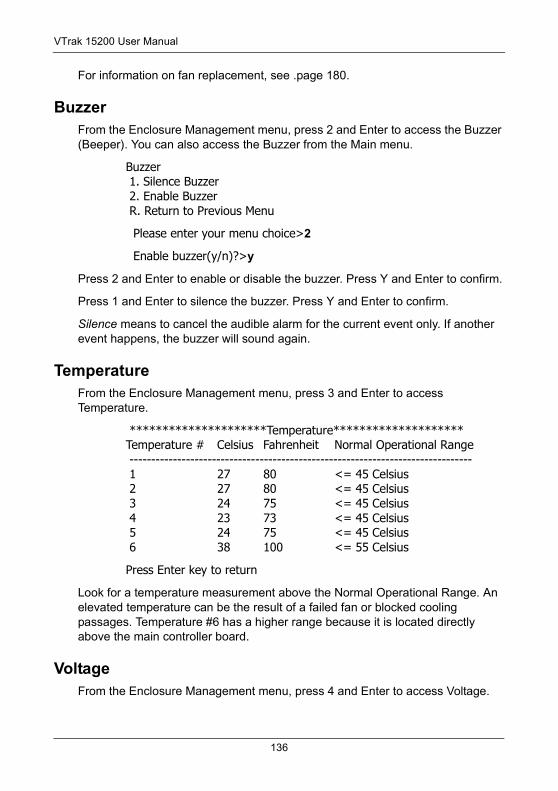
VTrak 15200 User Manual
For information on fan replacement, see .page 180.
BuzzerFrom the Enclosure Management menu, press 2 and Enter to access the Buzzer (Beeper). You can also access the Buzzer from the Main menu.
Buzzer 1. Silence Buzzer 2. Enable Buzzer R. Return to Previous Menu
Please enter your menu choice>2
Enable buzzer(y/n)?>y
Press 2 and Enter to enable or disable the buzzer. Press Y and Enter to confirm.
Press 1 and Enter to silence the buzzer. Press Y and Enter to confirm.
Silence means to cancel the audible alarm for the current event only. If another event happens, the buzzer will sound again.
TemperatureFrom the Enclosure Management menu, press 3 and Enter to access Temperature.
*********************Temperature********************Temperature # Celsius Fahrenheit Normal Operational Range ------------------------------------------------------------------------------- 1 27 80 <= 45 Celsius 2 27 80 <= 45 Celsius 3 24 75 <= 45 Celsius 4 23 73 <= 45 Celsius 5 24 75 <= 45 Celsius 6 38 100 <= 55 Celsius
Press Enter key to return
Look for a temperature measurement above the Normal Operational Range. An elevated temperature can be the result of a failed fan or blocked cooling passages. Temperature #6 has a higher range because it is located directly above the main controller board.
VoltageFrom the Enclosure Management menu, press 4 and Enter to access Voltage.
136
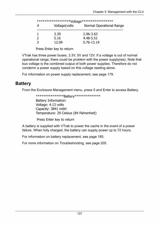
Chapter 5: Management with the CLU
******************Voltage***************** # Voltage(volts Normal Operational Range ---------------------------------------------------------------------- 1 3.39 2.96-3.63 2 5.16 4.48-5.51 3 12.09 0.76-13.19
Press Enter key to return
VTrak has three power buses, 3.3V, 5V and 12V. If a voltage is out of normal operational range, there could be problem with the power supply(ies). Note that bus voltage is the combined output of both power supplies. Therefore do not condemn a power supply based on this voltage reading alone.
For information on power supply replacement, see page 179.
BatteryFrom the Enclosure Management menu, press 5 and Enter to access Battery.
***************Battery**************Battery Information:Voltage: 4.13 voltsCapacity: 3841 mAHTemperature: 29 Celsius (84 Fahrenheit)
Press Enter key to return
A battery is supplied with VTrak to power the cache in the event of a power failure. When fully charged, the battery can supply power up to 72 hours.
For information on battery replacement, see page 185.
For more information on Troubleshooting, see page 205.
137
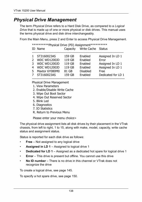
VTrak 15200 User Manual
Physical Drive ManagementThe term Physical Drive refers to a Hard Disk Drive, as compared to a Logical Drive that is made up of one or more physical or disk drives. This manual uses the terms physical drive and disk drive interchangeably.
From the Main Menu, press 2 and Enter to access Physical Drive Management.
**********Physical Drive (PD) Assignment**********ID Name Capacity Write Cache Status-----------------------------------------------------------------------------------1 ST3160023AS 159 GB Enabled Assigned In LD 12 WDC WD1200JD 119 GB Enabled Error3 WDC WD1200JD 119 GB Enabled Assigned In LD 14 WDC WD1200JD 119 GB Enabled Assigned In LD 15 Maxtor 6Y080M0 81 GB Disabled Free7 ST3160023AS 159 GB Enabled Dedicated for LD 1------------------------------------------------------------------------------------Physical Drive Management 1. View Parameters 2. Enable/Disable Write Cache 3. Wipe Out Boot Sector 4. Wipe Out Reserved Sector 5. Blink Led 6. Diagnostics 7. IO Statistics R. Return to Previous Menu
Please enter your menu choice>
The physical drive assignment lists all disk drives by their placement in the VTrak chassis, from left to right, 1 to 15, along with make, model, capacity, write cache status and assignment status.
Status is reported for each disk drive as follows:
• Free – Not assigned to any logical drive
• Assigned in LD 1 – Assigned to logical drive 1
• Dedicated for LD 1 – Assigned as a dedicated hot spare for logical drive 1
• Error – This drive is present but offline. You cannot use this drive
• No ID number – There is no drive in this channel or VTrak does not recognize the drive
To create a logical drive, see page 145.
To specify a hot spare drive, see page 150.
138
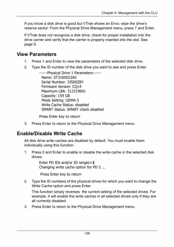
Chapter 5: Management with the CLU
If you know a disk drive is good but VTrak shows an Error, wipe the drive’s reserve sector. From the Physical Drive Management menu, press 7 and Enter.
If VTrak does not recognize a disk drive, check for proper installation into the drive carrier and verify that the carrier is properly inserted into the slot. See page 9.
View Parameters1. Press 1 and Enter to view the parameters of the selected disk drive.
2. Type the ID number of the disk drive you want to see and press Enter.
------Physical Drive 1 Parameters------ Name: ST3160023AS Serial Number: 3JS0SZ8Y Firmware Version: CQ14 Maximum LBA: 312319601 Capacity: 159 GB Mode Setting: UDMA 5 Write Cache Status: disabled SMART Status: SMART check disabled
Press Enter key to return
3. Press Enter to return to the Physical Drive Management menu.
Enable/Disable Write CacheAll disk drive write caches are disabled by default. You must enable them individually using this function.
1. Press 2 and Enter to enable or disable the write cache in the selected disk drives.
Enter PD IDs and/or ID ranges>2Changing write cache option for PD 2 ...
Press Enter key to return
2. Type the ID numbers of the physical drives for which you want to change the Write Cache option and press Enter.
This function simply reverses the current setting of the selected drives. For example, it will enable the write caches in all selected drives only if they are all currently disabled.
3. Press Enter to return to the Physical Drive Management menu.
139
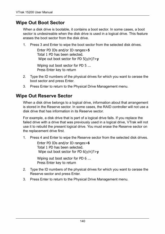
VTrak 15200 User Manual
Wipe Out Boot SectorWhen a disk drive is bootable, it contains a boot sector. In some cases, a boot sector is undesireable when the disk drive is used in a logical drive. This feature erases the boot sector from the disk drive.
1. Press 3 and Enter to wipe the boot sector from the selected disk drives.
Enter PD IDs and/or ID ranges>5Total 1 PD has been selected. Wipe out boot sector for PD 5(y/n)?>y
Wiping out boot sector for PD 5 ...Press Enter key to return
2. Type the ID numbers of the physical drives for which you want to cerase the boot sector and press Enter.
3. Press Enter to return to the Physical Drive Management menu.
Wipe Out Reserve SectorWhen a disk drive belongs to a logical drive, information about that arrangement is stored in the Reserve sector. In some cases, the RAID controller will not use a disk drive that has information in its Reserve sector.
For example, a disk drive that is part of a logical drive fails. If you replace the failed drive with a drive that was previously used in a logical drive, VTrak will not use it to rebuild the present logical drive. You must erase the Reserve sector on the replacement drive first.
1. Press 4 and Enter to wipe the Reserve sector from the selected disk drives.
Enter PD IDs and/or ID ranges>6Total 1 PD has been selected. Wipe out boot sector for PD 6(y/n)?>y
Wiping out boot sector for PD 6 ...Press Enter key to return
2. Type the ID numbers of the physical drives for which you want to cerase the Reserve sector and press Enter.
3. Press Enter to return to the Physical Drive Management menu.
140
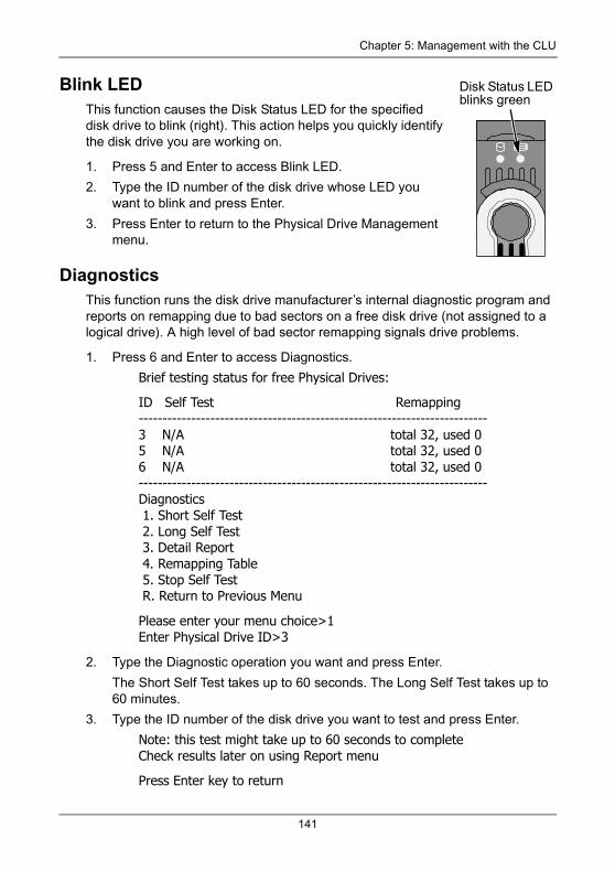
Chapter 5: Management with the CLU
Blink LEDThis function causes the Disk Status LED for the specified disk drive to blink (right). This action helps you quickly identify the disk drive you are working on.
1. Press 5 and Enter to access Blink LED.
2. Type the ID number of the disk drive whose LED you want to blink and press Enter.
3. Press Enter to return to the Physical Drive Management menu.
DiagnosticsThis function runs the disk drive manufacturer’s internal diagnostic program and reports on remapping due to bad sectors on a free disk drive (not assigned to a logical drive). A high level of bad sector remapping signals drive problems.
1. Press 6 and Enter to access Diagnostics.
Brief testing status for free Physical Drives:
ID Self Test Remapping-------------------------------------------------------------------------3 N/A total 32, used 05 N/A total 32, used 06 N/A total 32, used 0-------------------------------------------------------------------------Diagnostics 1. Short Self Test 2. Long Self Test 3. Detail Report 4. Remapping Table 5. Stop Self Test R. Return to Previous Menu
Please enter your menu choice>1Enter Physical Drive ID>3
2. Type the Diagnostic operation you want and press Enter.
The Short Self Test takes up to 60 seconds. The Long Self Test takes up to 60 minutes.
3. Type the ID number of the disk drive you want to test and press Enter.
Note: this test might take up to 60 seconds to completeCheck results later on using Report menu
Press Enter key to return
Disk Status LED blinks green
141
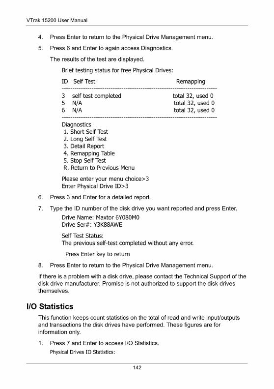
VTrak 15200 User Manual
4. Press Enter to return to the Physical Drive Management menu.
5. Press 6 and Enter to again access Diagnostics.
The results of the test are displayed.
Brief testing status for free Physical Drives:
ID Self Test Remapping-------------------------------------------------------------------------3 self test completed total 32, used 05 N/A total 32, used 06 N/A total 32, used 0-------------------------------------------------------------------------Diagnostics 1. Short Self Test 2. Long Self Test 3. Detail Report 4. Remapping Table 5. Stop Self Test R. Return to Previous Menu
Please enter your menu choice>3Enter Physical Drive ID>3
6. Press 3 and Enter for a detailed report.
7. Type the ID number of the disk drive you want reported and press Enter.
Drive Name: Maxtor 6Y080M0Drive Ser#: Y3K88AWE
Self Test Status:The previous self-test completed without any error.
Press Enter key to return
8. Press Enter to return to the Physical Drive Management menu.
If there is a problem with a disk drive, please contact the Technical Support of the disk drive manufacturer. Promise is not authorized to support the disk drives themselves.
I/O StatisticsThis function keeps count statistics on the total of read and write input/outputs and transactions the disk drives have performed. These figures are for information only.
1. Press 7 and Enter to access I/O Statistics.
Physical Drives IO Statistics:
142
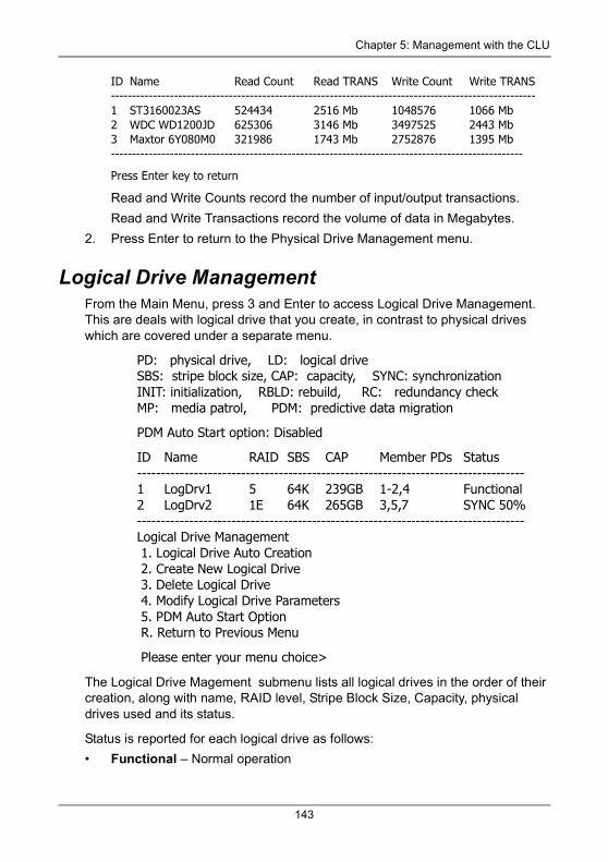
Chapter 5: Management with the CLU
ID Name Read Count Read TRANS Write Count Write TRANS-----------------------------------------------------------------------------------------------------1 ST3160023AS 524434 2516 Mb 1048576 1066 Mb2 WDC WD1200JD 625306 3146 Mb 3497525 2443 Mb3 Maxtor 6Y080M0 321986 1743 Mb 2752876 1395 Mb--------------------------------------------------------------------------------------------------
Press Enter key to return
Read and Write Counts record the number of input/output transactions.
Read and Write Transactions record the volume of data in Megabytes.
2. Press Enter to return to the Physical Drive Management menu.
Logical Drive ManagementFrom the Main Menu, press 3 and Enter to access Logical Drive Management. This are deals with logical drive that you create, in contrast to physical drives which are covered under a separate menu.
PD: physical drive, LD: logical driveSBS: stripe block size, CAP: capacity, SYNC: synchronizationINIT: initialization, RBLD: rebuild, RC: redundancy checkMP: media patrol, PDM: predictive data migration
PDM Auto Start option: Disabled
ID Name RAID SBS CAP Member PDs Status----------------------------------------------------------------------------------1 LogDrv1 5 64K 239GB 1-2,4 Functional2 LogDrv2 1E 64K 265GB 3,5,7 SYNC 50%----------------------------------------------------------------------------------Logical Drive Management 1. Logical Drive Auto Creation 2. Create New Logical Drive 3. Delete Logical Drive 4. Modify Logical Drive Parameters 5. PDM Auto Start Option R. Return to Previous Menu
Please enter your menu choice>
The Logical Drive Magement submenu lists all logical drives in the order of their creation, along with name, RAID level, Stripe Block Size, Capacity, physical drives used and its status.
Status is reported for each logical drive as follows:
• Functional – Normal operation
143
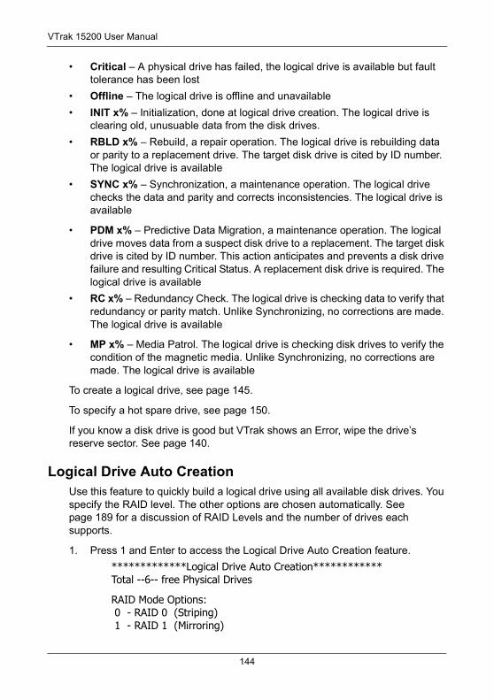
VTrak 15200 User Manual
• Critical – A physical drive has failed, the logical drive is available but fault tolerance has been lost
• Offline – The logical drive is offline and unavailable
• INIT x% – Initialization, done at logical drive creation. The logical drive is clearing old, unusuable data from the disk drives.
• RBLD x% – Rebuild, a repair operation. The logical drive is rebuilding data or parity to a replacement drive. The target disk drive is cited by ID number. The logical drive is available
• SYNC x% – Synchronization, a maintenance operation. The logical drive checks the data and parity and corrects inconsistencies. The logical drive is available
• PDM x% – Predictive Data Migration, a maintenance operation. The logical drive moves data from a suspect disk drive to a replacement. The target disk drive is cited by ID number. This action anticipates and prevents a disk drive failure and resulting Critical Status. A replacement disk drive is required. The logical drive is available
• RC x% – Redundancy Check. The logical drive is checking data to verify that redundancy or parity match. Unlike Synchronizing, no corrections are made. The logical drive is available
• MP x% – Media Patrol. The logical drive is checking disk drives to verify the condition of the magnetic media. Unlike Synchronizing, no corrections are made. The logical drive is available
To create a logical drive, see page 145.
To specify a hot spare drive, see page 150.
If you know a disk drive is good but VTrak shows an Error, wipe the drive’s reserve sector. See page 140.
Logical Drive Auto CreationUse this feature to quickly build a logical drive using all available disk drives. You specify the RAID level. The other options are chosen automatically. See page 189 for a discussion of RAID Levels and the number of drives each supports.
1. Press 1 and Enter to access the Logical Drive Auto Creation feature.
*************Logical Drive Auto Creation************Total --6-- free Physical Drives
RAID Mode Options: 0 - RAID 0 (Striping) 1 - RAID 1 (Mirroring)
144
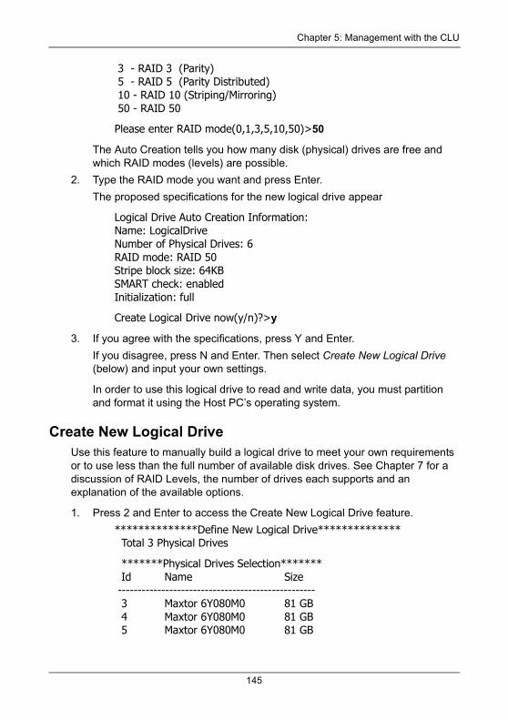
Chapter 5: Management with the CLU
3 - RAID 3 (Parity) 5 - RAID 5 (Parity Distributed) 10 - RAID 10 (Striping/Mirroring) 50 - RAID 50
Please enter RAID mode(0,1,3,5,10,50)>50
The Auto Creation tells you how many disk (physical) drives are free and which RAID modes (levels) are possible.
2. Type the RAID mode you want and press Enter.
The proposed specifications for the new logical drive appear
Logical Drive Auto Creation Information:Name: LogicalDriveNumber of Physical Drives: 6RAID mode: RAID 50Stripe block size: 64KBSMART check: enabledInitialization: full
Create Logical Drive now(y/n)?>y
3. If you agree with the specifications, press Y and Enter.
If you disagree, press N and Enter. Then select Create New Logical Drive (below) and input your own settings.
In order to use this logical drive to read and write data, you must partition and format it using the Host PC’s operating system.
Create New Logical DriveUse this feature to manually build a logical drive to meet your own requirements or to use less than the full number of available disk drives. See Chapter 7 for a discussion of RAID Levels, the number of drives each supports and an explanation of the available options.
1. Press 2 and Enter to access the Create New Logical Drive feature.
**************Define New Logical Drive************** Total 3 Physical Drives
*******Physical Drives Selection******* Id Name Size -------------------------------------------------- 3 Maxtor 6Y080M0 81 GB 4 Maxtor 6Y080M0 81 GB 5 Maxtor 6Y080M0 81 GB
145
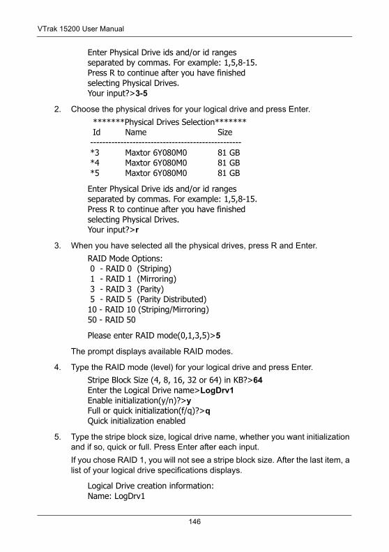
VTrak 15200 User Manual
Enter Physical Drive ids and/or id rangesseparated by commas. For example: 1,5,8-15.Press R to continue after you have finishedselecting Physical Drives.Your input?>3-5
2. Choose the physical drives for your logical drive and press Enter.
*******Physical Drives Selection******* Id Name Size -------------------------------------------------- *3 Maxtor 6Y080M0 81 GB *4 Maxtor 6Y080M0 81 GB *5 Maxtor 6Y080M0 81 GB
Enter Physical Drive ids and/or id rangesseparated by commas. For example: 1,5,8-15.Press R to continue after you have finishedselecting Physical Drives.Your input?>r
3. When you have selected all the physical drives, press R and Enter.
RAID Mode Options: 0 - RAID 0 (Striping) 1 - RAID 1 (Mirroring) 3 - RAID 3 (Parity) 5 - RAID 5 (Parity Distributed)10 - RAID 10 (Striping/Mirroring)50 - RAID 50
Please enter RAID mode(0,1,3,5)>5
The prompt displays available RAID modes.
4. Type the RAID mode (level) for your logical drive and press Enter.
Stripe Block Size (4, 8, 16, 32 or 64) in KB?>64Enter the Logical Drive name>LogDrv1Enable initialization(y/n)?>yFull or quick initialization(f/q)?>qQuick initialization enabled
5. Type the stripe block size, logical drive name, whether you want initialization and if so, quick or full. Press Enter after each input.
If you chose RAID 1, you will not see a stripe block size. After the last item, a list of your logical drive specifications displays.
Logical Drive creation information:Name: LogDrv1
146
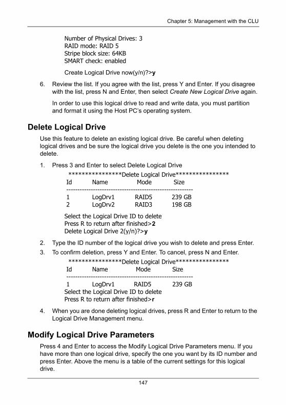
Chapter 5: Management with the CLU
Number of Physical Drives: 3RAID mode: RAID 5Stripe block size: 64KBSMART check: enabled
Create Logical Drive now(y/n)?>y
6. Review the list. If you agree with the list, press Y and Enter. If you disagree with the list, press N and Enter, then select Create New Logical Drive again.
In order to use this logical drive to read and write data, you must partition and format it using the Host PC’s operating system.
Delete Logical DriveUse this feature to delete an existing logical drive. Be careful when deleting logical drives and be sure the logical drive you delete is the one you intended to delete.
1. Press 3 and Enter to select Delete Logical Drive
****************Delete Logical Drive**************** Id Name Mode Size --------------------------------------------------------- 1 LogDrv1 RAID5 239 GB 2 LogDrv2 RAID3 198 GB
Select the Logical Drive ID to deletePress R to return after finished>2Delete Logical Drive 2(y/n)?>y
2. Type the ID number of the logical drive you wish to delete and press Enter.
3. To confirm deletion, press Y and Enter. To cancel, press N and Enter.
****************Delete Logical Drive**************** Id Name Mode Size --------------------------------------------------------- 1 LogDrv1 RAID5 239 GBSelect the Logical Drive ID to deletePress R to return after finished>r
4. When you are done deleting logical drives, press R and Enter to return to the Logical Drive Management menu.
Modify Logical Drive ParametersPress 4 and Enter to access the Modify Logical Drive Parameters menu. If you have more than one logical drive, specify the one you want by its ID number and press Enter. Above the menu is a table of the current settings for this logical drive.
147
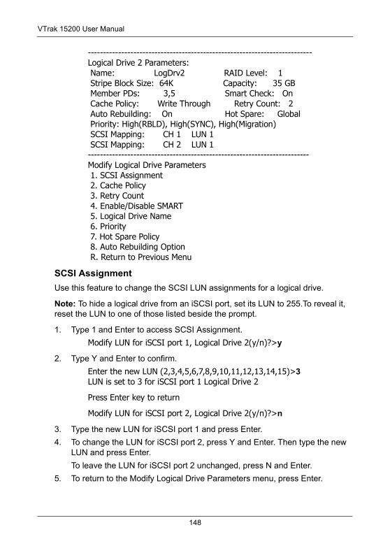
VTrak 15200 User Manual
--------------------------------------------------------------------------Logical Drive 2 Parameters: Name: LogDrv2 RAID Level: 1 Stripe Block Size: 64K Capacity: 35 GB Member PDs: 3,5 Smart Check: On Cache Policy: Write Through Retry Count: 2 Auto Rebuilding: On Hot Spare: Global Priority: High(RBLD), High(SYNC), High(Migration) SCSI Mapping: CH 1 LUN 1 SCSI Mapping: CH 2 LUN 1-------------------------------------------------------------------------Modify Logical Drive Parameters 1. SCSI Assignment 2. Cache Policy 3. Retry Count 4. Enable/Disable SMART 5. Logical Drive Name 6. Priority 7. Hot Spare Policy 8. Auto Rebuilding Option R. Return to Previous Menu
SCSI AssignmentUse this feature to change the SCSI LUN assignments for a logical drive.
Note: To hide a logical drive from an iSCSI port, set its LUN to 255.To reveal it, reset the LUN to one of those listed beside the prompt.
1. Type 1 and Enter to access SCSI Assignment.
Modify LUN for iSCSI port 1, Logical Drive 2(y/n)?>y
2. Type Y and Enter to confirm.
Enter the new LUN (2,3,4,5,6,7,8,9,10,11,12,13,14,15)>3LUN is set to 3 for iSCSI port 1 Logical Drive 2
Press Enter key to return
Modify LUN for iSCSI port 2, Logical Drive 2(y/n)?>n
3. Type the new LUN for iSCSI port 1 and press Enter.
4. To change the LUN for iSCSI port 2, press Y and Enter. Then type the new LUN and press Enter.
To leave the LUN for iSCSI port 2 unchanged, press N and Enter.
5. To return to the Modify Logical Drive Parameters menu, press Enter.
148
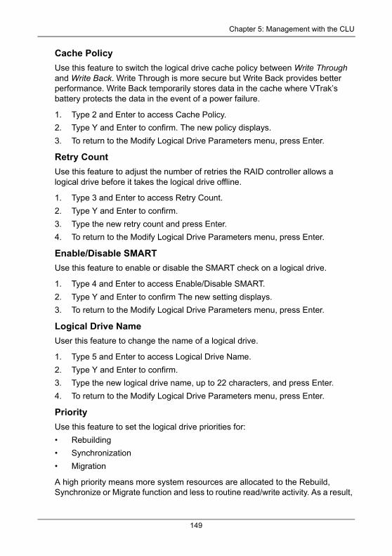
Chapter 5: Management with the CLU
Cache PolicyUse this feature to switch the logical drive cache policy between Write Through and Write Back. Write Through is more secure but Write Back provides better performance. Write Back temporarily stores data in the cache where VTrak’s battery protects the data in the event of a power failure.
1. Type 2 and Enter to access Cache Policy.
2. Type Y and Enter to confirm. The new policy displays.
3. To return to the Modify Logical Drive Parameters menu, press Enter.
Retry CountUse this feature to adjust the number of retries the RAID controller allows a logical drive before it takes the logical drive offline.
1. Type 3 and Enter to access Retry Count.
2. Type Y and Enter to confirm.
3. Type the new retry count and press Enter.
4. To return to the Modify Logical Drive Parameters menu, press Enter.
Enable/Disable SMARTUse this feature to enable or disable the SMART check on a logical drive.
1. Type 4 and Enter to access Enable/Disable SMART.
2. Type Y and Enter to confirm The new setting displays.
3. To return to the Modify Logical Drive Parameters menu, press Enter.
Logical Drive NameUser this feature to change the name of a logical drive.
1. Type 5 and Enter to access Logical Drive Name.
2. Type Y and Enter to confirm.
3. Type the new logical drive name, up to 22 characters, and press Enter.
4. To return to the Modify Logical Drive Parameters menu, press Enter.
PriorityUse this feature to set the logical drive priorities for:
• Rebuilding
• Synchronization
• Migration
A high priority means more system resources are allocated to the Rebuild, Synchronize or Migrate function and less to routine read/write activity. As a result,
149
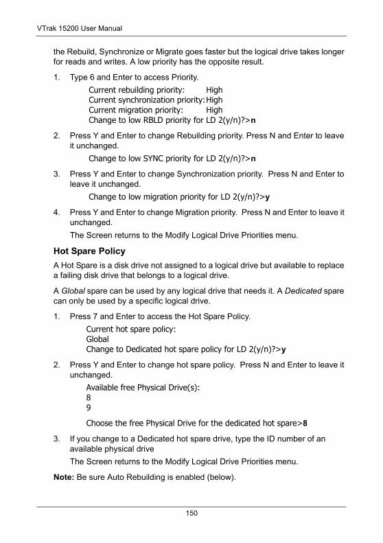
VTrak 15200 User Manual
the Rebuild, Synchronize or Migrate goes faster but the logical drive takes longer for reads and writes. A low priority has the opposite result.
1. Type 6 and Enter to access Priority.
Current rebuilding priority: High Current synchronization priority:High Current migration priority: High Change to low RBLD priority for LD 2(y/n)?>n
2. Press Y and Enter to change Rebuilding priority. Press N and Enter to leave it unchanged.
Change to low SYNC priority for LD 2(y/n)?>n
3. Press Y and Enter to change Synchronization priority. Press N and Enter to leave it unchanged.
Change to low migration priority for LD 2(y/n)?>y
4. Press Y and Enter to change Migration priority. Press N and Enter to leave it unchanged.
The Screen returns to the Modify Logical Drive Priorities menu.
Hot Spare PolicyA Hot Spare is a disk drive not assigned to a logical drive but available to replace a failing disk drive that belongs to a logical drive.
A Global spare can be used by any logical drive that needs it. A Dedicated spare can only be used by a specific logical drive.
1. Press 7 and Enter to access the Hot Spare Policy.
Current hot spare policy:GlobalChange to Dedicated hot spare policy for LD 2(y/n)?>y
2. Press Y and Enter to change hot spare policy. Press N and Enter to leave it unchanged.
Available free Physical Drive(s):89
Choose the free Physical Drive for the dedicated hot spare>8
3. If you change to a Dedicated hot spare drive, type the ID number of an available physical drive
The Screen returns to the Modify Logical Drive Priorities menu.
Note: Be sure Auto Rebuilding is enabled (below).
150
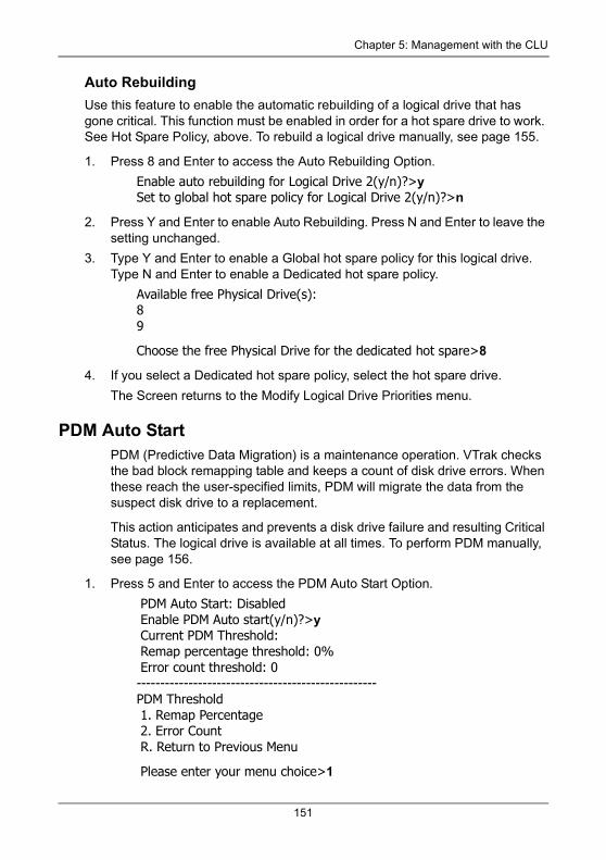
Chapter 5: Management with the CLU
Auto RebuildingUse this feature to enable the automatic rebuilding of a logical drive that has gone critical. This function must be enabled in order for a hot spare drive to work. See Hot Spare Policy, above. To rebuild a logical drive manually, see page 155.
1. Press 8 and Enter to access the Auto Rebuilding Option.
Enable auto rebuilding for Logical Drive 2(y/n)?>ySet to global hot spare policy for Logical Drive 2(y/n)?>n
2. Press Y and Enter to enable Auto Rebuilding. Press N and Enter to leave the setting unchanged.
3. Type Y and Enter to enable a Global hot spare policy for this logical drive. Type N and Enter to enable a Dedicated hot spare policy.
Available free Physical Drive(s):89
Choose the free Physical Drive for the dedicated hot spare>8
4. If you select a Dedicated hot spare policy, select the hot spare drive.
The Screen returns to the Modify Logical Drive Priorities menu.
PDM Auto StartPDM (Predictive Data Migration) is a maintenance operation. VTrak checks the bad block remapping table and keeps a count of disk drive errors. When these reach the user-specified limits, PDM will migrate the data from the suspect disk drive to a replacement.
This action anticipates and prevents a disk drive failure and resulting Critical Status. The logical drive is available at all times. To perform PDM manually, see page 156.
1. Press 5 and Enter to access the PDM Auto Start Option.
PDM Auto Start: Disabled Enable PDM Auto start(y/n)?>y Current PDM Threshold: Remap percentage threshold: 0% Error count threshold: 0---------------------------------------------------PDM Threshold 1. Remap Percentage 2. Error Count R. Return to Previous Menu
Please enter your menu choice>1
151
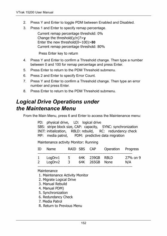
VTrak 15200 User Manual
2. Press Y and Enter to toggle PDM between Enabled and Disabled.
3. Press 1 and Enter to specify remap percentage.
Current remap percentage threshold: 0%Change the threshold(y/n)?>yEnter the new threshold(0~100)>80Current remap percentage threshold: 80%
Press Enter key to return
4. Press Y and Enter to confirm a Threshold change. Then type a number between 0 and 100 for remap percentage and press Enter.
5. Press Enter to return to the PDM Threshold submenu.
6. Press 2 and Enter to specify Error Count.
7. Press Y and Enter to confirm a Threshold change. Then type an error number and press Enter.
8. Press Enter to return to the PDM Threshold submenu.
Logical Drive Operations under the Maintenance Menu
From the Main Menu, press 6 and Enter to access the Maintenance menu:
PD: physical drive, LD: logical driveSBS: stripe block size, CAP: capacity, SYNC: synchronizationINIT: initialization, RBLD: rebuild, RC: redundancy checkMP: media patrol, PDM: predictive data migration
Maintenance activity Monitor: Running
ID Name RAID SBS CAP Operation Progress-------------------------------------------------------------------------1 LogDrv1 5 64K 239GB RBLD 27% on 92 LogDrv2 3 64K 265GB None N/A-------------------------------------------------------------------------Maintenance 1. Maintenance Activity Monitor 2. Migrate Logical Drive 3. Manual Rebuild 4. Manual PDM) 5. Synchronization 6. Redundancy Check 7. Media Patrol R. Return to Previous Menu
152
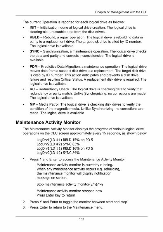
Chapter 5: Management with the CLU
The current Operation is reported for each logical drive as follows:
• INIT – Initialization, done at logical drive creation. The logical drive is clearing old, unusuable data from the disk drives.
• RBLD – Rebuild, a repair operation. The logical drive is rebuilding data or parity to a replacement drive. The target disk drive is cited by ID number. The logical drive is available
• SYNC – Synchronization, a maintenance operation. The logical drive checks the data and parity and corrects inconsistencies. The logical drive is available
• PDM – Predictive Data Migration, a maintenance operation. The logical drive moves data from a suspect disk drive to a replacement. The target disk drive is cited by ID number. This action anticipates and prevents a disk drive failure and resulting Critical Status. A replacement disk drive is required. The logical drive is available
• RC – Redundancy Check. The logical drive is checking data to verify that redundancy or parity match. Unlike Synchronizing, no corrections are made. The logical drive is available
• MP – Media Patrol. The logical drive is checking disk drives to verify the condition of the magnetic media. Unlike Synchronizing, no corrections are made. The logical drive is available
Maintenance Activity MonitorThe Maintenance Activity Monitor displays the progress of various logical drive operations on the CLU screen approximately every 15 seconds, as shown below.
LogDrv1(LD #1) RBLD 15% on PD 5LogDrv2(LD #2) SYNC 83%LogDrv1(LD #1) RBLD 16% on PD 5LogDrv2(LD #2) SYNC 84%
1. Press 1 and Enter to access the Maintenance Activity Monitor.
Maintenance activity monitor is currently running.When any maintenance activity occurs e.g. rebuilding,the maintenance monitor will display notificationmessage on screen.
Stop maintenance activity monitor(y/n)?>y
Maintenance activity monitor stopped nowPress Enter key to return
2. Press Y and Enter to toggle the monitor between start and stop.
3. Press Enter to return to the Maintenance menu.
153
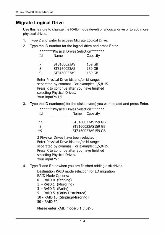
VTrak 15200 User Manual
Migrate Logical DriveUse this feature to change the RAID mode (level) or a logical drive or to add more physical drives.
1. Type 2 and Enter to access Migrate Logical Drive.
2. Type the ID number for the logical drive and press Enter.
*******Physical Drives Selection******* Id Name Capacity ---------------------------------------- 7 ST3160023AS 159 GB 8 ST3160023AS 159 GB 9 ST3160023AS 159 GB
Enter Physical Drive ids and/or id rangesseparated by commas. For example: 1,5,8-15.Press R to continue after you have finishedselecting Physical Drives.Your input?>7,9
3. Type the ID number(s) for the disk drive(s) you want to add and press Enter.
*******Physical Drives Selection******* Id Name Capacity ---------------------------------------- *7 ST3160023AS159 GB 8 ST3160023AS159 GB *9 ST3160023AS159 GB
2 Physical Drives have been selected.Enter Physical Drive ids and/or id rangesseparated by commas. For example: 1,5,8-15.Press R to continue after you have finishedselecting Physical Drives.Your input?>r
4. Type R and Enter when you are finished adding disk drives.
Destination RAID mode selection for LD migrationRAID Mode Options:0 - RAID 0 (Striping)1 - RAID 1 (Mirroring)3 - RAID 3 (Parity)5 - RAID 5 (Parity Distributed)10 - RAID 10 (Striping/Mirroring)50 - RAID 50
Please enter RAID mode(0,1,3,5)>5
154
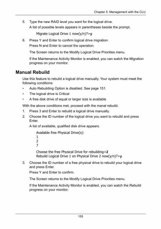
Chapter 5: Management with the CLU
5. Type the new RAID level you want for the logical drive.
A list of possible levels appears in parentheses beside the prompt.
Migrate Logical Drive 1 now(y/n)?>y
6. Press Y and Enter to confirm logical drive migration.
Press N and Enter to cancel the operation.
The Screen returns to the Modify Logical Drive Priorities menu.
If the Maintenance Activity Monitor is enabled, you can watch the Migration progress on your monitor.
Manual RebuildUse this feature to rebuild a logical drive manually. Your system must meet the following conditions:
• Auto Rebuilding Option is disabled. See page 151.
• The logical drive is Critical
• A free disk drive of equal or larger size is available
With the above conditions met, proceed with the manal rebuild.
1. Press 3 and Enter to rebuild a logical drive manually.
2. Choose the ID number of the logical drive you want to rebuild and press Enter.
A list of available, qualified disk drive appears.
Available free Physical Drive(s):127
Choose the free Physical Drive for rebuilding>2Rebuild Logical Drive 1 on Physical Drive 2 now(y/n)?>y
3. Choose the ID number of a free physical drive to rebuild your logical drive and press Enter.
Press Y and Enter to confirm.
The Screen returns to the Modify Logical Drive Priorities menu.
If the Maintenance Activity Monitor is enabled, you can watch the Rebuild progress on your monitor.
155
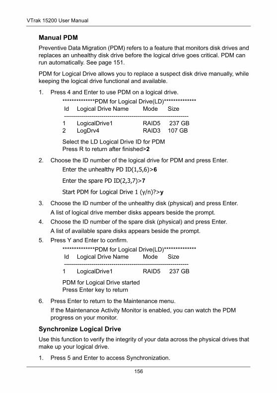
VTrak 15200 User Manual
Manual PDM Preventive Data Migration (PDM) refers to a feature that monitors disk drives and replaces an unhealthy disk drive before the logical drive goes critical. PDM can run automatically. See page 151.
PDM for Logical Drive allows you to replace a suspect disk drive manually, while keeping the logical drive functional and available.
1. Press 4 and Enter to use PDM on a logical drive.
**************PDM for Logical Drive(LD)************** Id Logical Drive Name Mode Size ---------------------------------------------------------------1 LogicalDrive1 RAID5 237 GB2 LogDrv4 RAID3 107 GB
Select the LD Logical Drive ID for PDMPress R to return after finished>2
2. Choose the ID number of the logical drive for PDM and press Enter.
Enter the unhealthy PD ID(1,5,6)>6
Enter the spare PD ID(2,3,7)>7
Start PDM for Logical Drive 1 (y/n)?>y
3. Choose the ID number of the unhealthy disk (physical) and press Enter.
A list of logical drive member disks appears beside the prompt.
4. Choose the ID number of the spare disk (physical) and press Enter.
A list of available spare disks appears beside the prompt.
5. Press Y and Enter to confirm.
**************PDM for Logical Drive(LD)************** Id Logical Drive Name Mode Size ---------------------------------------------------------------1 LogicalDrive1 RAID5 237 GB
PDM for Logical Drive startedPress Enter key to return
6. Press Enter to return to the Maintenance menu.
If the Maintenance Activity Monitor is enabled, you can watch the PDM progress on your monitor.
Synchronize Logical DriveUse this function to verify the integrity of your data across the physical drives that make up your logical drive.
1. Press 5 and Enter to access Synchronization.
156
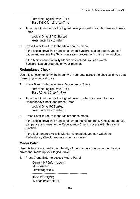
Chapter 5: Management with the CLU
Enter the Logical Drive ID>1Start SYNC for LD 1(y/n)?>y
2. Type the ID number for the logical drive you want to synchronize and press Enter.
Logical Drive SYNC StartedPress Enter key to return
3. Press Enter to return to the Maintenance menu.
If the logical drive was Functional when Synchronization began, you can pause and resume the Synchronization process with this same function.
If the Maintenance Activity Monitor is enabled, you can watch Synchronization progress on your monitor.
Redundancy CheckUse this function to verify the integrity of your data across the physical drives that make up your logical drive.
1. Press 6 and Enter to access Redundancy Check.
Enter the Logical Drive ID>1Start RC for LD 1(y/n)?>y
2. Type the ID number for the logical drive on which you want to run a Redundancy Check and press Enter.
Logical Drive RC StartedPress Enter key to return
3. Press Enter to return to the Maintenance menu.
If the logical drive was Functional when the Redundancy Check began, you can pause and resume the Redundancy Check process with this same function.
If the Maintenance Activity Monitor is enabled, you can watch the Redundancy Check progress on your monitor.
Media PatrolUse this function to verify the integrity of the magnetic media on the physical drives that make up your logical drive.
1. Press 7 and Enter to access Media Patrol.
Current MP Information: MP: disabled Percentage: 0%---------------------------------------------------Media Patrol(MP) 1. Enable/Disable MP
157
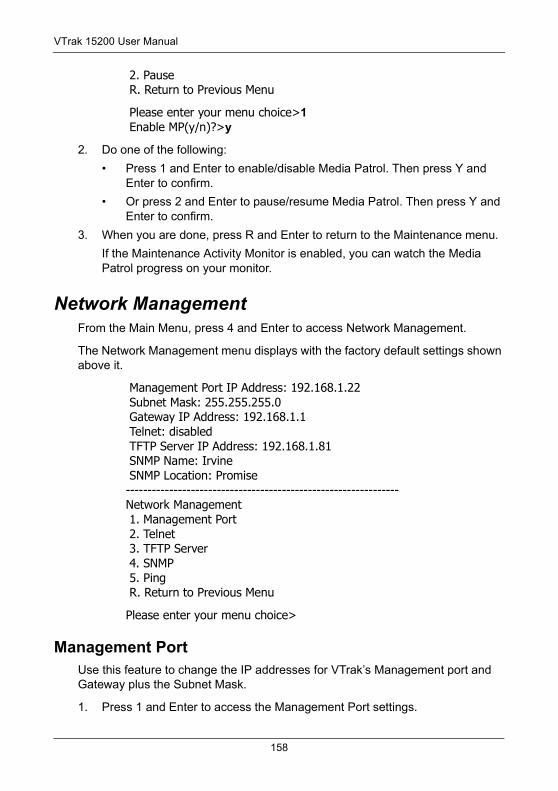
VTrak 15200 User Manual
2. Pause R. Return to Previous Menu
Please enter your menu choice>1 Enable MP(y/n)?>y
2. Do one of the following:
• Press 1 and Enter to enable/disable Media Patrol. Then press Y and Enter to confirm.
• Or press 2 and Enter to pause/resume Media Patrol. Then press Y and Enter to confirm.
3. When you are done, press R and Enter to return to the Maintenance menu.
If the Maintenance Activity Monitor is enabled, you can watch the Media Patrol progress on your monitor.
Network ManagementFrom the Main Menu, press 4 and Enter to access Network Management.
The Network Management menu displays with the factory default settings shown above it.
Management Port IP Address: 192.168.1.22 Subnet Mask: 255.255.255.0 Gateway IP Address: 192.168.1.1 Telnet: disabled TFTP Server IP Address: 192.168.1.81 SNMP Name: Irvine SNMP Location: Promise---------------------------------------------------------------Network Management 1. Management Port 2. Telnet 3. TFTP Server 4. SNMP 5. Ping R. Return to Previous Menu
Please enter your menu choice>
Management PortUse this feature to change the IP addresses for VTrak’s Management port and Gateway plus the Subnet Mask.
1. Press 1 and Enter to access the Management Port settings.
158
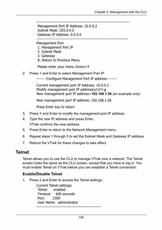
Chapter 5: Management with the CLU
-------------------------------------------------------------------------- Management Port IP Address: 10.0.0.2 Subnet Mask: 255.0.0.0 Gateway IP Address: 0.0.0.0-------------------------------------------------------------------------Management Port 1. Management Port IP 2. Subnet Mask 3. Gateway R. Return to Previous Menu
Please enter your menu choice>1
2. Press 1 and Enter to select Management Port IP.
--------Configure Management Port IP address--------
Current management port IP Address: 10.0.0.2Modify management port IP address(y/n)?>yNew management port IP address>192.168.1.56 (an example only)
New management port IP address: 192.168.1.56
Press Enter key to return
3. Press Y and Enter to modify the management port IP address.
4. Type the new IP address and press Enter.
VTrak confirms the new address.
5. Press Enter to return to the Network Management menu.
6. Repeat steps 1 through 5 to set the Subnet Mask and Gateway IP address
7. Reboot the VTrak for these changes to take effect.
TelnetTelnet allows you to use the CLU to manage VTrak over a network. The Telnet screen looks the same as the CLU screen, except that you have to log in. You must enable Telnet on VTrak before you can establish a Telnet connection.
Enable/Disable Telnet1. Press 2 and Enter to access the Telnet settings.
Current Telnet settings: Telnet: enabled Timeout: 600 seconds Port: 2300 User Name: administrator---------------------------------------------------
159
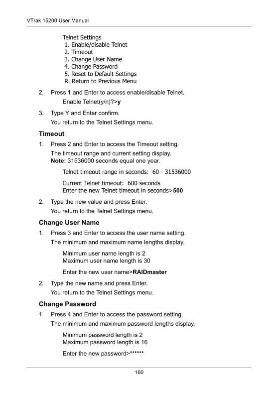
VTrak 15200 User Manual
Telnet Settings 1. Enable/disable Telnet 2. Timeout 3. Change User Name 4. Change Password 5. Reset to Default Settings R. Return to Previous Menu
2. Press 1 and Enter to access enable/disable Telnet.
Enable Telnet(y/n)?>y
3. Type Y and Enter confirm.
You return to the Telnet Settings menu.
Timeout1. Press 2 and Enter to access the Timeout setting.
The timeout range and current setting display. Note: 31536000 seconds equal one year.
Telnet timeout range in seconds: 60 - 31536000
Current Telnet timeout: 600 secondsEnter the new Telnet timeout in seconds>500
2. Type the new value and press Enter.
You return to the Telnet Settings menu.
Change User Name1. Press 3 and Enter to access the user name setting.
The minimum and maximum name lengths display.
Minimum user name length is 2Maximum user name length is 30
Enter the new user name>RAIDmaster
2. Type the new name and press Enter.
You return to the Telnet Settings menu.
Change Password1. Press 4 and Enter to access the password setting.
The minimum and maximum password lengths display.
Minimum password length is 2Maximum password length is 16
Enter the new password>******
160
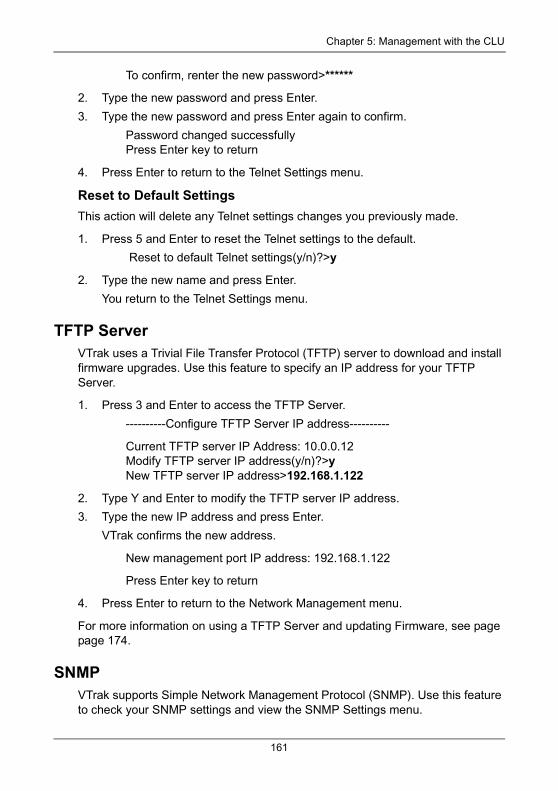
Chapter 5: Management with the CLU
To confirm, renter the new password>******
2. Type the new password and press Enter.
3. Type the new password and press Enter again to confirm.
Password changed successfullyPress Enter key to return
4. Press Enter to return to the Telnet Settings menu.
Reset to Default SettingsThis action will delete any Telnet settings changes you previously made.
1. Press 5 and Enter to reset the Telnet settings to the default.
Reset to default Telnet settings(y/n)?>y
2. Type the new name and press Enter.
You return to the Telnet Settings menu.
TFTP ServerVTrak uses a Trivial File Transfer Protocol (TFTP) server to download and install firmware upgrades. Use this feature to specify an IP address for your TFTP Server.
1. Press 3 and Enter to access the TFTP Server.
----------Configure TFTP Server IP address----------
Current TFTP server IP Address: 10.0.0.12Modify TFTP server IP address(y/n)?>yNew TFTP server IP address>192.168.1.122
2. Type Y and Enter to modify the TFTP server IP address.
3. Type the new IP address and press Enter.
VTrak confirms the new address.
New management port IP address: 192.168.1.122
Press Enter key to return
4. Press Enter to return to the Network Management menu.
For more information on using a TFTP Server and updating Firmware, see page page 174.
SNMPVTrak supports Simple Network Management Protocol (SNMP). Use this feature to check your SNMP settings and view the SNMP Settings menu.
161
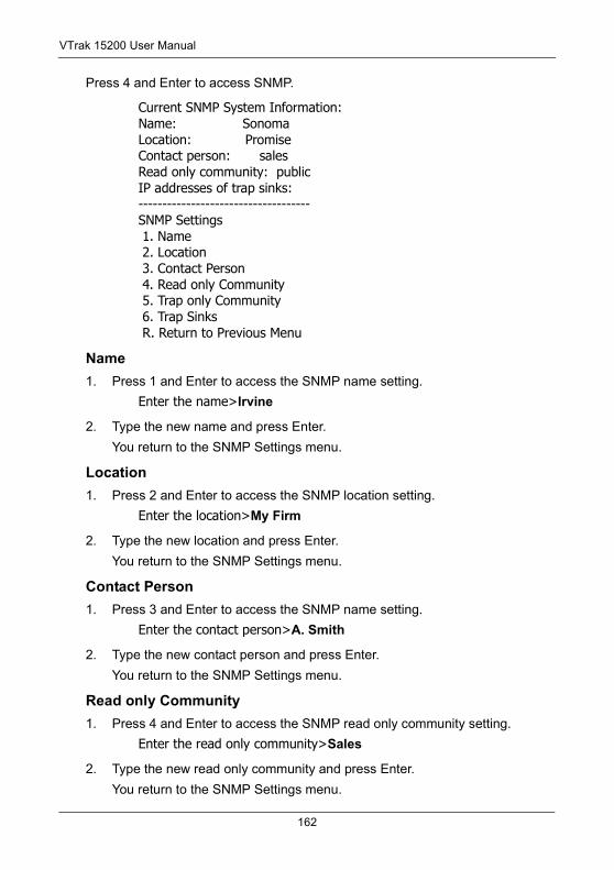
VTrak 15200 User Manual
Press 4 and Enter to access SNMP.
Current SNMP System Information:Name: SonomaLocation: PromiseContact person: salesRead only community: publicIP addresses of trap sinks:------------------------------------SNMP Settings 1. Name 2. Location 3. Contact Person 4. Read only Community 5. Trap only Community 6. Trap Sinks R. Return to Previous Menu
Name1. Press 1 and Enter to access the SNMP name setting.
Enter the name>Irvine
2. Type the new name and press Enter.
You return to the SNMP Settings menu.
Location1. Press 2 and Enter to access the SNMP location setting.
Enter the location>My Firm
2. Type the new location and press Enter.
You return to the SNMP Settings menu.
Contact Person1. Press 3 and Enter to access the SNMP name setting.
Enter the contact person>A. Smith
2. Type the new contact person and press Enter.
You return to the SNMP Settings menu.
Read only Community1. Press 4 and Enter to access the SNMP read only community setting.
Enter the read only community>Sales
2. Type the new read only community and press Enter.
You return to the SNMP Settings menu.
162
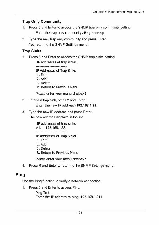
Chapter 5: Management with the CLU
Trap Only Community1. Press 5 and Enter to access the SNMP trap only community setting.
Enter the trap only community>Engineering
2. Type the new trap only community and press Enter.
You return to the SNMP Settings menu.
Trap Sinks1. Press 6 and Enter to access the SNMP trap sinks setting.
IP addresses of trap sinks:-------------------------IP Addresses of Trap Sinks 1. Edit 2. Add 3. Delete R. Return to Previous Menu
Please enter your menu choice>2
2. To add a trap sink, press 2 and Enter.
Enter the new IP address>192.168.1.88
3. Type the new IP address and press Enter.
The new address displays in the list.
IP addresses of trap sinks:#1: 192.168.1.88-------------------------IP Addresses of Trap Sinks 1. Edit 2. Add 3. Delete R. Return to Previous Menu
Please enter your menu choice>r
4. Press R and Enter to return to the SNMP Settings menu.
PingUse the Ping function to verify a network connection.
1. Press 5 and Enter to access Ping.
Ping TestEnter the IP address to ping>192.168.1.211
163
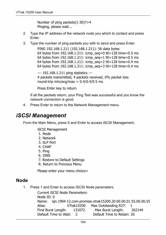
VTrak 15200 User Manual
Number of ping packets(1-30)?>4Pinging, please wait...
2. Type the IP address of the network node you which to contact and press Enter.
3. Type the number of ping packets you with to send and press Enter.
PING 192.168.1.211 (192.168.1.211): 56 data bytes64 bytes from 192.168.1.211: icmp_seq=0 ttl=128 time=0.5 ms64 bytes from 192.168.1.211: icmp_seq=1 ttl=128 time=0.5 ms64 bytes from 192.168.1.211: icmp_seq=2 ttl=128 time=0.4 ms64 bytes from 192.168.1.211: icmp_seq=3 ttl=128 time=0.4 ms
--- 192.168.1.211 ping statistics ---4 packets transmitted, 4 packets received, 0% packet lossround-trip min/avg/max = 0.4/0.4/0.5 ms
Press Enter key to return
If all the packets return, your Ping Test was successful and you know the network connection is good.
4. Press Enter to return to the Network Management menu.
iSCSI ManagementFrom the Main Menu, press 5 and Enter to access iSCSI Management.
iSCSI Management 1. Node 2. Network 3. SLP Port 4. CHAP 5. Ping 6. ISNS 7. Restore to Default Settings R. Return to Previous Menu
Please enter your menu choice>
Node1. Press 1 and Enter to access iSCSI Node parameters.
Current iSCSI Node Parameters:Node ID: 0Name: iqn.1994-12.com.promise.vtrak15200.20.00.00.01.55.00.00.55Alias: VTrak15200 Max Outstanding R2T: 1First Burst Length: 131072 Max Burst Length: 262144Default Time to Wait: 2 Default Time to Retain: 20
164
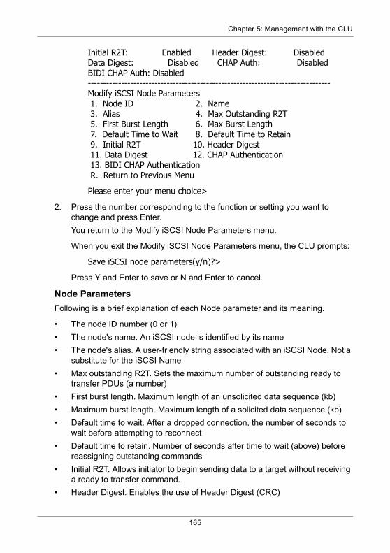
Chapter 5: Management with the CLU
Initial R2T: Enabled Header Digest: DisabledData Digest: Disabled CHAP Auth: DisabledBIDI CHAP Auth: Disabled--------------------------------------------------------------------------------Modify iSCSI Node Parameters 1. Node ID 2. Name 3. Alias 4. Max Outstanding R2T 5. First Burst Length 6. Max Burst Length 7. Default Time to Wait 8. Default Time to Retain 9. Initial R2T 10. Header Digest 11. Data Digest 12. CHAP Authentication 13. BIDI CHAP Authentication R. Return to Previous Menu
Please enter your menu choice>
2. Press the number corresponding to the function or setting you want to change and press Enter.
You return to the Modify iSCSI Node Parameters menu.
When you exit the Modify iSCSI Node Parameters menu, the CLU prompts:
Save iSCSI node parameters(y/n)?>
Press Y and Enter to save or N and Enter to cancel.
Node ParametersFollowing is a brief explanation of each Node parameter and its meaning.
• The node ID number (0 or 1)
• The node's name. An iSCSI node is identified by its name
• The node's alias. A user-friendly string associated with an iSCSI Node. Not a substitute for the iSCSI Name
• Max outstanding R2T. Sets the maximum number of outstanding ready to transfer PDUs (a number)
• First burst length. Maximum length of an unsolicited data sequence (kb)
• Maximum burst length. Maximum length of a solicited data sequence (kb)
• Default time to wait. After a dropped connection, the number of seconds to wait before attempting to reconnect
• Default time to retain. Number of seconds after time to wait (above) before reassigning outstanding commands
• Initial R2T. Allows initiator to begin sending data to a target without receiving a ready to transfer command.
• Header Digest. Enables the use of Header Digest (CRC)
165
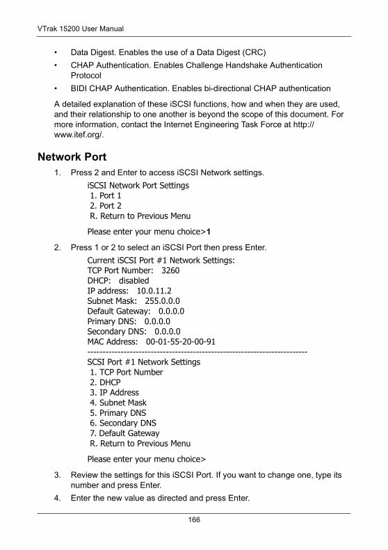
VTrak 15200 User Manual
• Data Digest. Enables the use of a Data Digest (CRC)
• CHAP Authentication. Enables Challenge Handshake Authentication Protocol
• BIDI CHAP Authentication. Enables bi-directional CHAP authentication
A detailed explanation of these iSCSI functions, how and when they are used, and their relationship to one another is beyond the scope of this document. For more information, contact the Internet Engineering Task Force at http://www.itef.org/.
Network Port1. Press 2 and Enter to access iSCSI Network settings.
iSCSI Network Port Settings 1. Port 1 2. Port 2 R. Return to Previous Menu
Please enter your menu choice>1
2. Press 1 or 2 to select an iSCSI Port then press Enter.
Current iSCSI Port #1 Network Settings:TCP Port Number: 3260DHCP: disabledIP address: 10.0.11.2Subnet Mask: 255.0.0.0Default Gateway: 0.0.0.0Primary DNS: 0.0.0.0Secondary DNS: 0.0.0.0MAC Address: 00-01-55-20-00-91-------------------------------------------------------------------------SCSI Port #1 Network Settings 1. TCP Port Number 2. DHCP 3. IP Address 4. Subnet Mask 5. Primary DNS 6. Secondary DNS 7. Default Gateway R. Return to Previous Menu
Please enter your menu choice>
3. Review the settings for this iSCSI Port. If you want to change one, type its number and press Enter.
4. Enter the new value as directed and press Enter.
166
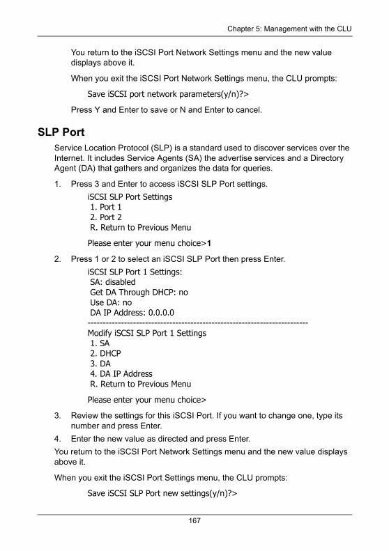
Chapter 5: Management with the CLU
You return to the iSCSI Port Network Settings menu and the new value displays above it.
When you exit the iSCSI Port Network Settings menu, the CLU prompts:
Save iSCSI port network parameters(y/n)?>
Press Y and Enter to save or N and Enter to cancel.
SLP PortService Location Protocol (SLP) is a standard used to discover services over the Internet. It includes Service Agents (SA) the advertise services and a Directory Agent (DA) that gathers and organizes the data for queries.
1. Press 3 and Enter to access iSCSI SLP Port settings.
iSCSI SLP Port Settings 1. Port 1 2. Port 2 R. Return to Previous Menu
Please enter your menu choice>1
2. Press 1 or 2 to select an iSCSI SLP Port then press Enter.
iSCSI SLP Port 1 Settings: SA: disabled Get DA Through DHCP: no Use DA: no DA IP Address: 0.0.0.0-------------------------------------------------------------------------Modify iSCSI SLP Port 1 Settings 1. SA 2. DHCP 3. DA 4. DA IP Address R. Return to Previous Menu
Please enter your menu choice>
3. Review the settings for this iSCSI Port. If you want to change one, type its number and press Enter.
4. Enter the new value as directed and press Enter.
You return to the iSCSI Port Network Settings menu and the new value displays above it.
When you exit the iSCSI Port Settings menu, the CLU prompts:
Save iSCSI SLP Port new settings(y/n)?>
167
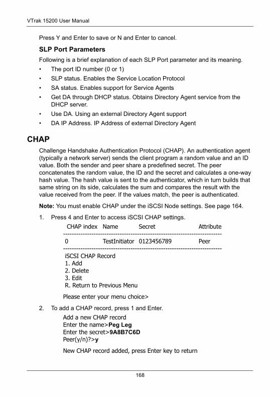
VTrak 15200 User Manual
Press Y and Enter to save or N and Enter to cancel.
SLP Port ParametersFollowing is a brief explanation of each SLP Port parameter and its meaning.
• The port ID number (0 or 1)
• SLP status. Enables the Service Location Protocol
• SA status. Enables support for Service Agents
• Get DA through DHCP status. Obtains Directory Agent service from the DHCP server.
• Use DA. Using an external Directory Agent support
• DA IP Address. IP Address of external Directory Agent
CHAPChallenge Handshake Authentication Protocol (CHAP). An authentication agent (typically a network server) sends the client program a random value and an ID value. Both the sender and peer share a predefined secret. The peer concatenates the random value, the ID and the secret and calculates a one-way hash value. The hash value is sent to the authenticator, which in turn builds that same string on its side, calculates the sum and compares the result with the value received from the peer. If the values match, the peer is authenticated.
Note: You must enable CHAP under the iSCSI Node settings. See page 164.
1. Press 4 and Enter to access iSCSI CHAP settings.
CHAP index Name Secret Attribute------------------------------------------------------------------------- 0 TestInitiator 0123456789 Peer------------------------------------------------------------------------- iSCSI CHAP Record 1. Add 2. Delete 3. Edit R. Return to Previous Menu
Please enter your menu choice>
2. To add a CHAP record, press 1 and Enter.
Add a new CHAP recordEnter the name>Peg LegEnter the secret>9A8B7C6DPeer(y/n)?>y
New CHAP record added, press Enter key to return
168
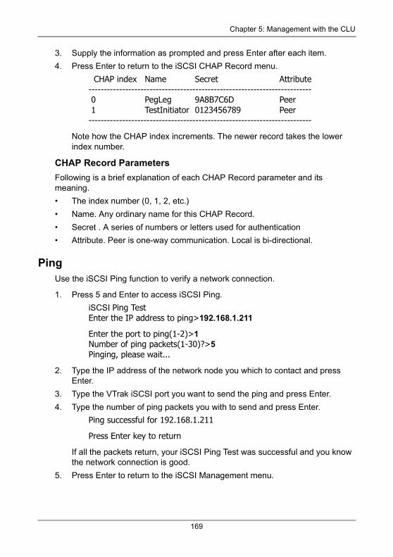
Chapter 5: Management with the CLU
3. Supply the information as prompted and press Enter after each item.
4. Press Enter to return to the iSCSI CHAP Record menu.
CHAP index Name Secret Attribute------------------------------------------------------------------------- 0 PegLeg 9A8B7C6D Peer 1 TestInitiator 0123456789 Peer-------------------------------------------------------------------------
Note how the CHAP index increments. The newer record takes the lower index number.
CHAP Record ParametersFollowing is a brief explanation of each CHAP Record parameter and its meaning.
• The index number (0, 1, 2, etc.)
• Name. Any ordinary name for this CHAP Record.
• Secret . A series of numbers or letters used for authentication
• Attribute. Peer is one-way communication. Local is bi-directional.
PingUse the iSCSI Ping function to verify a network connection.
1. Press 5 and Enter to access iSCSI Ping.
iSCSI Ping TestEnter the IP address to ping>192.168.1.211
Enter the port to ping(1-2)>1Number of ping packets(1-30)?>5Pinging, please wait...
2. Type the IP address of the network node you which to contact and press Enter.
3. Type the VTrak iSCSI port you want to send the ping and press Enter.
4. Type the number of ping packets you with to send and press Enter.
Ping successful for 192.168.1.211
Press Enter key to return
If all the packets return, your iSCSI Ping Test was successful and you know the network connection is good.
5. Press Enter to return to the iSCSI Management menu.
169

VTrak 15200 User Manual
iSNSInternet Storage Name Service (iSNS) is a protocol with discovery and management capabilities for IP storage. iSNS works for IP storage devices like DNS does for an ordinary network.
1. Press 6 and Enter to access iSCSI iSNS.
ISNS Settings 1. Port 1 2. Port 2 R. Return to Previous Menu
Please enter your menu choice>
2. Press 1 or 2 to select an iSNS Port then press Enter.
Current ISNS Port #1 Settings: Server IP address: 0.0.0.0 Server port: 3205 ISNS: disabled-------------------------------------------------------------------------ISNS Port #1 Settings 1. Server IP Address 2. Server Port 3. Enable/Disable ISNS R. Return to Previous Menu
Please enter your menu choice>
3. Supply the information as prompted and press Enter after each item.
You return to the iSCSI iSNS Port Settings menu.
When you exit the iSCSI iSNS Port Settings menu, the CLU prompts:
Save iSNS port settings(y/n)?>
Press Y and Enter to save or N and Enter to cancel.
iSNS Port Setting ParametersFollowing is a brief explanation of each iSNS port parameter and its meaning.
• The iSNS port ID number (1 or 2)
• SLP status. Enabled or disabled
• iSNS Server IP address (0.0.0.0 means not assigned)
• iSNS Server Port number (3205 for most applications)
170
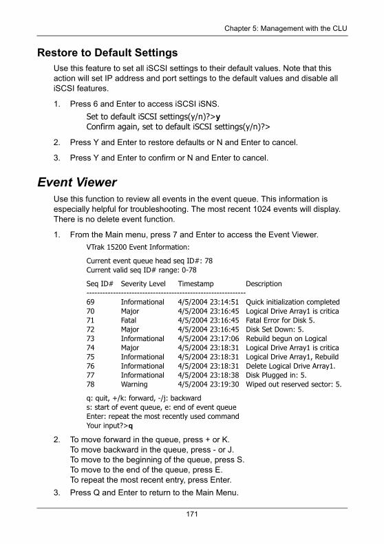
Chapter 5: Management with the CLU
Restore to Default SettingsUse this feature to set all iSCSI settings to their default values. Note that this action will set IP address and port settings to the default values and disable all iSCSI features.
1. Press 6 and Enter to access iSCSI iSNS.
Set to default iSCSI settings(y/n)?>yConfirm again, set to default iSCSI settings(y/n)?>
2. Press Y and Enter to restore defaults or N and Enter to cancel.
3. Press Y and Enter to confirm or N and Enter to cancel.
Event ViewerUse this function to review all events in the event queue. This information is especially helpful for troubleshooting. The most recent 1024 events will display. There is no delete event function.
1. From the Main menu, press 7 and Enter to access the Event Viewer.
VTrak 15200 Event Information:
Current event queue head seq ID#: 78Current valid seq ID# range: 0-78
Seq ID# Severity Level Timestamp Description------------------------------------------------------------69 Informational 4/5/2004 23:14:51 Quick initialization completed 70 Major 4/5/2004 23:16:45 Logical Drive Array1 is critica71 Fatal 4/5/2004 23:16:45 Fatal Error for Disk 5.72 Major 4/5/2004 23:16:45 Disk Set Down: 5.73 Informational 4/5/2004 23:17:06 Rebuild begun on Logical74 Major 4/5/2004 23:18:31 Logical Drive Array1 is critica75 Informational 4/5/2004 23:18:31 Logical Drive Array1, Rebuild76 Informational 4/5/2004 23:18:31 Delete Logical Drive Array1.77 Informational 4/5/2004 23:18:38 Disk Plugged in: 5.78 Warning 4/5/2004 23:19:30 Wiped out reserved sector: 5.
q: quit, +/k: forward, -/j: backwards: start of event queue, e: end of event queueEnter: repeat the most recently used commandYour input?>q
2. To move forward in the queue, press + or K.To move backward in the queue, press - or J. To move to the beginning of the queue, press S. To move to the end of the queue, press E.To repeat the most recent entry, press Enter.
3. Press Q and Enter to return to the Main Menu.
171

VTrak 15200 User Manual
BuzzerUse this feature to enable or disable VTrak’s buzzer (audible alarm, beeper). You can also temporarily silence the Buzzer.
From the Main menu, press 8 and Enter to access the Buzzer. You can also access the Buzzer from the Main menu.
Buzzer 1. Silence Buzzer 2. Enable Buzzer R. Return to Previous Menu
Please enter your menu choice>2
Enable buzzer(y/n)?>y
Press 2 and Enter to toggle between enable and disable. Press Y and Enter to confirm.
Press 1 and Enter to silence the buzzer. Press Y and Enter to confirm.
Silence means to cancel the audible alarm for the current event only. If another event happens, the buzzer will sound again.
See page 125 for a list of buzzer sounds.
172
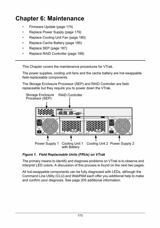
Chapter 6: Maintenance• Firmware Update (page 174)
• Replace Power Supply (page 179)
• Replace Cooling Unit Fan (page 180)
• Replace Cache Battery (page 185)
• Replace SEP (page 187)
• Replace RAID Controller (page 188)
This Chapter covers the maintenance procedures for VTrak.
The power supplies, cooling unit fans and the cache battery are hot-swappable field-replaceable components.
The Storage Enclosure Processor (SEP) and RAID Controller are field-replaceable but they require you to power down the VTrak.
Figure 1. Field Replaceable Units (FRUs) on VTrak
The primary means to identify and diagnose problems on VTrak is to observe and interpret LED colors. A discussion of this process is found on the next two pages.
All hot-swappable components can be fully diagnosed with LEDs, although the Command Line Utility (CLU) and WebPAM each offer you additional help to make and confirm your diagnosis. See page 205 additional information.
iSCSI 1iSCSI 2MgmtIOIOI
PROMISETECHNOLOGY, INC.
VTrak 15200 Controller
Storage EnclosureProcessor (SEP)
RAID Controller
Power Supply 1 Cooling Unit 1with Battery
Power Supply 2Cooling Unit 2
173
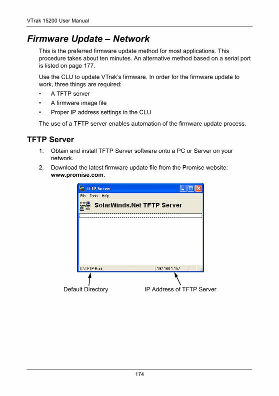
VTrak 15200 User Manual
Firmware Update – NetworkThis is the preferred firmware update method for most applications. This procedure takes about ten minutes. An alternative method based on a serial port is listed on page 177.
Use the CLU to update VTrak’s firmware. In order for the firmware update to work, three things are required:
• A TFTP server
• A firmware image file
• Proper IP address settings in the CLU
The use of a TFTP server enables automation of the firmware update process.
TFTP Server1. Obtain and install TFTP Server software onto a PC or Server on your
network.
2. Download the latest firmware update file from the Promise website: www.promise.com.
Default Directory IP Address of TFTP Server
174
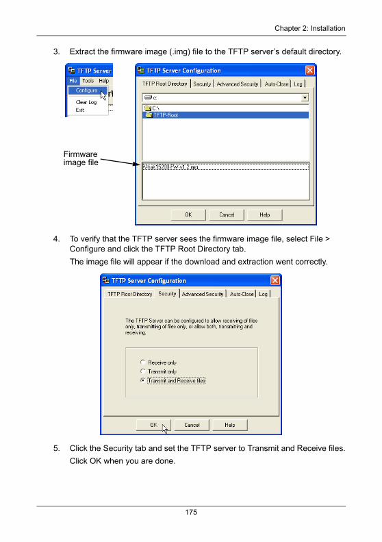
Chapter 2: Installation
3. Extract the firmware image (.img) file to the TFTP server’s default directory.
4. To verify that the TFTP server sees the firmware image file, select File > Configure and click the TFTP Root Directory tab.
The image file will appear if the download and extraction went correctly.
5. Click the Security tab and set the TFTP server to Transmit and Receive files.
Click OK when you are done.
Firmwareimage file
175
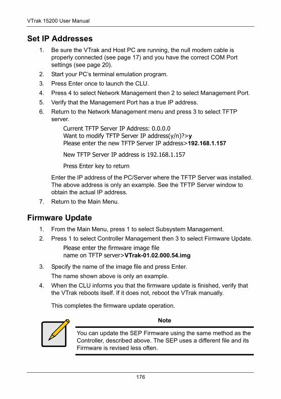
VTrak 15200 User Manual
Set IP Addresses1. Be sure the VTrak and Host PC are running, the null modem cable is
properly connected (see page 17) and you have the correct COM Port settings (see page 20).
2. Start your PC’s terminal emulation program.
3. Press Enter once to launch the CLU.
4. Press 4 to select Network Management then 2 to select Management Port.
5. Verify that the Management Port has a true IP address.
6. Return to the Network Management menu and press 3 to select TFTP server.
Current TFTP Server IP Address: 0.0.0.0Want to modify TFTP Server IP address(y/n)?>yPlease enter the new TFTP Server IP address>192.168.1.157
New TFTP Server IP address is 192.168.1.157
Press Enter key to return
Enter the IP address of the PC/Server where the TFTP Server was installed. The above address is only an example. See the TFTP Server window to obtain the actual IP address.
7. Return to the Main Menu.
Firmware Update1. From the Main Menu, press 1 to select Subsystem Management.
2. Press 1 to select Controller Management then 3 to select Firmware Update.
Please enter the firmware image filename on TFTP server>VTrak-01.02.000.54.img
3. Specify the name of the image file and press Enter.
The name shown above is only an example.
4. When the CLU informs you that the firmware update is finished, verify that the VTrak reboots itself. If it does not, reboot the VTrak manually.
This completes the firmware update operation.
Note
You can update the SEP Firmware using the same method as the Controller, described above. The SEP uses a different file and its Firmware is revised less often.
176
Chapter 2: Installation
Firmware Update – Serial PortUse this firmware update method only when your Management Port has no network connection or the RS-232 connection is required. This procedure takes about 30 minutes.
See also the network-based firmware upgrade procedure on page 174.
1. Download the latest firmware update file from the Promise website: www.promise.com.
2. Be sure the VTrak and Host PC are running, the null modem cable is properly connected (see page 22) and you have the correct COM Port settings (see page 26).
3. Start your PC’s terminal emulation program.
4. Press Enter once to launch the CLU.
5. Reboot the VTrak. Use either method:
• From the Main Menu, press 1 and Enter twice to access the Controller Management menu. Then press 5 and Enter to select Reboot. At each of two prompts, press Y and Enter to confirm the Reboot.
• Turn the VTrak’s power switches off and then on again.
6. Watch the terminal screen for the following:
Scrub DDR, waitingPlatform Init Done.+
7. At the +, press the Ctrl and F keys at the same time.
The prompt changes to >BSP.
8. At BSP> type load -r -v -b 0x01008000 -m y.
Double-check your entry. Then press Enter.
This command readies VTrak to receive a file transfer via Y-modem protocol. You have approximately 90 seconds to initiate the file transfer before the load operation times out.
9. Start the file transfer. For example, if you are using HyperTerminal:
• Go to Transfer > Send File
Warning
Do not allow the firmware update process to be interrupted for any reason. An interrupted update will incapacitate controller.
Then you must return the controller to Promise for repair.
177
VTrak 15200 User Manual
• Click on the firmware image file to select it. Example: VTrak-01.02.000.54.img
• Select Y-modem protocol
• Click Send
The file transfer takes about 20 minutes. When complete, the BSP> prompt will reappear.
10. At BSP> type ptiflash -b 0x01008000.
Double-check your entry. Then press Enter.
This command validates the firmware upgrade file then writes the binary image to VTrak’s flash ROM. These actions take about 8 minutes. When complete, the BSP> prompt will reappear.
11. Type reset and press Enter to restart the VTrak.
This completes the firmware update operation.
178
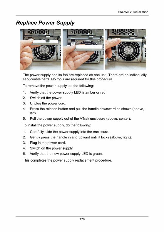
Chapter 2: Installation
Replace Power Supply
The power supply and its fan are replaced as one unit. There are no individually serviceable parts. No tools are required for this procedure.
To remove the power supply, do the following:
1. Verify that the power supply LED is amber or red.
2. Switch off the power.
3. Unplug the power cord.
4. Press the release button and pull the handle downward as shown (above, left).
5. Pull the power supply out of the VTrak enclosure (above, center).
To install the power supply, do the following:
1. Carefully slide the power supply into the enclosure.
2. Gently press the handle in and upward until it locks (above, right).
3. Plug in the power cord.
4. Switch on the power supply.
5. Verify that the new power supply LED is green.
This completes the power supply replacement procedure.
179
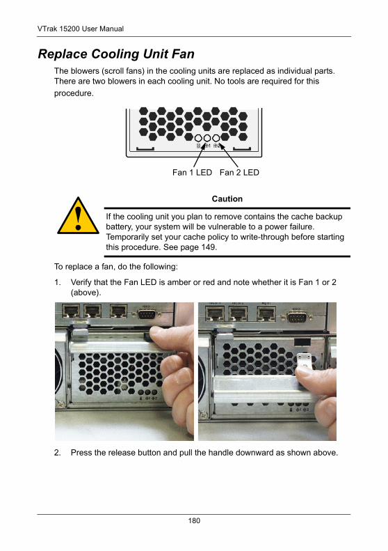
VTrak 15200 User Manual
Replace Cooling Unit FanThe blowers (scroll fans) in the cooling units are replaced as individual parts. There are two blowers in each cooling unit. No tools are required for this
procedure.
To replace a fan, do the following:
1. Verify that the Fan LED is amber or red and note whether it is Fan 1 or 2 (above).
2. Press the release button and pull the handle downward as shown above.
Caution
If the cooling unit you plan to remove contains the cache backup battery, your system will be vulnerable to a power failure. Temporarily set your cache policy to write-through before starting this procedure. See page 149.
Fan 2 LEDFan 1 LED
180
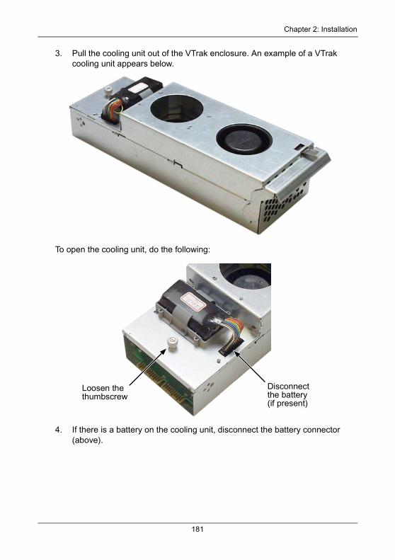
Chapter 2: Installation
3. Pull the cooling unit out of the VTrak enclosure. An example of a VTrak cooling unit appears below.
To open the cooling unit, do the following:
4. If there is a battery on the cooling unit, disconnect the battery connector (above).
Disconnect the battery(if present)
Loosen the thumbscrew
181
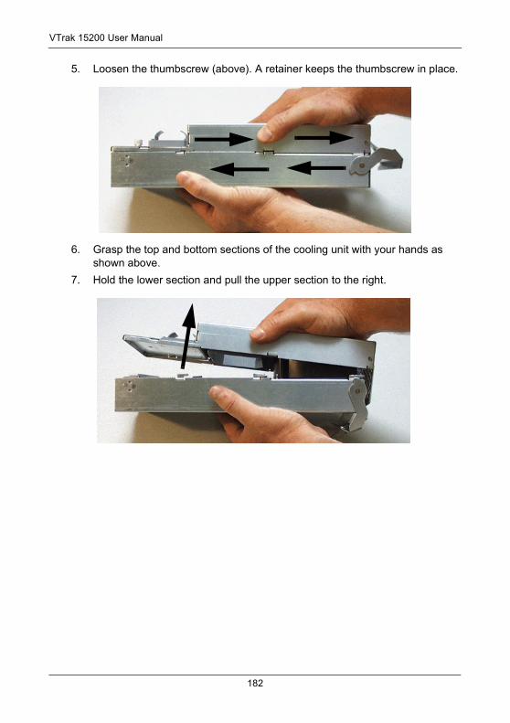
VTrak 15200 User Manual
5. Loosen the thumbscrew (above). A retainer keeps the thumbscrew in place.
6. Grasp the top and bottom sections of the cooling unit with your hands as shown above.
7. Hold the lower section and pull the upper section to the right.
182
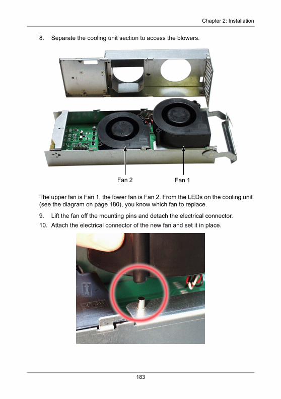
Chapter 2: Installation
8. Separate the cooling unit section to access the blowers.
The upper fan is Fan 1, the lower fan is Fan 2. From the LEDs on the cooling unit (see the diagram on page 180), you know which fan to replace.
9. Lift the fan off the mounting pins and detach the electrical connector.
10. Attach the electrical connector of the new fan and set it in place.
Fan 1Fan 2
183
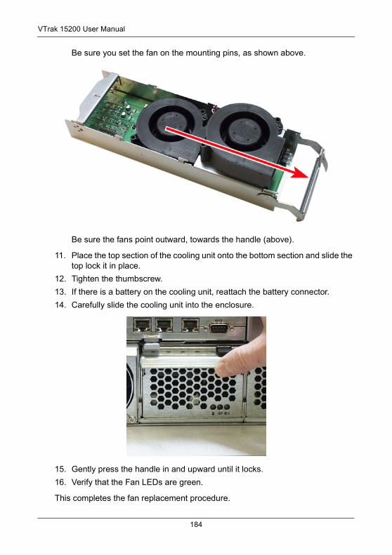
VTrak 15200 User Manual
Be sure you set the fan on the mounting pins, as shown above.
Be sure the fans point outward, towards the handle (above).
11. Place the top section of the cooling unit onto the bottom section and slide the top lock it in place.
12. Tighten the thumbscrew.
13. If there is a battery on the cooling unit, reattach the battery connector.
14. Carefully slide the cooling unit into the enclosure.
15. Gently press the handle in and upward until it locks.
16. Verify that the Fan LEDs are green.
This completes the fan replacement procedure.
184
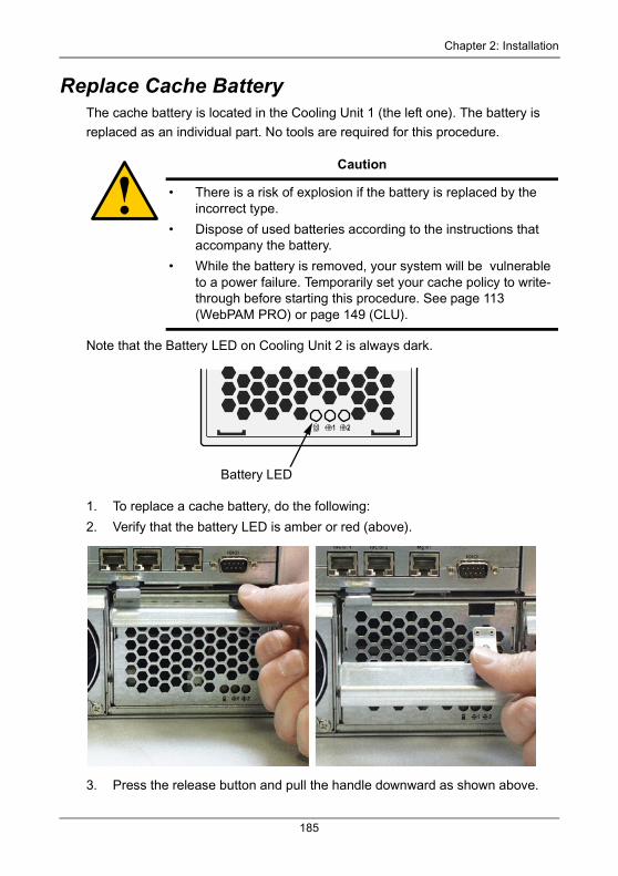
Chapter 2: Installation
Replace Cache BatteryThe cache battery is located in the Cooling Unit 1 (the left one). The battery is
replaced as an individual part. No tools are required for this procedure.
Note that the Battery LED on Cooling Unit 2 is always dark.
1. To replace a cache battery, do the following:
2. Verify that the battery LED is amber or red (above).
3. Press the release button and pull the handle downward as shown above.
Caution
• There is a risk of explosion if the battery is replaced by the incorrect type.
• Dispose of used batteries according to the instructions that accompany the battery.
• While the battery is removed, your system will be vulnerable to a power failure. Temporarily set your cache policy to write-through before starting this procedure. See page 113 (WebPAM PRO) or page 149 (CLU).
Battery LED
185
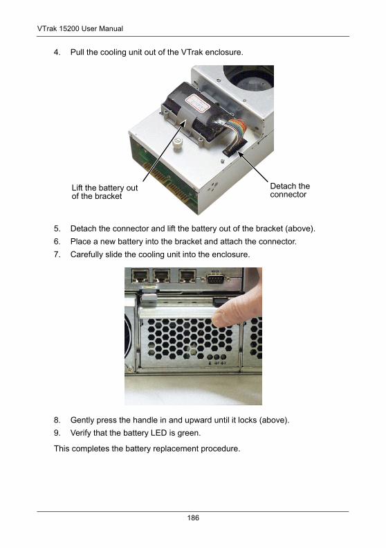
VTrak 15200 User Manual
4. Pull the cooling unit out of the VTrak enclosure.
5. Detach the connector and lift the battery out of the bracket (above).
6. Place a new battery into the bracket and attach the connector.
7. Carefully slide the cooling unit into the enclosure.
8. Gently press the handle in and upward until it locks (above).
9. Verify that the battery LED is green.
This completes the battery replacement procedure.
Detach the connector
Lift the battery out of the bracket
186
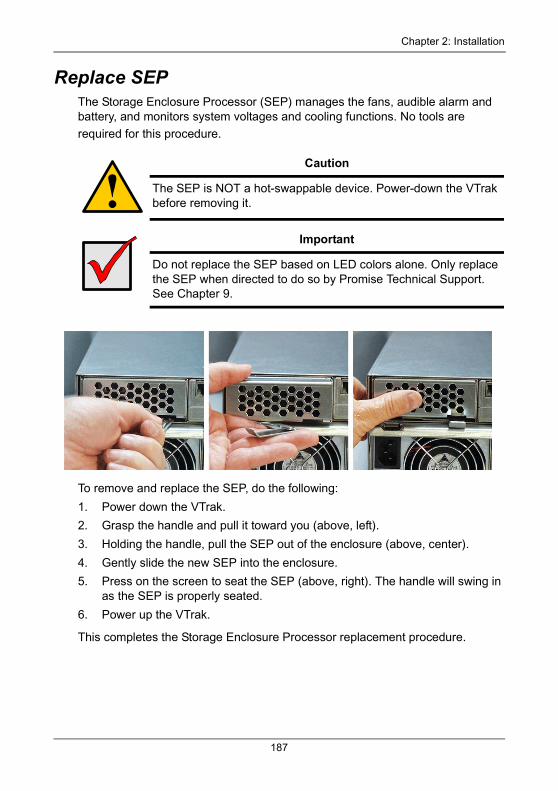
Chapter 2: Installation
Replace SEPThe Storage Enclosure Processor (SEP) manages the fans, audible alarm and battery, and monitors system voltages and cooling functions. No tools are
required for this procedure.
To remove and replace the SEP, do the following:
1. Power down the VTrak.
2. Grasp the handle and pull it toward you (above, left).
3. Holding the handle, pull the SEP out of the enclosure (above, center).
4. Gently slide the new SEP into the enclosure.
5. Press on the screen to seat the SEP (above, right). The handle will swing in as the SEP is properly seated.
6. Power up the VTrak.
This completes the Storage Enclosure Processor replacement procedure.
Caution
The SEP is NOT a hot-swappable device. Power-down the VTrak before removing it.
Important
Do not replace the SEP based on LED colors alone. Only replace the SEP when directed to do so by Promise Technical Support. See Chapter 9.
187
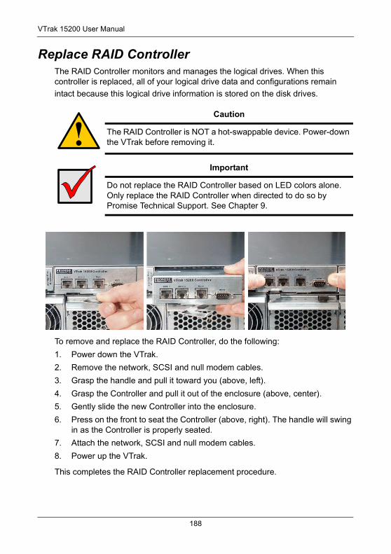
VTrak 15200 User Manual
Replace RAID Controller The RAID Controller monitors and manages the logical drives. When this controller is replaced, all of your logical drive data and configurations remain
intact because this logical drive information is stored on the disk drives.
To remove and replace the RAID Controller, do the following:
1. Power down the VTrak.
2. Remove the network, SCSI and null modem cables.
3. Grasp the handle and pull it toward you (above, left).
4. Grasp the Controller and pull it out of the enclosure (above, center).
5. Gently slide the new Controller into the enclosure.
6. Press on the front to seat the Controller (above, right). The handle will swing in as the Controller is properly seated.
7. Attach the network, SCSI and null modem cables.
8. Power up the VTrak.
This completes the RAID Controller replacement procedure.
Caution
The RAID Controller is NOT a hot-swappable device. Power-down the VTrak before removing it.
Important
Do not replace the RAID Controller based on LED colors alone. Only replace the RAID Controller when directed to do so by Promise Technical Support. See Chapter 9.
188
Chapter 7: Technology Background• Introduction to RAID (below)
• Choosing a RAID Level (page 196)
• Choosing Stripe Block Size (page 199)
• Gigabyte Boundary (page 199)
• Initialization (page 199)
• Hot Spare Drive (page 200)
• Partition and Format Logical Drive (page 200)
• Cache Settings (page 201)
• RAID Level Migration (page 201)
Introduction to RAIDRAID (Redundant Array of Independent Disks) allows multiple hard drives to be combined together to form one large logical drive. The operating system sees the logical drive as a single storage device, and treats it as such. The RAID software and/or controller handle all of the individual drives on its own. The benefits of a RAID can include:
• Higher data transfer rates for increased server performance
• Increased overall storage capacity for a single drive designation (such as, C, D, E, etc.)
• Data redundancy/fault tolerance for ensuring continuous system operation in the event of a hard drive failure
Different types of logical drives use different organizational models and have varying benefits. Also see Choosing RAID Level on page 196. The following outline breaks down the properties for each type of RAID logical drive:
189
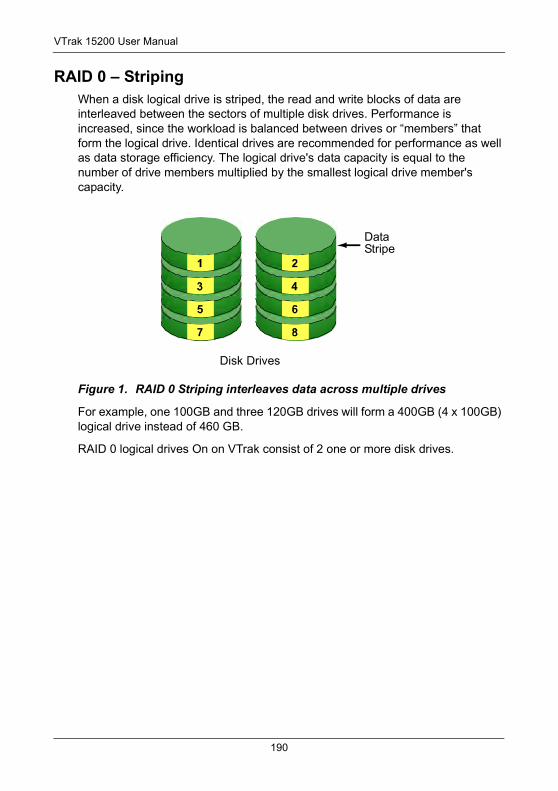
VTrak 15200 User Manual
RAID 0 – StripingWhen a disk logical drive is striped, the read and write blocks of data are interleaved between the sectors of multiple disk drives. Performance is increased, since the workload is balanced between drives or “members” that form the logical drive. Identical drives are recommended for performance as well as data storage efficiency. The logical drive's data capacity is equal to the number of drive members multiplied by the smallest logical drive member's capacity.
Figure 1. RAID 0 Striping interleaves data across multiple drives
For example, one 100GB and three 120GB drives will form a 400GB (4 x 100GB) logical drive instead of 460 GB.
RAID 0 logical drives On on VTrak consist of 2 one or more disk drives.
DataStripe
Disk Drives
190
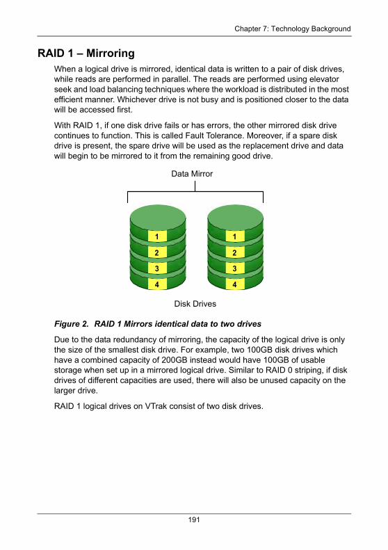
Chapter 7: Technology Background
RAID 1 – MirroringWhen a logical drive is mirrored, identical data is written to a pair of disk drives, while reads are performed in parallel. The reads are performed using elevator seek and load balancing techniques where the workload is distributed in the most efficient manner. Whichever drive is not busy and is positioned closer to the data will be accessed first.
With RAID 1, if one disk drive fails or has errors, the other mirrored disk drive continues to function. This is called Fault Tolerance. Moreover, if a spare disk drive is present, the spare drive will be used as the replacement drive and data will begin to be mirrored to it from the remaining good drive.
Figure 2. RAID 1 Mirrors identical data to two drives
Due to the data redundancy of mirroring, the capacity of the logical drive is only the size of the smallest disk drive. For example, two 100GB disk drives which have a combined capacity of 200GB instead would have 100GB of usable storage when set up in a mirrored logical drive. Similar to RAID 0 striping, if disk drives of different capacities are used, there will also be unused capacity on the larger drive.
RAID 1 logical drives on VTrak consist of two disk drives.
1
2
3
4
1
2
3
4
Data Mirror
Disk Drives
191
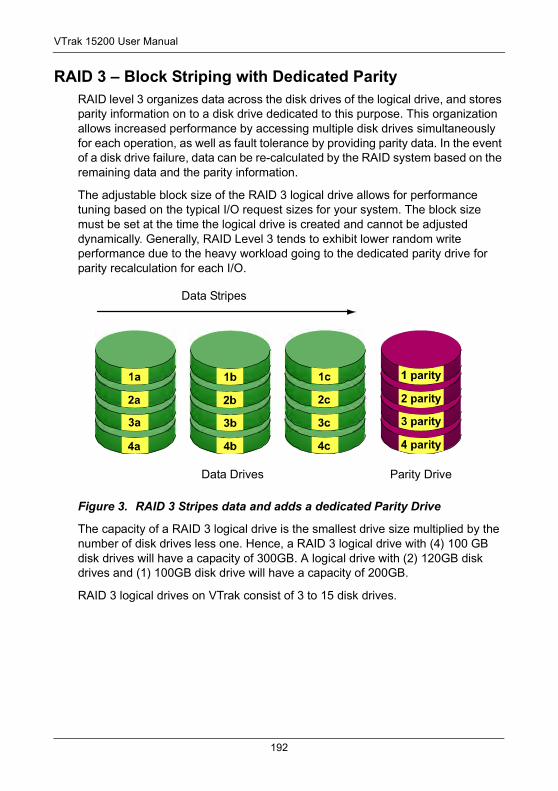
VTrak 15200 User Manual
RAID 3 – Block Striping with Dedicated ParityRAID level 3 organizes data across the disk drives of the logical drive, and stores parity information on to a disk drive dedicated to this purpose. This organization allows increased performance by accessing multiple disk drives simultaneously for each operation, as well as fault tolerance by providing parity data. In the event of a disk drive failure, data can be re-calculated by the RAID system based on the remaining data and the parity information.
The adjustable block size of the RAID 3 logical drive allows for performance tuning based on the typical I/O request sizes for your system. The block size must be set at the time the logical drive is created and cannot be adjusted dynamically. Generally, RAID Level 3 tends to exhibit lower random write performance due to the heavy workload going to the dedicated parity drive for parity recalculation for each I/O.
Figure 3. RAID 3 Stripes data and adds a dedicated Parity Drive
The capacity of a RAID 3 logical drive is the smallest drive size multiplied by the number of disk drives less one. Hence, a RAID 3 logical drive with (4) 100 GB disk drives will have a capacity of 300GB. A logical drive with (2) 120GB disk drives and (1) 100GB disk drive will have a capacity of 200GB.
RAID 3 logical drives on VTrak consist of 3 to 15 disk drives.
Data Stripes
Data Drives Parity Drive
192
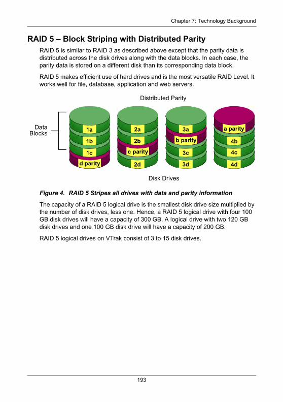
Chapter 7: Technology Background
RAID 5 – Block Striping with Distributed ParityRAID 5 is similar to RAID 3 as described above except that the parity data is distributed across the disk drives along with the data blocks. In each case, the parity data is stored on a different disk than its corresponding data block.
RAID 5 makes efficient use of hard drives and is the most versatile RAID Level. It works well for file, database, application and web servers.
Figure 4. RAID 5 Stripes all drives with data and parity information
The capacity of a RAID 5 logical drive is the smallest disk drive size multiplied by the number of disk drives, less one. Hence, a RAID 5 logical drive with four 100 GB disk drives will have a capacity of 300 GB. A logical drive with two 120 GB disk drives and one 100 GB disk drive will have a capacity of 200 GB.
RAID 5 logical drives on VTrak consist of 3 to 15 disk drives.
DataBlocks
Distributed Parity
Disk Drives
193
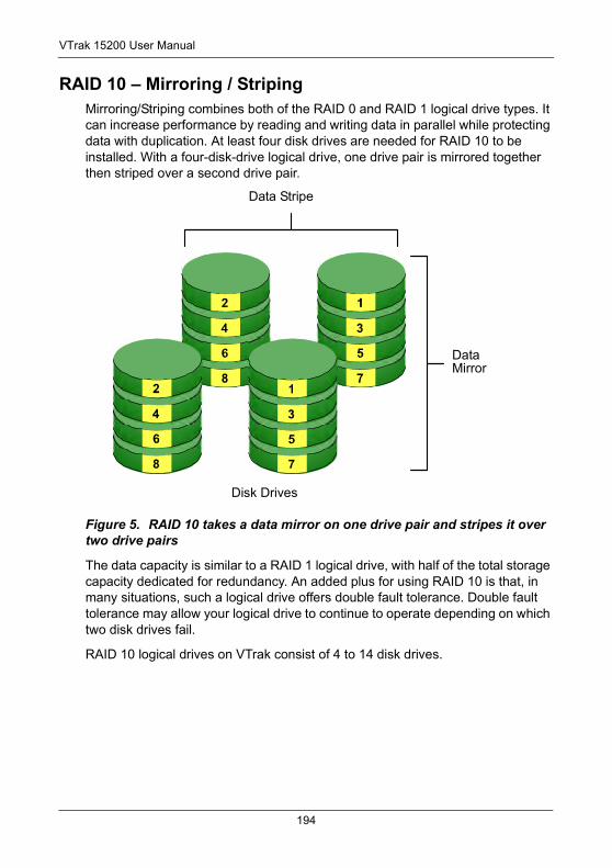
VTrak 15200 User Manual
RAID 10 – Mirroring / StripingMirroring/Striping combines both of the RAID 0 and RAID 1 logical drive types. It can increase performance by reading and writing data in parallel while protecting data with duplication. At least four disk drives are needed for RAID 10 to be installed. With a four-disk-drive logical drive, one drive pair is mirrored together then striped over a second drive pair.
Figure 5. RAID 10 takes a data mirror on one drive pair and stripes it over two drive pairs
The data capacity is similar to a RAID 1 logical drive, with half of the total storage capacity dedicated for redundancy. An added plus for using RAID 10 is that, in many situations, such a logical drive offers double fault tolerance. Double fault tolerance may allow your logical drive to continue to operate depending on which two disk drives fail.
RAID 10 logical drives on VTrak consist of 4 to 14 disk drives.
Data Stripe
Data Mirror
Disk Drives
194
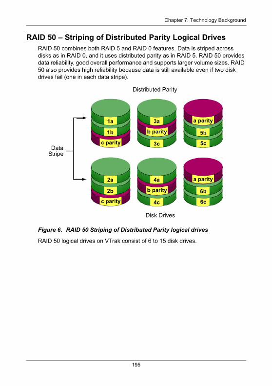
Chapter 7: Technology Background
RAID 50 – Striping of Distributed Parity Logical DrivesRAID 50 combines both RAID 5 and RAID 0 features. Data is striped across disks as in RAID 0, and it uses distributed parity as in RAID 5. RAID 50 provides data reliability, good overall performance and supports larger volume sizes. RAID 50 also provides high reliability because data is still available even if two disk drives fail (one in each data stripe).
Figure 6. RAID 50 Striping of Distributed Parity logical drives
RAID 50 logical drives on VTrak consist of 6 to 15 disk drives.
DataStripe
Distributed Parity
Disk Drives
195
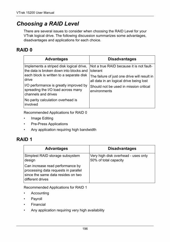
VTrak 15200 User Manual
Choosing a RAID LevelThere are several issues to consider when choosing the RAID Level for your VTrak logical drive. The following discussion summarizes some advantages, disadvantages and applications for each choice.
RAID 0
Recommended Applications for RAID 0
• Image Editing
• Pre-Press Applications
• Any application requiring high bandwidth
RAID 1
Recommended Applications for RAID 1
• Accounting
• Payroll
• Financial
• Any application requiring very high availability
Advantages Disadvantages
Implements a striped disk logical drive, the data is broken down into blocks and each block is written to a separate disk drive
I/O performance is greatly improved by spreading the I/O load across many channels and drives
No parity calculation overhead is involved
Not a true RAID because it is not fault-tolerant
The failure of just one drive will result in all data in an logical drive being lost
Should not be used in mission critical environments
Advantages Disadvantages
Simplest RAID storage subsystem design
Can increase read performance by processing data requests in parallel since the same data resides on two different drives
Very high disk overhead - uses only 50% of total capacity
196
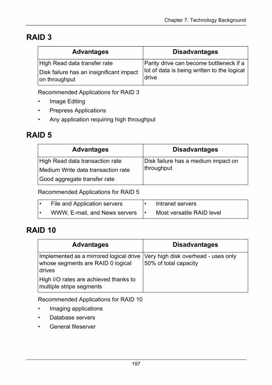
Chapter 7: Technology Background
RAID 3
Recommended Applications for RAID 3
• Image Editing
• Prepress Applications
• Any application requiring high throughput
RAID 5
Recommended Applications for RAID 5
RAID 10
Recommended Applications for RAID 10
• Imaging applications
• Database servers
• General fileserver
Advantages Disadvantages
High Read data transfer rate
Disk failure has an insignificant impact on throughput
Parity drive can become bottleneck if a lot of data is being written to the logical drive
Advantages Disadvantages
High Read data transaction rate
Medium Write data transaction rate
Good aggregate transfer rate
Disk failure has a medium impact on throughput
• File and Application servers
• WWW, E-mail, and News servers
• Intranet servers
• Most versatile RAID level
Advantages Disadvantages
Implemented as a mirrored logical drive whose segments are RAID 0 logical drives
High I/O rates are achieved thanks to multiple stripe segments
Very high disk overhead - uses only 50% of total capacity
197
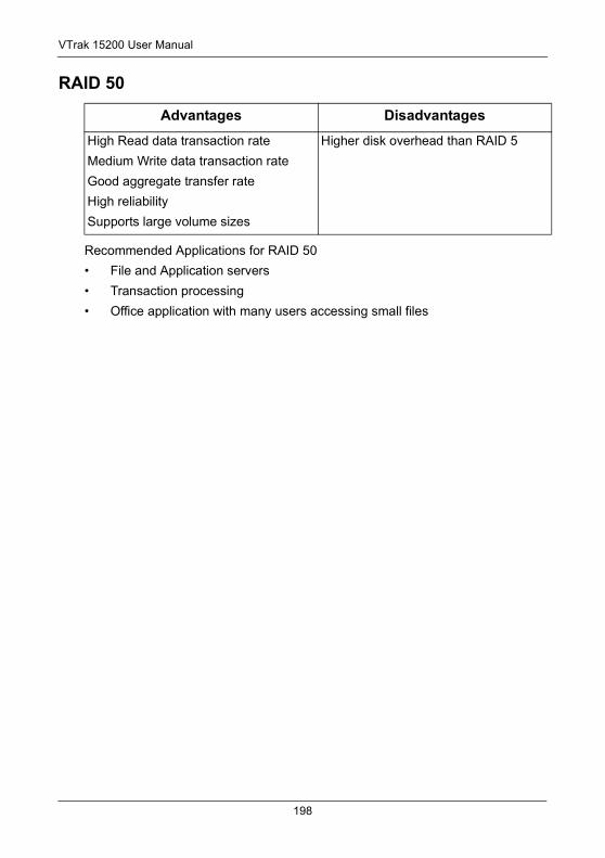
VTrak 15200 User Manual
RAID 50
Recommended Applications for RAID 50
• File and Application servers
• Transaction processing
• Office application with many users accessing small files
Advantages Disadvantages
High Read data transaction rate
Medium Write data transaction rate
Good aggregate transfer rate
High reliability
Supports large volume sizes
Higher disk overhead than RAID 5
198
Chapter 7: Technology Background
Choosing Stripe Block SizeThe stripe block size value can be set to 4KB, 8KB, 16KB, 32KB, and 64KB.
64 KB is the default. This selection will directly affect performance. There are two issues to consider when selecting the stripe block size.
• Choose a stripe block size equal to or smaller than the smallest cache buffer found on any disk drive in your logical drive. A larger value slows the logical drive down because disk drives with smaller cache buffers need more time for multiple accesses to fill their buffers.
• If your data retrieval consists of fixed-size data blocks, such as some database and video applications, choose that data block size as your stripe block size.
Generally speaking, email, POS and webservers prefer smaller stripe block sizes. Video and database applications prefer larger stripe block sizes.
Gigabyte BoundaryThe Gigabyte Boundary feature is designed for logical drives in which a drive has failed and the user cannot replace the drive with the same capacity or larger. Instead, the Gigabyte Boundary feature permits the installation of a replacement drive that is slightly smaller (within 1 gigabyte) than the remaining working drive (for example, an 80.5GB drive would be rounded down to 80GB). This can be helpful in the event that a drive fails and an exact replacement model is no longer available. With VTrak, this feature is always enabled.
InitializationInitialization is the process of setting all of the data bits on all of the disk drives to zero. This has the effect of erasing any existing data from the drives. This action is especially helpful in creating accurate parity in logical drives with more than four drives.
Initialization applies to RAID 1, 3, 5, 10 and 50. If you create one of these logical drives automatically, the logical drive is always initialized. If you create the logical drive manually, you can choose whether to initialize.
The initialization process begins immediately after the logical drive is created and may take some time to finish, depending on the size of the disk drives in your logical drive. Your logical drive is available while initialization is in progress.
199
VTrak 15200 User Manual
Hot Spare Drive(s)A hot spare is a disk drive that is connected to the logical drive system but is not assigned as a member of the logical drive. In the event of the failure of a drive within a functioning fault tolerant logical drive, the hot spare is activated as a member of the logical drive to replace a drive that has failed.
VTrak will replace a failing disk drive in a logical drive with an unassigned drive, if one is available. The unassigned drive is not part of any logical drive. Such a drive is called a hot spare drive. There are two types:
• Global – An unassigned disk drive available to any logical drive on the VTrak.
• Dedicated – An unassigned disk drive that can only be used by a specified logical drive.
The hot spare policy function lets you select whether a logical drive will access any unassigned disk drive or a designated drive in the event of disk drive failure. See page 113 (WebPAM PRO) or page 150 (CLU) for information on how to make this setting.
The spare drive effectively takes the place of the failed drive and the RAID system immediately begins to rebuild data onto the drive. When the rebuild is complete, the logical drive is returned to fault tolerant status.
Once the failed drive is replaced, the new drive is automatically recognized as a hot spare and will be activated in the event of a subsequent drive fault.
Maintaining a hot spare drive is a good precaution to protect your logical drive integrity in the event of drive failure.
Partition and Format the Logical DriveLike any other type of fixed disk media in your system, a RAID logical drive must also be partitioned and formatted before use. Use the same method of partitioning and formatting on an logical drive as you would any other fixed disk.
Depending on the operating system you use, there may or may not be various capacity limitations applicable for the different types of partitions.
200
Chapter 7: Technology Background
Cache SettingsThere is a data cache on the VTrak controller and another one on each Physical disk drive. A cache holds data in volatile memory during RAID management and data transfer activity. The right combination of cache settings for your needs can improve VTrak’s efficiency and performance.
Physical Drive Write Cache – Activates the write cache on the disk drive.
Write Back Cache – Activates write-back feature of VTrak’s controller cache. A write back cache holds data after an I/O operation and tells the controller the data has been written. The data is written as soon as the disk drive is no longer busy.
This action increases availability of the logical drive. If the power fails before the data is written to the disk drive, the data will be lost.
VTrak’s controller cache is equipped with a backup battery to power the cache and retain uncommitted cache data in it until regular power can be restored. Battery condition is reported by WebPAM PRO on page 122 and the CLU on page 137.
The alternative is a write-through cache policy, which reports that the data has been written to the disk only when it actually has.
Where to Make SettingsIn WebPAM PRO, these functions are under:
• Click on the Logical Drive View icon and select Logical Drive Functions from the Change Logical Drive Settings menu. Or see page 113
In the CLU, these functions are under:
• Drive Write Cache – From the Main Menu, press 2 Enter, 2 Enter or see page 139
• VTrak’s Cache Policy – From the Main Menu, press 3 Enter, 4 Enter, 2 Enter or see page 149
RAID Level MigrationTo migrate a Logical Drive is to do one or both of the following:
• Change its RAID level
• Increase the number of disk drives (sometimes called Expansion)
Migration takes place on an existing Functional Logical Drive without disturbing the existing data. While the Logical Drive is migrating, you can access the data as before. When migration is complete, your Logical Drive will have a different RAID level and/or a larger capacity.
201
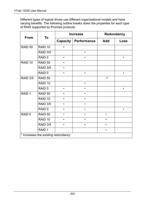
VTrak 15200 User Manual
Different types of logical drives use different organizational models and have varying benefits. The following outline breaks down the properties for each type of RAID supported by Promise products.
From ToIncrease Redundancy
Capacity Performance Add Lose
RAID 50 RAID 10 •
RAID 3/5 •
RAID 0 • • •
RAID 10 RAID 50 •
RAID 3/5 •
RAID 0 • • •
RAID 3/5 RAID 50 •*
RAID 10 •
RAID 0 • • •
RAID 1 RAID 50 • •
RAID 10 • •
RAID 3/5 • •
RAID 0 • • •
RAID 0 RAID 50 • • •
RAID 10 • • •
RAID 3/5 • • •
RAID 1 •
* Increases the existing redundancy
202
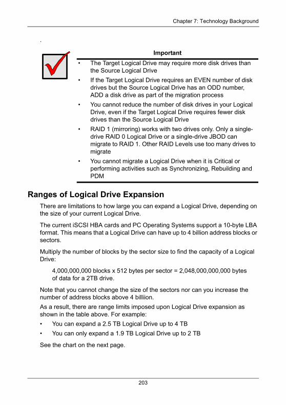
Chapter 7: Technology Background
.
Ranges of Logical Drive ExpansionThere are limitations to how large you can expand a Logical Drive, depending on the size of your current Logical Drive.
The current iSCSI HBA cards and PC Operating Systems support a 10-byte LBA format. This means that a Logical Drive can have up to 4 billion address blocks or sectors.
Multiply the number of blocks by the sector size to find the capacity of a Logical Drive:
4,000,000,000 blocks x 512 bytes per sector = 2,048,000,000,000 bytesof data for a 2TB drive.
Note that you cannot change the size of the sectors nor can you increase the number of address blocks above 4 billiion.
As a result, there are range limits imposed upon Logical Drive expansion as shown in the table above. For example:
• You can expand a 2.5 TB Logical Drive up to 4 TB
• You can only expand a 1.9 TB Logical Drive up to 2 TB
See the chart on the next page.
Important• The Target Logical Drive may require more disk drives than
the Source Logical Drive
• If the Target Logical Drive requires an EVEN number of disk drives but the Source Logical Drive has an ODD number, ADD a disk drive as part of the migration process
• You cannot reduce the number of disk drives in your Logical Drive, even if the Target Logical Drive requires fewer disk drives than the Source Logical Drive
• RAID 1 (mirroring) works with two drives only. Only a single-drive RAID 0 Logical Drive or a single-drive JBOD can migrate to RAID 1. Other RAID Levels use too many drives to migrate
• You cannot migrate a Logical Drive when it is Critical or performing activities such as Synchronizing, Rebuilding and PDM
203
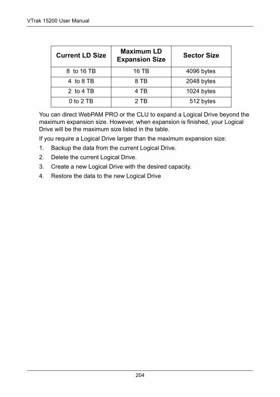
VTrak 15200 User Manual
You can direct WebPAM PRO or the CLU to expand a Logical Drive beyond the maximum expansion size. However, when expansion is finished, your Logical Drive will be the maximum size listed in the table.
If you require a Logical Drive larger than the maximum expansion size:
1. Backup the data from the current Logical Drive.
2. Delete the current Logical Drive.
3. Create a new Logical Drive with the desired capacity.
4. Restore the data to the new Logical Drive
Current LD Size Maximum LD Expansion Size Sector Size
8 to 16 TB 16 TB 4096 bytes
4 to 8 TB 8 TB 2048 bytes
2 to 4 TB 4 TB 1024 bytes
0 to 2 TB 2 TB 512 bytes
204
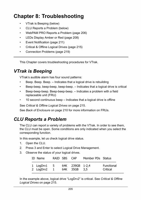
Chapter 8: Troubleshooting• VTrak is Beeping (below)
• CLU Reports a Problem (below)
• WebPAM PRO Reports a Problem (page 206)
• LEDs Display Amber or Red (page 208)
• Event Notification (page 211)
• Critical & Offline Logical Drives (page 215)
• Connection Problems (page 219)
This Chapter covers troubleshooting procedures for VTrak.
VTrak is BeepingVTrak’s audible alarm has four sound patterns:
• Beep. Beep. Beep. – Indicates that a logical drive is rebuilding
• Beep-beep, beep-beep, beep-beep. – Indicates that a logical drive is critical
• Beep-beep-beep. Beep-beep-beep. – Indicates a problem with a field replaceable unit (FRU)
• 10 second continuous beep – Indicates that a logical drive is offline
See Critical & Offline Logical Drives on page 215.
See Back of Enclosure on page 210 for more information on FRUs.
CLU Reports a ProblemThe CLU can report a variety of problems with the VTrak. In order to see them, the CLU must be open. Some conditions are only indicated when you select the corresponding function.
In this example, let us check logical drive status.
1. Open the CLU.
2. Press 3 and Enter to select Logical Drive Management.
3. Observe the status of your logical drives.
ID Name RAID SBS CAP Member PDs Status-----------------------------------------------------------------------------1 LogDrv1 5 64K 239GB 1-2,4 Functional2 LogDrv2 1 64K 35GB 3,5 Critical------------------------------------------------------------------------------------
In the example above, logical drive “LogDrv2” is critical. See Critical & Offline Logical Drives on page 215.
205
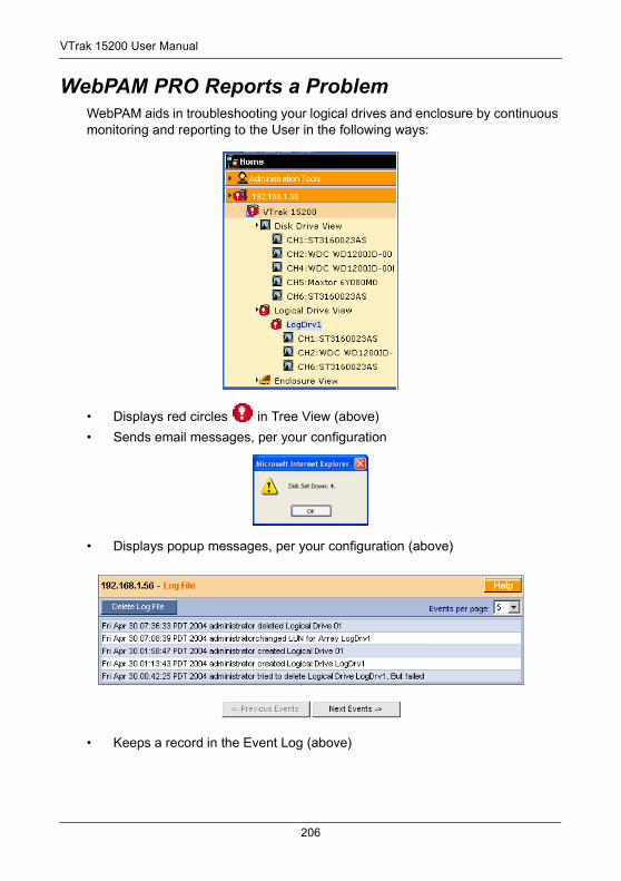
VTrak 15200 User Manual
WebPAM PRO Reports a ProblemWebPAM aids in troubleshooting your logical drives and enclosure by continuous monitoring and reporting to the User in the following ways:
• Displays red circles in Tree View (above)
• Sends email messages, per your configuration
• Displays popup messages, per your configuration (above)
• Keeps a record in the Event Log (above)
206
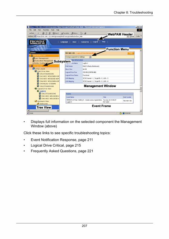
Chapter 8: Troubleshooting
• Displays full information on the selected component the Management Window (above)
Click these links to see specific troubleshooting topics:
• Event Notification Response, page 211
• Logical Drive Critical, page 215
• Frequently Asked Questions, page 221
207
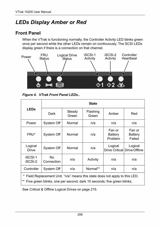
VTrak 15200 User Manual
LEDs Display Amber or Red
Front PanelWhen the VTrak is functioning normally, the Controller Activity LED blinks green once per second while the other LEDs remain on continuously. The SCSI LEDs display green if there is a connection on that channel.
Figure 4. VTrak Front Panel LEDs..
See Critical & Offline Logical Drives on page 215.
LEDsState
DarkSteady Green
Flashing Green
Amber Red
Power System Off Normal n/a n/a n/a
FRU* System Off Normal n/aFan or Battery Problem
Fan or Battery Failed
Logical Drive
System Off Normal n/aLogical
Drive CriticalLogical
Drive Offline
iSCSI-1iSCSI-2
No Connection
n/a Activity n/a n/a
Controller System Off n/a Normal** n/a n/a
* Field Replacement Unit. “n/a” means this state does not apply to this LED.
** Five green blinks, one per second; dark 10 seconds; five green blinks.
Power FRUStatus
Logical DriveStatus
iSCSI-1Activity
iSCSI-2Activity
ControllerHeartbeat
208
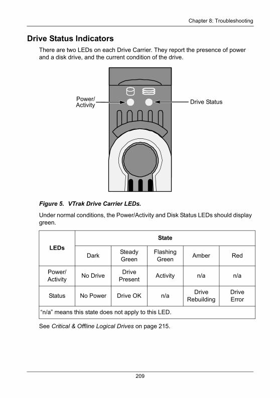
Chapter 8: Troubleshooting
Drive Status IndicatorsThere are two LEDs on each Drive Carrier. They report the presence of power and a disk drive, and the current condition of the drive.
Figure 5. VTrak Drive Carrier LEDs.
Under normal conditions, the Power/Activity and Disk Status LEDs should display green.
See Critical & Offline Logical Drives on page 215.
LEDsState
DarkSteady Green
Flashing Green
Amber Red
Power/Activity
No DriveDrive
PresentActivity n/a n/a
Status No Power Drive OK n/aDrive
RebuildingDriveError
“n/a” means this state does not apply to this LED.
Drive StatusPower/Activity
209
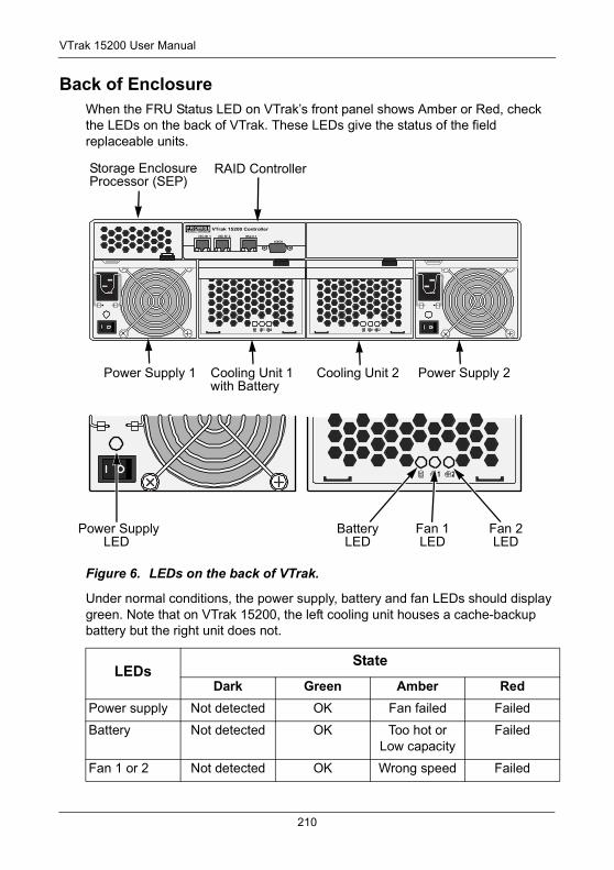
VTrak 15200 User Manual
Back of EnclosureWhen the FRU Status LED on VTrak’s front panel shows Amber or Red, check the LEDs on the back of VTrak. These LEDs give the status of the field replaceable units.
Figure 6. LEDs on the back of VTrak.
Under normal conditions, the power supply, battery and fan LEDs should display green. Note that on VTrak 15200, the left cooling unit houses a cache-backup battery but the right unit does not.
LEDsState
Dark Green Amber RedPower supply Not detected OK Fan failed Failed
Battery Not detected OK Too hot orLow capacity
Failed
Fan 1 or 2 Not detected OK Wrong speed Failed
Power Supply LED
iSCSI 1 iSCSI 2 Mgm t
IOIOI
PROMISETECHNOLOGY, INC.VTrak 15200 Controller
Storage EnclosureProcessor (SEP)
RAID Controller
Power Supply 1 Cooling Unit 1with Battery
Power Supply 2Cooling Unit 2
Fan 1LED
BatteryLED
Fan 2LED
210
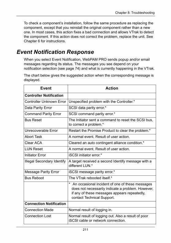
Chapter 8: Troubleshooting
To check a component’s installation, follow the same procedure as replacing the component, except that you reinstall the original component rather than a new one. In most cases, this action fixes a bad connection and allows VTrak to detect the component. If this action does not correct the problem, replace the unit. See Chapter 6 for instructions.
Event Notification ResponseWhen you select Event Notification, WebPAM PRO sends popup and/or email messages regarding its status. The messages you see depend on your notification selection (see page 74) and what is currently happening in the VTrak.
The chart below gives the suggested action when the corresponding message is displayed.
Event Action
Controller NotificationController Unknown Error Unspecified problem with the Controller.*
Data Parity Error SCSI data parity error.*
Command Parity Error SCSI command parity error.*
Bus Reset The Initiator sent a command to reset the SCSI bus, to correct a problem.*
Unrecoverable Error Restart the Promise Product to clear the problem.*
Abort Task A normal event. Result of user action.
Clear ACA Cleared an auto contingent alliance condition.*
LUN Reset A normal event. Result of user action.
Initiator Error iSCSI initiator error.*
Illegal Secondary Identify A target received a second Identify message with a different LUN.*
Message Parity Error iSCSI message parity error.*
Bus Reboot The VTrak rebooted itself.*
* An occasional incident of one of these messages does not necessarily indicate a problem. However, if any of these messages appears repeatedly, contact Technical Support.
Connection NotificationConnection Made Normal result of logging in.
Connection Lost Normal result of logging out. Also a result of poor iSCSI cable or network connection.
211
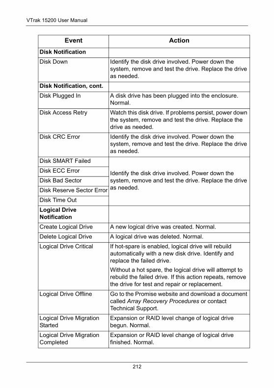
VTrak 15200 User Manual
Disk NotificationDisk Down Identify the disk drive involved. Power down the
system, remove and test the drive. Replace the drive as needed.
Disk Notification, cont.Disk Plugged In A disk drive has been plugged into the enclosure.
Normal.
Disk Access Retry Watch this disk drive. If problems persist, power down the system, remove and test the drive. Replace the drive as needed.
Disk CRC Error Identify the disk drive involved. Power down the system, remove and test the drive. Replace the drive as needed.
Disk SMART Failed
Identify the disk drive involved. Power down the system, remove and test the drive. Replace the drive as needed.
Disk ECC Error
Disk Bad Sector
Disk Reserve Sector Error
Disk Time Out
Logical Drive NotificationCreate Logical Drive A new logical drive was created. Normal.
Delete Logical Drive A logical drive was deleted. Normal.
Logical Drive Critical If hot-spare is enabled, logical drive will rebuild automatically with a new disk drive. Identify and replace the failed drive.
Without a hot spare, the logical drive will attempt to rebuild the failed drive. If this action repeats, remove the drive for test and repair or replacement.
Logical Drive Offline Go to the Promise website and download a document called Array Recovery Procedures or contact Technical Support.
Logical Drive Migration Started
Expansion or RAID level change of logical drive begun. Normal.
Logical Drive Migration Completed
Expansion or RAID level change of logical drive finished. Normal.
Event Action
212
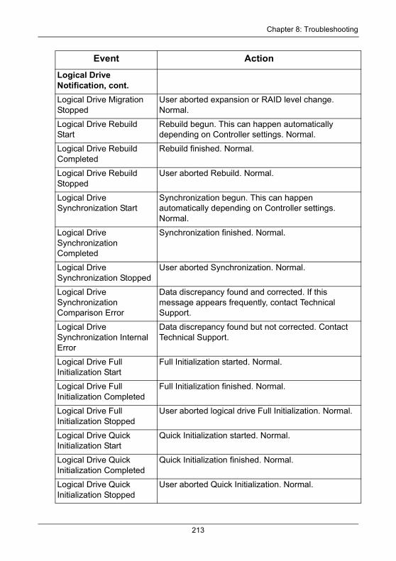
Chapter 8: Troubleshooting
Logical Drive Notification, cont.Logical Drive Migration Stopped
User aborted expansion or RAID level change. Normal.
Logical Drive Rebuild Start
Rebuild begun. This can happen automatically depending on Controller settings. Normal.
Logical Drive Rebuild Completed
Rebuild finished. Normal.
Logical Drive Rebuild Stopped
User aborted Rebuild. Normal.
Logical Drive Synchronization Start
Synchronization begun. This can happen automatically depending on Controller settings. Normal.
Logical Drive Synchronization Completed
Synchronization finished. Normal.
Logical Drive Synchronization Stopped
User aborted Synchronization. Normal.
Logical Drive Synchronization Comparison Error
Data discrepancy found and corrected. If this message appears frequently, contact Technical Support.
Logical Drive Synchronization Internal Error
Data discrepancy found but not corrected. Contact Technical Support.
Logical Drive Full Initialization Start
Full Initialization started. Normal.
Logical Drive Full Initialization Completed
Full Initialization finished. Normal.
Logical Drive Full Initialization Stopped
User aborted logical drive Full Initialization. Normal.
Logical Drive Quick Initialization Start
Quick Initialization started. Normal.
Logical Drive Quick Initialization Completed
Quick Initialization finished. Normal.
Logical Drive Quick Initialization Stopped
User aborted Quick Initialization. Normal.
Event Action
213
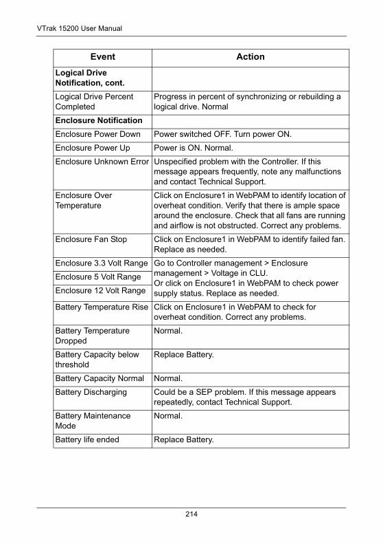
VTrak 15200 User Manual
Logical Drive Notification, cont.Logical Drive Percent Completed
Progress in percent of synchronizing or rebuilding a logical drive. Normal
Enclosure NotificationEnclosure Power Down Power switched OFF. Turn power ON.
Enclosure Power Up Power is ON. Normal.
Enclosure Unknown Error Unspecified problem with the Controller. If this message appears frequently, note any malfunctions and contact Technical Support.
Enclosure Over Temperature
Click on Enclosure1 in WebPAM to identify location of overheat condition. Verify that there is ample space around the enclosure. Check that all fans are running and airflow is not obstructed. Correct any problems.
Enclosure Fan Stop Click on Enclosure1 in WebPAM to identify failed fan. Replace as needed.
Enclosure 3.3 Volt Range Go to Controller management > Enclosure management > Voltage in CLU.Or click on Enclosure1 in WebPAM to check power supply status. Replace as needed.
Enclosure 5 Volt Range
Enclosure 12 Volt Range
Battery Temperature Rise Click on Enclosure1 in WebPAM to check for overheat condition. Correct any problems.
Battery Temperature Dropped
Normal.
Battery Capacity below threshold
Replace Battery.
Battery Capacity Normal Normal.
Battery Discharging Could be a SEP problem. If this message appears repeatedly, contact Technical Support.
Battery Maintenance Mode
Normal.
Battery life ended Replace Battery.
Event Action
214
Chapter 8: Troubleshooting
Critical & Offline Logical DrivesA fault-tolerant logical drive—RAID 1, 3, 5, 10 and 50—goes critical when a drive is removed or fails. Due to the fault tolerance of the logical drive, the data is still available and online. However, once the logical drive goes critical, the logical drive has lost its fault tolerance, and performance may be adversely affected.
If the fault was caused by a failed drive that was removed, the drive must be replaced by another drive, either identical or larger, in order for the RAID system to rebuild and restore optimal configuration.
If your fault-tolerant logical drive goes offline, go to the Promise website (www.promise.com) and download a document called Array Recovery Procedure.
A non-fault tolerant logical drive—RAID 0—goes offline when a drive is removed or fails. Since the logical drive is not fault tolerant, the data stored in the logical drive is no longer accessible.
If one disk drive fails, all of the data on the logical drive is lost. You must replace the failed drive. Then,if the logical drive had more than one disk drive, delete the logical drive and re-create it. Restore the data from a backup source.
When a Disk Drive FailsVTrak provides both audible and visual indicators to alert you of a disk drive failure. The following will occur when a disk drive fails or goes offline:
• The Logical Drive LED changes from green to amber
• The Disk Carrier Status LED changes from green to red
• The audible alarm repeatedly sounds two short beeps
• WebPAM PRO and the CLU report the condition
RebuildNormally, the logical drive will begin rebuilding automatically. You can access your logical drive during this time but read/write performance might be slower than normal.
• If a hot spare drive is provided and enabled, the controller will activate the hot spare and rebuild logical drive information and data to it.
• If there is no hot spare drive available, the controller will begin rebuilding the disk drive that failed.
215
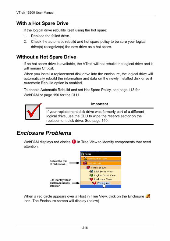
VTrak 15200 User Manual
With a Hot Spare DriveIf the logical drive rebuilds itself using the hot spare:
1. Replace the failed drive.
2. Check the automatic rebuild and hot spare policy to be sure your logical
drive(s) recognize(s) the new drive as a hot spare.
Without a Hot Spare DriveIf no hot spare drive is available, the VTrak will not rebuild the logical drive and it will remain Critical.
When you install a replacement disk drive into the enclosure, the logical drive will automatically rebuild the information and data on the newly installed disk drive if Automatic Rebuild option is enabled.
To enable Automatic Rebuild and set Hot Spare Policy, see page 113 for
WebPAM or page 150 for the CLU.
Enclosure ProblemsWebPAM displays red circles in Tree View to identify components that need attention.
When a red circle appears over a Host in Tree View, click on the Enclosure icon. The Enclosure screen will display (below).
Important
If your replacement disk drive was formerly part of a different logical drive, use the CLU to wipe the reserve sector on the replacement disk drive. See page 140.
216
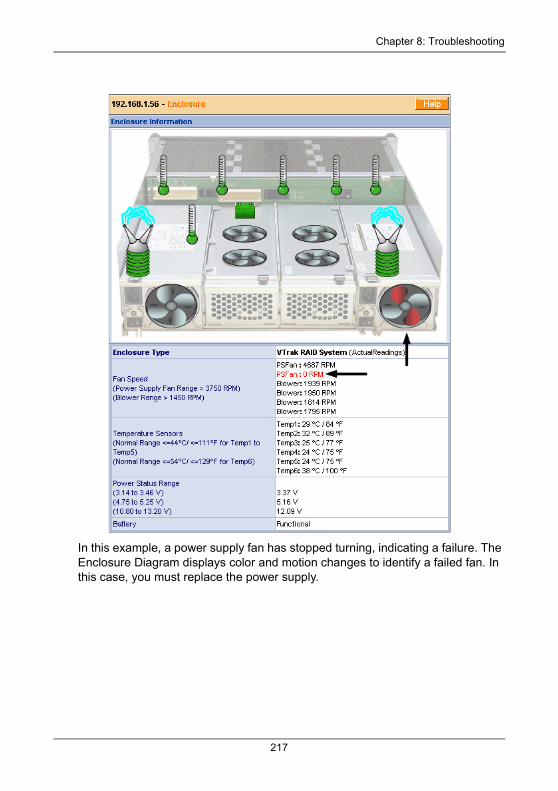
Chapter 8: Troubleshooting
In this example, a power supply fan has stopped turning, indicating a failure. The Enclosure Diagram displays color and motion changes to identify a failed fan. In this case, you must replace the power supply.
217
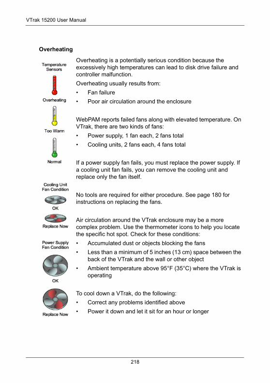
VTrak 15200 User Manual
Overheating
Overheating is a potentially serious condition because the excessively high temperatures can lead to disk drive failure and controller malfunction.
Overheating usually results from:
• Fan failure
• Poor air circulation around the enclosure
WebPAM reports failed fans along with elevated temperature. On VTrak, there are two kinds of fans:
• Power supply, 1 fan each, 2 fans total
• Cooling units, 2 fans each, 4 fans total
If a power supply fan fails, you must replace the power supply. If a cooling unit fan fails, you can remove the cooling unit and replace only the fan itself.
No tools are required for either procedure. See page 180 for instructions on replacing the fans.
Air circulation around the VTrak enclosure may be a more complex problem. Use the thermometer icons to help you locate the specific hot spot. Check for these conditions:
• Accumulated dust or objects blocking the fans
• Less than a minimum of 5 inches (13 cm) space between the back of the VTrak and the wall or other object
• Ambient temperature above 95°F (35°C) where the VTrak is operating
To cool down a VTrak, do the following:
• Correct any problems identified above
• Power it down and let it sit for an hour or longer
218
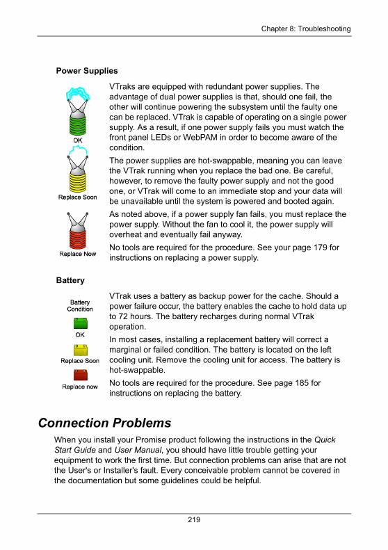
Chapter 8: Troubleshooting
Connection ProblemsWhen you install your Promise product following the instructions in the Quick Start Guide and User Manual, you should have little trouble getting your equipment to work the first time. But connection problems can arise that are not the User's or Installer's fault. Every conceivable problem cannot be covered in the documentation but some guidelines could be helpful.
Power Supplies
VTraks are equipped with redundant power supplies. The advantage of dual power supplies is that, should one fail, the other will continue powering the subsystem until the faulty one can be replaced. VTrak is capable of operating on a single power supply. As a result, if one power supply fails you must watch the front panel LEDs or WebPAM in order to become aware of the condition.
The power supplies are hot-swappable, meaning you can leave the VTrak running when you replace the bad one. Be careful, however, to remove the faulty power supply and not the good one, or VTrak will come to an immediate stop and your data will be unavailable until the system is powered and booted again.
As noted above, if a power supply fan fails, you must replace the power supply. Without the fan to cool it, the power supply will overheat and eventually fail anyway.
No tools are required for the procedure. See your page 179 for instructions on replacing a power supply.
Battery
VTrak uses a battery as backup power for the cache. Should a power failure occur, the battery enables the cache to hold data up to 72 hours. The battery recharges during normal VTrak operation.
In most cases, installing a replacement battery will correct a marginal or failed condition. The battery is located on the left cooling unit. Remove the cooling unit for access. The battery is hot-swappable.
No tools are required for the procedure. See page 185 for instructions on replacing the battery.
219
VTrak 15200 User Manual
Connection problems cause a majority of failures in almost any electrical system. While the installation of the cables and components was correct, they don't function properly, or at all, because:
• A connector is dirty or corroded
• A connector is loose or damaged
• A cable looks OK outside but has an open circuit inside
• The wrong cable was used
Promise products ship with a full set of new cables and terminators, as required for each specific product. Be sure to use these components because: 1.) They are the proper ones for your RAID subsystem, 2.) They are in brand-new condition, and 3.) You paid for them with the purchase of your Promise product.
Serial ConnectionsPromise products use a RS-232 serial connection for a command line utility (CLU). Normally, users prefer WebPAM because of its graphic user interface. But the CLU can do most of the same jobs. And the RS-232 connection will work when your Management Port connection is down.
For VTrak, you must use the CLU to set the RAID subsystem's initial IP address in order for WebPAM to connect with it. This issue is discussed further under Network Connections (below).
The CLU controls and manages but it does not move data. It communicates through a null-modem cable, supplied with the Promise product. You can connect a straight-through serial cable, but it will not work for this purpose. If you do not use the CLU often, you might want to disconnect and store the cable. Consider leaving it connected, to be sure it will be there when you need it.
Network ConnectionsThe VTrak 15200 has three GbE connectors on the back of its cabinet. The VTrak becomes a node on your network like any other PC, server or other component with an IP address. VTrak ships from the factory a Management Port IP address of 10.0.0.2. You must change this address to one that will work with your network. You make the initial IP address setting using the CLU, as mentioned above. You can make subsequent IP address changes using WebPAM.
Note that VTrak Management Port does not accept IP address assignments from a DHCP server. If you have a DHCP server on your network, there is a chance that it will inadvertently assign the VTrak's IP address to another node. You might see a warning to this effect on your PC's monitor. If this happens, WebPAM may not be able to connect. See your IT administrator to work out a suitable arrangement.
220
Chapter 9: Support• Frequently Asked Questions (below)
• How to contact Technical Support (page 225)
• Limited Warranty (page 227)
• Returning product for repair (page 229)
Frequently Asked QuestionsWhat kind of disk drives can I use with VTrak?
VTrak was designed to use Serial ATA disk drives. You can also use Ultra ATA 133/100/66 disk drives with the optional PATA-to-SATA Adapter available from Promise Technology.
Can I take the disk drives from my UltraTrak, put them into the VTrak and keep my logical drive (array) intact?
Yes. VTrak uses the same logical drive format as UltraTrak. Contact Promise Technology to purchase PATA-to-SATA Adapter for your existing PATA drives.
Can I use my existing SCSI card with VTrak 15200?
No. The VTrak 15200 uses iSCSI technology, which uses Ethernet rather than SCSI. Therefore you will not use your SCSI card at all with VTrak 15200.
How can I tell when the VTrak has fully booted?
When the VTrak is fully booted up, the Power, FRU and Logical Drive LEDs will light up green. The Controller LED blinks five times, once per second; goes dark for ten seconds; then blinks five times again.
How do I learn more about configuring and using my VTrak?
Read to this VTrak 15200 User Manual. It contains detailed information regarding configuration, troubleshooting and maintenance of your VTrak.
Why does VTrak come with a Command Line Utility?
First, to assign your VTrak a Management Port IP address in order for the WebPAM PRO management software to connect to it. Second, in the event of a network failure, you can still access the VTrak.
221
VTrak 15200 User Manual
I tried to log into WebPAM PRO but my browser showed the message “cannot be displayed.” What is the problem?
The browser decided prematurely that WebPAM was not responding. Click the Refresh button. This action usually brings up the login screen.
I created a Subystem on WebPAM PRO but when I click on it, nothing happens. What is the problem?
There is a broken network connection between your PC and the VTrak, or the VTrak is powered off. Locate and fix the connection or power on the VTrak, as required.
My recently upgraded WebPAM PRO is full of errors! How do I correct this problem?
This condition is the result of installing a new version of WebPAM PRO on top of an existing installation. There are two ways to fix this problem:
• Uninstall WebPAM PRO as described on page 33, then reinstall the new version.
• If you are familiar with the Windows Registry, run regedit, navigate to the HKEY_LOCAL_MACHINE > SOFTWARE folder and delete the JavaSoft key (folder).
Can WebPAM PRO connect through VTrak’s Serial (RS-232) port?
No. The VTrak Serial port is only for a HyperTerminal connection.
I can access the VTrak over my company’s intranet. But I can’t access it from an outside Internet connection. How do I make the Internet connection work?
This condition is not related to VTrak, but is due to your firewall and network connection protocol. Contact your MIS Administrator.
With other Promise products, such as UltraTrak, I used the Host PC’s IP address in WebPAM PRO to connect with the RAID subsystem. Why is VTrak different?
UltraTrak uses In-Band SCSI technology to connect with the Host PC. VTrak connects to the Host PC through a network connection. Therefore, it requires its own IP address. VTrak’s iSCSI connection is used only to move data.
222
Chapter 9: Support
Why can a RAID 1 logical drive on VTrak consist of only two disk drives?
On VTrak, RAID 1 logical drives work in matched pairs. But you are not limited to just one RAID 1 logical drive. VTrak supports up to 7 RAID 1 logical drives, using up to 14 disk drives.
See page 189 for more information on the number of disk drives you can use for each RAID level.
Are logical drives on VTrak limited to 2.199 terabytes?
No. The 2.199 TB logical drive size limit does not apply to VTrak. Check whether your operating system supports logical drives over 2.199 TB.
If logical drives can exceed 2.199 TB on VTrak, why can’t I expand my logical drive beyond 2.199 TB?
The problem is a limitation of the Operating System and the number and size of LBA sectors it can manage. See page 203 for more information and your options for logical drive expansion.
The CLU, WebPAM PRO and VTrak documentation use the term “logical drive” where earlier Promise products use the term “array.” Why did this change happen?
Technically, logical drive is the correct term. Array usually refers to a group of disk drives not arranged under RAID or to the RAID subsystem. Promise adjusted its use of terms to more closely match the industry.
I have two UltraTraks and use WebPAM to monitor them. Can I use my existing WebPAM setup to monitor the VTraks also?
No. Install WebPAM PRO from the VTrak Software CD.
The VTrak has no LCD panel. How can I set it up and create logical drives?
There are two ways to set up VTrak and create logical drives, using WebPAM PRO, on page 103 or the Command Line Utility, on page 144.
Why do the Rebuild, Synchronize, Expand and Convert operations take so long compared to moving data?
When data is moved, the operation consists of reading, writing and checking one or more files. Rebuild, Synchronize, Expand and Convert involve reading, writing and checking all the logical block addresses or individual data blocks on each disk drive. Plus, your logical drive remains available while these operations take place. These added requirements increase complexity and take more time.
223

VTrak 15200 User Manual
How can I be sure everything is working OK on the VTrak?
VTrak has several LEDs on the front to monitor the status of power, field replaceable units (FRUs) and logical drives. When these are green, VTrak is functioning normally.
What happens if a logical drive goes critical?
On the front of VTrak, the logical drive LED turns amber and an audible alarm sounds. This condition is described in Chapter 4 of the VTrak User Manual on the Software CD.
Can VTrak run using just one power supply?
Yes, it is possible to run VTrak on a single power supply. There are two power supplies so that VTrak will continue running if one of the power supply fails. But deliberately leaving one power supply off negates this advantage. Always switch on both power supplies.
224
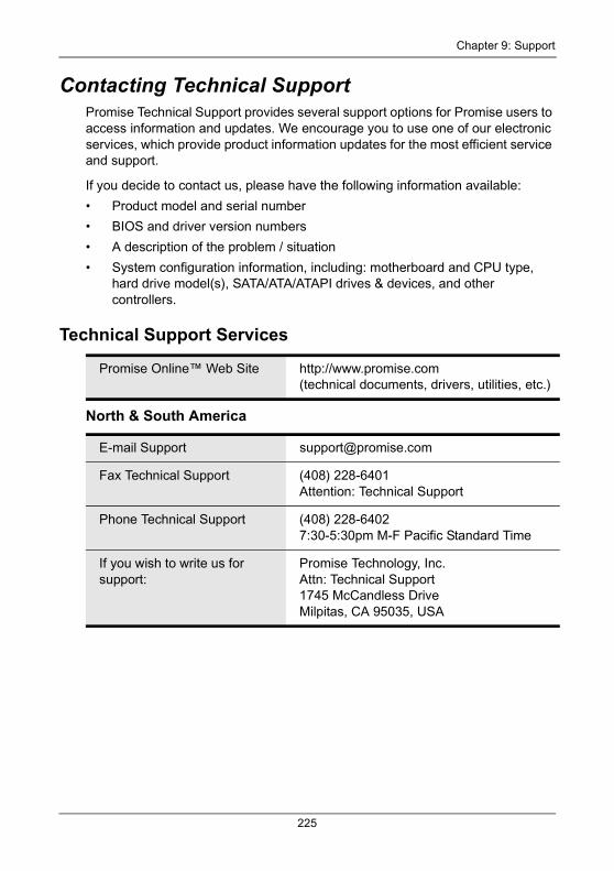
Chapter 9: Support
Contacting Technical SupportPromise Technical Support provides several support options for Promise users to access information and updates. We encourage you to use one of our electronic services, which provide product information updates for the most efficient service and support.
If you decide to contact us, please have the following information available:
• Product model and serial number
• BIOS and driver version numbers
• A description of the problem / situation
• System configuration information, including: motherboard and CPU type, hard drive model(s), SATA/ATA/ATAPI drives & devices, and other controllers.
Technical Support Services
North & South America
Promise Online™ Web Site http://www.promise.com(technical documents, drivers, utilities, etc.)
E-mail Support [email protected]
Fax Technical Support (408) 228-6401Attention: Technical Support
Phone Technical Support (408) 228-64027:30-5:30pm M-F Pacific Standard Time
If you wish to write us for support:
Promise Technology, Inc.Attn: Technical Support1745 McCandless DriveMilpitas, CA 95035, USA
225
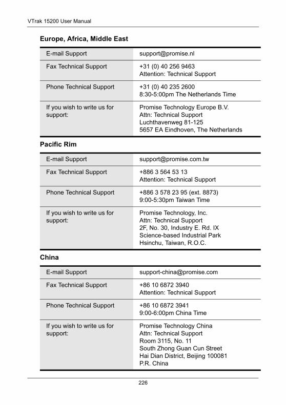
VTrak 15200 User Manual
Europe, Africa, Middle East
Pacific Rim
China
E-mail Support [email protected]
Fax Technical Support +31 (0) 40 256 9463Attention: Technical Support
Phone Technical Support +31 (0) 40 235 26008:30-5:00pm The Netherlands Time
If you wish to write us for support:
Promise Technology Europe B.V.Attn: Technical SupportLuchthavenweg 81-1255657 EA Eindhoven, The Netherlands
E-mail Support [email protected]
Fax Technical Support +886 3 564 53 13Attention: Technical Support
Phone Technical Support +886 3 578 23 95 (ext. 8873)9:00-5:30pm Taiwan Time
If you wish to write us for support:
Promise Technology, Inc.Attn: Technical Support 2F, No. 30, Industry E. Rd. IXScience-based Industrial ParkHsinchu, Taiwan, R.O.C.
E-mail Support [email protected]
Fax Technical Support +86 10 6872 3940Attention: Technical Support
Phone Technical Support +86 10 6872 39419:00-6:00pm China Time
If you wish to write us for support:
Promise Technology ChinaAttn: Technical Support Room 3115, No. 11South Zhong Guan Cun StreetHai Dian District, Beijing 100081P.R. China
226
Chapter 9: Support
Limited WarrantyPromise Technology, Inc. (“Promise”) warrants that for three (3) years from the time of the delivery of the product to the original end user:
a) the product will conform to Promise’s specifications;
b) the product will be free from defects in material and workmanship under normal use and service.
This warranty:
a) applies only to products which are new and in cartons on the date of purchase;
b) is not transferable;
c) is valid only when accompanied by a copy of the original purchase invoice.
d) Is not valid on spare parts, fans, and power supplies
This warranty shall not apply to defects resulting from:
a) improper or inadequate maintenance, or unauthorized modification(s), performed by the end user;
b) operation outside the environmental specifications for the product;
c) accident, misuse, negligence, misapplication, abuse, natural or personal disaster, or maintenance by anyone other than a Promise or a Promise-authorized service center.
Disclaimer of other warrantiesThis warranty covers only parts and labor, and excludes coverage on software items as expressly set above.
Except as expressly set forth above, Promise DISCLAIMS any warranties, expressed or implied, by statute or otherwise, regarding the product, including, without limitation, any warranties for fitness for any purpose, quality, merchantability, non-infringement, or otherwise. Promise makes no warranty or representation concerning the suitability of any product for use with any other item. You assume full responsibility for selecting products and for ensuring that the products selected are compatible and appropriate for use with other goods with which they will be used.
Promise DOES NOT WARRANT that any product is free from errors or that it will interface without problems with your computer system. It is your responsibility to back up or otherwise save important data before installing any product and continue to back up your important data regularly.
227
VTrak 15200 User Manual
No other document, statement or representation may be relied on to vary the terms of this limited warranty.
Promise’s sole responsibility with respect to any product is to do one of the following:
a) replace the product with a conforming unit of the same or superior product;
b) repair the product.
Promise shall not be liable for the cost of procuring substitute goods, services, lost profits, unrealized savings, equipment damage, costs of recovering, reprogramming, or reproducing of programs or data stored in or used with the products, or for any other general, special, consequential, indirect, incidental, or punitive damages, whether in contract, tort, or otherwise, notwithstanding the failure of the essential purpose of the foregoing remedy and regardless of whether Promise has been advised of the possibility of such damages. Promise is not an insurer. If you desire insurance against such damage, you must obtain insurance from another party.
Some states do not allow the exclusion or limitation of incidental or consequential damages for consumer products, so the above limitation may not apply to you.
This warranty gives specific legal rights, and you may also have other rights that vary from state to state. This limited warranty is governed by the State of California.
Your ResponsibilitiesYou are responsible for determining whether the product is appropriate for your use and will interface with your equipment without malfunction or damage. You are also responsible for backing up your data before installing any product and for regularly backing up your data after installing the product. Promise is not liable for any damage to equipment or data loss resulting from the use of any product.
228

Chapter 9: Support
Returning Product For RepairIf you suspect a product is not working properly, or if you have any questions about your product, contact our Technical Support Staff through one of our Technical Services, making sure to provide the following information:
• Product model and serial number (required)
• Return shipping address
• Daytime phone number
• Description of the problem
• Copy of the original purchase invoice
The technician will assist you in determining whether the product requires repair. If the product needs repair, the Technical Support Department will issue an RMA (Return Merchandise Authorization) number.
Return ONLY the specific product covered by the warranty (do not ship cables, manuals, diskettes, etc.), with a copy of your proof of purchase to:
You must follow the packaging guidelines for returning products:
• Use the original shipping carton and packaging
• Include a summary of the product’s problem(s)
• Write an attention line on the box with the RMA number
• Include a copy of proof of purchase
You are responsible for the cost of insurance and shipment of the product to Promise. Note that damage incurred due to improper transport or packaging is not covered under the Limited Warranty.
When repairing returned product(s), Promise may replace defective parts with new or reconditioned parts, or replace the entire unit with a new or reconditioned unit. In the event of a replacement, the replacement unit will be under warranty for the remainder of the original warranty term from purchase date, or 30 days, whichever is longer.
USA and Canada: Promise Technology, Inc.Customer Service Dept.Attn.: RMA # ______1745 McCandless DriveMilpitas, CA 95035
Other Countries: Return the product to your dealer or retailer.
Contact them for instructions before shipping the product.
229

VTrak 15200 User Manual
Promise will pay for standard return shipping charges only. You will be required to pay for any additional shipping options (such as express shipping).
230
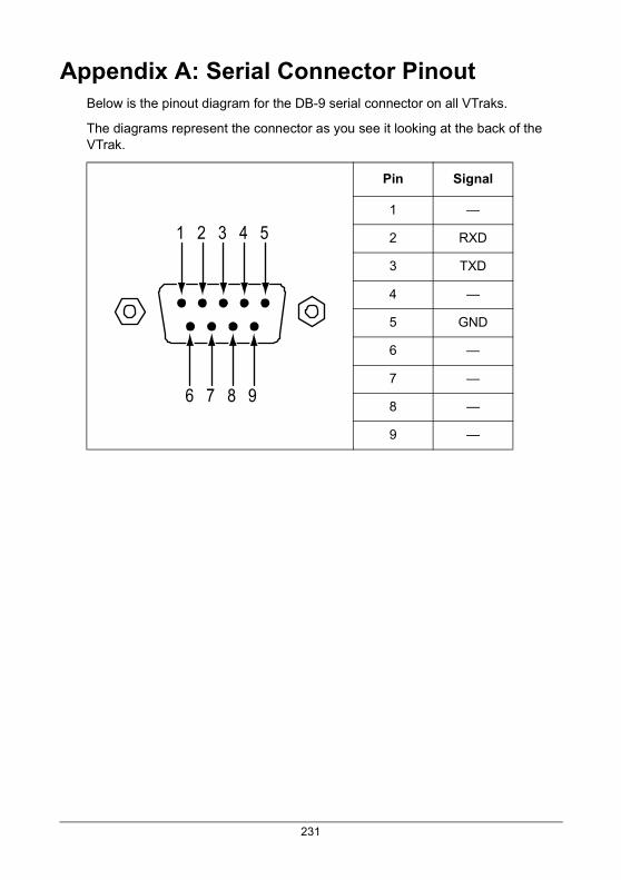
Appendix A: Serial Connector PinoutBelow is the pinout diagram for the DB-9 serial connector on all VTraks.
The diagrams represent the connector as you see it looking at the back of the VTrak.
Pin Signal
1 —
2 RXD
3 TXD
4 —
5 GND
6 —
7 —
8 —
9 —
1 2 3 4 5
6 7 8 9
231

VTrak 15200 User Manual
232
Index
AAbout This Manual 1Access a Host 69Access Control, enable 42Architectural Description of VTrak 3Audible alarm 63, 125, 205
BBeeper 63BIDI CHAP Authentication, enable
42Boot Sector, wipe 140Buzzer 125
CCache settings 201Certifications 6CHAP 93CHAP Authentication, enable 42CHAP secret 45Choose
cache setting 201CIMOM Agent 26CLU
Auto Rebuild Option 151Battery 137Blink LED 141Buzzer 136Buzzer setting 172connection 50Controller Management 134Diagnostics, disk drive 141Enable Telnet 23Enclosure Management 135Event viewer 171exit 60, 127
Fan Speed 135firmware update 174Functions under Controller
Mgt. 135I/O Statistics, disk drives 142Index to functions 129logical drive auto creation 144Logical Drive Management 143Logical drive name 149logical drive, create 57logical drive, create automati-
cally 57logical drive, create manually
58Network Management 158PDM auto start 151Physical Drive Management
138priority settings 149Problem reporting 205reports problem 205Set up 20Temperature 136Voltage 136
COM Port settings 20Connection
Ethernet 15network 15power 18serial 17Telnet 23
Connection problems and solutions 219
Connectionsserial 15, 17
Controller 85Controller Activity LED 61
233
VTrak 15200 User Manual
DDA IP address 45DA through DHCP, enable 45DAS 16Data Digest, enable 42DHCP enable 44Dimensions 6Direct Attached Storage 16Disk drive
assignment 102carrier 11failure and recovery 215information 100install 9move from UltraTrak 221numbering 14PATA-to-SATA Adapter 221rebuild 215usable in VTrak 221View parameters 139Write cache 139write cache, disk 114writeback cache, enable 114
Disk Status LED 19, 125
EEmail Alert Notification, set up 81Enclosure
Problem reporting 216Environmental 6Ethernet connection 15Event Log 70Events and meanings 74Exit the CLU 60
FFirmware Update 174Firmware update, Serial port 177Frequently Asked Questions 221FRU LED 19
GGigabyte Boundary 199
HHeader Digest, enable 42Hot Spare drive 216Hot Spare policy 150HyperTerminal 20
IInitialization 48, 104Initialization, choices 199Internet Browser 27Internet connection 222IP Address
Management port 21, 87, 158iSCSI
CHAP 93, 168iSNS 170Management 164Name, Alias 42Network Port 166Node 88, 164Node information 88Ping 46, 169Port 90Port information 90Restore to Default Settings 171SLP 92, 95SLP Port 167
JJava Development Kit 27Java Runtime Environment 27JBOD 199
234
Index
LLEDs
back of enclosure 210disk status 19, 63drive carrier 19, 62, 124, 209field replaceable units 173front panel 18, 61, 208power/activity 19, 63
Lock, set/release 86Log into WebPAM PRO 36, 64Log out of WebPAM PRO 49, 66Logical drive
auto rebuild 114Cache policy 149cache settings 201create 47, 103create automatically 57create manually 58, 145Critical status 107, 215dedicated hot spare 114delete 106, 147Hot Spare drive 200initialization 199LUN setting 109, 148Maintenance Activity monitor
153Media Patrol 157Migrate 154Modify parameters 147partition and format 49, 105,
200PDM 156PDM on demand 119rebuild 117Rebuild manually 155Redundancy Check 119, 157Retry count 149SMART 149synchronize 118, 156Target ID setting 109
Logical drive vs. Array 223
MManagement port settings 158Migration priority 114Minicom 20
NNetwork connection 15Network connections, problems
220Network HBA card 15, 16
OOperating Systems, supported 6Overview of VTrak 2
PPartition and format 49, 105Password, change 80PATA disk drive
install 13set jumpers 10
PATA-to-SATA Adapter 13Ping test, iSCSI ports 169Ping test, Management port 163popup messages, meaning 211Power connection 18Power LED 19Power requirements 6Power supply, replace 179Power/Activity LED 19, 125Promise Array Manager 27
RR2T enable 42Rackmount 8RAID
introduction to 189Level, choices 196Migration 201
235
VTrak 15200 User Manual
RAID, cont.RAID 0 190, 196RAID 1 191, 196RAID 10 194, 197RAID 3 192, 197RAID 5 193, 197RAID 50 195, 198
Rebuild priority 114Redundant Array of Independent
Disks 189Replace
cache battery 185fans 180RAID controller 188SEP 187
Reserve Sector, wipe 140RS-232 connection 17RS-232 connector, pinout 231
SS.M.A.R.T. 101, 102SA, enable 45SAN 15SATA disk drive, install 12Scheduled Synchronization 115screws, counter-sink 11SCSI
card 221LEDs 61
secret, CHAP 45Serial connection problems 220SLP, enable 45SMART check, enable 114SNMP settings 161Specifications 5Status Indicators 61, 123Storage Area Network 15Stripe Block Size, choices 199Subsystem, Add 67Subsystem Management 134Synchronization priority 114
TTechnical Support 225Telnet settings 159Telnet, enable 23TFTP Server settings 161Troubleshooting 205
UUnpack VTrak 7Use DA, enable 45User
Add 72delete 77Rights 78
Utility Server 25
VVerify Port Connections 95VTrak
beeping 205Maintenance procedures 173returning for repair 229
VTrak SetupCLU 50WebPAM PRO 36
WWarranty 227WebPAM PRO
auto rebuild 114change password 80controller management 85create logical drive 47, 103delete user 77disk drive view 101disk drive write cache 114disk drive writeback cache 114earlier version of 27Enclosure information 122event log 70
236
Index
WebPAM PROhot spare drive 114install 25Internet connection 49iSCSI CHAP 93iSCSI Node 88iSCSI Ping 95iSCSI Port 90iSCSI SLP settings 92logical drive critical status 107login 36, 64logout 49, 66OS support 25Problem reporting 206rebuild logical drive 117
WebPAM PRORegular Connection 64
Secure Connection 64Security Option 30set migration priority 114set rebuild priority 114set synchronization priority 114set/release lock 86setup email alert notification 81SMART check 114synchronize logical drive 118uninstall 33user rights 78
WebPAM vs. WebPAM PRO 223
237

VTrak 15200 User Manual
238