Embed Size (px)
Citation preview

VT300 Series Vehicle Telematics Gateway User Manual-EN 1.1

2
Chapter I Product Introduction and
Preparation
1. Introduction
1.1 Overview
The VT300 series vehicle tracking gateway is an asset tracking product that
features cost-effectiveness, rich interfaces and strong performance. It is
suitable for industries such as logistics and transportation, engineering vehicle
monitoring and so on. It offers precise positioning with GNSS, tracking and
monitoring the status, history track, geofencing, abnormity alarm and other
functions of vehicles and drivers, combined with the vehicle network cloud
platform, can realize remote vehicle management, asset tracking, preventive
maintenance, helping fleet operators save costs and improve efficiency. The
device provides sub-models that support wireless network access of various
speeds such as LTE CatM1, Cat1, Cat4, etc.

1.2 Packing List
1.2.1 Standard Packing List
Image 1-2-1
1.2.2 Optional Accessories

4
Optional accessories are not included in the default equipment package and
need to be selected according to the actual situation.
Image 1-2-2
Communication Cable Order Number Specifications
26PIN all-in-one test
cable SCAB000229
The cable has P1 and P2 ends: P1 is
26PIN female, connected to VT310;
P2 is open end, which requires a 9-
48V adaptor. Suitable for engineering
environments and indoor tests.
OBD-II7 PIN all-in-one
cable SCAB000231
The cable has P1, P2 and P3 ends:
P1 is 26PIN female connected to
VT310; P2 is OBD-II male connected
to the vehicle; P3 is ignition signal
terminal connected to the ignition
on/off. Suitable for heavy trucks with
OBD-II vehicle diagnostic interfaces,
and powers VT310 through
interfaces.
OBD-II 26 PIN all-in-one
cable SCAB000232
This cable has P1, P2, P3 and P4
ends: P1 is 26PIN female connected
to VT310; P2 is OBD-II male
connected to the vehicle; P3 is open
end that includes I/O, RS232-1 and
1-Wire; P4 is ignition signal terminal
connected to the ignition on/off.

5
Suitable for heavy trucks with OBD-II
vehicle diagnostic interfaces, and
powers VT310 through interfaces.
Recommended for customers who
need DI, DO, AI, 1-Wire devices or
vehicle-mounted controllers.
1.3 Product Appearance
1.3.1 Product Appearance Introduction
Image 1-3-1
1.3.2 Product Dimensions

6
VT310 Dimension (Unit mm)
2. SIM and Cable Installation
For general cases, the device can be used after mounted onto the vehicle,
with SIM card inserted and cable installed.
2.1 Install SIM Card
In the case of dial-up Internet access, a SIM card is needed. The VT310 will
dial automatically once it is powered and started. Open the waterproof baffle
on the downside of the VT310 and insert the SIM card into the slot in the
direction shown in the picture.

7
2.2 Mount the Tracker
Customers can fix the VT310 onto the vehicle with installation bolts. It is
recommended that the tracker be installed under the front windshield of the
vehicle, where GPS signal is better received and connection to the OBD-II
diagnostic interface is easier.
2.3 Introduction and Use of Cables
We offer three types of cables for different application scenarios. Wiring
methods of them will be shown below respectively.

8
2.3.1 26PIN All-in-one Test Cable Link
This cable is suitable for indoor testing and the tracker login. A 9-48V adapter
or 9-48V AC/DC power supply, a DB9-RS232 serial port female connector
and a USB to serial port line are required, as are shown below.
From left to right: Power supply module DB9-RS232 female connector, USB
to serial port line

9
Steps:
1. Insert the 26PIN female head of P1 into the VT310;
2. Connect P1 CONN-X-V- and P14 CONN-X-V+ to the negative and positive
poles of the power adapter respectively. P15 CONN-X-IGT and V + are both
connected to the positive side of the power supply;
3. Connect the CONN-RS232-RX1, CONN-RS232-TX1 and GND (any) of the
cable to the TXD, RXD and GND holes of the DB9 connector. Then connect
the USB to DB9 cable to the computer, as is shown below.

10
2.3.2 OBD-II 7PIN All-in-one Test Cable
Suitable for heavy trucks with OBD-II diagnostic interfaces. The VT310 is
powered by the ODB diagnostic interface, so the vehicle needs to be started
to get the VT310 working.
Steps:
1. Insert the 26PIN female head of cable P1 into the VT310;
2. Connect P2 to the OBD-II diagnostic interface of the vehicle;
3. If you need to judge whether the vehicle is ignited, you can connect P3 to the
ignition switch of the vehicle.
11
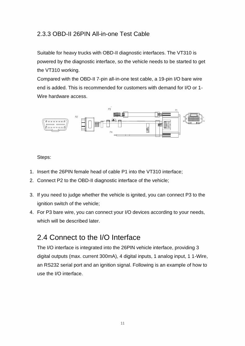
2.3.3 OBD-II 26PIN All-in-one Test Cable
Suitable for heavy trucks with OBD-II diagnostic interfaces. The VT310 is
powered by the diagnostic interface, so the vehicle needs to be started to get
the VT310 working.
Compared with the OBD-II 7-pin all-in-one test cable, a 19-pin I/O bare wire
end is added. This is recommended for customers with demand for I/O or 1-
Wire hardware access.
Steps:
1. Insert the 26PIN female head of cable P1 into the VT310 interface;
2. Connect P2 to the OBD-II diagnostic interface of the vehicle;
3. If you need to judge whether the vehicle is ignited, you can connect P3 to the
ignition switch of the vehicle;
4. For P3 bare wire, you can connect your I/O devices according to your needs,
which will be described later.
2.4 Connect to the I/O Interface
The I/O interface is integrated into the 26PIN vehicle interface, providing 3
digital outputs (max. current 300mA), 4 digital inputs, 1 analog input, 1 1-Wire,
an RS232 serial port and an ignition signal. Following is an example of how to
use the I/O interface.

12
2.4.1 Definition of 26PIN Interface
PIN Name PIN Name PIN Name PIN Name
1 V- 8 1-Wire 14 V+ 21 GND
2 GND 9 RS232_RX 15 IGT 22 RS232_TX
3 DI2 10 GND 16 DI1 23 GND
4 DI4 11 CAN_1L 17 DI3 24 CAN_1H
5 GND 12 CAN_2L 18 GND 25 CAN_2H
6 DO2 13 J1708_B 19 DO1 26 J1708_A
7 AI 20 DO3
2.4.2 RS232 Serial Port
The RS232 serial port is used for debugging. Connect the RS232_RX,
RS232_TX, and GND of the VT310 to TXD, RXD, and GND of the DB-9 serial
port welding-free interface. Use RS232 to USB cable to connect with DB-9
serial port surface welding port.
2.4.3 Digital Input (DI)
The DI can detect the switching value, such as whether the button is pressed
or bounced, and whether the switch is on or off. The VT310 provides
configurable pull-up. The DI has a default 10kΩ resistor pulled down to GND.

13
When the DI is configured to pull up, there is a 20kΩ resistor pull up to the
power supply voltage. When using DI, it is necessary to distinguish between
pull-up and no pull-up.
When the DI has no pull-up power supply, the external circuit is connected as
follows:
When the DI has a pull-up power supply, the external circuit is connected as
follows:

14
2.4.4. Digital Output (DO)
The DO can output DC voltage. The DO is an open-leakage output that
supports a current of 300mA and usually works with relays.
2.4.5. Analog Input (AI)
The AI can detect DC voltage, and customers can directly access the analog
quantity of voltage. External circuit is connected as follows:
2.4.6. 1-Wire

15
The 1-Wire is usually used for small communication equipment, such as
digital thermometers and iButton devices. Before use, the customer needs to
connect the DQ pin (signal line) of the 1-Wire device to the VT310 PIN8, and
connect the VDD and GND pins of the 1-Wire device to the GND of the
VT310. The sensor is the less02b type. The following picture shows the water
temperature detection wires of the 32 digital temperature sensor probe.
2.4.7 Ignition Sense
IGT(Ignition sense): IGT is used to connect to the Ignition switch of the
vehicle. The VT310 can detect whether the connected vehicle is ignited.
When using the 20PIN cable for testing, connect the IGT cable and V+ cables
to DC power supply.
3. Start the VT300
After the customer completes the installation according to the above steps,
the device can be started for debugging. The condition of the device can be

16
told through the status indicator. To avoid consumption of battery power
during transportation, the device is under transportation mode in the factory
state. The VT310 needs to be activated by external power supply or the
vehicle diagnostic interface.
3.1 GNSS Status Light
Indicator Status Function status
Long annihilation The device is not started or the GNSS
function is disabled.
Flash (frequency: 0.5Hz) GNSS 授时成功
GNSS delivery successful
Slow flash (frequency: 1Hz) GNSS function enabled
Solid Location success 定位成功
3.2 Cellular Status Light
Indicator status Function status
Long annihilation The device is disabled or the dialing
function is disabled.
Flash (frequency: 0.5Hz) Dialed successfully
Slow flash (frequency: 1Hz) Dialing enabled
Chapter II Login and Device Configuration
17
1. Install the Configuration Tool
The tool software supports the installation OS environment: Windows 10 ;
Not support Windosw 7.
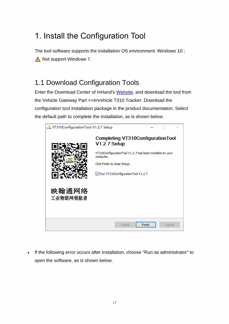
1.1 Download Configuration Tools
Enter the Download Center of InHand's Website, and download the tool from
the Vehicle Gateway Part >>InVehicle T310 Tracker. Download the
configuration tool installation package in the product documentation. Select
the default path to complete the installation, as is shown below.
• If the following error occurs after installation, choose "Run as administrator" to
open the software, as is shown below.

18
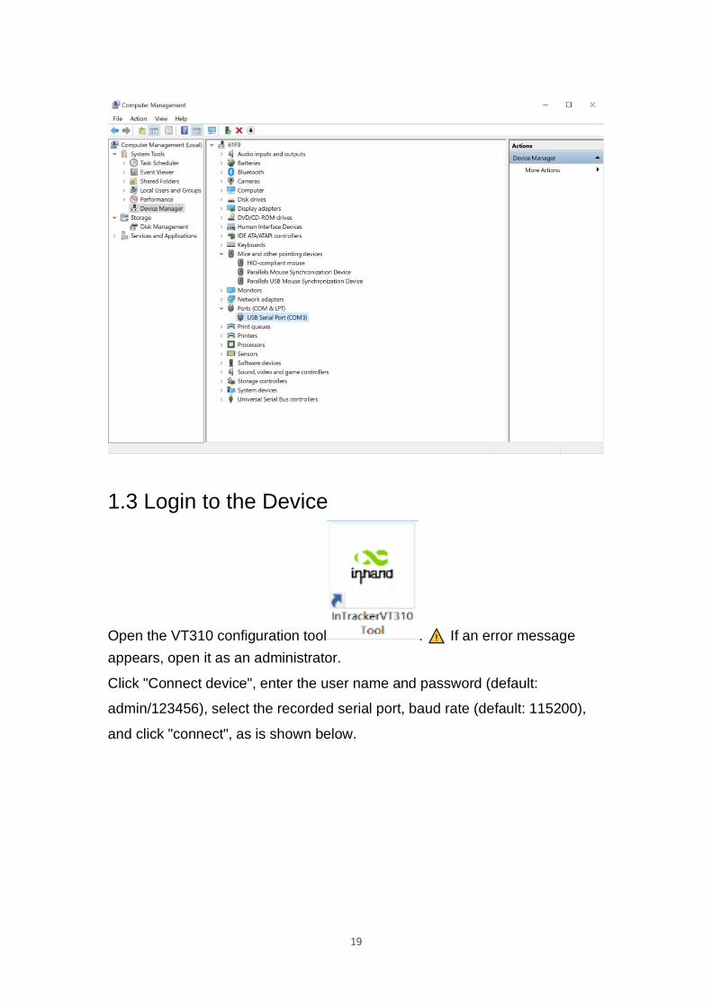
1.2 Search for the COM Port Number
Power the VT310 with an external adapter through the 26PIN all-in-one test
cable. The VT310 is connected to the computer through a USB to serial port
cable. If the GNSS or cellular light flickers, the device is started successfully.
Enter the device management page of the computer and observe the COM
slogan in the "device manager"> "ports (COM and LPT)" of the computer, as
is shown below.
19
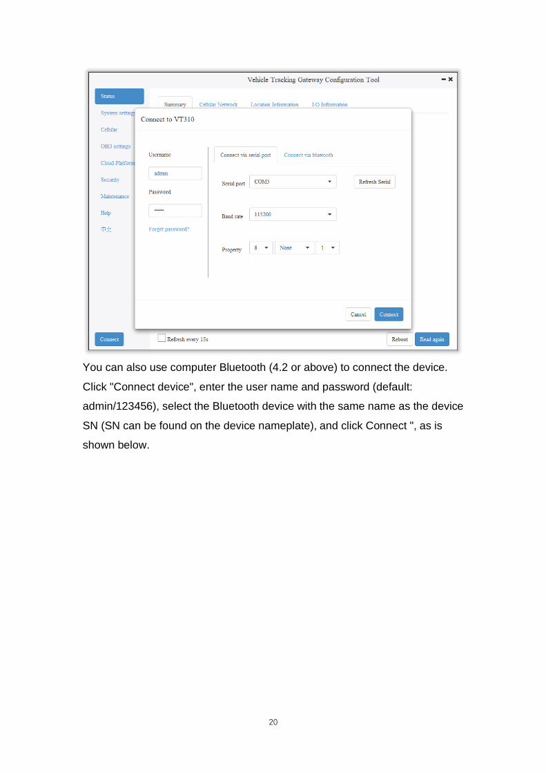
1.3 Login to the Device
Open the VT310 configuration tool . If an error message
appears, open it as an administrator.
Click "Connect device", enter the user name and password (default:
admin/123456), select the recorded serial port, baud rate (default: 115200),
and click "connect", as is shown below.
20
You can also use computer Bluetooth (4.2 or above) to connect the device.
Click "Connect device", enter the user name and password (default:
admin/123456), select the Bluetooth device with the same name as the device
SN (SN can be found on the device nameplate), and click Connect ", as is
shown below.

21
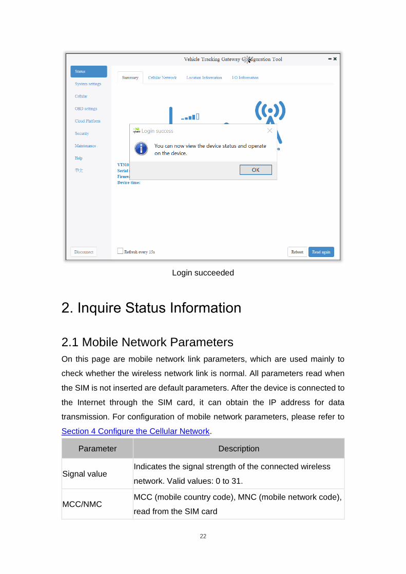
In the dialog box that pops up, you can view the device status and perform
operations on the device. Click OK to preview or modify the configuration, as
is shown below.
22
Login succeeded
2. Inquire Status Information
2.1 Mobile Network Parameters
On this page are mobile network link parameters, which are used mainly to
check whether the wireless network link is normal. All parameters read when
the SIM is not inserted are default parameters. After the device is connected to
the Internet through the SIM card, it can obtain the IP address for data
transmission. For configuration of mobile network parameters, please refer to
Section 4 Configure the Cellular Network.
Parameter Description
Signal value Indicates the signal strength of the connected wireless
network. Valid values: 0 to 31.
MCC/NMC MCC (mobile country code), MNC (mobile network code),
read from the SIM card

23
SIM card status Normal/Unidentified
IMEI
The International Mobile device identification code
(International Mobile Equipment Identity) is the built-in
dialing module code of the vehicle gateway.
Registration Registered/Not registered
LAC LAC(Location area code ) , obtain this parameter from the
base station after dialing successfully
IMSI IMSI(International Mobile Subscriber Identity) this
parameter is read from the SIM card
CELL ID This parameter is obtained from the base station after
dialing successfully.
ICCID
The ID of the integrated circuit card is the SIM card
number and ICCID (integrated circuit card identity). This
parameter is read from the SIM card.
IP ADDRESS After the dialing is successful, the carrier assigns the IP
address of the network access.
Cellular status Connected/Not connected
Authentication
method CHAP/PAP

24
2.2 Location Information
The location information page shows the latest parameters obtained by the
GNSS module. It includes location information and related parameters of the
inertial sensor. As is shown below.

25
2.3 I/O Information

26
3. System Settings
3.1 Sleep Mode
The sleep mode ensures the battery life after flameout, providing continuous
guarantee for special environments. The state machine is as follows:
Description of the state machine:
Run, Sleep, and Temp run represent normal running status, sleep status, and
temporary running status respectively.
① Corresponding to the state machine, the condition from Run to Temp run
is that the power supply voltage is less than sleep voltage (6V by default) or
IGT OFF (IGT needs to be enabled in the configuration), by default, the
device continues to run for 15Stemp (for reporting information) and then
enters Sleep.
27
② Corresponding to the state machine, the condition of entering Sleep from
the Temp run is that after the device runs a wake-up runtime cycle in the
Temp run or after the device runs Temp Run for 15s from run.
③ Corresponding to the state machine, the condition from Sleep to Run is
that the power supply voltage is greater than Sleep voltage or IGT ON (IGT
needs to be enabled in configuration).
④ Corresponding to the state machine, the condition of entering the Temp
run from Sleep is that after the device runs a wake-up interval in Sleep.
⑤ Corresponding to the state machine, the condition from Temp run to Run
is that the power supply voltage is greater than sleep voltage or IGT ON (IGT
needs to be enabled in configuration).
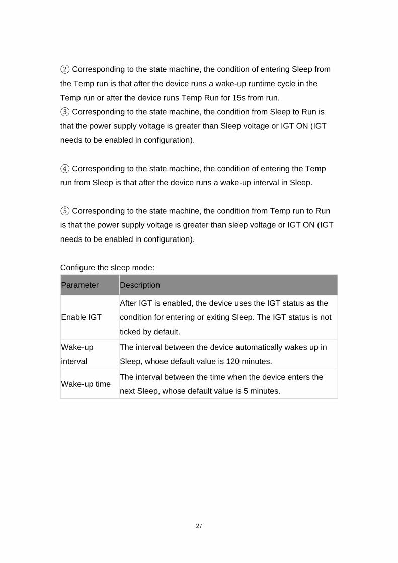
Configure the sleep mode:
Parameter Description
Enable IGT
After IGT is enabled, the device uses the IGT status as the
condition for entering or exiting Sleep. The IGT status is not
ticked by default.
Wake-up
interval
The interval between the device automatically wakes up in
Sleep, whose default value is 120 minutes.
Wake-up time The interval between the time when the device enters the
next Sleep, whose default value is 5 minutes.

28
3.2 Account Settings
This function allows the device administrator to modify the device
administrator login information. The default administrator account is admin,
password 123456. The device administrator can modify the configuration
options if necessary. After the modification, the device prompts a restart. Click
OK to restart the device and log in with the modified administrator account
and password. As is shown below.

29
4. Configure the Cellular Network
Click "Cellular" to enter the configuration page. Generally, customers only
need to configure "Network Access Point Name (APN)", "Network dialing user
name", "Network dialing password" and "Authentication mode" and click
"Save configuration". The device takes effect after restarting.
If the customer has special trial scenarios, click "Show Advanced Options" to
see hidden configuration items. Configure the network dial number, PIN, and
default host APN as needed. As is shown below.

30
Parameter Description
APN
This parameter is required when the APN private
network is connected to the mobile network. Most public
network service SIM cards do not authenticate APN
when dialing.
Network dialing
username
The default parameter is "gprs". When the private
network is AAA certified, the mobile network operator
needs to provide this parameter.
Network dialing
password
The default parameter is “gprs”. This is required by the
carrier during the AAA certification for the private
network.
Authentication mode
Automatic/CHAP/PAP. This parameter is required when
the private network is AAA certified. Automatic: take
turns to use PAP and CHAP authentication to dial (pap
authentication is used for the first power-on, if dialing
fails, chap authentication is used for dialing again, and
pap authentication is used for the next dialing, and so

31
on. If the authentication mode is not automatic, but PAP
or CHAP, use only PAP or CHAP authentication to dial.
Network dial number The default parameter is * 99 *** 1#, which is required
by mobile network operators.
PIN
PIN (Personal Identification Number) refers to the
Personal Identification password of the SIM card. When
the SIM card is enabled for PIN verification, does it fill in
the corresponding PIN of the SIM card. This parameter
is required for mobile network operators.
Default carrier APN This parameter is provided by the carrier.
The default host setting is a function for special data transmission required
by some carriers, which generally does not need configuration. If configuration
is required, please inquire from your carrier.
5. Configuration of Vehicle Diagnostic
Interface
The on-board diagnostic interface is the South interface of the tracker and the
configuration option of the protocol.
5.1 Configure ODB Interface
In the configuration tool, select OBD as the diagnostic protocol. The ODB
protocol is the CAN2 interface and J1708 interface of the vehicle tracker.
Parameter Description Others
J1939/J1979
ODB CAN2 interface protocol,
corresponding to physical layer PIN
CAN_2L(PIN 12) and CAN_2H(PIN
25)
OBD default configuration

32
J1939
ODB CAN2 interface protocol,
corresponding to physical layer PIN
CAN_2L(PIN 12) and CAN_2H(PIN
25)
J1939
ODB CAN2 interface protocol,
corresponding to physical layer PIN
CAN_2L(PIN 12) and CAN_2H(PIN
25)
J1708
J1708 interface protocol,
corresponding to physical layer PIN
J1708_ B(PIN13) and J1708_A (PIN
26)
Auto
When set to Auto mode, the vehicle
tracker will poll the link and
automatically poll and send the
protocol data of the above four
options for link testing. When
receiving data packets of the
corresponding protocol, the vehicle
tracker will choose this protocol for
communication.
When Auto mode is used, the
CAN1 and J1708 interfaces are
enabled at the same time.
Disable Disable ODB CAN2 and J1708

33
5.2 Configure CAN1 Interface
In the configuration tool, select CAN1 as the diagnostic protocol and the
CAN1 interface of the vehicle tracker.
Parameter Description Others
J1939/J1979
CAN1 interface protocol,
corresponding to physical layer PIN
CAN_1L(PIN 11) and CAN_1H(PIN
24)
CAN1 default configuration
J1939
CAN1 interface protocol,
corresponding to physical layer PIN
CAN_1L(PIN 11) and CAN_1H(PIN
24)
J1939
CAN1 interface protocol,
corresponding to physical layer PIN
CAN_1L(PIN 11) and CAN_1H(PIN
24)

34
Disable Disable CAN1
• The function of CAN1 and OBD can be enabled at the same time.
6. Configuration of the Cloud Platform
The configuration of the cloud platform is the North-direction interface and
protocol configuration option of the vehicle tracker. The VT310 can only be
connected to one cloud platform at a time. The configuration of the platform
takes effect only after the device is restarted. Click "Platform" to enter the
configuration page. Click "Modify" to enter the configuration page. As is
shown below.

35
6.1 SmartFleet Platform
The SmartFleet platform is a SaaS platform for the Internet of Vehicles market
launched by InHand Networks. It mainly includes vehicle profile, alarms,
driving behavior monitoring, statistical analysis of driving information,
electronic fence and other functions. Through the visual user interface and
simple operation, you can manage and monitor your hardware devices such
as the InVehicle Gateway with speed and ease. Deployment in the cloud
allows you to focus on your core business. Login address:
https://che.inhandiot.com. For more information about the platform, please
visit https://www.inhandnetworks.com and chat with us.
Cloud Platform >> Platform Type: SmartFleet,
Cloud Platform >> Enable
Cloud Platform >> Domain name: smartfleet.cloud
Cloud Platform >> Account (Enter the platform's registered account)
Cloud Platform >> License Plate Number

36
Click "Show Advanced Options" to show hidden configuration items.
Configure the LBS reporting interval, traffic reporting interval, and heartbeat
reporting interval as needed. The reporting interval is measured in seconds,
as is shown below. Click "Save configuration" and restart the device. As is
shown below.
On the Cloud Platfrom homepage, view the link status of the platform. The link
status is "linked". As is shown below.
Log in the platform and choose Gateways >> Gateway List. You can see if the
vehicle tracker is online. As is shown below.

37
6.2 Wialon Platform
Wialon has more than 18 years of best practice in software engineering in the area of
GPS vehicle tracking and a team of talented specialists committed to the common goal.
The community is united by continuous advancement of the proprietary products and five
offices around the world – the headquarters and development center in Minsk and sales
offices in Moscow, Boston, Dubai and Buenos Aires. Nowadays solutions by Gurtam take
up about 36% of the CIS commercial carrier market and are actively expanding to
Europe, the Middle East, the USA, South America, Africa and Australia, with even New
Zealand market tapped. For more information, visit https://gurtam.com/en/wialon.
To test the Wialon platform, you can contact manager Sun
[email protected] for more support.
Cloud Platform >> Platform Type: Wialon,
Cloud Platform >> Enable
Cloud Platform >> Domain name: nlgpsgsm.rog
Cloud Platform >> Port : 21000
Cloud Platform >> Account (Enter the platform's registered account)
Cloud Platform >> License Plate Number
To adjust the reporting frequency, click "Show Advanced Options" to show
hidden configuration items. Set the reporting interval reporting interval in
seconds. As is shown in the following.

38
If you have obtained an independent domain name provided by Wialon, enter
the custom domain name and port number. As is shown below.

39
6.2.1 Configuration on Wialon Platform
Platform website: https://hosting.wialon.com
New devices:
The device configuration information is as follows:
• Name: Custom
• Device Type: Select "Wialon Combine"
• Special ID: Enter the device-specific serial number. View the serial number of the device
or the serial number on the status page of the configuration tool. The information shown
in the following figure is for example only.

6.2.2 View Data Uploaded by Devices① Select "Message"② Select the name of the target device to be viewed③ Select the time range of interest④ Select the data type. Currently the colelcted I/O data is viewed through Raw Data⑤ Click the "Execute" button to view the information of the target device at the position of ⑥, as is shown below.
Note: The information display of the target device can be selected by clicking the configuration method, as is shown below.
6.3 Azure IoT HubAzure IoT builds IoT applications that offer highly secure and reliable two-waycommunication between IoT applications and their managed devices. Azure IoT Center provides the back end of cloud hosting solutions, which can

41
connect to almost any device. The solution is extended from the cloud to the
edge through authentication, built-in device management, and extended
configuration of each device. For more information, visit
https://azure.microsoft.com/zh-cn/services/iot-hub
Cloud Platform >> Platform Type: Azure IoT
Cloud Platform >> Enable
Cloud Platform >> Connect String
The Connect String is created from Microsoft IoT platform. See in the next
section.
To see invalid data, click "Show Advanced Options" to view hidden
configuration items. Tick "Show Invalid Data", as is shown below.
6.3.1 Configure Azure IoT Platform

42
1. Before configuring the Connect String, log in the Azure IoT platform to create
a device. In the left-side navigation pane of the IoT Center, choose "IoT
devices", and then select "New". As is shown below.
2. On the "Create a device" page, provide the name of the new device, such as
myDeviceId, and then select "Save". This creates a device identifier for IoT
Center. As is shown below.

43
3. After creating the device, open the device in the "IoT devices" pane. Copy the
"Primary Connection String" and later paste to the "Connection String" of the
configuration tool ". As is shown below.
6.4 AWS IoT Platform

44
With the AWS IoT Core, you can connect your IoT devices to the AWS cloud
without configuring or managing the server. The AWS IoT Core supports
billions of devices and trillions of messages, and can process those messages
before routing them to AWS terminal nodes and other devices with security
and reliability. With the AWS IoT Core, your applications can track all devices
and communicate with them anytime, even if those devices are not
connected. Build your IoT applications with AWS services, so that you can
collect, process and analyze data generated by connected devices and take
action without managing any infrastructure. For more information, please visit
https://aws.amazon.com/iot-core/.
6.4.1 Configure AWS IoT Platform
Method 1: Creat A Thing for link
1. Go to the Amazon IoT console >> Things page, and click "Create", as is
shown below.
Amazon IoT >> Things >> Create a single thing

45
Amazon IoT >> Things >> Create a single thing >> Add your device to the thing
registry >> Add certificate On this page, create a certificate for the thing just
created, as is shown below.
2. Download certificate file
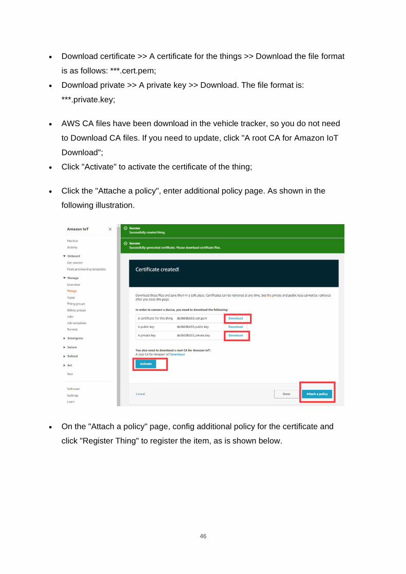
46
• Download certificate >> A certificate for the things >> Download the file format
is as follows: ***.cert.pem;
• Download private >> A private key >> Download. The file format is:
***.private.key;
• AWS CA files have been download in the vehicle tracker, so you do not need
to Download CA files. If you need to update, click "A root CA for Amazon IoT
Download";
• Click "Activate" to activate the certificate of the thing;
• Click the "Attache a policy", enter additional policy page. As shown in the
following illustration.
• On the "Attach a policy" page, config additional policy for the certificate and
click "Register Thing" to register the item, as is shown below.

47
•
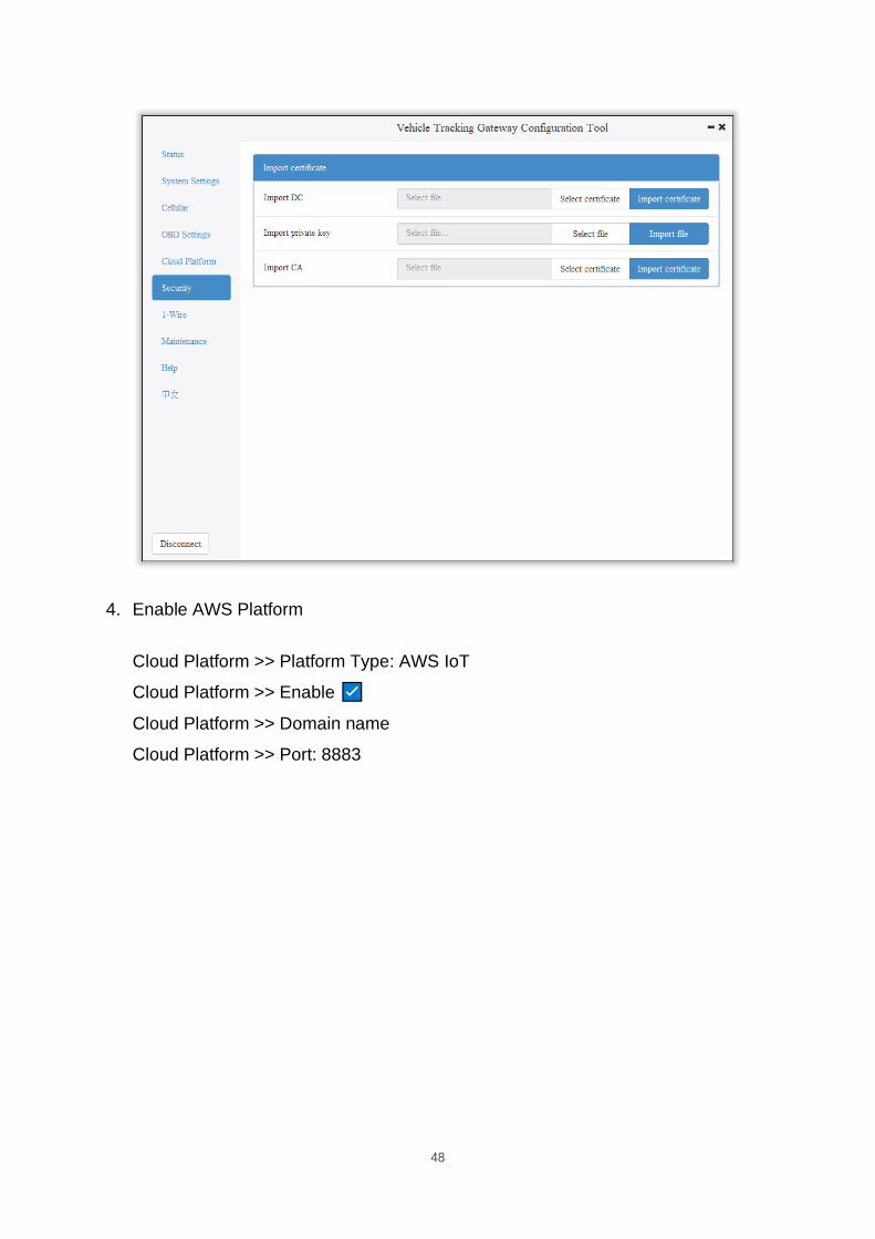
3. Use the configuration tool to import the certificate file to the tracker
• Security >> Import digital certificate >> Select a certificate (select the
downloaded digital certificate ***.cert.pem in the displayed dialog box); click
"Import certificate"
• Security>> Import private key certificate >> Select a file (select the
downloaded digital certificate ***. private.key in the dialog box that appears);
click "Import file";
• As the AWS CA files have been built into the vehicle tracker, there is no need
to download them. If you need to update them, go to Security >> Import CA
certificate >> Select a file (select the downloaded digital certificate ***.
private.key in the dialog box that appears); click import certificate, as is shown
below.
48
4. Enable AWS Platform
Cloud Platform >> Platform Type: AWS IoT
Cloud Platform >> Enable
Cloud Platform >> Domain name
Cloud Platform >> Port: 8883

49
“Cloud Platform >> Domain name” AWS IoT >> Things >> “Select the created
things” >> Interact Copy this domain name paste to “Cloud Platform >> Domain
name”
Save the configuration and restart the device. On the Cloud Plateform Cloud
Platform page, check the connection status:

50
By default, invalid data is not reported. To report invalid data, tick "Report invalid
data" in the advanced options. After that, the reported data value that does not
exist is NULL, as is shown below.
Method 2:Create a provisioning template connection for AWS
1. Create a prefabricated templet: Amazon IoT >> Fleet provisioning
templates >> Create, as is shown below.

51
Creat Certificate: Amazon IoT >> Certificates
Amazon IoT >> Things >> Create a single things >> Add your device to the
thing registry >> Add certificate
On this page, create a certificate for the thing just created, as is shown below.

52
2. Download a certificate file
• Download a public key file >> A certificate for the things >> Download. The file
format is ***.cert.pem;
• Download the private key file >> A private key >> Download. The file format is
***.private.key;
• As the AWS CA files have been built into the tracker, there is no need to
download them. If you need to update, click“A root CA for Amazon IoT
Download”;
• Click Activate to activate the certificate;
• Click the "Attach a policy", enter additional policy page, as is shown below.

53
• On the previous window, click "Activate" to enter the certificate list. Click
"Done" and complete certification.
• On the previous window, click "Attach a policy" to enter the Amazon IoT >>
Policy list to add a policy, as is shown below.

54
3. Use the configuration tool to import the certificate file to the vehicle tracker
• Security >> Import digital certificate >> Select a certificate (select the
downloaded digital certificate ***.cert.pem in the displayed dialog box), click
"Import certificate"
• Security >> Import private key certificate >> Select a file (select the
downloaded digital certificate \\. private.key in the dialog box that appears);
click "Import file";
• As the tracker already has a built-in AWS CA file, the CA file is not required. If
you need to update the CA file, go to Security >> Import CA certificate >>
Select a file (select the downloaded digital certificate ***.cert in the pop-up
dialog box), click "Import certificate";

55
4. Enable AWS
Cloud Platform >> Platform Type: AWS IoT
Cloud Platform >> Enable
Cloud Platform >> Domain name
Cloud Platform >> Port : 8883

56
If you create a preset template on AWS, you need to enable device preset
in the configuration tool. Tick to enable it, and enter the preset template
name. The template name can be found in AWS IoT >>Fleet provisioning
templates.
Copy the address in the AWS IoT >> Things >> “Select created things”>>
Interact option. Enter the domain name on the AWS IoT page.

57
Save the configuration and restart the device. On the Cloud Platform Cloud
Platform page, check the connection status:
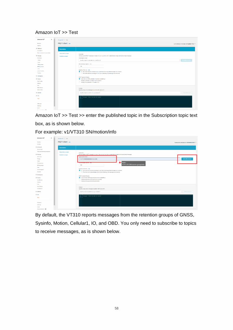
6.4.2 Subscription and Publishing of AWS
1. Subscribe to messages reported and published by VT310
58
Amazon IoT >> Test
Amazon IoT >> Test >> enter the published topic in the Subscription topic text
box, as is shown below.
For example: v1/VT310 SN/motion/info
By default, the VT310 reports messages from the retention groups of GNSS,
Sysinfo, Motion, Cellular1, IO, and OBD. You only need to subscribe to topics
to receive messages, as is shown below.

59
For more information, see API documentation.
《FlexAPI_over_MQTT_Reference_for_3rd_party_platform_VT310.pdf》
6.5 Aliyun IoT
The Alibaba Cloud Enterprise IoT platform provides fully-hosted instance
services. It allows you to easily access and manage devices without building
IoT infrastructure by yourself. It features low costs, high reliability, high
performance, and easy operation and maintenance. With powerful data
processing capabilities, it can better analyze and visualize device data. Real-
time security threat detection ensures that each instance is secure and
reliable. It is the first choice for each enterprise device to migrate to the cloud.
For more information, visit the Alibaba Cloud product page.
https://www.aliyun.com/product/iot.
Method 1: One machine and one key
For more information: https://help.aliyun.com/document_detail/74006.html
1. Go to the Alibaba Cloud Console IoT Platfrom >> Device >> Devices >>
Device Details. Create a Device and view the Device Secret, as is shown
below.

60
The Device Certificate of the replication Device includes three parameters:
Product Key, Device Name, and Device Secret, as is shown below.
2. Config Aliyun IoT
Cloud Platform >> Platform Type: Aliyun IoT
Cloud Platform >> Enable
Cloud Platform >> Device Name:
Cloud Platform >> Product Key
Cloud Platform >> Authentication Mode: Unique Certificate Per Device

61
Cloud Platform >> Device Secert
Tick to enable Secure Certification Mode: Unique Certificate Per
Device/Unique Certificate Per Model
The three parameters from Alibaba Cloud ProductKey, DeviceName, and
DeviceSecret. Enter the corresponding parameters in the configuration tool. In
the upper-left corner of the IoT platform console, view the region where your
service is located. For more information about the Region ID values, see
Region and zone.
6.6 Configuration of MQTT Platform Link
MQ Telemetry Transport (MQTT) is a lightweight proxy-based message
transmission protocol for Publishing/Subscribing. It is designed to be open,
simple, lightweight, and easy to implement. These features make it suitable
for restricted network environments, including but not limited to high-costs,
low-bandwidth and unreliable networks. CPU and memory resources are
limited for embedded devices. This protocol provides one-to-many message
publishing and discoupling applications using the publish/subscribe message
mode. It supports transmission of messages blocked by load content with

62
TCP/IP. Open-source software that supports MQTT, such as ThingsBoard
and EMQ, allows customers to develop their own IoT platforms.
6.6.1 MQTT Broker
Cloud Platform >> Platform Type >> Mqtt Broker: Enable, configure domain
name, port, username, and password ". Click "Save configuration" and restart,
as is shown below.
If you want to view invalid data, click "Show Advanced Options" to see hidden
configuration items. Select "Show invalid data", as is shown below.

63
6.6.2 Configure ThingBoard Open-source IoT Platform
ThingsBoard is an open-source IoT platform where you can quickly develop,
manage, and expand IoT projects. It is an open-source IoT platform for data
collection, processing, visualization, and device management. It connects
devices through the industry-standard IoT protocols - MQTT, CoAP, and
HTTP, and supports cloud and local deployment. For more information, go to
https://thingsboard.io.

64
ThingsBoard Architecture
1. Register an account and add a device. After adding a device, use the open
Device Device Credentials >> MQTT Basic to enter the Client ID, User Name,
and Password parameters. For more information, visit
https://thingsboard.io/docs/getting-started-guides.
Platform Device Parameters

65
2. In the configuration tool, enter the thingsboard.cloud, port number 1883,
username User Name, Password, Password of the device parameters added
by the platform.
7. Maintenance
You can upgrade the firmware with the local upgrade configuration tool,
xshell, or through OTA. OTA upgrading includes Alibaba Cloud standard OTA
upgrading, SmartFleet platform OTA upgrading and FlexAPI upgrading. Now
we will only introduce how to upgrade with local configuration tools. For more
information about upgrading, please contact technical support of InHand
Networks.
7.1 Firmware Upgrade
Step 1: Go to Maintenance >> Upgrade firmware, as is shown below:

66
Step 2: Click "Browse file" to select the firmware. Click "Upgrade" and wait for
firmware installation, as is shown below:

67
When a prompt box says "Will switch to the new version after restarting
VT310", new firmware has been imported successfully. Click "Restart" to
upgrade the firmware.
Note: After the device is upgraded, restart the device and then configure it.
7.2 Restore Factory Settings of FlexAPI
Go to Maintenance >> FlexAPI restore factory settings to reset FlexAPI
settings.

68
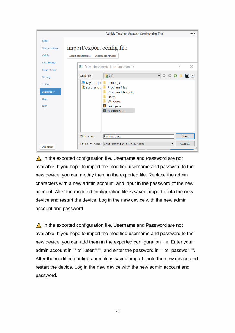
7.3 Import/Export Configuration
To back up and import configuration, go to Maintenance >> Import/export
congifuration file, as is shown below. Click "Export configuration" to back up
configuration, and click "Import configuration" to load the configuration file.

69
To back up configuration, click "Export configuration". The configuration tool
can read device configuration and pop up file storage window. Enter the name
of the backup file, and click "Open".
70
In the exported configuration file, Username and Password are not
available. If you hope to import the modified username and password to the
new device, you can modify them in the exported file. Replace the admin
characters with a new admin account, and input in the password of the new
account. After the modified configuration file is saved, import it into the new
device and restart the device. Log in the new device with the new admin
account and password.
In the exported configuration file, Username and Password are not
available. If you hope to import the modified username and password to the
new device, you can add them in the exported configuration file. Enter your
admin account in "" of "user:":"", and enter the password in "" of "passwd":"".
After the modified configuration file is saved, import it into the new device and
restart the device. Log in the new device with the new admin account and
password.

71
8. Restoration of the Default Account and
Password for Hardware
Because configuration usually involves the device certificate file, when the
device is restored to the factory via hardware, only the username and
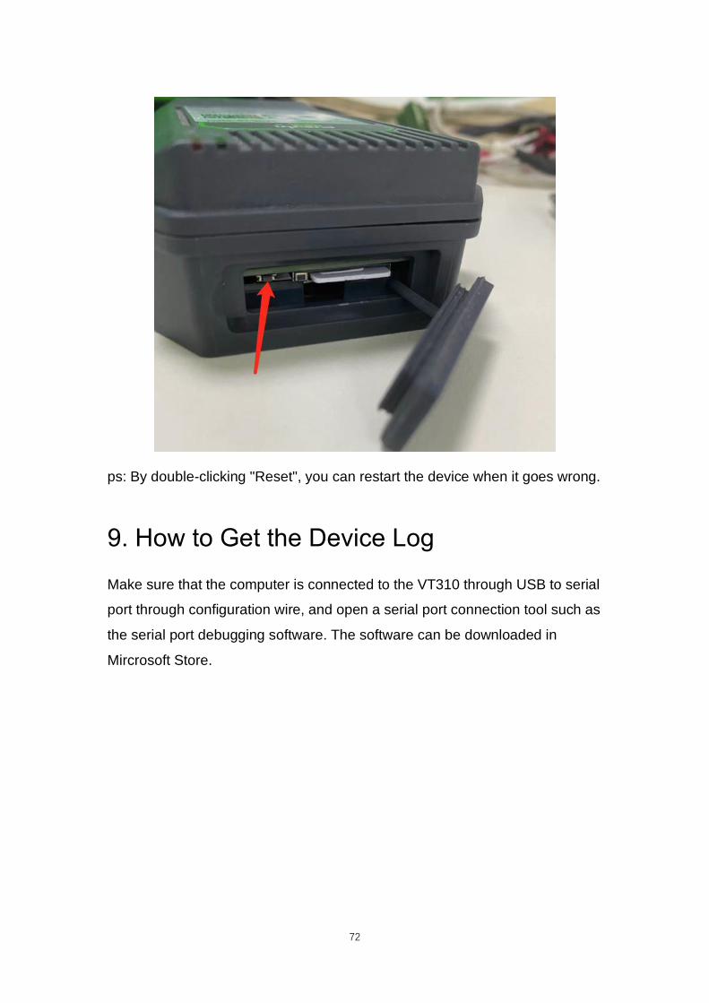
password are restored to admin/123456. As is shown in the following picture,
press the Reset button with a screwdriver or other tools for more than 8
seconds, and then loosen it.
72
ps: By double-clicking "Reset", you can restart the device when it goes wrong.
9. How to Get the Device Log
Make sure that the computer is connected to the VT310 through USB to serial
port through configuration wire, and open a serial port connection tool such as
the serial port debugging software. The software can be downloaded in
Mircrosoft Store.

73
1. Open the serial port debugging software and select the link serial port. The
default baud rate of the serial port is 115200/8/n/1. Click "Open serial port".
Note that the Character encoding mode (Character encoding) is ASCII, and
the line break mode (Linet break) is \n(LF).

74
2. Enter +++ in the content sending serial port to activate the CLI mode, as is
shown below;

75
Enter the Username admin (press the enter key), click "Send", enter the
password 123456 (press the enter key), and click send to enter the command
line mode.

76

77
3. Enable the log function. In the send text box, enter “log console enable”
(press the enter key) and click "Send". The following screenshot shows the
log information in the receive window.
4. Close log function, write “log console disable” (press the enter key) in the
send text box and click "Send". The receive window stops receiving logs.

78
5. If you need to link the configuration tool after exiting the serial port, write “exit”
(press the enter key) in the send text box, click "Send" (used to exit the CLI
mode), and then close the serial port. Or you wait for 180 seconds when the
device automatically exits the CLI mode.