Embed Size (px)
Citation preview

VT-10/13TENSION-WELD®
STRAPPING TOOLS

2
READ THESE INSTRUCTIONS CAREFULLY.
FAILURE TO FOLLOW THESE INSTRUCTIONS CAN RESULT IN SEVERE PERSONAL INJURY.
GENERAL SAFETY CONSIDERATIONS
1. STRAP BREAKAGE HAZARD.Improper operation of the tool or sharp corners on the load can result in strap breakage duringtensioning, which could result in the following:
! A sudden loss of balance causing you to fall.
! Both tool and strap flying violently towards your face.
Failure to place the strap properly around the load or an unstable or shifted load could resultin a sudden loss of strap tension during tensioning. This could result in a sudden loss ofbalance causing you to fall.
Read the tool's operating instructions. If the load corners are sharp use edge protectors. Place the strap correctly around a properly positioned load.
! Positioning yourself in-line with the strap, during tensioning and sealing, can result insevere personal injury from flying strap or tool. When tensioning or sealing, positionyourself to one side of the strap and keep all bystanders away.
! Using strap not recommended for this tensioner can result in strap breakage duringtensioning. Use the correct Signode products for your application.
2. TRAINING.This tool must not be used by persons not properly trained in its use. Be certain that youreceive proper training from your employer. If you have any questions contact your SignodeRepresentative.
3. EYE INJURY HAZARD.Failure to wear safety glasses with side shields can result in severe eye injury orblindness. Always wear safety glasses with side shields which conform to ANSIStandard Z87.1 or EN 166.
4. FALL HAZARD.Maintaining improper footing and/or balance when operating the tool can cause you to fall. Donot use the tool when you are in an awkward position.
5. CUT HAZARD.Handling strap or sharp parts could result in cut hands or fingers. Wear protectivegloves.

3
6. TOOL CARE. Take good care of the tool. Inspect and clean it daily, lubricate it weekly and adjust whennecessary. Replace any worn or broken parts.
7. WORK AREA. Keep work areas uncluttered and well lighted.
Several types of strap can be used with this tool. Use the correct Signode products for yourapplication. If you need help contact your Signode Representative.
SAFETY PROCEDURES FOR TOOL OPERATION
Before using this tool, read its Operation and Safety instructions.
! Do not exceed the operating air pressures stated elsewhere in the manual.
! Use Signode's approved filter-regulator-lubricator unit (P-008559).
! Never operate a pneumatic tool with a bottled air or gas source.
! For tension adjustments, follow instructions in this manual. For all other adjustments,repairs or cleaning of the tool, disconnect air supply.
! This tool is a Tension Weld® type sealer. A properly madejoint will appear as shown in the illustration. If the joint doesnot appear as shown, then the operator must proceed asfollows:
A. Insure that the tools operating instructions are being followed before applying another strap.B. Cut the strap off and apply another.
If the joint still does not appear as shown, then inspect the tool for worn and/or damaged parts.Replace tool parts as needed. NEVER HANDLE OR SHIP ANY LOAD WITH IMPROPERLY FORMEDJOINTS. Misformed joints may not secure the load and could cause serious injury.
! Tuck strap end back into the dispenser when not in use.
CUTTING TENSIONED STRAP
Use only cutters designed for cutting strap; never use claw hammers, crowbars, chisels, axes orsimilar tools. Such tools will cause the strap to fly apart with hazardous force. Before using anySignode product, read its Operation and Safety Manual.

4
VT-10Strapping Tool Part No. 425251
VT-13Strapping ToolPart No. 425252
TABLE OF CONTENTSPage
General Safety Instructions 2
Specifications 4
Major Components 5
Pneumatic Information 6
Operating Instructions 12
Adjustments 16
Page
Parts List, Tool 20
Parts List, Air Motors 24
Troubleshooting 28
Strap Size Conversion 32
Options 33
Maintenance 34
SPECIFICATIONS
MODELSTRAP
TYPE WIDTH THICKNESS
VT-10/13Tenax
&Contrax
9.0mm (.354")
10.5mm (.413")
12mm (.468")
0.016" to 0.032"(0.40mm - 0.81mm)
NOTE: VT-10 has an adjustable tension range of 30 to 100 lbs.VT-13 has an adjustable tension range of 80 to 200 lbs.

5
MAJOR COMPONENTS

6
PNEUMATIC INFORMATION
AIR PRESSURE REQUIREMENTS
The VT tools are designed to operate at an air pressure of 90 psig (6.2 Bar).
AIR PRESSURE VS. PERFORMANCE
The air pressure supplied to the VT tool must be a minimum of 85 psig (5.7 Bar) If the air supplypressure can be adjusted within a range from 85 psi to 90 psi (5.7 - 6.2 Bar) the VT tool'sperformance can be fine tuned to a particular application or operation preferences. Changing theVT air supply pressure to the tool will directly alter the rate at which the tool will take-up the strapslack and the strap tension. Increasing or decreasing the VT air supply within the suggested 85 to90 psig (5.7-6.2 Bar) range will not seriously affect the actual welding portion of the strap cycle.
After an initial "Break-In" period, the air motor may become more powerful. If the tool'sperformance is effected by this increase in performance, reduce the air motor output by turningthe adjustment screw (Key 98) counter-clockwise as required.
AIR SUPPLY INSTALLATION
If compressor has a good dryer unit, use black pickled pipe. When a dryer unit is not installed,use galvanized or copper pipe. To perform reliably, a pneumatic tool requires a continuous sourceof clean, water-free air at adequate pressure.
Never operate this tool using a bottled air or gas source.Bottled air/gas sources do not provide consistent operating pressure.
A filter-regulator-lubricator (FRL) unitmust be installed as close to the airtool as possible, preferably within 10feet. It should be placed in aconvenient location where it caneasily be drained, adjusted, and filledwith oil. The air hose must have atleast a 1/2" I.D. A quick disconnectsocket fitting is installed on thestress spring end of the hose forconvenient hookup to the air tool.
Filter-Regulator-Lubricator Unit, 1/2" NPT(Signode Part No. 424773)
FRL Mounting Bracket(Signode Part No. 071982)
Air Hose, 1/2" ID, 3/8" Fittings(Signode Part No. 424774)
Quick Disconnect, 3/8" Fitting(Signode Part No. 008569)
Reducer Bushing, 1/2" to 3/8"(Signode Part No. 071632)

7
Filter and lubricator bowls are made of polycarbonate material. Do not install where bowls may beexposed to materials incompatible with polycarbonate. Certain oils, solvents, and chemicals ortheir fumes can weaken these bowls and possibly cause them to burst. Clean only with warmwater. A cut-off valve placed ahead of the filter will be useful when cleaning the filter orreplenishing the lubricator.
MOISTURE
Moisture is always present in air lines due to condensation within the lines as the air cools. Stepsmust be taken to remove this moisture and to keep it from the air tool. This is because watertends to wash away lubricants and cause corrosion, sticking and failure of internal parts.
The main line should be pitched so the far end terminates in a water leg. Branch lines are takenfrom the top of the main, never off the bottom. Every branch should have a water leg at its lowestpoint, with a drain cock which is drained daily.
If these precautions are taken and water is still present, an after cooler and a moisture separatorare required between the compressor and the air receiver tank. A large air line separator can beinstalled in the air tool line, but precautions must be taken to insure that it will be drained daily,before the air tool is operated.
Water in air lines is a constant threat to the proper operation of air tool. Even near freezingoperating conditions, a good refrigerant type dryer is essential. A good dryer will remove 95% ormore of water right at the compressor. The remaining moisture is removed at the water leg in thepiping system or in the filter (Part No. 008559).
NOTE: Additional information is available in the Signode publication, "Air Supply Manual" (PartNo. 186038). If you have any questions, contact your local Signode Representative.
LUBRICATION
The air motor must be properly lubricated. This is achieved by keeping the air line lubricator filledwith oil and correctly adjusted. Without proper lubrication, the motor will become sticky and thetool will give low and erratic tension and be difficult to release from the strap.
Install the lubricator as close to the air tool as possible. The arrow on the lubricator's top surfacemust point in the direction of air flow. For proper operation, oil must drop through the lubricatorsight glass at a rate of 1 to 4 drops per minute. This rate is checked while the air tool is runningfree. Only 20% of this oil is actually delivered to the tool. The remaining oil drops back into the oilreservoir. The unit is factory set and should require no adjustment. If an adjustment is required,the adjusting screw on top of the lubricator may be turned as marked to reduce or increase theflow of oil.
The correct grade of oil must be used in the lubricator; too heavy an oil will not provide sufficientlubrication and will cause sticking and sluggish operation of the air tool. Recommended oils areany good grade of rust and oxidation inhibiting oil with a viscosity of 80-120 S.U.S. at 100 degreesFahrenheit. (0.15 to 0.25 cm2 /sec. at 38 degrees Celsius), such as:
Non Fluid Oil Co., grade #LS-1236 Signode oil - Part No. 008556
If necessary, use SAE #5 or SAE #10 non-detergent, cut 1 to 1 with kerosene.
NOTE: Some oils contain anti-wear additives which may disable the air motor. Be certain to userecommended oil.

8
PNEUMATIC INFORMATION, Continued
Several drops of lubricator oil added to the inlet of the air motor or into the air line each day willhelp insure good operation. A noticeable reduction of air motor performance can usually becorrected by squirting a few drops of oil into the air line.
STRAP TENSION
Strap tension is controlled by turning the adjustment screw (Key 98) as shown by arrow, in 1/4increment turns counter-clockwise to increase strap tension and clockwise to reduce straptension.
NOTE: Operating air pressure must be set between 85 and 90 psi (5.7-6.2 Bar). With accuratelycontrolled air pressure the tension will be uniform on all straps, provided the operator allows theair motor to stall.
Strap breakage hazard. Strap can break if inlet air pressure to tool exceeds 90 psig (6.2 bar).
Strap breakage can result in severe personal injury. Maximum operating air pressure is 90 psig (6.2 bar).
AIR CONSUMPTION
Air consumption in cubic feet per minute (cfm) for the VT can be calculated as follows: cfm = (a) x(b) x (0.40)
a = Number of straps applied per minute.b = Number of seconds motor is on per strap during tensioning, from start to deceleration
to stall including stall time while making joint.0.40 = VT efficiency ratio.
Example Calculation: Peak strapping load is 4 straps/min. so a = 4Air motor is on 5 seconds/strap, so b = 5 VT efficiency ratio is 0.40
(a)x(b)x(0.40) 6 4x5x0.40=8 cubic ft/min.4x5x0.67=13.4 cubic meters/hr. (13.4M3/hr.)
Air pressure is assumed to be 90 psig (6.2 Bar) with recommended size and length of air hose.Volume of air is at room temperature and sea level pressure, or so-called "free air" conditions. Formore detailed information about air supply systems refer to Signode manual Part No. 186038.
9
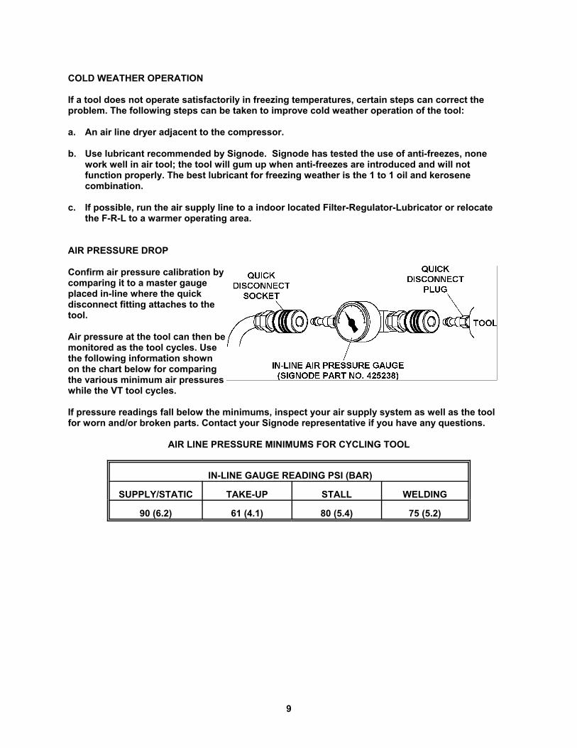
COLD WEATHER OPERATION
If a tool does not operate satisfactorily in freezing temperatures, certain steps can correct theproblem. The following steps can be taken to improve cold weather operation of the tool:
a. An air line dryer adjacent to the compressor.
b. Use lubricant recommended by Signode. Signode has tested the use of anti-freezes, nonework well in air tool; the tool will gum up when anti-freezes are introduced and will notfunction properly. The best lubricant for freezing weather is the 1 to 1 oil and kerosenecombination.
c. If possible, run the air supply line to a indoor located Filter-Regulator-Lubricator or relocatethe F-R-L to a warmer operating area.
AIR PRESSURE DROP
Confirm air pressure calibration bycomparing it to a master gaugeplaced in-line where the quickdisconnect fitting attaches to thetool.
Air pressure at the tool can then bemonitored as the tool cycles. Usethe following information shownon the chart below for comparingthe various minimum air pressureswhile the VT tool cycles.
If pressure readings fall below the minimums, inspect your air supply system as well as the toolfor worn and/or broken parts. Contact your Signode representative if you have any questions.
AIR LINE PRESSURE MINIMUMS FOR CYCLING TOOL
IN-LINE GAUGE READING PSI (BAR)
SUPPLY/STATIC TAKE-UP STALL WELDING
90 (6.2) 61 (4.1) 80 (5.4) 75 (5.2)
10
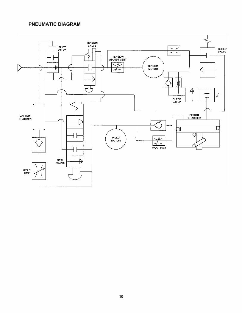
PNEUMATIC DIAGRAM

11
BLANK

12
OPERATING INSTRUCTIONS
Wear safety glasses. Stand to one side of the strap when tensioning.Make sure all bystanders are clear before proceeding.
PLEASE NOTE: Do not operate tool without strap, as damage to the tool may occur.
1. With the dispenser placedbehind you, bring the strap overthe top and around the package,place the straps together andremove any excess slack.
2. Using your right hand, squeezethe tension motor and stationaryhandle together to open thefeedwheel and strap path. Usingyour left hand, insert the overlapped straps under thefeedwheel and through thewelding mechanism.
Leave only a short tail ahead ofthe feedwheel and make surestraps are aligned behind thetool. Do not make a joint over avoid area of the package.

13
3. Recheck the strap alignment atthe rear of the tool and realign ifnecessary. Release the tensionmotor.
Press down the Green TensionControl Lever to begintensioning the strap.
When the tension motor stalls,indicating completion oftension, release the controllever. The strap will remaintensioned around the package.
NOTE: If the strap alignment is unsatisfactory or the tool needs to be removed before sealing.First, move the Red tension release latch to the left to disengage the tension motor. Squeezethe tension motor and stationary handle together to open the strap path.
4. Press the Blue Sealer Controllever to begin the sealing cycle.
It is not necessary to continueholding the lever down once theweld cycle has started.

14
OPERATING INSTRUCTIONS, Continued
5. The internal weld timer isenergized. The main pistonbrings the welding padstogether and the strap iswelded.
The supply end of the strap isthen cut off. Pull the cut strapaway from the tool duringwelding. The tool will continuethrough the weld cycle and stopautomatically.
6. When the weld cycle has completed the weld mechanism slowly returns to the neutralposition. This allows the newly welded strap joint to cool down properly. The tool can beeasily removed once the weld mechanism has completely returned to the neutral position.
7. Swing the tool out from thecompleted strap joint. Inspectthe joint to make sure the strapshave been properly welded.

15
STRAP JOINT INSPECTION
This tool is a Tension Weld® type sealer. A properly made joint will appear as shown in theillustration. If the joint does not appear as shown, then the operator must proceed asfollows:
1. Insure that the tool operating instructions are being followed before applying anotherstrap.
2. Cut the strap off and apply another.
A good weld will show some material displacement alongthe edges. The welded area should extend the full lengthand width of the gripper impression.
If the joint still does not appear as shown, then inspect the tool for worn and/or damagedparts. Replace tool parts as needed. NEVER HANDLE OR SHIP ANY LOAD WITHIMPROPERLY FORMED JOINTS. Misformed joints may not secure the load and could causeserious injury.

16
LOCATION OF WELD TIME ADJUSTMENT
TOOL ADJUSTMENTS
WELDING TIME
Weld time has been factory adjusted to provide acceptable weld strength when using HighStrength Tenax (polyester) type strap. Weld time may need to be adjusted due to air supplydifferences, tool wear, etc. Adjustments are made by turning the adjustment screw, located on thecover plate, using a small screwdriver. Turn the screw clockwise to increase weld time andcounterclockwise to decrease weld time.
Establishing the correct weld time is a matter of trial and error and should be conducted asfollows.
1. Remove the cap which protects the adjustment screw.Adjust the screw in 1/8 to 1/4 turn increments only.
2. Apply a strap and make a weld.
3. Compare the weld made with the illustrations shown onpage 13 of this manual. A good weld will displace somematerial along the outer edges of the joint.
4. If you are unable to produce an acceptable joint or if youhave any questions as to whether your tool is producinggood weld strength, contact your Signode SalesRepresentative.
5. Replace the cap over the screw.
WELD COOLING TIME
Cool time has been factory adjusted to allow the proper time for a weld to properly cool. The cooltime adjust controls how fast or slow the main piston bleeds off air pressure allowing the weldpads to separate from one another.
Cool time may also need to be adjusted due to air supply differences, tool wear, etc. Adjustmentsare made similar to weld time. Turning the screw clockwise increases cool time andcounterclockwise to decrease cooling time.
Establishing the correct cool time is a matter of trial and error and should be conducted asfollows.
1. Remove the cap which protects the adjustment screw.Adjust the screw in 1/8 to 1/4 turn increments only.
2. Apply a strap and make a weld.
3. A properly adjusted cool time should allow the strapjoint to cool for approximately three to five seconds.
NOTE: Cool time which is too short may lead to strapjoint separation.
4. Replace the cap over the screw.
LOCATION OF COOL TIME ADJUSTMENT

17
FEEDWHEEL ADJUSTMENTSCREW LOCATION (ARROW)
FEEDWHEEL TO GRIPPER PLUG
The feedwheel to gripper plug clearance may require readjustment if the feedwheel or gripper plughas been replaced. The feedwheel clearance should also be inspected during routine toolmaintenance procedures. Adjust the feedwheel clearance as follows:
1. Squeeze the tension motor and stationary handletogether to open the feedwheel gap. Place multiple(4 to 8) layers of .002", 1/2" wide (.05 x 12mm) shimstock between the feedwheel and the gripper plug.
NOTE: Do not use a single shim such as .008"(.20mm) as thicker shims may not conform to thefeedwheel shape, resulting in inaccurate clearancemeasurements.
2. Release the tensioner motor to pinch the shimsbetween the feedwheel and the gripper plug.Holding the shims with one hand, jog the tensionmotor on and off to rotate the feedwheel at least onefull revolution. If properly adjusted the tool shouldlightly tug at the shims while rotating. Clearance between the feedwheel and gripper plug atthis point should fall between .006" to .008" (.15mm to .20mm).
3. If the feedwheel needs to be adjusted, use a 3mm hexwrench to turn the adjustment screw which can beaccessed through the bottom of the tool base.
Turn the adjustment screw clockwise for greaterclearance and counter-clockwise for less clearance.Turn the adjustment screw only in 1/8 turn increments.After each 1/8 turn, repeat the adjustment testing asdescribed in step 2.
4. Once the proper clearance has been found the toolcan be returned to service.
NOTE: Never turn out the adjustment screw more than1/8 turn at a time without testing or completely removethe adjustment screw. These actions will severelydamage both the feedwheel and gripper plug.
STRAP TENSION
Strap tension is controlled by turning the adjustment screw asshown by arrow, in 1/4 increment turns counter-clockwise toincrease strap tension and clockwise to reduce strap tension. NOTE: Operating air pressure must be set between 85 and 90psi (5.7-6.2 Bar). With accurately controlled air pressure thetension will be uniform on all straps, provided the operatorallows the air motor to stall.

18
TOOL ADJUSTMENTS, Continued
STRAP CUTTER
The VT strap cutter has two serrated cuttingedges. After the first edge has become dull orstrap cut-off becomes difficult the blade can beremounted to use the second cutting edge. Once both edges have become worn the bladeshould be replaced. Use the instructions belowto remount, install and adjust a new cutterblade.
1. Remove the three mounting screws whichsecure the weld motor to the tool body.Remove the weld motor from the tool byturning the motor counter-clockwise torelease the O-ring which seats on the topof the motor.
NOTE: The small spring contained in the holder does not need to be removed from the holderto change the cutter blade.
2. The cutter blade group of parts can now be removed from the tool. Continue to also removethe cutter pin from the tool.
3. Remove the two smaller screws which mount the cutter blade to the holder. Rotate the cutterblade to the new cutting edge and reinstall the mounting screws.
NOTE: If both cutting edges are worn replace the cutter blade at this point.
4. Reinstall the cutter group of parts back into the tool. Before installing the cutter pin inspectthe cutter holder movement within the tool.
A. The holder should move freely up and down in the tool body. If the holder does not movefreely inspect the tool for debris or damage.
NOTE: If the holder has been replaced it may also be necessary to adjust the clearance ofthe two cutter guides.
B. The holder should not be able to move from side to side.Excessive side to side clearance will result in poor strapcut-off. If the holder does move side to side, loosen thefour mounting screws which secure the side guides. Movethe guides as needed to obtain a 0.025mm to 0.127mm(0.001"-0.005") clearance as noted by arrows.
C. Tighten the mounting screws.
5. Once the cutter holder has been inspected and adjusted,continue to reinstall the remaining parts in the order that theywere removed.
6. Run a few test cycles on the tool to confirm that the strap cut-off performs properly.

19
BLANK
20
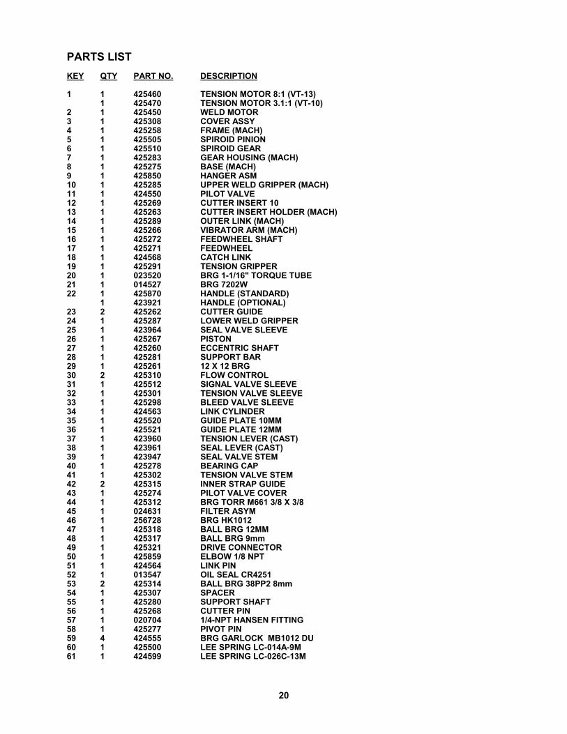
PARTS LISTKEY QTY PART NO. DESCRIPTION
1 1 425460 TENSION MOTOR 8:1 (VT-13)1 425470 TENSION MOTOR 3.1:1 (VT-10)
2 1 425450 WELD MOTOR3 1 425308 COVER ASSY4 1 425258 FRAME (MACH)5 1 425505 SPIROID PINION 6 1 425510 SPIROID GEAR 7 1 425283 GEAR HOUSING (MACH)8 1 425275 BASE (MACH)9 1 425850 HANGER ASM10 1 425285 UPPER WELD GRIPPER (MACH)11 1 424550 PILOT VALVE12 1 425269 CUTTER INSERT 1013 1 425263 CUTTER INSERT HOLDER (MACH)14 1 425289 OUTER LINK (MACH)15 1 425266 VIBRATOR ARM (MACH)16 1 425272 FEEDWHEEL SHAFT17 1 425271 FEEDWHEEL18 1 424568 CATCH LINK19 1 425291 TENSION GRIPPER20 1 023520 BRG 1-1/16" TORQUE TUBE21 1 014527 BRG 7202W22 1 425870 HANDLE (STANDARD)
1 423921 HANDLE (OPTIONAL)23 2 425262 CUTTER GUIDE24 1 425287 LOWER WELD GRIPPER25 1 423964 SEAL VALVE SLEEVE26 1 425267 PISTON27 1 425260 ECCENTRIC SHAFT28 1 425281 SUPPORT BAR29 1 425261 12 X 12 BRG30 2 425310 FLOW CONTROL31 1 425512 SIGNAL VALVE SLEEVE32 1 425301 TENSION VALVE SLEEVE33 1 425298 BLEED VALVE SLEEVE34 1 424563 LINK CYLINDER35 1 425520 GUIDE PLATE 10MM36 1 425521 GUIDE PLATE 12MM37 1 423960 TENSION LEVER (CAST)38 1 423961 SEAL LEVER (CAST)39 1 423947 SEAL VALVE STEM40 1 425278 BEARING CAP41 1 425302 TENSION VALVE STEM42 2 425315 INNER STRAP GUIDE43 1 425274 PILOT VALVE COVER44 1 425312 BRG TORR M661 3/8 X 3/845 1 024631 FILTER ASYM46 1 256728 BRG HK101247 1 425318 BALL BRG 12MM48 1 425317 BALL BRG 9mm49 1 425321 DRIVE CONNECTOR50 1 425859 ELBOW 1/8 NPT51 1 424564 LINK PIN52 1 013547 OIL SEAL CR425153 2 425314 BALL BRG 38PP2 8mm54 1 425307 SPACER55 1 425280 SUPPORT SHAFT56 1 425268 CUTTER PIN57 1 020704 1/4-NPT HANSEN FITTING58 1 425277 PIVOT PIN59 4 424555 BRG GARLOCK MB1012 DU60 1 425500 LEE SPRING LC-014A-9M61 1 424599 LEE SPRING LC-026C-13M

21
KEY QTY PART NO. DESCRIPTION
62 1 425861 LEE SPRING LC-026B-15M63 1 425501 ADJUSTMENT SCREW64 1 425297 BLEED VALVE STEM65 1 425513 SIGNAL VALVE STEM66 1 425872 PISTON67 2 425270 LEVER PIN68 2 422805 BRG GARLOCK MB1008 DU69 1 269423 Ø10 X 24 DOWEL PIN70 1 425320 SPRING71 1 424570 LINK SPRING72 1 009175 35MM INT. RET. RING (TA# N5000-137)73 1 422804 SPRING LEE LC-032C-674 1 425324 SPACER75 1 162391 Ø5 X 24 DOWEL PIN76 1 423493 Ø5 X 16 DOWEL PIN77 1 434284 M4 X 30 SHCS78 6 420216 M4 X 10 SHCS79 4 274937 19mm INT. RET. RING (TA# N5000-75)80 3 086190 KLIPRING 5304-3781 2 425858 9mm EXT. RET. RING (TA# 5100-35)82 2 424392 4MM CIRCLIP83 1 023438 1/2" INT. RET. RING (TA# N5000-50)84 1 425852 O-RING SAE# 32685 1 020699 O-RING SAE# 1386 3 423288 M5 X 12 SHCS87 2 424552 CAP88 1 425853 O-RING SAE# 1789 6 011214 M5 X 16 SHCS90 3 091624 O-RING SAE# 1091 2 010031 M5 X 25 SHCS92 2 423591 M4 X 5 SHCS93 1 425503 M5 HEX JAM NUT (ZINC)94 1 425854 O-RING SAE# 3495 1 425857 O-RING SAE# 2096 1 425860 M4 X 50 SHCS97 1 280811 M5 X 8 SSS CUP98 1 425855 O-RING SAE# 2199 1 425856 O-RING SAE# 126100 11 022789 O-RING SAE# 16101 2 432153 M3 X 6 SHCS102 3 004164 O-RING SAE# 11103 2 020728 O-RING SAE# 7104 1 094295 O-RING SAE# 8105 11 023446 O-RING SAE# 12106 1 010076 M5 LOCKWASHER (ZINC)107 1 059918 5/16-18 HEX NUT108 1 424762 O-RING SAE# 106109 1 423966 TUBE110 1 177721 SHSS M6 X 16 LG W/LG LCK111 1 423944 SPRING LEE # LC-038D-17112 1 423932 SPRING LEE # LC-036G-1113 1 424596 SPRING LEE # LC-032C-16M114 1 274451 Ø3 X 10 DOWEL PIN115 1 425873 O-RING SAE# 14116 1 436380 NAMEPLATE (VT-10)
1 436381 NAMEPLATE (VT-13)117 1 286383 SAFETY SIGN118 1 423953 WARNING SIGN119 3 166063 M5 X 20 SHCS

22
NEVER remove the air valves when air is connected to the tool. Removing an valve with air tothe tool will cause the valve to violently release from the tool.

23
* Use Loctite #242 or equivalent.** Use Loctite #609 or equivalent.
NOTES:
1. For optimum tool performance, fill gear housing one-third full of Red Mobilith SHC 007Grease (Signode Part No. 425239).

24
PARTS LIST, TENSION MOTOR, 425460 (VT-13)
KEY QTY PART NO DESCRIPTION
1 1 424166 LOCKING NUT2 1 080315 RETAINING RING3 1 023547 BALL BEARING4 1 425454 IDLER CARRIER5 3 024605 IDLER6 1 090065 LOCKING PIN7 1 424153 MOTOR GEAR HOUSING8 1 024608 RING GEAR9 1 423151 WASHER10 2 014541 BELLEVILE SPRING WASHER11 1 425455 SPACER12 1 023481 BALL BEARING13 1 424155 FRONT END PLATE14 2 424164 SPRING PIN15 1 425457 CYLINDER16 1 024602 SPACER17 1 425456 ROTOR18 5 024612 VANE19 1 424154 BACK END PLATE20 1 423582 CAMMOZZI 6700-8 CARTRIDGE21 1 424161 BALL BEARING (SEAL)22 2 424172 O-RING23 1 425313 MOTOR HOUSING24 1 424167 MUFFLER INSERT25 1 424165 MUFFLER PLATE26 1 424162 RETAINING RING

25
PARTS LIST, TENSION MOTOR, 425470 (VT-10)
KEY QTY PART NO DESCRIPTION
1 1 424166 LOCKING NUT2 1 080315 RETAINING RING3 1 023547 BALL BEARING4 1 425228 IDLER CARRIER5 3 425229 IDLER6 1 090065 LOCKING PIN7 1 424153 MOTOR GEAR HOUSING8 1 422870 RING GEAR9 1 423151 WASHER10 2 014541 BELLEVILE SPRING WASHER11 1 425455 SPACER12 1 023481 BALL BEARING13 1 424155 FRONT END PLATE14 2 424164 SPRING PIN15 1 425457 CYLINDER16 1 024602 SPACER17 1 425459 ROTOR18 5 024612 VANE19 1 424154 BACK END PLATE20 1 423582 CAMMOZZI 6700-8 CARTRIDGE21 1 424161 BALL BEARING (SEAL)22 2 424172 O-RING23 1 425313 MOTOR HOUSING24 1 424167 MUFFLER INSERT25 1 424165 MUFFLER PLATE26 1 424162 RETAINING RING27 1 425231 PINION GEAR

26
PARTS LIST, WELD MOTOR, 425450
KEY QTY PART NO DESCRIPTION
1 1 080315 RETAINING RING2 1 424181 FLAT WASHER3 2 014541 BELLEVILLE SPRING WASHER4 1 090118 BALL BEARING (SEAL)5 1 425458 FRONT END PLATE6 1 024602 SPACER7 5 024612 FRONT END PLATE8 1 425453 ROTOR9 1 090052 CYLINDER10 2 424164 SPRING PIN11 1 424154 BACK END PLATE12 1 424161 BALL BEARING (SEAL)13 2 424172 O-RING14 1 004164 O-RING15 1 425295 MOTOR HOUSING16 1 424167 MUFFLER INSERT17 1 424165 MUFFLER PLATE18 1 424162 RETAINING RING

27

28
TROUBLESHOOTING
The following items are the most common types of tool malfunctions. For symptoms or remediesnot shown, contact your Signode service representative for additional information and details. Thefollowing tool conditions are shown in this manual:
AIR SUPPLY #1 - The air motor is frozen. #2 - A leaking or sticking air valve. #3 - The tool runs sluggishly.
TENSIONING #4 - Feedwheel milling on strap and/or strap breaking. #5 - The top strap is being properly tensioned but the tool does not hold the bottom strap. #6 - The tool stops tensioning before maximum tension is reached (air motor continues to run).
WELDING #7 - A poor weld identified by an incomplete area of weld. #8 - Incomplete or no weld. #9 - Strap is over welded. #10 - Motor shut-off is sluggish. #11 - Strap weld time is erratic. #12 - Weld time is too long.
CUT-OFF ACTION #13 - The cut-off has become difficult. #14 - Weld strap is misaligned.
#1 CONDITION: The air motor is frozen.
CAUSE REMEDY
The motor is dry, hindering it from providingmaximum performance.
Add several drops of oil into the motor through theair inlet. Hook the tool up to air, depress and hold theoperating lever while gently tapping the motor with arubber mallet. Repeat this procedure several times ifnecessary.
#2 CONDITION: Air valve leaking or sticking.
CAUSE REMEDY
Worn, damaged or dirty O-rings on valve assemblies. Clean and lubricate the valve assemblies and thevalve sleeve assembly. Replace the O-rings on thevalve assemblies if necessary.

29
#3 CONDITION: The tool runs sluggishly.
CAUSE REMEDY
1. The air filter-regulator-lubricator ismalfunctioning or is not properly maintained.
2. The tool may run sluggishly due to a clogged ordirty motor filter screen due to a lack of properlyfiltered air supply.
3. The tool may run sluggishly due to an improperair motor adjustment or a clogged or dirtyvibrator assembly.
4. The end plates, pinion teeth on the rotor and therotor blades are worn, dirty or rusted.
1A. Check the regulator to see that the correct airpressure is getting to the tool.
1B. Check to see the filter unit is clean andfunctioning properly.
1C. Examine the lubricator to see there is oil in thebowl and that oil is seen dripping from the sightdome as the tool operates. This assures the airmotor is being properly lubricated.
2. Remove the Hansen plug at the inlet to the airmotor and examine the filter screen in the filterassembly and clean it if necessary.
3. Clean vibrator parts as needed. Inspect vibratoreccentric for wear or damage. Replace asrequired.
4. Carefully remove the air motor from the tool anddisassemble it. If these parts are only dirty,clean, thoroughly oil and reassemble. If theyare worn or rusted, replace them.
#4 CONDITION: Feedwheel milling on strap and/or strap breaking.
CAUSE REMEDY
1. Feedwheel is clogged with dirt or strap residue.
2. Worn teeth on the feedwheel.
3. Excessive or improperly set feedwheel to gripperplug clearance.
1. Clean teeth on feedwheel with the cleaningbrush (Signode Part No. 023963) provided.
2. Replace the feedwheel.
3. Adjust feedwheel gap as required.
#5 CONDITION: The top strap is being properly tensioned but the tool does not hold thebottom strap.
CAUSE REMEDY
1. The gripper plug may be packed with dirt or strapresidue preventing the teeth from penetrating thestrap.
2. Worn teeth on the gripper plug.
3. The tension release lever is being held whileoperating the tool.
1. Clean teeth on feedwheel with the cleaningbrush (Signode Part No. 023963) provided.
2. Replace the worn plug. Since the feedwheel andgripper plug are prevented from contacting oneanother by an inside shoulder on each part, it isnot often these parts have to be replaced.
3. Review the operating instruction shown in thismanual.

30
TROUBLESHOOTING, Continued
#7 CONDITION: A poor weld identified by an incomplete area of weld.
CAUSE REMEDY
Welding is achieved by a combination of vibration anddownward pressure of the upper gripper. Either arestriction of motion or a reduction of downwardpressure will cause a poor weld.
Dismantle and clean the weld mechanism by brushingaway the strap residue or washing the entire unit in asolvent. When a solvent is used it is imperative theassembly be blown dry to remove all solvent. Checkfor dry or worn bearings. Replace or lubricate asrequired. If the tool has been used extensively,examine the teeth on the upper and lower weld padsfor wear. Replace if worn.
#8 CONDITION: Incomplete or no weld.
CAUSE REMEDY
1. Improperly set weld time adjustment.
2. Worn teeth on upper or lower weld pads.
3. Insufficient air supply pressure.
4. Worn o-ring on main piston.
1. Adjust weld time as required per instruction inthis manual.
2. Replace as required.
3. Remedy as required.
4. Replace as required.
#9 CONDITION: Strap is over welded.
CAUSE REMEDY
Improper weld timing adjustment. Decrease weld timing as needed.
#10 CONDITION: Motor shutoff appears sluggish.
CAUSE REMEDY
1. Air leakage in timing circuit.
2. Dirty or very dry pilot valve.
3. Dirty or very dry sealer valve stem.
1. Check o-rings and pneumatic components forleaks. Replace parts as required.
2. Remove, clean and lubricate the pilot valveusing air line oil or replace if needed.
3. Remove valve stem and inspect o-rings fordamage. Replace o-rings as needed. Clean partand lubricate with EP Accrolube grease.

31
#11 CONDITION: Strap weld time is erratic.
CAUSE REMEDY
1. Air leakage in timing circuit.
2. Dirty or very dry pilot valve (Key 106).
3. Weld time flow control (Key 88) is contaminatedwith debris or oil.
1. Check o-rings and pneumatic components forleaks. Replace parts as required.
2. Remove, clean and lubricate the pilot valveusing air line oil or replace if needed.
3. Remove part and clean using dry compressedair.
#12 CONDITION: Weld time is too long.
CAUSE REMEDY
Too much oil in the air supply system of the tool. Purge the tool of all excess oil.
#13 CONDITION: The cut-off has become difficult.
CAUSE REMEDY
1. Strap residue jamming cutter mechanism.
2. Cutter blade worn or damaged adjustability.
1. Clean parts as required.
2. Replace as required.
#14 CONDITION: Welded strap is misaligned.
CAUSE REMEDY
1. The tool is not being operated properly.
2. Teeth of upper weld gripper or lower weld gripperare damaged.
3. Teeth of feedwheel or tension gripper aredamaged.
1. Review operating instruction shown in thismanual for proper operation of tool.
2. Replace damaged parts as needed.
3. Replace damaged parts as needed.
32
FIGURE-C
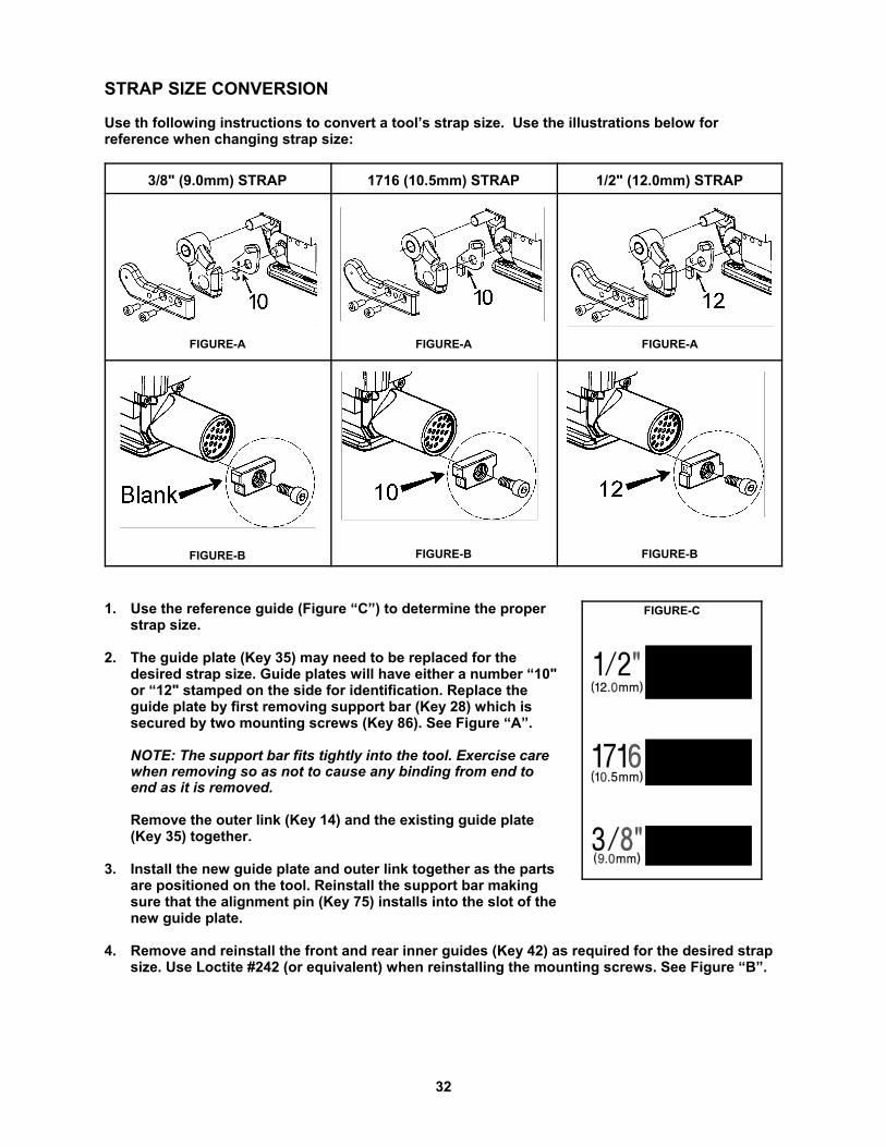
STRAP SIZE CONVERSION
Use th following instructions to convert a tool’s strap size. Use the illustrations below forreference when changing strap size:
3/8" (9.0mm) STRAP 1716 (10.5mm) STRAP 1/2" (12.0mm) STRAP
FIGURE-A FIGURE-A FIGURE-A
FIGURE-B FIGURE-B FIGURE-B
1. Use the reference guide (Figure “C”) to determine the properstrap size.
2. The guide plate (Key 35) may need to be replaced for thedesired strap size. Guide plates will have either a number “10"or “12" stamped on the side for identification. Replace theguide plate by first removing support bar (Key 28) which issecured by two mounting screws (Key 86). See Figure “A”.
NOTE: The support bar fits tightly into the tool. Exercise carewhen removing so as not to cause any binding from end toend as it is removed.
Remove the outer link (Key 14) and the existing guide plate(Key 35) together.
3. Install the new guide plate and outer link together as the partsare positioned on the tool. Reinstall the support bar makingsure that the alignment pin (Key 75) installs into the slot of thenew guide plate.
4. Remove and reinstall the front and rear inner guides (Key 42) as required for the desired strapsize. Use Loctite #242 (or equivalent) when reinstalling the mounting screws. See Figure “B”.

33
HORIZONTAL SEALING(USING OPTIONAL
SIDE HANGERP/N 425516)VERTICAL SEALINGTOP SEALING
OPTIONAL OVERHEAD SUSPENSION
To work effectively, your VT tool must be properly installed. This installation includes, in somecases, proper suspension of the tool over the container to be strapped, and the proper placementof a strapping dispenser to provide a continuous easy supply of strapping for the application. TheVT can be suspended in various operating positions by using the proper tool hanger andhardware.
Review the illustrations below for the appropriate configuration for the tool application.Applications are recommended to use an Overhead Tool Balancer as shown (Signode Part No.423283).
OPTIONAL STATIONARY HANDLE, Part No. 423921
For customer that suspend their tools thislonger handle aids the tool operation. Thishandle can be used with either the VT-10 or theVT-13 tools. Mounts using the existinghardware.
Review page 22 of this manual for additionalmounting details.

34
TOOL MAINTENANCE
1. Clean the teeth on the feedwheel and the gripper plug with the special brush provided.
2. Periodically clean the tool with compressed air.
3. Disassemble, clean and lubricate the welding mechanism.
GEAR HOUSING
Periodically check the gear housing portion of the tool:
1. Remove the end cap from the front of the gear housing by removing the set screw and pullingthe end cap off.
2. Check for adequate lubrication and wear of the Spiroid worm gear and ring gear.
3. This portion of the tool should be one-third full of gear grease.
4. Reinstall the end cap.

35

© Copyright 2005, Signode 512125 3/2005
SIGNODENEW TOOL WARRANTY
Signode Engineered Products Warrants that a new Signode strapping tool will operate per functionalspecifications for a period of sixty (60) days after the date of shipment to the owner's place of business.Normal wearing parts, as outlined in the Operation, Parts & Safety manual, are covered by a thirty (30) daywarranty unless, in Signode's judgement, these parts have been subjected to abnormal or extreme usage.Signode's sole liability hereunder will be to repair or replace, without charge, F.O.B. Signode's Glenview,Illinois plant, any tool which proves to not operate per functional specifications within the stated period.Signode reserves the right to replace any tool which proves not to operate per functional specificationswith a new or like-new tool of the same model if in Signode's judgement such replacement is appropriate.Any new replacement tool provided to an owner will carry a full sixty (60) day warranty. Any warrantyrepaired tool or like-new replacement tool will carry a warranty for the balance of the time remaining on theinitial sixty (60) day warranty. This warranty will be extended to compensate for the time the tool is inSignode's possession for warranty repairs.
This warranty is void as to any tool which has been: (I) subjected to mis-use, misapplication, accident,damage, or repaired with other than genuine Signode replacement parts, (II) improperly maintained, oradjusted, or damaged in transit or handling; (III) used with improperly filtered, unlubricated air or improperstrapping material, (IV) in Signode's opinion, altered or repaired in a way that affects or detracts from theperformance of the tool.
SIGNODE MAKES NO WARRANTY, EXPRESSED OR IMPLIED, RELATING TO MERCHANTABILITY,FITNESS OR OTHERWISE EXCEPT AS STATED ABOVE AND SIGNODE'S LIABILITY AS ASSUMED ABOVEIS IN LIEU OF ALL OTHERS ARISING OUT OF OR IN CONNECTION WITH THE USE AND PERFORMANCEOF THE TOOL. IT IS EXPRESSLY UNDERSTOOD THAT SIGNODE SHALL IN NO EVENT BE LIABLE FORANY INDIRECT OR CONSEQUENTIAL DAMAGES INCLUDING, BUT NOT LIMITED TO, DAMAGES WHICHMAY ARISE FROM LOSS OF ANTICIPATED PROFITS OR PRODUCTION, SPOILAGE OF MATERIALS,INCREASED COSTS OF OPERATION OR OTHERWISE.
Considerable effort has be made to ensure that this product conforms to our high quality standards.However, should you experience any difficulties, please contact your Sales Representative providingsamples and the manufacturing code specified on the tool.
Thank you for your help.
SIGNODE ENGINEERED PRODUCTSHand Tool Division
3620 W. Lake Avenue, Glenview, Illinois 60025