Embed Size (px)
Citation preview

vSRX Deployment Guide for Microsoft Hyper-V
Modified: 2018-04-13
Copyright © 2018, Juniper Networks, Inc.

Juniper Networks, Inc.1133 InnovationWaySunnyvale, California 94089USA408-745-2000www.juniper.net
Juniper Networks, the Juniper Networks logo, Juniper, and Junos are registered trademarks of Juniper Networks, Inc. and/or its affiliates inthe United States and other countries. All other trademarks may be property of their respective owners.
Juniper Networks assumes no responsibility for any inaccuracies in this document. Juniper Networks reserves the right to change, modify,transfer, or otherwise revise this publication without notice.
vSRX Deployment Guide for Microsoft Hyper-VCopyright © 2018 Juniper Networks, Inc. All rights reserved.
The information in this document is current as of the date on the title page.
YEAR 2000 NOTICE
Juniper Networks hardware and software products are Year 2000 compliant. Junos OS has no known time-related limitations through theyear 2038. However, the NTP application is known to have some difficulty in the year 2036.
ENDUSER LICENSE AGREEMENT
The Juniper Networks product that is the subject of this technical documentation consists of (or is intended for use with) Juniper Networkssoftware. Use of such software is subject to the terms and conditions of the End User License Agreement (“EULA”) posted athttps://www.juniper.net/support/eula/. By downloading, installing or using such software, you agree to the terms and conditions of thatEULA.
Copyright © 2018, Juniper Networks, Inc.ii

Table of Contents
About the Documentation . . . . . . . . . . . . . . . . . . . . . . . . . . . . . . . . . . . . . . . . . . . . ix
Documentation and Release Notes . . . . . . . . . . . . . . . . . . . . . . . . . . . . . . . . . . ix
Supported Platforms . . . . . . . . . . . . . . . . . . . . . . . . . . . . . . . . . . . . . . . . . . . . . ix
Documentation Conventions . . . . . . . . . . . . . . . . . . . . . . . . . . . . . . . . . . . . . . . ix
Documentation Feedback . . . . . . . . . . . . . . . . . . . . . . . . . . . . . . . . . . . . . . . . . xi
Requesting Technical Support . . . . . . . . . . . . . . . . . . . . . . . . . . . . . . . . . . . . . xii
Self-Help Online Tools and Resources . . . . . . . . . . . . . . . . . . . . . . . . . . . xii
Opening a Case with JTAC . . . . . . . . . . . . . . . . . . . . . . . . . . . . . . . . . . . . . xii
Chapter 1 Overview . . . . . . . . . . . . . . . . . . . . . . . . . . . . . . . . . . . . . . . . . . . . . . . . . . . . . . . . . 15
Understanding vSRX with Microsoft Hyper-V . . . . . . . . . . . . . . . . . . . . . . . . . . . . . 15
vSRX Overview . . . . . . . . . . . . . . . . . . . . . . . . . . . . . . . . . . . . . . . . . . . . . . . . . . 15
vSRX Benefits and Use Cases . . . . . . . . . . . . . . . . . . . . . . . . . . . . . . . . . . . . . . 16
vSRX in Microsoft Hyper-V . . . . . . . . . . . . . . . . . . . . . . . . . . . . . . . . . . . . . . . . 17
Requirements for vSRX on Microsoft Hyper-V . . . . . . . . . . . . . . . . . . . . . . . . . . . . 18
Software Requirements . . . . . . . . . . . . . . . . . . . . . . . . . . . . . . . . . . . . . . . . . . 18
Hardware Requirements . . . . . . . . . . . . . . . . . . . . . . . . . . . . . . . . . . . . . . . . . . 19
Best Practices for Improving vSRX Performance . . . . . . . . . . . . . . . . . . . . . . . 19
NUMA Nodes . . . . . . . . . . . . . . . . . . . . . . . . . . . . . . . . . . . . . . . . . . . . . . . 19
Interface Mapping for vSRX on Microsoft Hyper-V . . . . . . . . . . . . . . . . . . . . . 20
vSRX Default Settings on Microsoft Hyper-V . . . . . . . . . . . . . . . . . . . . . . . . . . 21
Junos OS Features Supported on vSRX . . . . . . . . . . . . . . . . . . . . . . . . . . . . . . . . . 22
SRX Series Features Supported on vSRX . . . . . . . . . . . . . . . . . . . . . . . . . . . . 22
SRX Series Features Not Supported on vSRX . . . . . . . . . . . . . . . . . . . . . . . . . 23
Chapter 2 Installing vSRX in Microsoft Hyper-V . . . . . . . . . . . . . . . . . . . . . . . . . . . . . . . . . 31
Preparing for vSRX Deployment in Microsoft Hyper-V . . . . . . . . . . . . . . . . . . . . . . 31
Deploying vSRX in a Hyper-V Host Using the Hyper-V Manager . . . . . . . . . . . . . . 32
Deploying vSRX in a Hyper-V Host Using Windows PowerShell . . . . . . . . . . . . . . 43
Chapter 3 vSRX VM Management . . . . . . . . . . . . . . . . . . . . . . . . . . . . . . . . . . . . . . . . . . . . 47
Adding vSRX Interfaces . . . . . . . . . . . . . . . . . . . . . . . . . . . . . . . . . . . . . . . . . . . . . . 47
Adding Virtual Switches . . . . . . . . . . . . . . . . . . . . . . . . . . . . . . . . . . . . . . . . . . 48
Configuring the vSRX to Use a VLAN . . . . . . . . . . . . . . . . . . . . . . . . . . . . . . . . 55
Powering Down a vSRX VM with Hyper-V . . . . . . . . . . . . . . . . . . . . . . . . . . . . . . . 56
Chapter 4 Configuring and Managing vSRX . . . . . . . . . . . . . . . . . . . . . . . . . . . . . . . . . . . . 59
vSRX Configuration and Management Tools . . . . . . . . . . . . . . . . . . . . . . . . . . . . . 59
Understanding the Junos OS CLI and Junos Scripts . . . . . . . . . . . . . . . . . . . . 59
Understanding the J-Web Interface . . . . . . . . . . . . . . . . . . . . . . . . . . . . . . . . . 59
iiiCopyright © 2018, Juniper Networks, Inc.

Understanding Junos Space Security Director . . . . . . . . . . . . . . . . . . . . . . . . 60
Configuring vSRX Using the CLI . . . . . . . . . . . . . . . . . . . . . . . . . . . . . . . . . . . . . . . 60
Configuring vSRX Using the J-Web Interface . . . . . . . . . . . . . . . . . . . . . . . . . . . . . . 61
Accessing the J-Web Interface and Configuring vSRX . . . . . . . . . . . . . . . . . . 62
Applying the Configuration . . . . . . . . . . . . . . . . . . . . . . . . . . . . . . . . . . . . . . . . 64
Adding vSRX Feature Licenses . . . . . . . . . . . . . . . . . . . . . . . . . . . . . . . . . . . . . 64
Managing Security Policies for Virtual Machines Using Junos Space Security
Director . . . . . . . . . . . . . . . . . . . . . . . . . . . . . . . . . . . . . . . . . . . . . . . . . . . . . . . 65
Chapter 5 Configuring vSRX Chassis Clusters . . . . . . . . . . . . . . . . . . . . . . . . . . . . . . . . . . 67
Configuring a vSRX Chassis Cluster in Junos OS . . . . . . . . . . . . . . . . . . . . . . . . . . . 67
Chassis Cluster Overview . . . . . . . . . . . . . . . . . . . . . . . . . . . . . . . . . . . . . . . . . 67
Enabling Chassis Cluster Formation . . . . . . . . . . . . . . . . . . . . . . . . . . . . . . . . 68
Chassis Cluster Quick Setup with J-Web . . . . . . . . . . . . . . . . . . . . . . . . . . . . . 69
Manually Configuring a Chassis Cluster with J-Web . . . . . . . . . . . . . . . . . . . . 69
vSRX Cluster Staging and Provisioning in Hyper-V . . . . . . . . . . . . . . . . . . . . . . . . . 75
Deploying the VMs and Additional Network Adapters in Hyper-V . . . . . . . . . 75
Creating the Control Link Connection in Hyper-V . . . . . . . . . . . . . . . . . . . . . . 76
Creating the Fabric Link Connection in Hyper-V . . . . . . . . . . . . . . . . . . . . . . . 79
Creating the Data Interfaces Using Hyper-V . . . . . . . . . . . . . . . . . . . . . . . . . . 80
Prestaging the Configuration from the Console . . . . . . . . . . . . . . . . . . . . . . . . 81
Connecting and Installing the Staging Configuration . . . . . . . . . . . . . . . . . . . 82
Chapter 6 vSRX Licensing . . . . . . . . . . . . . . . . . . . . . . . . . . . . . . . . . . . . . . . . . . . . . . . . . . . 85
vSRX Feature Licenses Overview . . . . . . . . . . . . . . . . . . . . . . . . . . . . . . . . . . . . . . 85
vSRX License Procurement and Renewal . . . . . . . . . . . . . . . . . . . . . . . . . . . . 85
vSRX Evaluation License . . . . . . . . . . . . . . . . . . . . . . . . . . . . . . . . . . . . . . . . . 86
Product Evaluation License . . . . . . . . . . . . . . . . . . . . . . . . . . . . . . . . . . . . 87
Advanced Security Features Evaluation License . . . . . . . . . . . . . . . . . . . 87
License Types . . . . . . . . . . . . . . . . . . . . . . . . . . . . . . . . . . . . . . . . . . . . . . . . . . 88
Throughput . . . . . . . . . . . . . . . . . . . . . . . . . . . . . . . . . . . . . . . . . . . . . . . . . . . . 89
License Duration . . . . . . . . . . . . . . . . . . . . . . . . . . . . . . . . . . . . . . . . . . . . . . . . 89
Individual (á la carte) Feature Licenses . . . . . . . . . . . . . . . . . . . . . . . . . . . . . . 90
Bundled Licenses . . . . . . . . . . . . . . . . . . . . . . . . . . . . . . . . . . . . . . . . . . . . . . . 90
Stacking Licenses . . . . . . . . . . . . . . . . . . . . . . . . . . . . . . . . . . . . . . . . . . . . . . . 90
vSRX License Keys Components . . . . . . . . . . . . . . . . . . . . . . . . . . . . . . . . . . . 90
License Management Fields Summary . . . . . . . . . . . . . . . . . . . . . . . . . . . . . . 91
Managing Licenses for vSRX . . . . . . . . . . . . . . . . . . . . . . . . . . . . . . . . . . . . . . . . . . 93
vSRX Evaluation License Installation Process . . . . . . . . . . . . . . . . . . . . . . . . . 93
Adding a New License Key with J-Web . . . . . . . . . . . . . . . . . . . . . . . . . . . . . . 94
Adding a New License Key from the CLI . . . . . . . . . . . . . . . . . . . . . . . . . . . . . 95
Updating vSRX Licenses . . . . . . . . . . . . . . . . . . . . . . . . . . . . . . . . . . . . . . . . . 96
Deleting a License with J-Web . . . . . . . . . . . . . . . . . . . . . . . . . . . . . . . . . . . . . 97
Deleting a License with the CLI . . . . . . . . . . . . . . . . . . . . . . . . . . . . . . . . . . . . 98
License Warning Messages . . . . . . . . . . . . . . . . . . . . . . . . . . . . . . . . . . . . . . . 98
vSRX License Model Numbers . . . . . . . . . . . . . . . . . . . . . . . . . . . . . . . . . . . . . . . . 99
Chapter 7 Troubleshooting . . . . . . . . . . . . . . . . . . . . . . . . . . . . . . . . . . . . . . . . . . . . . . . . . . 111
Finding the Software Serial Number for vSRX . . . . . . . . . . . . . . . . . . . . . . . . . . . . 111
Copyright © 2018, Juniper Networks, Inc.iv
vSRX Deployment Guide for Microsoft Hyper-V

List of Figures
Chapter 1 Overview . . . . . . . . . . . . . . . . . . . . . . . . . . . . . . . . . . . . . . . . . . . . . . . . . . . . . . . . . 15
Figure 1: vSRX Architecture . . . . . . . . . . . . . . . . . . . . . . . . . . . . . . . . . . . . . . . . . . . . 16
Figure 2: vSRX Deployment in Hyper-V . . . . . . . . . . . . . . . . . . . . . . . . . . . . . . . . . . 17
Chapter 2 Installing vSRX in Microsoft Hyper-V . . . . . . . . . . . . . . . . . . . . . . . . . . . . . . . . . 31
Figure 3: Example of vSRX Deployment in Hyper-V . . . . . . . . . . . . . . . . . . . . . . . . 32
Figure 4: Specify Name and Location Page . . . . . . . . . . . . . . . . . . . . . . . . . . . . . . 34
Figure 5: Specify Generation Page . . . . . . . . . . . . . . . . . . . . . . . . . . . . . . . . . . . . . . 35
Figure 6: Assign Memory Page . . . . . . . . . . . . . . . . . . . . . . . . . . . . . . . . . . . . . . . . . 36
Figure 7: Configure Networking Page . . . . . . . . . . . . . . . . . . . . . . . . . . . . . . . . . . . . 37
Figure 8: Connect Virtual Hard Disk Page . . . . . . . . . . . . . . . . . . . . . . . . . . . . . . . . 38
Figure 9: Summary Page . . . . . . . . . . . . . . . . . . . . . . . . . . . . . . . . . . . . . . . . . . . . . 39
Figure 10: Processor Pane . . . . . . . . . . . . . . . . . . . . . . . . . . . . . . . . . . . . . . . . . . . . 40
Figure 11: Network Adapter Pane . . . . . . . . . . . . . . . . . . . . . . . . . . . . . . . . . . . . . . . 41
Figure 12: Network Adapter Advanced Features Pane . . . . . . . . . . . . . . . . . . . . . . 42
Chapter 3 vSRX VM Management . . . . . . . . . . . . . . . . . . . . . . . . . . . . . . . . . . . . . . . . . . . . 47
Figure 13: Create Virtual Switch Pane . . . . . . . . . . . . . . . . . . . . . . . . . . . . . . . . . . . 49
Figure 14: Virtual Switch Properties Pane . . . . . . . . . . . . . . . . . . . . . . . . . . . . . . . . . 51
Figure 15: Adding Virtual Switch to Network Adapter Example . . . . . . . . . . . . . . . 53
Figure 16: Network Adapter Enable MAC Address Spoofing Example . . . . . . . . . . 54
Figure 17: Enable VLAN Identification Example . . . . . . . . . . . . . . . . . . . . . . . . . . . . 56
Chapter 5 Configuring vSRX Chassis Clusters . . . . . . . . . . . . . . . . . . . . . . . . . . . . . . . . . . 67
Figure 18: Create Virtual Switch Pane . . . . . . . . . . . . . . . . . . . . . . . . . . . . . . . . . . . 77
Figure 19: Virtual Switch Properties Pane . . . . . . . . . . . . . . . . . . . . . . . . . . . . . . . . 78
Figure 20: Adding Virtual Switch to Network Adapter Pane Example . . . . . . . . . . 79
Chapter 6 vSRX Licensing . . . . . . . . . . . . . . . . . . . . . . . . . . . . . . . . . . . . . . . . . . . . . . . . . . . 85
Figure 21: Sample vSRX License SKU . . . . . . . . . . . . . . . . . . . . . . . . . . . . . . . . . . . 89
Figure 22: J-Web LicensesWindow Showing Installed Licenses . . . . . . . . . . . . . . . 91
Figure 23: J-Web Licenses Window . . . . . . . . . . . . . . . . . . . . . . . . . . . . . . . . . . . . . 94
Figure 24: Add License Window . . . . . . . . . . . . . . . . . . . . . . . . . . . . . . . . . . . . . . . 95
Figure 25: License Details Window . . . . . . . . . . . . . . . . . . . . . . . . . . . . . . . . . . . . . 95
Figure 26: Deleting a License . . . . . . . . . . . . . . . . . . . . . . . . . . . . . . . . . . . . . . . . . . 97
Figure 27: Delete Licenses Window . . . . . . . . . . . . . . . . . . . . . . . . . . . . . . . . . . . . . 98
Figure 28: J-Web Dashboard for License Expiry Warning . . . . . . . . . . . . . . . . . . . . 99
vCopyright © 2018, Juniper Networks, Inc.

Copyright © 2018, Juniper Networks, Inc.vi
vSRX Deployment Guide for Microsoft Hyper-V

List of Tables
About the Documentation . . . . . . . . . . . . . . . . . . . . . . . . . . . . . . . . . . . . . . . . . . ix
Table 1: Notice Icons . . . . . . . . . . . . . . . . . . . . . . . . . . . . . . . . . . . . . . . . . . . . . . . . . . x
Table 2: Text and Syntax Conventions . . . . . . . . . . . . . . . . . . . . . . . . . . . . . . . . . . . . x
Chapter 1 Overview . . . . . . . . . . . . . . . . . . . . . . . . . . . . . . . . . . . . . . . . . . . . . . . . . . . . . . . . . 15
Table 3: Specifications for vSRX for Microsoft Hyper-V . . . . . . . . . . . . . . . . . . . . . 18
Table 4: Hardware Specifications for the Host Machine . . . . . . . . . . . . . . . . . . . . . 19
Table 5: Interface Names for a Standalone vSRX VM . . . . . . . . . . . . . . . . . . . . . . 20
Table 6: Interface Names for a vSRX Cluster Pair . . . . . . . . . . . . . . . . . . . . . . . . . . 21
Table 7: Factory Default Settings for Security Policies . . . . . . . . . . . . . . . . . . . . . . 22
Table 8: vSRX Feature Considerations . . . . . . . . . . . . . . . . . . . . . . . . . . . . . . . . . . 23
Table 9: SRX Series Features Not Supported on vSRX . . . . . . . . . . . . . . . . . . . . . 24
Chapter 2 Installing vSRX in Microsoft Hyper-V . . . . . . . . . . . . . . . . . . . . . . . . . . . . . . . . . 31
Table 10: New-VM Command Parameters . . . . . . . . . . . . . . . . . . . . . . . . . . . . . . . 44
Chapter 4 Configuring and Managing vSRX . . . . . . . . . . . . . . . . . . . . . . . . . . . . . . . . . . . . 59
Table 11: Instance Name and User Account Information . . . . . . . . . . . . . . . . . . . . 63
Table 12: System Time Options . . . . . . . . . . . . . . . . . . . . . . . . . . . . . . . . . . . . . . . . 63
Chapter 5 Configuring vSRX Chassis Clusters . . . . . . . . . . . . . . . . . . . . . . . . . . . . . . . . . . 67
Table 13: Chassis Cluster Configuration Page . . . . . . . . . . . . . . . . . . . . . . . . . . . . . . 71
Table 14: Edit Node Setting Configuration Details . . . . . . . . . . . . . . . . . . . . . . . . . . 72
Table 15: Add HA Cluster Interface Configuration Details . . . . . . . . . . . . . . . . . . . . 73
Table 16: Add Redundancy Groups Configuration Details . . . . . . . . . . . . . . . . . . . 74
Chapter 6 vSRX Licensing . . . . . . . . . . . . . . . . . . . . . . . . . . . . . . . . . . . . . . . . . . . . . . . . . . . 85
Table 17: vSRX Evaluation License Type . . . . . . . . . . . . . . . . . . . . . . . . . . . . . . . . . 87
Table 18: Summary of License Management Fields . . . . . . . . . . . . . . . . . . . . . . . . 92
Table 19: vSRX Licensing Package Types . . . . . . . . . . . . . . . . . . . . . . . . . . . . . . . 100
Table 20: Secure Cloud Connect (SCC) vSRX Bandwidth Licenses . . . . . . . . . . . 102
Table 21: Standard (STD) vSRX Bandwidth Licenses . . . . . . . . . . . . . . . . . . . . . . 103
Table 22: vSRX AppSecure and IPS Bundled (ASCB and ASECB) Bandwidth
Licenses . . . . . . . . . . . . . . . . . . . . . . . . . . . . . . . . . . . . . . . . . . . . . . . . . . . . . . 104
Table 23: Individual vSRX AppSecure and IPS Subscription Licenses . . . . . . . . . 105
Table 24: vSRX Content Security Bundled (CS-B) Bandwidth Licenses . . . . . . . 106
Table 25: vSRX Individual Content Security (CS) Subscription Licenses . . . . . . . 107
Table 26: vSRX Individual Sophos Antivirus (S-AV) Bandwidth Licenses . . . . . . 108
Table 27: vSRX Individual EnhancedWeb Filtering (W-EWF) Bandwidth
Licenses . . . . . . . . . . . . . . . . . . . . . . . . . . . . . . . . . . . . . . . . . . . . . . . . . . . . . . 109
viiCopyright © 2018, Juniper Networks, Inc.

Copyright © 2018, Juniper Networks, Inc.viii
vSRX Deployment Guide for Microsoft Hyper-V

About the Documentation
• Documentation and Release Notes on page ix
• Supported Platforms on page ix
• Documentation Conventions on page ix
• Documentation Feedback on page xi
• Requesting Technical Support on page xii
Documentation and Release Notes
To obtain the most current version of all Juniper Networks®technical documentation,
see the product documentation page on the Juniper Networks website at
https://www.juniper.net/documentation/.
If the information in the latest release notes differs from the information in the
documentation, follow the product Release Notes.
Juniper Networks Books publishes books by Juniper Networks engineers and subject
matter experts. These books go beyond the technical documentation to explore the
nuances of network architecture, deployment, and administration. The current list can
be viewed at https://www.juniper.net/books.
Supported Platforms
For the features described in this document, the following platforms are supported:
• vSRX
Documentation Conventions
Table 1 on page x defines notice icons used in this guide.
ixCopyright © 2018, Juniper Networks, Inc.

Table 1: Notice Icons
DescriptionMeaningIcon
Indicates important features or instructions.Informational note
Indicates a situation that might result in loss of data or hardware damage.Caution
Alerts you to the risk of personal injury or death.Warning
Alerts you to the risk of personal injury from a laser.Laser warning
Indicates helpful information.Tip
Alerts you to a recommended use or implementation.Best practice
Table 2 on page x defines the text and syntax conventions used in this guide.
Table 2: Text and Syntax Conventions
ExamplesDescriptionConvention
To enter configuration mode, type theconfigure command:
user@host> configure
Represents text that you type.Bold text like this
user@host> show chassis alarms
No alarms currently active
Represents output that appears on theterminal screen.
Fixed-width text like this
• A policy term is a named structurethat defines match conditions andactions.
• Junos OS CLI User Guide
• RFC 1997,BGPCommunities Attribute
• Introduces or emphasizes importantnew terms.
• Identifies guide names.
• Identifies RFC and Internet draft titles.
Italic text like this
Configure themachine’s domain name:
[edit]root@# set system domain-namedomain-name
Represents variables (options for whichyou substitute a value) in commands orconfiguration statements.
Italic text like this
Copyright © 2018, Juniper Networks, Inc.x
vSRX Deployment Guide for Microsoft Hyper-V

Table 2: Text and Syntax Conventions (continued)
ExamplesDescriptionConvention
• To configure a stub area, include thestub statement at the [edit protocolsospf area area-id] hierarchy level.
• Theconsoleport is labeledCONSOLE.
Represents names of configurationstatements, commands, files, anddirectories; configurationhierarchy levels;or labels on routing platformcomponents.
Text like this
stub <default-metricmetric>;Encloses optional keywords or variables.< > (angle brackets)
broadcast | multicast
(string1 | string2 | string3)
Indicates a choice between themutuallyexclusive keywords or variables on eitherside of the symbol. The set of choices isoften enclosed in parentheses for clarity.
| (pipe symbol)
rsvp { # Required for dynamicMPLS onlyIndicates a comment specified on thesame lineas theconfiguration statementto which it applies.
# (pound sign)
community namemembers [community-ids ]
Encloses a variable for which you cansubstitute one or more values.
[ ] (square brackets)
[edit]routing-options {static {route default {nexthop address;retain;
}}
}
Identifies a level in the configurationhierarchy.
Indention and braces ( { } )
Identifies a leaf statement at aconfiguration hierarchy level.
; (semicolon)
GUI Conventions
• In the Logical Interfaces box, selectAll Interfaces.
• To cancel the configuration, clickCancel.
Representsgraphicaluser interface(GUI)items you click or select.
Bold text like this
In the configuration editor hierarchy,select Protocols>Ospf.
Separates levels in a hierarchy of menuselections.
> (bold right angle bracket)
Documentation Feedback
We encourage you to provide feedback, comments, and suggestions so that we can
improve the documentation. You can provide feedback by using either of the following
methods:
• Online feedback rating system—On any page of the Juniper Networks TechLibrary site
at https://www.juniper.net/documentation/index.html, simply click the stars to rate the
content, anduse thepop-up formtoprovideuswith informationabout your experience.
Alternately, you can use the online feedback form at
https://www.juniper.net/documentation/feedback/.
xiCopyright © 2018, Juniper Networks, Inc.
About the Documentation

• E-mail—Sendyourcommentsto [email protected]. Includethedocument
or topic name, URL or page number, and software version (if applicable).
Requesting Technical Support
Technical product support is available through the JuniperNetworksTechnicalAssistance
Center (JTAC). If you are a customer with an active J-Care or Partner Support Service
support contract, or are covered under warranty, and need post-sales technical support,
you can access our tools and resources online or open a case with JTAC.
• JTAC policies—For a complete understanding of our JTAC procedures and policies,
review the JTAC User Guide located at
https://www.juniper.net/us/en/local/pdf/resource-guides/7100059-en.pdf.
• Product warranties—For product warranty information, visit
https://www.juniper.net/support/warranty/.
• JTAC hours of operation—The JTAC centers have resources available 24 hours a day,
7 days a week, 365 days a year.
Self-Help Online Tools and Resources
For quick and easy problem resolution, Juniper Networks has designed an online
self-service portal called the Customer Support Center (CSC) that provides youwith the
following features:
• Find CSC offerings: https://www.juniper.net/customers/support/
• Search for known bugs: https://prsearch.juniper.net/
• Find product documentation: https://www.juniper.net/documentation/
• Find solutions and answer questions using our Knowledge Base: https://kb.juniper.net/
• Download the latest versions of software and review release notes:
https://www.juniper.net/customers/csc/software/
• Search technical bulletins for relevant hardware and software notifications:
https://kb.juniper.net/InfoCenter/
• Join and participate in the Juniper Networks Community Forum:
https://www.juniper.net/company/communities/
• Open a case online in the CSC Case Management tool: https://www.juniper.net/cm/
Toverify serviceentitlementbyproduct serial number, useourSerialNumberEntitlement
(SNE) Tool: https://entitlementsearch.juniper.net/entitlementsearch/
Opening a Casewith JTAC
You can open a case with JTAC on theWeb or by telephone.
• Use the Case Management tool in the CSC at https://www.juniper.net/cm/.
• Call 1-888-314-JTAC (1-888-314-5822 toll-free in the USA, Canada, and Mexico).
Copyright © 2018, Juniper Networks, Inc.xii
vSRX Deployment Guide for Microsoft Hyper-V

For international or direct-dial options in countries without toll-free numbers, see
https://www.juniper.net/support/requesting-support.html.
xiiiCopyright © 2018, Juniper Networks, Inc.
About the Documentation

Copyright © 2018, Juniper Networks, Inc.xiv
vSRX Deployment Guide for Microsoft Hyper-V

CHAPTER 1
Overview
• Understanding vSRX with Microsoft Hyper-V on page 15
• Requirements for vSRX on Microsoft Hyper-V on page 18
• Junos OS Features Supported on vSRX on page 22
Understanding vSRXwithMicrosoft Hyper-V
This section presents an overview of vSRX as deployed in Microsoft Hyper-V.
• vSRX Overview on page 15
• vSRX Benefits and Use Cases on page 16
• vSRX in Microsoft Hyper-V on page 17
vSRXOverview
vSRX is a virtual security appliance that provides security and networking services at the
perimeter or edge in virtualized private or public cloud environments. vSRX runs as a
virtual machine (VM) on a standard x86 server. vSRX is built on the Junos operating
system(JunosOS)anddeliversnetworkingandsecurity features similar to thoseavailable
on the software releases for the SRX Series Services Gateways.
The vSRX provides you with a complete Next-Generation Firewall (NGFW) solution,
including core firewall, VPN, NAT, advanced Layer 4 through Layer 7 security services
such asApplication Security, intrusion detection andprevention (IPS), andUTM features
including EnhancedWeb Filtering and Anti-Virus. Combined with Sky ATP, the vSRX
offers a cloud-based advanced anti-malware service with dynamic analysis to protect
against sophisticatedmalware, andprovidesbuilt-inmachine learning to improve verdict
efficacy and decrease time to remediation.
Figure 1 on page 16 shows the high-level architecture for vSRX.
15Copyright © 2018, Juniper Networks, Inc.

Figure 1: vSRX Architecture
HYPERVISORS/CLOUD ENVIRONMENTS
Physical x86
g004195
vSRX VM
StorageMemory
Junos Control PlaneJCP / vRE
RPDRouting Protocol
Daemon
MGDManagement
Daemon
Junos Kernel
QEMU/KVM
Juniper Linux (Guest OS)
Advanced Services
Flow Processing
Packet Forwarding(JEXEC)
DPDKData Plane Development Kit
MicrosoftHyper-V
VMware
KVMKernel-based
VirtualMachines
AWSAmazonWeb
Services
MicrosoftAzureCloud
DeploymentContrail CloudDeployment
vSRX includes the Junos control plane (JCP) and the packet forwarding engine (PFE)
components that make up the data plane. vSRX uses one virtual CPU (vCPU) for the
JCP and at least one vCPU for the PFE.
vSRX Benefits and Use Cases
vSRX on standard x86 servers enables you to quickly introduce new services, deliver
customized services to customers, and scale security services based on dynamic needs.
vSRX is ideal for public, private, and hybrid cloud environments.
Some of the key benefits of vSRX in a virtualized private or public cloudmultitenant
environment include:
• Stateful firewall protection at the tenant edge
• Faster deployment of virtual firewalls into new sites
• Ability to run on top of various hypervisors and public cloud infrastructures
• Full routing, VPN, core security, and networking capabilities
• Application security features (including IPS and App-Secure)
• Content security features (including Anti Virus, Web Filtering, Anti Spam, and Content
Filtering)
• High Availability (HA) support for chassis clustering
Copyright © 2018, Juniper Networks, Inc.16
vSRX Deployment Guide for Microsoft Hyper-V

• Centralizedmanagement with Junos Space Security Director and local management
with J-Web Interface
• Juniper Networks Sky Advanced Threat Prevention (Sky ATP) integration
vSRX inMicrosoft Hyper-V
Microsoft Hyper-V is a hypervisor-based virtualization technology. It provides software
infrastructure and basic management tools that you can use to create andmanage a
virtualized server computing environment. This virtualized environment can be used to
address a variety of business goals aimed at improving efficiency and reducing costs.
Hyper-V works on x86- and x64-based systems runningWindows.
You deploy a vSRX virtual security appliance on a Microsoft Hyper-V server to provide
networking security features for the virtualized server computing environment. Hyper-V
implements isolationof virtualmachines in termsofapartition. ThevSRXvirtualmachine
runs in Microsoft Hyper-V as a child partition.
Note the following for deploying vSRX on a Microsoft Hyper-V server:
• Starting in JunosOSRelease 15.1X49-D80and JunosOSRelease 17.3R1, you candeploy
the vSRX only on Microsoft Hyper-V Server 2012 R2 or 2012.
• Starting in Junos OS Release 15.1X49-D100 and Junos OS Release 17.4R1, you can
deploy the vSRX on Microsoft Hyper-V Server 2016.
Figure 2 on page 17 illustrates the deployment of a vSRX in a Hyper-V environment to
provide security for applications running on one or more virtual machines.
Figure 2: vSRX Deployment in Hyper-V
17Copyright © 2018, Juniper Networks, Inc.
Chapter 1: Overview

Release History Table DescriptionRelease
Starting in JunosOSRelease 15.1X49-D80 and JunosOSRelease 17.3R1,you can deploy the vSRX only on Microsoft Hyper-V Server 2012 R2 or2012.
15.1X49-D80
Starting in JunosOSRelease 15.1X49-D100and JunosOSRelease 17.4R1,you can deploy the vSRX on Microsoft Hyper-V Server 2016.
15.1X49-D100
RelatedDocumentation
Hyper-V onWindows Server 2016•
• Microsoft Hyper-V Overview
• Microsoft Hyper-V
Requirements for vSRX onMicrosoft Hyper-V
This section presents an overview of requirements for deploying a vSRX instance on
Microsoft Hyper-V.
• Software Requirements on page 18
• Hardware Requirements on page 19
• Best Practices for Improving vSRX Performance on page 19
• Interface Mapping for vSRX on Microsoft Hyper-V on page 20
• vSRX Default Settings on Microsoft Hyper-V on page 21
Software Requirements
Table 3 on page 18 lists the software requirements for the vSRX instance on Microsoft
Hyper-V.
NOTE: Only the vSRX small flavor is supported onMicrosoft Hyper-V.
Table 3: Specifications for vSRX for Microsoft Hyper-V
SpecificationComponent
• Starting in Junos OS Release 15.1X49-D80 and Junos OS Release 17.3R1, you candeploy the vSRX only on Microsoft Hyper-V Server 2012 R2 or 2012.
• Starting in Junos OS Release 15.1X49-D100 and Junos OS Release 17.4R1, youcan deploy the vSRX on Microsoft Hyper-V Server 2016.
Hypervisorsupport
4 GBMemory
16 GB (IDE or SCSI drives)Disk space
2vCPUs
Copyright © 2018, Juniper Networks, Inc.18
vSRX Deployment Guide for Microsoft Hyper-V

Table 3: Specifications for vSRX for Microsoft Hyper-V (continued)
SpecificationComponent
8 Hyper-V specific network adaptersVirtualnetworkadapters
Hardware Requirements
Table 4 on page 19 lists the hardware specifications for the host machine that runs the
vSRX VM.
Table 4: Hardware Specifications for the Host Machine
SpecificationComponent
Minimum 4 GBHost memory size
x86 or x64-basedmulticore processor
NOTE: DPDK requires IntelVirtualizationVT-x/VT-dsupportin the CPU. See About Intel Virtualization Technology.
Host processor type
Emulates themultiportDEC21140 10/100TX100MBEthernetnetwork adapter with one to four network connections.
Gigabit (10/100/1000baseT)Ethernet adapter
Best Practices for Improving vSRX Performance
Review the following practices to improve vSRX performance.
NUMANodes
The x86 server architecture consists of multiple sockets andmultiple cores within a
socket. Each socket also has memory that is used to store packets during I/O transfers
from the NIC to the host. To efficiently read packets frommemory, guest applications
and associated peripherals (such as the NIC) should reside within a single socket. A
penalty is associated with spanning CPU sockets for memory accesses, which might
result in nondeterministic performance. For vSRX, we recommend that all vCPUs for the
vSRXVMare in thesamephysicalnon-uniformmemoryaccess(NUMA)nodeforoptimal
performance.
CAUTION: The Packet Forwarding Engine (PFE) on the vSRXwill becomeunresponsive if the NUMA nodes topology is configured in the hypervisor tospreadthe instance’svCPUsacrossmultiplehostNUMAnodes. vSRXrequiresthat you ensure that all vCPUs reside on the same NUMA node.
We recommend that you bind the vSRX instancewith a specific NUMAnodeby setting NUMA node affinity. NUMA node affinity constrains the vSRX VMresource scheduling to only the specified NUMA node.
19Copyright © 2018, Juniper Networks, Inc.
Chapter 1: Overview

InterfaceMapping for vSRX onMicrosoft Hyper-V
Each network adapter defined for a vSRX is mapped to a specific interface, depending
on whether the vSRX instance is a standalone VM or one of a cluster pair for high
availability.
NOTE: Starting in Junos OS Release 15.1X49-D100 for vSRX, support forchassis clustering to provide network node redundancy is only available onMicrosoft Hyper-V Server 2016.
Note the following:
• In standalonemode:
• fxp0 is the out-of-bandmanagement interface.
• ge-0/0/0 is the first traffic (revenue) interface.
• In cluster mode:
• fxp0 is the out-of-bandmanagement interface.
• em0 is the cluster control link for both nodes.
• Any of the traffic interfaces can be specified as the fabric links, such as ge-0/0/0
for fab0 on node 0 and ge-7/0/0 for fab1 on node 1.
Table 5 on page 20 shows the interface names andmappings for a standalone vSRX
VM.
Table 5: Interface Names for a Standalone vSRX VM
Interface Name in Junos OSNetworkAdapter
fxp01
ge-0/0/02
ge-0/0/13
ge-0/0/24
ge-0/0/35
ge-0/0/46
ge-0/0/57
ge-0/0/68
Copyright © 2018, Juniper Networks, Inc.20
vSRX Deployment Guide for Microsoft Hyper-V

Table 6 on page 21 shows the interface names andmappings for a pair of vSRX VMs in
a cluster (node 0 and node 1).
Table 6: Interface Names for a vSRX Cluster Pair
Interface Name in Junos OSNetworkAdapter
fxp0 (node 0 and 1)1
em0 (node 0 and 1)2
ge-0/0/0 (node 0)ge-7/0/0 (node 1)
3
ge-0/0/1 (node 0)ge-7/0/1 (node 1)
4
ge-0/0/2 (node 0)ge-7/0/2 (node 1)
5
ge-0/0/3 (node 0)ge-7/0/3 (node 1)
6
ge-0/0/4 (node 0)ge-7/0/4 (node 1)
7
ge-0/0/5 (node 0)ge-7/0/5 (node 1)
8
Release History Table DescriptionRelease
Starting in JunosOSRelease 15.1X49-D100 for vSRX, support for chassisclustering to provide network node redundancy is only available onMicrosoft Hyper-V Server 2016.
15.1X49-D100
RelatedDocumentation
KB Article - Interfacemust be in the same routing instance as the other interfaces in the
zone
•
vSRX Default Settings onMicrosoft Hyper-V
vSRX requires the following basic configuration settings:
• Interfaces must be assigned IP addresses.
• Interfaces must be bound to zones.
• Policies must be configured between zones to permit or deny traffic.
Table 7 on page 22 lists the factory-default settings for security policies on the vSRX.
21Copyright © 2018, Juniper Networks, Inc.
Chapter 1: Overview

Table 7: Factory Default Settings for Security Policies
Policy ActionDestination ZoneSource Zone
permituntrusttrust
permittrusttrust
denytrustuntrust
Release History Table DescriptionRelease
Starting in Junos OS Release 15.1X49-D80 and Junos OS Release 17.3R1,you can deploy the vSRX only on Microsoft Hyper-V Server 2012 R2 or2012.
15.1X49-D80
Starting in Junos OS Release 15.1X49-D100 and Junos OS Release 17.4R1,you can deploy the vSRX on Microsoft Hyper-V Server 2016.
15.1X49-D100
Starting in Junos OS Release 15.1X49-D100 for vSRX, support for chassisclustering to provide network node redundancy is only available onMicrosoft Hyper-V Server 2016.
15.1X49-D100
RelatedDocumentation
About Intel Virtualization Technology•
• DPDK Release Notes
Junos OS Features Supported on vSRX
This section presents an overview of the Junos OS features on vSRX. It includes
• SRX Series Features Supported on vSRX on page 22
• SRX Series Features Not Supported on vSRX on page 23
SRX Series Features Supported on vSRX
vSRX inherits most of the branch SRX Series features with the following considerations
shown in Table 8 on page 23.
Todetermine the JunosOS features supportedonvSRX, use the JuniperNetworksFeature
Explorer, a Web-based application that helps you to explore and compare Junos OS
feature information to find the right software release and hardware platform for your
network. Find Feature Explorer here:
Feature Explorer: vSRX
Copyright © 2018, Juniper Networks, Inc.22
vSRX Deployment Guide for Microsoft Hyper-V

Table 8: vSRX Feature Considerations
DescriptionFeature
Generally, onSRXSeries instances, the cluster ID andnode ID arewritten into EEPROM. For the vSRX VM, the IDs are saved inboot/loader.conf and read during initialization.
Chassis cluster
The IDP feature is subscription based andmust be purchased.After purchase, you can activate the IDP feature with the licensekey.
For SRX Series IDP configuration details, see:
Understanding Intrusion Detection and Prevention for SRXSeries
In J-Web, use the following steps to add or edit an IPS rule:
1. Click Security>IDP>Policy>Add.
2. In the Add IPS Rule window, select All instead of Any for theDirection field to list all the FTP attacks.
IDP
ISSU is not supported on vSRX.ISSU
The knownbehaviors for transparentmode support on vSRXare:
• The default MAC learning table size is restricted to 16,383entries.
• VMware vSwitch does not supportMAC learning. It also floodstraffic to the secondary node. The traffic is silently dropped bythe flow on the secondary node.
For information on configuring transparent mode vSRX, see:
Layer 2 Bridging and Transparent Mode Overview
Transparent mode
The UTM feature is subscription based andmust be purchased.After purchase, you canactivate theUTM featurewith the licensekey.
For SRX Series UTM configuration details, see:
Unified Threat Management Overview
For SRX Series UTM antispam configuration details, see:
Antispam Filtering Overview
UTM
SRX Series Features Not Supported on vSRX
vSRX inheritsmany features from the SRXSeries device product line. Table 9 on page 24
lists SRX Series features that are not applicable in a virtualized environment, that are
not currently supported, or that have qualified support on vSRX.
23Copyright © 2018, Juniper Networks, Inc.
Chapter 1: Overview

Table 9: SRX Series Features Not Supported on vSRX
vSRX NotesSRX Series Feature
Application Layer Gateways
Not supportedAvaya H.323
Authentication with IC Series Devices
Not supported
NOTE: UAC-IDP and UAC-UTMalso are not supported.
Layer 2 enforcement in UACdeployments
Chassis Cluster Support
NOTE: Support for chassis clustering to provide network node redundancy is only available on avSRX deployment in VMware, KVM, andWindows Hyper-V Server 2016.
Only supported with KVM
NOTE: The link status of VirtIOinterfaces is always reported asUP, so a vSRX chassis clustercannot receive link up and linkdownmessages from VirtIOinterfaces.
Chassis cluster for VirtIOdriver
Not supportedDual control links
Not supportedIn-band and low-impactcluster upgrades
Not supportedLAG and LACP (Layer 2 andLayer 3)
Not supportedLayer 2 Ethernet switching
Not supportedLow-latency firewall
Not supportedPPPoE over redundantEthernet interface
NOTE: Starting in Junos OSRelease 15.1X49-D100 andJunos OSRelease 17.4R1, thevSRX supportsPoint-to-PointProtocolovera redundant Ethernetinterface (PPPoE).
Not supported (see the KnownBehavior section of the vSRXRelease Notes for moreinformation about SR-IOVlimitations).
SR-IOV interfaces
Copyright © 2018, Juniper Networks, Inc.24
vSRX Deployment Guide for Microsoft Hyper-V

Table 9: SRX Series Features Not Supported on vSRX (continued)
vSRX NotesSRX Series Feature
Class of Service
Not supportedHigh-priority queue on SPC
Only GRE and IP-IP tunnelssupported
NOTE: A vSRX VM deployed onMicrosoft Azure Cloud does notsupport GRE and Multicast.
Tunnels
Data Plane Security LogMessages (StreamMode)
Not supportedTLS protocol
Diagnostics Tools
Not supportedFlowmonitoring cflowdversion 9
NOTE: Starting in Junos OSRelease 15.1X49-D80, thevSRX supports J-Flowversion9 flowmonitoring ona chassis cluster.
Not supportedPing Ethernet (CFM)
Not supportedTraceroute Ethernet (CFM)
DNS Proxy
Not supportedDynamic DNS
Ethernet Link Aggregation
Not supportedLACP in standalone orchassis cluster mode
Not supportedLayer 3 LAG on routed ports
Not supportedStatic LAG in standalone orchassis cluster mode
Ethernet Link Fault Management
Physical interface (encapsulations)
Not supportedethernet-cccethernet-tcc
Not supportedextended-vlan-cccextended-vlan-tcc
25Copyright © 2018, Juniper Networks, Inc.
Chapter 1: Overview

Table 9: SRX Series Features Not Supported on vSRX (continued)
vSRX NotesSRX Series Feature
Interface family
Not supportedccc, tcc
Not supportedethernet-switching
Flow-Based and Packet-Based Processing
Not supportedEnd-to-end packetdebugging
Not supportedNetwork processor bundling
Not supportedServices offloading
Interfaces
Not supportedAggregated Ethernetinterface
Not supportedIEEE 802.1X dynamic VLANassignment
Not supportedIEEE 802.1X MAC bypass
Not supportedIEEE 802.1X port-basedauthentication control withmultisupplicant support
Not supportedInterleaving using MLFR
Not supportedPoE
Not supportedPPP interface
Not supportedPPPoE-basedradio-to-router protocol
Not supportedPPPoE interface
NOTE: Starting in Junos OSRelease 15.1X49-D100 andJunos OSRelease 17.4R1, thevSRX supportsPoint-to-PointProtocoloverEthernet (PPPoE) interface.
Only supported if enabled on thehypervisor
Promiscuous mode oninterfaces
IP Security and VPNs
Copyright © 2018, Juniper Networks, Inc.26
vSRX Deployment Guide for Microsoft Hyper-V

Table 9: SRX Series Features Not Supported on vSRX (continued)
vSRX NotesSRX Series Feature
Not supportedAcadia - Clientless VPN
Not supportedDVPN
Not supportedHardware IPsec (bulkcrypto) Cavium/RMI
Supported on virtual router onlyIPsec tunnel termination inrouting instances
Not supportedMulticast for AutoVPN
IPv6 Support
Not supportedDS-Lite concentrator (akaAFTR)
Not supportedDS-Lite initiator (aka B4)
J-Web
Not supportedEnhanced routingconfiguration
Not supportedNew SetupWizard (for newconfigurations)
Not supportedPPPoEWizard
Not supportedRemote VPNWizard
Not supportedRescue link on dashboard
Not supportedUTM configuration forKaspersky antivirus and thedefault Web filtering profile
Log File Formats for System (Control Plane) Logs
Not supportedBinary format (binary)
Not supportedWELF
Miscellaneous
Not supportedGPRS
NOTE: Starting in Junos OSRelease 15.1X49-D70 andJunos OS Release 17.3R1, thevSRX supports GPRS.
27Copyright © 2018, Juniper Networks, Inc.
Chapter 1: Overview

Table 9: SRX Series Features Not Supported on vSRX (continued)
vSRX NotesSRX Series Feature
Not supportedHardware acceleration
Not supportedLogical systems
Not supportedOutbound SSH
Not supportedRemote instance access
Not supportedUSBmodem
Not supportedWireless LAN
MPLS
Not supportedCCC and TCC
Only if promiscuous mode isenabled on the hypervisor
Layer 2 VPNs for Ethernetconnections
Network Address Translation
Not supportedMaximize persistent NATbindings
Packet Capture
Only supported on physicalinterfaces and tunnel interfaces,such as gr, ip, and st0. Packetcapture is not supported onredundant Ethernet interfaces(reth).
Packet capture
Routing
Not supportedBGP extensions for IPv6
Not supportedBGP Flowspec
Not supportedBGP route reflector
Not supportedBidirectional ForwardingDetection (BFD) for BGP
Not supportedCRTP
Switching
Not supportedLayer3Q-in-QVLANtagging
Transparent Mode
Copyright © 2018, Juniper Networks, Inc.28
vSRX Deployment Guide for Microsoft Hyper-V

Table 9: SRX Series Features Not Supported on vSRX (continued)
vSRX NotesSRX Series Feature
Not supportedUTM
Unified Threat Management
Not supportedExpress AV
Not supportedKaspersky AV
Upgrading and Rebooting
Not supportedAutorecovery
Not supportedBoot instance configuration
Not supportedBoot instance recovery
Not supportedDual-root partitioning
Not supportedOS rollback
User Interfaces
Not supportedNSM
Not supportedSRC application
Only supported with VMwareJunos Space Virtual Director
29Copyright © 2018, Juniper Networks, Inc.
Chapter 1: Overview

Copyright © 2018, Juniper Networks, Inc.30
vSRX Deployment Guide for Microsoft Hyper-V

CHAPTER 2
Installing vSRX in Microsoft Hyper-V
• Preparing for vSRX Deployment in Microsoft Hyper-V on page 31
• Deploying vSRX in a Hyper-V Host Using the Hyper-V Manager on page 32
• Deploying vSRX in a Hyper-V Host UsingWindows PowerShell on page 43
Preparing for vSRX Deployment in Microsoft Hyper-V
Note the following guidelines when deploying vSRX on a Microsoft Hyper-V server:
• Starting in JunosOSRelease 15.1X49-D80and JunosOSRelease 17.3R1, you candeploy
the vSRX only on Microsoft Hyper-V Server 2012 R2 or 2012.
• Starting in Junos OS Release 15.1X49-D100 and Junos OS Release 17.4R1, you can
deploy the vSRX on Microsoft Hyper-V Server 2016.
• Ensure that thehostCPUsupportsa64-bit x86 Intel processorand is runningWindows.
• Ensure that you have a user account with administrator permissions to enable the
computer to deploy a vSRX virtual machine (VM) using either Microsoft Hyper-V
Manager or Windows PowerShell.
• Create the virtual switches on the Hyper-V host computer necessary to support the
fxp0(out-of-bandmanagement) interfaceandthe traffic (revenue) interfacesupported
by thevSRXVM.Youcreatevirtual switchesusingeither theMicrosoftHyper-VManager
orWindowsPowerShell. See “Adding vSRX Interfaces” onpage47 for details onadding
virtual switches for the vSRX VM using the Virtual Switch Manager.
Figure 2 on page 17 illustrates the deployment of a vSRX in a Hyper-V environment to
provide security for applications running on one or more virtual machines.
31Copyright © 2018, Juniper Networks, Inc.
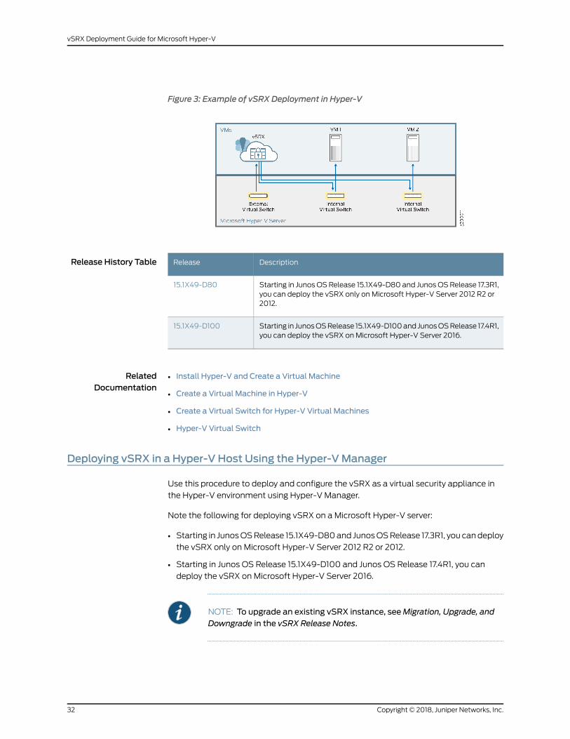
Figure 3: Example of vSRX Deployment in Hyper-V
Release History Table DescriptionRelease
Starting in JunosOSRelease 15.1X49-D80 and JunosOSRelease 17.3R1,you can deploy the vSRX only on Microsoft Hyper-V Server 2012 R2 or2012.
15.1X49-D80
Starting in JunosOSRelease 15.1X49-D100and JunosOSRelease 17.4R1,you can deploy the vSRX on Microsoft Hyper-V Server 2016.
15.1X49-D100
RelatedDocumentation
Install Hyper-V and Create a Virtual Machine•
• Create a Virtual Machine in Hyper-V
• Create a Virtual Switch for Hyper-V Virtual Machines
• Hyper-V Virtual Switch
Deploying vSRX in a Hyper-V Host Using the Hyper-VManager
Use this procedure to deploy and configure the vSRX as a virtual security appliance in
the Hyper-V environment using Hyper-V Manager.
Note the following for deploying vSRX on a Microsoft Hyper-V server:
• Starting in JunosOSRelease 15.1X49-D80and JunosOSRelease 17.3R1, you candeploy
the vSRX only on Microsoft Hyper-V Server 2012 R2 or 2012.
• Starting in Junos OS Release 15.1X49-D100 and Junos OS Release 17.4R1, you can
deploy the vSRX on Microsoft Hyper-V Server 2016.
NOTE: To upgrade an existing vSRX instance, seeMigration, Upgrade, andDowngrade in the vSRX Release Notes.
Copyright © 2018, Juniper Networks, Inc.32
vSRX Deployment Guide for Microsoft Hyper-V

To deploy vSRX using Hyper-V Manager:
1. Download the vSRX software image for Microsoft Hyper-V from the Juniper Networks
website. The vSRX disk image supported by Microsoft Hyper-V is a virtual hard disk
(VHD) format file.
CAUTION: Donotchangethe filenameof thedownloadedsoftware imageor the installation will fail.
2. Log onto your Hyper-V host computer using the Administrator account.
3. OpentheHyper-VManagerbyselectingStart>AdministrativeTools>Hyper-VManager.
Thewelcomepage forHyper-Vappears the first time that youopenHyper-VManager.
4. Create a virtual machine by selecting Action > New > Virtual Machine. The Before You
Begin screen appears for theNewVirtualMachineWizard. ClickNext tomove through
each page of the wizard, or you can click the name of a page in the left pane to move
directly to that page.
5. From the Specify Name and Location page (see Figure 4 on page 34), enter a name
and location for thevSRXVMthat youarecreatingand thenclickNext.We recommend
that you keep this name the same as the hostname you intend to assign to the vSRX
VM.
33Copyright © 2018, Juniper Networks, Inc.
Chapter 2: Installing vSRX in Microsoft Hyper-V

Figure 4: Specify Name and Location Page
6. From the Specify Generation page (see Figure 5 on page 35), keep the default setting
of Generation 1 as the generation of the vSRX VM and then click Next.
Copyright © 2018, Juniper Networks, Inc.34
vSRX Deployment Guide for Microsoft Hyper-V

Figure 5: Specify Generation Page
7. From the Assign Memory page (see Figure 6 on page 36), enter 4096MB as the
amount of startupmemory to assign to the vSRX VM. LeaveUseDynamicMemory for
this virtual machine clear. Click Next.
35Copyright © 2018, Juniper Networks, Inc.
Chapter 2: Installing vSRX in Microsoft Hyper-V

Figure 6: Assign Memory Page
8. From the Configure Networking page (see Figure 7 on page 37), select a virtual switch
from a list of existing virtual switches on the Hyper-V host computer to connect to
the vSRXmanagement interface. The default is Not connected. Click Next.
NOTE: See “Adding vSRX Interfaces” on page 47 for the procedure onaddingvirtual switches for thevSRXVMusing theVirtualSwitchManager.
Copyright © 2018, Juniper Networks, Inc.36
vSRX Deployment Guide for Microsoft Hyper-V

Figure 7: Configure Networking Page
9. FromtheConnectVirtualHardDiskpage(seeFigure8onpage38), clickUseanexisting
virtual hard disk and browse to the location of the vSRX virtual hard disk (VHD) file
(downloaded in Step 1). Click Next.
37Copyright © 2018, Juniper Networks, Inc.
Chapter 2: Installing vSRX in Microsoft Hyper-V

Figure 8: Connect Virtual Hard Disk Page
10. After you have finished configuring the new virtual machine, verify your selections in
the Summary page (see Figure 9 on page 39) and then click Finish to complete the
installation.
Copyright © 2018, Juniper Networks, Inc.38
vSRX Deployment Guide for Microsoft Hyper-V

Figure 9: Summary Page
11. Right-click the vSRX VM and select Settings from the context menu.
12. From the Settings dialog box, under the Hardware section, select Processor. The
Processor pane appears (see Figure 10 on page 40). Enter 2 in the Number of virtual
processors field (the default is 1).
39Copyright © 2018, Juniper Networks, Inc.
Chapter 2: Installing vSRX in Microsoft Hyper-V

Figure 10: Processor Pane
13. From the Settings dialog box, under the Hardware section, select Network Adapter.
The Network Adapter pane appears (see Figure 11 on page 41).
From the Virtual switch drop-down list, select a virtual switch to assign to a network
adapter to be used by the vSRX VM (see “Adding vSRX Interfaces” on page 47 for
details on adding virtual switches). Each network adapter that is defined for a vSRX
ismapped to a specific interface. See “Requirements for vSRX onMicrosoft Hyper-V”
on page 18 for a summary of interface names andmappings for a vSRX VM.
NOTE: If you need to add a network adapter to assign to a virtual switch,click Add Hardware > Network Adapter > Add.
Copyright © 2018, Juniper Networks, Inc.40
vSRX Deployment Guide for Microsoft Hyper-V

Figure 11: Network Adapter Pane
14. Enable the MAC address spoofing function for the vSRX VM if a network adapter is
to be used as an interface for Layer 2 mode support on the vSRX. From the Network
Adapter pane select Advanced Features. The Advanced Features pane appears (see
Figure 12 on page 42). Click the Enable MAC address spoofing check box.
MACaddress spoofingallowseachnetworkadapter to change its sourceMACaddress
for outgoing packets to one that is not assigned to them. Enabling MAC address
spoofing ensures those packets are not dropped by the network adapter if the source
MAC address fails to match the outgoing interface MAC address.
ClickOKwhen you complete your vSRX VM selections.
41Copyright © 2018, Juniper Networks, Inc.
Chapter 2: Installing vSRX in Microsoft Hyper-V

Figure 12: Network Adapter Advanced Features Pane
15. Before you power on the vSRX instance we recommend that you enable nested
virtualization for the vSRX VM. Nested virtualization allows you to run Hyper-V inside
of a Hyper-V virtual machine. This procedure can only be performed in the Hyper-V
environment usingWindows PowerShell (see “Deploying vSRX in a Hyper-V Host
UsingWindows PowerShell” on page 43, Step 8). You cannot enable nested
virtualization from the Hyper-V Manager.
NOTE: Nested virtualization can only be configured on a host runningMicrosoft Hyper-V Server 2016. In addition, Dynamic Memorymust bedisabledon thevirtualmachinecontaining thenested instanceofHyper-V.
Copyright © 2018, Juniper Networks, Inc.42
vSRX Deployment Guide for Microsoft Hyper-V

16. Launch and power on the vSRX instance in the Hyper-V Manager by selecting the
vSRXVMfromthe list of virtualmachines.Right-clickandselectStart fromthecontext
menu (or select Action > Start).
17. Configure the basic settings for the vSRX (see “Configuring vSRX Using the CLI” on
page 60).
Release History Table DescriptionRelease
Starting in JunosOSRelease 15.1X49-D80 and JunosOSRelease 17.3R1,you can deploy the vSRX only on Microsoft Hyper-V Server 2012 R2 or2012.
15.1X49-D80
Starting in JunosOSRelease 15.1X49-D100and JunosOSRelease 17.4R1,you can deploy the vSRX on Microsoft Hyper-V Server 2016.
15.1X49-D100
RelatedDocumentation
Install Hyper-V and Create a Virtual Machine•
• Create a Virtual Machine in Hyper-V
• Virtual Machine Settings in Hyper-VManager Explained
Deploying vSRX in a Hyper-V Host UsingWindows PowerShell
Use this procedure to deploy and configure the vSRX as a virtual security appliance in
the Hyper-V environment usingWindows PowerShell.
Note the following for deploying vSRX on a Microsoft Hyper-V server:
• Starting in JunosOSRelease 15.1X49-D80and JunosOSRelease 17.3R1, you candeploy
the vSRX only on Microsoft Hyper-V Server 2012 R2 or 2012.
• Starting in Junos OS Release 15.1X49-D100 and Junos OS Release 17.4R1, you can
deploy the vSRX on Microsoft Hyper-V Server 2016.
NOTE: To upgrade an existing vSRX instance, seeMigration, Upgrade, andDowngrade in the vSRX Release Notes.
43Copyright © 2018, Juniper Networks, Inc.
Chapter 2: Installing vSRX in Microsoft Hyper-V

To deploy vSRX usingWindows PowerShell:
1. Download the vSRX software image for Microsoft Hyper-V from the Juniper Networks
website. The vSRX disk image supported by Microsoft Hyper-V is a virtual hard disk
(VHD) format file.
CAUTION: Donotchangethe filenameof thedownloadedsoftware imageor the installation will fail.
2. On theWindows desktop, click the Start button and typeWindows PowerShell.
3. Right-clickWindows PowerShell and select Run as administrator.
4. Run the following command to enable Hyper–V using PowerShell:
Enable-WindowsOptionalFeature -Online -FeatureNameMicrosoft-Hyper-V -All
5. Enter the New-VM command to create the vSRX VM. The command syntax is as
follows:
PSC:>\Users\Administrator>New-VM-Name<Name>-MemoryStartupBytes<Memory>
-BootDevice <BootDevice> -VHDPath <VHDPath> -Path <Path> -Generation
<Generation> -Switch <SwitchName>
See Table 10 on page 44 for a summary of the parameters in the New-VM command.
Table 10: New-VMCommand Parameters
DescriptionParameter
Specify a name for the vSRX VM that you are creating. We recommend keeping thisname the same as the hostname you intend to give to the vSRX VM.
-Name
Enter 4GB as the amount of startupmemory to assign to the vSRX VM.-MemoryStartupBytes
Enter VHD as the device that the vSRX VM boots to when it starts.-BootDevice
Specify the location of the vSRX virtual hard disk (VHD) file that youwant to deploy.-VHDPath
Specify the location to store the vSRX VM configuration files.-Path
Enter 1 to create a generation 1 virtual machine for the vSRX.-Generation
Copyright © 2018, Juniper Networks, Inc.44
vSRX Deployment Guide for Microsoft Hyper-V

Table 10: New-VMCommand Parameters (continued)
DescriptionParameter
Specify the name of the virtual switch that you want the vSRX VM to assign to anetwork adapter used by the vSRX VM. Each network adapter that is defined for avSRX is mapped to a specific interface. See “Requirements for vSRX on MicrosoftHyper-V” on page 18 for a summary of interface names andmappings for a vSRXVM.
NOTE: To locate the name of a previously created virtual switch, use theGet-VMSwitchcommand.See “AddingvSRX Interfaces”onpage47 for theprocedureon adding virtual switches for the vSRX VM using the Virtual Switch Manager.
-SwitchName
The following is an example of theNew-VM command syntax for creating a vSRXVM:
PS C:>\Users\Administrator> New-VM -Name vSRX_0109 -MemoryStartupBytes 4GB
-BootDevice VHD -VHDPath
C:\Users\Public\Documents\Hyper-V\vsrx-0109-powershell\vsrx\media-vsrx-vmdisk-151X49D80.hyper-v.vhd
-Path ’C:\Users\Public\Documents\Hyper-V\vsrx-0109\’ Generation 1 SwitchName
test
6. Set the number of processors for the newly created vSRX VM by entering the
Set-VMProcessor command. Specify Count 2 for the number of processors. For
example:
PS C:>\Users\Administrator> Set-VMProcessor -VMName <vSRVName> -Count 2
7. Verify the newly created vSRX VM by entering the Get-VM command. For example:
PS C:>\Users\Administrator> Get-VM -VMName <vSRVName>
The output for the command is as follows:
Name State CPUUSage(%) MemoryAssigned(M) Uptime State VersionvSRX_0109 Off 0 0 00:00:00 Operating normally 8.0
8. Enable the MAC address spoofing function for the vSRX VM if a network adapter is
tobeusedasan interface for Layer2modesupporton thevSRX.MACaddressspoofing
allows the vSRXVM’s network adapter to change its sourceMACaddress for outgoing
packets to one that is not assigned to them. Enabling MAC address spoofing ensures
those packets are not dropped by the network adapter if the source MAC address
fails to match the outgoing interface MAC address.
The command syntax is as follows:
PS C:>\Users\Administrator> Set-VMNetworkAdapter -VMName <vSRVName>
–computerName<HyperVHostName>–VMNetworkAdapter<NetworkAdapterName>
-MacAddressSpoofing On
Verify that MacAddressSpoofing is On.
45Copyright © 2018, Juniper Networks, Inc.
Chapter 2: Installing vSRX in Microsoft Hyper-V

PS C:>\Users\Administrator> Get-VMNetworkAdapter -VMName <vSRVName>
–computerName <HyperVHostName> | fl
<HyperVHostName>name,macaddressspoofing
The output for the command is as follows:
Name : vSRX_0109MacAddressSpoofing : On
9. Enablenestedvirtualization for thevSRXVMbyusing theSet-VMProcessorcommand,
whereVMName is the nameof the vSRXVMyou created. By default, the virtualization
extensions are disabled for each VM. Nested virtualization allows you to run Hyper-V
inside of a Hyper-V virtual machine. For example:
PS C:>\Users\Administrator> Set-VMProcessor -VMName <vSRX_0109>
-ExposeVirtualizationExtensions $true
NOTE: Nested virtualization can only be configured on a host runningMicrosoft Hyper-V Server 2016. In addition, Dynamic Memorymust bedisabledon thevirtualmachinecontaining thenested instanceofHyper-V.
10. Launch and power on the vSRX VM by using the Start-VM command, where Name is
the name of the vSRX VM you created. For example:
PS C:>\Users\Administrator> Start-VM -Name <vSRX_0109>
11. Configure the basic settings for the vSRX (see “Configuring vSRX Using the CLI” on
page 60).
Release History Table DescriptionRelease
Starting in JunosOSRelease 15.1X49-D80 and JunosOSRelease 17.3R1,you can deploy the vSRX only on Microsoft Hyper-V Server 2012 R2 or2012.
15.1X49-D80
Starting in JunosOSRelease 15.1X49-D100and JunosOSRelease 17.4R1,you can deploy the vSRX on Microsoft Hyper-V Server 2016.
15.1X49-D100
RelatedDocumentation
• Hyper-VModule forWindows PowerShell
• Create a Virtual Machine in Hyper-V
• Run Hyper-V in a Virtual Machine with Nested Virtualization
Copyright © 2018, Juniper Networks, Inc.46
vSRX Deployment Guide for Microsoft Hyper-V

CHAPTER 3
vSRX VMManagement
• Adding vSRX Interfaces on page 47
• Powering Down a vSRX VMwith Hyper-V on page 56
Adding vSRX Interfaces
The Hyper-V virtual switch is a software-based Layer 2 Ethernet network switch that
connects VMs to either physical or virtual networks. A virtual switch can be configured
from Hyper-V Manager or Windows PowerShell . The Hyper-V host uses the virtual
switches toconnect virtualmachines to the internet through thehost computer's network
connection. You configure networking for the vSRX by adding, removing, andmodifying
its associated network adapters in the Hyper-V host as necessary.
NOTE: To perform this procedure, youmust have appropriate permissions.Contact your Virtual Server administrator to request the proper permissionsto add a virtual switch and network adapter..
For the vSRXVM, you pair a network adapter with a virtual switch for the vSRX to receive
and transmit traffic. Youmap network adapters to the specific vSRX interfaces: Network
adapter 1 ismapped to the fxp0 (out-of-bandmanagement) interface, network adapter
2 is mapped to the ge-0/0/0 (revenue) interface, network adapter 3 is mapped to
ge-0/0/1, and so on (see “Requirements for vSRX on Microsoft Hyper-V” on page 18).
Hyper-V supports a maximum of eight network adapters.
NOTE: Whenaddingvirtualswitches, thereareno limits imposedbyHyper-V.The practical limit depends on the available computing resources.
This section includes the following topics on adding vSRX interfaces in Hyper-V:
• Adding Virtual Switches on page 48
• Configuring the vSRX to Use a VLAN on page 55
47Copyright © 2018, Juniper Networks, Inc.

Adding Virtual Switches
To add virtual switches for the vSRXVMusing the Virtual SwitchManager in theHyper-V
Manager:
1. OpentheHyper-VManagerbyselectingStart>AdministrativeTools>Hyper-VManager.
2. Select Action > Virtual SwitchManager. The Virtual Switch Manager appears.
3. Under the Virtual Switches section, select New virtual network switch. The Create
Virtual Switch pane appears (see Figure 13 on page 49).
Copyright © 2018, Juniper Networks, Inc.48
vSRX Deployment Guide for Microsoft Hyper-V

Figure 13: Create Virtual Switch Pane
4. Choose the type of virtual switch to create:
• External—Gives virtual machines access to a physical network to communicate
with servers and clients on an external network. It allows virtual machines on the
same Hyper-V server to communicate with each other.
49Copyright © 2018, Juniper Networks, Inc.
Chapter 3: vSRX VMManagement

• Internal—Allows communication between virtual machines on the same Hyper-V
server, and between the virtual machines and themanagement host operating
system.
• Private—AllowscommunicationonlybetweenvirtualmachinesonthesameHyper-V
server. A private network is isolated fromall external network traffic on the Hyper-V
server. This type of network is useful when youmust create an isolated networking
environment, like an isolated test domain.
In most cases when adding a vSRX network adapter, select External as the type of
virtual switch. Internal andprivate virtual switchesare intended to keepnetwork traffic
within the Hyper-V server.
NOTE: For the fxp0 (out-of-bandmanagement) interface, connect it toExternal virtual switch, which could connect to an external network.
For thege-0/0/0(revenueport) interface, if onlycommunicationbetweenVMs in thesameHyper-Vserver isneeded, InternalorPrivatevirtual switchshould be sufficient. However, if communication between the VM and anexternal network is needed, connect it to External virtual switch.
5. Select Create Virtual Switch. The Virtual Switch Properties pane appears (see
Figure 14 on page 51).
Copyright © 2018, Juniper Networks, Inc.50
vSRX Deployment Guide for Microsoft Hyper-V

Figure 14: Virtual Switch Properties Pane
6. Specify a name for the virtual switch.
7. Choose the physical network interface card b(NIC) that you want to use (only a
requirement when you select External).
8. Isolate network traffic from themanagementHyper-V host operating systemor other
virtual machines that share the same virtual switch by selecting Enable virtual LAN
51Copyright © 2018, Juniper Networks, Inc.
Chapter 3: vSRX VMManagement

identification. You can change the VLAN ID to any number or leave the default. See
“Configuring the vSRX to Use a VLAN” on page 55 for details.
9. ClickOK, then click Yes to apply networking changes and to close the Virtual Switch
Manager window.
10. If necessary, repeat Steps 3 through 9 to add additional network adapters for use by
the vSRX VM.
11. Right-click thevSRXVMandselectSettings fromthecontextmenu.FromtheSettings
dialog box, under the Hardware section, click Network Adapter. The Network Adapter
pane appears (see Figure 15 on page 53).
12. From the Virtual switch drop-down list, select the virtual switch that you want to
assign to this network adapter. See “Requirements for vSRX on Microsoft Hyper-V”
on page 18 for a summary of interface names andmappings for a vSRX VM.
Copyright © 2018, Juniper Networks, Inc.52
vSRX Deployment Guide for Microsoft Hyper-V

Figure 15: Adding Virtual Switch to Network Adapter Example
13. If a network adapter is to be used as an interface for Layer 2 mode support on the
vSRX, then from the Network Adapter pane select Advanced Features. Select the
EnableMACaddressspoofing checkbox to enable theMACaddress spoofing function
for the network adapter (see Figure 16 on page 54).
MACaddress spoofingallowseachnetworkadapter to change its sourceMACaddress
for outgoing packets to one that is not assigned to them. Enabling MAC address
spoofing ensures those packets are not dropped by the network adapter if the source
MAC address fails to match the outgoing interface MAC address.
53Copyright © 2018, Juniper Networks, Inc.
Chapter 3: vSRX VMManagement
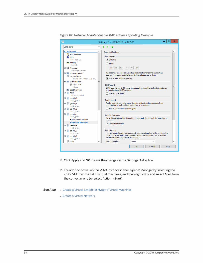
Figure 16: Network Adapter Enable MAC Address Spoofing Example
14. Click Apply andOK to save the changes in the Settings dialog box.
15. Launch and power on the vSRX instance in the Hyper-V Manager by selecting the
vSRX VM from the list of virtual machines, and then right-click and select Start from
the context menu (or select Action > Start).
See Also Create a Virtual Switch for Hyper-V Virtual Machines•
• Create a Virtual Network
Copyright © 2018, Juniper Networks, Inc.54
vSRX Deployment Guide for Microsoft Hyper-V

Configuring the vSRX to Use a VLAN
Hyper-V supports the configurationofVLANsonanetworkadapter in thehost computer.
For each network adapter that you configure for the vSRX VM, if required, you can add a
VLAN identifier to specify the VLAN that the vSRX VMwill use for all network
communications through the network adapter.
By default, Hyper-V enables trunk mode for a VLAN. Trunk mode allowsmultiple VLAN
IDs toshareaconnectionbetween thephysical networkadapterand thephysical network.
To give the vSRX VM external access on the virtual network in multiple VLANs, you will
need to configure the port on the physical network to be in trunk mode. You will also
need to know the specific VLANs that are used andall of theVLAN IDs usedby the virtual
machines that the virtual network supports.
To utilize a Hyper-V VLAN, ensure that you are using a physical network adapter that
supports 802.1q VLAN tagging. By default, the virtual network adapter in Hyper-V is in
untaggedmode and youmight need to enable the feature on a virtual network adapter.
NOTE: By usingWindows PowerShell, you can determine themode of thevNIC (Get-VmNetworkAdapterVlan command) and change themode of the
vNIC (Set-VmNetworkAdapterVlan command). See
Get-VMNetworkAdapterVlan and Set-VMNetworkAdapterVlan for details on
bothWindows PowerShell virtual network adapter commands.
To add a VLAN for a vSRX VM virtual network adapter:
1. OpentheHyper-VManagerbyselectingStart>AdministrativeTools>Hyper-VManager.
2. Right-click the vSRX VM and select Settings from the context menu.
3. From theSettings dialog box, under theHardware section, select the network adapter
connected to the external virtual network. The Network Adapter pane appears.
4. Select Enable virtual LAN identification, and then enter the VLAN ID you intend to use
(see Figure 17 on page 56). You can change the VLAN ID to any number or leave the
default. This is the VLAN identification number that the vSRX will use for all network
communication through this network adapter.
55Copyright © 2018, Juniper Networks, Inc.
Chapter 3: vSRX VMManagement

Figure 17: Enable VLAN Identification Example
5. ClickOK, and then click Yes to apply networking changes.
6. If necessary, repeatSteps3 through5 toaddVLAN identification toadditional network
adapters in use by the vSRX VM.
See Also Hyper-V: Configure VLANs and VLAN Tagging•
• Understanding Hyper-V VLANs
Powering Down a vSRX VMwith Hyper-V
In situations where you need to modify the vSRX VM settings from Hyper-V, youmust
first perform a graceful shut down of the vSRX VM using the Shut Down command. The
vSRX VM performs an orderly closing of all programs and attempts to shut off power to
avoid data loss.
Copyright © 2018, Juniper Networks, Inc.56
vSRX Deployment Guide for Microsoft Hyper-V

NOTE: If you are using Microsoft PowerShell, use the Stop-VM command to
perform a graceful shutdown of the vSRX VM.
To gracefully shut down the vSRX instance on the Hyper-V host computer:
1. Log onto your Hyper-V host computer using the Administrator account.
2. OpentheHyper-VManagerbyselectingStart>AdministrativeTools>Hyper-VManager.
3. Power down the vSRX instance in the Hyper-V Manager by selecting the vSRX VM
from the list of virtual machines, and then ight-click and select Shut Down from the
context menu (or select Action > Shut Down).
4. Power on the vSRX instance in the Hyper-V Manager by selecting the vSRX VM from
the list of virtual machines, and then right-click and select Start from the context
menu (or select Action > Start).
NOTE: If you are usingMicrosoft PowerShell, use theStart-VM command
to start the vSRX VM.
57Copyright © 2018, Juniper Networks, Inc.
Chapter 3: vSRX VMManagement

Copyright © 2018, Juniper Networks, Inc.58
vSRX Deployment Guide for Microsoft Hyper-V
CHAPTER 4
Configuring and Managing vSRX
• vSRX Configuration and Management Tools on page 59
• Configuring vSRX Using the CLI on page 60
• Configuring vSRX Using the J-Web Interface on page 61
• Managing Security Policies for Virtual Machines Using Junos Space Security
Director on page 65
vSRX Configuration andManagement Tools
This chapter is an overview on the various tools available to configure andmanage a
vSRX VM once it has been successfully deployed.
• Understanding the Junos OS CLI and Junos Scripts on page 59
• Understanding the J-Web Interface on page 59
• Understanding Junos Space Security Director on page 60
Understanding the Junos OS CLI and Junos Scripts
The Junosoperating systemcommand-line interface (JunosOSCLI) is a JuniperNetworks
specific command shell that runs on top of a UNIX-based operating system kernel.
Built into Junos OS, Junos script automation is an onboard toolset available on all Junos
OS platforms, including routers, switches, and security devices running Junos OS (such
as a vSRX instance).
You can use Junos OS CLI and the Junos OS scripts to configure, manage, administer,
and troubleshoot vSRX.
Understanding the J-Web Interface
The J-Web interface allows you to monitor, configure, troubleshoot, andmanage vSRX
instances by means of aWeb browser. J-Web provides access to all the configuration
statements supported by the vSRX instance.
You can use J-Web to configure, manage, administer, and troubleshoot vSRX.
59Copyright © 2018, Juniper Networks, Inc.

Understanding Junos Space Security Director
As one of the Junos Space Network Management Platform applications, Junos Space
Security Director helps organizations improve the reach, ease, and accuracy of security
policy administration with a scalable, GUI-basedmanagement tool. Security Director
automates security provisioning of a vSRX instance through one centralizedWeb-based
interface to help administrators manage all phases of security policy life cycle more
quickly and intuitively, from policy creation to remediation.
RelatedDocumentation
CLI User Interface Overview•
• J-Web Overview
• Security Director
• Mastering Junos Automation Programming
• Spotlight Secure Threat Intelligence
Configuring vSRXUsing the CLI
To configure the instance using the CLI:
1. Verify that the vSRX instance is powered on.
2. Log in as the root user (whose username is root). There is no password.
3. Start the CLI.
root#cliroot@>
4. Enter configuration mode.
configure[edit]root@#
5. Set the root authentication password by entering a cleartext password, an encrypted
password, or an SSH public key string (DSA or RSA). The following is an example of
a plain-text password. The CLI prompts you for the password and then encrypts it.
[edit]root@# set system root-authentication plain-text-passwordNew password: passwordRetype new password: password
6. Configure the hostname.
[edit]root@# set system host-name host-name
Copyright © 2018, Juniper Networks, Inc.60
vSRX Deployment Guide for Microsoft Hyper-V

7. Configure the management interface.
[edit]root@# set interfaces fxp0 unit 0 family inet dhcp-client
8. Configure the traffic interfaces.
[edit]root@# set interfaces ge-0/0/0 unit 0 family inet dhcp-client
9. Configure basic security zones and bind them to traffic interfaces.
[edit]root@# set security zones security-zone trust interfaces ge-0/0/0.0
10. Verify the configuration changes.
[edit]root@# commit checkconfiguration check succeeds
11. Commit the configuration to activate it on the instance.
[edit]root@# commitcommit complete
NOTE: Certain Junos OS software features require a license to activate thefeature. To enable a licensed feature, you need to purchase, install, manage,andverifya licensekey thatcorresponds toeach licensed feature.Toconformto software feature licensing requirements, youmust purchase one licenseper feature per instance. Thepresenceof the appropriate software unlockingkey on your virtual instance allows you to configure and use the licensedfeature.
See “Managing Licenses for vSRX” on page 93 for details.
RelatedDocumentation
CLI User Guide•
• Junos OS for SRX Series
Configuring vSRXUsing the J-Web Interface
• Accessing the J-Web Interface and Configuring vSRX on page 62
• Applying the Configuration on page 64
• Adding vSRX Feature Licenses on page 64
61Copyright © 2018, Juniper Networks, Inc.
Chapter 4: Configuring and Managing vSRX

Accessing the J-Web Interface and Configuring vSRX
To configure vSRX using the J-Web Interface:
1. Launch the J-Web interface from aWeb browser.
NOTE: Youwill be prompted to accept a system-generated certificate toaccess a vSRX VM using the J-Web interface.
2. Enter the vSRX out-of-bandmanagement (fxp0) interface IP address in the Address
box.
3. Specify the username and password.
4. Click Log In, and select the ConfigurationWizards tab from the left navigation panel.
The J-Web Setup wizard page opens.
5. Click Setup.
You can use the Setup wizard to configure the vSRX VM or edit an existing
configuration.
• Select Edit Existing Configuration if you have already configured the wizard using
the factory mode.
• Select Create NewConfiguration to configure the vSRX VM using the wizard.
The following configuration options are available in the guided setup:
• Basic
Copyright © 2018, Juniper Networks, Inc.62
vSRX Deployment Guide for Microsoft Hyper-V

Select basic to configure the vSRX VM name and user account information as
shown in Table 11 on page 63.
• Instance name and user account information
Table 11: Instance Name and User Account Information
DescriptionField
Type the name of the vSRX instance.Instance name
Create a default root user password.Root password
Verify the default root user password.Verify password
Add an optional administrative account in addition to the root account.
User role options include:
Operator
• SuperUser: This user has full systemadministration rightsandcanadd,modify, and delete settings and users.
• Operator: This user can perform system operations such as a systemreset but cannot change the configuration or add or modify users.
• Read only: This user can only access the system and view theconfiguration.
• Disabled: This user cannot access the system.
• Select either Time Server orManual. Table 12 on page 63 lists the system time
options.
Table 12: System Time Options
DescriptionField
Time Server
Type the hostname of the time server. For example:ntp.example.com.
Host Name
Type the IP address of the time server in the IP address entryfield. For example: 192.0.2.254.
IP
NOTE: You can enter either the hostname or the IP address.
Manual
Click the current date in the calendar.Date
Set the hour, minute, and seconds. Choose AM or PM.Time
Time Zone (mandatory)
Select the time zone from the list. For example: GMTGreenwichMean Time GMT.
Time Zone
63Copyright © 2018, Juniper Networks, Inc.
Chapter 4: Configuring and Managing vSRX

• Expert
Select Expert to configure the basic options as well as the following advanced
options:
• Four or more internal zones
• Internal zone services
• Application of security policies between internal zones
Click the Need Help icon for detailed configuration information.
You see a success message after the basic configuration is complete.
Applying the Configuration
To apply the configuration settings for vSRX:
1. Review and ensure that the configuration settings are correct, and click Next. The
Commit Configuration page appears.
2. Click Apply Settings to apply the configuration changes to vSRX.
3. Check the connectivity to vSRX, as youmight lose connectivity if you have changed
themanagement zone IP. Click the URL for reconnection instructions on how to
reconnect to the instance.
4. Click Done to complete the setup.
After successful completion of the setup, you are redirected to the J-Web interface.
CAUTION: After youcomplete the initial setup, youcan relaunchthe J-WebSetup wizard by clicking Configuration>Setup. You can either edit an
existing configuration or create a new configuration. If you create a newconfiguration, the current configuration in vSRXwill be deleted.
Adding vSRX Feature Licenses
Certain Junos OS software features require a license to activate the feature. To enable
a licensed feature, you need to purchase, install, manage, and verify a license key that
corresponds to each licensed feature. To conform to software feature licensing
requirements, youmust purchase one license per feature per instance. The presence of
the appropriate software unlocking key on your virtual instance allows you to configure
and use the licensed feature.
See “Managing Licenses for vSRX” on page 93 for details.
Copyright © 2018, Juniper Networks, Inc.64
vSRX Deployment Guide for Microsoft Hyper-V

Managing Security Policies for Virtual Machines Using Junos Space Security Director
Security Director is a Junos Spacemanagement application designed to enable quick,
consistent, and accurate creation, maintenance, and application of network security
policies for your security devices, including vSRX instances. With Security Director, you
canconfigure security-relatedpolicymanagement including IPsecVPNs, firewall policies,
NAT policies, IPS policies, andUTMpolicies. and push the configurations to your security
devices. These configurations use objects such as addresses, services, NAT pools,
application signatures, policy profiles, VPN profiles, template definitions, and templates.
These objects can be shared acrossmultiple security configurations; shared objects can
be created and used across many security policies and devices. You can create these
objects prior to creating security configurations.
When you finish creating and verifying your security configurations fromSecurityDirector,
you can publish these configurations and keep them ready to be pushed to all security
devices, including vSRX instances, from a single interface.
The Configure tab is the workspace where all of the security configuration happens. You
can configure firewall, IPS, NAT, and UTM policies, assign policies to devices, create and
apply policy schedules, create andmanage VPNs, and create andmanage all of the
shared objects needed for managing your network security.
RelatedDocumentation
• Security Director
65Copyright © 2018, Juniper Networks, Inc.
Chapter 4: Configuring and Managing vSRX

Copyright © 2018, Juniper Networks, Inc.66
vSRX Deployment Guide for Microsoft Hyper-V

CHAPTER 5
Configuring vSRX Chassis Clusters
• Configuring a vSRX Chassis Cluster in Junos OS on page 67
• vSRX Cluster Staging and Provisioning in Hyper-V on page 75
Configuring a vSRX Chassis Cluster in Junos OS
• Chassis Cluster Overview on page 67
• Enabling Chassis Cluster Formation on page 68
• Chassis Cluster Quick Setup with J-Web on page 69
• Manually Configuring a Chassis Cluster with J-Web on page 69
Chassis Cluster Overview
Chassis cluster groups a pair of the same kind of vSRX instances into a cluster to provide
network node redundancy. The devicesmust be running the same Junos OS release. You
connect the control virtual interfaces on the respective nodes to form a control plane
that synchronizes the configuration and Junos OS kernel state. The control link (a virtual
network or vSwitch) facilitates the redundancy of interfaces and services. Similarly, you
connect the data plane on the respective nodes over the fabric virtual interfaces to form
a unified data plane. The fabric link (a virtual network or vSwitch) allows for the
management of cross-node flow processing and for the management of session
redundancy.
The control plane software operates in active/passive mode. When configured as a
chassis cluster, one node acts as the primary device and the other as the secondary
device to ensure stateful failover of processes and services in the event of a system or
hardware failure on the primary device. If the primary device fails, the secondary device
takes over processing of control plane traffic.
NOTE: If you configure a chassis cluster on vSRX nodes across two physicalhosts, disable igmp-snooping on the bridge that each host physical interfacebelongs to that the control vNICs use. This ensures that the control linkheartbeat is received by both nodes in the chassis cluster.
The chassis cluster data plane operates in active/active mode. In a chassis cluster, the
data plane updates session information as traffic traverses either device, and it transmits
67Copyright © 2018, Juniper Networks, Inc.
informationbetween thenodesover the fabric link toguarantee that establishedsessions
arenotdroppedwhena failoveroccurs. Inactive/activemode, traffic canenter thecluster
on one node and exit from the other node.
Chassis cluster functionality includes:
• Resilient system architecture, with a single active control plane for the entire cluster
andmultiple Packet Forwarding Engines. This architecture presents a single device
view of the cluster.
• Synchronization of configuration and dynamic runtime states between nodes within
a cluster.
• Monitoringofphysical interfaces, and failover if the failureparameters crossaconfigured
threshold.
• Support for generic routing encapsulation (GRE) and IP-over-IP (IP-IP) tunnels used
to routeencapsulated IPv4or IPv6 trafficbymeansof two internal interfaces, gr-0/0/0
and ip-0/0/0, respectively. Junos OS creates these interfaces at system startup and
uses these interfaces only for processing GRE and IP-IP tunnels.
At any given instant, a cluster node can be in one of the following states: hold, primary,
secondary-hold, secondary, ineligible, or disabled. Multiple event types, such as interface
monitoring, Services Processing Unit (SPU)monitoring, failures, andmanual failovers,
can trigger a state transition.
Prerequisites
Ensure that your vSRX instances comply with the following prerequisites before you
enable chassis clustering:
• Use show version in Junos OS to ensure that both vSRX instances have the same
software version.
• Use show system license in Junos OS to ensure that both vSRX instances have the
same licenses installed.
Enabling Chassis Cluster Formation
You create two vSRX instances to form a chassis cluster, and then you set the cluster ID
and node ID on each instance to join the cluster. When a vSRX VM joins a cluster, it
becomes a node of that cluster. With the exception of unique node settings and
management IP addresses, nodes in a cluster share the same configuration.
You can deploy up to 255 chassis clusters in a Layer 2 domain. Clusters and nodes are
identified in the following ways:
• The cluster ID (a number from 1 to 255) identifies the cluster.
• The node ID (a number from 0 to 1) identifies the cluster node.
On SRXSeries devices, the cluster ID and node ID arewritten into EEPROM.On the vSRX
VM, vSRX stores and reads the IDs from boot/loader.conf and uses the IDs to initialize
the chassis cluster during startup.
Copyright © 2018, Juniper Networks, Inc.68
vSRX Deployment Guide for Microsoft Hyper-V

The chassis cluster formation commands for node 0 and node 1 are as follows:
• On vSRX node 0:
user@vsrx0>set chassis cluster cluster-id number node 0 reboot
• On vSRX node 1:
user@vsrx1>set chassis cluster cluster-id number node 1 reboot
NOTE: Use the same cluster ID number for each node in the cluster.
NOTE: The vSRX interface naming andmapping to vNICs changeswhen youenable chassis clustering.
After reboot, on node 0, configure the fabric (data) ports of the cluster that are used to
pass real-time objects (RTOs):
• user@vsrx0# set interfaces fab0 fabric-optionsmember-interfaces ge-0/0/0user@vsrx0# set interfaces fab1 fabric-optionsmember-interfaces ge-7/0/0
Chassis Cluster Quick Setupwith J-Web
To configure chassis cluster from J-Web:
1. Enter the vSRX node 0 interface IP address in aWeb browser.
2. Enter the vSRX username and password, and click Log In. The J-Web dashboard
appears.
3. Click ConfigurationWizards>Chassis Cluster from the left panel. The Chassis Cluster
Setup wizard appears. Follow the steps in the setup wizard to configure the cluster
ID and the two nodes in the cluster, and to verify connectivity.
NOTE: Usethebuilt-inHelp icon in J-Webfor furtherdetailson theChassisCluster Setup wizard.
Manually Configuring a Chassis Cluster with J-Web
You can use the J-Web interface to configure the primary node 0 vSRX instance in the
cluster.Onceyouhaveset thecluster andnode IDsand rebootedeachvSRX, the following
configuration will automatically be synced to the secondary node 1 vSRX instance.
SelectConfigure>ChassisCluster>ClusterConfiguration. TheChassisCluster configuration
page appears.
Table 13 on page 71 explains the contents of the HA Cluster Settings tab.
69Copyright © 2018, Juniper Networks, Inc.
Chapter 5: Configuring vSRX Chassis Clusters

Table 14 on page 72 explains how to edit the Node Settings tab.
Table 15 on page 73 explains how to add or edit the HA Cluster Interfaces table.
Table 16onpage 74explains how toaddor edit theHACluster RedundancyGroups table.
Copyright © 2018, Juniper Networks, Inc.70
vSRX Deployment Guide for Microsoft Hyper-V

Table 13: Chassis Cluster Configuration Page
FunctionField
Node Settings
Displays the node ID.Node ID
Displays the cluster ID configured for the node.Cluster ID
Displays the name of the node.Host Name
Displays the router used as a gateway while the Routing Engine isin secondary state for redundancy-group 0 in a chassis cluster.
Backup Router
Displays the management interface of the node.Management Interface
Displays the management IP address of the node.IP Address
Displays the state of the redundancy group.
• Primary–Redundancy group is active.
• Secondary–Redundancy group is passive.
Status
Chassis Cluster>HA Cluster Settings>Interfaces
Displays the physical interface name.Name
Displays the member interface name or IP address configured foran interface.
Member Interfaces/IPAddress
Displays the redundancy group.Redundancy Group
Chassis Cluster>HA Cluster Settings>Redundancy Group
Displays the redundancy group identification number.Group
Displays the selected preempt option.
• True–Mastership can be preempted based on priority.
• False–Mastership cannot be preempted based on priority.
Preempt
Displays the number of gratuitous Address Resolution Protocol(ARP) requests that a newly elected primary device in a chassiscluster sends out to announce its presence to the other networkdevices.
Gratuitous ARP Count
Displays the assigned priority for the redundancy group on thatnode. The eligible node with the highest priority is elected asprimary for the redundant group.
Node Priority
71Copyright © 2018, Juniper Networks, Inc.
Chapter 5: Configuring vSRX Chassis Clusters

Table 14: Edit Node Setting Configuration Details
ActionFunctionField
Node Settings
Enter the name of the host.Specifies the name of the host.Host Name
Enter the IP address of thebackup router.
Displays the device used as a gateway whilethe Routing Engine is in the secondary statefor redundancy-group 0 in a chassis cluster.
Backup Router
Destination
Click Add.Adds the destination address.IP
Click Delete.Deletes the destination address.Delete
Interface
Select an option.Specifies the interfacesavailable for the router.
NOTE: Allows you to add and edit twointerfaces for each fabric link.
Interface
Enter the interface IPaddress.
Specifies the interface IP address.IP
Click Add.Adds the interface.Add
Click Delete.Deletes the interface.Delete
Copyright © 2018, Juniper Networks, Inc.72
vSRX Deployment Guide for Microsoft Hyper-V

Table 15: Add HA Cluster Interface Configuration Details
ActionFunctionField
Fabric Link > Fabric Link 0 (fab0)
Enter the interface IP fabric link0.
Specifies fabric link 0.Interface
Click Add.Adds fabric interface 0.Add
Click Delete.Deletes fabric interface 0.Delete
Fabric Link > Fabric Link 1 (fab1)
Enter the interface IP for fabriclink 1.
Specifies fabric link 1.Interface
Click Add.Adds fabric interface 1.Add
Click Delete.Deletes fabric interface 1.Delete
Redundant Ethernet
Enter the logical interface.Specifies a logical interface consisting oftwo physical Ethernet interfaces, one oneach chassis.
Interface
Enter a redundant Ethernet IPaddress.
Specifies a redundant Ethernet IPaddress.
IP
Select a redundancy groupfrom the list.
Specifies the redundancy group IDnumber in the chassis cluster.
RedundancyGroup
Click Add.Adds a redundant Ethernet IP address.Add
Click Delete.Deletes a redundant Ethernet IP address.Delete
73Copyright © 2018, Juniper Networks, Inc.
Chapter 5: Configuring vSRX Chassis Clusters

Table 16: Add Redundancy Groups Configuration Details
ActionFunctionField
Enter the redundancy group name.Specifies the redundancy group name.Redundancy Group
–Allows a node with a better priority to initiate a failover for aredundancy group.
NOTE: By default, this feature is disabled. When disabled, anodewith abetter priority does not initiate a redundancy groupfailover (unless some other factor, such as faulty networkconnectivity identified for monitored interfaces, causes afailover).
Allow preemption ofprimaryship
Enter a value from 1 to 16. Thedefault is 4.
Specifies thenumberof gratuitousAddressResolutionProtocolrequests that a newly elected primary sends out on the activeredundant Ethernet interface child links to notify networkdevices of a change in mastership on the redundant Ethernetinterface links.
Gratuitous ARP Count
Enter the nodepriority number as0.Specifies the priority value of node0 for a redundancy group.node0 priority
Select the node priority number as1.
Specifies the priority value of node1 for a redundancy group.node1 priority
InterfaceMonitor
Select an interface from the list.Specifies the number of redundant Ethernet interfaces to becreated for the cluster.
Interface
Enter a value from 1 to 125.Specifies the weight for the interface to bemonitored.Weight
Click Add.Adds interfaces tobemonitoredby the redundancygroupalongwith their respective weights.
Add
Select the interface from theconfigured list and click Delete.
Deletes interfaces to bemonitored by the redundancy groupalong with their respective weights.
Delete
IP Monitoring
Enter a value from 0 to 255.Specifies the global weight for IP monitoring.Weight
Enter a value from 0 to 255.Specifies the global threshold for IP monitoring.Threshold
Enter a value from 5 to 15.Specifies the number of retries needed to declare reachabilityfailure.
Retry Count
Enter a value from 1 to 30.Specifies the time interval in seconds between retries.Retry Interval
IPV4 Addresses to BeMonitored
Enter the IPv4 addresses.Specifies the IPv4 addresses to bemonitored for reachability.IP
Copyright © 2018, Juniper Networks, Inc.74
vSRX Deployment Guide for Microsoft Hyper-V
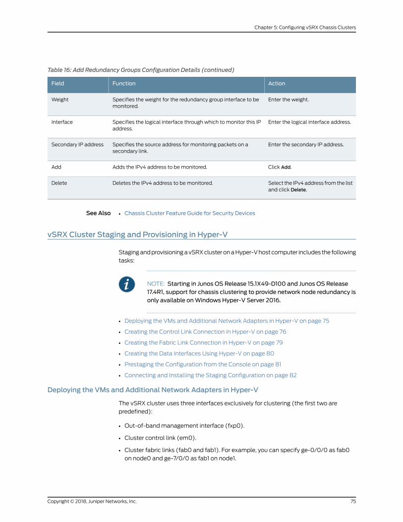
Table 16: Add Redundancy Groups Configuration Details (continued)
ActionFunctionField
Enter the weight.Specifies the weight for the redundancy group interface to bemonitored.
Weight
Enter the logical interface address.Specifies the logical interface through which to monitor this IPaddress.
Interface
Enter the secondary IP address.Specifies the source address for monitoring packets on asecondary link.
Secondary IP address
Click Add.Adds the IPv4 address to bemonitored.Add
Select the IPv4address fromthe listand click Delete.
Deletes the IPv4 address to bemonitored.Delete
See Also Chassis Cluster Feature Guide for Security Devices•
vSRX Cluster Staging and Provisioning in Hyper-V
StagingandprovisioningavSRXclusteronaHyper-Vhostcomputer includes the following
tasks:
NOTE: Starting in Junos OS Release 15.1X49-D100 and Junos OS Release17.4R1, support for chassis clustering to provide network node redundancy isonly available onWindows Hyper-V Server 2016.
• Deploying the VMs and Additional Network Adapters in Hyper-V on page 75
• Creating the Control Link Connection in Hyper-V on page 76
• Creating the Fabric Link Connection in Hyper-V on page 79
• Creating the Data Interfaces Using Hyper-V on page 80
• Prestaging the Configuration from the Console on page 81
• Connecting and Installing the Staging Configuration on page 82
Deploying the VMs and Additional Network Adapters in Hyper-V
The vSRX cluster uses three interfaces exclusively for clustering (the first two are
predefined):
• Out-of-bandmanagement interface (fxp0).
• Cluster control link (em0).
• Cluster fabric links (fab0 and fab1). For example, you can specify ge-0/0/0 as fab0
on node0 and ge-7/0/0 as fab1 on node1.
75Copyright © 2018, Juniper Networks, Inc.
Chapter 5: Configuring vSRX Chassis Clusters

A cluster requires three interfaces (two for the cluster and one for management) and
additional interfaces to forward data. This section outlines how to create the control link
and fabric link connections, and to map all data interfaces to network adapters.
NOTE: For an overview on the procedure to add virtual switches andmapthe virtual switch to a network adapter, see “Adding vSRX Interfaces” onpage 47
Creating the Control Link Connection in Hyper-V
To connect the control interface through the control link virtual switch using Hyper-V
Manager:
1. OpentheHyper-VManagerbyselectingStart>AdministrativeTools>Hyper-VManager.
2. From theHyper-VManager, selectAction>VirtualSwitchManager. TheVirtual Switch
Manager appears.
3. Under the Virtual Switches section, select New virtual network switch. The Create
Virtual Switch pane appears (see Figure 18 on page 77).
Copyright © 2018, Juniper Networks, Inc.76
vSRX Deployment Guide for Microsoft Hyper-V

Figure 18: Create Virtual Switch Pane
4. Select Internal as the type of virtual switch. Internal allows communication between
virtual machines on the same Hyper-V server, and between the virtual machines and
themanagement host operating system.
5. Select Create Virtual Switch. The Virtual Switch Properties page appears (see
Figure 19 on page 78).
77Copyright © 2018, Juniper Networks, Inc.
Chapter 5: Configuring vSRX Chassis Clusters

Figure 19: Virtual Switch Properties Pane
6. Specify a name for the control link virtual switch. Leave the other virtual switch
properties at their default settings.
7. ClickOK and then click Yes to apply networking changes and to close the Virtual
Switch Manager window.
8. Right-click thevSRXVMandselectSettings fromthecontextmenu.FromtheSettings
dialog for the vSRX VM, the Hardware section, click Network Adapter. The Network
Adapter pane appears (see Figure 20 on page 79). Assign network adapter 2 as the
control link (em0) virtual switch.
Copyright © 2018, Juniper Networks, Inc.78
vSRX Deployment Guide for Microsoft Hyper-V

Figure 20: Adding Virtual Switch to Network Adapter Pane Example
9. From the Virtual switch drop-down assign ctrl_link to the control link virtual switch.
10. From the Network Adapter pane, select Advanced Features. Select the Enable MAC
address spoofing check box to enable the MAC address spoofing function for the
network adapter. MAC address spoofing is a requirement for the control link interface
included in the redundancy groups.
11. ClickOK and then click Yes to apply network adapter changes.
Creating the Fabric Link Connection in Hyper-V
Toconnect the fabric interface through the fabric linkvirtual switchusingHyper-VManager
1. If necessary, open the Hyper-V Manager by selecting Start > Administrative Tools >
Hyper-VManager.
2. From theHyper-VManager, selectAction>VirtualSwitchManager. TheVirtual Switch
Manager appears.
79Copyright © 2018, Juniper Networks, Inc.
Chapter 5: Configuring vSRX Chassis Clusters

3. Under the Virtual Switches section, select New virtual network switch. The Create
Virtual Switch pane appears (see Figure 18 on page 77).
4. Select Internal as the type of virtual switch. Internal allows communication between
virtual machines on the same Hyper-V server, and between the virtual machines and
themanagement host operating system.
5. Select Create Virtual Switch. The Virtual Switch Properties page appears (see
Figure 19 on page 78).
6. Specifyanamefor the fabric link virtual switch. Leave theother virtual switchproperties
at their default settings.
7. ClickOK and then click Yes to apply networking changes and to close the Virtual
Switch Manager window.
8. Right-click thevSRXVMandselectSettings fromthecontextmenu.FromtheSettings
dialog for the vSRX VM, the Hardware section, click Network Adapter to access the
NetworkAdapterpane.TheNetworkAdapterpaneappears (seeFigure20onpage79).
Assign network adapter 3 as the fabric link (fab 0 or fab 1) virtual switch.
9. From the Virtual switch drop-down assign fab0or fab1 to the fabric link virtual switch.
10. From the Network Adapter pane, select Advanced Features. Select the Enable MAC
address spoofing check box to enable the MAC address spoofing function for the
network adapter. MAC address spoofing is a requirement for the fabric link interface
included in the redundancy groups.
11. ClickOK and then click Yes to apply network adapter changes.
Creating the Data Interfaces Using Hyper-V
Tomap all data interfaces to the desired network adapters:
1. If necessary, open the Hyper-V Manager by selecting Start > Administrative Tools >
Hyper-VManager.
2. From theHyper-VManager, selectAction>VirtualSwitchManager. TheVirtual Switch
Manager appears.
3. Under the Virtual Switches section, select New virtual network switch. The Create
Virtual Switch pane appears (see Figure 18 on page 77).
Copyright © 2018, Juniper Networks, Inc.80
vSRX Deployment Guide for Microsoft Hyper-V

4. Select Internal as the type of virtual switch. Internal allows communication between
virtual machines on the same Hyper-V server, and between the virtual machines and
themanagement host operating system.
5. Select Create Virtual Switch. The Virtual Switch Properties page appears (see
Figure 19 on page 78).
6. Specify a name for the data interface virtual switch. Leave the other virtual switch
properties at their default settings.
7. ClickOK and then click Yes to apply networking changes and to close the Virtual
Switch Manager window.
8. Right-click thevSRXVMandselectSettings fromthecontextmenu.FromtheSettings
dialog for the vSRX VM, the Hardware section, click Network Adapter to access the
NetworkAdapterpane.TheNetworkAdapterpaneappears (seeFigure20onpage79).
Assign network adapter 3 as the data interface (fab 0 or fab 1) virtual switch.
9. From the Virtual switch drop-down assign data interface to the virtual switch.
10. From the Network Adapter pane, select Advanced Features. Select the Enable MAC
address spoofing check box to enable the MAC address spoofing function for the
network adapter. MAC address spoofing is a requirement for the data interfaces
included in the redundancy groups.
11. ClickOK and then click Yes to apply network adapter changes. The data interfacewill
be connected through the data virtual switch.
Prestaging the Configuration from the Console
The following procedure explains the configuration commands required to set up the
vSRX chassis cluster. The procedure powers up both nodes, adds the configuration to
the cluster, and allows SSH remote access.
1. Log in as the root user. There is no password.
2. Start the CLI.
root#cliroot@>
3. Enter configuration mode.
configure[edit]root@#
81Copyright © 2018, Juniper Networks, Inc.
Chapter 5: Configuring vSRX Chassis Clusters

4. Copy the following commands and paste them into the CLI:
set groups node0 interfaces fxp0 unit 0 family inet address 192.168.42.81/24set groups node0 system hostname vsrx-node0set groups node1 interfaces fxp0 unit 0 family inet address 192.168.42.82/24set groups node1 system hostname vsrx-node1set apply-groups "${node}"
5. Set the root authentication password by entering a cleartext password, an encrypted
password, or an SSH public key string (DSA or RSA).
root@# set system root-authentication plain-text-passwordNew password: passwordRetype new password: passwordset system root-authentication encrypted-password "$ABC123"
6. To enable SSH remote access:
user@host#set system services ssh
7. To enable IPv6:
user@host#set security forwarding-options family inet6mode flow-based
This step is optional and requires a system reboot.
8. Commit the configuration to activate it on the device.
user@host#commitcommit complete
9. When you have finished configuring the device, exit configuration mode.
user@host#exit
Connecting and Installing the Staging Configuration
After the vSRX cluster initial setup, set the cluster ID and the node ID, as described in
“Configuring a vSRX Chassis Cluster in Junos OS” on page 67.
After reboot, the twonodesare reachable on interface fxp0withSSH. If the configuration
is operational, the show chassis cluster status command displays output similar to that
shown in the following sample output.
vsrx> show chassis cluster status
Cluster ID: 1 Node Priority Status Preempt Manual failover
Redundancy group: 0 , Failover count: 1 node0 100 secondary no no node1 150 primary no no
Redundancy group: 1 , Failover count: 1
Copyright © 2018, Juniper Networks, Inc.82
vSRX Deployment Guide for Microsoft Hyper-V

node0 100 secondary no no node1 150 primary no no
A cluster is healthy when the primary and secondary nodes are present and both have a
priority greater than 0.
Release History Table DescriptionRelease
Starting in Junos OSRelease 15.1X49-D100 and Junos OSRelease 17.4R1,support for chassis clustering to provide network node redundancy isonly available onWindows Hyper-V Server 2016.
15.1X49-D100
83Copyright © 2018, Juniper Networks, Inc.
Chapter 5: Configuring vSRX Chassis Clusters

Copyright © 2018, Juniper Networks, Inc.84
vSRX Deployment Guide for Microsoft Hyper-V
CHAPTER 6
vSRX Licensing
• vSRX Feature Licenses Overview on page 85
• Managing Licenses for vSRX on page 93
• vSRX License Model Numbers on page 99
vSRX Feature Licenses Overview
Some Junos OS software features require a license to activate the feature.
To enable a licensed feature, you need to purchase, install, manage, and verify a license
key that corresponds to each licensed feature. To conform to software feature licensing
requirements, youmust purchase one license per feature per instance. The presence of
the appropriate software unlocking key on your virtual instance allows you to configure
and use the licensed feature.
NOTE: If applicable for your vSRXdeployment, vSRXpay-as-you-go imagesdo not require any separate licenses.
• vSRX License Procurement and Renewal on page 85
• vSRX Evaluation License on page 86
• License Types on page 88
• Throughput on page 89
• License Duration on page 89
• Individual (á la carte) Feature Licenses on page 90
• Bundled Licenses on page 90
• Stacking Licenses on page 90
• vSRX License Keys Components on page 90
• License Management Fields Summary on page 91
vSRX License Procurement and Renewal
Licenses are usually ordered when the software application is purchased, and this
information isbound toacustomer ID. If youdidnotorder the licenseswhenyoupurchased
85Copyright © 2018, Juniper Networks, Inc.

your software application, contact your account team or Juniper Networks Customer
Care for assistance.
Licenses can be procured from the Juniper Networks LicenseManagement System (LMS).
For license renewal, use the show system license command to find the Juniper vSRX
software serial number that you use to renew a license.
vsrx> show system licenseLicense usage: Licenses Licenses Licenses Expiry Feature name used installed needed Virtual Appliance 1 1 0 58 days
Licenses installed: License identifier: E420588955 License version: 4 Software Serial Number: 20150625 Customer ID: vSRX-JuniperEval Features: Virtual Appliance - Virtual Appliance count-down, Original validity: 60 days
License identifier: JUNOS657051 License version: 4 Software Serial Number: 9XXXXAXXXXXXX9 Customer ID: MyCompany Features: Virtual Appliance - Virtual Appliance permanent
NOTE: Do not use the show chassis hardware command to get the serial
number on vSRX, because that command is only appropriate for thephysicalSRXSeries devices. Also, the license for advanced security features availableon the physical SRX Series devices cannot be usedwith vSRX deployments.
NOTE: If you are performing a software downgrade with licenses installed,youwill seeanerrormessage in theCLIwhenyou try toconfigure the licensedfeatures or run the show system license status command.
We recommend deleting existing licenses before performing a softwaredowngrade.
vSRX Evaluation License
To speed deployment of licensed features, the vSRX software image provides you with
a 60-day product evaluation license and a 30-day advanced security features license,
both of which allow you to use vSRX and licensed features for a specified periodwithout
having to install a license key.
Table 17 on page 87 lists vSRX evaluation license types.
Copyright © 2018, Juniper Networks, Inc.86
vSRX Deployment Guide for Microsoft Hyper-V

Table 17: vSRX Evaluation License Type
License ModelNumberPeriodTypeLicense Package
-60 daysProduct evaluation–BasicTrial license(temporary forevaluation only) -30 daysProductevaluation–Advanced
features
Product Evaluation License
ThevSRXsoftware image includesa60-day trial license.Whenyoudownloadand install
the vSRX image, you are entitled to use this trial license for 60 days. It is intended as an
evaluation license for using vSRX. This product-unlocking license is required to use the
basic functions of the vSRX, such as networking, routing, and basic security features
(such as stateful firewall).
NOTE: The use of the 60-day trial license does not include vSRX supportunless you already have a pre-existing vSRX support contract. If you requiresupport during this 60-day evaluation period, please work with your JuniperAccount team or go to the J-Net Community forum(https://forums.juniper.net/) and view the Support topics under the vSRX
category.
Within 30 days of the license expiration date, a license expiration warning appears each
time you log in to the vSRX instance. After the product evaluation license expires, you
will not be able to use the vSRX; it will be disabled and flow configuration options will
notwork (thevSRXwill stop forwarding traffic). At thispoint, onlymanagement interfaces
and CLI configurations are preserved.
Advanced Security Features Evaluation License
The advanced security features license is a 30-day trial license for vSRX that is required
for advanced security features such as UTM, IDP, and AppSecure. You can download the
trial license for advanced security features from the vSRX Free Trial License Page.
The 30-day trial license period begins on the day you enable the enhanced security
features after you install the 60-day product evaluation license for vSRX. To continue
using vSRX features after the 30-day license period expires, youmust purchase and
install the license; otherwise, the featuresaredisabled. If the license for advancedsecurity
features expireswhile the evaluation license (product unlocking license) is still valid, only
the advanced security features that require a license are disabled.
87Copyright © 2018, Juniper Networks, Inc.
Chapter 6: vSRX Licensing

NOTE: The UTM advanced features have a slightly different trial licensestrategy. UTM does not requires 30-day trial license but only a 30-day graceperiod. Once the 30-day advanced security features trial license expires,Juniper Networks supports a 30-day grace period for you to continue usingUTM features. The 30-day grace period goes into effect after the 30-triallicense expires.
There is also a 30-day trial license available for Juniper Sky Advanced Threat Prevention
(ATP). This is a second license that you can apply for a 30-day period in addition to the
advanced security features license for vSRX to enable the Sky ATP features. You can
download the Sky ATP trial license from the vSRX Free Trial License Page.
License Types
Juniper Networks provides a variety of licenses for both basic firewall features and
advanced security features for different throughputs and durations.
If you want to use vSRX to provide basic firewall features, you can use standard (basic)
licenses. However, to use some of the more advanced security features, such as
AppSecure, IDP, and UTM, youmight need to purchase advanced features licenses.
The high-level categories for licenses are:
• Throughput–All licenses have an associated throughput. Throughput rates include 1
Gbps, 2 Gbps, and 4 Gbps onmost platforms.
• Features–Licenses are available for different combinations of feature sets, from
standard (STD) through Content Security Bundle (CS-B).
• Individual or bundled–Licenses can be individual (á la carte) licenses for a set of
features, or can be bundled together to provide a broad range of features in one easy
license to maintain.
• Duration–All licenseshaveanassociated timeduration.Youcanpurchasebasic licenses
as perpetual (never expire) or subscription based (1-year or 3-year duration). All vSRX
licenses are subscription based.
• New or renewal–All subscription licenses are either new (first-time purchase) or
renewals (extending the license duration when the initial new subscription license is
about to expire).
Figure 21 on page 89 shows a sample license SKU and identifies how each field maps to
these categories.
Copyright © 2018, Juniper Networks, Inc.88
vSRX Deployment Guide for Microsoft Hyper-V

Figure 21: Sample vSRX License SKU
g043428
Product
Throughput
Duration
VSRX-10M-ASECB-3-RFeature set
New orrenewal
Bundled orindividual
These categories of licenses can also be combined, or stacked, to providemore flexibility
for your vSRX use cases.
Throughput
Bandwidth or throughput license types allow you to use a single instance of the software
for up to the maximum throughput specified in the license entitlement. Throughput can
be combined on a single instance of the software so that the maximum throughput for
that instance is the aggregate of all the throughput licenses assigned to that instance.
A throughput license cannot be split across multiple instances. Throughput is identified
in the license entitlement inmegabits per second (Mbps), or gigabits per second (Gbps).
For example, if youwant3Gbpsof throughput for a vSRX instanceusing theSTD features,
youwould purchase a 1G STD license and a 2GSTD license and install both on the vSRX.
If you wanted 2 Gbps of throughput on two vSRX instances acting as a chassis cluster,
you could not use the same 2 Gbps license on both vSRX instances. You would need to
purchase one set of licenses for each vSRX instance in the cluster.
License Duration
All licenses can be perpetual or subscription based.
• Perpetual license–A perpetual license allows you to use the licensed software
indefinitely. Perpetual licenses do not require renewals. Perpetual licenses do not
includemaintenance and upgrade support. Youmust purchase that separately, vSRX
software releases such as vSRX for AWS do not support perpetual licenses.
• Subscription license–A subscription license is an annual license that allows you to use
the licensed software feature for the matching duration. Subscriptions might involve
periodic downloads of content (such as for IDP threat signature files). Subscription
licenses start when you retrieve the license key or 30 days after purchase if you have
not retrieved the license key. At the end of the license period, you need to renew the
license to continue using it.
NOTE: All subscription licenses are renewable. To renew a subscriptionlicense, purchase a new subscription of the same license. For moreinformation, see Subscription - Register and Install.
89Copyright © 2018, Juniper Networks, Inc.
Chapter 6: vSRX Licensing

Individual (á la carte) Feature Licenses
Every vSRX instance requires at least one standard license to support the desired
throughput rate. Beyond that, you can select from a range of individual feature licenses
thatprovideadditional security feature sets. The feature licensemustmatch the standard
license rate.
NOTE: AWS does not support individual licenses.
Forexample, if youneedAppSecureandSophosantivirus featuresat 1Gbpsof throughput
for a year, you could purchase the following individual licenses:
• VSRX-STD-1G-1—Provides the standard feature set and 1 Gbps of throughput.
• VSRX-CS-1G-1—Provides the advanced features.
Bundled Licenses
Bundled licenses simplify the licensemanagement by combining one or more individual
licenses into a single bundled license. Instead of installing andmanaging a standard
throughput licenseandoneormore individualadvanced feature licenses, youcanpurchase
one of the bundle license options andmanage one license instead.
For example, if youneedAppSecureandSophosantivirus featuresat 1Gbpsof throughput
forayear, youcouldpurchase thesinglebundledVSRX-CS-B-1G-1 license,which includes
the STD throughput license. This means you only need to manage one license instead
of two individual licenses.
Stacking Licenses
You can combine individual or bundled licenses to combine features or build up the
overall supplied throughput for the vSRX instance.
For example, you can combine a 1-Gbps license and a 2-Gbps license to have 3 Gbps of
throughput for the vSRX instance. You can also combine individual licenses, such as
Sophos antivirus (SAV) andWebsense EnhancedWeb Filtering (EWF) to get both sets
of security features.
NOTE: Individual licenses require a STD license with the same throughputrate.
vSRX License Keys Components
A license key consists of two parts:
• License ID—Alphanumeric string thatuniquely identifies the licensekey.Whena license
is generated, it is given a license ID.
• License data—Block of binary data that defines and stores all license key objects.
Copyright © 2018, Juniper Networks, Inc.90
vSRX Deployment Guide for Microsoft Hyper-V

For example, in the following typical license key, the string E413XXXX57 is the license ID,
and the trailing block of data is the license data:
E413XXXX57 aaaaaa bbbbbb cccccc dddddd eeeeee ffffff cccccc bbbbbb dddddd aaaaaa ffffff aaaaaa aaaaaa bbbbbb cccccc dddddd eeeeee ffffff cccccc bbbbbb dddddd aaaaaa ffffff
The license data conveys the customer ID and the software serial number (Juniper
Networks support reference number) to the vSRX instance.
LicenseManagement Fields Summary
The Licenses window displays a summary of licensed features that are configured on
the vSRX instance and a list of licenses that are installed on the vSRX instance.
To view the license details, selectMaintain>Licenses in the J-Web user interface. The
Licenses window appears as shown in Figure 22 on page 91.
Figure 22: J-Web LicensesWindow Showing Installed Licenses
You can also view the details of a license in the CLI using the show system license
command. The following sample shows details of an evaluation license in the CLI:
License usage: Licenses Licenses Licenses Expiry Feature name used installed needed anti_spam_key_sbl 0 1 0 2016-04-15 08:00:00 CST idp-sig 0 1 0 2016-04-15 08:00:00 CST appid-sig 0 1 0 2016-04-15 08:00:00 CST av_key_sophos_engine 0 3 0 2016-07-29
91Copyright © 2018, Juniper Networks, Inc.
Chapter 6: vSRX Licensing

08:00:00 CST wf_key_websense_ewf 0 1 0 2016-04-15 08:00:00 CST Virtual Appliance 1 1 0 2016-04-25 08:00:00 CST
Licenses installed: License identifier: E420588955 License version: 4 Software Serial Number: 20150625 Customer ID: vSRX-JuniperEval Features: Virtual Appliance - Virtual Appliance count-down, Original validity: 60 days
The information on the licensemanagement page is summarized in Table 18 on page 92.
Table 18: Summary of License Management Fields
DefinitionField Name
Feature Summary
Name of the licensed feature:
• Features—Software feature licenses.
• All features—All-inclusive licenses.
Feature
Number of licenses currently being used on the vSRX instance. Usageis determined by the configuration. If a feature license exists and thatfeature is configured, the license is considered used.
Licenses Used
Number of licenses installed on the vSRX instance for the particularfeature.
Licenses Installed
Number of licenses required for legal use of the feature. Usage isdetermined by the configuration on the vSRX instance: If a feature isconfigured and the license for that feature is not installed, a licenseis needed.
Licenses Needed
Date the license expires.Licenses expires on
Installed Licenses
Unique alphanumeric ID of the license.ID
Valid—The installed license key is valid.
Invalid—The installed license key is not valid.
State
Numeric version number of the license key.Version
If the license defines a group license, this field displays the groupdefinition.
NOTE: Because group licenses are currently unsupported, this fieldis always blank.
Group
Copyright © 2018, Juniper Networks, Inc.92
vSRX Deployment Guide for Microsoft Hyper-V
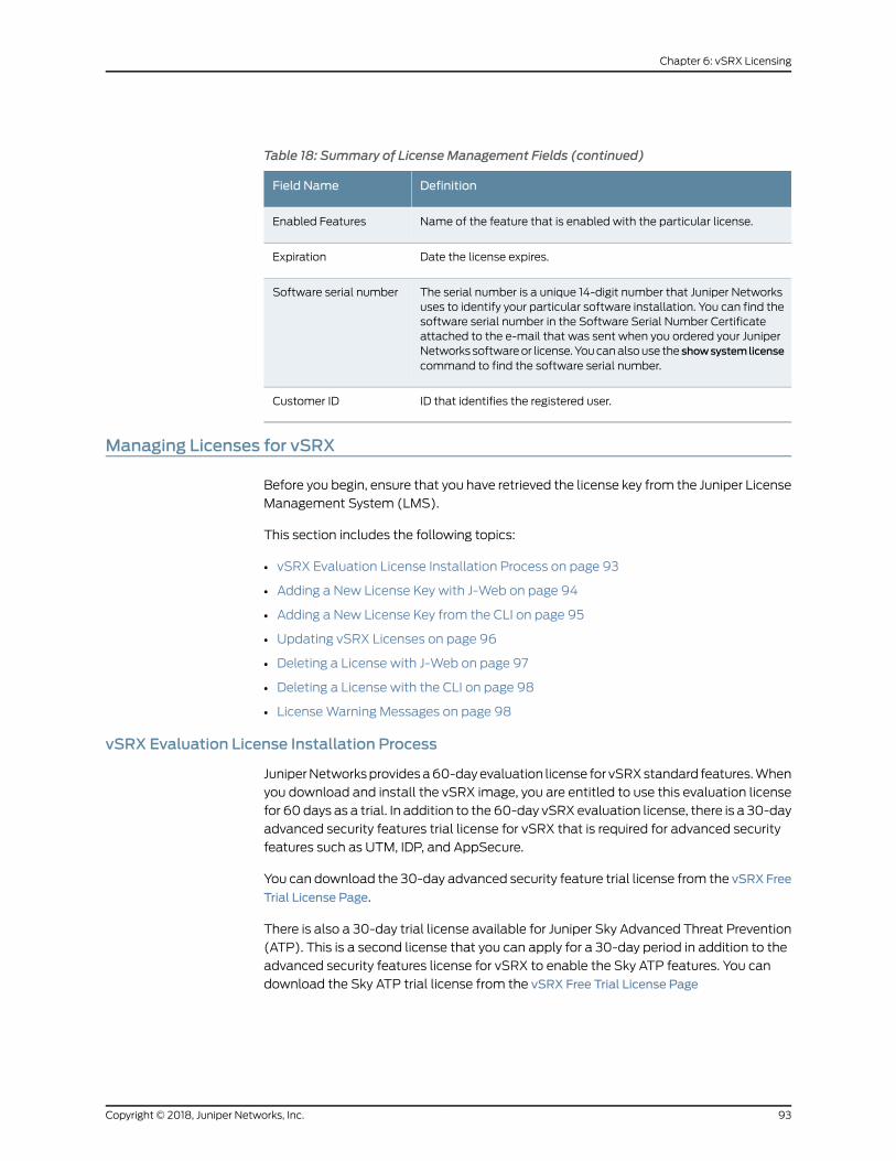
Table 18: Summary of License Management Fields (continued)
DefinitionField Name
Name of the feature that is enabled with the particular license.Enabled Features
Date the license expires.Expiration
The serial number is a unique 14-digit number that Juniper Networksuses to identify your particular software installation. You can find thesoftware serial number in the Software Serial Number Certificateattached to the e-mail that was sent when you ordered your JuniperNetworks softwareor license.Youcanalsouse the showsystemlicensecommand to find the software serial number.
Software serial number
ID that identifies the registered user.Customer ID
Managing Licenses for vSRX
Before you begin, ensure that you have retrieved the license key from the Juniper License
Management System (LMS).
This section includes the following topics:
• vSRX Evaluation License Installation Process on page 93
• Adding a New License Key with J-Web on page 94
• Adding a New License Key from the CLI on page 95
• Updating vSRX Licenses on page 96
• Deleting a License with J-Web on page 97
• Deleting a License with the CLI on page 98
• LicenseWarning Messages on page 98
vSRX Evaluation License Installation Process
JuniperNetworksprovidesa60-dayevaluation license for vSRXstandard features.When
you download and install the vSRX image, you are entitled to use this evaluation license
for 60 days as a trial. In addition to the 60-day vSRX evaluation license, there is a 30-day
advanced security features trial license for vSRX that is required for advanced security
features such as UTM, IDP, and AppSecure.
You can download the 30-day advanced security feature trial license from the vSRX Free
Trial License Page.
There is also a 30-day trial license available for Juniper Sky Advanced Threat Prevention
(ATP). This is a second license that you can apply for a 30-day period in addition to the
advanced security features license for vSRX to enable the Sky ATP features. You can
download the Sky ATP trial license from the vSRX Free Trial License Page
93Copyright © 2018, Juniper Networks, Inc.
Chapter 6: vSRX Licensing

Installation of the advanced security feature trial license is similar to the regular license
installation performed from the CLI (see “Adding a New License Key from the CLI” on
page 95).
Within 30 days of the license expiration date, a license expiration warning appears each
time you log in to the vSRX instance. After the product evaluation license expires, you
will not be able to use the vSRX; it will be disabled and flow configuration options will
notwork (thevSRXwill stop forwarding traffic). At thispoint, onlymanagement interfaces
and CLI configurations are preserved.
NOTE: The 30-day evaluation license period begins on the day you enableenhanced security features after installing evaluation licenses.
To continue using vSRX features after an optional 30-day evaluation period,youmust purchase and install the license. Otherwise, the features aredisabled.
For details about the 60- and 30-day license evaluation periods for the vSRX see “vSRX
Feature Licenses Overview” on page 85 .
Adding a New License Key with J-Web
To install a license using the J-Web interface:
1. SelectMaintain>Licenses on the J-Web user interface. The Licenses window is
displayed as shown in Figure 23 on page 94.
Figure 23: J-Web LicensesWindow
2. Under Installed Licenses, click Add. The Add License window is displayed as shown
in Figure 24 on page 95.
Copyright © 2018, Juniper Networks, Inc.94
vSRX Deployment Guide for Microsoft Hyper-V

Figure 24: Add LicenseWindow
3. Do one of the following, using a blank line to separate multiple license keys:
• Enter the full URL to the destination file containing the license key in the License
File URL box.
• Paste the license key text, in plaintext format, in the License Key Text box.
4. ClickOK to add the license key. The License Details window is displayed as shown in
Figure 25 on page 95.
Figure 25: License DetailsWindow
The license key is installed and activated on the vSRX instance.
Adding a New License Key from the CLI
You can add a license key from a local file, from a remote URL, or from the terminal.
To install a license from the CLI:
1. Use the request system license add operational mode command to either add the
license from a local file or remote URL that contains the license key, or to manually
paste the license key in the terminal.
user@vsrx> request system license add terminal
[Type ^D at a new line to end input,
95Copyright © 2018, Juniper Networks, Inc.
Chapter 6: vSRX Licensing

enter blank line between each license key]
E413XXXX57 aaaaaa bbbbbb cccccc dddddd eeeeee ffffff cccccc bbbbbb dddddd aaaaaa ffffff aaaaaa aaaaaa bbbbbb cccccc dddddd eeeeee ffffff cccccc bbbbbb dddddd aaaaaa ffffff
E413XXXX57: successfully added add license complete (no errors)
NOTE: You can save the license key to a file and upload the file to thevSRX file system through FTP or Secure Copy (SCP), and then use therequest system license add file-name command to install the license.
2. Optionally, use the show system license command to view details of the licenses.
root@host> show system license
License usage: Licenses Licenses Licenses Expiry Feature name used installed neededwf key websense ewf 1 0 1 invalid
Licenses installed: none
The license key is installed and activated on the vSRX instance.
Updating vSRX Licenses
You can update the vSRX licenses using either of the following twomethods:
• Automatic license update using the CLI
• Manual license update using the CLI
As a prerequisite, youmust install at least one valid license key on your vSRX instance
for required features. Automatic license updates as well as manual license updates are
performed based on a valid software serial number and customer ID embedded in the
license key.
To enable automatic license updates from the CLI:
1. Contact your account team or Juniper Networks Customer Care to extend the validity
period of existing license keys and obtain the URL for a valid update server.
2. Once you have successfully extended your license key and received the update server
URL, configure the auto-update parameter:
user@host> set system license autoupdate url https://ae1.juniper.net/
3. Configure renew options (if required). The following sample allows vSRX to contact
the license server 30 days before the current license expires and sends an automatic
update request every 6 hours.
Copyright © 2018, Juniper Networks, Inc.96
vSRX Deployment Guide for Microsoft Hyper-V

user@host> set system license renew before-expiration 30user@host> set system license renew interval 6
Tomanually update the licenses from the CLI:
1. Use the following command to update the license keys manually:
user@host> request system license update <url.of.license.server>
This command sends a license update request to the license server immediately.
NOTE: The request system license update commandwill always use the
default Juniper license server: https://ae1.juniper.net
2. Check the status of the license by entering the show system license command.
Deleting a License with J-Web
To delete a license using the J-Web interface:
1. SelectMaintain>Licenses.
2. Select the check box of the license or licenses you want to delete as shown in
Figure 26 on page 97.
Figure 26: Deleting a License
3. Click Delete.
4. ClickOK to confirm your deletion as shown in Figure 27 on page 98.
97Copyright © 2018, Juniper Networks, Inc.
Chapter 6: vSRX Licensing

Figure 27: Delete LicensesWindow
The license you deleted is removed.
Deleting a License with the CLI
To delete a license using the CLI:
1. From operational mode, for each license, enter the following command and specify
the license ID. You can delete only one license at a time.
user@host> request system license delete <license-key-identifier>
Or you can use the following command to delete all installed licenses.
user@host> request system license delete all
2. Type yeswhen you are prompted to confirm the deletion.
Delete license JUNOS606279 ? [yes,no] (no)
The license you deleted is removed.
LicenseWarningMessages
Youmust purchase a new license or renew your existing subscription-based license to
have a seamless transition from the old license to the new one.
The following conditions occur when a license expires on vSRX:
• Evaluation license for thecoreexpires—Packet forwardingonvSRX isdisabled.However,
you canmanage vSRX through the fxp0management interface, and the CLI
configuration is preserved.
• Subscription-based licenses for advanced security features expire but
subscription-based licenses for core servicesareactive—A30-daygraceperiodbegins,
allowing the user to continue using advanced security features. After the grace period,
advanced security features are disabled. Basic features are always available in the
vSRX. After subscription-based licenses for core services expire, a warning message
is displayed to notify the user, but basic features will remain preserved for the user.
• Subscription-based license for core features expires but subscription-based license
for advanced security features is active—Awarning message is displayed to notify the
user. However, you can continue to use the basic features on the vSRX. Advanced
security features are disabled when the subscription-based license for advanced
security features expires, but basic features will remain preserved for the user.
Copyright © 2018, Juniper Networks, Inc.98
vSRX Deployment Guide for Microsoft Hyper-V

NOTE: All subscription licenses are renewable. To renew a subscriptionlicense, purchase a new subscription of the same license. For moreinformation, see Subscription - Register and Install .
To use features that require a license, youmust install and configure a license. After the
license expires, warning messages are displayed in the system log and on the J-Web
dashboard.
When a license expires, the System Alarms section of the J-Web dashboard displays a
message stating that the license has expired as shown in Figure 28 on page 99.
Figure 28: J-Web Dashboard for License ExpiryWarning
When a license expires, the following message appears when you log in:
Virtual Appliance License is invalid
vSRX LicenseModel Numbers
The licenses used by all Juniper Networks instances are based on SKUs, which represent
lists of features. Each license includes a list of features that the license enables along
with information about those features.
For information about purchasing software licenses, contact your JuniperNetworks sales
representative at https://www.juniper.net/in/en/contact-us/.
vSRX licenses are based on application packages and processing capacity.
Bandwidth (throughput) licenses allow you to use a single instance of the software for
up to themaximum throughput specified in the license entitlement. Throughput licenses
can be combined on a single instance of the software so that the maximum throughput
for that instance is the aggregate of all the throughput licenses assigned to that instance.
A throughput license cannot be split across multiple instances. Throughput licenses are
identified in the licenseentitlement inmegabitsper second(Mbps), or gigabitsper second
(Gbps).
vSRXprovidesbandwidth in the followingcapacities (throughputper instance): 10Mbps,
100Mbps, 1 Gbps, 2 Gbps, 4 Gbps, 10 Gbps, and 20 Gbps. Each of these bandwidth tiers
is offeredwith four different packages alongwith bandwidth based, a la carte, advanced
Layer 7 security services SKUs.
99Copyright © 2018, Juniper Networks, Inc.
Chapter 6: vSRX Licensing

Table 19 on page 100 describes the features available with the various license packages.
Table 19: vSRX Licensing Package Types
DurationDescriptionLicenseType
Both perpetual and subscriptionlicense options are available.
See Table 20 on page 102 for SCCbandwidth SKUs available forvSRX.
Includes the following features:
• IPsec VPN (site-to-site VPN)
• NAT
• CoS
• Routing services – BGP, OSPF, DHCP,J-Flow, IPv4, and IPv6
• Foundation – Static routing,management (J-Web, CLI, andNETCONF), on-box logging, diagnostics
• Software platform – KVM, Openstack,ESXi 6.0, Contrail
Secure CloudConnect(SCC)
Both perpetual and subscriptionlicense options are available.
See Table 21 on page 103 for STDbandwidth SKUs available forvSRX.
Includes the following features:
• Core security – firewall, ALG, screens,user firewall
• IPsec VPN (site-to-site VPN)
• NAT
• CoS
• Multicast services – IP Multicast (PIM,IGMP)
• Routing services – BGP, OSPF, DHCP,J-Flow, IPv4, and IPv6
• High availability
• Foundation – Static routing,management (J-Web, CLI, andNETCONF), on-box logging, diagnostics
• Software platform – KVM, Openstack,ESXi 6.0, Contrail
STD
Subscription licenses only.
See Table 22 on page 104 forbandwidth SKUs available forvSRX with AppSecure and IPSfeatures.
Includes all STD features bundledwith thefollowing additional AppSecure features:
• AppID
• AppFW
• AppQoS
• AppTrack
ASCB andASECB
Subscription licenses only.
See Table 24 on page 106 for CS-Bbandwidth SKUs available forvSRX.
Includes all STD features bundled withASEC features and the addition of UTMcapabilities:
• Antispam
• Antivirus
• Content filtering
• Web filtering
CS-B
Copyright © 2018, Juniper Networks, Inc.100
vSRX Deployment Guide for Microsoft Hyper-V
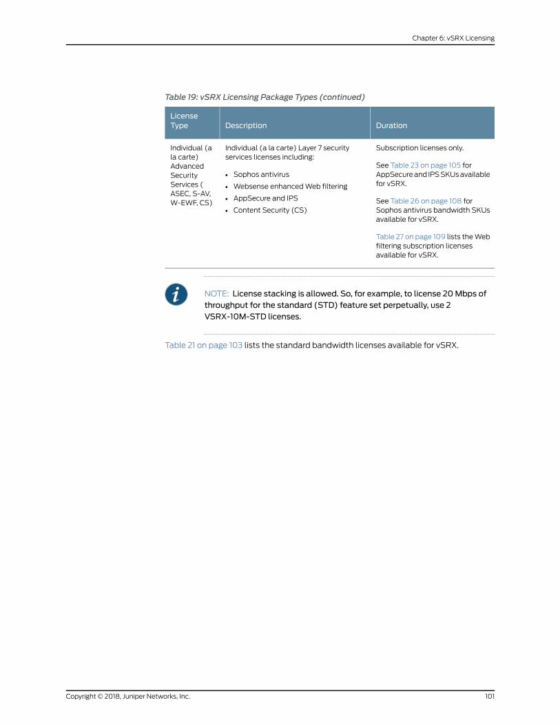
Table 19: vSRX Licensing Package Types (continued)
DurationDescriptionLicenseType
Subscription licenses only.
See Table 23 on page 105 forAppSecureand IPSSKUsavailablefor vSRX.
See Table 26 on page 108 forSophos antivirus bandwidth SKUsavailable for vSRX.
Table 27 on page 109 lists theWebfiltering subscription licensesavailable for vSRX.
Individual (a la carte) Layer 7 securityservices licenses including:
• Sophos antivirus
• Websense enhancedWeb filtering
• AppSecure and IPS
• Content Security (CS)
Individual (ala carte)AdvancedSecurityServices (ASEC, S-AV,W-EWF, CS)
NOTE: License stacking is allowed. So, for example, to license 20Mbps ofthroughput for the standard (STD) feature set perpetually, use 2VSRX-10M-STD licenses.
Table 21 on page 103 lists the standard bandwidth licenses available for vSRX.
101Copyright © 2018, Juniper Networks, Inc.
Chapter 6: vSRX Licensing

Table 20: Secure Cloud Connect (SCC) vSRX Bandwidth Licenses
Model NumberSCC Licenses
VSRX-10M-SCC
VSRX-10M-SCC-1
VSRX-10M-SCC-3
VSRX-100M-SCC
VSRX-100M-SCC-1
VSRX-100M-SCC-3
VSRX-1G-SCC
VSRX-1G-SCC-1
VSRX-1G-SCC-3
VSRX-2G-SCC
VSRX-2G-SCC-1
VSRX-2G-SCC-3
VSRX-4G-SCC
VSRX-4G-SCC-1
VSRX-4G-SCC-3
VSRX-10G-SCC
VSRX-10G-SCC-1
VSRX-10G-SCC-3
VSRX-20G-SCC
VSRX-20G-SCC-1
VSRX-20G-SCC-3
10M/100M/1G/2G/4G/10G/20Gthroughput—vSRXSCCpackage (1-year,3-year, or perpetual)
Copyright © 2018, Juniper Networks, Inc.102
vSRX Deployment Guide for Microsoft Hyper-V
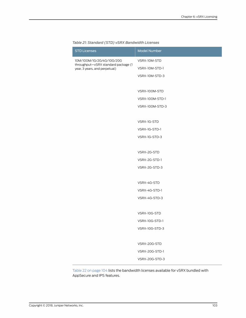
Table 21: Standard (STD) vSRX Bandwidth Licenses
Model NumberSTD Licenses
VSRX-10M-STD
VSRX-10M-STD-1
VSRX-10M-STD-3
VSRX-100M-STD
VSRX-100M-STD-1
VSRX-100M-STD-3
VSRX-1G-STD
VSRX-1G-STD-1
VSRX-1G-STD-3
VSRX-2G-STD
VSRX-2G-STD-1
VSRX-2G-STD-3
VSRX-4G-STD
VSRX-4G-STD-1
VSRX-4G-STD-3
VSRX-10G-STD
VSRX-10G-STD-1
VSRX-10G-STD-3
VSRX-20G-STD
VSRX-20G-STD-1
VSRX-20G-STD-3
10M/100M/1G/2G/4G/10G/20Gthroughput—vSRX standard package (1year, 3 years, and perpetual)
Table 22 on page 104 lists the bandwidth licenses available for vSRX bundled with
AppSecure and IPS features.
103Copyright © 2018, Juniper Networks, Inc.
Chapter 6: vSRX Licensing

Table 22: vSRX AppSecure and IPS Bundled (ASCB and ASECB) Bandwidth Licenses
Model NumberASCB / ASECB Licenses
VSRX-10M-ASECB-1
VSRX-10M-ASECB-3
VSRX-100M-ASCB-1
VSRX-100M-ASCB-3
VSRX-1G-ASECB-1
VSRX-1G-ASECB-3
VSRX-2G-ASECB-1
VSRX-2G-ASECB-3
VSRX-4G-ASECB-1
VSRX-4G-ASECB-3
VSRX-10G-ASECB-1
VSRX-10G-ASECB-3
VSRX-20G-ASECB-1
VSRX-20G-ASECB-3
10M/100M/1G/2G/4G/10G/20Gthroughput—vSRX AppSecure packageincludes all features in the STD packagewith IPSandAppSecure (1-yearor 3-yearsubscription)
Table23onpage 105 lists the individual (a la cart) subscription licensesavailable for vSRX
with AppSecure and IPS features.
Copyright © 2018, Juniper Networks, Inc.104
vSRX Deployment Guide for Microsoft Hyper-V

Table 23: Individual vSRX AppSecure and IPS Subscription Licenses
Model NumberASEC Licenses
VSRX-10M-ASEC-1
VSRX-10M-ASEC-3
VSRX-100M-ASEC-1
VSRX-100M-ASEC-3
VSRX-1G-ASEC-1
VSRX-1G-ASEC-3
VSRX-2G-ASEC-1
VSRX-2G-ASEC-3
VSRX-4G-ASEC-1
VSRX-4G-ASEC-3
VSRX-10G-ASEC-1
VSRX-10G-ASEC-3
VSRX-20G-ASEC-1
VSRX-20G-ASEC-3
10M/100M/1G/2G/4G/10G/20Gsubscription—vSRXAppSecurepackageincludes IPS and AppSecure (1-year or3-year subscription)
Table 24 on page 106 lists the Content Security bundled (CS-B) bandwidth licenses
available for vSRX.
105Copyright © 2018, Juniper Networks, Inc.
Chapter 6: vSRX Licensing

Table 24: vSRX Content Security Bundled (CS-B) Bandwidth Licenses
Model NumberCS Licenses
VSRX-10M-CS-B-1
VSRX-10M-CS-B-3
VSRX-100M-CS-B-1
VSRX-100M-CS-B-3
VSRX-1G-CS-B-1
VSRX-1G-CS-B-3
VSRX-2G-CS-B-1
VSRX-2G-CS-B-3
VSRX-4G-CS-B-1
VSRX-4G-CS-B-3
VSRX-10G-CS-B-1
VSRX-10G-CS-B-3
VSRX-20G-CS-B-1
VSRX-20G-CS-B-3
10M/100M/1G/2G/4G/10G/20Gthroughput—vSRX CS package includesall features in STD, IPS, and AppSecure,enhancedWebfiltering,Sophosantivirus,antispam, content filtering, (1-year or3-year subscription).
Table 25 onpage 107 lists the individual (a la carte) CS subscription licenses available for
vSRX.
Copyright © 2018, Juniper Networks, Inc.106
vSRX Deployment Guide for Microsoft Hyper-V
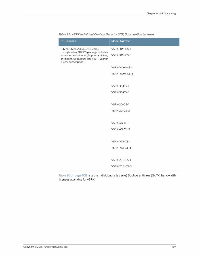
Table 25: vSRX Individual Content Security (CS) Subscription Licenses
Model NumberCS Licenses
VSRX-10M-CS-1
VSRX-10M-CS-3
VSRX-100M-CS-1
VSRX-100M-CS-3
VSRX-1G-CS-1
VSRX-1G-CS-3
VSRX-2G-CS-1
VSRX-2G-CS-3
VSRX-4G-CS-1
VSRX-4G-CS-3
VSRX-10G-CS-1
VSRX-10G-CS-3
VSRX-20G-CS-1
VSRX-20G-CS-3
10M/100M/1G/2G/4G/10G/20Gthroughput—vSRX CS package includesenhancedWebfiltering,Sophosantivirus,antispam, AppSecure and IPS (1-year or3-year subscription).
Table 26 on page 108 lists the individual (a la carte) Sophos antivirus (S-AV) bandwidth
licenses available for vSRX.
107Copyright © 2018, Juniper Networks, Inc.
Chapter 6: vSRX Licensing

Table 26: vSRX Individual Sophos Antivirus (S-AV) Bandwidth Licenses
Model NumberS-AV Licenses
VSRX-10M-S-AV-1
VSRX-10M-S-AV-3
VSRX-100M-S-AV-1
VSRX-100M-S-AV-3
VSRX-1G-S-AV-1
VSRX-1G-S-AV-3
VSRX-2G-S-AV-1
VSRX-2G-S-AV-3
VSRX-4G-S-AV-1
VSRX-4G-S-AV-3
VSRX-10G-S-AV-1
VSRX-10G-S-AV-3
VSRX-20G-S-AV-1
VSRX-20G-S-AV-3
10M/100M/1G/2G/4G/10G/20Gthroughput—vSRX S-AV license (1-yearor 3-year subscription).
Table 27 on page 109 lists the individual (a la carte) enhancedWeb filtering (W-EWF)
subscription licenses available for vSRX.
Copyright © 2018, Juniper Networks, Inc.108
vSRX Deployment Guide for Microsoft Hyper-V
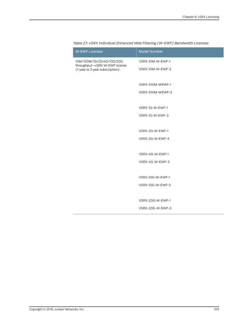
Table 27: vSRX Individual EnhancedWeb Filtering (W-EWF) Bandwidth Licenses
Model NumberW-EWF Licenses
VSRX-10M-W-EWF-1
VSRX-10M-W-EWF-3
VSRX-100M-WEWF-1
VSRX-100M-WEWF-3
VSRX-1G-W-EWF-1
VSRX-1G-W-EWF-3
VSRX-2G-W-EWF-1
VSRX-2G-W-EWF-3
VSRX-4G-W-EWF-1
VSRX-4G-W-EWF-3
VSRX-10G-W-EWF-1
VSRX-10G-W-EWF-3
VSRX-20G-W-EWF-1
VSRX-20G-W-EWF-3
10M/100M/1G/2G/4G/10G/20Gthroughput—vSRXW-EWF license(1-year or 3 year subscription).
109Copyright © 2018, Juniper Networks, Inc.
Chapter 6: vSRX Licensing

Copyright © 2018, Juniper Networks, Inc.110
vSRX Deployment Guide for Microsoft Hyper-V

CHAPTER 7
Troubleshooting
• Finding the Software Serial Number for vSRX on page 111
Finding the Software Serial Number for vSRX
You need the software serial number to open a support case or to renew a vSRX license.
1. Use the show system license command to find the vSRX software serial number.
vsrx> show system licenseLicense usage: Licenses Licenses Licenses Expiry Feature name used installed needed Virtual Appliance 1 1 0 58 days
Licenses installed: License identifier: E420588955 License version: 4 Software Serial Number: 20150625 Customer ID: vSRX-JuniperEval Features: Virtual Appliance - Virtual Appliance count-down, Original validity: 60 days
License identifier: JUNOS657051 License version: 4 Software Serial Number: 9XXXXAXXXXXXX9 Customer ID: MyCompany Features: Virtual Appliance - Virtual Appliance permanent
111Copyright © 2018, Juniper Networks, Inc.

Copyright © 2018, Juniper Networks, Inc.112
vSRX Deployment Guide for Microsoft Hyper-V