Embed Size (px)
Citation preview

1
V.S.B. ENGINEERING COLLEGE, KARUR
DEPARTMENT OF ELECTRICAL AND ELECTRONICS ENGINEERING
Academic Year: 2017-2018 (ODD Semester)
2 MARK AND 16 MARKS QUESTIONS
Class: III YEAR/ VI SEMESTER
S.
No
Subject
Code
Name of Subject Page.No
1 EE6501 Power System Analysis (PSA) 2
2 EE6502 Microprocessors and Microcontrollers (MPMC) 18
3 ME6701 Power Plant Engineering (PPE) 23
4 IC6501 Control Systems (CS) 28
5 EE6504 Electrical Machines–II (EM-II) 37
6 EE6503 Power Electronics (PE) 43

2
EE 6501 POWER SYSTEM ANALYSIS UNIT –I: INTRODUCTION
PART: A
1. Define per unit value of an electrical quantity. Write equation for base impedance with respect to 3-phase system.
2. What is bus admittance matrix, bus impedance matrix? 3. What is single line diagram? 4. A generator rated 25MVA, 11KV has a reactance of 15%. Calculate its p.u. reactance for
a base of 50MVA and 10KV. 5. What is the need for system analysis in planning and operation of power system? 6. Draw the single phase equivalent circuit of three winding transformer.
7. What are the approximations made in impedance diagram? 8. What are the advantages of per unit system?
9. How is generator in transient analysis represented? 10. Draw the π circuit representation of a transformer with off – nominal ratio „α‟. 11. Draw a simple per phase model for a cylindrical rotor synchronous machine.
12. What is meant by per phase analysis? 13. What are the functions of power system analysis?
14. What are the applications o Y-bus and Z-bus matrix? 15. What is restructure power system? 16. What is off nominal transformer ratio?
17. Define primitive network ? 18. Give the methods available for forming bus impedance matrix.
19. Why bus admittance matrix is preferred in load flow? 20. What are the restructure Models?
PART: B 1. The single line diagram of a simple power system is shown in Fig. The rating of
the generators and transformers are given below: Generator 1: 25MVA, 6.6KV, X=0.2p.u
Generator 2: 15MVA, 6.6KV, X=0.15p.u Generator 3: 30MVA, 13.2KV, X=0.15p.u Transformer1: 30MVA, 6.9∆/115Υ KV, X=10%
Transformer2: 15MVA, 6.9∆/115Υ KV, X=10% Transformer3: Single phase units each rated 10MVA, 6.9/69 KV, X=10% Draw an impedance diagram and mark all values in p.u choosing a base of
30MVA, 6.6KV in the generator 1 circuit.

3
2. Draw the reactance diagram for the power system shown in fig. Neglect resistance and
use a base of 100MVA , 220KV in 50KΩ line. The ratings of the generator motor and
transformer are give below.
Generator : 40MVA, 25KV ,X‟‟ =20%
Synchronous Motor : 50MVA , 11KV, X‟‟ =30%
T1:Y-Y transformer : 40MVA 33/220KV, X=15% T2:Y- Y transformer : 30 MVA 11/220KV, X=15%
3. Prepare a per phase schematic of the system in fig. and show all the impedance in per
unit on a 100 MVA, 132 KV base in the transmission line circuit. The necessary data are
given as follows. G1 : 50MVA, 12.2KV, X=0.15 pu. G2 : 20MVA, 13.8KV, X=0.15 pu.
T1 : 80MVA, 12.2/161KV, X=0.1 pu. T2 : 40MVA, 13.8/161KV, X=0.1 pu.
LOAD: 50MVA, 0.8 power factor lag operating at 154KV.Determine the
pu impedance of the load.
4. Draw the impedance diagram for the electric power system shown in fig showing all impedances in per unit on 100MVA base. Choose 20KV as the voltage base for generator. The three phase power and line- line ratings are given below. G1 : 90MVA, 20KV, X=9%.
G2 : 90MVA, 18KV, X=9%.

4
T1 : 80MVA, 20/200KV, X=16%.
T2 : 80MVA, 200/20KV, X=20%.
LINE : 200KV X=120Ω LOAD: 200KV ,S= 48MW + j64MVAR.
5. i) The parameters of a four system are as under:
Line Line s tart ing Line ending Line Line Cha rging
No. bus bus impedance(pu) Admittance(pu) 1 1 2 0.2+j0.8 j0.02
2 2 3 0.3+j0.9 j0.03
3 2 4 0.25+j1.0 j0.04 4 3 4 0.2+j0.8 j0.02 5 1 3 0.1+j0.4 j0.01
Dra w the Network a nd find bus a dmittance matr ix. ii) What are impedance and reactance diagram? Explain with assumptions.
6. i) What is primitive network matrix and represent its forms? Prove Ybus =At [y]A
using singular transformation?
ii) Form the Ybus for the given network:
Element Positive sequence reactance
1-2 j1.0
2-3 j0.4
2-4 j0.2
3-4 j0.2
3-1 j0.8 4-5 j0.08
7. Form Ybus for the network by singular transformation:
Element Positive sequence
E-A reactance
E-B 0.05
A-B 0.04
B-C 0.03

5
A-D 0.02
C-F 0.07 D-F 0.10
8. Explain modeling of transformer, transmission line, loads and generators for a load flow study. And derive general load flow equations.
9 .Obtain pu impedance diagram of the power system of figure 5. Choose base quantities as
15 MVA and 33 KV.
Generator: 30 MVA, 10.5 KV, X ′′ = 1.6 ohms.
Transformers T1 & T2: 15 MVA, 33/11 KV, X = 15 ohms referred to HV
Transmission line: 20 ohms / phase Load: 40 MW, 6.6 KV, 0.85 lagging p.f
. [16]
10. Draw the pu impedance diagram for the system shown in figure 5. Choose Base MVA
as 100 MVA and Base KV as 20 KV. [16]

6
UNIT –II: POWER FLOW ANALYSIS
PART: A
1. What are the types of buses? 2. What is the need for slack bus? 3. When the generator bus is treated as load bus?
4. What is meant by acceleration factor in Gauss Seidal Method? 5. What is load flow analysis? Give its significance in power system analysis.
6. What is load flow? 7. Why the load flow studies are important for planning the existing system as well as the
future expansion?
8. Why bus admittance matrix is used in Gauss Seidal instead of bus impedance matrix. 9. Write the general power flow equation.
10. What is the need for power flow study? 11.Compare GSM and NRM with respect to number of iterations taken for
convergenceand memory requirement. 12. What is Jacobian matrix? 13. How the buses in power systems are classified? 14. Write the load flow equations of Gauss seidel method.
15. Compare GS and NR method. 16. What do you mean by flat voltage start? 17. Write the polar form of the power flow equations.
18. State practical load flow problem. 19. Define voltage controlled bus and load bus.
20. What are the advantages and disadvantages of Gauss Seidal method.
PART: B 1. Derive the load flow algorithm using Gauss Seidal method with flow chart and
discuss the advantages of the method. (16) 2. For the sample system shown in the fig. the generators are connected at all four buses while
the loads are at buses 2 and 3. Assuming a flat voltage start, find bus voltages and bus angles at the end of first Gauss seidal iterations and consider the reactive power limit as 0.2 ≤ Q2 ≤1 (16)
Bus P in pu Q in pu V in pu Remarks
1 - - 1.04∟0o Slac k bus
2 0.5 - 1.04pu PV bus 3 -1.0 0.5 - PQ bus 4 0.3 -0.1 - PQ bus

7
3. Explain the types of buses and derive the power flow equations in load flow
analysis[16]. 4. Derive N-R method of load flow algorithm and explain the implementation of this
algorithm with the flowchart.
5. The system data for a load flow problem are given in table. i) Compute Y bus.
ii) Determine bus voltages at the end of first iteration by G-S method by taking α =1.6.
Line Bus Admittance
Bus Pd in Qd in V in p.u Remarks
no code in pu
code p.u p.u
1 1-2 2-j8
1 -------- ------- 1.06 Slack
2 1-3 1-j4
2 0.5 0.2 ------- PQ
3 2-3 0.6-j2.6
3 0.4 0.3 ------ PQ
6. Perform one iteration of Newton Raphson load flow method and determine the
power flow solution for the given system. Take base MVA as100. (16) LINE DATA: Line Bus R(pu) X(pu) Half line From To charging admittance in
pu
1 1 1 0.0839 0.5183 0.0636
BUS DATA:
Bus PL QL
1 90 20
2 30 10
7. i) Derive the static load flow equations of n-bus system.
ii) Compare GSLF, NRLF Methods. (8)
8. Using Ga uss Se idal me thod de termine bus volta ges for the f ig s hown. Ta ke ba se MV A
as100, α=1.1.

8
9. Derive necessary expressions for the off-diagonal and diagonal elements of the sub-
matrices J1, J2, J3 and J4 for carrying out a load flow study on power
system by using N-R method in Polar form.
10. The converged load flow solution is available how do you determine the slack bus
complex power injection and system total loss?
UNIT –III: FAULT ANALYSIS – BALANCED FAULT
PART: A 1. How do short circuits occur in a power circuit?
2. Define short circuit capacity of power system. 3. Draw the oscillation of short circuit current when an unloaded generator is subjected to
a symmetrical fault clearly marking sub-transient, transient and steady state regions.
4. Why the prefault currents are usually neglected in fault computation? 5. What is meant by fault?
6. List the various types of shunt and series faults. 7. Distinguish between symmetrical and unsymmetrical short circuits. 8. What is bolted fault?
9. The Z bus method is very suitable for fault studies on large system why? 10. Mention two approximations made in short circuit studies.
11. How do Short circuit occur in power system and mention two objective of Short circuit analysis.
12. Name the main differences in representation of power system for load flow and
short circuit studies. 13. What is meant by doubling effect? 14. What is the need for fault analysis in power system? 15. What is meant by subtransient reactance? 16. What is the reason for transients during short circuit?
17. What is meant by fault calculation?

9
18. Define synchronous reactance, transient reactance, sub transient reactance. 19. Define fault level.
20. State the applications of short circuit analysis.
PART: B 1. Explain the step by step procedure for systematic fault analysis for a three phase fault using bus impedance matrix. 2. A generator is connected through a transformer to a synchronous motor. The subtransient reactance of generator and motor are 0.15 p.u and 0.35p.u respectively. The leakage reactance
of the transformer is 0.1 p.u . All the reactance are calculated on a common base. A three phase fault occurs at the terminal of the motor when the terminal voltage of the generator is 0.9p.u .The output current of generator is 1p.u and 0.8 pf leading. Find the subtransient
current in p.u in the fault, generator and motor. Use the terminal voltage of
generator as reference vector. 3. Two synchronous motor are connected to the bus of large system through a short
transmission line shown in fig. The rating of the various components are given. MOTOR(each): 1MVA ,440V,0.1 pu. Transient reactance LINE: 0.05Ω (reactance)
Large system: Short circuit MVA at its bus at 440V is 8 When the motor are operating at 400V ,calculate the short circuit current (symmetrical) fed
into a three phase fault at motor bus

10
4. Write the step by step procedure to find the fault current of three phase symmetrical fault by
using thevenin‟s theorem.
5. For the radial network shown in figure , a 3 phase fault occurs at point F. Determine the fault
current.
6. A symmetrical fault occurs on bus 4 of system shown in figure ,Compute the fault current, post
fault voltages, line flows.
Generator G1 ,G2 :100MVA,20KV,X1=15%. Transformer T1, T2:, Xleak=9%, Transmission line L1,L2: X1=10%

11
7. Find the bus impedance matrix using bus building algorithm for the given network.
8. (i)Determine Bus Impedance matrix by Bus Building Algorithm.
ii) Define Bus impedance matrix. Describe the construction of Bus impedance matrix ZBus
using Bus building algorithm for lines without mutual coupling.

12
9. A symmetrical fault occurs on bus 4 of system through Zf=j0.14 pu in figure. Using bus
building algorithm, Compute the fault current, post fault voltages, line flows.
G1,G2 :100MVA,20kV,X+=15%
Transformer T1,T2: Xleak=9%
Transmission line L1,L2 : X+=10%.
10. A 3-phase 5MVA ,6.6 KV alternator with a reactance of 8% is connected to a feeder of series
impedance (0.12+j0.48) ohm/phase/Km through a step up transformer. The transformer is
rated at 3 MVA, 6.6 KV/33KV and has a reactance of 5%. Determine the fault current
supplied by the generator operating under no load with a voltage of 6.9 KV when a three
phase symmetrical fault occurs at a point 15Km along the feeder.

13
UNIT IV :FAULT ANALYSIS – UNBALANCED FAULTS
PART: A
1. For a fault at a given location, rank the various faults in the order of severity. 2.What is synchronous reactance?
3.Define subtransient reactance. 4.Define transient reactance. 5. What is the significance of subtransient reactance and transient reactance in short circuit
studies?
6 Write down the equation determining fault current in a generator when its reactance is known.
7.Write the equation for subtransient and transient internal voltage of the
generator. 8.Write the equation for subtransient and transient internal vo ltage of the
motor. 9.Define doubling effect and DC off-set current. 10.Differentiate between subtransient and transient
reactance. 11.What are symmetrical components? 12. Write the symmetrical components of three phase system. 13. Define negative sequence and zero sequence components. 14. Express the unbalanced voltages Va, Vb and Vc in terms of symmetrical
components Va1, Va2 and Va0. 15. Express the symmetrical components Va1, Va2 and Va0 in terms of unbalanced
vectors Va, Vb and Vc. 16. What assumption is made at the star / delta transformer? 17. Define positive sequence and negative sequence impedances. 18. Draw the zero sequence network diagram of a delta-delta connected
transformer. 19. In which fault, the negative and zero sequence currents are absent? 20. Draw the connection of sequence networks or line –to- line fault without fault
impedance.
PART: B 1. Explain the sequence impedance of synchronous machine, transmission lines and
star connected loads.
. 2. Draw the transformer zero sequence equivalent circuits for the various
winding connections 3. A 25MVA, 11KV, three phase generator has a sub transient reactance of 20%. The
generator supplies two motors over a transmission line with transformers at both ends
as shown in one line diagram a of figure. The motors have rated inputs of 15 and 7.5
MVA both 10KV with 25% sub transient reactance. The three phase transformers are
rated 30MVA, 10.8/121KV, and connection delta-star with leakage reactance of 10%
each. The series reactance of the line is 100 ohms. Draw the positive and negative
sequence networks of the system with reactance marked in

14
per unit.
4. Develop the sequence network for a double line to ground (LLG) fault. (16) 5. Draw the Zero sequence diagram for the system whose one line diagram is
shown in fig. 6. A salient pole generator without dampers is rated 20 MVA, 13.6 KV and has
direct axis sub – transient reactance of 0.2 per unit. The negative and zero sequence
reactances are, respectively, 0.35 and 0.1 per unit. The neutral of the generator is
solidly grounded. With the generator operating unloaded at rated voltage with Ean
=1.0 ∟0° per unit, a single line to ground fault occurs at the machine terminals,
which then have per – unit voltage to ground, Va = 0; Vb = 1.013∟-102.25°;
Vc = 1.013∟102.25° Determine the sub transient current in the generator and the line to line voltage
for sub transient conditions due to the fault. 7. Derive the expression for fault current in single line to ground fault on unloaded
generator. Draw an equivalent network showing the inter connection of networks to
simulate single line to ground fault 8. Derive the expression for fault current in double line to ground fault on unloaded
generator. Draw an equivalent network showing the inter connection of networks to
simulate double line to ground fault 9. Derive the expression for fault current in line to line fault on unloaded generator. Draw
an equivalent network showing the inter connection of networks to simulate double line to
line fault
10. An unloaded star connected solidly grounded 10 MVA, 11 KV, generator has Positive, Negative and zero sequence impedances as j 1.3 ohms, J 0.8 ohms and j
0.4 ohms respectively. Single line to ground fault occurs at terminals of the

15
generator. (i) Calculate the fault current. (ii) Determine the value of the inductive reactance that must be inserted at
the generator neutral to limit the fault current to 50% of the value obtained
in (i) Determine the fault current and MVA at faulted bus for a line to ground (solid)
fault at bus 4 as shown in fig G1, G2 : 100 MVA, 11 KV, X+ = X - 15%, Xn = 6%
T1, T2 : 100 MVA, 11 KV/220 KV, Xleak = 9% L1, L2 : X+ = X - = 10% on a base of 100 MVA. Consider Fault
at phase „a‟

16
UNIT- V:POWER SYSTEM STABILITY PART :A
1. What is meant by an infinite bus? 2. DefineStability. 3. Define transient stability. 4. Write any three assumptions upon transient stability.
5. What is meant by steady state stability limit? 6. What is transient stability limit? 7. How to improve the transient stability limit of power system? 8. How do you classify steady state stability limit. Define them. 9. What are the machine problems seen in the stability study. 10. Give the expression for swing equation. Explain each term along with their units. 11. What are the assumptions made in solving swing equation? 12. Define swing curve. What is the use of swing curve? 13. Give the control schemes included in stability control techniques? 14. What are the systems design strategies aimed at lowering system reactance? 15. State equal area criterion. 16. Give the expression for critical clearing time.
17. List the types of disturbances that may occur in a single machine infinite bus bar system of the equal area criterion stability
18. Define critical clearing angle. 19. List the assumptions made in multimachine stability studies. 20. What is Multimachine stability?
PART :B
1. Derive swing equation used for stability studies in power system. 2. Describe the equal area criterion for transient stability analysis of a system. 3. Write the computation algorithm for obtaining swing curves using modified
Euler‟s method 4. Write a short note on i. Factors influencing transient stability, ii. Voltage collapse

17
5. Given the system of figure below where a three phase fault is applied at a point P
as shown 6. Find the critical clearing angle for clearing the fault with simultaneous opening of
the breakers 1 and 2. The reactance vales of various components are indicated on
the diagram. The generator is delivering 1.0 p.u power at the instant preceding the
fault. The fault occurs at point P as shown in above figure. 7. Explain in detail the equal area criterion.
8. (i) Derive Expression for critical clearing angle.
(ii) A 150 MVA generator – transformer unit having an overall reactance of 0.3 p.u.
is delivering 150 MW to infinite bus bar over a double circuit 220 KV line having
reactance per phase per circuit of 100 ohms. A 3 - phase fault occurs midway
along one of the transmission lines. Calculate the maximum angle of swing that
the generator may achieve before the fault is cleared without loss of stability. 9. A 50 Hz, 500 MVA, 400 KV generator (with transformer) is connected to a 400
KV infinite bus bar through an interconnector. The generator has H = 2.5
MJ/MVA, Voltage behind transient reactance of 450 KV and is loaded 460 MW.
The transfer reactances between generator and bus bar under various conditions
are : Prefault 0.5 Pu
During Fault 1.0 Pu Post fault 0.75 Pu Calculate the swing curve using intervals of 0.05 sec and assuming that the fault
is cleared at 0.15 sec. 10. Explain the modified Euler method of analyzing multi machine power system
for stability, with neat flow chart.

18
EE6502- MICROPROCESSORS AND MICROCONTROLLERS
QUESTION BANK
UNIT – I
PART A
1. What is the function of program counter in 8085 microprocessor?
2. List the control and status signals of 8085 microprocessor and mention its need. 3. What is trap interrupt and its significance?
4. Define the function of parity flag and zero flag in 8085? 5. Draw the schematic of latching low-order address bus in 8085 microprocessor. 6. What is the need of ALE signal in 8085 microprocessor?
7. What is memory mapping? 8. What is tri-state logic?
9. What is stack and what is the function of stack pointer? 10. Differentiate between software and hardware interrupts. 11. What are the different machine cycles in 8085 microprocessor?
12. What is the function of ALE signal? 13. What are the flags available in 8085 processor?
14. List the steps involved in interfacing a memory to the 8085 microprocessor. 15. Specify the size of data, address, memory word and memory capacity of 8085 microprocessor.
16. State the functions of the two status signals S0 and S1 in 8085 Microprocessor. 17. Specify the control signals commonly used by the 8085MPU.
18. When an Auxilary carry flag is set in 8085 microprocessor? 19. The memory address of the last location of a 1Kbyte memory chip is given as FBFFH. Specify the starting address
20. What are the interrupts available in 8085? PART B
1. Explain with a neat block diagram the architecture of 8085 microprocessor. (16) 2. Write about the pin configuration of 8085 processor and explain them in detail. (16) 3. Briefly explain memory interfacing techniques used in 8085 microprocessor (16)
4. (i) Describe the interrupts of 8085 Microprocessor. (8) (ii) Draw and explain the flag register of 8085 in brief. (8)
5. Draw and explain the timing diagram for MVI A,32H (16) 6. (i) Explain the bus structure of 8085 processor. (8) (ii) Draw the timing diagram for memory read cycle and explain. (8)
7. Explain with flow diagram how an instruction is fetched and executed in an 8085 processor.(16)
8. Explain the I/O read and write operation of 8085 processor with timing diagram(16) 9. Briefly explain input and output interfacing techniques used in 8085 microprocessor (16) 10. Design an interface circuit for microprocessor controlled system to meet the following
specifications. (16) (a) 74LS138: 3to 8 decoder
(b) 2732 (4K x 8): EPROM- address range should begin at 0000h and additional 4K memory space should be available for future expansion. (c) 6116 (2K x 8): CMOS R/W memory

19
UNIT II
PART A
1. What are the different machine control instructions used in 8085 microprocessor? 2. What is an Instruction? 3. What is the function of stack?
4. Differentiate cascade stack and memory stack. 5. What are the types of addressing mode in 8085 microprocessor?
6. What is the use of branching instructions? Give example. 7. Why do we need look-up table? 8. How are the 8085 instructions classified according to the functional categories?
9. What is the function of SIM Instruction in 8085? 10. Differentiate CALL instruction from JUMP instruction.
11. Write the difference between opcode and operand. 12. Explain the purpose of the I/O instructions IN and OUT. 13. What is the significance of „XCHG‟ and „SPHL‟ instructions?
14. Write the operation carried out when 8085 executes RST0 instruction. 15. What are the use of CALL and RET instructions of 8085.
16. What is indirect addressing? 17. State the function of given 8085 instructions: JP, JPE, JPO, and JNZ. 18. How is PUSH B instruction executed? Find the status after execution.
19. What are the different addressing modes of 8085? 20. Write the stack related instructions in 8085 microprocessor.
PART B
1. (i) Describe with suitable examples the data transfer instructions in 8085 microprocessor. (8) (ii) Write an 8085 assembly language program to sort numbers ascending orders. (8)
2. With example explain the different addressing modes of 8085 and the different types of instruction. (16)
3. (i) Describe with suitable example the operation of stack. (8) (ii) Describe the categories of instructions used for data manipulation in 8085 μp (8) 4. (i) Describe with a suitable 8085 assembly language program the use of sub routine
instructions. (8) (ii) Give two examples for data transfer instructions, arithmetic instructions, logic
instructions and branch instructions (8) 5. (i) Write a program with a flowchart to multiply two 8-bit numbers. (8) (ii) Describe with suitable examples the data transfer, loading and storing instructions. (8)
6. (i) Compare the similarities and differences of CALL and RET instructions with PUSH and POP instructions. (8)
(ii) Write an assembly language program based on 8085 microprocessor instruction set to search the smallest data in a set. (8) 7. Explain the operations carried out when 8085 executes the instructions
(i) MOV A, M (ii) XCHG (iii) DAD B (iv) DAA (16) 8. (i) Explain the loop structure with counting and indexing in 8085 programming. (8)
(ii) Write an 8085 program to count the number of even and odd numbers in a given set of numbers. (8) 9. Explain how software delays can be implemented using counters. (16)
10. (i) Explain the process of writing assembly Language program with the help o f example.(10)
20
(ii) What do u mean by hand assembly? Explain with the help of example. (6)
UNIT III
PART A
1. What are the addressing modes of 8051 microcontroller? 2. Which ports of 8051 are bit addressable? 3. Define microcontroller.
4. What are the main features of 8051 microcontroller? 5. Draw the flowchart for programming of serial port of 8051.
6. List the on-chip peripherals of 8051 microcontroller. 7. List the alternative functions assigned to Port 3 pins of 8051 microcontroller. 8. Mention the size of DPTR and stack pointer in 8051 microcontroller.
9. What are the applications of 8051 microcontroller? 10. What is meant by SFR in 8051? Give an example.
11. What are the flags available in 8051? 12. Name the interrupts available in microcontroller 8051. 13. Why does Port 0 needs pull-up resistors?
14. Distinguish between microprocessor and microcontroller. 15. List the advantages of microcontroller over microprocessor.
16. What is the function of SM2 bit in the SCON register of 8051? 17. Explain the use of interrupt enable register in 8051 microcontroller 18. Write the vector address and priority sequence of 8051 interrupts?
19. How is stack implemented in 8051? 20. Quantify the number of register banks in 8051 and say how the CPU knows which bank is
currently in use. PART B
1. Explain with a neat block diagram the architecture of 8051 microcontroller. (16)
2. Briefly explain about interrupts used in 8051 microcontroller. (16) 3. (i) Draw the data memory structure of 8051 microcontroller and explain. (8)
(ii) Explain with block diagram how to access external memory devices in an 8051 based system. (8) 4. Explain in detail pin diagram of 8051 microcontroller. (16)
5. Explain how serial communication is performed in 8051 microcontroller. (16) 6. Discuss about the organization of internal RAM and special function registers of 8051
microcontroller in detail. (16) 7. (i) Explain in detail the different methods of memory address decoding in 8051. (8) (ii) Explain the operation of stack in 8051. (8)
8. Explain the timer/counter functional unit of microcontroller 8051 with relevant diagrams. (16)
9. Discuss in detail, the hardware and software support provided by 8051 for serial communication. (16) 10. Briefly explain the internal port structure of 8051 microcontroller. (16)
UNIT IV
PART A
1. What are different peripheral interfacing used with 8085 microprocessor? 2. What are the output terminals in USART 8251? 3. Draw the 3-bit digital to analog converter block and plot its analog output.
4. Draw the „Mode Word‟ format of 8251 USART.

21
5. What are the applications of D/A converter interfacing with 8255? 6. What is keyboard interfacing?
7. State the use of ISR and PR registers in 8259 PIC. 8. What are the different ways to end the interrupt execution in 8259 programmable interrupt
controller? 9. Define scan counter. 10. What is the function of scan section in 8279 programmable keyboard/display controller?
11. List the operation modes of 8255. 12. What is handshaking and what are handshake signals?
13. Give the operating modes of 8259A? 14. What is the cascade mode of 8259 programmable interrupt controller? 15. What is an USART?
16. Explain the working of receiver part of USART. 17. What is baud rate?
18. What is key bouncing? 19. How key bouncing is done by software? 20. What is the difference between two key lockout and N-key rollover modes in 8279?
PART B
1. Draw the Block diagram of 8255(PPI) and explain its various operating modes. (16)
2. Discuss the various modes of operation of the programmable interval timer 8254. (16) 3. Describe how 8279 keyboard and Display controller is interfaced to 8085 or 8051. (16) 4. Draw the Block diagram of 8259(PIC) and explain the initialization command words. (16)
5. Explain how the serial data transfer can be performed using 8251 USART. (16) 6. Draw and describe the interfacing of A/D and D/A converter interfacing to 8085 μp. (16)
7. (i) Explain the operation of 8255 PPI Port A programmed as input and output in mode 1 with necessary handshaking signals. (8) (ii) Explain the parallel communication between two processors using mode 2 of 8255. (8)
8. Draw the architecture of DMA controller 8237 and explain (16) 9. Explain the seven segment LED interface with microprocessor. (16)
10. With a neat Diagram explain the internal architecture of keyboard and display controller IC-8279. (16)
UNIT V
PART A
1. How is pulse generated from microcontroller for stepper motor control? 2. Why do we need opto- isolator circuit between microcontroller and the stepper motor?
3. What is the operation of the given 8051 microcontroller instructions: XRL A, direct? 4. What are the main different operations performed by Boolean variable instructions of 8051?
5. Name any four bit manipulation instructions in microcontroller 8051. 6. Write the I/O related instructions in microcontroller 8051. 7. Explain about the instruction DJNZ.
8. List the different types of 8051 instructions. 9. What are the addressing modes supported by 8051?
10. Give an example for DA instruction of 8051 microcontroller. 11. How can you perform multiplication instructions in microcontroller 8051? 12. Write an 8051 program to divide two 8-bit numbers.
13. What is the operation carried out when 8051 executes the instruction MOVC A,@A+DPTR?

22
14. Write about the jump statement? 15. Specify the addressing mode followed in the following instructions: MOV R1,#02H and
MOV R1,2 16. Differentiate the given 8051 instructions: MOVC and MOVX
17. Explain the instructions :LJMP and SJMP 18. How does 8051 differentiate between the external and internal program memory? 19. Write about CALL statement in 8051?
20. How DIV AB instruction works in an 8051 microcontroller? PART B
1. Describe with a neat diagram the stepper motor control using microcontroller. (16) 2. Explain with a neat diagram the closed loop control of servomotor using microcontroller. (16)
3. How to interface a 4 x 4 matrix keyboard using 8051 microcontroller and explain how to identify the key press. (16)
4. Draw the circuit diagram to interface an LCD display with 8051 microcontroller and explain how to display a character using LCD display. (16) 5. Explain with a neat diagram the application of 8051 microcontroller in washing machine
control (16) 6. Explain with a program to rotate the stepper motor in both clockwise and anticlockwise
direction using 8051 microcontroller. (16) 7. Explain the different types of instructions set used in 8051 microcontroller. (16) 8. Write an assembly language program based on 8051 microcontroller instruction set to
perform four arithmetic operations on two 8 bit data. (16) 9. Write a program to generate pulses to derive and for continuous operation of a stepper
motor. (16) 10. Explain about various types of jump instructions according to range. (16)

23
ME6701-POWER PLANT ENGINEERING
UNIT I - COAL BASED THERMAL POWER PLANTS
Part-A
1. Describe the processes of Rankine Cycle. 2. Design the layout of coal based thermal power plant. 3. Define steam rate and heat rate.
4. Analyze thermal power plants are not suitable for supplying fluctuating loads. 5. Illustrate the function boiler and turbine.
6. Define superheated steam. 7. Describe super critical boilers. 8. Define the merits of pulverized fuel firing system.
9. Describe stoker. classify it 10. Generalize the necessity of feed pump in thermal power plant.
11. Compare the various modern ash handling systems. 12. List the methods used for handling of coal. 13. Summarize the function of cooling tower.
14. Discuss the requirements of a modern surface condenser. 15. Explain the term boiler draught.
16. Explain pulveriser and why it is used 17. Express the factors affecting cooling of water in cooling tower. 18. Explain compounding of steam turbine.
19. Demonstrate a neat sketch of basic principle of FBC. 20. Point out the Cogeneration systems.
Part-B
1. Describe the following subsystems of thermal power plant (i) Fuel handling system
(ii) Ash handling system 2. (i)Explain any one type of cooling tower with neat sketch
(ii)Describe with the help of a neat sketch working of induced draught cooling tower 3. Draw a general layout of steam power plant with neat diagram and Explain the working of different circuits.
4. Explain the following with neat diagram: (i) Benson boiler
(ii) Any one type of cogeneration power plant 5. i) Describe the working of FBC boiler with a neat diagram. ii) Summarize the arrangement and operation of a surface condenser.
6. i) Discuss the functions of air heater types. ii) Describe with a sketch the working of a mercury water binary cycle.
7. Write the shorts notes on : i) Ash handling system. ii) Different draught systems.
8. Explain with a neat sketch the working of a thermal electric power plant station and discuss the function of major components in it.
9. Design an explanatory line diagram of an ash handling system employed in steam power plants and also explains the difficulties encountered in the handling of ash in a thermal power station.
10. Explain the water tube boiler and fire tube boiler with neat sketch.

24
PART – C
1. Explain with a neat sketch the principle of a commercial FBC system.
2. Draw a line diagram of fluidized bed combustion system where the steam turbine is used as a prime mover and explain its working.
3. Why is coal pulverized ? Explain any one type of pulverized systems used now a days.
UNIT II - DIESEL, GAS TURBINE AND COMBINED CYCLE POWER
PART-A
1. List the applications of diesel engine power plant.
2. Design the layout of Diesel power plant. 3. Analyze the purpose of air intake system in a diesel engine power plant. 4. Examine the commonly used fuel injection system in a diesel power station.
5. Explain are the processes of Otto cycle. 6. Discuss the processes of dual cycle.
7. Name the various gas power cycle 8. Tell the different types of Engines used in diesel power plants. 9. Summarize the processes of diesel cycle.
10. Prepare the list of the various processes of Brayton cycle. 11. Classify the various types of cooling system used in diesel power plant.
12. Tell any two drawbacks of a stationary gas turbine power plant for generation of electricity. 13. Name the Components of Gas Turbine Power plants. 14. Point out the major difference between Otto cycle and Diesel cycle.
15. Describe the effect of inter cooling in a gas turbine plant. 16. Give the advantages and disadvantages of a diesel power plant.
17. Demonstrate the process in combined cycle power plant. 18. Express the advantages of combined cycle power plants. 19. Give examples of combined cycle power plant.
20. Illustrate the advantages of Integrated gasifier based combined cycle power plants. PART-B
1. List the type of gas turbine power plant and explain in detail with neat diagram. 2. Examine the Otto cycle and processes with p-V and Ts diagrams. 3. Explain the essential components of the diesel power plant with neat diagram.
4.(i)Derive an expression for the work ratio using Brayton cycle (ii) Discuss the working of anyone type of combined cycle power plant.
5.(i) Express the advantages and disadvantages of a diesel power plant over a gas turbine power plant. (ii) Give a maintenance schedule for Diesel engine power plant.
PART – C
1. Identify p-v & t-s diagram explain the effect of intercooling, reheating& regeneration in a gas turbine plant. 2.Draw the theoretical and actual p-V diagram of a four stroke Otto cycle engine and Explain the
reason for derivations. 3. State the purpose of heating, regeneration and inter cooling in gas turbine power plants
UNIT III - NUCLEAR POWER PLANTS
PART-A
1. Describe the advantages of nuclear power plant.
2. Name the three moderators used in nuclear power plants.

25
3. Explain the function of nuclear reactor. 4. List the function of control rods.
5. Discuss is nuclear fission. 6. Generalize the fuels used in nuclear power plants.
7. List down the basic factors those are to be considered for the design of a nuclear power reactor. 8. Point out the advantages of fast breeder reactors.
9. Define is a „CANDU‟ reactor. 10. Explain the requirements of fission process.
11. Examine “half life” of nuclear fuels? 12. Explain the functions of moderators. 13. Distinguish between PHWR and LMFBR.
14. Define the term “Breeding”. 15. Name the components of pressurized water reactor nuclear power plant.
16. Classify the nuclear reactors. 17. Integrate to provide for safety of nuclear power 18. Illustrate the various types of fast breeders.
19. Explain the necessity of pressurizer in a PWR power plant. 20. Assess the components of supercritical water reactor nuclear power plant.
PART – B
1. Explain with neat diagram various components of nuclear reactor with layout of power plant. (i)With neat diagram explain boiler water reactor also mention its advantages and
disadvantages. (ii) Explain nuclear fission and chain reaction.
2. Describe the working of a typical fast breeder nuclear reactor power plant, with neat diagram. 3 .Demonstrate the difference between a pressurized water reactor nuclear power plant and boiling water reactor nuclear power plant.
4. Explain the difference between controlled and uncontrolled nuclear chain reaction. 5. With the help of a sketch show all the important part of nuclear reactor. Describe briefly the
functions of each part. PART – C
1. i) Explain the Gas Cooled and Liquid Metal Cooled Reactors.
ii) Explain the CANADA Deuterium- Uranium reactor (CANDU). 2. (i)Explain the function of reflectors and cladding.
(ii)Write a note on India‟s three stage nuclear power programme. 3. Draw the diagram of PWR and BWR and explain the advantages and disadvantages. 4.What are the conditions which prefer PWR and BWR and viceversa.
UNIT -4 POWER FROMRENEWABLE ENERGY
PART-A
1. Demonstrate the tall tower essential for mounting a horizontal axis wind turbine 2. Discuss the binding energy
3. Illustrate the advantages and disadvantages of hydropower plants 4. Define the function of surge tank in hydro plants
5. Give the merits of hydroelectric power plants 6. Classify the hydro electric turbines with respect to high medium and low head 7. Analyze the three main factors of power output of hydroelectric plant
8. Give the main parts of pelton wheel.

26
9. Demonstrate the function of spear & nozzle. 10. Describe the water hammer
11. Discuss the essential factor which should be considered while selecting a site for a hydro electric power plant
12. List the difference between Francis and Kaplan Turbine 13. Name the basis of classification of turbines 14. Compose the limitations of tidal power plant.
15. List the components of Tidal power plants 16. Explain the fuel cell and state its advantages.
17. Summarize the geothermal energy 18. Quote the applications of geothermal energy 19. Generalize the important criteria while selecting the geothermal energy
20. Identify the different types of geothermal fluid and give its temperature range PART – B
1. i) Draw a schematic diagram of a hydro plant and explain the operation. ii) write short note on Bio energy. 2. (i) Compare Kaplan turbine and Francis turbine.
(ii) Explain pumped storage power plant with its merits & demerits 3. With neat diagram explain the working of biogas plant and solar photovoltaic system with
advantages and disadvantages 4. Describe the detail about surge tank used in hydro electric power plant. Also explain about the classification and selection of dams.
5. Classify the turbines. Explain anyone with a suitable sketch PART – C
1. i) List out the essential elements of hydro Power plant and Explain with a neat sketch ii) Describe the working of low head Hydro Plant with a neat diagram. 2. Draw a Schematic diagram of a solar power plant and explain the operation of it. Also
mention its merits and demerits 3. Explain with a neat sketch working of a Distributed (parabolic) through solar power plant
UNIT-5 ENERGY, ECONOMIC AND ENVIRONMENTAL ISSUES OF
POWER PLANTS
PART-A
1. Define demand factor 2. Define load factor and capacity factor 3. Illustrate the significance of load curve
4. Show the load duration curve 5. Discuss the tariff
6. Calculate the cost of electricity 7. Express the two part tariff 8. Extend to improve the power factor
9. Tell the fixed costs in a power plant. 10. Explain the financing cost
11. Discuss the operating cost 12. Describe depreciation 13. Explain the various operating cost of coal fired steam power plant
14. Integrate the potential options for CO2 Sequestration

27
15. Explain the waste disposal options for Coal Power Plant 16. List the components of fixed cost.
17. Describe the significance of two part tariff and three part tariff. 18. Explain the criteria for site selection of power plant.
19. Generalize the merits and demerits site selection of power plant. 20. Summarize the waste disposal options for Nuclear Power Plant.
PART – B
1. Describe, what you understand by power plant economics? Explain the fixed costs and operating costs of a power station.
2. Summarize the elements which contribute to the cost of the electricity? And how can the cost power generation be reduced? 3. Discuss the cost of electrical generation?
4. Define tariff? Discuss and compare various tariff used in practice 5. Explain the pollution control technologies including waste disposal options for coal power
plant PART-C
1. List out the fixed and operating cost of steam power plant? How are they accounted for fixing
cost of electricity 2. The peak load on a thermal power plant is 75 MW. The loads having maximum demands of 35
MW, 20 MW, 15 MW and 18 MW are connected to the power plant. The capacity of the Power plant is 90 MW and the annual load factor is 0.53. Calculate the:
a) Average load on the power plant. b) Energy Supplied per year.
c) Demand factor. d) Diversity factor. 3. Elucidate the objective and requirement to tariff and general from of tariff

28
IC-6501, CONTROL SYSTEM
TWO MARK QUESTION
UNIT-I
SYSTEM AND THEIR REPRESENTATION PART-A
1. Define transfer function. 2. Define mason‟s gain formula.
3. What is meant by linear time invariance system? 4. Give one advantage and disadvantage of using transfer function. 5. Write the analogy of L, C, R in translation mechanical system.
6. What are the different types of feed back control systems? 7. What is the force to voltage analogy of mechanical spring?
8. What is the mathematical model of a system? 9. What is electrical analogous of a gear? 10. Draw the block diagram of a closed loop system, what it‟s transfer function.
PART –B
11. Mention the equivalent electrical element for the mass, damper , spring element in
mechanical system.
12. (a). Write the equations for the mechanical systems shown in figure
(b). State & explain masons gain formula?
2. For the signal flow graph given in figure, evaluate the closed loop transfer function of a
system? 3. Obtain the transfer function of the mechanical system as shown in figure?
4. Obtain the mathematical model for the mechanical system shown in figure? 5. With an example of your choice explain the block diagram reduction method to obtain the transfer function of a control system?
29
6. Determine the transfer function relating C& R for the block diagram shown below, use masons gain formula?
7. The closed loop control system shown is used for regulating the speed of field control D.C
motor. Determine the value of the reference voltage if the speed is to be maintained at 100 rpm 8. What are the different types of electric systems? Write the procedure to write the system equations for electric system?
9. Explain the procedure to construct the signal flow graph from block diagram. Give a simple example?
10. Write the simultaneous differential equations for the translation mechanical system is shown are shown & hence find X1(s).
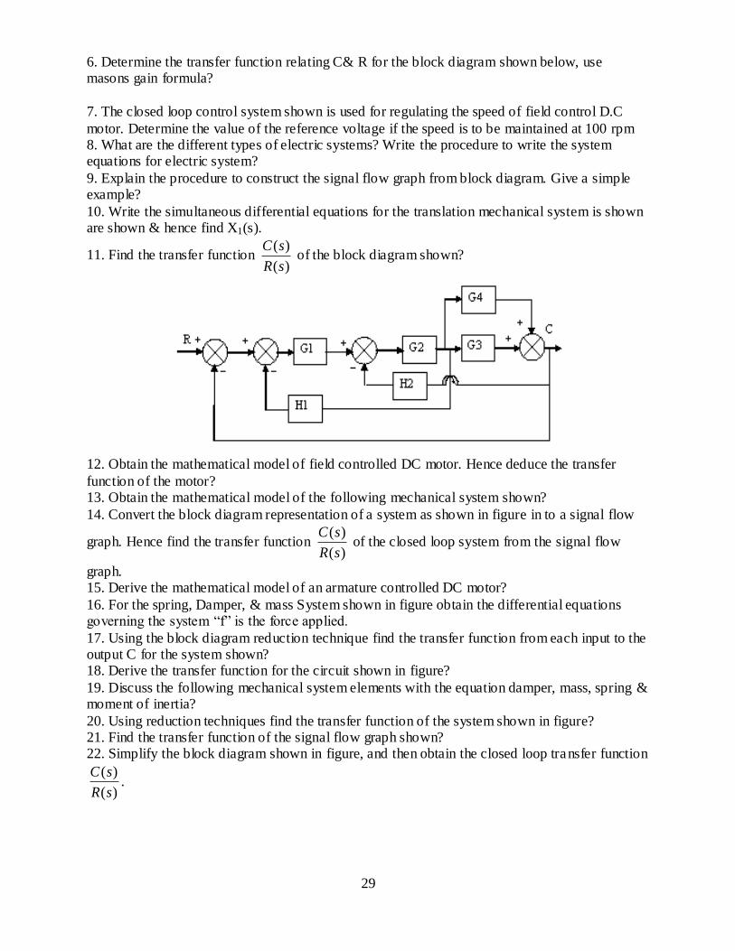
11. Find the transfer function )(
)(
sR
sC of the block diagram shown?
12. Obtain the mathematical model of field controlled DC motor. Hence deduce the transfer
function of the motor? 13. Obtain the mathematical model of the following mechanical system shown?
14. Convert the block diagram representation of a system as shown in figure in to a signal flow
graph. Hence find the transfer function )(
)(
sR
sC of the closed loop system from the signal flow
graph. 15. Derive the mathematical model of an armature controlled DC motor?
16. For the spring, Damper, & mass System shown in figure obtain the differential equations governing the system “f” is the force applied.
17. Using the block diagram reduction technique find the transfer function from each input to the output C for the system shown? 18. Derive the transfer function for the circuit shown in figure?
19. Discuss the following mechanical system elements with the equation damper, mass, spring & moment of inertia?
20. Using reduction techniques find the transfer function of the system shown in figure? 21. Find the transfer function of the signal flow graph shown? 22. Simplify the block diagram shown in figure, and then obtain the closed loop transfer function
)(
)(
sR
sC.

30
23. Derive the transfer function of the system shown in figure & Show these systems are analogous?
UNIT-II
TIME RESPONSE
PART-A
1. What is meant by settling time?
2. How the angle of arrival at zero is obtained in root locus. 3. List out any four time domain specification. 4. What is meant by order of a system?
5. How is system classified based on the damping factor?
6. For a system having)3)(1(
15
ssGs , H(s)=1 .Find the characteristic equation and n .
7. Differentiate between transient response and steady state response?
8. Define the steady state error. 9. Define rise time and write the expression for rise time respect to second order under
damped system.
10. What is the expression for the unit step response of the standard second order under damped system?
11. The total response of the system is given by )2(2
1)( 3tetC what are the expression
for the steady state and transient response. 12. What is the initial slope of a step response of a first order system?
13. What are the standard tests signals employed for time domain studies? 14. Define position and velocity error coefficient. 15. What is characteristic equation what is its role?
16. Name the three dynamic error coefficients. 17. What are the units of Kp, Kv and Ka?
PART-B 1. Define the time domain specifications for a second order system. Derive an expression
for the time to peek & peek overshoot for a second order under damped system?
2. The loop transfer function of a system)12.0(
40)()(
sssHsG . Obtain its generalized
error constants. Also find its steady error when the input is tttr )43()( .

31
3. Measurement conducted on a servomechanism shown the system response to be tt eetc 1060 2.12.01)( when subjected to a unit step input? Obtain the expression for
closed loop transfer function?
(i) Determine the un-damped natural frequency & Damping ratio of the system? 4. The open loop transfer function of a servo system with unity feedback is
)11.0(
10)(
sssG . Evaluate the dynamic error using dynamic error coefficients.
Obtain the steady state error of the system when subjected to an input given by the
polynomial 22
12
)( ta
taatr o .
5. The block diagram of a unity feedback system is shown. Find the damp ing constant, damping frequency, delay time maximum overshoot takes place for A=200.
6. Discuss the time response behaviour of the second order system subjected to unit ramp input and determine ess
7. Explain about static error coefficient and find the same for type 0 system
8. A unity feedback control system has it‟s open loop transfer function as 24
14
s
ssG
.Determine an expression for time response when the system is subjected to unit step input.
9. Derive the condition for maximum overshoot of a second order system 10. Obtain the steady state error for unit step, ramp input & parabolic input interms of the
transfer function 11. For a unity feedback second order system the open loop transfer function
nss
nsG
2
2
.calculate the generalized error coefficient and find error series
12. Determine the damping ratio, undamped natural frequency for the system shown in fig. what is the response c(t) of this system to a unit-step function excitation r(t)=u(t) when all
the initial conditions are zero. 13. Find the unit step response of the second order system whose transfer function
94
92
ss
sG
14. Derive the expression for the steady state error of the closed loop system in terms of generalized error coefficient
15. For a closed loop system with 5
1)(
ssG &H(s)=5.calculate generalized error
coefficient & find the error series 16. Derive the expression for the rise time, peak time, overshoot & settling time for the II
order system to the step input. 17. Define delay time ,rise time ,peak time and settling time 18. The open loop transfer function of a unity feed back control system is given by
11 21
sTsTs
KsG .Applying Routh-Hurwitz criterion to determine the value of K
in terms of T1 & T2 for the system to be stable. 19. Utilize the Routh table to determine the number of roots of the following polynomials in
the right half of the S-plane. Comment about the stability of the system.
(i) 1510632 2345 SSSSS
32
(ii) 244430156 2345 SSSSS
20. Consider the characteristic equation 01234 SkSS . Using the Routh method, determine the range of k for stability.
21. Using Routh‟s stability criterion, Discuss the stability of the system whose characteristics
equation is 05005010 23 SSS . 22. How the Nyquist plot may be used to determine the stability of a closed loop system
23. Given )3)(1(
)(
SSS
KsG Sketch the root locus plot and comment on the stability.
24. Obtain the root locus for a unity feed back system with open loop transfer function
)256()(
2
SSS
KsG
25. Draw the root locus curve whose open loop transfer function is given by
)1(
)3)(2()()(
ss
ssKsHsG
UNIT-III
FREQUENCY RESPONSE
PART-A
1. How the angle of arrival at zero is obtained in root locus?
2. Define the corner frequency. 3. What is frequency response?
4. In terms bode blot define stability of a system. 5. List any four specification of frequency response. 6. For a stable system both GM and PM should be positive. Justify the statement.
7. What are the advantages of Nichols chart? 8. What are the difficulties faced while applying Routh-Hurwitz criterion?
9. Define the system stability. 10. What are the advantages of bode blot? 11. Define the term peak resonance.
12. Define resonance peak and resonance frequency. 13. What is the relation between resonance peak and damping factor?
14. Define Asymptotic stability. 15. Define gain margin and space margin. 16. List the frequency domain specification.
17. Mention the use of Nichols chart. 18. State the rule for finding out the root loci on the real axis.
19. List any two advantages of frequency response analysis. 20. How do you get gain margin and space margin from polar plot? 21. Find the number of positive roots of the polynomial
5201510)( 234 xxxxxf Using Routh criterion
22. What is root locus?

33
PART-B 1. Draw the bode plot for a system whose open loop transfer function is
)8
1)(21(
)2
1(
)()(
jjj
js
sHsG
.
2. Sketch the bode plot for the following transfer function and determine gain margin and
phase margin )1.01)(5.01(
)25.01(75.0)(
ssssG
.
3. Consider the feed back system
(i) Find the value of K & a to satisfy the following frequency domain specifications. Mr=1.04, wr=11.55 rad/sec
(ii) For the value of K and a determine in part (i) calculate the settling time, Band
width of the system.
4. Draw the nyquist plot for a system with )1)(1(
)()(
sss
ksHsG and discuss stability.
5. For an example of your choice explain the procedure to draw the bode plot and determine
the gain margin and phase margin. 6. Using Nyquist criterion investigate the closed loop stability of the system whose open
loop transfer function is given by )2)(1(
50)()(
sssHsG
7. Check the stability of the system whose open loop transfer function is
)5.01)(2.01(
10)(
2 ssssG
by Nyquist criterion.
8. Sketch the bode plot for the system whose open loop transfer function G(s) & determine the system gain K for the gain cross over frequency wc to the system
)02.01)(2.01()(
2
ss
kssG
9. Draw the bode plot of the system )11.0)(1(
)(
sss
ksG . Hence obtain the exact plot by
doing necessary corrections at corner frequencies.
(i) Find the gain margin & phase margin (ii) The value of K for the phase margin=20o
10. Test the stability of the unity feed back system )5()1(
)(2
2
ss
kssG when k=10 using
nyquist criterion & then find the range of k for stability
11. Draw the bode plot for the transfer function 211.0
10
ssand obtain phase margin and
gain margin from the plot
12. Sketch the bode plot of a unity feed back s/m having sss
ksG
2.015.01)(
.Determine the value of k for a gain margin of 6 dB.

34
13. For the following open loop transfer function sketch the bode magnitude and phase plot
for )5(
)50(10)()(
ss
ssHsG .
14. Draw the polar plot for the transfer function )10(
)1(10)(
S
ssG
UNIT-IV
STABILITY AND COMPENSATOR DESIGN
PART-A
1. What is meant by Nyquist contour? 2. Define Nyquist stability criterion.
3. How is space margin determine from bode plot? 4. State Routh‟s criterion 5. Draw the electric Lag-Lead network?
6. State the property of a lead Compensator? 7. Draw the circuit of lead compensator & draw its pole-zero diagrams?
8. Write the equation of the PID controller? 9. What are the different methods of compensation? 10. What is the need for compensation?
11. Draw the Bode plot of a lag compensator. 12. Draw the bode plot of a lead compensator.
13. Write the transfer function of a typical lag- lead compensator. 14. Why the lead- lag compensator network preferred?
PART-B
1. A unity feedback s/m has an open loop transfer function )12(
4)(
sssG .It is desired to
obtain a phase margin of 400 without sacrificing Kv of the system. Design a suitable log network for the system.
2. Discuss the design procedure of a lead network with one example
3. A unity feedback system has an open loop transfer function )12.0(
)(2
ss
ksG .Design a
leed compensator to meet the following specification i)Acceleration constant ka=10 ii)Phase margin=35 degrees
4. Consider a unity feedback s/m with following open-loop transfer function
)4)(1()(
sss
ksG .Design a lag compensator to satisfy the following specifications
i)Damping ratio ∑=0.5 ii)Settling time ts=10 sec iii)Velocity error constant Kv ≥ 5sec-1 5. Discuss the need for compensation in control systems what are the different types?
Explain in detail 6. With the help of frequency plot explain how is phase log lead compensation obtained in
control s/m

35
7. The open- loop transfer function of a unity feed back control system is given by
)2()(
ss
ksG .The s/m is to have 25% maximum overshoot and peak time 1.0sec
Determine the value of k
8. Consider the unity feed back s/m whose open loop transfer function is )2(
4)(
sssG
Design a lead compensator for the s/m so that the static velocity error constant kv is 20sec-1,the phase margin is at least 500 and the gain margin is at least 10dB.
9. Consider the unity feedback system whose open loop transfer function is
)15.0)(1(
1)(
ssssG . Design a lag compensator for the system so that the static
velocity error constant kv is 5 sec-1,the phase margin is at least 400 and thwe gain margin
is at least 10 dB.
10. A unity feed back s/m has an open loop transfer function )12.0)(1(
)(
sss
ksG .Design
a suitable phase lag compensator to achieve the following specification kv=8 and phase margin=400 with usual notations
11. A unity feed back system has an open loop transfer function )1(
)(
ss
ksG .Design a
suitable phase lead compensator to achieve the following specification kv=10 and phase margin > 450 with usual notation
12. The open loop transfer function of a uncompensated system is )2(
5)(
sssG .Design a
suitable lag compensator for the system so that the static velocity error constant kv =20sec-1 the phase margin is atleast 550 and the gain margin is atleast 12dB.
13. Consider a type 1 unit feed back system with an OLTF )1(
)(
ss
ksG f it is specified
that kv=12 sec-1 and phase margin=400 design a lead compensator to meet the speciation. 14. Discus in detail about lead and lag networks
UNIT-V
STATE VARIABLE ANALYSIS 1. Draw the block diagram representation of a state model. 2. State the limitations of state variable feedback.
3. What is meant by „State‟ of a dynamic system? 4. Explain state and state variable.
5. When do you say that a system is completely state controllable? 6. List the advantages of state space approach. 7. Explain state diagram.
8. Write the state model of nthorder system. 9. Define state equation.
10.Explain the concept of controllability. 11.Write the condition to be satisfied for designing state feedback. 12. Explain the need of observability test.

36
13.Point out the limitations of physical system modelled by transfer Function approach.
14.What is meant by Linear Time Invariant system 15.Explain the need for state variables.
PART-B
1. Construct state space model for linear system.
2. State the concept of controllability and observability 3. Sate the concept of Effect of state feedback.
4.Explain the properties of State transition matrix
5.Find f(A)=A7 for A=
52
30
6. Determine the controllability and observability of the following system given below.
CX
X
X
X
YBUAXU
X
X
X
X
X
X
3
2
1
3
2
1
3
2
1
001;
10
0
0
320
100
010
7. consider a linear system described by the differential equation
UUYYY
2 with UYXYX
21 ,
Let us test controllability of the system by kalman‟s test.
8. Let us examine the observability of the system given below.
CX
X
X
X
YBUAXU
X
X
X
X
X
X
3
2
1
3
2
1
3
2
1
143;
1
0
0
320
100
010
Let us apply the kalman‟s method.
9. A System is characterized by the 6115
3
)(
)(23
SSSSU
SY. Determine whether or not the
System is completely controllable and observable.

37
EE6504 ELECRICAL MACHINES-II
UNIT-I
ALTERNATOR
1. Why a 3-phase synchronous motor will always run at synchronous speed?
2. What are the two classification synchronous machines? 3. What are the essential features of synchronous machine? 4. Mention the methods of starting of 3-phase synchronous motor.
5. What are the principal advantages of rotating field system type of construction of synchronous machines?
6. Write down the equation for frequency of emf induced in an alternator. 7. What are the advantages of salient pole type of construction used for synchronous machines? 8. Why do cylindrical rotor alternators operate with steam turbines?
9. Which type of synchronous generators are used in Hydroelectric plants and why? 10. What is the relation between electrical degree and mechanical degree?
11.What is the meaning of electrical degree? 12. Why short-pitch winding is preferred over full pitch winding? 13. Write down the formula for distribution factor.
14. Define winding factor. 15.Why are alternators rated in kVA and not in kW?
16. What are the causes of changes in voltage of alternators when loaded? 17. What is meant by armature reaction in alternators? 18. What do you mean by synchronous reactance?
19. What is effective resistant [Reff]? 20. What is synchronous impedance?
21. What is meant by load angle of an alternator? 22. Define the term voltage regulation of alternator. 23. What is the necessity for predetermination of voltage regulation?
24.Why is the synchronous impedance method of estimating voltage regulation is considered as pessimistic method?
25. Why is the MMF method of estimating the voltage regulation is considered as the optimization method?
16 MARK QUESTION
1. Describe with neat sketches the constructional details of a salient pole type alternator. 2. Draw a neat sketch showing the various parts of a synchronous machine. State the type of
synchronous generator used in nuclear power stations.
3. Discuss briefly the load charactertics of alternator for different power factor. 4. Explain any one method of predetermining the regulation of an alternator.
5. Explain why the potier reactance is slightly higher than leakages reactance. 6. Explain dark lamp method of synchronizing an alternator with the bus bar. 7. Explain Blondel s two-reaction theory,

38
8. Explain how will you determine the d and q axes reactance of a synchronous machine in your laboratory.
9. Derive an expression for synchronizing power. 10. For a salient pole synchronous machine, derive an expression for power developed as a
function of load angle. 11. Explain the operating principle of three-phase alternator.
UNIT-II SYNCHRONOUS-MOTOR
1. What does hunting of synchronous motor mean? 2. What could be the reasons if a 3-phase synchronous motor fails to start? 3. What is synchronous condenser?
4. Write the applications of synchronous motor. 5. What is an inverted 'V' curve?
6. A synchronous motor starts as usual but fails to develop its full torque. What could it be due to?
7. What are the two types of 3-phase induction motor?
8. Write the two extra features of slip ring induction motors. 9. Can we add extra resistance in series with squirrel cage rotor? State the reason?
10. Why an induction motor is called rotating transformer? 11. Why an induction motor will never run at its synchronous speed? 12. Define SCR?
13. Why is open circuit charactertics called magnetic charactertic? 14. What are the losses determined from SCC?
15. What are stray load losses? 16. What is synchronizing? 17. What is a synchroscope?
18. What is direct axis? 19. What is quadrature axis?
20. What are the two curves required for POTIER method? 21. What are the three methods of determining voltage regulation? 22. When does a synchronous motor get over excited?
23. Define pullout torque? 24. What is the main advantage of POTIER method?
25. What is meant by the subtransient period? 26. What is fractional pitch winding?
16 MARK QUESTION
1. Explain why a synchronous motor does not have starting torque. 2. Explain one method of starting a synchronous motor. 3. Why does the power factor of industrial installation tend to be low? How can it
be improved? 4. Does the change in excitation affect the p.f of the synchronous motor?
5. An over excited synchronous motor is called a synchronous condenser. Explain. 6. Mention some specific applications of synchronous motor. 7. Explain what happens when the load on a synchronous motor is changed.
8. What is meant by constant power circle for synchronous motor?

39
9. What is meant by hunting in a synchronous motor? Why is it undesirable? What is done to minimize it?
10. Explain V-curves and inverted V-curves. 11. Draw the power angle diagram of a synchronous machine.
12. Explain briefly the principle of operation of three-phase synchronous motor. 13. Describe the effect of varying the excitation on the armature current and power factor a
synchronous motor when input power to the motor is maintained constant.
UNIT-III
THREE PHASE INDUCTION MOTOR
1. What are types of 3- phase induction motor?
2. Why the rotor slots of a 3-phase induction motor are skewed? 3. Why the induction motor is called asynchronous motor?
4. What are slip rings? 5. State the difference between slip ring rotor and cage rotor of an induction motor? 6. Write an expression for the slip of an induction motor.
7. What is cogging of an induction motor? 8. Explain why the no load current of an induction motor is much higher than that of an
equivalent transformer. 9. State the effect of rotor resistance on starting torque? 10. What are the advantages of cage motor?
11. Give the conditions for maximum torque for 3-phase induction motor? 12. What is reason for inserting additional resistance in rotor circuit of a slip ring induction
motor? 13. List out the methods of speed control of cage type 3-phase induction motor? 14. Mention different types of speed control of slip ring induction motor?
15. What are the advantages of 3-phase induction motor? 16.What does crawling of induction motor mean?
17.State the application of an induction generator? 18. Name the two windings of a single-phase induction motor. 19. What are the various methods available for making a single-phase motor self-starting?
20. What is the function of capacitor in a single-phase induction motor? 21. Give the names of three different types of single-phase motor.
22. What is the use of shading ring in a pole motor? 23. State any four use of Michaelsing-phase induction motor. 24. Why is the efficiency of a 3-phase induction motor less than of a transformer?
25. What are the types of starters? 16 MARK QUESTIONS:
1. Develop the equivalent circuit for 3-phase induction motor? 2. Explain the different speed control methods of squirrel cage induction motor.
3. Describe the principle of operation of synchronous induction motor. 4. Explain any one method of speed control of three- phase induction motor
5. Draw the slip-torque charactertics for a three-phase induction motor and explain.
6. Explain how a rotating magnetic field is produced in a three-phase induction motor.
21. Draw and explain the equivalent circuit of a three-phase induction motor. Apr: 2000

40
Describe with a neat diagram, the principle of operation of induction generator Oct: 2000 Draw and explain the torque/slip curves of a three-phase induction motor for different
values of rotor resistance. Oct: 2000 Starting from the first principles, develop the equivalent circuit of a 3- phase induction
motor. Explain the procedure of drawing the circle diagram of an induction motor. How is the
performance character tics obtained from it? Apr: 2001
12. Explain the operation of induction generator. Oct: 2001
UNIT-IV STARTING AND SPEED CONTROL OF THREE PHASE INDUCTION MOTOR 1. What are the types of starters?
2. List out the methods of speed control of cage type 3-phase induction motor? 3. Mention different types of speed control of slip ring induction motor?
4. State the advantages of capacitor start run motor over capacitor start motor. 5. What is Universal motor? 6. State some application of universal motor.
7. Explain why single-phase induction motor is not self-starting one. 8. What type of motor is used for ceiling fan?
9. What is the type of induction motor used in wet grinders? 10. What kind of motor is used in mixie? 11. what is the application of shaded pole induction motor?
12. In which direction does a shaded pole motor run? 13. why single-phase induction motor has low power factor?
14. Diffrentiate between “capacitor start “and “capacitor start capacitor run “induction motor? 15. State the application of an induction generator? 16. What do you mean by residual EMF in a generator.
17. State the effect of rotor resistance on starting torque? 18. How can varying supply frequency control speed?
19. How is speed control achieved by changing the number of stator poles? 20. What are the disadvantage of of static control?
21. What are the methods of speed control preferred for large motors?
22. What is an induction regulator? 23. Define-Slip frequency.
24. Define- Asynchronous torque. 25. What is the main use of squirrel cage winding in synchronous motor starting? 26. What is breakdown torque?
27. What is the function of rotary converter? Where it is used? 28. What are the advantages of Kramer system of speed control?
29. Write the expression for concatenated speed of the set.
16 MARK QUESTIONS:
1. With neat diagrams explains the working of any two types of starters used for
squirrel cage type 3 phase induction motor. 2. Discuss the various starting methods of induction motors. 3. Explain the different speed control methods of phase wound induction motor
5. E xplain the diffe re nt s pee d c ontrol me tho ds of pha se wound induction motor

41
6. Discuss the theory of star delta starter 7. Explain the cascade operation of induction motors to obtain variable speed 8. Explain the various techniques of sped control of induction motor from
rotor side control. 9. Explain the various schemes of starting squirrel cage induction motor
Unit –V
SINGLE PHASE INDUCTION MOTORS AND SPECIAL MACHINES 1. Name the two winding of single phase induction motor?
2. What are methods available for making single phase induction motor a self start ing? 3. What is the function of capacitor in single phase induction motor? 4. State any 4 use of single phase induction motor?
5. Why single phase induction motor is not a self starting one? 6. What kind of motors used in ceiling fan and wet grinders?
7. What is the application of shaded pole induction motor? 8. In which direction a shaded pole motor runs? 9. Why single phase induction motor have low PF?
10. Differentiate between “capacitor start” & “Capacitor start capacitor run” single phase induction motor?
11. What are the principal advantages of rotating field type construction? 12. Why an induction motor never runs at its synchronous speed? 13. What are the advantages of cage motor?
14. Why an induction motor is called as rotating transformer? 15. What is the use of shading coil in the shaded pole motor?
16. Why capacitor –start induction motors advantageous? 17. List out 4 applications of shaded pole induction motor? 18. What are the drawbacks of the presence of the backward rotating field in a single phase
induction motor? 19. Why is hysteresis motor free from mechanical and magnetic vibrations?
20. What types of motor is used in computer drives and wet grinders? 21. Give two advantages and two applications of stepper motor. 22. List some applications of linear induction motor?
23. What are the specific characteristic features of the repulsion motor? 24. Discuss characteristics of single phase series motor
25. What are the demerits of repulsion motor? 26. List four applications of reluctance motors? 27.What is a universal motor?
16 MARK QUESTIONS:
1. Give the classification of single phase motors .Explain any two types of single phase induction motors.
2. Explain the double field revolving theory for operation of single
phase induction motor. 3. Explain the operation of shaded pole induction motor with diagram.
4. Develop equivalent circuit of a single phase induction motor ignoring core losses.

42
5. Explain the working principle of single phase induction motor .Mention its four applications.
6. What is the principle and working of hysteresis motor? Explain briefly. 7. Explain the construction and working of stepper motor.
8. Explain the principle of operation and applications of reluctance motor. 9. Explain the principle of operation and applications of repulsion motor
and hysteresis motor.

43
EE 6503 - POWER ELECTRONICS
TWO MARK QUESTIONS WITH ANSWER UNIT-I
POWER SEMI-CONDUCTOR DEVICES
PART-A
1. Why IGBT is very popular nowadays? 2. What are the different methods to turn on the thyristor?
3. What is the difference between power diode and signal diode? 4. IGBT is a voltage controlled device. Why?
5. Power MOSFET is a voltage controlled device. Why? 6. Power BJT is a current controlled device. Why? 7. What are the different types of power MOSFET?
8. How can a thyristor turned off? 9. Define latching current.
10. Define holding current. 11. What is a snubber circuit? 12. What losses occur in a thyristor during working conditions?
13. Define hard-driving or over-driving. 14. Define circuit turn off time.
15. Why circuit turn off time should be greater than the thyristor turn-off time? 16. Why MOSFETs are not preferred for low frequency applications? 17. What is the turn-off time for converter grade SCRs and inverter grade SCRs?
18. What are the advantages of GTO over SCR? 19. What is reverse recovery time?
20. In Triacs which of the mode the sensitivity of gate is high?
PART-B 1. Discuss the different modes of operation of thyristor with the help of static VI characteristics.
2. Explain the construction of SCR with neat sketch. 3. Draw the switching characteristics of SCR and explain it. 4. Discuss the different modes of operation of TRIAC with the help of VI characteristics.
5. Explain the switching characteristics of TRIAC. 6. With the help of neat diagram explain the operation of BJT.
7. Discuss the different modes of operation of thyristor with the help of its static V-I characteristics. 8. Explain why TRIAC is rarely operated in I quadrant with negative gate current & in III
quadrant positive gate current. 9. Describe the structure of an IGBT.
10. Draw the simplified model of a MOSFET to show the inter electrode capacitance. 11. Explain the four modes of operation of a TRIAC. Compare their sensitivity. 12. Draw the dynamic characteristics of SCR during turn-on and turn-off and explain.
13. Describe any one driver circuit and snubber circuit for MOSFET.

44
14. Write short notes on: (a) Snubber circuit of BJT
(b) Commutation circuit of SCR 15. Draw and explain the forward characteristics of SCR using two transistor model of SCR.
16. Compare any six salient features of MOSFET & IGBT.
UNIT-II
PHASE CONTROLLED CONVERTERS PART-A
1. What is the function of freewheeling diodes in controlled rectifier? 2. What are the advantages of freewheeling diodes in a controlled in a controlled rectifier? 3. What is meant by delay angle?
4. What are the advantages of single phase bridge converter over single phase mid-point Converter?
5. What is commutation angle or overlap angle? 6. What are the different methods of firing circuits for line commutated converter? 7. Give an expression for average voltage of single phase semiconverters?
8. What is meant by input power factor in controlled rectifier? 9. What are the advantages of six pulse converter?
10. What is meant by commutation? 11. What are the types of commutation? 12. What is meant by natural commutation?
13. What is meant by forced commutation? 14. What is meant by phase controlled rectifier?
15. Mention some of the applications of controlled rectifier? 16. What is the displacement factor? 17. What is the turns-ratio of a transformer?
18. What is the difference between rectifier and converters? 19. What are the performance parameters of a rectifier?
20. What is the purpose of the form factor of the rectifier?
PART-B
1. Discuss the working of 1Φ two pulse bridge converter with RLE load using relevant waveforms.
2. A 1 Φ two pulse bridge converter feeds power to RLE load with R=6Ω, L= 6mH, E = 60V, ac source voltage is 230V, 50Hz for continuous conduction. Find the average value of load current for firing angle of 50 °. In case one of four SCRs gets open circuited. Find the new value of
average load current assuming the output current as continuous. 3. Explain the operation of 1Φ semi converter and derive the expressions for its average and rms
output voltage. 4. Derive the expressions for harmonic, displacement and power factor of a 1Φ full converter from the fundamental principle.
5. Explain the working of 1Φ full converter with RL load and derive the expression for the average and rms value.
6. Discuss the principle of operation of DC-DC step down chopper with suitable waveforms. Derive the expression for its average dc voltage. 7. A step down dc chopper has input voltage of 230V with 10ohm load, voltage drop across
chopper is 2V, when it is on for a duty cycle of 0.5.

45
8. Discuss the operation of single phase half controlled rectifier with inductive load. Derive the average output voltage equation.
9. Explain the principle of operation of single phase dual converter with neat power circuit diagram.
10. Explain the operation of three phase half controlled rectifier supplying R- load with neat waveforms. Derive an expression for the average output voltage. 11. With necessary circuit and waveforms explain the principle of operation of single Phase fully
controlled converter. Derive the expression for average output voltage. 12. Explain the effect of source inductance in the operation of single phase fully controlled
converter. Derive the expression for its output voltage. 13. Explain the operation of three -phase full converter. Derive expression for its average output voltage.
UNIT-III
DC TO DC CONVERTER PART-A
1. What is meant by dc chopper?
2. What are the applications of dc chopper? 3. What are the advantages of dc chopper?
4. What is meant by step-up and step-down chopper? 5. What is meant by duty-cycle? 6. What are the two types of control strategies?
7. What is meant by Time Ratio Control? 8. What are the two types of Time Ratio Control?
9. What is meant by FM control in a dc chopper? 10. What is meant by PWM control in dc chopper? 11. Write down the expression for the average output voltage for step down and step up chopper?
12. What are the different types of chopper with respect to commutation process? 13. What is meant by voltage commutation?
14. What is meant by current commutation? 15. What is meant by load commutation? 16. What are the advantages of current commutated chopper?
17. What are the advantages of load commutated chopper? 18. What are the disadvantages of load commutated chopper?
19. Write down the expression for average output voltage for step down chopper? 20. What is SMPS?
PART-B 1. Explain the two quadrant dc chopper operation with RLE load using suitable waveforms.
2. Explain time ratio control and current limit control strategies. 3. Explain the resonant switching based SMPS. 4. Explain any one type of switched mode regulator and derive the expression for it.
5. Derive the expression for the output voltage of a step-up chopper & explain its control strategies.
6. Discuss the principle of operation of DC-DC step-down chopper with suitable waveform. Derive an expression for its average DC output voltage. 7. Draw the power circuit diagram of cuk regulator and explain its operation with equivalent
circuit for different modes with necessary waveforms.

46
8. Explain the various modes of operation of Boost DC – DC converter with necessary waveforms.
9. Explain the operation of class C and class D types of two quadrant choppers. 10. Explain about Type – E chopper.
11. Classify the basic topologies of switching regulators and explain the operation of buck regulator with continuous load current using suitable waveform
UNIT-IV INVERTERS
PART-A 1. What is meant by inverter? 2. What are the applications of an inverter?
3. What are the main classifications of inverter? 4. Why thyristors are not preferred for inverters?
5. How output frequency is varied in case of a thyristor? 6. Give two advantages of CSI. 7. Why diodes should be connected in antiparallel with the thyristors in inverter circuits?
8. What is meant a series inverter? 9. What is the condition to be satisfied in the selection of L and C in a series inverter?
10. What is meant a parallel inverter? 11. What are the applications of a series inverter? 12. How is the inverter circuit classified based on commutation circuitry?
13. What is meant by McMurray inverter? 14. What are the applications of a CSI?
15. What is meant by PWM control? 16. What are the advantages of PWM control? 17. What are the disadvantages of the harmonics present in the inverter system?
18. What are the disadvantages of current source inverters? 19. What are the methods of reduction of harmonic content?
20. Compare CSI and VSI.
PART-B
1. Explain the operation of single phase half bridge inverter with a neat sketch. 2. Explain different PWM techniques in detail.
3. Explain the operation of single phase full bridge inverter with neat sketch. 4. Write short notes on the following: i) Sinusoidal pulse width modulation as applied to inverters
ii) Current source inverters. 5. Describe the working of three phase inverter with suitable waveform
6. Explain the principle of operation of three phase inverter with 180° conduction mode with necessary waveforms and circuits. 7. Describe the functioning of three phase voltage source inverter supplying a balanced star -
connected load in 120° operating mode. 8. Describe any one PWM technique used in inverter in detail.
9. Explain the working principle of single phase current source inverter. 10. Write short note on series resonant inverter. 11. Explain how inverter can be controlled using multiple and sine PWM technique.
12. Explain the operation of single phase commutated current source inverter with R load.

47
13. Explain the different methods of voltage control adopted in an inverter with suitable waveforms.
UNIT-V
AC TO AC CONVERTERS PART-A
1. What does ac voltage controller mean?
2. What are the applications of ac voltage controllers? 3. What are the advantages of ac voltage controllers?
4. What are the disadvantages of ac voltage controllers? 5. What are the two methods of control in ac voltage controllers? 6. What is the difference between ON-OFF control and phase control?
7. What is the advantage of ON-OFF control? 8. What is the disadvantage of ON-OFF control?
9. What is the duty cycle in ON-OFF control method? 10. What is meant by unidirectional or half-wave ac voltage controller? 11. What are the disadvantages of unidirectional or half-wave ac voltage controller?
12. What is meant by bidirectional or half-wave ac voltage controller? 13. What type of gating signal is used in single phase ac voltage controller with RL load?
14. What are the disadvantages of continuous gating signal? 15. What is meant by high frequency carrier gating? 16. What is meant by sequence control of ac voltage regulators?
17. What are the advantages of sequence control of ac voltage regulators? 18. What is meant by cyclo-converter?
19. What are the two types of cyclo-converters? 20. What is meant by step-down cyclo-converters? 21. What is meant by step-up cyclo-converters?
22. What are the applications of cyclo-converter? 23. What is meant by positive converter group in a cyclo converter?
24. What is meant by negative converter group in a cyclo converter?
PART-B
1. With the aid of circuit diagram and waveform explain the operation of power factor control in AC voltage regulation.
2. Draw the circuit diagram of three phase to single phase cycloconverter and explain its operation with necessary waveforms. 3. With the aid of circuit diagram and waveform explain the operation of single phase full wave
AC voltage controller. 4. Write short notes on the following:
i) Integral cycle control ii) Multistage sequence control iii) Step up cycloconverter
iv) Matrix converter. 5. Explain the operation of multistage control of AC voltage controllers with neat diagram.
6. .Explain the operation of single phase AC voltage controller with RL load. 7. Explain the operation of sequence control of AC voltage controller. 8. Explain the operation of single phase sinusoidal AC voltage controller.

48
9. For a single phase voltage controller, feeding a resistive load, draw the waveforms of source voltage, gating signals, output voltage and voltage across the SCR. Describe the working with
reference to waveforms drawn. 10. Describe the basic principle of working of 1Φ-1Φ step down cycloconverter for a bridge type
converter. Assume both discontinuous and continuous conduction and draw the load current and load voltage waveforms for both cases. Mark the conduction of various thyristors.


![Effect of Distribution Generators on Stability in a ... · sient [6] considering the bus impedance matrix which is the inverse of the bus admittance matrix. Stability analysis is](https://img.dokumen.tips/doc/110x75/5eac72864d784927f130bdb7/effect-of-distribution-generators-on-stability-in-a-sient-6-considering-the.jpg)


![BUS BUS BUS BUS BUS BUS BUS BUS BUS · Sunday 15 May 2016 Liverpool Street to Colchester, Ipswich, Norwich and branches BUS BUS BUS BUS BUS BUS BUS BUS BUS] 1 1 1 1 1 1 1 1 1 1 1](https://img.dokumen.tips/doc/110x75/5fab4ce2477d2d3adf21016a/bus-bus-bus-bus-bus-bus-bus-bus-sunday-15-may-2016-liverpool-street-to-colchester.jpg)