Embed Size (px)
Citation preview

Virtual SAN Design and Sizing Guide
VMwa re Stora g e a nd A v a i la b i l i ty Doc um e nt a ti o n / 1
VMware® Virtual SAN™ 6.2 Design and Sizing Guide John Nicholson Storage and Availability Business Unit VMware v1.11 March 2016

Virtual SAN 6.2 Design and Sizing Guide
VMwa re Stora g e a nd A v a i la b i l i ty Doc um e nt a ti o n / 2
Contents INTRODUCTION.............................................................................................................. 5
HEALTH SERVICES........................................................................................................... 6 VIRTUAL SAN READY NODES ................................................................................... 6 VMWARE VXRAIL .......................................................................................................... 7 VIRTUAL SAN DESIGN OVERVIEW .......................................................................... 8
FOLLOW THE COMPATIBILITY GUIDE (VCG) PRECISELY ............................................... 8 Hardware, drivers, firmware .................................................................................. 8
USE SUPPORTED VSPHERE SOFTWARE VERSIONS.......................................................... 8 BALANCED CONFIGURATIONS......................................................................................... 9 LIFECYCLE OF THE VIRTUAL SAN CLUSTER ................................................................... 9 SIZING FOR CAPACITY, MAINTENANCE AND AVAILABILITY ............................................. 11 SUMMARY OF DESIGN OVERVIEW CONSIDERATIONS ...................................................... 11
HYBRID AND ALL-FLASH DIFFERENCES .............................................................12 ALL-FLASH CONSIDERATIONS................................................................................12 VIRTUAL SAN LIMITS ................................................................................................. 14
MINIMUM NUMBER OF ESXI HOSTS REQUIRED ...............................................................14 MAXIMUM NUMBER OF ESXI HOSTS ALLOWED..............................................................14 MAXIMUM NUMBER OF VIRTUAL MACHINES ALLOWED ..................................................14 MAXIMUM NUMBER OF VIRTUAL MACHINES PROTECTED BY VSPHERE HA.................... 15 DISKS, DISK GROUP AND FLASH DEVICE MAXIMUMS ...................................................... 15 COMPONENTS MAXIMUMS ..............................................................................................16 VM STORAGE POLICY MAXIMUMS................................................................................... 17 MAXIMUM VMDK SIZE ................................................................................................... 18 SUMMARY OF DESIGN CONSIDERATIONS AROUND LIMITS..............................................19
NETWORK DESIGN CONSIDERATIONS ............................................................... 20 NETWORK INTERCONNECT - 1GB/10GB ...................................................................... 20 ALL-FLASH BANDWIDTH REQUIREMENTS .................................................................... 20 NIC TEAMING FOR REDUNDANCY .................................................................................. 21 MTU AND JUMBO FRAMES CONSIDERATIONS ................................................................ 21 MULTICAST CONSIDERATIONS........................................................................................ 21 NETWORK QOS VIA NETWORK I/O CONTROL ............................................................ 22 SUMMARY OF NETWORK DESIGN CONSIDERATIONS ..................................................... 22 VIRTUAL SAN NETWORK DESIGN GUIDE ...................................................................... 22
STORAGE DESIGN CONSIDERATIONS .................................................................24 DISK GROUPS.................................................................................................................24 CACHE SIZING OVERVIEW .............................................................................................24 FLASH DEVICES IN VIRTUAL SAN ................................................................................. 25
Client Cache............................................................................................................ 25 Purpose of read cache.......................................................................................... 25 Purpose of write cache.........................................................................................26
PCIE FLASH DEVICES VERSUS SOLID STATE DRIVES (SSDS) ......................................26

Virtual SAN 6.2 Design and Sizing Guide
VMwa re Stora g e a nd A v a i la b i l i ty Doc um e nt a ti o n / 3
FLASH ENDURANCE CONSIDERATIONS ......................................................................... 27 FLASH CAPACITY SIZING FOR ALL-FLASH CONFIGURATIONS ....................................... 28 WHY DOES ALL-FLASH VIRTUAL SAN REQUIRE 10% CACHE:CAPACITY RATIO?........29 FLASH CACHE SIZING FOR HYBRID CONFIGURATIONS.................................................. 32
Working example --- hybrid configuration.........................................................34 FLASH CACHE SIZING FOR ALL-FLASH CONFIGURATIONS............................................ 35
Working example --- all-flash configuration ...................................................... 35 SCALE UP CAPACITY, ENSURE ADEQUATE CACHE ........................................................ 37 MAGNETIC DISKS...........................................................................................................39
Magnetic disk performance --- NL SAS, SAS or SATA ....................................39 Magnetic disk capacity --- NL-SAS, SAS or SATA ........................................... 40 Magnetic disk performance --- RPM ................................................................... 40 Number of magnetic disks matter in hybrid configurations ..........................41 Using different magnetic disks models/types for capacity ...........................41
HOW MUCH CAPACITY DO I NEED? ................................................................................41 HOW MUCH SLACK SPACE SHOULD I LEAVE? ...............................................................42 FORMATTING OVERHEAD CONSIDERATIONS................................................................ 44 SNAPSHOT CACHE SIZING CONSIDERATIONS ............................................................... 46 CHOOSING A STORAGE I/O CONTROLLER ....................................................................47
Multiple controllers and SAS Expanders...........................................................47 Multiple Controllers versus single controllers ..................................................47 Storage controller queue depth .........................................................................48 RAID-0 versus pass-through ...............................................................................48 Storage controller cache considerations ..........................................................48 Advanced controller features ............................................................................ 49 Knowledge base related controller issues....................................................... 49
DISK GROUP DESIGN.................................................................................................... 49 Disk groups as a storage failure domain.......................................................... 49 Multiple disk groups and 3-node clusters........................................................ 50
SMALL DISK DRIVE CAPACITY CONSIDERATIONS ........................................................... 51 VERY LARGE VMDK CONSIDERATIONS ......................................................................... 51 DESIGNING WITH CAPACITY FOR REPLACING/UPGRADING DISKS ................................ 53 DISK REPLACEMENT/UPGRADE ERGONOMICS .............................................................. 53 DESIGN TO AVOID RUNNING OUT OF CAPACITY............................................................54 SUMMARY OF STORAGE DESIGN CONSIDERATIONS ...................................................... 55
VM STORAGE POLICY DESIGN CONSIDERATIONS ......................................... 56 OBJECTS AND COMPONENTS ........................................................................................56 WITNESS AND REPLICAS............................................................................................... 57 VIRTUAL MACHINE SNAPSHOT CONSIDERATIONS........................................................59 REVIEWING OBJECT LAYOUT FROM UI .........................................................................59 POLICY DESIGN DECISIONS ........................................................................................... 60
Number of Disk Stripes Per Object/Stripe Width .......................................... 60 Stripe Width --- Sizing Consideration ..................................................................61 Flash Read Cache Reservation ............................................................................61 Flash Read Cache Reservation --- sizing considerations.................................62 Flash Read Cache Reservation configuration example .................................62 Number of Failures To Tolerate..........................................................................63 Failures to Tolerate sizing consideration..........................................................63

Virtual SAN 6.2 Design and Sizing Guide
VMwa re Stora g e a nd A v a i la b i l i ty Doc um e nt a ti o n / 4
Force Provisioning ............................................................................................... 64 Object Space Reservation ...................................................................................65 IOP Limit For Object ............................................................................................ 66 Disable Object Checksum ....................................................................................67
SUMMARY OF POLICY DESIGN CONSIDERATIONS ......................................................... 69 VIRTUAL MACHINE NAMESPACE & SWAP CONSIDERATIONS...................................... 69
VM Home Namespace ......................................................................................... 69 VM Swap................................................................................................................... 71 Deltas disks created for snapshots ..................................................................... 71 Snapshot memory ................................................................................................. 72
CHANGING A VM STORAGE POLICY DYNAMICALLY ..................................................... 72 PROVISIONING WITH A POLICY THAT CANNOT BE IMPLEMENTED .................................74 PROVISIONING WITH THE DEFAULT POLICY ..................................................................74
HOST DESIGN CONSIDERATIONS ..........................................................................75 CPU CONSIDERATIONS ................................................................................................. 75 MEMORY CONSIDERATIONS........................................................................................... 75 HOST STORAGE REQUIREMENT ..................................................................................... 75 BOOT DEVICE CONSIDERATIONS ................................................................................... 75 CONSIDERATIONS FOR COMPUTE-ONLY HOSTS............................................................76 MAINTENANCE MODE CONSIDERATIONS ...................................................................... 78 BLADE SYSTEM CONSIDERATIONS................................................................................. 78 EXTERNAL STORAGE ENCLOSURE CONSIDERATIONS ................................................... 78 PROCESSOR POWER MANAGEMENT CONSIDERATIONS ................................................79
CLUSTER DESIGN CONSIDERATIONS.................................................................. 80 3-NODE CONFIGURATIONS ........................................................................................... 80 VSPHERE HA CONSIDERATIONS................................................................................... 80 FAULT DOMAINS ............................................................................................................ 81 DEDUPLICATION AND COMPRESSION CONSIDERATIONS..............................................86
DETERMINING IF A WORKLOAD IS SUITABLE FOR VIRTUAL SAN ........... 86 USING VIEW PLANNER FOR VIRTUAL SAN SIZING ...................................................... 88 VMWARE INFRASTRUCTURE PLANNER --- VIP ............................................................. 90
DESIGN & SIZING EXAMPLES .................................................................................. 91 CAPACITY SIZING EXAMPLE I .........................................................................................91
CPU Configuration.................................................................................................93 Memory Configuration..........................................................................................93 Storage Configuration ..........................................................................................93 Component Count ................................................................................................ 94
CAPACITY SIZING EXAMPLE II .......................................................................................95 CPU Configuration.................................................................................................97 Memory Configuration..........................................................................................97 Storage Configuration --- option 1 .......................................................................98 Storage Configuration --- option 2 ..................................................................... 99 Storage Configuration --- option 3 All Flash (Storage Efficiency) ............... 101 Component Count ............................................................................................... 103 Server choice ........................................................................................................ 104
CONCLUSION..............................................................................................................106

Virtual SAN 6.2 Design and Sizing Guide
VMwa re Stora g e a nd A v a i la b i l i ty Doc um e nt a ti o n / 5
FURTHER INFORMATION ........................................................................................ 107 VMWARE READY NODES ............................................................................................ 107 VMWARE COMPATIBILITY GUIDE................................................................................ 107 VSPHERE COMMUNITY PAGE ...................................................................................... 107 KEY BLOGGERS............................................................................................................ 107 LINKS TO EXISTING DOCUMENTATION ......................................................................... 107 VMWARE SUPPORT ..................................................................................................... 107 ADDITIONAL READING ................................................................................................ 107
Introduction VMware® Virtual SAN™ is a hypervisor-converged, software-defined storage platform that is fully integrated with VMware vSphere®. Virtual SAN aggregates locally attached disks of hosts that are members of a vSphere cluster, to create a distributed shared storage solution. Virtual SAN enables the rapid provisioning of storage within VMware vCenter™ as part of virtual machine creation and deployment operations. Virtual SAN is the first policy-driven storage product designed for vSphere environments that simplifies and streamlines storage provisioning and management. Using VM-level storage policies, Virtual SAN automatically and dynamically matches requirements with underlying storage resources. With Virtual SAN, many manual storage tasks are automated - delivering a more efficient and cost-effective operational model. Virtual SAN 6.0 provides two different configuration options, a hybrid configuration that leverages both flash-based devices and magnetic disks, and an all-flash configuration. The hybrid configuration uses server-based flash devices to provide a cache layer for optimal performance while using magnetic disks to provide capacity and persistent data storage. This delivers enterprise performance and a resilient storage platform. The all-flash configuration uses flash for both the caching layer and capacity layer. There are a wide range of options for selecting a host model, storage controller as well as flash devices and magnetic disks. It is therefore extremely important that the VMware Compatibility Guide (VCG) is followed rigorously when selecting hardware components for a Virtual SAN design. This document focuses on helping administrators to correctly design and size a Virtual SAN cluster, and answer some of the common questions around number of hosts, number of flash devices, number of
Virtual SAN 6.2 Design and Sizing Guide
VMwa re Stora g e a nd A v a i la b i l i ty Doc um e nt a ti o n / 6
magnetic disks, and detailed configuration questions to help to correctly and successfully deploy a Virtual SAN.
Health Services Virtual SAN 6.2 comes with the Health Services UI. This feature checks a range of different health aspects of Virtual SAN, and provides insight into the root cause of many potential Virtual SAN issues. The recommendation when deploying Virtual SAN is to also deploy the Virtual SAN Health Services at the same time. Once an issue is detected, the Health Services highlights the problem and directs administrators to the appropriate VMware knowledgebase article to begin problem solving. Please refer to the Virtual SAN Health Services Guide for further details on how to get the Health Services components, how to install them and how to use the feature for validating a Virtual SAN deployment and troubleshooting common Virtual SAN issues.
Virtual SAN Ready Nodes There are two ways to build a Virtual SAN cluster:
• Build your own based on certified components
• Choose from list of Virtual SAN Ready Nodes A Virtual SAN Ready Node is a validated server configuration in a tested, certified hardware form factor for Virtual SAN deployment, jointly recommended by the server OEM and VMware. Virtual SAN Ready Nodes are ideal as hyper-converged building blocks for larger datacentre environments looking for automation and a need to customize hardware and software configurations. Select ready node partners are offering pre-installed Virtual SAN on ready nodes. The Virtual SAN Ready Node documentation can provide examples of standardized configurations, including the numbers of VMs supported and estimated number of 4K IOPS delivered. Further details on Virtual SAN Ready Nodes can be found here: Virtual SAN Hardware Quick Reference Guide

Virtual SAN 6.2 Design and Sizing Guide
VMwa re Stora g e a nd A v a i la b i l i ty Doc um e nt a ti o n / 7
VMware VxRAIL Another option available to customer is VxRAIL™. VxRAIL combines VMware compute, networking, and storage resources into a hyper-converged infrastructure appliance to create a simple, easy to deploy, all-in-one solution offered by our partner VCE. VxRAIL software is fully loaded onto a partners’ hardware appliance and includes VMware Virtual SAN. Further details on VxRAIL can be found here: http://www.vce.com/products/hyper-converged/vxrail

Virtual SAN 6.2 Design and Sizing Guide
VMwa re Stora g e a nd A v a i la b i l i ty Doc um e nt a ti o n / 8
Virtual SAN Design Overview There are a number of high-level considerations before getting into the specifics of Virtual SAN design and sizing.
Follow the Compatibility Guide (VCG) precisely It is very important that the vSphere Compatibility Guide (VCG) for Virtual SAN be followed rigorously. A significant number of support requests have been ultimately traced back to failing to adhere to these very specific recommendations. This on-line tool is regularly updated to ensure customers always have the latest guidance from VMware available to them. Always verify that VMware supports any hardware components that are used for a Virtual SAN deployment.
Hardware, drivers, firmware The VCG makes very specific recommendations on hardware models for storage I/O controllers, solid state drives (SSDs), PCIe flash cards and disk drives. It also specifies which drivers have been fully tested with Virtual SAN, and --- in many cases --- identifies minimum levels of firmware required. Ensure that the hardware components have these levels of firmware, and that any associated drivers installed on the ESXi hosts in the design have the latest supported driver versions.
Use supported vSphere software versions While VMware supports Virtual SAN running with vSphere 6.0 Update 2 and various versions since vSphere 5.5 (U2 and U1), we always recommend running the latest versions of vSphere software, both ESXi and vCenter Server. In particular, vSphere 5.5U2b includes a number of improvements for Virtual SAN. VMware does not support upgrading a BETA version of Virtual SAN to a GA version. In such cases, a fresh deployment of Virtual SAN is required, i.e. a fresh deployment of vSphere 5.5U1, 5.5U2, etc. Do not attempt to upgrade from 5.5 to 5.5U1 or 5.5U2 if the beta version of Virtual SAN was being used, and there is now a wish to use a GA version of the product.
VMware continuously fixes issues encountered by customers, so by using the latest version of the software, customers avoid encountering issues that have already been fixed.
Virtual SAN 6.2 Design and Sizing Guide
VMwa re Stora g e a nd A v a i la b i l i ty Doc um e nt a ti o n / 9
Balanced configurations As a best practice, VMware recommends deploying ESXi hosts with similar or identical configurations across all cluster members, including similar or identical storage configurations. This will ensure an even balance of virtual machine storage components across the disks and hosts cluster. While hosts that do not contribute storage can still leverage the Virtual SAN datastore if they are part of the same vSphere cluster, it may result in additional support effort if a problem is encountered. For this reason, VMware is not recommending unbalanced configurations. Best practice: Similarly configured and sized ESXi hosts should be used for the Virtual SAN cluster.
Lifecycle of the Virtual SAN cluster Virtual SAN provides customers with a storage solution that is easily scaled up by adding new or larger disks to the ESXi hosts, and easily scaled out by adding new hosts to the cluster. This allows customers to start with a very small environment and scale it over time, by adding new hosts and more disks. However, for both hybrid and all-flash solutions, it is important to scale in such a way that there is an adequate amount of cache, as well as capacity, for workloads. This consideration is covered in depth throughout this guide. In particular, one should consider choosing hosts for a design that have additional disk slots for additional capacity, as well as providing an easy way to install additional devices into these slots. When choosing hardware for Virtual SAN, keep in mind that adding capacity, either for hybrid configurations or all flash configurations, is usually much easier than increasing the size of the flash devices in the cache layer. Adding additional capacity might be as simple as plugging in new magnetic disk drives or flash capacity devices while maintaining the existing capacity. However, when one is updating the flash cache layer, unless adding an entirely new disk group, this may entail replacing a previous flash device with a new one. This is because there is only one flash device per disk group. If additional capacity is being added at the same time as adding additional flash, then scaling up a Virtual SAN is easy. If new capacity is not being added, but additional flash cache is,
Virtual SAN 6.2 Design and Sizing Guide
VMwa re Stora g e a nd A v a i la b i l i ty Doc um e nt a ti o n / 1 0
then it becomes a more involved maintenance task and may possibly involve the evacuation of all data from the disk group that is the target of the newer, larger flash cache device. This issue can be avoided by oversizing the cache devices up front. Best practice: Design for growth

Virtual SAN 6.2 Design and Sizing Guide
VMwa re Stora g e a nd A v a i la b i l i ty Doc um e nt a ti o n / 1 1
Sizing for capacity, maintenance and availability The minimum configuration required for Virtual SAN is 3 ESXi hosts, or two hosts in conjunction with an external witness node. However, this smallest environment has important restrictions. In Virtual SAN, if there is a failure, an attempt is made to rebuild any virtual machine components from the failed device or host on the remaining cluster. In a 3-node cluster, if one node fails, there is nowhere to rebuild the failed components. The same principle holds for a host that is placed in maintenance mode. One of the maintenance mode options is to evacuate all the data from the host. However, this will only be possible if there are 4 or more nodes in the cluster, and the cluster has enough spare capacity. One additional consideration is the size of the capacity layer. Since virtual machines deployed on Virtual SAN are policy driven, and one of those policy settings (NumberOfFailuresToTolerate) will make a mirror copy of the virtual machine data, one needs to consider how much capacity is required to tolerate one or more failures. This design consideration will be discussed in much greater detail shortly. Design decision: 4 nodes or more provide more availability options than 3 node configurations. Ensure there is enough storage capacity to meet the availability requirements and to allow for a rebuild of the components after a failure.
Summary of design overview considerations
• Ensure that all the hardware used in the design is supported by checking the VMware Compatibility Guide (VCG)
• Ensure that all software, driver and firmware versions used in the design are supported by checking the VCG
• Ensure that the latest patch/update level of vSphere is used when doing a new deployment, and consider updating existing deployments to the latest patch versions to address known issues that have been fixed
• Design for availability. Consider designing with more than three hosts and additional capacity that enable the cluster to automatically remediate in the event of a failure
• Design for growth. Consider initial deployment with capacity in the cluster for future virtual machine deployments, as well as enough flash cache to accommodate future capacity growth

Virtual SAN 6.2 Design and Sizing Guide
VMwa re Stora g e a nd A v a i la b i l i ty Doc um e nt a ti o n / 1 2
Hybrid and all-flash differences In Virtual SAN 6.0, VMware introduces support for an all-flash Virtual SAN configuration. There are some noticeable differences with the all-flash version when compared to the hybrid version. This section of the design and sizing guide will cover these differences briefly. All-flash Virtual SAN configuration brings improved, highly predictable and uniform performance regardless of workload as compared to hybrid configurations. All flash also supports RAID-5/RAID-6 protection as well as deduplication and compression. More information can be found regarding these features in the space efficiency guidance document. Both hybrid clusters and all-flash clusters carry a ‘‘10% of consumed capacity’’ recommendation for the flash cache layer; however, the cache is used differently in each configuration. In hybrid clusters (which uses magnetic disks for the capacity layer and flash for the cache layer), the caching algorithm attempts to maximize both read and write performance. 70% of the available cache is allocated for storing frequently read disk blocks, minimizing accesses to the slower magnetic disks. 30% of available cache is allocated to writes. Multiple writes are coalesced and written sequentially if possible, again maximizing magnetic disk performance. All-flash clusters have two types of flash: very fast and durable write cache, and more capacious and cost-effective capacity flash. Here cache is 100% allocated for writes, as read performance from capacity flash is more than sufficient. Many more writes are held by the cache and written to the capacity layer only when needed, extending the life of the capacity flash tier. Best practice: Ensure there is enough cache to meet the design requirements. The recommendation for cache is 10% of of the anticipated consumed storage capacity before the NumberOfFailuresToTolerate is considered.
All-flash considerations • All-flash is available in Virtual SAN 6.0 only • It requires a 10Gb network; it is not supported with 1Gb NICs • The maximum number of all-flash nodes is 64 • Flash devices are used for both cache and capacity

Virtual SAN 6.2 Design and Sizing Guide
VMwa re Stora g e a nd A v a i la b i l i ty Doc um e nt a ti o n / 1 3
• Flash read cache reservation is not used with all-flash configurations
• There is a need to mark a flash device so it can be used for capacity --- this is covered in the Virtual SAN Administrators Guide
• Endurance now becomes an important consideration both for cache and capacity layers.

Virtual SAN 6.2 Design and Sizing Guide
VMwa re Stora g e a nd A v a i la b i l i ty Doc um e nt a ti o n / 1 4
Virtual SAN Limits These are the Virtual SAN constraints that must be taken into account when designing a Virtual SAN cluster.
Minimum number of ESXi hosts required 6.1 introduced the option to deploy 2 ESXi hosts in a cluster with a remote Witness appliance. More information can be found about this in the stretched cluster and two node guide. When not using a witness, there is a minimum requirement of 3 ESXi hosts in a Virtual SAN cluster. This is the same for all versions. While Virtual SAN fully supports 3-node configurations, they can behave differently than configurations with 4 or greater nodes. In particular, in the event of a failure there is no way for Virtual SAN to rebuild components on another host in the cluster to tolerate another failure. Also with 3-node configurations, Virtual SAN does not have the ability to migrate all data from a node during maintenance. Design decision: 4 node clusters allow for greater flexibility. Consider designing clusters with a minimum of 4 nodes where possible.
Maximum number of ESXi hosts allowed For hybrid configurations, a maximum of 64 ESXi hosts per Virtual SAN cluster is supported in version 6.0. For Virtual SAN 5.5, a maximum of 32 ESXi hosts per Virtual SAN cluster are supported. To run 64 nodes, certain advanced settings must be set. Please refer to VMware KB article 2110081.
Maximum number of virtual machines allowed Virtual SAN 6.0 onward supports up to 200 virtual machines per ESXi host in version 6.0, with a maximum of 6,400 virtual machines per cluster. In version 5.5, there is a maximum of 100 virtual machines per ESXi host and at most 3200 virtual machines in a 32 host Virtual SAN cluster. Of course, available compute resources also limit the number of virtual machines that can be deployed in practice. This consideration will be examined in detail later in this guide when some design and sizing examples are explored.
Virtual SAN 6.2 Design and Sizing Guide
VMwa re Stora g e a nd A v a i la b i l i ty Doc um e nt a ti o n / 1 5
Design decision: If the design goal is to deploy a certain number of virtual machines, ensure that there are enough ESXi hosts in the cluster to support the design.
Maximum number of virtual machines protected by vSphere HA In vSphere 5.5, vSphere HA protects up to 2048 virtual machines on the same datastore. Since Virtual SAN has a single datastore, it meant that vSphere HA could protect up to 2048 virtual machines per Virtual SAN cluster. Therefore, in a Virtual SAN cluster with vSphere HA enabled, if there were more than 2048 virtual machines, vSphere HA would not be able to protect them all. This limit has been lifted in vSphere 6.0 and vSphere HA can now protect all of the virtual machines deployed on the cluster, up to the 6,400 maximum. Best practice: Enable vSphere HA on the Virtual SAN cluster for the highest level of availability.
Disks, disk group and flash device maximums Disk groups are management constructs created by combining locally attached storage devices. In hybrid configurations, a disk group will be a combination of a single flash-based device for caching and performance, and multiple magnetic disk devices for capacity. The creation of a disk group on hybrid configurations requires the assignment of a single flash-based device and one or more magnetic disks. In all-flash configurations, a disk group will be a combination of flash devices that serve two purposes. First, a single flash-based device for caching and performance, and second, there are multiple additional flash devices used for capacity. An additional step is required which specifically marks the flash devices destined for the capacity layer as capacity flash devices. The creation of a disk group on all flash requires the assignment of a single flash-based device for caching (tier-1 device) and one or more additional flash devices for the capacity layer. Caution: Virtual SAN does not support the mixing of all-flash disk groups and hybrid disk groups in the same cluster. Mixing disk group types can lead to erratic performance.

Virtual SAN 6.2 Design and Sizing Guide
VMwa re Stora g e a nd A v a i la b i l i ty Doc um e nt a ti o n / 1 6
There is a maximum of 5 disk groups (flash cache device + capacity devices) on an ESXi host participating in a Virtual SAN cluster. A flash cache device could be a PCIe flash device or a solid-state disk (SSD). Capacity devices can be either magnetic disks for hybrid configurations or flash devices for all-flash configuration. Flash cache devices are dedicated to an individual disk group: they cannot be shared with other disk groups, nor can they be shared for other uses. In hybrid configurations, there is a maximum of 7 magnetic disks per disk group for the capacity layer and there is a maximum of 1 flash device for cache per disk group. In all-flash configuration, there is a maximum of 7 flash devices per disk group for the flash capacity layer and there is a maximum of 1 flash device for cache per disk group. Extrapolating these maximum values, there can be a total 35 devices for the capacity layer per ESXi host and a maximum of 5 devices (either PCIe or SSD) for the cache layer per host.
Components maximums Virtual machines deployed on Virtual SAN are made up of a set of objects. For example, a VMDK is an object, a snapshot is an object, VM swap space is an object, and the VM home namespace (where the .vmx file, log files, etc. are stored) is also an object. Each of these objects is comprised of a set of components, determined by capabilities placed in the VM Storage Policy. For example, if the virtual machine is deployed with a policy to tolerate one failure, then objects will be made up of two replica components. If the policy contains a stripe width, the object will be striped across multiple devices in the capacity layer. Each of the stripes is a component of the object. The concepts of objects and components will be discussed in greater detail later on in this guide, but suffice to say that there is a maximum of 3,000 components per ESXi host in Virtual SAN version 5.5, and with Virtual SAN 6.0 (with on-disk format v2), the limit is 9,000 components per host. When upgrading from 5.5 to 6.0, the on-disk format also needs upgrading from v1 to v2 to get the 9,000 components maximum. The upgrade procedure is documented in the Virtual SAN Administrators Guide. Virtual SAN 6.1 introduced stretched clustering with a maximum of 45,000 witness components.

Virtual SAN 6.2 Design and Sizing Guide
VMwa re Stora g e a nd A v a i la b i l i ty Doc um e nt a ti o n / 1 7
VM storage policy maximums The maximum stripe width per object is 12. By default, the minimum stripe width is 1. However, Virtual SAN may decide an object may need to be striped across multiple disks without any stripe width requirement being placed in the policy. The reason for this can vary, but typically it is an administrator has requested that a VMDK be created which is too large to fit on a single physical drive. It should also be noted that the largest component size on Virtual SAN is 255GB. For objects that are greater than 255GB in size, Virtual SAN automatically divides them into multiple components. Therefore, if an administrator deploys a 2TB VMDK, it is possible to see 8 or more components in the same RAID-0 stripe configuration making up that VMDK object. Design decision: Ensure there are enough physical devices in the capacity layer to accommodate a desired stripe width requirement. The maximum number of failures that an object can tolerate is 3. By default, virtual machines will be deployed with a NumberOfFailuresToTolerate setting of 1. This policy setting determines the number of copies/replicas of an object deployed on Virtual SAN. To tolerate ‘‘n’’ failures, there needs to be ‘‘2n + 1’’ hosts in the cluster. If fault domains are part of the design, there needs to be ‘‘2n + 1’’ fault domains in the cluster to accommodate ‘‘n’’ failures in the Virtual SAN cluster. Design decision: Ensure there are enough hosts (and fault domains) in the cluster to accommodate a desired NumberOfFailuresToTolerate requirement. Another policy setting is FlashReadCacheReservation, applicable to hybrid configurations only. There is no read cache on all-flash configurations. The maximum values for FlashReadCacheReservation is 100%, meaning that there will be a reservation made to match the size of the virtual machine’s VMDK. Design considerations related to FlashReadCacheReservation will be discussed in greater detail in the VM Storage Policy design section. The maximum values for ObjectSpaceReservation, applicable to both hybrid and all-flash configurations, is 100%, meaning that the virtual machine’s VMDK will be deployed as ‘‘thick’’. Design considerations related to ObjectSpaceReservation will also be discussed in greater detail in the VM Storage Policy design section.

Virtual SAN 6.2 Design and Sizing Guide
VMwa re Stora g e a nd A v a i la b i l i ty Doc um e nt a ti o n / 1 8
The maximum value for IopLimitForObject is 2147483647 applicable to both hybrid and all flash configurations. Design considerations related to IopLimitForObject will be discussed in greater detail in the VM Storage Policy design section.
Maximum VMDK size In Virtual SAN 6.0, the maximum VMDK size of 62TB is supported. In Virtual SAN version 5.5, the maximum VMDK size was limited to 2TB. As mentioned in the previous section, objects are still striped at 255GB in Virtual SAN 6.0. If an administrator deploys a 62TB object, then there will be approximately 500 components created, assuming a default policy of NumberOfFailuresToTolerate = 1. When creating very large VMDKs on Virtual SAN, component maximums need to be considered.

Virtual SAN 6.2 Design and Sizing Guide
VMwa re Stora g e a nd A v a i la b i l i ty Doc um e nt a ti o n / 1 9
Summary of design considerations around limits
• Consider enabling vSphere HA on the Virtual SAN cluster for the highest level of availability. vSphere HA in version 6.0 can protect up to 6,400 virtual machines.
• Consider the number of hosts (and fault domains) needed to tolerate failures.
• Consider the number of devices needed in the capacity layer to implement a stripe width.
• Consider component count, when deploying very large virtual machines. It is unlikely that many customers will have requirements for deploying multiple 62TB VMDKs per host. Realistically, component count should not be a concern in Virtual SAN 6.0.
• Keep in mind that VMDKs, even 62TB VMDKs, will initially be thinly provisioned by default, so customers should be prepared for future growth in capacity.

Virtual SAN 6.2 Design and Sizing Guide
VMwa re Stora g e a nd A v a i la b i l i ty Doc um e nt a ti o n / 2 0
Network Design Considerations
Network Interconnect - 1Gb/10Gb VMware supports both 1Gb and 10Gb Network Interface Cards (NICs) for Virtual SAN network traffic in hybrid configurations. If a 1Gb NIC is used, VMware requires that this NIC be dedicated to Virtual SAN traffic. If a 10Gb NIC is used, this can be shared with other network traffic types. While VMware has successfully run smaller hybrid Virtual SAN deployments over 1Gb, the best practice is to use 10Gb links. The 10Gb links do not need to be dedicated; they can be shared with other network traffic types such as vMotion, etc. If a 10Gb NIC is shared between multiple traffic types, it is advisable to use Network I/O Control to prevent one traffic type from claiming all of the bandwidth. For all-flash configurations, VMware only supports 10Gb NICs or greater be used for Virtual SAN network traffic due to the potential for an increased volume of network traffic. This can once again be shared with other traffic types. Consideration needs to be given to how much replication and communication traffic is going between the ESXi hosts, which is directly related to the number of virtual machines in the cluster, how many replicas per virtual machine and how I/O intensive are the applications running in the virtual machines.
All-flash bandwidth requirements Virtual SAN all-flash configurations are only supported with a 10Gb network or larger interconnect. One reason for this is that the improved performance with an all-flash configuration may consume more network bandwidth between the hosts to gain higher throughput. It is also perfectly valid to deploy an all-flash configuration to achieve predictable low latencies, not to gain higher throughput.
• 1Gb networking is not supported with all-flash Virtual SAN configurations.
• A dedicated 1Gb networking continues to be supported on hybrid
configurations, both for versions 5.5 and 6.0.

Virtual SAN 6.2 Design and Sizing Guide
VMwa re Stora g e a nd A v a i la b i l i ty Doc um e nt a ti o n / 2 1
NIC teaming for redundancy Virtual SAN network traffic has not been designed to load balance across multiple network interfaces when these interfaces are teamed together. While some load balancing may occur when using LACP, NIC teaming can be best thought of as providing a way of making the Virtual SAN traffic network ‘‘highly available’’. Should one adapter fail, the other adapter will take over the communication.
MTU and jumbo frames considerations Virtual SAN supports jumbo frames. VMware testing finds that using jumbo frames can reduce CPU utilization and improve throughput. The gains are minimal because vSphere already uses TCP Segmentation Offload (TSO) and Large Receive Offload (LRO) to deliver similar benefits. In data centers where jumbo frames are already enabled in the network infrastructure, jumbo frames are recommended for Virtual SAN deployment. Otherwise, jumbo frames are not recommended as the operational cost of configuring jumbo frames throughout the network infrastructure could outweigh the limited CPU and performance benefits. The biggest gains for Jumbo Frames will be found in all flash configurations. Design consideration: Consider if the introduction of jumbo frames in a Virtual SAN environment is worth the operation risks when the gains are negligible for the most part.
Multicast considerations Multicast is a network requirement for Virtual SAN. Multicast is used to discover ESXi hosts participating in the cluster as well as to keep track of changes within the cluster. It is mandatory to ensure that multicast traffic is allowed between all the nodes participating in a Virtual SAN cluster. Multicast performance is also important, so one should ensure a high quality enterprise switch is used. If a lower-end switch is used for Virtual SAN, it should be explicitly tested for multicast performance, as unicast performance is not an indicator of multicast performance. Multicast

Virtual SAN 6.2 Design and Sizing Guide
VMwa re Stora g e a nd A v a i la b i l i ty Doc um e nt a ti o n / 2 2
performance can be tested by the Virtual SAN Health Service. While IPv6 is supported verify multicast performance as older networking gear may struggle with IPv6 multicast performance.
Network QoS via Network I/O Control Quality of Service (QoS) can be implemented using Network I/O Control (NIOC). This will allow a dedicated amount of the network bandwidth to be allocated to Virtual SAN traffic. By using NIOC, it ensures that no other traffic will impact the Virtual SAN network, or vice versa, through the use of a share mechanism. NIOC requires a distributed switch (VDS) and the feature is not available on a standard switch (VSS). With each of the vSphere editions for Virtual SAN, VMware is providing a VDS as part of the edition. This means NIOC can be configured no matter which edition is deployed. Virtual SAN does support both VDS and VSS however.
Summary of network design considerations
• 1Gb and 10Gb networks are supported for hybrid configurations • 10Gb networks are required for all-flash configurations • Consider NIC teaming for availability/redundancy • Consider if the introduction of jumbo frames is worthwhile • Multicast must be configured and functional between all hosts • Consider VDS with NIOC to provide QoS on the Virtual SAN
traffic
Virtual SAN network design guide The VMware Virtual SAN Networking Design Guide reviews design options, best practices, and configuration details, including:
• vSphere Teaming Considerations --- IP Hash vs other vSphere teaming algorithms
• Physical Topology Considerations --- Impact of Spine/Leaf vs Access/Aggregation/Core topology in large scale Virtual SAN clusters
• Virtual SAN Network Design for High Availability --- Design considerations to achieve a highly available Virtual SAN network
Virtual SAN 6.2 Design and Sizing Guide
VMwa re Stora g e a nd A v a i la b i l i ty Doc um e nt a ti o n / 2 3
• Load Balancing Considerations --- How to achieve aggregated bandwidth via multiple physical uplinks for Virtual SAN traffic in combination with other traffic types
• Virtual SAN with other Traffic Types --- Detailed architectural examples and test results of using Network IO Control with Virtual SAN and other traffic types
A link to the guide can be found in the further reading section of this guide, and is highly recommended.
Virtual SAN 6.2 Design and Sizing Guide
VMwa re Stora g e a nd A v a i la b i l i ty Doc um e nt a ti o n / 2 4
Storage design considerations Before storage can be correctly sized for a Virtual SAN, an understanding of key Virtual SAN concepts is required. This understanding will help with the overall storage design of Virtual SAN.
Disk groups Disk groups can be thought of as storage containers on Virtual SAN; they contain a maximum of one flash cache device and up to seven capacity devices: either magnetic disks or flash devices used as capacity in an all-flash configuration. To put it simply, a disk group assigns a cache device to provide the cache for a given capacity device. This gives a degree of control over performance as the cache to capacity ratio is based on disk group configuration. If the desired cache to capacity ratio is very high, it may require multiple flash devices per host. In this case, multiple disk groups must be created to accommodate this since there is a limit of one flash device per disk group. However, there are advantages to using multiple disk groups with smaller flash devices. They typically provide more IOPS and also reduce the failure domain. The more cache to capacity, then the more cache is available to virtual machines for accelerated performance. However, this leads to additional costs. Design decision: A single large disk group configuration or multiple smaller disk group configurations.
Cache sizing overview Customers should size the cache requirement in Virtual SAN based on the active working set of their virtual machines. Ideally the cache size should be big enough to hold the repeatedly used blocks in the workload. We call this the active working set. However, it is not easy to obtain the active working set of the workload because typical workloads show variations with respect to time, changing the working set and associated cache requirements. As a guideline, VMware recommends having at least a 10% flash cache to consumed capacity ratio in Virtual SAN configurations. This is recommended for both hybrid and all-flash Virtual SAN configurations.

Virtual SAN 6.2 Design and Sizing Guide
VMwa re Stora g e a nd A v a i la b i l i ty Doc um e nt a ti o n / 2 5
Flash devices in Virtual SAN In Virtual SAN hybrid configurations, the flash device serve two purposes; a read cache and a write buffer. In all-flash configurations, one designated flash device is used for cache while additional flash devices are used for the capacity layer. Both configurations dramatically improve the performance of virtual machines running on Virtual SAN. More information can be found in An Overview of Virtual San Caching Algorithms.
Client Cache The Client Cache, introduced in Virtual SAN 6.2, used on hybrid and all flash Virtual SAN configurations, leverages DRAM memory local to the virtual machine to accelerate read performance. The amount of memory allocated is .4% up to 1GB per host. As the cache is local to the virtual machine, it can properly leverage the latency of memory by avoiding having to reach out across the network for the data. In testing of read cache friendly workloads it was able to significantly reduce read latency. This technology is complementary to CBRC and will enable the caching of VMDK’s other than the read only replica’s that CBRC is limited to.
Purpose of read cache The read cache, which is only relevant on hybrid configurations, keeps a collection of recently read disk blocks. This reduces the I/O read latency in the event of a cache hit, i.e. the disk block can be fetched from cache rather than magnetic disk. For a given virtual machine data block, Virtual SAN always reads from the same replica/mirror. However, when there are multiple replicas (to tolerate failures), Virtual SAN divides up the caching of the data blocks evenly between the replica copies. If the block being read from the first replica is not in cache, the directory service is referenced to find if the block is in the cache of another mirror (on another host) in the cluster. If it is found there, the data is retrieved from there. If it isn’t in cache on the other host, then

Virtual SAN 6.2 Design and Sizing Guide
VMwa re Stora g e a nd A v a i la b i l i ty Doc um e nt a ti o n / 2 6
there is a read cache miss. In that case the data is retrieved directly from magnetic disk.
Purpose of write cache The write cache, found on both hybrid and all flash configurations, behaves as a non-volatile write buffer. This greatly improves performance in both hybrid and all-flash configurations, and also extends the life of flash capacity devices in all-flash configurations. When writes are written to flash, Virtual SAN ensures that a copy of the data is written elsewhere in the cluster. All virtual machines deployed to Virtual SAN have a default availability policy setting that ensures at least one additional copy of the virtual machine data is available. This includes making sure that writes end up in multiple write caches in the cluster. Once a write is initiated by the application running inside of the Guest OS, the write is duplicated to the write cache on the hosts which contain replica copies of the storage objects. This means that in the event of a host failure, we also have a copy of the in-cache data and no data loss will happen to the data; the virtual machine will simply reuse the replicated copy of the cache as well as the replicated capacity data.
PCIe flash devices versus Solid State Drives (SSDs) There are a number of considerations when deciding to choose PCIe flash devices over solid state disks. The considerations fall into three categories; cost, performance & capacity. Most solid-state disks use a SATA interface. Even as the speed of flash is increasing, SSDs are still tied to SATA’s 6Gb/s standard. In comparison, PCIe, or Peripheral Component Interconnect Express, is a physical interconnect for motherboard expansion. It can provide up to 16 lanes for data transfer, at ~1Gb/s per lane in each direction for PCIe 3.x devices. This provides a total bandwidth of ~32Gb/s for PCIe devices that can use all 16 lanes. Another useful performance consideration is that by using a PCIe caching device, it decreases the load on the storage controller. This has been seen to generally improve performance. This feedback has been
Virtual SAN 6.2 Design and Sizing Guide
VMwa re Stora g e a nd A v a i la b i l i ty Doc um e nt a ti o n / 2 7
received from a number of flash vendors who have done performance testing on Virtual SAN with PCIe flash devices. NVMe device support was introduced in Virtual SAN 6.1. NVMe offers low latency, higher performance, and lower CPU overhead for IO operations. This performance comes at a cost. Typically, PCIe flash devices and NVMe are more expensive than solid-state disks. Write endurance consideration is another important consideration; the higher the endurance, the higher the cost. Finally, there is the capacity consideration. Although solid-state disks continue to get bigger and bigger, on checking the VCG for supported Virtual SAN flash devices, the largest SSD at the time of writing was 4000GB, whereas the largest PCIe flash device was 6400GB. When sizing, ensure that there is sufficient tier-1 flash cache versus capacity (whether the capacity layer is magnetic disk or flash). Once again cost will play a factor. Design consideration: Consider if a workload requires PCIe performance or if the performance from SSD is sufficient. Consider if a design should have one large disk group with one large flash device, or multiple disk groups with multiple smaller flash devices. The latter design reduces the failure domain, and may also improve performance, but may be more expensive.
Flash endurance considerations With the introduction of flash devices in the capacity layer for all flash configurations, it is now important to optimize for endurance in both the capacity flash and the cache flash layers. In hybrid configurations, flash endurance is only a consideration for the cache flash layer. For Virtual SAN 6.0, the endurance class has been updated to use Terabytes Written (TBW), over the vendor’s drive warranty. Previously the specification was full Drive Writes Per Day (DWPD). By quoting the specification in TBW, VMware allows vendors the flexibility to use larger capacity drives with lower full DWPD specifications.

Virtual SAN 6.2 Design and Sizing Guide
VMwa re Stora g e a nd A v a i la b i l i ty Doc um e nt a ti o n / 2 8
For instance, a 200GB drive with a specification of 10 full DWPD is equivalent to a 400GB drive with a specification of 5 full DWPD from an endurance perspective. If VMware kept a specification of 10 DWPD for Virtual SAN flash devices, the 400 GB drive with 5 DWPD would be excluded from the Virtual SAN certification. By changing the specification to 2 TBW per day for example, both the 200GB drive and 400GB drives are qualified - 2 TBW per day is the equivalent of 5 DWPD for the 400GB drive and is the equivalent of 10 DWPD for the 200GB drive. For All-Flash Virtual SAN running high workloads, the flash cache device specification is 4 TBW per day. This is equivalent to 7300 TB Writes over 5 years. Of course, this is also a useful reference for the endurance of flash devices used on the capacity layer, but these devices tend not to require the same level of endurance as the flash devices used as the caching layer.
Flash capacity sizing for all-flash configurations All the same considerations for sizing the capacity layer in hybrid configurations also apply to all-flash Virtual SAN configurations. For example, one will need to take into account the number of virtual machines, the size of the VMDKs, the number of snapshots that are taken concurrently, and of course the number of replica copies that will be created based on the NumberOfFailuresToTolerate requirement in the VM storage policy. With all-flash configurations, the caching algorithms are different to the hybrid model. Read requests no longer need a cache tier to enhance performance. By removing the read cache in all-flash configurations, the entire device is devoted to write buffering and protecting the endurance of the capacity tier. This means that endurance and performance now become a consideration for the capacity layer in all-flash configurations. In VIRTUAL SAN 5.5, which was available as a hybrid configuration only with a mixture of flash and spinning disk, cache behaved as both a write buffer (30%) and read cache (70%). If the cache did not satisfy a read request, in other words there was a read cache miss, then the data block was retrieved from the capacity layer. This was an expensive operation, especially in terms of latency, so the guideline was to keep your working set in cache as much as possible. Since the majority of

Virtual SAN 6.2 Design and Sizing Guide
VMwa re Stora g e a nd A v a i la b i l i ty Doc um e nt a ti o n / 2 9
virtualized applications have a working set somewhere in the region of 10%, this was where the cache size recommendation of 10% came from. With hybrid, there is regular destaging of data blocks from write cache to spinning disk. This is a proximal algorithm, which looks to destage data blocks that are contiguous (adjacent to one another). This speeds up the destaging operations. All-Flash Virtual SAN still has a write cache, and all VM writes hit this cache device. The major algorithm change, apart from the lack of read cache, is how the write cache is used. The write cache is now used to hold ‘‘hot’’ blocks of data (data that is in a state of change). Only when the blocks become ‘‘cold’’ (no longer updated/written) are they are moved to the capacity layer. In all-flash configurations, having a high endurance flash cache device can extend the life of the flash capacity layer. If the working sets of the application running in the virtual machine fits mostly in the flash write cache, then there is a reduction in the number of writes to the flash capacity tier. Note: In version 6.0 of Virtual SAN, if the flash device used for the caching layer in all-flash configurations is less than 600GB, then 100% of the flash device is used for cache. However, if the flash cache device is larger than 600GB, then only 600GB is used in caching. This is a per-disk group basis.
Why does All-Flash Virtual SAN require 10% cache:capacity ratio? The All-Flash Virtual SAN model continues to have the 10% recommendation based on the reasons outlined above. If you are interested in how this calculation was reached, the details are provided here. First there are a number of flash terms to familiarize yourself with, especially around the endurance and longevity of flash devices.
• Tier1 --- the caching layer in an All-Flash Virtual SAN • Tier2 --- the capacity layer in an All-Flash Virtual SAN • DWPD --- (Full) Drive Writes Per Day endurance rating on SSDs • Write Amplification (WA) --- More data is written due to choosing
to use new cells rather than erase and rewrite existing cell for written data, leaving old copies of data to be cleaned up via

Virtual SAN 6.2 Design and Sizing Guide
VMwa re Stora g e a nd A v a i la b i l i ty Doc um e nt a ti o n / 3 0
garbage collection. This is accounted for in the endurance specifications of the device.
• Virtual SAN Write Amplification (VWA) --- A write operation from a workload results in some additional writes in the SSD because of Virtual SAN’s metadata. For example, for a bunch of blocks written in the Physical Log, we write a record in the Logical Log.
• Overwrite Ratio --- The average number of times a ‘‘hot’’ block is written in tier1 before becomes ‘‘cold’’ and moved to tier2
In a nutshell, the objective behind the 10% tier1 vs tier2 flash sizing recommendation is to try to have both tiers wear out around the same time. This means that the write ratio should match the endurance ratio. What we aim for is to have the two tiers have the same ‘‘life time’’ or LT. We can write this as the life time of tier should be equal to the life time of tier2:
LT1 = LT2 The ‘‘life time’’ of a device can be rewritten as ‘‘Total TB written / TB written per Day’’. Another way of writing this is:
TW1/TWPD1 = TW2/TWPD2 TB written Per Day (TWPD) can be calculated as ‘‘SSD Size * DWPD’’ where DWPD is full drive writes per day. If we add this calculation to tier1 and tier2 respectively:
TWPD1 = (SSDSize1 * DWPD1) TWPD2 = (SSDSize2 * DWPD2)
And to keep the objective of having both tiers wear out at the same time, we get:
TW1/(SSDSize1 * DWPD1) = TW2/(SSDSize2 * DWPD2) To write this another way, focusing on Total TB written:
TW1/TW2 = (SSDSize1 * DWPD1) / (SSDSize2 * DWPD2) To write this another way, focusing on capacity:
SSDSize1/SSDSize2 = (TW1/TW2) * (DWPD2/DWPD1)

Virtual SAN 6.2 Design and Sizing Guide
VMwa re Stora g e a nd A v a i la b i l i ty Doc um e nt a ti o n / 3 1
So now we have the lifespan of the SSDs based on their capacities. Let’s now take a working example using some Intel SSDs and see how this works out. Lets take the Intel S3700 for tier1 and S3500 for tier2. The ratings are as follows:
DWPD1 for Intel S3700 = 10 DWPD2 for Intel S3500 = 0.3 DWPD2/DWPD1 = 0.3/10 = 1/30
The next step in the calculation is to factor in a Virtual SAN Write Amplification (VWA) of the caching layer, which is the TW1/TW2 part of the equation. This VWA value is different to normal Write Amplification (WA) on SSD devices As mentioned earlier, Virtual SAN Write Amplification (VWA) is about the fact that a write operation from a workload results in some additional writes in the SSD because of Virtual SAN’s metadata. For example, when blocks are written to the Physical Log (PLog), Virtual SAN also writes a record in the Logical Log (LLog). We are using a VWA value in the cache layer of 1.5. We are doing some ‘‘future proofing’’ here with this value as we are also considering dedupe and checksum in this calculation. The Virtual SAN Write Amplification value is very dependent on the I/O patterns. In general, the larger the user data I/O, the smaller the relative size of the metadata. Therefore the smaller the VWA in terms of endurance impact. However Virtual SAN strives to keep it below 2, and 1.5 is a reasonable assumption. Currently, since we don’t have dedupe or software checksum, we could choose a different VWA value. But as I mentioned, we are using 1.5 as a way of ‘‘future proofing’’ the calculation. This will give us a TW1/TW2 = (1.5 / 1) = 1.5. Returning to the previous calculation, we now have the following cache to capacity ratio:
• SSDSize1/SSDSize2 = (TW1/TW2) * (DWPD2/DWPD1) • SSDSize1/SSDSize2 = (1.5) * (1 / 30) • SSDSize1/SSDSize2 = 1.5 / 30 = 5%
This means for an all-flash Virtual SAN configuration where we wish for the lifetime of the cache layer and the capacity layer to be pretty similar, we should deploy a configuration that has at least 5% cache when compared to the capacity size. However, this is the raw ratio at the disk group level. But we have not yet factored in the Overwrite Ratio (OR) which is the number of times that a block is overwritten in tier1 before we move it from the tier1 cache layer to the tier2 capacity layer.

Virtual SAN 6.2 Design and Sizing Guide
VMwa re Stora g e a nd A v a i la b i l i ty Doc um e nt a ti o n / 3 2
Written another way, this is how often a block in tier1 is overwritten before it goes ‘‘cold’’ and is moved to tier2. Remember that we have a new caching algorithm in All-Flash Virtual SAN that tries to keep hot blocks in the tier1 cache layer. For this calculation, we have chosen (somewhat arbitrarily) a value of 2. So with the raw ratio previously at 5%, now when we factor in OR, we arrive at the rule of thumb of 10% for flash caching in an All-Flash Virtual SAN configuration. As we get more metrics around usage, etc., we may change this requirement in a future. However, if you have better insight into your workload, additional, more granular calculations are possible:
1. If the first tier has really high endurance rating compared to the second tier, then a smaller first tier would be fine, and vice-verse.
2. If you have a very active data-set, such as database, then you would expect to see a large overwrite ratio before the data is ‘‘cold’’ and moved to the second tier. In this case, you would need a much bigger ratio than 5% raw, to give you both the performance as well as better endurance protection of the first tier.
3. If you know your IOPS requirement is quite low, but you want all-flash to give you a low latency variance, then neither the first nor the second tier SSDs are in danger of wearing out in a 5 year period. In this case, one can have a much smaller first tier flash device. VMware Horizon View may fall into this category.
4. If the maximum IOPS is known or can be predicted somewhat reliably, customers can just calculate the cache tier1 size directly from the endurance requirement, after taking into account write amplification.
Design consideration: For all flash configurations, a cache to capacity ratio of 10% is still recommended. Ensure that flash endurance is included as a consideration when choosing devices for the cache layer. Endurance figures are included on the VCG.
Flash Cache sizing for hybrid configurations The general recommendation for sizing flash capacity for Virtual SAN is to use 10% of the expected consumed storage capacity before the NumberOfFailuresToTolerate is considered. For example, a user plans to provision 1,000 virtual machines, each with 100GB of logical address

Virtual SAN 6.2 Design and Sizing Guide
VMwa re Stora g e a nd A v a i la b i l i ty Doc um e nt a ti o n / 3 3
space, thin provisioned. However, they anticipate that over time, the consumed storage capacity per virtual machine will be an average of 20GB. Measurement Requirements Values Projected virtual machine space usage 20GB Projected number of virtual machines 1,000 Total projected space consumption 20GB x 1,000 = 20,000GB =
20TB Target flash capacity percentage 10% Total flash capacity required 20TB x .10 = 2TB So, in aggregate, the anticipated consumed storage, before replication, is 1,000 x 20GB = 20TB. If the virtual machine’s availability factor is defined to support NumberOfFailuresToTolerate = 1 (FTT=1), this configuration results in creating two replicas for each virtual machine. That is, a little more than 40TB of consumed capacity, including replicated data. However, the flash sizing for this case is 10% x 20TB = 2TB of aggregate flash capacity in the cluster where the virtual machines are provisioned. The optimal value of the target flash capacity percentage is based upon actual workload characteristics, such as the size of the working set of the data on disk. 10% is a general guideline to use as the initial basis for further refinement. VMware recommends that cache be sized to be at least 10% of the capacity consumed by virtual machine storage (i.e. VMDK) For the majority of virtualized applications, approximately 10% of the data is being frequently accessed. The objective is to try to keep this data (active working set) in cache as much as possible for the best performance. In addition, there are considerations regarding what happens in the event of a host failure or flash cache device failure, or in the event of a host in a Virtual SAN cluster being placed in maintenance mode. If the wish is for Virtual SAN to rebuild the components of the virtual machines impacted by a failure or maintenance mode, and the policy contains a setting for read cache reservation, this amount of read flash cache must be available after the failure for the virtual machine to be reconfigured. The FlashReadCacheReservation policy setting is only relevant on hybrid clusters. All-flash arrays do not have a read cache. Reads come

Virtual SAN 6.2 Design and Sizing Guide
VMwa re Stora g e a nd A v a i la b i l i ty Doc um e nt a ti o n / 3 4
directly from the flash capacity layer unless the data block is already in the write cache. This consideration is discussed in detail in the VM Storage Policies section later on in this guide.
Working example --- hybrid configuration A customer plans to deploy 100 virtual machines on a 4-node Virtual SAN cluster. Assume that each VMDK is 100GB, but the estimate is that only 50% of each VMDK will be physically consumed. The requirement is to have ‘NumberOfFailuresToTolerate’ capability set to 1 in the policy used by these virtual machines. Note: Although the ‘NumberOfFailuresToTolerate’ capability set to 1 in the policy will double the amount of disk space consumed by these VMs, it does not enter into the calculation for cache sizing. Therefore the amount of estimated consumed capacity will be 100 x 50GB = 5TB. Cache should therefore be sized to 10% of 5TB = 500GB of flash is required. With a 4-node cluster, this would mean a flash device that is at least 125GB in size in each host. However, as previously mentioned, considering designing with a larger cache configuration that will allow for seamless future capacity growth. In this example, if VMDKs eventually consume 70% vs. the estimate of 50%, the cache configuration would be undersized, and performance may be impacted. Design consideration: Design for growth. Consider purchasing large enough flash devices that allow the capacity layer to be scaled simply over time.

Virtual SAN 6.2 Design and Sizing Guide
VMwa re Stora g e a nd A v a i la b i l i ty Doc um e nt a ti o n / 3 5
Flash Cache sizing for all-flash configurations Although all-flash Virtual SAN configurations use the flash tier for write caching only, the same design rule for cache sizing applies. Once again, as a rule of thumb, VMware recommends that cache be sized to be at least 10% of the Virtual SAN datastore capacity consumed by virtual machine storage (i.e. VMDK). However, consider designing with additional flash cache to allow for seamless future capacity growth.
Working example --- all-flash configuration Let’s take the same example as before where a customer plans to deploy 100 virtual machines on a 4-node Virtual SAN cluster. Once again, the assumption is that each VMDK is 100GB, but the business estimates that only 75% of each VMDK will be physically consumed. Let’s also say that the ‘NumberOfFailuresToTolerate’ requirement is set to 2 in the policy used by these virtual machines. Note: although having the ‘NumberOfFailuresToTolerate’ capability set to 2 in the policy will treble the amount of capacity space consumed by these virtual machines, it does not enter into the calculation for cache sizing. The amount of estimated consumed capacity will be 100 x 75GB = 7.5TB. Once again, the cache layer will be sized to 10% of 7.5TB, implying that 750GB of flash is required at a minimum. With a 4-node cluster, this cluster would need a flash device that is at least 187.5GB in size in each host. Here are a table showing endurance classes and TB writes: SSD Endurance
Class SSD Tier TB Writes Per
Day TB Writes in 5
years A All-Flash ---
Capacity 0.2 365
B Hybrid --- Caching 1 1825 C All-Flash ---
Caching (medium workload)
2 3650
D All-Flash --- Caching (high
workload)
4 7300

Virtual SAN 6.2 Design and Sizing Guide
VMwa re Stora g e a nd A v a i la b i l i ty Doc um e nt a ti o n / 3 6
If a vendor uses full Drive Writes Per Day (DWPD) in their specification, by doing the conversion shown here, one can obtain the endurance in Terabytes Written (TBW). For Virtual SAN, what matters from an endurance perspective is how much data can be written to an SSD over the warranty period of the drive (in this example, it is a five-year period).

Virtual SAN 6.2 Design and Sizing Guide
VMwa re Stora g e a nd A v a i la b i l i ty Doc um e nt a ti o n / 3 7
• TBW (over 5 years) = Drive size x DWPD x 365 x 5.
The VMware Compatibility Guide should always be checked for the most recent information and guidelines. Best practice: Check the VCG and ensure that the flash devices are (a) supported and (b) provide the endurance characteristics that are required for the Virtual SAN design.
Scale up capacity, ensure adequate cache One of the attractive features of Virtual SAN is the ability to scale up as well as scale out. For example, with a Virtual SAN cluster setup in automatic mode, one can simply add new disk drives to the cluster (assuming there are free disk slots), let Virtual SAN automatically claim the disk and add it to a disk group, and grow the available capacity of the Virtual SAN datastore. The same is true if both cache and capacity are being scaled up at the same time through the addition of a new disk group. An administrator can simply add one new tier-1 flash device for cache, and at least one additional magnetic disk or flash devices for the capacity tier and build a new disk group. However, if the intent is to scale up the capacity of the Virtual SAN datastore (adding more capacity per server), then it is important to ensure that there is sufficient cache. One consideration would be to provide a higher cache to capacity ratio initially, which will allow the capacity layer to grow with impacting future flash to capacity ratios. It is relatively easy to scale up both cache and capacity together with the introduction of new disk groups. It is also easy to add additional capacity by inserting new magnetic disks to a disk group in hybrid (or flash devices for all-flash). But it could be much more difficult to add additional cache capacity. This is especially true if there is a need to swap out the current cache device and replace it with a newer larger one. Of course, this approach is also much more expensive. It is far easier to overcommit on flash resources to begin with rather than trying to increase it once Virtual SAN is in production. Design decision: Design with additional flash cache to allow easier scale up of the capacity layer. Alternatively scaling up cache and capacity at the same time through the addition of new disks groups is
Virtual SAN 6.2 Design and Sizing Guide
VMwa re Stora g e a nd A v a i la b i l i ty Doc um e nt a ti o n / 3 8
also an easier approach than trying to simply update the existing flash cache device in an existing disk group.

Virtual SAN 6.2 Design and Sizing Guide
VMwa re Stora g e a nd A v a i la b i l i ty Doc um e nt a ti o n / 3 9
Magnetic Disks Magnetic disks have two roles in hybrid Virtual SAN configurations. They make up the capacity of the Virtual SAN datastore in hybrid configurations. The number of magnetic disks is also a factor for stripe width. When stripe width is specified in the VM Storage policy, components making up the stripe will be placed on separate disks. If a particular stripe width is required, then there must be the required number of disks available across hosts in the cluster to meet the requirement. If the virtual machine also has a failure to tolerate requirement in its policy, then additional disks will be required on separate hosts, as each of the stripe components will need to be replicated. In the screenshot below, we can see such a configuration. There is a stripe width requirement of two (RAID 0) and a failure to tolerate of one (RAID 1). Note that all components are placed on unique disks by observing the HDD Disk Uuid column:
Note that HDD refers to the capacity device. In hybrid configurations, this is a magnetic disk. In all-flash configurations, this is a flash device.
Magnetic disk performance --- NL SAS, SAS or SATA When configuring Virtual SAN in hybrid mode, the capacity layer is made up of magnetic disks. A number of options are available to Virtual SAN designers, and one needs to consider reliability, performance,
Virtual SAN 6.2 Design and Sizing Guide
VMwa re Stora g e a nd A v a i la b i l i ty Doc um e nt a ti o n / 4 0
capacity and price. There are three magnetic disk types supported for Virtual SAN:
• Serial Attached SCSI (SAS) • Near Line Serial Attached SCSI (NL-SAS) • Serial Advanced Technology Attachment (SATA)
NL-SAS can be thought of as enterprise SATA drives but with a SAS interface. The best results can be obtained with SAS and NL-SAS. SATA magnetic disks should only be used in capacity-centric environments where performance is not prioritized.
Magnetic disk capacity --- NL-SAS, SAS or SATA SATA drives provide greater capacity than SAS drives for hybrid Virtual SAN configurations. On the VCG for Virtual SAN currently, there are 4TB SATA drives available. The maximum size of a SAS drive at the time of writing is 1.2TB. There is definitely a trade-off between the numbers of magnetic disks required for the capacity layer, and how well the capacity layer will perform. As previously mentioned, although they provide more capacity per drive, SAS magnetic disks should be chosen over SATA magnetic disks in environments where performance is desired. SATA tends to less expensive, but do not offer the performance of SAS. SATA drives typically run at 7200 RPM or slower.
Magnetic disk performance --- RPM SAS disks tend to be more reliable and offer more performance, but at a cost. These are usually available at speeds up to 15K RPM (revolutions per minute). The VCG lists the RPM (drive speeds) of supported drives. This allows the designer to choose the level of performance required at the capacity layer when configuring a hybrid Virtual SAN. While there is no need to check drivers/firmware of the magnetic disks, the SAS or SATA drives must be checked to ensure that they are supported. Since SAS drives can perform much better than SATA, for performance at the magnetic disk layer in hybrid configurations, serious consideration should be given to the faster SAS drives. Cache-friendly workloads are less sensitive to disk performance than cache-unfriendly workloads. However, since application performance profiles may change over time, it is usually a good practice to be conservative on required disk drive performance, with 10K RPM drives being a generally accepted standard for most workload mixes.

Virtual SAN 6.2 Design and Sizing Guide
VMwa re Stora g e a nd A v a i la b i l i ty Doc um e nt a ti o n / 4 1
Number of magnetic disks matter in hybrid configurations While having adequate amounts of flash cache is important, so are having enough magnetic disk spindles. In hybrid configurations, all virtual machines write operations go to flash, and at some point later, these blocks are destaged to a spinning magnetic disk. Having multiple magnetic disk spindles can speed up the destaging process. Similarly, hybrid Virtual SAN configurations target a 90% read cache hit rate. That means 10% of reads are going to be read cache misses, and these blocks will have to be retrieved from the spinning disks in the capacity layer. Once again, having multiple disk spindles can speed up these read operations. Design decision: The number of magnetic disks matter in hybrid configurations, so choose them wisely. Having more, smaller magnetic disks will often give better performance than fewer, larger ones in hybrid configurations.
Using different magnetic disks models/types for capacity VMware recommends against mixing different disks types in the same host and across different hosts. The reason for this is that performance of a component will depend on which individual disk type to which a component gets deployed, potentially leading to unpredictable performance results. VMware strongly recommends using a uniform disk model across all hosts in the cluster. Design decision: Choose a standard disk model/type across all nodes in the cluster. Do not mix drive models/types.
How much capacity do I need? When determining the amount of capacity required for a Virtual SAN design, the ‘NumberOfFailuresToTolerate’ policy setting plays an important role in this consideration. There is a direct relationship between the NumberOfFailuresToTolerate and the number of replicas created. For example, if the NumberOfFailuresToTolerate is set to 1 in the virtual machine storage policy, then there is another replica of the VMDK created on the capacity layer on another host (two copies of the data). If the NumberOfFailuresToTolerate is set to two, then there are two replica copies of the VMDK across the cluster (three copies of the data).

Virtual SAN 6.2 Design and Sizing Guide
VMwa re Stora g e a nd A v a i la b i l i ty Doc um e nt a ti o n / 4 2
At this point, capacity is being sized for failure. However, there may be a desire to have enough capacity so that, in the event of a failure, Virtual SAN can rebuild the missing/failed components on the remaining capacity in the cluster. In addition, there may be a desire to have full availability of the virtual machines when a host is taken out of the cluster for maintenance. Another fundamental question is whether or not the design should allow Virtual SAN to migrate and re-protect components during maintenance (or rebuild components during a failure) elsewhere in the cluster. If a host is placed in maintenance mode, and the storage objects are not rebuilt, a device failure during this time may cause data loss --- an important consideration. Note that this will only be possible if there are more than 3 nodes in the cluster. If it is a 3-node cluster only, then Virtual SAN will not be able to rebuild components in the event of a failure. Note however that Virtual SAN will handle the failure and I/O will continue, but the failure needs to be resolved before Virtual SAN can rebuild the components and become fully protected again. If the cluster contains more than 3 nodes, and the requirement is to have the components rebuilt in the event of a failure or during a maintenance activity, then a certain amount of additional disk space needs to be reserved for this purpose. One should consider leaving one host worth of free storage available as that is the maximum amount of data that will need to be rebuilt if one failure occurs. If the design needs to tolerate two failures, then 2 additional nodes worth of free storage is required. This is the same for 16, 32 or 64 node configurations. The deciding factor on how much additional capacity is required depends on the NumberOfFailuresToTolerate setting. Design decision: Always include the NumberOfFailuresToTolerate setting when designing Virtual SAN capacity. Design decision: If the requirement is to rebuild components after a failure, the design should be sized so that there is a free host worth of capacity to tolerate each failure. To rebuild components after one failure or during maintenance, there needs to be one full host worth of capacity free. To rebuild components after a second failure, there needs to be two full host worth of capacity free.
How much slack space should I leave?

Virtual SAN 6.2 Design and Sizing Guide
VMwa re Stora g e a nd A v a i la b i l i ty Doc um e nt a ti o n / 4 3
VMware is recommending, if possible, 30% free capacity across the Virtual SAN datastore. The reasoning for this slack space size is that Virtual SAN begins automatic rebalancing when a disk reaches the 80% full threshold, generating rebuild traffic on the cluster. If possible, this situation should be avoided. Ideally we want configurations to be 10% less than this threshold of 80%. This is the reason for the 30% free capacity recommendation. Of course, customers can size for less free capacity if necessary. However be aware that Virtual SAN may be using cycles to keep the cluster balanced once the 80% threshold has been reached. Best practice/design recommendation: Allow 30% slack space when designing capacity.
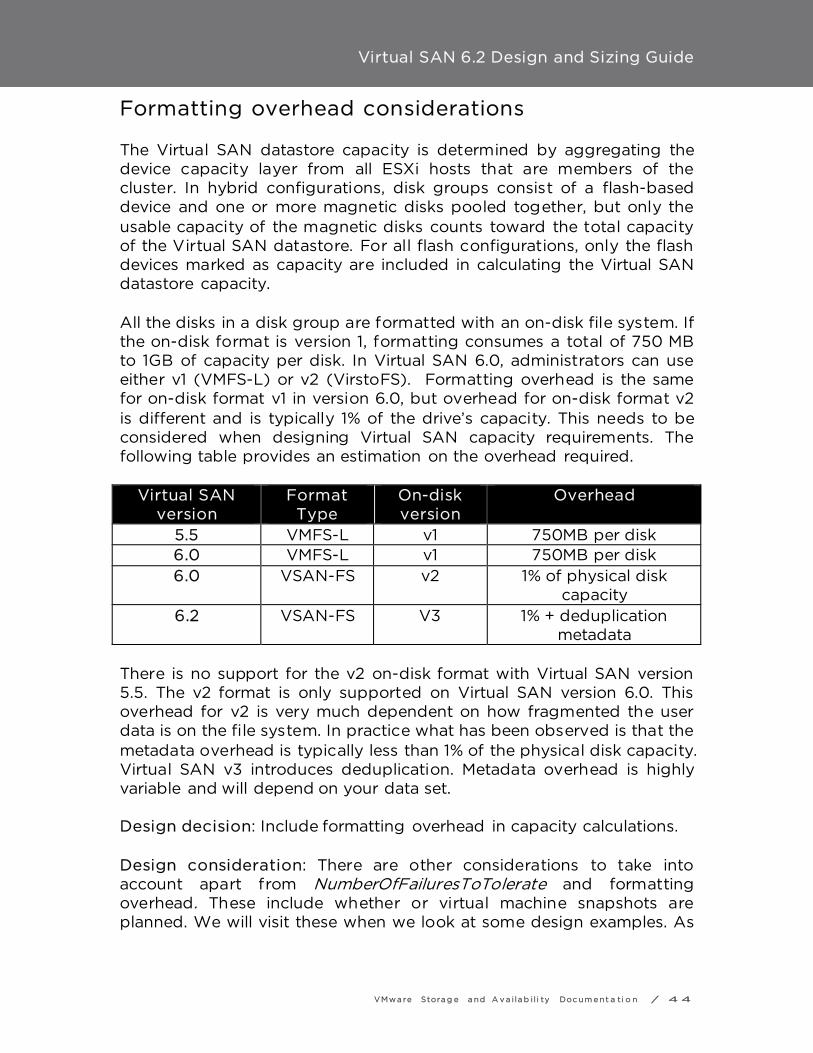
Virtual SAN 6.2 Design and Sizing Guide
VMwa re Stora g e a nd A v a i la b i l i ty Doc um e nt a ti o n / 4 4
Formatting overhead considerations The Virtual SAN datastore capacity is determined by aggregating the device capacity layer from all ESXi hosts that are members of the cluster. In hybrid configurations, disk groups consist of a flash-based device and one or more magnetic disks pooled together, but only the usable capacity of the magnetic disks counts toward the total capacity of the Virtual SAN datastore. For all flash configurations, only the flash devices marked as capacity are included in calculating the Virtual SAN datastore capacity. All the disks in a disk group are formatted with an on-disk file system. If the on-disk format is version 1, formatting consumes a total of 750 MB to 1GB of capacity per disk. In Virtual SAN 6.0, administrators can use either v1 (VMFS-L) or v2 (VirstoFS). Formatting overhead is the same for on-disk format v1 in version 6.0, but overhead for on-disk format v2 is different and is typically 1% of the drive’s capacity. This needs to be considered when designing Virtual SAN capacity requirements. The following table provides an estimation on the overhead required.
Virtual SAN version
Format Type
On-disk version
Overhead
5.5 VMFS-L v1 750MB per disk 6.0 VMFS-L v1 750MB per disk 6.0 VSAN-FS v2 1% of physical disk
capacity 6.2 VSAN-FS V3 1% + deduplication
metadata There is no support for the v2 on-disk format with Virtual SAN version 5.5. The v2 format is only supported on Virtual SAN version 6.0. This overhead for v2 is very much dependent on how fragmented the user data is on the file system. In practice what has been observed is that the metadata overhead is typically less than 1% of the physical disk capacity. Virtual SAN v3 introduces deduplication. Metadata overhead is highly variable and will depend on your data set. Design decision: Include formatting overhead in capacity calculations. Design consideration: There are other considerations to take into account apart from NumberOfFailuresToTolerate and formatting overhead. These include whether or virtual machine snapshots are planned. We will visit these when we look at some design examples. As

Virtual SAN 6.2 Design and Sizing Guide
VMwa re Stora g e a nd A v a i la b i l i ty Doc um e nt a ti o n / 4 5
a rule of thumb, VMware recommends leaving approximately 30% free space available in the cluster capacity.

Virtual SAN 6.2 Design and Sizing Guide
VMwa re Stora g e a nd A v a i la b i l i ty Doc um e nt a ti o n / 4 6
Snapshot cache sizing considerations In Virtual SAN version 5.5, administrators who wished to use virtual machine snapshots needed to consider all of the same restrictions when compared to using virtual machine snapshots on VMFS or NFS datastores. As per VMware KB article 1025279, VMware recommended using no single snapshot for more than 24-72 hours, and although 32 snapshots were supported in a chain, VMware recommended that only 2-3 snapshots in a chain were used. In Virtual SAN 6.0, and on-disk format (v2), there have been major enhancements to the snapshot mechanism, making virtual machine snapshots far superior than before. Virtual SAN 6.0 fully supports 32 snapshots per VMDK with the v2 on-disk format. The new snapshot mechanism on v2 uses a new ‘‘vsanSparse’’ format. However, while these new snapshots outperform the earlier version, there are still some design and sizing concerns to consider. When sizing cache for Virtual SAN 6.0 hybrid configurations, a design must take into account potential heavy usage of snapshots. Creating multiple, active snapshots may exhaust cache resources quickly, potentially impacting performance. The standard guidance of sizing cache to be 10% of consumed capacity may need to be increased to 15% or greater, especially with demanding snapshot usage. Cache usage for virtual machine snapshots is not a concern for Virtual SAN 6.0 all-flash configurations. If the on-disk format is not upgraded to v2 when Virtual SAN has been upgraded from version 5.5 to 6.0, and the on-disk format remains at v1, then the older (redo log) snapshot format is used, and the considerations in VMware KB article 1025279 continue to apply. Design consideration: If virtual machine snapshots are used heavily in a hybrid design, consider increasing the cache-to-capacity ratio from 10% to 15%.

Virtual SAN 6.2 Design and Sizing Guide
VMwa re Stora g e a nd A v a i la b i l i ty Doc um e nt a ti o n / 4 7
Choosing a storage I/O controller The most important aspect of storage design is ensuring that the components that are selected appear in the VMware Compatibility Guide (VCG). A VCG check will ensure that VMware supports the storage I/O controller and solid-state disk or PCIe flash device. Some design considerations for the storage hardware are listed here.
Multiple controllers and SAS Expanders Virtual SAN supports multiple controllers per ESXi host. The maximum number of disks per host is 35 (7 disks per disk group, 5 disk groups per host). Some controllers support 16 ports and therefore up to 16 disks can be placed behind one controller. The use of two such controllers in one host will get close to the maximums. However, some controllers only support 8 ports, so a total of 4 or 5 controllers would be needed to reach the maximum. SAS expanders are sometimes considered to extend the number of storage devices that can be configured with a single storage I/O controller. VMware has not extensively tested SAS expanders with Virtual SAN, and thus does not encourage their use. In addition to potential compatibility issues, the use of SAS expanders may impact performance and increase the impact of a failed disk group. SAS Expanders have been tested in limited cases with Ready Nodes on a case by case. These ready nodes may have a ‘‘up to’’ maximum on the number of drives that have been certified with the expander. Refer to the VSAN VCG to see what SAS Expanders have been certified and will be supported.
Multiple Controllers versus single controllers The difference between configuring ESXi hosts with multiple storage controllers and a single controller is that the former will allow potentially achieve higher performance as well as isolate a controller failure to a smaller subset of disk groups. With a single controller, all devices in the host will be behind the same controller, even if there are multiple disks groups deployed on the host. Therefore a failure of the controller will impact all storage on this host. If there are multiple controllers, some devices may be placed behind one controller and other devices behind another controller. Not only

Virtual SAN 6.2 Design and Sizing Guide
VMwa re Stora g e a nd A v a i la b i l i ty Doc um e nt a ti o n / 4 8
does this reduce the failure domain should a single controller fail, but this configuration also improves performance. Design decision: Multiple storage I/O controllers per host can reduce the failure domain, but can also improve performance.
Storage controller queue depth There are two important items displayed by the VCG for storage I/O controllers that should be noted. The first of these is ‘‘features’’ and the second is queue depth. Queue depth is extremely important, as issues have been observed with controllers that have very small queue depths. In particular, controllers with small queue depths (less than 256) can impact virtual machine I/O performance when Virtual SAN is rebuilding components, either due to a failure or when requested to do so when entering maintenance mode. Design decision: Choose storage I/O controllers that have as large a queue depth as possible. While 256 are the minimum, the recommendation would be to choose a controller with a much larger queue depth where possible.
RAID-0 versus pass-through The second important item is the ‘‘feature’’ column that displays how Virtual SAN supports physical disk presentation to Virtual SAN. There are entries referring to RAID 0 and pass-through. Pass-through means that this controller can work in a mode that will present the magnetic disks directly to the ESXi host. RAID 0 implies that each of the magnetic disks will have to be configured as a RAID 0 volume before the ESXi host can see them. There are additional considerations with RAID 0. For example, an administrator may have to take additional manual steps replacing a failed drive. These steps include rebuilding a new RAID 0 volume rather than simply plugging in a replacement empty disk into the host and allowing Virtual SAN to claim it. Design decision: Storage I/O controllers that offer RAID-0 mode typically take longer to install and replace than pass-thru drives from an operations perspective.
Storage controller cache considerations

Virtual SAN 6.2 Design and Sizing Guide
VMwa re Stora g e a nd A v a i la b i l i ty Doc um e nt a ti o n / 4 9
VMware’s recommendation is to disable the cache on the controller if possible. Virtual SAN is already caching data at the storage layer --- there is no need to do this again at the controller layer. If this cannot be done due to restrictions on the storage controller, the recommendation is to set the cache to 100% read.
Advanced controller features Some controller vendors provide third party features for acceleration. For example HP has a feature called Smart Path and LSI has a feature called Fast Path. VMware recommends disabling advanced features for acceleration when controllers are used in Virtual SAN environments. Design decision: When choosing a storage I/O controller, verify that it is on the VCG, ensure cache is disabled, and ensure any third party acceleration features are disabled. If the controller offers both RAID 0 and pass-through support, consider using pass-through as this makes maintenance tasks such as disk replacement much easier.
Knowledge base related controller issues A search of KB.VMware.com should be performed for known configuration issues for a given controller. In the case of the Dell H730 family of controllers (H730, H730p, H730 mini) the following KB articles should be observed.
• Avoiding a known drive failure issue when Dell PERC H730 controller is used with VMware Virtual SAN 5.5 or 6.0 (2135494)
• Using a Dell Perc H730 controller in an ESXi 5.5 or ESXi 6.0 host displays IO failures or aborts, and reports unhealthy VSAN disks (2109665)
Disk Group Design While Virtual SAN requires at least one disk group per host contributing storage in a cluster, it might be worth considering using more than one disk group per host.
Disk groups as a storage failure domain
Virtual SAN 6.2 Design and Sizing Guide
VMwa re Stora g e a nd A v a i la b i l i ty Doc um e nt a ti o n / 5 0
A disk group can be thought of as a storage failure domain in Virtual SAN. Should the flash cache device or storage I/O controller associated with a disk group fail, this will impact all the devices contributing towards capacity in the same disk group, and thus all the virtual machine components using that storage. All of the components residing in that disk group will be rebuilt elsewhere in the cluster, assuming there are enough resources available. No other virtual machines that have their components in other hosts or in other disk groups, or attached to a different storage I/O controller are impacted. Therefore, having one very large disk group with a large flash device and lots of capacity might mean that a considerable amount of data needs to be rebuilt in the event of a failure. This rebuild traffic could impact the performance of the virtual machine traffic. The length of time to rebuild the components is also a concern because virtual machines that have components that are being rebuilt are exposed to another failure occurring during this time. By using multiple smaller disk groups, performance can be improved and the failure domain reduced in the event of storage I/O controller or flash device failure. The trade off once again is that this design requires multiple flash devices and/or storage I/O controllers, which consumes extra disk slots and may be an additional expense and needs consideration. Often times the cost of implementing multiple disk groups is not higher. If the cost of 2 x 200GB solid-state devices is compared to 1 x 400GB solid-state device, the price is very often similar. Also worth considering is that two cache devices in two disk groups on the same host can provide significantly higher IOPS than one cache device in one disk group. Design decision: Multiple disk groups typically mean better performance and smaller fault domains, but may sometimes come at a cost and consume additional disk slots.
Multiple disk groups and 3-node clusters Another advantage of multiple disk groups over single disk group design applies to 3 node clusters. If there is only a single disk group per host in a 2node and 3-node cluster, and one of the flash cache devices fails, there is no place for the components in the disk group to be rebuilt.

Virtual SAN 6.2 Design and Sizing Guide
VMwa re Stora g e a nd A v a i la b i l i ty Doc um e nt a ti o n / 5 1
However, if there were multiple disk groups per host, and if there is sufficient capacity in the other disk group on the host when the flash cache device fails, Virtual SAN would be able to rebuild the affected components in the remaining disk group. This is another consideration to keep in mind if planning to deploy 2node and 3-node Virtual SAN clusters.
Small disk drive capacity considerations When using small capacity devices, and deploying virtual machines with large VMDK sizes, a VMDK object may be split into multiple components across multiple disks to accommodate the large VMDK size. This is shown as a RAID-0 configuration for the VMDK object. However when Virtual SAN splits an object in this way, multiple components may reside on the same physical disk, a configuration that is not allowed when NumberOfDiskStripesPerObject is specified in the policy. This is not necessarily an issue, and Virtual SAN is designed to handle this quite well. But it can lead to questions around why objects are getting striped when there was no stripe width request placed in the policy.
Very large VMDK considerations With Virtual SAN 6.0, virtual machine disk sizes of 62TB are now supported. However, consideration should be given as to whether an application actually requires this size of a VMDK. As previously mentioned, the maximum component size on Virtual SAN is 255GB. When creating very large VMDKs, the object will be split (striped) into multiple 255GB components. This may quickly consume the component count of the hosts, and this is especially true when NumberOfFailuresToTolerate is taken into account. A single 62TB VMDK with NumberOfFailuresToTolerate = 1 will require 500 or so components in the cluster (though many of these components can reside on the same physical devices). One other consideration is that although Virtual SAN might have the aggregate space available on the cluster to accommodate this large size VMDK object, it will depend on where this space is available and whether or not this space can be used to meet the requirements in the VM storage policy.

Virtual SAN 6.2 Design and Sizing Guide
VMwa re Stora g e a nd A v a i la b i l i ty Doc um e nt a ti o n / 5 2
For example, in a 3 node cluster which has 200TB of free space, one could conceivably believe that this should accommodate a VMDK with 62TB that has a NumberOfFailuresToTolerate=1 (2 x 62TB = 124TB). However if one host has 100TB free, host two has 50TB free and host three has 50TB free, then this Virtual SAN will not be able to accommodate this request.

Virtual SAN 6.2 Design and Sizing Guide
VMwa re Stora g e a nd A v a i la b i l i ty Doc um e nt a ti o n / 5 3
Designing with capacity for replacing/upgrading disks When a flash device or magnetic disk fails, Virtual SAN will immediately begin to rebuild the components from these failed disks on other disks in the cluster, with a goal to keep the cluster as balanced as possible. In the event of a magnetic disk failure or flash capacity device failure, components may get rebuilt on the capacity devices in the same disk group, or on a different disk group. In the case of a flash cache device failure, since this impacts the whole of the disk group, Virtual SAN will need additional capacity in the cluster to rebuild all the components of that disk group. If there are other disk groups on the same host, it may try to use these, but it may also use disk groups on other hosts in the cluster. Again, the aim is for a balanced cluster. If a disk group fails, and it has virtual machines consuming a significant amount of disk space, a lot of spare capacity needs to be found in order to rebuild the components to meet the requirements placed in the VM Storage Policy. Since the most common failure is a host failure, that is what should be sized for from a capacity perspective. Design decision: VMware recommends that approximately 30% of free capacity should be kept to avoid unnecessary rebuilding/rebalancing activity. To have components rebuilt in the event of a failure, a design should also include at least one free host worth of capacity. If a design needs to rebuild components after multiple failures, then additional free hosts worth of capacity needs to be included.
Disk replacement/upgrade ergonomics Ergonomics of device maintenance is an important consideration. One consideration is the ease of replacing a failed component on the host. One simple question regarding the host is whether the disk bays are located in the front of the server, or does the operator need to slide the enclosure out of the rack to gain access. A similar consideration applies to PCIe devices, should they need to be replaced. There is another consideration is around hot plug/host swap support. If a drive fails, Virtual SAN 6.0 provides administrators with the capability of lighting the LED on the drive for identification purposes. Once the drive is located in the server/rack, it can be removed from the disk

Virtual SAN 6.2 Design and Sizing Guide
VMwa re Stora g e a nd A v a i la b i l i ty Doc um e nt a ti o n / 5 4
group via the UI (which includes a disk evacuation option in version 6.0) and then the drive can be ejected and replaced with a new one. Certain controllers, especially when they are using RAID 0 mode rather than pass-through mode, require additional steps to get the drive discovered when it the original is ejected and a new drive inserted. This operation needs to be as seamless as possible, so it is important to consider whether or not the controller chosen for the Virtual SAN design can support plug-n-play operations.
Design to avoid running out of capacity VMware recommends uniformly configured hosts in the Virtual SAN cluster. This will allow for an even distribution of components and objects across all disks in the cluster. However, there may be occasions where the cluster becomes unevenly balanced, when there is a maintenance mode - full evacuation for example, or the capacity of the Virtual SAN datastore is overcommitted with excessive virtual machine deployments. If any physical device in the capacity layer reaches an 80% full threshold, Virtual SAN will automatically instantiate a rebalancing procedure that will move components around the cluster to ensure that all disks remain below the 80% threshold. This procedure can be very I/O intensive, and may impact virtual machine I/O while the rebalance is running. Best practice: Try to maintain at least 30% free capacity across the cluster to accommodate the remediation of components when a failure occurs or a maintenance task is required. This best practice will also avoid any unnecessary rebalancing activity.

Virtual SAN 6.2 Design and Sizing Guide
VMwa re Stora g e a nd A v a i la b i l i ty Doc um e nt a ti o n / 5 5
Summary of storage design considerations
• Consider whether an all-flash solution or a hybrid solution is preferable for the Virtual SAN design. All-flash, while possibly more expensive, can offer higher performance and low latency.
• Ensure that the endurance of the flash devices used in the design match the requirements
• Keep in mind the 10% flash to capacity ratio --- this is true for both hybrid and all-flash configurations. Spend some time determining how large the capacity layer will be over time, and use the formula provided to extrapolate the flash cache size
• Consider whether PCI-E flash devices or SSDs are best for the design
• Determine the endurance requirement for the flash cache, and the flash capacity requirement for all-flash solution designs
• Determine the best magnetic disk for any hybrid solution design • Remember to include filesystem overhead when sizing the
capacity layer • Consider, if possible, multiple storage I/O controllers per host for
performance and redundancy. • Consider the benefits of pass-through over RAID-0 and ensure
that the desired mode is supported by the controller • Disable cache on controllers, or if not possible, set cache to 100%
read • Disable advanced features of the storage I/O controllers • When designing disk groups, consider disk groups not only as a
failure domain, but a way of increasing performance • Consider the limitations around using very small physical drives • Consider the limitations when deploying very large virtual
machine disks on Virtual SAN • Design with one additional host with enough capacity to facilitate
remediation on disk failure, which will allow for another failure in the cluster to occur while providing full virtual machine availability
• Consider a design which will facilitate easy replacement of failed components
• As a rule of thumb, target keeping free capacity at ~30%

Virtual SAN 6.2 Design and Sizing Guide
VMwa re Stora g e a nd A v a i la b i l i ty Doc um e nt a ti o n / 5 6
VM Storage Policy Design Considerations It is important to have an understanding of the VM Storage Policy mechanism as part Virtual SAN. VM Storage Policies define the requirements of the application running in the virtual machine from an availability, sizing and performance perspective.
Objects and components A virtual machine deployed on a Virtual SAN datastore is comprised of a set of objects. These are the VM Home Namespace, the VMDK, VM Swap (when the virtual machine is powered on) and in the case of a snapshot, there is the delta VMDKs and the virtual machine memory snapshot (when this is captured as part of the snapshot):
Each of these objects is comprised of a set of components, determined by capabilities placed in the VM Storage Policy. For example, if NumberOfFailuresToTolerate=1 is set in the VM Storage Policy, then the VMDK object would be mirrored/replicated, with each replica being comprised of at least one component. If NumberOfDiskStripesPerObject is greater than one in the VM Storage Policy, then the object is striped

Virtual SAN 6.2 Design and Sizing Guide
VMwa re Stora g e a nd A v a i la b i l i ty Doc um e nt a ti o n / 5 7
across multiple disks and each stripe is said to be a component of the object. For every component created in Virtual SAN 5.5, an additional 2MB of disk capacity is consumed for metadata. In Virtual SAN 6.0, if the component is built on the capacity layer that has been upgraded to the v2 on-disk format, it is an additional 4MB. This appreciation of the relationship between virtual machines, objects and components will help with understanding the various Virtual SAN failure scenarios. Design consideration: Realistically, the metadata overhead incurred by creating components on Virtual SAN is negligible and doesn’t need to be included in the overall capacity.
Witness and Replicas In Virtual SAN version 5.5, witnesses are an integral component of every storage object, as long as the object is configured to tolerate at least one failure. They are components that do not contain data, only metadata. Their purpose is to serve as tiebreakers when availability decisions are made to meet the failures to tolerate policy setting. They are used when determining if a quorum of components exist in the cluster. A witness consumes about 2MB of space for metadata on the Virtual SAN datastore. In Virtual SAN 6.0, how quorum is computed has been changed. The rule is no longer "more than 50% of components". Instead, in 6.0, each component has a number of votes, which may be 1 or more. Quorum is now calculated based on the rule that "more than 50% of votes" is required. It then becomes a possibility that components are distributed in such a way that Virtual SAN can still guarantee failures-to-tolerate without the use of witnesses. However many objects will still have a witness in 6.0. Replicas make up a virtual machine storage objects. Replicas are instantiated when an availability capability (NumberOfFailuresToTolerate) is specified for the virtual machine. The availability capability dictates how many replicas are created. It enables virtual machines to continue running with a full complement of data when there are host, network or disk failures in the cluster.

Virtual SAN 6.2 Design and Sizing Guide
VMwa re Stora g e a nd A v a i la b i l i ty Doc um e nt a ti o n / 5 8
NOTE: For an object to be accessible in Virtual SAN 5.5, more than 50 percent of its components must be accessible. For an object to be accessible in Virtual SAN 6.0, more than 50 percent of its votes must be accessible. Design consideration: Realistically, the overhead incurred by creating witnesses on Virtual SAN is negligible and doesn’t need to be included in the overall capacity.

Virtual SAN 6.2 Design and Sizing Guide
VMwa re Stora g e a nd A v a i la b i l i ty Doc um e nt a ti o n / 5 9
Virtual Machine Snapshot Considerations There is a new snapshot format in Virtual SAN 6.0. This requires that the on-disk format is v2 however. If the on-disk format is left at v1 after an upgrade, then the older snapshot mechanism (based on the redo log format) continues to be used for virtual machine snapshots. Another major change in the handing of snapshots relates to virtual machine memory when a snapshot is taken of a running virtual machine. In Virtual SAN 5.5, the virtual machine memory was saved as a file in the VM home namespace when a snapshot was taken. In Virtual SAN 6.0, the virtual machine memory is now instantiated as its own object on the Virtual SAN datastore. Design consideration: The virtual machine memory snapshot size needs to be considered when sizing the Virtual SAN datastore, if there is a desire to use virtual machine snapshots and capture the virtual machine’s memory in the snapshot.
Reviewing object layout from UI The vSphere web client provides a way of examining the layout of an object on Virtual SAN. Below, the VM Home namespace object and VMDK object are displayed when a virtual machine has been deployed with a policy settings of NumberOfFailuresToTolerate = 1 and NumberOfDiskStripesPerObject = 2. The first screenshot is from the VM home. This does not implement the stripe width setting, but it does implement the failures to tolerate policy setting. There is a RAID 1 containing two components (replicas) and a third witness component for quorum. Both the components and witness must be on different hosts.
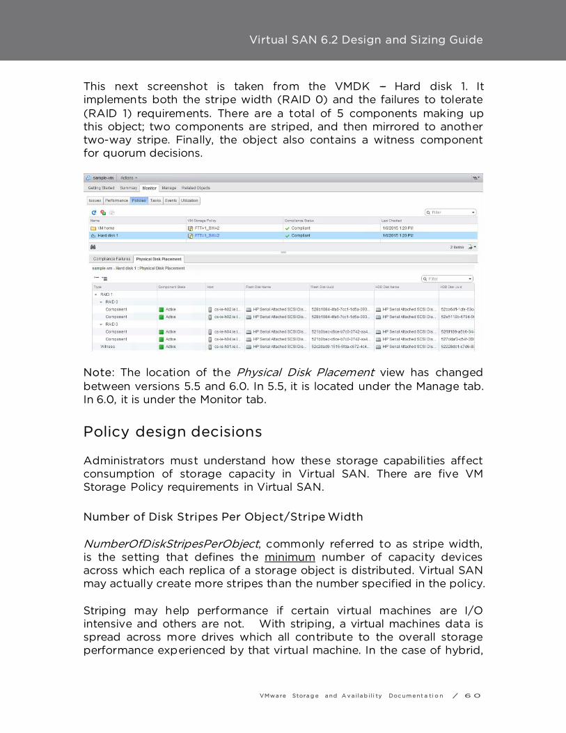
Virtual SAN 6.2 Design and Sizing Guide
VMwa re Stora g e a nd A v a i la b i l i ty Doc um e nt a ti o n / 6 0
This next screenshot is taken from the VMDK --- Hard disk 1. It implements both the stripe width (RAID 0) and the failures to tolerate (RAID 1) requirements. There are a total of 5 components making up this object; two components are striped, and then mirrored to another two-way stripe. Finally, the object also contains a witness component for quorum decisions.
Note: The location of the Physical Disk Placement view has changed between versions 5.5 and 6.0. In 5.5, it is located under the Manage tab. In 6.0, it is under the Monitor tab.
Policy design decisions Administrators must understand how these storage capabilities affect consumption of storage capacity in Virtual SAN. There are five VM Storage Policy requirements in Virtual SAN.
Number of Disk Stripes Per Object/Stripe Width NumberOfDiskStripesPerObject, commonly referred to as stripe width, is the setting that defines the minimum number of capacity devices across which each replica of a storage object is distributed. Virtual SAN may actually create more stripes than the number specified in the policy. Striping may help performance if certain virtual machines are I/O intensive and others are not. With striping, a virtual machines data is spread across more drives which all contribute to the overall storage performance experienced by that virtual machine. In the case of hybrid,

Virtual SAN 6.2 Design and Sizing Guide
VMwa re Stora g e a nd A v a i la b i l i ty Doc um e nt a ti o n / 6 1
this striping would be across magnetic disks. In the case of all-flash, the striping would be across whatever flash devices are making up the capacity layer. However, striping may not help performance if (a) an application is not especially I/O intensive, or (b) a virtual machine’s data is spread across devices that are already busy servicing other I/O intensive virtual machines. However, for the most part, VMware recommends leaving striping at the default value of 1 unless performance issues that might be alleviated by striping are observed. The default value for the stripe width is 1 whereas the maximum value is 12.
Stripe Width --- Sizing Consideration There are two main sizing considerations when it comes to stripe width. The first of these considerations is if there are enough physical devices in the various hosts and across the cluster to accommodate the requested stripe width, especially when there is also a NumberOfFailuresToTolerate value to accommodate. The second consideration is whether the value chosen for stripe width is going to require a significant number of components and consume the host component count. Both of these should be considered as part of any Virtual SAN design, although considering the increase in maximum component count in 6.0 with on-disk format v2, this realistically isn’t a major concern anymore. Later, some working examples will be looked at which will show how to take these factors into consideration when designing a Virtual SAN cluster.
Flash Read Cache Reservation Previously we mentioned the 10% rule for flash cache sizing. This is used as a read cache and write buffer in hybrid configurations, and as a write buffer only for all-flash configurations, and is distributed fairly amongst all virtual machines. However, through the use of VM Storage Policy setting FlashReadCacheReservation, it is possible to dedicate a portion of the read cache to one or more virtual machines. Note: This policy setting is only relevant to hybrid configurations. It is not supported or relevant in all-flash configurations due to changes in the caching mechanisms and the fact that there is no read cache in an all-flash configuration.

Virtual SAN 6.2 Design and Sizing Guide
VMwa re Stora g e a nd A v a i la b i l i ty Doc um e nt a ti o n / 6 2
For hybrid configurations, this setting defines how much read flash capacity should be reserved for a storage object. It is specified as a percentage of the logical size of the virtual machine disk object. It should only be used for addressing specifically identified read performance issues. Other virtual machine objects do not use this reserved flash cache capacity. Unreserved flash is shared fairly between all objects, so for this reason VMware recommends not changing the flash reservation unless a specific performance issue is observed. The default value is 0%, implying the object has no read cache reserved, but shares it with other virtual machines. The maximum value is 100%, meaning that the amount of reserved read cache is the same size as the storage object (VMDK).
Flash Read Cache Reservation --- sizing considerations Care must be taken when setting a read cache reservation requirement in the VM Storage Policy. What might appear to be small FlashReadCacheReservation numbers to users can easily exhaust all SSD resources, especially if thin provisioning is being used (Note that in VM Storage Policy terminology, thin provisioning is referred to as Object Space Reservation).
Flash Read Cache Reservation configuration example In this hybrid Virtual SAN example, the customer has set the VM Storage Policy --- FlashReadCacheReservation to 5% for all the virtual machine disks. Remember that 70% of flash is set aside for read cache in hybrid configurations. With thin provisioning, customers can overprovision and have more logical address space than real space. In this example, the customer has thin provisioned twice as much logical space than physical space (200%). If the FlashReadCacheReservation requested by the administrator is calculated and compared to the total flash read cache available on the host, it reveals the following:
o Total disk space consumed by VMs: X o Total available flash read cache: (70% of 10% of X) = 7% of
X
Virtual SAN 6.2 Design and Sizing Guide
VMwa re Stora g e a nd A v a i la b i l i ty Doc um e nt a ti o n / 6 3
o Requested flash read cache reservation: (5% of 200% of X) = 10% of X
=> 10% of X is greater than 7% of X
Therefore if thin provisioning is being used to overcommit storage space, great care must be taken to ensure this does not negatively impact cache reservation settings. If cache reservation uses up all of the read cache, it can negatively impact performance. Design consideration: Use FlashReadCacheReservation with caution. A misconfiguration or miscalculation can very easily over-allocate read cache to some virtual machines while starving others.
Number of Failures To Tolerate The NumberOfFailuresToTolerate policy setting is an availability capability that can be applied to all virtual machines or individual VMDKs. This policy plays an important role when planning and sizing storage capacity for Virtual SAN. Based on the availability requirements of a virtual machine, the setting defined in a virtual machine storage policy can lead to the consumption of as many as four times the capacity of the virtual machine. For ‘‘n’’ failures tolerated, "n+1" copies of the object are created and "2n+1" hosts contributing storage are required. The default value for NumberOfFailuresToTolerate is 1. This means that even if a policy is not chosen when deploying a virtual machine, there will still be one replica copy of the virtual machine’s data. The maximum value for NumberOfFailuresToTolerate is 3. Virtual SAN 6.0 introduces the concept of fault domains. This allows Virtual SAN to tolerate not just host failures, but also environmental failures such as rack, switch and power supply failures by locating replica copies of data in different locations. When working with fault domains, to tolerate ‘‘n’’ number of failures, "n+1" copies of the object are once again created but now "2n+1" fault domains are required. Each fault domain must contain at least one host contributing storage. Fault domains will be discussed in more detail shortly.
Failures to Tolerate sizing consideration For example, if the NumberOfFailuresToTolerate is set to 1, two replica mirror copies of the virtual machine or individual VMDKs are created

Virtual SAN 6.2 Design and Sizing Guide
VMwa re Stora g e a nd A v a i la b i l i ty Doc um e nt a ti o n / 6 4
across the cluster. If the number is set to 2, three mirror copies are created; if the number is set to 3, four copies are created.
Force Provisioning The Force provisioning policy allows Virtual SAN to violate the NumberOfFailuresToTolerate (FTT), NumberOfDiskStripesPerObject (SW) and FlashReadCacheReservation (FRCR) policy settings during the initial deployment of a virtual machine. Virtual SAN will attempt to find a placement that meets all requirements. If it cannot, it will attempt a much simpler placement with requirements reduced to FTT=0, SW=1, FRCR=0. This means Virtual SAN will attempt to create an object with just a single mirror. Any ObjectSpaceReservation (OSR) policy setting is still honored. Virtual SAN does not gracefully try to find a placement for an object that simply reduces the requirements that can't be met. For example, if an object asks for FTT=2, if that can't be met, Virtual SAN won't try FTT=1, but instead immediately tries FTT=0. Similarly, if the requirement was FTT=1, SW=10, but Virtual SAN doesn't have enough capacity devices to accommodate SW=10, then it will fall back to FTT=0, SW=1, even though a policy of FTT=1, SW=1 may have succeeded. There is another consideration. Force Provisioning can lead to capacity issues if its behavior is not well understood by administrators. If a number of virtual machines have been force provisioned, but only one replica copy of an object is currently instantiated due to lack of resources, as soon as those resources become available through the addition of new hosts or new disks, Virtual SAN will consume them on behalf of those virtual machines. Administrators who use this option to force provision virtual machines need to be aware that once additional resources become available in the cluster, Virtual SAN may immediately consume these resources to try to satisfy the policy settings of virtual machines. Caution: Another special consideration relates to entering Maintenance Mode in full data migration mode, as well as disk/disk group removal with data migration that was introduced in version 6.0. If an object is currently non-compliant due to force provisioning (either because initial placement or policy reconfiguration could not satisfy the policy

Virtual SAN 6.2 Design and Sizing Guide
VMwa re Stora g e a nd A v a i la b i l i ty Doc um e nt a ti o n / 6 5
requirements), then "Full data evacuation" of such an object will actually behave like "Ensure Accessibility", i.e. the evacuation will allow the object to have reduced availability, exposing it a higher risk. This is an important consideration when using force provisioning, and only applies for non-compliant objects. Best practice: Check if any virtual machines are non-compliant due to a lack of resources before adding new resources. This will explain why new resources are being consumed immediately by Virtual SAN. Also check if there are non-compliant VMs due to force provisioning before doing a full data migration.
Object Space Reservation An administrator should always be aware of over-committing storage on Virtual SAN, just as one need to monitor over-commitment on a traditional SAN or NAS array. By default, virtual machine storage objects deployed on Virtual SAN are thinly provisioned. This capability, ObjectSpaceReservation (OSR), specifies the percentage of the logical size of the storage object that should be reserved (thick provisioned) when the virtual machine is being provisioned. The rest of the storage object will remain thin provisioned. The default value is 0%, implying the object is deployed as thin. The maximum value is 100%, meaning the space for the object is fully reserved, which can be thought of as full, thick provisioned. Since the default is 0%, all virtual machines deployed on Virtual SAN are provisioned as thin disks unless one explicitly states a requirement for ObjectSpaceReservation in the policy. If ObjectSpaceReservation is specified, a portion of the storage object associated with that policy is reserved. There is no eager-zeroed thick format on Virtual SAN. OSR, when used, behaves similarly to lazy-zeroed thick. There are a number of safeguards that will prevent over commitment. For instance, if there is not enough storage capacity across the required number of hosts in the cluster to satisfy a replica or stripe width policy setting, then the following warning is displayed.

Virtual SAN 6.2 Design and Sizing Guide
VMwa re Stora g e a nd A v a i la b i l i ty Doc um e nt a ti o n / 6 6
The Monitor > Virtual SAN > Physical Disks view will display the amount of used capacity in the cluster. This screen shot is taken from a 5.5 configuration. Similar views are available on 6.0.
Design consideration: While the creation of replicas is taken into account when the capacity of the Virtual SAN datastore is calculated, thin provisioning over-commitment is something that should be considered in the sizing calculations when provisioning virtual machines on a Virtual SAN.
IOP Limit For Object There are cases where an administrator will want to limit the maximum amount of IOPS that are available to an object or virtual machine. There are two key use cases for this functionality

Virtual SAN 6.2 Design and Sizing Guide
VMwa re Stora g e a nd A v a i la b i l i ty Doc um e nt a ti o n / 6 7
• Preventing noisy neighbor workloads from impacting other workloads that need more performance available.
• Create artificial standards of service as part of a tiered service offering using the same pool of resources.
By default, Virtual SAN seeks to dynamically adjust performance based on demand and provide a fair weighting of resources available. This capability IopLimitForObject limits the amount of performance available to an object. This is normalized at a 32KB block size. A virtual machine reading or writing at 16KB would be treated the same as one performing 32KB sized operations. A 64KB read or write however would be treated as two separate operations, leading to half of the configured IOP limit being the number of operations performed.
Disable Object Checksum Object Checksums were introduced as a policy in Virtual SAN 6.2. They enable the detection of corruption caused by hardware/software components including memory, drives, etc during the read or write operations. Object Checksums are enabled by default for objects residing on Virtual SAN file system version 3. They will verify checksums on all reads, as well as a scrubber will scan all blocks that have not been read within one year. The scrubber schedule can be adjusted to run more often but note this may increase background disk IO. Object checksums carry a small disk IO, memory and compute overhead and can be disabled on a per object basis using the DisableObjectChecksum SPBM policy. Failure Tolerance Method Prior to Virtual SAN 6.2, RAID-1 (Mirroring) was used as the failure tolerance method. Virtual SAN 6.2 adds RAID-5/6 (Erasure Coding) to all-flash configurations. While mirroring techniques excel in workloads where performance is the most important factor, they are expensive in terms of capacity required. RAID-5/6 (Erasure Coding) data layout can be configured to help ensure the same levels of availability, while consuming less capacity than RAID-1 (Mirroring)
RAID-5/6 (Erasure Coding) is configured as a storage policy rule and can be applied to individual virtual disks or an entire virtual machine.

Virtual SAN 6.2 Design and Sizing Guide
VMwa re Stora g e a nd A v a i la b i l i ty Doc um e nt a ti o n / 6 8
Note that the failure tolerance method in the rule set must be set to RAID5/6 (Erasure Coding).
For FTT=1 the storage overhead will be 1.33X rather than 2X. In this case a 20GB VMDK would use on 27GB instead of the 40GB traditionally used by RAID-1. For FTT=2 the storage overhead will be 2X rather than 3X. In this case as 20GB VMDK will use 40GB instead of 60GB.
Erasure coding can provide significant capacity savings over mirroring, but it is important to consider that erasure coding incurs additional overhead. This is common among any storage platform today. Because erasure coding is only supported in all-flash Virtual SAN configurations, effects to latency and IOPS are negligible in most use cases due to the inherent performance of flash devices.
For more guidance on which workloads will benefit from erasure coding, see VMware Virtual SAN 6.2 Space Efficiency Technologies.

Virtual SAN 6.2 Design and Sizing Guide
VMwa re Stora g e a nd A v a i la b i l i ty Doc um e nt a ti o n / 6 9
Summary of policy design considerations
• Any policies settings should be considered in the context of the number of components that might result from said policy.
• StripeWidth may or may not improve performance for hybrid configurations; it will have little to offer for all-flash configurations.
• FlashReadCacheReservation should be used with caution, and only when a specific performance issue has been identified.
• NumberOfFailuresToTolerate needs to take into account how much additional capacity will be consumed, as this policy setting is incremented.
• When configuring NumberOfFailuresToTolerate, consideration needs to be given to the number of hosts contributing storage, and if using fault domains, the number of fault domains that contain hosts contributing storage.
• ForceProvisioning will allow non-compliant VMs to be deployed, but once additional resources/capacity become available, these VMs will consume them to become compliant.
• VM’s that have been force provisioned have an impact on the way that maintenance mode does full data migrations, using ‘‘Ensure accessibility’’ rather than ‘‘Full data migration’’.
• All virtual machines deployed on Virtual SAN (with a policy) will be thin provisioned. This may lead to over-commitment that the administrator will need to monitor.
Virtual Machine Namespace & Swap Considerations Virtual machines on Virtual SAN are deployed as object. Virtual SAN creates a virtual machine namespace (VM home) object when a virtual machine is deployed. When the virtual machine is powered on, a VM swap object is also instantiated whilst the virtual machine remains powered on. Neither the VM home namespace nor the VM swap inherits all of the setting from the VM Storage Policy. These have special policy settings that have significance when sizing a Virtual SAN cluster.
VM Home Namespace
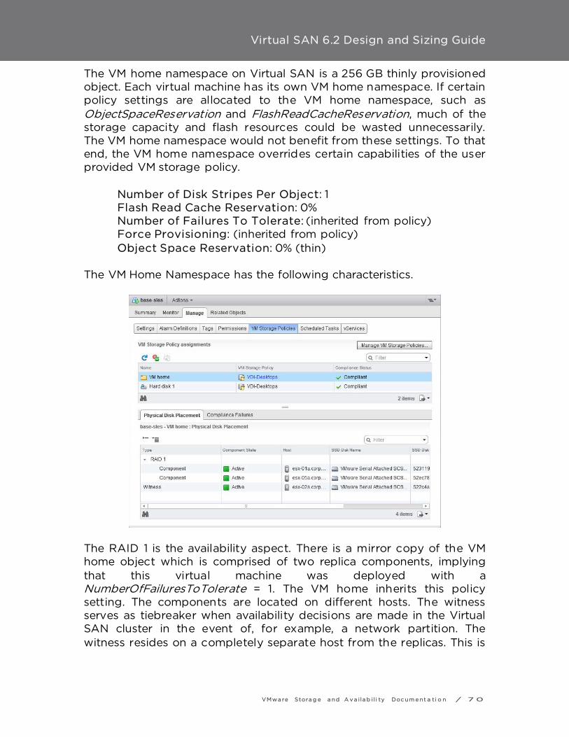
Virtual SAN 6.2 Design and Sizing Guide
VMwa re Stora g e a nd A v a i la b i l i ty Doc um e nt a ti o n / 7 0
The VM home namespace on Virtual SAN is a 256 GB thinly provisioned object. Each virtual machine has its own VM home namespace. If certain policy settings are allocated to the VM home namespace, such as ObjectSpaceReservation and FlashReadCacheReservation, much of the storage capacity and flash resources could be wasted unnecessarily. The VM home namespace would not benefit from these settings. To that end, the VM home namespace overrides certain capabilities of the user provided VM storage policy.
Number of Disk Stripes Per Object: 1 Flash Read Cache Reservation: 0% Number of Failures To Tolerate: (inherited from policy) Force Provisioning: (inherited from policy) Object Space Reservation: 0% (thin)
The VM Home Namespace has the following characteristics.
The RAID 1 is the availability aspect. There is a mirror copy of the VM home object which is comprised of two replica components, implying that this virtual machine was deployed with a NumberOfFailuresToTolerate = 1. The VM home inherits this policy setting. The components are located on different hosts. The witness serves as tiebreaker when availability decisions are made in the Virtual SAN cluster in the event of, for example, a network partition. The witness resides on a completely separate host from the replicas. This is

Virtual SAN 6.2 Design and Sizing Guide
VMwa re Stora g e a nd A v a i la b i l i ty Doc um e nt a ti o n / 7 1
why a minimum of three hosts with local storage is required for Virtual SAN. The VM Home Namespace inherits the policy setting NumberOfFailuresToTolerate. This means that if a policy is created which includes a NumberOfFailuresToTolerate = 2 policy setting, the VM home namespace object will use this policy setting. It ignores most of the other policy settings and overrides those with its default values.
VM Swap The virtual machine swap object also has its own default policy, which is to tolerate a single failure. It has a default stripe width value, is thickly provisioned, and has no read cache reservation. However, swap does not reside in the VM home namespace; it is an object in its own right, so is not limited by the way the VM home namespace is limited by a 255GB thin object. The VM Swap object does not inherit any of the setting in the VM Storage Policy. With one exception it always uses the following settings:
• Number of Disk Stripes Per Object: 1 (i.e. no striping) • Flash Read Cache Reservation: 0% • Number of Failures To Tolerate: 1 • Force Provisioning: Enabled • Object Space Reservation: 100% (thick)
In 6.2 a new advanced configuration parameter enables the disabling of force provisioning for VM Swap. SwapThickProvisionDisabled if set to true will enable this space to be allocated and consumed. Once this setting is set on a host as virtual machines are powered on this setting will be changed. For memory dense environments using linked clones (such as Horizion View) this should yield significant capacity savings. For additional guidance see this explanation of how to set and change this setting. Note that the VM Swap object is not visible in the UI when VM Storage Policies are examined. Ruby vSphere Console (RVC) commands are required to display policy and capacity information for this object.
Deltas disks created for snapshots

Virtual SAN 6.2 Design and Sizing Guide
VMwa re Stora g e a nd A v a i la b i l i ty Doc um e nt a ti o n / 7 2
Delta disks, which are created when a snapshot is taken of the VMDK object, inherit the same policy settings as the base disk VMDK. Note that delta disks are also not visible in the UI when VM Storage Policies are examined. However the VMDK base disk is visible and one can deduce the policy setting for the snapshot delta disk from the policy of the base VMDK disk. This will also be an important consideration when correctly designing and sizing Virtual SAN deployments.
Snapshot memory In Virtual SAN 5.5, snapshots of virtual machines that included memory snapshots would store the memory image in the VM home namespace. Since the VM home namespace is of finite size (255GB), it mean that snapshots of virtual machines that also captured memory could only be done if the memory size was small enough to be saved in the VM home namespace. In 6.0, memory snapshots are instantiated as objects on the Virtual SAN datastore in their own right, and are no longer limited in size. However, if the plan is to take snapshots that include memory, this is an important sizing consideration. Shortly, a number of capacity sizing examples will be looked at in detail, and will take the considerations discussed here into account.
Changing a VM Storage Policy dynamically It is important for Virtual SAN administrators to be aware of how Virtual SAN changes a VM Storage Policy dynamically, especially when it comes to sizing. Administrators need to be aware that changing policies dynamically may lead to a temporary increase in the amount of space consumed on the Virtual SAN datastore. When administrators make a change to a VM Storage Policy and then apply this to a virtual machine to make the change, Virtual SAN will attempt to find a new placement for a replica with the new configuration. If Virtual SAN fails to find a new placement, the reconfiguration will fail. In some cases existing parts of the current configuration can be reused and the configuration just needs to be updated or extended. For example, if an object currently uses NumberOfFailuresToTolerate=1, and the user asks for
Virtual SAN 6.2 Design and Sizing Guide
VMwa re Stora g e a nd A v a i la b i l i ty Doc um e nt a ti o n / 7 3
NumberOfFailuresToTolerate =2, if there are additional hosts to use, Virtual SAN can simply add another mirror (and witnesses). In other cases, such as changing the StripeWidth from 1 to 2, Virtual SAN cannot reuse the existing replicas and will create a brand new replica or replicas without impacting the existing objects. This means that applying this policy change will increase the amount of space that is being consumed by the virtual machine, albeit temporarily, and the amount of space consumed will be determined by the requirements placed in the policy. When the reconfiguration is completed, Virtual SAN then discards the old replicas.

Virtual SAN 6.2 Design and Sizing Guide
VMwa re Stora g e a nd A v a i la b i l i ty Doc um e nt a ti o n / 7 4
Provisioning with a policy that cannot be implemented Another consideration related to VM Storage Policy requirements is that even though there may appear to be enough space in the Virtual SAN cluster, a virtual machine will not provision with certain policy settings. While it might be obvious that a certain number of spindles is needed to satisfy a stripe width requirement, and that the number of spindles required increases as a NumberOfFailuresToTolerate requirement is added to the policy, Virtual SAN does not consolidate current configurations to accommodate newly deployed virtual machines. For example, Virtual SAN will not move components around hosts or disks groups to allow for the provisioning of a new replica, even though this might free enough space to allow the new virtual machine to be provisioned. . Therefore, even though there may be enough free space overall in the cluster, most of the free space may be on one node, and there may not be enough space on the remaining nodes to satisfy the replica copies for NumberOfFailuresToTolerate. A well balanced cluster, with unform storage and flash configurations, will mitiage this issue significantly.
Provisioning with the default policy With Virtual SAN 5.5, VM Storage Policies should always be used. Failure to select a policy will not deploy the VM’s disks as thin. Rather it will use the default policy which implements the virtual machine Provisioning wizard’s default VMDK provisioning format, which is Lazy-Zero-Thick. Virtual SAN 6.0 has a default VM Storage Policy that avoids this scenario. Best practice: In Virtual SAN 5.5, always deploy virtual machines with a policy. Do not use the default policy if at all possible. This is not a concern for Virtual SAN 6.0, where the default policy has settings for all capabilities.

Virtual SAN 6.2 Design and Sizing Guide
VMwa re Stora g e a nd A v a i la b i l i ty Doc um e nt a ti o n / 7 5
Host Design Considerations The following are a list of questions and considerations that will need to be included in the configuration design in order to adequately design a Virtual SAN Cluster.
CPU considerations
- Desired sockets per host - Desired cores per socket - Desired number of VMs and thus how many virtual CPUs (vCPUs)
required - Desired vCPU-to-core ratio - Provide for a 10% CPU overhead for Virtual SAN
Memory considerations
- Desired memory for VMs - A minimum of 32GB is required per ESXi host for full Virtual SAN
functionality (5 disk groups, 7 disks per disk group)
Host storage requirement
- Number of VMs, associated VMDKs, size of each virtual machine and thus how much capacity is needed for virtual machine storage.
- Memory consumed by each VM, as swap objects will be created on the Virtual SAN datastore when the virtual machine is powered on
- Desired NumberOfFailuresToTolerate setting, as this directly impacts the amount of space required for virtual machine disks
- Snapshots per VM, and how long maintained - Estimated space consumption per snapshot - Physical space for storage devices in the host
Boot device considerations
- Virtual SAN 5.5 supports both USB and SD devices for an ESXi boot device, but does not support SATADOM
- Virtual SAN 6.0 introduces SATADOM as a supported ESXi boot device

Virtual SAN 6.2 Design and Sizing Guide
VMwa re Stora g e a nd A v a i la b i l i ty Doc um e nt a ti o n / 7 6
- When USB and SD devices are used for boot devices, the logs and traces reside in RAM disks which are not persisted during reboots
o Consider redirecting logging and traces to persistent storage when these devices are used as boot devices
o VMware does not recommend storing logs and traces on the Virtual SAN datastore. These logs may not be retrievable if Virtual SAN has an issue which impacts access to the Virtual SAN datastore. This will hamper any troubleshooting effort.
o VMware KB article 1033696 has details on how to redirect scratch to a persistent datastore.
o To redirect Virtual SAN traces to a persistent datastore, esxcli vsan trace set command can be used. Refer to the vSphere command line documentation for further information.
- Virtual SAN traces are written directly to SATADOMs devices; there is no RAMdisk used when SATADOM is the boot device. Therefore, the recommendation is to use an SLC class device for performance and more importantly endurance.
Considerations for compute-only hosts The following example will provide some background as to why VMware recommend uniformly configured hosts and not using compute-only nodes in the cluster. Assume a six-node cluster, and that there are 100 virtual machines running per ESXi host in a cluster, and overall they consume 2,000 components each. In Virtual SAN 5.5, there is a limit of 3000 components that a host can produce. If all hosts in the cluster were to equally consume components, all hosts would consume ~2,000 components to have 100 running VMs in the above example. This will not give rise to any issues. Now assume that in the same six-node Virtual SAN cluster, only three hosts has disks contributing to the Virtual SAN datastore and that the other three hosts are compute-only. Assuming Virtual SAN achieves perfect balance, every host contributing storage would now need to produce 4,000 components for such a configuration to work. This is not achievable in Virtual SAN 5.5, so care must be taken when deploying virtual machines to Virtual SAN clusters in which not all hosts contribute storage.

Virtual SAN 6.2 Design and Sizing Guide
VMwa re Stora g e a nd A v a i la b i l i ty Doc um e nt a ti o n / 7 7
While the number of components per host has been raised to 9,000 in Virtual SAN 6.0, the use of compute-only hosts can lead to unbalanced configurations, and the inability to provision the maximum number of virtual machines supported by Virtual SAN. Best practice: use uniformly configured hosts for Virtual SAN deployments. While compute only hosts can exist in Virtual SAN environment, and consume storage from other hosts in the cluster, VMware does not recommend having unbalanced cluster configurations.

Virtual SAN 6.2 Design and Sizing Guide
VMwa re Stora g e a nd A v a i la b i l i ty Doc um e nt a ti o n / 7 8
Maintenance Mode considerations When doing remedial operations on a Virtual SAN Cluster, it may be necessary from time to time to place the ESXi host into maintenance mode. Maintenance Mode offers the administrator various options, one of which is a full data migration. There are a few items to consider with this approach:
1. Consider the number of hosts needed in the cluster to meet the NumberOfFailuresToTolerate policy requirements
2. Consider the number of capacity devices left on the remaining hosts to handle stripe width policy requirement when one host is in maintenance mode
3. Consider if there is enough capacity on the remaining hosts to handle the amount of data that must be migrated off of the host being placed into maintenance mode
4. Consider if there is enough flash cache capacity on the remaining hosts to handle any flash read cache reservations in a hybrid configurations
If there are not enough resources to do a full data migration when entering maintenance mode, the message that is typically thrown at this point is ‘‘Failed to enter maintenance mode in the current Virtual SAN data migration mode due to insufficient nodes or disks in the cluster. Retry operation in another mode or after adding more resources to the cluster."
Blade system considerations While Virtual SAN will work perfectly well and is fully supported with blade systems there is an inherent issue with blade configurations in that they are not scalable from a local storage capacity perspective; there are simply not enough disk slots in the hosts. However, with the introduction of support for external storage enclosures in Virtual SAN 6.0, blade systems can now scale the local storage capacity, and become an interesting solution for Virtual SAN deployments.
External storage enclosure considerations VMware is supporting limited external storage enclosure configurations in the 6.0 versions of Virtual SAN. This will be of interest to those customers who wish to use blade systems and are limited by the

Virtual SAN 6.2 Design and Sizing Guide
VMwa re Stora g e a nd A v a i la b i l i ty Doc um e nt a ti o n / 7 9
number of disk slots available on the hosts. The same is true for rack mount hosts that are limited by disk slots by the way. Once again, if the plan is to use external storage enclosures with Virtual SAN, ensure the VCG is adhered to with regards to versioning for these devices.
Processor power management considerations While not specific to Virtual SAN, processor power management settings can have an impact on overall performance. Certain applications that are very sensitive to processing speed latencies may show less than expected performance when processor power management features are enabled. A best practice is to select a ‘balanced’ mode and avoid extreme power-saving modes. There are further details found in VMware KB article 1018206.

Virtual SAN 6.2 Design and Sizing Guide
VMwa re Stora g e a nd A v a i la b i l i ty Doc um e nt a ti o n / 8 0
Cluster Design Considerations This section of the guide looks at cluster specific design considerations.
3-node configurations While Virtual SAN fully supports 2-node and 3-node configurations, these configurations can behave differently than configurations with 4 or greater nodes. In particular, in the event of a failure, there are no resources to rebuild components on another host in the cluster to tolerate another failure. Also with a 2-node and 3-node configurations, there is no way to migrate all data from a node during maintenance. In 2-node and 3-node configurations, there are 2 replicas of the data and a witness, and these must all reside on different hosts. A 2-node and 3-node configuration can only tolerate 1 failure. The implications of this are that if a node fails, Virtual SAN cannot rebuild components, nor can it provision new VMs that tolerate failures. It cannot re-protect virtual machine objects after a failure until the failed components are restored.
Design decision: Consider 4 or more nodes for the Virtual SAN cluster design for maximum availability
vSphere HA considerations Virtual SAN, in conjunction with vSphere HA, provide a highly available solution for virtual machine workloads. If the host that fails is not running any virtual machine compute, then there is no impact to the virtual machine workloads. If the host that fails is running virtual machine compute, vSphere HA will restart those VMs on the remaining hosts in the cluster. In the case of network partitioning, vSphere HA has been extended to understand Virtual SAN objects. That means that vSphere HA would restart a virtual machine on a partition that still has access to a quorum of the VM’s components, if the virtual machine previously ran on a partition that lost access due to the partition. There are a number of requirements for Virtual SAN to interoperate with vSphere HA.
1. vSphere HA must use the Virtual SAN network for communication
Virtual SAN 6.2 Design and Sizing Guide
VMwa re Stora g e a nd A v a i la b i l i ty Doc um e nt a ti o n / 8 1
2. vSphere HA does not use the Virtual SAN datastore as a "datastore heart beating" location
3. vSphere HA needs to be disabled before configuring Virtual SAN on a cluster; vSphere HA may only be enabled after the Virtual SAN cluster is configured.
One major sizing consideration with Virtual SAN is interoperability with vSphere HA. Current users of vSphere HA are aware that the NumberOfFailuresToTolerate setting will reserve a set amount of CPU & memory resources on all hosts in the cluster so that in the event of a host failure, there are enough free resources on the remaining hosts in the cluster for virtual machines to restart. Administrators should note that Virtual SAN does not interoperate with vSphere HA to ensure that there is enough free disk space on the remaining hosts in the cluster. Instead, after a period of time (60 minutes by default) has elapsed after a host failure, Virtual SAN will try to use all the remaining space on the remaining hosts and storage in the cluster to make the virtual machines compliant. This could involve the creation of additional replicas & stripes. Caution and advanced planning is imperative on Virtual SAN designs with vSphere HA as multiple failures in the Virtual SAN cluster may fill up all the available space on the Virtual SAN due to over-commitment of resources. Best practice: Enable HA with Virtual SAN for the highest possible level of availability. However, any design will need to include additional capacity for rebuilding components
Fault Domains The idea behind fault domains is that we want to be able to tolerate groups of hosts (chassis or racks) failing without requiring additional data copies. The implementation allows Virtual SAN to save replica copies of the virtual machine data in different domains, for example, different racks of compute. In Virtual SAN 5.5, when deploying a virtual machine with a NumberOfFailuresToTolerate = 1, there are 2n + 1 hosts required (where n = NumberOfFailuresToTolerate. This means that to tolerate 1 failure, 3 ESXi hosts are required. To tolerate 2 failures, 5 hosts were required and if the virtual machines are to tolerate 3 failures (maximum), then 7 hosts were required.

Virtual SAN 6.2 Design and Sizing Guide
VMwa re Stora g e a nd A v a i la b i l i ty Doc um e nt a ti o n / 8 2
In Virtual SAN 6.2 RAID 5-6 Fault tolerance methods added addition considerations. (Explain, use chart) NumberOfFailuresToTolerat
e Fault
Tolerance Method
Implemented Configuratio
n
Number of hosts
required 0 RAID-1 RAID-0 1 1 RAID-1 RAID-1 2 1 RAID5/6 RAID-5 4 2 RAID-1 RAID-1 5 2 RAID5/6 RAID-6 6 3 RAID-1 RAID-1 7

Virtual SAN 6.2 Design and Sizing Guide
VMwa re Stora g e a nd A v a i la b i l i ty Doc um e nt a ti o n / 8 3
Take the following example where there are 8 hosts in the Virtual SAN cluster, split across 4 racks. Let’s assume that there are 2 ESXi hosts in each rack. When a virtual machine that tolerates 1 failure is deployed, it is possible for both replicas to be deployed to different hosts in the same rack.
The same holds true in Virtual SAN 6.0 when fault domains are not enabled. However if fault domains are enabled, this allows hosts to be grouped together to form a fault domain. This means that no two copies/replicas of the virtual machine’s data will be placed in the same fault domain. To calculate the number of fault domains required to tolerate failures, use the same equation as before; when deploying a virtual machine with a NumberOfFailuresToTolerate = 1 on a cluster with fault domains, 2n + 1 fault domains (containing 1 or more hosts contributing storage) is required.
NumberOfFailuresToTolerate Number of fault domains required
1 3 2 5 3 7
Let’s consider the previous example, but now with 4 fault domains configured.
• Fault domain 1 contains hosts 1 and 2 (rack 1)

Virtual SAN 6.2 Design and Sizing Guide
VMwa re Stora g e a nd A v a i la b i l i ty Doc um e nt a ti o n / 8 4
• Fault domain 2 contains hosts 3 and 4 (rack 2) • Fault domain 3 contains hosts 5 and 6 (rack 3) • Fault domain 4 contains hosts 7 and 8 (rack 4)
When a virtual machine that tolerates 1 failure is deployed, its replicas are placed in different fault domains, making it impossible for both replicas to be deployed in the same rack. The witness is also deployed in its own fault domain, implying that a minimum of three fault domains is needed to support NumberOfFailuresToTolerate = 1. NumberOfFailuresToTolerate used to refer to ‘‘disks, NICs, hosts’’, but in this scenario it could now also be referring to fault domains (racks, power, top-of-rack network switches). In this scenario, NumberOfFailuresToTolerate = 1 can now tolerate one host or indeed one rack failure.
A major consideration of fault domains is to use uniformly configured hosts, since having unbalanced domains might mean that Virtual SAN consumes the majority of space in one domain that has low capacity, and leaves stranded capacity in the domain that has larger capacity. Previously the need to plan for 1 host failure was discussed, where 1 host worth of additional space is need to rebuild failed or missing components. With fault domain failures, one additional fault domain worth of additional space is needed to rebuild missing components. This is true for compute as well. In such a scenario, 1 fault domain worth

Virtual SAN 6.2 Design and Sizing Guide
VMwa re Stora g e a nd A v a i la b i l i ty Doc um e nt a ti o n / 8 5
of extra CPU/Memory is needed, as a fault domain failure needs to avoid resource starvation. Design decision: When designing very large Virtual SAN clusters, consider using fault domains as a way on avoiding single rack failures impacting all replicas belonging to a virtual machine. Also consider the additional resource and capacity requirements needed to rebuild components in the event of a failure.

Virtual SAN 6.2 Design and Sizing Guide
VMwa re Stora g e a nd A v a i la b i l i ty Doc um e nt a ti o n / 8 6
Deduplication and Compression Considerations Virtual SAN 6.2 introduces deduplication and compression technologies optimized for all-flash configurations to minimize storage capacity consumption. Deduplication and Compression are enabled as a single feature at a global cluster level.
When this feature is enabled, objects will not be deterministically assigned to a capacity device in a disk group, but will stripe across all disks in the disk group. This will reduce the need for component rebalancing, and should reduce the need to increase the NumberOfDiskStripesPerObject policy to balance random read performance. The ObjectSpaceReservation policy when used with deduplication and compression will result in reduced capacity availability as space must be reserved in case the blocks become non-unique. This policy will not change the performance characteristics (the blocks will still be hashed and compressed) but it will impact usable storage. For more information on recommended use cases see the space efficiency guide
Determining if a workload is suitable for Virtual SAN In general, most workloads are suitable for a properly sized Virtual SAN configuration, with few exceptions. For hybrid configurations, thought should be given as to how applications will interact with cache. Many applications are cache-friendly most of the time, and thus will experience great performance using Virtual SAN. But not all applications are cache-friendly all of the time. An example could be a full database scan, a large database load, a large content repository, backups and restores, and similar workload profiles. The performance of these workloads in a hybrid configuration will be highly dependent on the magnetic disk subsystem behind cache: how many disks are available, how fast they are, and how many other application workloads they are supporting.

Virtual SAN 6.2 Design and Sizing Guide
VMwa re Stora g e a nd A v a i la b i l i ty Doc um e nt a ti o n / 8 7
By comparison, all-flash configurations deliver predictably high levels of performance through low latency all of the time, independently of the workload profile. In these configurations, cache is used to extend the life of flash used as capacity, as well as being a performance enhancer. The Virtual SAN Ready Node documentation can provide examples of standardized configurations that include the numbers of virtual machines supported and the estimated number of 4K IOPS delivered. For those that want to go deeper, VMware has a number of tools to assist with determining whether or not Virtual SAN will meet performance requirements.

Virtual SAN 6.2 Design and Sizing Guide
VMwa re Stora g e a nd A v a i la b i l i ty Doc um e nt a ti o n / 8 8
Using View Planner for Virtual SAN Sizing If VMware View™ is the application that is being deployed on Virtual SAN, then the View Planner tool from VMware can assist with planning, design and sizing. Successful VMware View deployments hinge on understanding the systems, network and storage impact of desktop user activity. To more accurately configure and size a deployment, it's critical to simulate typical user workloads across a variety of compute tasks. With VMware View Planner you can systematically simulate workloads and adjust sizing and configuration parameters to demonstrate the impact, resulting in a more successful deployment. VMware View Planner increases consultant productivity and accelerates service delivery for View-related customer projects. View Planner simulates application workloads for various user types (task, knowledge and power users) by running applications typically used in a Windows desktop environment. During the execution of a workload, applications are randomly called to perform common desktop user operations, including open, save, close, minimize and maximize windows; view an HTML page, insert text, insert words and numbers, conduct a slideshow, view a video, send and receive email, and compress files. View Planner uses a proprietary watermark technique to quantify the user experience and measure application latency on a user client/remote machine. For further information on View planner, please reference the following link: http://www.vmware.com/products/desktop_virtualization/view-planner/overview.html For more information and architectural details, please refer to the paper here at http://labs.vmware.com/academic/publications/view-vmtj-winter2012 The View Planner Quality of Service (QoS) methodology splits user operations in to two main groups. Group A Interactive/fast running operations that are CPU bound, like
browsing through a PDF file, modifying a word document etc. Group B Long running slow operations that are IO bound, like opening a
large document, saving a PowerPoint file etc. Group C Background workloads. It is not part of the direct methodology
but it plays a role as a background load.

Virtual SAN 6.2 Design and Sizing Guide
VMwa re Stora g e a nd A v a i la b i l i ty Doc um e nt a ti o n / 8 9

Virtual SAN 6.2 Design and Sizing Guide
VMwa re Stora g e a nd A v a i la b i l i ty Doc um e nt a ti o n / 9 0
VMware Infrastructure Planner --- VIP VMware Infrastructure Planner gathers data on a virtual environment, and displays a summary of the specific resources that could be saved if deploying vCloud Suite and other Software Defined Data Centre (SDDC) products. These reports are segmented in easy-to-understand categories like compute, storage, and networking, and are backed up by more detailed reports. VMware Infrastructure Planner also provides a high level estimate of the financial benefits from deploying vCloud Suite. More details can be found here: http://www.vmware.com/products/infrastructure-planner
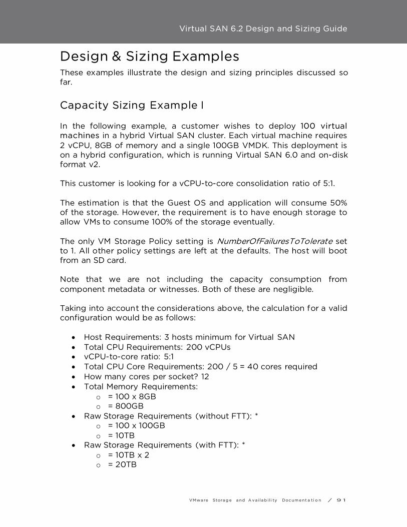
Virtual SAN 6.2 Design and Sizing Guide
VMwa re Stora g e a nd A v a i la b i l i ty Doc um e nt a ti o n / 9 1
Design & Sizing Examples These examples illustrate the design and sizing principles discussed so far.
Capacity Sizing Example I In the following example, a customer wishes to deploy 100 virtual machines in a hybrid Virtual SAN cluster. Each virtual machine requires 2 vCPU, 8GB of memory and a single 100GB VMDK. This deployment is on a hybrid configuration, which is running Virtual SAN 6.0 and on-disk format v2. This customer is looking for a vCPU-to-core consolidation ratio of 5:1. The estimation is that the Guest OS and application will consume 50% of the storage. However, the requirement is to have enough storage to allow VMs to consume 100% of the storage eventually. The only VM Storage Policy setting is NumberOfFailuresToTolerate set to 1. All other policy settings are left at the defaults. The host will boot from an SD card. Note that we are not including the capacity consumption from component metadata or witnesses. Both of these are negligible. Taking into account the considerations above, the calculation for a valid configuration would be as follows:
• Host Requirements: 3 hosts minimum for Virtual SAN • Total CPU Requirements: 200 vCPUs • vCPU-to-core ratio: 5:1 • Total CPU Core Requirements: 200 / 5 = 40 cores required • How many cores per socket? 12 • Total Memory Requirements:
o = 100 x 8GB o = 800GB
• Raw Storage Requirements (without FTT): * o = 100 x 100GB o = 10TB
• Raw Storage Requirements (with FTT): * o = 10TB x 2 o = 20TB

Virtual SAN 6.2 Design and Sizing Guide
VMwa re Stora g e a nd A v a i la b i l i ty Doc um e nt a ti o n / 9 2
• Raw Storage Requirements (with FTT) + VM Swap (with FTT): * o = (10TB + 800GB) x 2 o = 10.8TB x 2 o = 21.6TB
Since all VMs are thinly provisioned on the Virtual SAN datastore, the estimated storage consumption should take into account the thin provisioning aspect before the flash requirement can be calculated:
• Estimated Storage Consumption (without FTT) for cache calculation:
o (50% of raw storage before FTT)) o = 50% of 10TB o = 5TB
• Cache Required (10% of Estimated Storage Consumption): 500GB
• Estimated Snapshot Storage Consumption: 0 (keeping this example simple)
• Raw Storage Requirements (VMs + Snapshots): o 21.6TB
• Required slack space: 30% (slack space should be 30% of the raw
storage requirements after the disks have been formatted) • Raw Formatted Storage Capacity = Raw Storage Requirements +
30% Slack Space o Or written another way:
• Raw Storage Requirement = 70% of Raw Formatted Requirements
• Raw Formatted Storage Capacity = Raw Storage Requirements/0.7
• Raw Formatted Storage Capacity = 21.6/0.7 • Raw Formatted Storage Capacity = 30.9TB
• On disk format overhead = 1% of Raw Formatted Storage
Capacity o Or written another way:
• Raw Unformatted Storage Capacity = Raw Formatted Storage Capacity + disk format overhead
• Raw Unformatted Storage Capacity = 30.9/0.99 • Raw Unformatted Storage Capacity = 31.2TB**
* Thin provisioning/VM storage consumption is not considered here.

Virtual SAN 6.2 Design and Sizing Guide
VMwa re Stora g e a nd A v a i la b i l i ty Doc um e nt a ti o n / 9 3
** On-disk format overhead calculation is based on the total storage requirements of the capacity layer, so may differ slightly based on final capacity layer size.
CPU Configuration In this example, the customer requires 40 cores overall. If we take the 10% Virtual SAN overhead, this brings the total number of cores to 44. The customer has sourced servers that contain 12 cores per socket, and a dual socket system provides 24 cores. That gives a total of 72 cores across the 3-node cluster. This is more that enough for our 44 core requirement across 3 servers. It also meets the requirements of our virtual machines should one host fail, and all VMs need to run on just two hosts without any impact to their CPU performance.
Memory Configuration Each of the three servers would need to contain at least 300GB of memory to meet the running requirements. Again, if a host fails, we want to be able to run all 100 VMs on just two hosts, so we should really consider 500GB of memory per server. This also provides a 10% overhead for ESXi and Virtual SAN from a memory perspective. Virtual SAN designers will need to ensure that the server has enough DIMM slots for this memory requirement.
Storage Configuration For this configuration, a total of 21.6TB of magnetic disk is required, and 500GB of flash, spread across 3 hosts. To allow for a 30% of slack space, Raw Formatted Storage Capacity = Raw Storage Requirement/0.7 = 21.6/0.7 = 30.9TB. Added to this is the formatting overhead of the v2 Virtual SAN datastore. This is approximately 1% that equates to 280GB. The capacity required is now 31.2TB. Since we have already factored in a ‘‘failures to tolerate’’, each host would need to be configured to contain approximately 10.5TB of magnetic disk and approximately 200GB of flash. We advocate following the Virtual SAN best practices of having uniformly configured hosts.

Virtual SAN 6.2 Design and Sizing Guide
VMwa re Stora g e a nd A v a i la b i l i ty Doc um e nt a ti o n / 9 4
The next consideration is setting aside some space for rebuilding the virtual machine objects and components in the event of a failure. Since there are only have 3 hosts in this cluster, components cannot be rebuilt since there are not enough hosts. This would definitely be a consideration for larger configurations, where rebuilding components could create additional copies and once again allow the cluster to tolerate host failures. But in a 3-node cluster where one node has already failed, we cannot tolerate another failure. If we wish to proceed with this requirement, one additional host with matching capacity would need to be added to the cluster. At this point there is some leeway over how to configure the hosts; design decisions include whether or not there is a desire for one or more disk groups; how many magnetic disks per disk group; and so on. Also one should consider whether to use SAS, SATA or NL-SAS magnetic disks. Also should PCIe flash devices or solid state drives be chosen. As previously mentioned, SAS and SATA offer performance traded off against price. A similar argument could be made for PCIe flash versus SSD. Here is one proposed configuration for such a requirement:
• 10.5TB Magnetic Disk required => 11 x 1TB SAS 10K RPM per host • 200GB Flash required => 2 x 100GB SAS SSD per host
Why did we choose 2 x 100GB flash devices rather than 1 x 200GB flash device? The reason is that we can only have a maximum of seven capacity devices in a disk group. In this configuration, we have more than seven capacity devices, thus we need two disk groups. Each disk group must contain a flash device, thus we choose two smaller devices. Since the hosts are booting from an SD card, we do not need an additional disk for the ESXi boot image. With this configuration, a single disk group per host will suffice.
Component Count The next step is to check whether or not the component count of this configuration would exceed the 3,000 components per host maximum in Virtual SAN 5.5, or the 9,000 components per host maximum in Virtual SAN 6.0 (disk format v2). This 3-node Virtual SAN cluster supports running 100 virtual machines, each virtual machine containing a single VMDK. There is no snapshot requirement in this deployment.

Virtual SAN 6.2 Design and Sizing Guide
VMwa re Stora g e a nd A v a i la b i l i ty Doc um e nt a ti o n / 9 5
This means that each virtual machine will have the following objects:
• 1 x VM Home Namespace • 1 x VMDK • 1 x VM Swap • 0 x Snapshot deltas
This implies that there 3 objects per VM. Now we need to work out how many components per object, considering that we are using a VM Storage Policy setting that contains Number of Host Failures to Tolerate = 1 (FTT). It should be noted that only the VM Home Namespace and the VMDK inherit the FTT setting; the VM Swap Object ignores this setting but still uses FTT=1. Therefore when we look at the number of components per object on each VM, we get the following:
• 2 x VM Home Namespace + 1 witness • 2 x VMDK + 1 witness • 2 x VM Swap + 1 witness • 0 x Snapshot deltas
Now we have a total of 9 components per VM. If we plan to deploy 100 VM, then we will have a maximum of 900 components. This is well within our limits of 3, 000 components per host in Virtual SAN 5.5 and 9,000 per host in 6.0.
Capacity Sizing Example II Let’s look at a much larger and more complex configuration this time. In the following example, a customer wishes to deploy 400 virtual machines in a hybrid Virtual SAN cluster. Each virtual machine requires 1 vCPU, 12GB of memory and two disks, a single 100GB VMDK boot disk and another 200GB VMDK data disk. This deployment is on a hybrid configuration, which is running Virtual SAN 6.0 and on-disk format v2. In this case, the customer is looking for a vCPU-to-core consolidation ratio of 4:1. The estimation is that the Guest OS and application will consume 75% of the storage. The VM Storage Policy setting is HostFailuresToTolerate

Virtual SAN 6.2 Design and Sizing Guide
VMwa re Stora g e a nd A v a i la b i l i ty Doc um e nt a ti o n / 9 6
(FTT) set to 1 and StripeWidth set to 2. All other policy settings are left at the defaults. The ESXi hosts will boot from disk. Note that we are not including the capacity consumption from component metadata or witnesses. Both of these are negligible. Taking into account the considerations above, the calculation for a valid configuration would be as follows:
• Host Requirements: 3 hosts minimum for Virtual SAN, but might need more
• Total CPU Requirements: 400 vCPUs • vCPU-to-core ratio: 4:1 • Total CPU Core Requirements: 400 / 4 = 100 cores required • How many cores per socket? 12 • Total Memory Requirements: 400 x 12GB = 4.8TB • Total Storage Requirements (without FTT): *
o (400 x 100GB) + (400 x 200GB) o 40TB + 80TB o = 120TB
• Raw Storage Requirements (with FTT): * o = 120TB x 2 o = 240TB
• Raw Storage Requirements (with FTT) + VM Swap (with FTT): * o = (120TB + 4.8TB) *2 o = 240TB + 9.6TB o = 249.6TB
• Raw Storage Consumption (without FTT) for cache sizing: o (75% of total raw storage) o = 75% of 120TB o = 90TB
• Cache Required (10% of Estimated Storage Consumption): 9TB • Estimated Snapshot Storage Consumption: 2 snapshots per VM
o It is estimated that both of snapshot images will never grow larger than 5% of base VMDK
o Storage Requirements (with FTT) = 240TB o There is no requirement to capture virtual machine memory
when a snapshot is taken o Estimated Snapshot Requirements (with FTT) = 5% = 12TB
• Raw Storage Requirements (VMs + Snapshots): o = 249.6TB + 12TB o = 261.6TB
• Required slack space: 30% (slack space should be 30% of the raw storage requirements after the disks have been formatted)
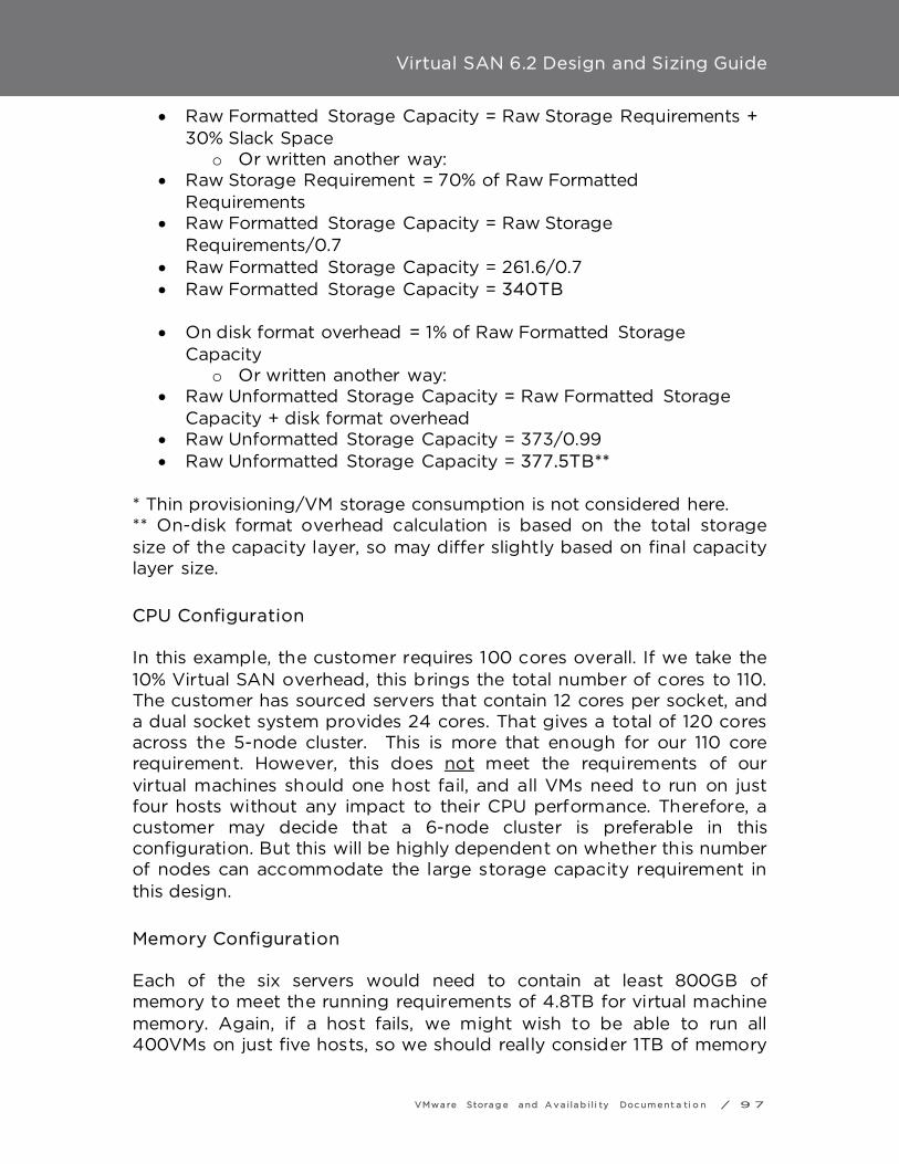
Virtual SAN 6.2 Design and Sizing Guide
VMwa re Stora g e a nd A v a i la b i l i ty Doc um e nt a ti o n / 9 7
• Raw Formatted Storage Capacity = Raw Storage Requirements + 30% Slack Space
o Or written another way: • Raw Storage Requirement = 70% of Raw Formatted
Requirements • Raw Formatted Storage Capacity = Raw Storage
Requirements/0.7 • Raw Formatted Storage Capacity = 261.6/0.7 • Raw Formatted Storage Capacity = 340TB
• On disk format overhead = 1% of Raw Formatted Storage
Capacity o Or written another way:
• Raw Unformatted Storage Capacity = Raw Formatted Storage Capacity + disk format overhead
• Raw Unformatted Storage Capacity = 373/0.99 • Raw Unformatted Storage Capacity = 377.5TB**
* Thin provisioning/VM storage consumption is not considered here. ** On-disk format overhead calculation is based on the total storage size of the capacity layer, so may differ slightly based on final capacity layer size.
CPU Configuration In this example, the customer requires 100 cores overall. If we take the 10% Virtual SAN overhead, this brings the total number of cores to 110. The customer has sourced servers that contain 12 cores per socket, and a dual socket system provides 24 cores. That gives a total of 120 cores across the 5-node cluster. This is more that enough for our 110 core requirement. However, this does not meet the requirements of our virtual machines should one host fail, and all VMs need to run on just four hosts without any impact to their CPU performance. Therefore, a customer may decide that a 6-node cluster is preferable in this configuration. But this will be highly dependent on whether this number of nodes can accommodate the large storage capacity requirement in this design.
Memory Configuration Each of the six servers would need to contain at least 800GB of memory to meet the running requirements of 4.8TB for virtual machine memory. Again, if a host fails, we might wish to be able to run all 400VMs on just five hosts, so we should really consider 1TB of memory

Virtual SAN 6.2 Design and Sizing Guide
VMwa re Stora g e a nd A v a i la b i l i ty Doc um e nt a ti o n / 9 8
per server. This also provides a 10% overhead for ESXi and Virtual SAN from a memory perspective. Designers will need to ensure that the server has enough DIMM slots for this memory requirement.
Storage Configuration --- option 1 A lot more magnetic disks in required in this example. To allow for a 30% of slack space, and 1% on-disk format, the actual capacity of the cluster must be 377.5TB. With a 6-node cluster, a total of 377.5TB spread across six hosts is required. This includes capacity to accommodate failures to tolerate, snapshots and on-disk format overhead. There is also a requirement for 9TB flash, spread across 6 hosts. Since we have already factored in a ‘‘failures to tolerate’’, each host would need to be configured to contain approx. 63TB of magnetic disk and approx. 1.5 of flash. A choice needs to be made --- the design will need to choose between SAS, SATA or NL-SAS for magnetic disks. However, SATA may not be suitable choice if performance of the magnetic disk layer is a requirement. Another design decision is the size that should be chosen. Finally, a server will need to be chosen that can accommodate the number of disks needed to meet the capacity requirement. A similar choice needs to be made for flash devices on whether or not to choose either a PCIe device or solid-state devices. Again, the number of SSDs needed per host must be determined if this is the option chosen. And an appropriate number of disk slots to accommodate both the SSD and the magnetic disks needs to be calculated given the choices made. If multiple disk groups are required, the design will need to ensure that no limits are hit with number disks per diskgroup, or the number of disk groups per host limit. Refer back to the limits section in the earlier part of this document for actual maximums. Here is one proposed configuration for such a requirement:
• 343.4TB Magnetic Disk required across the cluster implies ~63TB Magnetic Disk required per host (6 hosts in the cluster)
o One option is to consider using 16 x 4TB SATA 7200 RPM per host (although slightly below, it should meet our needs). This may be the cheapest option, but performance may not be acceptable.

Virtual SAN 6.2 Design and Sizing Guide
VMwa re Stora g e a nd A v a i la b i l i ty Doc um e nt a ti o n / 9 9
o 16 disks may entail the purchase of additional controllers, or SAS extenders (be sure to check supportability). Multiple controllers will offer superior performance, but at a cost.
o Another design consideration is to use an external storage enclosure to accommodate this many disks. Support for this is introduced in version 6.0.
o Since there are only 7 disks per disk group, a minimum of 3 disk groups is required.
• 9TB cache required per cluster implies 1.5TB cache required per host
o Need 3 flash devices, one for each of the above disk groups o 3 x 500GB SSD per host implies 19 disk slots are now
needed per host o For future growth, consideration could be given to using
larger flash devices. • ESXi hosts boot from disk
o 20 disk slots now required per host In this example, the customer now needs to source a server that contains 20 disk slots for this rather large configuration. This design is achievable with a 6-node cluster. However, if the customer now had a requirement to rebuild components in the event of a failure, one additional fully populated server would need to be added to the configuration. This brings the number of hosts required up to 7.
Storage Configuration --- option 2 In option 1, the capacity requirement for this Virtual SAN design could be achieved by using 16 x 4TB SATA 7200 RPM per host. However these drives may not achieve the desired performance for the end-solution. Again, there are choices to be made with regards to disk types. Options supported for Virtual SAN are SAS, SATA or NL-SAS as already mentioned. Considering that there is a desire for a more performance-capable capacity layer, here is a proposed configuration for such a requirement:
• The requirement is 377.5TB Magnetic Disk required across the cluster
o One option is to consider using 1.2TB SAS 10000 RPM. These provide an acceptable level of performance for the design.

Virtual SAN 6.2 Design and Sizing Guide
VMwa re Stora g e a nd A v a i la b i l i ty Doc um e nt a ti o n / 1 0 0
o This will mean a total of 315 x 1.2TB SAS 10K RPM drives are needed across the cluster. This is now the most important consideration for the design. One needs to consider how many hosts are needed to accommodate this storage requirement.
o With a maximum of 7 disks per disk group and 5 disk groups per host, this equates to 35 x 1.2TB of storage that can be provided per host. This equates to 42TB per host.
o At a minimum, 10 hosts would be required to meet this requirement. Of course, CPU and memory requirements now need to be revisited and recalculated. This implies that a less powerful host could be used for the cluster design.
o This many disks may entail the purchase of additional controllers, or SAS extenders. Multiple controllers will offer superior performance, but at a cost.
o Another design consideration is to use an external storage enclosure to accommodate this many disks. Support for this is introduced in version 6.0.
• 9TB cache required per cluster o Given the fact that there are now 10 hosts in the cluster,
there will be ~1TB of flash per host distributed across the cluster.
o Since there are 5 disk groups in each host, this requirement could be easily met using 5 x 200GB flash devices for each of the above disk groups.
o For future growth, we can give consideration to using a larger flash device, as shown here.
o With 5 x 200GB SSD per host, a total of 40 disk slots is now needed per host
• ESXi hosts boot from disk o 41 disk slots per host now required
This design now needs servers that contain 41 disk slots for this rather large configuration. In all likelihood, this design is looking at either additional controllers, SAS externals or an external storage enclosure to meet this design requirement. Support for external storage enclosures was introduced in 6.0. The alternative is to purchase even more servers, and distribute the storage across these servers. This would require a redesign however. Once again, if the customer included a requirement to rebuild components in the event of a failure, one additional fully populated server would need to be added to the configuration. This brings the number of hosts required up to 11.

Virtual SAN 6.2 Design and Sizing Guide
VMwa re Stora g e a nd A v a i la b i l i ty Doc um e nt a ti o n / 1 0 1
Storage Configuration --- option 3 All Flash (Storage Efficiency) In option 2, the requirements for additional hosts to meet capacity and performance requirements would increase the footprint for the environment. In this option we will review how all flash with storage efficiency technologies could reduce this footprint while maintaining high levels of performance consistency. Again, there are choices to be made with regards to flash disk types. Options supported for Virtual SAN are SAS, SATA, PCI-Express and NVMe. Deduplication and compression will be used for the cluster and RAID-5/6 will be chosen for the data disk. The expected deduplication and compression ratio are 4X for the boot disk as the virtual machines are cloned from a common template, and 2X for the data disks. In this case the application provider has required memory overconsumption will not be used, so sparse swap will be enabled to reclaim space used for swap.
• Raw Storage Requirements for the boot disk (with FTT=1 RAID-5, dedupe and compression Ratio =4X): *
o = 100GB*1.33 (FTT=1 RAID-5) o = 133GB/4 (Dedupe and Compression = 4X) o = 33.25GB
• Raw Storage Requirements for the Data disk (with FTT=1 RAID-5, no deduplication or compression): *
o = 200GB*1.33 (FTT=1,RAID-5) o = 266GB/2 (Dedupe and Compression = 2X) o = 133GB
• Raw Storage Requirements (with FTT) for 400: *
o = 33.25GB + 133GB o = 166.25GB * 400 (Virtual Machines) o = 66.5TB
• Raw Storage Consumption (without FTT) for cache sizing: o (75% of total raw storage) o = 75% of 66.5TB o = 49.87TB
• Cache Required (10% of Estimated Storage Consumption): 4.98TB • Estimated Snapshot Storage Consumption: 2 snapshots per VM
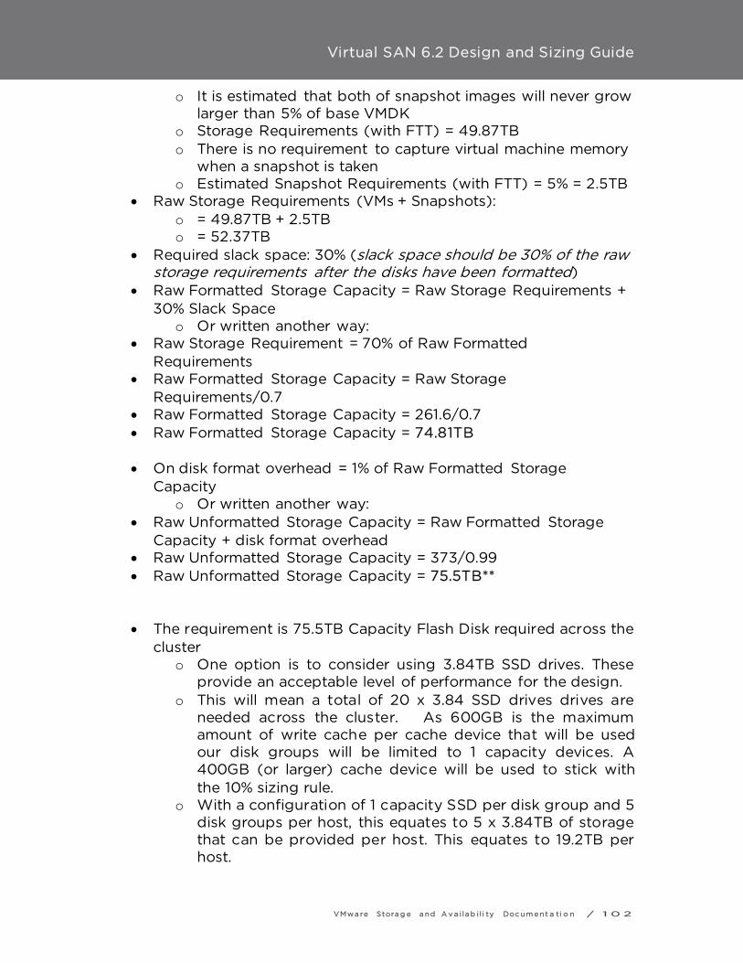
Virtual SAN 6.2 Design and Sizing Guide
VMwa re Stora g e a nd A v a i la b i l i ty Doc um e nt a ti o n / 1 0 2
o It is estimated that both of snapshot images will never grow larger than 5% of base VMDK
o Storage Requirements (with FTT) = 49.87TB o There is no requirement to capture virtual machine memory
when a snapshot is taken o Estimated Snapshot Requirements (with FTT) = 5% = 2.5TB
• Raw Storage Requirements (VMs + Snapshots): o = 49.87TB + 2.5TB o = 52.37TB
• Required slack space: 30% (slack space should be 30% of the raw storage requirements after the disks have been formatted)
• Raw Formatted Storage Capacity = Raw Storage Requirements + 30% Slack Space
o Or written another way: • Raw Storage Requirement = 70% of Raw Formatted
Requirements • Raw Formatted Storage Capacity = Raw Storage
Requirements/0.7 • Raw Formatted Storage Capacity = 261.6/0.7 • Raw Formatted Storage Capacity = 74.81TB
• On disk format overhead = 1% of Raw Formatted Storage
Capacity o Or written another way:
• Raw Unformatted Storage Capacity = Raw Formatted Storage Capacity + disk format overhead
• Raw Unformatted Storage Capacity = 373/0.99 • Raw Unformatted Storage Capacity = 75.5TB**
• The requirement is 75.5TB Capacity Flash Disk required across the cluster
o One option is to consider using 3.84TB SSD drives. These provide an acceptable level of performance for the design.
o This will mean a total of 20 x 3.84 SSD drives drives are needed across the cluster. As 600GB is the maximum amount of write cache per cache device that will be used our disk groups will be limited to 1 capacity devices. A 400GB (or larger) cache device will be used to stick with the 10% sizing rule.
o With a configuration of 1 capacity SSD per disk group and 5 disk groups per host, this equates to 5 x 3.84TB of storage that can be provided per host. This equates to 19.2TB per host.

Virtual SAN 6.2 Design and Sizing Guide
VMwa re Stora g e a nd A v a i la b i l i ty Doc um e nt a ti o n / 1 0 3
o A total of 20 disk groups (and 40 total disk bays) is required to meet this requirement in the cluster.
o At a minimum, 4 hosts would be required to meet this requirement, however This would require revisiting CPU and Memory density and consider more expensive quad socket systems. Assuming 7 hosts were used per the previous example, 3 hosts groups per host could be used, allowing denser servers limited to 8 drive bays to be considered.
• ESXi hosts boot from disk o 47 total drive bays would be used, but this would not
impact the use of 8 drive bays per servers. This design now needs servers that contain 7 disk slots in keeping with the 7 host requirement. This design would allow dense (4 server per 2RU) configurations.
Component Count The final check is to see whether or not the component count of this configuration would exceed the 3,000 components per host maximum in Virtual SAN 5.5 or the 9,000 components per host maximum in Virtual SAN 6.0. This Virtual SAN cluster has a requirement to run 400 virtual machines, each virtual machine containing a single VMDK. There is also a 2 snapshot per virtual machine requirement in this deployment. This means that each virtual machine will have the following object:
• 1 x VM Home Namespace • 2 x VMDK • 1 x VM Swap • 2 x Snapshot deltas
This implies that there 6 objects per VM. Now we need to work out how many components per object, considering that we are using a VM Storage Policy setting that contains Number of Host Failures to Tolerate = 1 (FTT) and Stripe Width = 2. It should be noted that only the VM Home Namespace, the VMDK and the snapshot deltas inherit the FTT setting; the VM Swap Object ignores

Virtual SAN 6.2 Design and Sizing Guide
VMwa re Stora g e a nd A v a i la b i l i ty Doc um e nt a ti o n / 1 0 4
this setting. Only the VMDK and snapshot deltas inherit the VM Storage Policy Next step is to look at the number of components per object:
• 2 components per VM Home Namespace (FTT only) + 1 x witness = 3
• 4 components per VMDK (FTT & Stripe Width) + 3 x witness o 7 components per VMDK x 2 = 14
• 2 components per VM Swap + 1 witness = 3 • 4 components per Snapshot deltas (FTT & Stripe Width) + 3 x
Witness o 7 components per snapshot delta x 2 = 14
Extrapolating this, each virtual machine could have a total of 3 + 14 + 3 + 14 = 34 components per VM. If this is applied to 400VMs, the total is 13,600 components. Taking option 1, the smallest configuration, and split this across the 7 hosts in the Virtual SAN cluster, the calculation shows that there are 1,943 components per host. This is well within the limits of 3,000 components per host in 5.5 and 9,000 components per host in 6.0, so we are good. The next step is to check if the cluster can still handle the same number of components in the event of a host failure. 12,800 components spread across 6 hosts implies a total of 2,267 components per host so we see that the design can tolerate a host failure and a rebuild of the missing components on the remaining 6 hosts in the cluster. Needless to say option 2, that includes 10 or 11 hosts in the cluster, is more than capable of handling this amount of components.
Server choice For option (1) customer’s server of choice is a HP DL380p, which needs to be checked to see if it can indeed be configured with up to 25 disk slots. If this was not possible, then customer may have to look at purchasing additional servers to meet the storage requirement, and the calculations would have to be revisited. This host can also meet the 12

Virtual SAN 6.2 Design and Sizing Guide
VMwa re Stora g e a nd A v a i la b i l i ty Doc um e nt a ti o n / 1 0 5
cores-per-socket requirements and has 24 DIMM slots to meet the memory requirement. For option (2) a customer may need to look at external storage enclosures if a host that does supports 41 slots is not found, which is likely. The alternative is to look at purchasing additional servers to meet the storage requirement, and the calculations would once again have to be revisited. If the customer has a server of choice, such as the HP DL380p, then a new round of calculation would be needed using the formulas discussed here. For Option (3) a customer’s server choice is a Dell FX2 Utilizing FC The FC 630 paired with FD332’s can meet the drive bay, core and DIMM requirements. Additionally, if fewer hosts are to be considered the FC830 quad socket system could be leveraged for denser RU/compute configurations.

Virtual SAN 6.2 Design and Sizing Guide
VMwa re Stora g e a nd A v a i la b i l i ty Doc um e nt a ti o n / 1 0 6
Conclusion Although most Virtual SAN design and sizing exercises are straightforward, careful planning at the outset can avoid problems later. Based on observed experiences to date, the most frequent design issues are:
- Failing to use VCG-listed components, drivers and firmware, resulting in unpredictable behavior. Flash devices and IO controllers are particularly sensitive.
- Not properly sizing cache for capacity growth (e.g. thin volumes progressively getting fatter), resulting in declining performance over time.
- Using 1Gb networking for performance-intensive environments, with predictably poor results.
- Not understanding 3-node limitations associated with maintenance mode and protection after a failure.
- Using very large, slow disks for capacity, resulting in poor performance if an application is not cache-friendly.
- Failure to have sufficient extra capacity for operations like entering maintenance mode, changing policy definitions, etc.

Virtual SAN 6.2 Design and Sizing Guide
VMwa re Stora g e a nd A v a i la b i l i ty Doc um e nt a ti o n / 1 0 7
Further Information
VMware Ready Nodes • http://www.vmware.com/resources/compatibility/search.php?de
viceCategory=vsan
VMware Compatibility Guide • http://vmwa.re/vsanhclc
vSphere Community Page • https://communities.vmware.com/community/vmtn/vsan
Key bloggers • http://cormachogan.com/vsan/ • http://www.yellow-bricks.com/virtual-san/ • http://www.virtuallyghetto.com/category/vsan • http://www.punchingclouds.com/tag/vsan/ • http://blogs.vmware.com/vsphere/storage • http://www.thenicholson.com/vsan
Links to existing documentation • http://www.vmware.com/products/virtual-san/resources.html • https://www.vmware.com/support/virtual-san
VMware support • https://my.vmware.com/web/vmware/login • http://kb.vmware.com/kb/2006985 - How to file a Support
Request • http://kb.vmware.com/kb/1021806 - Location of VMware Product
log files • http://kb.vmware.com/kb/2032076 - Location of ESXi 5.x log file • http://kb.vmware.com/kb/2072796 - Collecting Virtual SAN
support logs
Additional Reading • http://blogs.vmware.com/vsphere/files/2014/09/vsan-sql-
dvdstore-perf.pdf - Microsoft SQL Server Performance Study

Virtual SAN 6.2 Design and Sizing Guide
VMwa re Stora g e a nd A v a i la b i l i ty Doc um e nt a ti o n / 1 0 8
• http://www.vmware.com/files/pdf/products/vsan/VMW-TMD-Virt-SAN-Dsn-Szing-Guid-Horizon-View.pdf - Design & Sizing Guide for Horizon View VDI
• http://www.vmware.com/files/pdf/products/vsan/VMware-Virtual-SAN-Network-Design-Guide.pdf - Virtual SAN Network Design Guide
VMware, Inc. 3401 Hillview Avenue Palo Alto CA 94304 USA Tel 877-486-92 73 Fax 650-427-5001 www.vm wa re.co m Copyright © 2012 VMware, Inc. All rights reserved. This product is protected by U.S. and international copyright and intellectual propert y laws. VMware products are covered by one or more patents listed at http://www .vm wa re.com/go/pate nts . VMware is a registered tradema rk or trademark of VMware, Inc. in the United States and/or other jurisdiction. All other marks and names mentioned herein may be trademarks of their respective companies.