Embed Size (px)
Citation preview

2/11 Installation&OperatingManual MN767
VS1STAC Microdrive

Any trademarks used in this manual are the property of their respective owners.
Important:Be sure to check www.baldor.com for the latest software, firmware and drivers for your VS1ST product. Also you can download the latest version of this manual in Adobe Acrobat PDF format.

iMN767
Chapter1Introduction1.1 Getting Assistance from Baldor . . . . . . . . . . . . . . . . . . . . . . . . . . . . . . . . . . . . . . . . . . . . . . . . . . . . 1-11.2 Safety Notice . . . . . . . . . . . . . . . . . . . . . . . . . . . . . . . . . . . . . . . . . . . . . . . . . . . . . . . . . . . . . . . . . . . 1-11.3 Quick Start . . . . . . . . . . . . . . . . . . . . . . . . . . . . . . . . . . . . . . . . . . . . . . . . . . . . . . . . . . . . . . . . . . . . . 1-3
Chapter2GeneralInformationandRating2.1 Identify the Drive by Model Number . . . . . . . . . . . . . . . . . . . . . . . . . . . . . . . . . . . . . . . . . . . . . . . . . 2-12.2 Storage Guidelines . . . . . . . . . . . . . . . . . . . . . . . . . . . . . . . . . . . . . . . . . . . . . . . . . . . . . . . . . . . . . . . 2-12.3 VS1ST Ratings, Model Numbers and Frame Sizes . . . . . . . . . . . . . . . . . . . . . . . . . . . . . . . . . . . . . . 2-2
Chapter3InstallingtheDrive3.1 Receiving & Inspection . . . . . . . . . . . . . . . . . . . . . . . . . . . . . . . . . . . . . . . . . . . . . . . . . . . . . . . . . . . 3-13.2 General Requirements for the Installation Site . . . . . . . . . . . . . . . . . . . . . . . . . . . . . . . . . . . . . . . . . 3-1 3.2.1 Operating Conditions . . . . . . . . . . . . . . . . . . . . . . . . . . . . . . . . . . . . . . . . . . . . . . . . . . . . . . 3-1 3.2.2 Elevation . . . . . . . . . . . . . . . . . . . . . . . . . . . . . . . . . . . . . . . . . . . . . . . . . . . . . . . . . . . . . . . . 3-1 3.3 Mounting the Drive . . . . . . . . . . . . . . . . . . . . . . . . . . . . . . . . . . . . . . . . . . . . . . . . . . . . . . . . . . . . . . . 3-1 3.3.1 Watts Loss Data . . . . . . . . . . . . . . . . . . . . . . . . . . . . . . . . . . . . . . . . . . . . . . . . . . . . . . . . . . . 3-1 3.3.2 Mounting Clearances . . . . . . . . . . . . . . . . . . . . . . . . . . . . . . . . . . . . . . . . . . . . . . . . . . . . . . . 3-1
Chapter4PowerWiring 4.1 Overview of Power Connections . . . . . . . . . . . . . . . . . . . . . . . . . . . . . . . . . . . . . . . . . . . . . . . . . . . . 4-1
4.1.1 Safety Ground . . . . . . . . . . . . . . . . . . . . . . . . . . . . . . . . . . . . . . . . . . . . . . . . . . . . . . . . . . . . 4-1 4.1.2 Motor Ground . . . . . . . . . . . . . . . . . . . . . . . . . . . . . . . . . . . . . . . . . . . . . . . . . . . . . . . . . . . . 4-1 4.1.3 Shield Termination . . . . . . . . . . . . . . . . . . . . . . . . . . . . . . . . . . . . . . . . . . . . . . . . . . . . . . . . . 4-1 4.1.4 RFI Filter Grounding . . . . . . . . . . . . . . . . . . . . . . . . . . . . . . . . . . . . . . . . . . . . . . . . . . . . . . . . 4-14.2 Power Disconnect . . . . . . . . . . . . . . . . . . . . . . . . . . . . . . . . . . . . . . . . . . . . . . . . . . . . . . . . . . . . . . . 4-14.3 Protective Devices . . . . . . . . . . . . . . . . . . . . . . . . . . . . . . . . . . . . . . . . . . . . . . . . . . . . . . . . . . . . . . . 4-24.4 Electrical Installation . . . . . . . . . . . . . . . . . . . . . . . . . . . . . . . . . . . . . . . . . . . . . . . . . . . . . . . . . . . . . 4-2
4.4.1 Branch Circuit Protection . . . . . . . . . . . . . . . . . . . . . . . . . . . . . . . . . . . . . . . . . . . . . . . . . . . . 4-2 4.4.2 Single Phase Input Power Connections for 1 Phase Control . . . . . . . . . . . . . . . . . . . . . . . . 4-2 4.4.3 Three Phase Input Power Connections for 3 Phase Control . . . . . . . . . . . . . . . . . . . . . . . . . 4-2 4.4.4 EMC and VAR Screws . . . . . . . . . . . . . . . . . . . . . . . . . . . . . . . . . . . . . . . . . . . . . . . . . . . . . . 4-3 4.4.5 Optional Dynamic Brake Hardware Size B & C Controls. . . . . . . . . . . . . . . . . . . . . . . . . . . . 4-3 4.4.6 Motor Connections . . . . . . . . . . . . . . . . . . . . . . . . . . . . . . . . . . . . . . . . . . . . . . . . . . . . . . . . 4-4 4.4.7 M-Contactor Connections . . . . . . . . . . . . . . . . . . . . . . . . . . . . . . . . . . . . . . . . . . . . . . . . . . . 4-5
Chapter5ControlWiring 5.1 Control Wiring Overview . . . . . . . . . . . . . . . . . . . . . . . . . . . . . . . . . . . . . . . . . . . . . . . . . . . . . . . . . . 5-15.2 Connection Examples . . . . . . . . . . . . . . . . . . . . . . . . . . . . . . . . . . . . . . . . . . . . . . . . . . . . . . . . . . . . 5-2
5.2.1 Terminal Strip Control Set parameter P-07 =0 . . . . . . . . . . . . . . . . . . . . . . . . . . . . . . . . . . . . 5-1 5.2.2 Other Control Methods . . . . . . . . . . . . . . . . . . . . . . . . . . . . . . . . . . . . . . . . . . . . . . . . . . . . . 5-45.3 RJ45 Communication Connection . . . . . . . . . . . . . . . . . . . . . . . . . . . . . . . . . . . . . . . . . . . . . . . . . . . 5-45.4 Changing Parameters . . . . . . . . . . . . . . . . . . . . . . . . . . . . . . . . . . . . . . . . . . . . . . . . . . . . . . . . . . . . 5-55.5 Reset Factory Default Settings . . . . . . . . . . . . . . . . . . . . . . . . . . . . . . . . . . . . . . . . . . . . . . . . . . . . . 5-55.6 Terminal Control . . . . . . . . . . . . . . . . . . . . . . . . . . . . . . . . . . . . . . . . . . . . . . . . . . . . . . . . . . . . . . . . . 5-55.7 Keypad Control . . . . . . . . . . . . . . . . . . . . . . . . . . . . . . . . . . . . . . . . . . . . . . . . . . . . . . . . . . . . . . . . . 5-5
TableofContents

ii MN767
Chapter6UsingtheKeypad
6.1 Keypad Overview . . . . . . . . . . . . . . . . . . . . . . . . . . . . . . . . . . . . . . . . . . . . . . . . . . . . . . . . . . . . 6-16.2 Keypad Display Parameters . . . . . . . . . . . . . . . . . . . . . . . . . . . . . . . . . . . . . . . . . . . . . . . . . . . . 6-1 6.2.1 Default Configuration . . . . . . . . . . . . . . . . . . . . . . . . . . . . . . . . . . . . . . . . . . . . . . . . . . . 6-1 6.2.2 RPM Display . . . . . . . . . . . . . . . . . . . . . . . . . . . . . . . . . . . . . . . . . . . . . . . . . . . . . . . . . . 6-2 6.2.3 Custom Display Unit . . . . . . . . . . . . . . . . . . . . . . . . . . . . . . . . . . . . . . . . . . . . . . . . . . . . 6-2
Chapter7ParameterDescriptions7.1 Overview . . . . . . . . . . . . . . . . . . . . . . . . . . . . . . . . . . . . . . . . . . . . . . . . . . . . . . . . . . . . . . . . . . . . . . 7-1
Chapter8CustomizingforYourApplication 8.1 Simple Parameter Adjustments . . . . . . . . . . . . . . . . . . . . . . . . . . . . . . . . . . . . . . . . . . . . . . . . . . . . . 8-18.2 Analog and Digital Input Configurations . . . . . . . . . . . . . . . . . . . . . . . . . . . . . . . . . . . . . . . . . . . . . . 8-2 8.2.1 Terminal Strip Mode (P-07 = 0) . . . . . . . . . . . . . . . . . . . . . . . . . . . . . . . . . . . . . . . . . . . . . . . 8-2 8.2.2 Keypad Mode (P-07 = 1 or 2) . . . . . . . . . . . . . . . . . . . . . . . . . . . . . . . . . . . . . . . . . . . . . . . . . 8-4 8.2.3 Modbus Control Mode (P-07 = 3 or 4) . . . . . . . . . . . . . . . . . . . . . . . . . . . . . . . . . . . . . . . . . . 8-5 8.2.4 User PI Control Mode (P-07 = 5 or 6) . . . . . . . . . . . . . . . . . . . . . . . . . . . . . . . . . . . . . . . . . . 8-5
Chapter9Troubleshooting9.1 Fault Codes . . . . . . . . . . . . . . . . . . . . . . . . . . . . . . . . . . . . . . . . . . . . . . . . . . . . . . . . . . . . . . . . . . . . 9-19.2 Periodic Inspection . . . . . . . . . . . . . . . . . . . . . . . . . . . . . . . . . . . . . . . . . . . . . . . . . . . . . . . . . . . . . . 9-1
AppendixATechnicalSpecifications . . . . . . . . . . . . . . . . . . . . . . . . . . . . . . . . . . . . . . . . . . . . . . . . . . . . . . . . . . . . . . A-1
AppendixBParameterTables . . . . . . . . . . . . . . . . . . . . . . . . . . . . . . . . . . . . . . . . . . . . . . . . . . . . . . . . . . . . . . . . . . . B-1
AppendixCCEGuidelinesC.1 CE Declaration of Conformity . . . . . . . . . . . . . . . . . . . . . . . . . . . . . . . . . . . . . . . . . . . . . . . . . . . . . . C-1C.2 EMC - Conformity and CE - Marking . . . . . . . . . . . . . . . . . . . . . . . . . . . . . . . . . . . . . . . . . . . . . . . . C-1C.3 EMC Installation Options . . . . . . . . . . . . . . . . . . . . . . . . . . . . . . . . . . . . . . . . . . . . . . . . . . . . . . . . . . C-2C.4 Grounding for Wall Mounting (Class A) also see Chapters 4 and 5 . . . . . . . . . . . . . . . . . . . . . . . . . C-2C.5 Grounding for Enclosure Mounting (Class B) also see Chapters 4 and 5 . . . . . . . . . . . . . . . . . . . . . C-2
C.6 Using CE approved components will not guarantee a CE compliant system . . . . . . . . . . . . . . . . . . C-2C.7 EMC Wiring Technique . . . . . . . . . . . . . . . . . . . . . . . . . . . . . . . . . . . . . . . . . . . . . . . . . . . . . . . . . . . C-3C.8 EMC Installation Instructions . . . . . . . . . . . . . . . . . . . . . . . . . . . . . . . . . . . . . . . . . . . . . . . . . . . . . . C-3
AppendixDOptions&KitsD.1 Remote Keypad Option . . . . . . . . . . . . . . . . . . . . . . . . . . . . . . . . . . . . . . . . . . . . . . . . . . . . . . . . . . . D-1D.2 Accessories . . . . . . . . . . . . . . . . . . . . . . . . . . . . . . . . . . . . . . . . . . . . . . . . . . . . . . . . . . . . . . . . . . . . D-2

iiiMN767
AppendixERS485/MODBUSProtocolE.1 Introduction . . . . . . . . . . . . . . . . . . . . . . . . . . . . . . . . . . . . . . . . . . . . . . . . . . . . . . . . . . . . . . . . . . . . E-1E.2 Installation . . . . . . . . . . . . . . . . . . . . . . . . . . . . . . . . . . . . . . . . . . . . . . . . . . . . . . . . . . . . . . . . . . . . . E-2E.3 Operation . . . . . . . . . . . . . . . . . . . . . . . . . . . . . . . . . . . . . . . . . . . . . . . . . . . . . . . . . . . . . . . . . . . . . . E-2E.4 Performance Specifications . . . . . . . . . . . . . . . . . . . . . . . . . . . . . . . . . . . . . . . . . . . . . . . . . . . . . . . . E-2E.5 Hardware Specifications . . . . . . . . . . . . . . . . . . . . . . . . . . . . . . . . . . . . . . . . . . . . . . . . . . . . . . . . . . E-2E.6 Communication Specifications . . . . . . . . . . . . . . . . . . . . . . . . . . . . . . . . . . . . . . . . . . . . . . . . . . . . . E-3E.7 Communications Protocol (MODBUS-RTU) . . . . . . . . . . . . . . . . . . . . . . . . . . . . . . . . . . . . . . . . . . . E-3 E.7.1 Register Descriptions. . . . . . . . . . . . . . . . . . . . . . . . . . . . . . . . . . . . . . . . . . . . . . . . . . . . . . . E-4 E.7.2 Drive Error Codes . . . . . . . . . . . . . . . . . . . . . . . . . . . . . . . . . . . . . . . . . . . . . . . . . . . . . . . . . E-8 E.7.3 Data Flow Examples . . . . . . . . . . . . . . . . . . . . . . . . . . . . . . . . . . . . . . . . . . . . . . . . . . . . . . . E-8

iv MN767

Introduction 1-1MN767
Chapter1Introduction
This manual is intended for qualified electrical personnel familiar with installing, programming, and maintaining AC Drives. This manual contains information on: • Installing and wiring the VS1ST drive • Programming the drive • Troubleshooting the drive
1.1GettingAssistancefromBaldor
For technical assistance, contact your Baldor District Office. Before calling, please review the troubleshooting section of this manual. You will be asked for the drive model number or catalog number that is located on the Nameplate along with the drive serial number.
1.2SafetyNotice
This equipment contains voltages that may be as high as 1000 volts! Electrical shock can cause serious or fatal injury. Only qualified personnel should attempt the start-up procedure or troubleshoot this equipment.This equipment may be connected to other machines that have rotating parts or parts that are driven by this equipment. Improper use can cause serious or fatal injury. Only qualified personnel should attempt the start-up procedure or troubleshoot this equipment.
PRECAUTIONS:CLASSIFICATIONSOFCAUTIONARYSTATEMENTS
WARNING: Indicatesapotentiallyhazardoussituationwhich,ifnotavoided,couldresultininjuryordeath. CAUTION: Indicatesapotentiallyhazardoussituationwhich,ifnotavoided,couldresultindamageto property.
PRECAUTIONS
WARNING: Donottouchanycircuitboard,powerdeviceorelectricalconnectionbeforeyoufirstensure thatpowerhasbeendisconnectedandthereisnohighvoltagepresentfromthisequipmentor otherequipmenttowhichitisconnected.Electricalshockcancauseseriousorfatalinjury.Only qualifiedpersonnelshouldattemptthestart-upprocedureortroubleshootthisequipment. WARNING: Besurethatyouarecompletelyfamiliarwiththesafeoperationofthisequipment.Thisequipment maybeconnectedtoothermachinesthathaverotatingpartsorpartsthatarecontrolledbythis equipment.Improperusecancauseseriousorfatalinjury.Onlyqualifiedpersonnelshould attemptthestart-upprocedureortroubleshootthisequipment. WARNING: Donotusemotoroverloadrelayswithanautomaticresetfeature.Thesearedangeroussincethe processmayinjuresomeoneifasuddenorunexpectedautomaticrestartoccurs.Ifmanualreset relaysarenotavailable,disabletheautomaticrestartfeatureusingexternalcontrolwiring. WARNING: Thisunithasanautomaticrestartfeaturethatwillstartthemotorwheneverinputpoweris appliedandaRUN(FWDorREV)commandisissued.Ifanautomaticrestartofthemotorcould causeinjurytopersonnel,theautomaticrestartfeatureshouldbedisabled. WARNING: Besurethesystemisproperlygroundedbeforeapplyingpower.DonotapplyACpowerbefore youensurethatallgroundinginstructionshavebeenfollowed.Electricalshockcancauseserious orfatalinjury. WARNING: Donotremovecoverforatleastfive(5)minutesafterACpowerisdisconnectedtoallow capacitorstodischarge.Dangerousvoltagesarepresentinsidetheequipment.Electricalshock cancauseseriousorfatalinjury. WARNING: Improperoperationofcontrolmaycauseviolentmotionofthemotorshaftanddrivenequipment. Becertainthatunexpectedmotorshaftmovementwillnotcauseinjurytopersonnelordamage toequipment.Certainfailuremodesofthecontrolcanproducepeaktorqueofseveraltimesthe ratedmotortorque. WARNING: MotorcircuitmayhavehighvoltagepresentwheneverACpowerisapplied,evenwhenmotoris notrotating.Electricalshockcancauseseriousorfatalinjury. WARNING: Dynamicbrakeresistorsmaygenerateenoughheattoignitecombustiblematerials.Keepall combustiblematerialsandflammablevaporsawayfrombrakeresistors.

1-2 Introduction MN767
WARNING: Themotorshaftwillrotateduringtheautotuneprocedure.Becertainthatunexpectedmotorshaft movementwillnotcauseinjurytopersonnelordamagetoequipment. WARNING: MEDICALDEVICE/PACEMAKERDANGER-Magneticandelectromagneticfieldsinthevicinity ofcurrentcarryingconductorsandindustrialmotorscanresultinaserioushealthhazardto personswithcardiacpacemakers,internalcardiacdefibrillators,neurostimulators,metal implants,cochlearimplants,hearingaids,andothermedicaldevices.Toavoidrisk,stayaway fromtheareasurroundingamotoranditscurrentcarryingconductors.
CAUTION: Disconnectmotorleads(U,VandW)fromcontrolbeforeyouperformadielectricwithstand (insulation)testonthemotor.Failuretodisconnectmotorfromthecontrolwillresultinextensive damagetothecontrol.Thecontrolistestedatthefactoryforhighvoltage/leakageresistanceas partoftheUnderwritersLaboratoryrequirements. CAUTION: SuitableforuseonacircuitcapableofdeliveringnotmorethantheRMSsymmetricalshortcircuit ampereslistedhereatratedvoltage. Horsepower RMSSymmetricalAmperes 1-30 5,000 CAUTION: DonotconnectACpowertotheMotorterminalsU,VandW.ConnectingACpowertothese terminalsmayresultindamagetothecontrol. CAUTION: Baldordoesnotrecommendusing“GroundedLegDelta”transformersuppliesthatmaycreate groundloops.Instead,werecommendusingafourwireWye.
CAUTION: IftheDBhardwaremountingisanypositionotherthanvertical,theDBhardwaremustbederated by35%ofitsratedcapacity. CAUTION: OnlyBaldorcablesshouldbeusedtoconnectthekeypadandcontrol.Thesearespecialtwisted paircablestoprotectthecontrolandthekeypad.Damageassociatedwithothercabletypesare notcoveredbytheBaldorwarranty. CAUTION: IfanM-Contactorisinstalled,thecontrolmustbedisabledforatleast200msecbeforethe M-Contactorisopened.IftheM-Contactorisopenedwhilethecontrolissupplyingvoltageand currenttothemotor,thecontrolmaybedamaged.Beforethecontrolisenabled,theM-Contactor mustbeclosedforatleast200msec. CAUTION: Useofpowercorrectioncapacitorsontheoutputofthedrivecanresultinerraticoperation ofthemotor,nuisancetripping,and/orpermanentdamagetothedrive.Removepower correctioncapacitorsbeforeproceeding.Failuretoobservethisprecautioncouldresultin damageto,ordestructionof,theequipment. CAUTION: Integralsolidstateshortcircuitprotectiondoesnotprovidebranchcircuitprotection.Branch circuitprotectionmustbeprovidedinaccordancewiththeNationalElectricCodeandany additionallocalcodes.

Introduction 1-3MN767
1.3QuickStart(Quick Start Guide MS767 is also available separately.)
Figure1-1Power&MotorTerminalLocations
L1/L L2/N L3
U V W+DC BR
-DC
Only on3 Phase Units
Only on sizeB or larger
Only on size B or larger
See Recommended Tightening Torques in Table 4-1.
PowerUpProcedure(Refer to Chapter 3, 4 and 5 for additional details.)1. Remove all power from the control. 2. Couple the motor to its load. 3. Verify freedom of motion of motor shaft. 4. Verify the motor coupling is tight without backlash.5. Connect input control wires and output control wires, See Figure 1-2.6. Connect a control switch between terminals 1 and 2 ensuring that the contact is open (drive disabled). 7. Connect Power & Motor wires to the control, See Figure 1-1. 8. Turn power on. Be sure there are no faults. 9. Set the following parameters for the values displayed on the motor nameplate: P-01 Motor Rated Voltage P-02 Motor Rated Current P-03 Motor Rated Frequency P-04 Motor Rated Speed10. Set P07 = 1 or 2 (Start/Stop Source), P-08=4 (allows keypad up and down arrows for speed control). 11. Verify the holding brakes if any, are properly adjusted to fully release and set to the desired torque.12. Enable the drive by closing the switch between control terminals 1 & 2. 13. Run the drive from the keypad.14. Select and program additional parameters to suit your application, see Chapter 7.
The control is now ready for use in the keypad mode. If a different operating mode is desired, refer to Chapter 7 Parameter Descriptions and Chapter 8 Customizing for your Application.
To restore operation to terminal strip (remote) mode, set P-07 to 0 or as desired. Remove all power from the control and then remove the jumper at 1 & 2 of the control terminal strip.

1-4 Introduction MN767
Figure1-2InputConnections
Control Terminals
Tightening Torque =4.4 lb-in (0.5Nm)
1 2 3 4 5 6 7 8 9 10 11
Table1-1ControlTerminalDescriptions
Terminal SignalDescription
1 +24VDC (@ 100 mA)
2 Digital In1 (8-30 VDC)
3 Digital In2 (8-30 VDC)
4 Digital In3 (8-30 VDC)/ Analog In2 (0-10 VDC, 0-20mA or 4-20mA)
5 +10VDC (@ 10 mA) Reference for Potentiometer (1kohm minimum)
6 Analog In1 (0-10 VDC, 0-20mA or 4-20mA) / Digital In4 (8-30 VDC)
7 Common (terminals 7 & 9 are connected)
8 Analog Output (0-10 VDC @ 20mA max) / Digital Output (0-24 VDC)
9 Common (terminals 7 & 9 are connected)
10 Relay Common
11 Relay N.O. Contact (rated 250VAC@6A; 30VDC@5A)

General Information and Ratings 2-1MN767
Chapter2GeneralInformationandRatings
The VS1ST is an adjustable frequency PWM drive operating in V/Hz (volts per hertz) mode. This chapter contains information about the VS1ST drive, including how to identify the drive.
2.1IdentifytheDrivebyModelNumber
Each drive can be identified by its model number, as shown in Figure 2-1. The model number is one the shipping label and the drive nameplate. The model number includes the drive and any options.
Figure2-1DriveIdentification
2.2StorageGuidelines
Follow these recommendations to prolong drive life and performance if storing the drive:1. Storage surrounding temperature is -40°C to 60°C. 2. Storage Humidity range 10% to 95% RH non-condensing.3. Do not expose to corrosive atmosphere.
VS1ST 4 3 - 0 TFVS1 Family ST Microdrive
Voltage CodeHp Rated kW Rated1 = 115Vac 1PH - - -2 = 230Vac 3PH 2k = 230Vac 3PH4 = 460Vac 3PH 3k = 380-480Vac 3PH8 = 230Vac 1PH 8k = 230Vac 1PH
Power RatingHp Rated kW Rated0P5 = 0.5 0P4 = 0.371 = 1 0P8 = 0.752 = 2 1P5 = 1.53 = 3 2P2 = 2.25 = 5 4 = 47 = 7.5 5P5 = 5.510 = 10 7P5 = 7.5
OptionsT = Internal Brake TransistorF = EMC Filter
0 = IP20Enclosure
15 = 15 11 = 11

2-2 General Information and Ratings MN767
2.3VS1STRatings,ModelNumbersandFrameSizes
Table2-1DriveRatings
HPModelNumber kWModelNumber HP kWCurrent(Amps)
Frame WattsLossInput Output
110-115V+/-10%1-PhaseInput,230V3-PhaseOutput
VS1ST10P5-0 --- 0.5 --- 6.7 2.3 A 45
VS1ST11-0 --- 1 --- 12.5 4.3 A 90
VS1ST11P5-0T --- 1.5 --- 16.8 5.8 B 130
200-240V+/-10%1-PhaseInput,230V3-PhaseOutput
VS1ST80P5-0 VS1ST8K0P4-0 0.5 0.37 6.7 2.3 A 22
VS1ST81-0 VS1ST8K0P8-0 1 0.75 12.5 4.3 A 45
VS1ST82-0 VS1ST8K1P5-0 2 1.5 19.3 7 A 90
VS1ST82-0T VS1ST8K1P5-0T 2 1.5 19.3 7 B 90
VS1ST83-0T VS1ST8K2P2-0T 3 2.2 28.8 10.5 B 130
200-240V+/-10%3-PhaseInput
VS1ST20P5-0 VS1ST2K0P4-0 0.5 0.37 3 2.3 A 22
VS1ST21-0 VS1ST2K0P8-0 1 0.75 5.8 4.3 A 45
VS1ST22-0 VS1ST2K1P5-0 2 1.5 9.2 7 A 90
VS1ST22-0T VS1ST2K1P5-0T 2 1.5 9.2 7 B 90
VS1ST23-0T VS1ST2K2P2-0T 3 2.2 13.7 10.5 B 130
VS1ST25-0T VS1ST2K4-0T 5 4 20.7 18 C 240
380-480V+/-10%3-PhaseInput
VS1ST41-0 VS1ST3K0P8-0 1 0.75 2.9 2.2 A 50
VS1ST42-0 VS1ST3K1P5-0 2 1.5 5.4 4.1 A 90
VS1ST42-0T VS1ST3K1P5-0T 2 1.5 5.4 4.1 B 90
VS1ST43-0T VS1ST3K2P2-0T 3 2.2 7.6 5.8 B 130
VS1ST45-0T VS1ST3K4-0T 5 4 12.4 9.5 B 240
VS1ST47-0T VS1ST3K5P5-0T 7.5 5.5 17.6 14 C 280
VS1ST410-0T VS1ST3K7P5-0T 10 7.5 22.1 18 C 380
VS1ST415-0T VS1ST3K11-0T 15 11 28.2 24 C 380
Note: Ratings apply to EMC Filter ratings designated by the –F in the suffix of the model number.

Installing the Drive 3-1MN767
Chapter3InstallingtheDrive
This chapter provides information that must be considered when planning a VS1ST drive installation and provides drive mounting information and installation site requirements.
3.1Receiving&Inspection
When you receive your control, there are several things you should do immediately.1. Observe the condition of the shipping container and report any damage immediately to the commercial carrier that
delivered your control.2. Remove the control from the shipping container and remove all packing materials from the control. The container and
packing materials may be retained for future shipment.3. Verify that the part number of the control you received is the same as the part number listed on your purchase order. 4. Inspect the control for external physical damage that may have been sustained during shipment and report any damage
immediately to the commercial carrier that delivered your control.5. If the control is to be stored for several weeks before use, make sure that it is stored in a location that conforms to
published storage humidity and temperature specifications stated in this manual.
3.2GeneralRequirementsfortheInstallationSite
It is important to ensure that the drive’s environment and operating conditions are satisfactory. The area behind the drive must be kept clear of all control and power wiring. Power connections may create electromagnetic fields that may interfere with control wiring or components when run in close proximity to the drive. Read the recommendations in the following sections before continuing with the drive installation.
3.2.1OperatingConditionsBefore deciding on an installation site, consider the following guidelines:• Operating surrounding temperature must be within 14°F (-10°C) to 122°F (50°C). If temperature exceeds 50°C, de-rate the output by 5% per °C above 50°C up to 55°C maximum surrounding temperature.• Protect the cooling fan by avoiding dust or metallic particles. The drive must be protected from debris falling through the drive vents during installation and operation. The drive is designed to operate in IP20 Type installations.• Do not expose the drive to a corrosive atmosphere.• Protect the drive from moisture and direct sunlight.• Verify that the drive location will meet the environmental conditions specified in Table 3-1.
3.2.2ElevationMaximum elevation is 3300 ft (1000m) above sea level without de-rating. De-rate output power by 1% per 330 ft (100m) about 3300 ft to 6600 ft (2000m) maximum elevation.
Table3-1SurroundingTemperaturesandMountingClearances
SurroundingTemperatureEnclosureRating MinimumMountingClearances
(Vertical)Minimum Maximum
14°F (-10°C) 122°F (50°C) IP20 2 in (50mm)
3.3MountingtheDrive
For applications that require a higher IP rating than the IP20 offered by the standard drive, mount in an enclosure following the guidelines below.• Mount the drive upright on a flat, vertical, level surface.• Use Figure 3-1 for mounting hole locations.• Any enclosure should be made from a thermally conductive material.• When vented enclosures are used, there should be venting above the drive and below the drive to ensure good air circulation. Air should be drawn in below the drive and expelled above the drive.• If the external environment contains contamination particles such as dust, a suitable particle filter should be fitted to the vents and forced ventilation implemented. The filter must be serviced / cleaned appropriately.• High moisture, salt or chemical content environments should use a suitable sealed (non-ventilated) enclosure.
3.3.1WattsLossDataRefer to Table 2-1 for watts loss data.
3.3.2MountingClearancesProvide proper top, bottom and side clearance using Table 3-2.

3-2 Installing the Drive MN767
Table3-2MinimumMountingClearances
FrameSize
RecommendedClearance(Minimum)Recommended
AirFlowTopClearance EitherSide Between
in mm in mm in mm
A 1.97 50 1.97 50 1.30 33 11 CFM
B 2.95 75 1.97 50 1.81 46 11 CFM
C 3.94 100 1.97 50 2.05 52 26 CFM
Figure3-1IP20MountingHoleLocations
Table3-3IP20DriveDimensions
FrameA A1 A2 A3 A4 B B1 IΦ JΦ C
(Depth Weight
inmm
inmm
inmm
inmm
inmm
inmm
inmm
inmm
inmm
inmm lb kg
A 6.81173
6.38162
4.29109
6.30160
0.205
3.2382
1.9750
0.225.5
0.3910
4.84123 2.42 1.1
B 8.70221
8.23209
5.39137
8.15207
0.215.3
4.29109
2.4863
0.225.5
0.3910
5.91150 5.73 2.6
C 10.28261
9.72247 --- 9.69
2460.24
65.16131
3.1580
0.225.5
0.3910
6.89175 8.82 4.0
B1B
A1
A
C
A2
IJ
A4
A3

Power Wiring 4-1MN767
Chapter4PowerWiring
4.1OverviewofPowerConnections
The recommended grounding method is shown in Figure 4-1.
4.1.1SafetyGround-(G)This is the safety ground for the drive that is required by code. One of these points must be connected to adjacent building steel (girder, joist), a floor ground rod, or bus bar. Grounding points must comply with national and local industrial safety regulations and/or electrical codes.
Figure4-1RecommendedSystemGrounding
L1
AC Main Supply
SafetyGround
Driven EarthGround Rod
(Plant Ground)
Four WireWye
L1
L2
L3
Earth
L2L3 U V W
OptionalLine
Reactor
OptionalLoadReactor
Route all 4 wires L1, L2, L3 and Earth (Ground)together in conduit or cable.
Route all 4 wires U, V, W and Motor Ground togetherin conduit or cable.
Connect all wires (including motor ground)inside the motor terminal box.
Ground per NEC and Local codes.
Note: Wiring shown for clarity of groundingMethod only. Not representative ofactual terminal block location.
Note: A load reactor is recommended and must be purchased separately..
Note: A line reactor is recommended and must be purchased separately..
DriveSee recommended tightening torques in Table 4-1.
Use UL Listed Fork terminals for ground connections.
4.1.2MotorGroundThe motor ground must be connected to one of the ground terminals on the drive. Use UL Listed Fork terminals for ground connections.
4.1.3ShieldTerminationEither of the safety ground terminals located on the power terminal block provides a grounding point for the motor cable shield. The motor cable shield connected to one of these terminals (drive end) should also be connected to the motor frame (motor end). Use a shield terminating or EMI clamp to connect the shield to the safety ground terminal. When shielded cable is used for control and signal wiring, the shield should be grounded at the drive end only, never at both ends.
4.1.4RFIFilterGroundingUsing single-phase drives with integral filter, or an external filter with any drive rating, may result in relatively high ground leakage currents. Therefore, the filter must only be used in installations with grounded AC supply systems and be permanently installed and solidly grounded (bonded) to the building power distribution ground.
Ensure that the incoming supply neutral is solidly connected (bonded) to the same building power distribution ground. Grounding must not rely on flexible cables and should not include any form of plug or socket that would permit inadvertent disconnection. Some local codes may require redundant ground connections. The integrity of all connections should be checked periodically.
4.2PowerDisconnect
A power disconnect should be installed between the input power service and the drive for a fail safe method to disconnect power. The drive will remain in a powered-up condition until all input power is removed from the drive and the internal bus voltage is depleted.

4-2 Power Wiring MN767
4.3ProtectiveDevices
Recommended fuse sizes are based on the following:115% of maximum continuous current for time delay.150% of maximum continuous current for Fast or Very Fast action.
Note: These recommendations do not consider harmonic currents or surrounding temperatures greater than 45°C. Be sure a suitable input power protection device is installed. Use the recommended fuses and wire sizes shown in Table 4-1 is based on the use of copper conductor wire rated at 75°C. The table is specified for NEMA B motors.
Fast Action Fuses: 240VAC, Buss® KTN; 460VAC, Buss® KTS Very Fast Action: 240VAC, Buss® JJN; 460VAC, Buss® JJS Semiconductor: 240VAC, Ferraz Shawmut A50QS
Buss® is a trademark of Cooper Industries, Inc.
4.4ElectricalInstallation
All interconnection wires between the drive, AC power source, motor, host control and any operator interface stations should be in metal conduits or shielded cable must be used. Use listed M4 Fork connectors that are of appropriate size for wire gauge being used. Connectors are to be installed using crimp tool specified by the manufacturer of the connector. Only Class 1 wiring should be used.
4.4.1BranchCircuitProtectionThese devices require branch circuit protection. Branch circuit protection shall be provided. The size of the Branch Circuit Protection Fuse shall be as shown in the ratings table or equivalent.
4.4.2SinglePhaseInputPowerConnectionsfor1PhaseControlAll cables must be shielded and the shields must be grounded at the enclosure cable entrance. 1. Connect the single phase input power wires to an appropriate interrupter and protection.2. Connect the single phase AC input power leads to terminals L1/L and L2/N of the control (see Figure 4-2 for location).3. Connect the power ground wire to the ground terminal.
4.4.3ThreePhaseInputPowerConnectionsfor3PhaseControlAll cables must be shielded and the shields must be grounded at the enclosure cable entrance. 1. Connect the three phase input power wires to an appropriate interrupter and protection.2. Connect the three phase AC input power leads to terminals L1/L. L2/N and L3 of the control (see Figure 4-2 for location).3. Connect the power ground wire to the ground terminal (see Figure 4-2).
Figure4-2WiringLocations
See Recommended TighteningTorques in Table 4-1.
L1/L L2/N L3
U V W+DC BR
-DC
EMC
VAR
Only on sizeB or larger
Only on size B or larger
Power Wiring 4-3MN767
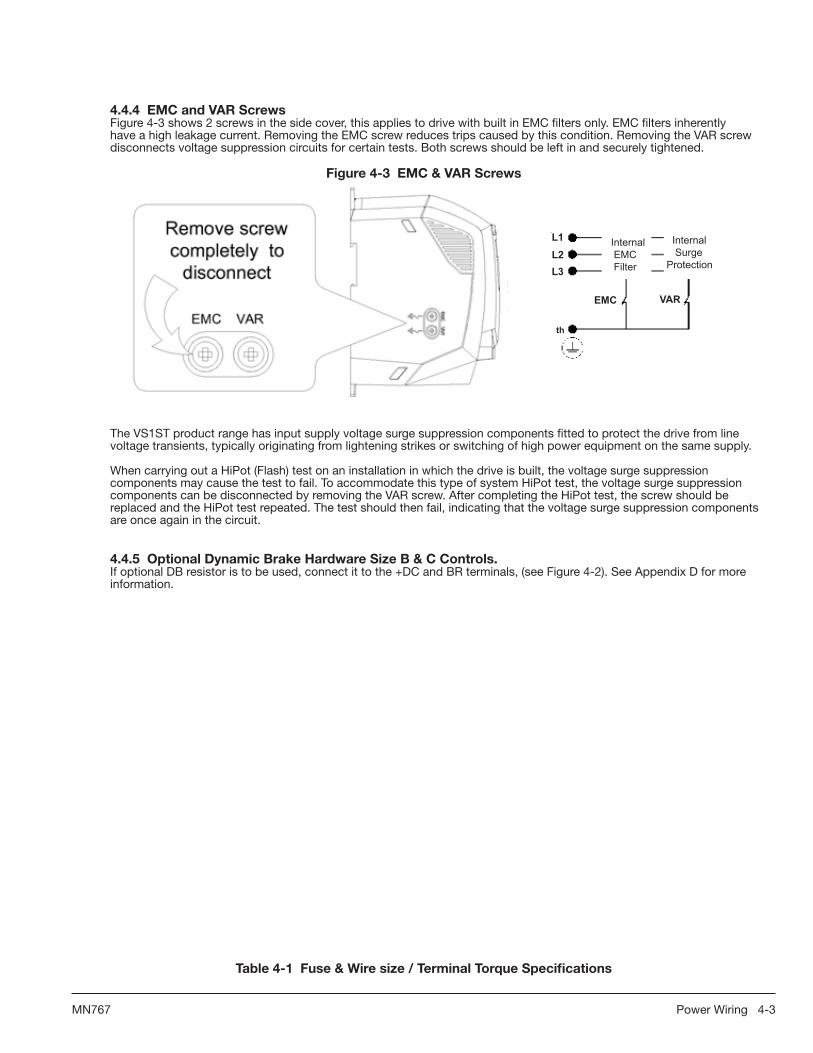
4.4.4EMCandVARScrewsFigure 4-3 shows 2 screws in the side cover, this applies to drive with built in EMC filters only. EMC filters inherently have a high leakage current. Removing the EMC screw reduces trips caused by this condition. Removing the VAR screw disconnects voltage suppression circuits for certain tests. Both screws should be left in and securely tightened.
Figure4-3EMC&VARScrews
Remove screw completely to disconnect
EMC VAR
L1L2L3
th
Internal SurgeProtection
Internal EMC Filter
EMC VAR
The VS1ST product range has input supply voltage surge suppression components fitted to protect the drive from line voltage transients, typically originating from lightening strikes or switching of high power equipment on the same supply.
When carrying out a HiPot (Flash) test on an installation in which the drive is built, the voltage surge suppression components may cause the test to fail. To accommodate this type of system HiPot test, the voltage surge suppression components can be disconnected by removing the VAR screw. After completing the HiPot test, the screw should be replaced and the HiPot test repeated. The test should then fail, indicating that the voltage surge suppression components are once again in the circuit.
4.4.5OptionalDynamicBrakeHardwareSizeB&CControls.If optional DB resistor is to be used, connect it to the +DC and BR terminals, (see Figure 4-2). See Appendix D for more information.
Table4-1Fuse&Wiresize/TerminalTorqueSpecifications

4-4 Power Wiring MN767
Hp kW
NominalInput
Current
FuseorMCB
SupplyCableSize
TorqueLb-in(Nm)
NominalOutputCurrent
MotorCableSize
TorqueLb-in(Nm)
MaxMotorCableLength
MinBrake
ResistorValue
amps amps AWG mm2 Amps AWG mm2 Feet Meters Ohms
110-115V+/-10%1-PhaseInput,230V3-PhaseOutput
0.5 --- 6.7 10 15 1.5 9.0 (1.0) 2.3 15 1.5 9.0 (1.0) 82 25 ---
1 --- 12.5 16 (15)* 15 1.5 9.0 (1.0) 4.3 15 1.5 9.0 (1.0) 82 25 ---
1.5 --- 16.8 20 14 2.5 9.0 (1.0) 5.8 15 1.5 9.0 (1.0) 328 100 47
200-240V+/-10%1-PhaseInput,230V3-PhaseOutput
0.5 0.37 6.7 10 15 1.5 9.0 (1.0) 2.3 15 1.5 9.0 (1.0) 82 25 ---
1 0.75 12.5 16 15 1.5 9.0 (1.0) 4.3 15 1.5 9.0 (1.0) 82 25 ---
2 1.5 19.3 25 12 4 9.0 (1.0) 7 15 1.5 9.0 (1.0) 82 25 ---
2 1.5 19.3 25 12 4 9.0 (1.0) 7 15 1.5 9.0 (1.0) 328 100 47
3 2.2 28.8 32 (35)* 12 4 9.0 (1.0) 10.5 15 1.5 9.0 (1.0) 328 100 47
200-240V+/-10%3-PhaseInput
0.5 0.37 3 6 15 1.5 9.0 (1.0) 2.3 15 1.5 9.0 (1.0) 82 25 --
1 0.75 5.8 10 15 1.5 9.0 (1.0) 4.3 15 1.5 9.0 (1.0) 82 25 ---
2 1.5 9.2 16 (15)* 14 2.5 9.0 (1.0) 7 15 1.5 9.0 (1.0) 82 25 ---
2 1.5 9.2 16 (15)* 14 2.5 9.0 (1.0) 7 15 1.5 9.0 (1.0) 328 100 47
3 2.2 13.7 20 12 4 9.0 (1.0) 10.5 15 1.5 9.0 (1.0) 328 100 47
5 4 20.7 32 (35)* 12 4 9.0 (1.0) 18 14 2.5 9.0 (1.0) 328 100 47
380-480V+/-10%3-PhaseInput
1 0.75 2.9 6 15 1.5 9.0 (1.0) 2.2 15 1.5 9.0 (1.0) 82 25 ---
2 1.5 5.4 10 15 1.5 9.0 (1.0) 4.1 15 1.5 9.0 (1.0) 82 25 ---
2 1.5 5.4 10 15 1.5 9.0 (1.0) 4.1 15 1.5 9.0 (1.0) 164 50 47
3 2.2 7.6 10 15 2.5 9.0 (1.0) 5.8 15 1.5 9.0 (1.0) 164 50 47
5 4 12.4 16 (15)* 14 2.5 9.0 (1.0) 9.5 15 1.5 9.0 (1.0) 164 50 47
7.5 5.5 17.6 20 12 4 9.0 (1.0) 14 14 2.5 9.0 (1.0) 328 100 22
10 7.5 22.1 25 12 4 9.0 (1.0) 18 14 2.5 9.0 (1.0) 328 100 22
15 11 28.2 32 (35) 10 6 9.0 (1.0) 24 12 4 9.0 (1.0) 328 100 22
For UL compliance Motor Cable to be Copper 75°C and Fuse current rating defined by ratings marked ( )*. Wire size is based on 40°C surrounding and fuses are based on 45°C surrounding, max continuous output and no harmonic current.
4.4.6MotorConnectionsAll cables must be shielded and the shields must be grounded at the enclosure cable entrance. 1. Remove covers. Cover removal is described in Chapter 3 of this manual. 2. Connect the Motor leads to terminals U, V and W (see Figure 4-2 for location).3. Connect the motor ground wire to the ground terminal (See Figure 4-2).
LongMotorLeadsThe wire leads that connect the motor to the control are critical in terms of sizing, shielding and the cable characteristics. Short cable runs are usually trouble free but fault-monitoring circuitry can produce numerous faults when long cables are used. Refer to Table 4-1 for maximum cable lengths. Baldor recommends adding an optional load reactor to the output of the control. The load reactor and/or common mode choke should be placed in close physical proximity to the control.
Unexpected faults may occur due to excessive charging current required for motor cable capacitance. If you use long motor leads and experience unexpected trips due to current overload conditions and are not sure how to correctly size and connect the optional load reactors, please contact your Baldor District representative. Baldor is always glad to assist.
4.4.7M-ContactorConnectionsIf required by local codes or for safety reasons, an M-Contactor (motor circuit contactor) may be installed. However,

Power Wiring 4-5MN767
incorrect installation or failure of the M-contactor or wiring may damage the control. If an M-Contactor is installed, the control must be disabled for at least 200msec before the M-Contactor is opened or the control may be damaged. M-Contactor connections are shown in Figure 4-4.
CAUTION: IfanM-Contactorisinstalled,thecontrolmustbedisabledforatleast200msecbeforetheM-Contactor isopened.IftheM-Contactorisopenedwhilethecontrolissupplyingvoltageandcurrenttothemotor, thecontrolmaybedamaged.Beforethecontrolisenabled,theM-Contactormustbeclosedforatleast 200msec.
Figure4-4MotorConnectionsandOptionalConnections
*Optional components not provided with control.
BaldorControl
* AC Motor
Note 1
*OptionalLoad
Reactor
Note 1
A1 B1 C1
A2 B2 C2
U V W
UV W
G
Note 3
* Optional RC DeviceElectrocubeRG1781-3
* M Enable
* M-ContactorTo Power Source (Rated Coil Voltage)
M=Contacts of optional M-Contactor
GND
* Optional M Contactor Connections
Note 2
See Recommended TighteningTorques in Table 4-1.
M
M
Notes: 1. Metal conduit should be used. Connect conduits so the use of Load Reactor or RC Device does not interrupt EMI/RFI shielding.2. See Line/Load Reactors described previously in this section.3. Use same gauge wire for ground as for U, V and W.

4-6 Power Wiring MN767

Control Wiring 5-1MN767
Chapter5ControlWiring
5.1ControlBoardConnections
Analog and Digital input and output connections are made at the Control Wiring Terminals shown in Figure 5-1.
Control wire connections can be made using shielded twisted pair #18 AWG (0.8mm2) wire minimum. The cable must also have an overall shield and not exceed 100 feet (30m) in length. Control wire cables must be separated from power wiring. Separate parallel runs of control cables and power cables by at least 3”. Cross power wires at right angles only. Insulate or tape ungrounded end of shields to prevent contact with other conductors or ground.
Figure5-1ControlTerminals
Control Terminals
Tightening Torque =4.4 lb-in (0.5Nm)
1 2 3 4 5 6 7 8 9 10 11
Table5-1ControlTerminalDescriptions
Terminal SignalDescription
1 +24VDC (@ 100 mA)
2 Digital In1 (8-30VDC)
3 Digital In2 (8-30VDC)
4 Digital In3 (8-30VDC) / Analog In2 (0-10VDC, 0-20mA or 4-20mA)
5 +10VDC (@ 10 mA) Reference for Potentiometer (1kohm minimum)
6 Analog In1 (0-10VDC, 0-20mA or 4-20mA) / Digital In4 (8-30VDC)
7 Common (terminals 7 & 9 are connected)
8 Analog Output (0-10VDC @ 20mA max) / Digital Output (0-24VDC)
9 Common (terminals 7 & 9 are connected)
10 Relay Common
11 Relay N.O. Contact (rated 250VAC@6A; 30VDC@5A)
5.2ConnectionExamples
The connections used are determined by the setting of Parameter P-08. 2-Wire or 3-Wire connectionsfor Digital In1, Digital In2 and Digital In3 are defined by this parameter. Preset Speed selections are alsomade by setting parameters P-12 to P-15. These selections are defined in Table 7-1.Analog Input 1 (terminal 6) can also be set as an additional digital input (Digital Input 4).Digital Input 3 (terminal 4) can also be set as an additional analog input (Analog Input 2).Analog Output (terminal 8) can also be set as a Digital Output.
5.2.1TerminalStripControlSetparameterP-07=0tousethecontrolterminalstripconnections.
Figure5-22Wirewith1Preset&FWD/REV
Tightening Torque =4.4 lb-in (0.5Nm)
P-07=0, P-08=02=Open=Stop, Closed=Run3=Open=FWD, Closed=REV4=Open=Analog Input*, Closed=Preset Speed1
1234567
+24VDC RefDigital Input 1Digital Input 2Digital Input 3+10VDC Pot RefAnalog Input 1Common
FWD/REVSpeed Select
Stop
* Analog Input= Analog Input1 (pin 6)

Control Wiring 5-2MN767
Figure5-32WirewithAnalogInputand2PresetSpeeds
Tightening Torque =4.4 lb-in (0.5Nm)
P-07=0, P-08=12=Open=Stop, Closed=Run3=Open=Analog, Closed=Preset Speed1/24=Open=Preset Speed1, Closed=Preset Speed2
1234567
+24VDC RefDigital Input 1Digital Input 2Digital Input 3+10VDC Pot RefAnalog Input 1Common
Speed Select 1Speed Select 2
Stop
Speed Select 1 Speed Select 2 ActionOpenOpenClosedClosed
OpenClosedOpenClosed
Analog Input 1Analog Input 1Preset Speed 1Preset Speed 2
Figure5-42Wirewith4PresetSpeedsPlusMax.SpeedSelectSwitch
Tightening Torque =4.4 lb-in (0.5Nm)
1234567
+24VDC RefDigital Input 1Digital Input 2Digital Input 3+10VDC Pot RefAnalog Input 1Common
Speed Select 1Speed Select 2
Stop
Speed Select 1 Speed Select 2 ActionOpenClosedOpenClosed
OpenOpenClosedClosed
Preset Speed 1Preset Speed 2Preset Speed 3Preset Speed 4
P-07=0, P-08=22=Open=Stop, Closed=Run3=Speed Select1 (see Table)4=Speed Select2 (see Table)6=Open=Preset Speed 1-4 Closed= Max Speed (P-06)
Digital Input 4
Figure5-52Wirewith1PresetSpeedandExternalTripInput
MN767 Control Wiring 5-3
Tightening Torque =4.4 lb-in (0.5Nm)
P-07=0, P-08=32=Open=Stop, Closed=Run3=Open=Analog, Closed=Preset Speed14=Open=External Trip is generated,
Closed=Reset Fault and run.
1234567
+24VDC RefDigital Input 1Digital Input 2Digital Input 3+10VDC Pot RefAnalog Input 1Common
Speed SelectExternal Trip
Stop
Digital Input 4 Closed = 5V<Vin<30VDCDigital Input 4 Open = Vin<2VDC
Figure5-62WirewithLocalorRemoteAnalogSpeedsand2AnalogInputs
Tightening Torque =4.4 lb-in (0.5Nm)
P-07=0, P-08=42=Open=Stop, Closed=Run3=Open=Local Ref (Analog In 1), Closed=Remote Ref
1234567
+24VDC RefDigital Input 1Digital Input 2Analog Input 2+10VDC Pot RefAnalog Input 1Common
Local/RemoteRemote Ref
Stop
+-Volts/
Current P44
Figure5-72Wirewith1PresetSpeed,andFWD/REV
Tightening Torque =4.4 lb-in (0.5Nm)
P-07=0, P-08=52=Open=Stop, Closed=Forward Run3=Open=Stop, Closed=Reverse Run4=Open=Analog, Closed=Preset Speed1
1234567
+24VDC RefDigital Input 1Digital Input 2Digital Input 3+10VDC Pot RefAnalog Input 1Common
ReverseSpeed Select
Forward
FWD Stop REV Stop ActionOpenClosedOpenClosed
OpenOpenClosedClosed
Drive StopForward RunReverse RunFast Stop (see P-33)

Control Wiring 5-3MN767
Figure5-82WirewithFWD/REVandExternalTripInput
Tightening Torque =4.4 lb-in (0.5Nm)
P-07=0, P-08=62=Open=Stop, Closed=Run3=Open=Forward, Closed=Reverse4=Open=External Trip is generated,
Closed=Reset Fault and run.Connect external thermistor type PT100or similar to Digital Input 3.
1234567
+24VDC RefDigital Input 1Digital Input 2Digital Input 3+10VDC Pot RefAnalog Input 1Common
Forward/ReverseExternal Trip
Stop
Figure5-92WirewithFWD/REVandExternalTripandFastStop
Tightening Torque =4.4 lb-in (0.5Nm)
P-07=0, P-08=72=Open=Stop, Closed=Forward Run3=Open=Stop, Closed=Reverse Run4=Open=External Trip is generated, Closed=Reset Fault and run.
1234567
+24VDC RefDigital Input 1Digital Input 2Digital Input 3+10VDC Pot RefAnalog Input 1Common
Reverse StopExternal Trip
Forward Stop
FWD Stop REV Stop ActionOpenClosedOpenClosed
OpenOpenClosedClosed
Drive StopForward RunReverse RunFast Stop (see P-33)
Connect external thermistor type PT100 or similar to Digital Input 3.
Figure5-102WirewithFWD/REVand4PresetSpeeds
Tightening Torque =4.4 lb-in (0.5Nm)
P-07=0, P-08=82=Open=Stop, Closed=Run3=Open=Forward, Closed=Reverse
1234567
+24VDC RefDigital Input 1Digital Input 2Digital Input 3+10VDC Pot RefAnalog Input 1Common
Forward/ReverseSpeed Select 1
Stop
Speed Select 1 Speed Select 2 ActionOpenClosedOpenClosed
OpenOpenClosedClosed
Preset Speed 1Preset Speed 2Preset Speed 3Preset Speed 4
Speed Select 2
Figure5-112WirewithFWD/REVand4PresetSpeeds
Tightening Torque =4.4 lb-in (0.5Nm)
P-07=0, P-08=92=Open=FWD Stop, Closed=FWD Run3=Open=REV Stop, Closed=REV Run
1234567
+24VDC RefDigital Input 1Digital Input 2Digital Input 3+10VDC Pot RefAnalog Input 1Common
Reverse StopSpeed Select 1
Forward Stop
Speed Select 2
Speed Select 1 Speed Select 2 ActionOpenClosedOpenClosed
OpenOpenClosedClosed
Preset Speed 1Preset Speed 2Preset Speed 3Preset Speed 4
Figure5-123WireStartandStopwith1PresetSpeed
Tightening Torque =4.4 lb-in (0.5Nm)
P-07=0, P-08=102=Momentary close Starts the drive.3=Momentary open Stops the drive.4=Open=Analog, Closed=Preset Speed1
1234567
+24VDC RefDigital Input 1Digital Input 2Digital Input 3+10VDC Pot RefAnalog Input 1Common
StopSpeed Select
Start

Control Wiring 5-4MN767
Figure5-133WireStartandStopwith1PresetSpeedandChangeDirection
Tightening Torque =4.4 lb-in (0.5Nm)
P-07=0, P-08=112=Momentary close Starts the drive.3=Momentary open Stops the drive.4=Open=Run,
Momentary close=Change Direction
1234567
+24VDC RefDigital Input 1Digital Input 2Digital Input 3+10VDC Pot RefAnalog Input 1Common
StopDirection
Start
Figure5-142Wirewith1PresetSpeedandFastStop
Tightening Torque =4.4 lb-in (0.5Nm)
P-07=0, P-08=122=Open=Stop, Closed=Run3=Open=Fast Stop,
Closed=Run (Fast Stop mode=P-33)4=Open=Analog, Closed=Preset Speed1
1234567
+24VDC RefDigital Input 1Digital Input 2Digital Input 3+10VDC Pot RefAnalog Input 1Common
Fast Stop/RunSpeed Select
Stop/Run
5.2.2OtherControlMethodsSetparameterP-07=0to6tousethecontrolmethodofyourchoice.
P-07 =0 is described in this section. For P-07 =1-2 see Chapter 6. For P-07 =3-6 refer to Chapter 8.0- Terminal Strip, Speed and other commands are from the terminal strip.1- Keypad control - forward only, uni-directional control from the keypad(<?> and arrows are used to change the speed reference).2- Keypad control - forward and reverse, bi-directional control from the keypad.START changes between forward and reverse, <?> and change speed.)3. MODBUS network control with internal accel / decel ramps.4. MODBUS network control with accel / decel ramp adjustment.5. User PI control with external feedback signal.6. User PI control with analog input 1 summation.
5.3RJ45CommunicationConnection
The RJ45 Data Port can be used as either a RS485 Serial Modbus interface or to connect the optional remote keypad (VS1ST-RKEY3) and/or copycat loader (VS1ST-CCL).
Serial Modbus networks use the RS485 PIN connection; see Appendix E for the communication protocols. Remote keypad kits and copycat programmers use the dedicated MXSTbus connection.
Figure5-2RJ45DataConnection1 No connection2 No connection3 0V4 RS485 - / MXSTbus5 RS485 + / MXSTbus6 +24V Keypad7 RS485 - / Modbus8 RS485 + / Modbus
For MXSTbus and Modbus,data format is fixed as:
1 start bit, 8 data bits,1 stop bit, no parity.
Baudrate and Addressset in P-35

Control Wiring 5-5MN767
5.4ChangingParameters
To change a parameter value press and hold the ENT/PROG key for > 1 second while the drive displays . The display changes to indicating parameter 01. Press and release the ENT/PROG key to display the value of this parameter.
Use the UP and DOWN arrow keys to change to the required value. Press and release the ENT/PROG key once more to store the change. Press and hold the ENT/PROG key for > 1 second to return to operational mode. The display shows if the drive is stopped or the real-time information (for example speed) if the drive is running.
5.5ResetFactoryDefaultSettings
To reset factory default parameters, press the UP, DOWN, and STOP keys simultaneously for > 2 seconds. The display shows indicating the drive has reset itself to factory default parameters. Press the STOP button to acknowledge and reset the drive.
5.6TerminalControl
When delivered, the VS1ST is set to operate in terminal control mode and all parameters (P-xx) have the default values as indicated in Chapter 7 Parameters. Connect the motor to the drive, checking star/delta connection for the voltage rating.
1. Remove all power from the control.2. Connect a control switch between the control terminals 1 and 2 ensuring that the contact is open (drive disabled). 3. Connect a potentiometer (1 kΩ min to 10 kΩ max) between terminals 5 and 7, and the wiper to terminal 6.4. With the potentiometer set to zero, switch on the power supply to the drive. The display will show .5. Enter motor data from motor nameplate: P-01 = motor rated voltage P-02 = motor rated current P-03 = motor rated frequency P-04 = motor rated speed 6. Close the control switch, terminals 1-2. The drive is now ‘enabled’ and the output frequency/speed are controlled by the potentiometer. The display shows zero speed in Hertz ( .) with the potentiometer turned to minimum.7. Turn the potentiometer to maximum. The motor will accelerate to 60Hz (the default value of P-06) under the control of the accelerating ramp time P-10. The display shows 60Hz ( .) at max speed. 8. To display motor current (A), briefly press the ENT/PROG key.9. Press ENT/PROG again to return to speed display.10. To stop the motor, either turn the potentiometer back to zero or disable the drive by opening the control switch (terminals 1-2).11. If the enable/disable switch is opened the drive will decelerate to stop at which time the display will show . If the potentiometer is turned to zero with the enable / disable closed the display will show .. (0.0Hz), if left like this for 20 seconds the drive will go into standby mode, display shows , waiting for a speed reference signal.
5.7KeypadControl
To allow the VS1ST to be controlled from the keypad in a forward direction only, set P-07 =1:
1. Connect Motor as for terminal control above.2. Enable the drive by closing the switch between control terminals 1 & 2. The display will show .3. Press the START key. The display shows ..4. Press the UP arrow to increase speed.5. The drive will run forward, increasing speed until the UP arrow is released. The rate of acceleration is controlled by the setting of P-10, check this before starting. 6. Press the DOWN arrow to decrease speed. The drive will decrease speed until DOWN is released. The rate of deceleration is limited by the setting in P-11.7. Press the STOP key. The drive will decelerate to rest at the rate set in P-11.8. The display will finally show at which point the drive is disabled.9. To preset a target speed prior to enable, press the DOWN arrow key while the drive is stopped. The display will show the target speed, use the UP & DOWN arrow keys to adjust as required then press the STOP key to return the display to . 10. Pressing the START key will start the drive accelerating to the target speed. Setting P-07=2 allows the VS1ST to be controlled in a forward and reverse direction from the keypad.11. Operation is the same as when P-07=1 for start, stop and changing speed.12. Press the START key. The display changes to ..13. Press the UP arrow to increase speed the drive will run forward, increasing speed until the UP arrow is released. Acceleration is limited by the setting in P-10. The maximum speed is the speed set in P-06.14. To reverse the direction of rotation of the motor, press the START key again. Note: Keypad Speed Control and Terminal Start/Stop Inputs:To use the drive keypad to control speed with a remote start/stop from the terminal strip, set parameter P-28 = 2 or 3. The status of digital input 1 controls the start/stop and the speed reference is from the keypad in this case. The drive Stop button is disabled in this case.
PROG ENT
PROG ENT
STOPRESET

5-6 Control Wiring MN767

Using the Keypad 6-1MN767
Chapter6UsingtheKeypad
6.1KeypadComponents
This chapter provides an overview of the integrated keypad and how to use it to program the VS1ST drive. The controls are shown in Table 6-1.
Table6-1OperatorInterfaceDescription
Key Name Description
Display 6 Digit seven segment display. Display of parameter numbers, values, error messages and other information.
StartStarts motor if Direction command and Speed reference are set. Only active if P07 is set to allow keypad control. Programmable to change the motor direction if pressed while running.
Stop / ResetStops the drive in all modes. Stop is always active and stops the drive in both keypad, terminal and network control modes. Resets any active faults, if fault condition has been cleared.
Enter / Program
Momentarily press to view available displays. Pressing and holding the ENT Key for approximately 2 Seconds or more will enter the programming mode or escape back out of the programming mode.
Increase
During operation increases the speed reference. (Active in keypad mode). Pressing for a period of time will increase the reference value rate of change. In edit mode, navigates between parameters and increments parameter values.
Decrease
During operation decreases the speed reference. (Active in keypad mode). Pressing for a period of time will increase the reference value rate of change. In edit mode, navigates between parameters and decrements parameter values.
6.2KeypadDisplayParameters
The following display values can be viewed from the keypad while operating the drive.
6.2.1DefaultConfigurationSpeed and Amps can be displayed by the drive in its default configuration. Press the ENT/PROG key momentarily to toggle between Hertz and Amps on the display.
Figure6-1StandardDisplayScreen
P-04=0,P-23=0
ENTPROG
ENTPROG
STOPRESET

6-2 Using the Keypad MN767
6.2.2RPMDisplaySetting P-04 to a value other than zero will set units for the VS1ST in RPM. This will enable a third display screen in operational mode to show the RPM units set in parameter P-04.
Figure6-2RPMDisplayP-04=1800,P-23=0
ENTPROG
ENTPROG
ENTPROG
6.2.3CustomDisplayUnitParameter P-23 is used to configure the display and show custom units based on the scale factor assigned. When a value other than zero is assigned to P-23, a new display is enabled in operational mode. If P-04=0, P-23 will scale units in Hertz, and if P-04 is not zero, P-23 will scale the RPM units set by P-04 (see display examples set below):
Figure6-3CustomDisplayP-04=0,P-23=2.0
ENTPROG
ENTPROG
ENTPROG
Figure6-4CustomDisplaywithRPM
P-04=1800,P-23=2.0
ENTPROG
ENTPROG
ENTPROG
ENTPROG

Parameter Descriptions 7-1MN767
Chapter7ParameterDescriptions
7.1Overview
Parameters P00 through P-45 are presented in this Chapter and each setting is explained. Selecting P00 and pressing ENT/PROG accesses a read-only menu to monitor internal drive values. Once in the display view, the UP and DOWN arrows will scroll between the read only variables shown below.
Table7-1ParameterDescriptions
Number Name(DisplayLevel) ValueRange,DescriptionandPresetValue
P00-01 ReadOnly Analog Input 1 Value (100%=Max Vin).
P00-02 Parameters Analog Input 2 Value (100%=Max Vin).
P00-03 Speed Reference Input -P-06 to P-06 (Hz if P-04=0, RPM if P-04≥1)
P00-04 Digital Input Status
P00-05 Reserved
P00-06 Reserved
P00-07 Motor Voltage
P00-08 DC Bus Voltage
P00-09 Internal Heatsink Temperature (in °C)
P00-10 Total Hours Run Time (Power applied)
P00-11 Run time since last trip. Reset on next enable after trip or power down.
P00-12 Run time since last trip. Reset on next enable after trip. Not by Undervolt trip or power down (unless after a trip condition).
P00-13 Run time since drive enabled. Reset on next enable after disable.
P00-14 PWM Frequency. May be less than selected by P-21 if drive is hot.
P00-15 DC Bus Volts Log. Last 8 sample values (every 250 msec).
P00-16 Thermistor temperature log. Last 8 sample values (every 500 msec).
P00-17 Motor Current. Last 8 sample values (every 250 msec).
P00-18 Software ID, I/O Processor & Motor Control versions.
P00-19 Drive Serial Number.
P00-20 Drive Identifier. (Drive Rating & Type).
1=Analog Input 1 Value Display Number Value Value (0.0% of Max Vin)
P-01 MotorRatedVolts Range: 0, 20V to 250V= 230VAC 0, 20V to 500V= 460VAC (400VAC)
Preset: 0
Rated (nameplate) voltage of the motor (Volts). Value limited to 250V for low voltage drives. Setting to zero disables voltage compensation.
P-02
MotorRatedCurrent Range:25% to 100% rated drive current (A)
Preset:4.3
The (FLA) Full Load Amps of the motor (listed on the motor nameplate). The drive will fault on a motor overload if the value set in this parameter is exceeded.
.

7-2 Parameter Descriptions MN767
Number Name(DisplayLevel) ValueRange,DescriptionandPresetValue
P-03 MotorRatedFrequency Range: 25 to 500 Hz
Preset:60 Hz (Display shows )
Rated frequency of the motor (listed on the nameplate). Adjusting the Voltage / Frequency (V/F)
If motor instability is experienced, increase or decrease the voltage (P-37) at the speed of instability (P-36).
Figure7-1AdjustingVolts/HzCharacteristics
Voltage
P01 [Motor NP Volts]
[P01]/2
P37 [V/F Adj Voltage]
P18 [Voltage Boost]
P05 Minimum Freq]
[P03]/2 P36[V/F Adj Freq]
P03[Motor NP Hertz]
P06 [Maximum Freq]
Frequency
P-04 MotorRatedSpeed Range:0, 360 to 30000 RPM
Preset:0
The RPM rated speed of the motor (listed on the motor nameplate). When set to a value other than 0, all speed related parameters are displayed in RPM.
P-05 MinimumOutputSpeed Range:0 to P-06 (max 500 Hz)
Preset:0
Limits the speed reference to the drive regardless of the speed reference supplied to the drive.
P-06 MaximumOutputSpeed Range: P-05 to 5 times P-03 (max 500Hz)
Preset:60.0
User specified maximum motor speed, speeds greater than this are not allowed.
P-07 Start/StopSource Range: 0 to 6
Preset:0
0 - Terminal StripSpeed and other commands are from the terminal strip.
1: Keypad control (forward only)Uni-directional control from the keypad (up down arrows are used to change the speed reference). Thedrivemustbeenabled(controlterminals1&2connected).
2: Keypad control (forward and reverse)Bi-directional control from the keypad. START changes between forward and reverse, and change speed). Thedrivemustbeenabled(controlterminals1and2connected).
3: MODBUS Network control using internal accel / decel ramps.
4: MODBUS Network control with accel / decel ramp adjustment via modbus.
5: User PI control with external feedback signal.
6: User PI control with analog input 1 summation. Sets the input source for Speed, Start/Stop and other commands. Note: The drive will respond to the keypad stop key regardless of the value in this parameter.
Table7-1ParameterDescriptions Continued

Parameter Descriptions 7-3MN767
Number Name(DisplayLevel) ValueRange,DescriptionandPresetValue
P-08 SpeedReferenceSource Range:0-12
Preset:0
Sets the digital inputs configuration. The operation of P-08 changes depending on the value of P-07. Refer to Table 8-1, Table 8-2, Table 8-3, and Table 8-4.
P-09 StopMode Range: 0 to 2
Preset:0
0: Ramp to stop (power dip ride-through. If input power is lost the drive will use regen power to reduce the motor speed.
1: Coast to stop. The transistor power device drivers are turned off and motor coasts to stop (no braking).
2: Ramp to stop (fast stop). Uses deceleration ramp when input power is lost or uses constant power braking mode for normal braking.
If the supply is lost and P-09=0 the drive will try to continue running by reducing the speed of the load using the load as a generator.
If the supply is lost and P-09=2, the drive will ramp to stop using the P-33 decel ramp. Also activates constant power braking mode for normal braking.
P-10 AccelTime Range: 0 to 600.0 seconds
Preset:5.0
Sets the time for the motor to accelerate from 0 to motor rated speed (P-03). Short times may cause over current trips.
P-11 DecelTime Range: 0 to 600.0 seconds
Preset:5.0
Sets the time for the motor to decelerate from motor rated speed (P-03) to 0. Short times may cause over voltage trips. When set to 0, drive will decel as fast as possible without tripping.
P-12 PresetSpeed1 Range: -P-06 to P-06
Preset:0.0
Sets the value of Preset Speed 1. Range is -P-06 (reverse) to + P-06.
P-13 PresetSpeed2 Range: -P-06 to P-06
Preset:0.0
Sets the value of Preset Speed 2. Range is -P-06 (reverse) to + P-06.
P-14 PresetSpeed3 Range: -P-06 to P-06
Preset:0.0
Sets the value of Preset Speed 3. Range is -P-06 (reverse) to + P-06.
P-15 PresetSpeed4 Range: -P-06 to P-06
Preset:0
Sets the value of Preset Speed 4. Range is -P-06 (reverse) to + P-06.
P-16 SpeedReferenceScaling Range: 0 to 500.0%
Preset:100.0
Sets the parameter value in % of full scale. Normally, the max speed reference (P-06) is 10 VDC or 20mA. P-16 adjusts the speed reference to another value (for example, 9.5 VDC or 19mA). If P-07 = 1 or 2, this parameter adjusts the keypad reference and an Analog Reference.
Table7-1ParameterDescriptions Continued

7-4 Parameter Descriptions MN767
Number Name(DisplayLevel) ValueRange,DescriptionandPresetValue
P-17 AnalogInputFormat Range:U 0 - 10
b 0 - 10
A 0 - 20
t 4 - 20
r 4 - 20
t 20 - 4
r 20 - 4
Preset:U 0 - 10
Sets the analog input for voltage or current operation and the range of expected input signal. A 50% offset by P-30 and 200% scaling by P-16 gives ± P-06.
“b” can be used for bipolar input signals.
“t” indicates the drive will trip if signal removed when drive is enabled.
“r” indicates the drive will ramp to Preset Speed 1 if signal is removed when drive is enabled.
P-18 VoltageBoost Range:0.0 to 20.0% for frame A
0.0 to 15.0% for frame B
0.0 to 10.0% for frame C (% of max. output voltage)
Preset:CALC
Sets the percentage of output voltage boost at zero frequency. Torque boost offsets the voltage drop of the AC motor at low speeds. For high friction loads or high inertia loads, a high starting torque level may be needed. Voltage boost is only effective at speeds less than one-half of the motor’s base frequency.
Figure7-2BoostVoltage
P18 [Voltage Boost]
50%
100%
Out
put V
olta
ge (%
)
Base Speed Base Speed
Frequency (Hz)
__________2
Table7-1ParameterDescriptions Continued

Parameter Descriptions 7-5MN767
Number Name(DisplayLevel) ValueRange,DescriptionandPresetValue
P-19 EnergySavings Range:0=Disabled
1=Enabled
Preset:0
When enabled, automatically reduces applied motor voltage on light load. Minimum value is 50% of nominal.
Figure7-3EnergySavingAdjustment
Voltage
P01
[P01]/2
Voltage
Default Linear V/F
LoadDependant V/F characteristic
Frequency
[P03]/2 P03
P-20 TripLog Range: Last four trips stored
Preset:N/A (Read Only)
Displays the last four trips as a coded fault. The codes are displayed most recent first to oldest. Use the up or down arrow keys to scroll the fault list.
P-21 PWMFrequency Range: 4-32kHz
Preset:16
Sets the effective switching frequency of the drive.If “rEd” is displayed, the switching frequency has been reduced to the level in P00-14 due to excessive drive heatsink temperature.
P-22 RelayOutputSelect Range: 0 to 7
Preset:1
Defines the function of the user relay (when operating conditions are met).
0: Drive enabled 4: Motor speed >= limit
1: Drive healthy 5: Motor current >= limit
2: Motor at target speed 6: Motor speed < limit
3: Drive tripped 7: Motor current < limit
Disabled: Contacts open Enabled: Contacts closed
Options 4 to 7: the Relay output is enabled using the level set in P-25.
P-23 DisplaySpeedScaleFactor Custom scaling factor
Preset:0.000
P-04 = 0, speed in Hz are scaled by this value.
P-04 > 0 RPM units are scaled by this value.
Scaled display values are preceded with “” for custom units.
Table7-1ParameterDescriptions Continued

7-6 Parameter Descriptions MN767
Number Name(DisplayLevel) ValueRange,DescriptionandPresetValue
P-24 Analog/Digitaloutputfunctionselect
Range: 0 to 9
Preset:8
Digitaloutputmode
0: Drive enabled 4: Motor speed >= limit
1: Drive healthy 5: Motor current >= limit
2: Motor at target speed 6: Motor speed < limit
3: Drive tripped 7: Motor current < limit
Digitaloutputmode
8: Motor speed 9: Motor current
Digital Output Mode:
Options 0 to 7 select a digital voltage output signal
Disabled: 0V; Enabled: +24V, (20mA limit).
Options 4 to 7: the Digital output is enabled using the level set in P-25
Analog Output Mode:
Option 8: Motor Speed signal range 0-10V = 0-100% of P-06
Option 9: Motor Current signal range 0-10V = 0-200% of P-02
P-25 Relayoutputlimit Range:0.0 to 100.0% for speed 0.0 to 200.0% for current
Preset:100.0
Sets the limit for P-22 and P-24 (when using Digital Output Mode).
P-26 Skipfrequency Range: P-05 to P-06
Preset:0.0
Sets the midpoint of the avoidance band selected in P-27. The avoidance band can help alleviate problems with vibration harmonics at a specific operating frequency of the driven motor or machinery. See also P-27
P-27 SkipFrequencyBand Range: 0 to P-06
Preset:0.0
Sets the width of the skip frequency band. Setting P-27 to 0 disables the avoidance frequency.
P-28 RestartMode Range: 0 to 3
Preset:1
0: Minimum Speed 2: Minimum Speed (Auto-run)1: Previous Speed 3: Previous Speed (Auto-run)
If set to 0 or 2, drive will always start from minimum speed.
If set to 1 or 3, drive ramps up to the operating speed prior to the last STOP command. If set to 2 or 3, the status of digital input 1 controls drive to start or stop. The start and stop button on the drive will not operate in this case. See also P-29.
P-29 AutoRestartAttempts Range: See below
Preset:Auto-0
Edge-r: if drive is powered up with Digital Input 1 closed (enabled), drive will not run. The switch must be opened & closed after power up or after clearing a trip for the drive to run.
Auto-0: drive will run whenever digital input 1 is closed (if not tripped).
Auto-1-5: drive will make 1-5 attempts to automatically restart after a trip (25s between attempts). If fault has cleared drive will restart.
To reset the counter the Drive must be powered down, reset on the keypad or by re-enabling the drive.
Table7-1ParameterDescriptions Continued

Parameter Descriptions 7-7MN767
Number Name(DisplayLevel) ValueRange,DescriptionandPresetValue
P-30 AnalogInputOffset Range: -500.0 to 500.0%
Preset:0.0
Amount of offset for analog input level.
Resolution of 0.1%.
P-31 BrakeAfterStop Range: 0 to 60.0 seconds
Preset:0.0
Sets the amount of time DC injection braking is applied during stop when zero speed is reached. (P-31=0, no DC Brake is applied). The amount of braking is set in P-18 - Voltage Boost. See also P-18, P-32.
P-32 BrakeBeforeStart Range: 0 or 1
Preset:0
0: The drive accelerates to speed without delay.
1: Applies DC braking when run command is issued.
The amount of time is set in P-31 and the amount of braking in P-18. The drive will then accelerate. DC braking may be applied after run command is issued. See also P-18, P-31.
P-33 Decel2 Range: 0 to 25
FastStop Preset:0.00
Sets a second Decel time.
P-33 is used if the drive input power is lost or fast stop mode is selected; P-09=0 or 2. Fast stop may also be enabled by setting P-08 =12 and opening Digital Input 2.
When P-09 = 2 and P-33 = 0, activating the fast stop disables the drive without braking, effectively coasting to a stop.
See also P-08, P-09.
P-34 BrakeChopperEnable Range: 0 to 2
Preset:0
0: Disabled
1: Enabled with Software protection for standard brake resistors (200W)
2: Enabled without s/w protection.
When enabled, the VS1ST software monitors bus voltage and turns On/Off braking as shown here.
Drive Voltage Rating
Brake Turn Off Level
Brake Turn On Level
240VAC 378VDC 390VDC
460VAC 756VDC 780VDC
Table7-1ParameterDescriptions Continued
7-8 Parameter Descriptions MN767
Number Name(DisplayLevel) ValueRange,DescriptionandPresetValue
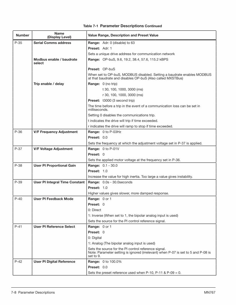
P-35 SerialCommsaddress Range: Adr: 0 (disable) to 63
Preset:Adr: 1
Sets a unique drive address for communication network
Modbusenable/baudrateselect
Range: OP-buS, 9.6, 19.2, 38.4, 57.6, 115.2 kBPS
Preset:OP-buS
When set to OP-buS, MODBUS disabled. Setting a baudrate enables MODBUS at that baudrate and disables OP-buS (Also called MXSTBus)
Tripenable/delay Range:0 (no trip)
t 30, 100, 1000, 3000 (ms)
r 30, 100, 1000, 3000 (ms)
Preset:t3000 (3 second trip)
The time before a trip in the event of a communication loss can be set in milliseconds.
Setting 0 disables the communications trip.
t indicates the drive will trip if time exceeded.
r indicates the drive will ramp to stop if time exceeded.
P-36 V/FFrequencyAdjustment Range: 0 to P-03Hz
Preset:0.0
Sets the frequency at which the adjustment voltage set in P-37 is applied.
P-37 V/FVoltageAdjustment Range: 0 to P-01V
Preset:0
Sets the applied motor voltage at the frequency set in P-36.
P-38 UserPIProportionalGain Range: 0.1 - 30.0
Preset:1.0
Increase the value for high inertia. Too large a value gives instability.
P-39 UserPIIntegralTimeConstant Range: 0.0s - 30.0seconds
Preset:1.0
Higher values gives slower, more damped response.
P-40 UserPIFeedbackMode Range: 0 or 1
Preset:0
0: Direct
1: Inverse (When set to 1, the bipolar analog input is used)
Sets the source for the PI control reference signal.
P-41 UserPIReferenceSelect Range: 0 or 1
Preset:0
0: Digital
1: Analog (The bipolar analog input is used)
Sets the source for the PI control reference signal.Note: Parameter setting is ignored (irrelevant) when P-07 is set to 5 and P-08 is set to 9.
P-42 UserPIDigitalReference Range: 0 to 100.0%
Preset:0.0
Sets the preset reference used when P-10, P-11 & P-09 = 0.
Table7-1ParameterDescriptions Continued

Parameter Descriptions 7-9MN767
Number Name(DisplayLevel) ValueRange,DescriptionandPresetValue
P-43 UserPIFeedbackSelect Range: 0 to 2
Preset:0
0: 2nd analog input
1: 1st analog input
2: Motor load current
This parameter selects the feedback signal source. Note: Parameter setting is ignored (irrelevant) when P-07 is set to 5 and P-08 is set to 9.
P-44 2ndAnalogInputformat Range:U 0 - 10
A 0 - 20
t 4 - 20
r 4 - 20
t 20 - 4
r 20 - 4
Preset:U 0 – 10
Selects the format of the 2nd analog input.
“t” indicates the drive will trip if signal removed when drive is enabled.
“r” indicates the drive will ramp to Preset Speed 1 if signal is removed when drive is enabled.
P-45 Parameteraccesslock Range: 0 or 1
Preset:0
0: Parameters can be changed, auto-saved on power down
1: Read-only. No changes allowed.
Controls access to parameters.
Table7-1ParameterDescriptions Continued

7-10 Parameter Descriptions MN767

Customizing Your Application 8-1MN767
Chapter8CustomizingYourApplication
8.1SimpleParameterAdjustments
Factory settings may give satisfactory performance, however certain adjustments may be beneficial.
Adjustment Parameter ParameterName
Motor Rated Volts P-01 The factory default setting P01 = 0 should be used unless voltage compensation is required.
Motor Rated Current P-02
Must be set to the value on the motor nameplate. P04 is optional. If this parameter is set to zero (default state), speed is displayed in Hz (otherwise, RPM).
Motor Rated Frequency P-03
Motor Rated Speed P-04
Minimum Speed P-05 Set P06 to the maximum speed and P05 to the minimum speed. These limits can also be negative for reverse speeds. If a non-zero minimum speed is set in P05, the motor will ramp to this minimum speed at the rate set in P10 as soon as the drive is enabled.Maximum Speed P-06
Start/Stop Source P-07 Set as required by the application.
Speed Ref Source P-08 Set as required by the application.
Stop Mode P-09 Select method of stopping required when drive is disabled.
Accel P-10 Adjust as need for your application. Short Acceleration or Deceleration times may cause excess motor current and may result in it tripping or the motor stalling.
Decel P-11
Analog Input Format P-17 Set as required by the application (0-10V, 0-20V, 4-20mA)
Voltage Boost P-18 Any hard to start load will benefit from voltage boost. Permits a boost of up to 20% of full motor voltage to be applied.

8-2 Customizing Your Application MN767
8.2AnalogandDigitalInputConfigurations
Parameters P-07 and P-08 can be set to allow various operating modes. Following are settings for these parameters.
8.2.1TerminalStripMode(P-07=0)
Table8-1ParameterP-08ControlofDigitalInputswhenP-07=0
P-08 DigitalIn1(Term.2) DigitalIn2(Term.3) DigitalIn3(Term.4) AnalogInput1(Term.6)
0 Open Stop Open FWD Run Open Analog Input 1
SPD Ref Closed Run Closed REV Run Closed Preset Speed1
1 Open Stop Open Analog SPD Ref Open Preset Speed1
SPD Ref Closed Run Closed Preset Speed 1/2 Closed Preset Speed2
2*
Open Stop
Digital In 2 Digital In 3 Speed Select
Open Preset Speed 1-40 0 Preset Speed 1
1 0 Preset Speed 2
Closed Run0 1 Preset Speed 3
Closed Max Speed (P-06) 1 1 Preset Speed 4
3* Open Stop Open Analog SPD Ref Open Trip (Ext Trip)
SPD Ref Closed Run Closed Preset Speed1 Closed Run
4 Open Stop Open Analog Input 1
Analog Input 2 SPD RefClosed Run Closed Analog Input 2
5* Open FWD Stop Open REV Stop Open Analog SPD Ref
SPD Ref Closed FWD Run Closed REV Run Closed Preset Speed1
6* Open Stop Open FWD Run Open Trip (Ext Trip)
SPD Ref Closed Run Closed REV Run Closed Run
7* Open FWD Stop Open REV Stop Open Trip (Ext Trip)
SPD Ref Closed FWD Run Closed REV Run Closed Run
8 Open Stop Open FWD Run Digital In 3 Analog In 1 Speed Select
Closed Run Closed REV Run 0 0 Preset Speed 1
9*
Open FWD Stop Open REV Stop 1 0 Preset Speed 2
Closed FWD Run Closed REV Run 0 1 Preset Speed 3
1 1 Preset Speed 4
10 3Wire ControlMomentary Close = RUN
3Wire Control Open = STOP
Open Analog SPD Ref SPD Ref
Closed Preset Speed 1
11* 3Wire ControlMomentary Close = RUN
3Wire Control Open = STOP
3Wire Control Momentary Closed = REV SPD Ref
12 Open Stop Open Fast Stop (P33) Open Analog SPD Ref
SPD Ref Closed Run Closed Run Closed Preset Speed1
Table 8-1 notes:P-08 = 2 Note: Analog Input 1 becomes Digital Input 4 Closed: 8V< Analog Input1 < 30V Open: Analog Input1 < 2VP-08 = 5, 7 or 9 Note: Closing both Digital Input 1 and 2 = Fast Stop (P33). P-08 = 3 or 6 Note: Connect external PTC Motor Thermistor or similar user contact to Digital Input 3. P-08 = 11 Note: Closing both Digital Input 1 and Digital Input 3 = Fast Stop (P33).

Customizing Your Application 8-3MN767
Figure8-1TerminalModeExampleWiring
1
2
3
4
5
6
7
1
2
3
4
5
6
7
1
2
3
4
5
6
7
T3 T40 01 00 11 1
SpeedPreset 1Preset 2Preset 3Preset 4
1
2
3
4
5
6
7
1
2
3
4
5
6
7
+-
1
2
3
4
5
6
7
Terminal mode P07 = 0, P08 = 0 Terminal mode P07 = 0, P08 = 1
Terminal mode P07 = 0, P08 = 2 Terminal mode P07 = 0, P08 = 3
+24V Output
O: Stop (disable)C: Run (enable)
O: ForwardC: Reverse
O: Analog Speed RefC: Preset Speed 1
+10V Output
Analog Speed Ref
0V
+24V Output
O: Stop (disable)C: Run (enable)
O: Analog Speed RefC: Preset Speed 1/2
O: Preset Speed 1C: Preset Speed 2
+10V Output
Analog Speed Ref
0V
+24V Output+24V Output
+24V Output+24V Output
O: Stop (disable)C: Run (enable)
O: Stop (disable)C: Run (enable)
O: Analog Speed RefC: Preset Speed 1
+10V Output +10V Output
Analog Speed Ref
0V0V
O: Preset Speeds 1-4C: Max Speed (P06)
Volts/Current (P44)
Terminal mode P07 = 0, P08 = 4 Terminal mode P07 = 0, P08 = 11
O: Stop (disable)C: Run (enable)
O: External TripC: Run Permit
C: Run Forward
O: Stop
C: Run Reverse
O: Local Speed RefC: Remote Speed 1/2
Remote Speed Ref
+10V Output
Local Analog Ref
0V
+10V Output
Analog Speed Ref
0V

8-4 Customizing Your Application MN767
8.2.2KeypadMode(P-07=1or2)
Table8-2ParameterP-08ControlofDigitalInputswhenP-07=1or2
P-08 DigitalIn1(Term.2) DigitalIn2(Term.3) DigitalIn3(Term.4) AnalogInput1(Term.6)
0, 1, 5, 8-12
Open Stop Open Open Open Forward
Closed Run Closed Remote UP Closed Remote Down Closed Reverse
2 Open Stop Open Open Open Keypad Speed
Ref
Closed Run Closed Remote UP Closed Remote Down Closed Preset Speed 1
3*Open Stop Open Open Trip (Ext Trip) Open
Closed Run Closed Remote UP Closed Run Closed Remote Down
4 Open Stop Open Open Keypad Speed Ref Analog Input 1
Closed Run Closed Remote UP Closed Analog Input 1
6* Open Stop Open FWD Run Open Trip (Ext Trip) Open Keypad Speed
Ref
Closed Run Closed REV Run Closed Run Closed Preset Speed 1
7* Open FWD Stop Open REV Stop Open Trip (Ext Trip) Open Keypad Speed
Ref
Closed FWD Run Closed REV Run Closed Run Closed Preset Speed 1
Remote Up and Remote Down are MOP (E-Pot) controls. These provide Speed Increase and Decrease inputs to allow MOP operation. (Keypad controls remain active)P-08 = 3, 6 or 7 note: Connect external PTC Motor Thermistor or similar user contact to Digital Input 3.P-08 = 7 note: Closing both Digital Input 1 and 2 = Fast Stop (P33).
Figure8-2KeypadModeExampleWiring
1
2
3
4
5
6
7
K Ohms
Keypad mode P07 = 1 or 2, P08 = 0Note: When P-07 = 1 or 2 and P-08 = 3, 6, 0r 7Motor Thermistor & E-Trip Connection
+24V Output
O: Stop (disable)C: Run (enable)
C: Remote Up
C: Remote Down
+10V Output
O: ForwardC: Reverse
0V
1 +24V Output
4 Digital Input 3
Suitable for PTC Motor Thermistors of type PT100 or similar.
Trip - Run
Trip Level set at 2.5
Only operational using E-trip terminal function on Digital Input 3

Customizing Your Application 8-5MN767
8.2.3ModbusControlMode(P-07=3or4)
Table8-3ParameterP-08ControlofDigitalInputswhenP-07=3or4
P-08 DigitalIn1(Term.2) DigitalIn2(Term.3) DigitalIn3(Term.4) AnalogInput1(Term.6)
0, 2, 4-5, 8-12
Open Stop Open Open No effect
Closed Run Closed Closed
3 Open Stop Open Master Speed Ref Open Trip (Ext Trip)
No effectClosed Run Closed Preset Speed 1 Closed Run
6 Open Stop Open Master Speed Ref Open Trip (Ext Trip) Analog input
referenceClosed Run Closed Analog Input 1 Closed Run
7 Open Stop Open Master Speed Ref Open Trip (Ext Trip)
No effectClosed Run Closed Keypad Speed Ref Closed Run
For the drive to run, digital in 1 must be closed and run and stop commands must be received on the RS485 link. Master Speed Ref - start and stop controlled by RS485. Keypad Speed Ref - drive auto runs if digital input 1 closed, depending on P-28 setting. For information on MODBUS RTU see Appendix E.Connect an external PTC Motor Thermistor or similar user contact to Digital Input 3.
8.2.4UserPIControlMode(P-07=5or6)Factory Settings for Proportional Gain (P-38), Integral Time Constant (P-39) and Feedback mode (P-43) are suitable for many HVAC and Pump applications. Adjustment of these parameter values may be necessary for your application.
Table8-4ParameterP-08ControlofDigitalInputswhenP-07=5or6
P-08 DigitalIn1(Term.2) DigitalIn2(Term.3) DigitalIn3(Term.4) AnalogInput1(Term.6)
0, 2, 4-5, 8-12
Open Stop Open PI Control Analog In2 (PI feedback) No effect
Closed Run Closed Preset Speed 1
1 Open Stop Open PI Control
Analog In2 (PI Feedback) Analog Input 1Closed Run Closed Analog Input 1
3, 6, 7* Open Stop Open PI Control Open Trip (Ext Trip) Analog In1
(PI Feedback)Closed Run Closed Preset Speed 1 Closed Run
9*Open Stop Open PI Control Analog In2
(PI Feedback)Analog In1
(PI Feedback)Closed Run Closed Preset Speed 1
Table 8-4P-08 = 3, 6 or 7 note: Connect external PTC Motor Thermistor or similar user contact to Digital Input 3. P-08 = 9 note: Analog ln1 or 2 selected on highest value. There will be a 5% selection bandwidth to stop continual switching when analog inputs are approximately equal.

8-6 Customizing Your Application MN767
Figure8-3PIControlModeExampleWiring
1
2
3
4
5
6
7
+-
1
2
3
4
5
6
7
+-
1
2
3
4
5
6
7
+-
Terminal mode P07 = 5, P08 = 0 Terminal mode P07 = 5, P08 = 1
Terminal mode P07 = 5, P08 = 3
+24V Output +24V Output
+24V Output
O: Stop (disable)C: Run (enable)
O: Stop (disable)C: Run (enable)
O: PI ControlC: Preset Speed 1
O: PI ControlC: Local Speed Ref
PI Feedback SignalPI Feedback Signal
+10V Output+10V Output
Volts/Current (P44)
Volts/Current (P44)
Local Analog RefLocal Analog Ref
0V 0V
O: Stop (disable)C: Run (enable)
O: PI ControlC: Preset Speed 1
O: External TripC: Run Permit
PI Feedback Signal
0V
+10V Output Volts/Current (P17)
1
2
3
4
5
6
7
+-
+-
+24V Output
Terminal mode P07 = 5, P08 = 9
O: Stop (disable)C: Run (enable)
O: PI Reference C: Preset Speed 1
Analog Input 2PI Feedback 2
PI Feedback Signal
0V
+10V Output
Analog Input 1
Note: 2 Analog Feedback signals are provided to Analog ln1 and Analog ln2. Feedback loop is prioritized based on highest value of Analog ln1 and Analog ln2.

Customizing Your Application 8-7MN767
Figure8-4PIControlBlockDiagram(WhenP-08≠9)
6An
alog
Inpu
t 1
P-42
PI
Dig
ital
Ref
eren
ce
P-41
PI
Ref
eren
ce
Sele
ct
6An
alog
Inpu
t 1
4An
alog
Inpu
t 2
Mot
or L
oad
Cur
rent
P-43
Fe
edba
ck R
efer
ence
Se
lect
+-
P G
ain
P-3
8I G
ain
P-3
9+
+
6An
alog
Inpu
t 1
P07
= 6
Anal
og In
put
1 Su
mm
atio
n
P00-
03Sp
eed
Ref
eren
ce
PI O
utpu
t0
to P
-06
0 1 0 1 2
-1
P-4
0 PI
Ope
ratin
g m
ode
(inve
rt)
P08
Ope
ratin
g M
ode
3
Pres
et S
peed
1
P-1
2
Dig
ital I
nput
2PI
Con
trol
/ Pre
set S
peed
1
0
10 1

8-8 Customizing Your Application MN767
Figure8-5PIControlBlockDiagram(WhenP-08=9)
P-42
PI
Dig
ital
Ref
eren
ce
6An
alog
Inpu
t 1
4An
alog
Inpu
t 2
P-08
= 9
Fe
edba
ck R
efer
ence
Se
lect
+-
P G
ain
P-3
8I G
ain
P-3
9
P00-
03Sp
eed
Ref
eren
ce
PI O
utpu
t0
to P
-06
-1
P-4
0 PI
Ope
ratin
g m
ode
(inve
rt)
3
Pres
et S
peed
1
P-1
2
Dig
ital I
nput
2PI
Con
trol
/ Pre
set S
peed
1
0
10 1
Com
p

Troubleshooting 9-1MN767
Chapter9Troubleshooting
The VS1ST continuously monitors its status and operation. When a fault occurs, the event and drive status is captured to help you troubleshoot problems. The following are designed to help in troubleshooting: • LEDs on the keypad indicate status (Stop, FWD, REV, Jog) • Fault Codes displayed on the keypad display as they occur • A log of these faults and the time each occurred is kept in the Event Log • A trace log for each event stored in the Event log
9.1FaultCodes
Fault codes indicate conditions within the drive that require immediate attention. The drive responds to a fault by initiating a coast-to-stop sequence and turning off motor power. 1. Note the fault code on the display. See Table 9-1 for a description of the fault and corrective actions. The cause must be
corrected before the fault can be cleared. 2. Remove the condition which caused the trip and press the STOP key or re-enable the drive. 3. The drive will restart according to the mode selected by P29.4. If the motor is stopped and the display shows STOP, there is no fault; the drive output is disabled and the drive is ready
to run.
Readfaultlogasfollows:1. Press and hold the Navigate to enter program mode.2. Use the Up / Down arrow keys to select P20 - Trip Log.3. Press Navigate to access the fault log. The last four faults can be monitored using the Up / Down arrow keys to view.4. The codes appear in the order they occurred with the first fault displayed being the most recent.
9.2PeriodicInspection
A periodic inspection schedule for the drive and driven equipment promotes proper operation and reduces down time. The frequency of inspections depends on operating environment. Inspections should be conducted more frequently in hostile conditions where there might be high vibration, dust, dirt, high humidity, or corrosive atmosphere. • Check for any loose mounting hardware and tighten to specified torque value. • Check electrical connections are tight and secure.• Check the cooling fan and heatsink for debris. Remove obstructions as necessary.

9-2 Troubleshooting MN767
Table9-1FaultDescriptionsandCorrectiveActions
FaultCode Description CorrectiveAction
Default parameters loaded Press STOP key, drive is ready to configure for particular application.
Output over current condition. Excess load on the motor. Over temperature on the heatsink.
Motor at constant speed: investigate overload or malfunction. Motor starting: load stalled or jammed. Check for star-delta motor wiring error. Motor accelerating/decelerating: The accel/decel time is too short requiring too much power. If P-10 or P-11 cannot be increased, a bigger drive is required. Cable fault between drive and motor.
. Drive has tripped on overload after delivering >100% of value in P02 for a period of time.
Check to see when the decimal points are flashing (drive in overload) and either increase acceleration ramp (P-10) or decrease motor load. Check cable length is within drive specification. Check the load mechanically to ensure it is free, and no jams, blockages or other mechanical faults exist.
Brake circuit over currentCheck the cabling to the brake resistor. Check the brake resistor value. Ensure minimum resistance values from the rating tables are observed.
Brake resistor overloadIncrease deceleration time, reduce load inertia or add further brake resistors in parallel. Ensure minimum resistance values from the rating tables are observed.
Internal power stage faultCheck wiring to motor, look for phase-phase or phase-Earth short circuit. Check drive surrounding temp, additional space or cooling is needed. Check drive is not forced into overload.
. Over voltage on DC bus Check to see if the Input Supply Voltage exceeds the rating, or increase deceleration ramp time P-11.
. Under voltage on DC bus This occurs routinely when power is switched off. If it occurs during running, check power supply voltage.
Heatsink over temperature Check drive surrounding temp. Additional space or cooling required.
Under temperature Trip occurs when surrounding temperature is less than -10°C. Temperature must be raised over -10°C in order to start the drive.
Faulty thermistor on heatsink. Refer to your Baldor District Office.
Comms loss trip Check communication link between drive and external devices. Make sure each drive in the network has its unique address.
Input phase loss trip Drive intended for use with a 3 phase supply has lost one input phase.
Spin start failed Spin start function failed to detect the motor speed.
Internal memory fault. Parameters not saved, defaults reloaded. Try again. If problem recurs, refer to your Baldor District Office.
Analog input current out of range Check input current in range defined by P-17.
Internal drive Fault Refer to your Baldor District Office.
Internal drive Fault Refer to your Baldor District Office.
i External trip (on digital Input 3)E-trip requested on digital input 3. Normally closed contact has opened for some reason. If motor thermistor is connected, check to see if the motor is too hot.
g__ Internal drive Fault Refer to your Baldor District Office.

Technical Specifications A-1MN767
AppendixATechnicalSpecifications
TableA-1VS1STSpecifications
Input Ratings
Voltage 115 230 460
Voltage Range 99-126 198-264 342-528
Phase Single Phase Single Phase and Three Phase Three Phase
Frequency 50/60Hz ±5%
Impedance 1% minimum from main connection
Output Ratings
Horsepower
1/2-1.5 HP 115VAC, 1 PH1/2-3 HP 230VAC, 1PH1/2-5 HP 230VAC, 3PH 1-15 HP 460VAC, 3PH
Overload Capacity 150% for 1 minute; 175% for 2 seconds.
Frequency 0-500Hz
Voltage 0 to maximum input voltage (RMS)
Protective Features
Trip Missing control power, over current, over voltage, under voltage, over temperature (motor or control), output shorted or grounded, motor overload
Stall Prevention Over voltage suppression, over current suppression
External Output LED trip condition indicators, 4 assignable logic outputs, 2 assignable analog outputs
Short Circuit Phase to phase, phase to ground
Electronic Motor Overload Meets UL508C (I2T)
Environmental Conditions
Temperature -10 to 50°C De-rate 3% per degree C above 50 to 55°C maximum surrounding temperature
Cooling 0.5hp Natural; 1-15hp Forced air
Enclosure IP20
Altitude Sea level to 3300 Feet (1000 Meters) De-rate 3% per 1000 Feet (303 Meters) above 3300 Feet
Humidity 10 to 95% RH Non-Condensing
Shock 1G
Vibration 0.5G at 10Hz to 60Hz
Storage Temperature -40 to +60°C
Duty Cycle 1.0
Control Specifications
Control Method V/Hz inverter
PWM Frequency Adjustable 4-32kHz
Speed Setting 0-10 VDC, 0-20 mA; digital (keypad)
Accel/Decel 0-600 seconds
Analog Output 0-10VDC, 20mA (1k ohm)
Relay Output 30VDC@5A, 250VAC@6A

A-2 Technical Specifications MN767

Parameter Tables B-1MN767
AppendixBParameterTables
B.1ParametersSortedbyParameterNumber
TableB-1ParametersSortedbyParameterNumber
Param# Access ParameterName Description(Range) Factory
SettingUser
Setting
P00 RO Read Only Parameters 1-20
P01 RW Motor Rated Volts 0, 20-250VAC or 0, 20-500VAC 0
P02 RW Motor Rated Current 25-100% CALC
P03 RW Motor Rated Frequency 25 to 500 Hz 60
P04 RW Motor Rated Speed 0 to 30000 RPM 0
P05 RW Minimum Output Speed 0.0 to P06 (max 500.0Hz) 0.0
P06 RW Maximum Output Speed P05 to 5*P03 (max 500Hz) 60.0
P07 RW Start/Stop Source
0- Terminal Strip1- Keypad FWD 2- Keypad bi-directional 3- MODBUS with accel / decel ramps4- MODBUS with accel / decel ramp adjustment5- User PI with external FDBK 6- User PI control Analog Input
0
P08 RW Operating Mode 0-12 0
P09 RW Stop Mode 0: Ramp to stop1: Coast to stop 2: Ramp to stop (fast stop)
0
P10 RW Accel Time 0 to 600 seconds 5.0
P11 RW Decel Time 0 to 600 seconds 5.0
P12 RW Preset Speed 1 -P06 to P06 0.0
P13 RW Preset Speed 2 -P06 to P06 0.0
P14 RW Preset Speed 3 -P06 to P06 0.0
P15 RW Preset Speed 4 -P06 to P06 0.0
P16 RW Speed Reference Scaling 0 to 500% 100.0
P17 RW Analog Input Format 0-10V, 0-20mA, 4-20mA, 20-4mA u 0-10
P18 RW Voltage Boost 0.0 to 20.0% CALC
P19 RW Energy Savings 0: Disabled 1: Enabled 0
P20 RO Trip Log Last Four Trips Stored
P21 RW PWM Frequency 4 to 32 kHz 16
P22 RW Relay Output
0: Drive enabled 1: Drive healthy 2: Motor at target speed 3: Drive tripped 4: Motor speed >= limit 5: Motor current >= limit 6: Motor speed < limit 7: Motor current < limit
1
P23 RW Display Speed Scale Factor Custom scaling factor used only if P-04 > 0 0.000

B-2 Parameter Tables MN767
Param# Access ParameterName Description(Range) Factory
SettingUser
Setting
P24 RW Analog/Digital Output
Digital output mode 0: Drive enabled 1: Drive healthy 2: Motor at target speed 3: Drive tripped 4: Motor speed >= limit 5: Motor current >= limit 6: Motor speed < limit 7: Motor current < limitAnalog output mode 8: Motor speed 9: Motor current
8
P25 RW Relay output limit 0.0 to 100.0% for Speed; 0-200% for Current 100.0
P26 RW Skip Frequency P-05 to P-06 0.0
P27 RW Skip Frequency Band 0 to P-06 0.0
P28 RW Restart Mode
0: Minimum Speed 1: Previous speed2: Minimum speed (Auto-run) 3: Previous speed (Auto-run)
1
P29 RW Auto Restart AttemptsEdge-r Auto-0 Auto-1-5
Auto-0
P30 RW Analog Input Offset -500.0 to 500.0% 0.0
P31 RW Brake After Stop 0 to 60.0 seconds 0.0
P32 RW Brake Before Start
0 - The drive accelerates to speed without delay.1 - Applies DC braking when run command is issued. The amount of time is set in P31 and the amount of braking in P18. (The drive will then accelerate.)
0
P33 RW Decel2 Fast Stop 0 to 25 seconds 0.00
P34 RW Brake Chopper Enable 0: Disabled 1: Enabled 2: Enabled without s/w protection
0
P35 RW Serial Comms address Modbus
enable / baudrate select Trip enable / delay
Addr: 0 (disable) to 63OP-buS, 9.6, 19.2, 38.4, 57.6, 115.2 kBPS 0 (no trip), t 30, 100, 1000, 3000 (ms) r 30, 100, 1000, 3000 (ms)
Adr 1 OP-BuS
t3000
P36 RW V/F Frequency Adjustment 0 to P-03 0.0
P37 RW V/F Voltage Adjustment 0 - P-01 0
P38 RW User PI Proportional Gain 0.1 - 30.0 1.0
P39 RW User PI Integral time constant 0.0s - 30.0seconds 1.0
P40 RW User PI feedback mode 0: Direct 1: Inverse 0
P41 RW User PI reference select 0: Digital 1: Analog 0
P42 RW User PI digital reference 0 - 100.0% 0.0
P43 RW User PI feedback select 0: 2nd analog input 1: 1st analog input 2: motor load current
0
P44 RW 2nd analog input format 0-10V, 0-20mA, t 4-20mA, r 4-20mA, t 20-4mA r 20-4mA
u0-10
P45 RW Parameter access lock 0: Parameters can be changed 1: Read-only 0
TableB-1ParametersSortedbyParameterNumber(Cont.)

CE Guidelines C-1MN767
AppendixCCEGuidelines
C.1CEDeclarationofConformity
Baldor indicates that the products are only components and not ready for immediate or instant use within the meaning of “Safety law of appliance”, “EMC Law” or “Machine directive”. The final mode of operation is defined only after installation into the user’s equipment. It is the responsibility of the user to verify compliance.
C.2EMC-ConformityandCEMarking
The information contained herein is for your guidance only and does not guarantee that the installation will meet the requirements of the council directive 2004/108/EC.The purpose of the EEC directives is to state a minimum technical requirement common to all the member states within the European Union. In turn, these minimum technical requirements are intended to enhance the levels of safety both directly and indirectly. Council directive 2004/108/EC relating to Electro Magnetic Compliance (EMC) indicates that it is the responsibility of the system integrator to ensure that the entire system complies with all relative directives at the time of installing into service.Motors and controls are used as components of a system, per the EMC directive. Hence all components, installation of the components, interconnection between components, and shielding and grounding of the system as a whole determines EMC compliance.The CE mark does not inform the purchaser which directive the product complies with. It rests upon the manufacturer or his authorized representative to ensure the item in question complies fully with all the relative directives in force at the time of installing into service, in the same way as the system integrator previously mentioned. Remember, it is the instructions of installation and use, coupled with the product, that comply with the directive.
Notethatthisdriveiscommercialindesign;notforresidentialenvironments.
WiringofShielded(Screened)CablesFigureC-1
Remove the outer insulation toexpose the overall screen.
Conductive Clamp
Shielded Couplings
360 Degree Coupling360 Degree Coupling
Conductive360 Degree Clamp
A B
C
d
A = </-30mmB = 500mm max.C = <30mm

C-2 CE Guidelines MN767
C.3EMCInstallationOptions
When installed for Class A or Class B operation, the control is compliant with EN55011 (1991)/ EN55022 (1994) for radiated emissions as described.
C.4GroundingforWallMounting(ClassA)also see Chapters 4 and 5
Top cover must be installed.
• A single-star point (earth) is required.• The protective earth connection (PE) to the motor must be run inside the screened cable or conduit between the motor
and control and be connected to the protective earth terminal at the control. • The internal/external AC supply filter must be permanently earthed. • The signal/control cables must be screened.
C.5GroundingforEnclosureMounting(ClassB) also see Chapters 4 and 5
• The unit is installed for Class B operation when mounted inside an enclosure that has 10dB attenuation from 30 to 100MHz (typically the attenuation provided by a metal cabinet with no opening greater than 0.15m), using the recommended AC supply filter and having met all cable requirements.
Note: Radiated magnetic and electric fields inside the cubicle will be high and components installed inside must be sufficiently immune.
• The control, external filter and associated equipment are mounted onto a conducting, metal panel. Do not use enclosures that use insulating mounting panels or undefined mounting structures. Cables between the control and motor must be screened or in conduit and terminated at the control.
C.6UsingCEapprovedcomponentswillnotguaranteeaCEcompliantsystem!
1. The components used in the drive, installation methods used, materials selected for interconnection of components are important.
2. The installation methods, interconnection materials, shielding, filtering and grounding of the system as a whole will determine CE compliance.
3. The responsibility of CE mark compliance rests entirely with the party who offers the end system for sale (such as an OEM or system integrator).
Baldor products which meet the EMC directive requirements are indicated with a “CE” mark. A signed CE declaration of conformity is provided in this section.

CE Guidelines C-3MN767
C.7EMCWiringTechnique
FigureC-2
1 CABINET The drawing shows an electroplated zinc coated enclosure, which is connected to ground. This enclosure has the following advantages: - All parts mounted on the back plane are connected to ground. - All shield (screen) connections are connected to ground. Within the cabinet there should be a spatial separation between power wiring (motor and AC power cables) and control wiring.
2 SCREEN CONNECTIONS All connections between components must use shielded cables. The cable shields must be connected to the enclosure. Use conductive clamps to ensure good ground connection. With this technique, a good ground shield can be achieved.
3 EMC - FILTER The EMI or main lter should be mounted next to the power supply (here BPS). For the connection to and from the main lter, screened cables should be used. The cable screens should be connected to screen clamps on both sides. (Exception: Analog Command Signal). 4 GROUNDING (EARTH) For safety reasons (VDE0160), all Baldor components must be connected to ground with a separate wire. The diameter of the wire must be at minimum AWG#6 (10mm2). Ground connections (dashed lines) must be made from the central ground to the regen resistor enclosure and from the central ground to the Shared Power Supply. 5 Y-CAPACITOR The connection of the regeneration resistor can cause RFI (radio frequency interference) to be very high. To minimize RFI, a Y-capacitor is used. The capacitor should only be connected between the dynamic brake resistor housing and terminal pin R1.
CONTROLLER
Y-Capacitor
Attention: The drawing shows only the principle of an EMC wiring. The installation shown can be different to any national standard (e.g. VDE).
C.8EMCInstallationInstructions
To ensure electromagnetic compatibility (EMC), the following installation instructions should be completed. These steps help to reduce interference.Consider the following:
• Grounding of all system elements to a central ground point• Shielding of all cables and signal wires • Filtering of power lines
A proper enclosure should have the following characteristics:
A) All metal conducting parts of the enclosure must be electrically connected to the back plane. These connections should be made with a grounding strap from each element to a central grounding point. [1]
B) Keep the power wiring (motor and power cable) and control wiring separated. If these wires must cross, be sure they cross at 90 degrees to minimize noise due to induction.
C) The shield connections of the signal and power cables should be connected to the screen rails or clamps. The screen rails or clamps should be conductive clamps fastened to the cabinet. [2]

C-4 CE Guidelines MN767
D) The cable to the regeneration resistor must be shielded. The shield must be connected to ground at both ends.
E) The location of the AC mains filter has to be situated close to the drive so the AC power wires are as short as possible.
F) Wires inside the enclosure should be placed as close as possible to conducting metal, cabinet walls and plates. It is advised to terminate unused wires to chassis ground. [1]
G) To reduce ground current, use at least a 10mm2 (6 AWG) solid wire for ground connections.
[1] Grounding in general describes all metal parts which can be connected to a protective conductor, e.g. housing of cabinet, motor housing, etc. to a central ground point. This central ground point is then connected to the main plant (or building) ground.
[2] Or run as twisted pair at minimum.
ExampleCableScreensGrounding
FigureC-3
Cable (Twisted Pair Conductors)
Conductive Clamp - Must contact bare cable shieldand be secured to metal backplane.

Options and Kits D-1MN767
AppendixDOptionsandKits
D.1RemoteKeypadOption
The VS1ST Remote Keypad can be panel mounted for remote control or display of the drive. The remote keypad comes with a standard 3.0 meter cable.
TableD-1RemoteKeypad
CatalogNumber Description
VS1ST-RKEY3 VS1ST and VS1ST Remote Keypad and 9ft (3m) cable
Note: Template may be distorted due to reproduction
FigureD-1
2.17 (55)
2.76
(70)
1. Cut a rectangular opening at the enclosure mounting locating using Figure D-1 as a template.2. Remove the covering from adhesive backing on the rear of the keypad. 3. The Remote keypad snaps into place. Simply press into the mounting location to seal. 4. Attach one end of the remote cable in the keypad connector of the control.5. Attach the other end of the remote cable to the remote keypad.
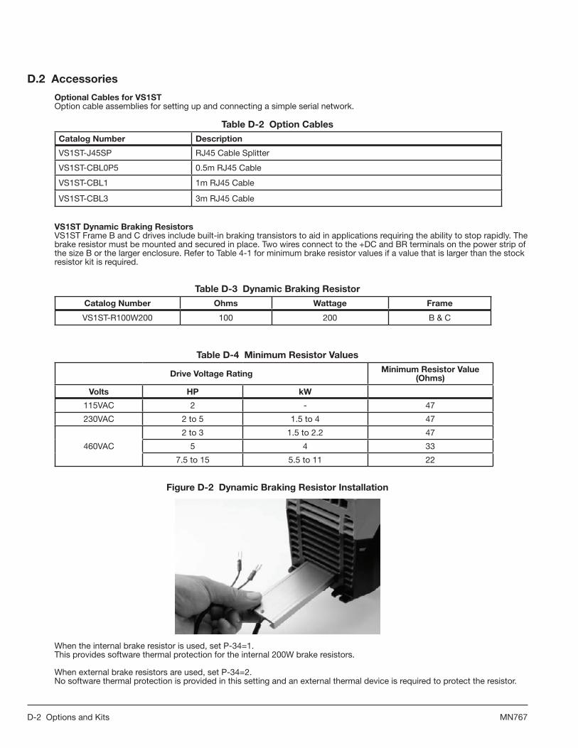
D-2 Options and Kits MN767
D.2Accessories
OptionalCablesforVS1STOption cable assemblies for setting up and connecting a simple serial network.
TableD-2OptionCables
CatalogNumber Description
VS1ST-J45SP RJ45 Cable Splitter
VS1ST-CBL0P5 0.5m RJ45 Cable
VS1ST-CBL1 1m RJ45 Cable
VS1ST-CBL3 3m RJ45 Cable
VS1STDynamicBrakingResistors VS1ST Frame B and C drives include built-in braking transistors to aid in applications requiring the ability to stop rapidly. The brake resistor must be mounted and secured in place. Two wires connect to the +DC and BR terminals on the power strip of the size B or the larger enclosure. Refer to Table 4-1 for minimum brake resistor values if a value that is larger than the stock resistor kit is required.
TableD-3DynamicBrakingResistor
CatalogNumber Ohms Wattage Frame
VS1ST-R100W200 100 200 B & C
TableD-4MinimumResistorValues
DriveVoltageRating MinimumResistorValue(Ohms)
Volts HP kW
115VAC 2 - 47
230VAC 2 to 5 1.5 to 4 47
460VAC
2 to 3 1.5 to 2.2 47
5 4 33
7.5 to 15 5.5 to 11 22
FigureD-2DynamicBrakingResistorInstallation
When the internal brake resistor is used, set P-34=1.This provides software thermal protection for the internal 200W brake resistors.
When external brake resistors are used, set P-34=2. No software thermal protection is provided in this setting and an external thermal device is required to protect the resistor.

Options and Kits D-3MN767
CopyCatLoader Connects to the RJ45 Port on the front of the VS1ST and allows the upload or download of software parameters.
FigureD-3CopyCatLoader
TableD-5CopyCatLoader
CatalogNumber Description
VS1ST-CCL VS1ST and VS1MX RJ45 CopyCat Loader
OptionCardsforVS1STProvides additional relay outputs for signal and control.
FigureD-4
2ROUT HVAC
TableD-6OptionCards
CatalogNumber Description
VS1ST-2ROUT Provides one additional relay output for the drive
VS1ST-HVAC Provides 2 relays for drive running & drive tripped indicators
VS1ST-LOGHV-11 Provides the ability to accept 100-120VAC control inputs
VS1ST-LOGHV-23 Provides the ability to accept 200-240VAC control inputs
VS1STFieldBusGatewaysConnects the VS1ST Modbus RTU RS485 communication interface to the field bus gateway.
TableD-7FieldBusGateways
CatalogNumber Description
VS1ST-PBUS Profibus Gateway
VS1ST-DNET DeviceNet Gateway
VS1ST-ENET Ethernet Gateway

D-4 Options and Kits MN767

RS485/MODBUS Protocol E-1MN767
AppendixERS485/MODBUSProtocol
E.1Introduction
The VS1ST AC Drive is supplied with imbedded RS-485 communications that supports the Modbus-R TU protocol. This allows the user to set up a multi-drop communications network between multiple VS1ST drives and a PLC or host computer without the requirement of option boards for the drives. This is a master-slave architecture where the master (e.g. PLC) can monitor and control multiple VS1ST drives on the same network with other Modbus-RTU slaves. This appendix defines the specifics needed to set up a VS1ST on an RS-485 network running the Modbus-R TU protocol and documents the function codes and exception codes supported by the VS1ST. For a complete definition of the Modbus-RTU protocol and the content of specific messages see www.modbus.org.
FigureE-1CommunicationConnectionforRS-485
Model VS1-CommUSBUSB to RS-485 Converter Kit
RDA(-)
TDB(+)
RDB(+)
TDA(-)
GND1
23
4
RS-485Echo OFF2 Wire2 Wire
RS-422Echo ON4 Wire4 Wire
Switch Settings(Rear of Adapter)
RS485-/Modbus – Pin 7
RS485+/Modbus - Pin 8
RS485 Modbus Ground
8
8
7
3
RS485-/Modbus N
RS485+/Modbus P
8
Communications Connection for RS-485 Communications
From a VS1-COMMUSB to a VS1ST or MX RJ-45 Port
MXST bus connections
RS485-/Modbus – Pin 3

E-2 RS485/MODBUS Protocol MN767
E.2Installation
1. Connect the RS485 communication line to RJ45 connector, (see Figure E-1). 2. Check the connections and turn ON the inverter. 3. Table E-1 documents the parameters within the VS1ST that are related to communications:
TableE-1CommunicationParameters
Number Name Comments
P07 Start/Stop Source Set to 3 or 4 for applications that require network control to start and stop the drive over the network.
P35 Drive Address Set to the desired Modbus-RTU address (note that each device on the network must have a unique address).
P35 Baud Rate Select the baud rate utilized by the master device on the network. All devices on the network must utilize the same baud rate.
P35 Trip Enable Delay Set to desired trip response to a loss of communications.
4. Make connection to the master and other slave devices. The maximum number of drives that can be connected is 31. Maximum length of communication line is 2300 ft (700m).
E.3Operation
1. Remove all power from the VS1ST control. 2. Disconnect the motor load from the control (terminals U, V and W). (Do not connect the motor load until stable
communication between the master controller and the inverter are verified.) 3. Verify master controller and the inverter connections. 4. Turn ON the inverter. 5. Start the communications program on the master controller. 6. Verify proper communications and that the VS1ST is controlled as desired. 7. Remove all power from the VS1ST control. 8. Connect the motor load to the control (terminals U, V and W). 9. Turn ON the inverter. 10. Verify proper operation. See Troubleshooting at the end of this section to aid in resolving any remaining problems.
E.4PerformanceSpecifications
TableE-2CommunicationPerformance
CommunicationMethod RS485Hardwarespecification,MODBUSprotocol
Transmission Form Bus method, Multi drop Master/Slave architecture
Applicable inverter VS1ST series
Connectable drives Max 31
Transmission distance Max. 2,300 ft (Repeater may be required for high noise environments.)
E.5HardwareSpecifications
TableE-3CommunicationHardware
Installation Use RJ45 connector on control (see Figure E-1)
Power Supply Provided by isolated power from the inverter power supply

RS485/MODBUS Protocol E-3MN767
E.6CommunicationSpecifications
TableE-4CommunicationSpecifications
Communication Speed 19200, 9600, 4800, 2400, 1200 bbs selectable
Control Procedure Asynchronous communication system
Communication Half Duplex
Characters (Data bits) ASCII (8 bit)
Start bits 1 bits
Stop bits 1 bits
Check Sum 2 byte CRC
Parity None
E.7CommunicationsProtocol(MODBUS-RTU)
Use MODBUS-RTU protocol (Open Protocol). Requires computer or other host to be network Master and inverters to be Slaves. Inverters respond to Read/Write commands from the Master.
TableE-5Modbus-RTUProtocol
Register Upperbyte LowerByte Command Type
1* Command 03,06 R/W
2* Speed reference 03,06 R/W
3* Reserved 03,06 R/W
4* Modbus ramp control time 03,06 R/W
5 Reserved 03 R
6* Error code Drive status 03 R
7* Motor speed 03 R
8* Motor current 03 R
9* Reserved 03 R
10 Reserved 03 R
11 Digital input status 03 R
12 Rating ID 03 R
13 Power rating 03 R
14 Voltage rating 03 R
15 IO processor software version 03 R
16 Motor control processor software version 03 R
17 Drive type 03 R
18 Reserved 03 R
19 Reserved 03 R
20 Analog 1 input result 03 R
21 Analog 2 input result 03 R
22 Speed reference value 03 R
23 DC bus voltages 03 R
24 Drive temperature 03 R
25 to 30 Reserved 03 R *Registers are available in standard field bus gateway configuration.

E-4 RS485/MODBUS Protocol MN767
E.7.1RegisterDescriptions
Readandwriteregisters
Register1:Drivecommand
15 14 13 12 11 10 9 8 7 6 5 4 3 2 1 0
High Byte Low Byte
Bit 0: Run/Stop command: Set to 1 to enable the drive. Set to 0 to stop the drive.Bit 1: Fast stop request. Set to 1 to enable drive to stop with 2nd deceleration ramp.Bit 2: Reset request. Set to 1 in order to reset the drive if drive is under trip condition. User must clear this bit when drive is under normal condition to prevent unexpected reset. Bit 3: Coast stop request. Set to 1 to issue a coast stop command. For normal operation, Bit 3 has the highest priority, Bit 0 has the lowest priority\ (bit 3>bit 1>bit 0).
Example: If user set command as 0x0009, drive will do a coast stop rather than run. For normal run/start, set register to 1. Note that start/stop (bit 0), fast stop (bit 1) and coast stop (bit 3) only works if P-28 [Restart Mode] = 0 or 1. Otherwise, start/stop function is controlled by drive control terminals. Reset function (bit 2) works all the times long as drive is operated under Modbus control mode (P-07 [Control Source Select] = 3 or 4).
Register2: Speed reference setupThis register holds the speed reference value. The input data is 16bits integer and includes one decimal place. For example, value 500 represents 50.0Hz, value 123 gives 12.3Hz. To get negative speed reference, user needs put negative value into this register. For example, -1(0xFFFF) gives -0.1Hz. -234(0xFF16) gives -23.4Hz. The input value range from -5000 (0 for single phase output drive) to +5000, however the drive output speed will be limited by the maximum speed set by P-06.
Register4: Modbus ramp control timeThis register specifies the drive acceleration and deceleration ramp time. User can only write to this register when P-07 is set to 4. The input data range is from 0 to 60000 (0.00s to 600.00s).
Readonlyregisters
Register6: Drive status and error code High byte gives drive error code. (Valid when drive tripped, see appendix for details). Low byte gives drive status (0: drive stopped, 1: drive running, 2: drive tipped).
Register7: Motor speed informationThis register gives motor speed information. The data is 16bits integer with one decimal place. For example, value 123 gives 12.3Hz. Value -234 (0xFF16) gives -23.4Hz.
Register8: Motor currentThis register gives motor current information. The data is 16bits integer with one decimal place. For example, 156 = 15.6A, 12 = 1.2A.
Register11: Digital input statusThe value in this register represents the drive terminal digital input status (Digital input 1 to 4). Lowest bit indicates digital input 1 status.
Register12: Rating IDThe value in this parameter includes specific drive ID information, and is not recommended to be used in general application by the customer.
Register13: Power ratingThis gives the drive power rating information, value includes two decimal places. The unit of this register depends on the drive type (KW/HP).
Register14: Voltage level.This register gives the rated input voltage for the drive. 230: 230V 400: 400V 460: 460V
Register15: IO software versionThis register contains the drive IO software version info. Value includes two decimal places. For example, 100 means version 1.00
Register16: Motor control processor software version This register contains the software version information of the motor control processor. Value includes two decimal places. For example, 100 means version 1.00.
Register17: Drive type This register gives drive internal type code.

RS485/MODBUS Protocol E-5MN767
Register20: Analog input 1 value This register gives drive analog input 1 value after scaling and offset control. Value 4096 = 100%.
Register21: Analog input 2 value This register gives drive analog input 2 value after scaling and offset control. Value 4096 = 100%.
Register22: Speed reference value. This register contains the reference speed information that being used by the drive for motor speed control. The data is in Hz and with one decimal place (for example, 234 = 23.4Hz).
Register23: DC bus voltageThis register contains drive internal DC bus voltage information. Data unit is Volt.
Register24: Drive temperatureThis register contains drive temperature information. Data is in Celsius with no decimal place.
ParameterRegisters(Supportcommand03and06)
TableE-6ParameterRegistersAdr Description Datarange Dataformat
129 Motor Rated Voltage 0, 20 to 250 V = 230 VAC
0, 20 to 500 V = 460 VAC
130 Motor Rated Current Drive dependent One decimal place 300=30.0A
131 Motor Rated Frequency 25 to 500 Data unit is in Hz
132 Motor Rated Speed 0 to Sync speed Maximum value equals to the sync speed of a typical 2-pole motor
133 Min Speed Limit 0 to P-06 Internal value (3000 = 50.0Hz)
134 Max Speed Limit 0 to 50 * P-03 Internal value (3000 = 50.0Hz)
135 Start/Stop Source 0 to 6
0: Terminal
1: Keypad forward only
2: Keypad forward and reverse
3: Modbus control mode
4: Modbus control with ramp control
5 : PID control
6 : PID control w/ analog speed sum
136 Operating Mode 0 to 12 See Chapter 7 for details
137 Stop Mode 0 to 2
0: Ramp to Stop
1: Coast to Stop
2: Ramp to Stop (Fast Stop)
138 Accel Time 0 to 6000 One decimal place 300=3.00s
139 Decel Time 0 to 6000 One decimal place 300=3.00s
140 Preset Speed 1 -P06 to P06 Internal value (3000 = 50.0Hz)
141 Preset Speed 2 -P06 to P06 Internal value (3000 = 50.0Hz)
142 Preset Speed 3 -P06 to P06 Internal value (3000 = 50.0Hz)
143 Preset Speed 4 -P06 to P06 Internal value (3000 = 50.0Hz)
144 Speed Reference Scaling 0-5000 100 = 10%

E-6 RS485/MODBUS Protocol MN767
Adr Description Datarange Dataformat
145 Analog Input Format 0-6
0: 0-10V
1: b 0-10V
2: 0-20mA
3: t 4-20mA
4: r 4-20mA
5: t 20-4mA
6: r 20-4mA
146 Voltage Boost 0-200 100 = 10.0%
147 Energy Savings 0, 1 0: Disable
1: Enable
148 Trip Log Last four trips (See E.7.2 Drive Error Codes)
149 PWM Frequency 0-5
0 = 4kHz,
1 = 8kHz,
2 = 12kHz
3 =16kHz,
4 = 24kHz,
5 = 32kHz
150 Relay Output 0-7 See user guide for function details
151 Display Speed Scale Factor 0-6000 100 = 0.100
152 Analog Output 0-9 See user guide for function details
153 Relay output limit 0-1000 100 = 10.0%
154 Skip Frequency 0 to P-06 Internal value (3000 = 50.0Hz)
155 Skip Frequency Band 0 to P-06 Internal value (3000 = 50.0Hz)
156 Restart Mode 0-3 See user guide for details
157 Auto Restart Attempts 0-6
0: Edgr-r
1: Auto_0
2-6: Auto_1 to Auto_5
158 Analog Input Offset -5000 to 5000 One decimal place 300=30.0%
159 Brake After Stop 0-600 seconds One decimal place 100=10.0 sec
160 Brake Before Start 0-1 0 - No brake.
1 - DC braking when run command is issued.
161 Decel2 Fast Stop 0-2500 Two decimal places 1000=10.00 sec
162 Brake Chopper Enable 0-2
0 : Disabled.
1 : Enabled.
2 : Enabled without s/w protection
TableE-6ParameterRegisters(Continued)

E-7 RS485/MODBUS Protocol MN767
Adr Description Datarange Dataformat
163
Serial Comms address [Parsing - Lower Byte] 0-63 Drive comms address
Modbus enable / baudrate select
[Parsing - Lower Nibble; Upper Byte]
1-6
1 = Optibus (or MXSTBus) fixed baudrate
2 = 9.6K
3 = 19.2K
4 = 38.4K
5 = 57.6K
6 = 115.2K
Trip enable / delay [Parsing - Upper Nibble;
Upper Byte]0-8
0 = No Stop
1 = t30
2 = t100
3 = t1000
4 = t3000 (ms)
5 = r30
6 = r100
7 = r1000
8 = r3000 (ms)
t = Trip Time; r = Ramp to Stop Time
Table E-6 Note: Address 163 Example
164 V/F Frequency Adjustment 0 to P03 60 = 60Hz
165 V/F Voltage Adjustment 0 to P01 100 = 100V
166 User PI Proportional Gain 1-300 10 = 1.0
167 User PI Integral time constant 0-300 10 = 1.0s
168 User PI feedback mode 0-1 0: Direct, 1: Inverse
169 User PI reference select 0-1 0: Digital, 1: Analog.
170 User PI digital reference 0-1000 100 =10.0%
171 User PI feedback select 0-2
0 : 2nd analog input
1 : 1st analog input
2 : motor load current
172 2nd analog input format 0-5
0: 0-10V
1: 0-20mA
2: t 4-20mA
3: r 4-20mA
4: t 20-4mA
5: r 20-4mA
173 Parameter access lock 0 or 1 0: Unlock
1: Locked
TableE-6ParameterRegisters(Continued)
0100 0010 0000 0001
FaultRamp Time4 = Fault3000ms
Address Node 1BaudRate 2 = 9.6K

E-8 RS485/MODBUS Protocol MN767
E.7.2DriveErrorCodes
0x00 No trip 0x01 Brake circuit over current (short circuit) 0x02 Brake circuit overload 0x03 Drive output over current 0x04 Motor overload0x05 Power stage trip 0x06 DC bus over voltage trip 0x07 DC bus under voltage trip 0x08 Over temperature trip 0x09 Under temperature trip0x0A Parameter default 0x0B External trip0x0C Communication data link loss trip 0x0D Phase imbalance trip0x0E Phase loss trip 0x0F Spin start failure 0x10 Thermistor fault 0x11 Flash data error fault 0x12 4..20mA /20..4mA input signal error
E.7.3DataFlowExamples
1. ReadDatafromRegister6TableE-7ReadDataExample
Request: [01] [03] [00] [05] [00] [01] [94] [0B]
(Drive Addr) (Command) (Reg start addr) (No. of Registers) (Checksum)
Reply: [01] [03] [02] [00] [00] [B8] [44]
(Drive Addr) (Command) (No of data bytes) (Data) (Checksum)
Note: The actual start address of register 6 is 5. All data in [ ] is in 8bits Hex format. 2 Write start command to the register 1 (assumes P-07=3, P-08=0 and Digital Input1=Closed)
2. Writestartcommandtotheregister1 (assumes P-07=3, P-08=0 and Digital Input 1 = Closed)
TableE-8WriteDataExample
Request: [01] [06] [00] [00] [00] [01] [48] [0A]
(Drive Addr) (Command) (Reg addr) (Data value) (Checksum)
Reply: [01] [06] [00] [00] [00] [01] [48] [0A]
(Drive Addr) (Command) (Reg addr) (Data value) (Checksum)
Note: The actual address of register 1 on the data link is 0. All data in [ ] is in 8bits Hex format. Reply can be error message depending on drive parameter settings and digital input status.

BaldorDistrictOffices
OREGON PORTLAND 20393SWAVERYCOURT TUALATIN,OR97062 PHONE:503-691-9010 FAX:503-691-9012
PENNSYLVANIA PHILADELPHIA 1035THOMASBUSCH MEMORIALHIGHWAY PENNSAUKEN,NJ08110 PHONE:856-661-1442 FAX:856-663-6363 PITTSBURGH 159PROMINENCEDRIVE NEWKENSINGTON,PA15068 PHONE:724-889-0092 FAX:724-889-0094
TENNESSEE MEMPHIS 4000WINCHESTERROAD MEMPHIS,TN38118 PHONE:901-365-2020 FAX:901-365-3914
TEXAS DALLAS 2920114THSTREETSUITE100 GRANDPRAIRIE,TX75050 PHONE:214-634-7271 FAX:214-634-8874
HOUSTON 10355W.LITTLEYORKROAD SUITE300 HOUSTON,TX77041 PHONE:281-977-6500 FAX:281-977-6510
UTAH SALT LAKE CITY 2230SOUTHMAINSTREET SALTLAKECITY,UT84115 PHONE:801-832-0127 FAX:801-832-8911
WISCONSIN MILWAUKEE 1960SOUTHCALHOUNROAD NEWBERLIN,WI53151 PHONE:262-784-5940 FAX:262-784-1215
INTERNATIONAL SALES FORT SMITH, AR P.O.BOX2400 FORTSMITH,AR72902 PHONE:479-646-4711 FAX:479-648-5895 CANADA EDMONTON, ALBERTA 4053-92STREET EDMONTON,ALBERTAT6E6R8 PHONE:780-434-4900 FAX:780-438-2600
TORONTO OAKVILLE, ONTARIO 2750COVENTRYROAD OAKVILLE,ONTARIOL6H6R1 PHONE:905-829-3301 FAX:905-829-3302
MARYLAND BALTIMORE 6660SANTABARBARARD. SUITES22-24 ELKRIDGE,MD21075 PHONE:410-579-2135 FAX:410-579-2677
MASSACHUSETTS BOSTON 6PULLMANSTREET WORCESTER,MA01606 PHONE:508-854-0708 FAX:508-854-0291
MICHIGAN DETROIT 5993PROGRESSDRIVE STERLINGHEIGHTS,MI48312 PHONE:586-978-9800 FAX:586-978-9969
MINNESOTA MINNEAPOLIS 21080134THAVENUENORTH ROGERS,MN55374 PHONE:763-428-3633 FAX:763-428-4551
MISSOURI ST LOUIS 422INDUSTRIALDRIVE MARYLANDHEIGHTS,MO63043 PHONE:314-298-1800 FAX:314-298-7660
KANSAS CITY 1501BEDFORDAVENUE NORTHKANSASCITY,MO64116 PHONE:816-587-0272 FAX:816-587-3735
NEW YORK AUBURN ONEELLISDRIVE AUBURN,NY13021 PHONE:315-255-3403 FAX:315-253-9923
NORTH CAROLINA GREENSBORO 1220ROTHERWOODROAD GREENSBORO,NC27406 PHONE:336-272-6104 FAX:336-273-6628
OHIO CINCINNATI 2929CRESCENTVILLEROAD WESTCHESTER,OH45069 PHONE:513-771-2600 FAX:513-772-2219
CLEVELAND 8929FREEWAYDRIVE MACEDONIA,OH44056 PHONE:330-468-4777 FAX:330-468-4778
OKLAHOMA TULSA 7170S.BRADEN,SUITE140 TULSA,OK74136 PHONE:918-366-9320 FAX:918-366-9338
MONTREAL, QUEBEC 5155J-ARMANDBOMBARDIER SAINT-HUBERT,QUÉBEC CANADAJ3Z1G4 PHONE:514-933-2711 FAX:514-933-8639
VANCOUVER, BRITISH COLUMBIA 1538KEBETWAY PORTCOQUITLAM, BRITISHCOLUMBIAV3C5M5 PHONE604-421-2822 FAX:604-421-3113
WINNIPEG, MANITOBA 54PRINCESSSTREET WINNIPEG,MANITOBAR3B1K2 PHONE:204-942-5205 FAX:204-956-4251
AUSTRALIA UNIT3,6STANTONROAD SEVENHILLS,NSW2147,AUSTRALIA PHONE:(61)(2)96745455 FAX:(61)(2)96742495
UNIT8,5KELLETTSROAD ROWVILLE,VICTORIA,3178AUSTRALIA PHONE:(61)(3)97534355 FAX:(61)(3)97534366
EL SALVADOR RESIDENCIALPINARESDESUIZA POL.15#44, NVA.SANSALVADOR,ELSALVADOR PHONE:+5032288-1519 FAX:+5032288-1518
CHILE LUISTHAYEROJEDA166, OF402-PROVIDENCIA SANTIAGO,CHILE PHONE:+5628169900
CHINA 160SONGSHENGROAD SONGJIANGINDUSTRYZONE SHANGHAI201613,CHINA PHONE:+862157605335 FAX:+862157605336
GERMANY HERMANN-HEINRICH-GOSSEN3 50858KOLN,GERMANY PHONE:49-2234379410 FAX:49-22343794164
DIESELSTRASSE22 D-85551KIRCHHEIM MUNICH,GERMANY PHONE:+4989905080 FAX:+498990508492
INDIA 14,COMMERCEAVENUE MAHAGANESHCOLONY PAUDROAD PUNE-411038 MAHARASHTRA,INDIA PHONE:+912025452717/18 FAX:+912025452719
INDONESIA TALAVERAOFFICEPARK, 28THFLOOR,SUITEM18 JI.T.B.SIMATUPANG,KAV.22-26 JAKARTA12430,INDONESIA PHONE:+622175999879 FAX:+622175999878
ITALY VIASOTTOBISIO30 BALERNACH-6828 PHONE:+41916836161 FAX:+41916302633
JAPAN DIABLDG802, 2-21-1TSURUYA-CHO, KANAGAWA-KU YOKOHAMA,221-0835,JAPAN PHONE:81-45-412-4506 FAX:81-45-412-4507
MEXICO LEON, GUANAJUATO KM.2.0BLVD.AEROPUERTO LEÓN37545,GUANAJUATO,MÉXICO PHONE:+524777612030 FAX:+524777612010MIDDLE EAST & NORTH AFRICA VSEINTERNATIONALCORP. P.O.BOX5618 BUFFALOGROVE,IL60089-5618 PHONE:8475905547 FAX:8475905587
PANAMA AVE.RICARDOJ.ALFARO EDIFICIOSUNTOWERSMALL PISO2,LOCAL55 CIUDADDEPANAMÁ,PANAMÁ PHONE:+507236-5155 FAX:+507236-0591
SINGAPORE 18KAKIBUKITROAD3,#03-09 ENTREPRENEURBUSINESSCENTRE SINGAPORE415978 PHONE:(65)67442572 FAX:(65)67471708
SWITZERLAND POSTFACH73 SCHUTZENSTRASSE59 CH-8245FEUERTHALEN SWITZERLAND PHONE:+41526474700 FAX:+41526592394
TAIWAN 1F,NO126WENSHAN3RDSTREET, NANTUNDISTRICT, TAICHUNGCITY408 TAIWANR.O.C PHONE:(886)423804235 FAX:(886)423804463
UNITED KINGDOM 6BRISTOLDISTRIBUTIONPARK HAWKLEYDRIVE BRISTOLBS320BFU.K. PHONE:+441454850000 FAX:+441454859001
VENEZUELA AV.ROMA.QTAELMILAGRO.URB. CALIFORNIANORTE CARACAS,1070 VENEZUELA PHONE/FAX:+582122727343 MOBILE:+584141148623
UNITED STATES
ARIZONA PHOENIX 4211S43RDPLACE PHOENIX,AZ85040 PHONE:602-470-0407 FAX:602-470-0464
ARKANSAS CLARKSVILLE 1001COLLEGEAVENUE CLARKSVILLE,AR72830 PHONE:479-754-9108 FAX:479-754-9205
CALIFORNIA LOS ANGELES 6480FLOTILLASTREET COMMERCE,CA90040 PHONE:323-724-6771 FAX:323-721-5859
HAYWARD 21056FORBESAVENUE HAYWARD,CA94545 PHONE:510-785-9900 FAX:510-785-9910
COLORADO DENVER 3855FORESTSTREET DENVER,CO80207 PHONE:303-623-0127 FAX:303-595-3772
CONNECTICUT WALLINGFORD 65SOUTHTURNPIKEROAD WALLINGFORD,CT06492 PHONE:203-269-1354 FAX:203-269-5485
FLORIDA TAMPA/PUERTO RICO/ VIRGIN ISLANDS 3906EAST11THAVENUE TAMPA,FL33605 PHONE:813-248-5078 FAX:813-247-2984
GEORGIA ATLANTA 62TECHNOLOGYDRIVE ALPHARETTA,GA30005 PHONE:770-772-7000 FAX:770-772-7200
ILLINOIS CHICAGO 340REMINGTONBLVD. BOLINGBROOK,IL60440 PHONE:630-296-1400 FAX:630-226-9420
INDIANA INDIANAPOLIS 5525W.MINNESOTASTREET INDIANAPOLIS,IN46241 PHONE:317-246-5100 FAX:317-246-5110
IOWA DES MOINES 1800DIXONSTREET,SUITEC DESMOINES,IA50316 PHONE:515-263-6929 FAX:515-263-6515

Baldor Electric CompanyWorld Headquarters
P.O. Box 2400, Fort Smith, AR 72902-2400 U.S.A., Ph: (1) 479.646.4711, Fax (1) 479.648.5792, International Fax (1) 479.648.5895 www.baldor.com
© Baldor Electric CompanyMN767
All Rights Reserved. Printed in USA.02/11
!767-0211*