Embed Size (px)
Citation preview

RT-PRC014H-E4
Voyager™ II
Rooftop Units
Cooling-only
TKD-TKH 155-175-200-250-265-290-340
Heat pump
WKD-WKH 125-155-200-265-290-340
Cooling-only with gas-fi red heating
YKD-YKH 155-175-200-250
Heat pump with gas-fi red heating
DKD/DKH 125-155-200-265-290-340
R410A Refrigerant
RT-PRC014H-E42 © 2014 Trane
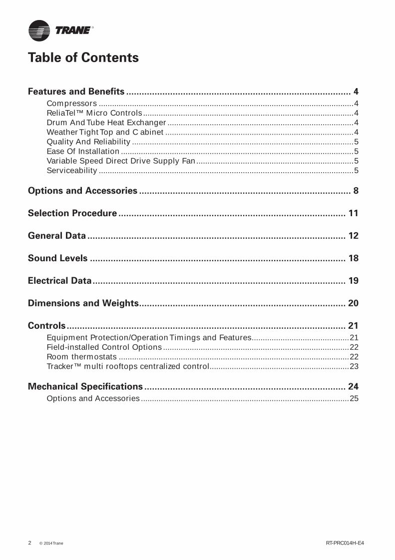
Table of Contents
Features and Benefits ....................................................................................... 4
Compressors ...................................................................................................................4ReliaTel™ Micro Controls ...............................................................................................4Drum And Tube Heat Exchanger ....................................................................................4Weather Tight Top and C abinet .....................................................................................4Quality And Reliability ....................................................................................................5Ease Of Installation .........................................................................................................5Variable Speed Direct Drive Supply Fan .......................................................................5Serviceability ...................................................................................................................5
Options and Accessories .................................................................................. 8
Selection Procedure ........................................................................................ 11
General Data .................................................................................................... 12
Sound Levels ................................................................................................... 18
Electrical Data .................................................................................................. 19
Dimensions and Weights ................................................................................ 20
Controls ............................................................................................................ 21
Equipment Protection/Operation Timings and Features ............................................21Field-installed Control Options ....................................................................................22Room thermostats ........................................................................................................22Tracker™ multi rooftops centralized control...............................................................23
Mechanical Specifications .............................................................................. 24
Options and Accessories ..............................................................................................25

RT-PRC014H-E4 3

Compressors
• Voyager contains the best Scroll compressor technology available, in order to achieve the highest performance possible. The Trane Voyager™ rooftop
has among the best COP in its class. All performances are Eurovent certifi ed which provides the assurance of accurate performance and common comparison criteria
ReliaTel™ Micro Controls
• The Micro provides unit control for heating, cooling and ventilating utilizing input from sensors that measure outdoor and indoor temperature.
• The Micro improves quality and reliability through the use of timetested microprocessor controls and logic.
− prevents the unit from short cycling, considerably improving compressor life.
− ensures that the compressor will run for a specifi c amount of time which allows oil to return for better lubrication, enhancing the reliability of the compressor.
− reduces the number of components required to operate the unit, thereby reducing possibilities for component failure.
• The Micro requires no special tools to run the unit through its paces. Simply place a jumper between Test 1 and Test 2 terminals on the Low Voltage Terminal Board and the unit will walk through its operational steps automatically. The unit automatically returns control to the zone sensor after stepping through the test mode a single time, even if the jumper is left on the unit.
• As long as the unit has power and the LED is lit, the Micro is operational. The light indicates that the Micro is functioning properly.
• The Micro features expanded diagnostic capabilities when utilized with Trane’s Integrated Comfort™ Systems.
• The Micro in the Voyager units has builtin anti-short-cycle timers, time delay relays and minimum ‘’on’’ time controls. These controls are functions of the Micro and are factory tested to assure proper operation.
• The Micro softens electrical ‘’spikes’’ by staging on fans, compressors and heaters.
• The Intelligent Fallback or Adaptive Control is a benefi t to the building occupant. If a component goes astray, the unit will continue to operate at predetermined temperature set points.
• Intelligent Anticipation is a standard feature of the Micro. It functions constantly as the Micro and zone sensor work together in harmony to provide tighter comfort control than conventional electro-mechanical thermostats.
Drum And Tube Heat Exchanger
• The drum and tube heat exchanger is designed for increased effi ciency and reliability and has utilized improved technology incorporated in the large rooftop commercial units for almost 20 years.
• The heat exchanger is manufactured using aluminized steel with stainless steel components for maximum durability. The drum and tube design has been tested and passed over 150,000 cycles.
• The negative pressure gas valve will not allow gas fl ow unless the combustion blower is operating. This is one of our unique safety features.
• The forced combustion blower supplies a gas-air mixture through a single stainless steel burner screen into a sealed drum where ignition takes place. It is more reliable to operate and maintain than a multiple burner system.
• The hot surface ignitor is a gas ignition device which doubles as a safety device utilizing a continuous test to prove the fl ame.
Weather Tight Top and C abinet
• Voyager units incorporate the Trane-Tite-Top (T3). Each part of the top (three pieces) overlaps in such a way that water cannot leak into the unit. These overlapped edges are gasketed and sealed to ensure superior water integrity.
• Quick- Access panels reduce the number of possible water entry points.
• For added water integrity, Voyager has a raised 30 mm lip around the supply and return of the downfl ow units to prevent water from blowing into the ductwork.
Figure 1 – High performance Scrollcompressor
RT-PRC014H-E44
Features and Benefits

Quality And Reliability
• The fan and idler arm assembly designs have been tested to over 300,000 cycles each.
• All of Voyager’s designs were rigorously rain tested at the factory to ensure water integrity.
• We perform a 100% coil leak test at the factory. The evaporator and condenser coils are leak tested at 1.4 MPa and pressure tested to 3.1 MPa.
• Every unit and its options receive a 100% unit run test before leaving the production line to make sure it lives up to Trane r equirements.
Ease Of Installation
Voyager units provide many time and money saving features.
Conversionless Units
• The dedicated design units (either downfl ow or horizontal) require no panel removal or alteration time to convert in the fi eld.
• Horizontal units come complete with duct fl anges so the contractor doesn’t have to fi eld fabricate them.
Improved Airfl ow
• U-shaped airfl ow allows for improved static capabilities.
Single Side Access
• No more than three screws must be removed to access components.
Trane’s Idler Arm Assembly
• On most units, our idler pulley provides quick- adjustment for belt or motor sheaves. No longer does one have to adjust the motor to tighten the belt or change the motor sheave setting.
Figure 2 – Idler arm assembly
Variable Speed Direct Drive Supply Fan
Effi cient, fl exible and low maintenance direct driven fan.
High effi ciency fan
Direct transmission, variable speed drives delivers energy saving through 3 aspects:
• Higher fan nominal effi ciency: The pulley no longer penalizes the airfl ow stream at the an inlet, resulting in less turbulence and higher fan static effi ciency.
• Direct coupling drive effi ciency: The direct coupling concept avoids losses by belt friction. Classic belt drive is depletes part of the motor power caused by improper belt tension, pulley misalignment. The direct driven fan improves motor consumption by about 15% to 20% compared to belt driven fan.
• Reduction of power input with fan speed modulation at part load or in ventilation mode. Substantial energy savings can be achieved by reducing fan speed by only 20%, resulting in 20% less airfl ow and 50% less absorbed power. On a typical application, the result is an annual energy saving of 30% of the total rooftop consumption.
• Power factor of the fan motor is corrected and inrush current is very low thanks to progressive fan ramp up start (by default: 1 minute ramp up time).
Reduced maintenance costs with:
• Almost no maintenance direct coupling compared to belt drive.
• Easy commissioning with adjustment of nominal airlfow and ramp up time for progressive textile duct infl ation.
Serviceability
Voyager’s Simpler Design
The Voyager design uses up to 42% fewer parts than previous units. Since it is simpler in design, it is easier to diagnose.
Reliatel
• Reliatel requires no special tools to run the Voyager unit through its paces. Simply press the Test button located on the right side of the control panel and the unit will walk through its operational steps automatically.
• As long as the unit has power and the LED is lit, Reliatel is operational. The light indicates that the Micro is functioning properly.
• Reliatel features expanded diagnostic capabilities when utilized with Trane’s Integrated Comfort™ Systems.
RT-PRC014H-E4 5
Features and Benefi ts

• One Zone Sensor option has central control panel lights which indicate the mode the unit is in and possible diagnostic information (dirty fi lters for example).
Figure 3 – RTRM (ReliaTel™ Refrigeration Module)
Standardized Components
• Components are placed in the same location for all Voyager units.
Easy Access Lo w Voltage Terminal Board
• The thermostat wires must be connected to the terminals located on the main board.
Single Point Power
• A single electrical connection powers the unit.
Figure 4 – Variable speed direct drive supply fan
An Answer to Market Needs
Capacity Modulation
• Voyager features dual Scroll compressor units. The dual compressor models are outstanding for humidity control, light load cooling conditions and system back-up applications.
Low Ambient Cooling
• All Voyager units have cooling capabilities down to -18°C as standard.
Flexible Applications
• Thanks to its high static pressure capabilities, the Voyager can replace an older machine with old ductwork and, in some cases, improve the comfort through better air distribution.
Figure 5 – RTOM (ReliaTel™ Option Module)
Figure 6 – Trane Communication Interface (TCI-R)
RT-PRC014H-E46
Features and Benefi ts

RT-PRC014H-E4 7
Indoor Air Quality
• Filters - all rooftops are shipped with throwaway fi lters to be used during the fi rst days of operation (usually the job site is not completely clean, and high effi ciency fi lters would get dirty in a few hours - this would be a waste of money) or G4/EU4 fi lters for regular operation.Panels in the indoor air section have a fi re-resistant (MO) aluminum foil-faced insulation. There is no more insulation paticules carried in the air. It can be cleaned which is paricuarly interesting for restaurant applications.
• All our drain pans are sloped. We thus avoid water stagnation that engenders corrosion and micro-organism life such as mold and fungi.
TD5 service and diagnostic user display
• The TD-5 display allows you to view data and make operational changes on Voyager rooftop equipped with Reliatel control v3.4 or above.
• TD-5 is a 5” (127mm diagonal) high resolution color touch screen display
• TD-5 provides in 26 languages: − 15 different reports (3 custom, 12 standard), − 12 differents graphs (4 custom, 8 standard) − View and reset Historic of last 100 detailed
alarms.• Graph data can be exported to an excel fi le through
USB memory stick.
Figure 7
Downfl ow And Horizontal Economizers
• Economizers come with a comparative enthalpy control.
Trane Communication Interface or TCI-R is available factory installed. This module when applied with the Micro easily interfaces with Trane’s Integrated Comfort TM System.
Trane Modbus Communication Interface (PIC) is an accessory that interfaces with the third party Modbus protocol communicating systems.
Lon® Communication Interface (LCI)
This is an electronic board mounted on the main control panel. It is needed to allow communication on a LonTalk® Network at the unit level.
Numerous options and accessories are available,
such as:
− Adjustable roof curb − Economizer − Electric heater − Hot water coil − Black epoxy fi n coating − CO2 sensor − Fused disconnect switch − Smoke detector − Firestat − Supply fan soft starter
On dual fuel units (DKD/DKH) Reliatel automatically selects the best source of heat. In low ambient operation, when mechanical heating is not delivering enough performance, the compressor switches off and the gas burner delivers the neede heat in an optimized conditions. This result in an optimized energy consumption, and higher compressor life cyle.
The unit is equipped in standard with phase reversing protection preventing reverse rotation operation on compressors and other unit motors.
Features and Benefi ts
RT-PRC014H-E48
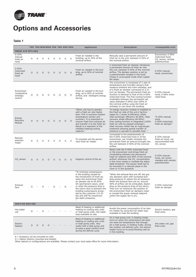
Options and Accessories
Table 1
TKD TKH WKDWKH YKD YKH DKD DKH Application Description Incompatible with
FRESH AIR OPTIONS0-25% manual fresh air hood
A A A A A A A AFresh air needed in the building, up to 25% of the nominal airfl ow.
Manually sets a permanent amount of fresh air in the unit, between 0-25% of the nominal airfl ow.
Economizer, 0-50% motorized hood, CO2 sensor, remote potentiometer.
0-50% motorized fresh air hood
O O O O O O O OFresh air needed in the buil-ding, up to 50% of nominal airfl ow.
A motorized fresh air damper introduces a permanent amount of fresh air into the unit, between 0-50% of the nominal airfl ow. The damper position is set by a potentiometer located in the hood. Closes in unoccupied mode when supply fan stops.
0-25% manual hood, economizer.
Economizer comparative enthalpy control
O O O O O O O O
Fresh air needed in the buil-ding, up to 50% of nominal airfl ow, and intelligent energy saving.
The economizer is composed of 2 sets of temperature and humidity sensors that measure ambient and room enthalpy, and of a fresh air damper connected to a re-turn air damper. The permanent fresh air function is identical to that of the 0-50% motorized hood. The free-cooling function modulates between the permanent set value (between 0-50%) and 100% of the nominal airfl ow using the fresh air enthalpy to cool down the building.
0-25% manual hood, 0-50% moto-rized hood.
Energy Recovery Module
O O O O O O O O
"When unit has to operate with a fresh air rate higher than 15% in extreme outdoor temperature (winter and summer). It is important to recover heat from exhaust air and transfer it to the fresh air.Result is a reduction of the installed heating/cooling capacity."
"A energy recovery module is installed on the fresh air side of the unit.2 techno-logies for 2 levels of effi ciency (Plate heat exchanger effi ciency 50-60%, Heat recovery wheel effi ciency 60-85%)Free cooling function is integrated (100% fresh air with by-passed exhanger).Heat recovery wheel has an hygroscopic treatment allowing partial transfer of moisture in parralel to sensible heat. "
"0-25% manual hood.0-50% motorized fresh air damper"
Remote potentio-meter
A A A A A A A ATo remotely set the perma-nent fresh air intake.
Connected to the potentiometer of the 0-50% motorized hood or of the economizer, can modify remotely the permanent fresh air amount brought into the unit between 0-50% of the nominal airfl ow.
0-25% manual fresh air hood, not recommended with CO2 sensor.
CO2 sensor O O O O O O O O Hygienic control of the air.
Works with the 0-50% motorized hood or the economizer and brings fresh air (modulating between the permanent fresh air setpoint and 50% of the nominal airfl ow) whenever the CO2 concentration in the room meets or exceeds the adjus-table threshold. The sensor itself has to be mounted in a relevant place in the room or in the ductwork.
0-25% manual hood, not recom-mended with remote potentiometer.
Exhaust fans O - O - O - O -
"To minimize overpressure in the building caused by the introduction of fresh air, when the economizer fresh air damper set at 40-50% OA (permanent value), and/or when the pressure drop in the return duct is between the building overpressure accep-ted by the customer (12-25 Pa) and 200 Pa (maximum fan static pressure)."
"When the exhaust fans are off, the gra-vity dampers open with increased buil-ding pressure to relieve the air pressure. When the exhaust fans are on, around 50% of airfl ow can be exhausted, depen-ding on the pressure drop of the return.They turn on whenever the position of the economizer fresh air dampers meet or exceed the power exhaust setpoint (when the supply fan is on)."
0-50% motorized fresh air damper
HEATING DEVICES
Hot water coil O - O - - - - -
Need of heating or additional heating on cooling only units or heat pump units. Hot water loop available on site.
Avoids the power consumption of an elec-tric heater by using the hot water loop available to heat the building.
Electric heaters, gas fi red units.
Electric heaters O O O O - - - -
Need of heating or additional heating on cooling only units or heat pump units. Very useful with a heat pump unit to keep a good comfort level during the defrost cycle.
On a heat pump unit, in heating mode, turns on when the compressors job does not raise the temperature fast enough. On a heat pump, in heating mode, during the outdoor coil defrost cycle, the electric heater turns on to avoid blowing cold air in the building.
Hot water coil, gas fi red units.
A = Accessory (to be mounted on site)O = Option (factory mounted and tested)Other options or confi gurations are available. Please contact your local sales offi ce for more information.

RT-PRC014H-E4 9
Options and Accessories
TKD TKH WKDWKH YKD YKH DKD DKH Application Description Incompatible with
VENTILATION
EU4 fi lters O O O O O O O O To fi lter the air. Washable media, treat the return and fresh air, 90% gravimetrical effi ciency.
EU4+EU7 fi lters O O O O O O O O To fi lter the air.
50mm+50mm Galvanized steel frame fi lters. Washable media for EU4 pre-fi lter, EU7 provides 85% opacimetric effi ciency.
Clogged fi l-ter detector O O O O O O O O
To facilitate maintenance of the fi lters.
When the pressure drop of the fi lter exceeds the selectable value, this diffe-rential pressostat report an alarm via a dry contact to the micro-control.
Textile duct soft starter O O O O O O O O
To achieve a progressive sup-ply fan start and progressive infl ation of textile duct.
Located in the main control pannel. Star-ting time can be adjusted from an actual range of 0 to 40 seconds (factory-set value: 40 s). If Direct driven fan option is selected, the VFD start with a 60s ramp up as factory setting
Direct drive fan O - O - O - O -
Direct coupling delivers better fan effi ciency, speed variation and reduced maintenance (No more belt)
Located in the fan section the VFD can drive fan witha fi xed reference or a 2 speed logic. By default this option includes 1 minute textile duct soft start.
SAFETY
Fused disconnect switch
O O O O O O O O
To manually disconnect the unit from the power supply line and protect it from inter-nal short circuits
Cuts the 3 phases of the power supply, the fuses blow up in case of short circuit into the unit. With electric heaters option, the unit is already fused.
Fire ther-mostat A A A A A A A A
To stop the unit when tempe-rature of the air stream rises abnormally.
A kit of 2 manual reset thermostats are delivered. The fi rst one, to be placed in the return duct, stops the unit and put the unit in general fault when the airstream rises above 57°C, the second, to be placed in the supply duct, reacts above 115°C. Temperature threshold can-not be changed.
Smoke detector O O O O O O O O
To detect smoke in the building.
Closes the return air damper if an economizer is installed, stops the indoor fan, switches off the electric heater if ins-talled and energized, and put the unit in general fault. This option provide a post ventilation period of 30 secondes in the case of high temperature cut out.
High tempera-ture safety thermostat
- - - - O O O OFor the French ERP regulation only : additional security ther-mostat for gas-fi red units.
This manual reset thermostat switches off the burner and the supply fan, and put the unit in general fault if the supply temperature rises above 120°C.
"Three-Phase Monitoring RelayPhase revresal + Phase loss"
S S S S S S S S
"This device monitors three-phase power supply in order to protect unit motors. It prevent risk of starting unit in reverse roation and phase loss that could cause motor burn out."
"The relay disables the unit control when one of the following failures occurs on power supply: phase reversal, phase loss.No fault reporting is not delayed."
"Three-Phase Monitoring RelayPhase revresal + Phase loss + Phase imbalance"
O O O O O O O O
"This device monitors three-phase power supply in order to protect unit motors. This option is recommended when there are risks of power supply imbalance or when power factor correction capa-citors are used. "
The relay disables the unit control when one of the following failures occurs on power supply: phase reversal, phase loss, phase imbalance (adjustable setting). The recommended setting is as follows: 5% imbalance on 3-phase voltage. Duration of imbalance should be set at 5 seconds.
ROOFCURBS
Standard roofcurb A - A - A - A -
Connection between a fl at roof and the rooftop.
Supports the rooftop and ensures water-tightness roof/roofcurb/rooftop, and easy connection of the ductwork .
Adjustable roofcurb.
Adjustable roofcurb A - A - A - A -
Connection between a sloped roof and the rooftop.
Supports the rooftop and ensures water-tightness roof/roofcurb/rooftop, and easy connection of the ductwork, correcting up to 8% slope.
Standard roofcurb.
A = Accessory (to be mounted on site)O = Option (factory mounted and tested)Other options or confi gurations are available. Please contact your local sales offi ce for more information.
Table 1 (Continued)

RT-PRC014H-E410
TKD TKH WKDWKH YKD YKH DKD DKH Application Description Incompatible with
CONTROL
"Reliatel™ Options Module (RTOM)"
O O O O O O O O
Required for some optional ReliaTel™ devices (frostat, clogged fi lter switch, fan failure switch, discharge air sensor (DAS) used for supply air tempering and ICS input data, smoke detector, exter-nal on/off switch).
Communication interface between the ReliaTel™ Refrigeration Module (RTRM) and some options.
TCI-R O O O O O O O O
To communicate with Trane Integrated Comfort Systems, such as the Tracer Summit™, the Tracker™ or a Varitrac™ system (CCP2).
Communication interface between a Trane ICS device and a Voyager™.
THS/P 03, and other communication interfaces
LCI-R O O O O O O O OTo communicate on a Lon-Talk® network at the unit level.
Communication interface between a LonTalk® management system and a Voyager™.
THS/P 03, and other communication interfaces
BCI-R O O O O O O O OTo communicate on a BACnet® MS/TP network at the unit level.
Communication interface between a BACnet management system and a Voyager™.
THS/P 03, and other communication interfaces
PIC O O O O O O O OTo communicate on a Modbus network at the unit level.
Communication interface between Modbus management system and a Voyager™.
THS/P 03, and other communication interfaces
THS03 A A A A A A A AControl of 1 cooling-only, heat pump or gas-fi red rooftop.
Electronic thermostat, 2 stages cooling, 1 stage compressor heating, 2 stages auxiliary heating. No CTI card needed, communicates in the same language as the rooftop micro-control and uses 100% of its advanced control features
All communication interfaces
THP03 A A A A A A A AControl of 1 cooling-only, heat pump or gas-fi red rooftop.
Electronic programmable thermostat, 2 stages cooling, 1 stage compressor heating, 2 stages auxiliary heating, LCD screen. Communicates in the same language as the rooftop micro-control and uses 100% of its advanced control features.
All communication interfaces
Remote sensor box for THS/THP03
A A A A A A A ANeed of remote or additional sensors with THS/THP03
Senses the temperature and sends the information to the THS/P 03.
Antifreeze thermostat O O O O O O O O
Additional device to prevent the indoor coil from icing. Very useful when a large amount of cold air is blown into the unit during the coo-ling mode.
A sensor is placed on the indoor coil and stops the compressors for the period of time needed, as soon as the coil approaches the freezing point (in cooling mode).
Remote fault relay O O O O O O O O
To send alarms signals to a local BMS.
Uses the compressor/heating/fan/power supply alarm output signals from the micro-control and reports them into one dry contact.
TD-5 A A A A A A A A
Plug and play diagnostic touch screen display. Read Only device connected to Reliatel boards.
5 inch touch screen display. Monitor all unit parameters, input, output, graph and record parameter trend. Provide alarm historic reporting and possibility to reset alarms
MISCELLANEOUSOversized drive / motor
O O O O O O O O High static pressure needs. Increases the fans speed via oversized pulleys/belts and/or oversized motors.
Black epoxy coating on condenser
O O O O O O O O Sea side application. The black epoxy coating slows down the corrosion process on the aluminum fi ns.
Black epoxy coating on condenser and evapo-rator
O O O O O O O OSea side application when a fresh air device is used.
The black epoxy coating slows down the corrosion process on the aluminum fi ns.
A = Accessory (to be mounted on site)O = Option (factory mounted and tested)Other options or confi gurations are available. Please contact your local sales offi ce for more information.
Options and Accessories
Table 1 (Continued)

RT-PRC014H-E4 11
To obtain product selection, please contact your local Trane sales office with the following information:
Table 2 – Mandatory informations to select a rooftop
System type Cooling Only Heat pump
Airflow information
Configuration of return duct 1 - Horizontal flow 2 - Downflow Other ........................................
Configuration of supply duct 3 - Horizontal flow 4 - Downflow Other ........................................
Unit airflow ........................................ m3/h
Fresh air rate ........................................ m3/h ........................................ % of nominal airflow
External static pressure on return duct ........................................
Pa
External static pressure on supply duct ........................................
Pa
Cooling mode design conditions
Unit cooling capacity ........................................ kW
Indoor air Dry Bulb ........................................ °C
Indoor air wet Bulb / Relative Humidity ........................................
°C........................................
%
Outdoor air Dry Bulb ........................................ °C
Heating mode design conditions
Heating capacity ........................................ kW
Auxiliary heat type Electric Heat Gas Heat Hot Water coil
Gas type Natural gas G20 Natural gas G25 Propane gas G31
Auxiliary heating capacity ........................................ kW
Indoor air Dry Bulb ........................................ °C
Outdoor air Dry Bulb ........................................ °C
Outdoor air wet Bulb / Relative Humidity ........................................
°C........................................
% (only for Heat pump)
Options
Air filter class ........................................
Variable speed drive With Without
Economizer type Without Manual fresh airComparative enthalpy
economizer
Energy recovery on exhaust / fresh air Without Rotary heat wheel Plate heat exchanger
Fresh air control Constant Remote reference CO2 sensor controled
Unit control Local control without scheduling
Local control with scheduling
Multi-unit centralized control
Remote relay interface control
Remote control communication interface LON Modbus Bacnet Trane
Smoke detector With Without
Fire detector With Without
Disconnect switch With Without
Dirty filter switch With Without
Fan fail switch With Without
Outdoor coil corrosion protection Without Epoxy coating
Indoor coil corrosion protection Without Epoxy coating
Roofcurb None Flat Adjustable pitch
Selection Procedure

RT-PRC014H-E412
Table 3 – General data TKD/TKH, YKD/YKHTKD / TKHYKD / YKH
TKD / TKHYKD / YKH
TKD / TKHYKD / YKH
TKD / TKHYKD / YKH
TKD/H TKD/H TKD/H
155 175 200 250 265 290 340R410A R410A R410A R410A R410A R410A R410A
Eurovent Performances (1)Net Cooling Capacity (kW) 44.2 50.6 56.5 67.9 73.6 85.4 94.9Total Power input in cooling (kW) 14.7 16.8 18.2 21.8 25.4 29.3 34.9EER 3.01 3.01 3.11 3.11 2.90 2.91 2.72Eurovent Effi ciency class Cooling A A A A B B CMain Power supply V/Ph/Hz 400/3/50 400/3/50 400/3/50 400/3/50 400/3/50 400/3/50 400/3/50Outdoor sound power level env. (dBA) 84 84 86 86 86 88 89Indoor sound power level in duct (dBA) 74 77 77 82 83 83 85Outdoor sound pressure level env. (6) (dBA) 52 52 54 54 54 56 57
Unit ampsUnit max amps (3) (A) 39,0 45,8 51,5 54,5 62,5 75,7 83,3Unit start-up amps (A) 163 168 175 177 187 209 251Unit power factor (1) 0,75 0,72 0,74 0,77 0,79 0,79 0,8Short circuit current (kA) 10 10 10 10 10 10 10
Electric Heater (TKD / TKH)Heating Capacity (kW) 25 25 37.5 37.5 37.5 37.5 37.5Capacity steps (kW) 12.5 / 12.5 12.5 / 12.5 25 / 12.5 25 / 12.5 25 / 12.5 25 / 12.5 25 / 12.5Max Amps (2) (A) 36 36 54 54 54 54 54
Gas burner (YKD / YKH)Heating Models G350 G350 G350 G350 N/A N/A N/AHeating Input (G20) (kW) 77 77 77 77 - - -Heating Output (kW) 69,3 69,3 69,3 69,3 - - -Steady State Effi ciency (%) 90 90 90 90 - - -No. Burners # 1 1 1 1 - - -No. Stages # 2 2 2 2 - - -Gas Connection Pipe Size 3/4" NPT 3/4" NPT 3/4" NPT 3/4" NPT - - -
CompressorNumber # 2 2 2 2 2 2 2Type Scroll Scroll Scroll Scroll Scroll Scroll ScrollModel 5T / 9T 6T / 10T 9T / 9T 10T / 10T 12T / 12T 13T / 13T 15T / 15TMax Amps(2) (A) 18.5 / 11.2 20 / 13.9 18.5 / 18.5 20 / 20 23 / 23 25.2 / 25.2 29 / 29Locked rotor Amps (2) (A) 142 / 82 142 / 87 142 / 142 142 / 142 147 / 147 158 / 158 197 / 197
Outdoor CoilType Wavy Wavy Wavy Wavy Wavy Wavy WavyTube Size OD (mm) 9.52 9.52 9.52 9.52 9.52 9.52 9.52Face Area (m²) 2.23 2.62 3.00 3.39 3.39 4.26 4.26Rows / Fin series # / FPF 2 / 192 2 / 192 2 / 192 2 / 192 2 / 192 2 / 192 2 / 192
Indoor CoilType Wavy Wavy Wavy Wavy Wavy Wavy WavyTube Size OD (mm) 9.52 9.52 9.52 9.52 9.52 9.52 9.52Face Area (m²) 1.63 1.63 2.42 2.42 2.42 2.42 2.42Rows / Fin series # / FPF 3 / 180 3 / 180 2 / 180 3 / 168 3 / 168 4 / 168 4 / 168Refrigerant Control Exp.Valve Exp.Valve Exp.Valve Exp.Valve Exp.Valve Exp.Valve Exp.ValveDrain Connection No./Size (mm) 1 / 3/4" NPT 1 / 3/4" NPT 1 / 3/4" NPT 1 / 3/4" NPT 1 / 3/4" NPT 1 / 3/4" NPT 1 / 3/4" NPT
Outdoor FanNominal Airfl ow (m3/h) 17300 18000 26700 27300 27300 39500 39500Type Axial Axial Axial Axial Axial Axial AxialDiameter (mm) 630 630 710 710 710 710 710Drive type Direct Direct Direct Direct Direct Direct DirectNumber # 2 2 2 2 2 3 3Motor HP (kW) 0.6 0.6 1.1 1.1 1.1 1.1 1.1Motor Max Amps(1) (A) 1.2 1.2 2.5 2.5 2.5 2.5 2.5Motor RPM (rpm) 900 900 900 900 900 900 900
(1) At Eurovent rating conditions : Indoor return Air (27°C DB / 19°C WB) - Ambiant 35°C according to EN14511:2013
(2) Per motor under 400V(3) For standard unit, with oversized drive, without electric heater options (4) At the nominal airfl ow with standard drive
(5) At the nominal airfl ow with oversized drive when available(6) At 10m from the unit in a free fi eldElectrical & refrigerant charge Data are subject to change without notice. Please refer to unit nameplate data.
General Data

RT-PRC014H-E4 13
TKD / TKHYKD / YKH
TKD / TKHYKD / YKH
TKD / TKHYKD / YKH
TKD / TKHYKD / YKH
TKD/H TKD/H TKD/H
155 175 200 250 265 290 340R410A R410A R410A R410A R410A R410A R410A
Indoor FanMinimum Airfl ow (m3/h) 6800 7880 8970 11280 11520 12960 14400Nominal Airfl ow (m3/h) 8500 9850 11210 14100 14400 16200 18000Maximum Airfl ow (m3/h) 10200 11820 13450 16920 17280 19440 21600Static pressure available (4) (Pa) 150 75 175 75 75 450 450Maximum static pressure available (5) (Pa) 350 375 450 375 375 500 500Type FC Centrifugal FC Centrifugal FC Centrifugal FC Centrifugal FC Centrifugal FC Centrifugal FC CentrifugalNumber # 1 1 1 1 1 1 1Diameter / Width (in / in) 15" / 15" 15" / 15" 18" / 18" 18" / 18" 18" / 18" 18" / 18" 18" / 18"Belt driven fan versionMotor HP (Standard/Oversized) (kW) 1.8 / 3.0 3.0 / 4.6 3.0 / 4.6 4.6 / - 4.6 / 5.5 7.5 / 9 7.5 / 9Motor Max Amps(Standard/Oversized) (A) 4 / 6.4 6.4 / 9 6.4 / 9 9 / 9 9 / 11 15 / 17.3 15 / 17.3Motor Locked rotor Amps (Standard/Oversized) (A) 36.4 / 57 57 / 71.9 57 / 71.9 71.9 / - 69 / 95 128 / 149 128 / 149
Motor RPM (Standard/Oversized) (rpm) 1450 / 2870 2870 / 2900 2870 / 2900 2900 / - 2900 / 2900 2900 / 2900 2900 / 2900Direct driven fan versionNumber # 1 1 1 1 1 1 1Motor HP (Standard/Oversized) (kW) 2.2 / 5.5 2.2 / 5.5 4 / 5.5 7.5 / 5.5 7.5 / 5.5 7.5 / 15 7.5 / 15Motor Max Amps(Standard/Oversized) (A) 5.4 / 8.5 5.4 / 9.8 9.4 / 12.4 11.3 / 13.3 11.3 / 13.5 16.4 / 23.3 16.6 / 22.9Motor RPM (Standard/Oversized) (rpm) 957 / 1455 957 / 1455 963 / 963 1455 / 963 1455 / 963 970 / 1457 970 / 1457
Energy Recovery Module (5)Plate Heat exchanger versionHeat recovery effi ciency at 10% / 50% fresh air (%) 51% / 50% 51% / 50% 56% / 54% 56% / 53% 57% / 54% 57% / 54% 57% / 53%
Air pressure drop at 10% / 50% fresh air (Pa) 2Pa / 43Pa 2Pa / 56Pa 3Pa / 70Pa 6Pa / 105Pa 2Pa / 63Pa 3Pa / 77Pa 4Pa / 93Pa
Exhaust fan kW at 10% / 50% fresh air (kW) 0.1kW /
0.4kW0.1kW / 0.7kW
0.2kW / 0.5kW
0.2kW / 0.9kW
0.3kW / 0.7kW
0.3kW / 0.9kW
0.3kW / 1.1kW
Length (Downfl ow / Horizontal fl ow) (mm) 2440 / 2288 2440 / 2288 2745 / 2745 2745 / 2745 2745 / 3050 2745 / 3050 2745 / 3050Width (Downfl ow / Horizontal fl ow) (mm) 1838 / 1838 1838 / 1838 2143 / 2143 2143 / 2143 2295 / 2143 2295 / 2143 2295 / 2143Height (Downfl ow / Horizontal fl ow) (mm) 1553 / 1350 1553 / 1350 1553 / 1503 1553 / 1503 1705 / 1503 1705 / 1503 1705 / 1503Weight (Downfl ow / Horizontal fl ow) (kg) 592 / 543 592 / 543 786 / 779 786 / 779 862 / 889 862 / 889 862 / 889Rotary Wheel Heat exchanger versionHeat recovery effi ciency at 10% / 50% fresh air (%) 84% / 69% 84% / 65% 85% / 68% 84% / 65% 81% / 70% 80% / 67% 80% / 67%
Air pressure drop at 10% / 50% fresh air (Pa) 13Pa / 109Pa 17Pa / 130Pa 14Pa / 109Pa 19Pa / 144Pa 9Pa / 87Pa 11Pa / 101Pa 13Pa / 115Pa
Exhaust fan kW at 10% / 50% fresh air (kW) 0.2kW /
0.5kW0.2kW / 0.6kW
0.2kW / 0.6kW
0.2kW / 0.8kW
0.2kW / 0.9kW
0.3kW / 0.9kW
0.3kW / 1.1kW
Length (Downfl ow / Horizontal fl ow) (mm) 2593 / 1778 2593 / 1778 2745 / 2745 2745 / 2745 2898 / 2898 2898 / 2898 2898 / 2898Width (Downfl ow / Horizontal fl ow) (mm) 1838 / 1563 1838 / 1563 2143 / 2143 2143 / 2143 1990 / 2143 1990 / 2143 1990 / 2143Height (Downfl ow / Horizontal fl ow) (mm) 1553 / 2293 1553 / 2293 1705 / 1655 1705 / 1655 2010 / 1960 2010 / 1960 2010 / 1960Weight (Downfl ow / Horizontal fl ow) (kg) 686 / 710 686 / 710 846 / 906 846 / 906 973 / 1095 973 / 1095 973 / 1095
FiltersType Furnished 2" Throwaway 2" Throwaway 2" Throwaway 2" Throwaway 2" Throwaway 2" Throwaway 2" Throwaway(No.) Size Recommended
TKH / YKH * # 2x (500x500x50)
2x (500x500x50)
8x (500x625x50)
8x (500x625x50)
8x (500x625x50)
8x (500x625x50)
8x (500x625x50)
+ +4x (500x625x50)
+4x (500x625x50)
TKD / YKD * # 2x (500x500x50)
2x (500x500x50)
4x (500x500x50)
4x (500x500x50)
4x (500x500x50)
4x (500x500x50)
4x (500x500x50)
+ +4x (500x625x50)
+4x (500x625x50)
+4x (500x625x50)
+4x (500x625x50)
+4x (500x625x50)
+4x (500x625x50)
+4x (500x625x50)
Operating limitsMinimum operating outdoor air temp. °C -18 -18 -18 -18 -18 -18 -18Maximum operating outdoor air temp. °C 50 50 50 50 50 50 50Minimum intake air temp. on the indoor coil °C 18 18 18 18 18 18 18
Physical data - Operating (3)Length (mm) 2726 2726 3107 3107 3107 3987 3987Width (mm) 1811 1811 2167 2167 2154 2154 2154Height (mm) 1313 1313 1704 1704 1704 1704 1704Operating weight TKD/TKH (kg) 598 631 768 789 869 1140 1148 YKD/YKH (kg) 673 706 847 869Shipping weight TKD/TKH (kg) 652 666 819 864 934 1205 1213 YKD/YKH (kg) 693 726 902 948
(1) At Eurovent rating conditions : Indoor return Air (27°C DB / 19°C WB) - Ambiant 35°C according to EN14511:2013
(2) Per motor under 400V(3) For standard unit, with oversized drive, without electric heater options (4) At the nominal airfl ow with standard drive
(5) At the nominal airfl ow with oversized drive when available(6) At 10m from the unit in a free fi eldElectrical & refrigerant charge Data are subject to change without notice. Please refer to unit nameplate data.
General Data
Table 3 – General data TKD/TKH, YKD/YKH (Continued)

RT-PRC014H-E414
TKD / TKHYKD / YKH
TKD / TKHYKD / YKH
TKD / TKHYKD / YKH
TKD / TKHYKD / YKH
TKD/H TKD/H TKD/H
155 175 200 250 265 290 340R410A R410A R410A R410A R410A R410A R410A
Unit construction
Sheet metal / Thickness Type / mm
GalvaSteel / 1.2
GalvaSteel / 1.2
GalvaSteel / 1.2
GalvaSteel / 1.2
GalvaSteel / 1.2
GalvaSteel / 1.2
GalvaSteel / 1.2
Paint Type / RAL
Polyester / 9002
Polyester / 9002
Polyester / 9002
Polyester / 9002
Polyester / 9002
Polyester / 9002
Polyester / 9002
Insulation / Thickness Type / mm M0 / 25 M0 / 25 M0 / 25 M0 / 25 M0 / 25 M0 / 25 M0 / 25
System DataRefrigerant circuit # 2 2 2 2 2 2 2Capacity steps % 60 / 40 60 / 40 50 / 50 50 / 50 50 / 50 50 / 50 50 / 50
Refrigerant Charge (3)Circuit A (YKD / YKH) (kg) 3.8 4.2 6.4 7.6 7.6 9.2 9.2Circuit B (YKD / YKH) (kg) 6.3 6.9 6.4 7.6 7.6 9.2 9.2
(1) At Eurovent rating conditions : Indoor return Air (27°C DB / 19°C WB) - Ambiant 35°C according to EN14511:2013
(2) Per motor under 400V(3) For standard unit, with oversized drive, without electric heater options (4) At the nominal airfl ow with standard drive
(5) At the nominal airfl ow with oversized drive when available(6) At 10m from the unit in a free fi eldElectrical & refrigerant charge Data are subject to change without notice. Please refer to unit nameplate data.
Table 3 – General data TKD/TKH, YKD/YKH (Continued)
General Data

RT-PRC014H-E4 15
Table 4 – General data WKD/WKH, DKD/DKHWKD / WKHDKD / DKH
WKD / WKHDKD / DKH
WKD / WKHDKD / DKH
WKD / WKHDKD / DKH
WKD / WKHDKD / DKH
WKD / WKHDKD / DKH
125 155 200 265 290 340R410A R410A R410A R410A R410A R410A
Eurovent Performances (1)Net Cooling Capacity (kW) 37.7 45.9 64.5 71.4 78.8 88.8Total Power input in cooling (kW) 11.4 15.1 20.9 25.8 28.4 33.4EER 3.30 3.04 3.09 2.77 2.77 2.65Eurovent Effi ciency class Cooling A A A C C CMain Power supply V/Ph/Hz 400/3/50 400/3/50 400/3/50 400/3/50 400/3/50 400/3/50Net Heating Capacity (kW) 35.5 46.5 57.8 66.0 77.5 86.7Total Power input in Heating (kW) 10.1 13.5 17.5 20.2 23.2 27.0COP 3.53 3.45 3.30 3.26 3.34 3.21Eurovent Effi ciency class Heating A A B B B BOutdoor sound power level env. (dBA) 84 84 86 86 87 88Indoor sound power level in duct (dBA) 79 74 81 83 83 85Outdoor sound pressure level env. (6) (dBA) 52 52 54 54 55 56
Unit ampsUnit max amps (3) (A) 37.1 39.7 54.5 62.5 73.0 80.6Unit start-up amps (A) 110 123 177 187 206 249Unit power factor (1) 0.67 0.72 0.76 0.80 0.80 0.80Short circuit current (kA) 10 10 10 10 10 10
Electric Heater (WKD / WKH)Heating Capacity (kW) 25 25 37.5 37.5 37.5 37.5Capacity steps (kW) 12.5 / 12.5 12.5 / 12.5 25 / 12.5 25 / 12.5 25 / 12.5 25 / 12.5Max Amps (2) (A) 36 36 54 54 54 54
Gas burner (DKD / DKH)Heating Models G250 G350 G350 G350 G400 G400Heating Input (G20) (kW) 53 77 77 77 85 85Heating Output (kW) 48,2 69,3 69,3 69,3 77,4 77,4Steady State Effi ciency (%) 91 90 90 90 91 91No. Burners # 1 1 1 1 1 1No. Stages # 2 2 2 2 2 2Gas Connection Pipe Size 3/4" NPT 3/4" NPT 3/4" NPT 3/4" NPT 3/4" NPT 3/4" NPT
CompressorNumber # 2 2 2 2 2 2Type Scroll Scroll Scroll Scroll Scroll ScrollModel 6T / 6T 7.5T / 7.5T 10T / 10T 12T / 12T 13T / 13T 15T / 15TMax Amps (2) (A) 13.9 / 13.9 15.2 / 15.2 20 / 20 23 / 23 25.2 / 25.2 29 / 29Locked rotor Amps (2) (A) 87 / 87 98 / 98 142 / 142 147 / 147 158 / 158 197 / 197
Outdoor CoilType Wavy Wavy Wavy Wavy Wavy WavyTube Size OD (mm) 9.52 9.52 9.52 9.52 9.52 9.52Face Area (m²) 2.23 2.62 3.39 3.39 4.26 4.26Rows / Fin series # / FPF 2 / 192 2 / 192 2 / 192 2 / 192 2 / 192 2 / 192Refrigerant Control Exp.Valve Exp.Valve Exp.Valve Exp.Valve Exp.Valve Exp.Valve
Indoor CoilType Wavy Wavy Wavy Wavy Wavy WavyTube Size OD (mm) 9.52 9.52 9.52 9.52 9.52 9.52Face Area (WKD / WKH) (m²) 1.63 1.63 2.42 2.42 2.42 2.42Rows / Fin series # / FPF 3 / 180 3 / 180 3 / 168 3 / 168 4 / 168 4 / 168Refrigerant Control Exp.Valve Exp.Valve Exp.Valve Exp.Valve Exp.Valve Exp.ValveDrain Connection No./Size (mm) 1 / 3/4" NPT 1 / 3/4" NPT 1 / 3/4" NPT 1 / 3/4" NPT 1 / 3/4" NPT 1 / 3/4" NPT
Outdoor FanNominal Airfl ow (m3/h) 17400 18000 27300 25400 34000 34000Type Axial Axial Axial Axial Axial AxialDiameter (mm) 630 630 710 710 630 630Drive type Direct Direct Direct Direct Direct DirectNumber # 2 2 2 2 4 4Motor HP (kW) 0.6 0.6 1.1 1.1 0.6 0.6Motor Max Amps(1) (A) 1.2 1.2 2.5 2.5 1.2 1.2Motor RPM (rpm) 900 900 900 900 900 900
(1) At Eurovent rating conditions : Indoor return Air (27°C DB / 19°C WB) - Ambiant 35°C according to EN14511:2013
(2) Per motor under 400V(3) For standard unit, with oversized drive, without electric heater options (4) At the nominal airfl ow with standard drive
(5) At the nominal airfl ow with oversized drive when available(6) At 10m from the unit in a free fi eldElectrical & refrigerant charge Data are subject to change without notice. Please refer to unit nameplate data.
General Data

RT-PRC014H-E416
WKD / WKHDKD / DKH
WKD / WKHDKD / DKH
WKD / WKHDKD / DKH
WKD / WKHDKD / DKH
WKD / WKHDKD / DKH
WKD / WKHDKD / DKH
125 155 200 265 290 340R410A R410A R410A R410A R410A R410A
Indoor FanMinimum Airfl ow (m3/h) 5710 6800 8970 11520 12960 14400Nominal Airfl ow (m3/h) 7140 8500 11210 14400 16200 18000Maximum Airfl ow (m3/h) 8570 10200 13450 17280 19440 21600Static pressure available (4) (Pa) 200 175 200 75 450 450Maximum static pressure available (5) (Pa) 425 325 350 375 500 500Type FC Centrifugal FC Centrifugal FC Centrifugal FC Centrifugal FC Centrifugal FC CentrifugalNumber # 1 1 1 1 1 1Diameter / Width (in / in) 15" / 15" 15" / 15" 18" / 18" 18" / 18" 18" / 18" 18" / 18"Belt driven fan versionMotor HP (Standard/Oversized) (kW) 1.8 / 3.0 1.8 / 3.0 3.0 / 4.6 4.6 / 5.5 7.5 / 9 7.5 / 9Motor Max Amps(Standard/Oversized) (A) 4.0 / 6.4 4.0 / 6.4 6.4 / 9.0 9.0 / 10.5 14.7 / 17.3 14.7 / 17.3Motor Locked rotor Amps (Standard/Oversized) (A) 36.4 / 57 36.4 / 57 57 / 71.9 69 / 95 128 / 149 128 / 149
Motor RPM (Standard/Oversized) (rpm) 1450 / 2870 1450 / 2870 2870 / 2900 2900 / 2900 2900 / 2900 2900 / 2900Direct driven fan versionMotor HP (Standard/Oversized) (kW) 2.2 / 5.5 2.2 / 5.5 4 / 5.5 7.5 / 5.5 7.5 / 15 7.5 / 15Motor Max Amps(Standard/Oversized) (A) 5.5 / 7.9 5.4 / 8.5 9.4 / 12.4 11.3 / 13.5 16.4 / 23.3 16.6 / 22.9Motor RPM (Standard/Oversized) (rpm) 957 / 1455 957 / 1455 963 / 963 1455 / 963 970 / 1457 970 / 1457
Energy Recovery Module (5)Plate Heat exchanger versionHeat recovery effi ciency at 10% / 50% fresh air (%) 51% / 50% 51% / 50% 56% / 54% 57% / 54% 57% / 54% 57% / 53%
Air pressure drop at 10% / 50% fresh air (Pa) 1Pa / 32Pa 2Pa / 43Pa 3Pa / 70Pa 2Pa / 63Pa 3Pa / 77Pa 4Pa / 93Pa
Exhaust fan kW at 10% / 50% fresh air (kW) 0.1kW / 0.3kW 0.1kW / 0.4kW 0.2kW / 0.5kW 0.3kW / 0.7kW 0.3kW / 0.9kW 0.3kW / 1.1kW
Length (Downfl ow / Horizontal fl ow) (mm) 2440 / 2288 2440 / 2288 2745 / 2745 2745 / 3050 2745 / 3050 2745 / 3050Width (Downfl ow / Horizontal fl ow) (mm) 1838 / 1838 1838 / 1838 2143 / 2143 2295 / 2143 2295 / 2143 2295 / 2143Height (Downfl ow / Horizontal fl ow) (mm) 1553 / 1350 1553 / 1350 1553 / 1503 1705 / 1503 1705 / 1503 1705 / 1503Weight (Downfl ow / Horizontal fl ow) (kg) 592 / 543 592 / 543 786 / 779 862 / 889 862 / 889 862 / 889Rotary Wheel Heat exchanger versionHeat recovery effi ciency at 10% / 50% fresh air (%) 86% / 70% 84% / 69% 85% / 68% 81% / 70% 80% / 67% 80% / 67%
Air pressure drop at 10% / 50% fresh air (Pa) 10Pa / 88Pa 13Pa / 109Pa 14Pa / 109Pa 9Pa / 87Pa 11Pa / 101Pa 13Pa / 115Pa
Exhaust fan kW at 10% / 50% fresh air (kW) 0.2kW / 0.4kW 0.2kW / 0.5kW 0.2kW / 0.6kW 0.2kW / 0.9kW 0.3kW / 0.9kW 0.3kW / 1.1kW
Length (Downfl ow / Horizontal fl ow) (mm) 2593 / 1778 2593 / 1778 2745 / 2745 2898 / 2898 2898 / 2898 2898 / 2898Width (Downfl ow / Horizontal fl ow) (mm) 1838 / 1563 1838 / 1563 2143 / 2143 1990 / 2143 1990 / 2143 1990 / 2143Height (Downfl ow / Horizontal fl ow) (mm) 1553 / 2293 1553 / 2293 1705 / 1655 2010 / 1960 2010 / 1960 2010 / 1960Weight (Downfl ow / Horizontal fl ow) (kg) 686 / 710 686 / 710 846 / 906 973 / 1095 973 / 1095 973 / 1095
FiltersType Furnished 2" Throwaway 2" Throwaway 2" Throwaway 2" Throwaway 2" Throwaway 2" Throwaway(No.) Size RecommendedWKH / DKH * # 2x(500x500x50) 2x(500x500x50) 8x(500x625x50) 8x(500x625x50) 8x(500x625x50) 8x(500x625x50)
+ +4x(500x625x50) +4x(500x625x50)WKD / DKD * # 2x(500x500x50) 2x(500x500x50) 4x(500x500x50) 4x(500x500x50) 4x(500x500x50) 4x(500x500x50)
+ +4x(500x625x50) +4x(500x625x50) +4x(500x625x50) +4x(500x625x50) +4x(500x625x50) +4x(500x625x50)Operating limits
Minimum operating outdoor air temp. (Cooling) °C -18 -18 -18 -18 -18 -18
Minimum operating outdoor air temp. (Heating) °C -15 -15 -15 -15 -15 -15
Maximum operating outdoor air temp. (Cooling) °C 50 50 50 50 48 48
Maximum operating outdoor air temp. (Heating) °C 18 18 18 18 18 18
Minimum intake air temp. on the indoor coil (Cooling) °C 18 18 18 18 18 18
Minimum intake air temp. on the indoor coil (Heating) °C 10 10 10 10 10 10
(1) At Eurovent rating conditions : Indoor return Air (27°C DB / 19°C WB) - Ambiant 35°C according to EN14511:2013
(2) Per motor under 400V(3) For standard unit, with oversized drive, without electric heater options (4) At the nominal airfl ow with standard drive
(5) At the nominal airfl ow with oversized drive when available(6) At 10m from the unit in a free fi eldElectrical & refrigerant charge Data are subject to change without notice. Please refer to unit nameplate data.
Table 4 – General data WKD/WKH, DKD/DKH (Continued)
General Data
RT-PRC014H-E4 17
WKD / WKHDKD / DKH
WKD / WKHDKD / DKH
WKD / WKHDKD / DKH
WKD / WKHDKD / DKH
WKD / WKHDKD / DKH
WKD / WKHDKD / DKH
125 155 200 265 290 340R410A R410A R410A R410A R410A R410A
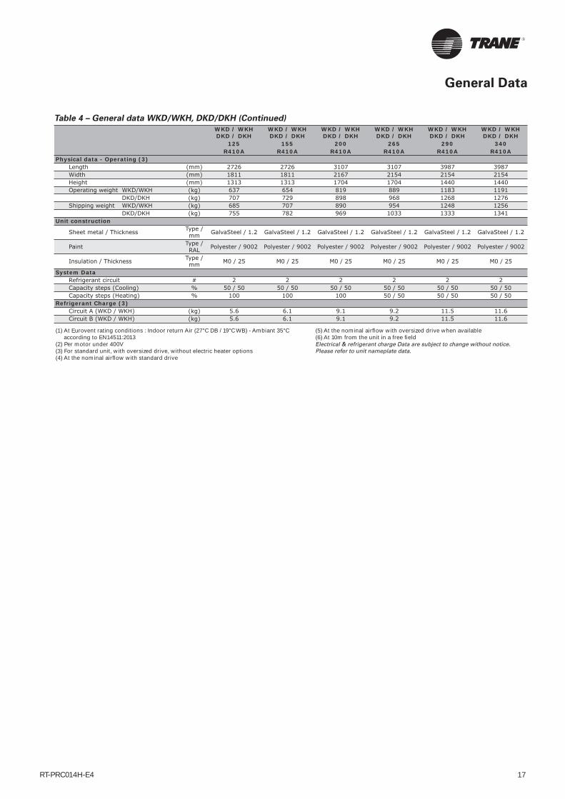
Physical data - Operating (3)Length (mm) 2726 2726 3107 3107 3987 3987Width (mm) 1811 1811 2167 2154 2154 2154Height (mm) 1313 1313 1704 1704 1440 1440Operating weight WKD/WKH (kg) 637 654 819 889 1183 1191 DKD/DKH (kg) 707 729 898 968 1268 1276Shipping weight WKD/WKH (kg) 685 707 890 954 1248 1256 DKD/DKH (kg) 755 782 969 1033 1333 1341
Unit construction
Sheet metal / Thickness Type / mm GalvaSteel / 1.2 GalvaSteel / 1.2 GalvaSteel / 1.2 GalvaSteel / 1.2 GalvaSteel / 1.2 GalvaSteel / 1.2
Paint Type / RAL Polyester / 9002 Polyester / 9002 Polyester / 9002 Polyester / 9002 Polyester / 9002 Polyester / 9002
Insulation / Thickness Type / mm M0 / 25 M0 / 25 M0 / 25 M0 / 25 M0 / 25 M0 / 25
System DataRefrigerant circuit # 2 2 2 2 2 2Capacity steps (Cooling) % 50 / 50 50 / 50 50 / 50 50 / 50 50 / 50 50 / 50Capacity steps (Heating) % 100 100 100 50 / 50 50 / 50 50 / 50
Refrigerant Charge (3)Circuit A (WKD / WKH) (kg) 5.6 6.1 9.1 9.2 11.5 11.6Circuit B (WKD / WKH) (kg) 5.6 6.1 9.1 9.2 11.5 11.6
(1) At Eurovent rating conditions : Indoor return Air (27°C DB / 19°C WB) - Ambiant 35°C according to EN14511:2013
(2) Per motor under 400V(3) For standard unit, with oversized drive, without electric heater options (4) At the nominal airfl ow with standard drive
(5) At the nominal airfl ow with oversized drive when available(6) At 10m from the unit in a free fi eldElectrical & refrigerant charge Data are subject to change without notice. Please refer to unit nameplate data.
Table 4 – General data WKD/WKH, DKD/DKH (Continued)
General Data

RT-PRC014H-E418
Data given at 250Pa & 35°C ambient for nominal airflow rateSound Power Référence = 10E--12 Watt
Table 5 – Overall Outdoor Sound Power level (Env.)
63 Hz 125 Hz 250 Hz 500 Hz 1000 Hz 2000 Hz 4000 Hz 8000 HzTKD/H - YKD/H 155 64.2 dBA 67.8 dBA 71.0 dBA 77.2 dBA 79.6 dBA 78.8 dBA 72.7 dBA 68.7 dBA 84 dBATKD/H - YKD/H 175 64.2 dBA 67.8 dBA 71.0 dBA 77.1 dBA 79.5 dBA 78.9 dBA 72.3 dBA 68.7 dBA 84 dBATKD/H - YKD/H 200 73.2 dBA 72.3 dBA 77.0 dBA 80.7 dBA 81.6 dBA 78.2 dBA 71.3 dBA 55.4 dBA 86 dBATKD/H - YKD/H 250 73.2 dBA 72.3 dBA 77.0 dBA 80.7 dBA 81.5 dBA 78.4 dBA 71.3 dBA 55.4 dBA 86 dBATKD/H - YKD/H 265 73.2 dBA 72.3 dBA 77.0 dBA 80.7 dBA 81.6 dBA 78.5 dBA 71.2 dBA 55.4 dBA 86 dBATKD/H - YKD/H 290 74.5 dBA 73.6 dBA 78.7 dBA 82.4 dBA 83.6 dBA 79.7 dBA 72.7 dBA 60.3 dBA 88 dBATKD/H - YKD/H 340 74.5 dBA 73.6 dBA 78.8 dBA 83.4 dBA 84.0 dBA 81.4 dBA 75.3 dBA 60.3 dBA 89 dBAWKD/H - DKD/H 125 64.2 dBA 67.8 dBA 71.0 dBA 77.3 dBA 79.4 dBA 78.8 dBA 72.5 dBA 68.7 dBA 84 dBAWKD/H - DKD/H 155 64.2 dBA 67.8 dBA 71.0 dBA 76.9 dBA 79.6 dBA 78.7 dBA 71.5 dBA 68.7 dBA 84 dBAWKD/H - DKD/H 200 73.2 dBA 72.3 dBA 77.0 dBA 80.7 dBA 81.5 dBA 78.4 dBA 71.3 dBA 55.4 dBA 86 dBAWKD/H - DKD/H 265 73.2 dBA 72.3 dBA 77.0 dBA 80.7 dBA 81.6 dBA 78.5 dBA 71.2 dBA 55.4 dBA 86 dBAWKD/H - DKD/H 290 63.5 dBA 69.8 dBA 74.0 dBA 79.9 dBA 83.0 dBA 81.5 dBA 74.7 dBA 71.9 dBA 87 dBAWKD/H - DKD/H 340 63.5 dBA 69.8 dBA 74.0 dBA 81.6 dBA 83.5 dBA 82.7 dBA 76.5 dBA 71.9 dBA 88 dBA
Table 6 – SUPPLY Indoor Sound Power level (In duct)
63 Hz 125 Hz 250 Hz 500 Hz 1000 Hz 2000 Hz 4000 Hz 8000 HzTKD/H - YKD/H 155 61.4 dBA 61.3 dBA 60.9 dBA 62.1 dBA 62.9 dBA 63.6 dBA 63.8 dBA 57.2 dBA 71 dBATKD/H - YKD/H 175 63.1 dBA 66.5 dBA 65.5 dBA 69.2 dBA 68.6 dBA 67.7 dBA 66.5 dBA 57.9 dBA 76 dBATKD/H - YKD/H 200 63.1 dBA 66.5 dBA 65.5 dBA 69.2 dBA 68.6 dBA 67.7 dBA 66.5 dBA 57.9 dBA 76 dBATKD/H - YKD/H 250 67.5 dBA 70.9 dBA 69.9 dBA 74.6 dBA 73.9 dBA 74.1 dBA 72.9 dBA 64.3 dBA 81 dBATKD/H - YKD/H 265 69.4 dBA 72.8 dBA 71.8 dBA 75.5 dBA 74.9 dBA 74.0 dBA 72.8 dBA 64.2 dBA 82 dBATKD/H - YKD/H 290 50.0 dBA 67.2 dBA 71.4 dBA 76.1 dBA 77.8 dBA 72.7 dBA 69.9 dBA 63.9 dBA 82 dBATKD/H - YKD/H 340 52.4 dBA 68.0 dBA 74.4 dBA 76.9 dBA 80.1 dBA 74.6 dBA 71.7 dBA 65.7 dBA 84 dBAWKD/H - DKD/H 125 66.4 dBA 66.3 dBA 65.9 dBA 67.1 dBA 67.9 dBA 68.6 dBA 68.8 dBA 62.2 dBA 76 dBAWKD/H - DKD/H 155 61.4 dBA 61.3 dBA 60.9 dBA 62.1 dBA 62.9 dBA 63.6 dBA 63.8 dBA 57.2 dBA 71 dBAWKD/H - DKD/H 200 67.1 dBA 70.5 dBA 69.5 dBA 73.2 dBA 72.6 dBA 71.7 dBA 70.5 dBA 61.9 dBA 80 dBAWKD/H - DKD/H 265 69.4 dBA 72.8 dBA 71.8 dBA 75.5 dBA 74.9 dBA 74.0 dBA 72.8 dBA 64.2 dBA 82 dBAWKD/H - DKD/H 290 50.0 dBA 67.2 dBA 71.4 dBA 76.1 dBA 77.8 dBA 72.7 dBA 69.9 dBA 63.9 dBA 82 dBAWKD/H - DKD/H 340 52.4 dBA 68.0 dBA 74.4 dBA 76.9 dBA 80.1 dBA 74.6 dBA 71.7 dBA 65.7 dBA 84 dBA
Table 7 – RETURN Indoor Sound Power level (In duct)
63 Hz 125 Hz 250 Hz 500 Hz 1000 Hz 2000 Hz 4000 Hz 8000 HzTKD/H - YKD/H 155 63.4 dBA 60.8 dBA 56.9 dBA 63.6 dBA 66.4 dBA 61.1 dBA 56.3 dBA 48.2 dBA 71 dBATKD/H - YKD/H 175 56.1 dBA 61.0 dBA 57.0 dBA 62.2 dBA 68.1 dBA 63.7 dBA 58.5 dBA 51.4 dBA 71 dBATKD/H - YKD/H 200 56.1 dBA 61.0 dBA 57.0 dBA 62.2 dBA 68.1 dBA 63.7 dBA 58.5 dBA 51.4 dBA 71 dBATKD/H - YKD/H 250 60.5 dBA 65.4 dBA 61.4 dBA 67.6 dBA 73.4 dBA 75.1 dBA 64.9 dBA 57.8 dBA 78 dBATKD/H - YKD/H 265 62.4 dBA 67.3 dBA 63.3 dBA 68.5 dBA 74.4 dBA 70.0 dBA 64.8 dBA 57.7 dBA 78 dBATKD/H - YKD/H 290 47.8 dBA 63.5 dBA 67.6 dBA 72.3 dBA 74.3 dBA 69.7 dBA 66.9 dBA 60.9 dBA 78 dBATKD/H - YKD/H 340 50.1 dBA 64.6 dBA 70.6 dBA 73.2 dBA 76.3 dBA 71.6 dBA 68.7 dBA 62.7 dBA 80 dBAWKD/H - DKD/H 125 68.4 dBA 65.8 dBA 61.9 dBA 68.6 dBA 71.4 dBA 66.1 dBA 61.3 dBA 53.2 dBA 76 dBAWKD/H - DKD/H 155 63.4 dBA 60.8 dBA 56.9 dBA 63.6 dBA 66.4 dBA 61.1 dBA 56.3 dBA 48.2 dBA 71 dBAWKD/H - DKD/H 200 60.1 dBA 65.0 dBA 61.0 dBA 66.2 dBA 72.1 dBA 67.7 dBA 62.5 dBA 55.4 dBA 75 dBAWKD/H - DKD/H 265 62.4 dBA 67.3 dBA 63.3 dBA 68.5 dBA 74.4 dBA 70.0 dBA 64.8 dBA 57.7 dBA 78 dBAWKD/H - DKD/H 290 47.8 dBA 63.5 dBA 67.6 dBA 72.3 dBA 74.3 dBA 69.7 dBA 66.9 dBA 60.9 dBA 78 dBAWKD/H - DKD/H 340 50.1 dBA 64.6 dBA 70.6 dBA 73.2 dBA 76.3 dBA 71.6 dBA 68.7 dBA 62.7 dBA 80 dBA
Sound Levels

RT-PRC014H-E4 19
Table 8 – Electrical characteristics
Indoor FanBelt Drive
Indoor FanDirect Drive
Control Compressor 1 / 2 Standard drive
Oversized drive
Standard drive
Oversized drive
Exhaust fan Outdoor Fan Electric
Heat
Unit Max Amps Max Amps Start
Amps Max Amps Max Amps Max Amps Qty Max Amps Max Amps
TK* / YK* 155 0.5 18.5 / 11.2 142 / 82 4 6.4 5.4 8.5 3.0 2 1.2 36TK* / YK* 175 0.5 20.0 / 13.9 142 / 87 6.4 9 5.4 9.8 3.0 2 1.2 36TK* / YK* 200 0.5 18.5 / 18.5 142 / 142 6.4 9 9.4 12.4 3.0 2 2.5 54TK* / YK* 250 0.5 20.0 / 20.0 142 / 142 9 9 11.3 13.3 3.0 2 2.5 54TK* 265 0.5 23.0 / 23.0 147 / 147 9 11 11.3 13.5 3.0 2 2.5 54TK* 290 0.5 25.2 / 25.2 158 / 158 15 17.3 16.4 23.3 3.0 3 2.5 54TK* 340 0.5 29.0 / 29.0 197 / 197 15 17.3 16.6 22.9 3.0 3 2.5 54WK* / DK* 125 0.5 13.9 / 13.9 87 / 87 4 6.4 5.5 7.9 3.0 2 1.2 36WK* / DK* 155 0.5 15.2 / 15.2 98 / 98 4 6.4 5.4 8.5 3.0 2 1.2 36WK* / DK* 200 0.5 20.0 / 20.0 142 / 142 6.4 9 9.4 12.4 3.0 2 2.5 54WK* / DK* 265 0.5 23.0 / 23.0 147 / 147 9 11 11.3 13.5 3.0 2 2.5 54WK* / DK* 290 0.5 25.2 / 25.2 158 / 158 15 17.3 16.4 23.3 3.0 4 1.2 54WK* / DK* 340 0.5 29.0 / 29.0 197 / 197 15 17.3 16.6 22.9 3.0 4 1.2 54
Data for nominal voltage 400V/3/50Data are subject to change without notice. Please refer to unit nameplate data.
Maximum length
Table 9 – Zone sensor wire size
Wire size(mm2)
Maximum wire length(m)
THS/THP 03
0.33 45
0.5 76
0.75 115
1.3 185
2 300
Conventional thermostat
0.33 10
0.5 15
0.75 23
1.3 37
2 60
CO2 sensor wire size
0.25 50
0.5 100
1 200
Electrical Data

RT-PRC014H-E420
Figure 8Dimensions, Weights and Clearances
Overall unit dimensions, shipping weights and operating weights are given in the General Data tables.
Table 10 – Minimum recommended clearances
Minimum clearanceUNIT 1 2 3 4 5TK* / YK* 155 1900 1800 1220 1000 1300TK* / YK* 175 1900 1800 1220 1000 1300TK* / YK* 200 1900 1800 1220 1000 1300TK* / YK* 250 1900 1800 1220 1000 1300TK* 265 1900 1800 1220 1000 1300TK* 290 1900 1800 1220 1000 1300TK* 340 1900 1800 1220 1000 1300WK* / DK* 125 1900 1800 1220 1000 1300WK* / DK* 155 1900 1800 1220 1000 1300WK* / DK* 200 1900 1800 1220 1000 1300WK* / DK* 265 1900 1800 1220 1000 1300WK* / DK* 290 1900 1800 1220 1000 1300WK* / DK* 340 1900 1800 1220 1000 1300
Weights of Factory-installed Accessories
Table 11 – Factory-installed Accessories Net Weights (kg)
UNIT
Pit
ched
R
oof
Cu
rb
Pit
ched
R
oof
Cu
rb
Econ
omiz
er
Man
ual
O
uts
ide
Air
D
amp
er
Mot
oriz
ed
Ou
tsid
e A
ir
Dam
per
Elec
tric
h
eate
r
Hot
wat
er
coil
Pow
er
exh
aust
fan
Dir
ect
dri
ve
fan
WKD/DKD 125 93 220 30 15 27 14 85 49 31WKD/DKD/TKD/YKD 155 93 220 30 15 27 14 85 49 31TKD/YKD 175 93 220 30 15 27 14 85 49 24WKD/DKD/TKD/YKD 200 107 260 37 15 34 18 110 49 48TKD/YKD 250 107 260 37 15 34 18 110 49 53WKD/DKD/TKD 265 107 260 37 15 34 18 110 49 53WKD/DKD/TKD 290 107 260 37 15 34 18 110 49 80WKD/DKD/TKD 340 107 260 37 15 34 18 110 49 80WKH/DKH 125 — — 30 15 27 14 — — —WKH/DKH/TKH/YKH 155 — — 30 15 27 14 — — —TKH/YKH 175 — — 30 15 27 14 — — —WKH/DKH/TKH/YKH 200 — — 37 15 34 18 — — —TKH/YKH 250 — — 37 15 34 18 — — —WKH/DKH/TKH 265 — — 37 15 34 18 — — —WKH/DKH/TKH 290 — — 37 15 34 18 — — —WKH/DKH/TKH 340 — — 37 15 34 18 — — —
Notes :
Net weight should be added to unit weight when ordering factory installed accessories.
To estimate shipping weight add 2.3 kg to net weight.
Filters
Table 12 – Filter arrangementG4+F7 Filter
G2 Filter G4 Filter G4 Filter F7 FilterUNIT Qty - Size Qty - Size Qty - Size Qty - SizeTKD / YKD 155 - 175 & WKD / DKD 125 - 155 2x (500x500x50) 2x (498x498x40) 1x (398x498x44) 2x (500x500x50)
+4x (500x625x50) +4x (500x625x50) +1x (498x498x40) +4x (500x625x50)+2x (500x625x50)+2x (400x625x50)
TKH / YKH 155 - 175 & WKH / DKH 125 - 155 2x (500x500x50) 2x (498x498x40) 4x (398x498x44) 2x (500x500x50)+4x (500x625x50) +4x (500x625x50) +2x (500x625x50) +4x (500x625x50)
YKD 200 - 250 & TKD / WKD / DKD 200 - 340 4x (500x500x50) 4x (498x498x40) 4x (498x498x40) 4x (500x500x50)+4x (500x625x50) +4x (500x625x50) +4x (500x625x50) +4x (500x625x50)
YKH 200 - 250 & TKH / WKH / DKH 200 - 340 8x (500x625x50) 8x (500x625x50) 6x (400x625x50) 8x (500x625x50)+2x (500x625x50)
Dimensions and Weights
RT-PRC014H-E4 21
Equipment Protection/Operation Timings
and Features
Increased reliability
Fewer components (moving electromechanical parts); less likelihood of equipment down time or failure. Standard
Proportional Integral (PI) Control
Proportional - sets corrective action proportional to deviation from setpoint. Integral - fi ne-tunes the rate of corrective action proportional to the error (results in superior temperature control). Standard
Built In “TEST” Mode
Aids in quick verifi cation of system and control operation; exercises both hardware and software (no special tools required). Standard
On Board Diagnostics
Assists with equipment troubleshooting if a problem should occur. Standard
Low Ambient Start Timer (LAST) Function
Bypasses low pressure control when a compressor starts, eliminating nuisance compressor lockouts. Standard
Anti Short Cycle Timer (ASCT) Function
Provides a three minute minimum “ON” time and a three minute minimum “OFF” time for compressors; enhances compressor reliability by ensuring proper oil return. Standard
Time Delay Relay (TDR) Function
Provides an incremental staging delay between compressors; minimizes equipment current inrush and consumption by keeping compressors from starting simultaneously. Standard
Built In Fan Delay Relay (FDR)
Provides custom indoor fan timing sequences for the different types of equipment, enhancing effi ciency and reliability. Standard
Built in Evaporator Defrost Control
Provides low ambient cooling down to -18°C. Standard
Intelligent Fallback
Built-in Default Control provides adaptive operation, which allows the equipment to continue to operate, and provide comfort in the event of certain input failures. Also, allows temporary operation without a thermostat. Standard
Emergency Stop Terminals on Low Voltage Terminal
Board
Provides a convenient point to disable the equipment completely and immediately. Standard
Lower Installation Cost
When using a Trane THS03 or THP03, control voltage wiring may be run up to fi ve times further than any electromechanical system with no increase in wire section. Example: Electromechanical System - 22 m
using 0.5 mm2 wire. Microcontrol System (THS/P 03) 110 m 0.5 mm2 wire. Standard
Alternating Lead/Lag
During periods of part load operation, each compressor cycles alternately as circuit number one, equalizing compressor wear and run time. Enable by cutting the wire at RTRM junction number J3-8.
Demand defrost - Heat pump
Defrost only if needed; not based on time like most other systems. Adapts to changing weather conditions and lowers operating costs. Standard
Heat pump Soft Start
Provides a smooth transition into heating after defrost, minimizing noise and compressor stress associated with switch over. Standard
Heat pump Smart Recovery and Smart Staging
Inhibits auxiliary heat operation if the space is recovering adequately (0.1°C /min) with the heat pump alone, providing considerable savings in operating costs. Standard
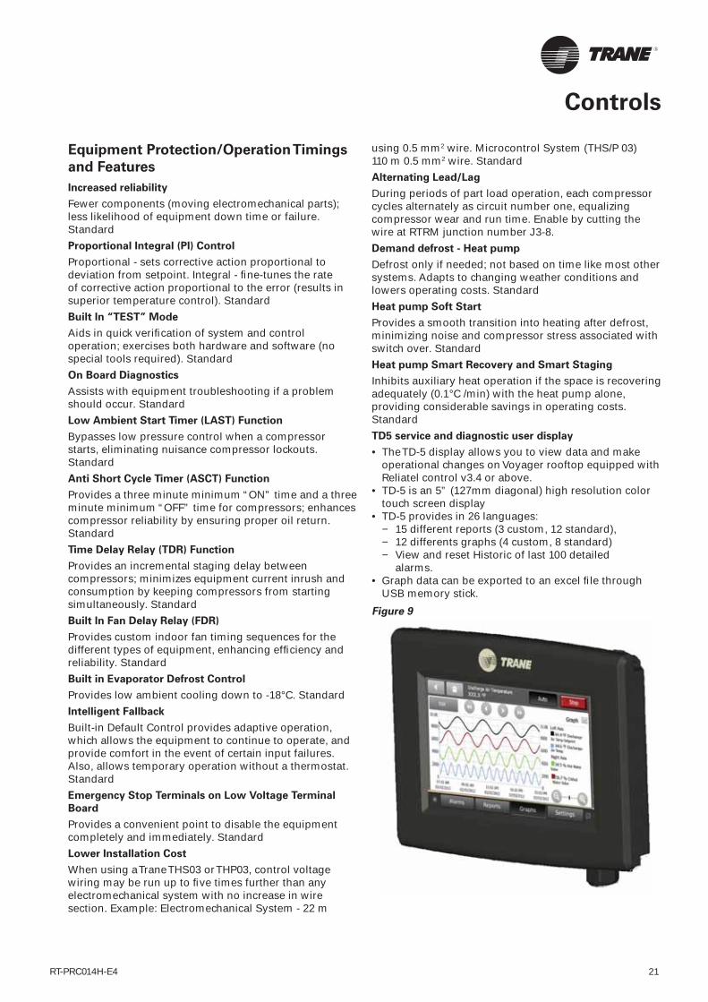
TD5 service and diagnostic user display
• The TD-5 display allows you to view data and make operational changes on Voyager rooftop equipped with Reliatel control v3.4 or above.
• TD-5 is an 5” (127mm diagonal) high resolution color touch screen display
• TD-5 provides in 26 languages: − 15 different reports (3 custom, 12 standard), − 12 differents graphs (4 custom, 8 standard) − View and reset Historic of last 100 detailed
alarms.• Graph data can be exported to an excel fi le through
USB memory stick.
Figure 9
Controls
RT-PRC014H-E422
Economizer Preferred Cooling
Provides fully integrated operation. Will not turn on a compressor with the economizer, if the space is recovering adequately with the economizer alone (0.1°C./minute). Allows the equipment to be utilized in more varied applications. Standard with economizer
Features lost when using a conventional thermostat
• When a Conventional Thermostat is applied, equipment operation differs signifi cantly. The basic equipment protection features remain intact, and the following features end benefi ts are lost :
• Proportional Integral (PI) control is lost, equipment is controlled by a thermostat or generic building automation system device.
• Intelligent Fall Back is lost, if a failure occures in the device controlling the equipment, operation will cease.
• Heat Pump Smart Recovery and Smart Staging is not available. Heat Pump operation becomes more costly unless the generic control applied can accomplish this.
Field-installed Control Options
Zone sensors
Zone sensors are the building occupants’ comfort control devices. They replace the conventional electromechanical thermostats. Zones sensors are to be used with the Voyager™ II units with the Micro control. These sensors are available in the following options:
• THP03: Sensor, programmable setpoint and operation mode according to a schedule
• TZS01: Sensor only, used when connected with CCP2 or Tracker™
• TZS02: Sensor and setpoint adjustable thumbwheel• THS03: Sensor, setpoint and operation mode, unit Led
indication (mode and alarms)
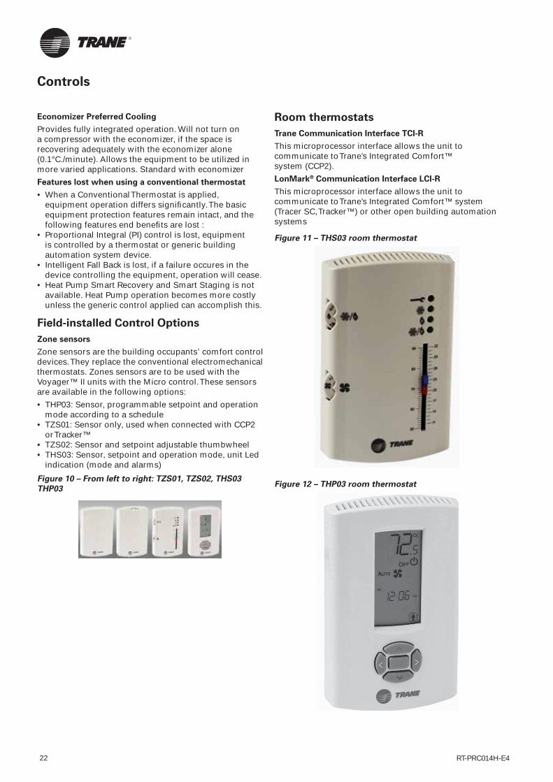
Figure 10 – From left to right: TZS01, TZS02, THS03 THP03
Room thermostats
Trane Communication Interface TCI-R
This microprocessor interface allows the unit to communicate to Trane’s Integrated Comfort™ system (CCP2).
LonMark® Communication Interface LCI-R
This microprocessor interface allows the unit to communicate to Trane’s Integrated Comfort™ system (Tracer SC, Tracker™) or other open building automation systems
Figure 11 – THS03 room thermostat
Figure 12 – THP03 room thermostat
Controls

RT-PRC014H-E4 23
Table 13 – Characteristics of Programmable and Conventional Thermostats
Conventional Thermostat THS03 THP03
Programmable ● - ●Electronic ● - ●Control type design Electro-mechanical ReliatelFor cooling-only units (TS*/TK*) ● ● ●For heat pump units (WS*/WK*) ● ● ●For gas-fi red units (YS*/YK*) ● ● ●Number of cooling stages 2 3 3Auxiliary heating stages (electric heater, hot water coil) 2 2 / 1 ModulatingLiquid crystal display ● - ●
● Available- Not Available
Tracker™ multi rooftops centralized
control
• Intuitive, menu-driven user interface• 2 wires cable communication with units (LonMark®)• 365-day scheduling and 10 schedules• Capability of including all equipment and devices in
one schedule• Temporary schedule override• Easy-to-administer security system with two levels of
access• Automatic daylight savings time changeover• Error and alarm messaging• Setpoint viewing and editing• Trend data collection• Report generation• Optimal startFeatures exclusive to the PC software (optional)
• RJ45 - Ethernet connection• Backup and restore capability• Standard graphics and HTML graphical interface• Binary output programming capability• Operator-defi ned custom alarms capability• Printer supportConnection to controllers over shared Ethernet/IP
connection
• E-mail forwarding of alarms and messages• Standard timed override (after hours) usage report• Standard daily, monthly, and yearly energy reportsNote: The Tracker PC software is not needed to set up and operate a typical building.
Figure 13 – Tracker interface
Controls

RT-PRC014H-E424
General
Units shall be dedicated downfl ow or horizontal airfl ow. Operating range shall be between 50°C and -18°C cooling as standard for all units. All units shall be factory assembled, internally wired, fully charged with refrigerant, and 100 percent run-tested before leaving the factory. Wiring internal to the unit shall be colored and numbered for simplifi ed identifi cation.
Unit shall be available with a main refrigeration circuit in cooling only and reversible version. Auxiliary heat type shall be selectable: Hot water heat, Gas heater and electrical heater in both refrigeration circuit versions.
Performance
The unit shall be certifi ed and registered on the Eurovent certifi cation under RT program (http://www.eurovent-certifi cation.com). Unit net EER shall be class B (>2.80) or higher in cooling mode except for reversible unit of 79kW and 88kW Eurovent cooling capacity .Reversible Unit net COP shall be class B (>3.20) or higher in Heating mode.
Casing
Unit casing shall be constructed of zinc coated, heavy-gauge, galvanized steel. All exterior components shall be mounted in a weather resistant steel cabinet and painted with a polyester white RAL 9002 powder paint. Where top cover seams exist, they shall be double hemmed and gasket sealed to prevent water leakage. Cabinet construction shall allow access for all maintenance on two sides of the unit. Service panels shall have handles and shall be removable while providing a water and air tight seal. The indoor air section shall be completely insulated with fi re resistant, permanent, odorless glass fi ber material, aluminum foil faced. The base of the unit shall have provisions for crane lifting.
Service Access ¼ locks: Standard
Electrical Control box access panel Filter access panel and supply fan access panel shall be locked by ¼ turn locks as standard for ease of unit service.
Filters
Unit shall be provided on standard with 50 mm, throwaway EU3 fi lters. 50 mm EU4 fi lters shall be optional.
Compressors
All units shall have scroll type compressors. Compressor shall be direct-drive, hermetic with self-lubrication. Motor shall be suction gas-cooled and shall have a voltage utilization range of plus or minus 10 percent of unit nameplate voltage. Internal temperature and current sensitive motor overloads shall be included for maximum protection. Each compressor shall be protected by external discharge temperature thermostat, winding temperature thermostat and reverse rotation/phase loss protection. Each compressor shall have crankcase heaters installed, properly sized to minimize the amount of liquid refrigerant present in the oil sump during off cycles. All scroll compressors shall be protected with phase monitoring protection.
Refrigerant Circuits
The unit shall be operating with R410A HFC-based refrigerant. Each refrigerant circuit shall have independent thermostatic expansion devices, service pressure ports and refrigerant line fi lter driers factory-installed as standard. An area shall be provided for replacement suction line driers. Refrigeration circuit shall be protected against refrigerant leak by a low pressure switch. Service valves shall be provided as standard and located on low pressure and high pressure side of the refrigeration piping.
Evaporator and Condenser Coils
Condenser coils shall have 3/8” (10 mm) copper tubes mechanically bonded to lanced aluminum plate fi ns. Evaporator coils shall be 3/8” (13 mm) internally fi nned copper tubes mechanically bonded to high performance aluminum plate fi ns. All coils shall be leak tested at the factory to ensure pressure integrity. All coils shall be leak tested to 2.1 MPa and pressure tested to 4.5 MPa. All evaporator coils shall be of intermingled confi guration. Sloped condensate drain pans are standard. Indoor coil shall be protected as optional by an ant frost thermostat.
Outdoor Fans
The outdoor fans shall be direct drive, statically and dynamically balanced, draw-through in the vertical discharge position. The fan motors shall be permanently lubricated and shall have built-in thermal overload protection.
Indoor Fan
Units shall have belt driven, forward curved centrifugal fans with variable diameter motor sheaves. All motors shall be protected from overload.
Controls
Unit shall be completely factory wired with necessary controls and terminal block for power wiring. Units shall provide an external location for mounting fused disconnect device. Unit controller shall be provided for all 24 volt control functions. The resident control algorithms shall make all heating, cooling and/or ventilating decisions in response to electronic signals from sensors measuring indoor and outdoor temperature. The control algorithm maintains accurate temperature control, minimizes drift from set point and provides better building comfort. Unit controller shall provide anti-short cycle timing and time delay between compressors to provide a higher level of machine protection. Heat pump unit shall manage defrost cycles based on demand defrost logic.
Unit shall be powered by 400V/3/50Hz supply (without neutral) on a single point of power connection.
Mechanical Specifications

RT-PRC014H-E4 25
Operation and diagnostic display
The unit shall be equipped with a 5’ high resolution color touch screen LCD display. The display allows you to view data and make operational changes on the rooftop.
Display shall provide in 26 languages:
• 15 different reports (3 custom, 12 standard), • 12 different graphs (4 custom, 8 standard)• View and reset historic of last 100 detailed alarms.Graph data shall be exported to an excel fi le through USB memory stick.
Ventilation Override
Shall allow a binary input from the fi re/life safety panel to cause the unit to override standard operation and assume one of two factory preset ventilation sequences, exhaust or pressurization. The two sequences shall be selectable based open a binary select input.
Phase Monitoring Relay: Standard
Unit shall detect phase loss, phase reversal from main power supply. In case of fault, the unit shall stop.
Through-The-Base Electrical Provision: Standard
An electrical service entrance shall be standard which allows access to route all high and low voltage electrical wiring inside the curb, through the bottom (vertically) and through the side (Horizontally) of the outdoor section of the unit and into the control box area.
Disconnect Switch: Optional
A factory installed disconnect switch with external handle shall be mounted inside the unit control box.
Options and Accessories
Manual Fresh Air Damper
A manually controllable outside air damper shall be adjustable for up to 25 percent outside air. Manual damper is set at desired position at unit start up.
Motorized Fresh Air damper
This option shall be factory mounted. Outdoor air rate shall be adjustable from 0 to 50 percent. Once set, outdoor air dampers shall open to set position when indoor fan starts. The damper shall close to the full closed position when indoor fan shuts down.
Economizer - Downfl ow
Economizer shall be factory installed. The assembly includes: fully modulating 0-100 percent motor and dampers, minimum position setting, preset linkage, wiring harness, and differential enthalpy control. It shall be provided with barometric relief damper. Barometric relief damper shall deliver a space pressure equalization and be gravity closing to prohibit entrance of outside air during the equipment “off” cycle.
Economizer - Horizontal fl ow
Economizer shall be factory installed. The assembly includes: fully modulating 0-100 percent motor and dampers, minimum position setting, preset linkage, wiring harness, and differential enthalpy control.
Power Exhaust Fan
Power exhaust shall be optional with the downfl ow economizer. It shall be available as a factory installed option on all units size. It shall assist the barometric relief damper in maintaining building pressurization.
Remote Potentiometer
A remote potentiometer shall be available to remotely adjust the unit fresh air damper minimum position.
CO2 Sensor
This accessory shall be compatible with motorized Fresh air damper and economizer options. It shall measure CO2 concentration in order to increase or decrease the fresh air amount in the building.
Direct driven Variable Frequency fan: Optional
VFDs shall be factory installed and tested to provide supply fan motor speed modulation. The VFD shall receive speed reference from the unit controller based upon supply zone heating/cooling demand and shall cause the drive to accelerate or decelerate as required to maintain the zone temperature setpoint. The fan coupling shall be direct type with the motor shaft. Units shall have a soft rubber direct coupling between centrifugal fans and motor. Motor, fan and VFD shall be individually replaced in case of maintenance operation.
Fan Fail Switch
This option allows checks for supply fan pressure. The fan failure switch will stop all unit functions and report Service alarm on the zone sensor module or Building management system.
Clogged Filter Switch
This option allows for individual dirty fi lter indication. The switch will light the Service LED on the zone sensor and will allow continued unit operation.
Smoke Detector
This option shall trip off in case of presence of smoke in the supply side of the unit and shall close the return air damper, if any, and stop the unit.
Phase Monitoring Relay
The phase monitoring relay shall detect phase loss, phase reversal and phase imbalance from main power supply. In case of fault, the unit must stop.
Black Epoxy Fin Coating
An optional coil corrosion resistant coating shall protect indoor and outdoor aluminum fi ns.
Fire thermostats
Field installed manually resettable high temperature thermostats shall provide input to the unit controls to shut down the system if the temperature sensed at the return is 57°C or at the discharge 115°C.
Mechanical Specifi cations

RT-PRC014H-E426
Roof Curb - Downfl ow
The roof curb shall be designed to mate with the downfl ow unit and provide support and watertight installation when installed properly.
The roof curb design shall allow fi eld fabricated rectangular supply/return ductwork to be connected directly to the curb.
Curb shall be shipped knocked down for fi eld assembly.
Adjustable Roof Curb
This factory assembled accessory is adjustable on site and allows correction of the slope of the roof up to 5%.
Hot Water Coil
This option shall be factory mounted and placed in the discharge section. It shall be shipped with one 3-way valve, 0 to 100% modulating built-in control and freezestat protection. If needed, on reversible unit, hot water coil shall be selected as fi rst source of heat before mechanical heating.
Electric Heaters
Electric heat shall be available for factory installation within basic unit. Electric heater elements shall be constructed of heavy-duty nickel chromium elements we connected for 380 and 415 volt. Staging shall be achieved through the unit controller. Each heater package shall have automatically reset high limit control operating through heating element contactors. All heaters shall be individually fused from factory, where required.
Gas Heater
The heating section shall have a drum and tube heat exchanger(s) design using corrosion resistant steel components. A forced combustion blower shall supply premixed fuel to a single burner ignited by a pilotless hot surface ignition system. In order to provide reliable operation, a negative pressure gas valve shall be used that requires blower operation to initiate gas fl ow. On an initial call for heat, the combustion blower shall purge the heat exchanger(s) 45 seconds before ignition. After three unsuccessful ignition attempts, the entire heating system shall be locked out until manually reset at the thermostat. Units shall be suitable for use with natural gas or propane (fi eld installed kit). All units shall have two stage heating.
Burner of 48kW and 70kW shall have a no emissions of CO (< 0.001%) and NOx emission below 30ppm (class 5 according to the requirements of Standard EN483). Burner of 77kW shall have a no emissions of CO (< 0.001%) and NOx emission below 50ppm (class 4 according to the requirements of Standard EN483)
Energy Recovery Module - General
Heat recovery should include direct driven exhaust fan. Fan speed should be adjusted by a separate frequency drive according to fresh air fl ow in order to maintain building pressurization.
Fresh air fl ow shall be fi ltered before entering in the heat exchanger in order to prevent clogging on the fresh air side.
When free cooling is needed, energy recovery should be by-passed to avoid heat exchange on the fresh fl ow entering into the building.
Energy Recovery Module - Plate heat exchanger version
Energy recovery module should have a total effi ciency of 51% or higher at -5°C outdoor, 19°C indoor and 30% fresh air rate. Module shall be equipped with freeze monitoring pressure switch that initiate defrost cycle when exchanger in clogged by frost in winter application.
Energy Recovery Module - Heat wheel version
Energy recovery should have a total effi ciency of 64% or higher at -5°C outdoor, 19°C indoor and 30% fresh air rate. Fresh air and exhaust air fl ow shall be fi ltered before entering in the heat exchanger in order to prevent exchanger clogging.
Thermostats and Zone Sensors
The thermostats and zone sensors shall be provided to interface with the ReliaTel® unit controls and shall be available in either manual, automatic programmable with night setback, with system malfunction lights or remote sensor options.
Communication Interface (TCI-R)
ReliaTel® Trane Communication Interface (TCI) shall be provided to interface with the Trane Integrated Comfort™ System and shall be available as a fi eld or factory-installed. The TCI-R shall allow control and monitoring of the rooftop unit via a two wires communication link.
Trane Modbus Communication Interface (PIC)
Modbus Communication Interface (PIC) shall be provided to interface with the Trane Integrated Comfort™ System and shall be available fi eld-installed. The PIC shall allow control and monitoring of the rooftop unit via a two wire communication link and Modbus protocol.
LonTalk® Communication Interface (LCI-R)
The fi eld or factory-installed ReliaTel® LonTalk Communication Interface (LCI-R) will be provided to interface with the Trane Integrated Comfort™ System or LonTalk® capable third party building management networks. The LCI-R will allow control and monitoring of the rooftop unit via a two wires communication link.
Tracker® Multi rooftop centralized management control
Simple Building Control
The Tracker building automation system (BAS) is a heating, ventilating, and air conditioning (HVAC) energy management system for small- to medium-size buildings. It provides reliable, centralized control for HVAC equipment, managing it for optimal comfort and effi ciency.
Mechanical Specifi cations

RT-PRC014H-E4 27
The Tracker BAS includes a controller with a liquid crystal display (LCD) touch screen. The Tracker BAS also includes optional Windows-based software that can be installed on a PC workstation. Connection between Tracker BAS and PC software is possible through modem, direct serial RS232 link or Ethernet IP communication.
The Tracker BAS is LonMark® compliant. It communicates with supported devices over a Trane Comm5 link. The Trane Comm5 link is a communication link that implements LonTalk and a LonTalk FTT-10A network. LonTalk is an open, industry-standard protocol.
The touch screen provide an easy-to-use visual interface. The interfaces enable an operator to set up and change HVAC operating parameters and collect and display building information.
The Tracker BAS offer these features:
• Intuitive LCD touch screen user interface• 365-day scheduling and 10 schedules• Capability of including all equipment and devices in
one schedule• Temporary schedule override• Easy-to-administer security system with two levels of
access• Automatic daylight savings time changeover• Error and alarm messaging• Setpoint viewing and editing• Auto confi gurationWhen Trane Comm5 devices are used as a system and power is applied to the controller, the Tracker BAS automatically confi gures itself. It is no longer necessary to program the building management system. During auto confi guration, the controller:
• Discovers all devices on the communication link• Loads all devices into a non-erasable memory
database• Turns to On or Occupied all discovered HVAC
equipment except the binary output relays of the Tracer MP503 I/O module, which remain de-energized (Off)
Reliatel® Unit controller Originated Data
• Unit operating mode• Unit failure status
− Cooling failure − Heating failure − Emergency service stop indication − Supply fan proving − Timed override activation − High temperature thermostat status
• Zone temperature• Supply air temperature• Cooling status (all stages)• Stage activated or not• Stage locked out by Reliatel• HPC status for that stage• Compressor disable inputs• Heating status• Number of stages activated• High temperature limit status• Economizer status• Requested minimum position
• Damper position• Dry bulb/enthalpy input status• Outside air temperature• Outside relative humidity• Sensor Failure
− Humidity sensor − Outdoor Air Temperature sensor − Supply Air Temperature sensor − Return Air Temperature sensor − Zone temperature sensor − Mode input − Cooling/heating setpoint from sensors − Unit mounted potentiometer
• Unit Confi guration data − Gas or electric heat − Economizer present
• Local setpoint• Local mode setting• Clogged fi lter service indicator• CO2 setpoint• CO2 value
Building Management System communication
Originated Data
• Command operating mode• Host controllable functions:
− Supply fan − Economizer − Cooling stages enabled − Heating stages enabled − Emergency shutdown
• Minimum damper position• Heating setpoint• Cooling setpoint• Supply air tempering enable/disable• Slave mode (CV only)• Tracer/Local operation• Daytime warm-up enable/disable• Power exhaust setpoint
Mechanical Specifi cations

Trane optimizes the performance of homes and buildings around the world. A business of Ingersoll Rand, the leader in creating and sustaining safe, comfortable and energy effi cient environments, Trane offers a broad portfolio of advanced controls and HVAC systems, comprehensive building services and parts. For more information visit www.Trane.com
Trane has a policy of continuous product and product data improvement and reserves the right to change design and specifi cations without notice.
© 2014 Trane All rights reserved
RT-PRC014H-E4 July 2014Supersedes RT-PRC014-E4_0513
We are committed to using environmentallyconscious print practices that reduce waste.