Embed Size (px)
Citation preview

VORTOS
Versatile Object-oriented Real-Time Operating System
by
Rusty Lee
Submitted to the Department of Electrical Engineering and Computer Science
in Partial Fulfillment of the Requirements for the Degrees of
Bachelor of Science in Electrical Engineering and Computer Science
and Master of Engineering in Electrical Engineering and Computer Science
at the Massachusetts Institute of Technology
May 23, 2001
Copyright 2001 Rusty Lee. All rights reserved.
The author hereby grants to M.I.T. permission to reproduce anddistribute publicly paper and electronic copies of this thesis
and to grant others the right to do so.
Author__________________________________________________________________Department of Electrical Engineering and Computer Science
May 23, 2001
Certified by______________________________________________________________Sanjay Sarma
Thesis Supervisor
Accepted by_____________________________________________________________Arthur C. Smith
Chairman, Department Committee on Graduate Theses

2

3
VORTOSVersatile Object-oriented Real-Time Operating System
by
Rusty Lee
Submitted to theDepartment of Electrical Engineering and Computer Science
on May 23, 2001, in partial fulfillment of therequirements of the Degrees of
Bachelor of Science in Electrical Engineering and Computer Science and
Master of Engineering in Electrical Engineering and Computer Science
Abstract
As computer software has become more complex in response to increasing demands andgreater levels of abstraction, so have computer operating systems. In order to achieve thedesired level of functionality, operating systems have become less flexible and overlycomplex. The additional complexity and abstraction introduced often leads to lessefficient use of hardware and increased hardware requirements. In embedded systemswith limited hardware resources, efficient resource use is extremely important to thefunctionality of the resources. Therefore, operating system functionality not useful forthe embedded system's applications is detrimental to the system. Component-basedsoftware provides a way to achieve both the efficient application-specific functionalityrequired in embedded systems and the ability to extend this functionality to otherapplications.
This thesis presents a component-based operating system, VORTOS, the VersatileObject-oriented Real-Time Operating System. VORTOS uses a virtual machine toabstract the hardware, eliminating the need for further portability abstractions within theoperating system and application level components. The simple modular componentarchitecture allows both the operating system and user applications to be extremelyflexible by allowing them to utilize the particular components required, withoutsacrificing performance.
Thesis Supervisor: Sanjay SarmaTitle: Assistant Professor, Department of Mechanical Engineering

4

5
Acknowledgements
The author would like to thank everyone who gave me support and
encouragement while completing this work. Thanks in particular go to Dr. Daniel Engels
and Professor Sanjay Sarma for helping me stay on track and reviewing and helping me
to revise my work. Thanks also go to Ian Ross and Brett Whittemore for helping me hash
out the design.

6
7
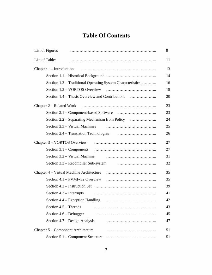
Table Of Contents
List of Figures ……………………………………………………….. 9
List of Tables ……………………………………………………….. 11
Chapter 1 – Introduction ……………………………………………….. 13
Section 1.1 – Historical Background ……………………………….. 14
Section 1.2 – Traditional Operating System Characteristics ……….. 16
Section 1.3 – VORTOS Overview ……………………………….. 18
Section 1.4 – Thesis Overview and Contributions ……………….. 20
Chapter 2 – Related Work ……………………………………………….. 23
Section 2.1 – Component-based Software ……………………….. 23
Section 2.2 – Separating Mechanism from Policy ……………….. 24
Section 2.3 – Virtual Machines ……………………………….. 25
Section 2.4 – Translation Technologies ……………………….. 26
Chapter 3 – VORTOS Overview ……………………………………….. 27
Section 3.1 – Components ……………………………………….. 27
Section 3.2 – Virtual Machine ……………………………….. 31
Section 3.3 – Recompiler Sub-system ……………………….. 32
Chapter 4 – Virtual Machine Architecture ……………………………….. 35
Section 4.1 – PVMF-32 Overview ……………………………….. 35
Section 4.2 – Instruction Set ……………………………………….. 39
Section 4.3 – Interrupts ……………………………………….. 41
Section 4.4 – Exception Handling ……………………………….. 42
Section 4.5 – Threads ……………………………………….. 43
Section 4.6 – Debugger ……………………………………….. 45
Section 4.7 – Design Analysis ……………………………….. 47
Chapter 5 – Component Architecture ……………………………….. 51
Section 5.1 – Component Structure ……………………………….. 51

8
Section 5.2 – Component Messaging ……………………………….. 54
Section 5.3 – Design Analysis ……………………………….. 56
Chapter 6 – Basic Components ……………………………………….. 59
Section 6.1 – Loader ……………………………………………….. 59
Section 6.2 – Task Scheduler ……………………………………….. 62
Section 6.3 – Memory Manager ……………………………….. 62
Section 6.4 – Design Analysis ……………………………….. 64
Chapter 7 – Recompiler Architecture ……………………………….. 65
Section 7.1 – Description ……………………………………….. 65
Section 7.2 – Design Analysis ……………………………….. 70
Chapter 8 – Implementation ……………………………………………….. 73
Section 8.1 – Experimental Setup ……………………………….. 73
Section 8.2 – Difficulties ……………………………………….. 74
Section 8.3 – Performance ……………………………………….. 74
Section 8.4 – Analysis ……………………………………….. 76
Chapter 9 – Conclusions ……………………………………………….. 77
References ……………………………………………………………….. 79
Appendix A – Table of Instructions ……………………………………….. 81
Appendix B – Code Listings ……………………………………………….. 85

9
List of Figures
Figure 1.3.1 – Logical Layers of VORTOS architecture ………………… 19
Figure 3.1.3 – Some Example Components ………………………………… 29
Figure 4.1.1 – The Virtual Machine ………………………………………… 36
Figure 4.1.2 – The Memory Map Structure ……………………………….... 37
Figure 4.2.1 – Instruction Formats ……………………………………….... 40
Figure 4.5.1 – Stack Layout in Memory ………………………………… 44
Figure 4.6.1 – Virtual Machine Register Window ………………………… 45
Figure 4.6.2 – Hexadecimal Dump of Virtual Machine RAM ………… 46
Figure 4.6.3 – Virtual Machine RAM Disassembly ………………………… 46
Figure 5.1.1 – Component Structure ………………………………………… 52
Figure B.1 – Fibonacci C Source Code Listing ………………………… 85
Figure B.2 – Fibonacci Java Source Code Listing ………………………… 86

10

11
List of Tables
Table 3.1.1 – Common Class Codes ……………………………………….. 28
Table 3.1.2 – Common Type Codes ……………………………………….. 28
Table 3.1.4. – Example Codes ……………………………………….. 29
Table 7.1.1 – Meta-Instruction Structure ……………………………….. 67
Table 7.1.2 – Instruction Translation ……………………………………….. 69
Table 8.3.1 – Fibonacci Test Run Times ……………………………….. 75
Table A.1 – Table of Instructions ……………………….………………. 81

12

13
Chapter 1
Introduction
Increased demand for functionality has increased the complexity of modern
software systems. To deal with the added complexity, operating systems have provided
increased levels of abstraction. While these added layers of abstractions simplify some
operations, they can also limit application flexibility. This makes it harder to adjust these
systems for use with specialized applications calling for specific functionality and
efficiency requirements.
Embedded systems, in particular, have limited memories and processing power
available to them. This means that programs and operating systems running on
embedded systems must run in an efficient manner, without using unnecessary memory
or processing time. Since most embedded systems are targeted towards some very
specific application, their specific functionality requirements for efficient operation vary
greatly. This means that operating systems must either be large enough to provide all of
the necessary functionality that could possibly be required or be customized for each
unique system.
The Versatile Object-oriented Real-time Operating System (VORTOS) addresses
these problems by providing a platform flexible enough to handle the specialized
functional needs of embedded systems without sacrificing efficiency.
This chapter gives an introduction to the problems faced by embedded systems
developers and provides an overview of VORTOS. Section 1.1 gives a historical

14
background of the problems of computer operating systems. Section 1.2 reviews why
traditional operating systems are unsuitable for embedded applications. Section 1.3
introduces VORTOS. Section 1.4 covers the findings of this thesis and outlines the rest
of the thesis.
1.1 Historical Background
When personal computers were first introduced, specialized programs were
written for every task. Writing these programs was a long and difficult task, since the
program had to take care of every aspect of interaction with the hardware, including
graphical display, user input, and low-level hardware functionality. Since every program
had its own needs, similar but unique code was written for the same tasks in many
different programs.
As hardware resources became more plentiful within the computer, software
programs expanded to take advantage of these additional resources; consequently, the
design and functions of computer programs became more complex. Computer operating
systems were introduced to simplify the design and construction of software. The
purpose of an operating system is to provide services and hardware abstractions for
software applications to make writing these applications easier. Examples of these
services and abstractions include program loading and scheduling, virtual memory
management, and graphical elements like menus and windows. Instead of directly
interacting with every aspect of the hardware, software developers can write programs
made to run on these operating systems, allowing them to concentrate on the higher level
features specific to a single application.

15
The general-purpose abstractions and services for the low-level tasks that
developers need eliminate the need for large amounts of redundant code between
software programs. This has become even more important as new hardware devices have
been introduced. It would be ludicrous for every single program to support every known
hardware device. The decreased dependence on hardware enabled by operating systems
makes software programs more portable across different hardware platforms.
Unfortunately, the great benefits provided by operating systems come at a price.
If a software developer wants to add low-level functionality to the system or take
advantage of new hardware, the operating system vendor must add this support before the
software developer can take advantage of it. Additionally, since operating systems are
designed for general application development, specific policies or algorithms at the
operating system level may not be the most efficient or most appropriate for any given
task an application may perform, and there is no way for a software developer to modify
this behavior. Despite these problems, operating systems over the past 30 years have
made possible sophisticated software projects that would have been too complex or time-
consuming to implement without them.
Although operating systems have increased the feasibility and speed of complex
software projects, both the software and the computers themselves have also become
more complex. The result is that modern software development is still a lengthy and
complex process. According to the Standish Group, a quarter of all software projects fail
and another 50% fall behind schedule [13]. The services provided by current operating
systems are often not flexible enough to accommodate the needs of modern software
developers, forcing them to spend time trying to work around these constraints. In
16
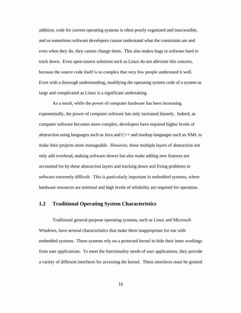
addition, code for current operating systems is often poorly organized and inaccessible,
and so sometimes software developers cannot understand what the constraints are and
even when they do, they cannot change them. This also makes bugs in software hard to
track down. Even open-source solutions such as Linux do not alleviate this concern,
because the source code itself is so complex that very few people understand it well.
Even with a thorough understanding, modifying the operating system code of a system as
large and complicated as Linux is a significant undertaking.
As a result, while the power of computer hardware has been increasing
exponentially, the power of computer software has only increased linearly. Indeed, as
computer software becomes more complex, developers have required higher levels of
abstraction using languages such as Java and C++ and markup languages such as XML to
make their projects more manageable. However, these multiple layers of abstraction not
only add overhead, making software slower but also make adding new features not
accounted for by these abstraction layers and tracking down and fixing problems in
software extremely difficult. This is particularly important in embedded systems, where
hardware resources are minimal and high levels of reliability are required for operation.
1.2 Traditional Operating System Characteristics
Traditional general-purpose operating systems, such as Linux and Microsoft
Windows, have several characteristics that make them inappropriate for use with
embedded systems. These systems rely on a protected kernel to hide their inner workings
from user applications. To meet the functionality needs of user applications, they provide
a variety of different interfaces for accessing the kernel. These interfaces must be general
17
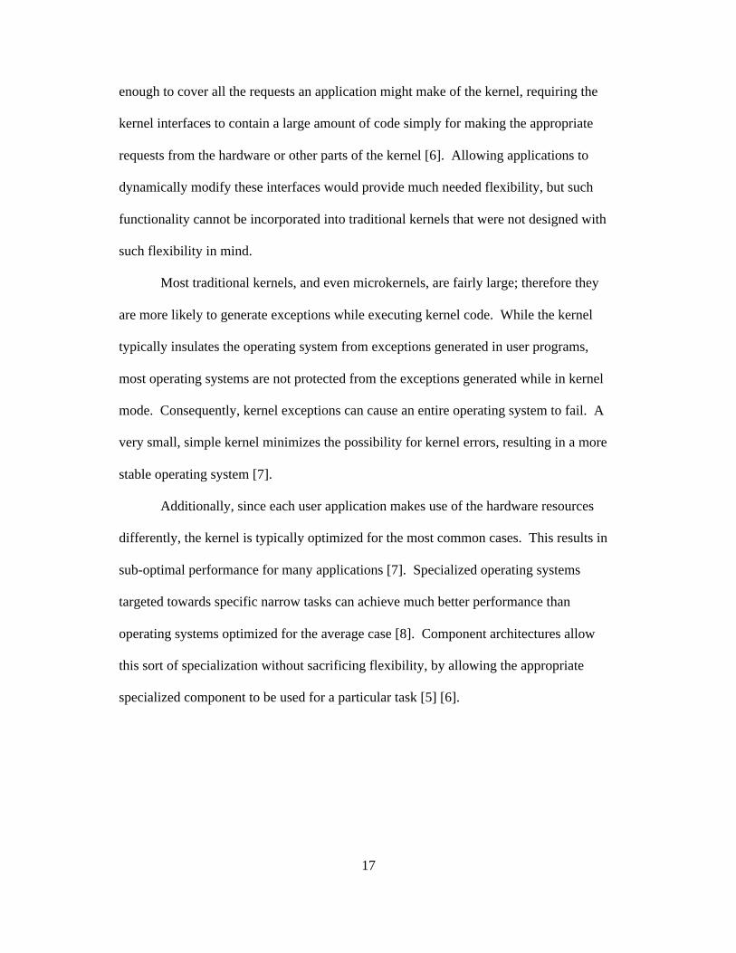
enough to cover all the requests an application might make of the kernel, requiring the
kernel interfaces to contain a large amount of code simply for making the appropriate
requests from the hardware or other parts of the kernel [6]. Allowing applications to
dynamically modify these interfaces would provide much needed flexibility, but such
functionality cannot be incorporated into traditional kernels that were not designed with
such flexibility in mind.
Most traditional kernels, and even microkernels, are fairly large; therefore they
are more likely to generate exceptions while executing kernel code. While the kernel
typically insulates the operating system from exceptions generated in user programs,
most operating systems are not protected from the exceptions generated while in kernel
mode. Consequently, kernel exceptions can cause an entire operating system to fail. A
very small, simple kernel minimizes the possibility for kernel errors, resulting in a more
stable operating system [7].
Additionally, since each user application makes use of the hardware resources
differently, the kernel is typically optimized for the most common cases. This results in
sub-optimal performance for many applications [7]. Specialized operating systems
targeted towards specific narrow tasks can achieve much better performance than
operating systems optimized for the average case [8]. Component architectures allow
this sort of specialization without sacrificing flexibility, by allowing the appropriate
specialized component to be used for a particular task [5] [6].

18
1.3 VORTOS Overview
The Versatile Object-oriented Real-Time Operating System (VORTOS)
overcomes the aforementioned limitations of traditional operating systems, by
minimizing the kernel code and providing the flexibility to allow specialization of the
operating system on a per-process basis. VORTOS is a real-time operating system with a
component-based architecture, allowing it to be adaptable to a wide-range of
environments and applications. It is highly scalable; it can be used in systems ranging
from embedded systems to high-end workstations to a distributed network of machines.
The component-based nature of VORTOS allows it to take advantage of whatever power
the underlying hardware has to offer. Specialized components can be added for
additional functionality or efficiency. It can satisfy real-time constraint requirements for
mission-critical operations, making it particularly suited for embedded applications. Its
modular structure can adapt to changing conditions to best meet the needs of its users.
For embedded applications, unnecessary components can be removed for a smaller
memory footprint and application-specific components can be used to optimize
performance. The kernel is extremely small and simple, providing a stable system.

19
Additional Components
SchedulerComponent
MemoryManagementComponent
CompilerComponent
Virtual Machine
Hardware Platform
Figure 1.3.1: Logical layers of VORTOS architecture
VORTOS consists of a collection of objects running on a simple virtual machine
that provides an abstraction layer between the objects and the underlying hardware
platform. Figure 1.3.1 graphically illustrates the logical layers of the VORTOS
architecture. The operating system functions and user programs running on the virtual
machine are made up of a collection of objects called components that contain code and
data. Components are run-time objects that provide specific services or functionality on a
given resource or data. For example, a memory management component allocates and
deallocates memory to programs in the address space it corresponds to. Since the
operating system functionality is implemented as a set of simple low-level components,
applications can choose the components that provide the exact functionality that they
need, providing maximum flexibility. User applications can also provide additional
custom components to more efficiently take advantage of specific low-level hardware
resources, thereby enhancing the functionality of the entire system.
The Portable Virtual Machine Format (PVMF) virtual machine acts as a very
simple kernel. The PVMF virtual machine provides a simple abstraction of the hardware
and simple services that allow the multiplexing of processor time across any number of

20
different local or remote components, while satisfying any real-time constraints
requested. Using a virtual machine provides binary compatibility for the components
across different hardware platforms. Therefore, VORTOS can be ported to new hardware
by simply porting the virtual machine. This gives software the flexibility to run on a
wide variety of platforms and even allows VORTOS to be embedded into existing
operating systems. It also provides maximum stability against errors in both application
and operating system components, since individual components can be shut down or
replaced without crashing the entire operating system.
1.4 Thesis Overview and Contributions
The main contribution of this thesis is VORTOS, a general-purpose system that
can provide customized functionality for each application. This custom functionality
allows specialized applications to run efficiently, without impeding the efficient
operation of other applications that do not require these specialized resources. The key to
this flexibility is a new form of dynamic messaging architecture integrated with a
component-based architecture running on top of a virtual machine. This thesis describes
VORTOS, the various components of its architecture, and how they fit together to
produce a flexible, scalable system.
Chapter 2 discusses related work to VORTOS. Chapter 3 gives an overview of
the component architecture and virtual machine used to provide a flexible, scalable
system. The instruction set architecture used by the virtual machine is detailed in
Chapter 4. Chapter 5 introduces a unique dynamic messaging architecture that is
responsible for providing the high level of flexibility and customizability of VORTOS.

21
Chapter 6 describes the essential operating system components and how they work
together to create a usable system that allows easy substitution of policies and dynamic
filtering of programmatic content. Chapter 7 discusses the compiler sub-system and how
machine code generated by a commercial off-the-shelf compiler is translated into usable
virtual machine code by the system. Chapter 8 describes an implementation of the
system and the simplicity benefits in implementation provided by the VORTOS
architecture. Chapter 9 presents conclusions and suggests future work.

22

23
Chapter 2
Related Work
Since operating systems cover a broad area of computer science research, there is
a large amount of related work in this area, and thus a large amount of overlapping
research. This chapter reviews several approaches used to address the problems of
embedded systems and operating system software in general. Section 2.1 looks at prior
component-based solutions. Section 2.2 reviews customizable software approaches.
Section 2.3 explores the abstraction provided by virtual machines. Section 2.4 looks at
some translation and recompilation resources for compatibility.
2.1 Component-based Software
Component-based operating systems have a long history. UNIX itself was
formed based on the idea of modular components, separating out functionality into a
kernel, various user-level utility programs, and libraries of code, with all components
using a portable source language, C [1]. However, UNIX suffers from the flexibility and
efficiency problems of traditional operating systems described earlier in Section 1.2.
In the early 1990’s, Taligent created an operating system known as Pink that was
based completely around autonomous components generated from C++ classes [2].
Although this provided increased flexibility, the overhead from the run-time
manipulation of C++ classes resulted in significant performance degradation [2].
24
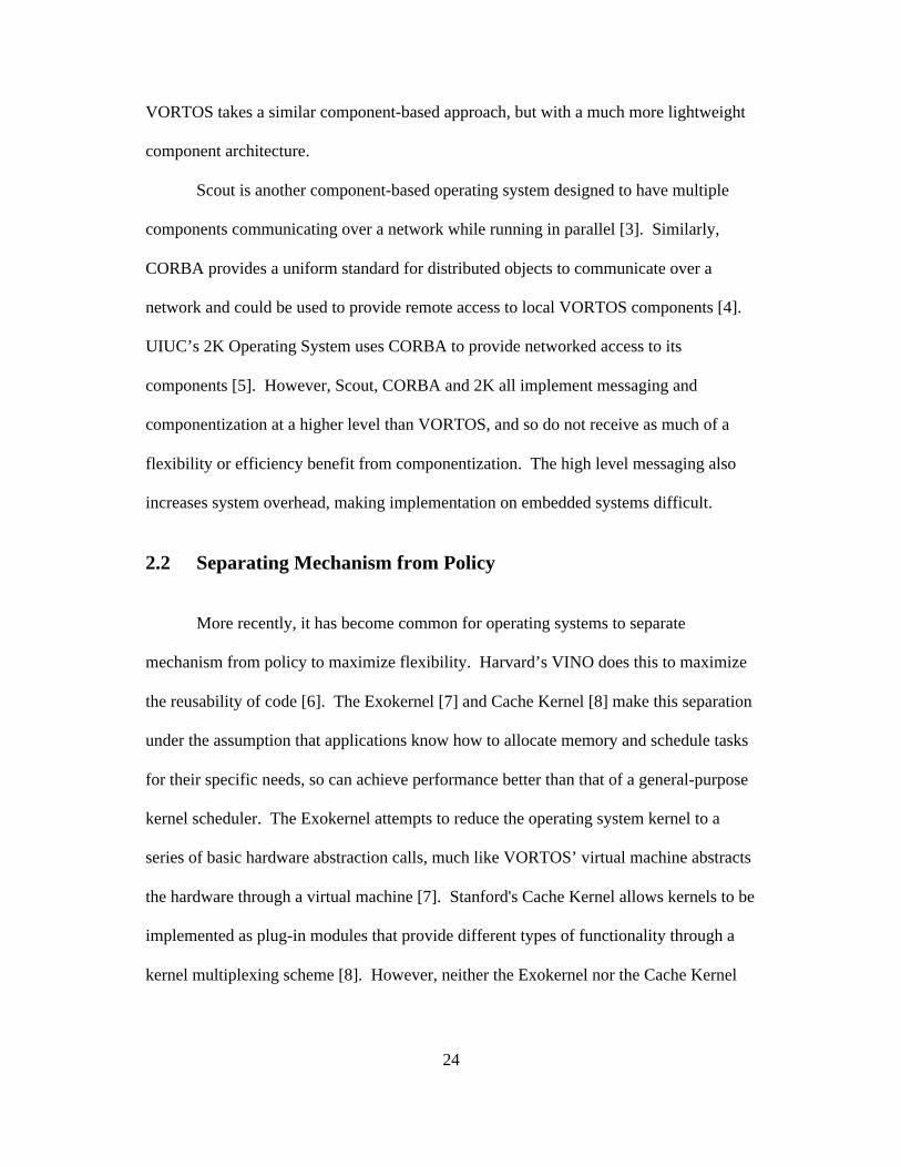
VORTOS takes a similar component-based approach, but with a much more lightweight
component architecture.
Scout is another component-based operating system designed to have multiple
components communicating over a network while running in parallel [3]. Similarly,
CORBA provides a uniform standard for distributed objects to communicate over a
network and could be used to provide remote access to local VORTOS components [4].
UIUC’s 2K Operating System uses CORBA to provide networked access to its
components [5]. However, Scout, CORBA and 2K all implement messaging and
componentization at a higher level than VORTOS, and so do not receive as much of a
flexibility or efficiency benefit from componentization. The high level messaging also
increases system overhead, making implementation on embedded systems difficult.
2.2 Separating Mechanism from Policy
More recently, it has become common for operating systems to separate
mechanism from policy to maximize flexibility. Harvard’s VINO does this to maximize
the reusability of code [6]. The Exokernel [7] and Cache Kernel [8] make this separation
under the assumption that applications know how to allocate memory and schedule tasks
for their specific needs, so can achieve performance better than that of a general-purpose
kernel scheduler. The Exokernel attempts to reduce the operating system kernel to a
series of basic hardware abstraction calls, much like VORTOS’ virtual machine abstracts
the hardware through a virtual machine [7]. Stanford's Cache Kernel allows kernels to be
implemented as plug-in modules that provide different types of functionality through a
kernel multiplexing scheme [8]. However, neither the Exokernel nor the Cache Kernel

25
provides the same level of functionality realized by VORTOS’ general-purpose uniform
component architecture. Rather than simply allow customization of basic hardware
kernels, VORTOS goes a step further by allowing the customization of every aspect of
the operating system and applications running on it.
2.3 Virtual Machines
Virtual machine architectures have been around for quite some time, and are quite
useful for process migration. FLUX-OS is an operating system that supports application-
specific and recursive virtual machines. These virtual machines can be customized on a
per-application basis to provide specialized functionality [9]. However, having a separate
virtual machine for each customized scenario has too large a footprint for many
embedded systems. The Spin operating system allows processes to migrate application-
specific functionality into kernel space, allowing user applications to supplement but not
replace kernel functionality [10]. Hope is an operating system that runs on parallel
virtual machines and uses optimistic prediction to maximize parallelism, but does not
provide any form of customized functionality [11]. Virtual machines such as Sun
Microsystem’s Java and Synthetix are high-level virtual machines that can generate code
at run-time for faster execution [12]. By combining a virtual machine with a component
architecture, VORTOS obtains the functionality and efficiency benefits of both
approaches.

26
2.4 Translation Technologies
Dynamic recompilation has become a popular approach for overcoming some of
the performance limitations of virtual machine architectures such as Java and Synthetix
[12]. Dynamic recompilation is common among game console emulators for
performance reasons. These systems use dynamic recompilation to speed up execution of
virtual machine code by translating it into machine code for the underlying native
hardware processor on-the-fly. Apple uses dynamic recompilation on its PowerPC
computers to provide compatibility with software written for older Motorola 68000
processors [14]. Digital developed an i386 to Alpha translator for similar compatibility
reasons [15]. UQBT is a general-purpose retargetable binary translator for general binary
code translation. It performs static binary translation for better optimization and to avoid
delays at run-time [16]. VORTOS is built with a similar, but more specific binary
translator tailored specifically for the virtual machine architecture used in VORTOS.

27
Chapter 3
VORTOS Overview
This chapter provides a general overview of VORTOS by describing its three
main parts involved in its operation: the components, the virtual machine, and the
recompiler sub-system. Section 3.1 describes the components that provide the operating
system functionality to the applications. Section 3.2 explains the virtual machine that
these components run on top of. Section 3.3 describes the translation mechanism used to
compile the components into compatible virtual machine code.
3.1 Components
VORTOS is a purely component-based operating system. All functionality,
including memory management, multitasking, and context switching, which are
traditionally included in the kernel, are contained in components. Components contain
header information, executable instructions, and data. Component functionality is
described in general terms to VORTOS by means of the class code, type code, and
implementation code associated with each component. The class code indicates the
general functional class of the object, for example, a class code of 'fsys' indicates that a
component is a file system and a class code of 'memm' indicates the component is a
memory management component. There are five basic class codes defined within
VORTOS as shown in Table 3.1.1.

28
Table 3.1.1: Common Class CodesComponent Name Class Code
Loader 'load'
Scheduler 'sche'
Memory Manager 'memm'
Disk Driver 'ddrv'
Filesystem 'fsys'
File Storage Component 'stor'
The type code indicates the functional subclass or specific type within the general
functional class of a given component. For example, a type code of 'ext2' indicates that a
component is an ext2 file system component, and a type code of 'page' indicates a page-
based memory management component. There are eight basic type codes defined within
VORTOS as shown in Table 3.1.2.
Table 3.1.2: Common Type CodesComponent Name Type Code
Loader 'load'
Scheduler 'sche'
Object-oriented Memory Manager 'oomm'
Page-based Memory Manager 'page'
SCSI Driver 'scsi'
IDE Driver 'ide '
Ext2 Filesystem 'ext2'
NTFS Filesystem 'ntfs'
XFS Filesystem 'xfs '
File Storage Component 'stor'
The implementation code contains a unique identifier for the component. It is
similar to the Universal Product Code (UPC) in that it uniquely identifies the author of

29
the component, and allows every author to have multiple uniquely identified versions of
the same component. For shared usage, these codes should be assigned by a central
authority or group, similarly to the distribution of IP addresses. All of the components
developed as part of this thesis have an implementation code of zero.
Page-based MemoryManager
SCSIDriver
IDEDriver
SchedulerComponent
Ext2NT
FSXFS
Object-orientedMemory Manager
File StorageComponent
Figure 3.1.3: Some Example Components
Figure 3.1.3 provides some example components and Table 3.1.4 shows their
associated class codes, type codes, and implementation codes.
Table 3.1.4: Example CodesComponent Name Class Code Type Code Implementation Code
Page-based Memory Manager 'memm' 'page' 0x00000000
Object-oriented Memory Manager 'memm' 'oomm' 0x00000000
Scheduler 'sche' 'sche' 0x00000000
SCSI Driver 'ddrv' 'scsi' 0x00000000
IDE Driver 'ddrv' 'ide ' 0x00000000
Ext2 Filesystem 'fsys' 'ext2' 0x00000000
NTFS Filesystem 'fsys' 'ntfs' 0x00000000
XFS Filesystem 'fsys' 'xfs ' 0x00000000
File Storage Component 'stor' 'stor' 0x00000000
30
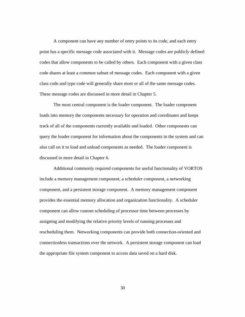
A component can have any number of entry points to its code, and each entry
point has a specific message code associated with it. Message codes are publicly defined
codes that allow components to be called by others. Each component with a given class
code shares at least a common subset of message codes. Each component with a given
class code and type code will generally share most or all of the same message codes.
These message codes are discussed in more detail in Chapter 5.
The most central component is the loader component. The loader component
loads into memory the components necessary for operation and coordinates and keeps
track of all of the components currently available and loaded. Other components can
query the loader component for information about the components in the system and can
also call on it to load and unload components as needed. The loader component is
discussed in more detail in Chapter 6.
Additional commonly required components for useful functionality of VORTOS
include a memory management component, a scheduler component, a networking
component, and a persistent storage component. A memory management component
provides the essential memory allocation and organization functionality. A scheduler
component can allow custom scheduling of processor time between processes by
assigning and modifying the relative priority levels of running processes and
rescheduling them. Networking components can provide both connection-oriented and
connectionless transactions over the network. A persistent storage component can load
the appropriate file system component to access data saved on a hard disk.

31
All of these components run in their own user-level address-space, so that if one
component crashes, it can be killed or reloaded as appropriate without bringing down the
rest of the system. This also allows the "hot-swapping" of components when desired.
Since the core parts of a traditional kernel are all implemented within components, even
these parts of the operating system receive the benefits of this protection. If the memory
manager somehow accesses an invalid address and triggers a memory protection fault,
the virtual machine will notify the scheduler, which will restart the memory management
component.
3.2 Virtual Machine
All components run on top of a virtual machine that provides inter-component
messaging facilities. The virtual machine can be viewed as a very simple kernel,
somewhat similar to the kernel in the Cache Kernel [8] or Exokernel [7] systems. Each
task is assigned a dynamic priority level by the operating system. A component may
have several corresponding tasks. The virtual machine executes tasks in a round-robin
fashion among those tasks with the highest priority. The scheduler component adjusts
these priorities as necessary and helps ensure that real-time tasks meet their deadlines.
The virtual machine also dispatches messages to components and vectors interrupts and
exceptions to the appropriate components. A unique identification number assigned by
the loader component when a component is first loaded identifies the target component of
a message.
By using a virtual machine, VORTOS components can run on a wide variety of
platforms, and even from within other operating systems, without modification. Only the
virtual machine implementation itself needs to be ported, and since it is an extremely

32
simple virtual machine with a simple instruction set as described in Chapter 4, it can be
easily ported to virtually any hardware or software platform, even those with minimal
resources such as embedded systems.
The virtual machine contains a built-in debugger that can be used to pause and
step through execution of PVMF instructions. Also it can display and disassemble
instructions and data in memory, and display the contents of all of the registers of the
virtual machine. The low-level facilities of the debugger make it easier to diagnose and
debug even very fundamental components of the operating system.
3.3 Recompiler Sub-system
VORTOS includes a recompiler sub-system that translates instructions from
foreign instruction set architectures to the PVMF instructions. The recompiler is not part
of the operating system itself, but is used for translating code during software
development. It allows code to be developed on existing platforms, alleviating the need
for a VORTOS-specific compiler. The recompiler reads in the compiled instructions
from the code generated by the foreign compiler one by one and replaces each one with
the corresponding PVMF instructions. Since the assumptions made by foreign processors
are different from those made by the VORTOS virtual machine, several extra control
instructions are sometimes necessary for a single foreign instruction. Sometimes it may
be necessary to save values stored in registers in foreign code on the stack temporarily in
PVMF code if there are not enough registers available. On the flip side, frequently
accessed variables currently stored on the stack in the foreign code can be stored in
registers in the PVMF code as an optimization when there are extra registers available.

33
Additionally, memory references need to be offset by the proper amounts to contain their
proper values in the generated PVMF code. The recompiler sub-system is described in
more detail in Chapter 7.

34

35
Chapter 4
Virtual Machine Architecture
This chapter details the general architecture of the 32-bit Portable Virtual
Machine Format (PVMF-32) virtual machine. Section 4.1 describes the memory address
model and architecture of the virtual machine itself. Section 4.2 describes the PVMF-32
instruction set. Section 4.3 explains the interrupt architecture used by the virtual
machine. The exception model is detailed in Section 4.4. Section 4.5 describes the
multitasking model. Section 4.6 describes the debugger built into the virtual machine.
Section 4.7 provides an analysis of the design features of the virtual machine.
4.1 PVMF-32 Overview
The PVMF-32 virtual machine is a virtual 32-bit processor with a very simple
RISC-like instruction set. The PVMF-32 is register-based, with a 32-bit address space.
PVMF-32 has 16 primitive operations that operate on some combination of integer
registers, floating-point registers, and 16-bit constant values. An architectural diagram of
the virtual machine is shown in Figure 4.1.1.

36
Figure 4.1.1: The Virtual Machine
The virtual machine has 31 general-purpose 32-bit integer registers named r0-r30
and 31 general-purpose 64-bit floating-point registers named fpr0-fpr30. Each of the 64-
bit floating-point registers conforms to the IEEE 754 standard for double-precision
floating-point numbers. An additional integer register (r31) and an additional floating-
point register (fpr31) always contain a value of zero. The current implementation of the
virtual machine uses the 32-bit integer register (r30) as a pointer to the base of the current
stack. The virtual machine operates solely in big-endian mode.
ProgramCounter
Intruction Fetch
ALU
32 IntegerRegisters
32 Floating-point
Registers
Memory
Load/Store
37
Root node of memory map
0x1000 Physical memory block start address4096 Physical memory block lengthr,w Permissions on memory block
0x1000 Start address of block in component address space0x2000 End address of block in component address space
Address map of memory below0x1000 in component address space
Address map of memoryabove 0x2000 in component
address space0x5000 Physical memory block
start address0xC000 Physical memory
block start address1024 Physical memory block
length2048 Physical memory
block lengthr,w Permissions on memory
blockr Permissions on
memory block0x0C00 Start address of block in
component address space0x2000 Start address of
block in componentaddress space
0x1000 End address of block incomponent address space
0x2800 End address ofblock in component
address space
Address map ofmemory below0x0C00 incomponent addressspace
Address map ofmemory between
0x1000 and 0x1000in componentaddress space
Address map ofmemory between
0x2000 and 0x2000in componentaddress space
Address map ofmemory above
0x2800 incomponent address
spaceNULL NULL NULL NULL
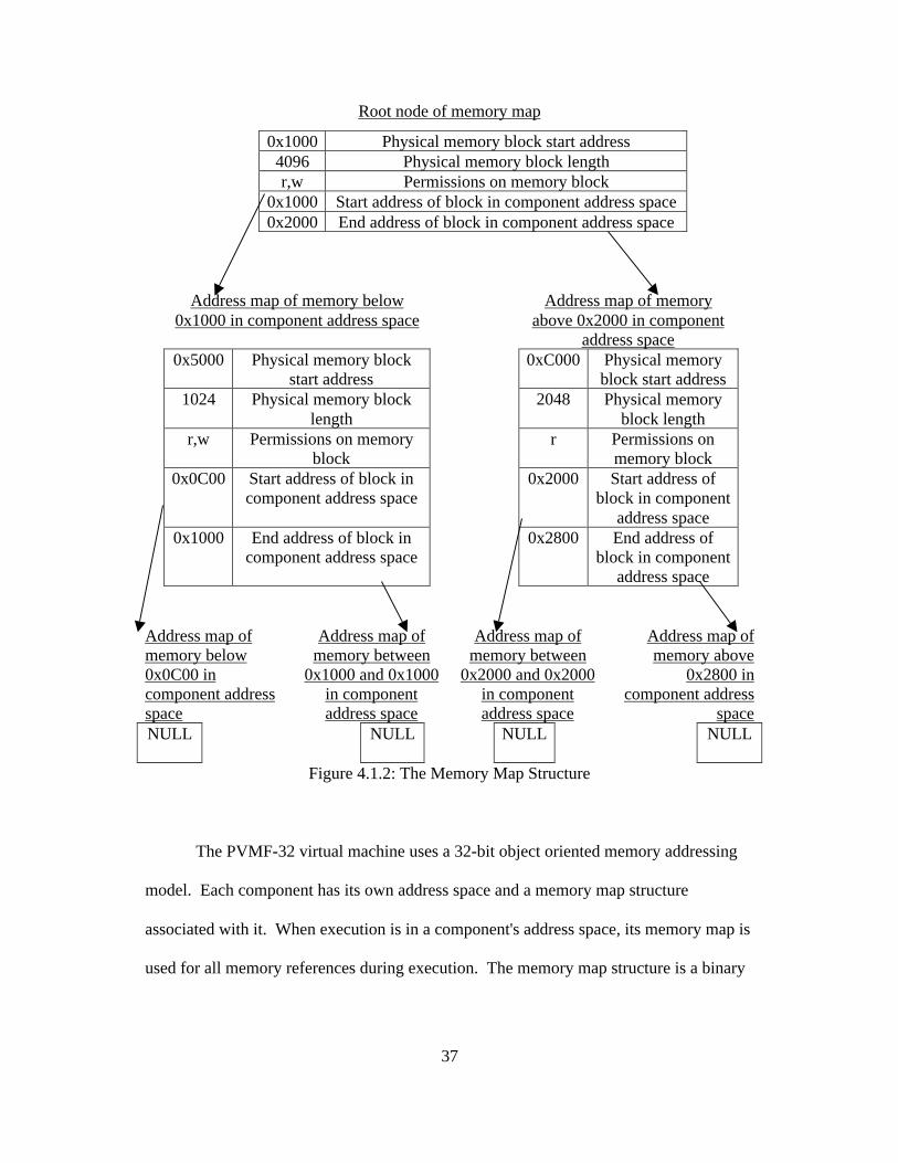
Figure 4.1.2: The Memory Map Structure
The PVMF-32 virtual machine uses a 32-bit object oriented memory addressing
model. Each component has its own address space and a memory map structure
associated with it. When execution is in a component's address space, its memory map is
used for all memory references during execution. The memory map structure is a binary
38
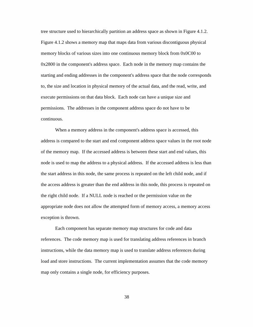
tree structure used to hierarchically partition an address space as shown in Figure 4.1.2.
Figure 4.1.2 shows a memory map that maps data from various discontiguous physical
memory blocks of various sizes into one continuous memory block from 0x0C00 to
0x2800 in the component's address space. Each node in the memory map contains the
starting and ending addresses in the component's address space that the node corresponds
to, the size and location in physical memory of the actual data, and the read, write, and
execute permissions on that data block. Each node can have a unique size and
permissions. The addresses in the component address space do not have to be
continuous.
When a memory address in the component's address space is accessed, this
address is compared to the start and end component address space values in the root node
of the memory map. If the accessed address is between these start and end values, this
node is used to map the address to a physical address. If the accessed address is less than
the start address in this node, the same process is repeated on the left child node, and if
the access address is greater than the end address in this node, this process is repeated on
the right child node. If a NULL node is reached or the permission value on the
appropriate node does not allow the attempted form of memory access, a memory access
exception is thrown.
Each component has separate memory map structures for code and data
references. The code memory map is used for translating address references in branch
instructions, while the data memory map is used to translate address references during
load and store instructions. The current implementation assumes that the code memory
map only contains a single node, for efficiency purposes.

39
Upon startup, the virtual machine starts by clearing all values in all registers to
zero and loading a ram image from disk. The ram image contains the initial state of all
memory in the virtual machine, including the initial code to run. The virtual machine sets
up the interrupt queue and installs a generic timer interrupt handler that generates a
rescheduling message. The virtual machine then sets up the stack and memory map
structures for the initial thread and starts executing instructions sequentially at the
program counter. Since the program counter is zero at initialization time, this means the
execution begins with the instruction at memory address zero. In most cases, this will be
the code for the loader component described in Section 6.1.
4.2 Instruction Set
The primitive instructions of the PVMF-32 virtual machine include addition,
subtraction, multiplication, division, bitwise-AND, bitwise-OR, bitwise-XOR, bitwise-
rotation, loading a register from memory, storing a register in memory, absolute and
relative conditional branching, and comparison instructions. Table A.1 in Appendix A
lists all of the PVMF-32 instructions, their assembly mnemonics, and their effects. In
The following notation is used to describe the instructions: rX represents an integer
register, fprX represents a floating-point register, CONST represents a 16-bit integer
constant, and PC is the current address the virtual machine is executing. Note that 16-bit
integer constants are used for both floating-point and integer instructions.

40
Register-based instruction
OpCode(8 bits)
Res-erved
(3bits)
RegisterFirst
Argument(5 bits)
RegisterResult(5 bits)
Reserved(6 bits)
RegisterSecond
Argument(5 bits)
Immediate Instruction
OpCode(6 bits)
RegisterResult(5 bits)
RegisterFirst
Argument(5 bits)
Constant Second Argument(16 bits)
Figure 4.2.1: Instruction Formats
Figure 4.2.1 shows the two different formats of instructions. The first argument
to an instruction and the result are always registers, while the second argument can either
be a register or a 16-bit constant depending on which format the instruction is in.
Register-based instructions have an extra two bits in their opcodes, so some of the entries
in the hash table of the virtual machine jump to the code to execute the same immediate
instructions.
There are two special instructions for message passing. These instructions are
called by components to interact with other components. The only ways components
interact are through one of these two instructions, Send Message or Fork Message. Each
type of component has a number of well-defined message codes that can be passed in a
register to the message instruction to indicate to the virtual machine which function of a
component to jump to. Another register contains the local identification number of the
component to send the message to. The versatility of the message passing instructions is
explored in detail in Section 5.
41
The Send Message instruction calls the message in the object indicated by the
values in the registers used as arguments for the Send Message instruction. This
instruction transfers control of the processor to the function with the specified message
code in the specified object, until a return message is sent to object ID 0. The virtual
machine intercepts all return messages to object ID 0 and returns control of execution to
the original caller at the instruction just after the Send Message instruction. The result of
the message call is placed in the register specified in the Send Message instruction's final
argument.
The Fork Message instruction performs the same actions as the Send Message
instruction. However, instead of transferring control to the destination object, a new
thread is created which begins execution at the function with the specified message code
in the destination object. This new thread executes simultaneously at the same priority
level as the original thread, while the original thread continues to execute the instructions
following the Fork Message instruction without waiting for a result from the called
object.
4.3 Interrupts
Components can send messages to the loader to register and remove interrupt
handlers. The loader maintains a list of all currently registered interrupt handlers. When
an interrupt occurs, the virtual machine saves the information passed to its generic
interrupt handler in a queue. Adding new entries to the queue is done in such a way to
place a very small hard upper bound on the amount of time spent adding entries to the
queue, at the expense of possibly losing interrupts if they are not handled quickly enough.

42
Since hardware can only store a fixed number of interrupts at a time, this is a danger in
any case, so this is unlikely to be a problem in practice.
Between instructions, when the virtual machine is in a synchronized and well-
defined state, the queue is emptied and for each of the entries in the queue, the virtual
machine sends a message to each component that has an interrupt handler registered for
the interrupt that created that entry. These messages are sent using the same mechanism
described for the Fork Message instruction in Section 4.2 so that they can be processed in
parallel with each other and other ongoing processes. However, the newly spawned
threads for forking these new messages to the appropriate components are given a special
high priority value, so that they will get processed before further execution. In most
cases, this means that these interrupts will all be handled completely before the rest of the
processes resume execution, unless the interrupt handlers block, in which case other
processes will continue execution normally as long as there is no higher priority process
active.
4.4 Exception Handling
The exception handling mechanism for the virtual machine is fairly simple. The
virtual machine inserts a special exception handler to be called by the underlying
hardware the virtual machine is running on whenever a hardware exception occurs. An
exception is also thrown if code running on the virtual machine attempts to execute an
illegal instruction or access memory out of bounds. When the exception handler is
called, it sets a boolean flag in the virtual machine's global memory space. Setting this
flag when it is already set has no effect, so that redundant exceptions are not generated by

43
the code that generated an exception before the initial exception is handled. The virtual
machine periodically checks to see if the flag is set and if it is, it sets another flag and
transfers execution to the exception handling message in the component that generated
the exception. If the second flag is already set or if that component has no exception
handling message, control is transferred to a routine in the loader to forcibly unload the
offending component. These checks only occur at safe points in between instructions, so
that the virtual machine will not be left in an invalid or unsynchronized state when
control is transferred.
4.5 Threads
The virtual machine allows multiple threads of execution to run simultaneously.
Each thread has a positive numerical priority associated with it. All ready threads with
the highest priority level are rotated through in a round-robin fashion. Every tenth of a
second, the virtual machine suspends the current thread and register context and loads the
thread and context with the highest priority. This interval can be changed as desired by
the operating system. If multiple threads have the same priority, and it is the highest
priority of any active thread, the thread with the highest priority that has not run for the
longest time interval is loaded. The tenth of a second timer is then reset and control of
the processor is transferred to the newly loaded thread. When the virtual machine starts,
it loads a special thread called the idle thread. The idle thread does nothing but
continuously loop. It has a priority of zero, the lowest priority of any thread, so that it
will only execute when no other threads are active. Using an idle thread simplifies the
scheduling algorithm since it ensures that at least one thread is always ready to run.

44
Each thread has a dynamically resizable stack associated with it. Local data such
as stack frames for functions and local variables can be stored on this stack.
0xFC VAddress return stack pointer
0xF8 VAddress return stack base
0xF4 VAddress return code offset
0xF0 VAddress return objectID
stack base addr -> 0xEC local stack data
0xE8 local stack data
stack pointer -> 0xE4 local stack data
Figure 4.5.1: Stack Layout in Memory
The layout of the stack is shown in Figure 4.5.1. The current implementation uses
register r30 for the stack pointer and register r29 for the stack base address. The base
address will always be higher than the stack pointer, because the stack grows downwards.
When a message instruction occurs, the virtual machine saves the current stack pointer,
stack base address, the address of the following instruction, and the calling object's ID
number on the stack. The stack base is set to the address of the current stack pointer after
all this information has been stored on the stack. The data address space of the called
object is modified to include the new stack, starting from the new stack base. If stack
space is running low, this can be used to continue the stack in another portion of memory
by storing the stack's information in the new portion of memory rather than right on the
current stack, then updating the stack pointer and base and to point to the new portion of

45
memory, right below the stored information. The new object will normally not have
access to any of the stack information from the calling object.
4.6 Debugger
This implementation of the virtual machine includes a built-in debugger for
tracing problems during program and operating system development. The virtual
machine can display windows showing the current values of every register for each CPU
currently executing.
Figure 4.6.1: Virtual Machine Register Window
When the value of a register changes, that register is briefly highlighted in red as
shown with the program counter in Figure 4.6.1 to provide visual feedback when
registers are modified. The state of the virtual machine's RAM can be examined in a hex
dump as seen in Figure 4.6.2.

46
Figure 4.6.2: Hexadecimal Dump of Virtual Machine RAM
The user can either execute instructions continuously or halt execution and step
through one instruction at a time on command. The currently executing instruction is
marked in the disassembly window. This window, shown in Figure 4.6.3, provides a
disassembly of the RAM using the assembly mnemonics listed in Appendix A.
Figure 4.6.3: Virtual Machine RAM Disassembly

47
4.7 Design Analysis
By using a virtual machine, VORTOS components can run on a wide variety of
platforms, and even from within other operating systems, without modification. Only the
virtual machine implementation itself needs to be ported, and since it is an extremely
simple virtual machine with a simple instruction set, it can easily be ported to virtually
any hardware or software platform, even those with minimal resources.
Keeping the virtual machine instruction set small and simple also keeps the
footprint of the virtual machine small. The low-level, register-based architecture of the
virtual machine avoids the overhead commonly incurred by higher levels of abstraction.
The simple RISC-style instruction set provides low-level primitives that can be
efficiently implemented on any modern hardware processor. This is particularly
important for embedded systems with limited hardware resources available.
Furthermore, these low-level primitives do not constrain higher level applications, since
they only perform the basic arithmetic functions. Higher level abstractions often limit
functionality and performance because they constrain data representations to a given
form. Data and programs that do not fit the artificially constructed abstractions well may
be awkward to implement and less efficient. The design impact of the special messaging
instructions is explored more fully in Chapter 5.
The PVMF-32 virtual machine is a 32-bit processor. Since most modern
microprocessors use either 32 or 64 bit registers and addressing, most processors should
be able to handle the 32-bit virtual machine quite naturally. At the same time, since most
embedded processors currently in use have 32 bit registers and addressing, using a 64-bit
virtual machine would unnecessarily increase the size of the system. Since few
48
embedded systems have more than the four gigabytes of memory addressable by a 32-bit
processor anyway, requiring them all to use 64-bit addressing would just be a waste of
space or processing power. Furthermore, the architecture of the virtual machine and
operating system is portable enough that a 64-bit virtual machine could be implemented
if desired. PVMF-32 code could be translated to run on a 64-bit virtual machine with
little difficulty using methods similar to those described in Chapter 7.
Using 64-bit floating-point registers that conform to the IEEE 754 double-
precision standard was a logical choice, since this format is commonly used among
modern floating-point processors and can be emulated using multiple 32-bit registers if
necessary. 16-bit integer constants are used with both integer and floating-point
instructions, since 16-bits is enough space to represent many common integral values but
most floating-point numbers that are not integers require more than 16 bits of precision.
Immediate instructions and register-based instructions have different formats to
accommodate the 16-bit arguments used by immediate instructions. Two of these bits are
used by register-based instructions to further differentiate between instructions, allowing
additional register-based instructions.
The virtual machine runs in big-endian mode. This means it works well with big-
endian processors, but it will also work with little-endian processors. However, little-
endian implementations of the virtual machine will need to swap the byte order of words
from memory after every load and before every store instruction. This may cause a very
small performance overhead to be incurred on little-endian machines. Note however, that
little-endian processors face a similar situation when transmitting data over most
networks, since TCP/IP stores data in big-endian byte order.

49
Since each component has its own code and data address spaces, the virtual
machine can easily enforce per-component memory isolation, to prevent one component
from illegally writing to the memory of another. The ability to map memory to a
component's address space arbitrarily allows more flexibility in implementing memory
allocation schemes, since memory blocks can be discontinuous and scattered throughout
memory in any arbitrary fashion. Furthermore, since these addresses are virtual
addresses, the memory manager can perform defragmentation of memory blocks
transparently to the application. Components can explicitly share portions of their
memory space with other components by sending the appropriate messages to the
memory management component, which will then map the given memory ranges to the
address spaces of the additional components. Using shared memory allows fast data
transfer between components, but since memory must be explicitly shared illegal
accesses will still be detected. Having separate code and data address spaces allows code
addresses to be marked as executable but not writable or readable, increasing stability and
security by protecting loaded code from malicious or accidental modification. The
assumption that the code address space is continuous both in the address space and in
memory was an optimization that improves the performance of the virtual machine
without placing undue constraints on the software, since situations requiring arbitrary
mapping of the code of simple components are rare since shared objects are accessed
entirely through the messaging instructions. It also places an upper-bound on the amount
of time necessary to fetch instructions from memory. This is important for systems that
require real-time performance. To provide a similar upper-bound on loads and stores to

50
and from the data address space requires limiting the depth of the data memory map tree,
which can be done on a per-component basis by the developer of a component.
The interrupt architecture provides a simple, generic interface for interrupts that
does not disrupt the operating of real-time processes with arbitrary interrupt handlers. At
the same time, the queuing of messages at interrupt time provides a flexible dispatch
mechanism that allows drivers to execute safely and securely in user-mode. Therefore,
errors in drivers can be contained from the rest of the system and drivers can be easily
dynamically loaded and hot-swapped. Since exception handling uses the same
mechanism, these advantages apply to hardware exceptions as well as interrupts.
The threading model employs a simple low-cost scheduling algorithm that can be
used to implement more sophisticated scheduling algorithms. Real-time processes can be
given a higher priority than other processes to help them meet their timing constraints.
The stack architecture isolates stack frames of functions across components, which
provides a higher level of stability. Even if a component corrupts its stack space, the
stack of the calling object will be unaffected. This also prevents common security
problems associated with stack buffer overflows, since the called object cannot access the
return address stored on the stack. Furthermore, since the code address space does not
include the stack, executable code cannot be stored on the stack. Although this may
cause some problems with very machine-specific self-modifying code, it should not
impact most applications and provides added security and stability benefits.
The debugger built into the virtual machine provides useful feedback for
development and allows step-by-step execution, monitoring, and debugging even of the
lowest-level components of the operating system.

51
Chapter 5
Component Architecture
This chapter discusses the component architecture of VORTOS and describes the
way components interact through messaging. The general nature of the component-
oriented messaging system provides a huge amount of flexibility. Section 5.1 describes
the structure of components and their characteristics. Section 5.2 describes the
messaging architecture. Section 5.3 discusses the ramifications and consequences of the
component-oriented messaging approach.
5.1 Component Structure
Components are objects containing code and data, just like executable files for
any modern architecture. The data organization of each component in memory or storage
begins with a header that contains information about how the component is used. The
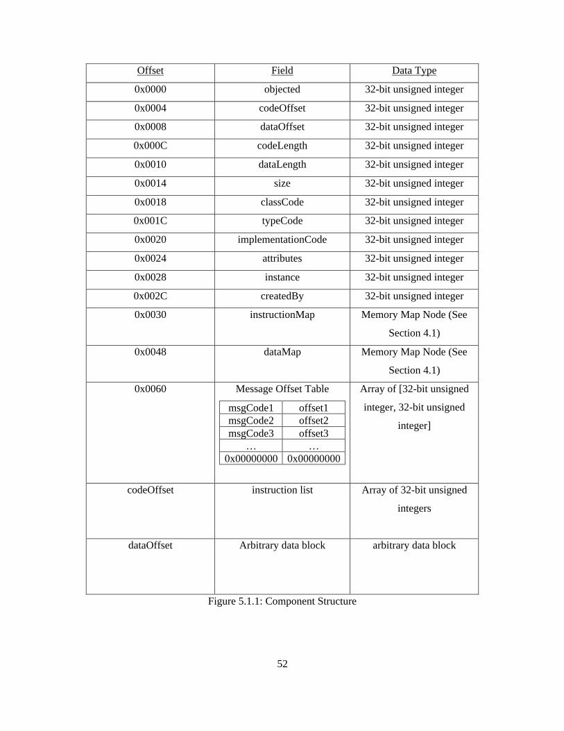
header is followed by a code and data section as shown in Figure 5.1.1.
52
Offset Field Data Type
0x0000 objected 32-bit unsigned integer
0x0004 codeOffset 32-bit unsigned integer
0x0008 dataOffset 32-bit unsigned integer
0x000C codeLength 32-bit unsigned integer
0x0010 dataLength 32-bit unsigned integer
0x0014 size 32-bit unsigned integer
0x0018 classCode 32-bit unsigned integer
0x001C typeCode 32-bit unsigned integer
0x0020 implementationCode 32-bit unsigned integer
0x0024 attributes 32-bit unsigned integer
0x0028 instance 32-bit unsigned integer
0x002C createdBy 32-bit unsigned integer
0x0030 instructionMap Memory Map Node (See
Section 4.1)
0x0048 dataMap Memory Map Node (See
Section 4.1)
0x0060 Message Offset Table
msgCode1 offset1msgCode2 offset2msgCode3 offset3
… …0x00000000 0x00000000
Array of [32-bit unsigned
integer, 32-bit unsigned
integer]
codeOffset instruction list Array of 32-bit unsigned
integers
dataOffset Arbitrary data block arbitrary data block
Figure 5.1.1: Component Structure

53
Each component has an object ID assigned to it when it is loaded into memory.
The objectID field is updated to contain this value when the component is loaded. The
codeOffset and dataOffset fields indicate the offsets from the beginning of the header to
the start of the code and data sections of the component, respectively. Similarly, the
codeLength and dataLength fields indicate the lengths of these sections.
The size field indicates the total size of the component, including the header. The
classCode, typeCode, and implementationCode fields indicate the class code, type code,
and implementation codes of the component, respectively, as defined in Section 3.1. The
attributes field is reserved for future use and is intended to indicate that a component
possesses certain attributes.
The instance field is instantiated with the component is loaded into active
memory. Its value is the number of other components with the same typeCode currently
active at the time the component is started. The createdBy field contains the object ID of
the object that made the call to load this component into active memory. The
instructionMap and dataMap fields contain the code address space and data address
space maps, respectively, as described in Section 4.1.
At the end of the component's header is the message offset table, which contains
an array of paired 32-bit unsigned integers containing a list of message codes and the
corresponding offsets in the component to jump to when those messages occur. These
message codes are similar to class and type codes in that their values correspond to
ASCII strings that indicate their purpose, such as 'open' for the open component message.
The end of the message offset table is indicated by a pair of zero entries in the table, since
54
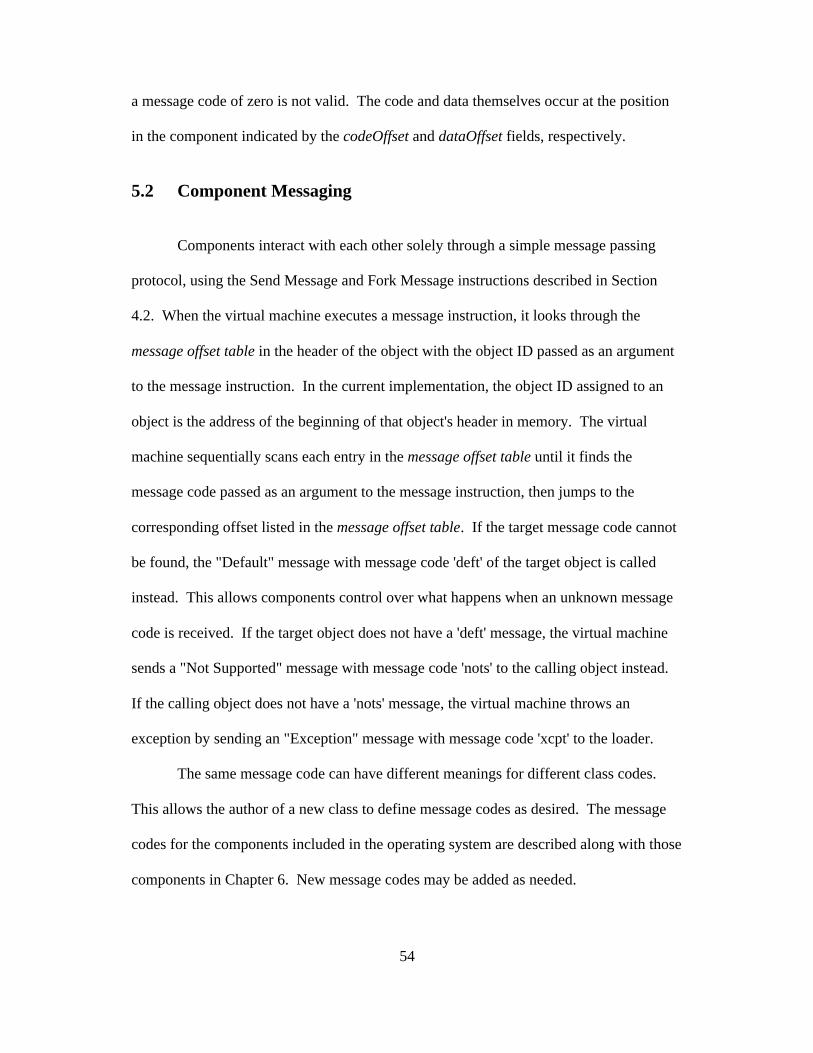
a message code of zero is not valid. The code and data themselves occur at the position
in the component indicated by the codeOffset and dataOffset fields, respectively.
5.2 Component Messaging
Components interact with each other solely through a simple message passing
protocol, using the Send Message and Fork Message instructions described in Section
4.2. When the virtual machine executes a message instruction, it looks through the
message offset table in the header of the object with the object ID passed as an argument
to the message instruction. In the current implementation, the object ID assigned to an
object is the address of the beginning of that object's header in memory. The virtual
machine sequentially scans each entry in the message offset table until it finds the
message code passed as an argument to the message instruction, then jumps to the
corresponding offset listed in the message offset table. If the target message code cannot
be found, the "Default" message with message code 'deft' of the target object is called
instead. This allows components control over what happens when an unknown message
code is received. If the target object does not have a 'deft' message, the virtual machine
sends a "Not Supported" message with message code 'nots' to the calling object instead.
If the calling object does not have a 'nots' message, the virtual machine throws an
exception by sending an "Exception" message with message code 'xcpt' to the loader.
The same message code can have different meanings for different class codes.
This allows the author of a new class to define message codes as desired. The message
codes for the components included in the operating system are described along with those
components in Chapter 6. New message codes may be added as needed.

55
All messages are dispatched to the correct destination by the virtual machine,
allowing messages to be routed to alternate components when desirable. Since messages
are the only form of communication between components, this allows a wide range of
flexibility in the use of components and application-specific components. For example, a
process with a complex memory management scheme can use its own memory
management component instead of using the default system memory management policy
by sending messages to its custom memory management component instead of the
default system component. This allows greater efficiency for applications that wish to do
their own memory allocation. However, this places no additional requirements on other
applications, since they can always use the system’s memory management policy by
default. The preferred components for a given function, such as memory management or
task scheduling can also be specified on a per-application basis if desired, allowing great
flexibility to users and developers alike.
This general message-passing system also allows one or more filters to be applied
to components by redirecting the messages for a target component to a filter component
by assigning the target object's ID to the filter instead. The filter component can supply a
'deft' message that passes any message not specified in the filter on to the target object
while allowing the filter to monitor or modify the arguments or destroy the message as
desired. Furthermore, individual message functions in the filter can provide "wrapper"
functionality, such as a compression filter that automatically compresses the data sent to
it with a "write" message before passing the data to the target object and automatically
decompresses data received from the target object with a "read" message before returning
it to the caller. This allows the compression filter to be applied to any component that

56
reads and writes data with a "read" and "write" message and automatically provides
transparent compression to the target component without any modification. This also
allows the implementation of a simple form of inheritance, where the messages defined in
the filter "override" those of the component the filter is intercepting messages for.
In addition, components can be swapped in and out of the system at run-time
without the need for complex initialization and shutdown procedures by simply routing
the messages to the new component. This rerouting is accomplished by simple assigning
the new component the object ID of the old component. This is particularly useful for
embedded systems, which often require high system availability.
5.3 Design Analysis
By isolating code modules into components and adopting a uniform message-
passing model, VORTOS makes it simple to distribute components across processors,
both locally and across a network. Since components are simply pieces of PVMF code
on the virtual machine, components can even migrate across a heterogeneous network to
a remote system of a different architecture. This means that VORTOS can be run as a
truly distributed operating system, and will easily scale up to large heterogeneous
networks of computer systems. By adding an ORB component to the system,
components can be exported quite naturally as CORBA objects, allowing interoperability
with a wide range of existing networked systems.
This component architecture also makes it simple to scale downwards to
embedded systems and microcontrollers. When space is at a premium, only the essential
components, such as memory management and scheduling, need to be loaded or included

57
with the system. An embedded system with no need for a graphic subsystem can leave
out all the graphical components. If specific functionality is required, the necessary
components can be included in the system. For example, a cell phone’s processor may
need to send data over a wireless network. The wireless driver component and some
networking components could be included to provide this functionality, but since a cell
phone has no hard drive, file system components are unnecessary and can be left out,
making the total footprint of the system smaller, which is important on a cellular phone
with a very limited memory.
The ability to reroute messages to components and to use filter components is a
very powerful feature of VORTOS. The "Not Supported" message allows components to
provide their own recovery functions rather than being arbitrarily killed for making an
invalid external call. The "Default" message provides a way to handle unexpected or
unknown messages and allows the easy implementation of filter components that can be
applied to a target component without knowing all of the internal details of the target
component. This architecture allows the implementation of components that can
automatically encrypt or compress data sent to the filtered components. Even messages
such as the "Exception" message could be intercepted by a filter component that, for
example, logs all exceptions to a file. This also allows hot-swappable components,
redundant components that provide insulation against failure, and components that apply
only in certain contextual situations, such as only for certain users or only allow a certain
amount of data to pass through them before they shutdown for security or bandwidth
reasons.

58
59
Chapter 6
Basic Components
VORTOS itself is a collection of components running on top of the virtual
machine. The components in that collection can be customized to fit the needs of the
user. However, there is a default set of core components that create a functional system.
The Loader component described in Section 6.1 loads and manages the operating system
and the components. The Task Scheduler described in Section 6.2 coordinates and
provides information about processes. The Memory Manager described in Section 6.3 is
responsible for allocating and managing memory for processes.
6.1 Loader
The primary component of VORTOS is the loader component. It has a class code
and type code of 'load'. The loader component provides the code necessary to initialize
and load the operating system and the key components at boot time. It is also used to
load and make queries about components. These queries include obtaining the
identification number of a particular component through the 'getc' message code. The
loader maintains a list of all current instantiations of components.
When the loader receives a 'getc' message, it looks for an existing component with
the class code, type code, and implementation code specified in the arguments to the
message. If the caller requests a component this is not currently active, the loader will
automatically load that component and assign it an object ID and call its 'open' message.

60
Since a component’s identification number is required to call a component, the scheduler
component always maintains an identification number of zero.
To find out if a component has a given message code, the message code 'hasm'
can be sent to the loader to find out if a component with a specific object ID has a given
message code. Upon receiving a 'hasm' message he loader searches the message offset
table described in Section 5.1 for a 'hasm' message code and if present, the loader sends
this message to the target component that is the object of the query and returns the result
of the message to the caller. If the target component does not have a 'hasm' message,
then the loader searches the message offset table of the target component itself to
determine if it contains the message code passed in the query, then returns the result to
the caller. This process ensures that components can provide their own 'hasm' message
handlers to respond directly to queries about which messages they support, rather than
relying on the scan done by the loader. This is important because components that take
advantage of the "Default" message, such as filter components, may not have a specific
message handler for a given message, but may pass that message on to another
component by intercepting it through a "Default" message handler. In these cases, the
loader's scan of the message offset table would indicate that the message in question was
not supported, even though for example, the object that a filter component passes its
messages on to may support the message code in question.
Components can send a "Register Interrupt" message with message code 'regi' to
the loader component to register an interrupt handler. When an exception is generated or
an interrupt occurs, the virtual machine will queue up a message to be sent to the
registered component. All messages in the queue will be sent asynchronously as soon as

61
the currently executing instruction has finished executing. The list of registered interrupt
messages and their destination components is maintained by the loader and read by the
virtual machine at interrupt time. When the loader component receives an exception
message, it will set a flag indicating that the given component has generated an exception
and then it will send a 'xcpt' message to the component that generated the exception. If
another exception message for the same component is received before the call to the first
'xcpt' message returns or if the loader receives a 'nots' message for the 'xcpt' message send
to the offending component, the loader will kill the offending component. The flag set
before sending the 'xcpt' message ensures that the loader does not get stuck in a loop,
where it keeps sending an 'xcpt' message to an object, but that object keeps generating
exceptions before returning, generating additional 'xcpt' messages to the loader for the
same object.
If the loader notices that no memory management component is currently running,
it will automatically load the default memory management component, since a memory
manager is required for most operations. Since the loader needs to be able to access all of
the components in the system, the loader's address space is mapped to the entire address
space of the physical RAM available to the virtual machine, and this address space is also
provided to the memory management component. The loader gives other components
their own private non-overlapping address spaces for added stability and security. Since
many common problems are the result of an attempt to access a NULL pointer, the loader
begins the address spaces for these components at the virtual address 0x00000004 instead
of 0x00000000, so the attempts to access a NULL pointer will generate an exception and
be detected immediately.

62
6.2 Task Scheduler
The scheduler is responsible for allocating processor time between processes, and
reserving processor time for components that need real-time guarantees. The virtual
machine provides a default scheduling algorithm described in Section 4.5 that should be
quite adequate for most scheduling needs. However, applications that wish finer grain
control over the scheduling process may provide a scheduler component.
By assigning itself a priority equal to the highest priority thread running, the
scheduler can cause itself to be called at regular intervals by the virtual machine's simple
scheduling algorithm and can reorder tasks and thread priorities according to any
customized scheduling needs. Rather than inserting an additional thread into the task
queue, the scheduler can also register itself for a timer interrupt at a given timer interval
and can adjust thread priorities as needed at such periodic timer intervals.
6.3 Memory Manager
Another important component is the memory management component, which is
responsible for the layout and allocation of physical memory within the machine, as well
as flushing caches and paging memory to disk when necessary. The memory
management component organizes memory into structures that the virtual machine
understands. The memory map trees are described in Section 3.1. The virtual machine
uses this information to resolve addresses on a per-component basis for loads, stores, and
branching instructions. This allows it to easily enforce per-component memory isolation,
thereby preventing one component from illegally writing to the memory of another. If
this happens, the virtual machine will generate an exception. Components can explicitly

63
share portions of their memory space with other components by sending a 'shar' message
to the memory management component, which will then map the given memory ranges to
the address spaces of the additional components.
The initial implementation of the default memory manager provides a simple
memory manager that can handle three message codes. The first message code 'memb'
allocates a block of memory of a size specified in the argument to the message and does
not return until the request can be satisfied. The second message code 'memd' frees a
previously allocated block of memory. The third message code 'memr' attempts to
allocate satisfy a memory allocation request, but fails and returns NULL if the request
cannot be satisfied within a given amount of time. This is useful for real-time systems
that cannot afford to block for arbitrary amounts of time.
The memory manager also reserves a portion of the available memory for system
usage. How much memory is reserved depends on the system and can be modified by the
user. The default setting is to reserve 1 megabyte of memory for each thread running or
one quarter of the total amount of memory for all the threads combined, whichever is
less. If the memory manager notices that a thread's stack is running out of memory, it
will allocate an additional share of memory for that thread. If a thread attempts to go
beyond the lower allocated bound of its stack, a memory access exception will occur and
the loader will call the memory manager to allocate additional memory for the thread.
Since this could be problematic for real-time threads, real-time programs should ensure
that enough memory is available before beginning critical operations.

64
6.4 Design Analysis
The loader and memory management components are required components in
VORTOS, since the virtual machine relies on both of their services. No other
components are required, but users are free to utilize as many components as they desire,
even multiple components of the same type for different specialized applications.
Custom scheduler components can be supplied to enhance or modify the virtual
machine's scheduling policy. In fact, a virtual machine component can run on top of the
virtual machine and can host its own memory manager and scheduler components,
allowing the hierarchical segregation of resources.
The loader and memory management components provide much of the basic
functionality required by embedded systems, but unlike traditional kernel or even
microkernel based operating systems they do not restrict what can be added to the core of
the operating system, since new components that extend the operating system
functionality can be easily added without any modification to the existing components.
Only those components that provide necessary functionality need to be included, so the
memory footprint of the system can be kept small, which is important given the limited
amount of memory available on embedded systems.

65
Chapter 7
Recompiler Architecture
This chapter discusses the implementation and design of the recompiler. Section
7.1 describes how the recompiler translates foreign code into the PVMF instruction set so
it can run on the virtual machine. Section 7.2 explores the consequences of this design.
7.1 Description
To provide compatibility with existing binary code, VORTOS includes a dynamic
recompiler system for binary translation. Although not an essential part of the operating
system itself, the recompiler sub-system is quite useful. The dynamic recompiler
translates code written for different hardware and software platforms into PVMF-32
code. Different components can be used for translating code from each hardware
instruction set and binary execution format to PVMF-32 code. Currently the only
implemented translation is from PowerPC code to PVMF-32 code.
The recompiler sub-system in the current implementation is a standalone program
written in ANSI C for maximum portability. This also has the added benefit of providing
an environment independent of VORTOS for bootstrapping purposes. Code can be
written and compiled using a standard prepackaged or 3rd-party compiler, and then the
program can be translated into PVMF-32 format. Since VORTOS is not required for this
translation, even the initial loading and privileged code for VORTOS can be developed in

66
this manner. This also ensures that bugs in VORTOS do not affect the translation, which
was particularly important while writing and debugging the core parts of VORTOS itself.
The recompiler takes as an optional argument the pathname of the input file to
translate. If no argument is given it uses standard input as the input file. The recompiler
has several routines that each attempt to process a different file format and return an error
if the file is not in the format that routine assumes. The recompiler will try the routine for
every supported format in sequence, until a routine either returns without an invalid
format error or it has gone though every routine available. If the routine for every
supported format fails, the recompiler will output an unrecognized format error and exit.
In a VORTOS-hosted implementation of the recompiler, these routines could be
implemented as separate components, but the current implementation only supports the
PEF container format or raw code and PowerPC instructions. Exported symbols in a PEF
container are labeled with message codes formed from the first four letters of the symbol
name. The exception is any main symbol, which is always labeled with the message code
'open'.
The recompiler sequentially scans each instruction in the file and generates one or
more meta-instructions for each instruction. A meta-instruction is a structure with the
format shown in Table 7.1.1. These structures are linked together sequentially through
their next field, which points to the next meta-instruction in the sequence.

67
Table 7.1.1: Meta-Instruction StructureField Data Type
sourceOffset 32-bit unsigned integer
primType 16-bit signed integer
arg1 32-bit unsigned integer
arg2 32-bit unsigned integer
result 32-bit unsigned integer
constArg 16-bit unsigned integer
flagsSet Array [0..15] of 32-bit unsigned integer
refAddress Meta-Instruction Pointer
next Meta-Instruction Pointer
The sourceOffset field contains the offset in the source binary of the instruction
that caused this meta-instruction structure to be generated. The primType field contains
the primitive operation type corresponding to this meta-instruction. This has a value of
the first 8 bits of the opcode of the corresponding PVMF-32 instruction. The arg1, arg2,
and result fields contain the register numbers for the first argument, second argument,
and result of the instruction, respectively. If the second argument is a constant rather
than a register, the arg2 field contains zero. The constArg field contains the value of the
constant argument to the instruction, if any. The flagsSet field is an array containing the
numbers of the flags or condition registers that are modified by the instruction. The
refAddress field contains a pointer to the meta-instruction referenced by the instruction, if
it is a branch instruction, otherwise it contains NULL.
The recompiler maintains a hash table with pointers to 64 functions that actually
generate the meta-instructions. The recompiler will hash into the table on the first 6 bits
of each PowerPC instruction and jump to the corresponding function to generate the

68
meta-instructions for that opcode. The mappings of PowerPC instructions to meta-
instructions is fairly straightforward, although sometimes it takes multiple meta-
instructions to perform the function of one PowerPC instruction. Any register arguments
are generated by looking up the current value of the PowerPC register arguments in a
table and using the found numerical result or creating a new table entry with a unique
register value if no result is found. When a PowerPC instruction overwrites a register,
the table entry for that register is cleared and a new unique register value is assigned to
the new register. This ensures that each sequence of code that uses a register refers to
that register as a unique register but all of the instructions in the sequence use the same
number to refer to the register. The same process is followed for the array of flagsSet.
However, when a conditional register or flag is overwritten, all previous references to it
are removed from the meta-instructions, back to just after the last read from it. When a
branch instruction is encountered, the refAddress field is set to a pointer to the meta-
instruction corresponding to the source address to branch to, if it exists. Otherwise, a
new meta-instruction is created and a pointer to it is stored in the refAddress field. When
the source address to branch to is reached, the new meta-instruction is used instead of
creating another meta-instruction for that sourceAddress. Additional meta-instructions
are still created as needed. If the branch address cannot be determined until run-time, the
refAddress field points to a special dynamic field and is filled in at run-time.
After the entire sequence of meta-instructions has been generated, the recompiler
scans through the linked link of meta-instructions and generates a PVMF-32 instruction
for each one. For each new register number encountered, the recompiler assigns the
register to a new PVMF-32 register. However, the PVMF-32 registers are released after

69
the last use of each register number in the meta-instruction list. If every register is
allocated and another needs to be allocated, the one referenced farthest in the past is
temporarily saved on the stack. A sample of the translation process can be seen in Table
7.1.2.
Table 7.1.2: Instruction TranslationC Source Code Meta-Instruction(s) PVMF-32 Instruction(s)
char *strcpy(char *dest,char*source){
stw r31,-0x0004(SP) STOREC r0,-0x0004,r30
char *start = dest; mr r31,r3 OR r1,r1,r0
while(*source != 0) { b $+0x0014 BRZC r31,0x0014,r31
OR r31,r31,r3
*dest++ = *source++; lbz r0,0x0000(r4) LOADB r2,r31,r3
addi r4,r4,1 ADDC r2,0x0001,r2
stb r0,0x0000(r3) STOREB r3,r31,r1
addi r3,r3,1 ADDC r1,0x0001,r1
OR r31,r31,r3
lbz r0,0x0000(r4) LOADB r2,r31,r3
extsb r0,r0 SEXT r3,1,r3
cmpwi r0,0
} bne $-0x001C BRNZC r3,-0x001C,r31
*dest = 0; li r0,0 OR r31,r31,r3
stb r0,0x0000(r3) STOREB r3,r31,r1
return(start); mr r3,r31 OR r0,r0,r1
lwz r31,-0x0004(SP) LOADC r30,-0x0004,r0
} blr BZ r31,r0,r31

70
7.2 Design Analysis
Since the recompiler is written entirely in ANSI C, it can be easily recompiled on
alternate hardware platforms. It operates directly on compiled binary code, so developers
can use standard commercial off-the-shelf compilers that they are familiar with, and the
recompiler will turn the output into PVMF-32 code.
The register sweeping process allows efficient allocation of registers and
condition flags, so that extra instructions are not added unnecessarily.
In addition to translating code from foreign binary formats to PVMF-32, the
recompiler could also conceivably recompile PVMF-32 code into the native instruction
set of the underlying hardware for faster execution. This is similar to the way Just In-
Time compilation works in Java.
For lightweight systems and code with real-time constraints, common features of
embedded systems, such translations may need to be done ahead of time to avoid
unnecessary bottlenecks or system requirements. Additional instructions can be added to
the translated code to provide the necessary real-time guarantees. The translation can
also be cached for future use.
In fact, since the current implementation is targeted towards embedded
processors, it uses the very strategy described above. Since the recompiler is
implemented as a standalone program and not currently integrated into the rest of the
system, the recompiler must be run on code generated by a PowerPC compiler to
translate it to PVMF-32 code before it can be used. The PVMF-32 code can then be run
on top of the VORTOS Virtual Machine with other PVMF-32 code. An alternative
implementation of the recompiler would include it as a VORTOS component that would
71
automatically be sent a message to recompile any non-PVMF-32 code loaded for
execution. This would allow VORTOS to execute code from multiple instruction sets
automatically, without requiring the user to worry about what system the code was
compiled for. Although this transparent binary compatibility is a valuable feature for
many users, the current implementation does not take this alternative approach, since it
adds additional processing and memory requirements to the system making it less
suitable for embedded processors.

72
73
Chapter 8
Implementation
This chapter describes the implementation of VORTOS. Section 8.1 describes the
computing environment used to develop and test VORTOS. Section 8.2 explains some
difficulties with the implementation. Section 8.3 analyses the performance of VORTOS.
Section 8.4 critiques the implementation and compares it to other conventional operating
systems.
8.1 Experimental Setup
VORTOS was developed and tested on the same hardware and software platform.
The hardware consisted of a 500 MHz PowerBook G3 running Mac OS 9.1. The
majority of the code was written in ANSI C using Metrowerks CodeWarrior Pro 5. The
C code was compiled to a shared Macintosh library with native PowerPC code. The
recompiler then translated the code from PowerPC instructions into PVMF-32
instructions so that it could be run on the virtual machine. The recompiler itself was
written in ANSI C and compiled and linked into a Macintosh executable using standard
settings for shared libraries.
The code for the virtual machine was written in C using the Macintosh API. The
code was compiled and linked into a Macintosh executable so that it could run on top of
the Mac OS. Test runs were conducted on this hardware platform comparing the

74
performance of the Java virtual machine, VORTOS, and the Mac OS. The results are
described in Section 8.3.
8.2 Difficulties
The main difficulty encountered was the lack of an existing compiler to generate
PVMF-32 code. Rather than generating the code by hand, the recompiler described in
Chapter 7 was developed to address this need. The debugger described in Section 4.6
was absolutely essential in getting the system working and tracking down problems, since
there were no display or network drivers for output in the initial implementation. Most of
the problems encountered during development of the initial implementation were a result
of the complexities involved in developing the recompiler described in Chapter 7, such as
improper mapping of instructions between architectures.
8.3 Performance
Performance testing was done using a program to compute values of the
Fibonacci sequence. It performs sequential computations of the first 40 numbers in the
Fibonacci sequence. The test program uses a naïve approach, acting only recursively and
not remembering the data from previous computations, so after each number is
calculated, the program starts from the beginning again and performs the same
calculations again before getting the next number in the sequence. The test program was
written in both Java and C for testing purposes. The C source is given in Figure B.1 in
Appendix B, and the Java source is given in Figure B.2. The test program was run in
Java on the Apple Java Virtual Machine, which includes a Just-In-Time compiler that
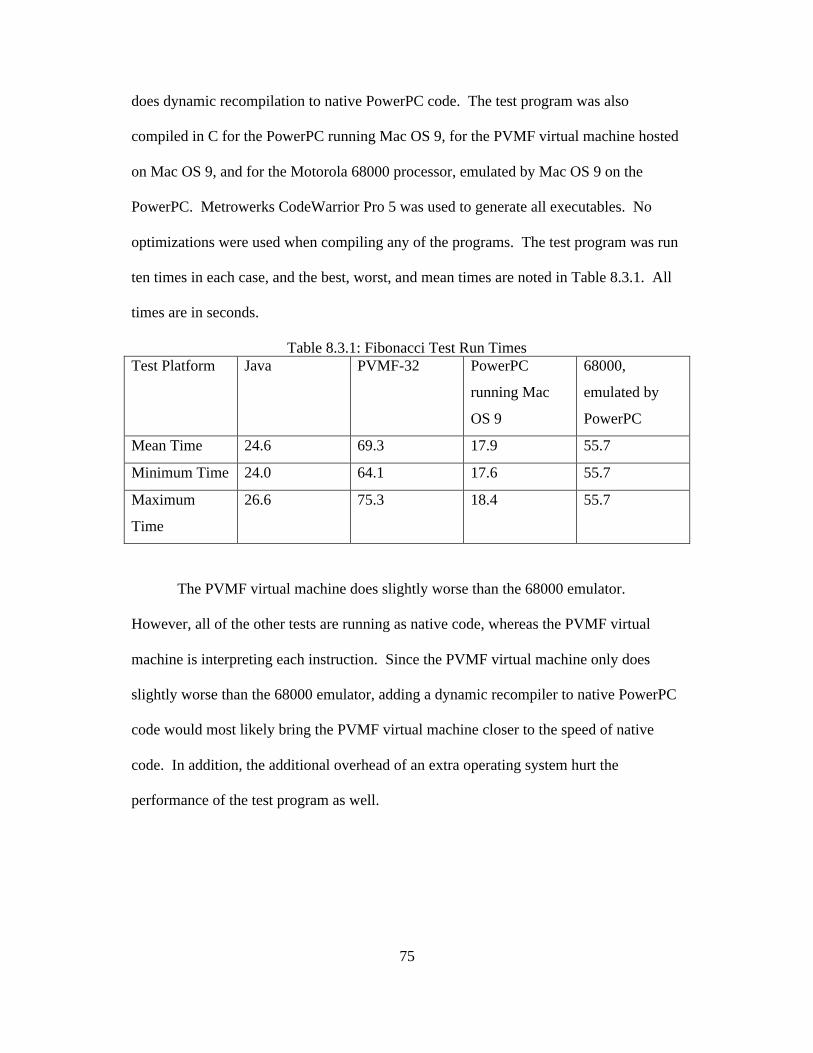
75
does dynamic recompilation to native PowerPC code. The test program was also
compiled in C for the PowerPC running Mac OS 9, for the PVMF virtual machine hosted
on Mac OS 9, and for the Motorola 68000 processor, emulated by Mac OS 9 on the
PowerPC. Metrowerks CodeWarrior Pro 5 was used to generate all executables. No
optimizations were used when compiling any of the programs. The test program was run
ten times in each case, and the best, worst, and mean times are noted in Table 8.3.1. All
times are in seconds.
Table 8.3.1: Fibonacci Test Run TimesTest Platform Java PVMF-32 PowerPC
running Mac
OS 9
68000,
emulated by
PowerPC
Mean Time 24.6 69.3 17.9 55.7
Minimum Time 24.0 64.1 17.6 55.7
Maximum
Time
26.6 75.3 18.4 55.7
The PVMF virtual machine does slightly worse than the 68000 emulator.
However, all of the other tests are running as native code, whereas the PVMF virtual
machine is interpreting each instruction. Since the PVMF virtual machine only does
slightly worse than the 68000 emulator, adding a dynamic recompiler to native PowerPC
code would most likely bring the PVMF virtual machine closer to the speed of native
code. In addition, the additional overhead of an extra operating system hurt the
performance of the test program as well.

76
8.4 Analysis
The use of ANSI C for VORTOS and the recompiler makes this implementation
both portable and efficient with minimal overhead, which makes it well suited for
embedded systems. Most modern operating systems are mostly written in C.
The performance of the virtual machine was not overly slow, but fell behind other
virtual machines and emulators. The addition of a dynamic recompiler to translate
PVMF-32 code into the native instruction set would improve performance considerably.
The simplicity of the virtual machine made it very straightforward to implement.
Furthermore, the small size of the instruction set and the use simple mathematical
primitives for instructions made mapping PowerPC instructions to PVMF-32 instructions
very natural in most cases. A higher-level virtual machine such as the Java Virtual
Machine would be more complicated to implement and would have a larger footprint.
The simple messaging architecture eliminated the need for any sort of static or
dynamic load-time linking of components, since messages are dispatched to the proper
recipients at execution time. This provides the size and flexibility advantages of the
dynamically linked libraries seen in many modern operating systems, but with even
greater flexibility because of the ability to substitute components around at run-time and
still have the messages be properly delivered. The code loader does not have to worry
about resolving all external symbol references at load-time, since the messaging system
will automatically find the proper offset with a component at execution time. This made
writing the loader easier, since it does not need to resolve symbol references, and made
writing the translator much easier, since no static linking of libraries was necessary.

77
Chapter 9
Conclusions
The Versatile Object-oriented Real-Time Operating System, VORTOS, provides
a portable, real-time, component-based operating system with a uniquely high level of
flexibility that addresses the specialized requirements of embedded systems. It has a
simple architecture and a small memory footprint; therefore, it works well with the
limited resources of embedded systems. VORTOS provides a greater level of flexibility
than traditional operating systems because of its modular component structure and
dynamic messaging architecture. Components with specialized policies or functionality
can supplement or replace existing components, providing high levels of extensibility and
customizability.
The versatility provided by the dynamic messaging architecture suggests many
possible applications for VORTOS. The uniform centralized dispatching of all messages
would lend itself well to real-time computer intrusion detection and monitoring. The
virtual machine architecture and messaging system make distributed computing possible
with a few additional components. Transparent encryption is possible through the use of
component filters. However, more components need to be created for each of these
applications.
A dynamic recompiler to compile PVMF-32 code into the native instruction set of
the underlying hardware would help performance considerably. In addition,
implementing hardware drivers would allow VORTOS to run directly on the hardware,

78
instead of running on top of another operating system, which would also improve
performance.
The architecture is flexible enough to allow custom specification of new
components without having to modify the existing components, but the existing
components can be replaced as well if a custom scheduling algorithm is necessary, for
example. A recompiler that converts PVMF-32 code to native machine code would
improve performance. Both the recompiler and the virtual machine can be extended to
support additional platforms, which should not be very difficult given the high portability
of VORTOS.
VORTOS provides many incidental benefits as well. The virtual machine
architecture means that programs running on VORTOS are binary compatible across
hardware platforms. The component architecture and separate address spaces provide an
improved level of stability and security. The recompiler provides compatibility with
existing systems. These benefits, combined with the major benefits from the dynamic
messaging architecture make VORTOS well-suited to embedded applications and
flexible enough to scale up to larger systems as well.

79
References
[1] D.M. Ritchie and K. Thompson. “The Unix Time-sharing System, C.” ACM 17No. 7 (July 1974).
[2] Sean Cotter. Inside Taligent Technology. Addison-Wesley, June 1995.
[3] A. B. Montz, D. Mosberger, S. W. O'Malley, L. L. Peterson, T. A. Proebsting.“Scout: A Communications-Oriented Operating System”. Hot OS (May 1995).
[4] Object Management Group. The Common Object Request Broker: Architectureand Specification (Revision 2.0). Object Management Group (OMG),Framingham, MA, July 1995.
[5] Fabio Kon, Ashish Singhai, Roy H. Campbell, Dulcineia Carvalho and RobertMoore. 2K: A Dynamic, Component-Based Operating System for RapidlyChanging Environments, UIUCDCS-R-98-2049 (May, 1998).
[6] Christopher Small and Margo Seltzer. “Structuring the Kernel as a Toolkit ofExtensible, Reusable Components,” Proceedings of the 1995 InternationalWorkshop on Object Orientation in Operating Systems (IWOOOS '95).
[7] Dawson R. Engler, M. Frans Kaashoek, and James W. O'Toole Jr. “The operatingsystem kernel as a secure programmable machine,” In the Proceedings of the 6thACM SIGOPS European workshop: Matching operating systems to applicationneeds, Dagstuhl Castle, Wadern, Germany, September 1994.
[8] David R. Cheriton and Kenneth J. Duda. A Caching Model of Operating SystemKernel Functionality, http://www-dsg.stanford.edu/papers/cachekernel/main.html(1994).
[9] Bryan Ford, Mike Hibler, Jay Lepreau, Patrick Tullmann, Godmar Back, StephenClawson. “Microkernels Meet Recursive Virtual Machines,” Appears in Proc. ofthe Second Symposium on Operating Systems Design and Implementation(OSDI'96), October 1996.
[10] Brian Bershad, Craig Chambers, Susan Eggers, Chris Maeda, Dylan McNamee,Przemyslaw Pardyak, Stefan Savage, Emin Gun Sirer, “SPIN - An ExtensibleMicrokernel for Application-specific Operating System Services,” University ofWashington, Technical Report TR-94-03-03, extended abstract appears in"Proceedings of the Sixth SIGOPS European Workshop on Matching OperatingSystems to Application Needs", Operating Systems Review, January 1995, v 29,no 1.
[11] Crispin Cowan. “Optimistic Replication in HOPE,” Proceedings of the 1992 CASConference, Toronto, Ontario, November 1992.
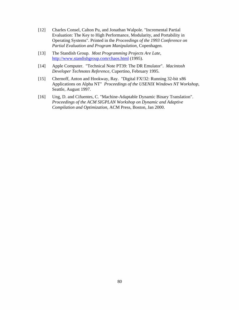
80
[12] Charles Consel, Calton Pu, and Jonathan Walpole. "Incremental PartialEvaluation: The Key to High Performance, Modularity, and Portability inOperating Systems". Printed in the Proceedings of the 1993 Conference onPartial Evaluation and Program Manipulation, Copenhagen.
[13] The Standish Group. Most Programming Projects Are Late,http://www.standishgroup.com/chaos.html (1995).
[14] Apple Computer. "Technical Note PT39: The DR Emulator". MacintoshDeveloper Technotes Reference, Cupertino, February 1995.
[15] Chernoff, Anton and Hookway, Ray. "Digital FX!32: Running 32-bit x86Applications on Alpha NT" Proceedings of the USENIX Windows NT Workshop,Seattle, August 1997.
[16] Ung, D. and Cifuentes, C. "Machine-Adaptable Dynamic Binary Translation".Proceedings of the ACM SIGPLAN Workshop on Dynamic and AdaptiveCompilation and Optimization, ACM Press, Boston, Jan 2000.

81
Appendix A
Table of Instructions
Table A.1: Table of InstructionsInstruction FormatInteger Addition ADD rA, rB, rC (rA + rB) -> rCInteger Addition ADDC rA, CONST, rC (rA + CONST) -> rCUnsigned Integer Addition UADD rA, rB, rC (rA + rB) -> rCUnsigned Integer Addition UADDC rA, CONST, rC (rA + CONST) -> rCFloating-point Addition FADD fprA, fprB, fprC (fprA + fprB) -> fprCFloating-point Addition FADDC fprA, CONST, (fprA + CONST) -> fprCSign Extend SEXT rA, CONST, rC (CONST)rA -> rCInteger Subtraction SUB rA, rB, rC (rA - rB) -> rCInteger Subtraction SUBC rA, CONST, rC (rA - CONST) -> rCUnsigned Integer USUB rA, rB, rC (rA - rB) -> rCUnsigned Integer USUBC rA, CONST, rC (rA - CONST) -> rCFloating-point Subtraction FSUB fprA, fprB, fprC (fprA - fprB) -> fprCFloating-point Subtraction FSUBC fprA, CONST, (fprA - CONST) -> fprCInteger Multiplication MUL rA, rB, rC (rA * rB) -> rCInteger Multiplication MULC rA, CONST, rC (rA * CONST) -> rCUnsigned IntegerMultiplication
UMUL rA, rB, rC (rA * rB) -> rC
Unsigned IntegerMultiplication
UMULC rA, CONST, rC (rA * CONST) -> rC
Floating-point Multiplication FMUL fprA, fprB, fprC (fprA * fprB) -> fprCFloating-point Multiplication FMULC fprA, CONST, (fprA * CONST) -> fprCInteger Division DIV rA, rB, rC (rA / rB) -> rCInteger Division DIVC rA, CONST, rC (rA / CONST) -> rCUnsigned Integer Division UDIV rA, rB, rC (rA / rB) -> rCUnsigned Integer Division UDIVC rA, CONST, rC (rA / CONST) -> rCFloating-point Division FDIV fprA, fprB, fprC (fprA / fprB) -> fprCFloating-point Division FDIVC fprA, CONST, (fprA / CONST) -> fprCInteger Bitwise-AND AND rA, rB, rC (rA & rB) -> rCInteger Bitwise-AND ANDC rA, CONST, rC (rA & CONST) -> rC64-bit Bitwise-AND FAND fprA, fprB, fprC (fprA & fprB) -> fprC64-bit Bitwise-AND FANDC fprA, CONST, (fprA & CONST) -> fprCInteger Bitwise-OR OR rA, rB, rC (rA | rB) -> rCInteger Bitwise-OR ORC rA, CONST, rC (rA | CONST) -> rC64-bit Bitwise-OR FOR fprA, fprB, fprC (fprA | fprB) -> fprC
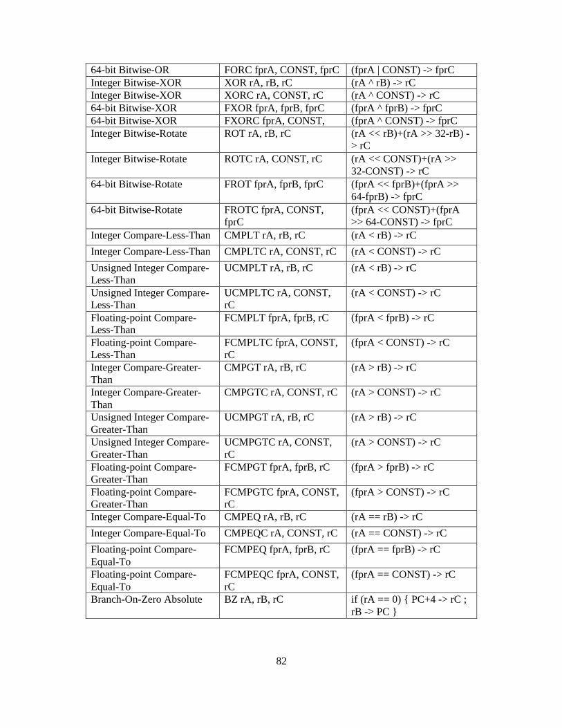
82
64-bit Bitwise-OR FORC fprA, CONST, fprC (fprA | CONST) -> fprCInteger Bitwise-XOR XOR rA, rB, rC (rA ^ rB) -> rCInteger Bitwise-XOR XORC rA, CONST, rC (rA ^ CONST) -> rC64-bit Bitwise-XOR FXOR fprA, fprB, fprC (fprA ^ fprB) -> fprC64-bit Bitwise-XOR FXORC fprA, CONST, (fprA ^ CONST) -> fprCInteger Bitwise-Rotate ROT rA, rB, rC (rA << rB)+(rA >> 32-rB) -
> rCInteger Bitwise-Rotate ROTC rA, CONST, rC (rA << CONST)+(rA >>
32-CONST) -> rC64-bit Bitwise-Rotate FROT fprA, fprB, fprC (fprA << fprB)+(fprA >>
64-fprB) -> fprC64-bit Bitwise-Rotate FROTC fprA, CONST,
fprC(fprA << CONST)+(fprA>> 64-CONST) -> fprC
Integer Compare-Less-Than CMPLT rA, rB, rC (rA < rB) -> rC
Integer Compare-Less-Than CMPLTC rA, CONST, rC (rA < CONST) -> rC
Unsigned Integer Compare-Less-Than
UCMPLT rA, rB, rC (rA < rB) -> rC
Unsigned Integer Compare-Less-Than
UCMPLTC rA, CONST,rC
(rA < CONST) -> rC
Floating-point Compare-Less-Than
FCMPLT fprA, fprB, rC (fprA < fprB) -> rC
Floating-point Compare-Less-Than
FCMPLTC fprA, CONST,rC
(fprA < CONST) -> rC
Integer Compare-Greater-Than
CMPGT rA, rB, rC (rA > rB) -> rC
Integer Compare-Greater-Than
CMPGTC rA, CONST, rC (rA > CONST) -> rC
Unsigned Integer Compare-Greater-Than
UCMPGT rA, rB, rC (rA > rB) -> rC
Unsigned Integer Compare-Greater-Than
UCMPGTC rA, CONST,rC
(rA > CONST) -> rC
Floating-point Compare-Greater-Than
FCMPGT fprA, fprB, rC (fprA > fprB) -> rC
Floating-point Compare-Greater-Than
FCMPGTC fprA, CONST,rC
(fprA > CONST) -> rC
Integer Compare-Equal-To CMPEQ rA, rB, rC (rA == rB) -> rC
Integer Compare-Equal-To CMPEQC rA, CONST, rC (rA == CONST) -> rC
Floating-point Compare-Equal-To
FCMPEQ fprA, fprB, rC (fprA == fprB) -> rC
Floating-point Compare-Equal-To
FCMPEQC fprA, CONST,rC
(fprA == CONST) -> rC
Branch-On-Zero Absolute BZ rA, rB, rC if (rA == 0) { PC+4 -> rC ;rB -> PC }

83
Branch-On-Zero Absolute BZC rA, CONST, rC if (rA == 0) { PC+4 -> rC ;CONST -> PC }
Branch-On-Zero Relative BRZ rA, rB, rC if (rA == 0) { PC+4 -> rC ;(rB + PC) -> PC }
Branch-On-Zero Relative BRZC rA, CONST, rC if (rA == 0) { PC+4 -> rC ;(CONST + PC) -> PC }
Branch-On-Not-ZeroAbsolute
BNZ rA, rB, rC if (rA != 0) { PC+4 -> rC ;rB -> PC }
Branch-On-Not-ZeroAbsolute
BNZC rA, CONST, rC if (rA != 0) { PC+4 -> rC ;CONST -> PC }
Branch-On-Not-ZeroRelative
BRNZ rA, rB, rC if (rA != 0) { PC+4 -> rC ;(rB + PC) -> PC }
Branch-On-Not-ZeroRelative
BRNZC rA, CONST, rC if (rA != 0) { PC+4 -> rC ;(CONST + PC) -> PC }
Integer Load LOAD rA, rB, rC *(rA + rB) -> rCInteger Load LOADC rA, CONST, rC *(rA + CONST) -> rCHalf Integer Load LOADH rA, rB, rC (*(rA + rB) >> 16) -> rCQuarter Integer Load LOADB rA, rB, rC (*(rA + rB) >> 24) -> rCFloating-point Load FLOAD rA, rB, fprC *(rA + rB) -> fprCFloating-point Load FLOADC rA, CONST, *(rA + CONST) -> fprCInteger Store STORE rA, rB, rC rA -> *(rC + rB)Integer Store STOREC rA, CONST, rC rA -> *(rC + CONST)Half Integer Store STOREH rA, rB, rC (rA & 0xFFFF) -> *(rC +
rB)Quarter Integer Store STOREB rA, rB, rC (rA & 0xFF) -> *(rC + rB)Floating-point Store FSTORE fprA, rB, rC fprA -> *(rC+ rB)Floating-point Store FSTOREC fprA, CONST, fprA -> *(rC + CONST)Send Message MSG rA, rB, rC Send message rB to object
id rA; store response in rCFork Message MSGF rA, rB, rC Send message rB to object
id rA and continueexecution without blocking;store response in rC

84
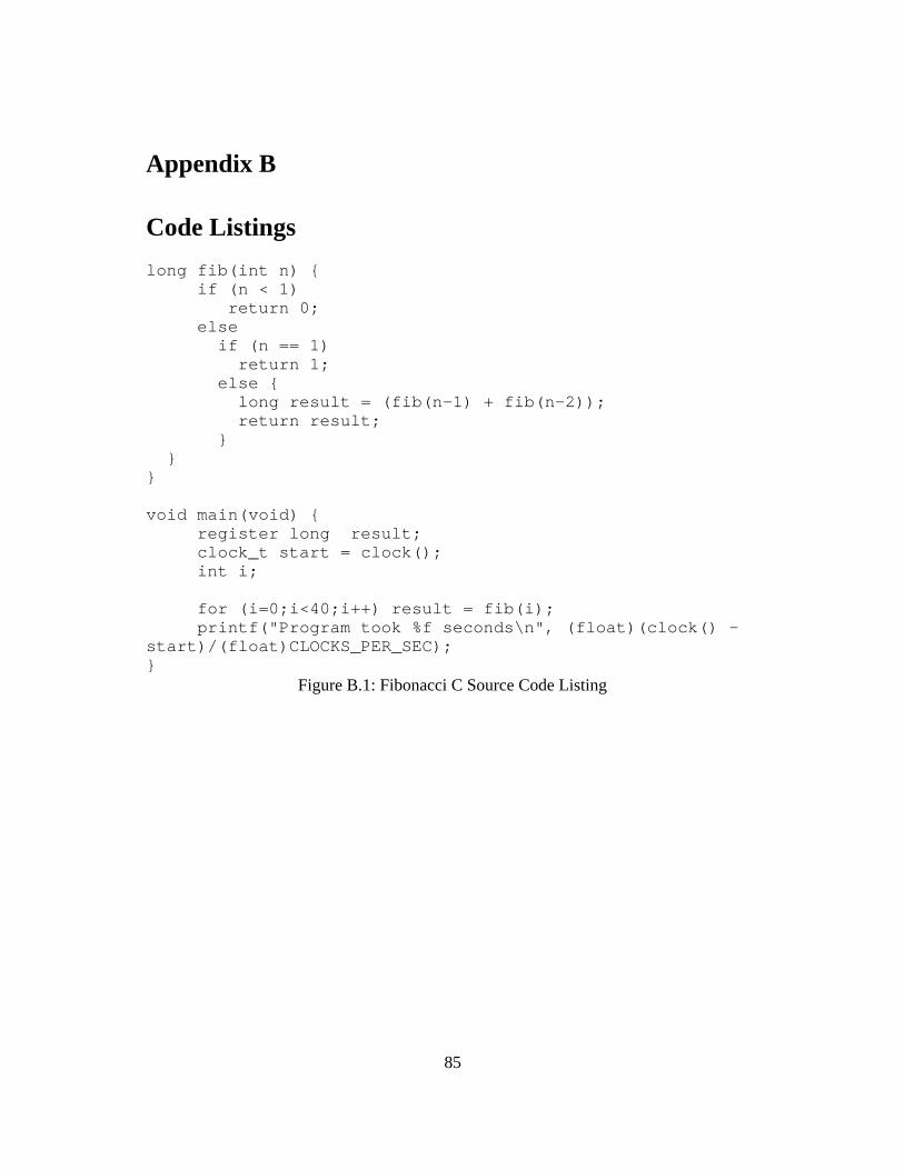
85
Appendix B
Code Listings
long fib(int n) { if (n < 1) return 0; else if (n == 1) return 1; else { long result = (fib(n-1) + fib(n-2)); return result; } }}
void main(void) {register long result;clock_t start = clock();int i;
for (i=0;i<40;i++) result = fib(i);printf("Program took %f seconds\n", (float)(clock() -
start)/(float)CLOCKS_PER_SEC);}
Figure B.1: Fibonacci C Source Code Listing

86
public class fibonacci { public static void main(String args[]) {
long result;
long startTime = System.currentTimeMillis();for (int i=0;i<40;i++) result = fib(i);
System.out.println("Fibonacci Took" +(System.currentTimeMillis()-startTime) + "ms"); } public static long fib(int n) { if (n < 1) return 0; else if (n == 1) return 1; else { long result = (fib(n-1) + fib(n-2)); return result; } }}
Figure B.2: Fibonacci Java Source Code Listing