Embed Size (px)
Citation preview

06-199 S.R. SMITH, LLC 2008 AUG13
VORTEX
CORPORATE HEADQUARTERS
WESTERN SALES AND MANUFACTURING PLANT P.O. Box 400 •••• 1017 SW Berg Parkway
Canby, Oregon 97013 Phone: (503) 266-2231 •••• Fax: (503) 266-4334
www.srsmith.com
ASSEMBLY AND INSTALLATION INSTRUCTIONS
2
Table of Contents INTRODUCTION......................................................................................................................................................... 2
INSTALLED VORTEX STRUCTURAL & INSTALLATION CHECKLIST ............................................................ 3 MAINTENANCE INSTRUCTIONS ........................................................................................................................... 3 VORTEX SLIDE WITH STAIRS LAYOUT .............................................................................................................. 4 VORTEX SLIDE WITH LADDER LAYOUT ............................................................................................................. 5 VORTEX MAIN SECTION PARTS LIST ................................................................................................................. 6 MAIN SECTION ASSEMBLY INSTRUCTIONS ..................................................................................................... 7
VORTEX SLIDE RUNWAY ASSEMBLY ................................................................................................................. 8 VORTEX CLOSED FLUME PARTS LIST ............................................................................................................. 13 VORTEX CLOSED FLUME ASSEMBLY INSTRUCTIONS ............................................................................... 14
VORTEX OPEN FLUME PARTS LIST .................................................................................................................. 17 VORTEX OPEN FLUME ASSEMBLY INSTRUCTIONS .................................................................................... 18
VORTEX STAIRWAY PARTS LIST ....................................................................................................................... 21 VORTEX STAIRWAY ASSEMBLY INSTRUCTIONS ......................................................................................... 22
VORTEX LADDER PARTS LIST ............................................................................................................................ 29 VORTEX LADDER ASSEMBLY INSTRUCTIONS .............................................................................................. 30
VORTEX WATER SYSTEM PARTS LIST ............................................................................................................ 33 VORTEX WATER SYSTEM ASSEMBLY INSTRUCTIONS .............................................................................. 34 CONCRETE WEDGE ANCHOR MOUNTING INSTRUCTIONS ....................................................................... 37 MANUFACTURER’S PLACEMENT INSTRUCTIONS ........................................................................................ 38
INTRODUCTION DANGER – FAILURE TO FOLLOW THESE WARNINGS, INSTRUCT IONS AND THE OWNER’S MANUAL MAY RESULT IN SEROUS INJURY OR DEATH
THE VORTEX™ SLIDE IS DESIGNED AND MANUFACTURED FOR INSTALLATION AND USE ON INGROUND SWIMMING POOLS ONLY. DO NOT INSTALL THE V ORTEX SLIDE ON ABOVE GROUND POOLS, HOUSEBOATS, BOAT DOCKS, FLOATING DOCK S OR PLATFORMS, OR OTHER BODIES OF WATER SUCH AS LAKES, PONDS, RIVERS, ETC. PROPER ASSEMBLY, INSTALLATION, USE, AND SUPERVISION IS ESSENTIAL FOR PROPER OPERATION AND TO REDUCE THE RISK OF SERIOUS INJURY OR DEATH. ALL NATIONAL AND LOCAL BUILDING CODES MUST BE FOLLO WED. THIS INCLUDES ANY APPLICABLE REQUIREMENTS FOR SIZE OF CONCRETE FOOTIN G, OVERALL HEIGHT OF SLIDE, AND BONDING OR ELECTRICAL CODES. CHECK INSIDE ALL BOXES AND PACKAGING MATERIALS FOR PARTS. BEFORE BEGINNING ASSEMBLY, READ ALL INSTRUCTIONS AND IDENTIFY PARTS USING THE FIGURES AND PARTS LISTED IN THIS DOCUMENT. IT IS CRITICAL THAT ALL P ARTS BE CAREFULLY INSPECTED BY THE INSTALLER PRIOR TO INSTALLATION TO ENSURE THAT NO DAMAGE OCCURRED IN TRANSIT AND THAT A DAMAGED PART IS NOT USED. PROPER INSTALLATION CANNOT BE OVERSTRESSED, IMPROPER INSTALLATION VOIDS S.R. SMIT H’S WARRANTY AND MAY AFFECT THE SAFETY OF THE USER. PRECAUTION: POWDER COATING IS SCRATCH RESISTANT, NO T SCRATCH PROOF. IT IS STILL SUSCEPTIBLE TO SCRATCHING AND CHIPPING. THIS SHOULD BE PREVENTED BECAUSE EXPOSED METAL SURFACES WILL RUST. PRECAUTION: CONTACT YOUR POOL PROFESSIONAL TO MAKE SURE THAT YOU HAVE ADEQUATE ACCESS TO YOUR POOL PUMP HOUSE FOR THE WAT ER SUPPLY. IT IS STRONGLY RECOMMENDED THAT THE WATER LINE BE PULLED FROM THE SWIMMING POOL RETURN LINE SO THAT THE CIRCULATED WATER IS SANITARY AND D OES NOT AFFECT THE CHEMISTRY OF THE POOL.

3
INSTALLER MUST GIVE TO SLIDE OWNER: VORTEX SLIDE IN STALLATION AND OWNER’S MANUAL, THE WARRANTY CARD, AND ANSWER ALL QUESTIION S REGARDING SAFE AND PROPER USE AND SLIDE MAINTENACE. WARNING SIGN MUST BE MOUNTED NEAR SLIDE ENTRANCE. S IGN SHOULD BE LOCATED WITHIN 2 FEET OF THE ENTRANCE OF THE SLIDE AND MUST POINT AWAY FROM ENTRANCE SO THAT IT IS VISIBLE AT LEAST 10 FEET FROM SLIDE. FOR COMPLETE SLIDE SAFETY INFORMATION REFER TO THE OWNER’S MANUAL. INSTALLED VORTEX STRUCTURAL & INSTALLATION CHECKLIS T (INSTALLER TO REVIEW WITH SLIDE OWNER UPON COMPLETI ON OF SLIDE INSTALLATION)
1. INSPECT THE RUNWAY FOR VISIBLE CRACKS OR TEAR S. 2. INSPECT THE SLIDE FOR SHARP EDGES, PROTRUSIONS, CRACKS OR TEARS. 3. INSPECT ALL FASTENERS TO MAKE SURE THEY ARE FULL Y TIGHTENED. 4. INSPECT THE LADDER FOR RIGIDITY AND ATTACHMENT. 5. MEASURE THE FOLLOWING DIMENSIONS AND COMPARE WIT H THE MANUFACTURER’S
PLACEMENT INSTRUCTIONS ON PAGES 38 AND 39. • MEASURE THE DEPTH OF WATER IN FRONT OF THE SLIDE EX IT. (4’-6” MIN.
DEPTH AT A DISTANCE OF 4’-6” FROM EXIT END OF SLIDE .) • MEASURE THE HEIGHT OF THE SLIDE RUNWAY EXIT ABOVE T HE WATER. (20”
MAX.) • MEASURE THE DISTANCE BETWEEN THE SLIDE CENTERLINE A ND THE EDGE
OF OTHER POOL EQUIPMENT. 6. OBSERVE THE POSITION OF THE EXIT OF THE SLIDE AS SHOWN IN FIGURES 33, 34 AND
36 ON PAGES 38 AND 39.
MAINTENANCE INSTRUCTIONS
1. PERIODICALLY INSPECT THE VORTEX TO ASSURE THERE AR E NO WORN PARTS AND THAT ALL HARDWARE IS PROPERLY TIGHTENED. REPLACE AN Y HARDWARE WHICH EXHIBITS RUST OR CORROSION.
2. ALL SLIDE COMPONENTS REQUIRE PERIODIC MAINTENANCE. CLEAN COMPONENTS WITH A COTTON CLOTH AND A NON-ABRASIVE SOAP AND WAT ER. AVOID HARSH CHEMICALS AND DISINFECTANTS.
3. ALWAYS READ THE LABEL INSTRUCTIONS ON ANY CLEANER CAREFULLY BEFORE APPLYING IT TO A SURFACE.
4. INSPECT THE PLUMBING SYSTEM FOR LEAKS. FREEZE/THAW CYCLES MAY CAUSE LEAKS AT PLUMBING JOINTS WHICH SHOULD BE REPAIRED P RIOR TO USE.
5. CHECK ALL SAFETY LABELS TO INSURE THEY HAVE NOT PE ELED OR BEEN REMOVED. CONTACT S.R. SMITH CUSTOMER SERVICE (800-824-4397) FOR REPLACEMENT LABELS.
6. THE SUPPORT STRUCTURE IS MADE FROM STEEL, IS PRIMED AND POWDER COATED WITH A HIGH QUALITY ACRYLIC URETHANE FINISH. HOWEVE R, CORROSION MAY OCCUR DEPENDING ON WATER CHEMISTRY AND ENVIRONMENTAL CONDITIONS. INSPECT THE SLIDE ON A SEMI-ANNUAL BASIS, SAND AND REPAIR ANY SURFACE RUST. FOR TOUCH-UP PAINT (PN # 09-819-1), CONTACT S.R. SMITH CUSTOMER SERVICE (800-824-4397).
CAUTION: BECAUSE THIS PRODUCT IS MANUFACTURED FROM STEEL, PLACEMENT ON A POOL WITH A SALT CHLORINE GENERATOR WILL REQUIRE FR EQUENT INSPECTION AND MAINTENANCE DUE TO THE CORROSIVE NATURE OF THESE SY STEMS WITH ALL STEEL ALLOYS. IT IS RECOMMENDED THAT ALL SLIDE COMPONENT S BE RINSED DAILY WITH FRESH WATER.

4
VORTEX SLIDE WITH STAIRS LAYOUT
FIGURE 1

5
VORTEX SLIDE WITH LADDER LAYOUT
FIGURE 2

6
(1)
(9)
VORTEX MAIN SECTION PARTS LIST
ITEM # PART # DESCRIPTION QTY. 1 6-690-1 Entrance Section 1 ea. 2 6-690-2 Runway Section 4 ea. 3 6-690-3 Exit Section 1 ea. 4 14-301 Branch Arm 5 ea. 5 14-300 Main Support 1 ea. 6 14-205 Exit Support 1 ea. 7 5-113 3/8” x 2” HHCS S/S 2 ea. 8 05-32-131 3/8” x 5-1/2” HHCS 8 ea. 9 5-523-SS ½” x 3-3/4” CONCRETE WEDGE ANCHOR W/HRDWR S/S 12 ea. 10 5-250 3/8” x 3-1/2” BHCS S/S 4 ea. 11 5-512 3/8” x 4” BHCS S/S 8 ea. 12 5-515 3/8” x 5” BHCS S/S 4 ea. 15 5-524-SS ½” x 5” HHCS S/S 5 ea. 16 VULKEM-116 VULKEM GRAY SEALANT 17 05-14-132 ½” x 1-3/8” FLAT WASHER S/S 10 ea. 18 05-14-115 ½” LOCK WASHER S/S 17 ea. 20 05-14-116 ½” HEX NUT S/S 5 ea. 21 05-14-107 3/8” x 1” FLAT WASHER S/S 18 ea. 22 05-616 ½” NYLON WASHER 22 ea. 23 05-32-111 3/8” NYLON WASHER 22 ea. 24 5-145 3/8” FLAT WASHER S/S 48 ea. 25 5-151 3/8” LOCK WASHER S/S 24 ea. 26 5-139 3/8” HEX NUT S/S 22 ea. 29 5-521-SS 3/8-16 X 3” CONCRETE WEDGE ANCHOR W/HRDWR S/S 2 ea. 31 8-536 .5” WIDE X .3” TALL RUBBER GASKET (NOT SHOWN) 21 FT
(2)
(3)
(5) (6) (8)
(10) (11)
(18)
(15)
(17)
(4)
(12)
(16) (20) (21)
(7)
(22) (24) (23) (25) (26) (27) (29)
7
MAIN SECTION ASSEMBLY INSTRUCTIONS Tools Required:
1. Ratchet handle 2. 9/16” deep socket 3. 9/16” wrench 4. 3/4" socket or wrench 5. 7/32” allen wrench (deep) 6. Phillips head screwdriver 7. Roto-hammer drill 8. 1/2" concrete drill bit 9. 3/8” concrete drill bit 10. 4” ratchet extension
11. 3 Irwin Quick Grip™ 18” XP Bar Clamps 12. Power drill 13. PVC pipe primer & glue 14. Anti-seize 15. Saw to cut PVC pipe 16. Knife 17. Level 18. Hammer 19. 8’ step ladder 20. Rubber Mallet
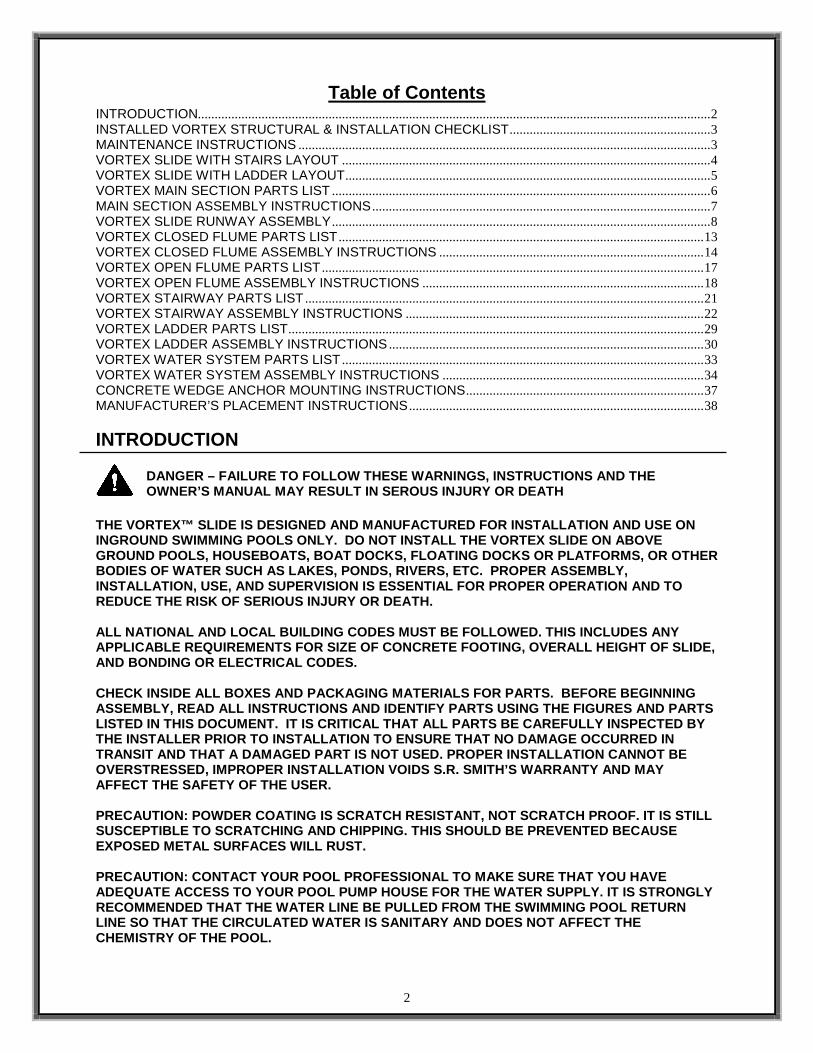
Gasket Installation:
• The gasket material has been installed at the factory, however additional gasket has been provided in case any gasket has fallen off during shipping. If gasket installation is required, follow the instructions below. • Apply gasket in the required locations as shown in the figures below. • Place gasket along the section to determine the length needed. • Cut gasket to appropriate length. • Remove backing and adhere gasket to slide.
FIGURE 3

8
VORTEX SLIDE RUNWAY ASSEMBLY
1) First, insert all five of the Branch Arms (4) into the Main Support (5). Ensure that the arms slide into the support sockets without damaging the powder coating. Align the holes in the main tube support with the holes in the branch arm and attach using the hardware shown in Figure 1. The required hardware is as follows: ½” – 13 x 5” Hex Head Cap Screw (15), ½” Flat Washer (17), ½” Nylon Washer (22), and ½” Nylon Washer (22), ½” Flat Washer (17), ½” Lock Washer (18), ½” Hex Nut (20) on the other side of the support. It is important not to tighten the hardware at this point. ANTI-SEIZE NEEDS TO BE USED ON ALL BOLTS, and shoul d be applied to the threading before attempting to place the nut on the bolt. 2) The image on the right shows the main tube support with all branch arms installed. Place the column close to the installation location.
(15)
(17)
(22) (20)
(18)
(4)
(5)
FIGURE 4
FIGURE 5

9
3) Before working with the flume pieces, cover the concrete with cardboard or carpet to help prevent scratching the plastic slide components. Order of assembly is important! Each of the slide components is numbered in the order that they should be assembled . See Figure 6 for order of assembly. Assemble the Exit Flume (3) and the Runway Section (2) labeled B1 together as shown. Install the hardware through both side rails as shown in Figure 6. The hardware used for this step, in order of assembly, is as follows: 3/8”-16 x 4” Button Head Cap Screw S/S (11), 3/8” Flat Washer (24), 3/8” Flat Washer (24), 3/8” Lock Washer (25), 3/8” Hex Nut S/S (26). Tighten the hardware until snug. Note: Be sure to apply anti-seize to all fasteners to prevent galling.
4) Next, flip over the two connected pieces of the runway. Place the Exit Support (6) under the Exit Flume (3), as shown in Figure 7. Use the following hardware to attach the exit support: 3/8”-16 x 2” Hex Head Bolt (7), 3/8” Flat Washer (24), 3/8” Nylon Washer (23), 3/8” Flat Washer (24), 3/8” Lock Washer (25), 3/8” Hex Nut (26). Tighten the hardware until snug. Note: Be sure to apply anti-seize to all fasteners to prevent galling.
(25)
(11)
(24)
(26)
(26) (23)
(25)
(24)
(7)
JOINT B1
JOINT B2
(3)
(2) JOINT B1
FIGURE 6
FIGURE 7
10
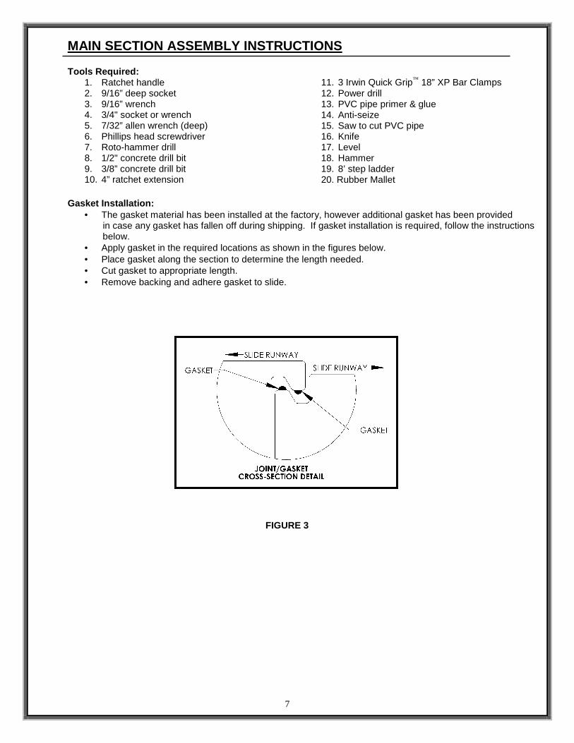
5) Position the slide on the deck such that the slide meets the requirements as given in the Manufacturer’s Placement Instructions on page 31. Make sure that the slide parts are correctly positioned on the branch arms. It is recommended that bolts be placed temporarily through the runway parts and into the first and second branch arms to ensure proper alignment. Once the assembly is in the correct position, mark the locations for exit support anchors. In addition, make reference marks at the corners of the main tube support flange to ensure that it remains in the desired position. Remove the flume sections and drill the anchor holes for both the Main Support (5) and the Exit Support (6). Drill the two 3/8” diameter X 2” deep holes in the marked locations for the exit support. The holes in the main support tube flange may be used as a template for drilling the 1/2” diameter X 2-1/4“deep holes. Follow the instruction on page 23 and install the concrete wedge anchors for the exit support and the main tube support.
6) Place the assembled Exit Flume (3) and Runway Section (2) over the first Branch Arm (6). Attach the slide sections to the first branch arm as shown above. The required hardware is as follows: 3/8”-16 x 5.5” Hex Head Cap Screw (8), 3/8” Flat Washer (21), 3/8” Nylon Washer (23), 3/8” Flat Washer (21), 3/8” Lock Washer (25), and a 3/8” Hex Nut (26). Do not completely tighten the hardware at this point. Note: Be sure to apply anti-seize to all fasteners to prevent galling.
MARK LOCATION OF HOLES IN EXIT SUPPORT FOR DRILLING 3/8” X 2” DEEP HOLES FOR CONCRETE ANCHORS
USE HOLES IN FLANGE AS TEMPLATE FOR DRILLING 1/2” DIAMETER X 2.25” DEEP HOLES FOR CONCRETE ANCHORS
FIGURE 8
FIGURE 9
(8)
(23)
(26)
(25)
(21)
11
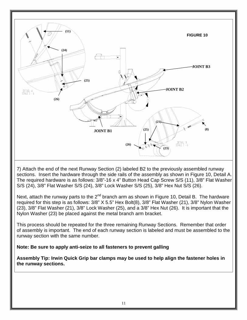
7) Attach the end of the next Runway Section (2) labeled B2 to the previously assembled runway sections. Insert the hardware through the side rails of the assembly as shown in Figure 10, Detail A. The required hardware is as follows: 3/8”-16 x 4” Button Head Cap Screw S/S (11), 3/8” Flat Washer S/S (24), 3/8” Flat Washer S/S (24), 3/8” Lock Washer S/S (25), 3/8” Hex Nut S/S (26). Next, attach the runway parts to the 2nd branch arm as shown in Figure 10, Detail B. The hardware required for this step is as follows: 3/8” X 5.5” Hex Bolt(8), 3/8” Flat Washer (21), 3/8” Nylon Washer (23), 3/8” Flat Washer (21), 3/8” Lock Washer (25), and a 3/8” Hex Nut (26). It is important that the Nylon Washer (23) be placed against the metal branch arm bracket. This process should be repeated for the three remaining Runway Sections. Remember that order of assembly is important. The end of each runway section is labeled and must be assembled to the runway section with the same number. Note: Be sure to apply anti-seize to all fasteners to prevent galling Assembly Tip: Irwin Quick Grip bar clamps may be us ed to help align the fastener holes in the runway sections.
JOINT B1
JOINT B2
JOINT B3
FIGURE 10
(8)
(21)
(23)
(25)
(26)
(24)
(11)
(25)
(26)

12
8) Assemble the Entrance Section (1) of the slide to the last Runway Section (2). First, insert the hardware through the sides of the runway as shown in Figure 11, Detail A. The hardware required for this step is as follows: 3/8”-16 x 5” Button Head Cap Screw S/S (12), 3/8” Flat Washer S/S (24), 3/8” Flat Washer S/S (24), 3/8” Lock Washer S/S (25), 3/8” Hex Nut S/S (26). Next, attach the runway assembly to the last branch arm, as shown in Figure 11, Detail B. The bolts will be threaded into the threaded inserts in the entrance section. The hardware required includes: 3/8”-16 x 3.5” Button Head Cap Screw S/S (10), 3/8” Lock Washer S/S (24), 3/8” Flat Washer S/S (25), and a 3/8” Nylon Washer (23). Note: Be sure to apply anti-seize to all fasteners to prevent galling After you have started all of these bolts, you shou ld go back through and tighten all of the fasteners installed up to this point . Apply the .5” wide X .3” tall gasket to the top run way parts along the outside curve edge only. The gasket should be applied on the mating surface, between the bolt holes and the inside edge of the part.
JOINT B4
JOINT B5
JOINT B1
JOINT B2
JOINT B3
FIGURE 11
(12)
(24)
(25)
(26)
(10)
(24) (25)
(23)
13
VORTEX CLOSED FLUME PARTS LIST
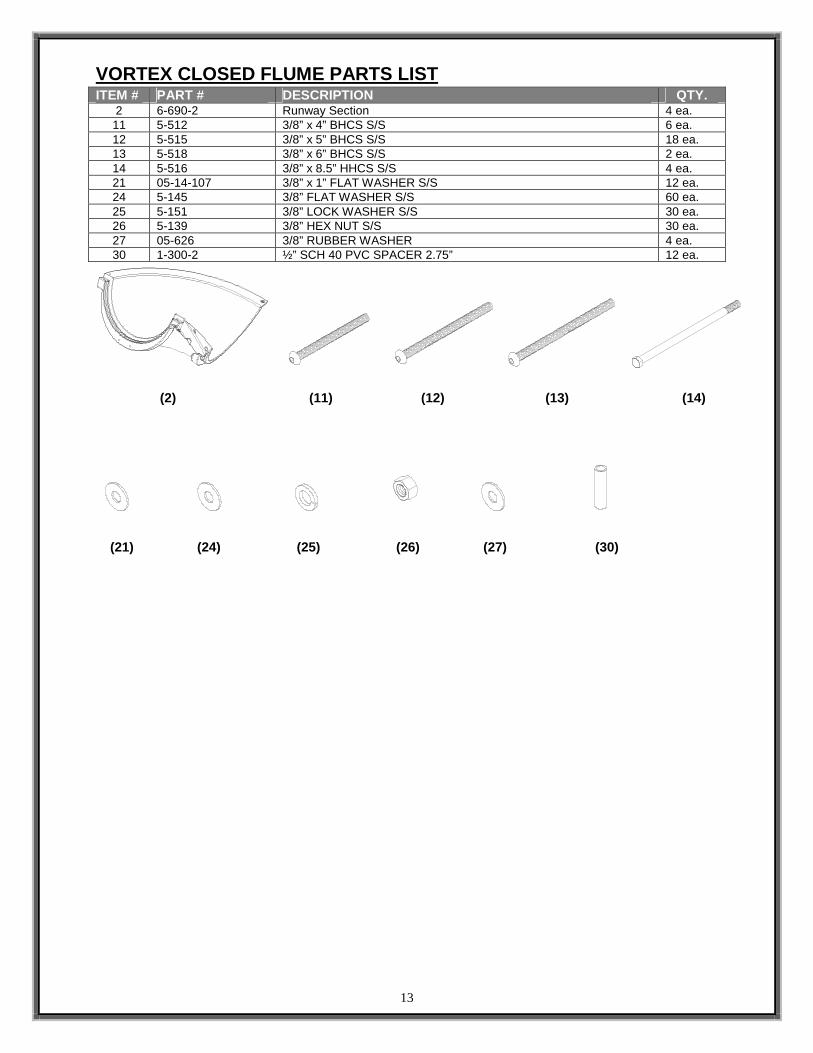
ITEM # PART # DESCRIPTION QTY. 2 6-690-2 Runway Section 4 ea. 11 5-512 3/8” x 4” BHCS S/S 6 ea. 12 5-515 3/8” x 5” BHCS S/S 18 ea. 13 5-518 3/8” x 6” BHCS S/S 2 ea. 14 5-516 3/8” x 8.5” HHCS S/S 4 ea. 21 05-14-107 3/8” x 1” FLAT WASHER S/S 12 ea. 24 5-145 3/8” FLAT WASHER S/S 60 ea. 25 5-151 3/8” LOCK WASHER S/S 30 ea. 26 5-139 3/8” HEX NUT S/S 30 ea. 27 05-626 3/8” RUBBER WASHER 4 ea. 30 1-300-2 ½” SCH 40 PVC SPACER 2.75” 12 ea.
(2) (11) (12) (13) (14)
(21) (24) (25) (26) (27) (30)

14
VORTEX CLOSED FLUME ASSEMBLY INSTRUCTIONS
9) Assemble the four remaining Runway Section (2) pieces. Order of assembly is important. The end of each runway section is labeled and must be assembled to the runway section with the same number. Assemble two sections together that are labeled T1 on the mating ends. Fasten the two sections together using the two bolt locations through the side of the parts as shown in Figure 12, Detail A. The hardware required for the two side locations is as follows: 3/8”-16 x 4” Button Head Cap Screw S/S (11), 3/8” Flat Washer S/S (24), 3/8” Flat Washer S/S (24), 3/8” Lock Washer S/S (25), 3/8” Hex Nut S/S (26). Next, finish fastening the parts together as shown in Figure 12, Detail B. The hardware required for this step is as follows: 3/8”-16 x 5” Button Head Cap Screw (12) and a 3/8” Flat Washer S/S (21), 3/8” Flat Washer (21), 3/8” Lock Washer (25), 3/8” Hex Nut (26). Follow the same procedure to finish assembling the remaining two sections together. Assemble the part labeled T2 to the previously assembled parts followed by the part labeled T3. Note: Be sure to apply anti-seize to all fasteners to prevent galling
JOINT T1
JOINT T2
JOINT T3
(12)
(26)
FIGURE 12
(21) (25)
(11)
(24) (26)
(25)
15
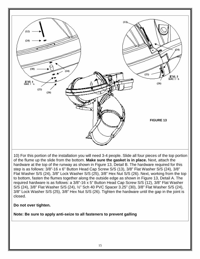
10) For this portion of the installation you will need 3-4 people. Slide all four pieces of the top portion of the flume up the slide from the bottom. Make sure the gasket is in place. Next, attach the hardware at the top of the runway as shown in Figure 13, Detail B. The hardware required for this step is as follows: 3/8”-16 x 6” Button Head Cap Screw S/S (13), 3/8” Flat Washer S/S (24), 3/8” Flat Washer S/S (24), 3/8” Lock Washer S/S (25), 3/8” Hex Nut S/S (26). Next, working from the top to bottom, fasten the flumes together along the outside edge as shown in Figure 13, Detail A. The required hardware is as follows: a 3/8”-16 x 5” Button Head Cap Screw S/S (12), 3/8” Flat Washer S/S (24), 3/8” Flat Washer S/S (24), ½” Sch 40 PVC Spacer 3.25” (30), 3/8” Flat Washer S/S (24), 3/8” Lock Washer S/S (25), 3/8” Hex Nut S/S (26). Tighten the hardware until the gap in the joint is closed. Do not over tighten. Note: Be sure to apply anti-seize to all fasteners to prevent galling
FIGURE 13
(12)
(24)
(25) (26)
(24)
(13)
(26)
(25)
(24)
(30)

16
11) Fasten the top and bottom runway parts together along the inside curve as shown in Figure 14, Detail A. The hardware required for this step is as follows: a 3/8”-16 x 8.5” Hex Head Cap Screw S/S (14), 3/8” Flat Washer S/S (24), 3/8” Rubber Washer (27), 3/8” Flat Washer S/S (24), 3/8” Lock Washer S/S (25), 3/8” Hex Nut S/S (26). There are four locations where this step is repeated. After you have started all of these bolts, you shou ld go back through and tighten all of the fasteners installed up to this point . Note: Be sure to apply anti-seize to all fasteners to prevent galling.
FIGURE 14
(14)
(27)
(24) (26)
(25)

17
VORTEX OPEN FLUME PARTS LIST
ITEM # PART # DESCRIPTION QTY. 59 6-690-4 CURVE SECTION RISER 4 ea. 60 4-235 CURVE SECTION RISER BRACKET S/S 2 ea. 11 5-513 3/8” x 4.5” BHCS S/S 6 ea. 12 5-515 3/8” x 5” BHCS S/S 16 ea. 61 5-514 3/8” x .75” BHCS S/S 4 ea. 23 05-32-111 3/8” NYLON WASHER 6 ea. 24 5-145 3/8” FLAT WASHER S/S 60 ea. 25 5-151 3/8” LOCK WASHER S/S 22 ea. 26 5-139 3/8” HEX NUT S/S 22 ea. 30 1-300-2 ½” SCH 40 PVC SPACER 2.75” 12 ea.
(59)
(11) (12)
(60)
(61)
(24) (25) (26) (30)
(23)
18
VORTEX OPEN FLUME ASSEMBLY INSTRUCTIONS
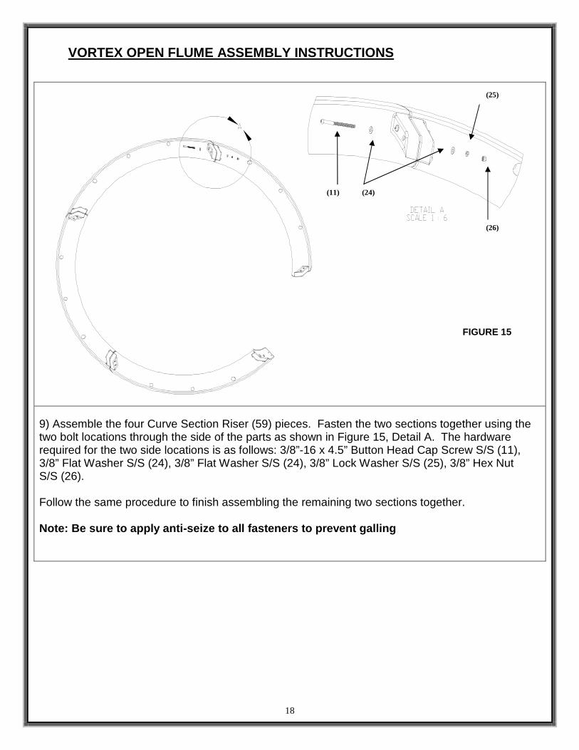
9) Assemble the four Curve Section Riser (59) pieces. Fasten the two sections together using the two bolt locations through the side of the parts as shown in Figure 15, Detail A. The hardware required for the two side locations is as follows: 3/8”-16 x 4.5” Button Head Cap Screw S/S (11), 3/8” Flat Washer S/S (24), 3/8” Flat Washer S/S (24), 3/8” Lock Washer S/S (25), 3/8” Hex Nut S/S (26). Follow the same procedure to finish assembling the remaining two sections together. Note: Be sure to apply anti-seize to all fasteners to prevent galling
(25)
(26)
FIGURE 15
(24) (11)

19
10) Slide all four pieces of the open flume up the slide from the bottom. Make sure the gasket is in place. Next, attach the hardware at the top of the runway as shown in Figure 16, Detail A. Use the Open Flume Bracket (60) to secure the open flume pieces to the slide. The hardware required for this step is as follows: First through the bottom flume and the bracket use a 3/8”-16 x 5” Button Head Cap Screw S/S (12), 3/8” Flat Washer S/S (24), 3/8” Flat Washer S/S (24), 3/8” Lock Washer S/S (25), 3/8” Hex Nut S/S (26). Next, through the open flume and the bracket use a 3/8”-16 x .75” Button Head Cap Screw S/S (61). 3/8” Nylon Washer (23), and a 3/8” Flat Washer S/S (24). Do not fully tighten any of the hardware until all of the hardware has been assembled. Do not over tighten. Note: Be sure to apply anti-seize to all fasteners to prevent galling
FIGURE 16
(12)
(25)
(26)
(24)
(25)
(61)
(60)

20
11) Next, working from the top to bottom, fasten the flumes together along the outside edge as shown in Figure 17, Detail A. The required hardware is as follows: a 3/8”-16 x 5” Button Head Cap Screw S/S (12), 3/8” Flat Washer S/S (24), 3/8” Flat Washer S/S (24), ½” Sch 40 PVC Spacer 3.25” (30), 3/8” Flat Washer S/S (24), 3/8” Lock Washer S/S (25), 3/8” Hex Nut S/S (26). Tighten the hardware until the gap in the joint is closed. After you have started all of these bolts, you shou ld go back through and tighten all of the fasteners installed up to this point . Note: Be sure to apply anti-seize to all fasteners to prevent galling.
FIGURE 17
(12)
(24)
(30)
(25)
(26)

21
VORTEX STAIRWAY PARTS LIST
ITEM # PART # DESCRIPTION QTY. 9 5-523-SS ½” x 3-3/4” CONCRETE WEDGE ANCHOR W/HRDW (See Page 5) 6 ea. 17 05-14-132 ½” x 1-3/8” FLAT WASHER S/S (See Page 5) 44 ea. 18 05-14-115 ½” LOCK WASHER S/S (See Page 5) 22 ea. 20 05-14-116 ½” HEX NUT S/S (See Page 5) 22 ea. 22 05-616 ½” NYLON WASHER (See Page 5) 24 ea. 23 05-32-111 3/8” NYLON WASHER (See Page 5) 46 ea. 25 5-151 3/8” LOCK WASHER S/S (See Page 5) 4 ea. 29 5-521-SS 3/8” X 3” CONCRETE WEDGE ANCHOR W/HRDWR (See Page 5) 4 ea. 31 5-252-SS ½” x 1.5” HEX HEAD BOLT S/S 22 ea. 32 5-253-SS 5/16” x 1.25” HEX HEAD LAG SCREW S/S 42 ea. 33 05-625 5/16” NYLON WASHER 50 ea. 34 5-306 5/16” LOCK WASHER S/S 8 ea. 35 5-303 5/16” FLAT WASHER S/S 50 ea. 36 2022650 5/16” HEX NUT S/S 8 ea. 37 05-233 ½” SPACER 14 ea. 38 8-301 OUTSIDE STAIR BRACKET 3 ea. 39 8-300 INSIDE STAIR BRACKET 3 ea. 40 8-303 BOTTOM OUTSIDE STAIR BRACKET 1 ea. 41 8-302 BOTTOM INSIDE STAIR BRACKET 1 ea. 19 8-306 STEP BRACKET ANCHOR 1 ea. 42 6-695 REAR PLATFORM STEP 3 ea. 43 6-694 FORWARD PLATFORM STEP 3 ea.
44a 6-693 RECTANGULAR STEP W/ PILOT HOLES 7 ea. 44b 6-696 RECTANGULAR STEP W/ THROUGH HOLES 1 ea. 45 14-305 INSIDE HANDRAIL 1 ea. 46 14-304 OUTSIDE HANDRAIL 1 ea. 47 14-302 MAIN STAIR SUPPORT 1 ea. 48 14-303 MIDDLE STAIR SUPPORT 1 ea. 49 5-257 5/16”-18 X 2.5” BHCS S/S 8 ea.
(31) (32) (33) (34) (35) (36) (37) (38) (39)
(40) (41) (42) (43)
(44a and b)
(45) (46) (47) (48)
(49)
(19)
22
VORTEX STAIRWAY ASSEMBLY INSTRUCTIONS
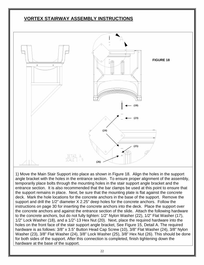
1) Move the Main Stair Support into place as shown in Figure 18. Align the holes in the support angle bracket with the holes in the entrance section. To ensure proper alignment of the assembly, temporarily place bolts through the mounting holes in the stair support angle bracket and the entrance section. It is also recommended that the bar clamps be used at this point to ensure that the support remains in place. Next, be sure that the mounting plate is flat against the concrete deck. Mark the hole locations for the concrete anchors in the base of the support. Remove the support and drill the 1/2” diameter X 2.25” deep holes for the concrete anchors. Follow the instructions on page 30 for inserting the concrete anchors into the deck. Place the support over the concrete anchors and against the entrance section of the slide. Attach the following hardware to the concrete anchors, but do not fully tighten: 1/2” Nylon Washer (22), 1/2” Flat Washer (17), 1/2” Lock Washer (18), and a 1/2”-13 Hex Nut (20). Next, place the required hardware into the holes on the front face of the stair support angle bracket, See Figure 15, Detail A. The required hardware is as follows: 3/8” x 3.5” Button Head Cap Screw (10), 3/8” Flat Washer (24), 3/8” Nylon Washer (23), 3/8” Flat Washer (24), 3/8” Lock Washer (25), 3/8” Hex Nut (26). This should be done for both sides of the support. After this connection is completed, finish tightening down the hardware at the base of the support.
FIGURE 18
(10)
(24)
(23)
(25)
(26)

23
Note: Be sure to apply anti-seize to all fasteners to prevent galling.
2) Place the Outside Stair Bracket (38) in line with the two holes on the inside of the Main Stair Support so that it is closest to the support tube, as shown in Figure 19. Use the following hardware to attach the bracket to the main stair support: 1/2” x 1.5” Hex Head Bolt (31), 1/2” Flat Washer (17), 1/2” Nylon Washer (22), 1/2” Nylon Washer (22), 1/2” Flat Washer (17), 1/2” Lock Washer (18), and a 1/2” Hex Nut (20), see Detail A. Do not fully tighten yet. After all hardware has been attached tighten each bolt securely. Second, place the Inside Stair Bracket (39) on the opposite side and repeat the steps to mount it securely to the slide. Add another set of inside and outside brackets and repeat the hardware steps to attach them. The next outside bracket should be placed inside of the first bracket, and the next inside bracket should be placed outside of the first bracket. Note: Be sure to apply anti-seize to all fasteners to prevent galling.
FIGURE 19
(31)
(17)
(22)
(18)
(20)
24
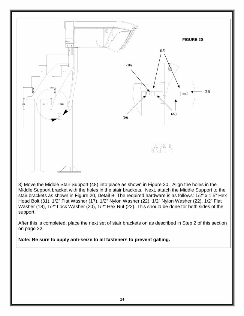
3) Move the Middle Stair Support (48) into place as shown in Figure 20. Align the holes in the Middle Support bracket with the holes in the stair brackets. Next, attach the Middle Support to the stair brackets as shown in Figure 20, Detail B. The required hardware is as follows: 1/2” x 1.5” Hex Head Bolt (31), 1/2” Flat Washer (17), 1/2” Nylon Washer (22), 1/2” Nylon Washer (22), 1/2” Flat Washer (18), 1/2” Lock Washer (20), 1/2” Hex Nut (22). This should be done for both sides of the support. After this is completed, place the next set of stair brackets on as described in Step 2 of this section on page 22. Note: Be sure to apply anti-seize to all fasteners to prevent galling.
FIGURE 20
(31)
(17)
(22)
(18)
(20)

25
4) Place the Bottom Outside Stair Bracket (40) in line with the two holes on the Outside Stair Bracket so that it is inside the stair bracket, as shown in Figure 21. Use the following hardware to attach the bracket to the main stair support: 1/2” x 1.5” Hex Head Bolt (31), 1/2” Flat Washer (17), 1/2” Nylon Washer (22), 1/2” Nylon Washer (22), 1/2” Flat Washer (17), 1/2” Lock Washer (18), and a 1/2” Hex Nut (20), see Detail C. Do not fully tighten yet. Finally, place the Bottom Inside Stair Bracket (41) on the opposite side, outside the previous bracket, and repeat the steps above to secure it to the stair assembly. Note: Be sure to apply anti-seize to all fasteners to prevent galling.
FIGURE 21
(31)
(17)
(22)
(18)
(20)

26
5) Place the Step Bracket Anchor (19) in line with the two holes on the Bottom Outside Stair Bracket so that it is inside the stair bracket, as shown in Figure 22. Use the following hardware to attach the bracket to the main stair support: 1/2” x 1.5” Hex Head Bolt (31), 1/2” Flat Washer (17), 1/2” Nylon Washer (22), 1/2” Nylon Washer (22), 1/2” Flat Washer (17), 1/2” Lock Washer (18), and a 1/2” Hex Nut (20), see Detail A. Do not fully tighten yet. Repeat this same step on the other side of the Step Bracket Anchor, and connect it to the Bottom Inside Stair Bracket using the same hardware as above. This should be kept slightly loose until the handrails and stairs have been attached.
(17)
(31) (20)
(18)
FIGURE 22
27
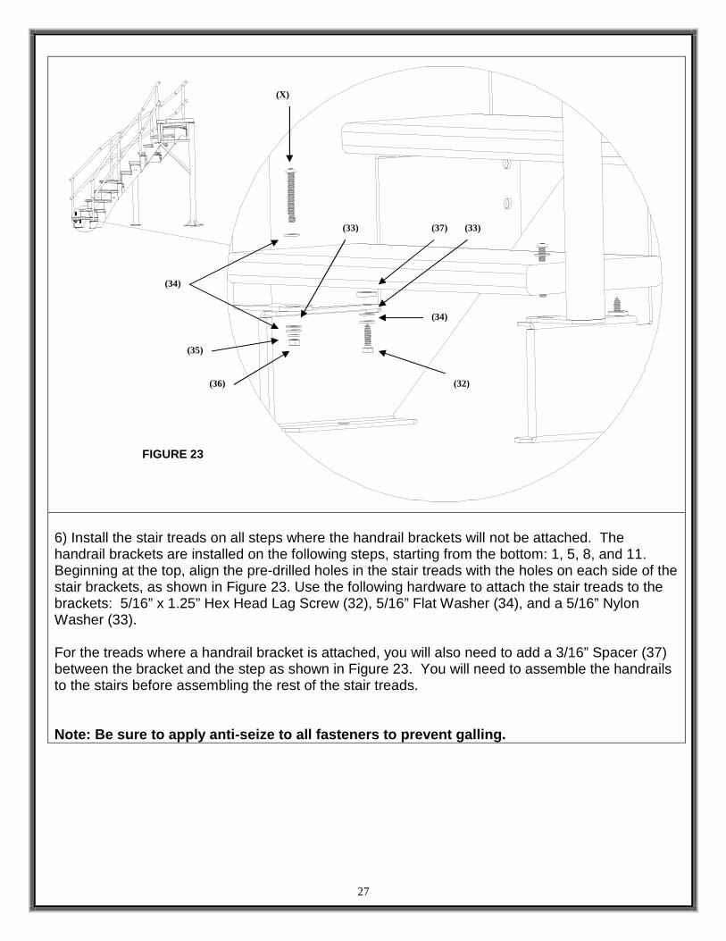
6) Install the stair treads on all steps where the handrail brackets will not be attached. The handrail brackets are installed on the following steps, starting from the bottom: 1, 5, 8, and 11. Beginning at the top, align the pre-drilled holes in the stair treads with the holes on each side of the stair brackets, as shown in Figure 23. Use the following hardware to attach the stair treads to the brackets: 5/16” x 1.25” Hex Head Lag Screw (32), 5/16” Flat Washer (34), and a 5/16” Nylon Washer (33). For the treads where a handrail bracket is attached, you will also need to add a 3/16” Spacer (37) between the bracket and the step as shown in Figure 23. You will need to assemble the handrails to the stairs before assembling the rest of the stair treads. Note: Be sure to apply anti-seize to all fasteners to prevent galling.
FIGURE 23
(X)
(34)
(33)
(35)
(36) (32)
(34)
(37) (33)

28
7) Position the inside and outside handrails in place, as shown in Figure 24. To ensure proper alignment of the assembly, temporarily install hardware through the mounting holes in the handrail brackets and the stair brackets. On steps where a handrail bracket is attached, you will have to use the following hardware to attach the stair treads through the brackets: 5/16” x 2.5” Socket Head Cap Screw (49), 5/16” Flat Washer (34), 5/16” Nylon Washer (33), 5/16” Flat Washer (34), 5/16” Lock Washer (35), and a 5/16” Hex Nut (36), see Figure 19. Next, be sure that the mounting plate for the Middle Stair Support (48) and the Step Bracket Anchor (16) are flat against the concrete deck. Mark the hole locations for the concrete anchors in the base of the middle stair support and the step bracket anchor. Remove the hardware connecting the top ladder brackets to the lower stair assembly. The handrails will also need to be removed. Move the stair assembly out of the way so that the concrete anchors can be installed. Drill the 3/8” diameter X 2” deep holes for the concrete anchors for the Middle Stair Support and the 1/2” X 2” deep holes for the Bottom Ladder Brackets in the locations previously marked out. Follow the instructions on page 30 for inserting the concrete anchors into the deck. Place the stair assembly back in position over the installed concrete anchors. Attach the following hardware to the concrete anchors, but do not fully tighten: Nylon Washer, Flat Washer, Lock Washer, and a Hex Nut. Reattach the stair assembly and the handrails. After all hardware has been attached, go through and make sure that all hardware is tightene d securely.
FIGURE 24

29 (49) (50) (51)
(12) (9) (10)
(23) (24) (25) (26)
VORTEX LADDER PARTS LIST
ITEM # PART # DESCRIPTION QTY. 9 5-523-SS ½” x 3-3/4” CONCRETE WEDGE ANCHOR W/HRDWR 4 ea. 10 5-250 3/8” x 3-1/2” BHCS S/S 2 ea. 12 5-515 3/8” x 5” BHCS S/S 2 ea. 24 5-145 3/8” FLAT WASHER S/S 12 ea. 25 5-151 3/8” LOCK WASHER S/S 8 ea. 26 5-139 3/8” HEX NUT S/S 8 ea. 23 05-32-111 3/8” NYLON WASHER 6 ea. 49 14-209 LADDER 1 ea. 50 14-204 LEFT GUARDRAIL 1 ea. 51 14-203 RIGHT GUARDRAIL 1 ea.

30
VORTEX LADDER ASSEMBLY INSTRUCTIONS
1) Move the ladder into place as shown in Figure 25. Align the holes in the ladder angle bracket with the holes in the entrance section. To ensure proper alignment of the assembly, temporarily place bolts through the mounting holes in the ladder and the entrance section. It is also recommended that the bar clamps be used at this point to ensure that the ladder remains in place. Next, be sure that the mounting plate is flat against the concrete deck. Mark the hole locations for the concrete anchors in the base of the ladder. Remove the ladder and drill the 1/2” diameter X 2.25” deep holes for the concrete anchors. Follow the instructions on page 30 for inserting the concrete anchors into the deck. Place the ladder over the concrete anchors and against the entrance section of the slide. Attach the following hardware to the concrete anchors, but do not fully tighten: 1/2” Nylon Washer, 1/2” Flat Washer, 1/2” Lock Washer, and a 1/2”-13 Hex Nut. Next, place the required hardware into the holes on the front face of the ladder angle bracket, See Figure 25, Detail A. The required hardware is as follows: 3/8” x 3.5” Button Head Cap Screw (10), 3/8” Flat Washer (24), 3/8” Nylon Washer (23), 3/8” Flat Washer (24), 3/8” Lock Washer (25), 3/8” Hex Nut (26). This should be done for both sides of the ladder. After this connection is completed, finish tightening down the hardware at the base of the ladder. Note: Be sure to apply anti-seize to all fasteners to prevent galling.
FIGURE 25
(26)
(25) (24)
(23)
(10)

31
2) First, place the Left Guard Rail (50) in the two sockets on the top of the Entrance Section so that the bolt end comes through the body of the slide, as shown in Detail A. Use the following hardware to attach the guardrail foot to the entrance section and the ladder: 3/8” x 5” Button Head Cap Screw, 3/8” Flat Washer (24), 3/8” Nylon Washer (23), 3/8” Nylon Washer (23), 3/8” Flat Washer (24), 3/8” Lock Washer (25), and a 3/8” Hex Nut (26), see Detail B. Do not fully tighten yet. Then attach the hardware to the two studs on the sides of the slide: 3/8” Flat Washer (24), 3/8” Lock Washer (25), and a 3/8” Hex Nut (26), see Detail A. After all hardware has been attached tighten each b olt securely. Second, place the Right Guard Rail (51) in the opposite side and repeat the steps to mount it securely to the slide. Note: Be sure to apply anti-seize to all fasteners to prevent galling.
FIGURE 26
(24)
(12)
(24)
(23)
(25) (26)
(25)
(26)
32
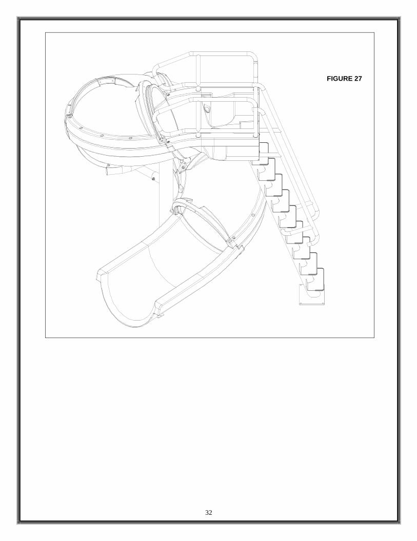
FIGURE 27

33
(52) (53)
(54) (55) (56)
(57)
VORTEX WATER SYSTEM PARTS LIST
ITEM # PART # DESCRIPTION QTY. 52 05-788 1-1/2” CLIC TOP PIPE CLAMP 4 ea. 53 5-522 #8-32 x 2” PANHEAD SCREW (PRE-INSTALLED IN MAIN
TUBE SUPPORT) 4 ea.
54 1-305-3 1-1/2” x 3” SCH 80 PIPE 1 ea. 55 05-795 1-1/2” 45 DEG SCH 80 ELBOW 1 ea. 56 05-794 1-1/2” 90 DEG SCH 80 ELBOW 1 ea. 57 05-777 1-1/2” PVC BALL VALVE 1 ea. 58 05-789 1-1/2” PVC FLEX HOSE 6’ LENGTH (NOT SHOWN) 2 ea.

34
VORTEX WATER SYSTEM ASSEMBLY INSTRUCTIONS
1) First, attach all of the 1-1/2” Clic Top Pipe Clamps (52) using the #8-32 X 2” Panhead Screw (53) as shown in Detail A. Repeat this step for the all 5 of the pipe clamps.
FIGURE 28
(53) (52)

35
2) Next, place three PVC components together in the order shown in Detail B. Do not glue any of the parts together at this point. The plumbing system should be fully assembled to ensure correct orientation before the parts are glued together. Assemble the 1-1/2” x 3” Sch 80 PVC pipe (54) into the back side of the water nozzle in the entrance section. Next, attach the 1-1/2” 45 degree Sch 80 Elbow (55), and finally the 1-1/2” 90 degree Sch 80 Elbow (56). The 1-1/2” PVC Flex Hose (58) runs along the Main Support (5), so make sure that the 1-1/2” 90 degree Sch 80 Elbow (56) points toward that direction.
FIGURE 29
(54)
(55) (56)

36
3) Starting at the stub location, connect the 1-1/2” PVC Flex Hose (58) and bring up through the first and second 1-1/2” Clic Top Pipe Clamps (52). Then attach the 1-1/2” PVC Ball Valve (57). On top of the ball valve, you should attach another length of 1-1/2” PVC Flex Hose (58), and run it up through the next two 1-1/2” Clic Top Pipe Clamps (52) to the 1-1/2” 90 degree Sch 80 Elbow (57). When all of these connections have been successfully completed, start at the top and use PVC primer and glue to attach each connection securely. First place the primer on both surfaces that will be attached, then place the glue on the connections and slide them together. These are not provided, but can be purchased at any plumbing supply store.
FIGURE 30
FIGURE 31 FIGURE 32
(57)

37
CONCRETE WEDGE ANCHOR MOUNTING INSTRUCTIONS
1. Place the assembled slide on the deck relative to the pool wall. Ensure that the exit flume clears any coping. Slide may be angled slightly providing all dimensions are maintained as noted in the Manufacturer’s Placement Instructions noted in the following section.
2. With the slide in its proper location, center punch or otherwise mark through the mounting holes at
the bottom of the ladder and pedestal so that a visible mark is apparent on the concrete.
3. Using a hammer drill and a concrete drill bit, drill the holes to the required depth. Use tape or a marking on the drill bit to ensure that the hole for the anchor is drilled to the required depth. Maintain drill hole straight and perpendicular for proper holding strength of anchor stud.
4. Clear the holes of all debris. Assemble anchor with nut and
washer so that the top of the nut is flush with the top of the anchor. Move the slide over the holes and insert the anchors. Drive anchor through the slide mounting holes so that nut and washer are flush with the surface material.
5. Expand anchor by tightening nut 3 to 5 turns. Once anchor is set remove nut and install a lock washer, and retighten nut to a torque of 25 ft.-lbs.

38
MANUFACTURER’S PLACEMENT INSTRUCTIONS PROPER ASSEMBLY, INSTALLATION, USE, AND SUPERVISION IS ESSENTIAL FOR PROPER OPERATION AND TO REDUCE THE RISK OF SERIOUS INJURY OR DEATH. 1. The critical dimensions for placement of the VORTEX are as shown in FIGURE ’S 33 and 34.
A. The slide exit runway surface shall not exceed twenty inches (20”) above the water surface as shown in FIGURE 33.
B. The slide shall be positioned so that all water flowing off the runway exit drops into the pool. The recommended overhang is 4 inches.
C. The minimum depth of water below the exit lip of the slide shall be three feet (3’) and increase to four feet six inches (4’-6”) at Pt. A, which is a distance of four feet six inches (4’-6”) from the exit lip of the slide as shown in FIGURE 33.
D. A minimum depth of four feet six inches (4’-6”) shall be maintained at a distance of nine feet (9’) along the extended centerline of the slide from Pt. A. as shown in FIGURE 33.
2. A minimum clearance area in front of the slide shall be maintained at all times as follows:
A. The minimum clearance distance on either side of the extended centerline of the slide runway shall not be less than three feet six inches (3’-6”) at a point no less than two feet six inches (2’-6”) from the exit lip of the slide and extending a distance of thirteen feet six inches (13’-6”) in front of the slide as shown in FIGURE 34.
FIGURE 33
FIGURE 34

39
3. SLIDE PLACEMENT INSTRUCTIONS FOR INSTALLATIONS ON POOLS WITH OTHER SLIDES AND/OR DIVING BOARDS
A. The minimum clearance area in front of a properly installed diving board on an inground swimming pool is a minimum distance of three feet six inches (3’-6”) on either side of the board’s centerline as shown in FIGURE 35. Pt. C extends a minimum distance of “C” from the tip end of the board as shown in FIGURE 35. The width distance “W” on either side of Pt. C is given in CHART 1 and shown in FIGURE 35.
“C” DIMENSION FOR BOARD = AB + BC or L2 + L3 “W” DIMENSION FOR BOARD = WIDTH AT PT.C
B. The minimum clearance area of a slide or diving board shall not intersect any coping or rope and
float line as shown in FIGURE 36. The minimum clearance area of a slide or diving board may intersect each other provided that they are not used simultaneously.
CHART 1 BOARD MINIMUM CLEARANCE AREA
POOL TYPE “C” DIMENSION “W” DIMENSION I 14’-6” 5’-0” II 14’-6” 6’-0” III 16’-6” 6’-0” IV 18’-6” 7’-6” V 21’-0” 7’-6” VI 18’-6” 9’-0” VII 21’-0” 10’-0” VIII 25’-0” 11’-0” IX 31’-6” 12’-0”
For Pool Type I-V, see Article 5.8 contained in ANSI/APSP/ICC-5 2011 STANDARD FOR RESIDENTIAL INGROUND SWIMMING POOLS and refer to FIGURE 3 and Table 1 for Minimum Water Envelope Dimensions AB, BC and Width at Point C. For Pool Type VI-IX, see Article 6.6 in ANSI/APSP-1 2003 STANDARD FOR PUBLIC SWIMMING POOLS and refer to Minimum Dimensions for Diving Portion of Class B and C Pools.
FIGURE 36
FIGURE 35