Embed Size (px)
Citation preview

IOSR Journal of Engineering (IOSRJEN) www.iosrjen.org
ISSN (e): 2250-3021, ISSN (p): 2278-8719
Vol. 07, Issue 04 (April. 2017), ||V1|| PP 20-31
International organization of Scientific Research20 | P a g e
Vortex flow over the flat plate and backward facing step
Malladi.R.CH.Sastry, Jthendra Kumar Repalle,I.Mehar Anudeep, N.Prem das Professor, Gudlavalleru Engineering College,Gudlavalleru, Assistant Professor, Gudlavalleru Engineering
College,Gudlavalleru, Assistant Professor, Gudlavalleru Engineering College,Gudlavalleru,Assistant
Professor, Gudlavalleru Engineering College,Gudlavalleru,
Abstract :- Fluid mechanics always plays a predominant role in different kinds of engineering streams. The
study of fluid flows is always an area of interest and it consists of different applications like flow past cylinders,
flat plate, and flow over suddenly expanded geometries. This paper deals with the experimental study of fluid
flow over suddenly expanded geometries at different Reynolds numbers. It is difficult to identify the flow
phenomena when the flow is inside a pipe. Hence the fluid is made to flow in an open channel so that the flow
phenomena can be easily observed. A suddenly expanded geometry is introduced during this flow at a certain
distance and a flow phenomenon is observed. Due to the expanded geometry vortex flow is created and this
vortex flow with different models at different Reynolds number is to be observed and analyzed.
During the formation of vortex flow reverse flow occur this reverse flow is also to be investigated. The effect of
change of geometry on vortex region is to be identified. By calculating various parameters like velocity,
Reynolds number and Froude number the flow will be identified whether it is sub critical or super critical.
Depending on the type flow it is to be analyzed. The flow conditions are observed by varying the shape of the
object to be introduced in the flow. Analysis of the flow will be used to understand the concepts of vortex flow,
reverse flow or recirculation zone, sub critical flow etc.
Flow over suddenly expanded geometries includes various applications like body of an automobile etc.
so the analysis of flow phenomena over the various shapes provides accurate solutions to various real problems.
I. INTRODUCTION Flow over simple geometries:
Simple geometries accommodate a flat plate and circular cylinder. The study of fluid flow over
these straightforwardgeometries can facilitate in understanding varied ideas of fluid dynamics. Flow over a flat
plate provides massivesupply of data regarding the physical phenomenon separation and transition of be
due laminar to turbulent. On the opposite hand, flow past a blunt body, like a circular
cylinder, sometimes experiences physical phenomenonseparation and extremely sturdy flow oscillations within
the wake region behind the body. Whenever the flow encounters associate degree object in its path associate
degree adverse pressure gradient is made and also the shear layer separation takes place on the sides of the
item and also the flow gets separated at some extent makinga pressure uphill region. and also the separated flow
tries to induce connected behind the item. Within the methodof reattachment flow gets re circulated or reversed
behind the item by forming vortices on the sides. The shapedvortex manipulation is that the key
for analysis of mechanics forces. This paper in the main targeted on reattachment purpose and also the vortex
region totally different for various objects at different Sir Joshua Reynolds variety (by variable the speed of the
flow field)
Suddenly expanded geometries:
Fluid flow past steps is an interesting practical problem with wide range of applications. Flow over
steps plays a dominant role in many practical situations. Most of the sequences involving flow past (or) over
various structures regard for the analysis of various characteristics of the flow such as flow pattern, pressure
distribution at various points of the flow etc.
In order to meet the requirements of the working environment with accuracy and efficiency, most of
these obstacles are comprised of cubical or cylindrical geometries. Hence researchers are showing much interest
in those areas involving flow over the cylindrical or cubical geometries. Out of the geometries involving cubical
structures, flow past steps has been proved as an interesting problem with wide range of practical applications.
In the open literature, various geometric parameters for this study are hardly available. Though there is large
amount of data both experimental and theoretical available in the literature, they are applicable mostly for high-
speed flows. Only limited information is available for the case of low subsonic flow past the steps. Even the
available information was confined to only steps with faired entrance.
The subsonic flow past the steps is an important area which needs further investigation. The reason for
going to study flow over stepped pattern is that it is being used most frequently than any of the other models.
There is innumerous number of practical applications for a stepped pattern. Though every application may not

Vortex flow over the flat plate and backward facing step
International organization of Scientific Research21 | P a g e
be an exact replica of the pattern, there may be slight modifications, which have their own specific reasons. For
example the most real time application is the body shape of any automobile (cars). A closer view at its shape
gives an idea that it has been derived from the stepped pattern. The body shape of a car combines both forward
facing step and backward facing step. However for drag reduction and practical utility view-point, various
combinations of step patterns have to be studied thoroughly. Till date many researchers have carried out their
work on flow over step with 900 of inclination.
II. FLOW THROUGH SUDDEN EXPANSION:
Change in flow rate owing to amendment (increase) within the pure mathematics of a pipe system
i.e., amendment (increase) in crosswise sets up eddies within the flow. This eddies doesn't follow a straight path
to the middle it follows a volute, whirling path. This path is named a vortex. A characteristic feature of a vortex
is that the skin of the vortex moves slowly and therefore the centre moves quickly. If the crosswise of a pipe
with fluid flowing through itis suddenly enlarged at sure place, fluid rising from the smaller pipe is unable to
follow the abrupt deviation of the boundary. Then the contour takes a typical radiating pattern. This creates
pockets of turbulent eddies within the corners leading to the dissipation of energy into building
block energy. and therefore the fluid flows against associate degree adverse pressure gradient. The upstream
pressure p1 is below the downstream pressure p2since the upstream rate V1 is over the downstream rate V2 as a
consequence of continuity. The fluid particles close to the wall owing to their low K.E. cannot overcome the
adverse pressure hill within the direction of flow and thus follow up the reverse path underneath the favorable
pressure gradient (from p2 to p1). This creates a zone of re-circulating flow with turbulent eddies close to the
wall of the larger tube at the abrupt amendment of crosswise, leading to a loss of total energy.
Fig 1.1 Geometrical representation of sudden expansion flow
Variation of pressure across sudden expansion:
After the flow encountering the sudden growth it separates from the wall and it attaches to the
wall far from the vertical wall. when the flow attaches to the wall it moves towards the face of the
model attributable to presence of depression at the vertical wall. And this recirculated flow rejoins with the
freestream flow and moves downstream. because the flow moves over a wall as a result of friction loss in
pressure takes place and when sudden growthspeed decreases and pressure will increase The fluid particles close
to the wall as a result of their low mechanical energy cannot overcome the adverse pressure hill within
the direction of flow and thus follow up the reverse path beneath the favorable pressure gradient.
Flow separation: The presence of the fluid consistence slows down the fluid particles terribly near the solid surface and
forms a skinny slow fluid layer known as a physical phenomenon. The flow speed is zero at the surface to
satisfy the no-slip stipulation. within the physical phenomenon, flow momentum is sort of low since it
experiences a powerfulviscous flow resistance. Therefore, the physical phenomenon flow is sensitive to the
external pressure gradient (as the shape of a pressure force acting upon fluid particles). If the pressure
decreases within the direction of the flow, the pressure gradient is claimed to be favorable.
However, if the pressure is increasing within the direction of the flow, AN adverse pressure gradient condition
as therefore it's known as exist. Additionalto the presence of a powerful viscous force, the fluid
particles currentlyought to move against the increasing pressure force. Therefore, the fluid particles can
be stopped or reversed, inflicting the neighboring particles to maneuver aloof from the surface.
This development is named the physical phenomenon separation.
III. LITERATURE REVIEW Introduction:
Two-dimensional laminar flow of an incompressible Newtonian fluid in a symmetric sudden expanded
channel flows with moderate expansion ratio. When the Reynolds number Re is relatively low, the flow is
symmetric and the re-circulating regions at the two channel walls are also symmetric. With the increase of

Vortex flow over the flat plate and backward facing step
International organization of Scientific Research22 | P a g e
Reynolds number, the flow remains two-dimensional but asymmetry of the flow sets in. Additional recirculation
zones appear along the channel walls for further higher values of Re. Using asymptotic analysis studied by G.C.
Layek et al [1].
Hawademonstrated that when the Reynolds number is smaller than a critical value, Rec, the symmetric
states have an asymptotically stable mode of disturbance. However, when Re > Rec, the symmetric states are
unstable to this mode of asymmetric disturbance. The asymmetry of the flow depends on the Reynolds number
of the flow, the expansion ratio and also on the aspect ratio. Zengyuanguostudied on Heating a gas flow in the
sudden expansion duct will result in the reduction in the corner recirculation zone (CRZ) length. The CRZ can
even disappear if the heating intensity is sufficiently large. The mechanism of heating effect on the CRZ lies in
the heating induced falling pressure gradient/pressure drop (thermal drag), which counteracts the adverse
pressure gradient and results in shrinkage of CRZ. describe The effects of side wall on the structure of laminar
flow over a plane-symmetric sudden expansion by varying the expansion ratio at different Reynolds number is
described by T.P. Chian et al [5]
Asymmetry in the turbulent flow of a viscoelastic liquid through an axisymmetric sudden expansion,
how the flow is varying across the geometry for different fluids was described by C. Dales, M.P. Escudier, et al
[4]. Jagannathrajasekharan et al [6] describe the flow characteristics behind the backward facing step and
studied separating point and attachment point and vortex shedding mechanisms by changing aspect ratio for
different types of models. Xuyongying, FuyoyXu, ZheZang et al [7] describe the numerical simulation and
visualization of flow around rectangular bluff bodies. Attachment length and recirculation length, lift coefficient
were calculated at Re 21400 using CFD simulation. Various influencing parameters were also studied. H
Sharma, AVashishtha and E Rathakrishnan et al [8] has studied the twin vortex flow around a flat plate and a
circular arc with same chord length at different angles and at different Reynolds number in an open channel.
They also manipulated the vortex length by capturing the flow at different Reynolds number. S.P Das,
U.Srinivasan, J.H Arakeri, et al [9] has studied the unsteady separation and vortex shedding from laminar
separation bubble over a bluff body in a channel. They studied about the shear layer separation for different
bluff bodies at different pressure gradients.
Present work
The intent of the present work is to investigate the nature of recirculation regions formed when the flow
encounters a normal flat plate placed at two different angles and also the primary and secondary recirculation
regions formed near the wall when the flow encounter the sudden change (increase) in geometry in its direction.
The above recirculation regions are observed for every model at different Reynolds number to compare the
results.Flow visualization is proved as one of the best techniques for describing and evaluating the flow features
of many real flow field problems in both subsonic and supersonic speeds. Many of the researchers have
developed many techniques such as smoke flow visualization, tufts, and chemical coating, shadowgraph, and
schlieren techniques to visualize the motion of air over the objects. Apart from all those an experimental set up
called open channel is one of the cheapest techniques used to visualize the flow over objects. Hence in our work
we have taken the open channel set up to visualize the flow conditions.
3. Experimental procedure
Experimental setup
Flow mental image is established mutually of the most effective techniques for describing and
evaluating the flow options of the many real flow field issues in each subsonic and supersonic speeds. several of
the researchers have developed several techniques like smoke flow mental image, tufts, and chemical
coating, photo, and schlierentechniquesto visualize the motion of air over the objects. With the exception of all
those associateexperimental started referred to as open channel is one amongst the most
affordable techniques wont to visualize the flow over objects.
Fabrication of Channel:
The channel is created of G.I sheet of 5mm thickness and also the sheet was bent into the form as
shown within thefigure. The breadth of the check section is of regarding 280mm and also the depth of water is
going to bemaintained 8mm.

Vortex flow over the flat plate and backward facing step
International organization of Scientific Research23 | P a g e
Fig. 3.1 Solid model of open channel
Calibration of the channel:
Calibration of any experimental setup is the important factor for getting the output accurately. Since the open
channel is very sensitive setup to the disturbances in the flow or the effect of surroundings on the channel, even
a very small disturbance like our breathing action on to the channel leads to suppress the total information which
is obtained. The calibration of the channel consists of some factors which are stated given below.
The size of the tank is one of the important factors in the channel setup. The small size of the tank leads
to increase the turbulence in the flow, whereas the large tank leads for the storage of large amount of water and
less turbulence in the water. Even though the increment in the size of the tank leads to the increase the size of
total experimental which can not to be entertained for the economical and the manufacturing defects comprises
of the channel. So in the present channel the size of the tank is 300×150×160 mm3.The main function of the
wedge is to drive the flow into the rest part of the channel uniformly, in fact it acts as spillway for the channel to
reduce the disturbance created by direct release of the flow into the channel. The angle of the wedge plays a
vital role because on decrease in the angle the height of the wedge is going to increase which may create the
disturbance because increase in the velocity of the flow. Whereas, increasing the angle the height of the wedge
decreases which leads to the less storage of water in the tank and the base width of the wedge also increases
which may cause decreases in the test section length which is not desirable. So from the discussion it can be
conclude that the angle of wedge should be in the range of 450 to 75
0. So in the present channel the wedge angle
is taken as 600.
The distance between the tank wall and the edge influence the size of the tank and the angle of the
wedge. As discussed above the variation in the size of the tank leads to create its own corresponding problem. It
also influences the angle and width of the wedge to be placed in the channel. By conducting the experiment by
trial and error method, it is concluded that the distance between the tank wall and the screens is decided as
150mm for the above tank and wedge configurations. The screen plays important role in the quality of the flow
in the sense of turbulence and the streamlined flow. The size of screen in the present design refers to the grid
size of the mesh. The larger grid size leads to the increase in the width of the streamline which is not effective
on the flow features over objects, where as the smaller grid size screen leads to the fine and effective streamline
flow over the models. So for effective flow features the size of the grid is as possible as minimum. The present
screen is made of stainless steel of minimum grid size which is available in the market, which fulfills the present
requirements and it also free from rust.
The distance between screens and the edge mainly reflects the flow quality because there should be an
enough space and the time for the flow to be settled before passing through the screens. The increase in the
distance leads to the increase of the channel dimensions which is not desirable, whereas the small distances lead
to small disturbances in the flow. To obtain the steady, uniform and streamlined flow the distance between the
screen and the wedge is taken as 130mm by doing experiments with different configurations. The uniformity of
the flow depends on the number of screens placed. Generally three screens will be preferred for the better
quality flow, whereas increasing the screens leads to the decreasing the test section length which is not
desirable. The distance between the screens is also taken into account for the calibration. It is because, the dye is
injected at the starting of second screens because by the time flow comes out the flow will be streamlined.
Generally the gap taken between the screens is about 10mm. The test-section is the area in the channel where
the model which is to be tested is placed. The length of the test-section depends on the parameters which stated
above. Generally the space which is available behind the screen is taken as test-section length. It should be
Wedge
Test section
Wire mesh
Water chamber

Vortex flow over the flat plate and backward facing step
International organization of Scientific Research24 | P a g e
moderate because the larger test-section length leads to the disturbances. By taking the all parameters into
account the length of test-section is taken as 720mm for the present channel.
Experimental procedure:
In the initiative mark the size and angles on the take a look at section portion of the
channel which is able to be accustomed live the some flow parameters. Place the channel on fine and straight
place that has no inclination. Currently offer the water to the channel at the water chamber in order that the
fairly uniformly flow are moving intothe take a look at section attributable to the impact of wedge and
screens.Test for the uniformity of flow i.e., either the flow was moving into the line from getting down to the
tip of the channel, if not build some changes to induce the uniform flow.In this step flow rate to be set within
the channel per the need, the speed of flow iscalculated by victimization the floating
particle technique that was delineated higher than.After setting the specified rate keep the model to be take a
look atwithin the test section per the necessities.Now inject the ample quantity of dye at the second
screen that helps to induce the flow and take the video from getting down tothe tip of flow pattern over the
thing for additional investigation.In this step amendment the model and repeat the higher than step.Calculate
the Reynolds variety for various objects supported the characteristicdimension and corresponding rate at
the part conditions.From the video extract the frames and keep the required frames for the analysis.
The models used for the study ar a flat plate, a backward facing step (BFS), combined step(both forward facing
and backward facing).The BFS and combined step ar designed atsame step height of 20cm, 30cm.
The models are shown in below Figs. 3.2 a, 3.2b, 3.3c, 3.4d.
Dimensionsof solid models:
Fig.3.2a Flat plate with uniform length of 44mm
Fig.3.2b backward facing step with step height of 22mm
IV. RESULTS AND DISCUSSION Calculation of Reynolds number
The Sir Joshua Reynolds go assumes a vital part inside the liquid flow, as an aftereffect of it's the sole
reference parameter for the outline of the delay the feign bodies. It conjointly assumes a primary part inside the
delineation of the stream include inside the mental picture procedures. to look out the Sir Joshua Reynolds go
starting the most parameter required is speed of stream which may be measured by the different procedures.
Among the different diverse systems, skimming molecule procedure is utilized inside the blessing study. inside
the coasting molecule technique, time taken to the travel drifting molecule over a separation is measurable. the
speed will be figured by isolating the hole with the time. when searching for the speed the Sir Joshua Reynolds
range will be ascertained with respect to the measurement of the model by exploitation the ensuing equation
Re = ρ V D/…………. (3.1)
Where
Re is the Reynolds number,
ρ is the density of the fluid,
D is the characteristic dimension of the body,
is the dynamic viscosity of the fluid.
V is the velocity of the flow.
Vortex flow over the flat plate and backward facing step
International organization of Scientific Research25 | P a g e
Characteristic dimensions of different models:
Table 4.1Reynolds number at velocity V1(Re1):
Table 4.2Reynolds number at velocity V2(Re2):
Velocity(m/sec) Flat plate BFS
0.0795 4387 3191
Table 4.3
The present work aims at understanding flow separation, recirculation, attachmentand reverse flow
phenomenon. The above mentioned flow features are highly complex to deal and understand. An attempt has
been made to understand above flow features by using sudden expanded geometries. The models are designed to
understand the effect of shape of the model on the complex flow phenomenon by varying reynolds number.
Flow over a flat plate placed parallel to the flow at Re1:
When a flat plate was introduced into the flowthe flow gets deviated from its flow path forming small
vortices along the edges of the plate. The separated flow gets attached at a distance of 10cms from the rear end
of the plate. The small vortices which are formed along the edges mixed and turns into a single vortex. The
small vortices which are formed will try to move towards the rear end of the plate thus forming a recirculation
zone. The formation of vortices and the recirculation of the flow of fluid can be visualized by introducing a
color dye in to the flow field. The observations are made from the following pictures which were taken during
the flow over the plate.
(a) (b)
(b) (d)
Fig.4.1 Flow visualisation of Flat plate parallel to the flow at Re1
Fig (a) represents the separation of flow along the edges and formation of vortices along the top edge.
Fig (b) shows the formation of vortex on the down edge and the vortices of both the edges tries to move towards
the plate opposite to the fluid motion without getting attached. Fig (c) shows the flow attachment at a distance of
nearly 6cms from the rear end of the plate and the mixing of small vortices to form a single vortex which is
moving towards the rear end of the plate. The length of recirculation zone is nearly 7cms from the back of the
plate.Fig (d) shows the vortex clearly touching the object and vortex length calculated from this figure is nearly
6cms.
Flat plate placed perpendicular to the flow at Re1:
When the flat plate was introduced perpendicular to the flow the flow gets separated along the
thickness of the plate on either side. On both the sides small vortices are formed along the thickness of the plate.
The separated flow on either side of the plate gets attached at the rear end of the plate. The flow separation and
the vortex formation leads to the reverse flow at the back of the plate. All these flow conditions are analysed by
introducing the color dye into the flow field and by observing the following photographs which were taken
Model name Characteristic dimension(m)
Flat plate 0.044
BFS 0.032
Velocity(m/sec) Flat plate BFS
0.1153 6363 4628
Vortex flow over the flat plate and backward facing step
International organization of Scientific Research26 | P a g e
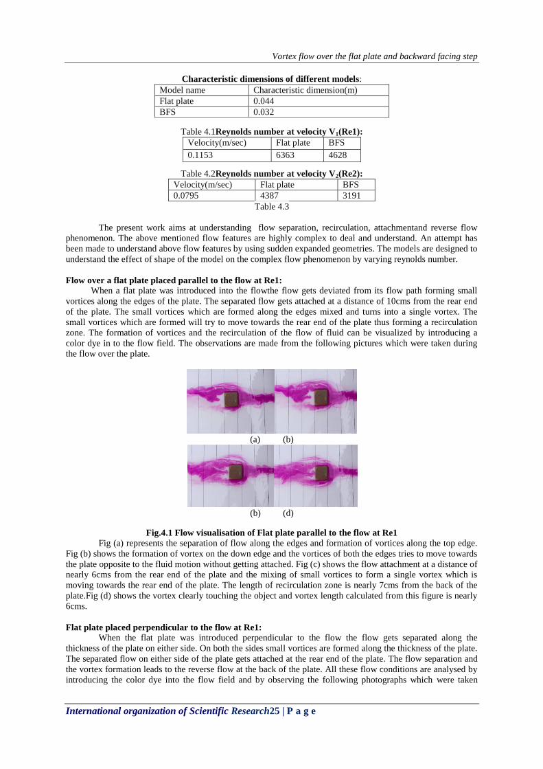
during the flow over the plate. The vortex length is calculated from these photographs by utilizing the calibrated
scale on the test section. The pictures which were kept for observations are as follows.
(a) (b)
(c) (d)
Fig.4.2 Flow visualisation of Flat plate perpendicular to the flow at Re 1
Fig (a) shows the flow getting separated along the thickness of the plate on both sides by forming small
vortices at the back of the edge. From Fig (b) it is observed that the separated flow around the plate is getting
forward to attach at a point and the vortices formed are increasing their size and flowing back towards the plate
thus creating a reverse flow at the back end of the plate. The vortex formed is of the length 10cms. The length of
recirculation zone is at a distance of 12cms from the back of the plate.The above two flow conditions of the flat
plate are studied at the same Reynolds number. When the plate is placed parallel to the flow the vortex formed is
of lesser length where as in the perpendicular condition it is of higher length. So the drag force on the plate
which is perpendicular to the flow will be more when compared to the plate placed parallel to the flow.
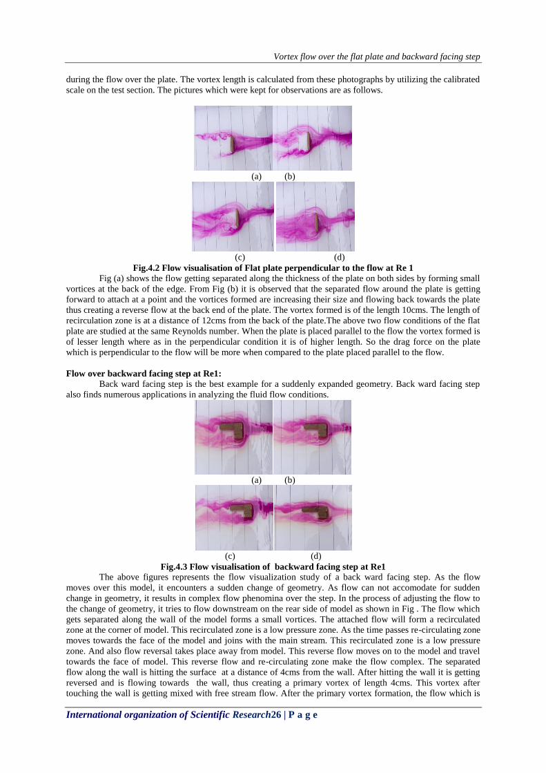
Flow over backward facing step at Re1:
Back ward facing step is the best example for a suddenly expanded geometry. Back ward facing step
also finds numerous applications in analyzing the fluid flow conditions.
(a) (b)
(c) (d)
Fig.4.3 Flow visualisation of backward facing step at Re1
The above figures represents the flow visualization study of a back ward facing step. As the flow
moves over this model, it encounters a sudden change of geometry. As flow can not accomodate for sudden
change in geometry, it results in complex flow phenomina over the step. In the process of adjusting the flow to
the change of geometry, it tries to flow downstream on the rear side of model as shown in Fig . The flow which
gets separated along the wall of the model forms a small vortices. The attached flow will form a recirculated
zone at the corner of model. This recirculated zone is a low pressure zone. As the time passes re-circulating zone
moves towards the face of the model and joins with the main stream. This recirculated zone is a low pressure
zone. And also flow reversal takes place away from model. This reverse flow moves on to the model and travel
towards the face of model. This reverse flow and re-circulating zone make the flow complex. The separated
flow along the wall is hitting the surface at a distance of 4cms from the wall. After hitting the wall it is getting
reversed and is flowing towards the wall, thus creating a primary vortex of length 4cms. This vortex after
touching the wall is getting mixed with free stream flow. After the primary vortex formation, the flow which is

Vortex flow over the flat plate and backward facing step
International organization of Scientific Research27 | P a g e
hitting the surface is again detached from the surface by forming a boundary layer and thus responsible for
secondary vortex of length 6cms.
Flow over a flat plate placed parallel to the flow at Re2:
The flat plate which is used to study the flow conditions at Re1 with the same dimensions is used to
study the flow conditions at Re2. The figure no is used to visualise the flow conditions
(a) (b)
(b) (d)
Fig.4.4 Flow visualisation of Flat plate parallel to the flow at Re2
As the flow reaches towards the plate which is placed parallel to the flow the flow is getting separated
along the edges of the plate on both the sides by forming small vortices along the edges. These vortices are
growing in size and trying to flow towards the rear end of the plate. From above figures it can clearly observed
that the attachment point is at a distance of nearly 4cms from the rear end of the plate. The reverse flow region
which is created at the back of the plate is a low pressure region in which the flow is re circulated and mixed
with the free stream. The recirculation zone is at a distance of 5cms from the back of the plate.
Flow over flat plate placed perpendicular to the flow at Re2:
The flat plate is now place perpendicular to the flow and the flow conditions are analyzed at same
Reynolds number.
(a) (b)
C (d)
(e) (e)
Fig.4.5 Flow visualisation of Flat plate perpendicular to the flow at Re2
From the above figures it can be clearly observed that the flow gets separated along the thickness of the
plate on both the sides by forming twin vortices. The left vortex formed will be of larger size when compared
with the right vortex. These vortices are growing in size and getting attached at the back of the plate at a
distance of nearly 8cms. The vortex formed is clearly seen in the last figure, the vortex length is nearly same as

Vortex flow over the flat plate and backward facing step
International organization of Scientific Research28 | P a g e
the attachment length. The recirculation zone is of length 10cms from the back of the plate. When compared
with the plate placed parallel to the flow perpendicularly placed plate has larger vortex length and hence it
experiences a higher pressure drag.
Flow over backward facing step at Re2:
The step which was used at Re 1 is now used at Re2 to study the flow conditions by changing Reynolds
number.
(a) (b)
C (d)
(e)
Fig.4.6Flow visualisation of fow over backfacing step at Re2
As the uniformly flowing fluid suddenly experiences a sudden change of geometry in its flow direction,
then the flow tries to accommodate for the change in geometry. When the flow is trying to adjust to the change
of geometry, it results in the complex flow phenomena. In this case, when the flow approaches the wall
of the step the flow deviates from its path and get separated along the wall. The separated flow over the wall
touches the flat surface of the step at a distance of 3cms from the wall. After touching the surface it gets re
circulated and touches the wall and gets mixed with the free stream flow. In the process of recirculation it forms
a vortex near the wall which is of the length 3cms.The initial separated layers down the step mixed with the
separated layers over the wall at a distance of 4cms from the rear end of the complete step thus resulting in
secondary recirculation zone and vortex. The primary and secondary vortices formed are responsible for the
pressure drag.
V. CONCLUSIONS: The comparison of vortex length and length of recirculation zone for flat plate placed parallel to
the flow at Re1, Re2:
Table 5.1
Fig 5.1 comparison of vortex length of parallel flat plate at Re1, Re2
S.NO Vortex
length
(cm)
Recirculation zone length
(cm)
Re1 6 7
Re2 4 5
0
5
10
Re1 Re2
vortex length
recirculation length

Vortex flow over the flat plate and backward facing step
International organization of Scientific Research29 | P a g e
Flat plate placed parallel to the flow at high Reynolds number (Re1) has vortex length of 6cms and at
low Reynolds number it has a vortex length of 4cms. So with the increase in velocity of the flow field the length
of vortex and recirculation zone is increasing, hence the pressure drag on the object also increases.
The comparison of vortex length and length of recirculation zone for flat plate placed perpendicular to
the flow at Re1, Re2:
S.NO Vortex
length
(cm)
Recirculation zone
length (cm)
Re1 10 12
Re2 8 10
Table 5.2
Fig 5.2 comparison of vortex length and recirculation zone length of perpendicular plate
From the above figure it is concluded that at higher Reynolds number the flat plate placed
perpendicular to the flow has higher vortex length hence it is experiencing a higher pressure drag. Whereas the
same plate at low Reynolds number is having less vortex length and hence it experiences a less pressure drag.
Comparison of vortex length for parallel plate with perpendicular plate at Re1,Re2:
Fig 5.3 comparison of vortex length and recirculation length of parallel and perpendicular plate at Re1, Re2
When we compare flat plate placed parallel to the flow and perpendicular to the flow at Re1,Re2 it is
observed that plate placed parallel to the flow has less vortex length and plate placed perpendicular to the flow
has higher vortex length. So perpendicular plate has higher pressure drag than the parallel plate at corresponding
Reynolds number.
0
2
4
6
8
10
12
Re1 Re2
vortex length
recirculation length
Vortex flow over the flat plate and backward facing step
International organization of Scientific Research30 | P a g e
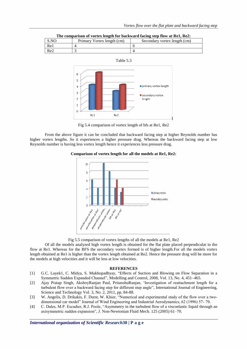
The comparison of vortex length for backward facing step flow at Re1, Re2:
S.NO Primary Vortex length (cm) Secondary vortex length (cm)
Re1 4 6
Re2 3 4
Table 5.3
Fig 5.4 comparison of vortex length of bfs at Re1, Re2
From the above figure it can be concluded that backward facing step at higher Reynolds number has
higher vortex lengths. So it experiences a higher pressure drag. Whereas the backward facing step at low
Reynolds number is having less vortex length hence it experiences less pressure drag.
Comparison of vortex length for all the models at Re1, Re2:
Fig 5.5 comparison of vortex lengths of all the models at Re1, Re2
Of all the models analyzed high vortex length is obtained for the flat plate placed perpendicular to the
flow at Re1. Whereas for the BFS the secondary vortex formed is of higher length.For all the models vortex
length obtained at Re1 is higher than the vortex length obtained at Re2. Hence the pressure drag will be more for
the models at high velocities and it will be less at low velocities.
REFERENCES
[1] G.C. Layek1, C. Midya, S. Mukhopadhyay, “Effects of Suction and Blowing on Flow Separation in a
Symmetric Sudden Expanded Channel”, Modelling and Control, 2008, Vol. 13, No. 4, 451–465.
[2] Ajay Pratap Singh, AkshoyRanjan Paul, PritanshuRanjan, „Investigation of reattachment length for a
turbulent flow over a backward facing step for different step angle”, International Journal of Engineering,
Science and Technology Vol. 3, No. 2, 2011, pp. 84-88.
[3] W. Angelis, D. Drikakis, F. Durst, W. Khier, “Numerical and experimental study of the flow over a two-
dimensional car model” Journal of Wind Engineering and Industrial Aerodynamics, 62 (1996) 57- 79.
[4] C. Dales, M.P. Escudier, R.J. Poole, “Asymmetry in the turbulent flow of a viscoelastic liquid through an
axisymmetric sudden expansion”, J. Non-Newtonian Fluid Mech. 125 (2005) 61–70.

Vortex flow over the flat plate and backward facing step
International organization of Scientific Research31 | P a g e
[5] T.P. Chiang, Tony W.H. Sheu, “S.K. Wang Side wall effects on the structure of laminar flow over a
plane-symmetric sudden expansion”, Computers & Fluids 29 (2000) 467±492.
[6] Jagannathrajasekaran, “ on the flow characteristics of a backward facing step and design of new model
for their study”.
[7] Xuyongying, FuyoyXu, ZheZang, “Numericalsimulation and visualization of flow around rectangular
bluff bodies”.
[8] H Sharma, AVashishtha and E Rathakrishnan , “ twin vortex flow around a flat plate and circular arc at
different angles to the flow”.
[9] S.P Das, U.Srinivasan, J.H Arakeri, “ Unsteady separation and vortex shedding from laminar separation
bubble over a bluff body”.