Embed Size (px)
Citation preview

Water kalibratie in gas.doc / 20.12.2005 1/9
To Whom It May Concern
Endress+Hauser BV Nikkelstraat 6-12 1411 AK Naarden Helga Linnartz Business Development Flow Email [email protected] Naarden, 20.12.2005
Vortex and Coriolis flow meters in gas applications Vortex and Coriolis flow meters today are commonly used for a wide variety of applications. As both meter types are based on universal measurement principles, they can be used for liquids as well as for gases. During the last decennia, a wealth of gas applications have been served by Vortex and Coriolis meters and application experience is available in abundance. Vortex volume flow meters Vortex meters have been used for gas flow measurement since their market introduction in the early seventies. Namely steam measurement has become their standard application due to their robust mechanical construction and wide range of process temperature and pressure. Vortex meters always measure the volumetric flow; for saturated steam applications an optional integrated temperature sensor can be used to calculate mass flow within the meter transmitter. Furthermore they are commonly used for process control or cost allocation metering of utility gases like compressed air, nitrogen or oxygen. Coriolis mass flow meters Coriolis meters are well known for the high accuracy measurement of liquid flow. They are often first choice meters especially in process industries where they offer the advantage of direct mass flow measurement. In latter years, Coriolis meters have been more and more used for gas measurement as well, covering a wide range of applications from hydrogen over natural gas to ethylene. A considerable amount of Endress+Hauser Coriolis meters Promass has been used in CNG (Compressed Natural Gas) dispensers for fuelling Natural Gas Vehicles. For these applications Promass has received a custody transfer approval from the Physikalisch-Technische Bundesanstalt (PTB). Factory water calibration The last step in a flow meter’s production process at Endress+Hauser is a wet calibration with water. During this procedure, the calibration factor (K-factor) of the individual device is determined. Using water as calibration fluid has many advantages. Due to the well known properties of water, highest calibration accuracy can be achieved. The calibration facilities of Endress+Hauser are accredited to ISO/IEC 17025 by the Swiss Accreditation Service. Overall accuracy achieved for this accreditation is better than ±0,05%. Additionally the use of water enables the achievement of optimum fluid dynamic conditions which lead to a regular flow profile.

Water kalibratie in gas.doc / 20.12.2005 2/9
Water calibration in gas applications Occasionally the question is raised if an instrument intended for use in gas applications has to be calibrated with a gas rather than with water. Attachment 1 and 2 shortly describe the Vortex and Coriolis measuring principles and the E+H meter designs. Based on that information the physical reasons for the universal validity of the K-factor are explained. In order to both test and demonstrate the feasibility of a water calibration for gas applications, a number of independent third party gas tests have been performed with Endress+Hauser’s Prowirl (Vortex) and Promass (Coriolis) meters. A test overview and short description of the test facilities can be found at the end of this document. Detailed test results can be presented upon request or are to be obtained as commercially available test reports provided by the testing organization. Basic third party test setup Although the tests widely vary in fluids and process conditions, the main setup is the same for all of them: - The meter under test is a standard production device and factory calibrated with water
according to the normal procedure. - The meter under test is installed in the gas test setup according to the manufacturer’s
specifications. - Measurements against reference meters are performed without changing the K-factor
determined during water calibration. - The deviation between test meter and reference meter results is calculated in order to check
if the test meter performs within its accuracy specifications for gas measurement. Conclusion Theoretical considerations as well as all attached third party tests demonstrate that a water calibrated flow meter operates within the published accuracy limits in gas applications. For this reason Endress+Hauser does not offer specific gas calibrations for their Prowirl and Promass flow meters. Attachments Attachment 1 Vortex flow meter measuring principle and third party tests Attachment 2 Coriolis flow meter measuring principle and third party tests Attachment 3 Prowirl 77 air calibration Attachment 4 Promass F pigsar™ test certificate ⎯⎯⎯⎯⎯⎯⎯⎯⎯⎯⎯⎯⎯⎯⎯⎯⎯⎯⎯⎯⎯⎯⎯⎯⎯⎯⎯⎯⎯⎯⎯⎯⎯⎯⎯⎯⎯⎯⎯⎯⎯⎯ Disclaimer: The information transmitted is intended only for the person or entity to which it is addressed and may contain confidential and/or privileged material. Any review, retransmission, dissemination or other use of, or taking of any action in reliance upon, this information by persons or entities other than the intended recipient is prohibited. If you receive this in error, please contact the sender and delete the material from any computer. The content of this message does not create legally binding commitments. ⎯⎯⎯⎯⎯⎯⎯⎯⎯⎯⎯⎯⎯⎯⎯⎯⎯⎯⎯⎯⎯⎯⎯⎯⎯⎯⎯⎯⎯⎯⎯⎯⎯⎯⎯⎯⎯⎯⎯⎯⎯⎯
Water kalibratie in gas.doc / 20.12.2005 3/9
Sensor
d �pV
Shedding edge
Sensor
d �pV
Shedding edge
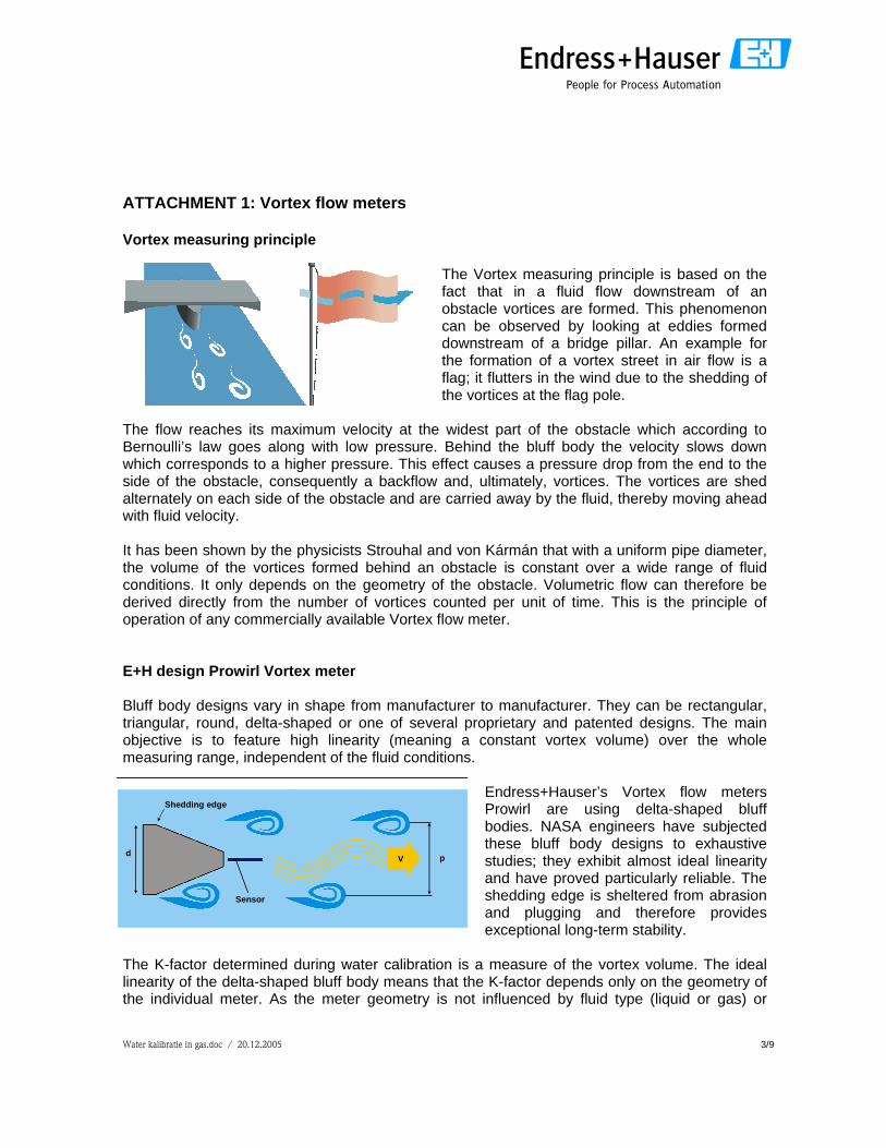
ATTACHMENT 1: Vortex flow meters Vortex measuring principle
The Vortex measuring principle is based on the fact that in a fluid flow downstream of an obstacle vortices are formed. This phenomenon can be observed by looking at eddies formed downstream of a bridge pillar. An example for the formation of a vortex street in air flow is a flag; it flutters in the wind due to the shedding of the vortices at the flag pole.
The flow reaches its maximum velocity at the widest part of the obstacle which according to Bernoulli’s law goes along with low pressure. Behind the bluff body the velocity slows down which corresponds to a higher pressure. This effect causes a pressure drop from the end to the side of the obstacle, consequently a backflow and, ultimately, vortices. The vortices are shed alternately on each side of the obstacle and are carried away by the fluid, thereby moving ahead with fluid velocity. It has been shown by the physicists Strouhal and von Kármán that with a uniform pipe diameter, the volume of the vortices formed behind an obstacle is constant over a wide range of fluid conditions. It only depends on the geometry of the obstacle. Volumetric flow can therefore be derived directly from the number of vortices counted per unit of time. This is the principle of operation of any commercially available Vortex flow meter. E+H design Prowirl Vortex meter Bluff body designs vary in shape from manufacturer to manufacturer. They can be rectangular, triangular, round, delta-shaped or one of several proprietary and patented designs. The main objective is to feature high linearity (meaning a constant vortex volume) over the whole measuring range, independent of the fluid conditions.
Endress+Hauser’s Vortex flow meters Prowirl are using delta-shaped bluff bodies. NASA engineers have subjected these bluff body designs to exhaustive studies; they exhibit almost ideal linearity and have proved particularly reliable. The shedding edge is sheltered from abrasion and plugging and therefore provides exceptional long-term stability.
The K-factor determined during water calibration is a measure of the vortex volume. The ideal linearity of the delta-shaped bluff body means that the K-factor depends only on the geometry of the individual meter. As the meter geometry is not influenced by fluid type (liquid or gas) or

Water kalibratie in gas.doc / 20.12.2005 4/9
process conditions like fluid pressure or density, the K-factor determined with water can be used for any fluid including for gas flow measurement. Due to the effect that the meter body expands with increasing temperature, the fluid temperature has a small effect on the K-factor which for stainless steel meter is about 0,5% per 100K. By entering the fluid temperature into the Prowirl 72 transmitter, this effect is compensated automatically. For Prowirl 73 the compensation is calculated automatically based on the integrated temperature measurement. Third party gas tests Prowirl Independent third party gas tests of Prowirl flow meters have been performed for different nominal diameters. As test gases natural gas at various pressures and air at ambient condition were available. By this means tests on both a wide pressure range as well as on different gases are available. An overview of the tests can be found in the following table: Gasunie, the Netherlands Gasunie is the Dutch national gas distribution company and gas supplier for the total Dutch market. They operate various gas metrology facilities. The Prowirl tests were performed on the high pressure flow test facility which operates on natural gas with pressures from 9 to 41 bar in pipes from DN 50 to DN 300. The following graphic shows the test results (error vs. flow rate) and a sample calibration printout from Gasunie. EAM (Eidgenössisches Amt für Messwesen), Switzerland EAM is the Swiss Federal Office of Metrology. The Prowirl vortex meter tests have been performed on air at ambient conditions with two different nominal diameters (DN 25 and DN 40). The test results have been confirmed by EAM with an official calibration certificate which can be found in attachment 3. For additional information, the certificates of the factory water calibration have been included in the file as well.
Test site Flow meter Test fluid Flow Pressure Temperature ReferenceGasunie, NL Prowirl 72 DN 100 / 4", Natural gas up to 20 m/s 9 bar a 20°C ± 1°C
ANSI Cl. 300 Sch. 40 17 bar a33 bar a40 bar a
EAM Bern, CH Prowirl 77F DN 40 / 1,5" Air 41 - 156 m3/h 0,93 bar a 20°C ± 1°CEAM Bern, CH Prowirl 70W DN 25 / 1" Air 15 - 95 m3/h 0,96 bar a 20°C ± 1°C
mass flow measurement, density from gas analysis, measured pressure and temperature

Water kalibratie in gas.doc / 20.12.2005 5/9
-2
-1.5
-1
-0.5
0
0.5
1
1.5
2
0 200 400 600 800 1000 1200
m^3/h
% e
rror 40bar
33bar17bar9bar

Water kalibratie in gas.doc / 20.12.2005 6/9
ATTACHMENT 2: Coriolis flow meters Coriolis measuring principle The Coriolis flow measuring principle is based on the Coriolis effect which occurs when both rotational and translational movements are superimposed in a system. An object in a rotating system which is moving straight forward from the center of rotation to the outward encounters steadily increasing rotational speed. As inertia comes into play, it has to overcome a force known as the Coriolis force. This force acts to deflect the object from its straight route. The heavier the object and the faster it moves, the more inertia is perceptible and the more powerful is the effect of the Coriolis force. In mathematical terms this means that the Coriolis force is proportional to the object’s mass flow, and the mass flow only. The force is not influenced by other object properties like fluid type, density or flow profile. In a Coriolis mass flow meter, the rotary motion described above that generates the Coriolis force is replaced by exciting the measuring tubes to oscillate at their resonance frequency. The individual mass particles of the measured fluid are influenced by the Coriolis force in the following manner:
Ê At zero flow, when the fluid is at a standstill, there is no linear movement. Consequently, no Coriolis force occurs. Ê Once the mass is flowing, the Coriolis force induced by the oscillation in the measuring tubes causes the fluid particles and eventually the measuring tubes to move to the side. Ê This additional movement has the opposite direction at the inlet section than at the outlet section of the measuring tubes. This means that the Coriolis force causes the measuring tubes to “twist” a few micrometers. Ê This twist movement causes a time shift of the original oscillation movement which is proportional to the mass flow. Sensors at the inflow and outflow section register the time shift as a phase difference.
The phase difference is directly proportional to the fluid mass flow. It does not depend on other fluid characteristics such as fluid type or density. For that reason the Coriolis measurement principle can be applied for liquid as well as for gaseous fluids. During water calibration of a Coriolis flow meter, the factor between phase shift and fluid mass flow is determined. This factor is the calibration factor of the individual meter. It depends only on the dynamic characteristics of the meter tubes as this defines the additional movement of the tubes caused by the Coriolis force. Process parameters like temperature and pressure can have a small effect on the dynamic behavior and thereby on the K-factor and therefore are compensated for in the meter electronics. An internal temperature measurement is made to compensate the dynamic changes to the tubes due to expansion and contraction. Very high fluid pressures can have a small effect on the K-factor as the tubes stiffen and therefore influence the dynamic behavior. By entering the fluid pressure into the transmitter, this effect is compensated automatically as well. If the fluid

Water kalibratie in gas.doc / 20.12.2005 7/9
Electrodynamic sensors
Exciter Secondary containment
Measuring tubeElectrodynamic sensors
Exciter Secondary containment
Measuring tube
pressure shows extreme variations, Prowirl 83 offers an optional current input to perform variable pressure compensation. E+H design Promass Coriolis meter When monitoring gas flows, the operating densities are generally a factor of 30 – 40 lower than that of a liquid and as a consequence, the mass flow-rates are comparably lower, hence the meter tends to be working in the lower operating region of its range and zero stability becomes of paramount importance. The Promass design is especially devoted to providing an exceptional zero stability by implementing the following points:
- A high resonance frequency of 400-1000 Hz ensures immunity to external pipe vibrations
due to pumps or compressors (typically 100-150 Hz). - A rigid carrier tube design prevents influences from external mechanical forces on the
pipeline. - Highly sophisticated welding techniques (electron beam welding, laser welding) ensure
highest accuracy in welding tolerances and therefore lowest impact on zero point stability. - The measuring tube material must be from the same batch of raw material to ensure the
absences of differences in material composition and tolerances. This results in an equal thermal expansion of the measuring tubes and therefore smallest impact on zero point stability.
Third party gas tests Promass (Coriolis measuring principle) Third party gas tests on Coriolis flow meters have been performed on natural gas between 12 and 70 bar, on air at 5 bar and on industrial gases like ethylene and propylene. For Promass as well as for Prowirl different nominal diameters have been tested. The following table shows a third party test overview:
Water kalibratie in gas.doc / 20.12.2005 8/9
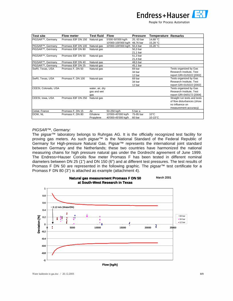
PIGSAR™, Germany: The pigsar™ laboratory belongs to Ruhrgas AG. It is the officially recognized test facility for proving gas meters. As such pigsar™ is the National Standard of the Federal Republic of Germany for High-pressure Natural Gas. Pigsar™ represents the international joint standard between Germany and the Netherlands; these two countries have harmonized the national measuring chains for high pressure natural gas under the Dordrecht agreement of June 1999. The Endress+Hauser Coriolis flow meter Promass F has been tested in different nominal diameters between DN 25 (1”) and DN 150 (6”) and at different test pressures. The test results of Promass F DN 50 are represented in the following graphic. The pigsar™ test certificate for a Promass F DN 80 (3”) is attached as example (attachment 4).
Natural gas measurement Promass F DN 50at South-West Research in Texas
-1
-0.8
-0.6
-0.4
-0.2
0
0.2
0.4
0.6
0.8
1
0 5000 10000 15000 20000 25000
Flow [kg/h]
Dev
iatio
n [%
] 69 bar34 bar12 bar
March 2001
~ 0.12 m/s (Water/DN)
Natural gas measurement Promass F DN 50at South-West Research in Texas
-1
-0.8
-0.6
-0.4
-0.2
Natural gas measurement Promass F DN 50at South-West Research in Texas
-1
-0.8
-0.6
-0.4
-0.2
0
0.2
0.4
0.6
0.8
1
0 5000 10000 15000 20000 25000
Flow [kg/h]
Dev
iatio
n [%
] 69 bar34 bar12 bar
March 2001
~ 0.12 m/s (Water/DN)
Test site Flow meter Test fluid Flow Pressure Temperature RemarksPIGSAR™, Germany Promass 83F DN 150 Natural gas 5'000-50'000 kg/h 20, 63 bar 14,68 °C
10'000-100'000 kg/h 48,76 bar 15,28 °CPIGSAR™, Germany Promass 83F DN 100 Natural gas 10'000-100'000 kg/h 50,4 bar 15,28 °CPIGSAR™, Germany Promass 83F DN 80 Natural gas 50,3 bar
21,1 barPIGSAR™, Germany Promass 83F DN 50 Natural gas 51,3 bar
21,4 barPIGSAR™, Germany Promass 83F DN 40 Natural gas 48,5 barPIGSAR™, Germany Promass 83F DN 25 Natural gas 45,1 barSwRI, Texas, USA Promass F, DN 50 Natural gas 69 bar
34 bar12 bar
SwRI, Texas, USA Promass F, DN 100 Natural gas 69 bar34 bar12 bar
CEESI, Colorado, USA water, air, dry gas and wet gas
Tests organized by Gas Research Institute, Test report GRI-04/0172 [2004]
CEESI, Iowa, USA Promass 83F DN 250 Natural gas Straight run tests and tests of flow disturbances (show no influence on measurement accuracy)
Cetiat, France Promass F, DN 15 Air 50-250 kg/h 5 bar aDOW, NL Promass F, DN 80 Ethylene 10'000-40'000 kg/h 75-95 bar 10°C
Propylene 40'000-45'000 kg/h 60 bar 10-15°C
Tests organized by Gas Research Institute, Test report GRI-01/0222 [2002]Tests organized by Gas Research Institute, Test report GRI-01/0222 [2002]

Water kalibratie in gas.doc / 20.12.2005 9/9
SwRI, Texas, USA: Southwest Research Institute is an independent, nonprofit applied research and development organization. The SwRI Metering Research Facility (MRF) is a high-accuracy natural gas flow laboratory used for meter research, calibration, and testing. Using a test medium of either natural gas or nitrogen, the MRF provides a broad range of test conditions similar to those experienced in the field. The Coriolis gas tests have been organized by the Gas Research Institute. CEESI, USA: Colorado Engineering Experiment Station, Inc. The corporation operates as an independent commercial calibration facility. The calibration capabilities of the Colorado test facility include water calibration as well as a wide range of flow rates, temperatures, and pressures utilizing numerous test gasses including air. The CEESI facility in Iowa provides natural gas calibration for ultrasonic flow meters, turbines, large diameter orifice meters and other meters requiring high Reynolds number ranges. Flow meter calibrations at CEESI are accredited by NVLAP and traceable to NIST. The Promass F DN 250 test has been presented on the 2005 AGA Operations Conference and Biennal Exhibition as joint contribution by Endress+Hauser and CEESI. Cetiat, France and DOW, the Netherlands: These are tests which have been performed by the customers in order to convince themselves from the feasibility of Promass for their respective applications. Results from the air test are shown in the following graphic.
Promass F DN 15 air measurement 5 bar abs at CETIAT
-2
-1.5
-1
-0.5
0
0.5
1
1.5
2
0 50 100 150 200 250 300 350
mass flow [kg/h]
devi
atio
n[%
]
deviation Promass Promass specification - Promass specification +

ATTACHMENT 3

ATTACHMENT 3

ATTACHMENT 3

ATTACHMENT 4

ATTACHMENT 4

ATTACHMENT 4