Embed Size (px)
Citation preview

Plus:
❚ media choices for grit blasting
❚ robots and engine maintenance
❚ the develoPment of curve solver
Spring 2019Volume 33, Issue 2 | ISSN 1069-2010
Shot PeenerThe
Sharing Information and Expanding Global Markets for Shot Peening and Blast Cleaning Industries
Blockchain TechnologyA fix for a stumbling block in manufacturing?

THE SHoT PEEnErSharing Information and Expanding Global Markets for Shot Peening and Blast Cleaning Industries
Spring 2019 | The Shot Peener 3
Spring 2019 | ConTEnT
6You’ve heard of Bitcoin? Read how the technology behind Bitcoin—Blockchain—can fix a major problem for manufacturers.
10 Media Choices for Grit BlastingGrit blasting is used by the automotive, aerospace and medical industries to pre-treat components. Kumar Balan examines the properties of frequently used AlOx and an alternate media.
18 Robots and Engine MaintenanceRolls-Royce has an exciting vision of how robotics can revolutionize the future of engine maintenance.
20 Clemco Industries Launches Apprenticeship ProgramFour Clemco employees are participating in a welding training program.
22 Midwestern Industries Introduces New Separator Screen Changing SystemAccording to a recent press release, the new ergonomically designed lift system from Midwestern Industries is electrically powered to make separator screen changes easier, faster, and safer.
28 Dr. Kirk’s Articles: The BackstoryDr. David Kirk has been an important contributor to The Shot Peener magazine for over 18 years. Learn more about Dr. Kirk and how he produces his popular articles.
29Upcoming Surface Engineering and Advanced Materials Processing Conference at Purdue UniversityLearn how your company can access Purdue Engineering’s advanced capabilities and world-class talent in the fields of surface engineering and materials processing.
30The Solver Story: An Autobiography Dr. Kirk’s article covers the development of his computer program that determines peening intensity quantitatively.
40 Laser Peening ResearchA research team from Curtiss-Wright Surface Technologies reports substantially enhanced fatigue and corrosion-fatigue lifetimes of propulsion shaft materials as a result of laser peening.
44 Blast Cleaning Case Study from Empire Abrasive EquipmentEmpire provided an economical and flexible abrasive blast cleaning system with PLC or manual control for a major defense manufacturer in the firearms industry.

oPEnInG SHoTJack Champaigne | Editor | The Shot Peener
4 The Shot Peener | Spring 2019
THE SHoT PEEnEr
EditorJack Champaigne
Associate EditorKathy Levy
PublisherElectronics Inc.
For a free subscription of the The Shot Peener, go to www.theshotpeenermagazine.com
The Shot Peener56790 Magnetic Drive Mishawaka, Indiana, 46545 USA Telephone: 1-574-256-5001 www.theshotpeenermagazine.com
The editors and publisher of The Shot Peener disclaim all warranties, express or implied, with respect to advertising and editorial content, and with respect to all errors or omissions made in connection with advertising or editorial submitted for publication.
Inclusion of editorial in The Shot Peener does not indicate that The Shot Peener management endorses, recommends or approves of the use of any particular commercial product or process, or concurs with the views expressed in articles contributed by our readers.
Articles in The Shot Peener may not be distributed, reprinted in other publications, or used on the internet without the written permission of The Shot Peener. All uses must credit The Shot Peener.
MAnY oF US have special people in our lives that have made big differences. For me, Professor David Kirk is at the top of my list of special persons. I remember meeting him the first time in 1993 at the 5th International Conference on Shot Peening (ICSP5) in Oxford. We stayed in dorm rooms on the Oxford campus—the students were on vacation. The rooms were quite large with very tall ceilings and the bathroom was down the hall. I got the feeling of being a student all over again. (I could now tell my friends that I attended Oxford.) The conference room was nearby and with the students gone we had the campus all to ourselves. I noticed Dr. Kirk was quite busy and seemed to be doing a one-man show using only a staff member to run the projector. Dr. Kirk performed all the steps needed for a successful conference. He received the manuscripts and assembled them into proper categories and then pre-printed the proceedings for availability at the conference. He then reprinted the final program, eliminating the papers that were not presented by their authors. I purchased a large quantity for re-sale at our website and later converted each document into a pdf file for on-line sharing. Upon meeting David in person at ICSP5, he asked me to serve on the international committee. I was given the honor of sitting at the “High Table” at the conference banquet. That indeed was a high honor. After the dinner, I joined the committee for the triennial meeting and answered questions about venues in the United States. I described several choices since I had experience with planning our annual U.S. shot peening workshops. I thought it was unusual that the questions kept coming back to San Francisco. The committee voted on that site and the following day I visited David at his office. I saw a calendar with photos of San Francisco on his office wall. Mystery solved. This was the beginning of a long and treasured friendship. David has contributed over 80 articles for The Shot Peener magazine. I have enjoyed every single one. We are compiling his articles into eBooks so his knowledge is shared at colleges and universities around the world. His analogies make the science of shot peening easy to understand. (I wish I could have attended his lectures at Coventry University.) I always look forward to his next article and I'm extremely grateful that he has contributed to our shot peening community. l
How I Met Professor David Kirk
Professor David Kirk and I at the 2018 Shot Peening Seminar in the United Kingdom.

Spring 2019 | The Shot Peener 5
1666 Enterprise Parkway Twinsburg, OH 44087
premiershot.com
As Cut
Normal Conditioning
Special Conditioning
The advantage of Premier Cut Wire Shot
(330) 405-0583 1666 Enterprise Parkway,
Twinsburg, Ohio 44087
A Cut Above
Highest Durability Due to its wrought internal structure with almost no internal defects (cracks, porosity, shrinkage, etc.) the durability of Premier Cut Wire Shot can be many times that of other commonly used peening media
Improved Consistency Highest consistency from particle to particle in size, shape, hardness and density compared to commonly used metallic media.
Highest Resistance to Fracture Premier Cut Wire Shot media tends to wear down and become smaller in size rather than fracturing into sharp-edged broken particles, which may cause surface damage to the part.
Lower Dust Generation Highest durability equals lowest dust levels.
Lower Surface Contamination Cut Wire Shot doesn’t have an Iron Oxide coating or leave Iron Oxide residue — parts are cleaner and brighter.
Improved Part Life Parts exhibit higher and more consistent life than those peened with equivalent size and hardness cast steel shot.
Substantial Cost Savings The increase in useful life of Premier Cut Wire Shot results in savings in media consumption and reclamation, dust removal and containment, surface contamination and equipment maintenance.
Premier Shot Cut Wire Products for
Automotive MedicalAerospace Applications Worldwide
premier_shot_ad_resized_lo4.indd 1 11/19/13 10:54 PM

InnovATIonKathy Levy | Associate Editor | The Shot Peener
6 The Shot Peener | Spring 2019
Blockchain Technology and Manufacturing
THE SHoT PEEnEr has always shared current information on the products, processes and services in our industry. You’ve probably noticed that we are now publishing more articles on what’s ahead—the technologies that could influence our industry in the near and not-so-near future. Blockchain is one of those technologies. It has captured our imagination because of the benefits it could bring to manufacturing. Let’s first define blockchain and then explore how it fixes a fundamental weakness in manufacturing. I’ll also share how aerospace and defense companies are using blockchain now.
BloCkCHAIn DEFInEDMany people connect blockchain with digital currencies like Bitcoin, but diverse industries including finance, healthcare, fashion, diamond mining and food safety are integrating blockchain into their business operations. One of the best definitions for blockchain is from David Amoyal in his article titled “What is Blockchain Technology?”1
Mr. Amoyal wrote, “A blockchain is a decentralized, distributed public ledger of transactional data secured by cryptography. Transactions are grouped together in blocks and are linked together in a chain to create an immutable ledger that is nearly impervious to fraud. People in the network agree by consensus to any updates in the records (or transactions) in the ledger. This consensus makes the records reliable. These records are also immutable, meaning they can never be erased.”
Think of a blockchain system has a shared network where every entry is timestamped, secure, and synchronized. Its immutable records can keep thousands of strangers honest and records consistent. And that brings us to the value of blockchain technology to manufacturing: Control of supply chains.
BloCkCHAIn In SUPPlY CHAInSWhether you are an original equipment manufacturer (OEM) or a shot peening facility, your product or service is part of a supply chain. These supply chains are crucial to our livelihoods but they are complex and difficult to control. Problems associated with supply chains include the introduction of counterfeit parts, lack of transparency and accountability, corruption, delays, and unnecessary expenses. Making matters even more complicated, supply chains are often global. Blockchain technology can be the solution for these problems.
“ Consider a large Tier One OEM shipping components to GM or Ford. Without blockchain and other smart technology, the OEM often is unable to trace the raw material it uses. Blockchain shows its value in those second- and third-tier supplier networks by adding a method to control and monitor the process.”
Joel NeidigDirector of Research and Development at ITAMCO
The following is a recap of the three properties of blockchain that will enable the technology to disrupt supply
Cryptography is the method of disguising and revealing, otherwise known as encrypting and decrypting,
information through complex mathematics. In blockchain, cryptography is primarily
used for two purposes: 1. Securing the identity of the sender of transactions 2. Ensuring that past records are tamper proof
Lisk Academy (www.lisk.io/academy)

Spring 2019 | The Shot Peener 7
chain management in a positive way. Much of the information on these properties comes from an article titled “Blockchain and Supply Chain: A Dynamic Duo.”2 These properties are: •Decentralization •Immutability •Transparency
DecentralizationDecentralization is the foundation of blockchain technology. Now individual suppliers “own” their data, making it impossible to verify its authenticity in a supply chain. In contrast, every “node” (a computer connected to the blockchain’s network) shares data stored in the blockchain. Data is timestamped and verified in an encrypted process. Furthermore, the participating nodes on the blockchain network verify the authenticity of each block.
ImmutabilityWhat keeps participants from tampering with data in a blockchain network? Blockchains are built on cryptographic hash functions that make data in a block chain immutable (i.e, tamper proof). For example, it would be impossible for a participant to raise the price of a product to justify extra payments in an existing record. Everyone in the blockchain can add new data to the blockchain, but no one can change or delete an existing record. If you make a mistake, you need another entry to fix it. (A cryptographic hash function is a mathematical equation that enables many everyday forms of encryption. This includes everything from the HTTPS protocol to payments made on e-commerce websites.)
TransparencyEvery transaction and its associated value are visible to anyone with access to the secure blockchain system. Each node, or user, on a blockchain has a unique 30-plus-character alphanumeric address that identifies it. Users can choose to remain anonymous or provide proof of their identity to others. While a person’s real identity is secure within a blockchain, every participant in the blockchain will see all transactions entered with his/her public address. This level of transparency is not possible within today’s supply chains.
BloCkCHAIn In AEroSPACE AnD DEFEnSEAerospace and defense companies are early adopters of technology. In fact, according to research by Accenture, a global professional services company, 86 percent of aerospace or defense companies expect to adopt blockchain into their
systems by 2021. Here are three applications of blockchain technology in aerospace and defense.
Airworthiness Certificate TrackingAn airworthiness certificate shows that an aircraft and its components follow all the airworthiness requirements from regulatory authorities of the country where the aircraft is registered. Tracking certificates and related materials through the lifetime of a plane is complex, slow and vulnerable to fraud. Sanjeev Ramakrishnan, general manager and business unit leader at Wipro, believes the biggest challenges in the current airworthiness certificate system that blockchain addresses are storing and securing the digital assets at every level of the supply chain.4 (Wipro is a global corporation based in India that provides information technology, consulting and business process services.) The level of traceability in blockchain provides an automatic audit trail. In addition, the provenance of each part would be registered in a blockchain. “It also prevents counterfeiting as it ensures that each part comes from a genuine partner. The shared ledger ensures a tamper-proof and reliable version of data is available for all participants,” said Mr. Ramakrishnan.4 Wipro has provided their blockchain airworthiness solution to a global aircraft manufacturer. Their client uses the solution to manage and audit their aircraft part suppliers as part of their quality assurance processes.
Aircraft MaintenanceAir France KLM’s engineering and maintenance division is evaluating a new digital ledger for managing replacement parts on in-service airplanes. The solution incorporates Microsoft Azure—a set of cloud-based services—and blockchain. Ramesh Sivasubramanian, a Ramco Aviation engineer, recently demonstrated a repair process for an Air
Here’s how a blockchain platform prevents corruption of its data. Each block holds information describing the block that comes before it in the chain. This information is in the form of a cryptographic hash. A cryptographic
hash is a unique ID in the form of a text string generated with the following variables:
•thetimestampofthecurrentblock, •thelistoftransactions, •anidentifierofthepreviousblock,and •variablecalledanonce(anumberusedonce).3

8 The Shot Peener | Spring 2019
France aircraft with an “aircraft on the ground” (AOG) status due to a hydraulic system failure. After troubleshooting the mock AOG situation, the engineering team concluded that an actuator needed repair. Sivasubramanian then showed how an Air France engineer could acquire a replacement actuator by creating a blockchain ledger that could be viewed by the engineer, the Air France KLM logistics and loan officers, and any other engineer or technician responsible for getting the replacement part to Air France.5
Parts TrackingTracking flight-critical aircraft parts from their origin drives up the cost to operate military aircraft. The Naval Air Systems Command (NAVAIR) and the Fleet Readiness Center Southwest (FRCSW) are exploring a blockchain technology named SIMBA Chain to track aviation parts at maintenance facilities across the country. The Indiana Technology and Manufacturing Company (ITAMCO) developed SIMBA Chain. NAVAIR’s agreement with ITAMCO gives the Navy access to cutting-edge blockchain code and innovative protocols that can quickly and securely recall data. The Navy plans to combine file access tracking and blockchain into a technology bundle for the management of aircraft parts. The technology will be useful for the U.S. Navy, the U.S. Department of Defense and external industry partners.
FRCSW is a Maintenance Repair and Overhaul facility that manages relationships with much of the Naval Aviation Enterprise, making it well positioned to assist the Navy in reducing costs and increasing efficiencies for maintenance programs across the country and around the world. ITAMCO is working with the U.S. Air Force and Army to develop similar blockchain-based programs.
BloCkCHAIn UnlEASEDIt may take years for blockchain technology to be widely used but if your product or service is part of a large supply chain in aerospace and defense, you may be introduced to it sooner than other industries. We will continue to publish articles on subjects like IoT, artificial intelligence and blockchain to make us more comfortable facing the challenges—and opportunities—facing our industry. l1 https://www.chainbits.com/blockchain-101/what-is-blockchain-
technology2 “Blockchain And Supply Chain: A Dynamic Duo” at https://
blockgeeks.com/guides/blockchain-and-supply-chain3 https://cryptomaniaks.com/latest-cryptocurrency-news/
blockchain/why-is-blockchain-important4 “Is Blockchain Coming to Manufacturing?” by David Greenfield
at www.automationworld.com. 5 https://www.aviationtoday.com/2017/10/03/air-france-klm-
evaluating-mro-potential-blockchain
Vidal Nuno, work leader for the fuel cells installation shop at the Fleet Readiness Center Southwest (FRCSW), opens a storage cage where ready-for-issue fuel cell parts are stored for legacy F/A-18 Hornets. A joint project by NAVAIR and
FRCSW using blockchain technology will improve the efficiency of the distribution system for all parts within
the naval aviation community.(Source: www.frcsw.navylive.dodlive.mil/2018/09)
Blockchain technology transforms record keeping in Maintenance, Repair and Overhaul (MRO) facilities. For example, many maintenance records are kept in
databases or on paper. In comparison, blockchain makes a “virtual record,” providing a tamper-proof record of the
origin of every part on the aircraft, every time the plane was inspected or repaired and by whom, from the time the plane was built. (Photo used with permission by Air France KLM.)

Spring 2019 | The Shot Peener 9
Call us at (450) 430-8000or visit us online at
www.shockform.com
FlapSpeed® PRO Flapper Peening • The leading reference tool in the industry • Meets AMS 2590, BAC5730-2 and all EOM specs • Guides the operator through the repair • Monitors and adjusts RPM in real time • Calculates peening intensity with the solver • Saves process data to USB key • Includes everything in one small case
Easy Controlled Peening for the Operator...Peace of Mind for the Supervisor!
Spiker® Needle Peening • New tool developed for on-wing repairs • Meets AMS 2545 • No risk of Foreign Object Debris (FOD) • Great for difficult-to-reach locations • Two peening heads for different geometries • Individual needle monitoring • Saves data to USB key for easy reporting
Shockform Aeronautique Inc.

10 The Shot Peener | Spring 2019
InTroDUCTIonSpecialists in the Coatings industry stress that the effectiveness of a coating is greatly dependent on the component’s pre-treatment process. This is a well-respected fact for some of us in the pre-treatment industry and it is what makes us tirelessly pursue the advancement of pre-treatment techniques. The two widely used types of pre-treatment techniques are mechanical and chemical. Though the manufacturing industry uses both, mechanical pre-treatment such as blast cleaning and grit blasting are preferred due to the environmental concerns associated with the use of chemicals. Pre-treatment requirements are also applicable for downstream processes such as thermal spraying and galvanizing. In Automotive, Aerospace and Medical—industries of interest to us—users attach great emphasis on grit blasting when pre-treating their components. The desired outcome on a grit-blasted part is a surface profile that improves bond strength for a downstream thermal “spraying” process such as plasma, flame, and HVOF (High Velocity Oxy-Fuel). These spraying techniques restore a damaged surface or provide resistance to wear, corrosion, abrasion and heat. Fine metal particles, when sprayed on the surface of a grit- blasted component, rely on the condition of the substrate for their bonding strength. In addition to surface roughness, the cleanliness of the surface and pre-heating of the substrate determine the efficiency. Given its criticality, most grit blasting machines, especially for aerospace applications, are designed and manufactured with the same sub-systems and controls for repeatability and accuracy as in a shot peening machine. The most commonly used grit blast media is Aluminum Oxide, commonly referred to as AlOx. In cleaning applications, AlOx is known for its aggressive nature and the rapid removal of paints and other contaminants while preparing the surface for coating. When blasted in a controlled fashion, it also imparts a profile (surface roughness) on the substrate. It is almost always propelled using compressed air through a blast nozzle. AlOx is available in several sizes to suit the application. With all its beneficial features, AlOx is also brittle and generates a fair amount of dust during blasting. The purpose of our
discussion is two-fold: (1) to explore alternate media to AlOx that can be used in common applications for cleaning and (2) analyze this media for specific grit blasting processes that require precise and repeatable surface profiling.
CHArACTErISTICS oF AloxThe blast industry is flooded with non-metallic abrasives for cleaning and surface profiling. These include different grades of garnet (mineral), slags (by-products of coal and other metal refining processes) and varieties of glass. Among these, AlOx is found to be most suitable in aerospace grit blasting applications. The suitability of AlOx for grit blasting is due to its physical characteristics such as angular shape and hardness of 9 on the Mohs scale. Talc powder is 1 and diamond is 10 on the Mohs scale. Plastic is 3 and steel shot/grit is 7-8. The bulk density of AlOx is 120 lb/cft. Steel shot/grit is about 280, glass bead is 100 and plastic is 45. Due to its low bulk density, AlOx is best propelled using compressed air so that sufficient momentum and impact energy can be generated. Unfortunately, with high hardness also comes greater brittleness that leads to reduced durability or life (measured in passes/cycles). When grit blasting aerospace components, the process is almost always associated and defined by a specification that has been derived over the years. Some of these OEM specifications were drafted when media choices were limited. With the choices available today, users should evaluate alternate media choices. One of the acknowledged advantages of AlOx is the maintenance of its angular profile upon repeated impacts, albeit at a reduced number. AlOx disintegrates into dust after a certain number of impacts but doesn’t blunt into a rounded edge. This allows the substrate to continue receiving angular hits that contribute to its surface roughness. Most grit blasting applications for aerospace components require the use of AlOx for this reason. However, the type of downstream process also determines the surface finish requirement. Typical surface roughness required for thermal spray is between 80 and 100 microns. In order to achieve this surface, AlOx between 60 to 120 mesh screening is commonly used. The surface profile requirement for HVOF is not as demanding as, for example,
An InSIDEr’S PErSPECTIvEKumar Balan | Blast Cleaning and Shot Peening Specialist
Media Choices for Grit Blasting

Spring 2019 | The Shot Peener 11
CNC Shot Peening
Computer Monitored Shot Peening
Multistage Shot Peening
Abrasive Blast Cleaning
Ultra-Finishing / Polishing
Glass Bead Blasting
Coatings Removal
Die Life Enhancement
NDT Services
TM
►Transportation►Power Generation►Performance Racing
► Aerospace► Oil & Gas► Defense
►Industrial►Marine►Medical
AS 9100 ISO 13485
SINTO SURFACE TECHNOLOGIES
SINTO SURFACE TECHNOLOGIESSinto America Group
Sinto Surface Technologies can custom tailor equipment and process to meet the customer’s
application. From small parts to larger parts- Sinto has the solution!
Strategically located facilities providing engineered solutions for the most
challenging opportunities
NATIONAL PEENINGSINTO AMERICATel 336-488-3058SintoAmerica.com
TECHNICAL METAL FINISHINGSINTO AMERICATel 336-488-3058SintoAmerica.com
SINTOKOGIO, LTDNagoya Intercity, JapanTel +81 52 582 9216www.sinto.com

12 The Shot Peener | Spring 2019
An InSIDEr’S PErSPECTIvE Continued
plasma spray. This opens up the opportunity to try other media types that may have better durability than AlOx.
An AlTErnATE MEDIA CHoICE – STAInlESS STEEl GrITStainless steel grit is increasingly replacing AlOx in cleaning applications that had previously utilized mineral abrasive with low to no durability. The reasons are quite obvious when we evaluate its physical and operational characteristics. For this discussion, technical data has been obtained from publications for AMAGRIT manufactured by Ervin Industries. To provide a performance comparison, surface profile data was taken from publications by BlastOne. In both cases, the manufacturers caution us that end results are greatly dependent on the operating parameters. This information falls within the general range published by other manufacturers of these abrasives. AMAGRIT is a contaminant-free inert metal abrasive with a martensite/chrome carbide microstructure. Its manufactured hardness is 57 HRc and chemistry is as follows: Carbon (2%), Silicon (4%), Manganese (2%) and Chromium (30%). The high percentage of chromium in this abrasive imparts its non-corrosive property. Tests conducted by the manufacturer have shown no trace of corrosion even after a 24-hour salt spray test. Joe McGreal, Ervin’s Vice President, adds, “AMAGRIT’s corrosion resistance was validated by one of our customers that manufactures trailers. They were looking for an alternative media to AlOx due to increasing operating costs and a dusty blast environment that resulted in a loss of productivity. The anti-corrosion property was paramount to them since residual media that lodged itself in the intricacies of the trailer could rust, giving the appearance of a coating failure. This same benefit works with Railroad Automobile Carriers where fugitive grains of grit could work themselves out of these intricacies and fall and rust on new automobiles. AMAGRIT works very well for our customer not only in terms of operating performance but has also resulted in significant cost savings.” More on the economics in paragraphs that follow. The surface profile that can be expected when blasting with AlOx ranges from 0.5 to 1.0 mil with 120 mesh (120 mesh is a screen with 120 openings per linear inch—a very fine media size). In contrast, 60 mesh (60 mesh is a screen with 60 openings per linear inch) AlOx will provide surface roughness in the 2.0 to 3.0 mil range. Larger mesh sizes of AlOx could increase the profile to as high as 6.0 mil (8 mesh AlOx). The area of reference is typically in the 60 to 120 mesh screening for aerospace coatings. For other grit blasting applications, the requirement could be potentially higher. Surface profile values obtained using AMAGRIT were recorded at a relatively lower pressure than typically found with use of AlOx. The sample coupons were stainless steel and
blasted at about 45 PSI and a blast angle of 45 degrees. Surface roughness for a similar particle size of AMAGRIT as AlOx was found to be at least 1 mil higher. As per the manufacturer, this is because of the stability of the work mix in AMAGRIT and a smaller percentage of very small particles. AlOx, due to its lower durability, tends to have a wider sieving range. When considering replacing AlOx with stainless steel grit, Ervin recommends replacement with a smaller grain size of AMAGRIT. Also important to mention are the other process parameters that will need alteration during the switch, since size is not the only parameter that affects surface roughness.
EConoMICS oF oPErATIonThe question of media durability is one of the most difficult for a manufacturer to answer. “It depends” is not an answer that’s accepted by users! However, that is unfortunately the reality when it comes to addressing this pressing issue. Among the factors that affect durability are media hardness, substrate hardness, blast pressure, media size, blast angle, stand-off distance and so on. Since this discussion will be incomplete without this topic, we will use field data obtained from multiple sources and compile the information using averages. Let us assume an operation using two blast nozzles blasting identical components. Process data is tabulated as follows:
Some noteworthy factors in this exercise include:•Thecleaningqualityisassumedtobecomparablewith
both abrasive types•Lossofproductivityandworkermoraleduetoexcessive
dust generation using AlOx has not been quantified•Savingsinmachinemaintenancecostshavenotbeen
quantified•Dustdisposalcosts(transportation,landfillfees,etc.)have
not been factored into the savings Stainless steel grit has the potential to be a viable substitute to AlOx, glass bead and garnet due to some distinct advantages and resulting savings in operating cost.
Airblast Operating Cost Analysis
Operating Data 5/16" Nozzle (qty. 2) @ 60 PSI Media flow rate/hour Field consumption data (cycles) Consumption per hour (lb) Abrasive cost per lb (USD)
AlOx AMAGRIT
1920 10 192.00 $0.60
2400 100 24.00 $3.00
Abrasive Cost Per Hour (USD) $115.20 $72.00
Per 8 hour shift (60% Blasting)Annual Cost (2000 Hours/USD)Abrasive Dust (Tons/2000 Hours)
$552.96$230,4000.00
192.00
$345.60$144,000.00
24.00

Spring 2019 | The Shot Peener 13
24100 Chagrin Blvd., Suite 380Beachwood, Oh 44122Tele. (216) 464-2300Fax. (216) [email protected]
We Recycle Blast Media!
ALUMINUM SHOT BROWN FUSED ALUMINUM OXIDE CUT STEEL WIRE GARNET GLASS BEADS SILICON CARBIDE STEEL GRIT STEEL SHOT WALNUT SHELLS WHITE ALUMINUM OXIDE ZINC SHOT ZIRSHOT AND MORE
Walnut Shells
Aluminum Oxide
ZirshotBackground image courtesy of Progressive Surface

14 The Shot Peener | Spring 2019
An InSIDEr’S PErSPECTIvE Continued
The atmosphere inside a blast facility using AMAGRIT is cleaner due to its low breakdown rate, and this leads to increased productivity. The operating cost with stainless steel grit is lower not only due to the lower attrition, but also given the decreased frequency at which blast nozzles, hoses and blast tank parts need to be replaced. Users have reported around 85% savings in such costs. Stainless grit is also popular for contaminant-free cleaning of aluminum castings, stainless forgings, zinc pressure die-castings, corrosion-prone metal surfaces and stainless steel railroad cars. Dust disposal efforts and costs are quite significant when blasting with low-durability media such as AlOx. Some municipalities and local and state agencies offer incentives to factories to reduce material sent to landfills. This adds to the justification of using blast media of greater durability.
MACHInE rETroFITS Since the majority of our discussions revolve around “conversions” to stainless steel grit, the obvious question in a reader’s mind is the cost involved in modifying the blast equipment. Let us consider all possible scenarios:1. If your blast operation currently uses minimally recyclable
or non-recyclable abrasive, you will need to incorporate some kind of recovery system. A few choices are:
a. If your blast operation is manual and involves a single operator, you could install a stand-alone vacuum recovery system that will include a recovery hopper in one corner of your room (into which the operator will sweep-in the abrasive), a media reclaim duct leading to a cyclone reclaimer, storage hopper and likely your existing blast tank. Approximate investment: $25,000.00 to $ 30,000.00.
b. If your blast operation involves two operators, the above retrofit could still work as long as the operators take precautions to not overload the reclaim system with a “media dump.” In other words, your operators
should meter the amount of media discharged into the reclaim hopper to prevent it from choking.
c. If metering the media discharged into the reclaim system is not possible or practical, consider “locking” the media flow rate from the blast nozzle so that the risk of choking the reclaim is stemmed at the source. This will of course require regular diversion of media into the reclaim system, too.
d. Incorporate a mechanical reclaim system with a single or multiple screw conveyors (augers) leading to a bucket elevator and airwash separator.
2. If your blast operation is built with a vacuum recovery system:
a. Check with your blast equipment manufacturer to confirm that the reclaim system can handle metallic abrasive. A well-designed system should be able to handle this switch, as long as you don’t exceed the media flow rate generated by a single nozzle.
b. Any modification to the reclaim system might entail a new reclaim duct and exhaust fan with a higher static pressure capability and a suitable motor drive.
In general, any resulting equipment modification will be justified in less than a year by cost savings from the use of stainless steel grit.
AMAGRIT is cleaner due to its low breakdown rate. AMAGRIT was used in the top blasting operation
and AlOx in the bottom operation.
AMAGRIT stainless steel grit from Ervin Industries.

16 The Shot Peener | Spring 2019
An InSIDEr’S PErSPECTIvE Continued
SUMMArYAll engineering cases and problems have multiple solutions with a handful of optimal ones. Use of abrasive in surface pre-treatment is no different. I have seen many blast operations that operate with a particular type and size of abrasive because “that is how it has always been done.” Change is seldom openly embraced. It takes considerable effort from both the supplier and end-user to initiate and effect change. Cost and process justifications have to be considered carefully and in conjunction with the other. Ultimately, the DFT (dry film thickness) of a coating, and its uniformity and life validate the quality of the pre-treatment process. Similarly, the thickness and bonding strength of the thermal spray will be determined by the effectiveness of the grit blasting process in presenting a suitable surface profile for the process. Since no single abrasive can provide a universal solution for all coating applications, explore to find the one that will result in the most suitable fit in cost and effectiveness. l
About Kumar Balan
Kumar Balan is a shot peening and blast cleaning technical specialist. He assists industry leaders achieve business growth in North American and overseas markets. His expertise is in centrifugal wheel- and air-blast cleaning and shot peening equipment. Kumar has published many technical papers on blast cleaning and shot peening and is a regular contributor to The Shot Peener magazine.
Kumar is a speaker at industry conferences and training seminars worldwide. He is also a Lead Instructor for EI Shot Peening Training at their international seminars and workshops. Please email him at [email protected].
UPCoMInG ConFErEnCES
4th International Symposium on Fatigue Design and Material Defects
May 26-28, 2020 in Potsdam, Germany
FollowInG the successful symposia in Trondheim in 2011, in Paris in 2014 and in Lecco in 2017, the conference chairpersons announce the 4th International Symposium on Fatigue Design and Material Defects from May 26-28, 2020 in Potsdam, Germany. Material defects such as non-metallic inclusions, pores, micro-shrinkages etc., play a crucial role in fatigue crack initiation and propagation which in turn has significant consequences for structural integrity in terms of lifetime, fatigue strength and other characteristics of cyclically loaded components. The main objectives of the symposium are to improve the understanding of the mechanisms and the impact of defects on structural integrity, and to work out measures to improve the fatigue properties of materials and components. To that purpose presentations are welcome which address the following topics:
• Defects and manufacturing processes• Defect detection and monitoring• Statistical considerations• Defects and fatigue strength• Short fatigue crack propagation starting at defects• Critical defect sizes• Defects as root causes of structural failure• Modelling fatigue life and strength taking into
account defects
All materials are concerned, particularly:• High-strength steels• Cast aluminium alloys• Nodular cast iron• Sinter materials• Weldments• Materials generated by Additive Manufacturing
To submit your abstract, go to https://fdmd2020.inventum.de/registration/registration. The deadline is October 31, 2019. The symposium will be chaired by Prof. Dr. Uwe Zerbst and Dr. Mauro Madia with BAM (Bundesanstalt für Materialforschung und -prüfung). BAM is a senior scientific and technical federal institute with responsibility to the Federal Ministry for Economic Affairs and Energy. BAM is located in Berlin, Germany. l
PEEnSolvErThe Free Curve Solver web AppBringing Dr. David Kirk’s popular Curve Solver to your internet browser!
Delivered to you by Electronics Inc. and EI Shot Peening Training.
Download it at www.peensolver.com

Spring 2019 | The Shot Peener 17
MagnaValve®
COLORS
BLACK PANTONE 130
Media valves for air-blast and wheel-blast machinesReduces labor, media and energy costs while adding control and reliability
to shot peening and blast cleaning processes
24 Vdc MagnaValves for air-blast
machines
24 Vdc MagnaValves for wheel-blast machines
The non-ferrous media MagnaValve for air-blast machines
1-800-832-5653 or 1-574-256-5001 www.electronics-inc.com
MagnaValve is a registered trademark of Electronics Inc.
You can depend on itThe unique design of the MagnaValve makes it one of the most reliable and
hard-working media valves on the market today. Other benef its include:❚ Flows most ferrous media and the 700-24 flows non-ferrous media
❚ MagnaValves have companion controllers for accurate and dependable media flow control
❚ Compliance to specif ications is readily attainable❚ Available in 24 Vdc and 120 Vac
❚ Trusted by OEMs and end-users worldwide

InnovATIonRolls-Royce | www.rolls-royce.com
18 The Shot Peener | Spring 2019
Rolls-Royce Poised to Revolutionize Engine MaintenancerollS-roYCE has an exciting vision of how robotics could be used to revolutionise the future of engine maintenance. Bringing another element of its “IntelligentEngine” vision to life, Rolls-Royce teamed up with academics from the University of Nottingham and Harvard University to discuss and demonstrate a wide range of potential future technologies at the 2018 Farnborough Airshow, from “snake” robots that work their way through the engine like an endoscope, to miniature, collaborative “swarm” robots that crawl through the insides of an engine. The IntelligentEngine vision was first introduced by Rolls-Royce at the Singapore Airshow earlier in 2018. It describes a world where product and service have become so closely connected that they are inseparable. This vision drives activity across a range of fields, including robotics, with a particular focus on digital technologies. The robotic technologies are an opportunity to improve the way engine maintenance is delivered, for example, by speeding up inspection processes or by removing the need to take an engine off an aircraft in order to perform maintenance work. This has the potential to offer significant benefits for customers by reducing the cost of engine maintenance, increasing the availability of an engine and ensuring any maintenance required is completed as quickly as possible. The technologies on display were at varying levels of maturity and included:
SWARM robots – a set of collaborative, miniature robots, each around 10 mm in diameter which would be deposited in the centre of an engine via a “snake” robot and would then perform a visual inspection of hard-to-reach areas by crawling through the engine. These robots would carry small cameras that provide a live video feed back to the operator, allowing them to complete a rapid visual inspection of the engine without having to remove it from the aircraft.
INSPECT robots – a network of “periscopes” permanently embedded within the engine, enabling it to inspect itself using the periscope cameras to spot and report maintenance
requirements. The pencil-sized robots are thermally protected from the extreme heat generated within an engine and the visual data they create would be used alongside the millions of data points already generated by today’s engines as part of their Engine Health Monitoring systems.
Remote boreblending robots – teams from Rolls-Royce and the University of Nottingham have worked together to develop a robotic boreblending machine that can be remotely controlled by specialist engineers. In practice this means that complicated maintenance tasks, such as repairing
damaged compressor blades using lasers to grind parts, could be completed by non-expert “local” teams who would simply install the tool in the engine and then hand control of it over to a dedicated expert back in Rolls-Royce’s Aircraft Availability Centre who would then direct its work remotely. This removes the need for specialist teams to travel to the location of an aircraft needing maintenance, vastly reducing the time required to return it to service.
FLARE – a pair of “snake” robots which are flexible enough to travel through an engine, like an endoscope, before collaborating to carrying out patch repairs to damaged thermal barrier coatings.
Speaking at the Farnborough Airshow, Dr. James Kell, a Rolls-Royce On-Wing Technology Specialist, said: “While some of these technologies, such as the SWARM robots, are still a long way from becoming an everyday reality, others, such as the remote boreblending robot, are already being tested and will begin to be introduced over the next few years. We have a great network of partners who support our work in this field and it is clear that this is an area with the potential to revolutionise how we think about engine maintenance.” Rolls-Royce works on robotics projects like these in partnership with a wide range of research organisations around the world, including the Harvard University and the University of Nottingham, which is a Rolls-Royce University Technology Centre (UTC). l
Image and content: Rolls-Royce
An artist’s impression of the Rolls-Royce SWARM robot. The robot will crawl
through engines, photographing hard-to-reach areas.

Spring 2019 | The Shot Peener 19
Control
Empire Abrasive Equipment | 2101 W. Cabot Blvd. | Langhorne, PA 19047
215-752-8800 | [email protected] | www.Empire-Airblast.com
Empire Abrasive Equipment continues to lead industry with best in class peening and grit-blast solutions. Our highly controlled air-blast and recovery technology enables quicker production times. Our multi-discipline team of experienced engineers, along with state-of-the art manufacturing and testing facilities, deliver solution driven designs for a diverse range of industries; from aerospace and automotive to energy and medical.
For over 70 years, we’ve been perfecting air-blast technology. Today, Empire has the most extensive range of advanced solution-driven equipment to exact any of your air-blast needs.
Let Empire engineer your competitive edge.
Empire Ad_Control_SPM.pdf 1 8/17/15 10:27 AM

PrESS rElEASEClemco Industries Corp. | www.clemcoindustries.com
20 The Shot Peener | Spring 2019
Clemco And Local College Launch Welder Apprenticeship Program
ClEMCo InDUSTrIES of Washington, Missouri, in collaboration with East Central College in neighboring Union, Missouri, launched their Welder Apprenticeship Program. Four Clemco employees are enrolled in the three-year program, which is funded by a Missouri Registered Apprenticeship Program (MORAP) grant. The $239,550 MORAP grant, awarded by the Missouri Department of Workforce Development, has enabled East Central to partner with Clemco to develop apprenticeship programs. The four Clemco employees in the Welder Apprenticeship Program range in age from 20 to 33 and from between less than a year and 4.5 years of employment in the Clemco manufacturing facility. Last fall they spent their Tuesday and Thursday evenings in four-hour, hands-on classes on the East Central campus. They were taught metal inert gas (MIG), tungsten inert gas (TIG), and stick welding. The MORAP grant covered the students’ tuition and book fees, and they maintained their day jobs at Clemco. “Our program with East Central College offers four of our employees an opportunity they may not have otherwise had,” says Clemco Vice President of Manufacturing Lou Ann Feldman. “Clemco now can more easily help four good employees progress within the company, and for that we, and I know they also, are grateful.” After completing the fall semester of instruction at East Central, the four apprentices began moving into full-time welding positions at Clemco. The hours they work count toward their on-the-job training required to earn their specialization in welding certificates from East Central. In mid-January, KETC Channel 9 (the St. Louis pubic television station) posted a video about the Welder Apprenticeship Program in its Working St. Louis web series, which explores in-demand jobs and careers in the region that are attainable after high school, with or without a college degree. The series is part of the station’s “American Graduate: Getting to Work” initiative. The video can also be viewed on YouTube. Clemco Industries employs more than 145 people. It is the world’s largest manufacturer of air-powered abrasive blast equipment used to clean, deburr, shot peen, remove coatings, finish, or otherwise improve surfaces. Since the mid-1940s, Clemco Industries has built industrial-grade blast equipment for contractors, facility owners, metal fabricators, and manufacturers around the globe. The company also sells safety and protection accessories.
MEET THE ClEMCo APPrEnTICES
Kasheea PortellCurrent Position: Cabinet AssemblerWelding Experience Prior to Apprenticeship: None“I like learning a new trade and being challenged, and that Clemco has offered me an opportunity for a second promotion within the company.”
Christopher Kallmbah Current Position: Pressure Vessel HydrotesterWelding Experience Prior to Apprenticeship: Two-month MIG welding credential from East Central College. MIG welder at previous employer for one year. “Through the apprenticeship I’ve learned new welding techniques and theories and different processes. Aside from the apprenticeship, I appreciate the other benefits at Clemco.”
Dennis Beanblossom Current Position: Plumber/Blast OperatorWelding Experience Prior to Apprenticeship: None“The classes are fast-paced so we learn a lot in a short amount of time, and soon I will be moving to the fabrication side of the plant where I will be welding. I appreciate that Clemco offered me the apprenticeship.”
Jarrett Vandaveer Current Position: WelderWelding Experience Prior to Apprenticeship: MIG, TIG, and Stick welding certificates from Jefferson College in Hillsboro, Missouri“I like the apprenticeship. It’s a great opportunity. Clemco is allowing us to participate in this program even though we are slammed with overtime. But Clemco is flexible. I like the people, the job, the facility. Other places won’t look at people who have less than four years of welding experience, but Clemco is willing to train you.”

Spring 2019 | The Shot Peener 21
Innovative Peening Systems 2825 Simpson Circle, Norcross, GA Tel: 770-246-9883
CNC motion allows the nozzle to follow the contour of the part. This motion provides consistent intensities and coverage to occur with speed and precision.
Innovative Peening Systems
High performance for high standards

22 The Shot Peener | Spring 2019
PrESS rElEASEMidwestern Industries | https://midwesternind.com
A New Ergonomic Separator Screen Changing System
Midwestern Industries, a leading manufacturing mainstay of innovation for the screening industry since 1953, has recently launched their operator-friendly Electro-Lift separator screen changing system. The revolutionary, ergonomically designed lift system is electrically powered to assist in making separator screen changes easier, faster, and safer. Engineered with a 120 volt sealed gear-driven system, operation is as simple as plugging into any convenient outlet and pressing a switch. Quality built and engineered in the USA, Midwestern’s Electro-Lift is adaptable to fit a variety of different frame deck configurations. While it is designed to lift the frames of Midwestern Industries’ round separators, most makes and models of competitors round separators can easily convert to this system.
ELECTRO-LIFT ERGONOMIC DIFFERENCEThe system’s ergonomically designed configuration assists with the lifting of separator frames to eliminate the need for two people to remove each frame, making screen changes virtually a one-man operation. Typically, screens must have hands on them when changing out. However, Electro-Lift is mounted independently to the frame so there is no need for it to be locked out when you are working under them with your hands. This engineering versatility also allows operators to change screens and gain access to the interior of the unit for cleaning or inspection which is exponentially faster than using comparable systems. The system can also be used to inspect the screens to ensure quality control. Ultimately, the system changes screens faster with no lifting of heavy frames, driving the Electro-Lift system’s key attribute of reducing downtime to a minimum.
ELECTRO-LIFT SAFETY SOLUTIONSafety is an integral part of the 120 volt Electro-Lift as it leverages a sealed gear-driven system, which ensures the frames will not drift down when changing your screens even
if the power fails. Unlike traditional hydraulic or pneumatic changing systems, if the power does go out during screen changes, the frames will not fall. Because the unit is 120 volt, it can be plugged into any convenient outlet, which eliminates the need for customers to provide compressed air. Whereas most competitive versions will use some form of clamping device if power is lost, Electro-Lift uses two mechanical screws powered by the actuator. Additionally, there are no cumber- some hoses, and the sealed system eliminates the need for greasing
which makes it environmentally cleaner.
CONCLUSIONThe Electro-Lift separator screen changing system is a next-generation solution that is vital for a myriad of processing industry applications including Pharmaceutical, Food and Beverage, Chemicals, Waste Water, Shot Peening, Plastics, Roofing Granules, Ceramics, and Powdered Metals, amongst others. The Midwestern Industries’ Electro-Lift is competitively priced versus traditional alternatives and it delivers the following essential configuration advantages:
•Adaptabletomultipledeckconfigurations.
•Fasterscreenchangeshelptoreducedowntimetoaminimum.
•Sealedgeardrivensystemensuressafescreenchangesevery time.
•120voltelectricalcanbepluggedintoanyconvenientoutlet.
•Frameswillnotfallorcomedownifpowerfailsduringscreen changes.
Visit www.midwesternind.com/electro-lift or call 877-4-SIZING (877-474-9464) for more Electro-Lift information and a video demo. l
Midwestern Industries’ new Electro-Lift platform provides faster screen changes
at the flip of a switch.

24 The Shot Peener | Spring 201524 The Shot Peener | Spring 2014
Engineered Abrasives®
Manufacturers of the Finest Blast Finishing and Shot Peening Systems
(708)389-9700 or (773)468-0440Email: [email protected] Web: www.engineeredabrasives.com
ISO/TS16949ISO 14001FORD Q1Certified
Job Services
Engineered Abrasives® index units are the most durable machines on the market today with all our special features
All Engineered Abrasives® systems are available with the EA® Knowledge System®. The EA® Knowledge System® features computer animation on machine operation and maintenance, including how to do Almen Strips.
60" Index UnitRing and Pinion Gears
for High Volume
8 Pressure Nozzleswith MagnaValves®,Buck Elevator, Sweco
and Dust Collector
Patented 72’’ Index Unit with Shot Flow Controls, Sweco, Bucket Elevator, 8 Nozzles and 16 Spindles. Designed for high-volume shot peening.
®
Look for RED components and surfaces to be sure you get Engineered Abrasives® quality equipment and OEM parts.
All Tooling and Fixtures Tool Steel hardened to 62 RC
Engineered Abrasives® High-VolumeIndex Unit with complete Material Handling and Robotic System
▲
®

Spring 2019 | The Shot Peener 25Single Cell Unit, 5 Pressure Nozzles Large 84" Index Unit, 12 Pressure Nozzles
Bucket Elevator Sweco System MagnaValves®
6 Spindles each station for high
volume
Dual Swing Doors for higher volume
▲▲
▲▲
ENGINEERED ABRASIVES®, EA, the stylized EA® logo, and the RED components and surfaces are registered trademarks of Engineered Abrasives®, Inc. © 2018 Engineered Abrasives®, Inc. All rights reserved.
Two (2) IndexUnits withcomplete loadand unloadFanuc Robotsand ConveyorSystem
Both machinesbuilt and tested on EA® floor
High-volumeautomotive systems for
transmission gears
Designed and built by EA®
Three (3) Index Units with complete load and unload automation
All three machines built and tested on EA® floor
High-volumeautomotive systems for
ring and pinion axle gears
Designed and built by EA®

26 The Shot Peener | Spring 2019
The #2 Almen gage from Electronics Inc. offers:• Patented magnetic grip and end stops
(U.S. Patent No. 5,297,418)• An easy-to-read display • 0.001 mm (0.0001”) resolution • SPC data port• Convenient battery replacement• Ergonomic design• One-year warranty• Calibration services or block kit available
(U.S. Patent No. 5,780,714)Use the EI Almen gage with EI Almen Strips and J442 Almen strip holder to ensure process repeatability
Also available: The patentedMini-Strip Gage and
Mini-Strips
1-800-832-5653 or 1-574-256-5001
www.electronics-inc.com
56790 Magnetic Drive Mishawaka, Indiana 46545
The Industry-Standard Tool for Measuring Intensity
The World’s Finest Almen Gage

Spring 2019 | The Shot Peener 27
1-800-832-5653 or 1-574-256-5001 | www.electronics-inc.com
Electronics Inc. – The Almen Strip Experts Since 1987
The onlyDouble-Sided Numbered Almen Stripswith Coverage Check Finish*
The Electronics Inc. Almen strip lot number is printed at the top of both sides of our Numbered Almen Strips with Coverage Check Finish.* This insures that you always have a legible lot number and plenty of room to add your own notes.
Printing our lot number on both sides of the strips is just one more way our Almen strips contribute to a validated shot peening process.
* U.S. Patent No. 6,568,239 for Coverage Check Finish
Our grading system (3™, 2™, 1™, 1S™) makes it easy to choose the best strips for your shot peening process including automotive, aerospace and medical applications.
Electronics Inc. maintains a large inventory of Almen strips to insure fast delivery around the world.
We are responsible for every aspect of the manufacturing process to ensure that EI Almen strips qualify to industry specs from standard MIL to aerospace specifications.
Ask for the results of our Almen Strip Consistency Testing Program. We can prove that our strips are nearly identical in lot-to-lot arc height results from month to month, year to year.

28 The Shot Peener | Spring 2019
In THE SPoTlIGHTKathy Levy | Associate Editor | The Shot Peener Magazine
Dr. kirk’s Articles:The Backstory
THE rElATIonSHIP between Dr. David Kirk and Jack Champaigne (Editor of The Shot Peener magazine) began in 1993 when they met at the 5th International Conference on Shot Peening in Oxford, United Kingdom. Dr. Kirk organized the conference and edited the Proceedings. He was Chairman of the School of Materials at Coventry University in Coventry, United Kingdom at the time. Mr. Champaigne was so impressed by Dr. Kirk’s knowledge of the shot peening process that he asked him to write for The Shot Peener. It wasn’t until Dr. Kirk retired in 1998 and after he contributed to seven research papers and an article on shot peening for Aircraft Engineering and Aerospace Technology that he committed to the undertaking. His first article titled “Image Analysis and Computer Microscopy of Shot Particles” was featured in the Summer 2001 magazine. As the Associate Editor of The Shot Peener, I’ve had the pleasure of working with Dr. Kirk since the publication of his first article. Preparing articles of his quality four times a year for over 18 years is no easy feat and I’ve often wondered how he does it. Not only did Dr. Kirk answer my questions, but he also shared a few hobbies and interests. You will enjoy learning more about Dr. David Kirk.
Dr. Kirk was born into a multi-generational steel-working family in Rotherham, South Yorkshire, England. His grandfather was the operational head of a rolling mill and his father was an open-hearth steelmaker and a part-time lecturer at Rotherham College of Arts and Technology. David won a scholarship to a local grammar school and his academic success secured three scholarships to the University of Birmingham where he studied Industrial Metallurgy. He was the first member of his family to attend university. Dr. Kirk received a Department of Science scholarship after graduation. He then obtained a doctorate for a thesis titled “The Hot Working of Metals.” Dr. Kirk’s employment as a Research Fellow at the University of Birmingham proceeded a short period as a Senior Research Metallurgist at the International Nickel Company’s Research Laboratory in Birmingham. Dr. Kirk then joined Coventry University as a Senior Lecturer in Metallurgy. He was promoted to Principal Lecturer in
Metallurgy and then Chairman of the School of Materials at Coventry University. His initial research focused on X-ray residual stress measurement. This work prompted him to establish Coventry Science Consultants Ltd. Dr. Kirk installed a shot peening research laboratory at the university with active encouragement and advice by the late Jack Plaster. Upon retirement, Dr. Kirk became a Visiting Research Fellow and is now Visiting Professor of Materials at Coventry University. Following his organization of the 5th International Conference on Shot Peening, he was elected Chairman of the International Scientific Committee for Shot Peening. The International Scientific Committee has since granted him “Life Member” status. Dr. Kirk has published over 80 research papers and articles on shot peening and residual stresses. Dr. Kirk received the 2001 “Shot Peener of the Year” award for his significant contributions to the advancement of shot peening.
kATHY: Please tell us about your work process. Are your articles based on research you conducted while at Coventry University? Do you still perform research at the shot peening research lab at Coventry?
Dr. kIrk: Most of my earlier articles were based on research carried out at Coventry University. A few years after I retired, both my X-ray and shot peening laboratories closed down. I was the only person using them and then only for about two hours a week. Small items donated to me personally, such as an Almen Gauge, Almen strips and shot samples, I took home where I have carried out further experimental work.
kATHY: Your analogies in the articles make difficult subjects so much easier to understand and they are fun to read. Did you use the same teaching technique in the classroom?
Dr. kIrk: Yes. In my view, teaching should be about imparting both knowledge and understanding. I find that the use of analogies is a useful way of facilitating understanding. kATHY: I’ve always appreciated your colorful graphics. Do you create them yourself?
ABoUT Dr. DAvID kIrk

Spring 2019 | The Shot Peener 29
Dr. Kirk’s cottage garden.
Dr. kIrk: Yes—“all my own work”—so any blemishes are entirely down to me.
kATHY: Do you have favorite topics/problems to explore?
Dr. kIrk: I wouldn’t call them “favorite”. Years ago I was foolish enough to believe that I knew enough to write a textbook on “The Science of Shot Peening.” After a few months I realized that there was a very great deal that I did not understand. Subsequent articles are the fruit of my attempts to rectify that situation.
kATHY: You’ve shared pictures with me of your beautiful garden. Is gardening your hobby?
Dr. kIrk: No, not really. I epitomize the lazy gardener approach. Seeds from neighbors’ gardens and passing birds maintain the cottage garden effect. My favorite hobby was always ballroom dancing.
kATHY: I didn’t know that! Tell me more.
Dr. kIrk: As a teenager I was smart enough to realize that girls preferred boys who didn’t tread on their feet when dancing. Taking lessons at a local dancing school led to unimaginable benefits. Whilst doing research for my PhD, I went to Birmingham’s biggest dancing school where I met my future wife. We are still happily married after more than sixty years.
kATHY: Did you have other interests in addition to studying and dancing with pretty girls?
Dr. kIrk: I represented my school at rugby football, athletics, swimming and chess, Birmingham University at boxing, and Coventry University at contract bridge. Quite a mixed bag!
kATHY: Thank you, Dr. Kirk, for making this article possible.
Surface Engineering and Advanced Materials
Processing ConferenceCoUlD YoUr CoMPAnY benefit from accessing Purdue Engineering’s advanced capabilities and world-class talent in the fields of surface engineering and materials processing? To find out, we invite you to join us for the Inaugural Surface Engineering & Advanced Materials Processing Conference on May 29 and 30 in West Lafayette, Indiana. At this event, you will have the opportunity to network with Purdue faculty and graduate students, as well as your industrial peers, in a collaborative environment. We will focus on the challenges and applied research opportunities in these two fields of Materials Science. While you are in town, you will have the opportunity to participate in the Center for Surface Engineering and Enhancement (CSEE) Workshop and attend the grand opening ceremony and tour our new Laboratory for Advanced Materials Processing (LAMP), an innovation center for applied research in advanced materials processing. Current technologies include, but will not be limited to, high temperature materials processing, ceramics and super-alloys as well as coatings and castings. During registration, you will have the opportunity to list areas of interest to your company. These comments will help us mold and define the conference agenda.
Tentative ScheduleMay 299:30 a.m. – 4:00 p.m. CSEE Workshop4:15 p.m. – 5:15 p.m. Open Discussion for interested potential Center members5:30 p.m. – 7:30 p.m. Networking with Purdue Engineering Faculty and conference attendees
May 308:30 a.m. – 12:00 p.m. LAMP Grand Opening, Tour and Presentations12:00 p.m. – 1:00 p.m. Lunch1:00 p.m. – 2:00 p.m. Open Discussion for interested potential Center members
Registration fee for a single day (May 29th or May 30th) is $75. Registration for both days is $100. Fees will be used to cover the cost of meals and facility rental. Visit www.giving.purdue.edu/PurdueMSEConference for updates and to register. l
PrESS rElEASEPurdue University Materials Engineering

Relationship between shot stream diameter and time of exposureConsider first an analogy of a train of length L traversing at a constant rate between two markers, A and B, that are L apart as illustrated schematically in fig.1. If the markers were 40 meters apart and the train was travelling at, say, 40 meters per second then it would take one second to pass both markers. If, however, the train was twice as long, 2L, then it would take two seconds to pass both markers. It follows that the time to pass both markers is directly proportional to the length of the train.
Fig.1. Representation of a train having to travel
between markers.
Consider next a circular-section shot stream traversing along an Almen strip. The time of exposure of the strip must be directly proportional to the diameter of the stream’s cross-section. Stream diameter variability is analogous to variability of train length.
30 The Shot Peener | Spring 2019
ACADEMIC STUDYDr. David Kirk | Coventry University
The Solver StoryAn Autobiography
InTroDUCTIonMany years ago Jack Champaigne asked me if I could write a computer program that would determine peening intensity quantitatively. This was to be an alternative to the subjective manual methods then being normally employed. No contract or payment was to be involved. The exercise was to be a purely academic one. Having recently retired from full-time employment at Coventry University, I had some time on my hands and so decided to take up the challenge. After all my experience with computer programs for X-ray residual stress analysis I thought that it shouldn’t involve much effort—big mistake! There are two essential elements that need to be considered: (1) Data points and (2) An appropriate curve-fitting equation.
Every measured data point throughout the Universe involves some variability, however small. Data values are affected by relevant variables. The effect of each variable can normally be expressed by an appropriate equation. This article is concerned with the way in which peening intensity can be derived by finding and using the parameters of an equation fitted to a set of data points. DATA PoInTSPeening intensity data points involve two variables: (1) Measured deflection from flatness of an Almen strip
and (2) The time of exposure to a shot stream.
Because only two variables are involved, we can easily plot peening intensity data points graphically as deflection against time—giving us the so-called ‘Saturation Curve’. Normally between 4 and 6 data points are produced. One problem to consider, however, is whether or not both deflection and peening time suffer variability. I knew that deflection for any given exposure to a shot stream suffers variability but what about the corresponding peening time? This question gave me some food for thought. What might cause a variation in the time of exposure to a given shot stream? One reason is variability in the diameter of the shot stream itself as it strikes the Almen strip. The following is an explanation of this effect.
I am not aware of any published quantitative evidence of stream diameter variability. Some variability must, however, occur although it is probably less than that of deflection variability.
CUrvE-FITTInG BY ‘lEAST-SQUArES’My approach was to apply the ‘least-squares’ technique that I was quite familiar with and which is built into the universally available Microsoft Excel program. This technique minimizes the squares of the differences between the data point values and the selected model equation. The following is an explanation of this effect.

Spring 2019 | The Shot Peener 31
Ultrasonic Shot Peening
STRESSVOYAGER® Portative system,Automatized & robotized machines,Subcontracting (in-house & ex-situ)
Reduced media & energy consumption Ideal lean environment friendly
manufacturing solution
Ultrasonic Impact Treatment (HFMI)
NOMAD Ruggedized & portative system
Low energy consumption & usage costFast treatment & easy to set up
RSI reduction
Material and Residual Stresses Characterization
X-ray Diffraction, Hole drilling Coverage checking, Roughness & Profile Control, Metallographic &
Metallurgical characterization
www.sonats-et.com
Enhance your metallic part lifetime and reduce Stress Corrosion Cracking
ACADEMIC STUDY Continued
32 The Shot Peener | Spring 2019
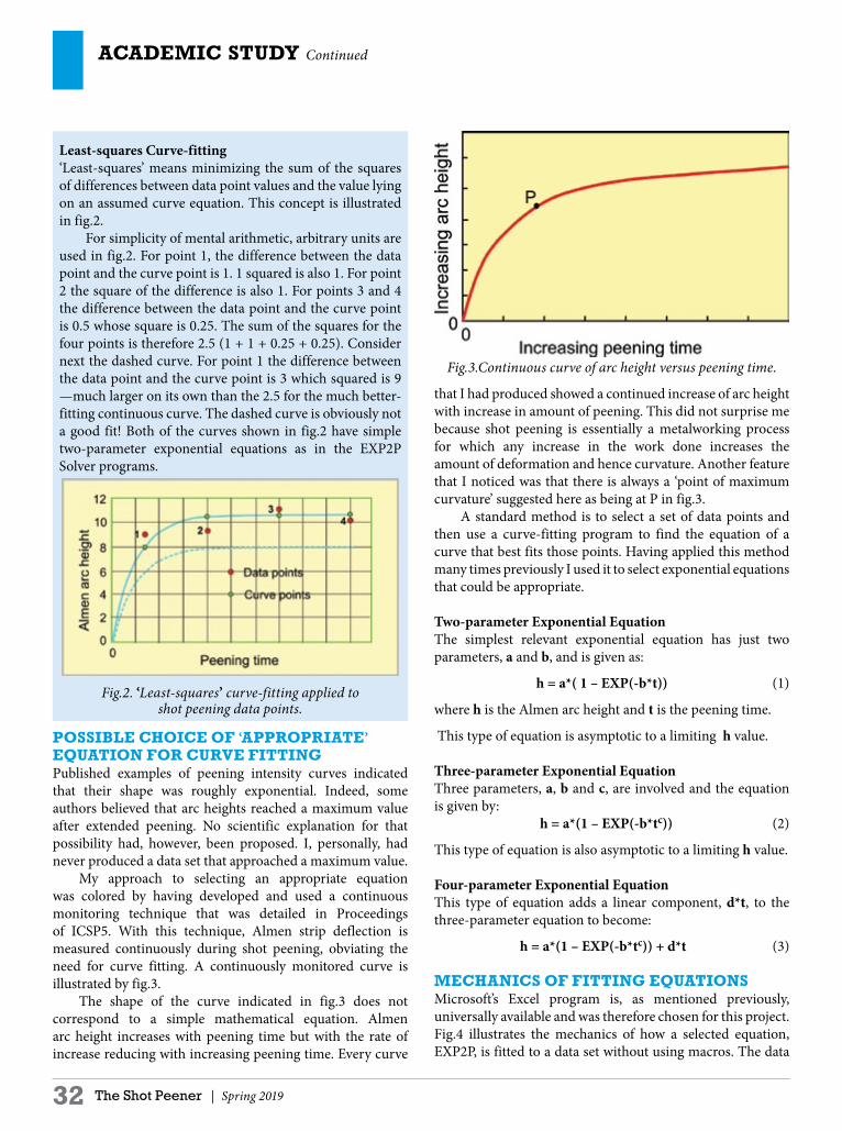
PoSSIBlE CHoICE oF ‘APProPrIATE’ EQUATIon For CUrvE FITTInGPublished examples of peening intensity curves indicated that their shape was roughly exponential. Indeed, some authors believed that arc heights reached a maximum value after extended peening. No scientific explanation for that possibility had, however, been proposed. I, personally, had never produced a data set that approached a maximum value. My approach to selecting an appropriate equation was colored by having developed and used a continuous monitoring technique that was detailed in Proceedings of ICSP5. With this technique, Almen strip deflection is measured continuously during shot peening, obviating the need for curve fitting. A continuously monitored curve is illustrated by fig.3. The shape of the curve indicated in fig.3 does not correspond to a simple mathematical equation. Almen arc height increases with peening time but with the rate of increase reducing with increasing peening time. Every curve
that I had produced showed a continued increase of arc height with increase in amount of peening. This did not surprise me because shot peening is essentially a metalworking process for which any increase in the work done increases the amount of deformation and hence curvature. Another feature that I noticed was that there is always a ‘point of maximum curvature’ suggested here as being at P in fig.3. A standard method is to select a set of data points and then use a curve-fitting program to find the equation of a curve that best fits those points. Having applied this method many times previously I used it to select exponential equations that could be appropriate.
Two-parameter Exponential EquationThe simplest relevant exponential equation has just two parameters, a and b, and is given as:
h = a*( 1 – EXP(-b*t)) (1)
where h is the Almen arc height and t is the peening time.
This type of equation is asymptotic to a limiting h value.
Three-parameter Exponential EquationThree parameters, a, b and c, are involved and the equation is given by: h = a*(1 – EXP(-b*tc)) (2) This type of equation is also asymptotic to a limiting h value.
Four-parameter Exponential EquationThis type of equation adds a linear component, d*t, to the three-parameter equation to become:
h = a*(1 – EXP(-b*tc)) + d*t (3)
MECHAnICS oF FITTInG EQUATIonSMicrosoft’s Excel program is, as mentioned previously, universally available and was therefore chosen for this project. Fig.4 illustrates the mechanics of how a selected equation, EXP2P, is fitted to a data set without using macros. The data
Least-squares Curve-fitting‘Least-squares’ means minimizing the sum of the squares of differences between data point values and the value lying on an assumed curve equation. This concept is illustrated in fig.2. For simplicity of mental arithmetic, arbitrary units are used in fig.2. For point 1, the difference between the data point and the curve point is 1. 1 squared is also 1. For point 2 the square of the difference is also 1. For points 3 and 4 the difference between the data point and the curve point is 0.5 whose square is 0.25. The sum of the squares for the four points is therefore 2.5 (1 + 1 + 0.25 + 0.25). Consider next the dashed curve. For point 1 the difference between the data point and the curve point is 3 which squared is 9 —much larger on its own than the 2.5 for the much better-fitting continuous curve. The dashed curve is obviously not a good fit! Both of the curves shown in fig.2 have simple two-parameter exponential equations as in the EXP2P Solver programs.
Fig.2. ‘Least-squares’ curve-fitting applied to shot peening data points.
Fig.3.Continuous curve of arc height versus peening time.

Spring 2019 | The Shot Peener 33
Exclusive agent in India
[email protected] Industries Ltd.
With thousands of successful installations and satisfied customers worldwide, our sales, engineering and tech support team stands ready to put our experience to work for you. We offer individualized service and technical support for your peening, cleaning and finishing challenges. Problem-solving is our strength. Count on us—you won’t be disappointed.
Attentive service and quality equipment at a level of sophistication to suit your budget.
Automated Air-Blast and Shot Peening Systems
www.clemcoindustries.comClemco Industries Corp. Washington, MO 63090
Designed and Engineered for You
Shot peen ad.indd 1 9/16/16 8:32 AM

ACADEMIC STUDY Continued
34 The Shot Peener | Spring 2019
set comprises nine measured values which is far more then shot peeners would normally acquire. This set does, however, reveal some subtle features of the program.
Data Input StageThis stage is straightforward as the values for the data set have to be entered within the blue frame. The next column uses a basic facility of Excel insofar as it allows values in one column to be automatically subtracted from corresponding values in another column to give ‘Corrected Height’ values.
Curve Solving StageExcel has a Solver function that I used to determine the least-squares best fit and from that the required peening intensity point. The word ‘Solver’ therefore appeared to be appropriate for titling purposes. For these programs. Solver has to be given reasonable starting values for a and b. It then uses those initial values for a and b to calculate the Y values that lie exactly on the equation’s curve. It then subtracts each calculated Y value from the corresponding data point’s arc height to give what is called a ‘Residual’ difference. If, for example, the initial
values for a and b gave a Y value of 3.6 for the first data point then the corresponding residual value would be -0.4 (3.6 – 4). Each of the residual values is then squared and added up to give a SUM (as in fig.4). This sum has to be minimised to give a least squares value. Solver uses iteration to find the minimum value of the SUM. ‘An iterative process is a process for calculating a desired result by means of a repeated cycle of operations. An iterative process should be convergent, i.e., it should come closer to the desired result as the number of iterations increases’. During iteration the values for a and b are repeatedly adjusted by tiny amounts causing the SUM to get smaller and smaller. When no further reduction is achieved the cycle stops to give values such as the 8.65 and 0.53 given in fig.4. The equation for the curve is now solved—in less than the blink of an eye!
Peening Intensity PointHaving now found the parameters a and b of the equation, the next step was to find the point on the curve that satisfied the requirement that ‘When the peening time is doubled the arc height increases by 10%’. Excel’s Solver could be employed to
Fig.4. Excel Worksheet using EXP2P program.

Spring 2019 | The Shot Peener 35
wabrasives.com
A full range of metallic abrasives dedicated to the Shot Peening Operations
A strict compliance with the requirements of automotive, aerospace industries SAE, AMS, VDFI standards as well as many other proprietary specifications
An invaluable technical support to boost your Shot Peening performance
A worldwide presence with more than 20 sister companies
MAIN REFERENCES SAFRAN GROUP, BOMBARDIER, ROLLS ROYCE…
To discover more about our products & services, contact us on wabrasives.com/shot-peening.htmlor [email protected]
Want to boost your Shot Peening performance ? Contact the world leader.
Robotic/CNC Shot Peening Equipment
Portable/Mobile Systems
Complete Turn Key Process including
Programming, Fixture Design, and
Documentation
Patent Pending Almen Fixture Design
EI Distributor for MagnaValves, Almen
Gages and Strips
www.peentech.com261 Burnham Street, East Hartford, CT 06108
860-289-4328

ACADEMIC STUDY Continued
36 The Shot Peener | Spring 2019
find this point using ‘Goal Seek’. However I found a simpler method. Expressing the 10% requirement mathematically gives the following: Y = a(1 – EXP(-b*T)) (4) 1.1Y = a(1 – EXP(-b*2T)) (5)Dividing equation (5) by equation (4) eliminates both Y and a: 1.1 = (1 – EXP(-b*2T)) /(1 – EXP(-b*T)) (6)Equation (6) simplifies to give that the required value for T is given by T = 1.897/b. This required value calculation was incorporated into the spreadsheet, e.g., 3.61 in fig.4. The calculated required value for T is then substituted into the now-established equation to give the required peening intensity value, e.g., 7.35 in fig.4.
Goodness of FitHaving found the parameters of the best fit of the selected equation, it is useful to be able to quantify how good the fit is. The SUM shown in fig.4 has the smallest value obtained using the least-squares method. This sum is, however, proportional to the number of data points. The greater the number of data points in a given set the larger will be the SUM. A term ‘Root Mean Square’ is generally used to quantify goodness of fit and eliminates the effect of data point number. This is achieved by taking the mean of the squared residuals (by dividing the SUM by the number of data points) and taking the root of the mean. This result is calculated automatically in the spreadsheet and displayed as RMS-R having a value of 0.2831 for the example shown as fig.4. The smaller the value of RMS-R the better is the fit. Root mean square values are useful for quantifying the magnitude of random errors. They do not, however, reveal systematic errors. As a parallel, consider tossing a coin 40 times and finding that ‘heads’ appeared 20 times and ‘tails’ also 20 times. We might reasonably conclude that the coin was unbiased. But what if ‘heads’ appeared for each of the first 20 tosses and ‘tails’ appeared for each of the second 20 tosses? That would indicate a high probability of a systematic error. A systematic error is also possible for the ‘residuals’ of the example shown in fig.4. I built in an indicator for systematic error by highlighting negative residuals pink. Using the coin-tossing parallel we have two ‘tails’ followed by 4 ‘heads’ and then by three ‘tails’. This sequence is exceptional, hence indicating a possible systematic error.
DISPLAY OF FINDINGSThroughout this exercise I decided to display all of the findings. This was so that users could discover how the findings had been determined. Many users are only interested in the results. A graphical type of display was therefore introduced that highlights the most important findings. Fig.5 is the graphical display that corresponds to the findings of fig.4. This display utilizes more of Excel’s excellent features.
Fig.5. Graphical display using findings presented in fig.4.
The arc height for Saturation Intensity, aka Peening Intensity, is headlined together with its peening time, T, and 2T. Corrected Gage Data Points can be compared with the Fitted Curve and Fitted Curve Points. In this case, the comparison reveals the possible systematic error considered previously for this particular data set. The spreadsheet shown in fig.4 also allowed for the specification limits to be entered. As it happens they were not specified for this data set. If they had been specified then two horizontal red lines would have appeared in fig.5. For example, specifying limits of 7 and 10 would highlight that the derived intensity of 7.35 was very close to the lower allowed limit.
MECHAnICS For oTHEr FITTED EQUATIonSHaving succeeded in producing a program using a two- exponent exponential equation, the next step was to modify the program to accommodate other equations.
Three-parameter Exponential - EXP 3PThis equation uses h = a*(1 – EXP(-b*tc)) as a fitting equation. The only significant modification required was to employ Excel’s GOAL SEEK function to calculate the ‘10% time’ and thence the arc height for that time. This was achieved by asking Goal Seek to minimize the following function: f(x) = 1.1 (1 – EXP(-b*T)) - (1 – EXP(-b*2T)) (7)Goal Seek starts by substituting a value for T into equation (7) in order to find a value for f(x). It then makes tiny changes to the value of T to see if they reduce the magnitude of f(x). Eventually it finds a value for T that minimizes f(x). That minimum value is normally the required peening intensity point’s time. The only problem with Goal Seek is that there are two possible answers! If it started its search with a time close to zero it would hone in on T = 0 as being the solution. In practice this rarely happens but when it does Goal Seek has to be given a value at least as great as the time for the first data point in the set.
Four-parameter Exponential - EXP 4PThis equation uses h = a*(1 – EXP(-b*tc)) + d*t as a fitting

Spring 2019 | The Shot Peener 37
Supplying spare parts for shot blast machines and shot peening accessories for the automotiveand aerospace industriessince1991
Av. De las Granjas No. 61 - 3 Col. Jardín Azpeítia, Azcapotzalco
C.P. 02530 México, D.F., Tel. 011-52-55-5355-0947, Fax 011-52-55-5355-6391
E-mail: [email protected]
SHOT BLAST PARTSCHAIN LINKSCUT WIRE SHOT
BLAST WHEELS
CAST NUTS
WHEEL LINERS
CONVEYOR FLIGHTS
MANGANESE
PLATE 11-14%
ALMEN STRIPS
SHOT PEENING
PRODUCTS
STRIP
HOLDERS
MAGNAVALVES
ALMEN GAGES
ALMEN MINI STRIPS3M FLAPPS SHOT PEENING
WORKSHOPSFLAPPER PEENING
KITS

ACADEMIC STUDY Continued
38 The Shot Peener | Spring 2019
equation. The d*t adds a linear component to EXP3P. I felt intuitively that this would achieve an excellent fit and so it turned out. One restriction, however, was that it could only be applied using the least-squares method to data sets that comprised at least six points. Also a four-parameter exponential equation is mathematically relatively unstable. I later found out that the improved fit was not necessary with respect to locating the peening intensity point. For that reason (discussed later), I did not include it in the Solver Suite of programs.
French Specification - 2PFThe French specification for computer-based analysis requires users to use a particular fitting equation. This is termed a ‘rational function’ and has the following equation: h = a*t/(t + b) (8)Equation (8) is exponential to the value of a. The value of the peening point time does not need Goal Seek as I found that it was equal to 9b/2. This is because we have the following relationship: 1.1*a*T/(b + T) = a*2*T/(b + 2T)a*T in the numerators cancel each other out leaving: 2*b + 2*T = 1.1*b + 2.2T which reduces to give: 0.9*b = 0.2*T or T = 0.9b/0.2
ProGrAM vArIAnTS Having succeeded in producing three workable programs, EXP2P and EXP3P, I modified them to accommodate the then published corrections needed for flapper peening and also to allow the findings from one data set to be compared with one from a previous data set. This led to a total of 12 separate programs forming the Solver Suite. I pondered about whether or not such a number might be found confusing. Eventually I decided that in practice users would normally only select one or two from the suite to use regularly.
ProGrAM CoMPArISonSThe primary objective of the exercise was to estimate the peening intensity point rather than finding the best fit. Estimates of the derived peening intensity point were therefore carried out using all four available programs (EXP2P, EXP3p, EXP4P and 2PF) and the same nine-point data set as shown in fig.4. This gave the results shown as Table 1.
Table 1 Effect of Program on derived Peening Intensity Point
Program Intensity TEXP2P 7.35 3.61EXP3P 7.69 4.30EXP4P 7.16 3.592PF 7.79 6.06Average 7.50 4.49
The results show clearly that these widely different programs all produce very similar derived peening intensity values albeit with substantial differences in the corresponding times, T. Years after producing the Solver Suite of programs, the SAE introduced J2597. This specification gives guidelines on computer-derived peening intensity values. Any program was allowed provided that it met a stated criterion when applied to its set of 10 data sets—the criterion being that all of the derived peening intensities should deviate less than ± 0.001" from the stated values. Fig.6 illustrates the deviations from the stated values for Solver Suite programs based on EXP2P and 2PF. Both meet the requirement.
Fig.6. Deviations from the J2579 data set for EXP2P and 2PF programs.
DISCUSSIonA set of programs was successfully produced that allowed peening intensity to be derived using features embodied in Microsoft’s Excel. It is believed that this free set of programs has stimulated the almost universal adoption of computer-based intensity derivation in place of subjective manual techniques. All of the programs are ‘open source’ as I insisted that a primary feature was for them to be ‘educational’—allowing users to know how values are being derived. In particular the fitting equation is always declared unlike commercial programs. As a word of warning, specifications are regularly updated which may impinge on some Solver Suite programs. For example, AMS2590B for flapper peening was updated in January 2019. This specification requires data corrections prior to creating a saturation curve. Only some of the proposed data corrections are applied automatically by the corresponding Suite programs. l

Spring 2019 | The Shot Peener 39
AutomatedPeen Forming
Solutions
KSA Kugelstrahlzentrum Aachen GmbH · Weststraße 22-24 · 52074 Aachen · Germany
Automated Peen Forming Solutionswww.ksa.de.com
KSA_Anz_8-2012_end.indd 1 07.09.12 12:17
Printer Notes:
Artwork is at 100% scale Die-line does not print - image is to bleed to the die-line edgeDocument is set up as CMYK for print
4.75”
7.0”

40 The Shot Peener | Spring 2019
lASEr PEEnInG rESEArCHCurtiss-Wright Surface Technologies | www.cwst.com
Lifetime Enhancement of Propulsion Shafts Against Corrosion Fatigue
by Laser PeeningLloyd A. Hackel and Jon E. Rankin
Curtiss-Wright Surface Technologies
The paper’s Introduction and Summary are provided here. To read the paper in its entirety, visit the online library at www.shotpeener.com. The document ID number is 2019012.
THIS PAPEr rEPorTS substantially enhanced fatigue and corrosion-fatigue lifetimes of propulsion shaft materials, 23284A steel and 23284A steel with In625 weld overlay cladding, as a result of shot or laser peening. Glass reinforced plastic (GRP) coatings and Inconel claddings are used to protect shafts against general corrosion and corrosion pitting. However salt water leakage penetrating under a GRP can actually enhance pitting leading to crack initiation and growth. Fatigue coupons, untreated and with shot or laser peening were tested, including with simultaneous salt water immersion. Controlled corrosion of the surfaces was simulated with electric discharge machining (EDM) of deep pits enabling evaluation of fatigue and corrosion-fatigue lifetimes. Results specifically show high energy laser peening (HELP) to be a superior solution, improving corrosion-fatigue resistance of shaft and cladding metal, reducing the potential for corrosion pits to initiate fatigue cracks and dramatically slowing crack growth rates. At a heavy loading of 110% of yield stress and with 0.020 inch deep pits, laser peening increased fatigue life of the steel by 1370% and by 350% in the corrosion-fatigue testing.
INTRODUCTIONPrevention of corrosion-induced fatigue cracking of propulsion shafting is an important operational and safety requirement and thereby significantly impacts the construction and operational cost of ships. The issue is specifically important for submarines where viability of shafts specifically defines operation limits. In ship operation, shafts undergo heavy mechanical loading while simultaneously exposed to the salt water environment. Shafts are often fabricated using weld-overlay Inconel coatings and glass reinforced plastic (GRP) coatings to protect against corrosion and corrosion pitting. However salt water can seep under the coatings where the confined environment actually exacerbates corrosion pitting
(crevice corrosion) leading to early fatigue crack initiation. Consequently ship inspection and overhaul schedules are often dictated in time to ensure shaft integrity. The issue is of particular importance to submarine safety. As summarized by Jonart in his thesis, “Submarine propulsion shafts have demonstrated acceptable reliability performance when inspected and refurbished at least every six years (Jonart 2014). Designers wish to extend the inspection interval to 12 years without sacrificing reliability. This interval is unprecedented, as no known submarine shafting system is currently operated with this inspection cycle, nor are any known commercial vessel shafts. Experience and improved design have eliminated many threats to the life of
The prevention of corrosion-induced fatigue cracking is especially important for submarines where the viability of
propulsion shafts affects operation limits.
Photo: The Ohio-class ballistic missile submarine USS Nebraska in Puget Sound, Washington. The Nebraska
recently completed a 41-month engineered refueling overhaul. The overhaul will extend the life of the submarine
for another 20 years. This U.S. Navy photo was taken by Mass Communication Specialist 1st Class Amanda R. Gray.

Spring 2019 | The Shot Peener 41
REPAIR STATIONMYLR882K
Est. 1942 - Elk Grove Village, Illinois
(847) 437-4488SHOT PEENING
WELDINGCOATINGSMETAL FINISHING NDT
WWW.MILINC.COM
Contact Us Today(847) 437-4488
AIRCRAFT WHEELS
GEARS
CRITICAL ENGINE FEATURES
DRIVETRAIN ELEMENTS
LANDING GEAR COMPONENTS
DEFENSEMEDICAL
AEROSPACE
Over 2,500 Prime ApprovalsYour True One-Stop Shop

42 The Shot Peener | Spring 2019
Shot Peening
NDT
Mass Media Finishing
Aerospace, Military & Commercial Approvals
FAA Repair Stations KJ1R272K (CT) & G89R878X (GA)
On-site Capabilities
peentech.com
Surface Enhancement (CT & GA) Nondestructive Testing (GA)
8 Eastern Park Road East Hartford, CT 06108
860-289-4328
3117 Emery Circle Austell, GA 30168
770-941-9573Established 1966
lASEr PEEnInG rESEArCH Continued
a submarine shaft, but inspections of existing shafts show a high percentage with signs of wetting, leaving designers with less-than-acceptable confidence to approve this longer inspection interval due to the possibility of corrosion-fatigue failure.” Jonart’s uses probabilistic models from literature for pitting and cracking of wetted shafts along with Monte Carlo simulations to predict expected times from shaft wetting to pitting, to crack initiation and growth and to eventual shaft failure. Based on allowable risk, this type of modeling is used to set allowable time intervals between shaft inspections. Reducing the potential for shaft failure would greatly enhance safety and could increase inspection intervals and thereby enable significant cost savings and increased ship availability. In this work we evaluate fatigue lifetimes of 23284A steel, a steel used for propulsion shafts, alone and in the presence of simultaneous salt water exposure (corrosion-fatigue lifetimes). We also evaluate the fatigue and corrosion fatigue lifetimes of this steel when deployed with an Inconel 625 weld overlay—an overlay used to inhibit corrosion and corrosion pitting. The work focuses on the ability of shot and laser peening to extend the lifetimes with the intent to enhance safety and reduce shaft inspection and replacement intervals.
SUMMARYUsing fatigue and corrosion fatigue testing, we have investigated the potential of laser and shot peening to extend the lifetime of propulsion shaft material, including 23284A steel and steel with In625 weld overlay. In all cases the tests showed that laser peening significantly increases the lifetime of the shaft material and the weld-overlayed material beyond that of untreated or shot peened material. For 23284A material clad with In625, material less prone to corrosion induced pitting, the laser peening increased the lifetime of a notched sample by over 1300% without a failure occurring. For the bare 23284A steel, test results are summarized in Figure 17. Propulsion shaft material experiences a 480% loss of fatigue lifetime at 125% of yield stress, following the EDM of a 1 mm diameter by 0.5 micron pit intended to simulate a salt water induced corrosion pit. In contrast, laser peening doubles the lifetime of pitted material at this high stress level. Pitting combined with salt water exposure dropped the fatigue performance by more than five (5) times. Laser peening overcomes much of this deficit, improving corrosion-fatigue by 350%. Inspection intervals, driven by concern for corrosion-fatigue failure, are a major driver in ship overhaul and hence a driver of cost and ship availability. Laser peening could safely extend inspection intervals. l
Read or download the complete paper at the online library at www.shotpeener.com. The document ID number is 2019012.

Spring 2019 | The Shot Peener 43
2019 Shot Peening Training
www.shotpeeningtraining.com (574)256-5001 or 1-800-832-5653
Improve your skills,reach your professional goals
Learn from expert instructors on relevant topics
FAA-accepted courses,Nadcap Partner in Education
On-site training programs are also availableTrain on your equipment • Can be customized • Includes facility and equipment review
Training can be held any time of year • Ideal for five or more employees
San Miguel de Allende, Mexico .............. March 26-28Shot Peening and Rotary Flap Peening Seminars
Toronto, Canada................................................ May 6-7Shot Peening and Rotary Flap Peening Seminars
Dattein, Germany .........................................May 14-16Shot Peening Seminar and Workshop in Deutsch
United Kingdom .......................................... June 10-11Shot Peening Seminar
Singapore ..................................................... June 25-27Shot Peening and Rotary Flap Peening Seminars
Chengdu, China ............................................. July 18-19Shot Peening Seminar in 普通话 (Mandarin)
Orlando, Florida USA ........... September 30 - October 2Shot Peening Seminar and Workshop
Receive recognition for achieving a higher level of shot peening education. Seminar, workshop and on-site training attendees are eligible to take our FAA-accepted shot peening and rotary-flap peening achievement exams.

44 The Shot Peener | Spring 2019
CASE STUDYEmpire Abrasive Equipment | www.empire-airblast.com
Improving the Surface Finish of Gun Components
MArkET: Firearms
APPlICATIon: Abrasive blast cleaning of gun components to prepare surface for coating application.
THE CHAllEnGE:A major defense manufacturer in the firearms industry needed the ability to improve the surface finish of gun components prior to final finishing. The parts being processed had minor surface imperfections such as scratches and grinding marks. The manufacturer had tried both outsourcing the abrasive blasting to a job shop as well as hand blasting in-house to prepare the surface for coating. In either case, however, they encountered problems with the consistency of the finish. This, in turn, was affecting the overall quality of the end product. As a result, they were looking for a solution that would result in a consistently high quality finish every time.
THE SolUTIon:Empire technical sales personnel and application engineers met with the defense manufacturer to evaluate their current processes and determine their requirements. After careful analysis, Empire recommended the installation of several Single Piece Flow Abrasive Blast Cleaning Systems to provide an automated solution that would reduce inventory requirements, conserve floor space and, most importantly, guarantee the consistency of the final surface finish. Empire’s Single Piece Flow Systems are available in two sizes, 38" D x 30" W and 24" D x 24" W. These compact, single-station closed cell machines are ideal for blasting cylindrical parts such as barrels, scopes, and hand guards. The larger of the two systems, the 38" x 30", features a 50" high blast area with four (4) oscillating suction blast guns.
The gun movement is controlled by an 18" DC drive belt oscillator. Parts are inserted into a customer-supplied fixture and then loaded onto a shaft in the blast cabinet. The shaft rotates while the blast gun nozzles move in vertical strokes. It is designed to cover all areas of the part. An integral PLC controller manages the machine functions including blast pressures, oscillation speed, number of strokes and other variables affecting cleaning, peening and finishing. Rotation speed is operator controlled via potentiometer. Operation is simple and efficient—just insert part, close compartment door, set parameters and start the blast cycle. The 24" x 24" system is a similar unit that is ideal for smaller parts. Featuring three (3) fixed suction blast guns, blasting of the part is also
accomplished by rotating the fixture while the blast guns cover all areas of the part. With this unit, the blast cycle is based on time as opposed to stroke count. All machine functions are available on the operator control panel including setting blast time and rotation speed. Available material handling options for both models include a vertical sliding door (replaces swing-out door) and light curtains and/or whisker switch to enhance operator safety.
BEnEFITS:Empire provided economical and flexible abrasive blast cleaning systems with PLC or manual control. The Empire solutions increased productivity and also assured a consistent finish and improved quality control. The Empire team helped the manufacturer meet the demands of its customers and give them a winning edge in an increasingly competitive global marketplace. l

Spring 2019 | The Shot Peener 45
Midwestern Industries, Inc.
“The Sizing People” ®
Screening Equipment Wire Cloth Replacement Parts Emergency Shipping
Visit: midwesternind.com
TOLL FREE 877 - 4 - SIZING
(877-474-9464)
Number one in cut wire shot since first pioneering the process nearly 60 years ago. Product quality, consistency and durability combined with knowledge, customer service and delivery still make us number one today.
SAE J441 | AMS-S-13165 | AMS 2431 | VDF1-8001 | BAC-5730 | MIL-S-851D
STAINLESS STEEL | ZINC | CARBON STEEL | ALUMINUM | COPPER
A CUT ABOVE THE REST
ISO 9001: 2000 Certified
PELLETS_QTR_PAGE.indd 1 5/7/06 4:24:26 PM

46 The Shot Peener | Spring 2019
Take Control of Your MediawiTh profile spiral separaTors
REMOVE broken media, leaving predominatelyround media for a controlled, effective shot peening process
SEPARATE round from non-roundmetal abrasives, metal shot, ceramic beads, glass beads and more
SAVE money on media—recycle it for a cost savings
PROTECT expensive parts from damage by broken media
LIMIT wear to machine parts from broken media
EXCEED SAE AMS 2430 requirements
Call 1-763-428-5858 today
1-763-428-5858 www.profile-ind.com | [email protected] 14525 James Road, P.O. Box 370, Rogers, Minnesota 55374 USA
Get Up To Speed On Rotary Flap Peening
with training from the experts
Rotary flap peening is one of the fastest-growing shot peening methods—it’s effective, economical and fast.
EI Shot Peening Training offers one-day on-site training programs for companies and military bases that want to expand their rotary flap peening skills.
Our rotary flap peening training will: • Help you achieve a controllable process • Increase your operators’ skill • Demonstrate how to achieve compliance to
specifications and standard practices, including AMS2590A
• Expand your use of this productive process
Our training program is beneficial to operators, supervisors, inspectors and application engineers.
FAA mechanics are eligible for training credit. Ask us for more information.
1-800-832-5653 (U.S. and Canada) or 1-574-256-5001or visit www.shotpeeningtraining.com
Get rotary flap peening training from the company that knows how to do it right. Dave Barkley is the Director of EI Shot Peening Training and one of EI’s rotary flap peening instructors. Mr. Barkley was the author/sponsor of AMS 2590 Revision A—“Rotary Flap Peening of Metal Parts.”
Rotary flap peening is ideal for peening small areas on new or repaired parts. The process can also be done in the field,
making the time-consuming and expensive disassembly and transportation of components unnecessary.

More efficient parts processing? Procisely!® PRIMS Pro® gives engineersand operators the most advanced and flexibleprocess controller ever. PRIMS Pro® is Windows-based and procisely
customized for your shot peening operations.
Part & program manager• Queue parts before processing, or while others process
• Search by easily sorting through large quantities of parts
• Select and define multiple motion control or surface functions
• Modify or review part programs
Preventive maintenance• Auto-sort based on next item required
• All-in-one maintenance scheduler, historian, and advisor
Multi-level security system• Customize permission levels by user log-in
• Control modifications to process parameters and part data
• Limit who can reset PM items or run alarms
PRIMS Pro automates process control, monitoring, and data-logging for key parameters.
It’s the ideal monitoring software for production, overhaul and repair, and R&D.
Learn more at:
progressivesurface.com
PS-full pg PRIMS Pro ad-ShotPeener.indd 1 3/23/12 8:55 AM