Embed Size (px)
Citation preview

A Publication of the Turbo Diesel Register
What you should know about the2003-2009 Ram Turbo Diesel truck.
TURB
O DI
ESELBuyer’s
Guide
Volume 2003-2009TU
RBO
DIES
EL
Guide

2 A Publication of the TURBO DIESEL REGISTERVolume 2003-2009
VOLUME 2003-2009TABLE OF CONTENTS
Why A Diesel? . . . . . . . . . . . . . . . . . . . . . . . . . . . . . . . . 4Charting the Changes . . . . . . . . . . . . . . . . . . . . . . . . . 8Third Generation Power Ratings . . . . . . . . . . . . . . . . 14What Does Every Turbo DieselOwner Need to Know (Issue 70, p40-41) . . . . . . . . . . 16Third GenerationPurchase Criteria (Issue 77, p54-59) . . . . . . . . . . . . . 18Mega Cab Introduction (Issue 50, p52-56) . . . . . . . . 26Over the Years -TSBs from 2003-2009 (Issue 66, p54-71) . . . . . . . . . 32Lube Oil Update (Issue 76, p52-56) . . . . . . . . . . . . . . 59Add Oil Here/PC-11 and CK-4 Update (Issue 93, p52-54) . . . . . . . . . . . . . . . . . 64Engine Evolution -5.9-Liter Hardware (Issue 43, p30-37) . . . . . . . . . . . 67Engine PerformanceEvaluations (Issue 47, p42-50) . . . . . . . . . . . . . . . . . . 735.9-Liter Engine Performance Enhancements –To Modify or Not to Modify
Introduction . . . . . . . . . . . . . . . . . . . . . . . . . . . . 81Performance Parts Update [Chances are the Modifi cations are Illegal] (Issue 95, p66-67) . . 82Performance EnhancementsIntroduction (Issue 45, p24-29) . . . . . . . . . . . . . 84Performance Enhancements -Part I (Issue 47, p53-61) . . . . . . . . . . . . . . . . . . . 88Performance Enhancements Part II (Issue 48, p50-58) . . . . . . . . . . . . . . . . . . 97Performance Enhancements -Part III (Issue 49, p36-43) . . . . . . . . . . . . . . . . 106Performance Enhancements -Part IV (Issue 53, p11-18) . . . . . . . . . . . . . . . . . 115Performance Enhancements -Epilogue (Issue 93, p12) . . . . . . . . . . . . . . . . . . 123
Engine and Transmission MaintenanceInjectors for HPCR Engines - Introduction(Issue 66, p46-50) . . . . . . . . . . . . . . . . . . . . . . 124Injectors for HPCR Engines - Repair(Issue 72, p44-57) . . . . . . . . . . . . . . . . . . . . . . 129Rebuilding the G56 Six-Speed Transmission(Issue 71, p106-109) . . . . . . . . . . . . . . . . . . . . . 143
Final Notes for Third Generation ’07.5-’09 Ownerswith the Cummins 6.7-liter Engine . . . . . . . . . . . . . 1476.7 HPCR Meets2010 Emissions (Issue 56, p44-45) . . . . . . . . . . . . . 148Engine Evolution - Emissions (Issue 49, p50-56) . . 150
A WORD ABOUT THIS BUYER’S GUIDE
Recently my wife and I spent much time looking for a “new” used car. I fi red up my computer, studied comments and users’ experiences in forum-based websites, and downloaded archived articles from Car and Driver and Edmunds.com. There was a lot of miscellaneous and helpful information, free and for the taking. I fi gure this sort of web search is pretty typical for prospective vehicle purchasers today. As it turned out, we didn’t make a purchase, but my experience in searching for a suitable used car made me more aware of issues of value and economy in owning a Turbo Diesel today.
As a writer it is tempting to tell the long story of “information being worth the price that you paid for it.” I will refrain. Many thought-provoking articles on the state of the publishing business versus the free-for-all of the interweb (pun intended) have been written and my opinion is not likely to change anyone’s point of view.
Back to the subject at hand—you are a prospective or new owner. You want more information. You want it now. You want it at no charge.
Since the late 90s we have compiled information on the Dodge/Cummins Turbo Diesel truck. Each year we update the book. We call the data the Turbo Diesel Buyers Guide, which you have successfully downloaded.
The price of this book has been discussed many times over. It is offered to you at no charge. Our hope is that its value will lead you to purchase a subscription to the Turbo Diesel Register magazine. Thanks for your consideration.
Robert PattonTDR Editor
TUR
BO D
IES
ELBuyer’sGuide
2003-2009 Buyer’s Guide last updated 2/2017.

3A Publication of the TURBO DIESEL REGISTER Volume 2003-2009
A WORD ABOUT THE TURBO DIESEL REGISTER
How did the Turbo Diesel Register get its start? First off, I’m an automotive enthusiast. An automotive enthusiast that was in search of a tow vehicle for my admittedly small collection of automobiles. As you can imagine, the search for the right tow vehicle took me in the direction of the Ram Turbo Diesel. My search was aided by the fact that my previous job was in the diesel engine profession as a Cummins distributor product support representative. Do I have a good knowledge of the Turbo Diesel engine? Well, maybe. I’ll let you be the judge.
Back to the “story.” As an automotive enthusiast, I am a member of a handful of car club/register type publications. In addition, I subscribe to just about every car and truck monthly publication in hopes that I can learn something more about my vehicles. The only vehicle I owned that didn’t have its own club was the Turbo Diesel. The light goes on. Why not start a Turbo Diesel club? The light flickers. I know the immediate answer: not enough time, no money, and who would write the articles? Needless to say, the idea got put on the back burner. Another great idea, but…
Looking back, that was many long years ago. Prior to our first magazine (Fall ’93) I took time to talk to other Turbo Diesel owners who wanted to know more about their truck and specifically the Cummins engine. At the time I knew the Turbo Diesel Register would work. I also knew it would be a lot of hard work with an up-front monetary investment and the commitment to publish the magazine.
Positive discussions with other club/register publishers and an unofficial “good luck” or two from the manufacturers, and well, I was still hesitant. Back to the all-important concerns: time, money and writing skills. Time? In the initial two-career-days it was nothing to stay up until 2:00 a.m. Money? What the heck, we took out a second mortgage. And writing skills? You’ve heard the saying, “if it is to be, it is up to me.” Thus, we started the TDR way back in the summer of 1993.
Robert Patton TDR Editor
PS. We hope you’ll learn something from the following collection of tips and Ram technical data. Please realize this booklet is just the “tip of the iceberg.” The TDR and its members provide a wealth of information. How to join? Please fill-out and mail the order form or register on-line at www.turbodieselregister.com.
Join Us Today!An annual subscription to the Turbo DIesel Register is $35.00 U.S. and $45 Canadian/Interna-tional.
Please complete this subscription form and enclose it in an envelope along with your check or money order payable to:
TURBO DIESEL REGISTER 1150 Samples Industrial Drive Cumming, Georgia 30041
(770) 886-8877
Name ______________________________________________________________
Address ____________________________________________________________
City __________________________________State ___________Zip ___________
Phone: Home ( ) _____________________________________________
Work ( ) _____________________________________________
Truck Year __________________ Model _______________
Payment Enclosed Bill my Mastercard/VISA
# __________________________________________ Exp. Date ______________

4 A Publication of the TURBO DIESEL REGISTERVolume 2003-2009
As the editor of a club news magazine (the Turbo Diesel Register for Dodge/Cummins owners), I am frequently asked, “Why is a diesel engine more fuel efficient than a gasoline engine of comparable displacement and horsepower?”
Let’s see if I can provide a simple, no-nonsense answer. At the close of this article we’ll do a quick diesel-payback example. Armed with a better understanding of why diesel provides a better payback on fuel consumption, you will be equipped to wring the most mileage from your tankful of diesel fuel.
How would you respond to, “Why is a diesel more fuel efficient?”
You may respond with one of the common clichés, such as, “It’s the design of the diesel, it’s built to be more efficient.” How about, “The compression ratio is higher, there is more power?” Or, maybe a little more helpful, “The Btu content of diesel fuel is greater;” or perhaps, “It’s in the injection system.”
All of the above are correct, but the answers are pretty intuitively obvious.
When working with diesel powered generators, I encountered similar queries and responded with the same partial answers. I’ve seen the same “you didn’t answer my question” body language from interested parties. It took being embarrassed in front of a large crowd before I vowed to get the complete answer.
Let’s see if I can tie it all together and give you an answer you’ll be able to use with your acquaintances. We will examine the diesel’s design, compression ratios, fuel Btu’s, and the fuel injection system to lead us to a concise answer, one that’s easy to recall.
THE DIESEL’S DESIGN“It’s the design of the diesel; it’s built to be more efficient.”
The diesel engine was designed and patented in 1892 in Europe by Rudolf Diesel.1 In the early part of the last century, Mr. Clessie Cummins, founder of Cummins Engine Company, refined the diesel design and developed engines to be used on-highway in the USA. Clessie’s son, Clessie Lyle Cummins Jr., is a diesel historian. A passage from his book Diesel’s Engine provides an historical perspective on Rudolf Diesel’s early struggle to perfect his revolutionary engine and bring it to market.2
After a ten-year search Rudolf Diesel was convinced he had found the way to design an engine with the highest thermal efficiency. He believed the most difficult days were over and transforming ideas into reality should prove a simpler task: License a qualified manufacturer to
develop and build the engine under his guidance and then await the forthcoming royalty check. One company finally agreed to evaluate a test engine built to his design, but gave him no financial support. Because of this limited commitment he continued to promote his theories through the book based on his studies. Gift copies went to influential professors and companies deemed possible licensees. A few favorable academic endorsements resulted, but no new firms showed any interest. Meanwhile, when Diesel came to realize that his patented combustion process was unsuitable for a real engine he quietly substituted another. The path of his endeavors still failed to follow his optimistic, short range plan.
Diesel continued to seek the “highest thermal efficiency,” or what he called a “heat engine,” until his suicide in 1913. But the design principle is remarkably simple. From Mr. Clessie Cummins’ book My Days With the Diesel,3 I’ll let the senior Mr. Cummins explain.
As the term “heat engine” implies, the diesel differs in principle from the gasoline engine, in that [diesel] combustion is obtained by the heat created by compression of air in the cylinder. The diesel needs no electrical (spark) ignition system. Furthermore, it burns low-grade oil rather than the highly refined, more expensive fuels required by the gasoline engine.
Adjudged practical only for heavy-duty, stationary, or marine power applications, diesels, when I first encountered them, weighed as much as 400 pounds per horsepower and ran at very slow speeds. Entering the industry some eight years after introduction of the diesel in this country, I undertook a personal campaign, with the crudest of experimental facilities, to reduce this pound-per-horsepower ratio, despite all textbook rules to the contrary. These efforts culminated in the invention of the high-speed, light-weight automotive diesel.
For two decades, while struggling with the engine developments, I battled equally big odds to build a highly specialized business. Cummins Engine Company was incorporated in 1919, but it took the better part of eighteen years for our bookkeeper to need any black ink. Then success arrived with a rush, after the initially skeptical long distance truckers finally accepted our new engine.
Today Cummins Inc., of Columbus, Indiana, is the world’s largest independent producer of automotive diesel engines. It provides jobs for ten thousand persons, with sales of more than $250 million annually (the publish date of Clessie Cummins’ book was 1967).
Note: 2005 sales were 9.92 billion.
WHy A DIESEL?by Robert Patton

5A Publication of the TURBO DIESEL REGISTER Volume 2003-2009
Considering the level of technology in machined parts in the late 19th century, it is no wonder that Rudolf Diesel was unable to build his heat engine and prove its practicality. But in time, technology would catch up with the simplicity of Diesel’s informing concept; and so the seemingly offhand answer that the design of the diesel is built to be more efficient is a true statement. Let’s look further at the components that make the diesel different.
Diesel’s first engine at the start of an 1893 test (photo courtesy of C. Lyle Cummins).
HIGHER COMPRESSION RATIO“The compression ratio is higher,
there is more power.”
Technically speaking, the compression ratio of an engine is the comparison of the total volume of the cylinder at the bottom of the piston’s stroke divided by the volume of the cylinder remaining at the top of the piston’s stroke. Since we are familiar with gasoline engines, let’s quickly discuss their compression ratios and a condition that spells disaster in a gasoline engine, detonation, or pinging.
The Gasoline Engine
Serious damage to a gasoline engine can result if you attempt to run a high compression ratio with low octane fuel. Detonation or pinging is the ignition of the fuel due to the high temperature caused by a high compression ratio/high pressure developed by a given design. Premature ignition of the fuel, i.e., coming before the spark of the spark plug, results in rapid uncontrolled burning. When timed properly, the approximate maximum compression ratio for a gasoline engine in race trim is 14:1. Most non-racing low octane compression ratios used in automobiles and trucks are less than 9:1.
The Diesel Engine
Remember, the diesel is a “heat engine” using heat energy developed from the compression of air. High compression ratios (ratios range from 14:1 to 20:1) are possible since air only is compressed. The hot compressed air is sufficient to ignite the diesel fuel when it is finally injected near the top of the compression stroke. A high compression ratio equals a greater expansion of the gases following ignition and a higher percent of the fuel’s energy is converted into power! The diesel compression ratio is higher, there is more power! However, I’ve provided yet another incomplete answer that is a true statement, but not the complete story.
Thus far we’ve covered the principle of diesel operation and the high compression ratios needed to make the heat for diesel engine combustion. The high compression ratio requires the designers to test and manufacture the block, heads, head bolts, crankshaft, connecting rods, rod bolts, pistons, piston pins, etc., with greater structural capacity. Diesel engines are heavy in comparison to their gasoline brothers. Take, for example, the B-Series engine used in the Dodge pickup. It is 970 pounds for the 359 cubic inch Turbo Diesel engine versus 540 pounds for the 360 cubic inch Dodge Magnum V-8 gasoline engine. With the greater structure and a diesel’s need for air, the turbocharger (introduced in the 1950s) was a natural fit for diesel engines.
Looking back, the first engine designed by Clessie Cummins in the 1920s was a monster at 400 pounds per horsepower produced. The year model 2005, 325 horsepower Cummins Turbo Diesel pickup truck engine is 3 pounds per unit of horsepower. I’d say diesels have made some progress in 85 years.
The Cummins engine used in today’s Dodge pickup.
FUEL BTU’S“The BTU value of diesel is greater.”
Quite true, the BTU, or British Thermal Unit, for diesel fuel is 130,000 per gallon, with a weight of 7.0 lbs./gallon. The value for gasoline is 117,000 BTUs at a weight of 6.3 lbs./gallon. If we go back to our basic physics rules for energy, you’ll note the fuel in the tank has potential for work if it is injected into the cylinders and, when combined with the compressed heated air, ignited. The piston is forced downward, the crankshaft rotates, and the wheels turn. True as all this is, the BTU value is not the major contributing factor to the diesel’s miles-per-gallon superiority. So, what is the key answer?

6 A Publication of the TURBO DIESEL REGISTERVolume 2003-2009
THE INJECTION SYSTEM“It’s in the injection system.”
Rudolf Diesel designed the heat engine to use the injection of fuel at the last moment to ignite the compressed air. Understanding the heart of the diesel, the fuel pump, is the key to answering the fuel efficiency question.
The Gasoline Engine
A gasoline engine is what engineers call “stochiometric.” Stochiometric describes the quantitative relationship between two or more substances, especially in processes involving physical or chemical change. With a gasoline engine there is a stochiometric equation of 14 parts of air to one part of fuel. Remember, always 14:1. Whether at idle or full throttle, the fuel and air are mixed outside the cylinders in a carburetor or injection manifold, and the mixture is introduced to the combustion chamber via the intake valve, 14:1, always.
The Diesel Engine
Fuel and air in the diesel design are not premixed outside the cylinder. Air is taken into the cylinder through the intake valve and compressed to make heat. Diesel fuel is injected near the top of the piston’s stroke in an amount or ratio corresponding to the load on the engine. At idle the air-to-fuel ratio can be as high as 85:1 or 100:1. At full load the diesel still boasts a miserly 25:1 or 30:1 ratio! It is in the injection system where we find the key to the diesel’s fuel mileage superiority.
The Fuel Pump is the Key
The fuel pump used on early ‘90s vintage diesel pickup trucks typically was a rotary style fuel pump. Think of this pump as a mini automobile-spark-distributor. A rotary head sends fuel pulses through the high-pressure fuel lines to the injectors. The pressure opens the injector valve, and fuel is injected.
As exhaust emissions standards tightened in 1994, there was a need for higher fuel injection pressures and more timely delivery of fuel into the combustion chamber. Pickup truck leader, Ford, used an injection system developed by Caterpillar called HEUI (hydraulically-actuated, electronically controlled, unit injection). The Dodge/Cummins engine used a Bosch P7100 in-line fuel pump. Think of it as a mini in-line six cylinder engine, and it’s easy to understand its principle of operation. Six plunger pumps actuated by the pump camshaft send fuel pulses through six high pressure fuel lines to the injectors. The pressure opens the injector valve, allowing fuel to pass into the combustion chamber. With the Bosch P7100 fuel pump the metering of the fuel (at idle, 85:1; or at full load, 25:1) is controlled by a fuel rack and gears that rotate a metering helix to allow fuel into the six plunger pumps.
C. Lyle Cummins Jr. poses in front of a ’02 Dodge/Cummins Turbo Diesel pickup.
Future Considerations
Further exhaust emission legislation in 1998 and again in 2002 has forced the diesel engine manufacturers to introduce electronic fuel injection controls. Key legislation dates were 1988, 1994, 1998, and 2002. Thus the progression from simple mechanical (vintage 1988-1993) to more complex mechanical (vintage 1994-1997) followed by simple electronics (vintage 1998-2001) and now advanced electronics (2002 and newer) has been the norm that the diesel industry has followed. Stay tuned as the 2007 emissions legislation has brought another dramatic decrease in exhaust emissions for diesel engines in pickups and big-rigs.
1. We capitalize “Wankel” when referring to a rotary engine. When did we stop capitalizing the “D” in diesel?
2. I found Lyle Cummins’ Diesel’s Engine to be a complete history of Rudolf Diesel’s engineering efforts. For information on how to order this book, please see this story’s source table. I’ll bet that if you request it, Mr. Cummins will autograph your copy! A must for your automotive library.
3. The senior Cummins’ book, My Days with the Diesel is no longer in print (publication date, 1967). Lyle Cummins remembers his father in his recent book, The Diesel Odyssey of Clessie Cummins. Copies of the latter book are available. Again, please see the source table for complete information.
Sources:Diesel’s Engine (760 pages, $55) and The Diesel Odyssey of Clessie Cummins (400 pages, $37) are books written by diesel historian Clessie Lyle Cummins Jr. Published by Carnot Press. The books can be ordered at (503) 694-5353.

7A Publication of the TURBO DIESEL REGISTER Volume 2003-2009
DIESEL VERSUS GASOLINE DO THE MATH
My own experience has been with a 2002 Dodge 1500 with its 360 cubic inch (5.9 liter) gasoline engine and a 2003 Dodge 2500 with the 359 cubic inch (5.9 liter) Cummins diesel engine. Overall numbers in around-town driving equated to 13.5 mpg gasoline, 18.5 diesel.
In our example, let’s figure that I travel 20,000 miles per year.
Gasoline usage: 20,000 = 1,481 gallons used 13.5
Diesel usage: 20,000 = 1,081 gallons used 18.5
It used to be that the price of diesel fuel was less than that of regular gasoline. Lately in my area that has not been the case. However, for comparison sake, let’s assume the numbers are equal at $3 a gallon.
Gasoline expense: $3 × 1,481 = $4,443
Diesel expense: $3 × 1,081 = $3,243
Diesel net yearly fuel savings = $1200
Estimated sticker price for the optional diesel engine – $7,000
Years (assuming 20K per year) and miles to payback – 5.8 years or 116,000 miles
If you subscribe to the adage, “Figures don’t lie, but liars figure,” you can easily make the previous example work for a shorter or longer payback period. In this short, down-n-dirty comparison we’re not going to consider maintenance or resale values. And don’t lose track of the obvious: as the diesel engine option in pickup trucks continues to price-creep upward, the payback is longer; however, as fuel prices rise, the payback is quicker.
To close the do-the-math example, remember that “your mileage may vary based on driving conditions.” Don’t ya love the clichés of automotive doubletalk?
Robert Patton TDR Staff
The Chrysler 360 gasoline engine delivers around-town fuel mileage of 13.5 mpg.
The Cummins Turbo Diesel engine delivers around-town fuel mileage of 18.5 mpg.

8 A Publication of the TURBO DIESEL REGISTERVolume 2003-2009
CHARTING THE CHANGES – THIRD GENERATION
2003 TURBO DIESEL
What is New:
• All new body and cab interior layouts. It is called “Third Generation” by Turbo Diesel enthusiast.
• New full four-door cab option with forward hinged rear doors is still called the Quad Cab.
• New hydro-formed boxed frame for greater rigidity.• New High Pressure, Common Rail diesel engine
fuel injection system eliminates distributor-type fuel injection pump. New engine meets tighter emission control standards while offering more power.
• Driving axles are now supplied by American Axle in ratios of 3.73 and 4.10 to 1.
• The 4x2 models get new rack and pinion steering system, while 4x4 models retain recirculating ball system of previous models.
• All models use 17-inch wheels and tires.• The 3500 model is available with either single or
dual rear wheels.
Models Available:
• 2500HD as standard cab, quad cab (full size rear doors) short bed, long bed, 4x2 and 4x4.
• 3500HD is available in single rear wheel and dual rear wheel versions. Dual wheel version has higher weight and towing capacities. Dual wheel version is not offered with a short box.
Engine Ratings:
• 235 HP and 460 ft-lbs torque for 47RE automatic. The states of CA, ME, MA are only offered the 235 HP/460 ft.-lbs. engine.
• 250 HP and 460 ft-lbs torque for the 48RE automatic (introduced mid-year as an 03.5) and five-speed manual transmission.
• 305 HP and 555 ft-lbs torque high output (HO) engine with six-speed manual only.
Transmissions:
• Five-speed manual NV4500HD 5th overdrive only with standard engine.
• Six-speed manual NV5600HD 6th overdrive only with HO engine.
• In the first half of the 2003 model year the four-speed automatic 47RE 4th overdrive with locking converter only with standard engine.
• In January of 2003 Dodge released the 48RE automatic transmission 4th overdrive with locking converter
Maximum Tow Ratings:
• 2500 regular cab and quad cab, 4x2 and 4x4, five-speed, 250 hp engine:
- 3.73 differential – 19,000 GCWR/18,000 GCWR for the states of CA, ME, MA.
- 4.10 differential – 20,000 GCWR.
• 2500 regular cab and quad cab, 4x2 and 4x4, 47RE automatic transmission, 235 hp engine:- 3.73 differential – 18,000 GCWR/17,000 GCWR for
the states of CA, ME, MA.- 4.10 differential – 20,000 GCWR/19,000 GCWR for
the states of CA, ME, MA.
• 2500 regular cab and quad cab, 4x2 and 4x4, six-speed or 48RE automatic transmission. 3.73 or 4.10 differential, High Output/305 hp engine – 20,000 GCWR.
• 3500 Regular Cab and Quad Cab, 4x2 and 4x4, five-speed, 250 hp engine, single or dual rear wheels:- 3.73 differential – 19,000 GCWR/18,000 GCWR for
the states of CA, ME, MA.- 4.10 differential – 21,000 GCWR/20,000 GCwr for the
states of CA, ME, MA.
• 3500 single or dual wheels, Regular Cab and Quad Cab, 4x2 and 4x4, 47RE automatic transmission, 235 hp engine:- 3.73 differential – 18,000 GCWR/17,000 GCWR for
the states of CA, ME, MA.- 4.10 differential – 20,000 GCWR/19,000 GCWR for
the states of CA, ME, MA.
• 3500 regular cab and quad cab, 4x2 and 4x4, six-speed or 48RE transmission, High Output/ 305 hp engine:
- 3.73 differential – 21,000 GCWR.
- 4.10 differential – 23,000 GCWR.
Summary: Varies with model and options. Maximum tow rating is a 3500 series with standard cab, long bed, manual transmission, 4x2, 4.10 axle ratio = 23,000 GCWR.
Cab/Chassis Models:
Not ofered by the factory. However, commercial owners could order a “box delete” option.
Comments:
This all-new body and cab interior layout also features options not previously offered. American rear axle features a larger ring and pinion set for greater strength and durability. New body gets new exterior paint colors and new interior upholstery colors and options. Cummins badging is moved form front doors to front fender edges near bumper.
At mid-year the 47RE automatic transmission was discontinued. The 305 hp High Output engine was matched to a NV5600 six-speed manual transmission and a new 48RE automatic transmission.

9A Publication of the TURBO DIESEL REGISTER Volume 2003-2009
• All other states with the 305 HP/505 ft-lbs engine or the 2004.5 325 HP/600 ft-lbs engine (all states approved) were shown to have a 20,000 GCWR regardless of transmission or axle ratio.
• 3500 single or dual wheels, regular cab and quad cab, 4x2 and 4x4, 235 HP/460 ft-lbs torque engine in the states of California, Maine, Massachusetts, New York and Vermont:
- five-speed, 3.73 differential – 18,000 GCWR
- five-speed, 4.10 differential – 20,000 GCWR
- 48RE automatic, 3.73 differential – 17,000 GCWR
- 48RE automatic, 4.10 differential – 19,000 GCWR
• All other states with the 305 HP/505 ft-lbs engine or the 2004.5 325HP/600 ft-lbs engine (all-states approved), with either an automatic transmission or six-speed:
- 3.73 differential – 21,000 GCWR
- 4.10 differential – 23,000 GCWR
Summary: Varies by model and options. Maximum is quad cab or standard cab 4x2, six-speed manual, 4.10 axle ratio, 4x2 = 23,000 GCWR.
Cab Chassis Models:
Not offered by the factory. Howeve,r commercial owners could order a “box delete” option.
Comments:
The 2004 model year was an exciting one for Dodge/Cummins fans. At year end, the bragging rights to the most powerful diesel engine belonged to Ram owners with an engine certification of 325 HP/610 ft-lbs torque. It is interesting to watch as the horsepower race continues.
2005 TURBO DIESEL
What is New:
• Polished aluminum wheel replaces the painted aluminum sheel on 2500/3500 SRW models.
• Optional on the Quad Cab are a power sunroof and satellite radio.
• The Cummins 325/600 engine was voted one of the “10 Best Engines” by Ward’s
Models Available:
• 2500HD as standard cab, quad cab, short bed, long bed, 4x2 and 4x4.
• 3500HD same as above. The dual wheel 3500 is not offered with a short box.
Engine Ratings:
• For 2005 the only rating offered is 325 HP and 610 ft-lbs torque. The engine is 50-state approved.
2004 TURBO DIESEL (also 2004.5 models)
What is New:
• See 2003 model for description of new body and frame.
• Minor trim and color changes.
• 2004 model engine ratings and transmission choices are different for California, Maine, Massachusetts, New York and Vermont. These states were given the 235 HP/460 ft-lbs engine only.
• At mid-year the 2004.5 engine with 325 HP and 600 ft-lbs torque is released. With it mid-year introduction this engine is now the only engine offered (50-state certified).
• Five-speed manual transmission is not offered in 2004.5 models with 325/600 engine.
• 2004.5 model is offered with uprated 48RE automatic transmission.
• 3500 Quad Cab, short bed now offered.
• 7/70 powertrain warranty, 7/100,000 Cummins engine warranty.
Models Available:
• 2500HD as standard cab, quad cab, short bed, long bed, 4x2 and 4x4.
• 3500HD same as above. The dual wheel 3500 is not offered with a short box.
Engine Ratings:
• The 2004 engine is 305 HP and 505 ft-lbs and is available with six-speed manual and 48RE automatic. The states of CA, ME, MA, NY, VT are only offered the 235 HP/460 ft-lbs engine for the first half of the year.
• The 2004.5 engine is 325 HP and 600 ft-lbs torque as standard with no optional engine. Offered only with six-speed manual or 48RE automatic. This 50 state engine was/is equipped with a catalytic converter.
Transmissions:
• Early 2004 models for California, Maine, Massachusetts, New York and Vermont: five-speed manual, NV4500HD 5th overdrive.
• All other states: six-speed manual, NV5600HD 6th
overdrive.Four-speed automatic 48RE 4th overdrive with revised torque converter lockup clutch programming.
Differential Ratios Offered:
• 3.73 and 4.10 to 1
Maximum Tow Ratings:
• 2500 regular cab and quad cab, 4x2 and 4x4, 235 HP/460 ft-lbs torque engine in the states of California, Maine, Massachusetts, New York and Vermont:
- five-speed, 3.73 differential – 18,000 GCWR
- five-speed, 4.10 differential – 20,000 GCWR
- 48RE automatic, 3.73 differential – 17,0000 GCWR
- 48RE automatic, 4.10 differential – 19,000 GCWR
10 A Publication of the TURBO DIESEL REGISTERVolume 2003-2009
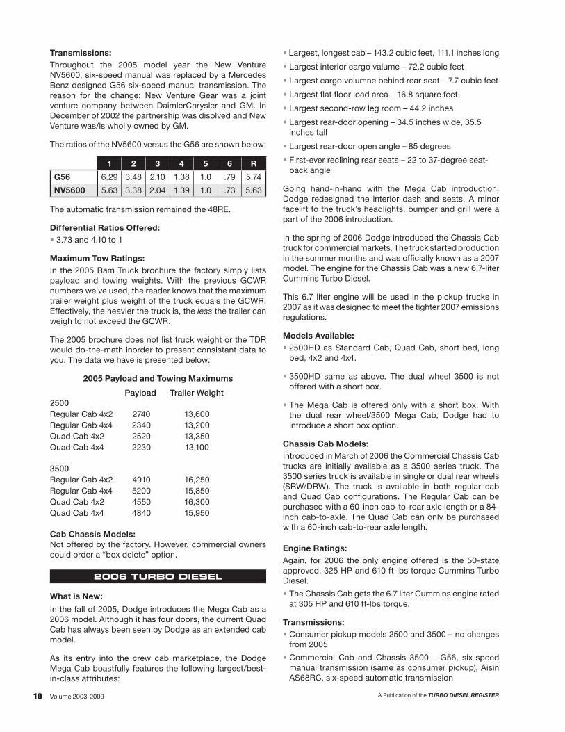
Transmissions:Throughout the 2005 model year the New Venture NV5600, six-speed manual was replaced by a Mercedes Benz designed G56 six-speed manual transmission. The reason for the change: New Venture Gear was a joint venture company between DaimlerChrysler and GM. In December of 2002 the partnership was disolved and New Venture was/is wholly owned by GM.
The ratios of the NV5600 versus the G56 are shown below:
1 2 3 4 5 6 R
G56 6.29 3.48 2.10 1.38 1.0 .79 5.74
NV5600 5.63 3.38 2.04 1.39 1.0 .73 5.63
The automatic transmission remained the 48RE.
Differential Ratios Offered:• 3.73 and 4.10 to 1
Maximum Tow Ratings:In the 2005 Ram Truck brochure the factory simply lists payload and towing weights. With the previous GCWR numbers we’ve used, the reader knows that the maximum trailer weight plus weight of the truck equals the GCWR. Effectively, the heavier the truck is, the less the trailer can weigh to not exceed the GCWR.
The 2005 brochure does not list truck weight or the TDR would do-the-math inorder to present consistant data to you. The data we have is presented below:
2005 Payload and Towing Maximums
Payload Trailer Weight2500Regular Cab 4x2 2740 13,600Regular Cab 4x4 2340 13,200Quad Cab 4x2 2520 13,350Quad Cab 4x4 2230 13,100
3500Regular Cab 4x2 4910 16,250Regular Cab 4x4 5200 15,850Quad Cab 4x2 4550 16,300Quad Cab 4x4 4840 15,950
Cab Chassis Models:Not offered by the factory. However, commercial owners could order a “box delete” option.
2006 TURBO DIESEL
What is New:
In the fall of 2005, Dodge introduces the Mega Cab as a 2006 model. Although it has four doors, the current Quad Cab has always been seen by Dodge as an extended cab model.
As its entry into the crew cab marketplace, the Dodge Mega Cab boastfully features the following largest/best-in-class attributes:
• Largest, longest cab – 143.2 cubic feet, 111.1 inches long
• Largest interior cargo valume – 72.2 cubic feet
• Largest cargo volumne behind rear seat – 7.7 cubic feet
• Largest flat floor load area – 16.8 square feet
• Largest second-row leg room – 44.2 inches
• Largest rear-door opening – 34.5 inches wide, 35.5 inches tall
• Largest rear-door open angle – 85 degrees
• First-ever reclining rear seats – 22 to 37-degree seat-back angle
Going hand-in-hand with the Mega Cab introduction, Dodge redesigned the interior dash and seats. A minor facelift to the truck’s headlights, bumper and grill were a part of the 2006 introduction.
In the spring of 2006 Dodge introduced the Chassis Cab truck for commercial markets. The truck started production in the summer months and was officially known as a 2007 model. The engine for the Chassis Cab was a new 6.7-liter Cummins Turbo Diesel.
This 6.7 liter engine will be used in the pickup trucks in 2007 as it was designed to meet the tighter 2007 emissions regulations.
Models Available:• 2500HD as Standard Cab, Quad Cab, short bed, long
bed, 4x2 and 4x4.
• 3500HD same as above. The dual wheel 3500 is not offered with a short box.
• The Mega Cab is offered only with a short box. With the dual rear wheel/3500 Mega Cab, Dodge had to introduce a short box option.
Chassis Cab Models:Introduced in March of 2006 the Commercial Chassis Cab trucks are initially available as a 3500 series truck. The 3500 series truck is available in single or dual rear wheels (SRW/DRW). The truck is available in both regular cab and Quad Cab configurations. The Regular Cab can be purchased with a 60-inch cab-to-rear axle length or a 84-inch cab-to-axle. The Quad Cab can only be purchased with a 60-inch cab-to-rear axle length.
Engine Ratings:Again, for 2006 the only engine offered is the 50-state approved, 325 HP and 610 ft-lbs torque Cummins Turbo Diesel.
• The Chassis Cab gets the 6.7 liter Cummins engine rated at 305 HP and 610 ft-lbs torque.
Transmissions:• Consumer pickup models 2500 and 3500 – no changes
from 2005
• Commercial Cab and Chassis 3500 – G56, six-speed manual transmission (same as consumer pickup), Aisin AS68RC, six-speed automatic transmission

11A Publication of the TURBO DIESEL REGISTER Volume 2003-2009
Engine Ratings:• For early ‘07 models, 325 HP and 610 ft-lbs for consumer
pickup models 2500 and 3500. This is a carry-over of the Cummins 5.9 liter engine.
• The 2007.5 consumer pickup models 2500 and 3500 received the Cummins 6.7 liter engine rated at 350 HP and 650 ft-lbs torque with the automatic transmission, 350HP and 610 ft-lbs torque with the manual transmission.
• The engine was introduced in January 2007 to meet a more stringent set of diesel exhaust emissions standards. The engine and its exhaust aftertreatment components were praised by the press as the engine not only met the 2007 standards, it also met the upcomming 2010 emissions standards. The fact that no further changes would be necessary for 2010 gave Dodge and Cummins an advantage over competitive engines that would go through two sets of hardware changes.
• The 6.7-liter’s introduction was not without its own set of problems. Multiple software calibrations were implemented to solve problems with soot. This engine, with its electronic controls, NOx filter, and particulate filter, does not lend itself to “hot rodding” as did the previous 5.9-liter engine.
• 305 HP and 610 ft-lbs for commercial Chassis Cab 3500 models using the Cummins 6.7 liter engine. The 4500 and 5500 trucks are introduced with the same engine and engine ratings as the 3500 Chassis Cab.
Transmissions:• For early 2007 the consumer pickup models 2500
and 3500 used the existing G56, six-speed manual transmission and 48RE, four-speed manual transmission.
• With the mid-year (2007.5) introduction of the 6.7 liter engine the automatic transmission was revised to a Chrysler-supplied 68RFE, six-speed unit.
48RE versus 68RFE Gear Ratio Comparison
1 2 3 4 5 6
‘03.5 -‘07, 48RE 2.45 1.45 1.0 .69
‘07.5+, 68RFE 3.23 1.84 1.41 1.00 .82 .63
• With the mid-year (2007.5) introduction of the 6.7 liter engine the manual transmission (the Mercedes Benz de-signed G56 six-speed unit) was revised. In order to raise the overall gear ratios in the manual transmission the re-design dropped a tooth on the input shaft. The resulting gear ratios are as follow:
G56 versus G56R Gear Ratio Comparison
1 2 3 4 5 6
‘05-‘07, G56 6.26 3.48 2.10 1.38 1.00 .79
‘07.5+, G56R 5.94 3.28 1.98 1.31 1.00 .74
• Commercial Cab Chassis – no changes from 2006:
- G56R, six-speed manual transmission and Aisin
- AS68RC, six-speed automatic transmission.
The Aisin internal gear ratios are as follow:
1 2 3 4 5 6
Aisin AS68RC 3.74 2.00 1.34 1.00 .77 .63
Differential Ratios Offered:3.73 and 4.10 to 1
Both the 3.73 and 4.10 are offered in consumer pickup models 2500 and 3500.
In the Chassis Cab model 3500 both the 3.73 and 4.10 are available with the G56 manual transmission. The 4.10 is the only axle ratio offered with the Aisin AS68RC automatic transmission.
Maximum Towing Capacities:With the single power offering of 325 HP/610 ft-lbs torque the GCWR towing capacities are simplified. The numbers below are for regular, Quad and Mega Cab trucks.
• 2500 Manual or Automatic transmission with a 3.73 differential – 20,000
• 2500 Automatic transmission, 4.10 differential – 20,000
• 3500 Automatic transmission, 3.73 differential – 21,000
• 3500 Automatic transmission, 4.10 differential – 23,000
• 3500 Manual transmission, 3.73 differential – 23,000
2007 TURBO DIESEL
What is New:• Mid-year introduction (2007.5) of Cummins 6.7 liter
engine in consumer pickup models 2500 and 3500. Mid-year introduction of a Chrysler-supplied 68RE, six-speed automatic transmission.
• Mid-year introduction (February 2007) of commercial Chassis Cab models 4500 and 5500. These trucks would officially be labeled as 2008 model year vehicles.
Models Available:Same as 2006.
• 2500HD as standard cab, quad cab, short bed, long bed, 4x2 and 4x4.
• 3500HD same as above. The dual wheel 3500 is not offered with a short box.
• The Mega Cab is available in the 2500 or 3500 single rear wheels, or 3500 dual rear wheels. It is only offered with a short cargo box.
Chassis Cab Models:The Commercial Chassis Cab trucks are initially available as a 3500 series truck. The 3500 series truck is available in single or dual rear wheels (SRW/DRW). The truck is available in both regular cab and Quad Cab configurations. The regular cab can be purchased with a 60-inch cab-to-rear axle length or a 84-inch cab-to-axle. The Quad Cab can only be purchased with a 60-inch cab-to-rear axle length.

12 A Publication of the TURBO DIESEL REGISTERVolume 2003-2009
Chassis Cab Models:• The 3500 is available in single or dual rear wheels• The 4500 and 5500 are dual rear wheels.
All three Chassis Cabs are available with a regular cab or Quad Cab configuration.
With the 3500, the regular cab can be purchased with a 60-inch cab-to-rear axle length or a 84-inch cab-to-axle length with single or dual rear whels (SRW/DRW). The 3500 Quad Cab can only be purchased with the 60-inch cab-to-rear axle length with SRW or DRW.
The 4500 and 5500 trucks are only offered with dual rear wheels. These trucks allow regular cab or Quad Cab cabins to be used with the 60-inch or 84-inch cab-to-axle length.
Engine Ratings:• Same as 2007.5
• For 2008 the engine ratings for the Cummins 6.7-liter engine in consumer pickup models 2500 and 3500 re-mained the same as they were when the 6.7-liter engine was introduced in January of 2007: 350 HP and 650 ft-lbs of torque with the automatic transmission and 350 HP and 610 ft-lbs of torque with the manual transmission.
• The engine ratings for the Cummins 6.7-liter engine in the Chassis Cab models 3500, 4500 and 5500 remained the same as they were when the engine was introduced in the first Chassis Cab 3500 model in March of 2006: 305 HP and 610 ft-lbs or torque.
Transmissions:• Same as 2007.5
• In the consumer pickup models 2500 and 3500 the au-tomatic and manual transmission are the same as those used in the ‘07.5 introduction of the Cummins 6.7-liter engine in January of 2007. The nomenclature for the au-tomatic transmission is the 68RFE; the nomenclature for the manual transmission is G56R. The gear ratio compar-ison chart is found in the “2007 Turbo Diesel” write-up.
• Commercial Chasis Cab models 3500, 4500, 5500 get the revised G56R manual transmission. The Aisin AS-68RC six-speed automatic transmission is the same as the initial offering of the first Chassis Cab 3500 model in March of 2006.
Differential Ratios Offered (Consumer 2500/3500 trucks):• Same as 2007.5. • 3.43 and 3.73 with the G56R manual transmission• 3.43, 3.73 and 4.10 with the 68RFE automatic
transmission.
Differential Ratios Offered (Chassis Cab 3500/4500/5500):In the Chassis Cab models both the 3.73 and 4.10 are available with the G56 manual transmission. The 4.10 is the only axle ratio offered with the Aisin AS68RC auto-matic transmission
Differential Ratios Offered (Consumer 2500/3500 trucks):
• With the mid-year (known as ’07.5) change to the Cummins 6.7-liter engine there was also a change in the differentials that were offered by Dodge. Starting mid-year:
- 3.43 and 3.73 with the G56R manual transmission
- 3.43, 3.73 and 4.10 with the 68RFE automatic transmission.
Differential Ratios Offered (Chassis Cab 3500):In the Chassis Cab model 3500 both the 3.73 and 4.10 are available with the G56 manual transmission. The 4.10 is the only axle ratio offered with the Aisin AS68RC automatic transmission
Maximum Towing Capacities:Again in 2007, with the single power offering of 325 HP/610 ft-lbs torque the GCWR towing capacities are simplified. The numbers below are for regular, Quad and Mega Cab trucks.
• 2500 Manual or Automatic transmission with a 3.73 differential – 20,000
• 2500 Automatic transmission, 4.10 differential – 20,000
• 3500 Automatic transmission, 3.73 differential – 21,000
• 3500 Automatic transmission, 4.10 differential – 23,000
• 3500 Manual transmission, 3.73 differential – 23,000
2008 TURBO DIESEL
What is New:Introduced to the public in February 2007 at the Chicago Auto Show, the Chassis Cab models 4500 and 5500 were officially known as 2008 model trucks. These Chassis Cab trucks share the same powertrain as the 3500 truck that was introduced in March of 2006. For the 4500 and 5500 trucks the differentials are larger. The front axle is made by Magna, the rear axle is made by Dana.
Available gearing for the existing 3500 Chassis Cab:- 3.73 and 4.10 with the manual transmission- 4.10 with the automatic transmission
Available gearing for the 4500 Chassis Cab:- 4.10 and 4.44 to 1 for the manual transmission- 4.44 and 4.88 to 1 for the automatic transmission
Available gearing for the 5500 Chassis Cab:- 4.44 and 4.88 to 1 for the manual transmission - 4.88 to 1 for the automatic transmission
Models Available:• Same as 2006 and 2007• 2500 HD as standard cab, quad cab, with short bed or
long bed in 4x2 and 4x4 configurations.• 3500 HD same as above, although the dual wheel 3500
is not offered wiith a short box.• The Mega Cab is available in the 2500 or 3500 single
rear wheels, or 3500 dual rear whels. It is only offered with a short cargo box.

13A Publication of the TURBO DIESEL REGISTER Volume 2003-2009
Maximum Towing Capacities:In the 2008 Ram Truck brochure the factory has gone back to the rating guidelines that they used in 2005 where-by they simply list the payload and towing weights. With previous GCWR numbers the reader knows the maxi-mum trailer weight plus the weight of the truck equals the GCWR. Effectively, the heavier the truck is, the less the trailer can weigh in order to not exceed the GCWR.
The 2008 brochure does not list the truck weight or the TDR would do-the-math in order to present consistant data to you. The data we have from the 2008 brochure is presented below:
Payload Trailer Weight2500Regular Cab 4x2 2,680 13,550Regular Cab 4x4 2,270 13,100Quad Cab 4x2 2,520 13,350Quad Cab 4x4 2,070 12,900Mega Cab 4x2 2,050 12,850Mega Cab 4x4 1,520 12,350
3500 (DRW equipped/4.10 axle)Regular Cab 4x2 4,790 16,150Regular Cab 4x4 5,120 16,750Quad Cab 4x2 4,480 16,150Quad Cab 4x4 4,780 16,750Mega Cab 4x2 3,200 15,550Mega Cab 4x4 2,770 16,100
2009 TURBO DIESEL
What is New:Although the Dodge Ram 1500 model received a new body and interior, the Turbo Diesel 2500 and 3500 con-sumer pickups and 3500, 4500, 5500 Chassis Cab trucks saw only minor trim revisions in this carryover/transitional model year.
Models Available:• Same as 2006, 2007, and 2008• 2500 HD as standard cab, quad cab, with short bed or
long bed in 4x2 and 4x4 configurations.• 3500 HD same as above, although the dual wheel 3500
is not offered with a short box.• The Mega Cab is available in the 2500 or 3500 single
rear wheels, or 3500 dual rear wheels. It is only offered with a short cargo box.
Chassis Cab Models:• Same as 2008.• The 3500 is available in single or dual rear wheels• The 4500 and 5500 are dual rear wheels.
All three Chassis Cabs are available with a regular cab or Quad Cab configuration.
With the 3500, the regular cab can be purchased with a 60-inch cab-to-rear axle length or a 84-inch cab-to-axle length with single or dual rear wheels (SRW/DRW). The 3500 Quad Cab can only be purchased with the 60-inch cab-to-rear axle length with SRW or DRW.
The 4500 and 5500 trucks are only offered with dual rear wheels. These trucks allow regular cab or Quad Cab cabins to be used with the 60-inch or 84-inch cab-to-axle length.
Engine Ratings:• Same as 2007.5 and 2008.
• In consumer pickup models 2500 and 3500: 350 HP and 650 ft-lbs of torque with the automatic transmission and 350 HP and 610 ft-lbs of torque with the manual trans-mission.
• The engine ratings for the Cummins 6.7-liter engine in the Chassis Cab models 3500, 4500 and 5500 remained the same when the engine was introduced in 2006: 305 HP and 610 ft-lbs or torque.
Engine Changes for 2009:Starting in ’02, the heavy duty trucks’ introduction has fol-lowed the Dodge Ram 1500 by one year. The model year 2009 heavy duty trucks are no exception, they continue with the same cab and chassis design. As you can expect there are only a few subtle changes to the engine. These changes are:
• Access port on the turbocharger’s exhaust housing that allows for exhaust turbine cleaning as needed.
• Revised stamped steel alternator bracket.
• Revised coolant hoses and O-ring fittings for the plumb-ing that goes to cool the exhaust gas recirculation heat exchanger.
• Revised fuel filter assembly that features a dual filter with greater filter area to strip away water as well as a secondary fuel filter with a smaller 5-micron rating. (The current fuel filter is 7-micron). The new fuel filter was released for production in January and the part can be retrofitted to the ’07.5 to early ’09 engines. Service parts for these engines were released in July 2009.
• Revised water inlet housing.
Transmissions:In the consumer pickup models 2500 and 3500 the au-tomatic and manual transmission are the same as those used in the ‘07.5 and ‘08. The nomenclature for the auto-matic transmission is the 68RFE; the nomenclature for the manual transmission is G56R. The gear ratio comparison chart is found in the “2007 Turbo Diesel” write-up.
Commercial Chassis Cab models 3500, 4500, 5500 use the same G56R manual transmission and Aisin AS68RC six-speed automatic transmission.
Differential Ratios Offered (Consumer 2500/3500 trucks):• Same as 2007.5 and 2008.• 3.43 and 3.73 with the G56R manual transmission• 3.43, 3.73 and 4.10 with the 68RFE automatic
transmission.
Differential Ratios Offered (Chassis Cab 3500/4500/5500):In the Chassis Cab models both the 3.73 and 4.10 are available with the G56 manual transmission. The 4.10 is the only axle ratio offered with the Aisin AS68RC auto-matic transmission
Maximum Towing Capacities:No changes from the listing chart for 2008.

14 A Publication of the TURBO DIESEL REGISTERVolume 2003-2009
THIRD GENERATION POWER RATINGS
Model Year HP@RPM Torque@RPM CPL Transmission Comments Boost Specification
2003 5.9L HPCR
235@2700 460@14008216 47RE Auto CARB - DOC 23
8224 5 Manual CARB - DOC 23
250@2900 460@14002624 47RE Auto EPA - Non-Catalyst 23
8223 5 Manual EPA - Non-Catalyst 23
305@2900 555@1400 2998 6 Manual EPA - Non-Catalyst 26
2003.5 5.9L HPCR
235@2700 460@14008410 47RE Auto CARB - DOC 23
8412 5 Manual CARB - DOC 23
250@2900 460@14008212 47RE Auto EPA - Non-Catalyst 23
8226 5 Manual EPA - Non-Catalyst 23
305@2900 555@14008228 6 Manual EPA - Non-Catalyst 26
8213 48RE Auto EPA - Non-Catalyst 26
2004 5.9L HPCR
235@2700 420@16008412 48RE Auto EPA - Non-Catalyst 23
8412 6 Manual CARB - DOC 23
305@2900 555@14008213 48RE Auto EPA - Non-Catalyst 26
8228 6 Manual CARB - DOC 26
2004.5 5.9L HPCR 325@2900 600@1600
83506 Manual
EPA - DOC 30
8351 CARB - DOC 30
834648RE Auto
EPA - DOC 30
8347 CARB - DOC 30
2005 5.9L HPCR 325@2900 610@1600
84236 Manual
EPA - DOC 30
8424 CARB - DOC 30
842148RE Auto
EPA - DOC 30
8422 CARB - DOC 30
2006 5.9L HPCR 325@2900 610@1600
83486 Manual
EPA - DOC 30
8349 CARB - DOC 30
834448RE Auto
EPA - DOC 30
8345 CARB - DOC 30
2007 5.9L HPCR 325@2900 610@1600
10916 Manual
EPA - DOC 30
1095 CARB - DOC 30
100048RE Auto
EPA - DOC 30
1083 CARB - DOC 30

15A Publication of the TURBO DIESEL REGISTER Volume 2003-2009
THIRD GENERATION POWER RATINGS
Model Year HP@RPM Torque@RPM CPL Transmission Comments Boost Specification
2007.5 6.7L HPCR Pickup
350@3000
610@16008233
6 ManualEPA - DOC/NAC/DPF 28*
8234 CARB - DOC/NAC/DPF 28*
650@16008230
68RE AutoEPA - DOC/NAC/DPF 28*
8231 CARB - DOC/NAC/DPF 28*
2007.5 6.7L HPCR Cab/Chassis
305@2900 610@1600
82326 Manual
EPA - DOC/NAC/DPF 26*
1264 CARB - DOC/NAC/DPF 26*
2885Aisin Auto
EPA - DOC/NAC/DPF 26*
1257 CARB - DOC/NAC/DPF 26*
2008 6.7L HPCR Pickup
350@3000610@1600 1489 6 Manual All States - DOC/NAC/DPF 28*
650@1600 1490 68RFE Auto All States - DOC/NAC/DPF 28*
2008 6.7L HPCR Cab/Chassis
305@2900 610@16008235 6 Manual All States - DOC/DPF 26*
2886 Aisin Auto All States - DOC/DPF 26*
2009 6.7L HPCR Pickup
350@3000610@1600 1489 6 Manual All States - DOC/NAC/DPF 28*
650@1600 1490 68RFE Auto All States - DOC/NAC/DPF 28*
2009 6.7L HPCR 3500 Cab/Chassis
305@2900 610@1600
2780 6 Manual All States - DOC/DPF 26*
2775 Aisin Auto All States - DOC/DPF 26*
2009 6.7L HPCR 4500/5500 Cab/Chassis
305@2900 610@1600
2779 6 Manual All States - DOC/DPF 30
2774 All States - DOC/DPF 30
DOC = diesel oxidation catalyst NAC = NOx absorption catalyst DPF = diesel particulate filter SCR = selective catalyst reduction (urea)
* The boost numbers for the ‘07.5 and newer 6.7-liter engine applications are approximate. There can be variance based on the amount of exhaust gas recirculation in the intake air, the intake
through the opening and the variable geometry turbocharger’s position.

16 A Publication of the TURBO DIESEL REGISTERVolume 2003-2009
WHAT DOES EVERy TURBO DIESEL OWNER NEED TO KNOW
by Robert Patton
I am reminded daily that “the world is going digital.” Perhaps so, but as the last of an older breed I enjoy sitting in the EZ chair and reading the newspaper and periodical magazines.
Always on the lookout for interesting ideas that serve as an inspiration to write, I noted an article in the American Motorcycle Association’s American Motorcyclist titled, “What Does Every Motorcyclist Need to Know?”
Shazam! Change the title to “What Does Every Turbo Diesel Owner Need to Know?” and I’ve got the basis for a good article. So, here goes…
TDR Related Items
First things first—you’ve got the magazine in hand and I thank you for your subscription. Now that I have paid due tribute, this resource article is going to direct you to the TDR’s web site (www.tdr1.com) because I’m guessing that you may not be aware of the wealth of information that is available to you.
Once at the TDR’s main page, look to the left and notice the heading “MAGAZINE.” Scroll down to “Technical FAQs” and print the file. Read the FAQs and you’ll be on your way to shedding the title of “diesel newbie.”
Do you want to impress your neighbor with your knowledge of year-by-year, model-by-model changes to the truck? Or, do you have a specific question about gear ratios or horsepower and torque ratings for a given year? Tab down to “Buyer’s Guide” and the 150+ page (we’re continuously adding to the Buyer’s Guide) PDF file is available for you to download. This book is a real gem.
With an eye on the basics one has to realize that your truck’s Owner’s Manual holds a wealth of information. From remote key lock reprogramming (some models), to tire inflation pressures, to the fluid capacities... the standing joke among TDR staff members is that there would not be a need for the TDR if owners would consult their Owner’s Manual.
Kidding aside, the Owner’s Manual is an excellent resource book and it covers the lubricants and fluids needed in your truck. The catch: often the Owner’s Manual only gives the Chrysler/Mopar specification or part number for a fluid. Should you want to source a generic fluid (read: less expensive), you will again find the TDR’s Turbo Diesel Buyer’s Guide to be a great resource. A quick thumb to the index shows the title “Liquids in Your Truck” and this article is helpful in your search for lower cost consumable items.
Lower cost is always an important matter. Go back to
the Buyer’s Guide index and note the title “Part Number Reference.” This chart gives oil, fuel and air filter crossover numbers; belt and hose numbers; and other miscellaneous parts. Use the chart wisely and save some additional money.
If I’ve not yet convinced you that the TDR Buyer’s Guide is an excellent resource, there is another chapter that is worthwhile to those looking for performance specifications. Take a look at “Your Truck and the Boost Treadmill” and you’ll see what I mean. Other noteworthy chapters: Most Common Problems, Preventive Maintenance, Mechanics Tips, and Memorable TDR Articles.
Have you encountered a problem with your truck that you think may have been previously discussed? While you’re at the TDR’s web site, tab down to “Magazine Index” and you’ll be able to print files and then search for the TDR magazine’s chapter-and-verse coverage of a problem, a gadget or a gizmo. My thanks to Bob and Jeannette Vallier for providing this valuable resource for us.
Still plagued with a problem or have an unanswered question? If you’ve not yet activated your username and password at the TDR’s web site, now is an excellent time to do so. Log on to the members’ “Discussion Forums” and ask the helpful TDR membership.
Enough about the technical information found at the TDR’s web site; what else does every Turbo Diesel owner need to know? For an in-depth look at the truck there is nothing better than a factory service manual. Back in the early 90s the book was one volume and maybe 500 pages. The latest service manual is not even offered in print, it is a $120 CD. The last print versions were 10 volumes and $450. An alternate source is the Haynes manuals at about 350 pages for $18. Both the factory manuals and Haynes books can be found at Geno’s Garage (800) 755-1715 or www.genosgarsage.com.
Factory Technical Service Bulletins (TSBs)
For a quick look at TSBs you can look at page 54 of this magazine or go to the TDR’s web site and tab down to “Dodge Technical Service Bulletins” and take a look through the archives. Alternately the 150+ page pdf file “Turbo Diesel Buyer’s Guide” (that you previously printed?) has the same TSB summary.

17A Publication of the TURBO DIESEL REGISTER Volume 2003-2009
Chrysler’s TechAuthority – An Outstanding Resource
The TDR’s list of technical service bulletins is provided as a service to the membership. We recognize and observe copyright, and our listing is only a summary of the TSB. If you need the entire text you can visit your dealer and discuss the referenced TSB number. Alternately, you can log onto Chrysler’s TechAuthority website (www.techauthority.com) and you can purchase all of the TSBs that may apply to your truck based on your truck’s vehicle identification number (VIN). This service is $20 and the information is invaluable.
More about TechAuthority: I spent several days putting together the TSB summary for this year. While I was at the TechAuthority web site using the VIN for my ’07.5 Turbo diesel truck, I noted the tab “Service Info.” I clicked onto it and I was amazed at the wealth of information that was available.
I could look up front end alignment specifications. I could review the flywheel runout specifications. I looked up the removal of upper and lower control arms. I looked up the removal of the drive shaft center bearing. I looked up the troublesome diagnostic trouble code (DTC) P0106 that randomly occurs on my truck.
Then it hit me: it appears that the entire service manual for my truck was/is available for my viewing for the $20 daily fee. To confirm my assumption I called Tech Authority and verified that the information that I was viewing was, in fact, from the factory service manual.
More accolades for TechAuthority: I mentioned the P0106 code that randomly occurs on my ’07.5 truck. I was armed with several VINs, so I did some research to see how a ’07 truck with the 5.9-liter engine might differ from my ’07.5 truck with the 6.7-liter engine. I started with a search on my truck with the 6.7. Using “Service Info,” I scrolled down to item “28 DTC Based Diagnostics,” then scrolled down to “MODULE, Engine Control (ECM) 6.7L.”
Next: Diagnostics and Testing
Next: P0106
I was amazed at the information on code P0106. There was a Theory of Operation; When Monitored; Possible Causes; and a Service Tree.
I did the same for the ’07 truck with the 5.9-liter engine and there was much less information. So, for owners of the ’07.5 and newer trucks with 6.7-liter engines, there is a world of information that awaits at the TechAuthority web site.
A side note to the 6.7-liter audience: As I reviewed the “Theory of Operation” for my P0106, the write up motivated me to look at other codes with a focus on whether the code has a derate-effect on the engine. For example, I found these two derate codes:
P0217 – Coolant Temperature Too High results in, “during this time the customer may experience an engine power derate.”
P242F – Diesel Particulate Filter Restriction – Ash Accumulation results in, “If the vehicle’s EVIC massage center notification is ignored, the engine will eventually derate and set a DTC and MIL lamp.”
I searched for others, but these were the only two that I came across in my quick review. Elsewhere in this magazine (page 91, “Make It Go Away”) you can read further my frustration with DTC codes and engine derate or damage implications.
The Boy Scouts
Other things you need to know? Were you a Boy Scout? It is always a good idea to be prepared. A “boonie box” of spare parts to carry around under the seat is a good idea. My spares: a fuel filter, belt, belt tensioner, hoses, thermostat and a small tool kit. By the way, a spare key hidden underneath the truck has saved me from inconvenience many times.
Summary
My review of the magazine, the TDR’s web site and the TDR Turbo Diesel Buyer’s Guide has convinced me that this membership group is your best resource. My sincere thanks to all of the members that have helped answer what every owner needs to know on the TDR’s active web site message boards. Also, Chrysler’s TechAuthority is an excellent web site location for information. And now, I’m at a loss for further recommendations. So, thumb-through the magazine to see what other TDR writers had to say about what every owner needs to know.
Robert Patton TDR Staff

18 A Publication of the TURBO DIESEL REGISTERVolume 2003-2009
WISH I’D KNOWN THAT
TDR members are very good at holding on to their old magazines. Likewise they know that indexes of previous articles were published yearly until year 2009. These important archives were compiled by Bob and Jeannette Vallier. These valuable yearly indexes are found in Issues 65, 61, 57, 53, 49, (deduct 4), etc. Then in 2009, we implemented a digital search of TDR magazines back to Issue 40 at our web site.
So, a solid infrastructure exists for those who want to research a topic.
But, how about a resource for those folks who don’t know what they don’t know?
That’s right, something for the “wish I’d known that” crowd.
Wait a minute, isn’t that what the TDR’s Turbo Diesel Buyer’s Guide (TDBG) is all about? Yes, indeed, and there is so much detail (aka, TDR’s solid infrastructure) in the TDBG – Oops, perhaps the detailed research is too daunting of a task for the prospective new owner who doesn’t know what he doesn’t know. How can we keep it simple?
Easy. I gave the “Wish I’d Known That” assignment to Joe Donnelly for the First Generation truck, Scott Dalgleish for the Second Generation truck and I took the Third Generation truck. I created an outline for each of us to follow and I completed the assignment first so they could see how the format should be turned into entertaining and educational text.
The Outline
Rather than reinvent the wheel, I used the established categories used by the Chrysler group for all of their Technical Service Bulletins. That numerical system is as follows:
2 Front Suspension 14 Fuel3 Axle/Driveline 16 Propeller Shafts and U-Joints5 Brakes 18 Vehicle Performance6 Clutch/Manual Transmission 19 Steering7 Cooling 21 Automatic Transmission8 Electrical 22 Wheels and tires9 Engine 23 Body11 Exhaust/Air Intake 24 Air Conditioning13 Frame and bumpers 25 Emissions Control
26 Miscellaneous
Within each of these categories I will present the most common “Wish I’d Known That” problems that have been encountered by the TDR audience. Then I’ll give a brief write-up of the solution with a TDR reference location (perhaps within the TDBG, perhaps in the magazines) where the new or prospective owner can go for details as needed. Here goes…
General Information
Before I start my “Known That” story, I’ll remind you of an inspection chart that TDR writer Andy Redmond uses for evaluation of any used vehicle. The detailed chart is found in Issue 70, page 121.
If you use this level of detail in your pre-purchase exercise(s), I have no doubt that the seller will be impressed with the thoroughness of your vehicle search. Andy’s inspection list trumps my, “If the door jambs and truck seal (or tailgate lift area) are clean, I am a buyer” pre-purchase criteria.
Rather than bore you with the “do a Carfax Report; check the NADA and Kelly blue book values; check with your insurance agent for policy prices; loan values; etc.,” I’m going to make the assumption that this truck purchase is not your first rodeo. If you need further information:
TDBG, “Buying a Used Truck”TDR #70, page 120, “Pre-Owned Purchase”TDR #73, page 96, “Let the Search Begin”This issue, page 80, “The Search for a New Ram”
Likewise, the TDBG is a fantastic source for performance and miles-per-gallon enhancements; specifications; Technical Service Bulletins; yearly changes to the truck; evolution of the different Cummins engines; warranty considerations – wait, why not give you the table of contents because I can guarantee it will be referenced when I get into the “Known That” story detail. The TOC is on the next page.
THIRD GENERATION PURCHASE CRITERIA
ISSUE 77 – TECHNICAL TOPICSby Robert Patton

19A Publication of the TURBO DIESEL REGISTER Volume 2003-2009
Why a Diesel? ....................................................................4Looking at the Changes ...................................................8Evolution of the Cummins Engine, 1989-Current ...... 26Performance Enhancements, 1989-Current .............. 48Performance, Warranty and You ..................................70Fuel Injection System ’89-’02 ........................................76Why Didn’t They Think of That – Exhaust Emissions ........................................................ 83So You Want Fuel Economy .......................................... 89 Part One – The Basics of Volumetric Efficiency ............89 Part Two – All Year Models and Updates ......................95 Part Three – How to Drive ............................................109Your Truck and the Boost Treadmill ...........................113Buying a Used Truck ....................................................118What Does Every Turbo Diesel Owner Needs to Know ..............................................................120The Driving Force Behind the Changes to the Cummins Engine/Meaningful Abbreviations ............122Dodge Technical Service Bulletins.............................128 TSBs Issued During ‘95 and Prior ...............................129 TSBs Issued During ‘96 ...............................................142 TSBs Issued During ‘97 ...............................................147 TSBs Issued During ‘98 ...............................................152 TSBs Issued During ‘99 ...............................................156 TSBs Issued During ‘00 ...............................................162 TSBs Issued During ‘01 ...............................................167 TSBs Issued During ‘02 ...............................................170 TSBs Issued During ‘03 ...............................................176 TSBs Issued During ‘03-’09 .........................................182 TSBs Issued During ‘10 .............................................. 206 TSBs Issued During ‘11 ................................................210Recall Notices ...............................................................215Most Common Problems ............................................ 221 Favorite Fumbles—Fabulous Fixes ..............................221 12-Valve Dowel Pin Common-Sensical Solution .........226 12-Valve No-Start Condition ........................................230 Vintage ’94-’04 Lock/Unlock .......................................231 Block 53 and Class Action Settlement ........................232 Steering Woes ..............................................................235 Fuel Transfer Pumps Revisited ....................................246 Low Pressure Fuel System Problems ..........................265DTCs and You ............................................................... 269Problems Solved by the TDR’s Writers, TDR Members, and TDR Vendors. ............................. 279Mechanics Tips ............................................................ 287New Owner’s Corner... ............................................... 290Part Number Reference .............................................. 291Why Ask Why—Liquids in Your Truck ........................ 293Memorable Articles . . . . . . . . . . . . . . . . . . 297
That, my friends, was a heck of a long introduction. Those with an eye for the details will carefully examine the TDBG’s “TSBs Issued During ’03-’09,” pages 182-205. These documents give the service network the proper repair technique for the most common Third Generation truck problems. Perhaps this article should have been simply republishing those 23 pages?
No, let’s attempt the highlights and add additional commentary. Here goes: Now, for the data that you’ve been waiting for, “Wish I’d Known That – Third Generation, 2003-2009.”
2 Front Suspension
For this concrete-cowboy who lives in Atlanta, Georgia, there is no need for a four-wheel drive truck. With the two Third Generation trucks that I have owned (one is still in the family) I can say that the only suspension maintenance required was to change the shock absorbers at 175,000 miles.
In consulting with my four-wheel drive buddies, they tell me that the Third Generation’s suspension is greatly improved over that of the previous ’94-’02 Second Generation truck. However, if you add big wheels and tires, raise the suspension and/or exceed the 100,000 milestone you will have to go underneath the truck and monitor the suspension components for wear. While this generation of truck is not as prone to the “death wobble,” the aforementioned big tires/raised suspension/mileage will have the owner looking at beefing up the steering box stabilizer, track bar, track bar bushings and steering damper. Unfortunately, there is not a one-size-fits-all solution to suspension wear. There is a 10-page article in the TDBG that covers suspension inspection and alignment specifications, pages 235-245.
3 Axle/Driveline
One word: bulletproof. Certainly there have been individual problems, but when was the last time you read a TDR article about U-joints, drive shaft, transfer case or axle problems?
5 Brakes
Normal maintenance is required.
If you want a complete tutorial on brakes, brake pads, brake bias, etc., you’ll want to review the four-part series written by brake expert, James Walker, in TDR Issues 40-44. Yes, this is the same James Walker that authored the book High-Performance Brake Systems. His words from Issues 40-44 still hold true today.
Issue 40: James explains that your brakes do not stop the vehicle. The traction available between the road and the tire’s four contact patches are what stops the vehicle. With this bit of enlightenment, you can bet that Issue 40 is worth a reread as James covers “Braking Systems in Plain English.” Discussion about everything from the brake pedal, master cylinder, brake calipers, brake rotors, brake pads, brake lines are in the Issue 40 text.
Issue 41: “Brake Pad Selection.” Brake pad material is a compromise. Read all about it.
Issue 42: “Twenty-One Brake Questions.” From how to break in brake pads to why the rotors warp, James answers your 21 questions.
20 A Publication of the TURBO DIESEL REGISTERVolume 2003-2009
Issue 43: “Brake Fluid.” What is the difference between DOT 3, 4, 5 and 5.1? You’ll know after you reread Issue 43.
Issue 44: “Brake Bias.” Have you ever locked up the rear tires and have the back of the vehicle want to pass the front? Do you know more about brake bias than the factory engineer? Another James Walker article that is worthy of reread.
6 Clutch/Manual Transmission
Transmission Options: You know, the TDBG is an excellent reference guide—I had to refer to its section “Looking at the Changes,” pages 14-19 to see what clutch/gearbox was used in the different ’03-’09 Third Generation trucks. Here goes—
2003: NV4500 with standard 235 or 250hp engine NV5600 with high output 305hp engine
2004: Early 2004 models in CA, ME, MA, NY and VT got the NV4500 gearbox with a 235hp engine. All other states got the NV5600 gearbox with a 305hp engine
2004.5: A mid-year introduction gave all states the 325hp engine and a NV5600 gearbox.
2005: As the 2005 model year progressed, the New Venture NV5600, six-speed manual was replaced by a Mercedes Benz designed G56 six-speed manual transmission. The reason for the change: New Venture Gear was a joint venture company between DaimlerChrysler and GM. In December of 2002 the partnership was dissolved and New Venture was/is wholly owned by GM.
So if you have a 2005 truck with a six-speed transmission, how do you tell—without crawling under the truck looking for signs of identification—if it is the NV5600 or the G56? Easy, the shift pattern for a NV gearbox has reverse up and to the right; the G56’s pattern is over to the left and down. (Thanks, Peter Pyfer at South Bend Clutch.)
2006: The G56 Mercedes Benz is now the only manual transmission that is offered.
2007: Same
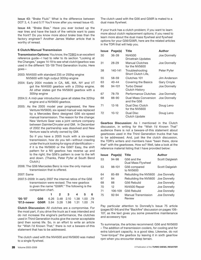
2007.5-2009: In early 2007 the internal ratios of the G56 transmission were revised. The new gearbox is given the name “G56R.” The following is the comparison chart.
1 2 3 4 5 6’05-’07 G56 6.26 3.48 2.10 1.38 1.00 .79’07.5-newer G56R 5.94 3.28 1.98 1.31 1.00 .74
Clutch Discussion: All clutches are a compromise. For the most part, if you drive the truck as it was intended and do not increase the engine’s performance, the clutches used in Third Generation trucks give the owner acceptable (and then some) life. So, in an effort to write an article for “Wish I’d Known That,” there is not a beware-of-this statement that has to be addressed.
The clutch used with the NV4500 and NV5600 was mated to a single flywheel.
The clutch used with the G56 and G56R is mated to a dual mass flywheel.
If your truck has a clutch problem; if you want to learn more about clutch replacement options; if you need to learn more about the dual mass flywheel and flywheel options for your G56/G56R, here are the related articles in the TDR that will help you.
Issue Page(s) Title Author
30 36-39 NV4500 Joe Donnelly Drivetrain Updates
31 28-29 Manual Clutches Joe Donnelly for the NV5600
38 140-141 Troubleshooting Peter Pyfer Short Clutch Life,
55 58-59 Clutches 101 Jim Anderson63 40-44 Covering the Basics Gary Croyle66 94-101 Turbo Diesel Joe Donnelly
Clutch History67 78-79 Performance Clutches Joe Donnelly68 88-90 Dual Mass Conversion Joe Donnelly
and the G5671 12-16 Dual Disc Clutch Doug Leno
for the NV560072 10-12 Dual Disc Doug Leno
Clutch Update
Gearbox Discussion: As I mentioned in the Clutch discussion, in writing for the “Wish I’d Known That” audience there is not a beware-of-this statement about gearboxes used in the Third Generation trucks that has to be addressed. And, just like the clutch discussion, the TDR’s writers and members have “been there, done that” with the gearboxes. How so? Well, take a look at the reference material listing that I have provided below:
Issue Page(s) Title Author
53 94-98 G56 and the Scott Dalgleish Dual Mass Flywheel53 98-101 G56 compared Scott Dalgeish
to NV560064 85-89 Rebuilding the NV5600 Joe Donnelly67 84 Rebuilding the NV5600 Joe Donnelly68 88 G56 Rebuild Joe Donnelly70 12 NV4500 Repair Joe Donnelly71 106-109 G56 Rebuild Joe Donnelly75 92-94 Manual Transmission Joe Donnelly
Review
Pay particular attention to Donnelly’s Issue 75 article (pages 92-94) and the “Backfire” discussion on pages 106-107, as the text gives you some preventive maintenance and accessory tips:
To summarize, the articles recommend: G56 and NV5600 – The addition of transmission coolers, for cooling and for extra lubricant capacity, is a good idea. Likewise, do not “over-torque” the gearbox by leaving it in sixth gear/low rpm when you encounter steep terrain.
21A Publication of the TURBO DIESEL REGISTER Volume 2003-2009
G56 – ATF+4 is the recommended lubricant. Donnelly and transmission vendors recommend over-filling the G56 by one quart and using a heavier fluid (Pennzoil Synchromesh as used in the NV5600 or a GL6-rated lubricant).
7 Cooling
Normal maintenance is required.
The TDBG has a summary of all of our antifreeze discussion on page 326.
And, for anyone who has had to change a water pump on any vehicle other than their Turbo Diesel, you have to give the Cummins engineers credit for the super-simple water pump design. Remove the accessory drive belt, remove two 10mm bolts that hold the water pump in place and you’ve got this project close to completion. Cooling system problems are few and far between.
8 Electrical
Normal maintenance to the alternator, starter, batteries, solenoids, etc., is required.
In this issue, you’ll read about Chrysler’s totally integrated power module (TIPM) that controls many of the truck’s electrical functions. A replacement TIPM is expensive ($700) and now that these trucks have aged—and seen multiple owners with multiple trailers with who-knows-what wiring—we are seeing TIPM failures. The TIPM was not designed as a circuit breaker, and, if owners do not correct wiring problems, they find out how expensive it is to replace the TIPM if they use it as a circuit breaker. Ouch.
9 Engine
With all of the components that make up an engine, you would think that there would be a long list to discuss. However, aside from programming issues with the 6.7-liter engine (covered later in “Vehicle Performance”), the 5.9 and the 6.7 are rock solid! And, in fact, the ’03-’07 5.9-liter engine is regarded by Turbo Diesel enthusiasts as the best of all. It is easy to maintain and service. The valve adjustment is every 100K miles. Hot rod parts are inexpensive and abundant and 400 horsepower is easy to attain. (Over 400 gets expensive as turbochargers need to be modified and other components have to be matched to the higher engine output.) Also, fuel mileage can be improved. All the particulars are in the TDBG starting on page 50 and again on page 96.
As I mentioned in “Axle/Driveline,” there are always individual problems that occur, but when was the last time you read a TDR article about a bad turbocharger, water pump, oil cooler, oil pump, camshaft, valve train, etc.?
However, there is one area of the engine that is prone to wear. To meet emissions standards the engine uses a Bosch high pressure common rail (HPCR) fuel injection system. These injectors can fire as many as four times in a combustion event. Fuel filter maintenance (every 15,000 miles) and clean fuel are paramount to injector life. The average life span is 160-200,000 miles. Normally, if you
need to replace one injector you’ll need to replace all six—kind of like the purchase of replacement tires. Expect to pay $350-400 per injector or $2100-$2400.
TDR writer Joe Donnelly tried to capture everything you need to know about the HPCR injectors in his Issue 72 article “Injectors for HPCR Engines.” The three page article starts on page 44. Any owner who wants to understand the principle of operation; wants to understand the importance of clean fuel; needs to replace an injector; has an engine stumble; wants to know about performance injectors; wants to know about alternate fuels; etc., you’ll want to reread Joe’s article. It is as relevant today as it was one year ago. Again, that is Issue 72, pages 44-57.
Performance upgrades for the 5.9-liter engine: Read all about it in the TDBG, pages 96-119, “So You Want Fuel Economy.”
Performance upgrades for the 6.7-liter engine: Three words sum it up—don’t do it. The TDBG, pages 72-77, “Performance, Warranty and You,” gives you the reasons. Also, flip to page 56 and read “Section 18 – Vehicle Performance” for the reason(s) that I suggest you leave the 6.7-liter engine alone.
11 Exhaust/Air Intake
I just returned from a show where the proud Turbo Diesel owner told me about his ’06 truck with the free flow exhaust, super monster filter and powder-coated intake air horn. He told me about the increased mileage (Really?) and the fact that he could hear the difference (No doubt!).
After we touched on several other topics—my favorite was the biodiesel junk—it was obvious that any challenge that I might present that opposed the justification for his modifications would be futile. So, I found a reason to excuse myself and walked away.
Don’t get me wrong. In the quest for high horsepower, performance exhaust and intake systems have their place. Both work to lower and control exhaust gas temperatures and give a measure of better horsepower. However, with the exhaust system you sacrifice noise, with air intakes you may sacrifice air filtration.
So, for the guy who wants a dependable, reliable truck, my suggestion is to leave the exhaust and air intake alone.
This is especially true with the 6.7-liter engine. Our contacts at Dodge tell us that the new emissions laws require more sensors than ever before. The engine is very sensitive to intake air temperature and any change in the filter or airbox could lead to:
• The potential for too much hot underhood air which can cause a derate condition. This occurs most often in high altitude situations when the engine fan is engaged.
• Too much oxygen (O2) in the exhaust system. This can prevent the regeneration from coming on and foul the exhaust aftertreatment system.

22 A Publication of the TURBO DIESEL REGISTERVolume 2003-2009
For 5.9-liter owners the K&N filter debacle was covered in Issue 34, pages 105. Back in the Fall of 2001 Cummins tested the K&N for air flow and dirt flow. The result: Yes, they flow more air and more dirt. At the time the K&N was the number two selling item at the sister company Geno’s Garage. As much as it could have hurt sales, the folks at Geno’s pulled the item from the shelves and no longer ofer the K&N line of filters.
Finally, the air filter, cold air intake, and the performance you should expect from these types of modifications was covered in Issue 56 and 59. These articles are also conveniently found at the Geno’s Garage web site under “Technical Information” and then the title “Understanding Air Intake Systems,” or at the TDR’s web site in the digital back issues area.
13 Frame and Bumpers
Back in 2003 Dodge introduced a new-and-improved hydroformed frame. This manufacturing technique results in a stiffer and stronger frame.
The folks at Dodge did not want a bunch of owners and aftermarket installers messing up this frame with Swiss cheese-type holes. They issued a technical service bulletin (TSB 13-001-03, 2/7/03) that set forth their guidelines. Since these trucks are now ten years old, I’ve no doubt that the second and third generation owners have ignored the TSB and the Swiss cheese holes have been drilled. The take away: beware of the overzealous frame driller. Aside from this watchword, the frame and bumpers are not problem areas.
14 Fuel
As mentioned in “Section 9 Engine Discussion,” clean fuel is paramount to injector life. In this issue see pages 14 to 16 for more information on clean fuel (Chrysler TSB 14-004-11).
Biodiesel: With the cost of injectors at $2100-$2400 per set (and the other HPCR injection components aren’t cheap either) I would steer clear of unknown biodiesel and not use anything greater than a B20 blend from a reputable supplier. Your Owner’s Manual states that you should only use a B5 blend.
16 Propeller Shafts and U-Joints
Normal maintenance and inspection are required.
18 Vehicle Performance
For ease of reading I will break this topic into the two engines used in Third Generation trucks: the 5.9-liter and the 6.7-liter.
5.9-Liter Engine
Earlier I mentioned that the 5.9-liter from ’03-’07 is regarded as the best of all engines found in our turbo Diesels. Leave it stock and it will last forever.
However, “leave it stock” is not a statement that the typical Turbo Diesel enthusiast can abide. So, what do owners do to this engine in their quest to improve on what was provided by the Cummins factory folks?
Boy, this is a lengthy topic. Exhaust and air intake have already been discussed in category 11. Programmers, turbochargers, camshafts, hot-rod injector—the TDR’s writers have “been there, done that” and achieved some amazing results with horsepower and fuel economy. I’m not going into all of the details for this “Wish I’d Known That” article, but I will give you the chapter and verse so that you can do due diligence in your research—TDBG, pages 96-119, “So You Want Fuel Economy” with particular attention to pages 104 and 1115. Scott Dalgleish articles: Issues 50, 51, 52, 54, 59, and 61. Doug Leno articles: Issues 45, 47, 48, 49, 51, 53, and 57. Doug Leno article update: Issue 68, pages 50-57.
Now, while you are on your due-diligence quest for horsepower and economy you need to realize that, for the most part, none of the performance gains were done using aftermarket parts that meet any EPA or California Air Research Board (CARB) emissions standards or testing. You are reading between the lines correctly: Prior to 2007.5 (actually 2009, but it is a real long story*), the world of diesel performance aftermarket parts was like the wild, wild West—anything, everything and lots of black smoke.
*If you want the long story, you’ll have to attend the Specialty Equipment Manufacturer’s Association (SEMA) show each year and sit in on the diesel performance roundtable discussions. A summary of many years of my participation is found in the TDBG, “Performance Warranty and You,” pages 72-77. Before you add any winky-twinky performance items to your truck, you need to understand the potential $25,000 fine you could face for violation of EPA code 203(a). Ouch!

23A Publication of the TURBO DIESEL REGISTER Volume 2003-2009
6.7-Liter Engine
As mentioned, the vehicle performance section was broken into two categories. Now it is time to discuss the 6.7-liter engine from the ’07.5-’09 model years.
TDR members know that some of the odd model year designations (’91.5, ’98.5, ’07.5) coincide with the tightening of federal exhaust emissions rules. Such was the case with the 6.7-liter introduction as an ’07.5 model. And, if you recall from your reading in the TDR or from the TDBG, the 6.7-liter engine was a step ahead of the competition and the federal emissions standards as it was emissions compliant for the standards that would be in force in 2010. Detailed information about the hardware changes that coincided with the 6.7-liter introduction: TDBG pages 42-48, “The 6.7-Liter Engine Introduction.”
Yet, early to the market with the new technology does not always equate to seamless reliability. Notice I did not mention durability, as the hardware (block, cylinder head, turbo, EGR components, water pumps, fuel injection equipment, etc.) have not given owners undue problems. However, the software, i.e., programming of the engine to stay in-sync with the emissions control hardware (the diesel particulate filter, the EGR controls, the diesel oxidation catalyst and the nitrogen absorber catalyst), has caused owners their share of grief. Knowing that there are two sides to every story, the blame is not entirely that of Cummins and Dodge. Back in ’07.5 we still had folks purchasing diesel trucks without a need to really have a diesel. The 6.7-liter engine should not be used to drive around town and bring home groceries.
Time has proven that if you use the engine as intended and leave it stock, it will last forever. This statement is a repeat of my assessment of the ’03-’07 5.9-liter engine. However, unlike the 5.9 owner that could not resist modifying his engine, the 6.7-liter owner had better leave it stock.
For those that resisted the temptation to tinker, in the past four years the 6.7 owner was faced with multiple ECM flashes and updates. Often these updates were complicated by fraudulent owners that would pull their
hot-rod programmer off the truck or reflash the ECM to stock. In March 2009, the Cummins folks—perhaps tired of this illegal game, and wanting tighter control of their ECM and/or influence by the EPA to stop owner tampering—embedded software to make sure only approved calibrations were downloaded, a secured ECM. If a non-approved flash was detected, a trouble code U1601 was set and the engine would not start.
Looking back to the TDR’s coverage of the secured ECM (Issue 67, page 34, “Spy Versus Spy: The 3/2009 Secured ECM”) I did some research to see how successful Cummins has been with their security attempt. Since there are aftermarket products available for Turbo Diesels made after 3/2009, one has to assume that the aftermarket folks found a way around the U1601 code and that engines do start with the aftermarket programmers. However, in typical Spy versus Spy fashion, I’ve no doubt that there are other counters (the number of downloads), timers or red flags in the ECM to tell the Dodge service technician that a reprogram has occurred.
If you value your warranty status, how many times do I have to say “Leave the engine stock.”
Here is what to look for if you play hot-rod guy with the 6.7 engine: First off, admit that you are a cowboy, a one-percenter, a member of the lone-wolf club. It is now your engine, and you are your own warranty station! Next, please read the TDBG article “Performance Warranty and You,” pages 72-77. Subsequently, the EPA and CARB have made enough threats to keep many in the aftermarket from playing in the 6.7-liter performance business. Likewise, another deterrent is the 2010 CARB emissions test that California residents have to pass in order to get a license tag.
Now, after all of the cautions that I have presented, I can only imagine that there will still be owners that want more performance from the 6.7-liter engine. In Issue 67, pages 31-34, I listed all of the modules/programmers that were available for the engine. In conclusion, I wonder to myself, “How many different ways can I say leave the engine stock.”
Finally, the TDR followed the trials and tribulations of a member that modified his 6.7-liter engine in a short article in Issue 72, page 32: “The Long Story, a Tale of Woe.”
Regardless of the cautions that I’ve issued, there will be the instance where a fault code/check engine light appears on your dash. How do you read the code and what does it mean? Is the code a nuisance or a serious call to action? Again, the intent is to keep this article brief: you can find all of the fault code answers in Issues 74, pages 84-85; Issue 66, pages 90-91; and the TDBG, pages 300-308.
19 Steering
In my review of the TSBs from ’03-’09 (TDBG, pages 189-212) I did not see anything out of the ordinary in the steering category.

24 A Publication of the TURBO DIESEL REGISTERVolume 2003-2009
21 Automatic Transmission
In my review of the TSBs from ’03-’09 (TDBG, pages 182-205) I did not see anything out of the ordinary in the automatic transmission category.
Before you cry, “Foul, we know there are automatic transmission problems,” let’s try for a civil discussion on the topic.
First, let’s discuss the time frame for changes to the automatic transmission. The first big change was January 1, 2003, for the change from the 47RE to the 48RE. There were no internal gear ratio changes.
The next change was January 1, 2007, for the change from the 48RE to the six-speed 68RFE. The new 68RFE went hand-in-hand with the ’07.5 introduction of the 6.7-liter engine. The gear ratio comparison to the 48RE:
1 2 3 4 5 6’3.55-’07 48RE 2.45 1.45 1.0 .69’07.5-newer 68RFE 3.23 1.84 1.41 1.00 .82 .63
The complete “Ask the Engineer” story about the 68RFE is found in TDR Issue 58, pages 46-47.
Now, let’s talk reliability, durability and all that stuff…
Okay, the ’03 and ’04 models have the same throttle position sensor (TPS) as the ’98.5-’02 trucks. The TPS has been widely known to give folks problems. Do you need to do some research to find out the particulars? TDBG, “Vintage ’94-’02 Lock/Unlock,” page 23.
More reliability, durability and stuff: Perhaps you are under the impression that the Dodge automatic transmissions are substandard and are the weak link in an otherwise good drive line. How did this idea come to be?
First off, let’s discuss the new 68RFE. It was introduced with the 6.7-liter engine in 2007.5. The initial power ratings for the engine was 350hp/650 torque. Not to be outdone by the competition, in February 2011 an engine rating of 350hp/800 torque was authorized for use with the 68RFE. (Notice, this rating was not released for manual transmissions—the clutch cannot take the torque.) Careful reading of the TDR magazine will reveal that the 68RFE is not being overpowered by the engine and the problems are few and far between.
I think the reason the 68RFE is doing well is two-fold: First, it is a good transmission. Second, owners of the 6.7 engine are not playing super hot rod/gonzo performance games with the engine and, therefore, not overpowering the torque converter lockup disc.
Now let’s talk about the 48RE. This transmission has the same casting footprint as the previous 47RH/RE (’94-’03 vintage), the A618 (’89-’93 vintage) and the famous Chrysler 727 transmission that dates back to the 1960s. Matched to moderate horsepower and torque ratings, this transmission performed well, at least until 1994. Although engine ratings did not substantially increase in 1994, the factory used a plastic transmission line connector that, given time and heat cycles, was prone to leak fluid. If you ran the
transmission low on fluid you would eventually overheat the transmission and end up with an expensive repair bill. Revised connectors were implemented in or about 1997. However, a damaged reputation was already established.
Add to this damaged reputation story the fact that Turbo Diesel owners were discovering all kinds of horsepower adders for their 12-valve and 24-valve engines, and the transmission’s reputation was further dinged. The extra horsepower/torque could, and did, overpower the 47RH/RE’s torque converter lockup disc. Once the disc slips the transmission has to be rebuilt.
That’s the transmission story, and the bad reputation kind of disappears with the Third Generation trucks and the 48RE and 68RFE. I fully understand the 68RFE story. I suspect the reason we don’t hear complaints from the ’03-’07 crowd with the 48RFE is that they know that their engine horsepower/torque modification has to be matched with a modified automatic transmission torque converter lockup. They listened and learned from the ’94-’02 owners.
23 Body
In my review of the TSBs from ’03-’09 (TDBG, pages 182-205) I did not see anything out of the ordinary in the body category. However, since your Third Generation truck is up to nine years old I am betting that the paint could use a bit of rejuvenation. TDR writer Doug Leno did an excellent article on truck detailing in Issue 68, pages 58-65. To rid your truck of those nasty swirl marks and etching from acid rain, this article is worth a reread.
24 Heating and A/C
Two words: blend door. Two more words: It happens. Reference material for the repair: Issue 66, pages 12-17.
25 Emission Control
Nothing to report.
26 Miscellaneous
Nothing to report.
Conclusion
It is difficult for me to put aside my bias for the Dodge/Cummins Turbo Diesel truck. However, the Third Generation vehicle is far better than the trucks from GM or Ford from the same vintage of years. The Ford owners had various engine problems to deal with in those years and the Duramax engine from GM was yet to be proven.
If you already own a Third Generation truck, I hope you agree with my assessment of your vehicle and that the article has provided a solid review for details that you had long since forgotten. For the prospective “Known That” owner my hope is that the data provided gives you the confidence to purchase the truck. The truck is not without its faults, but we TDR members are here to provide you with an information resource that is unmatched anywhere else.
Robert Patton TDR Staff

25A Publication of the TURBO DIESEL REGISTER Volume 2003-2009
NOTES:

26 A Publication of the TURBO DIESEL REGISTERVolume 2003-2009
MEGA CAB INTRODUCTIONby Robert Patton and G. R. Whale
MEGA CAB: THE GOOD, THE BAD, THE UGLY
Regular readers know that the TDR editorial team frequently share a different point of view, so instead of having one individual write a story on the 2006 Ram Mega Cab, we’ve opted for the counterpoint approach in this story. Both writers drove the same trucks in the same places under similar conditions. But, surprisingly little about a new truck launch seems to have much to do with actually driving the product.
In this TDR version of “Good Cop, Bad Cop” you’ll find 8 questions and 16 answers (that’s “20 Questions” in editorial math). We split the good and bad answers equally—without saying who did what—and addressed the first and last jointly. Expect the unexpected, as the writer accused of being ignorant isn’t the one with SL(u)T on the door pillar badge right next to his head.
How does it compare? Both
If you’re a regular reader you are no doubt familiar with the Mega Cab Ram concept displayed at the Chicago Auto Show in February. TDR writers St. Laurent and Mikonis covered the introduction in our Issue 48 magazine, pages 44-49. The take-away from the article is this quote from St. Laurent, “Placing the front seat where it was comfortable for me, I measured the distance between the back of the front seat to the front of the back seat. The GM measured 28 ½ inches and the Ford measured 29 ½ inches. Once seated in the trucks, both had a comparable amount of room inside. The Mega Cab checks-in at a limousine-like 32 ¾ inches between the seats. A person could get lost back there.”
However, if interior space is not the key criterion you use in your purchase decision you’ll want to note the GCWR and GWR numbers from the chart below.
Model Transmission Axle Base Curb Weight Payload GWR Maximum
Trailer Weight GCWR
2500 2WD SLT M6/G56 A4/48RE A4/48RE
3.73 3.73 4.10
6918 6840 6840
2080 2016 2160
9000 9000 9000
12,950 13,000 13,000
20,000 20,000 20,000
2500 2WD Laramie M6/G56 A4/48RE A4/48RE
3.73 3.73 4.10
7430 7352 7352
1570 1650 1650
9000 9000 9000
12,400 12,500 12,500
20,000 20,000 20,000
2500 4WD SLT M6/G56 A4/48RE A4/48RE
3.73 3.73 4.10
7520 7443 7443
1480 1560 1560
9000 9000 9000
12,350 12,400 12,400
20,000 20,000 20,000
2500 4WD Laramie M6/G56 A4/48RE A4/48RE
3.73 3.73 4.10
7520 7443 7443
1480 1560 1560
9000 9000 9000
12,350 12,400 12,400
20,000 20,000 20,000
3500 2WD SLT M6/G56 A4/48RE A4/48RE
3.73 3.73 4.10
7052 6974 6974
2850 2930 2930
9900 9900 9900
15,800 13,900 15,900
23,000 21,000 23,000
3500 2WD Laramie M6/G56 A4/48RE A4/48RE
3.73 3.73 4.10
7013 6935 6935
2890 2970 2970
9900 9900 9900
15,850 13,900 15,900
23,000 21,000 23,000
3500 4WD SLT M6/G56 A4/48RE A4/48RE
3.73 3.73 4.10
7471 7393 7393
2430 2510 2510
9900 9900 9900
15,400 13,450 13,450
23,000 21,000 23,000
3500 4WD Laramie M6/G56 A4/48RE A4/48RE
3.73 3.73 4.10
7468 7390 7390
2430 2510 2510
9900 9900 9900
15,400 13,450 13,450
23,000 21,000 23,000
Payload = GWR – base curb weight and is rounded to the nearest 10 pounds.Maximum trailer weight = GCWR – base curb weight – 150 pounds (allowance for driver). Maximum trailer weights are rounded to the nearest 50 pounds.

27A Publication of the TURBO DIESEL REGISTER Volume 2003-2009
A litany of “largest” this or that still applies using Dodge’s definition of best-in-class, which it calls “crew cab pickups.” Although it has four doors, the current Quad Cab has always been seen by Dodge as an extended cab model.
As its entry into the crew cab marketplace, the Dodge Mega Cab boastfully features the following largest/best-in-class attributes:
• Largest, longest cab – 143.2 cubic feet, 111.1 inches long• Largest interior cargo volume – 72.2 cubic feet• Largest cargo volume behind rear seat – 7.7 cubic feet• Largest flat floor load area – 16.8 square feet• Largest second-row leg room – 44.2 inches• Largest rear-door opening – 34.5 inches wide,
35.5 inches tall• Largest rear-door open angle – 85 degrees• First-ever reclining rear seats – 22- to 37-degree
seat-back angle
This picture of the rear seat area does not convey the comfort the rear seats give to the occupants.
Cargo space – you bet.
Except for some minor changes spread across the range, the Mega Cab doesn’t change the driving aspect appreciably compared to the long-bed Quad Cab model because it’s essentially the same truck with some extra weight and insulation. It’s a bit quieter because of the added upholstery, carpet and headliner between you and the back of the cab, sound-deadening material along the firewall, and the laminated glass side windows that cut down on mirror and wind noise; the front windows are shared with all 2006 Rams. A few hundred pounds tends to make things ride better, especially on one-tons where the rear spring pack has been upped to a 3- stage unit.
Otherwise it’s a 160-inch wheelbase Ram, 2 or 4 wheel drive, but no training wheels yet. The huge cab is obviously bigger than anyone else’s, and with the possible exception of tall riders in the outboard rear seats, the most comfortable. (The door/roof curvature may find you tall types knocking your head on interior trim.)
Towing capacity will be less than the Quad Cab; max GVW is 9,900, max GCWR is 23,000, and the truck weighs more. That weight’s gotta come off somewhere. The game must be played carefully, because according to Dodge literature a 2500 4WD Laramie weighs 52 pounds more than a 3500 4WD Laramie, but the 2500’s GCWR is 1,000-3,000 pounds less.
Furthermore, a fifth-wheel of any considerable size—say near 10,000 pounds—will push the envelope as the highest payload rating is 2,930 pounds. Finally, that short bed would require a slider hitch if you’ve any prayer of making a corner, and with the rear window so far from the driver’s head it is highly unlikely you’ll be able to crane your neck enough to see the hitch.
Vehicle Impressions: Both
Let’s start with the TDR editor’s driving impressions. Admittedly they do not let me out of the office too often. I’ll also concede that my impressions of vehicle performance are biased in favor of the Turbo Diesel being the best. After all, this is the Dodge/Cummins Turbo Diesel Register.
At the press introduction DaimlerChrysler had several ’06 Mega Cab 2500s and 3500s as well as competitive crew cabs from Ford, GMC, and Chevy. In order to make an apples-to-apples comparison I chose to drive three-quarter ton trucks with an automatic transmission. However, realize that the competitive trucks were 2005 models as I understand from Greg Whale that the ’06 GM Duramax engine is outfited with their latest generation of engine electronic controls and that the engine is quieter.
In the time period allotted I was able to drive all three trucks in grocery-getting trim. Yep, they were unloaded, but valid comparisons can be made as my truck is driven unloaded about 80% of the time.
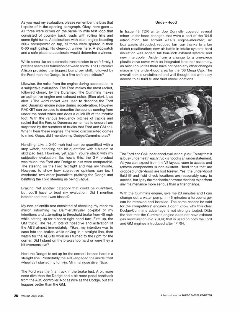
28 A Publication of the TURBO DIESEL REGISTERVolume 2003-2009
As you read my evaluation, please remember the bias that I spoke of in the opening paragraph. Okay, here goes ... All three were driven on the same 15 mile test loop that consisted of country back roads with rolling hills and some tight turns. Acceleration: with each engine boasting 300+ horsepower on tap, all three were spirited in their 0-60 mph gallop. No clear-cut winner here. A stopwatch and a safe place to accelerate would determine a winner.
While some like an automatic transmission to shift firmly, I prefer a seamless transition between shifts. The Duramax/Allison provided the biggest bump per shift, followed by the Ford then the Dodge. Is a firm shift an attribute?
Likewise, the noise from the engine during acceleration is a subjective evaluation. The Ford makes the most racket, followed closely by the Duramax. The Cummins makes an authoritive engine and exhaust noise. (Bias alert, bias alert .) The word racket was used to describe the Ford and Duramax engine noise during acceleration. However RACKET can be used to describe the sounds coming from under the hood when one does a quick lift of the throttle foot. With the various frequency pitches of cackle and racket that the Ford or Duramax owner has to endure I am surprised by the numbers of trucks that Ford and GM sell. When I hear these engines, the word disconcerted comes to mind. Oops, did I mention my Dodge/Cummins bias?
Handling: Like a 0-60 mph test can be quantified with a stop watch, handling can be quantified with a slalom or skid pad test. However, yet again, you’re stuck with my subjective evaluation. So, how’s this: the GM product was mush, the Ford and Dodge trucks were comparable. The steering on the Ford felt tight and was my favorite. However, to show how subjective opinions can be, I overheard two other journalists praising the Dodge and belittling the Ford steering as being vague.
Braking: Yet another category that could be quantified, but you’ll have to trust my evaluation. Did I mention beforehand that I was biased?
My non-scientific test consisted of checking my rearview mirror, informing my DaimlerChrysler co-pilot of my intentions and attempting to threshold brake from 45 mph while setting up for a sharp right hand turn. First up, the GM truck. The result: lots of nosedive and activation of the ABS almost immediately. Yikes, my intention was to ease into the brakes while driving in a straight line, then watch for the ABS to work as I turned to the right for the corner. Did I stand on the brakes too hard or were they a bit oversensitive?
Next the Dodge: to set up for the corner I braked hard in a straight line. Predictably the ABS engaged the inside front wheel as I started my turn-in. Minimal nose dive. Nice.
The Ford was the final truck in the brake test. A bit more nose dive than the Dodge and a bit more pedal feedback from the ABS controller. Not as nice as the Dodge, but still leagues better than the GM.
Under-Hood
In Issue 43 TDR writer Joe Donnelly covered several minor under-hood changes that were a part of the ’04.5 introduction: fan shroud was/is engine-mounted; air box was/is shrouded; reduced fan roar thanks to a fan clutch recalibration; new air baffle in intake system; hard insulation was added; full four-inch exhaust system; and new intercooler. Aside from a change to a one-piece plastic valve cover with an integrated breather assembly, as best I could tell there have not been any other changes made in the under-hood area for the ’06 Mega Cab. The overall look is uncluttered and well thought out with easy access to all fluid fill and fluid check locations.
The Ford and GM under-hood evaluation: yuck! To say that it is busy underneath each truck’s hood is an understatement. As you can expect from the V8 layout, room to access and remove components is non-existent. Hand tools that are dropped under-hood are lost forever. Yes, the under-hood fluid fill and fluid check locations are reasonably easy to access, but I pity the mechanic or owner that has to perform any maintenance more serious than a filter change.
With the Cummins engine, give me 20 minutes and I can change out a water pump. In 45 minutes a turbocharger can be removed and installed. The same cannot be said for the competitors’ engines. I don’t know why this clear Dodge/Cummins advantage is not strongly touted. Ditto the fact that the Cummins engine does not have exhaust gas recirculation (big YUCK) that is used on both the Ford and GM engines introduced after 1/1/04.

29A Publication of the TURBO DIESEL REGISTER Volume 2003-2009
Interior
With the introduction of the ’06 Mega Cab the Dodge group has redesigned the dashboard and freshened the interior with revised door panels and seating arrangements. As Dodge is the newest and freshest, it captures the award for best interior and I’ve not yet started talking about the largest-type virtues that the Mega Cab brings to market.
Again, it can be argued that styling is subjective and noted that the writer is biased. But I’ll bring up two things that cannot be argued where Dodge is the undisputed winner. First, the obvious: reread the bullet points about the Mega Cab that emphasize where Dodge lays claim to the largest-in-class. Second, realize that the details make the difference. In my evaluation of the interior it was unmistakable that Dodge had made an effort to sweat-out the details. Example: the metal U-shaped tethers for a child seat were left exposed (Ford); partially covered by a plastic piece that, once removed, would be lost (GM); covered by a plastic cap that was anchored to the surrounding plastic trim (Dodge). I could go on and on, however, one trip to comparison shop these three vehicles and you’ll see what I mean.
What is a Mega Cab? Good/Bad
Mega Cab is the biggest pickup truck cab offered by any factory on a Class III truck; even Dodge knows better than to argue the point with Freightliner or Peterbilt. If your fishin’ buddies or in-laws complain about the back of your Quad Cab, give them the old get in, sit down, shut up routine and show them the three-foot door. It has oodles of space and a decent palette of features that rivals many sport-utility vehicles.
What is there bad about the Mega Cab? In today’s politically correct climate of bigger-is-not-better the Mega Cab is a poster child candidate for excess. Will it replace the reigning excess champion, the Hummer H3? Will the Mega Cab become another Ford Excursion? My instinct says no as the Mega Cab is a truck and the PC world has yet to chastise crew cab pickup owners.
What makes a Mega Cab special or different? Good/Bad
Room, bragging rights, and style. The roofline resembles an old formal limo, with the rear door up against the front and a mass of sheetmetal to the rear suggesting privacy, luxury and comfort. It has rear seats that recline, a pair of headrests that will keep anyone’s head off the back window and as much legroom in back as a $100,000 German long-wheelbase sedan. Dodge claims the Mega Cab is the only crew that offers a DVD entertainment system and sunroof in the same truck.
Bad: Dodge may claim that, but I drove a Tundra Double Cab that had that a few months ago. Plus the Tundra sunroof felt bigger and the entire rear window rolls all the way down electrically.
How powerful is it? Good/Bad
How powerful? The specifications show the standard engine for the 1500 and 2500 Mega Cab as the 5.7 liter Hemi V8. This 343 cubic inch engine is rated at 345 horsepower @ 5400 rpm 375 ft-lbs torque @ 4200 rpm.
Optional on the 2500 and standard on the 3500 Mega Cab is the Cummins 5.9 liter, 325/610 engine. As has been the case since the ’04.5 introduction of this engine, the engine is offered at 325/610 for both the automatic transmission and manual transmission equipped trucks. The engine is also offered in all 50 states at 325/610.
So, to answer how powerful, the Cummins 325/610 is currently (September time-frame) the most power diesel option. Have GM or Ford trumped the Cummins in the power/numbers race?
How much? Good/Bad
TDR writer Andy Mikonis has done a summary of the suggested retail prices for the 2500 and 3500 Mega Cab trucks. Please see page 56 for his review.
As I think back to the Turbo Diesels that I’ve purchased (a ’96 2WD 3500, a ’99 2WD 2500, a ’03 2WD 2500; all extended or Quad Cab trucks) and that the top-of-the-line truck in a 4WD configuration will be over $50,000 I was surprised. But, I can’t recall what a deluxe 4WD version of my typical truck would have cost back in its day. As I analyze the 2WD version of the Mega Cab with less than deluxe appointments, the price point is more so reasonable and in line with inflation and my previous purchases. I’ve no doubt that the Dodge price-points are comparable to the GM and Ford price-points for similar vehicles.
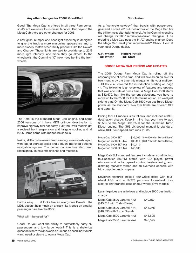
30 A Publication of the TURBO DIESEL REGISTERVolume 2003-2009
Any other changes for 2006? Good/Bad
Good: The Mega Cab is offered in all three Ram series, so it’s not exclusive to us diesel fanatics. But beyond the Mega Cab there are other changes for 2006.
A new grille, bumper and headlight assembly is designed to give the truck a more masculine appearance and to more closely match other family products like the Dakota and Charger. Those lights are said to provide up to 22% more light intensity, and since they go almost to the wheelwells, the Cummins “C” now rides behind the front wheels.
The Hemi is the standard Mega Cab engine, and some 2006 versions of it have MDS cylinder deactivation to improve highway fuel economy. Half-ton 2WD models get a revised front suspension and tailgate spoiler, and all 2006 Rams come with monotube shocks.
Inside, all Rams have new front seating, a new dash layout with lots of storage areas and a much improved optional navigation system. The center console has also been redesigned, as have the finishes and materials.
Bad is easy . . . it looks like an overgrown Dakota. The MDS doesn’t help much on a truck like it does on smaller passenger cars like the 300C.
What will it be used for?
Good: Do you want the ability to comfortably carry six passengers and tow large loads? This is a rhetorical question where the answer is as unique as each individuals want, need or desire to own a Mega Cab.
Conclusion
As a “concrete cowboy” that travels with passengers, gear and a small 20’ pull-behind trailer the Mega Cab fits the bill for me (editor talking here). As the Cummins engine will change for 2007 (emissions-driven changes), I’ll be ordering a Meg Cab post the 1/1/07 engine change. Does the Mega Cab meet your requirements? Check it out at your local Dodge dealer.
G.R. Whale Robert Patton TDR Writer TDR Staff
DODGE MEGA CAB PRICING AND UPDATES
The 2006 Dodge Ram Mega Cab is rolling off the assembly line at press time, and will have been on sale for two months by the time this magazine hits your mailbox. TDR Issue 48 covered the introduction starting on page 44. The following is an overview of features and options that was accurate at press time. A Mega Cab 1500 starts at $32,670, but, like the current selections, you have to move up to the 2500 for the Cummins option, so we’ll just skip to that. On the Mega Cab 3500 you get Turbo Diesel power as the standard. Two trim levels are offered: SLT and Laramie.
Pricing for SLT models is as follows, and includes a $900 destination charge. Keep in mind that you have to add $5,555 to the Mega Cab 2500 for the Cummins Turbo Diesel engine. The G56 six-speed manual is standard, while 48RE four-speed auto runs $1085.
Mega Cab 2500 SLT $35,065 ($40,620 with Turbo Diesel)Mega Cab 2500 SLT 4x4 $38,180 ($43,735 with Turbo Diesel)Mega Cab 3500 SLT 4x2 $40,410Mega Cab 3500 SLT 4x4 $43,500
Mega Cab SLT standard features include air conditioning, four-speaker AM/FM stereo with CD player, power windows and locks, speed control, keyless entry, auto dimming rearview mirror, and an overhead console with trip computer and compass.
Drivetrain features include four-wheel discs with four-wheel ABS, and a NV273 part-time four-wheel drive electric-shift transfer case on four-wheel drive models.
Laramie prices are as follows and include $900 destination charge:
Mega Cab 2500 Laramie 4x2 $40,160 ($45,715 with Turbo Diesel)
Mega Cab 2500 Laramie 4x4 $43,275 ($48,830 with Turbo Diesel)
Mega Cab 3500 Laramie 4x2 $45,505
Mega Cab 3500 Laramie 4x4 $48,595

31A Publication of the TURBO DIESEL REGISTER Volume 2003-2009
Laramie models include the features found on SLT, plus the following, which are optional on SLT: stereo with six-disc CD changer and Infinity speaker system, Sirius satellite radio, power-sliding rear window, six-way power driver’s seat, power adjustable pedals, security alarm, Sentry Key engine immobilizer, and steering wheel audio controls. Exclusive Laramie standard features include dual-zone climate control, leather upholstery, heated front seats, and 17-inch chrome-clad aluminum wheels.
Other options for both SLT and Laramie include bedliner, trailer tow mirrors, clearance lamps, power sun roof, full-screen navigation radio, DVD player, UConnect hands-free communication system, bucket seats, supplemental side curtain air bags, and 17-inch forged aluminum wheels. Some of the option packages include trailer tow group, heavy-duty snow plow prep group (2500 4WD only), protection group (4WD), and security group (SLT).
Curb weights and towing and hauling capacities have changed a bit since the early introduction. While the automatic was cited as heavier before, now the manual transmission models are approximately either 65 or 78 pounds heavier depending on the model and trim. This skews earlier reports a bit. GCVWR is still 20,000 pounds for a Turbo Diesel Mega Cab 2500. Going from lightest to heaviest in the 2500 class, a two-wheel drive Turbo Diesel SLT with automatic weighs in at 6840 pounds, leaving 2160 for payload and 13,000 max trailer weight; a four-wheel drive manual tips the scales at 7520, leaving 1480 for payload and 12,350 for trailer weight.
Moving on to the Mega Cab 3500, the six-speed manuals get a GCVWR of 23,000 with a 3.73 axle ratio. The automatics get the same 23,000 pounds with a 4.10, but 21,000 with a 3.73. On the 2500 automatics, the two axles are available but rated the same. The rest of the numbers don’t shake out quite the way one might expect. A Mega Cab 3500 Laramie with automatic is the lightest 3500 at 6935, and a 2970 payload; maximum trailer weight with the 4.10 axle is 15,900 pounds. The 3500 four-wheel drives are actually quoted as lighter than the 2500’s: 7471 for a SLT manual leaves 2430 payload and 15,400 for maximum trailer weight. Remember all Mega Cabs are single rear wheel.
Looks like a Mega Cab 3500 is a better deal if you are going to go with a Turbo Diesel. I’m not sure why anyone would pop for a Turbo Diesel option on a Mega Cab 2500, unless they were trying to skirt some licensing issue with a lower-rated truck.
Andy Mikonis TDR Writer

32 A Publication of the TURBO DIESEL REGISTERVolume 2003-2009
This combined section represents our review of Dodge Technical Service Bulletins (TSBs) issued to date (8/2009). Previously, Dodge vehicle TSBs were published in CD format and were available for purchase in July/August. As a service, we would purchase the TSB directory and then search through the CD to isolate only those bulletins relating to the Turbo Diesel truck.
The TSB directory is no longer available. However, the service that replaces it is an improvement. Armed with your truck’s vehicle indentification number (VIN) and a credit card you can log on to www.techauthority.com and, for $20, you can view/print all of the TSBs that apply to your vehicle.
Using several VINs from years 2003 to 2009 we downloaded the TSBs and have summarized the subject, the description of the problem, and the corrective action. Should you need the entire text, you should consult your dealer or use the www.techauthority.com web site to purchase the bulletin(s) pertaining to your truck.
One final note: As mentioned, the TSBs that we’ve researched cover those issued from 2003 to date (8/2009). For clarity we have printed in bold the TSB number and the models of trucks to which the TSB applies. The bold print will help you distinguish the old lisitngs from the newer ones.
In an effort to consolidate the TSBs for the magazine, we’re going to use the same index system categories as DaimlerChrysler. Below are the index categories.
2 Front Suspension 14 Fuel 3 Axle/Driveline 16 Propeller Shafts and U-Joints 5 Brakes 18 Vehicle Performance 6 Clutch 19 Steering 7 Cooling 21 Transmission 8 Electrical 22 Wheels & Tires 9 Engine 23 Body 11 Exhaust 24 Air Conditioning 13 Frame & Bumpers 26 Miscellaneous
A note concerning the TSBs and their use: The bulletins are intended to provide dealers with the latest repair information. Often the TSB is specific to the VIN. VIN data on the Chrysler service network helps the dealer in his service efforts. A TSB is not an implied warranty.
2009 TSBs
With the new service at www.techauthority.com we’ve gathered information on Dodge Technical Service Bulletins that have been released thus far in 2009. These 2009 TSBs are incorporated into our summary listing.
TECHNICAL SERVICE BULLETINS FOR 2003-2009
ISSUE 66 – TDRESOURCE
CATEGORY 2 FRONT SUSPENSIONTSB# MODEL SUBJECT/DESCRIPTION
02-003-086/20/08
’08 (DM)4500/5500
Front and/or rear shock absorber noise.The customer may experience a clunking-like sound when traveling over small inputs (bumps and dips) in the road. This clunk-like sound is sometimes described as being similar to the sound that “loose lumber” may make when loose boards strike each other. This condition is more noticeable during cold ambient conditions below 40°F and at lower vehicle speeds when background noise is less. The sound may come from the front and/or rear shock absorbers.
This condition is due to internal components within the vehicle shock absorber and the bulletin describes the replacement procedure.

33A Publication of the TURBO DIESEL REGISTER Volume 2003-2009
CATEGORY 3 AXLE/DRIVELINETSB# MODEL SUBJECT/DESCRIPTION
03-003-046/15/04
‘03 - ‘04 (DR) Launch shudder.This bulletin involves adjusting the propeller shaft working angles and applies to vehicles equipped with a two-piece rear driveshaft. The problem is described as a drive line shudder or vibration while accelerating from a stop. The condition is most noticeable under heavy throttle acceleration and is usually present only at low speeds (below 25 mph). Vehicles equipped with a two-piece driveshaft are designed to minimize reaction forces that result from the universal joint transmitting torque at an angle. These forces cannot be eliminated entirely because of the necessity to compromise joint angle selection between curb and design loading conditions. U-joint angles change depending upon the amount of weight applied to the vehicle bed. Therefore U-joint angle readings may need to be taken with different vehicle loads in order to obtain a satisfactory compromise. The vehicle should be evaluated under the loaded condition that produces the objectionable disturbance.
The repair procedure involves measurements at the transmission yoke, front propeller shaft, rear propeller shaft and rear axle. The working angles should be adjusted to provide the lowest angle possible for the output shaft to front propeller shaft, front propeller shaft to rear propeller shaft, and rear propeller shaft to axle pinion. The measurements will determine which direction to move the center bearing to optimize the angles. Install the appropriate bracket to obtain the minimum working angle, but still maintain at least ½ degree to ensure that there will be some movement in the U-joint bearings.
03-004-046/22/04
‘03 - ‘04 (DR) Axle whine.This bulletin applies to 4x2, 2500 series, 140.5 inch wheelbase vehicles equipped with diesel engine, sales code ETC/ETH, and an automatic transmission, sales code DG8. The problem is that some vehicles may exhibit rear axle whine at speeds between 35 and 70 mph. The repair procedure involves identification of the pinion flange and propeller shaft that the vehicle is equipped with. If a repair is necessary, the propeller shaft is replaced using the chart listing the appropriate part numbers.
03-003-0610/20/06
‘03-’07 (DR) Axle-fluid level.This bulletin supersedes TSB 03-001-04, revision A dated 5/11/04.
The axle fill holes on some 2004 Dodge Truck axles may be located considerably higher than the actual fluid level. Filling the axle until the fluid comes out of the fill hole will overfill the axle, which could cause fluid foaming. When checking fluid level or filling a rear axle with fluid, you must measure distance from the bottom of the fill hole to the actual fluid level. This can easily be accomplished using a pipe cleaner or piece of wire. Make a 90 degree bend in the wire two inches from the end. The wire can then be inserted into the axle fill hole and used as a dipstick. Measure the distance from the bend to the oil level. The fluid levels for the axles are shown in the table below.
Ram Truck 2500/3500
Axle Fluid Level (measured from the bottom of the fill hole) Fluid Capacity 10.5 Rear Axle 1 inch ± ¼ inch 85 oz. SAE 75W-90 Synthetic 11.5 Rear Axle ¼ inch ± ¼ inch 122 oz. SAE 75W-90 Synthetic 9¼ Front Axle ¼ inch ± ¼ inch 76 oz. SAE 75W-90 Synthetic
Note: The limited slip feature on 2500/3500 series Ram Trucks utilizes the Trac Rite locking feature which does not require Trac-Lok additives or friction modifiers.

34 A Publication of the TURBO DIESEL REGISTERVolume 2003-2009
CATEGORY 6 CLUTCHTSB# MODEL SUBJECT/DESCRIPTION
06-001-035/16/03
‘03 (BR) Rattle sound from transmission when idling.This bulletin applies to vehicles equipped with a 5.9L Cummins high output Turbo Diesel (sales code ETH) and NV5600 six-speed manual transmission (sales code DEE) built on or before May 11, 2003. The vehicle operator may describe a rattling sound when idling in neutral with the clutch pedal released. The bulletin involves replacing the clutch disc with a revised part.
06-001-072/03/07
‘07 Clutch system may over-adjust causing difficulty engaging transmission gear.This bulletin involves replacement of the clutch system flywheel, pressure plate, and disc.
This bulletin applies to vehicles equipped with a 5.9 liter or 6.7 liter Cummins Turbo Diesel engine and the G56 manual transmission (sales code ETH, ETJ, and DEG respectively), and built on or before November 09, 2006.
The customer may experience difficulty attempting to engage a manual transmission gear. This may be due to the self-adjusting mechanism in the clutch system. The self-adjusting clutch mechanism may over-adjust (forward adjust). This condition most often will occur within the first 1,000 miles of vehicle operation.
The bulletin describes the proper repair technique to replace the flywheel, clutch plate, and clutch disc.
CATEGORY 8 ELECTRICALTSB# MODEL SUBJECT/DESCRIPTION
08-004-033/14/03
‘02 - ‘03 (DR) Electro mechanical instrument cluster (MIC) erroneous indicator lamps.Three conditions have been identified which may be caused by communication errors between the electro mechanical instrument cluster (MIC) and other electronic modules on the vehicle. 1. An intermittent false “Check Gauges” on diesel engine equipped vehicles. 2. An intermittent false chime and “Low Wash” indicator. 3. A “Trans Temp” indicator on a manual transmission equipped vehicle.
This bulletin involves selectively erasing and reprogramming the MIC with new software.
08/007/034/4/03
‘03 (DR) Alternator mounting bracket cracked.This bulletin applies to vehicles equipped with a 5.9L 24-valve diesel engine (sales codes ETC, or ETH) and built on or before February 13, 2003, with engine serial numbers prior to 57013271. The problem is that the vehicle operator may experience an accessory drive belt squeal during normal driving conditions. This bulletin describes how to replace the alternator support bracket with a revised bracket.
08-019-036/20/03
‘03 (DR) Lamp-out indicator with aftermarket pickup box installation.This information-only bulletin discusses situations where an aftermarket utility box is installed after the removal of the original equipment pickup box. Under the circumstances the lamp-out indicator may illuminate. This is due to the use of aftermarket rear stop and turn signal lamps which use a dual filament bulb instead of separate circuits for the stop and turn indicator. The bulletin then describes the reprogramming procedure to reset the lamp-out indicator.

35A Publication of the TURBO DIESEL REGISTER Volume 2003-2009
CATEGORY 8 ELECTRICALTSB# MODEL SUBJECT/DESCRIPTION
08-031-0310/31/03
‘03 (DR) PCM connector corroded—sets MIL light.This bulletin applies to vehicles equipped with a 5.9 liter diesel engine and an automatic transmission. Water may enter the PCM connector causing corrosion of electrical terminals on the PCM. This condition can set diagnostic trouble codes and illuminate the MIL light. If diagnostic trouble codes are present or other diagnostics lead to PCM connector problems, inspect the PCM and the PCM wire harness connector. The repair procedure involves replacement of the wiring harness.
08-011-043/16/04
‘04 (DR) Poor radio sound quality with Infinity speakers.This bulletin applies to vehicles equipped with Infinity speakers, sales code RCK. Radios equipped with Infinity Speakers may exhibit a variety of symptoms due to reversed right front speaker wiring (polarity). Symptoms include: front door or speaker buzz, poor sound quality, lack of bass. The solution involves correcting speaker wiring polarity in the radio connector.
08-014-043/30/04
‘04 (DR) Radio intermittent audio.This bulletin applies to vehicles equipped with an AM/FM/cassette radio built prior to January 30, 2004 or AM/FM/CD radio built prior to January 30, 2004. Radios built after 1/30/04 will no longer have vent holes in the area the repair procedure covers. If the audio drops out when the vehicle is moved from a cold to a warm or humid environment, the reason is that condensation builds up across the audio amplifier circuitry, causing the amplifier to shut down. Typically, cycling the ignition switch off and on will restore the audio output. If the problem persists, the correct repair procedure is to apply tape over the row of slots on the left hand side of the radio’s top cover.
08-014-052/17/05
‘04 - ‘05 (DR) Mopar accessory remote starter inoperative due to hood switch.This bulletin applies to vehicles equipped with a Mopar remote starter kit. The problem frequently occurs as one or more of the following:
• When the transmitter is pressed twice for start, the vehicle horn will chirp once but the vehicle engine will not start.
• When the transmitter is pressed twice for start, the vehicle horn will chirp twice, indicating a problem with the remote start system and the vehicle engine will not start.
• When the transmitter is pressed twice for start, the vehicle will chirp once, the engine will start and then turn off.
The technician may not be able to verify the symptom(s) because it may be an intermittent condition. The corrective action involves replacing the hood switch for the remote starting system.
08-024-055/4/05
‘02 - ‘06 (DR) Radio communication equipment installation recommendations.This information only bulletin gives the dealership technician some guidelines for the installation of two-way radio equipment.
08-058-0510/29/05
‘05 - ‘06 (DR) Revised radio antenna mast installation procedure.This information only bulletin advises the proper tightening torque (30-32 in-lbs) for the radio antenna mast for various Chrysler group products.
08-014-063/16/06
‘06 (DR) UConnect Hands Free module fails to respond due to module lock-up.This bulletin supersedes service bulletin 08-049-05 dated September 1, 2005, and applies to vehicles equipped with UConnect Hands Free Communications (sales code RSP) that were built prior to October 2, 2005. If the UConnect Hands Free Communications system does not respond when system activation is attempted by the customer, the technical service bulletin gives the technician the proper repair technique to reset the hands-free module.

36 A Publication of the TURBO DIESEL REGISTERVolume 2003-2009
CATEGORY 8 ELECTRICALTSB# MODEL SUBJECT/DESCRIPTION
08-016-06Rev. A7/18/06
‘06 - ‘07 (DR) Intermittent operation of electrical components due to ignition off draw (IOD) fuse not being fully seated.This bulletin supersedes technical service bulletin 08-016-06, dated March 22, 2006. The ignition off draw (IOD) fuse is used to prevent battery discharge during shipping and long term storage of vehicles. If the fuse is not completely inserted, partial contact of the fuse terminals could occur. When the vehicle is prepped for customer delivery, ensure that the fuse is fully engaged. When the IOD fuse holder is depressed into the carrier, an initial distinct detent will be felt to overcome the “pre-hold position.” On ’06 and ’07 DR vehicles the circuits fed by the IOD fuse are: Radio, EVIC, Wireless Control Module, Hands Free Module, Satellite Radio, Video Screen, CCN wake-up with ignition off, Underhood Lamp, and CCN Interior Lighting.
08-020-065/5/06
‘04 (DR) Overhead console average fuel economy display.This information-only bulletin discusses the calculation method used by the truck’s average fuel economy display. On ’06 vehicles, the calculation has been changed to use the last displayed average fuel economy as a starting point for the calculation after a reset. The average fuel economy will then be adjusted from that point. If the display read 21.6 mpg at the time the reset was activated, the new display will start at 21.6 mpg and would change from that point depending on the current fuel usage. This was done to eliminate the extreme variations caused by very high or low fuel usage at the time of the reset.
08-021-06Rev. A10/13/06
Continued on next page.
‘06 TIPM Flash: DTC’s indicating short circuits in the wiring on the trailer or no engine crank with DTC P1277 – starter control circuit too low.This bulletin supersedes technical service bulletin 08-021-06, dated May 10, 2006.This bulletin involves a discussion and reprogramming of the totally integrated power module (TIPM). This bulletin applies to vehicles built prior to April 03, 2006.
The customer may experience any of the following TIPM diagnostic trouble codes (DTC’s):
B166B - Left Trailer Tow Lamp Control Circuit Low. Trailer harness left lamp circuit is shorted to ground.
B166C - Left Trailer Tow Lamp Control Circuit High. Trailer harness left lamp circuit is shorted to battery voltage.
B178C - Left Trailer Tow Lamp Control Circuit Over Current. Trailer harness left lamp circuit is intermittently grounding.
B166F - Right Trailer Tow Lamp Control Circuit Low. Trailer harness right lamp circuit is shorted to ground.
B1670 - Right Trailer Tow Lamp Control Circuit High. Trailer harness right lamp circuit is shorted to battery voltage.
B166E - Right Trailer Tow Lamp Control Circuit Over Current. Trailer harness right lamp circuit is intermittently grounding.
B1667 - Back Up Lamp Feed Low. Trailer harness back up circuit is shorted to ground.B2215 - Front Control Module Internal (TIPM). An internal fault code counter has exceeded
its limit of 250 counts and one or more electrical outputs controlled by the TOPM have been disabled.
P1277 - Starter Control Circuit 2 Low (TIPM). The output feed current to the starter solenoid has exceeded the upper current limit of 75 amps. This may result in a no-crank condition.
DTC’s B1667, B166B, B166E, B166F, B178C and B2215: These DTC’s indicate that a (hard or intermittent) short circuit to ground exists in the wiring of one or more of the trailer electrical harness circuits. The TIPM retries the output on each ignition cycle or request (brake or turn signal activation) in an attempt to enable the output in case the fault is intermittent. The new TIPM software raises the TIPM circuit trigger point from 15 amps to 20 amps.
DTC’s B166C and B1670: These DTC’s indicate that a short circuit to battery voltage (12 volts) exists in the wiring of one of the trailer electrical harness circuits.
37A Publication of the TURBO DIESEL REGISTER Volume 2003-2009
CATEGORY 8 ELECTRICAL08-021-06Rev. A10/13/06
Continued from previous page.
DTC B2215 - Front Control Module (TIPM): This fault code occurs when the TIPM detects a short (to ground or to battery) on one of the trailer circuits more than 250 times. When B2215 is present with one of the above trailer circuit faults, the TIPM will turn off (disable) the respective faulty trailer circuit or circuits. This internal fault does not mean that the TIPM module is defective. The TIPM memory can be cleared, and this action will turn on a previously disabled trailer circuit. If possible, the fault in the circuit should be repaired first before clearing the TIPM memory. The dealer will need a scan tool to clear the TIPM memory.
DTC P1277 - Starter Control Circuit too Low (TIPM): The TIPM monitors the output current to the starter solenoid for over-current conditions. The DTC is set when the output current to starter solenoid exceeds 75 amps. On trucks equipped with a diesel engine, there may be times in cold climates when it is normal for the starter solenoid current to exceed 75 amps. The new TIPM software raises the TIPM current trigger point for DTC P1277 from 75 amps to 100 amps.
If any of the DTC’s listed above are present, perform the repair procedure.
08-026-06Rev. A10/25/06
‘06 (DR/DH/D1) Overhead console temperature reading inaccurate or dome lamp turns off too soon.This bulletin supersedes technical service bulletin 08-026-06, dated June 02, 2006.
This bulletin involves selectively erasing and reprogramming the cabin compartment node (CCN) with new software. This bulletin applies to vehicles built on or before May 30, 2006. The vehicle owner may notice that if a vehicle door is left open for longer than 20 seconds the illuminated interior (dome) lamps will turn off. Or the vehicle operator may report that the ambient temperature first displayed in the overhead console is not accurate (displays -40°C or -40°F), when the ignition switch is turned to the “On” position, then slowly updates to the outside ambient temperature as the vehicle is driven. If the vehicle operator describes or experiences the symptom/condition, perform the repair procedure which involves a reflash to the CCN.
08-044-0610/07/06
‘07 (DR) Steering angle sensor over travel performance (DTC:C1240).This bulletin involves the diagnosis and possible replacement of the steering angle sensor. This bulletin applies to vehicles equipped with the Electronic Stability Program (sales code BNB) and built prior to October 03, 2006. The customer may experience an illumination on the instrument cluster of the ABS (anti-Lock Brake System) and/or the ESP/BAS (Electronic Stability Program/Brake Assist System) warning lights. Investigation may reveal the presence of diagnostic trouble code (DTC) C1240 – Steering Angle Sensor Over Travel Performance.
If the diagnostic test procedure for DTC C1240 determines that the steering angle sensor is at fault, then perform the repair procedure.
08-046-0610/25/06
‘04-’07 Cell phone induced buzz or clicking-like sound in radio speakers.This bulletin involves a discussion regarding cell phone generated signal interference with the vehicle radio system. A customer may experience a buzzing or clicking-like sound coming from the vehicle radio speaker(s). The sound may be heard when the radio is in AM or FM mode. The clicking-like sound may sound like Morse code.
This information-only bulletin points out that the construction of certain cell phones may generate frequencies that can interfere with the vehicle radio system. These frequencies may result in buzzing and/or clicking-like sounds in the vehicle radio. This condition can be easily corrected by instructing the customer to move their cell phone away from the immediate area around vehicle radio system (radio, radio amplifier, antenna, antenna lead). Do not replace any radio system component in an attempt to address this condition.

38 A Publication of the TURBO DIESEL REGISTERVolume 2003-2009
CATEGORY 8 ELECTRICAL08-003-0701/27/07
‘07 (DR/DH/D1/DC) Remote start system – Diagnostic chart for antenna.This bulletin involves a diagnostic chart that may be used to aid the technician with the diagnosis of the antenna on an originally equipped (factory installed) remote start system. This bulletin applies to vehicles with an original equipment remote start system (sales code XBM). The customer may notice that the signal range of the remote keyless entry system is reduced (less than 100 feet). This condition may be due to the RKE antenna. The diagnostic flow chart is provided as a diagnostic aid for dealer technicians.
08-015-0706/06/07
‘06-’07 (DR) Flash: Sunroof module, excessive ignition off draw, pop in radio with ignition off, dome lamp flickers and may not go off.This bulletin involves selectively erasing and reprogramming the Sunroof Motor Module with new software.
08-018-0706/23/07
‘07 (DR/DH/D1/DC) Mopar remote start system – RKE – intermittent operation or alarm may sound.This bulletin involves the installation of a Mopar remote start system service repair kit.
08-007-08 REV. A7/4/08
’07-’08 ngine does not crank or start due to electronic lockup of the remote key module.This bulletin applies to vehicles built on or before May 05, 2008. The customer may experience a no engine crank and a no engine start condition. Also, the remote keyless entry system will not operate. This condition may be due to an electrostatic discharge from the ignition key into the wireless control module (WCM), causing the WCM to electronically lock up. This condition is corrected by the replacement of the WCM (also known as the Sentry Key Remote Entry Module).
08-028-089/18/08
‘08 (DR/DH/DC/D1) Voice recognition screen lock-up on REN or REZ radio equipped with hands-free communications.The customer may experience one of the following conditions: a) A “lock up” condition of the radio screen when the voice recognition (VR) button is pressed b) When the VR button is pressed, the radio display changes to the phone screen and there is a lack of the “Ready” audio prompt.
If the above symptom/condition is experienced, the HFM is replaced. This bulletin applies to radios built before 11/6/07.
08-035-0811/21/08
‘07-’09 (DH/D1) Proper testing tools for oxygen sensor terminals.This bulletin describes the use of proper test probes to test the oxygen (O2) sensor connector terminals equipped with the new TP2 style sensor. The recommended tool for these testing procedures is the Miller Tool #6801.

39A Publication of the TURBO DIESEL REGISTER Volume 2003-2009
CATEGORY 9 ENGINETSB# MODEL SUBJECT/DESCRIPTION
09-004-0603/31/06
’03-’06 (DR) Accessory drive belt chirp at shutdown.This bulletin applies to vehicles with diesel engine sales code ETH. A chirping sound may be heard coming from the accessory drive belt when the engine is shut down. If a customer indicates that the condition is present, the bulletin directs the technician to install an overrunning clutch pulley on the generator.
09-002-09REV. A6/13/09
‘07-’09 (DH/D1) MIL illumination due to DTC P2262 - Revised diagnosis and repair procedures.This bulletin applies to vehicle equipped with a Cummins 6.7-liter engine (sales code ETJ). The bulletin supersedes technical service bulletin 09-002-09 dated 5/2/09. This bulletin discusses revised diagnostic and repair procedures for DTC P2262 - Turbocharger Boost Pressure Not Detected - Mechanical. Recent PCM calibration updates have improved the robustness to this DTC through updated diagnostic strategies. As a result, many events which have no adverse affects on drivability, emissions, or reliability will no longer set the P2262 fault.
As a result of recent PCM calibration updates, the proper repair for some P2262 faults is merely to update the calibration, while others will require cleaning or replacing the turbocharger. Scan Tool software includes a P2262 diagnosis test for this purpose. The new P2262 diagnosis test must be used prior to performing any of the following:
• Clearing codes• Updating the PCM• Beginning the turbocharger repair.
Based on the outcome of the P2262 diagnosis test, the Scan Tool will provide one of the following as the proper direction for the appropriate repair. Service info and complete the repair as directed:
• Update PCM flash calibration to the latest calibration. No repair required to the turbocharger.• Clean the turbocharger.• Update PCM flash calibration to the latest calibration and clean the turbocharger.• Replace the turbocharger.• Update PCM flash calibration to the latest calibration and replace the turbocharger.
CATEGORY 11 FRAME/BUMPERTSB# MODEL SUBJECT/DESCRIPTION
11-002-079/25/07
07-’08 (DH/D1)2500/3500
Inspection and test procedures for the 6.7-liter diesel particulate filter (DPF).This bulletin applies to vehicle equipped with a Cummins 6.7-liter engines (sales code ETF). The customer may experience a malfunction indicator lamp (MIL) illumination, warning chime, and an overhead electronic vehicle information center (EVIC) message that states “Catalyst Full Service Required.” Investigation may reveal that the MIL illumination is due to one or more of the following diagnostic trouble codes (DTCs):
P1451 – Diesel Particulate Filter System Performance.P2463 – Diesel Particulate Filter – Soot Accumulation.P242F – Diesel Particulate Filter Restriction – Ash Accumulation.
The balance of the 10-page bulletin describes the inspection, test, repair, or replacement of the DPF based on the severity of the accumulation in the DPF.

40 A Publication of the TURBO DIESEL REGISTERVolume 2003-2009
CATEGORY 11 FRAME/BUMPERTSB# MODEL SUBJECT/DESCRIPTION
11-001-085/21/08
’07-’08 (DH/D1)2500/3500
Cleaning the turbocharger on the Cummins 6.7-liter engine.This 17-page bulletin describes the process of cleaning the turbocharger using Cummins Engine Update Kit 10138-UPD to address excess soot accumulation. The procedure cleans the internal components on the exhaust side of the turbocharger.
The bulletin goes hand-in-hand with TSBs 11-005-08 and 11-002-07 for detailed turbocharger, engine and exhaust aftertreatment system repair procedures.
11-002-085/21/08
’07-’08 (DH/D1)2500/3500
Inspections and test for the turbocharger on the Cummins 6.7-liter engine.The customer may experience a malfunction indicator lamp (MIL) illumination due to diagnostic trouble code (DTC): P2262 – Turbocharger Boost Pressure Not Detected – Mechanical.
If further codes of P1451, P2463 or P242F are present, the technician is referred to the repair procedure listed in TSB 11-002-07. If the codes are not present, the repair and cleaning procedures in this 8-page bulletin and TSB 11-001-08 are to be performed.
11-001-097/23/09
‘07-’09 (DH/D1) Diesel Particulate Filter: Diagnosis and repair of DTC’s P1451, P200C, P242F or black smoke from exhaust.This bulletin applies to vehicles equipped with a Cummins 6.7-liter engine (sales code ETJ). The customer may experience a malfunction indicator lamp (MIL) illumination, warning chime and an overhead electronic vehicle information center (EVIC) message regarding the aftertreatment system and/or black smoke from the exhaust and/or a no start condition. Further investigation by the technician may reveal that the MIL illumination and/or EVIC message is due to one or more of the following diagnostic trouble codes (DTC’’s):
P1451 - Diesel Particulate Filter - System PerformanceP242F - Diesel Particulate Filter Restriction - Ash AccumulationP200C - Diesel Particulate Filter Over Temperature - Bank 1.
This bulletin provides revised diagnostic and repair procedures for DTC’s P1451, P200C, P242F, black smoke from the exhaust, or a no start condition due to a nonfunctional or plugged diesel particulate filter (DPF).
11-002-098/5/09
‘07-’09 (D1/DH) Diesel particulate filter Stationary DeSoot.This bulletin applies to D1/DH vehicles equipped with a 6.7-liter Cummins diesel engine (sales code ETJ). Mobile DeSoot still applies to DC/DM vehicles equipped with the 6.7-liter Cummins diesel engine (sales code ETJ). Stationary DeSoot has replaced Mobile DeSoot as the repair for Diagnostic Trouble Codes P1451 and P2463. This bulletin provides the procedure to perform Stationary DeSoot. This new procedure allows running the DeSoot in a secured area with the vehicle unattended.
Stationary DeSoot can only be performed when the diesel particulate filter has exceeded a specified soot threshold. The Diagnostic Scan Tool will not allow the procedure to operate unless the threshold has been exceeded. If the vehicle does not have an active P1451, the soot in the Diesel Particulate Filter is at a normal level and a scan tool initiated DeSoot is not needed.
CATEGORY 13 FRAME/BUMPERTSB# MODEL SUBJECT/DESCRIPTION
13-001-032/7/03
‘03 (DR) Frame alterations.This bulletin is to support the 2003 Body Builder’s Guide and presents guidelines that must be followed during modifications or alterations to any 2003 Dodge Ram pickup frame. The following general industry standard procedures are recommended for proper installation of special bodies and/or equipment on the Ram pickup frame, such as fifth-wheel hitches, snow plows, etc. Failure to follow these recommendations could result in damage to the basic vehicle and possible injury to occupants. The information-only bulletin gives the guidelines for welding and drilling of holes into the frame.

41A Publication of the TURBO DIESEL REGISTER Volume 2003-2009
CATEGORY 14 FUELTSB# MODEL SUBJECT/DESCRIPTION
14-004-05 ‘03 - ‘05 (DR) Electronic fuel control (EFC) actuator available for serviceThis bulletin deals specifically with an engine surge at idle condition. The diagnostic procedures are the same as those listed in TSB 14-003-05. The bulletin describes the repair procedure for replacement of the electronic fuel control actuator.
14-003-06Rev. A10/27/06
‘03 - ‘07(DR/DH/D1/DC)
Cummins diesel diagnostics.This bulletin applies to vehicles with the 5.9 liter engine, sales code ETH or ETC.
• Revised diagnostic procedures are available for the following conditions:• Engine cranks for a long time or will not start• White smoke and/or misfire after starting when the engine temperature is below 150° F• Engine surges at idle• Engine sounds
The 12-page bulletin gives the service technician a set of revised diagnostic procedures for the fuel system. Each condition is discussed and possible causes are established. Step-by-step instructions help the technician identify and repair the problem.
14-005-0607/27/06
‘07 (DH/D1/DC) 5.9-liter and 6/7-liter Cummins diesel engines - correct low and ultra-low sulfur highway diesel fuel use.This bulletin involves a discussion regarding the correct diesel fuel to use for either the 5.9-liter or the 6.7-liter Cummins diesel engine (sales code ETH and ETJ respectively).
Dodge Ram trucks equipped with the 6.7L Cummins Turbo-Diesel engine are required by Federal law to be fueled with ultra-low sulfur diesel fuel (model year ’07.5). Early production 2007 Dodge Ram trucks equipped with the 5.9 Cummins Turbo Diesel engine are allowed by Federal law to be fueled with low sulfur diesel fuel, and are encouraged to fuel with ultra-low sulfur diesel fuel. The new ultra-low sulfur highway diesel fuel enables vehicles equipped with the advanced emissions control devices to achieve more stringent U/S EPA vehicle emissions standards.
14-007-06Rev. A09/02/06
Continued on next page.
‘06-’07 (DH/D1/DC) Fuel and fuel filtering requirements for Cummins 5.9-liter and 6.7-liter engines.This bulletin supersedes technical service bulletin 14-007-06, dated August 25, 2006.
This information-only bulletin involves a discussion regarding fuel system requirements. The bulletin applies to vehicles equipped with a 5.9-liter High Output or a 6.7-liter Cummins Turbo Diesel engine (sales codes ETH or ETJ respectively) that were built on or after March 07, 2006. Bulletin highlights follow:
For the diesel engine system to operate at its peak performance a high level of fuel quality must be maintained. Emission control and fuel delivery systems have advanced significantly. Care must be taken to ensure that the fuel that is delivered to the engine fuel injection system is of the highest quality possible and free of contaminants.
Significant components to fuel quality are: the initial quality of the fuel (as dispensed from the service station fuel pump or bulk storage), on-vehicle fuel storage, and the on-vehicle fuel filtering of the diesel fuel prior to the fuel injection process.
Use good quality diesel fuel from a reputable supplier. It is recommended that purchase of diesel fuel be made from a service station that is known to dispense a high volume of highway diesel fuel.
Ultra low sulfur highway diesel fuel is required for use in Dodge Ram trucks equipped with a 6.7-liter diesel engine.
A maximum blend of 5% biodiesel (B5) is acceptable as long as the biodiesel mixture meets ASTM specification D-975, D-975-grade S-15, and ASTM D6751. A biodiesel fuel blend that is higher than 5% is not acceptable without additional fuel processing because these higher percentage biodiesel blends contain excess amounts of moisture which exceed the water stripping capability of the on-engine final fuel filter. Should a higher percentage biodiesel fuel be used, an auxiliary water stripping filter will be required.

42 A Publication of the TURBO DIESEL REGISTERVolume 2003-2009
CATEGORY 14 FUEL14-007-06Rev. A09/02/06
Continued from previous page.
\ A maximum blend of 20% biodiesel (B20) can be used by government, military, and commercial fleets who equip their vehicle(s) with an optional water separator, and adhere to the guidelines in the Department of Defense specification A-A-59693.
Fuel conditioners (additives) are not recommended and should not be required if you buy good quality fuel and follow cold weather advice supplied in the Owner’s Manual.
CATEGORY 18 VEHICLE PERFORMANCETSB# MODEL SUBJECT/DESCRIPTION
18-015-034/4/03
‘03 (DR) Powertrain control module (PCM) shift quality improvements.This bulletin applies to vehicles equipped with a 5.9L standard output Cummins diesel engine (sales code ETC) and a 47RE transmission(sales code DGP) built before December 31, 2002. The vehicle operator may find that the vehicle will not shift out of third gear at throttle between 50% and 90% until 70 mph. The repair involves selectively erasing and reprogramming the powertrain control module (PCM) with new software.
18-027-037/4/03
‘03 (DR) No throttle response, lack of power while towing and diagnostic trouble codes P2638/P0700.This bulletin applies to vehicles equipped with a Cummins diesel engine (sales code ETC or ETH) built on or before July 25, 2003. The vehicle may exhibit:
• No throttle response if the engine is started with the Accelerator Pedal Position Sensor (APPS) in an off-idle position (pedal depressed) and the transmission is shifted into drive or reverse while the APPS remains in an off-idle position (pedal depressed), causing the engine to remain at idle.
• Lack of power while towing or hauling a heavy load with the transmission in overdrive—vehicles equipped with 47RE transmission.
The repair involves selectively erasing and reprogramming the Cummins CM845 engine control module (ECM) with new software.
18-030-038/29/03
‘98.5 - ‘02 (BE/BR)‘03 - ‘04 (DR)
Generic Cummins engine control module (ECM) procedure.This bulletin applies to Ram trucks equipped with the 5.9L Cummins 24-valve diesel engine (sales code ETC or ETH). Mopar is phasing out pre-programmed Cummins Diesel engine control modules (ECM). New modules will no longer be pre-programmed when received from Mopar. Replacement of future ECM’s will require programming utilizing the DRBIII and TechCONNECT.
18-003-042/3/04
‘03 - ‘04 (DR) Poor A/C performance, slow fuel gauge response, and diagnostic trouble codes PO341 and P1757.This bulletin applies to vehicles equipped with a Cummins Turbo Diesel engine (sales code ETC or ETH) with an engine serial number 57130284 or earlier and the engine date of manufacture on or before December 10, 2003. The owner of the vehicle may describe slow fuel gauge response after adding fuel. On California emission equipped vehicles, the problem is rapid A/C clutch cycling and poor A/C performance until coolant temperature reaches 170°. The repair involves erasing and reprogramming the Cummins ECM with new software.
18-004-042/3/04
‘04 (DR) Poor cab heat and/or slow engine warm-up in cold ambient temperatures.This bulletin applies to DR vehicles equipped with a Cummins Turbo Diesel engine (sales code ETC or ETH) and an automatic transmission, with an engine serial number 57130284 or earlier and the engine date of manufacture on or before December 10, 2003. The vehicle operator may describe poor cab heat and/or slow engine warm-up in cold ambient temperatures. A new feature has been added that allows the vehicle operator to use the speed control switches to increase the engine speed up to 1500 rpm in order to improve cab heat. The feature must be enabled using the DRBIII. If the vehicle operator would like to have the feature enabled, perform the repair procedure which involves erasing and reprogramming the Cummins ECM with new software.

43A Publication of the TURBO DIESEL REGISTER Volume 2003-2009
CATEGORY 18 VEHICLE PERFORMANCE18-007-042/24/04
‘04 (DR) White smoke, engine stumble/misfire, or flat spot in engine performance.This bulletin applies to vehicles equipped with a Cummins Turbo Diesel engine (sales code ETH) with an engine serial number 57130285 through and including 57149668 and the engine date of manufacture 12/10/2003 through and including 2/2/2004. The vehicle operator may describe:
• White smoke during no-load engine acceleration between 2800 and 3000 rpm.• Engine stumble/misfire or flat spot during moderate accelerations between 1500 and 2500
rpm. May be accompanied by white smoke.• During cold ambient temperatures (30° or below) white smoke and/or engine stumble when
engine is started after an extended cold soak.• During cold ambient temperatures (30° or below) white smoke when restarting engine that
has not yet reached normal operating temperature.
If the vehicle operator describes or the technician experiences the problem, perform the repair procedure which involves erasing and reprogramming the Cummins ECM with new software.
18-033-048/20/04
‘98.5 - ‘02 (BR)‘03 - ‘05 (DR)
Cummins engine control module (ECM) procedure.Mopar is phasing out pre-programmed Cummins diesel engine control modules (ECM). New modules will no longer be pre-programmed when received from Mopar. Replacement of future ECM’s will require programming at the dealership. This bulletin describes the programming procedure.
18-041-0512/20/05
‘06 Flash: engine performance/white smoke.This bulletin applies to Ram trucks equipped with the 5.9L Cummins 24-valve diesel engine (sales code ETH) built on or after June 9, 2005, through and including November 8, 2005. This bulletin involves programming the PCM (Cummins) with new software. The software is designed to reduce white smoke and improve engine performance after a cold start at ambient temperatures below 60°F and to improve oil pressure gauge operation.
18-001-06Rev. A7/12/06
‘06 - ‘07 (DR, DH, D1)‘07 (DC)
StarSCAN StarMOBILE abort recovery procedures.This information-only bulletin supersedes technical service bulletin 18-001-06, dated January 11, 2006, and provides guidelines to minimize flash reprogramming problems and recovery procedure information for failed flash attempts.
18-003-06Rev. A09/27/06
‘05 - ‘06 (DH, D1) Flash: long crank when starting and/or transmission shift and battery charging enhancements.This bulletin applies to Ram trucks equipped with the 5.9L Cummins 24-valve diesel engine (sales code ETH) built on or after January 01, 2005. The vehicle operator may experience extended engine crank time in cold ambient temperatures on vehicles equipped with manual transmissions. This flash also provides the following enhancements:
• Improved start times for manual transmission vehicles• Improved automatic transmission shifting• Engine fan is activated if the coolant temperature sensor fails • Enhanced battery charging
This bulletin involves flash reprogramming the PCM (Cummins) with the software.
18-005-06Rev. B05/31/06
Continued on next page.
‘06 (DH/D1) Flash: DTC correction, turbocharger protection, and clutch durability improvement.This bulletin supersedes technical service bulletin 18-005-06 Rev. A, dated April 26, 2006. This bulletin applies to Ram trucks equipped with the 5.9L Cummins 24-valve diesel engine (sales code ETH) built on or after June 9, 2005, through and including May 31, 2006. The PCM software has been revised to address the following issues:
• A MIL may illuminate due to one or more of the following diagnostic trouble codes: P0071 – Inlet Air Temperature Sensor Rationality P0111 – Intake Air Temperature (IAT) Sensor Rationality P0514 – Battery Temperature Sensor Rationality P0191 – Fuel Pressure Rationality
• Turbocharger durability improvement: Implemented an engine speed limitation when cold, to protect the turbocharger bearings.

44 A Publication of the TURBO DIESEL REGISTERVolume 2003-2009
CATEGORY 18 VEHICLE PERFORMANCEContinued from previous page.
• Clutch durability improvement: Implemented a minimum engine speed limitation when launching vehicle from a stop, to protect the clutch.
This bulletin involves selectively erasing and reprogramming the PCM (Cummins) with new software.
18-022-0703/14/07
‘03 - ‘05 (DR) Flash: 5.9L Turbo-Diesel engine system enhancementsThis bulletin applies to vehicles equipped with a 5.9L Turbo Diesel engine (sales codes ETC and ETH respectively). The bulletin supersedes 18-022-06 dated 07/13/06. The following enhancements are included with this software update:
• Improved engine cooling (radiator fan activation) and prevention of possible engine overheat. When coolant temperature faults are present, the radiator fan is enabled (turned on) during vehicle operation.
• Correction to oil pressure reading when engine is operating at higher engine temperatures above 195°F.
• Improvement to the Temperature Sensor Rationality Test to prevent possible false test failures and their following related diagnostic trouble codes:
DTC P0071 – Inlet Air Temperature Sensor Rationality DTC P0111 – Intake Air Temperature (IAT) Sensor Rationality DTC P0514 – Battery Temperature Sensor Rationality.
• Additional water-in-fuel (WIF) warning added to indicate that the operator has had a WIF (DTC P2269) and has continued to operate the vehicle in excess of 500 miles without draining the water from the fuel filter. The following is the new WIF DTC that has been added:
DTC P0169 – WIF Too Long Error• Improvement to the fuel pressure rationality test to prevent false test failures and the
related DTC 0191.
This bulletin involves selectively erasing and reprogramming the engine control module with new software.
18-038-0612/05/06
‘07 (DC) Flash: DTC P0471 – Exhaust pressure sensor rationality on Cummins 6.7-liter Turbo Diesel.This bulletin applies to vehicles equipped with a 6.7-liter engine (sales code ETJ) built on or before October 05, 2006. The vehicle operator may experience a malfunction indicator lamp (MIL) illumination due to diagnostic trouble code (DTC) P0471: exhaust pressure sensor rationality. This bulletin involves selectively erasing and reprogramming the engine control module (ECM-Cummins) with new software.
18-001-0701/06/07
‘06 - ‘07 (DH/D1) Flash: check gauges lamp illuminates for alternator charging with DTC P2502, P2503, or P2509This bulletin applies to vehicles equipped with a 5.9-liter engine (sales code ETH) built on or before November 29, 2006. The customer may experience the illumination of the “Check Gauges” lamp on the instrument panel cluster. Inspection of the gauges may reveal that the battery charging gauge may read in the 11-volt range rather than in the 14-volt range. There may not be a Check Engine/Malfunction Indicator Lamp (MIL) illumination.
Further diagnosis may reveal the following diagnostic trouble codes (DTC’s) have been set: P2502 – Charging System Error – DieselP2503 – Charging System Output Low – DieselP2509 – Powerdown Data Lost Error – Diesel
This bulletin involves selectively erasing and reprogramming the powertrain control module (Cummins PCM) with new software.

45A Publication of the TURBO DIESEL REGISTER Volume 2003-2009
CATEGORY 18 VEHICLE PERFORMANCE18-009-07Rev. B07/13/07
‘07 (DC) Ram truck 3500 Cab and Chassis – Excessive soot accumulation in exhaust, PCM may not reprogram, and other engine system enhancements.This bulletin applies to Ram truck 3500 Cab and Chassis vehicles equipped with 6.7-liter Cummins Turbo Diesel engine (sales code ETJ). This bulletin supersedes technical service bulletin 18-009-07 Rev. A, dated May 16, 2007.
The vehicle operator and/or technician may experience one or more of the following conditions:
• The technician may not be able to reprogram (flash) the PCM with new application software.• After extensive idling of the vehicle engine or if an intake air leak is present, the vehicle
operator may experience a MIL illumination and/or an electronic vehicle information center (EVIC) message alert due to one or more of the following DTC’s:P1451 – Diesel Particulate Filter System Performance.P2463 – Diesel Particulate filter – Soot AccumulationP242F – Diesel Particulate Filter Restriction – Ash Accumulation.
• The vehicle operator may experience a MIL illumination due to one of the following DTC’s:P0101 – Manifold Absolute Pressure Sensor Performance.P0106 – Boost Pressure Sensor Rationality.P0191 – Fuel Rail Pressure Sensor Circuit Performance.
• Improved Water-In-Fuel (WIF) alert. To improve awareness that water has been detected in the fuel system, the vehicle operator will be alerted to a five (5) chime alert versus a single (1) chime alert.
This bulletin involves selectively erasing and reprogramming the powertrain control module (PCM) with “bootloader” software and application software.
18-030-0704/26/07
‘04 - ‘07 (DR/DH/D1/DC)
Engine off-idle speed limit feature to protect turbocharger when vehicle is not moving.This bulletin applies to vehicles equipped with a 5.9-liter or a 6.7-liter Cummins Turbo Diesel engine (sales codes: ETC, ETH, or ETJ). This bulletin involves a discussion regarding an engine control feature that limits engine off-idle speeds when the vehicle is not moving.
Dependent upon engine coolant temperature, the engine control module (ECM) will temporarily limit the maximum engine speed when the vehicle is not moving. For automatic transmission equipped vehicles the maximum engine speed is temporarily delayed when the vehicle speed is less than one mph, and when the transmission selector is in either the neutral or park position. For manual transmission equipped vehicles, the maximum engine speed is temporarily delayed when the vehicle speed is less than one mph. This ECM feature is used to protect the engine turbocharger.
This delay in maximum engine and turbocharger shaft speed allows for sufficient oil lubrication to the turbocharger shaft bearings which is important for long term turbocharger durability.
The maximum engine speed for the 5.9-liter engine is temporarily limited to 1,600 RPM when the above conditions are met. The 6.7-liter engine speed is temporarily limited to 1,200 RPM when the above conditions are met. The length of time that the maximum engine speed is temporarily limited is dependent upon engine coolant temperature. For example, the delay can be up to 45 seconds at 35° or 7 seconds at 70°.
18-033-07Rev. B06/28/07
Continued on next page.
‘07 (DH/D1) Ram truck 2500 and 3500 – Excessive soot accumulation in exhaust, PCM may not reprogram, OBD readiness status and other engine system enhancements.This bulletin applies to Ram truck 2500 and 3500 vehicles equipped with 6.7-liter Cummins Turbo Diesel engine (sales code ETJ) built on or before June 11, 2007. This bulletin supersedes technical service bulletin 18-033-07 Rev. A, dated June 12, 2007.
The vehicle operator and/or technician may experience one or more of the following conditions and/or enhancements:
• The technician may not be able to reprogram (flash) the PCM with new application software.• The vehicle may fail an emission inspection maintenance (I/M) test because two or more on-
aboard diagnostic (OBD) monitors report that they are not ready for testing. This condition may cause the customer vehicle to fail an emissions I/M test. The following is a list of OBD Monitors that may report as not ready for testing:
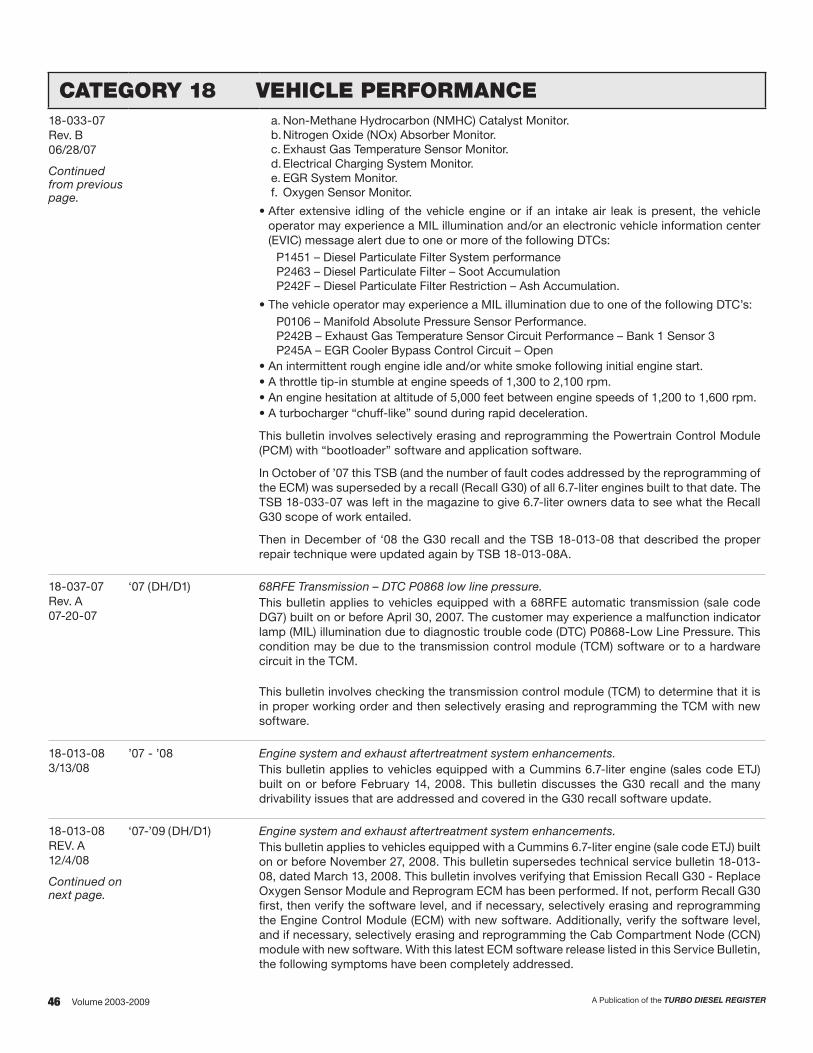
46 A Publication of the TURBO DIESEL REGISTERVolume 2003-2009
CATEGORY 18 VEHICLE PERFORMANCE18-033-07Rev. B06/28/07
Continued from previous page.
a. Non-Methane Hydrocarbon (NMHC) Catalyst Monitor.b. Nitrogen Oxide (NOx) Absorber Monitor.c. Exhaust Gas Temperature Sensor Monitor.d. Electrical Charging System Monitor.e. EGR System Monitor.f. Oxygen Sensor Monitor.
• After extensive idling of the vehicle engine or if an intake air leak is present, the vehicle operator may experience a MIL illumination and/or an electronic vehicle information center (EVIC) message alert due to one or more of the following DTCs:
P1451 – Diesel Particulate Filter System performanceP2463 – Diesel Particulate Filter – Soot AccumulationP242F – Diesel Particulate Filter Restriction – Ash Accumulation.
• The vehicle operator may experience a MIL illumination due to one of the following DTC’s:P0106 – Manifold Absolute Pressure Sensor Performance.P242B – Exhaust Gas Temperature Sensor Circuit Performance – Bank 1 Sensor 3P245A – EGR Cooler Bypass Control Circuit – Open
• An intermittent rough engine idle and/or white smoke following initial engine start.• A throttle tip-in stumble at engine speeds of 1,300 to 2,100 rpm.• An engine hesitation at altitude of 5,000 feet between engine speeds of 1,200 to 1,600 rpm.• A turbocharger “chuff-like” sound during rapid deceleration.
This bulletin involves selectively erasing and reprogramming the Powertrain Control Module (PCM) with “bootloader” software and application software.
In October of ’07 this TSB (and the number of fault codes addressed by the reprogramming of the ECM) was superseded by a recall (Recall G30) of all 6.7-liter engines built to that date. The TSB 18-033-07 was left in the magazine to give 6.7-liter owners data to see what the Recall G30 scope of work entailed.
Then in December of ‘08 the G30 recall and the TSB 18-013-08 that described the proper repair technique were updated again by TSB 18-013-08A.
18-037-07Rev. A07-20-07
‘07 (DH/D1) 68RFE Transmission – DTC P0868 low line pressure.This bulletin applies to vehicles equipped with a 68RFE automatic transmission (sale code DG7) built on or before April 30, 2007. The customer may experience a malfunction indicator lamp (MIL) illumination due to diagnostic trouble code (DTC) P0868-Low Line Pressure. This condition may be due to the transmission control module (TCM) software or to a hardware circuit in the TCM.
This bulletin involves checking the transmission control module (TCM) to determine that it is in proper working order and then selectively erasing and reprogramming the TCM with new software.
18-013-083/13/08
’07 - ’08 Engine system and exhaust aftertreatment system enhancements.This bulletin applies to vehicles equipped with a Cummins 6.7-liter engine (sales code ETJ) built on or before February 14, 2008. This bulletin discusses the G30 recall and the many drivability issues that are addressed and covered in the G30 recall software update.
18-013-08REV. A12/4/08
Continued on next page.
‘07-’09 (DH/D1) Engine system and exhaust aftertreatment system enhancements.This bulletin applies to vehicles equipped with a Cummins 6.7-liter engine (sale code ETJ) built on or before November 27, 2008. This bulletin supersedes technical service bulletin 18-013-08, dated March 13, 2008. This bulletin involves verifying that Emission Recall G30 - Replace Oxygen Sensor Module and Reprogram ECM has been performed. If not, perform Recall G30 first, then verify the software level, and if necessary, selectively erasing and reprogramming the Engine Control Module (ECM) with new software. Additionally, verify the software level, and if necessary, selectively erasing and reprogramming the Cab Compartment Node (CCN) module with new software. With this latest ECM software release listed in this Service Bulletin, the following symptoms have been completely addressed.

47A Publication of the TURBO DIESEL REGISTER Volume 2003-2009
CATEGORY 18 VEHICLE PERFORMANCE18-013-08REV. A12/4/08
Continued from previous page.
• One of the following driveability conditions:a. An intermittent rough engine idle and/or white smoke following initial engine start.b. A throttle tip-in stumble at engine speeds of 1,300 to 2,100 rpm.c. An engine hesitation at altitude of 5,000 feet between engine speeds of 1,200 to 1,600 rpm.d. A turbocharger “chuff-like” sound during rapid deceleration.
• The vehicle may fail an Emission Inspection Maintenance (I/M) Test because two or more On-Board Diagnostic (OBD) monitors report that they are not ready for testing. This condition may cause the customer vehicle to not pass an Emissions I/M test. The following is a list of OBD Monitors that may report as not ready for testing:a. Non-Methane Hydrocarbon (NMHC) Catalyst Monitor.b. Nitrogen Oxide (NOx) Absorber Monitor.c. Exhaust Gas Temperature Sensor Monitor.d. Electrical Charging System Monitor.e. EGR System Monitor.f. Oxygen Sensor Monitor.
• Malfunction Indicator Lamp (MIL) due to one or more of the following Diagnostic Trouble Codes (DTC’s):a. P0101 - Mass Air Flow (MAF) Sensor Rationalityb. P0128 - Thermostat Rationalityc. U1421 - Implausible Ignition Key Off Time Received.
The latest ECM software includes a new extended idle feature to accommodate the extended idle times present in some duty cycles. This feature may help to reduce the accumulation of soot in the exhaust aftertreatment system when the engine is idling for an extended period of time.
A number of improvements have been made to the engine diagnostics. Performing this Service Bulletin completely will enable these diagnostic improvements.
To determine if the vehicle has the latest software, compare the software level to the following notes:
• If the vehicle in question is a 2007 model year vehicle, then compare the current ECM software level part number to one of the following part numbers (or with a higher suffix):
55350430AZ (or higher) = DH 2500 6.7L Manual Transmission 50 State55350435AZ (or higher) = DH 2500 6.7L Automatic Transmission 50 State55351430AZ (or higher) = D1 3500 6.7L Manual Transmission 50 State55351435AZ (or higher) = D1 3500 6.7L Automatic Transmission 50 State
• If the vehicle in question is a 2008 model year vehicle, then compare the current ECM software level part number to one of the following part numbers (or with a higher suffix):
62350430AR (or higher) = DH 2500 6.7L Manual Transmission 50 State 62350435AR (or higher) = DH 2500 6.7L Automatic Transmission 50 State 62351430AR (or higher) = D1 3500 6.7L Manual Transmission 50 State 62351435AR (or higher) = D1 3500 6.7L Automatic Transmission 50 State• If the vehicle in question is a 2009 model year vehicle, then compare the current ECM
software level part number to one of the following part numbers (or with a higher suffix): 72350430AF (or higher) = DH 2500 6.7L Manual Transmission 50 State 72350435AF (or higher) = DH 2500 6.7L Automatic Transmission 50 State 72351430AF (or higher) = D1 3500 6.7L Manual Transmission 50 State 72351435AF (or higher) = D1 3500 6.7L Automatic Transmission 50 State• Determine if the current CCN module level software part number is one of the following (or
with a higher suffix): 05172187AG (or higher) = 2007 DH (2500) or 2007 D1 (3500) 05172334AG (or higher) = 2008 DH (2500) or 2008 D1 (3500) 05172529AG (or higher) = 2009 DH (2500) or 2009 D1 (3500)

48 A Publication of the TURBO DIESEL REGISTERVolume 2003-2009
CATEGORY 18 VEHICLE PERFORMANCE18-035-089/13/08
‘07-’08 (DH/D1) MIL illumination due to P2000, P2A00 and/or P2A01.The customer may experience MIL illumination. Further investigation by the technician may find one or more of the following DTC(s) present:
P2000 - NOx Absorber Efficiency Below Threshold - Bank 1.P2A00 - O2 Sensor 1/1 Circuit Performance.P2A01 - O2 Sensor 1/2 Circuit Performance.
This bulletin involves verifying all TSBs related to high sooting issues have been properly addressed, replacing both Oxygen (O2) Sensors, and wrapping the exhaust pipe in the area of the FRONT O2 sensor.
18-001-091/21/09
‘07-’09 (DC/DM) (3500/4500/5500 Cab Chassis)
Engine systems and exhaust aftertreatment systems enhancements.This bulletin applies to vehicles equipped with a Cummins 6.7-liter engine (sales code ETJ) built on or before January 13, 2009. This bulletin supersedes technical service bulletin 18-009-07 Rev. B, dated July 13, 2007.
This bulletin involves verifying that the latest software has been installed on 2007 MY vehicles. Selectively erasing and reprogramming the Engine Control Module (ECM). Selectively erasing and reprogramming the Cab Compartment Node (CCN).
The latest PCM software will address the erroneous MIL illumination of the following faults:P0191 - Fuel Rail Pressure Sensor Circuit PerformanceP0128 - Thermostat RationalityP0106 - Manifold Absolute Pressure Sensor Performance P0524 - Engine Oil Pressure Too LowP061A - ETC Level 2 Torque performanceP0607 - ECU Internal Performance
The latest PCM software will include the following operational and diagnostic improvements: Improve engine cooling capability and prevention of over temp condition (P0217 - Coolant Temperature Too High) when operating with snow plow. New feature that allows for customer selectable remote PTO speed (if equipped). The latest ECM software includes a new extended idle feature to accommodate the extended idle times present in some duty cycles. This feature may help to reduce the accumulation of soot in the exhaust aftertreatment system when the engine is idling for an extended period of time.
To determine if the vehicle has the latest software, compare the following notes:
• If the vehicle in question is a 2007 model year vehicle, then compare the current PCM software level part number to one of the following part numbers (or with a higher suffix):
52300430AX (or higher) = DC 3500 6.7L Manual Transmission 50 State55300434AX (or higher) = DC 3500 6.7L Automatic Transmission 50 State
• If the vehicle in question is a 2008 model year vehicle, then compare the current PCM software level part number to one of the following part numbers (or with a higher suffix):
61300430AK (or higher) = DC 3500 6.7L Manual Transmission 50 State61300434AK (or higher) = DC 3500 6.7L Automatic Transmission 50 State61301430AK (or higher) = DM 4500/5500 6.7L Manual Transmission 50 State61301434AK (or higher) = DM 4500/5500 6.7L Automatic Transmission 50 State
• If the vehicle in question is a 2009 model year vehicle, then compare the current PCM software level part number to one of the following part numbers (or with a higher suffix):
71300430AH (or higher) = DC 3500 6.7L Manual Transmission 50 State71300434AH (or higher) = DC 3500 6.7L Automatic Transmission 50 State71301430AH (or higher) = DM 4500/5500 6.7L Manual Transmission 50 State71301434AH (or higher) = DM 4500/5500 6.7L Automatic Transmission 50 State
• Determine if the current CCN module level software part number is one of the following (or with a higher suffix):
05172187AH (or higher) = 2007 DC (3500) / DM (3500/4500)05172334AG (or higher) = 2008 DC (3500) / DM (3500/4500)05172529AG (or higher) = 2009 DC (3500) / DM (3500/4500)

49A Publication of the TURBO DIESEL REGISTER Volume 2003-2009
CATEGORY 18 VEHICLE PERFORMANCE18-024-098/6/09
‘07-’09 (D1/DH) MIL illumination and stationary DeSoot and other enhancements.This bulletin applies to D1/DH vehicles equipped with a 6.7-liter Cummins engine (sales code ETJ) built before May 5, 2009. The customer may experience:
• An erroneous MIL illumination for P2262 - Turbocharger Boost Pressure Not Detected - Mechanical.
• Improved diagnostics for P2299 - Brake Pedal Position/Accelerator Pedal position Incompatible.
• An erroneous MIL illumination for P0402 - Exhaust Gas Recirculation (EGR) Flow Excessive Detected.
• An erroneous MIL illumination for P040B - EFR Temperature Sensor 1 Circuit Performance.• An erroneous MIL illumination for P0405 - EFR Position Sensor Circuit Low.
This bulletin involves selectively erasing and reprogramming the Engine Control Module (ECM) with new software.
CATEGORY 19 STEERINGTSB# MODEL SUBJECT/DESCRIPTION
19-005-038/29/03
‘94 - ‘02 (BR/BE)‘02 - ‘04 (DR)
Power steering fluid usage.The factory fill power steering fluid for most 2004 model year Chrysler Group vehicles is ATF+4 (part number 05013457AA/S9602) and it provides superior performance at both low and high temperatures. Refer to the table to identify factory fill and the approved service power steering fluid by year and model. From the table, it is noted that the ’94 to ’02 truck uses part number 04883077/MS5931. MS9602 should not be mixed or used as a “topping off” fluid on systems requiring MS5931.
19-008-0311/28/03
‘03 (DR) Vibration in steering column.A vibration may be felt in the steering wheel and/or the accelerator pedal on diesel engine vehicles with the engine operating between 2000 and 2200 rpm. The vibration may be more pronounced with the A/C compressor on. Operate the engine between 2000 and 2200 rpm. If the vibration is present, perform the repair procedure which involves installing a power steering hose containing a vibration damper.
19-010-0411/29/04
‘04 - ‘05 (DR) Power steering fluid contamination.This information-only bulletin discusses the use of supplements to the power steering fluid. Do not use fluids or supplements that contain Teflon as they will cause a restriction at the filter in the power steering system. The power steering fluid used in Chrysler Group vehicles is an engineered product. The addition of any unapproved fluids or supplements can interfere with the proper function of the fluid and cause damage to the steering system. To ensure the performance and durability of Chrysler Group steering systems, use only Mopar Power Steering Fluid +4, ATF+4 automatic transmission fluid, or equivalent (MS-9602), in the power steering system.
19-003-055/3/05
‘03 - ‘05 (DR) In and out movement in steering column.This bulletin applies to vehicles built after December 1, 2003. If there is a small amount of movement in the steering column when pulling the steering wheel toward you while seated in the driver’s seat, the TSB outlines the proper repair procedure which involves the installation of a steering retainer kit to the steering column.
19-008-05Rev. A11/2/05
‘02 - ‘06 (DR) Revised power steering system bleeding procedures.This bulletin supersedes service bulletin 19-008-05, dated October 26, 2005. The bulletin discussed that Mopar Power Steering fluid +4 or ATF+4 (MS-9602) is to be used in the power steering system of DR vehicles. No other power steering or automatic transmission fluid is to be used in these systems. Damage may result to the power steering pump and system if the incorrect fluid is used. Do not overfill the power steering reservoir. If the air is not purged from the power steering system correctly, pump failure could result.

50 A Publication of the TURBO DIESEL REGISTERVolume 2003-2009
CATEGORY 21 TRANSMISSIONTSB# MODEL SUBJECT/DESCRIPTION
21-023-0511/11/05
‘06 Out of park sense alarm.This information only bulletin applies to vehicles equipped with a 5.9L Turbo Diesel engine (sales code ETH). This information only bulletin discusses an alarm for “out of park” transmission setting. Vehicles with a diesel engine and an automatic transmission are equipped with an alarm that warns the customer, upon exiting the vehicle, that the transmission is not in the “Park” position. This feauture will only be functional under the following conditions:
• engine running• foot off the brake pedal• driver’s seat belt unbuckled • driver’s door open.
When this feature is triggered the horn will sound and the high beams and turn signal lamps will flash. This feature is standard equipment and cannot be disabled.
21-006-063/11/06
‘05 - ‘06 Transmission jumps out of reverse.This bulletin applies to vehicles equipped with Cummins Turbo Diesel engines, sales code ETH and G56 manual transmissions sales code DEG. A customer may experience the transmission jumping out of reverse. If the customer indicates that the condition is present, perform the repair procedure which involves replacing the reverse synchronizer.
21-010-064/14/06
All Automatic transmission fluid usage ATF+4 (Type MS9602).This bulletin supersedes technical service bulletin 21-004-04, dated March 16, 2004. ATF+4, type 9602, is being used as factory fill for Chrysler Group automatic transmissions. ATF+4 is recommended for all vehicles equipped with Chrysler Group automatic transmissions except for those noted: AW-4 transmissions, Sprinter transmissions, Crossfire transmissions, MK/PM vehicles equipped with Continuously Variable Transmission (CVT). ATF+4 is backward compatible with ATF+3, ATF+2, and ATF+. Additionally, ATF+4 can be used to top off vehicles that used ATF+3, ATF+2, or ATF+. Benefits:
• Better anti-wear properties• Improved rust/corrosion prevention• Controls oxidation• Eliminates deposits• Controls friction• Retains anti-foaming properties• Superior properties for low temperature operation.
Mopar ATF+4 has exceptional durability. However, the red dye used in ATF+4 is not permanent; as the fluid ages it may become darker or appear brown in color. ATF+4 also has a unique odor that may change with age. With ATF+4 fluid, color and odor are no longer indicators of fluid condition and do not necessarily support a fluid change.
21-003-0702/09/07
Automatic transmission diagnostic tear down procedure.This bulletin provides a procedure to determine repair versus replacement of an automatic transmission assembly. Follow the proper repair procedure based on the transmission type. This procedure is to be used after the transmission has been removed from the vehicle.
This bulletin supersedes technical service bulletin 21-008-06, dated 04/08/06.This bulletin supersedes technical service bulletin 21-021-08, dated 09/17/08.
21-006-0703/20/07
Continued on next page.
‘05 (DH) Flash: New 48RE feature that allows normal shift schedule with full disable of 4th gear overdrive.This bulletin applies to vehicles equipped with a 5.9-liter Cummins Turbo Diesel engine and a 48RE automatic transmission (sales codes ETH and DG8 respectively). A new 48RE transmission feature is added that will allow normal shift schedule with full disable of 4th gear (overdrive gear), when the customer selects the Over-Drive (O/D) switch.
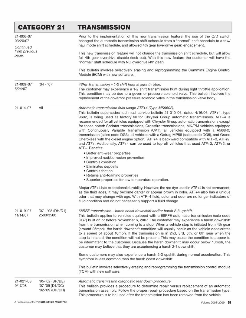
51A Publication of the TURBO DIESEL REGISTER Volume 2003-2009
CATEGORY 21 TRANSMISSION21-006-0703/20/07
Continued from previous page.
Prior to the implementation of this new transmission feature, the use of the O/D switch changed the automatic transmission shift schedule from a “normal” shift schedule to a tow/haul mode shift schedule, and allowed 4th gear (overdrive gear) engagement.
This new transmission feature will not change the transmission shift schedule, but will allow full 4th gear overdrive disable (lock out). With this new feature the customer will have the “normal” shift schedule with NO overdrive (4th gear).
This bulletin involves selectively erasing and reprogramming the Cummins Engine Control Module (ECM) with new software.
21-009-075/24/07
‘04 - ‘07 48RE Transmission – 1-2 shift hunt at light throttle.The customer may experience a 1-2 shift transmission hunt during light throttle application. This condition may be due to a governor pressure solenoid valve. This bulletin involves the replacement of the governor pressure solenoid valve in the transmission valve body.
21-014-07 All Automatic transmission fluid usage ATF+4 (Type MS9602).This bulletin supersedes technical service bulletin 21-010-06, dated 4/16/06. ATF+4, type 9602, is being used as factory fill for Chrysler Group automatic transmissions. ATF+4 is recommended for all vehicles equipped with Chrysler Group automatic transmissions except for those noted: Sprinter transmissions, Crossfire transmissions, MK/PM vehicles equipped with Continuously Variable Transmission (CVT), all vehicles equipped with a A568RC transmission (sales code DG3), all vehicles with a Getrag MP56 (sales code DG5), and Grand Cherokees with the diesel engine option. ATF+4 is backward compatible with ATF+3, ATF+2, and ATF+. Additionally, ATF+4 can be used to top off vehicles that used ATF+3, ATF+2, or ATF+. Benefits:
• Better anti-wear properties• Improved rust/corrosion prevention• Controls oxidation• Eliminates deposits• Controls friction• Retains anti-foaming properties• Superior properties for low temperature operation.
Mopar ATF+4 has exceptional durability. However, the red dye used in ATF+4 is not permanent; as the fluid ages, it may become darker or appear brown in color. ATF+4 also has a unique odor that may change with age. With ATF+4 fluid, color and odor are no longer indicators of fluid condition and do not necessarily support a fluid change.
21-019-0711/14/07
’07 - ’08 (DH/D1)2500/3500
68RFE transmission – harsh coast downshift and/or harsh 2-3 upshift.This bulletin applies to vehicles equipped with a 68RFE automatic transmission (sale code DG7) built on or before November 6, 2007. The customer may experience a harsh downshift from the transmission when coming to a stop. When a vehicle stop is initiated from 4th gear (around 25mph), the harsh downshift condition will usually occur as the vehicle decelerates to a speed of about 10mph. If the transmission is in 2nd, 3rd, 5th, or 6th gear when the stop is initiated, the condition will not be present. This may cause the condition to appear to be intermittent to the customer. Because the harsh downshift may occur below 10mph, the customer may believe that they are experiencing a harsh 2-1 downshift.
Some customers may also experience a harsh 2-3 upshift during normal acceleration. This symptom is less common than the harsh coast downshift.
This bulletin involves selectively erasing and reprogramming the transmission control module (TCM) with new software.
21-021-089/17/08
‘95-’02 (BR/BE)‘07-’09 (D1/DC)‘02-’09 (DR/DH)
Automatic transmission diagnostic tear down procedure.This bulletin provides a procedure to determine repair versus replacement of an automatic transmission assembly. Follow the proper repair procedure based on the transmission type. This procedure is to be used after the transmission has been removed from the vehicle.

52 A Publication of the TURBO DIESEL REGISTERVolume 2003-2009
CATEGORY 22 WHEELS AND TIRESTSB# MODEL SUBJECT/DESCRIPTION
22-001-0512/1/05
‘00 - ‘01 (BR/BE)‘02 - ‘06 (DR)
Chrome wheel care.This information-only bulletin discusses chrome wheel care. Chrome wheels should be cleaned regularly with mild soap and water or Mopar Car Wash Concentrate to maintain their luster and prevent corrosion. Wash them with the same soap solution as the body of the vehicle. Care must be taken in the selection of tire and wheel cleaning chemicals and equipment to prevent damage to wheels. Any of the “Do Not Use” items listed below can damage or stain wheels and wheel trim.
Wheel cleaners that contain hydrofluoric acid, biflouride compounds, sulfuric acid, or phosphoric acid.
• Any abrasive type cleaner.• Any abrasive cleaning pad (such as steel wool) or abrasive brush.• Any oven cleaner.• A car wash that has carbide tipped wheel-cleaning brushes.
22-005-0610/07/06
‘03 - ‘07 (DR/DH/D1/DC)
Front end shimmy on 4x4 vehicles when traveling over rough surfaces in the road.This bulletin applies to four wheel drive (4x4) 2500 and 3500 model vehicles. The customer may experience a self sustaining vibration (shimmy) felt in the front end of the vehicle after striking a bump or pothole. This bulletin involves verifying the condition of the vehicle front suspension and steering components, and adjusting the front tire pressure.
If the customer experiences the above condition, perform the repair procedure which includes a steering damper, tie rods and end links.
22-002-07Rev. A7/12/07
’08 (DH)2500
Tire pressure monitor system (TPMS) “Light Load” reset switch and tire rotation caution.This information-only bulletin provides information for new vehicle preparation, setting tire pressures, rotating tires and setting the light load switch on vehicles with the tire pressure monitoring system installed.
CATEGORY 23 BODYTSB# MODEL SUBJECT/DESCRIPTION
23-018-036/13/03
‘03 (DR) Instrument panel whistle.A whistling sound may be present coming from the front of the instrument panel near the bottom of the windshield when the heater A/C blower is on. This may be caused by air escaping through the holes in the center of the rivets that attach the VIN plate to the instrument panel. This can be mis-diagnosed as a windshield air leak. If necessary, remove the instrument panel top cover and apply a small drop of clear glass sealer to the center of each of the rivets to seal the rivet holes.
23-016-036/13/03
‘03 (DR) Buzzing or vibrating sound coming from the front of the vehicle.The description of the problem is a buzzing or vibrating sound coming from the front of the vehicle at highway speeds. Open the hood and inspect the ID plate located on the radiator support. The ID plate should be attached with four rivets. If there are only two rivets securing the ID plate, the ID plate may be vibrating against the radiator support. The repair involves securing the ID plate with additional rivets.
23-025-0310/24/03
‘03 (DR) Scratched aftermarket window tint film.Customers who have installed aftermarket window tint film see scratches on the film on the windows from contact with the door inner belt weather strip. Some vehicles may have been built with the weather strip not having a coating of soft protective flocking on the surface that contacts the window. The repair involves installing a revised door inner belt weather strip.

53A Publication of the TURBO DIESEL REGISTER Volume 2003-2009
CATEGORY 23 BODYTSB# MODEL SUBJECT/DESCRIPTION
23-001-041/13/04
‘03 (DR) Bug deflector wind whistle.Some vehicles equipped with a factory installed hood mounted bug deflector may exhibit a whistling sound coming from the front of the vehicle. The repair procedure involves installing foam tape to the bug deflector.
23-003-041/27/04
‘02 - ‘04 (DR) Water leak at grab handle.Water may enter the vehicle through the secondary door seal retainer or the roof seam, onto the headliner and run down the “A” pillar, coming out at the grab handle. The repair involves sealing holes in the roof panel.
23-004-04 ‘04 (DR) Cup holder binds or sticks.If the cup holder binds, will not open, or only opens partially, the instrument panel trim should be adjusted to provide clearance for the cup holder.
23-011-04 ‘03 - ‘04 (DR) Bug deflector loose/rattling.This bulletin applies to vehicles equipped with a factory installed bug deflector, sales code MXB. The bug deflector or air dam located on the front of the hood may become loose and rattle. The deflector could become dislodged in an automatic car wash. The repair involves replacing the bug deflector fasteners.
23-029-048/2/04
‘04 (DR) Binding front power window.This bulletin applies to vehicles equipped with trailer tow mirrors, sales code GPD or GPG. Vehicle owners may experience the power window on the front door binding or slow to operate. The corrective action involves lubricating the window channel and installing a spacer under the outside mirror.
23-005-051/31/05
‘03 - ‘04 (DR) Improved secondary door seal.Mud or dirt may accumulate on the rocker panel, causing customers to complain that their clothing gets dirty when they enter or exit the vehicle. This bulletin involves installing a new lower secondary door seal.
23-022-054/2/05
‘05 - ‘06 (DR) Low gloss interior trim.This information-only bulletin discusses that all Chrysler, Dodge, and Jeep vehicles are designed with a low gloss interior trim. This low gloss finish maintains pleasing aesthetics, and minimizes glare of the instrument panel into the windshield. This low gloss finish should not be altered with a medium or high gloss interior treatment solution such as MOPAR Protector’s or other Armor All-like products.
Instead, MOPAR Satin Select (part number 05174395AA) which has been specifically developed to remove minor surface contamination and maintain the low gloss appearance, should be used for interior trim treatment.
23-049-0510/12/05
‘04 - ‘05 (DR) Drip rail door seal torn.The drip rail or secondary door seal may become torn from contact with the lower “A” pillar of the front door. The repair involves replacing the secondary door seal with an improved seal.
23-009-062/14/06
‘04 - ‘05 Water leak at roof mounted marker lamps.Water leaks may be present coming from the roof mounted marker lamps. New marker lamps have been released which contain base gaskets. These marker lamps should be used in all cases where water leaks are present at the marker lamps. These lamps will have to be replaced in sets of five due to appearance differences. If water leak tests reveal that water leaks are present at the marker lamps, perform the repair procedure.

54 A Publication of the TURBO DIESEL REGISTERVolume 2003-2009
CATEGORY 23 BODY23-014-063/8/06
All Chrysler Group Vehicles
Windshield wiper blade maintenance.Windshield wiper blades/elements are frequently replaced unnecessarily. If the wipe pattern appears to be streaky or if there is chatter and no damage to the wiper blades/elements is obvious, the following steps should be performed:
• Use a soft cloth or sponge and squeegee and a solution of 50/50 alcohol and water, to wash the windshield.
• Raise the wiper blades off the glass and clean the wiper blade elements with a solution of 50/50 alcohol and water and a soft cloth, paper towel or sponge.
• Return the wiper blades to their normal operating position. If the wipe pattern is still objectionable, repeat several times. If the wipe pattern is still objectionable, replace the wiper blades/elements.
23-018-065/5/06
‘06 (DR) Speaker buzz.Customers may experience a buzzing sound coming from the door area when the radio is on. This bulletin involves adding insulating tape to the inner door and door trim panel.
23-004-0701/26/07
‘04 - ‘07 (DR) Transit film removal.This information only bulletin provides a transit film removal procedure.
23-021-06Rev. A08/09/06
‘07 (DR) YES Essentials stain, odor, and static resistant fabric care.This bulletin applies to vehicles equipped with YES Essentials stain, odor, and static resistant fabric (sales code XGW). YES Essentials fabric is an easy-care material that repels and releases soil to maintain the like-new appearance. Spills remain on the surface of the fabric to allow for easy clean up and to prevent stains and odors. The material is antimicrobial and static resistant.
YES Essentials fabric may be cleaned in the following manner:
• Remove as much of the stain as possible by blotting with a clean, dry towel.• Blot any remaining stain with a clean, damp towel.• For tough stains, apply Mopar Total clean, p/m 04897840AA, or a mild soap solution to
a clean damp cloth and remove the stain. Use a fresh, damp towel to remove the soap residue.
• For grease stains, apply Mopar Multi-purpose Cleaner, p/n 05127532AA, to a clean, damp cloth and remove the stain. Use a fresh, damp towel to remove the soap residue.
• Do NOT use any solvents or fabric protectants on Yes Essentials fabric.
23-047-0610/21/06
‘06 - ‘07 (DR/DH/D1) Cracked windshield.Windshield cracks caused by an impact from a foreign object (i.e. stone) are often difficult to identify. The following assessment should be used to verify the presence of an impact chip on the crack.
23-010-073/24/07
’06 - ’07 (DR/DH/D1)1500/2500/3500
Water leak due to small void in backlite sealer.The customer may experience the presence of water on or under the rear area floor carpet. This condition is likely due to water leaking past a small void in the adhesive used to retain the backlite glass to the body panel. It is recommended that a flowable sealer be applied to seal a small void in the backlite adhesive.
23-011-073/30/07
’06 - ’07 (DR/DH/D1)1500/2500/3500
Glass keeper loose on back power sliding window.The customer may notice that the glass keeper on the rear backlite has separated from the glass. The bulletin gives directions for the proper repair procedure.
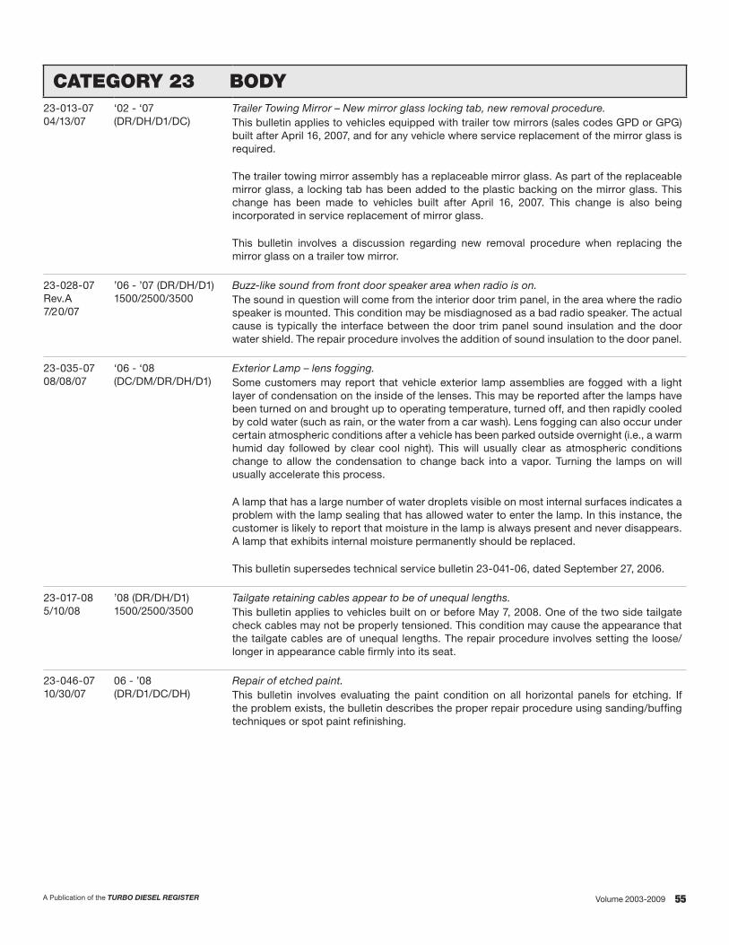
55A Publication of the TURBO DIESEL REGISTER Volume 2003-2009
CATEGORY 23 BODY23-013-0704/13/07
‘02 - ‘07(DR/DH/D1/DC)
Trailer Towing Mirror – New mirror glass locking tab, new removal procedure.This bulletin applies to vehicles equipped with trailer tow mirrors (sales codes GPD or GPG) built after April 16, 2007, and for any vehicle where service replacement of the mirror glass is required.
The trailer towing mirror assembly has a replaceable mirror glass. As part of the replaceable mirror glass, a locking tab has been added to the plastic backing on the mirror glass. This change has been made to vehicles built after April 16, 2007. This change is also being incorporated in service replacement of mirror glass.
This bulletin involves a discussion regarding new removal procedure when replacing the mirror glass on a trailer tow mirror.
23-028-07Rev.A7/20/07
’06 - ’07 (DR/DH/D1)1500/2500/3500
Buzz-like sound from front door speaker area when radio is on. The sound in question will come from the interior door trim panel, in the area where the radio speaker is mounted. This condition may be misdiagnosed as a bad radio speaker. The actual cause is typically the interface between the door trim panel sound insulation and the door water shield. The repair procedure involves the addition of sound insulation to the door panel.
23-035-0708/08/07
‘06 - ‘08(DC/DM/DR/DH/D1)
Exterior Lamp – lens fogging.Some customers may report that vehicle exterior lamp assemblies are fogged with a light layer of condensation on the inside of the lenses. This may be reported after the lamps have been turned on and brought up to operating temperature, turned off, and then rapidly cooled by cold water (such as rain, or the water from a car wash). Lens fogging can also occur under certain atmospheric conditions after a vehicle has been parked outside overnight (i.e., a warm humid day followed by clear cool night). This will usually clear as atmospheric conditions change to allow the condensation to change back into a vapor. Turning the lamps on will usually accelerate this process.
A lamp that has a large number of water droplets visible on most internal surfaces indicates a problem with the lamp sealing that has allowed water to enter the lamp. In this instance, the customer is likely to report that moisture in the lamp is always present and never disappears. A lamp that exhibits internal moisture permanently should be replaced.
This bulletin supersedes technical service bulletin 23-041-06, dated September 27, 2006.
23-017-085/10/08
’08 (DR/DH/D1)1500/2500/3500
Tailgate retaining cables appear to be of unequal lengths.This bulletin applies to vehicles built on or before May 7, 2008. One of the two side tailgate check cables may not be properly tensioned. This condition may cause the appearance that the tailgate cables are of unequal lengths. The repair procedure involves setting the loose/longer in appearance cable firmly into its seat.
23-046-0710/30/07
06 - ’08 (DR/D1/DC/DH)
Repair of etched paint.This bulletin involves evaluating the paint condition on all horizontal panels for etching. If the problem exists, the bulletin describes the proper repair procedure using sanding/buffing techniques or spot paint refinishing.

56 A Publication of the TURBO DIESEL REGISTERVolume 2003-2009
CATEGORY 23 HEATING & A/CTSB# MODEL SUBJECT/DESCRIPTION
24-003-035/23/03
‘90 - ‘04All Chrysler group products
A/C system additives.The use of A/C system sealers may result in damage to A/C refrigerant recovery/evacuation/recharging equipment and/or A/C system components. Many federal, state/provincial and local regulations prohibit the recharge of A/C systems with known leaks. DaimlerChrysler recommends the detection of A/C system leaks through the use of approved leak detectors available through Pentastar Service Equipment (PSE) and fluorescent leak detection dyes available through Mopar Parts. Vehicles found with A/C system sealers should be treated as contaminated, and replacement of the entire A/C refrigerant system is recommended.
24-004-036/13/03
‘03 (DR) Defrost/door inoperative.The defrost door may break at the pivot shaft, causing inadequate travel. The system may not completely close, causing a lack of air discharge out of the floor vents and full discharge from the defrost outlet. This may be caused by a broken actuator stop on the heater A/C (HVAC) housing. The bulletin describes the repair procedure for replacing the defrost door and the lower half of the heater/AC housing.
24-021-0512/16/05
‘06 (DR) Mega Cab – lack of air flow from rear seat heat duct.This bulletin applies to 2006 Ram Truck Mega Cab built between 8/29/2005 and 8/31/2005. The rear seat actuator rod could become disconnected from the actuator lever, causing the rear seat heater door to become inoperative. This bulletin involves replacing the rear seat heat duct actuator lever.
24-006-068/9/06
‘02 - ‘07 (DR) A/C cooling coil odor.This bulletin involves inspecting for leaves and other foreign material, cleaning, and treating the cooling coil and housing. Some vehicle operators may experience a musty odor from the A/C system, primarily at start up in hot and humid climates. This odor may be the result of microbial growth on the cooling coil. During normal A/C system operation, condensation, bacteria and fungi growth begins and odor results. If the operator describes, or the technician experiences, a musty odor when operating the A/C system, perform the appropriate repair procedure based on the vehicle model.

57A Publication of the TURBO DIESEL REGISTER Volume 2003-2009
RECALLS
The following are summaries of recall notices and satisfaction notifications that apply to various model year trucks. We have organized the information based on the bulletins’ release date. As is the practice with a recall, owners of record should have been notified directly by Chrysler. However, things do slip through the cracks, so we are printing reminders for you.
CUSTOMER SATISFACTION NOTIFICATON NO. C42 POWERTRAIN CONTROL MODULE CONNECTORS
Date: February 2004Models: ’03 (DR)
This notification applies only to trucks equipped with a 5.9-liter Cummins diesel engine (sales code ETC or ETH) and an automatic transmission (sales code DGP or DG8) built through July 9, 2003. The Powertrain Control Module (PCM) electrical connectors on about 70,000 of the above trucks may allow water to enter into the connectors. Water and the resulting corrosion in a PCM connector can cause the speed control and/or transmission overdrive function to become inoperative.
Repair: The three electrical connectors on the PCM must be removed and inspected for corrosion. If no corrosion is found, the connectors must be sealed by installing rubber O-rings onto the harness connectors.
If corrosion is found in the connector, the transmission wiring harness and PCM must be replaced.
CUSTOMER SATISFACTION NOTIFICATON NO. C44 TRANSMISSION COOLER LINE
Date: February 2004Models: ’03-’04 (DR)
This notification applies only to trucks equipped with a 5.9-liter Cummins diesel engine (sales code ETC or ETH) and an automatic transmission (sales code DG8 or DGP) built through November 24, 2003. The transmission cooler line on about 97,000 of the above vehicles can transmit high pressure pulses when the vehicle is operated at heavy loads. These pulses may cause the engine-mounted transmission cooler to crack and leak fluid which could result in significant transmission damage.
Repair: The transmission cooler line must be replaced on all involved vehicles. In addition, the engine-mounted transmission cooler must be inspected and replaced if necessary.
CUSTOMER SATISFACTION NOTIFICATION E10 FRONT SUSPENSION COIL SPRINGS
Date: July 2005 Models: ’05 (DH) Dodge Ram 3500 4x2 Pickup Truck
This notification applies only to the above vehicles built through May 27, 2005. Incorrect front coil springs may have been installed on about 8,100 of the above trucks’
front suspension. This may cause the front suspension to bottom out prematurely, which can reduce ride quality.
Repair: Both front suspension coil springs must be replaced.
SAFETY RECALL E17 OUT-OF-PARK ALARM SYSTEM
Date: March 2006 Models: ’03 – ’04 (DR); ’05 (DH)
This recall applies only to the vehicles equipped with a 5.9-liter diesel engine (6 or C in the eighth VIN Position) and an automatic transmission (sales code DGP or DG8). In certain circumstances when a driver has not placed the shifter lever fully into the “Park” position and leaves the engine running, the vehicle may unexpectedly move rearward after seeming to be stable. Unintended rearward movement of a vehicle could injure those in and/or near the vehicle.
Repair: An Out-of-Park alarm system must be installed on the vehicle. The alarm system will beep the horn and flash the headlamps and the shift indicator if a driver tries to exit a running vehicle without fully placing the shifter into the “Park” position.
CUSTOMER SATISFACTION NOTIFICATION F19 ROLL-OVER VALVE VENT HOSES
Date: June 2006 Models: ’06 (DH) Dodge Ram 2500 Pickup
and Cab-Chassis ’06 (D1) Dodge Ram 3500 Pickup and Cab-Chassis
This notification applies only to the above vehicles equipped with a 5.9-liter diesel engine (C in the eighth VIN position) built through February 1, 2006. The roll-over valves on about 69,300 of the vehicles may allow water to enter into the fuel tank. Excessive water in the fuel can damage the injection pump and/or injectors if the engine is off for an extended period of time.
Repair: A vent hose must be installed at each tank roll-over valve (ROV). The fuel system must be inspected for excessive water content. If excessive water is found, the water must be removed and the fuel filter must be replaced.
SAFETY RECALL F05 ANTILOCK BRAKE SYSTEM CONTROL MODULE
Date: July 2006Models: ’06 (D1) Dodge Ram Pickup (3500 Series)
’06 (DH) Dodge Ram Pickup (1500 Mega Cab and 2500 Series)
This recall applies only to the above vehicles equipped with a four-wheel Antilock Brake System (sales code BGK or BRT) built from September 12, 2005 through December 11, 2005.
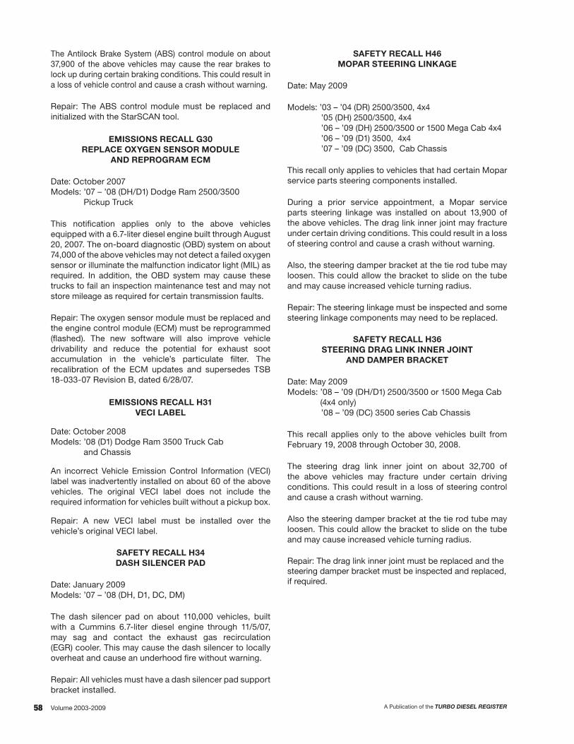
58 A Publication of the TURBO DIESEL REGISTERVolume 2003-2009
The Antilock Brake System (ABS) control module on about 37,900 of the above vehicles may cause the rear brakes to lock up during certain braking conditions. This could result in a loss of vehicle control and cause a crash without warning.
Repair: The ABS control module must be replaced and initialized with the StarSCAN tool.
EMISSIONS RECALL G30 REPLACE OXYGEN SENSOR MODULE
AND REPROGRAM ECM
Date: October 2007 Models: ’07 – ’08 (DH/D1) Dodge Ram 2500/3500
Pickup Truck
This notification applies only to the above vehicles equipped with a 6.7-liter diesel engine built through August 20, 2007. The on-board diagnostic (OBD) system on about 74,000 of the above vehicles may not detect a failed oxygen sensor or illuminate the malfunction indicator light (MIL) as required. In addition, the OBD system may cause these trucks to fail an inspection maintenance test and may not store mileage as required for certain transmission faults.
Repair: The oxygen sensor module must be replaced and the engine control module (ECM) must be reprogrammed (flashed). The new software will also improve vehicle drivability and reduce the potential for exhaust soot accumulation in the vehicle’s particulate filter. The recalibration of the ECM updates and supersedes TSB 18-033-07 Revision B, dated 6/28/07.
EMISSIONS RECALL H31 VECI LABEL
Date: October 2008 Models: ’08 (D1) Dodge Ram 3500 Truck Cab
and Chassis
An incorrect Vehicle Emission Control Information (VECI) label was inadvertently installed on about 60 of the above vehicles. The original VECI label does not include the required information for vehicles built without a pickup box.
Repair: A new VECI label must be installed over the vehicle’s original VECI label.
SAFETY RECALL H34 DASH SILENCER PAD
Date: January 2009Models: ’07 – ’08 (DH, D1, DC, DM)
The dash silencer pad on about 110,000 vehicles, built with a Cummins 6.7-liter diesel engine through 11/5/07, may sag and contact the exhaust gas recirculation (EGR) cooler. This may cause the dash silencer to locally overheat and cause an underhood fire without warning.
Repair: All vehicles must have a dash silencer pad support bracket installed.
SAFETY RECALL H46 MOPAR STEERING LINKAGE
Date: May 2009
Models: ’03 – ’04 (DR) 2500/3500, 4x4’05 (DH) 2500/3500, 4x4’06 – ’09 (DH) 2500/3500 or 1500 Mega Cab 4x4’06 – ’09 (D1) 3500, 4x4’07 – ’09 (DC) 3500, Cab Chassis
This recall only applies to vehicles that had certain Mopar service parts steering components installed.
During a prior service appointment, a Mopar service parts steering linkage was installed on about 13,900 of the above vehicles. The drag link inner joint may fracture under certain driving conditions. This could result in a loss of steering control and cause a crash without warning.
Also, the steering damper bracket at the tie rod tube may loosen. This could allow the bracket to slide on the tube and may cause increased vehicle turning radius.
Repair: The steering linkage must be inspected and some steering linkage components may need to be replaced.
SAFETY RECALL H36 STEERING DRAG LINK INNER JOINT
AND DAMPER BRACKET
Date: May 2009Models: ’08 – ’09 (DH/D1) 2500/3500 or 1500 Mega Cab
(4x4 only)’08 – ’09 (DC) 3500 series Cab Chassis
This recall applies only to the above vehicles built from February 19, 2008 through October 30, 2008.
The steering drag link inner joint on about 32,700 of the above vehicles may fracture under certain driving conditions. This could result in a loss of steering control and cause a crash without warning.
Also the steering damper bracket at the tie rod tube may loosen. This could allow the bracket to slide on the tube and may cause increased vehicle turning radius.
Repair: The drag link inner joint must be replaced and the steering damper bracket must be inspected and replaced, if required.

59A Publication of the TURBO DIESEL REGISTER Volume 2003-2009
LUBE OIL UPDATEISSUE 76 – TECHNICAL TOPICS
by Robert Patton and John Martin
A New Inquiry
Last October I received an e-mail from TDR member Desmond Rees:
I am looking for supplemental information following up John Martin’s article from Issue 57 on engine oil. The August 2007 article is somewhat dated. With the switch to the new API requirements for EGR/DPF diesel engines, are there plans to revisit this topic regarding the best engine oils meeting the API CJ-4 requirement? John’s article only looked at a handful of the CJ-4 oils and they ranked at the bottom of the pile when compared to the previous generation of oils. Thanks.Desmond Rees
My response: Prior to Desmond’s letter, there were no plans to revisit the topic. However, it has been five years and oils do change. I will purchase and test the CJ oils and John can comment on the data. We will see if John’s previous conclusion holds: “If it meets a spec, it becomes a commodity. Low price can be the purchase criteria. Change the oil based on the Owner’s Manual recommendations.”
Thanks to Desmond for the letter.
Background Information
It seems like just yesterday that I met lube oil expert John Martin and we collaborated on a series of articles about lube oils.
Ouch! As Desmond reminded me, “yesterday” was Issue 54 of the TDR, which was published in December of 2006. The four-part series that we wrote took a year to complete.
The reason behind the year-long series of articles was the forthcoming change from lube oil category CI+4 (an industry specification that was implemented in 2002) to the new category CJ. The CJ formula of oil was developed for the lower diesel exhaust emissions engines that were being implemented starting 1/1/2007.
I wondered how the lube oil would change. John Martin was the guy to tell me. (More about John in just a minute.)
In a lengthy telephone conversation he shared his opinion about the forthcomming CJ lube oil specification. Bottom line: John felt that the CI+4 oils were some of the best to come out of the respective refineries. In his discussions with those in the oil business, he had formed the opinion that the new CJ oils would not necessarily be new-and-improved.
As I noted, the CJ formula was developed for the new lower emissions diesel engines. From John I understood that the CJ oil would not necessarily be new-and-improved. Without analysis of the lube oils, I asked John what were the proposed changes from the highly acclaimed CI+4 to the new CJ oils. His response: “Robert, this is a lengthy topic, but it is very important for the audience to understand what is happening in the oil business.” So, I looked back to Issue 54 and made a couple of tweaks to its contents. The following is the updated text that gives you the insight that you need to understand the CI+4 to CJ change.
A Little Lube Oil History
Before we talk about what the additive industry and the oil companies have done to meet the EPA’s latest directive, we need a brief lube oil history lesson. Years ago diesels were operated on refined crude oils containing virtually no additive chemistry. As power density increased oil companies found they needed to add specific chemical compounds to the oil to provide performance attributes that crude oils couldn’t deliver. The additive industry was born.
Traditionally, each new diesel engine oil specification was issued because available oils couldn’t provide the lube oil performance needed. For example, API CE was issued to create oils which solved an oil consumption problem in Cummins NTC-400 engines. For fifty years each new diesel engine oil specification meant a better performing diesel engine oil was available—all the way from API CD to API CI+4.
Today diesel engine oils look like the example shown in figure 1. From 20 to 30% of modern diesel engine oil is additives designed to improve performance in key areas. These additives are carefully engineered mixtures of compounds formulated to pass the various diesel engine tests which define a new lube oil specification like the CI+4 or the new CJ.
Typical Diesel Oil Composition
Base Oils: 69-80%Performance Package 15-20%Viscosity Modifier: 5-10%Pour Point Depressant 0-1%

60 A Publication of the TURBO DIESEL REGISTERVolume 2003-2009
Pour point depressants are used to keep the oil fluid at very low temperatures. (They inhibit wax crystal formation.) Viscosity modifiers are used to make the oil thin out less as it is heated. This makes an oil which we call “Multigrade” and it simply means the multigrade oil acts like a thinner oil at low temperatures and a thicker oil at high temperatures. Multigrade diesel engine oils were a key part of the solution to the excessive oil consumption problem addressed by API formulation CE.
The performance additive package (see figure 2) is a mixture of 8-12 specialty chemicals, each of which is intended to impart specific properties to the oil’s performance. The important thing to remember here is that most additive chemicals (particularly detergents) deplete or wear out in service. This is one of the reasons why the oil must be changed. Life was good.
Typical Diesel Oil Performance Package
• Detergents Neutralize Combustion
Acids Minimize Wear Inhibit Rust Formation Oxidation Inhibitor
• Dispersants Prevent Agglomeration
of Soot Particles Suspend Contaminants
in Oil
• Oxidation InhibitorsRetard Oil DecompositionSlow Deposit Formation
• Anti-Wear AgentsCreate Sacrificial FilmBetween Metal PartsMinimize Valve Train Wear
• Foam InhibitorsPrevent Oil Foaming
What Did the EPA Do To Us/Why Do We Need CJ-4 Oils?
First, let’s discuss why this new oil was developed. The EPA tightened their exhaust emissions thumbscrew on diesel engines starting January 1, 2007, to reduce particulate matter (PM) and oxides of Nitrogen (NOx) emissions even further. To meet those requirements most diesel engine manufacturers resorted to the use of diesel particulate filters (DPFs). A DPF differs from the catalytic converters we have used for years on gasoline engines in that a DPF actually filters the entire diesel exhaust stream.
On the surface you wouldn’t think this would be a big deal—Europeans have been using DPFs for years. The difference is that Europeans don’t accumulate mileage like Americans and they will tolerate much more frequent service intervals. Our EPA has decreed that the new DPFs must go 150,000 miles before needing removal for cleaning. This means the soot collected in the DPF must be burned off in the exhaust system frequently if trap life is to exceed 150,000 miles without removal and cleaning.
Now, don’t take me wrong—I’m for a cleaner environment like everyone else is. The problem with the EPA is that they just decree which emissions will be reduced without once considering the cost, the technology needed or its effect on your operation. They refer to that as “Technology Forcing Legislation.” In the case of diesel engine oils, the EPA forced the adoption of a low-sulfate ash, phosphorus, and sulfur (low SAPS) oil whose technology hasn’t yet been proven extensively in the field.
I don’t have to tell you that diesel exhaust is relatively dirty. It consists of lots of soot (That’s what turns your oil black!) and unburned residues from both the fuel and the oil. Sulfur in the fuel can significantly hamper DPF performance. That’s why the ultra low sulfur diesel (ULSD) fuel was implemented 1/1/2007. Phosphorus and sulfur in the lube oil can shorten DPF cleaning intervals considerably. Phosphorus (P) can “glaze over” and plug the tiny holes in the DPF, making the openings effectively smaller and quicker to plug. Sulfur (S) can “mask” the DPF, making it temporarily less effective. Sulfated Ash (SA) in the lube is thought to build up deposits on the DPF over time. These deposits that originate from diesel fuel and lube oil then make the DPF effectively smaller and quicker to plug.
What does this mean to you?
Low P means the Feds placed a limit on the amount of Zincdithiophosphate (ZDP) additive which can be utilized. ZDP is the most effective oxidation inhibitor and anti-wear agent currently available. Additive manufacturers are now forced to use more expensive and less effective ashless oxidation inhibitors and anti-wear agents.
Low S means the new oils can’t rely on some of the least expensive Sulfur-based oxidation inhibitors used in the past. And, once again, many of the new ashless oxidation inhibitors haven’t been thoroughly field proven in heavily loaded trucks. Low S also means more highly refined base oils, which is a positive thing. Average base oil quality is now significantly improved.
Low SA (less than 1 percent weight) effectively places a limit on the amount of detergent which can be used in these oils. But diesels love detergents. In over 25 years of inspecting various diesel engines in the field, I’ve yet to see one which didn’t perform better on oils with higher levels of detergency.
So, What Oil Should I use?
If you have a diesel engine equipped with a DPF, you should probably use API CJ-4 oils. You really don’t have a choice unless you want to clean your particulate trap more frequently. Pay particular attention to oil change intervals.
I know that the major oil marketers are telling their customers that CJ-4 oils are backward compatible (you can use them in pre-2007 engines), and that is somewhat true. But if you use less detergent in an oil, your oil change interval should be shortened accordingly. Oil marketers don’t care if you have to change your oil more frequently—in fact, they love it! Remember oil companies are really in the business of moving as much base oil as possible. They love short oil change intervals.
In closing, remember to change your oil as frequently as possible, so we all can generate some more profits for those poor oil companies.
John R. Martin TDR Writer
61A Publication of the TURBO DIESEL REGISTER Volume 2003-2009
More About the Previous Series of Articles
Way back in Issue 54 I asked John how we might test the CI+4 oils and the new CJs. His response: “That’s easy: You spend the $25 for a complete oil sample evaluation. Be sure the test includes total base number (TBN) and viscosity—and send me the results. Don’t tell me what is what. Let’s see if there is an obvious difference and let’s see who makes the best lube oil(s). Who knows what we will find. Will purchasing a lube oil be as easy as purchasing a commodity? You know, as long as it meets a specification then it is ‘good,’ therefore you can shop for your lube oil based on price.”
Answers to these questions gave me the basis for an excellent article. So, the oil analysis kits were purchased, $25 x 22 kits ($550) and I went on a shopping spree for oil, $15 x 22 oils ($330). A cool $880, just so John and Robert would know about lube oils.
Earlier I stated that John was the oil expert. Prior to retirement he was an engineer at Lubrizol, one of the companies that makes and sells the additive packages to the oil manufacturers. And, at John’s stage in life, he was/is not beholden to anyone in the industry.
So, what conclusions could one draw from the year-long Martin and Patton examination of 22 different diesel lube oils? I’ve talked to many TDR members about the series of articles and each one has shared with me their own unique conclusion. Didn’t we all read the same article?
I have often stated that, “changing a person’s opinion about lube oils is like trying to change their opinion about religion. It is not going to happen.” My take-away from the year long, $880 expenditure (oops… perhaps John Martin has brainwashed me) is as follows:
Back in 1999, it took a series of oil analyses samples before I was comfortable changing my 3,000 mile change-the-lube-oil/guy-on-TV mentality. Then again, it took a series of 22 oil samples to change my mentality concerning lube oil by brand name versus lube oil as a commodity.
I’m on the same page as John Martin; if it meets the specification you can purchase oil like a commodity. Change the oil based on the Owner’s Manual recommendations.
LUBE OILS – VERSION 2012
Questions for 2012
So, the long answer to Desmond Rees has thus far taken 2.5 pages! However, I felt the background data was necessary before we just jumped into “Lube Oils—Version 2012.” The following are the questions I wanted John to help me answer:
Q1 Could I find the good stuff, an old CI-4 specification oil?
Q3 Who has the best “John Martin” oil for 2012?
Q2 How would the CJ-4 oils blended today compare with the same oil that we sampled back in the summer of 2007?
Q4 What has changed in the world of John Martin in these past five years?
The Oil Analysis for 2012
As mentioned, back in 2007 we tested 22 different brands of lube oils: everything from Amsoil to Walmart; Caterpillar to John Deere; Red Line to Liqui Moly. The prices ranged from low of Walmart’s Super Tech at $7.68 per gallon to the high of Red Line Diesel Synthetic at $35 per gallon. If you want the complete list of CI-4 plus and CJ-4 oils that were tested you’ll want to look back at Issue 58, pages 52 and 53.
Why 22 oils back then and only 10 oils for 2012? Remember my comment about lube oils, religion and the change of opinion? Well, my opinion has been changed! How so? A look back at Issue 56 gives you some insight into my mindset prior to the testing of the 22 lube oils. Here is the recap:
“When new lube oil is analyzed you can get a good idea of the quality of the additive package that, as learned from Martin’s experience, makes up 20–25% of the lube oil blend. Maintaining viscosity at higher temperatures, maintaining high alkalinity (total base number); and protecting against wear with the right blend of molybdenum, zinc, phosphorus and boron are important lube oil attributes. Readings for calcium are a way to measure dispersion detergency.
“In the blind-sampling-from-the-bottle done by Trailer Lifemagazine in January 2005, I was greatly disappointed to see that Walmart Super Tech 15W40 diesel oil stood toe-to-toe with other very respected brand names.
“Why disappointment? First, consider what John Martin said, ‘Consequently there is less and less difference between engine oil that barely passes the API certification test and one that is designed to pass by a significant margin. Therefore, oils meeting a given performance spec are approaching commodity status.’
“Second, I am not a big fan of Walmart. I could go into a long tirade, but I will refrain.
“Third, for all of my vehicle ownership years (let’s see, that is about 37 years) had I been duped? Had I fallen for the marketing hype? I did not want to believe that lube oil is just a commodity. Yet the Trailer Life grid did not lie.”
What story did the forthcoming TDR grid tell?
Had I fallen for the marketing hype? I did not want to believe that lube oil is just a commodity

62 A Publication of the TURBO DIESEL REGISTERVolume 2003-2009
The previous 22 brand oil test did give me an education. For 2012 I did not feel the need to test every lube oil in the marketplace. As a matter of fact, I only went to two places for the various oils, Autozone (where each oil was priced at $17.99) and Walmart. The following is the blind sampling data:
Sam
ple
Desc
riptio
n
Vis
cosi
ty @
100
°
TBN
Cal
cium
Mag
nesi
um
Pho
spho
rus
Zin
c
Bor
on
Mol
ybde
num
1 14.1 8.84 1050 777 975 1110 82 0
2 15.5 8.17 2183 9 1053 1152 3 1
3 15.1 8.69 1135 783 1020 1172 0 40
4 14.7 9.27 1299 837 941 1069 64 48
5 16.5 8.19 1412 395 1084 1250 503 89
6 15.5 9.15 1171 970 1088 1202 0 43
7 15.0 9.03 2209 10 1039 1156 35 0
8 15.1 9.09 2305 10 1077 1169 58 0
9 15.5 8.7 1134 787 1017 1169 0 40
10 14.3 9.22 770 1119 994 1171 60 58
Product Identification Chart
Item Product Viscosity Price
1 Mobil 1 (Syn) 5W40 $26.33
2 Motorcraft 15W40 20.99
3 Walmart 15W40 10.97
4 Mobil Delvac 15W40 17.99
5 Chevron Delo 15W40 17.99
6 Valvoline 15W40 17.99
7 Shell Rotella 15W40 17.99
8 Castrol Tection 15W40 17.99
9 Warren 15W40 14.99
10 Shell Rotella (Syn) 5W40 27.99
And now, the answers for Lube Oils – Version 2012:
A1) I could not find any CI-4 lube oil.
A2) I’ll turn this answer over to John Martin. John’s response:
Robert and TDR audience, remember my often-used statement, “Diesels Love Detergents”? It appears from the oil analysis data that Samples 4, 5, 6, 7, 8, and 10 all have total base numbers (TBN) in excess of 9, which suggests to me that these oil marketers are trying to provide as much TBN as possible given the 1.0% weight sulfated ash limitation imposed by the API CJ-4 specification. They are doing this to satisfy those fleets whose oil change intervals are based on TBN depletion.
Samples 2 and 5 have the least amount of detergency of the oils tested. Sample 5 uses either a borated detergent or a boron-containing oxidation inhibitor. Borated detergents are thought by some to be more effective than traditional detergents. It is also possible that data in the last two columns for sample 5 has been transposed. (Editor’s note: the 503 and 89 numbers are as printed by the lab.)
My field test experience has taught me that calcium (Ca) detergents are more effective than magnesium (Mg) detergents, so, to answer question 2, “Who has the best oil for 2012?” I think oils 7 and 8 would be the best of the oils you surveyed. Oils 4, 6, and 10 also have high TBN values for CJ-4 oils, but they depend heavily on magnesium detergents, so I don’t think they would yield diesel performance as good as oils 7 and 8.
Oils 1, 4, 5, 7, 8, and 10 all contain boron, but I’m certain that the additive chemistry in sample 5 is different than the others (or the last two columns of data for sample 5 have been transposed). Boron oxidation inhibitors are evidently being utilized to improve the high temperature performance of these CJ-4 oils.
Now, if you allow me to look at the number-to-product identification report I can tell you that oil 5 has been completely reformulated, and I know why. Chevron Delo 400 is the most widely used oil in big trucking fleets. When CJ-4 came about, fleet operators told Chevron they preferred the old CI-4 oil, particularly when they found out that Chevron was going to ask more money for their CJ-4 oil. Neither Chevron nor the fleets would budge off their positions, and big marketers like Chevron only want one oil in their distribution systems. Chevron went back to the drawing board, reformulated, and retested until they could pass the API CI-4 tests with a CJ-4 oil. Then they dropped both earlier oils out of their systems and offered only the new, improved CJ-4 oil. I wonder if the big fleets paid them more money for the new oil?
Mobil and Shell also supply a lot of oil to truckers. If you compare sample 1 (a consumer oil, Mobil 1 synthetic) with sample 4 ((Mobil Delvac) you can see that Mobil added more detergency to oil 4 (Ca and Mg) to give their big fleets increased TBN and keep them happy. Fleets wouldn’t use the Mobil oil in Sample 1. The Shell samples (7 and 10) are also very interesting. Shell is using different additive chemistry in their 15W40 (Rotella mineral, sample 7) than in their 5W40 (Rotella synthetic, sample 10). I’m guessing that the big fleets are mostly purchasing oil 7. I do not know why the chemistry is so different in oil 10, other than perhaps another additive supplier was able to pass the tests, allowing Shell to get the credentials they desired.
So, once again, my picks are oils 7 and 8. If you religiously adhere to your manufacturer’s recommended oil change intervals, oil 3 would be the best performer on a cost per mile basis. Oils 1, 2, and 10 offer the highest cost per mile, so I would avoid them altogether.
A3) Now, let’s compare the 2007 oils to the 2012 oils. I asked Robert to save you from going back to Issue 58 and present a comparison chart for you.

63A Publication of the TURBO DIESEL REGISTER Volume 2003-2009
The CJ-4 Lube Oils Tested in Issue 58 were:
Shell Rotella T 15W40Castrol Tection 15W40Chevron Delo 400 LE 15W40Cummins/Valvoline Premium Blue 15W40
The following chart gives you the “Then and Now” candidates:
Pric
e
Desc
riptio
n
Vis
cosi
ty @
100
°
TBN
Cal
cium
Mag
nesi
um
Pho
spho
rus
Zin
c
Bor
on
Mol
ybde
num
$10.96 Shell Rotella T 15.7 8.77 2488 8 1108 1147 37 2
17.99 Same 2012 15.0 9.03 2209 10 1039 1156 35 0
10.80 Castrol Tection 14.7 7.74 2011 6 876 1035 0 0
17.99 Same 2012 15.1 9.09 2305 10 1077 1169 58 0
12.99 Chevron Delo 400 LE 15.7 7.82 1593 416 1156 1268 83 570
17.99 Same 2012 16.5 8.19 1412 395 1084 1250 503 89
9.98 Cummins/Valvoline 15.6 8.42 1109 827 994 1041 0 41
17.99 Same 2012 15.5 9.15 1171 970 1088 1202 0 43
Now, to compare the 2012 results to the 2007 table, it appears that Shell has dropped their ZDP content by 10% in oil 7. Before interpreting data from this type of analysis remember that repeatability of these numbers is no better than 10%. Looking at the data in that light, two things could have happened in the last five years. Either the ZDP level could have been dropped 10% to enable Shell’s additive supplier to put more detergent in the oil to increase TBN levels, or the data is on the outer edge of the repeatability limits. When comparing today’s Shell oils, it looks to me like Shell may be using a different ZDP than they did in 2007.
But, audience, did you notice from your 2007 to 2012 comparative data that all of the oils cost more in 2012? Whether or not the oil marketer changed his initial CJ-4 formulation, he has managed to use the new credentials as a vehicle to raise the selling price of their oils significantly. As I said before, I don’t know if oil marketers are getting more for their CJ-4 oils at major fleets, but they are certainly getting more from retail consumers. (Editor’s note: I looked back to November 2007 and a barrel of crude oil was $88, today it is $106.) You and I get to pay for everything!
A4) What has changed in John Martin’s world in the last five years?
For one thing, I spend much more time researching alternate fuels than diesel lube oils these days. Everyone wants to just jump into the future, be green and reduce our dependence on foreign sources of crude oil without even considering what these moves will do to the poor people who design the vehicles and systems that will have to make that happen.
For example, the public is finally beginning to discover that corn-based ethanol containing fuels (one of the worst jokes of the modern era) are actually worse than gasoline regarding greenhouse gas (GHG) emissions. It has taken the do-gooders billions of our tax dollars to discover what they’ve been told long ago by
fuels researchers. The California Air Resources Board (CARB), a bastion of the most radical environmentalists in the world, has actually had their low carbon fuel standard (LCFS) overturned by a Federal judge.
Secondly, remember how the do-gooders tell us we should all be driving the Toyota Prius (Pious)? The latest GHG emissions research has shown that power plants are responsible for more GHG emissions than transportation vehicles. Where did the do-gooders think that electricity was coming from? Was it magic? Left-wing environmentalists never let facts get in the way of a good story. These are the same radicals who are currently stalling the Keystone pipeline project which could bring much needed crude oil from the North to refineries on the Gulf Coast. After the OPEC countries, China, and Hugo Chavez purchase all that valuable Canadian crude, we will decide to build the pipeline. Our environmentalists are getting to the point where they are very destructive. (My political rant is over. Don’t send the editor hate mail.)
Our next new diesel lube oil spec (currently called PC-11) will occur sometime around 2015. The Federal government recently decreed that diesel trucks must provide significantly better fuel economy by 2016. The Engine Manufacturers Association (EMA) has already asked the lube oil industry for some improved fuel economy (FE) oils by 2015 so they can be field tested prior to production. Since the major fuel economy differences are observed by lowering oil viscosity, expect to see some very thin (5W30, 5W20) diesel oils in 2015. Very thin oils probably won’t work well in current engines. (More about that in future TDR magazines?) This, too, won’t be as easy as the EPA activists think it will be, but, as long as your tax money will hold out, they will be asking you to finance this research.
John Martin TDR Writer

64 A Publication of the TURBO DIESEL REGISTERVolume 2003-2009
ADD OIL HERE/PC-11 AND CK-4 UPDATE
ISSUE 83 – TDREVIEW
ADD OIL HEREby Robert Patton
Every now and then you’ll stumble across an automotive writer that clicks with you. (See Motojournalism Connection, pages 4-7.)You find that their stories convey what you would say if you had their literary talent. Some of my favorite writers: the TDR’s very own Greg Whale (all things automotive, Whale’s “been there, done that”); Kevin Cameron (Kevin can make a nut and bolt into a fascinating story) and Mark Barnes (Mark’s writings have reinforced that I’m not the only one that enjoys the solitude of a workshop); Peter Egan from Road & Track and Cycle World (Egan’s writings can make a trip to the 7-11 store into an adventure); and Peter DeLorenzo from Autoextremist.com (his automotive rants/insights challenge the norm).
A quick story about Greg, Kevin, and Mark.
Back in the early days of the TDR (think 1994 for Greg Whale, 1996 for Kevin Cameron, 1998 for Mark Barnes) I was on the lookout for writers that could bring their insight to our new member/club organization. To reach these writers, I sent a request to their respective editors asking if I could contact them. As I have come to learn, automotive and freelance writing is not the glamor job you might envision, and the editors were willing to grant me access to these talented writers. After all, the TDR did not compete with the titles that Greg, Kevin or Mark were writing for. So, now you know the TDR writer story.
Oops, I’m a little off track.
I have here before me a story from Cycle World written by Egan that reminded me of the oil change woes that many of us have encountered with the 2013-and newer Turbo Diesel trucks. However, unlike the TDR’s Donnelly, Roberts, Redmond or Langan that give you the steps to perform the task, Egan tells the oil change story of the average Joe, complete with a handful of mistakes.
Here are just a few excerpts from the story that will help me transition into a humorous story that was told to me by our very own Greg Whale.
Egan’s original article in Cycle World was titled “Zen and the Art of the Oil Change.” He starts the story with a long introduction and then a question from a CW reader:
“These days, a lot of younger, less experienced riders come up to me and say, ‘Mr. Egan, you have an almost legendary reputation for being able to change the oil and filter on your motorcycles without spilling more than about 30 percent of the oil onto the garage floor or your own clothing. How the heck do you do it?’”
Next Egan gives the audience the step-by-step process that he used to tell this tale:
“Step 1: Place a ‘suitable container’ under the sump or oil reservoir—which, in the Buell’s case, is in the hollow swingarm above the end of the muffler—and remove the plug. A stream of scalding hot oil will run down over the rear of the muffler and cascade into the pan, like Niagara Falls in a nightmare. Some will run down to the far end of the muffler and onto the floor. Or trickle warmly down your forearm and into your sleeve.
“Step 2: While oil is dripping from the drain hole and muffler, remove the small chin fairing and place another pan under the oil filter. Remove the filter with a web-type tool and stand back as oil from the engine and filter run over the front of the muffler and into the pan. Much of the oil will follow the bottom of the muffler and run onto the floor. Expect some to drip off the filter wrench onto your blue jeans. Accidentally drop the slippery, hot filter into the pan for a nice splash effect.
“Step 3: Carefully fill the new filter with oil, spilling hardly any at all, then screw it into the engine and put the drain plug back in. Here’s where you give the drain pan an accidental kick so that a small tidal wave of oil flops onto the floor. Then refill the reservoir using a funnel with too small an opening so that it overflows immediately and burps oil onto the swingarm. Before putting the chin spoiler back on, use massive amounts of contact cleaner/degreaser to clean up the muffler and floor, along with ecologically friendly piles of oil-soaked paper towels.
“Step 4: Carry the main oil drain pan across the workshop and dump it down a large funnel into a disgustingly filthy, oil-streaked, red-plastic five-gallon gas can with the words ‘DRAIN OIL’ scrawled across it so people don’t accidentally drink from it.
“Step 5: Check to make sure this can isn’t already almost full. Otherwise, about two quarts of dirty drain oil will well up around the sides of the funnel and run onto the floor, as mine did. Expect some oil to run down the back side of the pouring spout on the drain pan and drip onto your running shoes.
“Step 6: Mop up the oil spill with more paper towels and wring them out over your drain pan. Clean the whole area with half a spray can of contact cleaner, but don’t breathe any of the fumes. When everything is cleaned up, start the bike and check it for oil leaks. Mine was fine; not a sign of a drip.

65A Publication of the TURBO DIESEL REGISTER Volume 2003-2009
“Step 7: Wipe your tools carefully, put them away and then go into the house. Throw all your clothes—including the running shoes—into the washer and then take a shower. Put on clean clothes and return to the workshop to have a beer and ponder the evening’s work. Now, you’re done.
Peter Egan Cycle World
A “Zen” moment as the editor-dude changes the oil in his EcoDiesel. (Like it’s big brother, it holds almost three
gallons.) The unattended drain bucket almost overflowed.
As mentioned, I wish I could tell a story like that. The best I can do is to add a footnote to his yarn. From TDR’s Greg Whale: “Dear Mr. Egan, please add steps 3a and 3b.
“3a: As you are pouring fresh oil into the engine make a note that the fresh oil ($8/quart) is leaking from the location of the oil drain plug. Oops, it’s not leaking, it is pouring. STOp ADDING FRESh OIL!
“3b: Rush to install the oil drain plug.”
Now, in fairness to the folks at Cycle World and to peter Egan, I have to give credit where the credit is due. You can find all of Egan’s books from his Cycle World days and from his Road & Track editorials by doing a quick search at Google for your favorite place to shop for books or go directly to Amazon.com.
The “Zen” quotes came from Egan’s book “Leanings 3: On the Road and in the Garage with Cycle World’s peter Egan.
While you have your computer fired-up, take a few minutes to log onto www.cycleworld.com and start a new subscription! You’ll not be disappointed.
Enjoy Mr. Egan’s writing. Buy one (or all) of his books. Subscribe to Cycle World. I’m hopeful my endorsements prompt you to make a purchase. Again, some great reading material, you won’t be disappointed!
Robert Patton TDR Staff
While we’re on the subject of lube oil...
The Motojournalism thing, combined with excerpts from Mr. Egan and Greg Whale tie-in give you a humorous look at the mundane oil change(s) that we all have to endure. I can only imagine those of you guilty of Steps 3a and 3b, myself included.
Now, let’s move on to the serious look at oil in the news, the new lube oil specifications that will be introduced in December. In the update that follows, our oil-guru, John Martin, tells us about the new CK-4 and FA-4 oils.
Robert Patton TDR Staff
PC-11 UPDATEor
You’re Getting Something Besides Red Socks for Christmas
by John Martin
If you readers will recall, I thoroughly discussed the upcoming new engine lube oil performance category, PC-11, in October of last year, TDR Issue 89. I mentioned that the API (American Petroleum Institute), the ASTM (American Society for Testing of Materials) and the SAE (Society of Automotive Engineers) were feverishly working to develop two new diesel engine oil performance categories as requested by the EMA (Engine Manufacturers Association) to improve diesel engine fuel economy. This is part of our nation’s greenhouse gas (GHG) reduction effort.
Well, folks, on December 1, 2016, it’s finally going to become a reality. This will be a major change for the diesel engine oil market for several reasons.
First, there will be two new performance categories, API CK-4 (PC-11A) for existing diesel engines and API FA-4 (PC-11B) for new/post 2017 engine designs which will tolerate lower viscosity oils. (Viscosity is still the most important parameter influencing both fuel economy and horsepower.)
API CK-4 is no big deal, other than the cost and time it takes to develop a new diesel engine oil. Current estimates are that it costs over one million dollars to develop a new oil even if it passes all the required laboratory tests the first time out. And that doesn’t count the time and money it takes to field test the new product in a variety of engines in different types of service. In this day and age, you need at least two to three years of field testing to feel comfortable about the performance of any new diesel engine oil.
Now, the new FA-4 oil is creating quite a stir for several reasons. Oil marketers get very nervous when someone suggests putting an FA-4 oil in an older engine design with looser engine clearances, yet having to spend millions of dollars to develop a product to be used on only 2017 and later engine designs doesn’t fully justify the tremendous expenditures involved.

66 A Publication of the TURBO DIESEL REGISTERVolume 2003-2009
So both end users and oil marketers will want to see how many other engines the FA-4 oils can safely be used in to maximize their investment. In the end it will probably be up to each engine manufacturer to determine which of their engines can tolerate FA-4 oils without sacrificing engine service life. Big Oil will want you to put this oil in everything to simplify logistics, but most end users will want to make sure FA-4 oils don’t void their warranties. It’s a shame oil marketers didn’t better educate the end users ahead of time so they could make more intelligent selections.
Due to the extremely high costs associated with developing and marketing two completely new oils, many oil marketers are taking a closer look at product line simplification. ConocoPhillips, for example, currently markets four diesel engine oils under its brand umbrella, Conoco, Kendall, Phillips, and 76 Lubricants. To minimize developmental and marketing costs, they have decided to drop the Conoco and 76 Lubricants brands from their diesel engine oil lineup.
I’m sure other oil marketers are either reducing product lines or having a brand represent only one of the new oils. For example, Shell, which has both their Rimula and Rotella brands, also owns Pennzoil and Quaker State. Will they eliminate some oils from this complicated lineup? I predict that both Rimula and Quaker State won’t offer the full range of FA-4 products to minimize expenditures.
It’s going to be fun with a lot of to-ing and fro-ing. Take the time to carefully read the API label on the container (see examples). Note that the FA-4 label will be shaded to make it stand out a little. API CJ-4 oils will continue to be produced and marketed for at least a year before that performance category is obsoleted. The CK-4 oils shouldn’t pose any problems for you.
Who knows, once there is product available (both CK-4 and FA-4), I might have the TDR guy go on a spending spree so we can check the composition of all these new-fangled oils and see what is really best for your truck.
John Martin TDR Writer
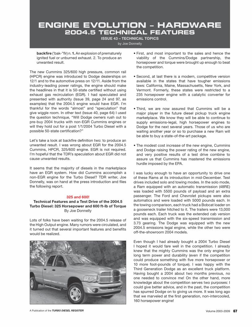
67A Publication of the TURBO DIESEL REGISTER Volume 2003-2009
ENGINE EVOLUTION – HARDWARE 2004.5 TECHNICAL FEATURES
ISSUE 43 – TECHNICAL TOPICSby Joe Donnelly
backfire (‘bak-”fIr) n. 1. An explosion of prematurely ignited fuel or unburned exhaust. 2. To produce an unwanted result.
The new Cummins 325/600 high pressure, common rail (HPCR) engine was introduced to Dodge dealerships on 12/1 and to the automotive press on 12/11. Aside from the industry-leading power ratings, the engine should make the headlines in that it is 50-state certified without using exhaust gas recirculation (EGR). I had speculated and presented with authority (Issue 39, page 24 and 97, as examples) that the 2004.5 engine would have EGR. I’m thankful for the words “almost” and “speculation” that give wiggle room. In other text (Issue 40, page 64) I used the question technique, “Will Dodge owners rush out to pre-buy 2004 trucks with non-EGR Cummins engines or will they hold out for a post 1/1/2004 Turbo Diesel with a possible 50-state certification?”
Let’s take a look at backfire definition two: to produce an unwanted result. I was wrong about EGR for the 2004.5 Cummins, HPCR, 325/600 engine. EGR is not required. I’m hopeful that the TDR’s speculation about EGR did not cause unwanted results.
It seems that the majority of diesels in the marketplace have an EGR system. How did Cummins accomplish a non-EGR engine for the Turbo Diesel? TDR writer, Joe Donnelly, was on hand at the press introduction and files the following report.
325 and 600!Technical Features and a Test Drive of the 2004.5
Turbo Diesel: 325 Horsepower and 600 ft-lb of TorqueBy Joe Donnelly
Lots of folks have been waiting for the 2004.5 release of the High Output engine. Many rumors were circulated, and it turned out that several important features and benefits would be realized.
• First, and most important to the sales and hence the viability of the Cummins/Dodge partnership, the horsepower and torque were brought up enough to beat the competition.
• Second, at last there is a modern, competitive version available in the states that have tougher emissions laws: California, Maine, Massachusetts, New York, and Vermont. Formerly, these states were restricted to a 235 horsepower engine with a catalytic converter for emissions control.
• Third, we are now assured that Cummins will be a major player in the future diesel pickup truck engine marketplace. We know they will be able to continue to supply emissions-legal, high horsepower engines to Dodge for the next several years. Those of us who are waiting another year or so to purchase a new Ram will be able to buy a state-of-the-art package.
• The modest cost increase of the new engine, Cummins and Dodge raising the power rating of the new engine, and very positive results of a test drive combine to assure us that Cummins has mastered the emissions hurdle imposed by the EPA.
I was lucky enough to have an opportunity to drive one of these Rams at its introduction in mid-December. Test drives included solo and towing modes. In the solo mode, a Ram equipped with an automatic transmission (48RE) was loaded with 5500 pounds of payload and an extra passenger. The Ford and Chevrolet pickups were also automatics and were loaded with 5000 pounds each. In the towing comparison, each truck had a Bobcat loader on a gooseneck trailer hitched to it. The trailers were 13,000 pounds each. Each truck was the extended cab version and was equipped with the six-speed transmission and 3.73 gearing. The Dodge was equipped with the new 2004.5 emissions legal engine, while the other two were off-the-showroom 2004 models.
Even though I had already bought a 2004 Turbo Diesel I hoped it would fare well in the competition. I already knew that the mighty Cummins was the only engine for long term power and durability (even if the competition could produce something with five more horsepower or 10 more foot-pounds of torque). I was happy with the Third Generation Dodge as an excellent truck platform. Having bought a 2004 about two months previous, no one needed to convince me! On the other hand, more knowledge about the competition serves two purposes: I could give better advice, and in the past, the competition has spurred Dodge on to giving us more. It was long ago that we marveled at the first generation, non-intercooled, 160 horsepower engine!

68 A Publication of the TURBO DIESEL REGISTERVolume 2003-2009
Two press releases are reproduced here, one from Dodge, and one from Cummins:
Dodge Dominates
Dodge, the brand that revolutionized the diesel pickup market when it launched the state-of-the-art 1989 Dodge Ram, Cummins Turbo Diesel, announced today the 2004.5 Dodge Ram Heavy Duty Cummins “600” with a class-dominating 600 lb.-ft. of torque at 1,600 rpm and 325 horsepower at 2,900 rpm. Equipped with the new Cummins “600,” the Dodge Ram Heavy Duty takes its position at the head of the heavy-duty pickup segment.
“The Dodge Ram dominates in every category,” said Darryl Jackson, Vice President, Dodge Marketing, Chrysler Group. “With the new Ram Heavy Duty Cummins ‘600,’ the Ram family of trucks now includes the strongest heavy-duty pickup available, the fastest production pickup with the 150 mph Dodge Ram SRT-10, and the most powerful, mass-produced light-duty pickup, the HEMI-powered Dodge Ram 1500. This is an exciting time for Dodge.”
In addition to the most torque ever available in a production heavy-duty pickup, the Dodge Ram Heavy Duty Cummins “600” boasts best-in-class towing capability of 16,400 lbs. (a 3,000 pound advantage over the Ford F-350 PowerStroke), a payload of 5,020 pounds and a best-in-class Gross Combined Weight Rating (GCWR) and Gross Vehicle Weight Rating (GVWR) of 23,000 pounds and 12,000 pounds, respectively. Additionally, the new Cummins “600” generates its peak torque of 600 lb.-ft. at 1,600 rpm, earlier than either Ford’s PowerStroke or Chevrolet’s Duramax diesels. The new Cummins “600” delivers an 80 lb.-ft. torque and 25 horsepower advantage over Chevrolet Duramax and is priced just $135 more than the previous Cummins High Output Turbo Diesel. The Standard Output Cummins Turbo Diesel is dropped from the Ram Heavy Duty line-up.
“The Ram Heavy Duty has the most sophisticated chassis in the segment, the biggest brakes, excellent handling and class-exclusive safety features such as side curtain air bags,” said Eric Ridenour, Executive Vice President Product Development. “It is only fitting that it now has the most powerful diesel engine. This is also the quietest Ram diesel ever and the first High Output Cummins Turbo Diesel that meets 50-state emissions requirements.”
Do More, Get the Job Done
The names Dodge Ram and Cummins are synonymous with power, durability and quality. All are characteristics that made the Dodge Ram Heavy Duty Motor Trend’s 2003 Truck of the Year and merited a best-in-class rating for the Cummins-powered Dodge Ram Heavy Duty in the J.D. Powers 2003 Initial Quality Survey, surpassing both Ford PowerStroke and Chevrolet Duramax.
With real-world customers in mind, the re-designed 5.9-liter Cummins “600” powerplant not only meets 50-state emissions requirements, but was designed to be even tougher with premium exhaust valves and seats, high-strength exhaust manifolds, gallery cooled pistons and an oil bath turbo system.
Built for high-mileage customers who need the most capability available, the new Cummins “600” delivers best-in-class oil change intervals of 15,000 miles (versus 7,500 for the competition) and is the only heavy-duty diesel pickup pre-equipped for an exhaust brake. The Ram Heavy Duty Cummins “600” is also capable of zero-throttle launches, enabling smooth drive-offs under load with the six-speed manual transmission. An automatic transmission is also available with the new Cummins “600.”
“Our goal during the development of the Cummins ‘600’ was to make meaningful changes, not just chase numbers,” said Frank Klegon, Vice President, Truck Product Team. “The Ram Heavy Duty Cummins ‘600’ delivers more torque and power where our customer needs it, under a full load and heading up a steep grade. We designed the Ram Heavy Duty Cummins ‘600’ for the severe use customer, and for them, torque is everything. Dodge is also the only heavy-duty pickup manufacturer confident enough in our product to offer a seven year, 100,000 mile powertrain warranty.”
And now from Cummins:
Frank Kelgon, Dodge Vice President, Truck Product Team, giving us a talk on the 2004.5 Ram.
A cut-away engine is also in the tent.
Cummins Inc. announced today that its next-generation turbo diesel engine will be supplying the power to the 2004.5 model year Dodge Ram Heavy Duty pickup, launching in January 2004.
The re-engineered Cummins 5.9-liter diesel engine builds on the power and quality of the 2003 model year engine that helped make the Dodge Ram Motor Trend magazine’s “Truck of the Year.” The Cummins engine for the Dodge Ram also merited a best-in-class rating in the J.D. Power 2003 Initial Quality Survey.

69A Publication of the TURBO DIESEL REGISTER Volume 2003-2009
“We are excited to supply this engine for the new Dodge Ram,” said Joe Loughrey, Cummins President – Engine Business. “We have built upon the proven performance and reliability of our previous engine, and engineered the new Cummins turbo diesel to provide more power and torque with reduced noise, while meeting tougher emissions standards. We think our customers will love the new Dodge/Cummins package.”
The launch of the 2004.5 Dodge Ram is the latest collaboration between the two companies, which have been partners since 1988 when Dodge first offered the Cummins engine option. Earlier this year, Cummins celebrated production of the one-millionth Dodge Ram engine, which is made at the Company’s Walesboro, IN, facility.
In October the Company announced the extension of its agreement as the exclusive supplier of diesel engines for the Dodge Ram. The agreement also includes consideration of Cummins as a supplier for the diesel engine after treatment system, which would be provided by Fleetguard, a wholly-owned Cummins business unit.
Market Data
First, let’s summarize some product features and marketing data for the Turbo Diesel Ram:
Dodge expects that the new 2004.5 Heavy Duty Ram will meet and beat the competition for the title of most powerful heavy duty pickup. The new Cummins “600” is rated 325 horsepower, 600 foot-pounds of torque. It meets emissions requirements for all fifty states. For forty-five states, the increase is 20 horsepower and 45 ft-lb of torque over the previous 2003-2004 model HO engine. For California, Maine, Massachusetts, New York, and Vermont, the increase is a tremendous 90 horsepower and 140 ft-lb torque, because these five states were formerly restricted to the standard output Cummins engine with 235 horsepower, 460 ft-lb torque, and a catalytic converter (3” exhaust head pipe and converter inlet). Furthermore, the peak torque is lower at 1600 rpm than the competition, and is designed for improved towing capability at moderate rpm. The previous five-state 235 horsepower engine required oil changes at every 3,750 miles (Schedule B) or 7,500 miles (Schedule A) while the 250 horsepower and 305 horsepower engines sold in the other 45 states needed oil changes at 7,500 miles (Schedule B) or 15,000 miles (Schedule A). Soot levels in the new engine are so low that oil change intervals are driven not by soot but by oxidation and acid numbers.
Ram payloads are now up to a maximum of 5,220 pounds, with a gross vehicle weight rating (GVWR) of 12,200 pounds (with proper equipment). Gross combined weight ratings are as much as to 23,000 pounds, with a trailer weight of up to 16,400 pounds.
Surveys of the percentage of pickups remaining on the road for the past twenty years have shown the Ram to be the longest lasting pickup on the market. Ram has the largest brakes, and largest standard wheels and tires in the heavy-duty pickup truck segment.
The Ram comes with either the iron-case New Venture 5600 six-speed manual transmission or the Chrysler 48RE four-speed automatic transmission. Both transmissions include overdrive. The 48RE also includes a “Tow-Haul” button on the shift lever. This feature locks out overdrive and locks the torque converter clutch. If you engage Tow-Haul at speeds above 50 mph, the transmission will shift or stay in third gear and the converter will lock. If you shift the transmission manually to second gear when you slow down to below 50 mph, the transmission will shift down to second gear with locked torque converter.
Sales of the Ram are up 13% for the year. Ram 2500 and 3500 models account for a third of overall Ram sales. Currently, the Ram holds 28.4% of the heavy duty diesel market. Ram holds the J.D. Powers 2003 Initial Quality Survey best-in-class rating. About 73% of the Heavy Duty Rams are Cummins powered, and about 70% of the Heavy Duty Rams are four wheel drive.
2004.5 Component Changes
Now, let’s take a look at the changes made to the 2004.5 Ram to accommodate the new Cummins “600” engine.
The engine fan shroud is now engine mounted, with soft plastic seals to the radiator assembly. Mounting the shroud onto the engine allowed a tighter clearance to the fan blades for improved forced air flow and cooling. The area in front of the air cleaner box is shrouded with an air blocker so that hot air off the radiator and from recirculation inside the engine compartment cannot pass to the air cleaner. Dodge claims an improvement of 30 to 40 degrees in inlet air temperature. The fan clutch calibration is different, to reduce fan roar and to improve cooling. The turbocharger air intake system has been refined with a new “resonator,” or air baffle. A hood insulator has been installed (absent in the past few years of Rams). With a new design catalytic converter the exhaust system is now a full four inches in diameter throughout. The truck is configured to be compatible with the use of an exhaust brake, even with the 48RE automatic transmission. The intercooler is new, with higher flow. The end plates and hose connections are plastic.
This picture is the 2004.5 engine compartment. Note the engine-mounted fan shroud and the blocker
panel to the left and in front of the air cleaner box.

70 A Publication of the TURBO DIESEL REGISTERVolume 2003-2009
Underneath view showing the catalytic converterjust beyond the transfer case.
Both Dodge and Cummins spent considerable time controlling noise, vibration, and harshness (NVH). The result is a truck platform with the best manners ever (as we will discuss later in this article), far better than the competition.
2004.5 Engine Changes
Further, let’s discuss the changes made to the Cummins engine, focusing on the changes made from the former 305 horsepower product in order to produce the new 325 horsepower engine that meets emissions requirements for all fifty states.
The primary means to control emissions on the new engine are inside the combustion chamber. Exhaust gas recirculation (EGR) is not used. This change represents a major advance from the interim approach, with use of EGR, taken in 2002 to meet federal EPA emissions regulations for the medium-duty truck market with the B-engine. The engine system becomes significantly simpler. Fifty-eight new part numbers have been required to implement EGR as a part of the emissions strategy. Only seven new emissions part numbers are needed for the new approach used on the 325/600 engine. A diesel oxidation catalyst (catalytic converter) is employed. The pilot injection/primary injection strategy has changed significantly. Formerly, a small pilot injection was followed by the larger injection event; at higher loads and above 2000 rpm, a single injection event would be used. In the new engine, two or three events are used. The pilot injection is larger, and when under power a post-event is added. These events are part of the emissions and power strategy, as well as a means to noise reduction. The engine control module now contains 550 kilobytes of code for engine control, while the previous 305 horsepower HO engine used only 350 kilobytes.
The Cummins noise control strategy includes carry-over of the straight-cut gears from the previous HO. The Bosch CP3 high pressure fuel pump is quieter than the former VP44 and P7100 injection pumps, which suffered noise-producing torque-reversals. Rubber isolators have been added to the valve cover hold-down bolts. Overall, the engine is a little quieter, with less rattle and a deeper tone.
The new cylinder head has revised ports with less swirl. High-cobalt stellite valve seats are used with high strength inconel valves. The forged steel connecting rods with cracked-cap technology are carried over from the 305 horsepower engine. These rods pass exactly the same strength and durability tests as the former, machined cap rods, while providing more rigidity than the former units. The exhaust manifold material and shape has been slightly revised for durability, and multi-layer gaskets are used between the manifold and head. The piston bowls are slightly more open. The cooling passages for the piston rings are carried over from the 305 horsepower HO engine.
Other testing involved the equivalent of five million miles of driving.
The turbocharger remains an HY-35, but with a new, large compressor wheel and housing for increased air flow. The wastegate has an electronic controller to better match boost pressure to engine needs for optimized emissions control. The turbo shaft bearings have small oil reservoirs under them to improve oiling on cold start- up. The oil drain tube is flexible steel, replacing the former system of two rigid steel tubes connected by a hose with two worm-drive clamps. This oil drain and the new exhaust gaskets were developed as a result of their successful use in heavy duty engines.
Engine testing included 22,000 hours on the dynamometer, much of it at full power. For example, a standard Cummins engine test involves running the engine at full power for one thousand hours straight. Other testing involved the equivalent of five million miles of driving. Two such tests were the Lap of America and the Lap of Indiana. The former test is a run of 50,000 highway miles with the truck loaded to its gross combined weight rating. The latter test is a run of 100,000 miles at 4,300 miles per week, at slow speeds with the vehicle loaded to its gross combined weight rating.
Lap of Indiana testing.

71A Publication of the TURBO DIESEL REGISTER Volume 2003-2009
Driving the Diesels, Towing 13,000 Pounds
For common comparison, each truck was an extended cab, dually,
long bed with six-speed manual transmission and 3.73 axle ratio. The three trailers were identical, each with a Bobcat loader chained down to it. Each truck had a properly functioning electric trailer brake controller. All three trucks were near new. The Dodge/Cummins and the Ford PowerStroke met 2004.5 emission specs while the Chevrolet Duramax will need a catalytic converter to met the January 2004 EPA emissions specifications. The Ram and its competitors were driven over the same course, downhill and up again, through turns and stops, and through a radar speed trap to show us the maximum speed that the vehicle and trailer could achieve on a fairly steep hill. Part of the test was a standing start test in low and in second gear, uphill on a moderate grade.
This picture shows the three trucks set up for the towing test. Each loaded trailer weighs 13,000 pounds and is
mounted to the truck with a gooseneck hitch.
The Ram handled solidly and felt very safe at 45-50 mph going downhill. The exhaust brake engaged quietly and could hardly be heard at an idle or on the road. It did give just the right amount of braking effort for this load and a rather steep hill. The Ram service brakes were excellent and gave me tremendous confidence. The Other testing ride was smooth and tight; the steering felt stable, like full weight was still on the front wheels. I easily started the rig in first gear and even in second from a stop, going uphill. I did not have to touch the accelerator pedal, or smoke the clutch. At the radar unit, the rig was going 45 mph uphill at full power in fourth gear.
The Ram handled solidly and felt very safe at 45-50 mph going downhill.
The Ford had a rather jarring ride, and handling felt “on the edge” in the curves. Every bump in the road caused bouncing and jumping. The driver needed to have a strong stomach and back. The truck constantly reminded me that it was heavy duty and I was not! The brakes were not good, just okay. The rig was difficult to start from a stop going uphill. Even in first gear, I had to slip the clutch quite a bit
and carefully modulate the accelerator pedal. Otherwise, the engine stalled, regardless of the care I took. The ZF aluminum cased transmission was louder than the Dodge NV5600. I was especially unhappy with the difficult, notchy shift from first to second. Almost all of the momentum gained in the low gear was lost in the time it took to shift. The rig achieved 41 mph at the radar unit. I gained several other impressions about the Ford that I want to relate.
The Ford had a rather jarring ride, and handling felt “on the edge”
in the curves.
The ignition key release button is difficult to operate, especially if you are not in the seat and just reaching across from outside the truck. The idle is rattly, and transitions to quiet just off idle. However, under load and release, a “machine gun” rattle comes back, like pouring BB’s onto a steel dish. The transmission/gear train is noticeably louder than the Ram’s. The shifter is too close to the driver and the seat in first gear. Overall, the shifter moves too much going through its pattern. Ford/Navistar needs both a catalytic converter and exhaust gas recirculation to meet the easier 2004.5 emission standards. An especially troubling problem occurs if you give the engine some accelerator pedal at a stop in neutral. First the engine goes to 2000 rpm, or greater. Then without any driver input, it runs away clear to the red-line rpm (4000). From pulling the trailer, it seemed that there was no advantage to the last 500 rpm going to the 4000 rpm red line. The power curve was moderately good, but more peaky than the Ram. In other words, the Ford needed to get up in rpm much more than the Ram to pull the load.
The Chevrolet Duramax is not for a truck enthusiast.
The Chevrolet Duramax is not for a truck enthusiast. Even in first gear, it was difficult to start the rig going uphill on the modest grade without stalling. Second gear starts were completely out of the question. Handling was definitely “on the edge” going through downhill curves, and the brakes were not even close to confidence- inspiring. The best I could get through the radar unit was 33 mph. The engine and drivetrain emitted a variety of unhappy noises, growls and whines, with lots of fan noise. As the radar showed, power was poor. The redline was about 3000 rpm, and you had to be near there to get any power.

72 A Publication of the TURBO DIESEL REGISTERVolume 2003-2009
Driving the Diesels, loaded with 5000 pounds in the bed.
These trucks were extended cab, dual wheel, one-tons with automatic transmissions. The route consisted of a downhill section followed by a twisty narrow uphill road. The Ram was tight, controlled, and felt like the load was not at all severe. Handling was very good. No creaking or groaning on turns was experienced. Power going through the curves was good, and a good speed could easily be maintained with minimal experience.
The Ford handled noticeably less well, and emitted some creaking on making a turn where the rear suspension had to flex sideways. The engine gave a loud and distracting whine/howl on acceleration. Handling and braking were fair. The truck is suited to those who feel high brand-loyalty to Ford and gratefully accept whatever Ford is willing to give them. Many of them have no experience with the Third Generation Dodge Ram, so they don’t know any better.
Once again, the Chevrolet was generic and did not inspire any confidence in the power, handling, or braking departments. It creaked and groaned in the side-flex curve, and made a lot of noise when the driver begged for power. Perhaps the low power was a blessing, because hitting the brake pedal seemed to be only a mild suggestion to the truck that it needed to slow down. Actually, my main concern was not whether the brakes worked—they did a fair job—but the pedal went almost to the floor even pushing on it at a stop. Using the clutch was not easy, because a large box is bolted to the floor just above and to the left of the clutch pedal. I hit it several times with my foot and was unable to depress the clutch pedal fully when that happened. The handling was rather sloppy and the suspension seemed soft, particularly with the weight in the bed.
In distinct contrast to the competitors, the Ram was rather quiet, with a deep hum or growl on acceleration. There was no creaking or groaning, and the load did not seem to upset the truck’s tight and solid manners in accelerating, stopping, or negotiating curves. Oh, just to slap the competition a bit, the Dodge had an extra passenger and an extra 500 pound slab in the bed. Dodge’s homework spent on the 48RE was apparent in the better manners exhibited by the transmission in shifting and in transferring power through the torque converter.
Concluding Driving Impressions of the Cummins 325/600 Turbo Diesel
Beforehand, I was concerned about drivability. The concerns were groundless. I remembered the 1970s when emissions controls caused the gasoline powered engines to hesitate, have flat spots in the power curves, have much lower power, run roughly, etc. Driving the new Ram, you would never know that it meets the most stringent emissions regulations ever written. Smoothness, lack of extraneous noises, power, and drivability are inherent characteristics of this engine. Even meeting
tougher specifications than the competition, sthe engine’s performance is far superior. The Cummins starts, runs, and pulls like a textbook example of what a diesel engine should be. In my opinion, the others act like children’s drawings of illustrations in that textbook.
The Ram has come up to a very high level of performance and quality as well. The other brands should now be ashamed of their poor brakes. Such brakes were the standard ten years ago, but need not be tolerated any more in a new truck. The Dodge rides like it is a half-ton with a rally suspension. The others ride and handle like an old truck is expected to ride. The Ford is like an old three-quarter ton, and the Chevy rides like an old half-ton.
Folks, I expected the comparisons to be close, and hoped the Ram would shade the competition—maybe with some buyer preferences to help. As it turned out for me, I see no need to say much about personal preferences regarding placement of controls, shape of the instrument panel, exterior styling, or fit and finish. I happen to be very happy with my 2004 Turbo Diesel in those respects, but I never got to those considerations in these tests. Fundamentals and objective measurements were all that were needed for me to formulate my opinions, and overrode the “kinder and gentler” issues for making a purchasing decision. I feel that the Ford was well below the Dodge Ram, even on the most simplistic, objective considerations. For me, the Chevrolet was not even in the running. A Chevy buyer would seem to be someone who hates to drive a truck and expects the experience to be unpleasant. Chevy does not disappoint or surprise such a buyer, in my opinion. I found the Ford platform to be somewhat primitive in comparison to the Ram in capabilities and in noise-vibration-harshness. The Chevy engine was very disappointing. The Ford 6.0 liter Power Stroke engine was a distinct second in power and smoothness. It needed a lot more rpm to perform, and was peaky in power. Shifting gears took you out of the power band too quickly. It was noisy, and the noise came and went disconcertingly. The tentative connection between the accelerator pedal and the engine’s response/rpm did not inspire confidence when letting out the clutch.
Joe Donnelly TDR Writer TDR Issue 43
A view of the tent where the talks were given and four parked Rams.

73A Publication of the TURBO DIESEL REGISTER Volume 2003-2009
As the model year 2005 Turbo Diesel is being introduced (and, as of this printing, is a full five-months into production), I reflected back three years to the unveiling of the Third Generation 2500/3500 truck at the Chicago Auto Show in February of 2002.
The look back in time, combined with a trip to Cummins’ home town of Columbus, Indiana, provided an idea for an updated TDR article on the Cummins high-pressure, common-rail (HPCR) engine.
As I prepared for the trip to Columbus, several thoughts came to mind. To organize my review, I jotted down the topics I wanted to cover. An article updating the HPCR should include the following topics.
• Emissions: past, present, future• Ratings: past, present, future• Engine Hardware: past, present, future• Engine Software: past, present, future• Product Launch: past, present, future
With my topic outline in hand I journeyed to Cummins to get for our TDR readers this exciting “2005 Cummins Engine Update.”
The new legend – the Cummins HPCR Engine.
EMISSIONS: PAST, PRESENT, FUTURE
Any in-depth article on diesel engines has to include a discussion of exhaust emissions. In model year 2002 the Third Generation Dodge Ram 1500 truck was introduced with gasoline engine power. Diesel customers had to wait for the 2003 truck model year. At the time there was much speculation about the reason the 2500/3500 series trucks were not introduced at the same time. Was there a dramatic difference in the body vis-à-vis Ford and their 150 truck offering being totally different than their 250/350 trucks? Was the hold-up due to upcoming diesel emissions legislation and the need to give Cummins more time to finalize their HPCR engine? Or, was the delay of the 2500/3500 simply an instance of the staggered-launch marketing tactic that is frequently used by manufacturers? The speculation is over and the answer is “a finalized HPCR engine and staggered-launch marketing.”
Moving back on topic, the 2003 Cummins HPCR engine was introduced prior to the impending and tighter 1/1/2004 exhaust emissions standards.
Looking back to Issue 40 we find a comprehensive article that summarizes exhaust emissions over a 22 year period—1985 to 2007. In the article we took time to describe the hardware changes required byl emissions legislation that was enacted in ’88, ’91, ’94, ’98, ’04 and soon to be ’07.
Emissions — past, present, future: if you care to read the details, please refer to your Issue 40 magazine. The next issue of the magazine will have a detailed “Technical Topics” discussion of the pending ‘07 regulations.
RATINGS: PAST, PRESENT, FUTURE
Publishing the past and present ratings for your Turbo Diesel is as easy as making a chart. The horsepower and torque numbers make good copy, but you’ll note from the chart that there are two additional columns, “CPL and Comments.”
The comments column is self explanatory.
CPL is a Cummins abbreviation that stands for “control parts list.” The CPL provides a comprehensive breakdown of performance hardware, i.e. pistons, turbo, camshaft, injectors, and fuel pump that were used in the engine build. The CPL number along with the Cummins engine serial number will help your Cummins parts professional should you need engine hardware.
ENGINE PERFORMANCE EVALUATIONS
ISSUE 47 – TECHNICAL TOPICSby Bill Stockard and Robert Patton
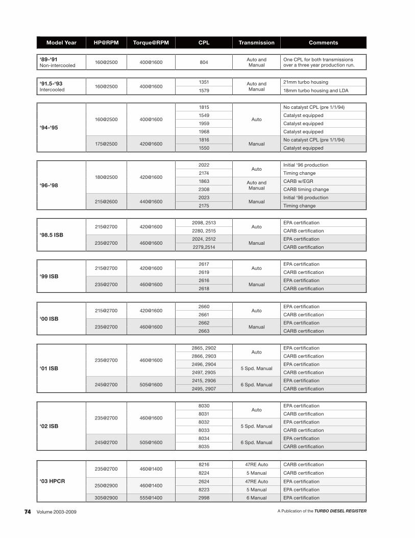
74 A Publication of the TURBO DIESEL REGISTERVolume 2003-2009
Text.Model Year HP@RPM Torque@RPM CPL Transmission Comments
‘89-‘91 Non-intercooled
160@2500 400@1600 804 Auto and Manual
One CPL for both transmissions over a three year production run.
‘91.5-‘93 Intercooled
160@2500 400@16001351 Auto and
Manual
21mm turbo housing
1579 18mm turbo housing and LDA
‘94-‘95
160@2500 400@1600
1815
Auto
No catalyst CPL (pre 1/1/94)
1549 Catalyst equipped
1959 Catalyst equipped
1968 Catalyst equipped
175@2500 420@16001816
ManualNo catalyst CPL (pre 1/1/94)
1550 Catalyst equipped
‘96-‘98
180@2500 420@1600
2022Auto
Initial ‘96 production
2174 Timing change
1863 Auto and Manual
CARB w/EGR
2308 CARB timing change
215@2600 440@16002023
ManualInitial ‘96 production
2175 Timing change
‘98.5 ISB
215@2700 420@16002098, 2513
AutoEPA certification
2280, 2515 CARB certification
235@2700 460@16002024, 2512
ManualEPA certification
2279,2514 CARB certification
‘99 ISB
215@2700 420@16002617
AutoEPA certification
2619 CARB certification
235@2700 460@16002616
ManualEPA certification
2618 CARB certification
‘00 ISB
215@2700 420@16002660
AutoEPA certification
2661 CARB certification
235@2700 460@16002662
ManualEPA certification
2663 CARB certification
‘01 ISB
235@2700 460@1600
2865, 2902Auto
EPA certification
2866, 2903 CARB certification
2496, 29045 Spd. Manual
EPA certification
2497, 2905 CARB certification
245@2700 505@16002415, 2906
6 Spd. ManualEPA certification
2495, 2907 CARB certification
‘02 ISB
235@2700 460@1600
8030Auto
EPA certification
8031 CARB certification
80325 Spd. Manual
EPA certification
8033 CARB certification
245@2700 505@16008034
6 Spd. ManualEPA certification
8035 CARB certification
‘03 HPCR
235@2700 460@14008216 47RE Auto CARB certification
8224 5 Manual CARB certification
250@2900 460@14002624 47RE Auto EPA certification
8223 5 Manual EPA certification
305@2900 555@1400 2998 6 Manual EPA certification
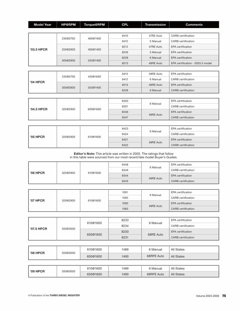
75A Publication of the TURBO DIESEL REGISTER Volume 2003-2009
Model Year HP@RPM Torque@RPM CPL Transmission Comments
‘03.5 HPCR
235@2700 460@14008410 47RE Auto CARB certification
8412 5 Manual CARB certification
250@2900 460@14008212 47RE Auto EPA certification
8226 5 Manual EPA certification
305@2900 555@14008228 6 Manual EPA certification
8213 48RE Auto EPA certification - 2003.5 model
‘04 HPCR
235@2700 420@16008412 48RE Auto EPA certification
8412 6 Manual CARB certification
305@2900 555@14008213 48RE Auto EPA certification
8228 6 Manual CARB certification
‘04.5 HPCR 325@2900 600@1600
83506 Manual
EPA certification
8351 CARB certification
834648RE Auto
EPA certification
8347 CARB certification
‘05 HPCR 325@2900 610@1600
84236 Manual
EPA certification
8424 CARB certification
842148RE Auto
EPA certification
8422 CARB certification
Editor’s Note: This article was written in 2005. The ratings that follow in this table were sourced from our most recent/late model Buyer’s Guides.
‘06 HPCR 325@2900 610@1600
83486 Manual
EPA certification
8349 CARB certification
834448RE Auto
EPA certification
8345 CARB certification
‘07 HPCR 325@2900 610@1600
10916 Manual
EPA certification
1095 CARB certification
100048RE Auto
EPA certification
1083 CARB certification
‘07.5 HPCR 350@3000
610@16008233
6 ManualEPA certification
8234 CARB certification
650@16008230
68RE AutoEPA certification
8231 CARB certification
‘08 HPCR 350@3000610@1600 1489 6 Manual All States
650@1600 1490 68RFE Auto All States
‘09 HPCR 350@3000610@1600 1489 6 Manual All States
650@1600 1490 68RFE Auto All States

76 A Publication of the TURBO DIESEL REGISTERVolume 2003-2009
ENGINE HARDWARE: PAST, PRESENT, FUTURE
While I was writing the piece on the previous sub-topic and reviewing the material on exhaust emissions printed in Issue 40, I noted that the HPCR engine was also covered there in great detail.
I faced a dilemma. Should I reprint the engine information from Issue 40 or simply direct the reader back to its pages? I could not overlook the fact that TDR has added many new members in the past two years. My decision—for the benefit of both longtime and new readers—was to reprint the timely information on engine hardware from Issue 40, but to omit the dismal numbers in Issue 40’s recitation of exhaust emissions regulations.
What appears immediately below incorporates the engine information from Issue 40 with text from Issue 43 on the ’04.5 engine and recent information on changes in ’05 HPCR engine hardware.
The ‘03–‘05 HPCR Cummins Engine
First things first. The emission numbers: for 2004 the Federal NOx changed from 4 to 2.4. The 2.4 number is actually a combination of NOx and non-methyl hydrocarbons. California pulled up the NOx standard and implemented a 3.0 number effective in late 2002. The California number parallels the Federal NOx of 2.4 that was forced on the six Consent Decree manufacturers (Cat, Mack, Detroit Diesel, Volvo, Navistar and Cummins) as they were required to meet the 2004 standard early. Their effective implementation date was 10/2002. The Dodge pickup engine was exempt from the 10/2002 early implementation (Issue 32, page 85). The particulate number of 0.1 stayed the same for 2004.
Horsepower Changes
Torque Changes
As you can note from the graph, horsepower has been steadily increased over the years beginning with 160 horsepower and 400 ft-lbs of torque in 1989 to the 325 horsepower and 610 ft-lbs of torque with the 2005 engine. The 2005 engine is matched up to the NV5600 six-speed manual transmission or the 48RE automatic transmission.
In early 2004 the California engine was rated at 235 horsepower and 460 torque. This engine was matched to the NV5600 six-speed manual transmission or the 48RE automatic transmission. Other states got the high-output 305/555 engine with the NV5600 or 48RE transmissions. As a mid-year release (’04.5) Dodge and Cummins made the 325/600 engine the standard for all 50-states.
In 2003 the standard engine was rated at 250 horsepower and 460 torque. This engine was matched to the NV4500 five-speed manual transmission or the 47 RE automatic transmission. The high-output 305/555 engine was matched to the NV5600 six-speed transmission or the 48RE automatic transmission.
In 2003 trucks sold in California were available with a 235 hp/460 torque (CARB) version of the engine. This lower rating was necessary because of a tighter oxides of nitrogen standard (three grams per brake horsepower hour) and was achieved through the use of an oxidation catalyst (similar to the one used on all 12-valve engines from ’94 to early ’98), engine control module programming, and smaller injectors.
I faced a dilemma. Should I reprint the engine information
from Issue 40 or simply direct the reader back to its pages? I could not overlook the fact that TDR has added many new
members in the past two years.

77A Publication of the TURBO DIESEL REGISTER Volume 2003-2009
Text.As an aside, we often receive a phone call complaing that “My new ’05 truck (or 2001, or 1998—pick your model year) just doesn’t get the same fuel economy as my old, trusty ’91 truck. What gives?” There are legitimate complaints that need mechanical attention, but the obvious answer to the smaller discrepancies lies in the progression of power. The new 2005 engine is rated 165 horsepower greater than the initial ’89 through ’93 engines. Torque on the engine is 210 ft-lbs greater. The ’98 24-valve engine boasted 55 horsepower and 20 ft-lbs torque (automatic) or a 75 horsepower and 60 lb-ft torque (five-speed) increase. If you use the additional power, should the fuel economy stay the same?
Back to the subject at hand, the HPCR engine. The HPCR engine was another evolutionary step in the 5.9 liter, B-series platform that was introduced back in 1983. However, two-thirds of the HPCR engine is new or redesigned. The lion’s share of the new hardware had to do with the fuel injection system. The engine uses a HPCR fuel system from Bosch. Although new to us here in the United States, Cummins has used the HPCR fuel system in Europe since 2001. This track history helped eliminate product concerns that owners might have had.
Parts Carryovers
Let’s start the analysis by listing the carryover parts from the previous 5.9 liter engine. Purists will be pleased that the engine’s bottom-end hardware, the crankshaft, connecting rod and bearing assemblies, are the same as the previous, proven, 24-valve engine. Other carryover parts include:
• Head bolts• Water pump• Oil pump• Camshaft• Valve train• Critical fasteners (head, rod and flywheel bolts)
New Designs
As we have noted, the biggest change to the engine in 2003 was the use of the Bosch HPCR fuel system. The system has rail pressure of 23,200 psi (1600 bar) on the high output engine. The change in the fuel system netted a reduction of 8-10 db of noise. Additionally, the ability to better control injection timing and pilot injection provides an extended rpm peak torque band over previous engines (200 rpm lower and higher). The lift/supply pump is located on the side of the motor right next to the fuel filter and is an all-new design supplied by Federal-Mogul.
Instead of an injection pump (previous VP44 electronic for 24-valve engines, or P7100 and VE mechanical pumps for 12-valve engines) that sequences high-pressure fuel to injectors at the proper time, the new fuel pump supplies a common rail with high-pressure fuel, which is, in turn, fed to the individual injectors. The injectors deliver the pressurized fuel to the cylinders as the result of a signal from the engine control module, not as a result of a pulse of high pressure from the pump.
All in all, the HPCR fuel system brought the following attributes to the engine:
• Gear-driven fuel pump delivers high pressure fuel supply to a common rail
• Fuel delivery through electronically controlled unit injectors
• Multiple injection events (pilot, main, post injection)• Higher injection pressures—up to 1600 Bar• Timing, pressure and quantity less dependent on
engine speed
As a result the owner can expect:
• Cleaner combustion• Improved power and engine response• Improved cold start capability• Lower noise• Lower vibration and harshness
Of course, the new fuel system drives changes throughout the engine. The cylinder head maintains a four-valve per cylinder design. However, the new cylinder head has induction hardened valve seats, on both intake and exhaust, to handle the higher temperatures and pressures.
The change to the HPCR fuel system drove several changes to the engine block. The block now incorporates sculpted side walls to stiffen the block. This change was necessary as the stiffer block is needed to help withstand the higher peak cylinder pressures needed for emissions control and power requirements. Additionally, it aids in noise reduction by absorbing noise. An engine’s bedplate was also designed and added to the engine for less noise and greater durability.
The ‘03 and ‘04 standard-output engines continued to use saddle jets located in the upper main bearing saddles to spray the connecting rods and the pistons.
The 2005 and previous 305 horsepower High Output engines use a system that includes a component called a “J-jet” for each piston. The J-jet nozzle is bolted to the block and directs a stream of oil to the underside of the piston. The 2005 and previous HO pistons have a passageway to direct the flow of oil through the piston head to cool it. The 2005 and previous HO engines also have an exhaust manifold that is capable of higher exhaust temperatures.
The J-jet piston cooling nozzle.

78 A Publication of the TURBO DIESEL REGISTERVolume 2003-2009
Underside of the HO piston. Note the passageway for oil to flow through the piston.
Underside of the standard piston.
Cummins has taken measures to reduce the amount of dead space in the combustion chamber. The head gasket is now measured and matched (graded) based on block height and cylinder head thickness. During assembly a machine measures piston protrusion and, based on the measurement, a thick or thin headgasket is chosen for assembly. Get the picture that meeting emissions standards is serious business?
Further, the HPCR fuel system necessitated changes to the engine’s front gear train. New high contact-ratio spur gears result in quieter operation.
The turbo on all versions of the engine is an HY35 with a 9cm2 exhaust housing. This turbo has been redesigned from previous HY35’s. Exhaust exits the turbo at 3.5” and flows to a 3.5” muffler inlet. The exhaust is now a full 4” system from the muffler to the tail as opposed to the previous 3” system. The turbo has an intake silencer to eliminate high frequency, blade pass noise. There is closer tolerance control of the turbo’s critical components.
Specifications for turbocharger boost pressure are numbers that TDR members carefully watch. An engine that achieves its specified number is an engine that will deliver its advertised horsepower numbers. The wide open throttle boost specifications: ‘03 and ‘04 standard engine, 22-24 psi; 2005 and previous HO engines, 25-26 psi.
Other Changes
Besides changes to the engine, let’s take a look at some of the hardware codifications.
In the area of accessory drive components, you will also notice that the power steering pump is now driven by the accessory drive belt instead of by a gear. The vacuum pump, which was previously combined with the power steering pump, is no longer used; however, it is available as a Mopar Accessory for trucks using an exhaust brake.
The radiator cooling fan used with the Cummins HPCR engine is quite a bit different than the fan used with previous engines. The fan still uses a viscous drive; now, however, the drive is actuated electronically by the engine control module. The controller looks at inputs from coolant, air intake, and transmission temperature sensors and the A/C status and then sends a pulse width modulated signal to the solenoid in the fan drive. The solenoid controls the viscous fluid to match fan speed with vehicle operating conditions.
The crankcase vent system has been a point of contention for many Turbo Diesel owners. To virtually eliminate the driveway-drip problem Cummins and Fleetguard have redesigned the crankcase vent system. Thankfully the crankcase vent (read: low pressure vaporized oil) is not routed to the engine’s air intake system [like the new 6.0 liter Power Stroke (Issue 39, page 96). The vent goes from the engine to an oil separator box on top of the valve cover and then is vented to atmosphere.
The 2003 crankcase vent system. The white arrow| shows the inlet from the crankcase to the filter
assembly. The black arrow points to the outlet hose that vents to atmosphere.

79A Publication of the TURBO DIESEL REGISTER Volume 2003-2009
2004.5 and ‘05 Engine Changes
Further, let’s discuss the changes made to the Cummins engine, focusing on the necessary changes made to the former 305 horsepower product in order to produce the new 325 horsepower engine that meets emissions requirements for all fifty states.
The primary means to control emissions on the new engine are inside the combustion chamber. Exhaust gas recirculation (EGR) is not used. This change represents a major advance from the interim approach, with use of EGR, taken in 2002 to meet federal EPA emissions regulations for the medium-duty truck market with the B-engine. The engine system becomes significantly simpler. Fifty-eight new part numbers were required to implement EGR as a part of the emissions strategy on the other versions of the B-series engine that Cummins sells to other customers. Only seven new emissions part numbers were needed for the new approach used on the Dodge 325/600-610 engine. Starting 1/1/2004 a diesel oxidation catalyst (catalytic converter) was employed. The pilot injection/primary injection strategy has changed significantly. Formerly, a small pilot injection was followed by the larger injection event; at higher loads and above 2000 rpm, a single injection event would be used. In the new engine, two or three events are used. The pilot injection is larger, and when under power, a post-event is added. These events are part of the emissions and power strategy, as well as a means to noise reduction. The engine control module now contains 550 kilobytes of code for engine control, while the previous 305 horsepower HO engine used only 350 kilobytes.
The Cummins noise control strategy includes carry-over of the straight-cut gears from the previous HO engine.
A new cylinder head has revised ports with less swirl. High-cobalt stellite valve seats are used with high strength inconel valves. The forged steel connecting rods with cracked-cap technology are carried over from the 305 horsepower engine. These rods pass exactly the same strength and durability tests as the former, machined cap rods, while providing more rigidity than the former units. The exhaust manifold material and shape has been slightly revised for durability, and multi-layer gaskets are used between the manifold and head. The piston bowls are slightly more open. The cooling passages for the piston rings are carried over from the 305 horsepower HO engine.
For the ‘04.5 and ‘05 325/600-610 engines the turbocharger remains an HY-35, but with a new, larger compressor wheel and housing for increased air flow. The wastegate has an electronic controller to better match boost pressure to engine needs for optimized emissions control. The turbo shaft bearings have small oil reservoirs under them to improve oiling on cold start-up. The oil drain tube is flexible steel, replacing the former system of two rigid steel tubes connected by a hose with two worm-drive clamps. This oil drain and the new exhaust gaskets were developed as a result of their successful use in heavy duty engines.
2004.5–’05 Component Changes
The engine fan shroud is now engine mounted, with soft plastic seals to the radiator assembly. Mounting the shroud onto the engine allowed a tighter clearance to the fan blades for improved forced air flow and cooling. The area in front of the air cleaner box is shrouded with an air blocker so that hot air from the radiator and from recirculation inside the engine compartment cannot pass to the air cleaner. Dodge claims an improvement of 30 to 40 degrees in inlet air temperature. The fan clutch calibration is different, to reduce fan roar and to improve cooling. The turbocharger air intake system has been refined with a new “resonator,” or air baffle. A hood insulator has been installed (absent in the past few years of Rams). With a new design catalytic converter, the exhaust system is now a full four inches in diameter throughout. With a manual transmission, the truck is configured to be compatible with the use of an exhaust brake. The intercooler is new, with higher flow.
New for 2005, the lift/supply fuel pump design has been changed. The previous electronic lift/supply fuel pump was located next to the fuel filter assembly. The pump has been relocated to the fuel tank where it pushes fuel to the engine rather than pulling fuel from the fuel tank.
For those trucks equipped with the 48RE automatic transmission there are subtle changes in other components. A pedal position sensor has replaced the throttle position sensor and the cruise control vacuum actuator has been removed, having been replaced as an integrated function of the ECM. There were additional changes to ECM programming to give the transmission a more aggressive lock-up schedule and to enhance the shift schedule.
Finally, for 2005 the intake air grid heater now uses a gasket that is electronically conductive. The conductive gasket allowed Cummins to eliminate the grid heater’s ground strap.
Engine hardware—past, present, future: The proof of the HPCR’s solid engine design will be shown in the heading covering the engine’s product launch. Likely you noted that the changes to the engine in the past two years have been incremental. There are no anticipated changes for the ‘06 product.

80 A Publication of the TURBO DIESEL REGISTERVolume 2003-2009
ENGINE SOFTWARE: PAST, PRESENT, FUTURE
With TDR Issues 46 and 42 in hand, I carefully looked at the “TDResource” column for Dodge technical service bulletins (TSBs) that would address programming or software changes to the engine control module (ECM). There was only one bulletin (found in Issue 46) and that TSB has been updated with the following TSB 18-037-04.
The single TSB that has been issued for the sales code “ETH” engines is indicative of a smooth product launch by Cummins. Point of clarification: ETH sales code applies to those engines that are known as high output. The engines that have a horsepower rating of 325 (’04.5 engines and early ‘05 models) are a part of the TSB’s coverage.
PRODUCT LAUNCH: PAST, PRESENT, FUTURE
The last topic to be covered is perhaps the most important. It was mentioned in the Engine Hardware section that Cummins had used the HPCR fuel system on its B-series engine in Europe two years prior to the introduction of the Turbo Diesel engine in our pickup. One has to assume that the two year head start was helpful. Regardless, the data from Cummins on the product launch on the HPCR engine is overwhelmingly positive.
The data that I had a chance to inspect showed cost per engine and the frequency of repairs. Similar to the graphs we have published that debunked diesel fuel, price gouging conspiracies (cost of diesel fuel goes hand-in-hand with the price of crude oil—Issue 45, page 64) the frequency of repairs and the cost per engine graphs closely parallel one another.
To put the HPCR engine’s successful product launch into perspective, I was able to average some numbers relating to the repairs. I think we can all agree that the ’94-’98, 12-valve engines with the mechanical fuel system are renowned for their record of reliability.
If you compare the HPCR to the old ’94-’98 12-valve engine you should note that, not only the average number, but the high and low numbers are all less than half of the numbers posted by the 12-valve engine.
Phenomenal! Certainly the HPCR engine in the Third Generation truck is worthy of your trust. The question that now comes to mind is, “how good is the Dodge chassis and driveline in the Third Generation trim?” My observations using the number (or lack thereof) of technical service bulletins (TSBs) and owner correspondence is that Dodge is also enjoying a smooth product launch with the truck.
Product launch—past, present, future: The past and present engine numbers have been presented. The trend for the HPCR engine started at the high of 3.6 and has trended downward to a steady number that is less than 2. Looking to the future, Cummins is well-pleased with the performance of the engine and they look to move the repair rate numbers even lower.
The analysis of the frequency of repair serves as an endorsement for HPCR owners and those that are considering a Turbo Diesel purchase. Knowing that TDR members are well revered for their knowledge of all things automotive, share the good news with your friends and sell ‘em a Dodge Truck with confidence inspired by a smooth product launch.
Conclusion
In this update on the Cummins High Pressure Common Rail engine, we have borrowed extensively from Issues 40 and 43 for technical information available at the launch of the HPCR. Such a review and update not only brings new readers up to speed, it provides all of us with the comprehensive information and a perspective that inspires all of us with pride and confidence in today’s foremost diesel-engines pickup truck.
Robert Patton TDR Staff
CATEGORY 18 VEHICLE PERFORMANCETSB# MODEL SUBJECT/DESCRIPTION
18-037-049/27/04
‘04.5 - ‘05 (DR) Fuel economy improvement, white smoke on start up, accuracy of fuel mileage in overhead console display.This bulletin applies to DR vehicles equipped with a 5.9L Cummins Turbo Diesel engine (sales code ETH), with an engine serial number 57130285 through and including 57246361; and the engine date of manufacture 12/10/2003 through and including 8/17/2004. The bulletin gives the dealership specific information for erasing and reprogramming the Cummins ECM with new software. The following enhancements are included with this software:
• Improved fuel economy—A new ECM calibration has been developed which should provide customers an average fuel economy improvement of approximately 1 mpg.
• Reduces white exhaust smoke on cold start at temperatures below 50°.• Improves accuracy of the fuel economy calculation in the overhead console display.

81A Publication of the TURBO DIESEL REGISTER Volume 2003-2009
“5.9-Liter Engine Performance Enhancements – To Modify or Not to Modify,” wow, what a title. Of course, I want more power! Modify, you bet!
That was the prevailing thought since the Ram/Cummins introduction back in 1989. Truthfully there was not much thought given to the increased exhaust emissions that go hand-in-hand with increases in engine performance. Still today, there are those that get a kick from “rollin’ coal” with their diesel pickup truck. As you’ll soon understand, it was (is) the diesel-smoke cowboy that has really messed up the marketplace to those that wanted to legitimately modify their engine.
So, to start this collection of articles about performance enhancements for the Cummins 5.9-liter engine I’m gonig to bring you up to date by referencing TDR 95, February 2017 and our report from the 2016 SEMA Show. The article tells you “buyer beware” in your quest to fi nd emissions-legal parts. At the end of the article you’ll understand the importance of a California Air Resoruce Board Executive Order number.
From there it is up to you to decide whether to modify or not. If you choose to continue your quest for performance you can follow TDR writer Doug Leno’s six-part story as he builds a 500 horsepower engine. Over these many years we are grateful to Doug and technical editor Joe Donnelly for giving the audience facts, fi gures, the proper “prescription for power.” Their understanding of how the fuel-plus-air equation must be balance to ensure driveability and dependability has saved many folks lots of money and aggravation.
As you ready the six-part story youi’ll want to look at the vendors listed at Doug’s “Source Box” at the end of each article. Pending the all-important CARB EO number and the EPA’s crackdown over the years of illegal parts I’m wondering how many of the vendors are still in business.
Robert PattonTDR Editor
5.9-LITER ENGINEPERFORMANCE ENHANCEMENTS– TO MODIFy OR NOT TO MODIFy
INTRODUCTIONby Robert Patton

82 A Publication of the TURBO DIESEL REGISTERVolume 2003-2009
5.9-LITER ENGINE PERFORMANCE ENHANCEMENTS – TO MODIFy OR NOT TO MODIFy
PERFORMANCE PARTS UPDATE - 2016Issue 95 - TECHNICAL TOPICS
“Step right up, step right up.
“Men, women, boys and girls the SEMA 2016 presentation ‘49-State Legal Performance Parts’ is about to begin!
“Step right up, step right up.
“You’ve travelled from near and far. This seminar will unlock all the secrets. Hurry, hurry, hurry, our presentation is about to begin!”
I’ve been attending the emissions-related seminar that is held every year at the SEMA show. Every year I file a report for the TDR audience. However, to borrow the words from the mid-80s song “Smuggler’s Blues,” so much has happened, but nothing has changed.
What is new for 2016 that warrants the cry to, “Hurry, hurry, hurry, step right up”?
How about this: To add emphasis to this year’s presentation the lead speaker is SEMA’s President and CEO, Chris Kersting. It doesn’t get any more powerful than an introduction from Mr. Kersting.
As you can expect from a CEO, Kersting’s opening remarks were insightful and engaging. Mr. Kersting took us back almost 50 years ago to a gathering that was covered by the precursor to the SEMA News magazine, the Hot Rod Industry News. Therein Kersting talked about the upcoming California anti-smog legislation and how the other 49 states were aware of, and likely would adopt, the steps being taken in California. Indeed this was the very start of the California Air Resources Board (CARB) and the rest of the US is still (somewhat) following their lead. Kersting mentioned that “The biggest challenge then, and now, is the interpretation of the laws.” As you’ll see a little further in this article, that statement is very much true today.
Later, Kersting told us how back in the 1990s the industry tried to implement an emissions-approved labeling system. It didn’t happen. Subsequently the CARB executive order (EO) program was set up and, if a product completed the EO testing program, the folks at the US Environmental Protection Agency (EPA) would accept the product as being emissions legal and approved for sale in the other 49 states.
Sounds simple enough, right?
However, if you’ve followed this “Performance Parts Update” saga that we started 10 years ago, you know that the majority of aftermarket performance vendors did not play by the rules. Need evidence? Start looking for CARB EO numbers on performance parts you have or may be purchasing.
Every year SEMA’s Jim McFarland reminds (hammers?) the audience with this message from the SEMA compliance booklet.
Here is the verbiage:
“Parts and components that affect emissions of a motor vehicle require testing and certification to demonstrate that they do not increase vehicle emissions. Air filters, camshafts, exhaust headers, intake/exhaust components and turbochargers are examples of parts regulated by the EPA and CARB. Generally, if a product affects airflow into or out of the engine, impacts the containment or delivery of fuel or affects the functionality of an emissions control device or system, certification is required. It is illegal to market a part or system that would negatively affect emissions performance. It is also illegal to tamper with any device already installed for emissions compliance.
“The EPA requires manufacturers to have a reasonable basis for concluding their products do not adversely affect the emissions of a vehicle on which they are to be installed. Although no test data is required to be submitted to the EPA, the agency may investigate a company’s methods for forming a reasonable basis. Currently, the EPA recognizes a company’s CARB Executive Order (EO) as sufficient for meeting the required ‘reasonable basis.’”
In previous years the discussion has been focused on those that did not play by the rules (read: no regard for SEMA, the EPA, CARB, or the testing procedure required to get the CARB EO). You can only imagine vendor A crying because he was/is trying to play by the rules where vendor B had/has total disregard for the rules process. It is still not a “level playing field,” and it never will be as long as there are companies willing to take their chances on getting caught by the EPA. Yep, there is only so much “enforcement” to go around.
In previous years the discussion has been on who, what, when and where aftermarket manufacturers were caught and subsequently fined by the EPA.

83A Publication of the TURBO DIESEL REGISTER Volume 2003-2009
In previous years the EPA’s long arm of enforcement extended its reach to distributors of non-legal (read: no CARB EO number) performance products. Who, what, when where all over again.
In previous years the EPA’s long arm of enforcement extended its reach to the service shop that would install the non-legal performance products. Who, what, when, where all over again.
And, just last year, the EPA’s Evan Belser’s presentation caught everyone in the audience off-guard as he was hell-bent on amending the writing in the Clean Air Act, Title II, Section 203 to extend the EPA’s long arm of enforcement to anything that was manufactured with a vehicle identification number. Imagine that, all hobby (and some professional) race vehicles that are racing at your local drag strip, circle track, road course or off-road would be expected to still have unmodified pollution control items still in place.
Also, imagine the outcry from SEMA, its members and the general public. The attempt by Belser and the EPA to write-in/further-define the scope of the EPA to all race vehicles with a VIN backfired. With help from SEMA, legislators introduced the “Recognizing the Protection of Motorsports Act of 2016 (RPM act of 2016) that would “exclude vehicles used solely for competition from certain provisions of the Clean Air Act.” TDR Issue 92, pages 42-44, has all of the details. In reality the EPA did not want to go after an individual’s race vehicle, they wanted to shut down the entire aftermarket that sells any performance part.
So What Happened This Year?
All right, SEMA’s Chris Kersting did the opening remarks—his presence let the audience know that the emissions topic is serious. SEMA’s Jim McFarland gave us lots of background information. It was discussed that a big fish in the pond, Harley Davidson, was fined $12 million last year for selling non-EO compliant motorcycle performance kits. See, the EPA doesn’t discriminate: they’ll go after fish in the two wheel marketplace, too.
Next up: emphasis on the seminar’s title: “49-State Legal Performance Parts.”
Now, likely you’ve seen this verbage in advertisements, at a manufacturer’s web site or on the outside of a box that has a performance part inside.
Guess what?
There ain’t no such thing!
Seriously.
And, any performance parts manufacturer or vendor that is using that tag-line is kind of like the dude driving the old car with a made up tag that says “Tag Applied 4” (misspelling for emphasis). Yep, he’s just asking for a ticket or a trip to jail.
Okay, then, what’s the story behind “49-State Legal Performance Part”?
Take a look back at SEMA President and CEO Chris Kersting’s opening remarks where he took the audience back 50 years and explained the connection between CARB and the EPA. Then he mentioned that in the 1990s the CARB EO testing process was put into place and if a product passed the EO test it would be accepted by the EPA as emissions legal for sale in the other 49 states.
Here’s the kicker: there is not an EPA protocol for aftermarket performance parts testing. Repeat the closing sentence of the above paragraph: if a product passes the CARB EO testing then it is approved by the EPA.
Again, the EPA doesn’t test aftermarket parts. So, there is no such thing as a 49-state legal part, it is CARB approved with an EO number (and therefore good for all 50 states) or it is not legal.
Got it?
Okay, there could be an exception(s), but the scenario is so unlikely. Here is the story: an aftermarket vendor could submit a part to the EPA, but a part of the EPA test is a criteria for durability. How does the part fit in with the durability test of an entire vehicle? It doesn’t. Not to mention the EPA is way too busy testing each and every new vehicle that comes to market. (Let’s not comment on Volkswagen and how competent the EPA is or is not.) Finally, EPA testing is very expensive.
Bottom line: “49-state legal” and “Tag Applied 4” are one and the same.
Conclusion
What is the take-away from this and from attendance at so many previous SEMA events? Simply put: if you are in the market for an aftermarket performance part you should be looking for a CARB EO number to be proudly (remember, testing is expensive and much is spent in research/development) displayed.
In my review of the 10+ years that I have been attending the show, the long standing hurdle for folks in the diesel performance business was/is the testing protocol. It is still in its development stages for the diesel market vendors. To me, it is a wonder there are any products available for a diesel that can be purchased. Does your performance part have an EO number, ‘cause we know (without a doubt) that there is no such thing as “49-state legal.”
Robert Patton TDR Staff

84 A Publication of the TURBO DIESEL REGISTERVolume 2003-2009
5.9-LITER ENGINE PERFORMANCE ENHANCEMENTS – TO MODIFy OR NOT TO MODIFy
3G PERFORMANCE ENHANCEMENTS INTROISSUE 45 - TECHNICAL TOPICS
It has been 1.5 years since the introduction of the Cummins high pressure, common rail (HPCR) engine in the Dodge Ram pickup. Early this year TDR member Doug Leno posted on the TDR’s website a request for member input on the horsepower and torque performance products available for the engine. Doug’s goal: to prepare a table listing the different products, the type of product, the advertised power gain, the actual power gain and the owners’ comments. Doug found that what sounds like a simple product matrix is complicated by advertising hype, customer misapplication, engine baseline variances (are you starting with an ’03 or ’04 engine at 250 hp or 305 hp; or the five-state, 235 hp rating; or is your engine an ‘04.5 with the 325/600 rating?), and engine testing variances. Did we mention that the performance products offered are continually being updated? Some vendors have already offered three calibration updates.
Editor’s comment to Doug: The road to printing in the TDR magazine is paved with good intentions! Thanks, Doug, for your efforts as there is a product table on the TDR’s web site. Given that there is a new vendor entry or a new-and-improved existing vendor product being introduced with great frequency, the product matrix can only be used as an approximation.
However, is there something that we can offer the membership as you attempt to separate the wheat-from-the-chaff? I had Joe Donnelly, our “Technical Topics” guru, contact Doug Leno to do an article for us explaining the HPCR fueling box technology. The article begins with background information on horsepower and torque, then discusses the product technologies, and closes with commentary about the proper perspective on HPCR performance upgrades. We’ll work with Joe and Doug to try and incorporate a product matrix in the next issue of the TD. For now, enjoy their collaborative article.
FUELING BOX SUMMARY 2003-04 HPCR DOGE CUMMINS TURBO DIESEL
By Doug Leno and Joe Donnelly
Background Information
Horsepower is the best parameter to describe the ability to achieve speed. It is the rate of doing work. In the case of an engine in a vehicle, acceleration of the vehicle or the speed at which it can pull a load gives a practical description of horsepower. Of course, horsepower is also a number reported on test dynamometer.
Torque is related to horsepower by this formula: Torque = (HP x 5252) / rpm. Rearranging this equation gives us: Torque x rpm = HP x 5252. Thus we see that the ability to do work, or the rate at which work can be performed by an engine, can be increased by increasing torque or increasing rpm, or increasing both. Gasoline racing engines popularly raise the rpm at which the engine operates to increase horsepower. So long as gearing keeps the engine in its best rpm band, it will pull the load. The problem comes when your vehicle doesn’t have enough gears to stay in that rpm range all the time. If rpm drops too much, torque must increase to compensate, or pulling power (horsepower) will decrease. That is why diesels with high “torque rise” help them pull the load. For these engines, the torque peak is very high and occurs at an rpm that is considerably lower than the peak horsepower rpm. To take advantage of this, such engines typically cruise at an rpm that is higher than the peak torque. If the load is so great that cruising horsepower is not quite enough to maintain speed, rpm is lost less rapidly because torque actually rises with the falling rpm. This means the horsepower is not “peaky” but is broad and drops off slowly as rpm falls. Most gasoline engines do not have enough torque rise, so in the real world, when gearing is insufficient to keep the engine at peak horsepower, road speed drops quickly. Their power curve is “peaky” so pulling power is not as good when rpm varies from the rpm of peak horsepower.
For an oversimplified description of fueling versus power, consider that more fuel gives more torque. Adding a lot of fuel at low rpm increases horsepower because torque is increased sharply. At higher rpm, torque (fuel) again helps, but its effect is not as obvious because rpm is contributing more strongly than it did at low rpm. Since the load also tends to cause rpm to drop, the contribution to low-end torque helps the engine to maintain rpm (pulling speed).
In the context of torque as the pulling force that accelerates the truck, consider the following objectives and how a fueling box might fulfill them by providing the correctly shaped torque curve that best fits your goals.
1) The ability to post big numbers on dyno day: There are generally two things of interest on dyno day—peak torque and peak horsepower. Peak torque and peak horsepower are simply the highest points on the curves, without regard to the rpm at which they occur, or the shape of the curves themselves. The usability of the horsepower curve, or versatility of the engine for pulling a load, depends more on the average horsepower or torque over the rpm range where the engine operates.

85A Publication of the TURBO DIESEL REGISTER Volume 2003-2009
2) The ability to maintain cruising speed while towing: Here is where advertising or even dyno day bragging rights may not give an adequate description. What we really want is a flat horsepower curve, so shifting gears will not cause speed to drop. To achieve this flatness, we need a lot of “torque rise” meaning the torque peak is great, and at lower rpm. As rpm rises, torque can fall off and horsepower will stay nearly the same. A typical diesel pulling scenario occurs when rpm begins to drop because horsepower at cruising rpm, say 2000, is not enough to maintain speed on the hill. You would shift to the next lower gear, and use rpm to compensate, placing the engine back into its peak horsepower rpm (and lower fuel economy), even though the total rate of work being done, i.e. how quickly the load gets to the top, is lower. In a more extreme case, rpm continues to drop and you downshift again. You have multiplied torque with the gearing, although total horsepower output has not increased Your rig is traveling more slowly, but is able to maintain its speed at the lower road speed at a higher rpm where peak engine horsepower is achieved. Total rate of doing work = horsepower has not improved. It would take more horsepower than your engine has to maintain speed up the mountain because you would have to increase the rate of doing work to maintain speed under those conditions. In reality, you are doing work at the same rate (same horsepower) up the mountain, which translates to lower speed because the actual amount of work is greater. The higher speed you ran on the flat road corresponded to the same horsepower because it was easier (less work) to move your rig on a flat road than up the mountain at the same speed.
3) The stock Turbo Diesel has a relatively flat torque curve. Keeping the torque moderate at lower rpm is easier on the drivetrain parts, but does not give the desirable “torque rise” for the broadest rpm range pulling power. Some fueling boxes change the shape of the stock torque curve, raising torque in the lower rpm region more than they do in the upper rpm region (usually to avoid high exhaust gas temperatures). This gives rise to very responsive acceleration at low rpm, because the horsepower curve is flatter across the rpm range, and substantially higher than stock everywhere.
When evaluating a fueling box, consider carefully what you are trying to accomplish. Avoid making assumptions about what published numbers mean to your application, especially if RPM is not reported along with horsepower and torque figures. Some manufacturer’s numbers are stated more conservatively than others. If possible, it is always better to look at an actual horsepower or torque curve than it is to look at a single number. The curve will show you how the modification behaves over a wide RPM range. An absolute number will indicate performance at only one RPM.
There is also variability among dynamometers and test conditions. Ideally, one would test various fueling boxes on the same dyno at the same time, on the same truck. Vendors may be providing data on the California 235 hp engine, on the 250 hp, on the 305 hp, or the 325 hp High Output engine, so their results can vary considerably. Choose your vendor wisely.
Owner Responsibilities
Any discussion of fueling box enhancements needs to also describe the responsibilities of the owner. For example:
1. With additional fuel comes increased exhaust gas temperatures. Fueling boxes have the potential to raise EGTs to unacceptable levels.
2. Depending on how aggressive the fueling box is, the stock turbocharger may not tolerate the quick acceleration of the rotor and the associated stresses on the shaft and its bearings.
3. Other risks that power enhancements introduce include stress to the high pressure common rail “pop-off” valve (pressure boxes), the intercooler, connecting hoses, and head gasket (associated with increased boost), and, of course, the drivetrain itself (transmission, transfer case, u-joints, differentials, etc.).
4. “You are your own warranty station.” DaimlerChrysler is not obligated to provide warranty protection for power-related failures on a vehicle that has been enhanced. Technically speaking, the editor has used these words in discussions about increased power levels, “The owner puts his/her rights to warranty consideration in serious jeopardy.” The statement did not say “no warranty” or “yes warranty.” Be willing to pay if you want to play.
FUELING BOX TECHNOLOGY AND BOX TYPES FOR THIRD GENERATION HPCR ENGINES
Pressure Type boxes work by fooling the pressure feedback loop to the ECM (pressure fooling). This is accomplished by intercepting the fuel pressure signal itself, either via the pressure port connector or the ECM input connector. By introducing negative error into this signal, the box causes the ECM to think that fuel pressure is low, and in response to this, the ECM sends higher and higher pressure commands to the CP3 pump until it (the ECM) is satisfied.
Boost fooling is another task that pressure boxes perform. In its simplest form, boost fooling simply sends manifold absolute pressure (MAP) signals to the ECM but limits the signal at some maximum level before the ECM tries to de-fuel and/or set an over-boost code. In its advanced forms, more complex manipulation of the MAP signal itself causes the ECM to fuel differently which affect driveability, responsiveness and available power.
Available pressure boxes include Edge EZ and Diesel Dynamics True Torque (these two boxes have the same fueling and are both produced by Edge), TS Ramifier, Quadzilla Towing Module, Van Aaken Smart Box L1, and the Bullydog Adjustable Torque Dog. There is a limit to how much the pressure can be raised safely. For example, if a box claims a 100 horsepower gain (pressure only), either the gain is being creatively reported or the rail pressure is very close to the level that will cause the “pop-off” valve to blow. When the valve blows once or a few times, we know

86 A Publication of the TURBO DIESEL REGISTERVolume 2003-2009
that the check ball and seat will be etched by the high pressure fuel and drivability will suffer considerably until the valve or entire rail with valve is replaced.
At this time, we are not able to report what exact rail pressures are required to achieve certain horsepower gains with pressue only modifications. However, we have noticed some fueling box manufacturers taking a more conservative stand on maximum fuel pressure and the safety concerns associated with achieving high horsepower with pressure. For example, Diesel Dynamics and Edge restrict their peak gain to 65 horsepower on the dyno (305 hp engine), so that the rail pressure is well below that which has been found to blow the pop-off valve.
One significant advantage of pressure boxes is their ease of installation: only two connections are required, one to the factory MAP sensor and the other to the factory fuel pressure sensor port. The electronics are not complex, so the cost of most pressure boxes is lower than pulse-duration boxes.
Pressure/Timing boxes raise fuel pressure and alter boost signals like pressure boxes do, but also provide injection timing advance via direct connection to the crank and cam sensor. By introducing artificial delay into these analog timing signals, the ECM is essentially “time fooled” into advancing the injector opening event. Vendors report that approximately 30-40 horsepower is available via aggressive timing, but a very precise phase relationship between the crank and cam signals must be maintained to avoid setting an engine code.
At the time of this writing, we understand that two pressure/timing boxes have exited from the market due to engine code problems. The remaining pressure/timing boxes available today (Banks Six-Gun and PDQ Volumizer) appear to advance timing only a small amount. Besides timing, the other possible advantage obtained by connecting to the crank and cam sensors, is that RPM information is available to the box electronics, and can be used to manipulate the fueling curve
Timing/Duration boxes advance timing and increase fuel pulse duration by connecting to the wiring harness at each injector. They connect directly to the high voltage injector control circuitry and keep the injector open longer than the ECM has directed. TST offers such a box: the PowerMax CR. Edge has a box in the prototype stage, the Juice with Attitude monitor.
Fuel economy can be improved with fuel pressure and with timing. Pulse duration by itself does not improve economy and may hurt it.
Van Aaken offers a Digital Duration box that controls injector pulse width only, without adjusting pressure or timing, and without connecting to the high voltage injector control harness. This results in a very simple installation with a single connection to the ECM. However, lengthening pulse-duration without a timing advance results in effectively retarding average fuel delivery timing, and may raise EGTs.
Stacking BoxesThe practice of “stacking” two fueling boxes together means essentially hooking them both up and using both at the same time. The success or failure of this effort requires a general understanding of how the boxes work so that the choice of boxes can be made intelligently. For the most part, fueling boxes are not made to be stacked. Some experiments have been conducted, but results are not yet promising in terms of achieving higher power levels. One set of dyno tests showed a gain of only ten horsepower from stacking a pressure box with a timing/duration box (480 to 490 horsepower).
Proper Perspective on the Third Generation HPCR EngineBack when the first generation Turbo Diesel came out in calendar year 1988 with 160 hp, it had a Holset turbo with 18.5 sq. cm. turbine housing. Now, in 2004, the engine output is 120-130 hp higher but it uses a turbine housing with half the cross-sectional area (9 sq. cm.). This is done for emissions—to have immediate responsiveness and power, a small housing is needed for instant spool up. This housing becomes a choke-point at high power/boost, and especially under power at higher rpm. At high power levels, the pumping losses and exhaust gas temperatures make the stock turbocharger completely impractical, to the point of seriously endangering the engine. We cannot expect to control exhaust gas temperatures (EGT), or to moderate the pumping losses on a high horsepower engine, with an HY35 turbo having a 9 sq. cm. exhaust housing. We are pushing it at about 325 horsepower at the wheels for sure. Depending on altitude, EGTs of the stock HO engine can exceed 1300 degrees. Even with design improvements allowing 1400 degrees or above on an occasional basis, a larger turbocharger must be part of an aggressive horsepower uprate process.
Previous marketing to 24-valve owners and the availability of power boxes, injectors, etc. have made many of us casual about power uprates, despite the reports of turbocharger and engine damage from off-balanced power enhancements. It is important to increase engine airflow to match increased fueling, but the higher cost and difficulty of installing air upgrades has tempted some to “cheat.” Such things such as the lift pump, exhaust manifold, air intake, and turbocharger systems aren’t bigger on today’s HPCR engine. Thus, the level of over-engineering is smaller and upgrades may be needed with more than a small power increase. There just isn’t the same amount of margin built into the HPCR engine. It is optimized for exhaust emissions while offering industry-leading power and torque, and providing respectable fuel economy.
Most experimenters are finding that there is a distinct limit to the amount of fueling the common rail can supply (and hence horsepower), and there are both costs and technical problems in developing and buying aftermarket turbochargers that give good responsiveness and air flow to support elevated power levels (350 hp and above). We will be studying this in more detail and hope to bring some useful information forward in a future article.

87A Publication of the TURBO DIESEL REGISTER Volume 2003-2009
The “bottom line” is that if you don’t want to upgrade the turbocharger and possibly other systems (such as the fuel lift pump), you probably won’t be able to safely add more than about 60-70 horsepower. A box that is capable of adding more power than that will give you the ability to add more power after conducting further upgrades, but the key word is after. It is easier than ever to add power to your HPCR engine, but the same basic systems [air intake, exhaust manifold, exhaust system, turbocharger(s), fuel delivery pumps] will need immediate uprates too. More fuel can be introduced per unit time by increasing fuel pressure. Longer duration of fuel addition is possible now, as it was with fueling boxes on the VP44 pump used from 1998.5 to 2002, and before that, with torque plates in the P7100 pump used from 1994-1998. However, turbochargers and other air system upgrades cannot be ignored because “all I did was add a little box.”
Joe Donnelly Doug LenoTDR Writer Boise, ID

88 A Publication of the TURBO DIESEL REGISTERVolume 2003-2009
5.9-LITER ENGINE PERFORMANCE ENHANCEMENTS – TO MODIFy OR NOT TO MODIFy
3G PERFORMANCE ENHANCEMENTS - PART IISSUE 47 - TECHNICAL TOPICS
FUELING BOX POWER ENHANCEMENTS FOR ‘03-‘04 (305 HP) TRUCKSby Doug Leno and Joe Donnelly
Background
In issue 45, we introduced the subject of fueling box enhancements for the ‘03-’04 305 horsepower, high output (HO) engines. In that article we gave an overview of fueling box technology and ratings, owner responsibilities, and the limitations of the stock air and fuel systems to accommodate today’s fueling boxes. We noted a tendency to become casual about power upgrades without considering other upgrades necessary for a balanced, well-designed approach. In particular, we emphasized how the emissions goals of today’s engines have influenced the turbocharger’s design, so that today’s engine dynos at approximately 13z0 horsepower greater than in 1989, but uses a turbocharger exhaust housing that is less than half the square area—resulting in very little margin for power enhancements.
In this article, we turn our attention to the individual fueling box enhancements available today (or at least available at the time of this writing). Analyzing every available fueling enhancement for the high pressure common rail (HPCR) engines is, of course, not possible. We have limited this study to the ‘03-’04 trucks with the 305 horsepower HO engine. We have also limited this article to the known, currently available boxes advertised at or below ~100 horsepower gain at the rear wheels.
For the purpose of describing the various boxes and the technologies used, it is very important to use precise language. That way, when we say “pressure box” or “duration/timing box,” we communicate something meaningful. With that in mind, we have chosen to describe the various fueling boxes by the engine interfaces they connect to and directly influence or control. The following paragraphs define the terminology we have adopted for the various enhancement methods:
Pressure: The box connects to the rail pressure sending unit, reads and intercepts the pressure signal intended for the engine control module (ECM), and replaces it with a new signal. This function is sometimes referred to as “pressure fooling” because the box essentially fools the ECM into thinking that rail pressure is lower than it actually is. In response, the ECM sends signals to raise rail pressure.
Duration: This type of performance module causes the injector to stay open longer (sometimes referred to as “pulse width” or “fuel stretch”). One way to do this is to connect directly to the high-voltage injector control harness and override the control signals initiated by the ECM. Another way is to connect to the ECM and assert duration commands in the digital domain.
Timing: This type of performance module advances the moment in time when the injector first opens. The opportunity for timing advance exists because the stock timing curve has been designed with emissions, not maximum power, in mind. All boxes described in this article that advance timing do so by connecting to and directly manipulating the crank position signal and the cam position signal. This is denominated as “analog time fooling” because the signals from these sensors are intercepted and changed before they are delivered to the ECM for processing. The ECM is essentially time-fooled into opening the injector sooner.
Boost fooling: To perform this function, the box connects to the manifold absolute pressure (MAP) sensor, where it reads and intercepts the boost signal intended for the ECM and replaces it with a new signal. Primarily, the function of boost fooling is to limit the boost signal seen by the ECM so that the ECM does not de-fuel or set an over-boost code. All the boxes in this article perform this function and cap the boost signal at about 22 psi, as measured on the truck at a moderate elevation (2700 feet). In addition to boost fooling, one of the boxes we tested actually does something more. At lower boost levels (below 22 psi), the PDQ Volumizer tells the ECM that boost is higher than it actually is. This behavior was certainly interesting to watch with an OBD-II scanner. We could watch as boost pressures reported by the ECM were higher than the boost pressure measured by a mechanical gauge! Of course, the opportunity to manipulate boost in this way is limited to boost levels below the factory maximum (before the defueling/overboost code occurs). The manipulated ECM actually increases fueling by making adjustments in response to the higher boost signal. In our testing we found that this technique produced a stronger low end, more smoke, and faster turbocharger spool-up, but it did not impact the peak power of the fueling box. In all cases the peak horsepower occurs at a boost level above the factory maximum.
One important reason that we have adopted the precise language described in the preceding paragraphs is that it will help you interpret manufacturing claims. For example, don’t be fooled (along with your ECM): in that pressure

89A Publication of the TURBO DIESEL REGISTER Volume 2003-2009
boxes do not adjust timing, duration or the fuel injection pattern directly. They tell rail-pressure lies to the ECM, which makes the ECM attempt to raise rail pressure. Of course, there are a number of interesting side-effects to pressure fooling (besides increased pressure), which we will discuss later. But for the purpose of classifying and identifying the boxes, we will refer to the primary behavior of the box itself. You will know what benefits apply to the boxes by the way we classify them, and thus you can avoid the confusion when one manufacturer makes a claim that should apply to other boxes doing the same thing. We take the same approach in our analysis of enhanced boost fooling, a technique which does not manipulate duration or timing directly, but allows the ECM to fuel harder according to its own fueling tables.
Purpose and Approach to Testing
In presenting this information, we are aiming at a moving target, in that the industry is continually changing its products and developing new ones. We have tried to be as comprehensive as possible, but we were not able to obtain every box available. Furthermore, by the time you read this, new products may be available, while older models may have updated calibrations or programming. But, we did not intend for this article to be just another box “shootout.” We wanted to present as much meaningful information as possible so that readers can understand how the boxes work and be better prepared to assess their merits and the consequences of installing one.
In designing the test plan, we marshaled a number of questions we thought were of interest:
• How are the manufacturer’s horsepower claims to be interpreted?
• How high does rail pressure go, and is this of any importance?
• How is the low pressure fuel system affected by enhanced fueling?
• What is the effect on exhaust gas temperature?
• How does the stock turbocharger behave under enhanced fueling?
• Are there critical limits to the stock drive train that are important?
With objectives thus defined, we contacted the suppliers that manufactured electronic fueling boxes in the 100 horsepower category for the ‘03-’04 (305 hp) engines, and asked if they would be interested in participating in our evaluation. We got an enthusiastic response and ended up with an excellent cross section of the market with nine different products. The data presented here come from the boxes we were able to obtain.
Thanks to Don Bentley of Meridian Motorsports (Meridian, Idaho, phone 208-887-2058), we had the use of a Dynojet 248 inertial dynamometer for an afternoon. This allowed us enough time to remove and install the various boxes and conduct the tests with sufficient care and repeatability. Nathan Wright operated the dyno. Thus, by using the same
truck on the same day on the same dyno operated by the same person, we were able to eliminate the variables that often make comparisons difficult. For example, variability between dynamometers, elevation, barometric pressure, air temperature, differences from truck to truck, choice of starting RPM, transmission gear—all these factors, and more, can have an influence on the measured power levels subject to measurement. The following parameters were included in our study:
Horsepower: This is certainly a measurement of great interest, and, of course, the reason most people buy fueling boxes. The dynojet measures horsepower by calculating how quickly the truck can accelerate a drum of known rotational inertia. As it turns out, the accuracy of the Dynojet, as well as the performance of the test truck, was easy to validate by simply noting that the test truck made 263 rear wheel horsepower in the stock configuration. This represents a 42 horsepower loss through the drive train, or about 14%, which is to be expected for the standard transmission in fifth gear. Since the purpose of this article is to evaluate the boxes, and not the test truck or even the dynamometer, horsepower gains will be emphasized over absolute horsepower numbers. We will present the entire horsepower curves, not just the peak HP numbers.
Torque: The dynojet measures torque by utilizing an outboard RPM pickup during the test. From this information, the software derives the torque curve using the relationship:
Torque = HP × 5252 RPM
The shape of the torque curve is important, not just the highest point, which we call peak torque. Experienced power enthusiasts have noted that if there is one weakness of the Dynojet, it is that the equivalent inertia of the rollers is less than that of the truck itself on the road, and this can cause turbocharger spool-up to be somewhat slower in terms of RPM. This means that low-RPM torque may be higher in actual driving situations than reported on the dyno. However, we are not evaluating the test truck’s turbocharger or the dynamometer; we are comparing the performance of fueling boxes. We experimented several times by starting the dyno run at various RPMs to see if we could influence peak numbers by manipulating bottom end spool-up. The results were insignificant, and we concluded that the turbocharger spools fast enough to make such differences of no consequence. We used the 1:1 ratio of fifth gear, and started every run at 1200 RPM for consistency. Thus, each box was subjected to the same roller inertia, spool-up behavior, and drive train losses. As it turns out, Don’s dynojet has been used extensively for local testing and for validating ¼-mile times, so we have high confidence that the measurements are accurate.
Exhaust Gas Temperature Measurements: All the horsepower in the world won’t do you any good if high exhaust gas temperatures prevent you from using it. One of the objectives we had in this effort was to evaluate each box in a typical installation. The test truck was otherwise unmodified expect for being outfitted with an after market high-flow air intake system. The previous (TDR Issue 45)

90 A Publication of the TURBO DIESEL REGISTERVolume 2003-2009
discussion about the turbocharger airflow choke-point shows that we expected very little in terms of supporting additional boost pressures and air flow, but we wanted to test this hypothesis with real data. Our goal was to study the relationship between box technology, horsepower output, and maximum EGT generated during the run.
We also wanted to know if we could distinguish between the box technologies on the basis of the exhaust gas temperatures they generated. To do this, we needed an exhaust gas temperature gauge that would accurately respond to very rapid temperature increases generated by wide-open throttle test runs of only a few seconds in duration. We went back to TDR Issue 34 and reviewed Jim Weir’s article on thermocouples, noting that among thermocouples tested, the SPA device responded most rapidly. Also, since all type-K thermocouples respond to the difference between exhaust temperature and ambient air temperature, we wanted to make sure our measurements
were not influenced by temperature variation in the cab or under the hood during the day’s testing. We found that the SPA Technique gauge we chose is temperature compensated, meaning that it automatically corrects for changing ambient temperatures. Such accuracy may be overkill for normal, every-day use, but it is important to ensuring the validity of our tests.
Test Results
After months of research it was great to move from theory to data sheet. Over the course of testing we validated some key assumptions and learned a lot in the process. First, we will present a table of the boxes, their technologies and features. Next we will present torque and horsepower curves from the dyno runs. Using graphs to support our conclusions, we will then offer some comments and interpretations of the data, using graphical methods to support our conclusions.
Comparative Matrix
Product Type Boost Fooling Method
Engine Connections Adjustability Features
Bully Dog “Torque Dog” Pressure Traditional limiting MAP sensor, rail
pressure sensor
Three position toggle switch in
cab. Off-low-high
Aggressive power increase. Simple
install.
Diesel Dynamics “True Torque” or Edge “EZ”
Pressure Traditional limiting MAP sensor, rail pressure sensors
Four jumper positions under hood. Levels 1-4
Moderate power increase. Simple
install.
Pacific Performance Engineering
Pressure Enhanced low-boost fueling
MAP sensor, rail pressure sensor
Three position toggle switch in
cab. Off-low-high
Aggressive power increase. Simple
install.
Predator “Stage 3” Pressure Traditional limiting MAP sensor, rail
pressure sensor OptionalAggressive power increase. Simple
install.
Quadzilla Pressure Traditional limiting MAP sensor, rail pressure sensor
Three position toggle switch in
cab. Off-low-high
Aggressive power increase. Simple
install.
Van Aaken “SmartBox C3 L1” Pressure Traditional limiting
Connects only to the ECM 60-pin
connector
Three position toggle switch in
cab. Off-low-high
Aggressive power increase. Simple
install.
Van Aaken “SmartBox C3 L2” Duration Traditional limiting
Connects only to the ECM 60-pin
connector
Three position toggle switch in
cab. Off-low-high
Small power increase. EGT
control.
Banks “Six Gun” Pressure/Timing Traditional limiting
Cam and crank position sensors,
MAP sensor, rail pressure
sensor, CANbus, transmission TCC solenoid, switched
12V
Six-position rotary switch in cab.
Including “Off”.
Aggressive power increase. EGT-
based de-fueling, minimum coolant
temperature conditional
fueling, drivetrain slip detection
PDQ “Volumizer” Pressure/Timing Enhanced
low-boost fueling
MAP sensor, rail pressure sensor, cam and crank
position sensors
Three position toggle switch in
cab. Off-low-high
Aggressive power increase
with small timing advance.

91A Publication of the TURBO DIESEL REGISTER Volume 2003-2009
Bully Dog Adjustable “Torque Dog”
Diesel Dynamics “True Torque” / Edge “EZ”
Pacific Performance Engineering
Predator “Stage 3”
Quadzilla (towing module)
Van Aaken “C3.1” (pressure)
Horsepower Curves (all runs include a baseline stock run)

92 A Publication of the TURBO DIESEL REGISTERVolume 2003-2009
Van Aaken “C3.2” (duration)
Banks ”Six Gun” with speed loader
PDQ “Volumizer”
INTERPRETATIONS AND CONCLUSIONS
Exhaust Gas Temperatures: General Observations
The exhaust gas temperature measurements led to some interesting observations. Figure 1 shows a bar graph of the exhaust gas temperatures generated by each of five of the six pressure-only boxes on their highest settings. These boxes deliver approximately the same peak power to the rear wheels (within less than 10 horsepower), and the EGT numbers are within a range of 100°, or 10%. For comparison we added a pressure/timing box (shaded area 6). The P/T box runs approximately 150 degrees cooler than the other five.
Next we dialed-back the various performance modules. To analyze the data for the lower horsepower settings, we utilized a simple technique known as an XY “scattergram” (See figure 2), which is nothing more than an XY graph without lines connecting the data points. This allowed us to visualize the correlation between peak horsepower measured on the dyno and exhaust gas temperatures as measured by the SPA gauge during the run. Figure 2 shows the EGT versus horsepower performance for the lower power levels (below 90 hp gain at the rear wheels). All nine boxes are included on this graph, but the aggressive boxes from Figure 1 (the five pressure-only and the one pressure/timing) were placed into their low power modes. Figure 2 shows three important things. First and not surprisingly, there is an approximately linear relationship

93A Publication of the TURBO DIESEL REGISTER Volume 2003-2009
between horsepower and exhaust gas temperature for the pressure boxes at these power levels. This is illustrated by the red-shaded area of the graph. Second, we note the small exhaust gas temperature benefit of timing advance even at the lower power setting of the pressure/timing box. Third, the outlier at the top of the graph illustrates the exhaust gas temperature consequence for the use of duration without timing advance.
From the data, the following important conclusions emerged:
• As we mentioned in our last article (TDR Issue 45), simply extending the injector “on” time further beyond the stock duration results in a net retardation of timing. More fuel injected later represents an EGT disadvantage, and this is especially problematic for the stock turbocharger, which is already limited in air flow. Conversely, these results emphasize the importance of timing advance as a way to increase efficiency and lower exhaust gas temperatures. The duration-only box is manufactured by Van Aaken, and we are informed that they are currently working on a new box that combines timing and duration to better control exhaust gas temperatures and deliver more efficient power. We understand that this box will still be 100% digital, and will still connect only to the ECM connector as today’s box does.
• Timing advance, as demonstrated by the Banks Six Gun with the optional speed loader, represents a measurable benefit over a traditional pressure box in the form of reduced exhaust gas temperatures.
• We found that the PDQ Volumizer, although it connects to the cam sensor and crank sensor as the Banks does, behaves like a pressure box in terms of its EGT performance. It performed as advertised in terms of horsepower and drivability, and it remains one of the most aggressive pressure boxes available.
Exhaust Gas Temperatures: Turbocharger Limitations
Those acquainted with the older Cummins Turbo Diesels will remember the general rule of thumb suggesting a 300 degree temperature difference between pre-turbo and post-turbo EGT measurements. This figure was generated (or at least re-affirmed) by Cummins during the Second Generation 24-valve era (1998.5-2002 model years) with a considerable amount of engineering work and experimentation. The primary motivation for this work was to allow post-turbo EGT measurements that would accurately correlate with known pre-turbo EGT limitations when the turbocharger is operating efficiently (meaning under stock conditions). However, this number also gives us some good insight into turbocharger behavior and the air flow choke-point we previously mentioned. When the turbo is efficiently pumping air without approaching the choke-point restriction of the exhaust housing, it will maintain a reasonable differential temperature of around 300 degrees or less. When the turbocharger is operating beyond its intended operating range, the differential temperature (that is, the difference between pre and post-EGT measurements) will quickly rise.
During our tests of the fueling boxes, we noticed that the airflow choke-point produced by the small 9cm turbine housing is a severe limitation. In actual highway driving situations, even moderate fueling above stock levels produced elevated differential temperatures across the turbocharger. For example, with one of the pressure boxes installed on the test truck, a moderate highway mountain pass at 70 mph (running empty) produced a boost pressure of just 25 psi and a 400 degree temperature difference between pre and post turbo measurements. Hard accelerations produced boost pressures of up to 27 psi and 500 degrees difference between pre and post EGTs.
The data led us to a decision that influenced the way we conducted the dynamometer tests. We decided not to use any aftermarket wastegate modifications. Raising the turbocharger set point, we determined, would yield small, if any, realizable benefit, because this would operate the turbocharger beyond its airflow choke-point. We note that at least one manufacturer, Diesel Dynamics, recommends against the use of a wastegate modifying “boost elbow” even for only a 65 horsepower enhancement, because this operates the turbocharger outside of its efficiency map. This means that the impeller RPM required to achieve the higher boost pressures is too high, and the turbocharger is not efficiently converting energy from the exhaust to obtain higher intake boost pressures.
Although committed to testing a stock truck engine, we couldn’t help but wonder what benefit might come from using an upgraded air intake system. Interestingly enough, we did record a small EGT benefit from using an aftermarket high-flow intake system (we used an AFE Magnum Force during the tests) at higher power levels, but this benefit was still not substantial enough to fully utilize a 90 horsepower upgrade. Exhaust gas temperatures were still too high, and this was not only reflected on the dyno (remember each run lasts for only a few seconds), but in actual driving situations. An upgraded exhaust system may have helped as well, but the real problem is the turbocharger itself and its small choke-point exhaust housing.
We noted in our last article that approximately 325 horsepower at the rear wheels (that’s 378 hp at the flywheel) was stretching the limits of the stock turbocharger. After reviewing the data presented here, we think this figure should be closer to 310 (read, 360 flywheel hp) horsepower, or about 50 horsepower gain at the rear wheels. In any case, we can’t stress enough that a good, accurate exhaust temperature gauge and an upgrade to the intake and exhaust system are highly recommended for even a small power enhancement. Beyond approximately 50 horsepower gain at the rear wheels, we are putting the turbocharger’s long-term reliability at risk.
Peak Horsepower Rail Pressure and the Pressure Limiting Valve Discussion
From a technical perspective TDR Issue 42 introduced the Bosch HPCR system and discussed the concept of raising
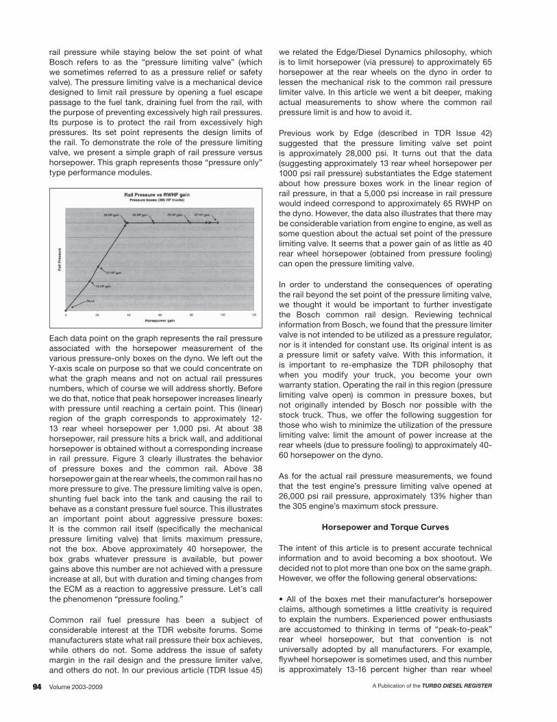
94 A Publication of the TURBO DIESEL REGISTERVolume 2003-2009
rail pressure while staying below the set point of what Bosch refers to as the “pressure limiting valve” (which we sometimes referred to as a pressure relief or safety valve). The pressure limiting valve is a mechanical device designed to limit rail pressure by opening a fuel escape passage to the fuel tank, draining fuel from the rail, with the purpose of preventing excessively high rail pressures. Its purpose is to protect the rail from excessively high pressures. Its set point represents the design limits of the rail. To demonstrate the role of the pressure limiting valve, we present a simple graph of rail pressure versus horsepower. This graph represents those “pressure only” type performance modules.
Each data point on the graph represents the rail pressure associated with the horsepower measurement of the various pressure-only boxes on the dyno. We left out the Y-axis scale on purpose so that we could concentrate on what the graph means and not on actual rail pressures numbers, which of course we will address shortly. Before we do that, notice that peak horsepower increases linearly with pressure until reaching a certain point. This (linear) region of the graph corresponds to approximately 12-13 rear wheel horsepower per 1,000 psi. At about 38 horsepower, rail pressure hits a brick wall, and additional horsepower is obtained without a corresponding increase in rail pressure. Figure 3 clearly illustrates the behavior of pressure boxes and the common rail. Above 38 horsepower gain at the rear wheels, the common rail has no more pressure to give. The pressure limiting valve is open, shunting fuel back into the tank and causing the rail to behave as a constant pressure fuel source. This illustrates an important point about aggressive pressure boxes: It is the common rail itself (specifically the mechanical pressure limiting valve) that limits maximum pressure, not the box. Above approximately 40 horsepower, the box grabs whatever pressure is available, but power gains above this number are not achieved with a pressure increase at all, but with duration and timing changes from the ECM as a reaction to aggressive pressure. Let’s call the phenomenon “pressure fooling.”
Common rail fuel pressure has been a subject of considerable interest at the TDR website forums. Some manufacturers state what rail pressure their box achieves, while others do not. Some address the issue of safety margin in the rail design and the pressure limiter valve, and others do not. In our previous article (TDR Issue 45)
we related the Edge/Diesel Dynamics philosophy, which is to limit horsepower (via pressure) to approximately 65 horsepower at the rear wheels on the dyno in order to lessen the mechanical risk to the common rail pressure limiter valve. In this article we went a bit deeper, making actual measurements to show where the common rail pressure limit is and how to avoid it.
Previous work by Edge (described in TDR Issue 42) suggested that the pressure limiting valve set point is approximately 28,000 psi. It turns out that the data (suggesting approximately 13 rear wheel horsepower per 1000 psi rail pressure) substantiates the Edge statement about how pressure boxes work in the linear region of rail pressure, in that a 5,000 psi increase in rail pressure would indeed correspond to approximately 65 RWHP on the dyno. However, the data also illustrates that there may be considerable variation from engine to engine, as well as some question about the actual set point of the pressure limiting valve. It seems that a power gain of as little as 40 rear wheel horsepower (obtained from pressure fooling) can open the pressure limiting valve.
In order to understand the consequences of operating the rail beyond the set point of the pressure limiting valve, we thought it would be important to further investigate the Bosch common rail design. Reviewing technical information from Bosch, we found that the pressure limiter valve is not intended to be utilized as a pressure regulator, nor is it intended for constant use. Its original intent is as a pressure limit or safety valve. With this information, it is important to re-emphasize the TDR philosophy that when you modify your truck, you become your own warranty station. Operating the rail in this region (pressure limiting valve open) is common in pressure boxes, but not originally intended by Bosch nor possible with the stock truck. Thus, we offer the following suggestion for those who wish to minimize the utilization of the pressure limiting valve: limit the amount of power increase at the rear wheels (due to pressure fooling) to approximately 40-60 horsepower on the dyno.
As for the actual rail pressure measurements, we found that the test engine’s pressure limiting valve opened at 26,000 psi rail pressure, approximately 13% higher than the 305 engine’s maximum stock pressure.
Horsepower and Torque Curves
The intent of this article is to present accurate technical information and to avoid becoming a box shootout. We decided not to plot more than one box on the same graph. However, we offer the following general observations:
• All of the boxes met their manufacturer’s horsepower claims, although sometimes a little creativity is required to explain the numbers. Experienced power enthusiasts are accustomed to thinking in terms of “peak-to-peak” rear wheel horsepower, but that convention is not universally adopted by all manufacturers. For example, flywheel horsepower is sometimes used, and this number is approximately 13-16 percent higher than rear wheel

95A Publication of the TURBO DIESEL REGISTER Volume 2003-2009
horsepower, due to drive train losses. Also, “best gain” is sometimes used instead of “peak-to-peak gain.” “Peak-to-peak” gain is literally the difference between the highest point on the enhanced curve and the highest point on the stock curve. “Best gain” is the largest difference between the enhanced and stock curves at one particular RPM.
• The Van Aaken C3.2 duration box has a very aggressive torque rise, making close to 850 ft-lbs of torque at the flywheel on one of our test runs. We were not able to duplicate this figure in any of three subsequent attempts. We should acknowledge that the stock clutch in the test truck was probably not capable of holding this much torque; so our data may not have accurately represented this box. Noting this, however, the box still made about 100 rear wheel horsepower “best gain” at about 2300 RPM, which is approximately 120 horsepower (best gain) at the flywheel.
• The low-boost fueling capability of the Volumizer (via enhanced boost fooling) was measurable in the form of a slightly stronger low end.
• The six most aggressive (90+ horsepower) boxes were remarkably similar in their wide open throttle performance, with the Diesel Dynamics/Edge EZ performing predictably about 20-30 horsepower less, since it has been designed to limit rail pressure.
• Since drivability differs between six-speeds and automatics, and is a subjective judgment, we won’t confuse the issue by introducing our own impressions. However we will note that the wide open throttle dyno runs do not reflect the drivability of the box in lower power situations. We found most of the aggressive boxes to be similar in drivability, some having greater throttle sensitivity than others and some applying power more smoothly than others throughout the RPM range. Generally, the boxes on their low power settings were very mild, exhibiting very little throttle sensitivity.
Here is a picture of the pressure relief valve. The valve is located just to the right (towards the firewall) of the rail pressure sender.
Note the banjo bolt and fuel return line mounted on the tip of the valve—this is how fuel is drained from the
rail when the valve opens. To the right of the pressure relief valve are injector lines #2, 3, and 4. The oil dipstick tube
is visible in the upper right of the picture.
Lift Pump Fuel Pressure
It is not the purpose of this article to repeat the multitude of experiments showing the limitations of the stock lift pump and low pressure fuel system. This series of tests was done simply validate that the stock fuel system is sufficient for power enhancements delivered by the boxes we tested (100 horsepower and below). We found no stumbling, hesitation, or other performance problems using any of the tested boxes; the power was smooth and predictable. As for actually measuring low-side fuel pressure, we hooked up the boost channel of the SPA Technique EGT/boost gauge to an SPA pressure sender on the Bosch CP3 fuel pump inlet. For the most aggressive power increase we tested, the low-side fuel pressure dropped to a value that is nominally equal to atmospheric pressure (gauge pressure read zero). This means that the low pressure fuel system is at the limit of its capacity, and from this we concluded that for the power levels tested, the low-pressure fuel system was sufficient, although barely so. Zero gauge pressure simply means that the CP3 inlet is not drawing (or pulling) fuel under vacuum.
Several Conclusions
• Power enhancements up 40-60 horsepower gain at the rear wheels (allowing for differences between trucks) can be obtained with an increase in rail pressure. To obtain power levels higher than this, an aggressive pressure box will open the pressure limiting valve on the rail and force the ECM to add duration and small amounts of timing. The more aggressive the pressure box, the more time is spent with the pressure limiting valve open, forcing the rail into constant pressure mode with excess pressure diverted back to the fuel tank.
• To limit operation of the rail in the constant-pressure mode (pressure limiting valve open), power gains to the rear wheels should be limited to approximately 40-60 horsepower.
• Above approximately 40-60 horsepower gain at the rear wheels, the stock turbocharger does not provide enough airflow for sustained loads (towing). It may be sufficient for short acceleration runs but exhaust gas temperatures can get out of hand very quickly (especially at high elevations), and this is a significant risk.
• The efficiency map of the 03-04 turbocharger has been designed to achieve very fast spool-up to control smoke and to meet emissions standards. Above approximately 40-60 horsepower gain at the rear wheels, the turbine speeds required to support elevated boost pressures may put the turbocharger’s long term reliability at risk.
• We recommend not using a boost elbow to change the wastegate set point of the stock turbocharger. The higher boost pressures that result will have limited benefit because the turbocharger will operate outside of its efficiency map and beyond the airflow choke-point.

96 A Publication of the TURBO DIESEL REGISTERVolume 2003-2009
• Timing advance provides a significant and measurable benefit to exhaust gas temperatures beyond the simple pressure boxes. However, it is beyond the scope of this article to discuss various levels of timing advance and to prescribe or recommend safe limits. Vendors should be carefully evaluated for their contribution in this area.
• It is always wise to choose vendors carefully, paying particular attention to what a manufacturer says about safety and durability issues, what work they have accomplished, and what data may be behind their recommendations.
• The behavior of aggressive pressure boxes demonstrates that above approximately 40-60 horsepower, the use of duration and timing is necessary. Although it is beyond the scope of this article, the use of injectors will probably remain an attractive avenue towards a balanced approach to adding fuel without excessive use of duration.
• The drive train of the stock ‘03-’04 HO Cummins Turbo Diesel will need some attention at or above approximately 350 horsepower at the rear wheels. In particular, at these levels we are stretching the limits of the six-speed clutch. The automatic transmission also requires some attention above these levels, as we’ve all seen pictures of the transmission’s torque converter lock-up clutchpack (see Issue 45, page 154).
Aren’t There Other Boxes?
We hope this article has been useful and that we have achieved our goal of offering more than just a comparative matrix of fueling boxes. We have clearly established the need to balance fueling enhancements with intake, exhaust, drive train, fuel system, and turbocharger considerations. We can now answer the question of why we did not include other more powerful boxes in this article, the boxes that use timing and duration recalibrations as the basis for horsepower increase. In this article we wanted to demonstrate the use of power enhancements on the typical (stock truck). This approach allowed us to make real measurements and show the importance of a balanced approach should the owner want an increase above the 40-60 horsepower level.
We suspect that readers will agree with us when we say that this inquiry into power enhancements would not be complete without widening our scope to include other more powerful boxes available on the market. In our next article we will broaden our investigation to include the TST “PowerMax CR” and the Edge “Juice” (if available). We will again try to cross-section the market by testing new products that may emerge.
What’s Next?
As for what the future holds, we can probably expect more manufacturers to utilize the CANbus for timing and perhaps other information for monitoring purposes or to help control fueling. There may be a limit to how much timing advance can be accomplished by this interface, but the ease of installation (compared to the cam and crank sensor method) will be attractive. Efforts continue in the area of timing and in the use of the cam and crank position sensors to accomplish analog time-fooling. There may be more products that modify performance in timing and pressure to obtain additional horsepower. At this writing, at least three manufacturers are working on downloader technology that re-flashes the ECM with different fueling parameters, overriding the stock values. By the time you read this, one or more of these products may have been released.
Doug Leno Joe Donnelly
Manufacturer’s and vendors mentioned in this article:
Gale Banks Engineering 546 Duggan Avenue Azusa, CA 91702
Pacific Performance Engineering 303 N. Placentia Fullerton, CA 92831
Bully Dog Technologies 4150 Church Street Suite 1024 Sanford, Florida 32771
PDQ Performance Whse 251 Central Park Dr. Sanford, FL 32771
Edge Products 1080 South Depot Drive Ogden, Utah 84401
SPA Technique, Inc 1209 Indy Way Indianapolis, IN 46214
Meridian Motorsports 521 E King Meridian, ID 83642
Quadzilla Diesel Performance 6028 Jacksboro Highway Fort Worth, TX 76136
Predator, Inc 760 N Thorton Suite #5 Post Falls, ID 83854
Van Aaken Developments, LTD Telford Avenue, Crowthorne Berkshire, RG45 6XA UK

97A Publication of the TURBO DIESEL REGISTER Volume 2003-2009
FUELING BOX POWER ENHANCEMENTS FOR THE ’03-’04 (305HP) ENGINES – PART TW0
By Doug Leno
Introduction
According to Murphy’s Law, “if anything can go wrong, it will,” and our article on fueling box power enhancements (in “Technical Topics,” Issue 47, page 53) appears to be an example of this wisdom. When the article appeared in print, some important discussion points were missing, and the discussion of rail pressure was not the version we submitted in manuscript. So we’ll rectify that. While we’re at it, we will use this opportunity to reprint some of the graphics (poor quality—printer error) and clarify some of the points in the Issue 47 article.
We will begin this update by revisiting the subject of rail pressure, this time with a more accurate interpretation of the data and with some additional discussion points that escaped the original typeset (editor’s stroke of pen?). Next, we present the horsepower and torque curves in more readable form. We will then attempt to clarify the discussion of exhaust gas temperature. Finally, we will evaluate the effects of an upgraded, four-inch exhaust system; present some additional experimental data on limitations of the stock turbocharger; and include vendor contact information.
Rail Pressure
The rail pressure measurements in Issue 47 were performed with a custom-made analog pressure gauge calibrated for, and connected to, the same on-board sending unit that provides rail pressure information to the ECM and to the installed pressure boxes. Using such a gauge, we witnessed the dynamic nature of rail pressure, as it varied with engine load from approximately 5,000 psi at idle to roughly 23,500 psi at wide open throttle in our baseline stock engine. Our readings were limited by the accuracy inherent to the sensor system.
We also discovered that in actual driving situations, the more aggressive pressure boxes forced rail pressure to run up to 5,000 psi higher than stock over the same conditions. What we could not see was the duration of injection event set by the engine control module. Typically the duration decreased with the increase in rail pressure so that the amount of fuel delivered to the cylinder was the same as or slightly less than with the fueling box installed. What this means to you is that the earlier fuel delivery (at a higher pressure and with a shorter duration) produces the same amount of power with less fuel. This
explains why some have reported moderate fuel economy improvements with the use of such enhancements. We suspect such improvements are both small and difficult to establish, and refer the reader to Issue 47, page 103 (in “The Way We Were”), where the subjects of fuel economy and power enhancements are covered in more detail.
Now it is time to present a more complete discussion of peak pressure achieved in the rail and the role of the pressure relief valve, with conclusions that were “Murphyed” in Issue 47.
Additional Rail Pressure Discussion
Figure 1: rail pressure graph from Issue 47.
Figure 1 shows the rail pressure graph from Issue 47, page 59. Note that the Y-axis is missing. This was intentional to acknowledge the limitations of our measurement method and to avoid making the conclusion that the rail has only 40 horsepower or so to give via increased pressure. The graph represents the data we collected. What follows are the interpretations we originally intended.
The Y-axis value corresponding to the 40 horsepower point in the graph is indeed approximately 26,000 psi as stated in Issue 47. However, we do not believe the graph reflects the behavior of the pressure relief valve or the pressure in the rail itself. It more likely reflects the upper saturation limit of the on-board rail pressure sender and this has been noted for clarity within the present graph. Note that we did not measure pressure directly; we measured the voltage output of the on-board rail pressure sender and used calibration data published by Cummins to convert voltage to pressure for our custom gauge. However, calibration data for the sender is not available for pressures above approximately 26,000 psi. We concluded that the on-board rail pressure sender is not a reliable indicator of actual rail pressures beyond this point.
5.9-LITER ENGINE PERFORMANCE ENHANCEMENTS – TO MODIFy OR NOT TO MODIFy
3G PERFORMANCE ENHANCEMENTS - PART IIISSUE 48 - TECHNICAL TOPICS

98 A Publication of the TURBO DIESEL REGISTERVolume 2003-2009
What, then, does the graph tell about the horsepower and rail pressure relationship? First, let’s review what we know:
1. There appears to be a correlation of approximately 13 peak horsepower gain at the rear wheels for every 1,000 psi increase in rail pressure for the region between stock (23,500 psi) and 38 horsepower (26,000 psi).
2. We were not able to measure rail pressures higher than approximately 26,000 psi and approximately 40 horsepower even though the horsepower gains achieved by some of the pressure boxes in our study achieved well over 90 horsepower.
The behavior of the rail below 26,000 psi and 40 horsepower is clearly illustrated. When more than 40 horsepower gain at the rear wheels is obtained with a pressure-type performance module, we suggest that pressure in the rail probably rises in a manner similar to that indicated in the lower portion of the graph, but continues beyond 26,000 psi until the set point of the pressure relief valve is obtained in the rail. At this point, the spring-loaded plunger of this valve opens, bleeding fuel back into the low-pressure fuel circuit to protect the rail from excessively high pressures.
Without specialized testing it is impossible to know the actual pressure behavior in the rail above 26,000 psi, or the point when when the pressure relief valve actually opens. Edge and Diesel Dynamics have suggested that the valve opens somewhere close to approximately 65 horsepower and 28,000 psi in the rail, but the limitations of our measurement method prevented us from actually verifying this.
We note that today’s Edge Product’s EZ or Diesel Dynamics’ TTPM module (set to level four) is not known to promote pressure relief valve failure and yet it produced approximately 79 peak horsepower gain at the rear wheels on our dyno. In another set of tests, it produced a gain of 65 horsepower. Remember that each truck is different in its ability to sustain high pressures in the rail, and every dynamometer test condition is different as well—so be careful how you interpret the data. We do know that some have experienced pressure relief valve failures using a pressure box delivering significantly more than 65 horsepower (for example, the older Edge Products EZ module on level six), and yet others that use such aggressive pressure have dodged immediate failure. Perhaps in these cases, the relief valve might actually open and reset itself without the driver’s knowing.
Let’s now address a concern about the behavior of the pressure boxes we tested when they are delivering greater than approximately 65-80 peak horsepower gain. Consider that, at 13 horsepower per 1,000 psi, a pressure box making 90 horsepower at the rear wheels would require over 30,000 psi in the rail. If we are right about the pressure relief valve set point at 28,000 psi and approximately 65-80 horsepower, and the (presumed) constant or semi-regulated pressure behavior of the rail at or near this point, then we must conclude that 30,000 psi will not be achieved in the rail and that such power levels will not be achieved from pressure alone. How, then, can a pressure box make 90+ horsepower?
Consider that the ECM controls all of the fueling parameters (pressure, duration, and timing) based on the inputs it receives from various sources. We know that pressure boxes work by making the ECM think that pressure is too low, and this causes the ECM to attempt to raise the rail pressure (known as pressure fooling). However, one of the interesting side effects of pressure fooling is that the ECM may dial up more than just additional pressure in its attempt to correct the very condition created by installing a pressure box. More specifically, when the CP3 fuel injection pump cannot meet the pressure demanded, the ECM may try to correct this condition by introducing additional duration and timing according to its own fueling tables. Thus, the pressure boxes in our study may be taking advantage of the ECM’s corrective action to gain additional horsepower when the rail has no more pressure to give.
Recognizing the empirical nature of our rail pressure study, we offer the following summary:
• The on-board rail pressure sending unit appears to be an unreliable indicator of rail pressure beyond a 40 horsepower gain. In our experiment, this limit appeared to occur at approximately 26,000 psi.
• Power gains up to approximately 65-80 horsepower can be obtained with an apparently safe increase in rail pressure (i.e. without opening the pressure relief valve). Above this level, we suspect that the rail may be pressure-limited and that additional horsepower comes from the ECM in the form of duration and timing.
• For horsepower gains beyond this point, the CP3 pump may not be able to sustain higher pressures in the rail due to the behavior of the pressure relief valve, and such gains probably involve duration and timing changes made by the ECM as it tries to compensate for what it thinks is low rail pressure.
• Opening the pressure relief valve is not the original intent of the rail design. Continuous operation of the rail with a pressure box exceeding 65-80 horsepower over stock may present a long term reliability issue for this expensive component.
• It is not the purpose of this study to declare precisely what rail pressures are safe, and we want to make it clear that our work should not be interpreted as such. Our intent is to describe the behavior of the performance modules, and to present data describing where we believe vulnerabilities may exist. Much higher fuel pressures may cause erosion wear of various components such as injectors. Remember, you are your own warranty station.

99A Publication of the TURBO DIESEL REGISTER Volume 2003-2009
Horsepower and Torque Curves
Because some of the original dyno runs in Issue 47 did not reproduce well, we will reprint all of them here for clarity. You will note that we have added an additional performance
module, the TST PowerMaxCR. We used this well below its capability, at approximately 90 horsepower, in order to correspond with the other 90-horsepower boxes in our study. Here is how the PowerMaxCR is described in the comparative matrix style of Issue 47:
Comparative Matrix
Product Type Boost Fooling Method
Engine Connections Adjustability Features
TST Powermax CR
Duration and Timing Traditional limiting
Cam and crank position sensors,
MAP sensor, injector control
harness
Nine adjustable torque settings
and nine adjustable
horsepower setting
Most aggressive power increases available at press time. EGT-based de-fueling, and
integrated gauges. No rail pressure
increase.
Banks ”Six Gun” with speed loader
Diesel Dynamics “True Torque” / Edge “EZ”
Bully Dog Adjustable “Torque Dog”
Pacific Performance Engineering

100 A Publication of the TURBO DIESEL REGISTERVolume 2003-2009
Predator “Stage 3”
Van Aaken “C3.1” (pressure)
PDQ “Volumizer”
Quadzilla (towing module)
Van Aaken “C3.2” (duration)
TST PowerMaxCR, level 4/4 and 5/5
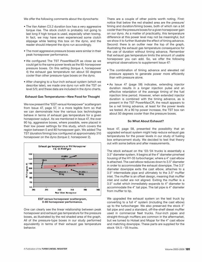
101A Publication of the TURBO DIESEL REGISTER Volume 2003-2009
We offer the following comments about the dynocharts:
• The Van Aaken C3.2 duration box has a very aggressive torque rise. The stock clutch is probably not going to last long if high torque is used, especially when towing. In fact, we may have even experienced some clutch slippage while testing this box on the dyno, and the reader should interpret the dyno run accordingly.
• The most aggressive pressure boxes were similar in their peak horsepower performance.
• We configured The TST PowerMaxCR as close as we could get to the same power levels as the 90-horsepower pressure boxes. On this setting (torque 4, horsepower 4) the exhaust gas temperature ran about 50 degrees cooler than other pressure-type boxes on the dyno.
• After changing to a four-inch exhaust system (which we describe later), we made one dyno run with the TST on level 5/5; and these data are included in the dyno charts.
Exhaust Gas Temperatures—New Food for Thought
We now present the “EGT versus Horsepower” scattergram from Issue 47, page 57, in a more legible form so that we can demonstrate how the various box technologies behave in terms of exhaust gas temperature for a given horsepower output. As we mentioned in Issue 47, the over 90 hp, aggressive boxes, where possible, were placed in their low power settings for this study, which covers the region between 0 and 80 horsepower gain. We added The TST (duration/timing) box configured at approximately 310 horsepower on the dyno (torque 2, horsepower 2).
EGT versus horsepower scattergram, 0-80 horsepower performance.
One can clearly see the linear relationship between peak horsepower and exhaust gas temperature for the pressure boxes, as illustrated by the red shaded area of the graph. All of the pressure-type boxes in our study performed equivalently in terms of their exhaust gas temperature behavior.
There are a couple of other points worth noting. First: notice that below the red shaded area are the pressure/timing and duration/timing boxes, both of which ran a bit cooler than the pressure boxes for a given horsepower gain on our dyno. As a matter of practicality, this temperature difference at this power level may not be meaningful, but we show it to further illustrate the effect of timing advance. Second: there is an outlier near the top of the graph, illustrating the exhaust gas temperature consequence for the use of duration without timing advance. Remember that exhaust gas temperature limits the amount of usable horsepower you can add. So, we offer the following empirical observations to supplement Issue 47:
• The combination of timing advance and elevated rail pressure appears to generate power more efficiently than with pressure alone.
• As Issue 47 (page 58) indicates, extending injector duration results in a longer injection pulse and an effective retardation of the average timing of the fuel injection time period. However, when extended injector duration is combined with the timing advance, as is present in the TST PowerMaxCR, the result appears to be a net timing advance, at least for the power levels we tested. At a 90 hp power increase, the TST box ran about 50 degrees cooler than the pressure boxes.
So What About Exhaust?
Issue 47, page 58, presented the possibility that an upgraded exhaust system might help reduce exhaust gas temperatures for the power levels in our study of fueling box enhancement study. We decided to test that theory out with some before and after measurements.
The stock exhaust on the ‘03-‘04 trucks is essentially a 3.5” diameter system. It begins at the 4” diameter pinwheel housing of the HY-35 turbocharger, where a 4” cast elbow is attached. The cast elbow reduces down to 3.5” diameter in order to accommodate the exhaust downpipe. The 3.5” diameter downpipe exits the cast elbow, attaches to a 3.5” intermediate pipe and ultimately to the 3.5” muffler inlet. The muffler is an offset design, meaning that muffler inlet and outlet are not aligned. Exiting the muffler is a 3.5” outlet which immediately expands to 4” diameter to accommodate the 4” tail pipe. The tail pipe is 4” diameter from muffler to tip.
We upgraded the exhaust system on the test truck by converting to a full 4” system (including the cast elbow) up to the turbocharger. We also preserved the stock 4” tail pipe and used a standard, off-the-shelf diesel muffler used in commercial fleet trucks. Four-inch pipes and straight-through mufflers are common in the aftermarket, but we turned to Holset and Mopar for the 4” cast elbow and matching downpipe. These parts are supplied for the stock ‘04.5 –‘05 trucks.
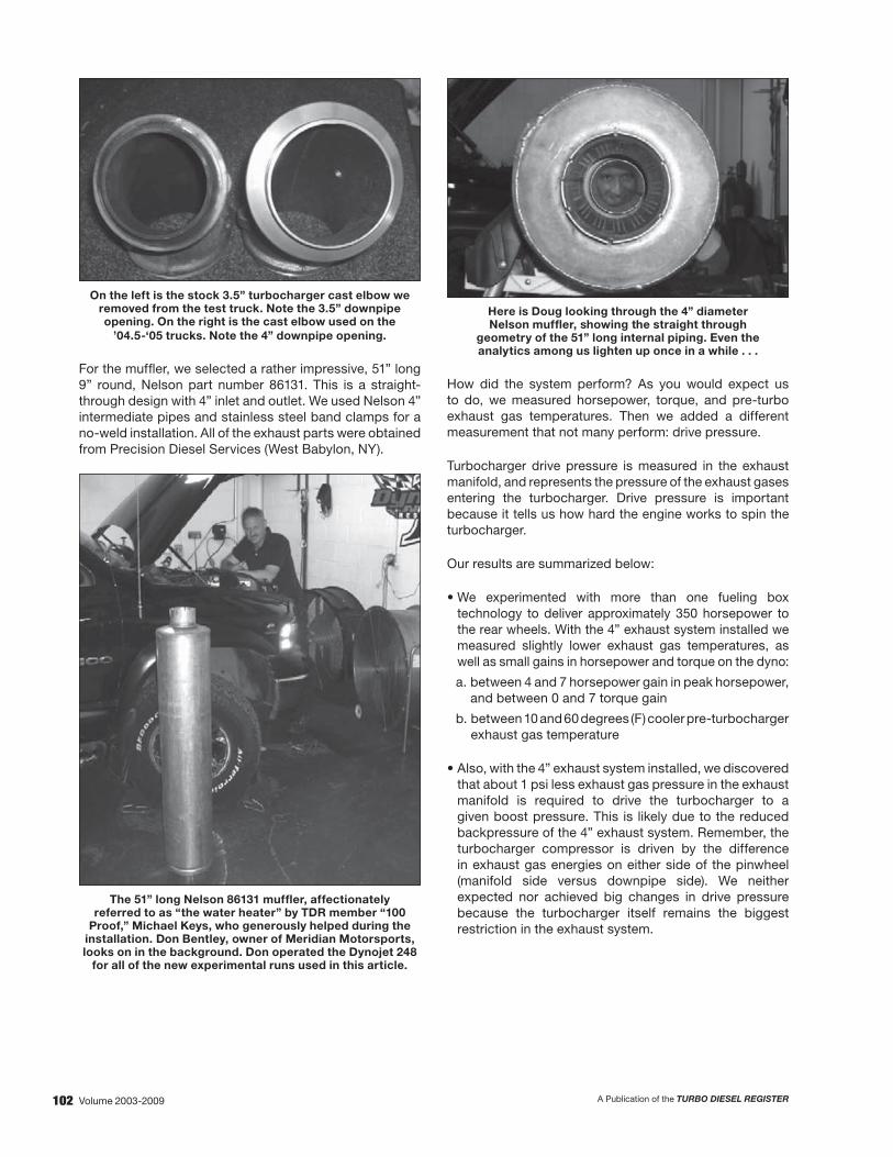
102 A Publication of the TURBO DIESEL REGISTERVolume 2003-2009
On the left is the stock 3.5” turbocharger cast elbow we removed from the test truck. Note the 3.5” downpipe opening. On the right is the cast elbow used on the
’04.5-‘05 trucks. Note the 4” downpipe opening.
For the muffler, we selected a rather impressive, 51” long 9” round, Nelson part number 86131. This is a straight-through design with 4” inlet and outlet. We used Nelson 4” intermediate pipes and stainless steel band clamps for a no-weld installation. All of the exhaust parts were obtained from Precision Diesel Services (West Babylon, NY).
The 51” long Nelson 86131 muffler, affectionately referred to as “the water heater” by TDR member “100
Proof,” Michael Keys, who generously helped during the installation. Don Bentley, owner of Meridian Motorsports, looks on in the background. Don operated the Dynojet 248
for all of the new experimental runs used in this article.
Here is Doug looking through the 4” diameterNelson muffler, showing the straight through
geometry of the 51” long internal piping. Even theanalytics among us lighten up once in a while . . .
How did the system perform? As you would expect us to do, we measured horsepower, torque, and pre-turbo exhaust gas temperatures. Then we added a different measurement that not many perform: drive pressure.
Turbocharger drive pressure is measured in the exhaust manifold, and represents the pressure of the exhaust gases entering the turbocharger. Drive pressure is important because it tells us how hard the engine works to spin the turbocharger.
Our results are summarized below:
• We experimented with more than one fueling box technology to deliver approximately 350 horsepower to the rear wheels. With the 4” exhaust system installed we measured slightly lower exhaust gas temperatures, as well as small gains in horsepower and torque on the dyno:
a. between 4 and 7 horsepower gain in peak horsepower, and between 0 and 7 torque gain
b. between 10 and 60 degrees (F) cooler pre-turbocharger exhaust gas temperature
• Also, with the 4” exhaust system installed, we discovered that about 1 psi less exhaust gas pressure in the exhaust manifold is required to drive the turbocharger to a given boost pressure. This is likely due to the reduced backpressure of the 4” exhaust system. Remember, the turbocharger compressor is driven by the difference in exhaust gas energies on either side of the pinwheel (manifold side versus downpipe side). We neither expected nor achieved big changes in drive pressure because the turbocharger itself remains the biggest restriction in the exhaust system.

103A Publication of the TURBO DIESEL REGISTER Volume 2003-2009
Correlating the above results with actual driving conditions is difficult, since we tested only one truck under one set of test conditions. However, our measurements do suggest small improvements in peak horsepower and peak torque at these power levels. As for the improvement in exhaust gas temperatures, we suggest small, if any, practical improvement, since the real limitation is the turbocharger itself, as we have been saying throughout this series of articles.
The reduction in drive pressure is interesting. It appears that, with the 4” exhaust installed, a tiny bit less energy from the engine is required to drive the turbocharger. This may also explain why some have actually reported a small net loss in power output with the installation of a low-restriction exhaust system on an otherwise stock ‘03-‘04 truck. The explanation: with the upgraded exhaust, the relationship between boost pressure and drive pressure is different than what the ECM is calibrated for, and this may produce an effect that is opposite of what is expected. The turbocharger now spools up quicker in response to the same drive pressure, and the ECM may actually de-fuel to control the boost pressures it sees, resulting in a small power loss. Of course, this is not an issue when a fueling box is installed because the fueling box fools the ECM so that it does not de-fuel.
Turbocharger Limits Without Exhaust Gas Temperature Measurements
Issue 47, page 58, suggested that the stock HY-35 turbocharger (‘03-‘04 engines) may not reliably support more than about 50 horsepower gain at the rear wheels, and that 325 horsepower to the rear wheels (a 65-horsepower gain) was stretching its limits. The data behind this statement consisted of pre-turbo and post-turbo exhaust gas temperature measurements. Excessive EGTs highlight the turbocharger’s airflow choke point caused by its 9 square centimeter exhaust housing. When the turbocharger is operating efficiently, it delivers relatively cool, pressurized air to the intercooler, ultimately resulting in sufficient charge air density and acceptable exhaust gas temperatures. When the turbocharger is not operating efficiently, it delivers hotter, less dense air to the intercooler which results in elevated exhaust gas temperatures.
Remember that the goal of the turbocharger is to increase the number of air molecules passing through the engine, not just to make boost pressure. When boost air gets hotter, this alone increases its pressure. A higher reading on the boost gauge doesn’t tell us whether we are actually getting more air molecules into the engine, or just hotter molecules into the engine.
To investigate this further, we decided to directly measure the temperature of the air leaving the turbocharger’s compressor housing. To do this, we again turned to SPA Technique digital gauges for an accurate measurement so we could correlate boost pressures with compressor output air temperatures. We installed a low-temperature, bead-type thermocouple directly into the turbocharger compressor housing. Bead-type thermocouples are not
coated with the protective materials found on an EGT probe (hence the low temperature restriction), and are extremely fast and accurate. The one we used is intended for measuring intercooler temperatures.
Bead-type low temperature thermocouple installed in the turbocharger compressor housing, which provided
very precise and reproducible air temperature measurements at various boost pressures.
The peak reading capability of the gauges allowed us to accurately record the relationship between peak boost pressure and peak air temperature in the compressor housing during actual driving conditions. Here are the results:
Compressor output air temperature as a function of boost pressure, illustrating turbocharger efficiency
breakdown above approximately 24 psi boost. The data was collected during actual driving conditions
at approximately 2700 feet above sea level.
The graph gives us a direct view of turbocharger efficiency and clearly shows the effect of elevated boost pressures on the little HY-35 turbocharger used on the test truck. When the turbocharger is used within its intended limits, the air temperature delivered by its compressor wheel rises linearly with boost, reaching a breakpoint at about 24 psi and 260 degrees Fahrenheit. Within this region (below 24 psi), the increase in air temperature as a consequence of boost is reasonable, and the turbocharger is effectively pushing more air molecules through the engine. However, above this point notice that the price of boost is very high and that small increase in boost pressure result in large increases in air temperature. We will spare you the math here, but after going through the calculations we can say that further increases in boost pressure (above 24 psi)

104 A Publication of the TURBO DIESEL REGISTERVolume 2003-2009
result in almost no increase in the actual number of air molecules delivered to the intercooler. This is the result of the turbocharger operating beyond its efficiency map, and affirms to us that the factory boost limits built into the ECM, as well as the mechanical wastegate set point, are appropriate for this turbocharger. Operation beyond those limits provides very little, if any, benefit and probably compromises long term durability.
We should mention that the electrical/mechanical operation of the wastegate in the ‘04.5-‘05 turbochargers must be treated differently. If one uses a power box that fools the manifold absolute pressure (MSP) sensor, the electrical signal will not tell the wastegate to open at a safe boost level. A major goal of boost fooling is to prevent the engine control module from defueling when it sees overboost, so the ECM may never see enough of a voltage signal to open the wastegate. The turbocharger will spool up to such high actual boost levels that it will potentially blow up. This problem can be avoided with an approach such as TST uses. They provide a conversion to mechanical wastegate operation. That is, they use actual boost pressure to activate the pressure pot that opens the wastegate.
Pictures Tell the Story
As previously discussed, the exhaust housing on the stock ‘03-‘04 turbocharger is 9 square centimeters in cross sectional area. This is about the same cross sectional area as a 1.3” diameter pipe. The small exhaust housing is used to accelerate exhaust gases (under the influence of drive pressure) to spin the turbine. We thought the TDR readership would appreciate knowing what a small turbine it really is! Below is a photograph of the HY-35 exhaust pinwheel, made visible when we removed the 3.5” cast housing from the test truck. This picture shows you why upgrading to a 4” diameter exhaust system produced only small gains. It should leave no doubt as to the power limitations of this turbocharger. Of course, this turbocharger works well for the Cummins recipe of low emissions with stock power.
The exhaust pinwheel of the HY-35 turbocharger installed on the ‘03-‘04 trucks. The pinwheel is inside of a 4” diameter housing that mates up directly to the exhaust elbow. The wastegate is seen directly to the
left of the pinwheel. The turbocharger mounting studs and nuts are visible in the upper left.
Recognizing the inherent variability from owner to owner, our recommendations are as follows:
• The use of a 4” exhaust system may provide small (single digit) improvements in peak horsepower and peak torque at the 350 horsepower level, but is not necessary for a stock truck.
• The HY-35 turbocharger used on the ‘03-‘04 trucks should probably not be used at boost pressures above approximately 24 psi, at least not for extended periods of time. Above this point, the turbocharger is operating beyond its efficiency map which results in little or no benefit, and indicates a compromise in long term durability. Utilizing a variety of fueling box technologies, we found that 24 psi boost (without wastegating) corresponded to a maximum of 56 horsepower gain at the rear wheels on the dyno.
• The use of timing advance is effective in reducing exhaust gas temperatures for both low and elevated power levels.
• The use of timing advance, 4” exhaust, upgraded intake system, and short-duration acceleration runs may keep exhaust gas temperatures within acceptable limits in some cases, but doing so does not change the inherent efficiency of the ‘03-‘04 turbocharger itself, which appears to be acceptable only at boost pressures below 24 psi, at least for our tests.
Conclusions
We hope we have shown how important it is to establish a balanced approach to power upgrades. We established that the stock turbocharger reliably supports only about 50 to 65 rear wheel horsepower gain and approximately 24 psi maximum boost pressure, depending of course on driving conditions, elevation, etc. We touched on the fact that the stock clutch is limited to approximately 350 horsepower, as is the automatic transmission in its stock form. We also showed that timing advance and 4” exhaust also have a positive effect on exhaust gas temperatures. Finally, depending exclusively on exhaust gas temperatures to express the limits of the turbocharger may not be wise.
We’re not ending our look into Third Generation, high-pressure, common-rail power enhancements. We plan to explore higher power levels, properly addressing the weak links exposed in our article thus far. The data presented in this and the previous article will give us a good baseline for further study.
Doug Leno Joe Donnelly
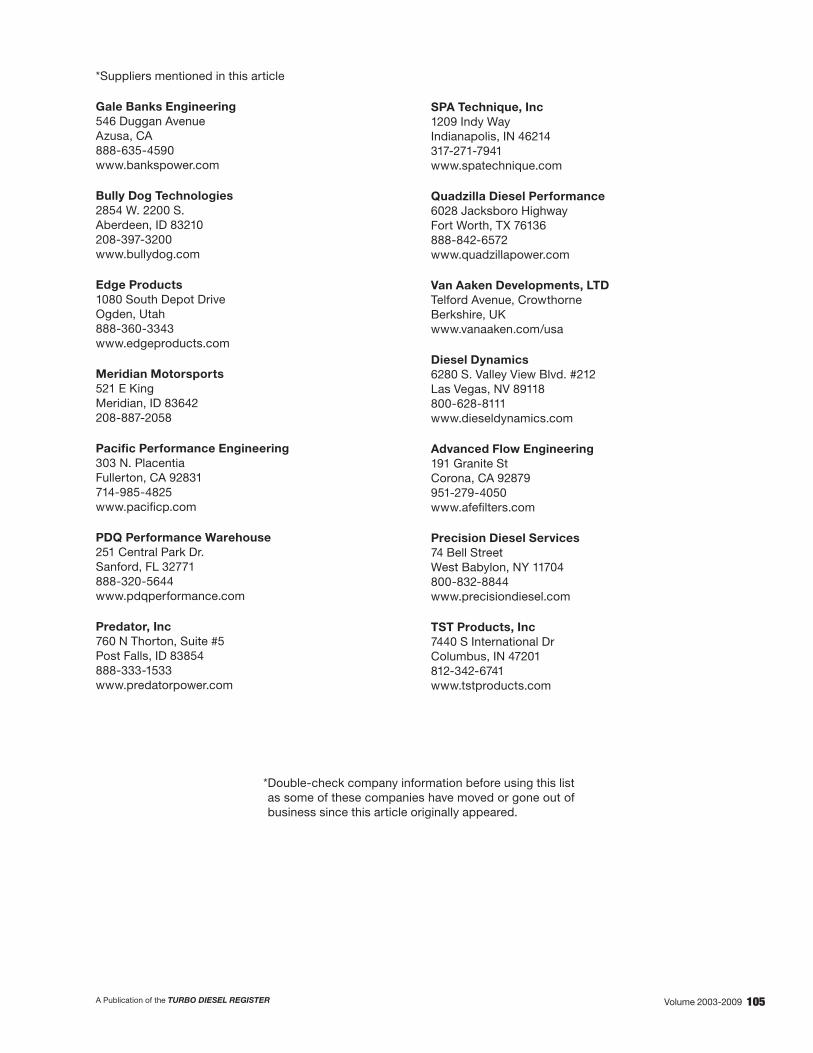
105A Publication of the TURBO DIESEL REGISTER Volume 2003-2009
*Suppliers mentioned in this article
Gale Banks Engineering 546 Duggan Avenue Azusa, CA 888-635-4590 www.bankspower.com
Bully Dog Technologies 2854 W. 2200 S. Aberdeen, ID 83210 208-397-3200 www.bullydog.com
Edge Products 1080 South Depot Drive Ogden, Utah 888-360-3343 www.edgeproducts.com
Meridian Motorsports 521 E King Meridian, ID 83642 208-887-2058
Pacific Performance Engineering 303 N. Placentia Fullerton, CA 92831 714-985-4825 www.pacificp.com
PDQ Performance Warehouse 251 Central Park Dr. Sanford, FL 32771 888-320-5644 www.pdqperformance.com
Predator, Inc 760 N Thorton, Suite #5 Post Falls, ID 83854 888-333-1533 www.predatorpower.com
SPA Technique, Inc 1209 Indy Way Indianapolis, IN 46214 317-271-7941 www.spatechnique.com
Quadzilla Diesel Performance 6028 Jacksboro Highway Fort Worth, TX 76136 888-842-6572 www.quadzillapower.com
Van Aaken Developments, LTD Telford Avenue, Crowthorne Berkshire, UK www.vanaaken.com/usa
Diesel Dynamics 6280 S. Valley View Blvd. #212 Las Vegas, NV 89118 800-628-8111 www.dieseldynamics.com
Advanced Flow Engineering 191 Granite St Corona, CA 92879 951-279-4050 www.afefilters.com
Precision Diesel Services 74 Bell Street West Babylon, NY 11704 800-832-8844 www.precisiondiesel.com
TST Products, Inc 7440 S International Dr Columbus, IN 47201 812-342-6741 www.tstproducts.com
* Double-check company information before using this list as some of these companies have moved or gone out of business since this article originally appeared.

106 A Publication of the TURBO DIESEL REGISTERVolume 2003-2009
5.9-LITER ENGINE PERFORMANCE ENHANCEMENTS – TO MODIFy OR NOT TO MODIFy
3G PERFORMANCE ENHANCEMENTS - PART IIIISSUE 49 - TECHNICAL TOPICS
FUELING BOX POWER ENHANCEMENTS FOR THE ’03-’04 (305HP) ENGINES—PART THREE
by Doug Leno
Introduction
My intent throughout this series of articles is to present the Cummins Turbo Diesel engine in its stock form as a careful balance of several design parameters, noting that when we increase power output beyond stock levels we must understand the impact. Here is a summary of the areas dealt with thus far:
• Turbocharger: The HY-35 turbocharger in the 03-04 trucks with its fixed wastegate and nine-square-centimeter exhaust housing provides excellent low-power spool-up, throttle responsiveness, and emissions controls. But the turbocharger has only about 50-65 horsepower margin (at best) to support additional power upgrades before compromising long term reliability.
The turbocharger supplied with the ‘04.5-‘05 trucks contains a variable wastegate controlled by the engine control module (ECM), and slightly enlarged compressor and turbine geometries to support the higher-output stock power levels as well as the emissions-motivated goals. This turbocharger may contain a bit more useful margin for power upgrades, but without further testing I remain cautious about this component as well. In any case, adding power above stock levels in any model year means that the turbocharger is operating closer to (or beyond) its design limits and at higher exhaust gas temperatures (EGTs). The exhaust side of the turbo does not provide the amount of air flow needed for larger horsepower increases, and the compressor cannot provide the amount of air either; the increases in boost pressure that are obtained come (mostly) from increasing intake air temperature rather than mass.
• Clutch (for standard transmissions) and the automatic transmission: Again, there is not much margin in these stock components, and power upgrades exceeding approximately 65-100 hp are likely to cause premature wear due to slippage from the higher torque. Aftermarket clutches and automatic transmission upgrades are available to handle the extra power, but add a significant cost to the overall package.
• Low pressure fuel delivery system: In my experiments, the stock lift pump is able to support only about 90 hp (at best) before starving the high pressure CP3 pump. The stock lift pump will not flow enough fuel, even if another pump is pushing fuel to it. Preliminary reports also indicate that the 2005 in-tank pump is also inadequate
in capacity for large power upgrades. Aftermarket lift pumps are available to add fuel delivery capacity.
• High pressure fuel rail and injectors: The use of pressure-type fueling boxes puts additional stresses on the injectors and the fuel rail itself (namely the pressure relief valve). Adding more than approximately 65 hp in this manner probably puts these components at a higher risk for premature failure, at least over the long term.
In this article, I will deal with two key areas: First note that the dynamometer measurements used thus far in the series have been restricted to an inertia-type measurement system (Dynojet 248c). In this article I will introduce comparative data from a loadtype measurement system (Mustang 1750) and briefly discuss the differences between the two systems.
Second, recall that the power enhancements studied up to this point have been limited to 100 hp or less due to the limitations described above. In this article I will describe the steps taken in order to accommodate the TST “PowerMaxCR” fueling box introduced in the previous TDR Issue 48 article. At this writing, the PowerMaxCR is the only fueling enhancement module I was able to obtain for the ‘03-‘04 trucks that is capable of achieving substantially over 100 hp gain. This module is a duration/timing-type fueling box, which means it does not make any changes to the stock rail pressure to achieve its power gains. See TDR Issue 45, page 24, for more details on the different fueling box technologies. In a future TDR article I will again review the market and present an updated matrix of available enhancements.
Inertia Versus Load Dynamometers
Horsepower is the physical parameter that best describes the ability of the engine to perform the task of interest. Those who say “it’s all about torque” are really describing the contribution of torque to horsepower, usually at low rpm. Since Horsepower = (Torque x rpm) ÷ 5252, we can see that it takes both torque and rpm to make horsepower, and that higher torque output from the engine is required to maintain the same power output at a lower rpm.
To illustrate, consider the stock engine and its relatively flat torque curve. Since available torque is nearly the same across the useful rpm range, the available horsepower drops when rpm drops. This is why downshifting provides more pulling power—it raises engine rpm so that horsepower can increase while torque output stays at nearly the same level. TDR Issue 45, page 24, (the introductory article to this series) discusses these topics in more detail.

107A Publication of the TURBO DIESEL REGISTER Volume 2003-2009
The TST PowerMaxCR fueling box has settings for both torque enhancement (TE) and horsepower (HP). A higher TE setting increases available low-end horsepower with a torque increase in the 1200-2000 rpm region. A higher HP setting increases available high-end horsepower with a torque increase in the 2000-2900 rpm region. In both cases, the box adds fuel and therefore increases the torque output of the engine and, by virtue of the mathematical equation, HP = (Torque x rpm) ÷ 5252.
The value of the dynamometer is to graph horsepower output over a range of engine rpm, so that we can analyze the available power across the region of interest. The inertia-type and load-type dynamometers each has advantages and disadvantages, followers and critics. It is beyond the scope of this article to discuss the two types in detail, but I will describe the basic characteristics of each:
• The load dyno applies a specific, electronically controlled load to the rollers, simulating what the vehicle could experience on the road while the engine is delivering maximum power. During the course of a test, the system controls roller speed, forcing the engine to slowly sweep through its rpm range while the driver holds the accelerator pedal to the floor (wide open throttle). The torque experienced by the rollers is measured, and horsepower is calculated from the relationship, HP = (Torque x rpm) ÷ 5252. Calibration of the system is a critical step in overall accuracy and involves tuning the electronically controlled braking system used to load the vehicle and which measures torque. An advantage of the load-type dyno is that the engine experiences a load that is close to actual driving situations. The applied load affects both turbocharger spool-up and engine fueling controlled by the ECM. This can have an accuracy advantage on the data collected from high-horsepower turbocharged engines. Disadvantages of the load dyno are that the test duration is long (compared to an inertia-type dyno test), which results in higher exhaust gas temperatures during the test, and a greater load on the vehicle’s cooling system (which is already disadvantaged because the vehicle is not moving). Additionally, the horsepower calculation itself is complex and more difficult to perform (with high accuracy) than the calculation required by an inertia dyno.
• The inertia dyno uses a roller of known mechanical rolling resistance (inertia) to load the vehicle. During the course of a test, the system allows the vehicle to accelerate the rollers at whatever rate it is capable of achieving. Horsepower is measured directly from the rate of acceleration achieved by the vehicle’s rear wheels (the time to accelerate the roller from one rpm to another), and then torque is calculated from the mathematical relationship Torque = (HP x 5252) ÷ rpm. Calibration of the system is not required, since the physical characteristics of the roller itself (its inertia, friction losses and wind resistance) remain stable. Advantages of this system include the fact that the horsepower calculation itself is based on quantities that are easily measured with great accuracy. The system is also less complex and is easier to maintain and to keep accurate. The test runs themselves generate lower EGTs and place a lighter load on the vehicle’s cooling system due to a shorter measurement time. Disadvantages include the fact that the roller inertia may be less than the equivalent rolling resistance of the vehicle, and this may cause the ECM to control the engine differently (due to slower turbocharger spool-up time) and produce less horsepower at low rpm than in certain (high load) driving situations. However, spool-up time can be accounted for by measuring different engine configurations with comparative dyno runs.
Throughout these articles, I have emphasized the use of the dynamometer for comparative, rather than absolute, measurements. Note that each of the fueling box dyno charts presented in TDR Issue 48 contains both a stock run and one or more “with fueling box installed” runs. This was to focus attention on how the fueling box performed, and not how the dynamometer performed. The most meaningful way to utilize a dynamometer is make measurements on one machine before and after a particular change has been made. Trying to interpret the absolute measurement data from two different machines (especially two different types and/or different physical locations) will often raise an endless list of questions about data credibility.
In this article I will present data comparing the two different dynamometers. For this test, the test truck was outfitted with an AFE “Stage 1” intake system with Proguard-7 media, a four-inch “turbo-to-tail” exhaust system described in Issue 48, and the Banks Six-gun with Speed Loader fueling box. These upgrades yielded approximately 350 peak horsepower at the rear wheels.
The dynamometers “tested” for this particular study are as follows:
1. Dynojet model 248c inertia dyno at Meridian Motorsports, Meridian, ID
2. Mustang model 1750 load dyno at ATS Diesel Performance, Arvada, CO

108 A Publication of the TURBO DIESEL REGISTERVolume 2003-2009
The graph below shows how each dyno behaved with the same truck on its rollers. The point of the test being that the peak horsepower measurement was approximately the same for each dynamometer (this is determined by the way they were operated and calibrated), but that low rpm horsepower measured higher on the load dyno than on the inertia dyno. This is because the load presented to the truck while on the load dyno caused the turbocharger to spool up sooner and the vehicle’s ECM to fuel more aggressively.
Horsepower curves for the Banks six gun with speed loader on level 6, measured on a Load dyno (Mustang 1750)
and Inertial dyno (Dynojet 248) with the same truck.
Note how the higher load presented by the Mustang resulted in a higher horsepower measurement at lower engine rpm.
Does the data indicate a significant difference in accuracy between the two dynamometer models? That depends on how the results are used. One could argue that the load dynamometer may have an accuracy advantage at low rpm for some high horsepower turbocharged engines when there is a single (absolute) measurement run (nothing to compare with). On the other hand, the best use of a dynamometer is for comparative measurements; and either type of dyno is useful because the engine configuration, not the dynamometer, is being tested.
To illustrate how difficult it is to compare results from different dynos at different locations I would like to highlight a few important points about the above graph. The Mustang load dyno test was performed in May 2005 at 5,500 ft. elevation and utilized standard correction factors for barometric pressure, temperature, and relative humidity. The Dynojet inertia dyno data was taken in October 2004 at 2,700 ft. elevation and are “uncorrected,” meaning that no correction factors were applied to the data after measurement. Both machines were calibrated according to the manufacturer’s procedures. For the Mustang, this means the electronic brake and torque measurement system was tuned and calibrated using a specific set of steps. For the Dynojet, this means validating that the correct physical roller parameters given by the manufacturer were loaded into the software at the time the system was installed.
Questions arise from the comparison of corrected data collected at 5500 ft., with uncorrected data collected at 2,700 ft. At the Meridian Motorsports Dynojet location in particular, standard SAE (Society of Automotive Engineers) correction factors for weather and altitude equate to unusually high horsepower numbers in my testing, so I prefer not to use them. One must recognize, however, that higher elevations do result in lower engine output and the use of such correction factors becomes more important at higher elevations such as the Denver, Colorado, Mustang 1750 owned by ATS Diesel Performance. More importantly we also have to realize that such correction factors are only a part of the overall horsepower calculation. The purpose of altitude and weather-based correction factors in a dynamometer measurement is so that one truck will measure the same whether it is measured in Denver or New Orleans. In actual practice, attempts to drive one truck around to several dynamometers still result in measurement differences. The fact of the matter is that sometimes two dynamometers are the same.
Correction factors aside, we can see a difference in the horsepower curves at low rpm for the Banks fueling box and note the generally higher engine output at these points for the Mustang load dyno. This difference is real and may be important as a general characteristic.
The important point to remember is that either dynamometer type can be used with good accuracy for comparative measurements, and that both systems have their own particular measurement bias for absolute measurements. In summary:
• Comparing “peak horsepower” or “peak torque” numbers generated on different dynamometers (such as from different dyno day events) cannot be used to detect small differences or improvements
• The load dyno’s ability to load the rollers probably gives moreaccurate, low-RPM results for absolute (non-comparative) measurements especially when large, slow-spooling turbochargers are involved.
• The inertia dyno is less susceptible to calibration errors, especially over time, since no calibration is required other than loading the correct physical roller parameters once into the system.
Beyond 100 Horsepower
The previous TDR Issue 48 article stopped short of testing the capabilities of the TST PowerMaxCR fueling box because of several limitations in the test truck: the turbocharger, the clutch, and the low-pressure fuel supply system. The truck had only been upgraded with an air intake system (AFE “Stage 1”) and four-inch “turbo to tail” exhaust system. In order to present the capabilities of this module I had to address the limitations.
The turbocharger: The TST fuels so aggressively that I feel the stock turbocharger is severely undersized. (See “Comments and Clarifications From TST” at the end of this article.) I didn’t want the stock turbocharger on the test truck to end up like the following example!

109A Publication of the TURBO DIESEL REGISTER Volume 2003-2009
Stock HY-35 turbocharger (from an ‘03-‘04 truck)that was destroyed from the use of aggressive fueling enhancements. The compressor wheel literally flewapart and broke through the compressor housing.
The need for additional air implies that higher boost pressures will be required. However, recall from the previous Issue 48 article that boost pressure, by itself, is not the objective. As the article states (page 56), “Remember that the goal of the turbocharger is to increase the number of air molecules passing through the engine, not just to make boost pressure. When boost air gets hotter, this alone increases its pressure. A higher reading on the boost gauge doesn’t tell us whether we are actually getting more air molecules into the engine or just hotter molecules into the engine.” I felt that in order to test the TST box I would need a turbocharger that would both stand up to the aggressive TST fueling, and efficiently move more air molecules through the engine at higher boost pressures.
With that in mind, there are a number of turbocharger choices available in the aftermarket. There are small singles, big singles, variable geometry, and even custom compounds (“twins”). It is not the purpose of this article to discuss these choices in detail, but I will report on the performance of one particular choice, the big single. I will report on at least one other approach in a future article.
The big-single choice carries with it some advantages and some disadvantages. Generally one can expect significantly slower spool-up and somewhat sluggish performance at low engine rpm, but impressive performance at higher rpm after spool-up takes place. For a standard transmission, loss of spool-up between gears is unavoidable and significant compared to the
smaller stock turbocharger. For automatic transmissions, especially those that have been modified for racing, the loss of spool-up is not as pronounced or problematic.
One other characteristic of the big single is that the driver may be more likely to experience the turbocharger’s “surge limit.” This is an operating condition that occurs when the compressor is not spinning fast enough to support the boost pressure that it creates, causing boost pressure to become unstable. This can occur with aggressive fueling at low rpm, and can usually be corrected by forcing a higher engine rpm with lower gears.
For the purpose of this test I outfitted the test truck with the ATS “Aurora 5000” turbocharger, along with its companion products, the ATS two-piece exhaust manifold and the ATS “Arcflow” intake air manifold. No exhaust modifications to the truck were required, as the Aurora 5000 turbocharger bolts up to the stock cast elbow already in place. The two-piece exhaust manifold is a substantial improvement over the stock manifold in terms of durability and susceptibility to cracking, and is recommended to handle the larger physical size of the Aurora 5000. The Arcflow eliminates a particular air restriction present in the stock truck at the grid heaters just before intake air enters the engine. The Arcflow also has been found to reduce the surge limit effect of the very large Aurora 5000 compressor by improving airflow stability at high boost pressures and low engine rpm.
ATS two-piece manifold (top). Note the more robust design, and the expansion joint (arrow) which prevents cracking
when large power enhancements are used.
The stock manifold and turbocharger are shown at the bottom.

110 A Publication of the TURBO DIESEL REGISTERVolume 2003-2009
The Aurora 5000 turbocharger is shown installed with the ATS two-piece manifold. The Aurora bolts directly to the same exhaust cast elbow (see arrow) and downpipe assembly supplied for the stock truck. A post-turbo EGT
probe is installed in the exhaust cast elbow. A turbocharger drive pressure line is shown going across the top of the cast elbow connecting to the manifold. A pre-turbo EGT
probe is shown in the manifold right next to the heat shield.
About three years in the making, ATS describes the Aurora 5000 as one that “flows like an HX-55 but spools like an HX-40.” This turbocharger is definitely not a mild daily driver, and I quickly discovered how much air it is capable of delivering. At high engine rpm after boost achieved 10-15 psi, it quickly spooled into the 50+ psi region, nicely supporting very aggressive fueling delivered by the TST PowerMaxCR. This high rpm airflow performance presented a tradeoff at low engine rpm in the form of the turbocharger’s surge limit. On the test truck, this surge limit occurred in the 1600-2200 rpm region at higher engine loads. Thus, this turbocharger is more suited for racing than towing.
The ATS Aurora 5000, left, shown next to the stock turbocharger supplied for the ‘04.5-‘05 trucks (center)
and for the ‘03-‘04 trucks (far right). The very large Aurora compressor loves high engine rpm, spools
very aggressively starting from about 10-15 psi, and easily achieves 50+ psi.
Considerations for High Boost Pressures
One of the issues I have not discussed so far in this article is the consequence of high boost pressure. With the stock (2003-2004 model year) turbocharger, wastegated at approximately 24 psi, there has not been a problem. However, as mentioned, the Aurora 5000 is capable of exceeding 50 psi, and this calls for additional consideration. What exhaust gas pressures are present in the exhaust manifold at these boost pressures? Can the stock headgasket sustain the high combustion pressures generated by these boost pressures?
The pressure of the exhaust gasses in the manifold is often referred to as “turbocharger drive pressure” because it is exhaust gas energy (expansion of the hot gases) that drives the turbine (which in turn spins the compressor which generates boost). Drive pressure is not typically worrisome, but with boost pressures this high we have to make certain that the engine’s valvetrain is not stressed.
Below is a graph of drive pressure versus boost for both the stock turbocharger and the Aurora 5000. The data were collected during actual driving conditions. Notice that for the stock turbocharger (top), drive pressures are significantly higher than boost pressures. We would not want such a turbocharger generating 50 psi of boost (even if it could)! However, for the Aurora 5000, drive and boost pressures are nearly the same. This confirms that the high boost pressures generated by this turbocharger are not associated with excessively high drive pressures. Indeed, the back pressures generated by an exhaust brake can be in the 60 psi region.
Drive pressure versus boost pressure for the stock and Aurora 5000 turbochargers. Drive pressure
for the stock turbo climbs significantly higher than boost pressure, while for the Aurora 5000, boost
and drive pressure are nearly equal.
The stock engine was never intended to sustain such high boost pressures, and you risk a blown headgasket without taking additional precautions. I have been told of examples where owners have dismissed this warning and ended up with a major engine repair! It turns out that the headgasket itself is not the issue—it is the strength and integrity of the headbolts supplied on the stock engine. High boost pressures translate into very high combustion pressures and very high forces on the headbolts. This causes the bolts to stretch, the head to lift, and the gasket to blow.
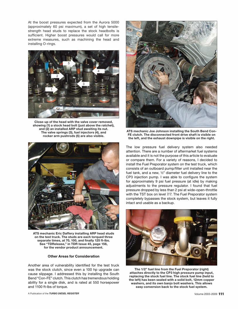
111A Publication of the TURBO DIESEL REGISTER Volume 2003-2009
At the boost pressures expected from the Aurora 5000 (approximately 60 psi maximum), a set of high tensile-strength head studs to replace the stock headbolts is sufficient. Higher boost pressures would call for more extreme measures, such as machining the head and installing O-rings.
Close-up of the head with the valve cover removed, showing (1) a stock head bolt (just above the ratchet),
and (2) an installed ARP stud awaiting its nut. The valve springs (3), fuel injectors (4), and
rocker arm pushrods (5) are also visible.
ATS mechanic Eric Daffery installing ARP head studs on the test truck. The studs are each torqued three
separate times, at 70, 100, and finally 125 ft-lbs. See “TDRelease,” in TDR Issue 45, page 156,
for the vendor product announcement.
Other Areas for Consideration
Another area of vulnerability identified for the test truck was the stock clutch, since even a 100 hp upgrade can cause slippage. I addressed this by installing the South Bend “Con-FE” clutch. This clutch has tremendous holding ability for a single disk, and is rated at 550 horsepower and 1100 ft-lbs of torque.
ATS mechanic Joe Johnson installing the South Bend Con-FE clutch. The disconnected front drive shaft is visible on the left, and the exhaust downpipe is visible on the right.
The low pressure fuel delivery system also needed attention. There are a number of aftermarket fuel systems available and it is not the purpose of this article to evaluate or compare them. For a variety of reasons, I decided to install the Fuel Preporator system on the test truck, which consists of an outboard pump/filter unit installed near the fuel tank, and a new, ½” diameter fuel delivery line to the CP3 injection pump. I was able to configure the system for approximately 9 psi fuel pressure (at idle) by making adjustments to the pressure regulator. I found that fuel pressure dropped by less than 2 psi at wide-open-throttle with the TST box on level 7/7. The Fuel Preporator system completely bypasses the stock system, but leaves it fully intact and usable as a backup.
The 1/2” fuel line from the Fuel Preporator (right) attaches directly to the CP3 high pressure pump input, replacing the stock fuel line. The stock fuel line (held to the left) has been sealed with a solid bolt, 12mm copper
washers, and its own banjo bolt washers. This allows easy conversion back to the stock fuel system.

112 A Publication of the TURBO DIESEL REGISTERVolume 2003-2009
Measurement Instruments
I have referred to a number of different measurement data in this article without describing the measurement tools that I used. As in TDR Issue 48, I used SPA technique digital gauges, which provided the capability to capture a number of parameters simultaneously. For example, the gauges enabled me to study the relationship between boost pressure and compressor output temperature, and the relationship between boost pressure and drive pressure.
Below is a picture of the gauge cluster used on the test truck. On the left is an SPA dual pressure gauge: the top channel is displaying fuel pressure from the Fuel Preporator at 8.6 psi; the bottom channel is displaying turbocharger drive pressure at 19.1 psi. In the center is an SPA dual temperature gauge: the top channel is displaying turbocharger compressor output temperature; the bottom channel is measuring post-turbo exhaust gas temperature. On the right is the rail pressure gauge mentioned in TDR Issue 48, reading approximately 23,500 psi (stock maximum). The vehicle was under moderate load at approximately 75 mph during this measurement. The reason rail pressure was at stock maximum under only moderate load is because a pressure-type fueling box was installed. The SPA boost/EGT gauge, used to collect boost pressure and pre-turbo exhaust gas temperature (EGT) data, is not shown.
Gauge cluster installed on the test truck, capturing several parameters while the vehicle was moving. Not
shown is an SPA pre-turbo EGT and boost gauge.
Test Results
With the test truck notably upgraded, I was prepared to test the TST PowerMaxCR fueling box. For a variety of reasons, I was not able to test on both the load-type and inertia-type dynos. I ended up back at Meridian Motorsports, the same test facility that I used for all of the products tested in Issue 48. Their Dynojet inertia-type dyno would provide apples-to-apples comparison numbers to the test in Issue 48.
The first result of note is the stock fueling run made with the Aurora 5000 turbocharger installed, and only “boost fooling” provided by the TST box on level 0/0. With this configuration, the air provided by the Aurora developed approximately 2-3 psi more boost (than stock) and the truck made approximately 20 peak horsepower more than stock. Notice the very slow spool-up of the bottom run in the graph, caused by the use of stock fueling with the big Aurora 5000 turbocharger.
Horsepower and torque curves produced by stock fueling on the test truck. With the Aurora 5000
turbocharger and the TST box “off” (level 0/0), spool-up was much slower on the Dynojet, but resulted in
a gain of approximately 20 peak horsepower.
The second result is the performance of the TST box itself, fully utilized with sufficient air and a clutch that was able to hold. The slow spool-up condition caused by the large turbocharger tested on the inertia dynamometer is evident. The configuration generated approximately 500 uncorrected peak horsepower. This run produced 52.9 psi of boost, 61.7 lbs of drive pressure in the exhaust manifold, and 1384 degrees pre-turbo EGT.
The test truck made approximately 500 uncorrected peak horsepower on the Dynojet with the Aurora 5000
turbocharger and TST fueling box set to level 7/7.

113A Publication of the TURBO DIESEL REGISTER Volume 2003-2009
The performance of the turbocharger itself is also of interest, since we are attempting to generate high boost pressures with a greater number of air molecules as opposed to just hotter ones. Recall from issue 48 (page 56) that the stock turbocharger appears to be out of its efficiency map above approximately 24-26 lbs, producing high compressor output air temperatures at these boost pressures.
For this article, I collected some new test data (on the stock turbocharger) during actual driving conditions and compared it with Aurora 5000 performance under similar conditions. The results are revealing. In my tests, I found the Aurora 5000 delivers 50-75 degrees cooler air, producing a higher “charge air density.” This means that for a given boost pressure, the Aurora turbocharger delivers a greater number of air molecules, satisfying the need for more, not just hotter air to create boost.
Scattergram of compressor output temperature versus boost, for both the stock turbocharger and the ATS Aurora 5000 “big single”. Note how much cooler the Aurora runs: The air delivered to the intercooler is approximately 50-75
degrees cooler than produced by the stock turbo.
Conclusions/Summary
• The “load type” and “inerta type” dynamometers each have advantages and disadvantages and unique susceptibilities to bias in their measurements. The best approach for measuring change is to understand the dynamometer you are using and do before and after measurements on the same machine.
• The stock turbocharger is useful for only mild power enhancements. The use of aggressive fueling severely compromises long-term reliability and can cause catastrophic failure.
• A wide variety of large turbochargers are now commercially available for the high-pressure, common rail engines, each having its own particular performance characteristics. The choice of a big single turbocharger, such as the Aurora 5000 used in the test truck, will more efficiently generate high boost pressures, but may spool slowly and exhibit a surge limit for low engine rpms and high engine loads.
• When boost pressures exceed the mid 40s, the use of high-strength head studs may be advised to maintain headgasket integrity.
• The use of both pre-turbocharger and post-turbocharger exhaust gas temperature gauges may be helpful when greatly enhanced fueling is utilized, or if the turbocharger has been upgraded to a large, specialized one. The new turbine design may require extra cool-down time after a hard run, and premature engine shutdown could severely stress the engine oil that lubricates and cools the turbocharger bearings. In my tests, I let the post-turbocharger EGT fall to 330° before engine shutdown, and found that the large Aurora 5000 turbine required extra cool-down time compared to the stock turbocharger.
• At the 500 horsepower level, higher than stock fuel pressures on the low-pressure side do not appear to be necessary. In my tests, the pressure-regulated Fuel Preporator installed on the test truck provided sufficient fuel, generating about 9 psi at idle and 7 psi at wide-open-throttle.
• At the 500 horsepower level, we are pushing the limits of a single-disk clutch. However, the South Bend Con-FE clutch appeared to hold well in my tests, and is rated for 550 hp. Such a strong clutch has a different feel to it, and may not engage quite as smoothly as the stock clutch.

114 A Publication of the TURBO DIESEL REGISTERVolume 2003-2009
Vendors/Suppliers and manufacturers mentioned
ATS Diesel Performance 5293 Ward Road
Arvada, CO 800-949-6002
www.atsdiesel.com
Automotive Racing Products 1863 Eastman Ave, Ventura, CA 93003
800-826-3045 www.arp-bolts.com
Dynojet Research, Inc. 2191 Mendenhall Drive
North Las Vegas, NV 89081 1-800-992-3525
www.dynojet.com
PureFlow Technologies, Inc 5400 Business 50 W, Suite 8
Jefferson City, MO 65109 877-463 - 4373
www.fuelpreporator.com
Meridian Motorsports 521 E King
Meridian, ID 83642 208-887-2058
Mustang Dynamometer 2300 Pinnacle Parkway, Twinsburg, Ohio 44087
888-468-7826 www.mustangdyne.com
South Bend Clutch 709 W Jefferson Blvd Mishawaka, IN 46545
1-800-988-4345 www.southbendclutch.com
SPA Technique, Inc 1209 Indy Way
Indianapolis, IN 46214 317-271-7941
www.spatechnique.com
TST Products, Inc 7440 S International Dr
Columbus, IN 47201 812-342-6741
www.tstproducts.com
Doug Leno Joe Donnelly TDR Writer Technical Editor
COMMENTS AND CLARIFICATIONS FROM TST
TST spent almost two years bringing the PowerMax CR to market. We continually test various intake modifications and exhaust modifications and have found none that made a measurable positive difference. TST’s goal is to make the most usable power for the dollar; we don’t want our customers to feel they have to buy a package deal to get the benefit.
We run hundreds of load dyno runs to determine what boost levels give the best power per EGT and determined that approximately 35 psi gives the best temperature for a given full power ( a 9/9 setting approximates 450+ horsepower). We have not heard of a destroyed stock turbo when the PowerMax CR was the only power addition used along with the wastegate modification that we recommend and supply with our units.
Just like the fuel delivery capacity on a ’89-’93 Bosch VE fuel pump was approximately 225 horsepower, there is only so much power to be derived from the Bosch CP3 stock pump. At the 9/9 setting the stock CP3 pump is at its maximum capacity.
Mark Chapple TST Products
EDITOR’S NOTES
Writer Doug Leno’s use of an aftermarket turbocharger and exhaust manifold to go with the TST PowerMax differs from the comments of TST Products’ owner Mark Chapple. I understand the difference of opinion and suggest that the final answer depends on the customer’s intended use for the power upgrade as well as the duty-cycle that the engine and driveline will be expected to endure. Is it not fun to have to make choices?
Robert Patton TDR Staff

115A Publication of the TURBO DIESEL REGISTER Volume 2003-2009
PART FOUR: FUELING BOX POWER ENHANCEMENTS FOR THE ’03-’04 (305HP) ENGINES
In part three of this series (Issue 49, page 36) I reported achieving 500-plus horsepower at the rear wheels by using the TST PowerMax CR fueling enhancement and the ATS Aurora 5000 large single turbocharger.
This article continues to analyze power enhancement products by reviewing three new aftermarket fueling choices that deliver approximately 350 to 400 horsepower to the rear wheels. A different turbocharger choice, the ATS Aurora 2000 “small single,” which is appropriately sized for the 350 to 400 power levels, will be discussed. The turbocharger is central to any power enhancement project, as it ultimately determines the amount of air passing through the engine, as well as dictating tradeoffs between drivability and the power levels it can reliably support.
Throughout the article, I will present data comparing the Aurora 2000 with the Holset HY-35 as supplied on the stock truck. It is not my purpose to restate the shortcomings of the HY-35 in higher-than-stock horsepower applications, as this has already been thoroughly discussed throughout this series and in other articles as well (see Joe Donnelly’s discussion in Issue 52, page 98). While some mention will be unavoidable, I will concentrate on performance comparisons during actual driving conditions to show how theory correlates to the real world. The testing will show that the primary role of the turbocharger is to increase the air passing through the engine and, as in the previous articles, I will compare some of the important turbocharger performance parameters such as compressor output, temperature, and drive pressure.
Characteristics of the Small Single Turbocharger
I follow the general practice of describing the size of a turbocharger by referring to its compressor in terms of “small single” and “large single” which are used quite subjectively.
While the specific turbochargers tested here and in Issue 49 fit these generalizations, one should realize that there is much more to turbocharger performance than compressor size. Every design is a unique combination of individual components (turbine and compressor wheels, exhaust housings, compressor housings, bearings, wastegates, etc.) selected to fit a specific design goal. It is interesting to note that some turbocharger manufacturers build and/or market the entire product from the ground up, some achieve particular design goals by assembling purchased components, and still others build final products from
a combination of purchased and proprietary (or even modified) components.
At the risk of oversimplification, there are some points worth making about turbochargers with small compressors versus those with large compressors. Generally, the small single/small compressor turbocharger will produce:
1. Faster spool-up, due to the smaller size of the compressor and exhaust housing
2. Less (or zero) tendency to surge because a greater portion of actual driving conditions are within the compressor’s efficiency map
3. Higher exhaust gas temperatures (at higher power and boost levels) due to less efficient turbines and compressors.
The ATS Aurora 2000 Small Single Turbocharger
The ATS Aurora 2000 is designated as a small single because of the smaller size of its compressor. The picture shows the Aurora 2000 and, for comparison purposes, the Aurora 5000 large single turbocharger that was tested in Issue 49.
The ATS Aurora 2000 small single, right, shown next to the Aurora 5000 large single, left. Note the smaller compressor
housing of the Aurora 2000, used to achieve fast spool-up. The Aurora 2000 is useful for power levels up to approximately 450 horsepower at the rear wheels.
As it turns out, the stock Holset HY-35 compressor is similar in size externally to the Aurora 2000 compressor, and it fits the small single designation as well. However, this is where the resemblance ends. Test data confirm that the Aurora 2000 has a much more efficient turbine
5.9-LITER ENGINE PERFORMANCE ENHANCEMENTS – TO MODIFy OR NOT TO MODIFy
3G PERFORMANCE ENHANCEMENTS - PART IVISSUE 53 - TECHNICAL TOPICS

116 A Publication of the TURBO DIESEL REGISTERVolume 2003-2009
than that which is found in the stock turbocharger, and the Aurora 2000 is capable of substantially higher air flow. For comparison, from Issue 49, page 39, is a picture of the stock turbocharger next to the Aurora 5000.
The very large ATS Aurora 5000, left, shown next to the stock turbocharger supplied for the ‘04.5-‘05 trucks (center) and for the ‘03-‘04 trucks (far right). The Aurora
5000 compressor loves high engine rpm, spools very aggressively starting from about 10-15 psi,
and easily achieves 50+ psi.
For additional comparison purposes the Aurora 2000 turbine (right) is shown next to the Aurora 5000 turbine.
The Aurora 2000 turbine lowers drive pressure and increases turbine efficiency compared to the stock Holset
HY35 turbo (not shown) without sacrificing spool-up.
Inside the Aurora 2000 Cartridge
The Aurora 2000 is a hybrid design built around a combination of purchased internal parts (wheels and bearings), and proprietary castings manufactured by ATS. The internal components have been selected for extreme durability, high rpm and heat tolerance, as evidenced by the three-year, 150,000 mile warranty. The shaft bearings, normally stationary in conventional designs (including the stock turbocharger), are themselves allowed to spin independently of the shaft they support, creating dual-concentric oil film surfaces to bear the load. This greatly increases durability and allows for very fast wheel acceleration. The dual-concentric bearing design can also endure extremely high shaft rpm because the oil film directly supporting the shaft itself (inner bearing surface) sees only about half of the actual shaft rpm.
Figure 2 shows the simple bearing structure of the stock HY-35 turbocharger. The shaft itself (not shown) extends from one bearing, through the spring, and into the opposite bearing. The purpose of the spring is to spread the bearings apart, forcing them against the machined surface of the cartridge.
Figure 2: Simple, low-cost bearing structure of the stock turbocharger. The bearings are held in
place by the spring (forcing them outward against the cartridge) and see the full rpm of the shaft.
Figure 3 shows the more robust bearing structure of the Aurora 2000. Not only are the bearings themselves larger, each bearing is kept in place by two snap rings instead of a separating spring. This precision placement allows them to fit into an oil-fed, machined race so that they can rotate with respect to the cartridge housing.
Figure 3: More robust bearing structure of the Aurora 2000. The bearings are held in place with snap rings which allows precision placement in the cartridge. The bearings rotate with respect to the cartridge and independently from the
shaft, and see only about half of the actual shaft rpm.

117A Publication of the TURBO DIESEL REGISTER Volume 2003-2009
The castings manufactured by ATS contain proprietary alloy formulas which are optimized for heat tolerance and resistance to cracking. The in-house foundry allows them to manufacture custom geometries to obtain bolt-on compatibility with the stock exhaust system. This means that the various aftermarket exhaust brakes (which take the place of the stock cast elbow) are bolt-on compatible with the Aurora 2000.
During this evaluation two other components were installed on the test truck: The ATS two-piece exhaust manifold and the Scotty 3 air intake system from Scotty Systems. The exhaust manifold was recommended by ATS as a more durable, heat tolerant component. It is virtually immune to cracking, because of the interference fit that expands and contracts as needed, and also because of the particular alloy formulations used in its manufacture. I found the Scotty 3 air system (Issue 52, page 95) to be an effective companion to the Aurora 2000 turbocharger. Because of its enclosed design, the Scotty 3 is effective at quieting down an otherwise noisy turbocharger. In addition, the dual-inlet design brings in air from the front grille as well as the stock location (right front fender), and its two-stage, oiled foam filter is an excellent combination of filtration efficiency and flow. In my tests of similar filter media using engine lube oil analysis, I found silica levels (a typical indicator of dirt) to be as low as I have ever tested.
Initial driving tests
With these parts installed on the test truck, the first thing I did was to run the Aurora 2000 at the stock fueling level. I wanted to see how responsive the turbocharger was and how closely its performance worked with the OEM fueling curves. Were it not for the increased whine from the compressor, largely muffled by the Scotty 3, it was difficult to tell that I had installed an aftermarket turbocharger. Spool-up was very nearly the same, and the turbocharger easily sailed into the 26 psi (boost pressure) region, which for the ‘03-’04 trucks is higher than the stock ECM allows. Because the Aurora 2000 contains no wastegate and is therefore capable of higher boost levels than stock, I found that the ECM de-fueled fairly aggressively to control maximum boost levels. This was reflected on the dyno, where the horsepower curve showed a particular wavy behavior as the ECM corrected for what it thought was too high of a boost level (see page 18 for the horsepower graphs). Thus, it is obvious that the Aurora 2000 should be used with a power module that utilizes “boost fooling” logic to the ECM.
Changing to higher fueling levels, I found the Aurora 2000 turbocharger to be quite happy in the 400 horsepower region, producing boost pressures into the mid 30s at 2,700 feet above sea level. This turbocharger is well suited for maximum boost pressures in the upper 20s to low 30s as well as for sustained operation at 350 to 400 horsepower. Its durability suggests that it could easily accommodate bursts into the mid 30s and 450 horsepower. Presenting absolutely no surge behavior, this turbocharger appears to be well suited for towing.
TURBOCHARGER PERFORMANCE MEASUREMENTS
Next up I will evaluate the Aurora 2000 against the stock turbo under driving conditions. Consistent with Issue 49, I collected data on the compressor and turbine sides individually (via compressor output temperature and drive pressure, respectively). For this article, I was able to collect meaningful exhaust gas temperature data as well. Typically exhaust temperature studies suffer from repeatability and accuracy problems as weather and driving conditions vary. But by collecting a substantial amount of data (some 700 points) over the same test loop with consistent daytime temperatures, I was able to generate a compelling set of results. I used slow and deliberate acceleration and then captured data points simultaneously using a SPA digital gauge’s peak detect functions.
The areas of study will be as follows:
• Compressor output temperature• Drive pressure• Exhaust Gas Temperature• Turbine Differential Temperature
Compressor Output Temperature
I measured compressor output temperatures by inserting a lowtemperature thermocouple directly into the compressor discharge. I also measured the intake air temperature on the turbocharger side of the air filter, and subtracted this figure from the compressor output temperature. As the goal of the turbocharger is to increase air passing through the engine without too much heat build-up, any reduction in the air temperature exiting the turbocharger is welcome. Figure 4 is a graph comparing the compressor output temperature of the Aurora 2000 with that of the stock HY-35.
Figure 4: Scattergram of normalized compressor output temperature versus boost, for both the stock turbocharger
and the ATS Aurora 2000 small single under highway driving conditions. At 2000 rpm, the air delivered to the
intercooler by the Aurora is approximately 10-20 degrees cooler than that produced by the stock turbo.

118 A Publication of the TURBO DIESEL REGISTERVolume 2003-2009
Drive Pressure
The pressure of exhaust gasses in the manifold, referred to as drive pressure, tells you how efficiently the turbocharger evacuates exhaust gasses through the turbocharger exhaust housing, past the turbine wheel, and into the exhaust downpipe. The small exhaust housing of the stock turbocharger serves to accelerate exhaust gasses as they approach the turbine wheel. This design yields very fast spool-up and supports moderate power levels, but presents a pressure restriction as the exhaust gasses exit the manifold. Such a restriction manifests itself in the form of drive pressures that are higher than incoming boost pressures and results in high exhaust gas temperatures.
Figure 5 shows the drive pressure behavior of the Aurora 2000 turbine at cruising speeds. The straight line in the graph represents the condition where drive pressure equals boost pressure. Note that for the Aurora 2000, drive pressure is typically lower than boost pressure. By comparison, the stock turbocharger runs with a drive pressure that is always higher than boost pressure. Comparing the two turbochargers against each other reveals that the Aurora 2000 runs approximately 5 psi lower in drive pressure during moderate to high boost pressures.
Figure 5: Scattergram of turbocharger drive pressure, comparing the Aurora 2000 with the stock HY-35 at 2000 rpm. The Aurora runs with drive pressure approximately
equal to or less than boost pressure.
Exhaust Gas Temperature
The Aurora 2000 was specifically designed to address high exhaust gas temperatures during heavy loads. With its responsive spool-up behavior, I wondered how much improvement I would see compared to the stock turbo. Figure 6 shows actual exhaust gas temperatures measured using the Aurora 2000 and the stock turbo. The temperatures were measured pre-turbo (in the exhaust manifold) under the same driving conditions over the same stretch of highway. Two striking features emerge from the data:
1. The Aurora 2000 actually ran a tiny bit hotter than the stock turbocharger at low to moderate boost pressures. Under these conditions both turbochargers performed very well in this region, producing exhaust gas temperatures well below 1000°.
2. The real story is in the shape of the exhaust gas temperature curves at high boost pressures. Here the Aurora 2000 clearly outperforms the stock turbocharger. At boost pressures above the low 20s, the graph shows how fast exhaust gas temperatures rise for the stock turbocharger approaching approximately 1300° at 25 psi of boost. The Aurora delivered a 300° exhaust gas temperature advantage at this power level.
Figure 6: Graph of actual exhaust gas temperatures under equivalent driving conditions, comparing the Aurora 2000 with the stock turbocharger. When boost pressures are in the low 20s to low 30s, the stock turbocharger does not operate efficiently while the Aurora 2000 is quite happy.
Turbine Differential Temperature
The Figure 7 scattergram shows the difference between pre-turbo and post-turbo exhaust temperatures, or turbine differential temperature. The results are quite revealing. I installed two identical SPA exhaust gas temperature gauges in the test truck (one before the turbocharger and one after) I was able to meaningfully compare the performance of both the stock and the Aurora 2000 turbines under the same conditions. As an aside, the Aurora 2000 itself provided an additional convenience: because it bolts up to the same exhaust cast elbow utilized by the stock turbocharger, I was able to use the same thermocouple install locations for both turbochargers.
Do you notice the similarity in shape of figure 6 to figure 7? The data shows why the Aurora 2000 yields such impressive exhaust gas temperature performance with boost pressure well into the mid-30s. As boost approaches the mid 20s, the stock turbine doesn’t efficiently utilize the energy in the exiting exhaust gasses, causing turbine differential temperature to rise significantly. Over this same region the turbine differential temperature of the Aurora 2000 remains relatively constant, revealing a more efficient design.

119A Publication of the TURBO DIESEL REGISTER Volume 2003-2009
Figure 7: Scattergram of turbine differential temperature, comparing the stock HY-35 to the Aurora 2000. The similarity in shape between this graph and Figure 6
shows that the superior exhaust gas temperature behavior of the Aurora 2000 is largely due to turbine efficiency.
This result also shows why attempts to increase boost by disabling or modifying the wastegate of the stock turbocharger have not met with resounding success. The limitation is in the entire turbine assembly: the turbine wheel and exhaust housing, not just the wastegate set point. The data shows that when boost is high, the energy trapped in the turbine itself (in the form of heat) rises significantly. This means any additional boost created by modifying the wastegate is useless because the turbine cannot evacuate the additional air. The result is additional stress on the turbocharger bearings due to increased shaft rpm and higher (but useless) boost pressures.
Recall my earlier statement that the primary role of the turbocharger is to increase air passing through the engine. While we tend to emphasize the air intake side, compressor efficiency and the importance of supplying cool air to the engine, it is just as important to consider the exhaust side, turbine efficiency and the importance of evacuating hot air from the engine. The previous two graphs show that the compressor side of the Aurora 2000 is more efficient than that of the stock turbocharger at the test point of 400 horsepower. And you should note that the exhaust gas temperature advantage of the Aurora 2000 at high boost pressures is most heavily influenced by its turbine.
Small Single Turbocharger Conclusion/Summary
• The obvious: The stock HY35 turbocharger is a good match for the stock 305 horsepower or 325 horsepower rated HPCR engines.
• Modern small single compressor designs, with extended compressor wheels and more efficient housings, can deliver a greater charge density and increase power output when compared to the stock turbocharger. For example, the Aurora 2000 with a four-inch exhaust and Scotty 3 air system installed produced 27 additional horsepower in the tests presented here (page 18, first graph).
• At high boost pressures the turbine of the stock turbocharger shows a sharp increase in turbine differential temperature, trapping energy in the turbine and preventing the evacuation of exhaust gasses. An aftermarket design, such as the Aurora 2000, can dramatically improve exhaust gas temperature behavior and increase usable power.
• By making efficiency improvements to both the turbine and compressor sides, an aftermarket small single turbocharger can be a good replacement for the stock unit supporting moderate power increases while maintaining stock-like drivability.
AFTERMARKET FUELING ENHANCEMENTS
To update the previous articles in this series let’s look at three additional aftermarket fueling modules for the HPCR engine. Since it has been some time since the introductory article appeared Issue 47, February ‘05, a short review of the way I categorize fueling enhancements is appropriate. I have chosen to describe the performance modules by how they connect to the engine and/or the parameters they control directly. The descriptive and the table below summarize the modules’ attributes.
Performance Module Notes
Type: This column lists the parameters directly controlled in order to obtain power gains. There are three specific techniques used individually or in combination: (1) “Pressure” refers to raising the pressure inside the common fuel rail through the use of “pressure fooling” to make the ECM compensate for what it thinks is low rail pressure. (2) “Duration” refers to extending the length of time the injector stays open, either by manipulating the low-voltage injector control signals or the high-voltage signals via the injector harness. (3) “Timing” refers to changing the injector event itself to occur earlier in time.
Boost fooling method: This refers to the fact that some external boxes simply limit (cap) the boost signal as seen by the ECM, and some dynamically enhance the boost signal in order to coax the ECM into fueling differently. Both of the external boxes (Edge and Quadzilla) tested manipulate the boost signal.

120 A Publication of the TURBO DIESEL REGISTERVolume 2003-2009
Additional Comments on the Products:
The Edge Juice w/Attitude provides numerous features, such as power adjustability, performance tests, and adjustable threshold alarms. The product announcement and additional detail can be found in Issue 49 on page 159. An interesting observation I made when testing this box was that it produced exhaust gas temperatures equivalent to the Quadzilla pressure box at the same power levels. This is an important observation because the Juice module uses a combination of injector duration and pressure to obtain power, while the Quadzilla uses predominantly pressure. These two modules delivered approximately the same power (withing 4-5 horsepower) to the ground. I would normally expect that, without a corresponding timing advance, the use of injector duration would result in elevated exhaust gas temperatures. The engineers at Edge have developed a unique technology for accomplishing timing advance without connecting to the cam or crank sensors. The advance is accomplished via a direct connection to the injectors. The use of timing advance to compensate for extended injector duration which causes high EGTs has been demonstrated previously in Issue 48, page 54. In that test I found that the timing advance capability of the TST PowerMax CR more than compensated for the use of extended injector duration at the 90 horsepower level. When configured for approximately 90 horsepower gain, the TST PowerMax CR produced slightly lower exhaust gas temperatures in my tests than a pressure-type box of the same power level.
The Quadzilla Xzillaraider is predominantly a pressure box, but it utilizes a connection to the CAN bus (‘03-‘05 trucks) or the throttle position sensor (‘06 trucks) to improve drivability. With the six-speed manual transmission in my truck, there is no torque converter to absorb an overly-responsive throttle. I have found that most pressure boxes in the 100 horsepower range are too responsive. Usually, when testing a pressure box, I find myself reaching for the adjustment knob to turn it down while driving in the city, but I did not feel as compelled to do that when running the Xzillaraider. The drivability of this box (responsiveness and power without being jumpy) is excellent. One unique difference between the Xzillaraider and other boxes is its extraordinarily small size (about 2½ x 1¾ inches), and the fact that it mounts inside the cab, tucked up above the pedals.
The ATS Xcelerator is a download device that programs new software into the engine’s ECM. No external boxes or connections are required, other than performing the download via the OBD connection port inside the cab. Three different power upgrade programs are supplied with the Xcelerator: Towing (nice power), Performance (wow), and Extreme (meet me at the track!). In my tests, the Xcelerator showed excellent drivability with the Tow and Performance downloads which yielded up to 415 rear wheel horsepower. Exhaust gas temperatures were comparable to the Quadzilla and Edge boxes for the same power level, suggesting that it too performs substantial timing advance (via software). I was not able to measure any increase in rail pressure for the programs I downloaded. The Xcelerator extreme program is more powerful than either the Edge or the Quadzilla boxes that I tested, making approximately 443 horsepower at the rear wheels with the ATS Aurora 2000 turbocharger. The extreme program was profoundly responsive, even jumpy, confirming that this setting is intended for racing.
Comparative Matrix
Product Type Boost Fooling Method
Engine Connections Adjustability Features
Edge Juice with Attitude
Pressure, Duration, Timing
Enhanced low-boost fueling,
Adjustable
Injector control harness, MAP
sensor, rail pressure sensor,
CAN bus
In-cab on the fly electronic display
100 HP achieved without a large
increase in rail pressure,
numerous display features.
Quadzilla Xzilleraider Pressure, Timing
Enhanced low-boost fueling,
Non-adjustable
MAP sensor, rail pressure sensor, throttle position sensor, CAN bus
0-30-60-100 HP four position
rotary switch.
Drivability, easy install
ATS Xcellerator Downloader
Duration and Timing via software.
N/A. The boost limit itself is adjusted via
software.
N/A
Once the softwre of choice is
downloaded, it cannot be
adjusted.
Impressive power gains with no external box.

121A Publication of the TURBO DIESEL REGISTER Volume 2003-2009
Performance Tests
The three power enhancement products were tested on a DynoJet 248c at Meridian Motorsports, Meridian, Idaho. As a departure from my previous work, I used SAE correction factors (the altitude is 2700 feet in Meridian) for the peak horsepower and torque measurements this time. After all, these numbers are more fun to look at because they are higher than the uncorrected figures presented in previous articles.
Stock Fueling (1): The Aurora 2000, Scotty Air 3, and big exhaust show a 57 ft-lb increase in torque. Without boost
fooling, however, the stock ECM trips over the higher boost levels of the Aurora 2000 and limits peak horsepower.
The dyno runs labeled “Stock Fueling (1)” deserve additional comment. Note the bottom run (stock trk.001), representing the stock truck at 283 horsepower at the rear wheels. This seems a bit generous, as it represents only 7% power loss in the drivetrain (assuming the engine delivers exactly 305 horsepower to the flywheel per stock specifications). Noting that the run was made with the standard transmission in fifth gear (1:1), I chose to accept the “SAE corrected” horsepower from the Dynojet as accurate.
The top run (stock trk+Aurora 2000.001) represents the addition of the Aurora 2000 turbocharger, Scotty 3 air system and a four inch exhaust. This change yielded an impressive 57 ft-lb increase in torque. However, because the stock ECM saw the higher boost pressures of the Aurora 2000, it de-fueled significantly (due to no boost fooling) which limited peak horsepower.
The set of dyno runs labeled “Stock Fueling (2)” also deserve comment. When I ran the TST PowerMax on Level 1 (timing only) using the stock turbocharger, it showed a clear 30 horsepower gain. This is shown by the bottom run (stock trk.001) and the middle run (TST 1-1 stock turbo.001) on the graph. The highest run (TST 1-1 Aurora 2000.001) shows an additional 27 horsepower gain from the Aurora 2000 when combined with big exhaust and the Scotty 3 intake. This equals a total of 57 horsepower just from air, timing, and boost fooling.
Stock Fueling (2): The TST PowerMax CR on Level 1(timing only) clearly shows a 30 horsepower increase with the stock turbocharger. Adding the Aurora 2000, big exhaust, and Scotty Air 3 yielded an additional 27
horsepower gain, for a total 57 horsepower from timingand air combined. The benefits of charge air density!
Edge Juice with Attitude: 395 hp/718 torque
Quadzilla Xzillaraider: 399 hp/794 torque
ATS Xcelerator downloader: 443 hp/890 torque

122 A Publication of the TURBO DIESEL REGISTERVolume 2003-2009
RAIL PRESSURE UPDATE
Along with my studies of rail pressure (see TDR Issue 48, page 50) I have been investigating the ways in which rail pressure can be measured using the factory (Bosch) rail pressure sending unit. The technique I have used thus far employs an analog gauge with the prototype specially made by Pricol. The responsiveness of the gauge has been tuned so that it is fast enough to reflect sudden changes in rail pressure, but slow enough so that it is not fooled by high-frequency, instantaneous spikes in the rail that naturally occur.
In a recent set of tests, I used a fast digital voltmeter (Fluke 189) with a peak detect feature to better understand the behavior of “instantaneous spikes” in the rail. The Fluke would often detect peak values in the rail that were difficult to correlate with the power levels used. Why is this discovery important? It confirms that watching the needle of an analog gauge, such as the Pricol prototype I have been using, is still the best real-time diagnostic indicator of rail pressure. Even though I have used digital gauges for the other eight parameters I have studied during this article series, I find that the dynamic nature of rail pressure lends itself well to the analog gauge.
Using the Pricol gauge I have been able to study the following:
• Dynamic rail pressure behavior under stock conditions such as idle, cruise, acceleration runs, and WOT.
• General effect on the rail from the use of aftermarket performance modules.
• Elevated rail pressure under cruise conditions from the use of pressure fooling-type performance modules.
• Detection of sudden rail pressure decreases from the use of excessive fueling beyond the ability of the CP3 to maintain pressure in the rail.
• Touchy throttle response due to aggressive pressure fooling.
• The saturation point of the factory sensor and the highest possible pressure that can be directly measured or detected.
The new gauge will be part of the Pricol Optix™ series, which we hope will be available through at least one retailer by the time this article is published. The prototype (black face) gauge is shown reading approximately 5,000 psi rail pressure obtained at curb idle on the test truck. The production offering will be the white face design matching the Dodge instrument panel.
New PSI rail pressure gauge from Pricol,for the ‘03-’06 Turbo Diesels, showing approximately
5,000 psi at curb idle. The maximum pressure thatcan be measured is limited by the factory sensorand is approximately 26,500 psi. The stock truck
maximum rail pressure is approximately 23,500 psi.
Vendors/Suppliers and manufacturers mentioned in this article
ATS Diesel Performance 5293 Ward Road
Arvada, CO 800-949-6002
www.atsdiesel.com
Edge Products 1080 South Depot Drive
Ogden, Utah 84404 888-360-3343
www.edgeproducts.com
Quadzilla Performance Technologies, Inc. 6016-A Jacksboro Hwy.
Fort Worth, TX 76135 888-842-6572
www.quadzillapower.com
Dynojet Research, Inc. 2191 Mendenhall Drive
North Las Vegas, NV 89081 1-800-992-3525
www.dynojet.com
TST Products, Inc 7440 S International Drive
Columbus, IN 47201 812-342-6741
www.tstproducts.com
Meridian Motorsports 521 E King
Meridian, ID 83642 208-887-2058
Scotty Systems 869 McIntosh Street
Regina, Saskatchewan S4T 5B5 Canada
www.scottysystems.ca
Doug LenoTDR Writer

123A Publication of the TURBO DIESEL REGISTER Volume 2003-2009
5.9-LITER ENGINE PERFORMANCE ENHANCEMENTS – TO MODIFy OR NOT TO MODIFy3G PERFORMANCE ENHANCEMENTS - EPILOGUE
ISSUE 93 - TECHNICAL TOPICS
PERFORMANCE
I didn’t make it too far into Issue 53 and there it was, “Part Four: Fueling Box Power Enhancements for the ’03-’04 (305HP) Engines” by Doug Leno. Part Four?
Yes, Leno had spent two years swapping hardware (the latest gonzo, ball-buster turbo) and software (rack ’em, jack ’em and stack ’em) in pursuit of 500 manageable horsepower for his 2004 Turbo Diesel truck that was originally delivered with a 305hp, high output engine and a manual NV5600 six-speed transmission. What was the culmination of his efforts?
Now, since it is 10 years later, I called Doug to ask for an update. He responded by using the article in Issue 53 (page 11) as the anchor point.
Doug Leno’s Performance Update
The Issue 53 article featured the benefits of replacing the stock Holset HY-35 turbocharger with an aftermarket, small-single turbocharger, the Aurora 2000 from ATS. I learned that the Aurora 2000 was a more efficient charger, as evidenced by drive pressure and compressor output temperature measurements, and provided cooler peak exhaust gas temperatures.
One year later, in Issue 57 (page 44) I was still chasing power, and discovered an astonishing 160hp gain when I added Dynomite Diesel Performance 90hp injectors, the TST PowerMax, and the ATS “Aurora 5000” compound turbocharger configuration: an Aurora 5000 “woofer” to the Aurora 2000 mentioned in Issue 53. For this level of power, I was also using a South Bend Dual Disk racing clutch, and I achieved 598hp on Lenny Reed’s “stingy dyno.” Ever perform a full throttle launch from a dead stop in third gear?
As a follow-up, in Issue 58 (page 48) I presented a discussion on the merits of compound turbochargers and referred back to my 600hp accomplishment outlined in Issue 57.
Advance the clock three years to February 2010 and Issue 68 (page 50) is where I started a change in course, dropping down to DDP 50hp injectors (instead of the 90s) to reduce smoke and improve fuel economy, and a quicker-spooling ATS “Aurora 4000 plus” compound turbocharger, which used the stock HY35 (with a modified wastegate) “on top” with the Aurora 4000 “on the bottom.” At 484 peak horsepower, this configuration was much more drivable. It turned out that my favorite power level of 437hp at the rear wheels could be obtained with the TST set to “level 3.” This setting also optimized my fuel economy at 21.5mpg, a respectable number indeed for this manual transmission truck outfitted with a 3” lift and off-road suspension.
In a surprising twist, it turns out that the power level I am targeting is close to what is currently available in new, unmodified trucks!
Since Issue 68 I have found that 484hp was still more than I needed, and have been planning another project targeting closer to my favorite of 437hp, discovered in Issue 68. I should be able to obtain this without the complexity of a compound turbocharger. Also, at approximately 130,000 miles I had to replace my injector bodies, which meant throwing away the DDP 50hp nozzles that no longer fit in the updated Bosch parts, so I am running stock injectors now. I am currently experimenting with Smarty Junior software-based fueling and a 425hp rated single disc clutch from South Bend that provides just the right compromise of pedal pressure, smoothness of engagement, and holding power. In a surprising twist, it turns out that the power level I am targeting is close to what is currently available in new, unmodified trucks!
Doug Leno TDR Writer

124 A Publication of the TURBO DIESEL REGISTERVolume 2003-2009
Many Third Generation trucks have surpassed the 250,000 milestone. With this thought in mind, the editor asked me to educate the audience on the 5.9-liter engine’s high pressure, common rail (HPCR) injector, as this precision component will need repair/replacement.
An Overview of Injectors
First, let’s take a look at the injectors themselves for the various generations of the Cummins B-series engine.
12-valve injector (’94-’98).
24-valve injector for ISB engine (’98.5-’02)
Common rail injector for ‘03-‘07 engines.
Common rail injectors for ‘07.5-up 6.7-liter engines.
Over the years, diesel fuel injectors have had to deal with increasing system fuel pressures to improve atomization of the injected fuel stream for decreased exhaust emissions. Corresponding to the increases in pressures and emissions regulations, the injectors have been built to ever-tightening specifications, including tighter clearances (millionths of an inch). The older ‘89-‘98 12-valve engines and the early ‘98.5-‘02 24-valve engines (up to 2002 model year) used mechanical injectors. These units use a stiff spring to hold the metering “valve” closed except when the injection pump sends a high pressure pulse of fuel through the line to the injector.
Beginning with the 2003 model year, substantially higher injection pressures were incorporated into the system, along with a major change in how the injectors were opened and closed. The new high pressure common rail (HPCR) is kept at high pressure from a simple pump whenever the engine is running. Thus, the injectors always have a high pressure fuel available and they are now opened and closed electrically. This change also allows the engine computer to open and close the injector more than once during a “firing” event. Beginning in 2003, a small injection occurs first, just before the main injection event. The early pulse is a major contributor to the quieter operation of these HPCR engines compared to earlier engines. For emissions reasons, later engines, the ‘04.5 to ‘07 model years, went to a total of three injections per firing event. In 2007.5 and later models (the 6.7-liter engine) four injections are used.
ENGINE AND TRANSMISSION MAINTENANCE
INJECTORS FOR HPCR ENGINES – INTRODUCTIONISSUE 66 - TECHNICAL TOPICS

125A Publication of the TURBO DIESEL REGISTER Volume 2003-2009
Injector topics have been discussed in some previous issues. Here are a few references:
• Injector installations, 12-valve, 24-valve, and HPCR, were covered in TDR Issue 51, page 94.
• Another reader’s (SAG2) approach to installing common rail injectors was presented in Issue 52, page 46.
• Scott Dalgleish visited Dynomite Diesel Performance (DDP), a high quality aftermarket injector shop, in Issue 56, page 96; and Issue 59, page 86.
• Common rail injector lines #4 and 6 have experienced failures. An updated line with a hold-down bracket was covered in Issue 56, page 108.
The stock injectors in all of our Turbo Diesels are made by Bosch. A useful First-Generation 12-valve upgrade injector is made by Lucas. For some engines, larger injectors from Bosch are available. The most successful (i.e. meaning serving a real purpose and “niche market”) are the 215hp 12-valve injector for the ’94-’98 12-valve engines and the 370hp “marine injector” for the 12-valve engines. A performance injector for the 24-valve engines used from ‘98.5 to ‘02 model years is the noteworthy 275hp “RV injector.” Most successful aftermarket injectors have been based on Bosch components. The stock nozzles, or other Bosch nozzles with larger holes for a different engine application, can be extrude-honed for greater flow.
In the extrude hone process, a very fine abrasive slurry is pumped through the nozzle under pressure. Done properly, the seat for the pintle (needle) is not “washed out,” but the entrances and exits of the holes are slightly rounded, and the cutting marks inside the holes are smoothed. The offset holes in the photos show that they are 12-valve nozzles, with 5 holes, as is the case for 12-valve engine applications.
Borescope view of the inside of a 12-valve injector nozzle.
Borescope view of an extrude honed nozzle.
An alternative to the extrude hone process for making higher fuel flow nozzles is electrical discharge machining (EDM) wherein electrical current is used to burn precise holes through the steel tip of the nozzle. Done properly, this process is not only good, but it is the way Bosch originally made the holes in their nozzles (around .007” to .012”). Done poorly, EDM can result in poorly shaped, poorly spaced holes with burns in the steel inside the nozzle, even at the seating area for the pintle.
Borescope view of a poorly manufactured nozzle by an EDM process.
The ‘94-’98 12-valve mechanical lift pump will support large power gains over stock. The electric pumps used in ‘98.5-’02 engines may not be adequate for more than a gain of about 60-70hp over stock. You can see pictures of these lift pumps in the Geno’s Garage catalog, which happens to be a good and convenient source for these repair parts. Particularly if your Turbo Diesel comes with an electric lift pump (all ’98.5 to current trucks have electric lift pumps), add a spare to your “boonie box” and monitor the performance of your lift pump with an electric gauge (so you won’t have diesel fuel in the cab). The range of most Turbo Diesel engines with stock turbos likewise may remain safe with up to 60-70hp more. However, these two components (the lift pump and the turbocharger) may be closer to “maxed out” with typical hop-ups on newer

126 A Publication of the TURBO DIESEL REGISTERVolume 2003-2009
Turbo Diesels than the older trucks were. In part this is because the older trucks started with lower horsepower levels. Check your fuel pressure gauge and see if the lift pump pressure stays above 5psi under full power. See if EGT gets too high under full power and/or heavy loads. Maximum EGT is around 1300°-1350° up to the 2002 model year; 1450° for ‘03-‘04; and 1500° for ‘04.5-up engines. For safety, it is a good idea to stay well under these maximums, particularly for long pulls.
In keeping with the editor’s “Groundhog Day” discussion in Issue 65’s editorial (you remember, the writer’s should use “suggested reading from your TDR archives…”), I will add some installation details to the basic instructions that I wrote about in Issue 51, starting on page 94.
Clean the injector wells so there is no grit at the sealing surface on the bottoms of them. For a 12-valve engine you can put a pushrod into the hole for the injector tip to block it, and blow the wells out with compressed air. 24-valve and HPCR injector wells stay clean except for engine oil and possibly deposits from the injector tips as they are pulled up through their holes into the combustion chambers. Run a rifle bore brush through the holes into the cylinders to clean out the passages that the injector tips go through. Wipe out the sealing areas where the copper washers rest on the bottom of the wells, with Q-tips. You can use a hollow 5/16” automobile pushrod that is partially squashed near the end to retain one end of the Q-tip so it can’t fall into the cylinder. Cleaning the wells is especially important with the thin .020” washers (used on 215hp 12-valve engines) as they are less able to have grit imbedded in them than thick ones. If there was any tiny grit on the injector parts when they were assembled, they will leak at the threaded junction between halves of the bodies. On a 12-valve injector, you will see fuel coming up around the hold-down nut. If you torque the 12-valve injector hold down 24 mm (15/16” socket works also) nuts too tightly, you will crack the bodies. Stay with the 44 ft-lb specification. The sealing ball area of the injector lines can get dirty or corroded, and subsequently leak. Usually cleaning with fine aluminum oxide or emery paper (600 or 800 grit) will take care of it. Be sure to spray off the area so no grit remains on the surface or inside the line. Don’t torque the line nut over 25-30 ft-lb; put a little grease on the threads and back side of the sealing ball where the nut grips it, to get a smooth torque reading and to prevent the line from twisting.
Focus on ’03-’07 5.9-liter HPCR Injectors
Overall, high quality aftermarket injectors are a significant and valuable component of a well-balanced performance strategy. They are more involved to install on ‘03-’07 HPCR engines than on earlier trucks. I have found that Stage 1 injectors (50-60hp gain) are a good, moderate compromise, suitable for daily driving, towing, and performance. At a small sacrifice in fuel mileage, Stage 2 injectors may be substituted. (DDP Stage 2 injectors are good for a 90hp gain.) Either should give similar mileage to stock injectors, or in some driving conditions, a little better than stock.
In Issue 56, page 96, Scott Dalgleish discussed his results with Dynomite Diesel Performance (DDP) injectors on his Third Generation Turbo Diesel. In his quest for mileage first, and power second, Scott chose a set of DDP Stage 1 injectors. His article described the manufacturing processes and provided dyno results verifying the horsepower claims of DDP. He reported an increase in fuel mileage of 8%, not accounting for the approximately 7% loss he associated with the winter fuel he was using at the time. This comes out to about 1.5-2.5mpg, estimating conservatively. Later, Scott went to Stage 2 injectors in Issue 59, page 86, and reported a 6% loss in fuel economy with them (compared to the Stage 1s) in Issue 60, page 84. Doug Leno gave us additional discussion and photos in Issue 57, page 45. He also chose Stage 2 injectors.
I have tried Diesel Dynamics injectors, F1 Stage 1 and 3 injectors. Unfortunately Diesel Dynamics is no longer in business. I have also used Dynomite Diesel (DDP) Stage 1. The various Stage 2’s gave mileage similar to stock. The Stage 1’s give a little better than stock, maybe 1mpg, and the Stage 3s were about 2mpg worse than stock. These numbers are approximate, because measuring mileage is difficult and mileage varies significantly under different conditions that are hard to control. With most of my usage being highway driving, moderate towing, and other tasks where mileage is more important than very high power, I am satisfied with my DDP super-precision set of Stage 1 injectors. My plan is to use electronics (box or program) on my 2004 Turbo Diesel to bring additional power when needed and get maximum economy when not using a lot of power.

127A Publication of the TURBO DIESEL REGISTER Volume 2003-2009
About a year ago, Bosch started supplying replacement HPCR injectors with stainless steel bodies for better durability against cracking and erosion of the fuel return seat. I have seen various types of injector failures, particularly on HPCR Turbo Diesels with over 150,000 miles. After all, they cycle two times per firing (on ‘03-‘04 Turbo Diesels). They cycle three times per firing on ‘04.5 through ‘07 engines, and five times on the new ‘07.5 engine (6.7- liter). Fuel pressures are higher, so any tiny residual particulates are more abrasive than on earlier engines. It is not reasonable to expect them to last as long as 12-valve or 24-valve injectors. While “chatter” during the fuel pulse made mechanical injectors wear more than you might think for one cycle per injection event, the springs were durable. In comparison, the electric solenoids are things with “minds of their own” and, as you know, electrical stuff can fail whenever it feels like it. These solenoids cycle the two to four times per injection event and have become a significant source of high-mileage failure on HPCR engines. The dirtier the fuel (3 micron filtration is the way to go, and FASS offers such a filter) and the higher the rail pressure, the faster the injectors wear out. Very high rail pressures (from pressure boxes mostly) and very high EGT’s contribute greatly to cracking and wear of moving parts inside the injectors.
For preventive maintenance, I got a completely new set of injectors with the stainless steel bodies at about 100,000 miles, and I asked Lenny Reed of DDP what would give the best mileage. He recommended his Stage 1 over anything else, including stock.
Six new DDP Stage 1 injectors with shiny white stainless steel bodies; and facing the other way is a used injector
with the regular gray colored steel body.
This photo shows six new DDP1 injectors with shiny white stainless steel bodies, and facing the other way is a used injector with the regular gray colored steel body. I have known Lenny for years and my very favorable impression of him was augmented by the information the other TDR writers gave in their articles, and the fact that DDP has invested around a half million dollars in test equipment, dynamometer, etc. to make the very best injectors possible. In particular, the HPCR injectors are much more complex to test and build than the injectors for the old
12-valve and 24-valve Turbo Diesels. DDP’s equipment rivals what Bosch uses, and indeed, DDP is a Bosch distributor and repair facility. I have included a photo of their Hartridge injector tester.
Hartridge injector tester to determine leakage, flow rate, and response time.
Their computerized endoscope (bore scope) from Karl Storz “looks” at the inside of an injector nozzle for quality control. Photos are shown above [photos inj 6,7,8]. The DDP test procedures, using their Hartridge tester, meet and exceed those specified by Bosch, and DDP provided data on both my new injectors and on the old ones that I sent them to check. They can test your injectors for you and interpret the results so you know how good or bad each injector is. DDP looks at such parameters as fuel delivery flow rates under idle, mid range, and full power conditions; backflow and leakage; and response time. When a HPCR injector fails, it can be something that needs immediate attention. You don’t want a crankcase full of diesel fuel, a dead miss, or clouds of white smoke with the attendant washing of lubrication from the cylinder walls.
As I mentioned in Issue 60, page 90, stacking power boxes and running high rail pressures can lead to early problems with HPCR injectors. It is easy and relatively cheap to add electronic power-adders, without taking adequate steps to control EGT. You are just a click away from taking the rail pressures so high that you will sooner or later “blow” the pressure relief valve on the fuel rail. If your truck is hard to start, that may be the reason. High rail pressures are also resulting in greatly increased injector failures. Any contaminant in the fuel becomes much more abrasive at higher injection pressures, necessitating better fuel filtration. Think of a water hose, then a high pressure nozzle on the hose, then a water jet steel cutter. It’s all about pressure! I am running the FASS 200 lift pump system with 3 micron filtration, and use the stock filter canister with a 7 micron filter as a last chance back-up. I have seen a lot of injectors with failures at the nozzles and the injector bodies from high rail pressures and high exhaust gas temperatures.

128 A Publication of the TURBO DIESEL REGISTERVolume 2003-2009
Cracked injector nozzle.
Cracked injector body.
Summary
In summary, injectors are getting more complex and clearances are getting tighter to work with higher injection pressures and meet ever stricter emissions regulations. Our usage habits have to be consistent with these changes. We could get away with some practices such as iffy fuel, high EGT, and neighborhood shop modified injectors with the old engines. We need to use cleaner fuel. No used motor oil, please, on new engines. If that engine oil was too used up and filled with wear metals for your engine bearings with.005” clearance, why should you add some to your fuel, and use it in a fuel injection system with 25 millionths of an inch clearances? The new engines will respond to modifications with more power than ever before, but to get the longevity and reliability you want, you have to practice moderation.
Joe Donnelly TDR Writer

129A Publication of the TURBO DIESEL REGISTER Volume 2003-2009
The editor called with the assignment for this issue, “I want an all-encompassing article on fuel injectors for the 2003-and-newer engines that use the high pressure common rail (HPCR) fuel system. Can you do such?”
I asked for a little guidance: where to start, what to say. His recommendation, “Think about country music. Haven’t you heard that David Allen Coe song where he sings about the ‘perfect country music song?’ I want you to do the perfect injector article—an article that is timeless and, much like the ‘perfect fuel transfer pump’ article that was written in Issue 56, one that Turbo Diesel owners can reference time and time again.”
So, I looked back at Issue 56 and read, once again, about the low pressure fuel delivery/fuel transfer pump systems used on our Turbo Diesel trucks. Four years later, other than the price and availability of parts, nothing has changed in the fuel transfer pump saga.
The following is my attempt to cover injectors that are used on 2003 and newer high pressure common rail (HPCR) engines. Below is an outline of the topics that will be covered:
• Principle of operation• Related discussion in previous magazines• Aftermarket processes• Upgrades and preventing failures• Inside the Injector• The fuel transfer pump• Frequently asked questions• Injector removal and replacement
Principle of Operation
Over the past nine years, many of us TDR members have been introduced to the new high pressure, common rail (HPCR) fuel system used on the 2003 and later model year Cummins B-series engines. For example, way back in Issue 38, G.R. Whale mentioned the HPCR system and its multiple fuel injection events for a single cycle and Robert Patton quantified the quieter character of the new engine in the Ram. A few characteristics of the HPCR fuel system were mentioned in Issue 39, page 24.
Formerly, the ‘98.5-’02 24-valve Cummins engine relied on the Bosch VP44 pump to pressurize and distribute the fuel to each cylinder. These tasks proved difficult to accomplish with a single, compact unit, and durability was less than optimum. For the new HPCR engine, Cummins is again using a Bosch fuel injection system, but this time the high pressure pump does only that one thing—pressurize fuel.
72i1. The rear of the Bosch CP3 high pressure pump showing the finned cover of the gear type pump at lower
right. The Fuel Control Actuator is lying on the pumpand attaches on the rear left side of the pump.
This is a much simpler task and high pressure pumps are matured products. They can readily be made both durable and reliable. The Cummins electronic control system (ECM or engine control module) is also a proven electronic product.
72i2. The driver’s side of the 2003 HPCR Cummins engine. The injection pump, engine control module (ECM
computer), HPCR fuel delivery system, and fuel filter with fuel “lift” or transfer pump are labeled.
The HPCR injectors are electrically opened and closed. Pressurized fuel is fed to both sides of the needle-and-seat control shaft, so the solenoid does not have to be very powerful, which would be required to overcome a high pressure differential if only one side of the needle valve were being fed fuel.
ENGINE AND TRANSMISSION MAINTENANCE
INJECTORS FOR HPCR ENGINES – REPAIRISSUE 72 - TECHNICAL TOPICS

130 A Publication of the TURBO DIESEL REGISTERVolume 2003-2009
72i3. Bosch injector for the HPCR system. The extra height of the injector for the new common rail system, compared
to older style mechanical injectors, accommodates the electrical control mechanism to open and close the
injector. Prior designs on our Turbo Diesels used fuel pressure to open and close the injector.
Electrically operated injectors have been commonplace for a couple of decades in gasoline engines. Again, the technology is reasonably durable and reliable, in addition to being the only practical solution to federal and state emissions mandates.
In Issue 40 we were introduced to the HPCR engine from an emissions perspective. The HPCR system has a rail pressure of up to 23,200 psi (1600 bar). The multiple injection events under such high fuel pressure result in a reduction of 8-10 decibels of noise. Improved injection timing and pilot injection widens the peak torque band by 400 rpm compared to the earlier ’98.5-’02 24-valve engine with the VP44 injection pump. The high pressure pump supplies fuel to the injectors through the common rail.
72i4. The high pressure fuel rail with the pressure relief valve above it on the left. In the center are the shortened wrenches used to remove the #6 fuel line while clearing
the cowl of the truck. The #6 line is threaded into the rail and an injector connector tube.
The injection event is controlled by the engine control module. With the previous Turbo Diesel engines (’89-’93 Bosch VE fuel pump; ’94-’98 Bosch P-7100 fuel pump and ’98.5-’02 Bosch VP44 fuel pump), fuel pressure
pulses control the injection events. The HPCR fuel system gives higher peak cylinder pressures, so the engine block was strengthened and stiffened with sculpted side walls, stiffening rails, and a stiffener plate across the oil pan surface, just below the main bearing caps.
The HPCR system consists of five main components: electronic fuel lift pump, fuel filter and housing, fuel pump and fuel pump gear pump, fuel rail, and fuel injectors. Fuel travels from the fuel tank to the fuel “lift” pump which pressurizes the fuel to about 10 psi. The fuel then enters the fuel filter, and next travels to the high pressure pump (CP3). A gear-type fuel pump under the finned cover on the rear of the pump raises fuel pressure to 80-180 psi. The fuel from the gear pump is then supplied to the electronic fuel control actuator (FCA). The electronic fuel-control actuator (FCA) is an electronically controlled solenoid valve. The ECM controls the amount of fuel that enters the high pressure pumping chambers by opening and closing the electronic fuel-control actuator based on a demanded fuel pressure.
72i5. The electric fuel transfer (lift) pump used from 2003-4 is on the side of the fuel filter canister that faces the rear of the engine. The 2005-up models use
a fuel transfer pump mounted inside the fuel tank.
The Bosch high pressure CP3 fuel pump (see picture 72i1) is mounted with three studs to the rear of the front gear case of the engine. The fuel pump is gear driven at a 1:1 ratio with the crankshaft; however, it is not timed to the engine. Therefore there is no need for a key-way in the drive gear. The gear is attached with a nut and washer. The CP3 fuel pump uses an O-ring seal to contain engine oil inside the gear case, where it mounts on the gear cover. Prior design fuel pumps were driven at camshaft speed (one-half of engine speed). The new gear case is also different in that it is indexed to the engine block by two dowel tubes inside the bottom two mounting bolts. There are no dowel pins for indexing the gear case, as was done previously. Hence, the concerns about the “killer dowel pin” (a potential problem with the previous engines ’89-’02) falling out onto the gears do not exist for the new engine.

131A Publication of the TURBO DIESEL REGISTER Volume 2003-2009
The pressure sensor on the fuel rail monitors the actual fuel pressure and sends an electrical signal to the ECM. When the actuator is opened, the maximum amount of fuel is being supplied to the high pressure pump. Any fuel that does not enter the high pressure pump is directed to the cascade overflow valve. The cascade overflow valve regulates how much excess fuel is used for lubrication for the pump and how much is returned to the tank.
The fuel that enters the high pressure CP3 pump is then pressurized to between 300-1600 bar (4,251-23,206 psi) by three radial pumping chambers. The pressurized fuel is next supplied to the fuel rail.
Fuel is pressurized in the CP3 fuel pump to a maximum of 1600 bar (23,206 psi) and then travels through the fuel rail supply line to the fuel rail. The fuel pressure at the fuel rail is monitored by the rail pressure sensor. If the pressure becomes excessive, the pressure limiting valve opens and vents excess pressure to the fuel drain circuit.
High pressure fuel then travels through the injector supply lines and through a high pressure connector. The high pressure connector contains an O-ring and locating pins. The high pressure connector pushes against the injector body when the high pressure connector nut is tightened. The injector supply line is then connected to the fuel connector. The connector tube O-ring seals returning fuel from leaking to the outside of the engine.
As mentioned earlier, the engine control module controls the fueling and timing of the engine by actuating the solenoids on the injectors. An electronic pulse is sent to the solenoids to lift the needle and start the injection event. By electronically controlling the injectors, there is a more precise and accurate control of fueling quantity and timing. Also, multiple injection events can be achieved by electronically controlling the injectors. For the HPCR engines, a pilot injection event is used before the main injection event to minimize noise, improve emissions, and improve cold starting. The familiar engine block heater is now an option because pilot injection is so effective for cold starts that it may be sufficient down to -40 degrees Fahrenheit!
The rocker housing is located on the top of the cylinder head. The 2003-2005 rocker housing has three pass-through connectors which connect the ECM wiring harness to the fuel injector wiring harness.
72i6. The rocker lever housing installed on an engine,with injector wiring shown for cylinders 1-3.
The 2006-2007 rocker housing uses a single multi-wire connector to the ECM wiring harness. The fuel injector wiring harness then connects to the fuel injector solenoid posts. The housing is two-piece, with the lower piece remaining on the engine for normal maintenance operations. The black plastic cover on top of the aluminum rocker housing shrouds the crankcase breather system and its filter on 2003-2005 engines. The 2006-2007 engines use a one-piece molded plastic valve cover with integral filter/breather.
The fuel drain circuit incorporates several fuel return paths. As the fuel travels through the fuel filter and on to the CP3 fuel pump, a portion of the fuel flows through a passage in the fuel filter housing and into a fuel drain line back to the fuel tank. The fuel that flows to the CP3 fuel pump is pressurized and sent into a passage in the fuel pump. At this point, the fuel is channeled into two passages. One passage sends fuel to the electronic fuel control actuator and the other passage sends fuel to the cascade overflow valve. The cascade overflow valve sends some fuel to a lubrication passage which is used to lubricate the fuel pump, and the rest of the fuel is sent to a drain passage which connects to an external fuel line that is connected to a fuel drain circuit via the fuel filter housing.
At the fuel injectors, the fuel that is not injected is used for lubrication of the injectors. This fuel then travels through an internal passage to the rear of the cylinder head and into an external fuel return line. This fuel line connects with the other fuel return lines to make one fuel return line that returns fuel to the fuel tank.
The blow-off or “safety valve” on the top side of the common rail is set at 28,000 psi, whereas stock rail pressure is kept to about 23,000 psi. If pressure goes too high, the blow-off valve releases pressure and must be replaced because the check ball and its seat will become etched and no longer seal. As we look back to 1989 and the VE pump with about 10,000 psi, the P7100 with 16,700 psi, the VP44 with 14,500 psi, and now the HPCR with 23,000 psi, we see that higher injection pressures have increased fueling and power and improved fuel atomization for lower emissions.

132 A Publication of the TURBO DIESEL REGISTERVolume 2003-2009
Related Discussion in Previous TDR Magazines
Over the years, diesel fuel injectors have had to deal with increasing system fuel pressures to improve atomization of the fuel for decreased exhaust emissions. Corresponding to the increases in pressures and emissions regulations, the injectors have been built to ever tightening specifications, including tighter clearances (millionths of an inch). The older 12-valve engines and the early 24-valve engines (up to 2002 model year) used mechanical injectors. These units use a stiff spring to hold the metering “valve” closed until the injection pump sends a high pressure pulse of fuel through the line to the injector. Beginning with the 2003 model year and the HPCR engine, substantially higher injection pressures were incorporated into the system, along with a major change in how the injectors were opened and closed. The new high pressure common rail (HPCR) is kept at high pressure from a simple pump whenever the engine is running. Thus, the injectors always have a high pressure fuel “pulse” at them, and they are now opened and closed electrically. This change also allows the engine computer to open and close the injector more than once during a “firing” event. With the 2003-2004 HPCR engines, a small injection occurs first, just before the main injection event. The early pulse is a major contributor to the quieter operation of these HPCR engines compared to earlier engines. For emissions reasons, later engines, the 2004.5 to 2007 model years, went to a total of three injections per firing event. In 2007.5 and later models (the 6.7-liter engine) four injections are used.
Since the focus of this article is a comprehensive look at the HPCR fuel system, there are other removal and installation articles you may want to reference. The following is a comprehensive listing:
• Injector installations, 12-valve, 24-valve, and HPCR were covered in TDR Issue 51, page 94.
• A slightly different approach for removal and installation was presented by TDR member Stan Gozzi (SAG2) , which follows the Cummins and Chrysler procedures and uses the special Cummins tools, is found in TDR Issue 52, page 46.
• Scott Dalgleish visited Dynomite Diesel Performance (DDP), a high quality aftermarket injector shop, and discussed their injectors in Issue 56, page 96; Issue 59, page 86.
• Common rail injector lines #4 and 6 have experienced failures. An updated line with a hold-down bracket was covered in Issue 56, page 108. (see photo 72i7).
• HPCR topics have been covered in the “Have Ram Will Travel” column several times, including Issues 56 (CP3 installation), 62, 63, 69 (injectors) Andy Redmond discussed hard starting problems and low fuel pressure testing in Issue 66, pages 124-125.
And, to meet the objective of my assignment, at the end of the article I’ll again cover the removal and installation procedure, complete with updates that I’ve learned through the years.
Overall, high quality aftermarket injectors are a significant and valuable component of a well-balanced hop-up strategy. These injectors are more involved to install than on earlier trucks. I have found that Stage 1 injectors (50-60hp gain) are a good, moderate compromise, suitable for daily driving, towing, and performance. At a small sacrifice in fuel mileage, Stage 2 injectors may be substituted (DDP Stage 2 injectors are good for a 90hp gain). Stage 1 injectors of the quality supplied by DDP and a few other vendors give similar mileage to stock injectors, or in some driving conditions, a little better than stock.
Aftermarket Processes
Extrude HoningThis process was popularized and refined for injectors by Diesel Dynamics more than a decade ago, and is now carried on by Dynomite Diesel. A very fine abrasive slurry is pumped through the injector nozzle under pressure. Done properly, the seat for the pintle (needle) is not “washed out,” but the entrances and exits of the holes are slightly rounded, and the cutting marks inside the holes are smoothed. The offset holes in the photo on the computer screen shows that they happen to be older 12-valve Bosch/Cummins nozzles, with 5 holes as is the case for the 12-valve applications. This computerized endoscope (borescope) from Karl Storz “looks” at the inside of an injector nozzle for quality control. The DDP test procedures for all their injectors includes using their Hartridge test bench, which allows them to meet and exceed the specifications by Bosch. DDP looks at such parameters as fuel delivery flow rates under idle, mid range, and full power conditions, backflow and leakage, and response time. When a HPCR injector fails, it can be something that needs immediate attention. You don’t want a crankcase full of diesel fuel, a dead miss, or clouds of white smoke with the attendant washing of lubrication from the cylinder walls. More on injector failure later in the article.
72i8. Borescope on-screen view of the inside of an extrude honed 12-valve injector nozzle.

133A Publication of the TURBO DIESEL REGISTER Volume 2003-2009
72i9. Hartridge injector tester to determine leakage,flow rate, and response time
DDP Injectors use Extrude Hone Technology. They start with Bosch EDM’d nozzles with the correct spray angle, and finish hone them to remove imperfections, polish the inside of the nozzle, and radius the inside of the holes where the fuel flows. This leads to better atomization, which provides less smoke and heat, and more power and mileage. DDP hones each nozzle separately and balances their flow to closer than factory specs to create a smooth idle, and smoother running truck. Stock injector nozzles from Bosch are usually within 2 to 3 liters per minute on a flow test machine. When any set of nozzles leaves DDP, it will be within 1 liter per minute.
Electrical Discharge MachiningAn alternative to the extrude hone process for making higher fuel flow nozzles is electrical discharge machining (EDM) wherein electrical current is used to burn precise holes through the steel tip of the nozzle. Done properly, this process is not only good, but the way Bosch originally makes the holes in their nozzles. The nozzles are high quality steel and the small drill bits (around .007” to .012”) that would be needed would be too fragile to make drilling the holes practical. Done poorly, EDM can result in poorly shaped, poorly spaced holes with burns in the steel inside the nozzle, even at the seating area for the pintle.
72i10. Borescope view of a poorlymanufactured nozzle by an EDM process
Bosch uses EDM to create nozzles, but on a very advanced machine that controls the angle and speed of the wire insertion. The correct angle of insertion is very important or the spay angle will be changed, resulting in possible engine damage. When Bosch changes the speed of insertion, they can achieve a cone shaped hole that will improve atomization. EDM’s used in the aftermarket are usually decommissioned medical instruments that do not have the ability to control either angle or speed precisely enough to create a quality product. EDM that is done by Bosch is followed by abrasive flow machining, to clean up any imperfections, remove burn residual and balance injector flow. Aftermarket EDMing does not use abrasive flow to balance flow or clean up any imperfections.
Injector Upgrades and Preventing Failures
In Issue 56 (page 96), Scott Dalgleish discussed his results with Dynomite Diesel Performance (DDP) injectors on his Third Generation Turbo Diesel. In his quest for mileage first, and power second, Scott chose a set of Stage 1 injectors. His article described the aforementioned extrude honing manufacturing processes and provided dyno results verifying the horsepower claims of DDP. He reported an increase in fuel mileage of 8%, not accounting for the approximately 7% loss he associated with the winter fuel he was using at the time. This comes out to about 1.5-2.5mpg, estimating conservatively. In Issue 59, Scott went to Stage 2 injectors and reported a 6% loss in fuel economy with them (compared to the Stage 1s) in Issue 60, page 84. Doug Leno gave us additional discussion and photos in Issue 57, page 45. He also chose Stage 2 injectors.
A couple of years ago, Bosch started supplying replacement HPCR injectors with Saleen coated steel bodies for better durability against cracking and some internal re-design to minimize sticking and erosion of the fuel return seat. This photo shows six new DDP Stage 1 injectors with shiny white coated steel bodies, and facing the other way is a used injector with the regular gray colored steel body.
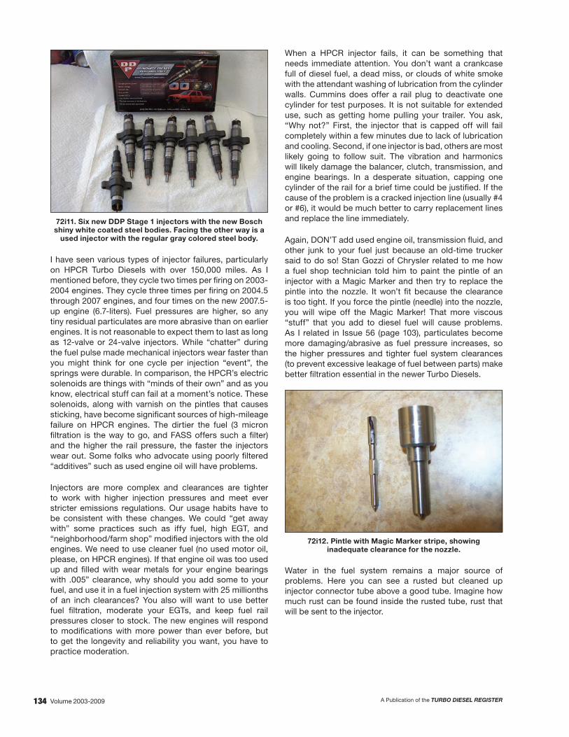
134 A Publication of the TURBO DIESEL REGISTERVolume 2003-2009
72i11. Six new DDP Stage 1 injectors with the new Bosch shiny white coated steel bodies. Facing the other way is a
used injector with the regular gray colored steel body.
I have seen various types of injector failures, particularly on HPCR Turbo Diesels with over 150,000 miles. As I mentioned before, they cycle two times per firing on 2003-2004 engines. They cycle three times per firing on 2004.5 through 2007 engines, and four times on the new 2007.5-up engine (6.7-liters). Fuel pressures are higher, so any tiny residual particulates are more abrasive than on earlier engines. It is not reasonable to expect them to last as long as 12-valve or 24-valve injectors. While “chatter” during the fuel pulse made mechanical injectors wear faster than you might think for one cycle per injection “event”, the springs were durable. In comparison, the HPCR’s electric solenoids are things with “minds of their own” and as you know, electrical stuff can fail at a moment’s notice. These solenoids, along with varnish on the pintles that causes sticking, have become significant sources of high-mileage failure on HPCR engines. The dirtier the fuel (3 micron filtration is the way to go, and FASS offers such a filter) and the higher the rail pressure, the faster the injectors wear out. Some folks who advocate using poorly filtered “additives” such as used engine oil will have problems.
Injectors are more complex and clearances are tighter to work with higher injection pressures and meet ever stricter emissions regulations. Our usage habits have to be consistent with these changes. We could “get away with” some practices such as iffy fuel, high EGT, and “neighborhood/farm shop” modified injectors with the old engines. We need to use cleaner fuel (no used motor oil, please, on HPCR engines). If that engine oil was too used up and filled with wear metals for your engine bearings with .005” clearance, why should you add some to your fuel, and use it in a fuel injection system with 25 millionths of an inch clearances? You also will want to use better fuel filtration, moderate your EGTs, and keep fuel rail pressures closer to stock. The new engines will respond to modifications with more power than ever before, but to get the longevity and reliability you want, you have to practice moderation.
When a HPCR injector fails, it can be something that needs immediate attention. You don’t want a crankcase full of diesel fuel, a dead miss, or clouds of white smoke with the attendant washing of lubrication from the cylinder walls. Cummins does offer a rail plug to deactivate one cylinder for test purposes. It is not suitable for extended use, such as getting home pulling your trailer. You ask, “Why not?” First, the injector that is capped off will fail completely within a few minutes due to lack of lubrication and cooling. Second, if one injector is bad, others are most likely going to follow suit. The vibration and harmonics will likely damage the balancer, clutch, transmission, and engine bearings. In a desperate situation, capping one cylinder of the rail for a brief time could be justified. If the cause of the problem is a cracked injection line (usually #4 or #6), it would be much better to carry replacement lines and replace the line immediately.
Again, DON’T add used engine oil, transmission fluid, and other junk to your fuel just because an old-time trucker said to do so! Stan Gozzi of Chrysler related to me how a fuel shop technician told him to paint the pintle of an injector with a Magic Marker and then try to replace the pintle into the nozzle. It won’t fit because the clearance is too tight. If you force the pintle (needle) into the nozzle, you will wipe off the Magic Marker! That more viscous “stuff” that you add to diesel fuel will cause problems. As I related in Issue 56 (page 103), particulates become more damaging/abrasive as fuel pressure increases, so the higher pressures and tighter fuel system clearances (to prevent excessive leakage of fuel between parts) make better filtration essential in the newer Turbo Diesels.
72i12. Pintle with Magic Marker stripe, showing inadequate clearance for the nozzle.
Water in the fuel system remains a major source of problems. Here you can see a rusted but cleaned up injector connector tube above a good tube. Imagine how much rust can be found inside the rusted tube, rust that will be sent to the injector.

135A Publication of the TURBO DIESEL REGISTER Volume 2003-2009
72i13 Rust pitted connector tube above a good tube.
For preventive maintenance, I purchased a completely new set of injectors at about 100,000 miles. Like the two other TDR writers, Dalgleish and Leno, I asked Lenny Reed of DDP what would give the best mileage. He recommended his Stage 1 over anything else, including stock. In the future, since I use only high quality fuel and a 3 micron filter, and have not raised rail pressure nor run high EGT, I believe I can extend the safe service interval for my injectors significantly. Cost for parts (six injectors) will typically run around $2000 for rebuilt injectors, up to $2700-$3000 for new stock or Stage 1 units. Installation should take about eight hours. Sometimes injector problems will be reported by the engine’s ECM as diagnostic trouble codes, but often diagnosis is a matter of careful thinking. First replace potentially relevant, less expensive parts such as the FCA, pressure sensor on the fuel rail, and pressure relief valve. The nature of the problem you have should be considered against the roles these parts play. Hard starting could be caused by these parts, for example, or by excessive fuel return from worn and eroded check balls and seats in the injectors. White smoke at idle is most likely caused by cracked injectors or sticking pintles. Violent rattling at idle and difficulty in maintaining idle is most likely the FCA or possibly the pressure sensor. If you have been experimenting with fuels or additives, have stacked pressure and other fueling boxes, and/or have big power upgrades with the stock turbo, you are probably a candidate for new injectors. If you just don’t have very good luck, it might be injectors. Do yourself a big favor. If you added ATF or some other “mouse milk” on the advice of that old-time trucker, completely drain and flush the entire fuel system, and replace all the filters before installing new injectors. If you like that big power, get enough turbocharger/s before using it with the new injectors. It is far easier to make big power with the HPCR engines than with earlier versions, but remember that you can add power/fuel and increase EGTs with no warning until it breaks or melts. The faithful Cummins will pull harder and harder upon your demand, even if it kills itself.
Very high rail pressures (from pressure boxes mostly) and very high EGTs contribute greatly to cracking and wear of moving parts inside the injectors. Only after the injector is disassembled can you see the cracked nozzle and cracked body. It is easy and relatively cheap to add electronic power-adders, without taking adequate steps to control EGTs. You are just a click away from taking the rail pressures so high that you will sooner or later “blow” the pressure relief valve on the fuel rail. If your truck is hard to start, that may be the reason. High rail pressures are also resulting in greatly increased injector failures. Any contamination in the fuel becomes much more abrasive at higher injection pressures, necessitating better fuel filtration. Think of a water hose, then a high pressure nozzle on the hose, then a water jet steel cutter. It’s all about pressure! I am running the FASS 200 lift pump system with 3 micron filtration, and use the stock filter canister with a 7 micron filter as “last chance” back-up. I have seen a lot of injectors with failures at the nozzles and the injector bodies from high rail pressures and high exhaust gas temperatures.
72i14. Cracked injector nozzle.
72i15. Cracked injector body.

136 A Publication of the TURBO DIESEL REGISTERVolume 2003-2009
Inside the Injector
We have looked at the pintle and nozzle with the remarkably tight clearance between them. Here are the components of the HPCR injector, first the bottom half with the nozzle nut, nozzle, pintle, and the main body to the right. Next is a photo of the top half with the armature to the left, check ball and seat in the center, and the solenoid and its nut to the right. Next is a close up of the armature that was on the left of the preceding photo. You can see the buildup of sludge on it from contaminated fuel. Finally, on a one-inch wide block you can see the fuel return seat, ball check (.053” diameter) and the end of the armature that fits to the fuel return check ball. A technician needs 500x magnification to inspect the ball, cup, and the seat in the armature for wear or erosion.
72i16. Disassembled bottom half of HPCR injector.
72i17. Disassembled top half of HPCR injector.
72i18. HPCR injector armature showing built up sludge.
72i19. Fuel return seat, check ball, and end of armature.
Fuel Transfer (lift) Pumps
The electric fuel transfer pumps used in 2003-2004 engines [photo 72i5] may not be adequate for more than a gain of about 60-70hp over stock. The in-tank 2005-up lift pump has a slightly better reputation for fuel delivery and a noticeably better reputation for longevity. These lift pumps were covered in detail in Issue 56, pages 60-74. If your Turbo Diesel comes with an electric lift pump, add a spare to your “boonie box” and monitor the performance of your lift pump with an electric gauge (so you won’t have diesel fuel in the cab). There are also aftermarket lift pumps, with or without extra fuel filtration. The FASS 200 gallon per hour lift pump and filtration system was described in Issue 56, page 102.
The EGT range of most Turbo Diesel engines with stock turbos likewise may or may not remain safe with up to 60-70hp more, depending on load, altitude, ambient temperature, etc. However, these two components may be closer to “maxed out” with typical hop-ups on newer Turbo Diesels than the older trucks were. In part this is because the older trucks started with lower horsepower levels. Check your fuel pressure gauge and see if the lift pump pressure stays around 5 psi or so under full power. See if EGT get too high under full power and and/or heavy loads. Maximum EGT is 1450° for 2003-‘04 and 1500° for 2004.5-up engines. For safety, it is a good idea to stay well under these maximums, particularly for long pulls. With my BD compound turbochargers and intercooler, I can keep EGT below or at 1100° towing a 5000-pound trailer in the mountains at higher altitudes and 70-75mph.
Summary
In summary, the enemies of the HPCR fuel system are dirt, water, contaminated fuel, and excessive rail pressure. Have we covered everything you need to know? Not quite yet, let’s answer some questions and then finish the article with the removal and installation procedures.

137A Publication of the TURBO DIESEL REGISTER Volume 2003-2009
Frequently Asked Questions
Rail Pressure versus Fuel MileageQ: In Issue 63, page 82, writer Joe Donnelly did an article about the 2003 and newer ECMs and reprogramming them using a “Smarty” by MADS Electronics. In that article we are told that added rail pressure does not give mileage gains and is “problematic to injector and injection system durability.” Then on page 110 there was a “Product Showcase” article where we are led to believe that increasing fuel pressure will increase mpg by 7%. What is the story?
A: In theory, it would seem that increasing rail pressure would help mileage, as noted by writer Gary Wescott in his “Product Showcase” about the Edge products’ Mileage Max product on page 110. In practice, neither Marco Castano (owner MADS, electronics/developer of Smarty), Mark Chapple (owner of TST, Cummins engineer for 33 years, developer of Power Kit and PowerMax products), nor I have seen any clear, verifiable mileage increase from raising rail pressure above the stock Cummins curve. Power adders do “cheat” the truck’s overhead console report of fuel mileage, giving falsely high readings because fuel is being added that the computer doesn’t know about. Mark Chapple told me he did see a nice torque increase in the 900-1300 rpm range from added rail pressure that was not achievable to the same extent by adding injection duration. As with some other products and approaches to modifying turbo diesels, “YMMV” in internet slang, or “your mileage may vary.” Remember that the Turbo Diesels with the lowest injection pressures, the First Generation trucks, were renowned for giving good mileage. (Then again, they were only rated at 160 horsepower/400 torque and the truck itself was much lighter.)
Finally, in another one of those all-encompassing articles, see the Turbo Diesel Buyer’s Guide, pages 80-99, “So You Want Fuel Economy,” for the bottom line on YMMV information.
Preventive Maintenance?Q: What should I do for preventive maintenance on my 2006 Turbo Diesel? I have heard of many injector problems. Do I need a better fuel filter set up?
A: Here are some general things, my opinions:
• Keep exhaust gas temperatures down; I like to keep EGT under 1300° even though you can get away with a bit higher. Dropping a valve seat is expensive, and that is what usually happens first after a number of high EGT “excursions.”
• Change the oil regularly, using CI4+ rather than the newer spec CJ if possible. I like to change it at 4000-4500 miles.
• Keep rpm under 3000, but don’t lug the engine and drivetrain under high power below 1800rpm.
• If you raise rail pressure with a “box” or program, you should improve fuel filtration; 3 microns is a good level. Otherwise, you will probably be okay with the stock 7 micron Fleetguard filter. I like the FASS for its reliable fuel transfer pump and good filters.
Finding the Bad InjectorQ: My Turbo diesel has a lot of timing rattle noise and rough acceleration around 2000rpm under light throttle. When slowing down, the idle drops down to 500rpm and then recovers.
A: Since the truck is not lighting up the dash with diagnostic trouble codes, it is best to start parts-swapping with the least expensive items. Start with the fuel control actuator (FCA) on the back of the CP3 pump. The FCA is less than $120.
Let’s continue to discuss parts-swapping with the least expensive items. The following is a tip that I picked-up from TDR issue 62 where a TDR member wrote-in with a surging, rough idle and hard start problem. Unfortunately for the owner, he had already replaced the injectors, an expensive repair. The tip: “Try adding a couple of cans of ashless two-stroke oil to the fuel. If it clears up, it’s a defective fuel control actuator (FCA). The oil lubricates the FCA and the engine will idle until the two-stroke oil is depleted. It’s a cheap diagnosis method and only takes the time to run some treated fuel through it.”
To finish the story from Issue 62, “I was told that adding a fuel lube to check the FCA was a test that STAR (Chrysler tech assistance) was using some time ago. A friend who had a Turbo Diesel with a sticking FCA added fuel lube to it by accident and the truck ran fine. After a tank and a half of fuel without the additive, the rough idle, stalling, and stumbling returned. He had problems similar to yours and everyone was telling him it was defective injectors. As long as he kept the fuel additive in the tank, the engine ran fine. He tried different fuel treatments including Marvel Mystery Oil. I read about the fuel lube test, STAR, and the FCA and told him to replace the FCA. He replaced the FCA and the truck has been running like new without any additives.”
The owner tried the two-stroke oil and the engine did not stumble, but it still idled rough. The dealership replaced the FCA and the problem with the engine was solved.
To check individual injectors on the ’03-’05 Turbo Diesels, you could unplug one of the three electrical connectors at the head, while the engine is not running (the wires carry up to 50-volts). Once you see which pair of cylinders is at fault, you can remove the valve cover and remove one pair of wires at a time. Or, you could go right to the individual injector wires. You will get a trouble code, but you can remove it later. Since other injectors may be “weak” the best approach would be to send all six to a Bosch shop like Dynomite Diesel for testing. They are a Bosch dealer and could sell you new injectors as needed. Obviously, unplugging the injector will serve as a diagnostic method only if the electrical solenoid is at fault. If you have a mechanical failure, you would have to plug off one injector at a time or replace one at a time. DDP could test all six for you if that would be more convenient.

138 A Publication of the TURBO DIESEL REGISTERVolume 2003-2009
Other Injector SymptomsQ: What are some of the other symptoms that I have an injector-related problem?
A: Often a truck will idle and run rough like it is missing. If it shows a diagnostic trouble code (DTC) P2149-“Fuel Injector Group, 2 Supply Voltage Circuit,” you’ll want to check for a fuel injector solenoid failure or the electrical connection through the valve cover gasket. To check for either problem, the valve cover must be removed.
Disconnect each injector in the bank affected which should be cylinder number 4, 5, and 6 and check the resistance with an ohmmeter. It should check less than 1-ohm and greater than 0 resistance. Look for the odd reading.
Disconnect injector harness outside the valve cover and using an ohmmeter, check each wire for continuity and resistance. The wires should be less than 1 ohm and greater than 0 resistance.
Hard Start = Injector Problem?Q: I have heard that an engine that is hard to start could signal a looming injector(s) problem. Can you explain?
A: Let’s talk about the long crank issue. This is generally created due to the CP3 injection pump not being able to pump up enough pressure in the common rail to fire the injectors (around 5200psi). The first thing to check is the total fuel return volume to see that it doesn’t exceed about 30 ml during a 10-second crank period. Sometimes you can cure the problem by re-torqueing the fuel delivery tubes. Next, check the individual injectors to see that they are returning only 2-6ml during a 10-second crank period.Any injector with a return volume in the 12-14ml range during a 10-second crank period needs to be replaced. This happens when the check ball wears so that it doesn’t seat correctly which, of course, causes a leak. To confirm the problem, with the engine cold, cap off each injector during cranking and see which one allows the engine to fire up.
I noted that TDR writer Andy Redmond had presented this Q&A back in Issue 66. The following is how he went about the diagnostics and repair:
“Recently, a 2005 truck arrived with a hard starting problem. Other recent repairs included two remanufactured injectors, but shortly after the injectors were installed the owner complained the hard start problem worsened as did his poor fuel economy. The scan tool was connected and no diagnostic trouble codes (DTC’s) were present. The batteries were tested and found to have a good charge. My next step was to monitor actual and desired rail pressure (psi) during the cranking attempts. After several consecutive cranking cycles the scanner showed pressure increasing from 1000 psi to about 4,000 psi at which time the engine started. Why will the truck not crank until a certain pressure level is met? Simple. At low pressure the ECM programming does not command the injector solenoids to energize. A light misfire was observed at engine idle.
“The minimum rail psi for engine start is purposefully not stated. Depending upon the scan tool manufacturer and the ECM programming of desired rail psi, it will vary. Likely much of the variance is due to how quickly the scan tool can respond and display a value. I have not personally observed a truck that would start while cranking with less than 2,000 psi. Usually the range is often 4,300-5,800 on a known well running truck. Chrysler lists the rail operating pressures from 4,321 to 23,206 psi.
I suspected excessive injector return flow. Miller SPX service tool part # 9012 (see photo) was installed into the fuel return port on the right rear side of the fuel filter housing (item 4); then a length of fuel line was routed from the fitting to a five gallon diesel fuel can.
Looking at the 5.9 HPCR (’03-’07) fuel filter assembly:
1. Fuel supply line from the fuel tank to the fuel filter at the quick connect point
2. Fuel return line to fuel tank at quick connect point
3. Banjo bolt location for fuel rail and CP3 to return fuel to the system
4. Banjo bolt location for the fuel injectors to return fuel to the filter/fuel tank
Another length of fuel line was routed from the fuel return line to a calibrated container. The total return flow after the engine idles one minute should be less than 180 ml (6×30 ml as previously sugested). This truck showed 443 ml of fuel after the test. This suggests one or more injectors leaking into the return fuel passages (integral inside the cylinder head); improperly torqued injector connector tube retaining nuts (should be 37 ft-lbs); cracked injector

139A Publication of the TURBO DIESEL REGISTER Volume 2003-2009
body; or fuel leaking into the cylinders (usually causes white exhaust smoke), etc. The injection lines were removed and the connector tube nuts were retorqued. All of the retaining nuts were under specification, with the two at the recently replaced injectors being significantly less than the desired torque specification. Could the torque on the two injector tubes be the only problem?
The injector return flow test volume specifications/testing procedures have varied by model year and have been updated to include additional testing technique—such as the idle ramp up return test and the no start return test (see 2007, Factory Manual, TSB 14-003-06 and Warranty Bulletin D-05-24).
After the injection lines were reinstalled the return test was again performed. The truck started with fewer cranking attempts to build required rail pressure. But, it still wasn’t right. The engine idled one minute and still returned 325 ml of fuel. Next the injector lines were removed one at the time and the Miller SPX tool # 9011 (see photo) was installed at the rail. The engine will run on five cylinders while one line is blocked. The engine was started for one minute with each line consecutively removed, then reinstalled to test each injector. The calibrated container was closely measured for return fuel after each individual injector was block tested. The reason for this process of elimination is to isolate one or more injectors that have excessive return. Any injector contributing more than 40 ml in one minute is excessive. No single injector seemed to be the major leak source. Therefore, replacement of the other four injectors was recommended. The total return flow returned to less than the 180 ml specification when retested. The truck built rail pressure quickly and started normally. The customer later stated that the “lost” fuel economy returned.
Miller spx specialty tools.
When to Replace Injectors?Q: My 2004 Turbo Diesel has 198,000 miles, but so far no injector problems. Should I replace the injectors now, or wait until I have a problem? They are expensive.
A: Perhaps some discussion about modes of failure would be in order here. As some feel, if things are fine, you don’t need to change injectors. If you haven’t added power, the mechanical aspects will be fine for a long time. As I mentioned, high exhaust gas temperatures and high rail pressures can cause damage. Cracks in the nozzles or bodies, and wear of the check ball and seat are two problems that can occur. On the other hand, failure of the electrical solenoid can happen any time.
Whether you want to incur cost now is up to you. I have heard of folks paying more for reconditioned injectors than what new ones can be bought for. I have heard of high costs at some shops for replacement, and have seen evidence of poor workmanship, leading to further problems. Therefore, you may have two reasons for performing preventive maintenance. You can choose the mechanic/shop and you can buy the latest, stainless steel injectors. On the other hand, you might be able to continue using your old parts for many more miles. Consider also your usage for the truck. If you take long trips through unpopulated areas, such as in the West, a failure could leave you stranded.
What Does it Cost?Q: Okay, let’s get to the bottom-line: what is it going to cost to replace the injectors, and can I replace them as needed?
A: In the “Injector Upgrades and Preventing Failures” section of this article I briefly touched on the cost, but let me take this opportunity to be specific.
For the do-it-yourselfer the first time you remove and install an injector(s) can take a full 8-hour day. Subsequent R&I can be done in about 4-5 hours. So, time is money…what is the cost of shop labor in your area? What is your time worth?
Unfortunately it takes almost as long to change only one injector as it does to do all six. All types of intake plumbing, breather assembly, wiring, and injector lines have to be removed. So, outside of a low mileage, one-off kind of situation, or where you have a DTC telling you what to do, if an injector is giving problems and you’ve had a good service life from Day One, I would replace all six injectors at the same time.
Shops and vendors have been investing six-figure sums of money to be able to test injectors. Should you have the time to send out for test, this service is becoming more so available. Injector testing cost about $50-60 per unit.
What about the cost of the replacement injectors?

140 A Publication of the TURBO DIESEL REGISTERVolume 2003-2009
The editor recently did a search using different engine serial numbers used in years 2003-2009 engines. Interestingly there are only three injector generations. I’ll break those down, along with part numbers, for you:
Bosch Cummins ReCon Mopar’03-’04 X0986435503 5254686RX R 8004082AB’04.5-’07 X0986435505 5254688RX R 5135790AE’07.5-current X0986435518 5253220NX R 8069384AA
How much do the injectors cost? On any given day you can search the internet and get price quotes from $300 to over $700 per injector. On any given day you can be bumfuzzled with hype and such by alligator-this and hot rod-that shops that claim to sell injectors. On any given day there is a shop or vendor that has invested six-figure sums of money for Bosch test stand equipment to check, test and remanufacture these injectors. On any given day there may be a short supply of injector units.
If you need injectors you’ll want to deal with reputable sales agents. For your consideration: Mopar, Cummins, Cummins ReCon, Bosch accredited shops as recognized by the Association of Diesel Specialist (www.diesel.org, page 137, TDR vendors and specialty shops.
Did you want a performance upgrade injector with your order, sir? How about an order of fries or a hot apple pie? (My attempt at being cute…)
So, as I mentioned before, the average price for a six-pack of injectors and
their removal and replacement: $2000-$3000 for parts, 8 hours for labor.
Stock or Aftermarket InjectorsQ: What is better, stock or aftermarket injectors to replace my leaking injectors? Can I replace them myself?
A: Dynomite Diesel has the Bosch injector testing equipment and gets the new stainless steel bodies when they get new injectors from Bosch. They recommend the Stage 1 over stock for performance and mileage. That is what I put into my Turbo Diesel recently. They provide complete installation instructions with color photos with their injectors. For the “how to” on injector replacement, I’ve updated the instructions that I wrote five-years ago in Issue 51 at the end of this article. Be sure the seating nipple end of the connecting tubes are smooth and are seated uniformly, and that the injector line ends are also smooth and corrosion free.
For further discussion on the Dynomite Diesel injectors you’ll want to reread the detailed articles in Issue 66, page 46; Issue 60, page 84; Issue 59, page 86; Issue 57, page 45; Issue 56, page 96.
Injector Removal and Replacement
Tools:You will need a few specialty tools to make the injector replacement easier. The aluminum plate at the top keeps the exhaust rockers in order and assembled. Under it at the left is a 15/16” socket cut down to 1” total length, with a connector tube nut in it. To the right of the nut is an orange painted tube that facilitates pressing the new injector into its well in the head. Next is a blue painted cover for the air intake hole after removal of the air horn. Over it and the aluminum plate is a 9” length of 3/16” brake line tubing and ¼” OD vinyl hose for sucking diesel fuel from the piston bowl if some drains in a cylinder after removing an injector. To the left is a “lady foot” pry bar to remove the injectors. It has red paint on it. At the bottom are a length of 5/16” pushrod with the open end partially squashed to retain a Q-Tip, and a modified rifle bore brush and rod for cleaning out the injector tip hole in the head. These tools are discussed below in more detail.
72i20. Specialty tools for HPCR injector replacement.
You can use a nut of M14 x 1.5 thread and a screwdriver to pull the connector tubes in the head. In most cases, the tubes can be pulled just with fingers on the threaded end, or by nudging them with a screwdriver blade on the threads. It is helpful to have a cut-off 5/16” hollow engine pushrod with the cut end partially flattened so it will hold a Q-tip tightly. This tool enables you to clean the sealing surface in the head at the bottom of the injector well.
You will use ¾” (19 mm) and 7/8” open-end wrenches with total length not exceeding 6.5 inches to remove the injector line nuts from the ends of the rail. Get a small (about 5.5 inches long) “lady foot” rocker style pry bar to pull up the injector. (Make sure the nut and connector tube are out of the way so you won’t nick the end of the connector tube.) A ¾” or 19 mm flare nut crow’s foot and flex head ratchet will help remove the #5 and #6 injector line nuts. You also will want a 15/16” or 24 mm socket and flex head ratchet to remove the nuts at the cylinder head. A 3/8” drive socket cut down to 1 inch long gives better access for #3 and #6 connector tube nuts. In this engine, the injection line nut threads into the connector tube which is held in place by another nut that is threaded into the head.

141A Publication of the TURBO DIESEL REGISTER Volume 2003-2009
Make up a steel or aluminum tube with an inside diameter of 1.15” to 1.25” and length of about 2.8” to press the new injector into its well. You may need to file it flat on one side if it is a thick walled tube, to clear the intake rocker. You don’t want any stress on the electrical studs or plastic end of the injector. Greasing the injector body O-ring helps a lot for pressing the injector into its well in the head. To vacuum out fuel from a cylinder, I use a piece of clear, flexible plastic (“Tygon” or vinyl) 0.25 inch outside diameter tubing, about 3.5 to 4 feet long with a 9 inch long piece of 3/16” brake line pushed into one end for about one inch. The ends of the brake line should be chamfered and the tube cleaned of any metal shavings. You will insert the 3/16” steel tube into the cylinder through the injector hole to suck out any fuel that drained into the cylinder and is in the piston bowl. The extra length of the plastic tubing allows a “belly” to form and trap the fuel that is withdrawn. If you prefer, it is safer to have a suction pump and trap attached.
Procedures:First, remove the plastic cover over the engine and the breather assembly from the top of the valve cover (four bolts with 10 mm head and O-rings under the heads on 2003-2004 engines). Remove the valve cover lid (six bolts with 10 mm heads). You will remove the air intake for better access to the injector lines. It is held on with four bolts having 10 mm heads, plus one for the dipstick tube, and a 7/16” (11 mm) nut on the band clamp.
When removing the aluminum air intake horn from the head, it is easy to tear the gasket. Keep a couple of them around. Get Cummins part number 3969988 (the newest heat resistant type, replacing the 3938158 pink gasket that Cummins used in the past few years).
Plug the plenum hole in the head and the boost pipe so nothing falls into them. Be sure the areas around the lines at the rail and at the head are very clean. Remove the injector lines. Be sure to use a backup wrench on the nut at the head and on the ends of the rail to prevent damage to either the connector inside the head or the fuel rail. Keep the injector lines and exhaust rockers in order for correct re-installation, if you elect to address all six injectors at once. On many engines, the last digit of the injector line part numbers, etched on the engine end’s nuts, are in numerical order from #1-#6, for example 3957081, 3957082, 3957223, 3957084, 3957085, 3957146. Remove the nuts at the head and gently pull out the connector tubes about ½ inch with an M14 x 1.5 thread nut and a screwdriver on the nut. The tubes have balls peened onto their outsides to index them in the head.
Remove the exhaust rocker arms assemblies. A rocker assembly is shown but you will usually only remove the exhaust rocker. Disconnect the solenoid wires at the top of each injector. Be gentle! These studs are easily broken. Remove the two injector hold down bolts (M6 x 1.0 thread, 8 mm or 5/16” head). Pull the injectors gently with the “lady foot” puller.
72i21. Rocker assembly for one cylinder. Exhaust, pedestal,intake, rocker pivot shaft and bolt, and two bridges below
to couple pairs of intake or exhaust valves.
72i22. Common-rail engine with the “lady foot” injector puller positioned to lift #1 injector. (The exhaust rocker, injection line and connecting tube were removed first.)
If the intake valves were open, it may be necessary to loosen the intake rocker to get clearance to remove the injector. Listen carefully. If you hear fuel drain into the cylinder, you must vacuum it out with a hose through the injector tip hole in the head, as a piston bowl full of fuel will cause a hydraulic “lock” when you try to turn over the engine later. It is common to get two or three milliliters of fuel into a cylinder’s piston bowl when removing an injector. I use the tube described above in the “tools” paragraph and gentle mouth suction, letting the fuel settle into a “belly” in the hose—no one wants or should get a mouthful of fuel! Check the injector well in the head and if the sealing surface at the bottom of the well is contaminated, mop it clean with a Q-tip that is held tightly in the partly flattened end of a tube to gain the needed length (I use an old 5/16” hollow engine pushrod).
Clean the injector wells so that there is no grit at the sealing surface on the bottoms of them. HPCR injector wells stay clean except for engine oil and deposits from the injector tips as they are pulled up through their holes upon removal. If there are heavy deposits making it difficult to install the new injectors, you can run a rifle bore brush through the holes into the cylinders to clean out the passages the injector tips go through. Wipe out the sealing areas where the copper washers rest on the bottom of the wells, with

142 A Publication of the TURBO DIESEL REGISTERVolume 2003-2009
Q-tips. You can use a hollow 5/16” automobile pushrod that is partially squashed near the end to retain one end of the Q-tip so it can’t fall into the cylinder. The sealing ball area of the injector lines can get dirty or corroded, and subsequently leak. Usually cleaning with fine aluminum oxide or emery paper (600 or 800 grit) will take care of it. Be sure to spray off the area so no grit remains on the surface or inside the line. Don’t torque the line nut over 25-30 ft lb; put a little grease on the threads and back side of the sealing ball where the nut grips it, to get a smooth torque reading and to prevent the line from twisting.
Grease the O-ring on the body of each new injector. Push the injector into its well using the 2.8” long tube over the injector body, bearing against the hold down bracket that is captive on the injector body. The factory service manual specifies that you snug down the injector hold down bolts, then relieve the tension and tighten the connector tube nut to 11 ft-lb. Then, tighten the injector hold down bolts to 89 in-lb and tighten the connector tube nut to 37 ft-lb torque. I suggest using a thin film of grease on the threads and sealing surface of the nuts. I also put a bit of engine oil around the hole in the side of the injector where the connecting tube fits. Install the exhaust rocker, and set the lash. The lash generally does not change with this procedure, but if your engine has a lot of miles on it, you might want to set the valve lash on all valves. Valve lash specifications for the 2003-up common-rail engine are as follows:
Intake Exhaust
0.006 inch minimum 0.015 inch minimum
0.015 inch maximum 0.030 inch maximum
0.010 inch when resetting 0.020 inch when resetting
I prefer to keep lash measurements as close as practical to the same in all cylinders, and generally use 0.010 inch on the intakes and 0.020 on the exhausts on 12- and 24-valve engine types.
Re-assembly goes in the reserve order of the removal procedures above. Torque specifications for re-assembly are as follows:
Injector Hold Down Bolt: 8mm (or 5/16”) head, 89 in-lb maximum; 80 in-lb may be “safer” if the bolts seem to be “stretching” excessively.
Injector Wire Nut: 8mm head, 11 in-lb. That’s a very light torque—the M4 x 0.7 studs are easily broken; gently snug is another way to describe it. You can use a nut driver (like a screwdriver) to help you get a good feel when snugging down these nuts). Note that the yellow or brown wire is closest to the intake side or intake rocker.
Rocker: 10mm head, 27 ft-lb
Connector Tube Nut: 24mm or 15/16”, 37 ft-lb
Injection Lines: 19mm or ¾”, 22 ft-lb
Valve Cover and Miscellaneous: M8 x 1.25 thread bolts with 10mm head, 18 ft-lb
Joe Donnelly TDR Writer

143A Publication of the TURBO DIESEL REGISTER Volume 2003-2009
The six-speed manual transmission for the Turbo Diesel was changed by Dodge from the New Venture 5600 that had been used since 1999 until late in the 2005 model year, to a Mercedes Benz unit, the G56. The G56, as we are now aware, is an aluminum cased six-speed with integral bell housing, and a new (for Dodge) design dual-mass flywheel. The Chrysler noise/vibration/harshness engineering group wanted to “elevate the customer experience” with the change in flywheel design. The G56 shifts easier and smoother, but reaching reverse seems easier with the NV5600 than the G56. Initially, the overdrive was not as steep (0.79 versus 0.73 for the NV5600) in the G56, but there was a change to an overdrive ratio of 0.74 in a new version of the G56 for the 6.7-liter Cummins (2007.5 year model). The early input shaft has two grooves, which can be seen by removing the front bearing retainer (a stamped steel part that costs $159) (photo 71-15). The late ratio input shaft has three grooves (photo 71-16). More reports of noise seem to be associated with the later design. A fairly large number of sixth gear failures have occurred, and it may be that the mild 0.79 overdrive ratio causes more drivers to use sixth gear when towing heavy trailers, when direct drive (fifth gear) should be used.
71-15 Early G56 input gear (0.79 overdrive ratio) and front bearing retainer.
71-16 Late G56 input (0.74 overdrive).
The dual mass flywheel has been problematic. At the time Dodge introduced it, Peter Pyfer of South Bend Clutch described issues with the Duramax version of Luk’s dual mass flywheel, and the scope and limitations of the concept (Issue 53, page 98). Specifically, the Luk design experienced some failures and was strengthened, but he felt the Dodge version was similar to the Duramax and “the problem was, and still is, not resolved.”
Now, five years later we find that the South Bend clutch conversion (see Issue 68, page 88) is a “standardized” replacement for the OEM dual mass flywheel and clutch. Performance of the G56 has been flawed, according to Charlie Jetton and Richard Poels of Standard Transmission and Gear in Fort Worth, Texas. In lighter duty and moderate towing, the G56 transmission has been adequate. Hot shotters and other owners who do very heavy towing have experienced failures that are still not completely resolved. Conventional rebuilds help, but do not eliminate all problems for these owners.
Richard Poels of Standard Transmission explained that the G56 transmission often came with too little lubricant, and further that automatic transmission fluid may not be suitable under some driving conditions. A slightly “heavier” lubricant is better at the elevated temperatures that the transmission may experience towing or at higher ambient temperatures. They recommend that lubricants successful in the NV5600, such as Pennzoil Synchromesh, be used. My NV5600 did very well with Torco RTF (Issue 67, page 87) and it should be an excellent lubricant for the G56. Aluminum “grows” with heat at about three times the rate of cast iron, so endplay clearances can become excessive at high transmission temperatures. High ambient temperatures and heavy towing both increase transmission heat; the unit is “trapped” in a floor tunnel of the truck and gets limited airflow for cooling. Units run with the factory lube (ATF) come in to Standard with browned bearings from lubricant degradation.
ENGINE AND TRANSMISSION MAINTENANCE
REBUILDING THE G56 SIX-SPEED TRANSMISSIONISSUE 71 - HAVE RAM, WILL TRAVEL

144 A Publication of the TURBO DIESEL REGISTERVolume 2003-2009
Richard Poels took me through the procedures for correctly rebuilding a G56 six-speed, aluminum-cased transmission. Standard Transmission stresses cleanliness and goes to extremes to ensure the parts and housing are clean. As with most manual transmissions, the gearbox does not have a filter, so any grit, metallic dust, or pieces will circulate and cause more damage. For clean-up, they use both solvent washers and a hot tank. They use a special assembly lube, with high pressure additives.
The main drive bearing at the front of the case (the input shaft bearing) is prone to failure. If you hear a transmission noise, get it fixed immediately before the main case is ruined. Virtually every G56 that comes in for rebuilding has large endplay on the input shaft. The rear bearings also can fail. The spot welded shifter forks (photo 71-17) may break at the weld. Standard re-welds them inside and outside. Due to case flex and stretch, Standard often has to add 0.008” to 0.011” more shim to reduce endplay. The stock shim is generally 0.055” thick. In contrast, the cluster shaft usually takes the same shim, or at most 0.001” to 0.002” thicker shimming.
71-17 Heavy stamped steel shift fork with welds that are prone to failure.
Standard often finds evidence of misalignment of the mainshaft gears versus the cluster gear, shown here on an input gear (photo 71-18). Broken gear teeth can result (photo 71-19). Wear patterns indicate that the teeth are spreading the transmission case, causing wobble in the input gear, and gear teeth are wearing closer to the edges of the teeth. Heavy loads then cause them to break.
71-18 Input with wear indicating misalignment of gears.
71-19 Input and cluster with broken teeth caused by poor alignment and heavy loading.
The stock transmission case is two-piece, split crosswise just behind the shifter tower area (photo 71-20). Inside, the front of the case can be seen to include supports for all internal components. The inside view of the rear housing shows corresponding bearing and shaft mounting supports (photo 71-22). Owners have tried to repair cracked cases with poor success. This one was warped to 0.070” out of “square” by welding (photo 71-23).
71-20 G56 two-piece transmission case.

145A Publication of the TURBO DIESEL REGISTER Volume 2003-2009
71-22 Rear half of G56 case viewedfrom the split at mid-case.
71-23 Welded but distorted G56 case at bell housing area.
After splitting the case, the internal components remain in the rear case half (photo 71-24). A close-up view shows that the reverse idler gear prevents removal of the gear sets (photo 71-25). The secret to disassembly is to thread a metric bolt (M6 x 1.0 thread) into the end of the shaft, and remove the shaft (photo 71-26). Then, push the gear out of the way and separate the cluster and mainshaft (photo 71-27).
71-24 Rear half of the case with mainshaft and cluster assemblies.
71-25 Close up view of reverse idler gearin rear half of case.
71-26 Removal of idler gear shaft.
71-27 Separation of cluster and mainshaft assemblies after moving reverse idler gear out of the way.

146 A Publication of the TURBO DIESEL REGISTERVolume 2003-2009
This transmission is a German design, but manufactured in Brazil. Currently, parts have to be purchased from Dodge at high prices. For example, each synchronizer assembly (photo 71-28) is a complete set for a pair of gears (1-2; 3-4; 5-6) and costs as much as $740. The input shaft/gear costs $750; the cluster gear, $1385; mainshaft, $474; sixth gear, $450.
71-28 Synchronizer assembly for one pair of gears (1-2, etc.)
Standard has seen electrolytic pitting of gear teeth (photo 71-29) similar to that seen in automatic transmissions which also have aluminum cases. An extra ground strap such as is sometimes added to automatics may be the cure for this issue. The damage is seen on the leading drive side and edge of cluster and main gear teeth, presumably from an electric field being generated.
71-29 Electrolytic pitting of gear teeth.
It appears that the transmission case is irreversibly spreading lengthwise more at the mainshaft (top) than at the cluster. The mainshaft being two-piece, with an input gear separate from the rest of the mainshaft, contributes to the forces spreading the case, and brings about the excessive endplay seen in the mainshaft and sloppy sideplay felt when wiggling an input shaft side to side. This is a buckling or distortion and not merely dimensional growth with heat, although that growth is no doubt involved also. I brought up the idea of building a “girdle,” possibly with load bolts to the top of the case, and Standard is looking into this modification in an effort to strengthen the G56 case which appears to be rather thin, inadequately reinforced at the top, and further weakened by being split cross-wise.
In summary, the G56 has proved itself as a fairly good transmission but several upgrades are worth considering: more and better lubricant; preventive teardown and rebuild before catastrophic failure; downshifting to avoid heavy towing at low rpm; and changing the clutch periodically, making sure to replace the pilot bearing as well. This transmission does not seem well suited to heavy towing beyond manufacturer’s recommendations.
Standard Transmission and Gear 1000 NE 29th Street Fort Worth, TX 76106 1-800-STD-TRAN
Joe Donnelly TDR Writer

147A Publication of the TURBO DIESEL REGISTER Volume 2003-2009
Here goes:
Obviously you noticed the long discussion about performance enhancements for the 5.9-liter Cummins engine in the 2003-2007 trucks (Yep, all the pages from 72 through 122). Why nothing about the 6.7?
Take a minute to read the opening article “Performance Parts Update 2016 – [Chances are the Modifi cations are Illegal]”.
A look back in time tells us that the 2007.5 introduction of the Cumins 6.7-liter engine brought us a very complicated exhaust emissions aftertreatment system. Hand-in-hand with the new hardware was a stronger threat from the EPA to crack down on illegal parts, vendors, distributors and installers (many of which have been fi ned or put out of business by the EPA). As a print magazine, it was decided to not engage in stories or how-to articles about non-CARB EO approved parts and their subsequent performance gains.
Where does that leave the 6.7-liter owner that is looking for performance? Well, we’re in the same holding pattern, ever on the lookout for a CARB EO approved part to test on our 6.7-liter engine. Time will tell what parts are legallyavailable.
TDR Staff
P.S. As a 6.7-liter owner you will fi nd our TDR Buyer’s Guide, Volume 2010-2012 has many excellent articles on the 6.7-liter engine and the entire exhaust aftertreatement system. Since you are a TDR member I would strongly suggest that you download the Volume 2010-2012 Buyer’s Guide as the 6.7-liter engine and its exhaust aftertreatment were unchanged in those years 2007.5-2012.
FINAL NOTESFOR THIRD GENERATION ’07.5-’09 OWNERS
WITH CUMMINS 6.7-LITER ENGINERobert Patton
A Publication of the Turbo Diesel Register
This Buyer’s Guide was last updated
6/2014
What you should know about the
2010-2012 Ram Turbo Diesel truck.
TURB
O DI
ESELBuyer’s
GuideThis Buyer’s Guide was last updated
6/2014
TURB
O DI
ESEL
Guide
Volume 2010-2012
148 A Publication of the TURBO DIESEL REGISTERVolume 2003-2009
6.7 HPCR ENGINE MEETS 2010 EMISSIONS
ISSUE 56 – 6.7 HPCR
It has been a full year since the March ’05 announcement of the Dodge 3500 Chassis Cab with the 6.7 liter Cummins engine. The 3500 Chassis Cabs rolled off the assembly line last fall and we introduced this column in the magazine to cover developments with the 6.7 HCPR engine.
At the Chicago Auto Show in February Dodge announced their new 4500 and 5500 Chassis Cab that use the same 6.7 HPCR engine. Hand-in-hand was the ’07.5 model year introduction of the 6.7 HPCR engine in the 2500 and 3500 pickup trucks.
Somewhat lost in the flurry of announcements, introductions and hardware hitting the streets was the following press release from Cummins.
“In January Cummins Inc. unveiled the strongest, cleanest, quietest best-in-class 2007 6.7-liter Turbo Diesel engine, used exclusively in Dodge Ram 2500 and 3500 Heavy Duty pickup trucks. The engine has increased displacement providing increased horsepower and torque while achieving the world’s lowest 2010 Environmental Protection Agency (EPA) NOx standard a full three years ahead of the requirements.
“Cummins is the first diesel engine manufacturer to have a product certified to the 2010 EPA heavy-duty engine standards for oxides of nitrogen (NOx) and particulate matter (PM) emissions, making it the cleanest heavy-duty diesel engine available in North America. The 2010 EPA standards for NOx (0.2g) and PM (0.01g) represent a more than 90 percent reduction in each pollutant, compared to the 2004 standards.
“‘The application of the right technology on the Dodge Ram is an extension of the joint clean diesel development work Cummins and DaimlerChrysler have performed together for nearly two decades,’ said Cummins President and Chief Operating Officer Joe Loughrey. ‘The new best-in-class Cummins Turbo Diesel and the Dodge Ram will provide the strongest, cleanest, quietest solution for heavy-duty pickup truck customers.’
“‘This new technology is a significant validation of the industry’s ability to meet the EPA’s 2010 clean diesel standards. These innovations help power our economy and drive our environmental successes,’ said Bill Wehrum, EPA’s Acting Assistant Administrator for Air and Radiation.”
Cummins, in conjunction with DaimlerChrysler and the EPA, made this announcement prior to the Washington DC Auto Show in January.
When I first read the press release my reaction was, “Ho, hum, another beat-the-chest exercise by the PR folks.” Is your reaction the same?
Look at the release again. It is important to note that with the 6.7 HPCR engine Cummins is the first diesel engine
manufacturer to meet the 2010 EPA standards. This is big news!
Let’s say it again, the 6.7 HPCR engine meets the 2010 EPA standards.
So, unlike the yo-yo changes that we have had to endure every 3 to 4 years, the ’07 HPCR will be good until the next set of emissions legislation in 2013.
Will Ford be able to offer an engine package like this?
Will GM be able to offer an engine package like this?
Additionally, consider that the 2010 6.7 HPCR engine offers a solid engine platform that allows Dodge to engineer the next generation Ram, thus keeping the Dodge/Cummins relationship stable.
2010 Technology
This is big news. So much so that the February ’07 issue of Diesel Progress (a trade-only publication, not to be confused with the plethora of newsstand “glossy” publications) devoted five pages to the 6.7 HPCR and its technology. The following are excerpts from the Diesel Progress article by Mike Brezonick as he talks with several of the Cummins Inc. personnel behind the 6.7 HPCR project.
“When Dodge and Cummins announced the 2007 engine months ago, both companies highlighted some of the notable and apparent changes. Yet both companies kept very quiet on what is in some ways the most noteworthy aspect of all, choosing to save that for a more appropriate stage.
“That stage turned out to be the Washington Automobile Show in January. Cummins took the wraps off emissions technology that is being used on the 2007 model year Ram 2500 and 3500 Heavy Duty pickup trucks. The system, which Dodge and Cummins said will meet EPA’s emissions regulations for the next six years, is unprecedented in its sophistication and includes what is considered to be the first commercially produced NOx adsorber system to be used on a production vehicle in any market segment in North America.
The Challenge and Relationships
“‘As we looked ahead to ’07, Dodge’s challenge to us was to stay up with the competition in the horsepower and torque wars,’ said Jeff Caldwell, Cummins executive director – DaimlerChrysler Business. ‘Our challenge was how do we do that and meet emissions?
“‘Beyond cooled EGR and variable geometry turbos we knew we were going to add aftertreatment and if we took the same path that everyone else was taking, it would drive some pretty significant changes to the cooling system.

149A Publication of the TURBO DIESEL REGISTER Volume 2003-2009
You’ve seen that in the 2007/2008 model year trucks from Dodge’s competition—they’re wider and taller. They’ve changed the trucks.
“‘We feel terrifically about our relationship with Daimler Chrysler,’ said Joe Loughrey, Cummins’ president and chief operating officer. ‘And the decision to use this particular recipe to meet the 2010 standards in 2007 was a collective decision between Cummins and DaimlerChrysler after having reviewed more than one alternative as to what our approach might be.
“‘I have to emphasize that this was not Cummins walking in to say, hey, here’s the deal. It was us working very closely with DaimlerChrysler and our partners and determining this was the best by far course of action to make the best truck for customers and the cleanest truck you can find anywhere in America.’
The Technologies
“Clearly, the most head-turning part of the vehicle is the addition of the NOx adsorber to the aftertreatment system. For the better part of a decade, NOx adsorbers have been cited as a promising technology for controlling NOx emissions from diesel engines—indeed, they were specifically cited as key technology by EPA in its rulemaking.
“A NOx adsorber resembles a conventional catalyst, incorporating a catalytic substrate through which diesel exhaust is directed. Then the NOx molecules are collected and held—“adsorbed”—onto the surface of the substrate, removing them from the exhaust stream. When the surface area of the substrate is full, the adsorber is regenerated with heat used to chemically change the NOx into more benign gases, mostly nitrogen and oxygen.
“However, for all their potential in principle and in the lab, NOx adsorbers remained closer to a promise than a real product. More on the NOx adsorber in a minute.
“Cummins incorporated a range of technologies into the engine. A variable geometry turbocharger from Cummins Turbo Technologies contributes to improved engine breathing. And, because of the robustness of the sliding vane design, it also can be used to provide engine braking, a beneficial feature, particularly in towing applications.
“Other changes to the engine include an intake throttle between the engine and charge-air cooler and a bypass valve in the EGR circuit that allows the gas flow to bypass the EGR cooler entirely in some operating conditions. This allows for more precise control of EGR rates, faster engine and vehicle warm-up and can also assist in raising exhaust temperatures for aftertreatment regeneration.
“The engine also has a closed crankcase ventilation system developed by Cummins filtration. The system incorporates a coalescing filter that captures oil mist and returns it to the crankcase. The filter requires service after approximately 60,000 miles.
The Aftertreatment System
“The Aftertreatment system is a three-section unit that is packaged mostly under the vehicle floor. It begins with a close-coupled catalyst—essentially a conventional diesel oxidation catalyst incorporating a metallic substrate—mounted to a short downpipe just off the back of the turbocharger. Shortly behind and below the close-coupled catalyst is the NOx adsorber unit, which is followed by a particulate filter. Both the NOx adsorber and PM filter use ceramic substrates.
“All three aftertreatment sections have their own active regeneration schedules, and the engine ECM controls the regeneration cycles. Even more significant, despite the use of fuel for regeneration, the overall fuel economy for the vehicle is virtually unchanged from the 2006 trucks, Cummins said.
“The NOx adsorber is regenerated every few minutes at approximately 600° to 800°F and the process takes about three to five seconds. The NOx adsorber will also, over time, absorb sulfur from the fuel, which can reduce its effectiveness over time. So depending on how much fuel is burned—typically every two tankfuls, a separate regeneration cycle is initiated to remove the sulfur. The PM filter is regenerated when mass flow sensors in the exhaust system detect a specified amount of loading on the substrate, typically about every four operating hours. Unlike the PM filter systems used on heavy-duty applications, there is no ash cleaning required, and the PM filter—like the NOx adsorber and close-coupled catalyst—is rated for the life of the vehicle.
“In another departure from the heavy-duty side, all of the hydrocarbon dosing (diesel fuel) needed to raise the temperature for the various aftertreatment regenerations is handled by the fuel injection system rather than a separate injection system.
“‘It took some time and a lot of work to integrate the control system,’ said Jim Fier, technical project leader. ‘Some of the fuel we use to light the catalyst is partially burned, and any time you burn fuel, you produce power. If we didn’t you would feel that extra fuel as power. With both the air handling and the fueling, we had to adjust those various pulses in order to keep the power balance and the torque balance as we go in and do the regenerations.’
“Cummins engineered the entire aftertreatment system down to specifying the washcoat on the catalyst bricks, and the system was assembled by Tenneco, which does aftertreatment system packaging for many segments of DaimlerChrysler.”
At the onset I noted that the news about 2010 emissions and the 6.7 HPCR engine was noteworthy. The Diesel Progress article excerpts give us a better understanding of the technology behind the engine. Go forth and be proud of the Dodge/Cummins truck that you own.
Robert Patton TDR Staff

150 A Publication of the TURBO DIESEL REGISTERVolume 2003-2009
Note the sharp, ten-fold drop in emissions from year 2004 to 2007. I recall that one of the first TDR magazines stated that emissions were the driving force behind changes to the diesel engine. The 2007 emissions targets nail home that statement.
Certainly ultra-low sulfur fuel will help, but the engineering it will take to meet the targets is difficult to imagine.
0
2
4
6
8
10
12
1985
1988
1990
1991
1994
1998
2002
2004
2007
gm/b
hp-h
r
NOx FederalNOx California
0
0.1
0.2
0.3
0.4
0.5
0.6
0.7
1985
1988
1990
1991
1994
1998
2002
2004
2007
gm/b
hp-h
r
PM
ENGINE EVOLUTION – EMISSIONSISSUE 49 – TECHNICAL TOPICS
by Robert Patton
EPA, NOx, PM, SCR, EGR, DPF, NAC, VGT, ULSD, HPCR, HCCI, NMHC, ACERT, TITT: Can you pick the abbreviation that is non-diesel, non-emissions related? It’s easy, TITT as in “throw in the towel.” The balance of the abbreviations serves to bewilder your diligent scribe. However, with a new round of diesel exhaust emission legislation less than two years away and with ultra low sulfur diesel fuel (abbreviation: ULSD), due in the summer of ’06, it is appropriate that we understand what the abbreviations will mean to the diesel enthusiast.
As TDR subscribers know, emission legislation dates are the driving force in the changes to the Cummins engine hardware. To make a boring story into a relevant topic, the subject matter has to address “what does it mean to me?” The best way to answer this question is to crank-up the way-back machine to Issue 40 and look at the progression of the ever-tightening emissions standards.
After we review the material which answers the question, “what does it mean to me?” material, I’ll attempt to tie the big picture together with a look at those annoying abbreviations and what is on the horizon for 2006 and 2007.
Boring Stuff?
While it might be tempting to skip through this subtitle, I’ll ask for your concentrated efforts as we simplify (oversimplify?) the two emissions components that concern the diesel engineer: oxides of nitrogen (NOx) and particulate matter (PM). The following paragraphs may provide us a more informed understanding of these two emissions components.
Oxides of Nitrogen (NOx)
• One of the primary regulated pollutants from diesel engines.
• Reacts with hydrocarbons in the presence of sunlight to form ozone.
• Formed by reaction between nitrogen and oxygen in the combustion chamber.
• NOx formation increases with higher combustion temperature and cylinder pressures.
• Methods of reduction include lower intake manifold temperature, lower in-cylinder temperature, retarded fuel injection and combustion optimization. Any in-cylinder approach to NOx reduction involves lowering the temperature and limiting the time of the combustion event.
• Potential impacts can be higher fuel consumption and requirement of a more complex cooling system.

151A Publication of the TURBO DIESEL REGISTER Volume 2003-2009
Particulate Matter (PM)
• Often visible as black smoke.
• Formed when insufficient air or low combustion temperature prohibits complete combustion of the free carbon.
• Primarily partially burned fuel and lube oil.
• Methods of control include oil consumption reduction, catalytic converters, combustion system development and higher fuel injection pressures.
To oversimplify, think back to last winter and the many fireside evenings you enjoyed. As you built the fire, there was inefficient combustion, characterized by black smoke and not much heat generation. Thirty minutes into the exercise you were sitting back in the easy chair, with a raging fire, no more black smoke, a beautiful yellow and blue flame, and lots of heat.
Now, refer back to the NOx and PM bullet statements and reflect on the following: the design engineers could control particulates (PM) by raising the combustion efficiency (temperatures and pressures). But, raising temperatures and pressures causes the formation of oxides of nitrogen (NOx) to go out of the emissions box. Likewise, efficiency and heat of combustion can be sacrificed to meet the NOx legislation, but the particulates go out of the emissions box. How does the engineer get the teeter-totter level?
As an interesting sidenote, NOx not only is formed in internal combustion engines, it is the result of elevating the temperature of air—made up of 79% Nitrogen and 21% Oxygen—high enough for the reaction to occur. One of the most significant sources of NOx formation in nature is lightning.
The reaction that forms NOx is also time related; the longer the temperature remains elevated, the greater the level of NOx formation.
In the diesel engine, NOx formation can be correlated to engine performance; the higher the rate of formation, the more efficient the engine. As most are aware, the impact of reducing NOx emissions is increased fuel consumption, which is the result of reduced efficiency.
For a good demonstration of the principle, consider that in-cylinder temperatures are much higher on two-stroke engines because fuel is provided on every stroke. Also, consider the lack of oil control that contributes to too many particulate emissions. These factors made it impossible for two-stroke engines to meet emission targets and maintain fuel consumption and other performance targets. The 1988 on-highway emissions regulations were the final blow to the two-stroke diesel in trucking applications. Two-stroke diesels are now only produced for off-highway and generator set markets.
The method of attack in reducing NOx formation in the diesel engine is basically twofold: a) reduce the in-cylinder temperature and/or, b) reduce the time for the reaction to occur. Control of the temperature within the cylinder is
managed in part by reduced intake manifold temperature (an intercooler/charge air cooler). Although not used on our Cummins diesel engines, exhaust gas recirculation (EGR) is another method used to control the in-cylinder temperature and, in turn, NOx formation. Recirculated exhaust gas is oxygen-depleted and the inert gas acts to buffer the combustion event thus lowering the in-cylinder temperature. Reduced reaction time is controlled largely by retardation of the injector timing. Also note the ’03-‘05 Turbo Diesel engine with its high-pressure, common-rail (HPCR) fuel injection system gives a pilot shot of fuel prior to, and post of the larger injection event. The pilot shots of fuel help control the temperature and reduce NOx formation. Pilot injection also has greatly reduced the noise level that is associated with diesel combustion.
As you review the NOx and PM bullets, you can understand the balancing act the engineer has to perform. Now, add to the emissions teeter-totter the need for the engineer to deliver to the market place an engine that can maintain or show an increase in fuel economy. Further, competition dictates higher performance from the engine. Quite a job for the engineering community.
THE LOOK AHEAD
Back to the Basics
For easy understanding and efficient recall, let’s start with a glossary of terms that will be used in this article.
EPA: Environmental Protection Agency, the governmental department that is responsible for governing diesel exhaust emissions.
NOx: oxides of nitrogen, a key pollutant that reacts with hydrocarbons in the presence of sunlight to form ozone.
PM: particulate matter, another key diesel pollutant that is primarily soot and other combustion byproducts that form urban smog.
SCR: selective catalytic reduction, an aftertreatment technology that uses a chemical reductant (urea) that is injected into the exhaust stream where it transforms into ammonia and reacts with NOx on a catalyst, converting the NOx to nitrogen and water vapor.
EGR: exhaust gas recirculation, a technology that diverts a small percentage of the oxygen depleted, inert exhaust gas back into the cylinder to help lower the combustion temperatures, thus reducing NOx.
DPF: diesel particulate filter, also known as a particulate trap. DPFs will be used to capture particles of soot in a semi-porous medium as they flow through the exhaust system. DPFs are available in passive or active configurations. Active DPFs use a control system to actively promote regeneration events.
NAC: NOx absorber catalyst, a catalyst that releases NOx for a conversion to nitrogen gas and water vapor.

152 A Publication of the TURBO DIESEL REGISTERVolume 2003-2009
VGT: variable geometry turbo, turbochargers that constantly adjust the amount of airflow into the combustion chamber, optimizing performance and efficiency. In essence, the turbine casing varies from a small to a large cross section.
ULSD: ultra low sulfur diesel, this fuel is scheduled to be available in September 2006. Over the years the sulfur in diesel fuel has all but been removed. The standards: prior to 1994 – 5000 ppm; 1994 – 500 ppm; 2006 – 15 ppm. It is interesting to note that the European standard is 50 ppm which was enacted in 2004. With ULSD in September 2006 the United States will have the world’s strictest standard.
HPCR: high-pressure, common-rail, this is the type of fuel system that is currently produced for our Dodge/Cummins pickup trucks.
HCCI: homogeneous charge compression ignition, a method of in-cylinder NOx reduction. Think of HCCI as “massive EGR.”
NMHC: non-methane hydrocarbons, these are primarily unburned fuel in the exhaust stream and are not a substantial part of the diesel emissions problem. In 2002 the EPA added the NMHC number to the NOx number for a total standard of 2.5-g/bhp-hr (NOx + NMHC).
ACERT: advanced combustion emission reduction technology, the abbreviation for Caterpillar’s emission control system.
The 2007 EPA Emissions Rules
Looking ahead to 2007-2010, the emissions requirements will change dramatically for diesel pickup trucks. Both NOx and PM are reduced by 90% from 2004 levels. Specifically, NOx must be reduced to 0.2 grams/brake horsepower-hour by 2010, while the particulate standard is reduced to 0.01 g/bhp-hr PM beginning in 2007.
The EPA has allowed for NOx phase-in from 2007 through 2009. During this time, 50% of the engines produced must meet the 0.2 g/bhp-hr NOx standard, while 50% may continue to meet the current 2.5 g/bhp-hr NOx + NMHC standard.
Most engine manufacturers will use the NOx phase-in provisions along with averaging to certify engines to a NOx value roughly halfway between the 2004 number and the final 2010 NOx level. This calculates to approximately 1.2 g/bhp-hr NOx.
The PM level is not phased in, and thus all engine production is required to be at 0.01 g/bhp-hr PM beginning January 2007.
In addition to the lower NOx and PM levels, crankcase gases will be included in the emissions measurements. This requirement will drive closed crankcase systems for 2007 or ultra-low emissions from open systems. Open systems allow crankcase gases to be vented into the
atmosphere through a breather tube. Closed systems reroute crankcase ventilation gases from the breather tube back into the engine intake airflow to be used for combustion.
Likely there will be further EPA regulations which will require advanced onboard diagnostics, which will lead to additional sensors to monitor the effectiveness of emissions systems on the engine.
Ultra-Low Sulfur Fuel
In addition to new exhaust emissions standards and in support of the new exhaust emissions, the EPA is lowering the limit for diesel fuel sulfur from 500 parts per million (ppm) to 15 ppm. The new fuel standard will be phased in beginning September 1, 2006 (80% participation) through September 1, 2010 (100% participation). It is expected that 15-ppm fuel will be widely available. On a volume basis, over 95% of highway diesel fuel produced in 2006 is projected to meet the 15-ppm sulfur standard. On a facility basis, over 90% of refineries and importers have stated that they plan to produce some15-ppm diesel fuel. It is projected that the additional cost of the new fuel will be less than 5¢/gallon.
Ultra-low sulfur fuel (ULSD) has several beneficial effects. It inherently produces less PM from combustion, so it is a PM control strategy for all in-use equipment. And, just like unleaded gasoline in the early ‘70s, ULSD enables NOx absorber catalyst (NAC) technology to be highly effective and reduces the production of sulfuric acid.
In 1994 there were widespread problems associated with the introduction of low sulfur diesel. The desulphurization process that removes the sulfur plays havoc with the aromatic composition of the fuel. The change in composition caused shrinking, cracking and oxidation of rubber compounds, specifically fuel pump o-rings, and fuel leakage was the result. Manufacturers scrambled to switch the composition of their fuel pump seals.
Many tried to link the fuel pump leakage problem to the lower lubricity of ‘94s low sulfur fuel. However, a fuel lubricity specification was never adopted by the American Society of Testing and Materials (ASTM). For 2007 the ASTM has set fuel lubricity standards and these are set to take effect in early 2006.
Cooled EGR to Reduce NOx
Cooled EGR is an effective NOx control. The EGR system takes a measured quantity of exhaust gas, passes it through a cooler before mixing it with the incoming air charge to the cylinder. The EGR adds heat capacity and reduces oxygen concentration in the combustion chamber by diluting the incoming ambient air. During combustion, EGR has the effect of reducing flame temperatures, which in turn reduces NOx production since NOx is proportional to flame temperature.

153A Publication of the TURBO DIESEL REGISTER Volume 2003-2009
In order to control both NOx and particulate emissions accurately, the amount of recirculated exhaust gas and air has to be precisely metered into the engine under all operating conditions. This has driven the use of advanced variable geometry turbochargers (VGT) that continuously vary the quantity of air delivered to the engine.
Aftertreatment Solutions to Reduce NOx
While cooled EGR is an in-cylinder technology that can reduce NOx, there are several aftertreatment solutions which can achieve reduced NOx levels by treating the exhaust gases after they leave the engine. These include selective catalytic reduction (SCR), NOx adsorbers and lean-NOx catalysts.
SCR systems use a chemical reductant, in this case urea, which converts to ammonia in the exhaust stream and reacts with NOx over a catalyst to form harmless nitrogen gas and water. Urea is a benign substance that is generally made from natural gas and widely used in industry and agriculture.
The SCR-urea catalyst is a more mature technology. The first SCR applications have been implemented in Europe and Japan. And, while the EPA has not said no to SCR, the world’s diesel manufacturers have an understanding of the problems associated with SCR in the US—specifically distribution at fueling locations, additional tanks and plumbing on trucks and controls to ensure the operator refills the SCR tanks. Nevertheless, the European diesel manufacturers as well as Detroit Diesel are intent on using SCR technology for the North American market in 2007.
For several reasons Cummins has chosen SCR for its engine in Europe: the NOx limits in Europe are a bit more lenient; relative to the cost of diesel fuel, the urea price is low; and there is a supporting urea distribution infrastructure.
For the North American market Cummins will continue with cooled EGR and work with original equipment manufacturers to select the appropriate NOx aftertreatment.
Caterpillar will continue with their ACERT combustion technology and the appropriate NOx aftertreatment. In a November ’04 issue of Transportation Topics, William Morris, chief engineer for on-highway engines at Caterpillar responded, “the selective catalytic reduction process ‘was at the bottom of the list for 2010 solutions.’ Morris said Caterpillar was more interested in modifying its existing emission control system called ACERT and that Caterpillar was doing something similar in 2007 with new designs for ‘pistons, rings and liners’ to improve the combustion that takes place in the cylinder.”
NOx Adsorber Catalyst to Reduce NOx
The NOx adsorber catalyst (NAC) is a technology developed in the late 1990s. The NAC uses a combination of base metal oxide and precious metal coatings to effect control of NOx. The base metal component (for example, barium oxide) reacts with NOx to form barium
nitrate—effectively storing the NOx on the surface of the catalyst. When the available storage sites are occupied, the catalyst is operated briefly under rich exhaust gas conditions (the air-to-fuel ratio is adjusted to eliminate oxygen in the exhaust). This releases the NOx and allows it to be converted to nitrogen gas and water vapor. Just like unleaded fuel in the early 70s, ULSD enables NAC technology to be implemented.
The elimination of all excess oxygen in the exhaust gas for a short period of time can be accomplished by operating the engine in a rich mode. This is done by injecting fuel directly into the exhaust stream ahead of the adsorber to consume the remaining oxygen in the exhaust. Either way, the engine and catalyst must be controlled as a system to determine exactly when regeneration is needed, and to control the exhaust parameters during regeneration itself.
NOx adsorbers are expected to appear first in light-duty applications.
PM Reduction
Previous reductions in particulate matter emissions have been achieved through engine combustion improvements and oxidation catalysts, the stringent 2007 particulate standards (90% lower than current-day standards) will require very effective particulate aftertreatment.
The active diesel particulate filter (DPF) is the only current technical option for meeting the 2007 PM emissions standards. It is expected that all engine manufacturers will use this technology.
Filtration of exhaust gas to remove soot particles is accomplished using porous ceramic media generally made of cordierite or silicon carbide. A typical filter consists of an array of small channels that the exhaust gas flows through.

154 A Publication of the TURBO DIESEL REGISTERVolume 2003-2009
Adjacent channels are plugged at opposite ends, forcing the exhaust gas to flow through the porous wall, capturing the soot particles on the surface and inside pores of the media. Soot accumulates in the filter, and when sufficient heat is present a regeneration event occurs, oxidizing the soot and cleaning the filter.
There are several methods to control or raise the exhaust temperature to manage the regeneration event in the DPF. The most promising methods for an active integrated system for 2007 are management of the engine combustion process in combination with an additional oxidation catalyst. This will allow regeneration to take place under low-ambient/low-load conditions when exhaust temperatures are low, as well as during normal operation.
As oil is consumed and particulate matter is burned off through regeneration they become ash and collect in the filter. The ash must be cleaned from the filter or plugging will occur. Maintenance may be required on diesel particulate filters.
Cummins is currently working with oil manufacturers on the development of low-ash oils and to determine how different oil additive components may behave with regard to filter plugging. If maintenance of the diesel particulate filter is required, it is anticipated that it will be at relatively high-mileage intervals of 185,000-250,000miles.
2007 Lubricating Oil
New specifications are being developed for lubrication oil compatible with the low-emissions engines for 2007-2010. The primary focus will be to make the oils compatible with aftertreatment devices. For 2007, the immediate requirement is to reduce ash in order to enable extended maintenance intervals on the diesel particulate filter while maintaining the important lubricity capability of the lubricant.
And the Bottom Line?
Yours truly is not an accomplished prognosticator. I am often reminded that we incorrectly predicted that the post 1/1/04 Turbo Diesel would have EGR. While the Ford and General Motors diesels were saddled with EDR, the engineers at Cummins were diligent with their in-cylinder development and avoided adding the recirculated exhaust gas plumbing and controls to the engine.
With my qualifications duly noted, as we look toward the future I will stick with factual data and quotations from other periodicals.
• ULSD is currently legislated to be available in September of ’06. The problems associated with the introduction of low sulfur diesel fuel in 1994 have not been forgotten and the fuel vendors and the ASTM have standards in place to avert problems.
• Particulate control: according to Diesel Progress, November 2004: “Major manufacturers such as Caterpillar, Cummins, Detroit Diesel and International Truck and Engine have adopted diesel particulate filters as the preferred strategy/technology for PM reduction, but there is no consensus on NOx control technologies. The two most practical and cost-effective approaches to lower NOx emissions from diesel trucks are in-cylinder techniques such as a high rate of EGR and exhaust system technologies such as urea-SCR, which is being adopted in the European Union staring in 2005.”
• Further, Diesel Progress, December 2004 notes: “Diesel particulate filter can be considered a relatively mature technology. At least in light-duty vehicles, DPFs have been used in high-volume applications in diesel passenger cars in Europe, with over 850,000 systems sold since 2000. In the US, several heavy-duty engine manufacturers have been testing their 2007 truck prototypes and expressed confidence in the DPF technology.”
• Confident that PM can be addressed with DPFs? Let’s continue to address NOx. Consider this excerpt from Successful Dealer, March 2004: “According to technology chief John Wall, Cummins already has laboratory engines that can achieve a 1g level for NOx emissions and he is confident of being able to manufacture production engines that will meet the 1.2g “averaging” level without exhaust aftertreatment.
“Furthermore, Wall zsaid highly-advanced combustion research techniques that actually use windows on the combustion process, and the complex modeling they can now do, allow him to predict that fuel consumption will not take a hit next time. It may even improve in some applications. Conclusion: For Cummins the refinement of the EGR process currently in place is the right emissions strategy for North America.
“In Europe, Wall says it is likely Cummins will use the alternative selective catalytic-reduction (SCR) technology. The requirements for Euro 5 are less stringent on PM and the big differential between the cost of fuel between European countries and the United States (their cost per gallon is four or five times ours) means SCR is the more economical solution.
“The economics are simply not there for the US. However, he did not rule out some SCR for 2010 to clean up the NOx from 1.2g down to the 0.2g levels.”

155A Publication of the TURBO DIESEL REGISTER Volume 2003-2009
• Specifically, how about NOx control on our light-duty pickup diesel. Scowering through the trade publication Transportation Topics—Equipment and Maintenance Update, March 2004, I found another interview with Cummins’ John Wall. “John Wall, vice president and chief technical officer for engine manufacturer Cummins, said NAC adsorbers would likely go into lighter applications first because ‘they have a lot of precious metals in them and they get more expensive as you scale them up to heavy-duty applications.’”
To conclude: your light-duty Cummins engine will require some form of exhaust aftertreatment. The allowable NOx phase-in between years ‘07 to ‘10 make prediction difficult and complex. Therefore I will refrain from bold statements laden with abbreviations like, “expect an EGR and VGT-equipped engine with a DPF and later a NAC.
Time will tell. I will keep a watchful eye toward press information and an open ear when in conversation with others.
The Right Technology
As a postscript to our crystal ball look into the future I found an article in the 1/3/05 Transportation Topics magazine that give further insight into the use of SCR to control NOx emissions. As was mentioned several times in the article, the EPA would not take a stand on the technology the manufacturers should use. However, there was pressure against the SCR concept. How so? Consider the following from TT: “SCR can reduce levels of NOx by mixing urea, an ammonia-based solution, into the exhaust stream ahead of the catalytic converter. SCR would allow the combustion process to operate in a more traditional way, proponents have argued.
“Detroit Diesel Corporation, a subsidiary of Freightliner, plus the powertrain units of Mack Trucks and Volvo Trucks North America had been considering SCR for 2007 engines.
“They finally dropped the option in the face of EPA’s concern over the engine makers’ ability to ensure SCR’s use when a truck was operating, plus the lack of a distribution infrastructure for the mixture.”
If we read between the lines it looks like the use of SCR has not been abandoned, rather pushed back. See if you come to the same conclusion as we again quote from TT, “Diesel manufacturers have put the selective catalytic reduction aftertreatment process on hold, but the manufacturers said SCR would still be an option for 2010, when emission standards were set to change again.”
Final Conclusion
Again, I’ll remind you that I am not adept at predicting the future. However, we’ve provided a paint-by-numbers guide for the 2007 emissions picture; it’s up to you to fill in the colors. Will your picture match the one that Cummins and Dodge are painting? We’ve got about one year before the 2007 model year truck is introduced. Get busy with your brush.
Credits: Much of the technical information (abbreviation definitions and emissions solutions) was gleaned from Cummins bulletin number 4103666, “2007 Emissions: Choosing the Right Technology.” Copies of this bulletin can be sourced at your Cummins distributor or by calling 800-DIESELS.