Embed Size (px)
Citation preview

Vendor Name: _____________________
TARRANT COUNTY PURCHASING DEPARTMENT JACK BEACHAM, C.P.M., A.P.P. ROB COX, C.P.M., A.P.P. PURCHASING AGENT ASSISTANT PURCHASING AGENT
VOLUME 2 – TECHNICAL SPECIFICATIONS
BID NO. 2016-118
PROJECT MANUAL FOR
TARRANT COUNTY CORRECTIONS CENTER LEVEL 1 RENOVATION
100 N. LAMAR STREET
FORT WORTH, TEXAS 76102
BIDS DUE MAY 3, 2016 2:00 P.M.
Technical Specifications Prepared by Bennett Benner Partners
500 W. 7th Street, Suite 1400 Fort Worth, Texas 76102
RFB NO. 2016-118

Tarrant County Corrections Center Level 1 Renovation
100 North Lamar StreetFort Worth, Texas 76102
Project Manual
Conformed Set25 February 2016
Volume 2 of 2Technical Specifi cations
Divisions 01 thru 16
associate architect wiginton hooker jeffry500 North Central Expressway
Suite 300Plano, Texas 75074
Tel 972.665.0657Fax 972.665.0656
architect bennett benner partners500 West Seventh Street
Suite 1400Fort Worth, Texas 76102
Tel 817.335.4991Fax 817.877.1867
Acknowledge receipt of permitable construction documents for the Tarrant County Corrections Center Level 1 Renovation.
Chief Timothy Randall Date
Captain Michael Gravitt Date
Tarrant County Corrections Center Level 1 Renovation BBP – 07163.00
SEALS PAGE 00007 - 1
Tarrant County Corrections Center Level 1 Renovation Fort Worth, Texas Project No.: 07163.00 Design Professional Seals Page Bennett Benner Pettit Architects + Planners – Architect of Record 500 West Seventh Street Suite 1400 Fort Worth, Texas 76102 817.335.4991 Jaster-Quintanilla – Structural Engineering F-1294 1301 West Seventh Street Suite 141 Fort Worth, Texas 76102 817.546.7200
06/10/2015

Tarrant County Corrections Center Level 1 Renovation BBP – 07163.00
SEALS PAGE 00007 - 2
Summit Consultants, Inc. – Mechanical, Electrical, Plumbing and Fire Protection Engineering 1300 Summit Avenue Suite 500 Fort Worth, Texas 76102 817.878.4242 Latta Technical Services, Inc. – Electronic Security Systems 500 N Central Expressway Suite 310 Plano, TX 75074 972.633.5850

Tarrant County Corrections Center Level 1 Renovation BBP – 07163.00
TABLE OF CONTENTS 00010- 1
Tarrant County Correction Center Level 1 Renovation Fort Worth, Texas Project No.: 07163.00 Table of Contents VOLUME 1 Procurement and Contracting Requirements VOLUME 2 INTRODUCTORY INFORMATION 00007 Design Professional Seals Page 00010 Table of Contents DIVISION 1 - GENERAL REQUIREMENTS 01100 Summary 01230 Alternates 01250 Contract Modification Procedures 01270 Unit Prices 01290 Payment Procedures 01291 Extra Materials Summary 01310 Project Management and Coordination 01330 Submittal Procedures 01400 Quality Requirements 01450 Testing Laboratory Services 01500 Temporary Facilities and Controls 01524 Construction Waste Management 01600 Product Requirements 01610 Product Substitution Requirements 01700 Execution Requirements 01731 Cutting and Patching 01770 Closeout Procedures 01781 Project Record Documents 01782 Operation and Maintenance Data 01810 Commissioning DIVISION 2 - SITE CONSTRUCTION NOT USED
DIVISION 3 - CONCRETE03300 Cast-in-Place Concrete 03350 Concrete Floor Finishing 03351 Concrete Polishing System
DIVISION 4 - MASONRY 04810 Unit Masonry Assemblies
DIVISION 5 - METALS 05500 Metal Fabrications DIVISION 6 - WOOD AND PLASTICS

Tarrant County Corrections Center Level 1 Renovation BBP – 07163.00
TABLE OF CONTENTS 00010- 2
06100 Rough Carpentry 06402 Interior Architectural Woodwork DIVISION 7 - THERMAL AND MOISTURE PROTECTION 07840 Through Penetration Firestop System 07920 Joint Sealants DIVISION 8 - DOORS AND WINDOWS 08110 Steel Doors and Frames 08311 Access Doors and Frames 08710 Finish Hardware DIVISION 9 - FINISHES 09511 Acoustical Panel Ceilings 09912 Painting DIVISION 10 - SPECIALTIES 10100 Visual Display Surfaces 10410 Signage 10520 Fire Protection Specialties 10801 Toilet and Bath Accessories DIVISION 11 - EQUIPMENT 11190 Detention Equipment – General 11191 Detention Hollow Metal 11192 Security Locks and Hardware 11193 Detention Locking Devices 11194 Detention Schedules 11195 Security Glass and Glazing 11196 Detention Furniture and Accessories 11400 Foodservice Equipment DIVISION 12 - FURNISHINGS NOT USED DIVISION 13 - SPECIAL CONSTRUCTION 13800 Electronic System General Requirements 13820 Digital Intercom and Paging System 13830 Cabinets and Enclosures 13832 Electronic Control System 13833 Touch Screen Control and Management System 13840 Video Surveillance System 13845 Uninterruptable Power Supply 13915 Fire Suppression Piping DIVISION 14 - CONVEYING SYSTEMS NOT USED DIVISION 15 - MECHANICAL 15050 Basic Mechanical Materials and Methods 15060 Hangers and Supports

Tarrant County Corrections Center Level 1 Renovation BBP – 07163.00
TABLE OF CONTENTS 00010- 3
15075 Mechanical Identification 15081 Duct Insulation 15082 Equipment Insulation 15083 Pipe Insulation 15110 Valves 15127 Meters and Gages 15140 Domestic Water Piping 15145 Domestic Water Piping Specialties 15150 Sanitary Waste and Vent Piping 15155 Drainage Piping Specialties 15413 Security Plumbing Fixtures 15725 Central Air Handling Units 15815 Metal Ducts – Low and Medium Pressure 15820 Duct Accessories 15838 Power Ventilators 15840 Air Terminal Units 15850 Variable Frequency Drives 15986 Smoke Purge Sequence of Operation DIVISION 16 - ELECTRICAL 16051 Common Work Results for Electrical 16055 Overcurrent Protective Device Coordination 16060 Grounding and Bonding 16073 Hangers and Support for Electrical Systems 16075 Electrical Identification 16120 Conductors and Cables 16130 Raceways and Boxes 16140 Wiring Devices 16511 Interior Lighting 16721 Fire Alarm System END OF TABLE OF CONTENTS

division 01 general requirements
Tarrant County Corrections Center Level 1 Renovation BBP - 07163.00
SUMMARY 01100 - 1
SECTION 01100 - SUMMARY
PART 1 - GENERAL
1.1 SUMMARY
A. This Section includes the following:
1. Work covered by the Contract Documents. 2. Work phases. 3. Use of premises. 4. Owner's occupancy requirements. 5. Specification formats and conventions.
1.2 WORK COVERED BY CONTRACT DOCUMENTS
A. Project Identification: Tarrant County Corrections Center Level 1 Renovation
1. Project Location: 100 N Lamar Street Fort Worth, Texas 76102
B. Owner: Tarrant County 100 W Weatherford Fort Worth, Texas 76196
1. Owner's Representative: Broaddus & Associates 100 W Weatherford, Suite 350 Fort Worth, Texas 76196 817.884.3691
C. Architect of Record: Bennett Benner Partners 500 W Seventh Street, Suite 1400 Fort Worth, Texas 76102 817.335.4991
D. Associate Architect: Wiginton Hooker Jeffry 500 N Central Expressway, Suite 300 Plano, Texas 75074 972.665.0657
E. Construction Manager / Contractor: TBD
F. The Work consists of the following:
1. The Work consists of renovations to the first floor of the Tarrant County Corrections Center that is to remain operational throughout the Project.
G. Project will be constructed under a single prime contract.
1.3 USE OF PREMISES
A. General: Contractor shall have restricted use of premises for construction operations, including use of Project site, during construction period. Contractor's use of premises is limited by Owner’s restrictions to prevent the interruption of the daily operations of the Tarrant County Corrections

Tarrant County Corrections Center Level 1 Renovation BBP - 07163.00
SUMMARY 01100 - 2
Center, and also by the Owner’s right to perform work or retain other contractors on portions of the Project.
B. Use of Site: Limit use of premises to work in areas indicated. Do not disturb portions of Project site beyond areas in which the Work is indicated.
1. Owner Occupancy: Allow for Owner occupancy of Project site and use by the public. 2. Driveways and Entrances: Keep driveways and entrances serving premises clear and
available to Owner, Owner's employees, and emergency vehicles at all times. Do not use these areas for parking or storage of materials.
a. Schedule deliveries to minimize use of driveways and entrances. b. Schedule deliveries to minimize space and time requirements for storage of materials
and equipment on-site.
C. Use of Existing Building: Maintain existing building in a weathertight condition throughout construction period. Repair damage caused by construction operations. Protect building and its occupants during construction period.
1.4 OWNER'S OCCUPANCY REQUIREMENTS
A. Partial Owner Occupancy: Owner will occupy the premises during entire construction period, with the exception of areas under construction. Cooperate with Owner during construction operations to minimize conflicts and facilitate Owner usage. Perform the Work so as not to interfere with Owner's operations. Maintain existing exits, unless otherwise indicated.
1. Maintain access to existing walkways, corridors, and other adjacent occupied or used facilities. Do not close or obstruct walkways, corridors, or other occupied or used facilities without written permission from Owner and authorities having jurisdiction.
B. Owner Occupancy of Completed Areas of Construction: Owner reserves the right to occupy and to place and install equipment in completed areas of building, before Substantial Completion, provided such occupancy does not interfere with completion of the Work. Such placement of equipment and partial occupancy shall not constitute acceptance of the total Work.
1. Architect will prepare a Certificate of Substantial Completion for each specific portion of the Work to be occupied before Owner occupancy.
2. Obtain a Certificate of Occupancy from authorities having jurisdiction before Owner occupancy.
3. Before partial Owner occupancy, mechanical and electrical systems shall be fully operational, and required tests and inspections shall be successfully completed. On occupancy, Owner will operate and maintain mechanical and electrical systems serving occupied portions of building.
4. On occupancy, Owner will assume responsibility for maintenance and custodial service for occupied portions of building.
1.5 WORK RESTRICTIONS
A. Restricted Work Areas: Access to the work areas require Sheriff’s Deputy escorting at particular times and locations. 1. Access to service elevator and secured corridors require coordination and approval of Sheriff
during the hours between 4 a.m. to 6 p.m. Food service and commissary operations have priority to the service elevator at these hours and Sheriff’s Deputy escorting is required.

Tarrant County Corrections Center Level 1 Renovation BBP - 07163.00
SUMMARY 01100 - 3
2. Access to the service elevator does not require escorting between the hours of 6 p.m. and 4 p.m., but access may be denied in emergency situations.
3. Access to holding cell work area and commissary work area does not require escorting. 4. Access to all other areas of the building, including the level 4 mechanical areas, requires
coordination and approval of Sheriff, and requires Sheriff’s Deputy escorting.
B. Nonsmoking Building: Smoking is not permitted within the building or within 25 feet (8 m) of entrances, operable windows, or outdoor air intakes.
C. Employee Screening: Comply with Owner’s requirements for background screening of Contractor personnel working on Project site.
1. Maintain a list of approved screened personnel with Owner’s representative.
1.6 SPECIFICATION FORMATS AND CONVENTIONS
A. Specification Format: The Specifications are organized into Divisions and Sections using the 16-division format and CSI/CSC's "MasterFormat" numbering system.
1. Division 1: Sections in Division 1 govern the execution of the Work of all Sections in the Specifications.
B. Specification Content: The Specifications use certain conventions for the style of language and the intended meaning of certain terms, words, and phrases when used in particular situations. These conventions are as follows:
1. Abbreviated Language: Language used in the Specifications and other Contract Documents is abbreviated. Words and meanings shall be interpreted as appropriate. Words implied, but not stated, shall be inferred as the sense requires. Singular words shall be interpreted as plural, and plural words shall be interpreted as singular where applicable as the context of the Contract Documents indicates.
2. Imperative mood and streamlined language are generally used in the Specifications. Requirements expressed in the imperative mood are to be performed by Contractor. Occasionally, the indicative or subjunctive mood may be used in the Section Text for clarity to describe responsibilities that must be fulfilled indirectly by Contractor or by others when so noted.
a. The words "shall," "shall be," or "shall comply with," depending on the context, are implied where a colon (:) is used within a sentence or phrase.
C. LEED Requirements: This Project will not be submitted for compliance with USGBC LEED prerequisites for obtaining certification. Disregard any references in the Sections’ text regarding LEED requirements.
1.7 ASBESTOS CONTAINING MATERIALS
A. No products or materials containing asbestos shall be used on the project.
PART 2 - PRODUCTS (Not Used)
PART 3 - EXECUTION (Not Used)
END OF SECTION 01100

Tarrant County Corrections Center Level 1 Renovation BBP – 07163.00
ALTERNATES 01230 - 1
SECTION 01230 - ALTERNATES
PART 1 - GENERAL
1.1 RELATED DOCUMENTS
A. Drawings and general provisions of the Contract, including General and Supplementary Conditions and other Division 01 Specification Sections, apply to this Section.
1.2 SUMMARY
A. Section includes administrative and procedural requirements for alternates.
1.3 DEFINITIONS
A. Alternate: An amount proposed by bidders and stated on the Bid Form for certain work defined in the bidding requirements that may be added to or deducted from the base bid amount if Owner decides to accept a corresponding change either in the amount of construction to be completed or in the products, materials, equipment, systems, or installation methods described in the Contract Documents.
1. Alternates described in this Section are part of the Work only if enumerated in the Agreement. 2. The cost or credit for each alternate is the net addition to or deduction from the Contract Sum
to incorporate alternate into the Work. No other adjustments are made to the Contract Sum.
1.4 PROCEDURES
A. Coordination: Revise or adjust affected adjacent work as necessary to completely integrate work of the alternate into Project.
1. Include as part of each alternate, miscellaneous devices, accessory objects, and similar items incidental to or required for a complete installation whether or not indicated as part of alternate.
B. Notification: Immediately following award of the Contract, notify each party involved, in writing, of the status of each alternate. Indicate if alternates have been accepted, rejected, or deferred for later consideration. Include a complete description of negotiated revisions to alternates.
C. Execute accepted alternates under the same conditions as other work of the Contract.
D. Schedule: A schedule of alternates is included at the end of this Section. Specification Sections referenced in schedule contain requirements for materials necessary to achieve the work described under each alternate.

Tarrant County Corrections Center Level 1 Renovation BBP – 07163.00
ALTERNATES 01230 - 2
PART 2 - PRODUCTS (Not Used)
PART 3 - EXECUTION
3.1 SCHEDULE OF ALTERNATES
A. Alternate No. 1: On-Site Work Hours.
1. Base Bid: Limit work in the existing building to normal business hours. Comply with work area access restrictions specified in Section 01100 “Summary,” paragraph 1.5.A.1.
2. Alternate: Schedule on-site work hours between 6:00pm and 4:00am to avoid work area access restrictions described in Section 01100 “Summary,” paragraph 1.5.A.1.
END OF SECTION 01230

Tarrant County Corrections Center Level 1 Renovation BBP - 07163.00
CONTRACT MODIFICATION PROCEDURES 01250 - 1
SECTION 01250 - CONTRACT MODIFICATION PROCEDURES
PART 1 - GENERAL
1.1 RELATED DOCUMENTS
A. Drawings and general provisions of the Contract, including General and Supplementary Conditions and other Division 1 Specification Sections, apply to this Section.
1.2 SUMMARY
A. This Section specifies administrative and procedural requirements for handling and processing Contract modifications.
B. Related Sections include the following:
1. Division 1 Section "Allowances" for procedural requirements for handling and processing allowances.
2. Division 1 Section "Unit Prices" for administrative requirements for using unit prices. 3. Division 1 Section "Product Requirements" for administrative procedures for handling
requests for substitutions made after Contract award.
1.3 MINOR CHANGES IN THE WORK
A. Architect will issue Architect’s Supplemental Instructions (ASI) authorizing Minor Changes in the Work, not involving adjustment to the Contract Sum or the Contract Time, on AIA Document G710, "Architect's Supplemental Instructions."
1.4 PROPOSAL REQUESTS
A. Owner-Initiated Proposal Requests: Architect will issue a detailed description of proposed changes via a Proposed Change Request (PCR) in the Work that may require adjustment to the Contract Sum or the Contract Time. If necessary, the description will include supplemental or revised Drawings and Specifications.
1. Proposal Requests issued by Architect are for information only. Do not consider them instructions either to stop work in progress or to execute the proposed change.
2. Within 20 calendar days after receipt of Proposed Change Request, submit a quotation estimating cost adjustments to the Contract Sum and the Contract Time necessary to execute the change.
a. Include a list of quantities of products required or eliminated and unit costs, with total amount of purchases and credits to be made. If requested, furnish survey data to substantiate quantities.
b. Indicate applicable taxes, delivery charges, equipment rental, and amounts of trade discounts.
c. Include costs of labor and supervision directly attributable to the change. d. Include an updated Contractor's Construction Schedule that indicates the effect of the
change, including, but not limited to, changes in activity duration, start and finish times, and activity relationship. Use available total float before requesting an extension of the Contract Time.
B. Contractor-Initiated Proposals: If latent or unforeseen conditions require modifications to the Contract, Contractor may propose changes by submitting a request for a change to Architect.

Tarrant County Corrections Center Level 1 Renovation BBP - 07163.00
CONTRACT MODIFICATION PROCEDURES 01250 - 2
1. Include a statement outlining reasons for the change and the effect of the change on the Work. Provide a complete description of the proposed change. Indicate the effect of the proposed change on the Contract Sum and the Contract Time.
2. Include a list of quantities of products required or eliminated and unit costs, with total amount of purchases and credits to be made. If requested, furnish survey data to substantiate quantities.
3. Indicate applicable taxes, delivery charges, equipment rental, and amounts of trade discounts.
4. Include costs of labor and supervision directly attributable to the change. 5. Include an updated Contractor's Construction Schedule that indicates the effect of the
change, including, but not limited to, changes in activity duration, start and finish times, and activity relationship. Use available total float before requesting an extension of the Contract Time.
6. Comply with requirements in Division 1 Section "Product Requirements" if the proposed change requires substitution of one product or system for product or system specified.
C. Proposal Request Form: Use AIA Document G709 for Proposal Requests.
1.5 ALLOWANCES
A. Allowance Adjustment: To adjust allowance amounts, base each Change Order proposal on the difference between purchase amount and the allowance, multiplied by final measurement of work-in-place. If applicable, include reasonable allowances for cutting losses, tolerances, mixing wastes, normal product imperfections, and similar margins.
1. Include installation costs in purchase amount only where indicated as part of the allowance. 2. If requested, prepare explanation and documentation to substantiate distribution of overhead
costs and other margins claimed. 3. Submit substantiation of a change in scope of work, if any, claimed in Change Orders related
to unit-cost allowances. 4. Owner reserves the right to establish the quantity of work-in-place by independent quantity
survey, measure, or count.
B. Submit claims for increased costs because of a change in scope or nature of the allowance described in the Contract Documents, whether for the Purchase Order amount or Contractor's handling, labor, installation, overhead, and profit. Submit claims within 21 days of receipt of the Change Order or Construction Change Directive authorizing work to proceed. Owner will reject claims submitted later than 21 days after such authorization.
1. Do not include Contractor's or subcontractor's indirect expense in the Change Order cost amount unless it is clearly shown that the nature or extent of work has changed from what could have been foreseen from information in the Contract Documents.
2. No change to Contractor's indirect expense is permitted for selection of higher- or lower-priced materials or systems of the same scope and nature as originally indicated.
1.6 CHANGE ORDER PROCEDURES
A. On Owner's approval of a Proposed Change Request, Architect will issue a Change Order for signatures of Owner and Contractor on AIA Document G701.
1.7 CONSTRUCTION CHANGE DIRECTIVE
A. Construction Change Directive: Architect may issue a Construction Change Directive on AIA Document G714. Construction Change Directive instructs Contractor to proceed with a change in the Work, for subsequent inclusion in a Change Order.

Tarrant County Corrections Center Level 1 Renovation BBP - 07163.00
CONTRACT MODIFICATION PROCEDURES 01250 - 3
1. Construction Change Directive contains a complete description of change in the Work. It also designates method to be followed to determine change in the Contract Sum or the Contract Time.
B. Documentation: Maintain detailed records on a time and material basis of work required by the Construction Change Directive.
1. After completion of change, submit an itemized account and supporting data necessary to substantiate cost and time adjustments to the Contract.
PART 2 - PRODUCTS (Not Used)
PART 3 - EXECUTION (Not Used)
END OF SECTION 01250

Tarrant County Corrections Center Level 1 Renovation BBP – 07163.00
UNIT PRICES 01270 - 1
SECTION 01270 - UNIT PRICES
PART 1 - GENERAL
1.1 RELATED DOCUMENTS
A. Drawings and general provisions of the Contract, including General and Supplementary Conditions and other Division 1 Specification Sections, apply to this Section.
1.2 SUMMARY
A. This Section includes administrative and procedural requirements for unit prices.
B. Related Sections include the following:
1. Division 1 Section "Contract Modification Procedures" for procedures for submitting and handling Change Orders.
2. Division 1 Section "Quality Requirements" for general testing and inspecting requirements.
1.3 DEFINITIONS
A. Unit price is an amount proposed by bidders, stated on the Bid Form, as a price per unit of measurement for materials or services added to or deducted from the Contract Sum by appropriate modification, if estimated quantities of Work required by the Contract Documents are increased or decreased.
1.4 PROCEDURES
A. Unit prices include all necessary material, plus cost for delivery, installation, insurance, applicable taxes, overhead, and profit.
B. Measurement and Payment: Refer to individual Specification Sections for work that requires establishment of unit prices. Methods of measurement and payment for unit prices are specified in those Sections.
C. Owner reserves the right to reject Contractor's measurement of work-in-place that involves use of established unit prices and to have this work measured, at Owner's expense, by an independent surveyor acceptable to Contractor.
D. List of Unit Prices: A list of unit prices is included in Part 3. Specification Sections referenced in the schedule contain requirements for materials described under each unit price.

Tarrant County Corrections Center Level 1 Renovation BBP – 07163.00
UNIT PRICES 01270 - 2
PART 2 - PRODUCTS (Not Used)
PART 3 - EXECUTION
3.1 SCHEDULE OF UNIT PRICES
A. Unit Price 1: Minidome Cameras.
1. Description: Video camera specified in Section 13840 “Video Management and Recording System,” Article 2.3.
2. Unit of Measurement: Per camera.
END OF SECTION 01270

Tarrant County Corrections Center Level 1 Renovation BBP - 07163.00
PAYMENT PROCEDURES 01290 - 1
SECTION 01290 - PAYMENT PROCEDURES
PART 1 - GENERAL
1.1 RELATED DOCUMENTS
A. Drawings and general provisions of the Contract, including General and Supplementary Conditions and other Division 1 Specification Sections, apply to this Section.
1.2 SUMMARY
A. This Section specifies administrative and procedural requirements necessary to prepare and process Applications for Payment.
B. Related Sections include the following: 1. Division 1 Section "Contract Modification Procedures" for administrative procedures for
handling changes to the Contract. 2. Division 1 Section "Unit Prices" for administrative requirements governing use of unit prices.
1.3 DEFINITIONS
A. Schedule of Values: A statement furnished by Contractor allocating portions of the Contract Sum to various portions of the Work and used as the basis for reviewing Contractor's Applications for Payment.
1.4 SCHEDULE OF VALUES
A. Coordination: Coordinate preparation of the Schedule of Values with preparation of Contractor's Construction Schedule.
1. Correlate line items in the Schedule of Values with other required administrative forms and schedules, including the following:
a. Application for Payment forms with Continuation Sheets. b. Submittals Schedule. c. Contractor's Construction Schedule.
2. Submit the Schedule of Values to Architect at earliest possible date but no later than seven days before the date scheduled for submittal of initial Application for Payment.
3. Subschedules: Where the Work is separated into phases requiring separately phased payments, provide subschedules showing values correlated with each phase of payment.
B. Format and Content: Use the Project Manual table of contents as a guide to establish line items for the Schedule of Values. Provide at least one line item for each Specification Section.
1. Identification: Include the following Project identification on the Schedule of Values:
a. Project name and location. b. Name of Architect. c. Architect's project number. d. Contractor's name and address. e. Date of submittal.
2. Submit draft of AIA Document G703 Continuation Sheets.

Tarrant County Corrections Center Level 1 Renovation BBP - 07163.00
PAYMENT PROCEDURES 01290 - 2
3. Arrange the Schedule of Values in tabular form with separate columns to indicate the following for each item listed:
a. Related Specification Section or Division. b. Description of the Work. c. Name of subcontractor. d. Name of manufacturer or fabricator. e. Name of supplier. f. Change Orders (numbers) that affect value. g. Dollar value.
1) Percentage of the Contract Sum to nearest one-hundredth percent, adjusted to total 100 percent.
4. Provide a breakdown of the Contract Sum in enough detail to facilitate continued evaluation of Applications for Payment and progress reports. Coordinate with the Project Manual table of contents. Provide several line items for principal subcontract amounts, where appropriate.
5. Round amounts to nearest whole dollar; total shall equal the Contract Sum. 6. Provide a separate line item in the Schedule of Values for each part of the Work where
Applications for Payment may include materials or equipment purchased or fabricated and stored, but not yet installed.
a. Differentiate between items stored on-site and items stored off-site. If specified, include evidence of insurance or bonded warehousing. Refer to specification 01600.
7. Provide separate line items in the Schedule of Values for initial cost of materials, for each subsequent stage of completion, and for total installed value of that part of the Work.
8. Each item in the Schedule of Values and Applications for Payment shall be complete. Include total cost and proportionate share of general overhead and profit for each item.
a. Temporary facilities and other major cost items that are not direct cost of actual work-in-place may be shown either as separate line items in the Schedule of Values or distributed as general overhead expense, at Contractor's option.
9. Schedule Updating: Update and resubmit the Schedule of Values before the next Applications for Payment when Change Orders or Construction Change Directives result in a change in the Contract Sum.
1.5 APPLICATIONS FOR PAYMENT
A. Each Application for Payment shall be consistent with previous applications and payments as certified by Architect and paid for by Owner.
1. Initial Application for Payment, Application for Payment at time of Substantial Completion, and final Application for Payment involve additional requirements.
B. Payment Application Times: The date for each progress payment is indicated in the Agreement between Owner and Contractor. The period of construction Work covered by each Application for Payment is the period indicated in the Agreement.
C. Payment Application Forms: 1. Use AIA Document G702 and AIA Document G703 Continuation Sheets as form for
Applications for Payment. 2. Requests for stored materials shall be accompanied by the forms at the end of this section.

Tarrant County Corrections Center Level 1 Renovation BBP - 07163.00
PAYMENT PROCEDURES 01290 - 3
D. Application Preparation: Complete every entry on form. Notarize and execute by a person authorized to sign legal documents on behalf of Contractor. Architect will return incomplete applications without action.
1. Entries shall match data on the Schedule of Values and Contractor's Construction Schedule. Use updated schedules if revisions were made.
2. Include amounts of Change Orders and Construction Change Directives issued before last day of construction period covered by application.
E. Transmittal: Submit 3 signed and notarized original copies of each Application for Payment to Architect by a method ensuring receipt. One copy shall include waivers of lien and similar attachments if required.
1. Transmit each copy with a transmittal form listing attachments and recording appropriate information about application.
F. Waivers of Mechanic's Lien: With each Application for Payment, submit waivers of mechanic's lien from every entity who is lawfully entitled to file a mechanic's lien arising out of the Contract and related to the Work covered by the payment.
1. Submit partial waivers on each item for amount requested in previous application, after deduction for retainage, on each item.
2. When an application shows completion of an item, submit final or full waivers. 3. Owner reserves the right to designate which entities involved in the Work must submit
waivers. 4. Waiver Forms: Submit waivers of lien on forms, executed in a manner acceptable to Owner.
G. Waivers of Mechanic's Lien: With each Application for Payment, submit waivers of mechanic's liens from subcontractors, sub-subcontractors, and suppliers for construction period covered by the previous application.
1. Submit partial waivers on each item for amount requested in previous application, after deduction for retainage, on each item.
2. When an application shows completion of an item, submit final or full waivers. 3. Owner reserves the right to designate which entities involved in the Work must submit
waivers. 4. Submit final Application for Payment with or preceded by final waivers from every entity
involved with performance of the Work covered by the application who is lawfully entitled to a lien.
5. Waiver Forms: Submit waivers of lien on forms, executed in a manner acceptable to Owner.
H. Initial Application for Payment: Administrative actions and submittals that must precede or coincide with submittal of first Application for Payment include the following:
1. List of subcontractors. 2. Schedule of Values. 3. Contractor's Construction Schedule (preliminary if not final). 4. Products list. 5. Schedule of unit prices. 6. Submittals Schedule (preliminary if not final). 7. List of Contractor's staff assignments. 8. List of Contractor's principal consultants. 9. Copies of building permits. 10. Copies of authorizations and licenses from authorities having jurisdiction for performance of
the Work. 11. Initial progress report.

Tarrant County Corrections Center Level 1 Renovation BBP - 07163.00
PAYMENT PROCEDURES 01290 - 4
12. Report of preconstruction conference. 13. Certificates of insurance and insurance policies. 14. Performance and payment bonds. 15. Data needed to acquire Owner's insurance. 16. Initial settlement survey and damage report if required.
I. Application for Payment at Substantial Completion: After issuing the Certificate of Substantial Completion, submit an Application for Payment showing 100 percent completion for portion of the Work claimed as substantially complete.
1. Include documentation supporting claim that the Work is substantially complete and a statement showing an accounting of changes to the Contract Sum.
2. This application shall reflect Certificates of Partial Substantial Completion issued previously for Owner occupancy of designated portions of the Work.
J. Final Payment Application: Submit final Application for Payment with releases and supporting documentation not previously submitted and accepted, including, but not limited, to the following:
1. Evidence of completion of Project closeout requirements. 2. Insurance certificates for products and completed operations where required and proof that
taxes, fees, and similar obligations were paid. 3. Updated final statement, accounting for final changes to the Contract Sum. 4. AIA Document G706, "Contractor's Affidavit of Payment of Debts and Claims." 5. AIA Document G706A, "Contractor's Affidavit of Release of Liens." 6. AIA Document G707, "Consent of Surety to Final Payment." 7. Evidence that claims have been settled. 8. Final meter readings for utilities, a measured record of stored fuel, and similar data as of date
of Substantial Completion or when Owner took possession of and assumed responsibility for corresponding elements of the Work.
9. Final, liquidated damages settlement statement.
PART 2 - PRODUCTS (Not Used)
PART 3 - EXECUTION (Not Used)
PART 4 – FORMS
A. Tarrant County Requirements for Stored Materials – at end of this section.
END OF SECTION 01290


Tarrant County Corrections Center Level 1 Renovation BBP - 07163.00
EXTRA MATERIALS SUMMARY 01291 - 1
SECTION 01291 – EXTRA MATERIALS SUMMARY
PART 1 - GENERAL
1.1 RELATED DOCUMENTS
A. Drawings and general provisions of the Contract, including General and Supplementary Conditions and other Division 1 Specification Sections, apply to this Section.
1.2 SUMMARY
A. This Section includes a summary of the Owner’s ‘Extra Materials’ requirements. Extra materials listed in the Project Manual but not included on the schedule below are also the responsibility of the contractor.
1.3 SCHEDULE
DESCRIPTION QTY. COMMENTS
A R C H I T E C T U R A L
Acoustical Panel Ceiling (09511): For each size and type, provide/case/box(s) in the quantity indicated at right.
1 Furnish extra stock matching installed products, packaged with protective covering for storage, and identified with labels clearly describing contents. Deliver and store units at a location as directed by Owner.
Paints (09912): For each color and type, provide the number of gallons indicated at right
1 Furnish extra stock matching installed products, packaged with protective covering for storage, and identified with labels clearly describing contents. Deliver and store units at a location as directed by Owner.
Signage (10410): For each type, provide the quantity indicated at right.
1 Furnish extra stock matching installed products, packaged with protective covering for storage, and identified with labels clearly describing contents. Deliver and store units at a location as directed by Owner.

Tarrant County Corrections Center Level 1 Renovation BBP - 07163.00
EXTRA MATERIALS SUMMARY 01291 - 2
Security Locks / Hardware (11192): For each type and size indicated below, provide the quantity indicated at right
Type B2 electric motor
Type D mechanical deadlock
Type I institutional latchset
4-1/2 FM hinges.
#2 pulls.
#4 pulls.
Closer/DPS units.
Sets - smoke gasket.(Each Size)
Rubber door silencers.
10
1
2
12
2
1
2
2
20
Furnish extra stock matching installed products, packaged with protective covering for storage, and identified with labels clearly describing contents. Deliver and store units at a location as directed by Owner.
Locking Devices (11193): For each type and size indicated below, provide the quantity indicated at right.
Motor for sliding devices.(EACH TYPE)
Sets of limit switches.(EACH TYPE)
1
3
Furnish extra stock matching installed products, packaged with protective covering for storage, and identified with labels clearly describing contents. Deliver and store units at a location as directed by Owner.
Security Glass (11195): For each type and size indicated below, provide the quantity indicated at right.
Piece of Security Glass.(EACH TYPE/Each Size)
1
Furnish extra stock matching installed products, packaged with protective covering for storage, and identified with labels clearly describing contents. Deliver and store units at a location as directed by Owner.
ELECTRICAL
Lighting lamps – 24-inch 14W T5 lamps; provide quantity indicated at right.
100 Furnish extra materials that match products installed and that are packaged with protective covering for storage and identified with labels describing contents.

Tarrant County Corrections Center Level 1 Renovation BBP - 07163.00
EXTRA MATERIALS SUMMARY 01291 - 3
Lighting lamps – 24-inch 14W T5 lamps; provide quantity indicated at right.
100 Furnish extra materials that match products installed and that are packaged with protective covering for storage and identified with labels describing contents.
Lighting lamps – maximum security fixture LED lamps and drivers; provide quantity indicated at right.
20 Furnish extra materials that match products installed and that are packaged with protective covering for storage and identified with labels describing contents.
Lighting fixtures – Type ‘V3’; Provide the quantity indicated at right for fixture, normal ballast and emergency ballast.
10 Furnish extra materials that match products installed and that are packaged with protective covering for storage and identified with labels describing contents.
Lighting fixtures – Type ‘M2’; Provide the quantity indicated at right for fixture, normal ballast and emergency ballast.
20 Furnish extra materials that match products installed and that are packaged with protective covering for storage and identified with labels describing contents.
Lighting fixtures – Type ‘S4’; Provide the quantity indicated at right for fixture, normal ballast and emergency ballast.
10 Furnish extra materials that match products installed and that are packaged with protective covering for storage and identified with labels describing contents.
Smoke detectors - For each size and type; provide the quantity indicated at right.
20 Furnish extra materials that match products installed and that are packaged with protective covering for storage and identified with labels describing contents.
Smoke detector bases - For each size and type; provide the quantity indicated at right.
20 Furnish extra materials that match products installed and that are packaged with protective covering for storage and identified with labels describing contents.
Heat detectors - For each size and type; provide the quantity indicated at right.
20 Furnish extra materials that match products installed and that are packaged with protective covering for storage and identified with labels describing contents.
Fire alarm control modules - For each size and type; provide the quantity indicated at right.
2 Furnish extra materials that match products installed and that are packaged with protective covering for storage and identified with labels describing contents.

Tarrant County Corrections Center Level 1 Renovation BBP - 07163.00
EXTRA MATERIALS SUMMARY 01291 - 4
Lighting controls – occupancy sensors. For each type and size installed provide the quantity indicated at right.
2 Furnish extra materials that match products installed and that are packaged with protective covering for storage and identified with labels describing contents.
Lighting controls – timer switches. For each type and size installed provide the quantity indicated at right.
2 Furnish extra materials that match products installed and that are packaged with protective covering for storage and identified with labels describing contents.
M E C H A N I C A L/P L U M B I N G
Security Plumbing Fixtures (15413): For each detention type plumbing fixture listed on the plumbing drawings. This include Combination fixtures, floor drain strainers and water flow control system components; provide complete set in quantities indicated at right.
5 Furnish extra materials that match products installed and that are packaged with protective covering for storage and identified with labels describing contents.
Security Plumbing Fixtures (15413): Flushometer Valves: For each size and type; provide the quantity indicated at right.
5 Furnish extra materials that match products installed and that are packaged with protective covering for storage and identified with labels describing contents.
Security Plumbing Fixtures (15413): Mechanical and Air-Operated Valves: For each size and type; provide the quantity indicated at right.
5 Furnish extra materials that match products installed and that are packaged with protective covering for storage and identified with labels describing contents.
Central Air Handling Units (15725): In quantities indicated at right, provide spare motor(s) for each motor size provided on the project.
In quantities indicated at right, provide spare belts for each air handler and label which air handler the belts are intended for.
In quantities indicated at right, provide set(s) of spare filters for each air handler.
In quantities indicated at right, provide shaft, blower and bearing set.
1
2
2
2
List on the box which air handlers the motor in the box can be installed on.

Tarrant County Corrections Center Level 1 Renovation BBP - 07163.00
EXTRA MATERIALS SUMMARY 01291 - 5
Duct Accessories (15820): Fusible Links: For each size and type; provide the quantity indicated at right.
2
Furnish extra materials that match products installed and that are packaged with protective covering for storage and identified with labels describing contents.
OSHA approved fan drive guards: For each size and type; provide the quantity indicated at right.
2 Furnish extra materials that match products installed and that are packaged with protective covering for storage and identified with labels describing contents.
Power Ventilators (15838): Belts - In quantities indicated at right, provide set(s) for each belt-driven unit.
In quantities indicated at right, provide spare motor for each type of motor used on the project
In quantities indicated at right, provide suspension vibration isolation kit for each size and type used on the Project.
2
1
1
Furnish extra materials that match products installed and that are packaged with protective covering for storage and identified with labels describing contents.
Air Terminal Units (15840): In quantities indicated at right, provide for each size and configuration of air terminal unit used on the project.
Provide controller and fan motor where applicable, un the quantity indicated at right.
1
5
Mark on the box/crate which terminal units that the spare terminal can replace.
Variable Frequency Drives (15850): In quantities indicated at right, provide for each type of variable frequency drive used on the project.
1 Indicate on the box/crate which piece of equipment the spare drive can be used on
S E C U R I T Y E L E C T R O N I C S
Digital Communications Controller (DCC) (13820-2.8-B-1): Provide quantity indicated at right.
1 Furnish extra materials that match products installed and that are packaged with protective covering for storage and identified with labels describing contents.

Tarrant County Corrections Center Level 1 Renovation BBP - 07163.00
EXTRA MATERIALS SUMMARY 01291 - 6
Discrete I/O modules (13820-2.8-B-3): Provide quantity indicated at right.
1 Furnish extra materials that match products installed and that are packaged with protective covering for storage and identified with labels describing contents.
Network repeater (13820-2.8-B-4): Provide quantity indicated at right.
1 Furnish extra materials that match products installed and that are packaged with protective covering for storage and identified with labels describing contents.
Desktop Intercom Master Station (Section 13820-2.8-B-5): Provide quantity indicated at right.
1 Furnish extra materials that match products installed and that are packaged with protective covering for storage and identified with labels describing contents.
Touch Screen Master Station (13820-2.8-B-6): Provide quantity indicated at right.
1 Furnish extra materials that match products installed and that are packaged with protective covering for storage and identified with labels describing contents.
System boards (13820-2.8-B-7): For each size and type; provide the quantity indicated at right.
1 Furnish extra materials that match products installed and that are packaged with protective covering for storage and identified with labels describing contents.
Paging amplifier (13820-2.8-B-8): For each size and type; provide the quantity indicated at right.
1 Furnish extra materials that match products installed and that are packaged with protective covering for storage and identified with labels describing contents.
Intercom stations (13820-2.8-B-10): For each size and type; provide the quantity indicated at right.
5 Furnish extra materials that match products installed and that are packaged with protective covering for storage and identified with labels describing contents.
Power Supply (13820-2.8-B-11): For each size and type; provide the quantity indicated at right.
2 Furnish extra materials that match products installed and that are packaged with protective covering for storage and identified with labels describing contents.
PLC- Input modules (13832-2.11-B-1a): For each size and type per location; provide quantity indicated at right.
1 Furnish extra materials that match products installed and that are packaged with protective covering for storage and identified with labels describing contents.

Tarrant County Corrections Center Level 1 Renovation BBP - 07163.00
EXTRA MATERIALS SUMMARY 01291 - 7
PLC- Output modules (13832-2.11-B-1b): For each size and type per location; provide quantity indicated at right.
1 Furnish extra materials that match products installed and that are packaged with protective covering for storage and identified with labels describing contents.
PLC- Ethernet network interface card with transceivers (13832-2.11-B-1c): For each size and type; provide the quantity indicated at right.
1 Furnish extra materials that match products installed and that are packaged with protective covering for storage and identified with labels describing contents.
PLC- Communications modules (13832-2.11-B-1d): For each size and type; provide the quantity indicated at right.
1 Furnish extra materials that match products installed and that are packaged with protective covering for storage and identified with labels describing contents.
PLC- Processors (13832-2.11-B-1f): For each size and type; provide the quantity indicated at right.
1 Furnish extra materials that match products installed and that are packaged with protective covering for storage and identified with labels describing contents.
Network Devices- Managed Switch (13832-2.11-B-2a): For each size and type; provide the quantity indicated at right.
1 Furnish extra materials that match products installed and that are packaged with protective covering for storage and identified with labels describing contents.
Network Devices- Network Switches (13832-2.11-B-2b): For each size and type; provide the quantity indicated at right.
1 Furnish extra materials that match products installed and that are packaged with protective covering for storage and identified with labels describing contents.
Network Devices- Power Supplies (13832-2.11-B-2c): For each size and type; provide the quantity indicated at right.
1 Furnish extra materials that match products installed and that are packaged with protective covering for storage and identified with labels describing contents.
Relays (13832-2.11-B-3): For each size and type; provide the quantity indicated at right.
10 Furnish extra materials that match products installed and that are packaged with protective covering for storage and identified with labels describing contents.
Relay Boards (13832-2.15-B-4): For each size and type; provide the quantity indicated at right.
4 Furnish extra materials that match products installed and that are packaged with protective covering for storage and identified with labels describing contents.

Tarrant County Corrections Center Level 1 Renovation BBP - 07163.00
EXTRA MATERIALS SUMMARY 01291 - 8
Fuses (13832-2.15-B-5): For each size and type; provide the quantity indicated at right.
5 Furnish extra materials that match products installed and that are packaged with protective covering for storage and identified with labels describing contents.
Power supply (13832-2.15-B-6): For each size and type; provide the quantity indicated at right.
1 Furnish extra materials that match products installed and that are packaged with protective covering for storage and identified with labels describing contents.
Remote speaker (13833-2.2H-2b): For each size and type; provide pairs in the quantity indicated at right.
1 Furnish extra materials that match products installed and that are packaged with protective covering for storage and identified with labels describing contents.
Pointing devices (13833-2.2H-2c): Provide quantity indicated at right.
2 Furnish extra materials that match products installed and that are packaged with protective covering for storage and identified with labels describing contents.
Video Surveillance- Camera (13840-2.13-A1): For each size and type; provide the quantity indicated at right.
Type A
2
Furnish extra materials that match products installed and that are packaged with protective covering for storage and identified with labels describing contents.
Video Surveillance monitor: (23-inch LCD; provide the quantity indicated at right.
1 Furnish extra materials that match products installed and that are packaged with protective covering for storage and identified with labels describing contents.
PART 2 - PRODUCTS (Not Used)
PART 3 - EXECUTION (Not Used)
END OF SECTION 01291

Tarrant County Corrections Center Level 1 Renovation BBP - 07163.00
PROJECT MANAGEMENT AND COORDINATION 01310 - 1
SECTION 01310 - PROJECT MANAGEMENT AND COORDINATION
PART 1 - GENERAL
1.1 RELATED DOCUMENTS
A. Drawings and general provisions of the Contract, including General and Supplementary Conditions and other Division 1 Specification Sections, apply to this Section.
1.2 SUMMARY
A. This Section includes administrative provisions for coordinating construction operations on Project including, but not limited to, the following:
1. Coordination Drawings. 2. Administrative and supervisory personnel. 3. Project meetings. 4. Requests for Interpretation (RFIs).
B. Related Sections include the following:
1. Division 1 Section "Construction Progress Documentation" for preparing and submitting Contractor's Construction Schedule.
2. Division 1 Section "Execution Requirements" for procedures for coordinating general installation and field-engineering services, including establishment of benchmarks and control points.
3. Division 1 Section "Closeout Procedures" for coordinating closeout of the Contract.
1.3 DEFINITIONS
A. RFI: Request from Contractor seeking interpretation or clarification of the Contract Documents.
1.4 COORDINATION
A. Coordination: Coordinate construction operations included in different Sections of the Specifications to ensure efficient and orderly installation of each part of the Work. Coordinate construction operations, included in different Sections that depend on each other for proper installation, connection, and operation.
1. Schedule construction operations in sequence required to obtain the best results where installation of one part of the Work depends on installation of other components, before or after its own installation.
2. Coordinate installation of different components with other contractors to ensure maximum accessibility for required maintenance, service, and repair.
3. Make adequate provisions to accommodate items scheduled for later installation. 4. Where availability of space is limited, coordinate installation of different components to
ensure maximum performance and accessibility for required maintenance, service, and repair of all components, including mechanical and electrical.
B. Prepare memoranda for distribution to each party involved, outlining special procedures required for coordination. Include such items as required notices, reports, and list of attendees at meetings.
1. Prepare similar memoranda for Owner and separate contractors if coordination of their Work is required.

Tarrant County Corrections Center Level 1 Renovation BBP - 07163.00
PROJECT MANAGEMENT AND COORDINATION 01310 - 2
C. Administrative Procedures: Coordinate scheduling and timing of required administrative procedures with other construction activities and activities of other contractors to avoid conflicts and to ensure orderly progress of the Work. Such administrative activities include, but are not limited to, the following:
1. Preparation of Contractor's Construction Schedule. 2. Preparation of the Schedule of Values. 3. Installation and removal of temporary facilities and controls. 4. Delivery and processing of submittals. 5. Progress meetings. 6. Preinstallation conferences. 7. Project closeout activities. 8. Startup and adjustment of systems. 9. Project closeout activities.
D. Conservation: Coordinate construction activities to ensure that operations are carried out with consideration given to conservation of energy, water, and materials.
1. Salvage materials and equipment involved in performance of, but not actually incorporated into, the Work. Refer to other Sections for disposition of salvaged materials that are designated as Owner's property.
1.5 SUBMITTALS
A. Coordination Drawings: Prepare Coordination Drawings if limited space availability necessitates maximum utilization of space for efficient installation of different components or if coordination is required for installation of products and materials fabricated by separate entities.
1. Content: Project-specific information, drawn accurately to scale. Do not base Coordination Drawings on reproductions of the Contract Documents or standard printed data. Include the following information, as applicable:
a. Indicate functional and spatial relationships of components of architectural, structural, civil, mechanical, and electrical systems.
b. Indicate required installation sequences. c. Indicate dimensions shown on the Contract Drawings and make specific note of
dimensions that appear to be in conflict with submitted equipment and minimum clearance requirements. Provide alternate sketches to Architect for resolution of such conflicts. Minor dimension changes and difficult installations will not be considered changes to the Contract.
2. Sheet Size: At least 8-1/2 by 11 inches but no larger than 30 by 42 inches. 3. Number of Copies: Submit two opaque copies of each submittal. Architect will return one
copy.
a. Submit five copies where Coordination Drawings are required for operation and maintenance manuals. Architect will retain one copy; remainder will be returned.
4. Refer to individual Sections for Coordination Drawing requirements for Work in those Sections.
B. Key Personnel Names: Within 15 days of starting construction operations, submit a list of key personnel assignments, including superintendent and other personnel in attendance at Project site. Identify individuals and their duties and responsibilities; list addresses and telephone numbers, including home and office telephone numbers. Provide names, addresses, and telephone numbers of individuals assigned as standbys in the absence of individuals assigned to Project.

Tarrant County Corrections Center Level 1 Renovation BBP - 07163.00
PROJECT MANAGEMENT AND COORDINATION 01310 - 3
1. Post copies of list in Project meeting room, in temporary field office, and by each temporary telephone. Keep list current at all times.
1.6 ADMINISTRATIVE AND SUPERVISORY PERSONNEL
1.7 PROJECT MEETINGS
A. General: Schedule and conduct meetings and conferences at Project site, unless otherwise indicated.
1. Attendees: Inform participants and others involved, and individuals whose presence is required, of date and time of each meeting. Notify Owner and Architect of scheduled meeting dates and times.
2. Agenda: Prepare the meeting agenda. Distribute the agenda to all invited attendees. 3. Minutes: Record significant discussions and agreements achieved. Distribute the meeting
minutes to everyone concerned, including Owner and Architect, within three days of the meeting.
B. Preconstruction Conference: Schedule a preconstruction conference before starting construction, at a time convenient to Owner and Architect, but no later than 15 days after execution of the Agreement. Hold the conference at Project site or another convenient location. Conduct the meeting to review responsibilities and personnel assignments.
1. Attendees: Authorized representatives of Owner, Architect, and their consultants; Contractor and its superintendent; major subcontractors; suppliers; and other concerned parties shall attend the conference. All participants at the conference shall be familiar with Project and authorized to conclude matters relating to the Work.
2. Agenda: Discuss items of significance that could affect progress, including the following:
a. Tentative construction schedule. b. Phasing. c. Critical work sequencing and long-lead items. d. Designation of key personnel and their duties. e. Procedures for processing field decisions and Change Orders. f. Procedures for RFIs. g. Procedures for testing and inspecting. h. Procedures for processing Applications for Payment. i. Distribution of the Contract Documents. j. Submittal procedures. Packaging related to submittals. k. Preparation of Record Documents. l. Use of the premises and existing building. m. Work restrictions. n. Owner's occupancy requirements. o. Responsibility for temporary facilities and controls. p. Construction waste management and recycling. q. Parking availability. r. Office, work, and storage areas. s. Equipment deliveries and priorities. t. First aid. u. Security. v. Progress cleaning. w. Working hours. x. List of trades requiring preinstallation conference. y. Final property survey. z. Project closeout. aa. Operation and maintenance manuals.
Tarrant County Corrections Center Level 1 Renovation BBP - 07163.00
PROJECT MANAGEMENT AND COORDINATION 01310 - 4
3. Minutes: Record and distribute meeting minutes.
C. Preinstallation Conferences: Conduct a preinstallation conference at Project site before each construction activity that requires coordination with other construction.
1. Attendees: Installer and representatives of manufacturers and fabricators involved in or affected by the installation and its coordination or integration with other materials and installations that have preceded or will follow, shall attend the meeting. Advise Architect of scheduled meeting dates.
2. Agenda: Review progress of other construction activities and preparations for the particular activity under consideration, including requirements for the following:
a. The Contract Documents. b. Related RFIs. c. Related Change Orders. d. Purchases. e. Deliveries. f. Submittals. g. Review of mockups. h. Possible conflicts. i. Compatibility problems. j. Time schedules. k. Weather limitations. l. Manufacturer's written recommendations. m. Warranty requirements. n. Compatibility of materials. o. Acceptability of substrates. p. Temporary facilities and controls. q. Space and access limitations. r. Regulations of authorities having jurisdiction. s. Testing and inspecting requirements. t. Installation procedures. u. Coordination with other work. v. Required performance results. w. Protection of adjacent work. x. Protection of construction and personnel.
3. Record significant conference discussions, agreements, and disagreements, including required corrective measures and actions.
4. Reporting: Distribute minutes of the meeting to each party present and to parties who should have been present.
5. Do not proceed with installation if the conference cannot be successfully concluded. Initiate whatever actions are necessary to resolve impediments to performance of the Work and reconvene the conference at earliest feasible date.
D. Progress Meetings: Conduct progress meetings at weekly intervals. Coordinate dates of meetings with preparation of payment requests.
1. Attendees: In addition to representatives of Owner, Construction Manager, and Architect, each contractor, subcontractor, supplier, and other entity concerned with current progress or involved in planning, coordination, or performance of future activities shall be represented at these meetings. All participants at the conference shall be familiar with Project and authorized to conclude matters relating to the Work.
2. Agenda: Review and correct or approve minutes of previous progress meeting. Review other items of significance that could affect progress. Include topics for discussion as appropriate to status of Project.

Tarrant County Corrections Center Level 1 Renovation BBP - 07163.00
PROJECT MANAGEMENT AND COORDINATION 01310 - 5
a. Contractor's Construction Schedule: Review progress since the last meeting. Determine whether each activity is on time, ahead of schedule, or behind schedule, in relation to Contractor's Construction Schedule. Determine how construction behind schedule will be expedited; secure commitments from parties involved to do so. Discuss whether schedule revisions are required to ensure that current and subsequent activities will be completed within the Contract Time.
1) Review schedule for next period.
b. Review present and future needs of each entity present, including the following:
1) Interface requirements. 2) Sequence of operations. 3) Status of submittals. 4) Deliveries. 5) Access. 6) Site utilization. 7) Temporary facilities and controls. 8) Hazards and risks. 9) Progress cleaning. 10) Quality and work standards. 11) Status of correction of deficient items. 12) Field observations. 13) RFIs. 14) Status of proposal requests. 15) Pending changes. 16) Status of Change Orders. 17) Pending claims and disputes. 18) Documentation of information for payment requests.
3. Minutes: Record the meeting minutes. 4. Reporting: Distribute minutes of the meeting to each party present and to parties who should
have been present.
a. Schedule Updating: Revise Contractor's Construction Schedule after each progress meeting where revisions to the schedule have been made or recognized. Issue revised schedule concurrently with the report of each meeting.
1.8 REQUESTS FOR INTERPRETATION (RFIs)
A. Procedure: Immediately on discovery of the need for interpretation of the Contract Documents, and if not possible to request interpretation at Project meeting, prepare and submit an RFI in the form specified.
1. RFIs shall originate with Contractor. RFIs submitted by entities other than Contractor will be returned with no response.
2. Coordinate and submit RFIs in a prompt manner so as to avoid delays in Contractor's work or work of subcontractors.
B. Content of the RFI: Include a detailed, legible description of item needing interpretation and the following:
1. Project name. 2. Date. 3. Name of Contractor. 4. Name of Architect.

Tarrant County Corrections Center Level 1 Renovation BBP - 07163.00
PROJECT MANAGEMENT AND COORDINATION 01310 - 6
5. RFI number, numbered sequentially. 6. Specification Section number and title and related paragraphs, as appropriate. 7. Drawing number and detail references, as appropriate. 8. Field dimensions and conditions, as appropriate. 9. Contractor's suggested solution(s). If Contractor's solution(s) impact the Contract Time or the
Contract Sum, Contractor shall state impact in the RFI. 10. Contractor's signature. 11. Attachments: Include drawings, descriptions, measurements, photos, Product Data, Shop
Drawings, and other information necessary to fully describe items needing interpretation.
a. Supplementary drawings prepared by Contractor shall include dimensions, thicknesses, structural grid references, and details of affected materials, assemblies, and attachments.
C. Hard-Copy RFIs:
1. Identify each page of attachments with the RFI number and sequential page number.
D. Architect's Action: Architect will review each RFI, determine action required, and return it. Allow seven working days for Architect's response for each RFI. RFIs received after 1:00 p.m. will be considered as received the following working day.
1. The following RFIs will be returned without action:
a. Requests for approval of submittals. b. Requests for approval of substitutions. c. Requests for coordination information already indicated in the Contract Documents. d. Requests for adjustments in the Contract Time or the Contract Sum. e. Requests for interpretation of Architect's actions on submittals. f. Incomplete RFIs or RFIs with numerous errors.
2. Architect's action may include a request for additional information, in which case Architect's time for response will start again.
3. Architect's action on RFIs that may result in a change to the Contract Time or the Contract Sum may be eligible for Contractor to submit Change Proposal according to Division 1 Section "Contract Modification Procedures."
a. If Contractor believes the RFI response warrants change in the Contract Time or the Contract Sum, notify Architect in writing within five days of receipt of the RFI response.
E. On receipt of Architect's action, update the RFI log and immediately distribute the RFI response to affected parties. Review response and notify Architect within three days if Contractor disagrees with response.
F. RFI Log: Prepare, maintain, and submit a tabular log of RFIs organized by the RFI number. Submit log weekly. Include the following:
1. Project name. 2. Name and address of Contractor. 3. RFI number including RFIs that were dropped and not submitted. 4. RFI description. 5. Date the RFI was submitted. 6. Date Architect's response was received. 7. Identification of related Minor Change in the Work, Construction Change Directive, and
Proposal Request, as appropriate.

Tarrant County Corrections Center Level 1 Renovation BBP - 07163.00
PROJECT MANAGEMENT AND COORDINATION 01310 - 7
PART 2 - PRODUCTS (Not Used)
PART 3 - EXECUTION (Not Used)
END OF SECTION 01310

Tarrant County Corrections Center Level 1 Renovation BBP - 07163.00
SUBMITTAL PROCEDURES 01330 - 1
SECTION 01330 - SUBMITTAL PROCEDURES
PART 1 - GENERAL
1.1 RELATED DOCUMENTS
A. Drawings and general provisions of the Contract, including General and Supplementary Conditions and other Division 1 Specification Sections, apply to this Section.
1.2 SUMMARY
A. This Section includes administrative and procedural requirements for submitting Shop Drawings, Product Data, Samples, and other submittals.
B. Related Sections include the following:
1. Division 1 Section "Payment Procedures" for submitting Applications for Payment and the Schedule of Values.
2. Division 1 Section "Project Management and Coordination" for submitting and distributing meeting and conference minutes and for submitting Coordination Drawings.
3. Division 1 Section "Quality Requirements" for submitting test and inspection reports and for mockup requirements.
4. Division 1 Section "Closeout Procedures" for submitting warranties. 5. Division 1 Section "Project Record Documents" for submitting Record Drawings, Record
Specifications, and Record Product Data. 6. Division 1 Section "Operation and Maintenance Data" for submitting operation and
maintenance manuals. 7. Divisions 2 through 16 Sections for specific requirements for submittals in those Sections.
1.3 DEFINITIONS
A. Action Submittals: Written and graphic information that requires Architect's responsive action.
B. Informational Submittals: Written information that does not require Architect's responsive action. Submittals may be rejected for not complying with requirements.
1.4 SUBMITTAL PROCEDURES
A. General: Electronic copies of CAD Drawings of the Contract Drawings will be provided by Architect for Contractor's use in preparing submittals. 1. Form – AIA Document E201-2007 will be utilized. Document is included at the end of this
section.
B. Coordination: Coordinate preparation and processing of submittals with performance of construction activities.
1. Coordinate each submittal with fabrication, purchasing, testing, delivery, other submittals, and related activities that require sequential activity.
2. Coordinate transmittal of different types of submittals for related parts of the Work so processing will not be delayed because of need to review submittals concurrently for coordination.
a. Architect reserves the right to withhold action on a submittal requiring coordination with other submittals until related submittals are received.

Tarrant County Corrections Center Level 1 Renovation BBP - 07163.00
SUBMITTAL PROCEDURES 01330 - 2
1) Example of this is doors, door frames, and door hardware.
C. Submittals Schedule: Comply with requirements in Division 1 Section "Construction Progress Documentation" for list of submittals and time requirements for scheduled performance of related construction activities.
D. Processing Time: Allow enough time for submittal review, including time for resubmittals, as follows. Time for review shall commence on Architect's receipt of submittal. No extension of the Contract Time will be authorized because of failure to transmit submittals enough in advance of the Work to permit processing, including resubmittals.
1. Initial Review: Allow 15 days for initial review of each submittal. Allow additional time if coordination with subsequent submittals is required. Architect will advise Contractor when a submittal being processed must be delayed for coordination.
2. Intermediate Review: If intermediate submittal is necessary, process it in same manner as initial submittal.
3. Resubmittal Review: Allow 15 days for review of each resubmittal.
E. Identification: Place a permanent label or title block on each submittal for identification.
1. Indicate name of firm or entity that prepared each submittal on label or title block. 2. Provide a space approximately 6 by 8 inches on label or beside title block to record
Contractor's review and approval markings and action taken by Architect. 3. Include the following information on label for processing and recording action taken:
a. Project name. b. Date. c. Name and address of Architect. d. Name and address of Contractor. e. Name and address of subcontractor. f. Name and address of supplier. g. Name of manufacturer. h. Submittal number or other unique identifier, including revision identifier.
1) Submittal number shall use Specification Section number followed by a decimal point and then a sequential number (e.g., 06100.01). Resubmittals shall include an alphabetic suffix after another decimal point (e.g., 06100.01.A).
i. Number and title of appropriate Specification Section. j. Drawing number and detail references, as appropriate. k. Location(s) where product is to be installed, as appropriate. l. Other necessary identification.
F. Deviations: Highlight, encircle, or otherwise specifically identify deviations from the Contract Documents on submittals.
G. Additional Copies: Unless additional copies are required for final submittal, and unless Architect observes noncompliance with provisions in the Contract Documents, initial submittal may serve as final submittal. 1. Additional copies submitted for maintenance manuals will not be marked with action taken
and will be returned.
H. Transmittal: Package each submittal individually and appropriately for transmittal and handling. Transmit each submittal using a transmittal form. Architect will discard submittals received from sources other than Contractor. 1. Transmittal Form: Provide locations on form for the following information:

Tarrant County Corrections Center Level 1 Renovation BBP - 07163.00
SUBMITTAL PROCEDURES 01330 - 3
a. Project name. b. Date. c. Destination (To:). d. Source (From:). e. Names of subcontractor, manufacturer, and supplier. f. Category and type of submittal. g. Submittal purpose and description. h. Specification Section number and title. i. Drawing number and detail references, as appropriate. j. Transmittal number, numbered consecutively. k. Submittal and transmittal distribution record. l. Remarks. m. Signature of transmitter.
2. On an attached separate sheet, prepared on Contractor's letterhead, record relevant information, requests for data, revisions other than those requested by Architect on previous submittals, and deviations from requirements in the Contract Documents, including minor variations and limitations. Include same label information as related submittal.
I. Resubmittals: Make resubmittals in same form and number of copies as initial submittal.
1. Note date and content of previous submittal. 2. Note date and content of revision in label or title block and clearly indicate extent of revision. 3. Resubmit submittals until they are marked "<Insert approval notation from Architect's (and
Construction Manager's) action stamp>."
J. Distribution: Furnish copies of final submittals to manufacturers, subcontractors, suppliers, fabricators, installers, authorities having jurisdiction, and others as necessary for performance of construction activities. Show distribution on transmittal forms.
K. Use for Construction: Use only final submittals with mark indicating “No Exceptions Taken” or “Exceptions as Noted.”
1.5 CONTRACTOR'S USE OF ARCHITECT'S CAD FILES
A. General: At Contractor's written request, copies of Architect's CAD files will be provided to Contractor for Contractor's use in connection with Project, subject to the following conditions:
1. Base files for floor plans only.
PART 2 - PRODUCTS
2.1 ACTION SUBMITTALS
A. General: Prepare and submit Action Submittals required by individual Specification Sections.
B. Product Data: Collect information into a single submittal for each element of construction and type of product or equipment.
1. If information must be specially prepared for submittal because standard printed data are not suitable for use, submit as Shop Drawings, not as Product Data.
2. Mark each copy of each submittal to show which products and options are applicable. 3. Include the following information, as applicable:
a. Manufacturer's written recommendations. b. Manufacturer's product specifications.

Tarrant County Corrections Center Level 1 Renovation BBP - 07163.00
SUBMITTAL PROCEDURES 01330 - 4
c. Manufacturer's installation instructions. d. Standard color charts. e. Manufacturer's catalog cuts. f. Wiring diagrams showing factory-installed wiring. g. Printed performance curves. h. Operational range diagrams. i. Mill reports. j. Standard product operation and maintenance manuals. k. Compliance with specified referenced standards. l. Testing by recognized testing agency. m. Application of testing agency labels and seals. n. Notation of coordination requirements.
4. Submit Product Data concurrent with Samples. 5. Number of Copies: Submit one copy to be retained by Architect, two copies if review is also
required by Architect’s Consultant, three copies if Owner concurrent review is required, and additional number of copies as required for subcontractors, unless otherwise indicated. Mark up and retain one returned copy as a Project Record Document.
C. Shop Drawings: Prepare Project-specific information, drawn accurately to scale. Do not base Shop Drawings on reproductions of the Contract Documents or standard printed data.
1. Preparation: Fully illustrate requirements in the Contract Documents. Include the following information, as applicable:
a. Dimensions. b. Identification of products. c. Fabrication and installation drawings. d. Roughing-in and setting diagrams. e. Wiring diagrams showing field-installed wiring, including power, signal, and control
wiring. f. Shopwork manufacturing instructions. g. Templates and patterns. h. Schedules. i. Design calculations. j. Compliance with specified standards. k. Notation of coordination requirements. l. Notation of dimensions established by field measurement. m. Relationship to adjoining construction clearly indicated. n. Seal and signature of professional engineer if specified. o. Wiring Diagrams: Differentiate between manufacturer-installed and field-installed
wiring.
2. Sheet Size: Except for templates, patterns, and similar full-size drawings, submit Shop Drawings on sheets at least 8-1/2 by 11 inches but no larger than 30 by 40 inches.
3. Number of Copies: Submit three opaque copies of each submittal (four opaque copies if review is also required by Architect’s Consultant and five opaque copies if owner concurrent review is required), unless copies are required for operation and maintenance manuals. Submit five copies where copies are required for operation and maintenance manuals. Architect will retain one copy (two copies if Architect’s Consultant has reviewed); remainder will be returned.
D. Samples: Submit Samples for review of kind, color, pattern, and texture for a check of these characteristics with other elements and for a comparison of these characteristics between submittal and actual component as delivered and installed.

Tarrant County Corrections Center Level 1 Renovation BBP - 07163.00
SUBMITTAL PROCEDURES 01330 - 5
1. Transmit Samples that contain multiple, related components such as accessories together in one submittal package.
2. Identification: Attach label on unexposed side of Samples that includes the following:
a. Generic description of Sample. b. Product name and name of manufacturer. c. Sample source. d. Number and title of appropriate Specification Section.
3. Disposition: Maintain sets of approved Samples at Project site, available for quality-control comparisons throughout the course of construction activity. Sample sets may be used to determine final acceptance of construction associated with each set. a. Samples not incorporated into the Work, or otherwise designated as Owner's property,
are the property of Contractor.
4. Samples for Initial Selection: Submit manufacturer's color charts consisting of units or sections of units showing the full range of colors, textures, and patterns available.
a. Number of Samples: Submit one full set of available choices where color, pattern, texture, or similar characteristics are required to be selected from manufacturer's product line. Architect will return submittal with options selected.
5. Samples for Verification: Submit full-size units or Samples of size indicated, prepared from same material to be used for the Work, cured and finished in manner specified, and physically identical with material or product proposed for use, and that show full range of color and texture variations expected. Samples include, but are not limited to, the following: partial sections of manufactured or fabricated components; small cuts or containers of materials; complete units of repetitively used materials; swatches showing color, texture, and pattern; color range sets; and components used for independent testing and inspection.
a. Number of Samples: Submit three sets of Samples. Architect will retain one Sample set; remainder will be returned. Mark up and retain one returned Sample set as a Project Record Sample.
1) Submit a single Sample where assembly details, workmanship, fabrication techniques, connections, operation, and other similar characteristics are to be demonstrated.
2) If variation in color, pattern, texture, or other characteristic is inherent in material or product represented by a Sample, submit at least three sets of paired units that show approximate limits of variations.
E. Product Schedule or List: As required in individual Specification Sections, prepare a written summary indicating types of products required for the Work and their intended location. Include the following information in tabular form:
1. Type of product. Include unique identifier for each product. 2. Number and name of room or space. 3. Location within room or space. 4. Number of Copies: Submit three copies of product schedule or list, unless otherwise
indicated. Architect, will return two copies.
a. Mark up and retain one returned copy as a Project Record Document.
F. Contractor's Construction Schedule: Comply with requirements specified in Division 1 Section "Construction Progress Documentation" for Construction Manager's action.

Tarrant County Corrections Center Level 1 Renovation BBP - 07163.00
SUBMITTAL PROCEDURES 01330 - 6
G. Submittals Schedule: Comply with requirements specified in Division 1 Section "Construction Progress Documentation."
H. Application for Payment: Comply with requirements specified in Division 1 Section "Payment Procedures."
I. Schedule of Values: Comply with requirements specified in Division 1 Section "Payment Procedures."
J. Subcontract List: Prepare a written summary identifying individuals or firms proposed for each portion of the Work, including those who are to furnish products or equipment fabricated to a special design. Include the following information in tabular form:
1. Name, address, and telephone number of entity performing subcontract or supplying products.
2. Number and title of related Specification Section(s) covered by subcontract. 3. Drawing number and detail references, as appropriate, covered by subcontract. 4. Number of Copies: Submit three copies of subcontractor list, unless otherwise indicated.
Architect will return two copies.
a. Mark up and retain one returned copy as a Project Record Document.
2.2 INFORMATIONAL SUBMITTALS
A. General: Prepare and submit Informational Submittals required by other Specification Sections.
1. Number of Copies: Submit two copies of each submittal, unless otherwise indicated. Architect will not return copies.
2. Certificates and Certifications: Provide a notarized statement that includes signature of entity responsible for preparing certification. Certificates and certifications shall be signed by an officer or other individual authorized to sign documents on behalf of that entity.
3. Test and Inspection Reports: Comply with requirements specified in Division 1 Section "Quality Requirements."
B. Coordination Drawings: Comply with requirements specified in Division 1 Section "Project Management and Coordination."
C. Qualification Data: Prepare written information that demonstrates capabilities and experience of firm or person. Include lists of completed projects with project names and addresses, names and addresses of architects and owners, and other information specified.
D. Welding Certificates: Prepare written certification that welding procedures and personnel comply with requirements in the Contract Documents. Submit record of Welding Procedure Specification (WPS) and Procedure Qualification Record (PQR) on AWS forms. Include names of firms and personnel certified.
E. Installer Certificates: Prepare written statements on manufacturer's letterhead certifying that Installer complies with requirements in the Contract Documents and, where required, is authorized by manufacturer for this specific Project.
F. Manufacturer Certificates: Prepare written statements on manufacturer's letterhead certifying that manufacturer complies with requirements in the Contract Documents. Include evidence of manufacturing experience where required.
G. Product Certificates: Prepare written statements on manufacturer's letterhead certifying that product complies with requirements in the Contract Documents.

Tarrant County Corrections Center Level 1 Renovation BBP - 07163.00
SUBMITTAL PROCEDURES 01330 - 7
H. Material Certificates: Prepare written statements on manufacturer's letterhead certifying that material complies with requirements in the Contract Documents.
I. Material Test Reports: Prepare reports written by a qualified testing agency, on testing agency's standard form, indicating and interpreting test results of material for compliance with requirements in the Contract Documents.
J. Product Test Reports: Prepare written reports indicating current product produced by manufacturer complies with requirements in the Contract Documents. Base reports on evaluation of tests performed by manufacturer and witnessed by a qualified testing agency, or on comprehensive tests performed by a qualified testing agency.
K. Research/Evaluation Reports: Prepare written evidence, from a model code organization acceptable to authorities having jurisdiction, that product complies with building code in effect for Project. Include the following information:
1. Name of evaluation organization. 2. Date of evaluation. 3. Time period when report is in effect. 4. Product and manufacturers' names. 5. Description of product. 6. Test procedures and results. 7. Limitations of use.
L. Schedule of Tests and Inspections: Comply with requirements specified in Division 1 Section "Quality Requirements."
M. Preconstruction Test Reports: Prepare reports written by a qualified testing agency, on testing agency's standard form, indicating and interpreting results of tests performed before installation of product, for compliance with performance requirements in the Contract Documents.
N. Compatibility Test Reports: Prepare reports written by a qualified testing agency, on testing agency's standard form, indicating and interpreting results of compatibility tests performed before installation of product. Include written recommendations for primers and substrate preparation needed for adhesion.
O. Field Test Reports: Prepare reports written by a qualified testing agency, on testing agency's standard form, indicating and interpreting results of field tests performed either during installation of product or after product is installed in its final location, for compliance with requirements in the Contract Documents.
P. Maintenance Data: Prepare written and graphic instructions and procedures for operation and normal maintenance of products and equipment. Comply with requirements specified in Division 1 Section "Operation and Maintenance Data."
Q. Design Data: Prepare written and graphic information, including, but not limited to, performance and design criteria, list of applicable codes and regulations, and calculations. Include list of assumptions and other performance and design criteria and a summary of loads. Include load diagrams if applicable. Provide name and version of software, if any, used for calculations. Include page numbers.
R. Manufacturer's Instructions: Prepare written or published information that documents manufacturer's recommendations, guidelines, and procedures for installing or operating a product or equipment. Include name of product and name, address, and telephone number of manufacturer. Include the following, as applicable:

Tarrant County Corrections Center Level 1 Renovation BBP - 07163.00
SUBMITTAL PROCEDURES 01330 - 8
1. Preparation of substrates. 2. Required substrate tolerances. 3. Sequence of installation or erection. 4. Required installation tolerances. 5. Required adjustments. 6. Recommendations for cleaning and protection.
S. Manufacturer's Field Reports: Prepare written information documenting factory-authorized service representative's tests and inspections. Include the following, as applicable:
1. Name, address, and telephone number of factory-authorized service representative making report.
2. Statement on condition of substrates and their acceptability for installation of product. 3. Statement that products at Project site comply with requirements. 4. Summary of installation procedures being followed, whether they comply with requirements
and, if not, what corrective action was taken. 5. Results of operational and other tests and a statement of whether observed performance
complies with requirements. 6. Statement whether conditions, products, and installation will affect warranty. 7. Other required items indicated in individual Specification Sections.
T. Insurance Certificates and Bonds: Prepare written information indicating current status of insurance or bonding coverage. Include name of entity covered by insurance or bond, limits of coverage, amounts of deductibles, if any, and term of the coverage.
U. Material Safety Data Sheets (MSDSs): Submit information directly to Owner; do not submit to Architect.
1. Architect will not review submittals that include MSDSs and will return the entire submittal for resubmittal.
2.3 DELEGATED DESIGN
A. Performance and Design Criteria: Where professional design services or certifications by a design professional are specifically required of Contractor by the Contract Documents, provide products and systems complying with specific performance and design criteria indicated.
1. If criteria indicated are not sufficient to perform services or certification required, submit a written request for additional information to Architect.
B. Delegated-Design Submittal: In addition to Shop Drawings, Product Data, and other required submittals, submit three copies of a statement, signed and sealed by the responsible design professional, for each product and system specifically assigned to Contractor to be designed or certified by a design professional.
1. Indicate that products and systems comply with performance and design criteria in the Contract Documents. Include list of codes, loads, and other factors used in performing these services.
PART 3 - EXECUTION
3.1 CONTRACTOR'S REVIEW
A. Review each submittal and check for coordination with other Work of the Contract and for compliance with the Contract Documents. Note corrections and field dimensions. Mark with approval stamp before submitting to Architect and Construction Manager.

Tarrant County Corrections Center Level 1 Renovation BBP - 07163.00
SUBMITTAL PROCEDURES 01330 - 9
B. Approval Stamp: Stamp each submittal with a uniform, approval stamp. Include Project name and location, submittal number, Specification Section title and number, name of reviewer, date of Contractor's approval, and statement certifying that submittal has been reviewed, checked, and approved for compliance with the Contract Documents.
3.2 ARCHITECT'S ACTION
A. General: Architect will not review submittals that do not bear Contractor's approval stamp and will return them without action.
B. Action Submittals: Architect will review each submittal, make marks to indicate corrections or modifications required, and return it. Architect will stamp each submittal with an action stamp and will mark stamp appropriately to indicate action taken, as follows:
1. “No Exceptions Taken:” Fabrication and/or installation may be undertaken. Action does not authorize change to the Contract Sum or Contract Time.
2. “Exceptions as Noted:” Fabrication and/or installation may be undertaken. Action does not authorize change to the Contract Sum or Contract Time.
3. “Revise and Resubmit:” Fabrication and/or installation may not be undertaken. In resubmitting, limit corrections to items marked.
4. “Rejected:” Submit item specified.
C. Informational Submittals: Architect will review each submittal and will not return it, or will return it if it does not comply with requirements. Architect will forward each submittal to appropriate party.
D. Partial submittals are not acceptable, will be considered nonresponsive, and will be returned without review.
E. Submittals not required by the Contract Documents may not be reviewed and may be discarded.
END OF SECTION 01330


Tarrant County Corrections Center Level 1 Renovation BBP - 07163.00
QUALITY REQUIREMENTS 01400 - 1
SECTION 01400 - QUALITY REQUIREMENTS
PART 1 - GENERAL
1.1 RELATED DOCUMENTS
A. Drawings and general provisions of the Contract, including General and Supplementary Conditions and other Division 1 Specification Sections, apply to this Section.
1.2 SUMMARY
A. This Section includes administrative and procedural requirements for quality assurance and quality control.
B. Testing and inspecting services are required to verify compliance with requirements specified or indicated. These services do not relieve Contractor of responsibility for compliance with the Contract Document requirements.
1. Specific quality-assurance and -control requirements for individual construction activities are specified in the Sections that specify those activities. Requirements in those Sections may also cover production of standard products.
2. Specified tests, inspections, and related actions do not limit Contractor's other quality-assurance and -control procedures that facilitate compliance with the Contract Document requirements.
3. Requirements for Contractor to provide quality-assurance and -control services required by Architect, Owner, Construction Manager, or authorities having jurisdiction are not limited by provisions of this Section.
C. Related Sections include the following:
1. Division 1 Section "Allowances" for testing and inspecting allowances. 2. Division 1 Section "Construction Progress Documentation" for developing a schedule of
required tests and inspections. 3. Division 1 Section "Cutting and Patching" for repair and restoration of construction disturbed
by testing and inspecting activities. 4. Divisions 2 through 16 Sections for specific test and inspection requirements.
1.3 DEFINITIONS
A. Quality-Assurance Services: Activities, actions, and procedures performed before and during execution of the Work to guard against defects and deficiencies and substantiate that proposed construction will comply with requirements.
B. Quality-Control Services: Tests, inspections, procedures, and related actions during and after execution of the Work to evaluate that actual products incorporated into the Work and completed construction comply with requirements. Services do not include contract enforcement activities performed by Architect or Construction Manager.
C. Mockups: Full-size, physical assemblies that are constructed on-site. Mockups are used to verify selections made under sample submittals, to demonstrate aesthetic effects and, where indicated, qualities of materials and execution, and to review construction, coordination, testing, or operation; they are not Samples. Approved mockups establish the standard by which the Work will be judged.
D. Laboratory Mockups: Full-size, physical assemblies that are constructed at testing facility to verify performance characteristics.

Tarrant County Corrections Center Level 1 Renovation BBP - 07163.00
QUALITY REQUIREMENTS 01400 - 2
E. Preconstruction Testing: Tests and inspections that are performed specifically for the Project before products and materials are incorporated into the Work to verify performance or compliance with specified criteria.
F. Product Testing: Tests and inspections that are performed by an NRTL, an NVLAP, or a testing agency qualified to conduct product testing and acceptable to authorities having jurisdiction, to establish product performance and compliance with industry standards.
G. Source Quality-Control Testing: Tests and inspections that are performed at the source, i.e., plant, mill, factory, or shop.
H. Field Quality-Control Testing: Tests and inspections that are performed on-site for installation of the Work and for completed Work.
I. Testing Agency: An entity engaged to perform specific tests, inspections, or both. Testing laboratory shall mean the same as testing agency.
J. Installer/Applicator/Erector: Contractor or another entity engaged by Contractor as an employee, Subcontractor, or Sub-subcontractor, to perform a particular construction operation, including installation, erection, application, and similar operations.
1. Using a term such as "carpentry" does not imply that certain construction activities must be performed by accredited or unionized individuals of a corresponding generic name, such as "carpenter." It also does not imply that requirements specified apply exclusively to tradespeople of the corresponding generic name.
K. Experienced: When used with an entity, "experienced" means having successfully completed a minimum of five previous projects similar in size and scope to this Project; being familiar with special requirements indicated; and having complied with requirements of authorities having jurisdiction.
1.4 CONFLICTING REQUIREMENTS
A. General: If compliance with two or more standards is specified and the standards establish different or conflicting requirements for minimum quantities or quality levels, comply with the most stringent requirement. Refer uncertainties and requirements that are different, but apparently equal, to Architect for a decision before proceeding.
B. Minimum Quantity or Quality Levels: The quantity or quality level shown or specified shall be the minimum provided or performed. The actual installation may comply exactly with the minimum quantity or quality specified, or it may exceed the minimum within reasonable limits. To comply with these requirements, indicated numeric values are minimum or maximum, as appropriate, for the context of requirements. Refer uncertainties to Architect for a decision before proceeding.
1.5 SUBMITTALS
A. Qualification Data: For testing agencies specified in "Quality Assurance" Article to demonstrate their capabilities and experience. Include proof of qualifications in the form of a recent report on the inspection of the testing agency by a recognized authority.
B. Schedule of Tests and Inspections: Prepare in tabular form and include the following:
1. Specification Section number and title. 2. Description of test and inspection. 3. Identification of applicable standards. 4. Identification of test and inspection methods. 5. Number of tests and inspections required.

Tarrant County Corrections Center Level 1 Renovation BBP - 07163.00
QUALITY REQUIREMENTS 01400 - 3
6. Time schedule or time span for tests and inspections. 7. Entity responsible for performing tests and inspections. 8. Requirements for obtaining samples. 9. Unique characteristics of each quality-control service.
C. Reports: Prepare and submit certified written reports that include the following:
1. Date of issue. 2. Project title and number. 3. Name, address, and telephone number of testing agency. 4. Dates and locations of samples and tests or inspections. 5. Names of individuals making tests and inspections. 6. Description of the Work and test and inspection method. 7. Identification of product and Specification Section. 8. Complete test or inspection data. 9. Test and inspection results and an interpretation of test results. 10. Record of temperature and weather conditions at time of sample taking and testing and
inspecting. 11. Comments or professional opinion on whether tested or inspected Work complies with the
Contract Document requirements. 12. Name and signature of laboratory inspector. 13. Recommendations on retesting and reinspecting.
D. Permits, Licenses, and Certificates: For Owner's records, submit copies of permits, licenses, certifications, inspection reports, releases, jurisdictional settlements, notices, receipts for fee payments, judgments, correspondence, records, and similar documents, established for compliance with standards and regulations bearing on performance of the Work.
1.6 QUALITY ASSURANCE
A. General: Qualifications paragraphs in this Article establish the minimum qualification levels required; individual Specification Sections specify additional requirements.
B. Installer Qualifications: A firm or individual experienced in installing, erecting, or assembling work similar in material, design, and extent to that indicated for this Project, whose work has resulted in construction with a record of successful in-service performance.
C. Manufacturer Qualifications: A firm experienced in manufacturing products or systems similar to those indicated for this Project and with a record of successful in-service performance, as well as sufficient production capacity to produce required units.
D. Fabricator Qualifications: A firm experienced in producing products similar to those indicated for this Project and with a record of successful in-service performance, as well as sufficient production capacity to produce required units.
E. Professional Engineer Qualifications: A professional engineer who is legally qualified to practice in jurisdiction where Project is located and who is experienced in providing engineering services of the kind indicated. Engineering services are defined as those performed for installations of the system, assembly, or product that are similar to those indicated for this Project in material, design, and extent.
F. Specialists: Certain sections of the Specifications require that specific construction activities shall be performed by entities who are recognized experts in those operations. Specialists shall satisfy qualification requirements indicated and shall be engaged for the activities indicated.

Tarrant County Corrections Center Level 1 Renovation BBP - 07163.00
QUALITY REQUIREMENTS 01400 - 4
1. Requirement for specialists shall not supersede building codes and regulations governing the Work.
G. Testing Agency Qualifications: An NRTL, an NVLAP, or an independent agency with the experience and capability to conduct testing and inspecting indicated, as documented according to ASTM E 548; and with additional qualifications specified in individual Sections; and where required by authorities having jurisdiction, that is acceptable to authorities.
1. NRTL: A nationally recognized testing laboratory according to 29 CFR 1910.7. 2. NVLAP: A testing agency accredited according to NIST's National Voluntary Laboratory
Accreditation Program.
H. Factory-Authorized Service Representative Qualifications: An authorized representative of manufacturer who is trained and approved by manufacturer to inspect installation of manufacturer's products that are similar in material, design, and extent to those indicated for this Project.
I. Mockups: Before installing portions of the Work requiring mockups, build mockups for each form of construction and finish required to comply with the following requirements, using materials indicated for the completed Work:
1. Build mockups in location and of size indicated or, if not indicated, as directed by Architect. 2. Notify Architect and Construction Manager seven days in advance of dates and times when
mockups will be constructed. 3. Demonstrate the proposed range of aesthetic effects and workmanship. 4. Obtain Architect's approval of mockups before starting work, fabrication, or construction.
a. Allow seven days for initial review and each re-review of each mockup.
5. Maintain mockups during construction in an undisturbed condition as a standard for judging the completed Work.
6. Demolish and remove mockups when directed, unless otherwise indicated.
J. Laboratory Mockups: Comply with requirements of preconstruction testing and those specified in individual Sections in Divisions 2 through 16.
1.7 QUALITY CONTROL
A. Owner Responsibilities: Where quality-control services are indicated as Owner's responsibility, Owner will engage a qualified testing agency to perform these services.
1. Owner will furnish Contractor with names, addresses, and telephone numbers of testing agencies engaged and a description of types of testing and inspecting they are engaged to perform.
2. Payment for these services will be made from testing and inspecting allowances, as authorized by Change Orders.
3. Costs for retesting and reinspecting construction that replaces or is necessitated by work that failed to comply with the Contract Documents will be charged to Contractor, and the Contract Sum will be adjusted by Change Order.
B. Tests and inspections not explicitly assigned to Owner are Contractor's responsibility. Unless otherwise indicated, provide quality-control services specified and those required by authorities having jurisdiction. Perform quality-control services required of Contractor by authorities having jurisdiction, whether specified or not.
1. Where services are indicated as Contractor's responsibility, engage a qualified testing agency to perform these quality-control services.

Tarrant County Corrections Center Level 1 Renovation BBP - 07163.00
QUALITY REQUIREMENTS 01400 - 5
a. Contractor shall not employ same entity engaged by Owner, unless agreed to in writing by Owner.
2. Notify testing agencies at least 48 hours in advance of time when Work that requires testing or inspecting will be performed.
3. Where quality-control services are indicated as Contractor's responsibility, submit a certified written report, in duplicate, of each quality-control service.
4. Testing and inspecting requested by Contractor and not required by the Contract Documents are Contractor's responsibility.
5. Submit additional copies of each written report directly to authorities having jurisdiction, when they so direct.
C. Manufacturer's Field Services: Where indicated, engage a factory-authorized service representative to inspect field-assembled components and equipment installation, including service connections. Report results in writing as specified in Division 1 Section "Submittal Procedures."
D. Retesting/Reinspecting: Regardless of whether original tests or inspections were Contractor's responsibility, provide quality-control services, including retesting and reinspecting, for construction that replaced Work that failed to comply with the Contract Documents.
E. Testing Agency Responsibilities: Cooperate with Architect, and Contractor in performance of duties. Provide qualified personnel to perform required tests and inspections.
1. Notify Architect[, and Contractor promptly of irregularities or deficiencies observed in the Work during performance of its services.
2. Determine the location from which test samples will be taken and in which in-situ tests are conducted.
3. Conduct and interpret tests and inspections and state in each report whether tested and inspected work complies with or deviates from requirements.
4. Submit a certified written report, in duplicate, of each test, inspection, and similar quality-control service through Contractor.
5. Do not release, revoke, alter, or increase the Contract Document requirements or approve or accept any portion of the Work.
6. Do not perform any duties of Contractor.
F. Associated Services: Cooperate with agencies performing required tests, inspections, and similar quality-control services, and provide reasonable auxiliary services as requested. Notify agency sufficiently in advance of operations to permit assignment of personnel. Provide the following:
1. Access to the Work. 2. Incidental labor and facilities necessary to facilitate tests and inspections. 3. Adequate quantities of representative samples of materials that require testing and
inspecting. Assist agency in obtaining samples. 4. Facilities for storage and field curing of test samples. 5. Delivery of samples to testing agencies. 6. Preliminary design mix proposed for use for material mixes that require control by testing
agency. 7. Security and protection for samples and for testing and inspecting equipment at Project site.
G. Coordination: Coordinate sequence of activities to accommodate required quality-assurance and -control services with a minimum of delay and to avoid necessity of removing and replacing construction to accommodate testing and inspecting.
1. Schedule times for tests, inspections, obtaining samples, and similar activities.

Tarrant County Corrections Center Level 1 Renovation BBP - 07163.00
QUALITY REQUIREMENTS 01400 - 6
1.8 SPECIAL TESTS AND INSPECTIONS
A. Special Tests and Inspections: Conducted by a qualified testing agency as required by authorities having jurisdiction, as indicated in individual Specification Sections, and as follows:
1. Verifying that manufacturer maintains detailed fabrication and quality-control procedures and reviewing the completeness and adequacy of those procedures to perform the Work.
2. Notifying Architect, and Contractor promptly of irregularities and deficiencies observed in the Work during performance of its services.
3. Submitting a certified written report of each test, inspection, and similar quality-control service to Architect with copy to Contractor and to authorities having jurisdiction.
4. Submitting a final report of special tests and inspections at Substantial Completion, which includes a list of unresolved deficiencies.
5. Interpreting tests and inspections and stating in each report whether tested and inspected work complies with or deviates from the Contract Documents.
6. Retesting and reinspecting corrected work.
PART 2 - PRODUCTS (Not Used)
PART 3 - EXECUTION
3.1 TEST AND INSPECTION LOG
A. Prepare a record of tests and inspections. Include the following:
1. Date test or inspection was conducted. 2. Description of the Work tested or inspected. 3. Date test or inspection results were transmitted to Architect. 4. Identification of testing agency or special inspector conducting test or inspection.
B. Maintain log at Project site. Post changes and modifications as they occur. Provide access to test and inspection log for Architect's and Construction Manager's reference during normal working hours.
3.2 REPAIR AND PROTECTION
A. General: On completion of testing, inspecting, sample taking, and similar services, repair damaged construction and restore substrates and finishes.
1. Provide materials and comply with installation requirements specified in other Specification Sections. Restore patched areas and extend restoration into adjoining areas with durable seams that are as invisible as possible.
2. Comply with the Contract Document requirements for Division 1 Section "Cutting and Patching."
B. Protect construction exposed by or for quality-control service activities.
C. Repair and protection are Contractor's responsibility, regardless of the assignment of responsibility for quality-control services.
END OF SECTION 01400

Tarrant County Corrections Center Level 1 Renovation GT - 07163.00
TESTING LABORATORY SERVICES 01450 - 1
SECTION 01450 - TESTING LABORATORY SERVICES PART 1 - GENERAL 1.1 REFERENCED DOCUMENTS
A. Drawings and general provisions of the Contract, including General and Supplementary Conditions and Division 1 Specification Sections, apply to this Section.
1.2 WORK INCLUDED
A. The testing laboratory shall make all inspections and perform all tests in accordance with the building code, local authorities, ASTM specifications and the Contract Documents.
B. Materials and workmanship not meeting the required standards are to be removed and replaced.
Replacement and subsequent testing shall be at the expense of the Contractor. C. Inspection by the laboratory shall not relieve the Contractor or Fabricator of his responsibility to
furnish materials and workmanship in accordance with the Contract Documents. 1.3 SELECTION AND PAYMENT
A. Owner will employ and pay for services of an independent testing laboratory to perform inspection and testing services specified in this section.
1.4 REFERENCED STANDARDS
A. The latest adopted edition of all standards referenced in this Section shall apply, unless noted otherwise. In case of conflict between these Contract Documents and a referenced standard, the Contract Documents shall govern. In case of conflict between these Contract Documents and the Building Code, the more stringent shall govern.
1.5 QUALITY ASSURANCE
A. Testing Laboratory shall meet the requirements of ASTM E329 and ASTM E543. B. Testing Laboratory shall be insured against errors and omissions by a professional liability
insurance policy having a limit of liability not less than $500,000. C. Testing Laboratory shall be under the direction of a Registered Engineer licensed in the State of
Texas, having at least five years experience in inspection and testing of construction materials. D. Laboratory staff monitoring concrete work shall be ACI certified inspectors. E. Testing Equipment: Calibrated at reasonable intervals with devices of an accuracy traceable to
either National Bureau of Standards or accepted values of natural physical constants. 1.6 LABORATORY RESPONSIBILITIES
A. Attend preconstruction meetings and progress meetings as required to coordinate work with the
Contractor and address quality control issues. B. Test samples of design mixes submitted by Contractor. C. Provide qualified personnel at site. Cooperate with Architect/Engineer and Contractor in
performance of services.

Tarrant County Corrections Center Level 1 Renovation GT - 07163.00
TESTING LABORATORY SERVICES 01450 - 2
D. Perform specified inspecting, sampling, and testing of Products in accordance with specified standards.
E. Ascertain compliance of materials and mixes with requirements of Contract Documents. F. Promptly notify Architect/Engineer and Contractor of observed irregularities or non-conformance of
Work or Materials. G. Perform all inspections and tests in accordance with building code requirements for "Special
Inspection" whether or not such inspections are specified in the Contract Documents. 1.7 LABORATORY REPORTS
A. After each inspection and test, promptly submit copies of laboratory reports to Architect, Engineer, Owner and to Contractor.
B. Include:
1. Date issued 2. Project title and number 3. Name of inspector 4. Date and time of sampling or inspection 5. Identification of product and specifications section 6. Location in the Project 7. Type of inspection or test 8. Date of test 9. Results of tests 10. Conformance with Contract Documents
1.8 LIMITS ON TESTING LABORATORY AUTHORITY
A. Laboratory may not release, revoke, alter, or enlarge the requirements of the Contract Documents. B. Laboratory may not approve or accept any portion of the Work, except where such approval is
specifically called for in these specifications. C. Laboratory may not assume any duties of Contractor. D. Laboratory has no authority to stop the Work.
1.9 CONTRACTOR RESPONSIBILITIES
A. See technical sections of these specifications for specific requirements. B. Deliver to the laboratory, without cost to the Owner, adequate samples of materials proposed for
use which are required to be tested. C. Advise laboratory sufficiently in advance of construction operations to allow laboratory to complete
any required checks or tests and to assign personnel for field inspection and testing as specified. D. Provide facilities for safe storage and proper curing of concrete test samples on project site for the
first 24 hours and also for subsequent field curing as required by ASTM specifications C31. E. Provide incidental labor and equipment as required to assist laboratory personnel in obtaining and
handling samples at the site and in accessing work for inspection. F. Furnish concrete mix designs, in accordance with ACI 301, section 3.9, made by an independent

Tarrant County Corrections Center Level 1 Renovation GT - 07163.00
TESTING LABORATORY SERVICES 01450 - 3
testing laboratory or qualified concrete supplier. Where mix designs are required, the laboratory shall be selected and paid by the Contractor.
G. Provide current welder certifications for each welder to be employed. H. Furnish fabrication and erection inspection of all welds in accordance with AWS D1.1, Chapter 6. I. Prequalification of all welding procedures to be used in executing the work.
PART 2 - PRODUCTS (NOT APPLICABLE) PART 3 - EXECUTION 3.1 FILLING
A. Qualified testing agency shall perform the testing and inspection specified in this section. B. The Contractor shall make available to the laboratory, adequate samples of each fill material from
the proposed sources of supply not less than 10 days prior to the start of the work. C. Laboratory shall analyze samples as required to provide a soil description and to determine
compliance with quality requirements. Perform the following tests:
1. Test for liquid limit in accordance with ASTM D423. 2. Test for plastic limit of soils and plasticity index of soils in accordance with ASTM D424. 3. Tests for moisture density relations of soil in accordance with ASTM D698 or D1557, as
applicable. D. Furnish a report for each individual test and state whether sample conforms to specified
requirements or reasons for nonconformance. E. Inspect under slab drainage material and placement for compliance with specified gradation,
quality and compaction. F. Make in-place compaction test for moisture content, moisture-density relationship, and density of
fill material after compaction to determine that backfill materials have been compacted to the specified density. Number of tests shall be as follows:
1. One test for each 5000 square feet of area of each lift placed under floor slab. Stagger test
locations in each lift from those in the previous lift. Perform a minimum of three tests for each lift.
2. One test for each 100 linear feet, or portion thereof, of each lift placed against foundation walls, with locations staggered from those in the previous lift.
3. One test of each lift placed below any isolated footing, and every 100 linear feet under continuous footings, with locations taken on a different side from that in the lift below.
3.2 CONCRETE INSPECTION AND TESTING
A. Refer to Section 03300. 3.3 MASONRY
A. Inspection
1. Provide a qualified inspector to inspect all structural masonry work on a periodic basis.

Tarrant County Corrections Center Level 1 Renovation GT - 07163.00
TESTING LABORATORY SERVICES 01450 - 4
Inspect the work in progress at least once for each 5000 square feet of wall laid, but not less than once each day, to check compliance with the Contract Documents and the applicable building code.
2. Inspect the following:
a. Preparation of masonry prisms for testing. b. Placement of reinforcing. c. Cavities to be grouted (prior to grouting and prior to closing cleanouts, if any). d. Mortar mixing operations. e. Bedding of mortar for each type of unit and placing of units. f. Grouting operations. g. Condition of units before laying for excessive absorption.
3. Provide report of each inspection.
B. Compressive Test for Mortar
1. Secure composite samples of mortar at the jobsite in accordance with ASTM C780. 2. Mold and cure three cube specimens in accordance with ASTM C109 and C780. Supervise
the curing protection provided by the contractor for test specimens in the field and the transportation from the field to the laboratory. The specimens shall be stored in the field 24 hours and then be moved to the laboratory and cured in accordance with ASTM C780.
3. Test specimens in accordance with ASTM C780. Two specimens shall be tested at 28 days for acceptance and one shall be tested at seven days for information.
4. Make one strength test (three cubes) for each 5000 square feet of wall area.
C. Compressive Test for Grout
1. Secure composite samples of grout at the jobsite in accordance with ASTM C172. 2. Mold and cure three, 3" diameter by 6" tall cylinders from each sample in accordance with
ASTM C31. Supervise the curing protection provided by the contractor for the test specimens in the field and transportation to the laboratory. The test cylinders shall be stored in the field 24 hours and then moved to the laboratory and cured in accordance with ASTM C31.
3. Test specimens in accordance with ASTM C39. Two specimens shall be tested at 28 days for acceptance and one shall be tested at seven days for information.
4. Make one strength test (three cylinders) for each 10 cubic yards of grout poured but not less than one strength test for each 5000 square feet of wall area.
D. Prism Tests:
1. Build prisms at the jobsite using the same materials and methods as being used for the wall construction. Store prisms in a place where they will be undisturbed for two days and have approximately same curing conditions as masonry construction. After 48 hours, move prisms to the laboratory and test in accordance with ASTM C1314.
2. Make prism tests in advance of operations using materials under same conditions, with the same bonding and construction methods as is being used for the structure. When building prisms, moisture content of the units at time of laying, consistency of mortar and width and thickness of mortar joints shall be same as used in the structure.
3. Build prisms of hollow masonry units the same width as unit by 16" long by 16" high. Apply mortar to face shells only. Do not fill hollow core with grout. Compute value of ultimate net compressive strength, by dividing ultimate load by net face shell area of masonry units.
4. Cure and test prisms in accordance with applicable provisions of ASTM C1314. Test five specimens of each type of masonry unit before delivering material to the jobsite and submit results for approval. During construction, test three specimens of each type of masonry unit for each 5000 square feet of wall placed.
5. The prisms shall be tested after 28 days, but may be tested at seven days provided the relationship between seven and 28 day strengths has been established for the materials

Tarrant County Corrections Center Level 1 Renovation GT - 07163.00
TESTING LABORATORY SERVICES 01450 - 5
used prior to the start of construction. 6. When the average strength of a set of prisms falls below the specified compressive strength
(f'm), the masonry corresponding to the test shall be deemed unacceptable. In such a case, notify the Architect and Contractor immediately.
END OF SECTION 01450

Tarrant County Corrections Center Level 1 Renovation BBP - 07163.00
TEMPORARY FACILITIES AND CONTROLS 01500 - 1
SECTION 01500 - TEMPORARY FACILITIES AND CONTROLS
PART 1 - GENERAL
1.1 RELATED DOCUMENTS
A. Drawings and general provisions of the Contract, including General and Supplementary Conditions and other Division 1 Specification Sections, apply to this Section.
1.2 SUMMARY
A. This Section includes requirements for temporary utilities, support facilities, and security and protection facilities.
B. Related Sections include the following:
1. Division 1 Section "Summary" for limitations on utility interruptions and other work restrictions.
2. Division 1 Section "Submittal Procedures" for procedures for submitting copies of implementation and termination schedule and utility reports.
3. Division 1 Section "Execution Requirements" for progress cleaning requirements. 4. Divisions 2 through 16 Sections for temporary heat, ventilation, and humidity requirements
for products in those Sections.
1.3 DEFINITIONS
A. Permanent Enclosure: As determined by Architect, permanent or temporary roofing is complete, insulated, and weathertight; exterior walls are insulated and weathertight; and all openings are closed with permanent construction or substantial temporary closures.
1.4 USE CHARGES
A. General: Cost or use charges for temporary facilities shall be included in the Contract Sum. Allow other entities to use temporary services and facilities without cost, including, but not limited to, Owner's construction forces, Architect, occupants of Project, testing agencies, and authorities having jurisdiction.
B. Water Service: Water from Owner's existing water system is available for use without metering and without payment of use charges. Provide connections and extensions of services as required for construction operations.
C. Electric Power Service: Electric power from Owner's existing system is available for use without metering and without payment of use charges. Provide connections and extensions of services as required for construction operations.
1.5 SUBMITTALS
A. Site Plan: Show temporary facilities, utility hookups, staging areas, and parking areas for construction personnel.
1.6 QUALITY ASSURANCE
A. Electric Service: Comply with NECA, NEMA, and UL standards and regulations for temporary electric service. Install service to comply with NFPA 70.

Tarrant County Corrections Center Level 1 Renovation BBP - 07163.00
TEMPORARY FACILITIES AND CONTROLS 01500 - 2
B. Tests and Inspections: Arrange for authorities having jurisdiction to test and inspect each temporary utility before use. Obtain required certifications and permits.
1.7 PROJECT CONDITIONS
A. Temporary Use of Permanent Facilities: Installer of each permanent service shall assume responsibility for operation, maintenance, and protection of each permanent service during its use as a construction facility before Owner's acceptance, regardless of previously assigned responsibilities.
PART 2 - PRODUCTS
2.1 MATERIALS
A. Lumber and Plywood: Comply with requirements in Division 6 Section "Miscellaneous Carpentry."
B. Gypsum Board: Minimum 1/2 inch thick by 48 inches wide by maximum available lengths; regular-type panels with tapered edges. Comply with ASTM C 36/C 36M.
C. Insulation: Unfaced mineral-fiber blanket, manufactured from glass, slag wool, or rock wool; with maximum flame-spread and smoke-developed indexes of 25 and 50, respectively.
D. Paint: Comply with requirements in Division 9 painting Sections.
2.2 TEMPORARY FACILITIES
A. Field Offices, General: Prefabricated or mobile units with serviceable finishes, temperature controls, and foundations adequate for normal loading.
B. Common-Use Field Office: Of sufficient size to accommodate needs of construction personnel. Keep office clean and orderly. Furnish and equip offices as follows:
1. Furniture required for Project-site documents including file cabinets, plan tables, plan racks, and bookcases.
2. Conference room of sufficient size to accommodate meetings of [10] <Insert number> individuals. Provide electrical power service and 120-V ac duplex receptacles, with not less than 1 receptacle on each wall. Furnish room with conference table, chairs, and 4-foot- square tack board.
3. Drinking water and private toilet. 4. Coffee machine and supplies. 5. Heating and cooling equipment necessary to maintain a uniform indoor temperature of 68 to
72 deg F. 6. Lighting fixtures capable of maintaining average illumination of 20 fc at desk height.
C. Storage and Fabrication Sheds: Provide sheds sized, furnished, and equipped to accommodate materials and equipment for construction operations.
1. Store combustible materials apart from building.
2.3 EQUIPMENT
A. Fire Extinguishers: Portable, UL rated; with class and extinguishing agent as required by locations and classes of fire exposures.

Tarrant County Corrections Center Level 1 Renovation BBP - 07163.00
TEMPORARY FACILITIES AND CONTROLS 01500 - 3
PART 3 - EXECUTION
3.1 INSTALLATION, GENERAL
A. Locate facilities where they will serve Project adequately and result in minimum interference with performance of the Work. Relocate and modify facilities as required by progress of the Work.
1. Locate facilities to limit site disturbance as specified in Division 1 Section "Summary."
B. Provide each facility ready for use when needed to avoid delay. Do not remove until facilities are no longer needed or are replaced by authorized use of completed permanent facilities.
3.2 TEMPORARY UTILITY INSTALLATION
A. General: Install temporary service or connect to existing service.
1. Arrange with utility company, Owner, and existing users for time when service can be interrupted, if necessary, to make connections for temporary services.
B. Sanitary Facilities: Provide temporary toilets, wash facilities, and drinking water for use of construction personnel. Comply with authorities having jurisdiction for type, number, location, operation, and maintenance of fixtures and facilities.
1. Toilets: Use of Owner's existing toilet facilities will be permitted, as long as facilities are cleaned and maintained in a condition acceptable to Owner. At Substantial Completion, restore these facilities to condition existing before initial use.
C. Lighting: Provide temporary lighting with local switching that provides adequate illumination for construction operations, observations, inspections, and traffic conditions.
1. Install and operate temporary lighting that fulfills security and protection requirements without operating entire system.
D. Telephone Service: Provide temporary telephone service in common-use facilities for use by all construction personnel. Install one telephone line for each field office.
1. Provide additional telephone lines for the following:
a. Provide a dedicated telephone line for each facsimile machine and computer in each field office.
2. At each telephone, post a list of important telephone numbers.
a. Police and fire departments. b. Ambulance service. c. Contractor's home office. d. Architect's office. e. Engineers' offices. f. Owner's office. g. Principal subcontractors' field and home offices.
3. Provide superintendent with cellular telephone or portable two-way radio for use when away from field office.
E. Electronic Communication Service: Provide temporary electronic communication service, including electronic mail, in common-use facilities.

Tarrant County Corrections Center Level 1 Renovation BBP - 07163.00
TEMPORARY FACILITIES AND CONTROLS 01500 - 4
3.3 SUPPORT FACILITIES INSTALLATION
A. General: Comply with the following:
1. Provide incombustible construction for offices, shops, and sheds located within construction area or within 30 feet of building lines. Comply with NFPA 241.
2. Maintain support facilities until near Substantial Completion. Remove before Substantial Completion. Personnel remaining after Substantial Completion will be permitted to use permanent facilities, under conditions acceptable to Owner.
B. Traffic Controls: Comply with requirements of authorities having jurisdiction.
1. Protect existing site improvements to remain including curbs, pavement, and utilities. 2. Maintain access for fire-fighting equipment and access to fire hydrants.
C. Parking: Use designated areas of Owner's existing parking areas for construction personnel.
D. Project Identification and Temporary Signs: Provide Project identification and other signs. Install signs where indicated to inform public and individuals seeking entrance to Project. Unauthorized signs are not permitted.
1. Provide temporary, directional signs for construction personnel and visitors. 2. Maintain and touchup signs so they are legible at all times.
E. Waste Disposal Facilities: Comply with requirements specified in Division 1 Section "Construction Waste Management."
F. Existing Elevator Use: Use of Owner's existing elevators will be permitted, as long as elevators are cleaned and maintained in a condition acceptable to Owner. At Substantial Completion, restore elevators to condition existing before initial use, including replacing worn cables, guide shoes, and similar items of limited life.
1. Do not load elevators beyond their rated weight capacity. 2. Provide protective coverings, barriers, devices, signs, or other procedures to protect elevator
car and entrance doors and frame. If, despite such protection, elevators become damaged, engage elevator Installer to restore damaged work so no evidence remains of correction work. Return items that cannot be refinished in field to the shop, make required repairs and refinish entire unit, or provide new units as required.
G. Existing Stair Usage: Use of Owner's existing stairs will be permitted, as long as stairs are cleaned and maintained in a condition acceptable to Owner. At Substantial Completion, restore stairs to condition existing before initial use.
1. Provide protective coverings, barriers, devices, signs, or other procedures to protect stairs and to maintain means of egress. If, despite such protection, stairs become damaged, restore damaged areas so no evidence remains of correction work.
3.4 SECURITY AND PROTECTION FACILITIES INSTALLATION
A. Environmental Protection: Provide protection, operate temporary facilities, and conduct construction in ways and by methods that comply with environmental regulations and that minimize possible air, waterway, and subsoil contamination or pollution or other undesirable effects.
1. Comply with work restrictions specified in Division 1 Section "Summary."

Tarrant County Corrections Center Level 1 Renovation BBP - 07163.00
TEMPORARY FACILITIES AND CONTROLS 01500 - 5
B. Pest Control: Engage pest-control service to recommend practices to minimize attraction and harboring of rodents, roaches, and other pests and to perform extermination and control procedures at regular intervals so Project will be free of pests and their residues at Substantial Completion. Obtain extended warranty for Owner. Perform control operations lawfully, using environmentally safe materials.
C. Barricades, Warning Signs, and Lights: Comply with requirements of authorities having jurisdiction for erecting structurally adequate barricades, including warning signs and lighting.
D. Temporary Partitions: Provide floor-to-ceiling dustproof partitions to limit dust and dirt migration and to separate areas occupied by Owner from fumes and noise. 1. Construct dustproof partitions with 2 layers of 3-mil polyethylene sheet on each side. Cover
floor with 2 layers of 3-mil polyethylene sheet, extending sheets 18 inches up the sidewalls. Overlap and tape full length of joints. Cover floor with fire-retardant plywood.
a. Construct vestibule and airlock at each entrance through temporary partition with not less than 48 inches between doors. Maintain water-dampened foot mats in vestibule.
2. Insulate partitions to provide noise protection to occupied areas. 3. Seal joints and perimeter. Equip partitions with dustproof doors and security locks. 4. Protect air-handling equipment. 5. Weather strip openings. 6. Provide walk-off mats at each entrance through temporary partition.
E. Temporary Fire Protection: Install and maintain temporary fire-protection facilities of types needed to protect against reasonably predictable and controllable fire losses. Comply with NFPA 241.
1. Prohibit smoking in construction areas. 2. Supervise welding operations, combustion-type temporary heating units, and similar sources
of fire ignition according to requirements of authorities having jurisdiction. 3. Develop and supervise an overall fire-prevention and -protection program for personnel at
Project site. Review needs with local fire department and establish procedures to be followed. Instruct personnel in methods and procedures. Post warnings and information.
3.5 OPERATION, TERMINATION, AND REMOVAL
A. Supervision: Enforce strict discipline in use of temporary facilities. To minimize waste and abuse, limit availability of temporary facilities to essential and intended uses.
B. Maintenance: Maintain facilities in good operating condition until removal.
1. Maintain operation of temporary enclosures, heating, cooling, humidity control, ventilation, and similar facilities on a 24-hour basis where required to achieve indicated results and to avoid possibility of damage.
C. Temporary Facility Changeover: Do not change over from using temporary security and protection facilities to permanent facilities until Substantial Completion.
D. Termination and Removal: Remove each temporary facility when need for its service has ended, when it has been replaced by authorized use of a permanent facility, or no later than Substantial Completion. Complete or, if necessary, restore permanent construction that may have been delayed because of interference with temporary facility. Repair damaged Work, clean exposed surfaces, and replace construction that cannot be satisfactorily repaired.
1. Materials and facilities that constitute temporary facilities are property of Contractor. Owner reserves right to take possession of Project identification signs.

Tarrant County Corrections Center Level 1 Renovation BBP - 07163.00
TEMPORARY FACILITIES AND CONTROLS 01500 - 6
2. At Substantial Completion, clean and renovate permanent facilities used during construction period. Comply with final cleaning requirements specified in Division 1 Section "Closeout Procedures."
END OF SECTION 01500

Tarrant County Corrections Center Level 1 Renovation BBP - 07163.00
CONSTRUCTION WASTE MANAGEMENT 01524 - 1
SECTION 01524 - CONSTRUCTION WASTE MANAGEMENT
PART 1 - GENERAL
1.1 RELATED DOCUMENTS
A. Drawings and general provisions of the Contract, including General and Supplementary Conditions and Division 1 Specification Sections, apply to this Section.
1.2 SUMMARY
A. This Section includes administrative and procedural requirements for the following:
1. Salvaging nonhazardous demolition and construction waste. 2. Recycling nonhazardous demolition and construction waste. 3. Disposing of nonhazardous demolition and construction waste.
B. Related Sections include the following: 1. Division 1 Section "Temporary Facilities and Controls" for environmental-protection measures
during construction, and location of waste containers at Project site. 2. Division 2 Section "Building Demolition" for disposition of waste resulting from demolition of
buildings, structures, and site improvements, and for disposition of hazardous waste. 3. Division 2 Section "Site Clearing" for disposition of waste resulting from site clearing and
removal of above- and below-grade improvements. 4. Division 4 Section "Unit Masonry Assemblies" for disposal requirements for masonry waste. 5. Division 4 Section "Stone Veneer Assemblies" for disposal requirements for excess stone and
stone waste.
1.3 PERFORMANCE GOALS
A. The Owner has established that this Project shall generate the least amount of waste possible and that processes that ensure the generation of as little waste as possible due to error, poor planning, breakage, mishandling, contamination, or other factors shall be employed.
B. Of the inevitable waste that is generated, as many of the waste materials as economically feasible shall be reused, salvaged, or recycled. Waste disposal in landfills shall be minimized.
C. With regard to these goals the Contractor shall develop, for the Owner and Architect’s review, a Waste Management Plan for this Project.
1.4 SUBMITTALS
A. Construction Waste Management Plan.
B. Periodic and final summary report of waste materials recycled, salvaged and landfilled.
C. Weight tickets for all waste materials removed from the site during demolition and construction.
1.5 WASTE MANAGEMENT PLAN A. Draft Waste Management Plan: Prior to the Pre-Construction Conference, or prior to any waste re-
moval, whichever occurs sooner, the Contractor shall meet with the Owner designated representa-tive(s) and Architect to discuss preparation of a Draft Waste Management Plan. The Draft Plan shall contain the following: 1. Analysis of the proposed jobsite waste to be generated. Include the types of material to be
generated and estimated quantity of each material (in tons).

Tarrant County Corrections Center Level 1 Renovation BBP - 07163.00
CONSTRUCTION WASTE MANAGEMENT 01524 - 2
2. Landfill options: Estimated cost of disposing of all project waste in transfer sta-tion(s)/landfill(s), name of transfer station(s)/landfill(s) where Project waste would normally be disposed of and tipping fees. Estimated cost of transportation and other relevant costs and fees.
3. Alternatives to Landfilling: A list of each material proposed to be salvaged or recycled during the course of the Project. The list of these materials is to include, at a minimum, the following materials: a. Concrete b. Asphalt c. Bricks d. Concrete Masonry Units (CMU) e. Landclearing debris f. Clean dimensional wood g. Plywood, OSB, and particle board h. Cardboard i. Paper j. Metals k. Gypsum Wallboard l. Carpet m. Paint n. Plastic o. Glass p. Ridged foam insulation q. Beverage Containers
4. Material Handling Procedures: A description of the means by which any waste materials iden-tified in item (3) above will be protected from contamination, and a description of the means to be employed in recycling the above materials consistent with requirements for acceptance by designated facilities.
5. Transportation: A description of the means of transportation of the recyclable materials (whether materials will be site-separated and self-hauled to designated centers, or whether mixed materials will be collected by a waste hauler and removed from the site) and destina-tion of materials. The final destination must be approved by Owner designated representa-tive(s).
6. Source Reduction: List processes that minimize waste such as working with suppliers to take back or buy back substandard, rejected or unused items and to deliver supplies using return-able pallets and containers. Also include procedures to minimize breakage, mishandling, con-tamination, and other factors that reduce job site waste.
7. Meetings: A description of the regular meetings to be held to address waste management. Contractor shall conduct Construction Waste Management meetings. Meetings shall include subcontractors affected by the Waste Management Plan as well as Owner designated repre-sentative(s). At a minimum, waste management goals and issues shall be discussed at the following meetings: pre-bid meeting, pre-construction meeting, and regularly scheduled job-site meetings.
8. Indicate any instance where compliance with requirements of this specification does not ap-pear to be possible and request resolution from the Owner and Architect.
B. Waste Management Plan Review Meeting: Once the Owner and Architect have reviewed the Draft Waste Management Plan and prior to any waste removal at the site, schedule and conduct a follow-up meeting agreed upon during the meeting identified in item 1.5 A. The purpose of the meeting is to review the Draft Waste Management Plan and discuss procedures, schedules and specific re-

Tarrant County Corrections Center Level 1 Renovation BBP - 07163.00
CONSTRUCTION WASTE MANAGEMENT 01524 - 3
quirements for waste materials recycling and disposal. Discuss coordination and interface between the Contractor and other construction activities. Identify and resolve potential compliance problems with requirements. Record minutes of the meeting, identifying all conclusions reached and matters requiring further resolution.
1. Attendees: The Contractor and related Contractor personnel associated with the work of this
section, including personnel to be in charge of the waste management program, Architect, Owner and such additional personnel as the Architect or Owner deem appropriate.
C. Final Construction Waste Management Plan: Make any revisions to the Draft Waste Management
Plan agreed upon during the meeting identified in item 1.5 C above and incorporate resolutions agreed to be made subsequent to the meeting. Submit the revised plan to the Owner and Architect for approval within 10 calendar days of the meeting.
PART 2 - PRODUCTS (Not Used)
PART 3 - EXECUTION
1.6 PLAN IMPLEMENTATION
A. Manager: The Contractor shall designate an on-site party (or parties) responsible for instructing workers and overseeing and documenting results of the Waste Management Plan for the Project.
B. Distribution: The Contractor shall distribute copies of the Waste Management Plan to the Job Site Foreman, each Subcontractor, the Owner, and the Architect.
C. Instruction: The Contractor shall provide on-site instruction of appropriate separation, handling, and recycling, salvage, reuse, and return methods to be used by all parties at the appropriate stages of the Project.
D. Separation facilities: The Contractor shall lay out and label a specific area to facilitate separation of materials for potential recycling, salvage, reuse, and return. Recycling and waste bin areas are to be kept neat and clean and clearly marked in order to avoid contamination of materials.
E. Hazardous Waste: Hazardous wastes shall be separated, stored, and disposed of according to local regulations.
F. Application for Progress Payments: The Contractor shall submit with each Application for Progress Payment a Summary of Waste Generated by the Project. Failure to submit this information shall render the Application for Payment incomplete and shall delay Progress Payment. The Summary shall be submitted on a form acceptable to the Owner and shall contain the following information: 1. The amount of waste (in tons) landfilled from the Project, the identity of the transfer
station/landfill, the total amount of tipping fees paid at the landfill, the transportation cost, and the total disposal cost. Include manifests, weight tickets, receipts, and invoices
2. For each material recycled, reused, or salvaged from the Project, the amount (in tons), the date removed from the jobsite, the receiving party, the transportation cost, the amount of any money paid or received for the recycled or salvaged material, and the net total cost or savings of salvage or recycling each material. Attach manifests, weight tickets, receipts, and invoices.
G. At the end of the project the Contractor shall submit a Final Waste Management Report. The Report shall be submitted on a form acceptable to the Owner and shall contain the following information: 1. The total amount of waste landfilled from the Project, the identity of the transfer
station/landfill, the total amount of tipping fees paid at the landfill, the transportation cost, and the total disposal cost.
2. The total amount (in tons) of each material recycled, reused, or salvaged from the Project, the receiving party, and net cost savings or additional costs resulting from separating and

Tarrant County Corrections Center Level 1 Renovation BBP - 07163.00
CONSTRUCTION WASTE MANAGEMENT 01524 - 4
recycling (versus landfilling) each material. The total amount of all materials recycled in tons and the total net cost savings or additional costs.
3. The total percentage of material recycled in tons.
END OF SECTION 01524

Tarrant County Corrections Center Level 1 Renovation BBP - 07163.00
PRODUCT REQUIREMENTS 01600 - 1
SECTION 01600 - PRODUCT REQUIREMENTS
PART 1 - GENERAL
1.1 RELATED DOCUMENTS
A. Drawings and general provisions of the Contract, including General and Supplementary Conditions and other Division 1 Specification Sections, apply to this Section.
1.2 SUMMARY
A. This Section includes administrative and procedural requirements for selection of products for use in Project; product delivery, storage, and handling; manufacturers' standard warranties on products; special warranties; product substitutions; and comparable products.
B. Related Sections include the following: 1. Division 1 Section "Closeout Procedures" for submitting warranties for Contract closeout. 2. Divisions 2 through 16 Sections for specific requirements for warranties on products and
installations specified to be warranted.
1.3 DEFINITIONS
A. Products: Items purchased for incorporating into the Work, whether purchased for Project or taken from previously purchased stock. The term "product" includes the terms "material," "equipment," "system," and terms of similar intent.
1. Named Products: Items identified by manufacturer's product name, including make or model number or other designation shown or listed in manufacturer's published product literature, that is current as of date of the Contract Documents.
2. New Products: Items that have not previously been incorporated into another project or facility, except that products consisting of recycled-content materials are allowed, unless explicitly stated otherwise. Products salvaged or recycled from other projects are not considered new products.
3. Comparable Product: Product that is demonstrated and approved through submittal process, or where indicated as a product substitution, to have the indicated qualities related to type, function, dimension, in-service performance, physical properties, appearance, and other characteristics that equal or exceed those of specified product.
B. Substitutions: Changes in products, materials, equipment, and methods of construction from those required by the Contract Documents and proposed by Contractor.
C. Basis-of-Design Product Specification: Where a specific manufacturer's product is named and accompanied by the words "basis of design," including make or model number or other designation, to establish the significant qualities related to type, function, dimension, in-service performance, physical properties, appearance, and other characteristics for purposes of evaluating comparable products of other named manufacturers.
1.4 SUBMITTALS
A. Product List: Submit a list, in tabular from, showing specified products. Include generic names of products required. Include manufacturer's name and proprietary product names for each product.
1. Coordinate product list with Contractor's Construction Schedule and the Submittals Schedule. 2. Form: Tabulate information for each product under the following column headings:

Tarrant County Corrections Center Level 1 Renovation BBP - 07163.00
PRODUCT REQUIREMENTS 01600 - 2
a. Specification Section number and title. b. Generic name used in the Contract Documents. c. Proprietary name, model number, and similar designations. d. Manufacturer's name and address. e. Supplier's name and address. f. Installer's name and address. g. Projected delivery date or time span of delivery period. h. Identification of items that require early submittal approval for scheduled delivery date.
3. Initial Submittal: Within 30 days after date of commencement of the Work, submit 3 copies of initial product list. Include a written explanation for omissions of data and for variations from Contract requirements.
a. At Contractor's option, initial submittal may be limited to product selections and designations that must be established early in Contract period.
4. Completed List: Within 60 days after date of commencement of the Work, submit 3 copies of completed product list. Include a written explanation for omissions of data and for variations from Contract requirements.
5. Architect's Action: Architect will respond in writing to Contractor within 15 days of receipt of completed product list. Architect's response will include a list of unacceptable product selections and a brief explanation of reasons for this action. Architect's response, or lack of response, does not constitute a waiver of requirement to comply with the Contract Documents.
B. Substitution Requests: Submit three copies of each request for consideration. Identify product or fabrication or installation method to be replaced. Include Specification Section number and title and Drawing numbers and titles.
1. Substitution Request Form: Use forms provided in section 01610. 2. Documentation: Show compliance with requirements for substitutions and the following, as
applicable:
a. Statement indicating why specified material or product cannot be provided. b. Coordination information, including a list of changes or modifications needed to other
parts of the Work and to construction performed by Owner and separate contractors, that will be necessary to accommodate proposed substitution.
c. Detailed comparison of significant qualities of proposed substitution with those of the Work specified. Significant qualities may include attributes such as performance, weight, size, durability, visual effect, and specific features and requirements indicated.
d. Product Data, including drawings and descriptions of products and fabrication and installation procedures.
e. Samples, where applicable or requested. f. List of similar installations for completed projects with project names and addresses
and names and addresses of architects and owners. g. Material test reports from a qualified testing agency indicating and interpreting test
results for compliance with requirements indicated. h. Research/evaluation reports evidencing compliance with building code in effect for
Project, from a model code organization acceptable to authorities having jurisdiction. i. Detailed comparison of Contractor's Construction Schedule using proposed
substitution with products specified for the Work, including effect on the overall Contract Time. If specified product or method of construction cannot be provided within the Contract Time, include letter from manufacturer, on manufacturer's letterhead, stating lack of availability or delays in delivery.
j. Cost information, including a proposal of change, if any, in the Contract Sum.

Tarrant County Corrections Center Level 1 Renovation BBP - 07163.00
PRODUCT REQUIREMENTS 01600 - 3
k. Contractor's certification that proposed substitution complies with requirements in the Contract Documents and is appropriate for applications indicated.
l. Contractor's waiver of rights to additional payment or time that may subsequently become necessary because of failure of proposed substitution to produce indicated results.
3. Architect's Action: If necessary, Architect will request additional information or documentation for evaluation within 7 days of receipt of a request for substitution. Architect will notify Contractor of acceptance or rejection of proposed substitution within 15 days of receipt of request, or 7 days of receipt of additional information or documentation, whichever is later.
a. Form of Acceptance: Change Order. b. Use product specified if Architect cannot make a decision on use of a proposed
substitution within time allocated.
C. Comparable Product Requests: Submit three copies of each request for consideration. Identify product or fabrication or installation method to be replaced. Include Specification Section number and title and Drawing numbers and titles.
1. Architect's Action: If necessary, Architect will request additional information or documentation for evaluation within one week of receipt of a comparable product request. Architect will notify Contractor of approval or rejection of proposed comparable product request within 15 days of receipt of request, or 7 days of receipt of additional information or documentation, whichever is later.
a. Form of Approval: As specified in Division 1 Section "Submittal Procedures." b. Use product specified if Architect cannot make a decision on use of a comparable
product request within time allocated.
D. Basis-of-Design Product Specification Submittal: Comply with requirements in Division 1 Section "Submittal Procedures." Show compliance with requirements.
1.5 QUALITY ASSURANCE
A. Compatibility of Options: If Contractor is given option of selecting between two or more products for use on Project, product selected shall be compatible with products previously selected, even if previously selected products were also options.
1.6 PRODUCT DELIVERY, STORAGE, AND HANDLING
A. Deliver, store, and handle products using means and methods that will prevent damage, deterioration, and loss, including theft. Comply with manufacturer's written instructions.
B. Delivery and Handling:
1. Schedule delivery to minimize long-term storage at Project site and to prevent overcrowding of construction spaces.
2. Coordinate delivery with installation time to ensure minimum holding time for items that are flammable, hazardous, easily damaged, or sensitive to deterioration, theft, and other losses.
3. Deliver products to Project site in an undamaged condition in manufacturer's original sealed container or other packaging system, complete with labels and instructions for handling, storing, unpacking, protecting, and installing.
4. Inspect products on delivery to ensure compliance with the Contract Documents and to ensure that products are undamaged and properly protected.
C. Storage:

Tarrant County Corrections Center Level 1 Renovation BBP - 07163.00
PRODUCT REQUIREMENTS 01600 - 4
1. Store products to allow for inspection and measurement of quantity or counting of units. 2. Store materials in a manner that will not endanger Project structure. 3. Store products that are subject to damage by the elements, under cover in a weathertight
enclosure above ground, with ventilation adequate to prevent condensation. 4. Store cementitious products and materials on elevated platforms. 5. Store foam plastic from exposure to sunlight, except to extent necessary for period of
installation and concealment. 6. Comply with product manufacturer's written instructions for temperature, humidity,
ventilation, and weather-protection requirements for storage. 7. Protect stored products from damage and liquids from freezing. 8. Provide a secure location and enclosure at Project site for storage of materials and
equipment by Owner's construction forces. Coordinate location with Owner.
1.7 PRODUCT WARRANTIES
A. Warranties specified in other Sections shall be in addition to, and run concurrent with, other warranties required by the Contract Documents. Manufacturer's disclaimers and limitations on product warranties do not relieve Contractor of obligations under requirements of the Contract Documents.
1. Manufacturer's Warranty: Preprinted written warranty published by individual manufacturer for a particular product and specifically endorsed by manufacturer to Owner.
2. Special Warranty: Written warranty required by or incorporated into the Contract Documents, either to extend time limit provided by manufacturer's warranty or to provide more rights for Owner.
B. Special Warranties: Prepare a written document that contains appropriate terms and identification, ready for execution. Submit a draft for approval before final execution.
1. Manufacturer's Standard Form: Modified to include Project-specific information and properly executed.
2. Specified Form: When specified forms are included with the Specifications, prepare a written document using appropriate form properly executed.
3. Refer to Divisions 2 through 16 Sections for specific content requirements and particular requirements for submitting special warranties.
C. Submittal Time: Comply with requirements in Division 1 Section "Closeout Procedures."
PART 2 - PRODUCTS
2.1 PRODUCT SELECTION PROCEDURES
A. General Product Requirements: Provide products that comply with the Contract Documents, that are undamaged and, unless otherwise indicated, that are new at time of installation.
1. Provide products complete with accessories, trim, finish, fasteners, and other items needed for a complete installation and indicated use and effect.
2. Standard Products: If available, and unless custom products or nonstandard options are specified, provide standard products of types that have been produced and used successfully in similar situations on other projects.
3. Owner reserves the right to limit selection to products with warranties not in conflict with requirements of the Contract Documents.
4. Where products are accompanied by the term "as selected," Architect will make selection. 5. Where products are accompanied by the term "match sample," sample to be matched is
Architect's.
Tarrant County Corrections Center Level 1 Renovation BBP - 07163.00
PRODUCT REQUIREMENTS 01600 - 5
6. Descriptive, performance, and reference standard requirements in the Specifications establish "salient characteristics" of products.
B. Product Selection Procedures:
1. Product: Where Specifications name a single product and manufacturer, provide the named product that complies with requirements.
2. Manufacturer/Source: Where Specifications name a single manufacturer or source, provide a product by the named manufacturer or source that complies with requirements.
3. Products: Where Specifications include a list of names of both products and manufacturers, provide one of the products listed that complies with requirements.
4. Manufacturers: Where Specifications include a list of manufacturers' names, provide a product by one of the manufacturers listed that complies with requirements.
5. Available Products: Where Specifications include a list of names of both products and manufacturers, provide one of the products listed, or an unnamed product, that complies with requirements. Comply with provisions in Part 2 "Comparable Products" Article for consideration of an unnamed product.
6. Available Manufacturers: Where Specifications include a list of manufacturers, provide a product by one of the manufacturers listed, or an unnamed manufacturer, that complies with requirements. Comply with provisions in Part 2 "Comparable Products" Article for consideration of an unnamed product.
7. Product Options: Where Specifications indicate that sizes, profiles, and dimensional requirements on Drawings are based on a specific product or system, provide the specified product or system. Comply with provisions in Part 2 "Product Substitutions" Article for consideration of an unnamed product or system.
8. Basis-of-Design Product: Where Specifications name a product and include a list of manufacturers, provide the specified product or a comparable product by one of the other named manufacturers. Drawings and Specifications indicate sizes, profiles, dimensions, and other characteristics that are based on the product named. Comply with provisions in Part 2 "Comparable Products" Article for consideration of an unnamed product by the other named manufacturers.
9. Visual Matching Specification: Where Specifications require matching an established Sample, select a product that complies with requirements and matches Architect's sample. Architect's decision will be final on whether a proposed product matches.
a. If no product available within specified category matches and complies with other specified requirements, comply with provisions in Part 2 "Product Substitutions" Article for proposal of product.
10. Visual Selection Specification: Where Specifications include the phrase "as selected from manufacturer's colors, patterns, textures" or a similar phrase, select a product that complies with other specified requirements.
a. Standard Range: Where Specifications include the phrase "standard range of colors, patterns, textures" or similar phrase, Architect will select color, pattern, density, or texture from manufacturer's product line that does not include premium items.
b. Full Range: Where Specifications include the phrase "full range of colors, patterns, textures" or similar phrase, Architect will select color, pattern, density, or texture from manufacturer's product line that includes both standard and premium items.
2.2 PRODUCT SUBSTITUTIONS
A. Timing: Architect will consider requests for substitution if received during bidding if submitted seven working days prior to bid due date. Requests received after that time may be considered or rejected at discretion of Architect.
Tarrant County Corrections Center Level 1 Renovation BBP - 07163.00
PRODUCT REQUIREMENTS 01600 - 6
B. Conditions: Architect will consider Contractor's request for substitution when the following conditions are satisfied. If the following conditions are not satisfied, Architect will return requests without action, except to record noncompliance with these requirements:
1. Requested substitution offers Owner a substantial advantage in cost, time, energy conservation, or other considerations, after deducting additional responsibilities Owner must assume. Owner's additional responsibilities may include compensation to Architect for redesign and evaluation services, increased cost of other construction by Owner, and similar considerations.
2. Requested substitution does not require extensive revisions to the Contract Documents. 3. Requested substitution is consistent with the Contract Documents and will produce indicated
results. 4. Substitution request is fully documented and properly submitted. 5. Requested substitution will not adversely affect Contractor's Construction Schedule. 6. Requested substitution has received necessary approvals of authorities having jurisdiction. 7. Requested substitution is compatible with other portions of the Work. 8. Requested substitution has been coordinated with other portions of the Work. 9. Requested substitution provides specified warranty. 10. If requested substitution involves more than one contractor, requested substitution has been
coordinated with other portions of the Work, is uniform and consistent, is compatible with other products, and is acceptable to all contractors involved.
2.3 COMPARABLE PRODUCTS
A. Conditions: Architect will consider Contractor's request for comparable product when the following conditions are satisfied. If the following conditions are not satisfied, Architect will return requests without action, except to record noncompliance with these requirements:
1. Evidence that the proposed product does not require extensive revisions to the Contract Documents, that it is consistent with the Contract Documents and will produce the indicated results, and that it is compatible with other portions of the Work.
2. Detailed comparison of significant qualities of proposed product with those named in the Specifications. Significant qualities include attributes such as performance, weight, size, durability, visual effect, and specific features and requirements indicated.
3. Evidence that proposed product provides specified warranty. 4. List of similar installations for completed projects with project names and addresses and
names and addresses of architects and owners, if requested. 5. Samples, if requested.
PART 3 - EXECUTION (Not Used)
END OF SECTION 01600

Tarrant County Corrections Center Level 1 Renovation BBP - 07163.00
PRODUCT SUBSTITUTION REQUIREMENTS 01610 - 1
SECTION 01610 - PRODUCT SUBSTITUTION REQUIREMENTS
PART 1 - GENERAL
1.1 RELATED DOCUMENTS
A. Drawings and general provisions of the Contract, including General and Supplementary Conditions and other Division 1 Specification Sections, apply to this Section.
1.2 SUMMARY
A. This Section includes forms for requesting substituted products during the bidding phase and after the bidding phase. 1. Product Substitution Request Form: During Bidding Phase. 2. Product Substitution Request Form: After the Bidding Phase.
PART 2 - PRODUCTS (Not Used)
PART 3 - EXECUTION (Not Used)
END OF SECTION 01610

Page - 1
PRODUCT SUBSTITUTION REQUEST FORM
(After the Bidding Phase)
Project: Substitution Request No: From:
To: Date: A/E Project No: Reference: Contract For: Specification Title: Section: Page: Article / Paragraph: Proposed Substitution: Manufacturer: Address: Telephone: Proposed Model No.: Installer: Address: Phone: History: New product 2-5 years old 5-10 years old More than 10 years old Differences between proposed substitution and specified product: Point-by-point comparative data attached – REQUIRED BY A/E Reason for not providing specified item: Similar installation: Project: Architect: Address: Owner: Date Installed: Proposed substitution affects other parts of Work: No Yes; Explain Savings to Owner for accepting substitution: ($ ) Proposed substitution changes Contract Time: No Yes ( Add ) ( Deduct ) days Supporting Data Attached: Drawings Product Data Samples Tests Reports

Page - 2
PRODUCT SUBSTITUTION REQUEST FORM
(Continued) The undersigned certifies: • Proposed substitution has been fully investigated and determined to be equal or superior in all respects to specified product. • Same warranty will be furnished for proposed substitution as for specified product. • Same maintenance service and source of replacement parts, as applicable, is available. • Proposed substitution will have no adverse effect on other trades and will not affect or delay progress schedule. • Cost data as stated above is complete. Claims for additional costs related to accepted substitution which may subsequently become
apparent are to be waived. • Proposed substitution does not affect dimensions and functional clearances. • Payment will be made for changes to building design, including A/E design, detailing, and construction costs caused by substitution. • Coordination, installation, and changes in the Work as necessary for accepted substitution will be complete in all respects. Submitted By: Signed : Firm: Address: Phone: Attachments: A/E’s REVIEW & ACTION Substitution approved – Make submittals in accordance with Project Manual requirements. Substitution approved as noted – Make submittals in accordance with Project Manual requirements. Substitution rejected – Use specified materials. Substitution Request received too late – Use specified materials. A/E Signature: Date: Additional Comments: Contractor Subcontractor Supplier Manufacturer A/E
END OF REQUEST FORM

PRODUCT SUBSTITUTION REQUEST FORM
(During the Bidding Phase – Must be submitted a minimum of seven working days before the Bid Due Date)
Project: Substitution Request No: From:
To: Date: A/E Project No: Reference: Contract For: Specification Title: Section: Page: Article / Paragraph: Proposed Substitution: Manufacturer: Address: Telephone: Proposed Model No.: Attached data includes product description, specifications, drawings, photographs, and performance and test data adequate for evaluation of the request; applicable portions of the data are clearly identified. Attached data also includes a description of changes to the Contract Documents that the proposed substitution will require for its installation. The undersigned certifies: • Proposed substitution has been fully investigated and determined to be equal or superior in all respects to specified product. • Same warranty will be furnished for proposed substitution as for specified product. • Same maintenance service and source of replacement parts, as applicable, is available. • Proposed substitution will have no adverse effect on other trades and will not affect or delay progress schedule. • Proposed substitution does not affect dimensions and functional clearances. • Payment will be made for changes to building design, including A/E design, detailing, and construction costs caused by substitution. Submitted By: Signed : Firm: Address: Phone: A/E’s REVIEW & ACTION Substitution approved – Make submittals in accordance with Project Manual requirements. Substitution approved as noted – Make submittals in accordance with Project Manual requirements. Substitution rejected – Use specified materials. Substitution Request received too late – Use specified materials. A/E Signature: Date: Supporting Data Attached: Drawings Product Data Samples Tests Reports
END OF REQUEST FORM

Tarrant County Corrections Center Level 1 Renovation BBP - 07163.00
EXECUTION REQUIREMENTS 01700 - 1
SECTION 01700 - EXECUTION REQUIREMENTS
PART 1 - GENERAL
1.1 RELATED DOCUMENTS
A. Drawings and general provisions of the Contract, including General and Supplementary Conditions and other Division 1 Specification Sections, apply to this Section.
1.2 SUMMARY
A. This Section includes general procedural requirements governing execution of the Work including, but not limited to, the following:
1. Construction layout. 2. Field engineering and surveying. 3. General installation of products. 4. Progress cleaning. 5. Starting and adjusting. 6. Protection of installed construction. 7. Correction of the Work.
B. Related Sections include the following: 1. Division 1 Section "Closeout Procedures" for submitting final property survey with Project
Record Documents, recording of Owner-accepted deviations from indicated lines and levels, and final cleaning.
1.3 SUBMITTALS
A. Qualification Data: For professional engineer.
B. Certificates: Submit certificate signed by professional engineer certifying that location and elevation of improvements comply with requirements.
C. Landfill Receipts: Submit copy of receipts issued by a landfill facility, licensed to accept hazardous materials, for hazardous waste disposal.
D. Certified Surveys: Submit two copies signed by professional engineer.
E. Final Property Survey: Submit 4 copies showing the Work performed and record survey data.
1.4 QUALITY ASSURANCE
A. Land Surveyor Qualifications: A professional land surveyor who is legally qualified to practice in jurisdiction where Project is located and who is experienced in providing land-surveying services of the kind indicated.

Tarrant County Corrections Center Level 1 Renovation BBP - 07163.00
EXECUTION REQUIREMENTS 01700 - 2
PART 2 - PRODUCTS (Not Used)
PART 3 - EXECUTION
3.1 EXAMINATION
A. Existing Conditions: The existence and location of site improvements, utilities, and other construction indicated as existing are not guaranteed. Before beginning work, investigate and verify the existence and location of mechanical and electrical systems and other construction affecting the Work.
1. Before construction, verify the location and points of connection of utility services.
B. Existing Utilities: The existence and location of underground and other utilities and construction indicated as existing are not guaranteed. Before beginning sitework, investigate and verify the existence and location of underground utilities and other construction affecting the Work.
1. Before construction, verify the location and invert elevation at points of connection of sanitary sewer, storm sewer, and water-service piping; and underground electrical services.
2. Furnish location data for work related to Project that must be performed by public utilities serving Project site.
C. Acceptance of Conditions: Examine substrates, areas, and conditions, with Installer or Applicator present where indicated, for compliance with requirements for installation tolerances and other conditions affecting performance. Record observations.
1. Verify compatibility with and suitability of substrates, including compatibility with existing finishes or primers.
2. Examine roughing-in for mechanical and electrical systems to verify actual locations of connections before equipment and fixture installation.
3. Examine walls, floors, and roofs for suitable conditions where products and systems are to be installed.
4. Proceed with installation only after unsatisfactory conditions have been corrected. Proceeding with the Work indicates acceptance of surfaces and conditions.
3.2 PREPARATION
A. Existing Utility Information: Furnish information to local utility and Owner that is necessary to adjust, move, or relocate existing utility structures, utility poles, lines, services, or other utility appurtenances located in or affected by construction. Coordinate with authorities having jurisdiction.
B. Field Measurements: Take field measurements as required to fit the Work properly. Recheck measurements before installing each product. Where portions of the Work are indicated to fit to other construction, verify dimensions of other construction by field measurements before fabrication. Coordinate fabrication schedule with construction progress to avoid delaying the Work.
C. Space Requirements: Verify space requirements and dimensions of items shown diagrammatically on Drawings.
D. Review of Contract Documents and Field Conditions: Immediately on discovery of the need for clarification of the Contract Documents, submit a request for information to Architect. Include a detailed description of problem encountered, together with recommendations for changing the Contract Documents. Submit requests on CSI Form 13.2A, "Request for Interpretation."

Tarrant County Corrections Center Level 1 Renovation BBP - 07163.00
EXECUTION REQUIREMENTS 01700 - 3
3.3 CONSTRUCTION LAYOUT
A. Verification: Before proceeding to lay out the Work, verify layout information shown on Drawings, in relation to the property survey and existing benchmarks. If discrepancies are discovered, notify Architect and Construction Manager promptly.
B. General: Engage a professional engineer to lay out the Work using accepted surveying practices.
1. Establish benchmarks and control points to set lines and levels at each story of construction and elsewhere as needed to locate each element of Project.
2. Establish dimensions within tolerances indicated. Do not scale Drawings to obtain required dimensions.
3. Inform installers of lines and levels to which they must comply. 4. Check the location, level and plumb, of every major element as the Work progresses. 5. Notify Architect when deviations from required lines and levels exceed allowable tolerances. 6. Close site surveys with an error of closure equal to or less than the standard established by
authorities having jurisdiction.
C. Site Improvements: Locate and lay out site improvements, including pavements, grading, fill and topsoil placement, utility slopes, and invert elevations.
D. Building Lines and Levels: Locate and lay out control lines and levels for structures, building foundations, column grids, and floor levels, including those required for mechanical and electrical work. Transfer survey markings and elevations for use with control lines and levels. Level foundations and piers from two or more locations.
E. Record Log: Maintain a log of layout control work. Record deviations from required lines and levels. Include beginning and ending dates and times of surveys, weather conditions, name and duty of each survey party member, and types of instruments and tapes used. Make the log available for reference by Architect.
3.4 FIELD ENGINEERING
A. Reference Points: Locate existing permanent benchmarks, control points, and similar reference points before beginning the Work. Preserve and protect permanent benchmarks and control points during construction operations.
1. Do not change or relocate existing benchmarks or control points without prior written approval of Architect. Report lost or destroyed permanent benchmarks or control points promptly. Report the need to relocate permanent benchmarks or control points to Architect before proceeding.
2. Replace lost or destroyed permanent benchmarks and control points promptly. Base replacements on the original survey control points.
B. Benchmarks: Establish and maintain a minimum of [two] <Insert number> permanent benchmarks on Project site, referenced to data established by survey control points. Comply with authorities having jurisdiction for type and size of benchmark.
1. Record benchmark locations, with horizontal and vertical data, on Project Record Documents. 2. Where the actual location or elevation of layout points cannot be marked, provide temporary
reference points sufficient to locate the Work. 3. Remove temporary reference points when no longer needed. Restore marked construction to
its original condition.
Tarrant County Corrections Center Level 1 Renovation BBP - 07163.00
EXECUTION REQUIREMENTS 01700 - 4
C. Certified Survey: On completion of foundation walls, major site improvements, and other work requiring field-engineering services, prepare a certified survey showing dimensions, locations, angles, and elevations of construction and sitework.
D. Final Property Survey: Prepare a final property survey showing significant features (real property) for Project. Include on the survey a certification, signed by professional engineer, that principal metes, bounds, lines, and levels of Project are accurately positioned as shown on the survey.
1. Show boundary lines, monuments, streets, site improvements and utilities, existing improvements and significant vegetation, adjoining properties, acreage, grade contours, and the distance and bearing from a site corner to a legal point.
2. Recording: At Substantial Completion, have the final property survey recorded by or with authorities having jurisdiction as the official "property survey."
3.5 INSTALLATION
A. General: Locate the Work and components of the Work accurately, in correct alignment and elevation, as indicated.
1. Make vertical work plumb and make horizontal work level. 2. Where space is limited, install components to maximize space available for maintenance and
ease of removal for replacement. 3. Conceal pipes, ducts, and wiring in finished areas, unless otherwise indicated. 4. Maintain minimum headroom clearance of [8 feet] <Insert dimension> in spaces without a
suspended ceiling.
B. Comply with manufacturer's written instructions and recommendations for installing products in applications indicated.
C. Install products at the time and under conditions that will ensure the best possible results. Maintain conditions required for product performance until Substantial Completion.
D. Conduct construction operations so no part of the Work is subjected to damaging operations or loading in excess of that expected during normal conditions of occupancy.
E. Tools and Equipment: Do not use tools or equipment that produce harmful noise levels.
F. Templates: Obtain and distribute to the parties involved templates for work specified to be factory prepared and field installed. Check Shop Drawings of other work to confirm that adequate provisions are made for locating and installing products to comply with indicated requirements.
G. Anchors and Fasteners: Provide anchors and fasteners as required to anchor each component securely in place, accurately located and aligned with other portions of the Work.
1. Mounting Heights: Where mounting heights are not indicated, mount components at heights directed by Architect.
2. Allow for building movement, including thermal expansion and contraction. 3. Coordinate installation of anchorages. Furnish setting drawings, templates, and directions for
installing anchorages, including sleeves, concrete inserts, anchor bolts, and items with integral anchors, that are to be embedded in concrete or masonry. Deliver such items to Project site in time for installation.
H. Joints: Make joints of uniform width. Where joint locations in exposed work are not indicated, arrange joints for the best visual effect. Fit exposed connections together to form hairline joints.

Tarrant County Corrections Center Level 1 Renovation BBP - 07163.00
EXECUTION REQUIREMENTS 01700 - 5
I. Hazardous Materials: Use products, cleaners, and installation materials that are not considered hazardous.
3.6 PROGRESS CLEANING
A. General: Clean Project site and work areas daily, including common areas. Coordinate progress cleaning for joint-use areas where more than one installer has worked. Enforce requirements strictly. Dispose of materials lawfully.
1. Comply with requirements in NFPA 241 for removal of combustible waste materials and debris.
2. Do not hold materials more than 7 days during normal weather or 3 days if the temperature is expected to rise above 80 deg F.
3. Containerize hazardous and unsanitary waste materials separately from other waste. Mark containers appropriately and dispose of legally, according to regulations.
B. Site: Maintain Project site free of waste materials and debris.
C. Work Areas: Clean areas where work is in progress to the level of cleanliness necessary for proper execution of the Work.
1. Remove liquid spills promptly. 2. Where dust would impair proper execution of the Work, broom-clean or vacuum the entire
work area, as appropriate.
D. Installed Work: Keep installed work clean. Clean installed surfaces according to written instructions of manufacturer or fabricator of product installed, using only cleaning materials specifically recommended. If specific cleaning materials are not recommended, use cleaning materials that are not hazardous to health or property and that will not damage exposed surfaces.
E. Concealed Spaces: Remove debris from concealed spaces before enclosing the space.
F. Exposed Surfaces in Finished Areas: Clean exposed surfaces and protect as necessary to ensure freedom from damage and deterioration at time of Substantial Completion.
G. Waste Disposal: Burying or burning waste materials on-site will not be permitted. Washing waste materials down sewers or into waterways will not be permitted.
H. During handling and installation, clean and protect construction in progress and adjoining materials already in place. Apply protective covering where required to ensure protection from damage or deterioration at Substantial Completion.
I. Clean and provide maintenance on completed construction as frequently as necessary through the remainder of the construction period. Adjust and lubricate operable components to ensure operability without damaging effects.
J. Limiting Exposures: Supervise construction operations to assure that no part of the construction, completed or in progress, is subject to harmful, dangerous, damaging, or otherwise deleterious exposure during the construction period.
3.7 STARTING AND ADJUSTING
A. Start equipment and operating components to confirm proper operation. Remove malfunctioning units, replace with new units, and retest.

Tarrant County Corrections Center Level 1 Renovation BBP - 07163.00
EXECUTION REQUIREMENTS 01700 - 6
B. Adjust operating components for proper operation without binding. Adjust equipment for proper operation.
C. Test each piece of equipment to verify proper operation. Test and adjust controls and safeties. Replace damaged and malfunctioning controls and equipment.
D. Manufacturer's Field Service: If a factory-authorized service representative is required to inspect field-assembled components and equipment installation, comply with qualification requirements in Division 1 Section "Quality Requirements."
3.8 PROTECTION OF INSTALLED CONSTRUCTION
A. Provide final protection and maintain conditions that ensure installed Work is without damage or deterioration at time of Substantial Completion.
B. Comply with manufacturer's written instructions for temperature and relative humidity.
3.9 CORRECTION OF THE WORK
A. Repair or remove and replace defective construction. Restore damaged substrates and finishes. Comply with requirements in Division 1 Section "Cutting and Patching."
1. Repairing includes replacing defective parts, refinishing damaged surfaces, touching up with matching materials, and properly adjusting operating equipment.
B. Restore permanent facilities used during construction to their specified condition.
C. Remove and replace damaged surfaces that are exposed to view if surfaces cannot be repaired without visible evidence of repair.
D. Repair components that do not operate properly. Remove and replace operating components that cannot be repaired.
E. Remove and replace chipped, scratched, and broken glass or reflective surfaces.
END OF SECTION 01700

Tarrant County Corrections Center Level 1 Renovation BBP – 07163.00
CUTTING AND PATCHING 01731 - 1
SECTION 01731 - CUTTING AND PATCHING
PART 1 - GENERAL
1.1 SUMMARY
A. This Section includes procedural requirements for cutting and patching.
B. See Division 7 Section "Through-Penetration Firestop Systems" for patching fire-rated construction.
C. See Divisions 2 through 16 Sections for specific requirements and limitations applicable to cutting and patching individual parts of the Work.
D. Requirements in this Section apply to mechanical and electrical installations. See Divisions 15 and 16 Sections for other requirements and limitations applicable to cutting and patching mechanical and electrical installations.
1.2 SUBMITTALS
A. Cutting and Patching Proposal: Submit a proposal describing procedures at least 10days before the time cutting and patching will be performed, requesting approval to proceed. Include the following information:
1. Extent: Describe cutting and patching, show how they will be performed, and indicate why they cannot be avoided.
2. Changes to Existing Construction: Describe anticipated results. Include changes to structural elements and operating components as well as changes in building's appearance and other significant visual elements.
3. Products: List products to be used and firms or entities that will perform the Work. 4. Dates: Indicate when cutting and patching will be performed. 5. Utilities: List utilities that cutting and patching procedures will disturb or affect. List utilities that
will be relocated and those that will be temporarily out of service. Indicate how long service will be disrupted.
6. Structural Elements: Where cutting and patching involve adding reinforcement to structural elements, submit details and engineering calculations showing integration of reinforcement with original structure.
7. Architect's Approval: Obtain approval of cutting and patching proposal before cutting and patching. Approval does not waive right to later require removal and replacement of unsatisfactory work.
1.3 QUALITY ASSURANCE
A. Structural Elements: Do not cut and patch structural elements in a manner that could change their load-carrying capacity or load-deflection ratio.
B. Operational Elements: Do not cut and patch operating elements and related components in a manner that results in reducing their capacity to perform as intended or that results in increased maintenance or decreased operational life or safety.

Tarrant County Corrections Center Level 1 Renovation BBP – 07163.00
CUTTING AND PATCHING 01731 - 2
C. Visual Requirements: Do not cut and patch construction in a manner that results in visual evidence of cutting and patching. Do not cut and patch construction exposed on the exterior or in occupied spaces in a manner that would, in Architect's opinion, reduce the building's aesthetic qualities. Remove and replace construction that has been cut and patched in a visually unsatisfactory manner.
1.4 WARRANTY
A. Existing Warranties: Remove, replace, patch, and repair materials and surfaces cut or damaged during cutting and patching operations, by methods and with materials so as not to void existing warranties. Notify warrantor before proceeding. Existing warranties include the following:
1. Roofing System:
a. Period: Warranted until July 2017. b. Warrantor: Intec/Permaglas Roofing and Waterproofing Systems
P.O. Box 2845 Port Arthur, Texas 77643 1-800-624-6832 TX-FW-97-135409
c. Installing Contractor: Seyforth Roofing Company, Inc. P.O. Box 550576 Dallas, Texas75355-0576 (972) 864-8591
B. Notify warrantor on completion of scope of work, and obtain documentation verifying that existing system has been inspected and warranty remains in effect. Submit documentation at Project closeout.
PART 2 - PRODUCTS
2.1 MATERIALS
A. General: Comply with requirements specified in other Sections of these Specifications.
B. Existing Materials: Use materials identical to existing materials. For exposed surfaces, use materials that visually match existing adjacent surfaces to the fullest extent possible.
1. If identical materials are unavailable or cannot be used, use materials that, when installed, will equal or surpass the visual and functional performance of existing materials.
PART 3 - EXECUTION
3.1 EXAMINATION
A. Examine surfaces to be cut and patched and conditions under which cutting and patching are to be performed.
1. Compatibility: Before patching, verify compatibility with and suitability of substrates, including compatibility with existing finishes or primers.

Tarrant County Corrections Center Level 1 Renovation BBP – 07163.00
CUTTING AND PATCHING 01731 - 3
2. Proceed with installation only after unsafe or unsatisfactory conditions have been corrected.
B. Contractor shall field verify existing flat slab condition and locate existing slab reinforcing and other embedment’s by non-destructive means before coring through the floor structure. If cores through existing slab reinforcing, embedment’s or floor beams are unavoidable, contractor shall submit proposed coring locations for A/E review prior to coring through the existing floor structure.
3.2 PREPARATION
A. Temporary Support: Provide temporary support of Work to be cut.
B. Protection: Protect existing construction during cutting and patching to prevent damage. Provide protection from adverse weather conditions for portions of Project that might be exposed during cutting and patching operations.
C. Adjoining Areas: Avoid interference with use of adjoining areas or interruption of free passage to adjoining areas.
D. Existing Services: Where existing services are required to be removed, relocated, or abandoned, bypass such services before cutting to avoid interruption of services to occupied areas.
3.3 PERFORMANCE
A. General: Employ skilled workers to perform cutting and patching. Proceed with cutting and patching at the earliest feasible time, and complete without delay.
1. Cut existing construction to provide for installation of other components or performance of other construction, and subsequently patch as required to restore surfaces to their original condition.
B. Cutting: Cut existing construction by sawing, drilling, breaking, chipping, grinding, and similar operations, including excavation, using methods least likely to damage elements retained or adjoining construction. If possible, review proposed procedures with original Installer; comply with original Installer's written recommendations.
1. In general, use hand or small power tools designed for sawing and grinding, not hammering and chopping. Cut holes and slots as small as possible, neatly to size required, and with minimum disturbance of adjacent surfaces. Temporarily cover openings when not in use.
2. Existing Finished Surfaces: Cut or drill from the exposed or finished side into concealed surfaces. 3. Concrete and/or Masonry: Cut using a cutting machine, such as an abrasive saw or a diamond-
core drill. 4. Excavating and Backfilling: Comply with requirements in applicable Division 2 Sections where
required by cutting and patching operations. 5. Mechanical and Electrical Services: Cut off pipe or conduit in walls or partitions to be removed.
Cap, valve, or plug and seal remaining portion of pipe or conduit to prevent entrance of moisture or other foreign matter after cutting.
6. Proceed with patching after construction operations requiring cutting are complete.

Tarrant County Corrections Center Level 1 Renovation BBP – 07163.00
CUTTING AND PATCHING 01731 - 4
C. Patching: Patch construction by filling, repairing, refinishing, closing up, and similar operations following performance of other Work. Patch with durable seams that are as invisible as possible. Provide materials and comply with installation requirements specified in other Sections of these Specifications.
1. Inspection: Where feasible, test and inspect patched areas after completion to demonstrate integrity of installation.
2. Exposed Finishes: Restore exposed finishes of patched areas and extend finish restoration into retained adjoining construction in a manner that will eliminate evidence of patching and refinishing.
3. Floors and Walls: Where walls or partitions that are removed extend one finished area into another, patch and repair floor and wall surfaces in the new space. Provide an even surface of uniform finish, color, texture, and appearance. Remove existing floor and wall coverings and replace with new materials, if necessary, to achieve uniform color and appearance.
4. Ceilings: Patch, repair, or rehang existing ceilings as necessary to provide an even-plane surface of uniform appearance.
5. Exterior Building Enclosure: Patch components in a manner that restores enclosure to a weathertight condition.
END OF SECTION 01731

Tarrant County Corrections Center Level 1 Renovation BBP - 07163.00
CLOSEOUT PROCEDURES 01770 - 1
SECTION 01770 - CLOSEOUT PROCEDURES
PART 1 - GENERAL
1.1 RELATED DOCUMENTS
A. Drawings and general provisions of the Contract, including General and Supplementary Conditions and other Division 1 Specification Sections, apply to this Section.
1.2 SUMMARY
A. This Section includes administrative and procedural requirements for contract closeout, including, but not limited to, the following:
1. Inspection procedures. 2. Warranties. 3. Final cleaning.
B. Related Sections include the following:
1. Division 1 Section "Payment Procedures" for requirements for Applications for Payment for Substantial and Final Completion.
2. Division 1 Section "Execution Requirements" for progress cleaning of Project site. 3. Division 1 Section "Project Record Documents" for submitting Record Drawings, Record
Specifications, and Record Product Data. 4. Division 1 Section "Operation and Maintenance Data" for operation and maintenance manual
requirements. 5. Division 1 Section "Demonstration and Training" for requirements for instructing Owner's
personnel. 6. Divisions 2 through 16 Sections for specific closeout and special cleaning requirements for
the Work in those Sections.
1.3 SUBSTANTIAL COMPLETION
A. Preliminary Procedures: Before requesting inspection for determining date of Substantial Completion, complete the following. List items below that are incomplete in request.
1. Prepare a list of items to be completed and corrected (punch list), the value of items on the list, and reasons why the Work is not complete.
2. Advise Owner of pending insurance changeover requirements. 3. Submit specific warranties, workmanship bonds, maintenance service agreements, final
certifications, and similar documents. 4. Obtain and submit releases permitting Owner unrestricted use of the Work and access to
services and utilities. Include occupancy permits, operating certificates, and similar releases. 5. Prepare and submit Project Record Documents, operation and maintenance manuals, Final
Completion construction photographs, damage or settlement surveys, property surveys, and similar final record information.
6. Deliver tools, spare parts, extra materials, and similar items to location designated by Owner. Label with manufacturer's name and model number where applicable.
7. Make final changeover of permanent locks and deliver keys to Owner. Advise Owner's personnel of changeover in security provisions.
8. Complete startup testing of systems. 9. Submit test/adjust/balance records. 10. Terminate and remove temporary facilities from Project site, along with mockups,
construction tools, and similar elements.

Tarrant County Corrections Center Level 1 Renovation BBP - 07163.00
CLOSEOUT PROCEDURES 01770 - 2
11. Advise Owner of changeover in heat and other utilities. 12. Submit changeover information related to Owner's occupancy, use, operation, and
maintenance. 13. Complete final cleaning requirements, including touchup painting. 14. Touch up and otherwise repair and restore marred exposed finishes to eliminate visual
defects.
B. Inspection: Submit a written request for inspection for Substantial Completion. On receipt of request, Architect will either proceed with inspection or notify Contractor of unfulfilled requirements. Architect will prepare the Certificate of Substantial Completion after inspection or will notify Contractor of items, either on Contractor's list or additional items identified by Architect, that must be completed or corrected before certificate will be issued.
1. Reinspection: Request reinspection when the Work identified in previous inspections as incomplete is completed or corrected.
2. Results of completed inspection will form the basis of requirements for Final Completion.
1.4 FINAL COMPLETION
A. Preliminary Procedures: Before requesting final inspection for determining date of Final Completion, complete the following:
1. Submit a final Application for Payment according to Division 1 Section "Payment Procedures." 2. Submit certified copy of Architect's Substantial Completion inspection list of items to be
completed or corrected (punch list), endorsed and dated by Architect. The certified copy of the list shall state that each item has been completed or otherwise resolved for acceptance.
3. Submit evidence of final, continuing insurance coverage complying with insurance requirements.
4. Submit pest-control final inspection report and warranty. 5. Instruct Owner's personnel in operation, adjustment, and maintenance of products,
equipment, and systems. Submit demonstration and training videotapes.
B. Inspection: Submit a written request for final inspection for acceptance. On receipt of request, Architect will either proceed with inspection or notify Contractor of unfulfilled requirements. Architect will prepare a final Certificate for Payment after inspection or will notify Contractor of construction that must be completed or corrected before certificate will be issued.
1. Reinspection: Request reinspection when the Work identified in previous inspections as incomplete is completed or corrected.
1.5 LIST OF INCOMPLETE ITEMS (PUNCH LIST)
A. Preparation: Submit three copies of list. Include name and identification of each space and area affected by construction operations for incomplete items and items needing correction including, if necessary, areas disturbed by Contractor that are outside the limits of construction.
1. Organize list of spaces in sequential order, starting with exterior areas first and proceeding from lowest floor to highest floor.
2. Organize items applying to each space by major element, including categories for ceiling, individual walls, floors, equipment, and building systems.
1.6 WARRANTIES
A. Submittal Time: Submit written warranties on request of Architect for designated portions of the Work where commencement of warranties other than date of Substantial Completion is indicated.

Tarrant County Corrections Center Level 1 Renovation BBP - 07163.00
CLOSEOUT PROCEDURES 01770 - 3
B. Organize warranty documents into an orderly sequence based on the table of contents of the Project Manual.
1. Bind warranties and bonds in heavy-duty, 3-ring, vinyl-covered, loose-leaf binders, thickness as necessary to accommodate contents, and sized to receive 8-1/2-by-11-inch paper.
2. Provide heavy paper dividers with plastic-covered tabs for each separate warranty. Mark tab to identify the product or installation. Provide a typed description of the product or installation, including the name of the product and the name, address, and telephone number of Installer.
3. Identify each binder on the front and spine with the typed or printed title "WARRANTIES," Project name, and name of Contractor.
C. Provide additional copies of each warranty to include in operation and maintenance manuals.
PART 2 - PRODUCTS
2.1 MATERIALS
A. Cleaning Agents: Use cleaning materials and agents recommended by manufacturer or fabricator of the surface to be cleaned. Do not use cleaning agents that are potentially hazardous to health or property or that might damage finished surfaces.
PART 3 - EXECUTION
3.1 FINAL CLEANING
A. General: Provide final cleaning. Conduct cleaning and waste-removal operations to comply with local laws and ordinances and Federal and local environmental and antipollution regulations.
B. Cleaning: Employ experienced workers or professional cleaners for final cleaning. Clean each surface or unit to condition expected in an average commercial building cleaning and maintenance program. Comply with manufacturer's written instructions.
1. Complete the following cleaning operations before requesting inspection for certification of Substantial Completion for entire Project or for a portion of Project:
a. Clean Project site, yard, and grounds, in areas disturbed by construction activities, including landscape development areas, of rubbish, waste material, litter, and other foreign substances.
b. Sweep paved areas broom clean. Remove petrochemical spills, stains, and other foreign deposits.
c. Rake grounds that are neither planted nor paved to a smooth, even-textured surface. d. Remove tools, construction equipment, machinery, and surplus material from Project
site. e. Remove snow and ice to provide safe access to building. f. Clean exposed exterior and interior hard-surfaced finishes to a dirt-free condition, free
of stains, films, and similar foreign substances. Avoid disturbing natural weathering of exterior surfaces. Restore reflective surfaces to their original condition.
g. Remove debris and surface dust from limited access spaces, including roofs, plenums, shafts, trenches, equipment vaults, manholes, attics, and similar spaces.
h. Sweep concrete floors broom clean in unoccupied spaces. i. Vacuum carpet and similar soft surfaces, removing debris and excess nap; shampoo if
visible soil or stains remain. j. Clean transparent materials, including mirrors and glass in doors and windows.
Remove glazing compounds and other noticeable, vision-obscuring materials. Replace
Tarrant County Corrections Center Level 1 Renovation BBP - 07163.00
CLOSEOUT PROCEDURES 01770 - 4
chipped or broken glass and other damaged transparent materials. Polish mirrors and glass, taking care not to scratch surfaces.
k. Remove labels that are not permanent. l. Touch up and otherwise repair and restore marred, exposed finishes and surfaces.
Replace finishes and surfaces that cannot be satisfactorily repaired or restored or that already show evidence of repair or restoration.
1) Do not paint over "UL" and similar labels, including mechanical and electrical nameplates.
m. Wipe surfaces of mechanical and electrical equipment and similar equipment. Remove excess lubrication, paint and mortar droppings, and other foreign substances.
n. Replace parts subject to unusual operating conditions. o. Clean plumbing fixtures to a sanitary condition, free of stains, including stains resulting
from water exposure. p. Replace disposable air filters and clean permanent air filters. Clean exposed surfaces
of diffusers, registers, and grills. q. Clean ducts, blowers, and coils if units were operated without filters during
construction. r. Clean light fixtures, lamps, globes, and reflectors to function with full efficiency.
Replace burned-out bulbs, and those noticeably dimmed by hours of use, and defective and noisy starters in fluorescent and mercury vapor fixtures to comply with requirements for new fixtures.
s. Leave Project clean and ready for occupancy.
C. Pest Control: Engage an experienced, licensed exterminator to make a final inspection and rid Project of rodents, insects, and other pests. Prepare a report.
D. Comply with safety standards for cleaning. Do not burn waste materials. Do not bury debris or excess materials on Owner's property. Do not discharge volatile, harmful, or dangerous materials into drainage systems. Remove waste materials from Project site and dispose of lawfully.
END OF SECTION 01770

Tarrant County Corrections Center Level 1 Renovation BBP - 07163.00
PROJECT RECORD DOCUMENTS 01781 - 1
SECTION 01781 - PROJECT RECORD DOCUMENTS
PART 1 - GENERAL
1.1 RELATED DOCUMENTS
A. Drawings and general provisions of the Contract, including General and Supplementary Conditions and other Division 1 Specification Sections, apply to this Section.
1.2 SUMMARY
A. This Section includes administrative and procedural requirements for Project Record Documents, including the following:
1. Record Drawings. 2. Record Specifications. 3. Record Product Data.
B. Related Sections include the following:
1. Division 1 Section "Closeout Procedures" for general closeout procedures. 2. Division 1 Section "Operation and Maintenance Data" for operation and maintenance manual
requirements. 3. Divisions 2 through 16 Sections for specific requirements for Project Record Documents of
the Work in those Sections.
1.3 SUBMITTALS
A. Record Drawings: Comply with the following:
1. Number of Copies: Submit one set of marked-up Record Prints.
B. Record Specifications: Submit one copy of Project's Specifications, including addenda and contract modifications.
C. Record Product Data: Submit one copy of each Product Data submittal.
1. Where Record Product Data is required as part of operation and maintenance manuals, submit marked-up Product Data as an insert in manual instead of submittal as Record Product Data.
PART 2 - PRODUCTS
2.1 RECORD DRAWINGS
A. Record Prints: Maintain one set of blue- or black-line white prints of the Contract Drawings and Shop Drawings.
1. Preparation: Mark Record Prints to show the actual installation where installation varies from that shown originally. Require individual or entity who obtained record data, whether individual or entity is Installer, subcontractor, or similar entity, to prepare the marked-up Record Prints.

Tarrant County Corrections Center Level 1 Renovation BBP - 07163.00
PROJECT RECORD DOCUMENTS 01781 - 2
a. Give particular attention to information on concealed elements that would be difficult to identify or measure and record later.
b. Accurately record information in an understandable drawing technique. c. Record data as soon as possible after obtaining it. Record and check the markup
before enclosing concealed installations.
2. Content: Types of items requiring marking include, but are not limited to, the following:
a. Dimensional changes to Drawings. b. Revisions to details shown on Drawings. c. Depths of foundations below first floor. d. Locations and depths of underground utilities. e. Revisions to routing of piping and conduits. f. Revisions to electrical circuitry. g. Actual equipment locations. h. Duct size and routing. i. Locations of concealed internal utilities. j. Changes made by Change Order or Construction Change Directive. k. Changes made following Architect's written orders. l. Details not on the original Contract Drawings. m. Field records for variable and concealed conditions. n. Record information on the Work that is shown only schematically.
3. Mark the Contract Drawings or Shop Drawings, whichever is most capable of showing actual physical conditions, completely and accurately. If Shop Drawings are marked, show cross-reference on the Contract Drawings.
4. Mark record sets with erasable, red-colored pencil. Use other colors to distinguish between changes for different categories of the Work at same location.
5. Mark important additional information that was either shown schematically or omitted from original Drawings.
6. Note Construction Change Directive numbers, alternate numbers, Change Order numbers, and similar identification, where applicable.
2.2 RECORD SPECIFICATIONS
A. Preparation: Mark Specifications to indicate the actual product installation where installation varies from that indicated in Specifications, addenda, and contract modifications.
1. Give particular attention to information on concealed products and installations that cannot be readily identified and recorded later.
2. Mark copy with the proprietary name and model number of products, materials, and equipment furnished, including substitutions and product options selected.
3. Record the name of manufacturer, supplier, Installer, and other information necessary to provide a record of selections made.
4. For each principal product, indicate whether Record Product Data has been submitted in operation and maintenance manuals instead of submitted as Record Product Data.
5. Note related Change Orders, Record Product Data, and Record Drawings where applicable.
2.3 RECORD PRODUCT DATA
A. Preparation: Mark Product Data to indicate the actual product installation where installation varies substantially from that indicated in Product Data submittal.
1. Give particular attention to information on concealed products and installations that cannot be readily identified and recorded later.
Tarrant County Corrections Center Level 1 Renovation BBP - 07163.00
PROJECT RECORD DOCUMENTS 01781 - 3
2. Include significant changes in the product delivered to Project site and changes in manufacturer's written instructions for installation.
3. Note related Change Orders, Record Specifications, and Record Drawings where applicable.
2.4 MISCELLANEOUS RECORD SUBMITTALS
A. Assemble miscellaneous records required by other Specification Sections for miscellaneous record keeping and submittal in connection with actual performance of the Work. Bind or file miscellaneous records and identify each, ready for continued use and reference.
PART 3 - EXECUTION
3.1 RECORDING AND MAINTENANCE
A. Recording: Maintain one copy of each submittal during the construction period for Project Record Document purposes. Post changes and modifications to Project Record Documents as they occur; do not wait until the end of Project.
B. Maintenance of Record Documents and Samples: Store Record Documents and Samples in the field office apart from the Contract Documents used for construction. Do not use Project Record Documents for construction purposes. Maintain Record Documents in good order and in a clean, dry, legible condition, protected from deterioration and loss. Provide access to Project Record Documents for Architect's reference during normal working hours.
END OF SECTION 01781

Tarrant County Corrections Center Level 1 Renovation BBP - 07163.00
OPERATION AND MAINTENANCE DATA 01782 - 1
SECTION 01782 - OPERATION AND MAINTENANCE DATA
PART 1 - GENERAL
1.1 SUMMARY
A. This Section includes administrative and procedural requirements for preparing operation and maintenance manuals, including the following:
1. Emergency manuals. 2. Operation manuals for systems, subsystems, and equipment. 3. Maintenance manuals for the care and maintenance of products, materials and finishes,
systems and equipment.
B. See Divisions 2 through 16 Sections for specific operation and maintenance manual requirements for the Work in those Sections.
1.2 SUBMITTALS
A. Manual: Submit one of each manual in final form at least 30 days before final inspection. Architect will return copy with comments within 15 days after final inspection.
1. Correct or modify each manual to comply with Architect's comments. Submit 2 copies of each corrected manual within 15 days of receipt of Architect's comments.
PART 2 - PRODUCTS
2.1 MANUALS, GENERAL
A. Organization: Unless otherwise indicated, organize each manual into a separate section for each system and subsystem, and a separate section for each piece of equipment not part of a system. Each manual shall contain a title page, table of contents, and manual contents.
B. Title Page: Enclose title page in transparent plastic sleeve. Include the following information:
1. Subject matter included in manual. 2. Name and address of Project. 3. Name and address of Owner. 4. Date of submittal. 5. Name, address, and telephone number of Contractor. 6. Name and address of Architect. 7. Cross-reference to related systems in other operation and maintenance manuals.
C. Table of Contents: List each product included in manual, identified by product name, indexed to the content of the volume, and cross-referenced to Specification Section number in Project Manual.
D. Manual Contents: Organize into sets of manageable size. Arrange contents alphabetically by system, subsystem, and equipment. If possible, assemble instructions for subsystems, equipment, and components of one system into a single binder.
1. Binders: Heavy-duty, 3-ring, vinyl-covered, loose-leaf binders, in thickness necessary to accommodate contents, sized to hold 8-1/2-by-11-inch (215-by-280-mm) paper; with clear plastic sleeve on spine to hold label describing contents and with pockets inside covers to hold folded oversize sheets.

Tarrant County Corrections Center Level 1 Renovation BBP - 07163.00
OPERATION AND MAINTENANCE DATA 01782 - 2
a. Identify each binder on front and spine, with printed title "OPERATION AND MAINTENANCE MANUAL," Project title or name, and subject matter of contents. Indicate volume number for multiple-volume sets.
2. Dividers: Heavy-paper dividers with plastic-covered tabs for each section. Mark each tab to indicate contents. Include typed list of products and major components of equipment included in the section on each divider, cross-referenced to Specification Section number and title of Project Manual.
3. Protective Plastic Sleeves: Transparent plastic sleeves designed to enclose diagnostic software diskettes for computerized electronic equipment.
4. Drawings: Attach reinforced, punched binder tabs on drawings and bind with text.
a. If oversize drawings are necessary, fold drawings to same size as text pages and use as foldouts.
b. If drawings are too large to be used as foldouts, fold and place drawings in labeled envelopes and bind envelopes in rear of manual. At appropriate locations in manual, insert typewritten pages indicating drawing titles, descriptions of contents, and drawing locations.
2.2 EMERGENCY MANUALS
A. Content: Organize manual into a separate section for type of emergency, emergency instructions, and emergency procedures.
B. Type of Emergency: Where applicable for each type of emergency indicated below, include instructions and procedures for each system, subsystem, piece of equipment, and component for fire, flood, gas leak, water leak, power failure, water outage, equipment failure and chemical release or spill.
C. Emergency Instructions: Describe and explain warnings, trouble indications, error messages, and similar codes and signals. Include responsibilities of Owner's operating personnel for notification of Installer, supplier, and manufacturer to maintain warranties.
D. Emergency Procedures: Include instructions on stopping, shutdown instructions for each type of emergency, operating instructions for conditions outside normal operating limits, and required sequences for electric or electronic systems.
2.3 OPERATION MANUALS
A. Content: In addition to requirements in this Section, include operation data required in individual Specification Sections and equipment descriptions, operating standards, operating procedures, operating logs, wiring and control diagrams, and license requirements.
B. Descriptions: Include the following:
1. Product name and model number. 2. Manufacturer's name. 3. Equipment identification with serial number of each component. 4. Equipment function. 5. Operating characteristics. 6. Limiting conditions. 7. Performance curves. 8. Engineering data and tests. 9. Complete nomenclature and number of replacement parts.

Tarrant County Corrections Center Level 1 Renovation BBP - 07163.00
OPERATION AND MAINTENANCE DATA 01782 - 3
C. Operating Procedures: Include start-up, break-in, and control procedures; stopping and normal shutdown instructions; routine, normal, seasonal, and weekend operating instructions; and required sequences for electric or electronic systems.
D. Systems and Equipment Controls: Describe the sequence of operation, and diagram controls as installed.
E. Piped Systems: Diagram piping as installed, and identify color-coding where required for identification.
2.4 PRODUCT MAINTENANCE MANUAL
A. Content: Organize manual into a separate section for each product, material, and finish. Include source information, product information, maintenance procedures, repair materials and sources, and warranties and bonds, as described below.
B. Source Information: List each product included in manual identified by product name and arranged to match manual's table of contents. For each product, list name, address, and telephone number of Installer or supplier and maintenance service agent, and cross-reference Specification Section number and title in Project Manual.
C. Product Information: Include the following, as applicable:
1. Product name and model number. 2. Manufacturer's name. 3. Color, pattern, and texture. 4. Material and chemical composition. 5. Reordering information for specially manufactured products.
D. Maintenance Procedures: Include manufacturer's written recommendations and inspection procedures, types of cleaning agents, methods of cleaning, schedule for cleaning and maintenance, and repair instructions.
E. Repair Materials and Sources: Include lists of materials and local sources of materials and related services.
F. Warranties and Bonds: Include copies of warranties and bonds and lists of circumstances and conditions that would affect validity of warranties or bonds.
2.5 SYSTEMS AND EQUIPMENT MAINTENANCE MANUAL
A. Content: For each system, subsystem, and piece of equipment not part of a system, include source information, manufacturers' maintenance documentation, maintenance procedures, maintenance and service schedules, spare parts list and source information, maintenance service contracts, and warranty and bond information, as described below.
B. Source Information: List each system, subsystem, and piece of equipment included in manual, identified by product name and arranged to match manual's table of contents. For each product, list name, address, and telephone number of Installer or supplier and maintenance service agent, and cross-reference Specification Section number and title in Project Manual.
C. Manufacturers' Maintenance Documentation: Manufacturers' maintenance documentation including maintenance instructions, drawings and diagrams for maintenance, nomenclature of parts and components, and recommended spare parts for each component part or piece of equipment:

Tarrant County Corrections Center Level 1 Renovation BBP - 07163.00
OPERATION AND MAINTENANCE DATA 01782 - 4
D. Maintenance Procedures: Include test and inspection instructions, troubleshooting guide, disassembly instructions, and adjusting instructions, and demonstration and training videotape if available, that detail essential maintenance procedures:
E. Maintenance and Service Schedules: Include service and lubrication requirements, list of required lubricants for equipment, and separate schedules for preventive and routine maintenance and service with standard time allotment.
F. Spare Parts List and Source Information: Include lists of replacement and repair parts, with parts identified and cross-referenced to manufacturers' maintenance documentation and local sources of maintenance materials and related services.
G. Maintenance Service Contracts: Include copies of maintenance agreements with name and telephone number of service agent.
H. Warranties and Bonds: Include copies of warranties and bonds and lists of circumstances and conditions that would affect validity of warranties or bonds.
PART 3 - EXECUTION
3.1 MANUAL PREPARATION
A. Emergency Manual: Assemble a complete set of emergency information indicating procedures for use by emergency personnel and by Owner's operating personnel for types of emergencies indicated.
B. Product Maintenance Manual: Assemble a complete set of maintenance data indicating care and maintenance of each product, material, and finish incorporated into the Work.
C. Operation and Maintenance Manuals: Assemble a complete set of operation and maintenance data indicating operation and maintenance of each system, subsystem, and piece of equipment not part of a system.
D. Manufacturers' Data: Where manuals contain manufacturers' standard printed data, include only sheets pertinent to product or component installed. Mark each sheet to identify each product or component incorporated into the Work. If data include more than one item in a tabular format, identify each item using appropriate references from the Contract Documents. Identify data applicable to the Work and delete references to information not applicable.
E. Drawings: Prepare drawings supplementing manufacturers' printed data to illustrate the relationship of component parts of equipment and systems and to illustrate control sequence and flow diagrams. Coordinate these drawings with information contained in Record Drawings to ensure correct illustration of completed installation.
1. Do not use original Project Record Documents as part of operation and maintenance manuals.
F. Comply with Division 1 Section "Closeout Procedures" for schedule for submitting operation and maintenance documentation.
END OF SECTION 01782

Tarrant County Corrections Center Level 1 Renovation BBP – 07163.00
COMMISSIONING 01810 - 1
SECTION 01810 - COMMISSIONING PART 1 GENERAL 1.1 SUMMARY
A. Section includes: 1. Building commissioning of the following systems:
a. HVAC components and equipment. b. HVAC system: interaction of cooling, heating, and comfort delivery systems. c. Building Automation System (BAS): control hardware and software,
sequence of operations, and integration of factory controls with BAS. d. Lighting Control System and interface with daylighting.
B. The Owner, Architect/Engineer, and Commissioning Agent are not responsible for construction
means, methods, job safety, or management function related to commissioning on the job site.
1.2 DEFINITIONS
A. Basis of Design - The basis of design is the documentation of the primary thought processes and assumptions behind design decisions that were made to meet the owner’s project requirement. The basis of design describes the systems, components, conditions and methods chosen to meet the intent. Some reiterating of the design intent may be included.
B. Commissioning – Commissioning is a comprehensive and systematic process to verify that
the building systems perform as designed to meet the Owner’s requirements. Commissioning during the construction, acceptance, and warranty phases is intended to achieve the following specific objectives:
1. Verify and document that equipment is installed and started per manufacturer’s
recommendations, industry accepted minimum standards, and the Contract Documents. 2. Verify and document that equipment and systems receive complete operational checkout
by installing contractors. 3. Verify and document equipment and system performance. 4. Verify the completeness of operations and maintenance materials. 5. Ensure that the Owner’s operating personnel are adequately trained on the operation and
maintenance of building equipment. The commissioning process does not take away from or reduce the responsibility of the system designers or installing contractors to provide a finished and fully functioning product.
C. Commissioning Plan - an overall plan that provides the structure, schedule and coordination
planning for the commissioning process. D. Deficiency - a condition in the installation or function of a component, piece of equipment or
system that is not in compliance with the Contract Documents, does not perform properly or is not complying with the design intent.
Tarrant County Corrections Center Level 1 Renovation BBP – 07163.00
COMMISSIONING 01810 - 2
E. Functional Performance Test - test of the dynamic function and operation of equipment and
systems using manual (direct observation) or monitoring methods. Functional testing is the dynamic testing of systems (rather than just components) under full operation (e.g., the chiller pump is tested interactively with the chiller functions to see if the pump ramps up and down to maintain the differential pressure setpoint). Systems are tested under various modes, such as during low cooling or heating loads, high loads, component failures, unoccupied, varying outside air temperatures, fire alarm, power failure, etc. The systems are run through all the control system’s sequences of operation and components are verified to be responding as the sequences state. Traditional air or water test and balancing (TAB) is not functional testing, in the commissioning sense of the word. TAB’s primary work is setting up the system flows and pressures as specified, while functional testing is verifying that which has already been set up. The Commissioning Agent develops the functional test procedures in a sequential written form, coordinates, oversees and documents the actual testing, which is usually performed by the installing contractor or vendor. Functional Performance Tests are performed after prefunctional checklists and startup are complete.
F. Manual Test - using hand-held instruments, immediate control system readouts or direct
observation to verify performance (contrasted to analyzing monitored data taken over time to make the “observation”).
G. Monitoring - the recording of parameters (flow, current, status, pressure, etc.) of equipment
operation using data loggers or the trending capabilities of control systems. H. Prefunctional Checklist - a list of items to inspect and elementary component tests to
conduct to verify proper installation of equipment, provided by the Commissioning Agent to the contractor. Prefunctional checklists are primarily static inspections and procedures to prepare the equipment or system for initial operation (e.g., belt tension, oil levels OK, labels affixed, gages in place, sensors calibrated, etc.). However, some prefunctional checklist items entail simple testing of the function of a component, a piece of equipment or system (such as measuring the voltage imbalance on a three-phase pump motor of a chiller system). The word “prefunctional” refers to before functional testing. Prefunctional checklists augment and are combined with the manufacturer’s start-up checklist.
I. Seasonal Performance Tests - Functional Performance Test that are deferred until the
system(s) will experience conditions closer to their design conditions. J. Owner’s Project Requirement - a dynamic document that provides the explanation of the
ideas, concepts and criteria that are considered to be very important to the Owner. It is initially the outcome of the programming and conceptual design phases.
1.3 COORDINATION
A. Perform commissioning services to expedite the testing process and minimize unnecessary delays, while not compromising the integrity of the procedures.
B. Commissioning Agent shall provide overall coordination and management of the
commissioning program as specified herein.

Tarrant County Corrections Center Level 1 Renovation BBP – 07163.00
COMMISSIONING 01810 - 3
1. Communication: All communication, including coordination issues, meeting arrangements, and scheduling for site visits, shall be through the owner and general contractor.
C. Commissioning Team: The commissioning process will require cooperation of the Contractor,
subcontractors, vendors, Architect/Engineer, Commissioning Agent, Green Consultant, and Owner. The scope matrix is provided as Appendix A. The commissioning team shall be comprised of the following: 1. Contractor (Division 15 and 16)
a. Project Manager b. Test Engineer
2. Subcontractors (includes factory representation): As appropriate to product or system being commissioned.
3. Commissioning Agent a. Project Manager b. Project Engineers
4. Owner Representative(s) . 5. Architect/Engineer
a. Architect b. MEP engineers c. Specialty Consultant(s)
D. Progress Meetings: Attend construction job-site meetings, as necessary, to monitor
construction and commissioning progress. Coordinate with contractor to address coordination, deficiency resolution and planning issues. 1. Plan and coordinate additional meetings as required to progress the work.
E. Site Observations: Perform site visits, as necessary, to observe component and system installations. F. Functional Testing Coordination:
1. Equipment shall not be “temporarily” started for commissioning. 2. Functional performance testing shall not begin until pre-functional, start-up and TAB
is completed for a given system. 3. The controls system and equipment it controls shall not be functionally tested until all
points have been calibrated and pre-functional checklists are completed. 1.4 QUALITY CONTROL
A. Qualifications for Commissioning Agents: Engage commissioning service personnel, that specialize in the types of inspections and tests to be performed. 1. Inspection and testing service agencies shall be certified by the AABC Commissioning
Group (ACG).
1.5 SUBMITTALS
A. Commissioning Agent shall submit the following: 1. The OPR and BOD review.
a. Update as necessary during the work to reflect the progress on the components and systems.
2. Scoping Meeting Minutes.

Tarrant County Corrections Center Level 1 Renovation BBP – 07163.00
COMMISSIONING 01810 - 4
3. Commissioning Plan: a. Update as necessary during the work to reflect the progress on the
components and systems. 4. Commissioning Schedule: Submit with Commissioning Plan.
a. Update as necessary during the work to reflect the progress on the components and systems.
5. Functional performance test forms: Submit minimum 30 calendar days prior to testing.
6. Deficiency Report and Resolution Record: Document items of non-compliance in materials, installation or operation. Document the results from start-up/pre-functional checklists, functional performance testing, and short-term diagnostic monitoring. Include details of the components or systems found to be non-compliant with the drawings and specifications. Identify adjustments and alterations required to correct the system operation, and identify who is responsible for making the corrective changes. a. Update as necessary during the work to reflect the progress on the
components and systems. 7. Final Commissioning Report: Compile a final Commissioning Report. Summarize all
of the tasks, findings, conclusions, and recommendations of the commissioning process. Indicate the actual performance of the building systems in reference to the design intent and contract documents. Include completed pre-functional inspection checklists, functional performance testing records, diagnostic monitoring results, identified deficiencies, recommendations, and a summary of commissioning activities.
8. O&M Submittals: a. Training plan: Training plan shall include for each training session:
Dates, start and finish times, and locations; Outline of the information to be presented; Names and qualifications of the presenters; List of texts and other materials required to support training.
b. O&M Database.
PART 2 PRODUCTS 2.1 TEST EQUIPMENT
A. Instrumentation shall meet the following standards:
1. Be of sufficient quality and accuracy to test and measure system performance within the tolerances required to determine adequate performance.
2. Be calibrated on the manufacturer’s recommended intervals with calibration tags permanently affixed to the instrument being used.
3. Be maintained in good repair and operation condition throughout the duration of use on this project.
B. All standard testing equipment required to perform startup and initial checkout and required
functional performance testing shall be provided by the contractor for the equipment being tested.
C. Data logging equipment or software required to test equipment will be provided by the
Commissioning Agent, but shall not become the property of the Owner.

Tarrant County Corrections Center Level 1 Renovation BBP – 07163.00
COMMISSIONING 01810 - 5
PART 3 EXECUTION 3.1 COMMISSIONING PROCESS
A. The following activities outline the commissioning tasks and the general order in which they
occur. The Commissioning Agent shall coordinate all activities. 1. Design Review and Documentation.
a. Documentation of Basis of Design and Design Intent. b. Design Development Review. c. Construction Document Review.
2. Commissioning Scoping Meeting. 3. Commissioning Plan. 4. Submittals Review. 5. Start-Up/Pre-Functional Checklists. 6. Functional Performance Testing. 7. Short-Term Diagnostic Testing. 8. Deficiency Report and Resolution Record. 9. Operations and Maintenance Training.
a. O&M Manual Review. b. Training Review. c. O&M Database.
10. Record Documents Review. 11. Final Commissioning Report. 12. Deferred Testing.
a. Unforeseen Deferred Tests. b. Seasonal Testing. c. End-of-Year (First Year of Occupancy) Review.
3.2 DESIGN REVIEW AND DOCUMENTATION
A. Documentation of Owner’s Project Requirement and Basis of Design: Compare the OPR and BOD as they relate to environmentally responsive characteristics, including: functionality, energy performance, water efficiency, maintainability, system cost, indoor environmental quality and local environmental impacts.
B. Design Development Review: Review design documents to verify that each commissioned
system meets the design intent. C. Construction Document Review: Review construction documents to verify that commissioning
is adequately specified, that each commissioned system can be commissioned and is likely to meet the design intent.
3.3 COMMISSIONING SCOPING MEETING
A. Commissioning Scoping Meeting: 1. Schedule, coordinate, and facilitate a scoping meeting. 2. Review each building system to be commissioned, including its intended operation,
commissioning requirements, and completion and start-up schedules. 3. Establish the scope of work, tasks, schedules, deliverables, and responsibilities for
implementation of the Commissioning Plan.

Tarrant County Corrections Center Level 1 Renovation BBP – 07163.00
COMMISSIONING 01810 - 6
B. Attendance: Commissioning Team members.
3.4 COMMISSIONING PLAN
A. Commissioning Plan: Develop a commissioning plan to identify how commissioning activities
will be integrated into general construction and trade activities. The commissioning plan shall identify how commissioning responsibilities are distributed. The intent of this plan is to evoke questions, expose issues, and resolve them with input from the entire commissioning team early in construction. 1 Identify who will be responsible for producing the various procedures, reports, Owner
notifications and forms. a. Refer to Appendix A for Preliminary Commissioning Scope Matrix.
2. Include the commissioning schedule. 3. Describe the test/acceptance procedure.
3.5 SUBMITTALS REVIEW
A. Submittal Review: Review the contractor submittals to verify that the equipment and systems provided meet the requirements of the Contract Documents and Design Intent.
3.6 START-UP/PRE-FUNCTIONAL CHECKLISTS
A. Start-Up/Pre-Functional Checklists: Coordinate start-up plans and documentation formats, including providing contractor with pre-functional checklists to be completed during the startup process. 1. Manufacturer’s start-up checklists and other technical documentation guidelines may
be used as the basis for pre-functional checklists. B. Start-Up/Pre-Functional Checklist shall help verify that the systems are complete and
operational, so that the functional performance testing can be scheduled. 3.7 FUNCTIONAL PERFORMANCE TESTING
A. Functional Performance Testing: Test procedures shall fully describe system configuration
and steps required for each test; appropriately documented so that another party can repeat the tests with virtually identical results. 1. Test Methods; Functional performance testing and verification may be achieved by
direct manipulation of system inputs (i.e. heating or cooling sensors), manipulation of system inputs with the building automation system (i.e. software override of sensor inputs), trend logs of system inputs and outputs using the building automation system, or short-term monitoring of system inputs and outputs using stand alone data loggers. A combination of methods may be required to completely test the complete sequence of operations. The Commissioning Agent shall determine which method, or combination, is most appropriate.
2. Setup: Each test procedure shall be performed under conditions that simulate normal operating conditions as closely as possible. Where equipment requires integral safety devices to stop/prevent equipment operation unless minimum safety standards or conditions are met, functional performance test procedures shall

Tarrant County Corrections Center Level 1 Renovation BBP – 07163.00
COMMISSIONING 01810 - 7
demonstrate the actual performance of safety shutoffs in a real or closely-simulated conditions of failure.
3. Sampling: Multiple identical pieces of non-life-safety or non-critical equipment may be functionally tested using a sampling strategy. The sampling strategy shall be developed by the Commissioning Agent. If, after three attempts at testing the specified sample percentage, failures are still present, then all remaining units shall be tested at the contractors’ expense.
B. Develop functional performance test procedures for equipment and systems. Identify specific
test procedures and forms to verify and document proper operation of each piece of equipment and system. Coordinate test procedures with the contractor for feasibility, safety, equipment and warranty protection. Functional performance test forms shall include the following information: 1. System and equipment or component name(s). 2. Equipment location and ID number. 3. Date. 4. Project name. 5. Participating parties. 6. Instructions for setting up the test, including special cautions, alarm limits, etc. 7. Specific step-by-step procedures to execute the test. 8. Acceptance criteria of proper performance with a Yes / No check box. 9. A section for comments.
C. Coordinate, observe and record the results of contractor’s functional performance testing.
1. Coordinate retesting as necessary until satisfactory performance is verified. 2. Verify the intended operation of individual components and system interactions
under various conditions and modes of operation.
3.8 SHORT-TERM DIAGNOSTIC TESTING
A. Short-Term Diagnostic Testing: After initial occupancy, perform short-term diagnostic testing, using data acquisition equipment or the building automation system to record system operation over a two to three week period. 1. Investigate the dynamic interactions between components in the building system. 2. Evaluate the scheduling, the interaction between heating and cooling, and the
effectiveness of the HVAC system in meeting the comfort requirements. 3.9 DEFICIENCY REPORT AND RESOLUTION RECORD
A. Deficiency Report and Resolution Record: Document items of non-compliance in materials, installation or operation.
B. Non-Conformance. Non-conformance and deficiencies observed shall be addressed
immediately, in terms of notification to responsible parties, and providing recommended actions to correct deficiencies. 1. Corrections of minor deficiencies identified may be made during the tests at the
discretion of the Commissioning Agent. In such cases the deficiency and resolution shall be documented on the procedure form.
2. For identified deficiencies: a. If there is no dispute on the deficiency and the responsibility to correct it:

Tarrant County Corrections Center Level 1 Renovation BBP – 07163.00
COMMISSIONING 01810 - 8
1) The Commissioning Agent documents the deficiency and the adjustments or alterations required to correct it. The contractor corrects the deficiency and notifies the Commissioning Agent that the equipment is ready to be retested.
2) The Commissioning Agent reschedules the test and the test is repeated.
b. If there is a dispute about a deficiency or who is responsible: 1) The deficiency is documented on the non-compliance form and a
copy given to the Green Consultant. 2) Resolutions are made at the lowest management level possible.
Additional parties are brought into the discussions as needed. Contractor shall have responsibility for resolving construction deficiencies. If a design revision is deemed necessary and approved by Owner, Architect/Engineer shall have responsibility for providing design revision.
3) The Commissioning Agent documents the resolution process. 4) Once the interpretation and resolution have been decided, the
appropriate party corrects the deficiency and notifies the Commissioning Agent that the equipment is ready to be retested. The Commissioning Agent reschedules the test and the test is repeated until satisfactory performance is achieved.
3. Cost of Retesting: Costs for retesting shall be charged to the Contractor.
3.10 OPERATIONS AND MAINTENANCE TRAINING
A. O&M Manual: Review the operation and maintenance manuals compiled by the contractor for completeness and for adherence to the requirements of the specifications. 1. Obtain additional materials from contractor as necessary to stress and enhance the
importance of system interactions, troubleshooting, and long-term preventative maintenance and operation.
B. Training Review: Coordinate and review the training programs for Owner’s personnel.
1. Obtain additional materials from contractor as necessary to stress and enhance the importance of system interactions, troubleshooting, and long-term preventative maintenance and operation.
C. O&M Database: Develop a database from the O&M manual that contains the information
required to start a preventative maintenance program.
3.11 RECORD DOCUMENTS REVIEW
A. Record Documents: Review record documents to verify accuracy. 3.12 FINAL COMMISSIONING REPORT
A. Final Commissioning Report: Compile final commissioning report. Summarize all of the tasks, findings, conclusions, and recommendations of the commissioning process.
3.13 DEFERRED TESTING
Tarrant County Corrections Center Level 1 Renovation BBP – 07163.00
COMMISSIONING 01810 - 9
A. Unforeseen Deferred Tests: If a test cannot be completed due to the building structure,
required occupancy condition, or other deficiency, the functional testing may be delayed upon recommendation of the Commissioning Agent and the approval of the Owner. These tests are conducted in the same manner as the seasonal tests as soon as possible.
B. Seasonal Testing;
1. Schedule, coordinate, observe, and document additional testing for seasonal variation in operations and control strategies during the opposite season to verify performance of the HVAC system and controls. Complete testing during the warranty period to fully test all sequences of operation.
2. Update O&M manuals and Record Documents as necessary due to the testing. C. End-of-Year (First Year of Occupancy) Review: Conduct end of year review at end of first year
of occupancy. Review the current building operation with the facility maintenance staff. The review shall include outstanding issues from original or seasonal testing. Interview facility staff to identify concerns with building operation. Provide suggestions for improvements and assist owner in developing reports or documentation to remedy problems. 1. Update O&M manuals and Record Documents as necessary due to the testing.

Tarrant County Corrections Center Level 1 Renovation BBP – 07163.00
COMMISSIONING 01810 - 10
3.14 EQUIPMENT & SYSTEM SCHEDULE
A. The following equipment shall be commissioned in this project.
System Equipment Check HVAC System Air Handling Units Chillers Boilers Exhaust fans Supply fans Electrical System Sweep or scheduled lighting controls Lighting occupancy sensors BAS System Lighting HVAC

Tarrant County Corrections Center Level 1 Renovation BBP – 07163.00
COMMISSIONING 01810 - 11
Appendix A – Preliminary Commissioning Scope Matrix
Phas
e
Recommended Cx Activities Cx Agent Contractor Engineer Owner
Cons
truc
tion
Relevant Construction Submittal R X R R
Design Change R R X R
Cx Plan X R R R
Develop Cx Schedule X R N R
Develop Pre-Functional Checklists X R N R
Commissioning Inspections X P N R
Startup Plan P X R R
Document Field Conditions for As-Builts N X N N
Startups P X P P
Test & Document Pre-Functional Checklists
P X N N
Progress & Deficiency Reports X R R R
Develop Functional Performance Tests X R N R
O&M Manuals R X R R
Develop Training Plan P X R R
Owner Training P X N P
Construction Phase Cx Meetings X P P P
Acce
ptan
ce
Functional Performance Testing X P N P
Field Test Documentation & Reports X R R R
FPT Action Item List X R N P
Warranty Matrix R X R R
Cx Report X R R R
Acceptance Phase Meetings X P N P
Post
-Acc
epta
nce
(1st
Yea
r)
Deferred Functional Testing X P N P
Trend Analysis X P N R
Recommend Control Modifications X P R P
Prepare As-Builts R X R R
Maintenance Records R N N X
Modified Operating Procedures R N R X
Complaint Logs R N R X
Log of Equipment Performance R N N X
Facility / System Modifications R N R X
Update O&M Systems Manuals R X R R

Tarrant County Corrections Center Level 1 Renovation BBP – 07163.00
COMMISSIONING 01810 - 12
Update Cx Report X R N R
X = Party Responsible (Lead) P = Participate R = Reviews & Provides Comment N = Not Involved END OF SECTION 01810

division 02 site construction
not used

division 03 concrete

Tarrant County Corrections Center Level 1 Renovation GT - 07163.00
CAST-IN-PLACE CONCRETE 03300 - 1
SECTION 03300 - CAST-IN-PLACE CONCRETE PART 1 - GENERAL
1.1 RELATED DOCUMENTS
A. Drawings and general provisions of the Contract, including General and Supplementary Conditions and Division 1 Specification Sections, apply to this Section.
1.2 SUMMARY
A. This Section specifies cast-in place concrete, including formwork, reinforcement, concrete materials, mixture design, placement procedures, and finishes, for the following:
1. Slabs-on-grade. 2. Concrete toppings.
B. WORK INCLUDED
1. Design, fabrication, erection, and stripping of formwork for cast-in-place concrete including shoring, reshoring, falsework, bracing, proprietary forming systems, prefabricated forms, void forms, permanent metal forms, bulkheads, keys, blockouts, sleeves, pockets, and accessories. Erection shall include installation in formwork of items furnished by other trades.
2. Furnish all labor and materials required to fabricate, deliver and install reinforcement and embedded metal assemblies for cast-in-place concrete, including steel bars, welded steel wire fabric, ties and supports.
3. Furnish all labor and materials required to perform the following:
a. Cast-in-place concrete. b. Concrete mix designs.
1.3 DEFINITIONS
A. Cementitious Materials: Portland cement alone or in combination with one or more of the following: blended hydraulic cement, fly ash and other pozzolans, ground granulated blast-furnace slag, and silica fume; subject to compliance with requirements.
1.4 SUBMITTALS
A. Product Data: For each type of product indicated.
B. LEED Submittals:
1. Product Data for Credit MR 4.1 and Credit MR 4.2: For products having recycled content, documentation indicating percentages by weight of postconsumer and pre-consumer recycled content.
a. Include statement indicating costs for each product having recycled content.
C. Design Mixtures: For each concrete mixture. Submit alternate design mixtures when characteristics of materials, Project conditions, weather, test results, or other circumstances warrant adjustments.
1. Indicate amounts of mixing water to be withheld for later addition at Project site.

Tarrant County Corrections Center Level 1 Renovation GT - 07163.00
CAST-IN-PLACE CONCRETE 03300 - 2
D. Steel Reinforcement Shop Drawings: Placing drawings that detail fabrication, bending, and placement. Include bar sizes, lengths, material, grade, bar schedules, stirrup spacing, bent bar diagrams, bar arrangement, splices and laps, mechanical connections, tie spacing, hoop spacing, and supports for concrete reinforcement.
1. Do not reproduce the structural drawings for use as shop drawings. 2. Embedded metal assemblies: Submit shop drawings for fabrication and placement. Use
standard AWS welding symbols.
E. Steel Reinforcement Submittals for Information: Mill test certificates of supplied concrete reinforcing, indicating physical and chemical analysis.
F. Formwork Shop Drawings: Prepared by or under the supervision of a qualified professional engineer detailing fabrication, assembly, and support of formwork.
1. Shoring and Reshoring: Indicate proposed schedule and sequence of stripping formwork, shoring removal, and installing and removing reshoring.
G. Welding certificates.
H. Qualification Data: For Installer, manufacturer and testing agency.
I. Material Test Reports: For the following, from a qualified testing agency, indicating compliance with requirements:
1. Aggregates. Include service record data indicating absence of deleterious expansion of concrete due to alkali aggregate reactivity.
J. Material Certificates: For each of the following, signed by manufacturers:
1. Cementitious materials. 2. Admixtures. 3. Form materials and form-release agents. 4. Steel reinforcement and accessories. 5. Waterstops 6. Curing compounds. 7. Floor and slab treatments. 8. Bonding agents. 9. Adhesives. 10. Vapor retarders. 11. Semirigid joint filler. 12. Joint-filler strips. 13. Repair materials.
K. Submit manufacturer's certification of maximum chloride ion content in admixtures.
L. Fly ash: Submit certification attesting to carbon content and compliance with ASTM C618.
M. Construction Joints: Submit a diagram of proposed construction joints other than those indicated on the Drawings.
N. Floor surface flatness and levelness measurements to determine compliance with specified tolerances.
O. Field quality-control test and inspection reports.

Tarrant County Corrections Center Level 1 Renovation GT - 07163.00
CAST-IN-PLACE CONCRETE 03300 - 3
P. Minutes of pre-installation conference.
1.5 QUALITY ASSURANCE
A. Installer Qualifications: A qualified installer who employs on Project personnel qualified as ACI-certified Flatwork Technician and Finisher and a supervisor who is an ACI-certified Concrete Flatwork Technician.
B. Manufacturer Qualifications: A firm experienced in manufacturing ready-mixed concrete products and that complies with ASTM C 94/C 94M requirements for production facilities and equipment.
1. Manufacturer certified according to NRMCA's "Certification of Ready Mixed Concrete Production Facilities."
C. Testing Agency Qualifications: An independent agency, acceptable to authorities having jurisdiction, qualified according to ASTM C 1077 and ASTM E 329 for testing indicated, as documented according to ASTM E 548.
1. Personnel conducting field tests shall be qualified as ACI Concrete Field Testing Technician, Grade 1, according to ACI CP-01 or an equivalent certification program.
2. Personnel performing laboratory tests shall be ACI-certified Concrete Strength Testing Technician and Concrete Laboratory Testing Technician - Grade I. Testing Agency laboratory supervisor shall be an ACI-certified Concrete Laboratory Testing Technician - Grade II.
D. Source Limitations: Obtain each type or class of cementitious material of the same brand from the same manufacturer's plant, obtain aggregate from one source, and obtain admixtures through one source from a single manufacturer.
E. Welding: Qualify procedures and personnel according to AWS D1.4, "Structural Welding Code--Reinforcing Steel."
F. ACI Publications: Comply with the following unless modified by requirements in the Contract Documents:
1. ACI 301, "Specification for Structural Concrete," Sections 1 through 5 and Section 7, "Lightweight Concrete."
2. ACI 117, "Specifications for Tolerances for Concrete Construction and Materials."
G. Concrete Testing Service: Engage a qualified independent testing agency to perform material evaluation tests and to design concrete mixtures.
1.6 DELIVERY, STORAGE, AND HANDLING
A. Steel Reinforcement: Deliver, store, and handle steel reinforcement to prevent bending and damage.
B. Waterstops: Store waterstops under cover to protect from moisture, sunlight, dirt, oil, and other contaminants.
PART 2 - PRODUCTS
2.1 MANUFACTURERS
A. In other Part 2 articles where titles below introduce lists, the following requirements apply to product selection:

Tarrant County Corrections Center Level 1 Renovation GT - 07163.00
CAST-IN-PLACE CONCRETE 03300 - 4
1. Available Products: Subject to compliance with requirements, products that may be incorporated into the Work include, but are not limited to, products specified.
2. Products: Subject to compliance with requirements, provide one of the products specified. 3. Available Manufacturers: Subject to compliance with requirements, manufacturers offering
products that may be incorporated into the Work include, but are not limited to, manufacturers specified.
4. Manufacturers: Subject to compliance with requirements, provide products by one of the manufacturers specified.
2.2 FORM-FACING MATERIALS
A. Smooth-Formed Finished Concrete: Form-facing panels that will provide continuous, true, and smooth concrete surfaces. Furnish in largest practicable sizes to minimize number of joints.
1. Plywood, metal, or other approved panel materials. 2. Exterior-grade plywood panels, suitable for concrete forms, complying with DOC PS 1, and as
follows:
a. High-density overlay, Class 1 or better. b. Medium-density overlay, Class 1 or better; mill-release agent treated and edge
sealed. c. Structural 1, B-B or better; mill oiled and edge sealed. d. B-B (Concrete Form), Class 1 or better; mill oiled and edge sealed.
B. Rough-Formed Finished Concrete: Plywood, lumber, metal, or another approved material. Provide lumber dressed on at least two edges and one side for tight fit.
C. Polystyrene Foam Fill: Lightweight expanded polystyrene with a minimum compressive strength of 2.2 pounds per square inch (psi) at 1% deformation meeting ASTM D 6817. Polystyrene Foam shall be shaped to provide continuous support for raised slabs.
D. Chamfer Strips: Wood, metal, PVC, or rubber strips, 3/4 by 3/4 inch, minimum.
E. Rustication Strips: Wood, metal, PVC, or rubber strips, kerfed for ease of form removal.
F. Form-Release Agent: Commercially formulated form-release agent that will not bond with, stain, or adversely affect concrete surfaces and will not impair subsequent treatments of concrete surfaces.
1. Formulate form-release agent with rust inhibitor for steel form-facing materials.
G. Form Ties: Factory-fabricated, removable or snap-off metal or glass-fiber-reinforced plastic form ties designed to resist lateral pressure of fresh concrete on forms and to prevent spalling of concrete on removal.
1. Furnish units that will leave no corrodible metal closer than 1 inch to the plane of exposed concrete surface.
2. Furnish ties that, when removed, will leave holes no larger than 1 inch in diameter in concrete surface.
3. Furnish ties with integral water-barrier plates to walls indicated to receive dampproofing or waterproofing.
2.3 STEEL REINFORCEMENT
A. Recycled Content of Steel Products: Provide products with an average recycled content of steel products so postconsumer recycled content plus one-half of pre-consumer recycled content is not less than 25 percent.

Tarrant County Corrections Center Level 1 Renovation GT - 07163.00
CAST-IN-PLACE CONCRETE 03300 - 5
B. Reinforcing Bars: ASTM A 615/A 615M, Grade 60, deformed.
C. Low-Alloy-Steel Reinforcing Bars: ASTM A 706/A 706M, deformed.
D. Steel Bar Mats: ASTM A 184/A 184M, fabricated from ASTM A 615/A 615M, Grade 60 or ASTM A 706/A 706M, deformed bars, assembled with clips.
E. Plain-Steel Wire: ASTM A 82, as drawn or galvanized.
F. Deformed-Steel Wire: ASTM A 496.
G. Plain-Steel Welded Wire Reinforcement: ASTM A 185, plain, fabricated from as-drawn steel wire into flat sheets.
H. Deformed-Steel Welded Wire Reinforcement: ASTM A 497, flat sheet.
2.4 REINFORCEMENT ACCESSORIES
A. Joint Dowel Bars: ASTM A 615/A 615M, Grade 60, plain-steel bars, cut bars true to length with ends square and free of burrs.
B. Zinc Repair Material: ASTM A 780, zinc-based solder, paint containing zinc dust, or sprayed zinc.
C. Bar Supports: Bolsters, chairs, spacers, and other devices for spacing, supporting, and fastening reinforcing bars and welded wire reinforcement in place. Manufacture bar supports from steel wire, plastic, or precast concrete according to CRSI's "Manual of Standard Practice," of greater compressive strength than concrete and as follows:
1. For concrete surfaces exposed to view where legs of wire bar supports contact forms, use CRSI Class 1 plastic-protected steel wire or CRSI Class 2 stainless-steel bar supports.
2. For epoxy-coated reinforcement, use epoxy-coated or other dielectric-polymer-coated wire bar supports.
3. For zinc-coated reinforcement, use galvanized wire or dielectric-polymer-coated wire bar supports.
D. For slabs on grade, provide sand plates, horizontal runners, or precast concrete blocks on bottom where base material will not support chair legs or where vapor barrier has been specified.
2.5 MECHANICAL SPLICES
A. Provide mechanical splices designed to develop, in tension and compression, 125 percent of the minimum ASTM specified yield strength of the smaller bar being spliced. The following splicing systems are acceptable:
1. Erico "Cadweld T-Series" 2. Erico "Lenton" 3. Dayton Barsplice "Bar-Grip" 4. Dayton Barsplice "Grip-Twist"
2.6 DOWEL BAR ANCHORS
A. Provide dowel bar anchors and threaded dowels designed to develop, in tension and compression, 125 percent of the minimum ASTM specified yield strength of the dowel bars. Unless otherwise indicated, anchors shall be furnished with ACI standard 90 degree hooks. Dowels shall be furnished by the anchor supplier. The following dowel splicing systems are acceptable:

Tarrant County Corrections Center Level 1 Renovation GT - 07163.00
CAST-IN-PLACE CONCRETE 03300 - 6
1. Richmond Screw Anchor "Dowel Bar Splicer" 2. Erico "Lenton Form Saver" 3. Dayton Barsplice "Grip-Twist"
2.7 EMBEDDED METAL ASSEMBLIES
A. Steel Shapes and Plates: ASTM A36
B. Headed Studs: Heads welded by full-fusion process, as furnished by TRW Nelson Stud Welding Division.
C. Welded Deformed Bar Anchors: Welded by full fusion process, as furnished by TRW Nelson Stud Welding Division.
D. Reinforcing Bars to be Welded: ASTM A706.
E. Coatings
1. Epoxy coating for metal assemblies shall be "Hi-Build Epoxoline," as manufactured by the Tnemec Company, Kansas City, Missouri, applied in accordance with manufacturer's recommendations.
2. Hot dip galvanizing shall conform to ASTM A123, "Specification for Zinc (Hot Dip Galvanized) Coatings on Iron and Steel Products."
3. Cold Galvanizing Compound for field repair of galvanizing: "ZRC Cold Galvanizing Compound" by ZRC Chemical Products Company, Quincy, Massachusetts.
2.8 INSERTS
A. Provide metal inserts required for anchorage of materials or equipment to concrete construction where not supplied by other trades:
1. In vertical concrete surfaces for transfer of direct shear loads only, provide adjustable wedge
inserts of malleable cast iron, complete with bolts, nuts, and washers. Provide 3/4" bolt size unless otherwise indicated.
2. In horizontal concrete surfaces and whenever inserts are subject to tension forces, provide threaded inserts of malleable cast iron, furnished with full depth bolts, 3/4" bolt size unless otherwise indicated.
2.9 CONCRETE MATERIALS
A. Cementitious Material: Use the following cementitious materials, of the same type, brand, and source, throughout Project:
1. Portland Cement: ASTM C 150, Type I/II, gray. Supplement with the following:
a. Fly Ash: ASTM C 618, Class C or F.
B. Normal-Weight Aggregates: ASTM C 33, Class 3S coarse aggregate or better, graded. Provide aggregates from a single source with documented service record data of at least 10 years' satisfactory service in similar applications and service conditions using similar aggregates and cementitious materials.
1. Maximum Coarse-Aggregate Size: As noted on drawings. 2. Fine Aggregate: Free of materials with deleterious reactivity to alkali in cement.
C. Lightweight Aggregate: ASTM C 330, aggregate size as noted on drawings.

Tarrant County Corrections Center Level 1 Renovation GT - 07163.00
CAST-IN-PLACE CONCRETE 03300 - 7
D. Water: ASTM C 94/C 94M and potable.
2.10 ADMIXTURES
A. Air-Entraining Admixture: ASTM C 260.
B. Chemical Admixtures: Provide admixtures certified by manufacturer to be compatible with other admixtures and that will not contribute water-soluble chloride ions exceeding those permitted in hardened concrete. Do not use calcium chloride or admixtures containing calcium chloride.
1. Water-Reducing Admixture: ASTM C 494/C 494M, Type A. 2. Retarding Admixture: ASTM C 494/C 494M, Type B. 3. Water-Reducing and Retarding Admixture: ASTM C 494/C 494M, Type D. 4. High-Range, Water-Reducing Admixture: ASTM C 494/C 494M, Type F. 5. High-Range, Water-Reducing and Retarding Admixture: ASTM C 494/C 494M, Type G. 6. Plasticizing and Retarding Admixture: ASTM C 1017/C 1017M, Type II.
C. Non-Set-Accelerating Corrosion-Inhibiting Admixture: Commercially formulated, non-set-accelerating, anodic inhibitor or mixed cathodic and anodic inhibitor; capable of forming a protective barrier and minimizing chloride reactions with steel reinforcement in concrete.
1. Products:
a. Axim Concrete Technologies; Catexol 1000CI. b. Boral Material Technologies, Inc.; Boral BCN2. c. Cortec Corporation; MCI 2000. d. Grace Construction Products, W. R. Grace & Co.; DCI-S. e. Master Builders, Inc.; Rheocrete 222+. f. Sika Corporation; FerroGard-901.
2.11 WATERSTOPS
A. Waterstops: At all construction joints below grade. "Synko-Flex" Preformed Plastic Waterstop by the Henry Company, Inc., meeting the requirements of Federal Specification SSS-210.
B. Flexible PVC Waterstops: CE CRD-C 572, with factory-installed metal eyelets, for embedding in concrete to prevent passage of fluids through joints. Factory fabricate corners, intersections, and directional changes.
1. Manufacturers:
a. Bometals, Inc. b. Greenstreak. c. Meadows, W. R., Inc. d. Murphy, Paul Plastics Co. e. Progress Unlimited, Inc. f. Tamms Industries, Inc. g. Vinylex Corp.
2. Profile: As indicated. 3. Dimensions: 6 inches by 3/8 inch thick; non-tapered.
C. Self-Expanding Butyl Strip Waterstops: Manufactured rectangular or trapezoidal strip, butyl rubber with sodium bentonite or other hydrophilic polymers, for adhesive bonding to concrete, 3/4 by 1 inch.

Tarrant County Corrections Center Level 1 Renovation GT - 07163.00
CAST-IN-PLACE CONCRETE 03300 - 8
1. Products:
a. Colloid Environmental Technologies Company; Volclay Waterstop-RX. b. Concrete Sealants Inc.; Conseal CS-231. c. Greenstreak; Swellstop. d. Henry Company, Sealants Division; Hydro-Flex. e. JP Specialties, Inc.; Earthshield Type 20. f. Progress Unlimited, Inc.; Superstop. g. TCMiraDRI; Mirastop.
D. Self-Expanding Rubber Strip Waterstops: Manufactured rectangular or trapezoidal strip, bentonite-free hydrophilic polymer modified chloroprene rubber, for adhesive bonding to concrete, 3/8 by 3/4 inch.
1. Products:
a. Deneef Construction Chemicals; Swellseal. b. Greenstreak; Hydrotite. c. Mitsubishi International Corporation; Adeka Ultra Seal. d. Progress Unlimited, Inc.; Superstop.
2.12 VAPOR RETARDERS / VAPOR BARRIERS
A. Plastic Vapor Retarder: ASTM E 1745, Class A or better. Include manufacturer's recommended adhesive or pressure-sensitive tape.
1. Membrane shall have the following properties:
a. Minimum 15 mils thickness. b. Manufactured from Prime, Virgin Resins. c. Water Vapor Transmission Rate: ASTM E 960.006 gr./ft2/hr. or lower. d. Permeance Rating: ASTM E 96, 0.01 Perms or lower. e. Puncture Resistance: ASTM D 1709, Minimum 2400 grams f. Tensile Strength: ASTM D 882, Minimum 45.0 lbf./in.
2. Products:
a. Fortifiber Corporation; Moistop Ultra A. b. Raven Industries Inc.; Vapor Block 15. c. Stego Industries, LLC; Stego Wrap, 15 mils. d. W R Meadows VaporMat, 15 mil Premoulded Membrane with Plasmatic Core.
B. Granular Fill: Clean mixture of crushed stone or crushed or uncrushed gravel; ASTM D 448, Size 57, with 100 percent passing a 1-1/2-inch sieve and 0 to 5 percent passing a No. 8 sieve.
C. Fine-Graded Granular Material: Clean mixture of crushed stone, crushed gravel, and manufactured or natural sand; ASTM D 448, Size 10, with 100 percent passing a 3/8-inch sieve, 10 to 30 percent passing a No. 100 sieve, and at least 5 percent passing No. 200 sieve; complying with deleterious substance limits of ASTM C 33 for fine aggregates.
2.13 CURING MATERIALS
A. Evaporation Retarder: Waterborne, monomolecular film forming, manufactured for application to fresh concrete.
1. Products:

Tarrant County Corrections Center Level 1 Renovation GT - 07163.00
CAST-IN-PLACE CONCRETE 03300 - 9
a. Axim Concrete Technologies; Cimfilm. b. Burke by Edoco; BurkeFilm. c. ChemMasters; Spray-Film. d. Dayton Superior Corporation; Sure Film. e. Euclid Chemical Company (The); Eucobar. f. Kaufman Products, Inc.; Vapor Aid. g. Lambert Corporation; Lambco Skin. h. L&M Construction Chemicals, Inc.; E-Con. i. MBT Protection and Repair, Div. of ChemRex; Confilm. j. Meadows, W. R., Inc.; Sealtight Evapre.
B. Absorptive Cover: AASHTO M 182, Class 2, burlap cloth made from jute or kenaf, weighing approximately 9 oz./sq. yd. when dry.
C. Moisture-Retaining Cover: ASTM C 171, polyethylene film or white burlap-polyethylene sheet.
D. Water: Potable.
E. Clear, Waterborne, Membrane-Forming Curing Compound: ASTM C 309, Type 1, Class B, dissipating.
1. Products:
a. Anti-Hydro International, Inc.; AH Curing Compound #2 DR WB. b. Burke by Edoco; Aqua Resin Cure. c. ChemMasters; Safe-Cure Clear. d. Dayton Superior Corporation; Day Chem Rez Cure (J-11-W). e. Euclid Chemical Company (The); Kurez DR VOX. f. Kaufman Products, Inc.; Thinfilm 420. g. Lambert Corporation; Aqua Kure-Clear. h. L&M Construction Chemicals, Inc.; L&M Cure R. i. Meadows, W. R., Inc.; 1100 Clear.
F. Clear, Waterborne, Membrane-Forming Curing Compound: ASTM C 309, Type 1, Class B, nondissipating, certified by curing compound manufacturer to not interfere with bonding of floor covering.
1. Products:
a. Anti-Hydro International, Inc.; AH Clear Cure WB. b. Burke by Edoco; Spartan Cote WB II. c. ChemMasters; Safe-Cure & Seal 20. d. Dayton Superior Corporation; Safe Cure and Seal (J-18). e. Euclid Chemical Company (The); Aqua Cure VOX. f. Kaufman Products, Inc.; Cure & Seal 309 Emulsion. g. Lambert Corporation; Glazecote Sealer-20. h. L&M Construction Chemicals, Inc.; Dress & Seal WB. i. Meadows, W. R., Inc.; Vocomp-20.
G. Clear, Waterborne, Membrane-Forming Curing Compound: ASTM C 309, Type 1, Class B, 18 to 25 percent solids, nondissipating, certified by curing compound manufacturer to not interfere with bonding of floor covering.
1. Products:
a. Burke by Edoco; Spartan Cote WB II 20 Percent.

Tarrant County Corrections Center Level 1 Renovation GT - 07163.00
CAST-IN-PLACE CONCRETE 03300 - 10
b. ChemMasters; Safe-Cure Clear. c. Dayton Superior Corporation; Safe Cure and Seal (J-19). d. Euclid Chemical Company (The); Diamond Clear VOX. e. Kaufman Products, Inc.; SureCure Emulsion. f. Lambert Corporation; Glazecote Sealer-20. g. L&M Construction Chemicals, Inc.; Dress & Seal WB. h. MBT Protection and Repair, Div. of ChemRex; MasterKure-N-Seal VOC. i. Meadows, W. R., Inc.; Vocomp-20.
H. Clear, Solvent-Borne, Membrane-Forming Curing and Sealing Compound: ASTM C 1315, Type 1, Class A.
1. Products:
a. Burke by Edoco; Cureseal 1315. b. ChemMasters; Spray-Cure & Seal Plus. c. Dayton Superior Corporation; Day-Chem Cure and Seal (J-22UV). d. Euclid Chemical Company (The); Super Diamond Clear. e. Kaufman Products, Inc.; Sure Cure 25. f. Lambert Corporation; UV Super Seal. g. L&M Construction Chemicals, Inc.; Lumiseal Plus. h. Meadows, W. R., Inc.; CS-309/30.
I. Clear, Waterborne, Membrane-Forming Curing and Sealing Compound: ASTM C 1315, Type 1, Class A.
1. Products:
a. Burke by Edoco; Cureseal 1315 WB. b. ChemMasters; Polyseal WB. c. Euclid Chemical Company (The); Super Diamond Clear VOX. d. Kaufman Products, Inc.; Sure Cure 25 Emulsion. e. Lambert Corporation; UV Safe Seal. f. L&M Construction Chemicals, Inc.; Lumiseal WB Plus. g. Meadows, W. R., Inc.; Vocomp-30.
2.14 RELATED MATERIALS
A. Expansion- and Isolation-Joint-Filler Strips: ASTM D 1751, asphalt-saturated cellulosic fiber or ASTM D 1752, cork or self-expanding cork.
B. Semirigid Joint Filler: Two-component, semirigid, 100 percent solids, epoxy resin with a Type A shore durometer hardness of 80 or aromatic polyurea with a Type A shore durometer hardness range of 90 to 95 per ASTM D 2240.
C. Bonding Agent: ASTM C 1059, Type II, non-redispersible, acrylic emulsion or styrene butadiene.
D. Bonding Agent: Two component, moisture insensitive, extended pot life epoxy bonding agent equal to "Sikadur 32 Hi-Mod LPL", by the Sika Corporation.
E. Epoxy Bonding Adhesive: ASTM C 881, two-component epoxy resin, capable of humid curing and bonding to damp surfaces, of class suitable for application temperature and of grade to suit requirements, and as follows:
1. Types IV and V, load bearing, for bonding hardened or freshly mixed concrete to hardened concrete.

Tarrant County Corrections Center Level 1 Renovation GT - 07163.00
CAST-IN-PLACE CONCRETE 03300 - 11
F. Reglets: Fabricate reglets of not less than 0.0217-inch thick, galvanized steel sheet. Temporarily fill or cover face opening of reglet to prevent intrusion of concrete or debris.
G. Sleeves and Blockouts: Formed with galvanized metal, galvanized pipe, polyvinyl chloride pipe, fiber tubes, or wood.
H. Nails, Spikes, Lag Bolts, Through Bolts, Anchorages: Sized as required; of strength and character to maintain formwork in place while placing concrete.
2.15 CONCRETE MIXTURES, GENERAL
A. Prepare design mixtures for each type and strength of concrete, proportioned on the basis of laboratory trial mixture or field test data, or both, according to ACI 301.
1. Use a qualified independent testing agency for preparing and reporting proposed mixture designs based on laboratory trial mixtures.
2. Required average strength above specified strength:
a. Based on a record of past performance: Determination of required average strength above specified strength shall be based on the standard deviation record of the results of at least 30 consecutive strength tests in accordance with ACI 318, Chapter 5.3 by the larger amount defined by formulas 5-1 and 5-2.
b. Based on laboratory trial mixtures: Proportions shall be selected on the basis of
laboratory trial batches prepared in accordance with ACI 318, Chapter 5.3.3.2 to produce an average strength greater than the specified strength f'c by the amount defined in table 5.3.2.2. 1) Proportions of ingredients for concrete mixes shall be determined by an
independent testing laboratory or qualified concrete supplier. 2) For each proposed mixture, at least three compressive test cylinders shall be
made and tested for strength at the specified age. Additional cylinders may be made for testing for information at earlier ages.
B. Cementitious Materials: Limit percentage, by weight, of cementitious materials other than portland cement in concrete as follows:
1. Fly Ash: As noted on drawings.
C. Air dry density and splitting tensile strength for lightweight concrete determined in accordance with ASTM C330.
D. Limit water-soluble, chloride-ion content in hardened concrete to 0.06 percent by weight of cement.
E. Admixtures: Use admixtures according to manufacturer's written instructions.
1. Do not use admixtures which have not been incorporated and tested in accepted mixes.
2. Use water-reducing, high-range water-reducing or plasticizing admixture in concrete, as required, for placement and workability.
3. Use water-reducing and retarding admixture when required by high temperatures, low humidity, or other adverse placement conditions.

Tarrant County Corrections Center Level 1 Renovation GT - 07163.00
CAST-IN-PLACE CONCRETE 03300 - 12
4. Use water-reducing admixture in pumped concrete, concrete for heavy-use industrial slabs and parking structure slabs, concrete required to be watertight, and concrete with a water-cementitious materials ratio below 0.50.
5. Use corrosion-inhibiting admixture in concrete mixtures where indicated.
F. Any special requirements for pumping.
G. Any special characteristics of the mix which require precautions in the mixing, placing, or finishing techniques to achieve the finished product specified.
2.16 FABRICATING REINFORCEMENT
A. Fabricate steel reinforcement according to CRSI's "Manual of Standard Practice."
2.17 CONCRETE MIXING
A. Ready-Mixed Concrete: Measure, batch, mix, and deliver concrete according to ASTM C 94/C 94M and ASTM C 1116, and furnish batch ticket information.
1. When air temperature is between 85 and 90 deg F, reduce mixing and delivery time from 1-1/2 hours to 75 minutes; when air temperature is above 90 deg F, reduce mixing and delivery time to 60 minutes.
B. Project-Site Mixing: Measure, batch, and mix concrete materials and concrete according to ASTM C 94/C 94M. Mix concrete materials in appropriate drum-type batch machine mixer.
1. For mixer capacity of 1 cu. yd. or smaller, continue mixing at least 1-1/2 minutes, but not more than 5 minutes after ingredients are in mixer, before any part of batch is released.
2. For mixer capacity larger than 1 cu. yd., increase mixing time by 15 seconds for each additional 1 cu. yd..
3. Provide batch ticket for each batch discharged and used in the Work, indicating Project identification name and number, date, mixture type, mixture time, quantity, and amount of water added. Record approximate location of final deposit in structure.
PART 3 - EXECUTION
3.1 FORMWORK
A. Design, erect, shore, brace, and maintain formwork, according to ACI 301, to support vertical, lateral, static, and dynamic loads, and construction loads that might be applied, until structure can support such loads.
B. Construct formwork so concrete members and structures are of size, shape, alignment, elevation, and position indicated, within tolerance limits of ACI 117. 1. Lateral alignment:
a. Members - 1 inch. b. Centerline of openings 12 inches or smaller and edge location of larger openings in
slabs - 1/2 inch. c. Sawcuts, joints, and weakened plane embedments in slabs - 3/4 inch.
2. Level alignment:
a. Elevation of slabs-on-grade - 3/4 inch.

Tarrant County Corrections Center Level 1 Renovation GT - 07163.00
CAST-IN-PLACE CONCRETE 03300 - 13
3. Cross-sectional dimensions: Overall dimensions of beams, joists, and columns and thickness of walls and slabs.
a. 12 inch dimension or less - plus 3/8 inch to minus 1/4 inch.
C. Limit concrete surface irregularities, designated by ACI 347R as abrupt or gradual, as follows:
1. Class A, 1/8 inch for smooth-formed finished surfaces. 2. Class B, 1/4 inch for rough-formed finished surfaces.
D. Construct forms tight enough to prevent loss of concrete mortar.
E. Fabricate forms for easy removal without hammering or prying against concrete surfaces. Provide crush or wrecking plates where stripping may damage cast concrete surfaces. Provide top forms for inclined surfaces steeper than 1.5 horizontal to 1 vertical.
1. Install keyways, reglets, recesses, and the like, for easy removal. 2. Do not use rust-stained steel form-facing material.
F. Set edge forms, bulkheads, and intermediate screed strips for slabs to achieve required elevations and slopes in finished concrete surfaces. Provide and secure units to support screed strips; use strike-off templates or compacting-type screeds.
G. Forms for Exposed Concrete: 1. Drill forms from the contact face to the outside to suit form ties used. Do not splinter forms
by driving ties through improperly prepared holes. 2. Provide sharp, clean corners at intersecting planes without visible edges or offsets. Back
joints with extra studs or girts if required to maintain corners. 3. Provide extra studs, girts, walers, and bracing to prevent bowing of forms. 4. Form shapes, recesses and projections with smooth finish materials, and install in forms
with sealed joints. 5. Locate form ties in level horizontal rows, plumbed vertically, and in symmetrical
arrangements, unless noted otherwise.
H. Chamfer exterior corners and edges of permanently exposed concrete.
I. Form openings, chases, offsets, sinkages, keyways, reglets, blocking, screeds, and bulkheads required in the Work. Determine sizes and locations from trades providing such items.
J. Clean forms and adjacent surfaces to receive concrete. Remove chips, wood, sawdust, dirt, and other debris just before placing concrete.
K. Retighten forms and bracing before placing concrete, as required, to prevent mortar leaks and maintain proper alignment.
L. Coat contact surfaces of forms with form-release agent, according to manufacturer's written instructions, before placing reinforcement, anchoring devices, and embedded items. 1. Do not apply form release agent where concrete surfaces are scheduled to receive
subsequent finishes which may be affected by agent. Soak contact surfaces of untreated forms with clean water. Keep surfaces wet prior to placing concrete.
3.2 REMOVING AND REUSING FORMS
A. General: Formwork for sides of beams, walls, columns, and similar parts of the Work that does not support weight of concrete may be removed after cumulatively curing at not less than 50 deg F for

Tarrant County Corrections Center Level 1 Renovation GT - 07163.00
CAST-IN-PLACE CONCRETE 03300 - 14
24 hours after placing concrete, if concrete is hard enough to not be damaged by form-removal operations and curing and protection operations are maintained.
1. Leave formwork for beam soffits, joists, slabs, and other structural elements that supports weight of concrete in place until concrete has achieved at least 75 percent of its 28-day design compressive strength.
2. Wood forms shall be completely removed. Provide temporary openings if required. 3. Provide adequate methods of curing and thermal protection of exposed concrete if forms
are removed prior to completion of specified curing time. 4. Obtaining concrete compressive strength tests for the purposes of form removal shall be the
responsibility of the Contractor.
B. Clean and repair surfaces of forms to be reused in the Work. Split, frayed, delaminated, or otherwise damaged form-facing material will not be acceptable for exposed surfaces. Apply new form-release agent.
C. When forms are reused, clean surfaces, remove fins and laitance, and tighten to close joints. Align and secure joints to avoid offsets. Do not use patched forms for exposed concrete surfaces unless approved by Architect.
3.3 VAPOR RETARDERS
A. Plastic Vapor Retarders: Place, protect, and repair vapor retarders according to ASTM E 1643 and manufacturer's written instructions.
1. Lap joints 6 inches and seal with manufacturer's recommended tape.
B. Bituminous Vapor Retarders: Place, protect, and repair vapor retarders according to manufacturer's written instructions.
C. Granular Course: Vapor retarder shall be placed over 4 inches of fine-graded granular material, moisten, and compact with mechanical equipment to elevation tolerances of plus 0 inch or minus 3/4 inch.
3.4 STEEL REINFORCEMENT
A. General: Comply with CRSI's "Manual of Standard Practice" for placing reinforcement.
1. Do not cut or puncture vapor retarder. Repair damage and reseal vapor retarder before placing concrete.
B. Clean reinforcement of loose rust and mill scale, earth, ice, and other foreign materials that would reduce bond to concrete.
C. Accurately position, support, and secure reinforcement against displacement. Locate and support reinforcement with bar supports to maintain minimum concrete cover. Do not tack weld crossing reinforcing bars.
1. Weld reinforcing bars according to AWS D1.4, where indicated. Only steel conforming to ASTM A706 may be welded.
D. Installation tolerances:
1. Top and bottom bars in slabs, girders, beams and joists:
a. Members 8" deep or less: ±3/8"

Tarrant County Corrections Center Level 1 Renovation GT - 07163.00
CAST-IN-PLACE CONCRETE 03300 - 15
b. Members more than 8" deep: ±1/2"
2. Concrete Cover to Formed or Finished Surfaces: ±3/8" for members 8" deep or less; ±1/2" for members over 8" deep, except that tolerance for cover shall not exceed 1/3 of the specified cover.
E. Concrete Cover: refer to the Structural Notes.
F. Splices: Provide standard reinforcement splices by lapping and tying ends. Comply with ACI 318 for minimum lap of spliced bars where not specified on the documents. No. 14 and 18 bars shall not be lap spliced.
G. Field Welding of Embedded Metal Assemblies: All paint and galvanizing shall be removed in areas to receive field welds. All areas where paint or galvanizing has been removed shall be field repaired with the specified paint or cold galvanizing compound, respectively.
H. Set wire ties with ends directed into concrete, not toward exposed concrete surfaces.
I. Install welded wire reinforcement in longest practicable lengths on bar supports spaced to minimize sagging. Lap edges and ends of adjoining sheets at least one mesh spacing. Offset laps of adjoining sheet widths to prevent continuous laps in either direction. Lace overlaps with wire.
3.5 JOINTS
A. General: Construct joints true to line with faces perpendicular to surface plane of concrete.
B. Contraction Joints in Slabs-on-Grade: Form weakened-plane contraction joints, sectioning concrete into areas as indicated. Construct contraction joints for a depth equal to at least one-fourth of concrete thickness as follows:
1. Grooved Joints: Form contraction joints after initial floating by grooving and finishing each edge of joint to a radius of 1/8 inch. Repeat grooving of contraction joints after applying surface finishes. Eliminate groover tool marks on concrete surfaces.
2. Sawed Joints: Form contraction joints with power saws equipped with shatterproof abrasive or diamond-rimmed blades. Cut 1/8-inch wide joints into concrete when cutting action will not tear, abrade, or otherwise damage surface and before concrete develops random contraction cracks.
C. Isolation Joints in Slabs-on-Grade: After removing formwork, install joint-filler strips at slab junctions with vertical surfaces, such as column pedestals, foundation walls, grade beams, and other locations, as indicated.
1. Extend joint-filler strips full width and depth of joint, terminating flush with finished concrete surface, unless otherwise indicated.
2. Terminate full-width joint-filler strips not less than 1/2 inch or more than 1 inch below finished concrete surface where joint sealants, specified in Division 7 Section "Joint Sealants," are indicated.
3. Install joint-filler strips in lengths as long as practicable. Where more than one length is required, lace or clip sections together.
3.6 WATERSTOPS
A. Flexible Waterstops: Install in construction joints and at other joints indicated to form a continuous diaphragm. Install in longest lengths practicable. Support and protect exposed waterstops during progress of the Work. Field fabricate joints in waterstops according to manufacturer's written instructions.

Tarrant County Corrections Center Level 1 Renovation GT - 07163.00
CAST-IN-PLACE CONCRETE 03300 - 16
B. Self-Expanding Strip Waterstops: Install in construction joints and at other locations indicated, according to manufacturer's written instructions, adhesive bonding, mechanically fastening, and firmly pressing into place. Install in longest lengths practicable.
3.7 CONCRETE PLACEMENT
A. Before placing concrete, verify that installation of formwork, reinforcement, and embedded items is complete and that required inspections have been performed.
B. Do not add water to concrete during delivery, at Project site, or during placement unless approved by Architect.
C. Before test sampling and placing concrete, water may be added at Project site, subject to limitations of ACI 301.
1. Do not add water to concrete after adding high-range water-reducing admixtures to mixture. 2. Water content shall not exceed the maximum specified water/cement ratio for the mix.
D. Deposit concrete continuously in one layer or in horizontal layers of such thickness that no new concrete will be placed on concrete that has hardened enough to cause seams or planes of weakness. If a section cannot be placed continuously, provide construction joints as indicated. Deposit concrete to avoid segregation.
1. Deposit concrete in horizontal layers of depth to not exceed formwork design pressures and in a manner to avoid inclined construction joints.
2. Consolidate placed concrete with mechanical vibrating equipment according to ACI 301. 3. Do not use vibrators to transport concrete inside forms. Insert and withdraw vibrators
vertically at uniformly spaced locations to rapidly penetrate placed layer and at least 6 inches into preceding layer. Do not insert vibrators into lower layers of concrete that have begun to lose plasticity. At each insertion, limit duration of vibration to time necessary to consolidate concrete and complete embedment of reinforcement and other embedded items without causing mixture constituents to segregate.
4. Do not permit concrete to drop freely any distance greater than 10'-0" for concrete containing a high range water reducing admixture (superplasticizer) or 5'-0" for other concrete. Provide chute or tremie to place concrete where longer drops are necessary. Do not place concrete into excavations with standing water. If place of deposit cannot be pumped dry, pour concrete through a tremie with its outlet near the bottom of the place of deposit.
5. Pump priming grout shall be discarded and not used in the structure.
E. Deposit and consolidate concrete for floors and slabs in a continuous operation, within limits of construction joints, until placement of a panel or section is complete.
1. Consolidate concrete during placement operations so concrete is thoroughly worked around reinforcement and other embedded items and into corners.
2. Maintain reinforcement in position on chairs during concrete placement. 3. Screed slab surfaces with a straightedge and strike off to correct elevations. 4. Slope surfaces uniformly to drains where required. 5. Begin initial floating using bull floats or darbies to form a uniform and open-textured surface
plane, before excess bleedwater appears on the surface. Do not further disturb slab surfaces before starting finishing operations.

Tarrant County Corrections Center Level 1 Renovation GT - 07163.00
CAST-IN-PLACE CONCRETE 03300 - 17
3.8 FINISHING FORMED SURFACES
A. Rough-Formed Finish: As-cast concrete texture imparted by form-facing material with tie holes and defects repaired and patched. Remove fins and other projections that exceed specified limits on formed-surface irregularities.
1. Apply to concrete surfaces not exposed to public view.
B. Smooth-Formed Finish: As-cast concrete texture imparted by form-facing material, arranged in an orderly and symmetrical manner with a minimum of seams. Repair and patch tie holes and defects. Remove fins and other projections that exceed specified limits on formed-surface irregularities.
1. Apply to concrete surfaces exposed to public view.
C. Related Unformed Surfaces: At tops of walls, horizontal offsets, and similar unformed surfaces adjacent to formed surfaces, strike off smooth and finish with a texture matching adjacent formed surfaces. Continue final surface treatment of formed surfaces uniformly across adjacent unformed surfaces, unless otherwise indicated.
3.9 MISCELLANEOUS CONCRETE ITEMS
A. Filling In: Fill in holes and openings left in concrete structures, unless otherwise indicated, after work of other trades is in place. Mix, place, and cure concrete, as specified, to blend with in-place construction. Provide other miscellaneous concrete filling indicated or required to complete the Work.
B. Curbs: Provide monolithic finish to interior curbs by stripping forms while concrete is still green and by steel-troweling surfaces to a hard, dense finish with corners, intersections, and terminations slightly rounded.
C. Equipment Bases and Foundations: Provide machine and equipment bases and foundations as shown on Drawings. Set anchor bolts for machines and equipment at correct elevations, complying with diagrams or templates from manufacturer furnishing machines and equipment.
1. Housekeeping pads: Unless noted otherwise on drawings, concrete fill shall be normal
weight concrete (3000 psi), reinforced with 4x4-W2.1xW2.1 welded wire fabric set at mid-depth of pad. Trowel concrete to a dense, smooth finish. Set anchor bolts for securing mechanical or electrical equipment during pouring of concrete fill.
3.10 CONCRETE PROTECTING AND CURING
A. General: Protect freshly placed concrete from premature drying and excessive cold or hot temperatures. Comply with ACI 306.1 for cold-weather protection and ACI 301 for hot-weather protection during curing.
B. Evaporation Retarder: Apply evaporation retarder to unformed concrete surfaces if hot, dry, or windy conditions cause moisture loss approaching 0.2 lb/sq. ft. x h before and during finishing operations. Apply according to manufacturer's written instructions after placing, screeding, and bull floating or darbying concrete, but before float finishing.
C. Formed Surfaces: Cure formed concrete surfaces, including underside of beams, supported slabs, and other similar surfaces. If forms remain during curing period, moist cure after loosening forms. If removing forms before end of curing period, continue curing for the remainder of the curing period.

Tarrant County Corrections Center Level 1 Renovation GT - 07163.00
CAST-IN-PLACE CONCRETE 03300 - 18
D. Unformed Surfaces: Begin curing immediately after finishing concrete. Cure unformed surfaces, including floors and slabs, concrete floor toppings, and other surfaces.
E. Cure concrete according to ACI 308.1, by one or a combination of the following methods:
1. Moisture Curing: Keep surfaces continuously moist for not less than seven days with the following materials:
a. Water. b. Continuous water-fog spray. c. Absorptive cover, water saturated, and kept continuously wet. Cover concrete
surfaces and edges with 12-inch lap over adjacent absorptive covers.
2. Moisture-Retaining-Cover Curing: Cover concrete surfaces with moisture-retaining cover for curing concrete, placed in widest practicable width, with sides and ends lapped at least 12 inches, and sealed by waterproof tape or adhesive. Cure for not less than seven days. Immediately repair any holes or tears during curing period using cover material and waterproof tape.
a. Moisture cure or use moisture-retaining covers to cure concrete surfaces to receive floor coverings.
b. Moisture cure or use moisture-retaining covers to cure concrete surfaces to receive penetrating liquid floor treatments.
c. Cure concrete surfaces to receive floor coverings with either a moisture-retaining cover or a curing compound that the manufacturer certifies will not interfere with bonding of floor covering used on Project..
3. Curing Compound: Apply uniformly in continuous operation by power spray or roller according to manufacturer's written instructions. Recoat areas subjected to heavy rainfall within three hours after initial application. Maintain continuity of coating and repair damage during curing period.
a. After curing period has elapsed, remove curing compound without damaging concrete surfaces by method recommended by curing compound manufacturer unless manufacturer certifies curing compound will not interfere with bonding of floor covering used on Project.
4. Curing and Sealing Compound: Apply uniformly to floors and slabs indicated in a continuous operation by power spray or roller according to manufacturer's written instructions. Recoat areas subjected to heavy rainfall within three hours after initial application. Repeat process 24 hours later and apply a second coat. Maintain continuity of coating and repair damage during curing period.
3.11 CONCRETE SURFACE REPAIRS
A. Defective Concrete: Repair and patch defective areas when approved by Architect. Remove and replace concrete that cannot be repaired and patched to Architect's approval.
B. Patching Mortar: Mix dry-pack patching mortar, consisting of one part portland cement to two and one-half parts fine aggregate passing a No. 16 sieve, using only enough water for handling and placing.
C. Repairing Formed Surfaces: Surface defects include color and texture irregularities, cracks, spalls, air bubbles, honeycombs, rock pockets, fins and other projections on the surface, and stains and other discolorations that cannot be removed by cleaning.

Tarrant County Corrections Center Level 1 Renovation GT - 07163.00
CAST-IN-PLACE CONCRETE 03300 - 19
1. Immediately after form removal, cut out honeycombs, rock pockets, and voids more than 1/2 inch in any dimension in solid concrete, but not less than 1 inch in depth. Make edges of cuts perpendicular to concrete surface. Clean, dampen with water, and brush-coat holes and voids with bonding agent. Fill and compact with patching mortar before bonding agent has dried. Fill form-tie voids with patching mortar or cone plugs secured in place with bonding agent.
2. Repair defects on surfaces exposed to view by blending white portland cement and standard portland cement so that, when dry, patching mortar will match surrounding color. Patch a test area at inconspicuous locations to verify mixture and color match before proceeding with patching. Compact mortar in place and strike off slightly higher than surrounding surface.
3. Repair defects on concealed formed surfaces that affect concrete's durability and structural performance as determined by Architect.
D. Repairing Unformed Surfaces: Test unformed surfaces, such as floors and slabs, for finish and verify surface tolerances specified for each surface. Correct low and high areas. Test surfaces sloped to drain for trueness of slope and smoothness; use a sloped template.
1. Repair finished surfaces containing defects. Surface defects include spalls, popouts, honeycombs, rock pockets, crazing and cracks in excess of 0.01 inch wide or that penetrate to reinforcement or completely through unreinforced sections regardless of width, and other objectionable conditions.
2. After concrete has cured at least 14 days, correct high areas by grinding. 3. Correct localized low areas during or immediately after completing surface finishing
operations by cutting out low areas and replacing with patching mortar. Finish repaired areas to blend into adjacent concrete.
4. Correct other low areas scheduled to receive floor coverings with a repair underlayment. Prepare, mix, and apply repair underlayment and primer according to manufacturer's written instructions to produce a smooth, uniform, plane, and level surface. Feather edges to match adjacent floor elevations.
5. Correct other low areas scheduled to remain exposed with a repair topping. Cut out low areas to ensure a minimum repair topping depth of 1/4 inch to match adjacent floor elevations. Prepare, mix, and apply repair topping and primer according to manufacturer's written instructions to produce a smooth, uniform, plane, and level surface.
6. Repair defective areas, except random cracks and single holes 1 inch or less in diameter, by cutting out and replacing with fresh concrete. Remove defective areas with clean, square cuts and expose steel reinforcement with at least a 3/4-inch clearance all around. Dampen concrete surfaces in contact with patching concrete and apply bonding agent. Mix patching concrete of same materials and mixture as original concrete except without coarse aggregate. Place, compact, and finish to blend with adjacent finished concrete. Cure in same manner as adjacent concrete.
7. Repair random cracks and single holes 1 inch or less in diameter with patching mortar. Groove top of cracks and cut out holes to sound concrete and clean off dust, dirt, and loose particles. Dampen cleaned concrete surfaces and apply bonding agent. Place patching mortar before bonding agent has dried. Compact patching mortar and finish to match adjacent concrete. Keep patched area continuously moist for at least 72 hours.
E. Perform structural repairs of concrete, subject to Architect's approval, using epoxy adhesive and patching mortar.
F. Repair materials and installation not specified above may be used, subject to Architect's approval.
3.12 CLEANUP
A. Imperfect or damaged work, or any material damaged or determined to be defective before final completion and acceptance of the entire job, shall be satisfactorily replaced at the Contractor's

Tarrant County Corrections Center Level 1 Renovation GT - 07163.00
CAST-IN-PLACE CONCRETE 03300 - 20
expense, and in conformity with all of the requirements of the Drawings and Specifications. Removal and replacement of concrete work shall be done in such manner as not to impair the appearance or strength of the structure in any way.
B. Cleaning: Upon completion of the work all forms, equipment, protective coverings and any rubbish resulting therefrom shall be removed from the site. After sweeping floors, wash floors with clean water. Finished concrete surfaces shall be left in a clean condition, satisfactory to the Owner.
C. All parking decks in open garages shall be tested by the contractor for proper drainage at the completion of the project. Decks shall be flooded with water after curing of the final coat of sealer. Drains not functioning properly shall be cleaned and repaired. Ponding areas shall be marked and brought to the attention of the Architect.
3.13 FIELD QUALITY CONTROL
A. Testing and Inspecting: Owner will engage a qualified testing and inspecting agency to perform field tests and inspections and prepare test reports.
B. Testing and Inspecting: Engage a qualified testing and inspecting agency to perform tests and inspections and to submit reports.
C. Inspections:
1. Steel reinforcement placement. 2. Verification of use of required design mixture. 3. Concrete placement, including conveying and depositing. 4. Curing procedures and maintenance of curing temperature. 5. Verification of concrete strength before removal of shores and forms from beams and slabs.
D. Concrete Tests: Testing of composite samples of fresh concrete obtained according to ASTM C 172 shall be performed according to the following requirements:
1. Testing Frequency: Obtain at least one composite sample for each 100 cu. yd. or fraction thereof of each concrete mixture placed each day.
a. When frequency of testing will provide fewer than five compressive-strength tests for each concrete mixture, testing shall be conducted from at least five randomly selected batches or from each batch if fewer than five are used.
2. Slump: ASTM C 143/C 143M; one test at point of placement for each composite sample, but not less than one test for each day's pour of each concrete mixture. Perform additional tests when concrete consistency appears to change.
3. Air Content: ASTM C 231, pressure method, for normal-weight concrete; ASTM C 173/C 173M, volumetric method, for structural lightweight concrete; one test for each composite sample, but not less than one test for each day's pour of each concrete mixture.
4. Concrete Temperature: ASTM C 1064/C 1064M; one test hourly when air temperature is 40 deg F and below and when 80 deg F and above, and one test for each composite sample.
5. Unit Weight: ASTM C 567, fresh unit weight of structural lightweight concrete; one test for each composite sample, but not less than one test for each day's pour of each concrete mixture.
6. Compression Test Specimens: ASTM C 31/C 31M.
a. Cast and cure two sets of two standard cylinder specimens for each composite sample.

Tarrant County Corrections Center Level 1 Renovation GT - 07163.00
CAST-IN-PLACE CONCRETE 03300 - 21
7. Compressive-Strength Tests: ASTM C 39/C 39M; test one cylinder specimen at 7 days and one set of two cylinder specimens at 28 days. The fourth cylinder specimen shall be held for a 56 day test as required.
a. A compressive-strength test shall be the average compressive strength from a set of two specimens obtained from same composite sample and tested at age indicated.
8. Strength of each concrete mixture will be satisfactory if every average of any three consecutive compressive-strength tests equals or exceeds specified compressive strength and no compressive-strength test value falls below specified compressive strength by more than 500 psi.
9. Test results shall be reported in writing to Architect, concrete manufacturer, and Contractor within 48 hours of testing. Reports of compressive-strength tests shall contain Project identification name and number, date of concrete placement, name of concrete testing and inspecting agency, location of concrete batch in Work, design compressive strength at 28 days, concrete mixture proportions and materials, compressive breaking strength, and type of break for both 7- and 28-day tests.
10. Nondestructive Testing: Impact hammer, sonoscope, or other nondestructive device may be permitted by Architect but will not be used as sole basis for approval or rejection of concrete.
11. Additional Tests: Testing and inspecting agency shall make additional tests of concrete when test results indicate that slump, air entrainment, compressive strengths, or other requirements have not been met, as directed by Architect. Testing and inspecting agency may conduct tests to determine adequacy of concrete by cored cylinders complying with ASTM C 42/C 42M or by other methods as directed by Architect.
a. When the strength level of the concrete for any portion of the structure, as indicated by cylinder tests, falls below the specified requirements, the Contractor shall provide improved curing conditions and/or adjustments to the mix design as required to obtain the required strength. If the average strength of the laboratory control cylinders falls so low as to be deemed unacceptable, the Contractor shall follow the core test procedure set forth in ACI 301, Chapter 17. Locations of core tests shall be approved by the Architect. Core sampling and testing shall be at Contractors expense.
b. If the results of the core tests indicate that the strength of the structure is inadequate, any replacement, load testing, or strengthening as may be ordered by the Architect shall be provided by the Contractor without cost to the Owner.
12. Additional testing and inspecting, at Contractor's expense, will be performed to determine compliance of replaced or additional work with specified requirements.
13. Correct deficiencies in the Work that test reports and inspections indicate dos not comply with the Contract Documents.
E. Measure floor and slab flatness and levelness according to ASTM E 1155 within 48 hours of finishing.
END OF SECTION 03300

Tarrant County Corrections Center Level 1 Renovation BBP – 07163.00
CONCRETE FLOOR FINISHING 03350 - 1
SECTION 03350 - CONCRETE FLOOR FINISHING
PART 1 - GENERAL
1.1 RELATED DOCUMENTS
A. Drawings and general provisions of the Contract, including General and Supplementary Conditions and Division 1 Specification Sections, apply to this Section.
1.2 SUMMARY
A. This Section includes the following: 1. Finishing slabs-on-grade, monolithic floor slabs, and separate floor toppings. 2. Surface treatment with concrete sealer.
B. Related Sections include the following:
1. Division 3 Section "Cast-in-Place Concrete" for concrete slab construction and finish and concrete topping slabs.
2. Division 7 Section “Joint Sealers”
1.3 REFERENCES
A. The latest adopted edition of all standards referenced in this section shall apply, unless noted otherwise. 1. ACI 301 - Specifications for Structural Concrete for Buildings 2. ACI 302 - Guide for Concrete Floor and Slab Construction 3. ASTM E1155 - Determining Floor Flatness and Levelness Using the F-Number System
(Inch-Pound Units).
1.4 QUALITY ASSURANCE
A. Testing Agency Qualifications: An independent agency qualified according to ASTM C 1077 and ASTM E 329 for testing indicated, as documented according to ASTM E 548.
B. Submittals
1. Product Data: Submit manufacturer's data showing compliance with the specifications for the following products:
a. Sealer
C. Pre-installation Conference: Conduct conference at Project site to comply with requirements in Division 1 Section "Project Meetings."
1. The Contractor shall call a meeting to review the detailed requirements for floor
construction, including the concrete placing techniques, finishing techniques, curing techniques, and the application of floor finishing materials. All contractors involved in the floor installation shall attend the conference.
2. The Contractor shall notify the Owner, Architect and the Structural Engineer at least 10 business days prior to the scheduled date of the conference.

Tarrant County Corrections Center Level 1 Renovation BBP – 07163.00
CONCRETE FLOOR FINISHING 03350 - 2
1.5 DELIVERY, STORAGE, AND HANDLING
A. Deliver materials in original packages and containers, with seals unbroken, bearing manufacturer's labels indicating brand name and directions for storage, mixing with other components, and application.
B. Store materials to comply with manufacturer's written instructions to prevent deterioration from moisture or other detrimental effects.
PART 2 - PRODUCTS
2.1 MANUFACTURERS
A. Available Products: Subject to compliance with requirements, products that may be incorporated into the Work include, but are not limited to, the following:
2.2 FLOOR AND SLAB TREATMENTS
A. Penetrating Liquid Floor Treatment: Water based modified acrylic polymer emulsion type floor sealer with polymers, plasticizers, coalescents and leveling agents; ; odorless; colorless; U.L. Slip resistant.
1. Basis of Design: Pro-Seal Ultra by ChemSearch, a Division of NCH Corporation, Irving, TX.
2. Optional Manufacturers:
a. Burke by Edoco b. ChemMasters; c. ChemTec International; d. Conspec Marketing & Manufacturing Co., Inc., a Dayton Superior Company; e. Curecrete Distribution Inc.; f. Dayton Superior Corporation; g. Euclid Chemical Company (The); h. Kaufman Products, Inc.; i. L&M Construction Chemicals, Inc.; j. Meadows, W. R., Inc.; k. Metalcrete Industries; l. Nox-Crete Products Group, Kinsman Corporation; m. Symons Corporation, a Dayton Superior Company; n. US Mix Products Company; o. Vexcon Chemicals, Inc.;
2.3 RELATED MATERIALS
A. Sawcut joint filler: Euco 700 epoxy by The Euclid Chemical Company, or approved equal.
PART 3 - EXECUTION
3.1 FINISHING FLOORS AND SLABS
A. General: Comply with ACI 302.1R recommendations for screeding, restraightening, and finishing operations for concrete surfaces. Do not wet concrete surfaces.
B. Concrete slabs shall be finished as specified below, within the tolerances specified elsewhere in this Section.

Tarrant County Corrections Center Level 1 Renovation BBP – 07163.00
CONCRETE FLOOR FINISHING 03350 - 3
1. Highway straightedges are recommended for use in lieu of bullfloats for all slab placement and finishing operations.
2. Screeding: Immediately after placing, slab shall be vibrated and struck off true by double screeding to the required level, at or below the elevation or grade of the finished slabs as indicated on the Drawings. Vibrators shall not be used to spread the concrete. When camber is indicated for slabs supported on formwork, screed to the required camber. Fixed screed guides are recommended where specified surface tolerance exceeds FF25/FL20.
3. Floating: Immediately after screeding, before any excess bleed water is present on the surface, float the surface using long-handled bull floats or darbies.
4. Straightedging: Immediately after screeding and before excess bleed water is present on the surface, straighten the surface using a highway straightedge.
5. Edging and jointing, where required, shall be done after bleed water has evaporated and before further finishing.
6. .
C. Trowel Finish: After applying float finish, apply first troweling and consolidate concrete by hand or power-driven trowel. Continue troweling passes and restraighten until surface is free of trowel marks and uniform in texture and appearance. Grind smooth any surface defects that would telegraph through applied coatings or floor coverings.
1. Apply a trowel finish to surfaces indicated as exposed to view or to be covered with resilient flooring, carpet, ceramic or quarry tile set over a cleavage membrane, paint, or another thin-film-finish coating system.
2. Locations: Exposed concrete floors not otherwise specified, concrete surfaces under carpets, vinyl tile, thin set tile, wood flooring, elastomeric coatings, and painted concrete floors.
3.2 FINISHING CONCRETE TOPPING SLABS
A. Place concrete floor topping continuously in a single layer, tamping and consolidating to achieve tight contact with bonding surface. Do not permit cold joints or seams to develop within pour strip.
1. Screed surface with a straightedge and strike off to correct elevations. 2. Slope surfaces uniformly where indicated. 3. Begin initial floating using bull floats to form a uniform and open-textured surface plane free
of humps or hollows.
B. Finishing: Consolidate surface with power-driven floats as soon as concrete floor topping can support equipment and operator. Re-straighten, cut down high spots, and fill low spots. Repeat float passes and re-straightening until concrete floor topping surface has a uniform, smooth, granular texture.
1. Hard Trowel Finish: After floating surface, apply first trowel finish and consolidate concrete floor topping by power-driven trowel without allowing blisters to develop. Continue troweling passes and re-straighten until surface is smooth and uniform in texture.
a. Finish surfaces to specified overall values of flatness, F(F) 25; and levelness, F(L) 20; with minimum local values of flatness, F(F) 17; and levelness, F(L) 15, and measure within 24 hours according to ASTM E 1155 for a randomly trafficked floor surface.
b. Finish and measure surface so gap at any point between surface and an unleveled freestanding 10-foot long straightedge, resting on 2 high spots and placed anywhere on the surface, does not exceed 1/4 inch.

Tarrant County Corrections Center Level 1 Renovation BBP – 07163.00
CONCRETE FLOOR FINISHING 03350 - 4
3.3 LIQUID FLOOR TREATMENTS
A. Penetrating Liquid Floor Treatment: Prepare, apply, and finish penetrating liquid floor treatment according to manufacturer's written instructions.
1. Remove curing compounds, sealers, oil, dirt, laitance, and other contaminants and complete surface repairs.
2. Do not apply to concrete that is less than thirth days' old. 3. Apply liquid until surface is saturated, scrubbing into surface until a gel forms; rewet; and
repeat brooming or scrubbing. Rinse with water; remove excess material until surface is dry. Apply a second coat in a similar manner if surface is rough or porous.
B. Sealing Coat: Uniformly apply a continuous sealing coat of curing and sealing compound to hardened concrete by power spray or roller according to manufacturer's written instructions.
3.4 CONTROL JOINTS
A. Saw-cut Control Joints: Form weakened-plane control joints with power saws equipped with shatterproof abrasive or diamond-rimmed blades. Cut 1/8-inch wide joints into concrete floor topping when cutting action will not tear, abrade, or otherwise damage surface and before random contraction cracks develop.
B. Saw-cut Control Joints with Soff-Cut saw: After completion of finishing operation, cut control joints using a "Soff-Cut" brand electric saw along straight lines where called for on the Drawings. Follow manufacturer's instructions in using "Soff-Cut" saw. Sawcutting shall be done within 2 hours after the completion of finishing, but not so soon as to cause raveling of the joint. Cut to depth indicated on the Drawings. 1. After completion of finishing operations, cut control joints along straight lines where called
for on the Drawings. Saw cutting shall be done within 4 hours after the completion of finishing, but not so soon to cause raveling of the joint. Cut to the depth indicated on the Drawings.
C. Form joints in concrete floor topping over control joints in base slabs, unless otherwise indicated.
D. Construct control joints for a combined depth equal to topping thickness and not less than one-fourth of base-slab thickness.
E. Construct control joints for a depth equal to one-half of concrete floor topping thickness, but not less than 1/2 inch deep.
3.5 JOINT FILLING
A. Prepare, clean, and install joint filler according to manufacturer's written instructions.
1. Defer joint filling until concrete has aged at least one month. Do not fill joints until construction traffic has permanently ceased.
B. Remove dirt, debris, saw cuttings, curing compounds, and sealers from joints; leave contact faces of joint clean and dry.
C. Install semirigid joint filler full depth in saw-cut joints and at least 2 inches deep in formed joints. Overfill joint and trim joint filler flush with top of joint after hardening. 1. Install joint-filler strips in lengths as long as practicable. Where more than one length is
required, lace or clip sections together.

Tarrant County Corrections Center Level 1 Renovation BBP – 07163.00
CONCRETE FLOOR FINISHING 03350 - 5
3.6 CONCRETE FINISH MEASUREMENT AND TOLERANCES
A. All floors are subject to measurement for flatness and levelness and shall comply with the following: 1. Slabs shall be flat within a tolerance of 5/16" in 10'-0" when tested with a ten foot long
straightedge. Apply straightedge to the slab at 3'-0" intervals in both directions, lapping straightedge 3'-0" on areas previously checked. Low spots shall not exceed the above dimension anywhere along the straightedge. Flatness shall be checked the next work day after finishing.
2. Slabs shall be level within a tolerance of plus or minus 1/4" in 10'-0", not to exceed 3/4" total variation, anywhere on the floor, from elevations indicated on the Drawings. Levelness shall be checked on a 10'-0" grid using a level after removal of forms.
3. Measurement Standard: All floors are subject to measurement for flatness and levelness, according to ASTM E1155, "Standard Test Method for Determining Floor Flatness and Levelness Using the F-Number System."
B. Two Tiered Measurement Standard: Each floor test section and the overall floor area shall conform to the two-tiered measurement standard as specified herein.
1. Minimum Local Value: The minimum local FF/FL values represent the absolute minimum
surface profile that will be acceptable for any one test sample (line of measurements) anywhere within the test area.
2. Specified Overall Value: The specified overall FF/FL values represent the minimum values acceptable for individual floor sections as well as the floor as a whole.
C. Floor Test Sections
1. A floor test section is defined as the smaller of the following areas:
a. The area bounded by column and/or wall lines. b. The area bounded by construction and/or control joint lines. c. Any combination of column lines and/or control joint lines.
2. Test sample measurement lines within each test section shall be multidirectional along two
orthogonal lines, as defined by ASTM E1155, at a spacing to be determined by the Owner's testing agency.
3. The precise layout of each test section shall be determined by the Owner's testing agency.
D. Concrete Floor Finish Tolerance
1. The following values apply before removal of shores. Levelness values (FL) do not apply to intentionally sloped or cambered areas, nor to slabs poured on metal deck or precast concrete.
a. Exposed or vinyl tiled floors, unless otherwise specified:
Overall Value FF25/FL20 Minimum Local Value FF17/FL15
b. Floors to be covered with carpet or thin-set tile:
Overall Value FF20/FL20 Minimum Local Value FF15/FL15
c. Recessed floors and roof slabs:
Overall Value FF15/FL13

Tarrant County Corrections Center Level 1 Renovation BBP – 07163.00
CONCRETE FLOOR FINISHING 03350 - 6
Minimum Local Value FF13/FL10
E. Floor Elevation Tolerance Envelope:
1. The acceptable tolerance envelope for absolute elevation of any point on the slab surface, with respect to the elevation shown on the Drawings, is as follows:
a. Slab-on-Grade Construction: +/- 3/4" b. Top surfaces of formed slabs measured prior to removal of supporting shores: +/-
3/4" c. Top surfaces of all other slabs: +/- 3/4" d. Slabs specified to slope shall have a tolerance from the specified slope of 3/8" in
10'-0" at any point, up to 3/4" from theoretical elevation at any point.
3.7 FIELD QUALITY CONTROL
A. Concrete Floor Flatness and Levelness:
1. Measurement Standard: Floors shall be measured for flatness and levelness according to ASTM E1155, "Standard Test Method for Determining Floor Flatness and Levelness Using the F-Number System." Tolerances are specified in Section 03300.
2. Time Period for Measuring and Reporting: All measurements shall be made by the testing laboratory or designated agency before the end of the next workday after the completion of finishing operations. For structural elevated floors, measurement shall also be made prior to removal of forms and shores. The Contractor shall be notified immediately after the measurements of any section are complete, and a written report of the floor measurement results shall be submitted within 72 hours after finishing operations are complete. The Contractor shall take immediate action to correct any work that is outside the specified tolerances.
3. Measuring Equipment: The concrete surface profile shall be measured using equipment manufactured for the purpose, such as the Dipstick Floor Profiler, as manufactured by the Edward W. Face Company, Norfolk, Virginia, or by other methods specified in ASTM E1155.
4. Floor Test Sections:
a. A floor test section is defined as the smaller of the following areas:
1) The area bounded by column and/or wall lines. 2) The area bounded by construction and/or control joint lines. 3) Any combination of column lines and/or control joint lines.
b. Test sample measurement lines within each test section shall be multidirectional along two orthogonal lines.
c. The precise layout of each test section shall be determined by the testing agency and shall be submitted for the Architect's review and approval.
3.8 REPAIRS
A. Defective Topping: Repair and patch defective concrete floor topping areas, including areas that have not bonded to concrete substrate.
B. Remedial Measures for Slab Finish Construction not Meeting Specified Tolerances:
1. Application of Remedial Measures. Remedial measures specified herein are required whenever either or both of the following occur:

Tarrant County Corrections Center Level 1 Renovation BBP – 07163.00
CONCRETE FLOOR FINISHING 03350 - 7
a. The composite overall values of flatness or levelness of any test section or the entire floor installation measure less than specified values.
b. Any individual test sample (line of measurements) measures less than the specified absolute minimum flatness or levelness value.
2. Modification of Existing Surface:
a. If, in the opinion of the Architect or Owner's representative, all or any portion of the
substandard work can be repaired without sacrifice to the appearance or serviceability of the area, the Contractor shall immediately undertake the approved repair method.
b. The Contractor shall submit for review and approval a detailed work plan of the proposed repair showing areas to be repaired, method of repair, and time required to make the repair.
c. Repair method(s), at the sole discretion of the Architect or Owner's Representative, may include grinding (floor stoning), planing, retopping with specified floor leveling compound, or any combination of the above.
d. All repair work shall be performed at no additional cost to the Owner and with no extension to the construction schedule.
3. Removal and Replacement:
a. If, in the opinion of the Architect/Engineer or Owner's Representative, all or any
portion of the substandard work cannot be satisfactorily repaired without sacrifice to the appearance or serviceability of the area, the Contractor shall remove and replace the defective work as directed.
b. Replacement sections may be retested for compliance at the discretion of the Architect/Engineer or Owner's Representative.
c. All replacement work shall be performed at no additional cost to the Owner and with no extension to the construction schedule.
END OF SECTION 03350

Tarrant County Corrections Center Level 1 Renovation BBP –07563.00
CONCRETE POLISHING SYSTEM 03351 ‐ 1
SECTION 03351 – CONCRETE POLISHING SYSTEM PART 1 – GENERAL 1.1 RELATED DOCUMENTS
A. Drawings and general provisions of the Contract, including General and Supplementary Conditions and Division 1 Specification Sections, apply to this section.
1.2 SUMMARY
A. Work specified in this section includes all labor, materials, equipment and services necessary to complete the VitraFlor by Bomanite Custom Polishing System including curing compounds, appropriate suface preparation, concrete densifiers and stain‐resistant treatments.
B. Related Sections include the following:
1. Division 1 Section “Product Requirements” for submittals and
substitutions.
2. Division 3 Section “Curing Compounds” for concrete slabs. 3. Division 3 Section “Joint Sealers” Installation of caulking.
1.3 SUBMITTALS
A. Product Requirements:
1. Provide submittal information per Division 1.
B. Product Data:
1. Submit special concrete finishes manufacturer’s specifications, test data and other data required for each type of manufactured material and product indicated.
2. Submit special concrete finishes technical bulletins listing manufacturer’s name,
product name and descriptive data, curing time and application requirements. 3. Submit special concrete finishes manufacturer’s Material Safety Data Sheet (MSDS)
and other safety requirements. 1.4 QUALITY ASSURANCE
A. Installer Qualifications: The contractor for this work shall be a Certified Applicator trained and equipped by manufacturer. 1. Provide letter of certification from manufacturer stating that installer is a certified
applicator of special concrete finishes and is familiar with proper procedures/installation requirements of the manufacturer.

Tarrant County Corrections Center Level 1 Renovation BBP –07563.00
CONCRETE POLISHING SYSTEM 03351 ‐ 2
2. Use an adequate number of skilled workmen who are thoroughly trained and experienced in the necessary craft.
3. Applicator shall be familiar with the specified requirements and the methods needed
for proper performance of work of this section.
4. Applicator shall be familiar with the previously approved mock‐ups that demonstrated standard of workmanship.
5.
B. Manufacturer Qualifications: A firm experienced in the support and training of a national
installer network and manufacturing products required/listed to complete the work.
C. Source Limitations:
1. Concrete: Obtain each type or class of cementitous material of the same brand from
the same manufacturer’s plant, obtain aggregate from one source and obtain admixtures from one source from a single manufacturer.
D. Mock‐ups:
1. Apply each type finish to mock‐ups to demonstrate typical joints, depth of grind, color variation (if any) and standard of workmanship.
a. Mock‐up shall include entire system, including specified concrete mix, depth of
grind, hardening chemicals and surface treatments.
b. Notify Architect or Owner Representative seven days in advance of dates and times when mock‐ups will be constructed.
c. Obtain from the Architect or Owner Representative approval of mock‐ups
before starting construction.
d. If the Architect or Owner Representative determines that the mock‐ups do not meet requirements, General Contractor will demolish and remove them from the site and cast others until mock‐ups are approved.
e. Maintain mock‐ups during construction in an undisturbed condition as a
standard for judging the completed work. 1.5 DELIVERY, STORAGE AND HANDLING
A. Deliver materials in original packages and containers, with seals unbroken, bearing manufacturer labels indicating brand name and directions for storage, mixing with other components and application.
B. Store materials to comply with manufacturer’s written instructions to prevent deterioration
from moisture or other detrimental effects.

Tarrant County Corrections Center Level 1 Renovation BBP –07563.00
CONCRETE POLISHING SYSTEM 03351 ‐ 3
C. Dispense special concrete finish material from factory numbered and sealed containers. Maintain record of container numbers.
1.6 PROJECT CONDITIONS
A. Environmental Limitations:
1. Comply with manufacturer’s written instructions for substrate temperature and moisture content, ambient temperature and humidity, ventilation and other conditions affecting installation performance.
2. Concrete must be cured a minimum of 28 days or as directed by the manufacturer
before Polishing can begin.
B. Close areas to traffic during and after floor application for time period recommended in writing by licensed installer.
PART 2 ‐ PRODUCTS 2.1 MANUFACTURERS
A. In other Part 2 articles where titles below introduce products, the following requirements apply to product selection:
1. Manufacturers: Subject to compliance with requirements, manufacturers offering
materials decorative in nature required to be incorporated into the work include, and are limited to, manufacturer listed.
a.Bomanite Corporation (559) 673‐2411 www.bomanite.com
2. Alternate Manufacturers: Scofield
2.2 MATERIALS
A. Bomanite Stabilizer Pro: Proprietary water based liquid hardener based on Lithium Silicate
with Silane additives containing no VOC’s applied at three points of the installation process formulated to chemically harden and improve the density of concrete surfaces.
B. Bomanite Stain Guard: Proprietary water based liquid hardener with additional stain resistant properties based on Lithium Silicate and Methacrylate additives containing <50 g/l VOC applied as the final step of the installation process formulated to chemically harden and improve the stain resistance of interior concrete surfaces.
C. Bomanite Concrete Dye: Non‐reactive organic pigment that deeply penetrates into
concrete and cementitious toppings, residing in microscopic voids of the substrate structure.
D. Patching materials: Bomanite GFRC Facing Mix – no equals accepted. Trowel or spray applied mortar based on Type II Portland cement blended with Calcium Aluminate cement modified with Styrene Butadiene polymer designed to bond to prepared concrete and cure rapidly in order to aid grinding production.

Tarrant County Corrections Center Level 1 Renovation BBP –07563.00
CONCRETE POLISHING SYSTEM 03351 ‐ 4
E. Alternates to the above:
1. Scofield Formula One Lithium MP.
2. Scofield Formula One Liquid Dye.
3. Scofield Formula One Guard S.
F. Related Materials.
1. QC Construction Products Clear Cure: A water based acrylic sealer containing <250 g/l VOC designed to bond to fresh concrete and meet ASTM C‐309 membrane curing standards while being compatible with the Bomanite Custom Polishing processes. 1‐800‐453‐8213
2. Hi‐Tech Structural Systems Polyurea Joint Filler HT‐PE85: A two component rapid
curing polyurea joint filler containing <70 g/l VOC designed to fill and support the sawed joints in a concrete slab while being compatible with the Bomanite Custom Polishing processes. 1‐800‐454‐5530
3. Alternates to the above must be approved prior to installation.
2.3 CONCRETE A. Refer to 03300 Cast‐in‐Place Concrete. B. Air Entrainment: No air entrainment is to be used in the concrete mix design.
PART 3 ‐ EXECUTION 3.1 PRECONSTRUCTION PLANNING
A. Consult General Contractor, Structural Engineer, Architect and Concrete Contractor prior to installation of concrete slab to ensure complete understanding of substrate preparation, reinforcement, penetrations, mix design, placing and finishing requirements, etc.
B. Verify that the concrete slab will meet a minimum of 3,000 psi of compressive strength and
has a minimum flatness rating of F35 as per ASTM E1155 – see supplemental Bomanite Custom Polishing Standard FF/FL Floor Tolerance Specification. Consult American Concrete Institute ACI302.IR‐89, Guide for Concrete Floor and Slab Construction requirements in Division 3 Section "Cast‐In‐Place Concrete," and “Project Conditions.”
C. Confirm that the General Contractor through coordination with other trades will be responsible for the protection of the slab during construction to ensure that no contaminants such as (but not limited to) oil, grease, paint, adhesives, flux, etc will be present at the time of concrete polishing.
3.2 EXAMINATION OF SLAB PRIOR TO APPLICATION

Tarrant County Corrections Center Level 1 Renovation BBP –07563.00
CONCRETE POLISHING SYSTEM 03351 ‐ 5
A. Examine substrate, with installer present, for conditions affecting performance of finish. Rectify conditions detrimental to timely and proper work. Do not proceed until unsatisfactory conditions are corrected.
B. Verify that base slab meets finish and surface profile requirements in Division 3 Section
"Cast‐In‐Place Concrete," and “Project Conditions” above.
C. Prior to application, verify that floor surfaces are free of construction damage and contaminants.
D. Repair of defective concrete due to improper installation is the Polishing Concrete Contractor’s responsibility. Removal and replacement of concrete that cannot be repaired and patched to Architect’s approval is the Concrete Contractor’s responsibility. The determination of whether the concrete can be repaired or must be removed and replaced is the General Contractor’s to make with the knowledge that adequate cure time of replaced sections must be allowed prior to commencing the grinding, staining and polishing process.
3.3 INSTALLATION OF POLISHING PROCESS
A. Construction Process:
1. Apply specialty hardening and polishing process in accordance with manufacturer’s proprietary, internal application procedures.
a. VitraFlor by Bomanite—Exposure of aggregate: Concrete to be ground to a full
sand exposure with minimal top size aggregate exposure (minimum starting grit of 150 metal bond) and polished to 3,000 grit.
b. Concrete must be in place to reach an adequate strength to begin polishing
without experiencing fine aggregate loss from the initial grinding process or as directed by Bomanite before application can begin.
c. Control joints to be filled with Polyurea and shaved prior to the grinding and
polishing process.
d. Application is to take place and be completed prior to racking and other in‐store furniture and cabinetry installation, thus providing a complete, un‐inhibited concrete slab for application.
e. Only a certified applicator shall install Bomanite VitraFlor. Applicable
procedures must be followed as recommended by the product manufacturer and as required to match approved test sample and achieve required properties.
3.4 PROTECTION
A. General: Protect finished work from traffic until fully cured in accordance with manufacturer’s recommendations.
END OF SECTION 03351

division 04 masonry

Tarrant County Corrections Center Level 1 Renovation BBP – 07163.00
UNIT MASONRY ASSEMBLIES 04810 - 1
SECTION 04810 - UNIT MASONRY ASSEMBLIES
PART 1 - GENERAL
1.1 SUMMARY
A. This Section includes unit masonry assemblies consisting of the following:
1. Concrete masonry units.
1.2 SUBMITTALS
A. Product Data: For each masonry unit, accessory, and other manufactured product indicated.
B. Shop Drawings: For masonry reinforcing bars; comply with ACI 315, "Details and Detailing of Concrete Reinforcement."]
C. Material Test Reports: For each type of masonry unit, mortar, and grout required.
D. Material Certificates: For each type of masonry unit required.
1.3 QUALITY ASSURANCE
A. Preconstruction Testing Service: Engage a qualified independent testing agency to perform preconstruction testing on each type of unit required per test method indicated. 1. Concrete Masonry Units: ASTM C 140. 2. Mortar: For properties per ASTM C 270. 3. Grout: For compressive strength per ASTM C 1019.
B. Fire-Resistance Ratings: Where indicated, provide materials and construction identical to those of assemblies with fire-resistance ratings determined per ASTM E 119 by a testing and inspecting agency, by equivalent concrete masonry thickness, or by another means, as acceptable to authorities having jurisdiction.
C. Tolerances: 1. Maximum variation from plumb in vertical lines and surfaces of columns, walls and areas:
a. ¼ IN in 10 FT. b. 3/8 IN in a story height not over 20 FT. c. ½ IN in 40 FT or more.
2. Maximum variation from plumb for external corners, expansion joints and other conspicuous lines: a. ¼ IN in any story or 20 FT maximum. b. ½ IN in 40 FT or more.
3. Maximum variation from level of grades for exposed lintels, sills, parapets, horizontal groves and other conspicuous lines: a. ¼ IN in any bay or 20 FT. b. ½ IN in 40 FT or more.
4. Maximum variation from plan location or related portions of columns, walls and partitions: a. ½ IN in any bay or 20 FT.

Tarrant County Corrections Center Level 1 Renovation BBP – 07163.00
UNIT MASONRY ASSEMBLIES 04810 - 2
b. 3/4 IN in 40 FT or more. 5. Maximum variation in cross section of columns and thicknesses of walls from dimensions
indicated: a. Minus ¼ IN. b. Plus ½ IN.
1.4 PROJECT CONDITIONS
A. Cold-Weather Requirements: Do not build on frozen substrates. Remove and replace unit masonry damaged by frost or by freezing conditions. Comply with cold-weather construction requirements in ACI 530.1/ASCE 6/TMS 602.
B. Hot-Weather Requirements: When ambient temperature exceeds 100 deg F (38 deg C), or 90 deg F (32 deg C) with a wind velocity greater than 8 mph (13 km/h), do not spread mortar beds more than 48 inches (1200 mm) ahead of masonry. Set masonry units within one minute of spreading mortar.
PART 2 - PRODUCTS
2.1 MANUFACTURERS
A. In other Part 2 articles where subparagraph titles below introduce lists, the following requirements apply for product selection:
1. Available Products: Subject to compliance with requirements, products that may be incorporated into the Work include, but are not limited to, the products specified.
2. Products: Subject to compliance with requirements, provide one of the products specified.
2.2 COLORS AND TEXTURES
A. Masonry Veneer Units: As selected from manufacturer's full range.
2.3 MASONRY UNITS
A. Concrete Masonry Units: ASTM C 90.
1. Unit Compressive Strength: 2800-psi- (19.3-MPa-) minimum, average net-area compressive strength.
2. Weight Classification: Normal weight. 3. Type: I, moisture-controlled units. 4. Use bull nose units at external corners and at jambs of openings except where frame is full
width/depth of unit. 5. Special Shapes: Provide for lintels, corners, jambs, sash, control joints, headers, bonding, and
other special conditions.
2.4 MORTAR AND GROUT MATERIALS
A. Portland Cement: ASTM C 150, Type I or II, except Type III may be used for cold-weather construction.

Tarrant County Corrections Center Level 1 Renovation BBP – 07163.00
UNIT MASONRY ASSEMBLIES 04810 - 3
B. Hydrated Lime: ASTM C 207, Type S.
C. Mortar Cement: ASTM C 1329.
D. Aggregate for Mortar: ASTM C 144; except for joints less than 1/4 inch (6.5 mm) thick, use aggregate graded with 100 percent passing the No. 16 (1.18-mm) sieve.
E. Aggregate for Grout: ASTM C 404.
F. Epoxy Pointing Mortar: ASTM C 395, epoxy-resin-based material formulated for use as pointing mortar for structural-clay tile facing units.
G. Cold-Weather Admixture: Nonchloride, noncorrosive, accelerating admixture complying with ASTM C 494, Type C, and recommended by the manufacturer for use in masonry mortar of composition indicated.
1. Products:
a. Euclid Chemical Co.; Accelguard 80. b. Grace, W. R. & Co., Construction Products Division; Morseled. c. Sonneborn, Div. of ChemRex, Inc.; Trimix-NCA.
H. Water: Potable.
2.5 REINFORCING
A. Uncoated Steel Reinforcing Bars: ASTM A 615/A 615M; ASTM A 616/A 616M, including Supplement 1; or ASTM A 617/A 617M, Grade 60 (Grade 400).
B. Masonry Joint Reinforcement: ASTM A 951; mill galvanized, carbon-steel wire for interior walls and hot-dip galvanized, carbon-steel wire for exterior walls.
1. Wire Size for Side Rods: 9 gauge or 3/16 inch or 0.187-inch (4.8-mm diameter). 2. Wire Size for Cross Rods: 9 gauge or 3/16 inch or 0.187-inch (4.8-mm diameter). 3. Single-Wythe Masonry: Use either ladder or truss type with single pair of side rods and cross
rods spaced not more than 16 inches (407 mm) o.c. 4. Multiwythe Masonry: Use ladder type with perpendicular cross rods spaced not more than 16
inches (407 mm) o.c. and 1 side rod for each face shell of hollow masonry units more than 4 inches (100 mm) in width, plus 1 side rod for each wythe of masonry 4 inches (100 mm) or less in width.
2.6 TIES AND ANCHORS
A. Materials, General: As follows, unless otherwise indicated:
1. Galvanized Carbon-Steel Wire: ASTM A 82; with ASTM A 153, Class B-2 coating for exterior walls and Class 1 coating for interior walls.
2. Galvanized Steel Sheet: ASTM A 366/A 366M cold-rolled, carbon-steel sheet hot-dip galvanized after fabrication to comply with ASTM A 153, at exterior walls; and ASTM A 653/A 653M, G60 (Z180), commercial-quality, steel sheet zinc coated by hot-dip process on continuous lines before fabrication at interior walls.

Tarrant County Corrections Center Level 1 Renovation BBP – 07163.00
UNIT MASONRY ASSEMBLIES 04810 - 4
B. Bent Wire Ties: Rectangular units with closed ends and not less than 4 inches (100 mm) wide, made from 3/16-inch- (4.8-mm-) diameter, galvanized steel wire.
C. Adjustable Anchors for Connecting to Steel Frame: Two-piece assemblies that allow vertical or horizontal adjustment but resist tension and compression forces perpendicular to wall.
1. Anchor Section: Crimped 1/4-inch- (6.4-mm-) diameter, galvanized steel wire anchor section for welding to steel.
2. Tie Section: Triangular-shaped wire tie, sized to extend within 1 inch (25 mm) of masonry face, made from 0.1875-inch- (4.8-mm-) diameter, galvanized steel wire.
D. Anchors for Connecting to Concrete: Provide two-piece assemblies that allow vertical or horizontal adjustment but resist tension and compression forces perpendicular to wall.
1. Anchor Section: Dovetail anchor section formed from 0.0528-inch- (1.35-mm-) thick, galvanized steel sheet.
2. Tie Section: Triangular-shaped wire tie, sized to extend within 1 inch (25 mm) of masonry face, made from 0.1875-inch- (4.8-mm-) diameter, galvanized steel wire.
E. Partition Top Anchors for Connecting to Steel or Concrete: Provide assembly that provide lateral shear resistance at upper limit of masonry walls and permit vertical deflection of the slab above. 1. Basis of Design: Model PTA #420, galvanized, Hohman & Barnard, Inc.
F. Adjustable Masonry-Veneer Anchors: Provide 2-piece assemblies that allow vertical or horizontal adjustment but resist tension and compression forces perpendicular to wall, for attachment over sheathing to wood or metal studs, and that are capable of withstanding a 100-lbf (445-N) load in both tension and compression without deforming or developing play in excess of 0.05 inch (1.3 mm).
1. Screw-Attached, Masonry-Veneer Anchors: Units with triangular wire tie and rib-stiffened, sheet metal anchor section with screw holes top and bottom and with raised rib-stiffened strap stamped into center to provide a slot for connection of wire tie.
a. Products:
1) Dur-O-Wal, Inc.; D/A 213. 2) Heckman Building Products, Inc.; 315-D with 316. 3) Hohmann & Barnard, Inc.; DW-10. 4) Masonry Reinforcing Corporation of America; 1004, Type III
2. Seismic Masonry-Veneer Anchors: Units with rib-stiffened, sheet metal anchor section with screw holes top and bottom and with raised rib-stiffened strap stamped into center to provide a slot for a connector section designed to engage a continuous wire embedded in the veneer mortar joint.
a. Products:
1) Dur-O-Wal, Inc.; D/A 213S. 2) Hohmann & Barnard, Inc.; DW-10-X-Seismiclip. 3) Masonry Reinforcing Corporation of America; RJ-711 with Wire-Bond clip.

Tarrant County Corrections Center Level 1 Renovation BBP – 07163.00
UNIT MASONRY ASSEMBLIES 04810 - 5
2.7 MASONRY CLEANERS
A. Job-Mixed Detergent Solution: Solution of 1/2-cup (0.14-L) dry measure tetrasodium polyphosphate and 1/2-cup (0.14-L) dry measure laundry detergent dissolved in 1 gal. (4 L) of water.
B. Proprietary Acidic Cleaner: Manufacturer's standard-strength cleaner designed for removing mortar/grout stains, efflorescence, and other new construction stains from new masonry without discoloring or damaging masonry surfaces. Use product approved for intended use by cleaner manufacturer and manufacturer of masonry units being cleaned.
2.8 MORTAR AND GROUT MIXES
A. General: Do not use admixtures, unless otherwise indicated. Do not use calcium chloride in mortar or grout.
B. Mortar for Unit Masonry: Comply with ASTM C 270, Proportion Specification.
C. Mortar for Unit Masonry: Comply with ASTM C 270, Property Specification.
1. Extended-Life Mortar for Unit Masonry: Mortar complying with ASTM C 1142 may be used instead of mortar specified above, at Contractor's option.
2. Limit cementitious materials in mortar to portland cement, mortar cement, and lime. 3. For masonry below grade, in contact with earth, and where indicated, use Type S, minimum
1800 PSI unless otherwise indicated. 4. For exterior, above-grade, load-bearing and non-load-bearing walls and parapet walls; for
interior load-bearing walls; for interior non-load-bearing partitions; and for other applications where another type is not indicated, use Type S, minimum 1800 PSI unless otherwise indicated.
5. DO NOT USE MASONRY CEMENT FOR EXTERIOR CONDITIONS.
D. Grout for Unit Masonry: Comply with ASTM C 476.
1. Use grout of type indicated or, if not otherwise indicated, of type (fine or coarse) that will comply with Table 5 of ACI 530.1/ASCE 6/TMS 602 for dimensions of grout spaces and pour height.
2. Provide grout with a slump of 8 to 11 inches (200 to 280 mm) as measured according to ASTM C 143.
2.9 SOURCE QUALITY CONTROL
A. Owner will engage a qualified independent testing agency to perform source quality-control testing indicated below. Payment for these services will be made by Owner.
B. Concrete Masonry Unit Tests: For each type of concrete masonry unit indicated, units will be tested according to ASTM C 140.

Tarrant County Corrections Center Level 1 Renovation BBP – 07163.00
UNIT MASONRY ASSEMBLIES 04810 - 6
PART 3 - EXECUTION
3.1 INSTALLATION, GENERAL
A. Cut masonry units with motor-driven saws. Allow units cut with water-cooled saws to dry before placing, unless wetting of units is specified. Install cut units with cut surfaces and, where possible, cut edges concealed.
B. Select and arrange units for exposed unit masonry to produce a uniform blend of colors and textures.
C. Do not wet concrete masonry units.
D. Comply with tolerances in ACI 530.1/ASCE 6/TMS 602 and the following:
1. For conspicuous vertical lines, such as external corners, door jambs, reveals, and expansion and control joints, do not vary from plumb by more than 1/4 inch in 20 feet (6 mm in 6 m), nor 1/2 inch (12 mm) maximum.
2. For conspicuous horizontal lines, such as exposed lintels, sills, parapets, and reveals, do not vary from level by more than 1/4 inch in 20 feet (6 mm in 6 m), nor 1/2 inch (12 mm) maximum.
3.2 LAYING MASONRY WALLS
A. Lay out walls in advance for accurate spacing of surface bond patterns with uniform joint thicknesses and for accurate location of openings, movement-type joints, returns, and offsets. Avoid using less-than-half-size units, particularly at corners, jambs, and, where possible, at other locations.
B. Bond Pattern for Exposed Masonry: Lay exposed masonry in running bond pattern; do not use units with less than nominal 4-inch (100-mm) horizontal face dimensions at corners or jambs.
C. Built-in Work: As construction progresses, build in items specified under this and other Sections of the Specifications. Fill in solidly with masonry around built-in items.
D. Fill cores in hollow concrete masonry units with grout 24 inches (600 mm) under bearing plates, beams, lintels, posts, and similar items, unless otherwise indicated.
3.3 MORTAR BEDDING AND JOINTING
A. Lay hollow masonry units as follows:
1. With full mortar coverage on horizontal and vertical face shells. a. Do not slush head joints.
2. Bed webs in mortar in starting course on footings and in all courses of piers, columns, and pilasters, and where adjacent to cells or cavities to be filled with grout.
3. For starting course on footings where cells are not grouted, spread out full mortar bed, including areas under cells.
B. Tool exposed joints slightly concave when thumbprint hard, using a jointer larger than the joint thickness, unless otherwise indicated.

Tarrant County Corrections Center Level 1 Renovation BBP – 07163.00
UNIT MASONRY ASSEMBLIES 04810 - 7
3.4 CAVITIES
A. Keep cavities clean of mortar droppings and other materials during construction.
1. Use wood strips temporarily placed in cavity to collect mortar droppings. As work progresses, remove strips, clean off mortar droppings, and replace in cavity.
3.5 MASONRY JOINT REINFORCEMENT
A. Provide continuous masonry joint reinforcement as indicated. Install with a minimum cover of 5/8 inch (16 mm) on exterior side of walls, 1/2 inch (13 mm) elsewhere. Lap reinforcement a minimum of 6 inches (150 mm).
B. Provide continuity at corners and wall intersections by using prefabricated "L" and "T" sections.
3.6 ANCHORING MASONRY
A. Anchor masonry to structural members where masonry abuts or faces structural members to comply with the following:
1. Provide an open space not less than 1 inch (25 mm) in width between masonry and structural member, unless otherwise indicated.
2. Anchor masonry to structural members with flexible anchors embedded in masonry joints and attached to structure.
B. Anchor masonry veneers to wall framing and/or concrete and masonry backup with seismic masonry-veneer anchors to comply with the following requirements:
1. Fasten each anchor section through sheathing to wall framing and/or to concrete and masonry backup with two metal fasteners of type indicated.
2. Embed tie sections or connector sections and continuous wire in masonry joints. Provide not less than 2 inches (50 mm) of air space between back of masonry veneer and face of sheathing.
3. Space anchors as indicated, but not more than 16 inches (406 mm) o.c. vertically and 24 inches (610) o.c. horizontally with not less than 1 anchor for each 2.67 sq. ft. (0.25 sq. m) of wall area. Install additional anchors within 12 inches (305 mm) of openings and at intervals, not exceeding 36 inches (914 mm), around perimeter.
3.7 LINTELS
A. Provide masonry lintels where shown. Provide precast lintels made from concrete matching concrete masonry units in color, texture, and compressive strength and with reinforcing bars indicated or required to support loads indicated.
3.8 REINFORCED UNIT MASONRY INSTALLATION
A. Temporary Formwork and Shores: Construct formwork and shores to support reinforced masonry elements during construction.

Tarrant County Corrections Center Level 1 Renovation BBP – 07163.00
UNIT MASONRY ASSEMBLIES 04810 - 8
1. Do not remove forms and shores until reinforced masonry members have hardened sufficiently to carry their own weight and other temporary loads that may be placed on them during construction.
B. Placing Reinforcement: Comply with requirements in ACI 530.1/ASCE 6/TMS 602.
C. Grouting: Do not place grout until entire height of masonry to be grouted has attained sufficient strength to resist grout pressure.
1. Comply with requirements in ACI 530.1/ASCE 6/TMS 602 for cleanouts and for grout placement, including minimum grout space and maximum pour height.
3.9 FIELD QUALITY CONTROL
A. Owner will engage a qualified independent testing agency to perform field quality-control testing indicated below. Payment for these services will be made by Owner].
1. Testing Frequency: Tests and Evaluations listed in these subparagraphs will be performed during construction for each 5000 sq. ft. (465 sq. m) of wall area or portion thereof.
2. Mortar: Properties will be tested per ASTM C 780. 3. Grout: Sampled and tested for compressive strength per ASTM C 1019 4. Concrete Masonry Unit Tests: For each type of concrete masonry unit indicated, units will be
tested according to ASTM C 140.
3.10 CLEANING
A. Clean unit masonry by dry brushing to remove mortar fins and smears before tooling joints, as work progresses.
B. After mortar is thoroughly set and cured, clean exposed masonry as follows:
1. Test cleaning methods on sample wall panel; leave one-half of panel uncleaned for comparison purposes.
2. Protect adjacent surfaces from contact with cleaner. 3. Wet wall surfaces with water before applying cleaners; remove cleaners promptly by rinsing the
surfaces thoroughly with clear water. 4. Clean brick by the bucket-and-brush hand-cleaning method described in BIA Technical Notes
No. 20, using job-mixed detergent solution. 5. Clean masonry with a proprietary acidic cleaner applied according to manufacturer's written
instructions. 6. Clean concrete masonry by cleaning method indicated in NCMA TEK 8-2 applicable to type of
stain on exposed surfaces.
3.11 MASONRY WASTE DISPOSAL
A. Masonry Waste Disposal: Dispose of clean masonry waste, including broken masonry units, waste mortar, and excess or soil-contaminated sand, by crushing and mixing with fill material as fill is placed.
1. Do not dispose of masonry waste as fill within 18 inches (450 mm) of finished grade.

Tarrant County Corrections Center Level 1 Renovation BBP – 07163.00
UNIT MASONRY ASSEMBLIES 04810 - 9
2. Remove excess, clean masonry waste that cannot be used as fill, as described above, and other masonry waste, and legally dispose of off Owner's property.
END OF SECTION 04810

division 05 metals

Tarrant County Corrections Center Level 1 Renovation BBP - 07163.00
METAL FABRICATIONS 05500 - 1
SECTION 05500 - METAL FABRICATIONS
PART 1 - GENERAL
1.1 SUMMARY
A. This Section includes the following:
1. Miscellaneous steel framing and supports. 2. Shelf angles. 3. Loose bearing and leveling plates. 4. Steel weld plates and angles. 5. Miscellaneous steel trim. 6. Loose steel lintels.
B. Related Sections include the following: 1. Division 5 Section "Structural Steel" for structural-steel framing system components. 2. Division 9 Section "Painting" for field painting.
1.2 SUBMITTALS
A. Shop Drawings: Detail fabrication and erection of each metal fabrication indicated. Include plans, elevations, sections, and details of metal fabrications, special preparation for galvanizing, fasteners and anchors. 1. Provide templates for anchors and bolts specified for installation under other Sections.
B. Mill Certificates: Signed by manufacturers of stainless-steel sheet certifying that products furnished comply with requirements.
C. Welding Certificates: Copies of certificates for welding procedures and personnel.
D. Qualification Data: For firms and persons specified in "Quality Assurance" Article to demonstrate their capabilities and experience. Include lists of completed projects with project names and addresses, names and addresses of architects and owners, and other information specified.
E. Product Data: For the following: 1. Paint products. 2. Grout. 3. Concrete platform nosing.
PART 2 - PRODUCTS
2.1 MANUFACTURERS
A. In other Part 2 articles where titles below introduce lists, the following requirements apply to product selection:
1. Available Products: Subject to compliance with requirements, products that may be incorporated into the Work include, but are not limited to, products specified.

Tarrant County Corrections Center Level 1 Renovation BBP - 07163.00
METAL FABRICATIONS 05500 - 2
2. Products: Subject to compliance with requirements, provide one of the products specified. 3. Available Manufacturers: Subject to compliance with requirements, manufacturers offering
products that may be incorporated into the Work include, but are not limited to, manufacturers specified.
4. Manufacturers: Subject to compliance with requirements, provide products by one of the manufacturers specified.
2.2 METALS
A. Metal Surfaces, General: Provide materials with smooth, flat surfaces without blemishes.
B. Ferrous Metals:
1. Steel Plates, Shapes, and Bars: ASTM A 36/A 36M. 2. Stainless-Steel Bars and Shapes: ASTM A 276, Type [304] [316L].
a. Products:
1) IKG Industries, a Harsco company; Mebac. 2) W. S. Molnar Company; SlipNOT.
3. Steel Tubing: ASTM A 500, cold-formed steel tubing. 4. Steel Pipe: ASTM A 53/A 53M, standard weight (Schedule 40), unless another weight is
indicated or required by structural loads. 5. Slotted Channel Framing: Cold-formed metal channels complying with MFMA-3, 1-5/8 by 1-
5/8 inches (41 by 41 mm). Channels made from galvanized steel complying with ASTM A 653/A 653M, structural steel, Grade 33 (Grade 230), with G90 (Z275) coating; 0.079-inch (2-mm) nominal thickness.
2.3 FASTENERS
A. General: Type 304 stainless-steel fasteners for exterior use and zinc-plated fasteners with coating complying with ASTM B 633, Class Fe/Zn 5, at exterior walls. Provide stainless-steel fasteners for fastening aluminum. Select fasteners for type, grade, and class required.
B. Cast-in-Place Anchors in Concrete: Threaded or wedge type; galvanized ferrous castings, either ASTM A 47/A 47M malleable iron or ASTM A 27/A 27M cast steel. Provide bolts, washers, and shims as needed, hot-dip galvanized per ASTM A 153/A 153M.
2.4 MISCELLANEOUS MATERIALS
A. Universal Shop Primer: Fast-curing, lead- and chromate-free, universal modified-alkyd primer complying with MPI #79.
B. Zinc-Rich Primer: Complying with SSPC-Paint 20 or SSPC-Paint 29 and compatible with topcoat.
1. Products:
a. Benjamin Moore & Co.; Epoxy Zinc-Rich Primer CM18/19. b. Carboline Company; Carbozinc 621. c. ICI Devoe Coatings; Catha-Coat 313. d. International Coatings Limited; Interzinc 315 Epoxy Zinc-Rich Primer. e. PPG Architectural Finishes, Inc.; Aquapon Zinc-Rich Primer 97-670.

Tarrant County Corrections Center Level 1 Renovation BBP - 07163.00
METAL FABRICATIONS 05500 - 3
f. Sherwin-Williams Company (The); Corothane I GalvaPac Zinc Primer. g. Tnemec Company, Inc.; Tneme-Zinc 90-97.
C. Galvanizing Repair Paint: SSPC-Paint 20, high-zinc-dust-content paint for regalvanizing welds in steel.
D. Nonshrink, Nonmetallic Grout: Factory-packaged, nonstaining, noncorrosive, nongaseous grout complying with ASTM C 1107.
E. Concrete Materials and Properties: Comply with requirements in Division 3 Section "Cast-in-Place Concrete" for normal-weight, air-entrained, ready-mix concrete with a minimum 28-day compressive strength of 3000 psi (20 MPa), unless otherwise indicated.
2.5 FABRICATION
A. General: Preassemble items in the shop to greatest extent possible. Use connections that maintain structural value of joined pieces.
1. Cut, drill, and punch metals cleanly and accurately. Remove burrs and ease edges. Remove sharp or rough areas on exposed surfaces.
2. Weld corners and seams continuously. Use materials and methods that minimize distortion and develop strength and corrosion resistance of base metals. Obtain fusion without undercut or overlap. Remove welding flux immediately. Finish exposed welds smooth and blended.
3. Form exposed connections with hairline joints, flush and smooth, using concealed fasteners where possible. Locate joints where least conspicuous.
4. Fabricate seams and other connections that will be exposed to weather in a manner to exclude water. Provide weep holes where water may accumulate.
5. Where units are indicated to be cast into concrete or built into masonry, equip with integrally welded steel strap anchors, not less than 24 inches (600 mm) o.c.
B. Miscellaneous Framing and Supports: Provide steel framing and supports not specified in other Sections as needed to complete the Work. Fabricate units from steel shapes, plates, and bars of welded construction. Cut, drill, and tap units to receive hardware, hangers, and similar items.
1. Fabricate steel girders for wood frame construction from continuous steel shapes. Where wood nailers are attached to girders with bolts or lag screws, drill holes at 24 inches (600 mm) o.c.
2. Fabricate steel pipe columns for supporting wood frame construction with steel baseplates and top plates welded to pipe with fillet welds the same size as pipe wall thickness.
C. Loose Steel Lintels: Fabricate loose steel lintels from steel angles and shapes of size indicated for openings and recesses in masonry walls and partitions at locations indicated.
1. Lintels in Exterior Walls: Galvanize, Prime with zinc-rich primer.
D. Shelf Angles: Fabricate shelf angles of sizes indicated and for attachment to framing. Fabricate with horizontally slotted holes to receive 3/4-inch (19-mm) bolts, spaced not more than 6 inches (150 mm) from ends and 24 inches (600 mm) o.c.
1. Shelf Angles in Exterior Walls: Galvanize, Prime with zinc-rich primer. 2. Furnish wedge-type concrete inserts, complete with fasteners, to attach shelf angles to cast-
in-place concrete.

Tarrant County Corrections Center Level 1 Renovation BBP - 07163.00
METAL FABRICATIONS 05500 - 4
E. Loose Bearing and Leveling Plates: Provide loose bearing and leveling plates for steel items bearing on masonry or concrete construction. Drill plates to receive anchor bolts.
F. Miscellaneous Steel Trim: Fabricate units from steel shapes, plates, and bars of profiles shown with continuously welded joints and smooth exposed edges. Miter corners and use concealed field splices where possible. Provide cutouts, fittings, and anchorages as needed to coordinate assembly and installation with other work.
1. Exterior Miscellaneous Steel Trim: Galvanize, Prime with zinc-rich primer.
2.6 FINISHES
A. Comply with NAAMM's "Metal Finishes Manual for Architectural and Metal Products" for recommendations for applying and designating finishes. Finish metal fabrications after assembly.
B. Steel and Iron Finishes:
1. Hot-dip galvanize items as indicated to comply with ASTM A 123/A 123M or ASTM A 153/A 153M as applicable.
2. Preparation for Shop Priming: Prepare uncoated ferrous-metal surfaces to comply with requirements indicated below for environmental exposure conditions of installed metal fabrications: a. Interiors (SSPC Zone 1A): SSPC-SP 3, "Power Tool Cleaning."
3. Shop Priming: Apply shop primer to uncoated surfaces of metal fabrications, except those with galvanized finishes and those to be embedded in concrete, sprayed-on fireproofing, or masonry, to comply with SSPC-PA 1, "Paint Application Specification No. 1: Shop, Field, and Maintenance Painting," for shop painting.
PART 3 - EXECUTION
3.1 INSTALLATION
A. General: Perform cutting, drilling, and fitting required for installing metal fabrications. Set metal fabrications accurately in location, with edges and surfaces level, plumb, and true.
1. Fit exposed connections accurately together. Weld connections that are not to be left as exposed joints but cannot be shop welded. Do not weld, cut, or abrade surfaces of exterior units that have been hot-dip galvanized after fabrication.
2. Provide anchorage devices and fasteners where metal fabrications are required to be fastened to in-place construction.
3. Provide temporary bracing or anchors in formwork for items that are to be built into concrete, masonry, or similar construction.
B. Set bearing and leveling plates on cleaned surfaces using wedges, shims, or leveling nuts. After bearing members have been positioned and plumbed, tighten anchor bolts and pack solidly with nonshrink, nonmetallic grout.
C. Touch up surfaces and finishes after erection.
1. Painted Surfaces: Clean field welds, bolted connections, and abraded areas and touch up paint with the same material as used for shop painting.

Tarrant County Corrections Center Level 1 Renovation BBP - 07163.00
METAL FABRICATIONS 05500 - 5
2. Galvanized Surfaces: Clean field welds, bolted connections, and abraded areas and repair galvanizing to comply with ASTM A 780.
END OF SECTION 05500

division 06 woods and plastics

Tarrant County Corrections Center Level 1 Renovation BBP - 07163.00
ROUGH CARPENTRY 06100 - 1
SECTION 06100 - ROUGH CARPENTRY
PART 1 - GENERAL
1.1 SUMMARY
A. This Section includes the following:
1. Wood framing. 2. Wood supports. 3. Wood blocking. 4. Wood cants. 5. Wood nailers. 6. Wood furring. 7. Wood grounds. 8. Wood underlayment. 9. Plywood backing panels.
1.2 SUBMITTALS
A. Product Data: For each type of process and factory-fabricated product indicated.
1. Include data for wood-preservative and fire-retardant treatment from chemical treatment manufacturer and certification by treating plant that materials comply with requirements.
B. Material Certificates: For dimension lumber specified to comply with minimum allowable unit stresses.
C. Research/Evaluation Reports: For the following:
1. Treated wood. 2. Engineered wood products. 3. Power-driven fasteners. 4. Powder-actuated fasteners. 5. Expansion anchors. 6. Metal framing anchors. 7. Building wrap.
1.3 PRODUCT QUALITY ASSURANCE
A. Source Limitations for Engineered Wood Products: Obtain each type of engineered wood product through one source from a single manufacturer.
PART 2 - PRODUCTS
2.1 WOOD PRODUCTS, GENERAL
A. Lumber: DOC PS 20 and applicable rules of lumber grading agencies certified by the American Lumber Standards Committee Board of Review.

Tarrant County Corrections Center Level 1 Renovation BBP - 07163.00
ROUGH CARPENTRY 06100 - 2
1. Factory mark each piece of lumber with grade stamp of grading agency. 2. Provide dressed lumber, S4S, unless otherwise indicated. 3. Provide dry lumber with 19 percent maximum moisture content at time of dressing for 2-
inch nominal (38-mm actual) thickness or less, unless otherwise indicated.
2.2 WOOD-PRESERVATIVE-TREATED MATERIALS
A. Preservative Treatment by Pressure Process: AWPA C2 (lumber) and AWPA C9 (plywood), except that lumber that is not in contact with the ground and is continuously protected from liquid water may be treated according to AWPA C31 with inorganic boron (SBX).
B. Kiln-dry material after treatment to a maximum moisture content of 19 percent for lumber and 15 percent for plywood.
C. Mark each treated item with treatment quality mark of an inspection agency approved by the American Lumber Standards Committee Board of Review.
D. Application: Treat items indicated on Drawings, and the following:
1. Wood cants, nailers, curbs, equipment support bases, blocking, stripping, and similar members in connection with roofing, flashing, vapor barriers, and waterproofing.
2. Wood sills, sleepers, blocking, furring, stripping, and similar concealed members in contact with masonry or concrete.
3. Wood framing members less than 18 inches (460 mm) above grade. 4. Wood floor plates that are installed over concrete slabs directly in contact with earth.
2.3 FIRE-RETARDANT-TREATED MATERIALS
A. General: Where fire-retardant-treated materials are indicated, provide materials that comply with performance requirements in AWPA C20 (lumber) and AWPA C27 (plywood). Identify fire-retardant-treated wood with appropriate classification marking of UL, U.S. Testing, Timber Products Inspection, or another testing and inspecting agency acceptable to authorities having jurisdiction.
1. Use treatment for which chemical manufacturer publishes physical properties of treated wood after exposure to elevated temperatures, when tested by a qualified independent testing agency according to ASTM D 5664, for lumber and ASTM D 5516, for plywood.
2. Use treatment that does not promote corrosion of metal fasteners. 3. Use Interior Type A High Temperature (HT), unless otherwise indicated.
2.4 TIMBER AND MISCELLANEOUS LUMBER
A. Provide miscellaneous lumber for support or attachment of other construction, including the following:
1. Rooftop equipment bases and support curbs. 2. Blocking. 3. Cants. 4. Nailers. 5. Furring. 6. Grounds.
B. For items of dimension lumber size, provide No. 2 grade lumber with 15 percent maximum moisture content of any species.

Tarrant County Corrections Center Level 1 Renovation BBP - 07163.00
ROUGH CARPENTRY 06100 - 3
C. For concealed boards, provide lumber with 15 percent maximum moisture content and any of the following species and grades:
2.5 PLYWOOD BACKING PANELS
A. Telephone and Electrical Equipment Backing Panels: DOC PS 1, Exposure 1, C-D Plugged, fire-retardant treated, in thickness indicated or, if not indicated, not less than 1/2 inch (12.7 mm) thick
2.6 MISCELLANEOUS MATERIALS
A. Fasteners:
1. Where rough carpentry is exposed to weather, in ground contact, or in area of high relative humidity, provide fasteners with hot-dip zinc coating complying with ASTM A 153/A 153M or of Type 304 stainless steel.
2. Power-Driven Fasteners: CABO NER-272. 3. Bolts: Steel bolts complying with ASTM A 307, Grade A (ASTM F 568M, Property Class 4.6);
with ASTM A 563 (ASTM A 563M) hex nuts and, where indicated, flat washers.
B. Metal Framing Anchors: Made from hot-dip, zinc-coated steel sheet complying with ASTM A 653/A 653M, G60 (Z180) coating designation.
1. Manufacturers: a. Alpine Engineered Products, Inc. b. Cleveland Steel Specialty Co. c. Harlen Metal Products, Inc. d. KC Metals Products, Inc. e. Silver Metal Products, Inc. f. Simpson Strong-Tie Company, Inc. g. Southeastern Metals Manufacturing Co., Inc. h. United Steel Products Company, Inc.
2. Research/Evaluation Reports: Provide products acceptable to authorities having jurisdiction and for which model code research/evaluation reports exist that show compliance of metal framing anchors, for application indicated, with building code in effect for Project.
3. Allowable Design Loads: Meet or exceed those indicated per manufacturer's published values determined from empirical data or by rational engineering analysis and demonstrated by comprehensive testing performed by a qualified independent testing agency.
C. Sill-Sealer Gaskets: Glass-fiber-resilient insulation, fabricated in strip form, for use as a sill sealer; 1-inch (25-mm) nominal thickness, compressible to 1/32 inch (0.8 mm); selected from manufacturer's standard widths to suit width of sill members indicated.
D. Adhesives for Field Gluing Panels to Framing: Formulation complying with APA AFG-01 or ASTM D 3498 that is approved for use with type of construction panel indicated by both adhesive and panel manufacturers
Tarrant County Corrections Center Level 1 Renovation BBP - 07163.00
ROUGH CARPENTRY 06100 - 4
PART 3 - EXECUTION
3.1 INSTALLATION
A. Set rough carpentry to required levels and lines, with members plumb, true to line, cut, and fitted. Fit rough carpentry to other construction; scribe and cope as needed for accurate fit. Locate furring, nailers, blocking, grounds, and similar supports to comply with requirements for attaching other construction.
B. Apply field treatment complying with AWPA M4 to cut surfaces of preservative-treated lumber and plywood.
C. Securely attach rough carpentry work to substrate by anchoring and fastening as indicated, complying with the following:
1. CABO NER-272 for power-driven fasteners. 2. Published requirements of metal framing anchor manufacturer. 3. Table 2305.2, "Fastening Schedule," in the BOCA National Building Code. 4. Table 2306.1, "Fastening Schedule," in the Standard Building Code. 5. Table 602.3(1), "Fastener Schedule for Structural Members," and Table 602.3(2), "Alternate
Attachments," in the International One- and Two-Family Dwelling Code.
D. Use finishing nails for exposed work, unless otherwise indicated. Countersink nail heads and fill holes with wood filler.
E. Framing Standard: Comply with AFPA's "Manual for Wood Frame Construction," unless otherwise indicated.
F. Framing with Engineered Wood Products: Install engineered wood products to comply with manufacturer's written instructions.
G. Comply with applicable recommendations contained in APA Form No. E30K, "APA Design/Construction Guide: Residential & Commercial," for types of structural-use panels and applications indicated.
1. Comply with "Code Plus" provisions in above-referenced guide.
H. Fastening Methods: 1. Plywood Backing Panels: Nail or screw to supports.
END OF SECTION 06100

Tarrant County Corrections Center Level 1 Renovation BBP - 07163.00
INTERIOR ARCHITECTURAL WOODWORK 06402 - 1
SECTION 06402 - INTERIOR ARCHITECTURAL WOODWORK
PART 1 - GENERAL
1.1 SUMMARY
A. This Section includes interior woodwork including for the following applications:
1. Standing and running trim. 2. Wood cabinets. 3. Plastic-laminate cabinets. 4. Plastic-laminate countertops. 5. Solid-surfacing-material countertops. 6. Shop finishing of woodwork. 7. Stainless steel countertops 8. Stainless steel cabinets.
B. Interior architectural woodwork includes exterior wood furring, blocking, shims, and hanging strips, unless concealed within other construction before woodwork installation.
C. Rough carriages for stairs are interior architectural woodwork.
1. See Division 6 Section "Rough Carpentry" for platform framing and other rough framing associated with stairwork or platforms.
1.2 SUBMITTALS
A. Product Data: For the following:
1. Cabinet hardware and accessories. 2. Handrail brackets. 3. Finishing materials and processes.
B. Shop Drawings: Include location of each item, plans and elevations, large-scale details, attachment devices, and other components.
C. Samples:
1. Lumber and panel products for transparent finish, for each species and cut, finished on one side and one edge.
2. Plastic-laminate-clad panel products, for each type, color, pattern, and surface finish. 3. Solid-surfacing materials.
1.3 QUALITY ASSURANCE
A. Installer Qualifications: Fabricator of woodwork.
B. Quality Standard: Unless otherwise indicated, comply with AWI's "Architectural Woodwork Quality Standards" for grades of interior architectural woodwork, construction, finishes, and other requirements.

Tarrant County Corrections Center Level 1 Renovation BBP - 07163.00
INTERIOR ARCHITECTURAL WOODWORK 06402 - 2
1. Provide AWI certification labels indicating that woodwork complies with requirements of grades specified.
1.4 PROJECT CONDITIONS
A. Environmental Limitations: Do not deliver or install woodwork until building is enclosed, wet work is complete, and HVAC system is operating and maintaining temperature and relative humidity at levels planned for building occupants during the remainder of the construction period.
PART 2 - PRODUCTS
2.1 MATERIALS
A. Wood Products:
1. Hardboard: AHA A135.4. 2. Medium-Density Fiberboard: ANSI A208.2, Grade MD. 3. Particleboard: ANSI A208.1, Grade M-2. 4. Softwood Plywood: DOC PS 1, Medium Density Overlay. 5. Stainless Steel: ASTM A 666, Type 304
B. Thermoset Decorative Overlay: Particleboard or medium-density fiberboard with surface of thermally fused, melamine-impregnated decorative paper complying with LMA SAT-1.
C. High-Pressure Decorative Laminate: NEMA LD 3.
1. Available Manufacturers: Subject to compliance with requirements, manufacturers offering products that may be incorporated into the Work include, but are not limited to, the following:
2. Manufacturers: Subject to compliance with requirements, provide products by one of the following:
a. Formica Corporation. b. Nevamar. c. Laminart. d. Pioneer Plastics Corp. e. Wilsonart International; Div. of Premark International, Inc.
D. Solid-Surfacing Material: Homogeneous solid sheets of filled plastic resin complying with ANSI Z124.3, for Type 5 or Type 6 material and performance requirements, without a precoated finish.
1. Available Products: Subject to compliance with requirements, products that may be incorporated into the Work include, but are not limited to, the following:
2. Products: Subject to compliance with requirements, provide one of the following:
a. Avonite, Inc.; Avonite. b. DuPont Polymers; Corian. c. Formica Solid Surfacing d. International Paper, Decorative Products Div.; Fountainhead. e. Swan Corporation (The); Swanstone.

Tarrant County Corrections Center Level 1 Renovation BBP - 07163.00
INTERIOR ARCHITECTURAL WOODWORK 06402 - 3
2.2 FIRE-RETARDANT-TREATED MATERIALS
A. Fire-Retardant-Treated Lumber and Plywood: Materials impregnated with fire-retardant chemical formulations to comply with AWPA C20 (lumber) and AWPA C27 (plywood), Exterior Type or Interior Type A. Use fire-retardant-treatment formulations that do not bleed through or otherwise adversely affect finishes. Kiln-dry material after treatment.
B. Fire-Retardant Particleboard: Panels made from softwood particles and fire-retardant chemicals mixed together at time of panel manufacture with flame-spread index of 25 or less and smoke-developed index of 25 or less per ASTM E 84.
C. Fire-Retardant Fiberboard: ANSI A208.2 medium-density fiberboard panels made from softwood fibers, synthetic resins, and fire-retardant chemicals mixed together at time of panel manufacture with flame-spread index of 25 or less and smoke-developed index of 200 or less per ASTM E 84.
2.3 CABINET HARDWARE AND ACCESSORIES
A. General: Provide cabinet hardware and accessory materials for a complete installation of architectural woodwork, except for items specified in Division 8 Section "Door Hardware."
B. Hardware Standard: Comply with BHMA A156.9 for items indicated by referencing BHMA numbers or items referenced to this standard.
C. Frameless Concealed Hinges (European Type): BHMA A156.9, B01602, self-closing GRASS 3803, 120deg snap-on hinges.
D. Recessed Pulls: Plastic Flush Handle, Black, Hafele 129.67.609.
E. Catches: Magnetic, BHMA A156.9, B03141 Hafele 245.62.301, magnetic pressure catch.
F. Adjustable Shelf Pins for 32mm Holes: BHMA A156.9, B04071; Hettich 5mm straight post shelf support.
G. Drawer Slides: Side-mounted, full-extension, zinc-plated steel drawer slides with steel ball bearings, BHMA A156.9, B05091, and rated for the following loads:
1. Box Drawer Slides: K&V 8417 SC FE 100 lbf. 2. File Drawer Slides: K&V 8505 SC FE 150 lbf. 3. Pencil Drawer Slides: Accuride Model 2006, 45 lbf .
H. Door Locks: BHMA A156.11, E07121 Timberline Compx Locking System to meet requirements. 1. One per door.
I. Drawer Locks: BHMA A156.11, E07041 Timberline Compx Locking System to meet requirements. 1. One per drawer
J. Exposed Hardware Finishes: Complying with BHMA A156.18 for BHMA finish number indicated. 1. Satin Chromium Plated: BHMA 626 for brass or bronze base; BHMA 652 for steel base.
2.4 INSTALLATION MATERIALS
A. Furring, Blocking, Shims, and Hanging Strips: Softwood or hardwood lumber, kiln-dried to less than 15 percent moisture content or CDX.

Tarrant County Corrections Center Level 1 Renovation BBP - 07163.00
INTERIOR ARCHITECTURAL WOODWORK 06402 - 4
B. Rough Carriages for Stairs: Comply with requirements in Division 6 Section "Rough Carpentry." Kiln-dry to less than 15 percent moisture content.
C. Handrail Brackets: Cast from aluminum with wall flange drilled and tapped for concealed hanger bolt and with support arm for screwing to underside of rail. Sized to provide 1-1/2-inch (38-mm) clearance between handrail and wall. LAVI Industries, LV301 Brackets.
2.5 FABRICATION
A. General: Complete fabrication to maximum extent possible before shipment to Project site. Where necessary for fitting at site, provide allowance for scribing, trimming, and fitting.
1. Interior Woodwork Grade: Premium complying with the referenced quality standard. 2. Shop cut openings to maximum extent possible. Sand edges of cutouts to remove splinters and
burrs. 3. Seal edges of openings in countertops with a coat of varnish. 4. Install glass to comply with applicable requirements in Division 8 Section "Glazing" and in
GANA's "Glazing Manual." For glass in wood frames, secure glass with removable stops. 5. For trim items wider than available lumber, use veneered construction. Do not glue for width. 6. Backout or groove backs of flat trim members and kerf backs of other wide, flat members,
except for members with ends exposed in finished work. 7. Assemble casings in plant except where limitations of access to place of installation require
field assembly.
B. Plastic-Laminate Cabinets:
1. AWI Type of Cabinet Construction: Flush overlay. 2. Reveal Dimension: [1/8 inch (3 mm). 3. Laminate Cladding for Exposed Surfaces: High-pressure decorative of grade indicated.
a. Horizontal Surfaces Other Than Tops: HGS, HGL, Standard .050 or postforming .044. b. Postformed Surfaces: HGP, Postforming Grade .044. c. Vertical Surfaces: HGS VGS, Postforming .o44 or vertical .027. d. Edges: 1 mm vinyl edging matching laminate in color, patterns, finish.
4. Materials for Semiexposed Surfaces Other Than Drawer Bodies: Thermoset decorative overlay, color as selected by architect.
a. Drawer Sides and Backs: Solid-hardwood lumber. b. Drawer Bottoms: Hardwood plywood.
5. Colors, Patterns, and Finishes: Match architects sample. 6. Provide dust panels of 1/4-inch (6.4-mm) plywood or tempered hardboard above
compartments and drawers, unless located directly under tops.
C. Plastic-Laminate Countertops:
1. High-Pressure Decorative Laminate Grade: HGS HGP, Standard .050 or Postforming .044. 2. Colors, Patterns, and Finishes: [Match architects sample. 3. Edge Treatment: Same as laminate cladding on horizontal surfaces. 4. Core Material at Sinks: Exterior-grade plywood].
D. Solid-Surfacing-Material Countertops:

Tarrant County Corrections Center Level 1 Renovation BBP - 07163.00
INTERIOR ARCHITECTURAL WOODWORK 06402 - 5
1. Solid-Surfacing-Material Thickness: 3/4 inch (19 mm), or as indicated. 2. Colors, Patterns, and Finishes: Match architects sample 3. Fabricate tops in one piece with shop-applied edges, unless otherwise indicated. Comply with
solid-surfacing-material manufacturer's written recommendations for adhesives, sealers, fabrication, and finishing.
E. Countertops and Cabinet Faces Fabricated of Stainless Steel: 1. Fabricate of stainless steel sheet not less than 0.062 in thick, with No. 4 finish. 2. At countertops, extend top down 1 in at edges with ½ in return flange under frame. Apply
heavy coating of heat resistant, sound deadening mastic to underside. 3. At cabinet faces, wrap outside face and edges of doors, stiles, and rails, with ½ in. return
flange at back, tight over wood panels. 4. Weld shop-made joints. After fabricating and welding, grind surfaces smooth and polish as
needed to produce uniform, directional textured with no evidence of welds and free of cross scratches. Passivate and rinse surfaces; remove embedded foreign matter and leave surfaces clean.
F. Fire-Rated Interior Frames and Jambs: Products fabricated from fire-retardant particleboard or fire-retardant medium-density fiberboard with veneered, exposed surfaces and listed and labeled by a testing and inspecting agency acceptable to authorities having jurisdiction, for fire ratings indicated, based on testing according to NFPA 252.
1. Test Pressure: Test at atmospheric pressure. 2. Fire Rating: 20 minutes.
2.6 SHOP FINISHING
A. Finish architectural woodwork at fabrication shop. Defer only final touchup, cleaning, and polishing until after installation.
B. Backpriming: Apply one coat of sealer or primer, compatible with finish coats, to concealed surfaces of woodwork. Apply two coats to back of paneling.
PART 3 - EXECUTION
3.1 INSTALLATION
A. Condition woodwork to average prevailing humidity conditions in installation areas and examine and complete work as required, including removal of packing and backpriming before installation.
B. Quality Standard: Install woodwork to comply with AWI Section 1700 for the same grade specified in this Section for type of woodwork involved.
C. Install woodwork level, plumb, true, and straight to a tolerance of 1/8 inch in 96 inches (3 mm in 2400 mm). Shim as required with concealed shims.
D. Scribe and cut woodwork to fit adjoining work, and refinish cut surfaces and repair damaged finish at cuts.
E. Anchor woodwork to anchors or blocking built in or directly attached to substrates. Secure with countersunk, concealed fasteners and blind nailing as required for complete installation. Use fine

Tarrant County Corrections Center Level 1 Renovation BBP - 07163.00
INTERIOR ARCHITECTURAL WOODWORK 06402 - 6
finishing nails for exposed fastening, countersunk and filled flush with woodwork and matching final finish if transparent finish is indicated.
F. Standing and Running Trim: Install with minimum number of joints possible, using full-length pieces (from maximum length of lumber available) to greatest extent possible
G. Cabinets: Install without distortion so doors and drawers fit openings properly and are accurately aligned. Adjust hardware to center doors and drawers in openings and to provide unencumbered operation.
1. Fasten wall cabinets through back, near top and bottom, at ends and not more than 16 inches (400 mm) o.c. with No. 10 wafer-head screws sized for 1-inch (25-mm) penetration into wood framing, blocking, or hanging strips.
H. Countertops: Anchor securely by screwing through corner blocks of base cabinets or other supports into underside of countertop. Calk space between backsplash and wall with sealant specified in Division 7 Section "Joint Sealants."
I. Stairwork and Rails: Cut carriages to accurately fit treads and risers and securely anchor to supporting substrates. Glue treads to risers, and glue and nail treads and risers to carriages. .
1. Install stairwork with treads and risers no more than 1/8 inch (3 mm) from indicated position and no more than 1/16 inch (1.5 mm) out of position for adjacent treads and risers.
END OF SECTION 06402

division 07 thermal and moisture protection

Tarrant County Corrections Center Level 1 Renovation BBP - 07163.00
THROUGH PENETRATION FIRESTOP SYSTEM 07840 - 1
SECTION 07840 – THROUGH PENETRATION FIRESTOP SYSTEM
PART 1 - GENERAL
1.1 SUMMARY
A. Section Includes:
1. Through-penetration firestop systems for penetrations through the following fire-resistance-rated assemblies, including both empty openings and openings containing penetrating items:
a. Walls and partitions. b. Floor structures.
2. Fire-resistive joint systems for following:
a. Floor-to-floor joints. b. Floor-to-wall joints. c. Head-of-wall joints.
B. Related Sections:
1. Section 07210 – Building Insulation. 2. Division 15 Sections specifying duct and piping penetrations. 3. Division 16 Sections specifying cable and conduit penetrations.
1.2 PERFORMANCE REQUIREMENTS
A. General: For the following constructions, provide firestop systems and fire-resistive joint systems that are produced and installed to resist spread of fire according to requirements indicated, resist passage of smoke and other gases, and maintain original fire-resistance rating of assembly pene-trated. Reference Firestopping Schedule, Part 3
1. Fire-resistance-rated load bearing and non-load bearing walls, including partitions, with fire-protection-rated openings.
2. Floor assemblies.
B. Rated Systems: Provide through-penetration firestop systems with F-ratings indicated, as deter-mined per ASTM E 814, but not less than that equaling or exceeding fire-resistance rating of con-structions penetrated.
C. For firestop systems exposed to view, traffic, moisture, and physical damage, provide products that after curing do not deteriorate when exposed to these conditions both during and after construc-tion.
1. For piping penetrations for plumbing and wet-pipe sprinkler systems, provide moisture-resistant firestop systems.
2. For penetrations involving insulated piping, provide firestop systems not requiring removal of insulation.
D. For firestop systems exposed to view, provide products with flame-spread ratings of less than 25

Tarrant County Corrections Center Level 1 Renovation BBP - 07163.00
THROUGH PENETRATION FIRESTOP SYSTEM 07840 - 2
and smoke-developed ratings of less than 450, as determined per ASTM E 84.
E. Fire Resistance of Joint Systems: Assembly ratings and movement capabilities indicated, but with assembly ratings not less than that equaling or exceeding fire-resistance rating of constructions in which joints are located, as determined by UL 2079.
F. Fire Resistance of Perimeter Fire-Containment Systems: Integrity and insulation ratings indicated as determined by UBC Standard 26-9 and UL 2079.
1.3 SUBMITTALS
A. Product Data: For each type of firestop system product indicated.
B. Shop Drawings: For each firestop system and fire-resistive joint system, show each kind of con-struction condition penetrated, relationships to adjoining construction, and kind of penetrating item. Include firestop design designation of testing and inspecting agency acceptable to authori-ties having jurisdiction that evidences compliance with requirements for each condition indicated.
1. Submit documentation, including illustrations, from a qualified testing and inspecting agen-cy that is applicable to each firestop system configuration for construction and penetrating items.
2. Where Project conditions require modification of qualified testing and inspecting agency's il-lustration to suit a particular firestop condition, submit illustration, with modifications marked, approved by firestop system manufacturer's fire-protection engineer.
C. Qualification Data: For firms and persons specified, to demonstrate their capabilities and experi-ence. Include lists of completed projects with project names and addresses, names and addresses of architects and owners, and other information specified.
D. Product Certificates: Signed by manufacturers of firestop system products certifying that products furnished comply with requirements.
E. Product Test Reports: From a qualified testing agency indicating firestop system complies with re-quirements, based on comprehensive testing of current products.
F. Compatibility and Adhesion Test Reports: From fire-resistive joint system manufacturer indicating the following: 1. Materials forming joint substrates have been tested for compatibility and adhesion with fill
materials. 2. Interpretation of test results and written recommendations for primers and substrate prepa-
ration needed for adhesion.
G. Evaluation Reports: Evidence of fire-resistive joint systems' compliance with ICBO ES AC30, from the ICBO Evaluation Service.
1.4 QUALITY ASSURANCE
A. Installer Qualifications: An experienced installer who has completed firestop systems similar in material, design, and extent to that indicated for this Project and whose work has resulted in con-struction with a record of successful in-service performance.
B. Source Limitations: Obtain firestop systems, for each kind of penetration and construction condi-tion indicated, from a single manufacturer.

Tarrant County Corrections Center Level 1 Renovation BBP - 07163.00
THROUGH PENETRATION FIRESTOP SYSTEM 07840 - 3
C. Fire-Test-Response Characteristics: Provide firestop systems that comply with the following re-quirements and those specified:
1. Firestopping tests are performed by a qualified testing and inspecting agency. A qualified testing and inspecting agency is Underwriters Laboratories (UL).
2. Through-penetration firestop systems are identical to those tested per ASTM E 814. Provide rated systems complying with the following requirements.
3. Fire-resistive joint systems are identical to those tested per ICBO ES AC30 and are qualified for types of joints and joint movement capabilities indicated in a current Evaluation Report by the ICBO Evaluation Service.
4. Perimeter fire-containment systems are identical to those tested per UL 2079. 5. Firestop systems correspond to those indicated by reference to firestop system designations
listed by the following:
a. UL "Fire Resistance Directory."
D. Preconstruction Compatibility and Adhesion Testing: Submit to fire-resistive joint system manufac-turers, for testing indicated below, samples of materials that will contact or affect fill materials.
1. Use manufacturer's standard test methods to determine whether priming and other specific
joint preparation techniques are required to obtain rapid, optimum adhesion of fill materials to joint substrates.
a. Perform tests under environmental conditions replicating those that will exist during
installation.
2. For materials failing tests, obtain fire-resistive joint system manufacturer's written instruc-tions for corrective measures, including the use of specially formulated primers.
E. Preinstallation Conference: Conduct conference at Project site to comply with requirements in Di-vision 1.
1.5 DELIVERY, STORAGE, AND HANDLING
A. Deliver firestop system products to Project site in original, unopened containers or packages with intact and legible manufacturers' labels identifying product and manufacturer; date of manufac-ture; lot number; shelf life, if applicable; qualified testing and inspecting agency's classification marking applicable to Project; curing time; and mixing instructions for multicomponent materials.
B. Store and handle materials for firestop systems to prevent their deterioration or damage due to moisture, temperature changes, contaminants, or other causes.
1.6 PROJECT CONDITIONS
A. Environmental Limitations: Do not install firestop systems when ambient or substrate tempera-tures are outside limits permitted by firestop system manufacturers or when substrates are wet due to rain, frost, condensation, or other causes.
B. Ventilate firestop systems per manufacturer's written instructions by natural means or, where this is inadequate, forced-air circulation.
1.7 COORDINATION

Tarrant County Corrections Center Level 1 Renovation BBP - 07163.00
THROUGH PENETRATION FIRESTOP SYSTEM 07840 - 4
A. Coordinate construction of openings and penetrating items to ensure that firestop systems are in-stalled according to specified requirements.
B. Coordinate sizing of sleeves, openings, core-drilled holes, or cut openings to accommodate firestop systems.
C. Notify inspection agency at least seven days in advance of firestop system installations; confirm dates and times on days preceding each series of installations.
D. Do not cover up firestop system installations that will become concealed behind other construction until inspection agency and building inspector, if required by authorities having jurisdiction, have examined each installation.
PART 2 - PRODUCTS
2.1 PRODUCTS AND MANUFACTURERS
A. Subject to compliance with requirements, provide through-penetration and fire-resistive joint sys-tem products by one of following. Manufacturers not listed shall be reviewed as substitutes.
1. Hilti Construction Chemicals, Inc. 2. International Protective Coatings Corp. 3. Nelson Firestop Products. 4. Specified Technologies Inc. 5. 3M Fire Protection Products. 6. Tremco.
B. Subject to compliance with requirements, provide perimeter fire-containment system products by one of following:
1. Specified Technologies Inc. 2. United States Gypsum Company.
2.2 FIRESTOPPING, GENERAL
A. Compatibility: Provide firestop systems that are compatible with one another, with the substrates forming openings, and with the items, if any, penetrating firestop systems, under conditions of ser-vice and application, as demonstrated by firestop system manufacturer based on testing and field experience.
B. Accessories: Provide components for each firestop system that are needed to install fill materials and to comply with "Performance Requirements" Article. Use only components specified by fire-stop system manufacturer and approved by the qualified testing and inspecting agency for firestop systems indicated. Accessories include, but are not limited to, the following items:
1. Permanent forming/damming/backing materials, including the following:
a. Slag-/rock-wool-fiber insulation. b. Sealants used in combination with other forming/damming/backing materials to
prevent leakage of fill materials in liquid state. c. Fire-rated form board. d. Fillers for sealants.

Tarrant County Corrections Center Level 1 Renovation BBP - 07163.00
THROUGH PENETRATION FIRESTOP SYSTEM 07840 - 5
2. Temporary forming materials. 3. Substrate primers. 4. Collars. 5. Steel sleeves.
2.3 FILL MATERIALS
A. General: Provide firestop systems containing the types of fill materials indicated by reference to the types of materials described in this Article. Fill materials are those referred to in directories of the referenced testing and inspecting agencies as fill, void, or cavity materials.
B. Latex Sealants: Single-component latex formulations that after cure do not re-emulsify during ex-posure to moisture.
C. Firestop Devices: Factory-assembled collars formed from galvanized steel and lined with intumes-cent material sized to fit specific diameter of penetrant.
D. Intumescent Composite Sheets: Rigid panels consisting of aluminum-foil-faced elastomeric sheet bonded to galvanized steel sheet.
E. Intumescent Putties: Nonhardening dielectric, water-resistant putties containing no solvents, inor-ganic fibers, or silicone compounds.
F. Intumescent Wrap Strips: Single-component intumescent elastomeric sheets with aluminum foil on one side.
G. Mortars: Prepackaged, dry mixes consisting of a blend of inorganic binders, hydraulic cement, fill-ers, and lightweight aggregate formulated for mixing with water at Project site to form a nonshrink-ing, homogeneous mortar.
H. Silicone Foams: Multicomponent, silicone-based liquid elastomers that, when mixed, expand and cure in place to produce a flexible, nonshrinking foam.
I. Silicone Sealants: Moisture-curing, single-component, silicone-based, neutral-curing elastomeric sealants of grade indicated below:
1. Grade: Pourable (self-leveling) formulation for openings in floors and other horizontal sur-faces and nonsag formulation for openings in vertical and other surfaces requiring a non-slumping, gunnable sealant, unless indicated firestop system limits use to nonsag grade for both opening conditions.
2. Grade for Horizontal Surfaces: Pourable (self-leveling) formulation for openings in floors and other horizontal surfaces.
3. Grade for Vertical Surfaces: Nonsag formulation for openings in vertical and other surfaces.
2.4 MIXING
A. For those products requiring mixing before application, comply with firestop system manufacturer's written instructions for accurate proportioning of materials, water (if required), type of mixing equipment, selection of mixer speeds, mixing containers, mixing time, and other items or proce-dures needed to produce products of uniform quality with optimum performance characteristics for application indicated.
PART 3 - EXECUTION

Tarrant County Corrections Center Level 1 Renovation BBP - 07163.00
THROUGH PENETRATION FIRESTOP SYSTEM 07840 - 6
3.1 EXAMINATION
A. Examine substrates and conditions, with Installer present, for compliance with requirements for opening configurations, penetrating items, substrates, and other conditions affecting performance.
B. Proceed with installation only after unsatisfactory conditions have been corrected.
3.2 PREPARATION
A. Surface Cleaning: Clean out openings immediately before installing firestop systems to comply with written recommendations of firestop system manufacturer and the following requirements:
1. Remove from surfaces of opening substrates and from penetrating items foreign materials that could interfere with adhesion of firestop systems.
2. Clean opening substrates and penetrating items to produce clean, sound surfaces capable of developing optimum bond with firestop systems. Remove loose particles remaining from cleaning operation.
3. Remove laitance and form-release agents from concrete.
B. Priming: Prime substrates where recommended in writing by firestop system manufacturer using that manufacturer's recommended products and methods. Confine primers to areas of bond; do not allow spillage and migration onto exposed surfaces.
C. Masking Tape: Use masking tape to prevent firestop systems from contacting adjoining surfaces that will remain exposed on completion of Work and that would otherwise be permanently stained or damaged by such contact or by cleaning methods used to remove smears from firestop system materials. Remove tape as soon as possible without disturbing firestop system's seal with sub-strates.
3.3 FIRESTOP SYSTEM INSTALLATION
A. General: Install firestop systems to comply with "Performance Requirements" Article and firestop system manufacturer's written installation instructions and published drawings for products and applications indicated.
B. Install forming/damming/backing materials and other accessories of types required to support fill materials during their application and in the position needed to produce cross-sectional shapes and depths required to achieve fire ratings indicated.
1. After installing fill materials, remove combustible forming materials and other accessories not indicated as permanent components of firestop systems.
C. Install fill materials for firestop systems by proven techniques to produce the following results:
1. Fill voids and cavities formed by openings, forming materials, accessories, and penetrating items as required achieving fire-resistance ratings indicated.
2. Apply materials so they contact and adhere to substrates formed by openings and penetrat-ing items.
3. For fill materials that will remain exposed after completing Work, finish to produce smooth, uniform surfaces that are flush with adjoining finishes.
3.4 IDENTIFICATION

Tarrant County Corrections Center Level 1 Renovation BBP - 07163.00
THROUGH PENETRATION FIRESTOP SYSTEM 07840 - 7
A. Identify firestop systems with pressure-sensitive, self-adhesive, preprinted vinyl labels. Attach la-bels permanently to surfaces of penetrated construction on both sides of each firestop system in-stallation where labels will be visible to anyone seeking to remove penetrating items or firestop systems. Include the following information on labels:
1. The words: "Warning-- Firestop System--Do Not Disturb. Notify Building Management of Any Damage."
2. Contractor's name, address, and phone number. 3. Firestop system designation of applicable testing and inspecting agency. 4. Date of installation. 5. Firestop system manufacturer's name. 6. Installer's name.
3.5 CLEANING AND PROTECTION
A. Clean off excess fill materials adjacent to openings as Work progresses by methods and with clean-ing materials that are approved in writing by firestop system manufacturers and that do not dam-age materials in which openings occur.
B. Provide final protection and maintain conditions during and after installation that ensure firestop systems are without damage or deterioration at time of Substantial Completion. If, despite such protection, damage or deterioration occurs, cut out and remove damaged or deteriorated firestop systems immediately and install new materials to produce firestop systems complying with speci-fied requirements.
END OF SECTION 07840

Tarrant County Corrections Center Level 1 Renovation BBP - 07163.00
JOINT SEALANTS 07920 - 1
SECTION 07920 - JOINT SEALANTS
PART 1 - GENERAL
1.1 SUMMARY
A. This Section includes sealants for the following applications, including those specified by reference to this Section:
1. Interior joints in the following vertical surfaces and horizontal nontraffic surfaces:
a. Perimeter joints of exterior openings or where indicated. b. Vertical control joints on exposed surfaces of interior unit masonry and partitions. c. Perimeter joints between interior wall surfaces and frames of interior doors, windows,
and elevator entrances, and joints between walls and counters. d. Joints between plumbing fixtures and adjoining walls, floors, and counters. e. Other joints as indicated in this Section or on Drawings.
1.2 PERFORMANCE REQUIREMENTS
A. Provide elastomeric joint sealants that establish and maintain watertight and airtight continuous joint seals without staining or deteriorating joint substrates.
B. Provide joint sealants for interior applications that establish and maintain airtight and water-resistant continuous joint seals without staining or deteriorating joint substrates.
1.3 SUBMITTALS
A. Product Data: For each joint-sealant product indicated.
B. Samples for Initial Selection: Manufacturer's color charts consisting of strips of cured sealants showing the full range of colors available for each product exposed to view.
C. Samples for Verification: For each type and color of joint sealant required. Install joint sealants in 1/2-inch wide joints formed between two 6-inch long strips of material matching the appearance of exposed surfaces adjacent to joint sealants.
D. Product Certificates: Signed by manufacturers of joint sealants certifying that products furnished comply with requirements and are suitable for the use indicated.
E. SWRI Validation Certificate: For each elastomeric sealant specified to be validated by SWRI's Sealant Validation Program.
F. Qualification Data: For firms and persons specified in "Quality Assurance" Article to demonstrate their capabilities and experience. Include lists of completed projects with project names and addresses, names and addresses of architects and owners, and other information specified.

Tarrant County Corrections Center Level 1 Renovation BBP - 07163.00
JOINT SEALANTS 07920 - 2
G. Preconstruction Field Test Reports: Indicate which sealants and joint preparation methods resulted in optimum adhesion to joint substrates based on preconstruction testing specified in "Quality Assurance" Article.
H. Field Test Report Log: For each elastomeric sealant application. Include information specified in "Field Quality Control" Article.
I. Compatibility and Adhesion Test Reports: From sealant manufacturer indicating the following:
1. Materials forming joint substrates and joint-sealant backings have been tested for compatibility and adhesion with joint sealants.
2. Interpretation of test results and written recommendations for primers and substrate preparation needed for adhesion.
J. Product Test Reports: From a qualified testing agency indicating sealants comply with requirements, based on comprehensive testing of current product formulations.
K. Warranties: Special warranties specified in this Section.
1.4 QUALITY ASSURANCE
A. Installer Qualifications: An experienced installer who has specialized in installing joint sealants similar in material, design, and extent to those indicated for this Project and whose work has resulted in joint-sealant installations with a record of successful in-service performance.
B. Source Limitations: Obtain each type of joint sealant through one source from a single manufacturer.
C. Product Testing: Obtain test results for "Product Test Reports" Paragraph in "Submittals" Article from a qualified testing agency based on testing current sealant formulations within a 36-month period.
1. Testing Agency Qualifications: An independent testing agency qualified according to ASTM C 1021 to conduct the testing indicated, as documented according to ASTM E 548.
2. Test elastomeric joint sealants for compliance with requirements specified by reference to ASTM C 920, and where applicable, to other standard test methods.
3. Test elastomeric joint sealants according to SWRI's Sealant Validation Program for compliance with requirements specified by reference to ASTM C 920 for adhesion and cohesion under cyclic movement, adhesion-in peel, and indentation hardness.
4. Test other joint sealants for compliance with requirements indicated by referencing standard specifications and test methods.
D. Mockup: Before installing joint sealants, apply elastomeric sealants as follows to verify selections made under sample Submittals and to demonstrate aesthetic effects and qualities of materials and execution:
1. Joints in mockup of assemblies specified in other Sections that are indicated to receive elastomeric joint sealants, which are specified by reference to this Section.
E. Preinstallation Conference: Conduct conference at Project site.

Tarrant County Corrections Center Level 1 Renovation BBP - 07163.00
JOINT SEALANTS 07920 - 3
1.5 DELIVERY, STORAGE, AND HANDLING
A. Deliver materials to Project site in original unopened containers or bundles with labels indicating manufacturer, product name and designation, color, expiration date, pot life, curing time, and mixing instructions for multicomponent materials.
B. Store and handle materials in compliance with manufacturer's written instructions to prevent their deterioration or damage due to moisture, high or low temperatures, contaminants, or other causes.
1.6 PROJECT CONDITIONS
A. Environmental Limitations: Do not proceed with installation of joint sealants under the following conditions:
1. When ambient and substrate temperature conditions are outside limits permitted by joint sealant manufacturer.
2. When joint substrates are wet.
B. Joint-Width Conditions: Do not proceed with installation of joint sealants where joint widths are less than those allowed by joint sealant manufacturer for applications indicated.
C. Joint-Substrate Conditions: Do not proceed with installation of joint sealants until contaminants capable of interfering with adhesion are removed from joint substrates.
1.7 WARRANTY
A. General Warranty: Special warranties specified in this Article shall not deprive Owner of other rights Owner may have under other provisions of the Contract Documents and shall be in addition to, and run concurrent with, other warranties made by Contractor under requirements of the Contract Documents.
B. Special Installer's Warranty: Written warranty, signed by installer agreeing to repair or replace elastomeric joint sealants that do not comply with performance and other requirements specified in this Section within specified warranty period.
1. Warranty Period: Two years from date of Substantial Completion.
C. Special Manufacturer's Warranty: Written warranty, signed by elastomeric sealant manufacturer agreeing to furnish elastomeric joint sealants to repair or replace those that do not comply with performance and other requirements specified in this Section within specified warranty period.
1. Warranty Period: 20 years from date of Substantial Completion.
D. Special warranties specified in this Article exclude deterioration or failure of elastomeric joint sealants from the following:
1. Movement of the structure resulting in stresses on the sealant exceeding sealant manufacturer's written specifications for sealant elongation and compression caused by structural settlement or errors attributable to design or construction.
2. Disintegration of joint substrates from natural causes exceeding design specifications.

Tarrant County Corrections Center Level 1 Renovation BBP - 07163.00
JOINT SEALANTS 07920 - 4
3. Mechanical damage caused by individuals, tools, or other outside agents. 4. Changes in sealant appearance caused by accumulation of dirt or other atmospheric
contaminants.
PART 2 - PRODUCTS
2.1 PRODUCTS AND MANUFACTURERS
A. Available Products: Subject to compliance with requirements, products that may be incorporated into the Work include the products specified in the Sealant Schedule at the end of Part 3. Manufacturer’s not listed shall be reviewed as substitutes.
2.2 MATERIALS, GENERAL
A. Compatibility: Provide joint sealants, backings, and other related materials that are compatible with one another and with joint substrates under conditions of service and application, as demonstrated by sealant manufacturer based on testing and field experience.
B. Colors of Exposed Joint Sealants: As selected by Architect from manufacturer's full range of colors.
2.3 ELASTOMERIC JOINT SEALANTS
A. Elastomeric Sealant Standard: Comply with ASTM C 920 and other requirements indicated for each liquid-applied chemically curing sealant in the Sealant Schedule at the end of Part 3, including those referencing ASTM C 920 classifications for type, grade, class, and uses.
B. Additional Movement Capability: Where additional movement capability is specified in the Sealant Schedule, provide products with the capability, when tested for adhesion and cohesion under maximum cyclic movement per ASTM C 719, to withstand the specified percentage change in the joint width existing at the time of installation and remain in compliance with other requirements of ASTM C 920 for uses indicated.
C. Stain-Test-Response Characteristics: Where elastomeric sealants are specified in the Sealant Schedule to be nonstaining to porous substrates, provide products that have undergone testing according to ASTM C 1248 and have not stained porous joint substrates indicated for Project.
2.4 PREFORMED JOINT SEALANTS
A. Preformed Foam Sealants: For each product of this description indicated in the Preformed Joint-Sealant Schedule at the end of Part 3, provide manufacturer’s standard preformed, precompressed, impregnated, open-cell foam sealant manufactured from high-density urethane foam impregnated with a nondrying, water-repellent agent; factory produced in precompressed sizes and in roll or stick form to fit joint widths indicated and to develop a watertight and airtight seal when compressed to the degree specified by manufacturer; and complying with the following: 1. Properties: Open-cell, high density, polyurethane foam. 2. Impregnating Agent: Water-based, stabilized acrylics.

Tarrant County Corrections Center Level 1 Renovation BBP - 07163.00
JOINT SEALANTS 07920 - 5
3. Density: Manufacturer’s standard.
2.5 JOINT-SEALANT BACKING
A. General: Provide sealant backings of material and type that are nonstaining; are compatible with joint substrates, sealants, primers, and other joint fillers; and are approved for applications indicated by sealant manufacturer based on field experience and laboratory testing.
B. Cylindrical Sealant Backings: ASTM C 1330, of type indicated below and of size and density to control sealant depth and otherwise contribute to producing optimum sealant performance:
1. Type C: Closed-cell material with a surface skin. 2. Type O: Open-cell material. 3. Type B: Bicellular material with a surface skin. 4. Type: Any material indicated above.
C. Elastomeric Tubing Sealant Backings: Neoprene, butyl, EPDM, or silicone tubing complying with ASTM D 1056, nonabsorbent to water and gas, and capable of remaining resilient at temperatures down to minus 26 deg F. Provide products with low compression set and of size and shape to provide a secondary seal, to control sealant depth, and otherwise contribute to optimum sealant performance.
D. Bond-Breaker Tape: Polyethylene tape or other plastic tape recommended by sealant manufacturer for preventing sealant from adhering to rigid, inflexible joint-filler materials or joint surfaces at back of joint where such adhesion would result in sealant failure. Provide self-adhesive tape where applicable.
2.6 MISCELLANEOUS MATERIALS
A. Primer: Material recommended by joint sealant manufacturer where required for adhesion of sealant to joint substrates indicated, as determined from preconstruction joint-sealant-substrate tests and field tests.
B. Cleaners for Nonporous Surfaces: Chemical cleaners acceptable to manufacturers of sealants and sealant backing materials, free of oily residues or other substances capable of staining or harming joint substrates and adjacent nonporous surfaces in any way, and formulated to promote optimum adhesion of sealants with joint substrates.
C. Masking Tape: Nonstaining, nonabsorbent material compatible with joint sealants and surfaces adjacent to joints.
PART 3 - EXECUTION
3.1 EXAMINATION

Tarrant County Corrections Center Level 1 Renovation BBP - 07163.00
JOINT SEALANTS 07920 - 6
A. Examine joints indicated to receive joint sealants, with Installer present, for compliance with requirements for joint configuration, installation tolerances, and other conditions affecting joint-sealant performance.
B. Proceed with installation only after unsatisfactory conditions have been corrected.
3.2 PREPARATION
A. Surface Cleaning of Joints: Clean out joints immediately before installing joint sealants to comply with joint sealant manufacturer's written instructions and the following requirements:
1. Remove all foreign material from joint substrates that could interfere with adhesion of joint sealant, including dust, paints (except for permanent, protective coatings tested and approved for sealant adhesion and compatibility by sealant manufacturer), old joint sealants, oil, grease, waterproofing, water repellents, water, surface dirt, and frost.
2. Clean porous joint substrate surfaces by brushing, grinding, blast cleaning, mechanical abrading, or a combination of these methods to produce a clean, sound substrate capable of developing optimum bond with joint sealants. Remove loose particles remaining from above cleaning operations by vacuuming or blowing out joints with oil-free compressed air. Porous joint surfaces include, but are not limited to, the following:
a. Concrete. b. Masonry.
3. Remove laitance and form-release agents from concrete. 4. Clean nonporous surfaces with chemical cleaners or other means that do not stain, harm
substrates, or leave residues capable of interfering with adhesion of joint sealants.
a. Metal. b. Glass.
B. Joint Priming: Prime joint substrates where recommended in writing by joint sealant manufacturer, based on preconstruction joint-sealant-substrate tests or prior experience. Apply primer to comply with joint sealant manufacturer's written instructions. Confine primers to areas of joint-sealant bond; do not allow spillage or migration onto adjoining surfaces.
C. Masking Tape: Use masking tape where required to prevent contact of sealant with adjoining surfaces that otherwise would be permanently stained or damaged by such contact or by cleaning methods required to remove sealant smears. Remove tape immediately after tooling without disturbing joint seal.
3.3 INSTALLATION OF JOINT SEALANTS
A. General: Comply with joint sealant manufacturer's written installation instructions for products and applications indicated, unless more stringent requirements apply.
B. Sealant Installation Standard: Comply with recommendations of ASTM C 1193 for use of joint sealants as applicable to materials, applications, and conditions indicated.

Tarrant County Corrections Center Level 1 Renovation BBP - 07163.00
JOINT SEALANTS 07920 - 7
C. Install sealant backings of type indicated to support sealants during application and at position required to produce cross-sectional shapes and depths of installed sealants relative to joint widths that allow optimum sealant movement capability.
1. Do not leave gaps between ends of sealant backings. 2. Do not stretch, twist, puncture, or tear sealant backings. 3. Remove absorbent sealant backings that have become wet before sealant application and
replace them with dry materials.
D. Install bond-breaker tape behind sealants where sealant backings are not used between sealants and back of joints.
E. Install sealants by proven techniques to comply with the following and at the same time backings are installed:
1. Place sealants so they directly contact and fully wet joint substrates. 2. Completely fill recesses provided for each joint configuration. 3. Produce uniform, cross-sectional shapes and depths relative to joint widths that allow
optimum sealant movement capability.
F. Tooling of Nonsag Sealants: Immediately after sealant application and before skinning or curing begins, tool sealants according to requirements specified below to form smooth, uniform beads of configuration indicated; to eliminate air pockets; and to ensure contact and adhesion of sealant with sides of joint.
1. Remove excess sealants from surfaces adjacent to joint. 2. Use tooling agents that are approved in writing by sealant manufacturer and that do not
discolor sealants or adjacent surfaces. 3. Provide concave joint configuration per Figure 5A in ASTM C 1193, unless otherwise
indicated. 4. Provide flush joint configuration, per Figure 5B in ASTM C 1193, where indicated. 5. Provide recessed joint configuration, per Figure 5C in ASTM C 1193, of recess depth and at
locations indicated.
a. Use masking tape to protect adjacent surfaces of recessed tooled joints.
G. Installation of Preformed Foam Sealants: Install each length of sealant immediately after removing protective wrapping, taking care not to pull or stretch material, to produce seal continuity at ends, turns, and intersections of joints. For applications at low ambient temperatures where expansion of sealant required acceleration to produce seal, apply heat to sealant to comply with sealant manufacturer’s written instruction.
3.4 FIELD QUALITY CONTROL
A. Field-Adhesion Testing: Field-test joint-sealant adhesion to joint substrates as follows:
1. Extent of Testing: Test completed elastomeric sealant joints as follows:
a. Perform 10 tests for the first 1000 feet of joint length for each type of elastomeric sealant and joint substrate.

Tarrant County Corrections Center Level 1 Renovation BBP - 07163.00
JOINT SEALANTS 07920 - 8
b. Perform one test for each 1000 feet of joint length thereafter or one test per each floor per elevation.
2. Test Method: Test joint sealants by hand-pull method described below:
a. Make knife cuts from one side of joint to the other, followed by two cuts approximately 2 inches long at sides of joint and meeting cross cut at one end. Place a mark 1 inch from cross-cut end of 2-inch piece.
b. Use fingers to grasp 2-inch piece of sealant between cross-cut end and 1-inch mark; pull firmly at a 90-degree angle or more in direction of side cuts while holding a ruler along side of sealant. Pull sealant out of joint to the distance recommended by sealant manufacturer for testing adhesive capability, but not less than that equaling specified maximum movement capability in extension; hold this position for 10 seconds.
c. For joints with dissimilar substrates, check adhesion to each substrate separately. Do this by extending cut along one side, checking adhesion to opposite side, and then repeating this procedure for opposite side.
3. Inspect joints for complete fill, for absence of voids, and for joint configuration complying with specified requirements. Record results in a field adhesion test log.
4. Inspect tested joints and report on the following:
a. Whether sealants in joints connected to pulled-out portion failed to adhere to joint substrates or tore cohesively. Include data on pull distance used to test each type of product and joint substrate. Compare these results to determine if adhesion passes sealant manufacturer's field- adhesion hand-pull test criteria.
b. Whether sealants filled joint cavities and are free from voids. c. Whether sealant dimensions and configurations comply with specified requirements.
5. Record test results in a field adhesion test log. Include dates when sealants were installed, names of persons who installed sealants, test dates, test locations, whether joints were primed, adhesion results and percent elongations, sealant fill, sealant configuration, and sealant dimensions.
6. Repair sealants pulled from test area by applying new sealants following same procedures used to originally seal joints. Ensure that original sealant surfaces are clean and new sealant contacts original sealant.
B. Evaluation of Field-Test Results: Sealants not evidencing adhesive failure from testing or noncompliance with other indicated requirements, will be considered satisfactory. Remove sealants that fail to adhere to joint substrates during testing or to comply with other requirements. Retest failed applications until test results prove sealants comply with indicated requirements.
3.5 CLEANING
A. Clean off excess sealants or sealant smears adjacent to joints as the Work progresses by methods and with cleaning materials approved in writing by manufacturers of joint sealants and of products in which joints occur.
3.6 PROTECTION

Tarrant County Corrections Center Level 1 Renovation BBP - 07163.00
JOINT SEALANTS 07920 - 9
A. Protect joint sealants during and after curing period from contact with contaminating substances and from damage resulting from construction operations or other causes so sealants are without deterioration or damage at time of Substantial Completion. If, despite such protection, damage or deterioration occurs, cut out and remove damaged or deteriorated joint sealants immediately so installations with repaired areas are indistinguishable from the original work.
3.7 SEALANT SCHEDULE
A. Mildew-Resistant Silicone Sealant: Where joints abut plumbing fixtures and countertops, provide products formulated with fungicide that are intended for sealing interior ceramic tile joints and other nonporous substrates that are subject to in-service exposures of high humidity and temperature extremes, and that comply with the following:
1. Products:
a. 786 Mildew Resistant; Dow Corning. b. NuFlex 302; NUCO Industries, Inc. c. 898 Silicone Sanitary Sealant; Pecora Corporation. d. Tremsil 600 White; Tremco.
2. Type and Grade: S (single component) and NS (nonsag). 3. Class: 25. 4. Use Related to Exposure: NT (nontraffic). 5. Uses Related to Joint Substrates: G, A, and O.
B. One component urethane sealant at typical interior joints, provide products complying with the followings:
1. Products:
a. Tremco Vulkem 116. b. Sikaflex 1a, Sika Corporation. c. Dymonic; Tremco. d. Sonolastic NP-1; Sonneborn
C. Preformed Joint Sealants 1. Where joint sealants of this type are indicated on drawings or described below, provide
products complying with the following: a. Emseal Greyflex; Emseal Joint Systems, Ltd. b. Polytite B; Polytite Manufacturing Corporation. c. Wilseal 600, Sealfoam, LTD.

Tarrant County Corrections Center Level 1 Renovation BBP - 07163.00
JOINT SEALANTS 07920 - 10
2 Applications: Secondary sealant at all unit masonry control joints, vertical joints between different materials, cavity wall window and door jambs and at other location as indicated on drawings.
A. Epoxy Sealants 1. Where joint sealants of this type are indicated on drawings or described below, provide
products complying with the following: 2. Products:
a. Sika Sikadur: 51 NS. b. Rocky Mountain, Niklepoxy 26 c. 1411 and 1428 by Adhesive Engineering d. Dayton Superior Sure-Anchor (J-50)
3. Material to have a minimum shore “D” hardness of 30-40. 4. Paint after installation 5. Applications: Provide epoxy sealant in dayroom and cell areas. Seal all spaces and cracks
between similar and dissimilar materials. This includes, but is not limited to, hollow metal frames, windows, fixtures, detention furniture, embeds, air diffusers, misc. lock columns and receivers, etc
END OF SECTION 07920

division 08 doors and windows

Tarrant County Corrections Center Level 1 Renovation BBP - 07163.00
STEEL DOORS AND FRAMES 08110 - 1
SECTION 08110 - STEEL DOORS AND FRAMES
PART 1 - GENERAL
1.1 SUMMARY
A. This Section includes hollow metal doors and frames, including louvers in hollow metal doors.
B. Related Sections include the following: 1. Division 8 Section "Door Hardware." 2. Division 8 Section "Glass & Glazing."
1.2 SUBMITTALS
A. Submit under provisions of Division 1, Section “Product Requirements”.
B. Product Data: For each product indicated. Include door designation, type, level and model, material description, label compliance, fire-resistance ratings, and finishes.
C. Door Schedule. Use same reference designations indicated on Drawings.
1.3 QUALITY ASSURANCE
A. Steel Door and Frame Standard: Comply with ANSI A 250.8, unless more stringent requirements are indicated.
B. Fire-Rated Door Assemblies: Assemblies complying with NFPA 80 that are listed and labeled by a testing and inspecting agency acceptable to authorities having jurisdiction, for fire-protection ratings indicated, based on testing according to NFPA 252.
PART 2 - PRODUCTS
2.1 MANUFACTURERS
A. Available Manufacturers: Subject to compliance with requirements, manufacturers offering products that may be incorporated into the Work include, but are not limited to, the following:
1. Amweld Building Products, Inc. 2. Benchmark Commercial Doors; a division of General Products Co., Inc. 3. Ceco Door Products; a United Dominion Company. 4. Copco Door Co. 5. Curries Company. 6. Deansteel Manufacturing, Inc. 7. Kewanee Corporation (The). 8. Mesker Door, Inc. 9. Pioneer Industries Inc. 10. Republic Builders Products. 11. Steelcraft; a division of Ingersoll-Rand.

Tarrant County Corrections Center Level 1 Renovation BBP - 07163.00
STEEL DOORS AND FRAMES 08110 - 2
2.2 MATERIALS
A. Hot-Rolled Steel Sheets: ASTM A 569/A 569M, Commercial Steel (CS), Type B; free of scale, pitting, or surface defects; pickled and oiled.
B. Cold-Rolled Steel Sheets: ASTM A 366/A 366M, Commercial Steel (CS), or ASTM A 620/A 620M, Drawing Steel (DS), Type B; stretcher-leveled standard of flatness.
C. Metallic-Coated Steel Sheets: ASTM A 653/A 653M, Commercial Steel (CS), Type B, with an A40 (ZF120) zinc-iron-alloy (galvannealed) coating; stretcher-leveled standard of flatness.
D. Electrolytic Zinc-Coated Steel Sheet: ASTM A 591/A 591M, Commercial Steel (CS), Class B coating; mill phosphatized; suitable for unexposed applications; stretcher-leveled standard of flatness where used for face sheets.
2.3 DOORS
A. Interior Doors: Complying with ANSI 250.8 for level and model and ANSI A250.4 for physical-endurance level indicated. 1. Level 3 and Physical Performance Level A, Model 2 (Seamless).
2.4 FRAMES
A. General: ANSI A250.8; conceal fastenings, unless otherwise indicated.
B. Frame Steel Sheet Thickness: 1. 0.067-inch- (1.7-mm-) for level 3 steel doors.
C. Door Silencers: Three silencers on single-door frames and two silencers on double-door frames.
D. Plaster Guards: 0.016-inch- (0.4-mm-) thick, steel sheet plaster guards or mortar boxes to close off interior of openings.
E. Supports and Anchors: Not less than 0.042-inch- (1.0-mm-) thick zinc-coated steel sheet.
1. Masonry Wall Anchors: 0.177-inch- (4.5-mm-) diameter, steel wire complying with ASTM A 510 (ASTM A 510M) may be used in place of steel sheet.
F. Inserts, Bolts, and Fasteners: Manufacturer's standard units. Zinc-coat items that are to be built into exterior walls according to ASTM A 153/A 153M, Class C or D as applicable.
2.5 FABRICATION
A. General: Fabricate steel door and frame units to comply with ANSI A250.8 free from defects including warp and buckle. Where practical, fit and assemble units in manufacturer's plant.
B. Interior Door and Panel Faces: Fabricate exposed faces of doors and panels, including stiles and rails of nonflush units, from cold-rolled steel sheet.
C. Core Construction: Manufacturer's standard core construction that produces a door complying with SDI standards. Provide insulated cores on all exterior doors and doors between apparatus bays and living areas in Building A.

Tarrant County Corrections Center Level 1 Renovation BBP - 07163.00
STEEL DOORS AND FRAMES 08110 - 3
D. Clearances for Non-Fire-Rated Doors: Not more than 1/8 inch (3.2 mm) at jambs and heads, except not more than 1/4 inch (6.4 mm) between pairs of doors. Not more than 3/4 inch (19 mm) at bottom.
E. Clearances for Fire-Rated Doors: As required by NFPA 80.
F. Door-Edge Profile: Square edge.
G. Tolerances: Comply with SDI 117.
H. Prepare doors and frames to receive mortised and concealed hardware according to final door hardware schedule and templates provided by hardware supplier. Comply with applicable requirements in ANSI A250.6 and ANSI A115 Series specifications for door and frame preparation for hardware.
I. Frame Construction:
1. Fabricate frames with mitered or coped and continuously welded corners and seamless face joints. Provide temporary spreader bars.
2. Fabricate knock-down frames with mitered or coped corners, for field assembly. 3. Fabricate knock-down, drywall slip-on frames for in-place gypsum board partitions. 4. Provide terminated stops where indicated.
J. Reinforce doors and frames to receive surface-applied hardware. Drilling and tapping for surface-applied hardware may be done at Project site.
K. Locate hardware as indicated or, if not indicated, according to ANSI A250.8.
L. Glazing Stops: Manufacturer's standard, formed from 0.032-inch- (0.8-mm-) thick steel sheet.
1. Provide nonremovable stops on outside of exterior doors and on secure side of interior doors for glass, louvers, and other panels in doors.
2. Provide screw-applied, removable, glazing stops on inside of glass, louvers, and other panels in doors.
M. Astragals: As required by NFPA 80 to provide fire ratings indicated.
2.6 FINISHES
A. Prime Finish: Manufacturer's standard, factory-applied coat of rust-inhibiting primer complying with ANSI A250.10 for acceptance criteria.
PART 3 - EXECUTION
3.1 INSTALLATION
A. Placing Frames: Comply with provisions in SDI 105, unless otherwise indicated. Set frames accurately in position, plumbed, aligned, and braced securely until permanent anchors are set. After wall construction is completed, remove temporary braces and spreaders, leaving surfaces smooth and undamaged.

Tarrant County Corrections Center Level 1 Renovation BBP - 07163.00
STEEL DOORS AND FRAMES 08110 - 4
1. Wall Anchors: Provide at least three anchors per jamb. For openings 90 inches (2286 mm) or more in height, install an additional anchor at hinge and strike jambs.
2. Fire-Rated Frames: Install according to NFPA 80.
B. Door Installation: Comply with ANSI A250.8. Shim as necessary to comply with SDI 122 and ANSI/DHI A115.1G.
1. Fire-Rated Doors: Install within clearances specified in NFPA 80. 2. Smoke Control Doors: Install to comply with NFPA 105.
C. After installation, remove protective wrappings from doors and frames and touch up prime coat with compatible air-drying primer.
END OF SECTION 08110
Tarrant County Corrections Center Level 1 Renovation BBP - 07163.00
ACCESS DOORS 08311 - 1
SECTION 08311 - ACCESS DOORS
PART 1 - PART 1 - GENERAL
1.1 RELATED DOCUMENTS
A. Drawings and general provisions of the Contract, including General and Supplementary Conditions and Division 1 Specification Sections, apply to this Section.
1.2 SUMMARY
A. This Section includes the following:
1. Access doors and frames.
B. Related Sections: The following Sections contain requirements that relate to this Section:
1. Division 9 Section "Acoustical Panel Ceilings” for Tectum grid ceiling panels. 2. Division 9 Section "Painting" for finish painting of units.
C. Provide where indicated on Drawings. 1. Mechanical: See Division 15. 2. Electrical: See Division 16.
D. Where not indicated on drawings, provide access panels and/or doors at walls, and inaccessible ceilings as required to permit access to equipment, devices and piping requiring service, adjust-ment, or inspection. 1. Mechanical: See Division 15. 2. Electrical: See Division 16.
1.3 SUBMITTALS
A. Product data for each type of access door assembly specified, including details of construction rel-ative to materials, individual components, profiles, finishes, and fire-protection ratings.
PART 2 - PART 2 - PRODUCTS
2.1 MANUFACTURED UNITS
A. Basis-of-Design Product: The design for the access door is based on the following:
1. Tectum Acoustical Panel Ceiling Grid System: Larsen's Manufacturing Co.
a. Size: Indicated on Drawings or a minimum 18 x 18 IN.
2. Concrete Block Access Door: Larsen's Manufacturing Co., L-MPG.

Tarrant County Corrections Center Level 1 Renovation BBP - 07163.00
ACCESS DOORS 08311 - 2
a. Size: Indicated on Drawings or a minimum 16 x 16 IN.
B. Subject to compliance with requirements, provide the named product or a comparable product by one of the following:
1. J.L. Industries. 2. Karp Associates, Inc. 3. Nystrom, Inc. 4. The Williams Bros. Corporation of America. 5. Milcor, Inc.
C. Fire rated construction: 1. Provide in fire rated walls floors and ceilings. 2. UL listed. 3. Sandwich type door filled with insulation. 4. 1-1/2 HR (B) fire rating. 5. Automatic door closing system.
D. Locks: Key operated cylinder lock
2.2 FINISHES
A. Typical Doors, Galvanized, followed by baked on prime coat and two coats of baked finish. Doors in Wet Areas: Stainless Steal. No. 4 finish.
PART 3 - EXECUTION
3.1 PREPARATION
A. Advise Installers of other work about specific requirements relating to access door installation, in-cluding sizes of openings to receive access door and frame, as well as locations of supports, in-serts, and anchoring devices. Furnish inserts and anchoring devices for access doors that must be built into other construction. Coordinate delivery with other work to avoid delay.
3.2 INSTALLATION
A. Comply with manufacturer's instructions for installing access doors.
B. Set frames accurately in position and attach securely to supports with plane of face panels aligned with adjacent finished surfaces.
3.3 ADJUST AND CLEAN
A. Adjust hardware and panels after installation for proper operation.
B. Remove and replace panels or frames that are warped, bowed, or otherwise damaged.
C. END OF SECTION 08311

Tarrant County Corrections Center Level 1 Renovation BBP - 07163.00
FINISH HARDWARE 08710-1
SECTION 08710 - FINISH HARDWARE
PART 1 - GENERAL
1.1 SECTION INCLUDES
A. Hardware for aluminum, wood and hollow steel doors.
B. Hardware for fire-rated doors.
C. Electrically operated and controlled hardware.
D. Thresholds.
E. Weatherstripping, seals and door gaskets.
F. The work in this section shall include the furnishing of all items of finish hardware as hereinafter specified, or obviously necessary to complete the building, except those items, which are specifically excluded from this section of the specification.
1.2 DESCRIPTION OF WORK
A. Finish Hardware - Hardware to fully equip doors throughout the project.
B. Related Sections: 1. Section 08110 - Steel Doors and Frames 2. Division 13. 3. Division 16.
1.3 QUALITY ASSURANCE
A. Hardware has been specified herein by manufacturer's name brand and catalog numbers for the purpose of establishing a basis for quality, finish, design, and operational function. To insure a uniform basis of acceptable material, it is the intention that only manufacturer's items specified as "Acceptable and Approved" are furnished for use on this project.
B. Substitutions: Request for substitutions of items of hardware not listed as “Acceptable and Approved" shall be made to the Architect no later than ten (10) days prior to bid opening. Approval of substitutions will only be in writing or by addenda. Request for substitutions shall be accompanied by samples and detailed information as to the manufacturers of the product. Items listed as “No Substitutions” will be provided as noted in order to match building standards.
C. Underwriters' Laboratories Requirements: Hardware for openings classed as requiring a UL label in the door schedule, or by code, shall be furnished and installed to meet the applicable requirements of NFPA 80. Hardware shall be UL listed for usage with types and sizes of fire doors specified and scheduled.
D. Federal Accessibility Standards: Hardware shall be in accordance with all requirements of the Americans with Disabilities Act - 1990. 1. All door operating devices shall be a lever type handle or other “U” shape devices required to
operate doors in an accessible manor. 2. Door closers: The sweep period of closers shall be adjusted by the hardware installer so that
from as open position of 90 degrees, the door will take at least five seconds to move to an open position of approximately 12 degrees.
3. The maximum force for pushing or pulling open door shall be as follows: a. Sliding, folding, and interior hinged doors: Not to exceed 5 lb. b. Fire doors: Adjusted to meet minimum closing force permitted by local governing fire
safety standards.

Tarrant County Corrections Center Level 1 Renovation BBP - 07163.00
FINISH HARDWARE 08710-2
E. Supplier: A recognized builders hardware supplier who has been furnishing hardware in the project's vicinity (100 miles) for a period of not less than two (5) years, and who is, or has in employment, a certified Architectural Hardware Consultant (AHC) in good standing as certified by the Society of Architectural Hardware Consultants Council. This consultant shall have experience in the preparation of architectural hardware specifications, estimating, detailing, ordering, servicing of architectural hardware in all its branches and will be available at reasonable times during the course of the work for project hardware consultant to the Owner, Architect and Contractor.
1.4 REFERENCES
A. NFPA 80 - Standard for Fire Doors and Windows; National Fire Protection Association;
B. NFPA 101 - Code for Safety to Life from Fire in Buildings and Structures; National Fire Protection Association;
C. NFPA 252 - Standard Methods of Fire Tests of Door Assemblies; National Fire Protection Association; 1995.
D. Underwriters' Laboratories Requirements: Hardware for openings classed as requiring a UL label in the door schedule, or by code, shall be furnished and installed to meet the applicable requirements of NFPA 80. Hardware shall be UL listed for usage with types and sizes of fire doors specified and scheduled. Products tested shall meet requirements of UBC 7-2-1997 / UL10C
E. IBC 2003 – International Building Code.
F. UL (BMD) - Building Materials Directory; Underwriters Laboratories Inc.; current edition.
G. Finish Hardware in this section shall meet the following as established by the American National Standards Institute, Inc. (ANSI) which is sponsored by the Builders Hardware Manufacturers Association, Inc., (BHMA). Product tests are to be administered by the ETL Testing Laboratories, Inc., or other official testing laboratories that have been designed by BHMA for the testing of ANSI standards latest revision will be in effect.
H. Materials and Finishes BHMA 1301
Butts and Hinges ANSI A156.1
Locks and Lock Trim ANSI A156.2
Exit Devices ANSI A156.3
Door Controls-Closers ANSI A156.4
Auxiliary Lock & Assoc. Products ANSI A156.5
Architectural Door Trim ANSI A156.6
Template Hinge Dimensions ANSI A156.7
Door Controls-Overhead Holders ANSI A156.8
Mortise Locks and Latches ANSI A156.13
I. Listed Hardware: Hardware which is to be installed in or on fire labeled doors and frames, Class A or lesser, single or pairs shall be tested and listed by Underwriters Laboratories and/or Warnock Hersey Fire Laboratories Division. Exit devices, which are to be used as panic hardware shall be tested and listed in Underwriters Laboratories "Accident Equipment List-Panic Hardware". All listed hardware shall be in compliance with National Fire Protection Association (NFPA) Standard Number 80 and be properly stamped or labeled for easy identification.
1.5 SUBMITTALS
A. As per Section 01300 - Administrative Requirements, for submittal procedures.

Tarrant County Corrections Center Level 1 Renovation BBP - 07163.00
FINISH HARDWARE 08710-3
B. The finish hardware supplier shall, after award of a formal contract, submit to the Architect, six (6) complete type written copies of the proposed Finished Hardware Schedule for approval. This schedule shall be prepared using the "Sequence and Format for the Hardware Schedule" as approved and recommended by the Door and Hardware Institute (DHI).
C. When submitting schedules for approval, include six (6) copies of cut sheets on each hardware item proposed. Index it with the use of numbers or letters or a combination of both, with the hardware schedule. The index numbers/letters are to be in the right hand column on the same line, as the respective manufacturer's numbers shall be indexed even when appearing more than once.
D. Samples: As part of this contract, if requested, the hardware supplier shall provide the Architect with one sample of each item of finished hardware that is to be furnished for this project.
E. Templates: The hardware supplier shall provide necessary templates and/or physical hardware to all trades requiring them in order that they may cut, reinforce or otherwise prepare their material or product to receive the hardware item. If any manufacturer requires physical hardware, the hardware supplier shall ship to them such hardware via prepaid freight insufficient time to prevent any delay in the execution of their work.
F. Wiring diagrams shall be supplied for all electrical hardware. Wiring Diagrams: Provide complete and detailed system operation and elevation diagrams specially developed for each opening requiring electrified hardware, except openings where only magnetic hold-opens or door position switches are specified. Provide these diagrams with hardware schedule submittal for approval. Provide detailed wiring diagrams with hardware delivery to jobsite. The schedule shall be reviewed prior to submission by a certified Architectural Hardware Consultant (AHC), who shall affix his or her seal attesting to the completeness and correctness of the schedule.
G. Provide 2 copies of illustrations from manufacturer’s catalogs and data in brochure form.
H. Check specified hardware for suitability and adaptability to details and surrounding conditions. Indicate unsuitable or incompatible items and proposed substitutions in hardware schedule.
I. Provide listing of manufacturer's template numbers for each item of hardware in hardware schedule.
J. Furnish other Contractors and Subcontractors concerned with copies of final approved hardware schedule. Submit necessary templates and schedules as soon as possible to hollow metal, wood door, and aluminum door fabricators in accordance with schedule they require for fabrication.
K. Samples: Lever design or finish sample: Provide 3 samples if requested by architect.
1.6 DELIVERY STORAGE AND HANDLING
A. All items of hardware to be delivered to the job site shall be completely packaged with all necessary screws, bolts, miscellaneous parts, instructions and where necessary installation templates for manufacturer's suggested installation. They are to be clearly labeled as to conveniently identify them and their intended location in the building.
B. A representative of the General Contractor shall receive the hardware when delivered at the job site. A dry locked storage space complete with shelving shall be set aside for the purpose of unpacking, sorting, checking and storage.
C. Finish Hardware shall be delivered to the General Contractor by the hardware supplier. Direct factory shipments to the job site are not acceptable.
D. The hardware shall be jointly inventoried by representatives of the General Contractor and the Hardware Supplier.
E. Items damaged in shipment shall be replaced promptly and with proper material without additional cost to the General Contractor.
F. All hardware shall be handled in a manner to minimize marring, scratching or damage.

Tarrant County Corrections Center Level 1 Renovation BBP - 07163.00
FINISH HARDWARE 08710-4
G. Pre-Installation Conference: Prior to the installation of hardware, manufacturer's representatives for locksets, closers, and exit devices shall arrange and hold a jobsite meeting to instruct the installing contractor's personnel on the proper installation of their respective products. A letter of compliance, indicating when this meeting is held and who is in attendance, shall be sent to the Architect and Owner.
1.7 REGULATORY REQUIREMENTS
A. Conform to applicable code for requirements applicable to fire rated doors and frames.
B. All Hardware on Fire-Rated Doors: Listed and classified by UL as suitable for the purpose specified and indicated.
C. Products Requiring Electrical Connection: Listed and classified by UL as suitable for the purpose specified and indicated.
D. Conform to Architectural Barriers Act Article 9102, Texas Civil States for handicapped accessibility.
1.8 WARRANTY
A. See Section 01780 - Closeout Submittals, for additional warranty requirements.
B. All the finish hardware shall carry a limited warranty against defects in workmanship and operation for a period of one (1) year from the date of acceptance.
C. Exceptions: 1. Hinges shall carry a lifetime warranty. 2. Door closers which shall carry a warranty of ten (10) years. 3. Exit devices five (5) years. 4. Cylindrical Locks shall carry a warranty of five (5) years. 5. Electrical locks and electric exit devices shall carry a warranty of one (1) year. 6. No liability is to be assumed where damage or faulty operation is due to abuse, improper
usage, improper installation or failure to exercise normal maintenance.
PART 2 - PRODUCTS
2.1 FINISH OF HARDWARE
A. Finish of items shall be as specified under the finish hardware sets of this section.
B. The finish of items not specially mentioned above or set forth in the schedule shall be 626, Satin Chrome, or 630, Satin stainless Steel. Painted items shall be to match AL, aluminum.
2.2 HINGES
A. Furnish butts and hinges with flat button tips.
B. Provide all hinges from one manufacturer.
C. Furnish hinges in size, weight, and finishes listed in hardware set.
D. Furnish five knuckle bearing hinges. Heavy-weight Non Removable Pin hinges at exterior doors swinging outwards.
E. Sizes of hinges shall be as follows: Door Thickness Hinge Hinge and Width Height Width
1 3/4" to 36" 4 1/2" 4" or 41/2
1 3/4" over 36" 4 1/2 4 1/2" Extra Heavy Ball Bearings
1 3/4" over 48" 5" 4 1/2" Extra Heavy Ball Bearings

Tarrant County Corrections Center Level 1 Renovation BBP - 07163.00
FINISH HARDWARE 08710-5
2 1/4 to 42" 5" 4 1/2" Extra Heavy Ball Bearings
2 1/4" over 42" 5" 4 1/2" Extra Heavy Ball Bearings
F. Number of hinges or pivots per door, provided quantities as follows: 1. For doors less than 5 feet high: 1 pair 2. For doors 5 feet to 7 feet 6 inches high: 1 1/2 pair and additional hinge or pivot for each
additional 2 1/2 feet or fraction thereof.
G. Where projection of door trim is such as to prevent degree of opening, the proper hinge width shall be provided to allow the door to clear the trim.
H. Provide steel or stainless steel hinges at all rated openings.
I. Hinges shall carry a lifetime warranty.
J. Acceptable and Approved Manufacturers: 1. McKinney, ASSA Abloy, Scranton, PA. 2. Stanley, New Britain, CT 3. Hager, St Louis, MO.
K. Provide hinge types as follows: 1. Standard Weight Steel Hinges
a. McKinney T2714 b. Stanley F179 c. Hager 1279
2. Standard Weight Steel Ball Bearing Hinges a. McKinney TA2714 b. Stanley FBB179 c. Hager BB1279
3. Heavy Weight Steel Ball Bearing Hinges a. McKinney T4A3786 b. Stanley FBB168 c. Hager BB1168
4. Heavy Weight Stainless Steel Ball Bearing Hinges a. McKinney T4A3386 b. Stanley FBB199 c. Hager BB1199
5. Standard Weight Stainless Steel Ball Bearing Hinges a. McKinney TA2314 b. Stanley FBB191 c. Hager BB1191
6. Electric Thru Wire Hinges a. McKinney QC8
L. All electric hardware shall be furnished with quick connect cables for connection to other electrified hardware. Where quick connect option is not available provide EPT power transfer and hardware modified to accept EPT along with color coded wiring schematic of how each item of electrified hardware is connected to each other. Catalog illustrations are not acceptable.
2.3 CONTINUOUS HINGES
A. Provide all hinges from one manufacturer. 1. Hager Hinge Co., St. Louis, MO. 2. McKinney, ASSA ABLOY, Scranton, PA. 3. ABH, Elk Grove, PA.
B. Full-Height door support, distributing stress evenly along the length of the hinge, door and frame.
C. Acceptable Products: 1. Full mortise Heavy duty hinge sized as required.

Tarrant County Corrections Center Level 1 Renovation BBP - 07163.00
FINISH HARDWARE 08710-6
a. Hager 780-112HD b. McKinney MCK-12HD c. ABH A110HD
D. Electric thru Wire Hinge 1. McKinney SER8
2.4 CYLINDERS AND KEYING
A. Cylinders: 1. Cylinders shall be Mortise and rim type: 2. Provide cylinders with keyed temporary cores for construction. 3. Factory-registered extension of the existing Corbin Russwin Pyramid patented key system
(No Substitutions).
B. Keying: 1. System: Grand masterkey cylinders as instructed by owner 2. Comply with Owner’s instructions for master-keying.
C. Keys: 1. Keys shall be permanently stamped with number of lock that identifies cylinder using
standard DHI keying nomenclature. 2. Provide following keys unless otherwise instructed by owner. 3. Provide two (2) change keys per cylinder. 4. Provide two (2) Grand master keys, and six (6) master keys per group. 5. Provide ten (10) construction keys. 6. Deliver Constructions keys to General Contractor. 7. Ship permanent cylinder cores and keys directly to owner via certified pre-paid freight. 8. Owner to install permanent cylinder cores. Temporary construction core are to be returned to
supplier.
2.5 LOCKSETS (FULL MORTISE TYPE)
A. Heavy duty construction with wrought case, minimum case thickness of 0.093 inch. Supply with fronts 8 inches x 1 1/4 inch adjustable to 1/8 inch in 2 inches with 2-3/4 inch Backset.
B. Provide metal wrought box strike boxes and curved lip strikes with proper lip length to pr trim of the frame, but not to project more than 1/8 inch beyond frame trim or the inactive le a pair of doors.
C. Mechanical mortise locks to meet ANSI Operational Grade 1 requirements.
D. One piece 3/4 inch throw, stainless steel, anti-friction latch bolts.
E. One (1) inch stainless steel dead bolt with hardened steel roller inserts.
F. All hardware functions to be exactly as listed in the individual hardware sets with no exceptions.
G. Acceptable Products: 1. Corbin ML2000VR NSV
2.6 DOOR CLOSERS
A. Surface door closers shall be made from cast iron or cast aluminum bodies.
B. Comply with manufacturer’s recommendations for size of door closer. Comply with ADA and ANSI A117.1 provisions for opening force and closing speed.
C. Arms with built in stops shall be heavy duty with spring tension stop, and have double bracket mounting on both face and stop of frame. Closers shall be regularly furnished with fully adjustable backcheck valve for all applications. Refer to hardware sets for individual product type. Closers shall be coded with manufacturers date and carry a 10-year warranty.

Tarrant County Corrections Center Level 1 Renovation BBP - 07163.00
FINISH HARDWARE 08710-7
D. Provide heavy duty cast aluminum body closers only.
E. Closers shall be mounted as follows unless otherwise noted in hardware schedule. 1. Exterior Doors Parallel Mount with Heavy Duty Stop Arm 2. Doors off Corridors Regular Arm Mount (Closers shall not be mounted in Corridors
unless specifically specified in hardware schedule. 3. All closers where scheduled (SNB) shall be mounted with sex nuts and bolts.
F. Approved manufacturers for Surface Closers: 1. Norton 7500 / 8501 series 2. LCN 4041 / 1461 series.
G. Furnish all closers with arm features and functions as specified in hardware sets.
2.7 TRIM - KICK PLATES - DOOR STOPS - FLUSH BOLTS - MISC. PULLS AND PUSH BARS
A. Provide plates in 0.050 thick stainless steel with countersunk screws and four beveled edges.
B. Standard type 4’ X 16” pushes and pull hardware Attach pulls with through bolts.
C. Provide kick plates 2" less than door width on the push side of single doors and 1" less door width on push side of double doors.
D. Stops to be wrought type. Floor or wall mounted depending on condition.
E. Acceptable and Approved as follows: 1. McKinney. 2. Rockwood. 3. Trimco.
2.8 WEATHER-STRIP – THRESHOLDS - SMOKE SEALS
A. Provide smoke seal (including meeting stile seal for door pairs) for all fire rated doors. All smoke seal and astragals shall be listed by either Underwriters Laboratory or Warnock-Hersey as Category “H” – Smoke and Draft Control Gasket under the testing protocols of UBC Standard 7-2 – 1997, Part 2 and/or UL1784. All smoke seal and astragals shall, additionally, comply with the door manufacturer’s listing under the same protocols.
B. Acceptable and Approved as follows: 1. Pemko. 2. McKinney. 3. Reese.
2.9 ELECTRONIC ACCESS CONTROL ACCESSORIES
A. Provide where listed in hardware schedule, a door position switch. Final wiring connections and extension of power to devices to be provided as specified.
B. Acceptable and approved manufacturers are as follows: 1. Card Reader: HID ThinLine II 5395 CK100. 2. Door Position Switch: Securitron DPS-M.
PART 3 - EXECUTION
3.1 INSPECTION
A. Verify that all doors and frames are ready to receive work and dimensions are as instructed by the manufacturer.
B. Verify that power is available to power operated devices and proper fire alarm contacts have been provided where indicated on hardware schedule.
Tarrant County Corrections Center Level 1 Renovation BBP - 07163.00
FINISH HARDWARE 08710-8
C. Beginning of installation means acceptance of existing conditions.
3.2 INSTALLATION
A. If requested by Owner or Owner representative, Hardware manufacturer shall hold a class for installation personnel on Locks, Closers, and Exit Devices showing proper manufacturers installation procedures. This class shall be on the job site.
B. Install hardware in accordance with manufacturer's instructions and requirement of SDI, ANSI/NFPA 80, BHMA, DHI, AWI, and NWWDA.
C. Use the templates provided by hardware item manufacturer.
D. Fit and install hardware on doors in conformance with the following hardware schedule. Tradesmen skilled in the application of commercial grade hardware shall install hardware. 1. Provide properly sized and accurately located mortises and drilled holes for hardware on
wood doors, using appropriate jigs, templates and power equipment. 2. Metal frames shall be drilled and tapped accurately. 3. Fit hardware accurately, remove until painter's finish is applied, and then replace and adjust. 4. Floor stops shall be installed prior to carpet being laid. 5. Keep levers and pulls covered with a protective material until final acceptance of the
building. Upon completion, leave hardware clean, undamaged, and proper working order.
E. After installation has been completed, provide services of qualified hardware consultant to check Project to determine proper application of finish hardware according to schedule. Also check operation and adjustment of hardware items.
F. Manufacturer’s representative for the locksets and door closers must inspect and approve, in writing, the installation of their products. Hardware installed incorrectly must be reported to the architect prior to the architects final punch list.
G. Adjust door control devices to compensate for final operation of heating and ventilating equipment.
3.3 HARDWARE LOCATIONS
A. Locate hardware for doors as follows, unless specifically detailed otherwise:
Locks and Latches 40" floor to centerline of strike.
Push Plates 45" floor to centerline of plate
Pulls (interior) 42" floor to centerline of grip.
Push/Pull (exterior/interior) 38" floor to centerline of push bar with pull installed
above push bar.
Deadlocks (with locks or latches) 48" floor to centerline of strike.
Deadlocks (with Push/Pull or exit devices) 60" floor to centerline of strike.
Panic Hardware 38" floor to centerline of touch pad/cross bar.
Hinges Door manufacturer's standard location.
B. Adjust and clean the operating hardware at each door. Lubricate parts with lubricant recommended by manufacturer. Replace units that cannot be adjusted to operate freely and smoothly.
3.4 ADJUSTING AND CLEANING
A. Adjust work under provisions of Section 01700.

Tarrant County Corrections Center Level 1 Renovation BBP - 07163.00
FINISH HARDWARE 08710-9
B. Adjust hardware and check operating item of hardware on each door to ensure proper operation and function of every unit. Replace units, which cannot be adjusted to operate as intended for application made.
C. Where hardware was installed prior to one month of acceptance or occupancy, make a final check and adjustment of hardware items. Adjust door closers to compensate for final operation of heating and cooling equipment.
D. Instruct Owners’ personnel in proper adjustment and maintenance of hardware and hardware finishes during final adjustment. Turn over maintenance manuals and operating instructions and installation manuals to Owner.
3.5 PROTECTION OF FINISHED WORK
A. Protect finished Work under provisions of Section 01700.
B. Do not permit adjacent work to damage hardware or finish.
3.6 HARDWARE SCHEDULE
A. Hardware Schedule does not list thickness of doors, hands or backsets of hardware items or method of fastening.
B. Check drawings and door schedule and provide all hardware required for openings.
C. Abbreviations / Manufacturers/ Catalog Information:
COR Corbin Russwin http://www.corbin-russwin.com/
MCK McKinney http://www.mckinneyhinge.com/
NOR Norton http://www.nortondoorcontrols.com/
PEM Pemko http://www.pemko.com/
RIX Rixson http://www.rixson.com/
SEC Securitron http://www.securitron.com/
D. Opening Index:
Opening Set
1149 09
1150 12
1151 12
1167 6.3
1168 11.2
1169 12

Tarrant County Corrections Center Level 1 Renovation BBP - 07163.00
FINISH HARDWARE 08710-10
Set 6.3 Pair HMF/HMD: Commissary
Opening 1167
2 ea Continuous Hinge MCK-FM300 630 MCK
2 ea Manual Flush Bolt FB01M-12 626 MCK
1 ea Dust Proof Strike DPS3 626 MCK
1 ea Storeroom Lockset ML2057VR NSV 626 COR
1 ea Closer 8501SN 689 NOR
2ea Armor Plate KP50 34” x DW2” B4E CSK 630 MCK
2ea Wall Stop WS03 626 MCK
2ea Silencer S1M GRAY MCK
Set 09 Single HMF/HMD: Storage
Opening 1149
3 ea Hinge TA2714 4.5 x 4.5 NRP TORX 630 MCK
1 ea Storeroom Lockset ML2057VR NSV 630 COR
1 ea Closer P8501 SN TORX 689 NOR
1 ea Kick Plate KP50 8” x DW-2” B4E CSK TORX 630 MCK
1 ea Wall Stop WS03 TORX 626 MCK
3 ea Silencer S1M GRAY MCK
Set 11.2 Single HMF/HMD: Office
Opening 1168
3 ea Hinge TA2714 4.5 x 4.5 NRP TORX 652 MCK
1 ea Entry Lockset ML2051 NSV 626 COR
1 ea Closer P8501 SN TORX 689 NOR
1 ea Kick Plate KP50 8” x DW-2” B4E CSK TORX 630 MCK
1 ea Wall Stop WS03 TORX 626 MCK
3 ea Silencer S1M GRAY MCK

Tarrant County Corrections Center Level 1 Renovation BBP - 07163.00
FINISH HARDWARE 08710-11
Set 12 Single HMF/HMD: Staff Toilet
Opening 1150, 1151, 1156
3 ea Heavy Weight Hinge T4A3786 4.5 x 4.5 TORX 652 MCK
1 ea Privacy Lockset w/Indicator ML2030 NSB M19V 626 COR
1 ea Closer P8501 SN 689 NOR
1 ea Kick Plate KP50 8” x DW-2” B4E CSK 630 MCK
1ea Mop Plate KP50 6” x DW-1”B4E CSK 630 MCK
1 ea Wall Stop WS03 TORX 626 MCK
3 ea Silencer S1M GRAY MCK
END OF SECTION 08710

division 09 finishes

Tarrant County Corrections Center Level 1 Renovation BBP - 07163.00
ACOUSTICAL PANEL CEILINGS 09511 - 1
SECTION 09511 - ACOUSTICAL PANEL CEILINGS
PART 1 - GENERAL
1.1 RELATED DOCUMENTS
A. Drawings and general provisions of the Contract, including General and Supplementary Conditions and Division 1 Specification Sections, apply to this Section.
1.2 SUMMARY
A. This Section includes acoustical panels and exposed suspension systems.
1.3 SUBMITTALS
A. Product Data: For each type of product specified.
1.4 DELIVERY, STORAGE, AND HANDLING
A. Deliver acoustical panels and suspension system components to Project site in original, unopened packages and store them in a fully enclosed space where they will be protected against damage from moisture, direct sunlight, surface contamination, and other causes.
B. Before installing acoustical panels, permit them to reach room temperature and a stabilized moisture content.
C. Handle acoustical panels carefully to avoid chipping edges or damaging units in any way.
1.5 PROJECT CONDITIONS
A. Environmental Limitations: Do not install acoustical panel ceilings until spaces are enclosed and weatherproof, wet-work in spaces is complete and dry, work above ceilings is complete, and ambient temperature and humidity conditions are maintained at the levels indicated for Project when occupied for its intended use.
1.6 COORDINATION
A. Coordinate layout and installation of acoustical panels and suspension system with other construction that penetrates ceilings or is supported by them, including light fixtures, HVAC equipment, fire-suppression system, and partition assemblies.

Tarrant County Corrections Center Level 1 Renovation BBP - 07163.00
ACOUSTICAL PANEL CEILINGS 09511 - 2
1.7 EXTRA MATERIALS
1. Furnish full-size matching products equal to 2.0 percent of amount installed, packaged in original with protective covering for storage, and are identified with labels describing contents. Store in area directed by Owner.
PART 2 - PRODUCTS
2.1 ACOUSTICAL CEILING PANELS
A. Tectum Inc. (TCT-1) 1. Size: 24 inches by 24 inches by 1 ½ inch thick. 2. Tile Edge: Back rabbet for clearance at hanger wires, clips and the bulb of the tee. 3. Color: White 4. Flame spread: 0 5. Smoke developed: 0 6. Suspended on intermediate-duty grid system with 1 ½ inch (38 mm) high square bulb main
runners and cross tees
B. Tectum Inc. (TCT-2) 1. Size: 24 inches by 96 inches (nominal) by 1 ½ inch thick
a. Corridor width may require field cutting of panels. 2. Tile Edge: Back rabbet for clearance at hanger wires, clips and the bulb of the tee. 3. Color: White 4. Flame spread: 0 5. Smoke developed: 0 6. Suspended on intermediate-duty grid system with 1 ½ inch (38 mm) high square bulb main
runners and cross tees
2.3 METAL SUSPENSION SYSTEM
A. Suspension System: 1. Armstrong World Industries, Inc., Exposed Tee Grid. 2. Chicago Metallic Corporation 3. Exposed grid, non-rated 4. Width: 15/16 inch. 5. Color: White. 6. Galvanized Steel.
B. Attachment Devices: Size for five times design load indicated in ASTM C 635, Table 1, Direct Hung, unless otherwise indicated.
C. Edge Moldings: Metal wall angle with single flange exposed, matching the width of the scheduled exposed tee grid, and finished to match tees and beams.
Tarrant County Corrections Center Level 1 Renovation BBP - 07163.00
ACOUSTICAL PANEL CEILINGS 09511 - 3
D. Wire Hangers, Braces, and Ties: Provide wires complying with the following requirements:
1. Zinc-Coated Carbon-Steel Wire: ASTM A 641/A 641M, Class 1 zinc coating, soft temper.
2. Size: Select wire diameter so its stress at three times hanger design load (ASTM C 635, Table 1, Direct Hung) will be less than yield stress of wire, but provide not less than 12 gauge wire.
PART 3 - EXECUTION
3.1 EXAMINATION
A. Examine substrates and structural framing to which acoustical panel ceilings attach or abut, with Installer present, for compliance with requirements specified in this and other Sections that affect ceiling installation and anchorage, and other conditions affecting performance of acoustical panel ceilings.
1. Proceed with installation only after unsatisfactory conditions have been corrected.
B. PREPARATION
1. Measure each ceiling area and establish layout of acoustical panels to balance border widths at opposite edges of each ceiling. Avoid using less-than-half-width panels at borders, and comply with layout shown on reflected ceiling plans.
C. INSTALLATION
1. General: Install acoustical panel ceilings to comply with ASTM C 636, per manufacturer's written instructions and CISCA's "Ceiling Systems Handbook."
2. Suspend ceiling hangers from building's structural members and as follows:
a Install hangers plumb and free from contact with insulation or other objects within ceiling plenum that are not part of supporting structure or of ceiling suspension system.
b Splay hangers only where required to miss obstructions; offset resulting horizontal forces by bracing, countersplaying, or other equally effective means.
c Where width of ducts and other construction within ceiling plenum produces hanger spacings that interfere with location of hangers at spacings required to support standard suspension system members, install supplemental suspension members and hangers in form of trapezes or equivalent devices. Size supplemental suspension members and hangers to support ceiling loads within performance limits established by referenced standards and publications.
d Secure wire hangers to ceiling suspension members and to supports above with a minimum of three tight turns. Connect hangers directly either to

Tarrant County Corrections Center Level 1 Renovation BBP - 07163.00
ACOUSTICAL PANEL CEILINGS 09511 - 4
structures or to inserts, eye screws, or other devices that are secure; that are appropriate for substrate; and that will not deteriorate or otherwise fail due to age, corrosion, or elevated temperatures.
e Do not support ceilings directly from permanent metal forms or floor deck. Fasten hangers to cast-in-place hanger inserts, powder-actuated fasteners, or drilled-in anchors that extend through forms into concrete.
f Do not attach hangers to steel deck tabs. g Do not attach hangers to steel roof deck. Attach hangers to structural
members. h Space hangers not more than 48 inches o.c. along each member supported
directly from hangers, unless otherwise indicated; and provide hangers not more than 8 inches from ends of each member.
3. Install edge moldings and trim of type indicated at perimeter of acoustical ceiling area and where necessary to conceal edges of acoustical panels.
a Screw attach moldings to substrate at intervals not more than 16 inches o.c. and not more than 3 inches from ends, leveling with ceiling suspension system to a tolerance of 1/8 inch in 12 feet. Miter corners accurately and connect securely.
b Do not use exposed fasteners, including pop rivets, on moldings and trim.
4. Install suspension system runners so they are square and securely interlocked with one another. Remove and replace dented, bent, or kinked members.
5. Install acoustical panels with undamaged edges and fitted accurately into suspension system runners and edge moldings. Scribe and cut panels at borders and penetrations to provide a neat, precise fit.
6. Arrange directionally patterned acoustical panels with pattern running in one direction parallel to long axis of space.
D. CLEANING
1. Clean exposed surfaces of acoustical panel ceilings, including trim, edge moldings, and suspension system members. Comply with manufacturer's written instructions for cleaning and touchup of minor finish damage. Remove and replace ceiling components that cannot be successfully cleaned and repaired to permanently eliminate evidence of damage.
END OF SECTION 09511

Tarrant County Corrections Center Level 1 Renovation BBP - 07163.00
PAINTING 09912- 1
SECTION 09912 - PAINTING
PART 1 - GENERAL
1.1 SUMMARY
A. This Section includes surface preparation and field painting of exposed exterior and interior items and surfaces.
B. Refer to Section 15075 – Mechanical Identification for painting requirements of mechanical equipment.
1.2 SUBMITTALS
A. Product Data: For each product indicated.
B. Samples: For each type of finish-coat material indicated.
1.3 QUALITY ASSURANCE
A. Benchmark Samples (Mockups): Provide a full-coat benchmark finish sample for each type of coating and substrate required. Comply with procedures specified in PDCA P5.
1. Wall Surfaces: Provide samples on at least 100 sq. ft. (9 sq. m). 2. Small Areas and Items: Architect will designate items or areas required. 3. Final approval of colors will be from benchmark samples.
1.4 PROJECT CONDITIONS
A. Store materials not in use in tightly covered containers in a well-ventilated area at a minimum ambient temperature of 45 deg F (7 deg C). Maintain storage containers in a clean condition, free of foreign materials and residue.
B. Apply waterborne paints only when temperatures of surfaces to be painted and surrounding air are between 50 and 90 deg F (10 and 32 deg C).
C. Apply solvent-thinned paints only when temperatures of surfaces to be painted and surrounding air are between 45 and 95 deg F (7 and 35 deg C).
D. Do not apply paint in snow, rain, fog, or mist; or when relative humidity exceeds 85 percent; or at temperatures less than 5 deg F (3 deg C) above the dew point; or to damp or wet surfaces.

Tarrant County Corrections Center Level 1 Renovation BBP - 07163.00
PAINTING 09912- 2
1.5 EXTRA MATERIALS
A. Furnish extra paint materials from the same production run as the materials applied and in the quantities described below. Package with protective covering for storage and identify with labels describing contents. Deliver extra materials to Owner.
1. Quantity: 10 percent, but not less than 1 gal. (3.8 L) or 1 case, as appropriate, of each material and color applied.
PART 2 - PRODUCTS
2.1 MANUFACTURERS
A. Available Products: Subject to compliance with requirements, products that may be incorporated into the Work include, but are not limited to, products listed in other Part 2 articles.
B. Products: Subject to compliance with requirements, provide one of the products listed in other Part 2 articles.
C. Manufacturers' Names: Shortened versions (shown in parentheses) of the following manufacturers' names are used in other Part 2 articles:
1. Benjamin Moore & Co. (Benjamin Moore). 2. Coronado Paint Company (Coronado). 3. ICI Dulux Paint Centers (ICI Dulux Paints). 4. Kelly-Moore Paint Co. (Kelly-Moore). 5. M. A. Bruder & Sons, Inc. (M. A. B. Paint). 6. PPG Industries, Inc. (Pittsburgh Paints). 7. Sherwin-Williams Co. (Sherwin-Williams). 8. TNEMEC (Tnemec Company Inc.)
2.2 PAINT MATERIALS, GENERAL
A. Material Compatibility: Provide block fillers, primers, and finish-coat materials that are compatible with one another and with the substrates indicated under conditions of service and application, as demonstrated by manufacturer based on testing and field experience.
B. Material Quality: Provide manufacturer's best-quality paint material of the various coating types specified that are factory formulated and recommended by manufacturer for application indicated. Paint-material containers not displaying manufacturer's product identification will not be acceptable.
C. Colors: Match Architects samples].
2.3 PREPARATORY COATS
A. Concrete Unit Masonry Block Filler: High-performance latex block filler of finish coat manufacturer and recommended in writing by manufacturer for use with finish coat and on substrate indicated.

Tarrant County Corrections Center Level 1 Renovation BBP - 07163.00
PAINTING 09912- 3
B. Concrete and Concrete Masonry Unit Filler (wet areas): As recommended in writing by manufacturer.
C. Exterior Primer: Exterior alkyd or latex-based primer of finish coat manufacturer and recommended in writing by manufacturer for use with finish coat and on substrate indicated.
1. Ferrous-Metal and Aluminum Substrates: Rust-inhibitive metal primer. 2. Zinc-Coated Metal Substrates: Galvanized metal primer. 3. Where manufacturer does not recommend a separate primer formulation on substrate
indicated, use paint specified for finish coat.
D. Interior Primer: Interior latex-based or alkyd primer of finish coat manufacturer and recommended in writing by manufacturer for use with finish coat and on substrate indicated.
1. Ferrous-Metal Substrates: Quick drying, rust-inhibitive metal primer. 2. Zinc-Coated Metal Substrates: Galvanized metal primer. 3. Where manufacturer does not recommend a separate primer formulation on substrate
indicated, use paint specified for finish coat.
2.4 EXTERIOR FINISH COATS
A. Exterior Flat Acrylic Paint:
1. Benjamin Moore; Moorcraft Super Spec Flat Latex House Paint No. 171. 2. Coronado; 8-Line Supreme Acrylic Latex Flat. 3. ICI Dulux Paints; 2200-XXXX Dulux Professional Exterior 100 Percent Acrylic Flat Finish. 4. Kelly-Moore; 1205 Color Shield Exterior Flat Acrylic House Paint. 5. M. A. B. Paint; Fresh Kote Latex House Paint 409 Line. 6. Pittsburgh Paints; 6-600 Series SpeedHide Exterior House Paint Flat Latex. 7. Sherwin-Williams; A-100 Exterior Latex Flat House & Trim Paint A6 Series.
B. Exterior Low-Luster Acrylic Paint:
1. Benjamin Moore; Moorcraft Super Spec Low Lustre Latex House Paint No. 185. 2. Coronado; 408-Line Supreme Acrylic Satin Exterior. 3. ICI Dulux Paints; 2402-XXXX Dulux Professional Exterior 100 Percent Acrylic Satin Finish. 4. Kelly-Moore; 1245 Acry-Velvet Exterior Low Sheen Acrylic Finish. 5. M. A. B. Paint; Fresh Kote Latex Eggshell 405 Line. 6. Pittsburgh Paints; 6-2000 Series SpeedHide Exterior House & Trim Satin--Acrylic Latex. 7. Pittsburgh Paints; 90-400 Series Pitt-Tech One Pack High Performance Waterborne Satin DTM
Industrial Enamels. 8. Sherwin-Williams; A-100 Exterior Latex Satin House & Trim Paint A82 Series.
C. Exterior Semigloss Acrylic Enamel:
1. Benjamin Moore; Moorcraft Super Spec Latex House & Trim Paint No. 170. 2. Coronado; 12-Line Supreme Acrylic Semi-Gloss. 3. ICI Dulux Paints; 2406-XXXX Dulux Professional Exterior 100 Percent Acrylic Semi-Gloss Finish. 4. Kelly-Moore; 1250 Acry-Lustre Exterior Semi-Gloss Acrylic Finish. 5. M. A. B. Paint; Sea Shore/Four Seasons Acrylic Latex Trim Enamel 024 Line. 6. Pittsburgh Paints; 6-900 Series SpeedHide Exterior House & Trim Semi-Gloss Acrylic Latex
Paint.

Tarrant County Corrections Center Level 1 Renovation BBP - 07163.00
PAINTING 09912- 4
7. Sherwin-Williams; A-100 Latex Gloss A8 Series.
D. Exterior Full-Gloss Acrylic Enamel for Concrete, Masonry, and Wood:
1. Benjamin Moore; Moore's IMC Acrylic Gloss Enamel M28. 2. Coronado; 414 Super Kote 5000 Acrylic Gloss Enamel. 3. ICI Dulux Paints; 3028-XXXX Dulux Interior/Exterior Acrylic Gloss Finish. 4. Kelly-Moore; 1780 Kel-Guard Acrylic Gloss Enamel. 5. M. A. B. Paint; Rust-O-Lastic Gloss Acrylic (DTM) Maintenance Finish 043 Line. 6. Pittsburgh Paints; 90 Line Pitt-Tech One Pack Interior/Exterior High Performance Waterborne
High Gloss DTM Industrial Enamels. 7. Sherwin-Williams; DTM Acrylic Coating Gloss (Waterborne) B66W100 Series. 8. Sherwin-Williams; SuperPaint Exterior High Gloss Latex Enamel A85 Series.
E. Exterior Full-Gloss Acrylic Enamel for Ferrous and Other Metals:
1. Benjamin Moore; Moore's IMC Acrylic Gloss Enamel M28. 2. Coronado; 80 Line Rust Scat Acrylic Latex High Gloss Enamel. 3. ICI Dulux Paints; 3028-XXXX Dulux Interior/Exterior Acrylic Gloss Finish. 4. Kelly-Moore; 5780 DTM Acrylic Gloss Enamel. 5. M. A. B. Paint; Rust-O-Lastic Gloss Acrylic (DTM) Maintenance Finish 043 Line. 6. Pittsburgh Paints; 90-300 Series Pitt-Tech One Pack Interior/Exterior High Performance
Waterborne High Gloss DTM Industrial Enamels. 7. Sherwin-Williams; DTM Acrylic Coating Gloss (Waterborne) B66W100 Series.
F. Exterior Full-Gloss Alkyd Enamel:
1. Benjamin Moore; Moore's IMC Urethane Alkyd Enamel M22. 2. Coronado; 123 Line Super Kote 5000 High Gloss Alkyd Enamel. 3. ICI Dulux Paints; 4308-XXXX Devguard Alkyd Industrial Gloss Enamel. 4. Kelly-Moore; 1700 Kel-Guard Gloss Alkyd Rust Inhibitive Enamel. 5. M. A. B. Paint; Rust-O-Lastic Finish Coating 074 Line. 6. Pittsburgh Paints; 7-814 Pittsburgh Paints Industrial Gloss-Oil Interior/Exterior Enamel. 7. Sherwin-Williams; Industrial Enamel B-54 Series.
2.5 INTERIOR FINISH COATS
A. Interior Flat Acrylic Paint:
1. Benjamin Moore; Moorecraft Super Spec Latex Flat No. 275. 2. Coronado; 28 Line Super Kote 5000 Latex Flat Paint. 3. ICI Dulux Paints; 1200-XXXX Dulux Professional Velvet Matte Interior Flat Latex Wall & Trim
Finish. 4. Kelly-Moore; 450 Pro-Wall Interior Flat Latex Wall Paint. 5. M. A. B. Paint; Fresh Kote Latex Flat 402 Line. 6. Pittsburgh Paints; 6-70 Line SpeedHide Interior Wall Flat-Latex Paint. 7. Sherwin-Williams; ProMar 200 Interior Latex Flat Wall Paint B30W200 Series.

Tarrant County Corrections Center Level 1 Renovation BBP - 07163.00
PAINTING 09912- 5
B. Interior Flat Latex-Emulsion Size:
1. Benjamin Moore; Moorecraft Super Spec Latex Flat No. 275. 2. Coronado; 28 Line Super Kote 5000 Vinyl Latex Flat Wall. 3. ICI Dulux Paints; 1200-XXXX Dulux Professional Velvet Matte Interior Flat Latex Wall & Trim
Finish. 4. Kelly-Moore; 450 Pro-Wall Interior Flat Latex Wall Paint. 5. M. A. B. Paint; Fresh Kote Latex Flat 402 Line. 6. Pittsburgh Paints; 6-70 Line SpeedHide Interior Wall Flat-Latex Paint. 7. Sherwin-Williams; ProMar 200 Interior Latex Flat Wall Paint B30W200 Series.
C. Interior Low-Luster Acrylic Enamel:
1. Benjamin Moore; Moorcraft Super Spec Latex Eggshell Enamel No. 274. 2. Coronado; 30-Line Super Kote 5000 Latex Eggshell Enamel. 3. ICI Dulux Paints; 1402-XXXX Dulux Professional Acrylic Eggshell Interior Wall & Trim Enamel. 4. Kelly-Moore; 1610 Sat-N-Sheen Interior Latex Low Sheen Wall and Trim Finish. 5. Kelly-Moore; 1686 Dura-Poxy Eggshell Acrylic Enamel. 6. M. A. B. Paint; Fresh Kote Latex Satin Eggshell Enamel 405 Line. 7. Pittsburgh Paints; 6-400 Series SpeedHide Eggshell Acrylic Latex Enamel. 8. Sherwin-Williams; ProMar 200 Interior Latex Egg-Shell Enamel B20W200 Series.
D. Interior Semigloss Acrylic Enamel:
1. Benjamin Moore; Moorcraft Super Spec Latex Semi-Gloss Enamel No. 276. 2. Coronado; 32-Line Super Kote 5000 Latex Semi-Gloss Enamel. 3. ICI Dulux Paints; 1406-XXXX Dulux Professional Acrylic Semi-Gloss Interior Wall & Trim Enamel. 4. Kelly-Moore; 1649 Acrylic-Latex Semi-Gloss Enamel. 5. Kelly-Moore; 1685 Dura-Poxy Semi-Gloss Acrylic Enamel. 6. M. A. B. Paint; Fresh Kote Latex Semi-Gloss 410 Line. 7. Pittsburgh Paints; 6-500 Series SpeedHide Interior Semi-Gloss Latex. 8. Sherwin-Williams; ProMar 200 Interior Latex Semi-Gloss Enamel B31W200 Series.
E. Interior Full-Gloss Acrylic Enamel:
1. Benjamin Moore; Moore's IMC Acrylic Gloss Enamel No. M28. 2. Coronado; 414 Line Super Kote 5000 Acrylic High Gloss Enamel. 3. ICI Dulux Paints; 3028-XXXX Dulux Interior/Exterior Acrylic Gloss Finish. 4. Kelly-Moore; 1680 Dura-Poxy Gloss Acrylic Enamel. 5. M. A. B. Paint; Rich Lux Architectural High Gloss Latex Enamel 022-127 Line. 6. Pittsburgh Paints; 6-8534 SpeedHide Interior Latex 100 Percent Acrylic Gloss Enamels. 7. Pittsburgh Paints; 90-374 Pitt-Tech One Pack Interior/Exterior High Performance Waterborne
High Gloss DTM Industrial Enamel. 8. Sherwin-Williams; ProMar 200 Interior Latex Gloss Enamel B21W201.
F. Interior Semigloss Alkyd Enamel:
1. Benjamin Moore; Moorcraft Super Spec Alkyd Semi-Gloss Enamel No. 271. 2. Coronado; 27-Line Super Kote 5000 Alkyd Semi-Gloss Enamel. 3. ICI Dulux Paints; 1516-XXXX Ultra-Hide Alkyd Semi-Gloss Interior Wall & Trim Enamel. 4. Kelly-Moore; 1630--Kel-Cote Interior Alkyd Semi-Gloss Enamel. 5. M. A. B. Paint; Fresh Kote Semi-Gloss 403 Line. 6. Pittsburgh Paints; 6-1110 Series SpeedHide Interior Enamel Wall & Trim Semi-Gloss Oil. 7. Sherwin-Williams; ProMar 200 Interior Alkyd Semi-Gloss Enamel B34W200 Series.

Tarrant County Corrections Center Level 1 Renovation BBP - 07163.00
PAINTING 09912- 6
G. Interior Full-Gloss Alkyd Enamel for Gypsum Board and Plaster:
1. Benjamin Moore; Moore's IMC Urethane Alkyd Enamel No. M22. 2. Coronado; 123 Line Super Kote 5000 High Gloss Alkyd Enamel. 3. ICI Dulux Paints; 4308-XXXX Devguard Alkyd Industrial Gloss Enamel. 4. Kelly-Moore; 1700 Kel-Guard Gloss Alkyd Rust Inhibitive Enamel. 5. M. A. B. Paint; Rich Lux Architectural Bright White Enamel 026-127 Line. 6. Pittsburgh Paints; 7-814 Series Pittsburgh Paints Industrial Gloss-Oil Interior/Exterior Enamel. 7. Sherwin-Williams; ProMar 200 Alkyd Gloss Enamel B35W200 Series.
H. Interior Full-Gloss Alkyd Enamel for Wood and Metal Surfaces:
1. Benjamin Moore; Moore's IMC Urethane Alkyd Enamel No. M22. 2. Coronado; 123 Line Super Kote 5000 High Gloss Alkyd Enamel. 3. ICI Dulux Paints; 4308-XXXX Devguard Alkyd Industrial Gloss Enamel. 4. Kelly-Moore; 1630--Kel-Cote Interior Alkyd Semi-Gloss Enamel. 5. M. A. B. Paint; Rich Lux Architectural Bright White Enamel 026-127 Line. 6. Pittsburgh Paints; 7-814 Series Pittsburgh Paints Industrial Gloss-Oil Interior/Exterior Enamel. 7. Sherwin-Williams; ProMar 200 Alkyd Gloss Enamel B35W200 Series.
I. Interior High-Gloss Modified Aliphatic Amine Epoxy for concrete, steel and concrete masonry units: 1. TNEMEC; Ceramlon ENV, Series 84.
2.6 INTERIOR WOOD STAINS AND VARNISHES
A. Open-Grain Wood Filler:
1. Benjamin Moore; Benwood Paste Wood Filler No. 238. 2. Coronado; none required. 3. ICI Dulux Paints; none required. 4. Kelly-Moore; none required. 5. M. A. B. Paint; Paste Wood Filler. 6. Pittsburgh Paints; none required. 7. Sherwin-Williams; Sher-Wood Fast-Dry Filler. 8. Sherwin-Williams; none recommended.
B. Interior Wood Stain: Alkyd based.
1. Benjamin Moore; Benwood Penetrating Stain No. 234. 2. Coronado; 3601-Line Quick-Seal Alkyd Stain. 3. ICI Dulux Paints; 1700-XXX WoodPride Interior Solventborne Wood Finishing Stain. 4. Kelly-Moore; McCloskey Stain. 5. M. A. B. Paint; Wood Stain 062 Line. 6. Pittsburgh Paints; 77-560 Rez Interior Semi-Transparent Oil Stain. 7. Sherwin-Williams; Wood Classics Interior Oil Stain A-48 Series.
C. Clear Sanding Sealer: Fast-drying alkyd based.
1. Benjamin Moore; Moore's Interior Wood Finishes Quick-Dry Sanding Sealer No. 413. 2. Coronado; 81-10 Dual Seal. 3. ICI Dulux Paints; 1902-0000 WoodPride Interior Satin Polyurethane Varnish. 4. Kelly-Moore; 2164 E Z Sand Alkyd Q. D. Sealer.

Tarrant County Corrections Center Level 1 Renovation BBP - 07163.00
PAINTING 09912- 7
5. M. A. B. Paint; Minit Dri Sanding Sealer 037-005 Line. 6. Pittsburgh Paints; 6-10 SpeedHide Quick-Drying Interior Sanding Wood Sealer and Finish. 7. Sherwin-Williams; Wood Classics Fast Dry Sanding Sealer B26V43.
D. Interior Alkyd- or Polyurethane-Based Clear Satin Varnish:
1. Benjamin Moore; Benwood Interior Wood Finishes Polyurethane Finishes Low Lustre No. 435. 2. Coronado; 67-100 Polyurethane Liquid Plastic Satin Varnish. 3. ICI Dulux Paints; 1902-0000 WoodPride Interior Satin Polyurethane Varnish. 4. Kelly-Moore; 2050 Kel--Aqua Stain Base. 5. M. A. B. Paint; Rich Lux Water Based Satin Polyurethane. 6. Pittsburgh Paints; 77-7 Rez Varnish, Interior Satin Oil Clear. 7. Sherwin-Williams; Wood Classics Fast Dry Oil Varnish, Satin A66-300 Series.
E. Interior Waterborne Clear Satin Varnish: Acrylic-based polyurethane.
1. Benjamin Moore; Stays Clear Acrylic Polyurethane No. 423, Satin. 2. Coronado; 70-10 Aqua-Plastic Urethane Clear Satin. 3. ICI Dulux Paints; 1802-0000 WoodPride Interior Waterborne Aquacrylic Satin Varnish. 4. Kelly-Moore; 2097 Kel-Thane II Clear Acrylic Urethane--Satin. 5. M. A. B. Paint; Rich Lux Water Based Satin Polyurethane 088-900s. 6. Pittsburgh Paints; 77-49 Rez Satin Acrylic Clear Polyurethane. 7. Sherwin-Williams; Wood Classics Waterborne Polyurethane Satin, A68 Series.
F. Interior Waterborne Clear Gloss Varnish: Acrylic-based polyurethane.
1. Benjamin Moore; Benwood Interior Wood Finishes Polyurethane Finishes High Gloss No. 428. 2. Coronado; 70-10 Aqua-Plastic Urethane Clear Gloss. 3. ICI Dulux Paints; 1808-0000 WoodPride Interior Waterborne Aquacrylic Gloss Varnish. 4. Kelly-Moore; 2096 Kel-Thane II Clear Acrylic Urethane--Gloss. 5. M. A. B. Paint; Rich Lux Water Based Gloss Polyurethane 088-899 Line. 6. Pittsburgh Paints; 77-45 Rez Full-Gloss Acrylic Clear Polyurethane. 7. Sherwin-Williams; Wood Classics Waterborne Polyurethane Gloss, A68 Series.
G. Paste Wax: As recommended by manufacturer.
PART 3 - EXECUTION
3.1 APPLICATION
A. Examine substrates, areas, and conditions, with Applicator present, for compliance with requirements for paint application.
B. Coordination of Work: Review other Sections in which primers are provided to ensure compatibility of the total system for various substrates. On request, furnish information on characteristics of finish materials to ensure use of compatible primers.
C. Remove hardware and hardware accessories, plates, machined surfaces, lighting fixtures, and similar items already installed that are not to be painted. If removal is impractical or impossible because of size or weight of the item, provide surface-applied protection before surface preparation and painting.

Tarrant County Corrections Center Level 1 Renovation BBP - 07163.00
PAINTING 09912- 8
1. After completing painting operations in each space or area, reinstall items removed using workers skilled in the trades involved.
D. Surface Preparation: Clean and prepare surfaces to be painted according to manufacturer's written instructions for each particular substrate condition and as specified.
1. Provide barrier coats over incompatible primers or remove and reprime. 2. Cementitious Materials: Remove efflorescence, chalk, dust, dirt, grease, oils, and release
agents. Roughen as required to remove glaze. If hardeners or sealers have been used to improve curing, use mechanical methods of surface preparation.
3. Wood: Clean surfaces of dirt, oil, and other foreign substances with scrapers, mineral spirits, and sandpaper, as required. Sand surfaces exposed to view smooth and dust off.
a. Scrape and clean small, dry, seasoned knots, and apply a thin coat of white shellac or other recommended knot sealer before applying primer. After priming, fill holes and imperfections in finish surfaces with putty or plastic wood filler. Sand smooth when dried.
b. Prime, stain, or seal wood to be painted immediately on delivery. Prime edges, ends, faces, undersides, and back sides of wood, including cabinets, counters, cases, and paneling.
c. If transparent finish is required, backprime with spar varnish. d. Backprime paneling on interior partitions where masonry, plaster, or other wet wall
construction occurs on back side. e. Seal tops, bottoms, and cutouts of unprimed wood doors with a heavy coat of varnish or
sealer immediately on delivery.
4. Ferrous Metals: Clean ungalvanized ferrous-metal surfaces that have not been shop coated; remove oil, grease, dirt, loose mill scale, and other foreign substances. Use solvent or mechanical cleaning methods that comply with SSPC's recommendations.
a. Blast steel surfaces clean as recommended by paint system manufacturer and according to SSPC-SP 6/NACE No. 3.
b. Treat bare and sandblasted or pickled clean metal with a metal treatment wash coat before priming.
c. Touch up bare areas and shop-applied prime coats that have been damaged. Wire-brush, clean with solvents recommended by paint manufacturer, and touch up with same primer as the shop coat.
5. Galvanized Surfaces: Clean galvanized surfaces with nonpetroleum-based solvents so surface is free of oil and surface contaminants. Remove pretreatment from galvanized sheet metal fabricated from coil stock by mechanical methods.
E. Material Preparation:
1. Maintain containers used in mixing and applying paint in a clean condition, free of foreign materials and residue.
2. Stir material before application to produce a mixture of uniform density. Stir as required during application. Do not stir surface film into material. If necessary, remove surface film and strain material before using.
F. Exposed Surfaces: Include areas visible when permanent or built-in fixtures, grilles, convector covers, covers for finned-tube radiation, and similar components are in place. Extend coatings in these areas, as required, to maintain system integrity and provide desired protection.

Tarrant County Corrections Center Level 1 Renovation BBP - 07163.00
PAINTING 09912- 9
1. Paint surfaces behind movable equipment and furniture the same as similar exposed surfaces. Before final installation of equipment, paint surfaces behind permanently fixed equipment or furniture with prime coat only.
2. Paint interior surfaces of ducts with a flat, nonspecular black paint where visible through registers or grilles.
3. Paint back sides of access panels and removable or hinged covers to match exposed surfaces. 4. Finish exterior doors on tops, bottoms, and side edges the same as exterior faces. 5. Finish interior of wall and base cabinets and similar field-finished casework to match exterior.
G. Sand lightly between each succeeding enamel or varnish coat.
H. Scheduling Painting: Apply first coat to surfaces that have been cleaned, pretreated, or otherwise prepared for painting as soon as practicable after preparation and before subsequent surface deterioration.
1. Omit primer over metal surfaces that have been shop primed and touchup painted. 2. If undercoats, stains, or other conditions show through final coat of paint, apply additional coats
until paint film is of uniform finish, color, and appearance.
I. Application Procedures: Apply paints and coatings by brush, roller, spray, or other applicators according to manufacturer's written instructions.
J. Minimum Coating Thickness: Apply paint materials no thinner than manufacturer's recommended spreading rate. Provide total dry film thickness of the entire system as recommended by manufacturer.
K. Mechanical and Electrical Work: Painting of mechanical and electrical work is limited to items exposed in equipment rooms and occupied spaces.
L. Block Fillers: Apply block fillers to concrete masonry block at a rate to ensure complete coverage with pores filled.
M. Prime Coats: Before applying finish coats, apply a prime coat, as recommended by manufacturer, to material that is required to be painted or finished and that has not been prime coated by others. Recoat primed and sealed surfaces where evidence of suction spots or unsealed areas in first coat appears, to ensure a finish coat with no burn-through or other defects due to insufficient sealing.
N. Pigmented (Opaque) Finishes: Completely cover surfaces as necessary to provide a smooth, opaque surface of uniform finish, color, appearance, and coverage. Cloudiness, spotting, holidays, laps, brush marks, runs, sags, ropiness, or other surface imperfections will not be acceptable.
O. Transparent (Clear) Finishes: Use multiple coats to produce a glass-smooth surface film of even luster. Provide a finish free of laps, runs, cloudiness, color irregularity, brush marks, orange peel, nail holes, or other surface imperfections.
P. Stipple Enamel Finish: Roll and redistribute paint to an even and fine texture. Leave no evidence of rolling, such as laps, irregularity in texture, skid marks, or other surface imperfections.
3.2 CLEANING AND PROTECTING
A. At the end of each workday, remove empty cans, rags, rubbish, and other discarded paint materials from Project site.

Tarrant County Corrections Center Level 1 Renovation BBP - 07163.00
PAINTING 09912- 10
B. Protect work of other trades, whether being painted or not, against damage from painting. Correct damage by cleaning, repairing or replacing, and repainting, as approved by Architect.
C. Provide "Wet Paint" signs to protect newly painted finishes. After completing painting operations, remove temporary protective wrappings provided by others to protect their work.
1. After work of other trades is complete, touch up and restore damaged or defaced painted surfaces. Comply with procedures specified in PDCA P1.
3.3 EXTERIOR PAINT SCHEDULE
A. Concrete and Masonry (Other Than Concrete Unit Masonry):
1. Acrylic FinishTwo finish coats over a primer.
a. Primer: Exterior concrete and masonry primer. b. Finish Coats: Exterior low-luster acrylic paint.
B. Concrete Unit Masonry:
1. Acrylic Finish: Two finish coats over a block filler.
a. Block Filler: Concrete unit masonry block filler. b. Finish Coats: Exterior low-luster acrylic paint].
C. Ferrous Metal:
1. Acrylic FinishTwo finish coats over a rust-inhibitive primer.
a. Primer: Exterior ferrous-metal primer (not required on shop-primed items). b. Finish Coats: Exterior semigloss acrylic enamel.
D. Zinc-Coated Metal:
1. Acrylic Finish: Two finish coats over a galvanized metal primer.
a. Primer: Exterior galvanized metal primer. b. Finish Coats: Exterior semigloss acrylic enamel.
E. Aluminum:
1. Acrylic-Enamel Finish: Two finish coats over a primer.
a. Primer: Exterior aluminum primer under acrylic finishes. b. Finish Coats: Exterior semigloss acrylic enamel.
3.4 INTERIOR PAINT SCHEDULE
A. Concrete and Masonry (Other Than Concrete Unit Masonry):
1. Acrylic Finish: Two finish coats over a primer.

Tarrant County Corrections Center Level 1 Renovation BBP - 07163.00
PAINTING 09912- 11
a. Primer: Interior concrete and masonry primer. b. Finish Coats: Interior semigloss acrylic enamel.
B. Concrete and Concrete Unit Masonry (wet areas)
1. High Gloss: Two finish coats over a filler and primer. a. Filler: Manufacturer’s recommended standard, compatible with coating and substrate. b. Primer as recommended by manufacturer for substrate, filler and coating.. c. Additional coats and thickness required will vary with substrate, application method and
exposure. d. Minimum DFT 3.0 to 8.0 mills per coat.
C. Concrete Unit Masonry:
1. Acrylic Finish: Two finish coats over a block filler.
a. Block Filler: Concrete unit masonry block filler. b. Finish Coats: Interior semigloss acrylic enamel.
D. Gypsum Board:
1. Acrylic FinishTwo finish coats over a primer.
a. Primer: Interior gypsum board primer. b. Finish Coats: Interior semigloss acrylic enamel.
E. Plaster (w/o integral color) and Veneer plaster:
1. Acrylic Finish: Two finish coats over a primer.
a. Primer: Interior plaster primer. b. Finish Coats: Interior flat acrylic paint.
2. Alkyd-Enamel Finish: Two finish coats over a primer.
a. Primer: Interior plaster primer. b. Finish Coats: Interior semigloss alkyd enamel.
F. Acoustical Plaster:
1. Flat Acrylic-Latex Finish: Two finish coats.
a. Finish Coats: Interior flat acrylic paint.
G. Wood: a. Per Section 06402, Transparent finish, AWI Finish system, TR-4, conversion varnish, stain
to match approved sample.
H. Ferrous Metal:
1. Acrylic Finish: Two finish coats over a primer.

Tarrant County Corrections Center Level 1 Renovation BBP - 07163.00
PAINTING 09912- 12
a. Primer: Interior ferrous-metal primer. b. Finish Coats: Interior semigloss acrylic enamel].
I. Zinc-Coated Metal:
1. Acrylic Finish: Two finish coats over a primer.
a. Primer: Interior zinc-coated metal primer. b. Finish Coats: Interior semigloss acrylic enamel.
J. All-Service Jacket over Insulation:
1. Acrylic Finish: Two finish coats. Add fungicidal agent to render fabric mildew proof.
a. Finish Coats: Interior flat latex-emulsion size.
END OF SECTION 09912

division 10 specialties

Tarrant County Corrections Center Level 1 Renovation BBP - 07163.00
VISUAL DISPLAY BOARD 10100 - 1 :
SECTION 10100 - VISUAL DISPLAY BOARDS
PART 1 - GENERAL
1.1 SUMMARY
A. Section Includes:
1. Porcelain enamel markerboards. 2.
1.2 SUBMITTALS
A. Product Data: For each type of visual display board indicated.
B. Shop Drawings: For each type of visual display board indicated.
1. Include dimensioned elevations. 2. Include sections of typical trim members. 3. Show anchors, grounds, reinforcement, accessories, layout, and installation details.
C. Samples for Initial Selection: Manufacturer's color charts showing the full range of colors and textures available for the following:
1. Markerboards: Actual sections of porcelain enamel finish for each type of markerboard.
D. Samples for Verification: Of the following products, showing color and texture or finish selected.
1. Visual Display Boards: Sample panels not less than 8-1/2 by 11 inches, mounted on the substrate indicated for the final Work. Include a panel for each type, color, and texture required.
2. Aluminum Trim and Accessories: Samples of each finish type and color, on 6-inch- long sections of extrusions and not less than 4-inch squares of sheet or plate.
E. Product Certificates: Signed by manufacturers of tackboards certifying that fabric-faced cork tackboard materials furnished comply with requirements specified for flame-spread ratings.

Tarrant County Corrections Center Level 1 Renovation BBP - 07163.00
VISUAL DISPLAY BOARD 10100 - 2 :
1.3 QUALITY ASSURANCE
A. Installer Qualifications: Engage an experienced installer who is an authorized representative of markerboard manufacturer for both installation and maintenance of the type of units required for this Project.
B. Source Limitations: Obtain visual display boards through one source from a single manufacturer.
1.4 PROJECT CONDITIONS
A. Field Measurements: Verify field measurements before preparation of Shop Drawings and before fabrication to ensure proper fitting. Coordinate fabrication schedule with construction progress to avoid delaying the Work.
1. Allow for trimming and fitting where taking field measurements before fabrication might delay the Work.
1.5 WARRANTY
A. General Warranty: The special porcelain enamel markerboard warranty specified in this Article shall not deprive the Owner of other rights the Owner may have under other provisions of the Contract Documents and shall be in addition to, and run concurrent with, other warranties made by the Contractor under requirements of the Contract Documents.
B. Porcelain Enamel Markerboard Warranty: Submit a written warranty executed by manufacturer agreeing to replace porcelain enamel markerboard that do not retain their original writing and erasing qualities, become slick and shiny, or exhibit crazing, cracking, or flaking within the specified warranty period, provided the manufacturer's written instructions for handling, installation, protection, and maintenance have been followed.
1. Warranty Period: 50 years from date of Substantial Completion.
PART 2 - PRODUCTS
2.1 PRODUCTS
A. Manufacturers:
1. Porcelain Enamel Markerboards: Polyvision 500 Series (or approved equal), wide profile trim system consisting of C-18, 1-1/2” extruded aluminum trim, clear anodized finish. Standard CR-53A, 2-3/4” pen tray with solid cast aluminum end closures. Aluminum framed boards with wrapped and mitered safety corners. Ceramic finished steel surface on ½” particle

Tarrant County Corrections Center Level 1 Renovation BBP - 07163.00
VISUAL DISPLAY BOARD 10100 - 3 :
board with moisture-resistant backer sheet. 1” map rail with natural cork insert. Sizes as indicated on Drawings.
2.2 2. MATERIALS
A. Porcelain Enamel Markerboards: Balanced, high-pressure-laminated, porcelain enamel markerboards of 3-ply construction consisting of face sheet, core material, and backing.
1. Face Sheet: 0.024-inch enameling grade steel especially processed for temperatures used in
coating porcelain on steel. Coat exposed face and edges with a 3-coat process consisting of primer, ground coat, and color cover coat. Coat concealed face with a 2-coat process consisting of primer and ground coat. Fuse cover and ground coats to steel at manufacturer's standard firing temperatures, but not less than 1200 deg F.
2. Face Sheet: 0.024-inch-, "Vitracite," porcelain enamel clad, Type 1, stretcher-leveled aluminized-steel face sheet, as manufactured by Claridge Products and Equipment or approved equal. Fuse porcelain enamel coating to steel at approximately 1000 deg F.
a. Cover Coat: Provide manufacturer's standard matte-finish cover coat, with color
selected from manufacturer's standards. b. Cover Coat: Provide manufacturer's standard, light-colored, special writing surface with
gloss finish intended for use with erasable dry markers.
3. Core: 3/8-inch- thick, particleboard core material complying with requirements of ANSI A208.1, Grade 1-M-1.
4. Core: 1/4-inch- thick, tempered hardboard core material. 5. Core: 3/8-inch- heavy kraft-paper, honeycomb core material. 6. Backing Sheet: 0.015-inch- thick, aluminum-sheet backing. 7. Backing Sheet: 0.005-inch- thick, aluminum-foil sheet backing. 8. Backing Sheet: 0.018-inch- thick, galvanized steel sheet backing. 9. Laminating Adhesive: Manufacturer's standard, moisture-resistant, thermoplastic-type
adhesive.
2.3 MARKERBOARDS AND TACKBOARDS
A. Provide nominal 36 x 60 IN. markerboard in each of the following. Locate as directed by Architect. 1. Staff 1148
2.4 ACCESSORIES
A. Metal Trim and Accessories: Fabricate frames and trim of not less than 0.062-inch- thick, extruded-aluminum alloy, size and shape as indicated, to suit type of installation. Provide straight, single-length units. Keep joints to a minimum. Miter corners to a neat, hairline closure.
1. Where size of visual display boards or other conditions require support in addition to normal trim, provide structural supports or modify trim as indicated or as selected by Architect from manufacturer's standard structural support accessories to suit conditions indicated.

Tarrant County Corrections Center Level 1 Renovation BBP - 07163.00
VISUAL DISPLAY BOARD 10100 - 4 :
2. Field-Applied Trim: Manufacturer's standard snap-on trim with no visible screws or exposed joints.
3. Tray: Manufacturer's standard, continuous, solid, extrusion-type, aluminum tray with ribbed section.
4. Map Rail: Furnish map rail at top of each unit, complete with the following accessories:
a. Display Rail: Provide continuous cork display rail, 1 inch wide. b. End Stops: Provide one end stop at each end of map rail. c. Map Hooks: Provide 2 map hooks for every 48 inches of map rail or fraction thereof.
2.5 FABRICATION
A. Porcelain Enamel Markerboards: Laminate facing sheet and backing sheet to core material under pressure with manufacturer's recommended flexible, waterproof adhesive.
B. Assembly: Provide factory-assembled markerboard units, unless field-assembled units are required.
1. Make joints only where total length exceeds maximum manufactured length. Fabricate with minimum number of joints, balanced around center of board, acceptable to Architect.
2. Provide manufacturer's standard vertical joint system between abutting sections.
2.6 FINISHES
A. General: Comply with NAAMM's "Metal Finishes Manual for Architectural and Metal Products" for recommendations relative to applying and designating finishes.
B. Finish designations prefixed by AA conform to the system established by the Aluminum Association for designating aluminum finishes.
C. Class II, Clear Anodic Finish: AA-M12C22A31 (Mechanical Finish: nonspecular as fabricated; Chemical Finish: etched, medium matte; Anodic Coating: Architectural Class II, clear coating 0.010 mm or thicker) complying with AAMA 607.1.
PART 3 - EXECUTION
3.1 EXAMINATION
A. Examine wall surfaces, with Installer present, for compliance with requirements and other conditions affecting installation of visual display boards.
1. Surfaces to receive markerboards shall be free of dirt, scaling paint, and projections or depressions that would affect smooth, finished surfaces of chalkboards or markerboards.
2. Do not proceed with installation until unsatisfactory conditions have been corrected.

Tarrant County Corrections Center Level 1 Renovation BBP - 07163.00
VISUAL DISPLAY BOARD 10100 - 5 :
3.2 INSTALLATION
A. Deliver factory-built visual display boards completely assembled in one piece without joints. If dimensions exceed panel size, provide 2 or more pieces of equal length as acceptable to Architect. When overall dimensions require delivery in separate units, prefit components at the factory, disassemble for delivery, and make final joints at the site. Use splines at joints to maintain surface alignment.
B. Install units in locations and at mounting heights indicated and according to manufacturer's written instructions. Keep perimeter lines straight, plumb, and level. Provide grounds, clips, backing materials, adhesives, brackets, anchors, trim, and accessories necessary for complete installation.
C. Coordinate Project-site-assembled units with grounds, trim, and accessories. Join parts with a neat, precision fit.
3.3 ADJUSTING AND CLEANING
A. Verify that accessories required for each unit have been properly installed and that operating units function properly.
B. Clean units according to manufacturer's written instructions.
END OF SECTION 10100

Tarrant County Corrections Center Level 1 Renovation BBP - 07163.00
SIGNAGE 10410 - 1
SECTION 10410 – SIGNAGE
PART 1 - GENERAL
1.1 SUMMARY
A. Related Documents: Provision established in conditions of the Contract, Division 1 – General Requirements, and the Drawings are collectively applicable to this Section.
B. Section includes 1. Furnish and install identifying devices where shown on the Drawings complete and as specified
including the following 2. Furnish and install identifying devices where shown on the drawings complete and as specified.
Fabrication, delivery, incidental materials and installation of signs, including the following a. Door number/room identification signs.
1.2 SUBMITTALS
A. Shop drawings and Manufacturer’s Brochures: Submit in accordance with Section 01330.
B. Samples: At the same time shop drawings are submitted, submit full-sized sample of each sign or letter conforming to specification requirements as to letter size, spacing and style.
C. Template: Submit full-size template drawing for approval of letter size, stock, spacing, setting screws.
PART 2 - PRODUCTS
2.1 DOOR NUMBERS
A. Signage on all Doors: 1. 6 IN. vinyl die cut letters and/or numbers.
a. Up to 5 characters per door.
B. Signage on Door Frame and Cased openings: 1. 1 IN. vinyl die cut letters and/or numbers.
a. Number shall match opening number on architectural floor plans. b. Place on head of door frame. c. Right hand side of frame, Corridor side of frame.
C. Signage on Observation Units (OBU) in Corridors and Chases: 1. 1 IN. vinyl die cut letters and/or numbers.
a. Number shall match “Cell Number” on architectural floor plans. b. Place on head of frame. c. Right hand side of frame, Corridor / Chase side of frame.

Tarrant County Corrections Center Level 1 Renovation BBP - 07163.00
SIGNAGE 10410 - 2
PART 3 - EXECUTION
3.1 DELIVERY AND STORAGE
A. Deliver and store identifying devices in protective wrappings until ready for installation. n.
3.2 INSTALLATION
A. Install signs plumb, level and square and in proper planes with other work, at heights as indicated by Architect.
B. Attach as recommended by sign manufacturer.
3.3 INTERIOR INSTALLATION – ROOM SIGNS
A. Install signs plumb, level and square and in proper planes with other work, at heights as indicated by Architect.
3.4 DAMAGE
A. Any identifying device which is scratched or defaced will be rejected.
3.5 CLEANING
A. Clean all signs. Clean surfaces with plain water or water with soap or household detergent.
END OF SECTION 10410

Tarrant County Corrections Center Level 1 Renovation BBP - 07163.00
FIRE PROTECTION SPECIALTIES 10520 - 1
SECTION 10520 - FIRE-PROTECTION SPECIALTIES
PART 1 - GENERAL
1.1 RELATED DOCUMENTS
A. Drawings and general provisions of the Contract, including General and Supplementary Conditions and Division 1 Specification Sections, apply to this Section.
1.2 SUMMARY
A. This Section includes the following:
1. Fire-protection cabinets. 2. Portable fire extinguishers.
1.3 SUBMITTALS
A. Product Data: Include construction details, material descriptions, dimensions of individual components and profiles, and finishes for fire-protection specialties specified.
PART 2 - PRODUCTS
2.1 FIRE-PROTECTION CABINETS
A. Basis-of-Design Product: The design for fire extinguisher cabinets is based on the following:
1. Larsen's Manufacturing Company a. FEC 1: Surface mount, Model 2409-R4, solid door, steel with lock. Provide at the
following: 1) Corridor 1152 – 2-units (on wall behind staff station), Corridor 1154 – 1-unit,
Corridor 1156 – 2-units and Corridor 1157 – 1-unit. b. FEC Cabinet Construction: Provide manufacturer's standard tub, unless indicated
otherwise, with trim, frame, door, and hardware to suit cabinet type, trim style, and door style indicated. Weld joints and grind smooth. Miter and weld perimeter door frames.
c. FEC shall have Larsen-Loc or equivalent latch.
B. Portable Fire Extinguishers, General: Provide fire extinguishers from the same source as fire extinguisher cabinets.
1. Multipurpose Dry-Chemical Type: UL-rated A:B:C, 10-lb nominal capacity, in enameled-steel container.
2. At locations indicated above FEC- 1 a fire extinguisher Cabinet (FEC), provide extinguisher listed above.
3. PART 3 - EXECUTION

Tarrant County Corrections Center Level 1 Renovation BBP - 07163.00
FIRE PROTECTION SPECIALTIES 10520 - 2
3.1 EXAMINATION
A. Examine walls and partitions for suitable framing depth and blocking.
B. Proceed with installation only after unsatisfactory conditions have been corrected.
3.2 INSTALLATION
A. Comply with manufacturer's written instructions for installing fire-protection specialties.
B. Install in locations indicated and with centerline of door panel no higher than 27” above finish floor.
1. Prepare recesses for cabinets as required by type and size of cabinet and trim style. 2. Fasten cabinets square and plumb to recess framing.
3.3 ADJUSTING, CLEANING, AND PROTECTION
A. Adjust cabinet doors that do not swing or operate freely.
B. Refinish or replace cabinets and doors damaged during installation.
C. Provide final protection and maintain conditions that ensure that cabinets and doors are without damage or deterioration at the time of Substantial Completion.
END OF SECTION 10520

Tarrant County Corrections Center Level 1 Renovation BBP - 07163.00
TOILET AND BATH ACCESSORIES 10801 - 1
SECTION 10801 - TOILET AND BATH ACCESSORIES
PART 1 - GENERAL
1.1 RELATED DOCUMENTS
A. Drawings and general provisions of the Contract, including General and Supplementary Conditions and Division 1 Specification Sections, apply to this Section.
1.2 SUMMARY
A. This Section includes the following:
1. Toilet and bath accessories for “Public” and “Staff Toilets”.
1.3 SUBMITTALS
A. Product Data: For each type of accessory specified.
1.4 QUALITY ASSURANCE
A. Product Options: Accessory requirements, including those for materials, finishes, dimensions, capacities, and performance, are established by specific products indicated in the Toilet and Bath Accessory Schedule.
1. Products of other manufacturers listed in Part 2 with equal characteristics, as judged solely by Architect, may be provided.
2. Do not modify aesthetic effects, as judged solely by Architect, except with Architect's approval. Where modifications are proposed, submit comprehensive explanatory data to Architect for review.
1.5 COORDINATION
A. Coordinate accessory locations with other work to prevent interference with clearances required for access by disabled persons, proper installation, adjustment, operation, cleaning, and servicing of accessories.
1.6 WARRANTY
A. General Warranty: Special warranty specified in this Article shall not deprive Owner of other rights Owner may have under other provisions of the Contract Documents and shall be in addition to, and

Tarrant County Corrections Center Level 1 Renovation BBP - 07163.00
TOILET AND BATH ACCESSORIES 10801 - 2
run concurrent with, other warranties made by Contractor under requirements of the Contract Documents.
B. Manufacturer's Mirror Warranty: Written warranty, executed by mirror manufacturer agreeing to replace mirrors that develop visible silver spoilage defects within minimum warranty period indicated.
1. Minimum Warranty Period: 15 years from date of Substantial Completion.
PART 2 - PRODUCTS
2.1 MANUFACTURERS
A. Subject to compliance with requirements, provide the named products or comparable products by one of the following: Manufacturer’s not listed shall be reviewed as substitutes.
1. A & J Washroom Accessories, Inc. 2. American Specialties, Inc. 3. Bobrick Washroom Equipment, Inc.
2.2 TOILET AND BATH ACCESSORY SCHEDULE
A. Basis of Design: Bobrick Washroom Equipment. 1. Paper Towel Dispenser/Waste Receptacle (Semi-recessed) B43944. 2. Paper Towel Dispenser/Waster Receptacle (Recessed) – B4369. 3. Paper Towel Dispenser (Surface Mounted) B4262. 4. Soap Dispenser (Wall Mount) B4112. 5. Soap Dispenser (Counter Mount) B822. 6. Toilet Tissue Dispenser (Surface Mounted) B4288. 7. Napkin/Tampon Dispenser (Surface Mounted) B435009. 8. Napkin/Tampon Dispenser (Recessed) B43500. 9. Napkin/Tampon Waste Receptacle (Surface Mounted) B270. 10. Napkin/Tampon Waster Receptacle (Recessed) B4353. 11. Mirror (Channel Frame) Center of Lavatory 24” x 36”- B290 2436. 12. Mirror (without frame) size undetermined. 13. Diaper Changing Station – B2210 14. Grab Bars (36”) B5806: 99x 36. 15. Grab Bars (42”) B5806: 99x42. 16. Towel/Robe Hook (Mount at 60” AFF) – B819. 17. Broom/Mop Holder/Shelf Combo – Typical all Janitor Rooms – B244. 18. Coat Hook/Door Stop (Center on Back of stall doors at 60” AFF) – B212. 19. Shower Curtain Rod (length as required) B-6047.

Tarrant County Corrections Center Level 1 Renovation BBP - 07163.00
TOILET AND BATH ACCESSORIES 10801 - 3
2.3 ACCESSORIES
A. Mirror-Unit Hangers: Provide mirror-unit mounting system that permits rigid, tamper- and theft-resistant installation, as follows:
1. One-piece, galvanized steel, wall-hanger device with spring-action locking mechanism to hold mirror unit in position with no exposed screws or bolts.
B. Fasteners: Screws, bolts, and other devices of same material as accessory unit, tamper and theft resistant when exposed, and of galvanized steel when concealed.
C. Keys: Provide universal keys for internal access to accessories for servicing and resupplying. Provide minimum of six keys to Owner's representative.
PART 3 - EXECUTION
3.1 INSTALLATION
A. Install accessories according to manufacturers' written instructions, using fasteners appropriate to substrate indicated and recommended by unit manufacturer. Install units level, plumb, and firmly anchored in locations and at heights indicated.
B. Secure mirrors to walls in concealed, tamper-resistant manner with special hangers, toggle bolts, or screws. Set units level, plumb, and square at locations indicated, according to manufacturer's written instructions for substrate indicated.
C. Install grab bars to withstand a downward load of at least 250 lbf, when tested according to method in ASTM F 446.
3.2 ADJUSTING AND CLEANING
A. Adjust accessories for unencumbered, smooth operation and verify that mechanisms function properly. Replace damaged or defective items.
B. Remove temporary labels and protective coatings.
C. Clean and polish exposed surfaces according to manufacturers written recommendations.
END OF SECTION 10801

division 11 equipment

Tarrant County Corrections Center Level 1 Renovation BBP – 07163.00
DETENTION EQUIPMENT - GENERAL 11190 - 1
SECTION 11190 – DETENTION EQUIPMENT - GENERAL
PART 1 - GENERAL
1.1 OVERALL
A. General:
1. Furnish all labor, materials, tools, equipment, and services for all detention equipment work as indicated, in accord with provisions of these specifications and all Contract Documents.
2. Comply with all requirements as outlined in General, Special, and Supplemental Conditions and Division 1 of these documents.
3. See Drawings with “D” sheet prefix.
4. See Detention Door Schedule in Section 11194. See Detention Window Schedule on Sht. D300
B. Abbreviations
1. See Abbreviations in Detention Door and Window Schedules and on Sht. D001 of the Detention drawings.
2. DEC: Detention Equipment Contractor.
3. ESS: Electronics Systems Subcontractor. (See Division 13800)
4. CM/GC: Construction Manager and/or General Contractor.
C. Security Fasteners:
1. All equipment specified herein shall utilize only security-type fasteners where removable fasteners are allowed in the construction of the item or required for anchorage.
2. All exposed fasteners shall be approved security fasteners. All security fasteners shall be of a single style.
3. All approved security fasteners shall be center-pin reject, “torx” type.
4. DEC shall submit product data and samples of security fasteners for review by Architect.
5. DEC shall provide spare fasteners and tool sets as in Section 01291.
D. Security Levels:
1. Throughout the Detention Equipment documents reference is made to Security Levels required on this project. Defined in terms of time; these levels are as follows (Note: Not all levels are used on every project):
a. Level 1 = 60 minutes b. Level 2 = 40 minutes c. Level 3 = 20 minutes d. Level 4 = 10 minutes e. N = None Required f. SP = Special (see specs) g. BR = Level 1 plus Ballistics (see specs)

Tarrant County Corrections Center Level 1 Renovation BBP – 07163.00
DETENTION EQUIPMENT - GENERAL 11190 - 2
2. These levels are derived from the standards and test methods published by ASTM Committee F33, on Detention and Correctional Facilities. See each product section for specific standards and tests applicable for each component to insure compliance with these levels of security as applied to this project.
1.2 SUMMARY
A. A single Detention Equipment Contractor (DEC); listed as approved herein or having met the minimum standards of qualifications of this Section and/or having been approved by Addendum, shall assume control and accountability for furnishing and installing Detention Equipment as specified herein and fully coordinating that work with the Electronics Security Subcontractor (ESS) providing the Electronic Security Systems as outlined in specification Division 13800.
B. Detention work required by, but not specified in, this Section includes the following:
1. Section 11191 “Detention Hollow Metal”
2. Section 11192 "Security Locks and Hardware."
3. Section 11193 "Detention Locking Devices"
4. Section 11194 “Detention Door Schedule”
5. Section 11195 "Security Glass and Glazing"
6. Section 11196 “Detention Furniture and Accessories”
C. Related work specified elsewhere:
1. Access panels (except as specified herein)
2. Division 15; Security grilles at mechanical openings at walls, roof and ducts.
3. Miscellaneous steel embedded anchoring plates, angles, channels, and similar items, except as required for equipment under this Section.
4. Division 16; Electrical work(except as specified herein)
5. Control work or annunciation(except as specified herein)
6. Security caulking and sealant.
7. Unit masonry (for grouting of frames).
8. Finish painting (except as specified herein)
9. Final cleaning.
10. Security Ceilings (except as specified herein)
D. The DEC shall integrate and interface the products and systems specified in this Section and Division 13800 in accordance with approved shop drawings and submittals and in compliance with the Contract Documents.
E. Prior to bid, the DEC shall examine the Drawings and Specifications for work by other trades that may influence the installation of the work defined in this Section. The DEC shall include in their Bid all services attributed to coordinating the installation of the detention equipment with the work of other trades.
F. Prior to the start of work, the DEC shall review the Project Drawings and Specifications and shall coordinate his Work with that of all other trades.

Tarrant County Corrections Center Level 1 Renovation BBP – 07163.00
DETENTION EQUIPMENT - GENERAL 11190 - 3
G. The DEC shall study the entire set of Contract Documents, both written and illustrated, and shall be responsible for all requirements, both explicit and implied, to implement the intent of the design of the detention equipment specified herein.
H. The DEC shall staff the project with personnel under their employ, who are experienced in the fabrication and installation of detention equipment and the products specified herein.
1.3 QUALITY ASSURANCE
A. The following DEC’s are judged to meet the minimum standards of qualifications for this work:
1. I.S.I. Detention Inc. San Antonio, Texas
2. CCC Group Inc. San Antonio, Texas
3. Secure Control Systems San Antonio, Texas
B. Other DEC firms interested in obtaining approval to bid this project must meet the minimum standards of qualifications for this work:
1. The information provided to the CM/GC and Architect for consideration shall include at a minimum the following:
a. Completed Form AIA 305 “Contractor Qualifications Statement “.
b. A List of projects completed in last 5 years of similar scope and magnitude. Each project listed shall include description of the work accomplished by the applicant; Value of work; References for the representative from the Architect and Owner and General Contractor.
c. Proof that Applicant has no less than 10 years continuous experience as a DEC and is licensed as a contractor in the State of Texas.
d. Evidence of financial stability and the ability to complete this project.
2. Approval of a firm as a DEC does not relieve that DEC from furnishing materials from the manufacturers specified (see individual 11190 sections).
C. Qualifications of Manufacturers: Throughout the specifications and drawings, types of materials may be approved and specified by the manufacturer's name and catalog number in order to establish standards of quality and performance. If the bidder elects to substitute, they must request the Architect's approval in writing no less than 14 days prior to bid date. If approved, notification shall be acknowledged by Addendum prior to bid date. Verbal approval will not satisfy this requirement. Subsequent submittals by non-approved manufacturers will not be opened. Grounds for disqualification shall exist if it is found that the information submitted for approval is inaccurate or does not satisfy the following qualification requirements.
1. In every category listed hereinafter, the products/materials shall be provided by manufacturing firms, who at present, have not less than the stated years of successful experience with and are presently actively engaged in the design and manufacture of the products listed within that section of the types required for this project. (NOTE: In the case of Security items that experience must be specifically within the Corrections industry.)

Tarrant County Corrections Center Level 1 Renovation BBP – 07163.00
DETENTION EQUIPMENT - GENERAL 11190 - 4
2. See the appropriate Section of these specifications for approved manufacturers. Approved manufacturers may be listed there in which deviate from these experience requirements based solely upon the Architect’s /Consultant's successful experience with that manufacturer on past projects.
D. Supervision: The successful DEC shall assign an experienced, site-based project superintendent to the project on a permanent basis upon the initiation of installation of its work. This superintendent shall remain assigned to the site until all punch list items are completed. The DEC shall agree to replace the superintendent only with the written agreement of the Owner.
1.4 SUBMITTALS
A. General: Submittals shall be made in accordance with procedures outlined in Division 1, Section 01340, and as listed herein.
B. Quality and Control: The DEC will extensively check each of the submittals under their scope of work prior to submittal, ensuring their correctness and compatibility, not only with each other, but also with the Contract Documents. The DEC shall specifically coordinate all hardware, locking devices, and glazing with the hollow metal. The DEC will promptly notify the CM/CM/GC and Architect of any discrepancies, conflicts, errors, etc., which become apparent during the preparation of submittals.
1. The DEC shall develop and submit complete submittals and do so in a timely manner. By failing to do so, the DEC agrees to be fully responsible for any and all damages that might be occasioned by the DEC’s failure to do so. Review of submittals shall be limited to 2 submissions. The Architect shall be compensated for additional reviews.
2. Review of shop drawings or schedules by the Architect shall not relieve the DEC from responsibility for deviations from drawings or specifications, unless they have, in writing, called attention to such deviations at the time of submission and secured written approval; nor shall it relieve them from responsibility for errors in shop drawings or schedules.
3. Submittals for individual systems and equipment assemblies that consist of more than one item or component shall be made for the system or assembly as a whole. Partial submittals will not be considered. Partial submittals will be returned at the expense of the DEC.
4. The DEC shall schedule a submittal review meeting for the purpose of initial submittal review for this Section of work. The meeting shall be scheduled and held within 60 days of award of contract. Notify the Architect three weeks in advance of proposed meeting date. Provide 2 sets of submittals to the Architect two weeks prior to the meeting. The pre-submittal review meeting will be held in the Architect’s offices. If submittals are not sufficiently complete for proper review, an additional meeting will be scheduled at the expense of the DEC.
C. Shop Drawings (General): Shop drawings and/or templates on all materials and equipment of this Section shall be submitted for approval. All shop drawings shall be to scale. All shop drawings shall clearly indicate each item’s location, size, type of materials, construction, finishes, spacing of anchors and joinery details with adjacent work.
1. Hollow Metal Drawings: Shop drawings showing all Hollow Metal constructions shall be submitted for approval. They shall clearly indicate item location, size, type of materials, construction, finishes, spacing of anchors and joinery details with adjacent work. The Hollow Metal Submittal shall include a complete ‘Opening Schedule’ showing all door and window openings. (Also—See Locking Device coordination drawings).

Tarrant County Corrections Center Level 1 Renovation BBP – 07163.00
DETENTION EQUIPMENT - GENERAL 11190 - 5
2. Locking Device Coordination Drawings: Shop drawings showing all Locking Device constructions shall be submitted for approval. They shall clearly indicate item location, size, type of materials, construction, finishes, spacing of anchors and joinery details with adjacent work. The Locking Device coordination drawings shall combine the Locking Device submittal drawings and the affected Hollow Metal frames into one, coordinated package.
3. Detention Equipment Drawings: Shop drawings showing all Detention Equipment (Furniture and Accessories) shall be submitted for approval. They shall clearly indicate item location, size, type of materials, construction, finishes, spacing of anchors and joinery details with adjacent work.
D. Schedules (General): Schedules and/or templates on all materials and equipment of this Section shall be submitted for approval. They shall clearly indicate each item’s location, size, type of materials, construction, finishes, spacing of anchors and joinery details with adjacent work.
1. Security Hardware Schedule: The DEC shall provide a complete Security Door/Hardware Schedule. This submittal shall include ALL openings provided under this section. The DEC shall cross-reference their hardware set numbers with the hardware set numbers used within the Contract Documents. . The submittal shall include cut sheets of all products included therein.
2. Security Glass / Glazing Schedule: The DEC shall provide a complete Security Glass / Glazing Schedule. This submittal shall include ALL openings provided under this section. The DEC shall cross-reference the glass types with those used within the Contract Documents. . The submittal shall include cut sheets of all products included therein. Product Data: Submit manufacturer’s printed technical product data and catalog sheets indicating product characteristics, performance and limiting criteria.
3. Keying Schedule: The DEC shall provide a preliminary keying schedule for ALL openings provided under this section. The DEC shall attend a meeting with the Design Team and user to review the Hardware Schedule and the proposed keying. (See section 11192 – Locks / Hardware).
E. Templates: Upon receipt of the approved security hardware schedule, the DEC shall promptly provide the security hardware templates to the security hollow metal manufacturer, the CM/CM/GC, the Consultant, the ESS, or others requiring said information, for those entities’ use in designing and installing their equipment and systems. The DEC shall extensively check the templates and shall certify their accuracy.
F. Product Data: Submit manufacturer’s printed technical product data and catalog sheets indicating product characteristics, performance and limiting criteria.
G. Fire Labels: The DEC shall review the fire rated openings within the scope of this contract and identify any openings that cannot be fire labeled and the reasons why they cannot. If the designer furnishes the name of an approved manufacturer who can supply the fire labeled openings in question, the DEC shall be required to furnish the openings with fire labels at no additional cost. However, if label openings are not available as designed, the designer shall either authorize the necessary changes in opening design, hardware, glass or other features which will bring the openings into compliance or drop the fire labeling requirement on openings in question. Manufacturing the openings "“Label Construction” without factory applied fire labels shall not be acceptable unless requested by the Consultant in writing.
H. Samples: Upon request of the Architect or Consultant, provide samples of any item specified herein for final approval/review. In each case where the sample is requested, the sample shall accurately reflect the item to be used in the project in every way and shall be of sufficient size and quality to allow judgment to be made as to its compliance with the requirements herein and the intent of the security design criteria.

Tarrant County Corrections Center Level 1 Renovation BBP – 07163.00
DETENTION EQUIPMENT - GENERAL 11190 - 6
1.5 COORDINATION
A. Coordinate detention work to ensure efficient and orderly installation of each part of detention work. Coordinate detention work that depends on each other for proper installation, connection, and operation.
1. Develop special procedures required for coordination of detention work.
2. Coordinate installation of different detention components to ensure maximum accessibility for required maintenance, service, and repair.
3. Coordinate provisions to accommodate detention work scheduled for later installation.
B. Coordinate final selection of detention products for compatibility.
C. Coordinate sequencing and scheduling of detention work. Prepare a sub-Schedule to Contractor's Construction Schedule for detention work. Base sub-Schedule on Preliminary Construction Schedule. Secure time commitments for performing critical construction activities from separate entities responsible for detention work.
1. Schedule construction operations in sequence required to obtain best results where installation of one part of detention work depends on installation of other components, before or after its own installation.
2. Coordinate sequence of detention work activities to accommodate tests and inspections.
D. Coordinate installation of anchorages and embedments for detention work. Obtain and distribute, to parties involved, setting drawings, templates, and directions for installing anchorages, including sleeves, concrete inserts, anchor bolts, and items with integral anchors, that are to be embedded in concrete or masonry. Deliver such items to Project site in time for installation.
1. Check Shop Drawings of other work to confirm that adequate provisions are made for locating and installing detention work to comply with indicated requirements.
E. Coordinate type of security fasteners for detention work so no more than two different sets of tools are required to operate security fasteners for entire Project.
F. Coordinate temporary facilities and controls required by detention work.
G. Coordinate, schedule, and approve interruptions of existing utilities related to maintaining existing levels of security, including those necessary to make connections for temporary services.
1. Provide information necessary to adjust, move, or relocate existing detention utility structures affected by detention work.
2. Locate connection points to existing detention utility systems.
H. Coordinate protection of detention work.
I. Coordinate all detention work with the work of the Security Electronics Integrator. Review all SE documents and submittals and correspondence for its impact on the Detention Equipment work. Integrate information from this process with the DE work throughout the project.
1.6 PROCEDURES
A. Administrative Procedures: Coordinate scheduling and timing of required administrative procedures with other construction activities to avoid conflicts and to ensure orderly progress of detention work. Such administrative activities include, but are not limited to, the following:

Tarrant County Corrections Center Level 1 Renovation BBP – 07163.00
DETENTION EQUIPMENT - GENERAL 11190 - 7
1. Preparation of detention work sub-schedule for Contractor's Construction Schedule.
2. Installation and removal of temporary facilities and controls for detention work.
3. Delivery and processing of detention work submittals.
4. Pre-installation conferences for detention work.
5. Project closeout activities for detention work.
B. Notifications: Prepare memoranda for distribution to each party involved with detention work, outlining special procedures required for coordination of detention work. Include such items as required notices, reports, and attendance at meetings.
C. Coordination Meetings: Conduct coordination meetings specifically for detention work at regular intervals. Coordination meetings are in addition to specific meetings held for other purposes, such as progress meetings, submittal reviews and pre-installation conferences.
1. Attendees: In addition to representatives of Owner, Associate, Prime Contractors and Contractor, each subcontractor, supplier, and other entity concerned with progress or involved in planning, coordination, or performance of future detention work activities shall be represented at these meetings. All participants at conference shall be familiar with Project and authorized to conclude matters relating to detention work.
2. Agenda: Review and correct or approve minutes of previous detention work coordination meeting. Review other items of significance that could affect progress of detention work. Include topics for discussion as appropriate to status of Project. a. Contractor's Construction Detention Work Sub-schedule: Review progress since last detention
work coordination meeting. Determine whether each schedule item is on time, ahead of schedule, or behind schedule. Determine how construction behind schedule will be expedited; secure commitments from parties involved to do so. Discuss whether schedule revisions are required to ensure that current and subsequent activities will be completed within the Contract Time.
b. Schedule Updating: Revise Contractor's Construction Detention Work Sub-schedule after each detention work coordination meeting where revisions to schedule have been made or recognized. Issue revised schedule concurrently with report of each meeting.
c. Review present and future needs of each entity present, including the following:
1.7 PRODUCT HANDLING AND STORAGE
A. This Section shall comply with all requirements of Division 1 of the documents, The individual product specifications, as well as the CM/GC scope summary.
B. Deliver all components boxed or crated to provide protection during transit and job storage. Follow all manufacturers' recommendations regarding packaging and shipping. Comply with all specific requirements listed within each Product section of this specification.
C. Inspect all components upon delivery for damage. Minor damages may be repaired, provided the finish items are equal in all respects to new work and acceptable to the Consultant. Otherwise, remove and replace damaged items as directed.
D. Store all components at the building site under cover. The DEC shall provide locked storage for all components deemed necessary by the Consultant. Do not store any materials directly on the ground or concrete. Provide adequate ventilation and protection to ensure materials are kept dry, clean, and secure. Store all materials in the manner and order as prescribed by the manufacturer and in accordance with Division 1 requirements of the Specifications.
Tarrant County Corrections Center Level 1 Renovation BBP – 07163.00
DETENTION EQUIPMENT - GENERAL 11190 - 8
E. Packing and Marking: Each piece of security hardware, locks, accessories, security glass and other finished items furnished under this Section shall be packaged and clearly marked showing the contents and quantity. Locks and hardware shall be marked according to the hardware set and/or door numbers on the approved hardware schedule. Detention HM frames shall be permanently marked with the opening number for final placement
F. Damaged items: Inspect all components upon delivery for damage. Minor damages may be repaired, provided the finish work is equal in every way to new, undamaged items. Do not install damaged items in the work without written permission from the Consultant. The DEC shall immediately remove damaged items from the job site and shall expedite replacement.
1.8 PROJECT CLOSEOUT
A. General: Provide Operations / Maintenance manuals and other project close-out materials in accordance with procedures outlined
B. Provide the following:
1. Operations manual (s) for all components and any system as a whole.
2. Maintenance manual (s) for all components and system as a whole.
3. List of spare parts, materials and suppliers of components. Provide name, address telephone number and appropriate contact person for each supplier.
4. Emergency instructions for operational and maintenance requirements.
5. Copies of all warranties.
6. Delivery time frame for replacement of component parts from suppliers.
7. Recommended inspection schedule and procedures for all components and system as a whole.
8. Complete “Approved” shop drawings and product data for all components and system as a whole.
9. Four (4) copies of O & M manuals required. Coordinate final distribution with GC and Owner.
10. Spare parts / Attic Stock as required in each product section. Coordinate final distribution with GC/CM and Owner.
C. All project close-out materials shall be neatly organized, indexed, and placed in sets of 3-ring binders or other agreed-upon systems. Each Binder shall be clearly labeled on the cover and the spine to identify its contents. The DEC shall provide both hard copies in the quantities called for in Division 1, but in no case shall that quantity be less than four complete sets. DEC shall provide one (1) CD ROM copy of all required materials in addition the hard copies required. Files on CD shall be organized the same as the hard copy version and shall be written in the latest versions of MS Word, Excel, and Access software. Drawing files shall be included, and shall be written in latest version of AutoCad.
D. All spare parts / attic stock shall be neatly packaged in factory containers and clearly marked on the outside of packaging with Manufacturers’ name, Part number, Part description and other identification as is reasonable to clearly identify the part for storage and future use. All spare parts shall be furnished complete with any fasteners, covers, accessories, trim, etc to allow replacement in the field without ordering additional minor items for successful replacement.
1.9 PROJECT SHAKEDOWN

Tarrant County Corrections Center Level 1 Renovation BBP – 07163.00
DETENTION EQUIPMENT - GENERAL 11190 - 9
A. The DEC shall coordinate with the CM/GC and the Owner to establish a shakedown period for the security systems. Shakedown period shall be a minimum of 30 days and shall be completed prior to substantial completion.
B. Prior to initiation of shakedown period, all work related to and supporting the security systems shall be complete. Such work shall include installation and operation of all locks and sliding door devices (emergency and daily operation). Coordinate shakedown period and hold in conjunction with shakedown period of Division 13800 for Electronic Security Systems.
C. The DEC shall maintain a log of all anomalies, malfunctions, and repairs encountered during the shakedown period. The log shall be submitted to the Consultant for assessment at the conclusion of the shakedown period.
D. Training of Owner’s staff may occur during the shakedown period.
1.10 RECORD DOCUMENTS
A. The Detention Equipment Contractor shall keep a complete set of all contract drawings, specifications, and the shop drawings /submittals in the job site office for use as Record Documents.
B. The DEC shall not use Record Documents for construction purposes. These documents shall be protected
from deterioration and loss in a secure, fire-resistive location. The DEC shall provide access to Record Documents for the Consultant’s reference during normal working hours.
C. As the work progresses, the DEC shall update the Record Documents to reflect changes in the work
covered by this section. Note the following:
1. Use these sets of drawings for showing as constructed installation of security systems and equipment. Where shop drawings are used for mark-up, record a cross-reference at the corresponding location on the working drawings. Give particular attention to concealed work that would be difficult to measure and record at a later date.
2. Where any material, equipment, wiring or system components are installed differently from that shown, show such differences clearly and neatly using ink or indelible pencil.
3. Note related change-order and addendum number on all sheets where applicable.
4. Organize Record Drawing sheets into manageable sets, bind with durable paper cover sheets, and print suitable titles, dates, and other identification on cover of each set.
D. Record Specifications: Maintain one complete copy of the Project Manual, including Addenda, and one
copy of other written construction documents such as Change Orders and modifications issued in printed form during construction. Mark these documents to show substantial variations in the actual Work performed in comparison with the text of the Specifications and modifications. Give particular attention to substitutions, selection of options and similar information on Work where it is concealed or cannot otherwise be readily discerned at a later date by direct observation. Note related Record Drawing information and product data, where applicable.
E. At project completion, submit the record set of contract drawings to the Consultant (see Division 1).

Tarrant County Corrections Center Level 1 Renovation BBP – 07163.00
DETENTION EQUIPMENT - GENERAL 11190 - 10
F. At project completion, make corrections to the shop drawings on the original media and submit the corrected Mylar reproducible drawings to the Consultant (see Division 1). Where the shop drawings were created on a computer aided drafting system, furnish AutoCAD-compatible electronic drawing files of all corrected shop drawings.
1.11 WARRANTIES
A. This Section shall comply with Division 1, Section 01740, as well as specified herein.
B. DEC warrants all materials furnished by the DEC under this Section to be free from defects in material and workmanship for a minimum of two (2) years after Substantial Completion of the project. Should the CM/GC serve written notice on the DEC during the warranty period of such defect, (for the convenience of the Construction Manager, the DEC will accept such written notice directly from the Owner,) the DEC shall make good the defect at its own expense.
C. Glass breakage other than breakage caused by the DEC personnel is excluded.
D. The DEC agrees to maintain full time employees trained in and devoted to the maintenance and repair of this equipment during the entire warranty period.
E. The DEC will also provide any extended warranties that may be required by this specification under a particular product section.
1.12 TRAINING
A. The DEC shall, without additional cost of the Owner, provide a representative specially trained in operation of security equipment and systems with a thorough knowledge of its mechanisms, for a five continuous work day instruction and training period. The representative must be capable of training the owner's personnel in operation, repair, and upkeep. The DEC shall provide a minimum of 40 hours of training.
B. DEC shall produce an Audio / Video record of key operational and maintenance instruction sessions, performed on site with the Owner’s personnel. These recordings shall be turned over to the Owner with the project closeout documents.
C. The sessions shall be recorded on standard ½” VHS videocassette(s) ( Note: With prior approval by the Owner the media may be submitted on a DVD), and shall describe operational sequences and instructions for proper use and maintenance of hardware, locking devices, control and monitoring systems and panels. The material content shall be in simple layman's terminology, step-by-step physical operations necessary for proper operation and necessary equipment adjustments, thereby assuring the Owner's ability to provide for a continuing source for training of new custodians, and optimum performance of the equipment.
D. The recordings shall be segmented and properly identified according to the content. As a minimum, the following shall be provided:
1. Operational Instructions: Locks and locking devices.
2. Maintenance and Equipment Adjustments: a. Locks, locking devices, closers, door position switches, and similar items. b. Glass replacement and maintenance. c. Furniture and accessories. d. Protective padding system. e. All others items and systems provided under this contract.

Tarrant County Corrections Center Level 1 Renovation BBP – 07163.00
DETENTION EQUIPMENT - GENERAL 11190 - 11
E. The DEC shall coordinate the training period to coincide and/or complement the training period provided by the ESS and the training schedule of the Owner.
1. Reporting: Record meeting results and distribute copies to everyone in attendance and to others affected by decisions or actions resulting from each meeting.
2. The DEC shall provide 3 full sets of the edited and organized training recordings to the Owner.

Tarrant County Corrections Center Level 1 Renovation BBP – 07163.00
DETENTION EQUIPMENT - GENERAL 11190 - 12
1.13 VERIFICATION
A. Prior to installation of work covered under this section, examine and inspect surfaces, anchors, and grounds that are to receive materials, fixtures, assemblies, and equipment specified. Check location, “rough in”, and field dimensions prior to beginning work. Report unsatisfactory conditions in writing to the Architect and CM/GC. Begin installation only after unsatisfactory conditions have been corrected.
B. Verify all field dimensions and be responsible for their correctness. No extra compensation will be allowed for differences between actual field measurements and dimensions indicated on the drawings.
C. Inspect built-in and cast-in anchor installations before installing detention work to verify that anchor installations comply with requirements. Prepare inspection reports.
1. Where inspections indicate that anchors do not comply with specified requirements, re-inspect after repairs or replacements are made.
2. Perform additional inspections to determine compliance of replaced or additional work. Prepare inspection reports.
D. Verify locations of detention work with those indicated on Coordination Drawings.
E. Comply with all installation requirements listed in individual specification sections under this contract.
1.14 FIELD QUALITY CONTROL
A. Install all fixtures, materials, assemblies, and equipment as specified herein and as indicated in the contract documents, and in strict compliance with manufacturer’s recommendations and instructions.
B. All devices shall be mounted tight to ceiling, walls, etc., capable of supporting reasonable load.
C. Provide for anchorage of the type(s) shown, coordinated with the supporting structure. Fabricate and space anchoring devices to provide adequate support for the intended use of the work. Where anchor types are not specified and/or conflict with field conditions, inform the Architect and CM/GC to obtain approval of alternate anchoring system(s).
D. Install all components and complete system as indicated and in accordance with manufacturer’s recommendation and instructions.
E. Set all work accurately in position, plumbed, aligned, and braced securely until permanent anchors are set. After surrounding construction is complete, remove temporary braces and spreaders leaving surfaces smooth and undamaged.
F. Pre-assemble items in the shop to the greatest extent possible, so as to minimize field splicing and assembly of units at the project site. Disassemble units only to the extent necessary for shipping and handling limitations. Clearly mark units for re-assembly and coordinated installation.
G. Nuts of all bolted work shall be drawn tight and threads battered, and/or field welded. Bolting may be used in the fabrication and installation of detention equipment provided that the nuts are not accessible to inmates or exposed to view. Bolts shall be special; oval head or flat head security type. Other types of bolts are unacceptable unless specifically approved by the Architect.
H. All Exposed fasteners shall be Approved Security Fasteners as specified in Section 05096 of this specification.
I. Observe installation and startup checks of detention work according to manufacturer's written instructions.

Tarrant County Corrections Center Level 1 Renovation BBP – 07163.00
DETENTION EQUIPMENT - GENERAL 11190 - 13
1.15 COMPLIANCE AND TESTING
A. Inspect installed detention work to verify compliance with requirements. Prepare inspection reports and indicate compliance with and deviations from the Contract Documents.
1. Perform additional inspections to determine compliance of replaced or additional work. Prepare inspection reports.
2. Prepare field quality-control certification that states installed detention work and its installation comply with requirements in the Contract Documents.
B. Testing: After installing electrified detention work and after electrical circuitry has been energized, test detention work for compliance with requirements.
1. When testing reveals detention work not in compliance with requirements, perform additional random testing to determine extent of noncompliance.
2. Where test results indicate that detention work does not comply with specified requirements, retest after repairs or replacements are made.
3. Perform additional testing and inspecting, at Contractor's expense, to determine compliance of replaced or additional work.
END OF SECTION 11190

Tarrant County Corrections Center Level 1 Renovation BBP – 07163.00
DETENTION EQUIPMENT - GENERAL 11191 - 1
SECTION 11191 - DETENTION HOLLOW METAL
PART 1 - GENERAL
1.1 RELATED DOCUMENTS
A. Drawings and general provisions of the Contract, including General and Special Conditions and Division 1, as well as Section 11190 DETENTION EQUIPMENT, apply to this Section.
B. See Detention Door and Window Schedules in Section 11194.
C. See Sht. D300 for Door and Frame and Window types.
D. Detention Hollow Metal (DHM) and Security Hollow Metal (SHM) are interchangeable terms. Reference to either DHM or SHM in the documents shall reference material specified under this section.
1.2 SUMMARY
A. Provide Detention hollow metal (DHM) work manufactured by a single firm specializing in the production of this type of work. Provide DHM for detention openings as defined by the Detention Door Schedule (DDS) and the Detention Window Schedule (DWS).
B. Detention hollow metal (DHM) doors and frames shall include but are not necessarily limited to:
1. DHM Doors, frames for detention doors, sidelights, borrowed lights, and related openings.
2. Stainless Steel (SS) Doors, frames for detention doors, sidelights, borrowed lights, and related openings.
3. Metal trim closures, metal panels and plates used in conjunction with DHM or DSS work.
4. Food and cuff passes incorporated into Detention hollow metal work.
5. Internal Security (pass-resistant) thresholds, Speaking ports, hollow metal flush pulls, and vision panels incorporated into security hollow metal work.
6. Steel plate partitions / panels above or below DHM or DSS work.
C. Related Work specified elsewhere: frames shall include but are not necessarily limited to:
1. Section 04220 Masonry
2. Section 04230 Reinforced Unit Masonry
3. Section 09900 Painting
4. Section 11190 Detention Equipment General
5. Section 11192 Security Locks and Hardware
6. Section 11193 Detention Locking Devices
7. Section 11194 Detention Schedules
8. Section 11195 Security Glass and Glazing
9. Section 11196 Detention Furniture and Accessories
1.3 DEFINITIONS

Tarrant County Corrections Center Level 1 Renovation BBP – 07163.00
DETENTION EQUIPMENT - GENERAL 11191 - 2
A. Uncoated Steel Sheet Thicknesses: Indicated as the minimum thicknesses.
B. Metallic-Coated Steel Sheet Thicknesses: Indicated as the minimum thicknesses of uncoated base metals.
C. Stainless-Steel Sheet Thicknesses: Indicated as the specified thicknesses for which over- and under-thickness tolerances apply, according to ASTM A 480/A 480M.
1.4 PERFORMANCE REQUIREMENTS
A. General: Except as may be amended herein, all Detention hollow metal shall be manufactured and installed in conformance with the standards established by the National Association of Architectural Metal Manufacturers (NAAMM) standard HMMA 863-90.
B. Testing and Performance: All DHM shall meet the following test criteria and be certified by an independent testing laboratory.
1. Detention hollow metal shall comply with the requirements of ASTM F1450-92 and shall be certified in accordance with Part 1, above.
2. Removable glazing stops shall comply with the requirements of NAAMM 863-90, paragraph 1.06/D, and shall be certified in accordance with Part 1, above.
C. Security Levels: Provide detention doors and frames that comply with Security Grades indicated in the Detention Door and Window Schedules, according to ASTM F 1450-92, as determined by testing manufacturer's standard products representing those indicated for this Project. Security Levels are listed in Section 11190 and herein.
D. Ballistics Levels: Provide detention doors and frames indicated as (BR) Security Level in the Door and Frame Schedules, that comply with Bullet Resistance Level 3 when tested to UL 752. Identify each door and frame with a recognized label, indicating applicable Ballistics rating of both door and frame. Note that all BR rated openings shall also be Security Level 1.
E. Fire-rated Assemblies: Provide fire-rated hollow metal doors and frames inspected and tested as fire door assemblies, complete with type of fire door hardware to be used. Identify each fire door and frame with a recognized label, indicating applicable fire rating of both door and frame. Construct assemblies to comply with NFPA Standard No. 80, and as
1.5 SUBMITTALS
A. Comply with all submittal requirements as outlined in Section 11190.
B. Product Data: Include construction details, material descriptions, core descriptions, label compliance, fire-resistance rating, and finishes for each type of detention door and frame specified.
C. Shop Drawings: For detention doors and frames. Include conditions at openings, details of construction, dimensions of profiles, and details of joints and connections. Show anchorage and accessories. Identify each detention door and frame using same reference numbers for openings as those on Drawings.
D. Coordination Drawings: Drawings of each opening, including detention door and frame, drawn to scale and coordinating detention door hardware. Show the following:
1. Locations, dimensions, and profiles of detention door hardware reinforcements.
2. Locations and installation details of detention door hardware.

Tarrant County Corrections Center Level 1 Renovation BBP – 07163.00
DETENTION EQUIPMENT - GENERAL 11191 - 3
3. Elevations of each detention door design type showing dimensions, locations of detention door hardware, and preparations for power, signal, and electrified control systems.
4. Details of each detention frame type.
E. Product Test Reports: Based on evaluation of comprehensive tests performed by a qualified testing agency, for detention doors and frames.
F. Test Reports: Security hollow metal manufacturers not listed herein shall submit independent testing laboratory report certifying the following minimum performances.
1. Approved manufacturers listed herein shall submit these certificates of compliance with their approval drawings.
2. All test reports shall include details of test samples and details or photographs of the testing apparatus. The test samples shall be retained at he manufacturer’s facilities for possible inspection through the warranty period.
a. Thickness: +1/16"
G. Provide samples of factory finishes or samples of special construction as requested by the Architect or Consultant.
1.6 QUALITY ASSURANCE
A. Acceptable Manufacturers: Except as otherwise specified, the equipment and materials of this Section shall be products of the following manufacturers:
1. Habersham Metal Products Company, Cornelia, GA
2. Chief Industries Inc., Grand Island, NE
3. Trussbilt Inc., New Brighton, MN.
4. Steel Door industries, Hartsville, AL
5. American Steel Products , Swainsboro, GA
B. Installer Qualifications: An authorized representative of detention door and frame manufacturer for installation of units required for this Project.
C. Welding: Qualify procedures and personnel according to the following:
1. AWS D1.1, "Structural Welding Code--Steel."
2. AWS D1.3, "Structural Welding Code--Sheet Steel."
D. Fire-Rated Detention Door Assemblies: Assemblies complying with NFPA 80 that are listed and labeled, by a testing and inspecting agency acceptable to authorities having jurisdiction, for fire ratings indicated, based on testing according to NFPA 252 or UL 10B.
1. Test Pressure: Test at atmospheric pressure.
2. Temperature-Rise Rating: If indicated, provide detention doors that have a temperature-rise rating of 450 deg F (250 deg C) maximum in 30 minutes of fire exposure.
E. Smoke-Control Detention Door Assemblies: Comply with NFPA 105.
F. Clearances and Tolerances

Tarrant County Corrections Center Level 1 Renovation BBP – 07163.00
DETENTION EQUIPMENT - GENERAL 11191 - 4
1. Edge clearance shall be as follows:
a. Between doors and frames at head and jambs: 1/8" b. At doorsills where no threshold is used: 3/8" max. A.F.F. c. At doorsills where threshold is used: 3/8” max. above threshold. d. Between edges of pairs of doors: 1/8"
2. Manufacturing tolerances shall be maintained within the following limits:
a. Frames for single door or pair of doors width, measured between rabbets at the head: Nominal opening width +1/16" - 1/32"; height, total length of jamb rabbet: Nominal opening height +3/64".
b. Hardware cut-out dimensions and template dimensions: + 1/64”, -0”. c. Hardware locations: + 1/32”
3. Cross Section profile dimensions:
a. Face: +1/32" b. Stop: +1/32" c. Rabbet: +1/64" d. Depth: +1/32" e. Throat: +1/16"
4. Frames overlapping walls shall have a throat dimension 1/8" greater than dimensioned wall thickness to accommodate irregularities in wall construction section.
5. Hardware cut-out dimensions:
a. Template dimensions +1/64", "-0" b. Hardware location: +1/32"
6. Doors:
a. Width: +3/64" b. Height: +3/64"
1.7 DELIVERY, STORAGE, AND HANDLING
A. Deliver detention doors and frames palleted, wrapped, or crated to provide protection during transit and Project-site storage. Do not use non-vented plastic.
B. Deliver detention frames with two removable spreader bars across bottom of frames, tack welded to jambs and mullions.
C. Inspect detention doors and frames, on delivery, for damage. Minor damage may be repaired provided refinished items match new work and are approved by Associate; otherwise, remove and replace damaged items as directed.
D. Store detention doors and frames under cover at building site. Place units in a vertical position with heads up, spaced by blocking, on minimum 4-inch-high wood blocking. Avoid using non-vented plastic or canvas shelters that could create a humidity chamber.
1. If wrappers on detention doors become wet, remove cartons immediately. Provide minimum 1/4-inch (6-mm) space between each stacked detention door to permit air circulation.
1.8 COORDINATION

Tarrant County Corrections Center Level 1 Renovation BBP – 07163.00
DETENTION EQUIPMENT - GENERAL 11191 - 5
A. Coordinate installation of anchorages for detention frames. Furnish setting drawings, templates, and directions for installing anchorages, including sleeves, concrete inserts, anchor bolts, and items with integral anchors, that are to be embedded in masonry. Deliver such items to Project site in time for installation.
1.9 MAINTENANCE TOOLS
A. Tool Kit: Provide six sets of tools for use with security fasteners, each packaged in a compartmented kit configured for easy handling and storage.
Tarrant County Corrections Center Level 1 Renovation BBP – 07163.00
DETENTION EQUIPMENT - GENERAL 11191 - 6
PART 2 - PART 2 - PRODUCTS
2.1 FRAMES
A. Requirements for Detention Hollow Metal Frames:
1. Interior: All interior Detention frames shall be Detention Hollow Metal (DHM) constructed of commercial quality steel that complies with ASTM A 366. The steel shall be free of scale, pitting, coil breaks or other surface defects. Metal thickness for DHM frames shall be as follows:
Security Level 1 = 10ga.
Security Level 2 = 12ga.
Security Level 3 = 14ga.
Security Level 4 = Not used.
2. Exterior: All Exterior Detention frames shall be Detention Hollow Metal (DHM) constructed of commercial quality galvanized steel that complies with ASTM A 381. The steel shall be free of scale, pitting, coil breaks or other surface defects. Metal thickness for DHM frames shall be as follows:
Security Level 1 = 10ga.
Security Level 2 = 12ga.
Security Level 3 = 14ga.
Security Level 4 = Not used.
B. Fabrication:
1. Frames shall be custom-made welded units of the sizes and types shown on approved shop drawings.
2. Finished work shall be strong and rigid, neat in appearance, square, and free of defects, warps, or buckles. Pressed steel members shall be straight and of uniform profile throughout their lengths.
3. Jamb, header, and sill profiles shall be as shown in the Contract Documents and on the approved shop drawings.
4. Corner joints shall have contact edges closed tight with faces and stops either butted or mitered. Corner joints shall be continuously welded. The use of gussets or splice plates will be unacceptable.
5. Minimum depth of stops in doorframe openings shall be 3/4", and in glass or panel openings shall be 1-1/4"”.
6. Frames having jamb mounted electric locks, door position switches or other hardware will be provided with factory-installed back-boxes and conduit with compression fitting which shall be grout tight.
7. When shipping limitations or job conditions so dictate, frames for large openings may be fabricated in sections designated for splicing in the field. Where splicing is necessary, angle splices shall be installed at the corners of the profile, and shall extend at least 4"” on either side of the joint. Splicing angles shall be the same gauge thickness as frame. Shop drawings shall clearly show all proposed splices.

Tarrant County Corrections Center Level 1 Renovation BBP – 07163.00
DETENTION EQUIPMENT - GENERAL 11191 - 7
8. Frames for multiple openings shall have mullion members that, after fabrication, are closed tubular shapes conforming to profile shown on approved shop drawings, and having no visible seams or joints. Joints between faces of abutted members shall be welded and finished smooth. Joints between stops of abutted members shall be welded along the depth of the stop and shall be left neat and uniform in appearance.
9. A polystyrene foam filler pad shall be permanently placed underneath each hinge reinforcement.
10. Removable glass stops shall be match drilled in the factory and held in place for shipping by two Phillips head screws. Closed end, treaded, steel rivet nuts shall be installed within the frame at each screw hole. The nuts shall be threaded to match the glass stop screws. The holes in the removable stops will be 1/8"” larger than the diameter of the screw to allow for adjustment.
11. Glass stop screws to be not less than ¼-20 security fasteners. They shall be shipped loose to the DEC’s office. An additional 5% shall be provided for spares.
12. All frames except those scheduled to receive weather-stripping or smoke gaskets shall be furnished with rubber door silencers (three per jamb on single doorframes, four per jamb on double doorframes). Silencers to be live molded rubber; Glynn Johnson GJ64 or equal. Provide mortar guards at silencers.
13. Frames with weather stripping shall have a continuous mortar guard at the point of installation. Screw holes to be field located by installer.
14. Hardware Reinforcements and Preparation: Frames shall be mortised, reinforced, drilled and tapped for templated hardware including surface mounted hardware in accordance with the final approved hardware schedule and templates provided by the hardware supplier. Minimum thickness of hardware reinforcing plates shall be as follows:
a. Hinge and pivot reinforcements: ¼"” x full width of hinge x 10"” in length. b. Strike reinforcements: 7 gauge. c. Flush bolt reinforcements: 7 gauge. d. Closer reinforcements: 7 gauge. e. Reinforcements for surface applied hardware: 7 gauge.
15. Device Covers: All coverplates for mortised items in frames for project shall be FLUSH type. Covers for frame mounted locks, Intercom stations, Junction boxes, etc will be detailed and fabricated in a manner that results in the coverplate surface being flush with the surrounding frame material. All fasteners for these covers shall be countersunk.
16. In cases where electrically operated hardware is required and where shown on approved shop drawings, hardware enclosures and junction boxes shall be provided and shall be interconnected using UL approved ¾"” conduit, elbows and connectors. Also, where shown on submittal drawings, junction boxes with access plates shall be provided to facilitate the proper installation of wiring. Access plates shall be the same gauge as the frame and fastened with a minimum of four #8-32 self-tapping security fasteners, but not to exceed 6"” o.c. Conduit ends shall be deburred at the factory. Where frames are to be grouted in place, the conduit shall be connected to lock pockets and boxes with compression type fittings and shall be grout tight. Frames with lock pockets or electrically operated hardware shall be provided with the factory –installed conduit; installed to the perimeter of the frame.
17. Floor Anchors: Floor anchors with two holes for fasteners shall be located inside jambs with at least four spot welds per anchor. Where scheduled, adjustable floor anchors, providing no less than 2"” height adjustment, shall be fastened in place with at least four spot welds per anchor. Gauge thickness of floor anchors shall be the same as the frame.

Tarrant County Corrections Center Level 1 Renovation BBP – 07163.00
DETENTION EQUIPMENT - GENERAL 11191 - 8
18. Jamb Anchors: Frames for installation in masonry walls shall be provided with adjustable jamb anchors of the yoke and strap type made from the same gauge steel as the frame. Straps shall be no less than 1-1/2"” x 10"” in size, corrugated and perforated. The number of anchors provided on each jamb shall be as follows:
a. Frames up to 7'-6" height: 4. b. Frames 7'-6" to 8'-0” height: 5. c. Frames over 8’-0” height: 1 anchor for each 18” or fraction thereof.
19. Frames scheduled for post-installation in pre-finished concrete openings shall be punched and countersunk for expansion bolt anchors and provided with hat shaped reinforcements, same gauge thickness as the frame, secured in place with at least four spot welds each. The number and spacing of anchors provided on each jamb shall be as follows:
a. Frames up to 7’-6” height: 4. b. Frames 7’-6 to 8’-0” height: 5. c. Frames over 8’-0” height: 1 anchor for each 18” or fraction thereof. d. Frames scheduled for post-installation shall have one additional anchor / jamb installed at 4”
AFF to replace the required floor anchor for embedded frames. Note: Most DHM Frames for this project are non-grouted.
20. Frames to be installed in pre-finished concrete, or masonry openings, but not to be anchored using expansion bolts, shall be constructed and provided with anchoring systems of suitable design as shown on the approved shop drawings.
21. Mortar/plaster guards made from no less than 22-gauge steel shall be welded in placed at hardware preparations on frames to be set to masonry or concrete openings. Preparations are to be sealed to prevent mortar, grout or plaster from entering the protected area.
22. Frames shall be provided with two temporary steel spreaders welded to the feet of the jambs to serve as bracing during shipping, handling and installation.
23. Removable Glazing Stops: Removable glazing stops shall be steel angles 1-1/4” x 1-1/4” minimum, not less than 10 GA thick. Stops shall be tight fitting at the corner joints, and secured in place with ¼-20 self-tapping security fasteners spaced 8” o.c. maximum. Stops shall be installed on the most secure (non-prisoner) side of the frame. The frame underneath the glazing stops and the inside of the glazing stop shall be treated for maximum paint adhesion and painted with a rust-inhibitive primer prior to installation in the frame.
1.02 DOORS
A. Requirements for Detention Hollow Doors:
1. Interior Detention doors shall be Detention Hollow Metal (DHM)and shall be constructed using commercial quality, steel which complies with ASTM A 366-72. The steel used shall be free from scale, pitting, coil breaks or other surface imperfections. The steel shall also be free of buckles, waves or other defects caused by the use of improperly leveled sheets. Face Sheets for Detention Hollow Metal (DHM) doors shall be not less than 14 gauge. Face sheets for DHM doors shall be as follows:
Security Level 1 = 12ga.
Security Level 2 = 14ga.
Security Level 3 = 14ga.
Security Level 4 = Not used.

Tarrant County Corrections Center Level 1 Renovation BBP – 07163.00
DETENTION EQUIPMENT - GENERAL 11191 - 9
2. Exterior Detention doors shall be Detention Hollow Metal (DHM)and shall be constructed using galvanized, steel which complies with ASTM A 381. The steel used shall be free from scale, pitting, coil breaks or other surface imperfections. The steel shall also be free of buckles, waves or other defects caused by the use of improperly leveled sheets. Face Sheets for Detention Hollow Metal (DHM) doors shall be not less than 14 gauge. Face sheets for DHM doors shall be as follows:
Security Level 1 = 12ga.
Security Level 2 = 14ga.
Security Level 3 = 14ga.
Security Level 4 = Not used.
B. Fabrication:
1. Doors shall be custom made, of the types and sizes shown on the approved shop drawings, and shall be prepared for hardware per the final approved hardware schedule.
2. Door edge seams shall be welded and finished smooth.
3. Door thickness shall be 2”. Doors shall be rigid, neat in appearance, and free from warpage or buckle. Edge bends shall be true and straight and of minimum radius for the gauge metal used.
4. Face sheets shall be stiffened by continuous vertically formed steel sections spanning the full thickness of the interior space between door faces. Stiffeners shall be 18 gauge minimum, spaced so that the vertical interior webs shall be no more than 4” o.c., and securely fastened to both face sheets by welding. Spaces between stiffeners shall be filled with glass or mineral fiber batt insulation.
5. The vertical edges shall be reinforced by a continuous steel channel, not less than 12 gauge, extending the full length of the door. The top and bottom edges shall be closed with a continuous channel, also not less than 12 gauge, welded to both face sheets not more than 3” o.c. unless supported by test data. The 12-gauge closing end channel shall be continuously welded to vertical reinforcing channel at four corners producing a fully welded perimeter reinforcing channel.
6. The top end channel shall be fitted with a flush closing channel of not less than 16 gauge. The flush closing channel shall be welded in place at the corners and at the center. Installation of closer channel using screws, security or otherwise shall be deemed unacceptable. The end channel and flush closer channel shall be installed such that they are permanent and non-removable.
7. Edge profiles shall be provided on both vertical edges of doors as follows:
a. Single acting doors: Beveled 1/8” in 2”. b. Horizontal track doors or equivalent: Square profile.
8. Hardware Reinforcements: Doors shall be mortised, reinforced, drilled and tapped at the factory for templated hardware including surface mounted hardware, in accordance with the final approved hardware schedule and templates provided by the hardware supplier. Minimum gauges for hardware reinforcements shall be as follows:
a. Full mortised hinges and pivots: 7 gauge. b. Surface applied maximum-security hinges: ¼” plate. c. Reinforcements for lock mountings, concealed holders, or surface mounted closer: 12 gauge. d. Internal reinforcements for other surface applied hardware: 7 gauge.
1.03 OTHER ITEMS

Tarrant County Corrections Center Level 1 Renovation BBP – 07163.00
DETENTION EQUIPMENT - GENERAL 11191 - 10
1. Glass Moldings and Stops: Doors and frames scheduled to have glazing shall be provided with steel moldings to secure glazing by in accordance with glass sizes and thickness shown on approved shop drawings. Fixed glass molding shall be no less than 12 gauge, and shall be welded to both face sheets at 5” o.c. maximum. Removable glass stops shall be steel angles, 1¼” × 1¼” × 10 GA minimum. Stops shall be tight fitting at the corner joints, and secured with ¼-20 self-tapping security fasteners, located 8” o.c. maximum. Where glass thickness dictates, 10 gauge, offset, surface-mounted glass stops may be used. The corners shall be tight fitting and the glass stop shall be secured to the face of the door using ¼-20 button head, self-tapping torx screws spaced 8” o.c. maximum. (Also see Observation Panels).
2. Observation Panels: (in doors where scheduled) An Observation Panel shall be an 8”square glazing panel. The observation panel shall be constructed as per par. 11,above. (Note; pre-manufactured observation panels designed specifically for use in detention facilities are also acceptable).
3. Speaking Devices: (where scheduled) A Speaking Device shall consist of a rectangular pattern of round holes, no more than ¼” diameter, in both face sheets directly across from each other. The minimum size of the rectangular hole pattern shall be 1” high x 4” wide with a minimum of two rows of holes spaced no more than 1” o.c. The interior of the door between the rectangular hole patterns shall be baffled using pressed steel sections, no less than 14 gauge, such that no objects can be passed through. (Note; pre-manufactured speaking devices designed specifically for use in detention facilities are also acceptable).
4. Shutters: A Shutter shall consist of a pan-formed shutter door of 10GA Steel. See Detail 128/D401. Provide continuous piano hinge, pull, and latching hardware. Latch (catch) shall be friction type. Magnetic type catches will not be accepted on door shutters.
5. Frame-mounted Intercoms: Frame-mounted intercoms shall be provided where scheduled in the Detention documents and/or the Security Electronics documents on this project. Note that these intercom stations are special. The inmate side of the frame shall receive a pattern of perforated holes at the speaker location. The Corridor side of the frame shall receive a removable cover for the intercom speaker location.(See Sht D-002 for location of Intercom speaker. See sht D300, Frame F300A for additional information). Each F300A frame with an intercom shall require a separate pushbutton location.
6. Talk-Thru Frames: Provide talk-thru frames where shown on the Detention drawings. Talk-Thru Frames shall be 14ga Stainless Steel. Provide jamb sections which allow the passage of sound, while preventing the passage of contraband. The interior of the frame between the rectangular hole patterns shall be baffled using pressed steel sections, no less than 14 gauge, such that no objects can be passed through. The sections of framing including the talk thru feature shall be protected with grout guards to prevent grout from entering these areas.
7. Detention Panels: Provide detention panels of the same materials, construction, and finish as specified for the adjoining doors and frames. Panels shall be used in transom and/or bottom sections as shown in the frame elevations on sheet D-300.
8. Observation Units (OBU): Observation units are located on the Detention Plans and detailed on Sht D400. Frame shall be 12ga. Door shall be 14ga. Provide continuous heavy-duty piano hinge. Provide magnetic door catch and a door pull unit. Provide glass stops as shown on the details and as specified in para 11, above. Coordinate glass thickness with Section 11195.

Tarrant County Corrections Center Level 1 Renovation BBP – 07163.00
DETENTION EQUIPMENT - GENERAL 11191 - 11
9. Cuff Passes (CP): Note that the Location and construction of Cuff Pass Units are specific to this project and are shown on detention plans and drawings D002, D300 and D400. Cuff Pass units are located in the Detention Doors as scheduled in the Detention Door Schedule in section 11194. Cuff Pass doors shall be “flush-type”, match the thickness of the main door, and shall have face sheets of not less than 12ga steel. Provide reinforcement for surface-mounted lock to be located on the Cuff pass door. Provide special cover for cuff pass lock. Lock cover and Lock keeper shall be of 7ga steel and shall include Cuff Ring as shown on Drawing D400. Provide Cuff Pass Hinge: (Heavy Duty Piano hinge). Hinge shall be continuous for width of Cuff Pass. Each Leaf shall be a minimum of 10 ga stainless steel sized in width to match main door thickness. Pin shall ¼” (min.) Dia. Stainless steel. Pin shall be non-removable, and shall be continuous for length of hinge. Each leaf shall be countersunk and provided with four ¼-20 flat head security fasteners. Finish shall be US32D.
10. Leg Passes: Note that the Location and construction of Leg Pass Units are specific to this project and are shown on drawings D101, D300 and D400. Leg Pass units are located in the Detention Doors Type B3 as scheduled in the Detention Door Schedule in section 11194. Leg Pass doors shall be “flush-type”, match the thickness of the main door, and shall have face sheets of not less than 12ga steel. Provide reinforcement for surface-mounted lock to be located on the Leg pass door. Provide special cover for Leg pass lock. Lock cover and Lock keeper shall be of 7ga steel and shall include Cuff Ring as shown on Drawing D400. Provide Leg Pass Hinge: (Heavy Duty Piano hinge). Hinge shall be continuous for width of Leg Pass. Each Leaf shall be a minimum of 10 ga stainless steel sized in width to match main door thickness. Pin shall ¼” (min.) Dia. Stainless steel. Pin shall be non-removable, and shall be continuous for length of hinge. Each leaf shall be countersunk and provided with four ¼-20 flat head security fasteners. Finish shall be US32D.
1.04 QUALITY ASSURANCE
A. Fabricate detention doors and frames rigid, neat in appearance, and free of defects, warp, or buckle. Accurately form metal to required sizes and profiles, with minimum radius for thickness of metal. Weld exposed joints continuously; grind, fill, dress, and make smooth, flush, and invisible. Where practical, fit and assemble units in manufacturer's plant. To ensure proper assembly at Project site, clearly identify work that cannot be permanently factory assembled before shipment.
1. Exterior Detention Doors: Provide weep-hole openings in bottom of detention doors to permit entrapped moisture to escape. Seal joints in top edges of detention doors against water penetration.
2. Fabricate detention doors and frames to comply with manufacturing tolerances indicated in HMMA 863.
3. Continuously weld detention frame corners, with contact edges closed tight and faces mitered.
4. Fabricate multiple-opening detention frames with mullions that have closed tubular shapes and with no visible seams or joints.
5. Exposed Fasteners: Provide countersunk security fasteners for exposed screws and bolts, unless otherwise indicated.
B. HARDWARE PREPARATION:
1. Factory-prepare detention doors and frames to receive mortised hardware, including cutouts, reinforcement, mortising, drilling, and tapping, according to final door hardware schedule and templates provided by detention door hardware supplier. Comply with applicable requirements in DHI A115 Series for detention door and frame preparation for door hardware.
2. Reinforce detention doors and frames to receive surface-mounted door hardware. Drilling and tapping may be done at Project site.
Tarrant County Corrections Center Level 1 Renovation BBP – 07163.00
DETENTION EQUIPMENT - GENERAL 11191 - 12
3. Locate door hardware as indicated or, if not indicated, according to HMMA 831, "Recommended Hardware Locations for Custom Hollow Metal Doors and Frames."
a. Factory-cut openings in detention doors for accessories.
b. Welding: Weld components to comply with referenced AWS standard. Weld before finishing components to greatest extent possible. Remove weld spatter and welding oxides from exposed surfaces by de-scaling or grinding.
C. FINISHES, GENERAL
1. Comply with NAAMM's "Metal Finishes Manual for Architectural and Metal Products" for recommendations for applying and designating finishes.
2. Finish detention doors and frames after assembly.
D. STEEL SHEET FINISHES
1. Surface Preparation: Clean surfaces to comply with SSPC-SP 1, "Solvent Cleaning"; remove dirt, oil, grease, or other contaminants that could impair paint bond. Remove mill scale and rust, if present, from uncoated steel, complying with SSPC-SP 3, "Power Tool Cleaning," or SSPC-SP 6/NACE No. 3, "Commercial Blast Cleaning."
a. Shop Primer: Manufacturer's or fabricator's standard, fast-curing, corrosion-inhibiting, lead- and chromate-free, universal primer complying with ANSI A224.1 acceptance criteria; compatible with substrate and field-applied finish paint system indicated; and providing a sound foundation for field-applied topcoats despite prolonged exposure.
2. STAINLESS STEEL FINISHES
a. General: Remove tool and die marks and stretch lines or blend into finish. Grind and polish surfaces to produce uniform, directionally textured, polished finish indicated, free of cross scratches. Run grain with long dimension of each piece.
b. Bright, Directional Polish: No. 4 finish.
c. When polishing is completed, passivate and rinse surfaces. Remove embedded foreign matter and leave surfaces chemically clean.
PART 3 - 1.05 SPARE PARTS
A. Provide spare units listed below to match project requirements in all aspects.
1. Door Shutter: 2 units, complete with all hardware.
2. Cuff Pass: 6 units, complete with all hardware.
3. Observation Units (OBU): 2 units.
PART 4 - PART 3 - EXECUTION
3.01 INSTALLATION
A. EXAMINATION:
1. Examine substrates, areas, and conditions, with Installer present, for compliance with requirements for installation tolerances and other conditions affecting performance of detention doors and frames.
a. Examine roughing-in for embedded and built-in anchors to verify actual locations of detention frame connections before detention frame installation.

Tarrant County Corrections Center Level 1 Renovation BBP – 07163.00
DETENTION EQUIPMENT - GENERAL 11191 - 13
b. For the record, prepare written report, endorsed by Installer, listing conditions detrimental to performance of detention doors and frames.
2. Inspect built-in and cast-in anchor installations before installing detention frames to verify that anchor installations comply with requirements. Prepare inspection reports.
a. Remove and replace anchors where inspections indicate that they do not comply with specified requirements. Re-inspect after repairs or replacements are made.
b. Perform additional inspections to determine compliance of replaced or additional work. Prepare inspection reports.
3. Verify locations of detention doors and frames with those indicated on Coordination Drawings.
4. For material whose orientation is critical for its performance as a ballistic barrier, verify installation orientation.
5. Proceed with installation only after unsatisfactory conditions have been corrected.
B. PREPARATION
1. Prior to installation and with spreaders removed, adjust detention frames for squareness, alignment, twist, and plumb to the following tolerances:
a. Squareness: Plus or minus 1/16 inch (1.6 mm), measured at door rabbet on a line 90 degrees from jamb and perpendicular to frame head.
b. Alignment: Plus or minus 1/16 inch (1.6 mm), measured at jambs on a horizontal line parallel to plane of face.
c. Twist: Plus or minus 1/16 inch (1.6 mm), measured at opposite face corners of jambs on parallel lines, and perpendicular to plane of door rabbet.
d. Plumbness: Plus or minus 1/16 inch (1.6 mm), measured at jambs on a perpendicular line from head to floor.
C. INSTALLATION
1. General: Install detention doors and frames plumb, rigid, properly aligned, and securely fastened in place, complying with Drawings, Coordination Drawings, DHI A115.IG, and manufacturer's written recommendations.
2. Detention Frames: Install detention frames for detention doors, borrowed lights, and other openings, of sizes and profiles indicated.
3. Anchors: Set masonry anchorage devices where required for securing detention frames to in-place concrete or masonry construction.
a. Set anchorage devices opposite each anchor location according to details on Shop Drawings and anchorage device manufacturer's written instructions. Leave drilled holes rough, not reamed, and free of dust and debris.
b. Embedment-Masonry-Type Jamb Anchors: Weld wall angle anchors to embedded steel plates to match locations of detention frame angle anchors. Remove jamb faces from detention frames and set detention frames into opening until detention frame anchors contact and match embedded anchors. Weld detention frame anchors to embedded anchors with 1-inch- (25-mm-) long welds at each end of angle. Reinstall jamb faces of detention frames.
Tarrant County Corrections Center Level 1 Renovation BBP – 07163.00
DETENTION EQUIPMENT - GENERAL 11191 - 14
c. Post-installed Expansion Jamb Anchors: After bolt is tightened, weld bolt head to provide non-removable condition. Grind, dress, and finish smooth welded bolt head.
d. Floor anchors may be set with powder-actuated fasteners instead of post-installed expansion anchors if so indicated on Shop Drawings.
4. Placing Detention Frames: Set detention frames accurately in position; plumbed, aligned, and braced securely until permanent anchors are set. After wall construction is complete, remove temporary braces and spreaders, leaving surfaces smooth and undamaged.
a. At fire-rated openings, install detention frames according to NFPA 80.
b. Field splice only at approved locations. Weld, grind, and finish as required to conceal evidence of splicing on exposed faces.
c. Install detention frames with removable stops located on secure (non-inmate) side of opening.
d. Assemble detention frames fabricated in sections. Install angle splices at each corner, of same material and thickness as detention frame, and extend at least 4 inches (102 mm) on both sides of joint.
e. Continuously weld and finish smooth joints between faces of abutted, multiple-opening, detention frame members.
5. Field Welding: Comply with the following requirements:
a. Use materials and methods that minimize distortion and develop strength and corrosion resistance of base metals.
b. Obtain fusion without undercut or overlap.
c. Remove welding flux immediately.
d. At exposed connections, finish exposed welds and surfaces smooth and blended so no roughness shows after finishing and contour of welded surface matches that of adjacent surface.
6. Grout: Where indicated, fill space between detention frames and masonry with grout. Install grout in lifts and take other precautions, including bracing detention frames, to ensure that detention frames are not deformed or damaged by grout forces.
a. Swinging Detention Doors: Fit non-fire-rated detention doors accurately in their respective detention frames, with the following clearances:
i. Between Doors and Frames at Jambs and Head: 1/8 inch (3.2 mm). ii. Between Edges of Pairs of Doors: 1/8 inch (3.2 mm). iii. At Door Sills with Threshold: 3/8 inch (9.5 mm). iv. Between Door Bottom and Nominal Surface of Floor Covering: 1/2 inch (12.7 mm).
b. Fire-Rated Detention Doors: Install with clearances as specified in NFPA 80.
c. Comply with installation tolerances indicated in HMMA 863.
d. Glazing: Comply with installation requirements in Division 11 Section "Security Glazing," unless otherwise indicated.
e. Security Fasteners: Install detention doors and frames using security fasteners with head style appropriate for installation requirements, strength, and finish of adjacent materials, except that a maximum of two different sets of tools shall be required to operate security fasteners for Project. Provide stainless-steel security fasteners in painted materials.
D. ADJUSTING AND CLEANING

Tarrant County Corrections Center Level 1 Renovation BBP – 07163.00
DETENTION EQUIPMENT - GENERAL 11191 - 15
a. Final Adjustments: Check and readjust operating hardware items just before final inspection. Leave work in complete and proper operating condition. Remove and replace defective work, including detention doors and frames that are warped, bowed, or otherwise unacceptable.
b. Clean grout and other bonding material off detention doors and frames immediately after installation.
c. Prime-Coat Touch-Up: Immediately after erection, sand smooth rusted or damaged areas of prime coat and apply touch-up of compatible air-drying primer.
d. After finishing smooth field welds, apply air-drying primer.
END OF SECTION 11191

Tarrant County Corrections Center Level 1 Renovation BBP – 07163.00
DETENTION EQUIPMENT - GENERAL 11192 - 1
SECTION 11192 – SECURITY LOCKS AND HARDWARE
PART 1 - GENERAL
1.1 RELATED DOCUMENTS
A. Drawings and general provisions of the Contract, including General and Special Conditions and Division 1, as well as Section 11190, DETENTION EQUIPMENT apply to this Section.
B. See Detention Door Schedule in Section 11194.
C. See Sht. D300 for Door and Frame types.
D. Detention Hardware and Security Hardware are interchangeable terms. Reference to either “DH” or “SH” in the documents shall reference material specified under this section.
1.2 SUMMARY
A. General
1. This section consists of providing the Detention locks and hardware required to complete the building.
2. The specification together with the drawings and schedules cover the required units.
3. Security hardware shall be provided for any units not included in the specification, but required per drawings and/or schedules. Hardware furnished shall be of character, serviceability, quality and finish consistent with that specified for similar or same use.
4. All detention hardware shall be provided per this specification section except as noted elsewhere in the construction documents.
B. Work includes, but is not limited to: The work to be performed consists of furnishing the security hardware and specific finish hardware as shown on the drawings and described in these specifications, including but not limited to the following:
1. All detention locks, keys, and other security hardware and accessories for all detention doors.
2. Supply at the jobsite for installation by others: All imbedded metal items such as anchor bolts and anchoring.
3. All finish hardware indicated in this section.
C. Related work specified elsewhere includes, but is not limited to:
1. Section 04220, Masonry
2. Section 04230, Reinforced Unit Masonry
3. Section 09900, Painting
4. /Section 11190, Detention Equipment -General
5. Section 11191, Detention Hollow Metal
6. Section 11193, Detention Locking Devices
7. Section 11196, Detention Furniture and Accessories
1.3 PERFORMANCE REQUIREMENTS

Tarrant County Corrections Center Level 1 Renovation BBP – 07163.00
DETENTION EQUIPMENT - GENERAL 11192 - 2
A. Swinging Detention Door Assemblies: Provide detention door hardware as part of a detention door assembly that complies with security grade indicated, when tested according to ASTM F 1450, based on testing manufacturer's standard units in assemblies similar to those indicated for this Project.
1.4 QUALITY ASSURANCE
A. In addition to the requirements of these specifications, comply with manufacturer's instructions and recommendations for all phases of work.
B. The Manufacturer of this work shall have been in business for the last ten (10) years and have provided security hardware on at least three (3) projects of comparable size during those ten (10) years. He shall have in his employ personnel with adequate prison hardware experience to qualify as an expert in this field. The material to be furnished shall be made by a manufacturer who specializes in security hardware.
C. Furnish a complete system to properly function as specified. Wiring diagrams for locks – DPS furnished.
D. Detention Hardware Manufacturer and Contractor shall guarantee the material provided by them and the workmanship performed by them on this project for two years from the date of Substantial Completion. Security Hardware Contractor shall repair or replace, within 48 hours, any defective work performed by them when given written notice during the warranty period. This obligation is limited to the replacement or repair. Security Hardware Supplier agrees to pass on all guarantees provided by their suppliers. Vandalism or excessive abuse is excluded from this warranty.
E. One security hardware manufacturer and one contractor shall provide the security hardware required for this work as indicated on the hardware sets.
F. Security hardware shall conform to the requirements of government authorities having jurisdiction except as dictated by more stringent project requirements.
1. Standards a. A.I.A. (NBFU) Pamphlet No. 80 b. Federal Specifications FF-H-00106, FF-H-00111, FF-H-121, and FF-H-0016. c. NBHA "Recommended Locations for Builders Hardware" d. ANSI/BHMA Standards A 156 Series, latest edition e. Americans with Disabilities Act (ADA) Accessibility guidelines for Buildings and
Facilities/Federal Register Vol. 56, No. 144/July 26, 1991 - Closers and Lever Handles and Locksets.
f. All hardware shall conform to OBBC.
2. Fire-rated Openings a. Provide hardware for fire-rated openings in compliance with NFPA standards. b. Provide only hardware which has been tested and listed by UL for the types and sizes
of doors required. c. Provide label where required.
1.5 SUBMITTALS
A. Product Data: Submit Manufacturer's technical product data for each item of finish hardware. Show compliance with requirements, and include instructions for installation and for maintenance of operating parts and finish.
B. Samples

Tarrant County Corrections Center Level 1 Renovation BBP – 07163.00
DETENTION EQUIPMENT - GENERAL 11192 - 3
1. Submit one actual unit of each piece of finish hardware, tagged with full description for coordination with the Schedule. If Samples conform to the Contract Documents, they will be returned for inclusion in the Project.
2. Submit Samples of each metal finish, on an actual piece of the metal specified.
C. Shop Drawings
1. Submit Shop Drawings showing quality, type, and location of security hardware. a. Wiring Diagrams: Detail power, signal, and control wiring and differentiate between
manufacturer-installed and field-installed wiring for electrified detention door hardware. Include the following:
1) System schematic. 2) Point-to-point wiring diagram, including location of connections. 3) Riser diagram. 4) Elevation of each detention door.
2. Provide template to door/frame manufacturer after contract and hardware schedule are complete and acceptable.
D. Hardware Schedule
1. Contractor shall prepare and submit a working schedule of finish hardware for Associate's review. This schedule shall list all items of finish hardware that are to be furnished. The format of the finish hardware schedule shall be "vertical type". Group all items of finish hardware so as to correspond to their areas of use and be readily identifiable.
2. Show required hardware and accessories for each door using door numbers indicated on Drawings.
3. List all other items required and the location in the building.
4. Establish degree of opening for doors with overhead holder, closer, etc.; include on hardware schedule.
5. The schedule shall be checked and approved by the Contractor prior to submittal to Associate.
E. Operation/Maintenance Manuals
1. Operation Manual covering parts, maintenance, and operation. Refer to Division 1 for submittal procedure.
F. Product Certificates: For each type of electrified detention door hardware, signed by product manufacturer.
1. Certify that detention door hardware approved for use on types and sizes of labeled fire doors complies with listed fire door assemblies.
1.6 PRODUCT DELIVERY, STORAGE AND HANDLING
A. Tag each item or package separately, with identification related to the Hardware Schedule, and include installation instructions. Deliver individually packaged hardware items at the proper times to the Shop or Project Site for installation.
B. Delivery of Materials
1. Furnish finish hardware in such quantities and at such times so as not to delay the progress of the building.

Tarrant County Corrections Center Level 1 Renovation BBP – 07163.00
DETENTION EQUIPMENT - GENERAL 11192 - 4
2. Label or tag finish hardware for its intended use in such a manner that application will be easily understood. Label with set numbers according to the approved hardware schedule.
C. Control of Materials
1. Prime Contractor shall arrange open shelving for assembling finish hardware before application so that it can be checked, and to enable all parties concerned to investigate discrepancies pertaining to quality and character.
2. Keep finish hardware in a locked, dry, room until ready for final application. Prime Contractor shall control this space and shall be responsible for protection of hardware after receiving it on the job.
D. Lock Cylinders and Keying
1. Control and limit use of keys. Turn keys over to Owner at date of Substantial Completion, or when directed.
1.7 JOB CONDITIONS
A. Field Service
1. The hardware supplier shall assign a competent representative to be at the job site each time a major shipment of security hardware is received. Such representatives shall assist in "checking in" these shipments and shall secure a receipt covering the contents of each shipment. In addition, such representative shall be available for immediate call to the job site when his presence is necessary.
2. Supplier shall provide 3 separate site visits by a competent manufacturer’s representative for keying meeting(s) and project coordination.
1.8 MAINTENANCE SERVICE
A. Maintenance Tools and Instructions: Furnish a complete set of specialized tools and maintenance instructions as needed for Owner's continued adjustment, maintenance, and removal and replacement of detention door hardware.
B. Tool Kit: Provide six sets of tools for use with security fasteners, each packaged in a compartmented kit configured for easy handling and storage.

Tarrant County Corrections Center Level 1 Renovation BBP – 07163.00
DETENTION EQUIPMENT - GENERAL 11192 - 5
PART 2 - PRODUCTS
2.1 DETENTION HARDWARE
A. Manufacturer: Except as otherwise specified, the equipment and materials of this Section shall be products of the listed here-in: Other manufacturers seeking approval shall do so in writing per the requirements of this section and shall list exact catalog numbers and description of the items proposed to furnish.
1. Hinges: Brookfield, S/F, and Stanley. 1. Push, Pulls: NS, Brink, and S/F. 2. Closers: LCN, Norton. 3. Closers/DPS: LCN 4. Door Position Switch: NS, Brink, S/F, , Airteq. 5. Monitoring Switches: NS, Brink, S/F, and Airteq. 6. Thresholds: Reese, Pemko. 7. Weather-strip: Reese, Pemko. 8. Smoke Gasket: Reese, Pemko. 9. Silencers: Pemko, GJ, Ives. 10. Doorstops: Rockwood, Stanley, Airteq.
B. DESIGNATIONS: Following abbreviations identify listed manufacturers:
1. Brookfield Brookfield Industries, Inc., Thomaston, CT 2. Brink R.R. Brink, Shurwood, IL 3. GJ Glynn-Johnson Corp.; Chicago, IL 4. Hiawatha Metalcraft, Inc.; Minneapolis, MN 5. Ives H. B. Ives Div.; New Haven, CT 6. LCN LCN Closers; Princeton, IL 7. Norton Norton Closer Div.; Charlotte, NC 8. Pemko Pemko Mfg. Co.; Emeryville, CA 9. Reese Reese Enterprises; Rosemount, MN 10. Rock Rockwood Manufacturing Co. 11. Stanley Stanley Hardware, 12. S/F Southern / Folger Co.; San Antonio, TX
C. FINISHES:
1. All hardware shall be US26D or US32D finish unless otherwise specified here-in. This requirement applies to all exposed hardware, including strikes, coverplates, switch covers, cylinders, etc which are exposed when the door is open as well as when closed.
2. Provide hardware in the finish(es) listed. Notify Architect immediately if scheduled hardware is not available in selected finsh(es).
D. HARDWARE (use where scheduled):
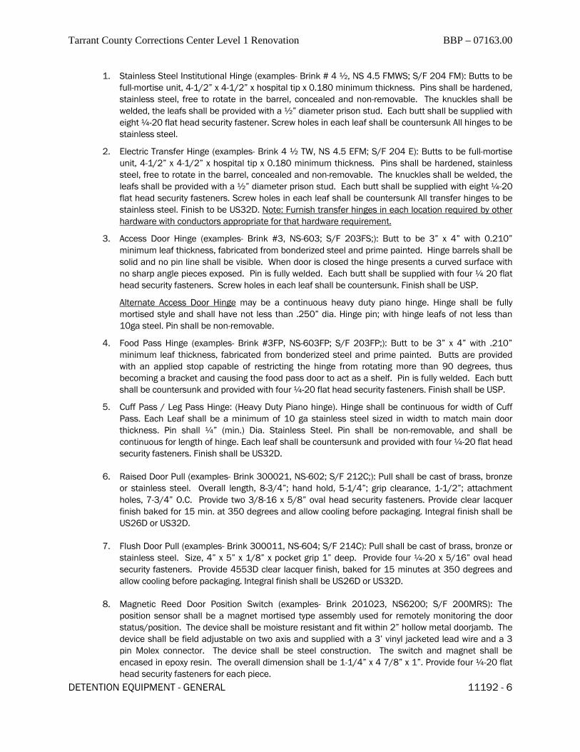
Tarrant County Corrections Center Level 1 Renovation BBP – 07163.00
DETENTION EQUIPMENT - GENERAL 11192 - 6
1. Stainless Steel Institutional Hinge (examples- Brink # 4 ½, NS 4.5 FMWS; S/F 204 FM): Butts to be full-mortise unit, 4-1/2” x 4-1/2” x hospital tip x 0.180 minimum thickness. Pins shall be hardened, stainless steel, free to rotate in the barrel, concealed and non-removable. The knuckles shall be welded, the leafs shall be provided with a ½” diameter prison stud. Each butt shall be supplied with eight ¼-20 flat head security fastener. Screw holes in each leaf shall be countersunk All hinges to be stainless steel.
2. Electric Transfer Hinge (examples- Brink 4 ½ TW, NS 4.5 EFM; S/F 204 E): Butts to be full-mortise unit, 4-1/2” x 4-1/2” x hospital tip x 0.180 minimum thickness. Pins shall be hardened, stainless steel, free to rotate in the barrel, concealed and non-removable. The knuckles shall be welded, the leafs shall be provided with a ½” diameter prison stud. Each butt shall be supplied with eight ¼-20 flat head security fasteners. Screw holes in each leaf shall be countersunk All transfer hinges to be stainless steel. Finish to be US32D. Note: Furnish transfer hinges in each location required by other hardware with conductors appropriate for that hardware requirement.
3. Access Door Hinge (examples- Brink #3, NS-603; S/F 203FS;): Butt to be 3” x 4” with 0.210” minimum leaf thickness, fabricated from bonderized steel and prime painted. Hinge barrels shall be solid and no pin line shall be visible. When door is closed the hinge presents a curved surface with no sharp angle pieces exposed. Pin is fully welded. Each butt shall be supplied with four ¼ 20 flat head security fasteners. Screw holes in each leaf shall be countersunk. Finish shall be USP.
Alternate Access Door Hinge may be a continuous heavy duty piano hinge. Hinge shall be fully mortised style and shall have not less than .250” dia. Hinge pin; with hinge leafs of not less than 10ga steel. Pin shall be non-removable.
4. Food Pass Hinge (examples- Brink #3FP, NS-603FP; S/F 203FP;): Butt to be 3” x 4” with .210” minimum leaf thickness, fabricated from bonderized steel and prime painted. Butts are provided with an applied stop capable of restricting the hinge from rotating more than 90 degrees, thus becoming a bracket and causing the food pass door to act as a shelf. Pin is fully welded. Each butt shall be countersunk and provided with four ¼-20 flat head security fasteners. Finish shall be USP.
5. Cuff Pass / Leg Pass Hinge: (Heavy Duty Piano hinge). Hinge shall be continuous for width of Cuff Pass. Each Leaf shall be a minimum of 10 ga stainless steel sized in width to match main door thickness. Pin shall ¼” (min.) Dia. Stainless Steel. Pin shall be non-removable, and shall be continuous for length of hinge. Each leaf shall be countersunk and provided with four ¼-20 flat head security fasteners. Finish shall be US32D.
6. Raised Door Pull (examples- Brink 300021, NS-602; S/F 212C;): Pull shall be cast of brass, bronze or stainless steel. Overall length, 8-3/4”; hand hold, 5-1/4”; grip clearance, 1-1/2”; attachment holes, 7-3/4” O.C. Provide two 3/8-16 x 5/8” oval head security fasteners. Provide clear lacquer finish baked for 15 min. at 350 degrees and allow cooling before packaging. Integral finish shall be US26D or US32D.
7. Flush Door Pull (examples- Brink 300011, NS-604; S/F 214C): Pull shall be cast of brass, bronze or stainless steel. Size, 4” x 5” x 1/8” x pocket grip 1” deep. Provide four ¼-20 x 5/16” oval head security fasteners. Provide 4553D clear lacquer finish, baked for 15 minutes at 350 degrees and allow cooling before packaging. Integral finish shall be US26D or US32D.
8. Magnetic Reed Door Position Switch (examples- Brink 201023, NS6200; S/F 200MRS): The position sensor shall be a magnet mortised type assembly used for remotely monitoring the door status/position. The device shall be moisture resistant and fit within 2” hollow metal doorjamb. The device shall be field adjustable on two axis and supplied with a 3’ vinyl jacketed lead wire and a 3 pin Molex connector. The device shall be steel construction. The switch and magnet shall be encased in epoxy resin. The overall dimension shall be 1-1/4” x 4 7/8” x 1”. Provide four ¼-20 flat head security fasteners for each piece.

Tarrant County Corrections Center Level 1 Renovation BBP – 07163.00
DETENTION EQUIPMENT - GENERAL 11192 - 7
9. Surface mounted Door Position Switch (examples- Brink 201090, S/F 220 and 220S dps) The door position switch shall be enclosed in a 10GA steel housing. The unit shall mount to the head of the door frame and shall include a pivoting operator that mounts to the top of the door face. Provide the 220S for frames with 2" heads, and 220 for frames with 4" heads. Provide with all necessary mounting plates and security fasteners. Finish of housing shall be USP.
10. Lock Keeper Monitoring Switch (by Lock manufacturer): The Lock keeper switch shall be enclosed in a 10GA steel housing. The lock keeper switch shall be provided by the lock manufacturer. The lock keeper switch shall be designed specifically for the lock in the opening in which it is used. Provide with all necessary mounting plates and security fasteners. Finish of recessed housing shall be USP. Finish of strike plate shall be US32D.
11. Mortised High Security Closer/Door Position Switch (examples- LCN #2210/dps AVB): Doors as detailed shall be controlled by overhead-concealed closers that have been tested to 10,000,000 opening-closing cycles. Closers shall have full hydraulic rack and pinion action with high strength cast iron cylinder. Spring power shall be adjustable from size III through size V. Hydraulic fluid shall be of a type requiring no seasonal adjustment for temperatures ranging from 120 degrees F to -30 Degrees F. Separate tamper-proof screw valves shall provide independent regularization of latch speed, general speed, and hydraulic back check. Regulating screws shall be accessible through a heavy duty mounting plate when finish plates are removed. Closers shall have an integral electromechanical device rated not less than 24VAC at 10 amperes to detect and signal rotation of the closer pinion. This device shall be field adjustable to allow setting for each door and fitting with a protective shield. Installation of the finish plate shall conceal adjustment mechanisms. Closer shall have an extra heavy duty forged steel concealed arm. The low friction track roller shall be attached to the arm by a threaded mounting. Closers shall have a metal track designed to prevent jamming and to eject foreign objects placed in the track mortised into the top of the door. Provide with all necessary mounting plates, covers and security fasteners. Finish of all exposed parts shall be US32D.All closers shall include advanced variable backcheck (AVB) feature.
12. Surface mounted High Security Closer (examples- LCN #4510-AVB): Doors as detailed shall be controlled by surface mounted closers that have been tested to 10,000,000 opening-closing cycles. Closers shall have full hydraulic rack and pinion action with high strength cast iron cylinder. Spring power shall be adjustable from size III through size V. Hydraulic fluid shall be of a type requiring no seasonal adjustment for temperatures ranging from 120 degrees F to -30 Degrees F. Separate tamper-proof screw valves shall provide independent regularization of latch speed, general speed, and hydraulic back check. Regulating screws shall be accessible through a heavy duty mounting plate when finish plates are removed. Installation of the finish plate shall conceal adjustment mechanisms. Closer shall have an extra heavy duty forged steel parallel arm. The low friction track roller shall be attached to the arm by a threaded mounting. Closers shall have a metal track designed to prevent jamming and to eject foreign objects placed in the track mounted onto the top of the door. Provide with all necessary mounting plates, covers and security fasteners. Finish of all exposed parts shall be US32D.All closers shall include advanced variable back-check (AVB) feature.
13. Aluminum Threshold (examples - Pemko 2005AS): Provide aluminum thresholds in the appropriate sizes shown in the Detention Door and/or Security Hardware Schedule. Provide all accessories and security fasteners required to provide complete, weatherproof installation. Finish shall be clear anodized aluminum.
14. Pass-proof Threshold (examples - Pemko 121A with 66A hook) : Provide aluminum pass-proof thresholds in the appropriate sizes shown in the Detention Door and/or Security Hardware Schedule. Provide all accessories and security fasteners required to provide complete, secure installation. Finish shall be clear anodized aluminum.

Tarrant County Corrections Center Level 1 Renovation BBP – 07163.00
DETENTION EQUIPMENT - GENERAL 11192 - 8
15. Weather-stripping / Smoke Gasket (examples Pemko S88AS): Provide continuous silicone smoke gasket / weather-stripping assembly as scheduled within the Detention Door and/or Security Hardware Schedule. Provide all accessories and security fasteners required to provide complete, weatherproof installation.
16. Detention Doorstops (examples Rockwood #467): Provide a Detention Doorstop for ALL swinging doors. Unit shall be constructed of heavy neoprene rubber with a minimum of 90 durometer hardness. Unit shall be approximately 2” dia. x 3 1/4” high and shall have integral mounting post for floor/wall installation that is 5/8" dia x 2 /1/2" long. Note: Doorstops shall be installed in all locations to maintain a minimum of 6” of clearance between the leading edge of the door and the wall.
E. SPECIAL SECURITY HARDWARE SETS:
1. Standard Security Hardware sets are scheduled within the DETENTION DOOR SCHEDULE in Section 11194 Detention Schedules; and in Part 4 of this section.
2. The following Special Security Hardware Sets are required as follows:
a. Set 80a: ( Special - Food Passes)
1 lock S/F 1010M - 1 (w/keeper).
1 hinge Heavy-Duty piano hinge (note: Hinge Pin shall be Stainless Steel)
Note: provide wherever Food Passes are scheduled. Provide hardware to DHM manu-facturer. Add to DEC hardware schedule. Include these locks in the Detention Keying Schedule
b. Set 80b: ( Special - Cuff Passes / Leg Passes)
1 lock S/F 1010M - 1 (w/keeper)
1 hinge Heavy-Duty piano hinge (note: Hinge Pin shall be Stainless Steel)
Note: provide wherever Cuff Passes or Leg Passes are scheduled. Provide hardware to DHM manufacturer. Add to DEC hardware schedule. Include these locks in the De-tention Keying Schedule
c. Set 80c: ( Special – Lockable Paper Passes) 1 lock S/F 1017M - 1 (w/keeper) 1 hinge Heavy-Duty piano hinge (note: Hinge Pin shall be Stainless Steel)
Note: provide wherever Lockable Paper Passes are shown in the documents. Provide hardware to DHM manufacturer. Add to DEC hardware schedule. Include these locks in the Detention Keying Schedule
d. Set 81a: ( Special – Security Access Panels)
1 lock S/F 1017M - 1 (w/keeper)
1 hinge Heavy-Duty piano hinge (note: Hinge Pin shall be Stainless Steel)
Note: provide wherever Security Access Panels are shown in the documents. Provide locks to Panel manufacturer. Add to DEC hardware schedule. Include these locks in the Detention Keying Schedule. Where Security Access Panels are required in Fire Rated walls, provide closer unit mounted on the Interior of the SAP. Provide SAP with fire rating required by host wall.
e. Set 82: ( Special - Roof Hatches)

Tarrant County Corrections Center Level 1 Renovation BBP – 07163.00
DETENTION EQUIPMENT - GENERAL 11192 - 9
NOT USED
f. Set 83: ( Special – Security Fire Cabinets)
1 lock S/F 1017M - w/housing and keeper switch
2 hinges By cabinet mfr.
Note: provide wherever Security Fire Cabinets are shown in the documents. Provide locks to Panel manufacturer. Add to DEC hardware schedule. Include these locks in the Detention Keying Schedule
-End of Special Hardware Sets-
2.2 CYLINDERS, KEYS AND KEYING:
A. SPECIAL CONDITION: The Security Hardware Supplier shall furnish ASSA Hi-Security cylinders and Keys on this project for all “builder’s –type” cylinders. The supplier shall furnish only True Mogul Cylinders and Mogul Keys where mogul style items are called for. Para-centric keyways will be provided as part of the locks affected.
2. Keying: The security locks will incorporate three (3) separate keying systems; one for lever tumbler (Paracentric), one for pin tumbler (mogul cylinder) and one for commercial (builder cylinder) locks. Each keying system’s keys shall be dye stamped for identification; corresponding to the hardware supplier’s final keying schedule.
3. Lever tumbler locks shall be keyed alike or different as directed. Provide cut keys as required. Paracentric prison locks shall be keyed in sets as coordinated with Owner, and provided with five keys for each set.
4. Builders cylinders and mogul type cylinders shall be keyed in sets and master keyed, grand master keyed, and similar items. to level as coordinated with Owner. Provide five keys per key change and five keys per master level.
5. Key Schedule: The DEC will prepare a proposed keying schedule for the security locks, showing
their recommendations for the system layout. (See 1.03; Submittals, this section). The DEC will provide copies of the keying schedule sorted by both door number and key change. The DEC shall provide Keying Plans, consisting of floor plans showing the location of each key code. The DEC shall coordinate the keying plans with the commercial as required by the Architect.
g. The Architect and Owner will review the schedule and make desired modifications. The DEC, and Owner shall meet to finalize the keying of the project.
6. Cylinders:
a. Provide all cell doors with 1 cylinder each on hinge side unless otherwise noted in Detention Door Schedule.
b. Provide all other doors with cylinders on both sides unless otherwise noted in Detention Door Schedule.
c. Provide cylinders for all manual release functions for sliding locking devices as required by the device manufacturer.
d. Provide cylinders for all electric key-switches called for in the ES documents (see ES drawings and Division 13) unless combined with locks specified to have the ‘LEK’ type function.

Tarrant County Corrections Center Level 1 Renovation BBP – 07163.00
DETENTION EQUIPMENT - GENERAL 11192 - 10
e. All cylinders shall be US26D or US32D to match other hardware unless otherwise noted.
f. Provide construction keys and cores during the construction period. Construction, control, and operating keys shall not be part of the Owner’s permanent keying system.
g. All Commercial (builders) cylinders provided under this contract shall be ASSA High Security Cylinders with 5C interchangeable cores.
h. Provide all mogul cylinders by Lock Manufacturer. Only “true Mogul” cylinders will be accepted.
i. Provide all paracentric keyways by the same manufacturer as that of the locks requiring them.
2.3 DETENTION LOCKS (for swing doors)
A. Acceptable Manufacturers: Except as otherwise specified, the equipment and materials of this Section shall be products of the following manufacturers:
1. Electric Mechanical Locks: Brink, S/F, and Airteq.
a. Wide Jamb Electric Locks: Brink, S/F, and Airteq. .
b. Narrow Jamb Electric Locks: Brink, S/F, and Airteq.
c. Mortise Locks: Brink, S/F, and Airteq.
2. All locks shall be standard products of the approved manufacturers, specifically designed for use in detention and corrections facilities.
3. All Detention locks on the project shall be by a single, approved manufacturer.
4. All exterior locks and locks for shower doors and chase doors shall be galvanized.
5. All motorized locks shall be provided with both full cycle and ½ cycle functions unless specifically scheduled to have only one or the other.
6. All motorized locks shall be provided with “no latch-back” feature unless otherwise specified.
7. All emergency exit doors shall be provided with “EED” function and shall be 115VAC-solenoid type.
8. All locks shall be furnished complete with key-ways and cylinders specifically designed for use in the corrections environment as required by the Detention Door Schedule. The DEC shall provide all required roses, escutcheons, cylinder extensions, etc to provide complete installation.
9. All locks shall be provided complete with mounting plates, covers, housings and other accessories or options as are required for scheduled installation and to comply with good industry practices.
10. Install lock cover plates with approved security fasteners on "secure" side of door unless otherwise specified. Request clarification from Architect where cover location is in doubt.
11. Provide electric transfer hinge for electromechanical locks/devices mortised in doors. This electric transfer hinge shall be provided in addition to the hinges required by the hardware sets. The transfer hinge shall be mounted as the center hinge.
12. Provide lock keeper switch for mechanical locks where monitoring is required by Detention Door Schedule.
B. LOCK TYPES:
1. General:
a. Lock descriptions herein are general. Specific features may vary by opening.
b. See DETENTION DOOR SCHEDULE in part 4 of this section.

Tarrant County Corrections Center Level 1 Renovation BBP – 07163.00
DETENTION EQUIPMENT - GENERAL 11192 - 11
c. The lock "types" (ie: A-2, B-1, etc.) are shown in a master list in the LOCK TYPE KEY with the Detention Door Schedule.
d. The Security Hardware Sets are shown at the end of this section.
e. The DEC shall immediately notify the Consultant of any conflicts between the Detention Door Schedule and these specifications.
2. LOCK TYPE A: 2" Jamb-mounted, Locks (examples; Brink #3520 series; S/F #10300 series,):
a. The lock shall be automatic, deadlocking latch, fail-secure type.
b. The latch shall be remotely retractable by one of the following as scheduled: a) 24VDC solenoid (Lock A1); b) 24VDC motor (Lock A2), or c) pneumatic solenoid (Lock A3), The latch shall also operate manually by key.
c. The overall dimensions of the lock shall be no greater than 1-5/8" wide x 1-1/2" deep x 11-1/2" high. Lock bolt shall retract with over 200 ft. lb. of lateral force against the door.
d. No greater than 1/16" depression of the auxiliary latch shall deadlock the latch and prevent its retraction by end pressure when in the projected position.
e. The lock shall be installed by mortising into the rabbet of the jamb at the lock rail height. The cutout required in the rabbet shall be no larger than 1-1/2" x 9-1/2". The mounting of the lock shall not require a special pocket or cutting into the stop, trim, or back bend of the frame except to provide a hole for the key cylinder. When the door is closed and locked, lock attachment screws shall be inaccessible.
f. The latchbolt shall have 3/4" throw, shall be of stainless steel, and shall contain two hardened steel pins for resistance to sawing.
g. A 1/2" thick stainless steel plate lock-body shall form a bearing surface for the latch and auxiliary bolts. Moving and structural parts shall be of stainless steel, brass, or bronze, and finished as specified.
h. The motor (lock A2), shall be sealed type, enclosed. It shall be rated 24VDC, continuous duty with power modulator, and tested to perform without failure for a minimum of 500,000 continuous cycles under actual load. The electric solenoid (Lock A1) shall be rated 24VDC, continuous duty ,solenoid. The air solenoid (Lock A3) shall be rated 60psi, continuous duty, solenoid.
i. The lock shall be operated by 1-5/32" diameter mortise or rim type key cylinder. The key cylinder shall be furnished by the lock manufacturer, as specified. Special features shall be provided as outlined in the security hardware sets.
j. The lock shall contain a limit switch actuated by the auxiliary and latchbolts. The switch shall serve to control a signal light to indicate the unlocked and deadlocked condition of the lock.
k. The lock shall be furnished with a plug connector for field wiring hookup. Wire leading from the lock shall terminate into a plug. A mating socket with corresponding color coded lead wires shall be furnished for connecting to field wires without the presence of the lock.
l. Standard latchbolt function is to be held in retracted position on unlocking until door is opened. On opening of door latchbolt extends and snap locks on closing of door. Dead bolt deadlocks latchbolt in extended position on closing of door. For variations, see specific locks. Special features shall be provided as outlined in the security hardware sets.
3. LOCK TYPE B: 8" Jamb-mounted, Locks (examples; Brink 5020 series, S/F #10120 series.):
a. The lock shall be automatic, deadlocking latch, fail-secure type.

Tarrant County Corrections Center Level 1 Renovation BBP – 07163.00
DETENTION EQUIPMENT - GENERAL 11192 - 12
b. The latch shall be remotely retractable by one of the following as scheduled: a) 24VDC solenoid (Lock B1); b) 24VDC motor (Lock B2), or c) pneumatic solenoid (Lock B3), The latch shall also operate manually by key.
c. The overall dimensions of the lock shall be no greater than 4 ¼" wide x 3" deep x 9 ¾" high. Lock bolt shall retract with over 300 ft. lb. of lateral force applied against the door.
d. The lock case shall be 1/8" steel, galvanized.
e. Lockbolt to be 3/4" x 1-1/2" with minimum 1" throw and shall be monitored by a limit switch within the lock. Strike keeper to be stainless steel.
f. The lock shall be equipped with a separate rollerbolt for deadlatching. No greater than 1/16" depression of the rollerbolt shall deadlock the latch and prevent its retraction by end pressure when in the projected position.
g. The lock shall be installed by recessing into a special pocket in the face of the door frame jamb. The lock requires a special cover, held in place with security fasteners. The cover shall be installed on the "secure" side of the opening.
h. Standard latchbolt function is to be held in retracted position on unlocking until door is opened. On opening of door latchbolt extends and snap locks on closing of door. Roller bolt deadlocks latchbolt in extended position on closing of door. For variations, see specific locks. Special features shall be provided as outlined in the security hardware sets.
i. Lock shall be provided with “True” Mogul cylinder(s) and keys in quantities and locations as scheduled.
4. LOCK TYPE C: 12" Jamb-mounted, Locks (examples; Brink 7050 series, S/F #1050 series.):
a. The lock shall be automatic, deadlocking latch, fail-secure type.
b. The latch shall be remotely retractable by one of the following as scheduled: a) 115VAC solenoid (Lock C1); b) 115VAC motor (Lock C2), or c) pneumatic solenoid (Lock C3), The latch shall also operate manually by key.
c. The overall dimensions of the lock shall be no greater than 9 " wide x 3 1/2" deep x 13 1/2" high. Lock bolt shall retract with over 400 ft. lb. of lateral force against the door.
d. The lock case shall be 1/8" steel, galvanized.
e. Lockbolt to be 3/4" x 1-1/2" with minimum 1" throw and shall be monitored by a limit switch within the lock. Strike keeper to be stainless steel.
f. The lock shall be equipped with a separate rollerbolt for deadlatching. No greater than 1/16" depression of the rollerbolt shall deadlock the latch and prevent its retraction by end pressure when in the projected position.
g. The lock shall be installed by recessing into a special pocket in the face of the door frame jamb. The lock requires a special cover , held in place with security fasteners. The cover shall be installed on the "secure" side of the opening.
h. Standard latchbolt function is to be held in retracted position on unlocking until door is opened. On opening of door latchbolt extends and snap locks on closing of door. Roller bolt deadlocks latchbolt in extended position on closing of door. For variations, see specific locks. Special features shall be provided as outlined in the security hardware sets.
5. LOCK TYPE D: Paracentric mechanical deadlock (examples; Brink 7080 series, S/F #1080 series.):
a. Lock case to be malleable iron with cold rolled steel cover. Latchbolt to be milled steel with hardened tool steel inserts unless otherwise specified.

Tarrant County Corrections Center Level 1 Renovation BBP – 07163.00
DETENTION EQUIPMENT - GENERAL 11192 - 13
b. Lock to operate by inserting paracentric key into matching polished alloy bronze cylinder and rotating key to align five or six spring temper hardened brass lever tumblers. Lever tumblers to be held in position by flat phosphor bronze springs.
c. Lock size to be approximately 5-1/2" x 1-1/2" x 3-3/4". Lockbolt to be used 3/4" x 2" milled steel with 3/4" throw. Deadbolt locking and unlocking activated by key only.
d. Lock to be mortised into door thickness.
6. LOCK TYPE E: Paracentric Mechanical Latchbolt (examples; Brink 7060, S/F 1060): or LOCK EK (examples Brink 7060K, S/F 1060K):
a. Lock case to be malleable iron with cold rolled steel cover. Latchbolt to be milled steel with hardened tool steel inserts unless otherwise specified.
b. Lock to operate by inserting paracentric key into matching polished alloy bronze cylinder and rotating key to align five or six spring temper hardened brass lever tumblers. Lever tumblers to be held in position by flat phosphor bronze springs.
c. Lock size shall be 5-1/2” × 1-1/2” × 3-3/4”. Latchbolt shall be retracted by knob or key. Lockbolt to spring latch on closing. Lock can be deadlocked by key.
d. Lock to be mortised into door thickness.
e. "K" designation denotes knobs.
7. LOCK TYPE F: Paracentric Mechanical Deadlatch (examples Brink 7070, S/F 1070): or LOCK FK (examples S/F 1070K; FA 70K):
a. Lock case to be malleable iron with cold rolled steel cover. Latchbolt to be milled steel with hardened tool steel inserts unless otherwise specified.
b. Lock to operate by inserting paracentric key into matching polished alloy bronze cylinder and rotating key to align five or six spring temper hardened brass lever tumblers. Lever tumblers to be held in position by flat phosphor bronze springs.
c. Lock size to be approximately 8-3/4" x 1-1/2" x 5". Beveled latchbolt to be 3/4" x 2 with 3/4" throw. Beveled latchbolt to be retracted by key operation only.
d. Lockbolt to spring lock on closing. Provide automatic deadlock actuator for deadlocking of latchbolt.
e. Lock to be mortised into door thickness.
8. LOCK TYPE G: Utility Mechanical Dead-lock (examples Brink 7010, S/F 1010): or LOCK TYPE GM (examples Brink 7010M, S/F 1010M):
a. Lock size to be approximately 4" x 1-1/4" x 2-3/4". Lockbolt to be 1/2" x 1" high strength bronze with 7/16" throw.
b. Lockbolt to be retracted by key operation only.
c. Cylinder to be paracentric or mogul type by lock manufacturer.
d. “M” denotes True Mogul cylinder.
9. LOCK TYPE H: Utility Mechanical Snap-lock (examples Brink 7017, S/F 1017): or LOCK HM (examples; Brink 7017M, S/F 1017M):
a. Lock size to be approximately 4" x 1-1/4" x 2-3/4". Beveled latchbolt to be 1/2" x 1" high strength bronze with 7/16" throw.
b. Beveled latchbolt to be retracted by key operation only. Latchbolt to spring lock on closing.
c. Cylinder to be paracentric or mogul type by lock manufacturer.

Tarrant County Corrections Center Level 1 Renovation BBP – 07163.00
DETENTION EQUIPMENT - GENERAL 11192 - 14
d. “M” denotes True Mogul cylinder.
10. LOCK TYPE I: Mortised Institutional Lockset (examples Brink 1040/1060 series, S/F 10500 series)
a. Lock size to be approximately 4" x 1-1/4" x 2-3/4". Beveled latchbolt to be 1/2" x 1" high strength bronze with 7/16" throw.
b. Beveled latchbolt to be retracted by key operation only. Latchbolt to spring lock on closing.
c. Cylinder and key to be true mogul type by lock manufacturer. Provide cylinder(s) as scheduled in Detention Door Schedule and Security Hardware sets.
d. Provide Lever set(s) for each lock. Provide levers for Key side.
e. Provide functions for each lock per keying meeting
11. LOCK TYPES K thru V: Not Used
(note: for type “Q” device see section 11193)
2.4 SPARE PARTS
A. Provide Spare parts / attic stock for Security Locks and Hardware as shown in Section 01291.
B. Each item provided shall be in factory packaging, clearly labeled with Item number and description.
C. Provide all units with trim, covers, fasteners, accessories, etc to match the unit provided on the project.
D. All Items require written receipt(s) from the client at the end of the project.
PART 3 - EXECUTION
3.1 EXAMINATION
A. Examine detention doors and frames, with Installer present, for compliance with requirements for installation tolerances, labeled fire door assembly construction, wall and floor construction, and other conditions affecting performance of detention door hardware.
1. Examine roughing-in for embedded and built-in anchors to verify actual locations of detention door hardware connections before detention door hardware installation.
2. For the record, prepare written report, endorsed by Installer, listing conditions detrimental to performance of detention door hardware.
B. Inspect built-in and cast-in anchor installations before installing detention door hardware to verify that anchor installations comply with requirements. Prepare inspection reports.
1. Remove and replace anchors where inspections indicate that they do not comply with specified requirements. Re-inspect after repairs or replacements are made.
2. Perform additional inspections to determine compliance of replaced or additional work. Prepare inspection reports.
C. Verify locations of detention door hardware with those indicated on Coordination Drawings.
D. Examine roughing-in for electrical power systems to verify actual locations of wiring connections before electrified detention door hardware installation.

Tarrant County Corrections Center Level 1 Renovation BBP – 07163.00
DETENTION EQUIPMENT - GENERAL 11192 - 15
E. Proceed with installation only after unsatisfactory conditions have been corrected.
3.2 PREPARATION
A. Examine doors, frames, and hardware for damage, defects, and suitability for intended use. Restore all parts or items found damaged, defective or inadequate, or replace with good material before installation.
3.3 INSTALLATION
A. Mounting Heights: Heights given are center line heights up from finish floor unless stated; heights given "Number to Number" indicates that all shall be at one height within limits given. Where heights of items are not listed, mount in accord with recommendations of DHI.
1. Bottom Hinge: 10 to 13 inches
2. Top Hinge: The Standard on this Project is 2 “top” hinges. See Sht. D002 for setting heights.
3. Intermediate Hinges: Equally spaced
4. Door Knob: 36 to 40-5/16 inches
5. Door Pull: 42 to 45 inches
6. Deadlocks: 54 inches from floor to centerline
B. Special Mounting Heights: There are special mounting heights for Hardware on this project. SEE THE DRAWINGS FOR SPECIAL REQUIREMENTS.
C. Fitting 1. Fit all hardware accurately and properly. Remove exposed parts until after painters finishing
is completed, then reinstall. Securely fasten all fixed parts. Fit faces of mortised parts snug and flush. Make sure operating parts move freely and smoothly without binding, sticking, or excessive clearance.
D. Adjusting and Finishing
1. After work has been otherwise completed, examine all hardware for complete and proper installation. Lubricate bearing surfaces of moving parts. Adjust latching and holding devices to proper function. Adjust door control devices to proper speed and power. Test keys for conformance to approved keying system. Clean all exposed surfaces, check for surface damage and polish.
E. Thresholds
1. Install in one continuous piece, full width of opening. Set in full bed of mastic and fasten with countersunk anchors at 6 inches on center (max.).
F. Doorstops:
1. ALL swinging detention doors shall receive doorstops. Install all doorstops on the wall in such a manner that a minimum of 6” clearance is maintained between the leading edge of the door and the wall.
2. Notify the Architect of any field conditions that interfere with the proper installation of doorstops.
3.4 DEFECTIVE WORK

Tarrant County Corrections Center Level 1 Renovation BBP – 07163.00
DETENTION EQUIPMENT - GENERAL 11192 - 16
A. Where hardware is found defective in materials or installation; rework, restore, replace, or otherwise correct as directed.
B. Following will be considered as defective materials:
1. Unauthorized substitutes.
2. Items delivered with missing, broken, damaged, or defaced parts.
3. Items of incorrect hand or function.
C. Following will be considered as defective installation:
1. Items broken, damaged, or defaced after delivery.
2. Items incomplete, misaligned or incorrectly located.
D. All expenses incurred by the Architect or Owner in troubleshooting security hardware problems, caused by inadequate workmanship or other form of poor performance on the part of a contractor, shall be borne by that contractor.
PART 4 - SECURITY HARDWARE SETS
See Following pages

6/10/2015
The following hardware sets are required . See Door Schedule for locations and Lock types.
Issue:
Hardware Sets
Job Name: Tarrant County
Hardware Set: S21ASet Description: Int-3h/1p
Items in Set: Openings
1166, 1164A, 1164BHardware Item Part No. QtyDPS - RECESS. SSCo 200MRS 1
SILENCERS GJ 64 3
LOCK W/ CYLINDER (S) See DDS For Lk Type /Key Side 1
D'RSTOP -JAIL Stanley 3001/3002 1
4.1/2 HINGE -JAIL SSCo 204FM SS 3
PULL - RAISED SSCo 212C (HS) 1
Hardware Set: S21GSet Description: Int-3h/1p/cl-dp
Items in Set: Openings
1163, 1166A, 1165, 1164Hardware Item Part No. QtyLOCK W/ CYLINDER (S) See DDS For Lk Type /Key Side 1
CLOSER/DPS -JAIL LCN 2210 DPSAVBT 1
D'RSTOP -JAIL Stanley 3001/3002 1
4.1/2 HINGE -JAIL SSCo 204FM SS 3
PULL - RAISED SSCo 212C (HS) 1
SILENCERS GJ 64 3
Hardware Set: S21HSet Description: Int-3h/2p/cl-dp
Items in Set: Openings
1162B, 1162A, 1161B, 1160B, 1160A, 1161AHardware Item Part No. QtyLOCK W/ CYLINDER (S) See DDS For Lk Type /Key Side 1
CLOSER/DPS -JAIL LCN 2210 DPSAVBT 1
D'RSTOP -JAIL Stanley 3001/3002 1
4.1/2 HINGE -JAIL SSCo 204FM SS 3
PULL - RAISED SSCo 212C (HS) 2
SILENCERS GJ 64 3
Page 1 of 4

Hardware Sets (cont'd)
6/10/2015Issue:
See Door Schedule for lock types for each opening
Job Name: Tarrant County
Hardware Set: S21ISet Description: Int-3h/cl-dp/ks
Items in Set: Openings
1170B, 1170AHardware Item Part No. QtyPULL - RAISED SSCo 212C (HS) 1
LOCK W/ CYLINDER (S) See DDS For Lk Type /Key Side 1
CLOSER/DPS -JAIL LCN 2210 DPSAVBT 1
D'RSTOP -JAIL Stanley 3001/3002 1
4.1/2 HINGE -JAIL SSCo 204FM SS 3
KEEPERSWITCH SSCo 4CL 1
SILENCERS GJ 64 3
Hardware Set: S22CSet Description: Int-4h/cl
Items in Set: Openings
1163B, 1163A, 1176Hardware Item Part No. QtyD'RSTOP -JAIL Stanley 3001/3002 1
CLOSER -JAIL CON. LCN 2210 AVBT 1
LOCK W/ CYLINDER (S) See DDS For Lk Type /Key Side 1
4.1/2 HINGE -JAIL SSCo 204FM SS 4
SILENCERS GJ 64 3
Hardware Set: S22HSet Description: Int-4h/2p/cl-dp
Items in Set: Openings
1168BHardware Item Part No. QtyCLOSER/DPS -JAIL LCN 2210 DPSAVBT 1
D'RSTOP -JAIL Stanley 3001/3002 1
LOCK W/ CYLINDER (S) See DDS For Lk Type /Key Side 1
4.1/2 HINGE -JAIL SSCo 204FM SS 4
PULL - RAISED SSCo 212C (HS) 2
SILENCERS GJ 64 3
Page 2 of 4

Hardware Sets (cont'd)
6/10/2015Issue:
See Door Schedule for lock types for each opening
Job Name: Tarrant County
Hardware Set: S22ISet Description: Int-4h/cl-dp/ks
Items in Set: Openings
1169Hardware Item Part No. QtyD'RSTOP -JAIL Stanley 3001/3002 1
LOCK W/ CYLINDER (S) See DDS For Lk Type /Key Side 1
CLOSER/DPS -JAIL LCN 2210 DPSAVBT 1
4.1/2 HINGE -JAIL SSCo 204FM SS 4
KEEPERSWITCH SSCo 4CL 1
SILENCERS GJ 64 3
Hardware Set: S22JSet Description: Int-4h/1p/cl-dp/ks
Items in Set: Openings
1177Hardware Item Part No. QtyCLOSER/DPS -JAIL LCN 2210 DPSAVBT 1
D'RSTOP -JAIL Stanley 3001/3002 1
LOCK W/ CYLINDER (S) See DDS For Lk Type /Key Side 1
4.1/2 HINGE -JAIL SSCo 204FM SS 4
KEEPERSWITCH SSCo 4CL 1
PULL - RAISED SSCo 212C (HS) 1
SILENCERS GJ 64 3
Page 3 of 4

Hardware Sets (cont'd)
6/10/2015Issue:
See Door Schedule for lock types for each opening
Job Name: Tarrant County
Hardware Set: S22MSet Description: Int-4h/1p/dp/ks
Items in Set: Openings
1111, 1121, 1120, 1119, 1118, 1117, 1116, 1115, 1114, 1101, 1112, 1124, 1110, 1109, 1108, 1107, 1106, 1105, 1104, 1103, 1102, 1113, 1130, 1146, 1143, 1142, 1141, 1137, 1136, 1135, 1134, 1133, 1122, 1131, 1123, 1129, 1138, 1139, 1140, 1128, 1127, 1126, 1125, 1147, 1132
Hardware Item Part No. QtyPUSHBUTTON See Security Electronics 1
DPS - SURFACE SSCo 220S 1
PULL - RAISED SSCo 212C (HS) 1
LOCK W/ CYLINDER (S) See DDS For Lk Type /Key Side 1
4.1/2 HINGE -JAIL SSCo 204FM SS 4
SILENCERS GJ 64 3
Hardware Set: S60ASet Description: Int-Slide 2p
Items in Set: Openings
1172Hardware Item Part No. QtyKEYSWITCH (CYL) SSCo 299 CKS 2
LOCK W/ CYLINDER (S) See DDS For Lk Type /Key Side 1
PULL - RAISED SSCo 212C (HS) 1
PULL - RECESSED. SSCo 214C (SS) 1
Page 4 of 4

Tarrant County Corrections Center Level 1 Renovation BBP – 07163.00
DETENTION EQUIPMENT - GENERAL 11193 - 1
SECTION 11193 - DETENTION LOCKING DEVICES
PART 1 - GENERAL
1.1 RELATED DOCUMENTS
A. Drawings and general provisions of the Contract, including General and Special Conditions and Division 1, as well as Section 11190, DETENTION EQUIPMENT apply to this Section.
1.2 SUMMARY
A. General
1. This section consists of furnishing the electro-mechanical Locking Devices as shown
2. The specification together with the drawings and schedules cover the required units.
B. Work includes, but is not limited to: The work to be performed consists of furnishing the electro-mechanical Locking Devices as shown on the drawings and described in these specifications, including but not limited to the following:
1. All detention sliding door devices complete.
2. Supply at the jobsite for installation by others: All imbedded metal items such as anchor bolts and anchoring.
3. All finish hardware and accessories indicated in this section.
C. Related work specified elsewhere includes, but is not limited to:
1. Section 04220, Masonry
2. Section 04230, Reinforced Unit Masonry
3. Section 09900, Painting
4. Section 11190, Detention Equipment -General
5. Section 11191, Detention Doors and Frames
6. Section 11192, Detention Locks and Hardware
7. Section 11194, Detention Schedules
8. Division 13800, Electronic Security
1.3 PERFORMANCE REQUIREMENTS
A. Sliding Detention Door Assemblies: Provide detention devices as part of a detention door assembly that complies with security grade indicated, when tested according to ASTM F 1450, based on testing manufacturer's standard units in assemblies similar to those indicated for this Project.
1.4 QUALITY ASSURANCE
A. In addition to the requirements of these specifications, comply with manufacturer's instructions and recommendations for all phases of work.
B. The Manufacturer of this work shall have been in business for the last ten (10) years and have provided security hardware on at least three (3) projects of comparable size during those ten (10) years. He shall have in his employ personnel with adequate prison hardware experience to qualify

Tarrant County Corrections Center Level 1 Renovation BBP – 07163.00
DETENTION EQUIPMENT - GENERAL 11193 - 2
as an expert in this field. The material to be furnished shall be made by a manufacturer who specializes in security hardware.
C. Furnish a complete system to properly function as specified. Wiring diagrams for locks – DPS furnished.
D. Detention Device Manufacturer and Contractor shall guarantee the material provided by them and the workmanship performed by them on this project for two years from the date of Substantial Completion. Security Hardware Contractor shall repair or replace, within 48 hours, any defective work performed by them when given written notice during the warranty period. This obligation is limited to the replacement or repair. Security Hardware Supplier agrees to pass on all guarantees provided by their suppliers. Vandalism or excessive abuse is excluded from this warranty.
E. Devices shall conform to the requirements of government authorities having jurisdiction except as dictated by more stringent project requirements.
1. Standards
a. A.I.A. (NBFU) Pamphlet No. 80 b. Federal Specifications FF-H-00106, FF-H-00111, FF-H-121, and FF-H-0016. c. NBHA "Recommended Locations for Builders Hardware" d. ANSI/BHMA Standards A 156 Series, latest edition e. Americans with Disabilities Act (ADA) Accessibility guidelines for Buildings and
Facilities/Federal Register Vol. 56, No. 144/July 26, 1991 - Closers and Lever Handles and Locksets.
f. All hardware shall conform to OBBC.
2. Fire-rated Openings
a. Provide hardware for fire-rated openings in compliance with NFPA standards. b. Provide only hardware which has been tested and listed by UL for the types and sizes
of doors required. c. Provide label where required.
1.5 SUBMITTALS
A. Product Data: Submit Manufacturer's technical product data for each item of finish hardware. Show compliance with requirements, and include instructions for installation and for maintenance of operating parts and finish.
B. Samples
1. Submit one actual unit of each piece of finish hardware, tagged with full description for coordination with the Schedule. If Samples conform to the Contract Documents, they will be returned for inclusion in the Project.
2. Submit Samples of each metal finish, on an actual piece of the metal specified.
C. Shop Drawings
1. Submit Shop Drawings showing quality, type, and location of security hardware.
a. Wiring Diagrams: Detail power, signal, and control wiring and differentiate between manufacturer-installed and field-installed wiring for electrified detention door hardware. Include the following:
1) System schematic. 2) Point-to-point wiring diagram, including location of connections. 3) Riser diagram. 4) Elevation of each detention door.

Tarrant County Corrections Center Level 1 Renovation BBP – 07163.00
DETENTION EQUIPMENT - GENERAL 11193 - 3
2. Provide template to door/frame manufacturer after contract and hardware schedule are complete and acceptable.
3. Provide information to the DEC for Device Coordination Drawing submittal.
D. Operation/Maintenance Manuals
1. Operation Manual covering parts, maintenance, and operation. Refer to Division 1 for submittal procedure.
E. Product Certificates: For each type of electrified detention door hardware, signed by product manufacturer.
1. Certify that detention door hardware approved for use on types and sizes of labeled fire doors complies with listed fire door assemblies.
1.6 PRODUCT DELIVERY, STORAGE AND HANDLING
A. Tag each item or package separately, with identification related to the Hardware Schedule, and include installation instructions. Deliver individually packaged hardware items at the proper times to the Shop or Project Site for installation.
1.7 JOB CONDITIONS
A. Field Service
1. The Device supplier shall assign a competent representative to be at the job site each time a major shipment of security hardware is received. Such representatives shall assist in "checking in" these shipments and shall secure a receipt covering the contents of each shipment. In addition, such representative shall be available for immediate call to the job site when, in the opinion of the Associate, his presence is necessary.
1.8 MAINTENANCE SERVICE
A. Maintenance Tools and Instructions: Furnish a complete set of specialized tools and maintenance instructions as needed for Owner's continued adjustment, maintenance, and removal and replacement of detention door hardware.
B. Tool Kit: Provide six sets of tools for use with security fasteners, each packaged in a compartmented kit configured for easy handling and storage.
PART 2 - PRODUCTS
2.1 LOCKING DEVICES - GENERAL
A. Acceptable manufacturer: Except as otherwise noted, the equipment in this Section shall be provided by one of the following manufacturers: 1. RR Brink 2. Southern /Folger 3. Airteq
B. The equipment and materials listed in this section are products of the Southern Steel Company (called S/F below), unless otherwise noted. Products of equal quality and function from acceptable manufacturers may be used.
C. The Device Types reference are scheduled in the DETENTION DOOR SCHEDULE. (DDS) And listed in the LOCK TYPE KEY.

Tarrant County Corrections Center Level 1 Renovation BBP – 07163.00
DETENTION EQUIPMENT - GENERAL 11193 - 4
2.2 LOCKING DEVICE COMPONENTS
A. HOUSINGS and COVERS
1. All devices shall have steel housings and covers by the device manufacturer.
2. The horizontal mechanism housing shall be constructed of 10-gauge steel plate. All openings thru the housing(s) shall be baffled. The back of the housing shall be 7-gauge steel plate. All exterior housings shall be galvanized.
3. The housing shall be of one-piece construction, securely enclosing the top, front, and bottom of the door operator(s).
4. The door hanger slot(s) shall be securely baffled in both the “Door Open” and “Door Closed” position.
5. Housing covers shall be constructed of 10-gauge sheet steel. All Housing covers shall be hinged with a continuous piano hinge; inaccessible when the cover is closed.
6. Housing profiles vary on this project. See detention drawings. The housing shall protrude from the wall surface maximum of 8”. The housing shall extend a maximum of 12 ¾” above the door opening, unless otherwise detailed.
7. Housing covers shall be locked to the housings with button head security fasteners.
8. The vertical lock bar housing and cover shall be constructed of 1” x 2” x 10-gauge steel tube. The vertical lock housing shall be removable only when the horizontal housing cover has been removed.
9. All Housings shall include all trim and fasteners to provide a complete and finished installation.
10. Where several Devices are grouped together, the housing covers shall be constructed to appear continuous; without gaps or holes between the housings. In cases where the housings are not continuous, ends shall be neatly closed and welded with 10ga steel plate. The device manufacturer shall provide additional housings for the pneumatic and electrical components as required to route those components to secure areas.
11. Provide 12 gage wire tray in the housing for the electrical wired cable harness in accordance with the applicable electrical code.
12. Paint all surfaces of housings and covers with rust inhibitive primer before shipment. Final painting by others.
B. HANGERS, ROLLERS, GUIDES
1. All Devices shall include rollers, hangers and track assemblies by the device manufacturer.
2. Door hangers and guides shall be min 1/4" thick steel plate. Door Hanger shall interlock with track support with a clearance of not more than 1/4".
3. Support rollers shall be milled from solid steel 3-3/4" OD grooved 3/8" deep to engage 1/2" cold drawn track.
4. Rollers shall have anti-friction ball bearings with hardened members and grease shields on both sides.
5. Roller studs shall be high alloy steel with eccentric bushing for adjustment and an automatic self-locking nut.
6. Paint assembly, except track, rollers and drive mechanisms with rust inhibitive primer before shipment. Final painting by others.

Tarrant County Corrections Center Level 1 Renovation BBP – 07163.00
DETENTION EQUIPMENT - GENERAL 11193 - 5
7. Door guides shall be 7 gauge. Steel (min). Top and bottom door guides must be designed to limit side motion of the door to reduce rattle-induced noise.
C. DRIVE MECHANISMS and OPERATORS
1. All Devices shall include drive and locking mechanisms and operators by the device manufacturer.
2. All Devices shall include rack and pinion operator assemblies by the device manufacturer. All components shall be of the highest quality and shall be rated for continuos operation by their manufacturer.
3. All Devices shall include mechanical locking mechanisms. Door shall lock at the top and bottom in both open and closed positions. The vertical lock bar shall be mechanically connected to the lock mechanism at all times. The locking mechanism shall include an automatic mechanical deadlock feature.
4. Device shall include rubber bumpers to cushion device movement at both open and closed position.
5. The vertical lock bar shall be constructed of 5/8” square cold rolled steel. The vertical lock bar shall be entirely enclosed in a steel housing. The lock bar shall move freely within the housing.
D. ELECTRICAL
1. All devices shall be factory wired to a multi-pin connector located within the housing above each door.
2. Provide factory wired cable harness inside housing.
3. All switches necessary for the function of the device and for door status indication shall be U.L. recognized. Other than limit switches, there shall be no other control logic components located internal to the locking device housing.
4. All limit switches shall be rated 5 to 15 amps. The use of magnetic reed switches for door control or indication is not acceptable.
5. All electrical components shall be rated by their manufacturer for continuous operation.
6. All wiring shall be UL approved, and shall be properly sized by the manufacturer to meet all applicable codes.
7. Where Electric Keyswitch feature is shown in the Detention Door Schedule and/or the Security Electronics documents (see Division 13); provide all necessary components to allow the device to be electrically operated via key at the door. Verify key side(s) with Architect / Consultant. Furnish and install electric keyswitch unit in pilaster housing. Keyswitch unit manufacturer shall match locks and hardware on the project (see section 11192). Key Cylinder shal’ real’ mogul type.
8. Where Access Control feature is shown in the Detention Door Schedule and/or the Security Electronics documents (see Division 17); provide all necessary components to allow the device to be operated electrically via access card device at the door. Verify access side(s) with Architect / Consultant. Card access devices shall be furnished by the ESS. Card access device(s) shall be mounted in the pilaster. The Device manufacturer shall provide required preparation and backboxes, conduits, etc for installing the access device(s). The cable wiring harness shall contain the required conductors for this feature.

Tarrant County Corrections Center Level 1 Renovation BBP – 07163.00
DETENTION EQUIPMENT - GENERAL 11193 - 6
9. Each Device shall be supplied with status switches to provide indication and interlocking capabilities. Status switches shall provide the following minimum indications:
a. Deadlocked closed b. Deadlocked open c. Any additional switches as may be required for the functions listed under each
device.
E. ELECTRIC
1. All electrical components shall be UL recognized.
2. All Devices shall include factory connected wiring for each device. Provide factory designed connector for pneumatic locking distribution tubing/piping at individual devices. Provide factory bundled tubing harness in wire tray in housing at multiple devices.
3. All components shall be rated by their manufacturer for continuous operation.
4. Where Electric Keyswitch feature is shown in the Detention Door Schedule and/or the Security Electronics documents (see Division 28); provide all necessary components to allow the device to be electrically operated via key at the door. Verify key side(s) with Architect / Consultant.
5. Where Access Control feature is shown in the Detention Door Schedule and/or the Security Electronics documents (see Division 28); provide all necessary components to allow the device to be operated electrically via access card device at the door. Verify access side(s) with Architect / Consultant. Card access devices shall be furnished by the ESS. Card access device(s) shall be mounted in the frame or special pilaster. The Device manufacturer shall provide required preparation and backboxes, conduits, etc for installing the access device(s). The cable wiring harness shall contain the required conductors for this feature.
2.3 DEVICE TYPES and FUNCTIONS
A. Device Type Q1: Fully Electromechanical Sliding Corridor Door Operator, (Example: Brink 57700 series; S/F #3165 Series) (rack/pinion) and fully controlled sliding door operator. (Types Q2 and Q3– Not Used).
1. Features. The device shall have the following features:
a. Unlock, open and lock open a 3'-0" door in not more than five seconds.
b. Unlock, close and deadlock close a 3'-0" door in not more than five seconds.
c. Stop the movement of any door in mid-travel so that it may be manually opened or closed by applying approximately 35 lb. of pressure on the door.
d. Instantly reverse the direction of the door. In the event the door is blocked, the door shall automatically continue to the open or closed position when the obstruction is removed.
e. Normal force exerted by a door in travel shall be 35 lb. This force shall be field adjustable from 20 lb. to 50 lb. to accommodate various door conditions.
f. Device shall hold preset pressure on door at times of operation.
g. The locking device shall be designed so that there are no projecting lugs on the receiver column or the door. Door shall automatically deadlock close at two points at rear of door. Front locking shall not be acceptable.
h. Each device shall have a locking pilaster.
Tarrant County Corrections Center Level 1 Renovation BBP – 07163.00
DETENTION EQUIPMENT - GENERAL 11193 - 7
i. Where scheduled, each Device shall be equipped with an electric key-switch or access card device to allow the device to be operated from one or both sides as indicated.

Tarrant County Corrections Center Level 1 Renovation BBP – 07163.00
DETENTION EQUIPMENT - GENERAL 11193 - 8
PART 3 - EXECUTION
3.1 EXAMINATION
A. Examine detention doors and frames, with Installer present, for compliance with requirements for installation tolerances, labeled fire door assembly construction, wall and floor construction, and other conditions affecting performance of detention door hardware.
1. Examine roughing-in for embedded and built-in anchors to verify actual locations of detention door hardware connections before detention door hardware installation.
2. For the record, prepare written report, endorsed by Installer, listing conditions detrimental to performance of detention door hardware.
B. Inspect built-in and cast-in anchor installations before installing detention door hardware to verify that anchor installations comply with requirements. Prepare inspection reports.
1. Remove and replace anchors where inspections indicate that they do not comply with specified requirements. Reinspect after repairs or replacements are made.
2. Perform additional inspections to determine compliance of replaced or additional work. Prepare inspection reports.
C. Verify locations of detention door hardware with those indicated on Coordination Drawings.
D. Examine roughing-in for electrical power systems to verify actual locations of wiring connections before electrified detention door hardware installation.
E. Proceed with installation only after unsatisfactory conditions have been corrected.
3.2 PREPARATION
A. Examine doors, frames, and hardware for damage, defects, and suitability for intended use. Restore all parts or items found damaged, defective or inadequate, or replace with good material before installation.
3.3 INSTALLATION
A. Fitting
1. Fit all Devices accurately and properly. Remove exposed parts until after painters finishing is completed, then reinstall. Securely fasten all fixed parts. Fit faces of mortised parts snug and flush. Make sure operating parts move freely and smoothly without binding, sticking, or excessive clearance.
B. Adjusting and Finishing
1. After work has been otherwise completed, examine all Devices for complete and proper installation. Lubricate bearing surfaces of moving parts. Adjust latching and holding devices to proper function. Adjust door control devices to proper speed and power. Test keys for conformance to approved keying system. Clean all exposed surfaces, check for surface damage and polish.
3.4 DEFECTIVE WORK
A. Where devices are found defective in materials or installation; rework, restore, replace, or otherwise correct as directed.

Tarrant County Corrections Center Level 1 Renovation BBP – 07163.00
DETENTION EQUIPMENT - GENERAL 11193 - 9
B. Following will be considered as defective materials:
1. Unauthorized substitutes.
2. Items delivered with missing, broken, damaged, or defaced parts.
3. Items of incorrect hand or function.
C. Following will be considered as defective installation:
1. Items broken, damaged, or defaced after delivery.
2. Items incomplete, misaligned or incorrectly located.
D. All expenses incurred by the Architect or Owner in troubleshooting security hardware problems, caused by inadequate workmanship or other form of poor performance on the part of the contractor, shall be borne by that contractor.
END OF SECTION 11193

Tarrant County Corrections Center Level 1 Renovation BBP – 07163.00
DETENTION EQUIPMENT - GENERAL 11194 - 1
SECTION 11194 - DETENTION SCHEDULES
PART 1 - GENERAL
1.1 RELATED DOCUMENTS
A. Drawings and general provisions of the Contract, including General and Special Conditions and Division 1, as well as Section 11190, DETENTION EQUIPMENT apply to this Section.
1.2 SUMMARY
A. General
1. This section consists of Schedules listing Detention Doors.
2. Detention Windows are shown on Sht. D-300.
3. This specification together with the drawings and schedules cover the required units.
B. Related work specified elsewhere includes, but is not limited to:
1. Section 04220, Masonry
2. Section 04230, Reinforced Unit Masonry
3. Section 09900, Painting
4. Section 11190, Detention Equipment -General
5. Section 11191, Detention Hollow Metal Doors and Frames
6. Section 11192, Security Locks and Hardware
7. Section 11193, Detention Locking Devices
8. Section 11195, Security Glass and Glazing
9. Division 13800, Electronic Security
1.3 SUMMARY: The following Schedules are bound into the specifications immediately following this Section:
A. Detention Door Schedule (DDS)
1.4 ABBREVIATIONS and TERMS; The following Abbreviations are used in the Detention Schedules
A. Materials and Miscellaneous
1. AL = Aluminum
2. CH = Chainlink
3. GR = Steel Grating
4 HM = Hollow Metal
5. PL = Steel Plate
6. SHM = Security Hollow Metal
7. SS = Stainless Steel
8. SG = Security Glass
9. SH = Security Hardware

Tarrant County Corrections Center Level 1 Renovation BBP – 07163.00
DETENTION EQUIPMENT - GENERAL 11194 - 2
10. SWD = Security Wood
11. WD = Wood
12. WW = Woven Wire Mesh
13. EXT = Exterior
14. INT = Interior
15. SW = Swinging Door
16. SL = Sliding Door
17. FIX = Fixed opening (DWS Only)
18. OP = Operable (DWS Only)
19. DDS = Detention Door Schedule
20.DWS = Detention Window Schedule
B. Security Levels (See Section 11190)
1. 1 = 40 min. attack
2. 2 = 20 min. attack
3. 3 = 10 min. attack
4. 4 = normal institutional construction
5. N = none required
6. SP = Special, See all documents
7. BR = bullet resistant (44 mag) required; plus 60min attack
C. Fire Ratings (UL)
1. A = 3 hr fire rating
2. B = 1 ½ hr fire rating
3. C = 60 min. fire rating
4. D. = 20 min fire rating
6. X = UL Construction – no label
D. Smoke Protection
1. N = No rating required
2. Y = Requires gasketing
E. LOCK TYPES / HARDWARE
1. The Lock Types listed in the Door Schedules and the LOCK TYPE KEY are specified in section
11192 – SECURITY LOCKS AND HARDWARE and section 11193 – DETENTION LOCKING DEVICES.
2. The Lock Type / Hardware Set / Key Side columns constitute the description of the Security Hardware Set. (ie: A2/SH-02/BS)
3. Security Hardware Sets for the project are scheduled in Part 4 of section 11192.
F. KEY SIDE
1. BS = Key Both Sides

Tarrant County Corrections Center Level 1 Renovation BBP – 07163.00
DETENTION EQUIPMENT - GENERAL 11194 - 3
2. HS = Key on Hinge Side only
3. SS = Key on Stop Side only
4. SP = Special, requires special condition described in section 11192
5. N = No key required
G. SECURITY GLASS TYPES
1. ‘SG’-X designates Security Glass type specified in section 11195 – SECURITY GLASS AND GLAZING.
2. “GL”-X designates Glass type specified in section 08800 – GLASS and GLAZING.
3. N = No glass required
4. X = Glass by others
5. SP = Special, requires special condition described in section 11195
H. ANCHORS
1. The designations listed under ANCHORS in the Detention Door and Windows Schedules are shown on Sht. D-002.; ANCHORAGE.
I. ACCESSORIES
1. The accessories section of the Detention Schedules indicates items / special conditions for each opening. The item is to be provided when the column is checked in the schedule for that opening.
2. DETENTION DOOR SCHEDULES
a. Food Pass: Provide Food Pass: See section 11191 / 11192
b. Spkg. Dev: Provide Speaking Device: See section 11191 /1196
c. Shutter: Provide Vision Shutter: See section 11191
d. Cuff Pass: Provide Cuff Pass: See section 11191 / 11192
e. Louver: Provide Louver: See section 11191
f. Galvanize: Entire Unit to be galvanized: See section 11191
g. Thermal Break: Unit to be Thermally- broken: See section 11191 / 11192
J. ELECTRONICS
1. Access Control – Schedules checked in this column indicate that the opening has access control (card reader, push-pad, biometrics, etc) and must be coordinated with division 13800. These devices may be required to be mounted within the frame.
2. Electric Key – Schedules checked in this column indicate that the opening has electric key control at the opening. See division 13800 documents and Section 11192.
3. Pushbutton – Schedules checked in this column indicate that the frame has a pushbutton device required in one or both sides. See division 13800 documents and Section 11192.
4. Emergency Release – Schedules checked in this column indicate that the opening is required by be on the emergency release function. See division 13800 documents and Section 11192. (Note Division 13800 requirements shall control this feature, whether or not a particular opening is thus scheduled).
5. Intercom – Schedules checked in this column indicate that an intercom device is mounted in the frame one or both sides. See division 13800 documents for location(s) .
6. Interlock – Schedules checked in this column indicate that the opening is interlocked with other openings. See division 13800 documents and Section 11192.

Tarrant County Corrections Center Level 1 Renovation BBP – 07163.00
DETENTION EQUIPMENT - GENERAL 11194 - 4
7. Monitor – Schedules checked in this column indicate that the opening is monitored from a remote location. See division 13800 documents and Section 11192.
8. Remote – Schedules checked in this column indicate that the opening is remotely controlled. See division 13800 documents and Section 11192.
PART 2 - PRODUCTS Not Used
PART 3 - EXECUTION Not Used
PART 4 - SCHEDULES See the following Detention Door Schedule (IN PROGRESS) (for Detention Windows see Sheet D300)

Detention Door Schedule
Page 1 of 4
Job No:GT-07163.1
Project:Tarrant County
Phase:Corr. Ctr. Lvl 1 Renovation
Location:Ft Worth, Texas
Issue:6/10/2015
Sid
e
Fir
e
Th
ickn
ess
An
cho
r
Gla
ss (
SG
)
Se
curi
ty
Sm
oke
Han
din
g
Sw
ing/
Slid
e
Pu
shb
utto
n
Rem
ote
Mo
nito
rIn
terl
ock
Inte
rco
mE
me
rge
ncy
Acc
ess
Ctr
l.
Lou
ver
Sp
ecia
l
Ga
lvan
ize
Cuf
f Pa
ss
Sh
utte
rS
pkg
De
vF
oo
d P
ass
Loc
k
Har
d.
Gla
ss (
SG
)
Th
ickn
ess
Ele
vatio
n
W x H Mtrl Elev Mtrl
DOORS
W x H
FRAMES
Hard Set
HARDWARE ACCESSORIES ELECTRONICS
ElecMan
Int Ext
PROPERTIES
Door No.
Ke
ysw
itch
B2 1101 3'-0'' x 7'-0''B3 SHM 07 F300A SHM 1 X N INT ELE2'' 3'-10"X 7'-4" N S22M HSM1 SW5 5/8"
B2 1102 3'-0'' x 7'-0''B3 SHM 07 F300A SHM 1 X N INT ELE2'' 3'-10"X 7'-4" N S22M HSM1 SW5 5/8"
B2 1103 3'-0'' x 7'-0''B3 SHM 07 F300A SHM 1 X N INT ELE2'' 3'-10"X 7'-4" N S22M HSM1 SW5 5/8"
B2 1104 3'-0'' x 7'-0''B3 SHM 07 F300A SHM 1 X N INT ELE2'' 3'-10"X 7'-4" N S22M HSM1 SW5 5/8"
B2 1105 3'-0'' x 7'-0''B3 SHM 07 F300A SHM 1 X N INT ELE2'' 3'-10"X 7'-4" N S22M HSM1 SW5 5/8"
B2 1106 3'-0'' x 7'-0''B3 SHM 07 F300A SHM 1 X N INT ELE2'' 3'-10"X 7'-4" N S22M HSM1 SW5 5/8"
B2 1107 3'-0'' x 7'-0''B3 SHM 07 F300A SHM 1 X N INT ELE2'' 3'-10"X 7'-4" N S22M HSM1 SW5 5/8"
B2 1108 3'-0'' x 7'-0''B3 SHM 07 F300A SHM 1 X N INT ELE2'' 3'-10"X 7'-4" N S22M HSM1 SW5 5/8"
B2 1109 3'-0'' x 7'-0''B3 SHM 07 F300A SHM 1 X N INT ELE2'' 3'-10"X 7'-4" N S22M HSM1 SW5 5/8"
B2 1110 3'-0'' x 7'-0''B3 SHM 07 F300A SHM 1 X N INT ELE2'' 3'-10"X 7'-4" N S22M HSM1 SW5 5/8"
B2 1111 3'-0'' x 7'-0''B3 SHM 07 F300A SHM 1 X N INT ELE2'' 3'-10"X 7'-4" N S22M HSM1 SW5 5/8"
B2 1112 3'-0'' x 7'-0''B3 SHM 07 F300A SHM 1 X N INT ELE2'' 3'-10"X 7'-4" N S22M HSM1 SW5 5/8"
B2 1113 3'-0'' x 7'-0''B3 SHM 07 F300A SHM 1 X N INT ELE2'' 3'-10"X 7'-4" N S22M HSM1 SW5 5/8"
B2 1114 3'-0'' x 7'-0''B3 SHM 07 F300A SHM 1 X N INT ELE2'' 3'-10"X 7'-4" N S22M HSM1 SW5 5/8"
B2 1115 3'-0'' x 7'-0''B3 SHM 07 F300A SHM 1 X N INT ELE2'' 3'-10"X 7'-4" N S22M HSM1 SW5 5/8"
B2 1116 3'-0'' x 7'-0''B3 SHM 07 F300A SHM 1 X N INT ELE2'' 3'-10"X 7'-4" N S22M HSM1 SW5 5/8"
B2 1117 3'-0'' x 7'-0''B3 SHM 07 F300A SHM 1 X N INT ELE2'' 3'-10"X 7'-4" N S22M HSM1 SW5 5/8"
B2 1118 3'-0'' x 7'-0''B3 SHM 07 F300A SHM 1 X N INT ELE2'' 3'-10"X 7'-4" N S22M HSM1 SW5 5/8"
B2 1119 3'-0'' x 7'-0''B3 SHM 07 F300A SHM 1 X N INT ELE2'' 3'-10"X 7'-4" N S22M HSM1 SW5 5/8"
B2 1120 3'-0'' x 7'-0''B3 SHM 07 F300A SHM 1 X N INT ELE2'' 3'-10"X 7'-4" N S22M HSM1 SW5 5/8"

Page 2 of 4
Job No:GT-07163.1
Project:Tarrant County
Phase:Corr. Ctr. Lvl 1 Renovation
Location:Ft Worth, Texas
Issue:6/10/2015
Detention Door Schedule (cont.)
Sid
e
Fir
e
Th
ickn
ess
An
cho
r
Gla
ss (
SG
)
Se
curi
ty
Sm
oke
Han
din
g
Sw
ing/
Slid
e
Pu
shb
utto
n
Rem
ote
Mo
nito
rIn
terl
ock
Inte
rco
mE
me
rge
ncy
Acc
ess
Ctr
l.
Lou
ver
Sp
ecia
l
Ga
lvan
ize
Cuf
f Pa
ss
Sh
utte
rS
pkg
De
vF
oo
d P
ass
Loc
k
Har
d.
Gla
ss (
SG
)
Th
ickn
ess
Ele
vatio
n
W x H Mtrl Elev Mtrl
DOORS
W x H
FRAMES
Hard Set
HARDWARE ACCESSORIES ELECTRONICS
ElecMan
Int Ext
PROPERTIES
Door No.
Ke
ysw
itch
B2 1121 3'-0'' x 7'-0''B3 SHM 07 F300A SHM 1 X N INT ELE2'' 3'-10"X 7'-4" N S22M HSM1 SW5 5/8"
B2 1122 3'-0'' x 7'-0''B3 SHM 07 F300A SHM 1 X N INT ELE2'' 3'-10"X 7'-4" N S22M HSM1 SW5 5/8"
B2 1123 3'-0'' x 7'-0''B3 SHM 07 F300A SHM 1 X N INT ELE2'' 3'-10"X 7'-4" N S22M HSM1 SW5 5/8"
B2 1124 3'-0'' x 7'-0''B3 SHM 07 F300A SHM 1 X N INT ELE2'' 3'-10"X 7'-4" N S22M HSM1 SW5 5/8"
B2 1125 3'-0'' x 7'-0''B3 SHM 07 F300A SHM 1 X N INT ELE2'' 3'-10"X 7'-4" N S22M HSM1 SW5 5/8"
B2 1126 3'-0'' x 7'-0''B3 SHM 07 F300A SHM 1 X N INT ELE2'' 3'-10"X 7'-4" N S22M HSM1 SW5 5/8"
B2 1127 3'-0'' x 7'-0''B3 SHM 07 F300A SHM 1 X N INT ELE2'' 3'-10"X 7'-4" N S22M HSM1 SW5 5/8"
B2 1128 3'-0'' x 7'-0''B3 SHM 07 F300A SHM 1 X N INT ELE2'' 3'-10"X 7'-4" N S22M HSM1 SW5 5/8"
B2 1129 3'-0'' x 7'-0''B3 SHM 07 F300A SHM 1 X N INT ELE2'' 3'-10"X 7'-4" N S22M HSM1 SW5 5/8"
B2 1130 3'-0'' x 7'-0''B3 SHM 07 F300A SHM 1 X N INT ELE2'' 3'-10"X 7'-4" N S22M HSM1 SW5 5/8"
B2 1131 3'-0'' x 7'-0''B3 SHM 07 F300A SHM 1 X N INT ELE2'' 3'-10"X 7'-4" N S22M HSM1 SW5 5/8"
B2 1132 3'-0'' x 7'-0''B3 SHM 07 F300A SHM 1 X N INT ELE2'' 3'-10"X 7'-4" N S22M HSM1 SW5 5/8"
B2 1133 3'-0'' x 7'-0''B3 SHM 07 F300A SHM 1 X N INT ELE2'' 3'-10"X 7'-4" N S22M HSM1 SW5 5/8"
B2 1134 3'-0'' x 7'-0''B3 SHM 07 F300A SHM 1 X N INT ELE2'' 3'-10"X 7'-4" N S22M HSM1 SW5 5/8"
B2 1135 3'-0'' x 7'-0''B3 SHM 07 F300A SHM 1 X N INT ELE2'' 3'-10"X 7'-4" N S22M HSM1 SW5 5/8"
B2 1136 3'-0'' x 7'-0''B3 SHM 07 F300A SHM 1 X N INT ELE2'' 3'-10"X 7'-4" N S22M HSM1 SW5 5/8"
B2 1137 3'-0'' x 7'-0''B3 SHM 07 F300A SHM 1 X N INT ELE2'' 3'-10"X 7'-4" N S22M HSM1 SW5 5/8"
B2 1138 3'-0'' x 7'-0''B3 SHM 07 F300A SHM 1 X N INT ELE2'' 3'-10"X 7'-4" N S22M HSM1 SW5 5/8"
B2 1139 3'-0'' x 7'-0''B3 SHM 07 F300A SHM 1 X N INT ELE2'' 3'-10"X 7'-4" N S22M HSM1 SW5 5/8"
B2 1140 3'-0'' x 7'-0''B3 SHM 07 F300A SHM 1 X N INT ELE2'' 3'-10"X 7'-4" N S22M HSM1 SW5 5/8"

Page 3 of 4
Job No:GT-07163.1
Project:Tarrant County
Phase:Corr. Ctr. Lvl 1 Renovation
Location:Ft Worth, Texas
Issue:6/10/2015
Detention Door Schedule (cont.)
Sid
e
Fir
e
Th
ickn
ess
An
cho
r
Gla
ss (
SG
)
Se
curi
ty
Sm
oke
Han
din
g
Sw
ing/
Slid
e
Pu
shb
utto
n
Rem
ote
Mo
nito
rIn
terl
ock
Inte
rco
mE
me
rge
ncy
Acc
ess
Ctr
l.
Lou
ver
Sp
ecia
l
Ga
lvan
ize
Cuf
f Pa
ss
Sh
utte
rS
pkg
De
vF
oo
d P
ass
Loc
k
Har
d.
Gla
ss (
SG
)
Th
ickn
ess
Ele
vatio
n
W x H Mtrl Elev Mtrl
DOORS
W x H
FRAMES
Hard Set
HARDWARE ACCESSORIES ELECTRONICS
ElecMan
Int Ext
PROPERTIES
Door No.
Ke
ysw
itch
B2 1141 3'-0'' x 7'-0''B3 SHM 07 F300A SHM 1 X N INT ELE2'' 3'-10"X 7'-4" N S22M HSM1 SW5 5/8"
B2 1142 3'-0'' x 7'-0''B3 SHM 07 F300A SHM 1 X N INT ELE2'' 3'-10"X 7'-4" N S22M HSM1 SW5 5/8"
B2 1143 3'-0'' x 7'-0''B3 SHM 07 F300A SHM 1 X N INT ELE2'' 3'-10"X 7'-4" N S22M HSM1 SW5 5/8"
B2 1146 3'-0'' x 7'-0''B3 SHM 07 F300A SHM 1 X N INT ELE2'' 3'-10"X 7'-4" N S22M HSM1 SW5 5/8"
B2 1147 3'-0'' x 7'-0''B3 SHM 07 F300A SHM 1 X N INT ELE2'' 3'-10"X 7'-4" N S22M HSM1 SW5 5/8"
Q1 1148 3'-4"X 7'-0"B SHM 05 F800 SHM 1 D N INT ELE2'' 8'-0"X 8'-0" N ELECT HW 0M1 SL5 5/8"
B2 1160A 3'-0'' x 7'-0''A SHM 07 F300 SHM 1 N N INT ELE2'' 3'-10"X 7'-4" N S21H BSM1 SW5 5/8"
B2 1160B 3'-0'' x 7'-0''A SHM 07 F300 SHM 1 N N INT ELE2'' 3'-10"X 7'-4" N S21H BSM1 SW5 5/8"
B2 1161A 3'-0'' x 7'-0''A SHM 07 F300 SHM 1 N N INT ELE2'' 3'-10"X 7'-4" N S21H BSM1 SW5 5/8"
B2 1161B 3'-0'' x 7'-0''A SHM 07 F300 SHM 1 N N INT ELE2'' 3'-10"X 7'-4" N S21H BSM1 SW5 5/8"
B2 1162A 3'-0'' x 7'-0''B SHM 05 F300 SHM 1 C N INT ELE2'' 3'-10"X 7'-4" N S21H BSM1 SW5 5/8"
B2 1162B 3'-0'' x 7'-0''B SHM 05 F300 SHM 1 C N INT ELE2'' 3'-10"X 7'-4" N S21H BSM1 SW5 5/8"
B2 1163 4'-0"X 7'-0"A SHM N F300 SHM 1 X N INT ELE2'' 4'-10"X 7'-4" N S21G BSM1 SW5 5/8"
F 1163A 3'-0'' x 7'-0''A SHM N F100 SHM 1 B N INT MAN2'' 3'-4"X 7'-4" N S22C BSM1 SW5 5/8"
F 1163B 3'-0'' x 7'-0''A SHM N F100 SHM 1 B N INT MAN2'' 3'-4"X 7'-4" N S22C BSM1 SW5 5/8"
B2 1164 3'-0'' x 7'-0''A SHM N F300 SHM 1 B N INT ELE2'' 3'-10"X 7'-4" N S21G BSM1 SW5 5/8"
I 1164A 3'-0'' x 7'-0''A SHM N F100 SHM 1 N N INT MAN2'' 3'-4"X 7'-4" N S21A BSM1 SW5 5/8"
I 1164B 3'-0'' x 7'-0''A SHM N F100 SHM 1 N N INT MAN2'' 3'-4"X 7'-4" N S21A BSM1 SW5 5/8"
B2 1165 4'-0"X 7'-0"A SHM N F300 SHM 1 X N INT ELE2'' 4'-10"X 7'-4" N S21G BSM1 SW5 5/8"
I 1166 3'-0'' x 7'-0''A SHM N F100 SHM 1 N N INT MAN2'' 3'-4"X 7'-4" N S21A BSM1 SW5 5/8"

Page 4 of 4
Job No:GT-07163.1
Project:Tarrant County
Phase:Corr. Ctr. Lvl 1 Renovation
Location:Ft Worth, Texas
Issue:6/10/2015
Detention Door Schedule (cont.)
Sid
e
Fir
e
Th
ickn
ess
An
cho
r
Gla
ss (
SG
)
Se
curi
ty
Sm
oke
Han
din
g
Sw
ing/
Slid
e
Pu
shb
utto
n
Rem
ote
Mo
nito
rIn
terl
ock
Inte
rco
mE
me
rge
ncy
Acc
ess
Ctr
l.
Lou
ver
Sp
ecia
l
Ga
lvan
ize
Cuf
f Pa
ss
Sh
utte
rS
pkg
De
vF
oo
d P
ass
Loc
k
Har
d.
Gla
ss (
SG
)
Th
ickn
ess
Ele
vatio
n
W x H Mtrl Elev Mtrl
DOORS
W x H
FRAMES
Hard Set
HARDWARE ACCESSORIES ELECTRONICS
ElecMan
Int Ext
PROPERTIES
Door No.
Ke
ysw
itch
B2 1166A 4'-0"X 7'-0"A SHM N F300 SHM 1 X N INT ELE2'' 4'-10"X 7'-4" N S21G BSM1 SW5 5/8"
B2 1168B 4'-0"X 7'-0"B SHM 07 F300 SHM 1 N N INT ELE2'' 4'-10"X 7'-4" N S22H BSM1 SW5 5/8"
F 1169 3'-0'' x 7'-0''A SHM N F100 SHM 1 N N INT MAN2'' 3'-4"X 7'-4" N S22I BSM1 SW5 5/8"
B2 1170A 3'-0'' x 7'-0''B SHM 07 F300 SHM 1 N N INT ELE2'' 3'-10"X 7'-4" N S21I BSM1 SW5 5/8"
B2 1170B 3'-0'' x 7'-0''B SHM 07 F300 SHM 1 N N INT ELE2'' 3'-10"X 7'-4" N S21I BSM1 SW5 5/8"
Q1 1172 3'-0'' x 7'-0''D SHM 01A F800 SHM 1 N N INT ELE2'' 8'-0"X 8'-0" N S60A BSM1 SL5 5/8"
F 1176 3'-0'' x 7'-0''A SHM N F100 SHM 1 B N INT MAN2'' 3'-4"X 7'-4" N S22C BSM1 SW5 5/8"
B2 1177 3'-0'' x 7'-0''A SHM N F300 SHM 1 C N INT ELE2'' 3'-10"X 7'-4" N S22J BSM1 SW5 5/8"
68

Tarrant County Corrections Center Level 1 Renovation BBP – 07163.00
DETENTION EQUIPMENT - GENERAL 11195 - 1
SECTION 11195 – SECURITY GLASS AND GLAZING
PART 1 - GENERAL
1.1 RELATED DOCUMENTS
1. Furnish all labor, materials, tools, equipment, and services for all detention equipment work as indicated, in accord with provisions of these specifications and all Contract Documents.
2. Comply with all requirements as outlined in General, Special, and Supplemental Conditions and Division 1 of these documents.
3. See Detention Door SCHEDULE in Section 11194. See Detention Windows on Sheet D-300.
4. See Drawings with “D” sheet prefix.
1.2 SUMMARY
A. This Section includes the following:
1. Security glazing.
2. Glazing accessories.
B. Related Sections: The following Sections contain requirements that relate to this Section.
1. Section 11190, Detention Equipment - General
2. Section 11191, Detention Hollow Metal
3. Section 11192, Security Locks and Hardware
4. Section 11193, Detention Locking Devices
5. Section 11194, Detention Schedules
6. Section 11196, Detention Furniture and Accessories
1.3 SUBMITTALS
A. Product data for each security glazing type, including type of materials, thickness, method of test, and performance.
B. Test reports for each security glazing type showing compliance with specified requirements. Certifications by the manufacturer that products supplied comply with performance requirements specified.
C. Glazing detail(s) for each security glazing type showing all setting materials and requirements.
D. Letters from the manufacturer and from the glazing supplier certifying that all components used in the manufacture and final installation and assembly are compatible.
E. All maintenance data covering proper cleaning and protection requirements for each product provided on the project under this section.
F. Letter from the manufacturer that the installer is trained and certified to install the products provided on the project.
1.4 QUALITY ASSURANCE

Tarrant County Corrections Center Level 1 Renovation BBP – 07163.00
DETENTION EQUIPMENT - GENERAL 11195 - 2
A. Certified Safety Glazing: Category II products complying with test requirements of 16 CFR 1201 and ANSI Z97.1, certified by Safety Glazing Certification Council, and permanently labeled.
B. Ballistics-Resistant and Forced-Entry Resistant Performance: Provide products identical to those tested for compliance with requirements indicated per tests specified for specific glazing types. 1. Have tests performed by qualified independent testing agency. 2. Testing Agency Qualifications: Demonstrate to Associate's satisfaction, based on evaluation
of laboratory-submitted criteria conforming to ASTM E 699, that it has the experience and capability to satisfactorily conduct the testing indicated without delaying the Work.
3. Testing Agencies: Subject to compliance with requirements, acceptable testing agencies are:
a. ETL Testing Laboratories, Inc. b. H. P. White Laboratory, Inc. c. Underwriters Laboratories, Inc. d. Warnock-Hersey International, Inc.
C. UL Test: Underwriters Laboratories, Inc., UL 752--Standard for Bullet Resisting Equipment. Provide UL-labeled products.
D. Manufacturer Qualifications: All security glazing products shall be manufactured by a firm experienced in manufacturing security glazing products that are similar to those indicated for this project and that have a record of successful in-service performance.
E. Installer Qualifications: Engage an experienced Installer who has specialized in installing security glazing similar to that required for this Project.
F. Security Fasteners: All equipment specified herein shall utilize only security-type fasteners where removable fasteners are allowed in the construction of the item or required for anchorage.
1. For Approved Security Fasteners on this project see Division 05096. Where security fasteners are references within this specification they shall be of the type and style listed in section 05096. See each subsection and/or product for the sizes of fasteners required.
1.5 DELIVERY, STORAGE, AND HANDLING
A. Ship and handle and protect all products specified in this section in accordance with manufacturer's recommendations. All products shall be stored in manufacturers’ shipping containers and shall be stored indoors at the jobsite or off-site in a warehouse until final installation is immanent.
B. Specifically, avoid damage to glass edges, and prevent damage to polycarbonate and glass-clad units from temperature changes, sunlight, and moisture.
1.6 PROJECT CONDITIONS
A. Keep at the Project site, for the duration of glazing operations, a copy of the each referenced document that applies to installation and each manufacturer's installation instructions.
B. Environmental Conditions: Do not install glazing when either air or substrate temperature exceeds the range recommended by sealant manufacturer or when substrate is wet, damp, or covered with snow, ice, or frost.
C. Install bulk sealants only at air and substrate temperatures above 40 deg F.
1.7 WARRANTY

Tarrant County Corrections Center Level 1 Renovation BBP – 07163.00
DETENTION EQUIPMENT - GENERAL 11195 - 3
A. Warranty: Submit a written warranty, executed by manufacturer, agreeing to replace modified ionomer laminates that delaminate within 7 years from date of Final Inspection and Acceptance. The warranty shall not deprive the Owner of other rights the Owner may have under other provisions of the Contract Documents and will be in addition to and run concurrent with other warranties made by the Contractor under requirements of the Contract Documents.
B. Provide warranties as follows: 1. Glass-Clad Polycarbomate = 5 years 2. Laminated Polycarbonate = 10 years 3. Air gap products = 1 year 4. Insulated Glass units = 10 years

Tarrant County Corrections Center Level 1 Renovation BBP – 07163.00
DETENTION EQUIPMENT - GENERAL 11195 - 4
PART 2 - PRODUCTS
2.1 MANUFACTURERS
A. Acceptable Manufacturers: Subject to compliance with all requirements, manufacturers offering products that may be incorporated in the Work include the following:
1. Laminated Glass and Polycarbonate/Glass Laminate Products:
a. Global Security Glazing* b. Viracon c. OldCastle Glass
2. * Note that Glass Types listed herein are those for Global Security Glazing. Other, accepted, manufacturers products may be used; provided that each glass type provided is equal or superior to those listed herein in all aspects.
B. Other Manufacturers: Security Glass Manufacturers not listed herein must be approved prior to bid. Qualifications must be submitted ands approved by the Architect and Owner no later than 14 days prior to the Bid date to be considered.
1. Minimum Requirements to be considered as a Security Glazing Manufacturer:
a. 10 years experience manufacturing Security glazing for Correctional facilities.
b. Evidence that the products to be provided equal of exceed the properties of those specified herein.
2.2 BASIC SECURITY GLAZING PRODUCTS
A. Float Glass: Type I (transparent glass, flat), Quality q3 (glazing select), complying with the following standards.
1. Clear Tempered Glass: ASTM C 1048, Condition A (uncoated surfaces), Class 1 (clear), Kind FT (fully tempered).
B. Polycarbonate Sheet: Rigid, flat polycarbonate sheet; thicknesses as indicated.
1. Relative Burning Characteristics: Average extent of burning less than 1 inch, when tested per ASTM D 635, using the thickness of material indicated for Project.
2. Mar-Resistant Coating: Apply on surfaces exposed to air.
C. Laminated Units: Multiple plies laminated together with interlayer, using heat and pressure, without air pockets or contaminants between plies.
1. Interlayer for All-Glass Units: Polyvinyl butyral interlayer specifically designed for lamination and with demonstrated long-term ability to maintain physical and visual properties under installed conditions.
2. Interlayer for Polycarbonate Units: Polyurethane or other material recommended by glazing manufacturer, specifically designed for lamination and with demonstrated long-term ability to maintain physical and visual properties under installed conditions.
D. Sealed Insulating Units: Factory-assembled multiple lites, separated by and sealed to spacers forming air-tight, dehydrated air spaces(s), complying with ASTM E 774, Class CBA, certified by Insulating Glass Certification Council.
1. Spacer Seals: Dual seal; polyisobutylene primary seal and silicone secondary seal or other combination acceptable to glazing manufacturer.

Tarrant County Corrections Center Level 1 Renovation BBP – 07163.00
DETENTION EQUIPMENT - GENERAL 11195 - 5
2. If units are fabricated at an elevation significantly different from that of the Project site, temporarily vent internal air space, then subsequently seal vents.

Tarrant County Corrections Center Level 1 Renovation BBP – 07163.00
DETENTION EQUIPMENT - GENERAL 11195 - 6
2.3 SECURITY GLAZING TYPES
A. General: The glazing types listed herein are scheduled in the Detention Door Schedule in Section 11194 and for Detention Windows as shown on Sht. D-300.
B. Security Glass types used on this project are described as follows:
1. SECURITY GLASS CATEGORY SG01 (60 MINUTE ATTACK RATING)
a. Type SG-01a: (Glass-Clad). Shall be Secur-Tem + Poly; Code SP028: glass-clad polycarbonate glazing as manufactured by Global Security Glazing or equal and must meet ASTM 1915 Grade Light transmission shall be 69% and U-value shall be 0.65. The security glazing unit is constructed as follows:
1) Overall thickness (Nominal) = 1” 2) 1/8-inch chemically strengthened glass. 3) .050” Clear urethane laminating interlayer. 4) 1/4-inch polycarbonate sheet. 5) .025” Clear urethane laminating interlayer. 6) 3/8-inch polycarbonate sheet. 7) .050” Clear urethane laminating interlayer. 8) 1/8-inch chemically strengthened glass. 9) Color = Clear
b. Types SG-01b, SG-01c, and SG-01d are Not Used on this Project
2. SECURITY GLASS CATEGORY SG02 (40 MINUTE ATTACK RATING)
a. Type SG-02a: (Glass-Clad). Shall be Secur-Tem + Poly - Code SP019: glass-clad polycarbonate glazing as manufactured by Global Security Glazing or equal and must meet ASTM 1915 Grade Light transmission shall be 75% and U-value shall be 0.74. The security glazing unit is constructed as follows:
1) Overall thickness (Nominal) = 3/4” 2) 1/8-inch chemically strengthened glass. 3) .050” Clear urethane laminating interlayer. 4) 1/4-inch polycarbonate sheet. 5) .025” Clear urethane laminating interlayer. 6) 1/8-inch polycarbonate sheet. 7) .050” Clear urethane laminating interlayer. 8) 1/8-inch chemically strengthened glass. 9) Color = Clear
b. Types SG-02b, SG02c, and SG-02d are Not Used on this project
3. SECURITY GLASS CATEGORY SG03 (30 MINUTE ATTACK RATING)
a. Type SG-03a: (Glass-Clad). Shall be Secur-Tem + Poly - Code 2116: glass-clad polycarbonate glazing as manufactured by Global Security Glazing or equal and must meet ASTM 1915 Grade Light transmission shall be 77% and U-value shall be 0.74. The security glazing unit is constructed as follows:
1) Overall thickness (Nominal) = 11/16” 2) 1/8-inch chemically strengthened glass. 3) .050” Clear urethane laminating interlayer. 4) 3/8-inch polycarbonate sheet.
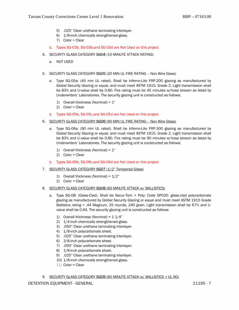
Tarrant County Corrections Center Level 1 Renovation BBP – 07163.00
DETENTION EQUIPMENT - GENERAL 11195 - 7
5) .025” Clear urethane laminating interlayer. 6) 1/8-inch chemically strengthened glass. 7) Color = Clear
b. Types SG-03b, SG-03b,and SG-03d are Not Used on this project
4. SECURITY GLASS CATEGORY SG04 (10 MINUTE ATTACK RATING)
a. NOT USED
5. SECURITY GLASS CATEGORY SG05 (20 MIN UL FIRE RATING – Non Wire Glass)
a. Type SG-05a: (45 min UL rated). Shall be Inferno-Lite FRP-200 glazing as manufactured by Global Security Glazing or equal, and must meet ASTM 1915, Grade 2. Light transmission shall be 83% and U-value shall be 0.80. Fire rating must be 45 minutes w/hose stream as listed by Underwriters’ Laboratories. The security glazing unit is constructed as follows:
1) Overall thickness (Nominal) = 1” 2) Color = Clear
b. Types SG-05b, SG-05c,and SG-05d are Not Used on this project
6. SECURITY GLASS CATEGORY SG06 (90 MIN UL FIRE RATING – Non Wire Glass)
a. Type SG-06a: (90 min UL rated). Shall be Inferno-Lite FRP-300 glazing as manufactured by Global Security Glazing or equal, and must meet ASTM 1915, Grade 2. Light transmission shall be 83% and U-value shall be 0.80. Fire rating must be 90 minutes w/hose stream as listed by Underwriters’ Laboratories. The security glazing unit is constructed as follows:
1) Overall thickness (Nominal) = 1” 2) Color = Clear
b. Types SG-06b, SG-06c,and SG-06d are Not Used on this project
7. SECURITY GLASS CATEGORY SG07 (1/2” Tempered Glass)
1) Overall thickness (Nominal) = 1/2” 2) Color = Clear
8. SECURITY GLASS CATEGORY SG08 (60 MINUTE ATTACK w/ BALLISTICS)
a. Type SG-08: (Glass-Clad). Shall be Secur-Tem + Poly; Code SP035: glass-clad polycarbonate glazing as manufactured by Global Security Glazing or equal and must meet ASTM 1915 Grade Ballistics rating = .44 Magnum, 25 rounds, 240 grain. Light transmission shall be 67% and U-value shall be 0.64. The security glazing unit is constructed as follows:
1) Overall thickness (Nominal) = 1 1/4” 2) 1/4-inch chemically strengthened glass. 3) .050” Clear urethane laminating interlayer. 4) 1/8-inch polycarbonate sheet. 5) .025” Clear urethane laminating interlayer. 6) 3/8-inch polycarbonate sheet. 7) .050” Clear urethane laminating interlayer. 8) 1/8-inch polycarbonate sheet. 9) .025” Clear urethane laminating interlayer. 10) 1/8-inch chemically strengthened glass. 11) Color = Clear
9. SECURITY GLASS CATEGORY SG09 (60 MINUTE ATTACK w/ BALLISTICS + UL 90)
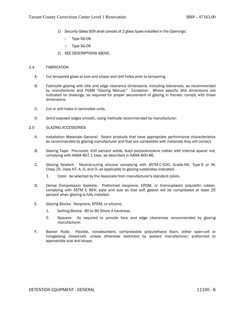
Tarrant County Corrections Center Level 1 Renovation BBP – 07163.00
DETENTION EQUIPMENT - GENERAL 11195 - 8
1) Security Glass S09 shall consist of 2 glass types installed in the Openings:
i. Type SG-08
ii. Type SG-06
2) SEE DESCRIPTIONS ABOVE.
2.4 FABRICATION
A. Cut tempered glass to size and shape and drill holes prior to tempering.
B. Fabricate glazing with bite and edge clearance dimensions, including tolerances, as recommended by manufacturer and FGMA "Glazing Manual." Exception: Where specific bite dimensions are indicated on drawings, as required for proper securement of glazing in frames, comply with those dimensions.
C. Cut or drill holes in laminated units.
D. Grind exposed edges smooth, using methods recommended by manufacturer.
2.5 GLAZING ACCESSORIES
A. Installation Materials--General: Select products that have appropriate performance characteristics as recommended by glazing manufacturer and that are compatible with materials they will contact.
B. Glazing Tape: Pre-cured, 100 percent solids, butyl polyisobutylene rubber with internal spacer rod, complying with AAMA 807.1 tape, as described in AAMA 800-86.
C. Glazing Sealant: Neutral-curing silicone complying with ASTM C 920, Grade NS, Type S or M, Class 25, Uses NT, A, G, and O--as applicable to glazing substrates indicated.
1. Color: As selected by the Associate from manufacturer's standard colors.
D. Dense Compression Gaskets: Preformed neoprene, EPDM, or thermoplastic polyolefin rubber, complying with ASTM C 864; style and size so that soft gasket will be compressed at least 25 percent when glazing is fully installed.
E. Glazing Blocks: Neoprene, EPDM, or silicone.
1. Setting Blocks: 80 to 90 Shore A hardness.
2. Spacers: As required to provide face and edge clearances recommended by glazing manufacturer.
F. Backer Rods: Flexible, nonabsorbent, compressible polyurethane foam, either open-cell or nongassing closed-cell, unless otherwise restricted by sealant manufacturer; preformed to appropriate size and shape.

Tarrant County Corrections Center Level 1 Renovation BBP – 07163.00
DETENTION EQUIPMENT - GENERAL 11195 - 9
PART 3 - EXECUTION
3.1 EXAMINATION
A. Examine frames and rabbets in which glazing is to be installed for possible damaging conditions. In particular, check for conditions that would void the manufacturer's warranty.
B. Submit Installer's report describing unacceptable conditions.
C. Do not proceed with installation until unsatisfactory conditions have been corrected.
3.2 PREPARATION
A. Clean surfaces and all glazing pockets to receive glazing just before installing glazing.
3.3 INSTALLATION - GENERAL
A. Comply with recommendations for installation contained in the GANA "Glazing Manual" and "Sealant Manual" except when specifically not recommended or prohibited by the glazing or glazing accessory manufacturer; comply with manufacturers' recommendations.
B. Protect glazing from edge and surface damage during handling and installation.
C. Do not install glazing that has edge or surface damage or defects that reduce glazing strength or diminish appearance.
D. Install unsymmetrical laminates with proper side out, according to their tested configuration.
E. Permanently adhere setting and edge blocks to frame.
F. Do not block weep holes.
G. Applied Stops: Fasten as indicated, after glazing has been set in frame. Do not exert excess force on glazing and glazing spacers.
3.4 TAPE GLAZING
A. Install tape continuously, placed so that when compressed the exposed face will be flush with the face of the framing.
B. Do not use joints in tape, except at corners; seal joints with compatible sealant.
C. After installation of stops, apply fillet bead of glazing sealant over exposed tape on both sides of glazing.
3.5 PROTECTION AND CLEANING
A. Apply warning tape or bands across each opening without touching glazing, immediately after installing glazing in frames.
B. Thoroughly clean all glazing for Substantial Completion.

Tarrant County Corrections Center Level 1 Renovation BBP – 07163.00
DETENTION EQUIPMENT - GENERAL 11195 - 10
3.6 OWNER PERSONNEL INSTRUCTION
A. Provide training for Owner Personnel in the proper maintenance and cleaning of all products provided under this section as required in section 11190.
B. Provide product information and maintenance / cleaning instructions for maintenance manuals as required Section 11190.
3.7 ATTIC STOCK
A. Provide spare glass units as shown in Section 01291
END OF SECTION 11195

Tarrant County Corrections Center Level 1 Renovation BBP – 07163.00
DETENTION EQUIPMENT - GENERAL 11196 - 1
SECTION 11196 - DETENTION FURNITURE AND ACCESSORIES
PART 1 - GENERAL
1.1 OVERALL
A. General:
1. Furnish all labor, materials, tools, equipment, and services for all detention furniture and accessories work as indicated, in accord with provisions of these specifications and all Contract Documents.
2. Comply with all requirements as outlined in General, Special, and Supplemental Conditions and Division 1 of these documents, including section 11190.
3. See Detention Drawings with ‘D’ sheet prefix.
B. Abbreviations
1. See Abbreviations in Detention Door Schedule, and on Sht. D001 of the Detention drawings.
2. DEC: Detention Equipment Contractor.
3. ESS: Electronics Systems Subcontractor. (See Division 13800)
4. CM/GC: Construction Manager and/or General Contractor.
C. Security Fasteners:
1. All equipment specified herein shall utilize only security-type fasteners where removable fasteners are allowed in the construction of the item or required for anchorage.
2. Furnish exposed fasteners in color and finish to match item fastened. Furnish fasteners of the same
metal as item fastened, except use plated brass or stainless steel for all aluminum items.
Tarrant County Corrections Center Level 1 Renovation BBP – 07163.00
DETENTION EQUIPMENT - GENERAL 11196 - 2
PART 2 - PRODUCTS
2.1 SECURITY FURNITURE AND ACCESSORIES
A. Acceptable Manufacturers: Except as otherwise specified, the equipment and materials of this Section shall be products of the following manufacturers:
Furniture
1) Norshield, Montgomery, AL
2) Southern/Folger, San Antonio, TX
3) Chief Industries, Inc., Grand Island, NE
4) KLN Corp., San Antonio, TX
5) Bob Barker Company, Fuquay-Varina, NC
6) CCC Group, San Antonio, TX Accessories
1) Pass-thru Units / Speaking Devices
i. Insulgard Corp., Hyattsville, MD (Pass-thru units)
ii. C.R. Laurence, Las Angeles, CA (Pass-thru units)
iii. Creative Industries, Indianapolis, IN
2) Suicide – resistant, Inmate Grabbars
i. Safebar Corp., Olympia, WA
ii. Bradley Corporation
iii. Acorn
3) Collapsible Safety Hooks
i. Bradley Corporation
ii. Acorn
B. Finish: All work under this section shall be delivered to the jobsite with one of the following finishes (as specified in the article)
1. Factory Primed: Finish work shall be cleaned of rust, oil and impurities, and phosphate coated to condition the surfaces to resist and inhibit corrosion and promote paint adhesion. Surfaces shall be coated with Sherwin Williams universal Primer #B50NZ6, or equal. Thickness shall be not less than 3 mil dry.
2. Factory Plated /Stainless: All parts scheduled to be stainless steel shall be type 304 stainless in gauges listed with #2 finish. All parts scheduled by manufacturer to be plated shall be US26D or US32D.
3. Parts or items scheduled for "Factory finish" shall have baked-enamel finish or powder coat finish as per manufacturers' recommendations – See individual Item.

Tarrant County Corrections Center Level 1 Renovation BBP – 07163.00
DETENTION EQUIPMENT - GENERAL 11196 - 3
C. FURNITURE and ACCESSORIES ITEMS
1. SD, Talk-Thru Device: ( Creative Industries #CLD103 or equal ) Not Used.
2. PP, Paper Pass: (Creative Industries #BRT316, or equal ). Not Used.
3. OBU, Observation Unit: (see details 102 & 103 / D400) Provide where shown on the detention plans. Construct per standards in section 11191, Detention Hollow Metal. Provide unit complete with Shutter door, Glazing, and Hardware. Glass shall be Type SG-07 as specified in section 11195, Security Glass and Glazing.
4. SAP, Security Access Panel: Provide where shown on the detention plans. See Details 100/101 on sht. D400. See section 11192 for Special Hardware Set S80E.
5. GB, (x) Detention Grab-bar: Provide where shown on the detention plans. See Details 110 on sht. D400 or provide Provide continuous outside and/or outside corners as required or miter bars to fit field conditions. Grabbars shall be removable where noted. (x) denotes lengths required at each location.
6. PS, (x) Privacy Screen: ( Not Used ).
7. M, Mirrors: (SSCo 432,or equal): Provide detention mirrors where shown on drawing. Mirror shall be single piece, 20 gauge, stainless steel - polished to a mirror finish Mirror size(s) as detailed. Mirror frame to be attached with 1/4" security screws, heads to have same chrome finish as frame. If mirror is mounted on concrete or masonry walls provide 3/16" thick steel back plate em-bedded in wall, sized to receive attachment of mirror assembly.
a. 1M indicates one mirror. 2M indicates two mirrors (see setting diagrams on Sht. D002).
8. FB, Floor Mounted Bench: (SSCo 563 or equal): Provide unit with overall height of 18". Posts to be made of 3" ASTM A 120 Schedule 40 steel pipe. Post shall be welded to 10" x 10" x 3/8" floor mounting plate. Floor mounting plate shall have four each 7/16" diameter holes. Seat to be 11 gauge stainless steel, type 304 with No. 2 finish. Seat to be lengths shown on drawings x 12” wide. Seat support plates shall be 1/4" x 11-3/4" diameter carbon steel plates welded to the top of the posts. Seat unit shall be welded to steel posts. Join unit by electric arc welding at such points and intervals as will develop adequate strength of members. Welds to be of neat appear-ance. Required anchor bolts to be provided by installer.
NOTE: All Bench Tops shall be single piece. Verify all wall dimensions in the field. All Benches shall be tight to adjacent surfaces and shall have any gaps to those surfaces closed with security caulk-ing.
PART 3 - EXECUTION
A. Inspect surface to receive work under this section. Notify the Architect in writing if surface is not satisfactory for application of materials. Commencement of work constitutes acceptance of surface.
B. Comply with manufacturers instructions.
C. Comply with Section 11190.
END OF SECTION 11196


Tarrant County Corrections Center Level 1 Renovation GT – 07163.00
SECTION 11400 - FOODSERVICE EQUIPMENT PART 1 - GENERAL 1.1 SECTION INCLUDES:
A. Foodservice equipment. 1.2 RELATED DIVISIONS / SECTIONS:
A. Refer to General Conditions, Supplementary Conditions, and applicable provisions of Division 1 for additional instructions.
1.3 DEFINITIONS:
A. Furnish - Supply and deliver to Project Site, ready for unloading, unpacking, assembly,
installation, and similar operations. B. Install (set in place) - Operations at Project Site including actual unloading, unpacking,
assembly, erecting, placing, anchoring, applying, finishing, curing, protecting, cleaning and similar operations; ready for final utility connections by other Divisions as appropriate.
C. Provide - Furnish and install complete, ready for intended use. D. Contractor - Refers to the Kitchen Equipment (Sub) Contractor in this Section. References to
any other Contractor or Division, will be specific; such as General Contractor, Plumbing (Sub) Contractor / Division, Electrical (Sub) Contractor / Division, Architect designated, etc.
1.4 SPECIFIER IDENTIFICATION SYSTEM:
A. Itemized Specifications included in article 3.10 includes the Specifier ID number(s), to identify
Ricca Newmark Design, as the specifying consultant for this Section. This code number(s) is part of the international Specifier Identification System (SIS) used throughout the foodservice industry. Contractor agrees to maintain this code number(s) on all correspondence, submittals, purchase orders, etc. generated for this Project.
1.5 LAWS, ORDINANCES, REGULATIONS AND STANDARDS:
A. Comply with the following:
1. National Sanitation Foundation (NSF): latest Standards and Revisions, and as accredited by ANSI, IAS, NELAC, ISO, OSHA and SCC. Provide NSF Seal of Approval on all standard manufactured items included in this Project and listed in any NSF Certified Food Equipment Products Category, and on all items of custom fabricated work included in this Project. (UL Sanitation approval and seal accepted if acceptable to local code jurisdictions.)
2. Underwriters Laboratories (U.L.): as applicable for electrical components and assemblies. Provide either U.L. labeled products or, where no labeling service is
FOODSERVICE EQUIPMENT 11400 - 1

Tarrant County Corrections Center Level 1 Renovation GT – 07163.00
available, “recognized markings” to indicate listing in the U.L. “Recognized Component Index”. (Canadian Standards Association or alternate testing lab's seals accepted if acceptable to local code jurisdictions.)
3. American with Disabilities Act (ADA): as applicable to this Project. 4. ETL and other national and international recognized Testing and Listing Agencies
labels and certifications are acceptable in lieu of Listing Agencies indicated in these documents, if acceptable to the local code jurisdictions.
5. All applicable local codes, standards and regulations. 6. All special local codes, standard, and regulations; such as (examples only) California
Energy Commissions Regulations, Dade County requirements for walk-in cooler(s) and/or freezer(s).
7. For detention facilities projects (as applicable): applicable Correctional Standards. Verify the level of security and construction required with the Architect, and provide all items in compliance.
1.6 CONTRACTOR’S QUALIFICATIONS:
A. In addition to requirements of Related Sections 1.2.A:
1. Five (5) years minimum continuous operation under the same company name and ownership.
2. Financial stability and ability to complete this Project. 3. Comparable size and scope projects completed in the last five (5) years. 4. Manufacturer's authorization to purchase, distribute, and install all items specified.
B. Any sub-contractor employed by Contractor, is to comply with the same qualifications.
1.7 SUBSTITUTIONS:
A. Submit itemized bids with the primary manufacturers and models specified. Unless otherwise
noted, substitutions may be submitted for consideration, but must be itemized at the end of the bid proposal.
B. Substitutions must be approved in writing by the Architect and/or Owner, prior to utilization in
this Contract. A copy of the approval must be included with any submittals by Contractor.
1.8 APPROVED SUBSTITUTIONS AND/OR LISTED ALTERNATES: A. Substitutions approved as noted in article 1.7, and/or any Listed Alternate manufacturers
included in the Itemized Specifications article 3.10, or added by Addendum, may be utilized, in lieu of the primary specified manufacturer with the following conditions: 1. These Contract Documents are designed and engineered using the primary specified
manufacturer and model. Contractor assumes total responsibility for any deviations required, due to utilization of a substitution/alternate manufacturer or model; including, but not limited to, fitting alternates into available space, providing directions for required changes, and assuming any associated cost for utility, building, architectural, or engineering changes.
2. Contractor is responsible for supplying the model, which is equal to the primary specified model in regards to general function, features, options, sizes, accessories,
FOODSERVICE EQUIPMENT 11400 - 2
Tarrant County Corrections Center Level 1 Renovation GT – 07163.00
utility requirements, finish, operation, and listing approvals. If it is determined by the Owner or their appointed representative at any time during the construction and installation, and prior to the final acceptance of the Project, that the substitution/alternate model submitted is not equal to the primary specified model, the Contractor will assume all associated cost and implications required to replace the model submitted, with the correct model.
3. The bid proposal is to clearly state any substitutions/alternates, which will be utilized including the manufacturer and model number. Also include a data sheet for each substitution/alternate, with any and all deviations between the primary specified manufacturer and the substitution/alternate manufacturer. Cut sheet from manufacturers, will not be acceptable as the data sheet. Complex alternates such as utility distribution systems, exhaust hoods, ventilators, etc. are to include a shop drawing specific to the Project.
4. Inclusion of an alternate manufacturer in Itemized Specifications article 3.10, is not intended to indicate that there is an equal alternate unit to match every primary specified unit. It is the responsibility of the Contractor to insure that the alternate unit submitted matches the primary specified unit; and meets the conditions as stated above.
5. Manufacturers not approved as substitutions, or included as a Listed Alternates will not be permitted.
1.9 DISCREPANCIES:
A. Where discrepancies are discovered between the drawings and the specifications, regarding
quality or quantity, the higher quality or the greater quantity is to be included in the Bid Proposal.
B. Contractor is responsible for verifying and coordinating all items provided in this Section, with
the drawings, specifications, manufacturer’s requirements, submittals, actual site conditions, adjacent items, and associated (Sub-) Contractors; to assure that there are no discrepancies or conflicts. This is to include, but not be limited to, quantities, dimensions, clearances required, direction of operation, door swings, utilities, fabrication details and methods, installation requirements, etc.
C. Contractor to notify the Architect, in writing, of any discrepancies discovered; and await written
clarification prior to proceeding with the items or areas in question.
1.10 SUBMITTALS: A. Provide two (2) sets of all Submittals for review by the Design Team. After review process, one
(1) set will be returned for copying and distribution. B. Contractor to review all submittals for compliance with the Contract Documents, prior to
submitting to the Design Team for review. C. Contractor is responsible for the accuracy of the information on their submittals. Refer to
article 1.9.B for additional Contractor responsibilities, in regards to submittals.
FOODSERVICE EQUIPMENT 11400 - 3

Tarrant County Corrections Center Level 1 Renovation GT – 07163.00
D. Contractor’s use of any Design Team’s AutoCAD contract drawings for basis of producing their submittal drawings, is with the following conditions and understanding:
1. Contractor assumes total liability and responsibility for accuracy, and for conformance and verification with the latest Architectural and Engineering drawings, actual field conditions, and all equipment provided.
2. Contractor further assumes responsibility for coordination of their submittals with those of other Contractors and Sub-Contractors, as required.
3. Submittals to have Contractor’s title block and information. E. Equipment Plan and Rough-In Drawings: 1. Submit 1/4” (1:50) scale drawings. These drawings are to include complete
information on the work included in this Contract, with references to equipment as provided by others; and are to provide sufficient information for associated trades, contractors, and/or sub-contractors to complete their division of work associated with food service equipment included in this Contract. They are to be dimensioned; showing locations of ducts, stubs, floor and wall sleeves, for ventilation, plumbing, steam, electrical, refrigeration lines, and concrete base and curb dimensions, as required for equipment so supported, and any additional information pertinent to the installation of this equipment
2. Drawings to also include equipment plan(s) with detailed equipment list, similar to Food Service Equipment Plans included in the Contract Drawings. Item numbers are to be the same as shown in the Contract Documents, and are to include Spare Numbers and associated items as provided by others.
3. In the event rough-ins have been accomplished before award of this contract, Contractor is to examine the existing facility and make adjustments to their equipment to suit building conditions and utilities, where possible. If not possible, so state in a letter, with reasons and an alternate method and pricing for their equipment, to the Architect.
F. Shop Drawings: N/A G. Product Data Submittal Manuals:
1. Product Data submittals will include a cover sheet and detailed information on every
item included in this Section. Detailed information is to include, but not be limited to, item number, description, quantity, model numbers, options and accessories provided, N.E.M.A. plug and receptacle configuration for applicable items, exact utility requirements, manufacturer’s cut-sheets, reference to specific shop drawings, and etc. Distribute one additional copy of installation and start-up instructions to the Installer. Every cover sheet and associated detailed submittal is to provide sufficient and complete information for the Design Team to verify that the Contractor understands the Contract requirements, and is providing each item in compliance with the Contract documents. Cover sheets to also include associated items as listed on the Equipment Plan, but provided by others; and are to be noted as “Not In Section 11400 Contract Division”.
2. Reproduction of any part of the Contract Specifications will not be acceptable as part or total of Contractor’s Product Date Submittal Manuals. These Manuals are to be produced and assembled entirely by the Contractor.
FOODSERVICE EQUIPMENT 11400 - 4

Tarrant County Corrections Center Level 1 Renovation GT – 07163.00
H. Design Team’s review of submittal drawings, shop details, product data brochures, and
operation and maintenance manuals is for general conformance with the design concept and contract documents. Review markings or comments are not to be construed as relieving Contractor from compliance with the contract documents, or departures there from. Contractor remains responsible for details and accuracy, confirming and correlating all quantities and dimensions, selecting fabrication processes, techniques of assembly, and performing their work in a safe, satisfactory, and professional manner.
I. Commencement of purchasing or fabrication by the Contractor, of any item(s) included in this
Contract, prior to receipt of reviewed Submittals from the Design Team, shall be at the Contractor’s own risk; unless specifically instructed to do so in writing by the Owner, including the specific item numbers requested.
1.11 OPERATION AND MAINTENANCE DATA MANUALS:
A. Two (2) bound sets of manuals are to be furnished for items of standard manufacture on/or
before the date of the first event to occur of the following: demo/start-up, start-up for intended use by the Owner/Operator, completion of installation of kitchen equipment contract package, or final acceptance of installation by Owner. Manuals are to be in alphabetical order according to manufacturer. Manufacturer’s info is to include Tech Services telephone number, email, and web site address, where available.
B. Provide a complete list of local service agencies for included manufacturers, complete with
address and telephone numbers. Also provide email and web site addresses, where available. C. Provide video tapes and/or CD’s for maintenance, training, operation, etc, where available.
1.12 AS-BUILT/ RECORD DOCUMENTS: A. Maintain one record set of Foodservice Equipment Plans with any related corrections,
revisions, additions, deletions, changes, etc. noted during construction and installation. Provide an "as-built" set in reproducible transparency form and electronic computer disk form.
B. Provide one (1) final set of Product Data Submittal Manual with any related corrections,
revisions, additions, deletions, changes, etc. noted during construction and installation as a specifications record set.
C. These documents are to be provided at the same time as the O & M Data Manuals.
1.13 SCHEDULE: A. Time is of the essence and acceptance constitutes assurance that the Contractor can and will
obtain materials, equipment and manpower, to permit installation of the items included in this Section, on schedule. Contractor is to coordinate their work with the progress schedule, as prepared and updated periodically by the General Contractor or Construction Manager.
B. Anticipated delays, not within the control of the Contractor, are to be noted in a written
FOODSERVICE EQUIPMENT 11400 - 5

Tarrant County Corrections Center Level 1 Renovation GT – 07163.00
notification to the Architect, immediately upon the Contractor's realization that delays are imminent.
C. Failure of manufacturers to meet promised delivery dates will not grant relief to the Contractor
for failure to meet schedules; unless the Contractor can establish, in writing, that orders were received by the manufacturer, with reasonable lead times.
D. Extra charges resulting from special handling or air shipment in order to meet the schedule
will be paid by the Contractor, if insufficient time was allowed in placing factory orders.
1.14 CONTRACTOR COORDINATION RESPONSIBILITY: A. Contractor is responsible for coordinating with all applicable Design Team members, General
Contractor, other Contractors and/or Sub-Contractors and Trades involved in this Project and associated with any items or work provided under this Section; as required for the successful provision, installation, completion, and functioning of these items and/or work, and the Project in general. This is to include, but not be limited to, exchange of shop drawings, details, and manufacturer’s information, supplying templates or actual components to be installed in or on items provided by other Sections, for coordination; and coordinating with and between their own internal staff, sub-contractors, trades, manufacturers, fabricators and installers, for compliance with the Contract Documents.
B. Contractor responsible for obtaining any documents referenced in this Section and on any
associated drawings, which contains information relative to the performance of this Contract; and disseminating and coordinating the pertinent information contained in them, with the appropriate sub-contractors, manufacturers, fabricators, and/or installers.
1.15 PRODUCT HANDLING:
A. Deliver materials (except bulk materials) in manufacturer's containers, fully identified with
manufacturer's name, trade name, type, class, grade, size, color, item number, area, etc. B. Contractor is responsible for receiving and warehousing equipment and fixtures, until ready
for installation. Store materials, equipment and fixtures in sealed containers, where possible. Store off the ground and under cover, protected from damage.
C. Contractor to verify and coordinate conditions at the building site, particularly door and/or wall
openings, and passages, to assure access for all equipment. Pieces too bulky for existing facilities are to be hoisted or otherwise handled with apparatus as required. All special handling equipment charges will be arranged for and paid for by Contractor.
1.16 PRODUCT PROTECTION:
A. To the best of their abilities, Contractor is to protect their equipment against theft or damage,
until final acceptance by the Owner. B. Use all means reasonable to protect the materials of this Section before, during, and after
installation; and to protect the associated work and materials of the other trades.
FOODSERVICE EQUIPMENT 11400 - 6

Tarrant County Corrections Center Level 1 Renovation GT – 07163.00
C. Pre-fabricated walk-in coolers/freezers are not to be used as general storage; and should be
locked before leaving the site daily. Damage and theft resulting from failure to secure units will be repaired or replaced at Contractor's expense.
1.17 WARRANTY:
A. Unless otherwise noted in Related Divisions / Sections 1.2.A, items furnished are to be fully
guaranteed against defects in workmanship, materials, and functionality for one full year from the date of the first event to occur of the following: date of issue of Certificate Of Occupancy (or the equivalent), start-up for intended use by the Owner/Operator, completion of installation of kitchen equipment contract package, or final acceptance of installation by Owner. Should a Temporary Certificate Of Occupancy be issued for partial completion of work, the items furnished within that designated area are to be under warranty from the date of issue of that Certificate. Contractor or their service agent will make necessary repairs and replacements without charge to the Owner, and within a reasonable time.
B. Additional Refrigeration Warranty: in addition to the one-year warranty requirements as stated
above, provide start-up, and parts and labor for the first year; plus additional four-year extended warranty on compressors. Extended warranty is for provision of replacement compressor, determined to be defective by a Certified refrigeration mechanic. However verification of defective compressor, installation of replacement compressor, recharging and repairs of system will be the responsibility of the Owner. This includes all items with built-in or remote refrigeration system.
C. Periodic routine maintenance, servicing, adjustments, cleaning, etc., as required by the
manufacturers included in this Project, are the responsibility of the Owner. D. Any and all parts or requirements for manufacturer’s warranties to be in effect, whether or not
noted in the itemized specifications, are to be provided or complied with by the Contractor. This is to include, but not be limited to, particular parts, accessories, or installation; installation supervision, start-up, and/or follow-up inspections required by factory trained, Certified, and/or authorized personnel. Factory training, Certification, and/or authorization is to be in effect at the time of bidding, installation, start-up, and warranty period of this Project.
E. Manufacturer’s warranties which comply with the requirements of this Warranty article 1.17,
are to be provided in lieu of Contractor’s own warranties, where available. Copies of the written warranties are to be included in the O & M Manuals.
PART 2 - PRODUCTS
2.1 EQUIPMENT:
A. Refer to schedule on Foodservice Drawings and Section 3.10 Itemized Specifications for
equipment included in this Section.
FOODSERVICE EQUIPMENT 11400 - 7

Tarrant County Corrections Center Level 1 Renovation GT – 07163.00
2.2 MATERIALS: N/A 2.3 FABRICATED PRODUCTS: N/A 2.4 FABRICATION OF METALWORK: N/A 2.5 FILTER EXHAUST HOODS AND/OR WATER WASH VENTILATOR FABRICATION: N/A 2.6 REFRIGERATION EQUIPMENT: N/A 2.7 MISCELLANEOUS MATERIALS AND FABRICATION: N/A PART 3 - EXECUTION
3.1 SUPERVISION:
A. A competent supervisor, representing the Contractor, is to be present at all times during
progress of the Contractor's work.
3.2 SITE EXAMINATION: A. Verify site conditions under the provisions of the General Conditions, Supplementary
Conditions and applicable provisions of Division 1 Sections. Notify the Architect, in writing, of unsatisfactory conditions for proper installation of foodservice equipment.
B. Verify wall, column, door, window, and ceiling locations and dimensions. Fabrication and
installation should not proceed until dimensions and conditions have been verified and coordinated with fabrication details.
C. Verify that wall reinforcement or backing has been provided, and is correct for wall supported
equipment. Coordinate placement dimensions with wall construction Section. D. Verify that ventilation ducts are of the correct characteristics, and in the required locations. E. Verify that utilities are available, of the correct characteristics, and in the required locations.
3.3 INSTALLATION: A. Sequence installation and erection to ensure correct mechanical and electrical utility
connections are achieved. B. Install items in accordance with manufacturer's instructions. C. Set each item of non-mobile and non-portable equipment securely in place, leveled and
adjusted to correct height.
3.4 ADJUSTING: N/A 3.5 CLEANING AND RESTORING FINISHES: N/A 3.6 TESTING, START-UP AND INSTRUCTIONS: N/A
3.7 CLEAR AWAY
A. Throughout the progress of their work, Contractor is to keep the working area free from debris,
FOODSERVICE EQUIPMENT 11400 - 8

Tarrant County Corrections Center Level 1 Renovation GT – 07163.00
and remove rubbish from premises resulting from work being done by them. At the completion of their work, Contractor is to leave the premises in a clean and finished condition.
3.8 REUSED EXISTING EQUIPMENT: N/A 3.9 STANDARD DETAILS: N/A
3.10 ITEMIZED SPECIFICATIONS:
A. Refer to the following pages for specific specification information on each item included in this
Section.
ITEM 343: DRY STORAGE SHELVING - CORRECTIONS BUILDING Quantity: Sixty (60) Manufacturer: Metro Model: METROSEAL 3 SIS No.: R157, R160
Fabricate/Furnish and set in place per plans, details and the following: 1. Length, width and configuration per plan and verified room dimensions. 2. Super Erecta MetroSeal 3 Wire Shelving. Corrosion-resistant finish, w/Microban® antimicrobial protection. 3. 86" High With Five Tiers. 4. Each section shall be free-standing with four legs. 5. Metro Model 9986Z Split Sleeves, aluminum with zinc rings
End of Section 11400
FOODSERVICE EQUIPMENT 11400 - 9

division 12 furnishings
not used

division 13 special construction

Tarrant County Corrections Center Level 1 Renovation GT - 07163.00
ELECTRONIC SYSTEM GENERAL REQUIREMENTS 13800 - 1
SECTION 13800 - ELECTRONIC SYSTEMS GENERAL REQUIREMENTS
PART 1 - GENERAL
1.1 DESCRIPTION
A. General:
1. Furnish all labor, materials, tools, equipment, and services for all electronic systems work
as indicated, in accord with provisions of Contract Documents.
2. Completely coordinate with work of all other trades.
3. Although such work is not specifically indicated, furnish and install all supplementary or
miscellaneous items, appurtenances and devices incidental to or necessary for a sound,
secure and complete installation.
4. See Division 1 for General Requirements.
B. Drawings use and interpretation:
1. Drawings are diagrammatic and indicate general arrangement of systems and equipment,
except when specifically dimensioned or detailed.
2. For exact locations of building elements, refer to dimensioned architectural/structural
drawings.
3. Field measurements take precedence over dimensioned drawings.
4. Intention is to show size, capacity, approximate location, direction and general relationship
of one work phase to another, but not exact detail or arrangement.
5. Field verify locations and arrangement of all existing systems and equipment.
6. Where ambiguity may exist between specifications and drawings, the most stringent shall
apply.
C. Installation of all systems and equipment is subject to clarification as indicated in reviewed shop
drawings and field coordination drawings.
D. Dimensions indicated anywhere are limiting dimensions.
E. Do not use equipment exceeding dimensions indicated or equipment or arrangements that
reduce required clearances or exceed specified maximum dimensions.
F. Description of systems: Furnish and install all materials to provide functioning systems in
compliance with performance requirements specified and any modifications resulting from
reviewed shop drawings and field coordinated drawings.
G. Furnished by Electronic Systems Integrator, for installation by Division 16:
1. Non standard electrical boxes.
H. Furnished and Installed by Electronic Systems Integrator:
1. Digital Intercom and Paging System: Section 13820.
2. Cabinets and Enclosures: Section 13830.
3. Electronic Control System: Section 13832.
4. Touch Screen Control and Management System: Section 13833.
5. Video Management and Recording System: Section 13840.
6. Uninterruptible Power System: Section 13845.
7. Cable and Wire
I. Furnished and installed by Division 16:
1. Complete raceway system from the main head end equipment to the end device, including
any necessary standard size backboxes, wireways and pull boxes. Install pull string in all
conduits.
2. All 120 volt AC wiring and connections for power panels and/or terminal strips in electronic
panels, cabinets, enclosures or consoles.

Tarrant County Corrections Center Level 1 Renovation GT - 07163.00
ELECTRONIC SYSTEM GENERAL REQUIREMENTS 13800 - 2
3. All 120 volt AC wiring, devices and connections for devices and equipment as indicated
on drawings.
4. The Electronic Systems Integrator shall furnish conduit requirements and special
backboxes to the Division 16 installer in a timely manner so as not to impede the progress
of the work. Conduit sizing shall allow for a maximum conductor fill of 40 percent of
conduit cross sectional area. Where pneumatic tubes are included in raceway system, the
tube shall be included in the fill requirement.
5. The Electronic Systems Integrator shall be responsible for any additional conduits required
(not shown on drawings) or increase in size of conduit to effect the installation of the
security system contained herein.
6. Exterior pole/equipment bases for electronics equipment
J. Related work:
1. Division 16
a. Raceway systems Products and Execution: Sections Div 16
1.2 BASIS OF DESIGN
A. The electronic security system described within the specifications and drawings shall function as
an integrated system. Although the system is made up of several sub systems, they shall be
integrated in both physical and electronic manner to achieve a single system presentation and
functionality to the operator. The control stations shall function as a single control point,
appearing to function as a single system.
B. The electronic security system at the LEVEL 1 area shall be standalone system and shall not be
integrated with the electronic security system in the Correction Center.
C. The integrated system is made up of several subsystems that communicate with each other via
a fault-tolerant, self-healing network. The network is Ethernet based with primary controlling
systems connected to the managed network switches. The network switches will direct all
communications to and from all devices connected to the systems.
1. Control of door locks, lights, receptacles, etc. will be managed via distributed
programmable logic controllers (PLC). Programmable logic controllers are located in the
electronic security equipment room.
2. The intercom switching system will be a digital intercom system with software based
configuration, fault tolerant design, and rugged construction. The system is integrated to
control stations via the electronic security network, allowing intercom functions to occur
between each control station and their assigned remote intercom stations and speakers
.
3. Two new touch screen stations shall be provided. One touch screen station shall be
located at the officer station 1172 and second backup station shall be located in the
existing Central Control Room 2201. Touch screen control stations will be connected to
the Ethernet network.
4. Control of devices such as lights, receptacles, etc. shall be provided via control relays.
These control relays shall in turn operate line voltage relays or contactors provided under
the Division 16-Electrical work. Switching shall be controlled via the local control panel
and the PLC
5. All new cameras shall be connected to video network to allow display of any camera on
any video viewing station. All cameras shall be recorded and video storage shall be sized
to retain recording for 90 days. All cameras shall be continuously recorded at 1080P
resolution, 15 images per second. Quite time recording (no motion) shall be 4CIF, 2
images per second for all cameras. The motion should be estimated at 60%. The video
management and recording system shall be an enterprise-class client/server based IP
video security solution that provides seamless management of digital video, audio and
data across an IP network. The system shall be designed to work with CCTV and ONVIF
compliant 3rd party products as part of a total video security management system to

Tarrant County Corrections Center Level 1 Renovation GT - 07163.00
ELECTRONIC SYSTEM GENERAL REQUIREMENTS 13800 - 3
provide full virtual matrix switching and control capability. Cameras, recorders, and
viewing stations may be placed anywhere in the IP network.
6. Miscellaneous devices (i.e. motion detectors, call buttons, duress buttons) shall be
configured as inputs to the local PLC with status displayed on the control stations.
D. The facility is to be provided with a two new touch screen station. The touch screen station
installed in the CCR shall be provided with the ADS/FS functions.
E. All computing equipment shall be provide with, and software applications compatible with
Windows 8 and Microsoft Server 2012 operating systems. If Windows 8 compatibility is not
available, Windows 7 operating system may be installed. In such a case, the contractor shall
upgrade the installed systems to Windows 8 and Microsoft Server 2012 operating systems prior
to expiration of warranty and subsequently extend the warranty related to the system upgrade
for an additional one year.
1.3 WARRANTY (See Division 1)
A. See Division 1 for warranty requirements.
B. Manufacturer’s warranties that extend beyond the requirements of Division 1 shall be
maintained and transferred to the Owner.
C. The existing equipment that is to be re-used need not be warranted. However such exception to
the warranty are limited to the equipment itself itself and excludes damage by the contractor. All
installation, operations, functionality, programming, etc. remains included in the required
warranties.
D. Respond within four (4) hours to an emergency maintenance request. Provide a twenty-four hour
telephone contact number (24 hours per day, 365 days per year). Service response time is
defined as the period between the placing of a service request and established communications
with the designated client representative. Emergency repair personnel shall be on-site within 24
hours of notification and repair or replacement of defective equipment shall be completed within
72 hours of notification.
E. Maintain a sufficient parts inventory during the warranty period to meet the anticipated system
repair times. Contractor shall monitor spare equipment inventory and replenish materials used
in an expedient manner.
F. Prior to expiration of warranty, system integrator shall provide all software patches available from
software supplier. Upon completion of installation, test affected systems to confirm operation.
Software patches shall be installed at time convenient to Owner/User considering potential for
security impact.
G. See individual sections for additional warranty requirements.
1.4 QUALITY ASSURANCE
A. Perform all work in accord with following codes and standards:
1. Codes Compliance: Comply with the following current adopted codes::
a. Federal, state and local codes, regulations and ordinances.
b. National Electrical Code (NEC), latest edition.
c. National Fire Code (NFC)
d. Occupational Safety and Health Act (OSHA).
e. International Building Code (IBC)
f. Factory Mutual System (FM) requirements.
g. Texas Commission on Jail Standards.
h. All authorities having jurisdiction.
2. Standards Compliance: Comply with the following standards as applicable:
a. Americans with Disabilities Act (ADA)
b. American National Standards Institute (ANSI)
c. American Society for Testing and Materials (ASTM)

Tarrant County Corrections Center Level 1 Renovation GT - 07163.00
ELECTRONIC SYSTEM GENERAL REQUIREMENTS 13800 - 4
d. Electronics Industry Association (EIA)
e. Electrical Testing Laboratories (ETL)
f. Factory Mutual (FM)
g. Institute of Electrical and Electronics Engineers (IEEE)
h. Insulated Cable Engineers Association (ICEA)
i. National Electrical Contractors Association (NECA)
j. National Electrical Manufacturers Association (NEMA)
k. National Fire Protection Association (NFPA)
l. Underwriter's Laboratories (UL)
B. Equipment Manufacturer:
1. Regularly engaged in the manufacture of products specified.
2. Manufacturer of products specified for a period of no less than five years with satisfactory
performance in similar applications.
C. System Integrator Personnel: (Project Manager, Project Engineer, On-site Supervising
Technician)
1. Regularly engaged in installation of products specified.
2. Installer of products specified for a period of no less than five years with satisfactory
performance.
D. Systems specified in this Division shall be engineered, assembled and installed under the
direction of a qualified electronic systems integrator. Electronic systems integrator shall meet
the following minimum requirements.
1. Qualifications.
a. Successful completion of at least three (3) similar detention facilities which have
been in successful operation for at least one (1) year.
b. Technical staff experienced and factory trained in systems specified.
c. The electronic systems integrator shall be bondable for an amount equal to 100%
of his bid.
2. Electronic systems integrators must be qualified to bid the project. Integrators not
indicated but desiring approval shall submit information supporting compliance with the
following minimum requirements.
a. Minimum five (5) continuous years in the business of installing electronic security
systems in detention and or correctional facilities incorporating systems and
equipment including but not limited to intercom/paging, programmable logic
controllers, touch screen control, access control, and video management and
recording systems.
b. Successful completion of at least three (3) detention facilities of similar size and
complexity that have been in operation for at least one (1) year.
1) Projects of similar size are represented by construction cost value in excess
of one million dollars ($1M).
2) Projects of similar complexity are represented by integrated systems
including but not limited to intercom/paging, programmable logic
controllers, touch screen control, and video management and recording
systems operating in a network environment with a minimum five (5)
equipment locations (nodes)
c. Definitions:
1) Similar Size: Detention Facility of…
a) Similar dollar value of installed electronic security systems
b) Similar duration (18 months)
c) Similar systems technology
2) Similar Complexity: Detention Facility …
a) Including replacement and transition of electronic security control
systems.

Tarrant County Corrections Center Level 1 Renovation GT - 07163.00
ELECTRONIC SYSTEM GENERAL REQUIREMENTS 13800 - 5
b) Using integration of multiple systems including video,
communications, and control.
E. Termination, testing and start-up of electronic systems shall be done under the direct supervision
of the system integrator. Prior to termination at system equipment, all field wiring shall be tested
against faults, grounds and other conditions that may impede the proper operation of the system.
System integrator shall verify and accept the field wiring prior to termination at system
equipment. Beginning of termination constitutes acceptance of conditions as satisfactory.
1.5 SUBMITTALS (See Section 01330)
A. Review of shop drawings or schedules by Engineer shall not relieve the Contractor from
responsibility for deviations from drawings or specifications, unless there is a formal letter which
called attention to such deviations at the time of submission and secured written approval; nor
shall it relieve him from responsibility for errors in shop drawings, schedules or coordination of
the work with other trades.
B. Submittals for individual systems and equipment assemblies which consist of more than one
item or component shall be made for the system or assembly as a whole. Partial submittals will
not be considered. Partial submittals will not be returned except at the request and expense of
the contractor.
C. The contractor shall develop and submit complete submittals and do so in a timely manner. By
failing to do so, the System Integrator agrees to be fully responsible for any and all damages
which might be occasioned by the contractor's failure to do so.
D. Where Engineer furnished electronic files of the Contract Documents are used as part of the shop
drawings, the Electronic Systems Integrator shall review such files and confirm completeness
and accuracy. Submission of such documentation as a part of the shop drawings shall be
indication that such review and confirmation has been performed and completed. Submission
and subsequent approval shall not relieve the Electronic Systems Integrator from the
requirements of the Contract Documents.
E. All shop drawings shall be created using AutoCAD v2014 or later. Schedules shall be created in
spreadsheet format using Microsoft Excel. Incorporate all revisions upon completion of work.
Submit with record drawings in both hard copy and electronic files.
F. Resubmittal of items that have been previously accepted or approved will not be reviewed unless
specific attention is called to changes in previously approved items. Resubmission that does not
specifically call attention to previously accepted or approved submittals shall not be considered
as subsequent approval of a change to the initially accepted or approved item.
G. Submit drawings, data sheets, schedules, and others, in compliance with Article "Submittal
Requirements" of this Section to permit adequate time for review by the Engineer, but in not less
than 14 calendar days. This 14 day review period is exclusive of time associated with travel,
mail, delivery, copy, and handling. Due to the integrated system, most submittals are interrelated
and thus are expected in Groups that are large and complex. Such submittals will require longer
review periods. Time required will depend on scheduling, size and complexity of submittal
H. Provide information required for complete review of each item in one submittal. When individual
sections of specifications require more than one item for review, such as shop drawings, product
data, samples, and related items, submissions shall include all specified information delivered
at one time.
1. Incomplete or partial submittals will not be reviewed by the Engineer.
2. Extra copies of submittals will not be marked or returned, except at the expense of the
Contractor.
3. Duplicate copies of incomplete or partial submittals, or extra copies of submittals, will be
discarded after 15 calendar days unless Contractor makes arrangement for return, at
Contractor’s expense.
4. Submittals not requested specifically may be returned to Contractor without review.

Tarrant County Corrections Center Level 1 Renovation GT - 07163.00
ELECTRONIC SYSTEM GENERAL REQUIREMENTS 13800 - 6
I. Review of submittals shall be limited to two (2) submissions. The Engineer shall be compensated
for additional reviews. In such an event, a change order to the General Construction Contract
will be executed for compensation of the Engineer. The change order shall be executed prior to
additional reviews.
J. Project Data: Electronic Systems General Requirements: Section 13800.
1. System Integrator personnel qualifications: (Project Manager, Project Engineer, On-site
Supervising Technician).
2. List of all manufacturers and equipment suppliers.
3. Submittal schedule: Schedule shall be submitted within 30 days of Notice to Proceed and
shall include time and duration for product data by group, shop drawings by group, touch
screen demonstration station, and testing procedures.
4. Schedule of Values: A schedule of values for the electronic security systems shall be
submitted within 60 days of Notice to Proceed and shall include material and labor costs
for each part of the work. Values for the following shall be provided at a minimum.
a. General Conditions: Section 13800
b. Testing: Section 13800
1) Submittals
2) Factory Testing
3) System Validation Testing
4) Demonstration Upon Completion of Work:
c. Programming: Sections 13833, 13832, 13820
d. Digital Intercom and Paging System: Section 13820.
e. Cabinets and Enclosures: Section 13830.
f. Electronic Control System: Section 13832.
g. Touch Screen Control and Management System: Section 13833.
h. Cable and Wire
5. Where modifications are required to existing control systems, the schedule shall include
phasing with identification of the time and duration of modifications to each portion of the
work. Time and durations shall be reviewed with the Owner/User in order to allow
continuous operation of the facility
6. Functional block diagram of complete integrated system with references to all related sub-
system drawings.
7. Floor plans indicating device locations and cable assignments/groupings. Submission of
these plans indicates that the contractor has coordinated the placement of all devices
with architectural plans, and coordinated raceway requirements with all related trades.
8. Drawings indicating complete conduit and raceway systems.
9. Spare parts inventory with quantity, description and source listed.
10. Testing: Provide complete testing procedure for electronic security systems. The
procedure shall identify testing of each function of each device under each condition.
Manufacturer recommended test procedures shall be incorporated into the testing
procedure. All testing shall be project specific.
K. Transient Surge Protection: Section 13800
1. Project Data: Submit material specifications and installation data for products specified
herein.
a. Include electrical characteristics, and ratings for each type of TSP equipment.
b. Indicate wiring diagrams indicating internal connections of TSP components within
each enclosure.
c. Drawings shall be provided indicating unit dimensions, weights, mounting
provisions, and connection details.
d. Submittals of each system shall indicate location of TSP devices.
1.6 WEATHERPROOF EQUIPMENT AND LOCATIONS
A. Weatherproof equipment and locations are where weatherproof (WP) is indicated or where
equipment is not located inside a building.

Tarrant County Corrections Center Level 1 Renovation GT - 07163.00
ELECTRONIC SYSTEM GENERAL REQUIREMENTS 13800 - 7
B. Enclosures and boxes to be NEMA 3R hot dipped galvanized steel, weatherproof cast iron or
malleable iron boxes and covers, or NEMA 4X stainless steel.
C. Mounting and support hardware to be hot dipped galvanized steel or stainless steel.
1.7 PROTECTION
A. Provide covering and shielding for all equipment provided to protect from damage.
B. Protect nameplates on equipment, to prevent defacing.
C. Repair, restore or replace damaged, corroded and rejected items.
1.8 DELIVERY, STORAGE AND HANDLING
A. Protect all materials and equipment from damage during storage at the site and throughout the
construction period. Protect equipment and materials during shipment and storage against
physical damage, dirt, dust, moisture, heat, cold, rain, and any foreign substances that may
damage the equipment.
B. Prevent damage from rain, dirt, sun and ground water by storing the equipment on elevated
supports and covering them on all sides with securely fastened protective rigid or flexible
waterproof coverings.
C. Protect conduit by storing it on elevated supports and capping the ends with suitable closure
material to prevent dirt accumulation.
D. Protect all fabricated and/or installed materials and equipment against dust, dirt, moisture,
physical damage, metal debris and any foreign substances that may damage the equipment.
E. Protect painted surfaces with removable heavy Kraft paper, sheet vinyl or equal, installed at the
factory and removed prior to final inspection.
F. Replace damaged equipment as determined by the Engineer. Repaint and finish damaged paint
on equipment and materials with the same quality of paint and workmanship used by
manufacturer so that repaired areas are not obvious.
1.9 OPERATING AND MAINTENANCE DATA (See Division 1)
A. Provide the following for each electronic system:
1. Operations manual for all components and system as a whole.
2. Maintenance manual for all components and system as a whole.
3. Record Drawings.
4. Point-to-point diagrams, wiring diagrams and construction details.
5. List of spare parts, materials and suppliers of components. Provide name, address and
telephone number for each supplier.
6. Emergency instructions for operational and maintenance requirements.
7. Copies of all warranties.
8. Delivery time frame for replacement of component parts from suppliers.
9. Recommend inspection schedule and procedures for all components and system as a
whole.
10. Complete 'Approved' shop drawings and product data for all components and system as a
whole.
B. Specific instructional material for this project.
1.10 JOB CONDITIONS
A. Cause as little interference or interruption of existing utilities and services as possible.
1. Schedule work which will cause interference or interruption in advance with Owner,
Architect or Engineer, authorities having jurisdiction and all affected trades.

Tarrant County Corrections Center Level 1 Renovation GT - 07163.00
ELECTRONIC SYSTEM GENERAL REQUIREMENTS 13800 - 8
B. Examine Contract Documents to determine how other work will affect the execution of electronic
systems.
C. Determine and verify locations of all existing utilities on or near site.
D. Make arrangements for and pay for necessary permits, licenses, and inspections.
E. Furnish conduit requirements and special backboxes for installation under Division 16 in a timely
manner so as not to delay progress of the Work.
1.11 EQUIPMENT AND SYSTEM IDENTIFICATION
A. All electronic security systems and equipment shall be labeled for identification.
1. Install a nameplate on each individual equipment rack, enclosure, boxes, cabinet, and
significant equipment item with text to coordinate with approved submittal documents.
2. Use identifiers and abbreviations defined in the Drawings whenever possible. Use plan
designation for labeling, unless indicated otherwise.
3. Nameplates shall be laminated black phenolic resin with a white core and engraved
lettering, a minimum of 1/4” high. Use fasteners to install nameplates. Do not fasten
with adhesives.
4. Engrave using upper case letters of uniform height; centered on device, cover plate, or
enclosure; with all characters made clearly and distinctly. Allow room for fastener
attachment.
5. All equipment shall have the manufacturer’s name, address, model number and rating on
a nameplate securely affixed in a conspicuous place. All equipment shall bear labels
attesting to Underwriters Laboratories approval where subject to Underwriters
Laboratories label service.
6. Identify all field terminals and relays with device identification. Lettering shall be 3/16”
high, minimum.
B. Raceway systems shall be labeled at all pull points and on each side of wall penetration, but in
no case less than 20 feet between labels. Identify raceways with name of security system
1. Apply preprinted labels with pressure sensitive, self-adhesive backing. If additional
adhesion is required to hold label in place, use appropriate taping material wrapped
completely around raceway.
2. Position identification so that it is readily visible from eye level.
3. Color scheme for labels:
a. Communications: Orange
b. Security Control: Green
c. VMS: Blue
d. Network: Yellow
C. All wire and cables shall have wire markers at each and every termination point. Each wire shall
be identified by unique code.
D. Labeling system suppliers:
1. Thomas & Betts
2. Brady
3. Westline
4. Seton
1.12 RECORD DRAWINGS (See Division 1)
A. The Electronic systems contractor shall keep a complete set of all electronic systems contract
drawings and the electronic systems shop drawings in the job site office.
1. Use these sets of drawings for showing as constructed installation of electronics security
systems and equipment.

Tarrant County Corrections Center Level 1 Renovation GT - 07163.00
ELECTRONIC SYSTEM GENERAL REQUIREMENTS 13800 - 9
2. Where any material, equipment, wiring or system components are installed differently
from that shown, show such differences clearly and neatly using ink or indelible pencil.
3. At project completion, submit the record set of contract drawings to Architect (see Division
1).
4. At project completion, make corrections to the shop drawings on the original media and
submit the corrected reproducible drawings to the Architect (See Division 1). Where the
shop drawings were created on a computer aided drafting system, furnish AutoCAD
compatible electronic drawing files of all corrected shop drawings.
B. Software Records:
1. Submit final software programs on electronic media compatible with the installed system.
a. Transfer all software licenses to the Owner/User representative at the completion
of the project. Transfer shall include customer support rights.
b. Fully comply with all license agreements for the installed software. Install sufficient
quantities of each software program so that the Owner fully meets the intent of the
publisher’s site license agreement. When in doubt, contact the publisher for an
interpretation and comply with that interpretation.
c. Provide the Owner with all original installation disks or CD-ROMs and all software
manuals for every software program installed on the system.
2. Standard and Custom Application Software:
a. Prepare and submit the licenses to all software installed for the system. Compile
a list with each program name, its installed version number, the number of copies
installed, the serial number of each copy, the publisher’s name and address, and
the publisher’s customer support telephone number.
b. Prepare and submit complete documentation of the final installed version of the
application program, including a diagram of its component modules, subroutines,
databases, libraries, drivers, and other parts. Narrative descriptions shall
accompany the diagram, giving basic descriptions of each component and
describing the interaction between components. Provide a complete, annotated
listing of all application settings.
3. User Data and User Programmable Software:
a. Provide complete documentation of all user data and user programmable software,
including but not limited to properties, preferences, settings, configurations,
component modules, plug-in modules, user subroutines, databases, libraries,
drivers, macros, templates, objects, slides, maps, images, sounds, icons, screen
savers, and any other software files for each site.
b. Provide narrative descriptions and diagrams that give basic descriptions of each
software component and the interaction between software components. Provide a
complete, annotated software component listing.
c. Provide a CD ROM or equivalent media of the final operating version of the user
data and user programmable software in accordance with Division 1 requirements.
Provide three (3) copies of the media, properly labels and dated in hard cases.
4. Operators Guide
a. Submit Operators Guide for approval 10 days prior to first phase of Operational
Training.
b. Operators Guide shall outline the operation of each system. A guide is to be kept
at each workstation for reference on the operation of the equipment.
c. Include written description in outline form how to operate the basics of the system.
This shall include but not be limited to: access and control of individual devices,
group control functions, emergency control functions, system acknowledgement
and reset of alarms.
d. Include 8.5 x 11 inch graphics as needed to identify device locations and facilitate
understanding of the written description.
e. Provide one copy for each work station and one master copy that may be
reproduced by the County.
f. Laminate each guide for each workstation, or other approved method.

Tarrant County Corrections Center Level 1 Renovation GT - 07163.00
ELECTRONIC SYSTEM GENERAL REQUIREMENTS 13800 - 10
PART 2 - PRODUCTS
2.1 GENERAL
A. Acceptable manufacturers:
1. See individual specification section.
B. The product numbers contained herein are for reference only and may not be the most current
available nor a complete listing of all features or options required. Where a manufacturer is listed
without a product number, an equivalent item of the specified manufacturer is acceptable.
Determination of equivalent is at the sole discretion of the Engineer. Where a conflict or
ambiguity exists between the written description and the product number, the written description
shall govern.
C. Equipment installed in exterior applications shall be fitted with fasteners and exposed surfaces
of stainless steel or other corrosion resistant material.
D. Use only prime quality, new materials, apparatus and equipment.
E. Use electrical materials approved by UL and bearing UL label where listing has been established
for materials or devices in question.
1. Manufactured items and fabricated assemblies of electrically operating equipment: UL
approval or UL re-examination listing.
F. Structural steel for supports: ASTM A36.
1. Galvanize members installed in areas of high humidity or condensation and exterior
locations.
2. Furnish other members with shop coat of red lead primer.
3. Shop fabricate for field assembly using bolts.
4. Minimize field welding.
5. Retouch primer after field welding.
2.2 SECURITY FASTENERS
A. Furnish material, head style and plating as appropriate for installation requirements.
B. Provide security fasteners on all device plates, equipment, etc., within occupied areas of the
facility.
1. Torx head with center pin, hardened steel.
2. Provide five fastening tools.
2.3 GROUNDING
A. All equipment shall be grounded in accordance with the NEC, these specifications and drawings,
and the equipment supplier's recommendations.
2.4 TRANSIENT SURGE PROTECTION
A. Industry Reference Standards: The following specification and standards are incorporated into
and become a part of this specification by reference.
1. Underwriters Laboratories, Inc. (UL)
a. No. 1449 2nd Edition Standard For Safety
b. No. 497 A, B, and C.
2. Institute Of Electrical And Electronics Engineers (IEEE)
a. Std. 142 - Recommended Practice For Grounding
b. Std. 518 - Recommended Guide On Electrical Noise
3. ANSI/IEEE C62.41 - 1991 Edition
4. Federal Information Processing Standards

Tarrant County Corrections Center Level 1 Renovation GT - 07163.00
ELECTRONIC SYSTEM GENERAL REQUIREMENTS 13800 - 11
a. Publication 94 (FIPS PUB 94)
B. Acceptable manufactures: All device(s) shall be by the same manufacture.
1. TSP Devices:
a. Base: Northern Technologies, Inc., Transtector Systems, Inc.
2. Other manufacturers desiring approval comply with Division 1
C. All TSP devices installed shall utilize Silicon Avalanche Diodes (SAD) as the primary means of
protection. Secondary protection shall be SADs or Metal Oxide Varistors (MOVs). Each protection
circuit shall be independent of each other and neither circuit shall short to ground on clamping
transient surges.
D. Each 120 VAC circuit or feeder required for the electronic control and monitoring system shall be
provided with a TSP device.
E. Each electronic security system circuit containing metallic conductor (s) shall be provided with a
TSP device when leaving the confines of a building. Each electronic security system circuit
containing metallic conductor(s) shall be provided with a TSP device when entering a building.
Circuits serving building mounted devices or equipment that are located below the roof that
originate or terminate in the building it is attached to, do not require TSP devices.
F. Locate TSP device at first termination point within the building. Locate all TSP devices in cabinets
or enclosures.
G. All TSP devices shall be provided with a ground connection. The ground circuit shall be sized in
conformance with the manufacturer's written requirements for proper grounding for the
associated device. The ground conductor shall be routed and connected to the nearest electrical
system ground point.
H. Alarm contacts on TSP devices shall be connected to the electronic control system and
annunciated as a system trouble alarm.
2.5 WIRING AND CABLE (as in means and methods of single and multiple conductor cable
installation)
A. Power wiring: Single conductor cable, soft drawn, copper wire with type THWN 600 volt
insulation, UL listed.
B. All cable shall be per manufacturer’s written recommendation for the application and
environment anticipated for this project, but in no case less than what is required by these
specifications. All cable shall be of standard type available from multiple manufacturers. Replace
cable determined to be inadequate for specified performance.
C. All Class 1 wiring shall be building wire of type specified in Division 16 work. Provide overcurrent
protection for conductors in accordance with NEC. Minimum sizes as follows:
a. Indication: 18 GA minimum.
b. Control: 14 GA minimum.
2. All Class 2 wiring may be single conductor or multiple conductor cables. Conductors to be
stranded type tinned copper, 22 GA minimum, PVC insulated.
D. Pulling lubricant: Do not use cable pulling lubrication compound containing petroleum or other
products which may deteriorate insulation.
E. Color coding of conductors:
1. Power circuits: in accord with NEC.
2. Lock wiring: per drawings, match lock device color code where possible, similar
throughout project.
F. All cable installation shall be continuous from equipment/device terminal to equipment/ device
terminal. No splicing of cables will be allowed.

Tarrant County Corrections Center Level 1 Renovation GT - 07163.00
ELECTRONIC SYSTEM GENERAL REQUIREMENTS 13800 - 12
G. Where connection to devices provided with factory installed wire leads is required, use "Wingnut"
or "Wirenut" insulated conical spring-type connectors. Do not make connections and taps with
indenter-type connectors.
2.6 RACEWAYS, WIREWAYS, BOXES AND FITTINGS
A. Raceways, wireways, boxes and fittings shall be provided under Division 16 with pull strings
installed. Coordinate and verify sizes and installation are adequate for electronic security
systems installation.
B. All raceways shall be sized for maximum 40 percent fill. All conductors shall be included in fill
calculations. Minimum conduit size shall be 3/4”.
C. Lock pockets have limited capabilities to accommodate incoming and outgoing conduits. Lock
pockets shall not be used for wire termination other than that required for connector of lock in
pocket. Wiring for no more than three (3) adjacent locks may be routed through a lock pocket,
provided the lock pockets will accommodate such. Coordinate with Detention Equipment
Contractor for conduit entries,
2.7 SPARE PARTS (See Division 1)
A. Deliver spare parts in protective wrapping and packaging for proper storage.
B. Provide spare parts as indicated in individual specification section.
C. Spare parts shall be available to the Contractor to use as immediate replacements during the
warranty period. The Contractor shall replace all spare parts used for the warranty requirements
within 30 days of use.
D. Provide the following spare parts:
1. Transient Surge Protection: two (2) of each type used.
PART 3 - EXECUTION
3.1 GENERAL
A. Use only workmen experiences in electronic security systems for installation of equipment and
termination of wire/cable systems.
B. When changes in location of any work are required, obtain approval of Engineer before making
change. Engineer may move any item prior to or at time of rough-in up to 5 FT - 0 IN without extra
cost.
C. Do not change indicated sizes without written approval in accordance with Division 1
requirements.
D. Equipment Installation:
1. Install all equipment in accordance with the manufacturer's recommendations, and
accepted shop drawings.
2. Install all equipment in compliance with NEC requirements, NECA's "Standard of
Installation", and recognized industry practices.
3. Do not attach electrical materials to roof decking, removable or knockout panels, or
temporary walls and partitions unless indicated otherwise. Use hangers and other
supports to support the equipment and materials, intended for this purpose.
4. Locate equipment as close as practical to the locations shown on the Drawings.
5. Maintain minimum 3-foot working clearances on each side of equipment or equipment
racks where access is required to inspect, service, or adjust.
6. Check equipment against available mounting space indicated on the drawings.
Coordinate location of equipment with existing devices to minimize interference. Bring all
conflicts or clearance problems to the attention of the Engineer during the preparation of
shop drawings.

Tarrant County Corrections Center Level 1 Renovation GT - 07163.00
ELECTRONIC SYSTEM GENERAL REQUIREMENTS 13800 - 13
7. Where the Engineer determines that equipment installation is not conveniently accessible
for operation and maintenance, remove and reinstall equipment in a conveniently
accessible manner.
8. Remove and protect existing equipment that is to be reinstalled. Make modifications and
adjustments as required for re-mounting devices.
3.2 CUTTING AND PATCHING (See Division 1)
A. Perform or pay for all cutting, fitting, repairing, patching and finishing of work of other sections
where it is necessary to disturb such work to permit installation of electrical work.
1. Repair or replace existing or new work disturbed.
B. Avoid cutting, where possible, by setting sleeves or frames, and by requesting openings in
advance.
C. Before cutting obtain approval of Architect or Engineer.
1. Use only approved methods.
2. Cut all holes neatly and as small as possible to admit work.
3. Do not weaken walls or floors; locate holes in concrete to miss structural sections.
D. Locate openings and sleeves to permit neat installation of equipment.
E. Do not remove or damage fireproofing materials.
1. Install hangers, inserts, supports, and anchors prior to installation of fireproofing.
2. Repair or replace fireproofing removed or damaged, at no extra cost.
3.3 RENOVATION
A. Verification of existing systems: Prior to completion of submittals, but in no case later than 30
days from notice to proceed, perform a complete operational test of the existing systems. Make
notations of all non-functioning systems, equipment and/or devices and make recommendation
for repair. Provide report no later than initial submittals.
1. The testing of existing systems may involve testing intermediate devices in the circuit by
measurement, application of jumpers, or similar devices in order to determine the
capabilities of the downstream circuitry and devices that are scheduled to remain in
operation. It is not the intent to remove all devices for testing, but may require removing
a sample device to determine a basis for evaluation.
2. Determination will be made as part of the submittal review period as to what action is
required for non-performing items.
3. Prior to start of work on each subsequent phase of the work, re-verify performance of
existing systems and devices to remain. Provide updated report to Inspector.
4. Failure to perform and submit results of pre-construction operational tests as described
shall be indication that the Sub-Contractor accepts existing conditions as fully operational
and will be fully responsible for specified operation.
5. Sub-Contractor shall have no recourse after the pre-construction operational tests for
claims relating to performance of existing systems, equipment and/or devices that remain
or are re-used in the new work.
6. Coordinate with Inspector for scheduling of pre-construction operational testing.
7. All testing shall be non-destructive. Any work damaged shall be immediately repaired by
the Contractor at Contractor cost.
B. Work in renovated areas shall include removal of all abandoned systems equipment and wiring.
Coordinate work of this section with that of related sections to make clear pathways as required
for installation of new work.
C. Where existing circuits are to be extended for connection to other equipment or systems, break
existing circuit at an accessible location, install terminal box with terminal strips or connectors
and extend circuitry as required.

Tarrant County Corrections Center Level 1 Renovation GT - 07163.00
ELECTRONIC SYSTEM GENERAL REQUIREMENTS 13800 - 14
D. Existing devices and equipment that is to remain for re-use shall be tested for proper operation,
opens and shorts prior to termination. If found to be defective, notify Architect or Engineer of
nature of problem and recommended remedy. Minor modifications shall be made at no
additional cost.
E. Where devices are removed from walls or ceilings that are to remain, provide stainless steel blank
cover plate over existing rough-in box.
F. Where circuits that are to remain in order to maintain operation to remaining devices, verify
continuity of circuits after removal of other equipment and/or devices. Where wire, cable and/or
raceway modifications are required to maintain circuits, provide such modification as part of the
work.
G. Where existing equipment is indicated to be reused, contractor may provide new equipment of
equal or greater capability and as specified for such new equipment. Such intent shall be
indicated in the submittal documents.
H. All equipment and/or devices removed shall be turned over to the Owner for use as spare parts.
Remove devices and equipment in such a manner to maintain their integrity where possible. That
equipment and/or devices not desired by the Owner shall be removed from the site at the
contractor’s expense.
3.4 PHASING OF THE WORK
A. The work includes relocation, renovation and/or equipment replacement in control stations
within the facility. The control systems of the facility shall remain sufficiently operational to
maintain a safe and secure facility at all times. The contractor shall make all temporary
accommodations as required to maintain operations.
B. Each affected control stations shall be configured ready for use prior to transfer of circuits from
the old control to the new. Circuits shall be transferred in logical groups such that at any time a
given portion of the building can be controlled from a single point.
C. All work shall be scheduled in advance with the Owner/User. Work during the night hours will be
required for transfer of major systems equipment and circuits.
D. The Owner/User will make reasonable accommodation for execution of the work. Such
reasonable accommodation includes additional staff for operations and security during transfer
periods, ready access to areas of transfer, and support for preliminary testing of transferred
circuits and equipment.
3.5 INSTALLATION OF EQUIPMENT
A. Install all equipment in accord with manufacturer's recommendations.
B. Provide all necessary anchoring devices and supports.
1. Use structural supports suitable for equipment, or as indicated.
2. Check weight and dimensions of equipment with shop drawings.
3. Do not cut or weld to building structural members.
C. Verify that equipment will fit support layouts indicated.
1. Where substitute equipment is used, revise indicated supports to fit.
D. Arrange for necessary openings to allow for admittance of equipment.
1. Where equipment cannot be installed as structure is being erected, provide and arrange
for building-in of boxes, sleeves or other devices to allow later installation.
E. Prior to installation of electronic security equipment in control rooms and/or equipment rooms,
complete all room finishes and provide a clean conditioned space for the electronic equipment
installation. Maintain a secure, clean and conditioned space throughout the installation process.
Where dust, dirt or moisture generating environment is anticipated or encountered after start of

Tarrant County Corrections Center Level 1 Renovation GT - 07163.00
ELECTRONIC SYSTEM GENERAL REQUIREMENTS 13800 - 15
installation of equipment, cease work and wrap/seal all equipment in waterproof protective
material. When environment is clean and conditioned, protective wrapping shall be removed,
equipment cleaned, and work resumed.
3.6 FIELD QUALITY CONTROL (See Division 1)
A. Perform indicated tests to demonstrate workmanship, operation, and performance.
1. Conduct tests in presence of inspectors of agencies having jurisdiction if required.
2. Arrange date of tests in advance with, manufacturer and installer.
3. Give all inspectors minimum of 24 hours notice.
4. Furnish all labor and materials required for period of test.
B. Repair or replace equipment and systems found inoperative or defective and re-test.
1. If equipment or system fails re-test, replace it with products which conform to Contract
Documents.
2. Continue remedial measures and re-tests until satisfactory results are obtained.
C. Test equipment and systems as indicated for each item, unless otherwise recommended by
manufacturer.
D. Coordinate work of this section with work of other sections to insure timely delivery and
installation of work.
E. Design all systems for continuous 24 hour operation.
3.7 TEST AND VERIFICATION
A. General: The Contractor shall verify that all requirements of this specification are met.
Verification shall be through a combination of analyses, inspections, demonstrations and tests,
as described below.
B. Verification by Inspection: Verification by inspection includes examination of an item and the
comparison of pertinent characteristics against the qualitative or quantitative standard set forth
in the cited paragraph. Inspection may require moving or partially disassembling the item to
accomplish the verification. Inspection shall be made of all equipment installations, proper
functioning of all locking hardware and lock controls, mounting and wiring of electrical and signal
distribution cabinets and components, and mounting and placement of sensors, cameras, etc.
to ensure requirements of the specifications are complied with and that the overall installation
is accomplished in a professional and workmanlike manner and in accordance with
manufacturer’s written recommendations. The Owner's quality control representative(s) shall
have full opportunity to witness the required inspections or to conduct his own inspections of the
installation.
C. Verification by Test and Demonstration: The Contractor shall verify by formal demonstrations or
tests that the requirements of this Specification have been met. All tests shall be documented
and report of results submitted to the Engineer.
D. Test Verification Requirements: Paragraphs 1-3 below list specific requirements which shall be
verified by formal demonstration/test. THE ENGINEER SHALL BE NOTIFIED IN WRITING
THIRTY(30) DAYS IN ADVANCE OF ALL SYSTEM TESTS.
1. Factory Tests: Following factory engineering and assembly, the Contractor shall
individually test each sensor and other components and verify the proper functioning of
each component within a particular subsystem. Each subsystem shall be similarly tested
until all detection zones, alarm assessment components, alarm reporting and display, and
access control functions have been verified. Any deficiency pertaining to these
requirements shall be corrected by the Contractor prior to shipment of the equipment to
the project site.
a. After fabrication, assembly and programming of the security electronics systems,
perform tests of the integrated security electronics system, including duress alarm,

Tarrant County Corrections Center Level 1 Renovation GT - 07163.00
ELECTRONIC SYSTEM GENERAL REQUIREMENTS 13800 - 16
access control, intrusion detection, intercommunication, intercom, video
management and recording system, operator interface, and miscellaneous
controls, with all functioning as a single, integrated system. Factory testing is a
major milestone that shall commence only after all shop assembly, system
integration, and software development is complete. Completion of the Factory
testing is required prior to shipment of any system equipment to the site for
installation.
b. Each input and output point, operational sequence, touch screen display, operation
of touch screen and control panel will be tested. Provide sample field devices,
approved mock up devices and jumpers to simulate actual field operating
conditions. In addition, simulated system failures, response time, boot up time and
other tests will be conducted as directed.
c. Conduct tests in strict accordance with an approved test procedure. Demonstrate
full compliance with the required operating modes and sequences of operation.
Record test results on a report that shall include a list of all personnel witnessing
the tests, test methods used, and a record of each specific test made.
d. The factory testing shall include all equipment and programming for the entire
facility.
2. Preliminary Tests: Following installation, the Contractor shall individually test each sensor
and other components and verify the proper functioning of each component within a
particular subsystem. Each subsystem shall be similarly tested until all detection zones,
alarm assessment components, alarm reporting and display, and access control functions
have been verified. Any deficiency pertaining to these requirements shall be corrected by
the Contractor prior to final functional and operational tests of the system. When
subsystem verification is complete, the entire system shall be tested to assure that all
elements are compatible and function properly as a complete system.
3. System Validation Test: The Contractor shall conduct validation testing of the completed
systems. During validation testing, the facility shall be under the control of the Contractor
and shall not begin until all parts of the system are 100% functional. Owner personnel
shall be part of the validation testing team.
a. The official validation test report shall consist of a continuous test of the entire
facility. No revision or correction to the system programming is permitted during
this test. If any such programming is required, the test must be re-started from the
beginning. However, adjustment of door hardware (i.e. door position switches and
lock status switches) will be permitted.
b. Each controlled door shall be tested for each and every function required by this
specification and the results of these tests shall be printed from the ADS using the
report generation application. Contractor shall find the source of any gaps in the
sequence log, and correct the deviation. The door shall be re-tested to confirm the
corrections.
c. Each function, not related to an individual door, shall be tested individually and the
results of the test shall be individually printed from the ADS using the report
generation application. Contractor shall find the source of any extraneous events
or gaps in the sequence log, and correct the deviations. The function shall be re-
tested to confirm the corrections, and the re-test results printed for the validation
report.
d. For each computer in the system, print a resource usage report showing.
1) All programs running on that computer and memory requirements.
2) A plot of the CPU utilization during the validation test. Identify the maximum
reached and the circumstances pertaining thereto.
e. For each PLC in the system, print a resource usage report showing,
1) Program memory used.
2) Remaining available installed memory.
3) Remaining available installed inputs and outputs.
f. Upon completion of the validation testing submit complete validation report for the
installed system to the Engineer.

Tarrant County Corrections Center Level 1 Renovation GT - 07163.00
ELECTRONIC SYSTEM GENERAL REQUIREMENTS 13800 - 17
4. Demonstration Upon Completion of Work: Upon successful completion of the System
Validation Test, the Contractor shall schedule and request final completion demonstration
and the Engineer notified. The request and notification shall include certification that the
installation is complete and operable and has satisfactorily performed the final tests
specified herein. The acceptance testing and final inspection will be accomplished in the
company of the Engineer and the Owner's representative(s). The demonstration shall be
structured so that all sensors and controls are stimulated directly in their installed and
finally adjusted positions and all audible and visual displays, signals, alarms and other
responses are demonstrated. A log of all demonstration activities and results shall be
maintained by the Contractor. Typed copies of this log shall be submitted to the Engineer
within seven days of the demonstration.
E. Upon successful completion of the Demonstration Upon Completion of Work, the electronic
security systems will be considered as substantially complete.
F. The Contractor shall carefully plan and coordinate the demonstrations so that all activities can
be satisfactorily completed within EIGHT (8) cumulative hours. The Contractor shall provide all
necessary instruments, labor and materials required for demonstrations, the equipment
manufacturer's technical representative, and qualified technicians in sufficient numbers to
perform the demonstration within the time limits imposed by this Specification.
G. In the event that the Engineer are required to witness a retest at a later date because the
Contractor is not adequately prepared to conduct the acceptance tests or because the systems
being tested have failed such tests, which shall be solely determined by the Architect, the costs
of witnessing additional tests (based on time and expenses at the established rates of the
Engineer) shall be borne exclusively by the Contractor. In such an event, a change order to the
General Construction Contract will be executed for compensation of the Engineer witnessing the
tests.
3.8 SHAKEDOWN PERIOD
A. The Electronic Systems Integrator shall coordinate with the Contractor to establish a shakedown
period for the electronic security systems. Shakedown period shall be a minimum of 28 days.
B. Initiation of Shakedown Period: Prior to initiation of shakedown period, all work related to and
supporting the electronic security systems shall be substantially complete. Such work related
shall include, but not be limited to the following:
1. All electrical power circuits and interface points.
2. All lighting in control locations.
3. All environmental conditioning and control in control locations.
4. All clean-up in control locations.
5. All locking devices and sliding door devices operational.
C. During the shake down period the Electronic System Integrator shall provide all labor and
materials to support operation of the facility by the Owner's staff.
D. The Electronic Systems Integrator shall maintain a log of all anomalies, malfunctions and repairs
encountered during the shakedown period. The log shall be submitted to the Architect for
assessment at the conclusion of the shakedown period.
E. Owner Training may be conducted during the Shakedown Period.
3.9 ADJUST AND CLEAN (See Division 1)
A. Inspect all equipment and put in good working order.
B. Clean all exposed and concealed items.
C. Touch up paint where finish is damaged to original color and texture.
D. Clear debris from and vacuum clean the interior of all turrets, consoles, equipment cabinets and
enclosures.

Tarrant County Corrections Center Level 1 Renovation GT - 07163.00
ELECTRONIC SYSTEM GENERAL REQUIREMENTS 13800 - 18
3.10 WIRING
A. All wiring within equipment: Point to point with appropriate terminal block connections for each
wire and component termination.
1. All connections mechanically secure.
2. All terminations on terminal blocks.
3. All terminal strips labeled to match submittal documents.
B. All cable and wire: As recommended by manufacturer of system, minimum as indicated in
individual sections.
1. Standard type available from multiple manufacturers.
2. Replace cable determined to be inadequate for specified performance.
3. All cable and wire shall be professionally labeled and tagged at each point of termination
to match submittal documents.
C. Provide all wire and cable and perform all terminations. Check each cable system for opens,
shorts, faults, or other discontinuities.
D. All wiring shall be color coded throughout.
E. Install all cable in conduit in accordance with other sections of these specifications. Minimum
conduit size shall be 3/4 inch trade size. Size all conduit such that cable, wire and/or tubes do
not to exceed 40 percent fill.
F. All wire and cables shall be installed continuous from field device to terminal point in equipment
cabinet, enclosure or console. No splices or intermediate terminations will be allowed
G. All cables specified herein are based on indoor “dry” applications unless noted otherwise. Where
actual construction conditions require cable other than indoor “dry” applications, provide
suitable cable to meet performance requirements of the systems for which they the cable is to
be provided.
3.11 OWNER PERSONNEL TRAINING (See Division 1)
A. Provide training of operations and maintenance staff. Training shall be structured and developed
to ensure proper understanding of systems to allow effective operation and maintenance of all
systems in this Division of work.
B. Conduct one (1) sessions for operational staff of duration of no less than 8 hours each.
C. Conduct training sessions for maintenance staff, consisting of not less than one (1) sessions of
eight (8) hours. Maintenance staff shall participate in operational staff training prior to
maintenance training.
D. Provide training manual(s) to each participant.
E. Video taping of selected demonstrations as well as preparation of slides or overheads shall be
made prior to training sessions to provide audio/visual aid.
F. Video taping of selected demonstrations as well as preparation of slides or overheads shall be
made prior to training sessions to provide audio/visual aid. Each training session shall be
videotaped in its entirety. Contractor shall enhance videotape with editing and insertion of
necessary video and audio to develop comprehensive training tapes. Convert video to DVD or
flesh drive format for viewing on a standard, consumer grade DVD/flesh drive player or PC.
Furnish to owner two (2) copies of each: VHS videotape, DVD/flesh drive, and training manuals
of each type.
G. See individual sections for specific training requirements.
H. Within 30 days prior to expiration of Warranty period, provide maintenance training update to
Owner maintenance staff. Provide a minimum of 16 hours instruction at the facility.

Tarrant County Corrections Center Level 1 Renovation GT - 07163.00
ELECTRONIC SYSTEM GENERAL REQUIREMENTS 13800 - 19
3.12 DEVICE MOUNTING SCHEDULE
A. Mounting of devices shall comply with ADA standards. Operating devices shall be no more than
54” above finished floor, except where an interposing wall is within 18” of the device. In such a
case, the operating device shall be no more than 48” above finished floor.
B. Where devices are mounted in door frames, mount device above the lock pocket such that
operating component elevation is equal to or less than 54 IN above finished floor.
C. Mounting heights as indicated below. Coordinate height of device with that of other trades i.e.
light switches. Dimensions are to top of box unless otherwise indicated.
1. Intercom Station 48 IN.
2. Panic Alarm Station 48 IN.
3. Panic Alarm Light 6 IN above door frame
4. Push button Stations 48 IN
5. Equipment cabinets and enclosures 72 IN.
6. Camera: Mounting height on drawing is lens elevation with horizontal housing.
7. Desk mounted devices: Coordinate final location of floor boxes, wall boxes and desk
mount devices with Architectural furniture plans.
END OF SECTION 13800

Tarrant County Corrections Center Level 1 Renovation GT - 07163.00
DIGITAL INTERCOM AND PAGING SYSTEMS 13820 - 1
SECTION 13820 - DIGITAL INTERCOM AND PAGING SYSTEM
PART 1 - GENERAL
1.1 DESCRIPTION
A. General:
1. Furnish all labor, materials, tools, equipment, and services for digital intercom and
paging systems as indicated in accord with provisions of Contract Documents.
2. Completely coordinate with work of all other trades.
3. Although such work is not specifically indicated, furnish and install all supplementary or
miscellaneous items, appurtenances and devices incidental to or necessary for a
sound, secure and complete installation.
4. See Section 13800 for Electronic Systems General Requirements.
5. See Division 1 for General Requirements.
B. Related work specified elsewhere:
1. Control Consoles/Cabinets and Enclosures: Section 13830
2. Electronic Control System: Section 13832.
3. Touch Screen Control and Management System: Section 13833
4. Video Management and Recording System (VMRS): Section 13840.
5. Uninterruptible Power Systems: Sections 13845
1.2 BASIS OF DESIGN
A. The electronic security systems described within the specifications and drawings shall
function as an integrated system. The control and monitoring stations shall function as a
single control point, appearing to function as a single system. Although the system is made
up of several sub-systems, they shall be integrated in both physical and electronic manner to
achieve a single system presentation to the operator.
B. The electronic security system at the LEVEL 1 area shall be standalone system and shall not
be integrated with the electronic security system in the Correction Center.
C. All intercom and paging system components (field devices and head-end equipment including
hardware and software) have to be from the same manufacturer (Harding) as intercom
system in the existing Tarrant County Correction Center.
D. The intercom switching system will be a digital intercom system with software based
configuration, fault tolerant design, and rugged construction. The system is integrated to
control stations via the electronic security network, allowing intercom functions to occur
between each control station and their assigned remote intercom stations and speakers.
E. The purpose of the intercom and paging system is to provide fast “duplex,” voice master-to-
master communication and half duplex master-to-intercom station communications. The
system shall be configured to provide instant intercommunications between any stations in
the system.
F. Master-to-master communications is to be provided with programming capability to restrict
access, conference, preset call groups and caller ID. Master stations shall use telephone sets
with digital displays capable of being mounted on wall or desk.
G. Intercom stations shall be provided in each single cell, on each side of remotely controlled
doors and similar areas as indicated on the drawings. Paging of the dayroom is provided from
any touch screen control station or master station.
H. The project includes multiple intercom communication controllers configured in a network
that will allow switching of system audio buses to a higher level control location when the
local control station is disabled.

Tarrant County Corrections Center Level 1 Renovation GT - 07163.00
DIGITAL INTERCOM AND PAGING SYSTEMS 13820 - 2
1. The communication controllers shall be networked together for data and audio
communication purposes. Data exchange shall be developed to provide functionality
and integrated operation with electronic control system, digital controllers, touch
screen control stations and the VMRS.
2. Desk mounted master stations and speaker/ microphone units shall be located at
control stations and touch screen control stations for audio communications.
3. The digital communication controllers shall be located in the designated security
equipment rooms.
I. When a local control station is disabled by, panic/duress activation or by a touch screen
control station, all local calls shall be transferred to a pre-selected touch screen control
station. Pre-selection shall be provided via the task group management functions of the
touch screen control system. Upon such action, calls from devices in the local area shall be
routed to the pre-selected touch screen control station.
J. Intercom stations shall be provided in each sleeping room and generally on each side of
remotely controlled doors. Other locations may be required as shown on drawings.
K. Call-in pushbutton switches are used where call-in is desired, but not audio communications.
L. A communication interface will be provided at each control station to allow intercom and
paging to occur.
M. The project includes configuration in a manner that will allow switching of system audio buses
to a higher level control location when the local control station is disabled.
1. An audio switching network shall be provided in order to allow transfer of the audio bus
from the local control location to higher level control.
2. When a control station is disabled by a duress alarm or touch screen station, the audio
of the local control shall be connected to the designated higher level control station.
Upon disable of the local control station, calls from devices in the local area shall be
routed to the designated higher level control station.
N. At touch screen stations, cameras that are associated with intercom stations,
acknowledgement of a call will cause the associated camera to be displayed.
O. Paging systems
1. Paging is provided at the local housing unit for the purpose of general announcements
to occupants and monitoring of ambient noise levels.
a. Paging horns are provided in the outdoor recreation areas associated with the
housing units.
b. Ceiling mounted paging speakers are provided in the housing units.
2. The paging system is a zoned system with all call options as listed in Schedule B at the
end of this section
1.3 QUALITY ASSURANCE (See Section 13800)
1.4 SUBMITTALS (See Section 13800)
A. Project data: Description of system operation indicating purpose and capabilities of each
component of system with functional system diagram indicating interfaces to all other
systems. Description shall include, and call attention to, all variances from the contract
documents.
B. Shop drawings: Complete installation drawings including system diagrams and terminal point
to terminal point wiring diagrams or schedules.
C. Product data: Technical data sheets and specifications for each and every component.
D. Calculations: Amplifier sizing

Tarrant County Corrections Center Level 1 Renovation GT - 07163.00
DIGITAL INTERCOM AND PAGING SYSTEMS 13820 - 3
1.5 WARRANTY (See section 13800)
1.6 OPERATING AND MAINTENANCE DATA (See Section 13800)
PART 2 - PRODUCTS
2.1 GENERAL
A. Acceptable manufacturers: All systems by same manufacturer, having authorized installer
and service organization.
1. Communication system:
c. Base:
1) Harding Instruments Co. Ltd. Microcomm DXL
2.2 SYSTEM DESCRIPTION
A. The system shall consist of a microprocessor controlled, fully "digital", PC programmable,
network of switching digital communication controllers with redundant controlling computers.
B. System installed capacity shall be no less than 480 intercom stations, and 8 master stations
with expansion capability to accommodate 768 intercom stations and 16 master stations.
The system shall have the capability to be expanded using transparent dialing between
remote modules
C. The scope of the system shall include all features and functions described herein and the
equipment shown on the plans. System shall be capable of adding optional features,
equipment and interfaces listed in the specifications, even if not initially included or shown on
the plans.
2.3 SYSTEM CONFIGURATION
A. The system shall consist of no less than ONE (1) digital communication controllers, and
remote cages as needed. The digital communication controllers shall be interconnected with
data and audio buses as required to provide maximum use of all audio channels and support
the task group management system of the touch screen control and management system.
B. The digital communication controllers and all associated equipment shall be mounted in
equipment cabinets as specified in Section 13830 and located as shown on the drawings.
C. System shall consist of duplex master stations with direct access buttons, with handsets, and
with LCD displays, as indicated on the plans. Each master shall be capable of calling all other
stations in the system unless specifically blocked or restricted through programming.
D. System shall include a "supervisor's" display type master control station at or near the central
digital communication controller to function as system maintenance and fault indication
station.
E. Administrative software shall be provided for management of all features and functions
available on the system.
2.4 SYSTEM OPERATION
A. Touch Screen Stations shall be provided with the operation of a master stations integrated
into the graphic presentation system as described in Section 13833 Paragraph 2.3, Touch
Screen Presentation and Display System. A speaker/microphone interface with headset jack
shall be located at each touch screen station.
B. Intercom master station general operation:

Tarrant County Corrections Center Level 1 Renovation GT - 07163.00
DIGITAL INTERCOM AND PAGING SYSTEMS 13820 - 4
1. Display to provide alphanumeric descriptions of functions, station and device names,
and current activity. Function key labeling to change depending on the location within
the menu structure or options available to the operator.
2. Master station to display, in a defined area, the current number of calls in the queue,
number of acknowledged calls, and number of stations removed from service or
monitor points in bypass mode.
3. Master stations, through their command functions, to have the ability to answer calls,
place calls, place calls on hold, transfer calls to another master station, place
conference calls, place group calls, make zoned public address announcements,
monitor intercom stations, control program distribution to stations and zones, adjust
their volume level, independently adjust each station’s volume level, monitor alarm
points, bypass alarm monitor points, remove stations from service, recall the last
station with a single control, adjust their display back lighting, select 12 or 24 hour
clock display, and adjust the step rate for switching between monitored stations.
4. Volume adjustment of master station and intercom station levels to be controllable
during communications. Each station’s volume level to be independently software
controlled. Level settings to remain in effect until modified by a future adjustment.
5. Master stations to include the ability to be placed in an unmanned mode which
automatically routes all of the associated call handling functions to a pre-defined
secondary master station.
C. Call placement from an intercom station: Integrate into touch screen presentation and
display system as defined in Section 13833 where applicable.
1. Depressing an intercom station’s call push-button to place a call request in the queue
of the master station or stations assigned to receive that station’s calls. Calls to be
queued in order of priority level associated with the intercom station and time the call
was placed.
2. Master station to normally display the identity of the top three calls in its call request
queue. Call identity to include the device ID number and/or an alphanumeric
descriptor. Descriptor to be up to 20 characters.
3. The master station display to indicate the total number of calls currently in its queue.
Scroll keys to enable the master station to view all calls in the queue.
4. Calls not answered within a pre-programmed time to place a secondary call request on
an assigned master station.
D. Call answering at an intercom master station: Integrate into touch screen presentation and
display system as defined in Section 13833 where applicable
1. Intercom master stations to be able to answer the top call request in its queue by
depressing the ‘Next’ function key. At the completion of the call, the ‘End’ function key
to close the communication link and remove the call from the queue.
2. Subsequent calls may be similarly handled for the remaining calls in the queue.
3. Queued calls may be answered out of sequence by scrolling through the queue to the
desired call. The selected call to flash on the display and may be answered by
depressing the ‘Enter’ key. ‘End’ key to close the communication link, remove the call
from the queue and return the master station display to the top of the queue.
4. A call that is currently connected to a master station to display that the call is
connected, the type of device connected, and the identity of the connected device.
E. Voice Communication
1. Telephone handset voice communication between intercom master stations to be full
duplex.
2. Open voice communications between intercom master stations to be automatically
switched half duplex with press-to-talk override.
3. Voice communications between intercom master stations and intercom stations to be
automatically switched half duplex with press-to-talk override.
F. Station audio monitoring:

Tarrant County Corrections Center Level 1 Renovation GT - 07163.00
DIGITAL INTERCOM AND PAGING SYSTEMS 13820 - 5
1. Master stations to be able to monitor an individual intercom station or a pre-defined
group of intercom stations.
2. System to permit establishing as many station monitor groups as there are unused
station ID numbers.
3. Each master station to individually control the rate at which stations in the monitor
group are sequenced through.
G. Paging distribution:
1. Master stations to have the ability to page to pre-determined groups of intercom
stations and/or loudspeaker zones.
2. Paging selection to be made by selecting the page function and a group or zone from
the selection list. Alternately, the zone number may be entered after the page function
has been selected.
H. Telephone paging:
2. Zoned telephone paging access to enable telephones programmed to access the
paging link to make zoned public address announcements.
3. Upon completion of a zone selection by keypad entry, the intercom system to reply with
a page ready signal signifying that all circuits have been freed and connected and are
ready to receive the announcement.
I. Tone and message distribution:
1. System is to include the capability to configure up to thirty-two distinct signal tones or
pre-recorded messages for distribution over intercom and paging loudspeakers.
2. Tone signals may be triggered in response to a system input, or from the system
program scheduler.
3. Program scheduler features to include complete 24 hour per day, 7 day per week,
365+ day per year scheduler with full week, weekday, weekend, and holiday
configuration.
J. VMRS interface:
1. Provide data interface between intercom system and VMRS.
2. Whenever a master station answers a call from an intercom station or places a call to
an intercom station, camera(s) associated with the intercom station to be displayed on
the associated video monitor with the master station.
K. Audio logging:
1. System is to include the capability to interface to audio logging recorders for archival
recording of each master station’s communication.
L. Alarm handling:
1. System to annunciate alarms and faults at the designated intercom master stations at
each central control room.
2. Alarms to be selectively acknowledged and canceled.
3. Event response programming to permit system output action to be automatically
initiated upon receipt of each specific alarm.
2.5 EQUIPMENT AND PRODUCTS
A. Digital Communication Controllers to each form an intercom exchange capable of
independent local operation. Exchange capacity to be increased by connecting up to four
Digital Communication Expanders to each DCC.
B. Multiple DCC’s to be networked together via digital audio trunks and Ethernet data networks
to form larger systems.
C. Each DCC to include:

Tarrant County Corrections Center Level 1 Renovation GT - 07163.00
DIGITAL INTERCOM AND PAGING SYSTEMS 13820 - 6
1. Process Control Card (PCC)
2. Master Control Card (MCC)
3. Station Control Cards (SCC’s)
4. Internal PCI card.
5. Front panel keypad/display for system setup and maintenance.
6. 110 VAC, 60 Hz power supply for internal functions.
D. Process Control Card: system configuration and data, control exchange operations and
switching, and provide exchange network ports.
E. Master Control Cards:
1. Ports for any combination of two intercom or telephone set master stations.
2. Line level audio inputs with status and control.
3. Level audio outputs with status and control.
4. Convert incoming audio signals to digital format and outgoing signals to analog format.
5. intercom master station audio, press-to-talk and hook switch status transmitted over
two single shielded pair cables with wiring supervision to detect open circuit and short
circuit faults.
6. telephone set master station functions all transmitted over a single wiring pair.
F. Station Control Cards:
1. Each provide sixteen half-duplex intercom station ports which can be employed in
adjacent pairs for full duplex devices.
2. Provide an interface for intercom stations. Units to convert incoming audio signals to
digital format and outgoing signals to analog format. Each channel to monitor the
status of up to two (2) switches associated with each intercom station.
3. Each card interfaces with 16 half-duplex channels. Each channel includes a separate
audio power amplifier for non-blocking call operation and sixteen (16) independent
software controlled volume settings.
4. All station audio, switch, and power functions on 400 Series and 401 Series cards to be
transmitted over a single shielded pair cable with supervision to detect open circuit and
short circuit faults.
G. Digital Communication Expanders (DCE’s)
1. Digital Communication Expanders to provide master station and intercom features
similar to the DCC’s to facilitate exchange expansion.
2. Each DCE to include:
a. slave Process Control Card (PCC) without exchange control or network functions.
b. Master Control Card (MCC)
c. Station Control Cards (SCC’s)
d. 110 VAC, 60 Hz power supply for internal functions.
H. Administrator Software
1. Administrator Software to function on a standard PC to support system configuration,
diagnostics, maintenance, and logging but not be required for system operation.
2. Administrator Software to employ Windows features including views of system tree
structure, tables of devices, screens for system settings and adjustments, and tables of
operational data.
3. Configuration features to include:
a. creation of overall system architecture.
b. creation of multiple device templates.
c. copy and paste functions with auto-numbering and auto-assignment to create
device schedules.
d. configuration error detection and alerts.
e. device naming and call routing functions.
f. device setting and performance functions.
4. Diagnostic and Maintenance features to include:

Tarrant County Corrections Center Level 1 Renovation GT - 07163.00
DIGITAL INTERCOM AND PAGING SYSTEMS 13820 - 7
a. verification of system configuration and installation.
b. verification of system networks.
c. verification of device connections.
d. verification of system operation.
e. diagnostics via modem or Ethernet ports.
5. Logging features to include:
a. display of system activity with filtering options.
b. search by time and date.
c. search by device.
d. search by parameter.
I. Discrete I/O Modules
1. Each Discrete I/O (input/output) module is to interface up to 48 contact closure type
input monitor points and 48 solid-state (16 relay, 48 relay) output control points.
Outputs are to be current sink (voltage source, LED driver, form C contact) type.
2. Inputs are to be supervised (non-supervised) for open circuit and short circuit faults in
field wiring. With terminating resistors, each supervised input is able to monitor two
contact points for a total of 96 inputs.
3. DIO modules to be rack or wall mounted.
J. Network Repeaters
1. Network repeaters are to extend LonWorks network cable limits or increase node
limits. Each unit is to include four network ports. Data received on any port to be re-
transmitted on the other ports.
2. Units to be surface wall mounted and include depluggable screw terminal connectors,
redundant power supply connections and internal fuse to protect circuitry.
3. Six (6) LED’s to indicate receiving port, network activity, and power supply status.
K. Desktop Master Stations.
1. Desktop intercom master stations to consist of display, keypads, internal
speaker/microphone, telephone handset with hook switch, headset jack, and external
buzzer contacts.
2. The display module to consist of 4 line by 20-character alphanumeric LCD display
mounted behind a brushed stainless steel faceplate. Display is to include a scratch and
impact resistant window, adjustable viewing angle, and adjustable back lighting.
Character size 0.19” H x 0.12” W.
3. Five function keys to be provided below the display to enter menu selections. Function
key action to be labeled on display and vary according to location in the menu structure
and current options available.
4. Separate 19 button keypad to include standard 12 numeric keypad keys, two scroll
keys, enter key, clear key, headset key, mute key, and press-to-talk key.
5. Key switch lifetime for all keys, 10 million operations.
6. Telephone handset with coiled cord, press-to-talk bar, and hook switch cradle to be
mounted on side of master station. Lifting handset from hook switch automatically
disconnect loudspeaker/microphone communications.
7. Desktop mounted intercom master station top housing assembly to be fabricated with
single piece, brushed stainless steel, slope-faced faceplate. Rear, bottom, and side
panels to be single piece formed steel with welded joints and matte black finish.
Overall housing dimensions, excluding rubber feet, 9.5” W x 10.25” D x 4.5” H .
8. Model:
9. Harding Instruments IMS-440
L. Panel, Wall, and Rack Mounted Intercom Master Station
1. Panel, wall and rack mounted intercom master stations are to consist of display
module, master audio interface module, and optional handset and/or
loudspeaker/microphone modules mounted on custom faceplates to suit location.

Tarrant County Corrections Center Level 1 Renovation GT - 07163.00
DIGITAL INTERCOM AND PAGING SYSTEMS 13820 - 8
2. Display module to consist of:
a. 4 line by 20 character alphanumeric LCD display mounted behind a brushed
stainless steel faceplate. Display to include scratch and impact resistant
window, adjustable viewing angle, and adjustable back lighting. Character size
0.19” H x 0.12” W.
b. brushed stainless steel faceplate with overall dimensions of 4.5”H x 9.75” W.
c. five function keys below display that are used to enter menu selections. Function
key action is to be labeled on display and to vary according to location in the
menu structure or current options available.
d. 19 button keypad including standard 12 numeric keypad keys, two scroll keys,
enter key, clear key, headset key, mute key, and press-to-talk key.
e. key switch lifetime for all keys, 10 million operations.
f. ribbon cable header to master audio interface module.
3. External master audio interface module to consist of:
a. network and power supply interface, audio amplification and processing module,
network and operating status LED’s, ribbon cable header for connection to
display module.
b. external microphone interface with phantom power capability.
c. external loudspeaker interface.
d. telephone handset with press-to-talk switch interface.
e. headset jack interface.
f. external buzzer contact closure interface.
g. surface wall mount enclosure nominally 9” H x 6.5” W x 1.8” D.
4. Flush wall mounted handset and loudspeaker/microphone module to consist of:
a. 2 1/2” diameter mylar cone loudspeaker, electret microphone, and handset
cradle on an 11-gauge stainless steel faceplate designed for mounting on a
standard 4-gang electrical device box.
b. loudspeaker to include offset baffle
c. telephone handset cradle with internal hookswitch and configured for vertically
hung handsets.
d. black telephone handset with press-to-talk bar and armored connecting cable.
5. Flush wall mounted handset module to consist of:
a. telephone handset cradle with internal hookswitch and configured for vertically
hung handsets.
b. black telephone handset with press-to-talk bar and coiled cord connecting cable.
c. two-gang, 11 gauge brushed stainless steel mounting plate.
6. Flush mounted loudspeaker/microphone module consisting of:
a. 2 1/2” diameter mylar cone loudspeaker and electret microphone with offset
grille for mounting behind perforated mounting panel.
b. optional 11 gauge, brushed stainless steel faceplate for mounting on two-gang
box.
M. Touch screen master stations (communications interface)
1. Touch screen intercom master stations to consist of audio interface module and
desktop loudspeaker/mic module.
2. Audio interface to consist of:
a. network and power supply interface, audio amplification and processing module,
network and operating status LED’s.
b. external microphone interface with phantom power capability.
c. external loudspeaker interface.
d. telephone handset and press-to-talk switch interfaces.
e. headset jack.
f. external buzzer contact closure interface.
g. surface wall mount enclosure nominally 9” H x 6.5” W x 1.8” D.
3. Desktop loudspeaker/mic module to consist of:
a. Desktop loudspeaker/mic unit is to include compact, slim line bottom plate with
stainless steel face, and rubber shock isolation mounting feet.

Tarrant County Corrections Center Level 1 Renovation GT - 07163.00
DIGITAL INTERCOM AND PAGING SYSTEMS 13820 - 9
b. Unit to include 12 inch, black, slim line electret gooseneck (flush mounted
electret) microphone, front mounted loudspeaker, front mounted rotary volume
control, and front
4. Model:
a. Harding Instruments MAI-425 with DSM-140.
b. Peiker PS20
N. Intercom Stations
1. Intercom stations are to be designed for mounting on standard 2-gang (3-gang) outlet
boxes. Faceplates to be constructed of 11 gauge brushed stainless. Internal steel offset
grille to restrict inserting objects through speaker grille. Stations to be ruggedly
constructed and resistant to damage from soil and sprays.
2. Each intercom station is to incorporate an internal loudspeaker, microphone
preamplifier and function multiplexing circuitry. One (two) pushbutton(s) is to be
provided on each station. Pushbuttons to be software assignable for placement of call
requests or control of auxiliary functions.
3. Pushbuttons to be single piece stainless steel construction and are backstopped to
prevent excessive travel. Switch to have positive tactile action with 1 million-operation
lifetime
4. Loudspeakers to be waterproof mylar cone type.
5. All intercom station functions to be transmitted over a single shielded pair cable.
Stations to be provided with MTA type insulation displacement connector that requires
no wire stripping for installation.
6. Outdoor intercom stations are to be identical in all respects to standard intercom
stations except that all metal plates and hardware to be stainless steel, and internal
circuitry and components to be conformally coated.
7. Model:
c. Harding Instruments ICM-420
O. Emergency call pushbutton
1. Call operating devices to be large red pushbutton switch actuators that are software
assignable to call request, call cancellation, acknowledge, event initiation or other
similar system function.
2. Units to be constructed with single gang 11 gauge brushed stainless steel faceplate
suitable for mounting on standard single gang outlet box.
3. Emergency call pushbutton and plunger to be single piece stainless steel construction
with backstop plate to limit excessive button travel.
4. Units to include line supervision circuitry and include conformal coating on components
for weatherproof locations.
5. Model:
d. Harding Instruments COD-210
P. Intercom Station Boards
1. Intercom station boards are to be used to interface generic intercom stations and
loudspeakers to system station audio boards for two-way voice communication or
audio monitoring.
2. Units are to include microphone preamplifier, line supervision electronics, multiplexing
electronics, and loudspeaker transformer.
3. Units are to include pigtail and switch options as required for each location.
Q. Paging amplifiers:
1. Provide paging amplifiers and zone switching as required to perform the functions
described herein and indicated on the drawings.
2. Paging amplifiers to be the constant voltage output type with power output capacities
to drive the loudspeakers connected at sufficient levels with no more than 90%
amplifier loading.

Tarrant County Corrections Center Level 1 Renovation GT - 07163.00
DIGITAL INTERCOM AND PAGING SYSTEMS 13820 - 10
R. Paging Horns – Recess or Surface plus Enclosure Mount
1. Provide horn of weatherproof construction.
2. Provide integral line transformer with power taps.
3. Frequency response: 475-14,000 Hz.
4. Minimum Dispersion: 180 deg
5. Power rating: 15 watts continuous
6. Model:
a. Atlas-Soundolier APF-15
b. Dukane
c. Rauland 3707
S. Speakers
1. 8 IN, seamless cone type.
2. Frequency Response: 60 - 16,000 Hz minimum
3. Power rating: 15 watt normal, 25 watt peak.
4. Minimum Dispersion: 100 deg.
5. Sensitivity: 96 dB
6. Voice coil: 1 IN diameter.
7. Impedance: 8 OHM.
8. Transformer: Preassembled with speaker, multiple power taps.
9. Model:
a. Atlas-Soundolier C5T72
b. Dukane 5A607
c. Rauland USO215
T. Speaker and intercom enclosures
1. Flush mount enclosures
a. Use in suspended ceilings.
b. Non-secure areas:
1) Atlas-Soundolier 198-8
2) Rauland ACC1105
c. Secure areas
1) Atlas-Soundolier 193-8
2) Rauland ACC1108
2. Recess mount paging horn enclosure:
a. Secure areas
1) Atlas Soundolier L20-201
2) Rauland ACC1111
3) Dukane
3. Surface mount enclosures
a. Exterior finish: Baked white enamel.
b. Non-secure areas
1) Atlas-Soundolier SE161-R(6)
2) Rauland ACC1113
3) Dukane
c. Secure areas
1) Atlas-Soundolier SE161-R(6)
2) Rauland
3) Dukane
4. Grilles:
a. Non-Secure areas
1) Atlas-Soundolier 161-8
2) Rauland ACC1003.
3) Dukane 6A328
b. Secure areas
1) Atlas-Soundolier VP161-R8

Tarrant County Corrections Center Level 1 Renovation GT - 07163.00
DIGITAL INTERCOM AND PAGING SYSTEMS 13820 - 11
2) Rauland ACC1008
3) Dukane
5. Provide mounting hardware to secure speaker to grille and grille to back box.
6. Attach with security fasteners.
7. Provide weatherproof housing and pedestal for mounting intercoms in outside areas as
indicated on drawings.
2.6 POWER SUPPLY
A. Provide power supplies as required for audio equipment and functions. Power supplies shall
conform to requirements of NEC Article 725. Provide overcurrent protection of primary and
distribute secondary overcurrent protection for secondary wiring circuits.
1. Class 1 power supplies shall be provided with overcurrent protection as required by NEC
Article 725. Provide overcurrent protection for all conductors in accordance with
ampere rating. Minimum conductor size served by a Class 1 power supply shall be 18
GA.
2. Class 2 power supplies shall be power limited and/or overcurrent protected in
accordance with NEC Article 725. Nameplate rating of power supply shall not exceed
limits indicated in NEC Article 725. Minimum conductor size served by a Class 2 power
supply shall be 22 GA.
3. Size power supplies to accommodate nameplate load of all components.
4. Load on power supplies shall not exceed 90 percent of nameplate rating of power
supply.
B. Power Source (120 VAC) for equipment shall be provided by Division 16. Provide terminals for
all incoming circuits provided.
2.7 WIRE AND CABLE
A. Provide special cable and interface to accommodate field wiring:
1. Factory manufactured field interface cables to be provided, as required, for all:
a. master station ports
b. station control card ports
2. Field wiring to conform to manufacturer’s recommendations.
B. Provide wire and cable for operation described. Provide separate cable for each intercom
station.
1. Manufacturer (dry application):
1) Belden 8724
2) West Penn 357
3) Comm/Scope, Inc.6600
4) Liberty 22-2P-INDSH-GRY
2. Manufacturer (wet application):
5) Belden 5502G1
6) West Penn AQC357
7) Comm/Scope, Inc.
8) Liberty
3. Call-in only: Minimum 22 GA one pair
e. Manufacturer (dry application):
1) Belden 8442
2) West Penn 221
3) Comm/Scope, Inc. S222USTR
4) Liberty 22-2C-SH-GRY
f. Manufacturer (wet application):
1) Belden 5500F1
2) West Penn ACQ224
3) Comm/Scope, Inc.

Tarrant County Corrections Center Level 1 Renovation GT - 07163.00
DIGITAL INTERCOM AND PAGING SYSTEMS 13820 - 12
4) Liberty
4. Page only: Minimum 22 GA one shielded pair,
g. Manufacturer (dry application):
1) Belden 9462
2) West Penn 291
3) Comm/Scope, Inc.S222SSTR
4) Liberty 22-2C-SH-GRY
h. Manufacturer (wet application):
1) Belden 5501G1
2) West Penn AQC291
3) Comm/Scope, Inc.
4) Liberty
2.8 SPARE PARTS (See Section 13800)
A. Deliver spare parts in protective wrapping and packaging for proper storage.
B. Provide the following spare parts:
1. Digital Communications Controller (DCC): one.
2. Digital Communications Expanders (DCE): one
3. Discrete I/O modules: one
4. Network repeater: one
5. Desktop Intercom Master station: FIVE.
6. Touch Screen Master Station:: TEN
7. System boards: FIVE of each type unless noted otherwise.
8. Paging amplifier: one of each size and type
9. Handheld microphone and associated preamplifier: two of each.
10. Intercom stations: four (4) for each type used
11. Power Supply: Two (2) of each type/size
PART 3 - EXECUTION
3.1 INSTALLATION (See Section 13800)
A. Shall be installed by qualified technicians who has been factory trained and certified.
B. Wiring shall be uniform and in accordance with codes, standards and manufacturers
instructions.
C. Equipment shall be firmly secured, plumb, and level.
D. All cable runs at the main terminal board and in all junction boxes shall be tagged and
identified.
E. Coordinate all work with other effected trades and contractors.
F. Microphone, line and speaker levels shall be run in separate raceways and shall be separated
from one another and from power cabling in racks and on terminal boards.
G. Comply with the manufacturer’s recommendations, procedures and standards for the setup
and adjustment of the systems installed.
1. Make all intercom speaker tap and amplifier gain adjustments prior to performance
testing as follows:
a. Intercom Speaker Tap Adjustments: Select intercom taps for 75 dBA at 4 feet
on-axis with power input equal to tap setting (e.g, at 1/2-watt input).
b. Once set, mark or identify all adjustment settings on the amplifiers and
accessories.

Tarrant County Corrections Center Level 1 Renovation GT - 07163.00
DIGITAL INTERCOM AND PAGING SYSTEMS 13820 - 13
3.2 WIRING (See Section 13800)
A. Provide wiring as recommended by manufacturer but no less that specified herein.
3.3 SYSTEM INITIALIZING AND PROGRAMMING
A. System shall include all software necessary for system configuration.
B. System shall be turned on and adjustments made to meet requirements of specifications and
on-site conditions.
C. System shall be programmed to function as specified.
D. Directory numbers, feature codes, and special programming shall be documented, printed
and made available to owner.
3.4 SYSTEM TESTING (See Section 13800)
A. Contractor to verify and document the full and proper operation of the complete system and
system interfaces provided under this contract.
B. Verification to include testing of all communication links including dialing, call request and
cancel functions, volume level, and volume level adjustment. Proper routing of associated
camera signals to operator monitors to be confirmed.
C. System monitoring, paging, and program distribution to be verified for all devices providing
those functions.
D. All applicable intercom master station call handling and system control functions to be
verified for each master station.
E. Performance verification to ensure that system is configured as directed by the Owner for
proper support of the facility’s operation.
F. Provide site services of manufacturer’s representatives for testing, adjusting and balancing to
ensure compliance with the Contract Documents. Factory trained technician in direct employ
of the supplier shall provide on-site services for a minimum of 40 hours prior to the tests upon
completion of the work to confirm system programming and operation.
3.5 OWNER PERSONNEL TRAINING (See Section 13800)
A. Provide instruction in field programming of the equipment.
B. Provide site services of appropriately qualified manufacturer’s representatives where site
training performed by the manufacturer’s representatives is required to ensure compliance
with the Contract Documents.
C. Training Outline-Operational staff
1. Functions performed
2. Acknowledgement/Responses
3. Control Functions
4. Emergency Staff Communications
D. Training Outline-Maintenance Staff
1. Systems Operation
2. Component Review
3. Routine Maintenance/Adjustments
4. Troubleshooting/Repair
5. Expansion Capabilities
6. System Programming
END OF SECTION 13820

Tarrant County Corrections Center Level 1 Renovation GT - 07163.00
CABINETS AND ENCLOSURES 13830 - 1
SECTION 13830 - CABINETS AND ENCLOSURES
PART 1 - GENERAL
1.1 DESCRIPTION
A. General:
1. Furnish all labor, materials, tools, equipment, and services for all cabinets and enclosures as
indicated in accordance with provisions of Contract Documents.
2. Completely coordinate with work of all other trades.
3. Although such work is not specifically indicated, furnish and install all supplementary or
miscellaneous items, appurtenances and devices incidental to or necessary for a sound,
secure and complete installation.
4. See Section 13800 for Electronic Systems General Requirements.
5. See Division 1 for General Requirements.
B. Related work:
1. Digital Intercom and Paging System: Section 13820.
2. Electronic Control System: Section 13832.
3. Touch Screen Control and Management System: Section 13833.
4. Video Management and Recording System: Section 13840.
5. Uninterruptible Power System: Section 13845.
1.2 Basis of design
A. Cabinets and Enclosures are provided for the protection and security or the equipment contained
therein.
B. All cabinets and enclosures shall be rated for the environment in which they are installed unless
noted otherwise.
1. Type 1: Indoor use primarily to provide protection against contact with the enclosed
equipment and against a limited amount of falling dirt.
2. Type 3: Outdoor use to provide a degree of protection against windblown dust and
windblown rain; undamaged by the formation of ice on the enclosure.
3. Type 3R: Outdoor use to provide a degree of protection against windblown rain; undamaged
by the formation of ice on the enclosure.
4. Type 4: Either indoor or outdoor use to provide a degree of protection against falling rain,
splashing water, and hose-directed water; undamaged by the formation of ice on the
enclosure.
5. Type 4X: Either indoor or outdoor use to provide a degree of protection against falling rain,
splashing water, and hose-directed water; undamaged by the formation of ice on the
enclosure, resists corrosion.
6. Type 12: Indoor use to provide a degree of protection against dust, dirt, fiber flyings, dripping
water, and condensation of non-corrosive liquids.
1.3 QUALITY ASSURANCE (See Section 13800)
1.4 SUBMITTALS (See Section 13800)
A. Cabinets and Enclosures: Section 13830.
1. Project data: Layouts of all electronic rooms equipment including floor plans and wall
elevations. NEC required working clearances shall be identified.
2. Shop drawings: Assembly drawings of each control console arrangement including plan
view, elevations, and sections.
3. Product data: Technical data sheets and specifications for each component.
4. Test results: Cabinet and enclosure temperatures.
Tarrant County Corrections Center Level 1 Renovation GT - 07163.00
CABINETS AND ENCLOSURES 13830 - 2
1.5 WARRANTY (See Division 1)
1.6 OPERATING AND MAINTENANCE DATA (See Section 13800)
PART 2 - PRODUCTS
2.1 GENERAL
A. Acceptable manufacturers:
1. Enclosures:
a. Hoffman www.hoffmanonline.com
b. Eldon,
c. H.O.M.E. Inc.,
d. Saginaw Control www.saginawcontrol.com
e. Middle Atlantic Products, Inc. www.middleatlantic.com
2. Other manufacturers desiring approval comply with Division 1.
B. Systems:
1. Provide complete coordinated consoles or groups of consoles as indicated on drawings and
specifications.
2.2 EQUIPMENT CABINETS
A. Cabinets:
1. Cold rolled steel units, 12 GA angles, 14 GA posts, 16 GA molding and braces.
2. Doors: 16 GA flush mount; plain or louvered, flush pulls.
3. Panels: 16 GA flush mount; plain or louvered, quick removal.
4. Tall floor mounted units: ‘
a. Door control and Video Equipment Cabinets: Nominal 30 IN deep; 30 IN wide; 72 to
90 IN height. 24 IN EIA rack mounting frames.
b. Intercom and Paging Equipment Cabinets: Nominal 30IN deep; 24 IN wide; 72 to 90
IN height. 19 IN EIA rack mounting frames.
5. Provide flush full front door with key lock on all cabinets.
6. Provide flush full louvered rear door with key lock on cabinets with rear access. Provide
flush full louvered panel on cabinets without access.
7. Provide ventilation grille at base of unit.
8. Provide ventilation fan where indicated on drawings or required to maintain manufacturer
recommended equipment temperatures.
9. Provide square side panels for all base cabinets.
10. Provide electrical plug strip mounted in rear of cabinet to power 120 volt equipment.
11. Provide blank plates by manufacturer to provide closure on all unused sections of units.
12. Finish: textured enamel from manufacturer's standard colors as selected by architect.
13. Install temperature gauge in each cabinet or series of contiguous cabinets with common
open interior. Position temperature gauge away from ventilation fan to sense average
ambient temperature.
B. Furnish door alarm contact switch on each door where cabinets are installed in spaces other than
dedicated electronic security equipment rooms. Connect wiring to electronic control system for
annunciation on designated control panel or touch screen display.
2.3 EQUIPMENT ENCLOSURES
A. Provide wall mounted equipment enclosures where indicated on drawings.
B. Equipment enclosures shall be NEMA 1 type with hinged door and key lock.
C. Provide ventilation fan where indicated on drawings or required to maintain manufacturer
recommended equipment temperatures. Install temperature gauge in each enclosure. Position

Tarrant County Corrections Center Level 1 Renovation GT - 07163.00
CABINETS AND ENCLOSURES 13830 - 3
temperature gauge away from ventilation fan to sense average ambient temperature. Provide high
temperature alarm contact and connect to electronic control system for annunciation on
designated control panel or touch screen display.
D. Furnish door alarm contact switch where enclosures are installed in spaces other than dedicated
electronic security equipment rooms. Connect wiring to electronic control system for annunciation
on designated control panel or touch screen display.
2.4 FABRICATION:
A. Fabricate enclosures to easily accommodate interconnecting cables entering from above or below
through the use of auxiliary gutters, cable trays, and conduits. Protect all metal cabinet edges
where conductors cross and conduit ends with protective covering or bushing.
B. Group wires and cables by types, boards and modules, and maintain National Electrical Code
clearances throughout the installation, including Class 1, Class 2, communications, and branch
circuit power separations. Maintain sufficient and proper separation between microphone-level
audio, line-level audio, high-level audio, and video cables.
C. Uniformly organize equipment and cable routing throughout all enclosures, racks, and cabinets.
Provide wiring ducts, wireways, wire posts, D rings, wire saddles to route and secure factory and
field wiring. Provide routing for all wiring from point of entry to point of termination to maintain
required separation, access to all components, and general organization to the wiring. Neatly dress,
route and secure wiring.
D. Mechanically fasten cabinet raceways and cable clamps to enclosure rear panels, rack members,
console members, or to other system components. The use of adhesive fasteners (without
mechanical fastener) is not permitted. Furnish and install cable support posts where necessary to
properly support cables.
E. No splices are permitted in cabinet raceways. Exception: Splice to cable shield when within two
inches of cable termination is permitted.
F. Furnish and install metal grounding type outlet strips in each equipment cabinet, enclosure, and
rack. Leave a minimum of two unused receptacles at each location for future expansion. Neatly
shorten and dress power cords from individual equipment to the outlet strips.
G. Provide protection from accidental contact of all terminals or exposed conductors over 25 volts
within enclosures that contain Class 2 wiring. Use non-conductive barriers, heat shrink or other
acceptable methods. Tape of any kind is not permitted.
PART 3 - EXECUTION
3.1 INSTALLATION (See Section 13800)
A. All equipment shall be mounted in cabinets and enclosures so as to provide ready accessibility for
equipment and termination. All cabinets and enclosures shall be located to provide working
clearance in front of accessible equipment as required by the National Electrical Code.
B. Bracing: Brace or anchor all free-standing cabinets using Uni-strut or other approved method to
building structure.
C. Flush Cabinets: Set flush cabinets in finished spaces flush with adjacent walls.
D. Painting: Touch up all welds, scrapes and other mars in the enclosure finish with a rust inhibiting
paint.
E. Front Access: Locate with minimum of 36 inches clear space in front of each cabinet or rack.
F. Other Access: Provide minimum 36 inches clear space to each side of enclosure which requires
access for inspection or service.
END OF SECTION 13830

Tarrant County Corrections Center Level 1 Renovation GT - 07163.00
ELECTRONIC CONTROL SYSTEM 13832 - 1
SECTION 13832 - ELECTRONIC CONTROL SYSTEM
PART 1 - GENERAL
1.1 DESCRIPTION
A. General:
1. Furnish all labor, materials, tools, equipment, and services for all electronic control systems
as indicated in accordance with provisions of Contract Documents.
2. Completely coordinate with work of all other trades.
3. Although such work is not specifically indicated, furnish and install all supplementary or
miscellaneous items, appurtenances and devices incidental to or necessary for a sound,
secure and complete installation.
4. See Section 13800 for Electronic Systems General Requirements.
5. See Division 1 for General Requirements.
B. Related work:
1. Digital Intercom and Paging System: Section 13820.
2. Cabinets and Enclosures: Section 13830.
3. Touch Screen Control and Management System: Section 13833.
4. Video Management and Recording System (VMRS): Section 13840.
5. Uninterruptible Power System: Section 13845.
1.2 BASIS OF DESIGN
A. The electronic security system described within the specifications and drawings shall function as
an integrated system. Although the system is made up of several sub systems, they shall be
integrated in both physical and electronic manner to achieve a single system presentation and
functionality to the operator. The control stations shall function as a single control point, appearing
to function as a single system.
B. The electronic security system at the LEVEL 1 area shall be standalone system and shall not be
integrated with the electronic security system in the Correction Center.
C. The new electronic control system is the central point of the integrated system. It performs all the
logic and switching functions for the system as it communicates discreetly or through data
interfaces to touch screen control station, field devices (i.e. locks, intercoms, lights), and related
systems. The system is made up of a single Programmable Logic controller (PLC) connected to a
network (ECSN).
1. The touch screen control stations will generate commands to the ECS and receive status
from the ECS. Communication between the touch screen control stations and the ECS shall
be via the security network (ECSN).
2. Control of devices such as lights, receptacles, etc. shall be provided via control relays. These
control relays shall in turn operate control relays provided under the Division 16 work.
3. Switching control of video images shall be from the ECS. Video images shall be displayed
and controlled on the basis of selected inputs (i.e. intercom acknowledge, door alarms, etc).
4. Miscellaneous devices (i.e. call buttons, duress buttons) shall be configured as inputs to the
ECS with status displayed on the touch screen control stations.
1.3 QUALITY ASSURANCE (See Section 13800)
1.4 SUBMITTALS (See Section 13800)
A. Electronic Control System: Section 13832.
1. Project data: Description of system operation indicating purpose and capabilities of each
component of system with functional system diagram indicating all interfaces to other

Tarrant County Corrections Center Level 1 Renovation GT - 07163.00
ELECTRONIC CONTROL SYSTEM 13832 - 2
systems. Description shall include, and call attention to, all variances from the contract
documents. Sample of each maintenance report.
2. Certification: Submit written certification that control wiring and locking system consoles
and panels have been coordinated with security hardware. (Section 11191). No submittal
review will be conducted until receipt of certification. Certification letter shall read as
follows:
"(Manufacturer/Supplier name) has reviewed all electrical characteristics and control
wiring requirements of all electric operated security devices, i.e., electric locks, position
switches, door operators to be installed in this project and has incorporated all modifications
and revisions required to provide a completely coordinated and functional control system."
3. Shop drawings: Complete installation drawings including system diagrams and terminal
point to terminal point wiring diagrams or schedules
4. Product data: Technical data sheets and specifications for each component.
5. Testing: Test reports of fiber optic cable installation.
1.5 WARRANTY (See Division 1)
1.6 OPERATING AND MAINTENANCE DATA (See Section 13800)
PART 2 - PRODUCTS
2.1 GENERAL
A. Acceptable manufacturers.
1. Networking products
a. Base: Hirschmann (to match existing)
2. Programmable Logic Controller (PLC).
a. Base: GE Fanuc (to match existing)
3. Power Supplies:
a. Class 1: Power One, Sola, Phoenix Contact, IDEC
b. Class 2: Power One, Sola, Phoenix Contact, IDEC
4. Relays:
a. Base: Schrack, Allen Bradley, General Electric, Potter & Brumfield, Magnecraft, IDEC,
Phoenix Contact, Finder
5. Other manufacturers desiring approval comply with Division 1.
B. Systems:
1. Provide complete coordinated systems for operation, monitoring and control of systems as
indicated on drawings and specifications.
2. Provide all wire, cable, terminal blocks, and fittings.
3. Provide terminal strips or connectorized plugs for connection of all incoming field wiring.
4. All low voltage wiring in consoles shall be Class 1 or Class 2 power limited circuitry in strict
accordance with NEC Article 725 except power cords for amplifiers, monitors, etc. Maintain
separation of conductors as required.
5. Provide wire restraint and bundling to prevent strain on devices.
6. Terminate all wiring on terminal blocks for connection to field wiring. Label all terminal
strips to coordinate with installation drawings.
7. Wiring system shall be Class 1 for both control and indication. Wiring from control stations
to equipment cabinet may be Class 2. Maintain separation of conductors per NEC Article
725.
8. Wiring and diagrams shown on drawings are provided for logic description only. Verify and
install all wiring from approved shop drawings and installation drawings from
manufacturers.
9. The interaction time between system input at the touch screen and the activation of a field
device shall not exceed 0.5 second. Similarly, the interaction time between field input
device and display on the touch screen shall not exceed 0.5 second. For group operations

Tarrant County Corrections Center Level 1 Renovation GT - 07163.00
ELECTRONIC CONTROL SYSTEM 13832 - 3
such as emergency release and group unlock, the interaction time between system input at
the touch screen and the activation of the last field device of a group shall not exceed ten
(10) seconds.
2.2 Electronic Control System Network
A. The Electronic Control System Network (ECSN) shall be made up of a single PLC and CPUs of other
systems in a distributed processing system.
B. The ECSN shall be a high speed, fault tolerant, self healing, Ethernet industrial data
communications system. The interaction time between system input at the touch screen and the
activation of a field device shall not exceed 0.5 second. Similarly, the interaction time between
field input device and display on the touch screen interface shall not exceed 0.5 second. For group
operations such as emergency release and group unlock, the interaction time between system
input at control location and the activation of the last field device of a group shall not exceed ten
(10) seconds.
C. The ECSN shall be a 100Mbps ring topology using fiber optic media.
1. Network Switches shall be of heavy duty design with fault tolerance by means of redundant
power supplies. Switches shall consist of 100 Mbps backplane with multiple 10BaseT ports
for connection to PLCs and 100 Mbps port for connection to other integrated system CPUs.
Each 10 Mbps port shall have full time 10Mbps availability from the backplane. LED
indicators shall be provided for each port to include power, data, collision, link status.
Contacts for remote alarm reporting shall be provided for such fault messages. Contacts for
remote alarm reporting shall be displayed as a system alarm on the touch screen control
and management system.
2. Network Management Switches shall be designed for redundant ring structures in
accordance with IEEE 802.1D with Network switches as specified and be fault tolerant by
means of redundant power supplies connections. The Network Management shall supervise
the ring and shall be responsible for detection and dynamic bypass of network fault in 3
seconds or less. Modules for interface to the network shall be provided. LED indicators shall
be provided for each port to include power, data, collision, link status. Contacts for remote
alarm reporting shall be provided for such fault messages. Contacts for remote alarm
reporting shall be displayed as a system alarm on the touch screen control and
management system.
3. Network Switches:
a. Network switches shall be modular and allow the use of fiber, copper or hybrid
modules containing Ethernet ports.
b. Network switches shall be expandable to 24 interface ports to meet network
requirements.
c. All network switches interfaces shall be capable of automatic detection of 10 Mbps or
100 Mbps data transmission rates.
d. Network switches shall be configurable via web-based management, SNMP, Telnet or
locally via an RS-232 (V.24) interface.
e. Model:
1) Hirschmann
4. The ECSN shall include connections to each PLC, TS, ADS, FS, FMS and other integrated
system CPUs.
5. Connect to indicator contacts (NC) on each network switch for remote trouble annunciation
to Touch Screen Control and Management System
2.3 PROGRAMMABLE LOGIC CONTROLLER (PLC)
A. The Programmable Logic Controller shall be general purpose in nature and not custom designed
for specific application. The PLC shall become location and operation specific upon installation of
input/output modules and programming. The PLC shall be a standard product of a single
manufacturer engaged in production of PLC's for industrial applications for a minimum of ten (10)
years.

Tarrant County Corrections Center Level 1 Renovation GT - 07163.00
ELECTRONIC CONTROL SYSTEM 13832 - 4
B. Each PLC shall control all input/output functions of the touch screen and associated remote
devices for the area served. Each PLC shall provide interface between the touch screen and related
systems. Each PLC shall be furnished with sufficient processor capacity and memory to meet or
exceed interaction time as specified.
C. Racking System: Provide assembly with mounting slots for all modules required for electronic
control system. Assembly shall include latching clamps or hold-down screws to secure modules in
slots, dead front cover for covering I/O wiring terminals, and wire routing clips.
1. Where multiple racks are required, provide bus expander unit to expand I/O capacity.
2. Provide rack system power supply as required for final system configuration.
3. Provide 10% spare input and 20% spare output capacity in each rack assembly.
D. Processor: Provide processor module for installation in rack assembly. Processor shall include
comprehensive self-test and self-diagnostic capabilities with dry contacts for remote monitoring in
the event of controller fault.
1. Provide instruction set for control of quantity of input and output points as required by
contract documents.
2. This project requires a minimum of one (1) processors plus spares as indicated.
3. Provide real time clock with accuracy within 1 second per day at 25 degrees C, 16 seconds
per day over full temperature and humidity range.
4. Provide basic control logic instructions including but not limited to the following functions to
provide operating features required by contract documents.
a. Logical AND, OR, XOR AND INVERT
b. On/Off Delay
c. Counters
d. Timers
e. Sequencers
f. Four Function Math (Add, Subtract, Multiply, Divide)
g. BCD Input and Output
h. Contacts
i. Coils
j. Block Instructions (conditional jumps)
k. Group Logic Functions
l. Array Math Functions
5. Provide memory capacity for control system as required by contract documents. Include a
minimum of 20% spare memory capacity. Install lithium battery for memory support in the
event of power failure.
6. System software shall be stored in EPROM. The operating software and fixed data base
shall be stored in battery backed RAM.
7. Provide system trouble output contact for monitoring. Output shall occur upon any of the
following conditions:
a. Low battery
b. Processor trouble
c. Rack system trouble
d. Enclosure open
e. Power supply trouble
E. Input/Output Modules: Provide digital or analogue input/output modules as required for control
system and field device connected. Modules shall plug in to rack assembly and contain 32 or 64
optically isolated inputs or outputs.
1. Provide red LED's indicators for "on" function.
2. Modules shall be 12-24 VDC for interface to electronic relay control.
F. Network Interface Modules: Provide module in each PLC for communications on the Ethernet
ECSN.

Tarrant County Corrections Center Level 1 Renovation GT - 07163.00
ELECTRONIC CONTROL SYSTEM 13832 - 5
G. Communication Modules: Provide capability of driving local I/O, where local is defined as up to one
hundred (100) feet from the control unit, without the need for further intelligent interface modules
or additional power supplies.
H. Rack Power Supply: Provide DC power supply to rack assembly to power all modules mounted in
the rack. Connect to rack with power supply cable.
1. Include battery backup power to maintain random access memory (RAM) in the processor
during power outages or power shutdown for a period of up to twelve (12) months.
2.4 PROGRAMMING
A. Programming of electronic control system shall be via the network. The programming software
may reside on the Administrative Station of the Touch Screen Control and Management System, or
provide a separate and dedicated computer for such purpose.
B. Provide software support for the Programmable Logic Controllers. Include capability for the
following minimum functions:
1. Password security.
2. On-line program development and monitoring.
3. Enter PID loop programming parameters
4. Screen prompted processor programming instructions.
5. Off-line processor program development.
6. Copy all or part of off-line memory to processor memory and vice versa.
7. Processor programming and monitoring by I/O labels.
8. Advanced processor I/O diagnostics using TIME SCAN function.
9. Coil verify capability.
10. Annotated program documentation, with 18 character I/O labels and full page rung
comments.
C. Report generation: Provide programming as required to meet requirements of Section 13833:
Touch Screen Control and Management System
2.5 SYSTEM CONTROL AND MONITORING FUNCTIONS
(See Sections 13833 for complementing display functions)
General: Each remote electrically operated door shall be provided with both a normal means of operation
and an emergency means of operation. The normal operation occurs at the Local touch screen, while the
emergency control occurs at the Central Control TS. Normal operation of a door will allow relocking without
additional action by the operator. Emergency operation of a door will unlock a device and maintain the
device in an unlocked position until an additional action is performed by the operator.
A. Single Swing Door Lock with no-holdback feature requires continuous input to maintain unlocked.
1. Control: Output unlock command causes door to unlock. Door will relock upon release of
command
2. Indication: Non-secure condition of door from lock bolt position or door position switch will
open the input circuit.
B. Single Swing Door Lock with no-holdback feature requiring momentary input.
1. Control: Output unlock command causes door to unlock. Lock bolt is held electrically
retracted for a preset period of time (set at 3 seconds).
2. Indication: Non-secure condition of door from lock bolt position or door position switch open
the input circuit.
C. Single Swing Door Lock with mechanical holdback (standard lock configuration.
1. Control: Output unlock command causes door to unlock. Lock bolt is held mechanically
retracted until door is opened. Door relocks when door is reclosed.
2. Indication: Non-secure condition of door from lock bolt position or door position switch will
open input circuit.

Tarrant County Corrections Center Level 1 Renovation GT - 07163.00
ELECTRONIC CONTROL SYSTEM 13832 - 6
D. Electric Sliding Door/Gate
1. Control: Output OPEN command shall cause the door/gate to open until limit switch is
opened or a STOP or CLOSE output command is received. Output CLOSE command shall
cause the door/gate to close until limit switch is opened or an OPEN or STOP output
command received.
2. Card Reader Control:
a. At controlled and monitored sliding doors, presentation of a valid card shall cause
door to open to a full open position, pause for one second and then recluse.
b. When door is in an open position (not secure), presentation of a valid card shall cause
the door to pause for one second and close.
3. Indication: Non-secure condition of door/gate from limit switch or door position switch will
open input circuit.
E. Door Monitor
1. Control: None.
2. Indication: Non-secure condition of door from lock bolt position or door position switch shall
illuminate a red LED.
F. Door Alarms:
1. Door prop: Controlled/monitored door remains unsecured longer than the preset timer
2. Unauthorized Access: Controlled/monitored door becomes unsecured by means other than
the control system.
a. Unauthorized Access alarms shall be programmed with a delay to prevent false alarm
from a door bounce effect.
G. Interlock Override
1. Control: Output INTERLOCK OVERRIDE command shall allow door to unlock/open despite
part of interlock group.
2. Indication: None.
H. Intercom or Paging
1. Control: Output AUDIO command causes previous audio command to be canceled (if
necessary), zone select and audio “Listen” to be activated.
2. Indication: Input from local intercom call push button initiates call request.
I. Intercom Call
1. Control: Reset of call via Alarm Silence and Alarm Reset functions.
2. Indication: Input from local intercom call push button initiates call request.
J. ON/OFF Control
1. Control: Output of ON command turns on lights/receptacles, devices or equipment as
indicated. Output of OFF command or removal of ON command turns off lights/receptacles,
or devices or equipment. Type of off control dependent on type of relay used.
2. Indication: Input from relay indicates contact status.
K. System Alarm: All system alarms shall be connected to NC contacts where provided.
1. Control: Reset of alarm via Alarm Silence and Alarm Reset functions.
2. Indication: Input from alarm contact shall open or close the circuit.
2.6 RELAY INTERFACE
A. Provide relay interface between control system and all controlled devices.
1. Wire Connections: Wires shall be attached to the relays by means of cable-clamping
terminal block activated by a screw. Connections shall be gas-tight and the terminal block
shall be fabricated of non-ferrous, non-corrosive materials.

Tarrant County Corrections Center Level 1 Renovation GT - 07163.00
ELECTRONIC CONTROL SYSTEM 13832 - 7
2. Equipment: relays shall include an integrated label holder that can be used to mark the
device. Relays shall have indication of operation by way of an LED (Light Emitting Diode).
Relays shall incorporate a free-wheeling diode to eliminate inductive kick-back. Isolation
voltage of 4000 kV, 50 Hz, 1 minute shall be provided between input and output.
3. Provide current overload protection, surge suppression, LED indication of status, and
troubleshooting features.
4. Relays: Electro-mechanical type, single or double pole, double throw.
a. Current rating: 125% of inrush current rating of device controlled, but not less than 10
amps. Rating for pneumatic lock relays not less than 3 amps.
b. Coil Voltage: 24 VDC or as required by application.
c. Contact voltage: 24 VDC or 120 VAC as required for application.
d. Isolation: 2500 VAC.
5. Provide surge protection on load side of each relay connected to a locking device, from
normally open contact to ground
6. Provide individual overcurrent protection (fuse, circuit breaker) for each relay serving an
electro-mechanical locking device to protect relay and system circuitry from a short circuit
failure at the lock.
7. Where relay systems are made up of modular components for DIN rail mounting, all wiring
points and plug connections shall be “touch safe” with no live voltages in accordance with
IEC 529.
a. Mounting: all relays shall have integral mounting brackets to attach to 35mm DIN-
rail conforming to DIN EN50022.
b. Wire Connections: wires shall be attached to the relays by means of cable-clamping
terminal block activated by a screw. Connections shall be gas-tight and the terminal
block shall be fabricated of non-ferrous, non-corrosive materials.
c. Equipment: relays shall include an integrated label holder that can be used to mark
the device. Relays shall have indication of operation by way of an LED (Light Emitting
Diode). Relays shall incorporate a free-wheeling diode to eliminate inductive kick-
back. Isolation voltage of 4000 kV, 50 Hz, 1 minute shall be provided between input
and output.
8. Integrated boards specifically designed for detention equipment control systems will be
considered under limited conditions.
a. Boards must be in production for a minimum of 5 years without substantial
modification.
b. Company must be operating a minimum of 10 years under the same name.
c. Boards shall be stocked and available for next day shipping.
1) Trentech: 248 Relay Board
2) Southern Steel Co: 8410/16810 Relay Board
3) STI: DRP-16/DRP-24 Door Relay Panel
B. Provide relay interface between electronic control system and all other Divisions of work. Relay
interface shall be programmed to meet the requirements of the controlling device of the related
trade. For momentary double throw control, provide programming for alternate action.
1. Relays: Electro-mechanical type, single pole.
a. Current rating: 4 amps.
b. Coil Voltage: 24 VDC
c. Contact voltage: 12 VDC or as required for application.
2. Controlled circuits include:
a. Lights
b. Receptacles
c. Water Control Valves
d. Inmate Telephones
3. Provide interface terminal block for termination of control conductors by related Division of
work.
C. Label all relays and terminations with designations to match installation and maintenance
drawings.

Tarrant County Corrections Center Level 1 Renovation GT - 07163.00
ELECTRONIC CONTROL SYSTEM 13832 - 8
2.7 ENCLOSURES (See Section 13830)
A. Install all components of control system in NEMA 1 enclosures with hinged doors(s), handle and
key lock. All enclosures keyed alike.
B. Install engraved nameplate on each enclosure with system designation.
C. Provide door switch for alarm input to electronic control system.
2.8 WIRE AND CABLE
A. All Class 1 wiring shall be building wire of type specified in Division 16 work. Provide overcurrent
protection for conductors in accordance with NEC. Minimum sizes as follows:
1. Indication: 18 GA minimum.
2. Control: 14 GA minimum.
B. All Class 2 wiring may be single conductor or multiple conductor cables. Conductors to be stranded
type tinned copper, 22 GA minimum, PVC insulated.
C. Wire for low voltage electro-mechanical locks shall be in sized to provide rated voltage at lock.
Minimum wire size for 24VDC locks shall be as follows.
1. Less than or equal to 200 feet of wire from power supply to lock: 14 gauge.
2. More than 200 feet and less than or equal to 360 feet of wire from power supply to lock: 12
gauge.
3. More than 360 feet and less than or equal to 570 feet of wire from power supply to lock: 10
gauge.
D. Data cable for Ethernet connections shall be Category 5e/6. Limit cable lengths to 100 meters
maximum.
1. Data Cable: Unshielded 4-Pair, shall exceed all requirements for ANSI/EIA/TIA-568-A-5 and
support high speed communication network applications.
a. Category 5e:
1) Belden: 1594A – Dry, 7997A – Wet
2) West Penn: 4245 – Dry, M57561 – Wet
3) Comscope: 5EN5 – Dry, 5NF4 – Wet
b. Category 6:
1) Belden: 7881A – Dry, Wet not available
2) West Penn: 4246 – Dry, M57562 – Wet
3) Comscope: 75N4 – Dry, 6NF4+ – Wet
E. Wire for pneumatic locks shall be in sized to provide rated voltage at lock. Minimum wire size as
follows.
1. Swing door locks:
a. Less than 800 feet of wire from power supply to lock: 18 gauge.
b. More than 800 feet and less than or equal to 1300 feet of wire from power supply to
lock: 16 gauge.
c. More than 1300 feet and less than or equal to 2100 feet of wire from power supply to
lock: 14 gauge.
2. Sliding door locks:
a. Less than 350 feet of wire from power supply to lock: 18 gauge.
b. More than 350 feet and less than or equal to 500 feet of wire from power supply to
lock: 16 gauge.
c. More than 500 feet and less than or equal to 900 feet of wire from power supply to
lock: 14 gauge.
3. For conditions other than described above, voltage drop shall not exceed 3 percent from
power supply to device.

Tarrant County Corrections Center Level 1 Renovation GT - 07163.00
ELECTRONIC CONTROL SYSTEM 13832 - 9
2.9 FIBER OPTIC CABLE AND ACCESSORIES
A. Fiber optic cable: Provide where shown on drawings. The fiber shall be a graded index multi-mode
glass fiber with a core diameter of 62.5 (+/- 3.0um), a cladding diameter of 125 (+/- 2.0um),
coating diameter of 250 (+/- 15um). Fiber shall meet or exceed industry standard FDDI
requirements and shall have dual window properties. The wavelengths parameters are:
1. Maximum attenuation @ 850nm 3.75dB/km
2. Maximum attenuation @ 1300nm 1.50dB/km
3. Minimum band-width @ 850nm 160MHz-km
4. Minimum band-width @ 1300nm 500MHz-km
5. Provide cable with fiber counts as indicated on drawings. The cable type shall be gel-filled
and each cable shall have an outer strength member constructed of Aramid fiber and shall
have a central dielectric strength member. Riser rated cables shall meet NEC Section 770,
UL subject 1666 (OFNR) and CSA FT-4.
6. Each cable shall have twelve feet (12’) of tail at each end, the contractor shall terminate all
fibers with “ST” series or compatible connector. “ST” series connector parameters are:
a. Attenuation at 1300 nm: 0.3 dB
b. Return loss: 25 dB
c. Operational temperature: 14 to 140 deg. F.
d. Models:
1) 3M Model 6100-B (ST)
7. Outdoor duct cable: Loose Tube, Single Jacket.
a. Models:
1) Belden 225702 Series
2) Chromatic Technologies 740L Series
3) Pirelli Unarmored loose tube cable
4) West Penn
8. Direct Burial cable: Loose Tube, Armored Jacket.
a. Models:
1) Belden 225902 Series
2) Chromatic Technologies 700L Series
3) Pirelli Single armored loose tube cable
4) West Penn
B. Provide cable with fiber counts as indicated on drawings.
C. Provide fiber optic enclosures, patch panels and splice shelves with all required materials at each
electronic security equipment room. Enclosures and panels shall be of sufficient size and capacity
to terminate all of the combined fiber count of risers and backbone outside fiber optic cables.
2.10 POWER SUPPLY
A. Provide power supplies as required for control and indication functions. Power supplies shall
conform to requirements of NEC Article 725. Provide overcurrent protection of primary and
distribute secondary overcurrent protection for secondary wiring circuits.
1. Class 1 power supplies shall be provided with overcurrent protection as required by NEC
Article 725. Provide overcurrent protection for all conductors in accordance with ampere
rating. Minimum conductor size served by a Class 1 power supply shall be 18 GA.
2. Class 2 power supplies shall be power limited and/or overcurrent protected in accordance
with NEC Article 725. Nameplate rating of power supply shall not exceed limits indicated in
NEC Article 725. Minimum conductor size served by a Class 2 power supply shall be 22 GA.
3. Size power supplies for nameplate ratings of each connected device or equipment.
4. Load on power supplies shall not exceed 90 percent of nameplate rating of power supply.
B. Power Supplies shall be fully enclosed and provide screw terminations for wires. Wires shall be
attached by means of a cable-clamping terminal block. Connections shall be gas-tight and the
terminal block shall be fabricated of non-ferrous, non-corrosive materials.

Tarrant County Corrections Center Level 1 Renovation GT - 07163.00
ELECTRONIC CONTROL SYSTEM 13832 - 10
C. All wiring points and plug connections shall be “touch safe” in accordance with IEC 529. Housings
shall be fully enclosed with a rating of at least NEMA1.
D. All power supplies shall have integral metal mounting feet to attach to 35mm DIN-rail conforming
to DIN EN 50022.
E. Power Supplies shall conform to CE electromagnetic compatibility as described in EN50081-1 and
EN 50082-2.
F. Power supplies shall be capable of being run in parallel mode without external circuitry to prevent
load competing.
G. Power Source (120 VAC) for equipment shall be provided by Division 16. Provide terminals for all
incoming circuits provided. Distribute load equally among all circuits provided.
H. Where groups of doors are operated with a single action, divide doors into sub-groups of eight
doors or less and provide time delay between each sub-group.
I. Power supplies for 24 VDC locks shall be provide in sufficient quantity for simultaneous emergency
release of all cell doors within at Housing Unit/Dayroom. Provide a minimum of one power supply
for each 32 locks, using programmed timers to meet emergency release requirements as specified
within specified loading requirements.
2.11 SPARE PARTS (See Section 13800)
A. Deliver spare parts in protective wrapping and packaging for proper storage.
B. Provide the following spare parts.
1. Programmable Logic Controller:
a. Input modules: one of each type used per location to meet spare points
requirements.
b. Output modules: one of each type used per location to meet spare points
requirements.
c. Ethernet network interface card: one of each type with transceivers
d. Communications modules: one of each type used
e. Software: one full backup.
f. Processors: one of each type.
2. Networking devices:
a. Managed Switches: One of each type used.
b. Network Switches: One of each type used.
c. Power Supplies: Two of each type used.
3. Relays: ten of each type used, four of each type relay board used.
4. Fuses: five of each type used.
5. Power supply: two of each type used.
PART 3 - EXECUTION
3.1 INSTALLATION (See Section 13800)
A. Provide direct supervision of installation of electronic control system at project site.
B. Clean area to receive electronic control system prior to installation.
C. Connect all field wiring to terminal blocks provided. Verify all labeling and coordinate with record
documents.
3.2 TESTING (See Section 13800)
A. Testing Specifications for each fiber optic cable:
1. All of the following test shall be performed on each fiber in each cable installed and each
test results shall be provided in written form

Tarrant County Corrections Center Level 1 Renovation GT - 07163.00
ELECTRONIC CONTROL SYSTEM 13832 - 11
2. End to end attenuation test with power meter. Maximum attenuation on installed cables /
fibers shall be within the manufacturer’s specifications.
B. The testing of both windows of each fiber optic cable.
1. If splicing of a fiber optic cable is required due to site conditions, each fiber in the associated
cable shall be tested using an Optical Time Division Reflectometer (OTDR). All testing
information and locations of each splice shall be in written form and provided with the as-
build documents. The following items must be tested on each fiber associated with a splice.
a. Test each strand on one wavelength in one direction on each segment, no jumper
allowed, and document.
b. Test for overall continuity and document.
c. Verify the length of each segment and document.
d. Locate and indicate all splices on drawings.
3.3 WIRING (See Section 13800)
A. Within consoles: point-to-point with appropriate terminal connections for every wire and
component termination.
1. All connections mechanically secure.
2. All wiring and terminals clearly identified to facilitate connection of field wiring.
3. Field wiring shall be terminated on IEC style terminal blocks capable of being mounted on
35mm rail conforming to EN 50022.
4. Terminal blocks shall be “touch safe” in accordance of IEC 529 where no live voltage can
make contact with a misplaced finger.
5. Terminal blocks shall be capable of being installed side by side, with no gap or air space
required for heat dissipation.
6. Terminal block metal parts shall be made of a non-corrosive material.
B. All cable and wire within console to be standard type available from multiple manufacturers.
C. All electrically operated locks and locking devices shall be grounded. Provide green ground
conductor. Connect to ground conductor or ground lug at lock or lock device. If a conductor or lug
is not provided with the lock or locking device, install a ground lug on the lock case and connect to
ground.
D. Wiring shall be installed in strict accordance with NEC Article 725.
3.4 OWNER PERSONNEL TRAINING (See Section 13800)
A. Provide training of owner personnel in proper operation and maintenance of electronic control
systems.
B. Training Outline-Maintenance Staff
1. Systems Operation
2. Component Review
3. Routine Maintenance/Adjustments
4. Troubleshooting/Repair
5. Expansion Capabilities
6. Software Overview
END OF SECTION 13832

Tarrant County Corrections Center Level 1 Renovation GT - 07163.00
TOUCH SCREEN AND MANAGEMENT SYSTEM 13833 - 1
SECTION 13833 - TOUCH SCREEN CONTROL AND MANAGEMENT SYSTEM
PART 1 - GENERAL
1.1 DESCRIPTION
A. General:
1. Furnish all labor, materials, tools, equipment, and services for a touch screen control and
management system as indicated in accord with provisions of Contract Documents.
2. Completely coordinate with work of all other trades.
3. Although such work is not specifically indicated, furnish and install all supplementary or
miscellaneous items, appurtenances and devices incidental to or necessary for a sound,
secure and complete installation.
4. See Section 13800 for Electronic Systems General Requirements.
5. See Division 1 for General Requirements.
B. Related work specified elsewhere:
1. Digital Intercom and Paging System: Section 13820
2. Cabinets and Enclosures: Section 13830
3. Electronic Control System: Section 13832
4. Video Management and Recording System (VMRS): Section 13840
5. Uninterruptible Power Systems: Section 13845.
1.2 BASIS OF DESIGN
A. The retrofit of the existing electronic security system shall include addition of two (2) new touch
screen stations for remote control and monitoring of all field devices in a new holding area at Level
1.
B. Two new touch screen stations shall be provided. One touch screen station shall be located at the
officer station 1172 and second backup station shall be located in the existing Central Control
Room 2201. Touch screen control stations will be connected to the Ethernet network.
C. The touch screen station installed in the CCR shall be provided with the ADS/FS functions.
D. Touch screen control and management system shall provide the means to control and monitor all
security devices in the (new and existing) facilities via the electronic control system. Additionally it
shall provide archiving of events to a database with ability to generate reports from that database.
E. The electronic security system at the LEVEL 1 area shall be standalone system and shall not be
integrated with the electronic security system in the Correction Center.
F. The touch screen control stations shall be for the purpose of control and monitoring of security
systems in the facility. The report printer shall be connected to the touch screen/administrative
station. .
G. The touch screen control stations shall be for the purpose of control and monitoring of security
systems in the facility. The Touch Screen Station/Administration Station/File Server shall be used
for administrative functions such as diagnostics, software and file back-up, system restoration,
storage of all database information, restoration of touch screen stations, and software back-ups,
report generation, etc.
H. The graphic display system on the touch screens shall consist of welcome and log-on screens, floor
plan screens with control icons, utility screens for miscellaneous functions and other screens for
supporting functions.
1. The welcome and log on screens shall provide the ability for operators to log on via a
password and such information be available via the data base for retrieval of information as
to the person operating the stations at any given time of day.

Tarrant County Corrections Center Level 1 Renovation GT - 07163.00
TOUCH SCREEN AND MANAGEMENT SYSTEM 13833 - 2
2. The utility screens shall provide general functions such as emergency release, local control
disable, card reader activation, etc
3. Building floor plan screens will illustrate all areas of the building, display the status of all
security systems in the building and allow control of all security system devices. Control
shall be by selection using touch or a pointing device (i.e. mouse, trackball). Movement
icons shall be provide for movement to screens depicting adjacent areas as well as areas
above and below on multi-level applications.
I. Supporting screens for emergency operations and annunciation of fire zones shall be provided.
1.3 QUALITY ASSURANCE (See Section 13800)
1.4 SUBMITTALS (See Section 13800)
A. Electronic files of the electronic systems floor plans will be made available to the electronic system
integrator upon request for the purpose of development of touch screen maps and other submittal
requirements. A release form will be required to obtain the files.
A. Touch Screen Control System: Section 13833
1. Project data: Description of system operation indicating purpose and capabilities of each
component of system with functional system diagram indicating all interfaces to other
systems. Description shall include, and call attention to, all variances from the contract
documents.
2. Shop drawings: Complete installation drawings including system diagrams and terminal
point to terminal point wiring diagrams.
3. Product data: Technical data sheets and specifications for each component.
B. Touch Screen Presentation and Display System: Section 13833
1. Shop drawings:
a. Full size layout of each graphic map.
b. List of system integrator suggested modifications to graphic maps.
c. Design of custom control stations.
d. Theory of Operation describing all functional operations of the system.
2. Demonstration: Two operating touch screen stations shall be provided for the purpose of
review of the presentation and display system. The stations shall be networked in order to
demonstrate task group management features. Each function of the system shall be
emulated via function keys.
a. Upon preliminary approval of the graphic maps, the Electronic Systems Integrator
shall fabricate and program two networked touch screen control stations with all
maps, icons, and functions as required by these contract documents.
b. Engineer Demonstration: The Electronic Systems Integrator shall set up the stations
at the offices of the Engineer and demonstrate the operational capabilities. The
stations shall remain at the offices of the Engineer for a minimum period of four
weeks. At the end of the review period, the Engineer will provide the Electronic
Systems Integrator with a listing of modifications and/or adjustments deemed
appropriate for the proper operation of the unit.
c. Upon completion of the Engineer review, the Electronic Systems Integrator shall
remove the unit from the offices of the Engineer and make all modifications and/or
adjustments listed by the Engineer. If resubmittal is required, the Electronic Systems
Integrator shall send updated software with instructions for loading and making
operational or install updated software as necessary to allow review of revised
operation.
d. Owner Review: Upon completion of the modifications and/or adjustments listed by
the engineer, the Electronic Systems Integrator shall set up the station at the offices
of the Owner and demonstrate the operational capabilities. The stations shall remain
at the offices of the Owner for a review period of 30 days. At the end of the review
period, the Engineer will provide the Electronic Systems Integrator with a listing of

Tarrant County Corrections Center Level 1 Renovation GT - 07163.00
TOUCH SCREEN AND MANAGEMENT SYSTEM 13833 - 3
modifications and/or adjustments deemed appropriate for the proper operation of
the unit.
e. Upon completion of the Owner review, the contractor shall make all modifications
and/or adjustments listed by the Engineer and update the demonstration stations
with software and hardware as required. If resubmittal is required, the Electronic
Systems Integrator shall install updated software as necessary to allow review of
revised operation. The demonstration stations shall remain at the offices of the
Owner.
3. Completion of the submittal review for this portion of the work shall not be construed as an
approval of the presentation system. Modifications and adjustments shall be provided as
needed after installation and field testing on site.
1.5 WARRANTY (See Division 1)
1.6 OPERATING AND MAINTENANCE DATA (See Section 13800)
A. Provide original copy of all software manual and disks.
B. Provide back-up media for final installed applications prior to final completion. Provide a bound
manual for back-up procedures for each computer station.
PART 2 - PRODUCTS
2.1 GENERAL
A. Manufacturers:
1. CPU:
a. Base: IBM, Dell, Hewlett Packard, Micron
2. Monitors:
a. Base: NEC, Mitsubishi, Sony
3. Touch Screen interface:
a. Base: Elographics
4. Printer:
a. Base: Hewlett Packard, Epson, Panasonic, Canon
5. Graphic User Interface:
a. Wonderware. Intouch HMI Interface, Irvine, CA (to match existing)
b. Software listed above may not provide all functionality required by these
specifications. Provide third party software applications where required to provide
specified functionality
c. The function based presentation and management system described herein has been
developed in prior applications using Wonderware. Use of another listed Graphic User
Interface shall be verified by the Electronic Security Systems Integrator that the
specified presentation and management system can be successfully developed to
meet this specification.
6. RDBMS software: (latest edition)
a. Sequel Server
7. Other manufacturers desiring approval comply with Division 1.
2.2 TOUCH SCREEN CONTROL AND MANAGEMENT SYSTEM
A. General
1. Acceptable Touch Screen Control & Management System: The specifications herein
represent minimum criteria and do not necessarily describe each and every function of a
touch screen control system. Complete functions for the touch screen control system will be
developed in conjunction with the successful Electronics Systems Integrator during the
submittal process. Completion of the submittal process should not be considered as final
approval of the system. Final approval of the system will only come as a result of all field

Tarrant County Corrections Center Level 1 Renovation GT - 07163.00
TOUCH SCREEN AND MANAGEMENT SYSTEM 13833 - 4
devices and equipment being installed and demonstrated to meet requirements of contract
documents with clarifications in submittals.
2. Abbreviations:
a. TS -Touch Screen Station(s)
b. TS/ADS/FS Administration Station
c. GUI Graphical User Interface
d. HMI Human Machine Interface
e. RDBMS - Relational Database Management System
f. SQL Sequential Query Language
3. Latest anti-virus program(s) shall be provided to protect all software integrity and inform
operator of possible corruption. All software shall be provided immune from known viruses.
B. Description
1. Provide a complete, fully integrated control and monitoring system for man-machine
interface at locations indicated on the drawings utilizing TS and TS/ADS/FS connected to
the Network. Each TS shall be capable of complete individual and simultaneous facility
control and monitoring. Provide all labor, materials, equipment, software, programming,
and supervision to configure, integrate, install, program, calibrate, adjust, demonstrate,
train, test, warrant, and maintain the total system.
2. All electronic security systems devices shall be controlled, monitored and displayed on
graphic screens by the touch screen control and management system.
3. The touch screen control and management system shall be compatible with the Network
and function in conjunction with all electronic security systems to display, control and
monitor all devices and functions in a GUI environment.
4. Pre-recorded audio messages shall be linked to alarms based on alarm type, and alarm
location. Audio message content shall be selected by the User. Audio messages shall be
submitted by Integrator for review and approval as part of submittal requirements of Touch
Screen Presentation and Display System.
5. The interaction time between system input at the touch screen and the activation of a field
device shall not exceed one half (0.5) second. Similarly, the interaction time between field
input device and display on the touch screen shall not exceed one half (0.5) second.
6. The interaction time to recall a complete graphic map shall not exceed one (1.0) second
under normal operation and two (2.0) seconds under single station control of entire facility.
7. No increase in reaction time for the system shall be acceptable due to multiple screens on
line or due to combination of functional areas.
8. Provide software tools, development package and all information needed for user
modification of maps and text on graphic displays. Include capability of editing the activity
descriptions.
9. Recovery of TS Station from (S/ADS/FS shall be accomplished via the Network. A complete
data copy of each individual CPU shall be maintained. The administrator shall have the
option of recovering the remote station with the original backup media, or the monthly
archived media backup. Backup and recovery procedures shall not effect system
performance. Archive command selection shall be user friendly with prompts to guide the
administrator through the backup/purge process for each station and system via
TS/ADS/FS. Complete backup and restore procedures for “all systems” shall be from the
Administration Station.
10. All equipment and software shall be readily available for purchase directly from the original
equipment manufacturer other than the Electronics System Integrator.
C. Computers
1. All computers shall be of common manufacturer, assembly and features.
2. Each item of equipment or device that makes up a computer shall be of the same
manufacturer. That is to say that all drives shall be of the same manufacturer and all CPU’s
will be of the same manufacturer, etc.
3. Computer minimum features:
a. Case and power supply:
1) TS and TS/ADS/FS: Tower configuration with heavy duty power supply

Tarrant County Corrections Center Level 1 Renovation GT - 07163.00
TOUCH SCREEN AND MANAGEMENT SYSTEM 13833 - 5
b. Microprocessor: Intel Core i7-4770, operating speed of 3.4+ gigahertz
c. Memory:
1) TS and TS/ADS/FS: Eight (8) gigabytes of high speed, on-board memory.
d. Data Storage:
1) Touch Screen stations: one 500.0+ gigabyte (minimum) fixed hard drive and
one 16X DVD+/- RW, SATA drive.
2) TS/ADS/FS: One 1000.0+ gigabyte (minimum) fixed hard drive, and one 16X
DVD+/- RW, SATA.
3) Video: 2GB DDR3 SDRAM with DVI ports
e. Audio: 32-bit multimedia sound package with speakers for playing voice messages
or sounds (wave files).
f. Network: 1000 Ethernet
g. Printer ports: Number and type to support specified printers
h. Monitors:
1) Touch Screen Station: 24” LCD TFT Active Matrix, 1280 x 1024, 16 million
colors, contrast ratio 500:1, response time 12 ms, touch screen, viewing angle
of 75/70/80/80 deg (up/down/left/right).
i. Provide pointing device for operator selection of all functions. The pointing device has
to be optical mouse connected to CPU via USB connector (no wireless). Provide a pad
for each device.
D. Touch Screen Stations (TS)
1. Touch Screen Overlay – Surface Acoustic Wave
a. The surface acoustic wave overlay shall utilize a single glass panel design with no
front layers or coating. Touch point activation shall be by piezoelectric transducers
attached to the corners of the touch screen assembly.
b. The surface acoustic wave overlay shall have a minimum light transmission from the
attached video display of ninety two percent.
c. The position accuracy shall have a maximum error of 0.125 inches regardless of
screen size.
d. Overlay durability shall be a minimum of two million touches with a finger at any
given point and regardless of screen size.
e. Maximum activation force shall be twelve ounces and shall have the capability
(through software) of setting the activation force from one ounce to the maximum.
2. Communications interface console. See Section 13820
E. Software
1. All user licenses, software, original software media, manuals, etc. shall be turned over to the
Owner at completion of the project. All project specific application software shall be
transferred at the end of the warranty period. Provide fireproof, waterproof lock box of size
suitable for storage (4 drawer file cabinet) of all manuals and software.
2. Where network integration software is used, it shall be non-proprietary in nature and readily
available for purchase from sources other than the Electronic Systems Integrator.
3. Provide all software patches, custom programming and modifications to listed GUI as
required to meet operational requirements specified herein.
4. Provide log-on security password for TS and TS/ADS/FS. Provide a minimum of 64 levels of
password protection. The software shall include a RDBMS for access to a minimum of 1024
users.
5. Support pre-formatted report printing capabilities with on-line utilities to edit and update
database(s), report generation, alarm tags, point descriptions, etc. These utilities shall be
protected by security level(s) and password protection.
6. All drawings, programs, etc. shall remain confidential and the property of the Owner.
7. Touch screen Operator Interface (GUI) Software / Human Machine Interface(HMI)
a. The GUI/HMI utilized shall be a commercially available development HMI package
operating in a Microsoft””operating system environment. The software shall be
programmed to the specified functions and features described in the contract

Tarrant County Corrections Center Level 1 Renovation GT - 07163.00
TOUCH SCREEN AND MANAGEMENT SYSTEM 13833 - 6
documents. Provide one (1) complete development package with a site license plus a
run time license for each TS, and TS/ADS/FS provided.
b. Have an open architecture that allows the system to run in a multitasking
environment with support for on-line dynamic data exchange with other applications
such as expert systems, spreadsheets, and database (RDBMS/SQL) programs.
c. Allow quick and easy modification of the end application by users in the field.
d. Support distributed access through the alarm and historical modules as well as
application development and transfer across a network with built-in Network
Application Development (NAD) functionality.
e. Be able to access multiple data sources/items with a single tag name using
functionality of built-in Dynamic Reference Addressing (DRA)
f. Support internally as well as third-party pre-animated graphical objects developed
using tool kit provided by original HMI /OEM.
g. Have display elements such as real time and historical trends, alarm summary
displays, bit map images, SPC charts, and shall be configurable with the capability to
be placed in any window in any configuration.
h. Have a graphic drawing system that is object orientated which allows the user the
capability to arrange objects. (i.e. Align Top, Align Bottom, Align Left, Align Center
Points, Space vertical, Send to Front, Send to Back, Space Horizontal, Rotate, Group
objects into a cell)
i. Be able to configure graphic screens while the system is monitoring the process.
j. Utilize the maximum resolution and colors of the monitor to enhance and simplify the
displayed control and status information. Minimum resolution shall be 1024 x 768
with 256 colors.
k. Touch screen HMI baseline software application and GUI shall be developed with the
latest tested and released version of the development package
8. Control management software shall be provided to monitor status of all control stations on
the network in order to support transfer of control stations that are disabled. a. When a control location becomes disabled, the control system must transfer control
to the next active hierarchical control station. This transfer of control must be
automatic once the system has determined the control station is no longer active.
Disabling of a control station shall include, but not be limited to; a user log off,
automatic disabling by the control system due to local duress alarms, remote
disabling by a higher level control station, loss of power to the control station
including power failures or depletion of battery power, and intentionally or
unintentionally turning off of the control station.
b. Additionally, the higher station must have status of subordinate control stations
available in order to meet the monitoring and control functionality required for all
control locations.
9. All computing equipment shall be provide with, and software applications compatible with
Windows 8 and Microsoft Server 2012 operating systems. If Windows 8 compatibility is not
available, Windows 7 operating system may be installed. In such a case, the contractor
shall upgrade the installed systems to Windows 8 and Microsoft Server 2012 operating
systems prior to expiration of warranty and subsequently extend the warranty related to the
system upgrade for an additional one year
F. Power Supply: See Section 13845
1. All equipment and all systems required to provide a fully functional touch screen control,
management and display operation shall be powered from uninterrupted power systems
2. System shall be sized to allow operation for a minimum period of twenty (20) minutes
without normal/emergency building power applied. All functions shall be maintained 100%
during this time.
G. Spare Parts:
1. Deliver spare parts in protective wrapping and packaging for proper storage.
2. Provide the following spare parts.
a. One hard drive to match each type hard drive.

Tarrant County Corrections Center Level 1 Renovation GT - 07163.00
TOUCH SCREEN AND MANAGEMENT SYSTEM 13833 - 7
b. One pair of each type remote speaker
c. One pointing devices
d. One Laser printer toner cartridge
e. One box of each type printer paper. (min. 1000 sheets each)
f. Provide and label HUNDRED (100) CD-RW disks
g. Provide and label one complete CD and boot disk for each CPU for recovery process.
h. TS monitor cleaning supplies for each TS.
H. All applicable components shall meet FCC Class B Computing Device standards and be U.L. and
C.S.A. listed.
2.3 TOUCH SCREEN PRESENTATION AND DISPLAY SYSTEM
A. The goal of the presentation to the touch screen operator is to provide intuitive operations through
visual simplicity, fast orientation, similarity of functions and ergonomics. Consideration shall be
given for operators that are visually color impaired.
B. Graphic displays shall be created for welcome, log-on, utilities, special functions, and building floor
plans of all areas of the facility, including site conditions. The display system shall convey an
accurate plan of all areas of the facility. Salient characteristics pertaining to colors, icons, and
graphics shall be confirmed during the submittal process. The cost of modifications during the
submittal process and through substantial completion is the responsibility of the Electronic
Systems Integrator.
C. Graphic screen hierarchy and access shall be both operator and event driven. The system shall
allow the operator to move between functional area maps via the floor, building and site maps, and
move between maps within a functional area by touching the area of the functional map that is
desired. The system shall also allow events to drive movement between screens.
D. The presentation and display system described herein is preferred, however the integrator’s typical
display system may be used in lieu of that specified herein provided that the functionality of such
include equivalent functionality to that specified and meets all requirements of applicable codes.
Submission of alternate presentation and display system shall include a compliance matrix
comparing or contrasting the proposed functionality and the specified functionality.
E. Display icons
1. General:
a. Control of functions shall be accomplished by the touching of icons on the graphic
video display. Touching of an icon shall initiate an audible beep for confirmation.
b. Each icon shall be distinct for its assigned function and consist of symbols and colors.
Each change of status shall include that for both selection (confirmation of touch
input) and verification (confirmation from controlled device).
c. Icons shall be created so that change in state is indicated by both color and graphical
change.
d. All control icons (switch functions) used shall be of size that will facilitate a positive
touch point. The minimum size shall be 0.375 inches square. Status indicators for
intercom, doors, etc., shall be a maximum of 0.250 inch in diameter, or equivalent
square, triangle or rectangle. Status indicators for personal alarms, fire, and other
alarms shall be a minimum of 0.250 inches in form, diameter, or equivalent square,
triangle or rectangle.
e. A date and time function shall be displayed continuously in same location on all
screens. All clocks shall automatically update and synchronize from the TS/ADS/FS.
Reset of system date and time shall be accomplished globally from the TS/ADS/FS.
f. Each map shall be titled and numbered for reference in the same location on all
screens.
g. A key plan of the building or site shall be displayed in the same location on all
screens. The key plan shall be segmented by functional area. The functional area
represented on the screen shall be shaded on the key plan to indicate location of
area displayed with respect to the building or site.

Tarrant County Corrections Center Level 1 Renovation GT - 07163.00
TOUCH SCREEN AND MANAGEMENT SYSTEM 13833 - 8
2. Graphic colors and text shall be chosen to meet the goals of the display system and emulate
passive presentation systems.
a. The background color and the color of the building walls shall be contrasting. The
background shall be black with medium blue walls.
b. The background color and the color of the building walls shall be contrasting. Provide
five (5) operator selectable options for background/wall colors for consideration as
part of submittals.
c. The background color and the color of the building walls shall be contrasting. Provide
five (5) operator selectable options for background/wall colors. Selection shall be
from the utilities menu.
d. Icons shall be gray in color when secure or inactive. Icon colors for alarm or non-
secure conditions shall be distinct in color as described elsewhere in these
specifications.
e. Interlocked areas shall be shaded gray to allow recognition of interlock conditions
f. The architectural room names shall be placed in each room on each screen to
facilitate review and coordination of work. These labels shall be toggled on/off by
function key on the TS keyboard. A separate function key shall be provided for each
group of labels.
g. The architectural room numbers shall be placed adjacent to each room name on
each screen to facilitate review and coordination of work. These labels shall be
toggled on/off by function key on the keyboard. A separate function key shall be
provided for each group of labels.
h. The architectural door numbers shall be placed adjacent to each door on each screen
to facilitate review and coordination of work. These labels shall be toggled on/off by
function key on the keyboard. A separate function key shall be provided for each
group of labels.
i. Rooms names and numbers to coordinate with the Owner/User’s signage shall be
inserted into maps. Such names and numbers will be confirmed or identified in the
submittal phase.
j. Text shall be of uniform font and size.
1) Room names and general text: 12 pt.
2) Room numbers: 10 pt.
3) Door numbers: 8 pt.
3. Functional Group Operation:
a. Functional group operation provides a single touch point for all items related to a
given door with activation by icons on the Menu Bar of the screen. Those items which
are not related to a door (i.e. cameras, panic buttons) shall be accessed via individual
icons in the display area of the screen when not the result of an alarm input.
b. A functional group consists of those items that are related at a selected door location.
The functional group will include, but not necessarily be limited to door
control/monitoring, intercom(s), and electric key function.
c. Each functional group will be represented by a single touch point. When an event (i.e.
call from an intercom, door alarm, reminder) is selected from the Activity List of the
Menu Bar, the associated map shall be displayed and the selected functional group
icon shall be automatically selected and highlighted. The touch point may be selected
directly for use when not the result of selection from the Activity List of the Menu Bar.
1) When the functional group has been selected automatically from the Activity
List or manually by touching the touch point in the display area, the associated
and applicable control icons in the menu bar shall be displayed.
2) When activated by selection from the Activity List the calling intercom audio
path shall be automatically activated. When activated directly by touching the
functional group icon on a screen without selection from the Activity List, the
audio paths for intercoms on both sides of the door shall be automatically
activated.
3) The camera icon shall not be a part of the functional group. Camera(s)
associated with the functional group will display on the video monitor(s) upon
selection of the functional group as described elsewhere in these

Tarrant County Corrections Center Level 1 Renovation GT - 07163.00
TOUCH SCREEN AND MANAGEMENT SYSTEM 13833 - 9
specifications. Cameras shall be manually selectable by touching the camera
icon on the screen.
4. Door Control Operations:
a. The icon for door control/status shall be [within the functional group icon for the
associated door. The door shall be] indicated by a thick line or bar indicating the door
position. The status icon for a door that is controlled on a given map shall be gray
and graphically closed when the door is secure, red and graphically open when the
door is unsecure, yellow when shunted, and flashing red when held unlocked. The
status icon for a door that is monitored only on a given map shall be a round circle
and shall be gray when secure, red when unsecure, yellow when shunted, and
flashing red when held unlocked. Doors that are monitored only and indicate door
status on monitor only screens shall be a round circle rather than a thick line or bar
as described for the controlled door.
b. Normal operation of detention swing door(s) or a manual sliding door(s) with
electric/pneumatic locking device(s) shall be such that touching the associated
UNLOCK icon shall initiate an unlock command. The locking device(s) shall be
controlled to withdraw the lock bolt and hold bolt withdrawn for a preset period of
time (set default at three seconds) and then released.
c. Emergency release operation of detention swing door(s) or a manual sliding door(s)
with an electric/pneumatic locking device shall be such that touching a HOLD
UNLOCK icon shall initiate a hold unlock command. The locking device(s) shall be
controlled to withdraw the lock bolt and hold withdrawn until the LOCK icon is
touched or a global site, floor, or area emergency release mode reset is selected from
Utility Screens. When emergency release of a group of doors is provided, the total
group select mode of operation time shall not exceed ten (10) seconds. Door hold
unlock activities shall be logged to the RDBMS for reporting purposes.
d. Normal and emergency release operation of full operable electric/ pneumatic sliding
devices shall be such that touching the OPEN icon associated with a door will cause
the door to stop momentarily (if moving) and then open. Touching the STOP icon
while the door is in movement shall cause the door to stop. Touching the CLOSE icon
when the door is not secure shall cause the door to stop momentarily (if moving) and
then close to a secure condition.
e. Selective group release and/or inmate access of cell doors and assign-unassign
functions shall be displayed in a dialogue box via the GROUP CONTROL icon in the
menu bar.
1) Provide UNLOCK/OPEN icon in dialogue box for release of assigned doors.
Assign/unassign functions shall be similar to that provided on the local control
panels. When in the assign/unassign mode, a dialogue box shall be displayed
to indicate the screen is not in an operational mode.
2) Assign/unassign of individual doors shall be accomplished by touching the
ASSIGN/UNASSIGN icon followed by touching the individual door to be
assigned. The assign/unassign function shall stay active until a SAVE,
CANCEL, or UNLOCK/OPEN icon is touched. The SAVE icon shall save the
assignments, the CANCEL shall cancel the changes made in the session, and
the UNLOCK/ OPEN icons shall save the assignments and unlock/open the
assigned doors.
f. Emergency release of doors shall be displayed in a dialogue box via the EMERGENCY
RELEASE icon in the menu bar.
1) Upon confirmation in the dialogue box, all doors in the selected group to shall
unlock and remain unlocked until the function is reset.
2) Reset shall be via the dialogue box.
3) Emergency release activities shall be logged to the RDBMS for reporting
purposes.
4) Monitoring/status of doors shall be displayed on all associated and applicable
screens. Status indication shall be displayed on all screens regardless of task
group assignment. The open contact position of the lock bolt switch or the door
position switch shall indicate an unsecured status. The closed contact

Tarrant County Corrections Center Level 1 Renovation GT - 07163.00
TOUCH SCREEN AND MANAGEMENT SYSTEM 13833 - 10
positions of the lock bolt switch and the door position switch shall indicate
secure status.
g. A door prop alarm shall be provided for each electrically controlled door. Any door
left non-secure after its assigned time period shall generate an alarm to the Activity
List. A pre-recorded audio message shall be associated with the alarm at the time it
is placed in the first line of the Activity List. Initially set each door to 30 second
reference timer. The time period shall be adjustable by the administrator via the
TS/ADS/FS.
1) Upon activation of a door prop alarm an alarm event shall be generated. A pre-
recorded audio message shall be associated with the alarm at time of
occurrence. Selection of the alarm from the Activity List shall display the
location of the alarm and activate the ALARM icon in the Menu Bar. See
description of ALARM icon for SILENCE/RESET functions.
2) Door prop alarm activities shall be logged to the RDBMS for reporting
purposes.
3) Door prop alarms are not required for cell doors in housing units, except those
in maximum security cells
h. An unauthorized access alarm shall be provided for each controlled or monitored door
except where indicated on drawings. Any door that becomes non-secure without a
command from the electronic security systems shall generate an alarm to the Activity
List. A pre-recorded audio message shall be associated with the alarm at time it is
placed in the first line of the Activity List.
1) Upon activation of an unauthorized access alarm an alarm event shall be
generated. A pre-recorded audio message shall be associated with the alarm
at time of occurrence. Selection of the alarm from the Activity List shall
display the location of the alarm and activate the ALARM icon in the Menu Bar.
See description of ALARM icon for SILENCE/RESET functions.
2) Unauthorized access alarm activities shall be logged to the RDBMS for
reporting purposes.
3) Unauthorized access alarms are not required for cell doors in housing units,
except those in maximum security cells
4) Unauthorized access alarms shall be programmed with a delay to prevent false
alarm from a door bounce effect.
i. A shunt function shall be provided for each door and alarm device (i.e. motion
detector).
1) Selection of a monitored door or security device followed by touching the
SHUNT icon in the menu bar shall cause a dialogue box to be displayed. After
confirmation the door prop, unauthorized access, or other alarm shall be
ignored by the system.
2) A shunt timer shall be provided for each device. Initially set to 15 minute
reference timer. The time period shall be adjustable by the administrator via
the TS/ADS/FS. Upon expiration of the timer, a reminder alarm shall be
generated to the Activity List. Selection of the activity shall display a reminder
that the device has been shunted and provide icons for CONTINUE and RESET.
3) Door shunt activities shall be logged to the RDBMS for reporting purposes.
j. An interlock override function shall be provided for each door that is part of one or
more interlock groups. An interlock shall prevent more than one door of a group from
being opened/unlocked electrically. An interlock override function shall provide the
means to defeat the interlock and electrically open/unlock more than one door of an
interlock group.
1) An attempt to open a door that is part of an interlock group while another door
of the interlock group is non-secure shall cause a dialogue box to be displayed
indicating presence of an interlock. A pre-recorded audio message shall be
associated with the dialogue box display.
2) The dialogue box shall include icons for OVERRIDE or CANCEL. Touching the
OVERRIDE icon shall defeat the interlock and unlock the previously selected

Tarrant County Corrections Center Level 1 Renovation GT - 07163.00
TOUCH SCREEN AND MANAGEMENT SYSTEM 13833 - 11
door. Touching the CANCEL icon shall return to the floor plan screen
maintaining the interlock.
3) Interlock override activities shall be logged to the RDBMS for reporting
purposes.
k. A function for enable/disable of electric key shall be provided for each door which an
electric key cylinder is provided. The function shall be part of the functional group. A
status icon of a “K” shall be displayed adjacent to the door. When the electric key is
enabled, the “K” shall be yellow. When the electric key is disabled, the “K” shall be
gray.
5. Intercom and Paging Control Operations:
a. The control of intercoms shall be [within the functional group icon for the associated
door. The status of the intercom shall be] indicated by a speaker shaped icon at the
intercom location. The status icon shall be gray when the intercom is inactive, and
yellow when the intercom is active. Icon in active state shall be graphically different
than in inactive state.
b. The status of paging function shall be indicated by a speaker shaped icon at the
paging location. The status icon shall be gray when the paging is inactive, and yellow
when the paging is active. Icon in active state shall be graphically different than in
inactive state.
6. Auxiliary Control Operations:
a. The icons for auxiliary control shall be available from the menu bar or utilities menu.
The icons for auxiliary devices shall be graphical representations of the device
controlled. The icon shall be gray when off and green when on.
b. Control of devices of auxiliary systems such as lighting, receptacles, phones, water
control valves, ventilation, and other circuits shall be accomplished with icons
assigned for such functions. Touching the icon shall alternately turn on/off the circuit.
On/Off indication shall be driven by remote relay auxiliary contact activation. Off/On
activation shall be capable of being placed on User defined time zones at the
TS/ADS/FS.
1) Lighting control: Provide outputs to the electrical lighting control system for
on/of control of selected lighting circuits as indicated on drawings.
2) Power control: Provide outputs to the electrical control system for control of
electrical receptacles as indicated on drawings.
3) Telephone control: Provide outputs to the telecommunications system for
control of inmate telephones as indicated on drawings.
4) Water control: Provide outputs to the water control system for cut-off of water
to selected areas as indicated on drawings.
5) Air systems control: Provide outputs to the HVAC control system for air purge
operations as indicated on drawings.
7. VMRS:
a. Icons for cameras shall be located on the graphic in their approximate location or in a
location that will support the visual relationship for operation of a remote device (i.e.
intercom, door). Touching the icon shall cause the video image to be displayed on the
associated incident monitor.
8. Auxiliary System Alarms:
a. Annunciation of fire alarms shall be provided as required to indicate area (smoke
zone) of alarm. Red flashing fire symbol shall be located in room/area of associated
alarm. Annunciation of alarms shall be secondary to the fire alarm system
annunciation within the control room. Upon receipt of a fire alarm, an alarm event
shall be generated in the queue. A pre-recorded audio message shall be associated
with the alarm at time of occurrence. Selection of the alarm from the queue shall
display the location of the alarm and a dialogue box describing the alarm condition.
The selection of the next item in the queue shall not be inhibited by this function. If
the condition has not been changed within an assigned time period, the alarm shall
recycle to the queue. The assigned time period shall be adjustable by the user via the
TS/ADS/FS.

Tarrant County Corrections Center Level 1 Renovation GT - 07163.00
TOUCH SCREEN AND MANAGEMENT SYSTEM 13833 - 12
b. Annunciation of UPS alarms shall be provided to indicate UPS on line and a summary
alarm for other UPS manufacturer provided alarm functions. A pre-recorded audio
message shall be associated with the alarm at time of occurrence.
c. Annunciation of electronic control system alarms shall be provided. A pre-recorded
audio message shall be associated with the alarm at the time of occurrence.
F. Welcome Screen
1. Provide Welcome screen with the visual image or perspective of the facility, the logo of the
Owner/User, and the Project Name. The Electronic Systems Integrator logo may be included
on the Welcome Screen (only). Provide icons for LOG ON, CLEAN SCREEN and TRAINING.
a. Provide a Log On icon. Touching the LOG ON icon shall cause the Log on screen to be
displayed. The Log on Screen shall be visual representation of a computer keyboard.
The user shall be required to enter his/her User ID. A proper User ID shall display the
visual image of a computer keyboard and request entry of a password. When
password is being typed, asterisks shall appear instead of the actual text being typed
to prevent viewing of password by others. Improper password shall generate a
message indicating such. Successful entry of User ID and password shall cause the
Main Screen to be displayed. Three unsuccessful log on attempts shall disable local
touch screen stations where exposed to inmate activities.
b. Provide a CLEAN SCREEN icon. Touching the CLEAN SCREEN icon shall cause a blank
screen with the message CLEAN SCREEN to be displayed with a countdown timer.
The countdown timer shall be adjustable from the TS/ADS/FS and preset at 30
seconds. The last five (5) second shall flash a warning message, TIMER IS EXPIRING,
STOP CLEANING AND DO NOT TOUCH. Upon expiration of the timer the previous
screen will be displayed.
c. Provide a TRAINING icon. Touching the TRAINING icon shall cause the Training
Screen to be displayed. A user does not have to be logged into the system to access
the training screens.
2. Welcome Screen shall be displayed on system boot-up. Access to Windows functions shall
not be accessible from the touch screen at any time.
3. Provide screen saver consisting of the logo of the Owner/User. Activate only when operator
is logged off the system. A text message shall inform operator to “touch screen”. Windows
screen blanking shall be de-activated. Screen shall be displayed continuously then operator
is logged on.
4. The logo of the Owner/User and visual image of the facility will be provided in *.jpg
electronic format. Update will be provided periodically during the submittal and installation
time up to completion. Insertion of updated files shall be made by the systems integrator at
no cost to the Owner.
G. Main Screen
1. Provide a Main Screen that is active when an operator is logged on the TS.
a. For single level buildings, the Main screen shall include a building floor plan with
icons for functional area selection.
b. For multi-level buildings, provide a perspective view of the building with icons for floor
selection. Upon selection, display floor plan selected with icons for functional area
selection.
c. When the project consists of multiple buildings on a site, the SITE PLAN shall display
the buildings and provide touch points for each. Touch of a building touch point shall
cause the security screen of the main/first floor plan of the building to be displayed.
d. Icons for area selection shall be gray when not assigned to station and green when
assigned to station.
2. Provide the following icons in the display area of the Main Screen for LOG OFF and SITE
PLAN.
a. Provide a LOG OFF icon on the Main Screen. Touching the LOG OFF icon shall cause a
confirming dialogue box to be displayed providing a choice to LOG OFF, CHANGE
USER, or CANCEL. Confirmation of LOG OFF shall log the operator out of the system
and cause the Welcome Screen to be displayed and associated screen saver to be

Tarrant County Corrections Center Level 1 Renovation GT - 07163.00
TOUCH SCREEN AND MANAGEMENT SYSTEM 13833 - 13
activated after preset time. At time of log off, task groups shall automatically
transfer in accordance with assignment tables. Selection of CHANGE USER shall log
the operator out of the system. User/Password screens to be displayed. (See
Welcome Screen description above for log in procedure.) Activities shall continue to
be received and held in the activity queue during the CHANGE USER process. Task
Groups shall not transfer during this process. If a new user is not successfully logged
on within 60 seconds, the function shall be canceled and tasks shall be transferred.
Provide an on-screen timer to indicate countdown. Selection of CANCEL shall return
to the Main Screen and resume operations.
b. Provide a SITE PLAN icon on the Main Screen. Touching the SITE PLAN icons shall
display the site plan of the facility including icons, graphics and functions for
cameras, intrusion detection systems, etc.
H. Menu Bar: Provide a Menu Bar at the bottom of each screen for operation of the touch screen.
(Welcome Screen shall not have a Menu Bar.)
1. Provide an Activity List with a title line.
a. The title line shall include a column for each of: the time the activity was received,
status (Acknowledged, Y or N), and activity description (minimum 40 characters).
Non-acknowledged alarms shall be in red text, with acknowledged alarms shall be in
yellow text.
b. The Activity List shall have a minimum of four lines displayed in the menu bar and an
unlimited number of non-displayed lines for waiting activities.
c. The first (top) line of the Activity List shall display the activity that is selected and
presently displayed. The first line shall be highlighted using a color background.
d. The activity in the second line of the Activity List shall be pre-selected and visually
highlighted for selection by the SELECT icon.
e. Incoming activities shall be placed in the Activity List based on their assigned priority.
Higher priority alarms shall be inserted above lower priority alarms. Activities of a
common priority shall be arranged in first-in-first-out sequence. Activities of priority
levels one two and three shall be linked with an audible alarm which shall sound
upon receipt of the alarm (not wait for selection).
2. Provide a SELECT icon that when touched will activate the selected activity from the second
line of the Activity List, causing movement to the map associated with the selected activity
and activation of the functional group or alarming device.
3. Provide an IC RESET icon for reset of an intercom station. Touching IC RESET icon shall turn
off the selected intercom station. Movement to a new map shall automatically turn off the
selected intercom station.
4. Provide an UNLOCK/OPEN icon.
a. The UNLOCK text shall display when a swing door or manual (kick-release) slider has
been selected. Touching the UNLOCK icon shall cause the selected swing door to
unlock or the selected manual (kick-release) slider to open.
b. The OPEN text shall display when a fully operational slider has been selected.
Touching the OPEN icon shall cause the selected sliding door to open to its full open
position unless the STOP or CLOSE icon is touched.
c. The space on the menu bar that was allocated for the icon shall be blank (no text)
when no door is selected.
5. Provide a HOLD UNLOCK/STOP icon.
a. The HOLD UNLOCK text shall display when a swing door or manual (kick-release)
slider has been selected. Touching the HOLD UNLOCK icon shall cause a dialogue box
to be displayed. When the dialogue box confirmation is made it shall cause the
selected swing door or the selected manual (kick-release) slider to unlock/open and
be electrically held unlocked/open. Door alarms shall be disabled when door is HOLD
UNLOCK position.
b. The STOP text shall display when a fully operational slider is selected.
c. Each controlled door shall be provided with a reminder alarm when placed in the
HOLD UNLOCK. A reminder that the door has been held unlocked shall be generated
periodically based on the referenced timer assigned for the hold unlock function.

Tarrant County Corrections Center Level 1 Renovation GT - 07163.00
TOUCH SCREEN AND MANAGEMENT SYSTEM 13833 - 14
Timer setting shall be initially set at 15 minutes. When the reminder timer has
expired, an activity shall be generated and displayed in the Activity List. Selection of
the activity shall cause a dialogue box to display with icons to CONTINUE, RESET, or
HELP.
1) Selecting the CONTINUE icon shall continue the HOLD UNLOCK function and
reinitiate the timer.
2) Selecting the RESET icon shall release the HOLD UNLOCK function, allowing
the door to be locked.
3) Selecting the HELP icon shall cause the HELP: HOLD UNLOCK dialogue box to
be displayed.
d. The space on the menu bar that was allocated for the icon shall be blank (no text)
when no door is selected.
6. Provide a CLOSE icon. The CLOSE text shall display when a fully operational slider or a
manual (kick release) slider is selected.
a. The CLOSE function for the fully operational slider shall cause the door to close until
locked.
b. The CLOSE function for a manual (kick release) slider shall release the door from its
locked open position, allowing the door to be manually closed. When manual slider is
standard configuration (without the locked open (NLO) position), the CLOSE function
is not required nor displayed.
c. The space on the menu bar that was allocated for the icon shall be blank (no text)
when no door is selected.
7. Provide an ACTIVITY LIST icon for display of the entire Activity List. Such list shall be
displayed in a pop-up window with an UP/DOWN (scroll), SELECT, CLEAR ALL, and CANCEL
icon. The activity selected shall be highlighted using a color background. SELECT shall
cause the highlighted line to be activated, pop-up window to be canceled, the activity placed
in the selected line of the activity area, causing movement to the map associated with the
selected activity and activation of the functional group or alarming device. CLEAR ALL shall
cause a confirming dialogue box to be displayed. Upon confirmation, all activities in the
queue shall be cleared.
8. Provide an ALARM icon. The ALARM text shall be displayed when an alarm activity is
selected (i.e. personal alarm, fire, duress pushbutton, unauthorized access, door prop,
motion detector, intrusion detection alarm).
a. Touching the ALARM icon shall cause a dialogue box to be displayed indicating the
type of alarm, current status and icons for SILENCE, RESET, and HELP.
1) When SILENCE is selected it shall cause the audible alarm to be silenced and
the activity to be placed in the Activity List as an acknowledged alarm. Upon
activation of the SILENCE function, an adjustable reminder timer (initially set
at 15 minutes) will start. Upon expiration of the timer, a reminder alarm shall
be generated and displayed in the Activity List.
2) Selecting the RESET icon shall cause the alarm to be reset. If the local
alarming device remains in alarm condition, a dialogue box shall be displayed
indicating that “the local alarming device has not been physically reset and
cannot be reset at this time.” In such a case the activity will remain as an
acknowledged alarm with periodic reminders until alarm is reset.
3) Selecting the HELP icon shall cause the HELP: ALARM dialogue box shall be
displayed.
b. The space on the menu bar that was allocated for the ALARM icon shall be blank (no
text) when no alarmed device has been selected.
9. Provide a SHUNT icon. The SHUNT text shall be displayed when an alarming device (i.e.
door, motion detector, intrusion detection alarm) has been selected.
a. Each alarming device shall be capable of having its alarm functions shunted. When
an alarm is shunted the alarm shall be ignored.
b. Selecting the SHUNT icon shall cause a dialogue box to be displayed indicating
current status and icons for SHUNT, CANCEL, and HELP.
1) Selecting the SHUNT icon shall cause the alarm for the selected device to be
shunted.

Tarrant County Corrections Center Level 1 Renovation GT - 07163.00
TOUCH SCREEN AND MANAGEMENT SYSTEM 13833 - 15
2) Selecting the CANCEL icon shall close the dialogue box and return to the
screen.
3) Selecting the HELP icon shall cause the HELP: ALARM SHUNT dialogue box to
be displayed
c. Each alarming device shall be provided with a reminder alarm when placed in SHUNT.
A reminder that the alarming device has been shunted shall be generated periodically
based on the referenced timer assigned for the shunt function. Initially set to 15
minute reference timer. When the reminder timer has expired, an activity shall be
generated and displayed in the Activity List. Selection of the activity shall cause a
dialogue box to display with icons to CONTINUE, RESET, or HELP.
1) Selecting the CONTINUE icon shall continue the SHUNT function and reinitiate
the timer.
2) Selecting the RESET icon shall release the SHUNT function, allowing the
alarming device to be active.
3) Selecting the HELP icon shall cause the HELP: ALARM SHUNT dialogue box to
be displayed.
d. The space on the menu bar that was allocated for the SHUNT icon shall be blank (no
text) when no alarming device is selected.
10. Provide a GROUP CONTROL icon. The GROUP CONTROL text shall be displayed when a
housing area screen with groups of cells is displayed.
a. Touching the GROUP CONTROL icon shall cause a dialogue box to be displayed with
icons for assignment of cells to groups and release of groups of doors. Icons shall be
provided for each cell door . Touching each icon shall alternately select/deselect the
door from a group. Icons shall be provided for ASSIGN/UNASSIGN ALL, SAVE,
UNLOCK/OPEN, CLOSE, CANCEL, and HELP.
1) Selecting the ASSIGN/UNASSIGN ALL icon shall alternately assign or unassign
all cells to the group.
2) Selecting the SAVE icon shall save the current settings.
3) Selecting the UNLOCK/OPEN icon shall unlock/open all cell doors assigned to
the group.
4) Selecting the CLOSE icon shall close all fully operational cell sliding doors and
release all manually operated sliding cell doors assigned to the group.
5) Selecting the CANCEL icon shall close the dialogue box and return to the
screen.
6) Selecting the HELP icon shall cause the HELP: GROUP CONTROL dialogue box
to be displayed
b. The space on the menu bar that was allocated for the GROUP CONTROL icon shall be
blank (no text) when a screen other than those for housing areas with groups of cells
is displayed.
11. Provide an AUXILIARY CONTROL icon. The AUXILIARY CONTROL text shall be displayed
when a screen depicts an area with auxiliary controls (i.e. lighting, phone, HVAC, television).
Auxiliary Controls shall mimic those provided on the local control panels and any additional
items indicated in contract documents.
a. Touching the AUXILIARY CONTROL icon shall cause a dialogue box to be displayed
with icons for each controlled device. Touching each icon shall alternately turn on/off
the device. Icons shall be provided for CANCEL and HELP.
1) Selecting the CANCEL icon shall close the dialogue box and return to the
screen.
2) Selecting the HELP icon shall cause the HELP: AUXILIARY CONTROL dialogue
box to be displayed
b. The space on the menu bar that was allocated for the AUXILIARY CONTROL icon shall
be blank (no text) when not on a screen where auxiliary controls are provided.
12. Provide an EMERGENCY RELEASE icon. The EMERGENCY RELEASE text shall be displayed
when a housing area screen with groups of cells is displayed.
a. Touching the EMERGENCY RELEASE icon shall cause a dialogue box to be displayed
with icons for emergency release of groups of doors.
Tarrant County Corrections Center Level 1 Renovation GT - 07163.00
TOUCH SCREEN AND MANAGEMENT SYSTEM 13833 - 16
b. Each emergency release group shall be provided with a reminder alarm when placed
in EMERGENCY RELEASE. A reminder that the group has been held placed in
emergency release shall be generated periodically based on the referenced timer
assigned for the hold unlock function. Timer setting shall be initially set at 15
minutes. When the reminder timer has expired, an activity shall be generated and
displayed in the Activity List. Selection of the activity shall cause a dialogue box to
display with icons to CONTINUE, RESET, or HELP.
1) Selecting the CONTINUE icon shall continue the EMERGENCY RELEASE function
and reinitiate the timer.
2) Selecting the RESET icon shall release the EMERGENCY RELEASE function,
causing swing door lock bolts to be released, fully operational sliding cell
doors to close, and manually operated sliding doors to be released, allowing
the doors to be closed/locked.
3) Selecting the HELP icon shall cause the HELP: EMERGENCY RELEASE dialogue
box to be displayed.
c. The space on the menu bar that was allocated for the EMERGENCY RELEASE icon
shall be blank (no text) when a screen other than those for housing areas with groups
of cells is displayed.
d. Activation of EMERGENCY RELEASE shall disable door prop alarms
13. Provide a UTILITY icon. The UTILITY icon shall be displayed on all screens except the
Welcome Screen. Touching the UTILITY icon shall cause the Utilities Screen to be displayed.
(Utility Screen is described later in these specifications).
14. Provide a MAIN icon. The MAIN icon and text shall be displayed on all screens except the
Welcome and Main Screen. Touching the MAIN icon shall cause the Main Screen to be
displayed.
15. Provide a SCREEN icon with back and forward graphic arrows. The SCREEN icon shall be
displayed on all screens except the Welcome Screen. Touching the back arrow icon shall
cause the previous screen to be displayed. The system shall provide the ability to go back a
minimum of six (6) previous screens. Touching the forward arrow shall allow return to the
original screen in reverse order from which the back arrow sequence began.
16. Provide icons for moving UP and DOWN between floors when facility includes multiple floors.
Where no floors exist to move to from the presently displayed screen, the associated icon
shall be blank.
I. Utility Screen
1. Provide list of all utility functions associated with facility operations for operator selection,
including, but not necessarily limited to the following.
a. Functional Area assignment screen: Assign functional areas to task groups using
matrix display.
1) List functional areas vertically on the left side and task groups horizontally
along the top.
2) Provide icons in matrix to assign each functional area to a task group
3) Provide separate screen for each of four time periods.
4) Provide DEFAULT icon on each screen for selection of default assignments.
5) Provide icons for SAVE and CANCEL.
6) Access limited to Supervisor level and above.
b. Task Group assignment screen: Assign task groups to touch screen stations.
1) List task groups vertically on the left side and touch screen station horizontally
along the top.
2) Provide icons in matrix to assign each task group to a touch screen station in
the priority to be assigned. Priority 1 shall be the first station the task group is
to be assigned to. If that station is inactive, the task group shall be assigned to
the touch screen designated as priority 2, and so on to the number of touch
screen stations provided (plus future stations as indicated).
3) Provide separate screen for each of four time periods.

Tarrant County Corrections Center Level 1 Renovation GT - 07163.00
TOUCH SCREEN AND MANAGEMENT SYSTEM 13833 - 17
4) Provide DEFAULT icon on each screen for selection of default assignments for
present time period. Selection of default on task group assignment screen
shall also select defaults on the functional area assignment screen.
5) Provide icons for SAVE and CANCEL. Selecting the SAVE icon shall save the
selected assignments.
6) Access limited to Supervisor level and above.
c. Functional Area Assigned screen: display list or graphic of functional areas under
control of the touch screen making the query.
d. Control Transfer: display the status of each control location and provide capability for
transfer of control.
e. Operator level assignment screen: display list of each function and the operator level
required to perform function independently.
f. Electric Key Control screen: Provide a screen with icons representing each functional
area of the building(s) to allow electric key control enable/disable by pre-assigned
group, area, floor, and site.
g. pre-assigned group, area, floor, and site.
h. Calibration Screen: Provide means to calibrate the screen for the operator using the
features of the MMI/GUI software.
i. Configure Users: (Administrative User only) Provide means to add and delete Users
and set User Names and User Passwords. Access limited to Manager and above
j. Help screen: Provide list of available help dialogue boxes.
k. Clean Screen: Provide access to clean screen function described previously.
l. Provide icons to return to Utility Screen or Main Screen on each screen under the
Utility Screen.
J. Help Screen
1. Provide list of help screens and dialogue boxes associated with the Presentation and Display
System for operator selection, including, but not necessarily limited to the following.
a. Controlled door operations
b. Door Prop alarms
c. Unauthorized access alarms
d. Electric key operations
e. Group control operations
f. Emergency release operations
g. Alarm shunt
h. Interlock override
i. Queue and Activity List
j. Intercom
k. Paging
l. Auxiliary controls
m. Configure Users
n. Functional Area Assignment
o. Task Group Assignment
p. Control Transfer
q. Supervisor override functions
r. Utilities
s. Others as needed and defined in submittals
2. Provide scrolling UP/DOWN, SELECT and CANCEL icons.
K. Building Screens
1. Screens shall be developed to display all areas of the facility. Plans shall be scaled to fit the
available monitor screen. Screens shall include but not be limited to the following.
a. An overall site and building(s) plan for selection of individual building, area or site.
b. An overall site plan with icons to include gate control, monitoring, camera locations,
intrusion detection, etc.
c. An overall floor plan of each floor/level of each building of the facility

Tarrant County Corrections Center Level 1 Renovation GT - 07163.00
TOUCH SCREEN AND MANAGEMENT SYSTEM 13833 - 18
d. A floor plan of each functional building area such as housing, jail support, services,
administration, etc.
e. Screens for housing areas with mezzanine cells shall position the mezzanine as a
projection from the main level rather than separate screens or plans.
f. Each functional area within a building area including but not limited to the following:
1) public entry(s).
2) visitation area(s)
3) transportation
4) booking/intake
5) release/discharge
6) service/delivery
7) vehicle sallyport(s)
8) pedestrian sallyport(s)
9) central plant
10) medical
11) maintenance
12) housing area(s)
13) support area(s)
14) administration area(s)
g. Screens for functional areas shall be displayed at a scale that will minimize the
quantity of maps and display as much of the functional area as possible on a single
map while maintaining sufficient spacing of touch points to prevent accidental
selection of improper icon. Multiple screens may be required for each functional area
h. Separation of screens shall generally occur at traffic locations within the complex
such as sallyports. At these locations the status of all related devices shall be
indicated, while the control of functional groups within these areas shall be assigned
to the adjacent areas that are to be entered.
i. Additional screens may be required to zoom in to selected areas due to scaling
factors.
j. Movement icons shall be provided on building screens to allow movement to all
adjacent areas. Movement icons shall consist of an arrow indicating the direction of
movement and text describing the adjacent screen.
2. Each area of the building shall be provided a screen for full control/monitor and a separate
screen for monitor only. The touch screen station assigned the functional area shall be
provided with the full control/monitor screens. Other touch screen stations (not assigned
the functional area) shall be provided with the monitor only screens. Screens for monitor
only shall include the status of all doors. Monitor only screens shall include icons to allow
selection of cameras associated with the screen. The status display of doors for monitor
only screens shall be a round indicator as specified for a door that is monitored only. See
Task Management.
L. Special Function Screens
1. Screens shall be developed for special functions include emergency life safety functions and
security functions.
a. Life Safety Screens shall be developed for life safety systems and emergency egress
operations. Smoke zones and paths of egress shall be identified on a series of
screens.
1) An overall floor plan of each floor/level of each building of the facility
2) A floor plan of each functional building area such as housing, jail support,
services, administration, etc.
3) Fire alarms shall be displayed by smoke zone and access to emergency egress
door control shall be provided on the associated screen.
4) Stairs shall be shaded and a different color to allow recognition of vertical
movement when they are a designated egress path.
5) Each screen shall indicate the status of all monitored doors of the area
displayed.

Tarrant County Corrections Center Level 1 Renovation GT - 07163.00
TOUCH SCREEN AND MANAGEMENT SYSTEM 13833 - 19
6) Egress paths shall be indicated by graphic flowing arrows. Egress paths shall
be determined from the Architect’s life safety plans.
7) An overlay of the active floor plan maps indicating the above information may
be used for these screens.
b. Security Screens shall be developed for security operations by functional areas, floor,
building, etc.
1) An overall floor plan of each floor/level of each building of the facility
2) A floor plan of each functional building area such as housing, jail support,
services, administration, etc.
3) Each screen shall indicate the status of all monitored doors of the area
displayed
M. Task Management
1. A task management system shall be provided to allow distribution of workload among all TS
stations “on-the-fly”. Assignment of tasks to TS shall be available at TS and the TS/ADS/FS.
Default configurations shall be available from the TS/ADS/FS only.
2. Each task shall be assignable to any station at any given time via a Task Assignment screen.
3. Prior to a TS being idled, another TS(s) must capture all task groups that are assigned to the
station to be idled and shall be transferred to their next priority station in accordance with
the task group assignment screen. All activities in queue Activity List of the station to be
idled shall be transferred to the selected station(s) at time of transfer.
N. Dialogue Boxes
1. Dialogue boxes shall be pop-up windows that are activated in order to provide information to
the operator and allow confirmation of action or direct alternative actions.
2. Each controlled device shall be provided with an associated informational dialogue box and
help dialogue box that shall contain information concerning the device or function selected.
Provide all necessary development time with User’s representative and Engineer after User
Initial Review for development and recording text to be provided in dialogue boxes.
3. Dialogue boxes shall contain icons for movement to other functions as well as return to
previous function.
4. Dialogue boxes shall be provided for, but not necessarily limited to the following functions.
a. Control panel or station enable/disable
b. Interlock override
c. Alarm shunt
d. Unauthorized access
e. Group door operations
f. Emergency release and reset
g. Group assign/unassign
h. Alarm silence/reset.
i. Camera/lens/PTZ control
j. Auxiliary controls
k. Interior security doors
l. exterior perimeter security doors
m. interior sallyport doors
n. exterior perimeter sallyport doors
o. Duress Alarms
p. Fire alarm
q. Hold Unlock
r. Door Prop Alarm
s. UPS Alarm
t. PLC Alarm
2.4 REPORT GENERATION
A. Provide report generation capabilities from the TS/ADS/FS for all system administration, inmate
management, employee data, and security system maintenance.

Tarrant County Corrections Center Level 1 Renovation GT - 07163.00
TOUCH SCREEN AND MANAGEMENT SYSTEM 13833 - 20
B. All data logging information shall be stored in the RDBMS.
1. Provide data reporting program to generate activity reports based on user selectable search
criteria.
2. Provide for creation of custom reports to retrieve data from the database.
C. Selected events shall be logged and archived on the FS for use in report generation from all devices
connected to the electronic security control systems. Logging shall be for each application and
each change in status. Provide means to print to logging printer at user selection for each alarm
type. Include the following items for archival and optional printing.
1. Log on Successful, Log on unsuccessful, Log off
2. Panel enable, Panel disable, Panel panic button,
3. Duress alarm activation, Duress alarm reset
4. Door unauthorized access, unauthorized access reset
5. Door ajar, Door ajar reset
6. Door unlock, open, close, hold unlock
7. Interlock override, Interlock override reset
8. Emergency release
9. Fire alarm, Fire alarm reset
10. Cabinet tamper alarms
11. ECS alarms
12. UPS alarms
13. Network alarms
14. Task Group reassignment (local, automatic and administrative)
15. Access Control System alarms
D. Report Generation: Provide access to the RDBMS to allow generation and printing of reports based
on user requests and queries.
1. Employee Log Report:
a. Purpose: To query, display and print activity of each employee consisting of time
logged in and/or out at each station or device.
b. Query options: Create report based on user entry of the following.
1) Employee identification: Individual, All (default). Sort all reports by time. When
by All, sort alphabetically.
2) Time (by minute) and Date: Time default shall be 12:00:00am to 11:59:59pm.
Date default shall be present date.
2. Door Activity Report:
a. Purpose: To query, display and print activity at each door in the facility.
b. Query options: Create report based on user entry of the following.
1) Door identification: Individual, Area, All (default). Sort all reports by time.
When by Area sort by door. When by All, sort by Area by door.
2) Time (by minute) and Date: Time default shall be 12:00:00am to 11:59:59pm.
Date default shall be present date.
3. Security System Report:
a. Purpose: Provide reports on security equipment and operations.
1) Device Number: Alpha-numeric, 8 characters, changeable
2) .Device type: Alpha-numeric, 8 characters, changeable
3) Installation Date: Alpha-numeric, 8 characters, changeable. (Initial installation
date shall be set to date of project warranty initiation).
4) Operations since installation: Alpha-numeric, 16 characters, system
generated.
5) Date of Last Maintenance: Alpha-numeric, 8 characters, changed by input to
device report.
6) Operations since last maintenance: Alpha-numeric, 16 characters, system
generated.
b. Query options: Create report based on user entry of the following.

Tarrant County Corrections Center Level 1 Renovation GT - 07163.00
TOUCH SCREEN AND MANAGEMENT SYSTEM 13833 - 21
1) Device: Individual, Area, All (default). When Area buy number, When All sort
by area by number.
2) Time (by minute) and Date: Time default shall be 12:00:00am to 11:59:59pm.
Date default shall be present date.
4. Security System Alarm Report:
a. Purpose: To query, display and print alarm activity on security system.
b. Query options: Create report based on user entry of the following. Sort all reports by
time.
1) Alarm Type: Individual, All (default). Sort all reports by time. When All sort by
alarm type.
2) Time (by minute) and Date: Time default shall be 12:00:00am to 11:59:59pm.
Date default shall be present date.
5. Interlock Override Report:
a. Purpose: To query, display and print all instances when interlocks were overridden.
b. Query options: Create report based on user entry of the following. Sort all reports by
time.
1) Building Area: Housing, Administration, Program, All (default). When All sort
by area.
2) Time (by minute) and Date: Time default shall be 12:00:00am to 11:59:59pm.
Date default shall be present date.
3) List Station, door, operator, and date/time.
6. Door Alarm (Unauthorized Access, Door Ajar) Report:
a. Purpose: To query, display and print all door operations not generated by a control
system input.
b. Query options: Create report based on user entry of the following. Sort all reports by
time.
1) Building Area: Housing, Administration, Program, All (default). When All sort
by area.
2) Time (by minute) and Date: Time default shall be 12:00:00am to 11:59:59pm.
Date default shall be present date.
3) List door, control station, and date/time.
7. Provide sufficient disk storage to accommodate 90 days of activity for all reports. Provide
message on TS/ADS/FS at end of each month suggesting database archival to back-up
media. Provide warning message on TS/ADS/FS and at Central Control TS after 75 days if
no back-up has been created. Warning message shall repeat every 24 hours until back-up is
accomplished. Provide user friendly, menu driven back-up sequence.
PART 3 - EXECUTION
3.1 WASTE MANAGEMENT
A. Separate and dispose of waste in accordance with the Project’s Waste Management Plan.
3.2 INSTALLATION (See Section 13800)
3.3 WIRING (See Section 13800)
3.4 TESTING (See Section 13800)
A. Task group management capabilities shall be tested and demonstrated to ensure separation of
control, audio, video, etc.
B. Test and demonstration shall include assignment of a single task group to a single station one at a
time in order to confirm isolation from all other task groups.
3.5 TECHNICAL SUPPORT
A. Programming Updates

Tarrant County Corrections Center Level 1 Renovation GT - 07163.00
TOUCH SCREEN AND MANAGEMENT SYSTEM 13833 - 22
1. The Electronic Systems Integrator shall provide a minimum of forty (40) hours of on-site
programming changes to the touch screen displays to accommodate User requests after
substantial completion. Programming changes shall be made by the original programmer
or a qualified programmer familiar with the programming of the project. Provide
supplementary programming for related systems as needed to support the changes in the
touch screen displays
B. Technical Support:
1. Provide on-site programming and unlimited technical support during business hours for the
duration of the warranty period (1 yr. From final acceptance) via a toll free telephone line.
a. Touch Screen software programming: 40 hours
b. Programmable logic controller programming: 40 hours
c. Related integrated systems programming (i.e. intercom, video): 40 hours
2. Provide a three ring binder with technical information, settings, and maintenance log for
each system CPU. Provide diagnostic configuration reports on each system. Maintain and
update this information throughout the warranty period.
3. Provide the ability to connect through a modem the security automation system from the
integrator’s office. The connections shall be connected manually by the authorized using
agency representative. The purpose is to provide remote diagnostics of the overall system,
download updated programs and to aid in troubleshoot of doors adjustment problems
among other services.
3.6 OWNER PERSONNEL TRAINING (See Section 13800)
A. Provide training of owner personnel in proper operation and maintenance of touch screen control
and management system.
B. Training Outline-Operational staff
1. Log ON/OF procedures
2. All Utilities Functions
3. Task Group Management
4. Screen movement and navigation
5. Acknowledgment/Responses
6. Control Functions
7. Emergency Operations
C. Training Outline-Administrative
1. Review of each software package including diagnostic capabilities
2. Database manipulation, settings and defaults
3. Task Group Management
4. Back-up and Restoration
5. Report Generation
6. Emergency Procedures
D. Training Outline-Maintenance Staff
1. Systems Operation
2. Component Review
3. Routine Maintenance/Adjustments
4. Hardware replacement, diagnostics, etc.
5. Expansion Capabilities
END OF SECTION 13833

Tarrant County Corrections Center Level 1 Renovation GT - 07163.00
VIDEO MANAGEMENT AND RECORDING SYSTEM 13840 - 1
SECTION 13840 - VIDEO MANAGEMENT AND RECORDING SYSTEM
PART 1 - GENERAL
1.1 DESCRIPTION
A. General:
1. Furnish all labor, materials, tools, equipment, and services for all video surveillance systems
as indicated, in accordance with provisions of Contract Documents.
2. Completely coordinate with work of all other trades.
3. Although such work is not specifically indicated, furnish and install all supplementary or
miscellaneous items, appurtenances and devices incidental to or necessary for a sound,
secure and complete installation.
4. See Section 13800 for Electronic Systems General Requirements.
5. See Division 1 for General Requirements.
B. Related work:
C. Related work:
1. Digital Intercom and Paging System: Section 13820.
2. Cabinets and Enclosures: Section 13830.
3. Electronic Control System: Section 13832.
4. Touch Screen Control & Management System: Section 13833.
5. Uninterruptible Power Supply: Section 13845
1.2 BASIS OF DESIGN
A. The purpose of video management and recording system is to provide visual confirmation of
movement through security barriers and general surveillance of movement. The Video
Management and recording System shall be an IP network-based, fully distributed digital video
system. The security video system will utilize local area networks (LAN) as a transmission medium
for video, configuration, as well as storage of all data. The IP video management system shall
provide support for IP cameras from multiple manufacturers and shall support standard resolution
and megapixel HD IP cameras. Network Storage shall be configured using fault-tolerant RAID-6
drive arrays.
B. The electronic security system at the LEVEL 1 area shall be standalone system and shall not be
integrated with the electronic security system in the Correction Center.
C. The electronic security system described within the specifications and drawings shall function as
an integrated system. The control and monitoring stations shall function as a single control point,
appearing to function as a single system. Although the system is made up of several sub systems,
they shall be integrated in both physical and electronic manner to achieve a single system
presentation to the operator.
D. All new cameras shall be connected to video network to allow display of any camera on any video
viewing station. All cameras shall be recorded and video storage shall be sized to retain recording
for 90 days. All cameras shall be continuously recorded at 1080P resolution, 15 images per
second. Quite time recording (no motion) shall be 4CIF, 2 images per second for all cameras. The
motion should be estimated at 60%.
E. All contractor provided hardware (including but not limited to CPUs, IP cameras, monitors) and
software shall be the latest available products on the market at the date of the project
implementation and no more than 6 months prior to the system installation.
F. All hardware (including but not limited to CPUs, IP cameras, monitors) and software proposed by
the electronic security system integrator will be mutually agreed upon at the time of
implementation and no more than 6 months prior to the system installation.

Tarrant County Corrections Center Level 1 Renovation GT - 07163.00
VIDEO MANAGEMENT AND RECORDING SYSTEM 13840 - 2
G. All licensing for cameras and software shall be included and no recurring license fees shall apply.
The software shall allow the owner to replace and/or add cameras without additional license fees
or software upgrade fees for the life of the system.
H. The video management and recording system specified is an enterprise-class client/server based
IP video security solution that provides seamless management of digital video, audio and data
across an IP network. The system is designed to work with CCTV and ONVIF compliant 3rd party
products as part of a total video security management system to provide full virtual matrix
switching and control capability. Cameras, recorders, and viewing stations may be placed
anywhere in the IP network.
I. The system shall provide full video control at the Tarrant County Jail Level 1, with additional full
selection capability at any point within the network from a workstation or a video console display.
The security video system shall provide expansion capability for the addition or modification of the
system.
J. The system shall permit normal and event monitoring of all secured areas on monitors as shown in
the specifications and drawings. Video monitoring consoles shall be installed as shown on the
drawings and described in these specifications. In all cases, the equipment shall be state of the
art, standardized commercial off-the-shelf, and modular. In all cases, the method of
communication from remote locations within the network to the central components shall be
transparent to the user. Equipment shall be selected and installed so repairs may be accomplished
on site by module replacement, utilizing spare components whenever possible.
K. The Contractor shall furnish and install all security video cameras, mounts, housings, power
supplies, network cables, connectors, equipment racks, monitors and consoles, computer
controlled network switches, work stations, network storage, encoders, decoders, video console
displays and all other hardware and software to provide a fully operational system.
L. The system shall provide multi-level diagnostics of each component in all critical areas. These
diagnostics shall be reported to a diagnostic console for processing. In addition, the diagnostic
data shall be capable of being scripted into actionable events within the system.
M. The system shall be able to handle future expansion of an unlimited total capacity from what is
shown in the drawings, including but not limited to cameras, monitors, workstations and
keyboards.
N. The system shall be installed by a certified dealer/integrator. Certification for installation shall be
conducted by the manufacturer and shall provide all necessary knowledge to fulfill the
systemization and deployment across diverse networks and infrastructures, as well as provide
commissioning abilities at the integrator level.
O. All the cameras shall be mounted within housings suitable for the environment in which they are
placed.
P. Each typical camera mounting location shall be field verified to confirm best video coverage. Video
coverage shall be approved either by the owner or the design engineer.
Q. The IP video management and recording system shall provide multi-level diagnostics of each
component in all critical areas. These diagnostics shall be reported to a diagnostic console for
processing. In addition, the diagnostic data shall be capable of being scripted into actionable
events within the system.
R. Provide user-programmable twelve-character title for each camera
1.3 QUALITY ASSURANCE (See Section 13800)
A. Work shall be performed in accordance with the applicable national and local codes or standards
current at the commencement of installation. The following list summarizes applicable standards:
1. National Electrical Safety Code, current edition.
2. National Fire Protection Association National Fire Codes, current edition.
3. EIA/TIA – 568: Commercial Building Telecommunications Wiring Standard.

Tarrant County Corrections Center Level 1 Renovation GT - 07163.00
VIDEO MANAGEMENT AND RECORDING SYSTEM 13840 - 3
4. EIA/TIA – 569: Commercial Building Standard for Telecommunications Pathways and
Spaces.
5. EIA/TIA – 606: Administrative Standards for the Telecommunications Infrastructure of
Commercial Buildings.
6. IEEE, RS 170 Variable Standard.
7. IEEE 802.3 digital data network standard.
8. Premises cabling standard EIT/TIA568A.
9. Member, MPEG-4 Industry Forum
10. Member, Universal Plug and Play (UPnP) Forum
11. Member, Universal Serial Bus (USP) Implementers Forum
12. Compliance, ISO/IEC 14496 standard (also known as MPEG-4)
B. Where more than one code or regulation is applicable, the more stringent regulation shall apply.
1.4 SUBMITTALS (See Section 13800)
A. Video Management and Recording System 13840
1. Project data: Description of system operation indicating purpose and capabilities of each
component of system with functional system diagram indicating all interfaces to other
systems. Description shall include, and call attention to, all variances from the contract
documents.
2. Shop drawings: Complete installation drawings including system diagrams and terminal
point to terminal point wiring diagrams or schedules.
3. Product data: Technical data sheets and specifications for each and every component.
4. Bandwidth calculation: To ensure that adequate bandwidth is available to support the full
functionality of any camera, any recorder and any viewing station.
5. Storage calculation: To ensure that adequate storage space is available for all cameras and
per criteria required in this document.
1.5 WARRANTY (See Division 1)
1.6 OPERATING AND MAINTENANCE DATA (See Section 13800)
PART 2 - PRODUCTS
2.1 GENERAL
A. Manufacturers:
1. Video management and recording software:
a. Avigilon
b. Bosch
c. Pelco
2. Video surveillance equipment:
a. Avigilon
b. Bosch
c. Pelco
3. CAT6 cable and Fiber Optic cable
a. Base: Belden, West Penn, Comm/Scope, Inc.
4. Video Management and Recording Servers:
a. Dell
b. HP - Hewlett-Packard
5. Video Management Workstations:
a. Dell
b. HP - Hewlett-Packard
6. Network Switch:

Tarrant County Corrections Center Level 1 Renovation GT - 07163.00
VIDEO MANAGEMENT AND RECORDING SYSTEM 13840 - 4
a. Base: CISCO, HP, Commnet
b. Optional manufacturers to be coordinated with Tarrant County Sheriff’s Office and the
county’s security system consultant.
7. The product numbers contained herein are for reference only and may not be the most
current available nor a complete listing of all features or options required. Where a
manufacturer is listed without a product number, an equivalent item of the specified
manufacturer is acceptable. Determination of equivalent is at the sole discretion of the
Engineer. Where a conflict or ambiguity exists between the written description and the
product number, the written description shall govern.
8. Video products listed in this specification section are based on Bosch product numbers,
performance and technical characteristics. Other products with the same or better technical
characteristics and performance will be considered.
9. Other manufacturers desiring approval comply with Division 1.
B. System Operation:
1. Provide complete system for viewing of remote scene including control of equipment
accessories.
2. Provide all programming of system as indicated herein.
3. Video Surveillance Automated Call-Up:
a. The video surveillance system shall be configured for automatic camera viewing on
selected intercom calls and alarms upon acknowledgment by the control operator.
1) When an intercom call or alarm is acknowledged, the camera viewing the
device shall be displayed as indicated in the camera schedule.
2) Intercom calls shall call up the camera viewing the intercom station.
3) Door alarms shall call up the camera viewing.
4) Panic/Duress activation shall call up the camera viewing the area of the alarm.
If a camera is not available for such, call up cameras on entry to area.
5) All call-ups shall be reviewed and revised as needed during the submittals.
b. Camera display shall reset upon the reset of the intercom, card reader or alarm.
2.2 VIDEO ANALYTICS
A. Provide state-of-the-art intelligent video analysis that reliably detects, tracks, and analyzes moving
objects while suppressing unwanted alarms from spurious sources in the image.
B. Cameras shall be capable of processing and analyzing video within the camera itself, with no extra
hardware required.
C. VMS shall record metadata so analytics can be used on recorded video without having been setup
for live video.
D. Analytics shall intelligently adapt to difficult conditions like changes in lighting or environment such
as rain, snow, clouds, and leaves blowing in the wind. The built-in tamper detection generates
alarms on camera hooding/masking, blinding, defocusing, and repositioning.
E. Analytics shall include
1. Detect objects within, entering, or leaving an area
2. Detect multiple line crossing from single line up to three lines combiones in a logical row
3. Detect objects traversing a route
4. Detect loitering in an area related to radius and time
5. Detect objects which are idle for a predefined tine span
6. Detect removed objects
7. Detect objects who’s properties such as size, speed, direction, and aspect ratio change
within a configured time span according to specification (for example something falling
down)
8. Count objects crossing virtual line or entering a certain area
9. Overhead people counting (Bird’s eye view)
10. Detect a certain crowd level in a predefined field

Tarrant County Corrections Center Level 1 Renovation GT - 07163.00
VIDEO MANAGEMENT AND RECORDING SYSTEM 13840 - 5
11. Detect specified motion direction and speed even in crowds (for example a person moving
the wrong way in a one-way gate)
12. Detect objects that move contrary to the motion of all other objects in the scene, even in
crowds
13. Take snapshots of frontal faces
14. Combine tasks using scripts
F. To enhance robustness, analytics shall be capable of being configured to ignore specified image
areas and small objects. Calibrated cameras shall automatically distinguish between upright
persons, bikes, cars, and trucks. Furthermore, object size, speed, two-way direction, aspect ratio,
and color filters shall be available for use in any combination to create specific detection rules for
exactly the objects you are looking for. Statistics on object properties shall be stored and capable
of being displayed for fine tuning the object filters. Object properties shall also be able to be
defined by selecting an appropriately similar object in the video.
G. Cameras specified and listed in the camera schedule with analytic requirements shall include all of
these capabilities without any licenses for individual features and functions.
2.3 1080P MINIDOME CAMERAS
A. The Vandal resistant 1080P HD camera shall have a microSD card slot that uses standard; off-the-
shelf microSD (SDHC and SDXC) cards for local storage (up to 2 TB) and be enclosed in a cast-
aluminum housing with an aluminum trim ring and a clear polycarbonate dome bubble (with UV
blocking anti-scratch coating) and a hardened inner liner and be capable of operating in an indoor
or an outdoor environment.
B. Image Sensor: 1/2.7-inch CMOS HD image sensor.
C. Lens: 3-9mm or 10-23mm motorized automatic zoom and focus (remote varifocal), super
resolution lenses with an advanced iris design.
D. Overall IP Delay: Min. 120 ms, Max. 240 ms
E. Dynamic Range: 76 dB
F. Audio
1. Standard:
a. AAC
b. G.711, 8 kHz sampling rate
c. L16, 16 kHz sampling rate
2. Signal-to-Noise Ratio: >50 dB
3. Audio Streaming: Full duplex / Half duplex
G. Light sensitivity (based on 3200K, Scene Reflectivity 89%, 30 IRE)
1. Lens 3-9 mm:
a. Color: 0.22 lx (0.022 fc)
b. Monochrome: 0.05 lx (0.005 fc)
2. Lens 10-23 mm:
a. Color: 0.4 lx (0.04 fc)
b. Monochrome: 0.1 lx (0.01 fc)
H. Content-based Imaging Technology (C-BIT) and Intelligent Dynamic Noise Reduction (iDNR)
technology to reduce the bitrate and storage requirements by removing noise artifacts.
I. Resolution: 1920 x 1080 pixels (HD 1080p) at 30 ips with a 16:9 image format, 1280 x 960 pixels
(HD 960p) at 30 ips with a 4:3 image format, 1280 x 720 pixels (HD 720p) at 30 ips with a 16:9
image format and D1 resolution of 704 x 480 pixels at 30 ips with a 4:3 image format.
J. Network:
1. Protocols: IPv4, IPv6, UDP, TCP, HTTP, HTTPS, RTP, IGMP V2/V3, ICMP, RTSP, FTP, Telnet,
ARP, DHCP, SNTP, SNMP (V1, MIB‑II), 802.1x, SMTP, iSCSI, UPnP (SSDP)

Tarrant County Corrections Center Level 1 Renovation GT - 07163.00
VIDEO MANAGEMENT AND RECORDING SYSTEM 13840 - 6
2. Encryption: TLS 1.0, SSL, AES (optional)
3. Ethernet: STP, 10/100 Base-T, auto-sensing, half/full duplex, RJ45
4. PoE Supply: IEEE 802.3at Type-2 compliant
K. Connectivity:
1. ONVIF Profile S
2. Auto-MDIX
L. Operating Temperature: -30°C to +50°C (-22°F to 122°F)
M. Cold Start Temperature: -20°C (-4°F)
N. Operating Humidity: 5% to 93% relative humidity
O. Water/Dust Protection: IP66 and NEMA Type 4X
P. Impact Protection: IK10
Q. Model:
1. Avigilon
2. Bosch NIN-832 series with mounting accessories as required
3. Pelco
2.4 HD VIDEO DECODER
A. The HD video decoder specified shall be capable of functioning on data networks, such as Ethernet
LANs and over the Internet and shall be capable of decoding high definition and standard definition
streams using H.264 or MPEG-4 compression technology at up to 60 ips.
B. The HD video decoder shall be capable of decoding four (4) full HD 1080p30 streams or four (4) HD
720p60 streams or six (6) HD 720p30 streams with up to 10 Mbps each.
C. The HD video decoder shall be capable of decoding six (6) full HD 1080p30 streams or six (6) HD
720p60 streams or ten (10) HD 720p30 streams with up to 5 Mbps each.
D. The HD video decoder shall be capable of decoding twelve (12) standard definition streams with up
to 5 Mbps each or twenty (20) standard definition streams with up to 2.5 Mbps each or up to 50
video streams at a lower resolution.
E. The HD video decoder shall be capable of directly driving up to two (2) HD display devices.
F. The HD decoder specified shall be provided by the manufacturer complete with configuration
cables, Installation and Operations Manuals, and safety instructions.
G. System Specifications
1. The HD decoder shall be based on the Intel H77 Express chipset
2. The HD decoder shall include a Mini-ITX board.
3. The HD decoder shall utilize a Core i3 CPU running at 3.1 GHz.
4. The HD decoder shall include a 16 GB Flash module as the boot medium for the operating
system and applications.
5. The HD decoder shall offer a Gigabyte Ethernet port.
6. The HD decoder shall run a tailored Microsoft Windows 7 Embedded operating system.
7. The HD decoder shall include Monitor Wall software.
H. Monitor Support
1. The HD decoder shall provide one (1) DVI-I, one (1) HDMI, and one (DP) monitor outputs with
two outputs usable simultaneously.
2. The HD decoder shall be capable of displaying four (4) high definition streams in a quad-view
display.
3. The HD decoder shall be capable of displaying twenty (20) standard definition streams in
appropriate views on two (2) 16:9 monitors.

Tarrant County Corrections Center Level 1 Renovation GT - 07163.00
VIDEO MANAGEMENT AND RECORDING SYSTEM 13840 - 7
4. The HD decoder shall be capable of displaying up to 60 standard definition streams (at a
lower resolution, bit rate, or frame rate) on two (2) 16:9 monitors, arranged in selectable
screen layouts.
5. The HD decoder shall be capable of switching screen layouts independently based on the
controlling video management system.
I. Video:
1. Video Outputs: 1 of 3
2. Connectors: DVI-I or HDMI or DP
3. Video Compression Standards:
a. H.264 (ISO/IEC 14496-10)
b. MPEG-4
4. Data Rates:
a. HD: Up to 20 Mbps, single stream
b. SD: Up to 6 Mbps per stream
5. GOP structure: I, IP, IBBP
6. Monitor Resolutions:
a. DVI-I: 1900 x 1200 maximum (WUXGA) at 60 Hz
b. HDMI: 1900 x 1200 maximum (WUXGA) at 60 Hz
c. DP: 2560 x 1600 maximum (WQXGA) at 60 Hz
J. Network
1. Ethernet: 10/100/1000 Base-T, auto-sensing, half/full duplex, RJ45
2. Protocols: RTP, Telnet, UPD, TCP, IP, HTTP, HTTPS, DHCP,
IGMP V2/V3, ICMP, ARP, SNTP, SNMP (V1, MIB-II)
3. Encryption: TLS 1.0, SSL, AES (optional)
K. Models:
1. Bosch VJD-7000
2. Pelco
3. Or Equal
2.5 27-INCH HIGH PERFORMANCE HD LCD MONITOR
A. Video
1. The HD monitor shall support Full HD 1080p resolution (1920 x 1080), feature a 3-D comb
filter, have performance-enhancing features such as picture-in-picture, picture-and-picture,
menu controls to adjust video features, and automatic detection of a NTSC signal, and
display images using an aspect ratio of 16:9 and be capable of displaying 16.7 million
colors.
B. Electrical/Mechanical
Main Supply Input Voltage: 100–230 VAC, 50/60 Hz
Monitor Input Voltage/Power Requirements: 90–264 VAC, 50/60
Power at Rated Voltage:
Operation: 260 W
Standby: 10 W
1. The HD monitor shall conform to the 130 x 130 mm VESA Mounting standard.
C. Video:
1. Sync Format: NTSC
2. LCD Panel: Active Matrix TFT LCD
3. Viewable Picture Area: 27 in, measured diagonally
4. Pixel Pitch (H x V): 0.4845 x 0.4845 mm
5. Resolution: 1920 x 1080 pixels
6. Aspect Ratio: 16:9

Tarrant County Corrections Center Level 1 Renovation GT - 07163.00
VIDEO MANAGEMENT AND RECORDING SYSTEM 13840 - 8
7. Display Colors: 8 bit interface; 16.7 million colors
8. Response Time: <8 milliseconds
9. Backlight:
a. Twenty (20) cold cathode fluorescent tubes
b. Rated Life: 50,000 hours
D. Optical Characteristics
1. Luminance: 500 cd/m2, anti-glare, hard-coating (3H) treatment
2. Contrast Ratio: 800:1 (typical)
3. Viewing Angle:
a. Horizontal: 178°
b. Vertical: 178°
E. Connectors
1. Video: Four (4) BNC types (2 in, 2 out)
2. RGB: One (1) 15-pin D-sub
3. Y/C (S-video): Two (2) (1 in, 1 out)
4. Component: Y, Pb, Pr
5. Audio:
a. Four (4) RCA type (2 stereo inputs)
b. One (1) PC stereo input
c. One (1) looping output, 1/8 in. mini phono plug
6. Digital:
a. One (1) DVI-D
b. One (1) HDMI
7. Power Cord: Two 3-wire with a grounded plug, 1.8 m (6 ft) long.
F. Mechanical:
1. Dimensions:
a. Monitor Only: 685 x 422 x 120 mm (27 x 16.6 x 4.7 in.)
2. Weight:
a. Monitor Weight: 22 kg (47.6 lbs)
G. Environmental:
1. Operating Temperature: 10 to 40C (50 to 104F)
2. Storage Temperature: -20 to +50C (-4 to 122F)
3. Humidity: Maximum 90%, non-condensing
H. Model:
1. Bosch UML-273-90 with appropriate mount
2. Pelco
3. Or EQUAL
2.6 55-INCH HIGH PERFORMANCE HD LCD/led MONITOR
A. Video
1. The HD monitor shall support Full HD 1080p resolution (1920 x 1080), feature a 3-D comb
filter, have performance-enhancing features such as picture-in-picture, picture-and-picture,
menu controls to adjust video features, and automatic detection of a NTSC signal, and
display images using an aspect ratio of 16:9 and be capable of displaying 16.7 million
colors.
B. Electrical/Mechanical
1. Main Supply Input Voltage: 100–240 VAC, 50/60 Hz
2. Power at Rated Voltage:
a. Operation: 170 W

Tarrant County Corrections Center Level 1 Renovation GT - 07163.00
VIDEO MANAGEMENT AND RECORDING SYSTEM 13840 - 9
3. The HD monitor shall conform to the 130 x 130 mm VESA Mounting standard.
C. Video:
1. Sync Format: NTSC
2. Viewable Picture Area: 1209.6 X 684 mm
3. Pixel Pitch (H x V): 0.630 x 0.630 mm
4. Resolution: 1920 x 1080 pixels
5. Aspect Ratio: 16:9
6. Display Colors: 1.07 billion colors
7. Response Time: <6.5 milliseconds
8. Backlight: LED
9. Rated Life: 50,000 hours
D. Optical Characteristics
1. Luminance: 450 cd/m2
2. Contrast Ratio: 4000:1
3. Viewing Angle:
a. Horizontal: 178°
b. Vertical: 178°
E. Connectors
1. Video: Four (4) BNC types (2 in, 2 out)
2. RGB: One (1) 15-pin D-sub
3. Y/C (S-video): Two (2) (1 in, 1 out)
4. Component: Y, Pb, Pr
5. Audio:
a. Four (4) RCA type (2 stereo inputs)
b. One (1) PC stereo input
c. One (1) looping output, 1/8 in. mini phono plug
6. Digital:
a. One (1) DVI-D
b. One (1) HDMI
7. Power Cord: two 3-wires with a grounded plug, 1.8 m (6 ft) long.
F. Mechanical:
1. Dimensions:
a. Monitor Only: 49.4 x 28.6 x 3.3 in.
2. Weight:
a. Monitor Weight: 30.2 kg (66.6 lbs)
G. Environmental:
1. Operating Temperature: 10 to 40C (50 to 104F)
2. Storage Temperature: -20 to +50C (-4 to 122F)
3. Humidity: Maximum 90%, non-condensing
H. Model:
1. Bosch
2. Pelco
3. Or EQUAL
2.7 Quad monitor WORKSTATION
A. Provide HP Z420 management workstation with Intel’s Xeon E5-1650 (3.2 GHz, 12 MB cache,
1600 MHz memory speed, Six-Core, HT, Turbo), 8 GB (4 x 2 GB) DDR3-1600 ECC unbuffered RAM
and AMD FirePro W7000 (4 GB, 4 x display ports) 3D graphics card ensures high performance and
resolution for fast presentation of displayed video data in a convertible mini-tower chasis with
600w, 90% efficient, custom PSU.

Tarrant County Corrections Center Level 1 Renovation GT - 07163.00
VIDEO MANAGEMENT AND RECORDING SYSTEM 13840 - 10
B. Microsoft Windows 7 Ultimate Edition, 64-bit OS
C. 500 GB, 7200RPM, SATA hard drive, HP blue-ray writer SATA ODD
D. Provide a 3–year standard warranty.
E. Model:
1. Bosch MHW-WZ4R2-EEUS
2. Dell
3. HP
2.8 SERVER
A. Provide as required for VMS and VRM.
B. HP ProLiant DL380 Generation 8 (G8) Server with hot plug fans and power supplies, and RAID
controller with RAID-1 operating system protection. One (1) state-of-the-art quad-core Intel Xeon
Processor E5-2620 (2.0 GHz, 6 core, 15 MB L3 cache, 95 W, and 8 (2 X 4 GB PC3L-10600R
(DDR3-1333) Registered DIMMs. 1 x Four Port Gigabit Server Adapter.
C. Provide a 3–year standard warranty.
D. The server shall come in a 2U, 19-inch rack mount version with a quick deploy rail system,
including sliding universal rails. The rack mount version allows access to all system components for
easy in-rack serviceability.
E. Model:
1. Bosch MHW-S380R8-SCUS
2. Dell
3. HP
2.9 STORAGE DEVICES
A. General:
1. The iSCSI Disk Array shall be a Bosch/NetApp E2600 series that provides a scale-out
network storage solution, offers redundant hot-swap power and cooling, dual 10 Gigabit
iSCSI host ports, battery-backed cache, and protection from double-disk failure and single
bit errors during RAID rebuilds with RAID‑6.
2. The iSCSI Disk Array shall be a full-featured RAID protected disk array which provides
advanced RAID-5 and RAID‑6 protection, shall be based on one (1) 2U controller unit with
12 internal 3.5 in., 7.2 K, Serial Attached SCSI (SAS), 2 TB HDDs (Nearline SAS).
3. The iSCSI Disk Array shall offer two configurations:
a. Standard Simplex Controller
b. Dual Simplex Controller
4. The The iSCSI Disk Array Standard Simplex Controller configuration shall support connection
of up to seven (7) disk shelf expansion units (12 x 2 TB HDD per expansion shelf.)
5. The iSCSI Disk Array Dual Simplex Controller configuration shall support connection of up to
three (3) high-density shelf expansion units (60 x HDD per expansion shelf.)
6. The iSCSI Disk Array shall offer a 4U expansion unit with 60 x 3.5 in., 7.2 K, SAS, 3 or 4 TB
HDDs.
7. The iSCSI Disk Array shall offer two (2) 10 Gigabit Ethernet ports for high speed iSCSI
connectivity.
B. Monitoring
1. The iSCSI Disk Array shall offer full SNMP support with MIB‑II and NetApp custom MIBs
supported, shall generate e-mail alert notifications in case of component failures and shall
offer an Event Monitor to send alert notifications to a central Major Event Log.
C. Advanced System Features

Tarrant County Corrections Center Level 1 Renovation GT - 07163.00
VIDEO MANAGEMENT AND RECORDING SYSTEM 13840 - 11
1. The iSCSI Disk Array shall provide automatic drive failover, detection, and rebuild using
global hot spare drives and shall provide mirrored data cache with battery backup and
destage to flash
D. Reliability and Availability
1. The iSCSI Disk Array shall offer redundant hot-swappable power and fans.
2. The iSCSI Disk Array shall offer protection from double-disk failures and single bit errors
during RAID rebuilds with high-performance RAID 6.
3. The iSCSI Disk Array shall offer automatic drive failover and detection and rebuild using
global hot spare drives.
4. The iSCSI Disk Array shall offer mirrored data cache with battery backup and destage to
flash.
5. The iSCSI Disk Array shall offer SANtricity Proactive Drive Health monitoring.
E. Management Features
1. The iSCSI Disk Array shall offer two (2) 1 Gigabit Ethernet ports for management access.
2. The iSCSI Disk Array shall offer a Command Line Interface (CLI) which is remotely accessible
by Telnet, SSH, or RSH.
3. The iSCSI Disk Array shall provide a maximum bandwidth of 800 Mbps with a maximum of
400 concurrent iSCSI connections.
4. The iSCSI Disk Array shall offer central management through an intuitive graphical user
interface.
5. The iSCSI Disk Array shall offer SANtricity Proactive Drive Health to identify problem drives.
6. SANtricity shall be capable of installation on a 32-bit or 64-bit Windows client.
7. SANtricity shall support on-the-fly expansion, reconfiguration, and maintenance without
interrupting storage system I/O.
F. Net Capacity
1. RAID-6
a. Controller Unit
1) 12 x 2 TB: 18620 GB
2) 12 X 3 TB: 27930 GB
3) 12 X 4 TB: 37240 GB
b. Expansion Unit
1) 12 x 2 TB: 18620 GB
2) 12 X 3 TB: 27930 GB
3) 12 X 4 TB: 37240 GB
4) 60 x 3 TB: 139700 GB
5) 60 X 4 TB: 186200 GB
G. Base Unit
1. Electrical Requirements – Controller Unit
a. Nominal Voltage
1) Low Range: 100 VAC
2) High Range: 240 VAC
b. Idle Current
1) Low Range: 3.97 A
2) High Range: 1.63 A
c. Maximum Operating Current
1) Low Range: 4.25 A
2) High Range: 1.68 A
d. System rating plate label
1) Low Range: 7.0 A
2) High Range: 2.9 A
2. Power Ratings
a. KVA: 0.400

Tarrant County Corrections Center Level 1 Renovation GT - 07163.00
VIDEO MANAGEMENT AND RECORDING SYSTEM 13840 - 12
b. AC Watts: 399
c. BTU/H: 1366
3. System Hardware Specifications
a. Chassis: CE2600 controller-drive tray conforms to the 483 mm(19.0 in) rack standard
b. Power supplies: Dual redundant, hot pluggable
c. Maximum disk drives: 12 x 2, 3 or 4 TB, 3.5-in., Nearline SAS
d. DDR2 memory (system RAM): 2 GB
e. Integrated I/O: 2 x 100 Mbps management port; 2 x 1/10 Gigabit Ethernet, copper
f. Remote management (via LAN): Yes (plus serial console on dedicated port)
4. Mechanical
a. Dimensions (H x W x D): 86.4 x 482.6 x 552.5 mm (3.4 x 19 x 21.75 in)
b. Weight: 24.9 kg (54.9 lb) / 27 kg (59.52 lb)
5. Environmental
a. Temperature
1) Operating range (both cabinet and subsystem): +10 °C to +35 °C
(+50 °F to +104 °F)
2) Maximum rate of change: 10 °C (50 °F) per hour
b. Relative humidity (non-condensing)
1) Operating range (both cabinet and subsystem): 20 to 80%
H. Expansion Unit
1. Electrical Requirements – Controller Unit
a. Nominal Voltage
1) Low Range: 100 VAC
2) High Range: 240 VAC
b. Idle Current
1) Low Range: 2.96 A
2) High Range: 1.23 A
c. Maximum Operating Current
1) Low Range: 3.03 A
2) High Range: 1.26 A
d. System rating plate label
1) Low Range: 7.0 A
2) High Range: 2.9 A
2. Power Ratings
a. KVA: 0.276
b. AC Watts: 276
c. BTU/H: 954
3. System Hardware Specifications
a. Chassis: DE1600 controller-drive tray conforms to the 483 mm(19.0 in) rack standard
b. Power supplies: Dual redundant, hot pluggable
c. Maximum disk drives: 12 x 2, 3 or 4 TB, 3.5-in., Nearline SAS
d. Integrated I/O: 6 Gb SAS
4. Mechanical
a. Dimensions (H x W x D): 86.4 x 482.6 x 552.5 mm (3.4 x 19 x 21.75 in)
b. Weight: 27 kg (59.52 lb)
5. Environmental
a. Temperature
1) Operating range (both cabinet and subsystem): +10 °C to +40 °C
(+50 °F to +104 °F)
2) Maximum rate of change: 10 °C (50 °F) per hour
b. Relative humidity (non-condensing)
1) Operating range (both cabinet and subsystem): 20 to 80%
I. High Density Expansion Unit
1. Electrical Requirements – Controller Unit
a. Nominal Voltage

Tarrant County Corrections Center Level 1 Renovation GT - 07163.00
VIDEO MANAGEMENT AND RECORDING SYSTEM 13840 - 13
1) Low Range: 100 VAC
2) High Range: 240 VAC
b. Idle Current
1) Low Range: 6.0 A
2) High Range: 6.0 A
c. Maximum Operating Current
1) Low Range: 7.56 A
2) High Range: 7.56 A
2. Power Ratings
a. KVA: 1.268
b. AC Watts: 1222
c. BTU/H: 4180
3. System Hardware Specifications
a. Chassis: DE6600 controller-drive tray conforms to the 483 mm(19.0 in) rack standard
b. Power supplies: Dual redundant, hot pluggable
c. Maximum disk drives: 60 x 3 or 4 TB, 3.5-in., Nearline SAS
d. Integrated I/O: 6 Gb SAS
4. Mechanical
a. Dimensions (H x W x D): 177.8 x 482.6 x 825.5 mm (7.0 x 19 x 32.5 in)
b. Weight: 105.2 kg (232 lb)
5. Environmental
a. Temperature
1) Operating range (both cabinet and subsystem): 0 °C to +35 °C
(+32 °F to +95 °F)
2) Maximum rate of change: 10 °C (50 °F) per hour
b. Relative humidity (non-condensing)
1) Operating range: 20 to 80%
2.10 VIDEO MANAGEMENT SYSTEM
A. The video management system (VMS) specified is an enterprise-class client/server based IP video
security solution that provides seamless management of digital video, audio and data across an IP
network. The video management system is designed to work with ONVIF compliant 3rd party
products as part of a total video security management system to provide full virtual matrix
switching and control capability. The video management system consists of the following software
modules: management server, recording services, configuration client and operator clients. Video
from other sites may be viewed from single or numerous workstations simultaneously at any time.
Cameras, recorders, and viewing stations may be placed anywhere in the IP network.
B. The VMS shall support the following recording services:
1. Video Recording Manager
2. Local Storage and Direct-to-iSCSI recording
3. Recording Station
4. Streaming Gateway
5. DVRs
C. The management server and the Recording Manager shall run as services on Windows Server
2008R2 or 2012.
D. The configuration client software shall run as an application on Windows Server 2008R2 or 2012.
E. The operator client software shall run as an application on Windows 7.
F. The VMS shall support ONVIF compliant cameras. It shall be possible to access live streams and to
control PTZ functionality.
G. It shall be possible to record Onvif compliant cameras. For recording only, 3rd party cameras that
support JPEG or RTSP shall be supported.

Tarrant County Corrections Center Level 1 Renovation GT - 07163.00
VIDEO MANAGEMENT AND RECORDING SYSTEM 13840 - 14
H. The VMS shall provide a transcoding service for supporting iPad and iPhone devices as well as
html5 based web clients as mobile video clients.
I. Mobile video clients shall be able to access live and recording data of all cameras in the video
management system. It shall be possible to view up to 4 video streams at once on a web client or
iPad and mix live and playback streams. The mobile video clients shall further more provide an
option for the user to zoom in as well as to opt between high resolution and smooth motion (higher
rate of frames per second). It shall be possible to access the video management system from
mobile video clients with the user accounts in the video management system.
J. The VMS shall be scalable to an Enterprise Management System that allows a user of an operator
client to simultaneously access the devices of multiple subsystems. Each subsystems shall contain
1 management server. The Enterprise Management Server shall manage up to 10 subsystems. If
each subsystem is restricted to 100 cameras, the number of subsystems may be extended to 30
Subsystems. Access permissions of Enterprise Operator Clients to subsystems and their devices
shall be managed within the subsystems by means of a user ID and PW. Enterprise Operator
Clients can than only access subsystems, when respective user ID and PW and set correctly in their
Enterprise User group. An Enterprise Management Server shall be able to provide 20 Enterprise
Management User groups. A change in a subsystem’s configuration shall be automatically
reflected for the Enterprise Operator Client. Extensions in the subsystems shall not require any
additional licensing within the dedicated Enterprise Management Server.
K. The VMS shall provide a documented Software Development Kit (SDK) to allow integration to and
integration from third-party software.
L. The VMS specified shall be a centrally managed, scalable client/server based architecture that
allows full virtual matrix switching and control systems.
M. The VMS shall be capable to be deployed in Local Area Networks (LAN) as well as in Wide Area
Networks (WAN). For establishing remote connections across WAN, it shall be possible to setup a
port mapping table within the configuration manager in order to map the public port to a private IP
and port of the devices. The VMS shall provide a RRAS configuration tool to transfer the port
mapping table to a RRAS Service.
N. The VMS shall allow a operator client to control and view live and playback streams of cameras
allocated to the VRM, VSG and DVRs from a remote site (across WAN). This includes ONVIF
cameras connected to the VSG.
O. The VMS shall provide the possibility to the operator to view transcoded video streams (live and
playback) in order view high quality images, when the remote operator client accesses the camera
via a low bandwidth connection. On selection, there shall be an indication in the image pane of the
operator client to indicate, that the stream is being transcoded.
P. The VMS shall provide a built-in command script editor that allows customized command scripts to
be written to control virtually all the system functions. Command scripts may be activated by
system operators or automatically in response to alarms or system events. The built-in command
script editor shall support C# and VB.NET.
Q. The VMS shall emulate the Allegiant Command Console Language (CCL). The VMS shall receive the
CCL commands on a freely definable serial port on the management server. It shall be possible to
select the Allegiant model that shall be emulated. CCL commands shall control:
1. Camera to decoder connections
2. Sequences on decoders
3. Virtual Inputs
4. PTZ commands
R. The VMS shall support all MPEG-4 and H.264 encoders, decoders, IP cameras, IP AutoDomes.
S. The VMS shall provide up to 10 different and independent programmable recording schedules. The
schedules may be programmed to provide different record frames rates for day, night, and
weekend periods as well as special days. Advanced task schedules may also be programmed that

Tarrant County Corrections Center Level 1 Renovation GT - 07163.00
VIDEO MANAGEMENT AND RECORDING SYSTEM 13840 - 15
could specify allowed logon times for user groups, when events may trigger alarms, and when data
backups should occur.
T. The VMS shall allow the establishment of user groups and Enterprise user groups that have access
rights to specific cameras, priority for pan/tilt/zoom control, rights for exporting video, and access
rights to system event log files. Access to live, playback, audio, PTZ control, preset control, and
auxiliary commands shall be programmable on an individual camera basis.
U. The VMS shall interface with the Intelligent Video Analysis (IVA) techniques of the IP encoders and
IP cameras to provide advanced motion detection that analyzes object size, direction, and speed as
well as detecting objects entering or leaving designated areas.
V. The VMS shall support Lightweight Directory Access Protocol (LDAP) that allows integration with
enterprise user management systems such as Microsoft Active Directory.
W. The VMS shall export video and audio data optionally in ASF format to a CD/DVD drive, a network
drive, or a USB drive. The exported data in ASF format may be played back using standard software
such as Windows Media Player. It shall also export video and audio data optionally in its native
recording format to a CD/DVD drive, a network drive, or a direct attached drive. The exported data
in native recording format shall include all associated metadata. Viewer software shall be included
with the export. Once installed, the viewer software allows playback of the streams on any
compatible Windows PC.
X. The VMS shall auto-discover encoder, decoder, VRM devices and DVRs. Device detection shall
support devices in different subnets.
Y. The VMS shall support continuous operation during management server down-times as live
viewing, playback of recording and export of video data. The operator client shall indicate its
connection status to the management server.
Z. The VMS software shall be maintenance free and provide free software upgrades, patches and
firmware. Software with annual maintenance agreements shall not be allowed
AA. Model:
1. Avigilon the latest Version
2. Bosch Video Management Software MBV-BPRO-50
3. Endura, Pelco
2.11 VIDEO RECORDING MANAGER (VRM)
A. The VMR shall be an optional package of the installation program of the VMS.
B. The video management system shall be capable of managing multiple VRMs.
C. The VRM shall be configured from the VMS configuration client. It shall be possible to assign
encoders and IP cameras to it.
D. The recording parameters shall be configured in the recording tables of the VMS configuration
program. These settings will be replicated into the devices from the management server.
E. The VRM shall manage any encoders, IP-Cameras, Streaming Gateways, and the iSCSI storage
systems. It shall offer system wide recording monitoring and management of iSCSI storage, video
servers and cameras.
F. The VRM shall support the encoders and cameras to directly stream the data to the iSCSI storage.
The VRM shall not be involved in the processing of the data.
G. The VRM shall manage all disk arrays in the system as a single virtual common pool of storage. It
shall dynamically assign portions of that pool to the encoders and IP-Cameras.
H. The transfer rate of the data from the encoder or IP-Camera is limited by network speed and the
iSCSI data throughput rate.

Tarrant County Corrections Center Level 1 Renovation GT - 07163.00
VIDEO MANAGEMENT AND RECORDING SYSTEM 13840 - 16
I. The VRM shall provide redundancy for storage provisioning and failover design for central recording
management service.
J. The VRM shall be able to restore a lost recording database from data on the iSCSI storages.
K. The VRM shall provide flexible retrieval of recordings. It shall be able to determine on which iSCSI
disk array data from each camera or encoder has been stored.
L. It shall be possible to secure the access to the VRM software with a password. This shall be done in
the configuration client.
M. The VRM software shall provide status monitoring information as a web interface. The following
information shall be provided:
1. Uptime of the VRM software
2. Bit rate information for the recorded data
3. Retention times per camera
4. Status on recording and storage
N. The video management system shall allow configuring if playback of recordings is streamed
through the VRM or is streamed directly from the iSCSI storage.
O. The video management system shall support to retrieve the playback information, i.e. from which
iSCSI storages to retrieve the video, audio and meta-data, either from the Video Recording
Manager or directly from the IP encoder or camera. Playback information directly from the IP
encoder or camera is limited in time and should be used while the VRM is not available to increase
the reliability of the video management system.
P. Model:
1. Avigilon the latest Version
2. Bosch Video Recording Manager (VRM) 3.0 or the latest available
3. Endura, Pelco
2.12 EDGE ETHERNET NETWORK SWITCH
A. The switch shall support transmission utilizing Category 6 cable or better, multimode fiber, or
single-mode fiber. The switch shall support IEEE 802.3 protocol using Auto-negotiating and Auto-
MDI/MDI-X features. The switch shall be capable of supporting IEEE 802.3at 30 Watt PoE at each
of the 24 (twenty-four) RJ-45 ports, considering the 400 W PoE budget for the switch as a whole.
The switch shall have a fully internal power supply. The switch shall feature 22 (twenty-two)
dedicated 10/100/1000T(X) RJ-45 ports capable of 802.3at PoE, 2 (two) dedicated 100/1000FX
SFP ports, and 2 (two) combo ports, each combo port containing 1 (one) 10/100/1000T(X) RJ-45
port capable of 802.3at PoE and 1 (one) 100/1000FX SFP port
B. To ease installation, the switch shall require no in-field electrical or optical adjustments or in-line
attenuators. The switch shall provide power, link speed, and fiber port status indicating LED’s for
monitoring proper system operation. The switch shall provide a serial connection for local
management of the device. The switch shall have a lifetime warranty to reduce system life cycle
cost in an event of a failure.
C. The following IEEE Networking Standards shall be supported:
1. IEEE 802.3 10Base-T Ethernet
2. IEEE 802.3u 100Base-TX Fast Ethernet
3. IEEE 802.3ab 1000Base-TX Gigabit Ethernet
4. IEEE 802.3at Power over Ethernet
5. IEEE 802.3z Gigabit Ethernet Fiber
6. IEEE 802.3x Flow Control and Back-pressure
7. IEEE 802.1p class of service
8. IEEE 802.1Q VLAN and GVRP
9. IEEE 802.1D-2004 Rapid Spanning Tree Protocol (RSTP)
10. IEEE 802.1s Multiple Spanning Tree Protocol

Tarrant County Corrections Center Level 1 Renovation GT - 07163.00
VIDEO MANAGEMENT AND RECORDING SYSTEM 13840 - 17
11. IEEE802.3ad LACP
12. IEEE802.1X Port-based Network Access Control
13. IEEE 802.1AB LLDP
D. Switching Performance
1. Switch Technology: Store and Forward Technology with 52 Gbps Switch Fabric.
2. Transfer Packet Size: 64 bytes to 9600 bytes (with VLAN Tag)
3. MAC Address: 8K MAC
4. Packet Buffer: 1Mbits
5. Relay Alarm: Dry Relay output with 1A@24V ability
E. Management
1. Configuration: Web, HTTPS, SSH, TFTP/Web Update for firmware and configuration
backup/restore, DHCP Client, Warm reboot, Reset to default, Admin password, Port
Speed/Duplex control, status, statistic, MAC address table display, Static MAC, Aging time,
SNMP v1, v2c, v3, Traps and RMON1.
2. SNMP MIB: MIB-II, Bridge MIB, VLAN MIB, SNMP MIB, RMON and Private MIB
3. Port Trunk: Up to 5 Static Trunk and 802.3ad LACP
4. VLAN: IEEE802.1Q VLAN, GVRP. Up to 64 VLAN groups
5. Quality of Service: Four priority queues per port,
6. IEEE802.1p COS and Layer 3 TOS/DiffServ
7. IGMP Snooping: IGMP Snooping V2/V3 for multicast filtering and IGMP Query
8. Rate Control: Ingress filtering for Broadcast, Multicast, Unknown DA or all packets, and
Egress filtering for all packets
9. NTP: Network Time Protocol to synchronize time from Internet
10. PTP: Precision Time Protocol for clock synchronization.
11. Port Mirroring: Online traffic monitoring on multiple selected ports
12. Port Security: Assign authorized MAC to specific port
13. IP Security: IP security to prevent unauthorized access
14. 802.1x: Port-based Network Access Control
15. DHCP Server: Can assign 255 IP address, support IP and MAC binding
16. System Log: Supports both Local mode and Server mode
F. Network Redundancy
1. Rapid Spanning Tree Protocol: IEEE802.1D-2004 Rapid Spanning Tree Protocol.
2. Compatible with Legacy STP and IEEE802.1w.
3. Multiple Spanning Tree Protocol: IEEE 802.1s
G. Data Specifications
1. Data Interface: Ethernet IEEE 802.3
2. Data Rate: up to 1000 Mbps
3. Data Inputs/Outputs: up to 26
4. Operation Mode: Half or Full Duplex
H. Specification
1. Number of Optical ports: up to 4 SFP-based
2. Number of Fibers Required: 1 or 2, SFP-dependent
3. Optical Wavelength: 1310 or 1550 nm, SFP-dependent
4. Optical Power Budget: SFP-dependent
5. Maximum Distance: up to 120 km (70 mi) singlemode, SFP-dependent
I. Status Indicators
1. Power: Proper Power = Green
2. RJ-45 Link/Data: Green, No Link/No Data: Off
3. SFP Link/Data: Green, No Link/No Data: Off
J. Connectors

Tarrant County Corrections Center Level 1 Renovation GT - 07163.00
VIDEO MANAGEMENT AND RECORDING SYSTEM 13840 - 18
1. Optical: LC or SC, SFP-dependent
2. Power: IEC60320 connector for standard AC line cord.
3. Data: RJ-45
4. Console: DB9 serial communication.
K. Electrical Specifications
1. Power: Internal power supply, 100 to 240 VAC, 50-60 Hz input.
2. PoE Support: 400 watts available for 24 ports with PoE+ (30W available at all 24 ports, not
to exceed 400 W total PoE consumption), at a maximum ambient operating temperature of
+60˚ C.
3. Current Protection: Automatic re-settable solid-state current limiters
4. Voltage Regulation: Solid-state, Independent on each board
5. Circuit Board: UL 94 flame rated and meets all IPC standards.
L. Mechanical Specifications
1. 16.97 in (W) x 13.46 in (D) x 1.73 in (H) 431 mm (W) x 342 mm (D) x 44 mm (H)
2. Finish: Module shall be constructed of a metal enclosure with a powder coat.
3. Weight: <13lb/6kg
M. Environmental Specifications
1. MTBF: >100,000 Hours
2. Operating Temp: –10˚ C to +60˚ C.
3. Storage Temp: -40˚ C to +85˚ C.
4. Relative Humidity: 5% to 95% (non-condensing).
N. REGULATORY AGENCIES/APPROVALS AND LISTINGS
1. Underwriters Laboratory (UL) Listing Number: I.T.E. 6D16
2. Underwriters Laboratory Canada (ULC) Listing Number: I.T.E. 6D16
3. UL 94-flame rated PCB board: 94VO
O. Models:
1. Cisco 2960X Series (POE) ADD#1
2. Commnet
2.13 VIDEO WIRING SYSTEMS
A. Fiber optic cable: Provide where shown on drawings. The fiber shall be a graded index multi-mode
glass fiber with a core diameter of 62.5 (+/- 3.0um), a cladding diameter of 125 (+/- 2.0um),
coating diameter of 250 (+/- 15um). Fiber shall meet or exceed industry standard FDDI
requirements and shall have dual window properties. The wavelengths parameters are:
1. Maximum attenuation @ 850nm 3.75dB/km
2. Maximum attenuation @ 1300nm 1.50dB/km
3. Minimum band-width @ 850nm 160MHz-km
4. Minimum band-width @ 1300nm 500MHz-km
5. Provide cable with fiber counts as indicated on drawings.
6. Each cable shall have twelve feet (12’) of tail at each end.
7. Outdoor duct cable: Loose Tube, Single Jacket.
a. Models:
1) Belden M9B5xx loose tube outdoor series
2) West Penn WP9B5xx loose tube cable
8. Direct Burial cable: Loose Tube, Armored Jacket.
a. Models:
1) Belden M9B3xx loose tube outdoor armored series
2) West Penn WP9B3xx armored loose tube cable
9. Indoor/Outdoor Ribbon cable: Tight Tube, Non-metallic, Double Jacket.
a. Models:

Tarrant County Corrections Center Level 1 Renovation GT - 07163.00
VIDEO MANAGEMENT AND RECORDING SYSTEM 13840 - 19
1) Chromatic Technlogies DRLTC series
2) Comm Scope R-XXX-LN-XY-F12BK series
3) Lucent Technologies Accudry series
4) Mohawk M9X810 series
5) Berk-Tek OPR series
6) Siecor FREEDM series
B. Provide cable with fiber counts as indicated on drawings.
C. Provide fiber optic patch panels and splice shelves with all required materials at each electronic
security equipment room. Enclosures and panels shall be of sufficient size and capacity to
terminate all of the combined fiber count of risers and backbone outside fiber optic cables.
1. Models:
a. Leviton Opt-X 1000 Rack Mount
b. Belden AX Series Fiber Express
c. West Penn Wire
D. Data Cable: Unshielded 4-pair, shall exceed all requirements for ANSI/EIA/TIA-568-A-5 and support
high speed communication network applications.
1. Category 6:
a. Belden: 7881A – Dry, Wet not available
b. West Penn: 4246 – Dry, M57562 – Wet
c. Comscope: 75N4 – Dry, 6NF4+ – Wet
2.14 MEDIA CONVERTERS
A. Transmits and receives 1000 Mbps data over multimode, single mode, optical fiber, or
10/100/1000 Mbps data over CAT5e or Cat6 electrical cable. The media converter shall meet
following requirements:
1. Data Interface: Ethernet
2. Data Rate: 10/100/1000 Mbps, IEEE 802.3 Compliant
3. Operating Mode: Full Duplex or Half Duplex
4. MTBF: > 100,000 hours
5. Operating Temp: -40° C to +74° C
6. Storage Temp: -40° C to +85° C
7. Relative Humidity: 0% to 95%
8. Model:
a. Comnet
b. GE IFS
c. OT Systems
2.15 CAMERA SCHEDULE (See Appendix A)
A. Schedule shall be reviewed and modified as needed during submittal phase to accommodate all
alarming inputs prior to system programming.
2.16 SPARE PARTS
A. Provide spare parts as follows:
1. Camera: Three (3) of each type required.
2. LCD HD Monitors 27”: One (1)
PART 3 - EXECUTION
3.1 INSTALLATION (See Section 13800)
A. Install all equipment in accordance with manufacturer’s recommendations.

Tarrant County Corrections Center Level 1 Renovation GT - 07163.00
VIDEO MANAGEMENT AND RECORDING SYSTEM 13840 - 20
B. Provide rack mount equipment as required for all equipment shown rack mounted on the
drawings.
C. Install all video surveillance system cabling in conduit.
D. Provide conduit with pull strings, boxes, and video system capacity for future cameras indicated on
plans.
E. Make all connections to video equipment with approved connectors for cable used.
F. After Substantial Completion and initial programming as specified, provide a minimum of eight (8)
hours of time with Owner Representative for review of specified program and modification to
User’s requirements.
3.2 TESTING (See Section 13800)
A. Testing Specifications for each fiber optic cable:
1. All of the following test shall be performed on each fiber in each cable installed and each
test results shall be provided in written form
2. End to end attenuation test with power meter. Maximum attenuation on installed cables /
fibers shall be within the manufacturer’s specifications.
B. The testing of both windows of each fiber optic cable.
1. If splicing of a fiber optic cable is required due to site conditions, each fiber in the associated
cable shall be tested using an Optical Time Division Reflectometer (OTDR). All testing
information and locations of each splice shall be in written form and provided with the as-
build documents. The following items must be tested on each fiber associated with a splice.
a. Test each strand on one wavelength in one direction on each segment, no jumper
allowed, and document.
b. Test for overall continuity and document.
c. Verify the length of each segment and document.
d. Locate and indicate all splices on drawings.
3.3 WIRING (See Section 13800)
3.4 OWNER PERSONNEL TRAINING (See Section 13800)
A. Provide training of owner personnel in proper operation and maintenance of video surveillance
system.
B. Training Outline-Operational staff
1. Functions performed
2. Control Functions
3. Recording/Playback
C. Training Outline-Maintenance Staff
1. Systems Operation
2. Component Review
3. Routine Maintenance/Adjustments
4. Troubleshooting/Repair
END OF SECTION 13840

TARRANT COUNTY CORRECTIONS CENTER
LEVEL 1 RENOVATION
SECTION 13840
SCHEDULE A
VIDEO SURVEILLANCE SYSTEMCamera Schedule
Video
Input
Camera
NumberName
Camera
Type
Lens
TypeMount Alarm Input(s)
1 C128 Staff 1172 1080P 3-9mm Ceiling Touch Screen Station logg-off at 1172
2 C129 Corridor 1171 1080P 3-9mm Ceiling None
3 C130 Corridor 1171 1080P 3-9mm Ceiling None
4 C131 Corridor 1171 1080P 3-9mm Ceiling Intercoms and door alarm from door 1160
5 C132 Corridor 1158 1080P 3-9mm Ceiling Door alarms from cell block 1158
6 C133 Corridor 1158 1080P 3-9mm Ceiling Door alarms from cell block 1158
7 C134 Corridor 1157 1080P 3-9mm Ceiling Door alarms from cells in Cooridor 1157
8 C135 Chase 1164 1080P 3-9mm Wall None
9 C136 Corridor 1157 1080P 3-9mm Ceiling Door alarms from cells in Cooridor 1157 and door 1164A
10 C137 Corridor 1056 1080P 3-9mm Ceiling Door alarms from cells in Cooridor 1056
11 C138 Corridor 1056 1080P 3-9mm Ceiling Door alarms from cells in Cooridor 1056
12 C139 Corridor 1056 1080P 3-9mm Ceiling Door alarms from cells in Cooridor 1056
13 C140 Corridor 1056 1080P 3-9mm Ceiling Door alarms from cells in Cooridor 1056
14 C141 Chase 1163 1080P 3-9mm Wall None
15 C142 Corridor 1160 1080P 3-9mm Ceiling Door alarms from cell block 1160
16 C143 Corridor 1160 1080P 3-9mm Ceiling Door alarms from cell block 1160
17 C144 Security Vestibule 1170 1080P 3-9mm Ceiling Door alarms and intercoms associated with doors 1170A and 1170B.
18 C145 Storage 1163 1080P 3-9mm Wall None
19 C146 Chase 1165 1080P 3-9mm Wall None
20 C147 Storage 1163 1080P 3-9mm Wall None
21 C148 Storage 1163 1080P 3-9mm Wall None
22 C149 Chase 1165 1080P 3-9mm Wall None
23 C150 Laundry Storage 1166 1080P 3-9mm Wall None
24 C151 Laundry Storage 1166 1080P 3-9mm Wall None
25 C152 Laundry Storage 1166 1080P 3-9mm Wall None
26 C153 Laundry Storage 1166 1080P 3-9mm Wall None
27 C154 Laundry Storage 1166 1080P 3-9mm Wall None
28 C155 Corridor 1158 1080P 3-9mm Ceiling Door alarm 160B
29 C165 Storage 1163 1080P 3-9mm Ceiling None
30 C166 Laundry Storage 1166 1080P 3-9mm Ceiling None
31 C167 Commissary 1167 1080P 3-9mm Ceiling None
32 C168 Corridor 1 105 1080P 3-9mm Ceiling None
33 C169 Corridor 1 146 1080P 3-9mm Ceiling None
34 C170 Corridor 1 119 1080P 3-9mm Ceiling None
35 C171 Corridor 1 119 1080P 3-9mm Ceiling None
36 C172 Corridor 1 107 1080P 3-9mm Ceiling None
Level 1 Tunnel
13840- APP-A - 1

Tarrant County Corrections Center Level 1 Renovation GT - 07163.00
UNINTERRUPTIBLE POWER SYSTEMS 13845 - 1
SECTION 13845 - UNINTERRUPTIBLE POWER SYSTEMS
PART 1 - GENERAL
1.1 DESCRIPTION
A. General:
1. Furnish all labor, materials, tools, equipment, and service for all uninterruptible power
supply (UPS) system as indicated in accordance with provisions of Contract Documents.
2. Completely coordinate work with other trades,
3. Although such work is not specifically indicated, furnish and install all supplementary or
miscellaneous items, appurtenances and devices incidental to or necessary for a sound,
secure and complete installation.
4. See Section 13800 For Electronic System General Requirements.
5. See Division 1 for General Requirements
B. Related work specified elsewhere:
1. Digital Intercom and Paging System: Section 13820.
2. Cabinets and Enclosures: Section 13830.
3. Electronic Control System: Section 13832.
4. Touch Screen Control and Management System: Section 13833.
5. Video Management and Recording System (VMRS): Section 13840.
1.2 QUALITY ASSURANCE (See section 13800)
1.3 SUBMITTALS (See Section 13801)
A. Uninterruptible Power Systems:
1. Project data: System and battery sizing calculations.
2. Product data: Technical data sheets and specifications.
1.4 WARRANTY (See Division 1)
A. The complete system, (batteries and UPS system) shall be furnished and guaranteed by the same
manufacturer.
B. Provide two year manufacturer’s warranty.
1.5 OPERATING AND MAINTENANCE DATA (See Section 13800)
PART 2 - PRODUCTS
2.1 GENERAL
A. Acceptable Manufacturers:
1. Computer Back-up Units
a. Base: American Power Conversion (APC).
2. Uninterruptible Power Systems
a. Base: Powerware, American Power Conversion (APC), Liebert; Control Power.
3. Other manufactures desiring approval comply with Division 1
B. Provide uninterruptible power for back-up of all control and monitoring systems except electro-
mechanical locks, and electrically operated gates or overhead doors.
C. Each UPS system shall independently receive its power supply directly from the main/emergency
power supply of the facility.

Tarrant County Corrections Center Level 1 Renovation GT - 07163.00
UNINTERRUPTIBLE POWER SYSTEMS 13845 - 2
D. Each UPS system shall be provided with an alarm panel for indication of individual system alarms.
On Battery and Summary alarms shall be remotely monitored by the touch screen control and
management system.
E. Each UPS system shall be sized for a minimum of twenty (20) minutes of stand-by power under full
connected load.
F. Each UPS shall have input and output voltages as indicated on drawings or specified herein.
G. The secondary circuit of each UPS unit shall be provided with a Transient Surge Protection device
as specified herein, located downstream of the bypass switch..
2.2 COMPUTER BACK-UPS UNITS
A. Where computer back-up units are indicated on drawings or in specifications, provide commercial
duty, 500VA/375W or greater unit to serve computer CPU, monitor, and printer as applicable. Size
at 125% of connected load.
2.3 UNINTERRUPTIBLE POWER SYSTEM (UPS)
A. Uninterruptible power systems shall provide active regulation of input voltage and standby battery
power in the event of power loss or degeneration below acceptable limits.
B. Upon loss or degeneration of input power the system shall instantaneously transfer to the inverter
and standby battery source. Retransfer to normal power shall occur upon return of input power
within acceptable limits.
C. In the event of an inverter malfunction the system shall instantaneously switch to the incoming AC
line. The inverter shall shut down and drive an alarm when the input voltage drops below 95 volts
DC.
D. The UPS and associated battery cabinet shall be free standing unless noted otherwise. Provide
wheel casters on all floor mounted units. Where indicated the UPS and associated battery cabinet
shall be rack mounted.
E. Provide Make-Before-Break manual bypass switch for each UPS unit.
F. UPS units shall be provided with integral keypad and digital display for system diagnostics. Where
integral keypad and display is not available, provide hand held remote keypad.
2.4 UPS SCHEDULE
UPS VOLT
AMP
WAT
T
INPUT
VOLTAG
E (V)
INPUT
BREAKER(A)
MOUNT
A 7000 500
0
208/1 40/2 FLOOR
PART 3 - EXECUTION
3.1 INSTALLATION (See Section 13800)
A. Follow all written instructions provided with the equipment and.
B. Coordinate location of UPS, Battery Unit, load distribution panels(s), and MBB switch within
equipment rooms. Maintain NEC required working clearances.
C. Provide grounding per NEC

Tarrant County Corrections Center Level 1 Renovation GT - 07163.00
UNINTERRUPTIBLE POWER SYSTEMS 13845 - 3
3.2 TESTING (See Section 13800)
A. UPS system shall be tested as a part of the Demonstration Upon Completion of Work to confirm
the duration of time from activation until low battery alarm, and from low battery alarm to system
drop out.
B. All security system equipment shall be turned on during the test.
C. Provide instrumentation including strip chart to illustrate the connected load reduction over time
3.3 WIRING (See Section 13800)
3.4 OWNER PERSONAL TRAINING (See Section 13800)
END OF SECTION 13845

�������������������� ������������������ ��� � �������������
�������������� !�����!�� ��"�#�����
����� !���"�#����������������� !�����!��
�$���������!��$%�
���� ��%$��&�& ��'�!���
$�� &��( �)����*�)�����+�,��� � �����-� �.����������/� ��+* �)�������+���*��,,+�0���������* � ������*�& � � ������,�� - ��� ������� ���/��,,+�����. ������ ����
��1� ��''$�2�
$�� �. ������ ��� ��+*����.��-�++�( �)�- ����,,���� ���, , �)� �� *���.��3 +* �)4�
��� 5���, ,���,� �6+�������0���
���� &���!��� !��
$�� ��7�4���.+�� ����*�,�+� �+��.+�� *��,+��� ���
8�� ��4���.+����+-�����*�,�+��.+�������.�� ���33����
��� 9 ).��������� � , �)� ����04� � � ����,,���� ��� , , �)� ����0� *�� )��*� ��� �,������ ��� (��6 �)�,�������. ).����.�������*��*���#�,� )��
&�� ��4����+��.+����,+��� ���
��:� �2���'�&�������� !��
$�� 5���� ,���,� �6+�������04��$��0�� ���,� �6+�������������.�*����, , �)������ � �)�(�������*��.��� ����������*� ���(����� �,,+�� �5�����* ��.��)��� 00�* ���+�-��0��,� �6+����(.��� �.�������,���*����,� �6+���� �,���(.���.����0�+���-� 3+�� + �6� ��� *�������-���) 3+�� *�� ���� �9���� ������� ���� ���� ��+*�*� -� �* ����*��
��#� ���� �'$!�����;����'�!���
$�� ����*��*�� , �)�����0���0,������5��6 �)��������4��% ���*�-������+�������#�,� )��
8�� 9 ).���������� , �)�����0���0,������5��6 �)��������4��% ���*�-���1#��,� )�0 � 00��
��� � ����,,���� �������*, ,������0�*�� )���.�++�3���,,����*�3���.�� � ���.�� �)�<� �* �� ����
��� ' � 00���� *�+�,�������������.�.����������� �����+��� ���.��-�++�( �)4�
��� !������=1�9����������� ���4���#�,� )��3�� !���1��=1�9����������� ���4������,� )��
1�� ��+���� ��.��( ��� �* ����*/� �.��-�++�( �)� ��0�> 00� ��� *�+�,������� ��� ��? ��*�-+�(�������.�.����������� �����+��4�

�������������������� ������������������ ��� � �������������
�������������� !�����!�� ��"�#���1�
��� !������=1�9����������� ���4������,� )��3�� !���1��=1�9����������� ���4����#�,� )��
&�� � ����,,���� ����,� �6+�������0�*�� )���.�++�3���,,����*�3���.�� � ���.�� �)�<� �* �� ����
��� '��) ���-���-���-���$�� +�3+��5������+�(���*��������4�����,������/� ��+* �)�+�������.��).�(��������� ���, , �)/���+���/���*�3��6-+�(�,�����������
1�� �,� �6+��� ��,����9�@��*��+��� - ��� ���4�
��� 8 +* �)����� ���$����4�� �* ����9�@��*/����,����3�� �+���� ��+��? ,0�������0�4�� �* ����9�@��*/����,������� ������+������)��$����4�� �* ����9�@��*/����,����*�� '��.�� ��+��? ,0�������0�4�� �* ����9�@��*/����,������� -- �����*��3+ ��$����4��% ).��9�@��*��-�� ������$����4�% ).��9�@��*��
��� ' � 00�&��� ��-���$��0�� ���,� �6+���� , �)�&�� )�4�
��� % ).��9�@��*� ��,���4�������),0�������#����?��-���������3�� �* ����9�@��*/����,��� ��,���4�����#�),0�������#����?��-������������ �* ����9�@��*/����,�1� ��,���4����1��),0�������#����?��-���������*�� �>����9�@��*/����,��� ��,���4�������),0������1#����?��-������������ �>����9�@��*/����,�1� ��,���4����:��),0������1#����?��-���������-�� �,�� �+� ��,����9�@��*4��$��*����0 ��*�3���.�� � ���.�� �)�<� �* �� ����
:�� '�> 00�������� ���$����,����,� �6+��4�������%�+ �� �)��#�� '�> 00�������� ���$����,����,� �6+��4�
��� -- ����,����4��11#��?��-����3�� �����)��$����4�������?��-������� '��.�� ��+��? ,0�������0�4�������?��-����*�� �+���� ��+��? ,0�������0�4�������?��-������� �.���$����4��$����* �)����!��$��������00��*�� ���/��+������.��( ��� �* ����*��
��� ����+���03 ��*�9���������0�&�0��*���? ��0���4��$����* �)����!��$���/��+������.��( ��� �* ����*4�
��� % ).��9�@��*� ��,��� ��4������),0�-������0 ������3�� �* ����9�@��*� ��,��� ��4��1#��),0�-���������"��0 ��������� �>����9�@��*� ��,��� ��4��#���),0�-���"������1��0 ������
���� ��8'���$%��
$�� ���*���&���4�������.��-�++�( �)/�(.�����,,+ ��3+�4�
��� � , �)� 0���� �+�/� ��+* �)� * �+���� �� - �� �)�/� -+�> 3+�� ������� ���/� ��*� �,� �6+��� �,�� �+��- �� �)���
1�� � ,��.��)������*��,,��������� 7�+���/� ��+* �)� + ���*� - ���,������ ��� ��+���/� �+ ���*� )�����+�*�� ��+���/� ��*� �,�� �+��
��+������*��� 0��:�� �,� �6+���/������.����/���*�)��*�������+*���,� �6+���-+�(��.������� �� ��/�0��� �)/�- � �./�
��*���.���,��� �����*�����#�� 9����������� ���/� ��+* �)�� @�/��,�/���*�- � �.����� 9���� ���� ���/� ��+* �)� � @�/� �,�/� ��*�- � �.� �-�.���� ������� ���A� �,�� ��*� +��)�.� �-�- ���
.����A�- � �.��-�- ���.������,+ �)�A��,�/�0���� �+/���*�- � �.��-���@@+��A���*�- � �.��-����6��

�������������������� ������������������ ��� � �������������
�������������� !�����!�� ��"�#�����
���� '�� ������B�� $+��0�*�� ���/� ��+* �)��+���� ��+�*�����
8�� �.�,�&��( �)�4��& �)��0�,�(��/�� )��+/���*�������+�( � �)��
��� $,,����*��,� �6+���� , �)�&��( �)�4��5��6 �)�,+���/�,��,���*������* �)����!��$���/��.���.����3�����,,����*�3���.�� � ���.�� �)�<� �* �� ��/� ��+* �)�.*��+ ����+�+�� ���/� -��,,+ ��3+���
&�� � �+*� ����� ��,����� ��*� ���� - �����4� � ��* ����� ��*� ����,���� ����� ���+��� -��� ��0,+ ����� ( �.�,��-��0����� ��? ��0����� ��*� ��� *���� 3�*� �� !��$���� ��*� !��$��:�� � ���+*�� C����������D��'���� �+���*���������� - �����-���$3���)���*�� , �)C���*�C����������D��'���� �+���*���������� - �����-�����*��)���*�� , �)�C�
��� 5�+* �)����� - �������
��� � �+*�?�+ ��������+��������,������
��� ,���� �����*�'� ���������&���4����������*, ,����*��,� �6+����,�� �+� ������ ��+*�� ���0��)���/��,���� ��/���*�0� ���������0���+���
���� ;�$%��2�$����$!���
$�� �����++���;�+ - ��� ���4�
��� �����++��D�� ���,��� 3 + � ��� ��+*�� *�� )� �)/� -�3� ��� �)/� ��*� ����++ �)� - ����,,���� �������0�� ��*� ,��� * �)� ,��-��� ���+� ��) ���� �)� ���� ���� ���*�*� ��� ���0�� ��) ���� �)����,��� 3 + ����8������+�+�� ����������+����-�- ���.*�����-+�(�������
��� ��) ���� �)����,��� 3 + �4� ����,���� ��� �-�(��6 �)�,+���/���+�+�� ���/���*�- �+*� �������,�����3���?�+ - �*�,��-��� ���+���) ������
8�� 5�+* �)4� �;�+ -�,��������� ��*� �,�������� �����* �)� ��� $�'��8� +��� ��*���������7����+� ��*�4������ ����E��
��� !��$� ����*��*�4� � � ����,,���� �������0� �? ,0���/� �,�� �+� ��/� �������� ��/� ����++�� ��/� ��*����� �)��.�++���0,+�( �.��.��-�++�( �)4�
��� !��$���/�C�����++�� ����-��,� �6+�������0��C�1�� !��$��:/�C�����++�� ����-�����*, ,�/��� �����9*����/���*�9��������0��C���� !��$�1��/�C� ���������� ����-������)��C�
��B� � �&�!$�� !�
$�� ����* ����� +���� ��*� ����++�� ��� �-� �,� �6+���� ( �.� ��.��� �������� ��� �.��� ,���������� �� + �)�/� ��+* �)�+ ).��- >����/�97$���? ,0���/���*�,��� � �������03+ ����
��"� �E��$�'$����$%��
$�� ��� �.��>����0���� �+��*���� 3�*�3�+�(��.���0���.�,��*���� ����++�*���*��.�������,��6�)�*�( �.�,������ �������� �)�-��������)����*� *��� - �*�( �.�+�3�+��*���� 3 �)�����������

�������������������� ������������������ ��� � �������������
�������������� !�����!�� ��"�#���:�
��� �,� �6+�����3 ����4� �� � �.�*/�(�++�0��� �)/�����+���3 ����( �.�. �)�*������/�( �.��,����-���0 � 00��-�� >��,�����,� �6+����,+���,� �6+���(����.������+*���03����-��,� �6+������? ��*�3�!��$������*��,� �6+���(����.�� ����+*����,������ ��3 ����( �.��,� �6+������*�(����.�-������.��,���-��,� �6+���������<�����
�$���1����� &�����
1��� '$!��$��������
$�� �����.��������1���� �+���(.����� �+���3�+�(� ����*���+ ���/��.��-�++�( �)���? ��0������,,+����,��*�����+��� ��4�
��� $�� +�3+��'��-�������4� ��3<���� ��� ��0,+ �����( �.� ��? ��0����/�0��-�������� �--�� �)�,��*���� �.��� 0�� 3�� ����,�����*� ���� �.�� 5��6� ��+*�/� 3�� ���� ���� + 0 ��*� ��/�0��-���������,�� - �*��
1�1� &����%���� !������$!&������!���
$�� '��.�� ��+�F� ��/�&�� +�������� ,�4��$55$���#�/�( �.�0��.�� ��+�<� ���3�++���*���*�,+� ����*��
��� '��.�� ��+�F� ��/�&�� +�������� �� �)�4��$55$�����/�*�� +������)��� ��������*��*�,����������$55$���#�/�*�� +�� ������0,����,��������
1�� �+��*�/����6���/���*�8�+��4��$55$�����/�*�� +������)��� ����)+��*/��33���)��6��/���*�����+�3�+�����*������
8�� ������*���*/�&�� +�������� ,�4��$55$���#�/�( �.�-����������- �+*�-��0�*/���* �����)�����*���*�������* �)����$55$�������
��� ������*�F� ���� , �)�����0�4�
��� �$�� +�3+��'��-�������4�
�G� 7 ���+ �������-�$0�� ����
3�� ������*���*�� �� �)�4��$��'�$�#��/�*�� +�� �������� �)�( �.� &�0���. �)�*�� +�� ����, ,�� &���*���0����+ � �)��
��� ������*���*�� ,����,+ �)�4��$55$�����/�)��6���*�- �� �)�0���. �)�*�� +�� ����, ,�� &�� � ���+*�� *�� +�� ���� .�� �)� ( �.� 6��� 0���. �)� *�� +�� ����, ,�� ��*� - �� �)�)������/�,��+3� ����*��33���)��6���( �.��������+�)/���*�����+�3�+�����*������
*�� ������*���*�� ,������� � �����,+ �)4���%�1�����*�$55$�����/�)��6���*�- �� �)�( �.���*�0���. �)�*�� +�� ����, ,�� &���*���*�0���. �)�����+�, ,�� &�� ����+*��*�� +�� ����.�� �)�( �.�6��0���. �)� *�� +�� ����, ,��)������ ��*�6��0���. �)� ����+�, ,��)�����/�,��+3� ����*� �33���)��6��� + ���*�-��� ���( �.�.�� �)/� ��*� ����+�3�+��� ��*������
��� ������*���*������ � ����+��)�4���%�1��/�)��6���*�- �� �)�( �.�6��-���*�� +�� ����, ,��* 0��� ���������+*��-+��)���,�/�*�� +�� ����.�� �)�( �.��33���)��6���+ ���*�-������( �.�.�� �)���*�����+�3�+�����*������
1��� ����%������$!&������!���
$�� �.���*�*���*/�����*��*�5� ).������+�� ,�4� � $��'�$�#�=$�#�'/�$��'�$���#/� ��� $��'�$��"#/�( �.�-����������- �+*�-��0�*��.���*�*���*���

�������������������� ������������������ ��� � �������������
�������������� !�����!�� ��"�#���#�
��� �����������.���*�*��+��)��4��$�'��8������1�� '�++��3+��������.���*�*�� �� �)�4��$�'��8��������� ����������.���*�*�� �� �)�4��$�'��8���:��:�� ����+� �.���*�*� � ,�� ! ,,+��4� � $��'�$����/� 0�*�� �-� $��'�$�#�=$�#�'� ��� $��'�$����/�
��.�*+��:�/����0+��������+�, ,�������+*����*��0���. �)�<� � �)�0��.�*��#�� ����+��.���*�*���,+ �)�4��$��'�$�B�#��
8�� �+� ����*/�����*��*�5� ).������+�� ,�4��$��'�$�#�=$�#�'/�$��'�$���#/����$��'�$��"#��
��� %��6 �)�%)�� �� �)�4���%�1��/�*�� +�� ����3�*�( �.����� ����+)���.�����? �������?�������������������, ,�� ��- �� �)��
��� �$�� +�3+��'��-�������4�
�G� $�� +��������� ���+/������1G� 7 ���+ �������-�$0�� �����G� 5��*�'��-���� �)��
��� �+� ����*/�����*��*�5� ).������+�� ,�4��$��'�$�#�=$�#�'/�$��'�$���#/����$��'�$��"#��
��� ����+�5�+* �)�� �� �)�4��$��'�$�1�:=$�1�:'/���*�$�'��8���"����$�'��8�������1�� ����+��+��)�����*��+��)�*�� �� �)�4��$�'��8���#��
&�� ������*���*/�����*��*�5� ).�� ����+� � ,�4� � $��'�$�#�=$�#�'/� $��'�$���#/� ��� $��'�$��"#/�( �.�-����������- �+*�-��0�*/��?�������������++�)�����*���*���
��� ������*�F� ���� , �)�����0�4�
��� '��-�������4�
�G� $�� +��������� ���+/������1G� ������+��,� �6+������,���G� &�� + �/������:G� F&9���� - �/������#G� !�� ���+�� �� �)�/�������G� �.�<� ���� , �)����*���/�������G� ���.(�������� ,�/������BG� 7 ���+ �������-�$0�� ����"G� 5��*�'��-���� �)��
3�� ������*���*� � �� �)�4� � �%�+ ���*/� $��'�$�#��/� *�� +�� ���� ���� �)�( �.� &�0���. �)�����+�, ,�� &��
��� ������*���*�� ,����,+ �)�4���%�1�����*�$55$�����/�� ) *�,������/��+������.��( ��� �* ����*A�)��6���*�- �� �)�0���. �)� ����+�, ,�� &�� ����+*��*�� +�� ����.�� �)�( �.�6���0���. �)�����+�, ,����*�- �� �)�)������/�,��+3� ����*��33���)��6���+ ���*�-������( �.�.�� �)/���*�����+�3�+�����*������
��� �.���*�*���*/���.�*+���������+�� ,�4��$��'�$���#����$��'�$��"#/�( �.�(�++� �. �6����� +���� �.�����.�*+��:�� ��*� �?�+� ��� ��� )������� �.��� ��.�*+����A� ��� $��'�$��"#� ��*� $�'��8�����'/���.�*+�����(��).������+�, ,�A�( �.�-����������- �+*��.���*�*���*���
��� �����������.���*�*��+��)��4��$�'��8������1�� '�++��3+��������.���*�*�� �� �)�4��$�'��8��������� ����������.���*�*�� �� �)�4��$�'��8���:��:�� ����+� �.���*�*� � ,�� ! ,,+��4� � $��'�$����/� 0�*�� �-� $��'�$�#�=$�#�'� ��� $��'�$����/�
��.�*+��:�/����0+��������+�, ,�������+*����*��0���. �)�<� � �)�0��.�*��

�������������������� ������������������ ��� � �������������
�������������� !�����!�� ��"�#�����
#�� ����+��.���*�*���,+ �)�4��$��'�$�B�#��
��� �+� ����*/� ��.�*+����� ����+� � ,�4� � $��'�$���#� ��� $��'�$��"#/� ( �.� (�++� �. �6����� +���� �.�����.�*+��:�� ��*� �?�+� ��� ��� )������� �.��� ��.�*+����A� ��� $��'�$��"#� ��*� $�'��8�����'/���.�*+�����(��).������+�, ,���
��� %��6 �)�%)�� �� �)�4���%�1��/�*�� +�� ����3�*�( �.����� ����+)���.�����? �������?�������������������, ,�� ��- �� �)��
��� �$�� +�3+��'��-�������4�
�G� $�� +��������� ���+/������1G� 7 ���+ �������-�$0�� �����G� 5��*�'��-���� �)��
��� �+� ����*/� ��.�*+����� ����+� � ,�4� � $��'�$���#� ��� $��'�$��"#/� ( �.� (�++� �. �6����� +���� �.�����.�*+��:�� ��*� �?�+� ��� ��� )������� �.��� ��.�*+����A� ��� $��'�$��"#� ��*� $�'��8�����'/���.�*+�����(��).������+�, ,���
��� ����+�5�+* �)�� �� �)�4��$��'�$�1�:=$�1�:'/���*�$�'��8���"����$�'��8�������1�� ����+��+��)�����*��+��)�*�� �� �)�4��$�'��8���#��
9�� ������*���*/���.�*+���������+�� ,�4� � $��'�$���#� ��� $��'�$��"#/�( �.�(�++� �. �6����� +���� �.�����.�*+��:�� ��*� �?�+� ��� ��� )������� �.��� ��.�*+����A� ��� $��'�$��"#� ��*� $�'��8�����'/���.�*+�����(��).������+�, ,�A�( �.�-����������- �+*�-��0�*/���++�)�����*���*���
��� ������*�F� ���� , �)�����0�4�
��� �'��-�������4�
�G� $�� +��������� ���+/������1G� ������+��,� �6+������,���G� &�� + �/������:G� F&9���� - �/������#G� !�� ���+�� �� �)�/�������G� �.�<� ���� , �)����*���/�������G� ���.(�������� ,�/������BG� 7 ���+ �������-�$0�� ����"G� 5��*�'��-���� �)��
3�� ������*���*� � �� �)�4� � �%�+ ���*/� $��'�$�#��/� *�� +�� ���� ���� �)�( �.� &�0���. �)�����+�, ,�� &��
��� ������*���*�� ,����,+ �)�4���%�1�����*�$55$�����/�� ) *�,������/��+������.��( ��� �* ����*A�)��6���*�- �� �)�0���. �)� ����+�, ,�� &�� ����+*��*�� +�� ����.�� �)�( �.�6���0���. �)�����+�, ,����*�- �� �)�)������/��33���)��6���+ ���*�-������( �.�.�� �)/���*�����+�3�+�����*������
��� �.���*�*���*/��.���*�3+�/��. �(�++�����+�� ,�4��$��'�$���#����$��'�$��"#/�( �.�(�++��. �6�����+�����.�����.�*+��:����*�)��������.�����.�*+����/���*�( �.�-����������- �+*�-��0�*��.���*�*���*���
��� �����������.���*�*��+��)��4��$�'��8������1�� '�++��3+��������.���*�*�� �� �)�4��$�'��8��������� ����������.���*�*�� �� �)�4��$�'��8���:��:�� ����+� �.���*�*� � ,�� ! ,,+��4� � $��'�$����/� 0�*�� �-� $��'�$�#�=$�#�'� ��� $��'�$����/�
��.�*+��:�/����0+��������+�, ,���#�� ����+��.���*�*���,+ �)�4��$��'�$�B�#��

�������������������� ������������������ ��� � �������������
�������������� !�����!�� ��"�#�����
F�� �+� ����*/� �.���*�3+�/� �. �(�++�����+�� ,�4� � $��'�$���#� ��� $��'�$��"#/�( �.�(�++� �. �6����� +�����.�����.�*+��:����*�)��������.�����.�*+������
��� %��6 �)�%)�� �� �)�4���%�1��/�*�� +�� ����3�*�( �.����� ����+)���.�����? �������?�������������������, ,�� ��- �� �)��
��� �$�� +�3+��'��-�������4�
�G� $�� +��������� ���+/������1G� 7 ���+ �������-�$0�� �����G� 5��*�'��-���� �)��
H�� �+� ����*/� �.���*�3+�/� �. �(�++�����+�� ,�4� � $��'�$���#� ��� $��'�$��"#/�( �.�(�++� �. �6����� +�����.�����.�*+��:����*�)��������.�����.�*+������
��� ����+�5�+* �)�� �� �)�4��$��'�$�1�:=$�1�:'/���*�$�'��8���"����$�'��8�������1�� ����+��+��)�����*��+��)�*�� �� �)�4��$�'��8���#��
%�� ������*���*/��.���*�3+�/��. �(�++�����+�� ,�4��$��'�$���#����$��'�$��"#/�( �.�(�++��. �6�����+�����.�����.�*+��:����*�)��������.�����.�*+����/���*�( �.�-����������- �+*�-��0�*/���++�)�����*���*���
��� ������*�F� ���� , �)�����0�4�
��� '��-�������4�
�G� $�� +��������� ���+/������1G� ������+��,� �6+������,���G� &�� + �/������:G� F&9���� - �/������#G� !�� ���+�� �� �)�/�������G� �.�<� ���� , �)����*���/�������G� ���.(�������� ,�/������BG� 7 ���+ �������-�$0�� ����"G� 5��*�'��-���� �)��
3�� ������*���*� � �� �)�4� � �%�+ ���*/� $��'�$�#��/� *�� +�� ���� ���� �)�( �.� &�0���. �)�����+�, ,�� &��
��� ������*���*�� ,����,+ �)�4���%�1�����*�$55$�����/�� ) *�,������/��+������.��( ��� �* ����*A�)��6���*�- �� �)�0���. �)� ����+�, ,�� &�� ����+*��*�� +�� ����.�� �)�( �.�6���0���. �)�����+�, ,����*�- �� �)�)������/�,��+3� ����*��33���)��6���+ ���*�-������( �.�.�� �)/���*�����+�3�+�����*������
'�� �+� ����*/���.�*+���������+�� ,�4��$��'�$���#����$��'�$��"#/���.�*+����� ��!���#���*��0�++��A���*�!��$�����,�� - �*�(�++��. �6����� ��!��������!�������
��� %��6 �)�%)�� �� �)�4���%�1��/�*�� +�� ����3�*�( �.����� ����+)���.�����? �������?�������������������, ,�� ��- �� �)��
��� �$�� +�3+��'��-�������4�
�G� $�� +��������� ���+/������1G� 7 ���+ �������-�$0�� �����G� 5��*�'��-���� �)��
!�� �+� ����*/���.�*+���������+�� ,�4��$��'�$���#����$��'�$��"#/���.�*+����� ��!���#���*��0�++��A���*�!��$�����,�� - �*�(�++��. �6����� ��!��������!�������

�������������������� ������������������ ��� � �������������
�������������� !�����!�� ��"�#���B�
��� ����+�5�+* �)�� �� �)�4��$��'�$�1�:=$�1�:'/���*�$�'��8���"����$�'��8�������1�� ����+��+��)�����*��+��)�*�� �� �)�4��$�'��8���#��
�� ������*���*/� ��.�*+����� ����+� � ,�4� � $��'�$���#� ��� $��'�$��"#/� ��.�*+����� �� !���#� ��*��0�++��A���*�!��$�����,�� - �*�(�++��. �6����� ��!��������!�����A�( �.�-����������- �+*�-��0�*/���++�)�����*���*���
��� ������*�F� ���� , �)�����0�4�
��� '��-�������4�
�G� $�� +��������� ���+/������1G� ������+��,� �6+������,���G� &�� + �/������:G� F&9���� - �/������#G� !�� ���+�� �� �)�/�������G� �.�<� ���� , �)����*���/�������G� ���.(�������� ,�/������BG� 7 ���+ �������-�$0�� ����"G� 5��*�'��-���� �)��
3�� ������*���*� � �� �)�4� � �%�+ ���*/� $��'�$�#��/� *�� +�� ���� ���� �)�( �.� &�0���. �)�����+�, ,�� &��
��� ������*���*�� ,����,+ �)�4���%�1�����*�$55$�����/�� ) *�,������/��+������.��( ��� �* ����*A�)��6���*�- �� �)�0���. �)� ����+�, ,�� &�� ����+*��*�� +�� ����.�� �)�( �.�6���0���. �)�����+�, ,����*�- �� �)�)������/�,��+3� ����*��33���)��6���+ ���*�-������( �.�.�� �)/���*�����+�3�+�����*������
1�:� &��%������������!���
$�� $���03+��.�++�3����,,����++�/�-�����/���*� ��+�� �)�0���� �+��( �.���*��0���. �)�, , �)�����0��
8�� & �+���� ���� ���4���������-�3� ����*�����03+/�*�� )��*�-���1#��,� )�0 � 00�(��6 �)�,�����������B�� *�)���� � ���+*�� ��+�� �)� 0���� �+� �.��� ��+����� * �� 0 +��� 0���� �+�� ��*� ��*�� ( �.� �� *���.���*�������* �)����$�'��8��1�����
��� �$�� +�3+��'��-�������4�
��� ��, ��+�'��-���� �)�����3�� ������+��+��� �����0,������� �,�����+��/������*�� 9������*��� ����������� ���+/��������� 5�������*��� ��/�����A�5��������*����& ���-�� I�����*��� ��/�����A�5 +6 ���& ���
��� & �+���� �� �+��)��4� ��������-�3� ����*���0,�� ���-+��)������03+/�-�����#�,� )�0 � 00�(��6 �)�,���������� �)������? ��*�-���, , �)�����0��
��� �$�� +�3+��'��-�������4�
��� ��, ��+�'��-���� �)�����3�� ������+��+��� �����0,������� �,�����+��/������*�� 5�������*��� ��/�����A�5��������*����& ���

�������������������� ������������������ ��� � �������������
�������������� !�����!�� ��"�#���"�
&�� & �+���� ���+��)�����+�� ���H ��4����0,�������-���- �+*�����03+��.�++� ��+*��������,.���+ ��)��6��/�������,.���+ ��3�+���+�����/�,.���+ ��(��.���/���*�����+�3��6 �)�(��.�����
��� �$�� +�3+��'��-�������4�
��� $*���������*������*�����0�/������3�� ��+, ��/��������� ������+��+��� �����0,����*�� � ,�+ ������+���*����+����/������
��� & �+���� ����,+ �)�4����+��� @�*�����+�( �.� �������*���������� ����.��0�,+��� ��+ � �)���*��.���*�*���*����*�����,� )�(��6 �)�,���������� �)����11#�*�)����
��� �$�� +�3+��'��-�������4�
��� ��+, ��/������3�� %��. ��������,��
��� & �+���� �� ! ,,+��4� � �+�����,+���*� ����+� ( �.� ����� ��*� ��������� ��� �.��0�,+��� �� + � �)/� ( �.���03 ��� ����-�,+� �/��.���*�*/����)�����*���*����*�����,� )�(��6 �)�,���������� �)����11#�*�)����
��� �$�� +�3+��'��-�������4�
��� ���-��� ������,���� ����3�� ���� � ����+03 �)����*���/������
c. Victaulic Co. of America.
1�#� ����!H%��������$%�2������!���
$�� �,� �6+��� �,�� �+��- �� �)�� �.�++� 3���%� + ���*� ��� �'�� �,,����*/�( �.� ��#�,� )�0 � 00�(��6 �)�,���������� �)/���*�0�*���-�0���� �+����0,�� 3+��( �.�, , �)����,� �6+����,�� �+��- �� �)���.�++�.����1#��,� )� 0 � 00� (��6 �)�,������� ��� �)� -� - �� �)�� ���� ��0,������� �-� . ).�,������� , , �)�����0��
8�� �+����,�� �+��� �� �)�4�
��� '��-�������4�
��� $�� +��������� ���+/������3�� ������+��,� �6+������,����� &�� + �/������*�� F&9���� - �/��������� !�� ���+�� �� �)�/������-�� �.�<� ���� , �)����*���/������)�� ���.(�������� ,�/������.�� ������ ,�����*���A������� �� �)��& ��� �� 7 ���+ �������-�$0�� ����<�� 5��*�'��-���� �)��
1�� '��.�� ��+�����*��������� �� �)�4���%�1��/�*�� +�� ����.�� �)�( �.�)��6���/�3�+�����*����/���*��.���*�*/�+��6 �)�+)/����)�����*���+�����
��� ���,� �� ��*�����,+���� �+��� � �� �)�4� ��%�1��/�*�� +�� ����.�� �)���� ���� �)�( �.�)��6�����*��.���*�*���+����

�������������������� ������������������ ��� � �������������
�������������� !�����!�� ��"�#������
��� �,� �6+���&�� ����*�$+��0������� �� �)�4�����������*�� +�� ����3�*A�( �.��.���*�*����+��6 �)�+)� �+�����*���+��/��������+��/���*��� - �����*�� ).��)+�����
��� �$�� +�3+��'��-�������4�
��� ������+��,� �6+������,��3�� � �����*���*����6������,����� 7 6 �)����,��*�� 7 ���+ �������-�$0�� ����
&�� �,� �6+��� 8����.�% ��� ����� � �� �)�4� � 8����� 3�*� ( �.� �.���*�*� �+��/� ��,,�*� *�� �� ��+��/� ��*��.���*�*���+���-����,� �6+����
��� �$�� +�3+��'��-�������4�
��� �+6.����8�����'-)�����/������3�� � �����*���*����6������,����� ����������0��A�� ���������� ���& ���
��� �,� �6+������,�����D�������� �� �)4�����������*�� +�� ����.�� �)�( �.��.���*�*� �+�����*�*�� ����+�����*�� ).��)+�����
��� �$�� +�3+��'��-�������4�
��� $���'��-���� �)�����3�� ������+��,� �6+������,����� �=F�������� ���/������*�� �� ,+�����,�� �+���-�$<�>/������
��� &��,�! ,,+��� �� �)�4���%��:�:/��*<���3+��( �.��.���*�*� �+�����*���+��/���*����+���
��� �$�� +�3+��'��-�������4�
��� ���$/�%%���
b. Merit.
1��� ����!H%����
$�� �,� �6+�����.�++�3���%� + ���*�����'���,,����*/�( �.���#�,� )�0 � 00�,���������� �)����,� �6+�����.�++�.����1#��,� )�0 � 00�,������� ��� �)� -��,� �6+����������0,��������-�. ).�,�������, , �)�����0��
8�� '��-�������4�
��� $�$�������1�� ������+��,� �6+������,����� � ��0�� ���,� �6+���&�� ���/������:�� �+�3��� ����,� �6+������,���� ����#�� �� ���++�� ���������� ������� ��+ �3+��$��0�� ���,� �6+������/��������� ������,� �6+��������B�� 7����� ���������� ��/�%�*��"�� 7 ���+ �������-�$0�� �������� 7 6 �)����,��

�������������������� ������������������ ��� � �������������
�������������� !�����!�� ��"�#������
��� $��0�� ���,� �6+���4��5 �.�.�������,��� ����+�0������0,+ �)�( �.��.��-�++�( �)4�
��� �%��""/�-��������� *��� �+��,,+ ��� �����
D. Sprinkler Types and Categories: Nominal �=1� ��. orifice for "Ordinary" temperature classification rating, unless otherwise indicated or required by application.
��� �,� �6+����,��/�-������/���*��,� �������-�++�(�4�
��� ������+�*��� + �)��,� �6+���/� ��+* �)�������,+�����1�� �>���*�*�������)���,� �6+�������� �+�.��� + �)��,� �6+���/� ��+* �)������.�����:�� 9 ).�,��������,� �6+�����#�� ���� �� ����,� �6+���/�0�*��( �.����0�++/�3���6�(��,��<��� ������� ���*�����,� �6+�������� ���*���/�*���,���,� �6+�����B�� ; �6����,������,� �6+�����"�� �������*��,� �6+���/� ��+* �)������.��������� � *�(�++��,� �6+��������� � *�(�++/�*���,���,� �6+������1�� �,� ).���,� �6+�����
��� �,� �6+���� � �.��4���.��0��,+���*/�3���@�/���*�,� ���*��
��� �,�� �+����� �)�4��5�>/�+��*/���*������� ������ ������,� ����
9�� �,� �6+��� �����.����4� � '���� �+�/� �,��/� ��*� - � �.��� -��� �.�� -�++�( �)� �,� �6+��� 0��� �)��,,+ ��� ����� � �����.����� -��� ������+�*/� -+�./� ��*� �������*��,�� �,� �6+���� ���� �,�� - �*� ( �.��,� �6+�����
��� �� + �)�'��� �)4���.��0��,+���*�����+/�1�, ���/�( �.��� ��.����� ��+��*<��0�����1�� � *�(�++�'��� �)4���.��0��,+���*�����+/�����, ���/�-+����
��� �,� �6+������*�4��5 �����)���,�/� ��+* �)�-����� �)�*�� ���-��������. �)�����,� �6+������� -�����
�$��������E����� !�
���� ����$�$�� !�
$�� ���-��0� - ���.*����� -+�(� ����� �����* �)� ��� !��$���/� !��$��:/� ��*� !��$�1"��� � ���� ���+��� -�������0�*�� )����+�+�� ������? ��*� ���������C;�+ ��$�������C�$�� �+���
8�� ��,������������+���,��0,�+���*� ��(� � �)��
��1� �E$'�!$�� !�
$�� �>�0 ��� ��). �)� �� -��� .���� ������� ���� ��*� ���� ���� ��� ��� -� ����+� +���� ���� �-� , , �)�������� ����3�-���� ����++�� ����

�������������������� ������������������ ��� � �������������
�������������� !�����!�� ��"�#����1�
8�� �>�0 ���(�++�� ��*�,��� � ����-��� � ��3+�� �. �6������/�- ������*��0�6������*��������� ��/�-��0 �)�-��� .�������� ��� ��3 ����/� ��*� ��.��� ���* � ���� (.���� .���� ������� ���� ��*� ���� ���� ���� ��� 3�� ����++�*��
��� ������*�( �.� ����++�� �����+��-�������� �-���������* � ����.����3������������*��
���� ����!��$��%��$�� !�/���!��$%�
$�� �.�,�(�+*�, ,��<� ����(.����(�+*�*�, , �)� �� �* ����*��
8�� &���������(�+*�*�<� ����-���)�+��� @�*�����+�, ,���
��� �+��)��/�-+��)�*�- �� �)�/�� ���/�� ,,+��/���*������ � �����*��,�� �+�- �� �)��( �.�- � �.���*�,���������� �)����0��������. ).����.�������0D��,���������� �)�0��3����*� ���3���)���*��,,+ ��� ���/��+������.��( ��� �* ����*��
��:� ����!H%����2���'�����!��$��%��$�� !��
A. Standard-Pressure, Wet-Pipe Sprinkler System, ��#�,� ) Maximum Working Pressure:
��� !������=1���*��0�++��4���.���*�*���*/�3+��6����)�+��� @�*/�����*��*�(� ).������+�, ,�A�������
���0�++��3+�� �����.���*�*�- �� �)�A���*��.���*�*�<� �����1�� !������=1���*��0�++��4� ��+� ����*/�3+��6����)�+��� @�*/�����*��*�(� ).������+�, ,�A�+��6 �)�
+)�- �� �)�A���*��( ���+��6�*�<� �������� !������=1���*��0�++��4� ��+� ����*/�3+��6/�����*��*�(� ).������+�, ,�A�����+�(�+* �)�- �� �)�A�
��*�(�+*�*�<� �����:�� !������=1���*��0�++��4���.���*�*���*/�3+��6����)�+��� @�*/���.�*+���������+�, ,�A����������
0�++��3+�� �����.���*�*�- �� �)�A���*��.���*�*�<� �����#�� !������=1���*��0�++��4� ��+� ����*/�3+��6����)�+��� @�*/���.�*+���������+�, ,�A� +��6 �)�+)�
- �� �)�A���*��( ���+��6�*�<� �������� !������=1���*��0�++��4���+� ����*/�3+��6/���.�*+���������+�, ,�A�����+�(�+* �)�- �� �)�A���*�
(�+*�*�<� �������� !������=1���*��0�++��4���.���*�*���*/��.���*�3+�/��. �(�++�����+�, ,�A����������0�++��3+�� ����
�.���*�*�- �� �)�A���*��.���*�*�<� �����B�� !������=1� ��*��0�++��4� ��+� ����*/� �.���*�3+�/� �. �(�++� ����+�, ,�A� +��6 �)�+)�- �� �)�A���*�
�( ���+��6�*�<� �����"�� !������=1���*��0�++��4���+� ����*/��.���*�3+�/��. �(�++�����+�, ,�A�����+�(�+* �)�- �� �)�A���*�
(�+*�*�<� ��������� !������=1� ��*��0�++��4� � �+� ����*/���.�*+����� ����+� , ,�A� +��6 �)�+)�- �� �)�A� ��*� �( ���
+��6�*�<� ��������� !������=1���*��0�++��4���+� ����*/���.�*+���������+�, ,�A�����+�(�+* �)�- �� �)�A���*�(�+*�*�
<� ������1�� !������=1���*��0�++��4���+� ����*/��������*��*� &/��. �(�++�����+�, ,�A�����+�(�+* �)�- �� �)�A�
��*�(�+*�*�<� ��������� !������=1���*��0�++��4���+� ����*�.3� *�, ,�/�����+�(�+* �)�- �� �)�/���*�(�+*�*�<� ������:�� !������=1� ��*��0�++��4� ���.�*+��#� ����+�, ,�/� ����+�,����������+�- �� �)�/� ��*�,�������
���+�*�<� ������#�� !������=1� ��*��0�++��4� � �+� ����*/� �,��%/�.��*� ��,,��� �3�A� ��,,��� - �� �)�A� ��*�3��@�*�
<� ��������� !������=1� ��*� �0�++��4� � �&�����#/� ��7�� , ,�A� ��.�*+��:�/� ��7�� - �� �)�A� ��*� ��+�����
��0����*�<� ��������� !���14���.���*�*���*/�3+��6����)�+��� @�*/�����*��*�(� ).������+�, ,�A����������0�++��3+�� ����
�.���*�*�- �� �)�A���*��.���*�*�<� �����

�������������������� ������������������ ��� � �������������
�������������� !�����!�� ��"�#������
�B�� !���14� ��+� ����*/�3+��6� ���)�+��� @�*/� ����*��*�(� ).�� ����+�, ,�A� +��6 �)�+)�- �� �)�A� ��*��( ���+��6�*�<� �����
�"�� !���14���+� ����*/�3+��6/�����*��*�(� ).������+�, ,�A�����+�(�+* �)�- �� �)�A���*�(�+*�*�<� �����1��� !���14� �������*���*/�3+��6� ���)�+��� @�*/� ����*��*�(� ).�� ����+�, ,�A�)�����*���*�- �� �)�A�
)�����*���*�, ,����,+ �)�A���*�)�����*�<� �����1��� !���14� � �.���*�*���*/�3+��6� ���)�+��� @�*/���.�*+����� ����+�, ,�A� ������ ���0�++��3+�� ����
�.���*�*�- �� �)�A���*��.���*�*�<� �����11�� !���14���+� ����*/�3+��6����)�+��� @�*/���.�*+���������+�, ,�A�+��6 �)�+)�- �� �)�A���*��( ���
+��6�*�<� �����1��� !���14���+� ����*/�3+��6/���.�*+���������+�, ,�A�����+�(�+* �)�- �� �)�A���*�(�+*�*�<� �����1:�� !���14� � ������*���*/� 3+��6� ��� )�+��� @�*/� ��.�*+����� ����+� , ,�A� )�����*���*� - �� �)�A�
)�����*���*�, ,����,+ �)�A���*�)�����*�<� �����1#�� !���14� � �.���*�*���*/� �.���*�3+�/� �. �(�++� ����+� , ,�A� ������ ��� 0�++��3+�� ���� �.���*�*�
- �� �)�A���*��.���*�*�<� �����1��� !���14���+� ����*/��.���*�3+�/��. �(�++�����+�, ,�A�+��6 �)�+)�- �� �)�A���*��( ���+��6�*�<� �����1��� !���14���+� ����*/��.���*�3+�/��. �(�++�����+�, ,�A�����+�(�+* �)�- �� �)�A���*�(�+*�*�<� �����1B�� !���14� �������*���*/� �.���*�3+�/� �. �(�++� ����+�, ,�A�)�����*���*�- �� �)�A�)�����*���*�, ,��
��,+ �)�A���*�)�����*�<� �����1"�� !���14���+� ����*/���.�*+���������+�, ,�A�+��6 �)�+)�- �� �)�A���*��( ���+��6�*�<� ��������� !���14���+� ����*/���.�*+���������+�, ,�A�����+�(�+* �)�- �� �)�A���*�(�+*�*�<� ��������� !���14� � ������*���*/� ��.�*+����� ����+� , ,�A� )�����*���*� - �� �)�A� )�����*���*�, ,��
��,+ �)�A���*�)�����*�<� ������1�� !���14� ��+� ����*/� �������*��*� &/� �. �(�++� ����+� , ,�A� ����+� (�+* �)�- �� �)�A� ��*�(�+*�*�
<� ��������� !���14��������*���*/��������*��*� &/��. �(�++�����+�, ,�A�)�����*���*�- �� �)�A�)�����*���*�
, ,����,+ �)�A���*�)�����*�<� ������:�� !���14���+� ����*�.3� *�, ,�/�����+�(�+* �)�- �� �)�/���*�(�+*�*�<� ������#�� !���14� � ������*���*� .3� *� , ,�/� )�����*���*� - �� �)�/� )�����*���*�, ,�� ��,+ �)�/� ��*�
)�����*�<� ��������� !���14����.�*+��#�����+�, ,�/�����+�,����������+�- �� �)�/���*�,����������+�*�<� ��������� !���14���+� ����*/��,��%/�.��*���,,����3�A���,,���- �� �)�A���*�3��@�*�<� ������B�� !���14���&�����#/���7��, ,�A���.�*+��B�/���7��- �� �)�A���*���+�������0����*�<� ������"�� !���1��=1� ��� !������=14� � �.���*�*���*/� 3+��6� ��� )�+��� @�*/� ����*��*�(� ).�� ����+� , ,�A�
���������0�++��3+�� �����.���*�*�- �� �)�A���*��.���*�*�<� �����:��� !���1��=1����!������=14���+� ����*/�3+��6/�����*��*�(� ).������+�, ,�A�����+�(�+* �)�- �� �)�A�
��*�(�+*�*�<� �����:��� !���1��=1� ��� !������=14� � ������*���*/� 3+��6� ��� )�+��� @�*/� ����*��*�(� ).�� ����+� , ,�A�
)�����*���*�- �� �)�A�)�����*���*�, ,����,+ �)�A���*�)�����*�<� �����:1�� !���1��=1����!������=14���.���*�*���*/�3+��6����)�+��� @�*/���.�*+���������+�, ,�A����������
0�++��3+�� �����.���*�*�- �� �)�A���*��.���*�*�<� �����:��� !���1��=1����!������=14���+� ����*/�3+��6/���.�*+���������+�, ,�A�����+�(�+* �)�- �� �)�A���*�
(�+*�*�<� �����::�� !���1��=1����!������=14��������*���*/�3+��6����)�+��� @�*/���.�*+���������+�, ,�A�)�����*�
��*�- �� �)�A�)�����*���*�, ,����,+ �)�A���*�)�����*�<� �����:#�� !���1��=1� ���!������=14� ��.���*�*���*/��.���*�3+�/��. �(�++�����+�, ,�A����������0�++��3+��
�����.���*�*�- �� �)�A���*��.���*�*�<� �����:��� !���1��=1����!������=14���+� ����*/��.���*�3+�/��. �(�++�����+�, ,�A�����+�(�+* �)�- �� �)�A���*�
(�+*�*�<� �����:��� !���1��=1����!������=14��������*���*/��.���*�3+�/��. �(�++�����+�, ,�A�)�����*���*�- �� �)�A�
)�����*���*�, ,����,+ �)�A���*�)�����*�<� �����:B�� !���1��=1� ��� !������=14� � �+� ����*/� ��.�*+����� ����+� , ,�A� ����+� (�+* �)� - �� �)�A� ��*�
(�+*�*�<� �����:"�� !���1��=1� ��� !������=14� � ������*���*/� ��.�*+����� ����+� , ,�A� )�����*���*� - �� �)�A�
)�����*���*�, ,����,+ �)�A���*�)�����*�<� �����#��� !���1��=1� ��� !������=14� � �+� ����*/� �������*��*� &/� �. �(�++� ����+� , ,�A� ����+� (�+* �)�
- �� �)�A���*�(�+*�*�<� �����

�������������������� ������������������ ��� � �������������
�������������� !�����!�� ��"�#����:�
#��� !���1��=1� ��� !������=14� �������*���*/� �������*��*� &/� �. �(�++� ����+� , ,�A�)�����*���*�- �� �)�A�)�����*���*�, ,����,+ �)�A���*�)�����*�<� �����
#1�� !���1��=1����!������=14���+� ����*�.3� *�, ,�/�����+�(�+* �)�- �� �)�/���*�(�+*�*�<� �����#��� !���1��=1� ���!������=14� �������*���*�.3� *�, ,�/�)�����*���*�- �� �)�/�)�����*���*�, ,��
��,+ �)�/���*�)�����*�<� �����#:�� !���1��=1���*�!����4���+� ����*/��,��%/�.��*���,,����3�A���,,���- �� �)�A���*�3��@�*�<� �����##�� !���1��=1� ��*� !����4� � �&�����#/� ��7�� , ,�A� ��.�*+��B�/� ��7�� - �� �)�A� ��*� ��+�����
��0����*�<� �����
��#� F �!��� !������� !�
$�� ��-��� ��� & � � ����#� ���� ��� C8�� �� '��.�� ��+� '���� �+�� ��*� '��.�*�C� -��� 3�� �� , , �)� <� ����������� ����
8�� �.���*�*�F� ���4����0,+�( �.�!��$����-���, ,���. �6�������*��.���*����&�������.���*�, ,���0�++����.��� !���B� J&!�1��G�( �.�(�++� �. �6����� +���� �.�����.�*+��:�� �+���� �,,����*�3� ��.�� � ���.�� �)�<� �* �� �����*��.���*�������.��6�*�3���� �)�)�)����*���0,+�( �.�$�'��8��1�����
��� �( ���%��6�*�F� ���4���������,+� ����*�, , �)� ����+��6 �)�+)�- �� �)���*������������ ����+)�����?�����������
&�� �����������+�*� F� ���4� � ���� �%�+ ���*� ���+� ��*� ,����*���� � ���+*�� ��� �-� �,�� - �� �? ,0���/�,����������+ �)����+/���*��������� ����
��� '��.�� ��++����0�*/���,,����3�� �+���F� ���4�������%�+ ���*����+���*�,����*�����&� ++�, +���.�+�� ����,,��� �3�/�-��0�3����.�-�����++��/�* 0,+�� �3�� ���-��0����� �)����,/���*�3��@��3����.��3�� ����-��0�*���++�����+����
��� ������*�F� ���4��$���03+��<� ����( �.�+ ���*���,+ �)���*�)��6��/�+3� ����/���*�3�+����
��� &�� +�������� ,�4� ���* �����)������ ��*�� �-�, , �)�� �����)�����*���*�- �� �)����*�)�����*���*�, ,����,+ �)���
1�� ����+�� ,�4���?������������++�)������, , �)���� �* ����*�������)�����*���*�- �� �)����*�� ) */�)�����*���*�, ,����,+ �)�/��+������.��( ��� �* ����*��
��� ��,,����3�4����++�)�������3 �)�������)�����*���*�- �� �)����*�)�����*���*��3����,+ �)���:�� &��� ,������0�4������- �� �)����*�)��6����+ ���*�-���*��, ,������ ����
��� & �� 0 +���'���+�� , �)�F� ���4� ����������<� ����� �)�* �+���� ��- �� �)����0,�� 3+��( �.�3��.�, , �)�0���� �+���
��� !���1���*��0�++��4������* �+���� ��� ���/���,+ �)�/����� ,,+����1�� !���1��=1����!���:4������* �+���� ��-+��)������� !���#���*�%��)��4������* �+���� ��-+��)�� ��+�� ���6 ����
���� ����!���!��$%%$�� !�
$�� %���� ���� ��*� $����)�0����4� �&��( �)�,+���/���.�0�� ��/���*�* �)��0�� �* �����)�����+� +���� �����*������)�0�����-�, , �)��������++�, , �)���� �* ����*/����-������,���� ��+��
��� &�� �� ����-��0��,,����*�(��6 �)�,+����-���, , �)���? ���(� ������,,����+�-��0���.�� � ���.�� �)� <� �* �� ���� � � +�� (� ����� �,,����+� ( �.� $��. ����� 3�-���� *�� �� �)� -��0� �,,����*�(��6 �)�,+�����

�������������������� ������������������ ��� � �������������
�������������� !�����!�� ��"�#����#�
8�� �����,,����*�- �� �)�����0�6���.��)��� ��* ���� ��/�3����.���6��--��-��0�0� ��/���*���*�� ���� ��, ,��� @����
��� �����++�� �����*<������������.���+��� ��, ,���!���1���*��0�++������� ��������������? ��*����-+��)�*�*�� ������� ��, , �)� ����++�� ����� �)�)�����*�<� �����
&�� �����++�-+��)������-+��)���*�,����������+���/��,,�����/���*��? ,0����.�� �)�!���1��=1���*�+��)���������� �����
��� �����++�C���,�����D�������������� ���C� ���,� �6+�������0�, , �)/���0,+����( �.��.��--���+��/�� @�*���*�+�����*������* �)����!��$�����
��� �����++��,� �6+���, , �)�( �.�*�� ���-�����0,+��������0�*�� ��)���
��� �����++��,� �6+���@����������+���+���/����������03+ ��/���*�*�� ��� ������*<�������������*, ,���(.����,� �6+���, , �)� ����������*��������*, ,����
9�� �����++�*�� ����+�����������*, ,����
��� �����++�3�++�*� ,���+�������*�� ��, , �)�3��(����- ���*�,���0����������� ������*��.��6���+������&�� �����-+����*�� �������� *��3 +* �)��
F�� 9��)������*��,,����4����0,+�( �.�!��$����-���.��)���0���� �+���
��� �����++�����*, ,������0�, , �)������* �)����!��$��:��1�� �����++��,� �6+�������0�, , �)������* �)����!��$�����
H�� � ++�(���, ,���,� �6+�������0�, , �)�( �.�(������
���� ����!H%���$��%��$�� !��
$�� &��( �)�� �* ����� �,� �6+��� �,��� ��� 3�� ��*�� � 5.���� �,�� - �� �,��� ���� ���� �* ����*/� ��� �.��-�++�( �)��,� �6+����,��4�
��� ���0��( �.����� + �)�4���,� ).���,� �6+�����1�� ���0�� ( �.� ��,��*�*� �� + �)�4� � K���*���� �,� �6+������*���� �,� �6+������*���� �,� �6+������*���� �,� �6+���L� K�������*� �,� �6+����������*� �,� �6+����������*� �,� �6+����������*� �,� �6+���L� K�+�.��+�.��+�.��+�.�
�,� �6+����,� �6+����,� �6+����,� �6+���L�K������+�*� �,� �6+���������+�*� �,� �6+���������+�*� �,� �6+���������+�*� �,� �6+���L�K���*���/� �������*/�-+�./���*�������+�*��,� �6+���/�������*���/� �������*/�-+�./���*�������+�*��,� �6+���/�������*���/� �������*/�-+�./���*�������+�*��,� �6+���/�������*���/� �������*/�-+�./���*�������+�*��,� �6+���/���� �* ����* �* ����* �* ����* �* ����*L��
��� 5�++�'��� �)4��� *�(�++��,� �6+�����:�� �,����� �3<���� ��� ����@ �)4� � K�,� ).�� �,� �6+����,� ).�� �,� �6+����,� ).�� �,� �6+����,� ).�� �,� �6+���L� K���*���/� *�� �,� �6+������*���/� *�� �,� �6+������*���/� *�� �,� �6+������*���/� *�� �,� �6+���L� K� *�(�++/� *��� *�(�++/� *��� *�(�++/� *��� *�(�++/� *��
�,� �6+����,� �6+����,� �6+����,� �6+���L�K�,� ).�/�,��*���/�*���,� �6+���A���*�� *�(�++/�*���,� �6+������� �* ����*�,� ).�/�,��*���/�*���,� �6+���A���*�� *�(�++/�*���,� �6+������� �* ����*�,� ).�/�,��*���/�*���,� �6+���A���*�� *�(�++/�*���,� �6+������� �* ����*�,� ).�/�,��*���/�*���,� �6+���A���*�� *�(�++/�*���,� �6+������� �* ����*L�M������������������������������.����.����.����.��N��
#�� �,� �6+���� � �.��4�
��� �,� ).�/����*���/���*�� *�(�++��,� �6+���4���.��0��,+���*� ��- � �.�*��,������>,���*���� � �(A� ��).�3���@�� �� �- � �.�*� �,����� ���� �>,���*� ��� � �(A�(�>� �����*�(.�����>,���*������ *�/��.�0 ��+�/������.��������� ���-0����
3�� ������+�*��,� �6+���4����).�3����/�( �.�-������,� ���*�(. ���������,+�������� �+�.��,� �6+���4��8� ).���.��0�/�( �.�,� ���*�(. ��������.�����*�� �������*��,� �6+���4��8� ).���.��0�/�( �.�3� ).���.��0�������.�������� ��� *��� �+��,� �6+���4��&++��.��0���

�������������������� ������������������ ��� � �������������
�������������� !�����!�� ��"�#������
��B� ����!H%����!��$%%$�� !�
$�� �����++� �,� �6+���� �� ��,��*�*� �� + �)�� �� ������� �-������(�* 0��� ��� �-������ ��+� �� + �)�,���+����*�� +����
8�� &�� ���� ����++�,��*���� ��� � *�(�++/�(����,�� �,� �6+���� �� ������ �3<���� ���-���@ �)�� ����� *���,���,� �6+����( �.�(������,,+�-��0�.����*��,�����
��"� � !!���� !��
$�� &��( �)�� �* �����)�����+������)�0�����-�, , �)/�- �� �)�/���*��,�� �+� ����
8�� �����++�, , �)��*<����������? ,0��������++�(����� �����*�0� ����������
��� ���������+��0�*�� �������- ����+��0��
&�� ����*��? ,0���������* �)����& � � ���������� ����
��� ��������( � �)������* �)����& � � ���������� ����
��� � ).�����+���� ��+��������������*����0 ��+�������* �)����0��-������D��,3+ �.�*����?��� ).��� �)���+���� � �-�0��-������D�� ���?�� ��+��� ���� ���� �* ����*/� ��� �.���� �,�� - �*� �� �%�:B�$� ��*��%�:B�8��
����� %$8�%�!��$!&��&�!�����$�� !�
$�� �����++� +�3�+ �)���*�, ,��0��6���� ��� �? ,0���� ��*�, , �)������* �)� ��� ��? ��0����� ��!��$������*�!��$��:���*� ��& � � ����#����� ���C'��.�� ��+��*��� - ��� ���C�
����� ���%&�;�$%��2�� !�� %�
$�� ���-��0��.��-�++�( �)�- �+*���������*� ��,��� ������*�,��,�����������,����4�
��� %��6�����4��$-���� ����++�� ��/��.��)������0���*������-���+��6������,� ��+��6����*���������� +����+��6���> ����
1�� ����� ��*� �*<��� ������+�� ��*� ��-�� ���� � ��,+���� *�0�)�*� ��*�0�+-��� �� �)� ������+�� ��*��? ,0�����
��� ����) @��� �� �������+���� ��+��? ,0������*�*�� �����:�� �+�./� ����/� ��*� ��,���� �,� �6+��� ����0�� �����* �)� ��� !��$���/� C����0�� $���,�����C�
�.�,�����#�� ����* �����( �.�- ����+��0��������� ,�����������? ��*��
8�� ��,������������+���,��0,�+���*� ��(� � �)����$��. �������*���.�� � ���.�� �)�<� �* �� ����
���1� �%�$!�!��$!&��� ����� !�
$�� �+����* �����*�*�3� ��-��0��,� �6+�����
8�� ��0������*���,+�����,� �6+����( �.�,� �����.����.���-������- � �.��
��� ���������,� �6+����-��0�*�0�)���� +��3����� �+���0,+�� ����

�������������������� ������������������ ��� � �������������
�������������� !�����!�� ��"�#������
����� &�' !���$�� !�
$�� ��)�)�� �� -��������.�� @�*� ���� ��� ��,�������� ��� ��� ��� �� (���D�� 0� ��������� ,�������+� ����*<��/��,�����/���*�0� ��� ���,�� �+����+��������-������& � � ������
�!&� ������� !���"�#�

division 14 conveying systems
not used

division 15 mechanical

Tarrant County Corrections Center GT – 07163.00
BASIC MECHANICAL MATERIALS AND METHODS 15050-1
SECTION 15050 – BASIC MECHANICAL MATERIALS AND METHODS
PART 1 - GENERAL
1.1 RELATED DOCUMENTS
A. Drawings and general provisions of the Contract, including General and Supplementary
Conditions and Division 1 Specification Sections, apply to this Section.
1.2 SUMMARY
A. Not all listed materials and systems may be utilized for this project. Use applicable items, as required
B. This Section includes the following:
1. Piping materials and installation instructions common to most piping systems. 2. Transition fittings. 3. Dielectric fittings. 4. Mechanical sleeve seals. 5. Sleeves. 6. Escutcheons. 7. Grout. 8. Equipment installation requirements common to equipment sections. 9. Painting and finishing. 10. Concrete bases. 11. Supports and anchorages.
1.3 DEFINITIONS
A. Finished Spaces: Spaces other than mechanical and electrical equipment rooms, furred spaces, pipe and duct shafts, unheated spaces immediately below roof, spaces above ceilings, unexcavated spaces, crawlspaces, and tunnels.
B. Exposed, Interior Installations: Exposed to view indoors. Examples include finished occupied spaces and mechanical equipment rooms.
C. Exposed, Exterior Installations: Exposed to view outdoors or subject to outdoor ambient temperatures and weather conditions. Examples include rooftop locations.
D. Concealed, Interior Installations: Concealed from view and protected from physical contact by building occupants. Examples include above ceilings and in duct shafts.
E. Concealed, Exterior Installations: Concealed from view and protected from weather conditions and physical contact by building occupants but subject to outdoor ambient temperatures. Examples include installations within unheated shelters.
F. The following are industry abbreviations for plastic materials:
1. ABS: Acrylonitrile-butadiene-styrene plastic. 2. CPVC: Chlorinated polyvinyl chloride plastic. 3. PE: Polyethylene plastic.

Tarrant County Corrections Center GT – 07163.00
BASIC MECHANICAL MATERIALS AND METHODS 15050-2
4. PVC: Polyvinyl chloride plastic.
G. The following are industry abbreviations for rubber materials:
1. EPDM: Ethylene-propylene-diene terpolymer rubber. 2. NBR: Acrylonitrile-butadiene rubber.
1.4 SUBMITTALS
A. GENERAL MECHANICAL SUBMITTAL REQUIREMENTS 1. In addition to submittal procedures indicated in other sections of this specification, all
Division 15 items shall be submitted as one complete set, tabbed and indexed with all equipment and systems properly and clearly identified per project document designations (partial submittals will not be accepted without the written permission of the Engineer). All capacities, standard accessories, options and characteristics shall be clearly and individually identified. Any deviations from the specified systems and equipment shall be clearly identified and accompanied by descriptions, explanations, drawings and calculations, etc. to support their use, indicating specifically how the submitted items will meet requirements of the original design specifications. The Engineer shall have sole discretion, without recourse, as to the determination of what items are deemed suitable for approval. Alternative submittals/substitutions: If re-design of the building and/or systems is required to accommodate the proposed alternative equipment/systems, such re-design shall be performed by the A/E of record, and paid for (on an hourly basis, plus expenses) by the contractor requesting the substitution. Submittals not meeting these requirements are subject to return without notice or review.
B. Product Data: For the following:
1. Transition fittings. 2. Dielectric fittings. 3. Mechanical sleeve seals. 4. Escutcheons.
C. Welding certificates.
1.5 QUALITY ASSURANCE
A.
B. Steel Support Welding: Qualify processes and operators according to AWS D1.1, "Structural Welding Code--Steel."
C. Steel Pipe Welding: Qualify processes and operators according to ASME Boiler and Pressure Vessel Code: Section IX, "Welding and Brazing Qualifications."
1. Comply with provisions in ASME B31 Series, "Code for Pressure Piping." 2. Certify that each welder has passed AWS qualification tests for welding processes involved
and that certification is current.
D. Electrical Characteristics for Mechanical Equipment: Equipment of higher electrical characteristics may be furnished provided such proposed equipment is approved in writing and connecting electrical services, circuit breakers, and conduit sizes are appropriately modified. If minimum energy ratings or efficiencies are specified, equipment shall comply with requirements.

Tarrant County Corrections Center GT – 07163.00
BASIC MECHANICAL MATERIALS AND METHODS 15050-3
E. MOTOR STARTERS AND CONTROLS SHALL BE FURNISHED WITH ALL MECHANICAL EQUIPMENT AND SYSTEMS, UNLESS OTHERWISE APPROVED. EXCEPTION: STARTERS THAT ARE TO BE FURNISHED AS PART OF A MOTOR CONTROL CENTER (MCC) SHALL BE COORDINATED WITH, AND FURNISHED BY ELECTRICAL.
F. ALL CONTROL WIRING SHALL BE INSTALLED IN EMT CONDUIT (OR OTHER APPROVED RACEWAY) AS PER DIVISION 16, AND NEC REQUIREMENTS, UNLESS OTHERWISE APPROVED. EXCEPTION: PROPERLY RATED CABLE (CEILING PLENUM, ETC.) MAY BE INSTALLED IN ACCESSIBLE, CONCEALED SPACES, AS DIRECTED IN OTHER SECTIONS OF THIS SPECIFICATION.
G. Work shall be performed in accordance with quality, commercial practices. The appearance of finished work shall be of equal importance with its operation. Materials and equipment shall be installed based upon the actual dimensions and conditions at the project site. Locations for materials or equipment requiring an exact fit shall be field measured. Rotating equipment, piping and duct system shall be isolated to avoid unacceptable noise levels from objectionable vibrations from all systems without cost to the Owner.
H. Some mechanical equipment sizes indicated on the Drawings are based on a particular manufacturer. It is the responsibility of the Contractor to verify that the equipment he proposes to furnish will fit in the space indicated on the Drawings. Refer to Architectural and Structural Drawings for building dimensions. Equipment furnished by the Owner shall be coordinated with equipment furnished and installed under this section and other sections.
1.6 DELIVERY, STORAGE, AND HANDLING
A. Deliver pipes and tubes with factory-applied end caps. Maintain end caps through shipping, storage, and handling to prevent pipe end damage and to prevent entrance of dirt, debris, and moisture.
B. Store plastic pipes protected from direct sunlight. Support to prevent sagging and bending.
1.7 COORDINATION
A. Arrange for pipe spaces, chases, slots, and openings in building structure during progress of construction, to allow for mechanical installations.
B. Coordinate installation of required supporting devices and set sleeves in poured-in-place concrete and other structural components as they are constructed.
C. Coordinate requirements for access panels and doors for mechanical items requiring access that are concealed behind finished surfaces.
D. Where the mechanical drawings indicate (diagrammatically or otherwise) the work intended and the functions to be performed, even though some minor details are not shown, the Contractor shall furnish all equipment, material (other than Owner furnished items), and labor to complete the installation, and accomplish all indicated functions of the mechanical installation. Further, the Contractor shall be responsible for taking the necessary actions to ensure that all mechanical work is coordinated and compatible with architectural, plumbing, electrical and structural plans. In the event of conflict between the plans and the enforcing code authority, the latter shall rule. Any modification resulting there from shall be made without additional cost to the Owner or Engineer. The contractor shall report such modifications to the Architect in writing and secure approval before proceeding. Where a conflict between the construction drawings and specifications occur the greater quantity and/or greater quality shall be used.
Tarrant County Corrections Center GT – 07163.00
BASIC MECHANICAL MATERIALS AND METHODS 15050-4
E. Maintain "As-Built" Drawing to be included with the O & M Manuals. Maintain a set of "Blue-Line Prints and indicate changes and diagrams of those portions of work in which actual construction is significantly at variance with the Contract Drawings. Mark the Drawings with a colored pencil. Prepare, as the work progresses and upon completion of work, drawings clearly indicating locations of all devices, equipment and other pertinent items, as installed. Include invert elevation or buried depth of piping. Upon completion of the project, submit all materials to the Owner, after verifying all the above data is shown correctly.
F. Perform work to meet or exceed the requirements of the International Building Code, International Mechanical Code, International Plumbing Code and other applicable statutes, ordinances, codes and regulations of governmental authorities having jurisdiction. Resolve any code violation discovered in the Contract Documents with the Engineer prior to award of the Contract. After award of the Contract, make any corrections or additions necessary for compliance with applicable codes at no additional cost to the Owner.
G. Obtain and pay for all permits, licenses and inspections as required by law for the completion of the work. Comply with the requirements of the applicable utility companies serving this project. Make all arrangements with the utility companies for proper coordination of the work.
PART 2 - PRODUCTS
2.1 MANUFACTURERS
A. In other Part 2 articles where subparagraph titles below introduce lists, the following requirements apply for product selection:
1. Available Manufacturers: Subject to compliance with requirements, manufacturers offering products that may be incorporated into the Work include, but are not limited to, the manufacturers specified.
2. Manufacturers: Subject to compliance with requirements, provide products by the manufacturers specified.
2.2 PIPE, TUBE, AND FITTINGS
A. Pipe Threads: ASME B1.20.1 for factory-threaded pipe and pipe fittings.
2.3 JOINING MATERIALS
A. Refer to individual Division 15 piping Sections for special joining materials not listed below.
B. Pipe-Flange Gasket Materials: Suitable for chemical and thermal conditions of piping system contents.
1. ASME B16.21, nonmetallic, flat, asbestos-free, 1/8-inch maximum thickness unless thickness or specific material is indicated.
a. Full-Face Type: For flat-face, Class 125, cast-iron and cast-bronze flanges. b. Narrow-Face Type: For raised-face, Class 250, cast-iron and steel flanges.
2. AWWA C110, rubber, flat face, 1/8 inch thick, unless otherwise indicated; and full-face or ring type, unless otherwise indicated.

Tarrant County Corrections Center GT – 07163.00
BASIC MECHANICAL MATERIALS AND METHODS 15050-5
C. Flange Bolts and Nuts: ASME B18.2.1, carbon steel, unless otherwise indicated.
D. Plastic, Pipe-Flange Gasket, Bolts, and Nuts: Type and material recommended by piping system manufacturer, unless otherwise indicated.
E. Solder Filler Metals: ASTM B 32, lead-free alloys. Include water-flushable flux according to ASTM B 813.
F. Brazing Filler Metals: AWS A5.8, BCuP Series, copper-phosphorus alloys for general-duty brazing, unless otherwise indicated; and AWS A5.8, BAg1, silver alloy for refrigerant piping, unless otherwise indicated.
G. Welding Filler Metals: Comply with AWS D10.12 for welding materials appropriate for wall thickness and chemical analysis of steel pipe being welded.
H. Fiberglass Pipe Adhesive: As furnished or recommended by pipe manufacturer.
2.4 TRANSITION FITTINGS
A. AWWA Transition Couplings: Same size as, and with pressure rating at least equal to and with ends compatible with, piping to be joined.
1. Manufacturers:
a. Cascade Waterworks Mfg. Co. b. Dresser Industries, Inc.; DMD Div. c. JCM Industries.
2. Underground Piping NPS 1-1/2 and Smaller: Manufactured fitting or coupling. 3. Underground Piping NPS 2 and Larger: AWWA C219, metal sleeve-type coupling. 4. Aboveground Pressure Piping: Pipe fitting.
B. Flexible Transition Couplings for Underground Nonpressure Drainage Piping: ASTM C 1173 with elastomeric sleeve, ends same size as piping to be joined, and corrosion-resistant metal band on each end.
1. Manufacturers:
a. Cascade Waterworks Mfg. Co. b. Fernco, Inc. c. Mission Rubber Company.
2.5 DIELECTRIC FITTINGS
A. Description: Combination fitting of copper alloy and ferrous materials with threaded, solder-joint, plain, or weld-neck end connections that match piping system materials.
B. Insulating Material: Suitable for system fluid, pressure, and temperature.
C. Dielectric Unions: Factory-fabricated, union assembly, for 250-psig minimum working pressure at 180 deg F.
1. Manufacturers:

Tarrant County Corrections Center GT – 07163.00
BASIC MECHANICAL MATERIALS AND METHODS 15050-6
a. Capitol Manufacturing Co. b. Watts Industries, Inc.; Water Products Div. c. Zurn Industries, Inc.; Wilkins Div.
D. Dielectric Flanges: Factory-fabricated, companion-flange assembly, for 150- or 300-psig minimum working pressure as required to suit system pressures.
1. Manufacturers:
a. Capitol Manufacturing Co. b. Epco Sales, Inc. c. Watts Industries, Inc.; Water Products Div.
E. Dielectric-Flange Kits: Companion-flange assembly for field assembly. Include flanges, full-face- or ring-type neoprene or phenolic gasket, phenolic or polyethylene bolt sleeves, phenolic washers, and steel backing washers.
1. Manufacturers:
a. Advance Products & Systems, Inc. b. Calpico, Inc. c. Central Plastics Company.
2. Separate companion flanges and steel bolts and nuts shall have 150- or 300-psig minimum working pressure where required to suit system pressures.
F. Dielectric Couplings: Galvanized-steel coupling with inert and noncorrosive, thermoplastic lining; threaded ends; and 300-psig minimum working pressure at 225 deg F.
1. Manufacturers:
a. Calpico, Inc. b. Lochinvar Corp.
G. Dielectric Nipples: Electroplated steel nipple with inert and noncorrosive, thermoplastic lining; plain, threaded, or grooved ends; and 300-psig minimum working pressure at 225 deg F.
1. Manufacturers:
a. Perfection Corp. b. Precision Plumbing Products, Inc. c. Victaulic Co. of America.
2.6 MECHANICAL SLEEVE SEALS
A. Description: Modular sealing element unit, designed for field assembly, to fill annular space between pipe and sleeve.
1. Manufacturers:
a. Advance Products & Systems, Inc. b. Calpico, Inc. c. Metraflex Co.

Tarrant County Corrections Center GT – 07163.00
BASIC MECHANICAL MATERIALS AND METHODS 15050-7
2. Sealing Elements: EPDM interlocking links shaped to fit surface of pipe. Include type and number required for pipe material and size of pipe.
3. Pressure Plates: Stainless steel. Include two for each sealing element. 4. Connecting Bolts and Nuts: Stainless steel of length required to secure pressure plates to
sealing elements. Include one for each sealing element.
2.7 SLEEVES
A. Galvanized-Steel Sheet: 0.0239-inch minimum thickness; round tube closed with welded longitudinal joint.
B. Steel Pipe: ASTM A 53, Type E, Grade B, Schedule 40, galvanized, plain ends.
C. Cast Iron: Cast or fabricated "wall pipe" equivalent to ductile-iron pressure pipe, with plain ends and integral waterstop, unless otherwise indicated.
D. Stack Sleeve Fittings: Manufactured, cast-iron sleeve with integral clamping flange. Include clamping ring and bolts and nuts for membrane flashing.
1. Underdeck Clamp: Clamping ring with set screws.
2.8 ESCUTCHEONS
A. Description: Manufactured wall and ceiling escutcheons and floor plates, with an ID to closely fit around pipe, tube, and insulation of insulated piping and an OD that completely covers opening. Where possible one piece escutcheons shall be used.
B. One-Piece, Deep-Pattern Type: Deep-drawn, box-shaped brass with polished chrome-plated finish.
C. One-Piece, Cast-Brass Type: With set screw.
1. Finish: Polished chrome-plated.
D. Split-Casting, Cast-Brass Type: With concealed hinge and set screw.
1. Finish: Polished chrome-plated.
E. One-Piece, Stamped-Steel Type: With set screw or spring clips and chrome-plated finish.
F. Split-Plate, Stamped-Steel Type: With concealed hinge, set screw or spring clips, and chrome-plated finish.
G. One-Piece, Floor-Plate Type: Cast-iron floor plate.
H. Split-Casting, Floor-Plate Type: Cast brass with concealed hinge and set screw.
2.9 GROUT
A. Description: ASTM C 1107, Grade B, nonshrink and nonmetallic, dry hydraulic-cement grout.
1. Characteristics: Post-hardening, volume-adjusting, nonstaining, noncorrosive, nongaseous, and recommended for interior and exterior applications.

Tarrant County Corrections Center GT – 07163.00
BASIC MECHANICAL MATERIALS AND METHODS 15050-8
2. Design Mix: 5000-psi, 28-day compressive strength. 3. Packaging: Premixed and factory packaged.
2.10 DRAIN PANS
A. Description: Aluminum or stainless steel formed or welded construction, sized to accommodate the equipment the pan is intended to protect. All equipment (i.e. water heaters, air handlers, pumps, etc.) that are required by code or as indicated on the construction documents shall be provided with a drain pan with the associated copper drain pipe routed to a code compliant receptor.
PART 3 - EXECUTION
3.1 PIPING SYSTEMS - COMMON REQUIREMENTS
A. Install piping according to the following requirements and Division 15 Sections specifying piping systems.
B. Drawing plans, schematics, and diagrams indicate general location and arrangement of piping systems. Indicated locations and arrangements were used to size pipe and calculate friction loss, expansion, pump sizing, and other design considerations. Install piping as indicated unless deviations to layout are approved prior to installation.
C. Install piping in concealed locations, unless otherwise indicated and except in equipment rooms and service areas.
D. Install piping indicated to be exposed and piping in equipment rooms and service areas at right angles or parallel to building walls. Diagonal runs are prohibited unless specifically indicated otherwise.
E. Install piping above accessible ceilings to allow sufficient space for ceiling panel, and lighting fixture removal.
F. Install piping to permit valve servicing.
G. Install piping at indicated slopes.
H. Install piping free of sags and bends.
I. Install fittings for changes in direction and branch connections.
J. Install piping to allow application of insulation.
K. Select system components with pressure rating equal to or greater than system operating pressure.
L. Install escutcheons for penetrations of walls, ceilings, and floors according to the following:
1. New Piping:
a. Piping with Fitting or Sleeve Protruding from Wall: One-piece, deep-pattern type. b. Chrome-Plated Piping: One-piece, cast-brass type with polished chrome-plated finish. c. Insulated Piping: One-piece, stamped-steel type with spring clips. d. Bare Piping at Wall and Floor Penetrations in Finished Spaces: One-piece, cast-brass
type with polished chrome-plated finish.

Tarrant County Corrections Center GT – 07163.00
BASIC MECHANICAL MATERIALS AND METHODS 15050-9
e. Bare Piping at Ceiling Penetrations in Finished Spaces: One-piece, stamped-steel type or split-plate, stamped-steel type with concealed hinge and set screw.
f. Bare Piping in Unfinished Service Spaces: One-piece, stamped-steel type with concealed hinge and set screw or spring clips.
g. Bare Piping in Equipment Rooms: One-piece, stamped-steel type with set screw or spring clips.
h. Bare Piping at Floor Penetrations in Equipment Rooms: One-piece, floor-plate type.
M. Install sleeves for pipes passing through concrete and masonry walls and concrete floor and roof slabs.
1. Cut sleeves to length for mounting flush with both surfaces.
a. Exception: Extend sleeves installed in floors of mechanical equipment areas or other wet areas 2 inches above finished floor level. Extend cast-iron sleeve fittings below floor slab as required to secure clamping ring if ring is specified.
2. Install sleeves in new walls and slabs as new walls and slabs are constructed. 3. Install sleeves that are large enough to provide 1/4-inch annular clear space between sleeve
and pipe or pipe insulation. Use the following sleeve materials:
a. Steel Pipe Sleeves: For pipes smaller than NPS 6. b. Steel Sheet Sleeves: For pipes NPS 6 and larger, penetrating gypsum-board partitions. c. Stack Sleeve Fittings: For pipes penetrating floors with membrane waterproofing.
Secure flashing between clamping flanges. Install section of cast-iron soil pipe to extend sleeve to 2 inches above finished floor level. Installation shall comply with roofing system warranty requirements.
1) Seal space outside of sleeve fittings with grout.
4. Except for underground wall penetrations, seal annular space between sleeve and pipe or pipe insulation, using joint sealants appropriate for size, depth, and location of joint.
N. Aboveground, Exterior-Wall Pipe Penetrations: Seal penetrations using sleeves and mechanical sleeve seals. Select sleeve size to allow for 1-inch annular clear space between pipe and sleeve for installing mechanical sleeve seals.
1. Install steel pipe for sleeves smaller than 6 inches in diameter. 2. Install cast-iron "wall pipes" for sleeves 6 inches and larger in diameter. 3. Mechanical Sleeve Seal Installation: Select type and number of sealing elements required for
pipe material and size. Position pipe in center of sleeve. Assemble mechanical sleeve seals and install in annular space between pipe and sleeve. Tighten bolts against pressure plates that cause sealing elements to expand and make watertight seal.
O. Underground, Exterior-Wall Pipe Penetrations: Install cast-iron "wall pipes" for sleeves. Seal pipe penetrations using mechanical sleeve seals. Select sleeve size to allow for 1-inch annular clear space between pipe and sleeve for installing mechanical sleeve seals.
1. Mechanical Sleeve Seal Installation: Select type and number of sealing elements required for pipe material and size. Position pipe in center of sleeve. Assemble mechanical sleeve seals and install in annular space between pipe and sleeve. Tighten bolts against pressure plates that cause sealing elements to expand and make watertight seal.
P. Fire-Barrier Penetrations: Maintain indicated fire rating of walls, partitions, ceilings, and floors at pipe penetrations. Seal pipe penetrations with firestop materials.

Tarrant County Corrections Center GT – 07163.00
BASIC MECHANICAL MATERIALS AND METHODS 15050-10
Q. Verify final equipment locations for roughing-in.
3.2 PIPING JOINT CONSTRUCTION
A. Join pipe and fittings according to the following requirements and Division 15 Sections specifying piping systems.
B. Ream ends of pipes and tubes and remove burrs. Bevel plain ends of steel pipe.
C. Remove scale, slag, dirt, and debris from inside and outside of pipe and fittings before assembly.
D. Soldered Joints: Apply ASTM B 813, water-flushable flux, unless otherwise indicated, to tube end. Construct joints according to ASTM B 828 or CDA's "Copper Tube Handbook," using lead-free solder alloy complying with ASTM B 32.
E. Brazed Joints: Construct joints according to AWS's "Brazing Handbook," "Pipe and Tube" Chapter, using copper-phosphorus brazing filler metal complying with AWS A5.8.
F. Threaded Joints: Thread pipe with tapered pipe threads according to ASME B1.20.1. Cut threads full and clean using sharp dies. Ream threaded pipe ends to remove burrs and restore full ID. Join pipe fittings and valves as follows:
1. Apply appropriate tape or thread compound to external pipe threads unless dry seal threading is specified.
2. Damaged Threads: Do not use pipe or pipe fittings with threads that are corroded or damaged. Do not use pipe sections that have cracked or open welds.
G. Welded Joints: Construct joints according to AWS D10.12, using qualified processes and welding operators according to Part 1 "Quality Assurance" Article.
H. Flanged Joints: Select appropriate gasket material, size, type, and thickness for service application. Install gasket concentrically positioned. Use suitable lubricants on bolt threads.
I. Plastic Piping Solvent-Cement Joints: Clean and dry joining surfaces. Join pipe and fittings according to the following:
1. Comply with ASTM F 402 for safe-handling practice of cleaners, primers, and solvent cements.
2. ABS Piping: Join according to ASTM D 2235 and ASTM D 2661 Appendixes. 3. CPVC Piping: Join according to ASTM D 2846/D 2846M Appendix. 4. PVC Pressure Piping: Join schedule number ASTM D 1785, PVC pipe and PVC socket fittings
according to ASTM D 2672. Join other-than-schedule-number PVC pipe and socket fittings according to ASTM D 2855.
5. PVC Nonpressure Piping: Join according to ASTM D 2855. 6. PVC to ABS Nonpressure Transition Fittings: Join according to ASTM D 3138 Appendix.
J. Plastic Pressure Piping Gasketed Joints: Join according to ASTM D 3139.
K. Plastic Nonpressure Piping Gasketed Joints: Join according to ASTM D 3212.
L. PE Piping Heat-Fusion Joints: Clean and dry joining surfaces by wiping with clean cloth or paper towels. Join according to ASTM D 2657.
1. Plain-End Pipe and Fittings: Use butt fusion. 2. Plain-End Pipe and Socket Fittings: Use socket fusion.

Tarrant County Corrections Center GT – 07163.00
BASIC MECHANICAL MATERIALS AND METHODS 15050-11
M. Fiberglass Bonded Joints: Prepare pipe ends and fittings, apply adhesive, and join according to pipe manufacturer's written instructions.
3.3 PIPING CONNECTIONS
A. Make connections according to the following, unless otherwise indicated:
1. Install unions, in piping NPS 2 and smaller, adjacent to each valve and at final connection to each piece of equipment.
2. Install flanges, in piping NPS 2-1/2 and larger, adjacent to flanged valves and at final connection to each piece of equipment.
3. Dry Piping Systems: Install dielectric unions and flanges to connect piping materials of dissimilar metals.
4. Wet Piping Systems: Install dielectric coupling and nipple fittings to connect piping materials of dissimilar metals.
3.4 EQUIPMENT INSTALLATION - COMMON REQUIREMENTS
A. Install equipment to allow maximum possible headroom unless specific mounting heights are indicated.
B. Install equipment level and plumb, parallel and perpendicular to other building systems and components in exposed interior spaces, unless otherwise indicated.
C. Install mechanical equipment to facilitate service, maintenance, and repair or replacement of components. Connect equipment for ease of disconnecting, with minimum interference to other installations. Extend grease fittings to accessible locations.
D. Install equipment to allow right of way for piping installed at required slope.
E. Install drain pans under equipment in such a manner that there is sufficient fall for the water to drain if an overflow/leak condition occurs. The contractor is responsible for coordinating the size and equipment installation for a drain pan and piping system that meets code and functionality requirements.
3.5 PAINTING
A. Damage and Touchup: Repair marred and damaged factory-painted finishes with materials and procedures to match original factory finish.
B. Unless otherwise indicated, where “bright” ductwork, or other piping, etc. systems are visible to the occupied space through grilles, etc., they shall be painted with “flat” black paint, as required.
3.6 CONCRETE BASES
A. Concrete Bases: Anchor equipment to concrete base according to equipment manufacturer's written instructions and according to seismic codes at Project.
1. Construct concrete bases of dimensions indicated, but not less than 4 inches larger in both directions than supported unit.
2. Install dowel rods to connect concrete base to concrete floor. Unless otherwise indicated, install dowel rods on 18-inch centers around the full perimeter of the base.

Tarrant County Corrections Center GT – 07163.00
BASIC MECHANICAL MATERIALS AND METHODS 15050-12
3. Install epoxy-coated anchor bolts for supported equipment that extend through concrete base, and anchor into structural concrete floor.
4. Place and secure anchorage devices. Use supported equipment manufacturer's setting drawings, templates, diagrams, instructions, and directions furnished with items to be embedded.
5. Install anchor bolts to elevations required for proper attachment to supported equipment. 6. Install anchor bolts according to anchor-bolt manufacturer's written instructions. 7. Use 3000-psi, 28-day compressive-strength concrete and reinforcement.
3.7 ERECTION OF METAL SUPPORTS AND ANCHORAGES
A. Cut, fit, and place miscellaneous metal supports accurately in location, alignment, and elevation to support and anchor mechanical materials and equipment.
B. Field Welding: Comply with AWS D1.1.
3.8 ERECTION OF WOOD SUPPORTS AND ANCHORAGES
A. Cut, fit, and place wood grounds, nailers, blocking, and anchorages to support, and anchor mechanical materials and equipment.
B. Select fastener sizes that will not penetrate members if opposite side will be exposed to view or will receive finish materials. Tighten connections between members. Install fasteners without splitting wood members.
C. Attach to substrates as required to support applied loads.
3.9 GROUTING
A. Mix and install grout for mechanical equipment base bearing surfaces, pump and other equipment base plates, and anchors.
B. Clean surfaces that will come into contact with grout.
C. Provide forms as required for placement of grout.
D. Avoid air entrapment during placement of grout.
E. Place grout, completely filling equipment bases.
F. Place grout on concrete bases and provide smooth bearing surface for equipment.
G. Place grout around anchors.
H. Cure placed grout.
END OF SECTION 15050

Tarrant County Corrections Center GT – 07163.00
HANGERS AND SUPPORTS 15060-1
SECTION 15060 – HANGERS AND SUPPORTS
PART 1 - GENERAL
1.1 RELATED DOCUMENTS
A. Drawings and general provisions of the Contract, including General and Supplementary Conditions and Division 1 Specification Sections, apply to this Section.
1.2 SUMMARY
A. This Section includes hangers and supports for mechanical system piping and equipment.
B. Not all listed devices may be utilized for this project. Use applicable units, as required.
1.3 DEFINITIONS
A. MSS: Manufacturers Standardization Society for the Valve and Fittings Industry.
B. Terminology: As defined in MSS SP-90, "Guidelines on Terminology for Pipe Hangers and Supports."
1.4 PERFORMANCE REQUIREMENTS
A. Design channel support systems for piping to support multiple pipes capable of supporting combined weight of supported systems, system contents, and test water.
B. Design heavy-duty steel trapezes for piping to support multiple pipes capable of supporting combined weight of supported systems, system contents, and test water.
C. Design seismic restraint hangers and supports for piping and equipment, to meet applicable code requirements.
D. Design and obtain approval from authorities having jurisdiction for seismic restraint hangers and supports for piping and equipment, where required by code.
1.5 SUBMITTALS
A. Product Data: For each type of pipe hanger, channel support system component, and thermal-hanger shield insert indicated.
1.6 QUALITY ASSURANCE
A. Welding: Qualify processes and operators according to ASME Boiler and Pressure Vessel Code: Section IX, "Welding and Brazing Qualifications."
PART 2 - PRODUCTS

Tarrant County Corrections Center GT – 07163.00
HANGERS AND SUPPORTS 15060-2
2.1 MANUFACTURERS
A. Manufacturers: Subject to compliance with requirements, provide products by one of the following:
1. Pipe Hangers: a. B-Line Systems, Inc. b. Anvil International. c. Piping Technology & Products, Inc.
2. Channel Support Systems:
a. B-Line Systems, Inc. b. Anvil International.; Power-Strut Unit. c. Unistrut Corp.
3. Thermal-Hanger Shield Inserts: a. Pipe Shields, Inc. b. Rilco Manufacturing Co., Inc. c. Value Engineered Products, Inc.
2.2 MANUFACTURED UNITS
A. Pipe Hangers, Supports, and Components: Refer to "Hanger and Support Applications" Article in Part 3 for where to use specific hanger and support types.
1. Galvanized, Metallic Coatings: For piping and equipment that will not have field-applied finish.
2. Nonmetallic Coatings: On attachments for electrolytic protection where attachments are in direct contact with copper tubing.
B. Channel Support Systems: MFMA-2, factory-fabricated components for field assembly.
1. Coatings: Manufacturer's standard finish, unless bare metal surfaces are indicated. 2. Nonmetallic Coatings: On attachments for electrolytic protection where attachments are in
direct contact with copper tubing.
C. Thermal-Hanger Shield Inserts: 100-psi minimum compressive-strength insulation, encased in sheet metal shield.
1. Material for Cold Piping: ASTM C 552, Type I cellular glass or water-repellent-treated, ASTM C 533, Type I calcium silicate with vapor barrier.
2. Material for Hot Piping: ASTM C 552, Type I cellular glass or water-repellent-treated, ASTM C 533, Type I calcium silicate.
3. For Trapeze or Clamped System: Insert and shield cover entire circumference of pipe. 4. For Clevis or Band Hanger: Insert and shield cover lower 180 degrees of pipe. 5. Insert Length: Extend 2 inches beyond sheet metal shield for piping operating below ambient
air temperature.
2.3 MISCELLANEOUS MATERIALS
A. Mechanical-Anchor Fasteners: Insert-type attachments with pull-out and shear capacities appropriate for supported loads and building materials where used.
B. Structural Steel: ASTM A 36/A 36M, steel plates, shapes, and bars, black and galvanized.

Tarrant County Corrections Center GT – 07163.00
HANGERS AND SUPPORTS 15060-3
C. Grout: ASTM C 1107, Grade B, factory-mixed and -packaged, nonshrink and nonmetallic, dry, hydraulic-cement grout.
1. Characteristics: Post hardening and volume adjusting; recommended for both interior and exterior applications.
2. Properties: Nonstaining, noncorrosive, and nongaseous. 3. Design Mix: 5000-psi, 28-day compressive strength.
PART 3 - EXECUTION
3.1 HANGER AND SUPPORT APPLICATIONS
A. Comply with MSS SP-69 for pipe hanger selections and applications that are not specified in piping system Specification Sections.
B. Horizontal-Piping Hangers and Supports: Unless otherwise indicated and except as specified in piping system Specification Sections, install the following types:
1. Adjustable Steel Clevis Hangers (MSS Type 1): For suspension of noninsulated or insulated stationary pipes, NPS 1/2 to NPS 30.
2. Yoke-Type Pipe Clamps (MSS Type 2): For suspension of 120 to 450 deg F pipes, NPS 4 to NPS 16, requiring up to 4 inches of insulation.
3. Carbon- or Alloy-Steel, Double-Bolt Pipe Clamps (MSS Type 3): For suspension of pipes, NPS 3/4 to NPS 24, requiring clamp flexibility and up to 4 inches of insulation.
4. Steel Pipe Clamps (MSS Type 4): For suspension of cold and hot pipes, NPS 1/2 to NPS 24, if little or no insulation is required.
5. Pipe Hangers (MSS Type 5): For suspension of pipes, NPS 1/2 to NPS 4, to allow off-center closure for hanger installation before pipe erection.
6. Adjustable Swivel Split- or Solid-Ring Hangers (MSS Type 6): For suspension of noninsulated stationary pipes, NPS 3/4 to NPS 8.
7. Adjustable Steel Band Hangers (MSS Type 7): For suspension of noninsulated stationary pipes, NPS 1/2 to NPS 8.
8. Adjustable Band Hangers (MSS Type 9): For suspension of noninsulated stationary pipes, NPS 1/2 to NPS 8.
9. Adjustable Swivel-Ring Band Hangers (MSS Type 10): For suspension of noninsulated stationary pipes, NPS 1/2 to NPS 2.
10. Split Pipe-Ring with or without Turnbuckle-Adjustment Hangers (MSS Type 11): For suspension of noninsulated stationary pipes, NPS 3/8 to NPS 8.
11. Extension Hinged or Two-Bolt Split Pipe Clamps (MSS Type 12): For suspension of noninsulated stationary pipes, NPS 3/8 to NPS 3.
12. U-Bolts (MSS Type 24): For support of heavy pipe, NPS 1/2 to NPS 30. 13. Pipe Saddle Supports (MSS Type 36): For support of pipes, NPS 4 to NPS 36, with steel pipe
base stanchion support and cast-iron floor flange. 14. Pipe Stanchion Saddles (MSS Type 37): For support of pipes, NPS 4 to NPS 36, with steel
pipe base stanchion support and cast-iron floor flange and with U-bolt to retain pipe. 15. Adjustable Pipe Saddle Supports (MSS Type 38): For stanchion-type support for pipes, NPS 2-
1/2 to NPS 36, if vertical adjustment is required, with steel pipe base stanchion support and cast-iron floor flange.
16. Single Pipe Rolls (MSS Type 41): For suspension of pipes, NPS 1 to NPS 30, from two rods if longitudinal movement caused by expansion and contraction might occur.
17. Adjustable Roller Hangers (MSS Type 43): For suspension of pipes, NPS 2-1/2 to NPS 20, from single rod if horizontal movement caused by expansion and contraction might occur.

Tarrant County Corrections Center GT – 07163.00
HANGERS AND SUPPORTS 15060-4
18. Complete Pipe Rolls (MSS Type 44): For support of pipes, NPS 2 to NPS 42, if longitudinal movement caused by expansion and contraction might occur but vertical adjustment is not necessary.
19. Pipe Roll and Plate Units (MSS Type 45): For support of pipes, NPS 2 to NPS 24, if small horizontal movement caused by expansion and contraction might occur and vertical adjustment is not necessary.
20. Adjustable Pipe Roll and Base Units (MSS Type 46): For support of pipes, NPS 2 to NPS 30, if vertical and lateral adjustment during installation might be required in addition to expansion and contraction.
21. Roof application: For support of pipes, NPS ¾ to NPS 8, where installation is above a flat roofing system. Supports shall be installed to comply with the roof warranty. Supports shall be roller type with vertical adjustment. Roller shall be coated steel or hard plastic and shall be selected based on the manufacturer’s data for pipe size and weight.
C. Vertical-Piping Clamps: Unless otherwise indicated and except as specified in piping system Specification Sections, install the following types:
1. Extension Pipe or Riser Clamps (MSS Type 8): For support of pipe risers, NPS 3/4 to NPS 20. 2. Carbon- or Alloy-Steel Riser Clamps (MSS Type 42): For support of pipe risers, NPS 3/4 to
NPS 20, if longer ends are required for riser clamps.
D. Hanger-Rod Attachments: Unless otherwise indicated and except as specified in piping system Specification Sections, install the following types:
1. Steel Turnbuckles (MSS Type 13): For adjustment up to 6 inches for heavy loads. 2. Steel Clevises (MSS Type 14): For 120 to 450 deg F piping installations. 3. Swivel Turnbuckles (MSS Type 15): For use with MSS Type 11, split pipe rings. 4. Malleable-Iron Sockets (MSS Type 16): For attaching hanger rods to various types of building
attachments. 5. Steel Weldless Eye Nuts (MSS Type 17): For 120 to 450 deg F piping installations.
E. Building Attachments: Unless otherwise indicated and except as specified in piping system Specification Sections, install the following types:
1. Steel or Malleable Concrete Inserts (MSS Type 18): For upper attachment to suspend pipe hangers from concrete ceiling.
2. Top-Beam C-Clamps (MSS Type 19): For use under roof installations with bar-joist construction to attach to top flange of structural shape.
3. Side-Beam or Channel Clamps (MSS Type 20): For attaching to bottom flange of beams, channels, or angles.
4. Center-Beam Clamps (MSS Type 21): For attaching to center of bottom flange of beams. 5. Welded Beam Attachments (MSS Type 22): For attaching to bottom of beams if loads are
considerable and rod sizes are large. 6. C-Clamps (MSS Type 23): For structural shapes. 7. Top-Beam Clamps (MSS Type 25): For top of beams if hanger rod is required tangent to
flange edge. 8. Side-Beam Clamps (MSS Type 27): For bottom of steel I-beams. 9. Steel-Beam Clamps with Eye Nuts (MSS Type 28): For attaching to bottom of steel I-beams
for heavy loads. 10. Linked-Steel Clamps with Eye Nuts (MSS Type 29): For attaching to bottom of steel I-beams
for heavy loads, with link extensions. 11. Malleable Beam Clamps with Extension Pieces (MSS Type 30): For attaching to structural
steel. 12. Welded-Steel Brackets: For support of pipes from below or for suspending from above by
using clip and rod. Use one of the following for indicated loads:

Tarrant County Corrections Center GT – 07163.00
HANGERS AND SUPPORTS 15060-5
a. Light (MSS Type 31): 750 lb. b. Medium (MSS Type 32): 1500 lb. c. Heavy (MSS Type 33): 3000 lb.
13. Side-Beam Brackets (MSS Type 34): For sides of steel or wooden beams. 14. Plate Lugs (MSS Type 57): For attaching to steel beams if flexibility at beam is required. 15. Horizontal Travelers (MSS Type 58): For supporting piping systems subject to linear horizontal
movement where head room is limited.
F. Saddles and Shields: Unless otherwise indicated and except as specified in piping system Specification Sections, install the following types:
1. Steel Pipe-Covering Protection Saddles (MSS Type 39): To fill interior voids with insulation that matches adjoining insulation.
2. Protection Shields (MSS Type 40): Of length recommended by manufacturer to prevent crushing insulation.
3. Thermal-Hanger Shield Inserts: For supporting insulated pipe, 360-degree insert of high-density, 100-psi minimum compressive-strength, water-repellent-treated calcium silicate or cellular-glass pipe insulation, same thickness as adjoining insulation with vapor barrier and encased in 360-degree sheet metal shield.
G. Spring Hangers and Supports: Unless otherwise indicated and except as specified in piping system Specification Sections, install the following types:
1. Restraint-Control Devices (MSS Type 47): Where indicated to control piping movement. 2. Spring Cushions (MSS Type 48): For light loads if vertical movement does not exceed 1-1/4
inches. 3. Spring-Cushion Roll Hangers (MSS Type 49): For equipping Type 41 roll hanger with springs. 4. Spring Sway Braces (MSS Type 50): To retard sway, shock, vibration, or thermal expansion in
piping systems. 5. Variable-Spring Hangers (MSS Type 51): Preset to indicated load and limit variability factor to
25 percent to absorb expansion and contraction of piping system from hanger. 6. Variable-Spring Base Supports (MSS Type 52): Preset to indicated load and limit variability
factor to 25 percent to absorb expansion and contraction of piping system from base support. 7. Variable-Spring Trapeze Hangers (MSS Type 53): Preset to indicated load and limit variability
factor to 25 percent to absorb expansion and contraction of piping system from trapeze support.
8. Constant Supports: For critical piping stress and if necessary to avoid transfer of stress from one support to another support, critical terminal, or connected equipment. Include auxiliary stops for erection, hydrostatic test, and load-adjustment capability. These supports include the following types:
a. Horizontal (MSS Type 54): Mounted horizontally. b. Vertical (MSS Type 55): Mounted vertically. c. Trapeze (MSS Type 56): Two vertical-type supports and one trapeze member.
3.2 HANGER AND SUPPORT INSTALLATION
A. Pipe Hanger and Support Installation: Comply with MSS SP-69 and MSS SP-89. Install hangers, supports, clamps, and attachments as required to properly support piping from building structure.
B. Channel Support System Installation: Arrange for grouping of parallel runs of piping and support together on field-assembled channel systems.
1. Field assemble and install according to manufacturer's written instructions.

Tarrant County Corrections Center GT – 07163.00
HANGERS AND SUPPORTS 15060-6
C. Heavy-Duty Steel Trapeze Installation: Arrange for grouping of parallel runs of horizontal piping and support together on field-fabricated, heavy-duty trapezes.
1. Pipes of Various Sizes: Support together and space trapezes for smallest pipe size or install intermediate supports for smaller diameter pipes as specified above for individual pipe hangers.
2. Field fabricate from ASTM A 36/A 36M, steel shapes selected for loads being supported. Weld steel according to AWS D-1.1.
D. Install building attachments within concrete slabs or attach to structural steel. Space attachments within maximum piping span length indicated in MSS SP-69. Install additional attachments at concentrated loads, including valves, flanges, guides, strainers, and expansion joints, and at changes in direction of piping. Install concrete inserts before concrete is placed; fasten inserts to forms and install reinforcing bars through openings at top of inserts.
E. Install mechanical-anchor fasteners in concrete after concrete is placed and completely cured. Install fasteners according to manufacturer's written instructions.
F. Install hangers and supports complete with necessary inserts, bolts, rods, nuts, washers, and other accessories.
G. Install hangers and supports to allow controlled thermal and seismic movement of piping systems, to permit freedom of movement between pipe anchors, and to facilitate action of expansion joints, expansion loops, expansion bends, and similar units.
H. Load Distribution: Install hangers and supports so that piping live and dead loads and stresses from movement will not be transmitted to connected equipment.
I. Pipe Slopes: Install hangers and supports to provide indicated pipe slopes and so maximum pipe deflections allowed by ASME B31.9, "Building Services Piping," is not exceeded.
J. Insulated Piping: Comply with the following:
1. Attach clamps and spacers to piping.
a. Piping Operating above Ambient Air Temperature: Clamp may project through insulation.
b. Piping Operating below Ambient Air Temperature: Use thermal-hanger shield insert with clamp sized to match OD of insert.
c. Do not exceed pipe stress limits according to ASME B31.9.
2. Install MSS SP-58, Type 39 protection saddles, if insulation without vapor barrier is indicated. Fill interior voids with insulation that matches adjoining insulation.
a. Option: Thermal-hanger shield inserts may be used. Include steel weight-distribution plate for pipe NPS 4 and larger if pipe is installed on rollers.
3. Install MSS SP-58, Type 40 protective shields on cold piping with vapor barrier. Shields shall span arc of 180 degrees.
a. Option: Thermal-hanger shield inserts may be used. Include steel weight-distribution plate for pipe NPS 4 and larger if pipe is installed on rollers.
4. Shield Dimensions for Pipe: Not less than the following:
a. NPS 1/4 to NPS 3-1/2: 12 inches long and 0.048 inch thick.

Tarrant County Corrections Center GT – 07163.00
HANGERS AND SUPPORTS 15060-7
b. NPS 4: 12 inches long and 0.06 inch thick. c. NPS 5 and NPS 6: 18 inches long and 0.06 inch thick. d. NPS 8 to NPS 14: 24 inches long and 0.075 inch thick. e. NPS 16 to NPS 24: 24 inches long and 0.105 inch thick.
5. Pipes NPS 8 and Larger: Include wood inserts. 6. Insert Material: Length at least as long as protective shield. 7. Thermal-Hanger Shields: Install with insulation same thickness as piping insulation.
3.3 EQUIPMENT SUPPORTS
A. Fabricate structural-steel stands to suspend equipment from structure above or to support equipment above floor.
B. Grouting: Place grout under supports for equipment and make smooth bearing surface.
3.4 METAL FABRICATION
A. Cut, drill, and fit miscellaneous metal fabrications for heavy-duty steel trapezes and equipment supports.
B. Fit exposed connections together to form hairline joints. Field-weld connections that cannot be shop-welded because of shipping size limitations.
C. Field Welding: Comply with AWS D1.1 procedures for shielded metal arc welding, appearance and quality of welds, and methods used in correcting welding work, and with the following:
1. Use materials and methods that minimize distortion and develop strength and corrosion resistance of base metals.
2. Obtain fusion without undercut or overlap. 3. Remove welding flux immediately. 4. Finish welds at exposed connections so no roughness shows after finishing and contours of
welded surfaces match adjacent contours.
3.5 ADJUSTING
A. Hanger Adjustment: Adjust hangers to distribute loads equally on attachments and to achieve indicated slope of pipe.
3.6 PAINTING
A. Touching Up: Clean and touchup painting of field welds, bolted connections, and abraded areas of shop paint on miscellaneous metal.
B. Galvanized Surfaces: Clean welds, bolted connections, and abraded areas and apply galvanizing-repair paint to comply with ASTM A 780.
END OF SECTION 15060

Tarrant County Corrections Center GT – 07163.00
MECHANICAL IDENTIFICATION 15075-1
SECTION 15075 – MECHANICAL IDENTIFICATION
PART 1 - GENERAL
1.1 RELATED DOCUMENTS
A. Drawings and general provisions of the Contract, including General and Supplementary Conditions and Division 1 Specification Sections, apply to this Section.
1.2 SUMMARY
A. This Section includes the following mechanical identification materials and their installation:
1. Equipment nameplates. 2. Equipment markers. 3. Equipment signs. 4. Access panel and door markers. 5. Pipe markers. 6. Duct markers. 7. Stencils. 8. Valve tags. 9. Valve schedules. 10. Warning tags.
B. Not all pipe/ductwork types or equipment types may be used on this project. Use the applicable colors and identification tags for equipment provided.
1.3 SUBMITTALS
A. Product Data: For each type of product indicated.
B. Samples: For color, letter style, and graphic representation required for each identification material and device. Provide a color board with piping name, color sample and stencil/identifier label to be used on pipe. This board, after approval, shall be mounted in the maintenance office for future reference.
C. Valve numbering scheme.
D. Valve Schedules: For each piping system. Furnish extra copies (in addition to mounted copies) to include in maintenance manuals.
1.4 COORDINATION
A. Coordinate installation of identifying devices with completion of covering and painting of surfaces where devices are to be applied.
B. Coordinate installation of identifying devices with location of access panels and doors.
C. Install identifying devices and paint before installing acoustical ceilings and similar concealment.

Tarrant County Corrections Center GT – 07163.00
MECHANICAL IDENTIFICATION 15075-2
PART 2 - PRODUCTS
2.1 MASTER COLOR CHART
A. Domestic Cold Water Blue
B. Domestic Hot Water Magenta
C. Domestic Hot Water Return Magenta
D. Sanitary Sewer Brown
E. Roof Drain White
F. Condensate Purple
G. Chilled Water Light Blue
H. Condenser Water Yellow
I. Heating Water Orange
J. Natural Gas Gray
K. Fire Sprinkler Red
L. Fuel Piping Forest Green
M. Supply Ductwork White
N. Return Ductwork Tan
O. Exhaust Ductwork Light Gray
P. Outside Air Ductwork Light Green
2.2 EQUIPMENT IDENTIFICATION DEVICES
A. Equipment Nameplates: Metal, with data engraved or stamped, for permanent attachment on equipment.
1. Data:
a. Manufacturer, product name, model number, and serial number. b. Capacity, operating and power characteristics, and essential data. c. Labels of tested compliances.
2. Location: Accessible and visible. 3. Fasteners: As required to mount on equipment.
B. Equipment Markers: Engraved, color-coded laminated plastic. Include contact-type, permanent adhesive.

Tarrant County Corrections Center GT – 07163.00
MECHANICAL IDENTIFICATION 15075-3
1. Terminology: Match schedules as closely as possible. 2. Data:
a. Name and plan number. b. Equipment service. c. Design capacity. d. Other design parameters such as pressure drop, entering and leaving conditions, and
speed.
3. Size: 2-1/2 by 4 inches for control devices, dampers, and valves; 4-1/2 by 6 inches for equipment.
C. Equipment Signs: ASTM D 709, Type I, cellulose, paper-base, phenolic-resin-laminate engraving stock; Grade ES-2, black surface, black phenolic core, with white melamine subcore, unless otherwise indicated. Fabricate in sizes required for message. Provide holes for mechanical fastening.
1. Data: Instructions for operation of equipment and for safety procedures. 2. Engraving: Manufacturer's standard letter style, of sizes and with terms to match equipment
identification. 3. Thickness: 1/16 inch for units up to 20 sq. in. or 8 inches in length, and 1/8 inch for larger
units. 4. Fasteners: Self-tapping, stainless-steel screws or contact-type, permanent adhesive.
D. Access Panel and Door Markers: 1/16-inch-thick, engraved laminated plastic, with abbreviated terms and numbers corresponding to identification (i.e. FD = fire damper, MAINT = maintenance access). Provide 1/8-inch center hole for attachment.
1. Fasteners: Self-tapping, stainless-steel screws or contact-type, permanent adhesive.
2.3 PIPING IDENTIFICATION DEVICES
A. Manufactured Pipe Markers, General: Preprinted, color-coded, with lettering indicating service, and showing direction of flow.
1. Colors: Background color shall be white with black letters 2. Lettering: Use piping system terms indicated and abbreviate only as necessary for each
application length. 3. Pipes with OD, Including Insulation, Less Than 6 Inches: Full-band pipe markers extending
360 degrees around pipe at each location. 4. Pipes with OD, Including Insulation, 6 Inches and Larger: Either full-band or strip-type pipe
markers at least three times letter height and of length required for label. 5. Arrows: Integral with piping system service lettering to accommodate both directions; or as
separate unit on each pipe marker to indicate direction of flow.
B. Pretensioned Pipe Markers: Precoiled semirigid plastic formed to cover full circumference of pipe and to attach to pipe without adhesive.
C. Shaped Pipe Markers: Preformed semirigid plastic formed to partially cover circumference of pipe and to attach to pipe with mechanical fasteners that do not penetrate insulation vapor barrier.
D. Self-Adhesive Pipe Markers: Plastic with pressure-sensitive, permanent-type, self-adhesive back.
E. Plastic Tape: Continuously printed, vinyl tape at least 3 mils thick with pressure-sensitive, permanent-type, self-adhesive back.

Tarrant County Corrections Center GT – 07163.00
MECHANICAL IDENTIFICATION 15075-4
1. Width for Markers on Pipes with OD, Including Insulation, Less Than 6 Inches: 3/4 inch minimum.
2. Width for Markers on Pipes with OD, Including Insulation, 6 Inches or Larger: 1-1/2 inches minimum.
2.4 DUCT IDENTIFICATION
A. Where ductwork is exposed in public spaces the contractor shall coordinate with the Architect to determine color selection for ductwork paint if no direction is given or if there is no preference then the ductwork shall be painted per the master color chart.
2.5 VALVE TAGS
A. Valve Tags: Stamped or engraved with 1/4-inch letters for piping system abbreviation and 1/2-inch numbers, with numbering scheme approved by Architect. Provide 5/32-inch hole for fastener.
1. Material: 0.032-inch-thick brass. 2. Valve-Tag Fasteners: Brass wire-link or beaded chain; or S-hook.
2.6 VALVE SCHEDULES
A. Valve Schedules: For each piping system, on standard-size bond paper. Tabulate valve number, piping system, system abbreviation (as shown on valve tag), location of valve (room or space), normal-operating position (open, closed, or modulating), and variations for identification. Mark valves for emergency shutoff and similar special uses.
1. Valve-Schedule Frames: Glazed display frame for removable mounting on masonry walls for each page of valve schedule. Include mounting screws.
2. Frame: Extruded aluminum. 3. Glazing: ASTM C 1036, Type I, Class 1, Glazing Quality B, 2.5-mm, single-thickness glass.
2.7 WARNING TAGS
A. Warning Tags: Preprinted or partially preprinted, accident-prevention tags; of plasticized card stock with matte finish suitable for writing.
1. Size: Approximately 4 by 7 inches. 2. Fasteners: Brass grommet and wire. 3. Nomenclature: Large-size primary caption such as DANGER, CAUTION, or DO NOT OPERATE. 4. Color: Yellow background with black lettering.
PART 3 - EXECUTION
3.1 APPLICATIONS, GENERAL
A. Products specified are for applications referenced in other Division 15 Sections. If more than single-type material, device, or label is specified for listed applications, selection is Installer's option.

Tarrant County Corrections Center GT – 07163.00
MECHANICAL IDENTIFICATION 15075-5
3.2 EQUIPMENT IDENTIFICATION
A. Install and permanently fasten equipment nameplates on each item of mechanical equipment. Locate nameplates where accessible and visible. Include nameplates for the following general categories of equipment:
1. Fuel-burning units, including boilers, furnaces, unit heaters, etc. 2. Pumps, compressors, chillers, condensers, booster pumps, fire pumps and similar motor-
driven units. 3. Heat exchangers, coils, evaporators, condensing units/condensers, cooling towers, heat
recovery units, and similar equipment. 4. Fans, blowers, primary balancing dampers, and terminal units (VAV boxes). 5. HVAC central-station and zone-type units.
B. Install equipment markers with permanent adhesive on or near each major item of mechanical equipment. Data required for markers may be included on signs, and markers may be omitted if both are indicated.
1. Letter Size: Minimum 1/4 inch for name of units if viewing distance is less than 24 inches, 1/2 inch for viewing distances up to 72 inches, and proportionately larger lettering for greater viewing distances. Include secondary lettering two-thirds to three-fourths the size of principal lettering.
2. Data: Distinguish among multiple units, indicate operational requirements, indicate safety and emergency precautions, warn of hazards and improper operations, and identify units.
3. Locate markers where accessible and visible. Include markers for the following general categories of equipment:
a. Main control and operating valves, including safety devices and hazardous units such as gas outlets.
b. Fire department hose valves and hose stations. c. Fuel-burning units, including boilers, furnaces, water heaters, ect. d. Pumps, compressors, chillers, condensers, booster pump, fire pump and similar motor-
driven units. e. Heat exchangers, coils, evaporators, cooling towers, heat recovery units, and similar
equipment. f. Fans, blowers, primary balancing dampers, and terminal units (VAV boxes). g. HVAC central-station and zone-type units. h. Tanks and pressure vessels. i. Strainers, filters, humidifiers, water-treatment systems, and similar equipment.
C. Install equipment signs with screws or permanent adhesive on or near each major item of mechanical equipment. Locate signs where accessible and visible.
1. Identify mechanical equipment with equipment markers in the following color codes: a. All identifiers shall be white face with black letters.
2. Letter Size: Minimum 1/4 inch for name of units if viewing distance is less than 24 inches, 1/2 inch for viewing distances up to 72 inches, and proportionately larger lettering for greater viewing distances. Include secondary lettering two-thirds to three-fourths the size of principal lettering.
3. Data: Distinguish among multiple units, indicate operational requirements, indicate safety and emergency precautions, warn of hazards and improper operations, and identify units.
4. Include signs for the following general categories of equipment:
a. Main control and operating valves, including safety devices and hazardous units such as gas outlets.

Tarrant County Corrections Center GT – 07163.00
MECHANICAL IDENTIFICATION 15075-6
b. Fuel-burning units, including boilers, furnaces, water heaters, etc. c. Pumps, compressors, chillers, condensers, booster pump, fire pump and similar motor-
driven units. d. Heat exchangers, coils, evaporators, cooling towers, heat recovery units, and similar
equipment. e. Fans, blowers, primary balancing dampers, and terminal units (VAV boxes). f. HVAC central-station and zone-type units. g. Tanks and pressure vessels. h. Strainers, filters, humidifiers, water-treatment systems, and similar equipment.
D. Install access panel markers with screws on equipment access panels.
3.3 PIPING IDENTIFICATION
A. Paint all exposed piping according to the master color chart. In addition to exposed piping all domestic cold, hot and hot water return piping shall be painted throughout the building regardless of location (do not paint piping inside of walls).
B. Install manufactured pipe markers indicating service on each piping system. Install with flow indication arrows showing direction of flow.
1. Pipes with OD, Including Insulation, Less Than 6 Inches: Self-adhesive pipe markers. Use color-coded, self-adhesive plastic tape, 1-1/2 inches wide, lapped at least 1-1/2 inches at both ends of pipe marker, and covering full circumference of pipe.
2. Pipes with OD, Including Insulation, 6 Inches and Larger: Self-adhesive pipe markers. Use color-coded, self-adhesive plastic tape, at least 1-1/2 inches wide, lapped at least 3 inches at both ends of pipe marker, and covering full circumference of pipe.
C. Locate pipe markers where piping is exposed in finished spaces; machine rooms; accessible maintenance spaces such as shafts, tunnels, access doors, above layin ceilings and plenums; and exterior nonconcealed locations as follows:
1. Near each valve and control device. 2. Near each branch connection, excluding short takeoffs for fixtures and terminal units. Where
flow pattern is not obvious, mark each pipe at branch. 3. Near penetrations through walls, floors, ceilings, and nonaccessible enclosures. 4. At access doors, manholes, and similar access points that permit view of concealed piping. 5. Near major equipment items and other points of origination and termination. 6. Spaced at maximum intervals of 50 feet along each run. Reduce intervals to 25 feet in areas
of congested piping and equipment. 7. On piping above removable acoustical ceilings.
3.4 DUCT IDENTIFICATION
A. Paint exposed ductwork according to the master color chart.
3.5 VALVE-TAG INSTALLATION
A. Install tags on valves and control devices in piping systems, except check valves; valves within factory-fabricated equipment units; plumbing fixture supply stops; faucets; convenience and lawn-watering hose connections; and HVAC terminal devices and similar roughing-in connections of end-use fixtures and units. List tagged valves in a valve schedule.

Tarrant County Corrections Center GT – 07163.00
MECHANICAL IDENTIFICATION 15075-7
3.6 VALVE-SCHEDULE INSTALLATION
A. Mount valve schedule on wall in accessible location in each major equipment room.
3.7 WARNING-TAG INSTALLATION
A. Write required message on, and attach warning tags to, equipment and other items where required.
3.8 ADJUSTING
A. Relocate mechanical identification materials and devices that have become visually blocked by other work.
3.9 CLEANING
A. Clean faces of mechanical identification devices and glass frames of valve schedules.
END OF SECTION 15075
Tarrant County Corrections Center GT – 07163.00
DUCT INSULATION 15081-1
SECTION 15081 – DUCT INSULATION
PART 1 - GENERAL
1.1 RELATED DOCUMENTS
A. Drawings and general provisions of the Contract, including General and Supplementary Conditions and Division 1 Specification Sections, apply to this Section.
1.2 SUMMARY
A. This Section includes semi-rigid, flexible duct, and plenum insulation; field-applied jackets; accessories and attachments; and sealing compounds.
B. All ductwork insulation installations shall comply with the 2000 or 2003 (whichever is applicable for the project location) International Energy Conservation Code (including all local amendments), and other applicable codes and ordinances.
1.3 SUBMITTALS
A. Product Data: Identify thermal conductivity, thickness, and jackets (both factory and field applied, if any), for each type of product indicated. Indicate code compliances.
B. Shop Drawings Show fabrication and installation details for the following:
1. Removable insulation sections at access panels. 2. Application of field-applied jackets. 3. Applications at linkages for control devices.
C. Samples (where requested by Engineer): For each type of insulation and field-applied jacket. Identify each Sample, describing product and intended use. Submit 12-inch-square sections of each sample material.
1. Manufacturer's Color Charts: Show the full range of colors available for each type of field-applied finish material indicated.
D. Material Test Reports: From a qualified testing agency acceptable to authorities having jurisdiction indicating, interpreting, and certifying test results for compliance of insulation materials, sealers, attachments, cements, and jackets with requirements indicated. Include dates of tests.
E. Installer Certificates: Signed by the Contractor certifying that installers comply with requirements.
1.4 QUALITY ASSURANCE
A. Installer Qualifications: Skilled mechanics who have successfully completed an apprenticeship program or another craft training program certified by the U.S. Department of Labor, Bureau of Apprenticeship and Training.
B. Fire-Test-Response Characteristics: As determined by testing materials identical to those specified in this Section according to ASTM E 84, by a testing and inspecting agency acceptable to authorities

Tarrant County Corrections Center GT – 07163.00
DUCT INSULATION 15081-2
having jurisdiction. Factory label insulation and jacket materials and sealer and cement material containers with appropriate markings of applicable testing and inspecting agency.
1. Insulation Installed Indoors: Flame-spread rating of 25 or less, and smoke-developed rating of 50 or less.
2. Insulation Installed Outdoors: Flame-spread rating of 75 or less, and smoke-developed rating of 150 or less.
1.5 DELIVERY, STORAGE, AND HANDLING
A. Packaging: Ship insulation materials in containers marked by manufacturer with appropriate ASTM specification designation, type and grade, and maximum use temperature.
1.6 COORDINATION
A. Coordinate clearance requirements with duct Installer for insulation application.
1.7 SCHEDULING
A. Schedule insulation application after testing duct systems. Insulation application may begin on segments of ducts that have satisfactory test results.
PART 2 - PRODUCTS
2.1 MANUFACTURERS
A. Manufacturers: Subject to compliance with requirements, provide products by one of the following:
1. Mineral-Fiber Insulation:
a. Johns-Manville. b. Approved equal
2.2 INSULATION MATERIALS
A. Fibrous Glass Flexible Liner Thermal Insulation: Glass fibers bonded with a thermosetting resin. Comply with ASTM C 1071, Type I, ASTM G-21 and G-22 with factory applied edge finish and air velocity rating of 5000 fpm. At 1” thickness the liner shall have an installed R value of 4.0, at 1-1/2” the R value shall be 6.0, at 2” the R value shall be 8.0. Insulation shall have a noise reduction coefficient of .70 minimum when tested in accordance with ASTM C423. Material shall be Johns-Manville, Permacote Linacoustic Standard or equal.
B. Fibrous Glass Blanket Thermal Insulation: Glass fibers bonded with a thermosetting resin. Comply with ASTM C 553-92, Type II, without facing and with all-service jacket manufactured from kraft paper, reinforcing scrim, aluminum foil, and vinyl film. At 1-1/2” thickness the liner shall have an installed R value of 4.5, at 2” the R value shall be 6.0. Material shall be Johns-Manville, Microlite, Type 100 or approved equal.

Tarrant County Corrections Center GT – 07163.00
DUCT INSULATION 15081-3
C. Fibrous Glass Rigid Plenum Thermal Insulation: Glass fibers bonded with a thermosetting resin. Comply with ASTM C 1071, Type II, ASTM G-21 and G-22 with factory applied edge finish and air velocity rating of 5000 fpm. At 1-1/2” thickness the liner shall have an installed R value of 6.0, at 2” the R value shall be 8.4. Material shall be Johns-Manville, Permacote Linacoustic R-300 or equal.
2.3 FIELD-APPLIED JACKETS
A. General: ASTM C 921, Type 1, unless otherwise indicated.
B. Aluminum Jacket: Deep corrugated sheets manufactured from aluminum alloy complying with ASTM B 209, and having an integrally bonded moisture barrier over entire surface in contact with insulation. Metal thickness and corrugation dimensions are scheduled at the end of this Section.
1. Finish: Smooth finish. 2. Moisture Barrier: 1-mil- thick, heat-bonded polyethylene and kraft paper.
2.4 ACCESSORIES AND ATTACHMENTS
A. Glass Cloth and Tape: Comply with MIL-C-20079H, Type I for cloth and Type II for tape. Woven glass-fiber fabrics, plain weave, presized a minimum of 8 oz./sq. yd..
1. Tape Width: 4 inches.
B. Bands: 3/4 inch wide, in one of the following materials compatible with jacket:
1. Stainless Steel: ASTM A 666, Type 304; 0.020 inch thick.
C. Wire: 0.080-inch, nickel-copper alloy; 0.062-inch, soft-annealed, stainless steel; or 0.062-inch, soft-annealed, galvanized steel.
D. Weld-Attached Anchor Pins and Washers: Copper-coated steel pin for capacitor-discharge welding and galvanized speed washer. Pin length sufficient for insulation thickness indicated.
1. Welded Pin Holding Capacity: 100 lb for direct pull perpendicular to the attached surface.
E. Adhesive-Attached Anchor Pins and Speed Washers: Galvanized steel plate, pin, and washer manufactured for attachment to duct and plenum with adhesive. Pin length sufficient for insulation thickness indicated.
1. Adhesive: Recommended by the anchor pin manufacturer as appropriate for surface temperatures of ducts, plenums, and breechings; and to achieve a holding capacity of 100 lb for direct pull perpendicular to the adhered surface.
F. Self-Adhesive Anchor Pins and Speed Washers: Galvanized steel plate, pin, and washer manufactured for attachment to duct and plenum with adhesive. Pin length sufficient for insulation thickness indicated.
2.5 VAPOR RETARDERS
A. Mastics: Materials recommended by insulation material manufacturer that are compatible with insulation materials, jackets, and substrates.
Tarrant County Corrections Center GT – 07163.00
DUCT INSULATION 15081-4
PART 3 - EXECUTION
3.1 EXAMINATION
A. Examine substrates and conditions for compliance with requirements for installation and other conditions affecting performance of insulation application.
B. Proceed with installation only after unsatisfactory conditions have been corrected.
3.2 PREPARATION
A. Surface Preparation: Clean and dry surfaces to receive insulation. Remove materials that will adversely affect insulation application.
3.3 GENERAL APPLICATION REQUIREMENTS
A. Apply insulation materials, accessories, and finishes according to the manufacturer's written instructions; with smooth, straight, and even surfaces; and free of voids throughout the length of ducts and fittings.
B. Refer to schedules at the end of this Section for materials, forms, jackets, and thicknesses required for each duct system.
C. Use accessories compatible with insulation materials and suitable for the service. Use accessories that do not corrode, soften, or otherwise attack insulation or jacket in either wet or dry state.
D. Apply multiple layers of insulation with longitudinal and end seams staggered.
E. Seal joints and seams with vapor-retarder mastic on insulation indicated to receive a vapor retarder.
F. Keep insulation materials dry during application and finishing.
G. Apply insulation with tight longitudinal seams and end joints. Bond seams and joints with adhesive recommended by the insulation material manufacturer.
H. Apply insulation with the least number of joints practical.
I. Apply insulation over fittings and specialties, with continuous thermal and vapor-retarder integrity, unless otherwise indicated.
J. Hangers and Anchors: Where vapor retarder is indicated, seal penetrations in insulation at hangers, supports, anchors, and other projections with vapor-retarder mastic. Apply insulation continuously through hangers and around anchor attachments.
K. Insulation Terminations: For insulation application where vapor retarders are indicated, seal ends with a compound recommended by the insulation material manufacturer to maintain vapor retarder.
L. Apply insulation with integral jackets as follows:
1. Pull jacket tight and smooth. 2. Joints and Seams: Cover with tape and vapor retarder as recommended by insulation
material manufacturer to maintain vapor seal.

Tarrant County Corrections Center GT – 07163.00
DUCT INSULATION 15081-5
3. Vapor-Retarder Mastics: Where vapor retarders are indicated, apply mastic on seams and joints and at ends adjacent to duct flanges and fittings.
M. Cut insulation according to manufacturer's written instructions to prevent compressing insulation to less than 75 percent of its nominal thickness.
N. Install vapor-retarder mastic on ducts and plenums scheduled to receive vapor retarders.
1. Ducts with Vapor Retarders: Overlap insulation facing at seams and seal with vapor-retarder mastic. Repair punctures, tears, and penetrations with mastic to maintain vapor-retarder seal.
2. Ducts without Vapor Retarders: Overlap insulation facing at seams and secure with outward clinching staples and pressure-sensitive tape having same facing as insulation.
O. Roof Penetrations: Apply insulation for interior applications to a point even with top of roof flashing.
1. Seal penetrations with vapor-retarder mastic. 2. Apply insulation for exterior applications tightly joined to interior insulation ends. 3. Seal insulation to roof flashing with vapor-retarder mastic.
P. Interior Wall and Partition Penetrations: Apply insulation continuously through walls and partitions, except fire-rated walls and partitions.
Q. Fire-Rated Wall and Partition Penetrations: Terminate insulation at fire/smoke damper sleeves for fire-rated wall and partition penetrations.
R. Floor Penetrations: Terminate insulation at underside of floor assembly and at floor support at top of floor.
1. For insulation indicated to have vapor retarders, taper termination and seal insulation ends with vapor-retarder mastic.
3.4 FIBROUS GLASS INSULATION APPLICATION
A. Blanket Applications for Ducts and Plenums: Secure blanket insulation with adhesive and anchor pins and speed washers.
1. Apply adhesives according to manufacturer's recommended coverage rates per square foot, for 100 percent coverage of duct and plenum surfaces.
2. Apply adhesive to entire circumference of ducts and to all surfaces of fittings and transitions. 3. Install anchor pins and speed washers on sides and bottom of horizontal ducts and sides of
vertical ducts as follows:
a. On duct sides with dimensions 18 inches and smaller, along longitudinal centerline of duct. Space 3 inches maximum from insulation end joints, and 16 inches o.c.
b. On duct sides with dimensions larger than 18 inches. Space 16 inches o.c. each way, and 3 inches maximum from insulation joints. Apply additional pins and clips to hold insulation tightly against surface at cross bracing.
c. Anchor pins may be omitted from top surface of horizontal, rectangular ducts and plenums.
d. Do not overcompress insulation during installation.
4. Impale insulation over anchors and attach speed washers. 5. Cut excess portion of pins extending beyond speed washers or bend parallel with insulation
surface. Cover exposed pins and washers with tape matching insulation facing.
Tarrant County Corrections Center GT – 07163.00
DUCT INSULATION 15081-6
6. Create a facing lap for longitudinal seams and end joints with insulation by removing 2 inches from one edge and one end of insulation segment. Secure laps to adjacent insulation segment with 1/2-inch staples, 1 inch o.c., and cover with pressure-sensitive tape having same facing as insulation.
7. Overlap unfaced blankets a minimum of 2 inches on longitudinal seams and end joints. Secure with steel band at end joints and spaced a maximum of 18 inches o.c.
8. Apply insulation on rectangular duct elbows and transitions with a full insulation segment for each surface. Apply insulation on round and flat-oval duct elbows with individually mitered gores cut to fit the elbow.
9. Insulate duct stiffeners, hangers, and flanges that protrude beyond the insulation surface with 6-inch- wide strips of the same material used to insulate duct. Secure on alternating sides of stiffener, hanger, and flange with anchor pins spaced 6 inches o.c.
10. Apply vapor-retarder mastic to open joints, breaks, and punctures for insulation indicated to receive vapor retarder.
B. Flexible Liner and Rigid Applications for Ducts and Plenums: Secure flexible liner insulation with adhesive and anchor pins and speed washers.
1. Apply adhesives according to manufacturer's recommended coverage rates per square foot, for 100 percent coverage of duct and plenum surfaces.
2. Apply adhesive to entire circumference of ducts and to all surfaces of fittings and transitions. 3. Space anchor pins as follows:
a. On duct sides with dimensions 18 inches and smaller, along longitudinal centerline of duct. Space 3 inches maximum from insulation end joints, and 16 inches o.c.
b. On duct sides with dimensions larger than 18 inches. Space 16 inches o.c. each way, and 3 inches maximum from insulation joints. Apply additional pins and clips to hold insulation tightly against surface at cross bracing.
c. Anchor pins may be omitted from top surface of horizontal, rectangular ducts and plenums.
d. Do not overcompress insulation during installation.
4. Cut excess portion of pins extending beyond speed washers or bend parallel with insulation surface. Cover exposed pins and washers with tape matching insulation facing.
5. Create a facing lap for longitudinal seams and end joints with insulation by removing 2 inches from one edge and one end of insulation segment. Secure laps to adjacent insulation segment with 1/2-inch staples, 1-inch o.c., and cover with pressure-sensitive tape having same facing as insulation.
6. Apply insulation on rectangular duct elbows and transitions with a full insulation segment for each surface. Groove and score insulation to fit as closely as possible to outside and inside radius of elbows. Apply insulation on round and flat-oval duct elbows with individually mitered gores cut to fit the elbow.
7. Insulate duct stiffeners, hangers, and flanges that protrude beyond the insulation surface with 6-inch- wide strips of the same material used to insulate duct. Secure on alternating sides of stiffener, hanger, and flange with anchor pins spaced 6 inches o.c.
8. Apply vapor-retarder mastic to open joints, breaks, and punctures for insulation indicated to receive vapor retarder.
3.5 FIELD-APPLIED JACKET APPLICATION
A. Apply aluminum jacket, where duct insulation may be damaged (i.e. floor penetrations, etc.) or where the ductwork is exposed outdoors.
1. Apply jacket smooth and tight to surface with 2-inch overlap at seams and joints. 2. Completely encapsulate insulation with jacket, leaving no exposed raw insulation.

Tarrant County Corrections Center GT – 07163.00
DUCT INSULATION 15081-7
3.6 FINISHES
A. Color: Paint exposed ductwork per master color chart described in another specification.
3.7 INDOOR DUCT AND PLENUM APPLICATION SCHEDULE
A. Service: Round, supply-air ducts, concealed.
1. Material: Fibrous glass blanket 2. Thickness: 1-1/2 inch. 3. Number of Layers: One. 4. Vapor Retarder Required: Yes.
B. Service: Round, PRIMARY and SECONDARY supply-air ducts, concealed (upstream or downstream of VAV boxes, respectively).
1. Material: Fibrous glass blanket. 2. Thickness: 1-1/2 inch. 3. Number of Layers: One. 4. Vapor Retarder Required: Yes.
C. Service: Round, supply-air ducts, concealed, in return plenum.
1. Material: Fibrous glass blanket 2. Thickness: 1-1/2 inch. 3. Number of Layers: One. 4. Vapor Retarder Required: Yes.
D. Service: Round, supply-air ducts, concealed, in non-insulated attic.
1. Material: Fibrous glass blanket 2. Thickness: 2 inch. 3. Number of Layers: One. 4. Vapor Retarder Required: Yes.
E. Service: Round, exhaust-air ducts, concealed.
1. Material: Fibrous glass blanket. 2. Thickness: 1-1/2 inch. 3. Number of Layers: One. 4. Vapor Retarder Required: Yes.
F. Service: Rectangular, supply-air ducts, concealed.
1. Material: Fibrous glass flexible liner. 2. Thickness: 1-1/2 inch. 3. Number of Layers: One. 4. Vapor Retarder Required: No.
G. Service: Rectangular, PRIMARY and SECONDARY supply-air ducts, concealed (upstream and downstream of VAV boxes, respectively).
1. Material: Fibrous glass flexible liner. 2. Thickness: 1-1/2 inch.
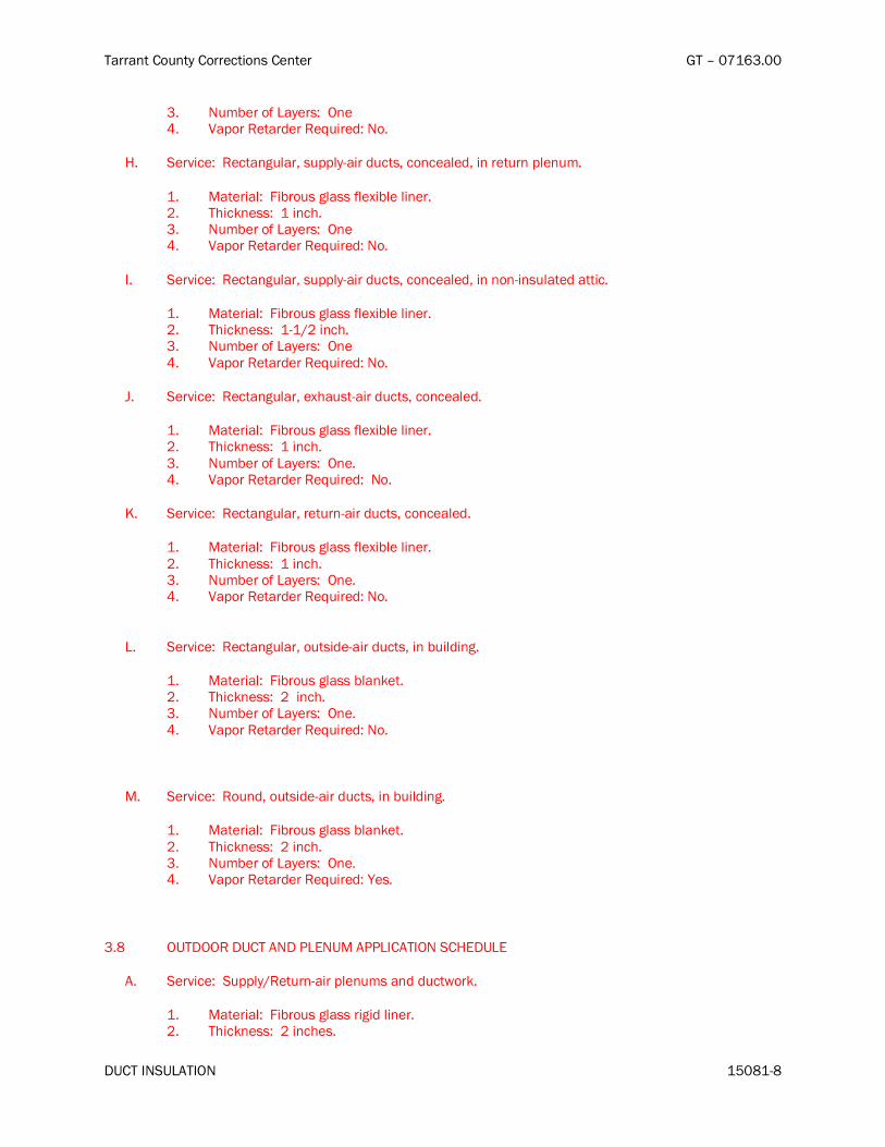
Tarrant County Corrections Center GT – 07163.00
DUCT INSULATION 15081-8
3. Number of Layers: One 4. Vapor Retarder Required: No.
H. Service: Rectangular, supply-air ducts, concealed, in return plenum.
1. Material: Fibrous glass flexible liner. 2. Thickness: 1 inch. 3. Number of Layers: One 4. Vapor Retarder Required: No.
I. Service: Rectangular, supply-air ducts, concealed, in non-insulated attic.
1. Material: Fibrous glass flexible liner. 2. Thickness: 1-1/2 inch. 3. Number of Layers: One 4. Vapor Retarder Required: No.
J. Service: Rectangular, exhaust-air ducts, concealed.
1. Material: Fibrous glass flexible liner. 2. Thickness: 1 inch. 3. Number of Layers: One. 4. Vapor Retarder Required: No.
K. Service: Rectangular, return-air ducts, concealed.
1. Material: Fibrous glass flexible liner. 2. Thickness: 1 inch. 3. Number of Layers: One. 4. Vapor Retarder Required: No.
L. Service: Rectangular, outside-air ducts, in building.
1. Material: Fibrous glass blanket. 2. Thickness: 2 inch. 3. Number of Layers: One. 4. Vapor Retarder Required: No.
M. Service: Round, outside-air ducts, in building.
1. Material: Fibrous glass blanket. 2. Thickness: 2 inch. 3. Number of Layers: One. 4. Vapor Retarder Required: Yes.
3.8 OUTDOOR DUCT AND PLENUM APPLICATION SCHEDULE
A. Service: Supply/Return-air plenums and ductwork.
1. Material: Fibrous glass rigid liner. 2. Thickness: 2 inches.

Tarrant County Corrections Center GT – 07163.00
DUCT INSULATION 15081-9
3. Number of Layers: One. 4. Vapor Retarder Required: No.
END OF SECTION 15081

Tarrant County Corrections Center GT – 07163.00
EQUIPMENT INSULATION 15082-1
SECTION 15082 – EQUIPMENT INSULATION
PART 1 - GENERAL
1.1 RELATED DOCUMENTS
A. Drawings and general provisions of the Contract, including General and Supplementary Conditions and Division 1 Specification Sections, apply to this Section.
1.2 SUMMARY
A. This Section includes blanket, board, and block insulation; insulating cements; field-applied jackets; accessories and attachments; and sealing compounds.
B. Not all listed materials and systems may be utilized for this project. Use applicable items, as required.
1.3 SUBMITTALS
A. Product Data: Identify thermal conductivity, thickness, and jackets (both factory and field applied, if any), for each type of product indicated.
B. Shop Drawings: Show fabrication and installation details for the following:
1. Field application for each equipment type. 2. Removable insulation sections at access panels. 3. Application of field-applied jackets. 4. Special shapes for cellular-glass insulation.
C. Samples (when requested by the Engineer): For each type of insulation and field-applied jacket. Identify each Sample, describing product and intended use. Submit 12-inch-square sections of each sample material.
D. Material Test Reports: From a qualified testing agency acceptable to authorities having jurisdiction indicating, interpreting, and certifying test results for compliance of insulation materials, sealers, attachments, cements, and jackets with requirements indicated. Include dates of tests.
E. Installer Certificates: Signed by the Contractor certifying that installers comply with requirements.
1.4 QUALITY ASSURANCE
A. Installer Qualifications: Skilled mechanics who have successfully completed an apprenticeship program or another craft training program certified by the U.S. Department of Labor, Bureau of Apprenticeship and Training.
B. Fire-Test-Response Characteristics: As determined by testing materials identical to those specified in this Section according to ASTM E 84, by a testing and inspecting agency acceptable to authorities having jurisdiction. Factory label insulation and jacket materials and sealer and cement material containers with appropriate markings of applicable testing and inspecting agency.

Tarrant County Corrections Center GT – 07163.00
EQUIPMENT INSULATION 15082-2
1. Insulation Installed Indoors: Flame-spread rating of 25 or less, and smoke-developed rating of 50 or less.
2. Insulation Installed Outdoors: Flame-spread rating of 75 or less, and smoke-developed rating of 150 or less.
1.5 DELIVERY, STORAGE, AND HANDLING
A. Packaging: Ship insulation materials in containers marked by manufacturer with appropriate ASTM specification designation, type and grade, and maximum use temperature.
1.6 COORDINATION
A. Coordinate clearance requirements with equipment Installer for insulation application.
PART 2 - PRODUCTS
2.1 MANUFACTURERS
A. Manufacturers: Subject to compliance with requirements, provide products by one of the following:
1. Mineral-Fiber Insulation:
a. Johns-Manville. b. Knauf FiberGlass GmbH. c. Owens-Corning Fiberglas Corp.
2. Flexible Elastomeric Thermal Insulation:
a. Armstrong World Industries, Inc. b. Rubatex Corp.
3. Calcium Silicate Insulation: a. Johns-Manville b. Approved equal
2.2 INSULATION MATERIALS
A. Mineral-Fiber Blanket Thermal Insulation: Glass fibers bonded with a thermosetting resin. Comply with ASTM C 553, Type II, without facing and with all-service jacket manufactured from kraft paper, reinforcing scrim, aluminum foil, and vinyl film.
B. Cellular-Glass Insulation: Inorganic, foamed or cellulated glass, annealed, rigid, hermetically sealed cells, incombustible.
1. Block Insulation: ASTM C 552, Type I. 2. Special-Shaped Insulation: ASTM C 552, Type III. 3. Board Insulation: ASTM C 552, Type IV.
C. Flexible Elastomeric Thermal Insulation: Closed-cell, sponge- or expanded-rubber materials. Comply with ASTM C 534, Type II for sheet materials.

Tarrant County Corrections Center GT – 07163.00
EQUIPMENT INSULATION 15082-3
1. Adhesive: As recommended by insulation material manufacturer. 2. Ultraviolet-Protective Coating: As recommended by insulation manufacturer.
D. Calcium Silicate Insulation: Flat-, curved-, and grooved-block sections of noncombustible, inorganic, hydrous calcium silicate with a nonasbestos fibrous reinforcement. Comply with ASTM C 533, Type I, asbestos free; 'k' value of 0.44 at 300 deg. F. Johns – Manville, Thermo-12 Gold or equal.
2.3 FIELD-APPLIED JACKETS
A. General: ASTM C 921, Type 1, unless otherwise indicated.
B. PVC Jacket: High-impact, ultraviolet-resistant PVC; 20 mils thick; roll stock ready for shop or field cutting and forming.
1. Adhesive: As recommended by insulation material manufacturer. 2. PVC Jacket Color: Color-code to match connected piping jackets based on materials
contained within the piping system.
C. Aluminum Jacket: Deep corrugated sheets manufactured from aluminum alloy complying with ASTM B 209, and having an integrally bonded moisture barrier over entire surface in contact with insulation. Metal thickness and corrugation dimensions are scheduled at the end of this Section.
1. Finish: Smooth finish. 2. Moisture Barrier: 1-mil-thick, heat-bonded polyethylene and kraft paper.
2.4 ACCESSORIES AND ATTACHMENTS
A. Glass Cloth and Tape: Comply with MIL-C-20079H, Type I for cloth and Type II for tape. Woven glass-fiber fabrics, plain weave, presized a minimum of 8 oz./sq. yd.
1. Tape Width: 4 inches.
B. Bands: 3/4 inch wide, in one of the following materials compatible with jacket:
1. Stainless Steel: ASTM A 666, Type 304; 0.020 inch thick.
C. Wire: 0.062-inch, soft-annealed, stainless steel.
D. Weld-Attached Anchor Pins and Washers: Copper-coated steel pin for capacitor-discharge welding and galvanized speed washer. Pin length sufficient for insulation thickness indicated.
1. Welded Pin Holding Capacity: 100 lb for direct pull perpendicular to the attached surface.
E. Adhesive-Attached Anchor Pins and Speed Washers: Galvanized steel plate, pin, and washer manufactured for attachment to duct and plenum with adhesive. Pin length sufficient for insulation thickness indicated.
1. Adhesive: Recommended by the anchor pin manufacturer as appropriate for surface temperatures of ducts, plenums, and breechings; and to achieve a holding capacity of 100 lb for direct pull perpendicular to the adhered surface.

Tarrant County Corrections Center GT – 07163.00
EQUIPMENT INSULATION 15082-4
F. Self-Adhesive Anchor Pins and Speed Washers: Galvanized steel plate, pin, and washer manufactured for attachment to duct and plenum with adhesive. Pin length sufficient for insulation thickness indicated.
2.5 VAPOR RETARDERS
A. Mastics: Materials recommended by insulation material manufacturer that are compatible with insulation materials, jackets, and substrates.
PART 3 - EXECUTION
3.1 EXAMINATION
A. Examine substrates and conditions for compliance with requirements for installation and other conditions affecting performance of insulation application.
B. Proceed with installation only after unsatisfactory conditions have been corrected.
3.2 PREPARATION
A. Surface Preparation: Clean and dry surfaces to receive insulation. Remove materials that will adversely affect insulation application.
3.3 GENERAL APPLICATION REQUIREMENTS
A. Apply insulation materials, accessories, and finishes according to the manufacturer's written instructions; with smooth, straight, and even surfaces; and free of voids throughout the length of equipment.
B. Refer to schedules at the end of this Section for materials, forms, jackets, and thicknesses required for each equipment system.
C. Use accessories compatible with insulation materials and suitable for the service. Use accessories that do not corrode, soften, or otherwise attack insulation or jacket in either the wet or dry state.
D. Apply multiple layers of insulation with longitudinal and end seams staggered.
E. Seal joints and seams with vapor-retarder mastic on insulation indicated to receive a vapor retarder.
F. Keep insulation materials dry during application and finishing.
G. Apply insulation with tight longitudinal seams and end joints. Bond seams and joints with adhesive recommended by the insulation material manufacturer.
H. Apply insulation with the least number of joints practical.
I. Apply insulation over fittings and specialties, with continuous thermal and vapor-retarder integrity, unless otherwise indicated.

Tarrant County Corrections Center GT – 07163.00
EQUIPMENT INSULATION 15082-5
J. Hangers and Anchors: Where vapor retarder is indicated, seal penetrations in insulation at hangers, supports, anchors, and other projections with vapor-retarder mastic. Apply insulation continuously through hangers and around anchor attachments.
K. Insulation Terminations: For insulation application where vapor retarders are indicated, seal ends with a compound recommended by the insulation material manufacturer to maintain vapor retarder.
L. Apply insulation with integral jackets as follows:
1. Pull jacket tight and smooth. 2. Joints and Seams: Cover with tape and vapor retarder as recommended by insulation
material manufacturer to maintain vapor seal. 3. Vapor-Retarder Mastics: Where vapor retarders are indicated, apply mastic on seams and
joints and at ends adjacent to flanges and fittings.
M. Cut insulation according to manufacturer's written instructions to prevent compressing insulation to less than 75 percent of its nominal thickness.
N. Install vapor-retarder mastic on equipment scheduled to receive vapor retarders. Overlap insulation facing at seams and seal with vapor-retarder mastic and pressure-sensitive tape having same facing as insulation. Repair punctures, tears, and penetrations with tape or mastic to maintain vapor-retarder seal.
O. Insulate the following indoor equipment:
1. Chilled-water air separators. 2. Chilled-water compression tanks. 3. Chilled-water centrifugal pump housings. 4. Domestic hot-water storage tanks, not factory insulated. 5. Heating hot-water air separators. 6. Heating hot-water expansion tanks. 7. Heating hot-water pump housings.
P. Omit insulation from the following:
1. Vibration-control devices. 2. Testing agency labels and stamps. 3. Nameplates and data plates. 4. Manholes. 5. Handholes. 6. Cleanouts.
3.4 INDOOR TANK AND VESSEL INSULATION APPLICATION
A. Blankets, Board, and Block Applications for Tanks and Vessels: Secure insulation with adhesive and anchor pins and speed washers.
1. Apply adhesives according to manufacturer's recommended coverage rates per square foot, for 100 percent coverage of tank and vessel surfaces.
2. Groove and score insulation materials to fit as closely as possible to the equipment, including contours. Bevel insulation edges for cylindrical surfaces for tight joint. Stagger end joints.
3. Protect exposed corners with secured corner angles. 4. Install adhesive-attached or self-adhesive anchor pins and speed washers on sides of tanks
and vessels as follows:

Tarrant County Corrections Center GT – 07163.00
EQUIPMENT INSULATION 15082-6
a. Do not weld anchor pins to ASME-labeled pressure vessels. b. On tank and vessel, 3 inches maximum from insulation end joints, and 16 inches o.c.
in both directions. c. Do not overcompress insulation during installation. d. Cut and miter insulation segments to fit curved sides and dome heads of tanks and
vessels.
5. Impale insulation over anchor pins and attach speed washers. 6. Cut excess portion of pins extending beyond speed washers or bend parallel with insulation
surface. Cover exposed pins and washers with tape matching insulation facing 7. Secure each layer of insulation with stainless-steel bands. 8. Stagger joints between insulation layers at least 3 inches. 9. Apply insulation in removable segments on equipment access doors and other elements that
require frequent removal for service. 10. Bevel and seal insulation ends around manholes, handholes, ASME stamps, and nameplates. 11. Apply vapor-retarder mastic to open joints, breaks, and punctures for insulation indicated to
receive vapor retarder.
B. Flexible Elastomeric Thermal Insulation Applications for Tanks and Vessels: Apply insulation over entire surface of tanks and vessels according to the manufacturer's written instructions.
1. Apply 100 percent coverage of adhesive to surface with manufacturer's recommended adhesive.
2. Seal longitudinal seams and end joints.
3.5 FIELD-APPLIED JACKET APPLICATION
A. Apply glass-cloth jacket where indicated, directly over bare insulation or insulation with factory-applied jackets.
1. Apply jacket smooth and tight to surface with 2-inch overlap at seams and joints. 2. Embed glass cloth between two 0.062-inch-thick coats of jacket manufacturer's
recommended adhesive. 3. Completely encapsulate insulation with jacket, leaving no exposed raw insulation.
B. PVC Jackets: Apply jacket with longitudinal seams along top and bottom of tanks and vessels for horizontal applications. Secure and seal seams and end joints with manufacturer's welding adhesive.
1. Apply two continuous beads of adhesive to seams and joints, one bead under lap and the finish bead along the seam and joint edge.
C. Aluminum Jackets: Secure jackets according to jacket manufacturer's written instructions.
3.6 FINISHES
A. Glass-Cloth Jacketed Insulation: Paint insulation finished with glass-cloth jacket.
B. Flexible Elastomeric Thermal Insulation: After adhesive has fully cured, apply two coats of insulation manufacturer's recommended protective coating.
C. Color: Final color shall match the associated piping based on the master color chart specified in another section.

Tarrant County Corrections Center GT – 07163.00
EQUIPMENT INSULATION 15082-7
3.7 FIELD QUALITY CONTROL
A. Inspection: Perform the following field quality-control inspections, after installing insulation materials, jackets, and finishes, to determine compliance with requirements:
1. Inspect pumps and tanks randomly selected by Architect. 2. Remove insulation and covers from two chilled-water pumps or one percent of chilled-water
pumps, whichever is greater. 3. Remove insulation and covers from two small tanks or one percent of small tanks, whichever
is greater.
B. Insulation applications will be considered defective if sample inspection reveals noncompliance with requirements. Remove defective Work and replace with new materials according to these Specifications.
C. Reinstall insulation and covers on pumps and tanks uncovered for inspection according to these Specifications.
3.8 EQUIPMENT APPLICATIONS
A. Insulation materials and thicknesses are specified in schedules at the end of this Section.
B. Materials and thicknesses for systems listed below are specified in schedules at the end of this Section.
3.9 INTERIOR TANK AND VESSEL INSULATION APPLICATION SCHEDULE
A. Equipment: Chilled-water air separators and compression tanks.
1. Operating Temperature: 35 to 75 deg F. 2. Insulation Material: Mineral fiber, with jacket or flexible elastomeric 3. Insulation Thickness: 1” 4. Field-Applied Jacket: Glass cloth. 5. Vapor Retarder Required: Yes. 6. Finish: Painted.
B. Equipment: Domestic hot-water storage tanks and expansion tanks, not factory insulated.
1. Operating Temperature: 55 to 140 deg F. 2. Insulation Material: Mineral fiber, with jacket or flexible elastomeric 3. Insulation Thickness: 1” 4. Field-Applied Jacket: Glass cloth. 5. Vapor Retarder Required: No. 6. Finish: Painted.
C. Equipment: Heating-water air separators and expansion tanks.
1. Operating Temperature: 100 to 200 deg F 2. Insulation Material: Mineral fiber or flexible elastomeric. 3. Insulation Thickness: 1” 4. Field-Applied Jacket: Glass cloth. 5. Vapor Retarder Required: No. 6. Finish: Painted.

Tarrant County Corrections Center GT – 07163.00
EQUIPMENT INSULATION 15082-8
D. Equipment: Heating-water, chilled-water and condenser-water pumps.
1. Operating Temperature: 40 to 200 deg F 2. Insulation Material: Flexible elastomeric. 3. Insulation Thickness: 1” 4. Field-Applied Jacket: none. 5. Vapor Retarder Required: Yes (on chilled water pumps only). 6. Finish: Painted.
E. Equipment: Generator muffler and exhaust pipe.
1. Operating Temperature: 100 to 1200 deg F 2. Insulation Material: Calcium Silicate molded or block type, as required. 3. Insulation Thickness: 4” 4. Field-Applied Jacket: Aluminum, with low emissivity paint for high temperature applications. 5. Vapor Retarder Required: No. 6. Finish: Painted.
END OF SECTION 15082

Tarrant County Corrections Center GT – 07163.00
PIPE INSULATION 15083-1
SECTION 15083 – PIPE INSULATION
PART 1 - GENERAL
1.1 RELATED DOCUMENTS
A. Drawings and general provisions of the Contract, including General and Supplementary Conditions and Division 1 Specification Sections, apply to this Section.
1.2 SUMMARY
A. This Section includes preformed, rigid and flexible pipe insulation; insulating cements; field-applied jackets; accessories and attachments; and sealing compounds. Paint per other Sections of these specifications. Not all listed systems may be utilized for this project. Use applicable systems, as re-quired.
1.3 SUBMITTALS
A. Product Data: Identify thermal conductivity, thickness, and jackets (both factory and field applied, if any), for each type of product indicated.
B. Shop Drawings: Show fabrication and installation details for the following:
1. Application of protective shields, saddles, and inserts at pipe hangers for each type of insula-tion and hanger.
2. Attachment and covering of heat trace inside insulation. 3. Insulation application at pipe expansion joints for each type of insulation. 4. Insulation application at elbows, fittings, flanges, valves, and specialties for each type of insu-
lation. 5. Removable insulation at piping specialties and equipment connections. 6. Application of field-applied jackets.
C. Material Test Reports: From a qualified testing agency acceptable to authorities having jurisdiction indicating, interpreting, and certifying test results for compliance of insulation materials, sealers, at-tachments, cements, and jackets with requirements indicated. Include dates of tests.
1.4 QUALITY ASSURANCE
A. Fire-Test-Response Characteristics: As determined by testing materials identical to those specified in this Section according to ASTM E 84, by a testing and inspecting agency acceptable to authorities having jurisdiction. Factory label insulation and jacket materials and sealer and cement material containers with appropriate markings of applicable testing and inspecting agency.
1. Insulation and Jackets Installed Indoors: Flame-spread rating of 25 or less, and smoke-developed rating of 50 or less.
2. Insulation and Jackets Installed Outdoors: Flame-spread rating of 75 or less, and smoke-developed rating of 150 or less.
1.5 DELIVERY, STORAGE, AND HANDLING

Tarrant County Corrections Center GT – 07163.00
PIPE INSULATION 15083-2
A. Packaging: Ship insulation materials in containers marked by manufacturer with appropriate ASTM specification designation, type and grade, and maximum use temperature.
1.6 COORDINATION
A. Coordinate size and location of supports, hangers, and insulation shields specified.
B. Coordinate clearance requirements with piping Installer for insulation application.
C. Coordinate installation and testing of steam or electric heat tracing.
1.7 SCHEDULING
A. Schedule insulation application after testing piping systems and, where required, after installing and testing heat-trace tape. Insulation application may begin on segments of piping that have satisfac-tory test results.
PART 2 - PRODUCTS
2.1 MANUFACTURERS
A. Manufacturers: Subject to compliance with requirements, provide products by one of the following:
1. Molded Mineral-Fiber Insulation:
a. Johns-Manville Insulation, Inc. b. Knauf FiberGlass GmbH. c. Owens-Corning Fiberglas Corp.
2. Flexible Elastomeric Thermal Insulation:
a. Armstrong World Industries, Inc. b. Rubatex Corp.
2.2 INSULATION MATERIALS
A. Molded Mineral-Fiber Insulation: Glass fibers bonded with a thermosetting resin complying with the following:
1. Preformed Pipe Insulation: Comply with ASTM C 547, Type 1, with factory-applied, all-purpose, vapor-retarder jacket.
2. Fire-Resistant Adhesive: Comply with MIL-A-3316C in the following classes and grades:
a. Class 1, Grade A for bonding glass cloth and tape to unfaced glass-fiber insulation, for sealing edges of glass-fiber insulation, and for bonding lagging cloth to unfaced glass-fiber insulation.
b. Class 2, Grade A for bonding glass-fiber insulation to metal surfaces.

Tarrant County Corrections Center GT – 07163.00
PIPE INSULATION 15083-3
3. Vapor-Retarder Mastics: Fire- and water-resistant, vapor-retarder mastic for indoor applica-tions. Comply with MIL-C-19565C, Type II.
4. Mineral-Fiber Insulating Cements: Comply with ASTM C 195. 5. Expanded or Exfoliated Vermiculite Insulating Cements: Comply with ASTM C 196. 6. Mineral-Fiber, Hydraulic-Setting Insulating and Finishing Cement: Comply with
ASTM C 449/C 449M.
B. Flexible Elastomeric Thermal Insulation: Closed-cell, sponge- or expanded-rubber materials. Comply with ASTM C 534, Type I for tubular materials and Type II for sheet materials.
1. Adhesive: As recommended by insulation material manufacturer. 2. Ultraviolet-Protective Coating: As recommended by insulation manufacturer.
C. Prefabricated Thermal Insulating Fitting Covers: Comply with ASTM C 450 for dimensions used in preforming insulation to cover valves, elbows, tees, and flanges.
2.3 ACCESSORIES AND ATTACHMENTS
A. Glass Cloth and Tape: Comply with MIL-C-20079H, Type I for cloth and Type II for tape. Woven glass-fiber fabrics, plain weave, presized a minimum of 8 oz./sq. yd..
1. Tape Width: 4 inches.
B. Bands: 3/4 inch wide, in one of the following materials compatible with jacket:
1. Stainless Steel: ASTM A 666, Type 304; 0.020 inch thick.
C. Wire: 0.062-inch, soft-annealed, stainless steel.
2.4 VAPOR RETARDERS
A. Mastics: Materials recommended by insulation material manufacturer that are compatible with insu-lation materials, jackets, and substrates.
PART 3 - EXECUTION
3.1 EXAMINATION
A. Examine substrates and conditions for compliance with requirements for installation and other con-ditions affecting performance of insulation application.
B. Proceed with installation only after unsatisfactory conditions have been corrected.
3.2 PREPARATION
A. Surface Preparation: Clean and dry pipe and fitting surfaces. Remove materials that will adversely affect insulation application.
3.3 GENERAL APPLICATION REQUIREMENTS

Tarrant County Corrections Center GT – 07163.00
PIPE INSULATION 15083-4
A. Apply insulation materials, accessories, and finishes according to the manufacturer's written instruc-tions; with smooth, straight, and even surfaces; free of voids throughout the length of piping, includ-ing fittings, valves, and specialties.
B. Refer to schedules at the end of this Section for materials, forms, jackets, and thicknesses required for each piping system.
C. Use accessories compatible with insulation materials and suitable for the service. Use accessories that do not corrode, soften, or otherwise attack insulation or jacket in either wet or dry state.
D. Apply insulation with longitudinal seams at top and bottom of horizontal pipe runs.
E. Apply multiple layers of insulation with longitudinal and end seams staggered.
F. Do not weld brackets, clips, or other attachment devices to piping, fittings, and specialties.
G. Seal joints and seams with vapor-retarder mastic on insulation indicated to receive a vapor retarder.
H. Keep insulation materials dry during application and finishing.
I. Apply insulation with tight longitudinal seams and end joints. Bond seams and joints with adhesive recommended by the insulation material manufacturer.
J. Apply insulation with the least number of joints practical.
K. Apply insulation over fittings, valves, and specialties, with continuous thermal and vapor-retarder in-tegrity, unless otherwise indicated. Refer to special instructions for applying insulation over fittings, valves, and specialties.
L. Hangers and Anchors: Where vapor retarder is indicated, seal penetrations in insulation at hangers, supports, anchors, and other projections with vapor-retarder mastic.
1. Apply insulation continuously through hangers and around anchor attachments. 2. For insulation application where vapor retarders are indicated, extend insulation on anchor
legs at least 12 inches from point of attachment to pipe and taper insulation ends. Seal ta-pered ends with a compound recommended by the insulation material manufacturer to main-tain vapor retarder.
3. Install insert materials and apply insulation to tightly join the insert. Seal insulation to insula-tion inserts with adhesive or sealing compound recommended by the insulation material manufacturer.
4. Cover inserts with jacket material matching adjacent pipe insulation. Install shields over jacket, arranged to protect the jacket from tear or puncture by the hanger, support, and shield.
M. Insulation Terminations: For insulation application where vapor retarders are indicated, taper insula-tion ends. Seal tapered ends with a compound recommended by the insulation material manufac-turer to maintain vapor retarder.
N. Apply adhesives and mastics at the manufacturer's recommended coverage rate.
O. Apply insulation with integral jackets as follows:
1. Pull jacket tight and smooth. 2. Circumferential Joints: Cover with 3-inch- wide strips, of same material as insulation jacket.
Secure strips with adhesive and outward clinching staples along both edges of strip and spaced 4 inches o.c.

Tarrant County Corrections Center GT – 07163.00
PIPE INSULATION 15083-5
3. Longitudinal Seams: Overlap jacket seams at least 1-1/2 inches. Apply insulation with longi-tudinal seams at bottom of pipe. Clean and dry surface to receive self-sealing lap. Staple laps with outward clinching staples along edge at 4 inches o.c.
a. Exception: Do not staple longitudinal laps on insulation having a vapor retarder.
4. Vapor-Retarder Mastics: Where vapor retarders are indicated, apply mastic on seams and joints and at ends adjacent to flanges, unions, valves, and fittings.
5. At penetrations in jackets for thermometers and pressure gages, fill and seal voids with vapor-retarder mastic.
P. Roof Penetrations: Apply insulation for interior applications to a point even with top of roof flashing.
1. Seal penetrations with vapor-retarder mastic. 2. Apply insulation for exterior applications tightly joined to interior insulation ends. 3. Extend metal jacket of exterior insulation outside roof flashing at least 2 inches below top of
roof flashing. 4. Seal metal jacket to roof flashing with vapor-retarder mastic.
Q. Interior Wall and Partition Penetrations: Apply insulation continuously through walls and floors.
R. Fire-Rated Wall and Partition Penetrations: Apply insulation continuously through penetrations of fire-rated walls and partitions per UL requirements for the construction of the partition/wall.
3.4 MOLDED MINERAL-FIBER INSULATION APPLICATION
A. Apply insulation to straight pipes and tubes as follows:
1. Secure each layer of preformed pipe insulation to pipe with wire, tape, or bands without de-forming insulation materials.
2. Where vapor retarders are indicated, seal longitudinal seams and end joints with vapor-retarder mastic. Apply vapor retarder to ends of insulation at intervals of 15 to 20 feet to form a vapor retarder between pipe insulation segments.
3. For insulation with factory-applied jackets, secure laps with outward clinched staples at 6 inches o.c.
4. For insulation with factory-applied jackets with vapor retarders, do not staple longitudinal tabs but secure tabs with additional adhesive as recommended by the insulation material manu-facturer and seal with vapor-retarder mastic.
B. Apply insulation to flanges as follows:
1. Apply preformed pipe insulation to outer diameter of pipe flange. 2. Make width of insulation segment the same as overall width of the flange and bolts, plus
twice the thickness of the pipe insulation. 3. Fill voids between inner circumference of flange insulation and outer circumference of adja-
cent straight pipe segments with mineral-fiber blanket insulation. 4. Apply canvas jacket material with manufacturer's recommended adhesive, overlapping seams
at least 1 inch, and seal joints with vapor-retarder mastic.
C. Apply insulation to fittings and elbows as follows:
1. Apply premolded insulation sections of the same material as straight segments of pipe insula-tion when available. Secure according to manufacturer's written instructions.
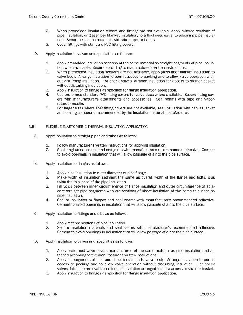
Tarrant County Corrections Center GT – 07163.00
PIPE INSULATION 15083-6
2. When premolded insulation elbows and fittings are not available, apply mitered sections of pipe insulation, or glass-fiber blanket insulation, to a thickness equal to adjoining pipe insula-tion. Secure insulation materials with wire, tape, or bands.
3. Cover fittings with standard PVC fitting covers.
D. Apply insulation to valves and specialties as follows:
1. Apply premolded insulation sections of the same material as straight segments of pipe insula-tion when available. Secure according to manufacturer's written instructions.
2. When premolded insulation sections are not available, apply glass-fiber blanket insulation to valve body. Arrange insulation to permit access to packing and to allow valve operation with-out disturbing insulation. For check valves, arrange insulation for access to stainer basket without disturbing insulation.
3. Apply insulation to flanges as specified for flange insulation application. 4. Use preformed standard PVC fitting covers for valve sizes where available. Secure fitting cov-
ers with manufacturer's attachments and accessories. Seal seams with tape and vapor-retarder mastic.
5. For larger sizes where PVC fitting covers are not available, seal insulation with canvas jacket and sealing compound recommended by the insulation material manufacturer.
3.5 FLEXIBLE ELASTOMERIC THERMAL INSULATION APPLICATION
A. Apply insulation to straight pipes and tubes as follows:
1. Follow manufacturer's written instructions for applying insulation. 2. Seal longitudinal seams and end joints with manufacturer's recommended adhesive. Cement
to avoid openings in insulation that will allow passage of air to the pipe surface.
B. Apply insulation to flanges as follows:
1. Apply pipe insulation to outer diameter of pipe flange. 2. Make width of insulation segment the same as overall width of the flange and bolts, plus
twice the thickness of the pipe insulation. 3. Fill voids between inner circumference of flange insulation and outer circumference of adja-
cent straight pipe segments with cut sections of sheet insulation of the same thickness as pipe insulation.
4. Secure insulation to flanges and seal seams with manufacturer's recommended adhesive. Cement to avoid openings in insulation that will allow passage of air to the pipe surface.
C. Apply insulation to fittings and elbows as follows:
1. Apply mitered sections of pipe insulation. 2. Secure insulation materials and seal seams with manufacturer's recommended adhesive.
Cement to avoid openings in insulation that will allow passage of air to the pipe surface.
D. Apply insulation to valves and specialties as follows:
1. Apply preformed valve covers manufactured of the same material as pipe insulation and at-tached according to the manufacturer's written instructions.
2. Apply cut segments of pipe and sheet insulation to valve body. Arrange insulation to permit access to packing and to allow valve operation without disturbing insulation. For check valves, fabricate removable sections of insulation arranged to allow access to strainer basket.
3. Apply insulation to flanges as specified for flange insulation application.

Tarrant County Corrections Center GT – 07163.00
PIPE INSULATION 15083-7
4. Secure insulation to valves and specialties and seal seams with manufacturer's recom-mended adhesive. Cement to avoid openings in insulation that will allow passage of air to the pipe surface.
3.6 FIELD-APPLIED JACKET APPLICATION
A. Apply PVC jacket where indicated, with 1-inch overlap at longitudinal seams and end joints. Seal with manufacturer's recommended adhesive.
B. Apply metal jacket where indicated, with 2-inch overlap at longitudinal seams and end joints. Over-lap longitudinal seams arranged to shed water. Seal end joints with weatherproof sealant recom-mended by insulation manufacturer. Secure jacket with stainless-steel bands 12 inches o.c. and at end joints.
3.7 FINISHES
A. Flexible Elastomeric Thermal Insulation: After adhesive has fully cured, apply two coats of the insu-lation manufacturer's recommended protective coating.
B. Color: Final color shall comply with the master color chart as specified in another section.
3.8 PIPING SYSTEM APPLICATIONS
A. Insulation materials and thicknesses are specified in schedules at the end of this Section.
B. Items Not Insulated: Unless otherwise indicated, do not apply insulation to the following systems, materials, and equipment:
1. Flexible connectors. 2. Vibration-control devices. 3. Fire-suppression piping. 4. Drainage piping located in crawl spaces, unless otherwise indicated. 5. Below-grade piping, unless otherwise indicated. 6. Chrome-plated pipes and fittings, unless potential for personnel injury. 7. Air chambers, unions, strainers, check valves, plug valves, and flow regulators.
3.9 INSULATION APPLICATION SCHEDULE, GENERAL
A. Refer to insulation application schedules for required insulation materials, vapor retarders, and field-applied jackets.
B. Application schedules identify piping system and indicate pipe size ranges and material, thickness, and jacket requirements.
3.10 INTERIOR INSULATION APPLICATION SCHEDULE
A. Service: Domestic cold water.
1. Operating Temperature: 55 to 65 deg F. 2. Insulation Material: Molded Mineral fiber, with jacket

Tarrant County Corrections Center GT – 07163.00
PIPE INSULATION 15083-8
3. Insulation Thickness: Apply the following insulation thicknesses:
a. Copper Pipe, Up to 2”: 1” b. Copper Pipe, 2” through 4”: 1-1/2” c. Copper Pipe, Over 4”: 2”
4. Field-Applied Jacket: PVC in mechanical rooms, cloth jacket elsewhere inside building, Alumi-num for outdoor applications
5. Vapor Retarder Required: Yes. 6. Finish: Painted.
B. Service: Domestic hot and recirculated hot water.
1. Operating Temperature: 60 to 140 deg F. 2. Insulation Material: Molded Mineral fiber, with jacket 3. Insulation Thickness: Apply the following insulation thicknesses:
a. Copper Pipe, Up to 1-1/2”: 1” b. Copper Pipe, 1-1/2” through 4”: 1 1/2” c. Copper Pipe, Over 4”: 2”
4. Field-Applied Jacket: PVC in mechanical rooms, cloth jacket elsewhere inside building. 5. Vapor Retarder Required: No. 6. Finish: Painted.
C. Service: Domestic hot with temperature maintenance tape.
1. Operating Temperature: 60 to 140 deg F. 2. Insulation Material: Molded Mineral fiber, with jacket 3. Insulation Thickness: Apply the following insulation thicknesses:
a. Copper Pipe, 1/2 to 1”: 1” b. Copper Pipe, 1-1/4” through 2”: 2” c. Copper Pipe, 2-1/2” through 6”: 2-1/2”
4. Field-Applied Jacket: PVC in mechanical rooms, cloth jacket elsewhere inside building. 5. Vapor Retarder Required: No. 6. Finish: Painted.
D. Service: Rainwater conductors.
1. Operating Temperature: 32 to 100 deg F. 2. Insulation Material: Molded Mineral fiber, with jacket 3. Insulation Thickness: Apply the following insulation thicknesses:
a. Up to 4” pipe – ½” insulation. b. Over 4” – 1” insulation.
4. Field-Applied Jacket: PVC in mechanical rooms, cloth jacket elsewhere inside building. 5. Vapor Retarder Required: Yes 6. Finish: Painted.
E. Service: Condensate drain piping.

Tarrant County Corrections Center GT – 07163.00
PIPE INSULATION 15083-9
1. Operating Temperature: 35 to 75 deg F. 2. Insulation Material: Flexible elastomeric 3. Insulation Thickness: ½” 4. Field-Applied Jacket: None. 5. Vapor Retarder Required: No. 6. Finish: Painted.
F. Service: Chilled-water supply and return.
1. Operating Temperature: 35 to 75 deg F. 2. Insulation Material: Molded Mineral fiber, with jacket 3. Insulation Thickness: Apply the following insulation thicknesses:
a. Up through 3” pipe – 1 ½” insulation. b. Over 3” pipe – 2” insulation.
4. Field-Applied Jacket: PVC in mechanical rooms, cloth jacket elsewhere inside building, Alumi-num jacket for outdoor applications.
5. Vapor Retarder Required: Yes 6. Finish: Painted.
G. Service: Condenser-water supply and return.
1. Operating Temperature: 50 to 105 deg F. 2. Insulation Material: Molded Mineral fiber, with jacket. 3. Insulation Thickness: 1” 4. Field-Applied Jacket: PVC in mechanical rooms, cloth jacket elsewhere inside building Alumi-
num for outdoors applications. 5. Vapor Retarder Required: Yes. 6. Finish: Painted.
H. Service: Heating-water supply and return.
1. Operating Temperature: 60 to 200 deg F. 2. Insulation Material: Molded Mineral fiber, with jacket 3. Insulation Thickness: Apply the following insulation thicknesses:
a. Up to 1-1/2”: 1” b. 2” through 4”: 2” c. Over 4”: 3”
4. Field-Applied Jacket: PVC in mechanical rooms, cloth jacket elsewhere inside building, Alumi-num jacket for outdoor applications.
5. Vapor Retarder Required: No. 6. Finish: Painted.
I. Service: Heating – steam and steam condensate.
1. Operating Temperature: up to 280 deg F. (35 psig) 2. Insulation Material: Molded Mineral fiber, with jacket 3. Insulation Thickness: Apply the following insulation thicknesses:
a. Steam pipe, Up to 1-1/2”: 1-1/2” b. Steam pipe, 2” and Up: 3”

Tarrant County Corrections Center GT – 07163.00
PIPE INSULATION 15083-10
c. Condensate pipe, Up to 1-1/2”: 1-1/2” d. Condensate pipe, 2” and Up: 2”
4. Field-Applied Jacket: Cloth fiber inside building, Aluminum jacket for outdoor applications. 5. Vapor Retarder Required: No. 6. Finish: Painted.
J. Service: All Refrigerant suction piping (and liquid refrigerant piping for heat pump applications, only where exposed to ambient):
1. Operating Temperature: 30 to 60 deg F. 2. Insulation Material: Molded Flexible elastomeric 3. Insulation Thickness: ¾” 4. Field-Applied Jacket: None. 5. Vapor Retarder Required: No. 6. Finish: Painted.
K. Service: Generator muffler and exhaust pipe………………………………
END OF SECTION 15083

Tarrant County Corrections Center GT – 07163.00
VALVES 15110-1
SECTION 15110 - VALVES
PART 1 - GENERAL
1.1 RELATED DOCUMENTS
A. Drawings and general provisions of the Contract, including General and Supplementary Conditions and Division 1 Specification Sections, apply to this Section.
1.2 SUMMARY
A. This Section includes general duty valves common to several mechanical piping systems.
1.3 SUBMITTALS
A. General: Submit each item in this Article according to the Conditions of the Contract and Division 1 Specification Sections.
B. Product Data for each valve type. Include body material, valve design, pressure and temperature classification, end connection details, seating materials, trim material and arrangement, dimensions and required clearances, and installation instructions. Include list indicating valve and its applica-tion.
C. Maintenance data for valves to include in the operation and maintenance manual specified in Divi-sion 1. Include detailed manufacturer's instructions on adjusting, servicing, disassembling, and re-pairing.
1.4 QUALITY ASSURANCE
A. Single-Source Responsibility: Comply with the requirements specified in Division 1 Section "Materi-als and Equipment," under "Source Limitations" Paragraph.
B. ASME Compliance: Comply with ASME B31.9 for building services piping and ASME B31.1 for power piping.
C. MSS Compliance: Comply with the various MSS Standard Practice documents referenced.
1.5 DELIVERY, STORAGE, AND HANDLING
A. Prepare valves for shipping as follows:
1. Protect internal parts against rust and corrosion. 2. Protect threads, flange faces, grooves, and weld ends. 3. Set globe and gate valves closed to prevent rattling. 4. Set ball and plug valves open to minimize exposure of functional surfaces. 5. Set butterfly valves closed or slightly open. 6. Block check valves in either closed or open position.
B. Use the following precautions during storage:
1. Maintain valve end protection. 2. Store indoors and maintain valve temperature higher than ambient dew-point temperature. If
outdoor storage is necessary, store valves off the ground in watertight enclosures.

Tarrant County Corrections Center GT – 07163.00
VALVES 15110-2
C. Use a sling to handle large valves. Rig to avoid damage to exposed parts. Do not use handwheels and stems as lifting or rigging points.
1.6 COMMISSIONING
A. This project will have selected building systems commissioned. A Commissioning Agent, whose ser-vices will be provided by the Owner, will direct the commissioning process.
PART 2 - PRODUCTS
2.1 MANUFACTURERS
A. Manufacturers: Subject to compliance with requirements, provide products by one of the following:
1. Gate Valves:
a. Crane Company; Valves and Fitting Division. b. Milwaukee Valve Company, Inc. c. NIBCO Inc. d. Red-White Valve Corp.
2. Ball Valves:
a. Conbraco Industries, Inc.; Apollo Division. b. Milwaukee Valve Company, Inc. c. NIBCO Inc. d. Victaulic Company of America.
3. Plug Valves:
a. Grinnell Corp. b. NIBCO Inc. c. Stockham Valves & Fittings, Inc. d. Victaulic Company of America.
4. Globe Valves:
a. Crane Company; Valves and Fitting Division. b. Milwaukee Valve Company, Inc. c. NIBCO Inc. d. Stockham Valves & Fittings, Inc.
5. Butterfly Valves:
a. Center Line, Mark Controls Corporation. b. Grinnell Corp. c. Milwaukee Valve Company, Inc. d. NIBCO Inc. e. Red-White Valve Corp. f. Victaulic Company of America.
6. Swing Check Valves:

Tarrant County Corrections Center GT – 07163.00
VALVES 15110-3
a. Cla-Val Co. b. Crane Company; Valves and Fitting Division. c. NIBCO Inc. d. Red-White Valve Corp.
7. Wafer Check Valves:
a. Cla-Val Co. b. Metraflex Company. c. NIBCO Inc. d. Red-White Valve Corp. e. Victaulic Company of America.
8. Lift Check Valves:
a. Crane Company; Valves and Fitting Division. b. NIBCO Inc. c. Powell: Wm. Powell Company (The). d. Red-White Valve Corp.
9. Hydronic Balancing Valves:
a. Victaulic b. Flow Design, Inc c. Griswold
2.2 BASIC, COMMON FEATURES
A. Design: Rising stem or rising outside screw and yoke stems, except as specified below.
1. Nonrising stem valves may be used only where headroom prevents full extension of rising stems.
B. Pressure and Temperature Ratings: As indicated in the "Application Schedule" of Part 3 of this Sec-tion and as required to suit system pressures and temperatures.
C. Sizes: Same size as upstream pipe, unless otherwise indicated.
D. Operators: Use specified operators and handwheels, except provide the following special operator features:
1. Handwheels: For valves other than quarter turn. 2. Lever Handles: For quarter-turn valves 6 inches and smaller, except for plug valves, which
shall have square heads. Furnish Owner with 1 wrench for every 10 plug valves. 3. Chain-Wheel Operators: For valves 4 inches and larger, installed 96 inches or higher above
finished floor elevation. 4. Gear-Drive Operators: For quarter-turn valves 8 inches and larger.
E. Extended Stems: Where insulation is indicated or specified, provide extended stems arranged to re-ceive insulation.
F. Bypass and Drain Connections: Comply with MSS SP-45 bypass and drain connections.

Tarrant County Corrections Center GT – 07163.00
VALVES 15110-4
G. Threads: ASME B1.20.1.
H. Flanges: ASME B16.1 for cast iron, ASME B16.5 for steel, and ASME B16.24 for bronze valves.
2.3 GATE VALVES
A. Gate Valves, 2-1/2 Inches and Smaller: MSS SP-80; Class 125, 200-psi cold working pressure (CWP), or Class 150, 300-psi CWP; ASTM B 62 cast-bronze body and bonnet, solid-bronze wedge, copper-silicon alloy rising stem, teflon-impregnated packing with bronze packing nut, threaded or soldered end connections; and with aluminum or malleable-iron handwheel.
B. Gate Valves, 3 Inches and Larger: MSS SP-70, Class 125, 200-psi CWP, ASTM A 126 cast-iron body and bonnet, solid cast-iron wedge, brass-alloy stem, outside screw and yoke, teflon-impregnated packing with 2-piece packing gland assembly, flanged end connections; and with cast-iron hand-wheel.
2.4 BALL VALVES
A. Ball Valves, 4 Inches and Smaller: MSS SP-110, Class 150, 600-psi CWP, ASTM B 584 bronze body and bonnet, 2-piece construction; chrome-plated brass ball, standard port for 1/2-inch valves and smaller and conventional port for 3/4-inch valves and larger; blowout proof; bronze or brass stem; teflon seats and seals; threaded or soldered end connections: 1. Operator: Vinyl-covered steel lever handle. 2. Stem Extension: For valves installed in insulated piping. 3. Memory Stop: For operator handles.
2.5 PLUG VALVES
A. Plug Valves: MSS SP-78, 175-psi CWP, ASTM A 126 cast-iron body and bonnet, cast-iron plug, Buna N, Viton, or teflon packing, flanged or grooved end connections:
1. Operator: Lever. 2. Operator: Worm and gear with handwheel, sizes 6 inches and larger. 3. Operator: Worm and gear with chain wheel, sizes 6 inches and larger, 96 inches or higher
above floor.
2.6 GLOBE VALVES
A. Globe Valves, 2-1/2 Inches and Smaller: MSS SP-80; Class 125, 200-psi CWP, or Class 150, 300-psi CWP; ASTM B 62 cast-bronze body and screwed bonnet, rubber, bronze, or teflon disc, silicon bronze-alloy stem, teflon-impregnated packing with bronze nut, threaded or soldered end connec-tions; and with aluminum or malleable-iron handwheel.
B. Globe Valves, 3 Inches and Larger: MSS SP-85, Class 125, 200-psi CWP, ASTM A 126 cast-iron body and bolted bonnet with bronze fittings, renewable bronze seat and disc, brass-alloy stem, outside screw and yoke, teflon-impregnated packing with cast-iron follower, flanged end connections; and with cast-iron handwheel.
2.7 BUTTERFLY VALVES
A. Butterfly Valves: MSS SP-67, 200-psi CWP, 150-psi maximum pressure differential, ASTM A 126 cast-iron body and bonnet, extended neck, stainless-steel stem, field-replaceable EPDM or Buna N sleeve and stem seals, wafer, lug, or grooved style: 1. Disc Type: Elastomer-coated ductile iron. 2. Operator for Sizes 2 Inches to 6 Inches: Standard lever handle with memory stop.

Tarrant County Corrections Center GT – 07163.00
VALVES 15110-5
2.8 CHECK VALVES
A. Swing Check Valves, 2-1/2 Inches and Smaller: MSS SP-80; Class 125, 200-psi CWP, or Class 150, 300-psi CWP; horizontal swing, Y-pattern, ASTM B 62 cast-bronze body and cap, rotating bronze disc with rubber seat or composition seat, threaded or soldered end connections:
B. Swing Check Valves, 3 Inches and Larger: MSS SP-71, Class 125, 200-psi CWP, ASTM A 126 cast-iron body and bolted cap, horizontal-swing bronze disc, flanged or grooved end connections.
C. Wafer Check Valves: Class 125, 200-psi CWP, ASTM A 126 cast-iron body, bronze disc/plates, stainless-steel pins and springs, Buna N seals, installed between flanges.
D. Lift Check Valves: Class 125, ASTM B 62 bronze body and cap (main components), horizontal or ver-tical pattern, lift-type, bronze disc or Buna N rubber disc with stainless-steel holder threaded or sol-dered end connections.
PART 3 - EXECUTION
3.1 EXAMINATION
A. Examine piping system for compliance with requirements for installation tolerances and other condi-tions affecting performance of valves. Do not proceed with installation until unsatisfactory condi-tions have been corrected.
B. Examine valve interior for cleanliness, freedom from foreign matter, and corrosion. Remove special packing materials, such as blocks, used to prevent disc movement during shipping and handling.
C. Operate valves from fully open to fully closed positions. Examine guides and seats made accessible by such operation.
D. Examine threads on valve and mating pipe for form and cleanliness.
E. Examine mating flange faces for conditions that might cause leakage. Check bolting for proper size, length, and material. Check gasket material for proper size, material composition suitable for ser-vice, and freedom from defects and damage.
F. Do not attempt to repair defective valves; replace with new valves.
3.2 INSTALLATION
A. Install valves as indicated on drawings, and in accordance with manufacturer's written instructions.
B. Drawings indicate the general arrangement of piping, fittings, and specialties.
C. Install valves with unions or flanges at each piece of equipment arranged to allow servicing, mainte-nance, and equipment removal without system shutdown.
D. Locate valves for easy access and provide separate support where necessary.
E. Install valves in horizontal piping with stem at or above the center of the pipe.
F. Install valves in a position to allow full stem movement.

Tarrant County Corrections Center GT – 07163.00
VALVES 15110-6
G. For chain-wheel operators, extend chains to 60 inches above finished floor elevation.
H. Installation of Check Valves: Install for proper direction of flow as follows:
1. Swing Check Valves: Horizontal position with hinge pin level. 2. Wafer Check Valves: Horizontal or vertical position, between flanges. 3. Lift Check Valve: With stem upright and plumb.
3.3 SOLDERED CONNECTIONS
A. Cut tube square and to exact lengths.
B. Clean end of tube to depth of valve socket with steel wool, sand cloth, or a steel wire brush to a bright finish. Clean valve socket.
C. Apply proper soldering flux in an even coat to inside of valve socket and outside of tube.
D. Open gate and globe valves to fully open position.
E. Remove the cap and disc holder of swing check valves having composition discs.
F. Insert tube into valve socket, making sure the end rests against the shoulder inside valve. Rotate tube or valve slightly to ensure even distribution of the flux.
G. Apply heat evenly to outside of valve around joint until solder melts on contact. Feed solder until it completely fills the joint around tube. Avoid hot spots or overheating valve. Once the solder starts cooling, remove excess amounts around the joint with a cloth or brush.
3.4 THREADED CONNECTIONS
A. Note the internal length of threads in valve ends and proximity of valve internal seat or wall to de-termine how far pipe should be threaded into valve.
B. Align threads at point of assembly.
C. Apply appropriate tape or thread compound to the external pipe threads, except where dry seal threading is specified.
D. Assemble joint, wrench tight. Wrench on valve shall be on the valve end into which the pipe is being threaded.
3.5 FLANGED CONNECTIONS
A. Align flange surfaces parallel.
B. Assemble joints by sequencing bolt tightening to make initial contact of flanges and gaskets as flat and parallel as possible. Use suitable lubricants on bolt threads. Tighten bolts gradually and uni-formly with a torque wrench.
C. For dead-end service, butterfly valves require flanges both upstream and downstream for proper shutoff and retention.
3.6 VALVE END SELECTION

Tarrant County Corrections Center GT – 07163.00
VALVES 15110-7
A. Select valves with the following ends or types of pipe/tube connections:
1. Copper Tube Size, 2-1/2 Inches and Smaller: Solder ends 2. Steel Pipe Sizes, 2-1/2 Inches and Smaller: Threaded or grooved end. 3. Steel Pipe Sizes, 3 Inches and Larger: Grooved end or flanged.
3.7 APPLICATION SCHEDULE
A. General Application: Use gate, ball, and butterfly valves for shutoff duty; globe, ball, and butterfly for throttling duty. Refer to piping system Specification Sections for specific valve applications and ar-rangements.
B. Domestic Water Systems: Use the following valve types: 1. Ball Valves: Class 150, 600-psi CWP, with stem extension. 2. Bronze Swing Check: Class 125, with rubber seat. 3. Check Valves: Class 125, swing or wafer type as indicated.
C. Heating Water Systems: Use the following valve types:
1. Gate Valves: Class 150, bronze or cast-iron body to suit piping system. 2. Ball Valves: Class 150, 600-psi CWP, with stem extension and memory stop. 3. Plug Valves: Viton or teflon packing. 4. Butterfly Valves: Nickel-plated ductile iron, aluminum bronze, or epoxy-coated ductile iron
disc; EPDM or Buna N sleeve and stem seals. 5. Bronze Swing Check: Class 150, with composition seat. 6. Check Valves: Iron swing, wafer, or lift type, as indicated. Swing check shall be Class 150
with bronze seat ring.
D. Chilled-Water Systems: Use the following valve types:
1. Gate Valves: Class 150, bronze body; or Class 125, cast-iron body. 2. Ball Valves: Class 150, 600-psi CWP, with stem extension and memory stop. 3. Plug Valves: Buna N packing. 4. Butterfly Valves: Nickel-plated ductile iron, aluminum bronze, or elastomer-coated ductile iron
disc; EPDM sleeve and stem seals. 5. Check Valves: Class 125, bronze body swing check with rubber seat; Class 125, cast-iron
body swing check; Class 125, cast-iron body wafer check; or Class 125, cast-iron body lift check.
6. Balancing Valves: Use Globe style with memory stop and test ports for 4” and smaller 7. Balancing Valves: Use Butterfly style with memory stop and test ports for 6” and larger
E. Condenser Water Systems: Use the following valve types:
1. Gate Valves: Class 125, bronze body; or Class 125, cast-iron body. 2. Ball Valves: Class 150, 600-psi CWP, with memory stop. 3. Plug Valves: Buna N packing. 4. Globe Valves: Class 125, bronze body with bronze or teflon disc; or Class 125, cast-iron body. 5. Butterfly Valves: Aluminum bronze, epoxy-coated ductile iron disc; EPDM sleeve and stem
seals. 6. Check Valves: Class 125, bronze body swing check with rubber seat; Class 125, cast-iron
body swing check; Class 125, cast-iron body wafer check; or Class 125, cast-iron body lift check.
7. Balancing Valves: Use Globe style with memory stop and test ports for 4” and smaller 8. Balancing Valves: Use Butterfly style with memory stop and test ports for 6” and larger

Tarrant County Corrections Center GT – 07163.00
VALVES 15110-8
3.8 ADJUSTING
A. Adjust or replace packing after piping systems have been tested and put into service, but before final adjusting and balancing. Replace valves if leak persists.
3.9 CONTRACTORS’ TESTING
A. Contractors' tests shall be scheduled and documented in accordance with the commissioning re-quirements.
3.10 SYSTEM VERIFICATION TESTING
A. System verification testing is part of the Commissioning Process. Verification testing shall be per-formed by the contractor and witnessed and documented by the Commissioning Agent.
END OF SECTION 15110

Tarrant County Corrections Center GT – 07163.00
METERS AND GAGES 15127-1
SECTION 15127 – METERS AND GAGES
PART 1 - GENERAL
1.1 RELATED DOCUMENTS
A. Drawings and general provisions of the Contract, including General and Supplementary Conditions and Division 1 Specification Sections, apply to this Section.
1.2 SUMMARY
A. Not all listed materials and systems may be utilized for this project. Use applicable items, as required.
B. This Section includes the following meters and gages for mechanical systems:
1. Thermometers. 2. Gages. 3. Test plugs. 4. Flow meters.
1.3 DEFINITIONS
A. CR: Chlorosulfonated polyethylene synthetic rubber.
B. EPDM: Ethylene-propylene-diene terpolymer rubber.
1.4 SUBMITTALS
A. Product Data: For each type of product indicated; include measurement performances.
B. Shop Drawings: Schedule for thermometers, all gages and flow meters indicating manufacturer's number, scale range, and location for each.
C. Product Certificates: For each type of thermometer, gage and flow meter, signed by product manufacturer.
D. Operation and Maintenance Data: For flow meters to include in emergency, operation, and maintenance manuals.
PART 2 - PRODUCTS
2.1 MANUFACTURERS
A. In other Part 2 articles where titles below introduce lists, the following requirements apply to product selection: 1. Manufacturers: Subject to compliance with requirements, provide products by one of the
manufacturers specified.
2.2 METAL-CASE, LIQUID-IN-GLASS THERMOMETERS
A. Manufacturers:

Tarrant County Corrections Center GT – 07163.00
METERS AND GAGES 15127-2
1. Palmer - Wahl Instruments Inc. 2. Trerice, H. O. Co. 3. Weiss Instruments, Inc.
B. Case: Die-cast aluminum, 7 inches long.
C. Tube: Red or blue reading, mercury filled, with magnifying lens.
D. Tube Background: Satin-faced, non-reflective aluminum with permanently etched scale markings.
E. Window: Glass.
F. Connector: Adjustable type, 180 degrees in vertical plane, 360 degrees in horizontal plane, with locking device.
G. Stem: Copper-plated steel, aluminum, or brass for thermo well installation and of length to suit installation.
H. Accuracy: Plus or minus 1 percent of range or plus or minus 1 scale division to maximum of 1.5 percent of range.
2.3 THERMOWELLS
A. Manufacturers: 1. Palmer - Wahl Instruments Inc. 2. Trerice, H. O. Co. 3. Weiss Instruments, Inc.
B. Manufacturers: Same as manufacturer of thermometer being used.
C. Description: Pressure-tight, socket-type metal fitting made for insertion into piping and of type, diameter, and length required to hold thermometer.
2.4 PRESSURE GAGES
A. Manufacturers: 1. Palmer - Wahl Instruments Inc. 2. Trerice, H. O. Co. 3. Weiss Instruments, Inc.
B. Direct-Mounting, Dial-Type Pressure Gages: Indicating-dial type complying with ASME B40.100.
1. Case: Liquid-filled type, drawn steel or cast aluminum, 4” diameter for thermowell mounting. 2. Pressure-Element Assembly: Bourdon tube, unless otherwise indicated. 3. Pressure Connection: Brass, NPS 1/4, bottom-outlet type unless back-outlet type is
indicated. 4. Movement: Mechanical, with link to pressure element and connection to pointer. 5. Dial: Satin-faced, non-reflective aluminum with permanently etched scale markings. 6. Pointer: Red metal. 7. Window: Glass. 8. Ring: Metal. 9. Accuracy: Grade A, plus or minus 1 percent of middle half scale. 10. Vacuum-Pressure Range: 30-in. Hg of vacuum to 15 psig of pressure. 11. Range for Fluids under Pressure: Two times operating pressure.

Tarrant County Corrections Center GT – 07163.00
METERS AND GAGES 15127-3
C. Remote-Mounting, Dial-Type Pressure Gages: ASME B40.100, indicating-dial type.
1. Case: Dry type, drawn steel or cast aluminum, 4-1/2-inch diameter with holes for panel mounting.
2. Pressure-Element Assembly: Bourdon tube, unless otherwise indicated. 3. Pressure Connection: Brass, NPS 1/4, bottom-outlet type unless back-outlet type is
indicated. 4. Movement: Mechanical, with link to pressure element and connection to pointer. 5. Dial: Satin-faced, non-reflective aluminum with permanently etched scale markings. 6. Pointer: Red metal. 7. Window: Glass. 8. Ring: Metal. 9. Accuracy: Grade A, plus or minus 1 percent of middle half] [B, plus or minus 2 percent of
middle half scale. 10. Vacuum-Pressure Range: 30-in. Hg of vacuum to 15 psig of pressure. 11. Range for Fluids under Pressure: Two times operating pressure.
D. Pressure-Gage Fittings:
1. Valves: NPS 1/4 brass or stainless-steel needle type. 2. Syphons: NPS 1/4 coil of brass tubing with threaded ends. 3. Snubbers: ASME B40.5, NPS 1/4 brass bushing with corrosion-resistant, porous-metal disc
of material suitable for system fluid and working pressure.
2.5 TEST PLUGS
A. Manufacturers:
1. Flow Design, Inc. 2. Sisco Manufacturing Co. 3. Trerice, H. O. Co. 4. Watts Industries, Inc.; Water Products Div.
B. Description: Corrosion-resistant brass or stainless-steel body with core inserts and gasketed and threaded cap, with extended stem for units to be installed in insulated piping.
C. Minimum Pressure and Temperature Rating: 500 psig at 200 deg F.
D. Core Inserts: One or two self-sealing rubber valves.
1. Insert material for air, water, oil, or gas service at 20 to 200 deg F shall be CR. 2. Insert material for air or water service at minus 30 to plus 275 deg F shall be EPDM.
E. Test Kit: Furnish one test kit(s) containing one pressure gage and adaptor, one thermometer(s), and carrying case. Pressure gage, adapter probes, and thermometer sensing elements shall be of diameter to fit test plugs and of length to project into piping.
1. Pressure Gage: Small bourdon-tube insertion type with 2- to 3-inch-diameter dial and probe. Dial range shall be 0 to 200 psig.
2. Low-Range Thermometer: Small bimetallic insertion type with 1- to 2-inch- diameter dial and tapered-end sensing element. Dial ranges shall be 25 to 125 deg F.
3. High-Range Thermometer: Small bimetallic insertion type with 1- to 2-inch- diameter dial and tapered-end sensing element. Dial ranges shall be 0 to 220 deg F.
4. Carrying case shall have formed instrument padding.
2.6 DUAL TURBINE INSERTION FLOW METER (with integral transmitter – analog output)

Tarrant County Corrections Center GT – 07163.00
METERS AND GAGES 15127-4
A. Manufacturers: 1. Onicon or approved equal
B. Description: Flow meter used for measuring electrically conductive water-based liquids
C. Construction: The flow measuring element shall be 316 stainless steel with brass fittings
D. Pressure Rating: 125 psig.
E. Temperature Rating: 200 deg F.
F. Output: 4-20 mA output
G. System Accuracy: +/- 2% of rate (.4 to 20 ft/s flow range)
H. Operating Instructions: Include complete instructions with each flowmeter.
PART 3 - EXECUTION
3.1 THERMOMETER APPLICATIONS
A. Install liquid-in-glass thermometers in the following locations: 1. Inlet and outlet of each hydronic boiler and chiller 2. Refer to mechanical drawings for other locations
B. Provide the following temperature ranges for thermometers:
1. Domestic Hot Water: 80 to 180 deg F, with 2-degree scale divisions. 2. Domestic Cold Water: 0 to 100 deg F, with 2-degree scale divisions. 3. Heating Hot Water: 80 to 240 deg F, with 2-degree scale divisions. 4. Heat Recovery Water: 0 to 160 deg F, with 2-degree scale divisions. 5. Condenser Water: 0 to 160 deg F, with 2-degree scale divisions. 6. Chilled Water: 0 to 100 deg F, with 2-degree scale divisions.
3.2 TEST PLUG APPLICATIONS
A. Install test plugs as indicated on plans, and as otherwise required for maintenance and balancing.
B. Inlet and outlet of each hydronic coil in air-handling units and built-up central systems.
C. Inlet and outlet of each thermal storage tanks and heat exchangers.
3.3 GAGE APPLICATIONS
A. Install dry-case-type pressure gages for discharge of each pressure-reducing valve.
B. Install liquid-filled-case-type pressure gages at chilled- and condenser-water inlets and outlets of chillers.
C. Install liquid-filled-case-type pressure gages at suction and discharge of each pump, unless otherwise indicated.
3.4 INSTALLATIONS

Tarrant County Corrections Center GT – 07163.00
METERS AND GAGES 15127-5
A. Install direct-mounting thermometers and adjust vertical and tilted positions.
B. Install thermo-wells with socket extending one-third of diameter of pipe and in vertical position in piping tees where thermometers are indicated.
C. Install direct-mounting pressure gages in piping tees with pressure gage located on pipe at most legible position.
D. Install remote-mounting pressure gages on panel.
E. Install needle-valve and snubber fitting in piping for each pressure gage for fluids (except steam).
F. Install test plugs in tees in piping.
G. Install flow indicators, in accessible positions for easy viewing, in piping systems.
H. Assemble and install connections, tubing, and accessories between flow-measuring elements and flow meters as prescribed by manufacturer's written instructions.
I. Install flow meter elements in accessible positions in piping systems.
J. Install differential-pressure-type flow meter elements with at least minimum straight lengths of pipe upstream and downstream from element as prescribed by manufacturer's written instructions.
K. Install wafer-orifice flow meter elements between pipe flanges.
L. Install permanent indicators on walls or brackets in accessible and readable positions.
M. Install connection fittings for attachment to portable indicators in accessible locations.
N. Install flow meters at discharge of hydronic system pumps and at inlet of hydronic air coils.
3.5 ADJUSTING
A. Calibrate meters according to manufacturer's written instructions, after installation.
B. Adjust faces of meters and gages to proper angle for best visibility.
END OF SECTION 15127
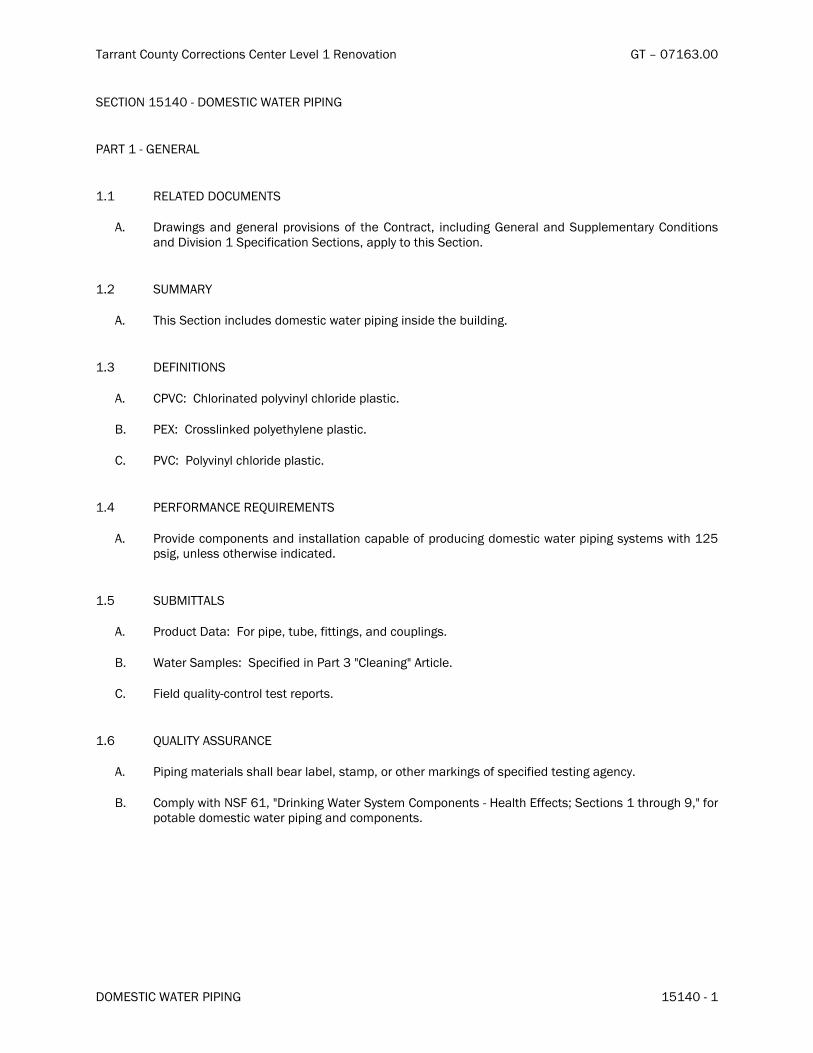
�������������������� �������������������������� ��� ��������������
������ ��!"����# # $�� �%�&��'���
���� �$��%�&��'������� ��!"����# # $��
#"�����'���$��"��
���� ���"�������(��$���
"�� ���) �*����+�*�������,��� � �����-� �.����������/� ���+ �*�����������+��,,��0���������+ � ������+�� � � ������,�� - ��� ������� ���/��,,������. ������ ����
��1� �(��"�2�
"�� �. ������ ��� ���+���+�0��� ��)�����, , �*� �� +���.��3 �+ �*��
���� ��4 $ � �$��
"�� �#5�6���.��� ����+�,��� ����.��� +��,���� ���
7�� #�86�������� �9�+�,����.�����,���� ���
��� #5�6��#��� ����.��� +��,���� ���
��&� #��4���"$�����:( ����$���
"�� #��� +����0,���������+� �������� �����,�3����-�,��+� �*�+�0��� ��)�����, , �*�����0��) �.��1%�,� */���������.��) ��� �+ ����+��
��%� �(7� ��"���
"�� #��+�������6��4���, ,�/��3�/�- �� �*�/���+���,� �*���
7�� !�������0,���6���,�� - �+� ��#������;����� �*;�"�� �����
��� 4 ��+�<�� �'���������������,������
���� :("� �2�"��(�"$���
"�� # , �*�0���� �����.����3������3��/����0,/������.���0��9 �*���-��,�� - �+����� �*��*�����
7�� ��0,��) �.�$�4���/�;�� �9 �*�!���������0���0,�������'�=����.��--����>����� �������.��*.�?/;�-���,���3���+�0��� ��)�����, , �*���+���0,��������
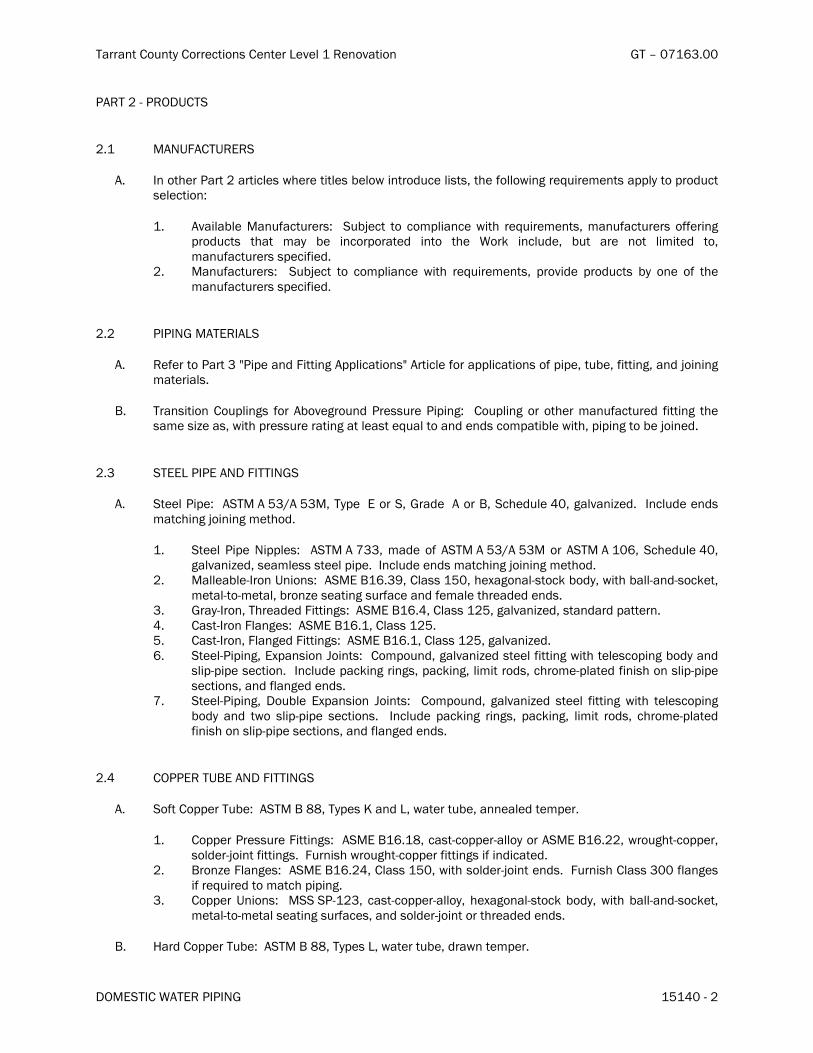
�������������������� �������������������������� ��� ��������������
������ ��!"����# # $�� �%�&��'�1�
#"���1�'�#���(����
1��� �"$(4"��(�����
"�� ����.���#����1���� �����).����� �����3���)� ����+���� ���/��.��-����) �*���< ��0������,,�����,��+��������� ��6�
��� "�� ��3������-�������6� ��3@���� ��� ��0,� �����) �.� ��< ��0����/�0��-�������� �--�� �*�,��+���� �.��� 0�� 3�� ����,�����+� ���� �.�� !��9� ���+�/� 3�� ���� ���� � 0 ��+� ��/�0��-���������,�� - �+��
1�� ���-�������6� ��3@���� ��� ��0,� ����� ) �.� ��< ��0����/�,��� +��,��+����3� ���� �-� �.��0��-���������,�� - �+��
1�1� # # $���"��� "���
"�� ��-������#������;# ,����+�4 �� �*�",,� ��� ���;�"�� ����-����,,� ��� �����-�, ,�/��3�/�- �� �*/���+�@� � �*�0���� �����
7�� ����� � �����,� �*��-��� "3���*���+�#�������# , �*6� ���,� �*���� ��.���0��-�����+�- �� �*� �.����0��� A����/�) �.�,���������� �*�����������<��������+���+����0,�� 3���) �./�, , �*����3��@� ��+��
1��� ������# #��"$��4 �� $���
"�� ������# ,�6��"����"�%�B"�%��/��,���������/����+���"����7/���.�+���&�/�*����� A�+��� ���+����+��0���. �*�@� � �*�0��.�+��
��� ������# ,��$ ,,���6� � "����"����/�0�+�� �-�"����"�%�B"�%������ "����"����/���.�+���&�/�*����� A�+/����0�����������, ,���� ���+����+��0���. �*�@� � �*�0��.�+��
1�� ������3��' ����(� ���6��"����7����?/��������%�/�.�C�*����'����9�3�+/�) �.�3���'��+'���9��/�0����'��'0����/�3���A������ �*���-������+�-�0�����.���+�+���+���
��� ���' ���/��.���+�+�4 �� �*�6��"����7���&/��������1%/�*����� A�+/�����+��+�,��������&�� ����' ����4���*��6��"����7����/��������1%��%�� ����' ���/�4���*�+�4 �� �*�6��"����7����/��������1%/�*����� A�+����� �����'# , �*/��C,��� ���D� ���6����0,��+/�*����� A�+�������- �� �*�) �.��������, �*�3�+���+�
�� ,', ,������ ����� ���+��,��9 �*�� �*�/�,��9 �*/�� 0 ����+�/��.��0�',����+�- � �.������ ,', ,������ ���/���+�-���*�+���+���
��� �����'# , �*/���3����C,��� ���D� ���6� � ��0,��+/�*����� A�+� ������- �� �*�) �.� �������, �*�3�+� ��+� �)�� �� ,', ,�� ���� ����� � ���+��,��9 �*� � �*�/�,��9 �*/� � 0 �� ��+�/� �.��0�',����+�- � �.������ ,', ,������ ���/���+�-���*�+���+���
1�&� ��##����(7��"$��4 �� $���
"�� ��-����,,����3�6��"����7�EE/��,���F���+��/�)������3�/��������+���0,����
��� ��,,���#�������4 �� �*�6��"����7����E/�����'��,,��'��������"����7���11/�)��*.�'��,,��/����+��'@� ���- �� �*����4�� �.�)��*.�'��,,���- �� �*�� -� �+ ����+��
1�� 7���A��4���*��6��"����7���1&/��������%�/�) �.����+��'@� �����+����4�� �.�����������-���*��� -���< ��+����0���.�, , �*��
��� ��,,���(� ���6� ������#'�1�/�����'��,,��'����/�.�C�*����'����9�3�+/�) �.�3���'��+'���9��/�0����'��'0��������� �*���-����/���+����+��'@� �������.���+�+���+���
7�� =��+���,,����3�6��"����7�EE/��,����/�)������3�/�+��)����0,����

�������������������� �������������������������� ��� ��������������
������ ��!"����# # $�� �%�&��'���
��� ��,,���#�������4 �� �*�6��"����7����E/�����'��,,��'��������"����7���11/�)��*.�'���,,��/����+��'@� ���- �� �*����4�� �.�)��*.�'��,,���- �� �*�� -� �+ ����+��
1�� 7���A��4���*��6��"����7���1&/��������%�/�) �.����+��'@� �����+����4�� �.�����������-���*��� -���< ��+����0���.�, , �*��
��� ��,,���(� ���6� ������#'�1�/�����'��,,��'����/�.�C�*����'����9�3�+/�) �.�3���'��+'���9��/�0����'��'0��������� �*���-����/���+����+��'@� �������.���+�+���+���
1�%� 5"�5���
"�� 7���A����+�����' ���/�*������'+��������������,�� - �+� ��� � � ����%����� ���;5������;�
7�� 7����� �*���+�+�� ��������������,�� - �+� ��� � � ����%����� ���;#�03 �*��,�� ��� ���;�
#"�����'��8��(� �$�
���� �8�"5"� �$�
"�� �C����� �*/������. �*/���+�3��9- �� �*������,�� - �+� ��� � � ���1����� ���;����.)��9�;�
��1� # #��"$��4 �� $��"##� �"� �$��
"�� ����� � �����+��,�� ���- �� �*��) �.�,������� ��� �*����� �������<��� ���, , �*���� �*�0��3����+� ���,,� ��� ����3���)/���������.��) ��� �+ ����+��
7�� 4���*���0��3����+�����3���*���+�, , �*/���������.��) ��� �+ ����+��
��� ������+�@� ����0��3����+�����3���*���+�*�����+'��+�, , �*��
��� 4 �� �*��,� ��6� ��C��+�+'���� ������� ���� ��+�3��A�+�@� ����0��3�� ��+� ��� �3���*���+� ��,,����3 �*��
��� (�+��'7 �+ �*'���3/� !����'���� ��� # , �*� ��� ���� ��� � +�� �-� !����� �����6� � ��-��� ��� � � � ���1����� ���;!������ ��� 3� ���;�
4�� ��0��� �� !����� # , �*� ��� ���� ��� � +�� �-� !����� ������ ��� �� +�� �.�� 7 �+ �*6� � (������ �-� �.��-����) �*�, , �*�0���� ����-������.�� A�����*�6�
��� $#��&����$#���6��������, ,�>�*��' ���/��.���+�+�- �� �*�>���+��.���+�+�@� �����1�� $#��&����$#���6��=��+���,,����3�/��,���>���,,���,�������- �� �*�>���+����+���+�@� �����
��� (�+��'7 �+ �*'���3/���0��� ��!�����# , �*����=����� +���-�!����������/�$#��1���+��0�����6����-����,,����3�/��,���>���,,���,�������- �� �*�>���+����+���+�@� �����
=�� "3���*���+���0��� ��!�����# , �*6��(�������-��.��-����) �*�, , �*�0���� ����-������.�� A�����*�6�
��� $#���'�B1� ��+��0�����6� �=��+� ��,,��� �3�/� �,���>� ��,,���,�������- �� �*�>� ��+� ���+���+�@� �����
1�� $#��&����$#���6��������, ,�>�*��' ���/��.���+�+�- �� �*�>���+��.���+�+�@� �������� $#��&����$#���6��=��+���,,����3�/��,���>���,,���,�������- �� �*�>���+����+���+�@� �����

�������������������� �������������������������� ��� ��������������
������ ��!"����# # $�� �%�&��'�&�
���� 5"�5��"##� �"� �$��
"�� ���) �*�� �+ ������������,������3����+���!.�����,�� - ���������,����������� �+ ����+/��.��-����) �*���< ��0������,,�6�
��� �.��--���6� �(���3���A��3���� ���*���� �������-���, , �*�$#��1� ��+� �0������� �(��� ����' ����3����-�����*�����������) �.�-���*�+���+��-���, , �*�$#��1'�B1���+����*����
1�� �.����� �*���6��(���3���A��3�������*��3���������-���, , �*�$#��1���+��0��������(�������' ����3����-���������) �.�-���*�+���+��-���, , �*�$#��1'�B1���+����*����
��� =��'!����'# , �*/�7����� �*���6����� 3����+�3����� �*���������&�� ��� ����6��=���'��+�+�� ����������
7�� ����' ���/�*�����+'��+��������0��3����+�) �.�*�����+'��+�, , �*��
��� ������� �.��--� ������ ������ ��� )����� 0� �� ��� ���.�3����.� ��+� � ���� ���� �*�,�03 �*�- C����� ����< ,0���/�������.�)������,,������< ,0���/���+�������.�)������,,�����,�03 �*�- C������.���+������.�����,,�����,����(���3�������*�����������-���, , �*�$#��1���+��0��������(���3����-�����*�����������-���, , �*�$#��1'�B1���+����*����
��� �������+�� ���������-����< ,0�������3�����-����.�)������ ���/������)�,� ���� ��.�� A������, , �*/���+�).������< ��+����+�� ��)�����, , �*��
��� �������.���'��+�+�� ��������������)�,� ���� ��)�����0� ��/�� ����/���+�3����.����1�� ����������,'��+')�����+�� ���������).���� �+ ����+��
��� ���������� 3����+�3����� �*�������� �����.�.��')������ ����� ���������3����.���+�+ ��.��*��� +���-����.�,0,���+�� ����������������� 3����+�3����� �*��������,������,����������� ���3���������,�-��)������ 3����+�3����� �*�������������,�� - �+� ��� � � ����%����� ���;#�03 �*��,�� ��� ���;�
��&� # # $�� $��"��"� �$�
"�� 7�� �� , , �*� �������� ��� ��< ��0����� ���� �,�� - �+� �� � � � ����%� ���� ��� ;7�� �� ���.�� ��������� ������+����.�+��;�
7�� ��������+��'3 �+ �*'���3���,,����3 �*������+ �*������"G��;��,,����3��=��+3��9�;�
��� �����������' �����������) �.�)��������,���+�0��.�� ����������������������.����� ���, ,��,������� ����.��*.�-��+�� ���)����� �������� �03��� �-� �������9 �*� �33��� � �9�� ��< ��+� ���0�9�� �������� ���)����� *.��� � �������� ��+� 0��.�� ���� ������� ������ ���� �,�� - �+� �� � � � ����%� ���� ��� ;7�� �����.�� ��������� ������+����.�+��;�
��� ��������.��--������/�.���'��+�+�� �������/����� ���/�,�������*�*�/���+����������) �.������/� �� +���.��3 �+ �*� ��� ���.� +�0��� �� )����� ���� ��� ���������� � #������� *�*��� ���� �,�� - �+� �� � � � ����%����� ���;������� ��+���*��/;� ��+�+�� �� ������� ��+� ���� ����� ���� �,�� - �+� ��� � � ����%����� ���;#�03 �*��,�� ��� ���;�
��� �������)����',���������*�������+�)������0�-��0��.��--��������).����)�����,�������) ����C���+���� ,� *�+�� ���� )����� ,�������� � !����',������� ��*������� ���� �,�� - �+� �� � � � ����%� ���� ���;#�03 �*��,�� ��� ���;�
4�� �������+�0��� ��)�����, , �*�������) �.���1%�,����������,��+�)�)��+���)��+�+�� ����+�,�03��

�������������������� �������������������������� ��� ��������������
������ ��!"����# # $�� �%�&��'�%�
��%� D� $����$���(�� �$�
"�� 7�� ��, , �*�@� ����������� �����< ��0����������,�� - �+� ��� � � ����%����� ���;7�� �����.�� ��������� ������+����.�+��;�
7�� ���+���+�D� ���6��(���"����7�E��/�)����'-��.�3��/����+'-����-�C>�"����7��1/����+'-���'��������+��>���+�"����7�E1E�,����+��/���������.��) ��� �+ ����+��
���� ="$����"$���(##���� $��"��"� �$�
"�� # ,�� .��*��� ��+� �,,���� +�� ���� ���� �,�� - �+� �� � � � ����%� ���� ��� ;=��*���� ��+� �,,�����;�� ��������.��-����) �*6�
��� 5��� ����# , �*6�������,��E�����,��&1/����0,���1�� �+ � +��/����� *.�/�=�� A������# , �*����6��"����+ �*�����.��-����) �*6�
��� ����4������+�����6�������,���/��+@���3��/����������� ��.��*�����3�� ���*����.�������4���6�������,��&�/��+@���3����������.��*�������� ���*����.�������4���6�������,��&?/��,� �*���. ��������/� -� �+ ����+��
��� ��� ,��/� ���� *.�/� =�� A������ # , �*� ���� ���� 4���� ��� ���*��6� � ���� �,��&&/� , ,�� ���������,,����, ,��������������,�A���
&�� 7�����-�5��� ����# , �*6�������,��%1/��,� �*�.��*�����
7�� ��������,,����������+ �*����� � � ����%����� ���;=��*������+��,,�����;�
��� �,,�������� ����, , �*���+��3 �*����3������+�������.�-������
��� ��+�+ �0�����0��3����+��+���� A��-���+�3��'��+�.��*���/������0 � 00��-��BE� ��.��
��� �������.��*����-��� ������, , �*�) �.� �.��-����) �*�0�C 00�.�� A������ �,�� �*� ��+�0 � 00� ��+�+ �0�����6�
��� $#���'�B&���+��0�����6��E&� ��.���) �.��BE' ��.���+��1�� $#���'�B16����E� ��.���) �.��BE' ��.���+����� $#��16�����-����) �.��BE' ��.���+��&�� $#��1'�B16�����-����) �.��B1' ��.���+��%�� $#������+�$#���'�B16���1�-����) �.��B1' ��.���+����� $#��&���+�$#��%6���1�-����) �.�%BE' ��.���+����� $#���6���1�-����) �.��B&' ��.���+��
4�� ��������,,�����-������� ����������, , �*�������%�-�����
��� �������.��*����-�����,,����3 �*�) �.��.��-����) �*�0�C 00�.�� A�������,�� �*���+�0 � 00���+�+ �0�����6�
��� $#���B&���+��0�����6����� ��.���) �.��BE' ��.���+��1�� $#������+�$#���'�B&6���1� ��.���) �.��BE' ��.���+����� $#���'�B1���+�$#��16��?�� ��.���) �.��BE' ��.���+��&�� $#��1'�B16����E� ��.���) �.��B1' ��.���+��%�� $#�������$#��%6�����-����) �.��B1' ��.���+����� $#���6�����-����) �.�%BE' ��.���+��
=�� ��������,,�����-������� ������,,����3 �*���������-�����

�������������������� �������������������������� ��� ��������������
������ ��!"����# # $�� �%�&��'���
�� �,,���� , , �*� ��+� �3 �*� ���� � ���+� �3���� �����+ �*� ��� �����#'�?� ��+�0��-������G�� )� ����� ������ �����
���� ��$$��� �$��
"�� ���) �*�� �+ �����*������������*�0�����-�, , �*/�- �� �*�/���+��,�� ��� ����
7�� �������, , �*��+@����������< ,0������+�0��. �����������)����� �����+�0� ����������
��� �������� +�0��� �� )����� , , �*� ��� �C��� ��� )����'���� ��� , , �*�� � (��� ����� � ��� - �� �*� ��� @� ��+ �� 0 ����, , �*�0���� �����
��� ��������+�0��� ��)�����, , �*����)����'���� ���, , �*�) �.��.��--������/���+��C���+���+�������������.��-����) �*6�
��� 7�������#0,�6�����+')�������� �����+�+ ��.��*��, , �*��1�� !����� =������6� � ���+')����� �,,�� ��+�.��')����� ������ , , �*� �� � A��� �+ ����+/�3�� ����
�0�������.���� A����-�)�����.������������� �������� #�03 �*�4 C����6�����+'���+�.��')������,,��, , �*� ��� A��� �+ ����+/�3�������0�������.���
��< ��+�3�,�03 �*���+������-������� � � ����%����� ���;#�03 �*�4 C�����;�&�� �< ,0���6�����+'���+�.��')������,,��, , �*���� �+ ����+/�3�������0�������.����< ,0����
������� ����� �#��� +�� �.��--������� ��+�� ���-��� ���.�������� ���� �(���-���*��� �����+��-�� ����-���$#��1'�B1���+����*����
��E� 4 ����:("� �2���$�����
"�� ��,����+�0��� ��)�����, , �*����-����)�6�
��� ��������������/������/����,��, , �*� �����,���� ����� �� ��.���3���� ��,����+���+��,,����+�3���.�� � ���.�� �*�@� �+ �� ����
1�� �� �*� �������� ��/���� -���.�� � ���.�� �*�@� �+ �� ��� ��� ������ 1&�.����3�-���� ��,��� ���0���3��0�+����#��-��0��������,�� - �+�3���)� ��,���������-���.�� � ���.�� �*�@� �+ �� ��6�
��� ��*. �*' �� ��,��� ��6��"����*��-��� ��,��� ����-�, , �*�3�-����������� �*�������� �*' ���-������*. �*' ����+�3�-�������� �*�- C������
3�� 4 ���� ��,��� ��6��"����*��- ���� ��,��� ���-�����.�� � ���.�� �*�@� �+ �� �������3�������������,�� - �+�3���)���+������������0,� �����) �.���< ��0������
��� �� ��,��� ��6�� -���.�� � ���.�� �*�@� �+ �� ���- �+��.���, , �*�) �������,������������ ��,��� ��/�0�9����< ��+�������� ������+������*��-����� ��,��� ����
&�� ��,����6��#��,���� ��,��� �����,�������+�.�����.�0�� *��+�3���.�� � ���.�� �*�@� �+ �� ����
7�� �����+�0��� ��)�����, , �*����-����)�6�
��� 4 ���+�0��� ��)�����, , �*����.��9���0,����������+����0 ����.����.����������� ��3��+���+��.���, , �*� ��-����-�)������
1�� �����-������9����+�+�-����� ����)�, , �*���+�,������-��C �� �*�, , �*��.���.����3����������+/��C���+�+/������,� ��+�� � -����� �*� ��,��-��0�+� ����*0����/��30 ����,��������,����-������.�����/���0,�����) �.�+ �*��0��-�,��� ����-�, , �*������+��
��� ��������)/�������+/��C���+�+/������,����+�+�0��� ��)�����, , �*��������+���+����������+��� �� ��.���3���������+���+��,,����+����C,����)��9��.���)���������+������������+�3�-���� ��)��������+��

�������������������� �������������������������� ��� ��������������
������ ��!"����# # $�� �%�&��'���
&�� ��,���+��3@����, , �*�������� ��)�����,��������-�%��,� *��3�����,���� �*�,������/�) �.����C���+ �*�,���������� �*��-�, , �*�����0�0���� ������ ��������������������+�����)��������+�-���-���.���������9����+������ �������,������������ ����+�-������.���0���3����,� ��+��
%�� ��,� �� ���9�� ��+� +�-����� ) �.� ��)� 0���� ���� ��+� ������� , , �*� ��� ,��� ��� �.����-� �� ����� �-������������������3�� ��+��
��� #��,������,�����-�����������+���< ��+�������� ������ ����
��?� "�D(�� $��
"�� #��-��0��.��-����) �*��+@��0�����3�-�����,���� ��6�
��� ������+�� ��������/�.+�����/���+�.����3 33���1�� �,����.��--�����������-����,���,�� � ������� �,����.����� �*�����������,��,������� �*��&�� "+@���3����� �*�������� ��.��')����'� ����� ���������, , �*����,��� +���+�<����-��)��
��� ������� �+@��� 3���'�,�� 3����� �*� ������� �� .��')����'� ����� ��� ������ , , �*� ���,��� +��-��)��-�.���)����� �����.�3����.��
3�� "+@������ 3����+�3����� �*�����������-��)�� �+ ����+��
%�� ��0����,�*����+�+� �*� ���� �*��-�, , �*���+�,�*����+�-��� ��0,����� ���� �*��-�, , �*�+� �*� �������� ����
��� ��0������+����������� ��������������������+�� �����������+���,�����+�� ��,�*������ ��0���� - ����� ����� +*��� -��0� .�� �*�� ��+� ��� -� �.��� ����� +*��� ���� ��� �,�� - �+� -���
�,,� ��� ���).������+���+�������������+����+�-�������E�� �.��9�,�03 �*��,�� ��� �����+���� -�,��,������� �*�/��+@��0����/���+��,���� ����
����� ���"$ $��
"�� ��������+�+ � �-����,���3�����+����',���3���+�0��� ��)�����, , �*����-����)�6�
��� #�*�� ��)� , , �*� ��+� ,����� �-� �C �� �*� +�0��� �� )����� , , �*� �.��� .���� 3���� ������+/��C���+�+/������,� ��+�3�-����� �*��
1�� (���,�* �*� ��+�+ � �-��� �*�,����+����,����� 3�+�3� ��.�� � ���.�� �*�@� �+ �� ��� ��/� -�0��.�+����������,����� 3�+/�,����+����+���� 3�+� ��� �.���"!!"���%�����"!!"���%1�������+���� 3�+�3���)6�
��� 4��.�, , �*� ����0� ) �.� �����/�,���3��� )����� �� �� + ��� )����� +���� ���� �,,���� �����������
3�� 4 �����+� �����������0������+ �*����� �.����-��.��-����) �*6�
�H� 4 �������0����,�����.����-�) �.�)����B�.��� ������� ���) �.���� ������%��,,0��-��.��� ����� �������) �.����������+�����)��������+�-���1&�.�����
1H� 4 �������0����,�����.����-�) �.�)����B�.��� ������� ���) �.����������1���,,0��-��.��� ����� ���������+�����)��������+�-����.����.�����
��� 4��.�����0�) �.������/�,���3���)������� ������.��� ��� �� ��)�������0 �*�-��0�����0��-�����.������+ �*�� 0���
+�� �30 �� )����� ��0,���� �� ���� ��� 3������� ��� ��.�� � ��� .�� �*� @� �+ �� ���� � ��,����,����+���� -�3 ���* �����C�0 ��� ����.�)�������0 ��� ����
7�� #��,������+��30 ����,������-�,�* �*���+�+ � �-��� �*���� � � ����
��� ������ ���� ����-�+�0��� ��)�����, , �*�����0�����0����+ �����+�+�3� �����)��9�,��*��������

�������������������� �������������������������� ��� ��������������
������ ��!"����# # $�� �%�&��'�E�
�$���4����� �$��%�&��

�������������������� �������������������������� ��� ��������������
������ ��!"����# # $���#�� "�� ��� �%�&%�'���
���� �$��%�&%�'������� ��!"����# # $���#�� "�� ���
#"�����'���$��"��
���� ���"�������(��$���
"�� ���) �*����+�*�������,��� � �����-� �.����������/� ���+ �*�����������+��,,��0���������+ � ������+�� � � ������,�� - ��� ������� ���/��,,������. ������ ����
��1� �(��"�2�
"�� �. ������ ��� ���+����.��-����) �*�+�0��� ��)�����, , �*��,�� ��� ��3�
��� 4��0�5���6�����1�� 7��6-��)�,�������������� !�����,������'��+� �*���������&�� 7����� �*���������%�� ��0,������'������+�)�����0 8 �*������������ ���� ��������� ������5�8����9�� :����5 55���;�� !����.+����������� ��� �������������� !�����.�00���������������1�� " ������������� ���,'�����,� 0������������&�� ���,'�����,� 0�������0���
���� #��<���"$�����=( ����$���
"�� � � 00� !��6 �*� #������� -��� ��0��� �� !����� # , �*� �,�� ��� ��3� � �1%� ,� */� ������ ��.��) ��� �+ ����+��
��&� �(7� ��"���
"�� #��+�������3��<������.��,���-�,��+��� �+ ����+��
7�� �.�,����) �*�3��� �*��0�,�)��/�� *���/���+���������) � �*��
��� < ��+�>�� �'���������������,������
��� �,���� ��� ��+��� �������������3� �<���+�0��� ��)�����, , �*��,�� ��� ��� ��� ���+�� ���0��*���/��,���� ��/���+�0� ���������0�������
��%� =("� �2�"��(�"$���
"�� ������ ���� ��0,������/� ��� ���/� ��+� "������� ��3� � � ���+� ��+� ��5���+� ��� +�- ��+� �� $<#"���/�"�� �������/� 5� �� ���� �*� �*���� ����,��5��� ��� ��.�� � ��� .�� �*� ?� �+ �� ��/� ��+� 0��6�+� -��� ����+�+�����

�������������������� �������������������������� ��� ��������������
������ ��!"����# # $���#�� "�� ��� �%�&%�'�1�
7�� $�<���0,� ����3�
��� ��0,�� ) �.� $�<��&/� @#���� ��� # , �*� ��0,������� ��+� ������+� ����� ���/@� -��� ,���� ��+�0��� ��)�����, , �*���0,��������
1�� ��0,�� ) �.� $�<���/� @�� �6 �*� !����� ����0� ��0,������� '� :����.� �--����A� ���� �������.��*.�;�@�
#"���1�'�#���(����
1��� 4"�((��7��"B����
"�� # ,�'",,� �+/�"�0��,.�� �'�,��4��0�7���6���3�
��� "�� ��5������-�������3� ��5?���� ��� ��0,� �����) �.� ��> ��0����/�0��-�������� �--�� �*�,��+�����.���0��5�� ����,�����+� �����.��!��6� ���+�/�5����������� 0 ��+���/��.��-����) �*3�
��� "0�������5�� ���5����� �+��� ��/� ������� <�7��A��#C�4������D�����������+�� !����� �+��� ��/� ���A�!�����#��+����� ������ E���#�05 �*�#��+�������,A�! �6 ���� ���
1�� ����+��+3��"������������� � F�3��$#���G&����$#���/������> ��+����0���.���������+�, , �*��&�� 7�+3��7���F���%�� �������+�������������� ���3���.���+�+����� < � �.3����*.�5���F���
7�� :���'������� ���4��0�7���6���3�
��� "�� ��5������-�������3� ��5?���� ��� ��0,� �����) �.� ��> ��0����/�0��-�������� �--�� �*�,��+�����.���0��5�� ����,�����+� �����.��!��6� ���+�/�5����������� 0 ��+���/��.��-����) �*3�
��� "���).��+�7�����#��+���/� ����5�� ���.�"�0������ ���5����� �+��� ��/� ����+�� � <"7/� ������� !����� �+��� ��/� ���A�!�����#��+����� ���-�� !��+-��+����-���� �*���0,����*�� E���#�05 �*�#��+�������,A�� *.����00��� ����,���� ����.�� E���#�05 �*�#��+�������,A�! �6 ���� ���
1�� ����+��+3��"������������� 7�+3��7���F�/������0���5��/�) �.�0�����+�� ���&�� ������������� ��3�����+��'.�����.���+�+���0,� �*�) �.�"����7��1�����%�� < � �.3����*.�5���F���
��� #�������4��0�7���6���3�
��� "�� ��5������-�������3� ��5?���� ��� ��0,� �����) �.� ��> ��0����/�0��-�������� �--�� �*�,��+�����.���0��5�� ����,�����+� �����.��!��6� ���+�/�5����������� 0 ��+���/��.��-����) �*3�
��� "0�������5�� ���5����� �+��� ��/� ����

�������������������� �������������������������� ��� ��������������
������ ��!"����# # $���#�� "�� ��� �%�&%�'���
��� <�7��A��#C�4������D�����������+�� !����� �+��� ��/� ���A�!�����#��+����� ������ E���#�05 �*�#��+�������,A�! �6 ���� ���
1�� ����+��+3��"������1������ �,���� ��3������ ���',��������,,� ��� �����&�� #�����������3��%�,� *�0�8 00/��.��*.�0 ++����G���-�-��)����*���%�� "������� ��3�
��� 4�����3��7�����,�/���� �������+��������
��� �, ��'��� ������4��0�7���6���3�
��� "�� ��5������-�������3� ��5?���� ��� ��0,� �����) �.� ��> ��0����/�0��-�������� �--�� �*�,��+�����.���0��5�� ����,�����+� �����.��!��6� ���+�/�5����������� 0 ��+���/��.��-����) �*3�
��� ���5����� �+��� ��/� ����5�� !����� �+��� ��/� ���A�!�����#��+����� ���
1�� ����+��+3��"������%������ �,���� ��3������ ���',��������,,� ��� �����&�� "������� ��3�
��� 4�����3��7�����,�/���� �������+��������
1�1� 7"�B<��!�#��4�$�����
"�� ����0�+ ����"�0��,.�� �'4����7��6-��)�#���������3�
��� "�� ��5������-�������3� ��5?���� ��� ��0,� �����) �.� ��> ��0����/�0��-�������� �--�� �*�,��+�����.���0��5�� ����,�����+� �����.��!��6� ���+�/�5����������� 0 ��+���/��.��-����) �*3���� ���5����� �+��� ��/� ����5�� <�7��A��#C�4������D�������������� :���)����!���������������+�� !����� �+��� ��/� ���A�!�����#��+����� ������ E���#�05 �*�#��+�������,A�! �6 ���� ���
1�� ����+��+3��"�������1����� �,���� ��3������ ���',��������,,� ��� �����&�� 7�+3��7���F���%�� ��+�������� ���3��(� ��/����+���?� ������� < � �.3����*.�5���F���
7�� ��+��+'#������'#� �� ,���7��6-��)�#���������3�
��� "�� ��5������-�������3� ��5?���� ��� ��0,� �����) �.� ��> ��0����/�0��-�������� �--�� �*�,��+�����.���0��5�� ����,�����+� �����.��!��6� ���+�/�5����������� 0 ��+���/��.��-����) �*3�
��� "0�������5�� ���5����� �+��� ��/� ������� <�7��A��#C�4������D�����������+�� !����� �+��� ��/� ���A�!�����#��+����� ������ E���#�05 �*�#��+�������,A�! �6 ���� ���
1�� ����+��+3��"����������

�������������������� �������������������������� ��� ��������������
������ ��!"����# # $���#�� "�� ��� �%�&%�'�&�
��� �,���� ��3������ ���',��������,,� ��� �����&�� #�����������3���1�,� *�0�8 00/��.��*.�0 ++����G���-�-��)����*���%�� 7�+3��7���F��-���$#��1���+��0�����A������ ����) �.� ���� ���� � �*���0,� �*�) �.�"!!"��%%��
����.��� ��<�"��,,����+�-���$#��1'�G1���+����*������� ��+�������� ���3���.���+�+�-���$#��1���+��0�����A�-���*�+�-���$#��1'�G1���+����*������� ���- *��� ��3����� *��+�-���.�� F�����/����� *.���.��*.�-��)��9�� "������� ��3�
��� 4�����3��7�����,��) �.��.���+�+���+����� �������+��������-�$#��1���+��0�����A���� +������)� ��+� �6�� *���'�,�� ) �.�-���*�+� ��+�� ��� ����� ��+� ������ �-�$#��1'�G1� ��+����*����
5�� " �'��,�< �� �*3��"����"��1���1/�0���. �*�5��6-��)',���������������� ����
��� ��5��'�.��6�7��6-��)'#������ ���"���05� ��3�
��� "�� ��5������-�������3� ��5?���� ��� ��0,� �����) �.� ��> ��0����/�0��-�������� �--�� �*�,��+�����.���0��5�� ����,�����+� �����.��!��6� ���+�/�5����������� 0 ��+���/��.��-����) �*3�
��� "0�������5�� ���5����� �+��� ��/� ������� <�7��A��#C�4������D�����������+�� !����� �+��� ��/� ���A�!�����#��+����� ������ E���#�05 �*�#��+�������,A�! �6 ���� ���
1�� ����+��+3��"�������%����� �,���� ��3������ ���',��������,,� ��� ���/���������.��) ��� �+ ����+��&�� #�����������3��%�,� *�0�8 00/��.��*.�0 ++����G���-�-��)����*���%�� 7�+3��7���F��-���$#��1���+��0�����A������ ����) �.� ���� ���� � �*���0,� �*�) �.�"!!"��%%��
����.��� ��<�"��,,����+�-���$#��1'�G1���+����*������� ��+�������� ���3���.���+�+�-���$#��1���+��0�����A�-���*�+�-���$#��1'�G1���+����*������� ���- *��� ��3����� *��+�-���.�� F�����/����� *.���.��*.�-��)��9�� "������� ��3�
��� 4�����3��7�����,��) �.��.���+�+���+����� �������+��������-�$#��1���+��0�����A���� +������)� ��+� �6�� *���'�,�� ) �.�-���*�+� ��+�� ��� ����� ��+� ������ �-�$#��1'�G1� ��+����*����
��� 7�����*�'� �,��� �*'�> ,0����7��6-��)�#���������3�
��� "�� ��5������-�������3� ��5?���� ��� ��0,� �����) �.� ��> ��0����/�0��-�������� �--�� �*�,��+�����.���0��5�� ����,�����+� �����.��!��6� ���+�/�5����������� 0 ��+���/��.��-����) �*3�
��� ���5����� �+��� ��/� ����5�� !����� �+��� ��/� ���A�!�����#��+����� ������ E���#�05 �*�#��+�������,A�! �6 ���� ���
1�� ����+��+3��"������11����� �,���� ��3������ ���',��������,,� ��� �����&�� � F�3��$#���G&����$#���G9��%�� 7�+3����� ���������������� ��+�������� ���3���.���+�+��
��� ���'�.��6'4�����7��6-��)�#���������3�
��� "�� ��5������-�������3� ��5?���� ��� ��0,� �����) �.� ��> ��0����/�0��-�������� �--�� �*�,��+�����.���0��5�� ����,�����+� �����.��!��6� ���+�/�5����������� 0 ��+���/��.��-����) �*3�

�������������������� �������������������������� ��� ��������������
������ ��!"����# # $���#�� "�� ��� �%�&%�'�%�
��� ���5����� �+��� ��/� ����5�� <�7��A��#C�4������D�������������� :���)����!���������������+�� ����������A�!�����#��+����� ������ !����� �+��� ��/� ���A�!�����#��+����� ���-�� E���#�05 �*�#��+�������,A�! �6 ���� ���
1�� ����+��+3��"������1&����� �,���� ��3������ ���',��������,,� ��� �����&�� 7�+3��7���F��) �.�� ��� ������
<�� ���5�����+'7�����*�'� �,�����/����'�.��6'4�����7��6-��)�#���������3�
��� "�� ��5������-�������3� ��5?���� ��� ��0,� �����) �.� ��> ��0����/�0��-�������� �--�� �*�,��+�����.���0��5�� ����,�����+� �����.��!��6� ���+�/�5����������� 0 ��+���/��.��-����) �*3�
��� ���.�"�0���5�� ����������,���� ������� !����� �+��� ��/� ���A�!�����#��+����� ���
1�� ����+��+3��"�������1����� �,���� ��3������ ���',��������,,� ��� �����&�� � F�3��$#���G&����$#���G9��%�� 7�+3����� ���������������� ��+�������� ���3���.���+�+��
��� ��5��'�.��6/���������'"���05��7��6-��)�#���������3�
��� "�� ��5������-�������3� ��5?���� ��� ��0,� �����) �.� ��> ��0����/�0��-�������� �--�� �*�,��+�����.���0��5�� ����,�����+� �����.��!��6� ���+�/�5����������� 0 ��+���/��.��-����) �*3�
��� "0�������5�� ���5����� �+��� ��/� ������� <�7��A��#C�4������D�����������+�� !����� �+��� ��/� ���A�!�����#��+����� ������ E���#�05 �*�#��+�������,A�! �6 ���� ���
1�� ����+��+3��"������&9���+�<����,,����+����(��� ���+����� �,���� ��3������ ���',��������,,� ��� �����&�� #�����������3��%�,� *�0�8 00/��.��*.�0 ++����G���-�-��)����*���%�� 7�+3������� ����) �.� ���� ���� � �*���0,� �*�) �.�"!!"��%%������.��� ��<�"��,,����+����� ��+�������� ���3��<���*�+����� ���- *��� ��3����� *��+�-���.�� F�����/����� *.���.��*.�-��)��9�� "������� ��3�
��� 4�����3����� +������)���+��6��*���'�,��) �.�-���*�+���+����� �������+��������5�� 7,���3� �! �.�+ �,����0���'�,��)�����0����/� �.��--� ������/� ��+� ��+��+',�������
5��6-��)�,����������
:�� :���'������� ���7��6-��)�#���������3�
��� "�� ��5������-�������3� ��5?���� ��� ��0,� �����) �.� ��> ��0����/�0��-�������� �--�� �*�,��+�����.���0��5�� ����,�����+� �����.��!��6� ���+�/�5����������� 0 ��+���/��.��-����) �*3�
��� ���5����� �+��� ��/� ����5�� !����� �+��� ��/� ���A�!�����#��+����� ���

�������������������� �������������������������� ��� ��������������
������ ��!"����# # $���#�� "�� ��� �%�&%�'���
��� !��+-��+����-���� �*���0,����
1�� ����+��+3��"������%1����� �,���� ��3��(,������'-����.��+��-�)�����5��6�,��������&�� ������ F�3��$#���G1����$#���G&��%�� ������� F�3�����+��'.�����.���+���0,� �*�) �.�"����7��1�������� ��,�� �3��"���������'*,0�-��)��
�� 7��6-��)'#��������������B ��3�
��� "�� ��5������-�������3� ��5?���� ��� ��0,� �����) �.� ��> ��0����/�0��-�������� �--�� �*�,��+�����.���0��5�� ����,�����+� �����.��!��6� ���+�/�5����������� 0 ��+���/��.��-����) �*3�
��� ���5����� �+��� ��/� ����5�� <�7��A��#C�4������D�������������� <��0�� �����,���� ����+�� !����� �+��� ��/� ���A�!�����#��+����� ������ E���#�05 �*�#��+�������,A�! �6 ���� ���
1�� ����� ,� ��3� � <������ ��� 5����+/� ) �.� *�*��/� - �� �*�/� .����/� ��+� ���� �*� ����� ) �.� ����',����+��� ������ �����
1��� !"����#����(��'���(� $��4"�4���
"�� !�������*������3�
��� "�� ��5������-�������3� ��5?���� ��� ��0,� �����) �.� ��> ��0����/�0��-�������� �--�� �*�,��+�����.���0��5�� ����,�����+� �����.��!��6� ���+�/�5����������� 0 ��+���/��.��-����) �*3�
��� ���.�"�0���5�� ���5����� �+��� ��/� ������� :���)����!���������������+�� !����� �+��� ��/� ���A�!�����#��+����� ������ E���#�05 �*�#��+�������,A�! �6 ���� ���
1�� ����+��+3��"������������� #���������� �*3�� � � ���)��6 �*�,��������-��%��,� *��&�� 7�+3��7���F��-���$#��1���+��0�����A������ ����) �.� ���� ���� � �*���0,� �*�) �.�"!!"��%%��
����.��� ��<�"��,,����+�-���$#��1'�G1���+�$#�����%�� 4������-���7�������:������!������,,�3�� ���+�� ���*����5,�������� ��+�������� ���3���.���+�+�-���$#��1���+��0�����A�-���*�+�-���$#��1'�G1���+�$#�����
7�� !�������������4�����3�
��� "�� ��5������-�������3� ��5?���� ��� ��0,� �����) �.� ��> ��0����/�0��-�������� �--�� �*�,��+�����.���0��5�� ����,�����+� �����.��!��6� ���+�/�5����������� 0 ��+���/��.��-����) �*3�
��� ��"'4"��"��0�� ����������4�������5�� <��0�� �����,���� ������� ��4���������4�������+�� !����� �+��� ��/� ���A�"0���<� +�������������0������ !����� �+��� ��/� ���A�!�����"�4��-�� E���#�05 �*�#��+�������,A�! �6 ���� ���
1�� ����� ,� ��3��# ���'�,���� ��/�+ �,.��*0'�,�/�� �*��'�����+�0� ��)��������������������
�������������������� �������������������������� ��� ��������������
������ ��!"����# # $���#�� "�� ��� �%�&%�'���
��� #������� ��� �*3� � � � ���)��6 �*�,������� �-� �%��,� *�0 � 00�) �.�"!!"��%%�� ��� <�"'�,,����+/� ���� ����,�8����� �*��� ���+���0����, ���'�������������/������ �����+�� ��/��,�� ����- �� �*�/���+��������, , �*��
&�� �� ��4�����7�+3������'����+�� ��' ����5�+�) �.�"!!"��%%�����<�"'�,,����+/� ���� ����,�8����� �*A������� �����'������5�+��
%�� ��+�������� ���3���.���+�+�-���$#��1���+��0�����A�-���*�+�-���$#��1'�G1���+����*����
1�&� 7"�"$� $��4"�4���
"�� ��,,��'"������� 5����+�7����� �*�4�����3�
��� "�� ��5������-�������3� ��5?���� ��� ��0,� �����) �.� ��> ��0����/�0��-�������� �--�� �*�,��+�����.���0��5�� ����,�����+� �����.��!��6� ���+�/�5����������� 0 ��+���/��.��-����) �*3�
��� "�0�����*� ������� ����/� ����5�� <���<�5� ������� ��� �+��� ��A�7����D���������� ���+�� $ 7��� $������ �"��"0�� �����-�� ����/� ����*�� !����� �+��� ��/� ���A�!�����#��+����� ���
1�� �,�3��7�������2',�������*��5��������) �.��)�����+���,�������+�0�0������� �*� �+ ���������� 7�+3��7��������5���F�/�&�� � F�3����0�������������+�, , �*/�5���������*����.���$#��1��%�� "������� ��3��������.����/�- �� �*�/�������/�+ --����� ���,�������0����/���+����� �*�������
7�� ����' ������� 5����+�7����� �*�4�����3�
��� "�� ��5������-�������3� ��5?���� ��� ��0,� �����) �.� ��> ��0����/�0��-�������� �--�� �*�,��+�����.���0��5�� ����,�����+� �����.��!��6� ���+�/�5����������� 0 ��+���/��.��-����) �*3�
��� "�0�����*� ������� ����/� ����5�� <���<�5� ������� ��� �+��� ��A�7����D���������� ���+�� $ 7��� $������ �"��"0�� �����-�� !����� �+��� ��/� ���A�!�����#��+����� ���
1�� �,�3��"+?���5���) �.�2',�������*��5�������/��)�����+���,����/���+�0�0��'���� �*� �+ ���������� � F�3����0�������������+�, , �*/�5�������0�������.���$#��1'�G1��
��� "������� ��3��������.����/�- �� �*�/�������/�+ --����� ���,�������0����/���+����� �*�������
1�%� ���#��"�(��'"��("����!"����� C $��4"�4���
"�� !����'��0,�������� 0 � �*���� ���3�
��� "�� ��5������-�������3� ��5?���� ��� ��0,� �����) �.� ��> ��0����/�0��-�������� �--�� �*�,��+�����.���0��5�� ����,�����+� �����.��!��6� ���+�/�5����������� 0 ��+���/��.��-����) �*3�
��� "�0�����*� ������� ����/� ����5�� ���.�"�0������ ���5����� �+��� ��/� ����

�������������������� �������������������������� ��� ��������������
������ ��!"����# # $���#�� "�� ��� �%�&%�'�9�
+�� :���)����!������������������ ��*��+�4������-�� ������+�4�������0,����*�� #�)���A���!����� �+��� �������.�� �00���� �+��� ��/� ���� �� ����/� ����?�� !����� �+��� ��/� ���A�!�����#��+����� ���6�� E���#�05 �*�#��+�������,A�! �6 ���� ���
1�� ����+��+3��"������������� #���������� �*3���1%�,� *��&�� �,�3���.��0����� ��������������+�)�����0 8 �*��������%�� ����� ��3��7���F��5�+�) �.������� ��'��� ������ ���� �����0,����������� ������� ���3���.���+�+�� ��� ��������+����������� "������� ��3� � �.��6� ���,�� ��� .��'� ��+� ���+')����� �,,� ��/� ��+� �+?���5��/� ��0,������'
��������.��+����9�� 4�����< � �.3����*.�5���F���
7�� #� 0��/��.��0����� �/�!������ 8 �*�4�����3�
��� "�� ��5������-�������3� ��5?���� ��� ��0,� �����) �.� ��> ��0����/�0��-�������� �--�� �*�,��+�����.���0��5�� ����,�����+� �����.��!��6� ���+�/�5����������� 0 ��+���/��.��-����) �*3�
��� "�0�����*� ������� ����/� ����5�� ��)�������-���� �*���0,��/� ������� ������+�4�������0,����+�� #�)���A���!����� �+��� ���������� �00���� �+��� ��/� ����
1�� ����+��+3��"������������� #���������� �*3���1%�,� *��&�� �,�3���8,���+'0��� �*/��.��0����� ��������������+�)�����0 8 �*��������%�� ����� ��3��7���F��5�+�) �.������� ��'��� ������ ���� �����0,����������� ������� ���3���.���+�+�� ��� ��������+����������� "������� ��3����������0,��������������/��.��6����,�����.��'���+����+')������,,� ��/���+�
�+?���5��/���0,������'��������.��+����9�� 4�����#���������� �*3���1%�,� *�0 � 00/���������.��) ��� �+ ����+��;�� 4�����< � �.3����*.�5���F������� # , �*�< � �.3����,,����
��� ��� -��+/��.��0����� �/�!����'� 8 �*'4�����"���05� ��3�
��� "�� ��5������-�������3� ��5?���� ��� ��0,� �����) �.� ��> ��0����/�0��-�������� �--�� �*�,��+�����.���0��5�� ����,�����+� �����.��!��6� ���+�/�5����������� 0 ��+���/��.��-����) �*3�
��� ������+�4�������0,����5�� #�)���A���!����� �+��� ���������� �00���� �+��� ��/� ����+�� "�0�����*�
1�� ����� ,� ��3��<�����'-�5� ����+/��8,���+'0��� �*/��.��0����� ��������������+/�)����'0 8 �*'����������05�� ���)�'������,�������������*�0�����
��� ���*�'<��)�#�������3���.��0����� ��)�����0 8 �*���������+�+�)������0�,���������*������) �.�,�������*�*������ �������+��������
&�� ����0�+ ���'<��)� #�������3� � �.��0����� �� )����� 0 8 �*� ������ ��+� +�)������0� ,���������*������) �.�,�������*�*������ �������+��������

�������������������� �������������������������� ��� ��������������
������ ��!"����# # $���#�� "�� ��� �%�&%�'�;�
%�� �0���'<��)�#�������3���.��0����� ��)�����0 8 �*����������� �.��0����� ��� 8 �*�4�����3����0,��) �.�"����������� ���+���.��6����,�����.��'���+����+'
)����� ��������+��.��--�������������������� !�������*�����H�I3����0,��) �.�"����������� ���+��,�������*�*����� �������+��������9�� ��0,������#���������� �*�3���1%�,� *�0 � 00/���������.��) ��� �+ ����+��;�� �.��0����� ��� 8 �*�4�������+�!�������*������< � �.3����*.�5���F������� # , �*�< � �.3����,,����
1��� ���" $����<��������� ��!"����# # $��
"�� 2'#����������� ����3�
��� #���������� �*3���1%�,� *�0 � 00/���������.��) ��� �+ ����+��1�� 7�+3��7���F��-���$#��1���+��0�����A������ ����) �.� ���� ���� � �*���0,� �*�) �.�"!!"��%%��
���<�"'�,,����+/��,�8����� �*���+�-���$#��1'�G1���+����*������� ��+�������� ���3���.���+�+�-���$#��1���+��0�����A-���*�+�-���$#��1'�G1���+����*����&�� ������3����� ������������) �.����+�,��-���� ���/���������.��) ��� �+ ����+��%�� #��-���� ���� F�3�
��� ���� ����$#��1���+��0�����3�������� ��.��5�� ���� �����$#��1'�G1����$#��&3������1� ��.����� ���� �����$#��%���+����*��3�����1%� ��.��
��� ��� �3��<�����' �������+/�.���'��+�+�� ���������
1��� �(�����7�C���
"�� ��0�6���������7�8��3�
��� "�� ��5������-�������3� ��5?���� ��� ��0,� �����) �.� ��> ��0����/�0��-�������� �--�� �*�,��+�����.���0��5�� ����,�����+� �����.��!��6� ���+�/�5����������� 0 ��+���/��.��-����) �*3�
��� "�������* ���� �*���0,����5�� #�����,���� ������� ��#�#��+�������,/� ����+�� ��������� #���� ���++ � ��A���+ � � ����-�� ���������,���������.����* ����
1�� ���� �*3���������+����� ����� �����+�< � �.3�����0���+'����������,�8',� ���+'������5�8���+�-���,������&�� <����3� �4����+�- �� �*���0,� �*�) �.�"����"��1��9���� � ���+��$#���G1�����0��������,,���
�5���������%�� �,,���.��--�< �� �*3��$#���G1�*���/�*��5�/����5������������+�$#���G1���,,��/�)������5 �*��
1�9� :����7 77��
"�� :����7 55�3�
��� ����+��+3��"����"��1��9���-�����+ 0����-�������1�� 7�+������ ��3��7���F������ ����3��7���F�/���,�����5����&�� �,,��������� ���3��$#���G1����$#���G&��.���+�+�������+��'?� ��� ������%�� ������������� ��3�����+��'.�����.���+���0,� �*�) �.�"����7��1�����

�������������������� �������������������������� ��� ��������������
������ ��!"����# # $���#�� "�� ��� �%�&%�'����
��� #���������� �*3���1%�,� *����� 4��0� 7���6��3� � ���*���� �����0���5��/� +�� ��5��/� .���'������� ��� ���0� 5���6���
��0,� �*�) �.�"����������9�� < � �.�-����> ,0�������0�3����*.�5���F�/�����.��0������ �6���,����+��;�� < � �.�-������� ���"����3����*.�5���F������� < � �.�-���< � �.�+����0�3���.��0������ �6���,����+������ �,���� ���-����> ,0�������0�3��!.����.��+�������,���� �*�6����1�� �,���� ���-������� ���"����3���,���� �*�6������� �,���� ���-���< � �.�+����0�3���,���� �*�6����&�� ���+���,���� �*�6��) �.����.��,���� �*'6��.����5 55���%�� ���+�� ���*����)����-���*��) �.����.��.��0�'����� �6��',����+�.����5 55��
1�;� !"���:2��"$���
"�� $��-���F��!����:+�����3�
��� "�� ��5������-�������3� ��5?���� ��� ��0,� �����) �.� ��> ��0����/�0��-�������� �--�� �*�,��+�����.���0��5�� ����,�����+� �����.��!��6� ���+�/�5����������� 0 ��+���/��.��-����) �*3�
��� J���0���0,����5�� � <"7/� ������� �0 �./�J������-*�����A�� � � ����-��0 �.� �+��� ��/� ����+�� �����# ,�A�!�+��� ������ !�������� ��*��#��+���� ����-�� !��+-��+����-���� �*���0,����*�� E���#�05 �*�#��+�������,A�� *.����00��� ����,���� ����.�� E���#�05 �*�#��+�������,A��,�� - ��� ������ ��*���,���� ����
1�� ����+��+3��"����"��1�1�����-���K��������+��������+��������+��������+L�K�8,���+�8,���+�8,���+�8,���+L'�����/����-'+�� � �*�)����.+���������� #���������� �*3���1%�,� *��&�� �,���� ��3��������6���%�� ��� �*���+��,���� �*���+3���-����*�.���> ��+����0���.�)�����. �6������� ���+��)�������0,����� ����3��$#���G&����$#�������� �����3� � ��������+/�) �.� ���*���� ���0�5���6��� ��+�*��+��'.���� �.���+� ��0,� �*�) �.�
"����7��1�����9�� 7�83�����,/�-��.�0��� �*�) �.��������;�� 7�8���+�������< � �.3��K#�� �.�+�� �6���5���F�#�� �.�+�� �6���5���F�#�� �.�+�� �6���5���F�#�� �.�+�� �6���5���F�L�K�.��0��,����+�.��0��,����+�.��0��,����+�.��0��,����+L�M ������- � �. ������- � �. ������- � �. ������- � �.N������ �����3� � �8,���+/� ) �.� ���*���� ���0� 5���6��� ��+� *��+��'.���� �.���+� ��0,� �*� ) �.�
"����7��1��������� $�FF�����+�!���'#�����< � �.3��K#�� �.�+�� �6���5���F�#�� �.�+�� �6���5���F�#�� �.�+�� �6���5���F�#�� �.�+�� �6���5���F�L�K��*.�5���F���*.�5���F���*.�5���F���*.�5���F�L�M ������- � �. ������- � �. ������- � �. ������- � �.N���1�� �,���� �*�B��H�I3��K������������L�K�)��)��)��)�L�) �.����.�)����.+������
7�� $��-���F�/�:��'���+����+'!�����!����:+������M ������+� ������+� ������+� ������+��) �*�+�� *��� ��� -����) �*�+�� *��� ��� -����) �*�+�� *��� ��� -����) �*�+�� *��� ��� -���N3�
��� "�� ��5������-�������3� ��5?���� ��� ��0,� �����) �.� ��> ��0����/�0��-�������� �--�� �*�,��+�����.���0��5�� ����,�����+� �����.��!��6� ���+�/�5����������� 0 ��+���/��.��-����) �*3�
1�� ���-�������3� ��5?���� ��� ��0,� �����) �.� ��> ��0����/�,��� +��,��+����5� ���� �-� �.��-����) �*3�
��� J���0���0,����5�� #� ���#��+���/� ������� �0 �./�J������-*�����A�� � � ����-��0 �.� �+��� ��/� ����+�� �����# ,�A�!�+��� ������ !�������� ��*��#��+���� ����-�� !��+-��+����-���� �*���0,����

�������������������� �������������������������� ��� ��������������
������ ��!"����# # $���#�� "�� ��� �%�&%�'����
*�� E���#�05 �*�#��+�������,A��,�� - ��� ������ ��*���,���� ����.�� M ������0��-������O����0�� ������0��-������O����0�� ������0��-������O����0�� ������0��-������O����0��N�
��� ����+��+3��"����"��1�1�����-���K��������+��������+��������+��������+L�K�8,���+�8,���+�8,���+�8,���+L'�����/����-'+�� � �*�)����.+�������&�� #���������� �*3���1%�,� *��%�� �,���� ��3��������6������ ��� �*�� ��+� �,���� �*� ��+�3� � �-� ���*�.� ��> ��+� ��� 0���.� )���� �. �6������ � ���+�� )����
���0,������ �����3��$#���G&����$#�����9�� �����3����������+��;�� 7�83�����,/�-��.�0��� �*�) �.������������ 7�8���+�������< � �.3��K#�� �.�+�� �6���5���F�#�� �.�+�� �6���5���F�#�� �.�+�� �6���5���F�#�� �.�+�� �6���5���F�L�K�.��0��,����+�.��0��,����+�.��0��,����+�.��0��,����+L�M ������- � �. ������- � �. ������- � �. ������- � �.N������ 4��0� 7���6��3� � $����0���5��/� 0����'+�� �'�,�/� .���'������� ��� K������������0� 5���6���0� 5���6���0� 5���6���0� 5���6���
��0,� �*�) �.�"�����0,� �*�) �.�"�����0,� �*�) �.�"�����0,� �*�) �.�"�����������������������L�K��������L�K5��6-��)�,��������� ��0,� �*�) �.�"���5��6-��)�,��������� ��0,� �*�) �.�"���5��6-��)�,��������� ��0,� �*�) �.�"���5��6-��)�,��������� ��0,� �*�) �.�"���������%1��%1��%1��%1L� ��+�) �.�*��+��'.�����.���+���0,� �*�) �.�"����7��1��������������
�1�� �,���� �*�B��H�I3��K������������L�K�)��)��)��)�L�) �.����.�)����.+������
1���� ��" $�4"�4���
"�� 7���'4����'�,�/�:���'��+���� ��4�����3�
��� ����+��+3�������#'����-�������+��+',���/��)�', ����5������������1�� #���������� �*3��&��',� *�0 � 00��!#����� � F�3��$#���G&��&�� 7�+3����,,���������%�� 7���3���.��0�',����+�5��������� ��������+������3����,�����5������� :��+��3��4 ��'������+��������9�� ����3���.���+�+�������+���?� ����;�� �����3� � �.���+�+/� �.���� � ,,���) �.�*��+��'.���� �.���+� ��0,� �*�) �.�"����7��1���� ��+�
��,�) �.�5������.� ���
7�� ���,'��+'!�������� ��4�����3�
��� ����+��+3�������#'����-���5�������������������#'9��-���*������������1�� #���������� �*3��1��',� *�0 � 00��!#�����������1%����� � F�3��$#���G&��&�� 7�+3����,,�����������"����7��1�5���F���%�� ��� �3��$#���G9�� +��������) �.���,��
1���� !"����:"�����"���������
"�� !�����:�00���"��������3�
��� "�� ��5������-�������3� ��5?���� ��� ��0,� �����) �.� ��> ��0����/�0��-�������� �--�� �*�,��+�����.���0��5�� ����,�����+� �����.��!��6� ���+�/�5����������� 0 ��+���/��.��-����) �*3�
��� "�����/� ����5�� J���0���0,������� � <"7/� ����+�� ###� ������� � �8��. �-����-���� �*���0,��/� ����-�� �0 �./�J������-*�����A�� � � ����-��0 �.� �+��� ��/� ����*�� �����# ,�A�!�+��� ���

�������������������� �������������������������� ��� ��������������
������ ��!"����# # $���#�� "�� ��� �%�&%�'��1�
.�� !�������� ��*��#��+���� ���� �� E���#�05 �*�#��+�������,A��,�� - ��� ������ ��*���,���� ����
1�� ����+��+3��"������������#� '!:�1������� �,�3��������5����)�������,,����5��) �.�, ������&�� � F�3��"��������/�� F���""���+�"��.��*.�<����#� '!:�1��/�� F���"��.��*.�<��
1��1� " ��4�$���
"�� 7����+'�������� ���"��0�� ��" ��4����3�
��� 7�+3��7���F���1�� #���������� �*3���1%',� *�0 � 00�,���������� �*�����&��+�*�<����� <����3����,�����5��/������� ��'��� ������0������&�� ���.�� �0���+�����3����� �������������%�� � F�3��$#���G1�0 � 00� ��������� �������+�4������������+�������� ���3���.���+�+��
7�� !��+�+'�������� ���"��0�� ��" ��4����3�
��� 7�+3����� �������������1�� #���������� �*3���%�',� *�0 � 00�,���������� �*����� <����3����,�����5��/������� ��'��� ������0������&�� ���.�� �0���+�����3����� �������������%�� � F�3��$#���G9�0 � 00� ��������� �������+�4������������+�������� ���3���.���+�+��
1���� ��"#'��"��#� ����4"�4���
"�� �,,�'�,�/����,'�����#� 0���4�����3�
��� "�� ��5������-�������3� ��5?���� ��� ��0,� �����) �.� ��> ��0����/�0��-�������� �--�� �*�,��+�����.���0��5�� ����,�����+� �����.��!��6� ���+�/�5����������� 0 ��+���/��.��-����) �*3�
��� � <"7/� ����5�� ###� ������� � �8��. �-����-���� �*���0,��/� ����+�� �0 �./�J������-*�����A�� � � ����-��0 �.� �+��� ��/� ������� !����� �+��� ��/� ���A�!�����#��+����� ���
1�� ����+��+3��"�������9����� #���������� �*3���1%�,� *�0 � 00��&�� 7�+3��7���F���%�� �������+�������������� ���3��$#���G1��.���+�+/�� ��/�������+���?� ������� ���� ����� ��������������� ��3��$#���G1��.���+�+�������+���?� ������� < � �.3���.��0��,����+/���� ��*.�5���F��-���� �����+�) �.�, ,����� �5���.��� �������.��0��
- � �.�+��
1��&� ��"#'��"��#� �����2������
"�� ���,'�����#� 0�������0�3�

�������������������� �������������������������� ��� ��������������
������ ��!"����# # $���#�� "�� ��� �%�&%�'����
��� "�� ��5������-�������3� ��5?���� ��� ��0,� �����) �.� ��> ��0����/�0��-�������� �--�� �*�,��+�����.���0��5�� ����,�����+� �����.��!��6� ���+�/�5����������� 0 ��+���/��.��-����) �*3�
��� ###� ����
1�� ����+��+3��"������&&/���� # , �*3��$#���G&/�"����7�99/��,���A���,,��/�)������5 �*��&�� ��5 ���3����-���'0��� �*�������5�8�) �.���� �����'�������������%�� ������ ����������3��1&'.���� 0��/������� +������/���+�0������) ��.�-����1�'4����,�)������� 4��0�7���6��3��"������������� � F��������3��$#���G1��
#"�����'��C��(� �$�
���� $��"��"� �$�
"�� ��-������� � � ����%����� ���@7�� �����.�� ��������� ������+����.�+�@�-���, , �*�?� � �*�0���� ���/�?� ����������� ��/���+�5�� �� �������� �����> ��0������
7�� �������5��6-��)�,���������� �����.�)������,,�����0��.�� �����> ,0������+�����0����+������.����> ,0���� ��+� )����� ����0�� �.��� 0�� 5�� ������� �-� �����0 ��� ���� � ��0,�� ) �.� ��.�� � ���.�� �*�?� �+ �� ����
��� �������5��6-��)�,���������� ����0�����0������������+��> ,0�����������0��1�� ������� +�� �� -��� 5��6-��)� ,���������� ) �.� ��0��,.�� �'����� +�� �� ������� ��� ) �.� � �'*�,�
- �� �*/� - 8�+� � �'*�,� - �� �*/� ��� �> ������� ,�� � ��� , ,�� ��,���� ��� �-� ��� ������ �)�� , ,��+ �0������ ��+�� ��, , �*���+�, ,�����-�����+�� ������������ �'*�,�+�� ��������.�+��������+���5��6-��)�,������������ 0,���� ��5���6��������������,��5���-����. ���,,� ��� ����
��� ������� �������5,����, , �*�����+�5��6-��)�,�����������
��� �������)�������*�������) �.� �������+��������.��--����������+�5,����) �.�0�0��'���,�5����� �*��������� �������,�������*�*������ �������+��������
��� �������)��������������������) �.� �������+��������.��--����������+�5,����) �.�*��5��������� � �������,�������*�*������ �������+��������
��� �������5����� �*�������� ������� ����).�����.��������� ��5���+?���+��
<�� ������� ��0,������'������+�)�����0 8 �*� �������) �.� �.��6� ���,����� �.��--�������� ��� ������ ��+�) �.��.��--�����������������
��� ��������.��0�0��������+�)�������*������� -��,�� - �+��1�� ���������5 ���'�,��� ����������+� �������-����0����+����)��������,�� - �+��
��� ������� 2',������� ���� �����-���)����� ��� �,,�� � +�� �-� ���.� �������� �����/�)�����,������'��+� �*������/������� +������/���+�,0,��
:�� ������� ������5�8��� �������+� ��)����� � ������� 1'5'&' ��.�- ��'�����+���'������+')��+�5���6 �*�)������ �-����0����5��)������+����< ��'�����+���'������+')��+�5���6 �*� ���,�� - �+� ��� � � ��������� ���@��*.����,�����@�
�� �������)�����.�00������������� ��)�����, , �*������+ �*����#� '!:�1����
J�� �������� �����������. *.�,� �����-�)�����, , �*�� �������+�� ��, , �*���+�+ ��.��*�������-�����+�� ���

�������������������� �������������������������� ��� ��������������
������ ��!"����# # $���#�� "�� ��� �%�&%�'��&�
B�� ������� �,,�'�,�/� ���,'����� ,� 0��� ������� ) �.� ������ , , �*� , ��.�+� +�)�� ��)��+� +�� �� ���,� ��0 � 00��-���,������/���+������������-����'+�� ��5�+/����,/���� �����- �� �*���"+?���������-���,��,���-��)��
��� �������+�� ��*�'�,�/����,'�����,� 0������������������������,�) �.�������, , �*�, ��.�+�+�)����)��+�+�� �����,���0 � 00��-���,������/���+������������-����'+�� ��5�+/����,/���� �����- �� �*��
��� ������� ���,'�����,� 0��� ����0��) �.� ������, , �*�, ��.�+�+�)�� ��)��+�+�� �� ���,� ��0 � 00� �-���,������/���+������������-����'+�� ��5�+/����,/���� �����- �� �*���"+?�������0�-���,��,���-��)��
��1� ��$$��� �$��
"�� # , �*� �������� ��� ��> ��0����� ���� �,�� - �+� �� ��.��� � � � ����%� ���� ����� � ���) �*�� �+ �����*������������*�0�����-�, , �*���+��,�� ��� ����
7�� ����+��> ,0���������+ �*����� � � ���������� ���@����+ �*���+�7��+ �*�@�
��� ��������) � �*������+ �*����� � � ���������� ���@���+��������+���5����@�
���� �"7�� $��"$�� ��$� <2 $��
"�� �> ,0����$�0�,��������+�� *��3�� ���������*����+�,���� �'��0 ������> ,0������0�,��������� *����������������.��-��.��-����) �*3�
��� #����������0�5���6�����1�� ����0�+ ������0��,.�� �'�����5��6-��)�,�������������� ��+��+',������',� �� ,���5��6-��)�,�����������&�� ��5��'�.��6�5��6-��)',������ �������05� ����%�� ���5�����+'5�����*�'0��. ���5��6-��)�,�������������� ���'�.��6'������5��6-��)�,�������������� ��5��'�.��6/�+�������'����05��5��6-��)�,�����������9�� !�����,������'��+� �*���������;�� ��� 5����+�5����� �*������������� #� 0��/��.��0����� �/�)�����0 8 �*������������� ��� -��+/��.��0����� �/�)����'0 8 �*'����������05� �����1�� #� 0���)�������0,�� �*������������� ������5�8�����&�� �,,�'�,�/����,'�����,� 0������������%�� ���,'�����,� 0�������0���
7�� � �� �* �.��0��*�0�� ,���� ��/� �-��0��,��������-��,���� ����� ��> ��0����/� �+ �������-�����+��0��*����,����� ���/���+�)�����-�.�F��+����+� 0,��,����,���� ���/� ���++ � ������ +��� - �*�� ����$�0�,��������+�� *��������,�� - �+� ��� � � ����%����� ���@���.�� ���� +��� - ��� ���@�
��&� < ����=("� �2���$�����
"�� #��-��0��.��-����) �*���������+�,��,�����������,����3�
��� ����� ���.�,������� ���0�5���6��� ��+��+',������',� �� ,���5��6-��)�,���������+�5��'�.��6� 5��6-��)',������ ��� ����05�� ��+� +�5��'�.��6/� +�������'����05�� 5��6-��)�,��������������+ �*������.�� � ���.�� �*�?� �+ �� �����+��.��+�� ��O����-�����������+��+��
7�� ��0������+���,�����0��-��� �� �*�+�0��� ��)�����, , �*��,�� ��� �����+������������,�� - �+��5�����

�������������������� ������������������ ��� � ��������������
����������������� �!����"�"���� �#�#��$���
�����%���#�#��$������������������ �!����"�"����
"������$�������&�
���� ��&��� � %�'(�����
��� ��) �*����+�*�����,�-��� � �����.� �/����������0� ��,+ �*�������,���+��--,�1���������+ � ������+� � � ������-�� . ��� ������� ���0��--,�����/ ������ ����
��2� �'((����
��� �/ ������ ��� ��,+����/��.�,,�) �*�.����� ,0�)����0���+������- - �*� �� +���/��3 ,+ �*4�
��� " -�0��3�0���+�. �� �*���2�� �-�� �,�- -��. �� �*������ ������1����.����+��*���+�1���,�- - �*��
���� �5�����%���
��� �6�4�����,�� �� ,�$3��+ ���$�������-,��� ���
6�� �" (4����/,���$-��-,���$+ �������-�,1����33����
��� && "�4��& ����0�,�)$+��� ��-�,��/,����-,��� ���
�� �6�4�����,�� �� ,�$3��+ �����33����
��� "�4��"�,��/,����-,��� ���
5�� "!�4��"�,� �,��/,�� +��-,��� ���
��� �"�4���/��1�-,��� ���,����1����
��7� "��5%�(�������8'���(�����
��� ��1-������� ��+� ����,,�� ��� �/�,,� 3�� ��-�3,�� �.� ) �/����+ �*� �/�� .�,,�) �*� 1 � 11� )��9 �*�-������0��,������/��) ��� �+ ����+4�
��� �� ,0������0���+�!����" - �*4����$.����/��+��.�)������
��#� �'6(����&��
��� "��+��� ���4��5���- -�0��3�0�. �� �*�0���+���-, �*���
6�� 5 �,+�:�, �$������,� ��-��� �����+��������-������

�������������������� ������������������ ��� � ��������������
����������������� �!����"�"���� �#�#��$�2�
���� 8'�&�������'������
��� " - �*�1���� �,���/�,,�3����,�3�,0����1-0������/���1��9 �*���.��-�� . �+����� �*��*�����
6�� ��1-,�) �/���5��70�;",��� ���" - �*�����1����1-���������+���,���+�(���� �,�0;�.���-,��� ��- - �*���1-�������� ����,+��1��9 �*�) �/�;��5$+)�;�.���-,��� ��+�� �0�)����0���+������- - �*<�;��5$+�� �;�.���-,��� ��+�� ��- - �*<�;��5$�3,��;�.���-,��� ������ ����)�����- - �*<���+�;��5$��)��;�.���-,��� ����)���- - �*��
"����2�$�"�% '����
2��� (��'5���'�����
��� �����/���"����2���� �,���)/����� �,���3�,�)� ����+���, ���0��/��.�,,�) �*���: ��1������--,����-��+�����,��� ��4�
��� ��� ,�3,��(��.�������4� ��3=���� ��� ��1-, �����) �/� ��: ��1����0�1��.�������� �..�� �*�-��+���� �/��� 1�� 3�� ����-�����+� ���� �/�� ���9� ��,+�0� 3�� ���� ���� , 1 ��+� ��0�1��.���������-�� . �+��
2�� (��.�������4� ��3=���� ��� ��1-, �����) �/� ��: ��1����0�-��� +��-��+����3� ���� �.� �/��1��.���������-�� . �+��
2�2� "�"����(������&��
��� ��.��� ��� "������ ;" - �*� �--, ��� ���;� ��� �,�� .��� �--, ��� ���� �.� - -�0� �3�0� . �� �*0� ��+� =� � �*�1���� �,���
2��� >'6$�� $�"��%�0�����$��%���%�&�"�"���� �5��������
A. ����-��3,��(��.�������4�
�?� �6@��5��+���2?� �/��,�����" -����+�5��+����?� �,���" -�<��� ,�" -�� ���
6�� " -����+�5 �� �*�4�����(����70����� �����+��A���$>�����,���B��?��
��� ���9���4�����(���#�70��33����
�� ��,9 �*�(���� �,�4�����(�6�2C0�-���,��+���+���91����/�1-�. 3����
2�7� >'6&��������$��%���%�&�"�"���� �5��������
A. ����-��3,��(��.�������4�
�?� �6@��5��+���2?� �/��,�����" -����+�5��+����?� �,���" -�<��� ,�" -�� ���
6�� " -����+�5 �� �*�4�����(���DDD���+����"�������

�������������������� ������������������ ��� � ��������������
����������������� �!����"�"���� �#�#��$���
��� �/ �,+�+� ��-, �*�4� � ���(����2��� ����13,� �.� 1���,� �/ �,+� ��� /�� �*0� ������ ��$��� ������.��������0���+��33����,�����) �/� ���*��,0��������- -�����-��
��� ����+��+0� �/ �,+�+0� ��� �,���$����,� ��-, �*�4� � ���"�����0� ) �/� ��� �,���$����,� ����*���+��/ �,+<���� �,���$����,�3��+����+�� */��� �*�+�� ���<���+����(���#�70��33����,������
A. ���� ,�3,��(��.�������4�
�?� ����%��2?� 5�����0�������?� �+��,� ��<����������-��7?� ( �� ����33�������#?� �,���" -�<��� ,�" -�� ���
2�� >���$ �0��/ �,+�+0���� �,���$����,� ��-, �*�4� �� �/� ��� �,���$����,� �/ �,+0� ��� �,���$����,�3��+����+�� */��� �*�+�� ���0���+����(���#�70��33����,������
A. ���� ,�3,��(��.�������4�
�?� ����%��2?� �,�1-$�,,����-���?� �+��,� ��<����������-��7?� ( �� ����33�������#?� �,���" -�<��� ,�" -�� ���
��� >���$ �0��/ �,+�+0�����$�������-, �*�4� ����(���7DE��7D(0� �)�$- ���0�����$ ���� /�� �*<���� �,���$����,�3�,�����+����<���+����(���#�70��33����,������
A. ���� ,�3,��(��.�������4�
�?� (��" - �*�"��+��������
2�#� ����&�"�"���� �5��������
��� ����,� " -�4� � ���(���#�E��#�(0� �-���� ��� �0� ���+���� ��� 60� ����+��+� �� */�� ��� ��/�+,��7�0�*�,��� F�+������,+����+��1���/ �*�=� � �*�1��/�+��
B. Drainage Fittings: ASME B16.12, galvanized, threaded, cast-iron drainage pattern.
2��� '���&�$��%��"�"���� �5��������
��� (��/�� ��,$G� ��0� �� ,�$�����" -�4� � �������#�0�) �/�1��/�� ��,$=� ���3�,,���+�-,� �� �- *��� ��+0��,����*�����+����.,��*�+���+������ �+ ����+��
��� (��/�� ��,$G� ��0� �� ,�$�����5 �� �*�4�����������0�+�� ,�$����*��$ ��������+��+�-�����������������#�0�+�� ,�$ ������1-����-��������
2�� �,��+�0����9���0���+�6�,��4� � ���������0�+�� ,�$� ���*��$ ����*,��+�0� �33���*��9���0���+�����,�3�,����
6�� "�/$��$G� ��0� �� ,�$�����" -�4� ��������#�0�) �/�-�/$��$=� ���3�,,���+�-,� �� �- *��� ��+0��,����*�����+����.,��*�+���+������ �+ ����+��

�������������������� ������������������ ��� � ��������������
����������������� �!����"�"���� �#�#��$�7�
��� "�/$��$G� ��0� �� ,�$����� 5 �� �*�4� � ���������0�+�� ,�$� ��� *��$ ���� ����+��+� -������� ����������#�0�+�� ,�$ ������1-����-��������
2�� ���9���4�����������0��33����
��� 5,��*��4����(������0��,�����2#0������ �����
2��� �%""����'6���� �5��������
��� ��--��� �!��3�4�����(�6����0�+�� ��*���3�0�+��)����1-����
��� ��--��� �� ��*�� 5 �� �*�4� � ��(��6���2�0� ����� ��--��� ��� ��(��6���2C0� )��*/�� ��--��0���,+��$=� ���. �� �*���
6�� >��+���--����3�4�����(�6�DD0��-���&���+�(0�)������3�0�+��)����1-����
��� ��--���"�������5 �� �*�4����(��6����D0�����$��--��$�,,�������(��6���220�)��*/�$��--��0���,+��$=� ���. �� �*����5�� �/�)��*/�$��--���. �� �*�� .� �+ ����+��
2�� ��--���5,��*��4����(��6���270��,�����#�0��������--���) �/���,+��$=� �����+����� ��--���'� ���4��(����"$�2�0���--��$�,,�0�/�A�*���,$����9�3�+�) �/�3�,,$��+$���9��0�1���,$
��$1���,����� �*���.����0���+���,+��$=� �������/���+�+���+���
��� ��.����--����3�4�����(�6�DD0��-��&0�)������3�0������,�+���1-����
��� ��--���"�������5 �� �*�4����(��6����D0�����$��--��$�,,�������(��6���220�)��*/�$��--��0���,+��$=� ���. �� �*����5�� �/�)��*/�$��--���. �� �*�� .� �+ ����+��
2�D� �"����&�"�"��5��������
��� 5,�A 3,�0����-�������" -����-, �*�4����1-,�) �/����(�������0��,����1�� �0��,����$�-�0���+� �*���� ����� � ���-�������� ����,+���/����� �*0���+���.���1��� F������- - �*����3��=� ��+0���+������� ��$��� �����$1���,����� ���3��+���+�� */��� �*�1��/�� �1�������/���+��
��� ���� ,�3,��(��.�������4�
A. �,,����-�� �,��@�(.*������B. 5�����0������C. &�*����,��"��+������1-���B�/�?��D. ( �� ����33�������E. � �0������F. ",��� ��%++ � ��0������
2�� �,�����(���� �,�4�
A. 5�������$������� ,�" -��4�����(���#�70��33����B. 5���",��� ��" -��4�����(�5�7��0��,����1�� �����,�������(� �#C2�0�"!���C. 5��� �� 1 ,��� " -��4� � ���(� �#C2�0� "!�� ��� ��/��� 1���� �,� ��1-�� 3,�� ) �/� - -��
1���� �,��3� �*�=� ��+��
6�� "�������" -����-, �*�4��������2�C�1���,0��,����$�-����1��� F����0�) �/�-���������� �*����,������:�,���0���+���+����1-�� 3,��) �/0�- -������3��=� ��+��
��� ���� ,�3,��(��.�������4�

�������������������� ������������������ ��� � ��������������
����������������� �!����"�"���� �#�#��$�#�
A. �����+�������)��9��(.*������B. ������0�����<� ( � ���C. �6����������,��0������D. 5��+�(�����6�A���1-��0������B�/�?<�" -��"��+���� ���E. G�(���+��� ��0������F. ��1�����+��� ��0������G. �1 �/$6,� �0������H. ! 9 �*�G�/������
2�� ������$�,�����(���� �,4��(��.������H������+��+����� ���9���(���� �,4�������,�������/�� ���33����7�� (���,���1-������5 � �/4�������� ��$��� ���������� �*����1���� �,��
��� 5,�A 3,�� 6�,,� G� ���4� � �� ,�$ ���� . �� �*� ) �/� ��13 ��� ��� �.� .,��*�+� ��+� 1��/�� ��,$=� ��� ��+����1-, �*�) �/� ���������� ��� �������#��� � ���,+��*��9���+�3�,,$=� ��� ���� ��� ��+�+�� ,�$ ����*,��+0��33���*��9��0���+�����,�3�,����
��� ���� ,�3,��(��.�������4�
A. �6����������,��0������
�� �A-��� ���G� ���4���)������/���$- ���0�+�� ,�$ ��������13,����� �� �*��.���,����- �*��,����B�?�) �/�*��9������+������� ��+$�-�0�+�� ,�$ ���0�3�,,$��+$�- *�����+����� ������1-, �*�) �/���������������������#��� � ��,���� ��+� ����13,�� ��1-������� .��� �A-��� ��� �+ ����+�� � ���,+�� ���������0�+�� ,�$ ����*,��+�0��33���*��9���0���+�����,�3�,����
��� (��.�������4�
A. �6����������,��0������B. ��1�����+��� ��0������C. �����" -��"��+���<������5 �� �*�� ���
��� ��,,$"������� ���5 �� �*�4����1-��+0�+�� ,�$ ������-, �*�. �� �*�) �/��,�������+�.,�A �*����� ����.���-� ��� 2�$+�*���� +�.,��� ��0� *��9���0� ��+� ������ ��+$=� ��� ��+�� ��1-, �*� ) �/� ���������� ����������#�������,+�����������0�+�� ,�$ ����*,��+�0��33���*��9���0���+�����,�3�,����
��� ���� ,�3,��(��.�������4�
A. ���(�����-��
2�C� ������(����5%��'� ����%'� �(���&�"�"����
��� ���� -� ��4� � ���(�����7� ��� ��������#0� / */$+��� �0� �����,�1 ����+�"��. ,1� �.�����7$ ��/� ���&& "��. ,1��.�����D$ ��/�1 � 11��/ �9������
6�� 5��14���/��������3���
��� ��,��4��6,��9���������,��

�������������������� ������������������ ��� � ��������������
����������������� �!����"�"���� �#�#��$���
"������$��I��'��%��
���� �I��!���%��
��� ��.������ � � ���2����� ���;����/)��9;�.����A����� �*0������/ �*0���+�3��9. ,, �*��
��2� "�"�����""&�����%���
��� 5,��*�����+�� ����1��3����+�����3���*���+�-�������- - �*0��,������/��) ��� �+ ����+��
6�� �3���*���+0��� ,���+�)�����- - �*��"��7���+��1�,,����/�,,�3������.��/��.�,,�) �*4�
��� ���� ����,���0�����$ ������ ,�- -����+�. �� �*�<�*��9���<���+�*��9���+�=� �����2�� >3,���� ����$ ���� �� ,� - -�� ��+� . �� �*�<� ����+��+0� �/ �,+�+0� ��� �,���$����,� ��-, �*�<� ��+�
/3,���$��-, �*�=� �������� ����,�- -�0�+�� ��*��. �� �*�0���+��/���+�+�=� �����7�� ��� �,���$����,�- -����+�. �� �*�0�*��9���0���+�*��9���+�=� �����#�� ��--��� �!��3�0���--���+�� ��*��. �� �*�0���+���,+���+�=� �������� �� 1 ,��� " -�$(���� �,� ��-, �*�4� � �/ �,+�+0� ���-������� - -�� ��-, �*�� .��� =� � �*�
+ �� 1 ,���- -��1���� �,��) �/��1�,,�+ ..������� ��% ��
��� �3���*���+0��� ,���+�)�����- - �*��"��#���+�,��*����/�,,�3������.��/��.�,,�) �*4�
��� ���� ����,���0�����$ ������ ,�- -����+�. �� �*�<�*��9���<���+�*��9���+�=� �����2�� >3,���� ����$ ���� �� ,�- -�� ��+�. �� �*�<� /���$+�� �/ �,+�+0� ��� �,���$����,� ��-, �*�<� ��+�
/3,���$��-, �*�=� �������� ����,�- -�0�+�� ��*��. �� �*�0���+��/���+�+�=� �����7�� �� 1 ,��� " -�$(���� �,� ��-, �*�4� � �/ �,+�+0� ���-������� - -�� ��-, �*�� .��� =� � �*�
+ �� 1 ,���- -��1���� �,��) �/��1�,,�+ ..������� ��% ��
�� �3���*���+0������- - �*��"��7���+��1�,,����/�,,�3������.��/��.�,,�) �*4�
��� ���� ����,���0�����$ ������ ,�- -����+�. �� �*�<�*��9���<���+�*��9���+�=� �����2�� >3,���� ����$ ���� �� ,� - -�� ��+� . �� �*�<� ����+��+0� �/ �,+�+0� ��� �,���$����,� ��-, �*�<� ��+�
/3,���$��-, �*�=� �������� ����,�- -�0�+�� ��*��. �� �*�0���+��/���+�+�=� �����7�� ��� �,���$����,�- -����+�. �� �*��*��9���0���+�*��9���+�=� �����#�� ��--��� �!��3�0���--���+�� ��*��. �� �*�0���+���,+���+�=� �����
A. %-� ���.���!����" - �*0��"��2$�E2���+��"���$�E24��>��+���--����3�0��-��(<���--���-�������. �� �*�<���+���,+���+�=� �����
��� �� 1 ,��� " -�$(���� �,� ��-, �*�4� � �/ �,+�+0� ���-������� - -�� ��-, �*�� .��� =� � �*�+ �� 1 ,���- -��1���� �,��) �/��1�,,�+ ..������� ��% ��
��� �3���*���+0������- - �*��"��#���+�,��*����/�,,�3������.��/��.�,,�) �*4�
��� ���� ����,���0�����$ ������ ,�- -����+�. �� �*�<�*��9���<���+�*��9���+�=� �����2�� >3,���� ����$ ���� �� ,�- -�� ��+�. �� �*�<� ����+��+0� ��+� /���$+�� �/ �,+�+0� ��� �,���$����,�
��-, �*�<���+�/3,���$��-, �*�=� �������� ����,�- -�0�+�� ��*��. �� �*�0���+��/���+�+�=� �����7�� �� 1 ,��� " -�$(���� �,� ��-, �*�4� � �/ �,+�+0� ���-������� - -�� ��-, �*�� .��� =� � �*�
+ �� 1 ,���- -��1���� �,��) �/��1�,,�+ ..������� ��% ��
5�� '�+��*���+0��� ,0�)����0���+������- - �*��"��7���+��1�,,����/�,,�3������.��/��.�,,�) �*4��
�������������������� ������������������ ��� � ��������������
����������������� �!����"�"���� �#�#��$���
��� ���� ����,���0�����$ ������ ,�- - �*<�*��9���<���+�*��9���+�=� �����2�� >3,���� ����$ ���� �� ,�- -�� ��+�. �� �*�<� /���$+�� �/ �,+�+0� ��� �,���$����,� ��-, �*�<� ��+�
/3,���$��-, �*�=� �������� ��� �,���$����,�- -����+�. �� �*�0�*��9���0���+�*��9���+�=� �����7�� �� 1 ,��� " -�$(���� �,� ��-, �*�4� � �/ �,+�+0� ���-������� - -�� ��-, �*�� .��� =� � �*�
+ �� 1 ,���- -��1���� �,��) �/��1�,,�+ ..������� ��% ��
��� '�+��*���+0��� ,���+�)�����- - �*��"��#���+�,��*����/�,,�3������.��/��.�,,�) �*4��
��� ���� ����,���0�����$ ������ ,�- - �*<�*��9���<���+�*��9���+�=� �����2�� >3,���� ����$ ���� �� ,�- -�� ��+�. �� �*�<� /���$+�� �/ �,+�+0� ��� �,���$����,� ��+� /���$+��
�/ �,+�+0�����$ ������-, �*�<���+�/3,���$��-, �*�=� �������� �� 1 ,��� " -�$(���� �,� ��-, �*�4� � �/ �,+�+0� ���-������� - -�� ��-, �*�� .��� =� � �*�
+ �� 1 ,���- -��1���� �,��) �/��1�,,�+ ..������� ��% ��
3.3 PIPING INSTALLATION
A. 6�� �� - - �*� ����,,�� ��� ��: ��1����� ���� �-�� . �+� �� � � ����#� ���� ��� ;6�� �� (��/�� ��,�(���� �,����+�(��/�+��;
6�� �����,,��+��*���+0�+�� ,�$ ���0��-�� �,�- -��. �� �*�������+ �*���������������
��� �����,,�������1�������- - �*������+ �*�������(�����7������������#��
��� �����,,�����$ �����,�����) �/�)��������-���+�1��/�� ��,��,��������,�������/����� ���- -��-������� ����/��*/�.��+�� ���)�,,�� ���,���� �13��� �.� ����,��9 �*� �33���, �9�� ��: ��+� ���1�9�� ����,,�� ���)����� */��� � �,������ ��+� 1��/�� ��,� �,����� ���,�� ���� �-�� . �+� �� � � ����#� ���� ��� ;6�� ��(��/�� ��,�(���� �,����+�(��/�+��;�
�� �����,,� ����$ ���� �� ,� - - �*� �����+ �*� ��� ���"�H�� ;����� ����� �� ,� " -�� ��+� 5 �� �*�� >��+3��90;��/�-�����!0�;�����,,�� ����.������������� ,�" -����+�5 �� �*��;�
��� �����,,�������1��������+��*���+�- - �*������+ �*�������(�����7������������#��
��� (�9���/��*��� ��+ ���� ���.����� ,���+�)�����+�� ��*����+������- - �*�� �*��--��-� ����3����/��0�3��+�0���+�,��*$�)��-�3��+��� ���� ���� �������+��/���$�)��-��E7�3��+��1��3����+�������� ��,�����9�� .��/��*�� ��+ ���� ����.�.,�)� ��.��1�/�� F����,�������� ��,���'���,��*$���0�+�3,���$3����/���+��ED$3��+�. �� �*�� .�2�. A����� ���� ����,,�+�3��9� ���3��9���� � +��3� � +��) �/� ��11���+�� ��- -�������� */������0��,3�)�0���+���������1��3����+���������, ������ �������/��*��+ ���� ����.�.,�)�1�����/���C��+�*�������'���-��-���� F���.�����+��+� ������������+���+����� .�- -����.�+ ..������� F���������������+�����+� �*�� F���.�+�� ��*��- - �*� ��+ ���� ����.�.,�)� ��-��/ 3 ��+��
5�� &��3� �+�3 ,+ �*�+�� ��*��- - �*�3�* �� �*����,�)�-� ����.����/�����1��������,,��������*��+�����+��, *�1���� �+ ����+0�) �/��3��9������� � ���.� ��������",����/3���+���.�- - �*�-�����1��������,,���: ��+�*��9���������+ �*����1��.������H��)� ����� ������ ����.�������.�,3� �����0���1����0���+���/��� ����,,�� �����: ��1�������(� ��� ���)�3� ��- - �*���+�-,,�-�������/�=� ��������1-,���+��
��� �����,,��� ,���+�)�����+�� ��*����+������- - �*���� �/��.�,,�) �*�1 � 11��,�-��0��,������/��) ��� �+ ����+4�
��� 6 ,+ �*���� ���� �� �4��2�-�������+�)�)��+� ��+ ���� ����.�.,�)�.���- - �*��"������+��1�,,��<���-�������+�)�)��+� ��+ ���� ����.�.,�)�.���- - �*��"��7���+�,��*����
2�� >�� F����,���� ���� �� ��*��" - �*4��2�-�������+�)�)��+� ��+ ���� ����.�.,�)����� !����" - �*4����-�������+�)����)��+����� ��,�. A��������������)��+����������9��

�������������������� ������������������ ��� � ��������������
����������������� �!����"�"���� �#�#��$�D�
>�� �����,,���* �����+��� ,���+�)�����+�� ��*����+������- - �*�����1�����.�,,�)�4�
��� ��13 ��� �����������+�!���4����1-,�) �/�����+��+���.���/�� � ���/�� �*�=� �+ �� ����2�� ��+��+$� F��!��� �*4����1-,�) �/�����+��+���.���/�� � ���/�� �*�=� �+ �� ����
��� �,�������������� ��: ��+�.�������$ ������ ,�- - �*�-��� �*��/��*/�����������,�3�$��$*��+�� .��,�3� ��) �/���1�13�����)����-���. �*��
G�� ���������,���0������0����-��- - �*� �����-���� ����� ,� �� �� ��-����+���+��--����+�3���/�� � ���/�� �*�=� �+ �� ����
��7� G%�����%����'���%��
��� 6�� ��- - �*�=� ����������� �����: ��1����������-�� . �+� �� � � ����#����� ���;6�� ��(��/�� ��,�(���� �,����+�(��/�+��;�
6�� G� ��/3$��+$�- *��0�����$ ������ ,�- - �*�) �/�*��9���=� ���������+ �*�������"�H��;������������ ,�" -����+�5 �� �*��>��+3��9;�.�����1-���� ���=� �����
��� G� ��/3$��+$�- *��0�����$ ������ ,�- - �*�) �/���,9�+�=� ���������+ �*�������"�H��;������������ ,�" -����+�5 �� �*��>��+3��9;�.���,��+���+���91���,9�+�=� �����
�� G� ��/3,��������$ ������ ,�- - �*������+ �*�������"��������+����"�H��;������������ ,�" -����+�5 �� �*��>��+3��9;�.���/3,���$��-, �*�=� �����
��� ��,+���+�G� ���4��'������(�6�D��0�)����$.,�/�3,�0�,��+$.����.,A<����(�6��20�,��+$.���$�,,����,+��<���+����(�6�D2D�-����+��0��,������/��) ��� �+ ����+��
��#� >�������� ��'""%��������&&���%��
��� " -��/��*������+��--����������-�� . �+� �� � � ����#����� ���;>��*������+��--�����;�������,,��/��.�,,�) �*4�
��� !��� ��,�" - �*4��(����-��D�����-��720��,�1-���2�� �����,,� �+ � +�,0����� */�0�/�� F����,�- - �*����������+ �*�����/��.�,,�) �*4�
A. ����5������+�&���4��(����-���0��+=���3,�0�����,��,�� ��/��*�����B. &��*����/�������5���4��(����-��7�0��+=���3,����,,���/��*�����C. &��*����/�������5���0� .���+ ����+4��(����-��7C0��-� �*���/ �����,,���
��� (,� -,�0� ���� */�0� >�� F����,� " - �*� ���� ���� 5���� ��� &��*��4� � (��� �-��770� - -�� ��,,�����--����- -����,,��������-�F���
7�� 6�����.�!��� ��,�" - �*4��(����-��#20��-� �*�/��*�����
6�� �����,,��--����������+ �*���� � � ����#����� ���;>��*������+��--�����;�
��� �--�������� ��,�- - �*���+��3 �*����3������+�������/�.,�����
�� ��+�+ �1�����1��3����+��+���� F��.���+�3,�$��+�/��*���0�) �/��ED$ ��/�1 � 11���+���
��� �����,,�/��*����.�������$ ������ ,�- - �*�) �/��/��.�,,�) �*�1�A 11�/�� F����,��-�� �*���+�1 � 11���+�+ �1�����4�

�������������������� ������������������ ��� � ��������������
����������������� �!����"�"���� �#�#��$�C�
��� �"���$�E2���+��"��24����� ��/���) �/��ED$ ��/���+��2�� �"���4����� ��/���) �/��E2$ ��/���+����� �"��7���+��"��#4����� ��/���) �/�#ED$ ��/���+��7�� �"���4����� ��/���) �/��E7$ ��/���+��#�� �"��D�����"���24����� ��/���) �/��ED$ ��/���+��
5�� �����,,��--�����.������� ��,�����$ ������ ,�- - �*�������#�.�����
��� �����,,� /��*����.��� ����,�- - �*�) �/� �/��.�,,�) �*�1�A 11� /�� F����,� �-�� �*� ��+�1 � 11� ��+�+ �1�����4�
��� �"���$�E74��D7� ��/���) �/��ED$ ��/���+��2�� �"���$�E24����D� ��/���) �/��ED$ ��/���+����� �"��24�����.����) �/��ED$ ��/���+��7�� �"��2$�E24�����.����) �/��E2$ ��/���+��#�� �"���4���2�.����) �/��E2$ ��/���+����� �"��7���+��"��#4���2�.����) �/�#ED$ ��/���+����� �"���4���2�.����) �/��E7$ ��/���+��D�� �"��D�����"���24���2�.����) �/��ED$ ��/���+��
>�� �����,,��--�����.������� ��,�����,�- - �*�������#�.�����
��� �����,,� /��*���� .��� ��� �,���$����,� - - �*� ) �/� �/�� .�,,�) �*� 1�A 11� /�� F����,� �-�� �*� ��+�1 � 11���+�+ �1�����4�
��� �"��24��D7� ��/���) �/��ED$ ��/���+��2�� �"���4��C�� ��/���) �/��E2$ ��/���+����� �"��74����D� ��/���) �/��E2$ ��/���+��7�� �"���4�����.����) �/�#ED$ ��/���+��
G�� �����,,��--�����.������� ��,���� �,���$����,�- - �*���������.�����
J�� �����,,�/��*����.�����--����3 �*�) �/��/��.�,,�) �*�1�A 11�/�� F����,��-�� �*���+�1 � 11���+�+ �1�����4�
��� �"���$�E74���2� ��/���) �/��ED$ ��/���+��2�� �"���$�E2���+��"��24��C�� ��/���) �/��ED$ ��/���+����� �"��2$�E24����D� ��/���) �/��E2$ ��/���+��7�� �"��������"��#4�����.����) �/��E2$ ��/���+��#�� �"���4�����.����) �/�#ED$ ��/���+����� �"��D4�����.����) �/��E7$ ��/���+��
&�� �����,,��--�����.������� ��,���--����3 �*���������.�����
(�� �--���� - - �*� ��+� �3 �*� ���� , ���+� �3���� �����+ �*� ��� (����"$�C� ��+�1��.������H�� )� ����� ������ �����
���� �%������%���
��� ��) �*�� �+ �����*�����,������*�1�����.�- - �*0�. �� �*�0���+��-�� �,� ����
6�� �������� �� ,� ��+�)�����- - �*� ��� �A �� �*� ��� ���� ��)���*��- - �*�� �'��� ����� � ���. �� �*� ���=� ��+ �� 1 ,���- - �*�1���� �,���
��� ��������+�� ��*����+������- - �*�����/��.�,,�) �*4�

�������������������� ������������������ ��� � ��������������
����������������� �!����"�"���� �#�#��$����
��� ",13 �*�5 A����4����������+�� ��*��- - �*� ��� F��� �+ ����+0�3�������1�,,����/�����: ��+�3�-,13 �*���+���
2�� ",13 �*�5 A�������+��: -1���4� �����������1��-/�� �� �����- - �*� �� � F��� �+ ����+0�3�������1�,,����/�����: ��+�3���/�� � ���/�� �*�=� �+ �� ����
��� ",13 �*��-�� �,� ��4� ���������+�� ��*����+������- - �*� �� � F��� �+ ����+0�3�������1�,,����/�����: ��+�3�-,13 �*���+���
7�� �: -1���4� � ��������+�� ��*��- - �*���� �+ ����+�� �"��� +�� �/��..���,��0� .� �+ ����+0���+�� ���.��� ���/� ������� ���� �'���.,��*��� �����+� �.� � ����.��� ������� �����"��2$�E2� ��+�,��*����
�
���� 5��& �8'�&�����%���%&�
��� � �*� ����,,�� ��0���� .���/�� � ���/�� �*�=� �+ �� ������,�����27�/����3�.���� ��-��� ���1���3��1�+����"��.��1��������-�� . �+�3�,�)� ��-���������.���/�� � ���/�� �*�=� �+ �� ����
��� ��*/ �*$ �����-��� ��4�������*��.��� ��-��� ����.�- - �*�3�.����������, �*�����,�� �*$ ���.������*/ �*$ ����+�3�.�������� �*�. A������
2�� 5 ��,����-��� ��4� � �����*��.��� . ��,� ��-��� ���3� ��/�� � ��� /�� �*�=� �+ �� ��� ��� �3�������������-�� . �+�3�,�)���+������������1-, �����) �/���: ��1������
6�� �� ��-��� ��4���.���/�� � ���/�� �*�=� �+ �� ���. �+��/���- - �*�) ,,�����-������������ ��-��� ��0�1�9����: ��+�������� ������+������*��.����� ��-��� ����
��� ��-����4��"��-���� ��-��� �����-�������+�/�����/�1�� *��+�3���/�� � ���/�� �*�=� �+ �� ����
�� �������� ����+�� ��*����+������- - �*������+ �*����-����+�����.���/�� � ���/�� �*�=� �+ �� �����0� ���3�������.�-3, �/�+�-����+���0����.�,,�)�4�
��� �����.���,��9����+�+�.����� ����)�- - �*���+�-������.��A �� �*�- - �*��/���/����3�����,����+0��A���+�+0������-� ��+�� ��.����� �*� ��-��.��1�+� ����*1����0��31 ����-��������-����.������/�����0���1-,����) �/�+ �*��1��.�-��� ����.�- - �*������+��
2�� &����� �������+� ��+� �������,�+� ��)0� �,����+0� �A���+�+0� ��� ��-,���+�+�� ��*�� ��+� �����- - �*��� ,� �� /���3���� �����+���+��--����+�� ��A-����)��9� �/���)��� ������+���� ������,�+�3�.���� ��)��������+��
��� ��*/ �*$ ��",13 �*������"����+��4�������+�� ��*����+������- - �*0��A��-����� +��,��+���0������1-,�� ����.���*/ �*$ ��� ��,�����-�� �*�� ��- - �*�����1���+�. ,,�) �/�)��������-� ����.�����.,�)0�3������,�����/�����$.����/��+��.�)�������5��1��#�1 �����3�.���� ��-��� ���������������1-,�� ����.� ��-��� ��0�)�����,���,�1�������+��-������-����=� ����.���,��9���
7�� 5 � �/�+�",13 �*������"����+��4���.����-,13 �*�. A�����/����3����������+����-��. ,,�+�) �/�)����0������������� ������+�-������/������*��� */����+�)����� */����",*�����$����9��-�� �*��������.���+�3 ,+ �*�+�� ���)/�����/��,�����3 ,+ �*��������+���� �� ����- - �*�����1��:�,���� -������� �.� �$ ��/� )*�� � '��� '$�3�� ��� 1���1����� ������+� �� ���-� �.� )����� �,����� ���1�������/ ��-���������� ��-�������1�����1� �����������) �/��� ����+� �*��++ � ���,�� ���/��*/��� -�� �+� �.� ��-��� ���� � ���-���� -,13 �*�. A���� ������� ���� .��� *��� ��+�)�����,��9���
#�� ��-� �� ,��9�� ��+� +�.����� ) �/� ��)� 1���� �,�� ��+� ������� - - �*0� ��� -��� ��� �/����.0� �� ,���� �.���������,��������3�� ��+��
��� "��-������-�����.�����������+���: ��+�������� ������ ������

�������������������� ������������������ ��� � ��������������
����������������� �!����"�"���� �#�#��$����
��D� �&�������
��� �,���� ���� ����.�- - �*�����1����+ �����+�+�3� �����)��9�-��*��������
6�� "�������+�� ���+� �*���1� �+����.��������� ���-�� �+������� +��,�** �*�) �/�+ �����+�+�3� ����+����-�������+�1�*��.��1����.. ����+��������� ���)��9��
��� ",����-,*�� ����+���.����1-,���+�- - �*������+��.�+����+�)/���)��9����-���
�� �%5������%���#�#��

�������������������� �������������������������� ��� ��������������
��������� � ����! ��������!� �"�""�#���
!����$���"�""�#���������� � ����! ��������!�
������#���������
���� ���������$�%&���!�
��� ���' �(����)�(�������*��� � �����+� �,����������-� ���) �(�����������)�!**��.���������) � ������)�� � � �����!*�� + ��� ���!��� ���-��**������, ��!��� ����
��/� !%&&��0�
��� �, ��!��� ��� ���)����,��+����' �(�)�� ��(��* * �(��*�� ��� ��1�
���� ����������/�� 2�����)�� ������� �,��(,#*������� ���+ �����*�����.3� ����4�� & �����������)�� ��(��* * �(��*�� ��� ����
���� ��2�����$�!�
��� �5!1�������� �� ��#3��) ���#�������*���� ���
5�� 2$�1��2���-�� ��-���)�(��������
��� 2� 1��2 3��(����#�� �+����)�*���� ���
��� 6� �1��6 (,#)��� ��*����,�����*���� ���
��� �1�� ����,�����*���� ���
2�� 1�� ��*��*�����*���� ���
��� %�1�� �����,����*���� ���
6�� 7�1�� ��� ����,��� )��*���� ���
1.4 SUBMITTALS
��� !,�*����' �(�1��!,�'�+�3� ��� �����)� �������� ���)��� ���+���+����#��� ��������������. ������
��� 8 � �(�� �(��.�1�� �'��-�� (���-���)���������' � �(��
5�� 2 ��)�9�� �#���������������*������
��� $*���� ��� ��)� &� ��������� ����1� � 2��� )�� ��(�� * * �(� �*�� ��� ��� ��� ���)�� �� �.��(���-��*���� ��-���)�.� ���������.�������

�������������������� �������������������������� ��� ��������������
��������� � ����! ��������!� �"�""�#�/�
��"� :%����0��!!%������
��� ��� ��(��* * �(��*�� ��� ����,����3������3��-����.*-������,���.��; �(���+��*�� + �)����� �(��(�����
5�� ������ ���� ��.*������-� ��� ���-� ��)� �������� ��1� � � ���)� ��)� ��3���)� ��� )�+ ��)� �� �2 ����-���� �������-� 3� �� ���� �(� �(���� ����*��3��� ��� ��,�� � ��� ,�� �(� <� �) �� ��-� ��)� .��;�)� +��� ����)�)�����
��� ��.*��' �,��!2��4-�= ���� ��� * �(���.*������� ��)�������)�&���� ���-=�+���*���� �� ��� ������)�����.�* * �(��*�� ������.*��������
���� �$$�������$��
��� ����) ����� � >�� ��)� ����� ��� �+� ���������3������ � ����� ���,��#3���� ������� ����3������ � ��������-��� �+����.���-���)�+��.'��;���9 ��.����������*�� + �)� ��� � � ������
5�� ����) ������ >����)������ ����+����+�*������� �����
����/�#� �$�%��!�
/��� �����$%�!�
��� ����#�����8������������1�
��� ��� ��3���&��+�������1� �!3<���� ��� ��.*� �����' �,� ��9 ��.����-�.��+�������� �++�� �(�*��)�����,���.��3�� ����*�����)� �����,��8��;� ���)�-�3����������� . ��)���-��,��+����' �(1�
��� ?���.���.*��@�?���.�� ���3�� &�2�5-��������� !. �,-�?�����&+(�����@�� � � ����+�!. �,���)��� ��-������)�� ����� *�@�8�)��� ������ 8�������� ��(�� ��)���������+�� A��� �.3 �(� ��)�������*@�!*�� + ��� ������ ��(��$*���� ����
/�� !���)��)1���!&�����/����/&�������)��'��������������� ! >�1��!�.�������������)�)�� ��(��* * �(��4�� 5�)1��63#��)#�* (��-�����# ������ ��* *���#3����,����63����-�����# ������ ��* *��������������
��9 ��)����.���,���������)�* * �(��"�� ������1����������;�*�(����� ������� �(�! >�1��!�.������������.�����,�������� >���.�������,������������ >������ 8����������1�����)-�)��*-��,��.�#*����)�3���>��������*�����' �,�����'��B�� 8����������1�����)�'���# �������� ���+��.����)��������
/�/� 2�$$�������!�
��� ����#�����2�������� ��1�
��� ��� ��3���&��+�������1� �!3<���� ��� ��.*� �����' �,� ��9 ��.����-�.��+�������� �++�� �(�*��)�����,���.��3�� ����*�����)� �����,��8��;� ���)�-�3����������� . ��)���-��,��+����' �(1�
��� ��..��� ������.�� �(�����

�������������������� �������������������������� ��� ��������������
��������� � ����! ��������!� �"�""�#���
3�� ?���.���.*��@�?���.�� ������ &�2�5-������)�� � ��� ��)���-��������� !. �,-�?�����&+(�����@�� � � ����+�!. �,���)��� ��-������+�� ����� *�@�8�)��� ���(�� 8�������� ��(�� ��)���������,�� A��� �.3 �(� ��)�������*@�� (,����..��� ���$*���� ���� �� A��� �.3 �(� ��)�������*@�!*�� + ��� ������ ��(��$*���� ����
/�� !���)��)1���!&�����/��������� ������1��2�����)�� ���4�� 5�)�&���� ��1������� �����"�� $����1��5����.������ ��*����!��� ����&���� ��1��!�� ���������������� ��*�!,�*�1�����)��B�� ��*����) �(������ + ��� ��1��6��������C�� ������2 �� �(1������ ���-�' �,��,���)�)� �������)��,���)�)�����* (��������-���)����*#�����*� .���
������������� �������� ���*�&���� ��1������ ��������� ���*� ������1��!���)��)� #���*���/�� ���*�2������1�����*#�����*� .���������)�� ��������� ����
/��� �6�$%�6# ��������$��2���!�$ ��!!�&5���!�
��� �,��(,# ������� ���2 �����*�����.3� ��1�
��� ��� ��3���&��+�������1� �!3<���� ��� ��.*� �����' �,� ��9 ��.����-�.��+�������� �++�� �(�*��)�����,���.��3�� ����*�����)� �����,��8��;� ���)�-�3����������� . ��)���-��,��+����' �(1�
��� ��!���!���.�������
/�� !���)��)1��%���4�C�����.3���+����������)�����;�+ �� �(�' �,�+ �����** �(�*�(����� ! >�1��!�.�������������)��� �-�'����-�������������;��4�� !�����1��&��)�)� 7��*���� �-��+����(�,����.���,����3��, �;�������)�' �,� ���(������ � �(�+���(��
���������)�+��� �������� ��� ������# �#*�����������������3����
/�4� &�!�������$%!���������� � ����! ��������!��
��� 2����#��� �-����*#!���� � .���2 �� �(�1�
��� ����� *� ��1������� ���-�' �,��,���)�)� �������)��,���)�)�����* (��������-���)����*#�����*� .���������������� ����
/�� ! >�1��!�.�����+�����)�� ��������' �,�� !��D/�� )�� ������
������#��E��%��$���
�������������������� �������������������������� ��� ��������������
��������� � ����! ��������!� �"�""�#�4�
���� ��!�������$��
��� ��+������� � � ����"�!��� ���=5�� ��&��,�� ����&���� ������)�&��,�)�=�+���* * �(�<� � �(�.���� ���-�<� ����������� ��-���)�3�� �� �������� �����9 ��.������
5�� ����������������� ���3���(���)�* * �(���)�3 �) �(�)�� ��* * �(������) �(�����,��+����' �(-���������,��' ��� �) ����)1�
��� ! >����.�����)�� ��(��* * �(�*����� !�4���%���� !�4�+������(���)�� ��(��* * �(����������(����������� �� �) ����)��
/�� �������������,��,��(�� ��) ���� ����+�* * �(�(��������,���4"�)�(��������� ����������. � ..� ����������+�"��+����+���* * �(�� !�4���)��.��������)�����+����+������(���
* * �(��4�� ����������3�����+����,����� ������ ����)�'���������;��
��� 2��� ��������� ������)� �� ��������)�* * �(-� ������� ��������'���� ������� ������-��+� �*��� �) ����)-�' �,�+��.����)�������+��,�' �,�+ � �,�)�'�����
��� ��������+�����)�� ��� ��� ��'�*� ���� �+� ��+���� ������ ���3��)�� ��)�� �!���(������ �+�)�� ���+��,�' �,�+ � �,�)�+����-���������,��' ��� �) ����)��
��� �� � ���+�����)�� ���+����������������)�.� ����������/�� !���+�����)�� ���3���'������� ����+������) �(�+ � �,�)�+������������'�+�����)�� ��(����!���' �,�
(������)�*�����)������) �(�����,��+����' �(�)�� ��(���������) 1�
��� ��) �-�������,����������1���9 ������������*����������*�-�3������������,����D4# ��,�������)�*���� ����
3�� ��) �-�������������,��1���9 ������������*����������*������ ��) �-�������,���������(��1���9 ������������*����������*�-�3������(��������,����# ��,�
������)�*���� ����
��� ��������+����#)�� ��+���, �(�����������+���(�����������;�(��������3��'����)�� ����)��)<� � �(�+���� �(���&� ��� �� ���(� ���+�'����*���+�.�.3������',����*��������)��
4. �������� �) � )������*��+���+�����)�� �����������)������� ����3 �) �(�)�� �-���������,��' ��� �) ����)�
��� �������� +����#)�� �-� ���*#����� *� .��� + �� �(�� ��� ����� ��� +����� )�� ��� �,��� ��9 ��� ���*#����� *� .���������� ����
��� �F��*� ��1��2 �� �(�.��3���. ���)� +����*�,������*#�����*� .���������� ����/�� ! >�1��!�.�����+�����)�� �� ������
2�� ��������'��)#3���; �(��� �+����.����+���'���#.��� �(#�*���*�� ��� ����
��� �������� ���*�� ��� *�.3 �(� �*�� ���� )�� �� �������� � $. �� ���*�� ��� �) ����� '������ ������ ���*� �� �) ����)��
6�� �������������,��������'���-�+����-���)��� � �(�*������� ���� ���F*���)�+ � �,�)������ ������)�' �, ����3 �������)�. ��'��;���%���)��*#*������������,����� +���9 ��)������������*����) �(�* *��+ �� �(���
��/� �$������$�!�
��� * �(� �������� ��� ��9 ��.����� ���� �*�� + �)� �� ��,��� � � � ����"� !��� ����� � ���' �(�� �) �����(������������(�.�����+�* * �(-�+ �� �(�-���)��*�� ��� ����

�������������������� �������������������������� ��� ��������������
��������� � ����! ��������!� �"�""�#�"�
5�� ��������* * �(��)<����������9 *.�����������'����� �����)�.� ����������
��� ����)��9 *.���������) �(����� � � ������!��� ���=����) �(���)�5��) �(�=�
��� ��������' � �(������) �(����� � � ������!��� ���=���)��������)���3����=�
���� 2�����:%����0��$���$��
�
��� ��������)����*��� ���1�
��� ���;�����1���+���� �������� ��-��,��(������.���)������+������;������*� �����;����)���������� ��������;���F ����
/�� ����� ��)� �)<��� ��������� ��)� ��+�� ���� � ��*�����)�.�(�)���)�.��+��� �� �(� ��������� ��)��9 *.�����
��4� �$�����$��
��� �������)�� ���)� �(� ��.� �)����+��������� ���*�� �)� ������ )����(( �(�' �,�) ��� ���)�3� ����)� ���*�������)�.�(��+��.����++ ������������� ���'��;��
5�� �����*�(�� ����)���+����.*����)�* * �(������)��+����,�)�����',���'��;����*���
��"� ��&$�!�����$��
��� ��(�(�� �� +�����#��,�� >�)� ���� ��� ��*�������� ��� ��� ��� �� $'���G�� .� ��������� *��������� ����)<��-��*�����-���)�.� ��� ��(��������.�����)�� ��������+������� � � �����!��� ���=��.������� �����)���� � �(�=�
����$2�!����$���"�""�

�������������������� �������������������������� ��� �������������
��������� ��!"�#��$�%������ �&'���(���
�����)#��&'���(���������� ��!"�#��$�%������
*�����(���#��*��
���� ���*��+�+)��!�#���
*�� +��, �-����.�-�������/��� � �����0� �1����������2� ���. �-�����������.��//��3���������. � ������.�+ � � ������/�� 0 ��� ������� ���2��//������1 ������ ����
��4� ��!!*���
*�� �1 ������ ��� ���.����1��0����, �-����� ��/�35 �-�0 6�������.�������.���3/������7�
��� ��35 ��� ���� ����4�� ������� ������� �1�,�����'�� 8��������������&�� �� ��������� $ 6�����//�����0���0����(3��� �-2���� �����(������0 6�������.�� �����(�1 ��2�,���(3��� �-�
0 6������
���� +�$�#���)#��
*�� *����� 5��� $ 6���7� � ���� �� /�35 �-�0 6���� �1��� ���� 5�� �//����1�.� ��.� ��.�5� /��/��� , �1�. ��5 � � ����
"�� "��9(!��� �-(�/��$ 6���7� ����� ��/�35 �-�0 6����.�� -��.����3�������,�����������5 ��� ����,������� �������� �����.���3������0�0 6������.�/ / �-���.���1�����3/��������������������� 5���0��3����� ����/����5�1 �.�,�����
��� $����(!��� �-(�/��$ 6���7� ����� ��/�35 �-�0 6����.�� -��.� ���3���� ���0 6���� �//����, �1� �������� �����.���3�����0��3�0 6����� .���0�,���2���.�/ / �-���.���1�����3/����������������� 5���0��3��������/������ ��0 6�������,�����
��'� ��"!���*���
*�� ��.���+���7��$������1��/���0�/��.��� �. ����.�������.��0�� �1�.��/�� ��� �����.��������� ����
"�� �1�/�+��, �-�7��+ �-��3�/�,��2�� -���2���.���������, � �-��
��� $ ��.�:�� �(���������������/������
+�� )/���� �����.�!� ���������+���7��$������� ��/�35 �-�0 6�������� ���.�� ���3��-���2��/���� ��2���.�3� ���������3�������

�������������������� �������������������������� ��� �������������
��������� ��!"�#��$�%������ �&'���(�4�
��&� ;�*�����*����*#���
*�� ������ ���� ��3/������2� +�� ���2� ��.� *������� ��7� � � ���.� ��.� ��5���.� ��� .�0 ��.� �� #$ *���2�*�� �������2� 5� �� ���� �-� �-���� ����/��5��� ��� ��1�� � ��� 1�� �-� <� �. �� ��2� ��.� 3��9�.� 0��� ����.�.�����
"�� ��-������ ��: ��3����7� � ��3/�� , �1� ��: ��3����� �� ����*�����2� =*����� 5��� ��.� ���5���" �. �-�� ��.�$�� � � ��=>� 5� �� ��,�?�('@�2�=*��1 ��������"��� ����*��=>���.� 5� �� ��,����(���2�=*3�� �����, �1�+ ��5 � � ���*��=>��5������� ��/�35 �-�0 6�����0���/��/���, �1�. ��5 � � ����
��� #�$�����.��.7� � ��3/�� , �1�#�$���2�=+� �9 �-�8����� ����3� ��3/������� (� A����1��00����2=�0���0 6����3���� �����1���, ���5�� ����������, �1�/���5���,������
+�� ������� ��35 ��� ���� �0� 0 6����� ��.� �� 32� 0�����2� 0 �� �-�2� ��.� ��1��� ��3/������� �1��� ������3/�� 5����
���� �%��*�!*����*���
*�� $�� �1��6����3���� ����.���� 5�.�5���,��1���3���1�/��.���� �������.���.��1�������/��9�-�.�, �1�/������ �������� �-�0��������-����.� .��� 0 �.�, �1���5����.���� 5 �-�����������
��� $��1�3�����B�����7���:���������/��������0��3���� �������.�0������1��/�� �. ����.2�5�����0�,����1���'��� ����
4�� !��1�� ������.�* �()/�����.�B�����7���:�������&�/��������0��3���� �������.�0������1��/�� �. ����.2�5�����0�,����1���'��� ����
*���4�(� �)+�����C��0������.��, �-��0���/��.���.���� /� �����.�����/��5���3��0�������D�
4��� $�%������� )����
*�� )00($����2� �35 �-�$ 6�����//����7�
��� *�� ��5���!��0�������7� ��5<���� ��� ��3/� �����, �1� ��: ��3����2�3��0�������� �00�� �-�/��.�����1���3��5�� ����/�����.� �����1��8��9� ���.�2�5����������� 3 ��.���2��1��0����, �-7�
��� E���3���3/����5�� !�$*"2��������� �3 �12�E�����!0-������.�� ����� /�>�8�.��+ ������ 8�����+�� ��-�� ��.��������>���. ����0�8�������.��� ��2������0�� F��� �35 �-� ��.�������/>��/�� 0 ��� ���+�� ��-��)/���� ����
4�� +���� /� ��7��*�!��*��4����!����� ����, �1�. 3��� ������.��� 3�3���1 �-�0 6�����
��� ��� �����(�����2�$����(!��� �-�$ 6����7��8 �1�3�. 0 ��� �����
�D� +� �9 �-�$���� ��7���/����.� �9 �-�0���� ������ ����4D� ������� ��7���/������������������ �����D� �� ����7���/����� �������� ���, �1� �����������������/����� ����: ��.��'D� 8������������7����35 ��� ����//������.�,�����0 �� �-�����35���
5�� ���� ���7� �8 �1����� ���� ������ /� -1���, �1�0����� �����.�� � �� ��.�2�5��� �-�/�����2���.�3��� �-���.��3���1 �-�0 6�������5���//����.��

�������������������� �������������������������� ��� �������������
��������� ��!"�#��$�%������ �&'���(���
��� ��35 ��� ����//������.�8�����$ �� �-�*���35� ��7��8 �1�0������.� �����������.�� ���� ����0���*����� 5���$ 6����7������.��������-���2����� ����������/� -1��� �����.��0�
������/ /��/� -1����
*�����(��%�����)#�
���� �%*!�#*��)#�
*�� �6�3 �����-1 �-( ��0���,������//����.���� ����.�� ��-����.������/ / �-�����3�������� 0������������ �����0�/ / �-�������� ����5�0�������� ��/�35 �-�0 6���� �������� ����
"�� �6�3 ���0��������.�,�����0���� ��5������. � ����,1�������� ��/�35 �-�0 6�����, ���5�� �������.��
��� �����.�, �1� �������� ��������0�������� �0���������. � ����1����5������������.��
��4� ��������� ��!"�#��$�%������#��*��*��)#�
*�� ��������5��9(3��� �-(�/�2���� �����(���������� ��/�35 �-�0 6��������0����,�7�
��� ��������,����������� ��,�����4�� ��������0 6���� ���,���� ������>�3���� ��3/������� ��� ��� �����1�.� ���,���� �������, �1��������
0��3������� 5������� ����/�������� �6���.��//��/ / �-�0��3����� ����/�������0 6�����'�� ���������� ����.�,�����/ / �-�0��3�0 6������.��6���.� �������� ����/�����&�� ��������0 6�������/� ������ ����/���� �����.��0�5���,�0 6����.�� ���
"�� ��������0����(3��� �-(�/�2���� �����(���������� ��/�35 �-�0 6��������0����,�7�
��� ��������0 6�����//�������3��� �-�5���9����4�� ��������0 6��������//���>�3������3/������� �� .���0���������1�.����0 6�������� �6���.��//��/ / �-�0��3�/ /���/�������0 6�����'�� �����������/�5���,�0 6������.��6���.��� ����.�,�����/ / �-� ����/ /���/�����
��� ������������ ��/�35 �-�0 6�����������, �1�-��9����������
+�� �������� 0 6����� .�� -����.� =������ 5��=� �����. �-� ��� ����*������ 0��� 1� -1��2� . 3��� ���2� ��.�������������
��� ��������0 6�������������.�/�35��
$�� ���������1��00�������� ��,����(�//��/ / �-����0 6�����������5���2�-���2����-��5�������� 0��/�� 0 ���/�������� �� ���� �. ����.�� ��������� ������� �� ����� ����,1���� �1�� ����5����� �� ����1�.�0��� �/���� �����B�����������/�� 0 �.� ��+ � � ����&����� ���=B������=�
��� ��������. ������ ��0 �� �-�� ��,����(�//��/ / �-����0 6����� 0�/ / �-���.�0 6����������� ��������3�.���0�. 00������3������������+ � � ����&����� ���="�� ��!��1�� ����!���� ������.�!��1�.�=�0���. ������ ��0 �� �-���

�������������������� �������������������������� ��� �������������
��������� ��!"�#��$�%������ �&'���(�'�
���� �)##����)#��
*�� / �-� �������� ��� ��: ��3����� ���� �/�� 0 �.� �� ��1��� + � � ����&� ���� ����� � +��, �-�� �. �����-������������-�3�����0�/ / �-2�0 �� �-�2���.��/�� ��� ����
"�� ��������1��(� ��.� ���.(,����� �//��/ / �-� ��� ���� ��/�35 �-�0 6������ �����.�� �//�� ���/�2� 0��/�� 0 �.2����5����������������1��//����"����������������/�� 0 �.� ��+ � � ����&����� ���=B������=�
��� ���������� ����.�,�����/ / �-�������� ��/�35 �-�0 6������
+�� ����.��: /3���������. �-����+ � � ���������� ���=����. �-���.�"��. �-�=�
��� ��������, � �-������. �-����+ � � ���������� ���=���.��������.���5����=�
��'� $���+�;�*������)#��)��
*�� ��0��3��1��0����, �-�0 ��.���������.� ��/��� ������.�/��/�����������/����7�
��� ���� �-7� � *0���� ������ �-� ���� �� /�35 �-� 0 6�������.� �0���� ������ ���� � �� ��� 1��� 5��������- G�.2������0�����3/� �����, �1���: ��3������
4�� ��3���� ��.� ��/�����3��0��� �� �-� ���� ��/�35 �-�0 6������ � ������� ��� �/�� 0 �.� �5�����0������/� ��������/����3���������3�.���
��&� *+E����#��
*�� )/��������.��.<���,����(�//��0��1�3��������.�0��,(���������������������� ��/�35 �-�0 6������
���� ���*#�#��
*�� ������ ���� �� /�35 �-� 0 6����2� 0�����2� ��.� ��1��� 0 �� �-�� , �1� 3��0�������H� ����33��.�.������ �-�3��1�.����.�3���� ������+���1��0����, �-7�
��� ��3����0������/������.����� ����2���3������. 3������.�.�5� �2���.��� ��������/������.����� ������
4�� ��3������. 3������.�.�5� ��0��3�.�� ����
"�� *0���� ��3/��� �-� �������� ��� �0� �6/���.2� 0�����(0 � �1�.� 0 6����2� 0�����2� ��.� 0 �� �-�2� ��/�����6/���.�0 � �1�����.���/� ��.�3�-�.�0 � �1����
���� �)�����)#�
*�� ��� .��/������ �������� �-�0��� �������.����� ��/�35 �-�0 6�������.�0 �� �-���
"�� +����������,�����0����� ��/�35 �-�0 6�����0�����3/�����0�� � � ����������//����.� ��,� � �-�5�),�����
�#+�)$������)#��&'���

Tarrant County Corrections Center GT – 07163.00
CENTRAL AIR HANDLING UNITS 15725-1
SECTION 15725 - CENTRAL AIR HANDLING UNITS
PART 1 - GENERAL
1.1 RELATED DOCUMENTS
Furnish labor and materials equipment and incidentals necessary to install central station air handling units with coils and components.
1.2 QUALITY ASSURANCE
A. Performance Ratings: Conform to ARI, and display the ARI certified rating seal.
B. Sound Ratings: Test to ARI, and bear ARI seal.
C. Fabrication: Conform to ARI
D. Air Coils: Certify capacities, pressure drops, and selection procedures in accordance with ARI 410.
E. Air Handling Units: Product of manufacturer regularly engaged in production of components who issues complete catalog data on total product.
F. Base performance on sea level conditions.
G. Acceptable Manufacturers:
Products that meet the specification as manufactured by the following companies will be acceptable:
1. McQuay 2. Trane 3. Carrier 4. York
1.3 SUBMITTALS
A. Submit shop drawings and product data in accordance with Division 1.
B. Indicate on shop drawings complete assembly, unit dimensions, weight loading, required clearances, construction details, and field connection details.
C. Indicate on product data all dimensions, weights, capacities, ratings, fan performance, motor electrical characteristics, gauges and finishes of materials. Indicate on submittal dimensions, weight, capacities, etc., that are different than basis of design.
D. Provide fan performance curves with specified operating point clearly plotted. Base performance curves on tests in accordance with current ARI standards. Conduct tests in an ARI approved laboratory.
E. Submit sound power levels for both fan outlet and casing radiation at scheduled conditions. Base sound power levels on actual test data on the fan sizes and accessories being furnished. Conduct tests in an ARI approved laboratory. If unit exceeds submitted sound power levels, manufacturer shall provide the necessary sound attenuators.
Tarrant County Corrections Center GT – 07163.00
CENTRAL AIR HANDLING UNITS 15725-2
F. Submit product data of filter media, filter sizes and quantities, filter performance data, filter assembly, and filter frames.
1.4 REFERENCES
A. American National Standards Institute (ANSI) Standards:
ANSI/AFBMA 9 - Load Ratings and Fatigue Life for Ball Bearings. ANSI/AFBMA 11 - Load Ratings and Fatigue Life for Roller Bearings. ANSI/UL 900 - Test Performance of Air Filter Units.
B. American Refrigeration Institute (ARI)
ARI 410 - Forced-Circulation Air-Cooling and Air-Heating Coils. ARI 430 - Standard for Central-Station Air-Handling Units. ARI 435 - Standard for Application of Central-Station Air-Handling Units.
C. National Fire Protection Agency (NFPA) Publications
NFPA 90A - Installation of Air Conditioning and Ventilation Systems.
D. Air moving and Control Association (AMCA) publications:
AMCA 301 - Method for Publishing Sound Ratings for Air Moving Devices
1.5 DELIVERY AND STORAGE
A. Deliver products to site in factory-fabricated protective containers, with factory-installed shipping skids and lifting lugs.
B. Store in clean dry place and protect from weather and construction traffic. Handle carefully to avoid damage to components, enclosures and finish. Replace damaged equipment.
1.6 OPERATION AND MAINTENANCE MANUALS
A. Submit operation and maintenance manuals in accordance with Division 1.
B. Include instructions for lubrication, filter replacement, motor and drive replacement, spare parts lists, and wiring diagrams.
1.7 COMMISSIONING
A. This project will have selected building systems commissioned. A Commissioning Agent, whose services will be provided by the Owner, will direct the commissioning process.
PART 2 - PRODUCTS
2.1 GENERAL
A. Provide variable air volume (VAV) type air handling units of the draw through arrangement suitable for medium pressure operation.
B. Fabricate units with fan section, coil sections, mixing box, filter section and access sections.

Tarrant County Corrections Center GT – 07163.00
CENTRAL AIR HANDLING UNITS 15725-3
C. Factory fabricate and test air handling units of sizes, capacities, and configuration as indicated and specified. Units shall be fully assembled up to practical shipping limitations. On units not shipped fully assembled, manufacturer shall tag each section to indicate location in direction of airflow to facilitate assembly at the job site.
2.2 CASING
A. Unit shall be double wall, insulated in all sections. Exterior wall shall be minimum 16 gauge steel with factory finish. Unit shall be designed and constructed such that all exterior panels are non-load bearing. Removal of all exterior panels shall not affect the structural integrity of the unit. Units with welds on exterior surfaces or welds that have burned through from the interior welds shall also receive a final shop coat of zinc-rich protective paint in manufacturer's standard color.
B. Insulate casing sections with two-inch thick, 1-1/2 lbs. per cubic foot density, neoprene coated, glass fiber insulation, "K" value at 75 degrees F maximum 0.26 BTU/inch/sq ft/degrees F/hr, applied to internal surfaces with adhesive over entire surface, and weld pins on approximate 24-inch centers. Provide nosing on lead edges and coat exposed edges of insulation with adhesive to prevent de-lamination or fretting. Insulation and Adhesive: Conform to NFPA 90A. Cover all exposed parts such as angles, braces, etc., in contact with exterior surfaces with insulation to prevent condensation on exterior surface. Install insulation in such a manner as not to disturb if panels are removed.
C. Provide at least three-fourths of a square foot, but no more than six square feet inspection doors of galvanized steel for flush mounting, with gasket, latch, and handle assembly where internal access for removal of motor, belts, etc. is required; provide access section through doors. Provide latch and handle assembly of heavy-duty cadmium plated, knurled knob locking type. Piano door hinges are not acceptable. Install door so that door pressure is against gasket that is adjustable on both sides of door. Provide door latches that swing into 11 gauge straps. Provide safety interlock on access doors that prevent entry into fan section while fan is running. Separate door insulation from unit insulation, and secure and seal as specified for casing insulation.
D. Construct the coil section so that the coils can be removed without affecting the structural integrity of the casing. Completely enclose all connections, coil headers and return bends, and do not use coil frame as structural member for the coil section.
E. Condensate drip pan shall extend under the complete coil section on horizontal draw-thru units. Drain connection shall be provided on both sides of drain pan. All drain pans shall be sealed double wall stainless steel construction with the manufacturer's standard insulation sandwiched between the pan layers.
2.3 FANS
A. Provide supply fan section with centrifugal plug fan (forward curved, centrifugal fans are not acceptable) designed and suitable for class of service indicated in the unit schedule. Fan shaft to be properly sized and protectively coated with lubricating oil. Fan shafts shall be solid and properly designed so that fan shaft does not pass through first critical speed as unit comes up to rated RPM. Fans shall be statically and dynamically tested as an assembly at the required RPM to meet design specifications. Fan wheel shall be properly secured to shaft to prevent slippage.
B. Provide self-aligning, grease lubricated pillow-block ball or roller bearings with lubrication fittings. Provide extended grease lines to drive side of unit casing, for all fan bearings, rigidly attached for easy service access. If extended grease lines are not provided, unit shall include an opposite drive side access door and service room must be allowed on the opposite side of the unit to perform regular maintenance. All bearings shall perform to L-50 200,000 hour average life.

Tarrant County Corrections Center GT – 07163.00
CENTRAL AIR HANDLING UNITS 15725-4
C. Fan(s) shall be internally isolated with 1" spring vibration isolators. If unit requires external isolation, the contractor shall be responsible for isolating the entire unit including the duct work and piping at the manufacturer's specified load points.
D. Fan and fan motors shall be rated for use with a variable frequency drive where applicable.
2.4 MOTORS AND DRIVES
A. Fan motors shall be mounted and isolated on the same integral base as the fan.
B. Fan motors shall be heavy duty open drip-proof, designed for use with variable frequency drive.
C. Bearings: ANSI/AFBMA 9, L-50 life at 200,000 hours, heavy duty pillow block or flange type, self-aligning, grease-lubricated ball bearings, or ANSI/AFBMA 11, L-10 life at 120,000 hours pillow block type, self-aligning, grease-lubricated roller bearings.
D. Shafts: Solid hot rolled steel, ground and polished, with key-way, and protectively coated with lubricating oil. Select shafts such that they do not pass through their first critical speed as the unit comes up to rated rpm.
E. V-Belt Drive: Cast iron or steel sheaves, dynamically balanced, bored to fit shafts and keyed. Provide fixed sheave for motors equipped with variable frequency drives and all motors 20 hp and over. Provide belts that are matched belts and drive rated for a minimum one and one-half times nameplate rating of the motor. Include one additional set of drives for final adjustments.
F. Belt Guard: Provide belt guard for all belts whether internal or external to the unit. Fabricate to SMACNA Low Pressure Duct Construction Standards; of 12 gage, 3/4" diamond mesh wire screen welded to settle angle frame or equivalent, prime coated. Secure to fan or fan supports without short circuiting vibration isolation, with provision for adjustment of belt tension, lubrication, and use of tachometer with guard in place.
2.5 COILS
A. Cooling coils shall be manufactured by the same company as the supplier of the air handling unit. Coils shall be designed with aluminum plate fins and copper tubes, maximum ten fins per inch.
B. Fins shall have collars drawn, belted and firmly bonded to the tubes by means of mechanical expansion of the tubes. Coils shall be mounted in the unit casing to be accessible for service and can be removed from the unit either through the side or top. Capacities, pressure drops and selection procedure shall be certified in accordance with ARI Standard 410.
C. Provide factory installed extended drain and vent connections for water coils.
D. Water Cooling and Heating Coils
1. All coils shall be enclosed in an insulated coil section. Coil headers and U-bends shall not be exposed.
2. Coils shall be drainable. 3. Water flow shall be counter to airflow. 4. Coils shall be tested at the factory under water at 300 psig and shall be suitable for 200
psig working pressure. 5. Headers shall be seamless copper tube with silver brazed joints or cast iron.
6. Tubes shall be 5/8" OD, .02" thick. 7. Each coil or set of coils shall be provided with a 2-way control valve. The coils and control
valve shall be pre-piped and ready for connection to the chilled or hot water system.

Tarrant County Corrections Center GT – 07163.00
CENTRAL AIR HANDLING UNITS 15725-5
2.6 FILTER
A. Provide filter box of steel similar to casing construction with filter guides, access doors from both sides, for side loading and permanent filter frames.
B. Provide flat, angle, or high capacity arrangement with 65% efficient filters.
C. Provide filters that are UL listed with Class II rating. Provide two spare filter sets for each air handler.
2.7 MIXING BOX
A. Provide mixing box with factory outside and return air openings and motorized control dampers. The motorized dampers shall have a variable actuator with control interface.
PART 3 - EXECUTION
3.1 INSTALLATION
A. Install in accordance with manufacturer's instructions.
B. Assemble units by bolting sections together. All joints and connections shall be fully gasketed and made air tight/weather tight.
C. Install filters.
D. Do not operate units for any purpose, temporary or permanent, until ductwork is clean, filters are in place, bearings lubricated and fan has been test run under observation.
B. Refer to the "TESTING, ADJUSTING AND BALANCING" section.
3.2 CONTRACTORS’ TESTING
A. Contractors' tests shall be scheduled and documented in accordance with the commissioning requirements. Refer to Section 01810, Commissioning, for further details.
3.3 SYSTEM VERIFICAITON TESTING
A. System verification testing is part of the Commissioning Process. Verification testing shall be performed by the contractor and witnessed and documented by the Commissioning Agent.
3.4 TRAINING
A. Training of the Owner’s operation and maintenance personnel is required in cooperation with the Owner's Representative. Provide competent, factory authorized personnel to provide instruction to operation and maintenance personnel concerning the location, operation, and troubleshooting of the installed systems. The instruction shall be scheduled in coordination with the Owner's Representative after submission and approval of formal training plans.
END OF SECTION 15725

Tarrant County Corrections Center GT – 07163.00
METAL DUCTS – LOW AND MEDIUM PRESSURE 15815-1
SECTION 15815 – METAL DUCTS – LOW AND MEDIUM PRESSURE
PART 1 - GENERAL
1.1 RELATED DOCUMENTS
A. Drawings and general provisions of the Contract, including General and Supplementary Conditions and Division 1 Specification Sections, apply to this Section.
1.2 SUMMARY
A. This Section includes metal ducts for supply, return, outside, and exhaust air-distribution systems in pressure classes from minus 2- to plus 10-inch wg. Metal ducts include the following:
1. Rectangular, round spiral-seam and flat oval ducts and fittings up stream of the variable air volume terminal units shall be +/- 4” wg, seal class “A”.
2. Rectangular and round spiral-seam ductwork and fittings down stream of the variable air volume terminal units shall be +/-1”wg, seal class “B”
3. Rectangular and round spiral-seam ductwork and fittings associated with exhaust systems shall be +/-1” wg, seal class “B”.
4. Rectangular ductwork associated with the smoke purge systems shall be +/-4” wg, seal class “A”.
1.3 DEFINITIONS
A. NUSIG: National Uniform Seismic Installation Guidelines.
1.4 SYSTEM DESCRIPTION
A. Duct system design, as indicated, has been used to select size and type of air-moving and -distribution equipment and other air system components. Changes to layout or configuration of duct system must be specifically approved in writing by Architect. Accompany requests for layout modifications with calculations showing that proposed layout will provide original design results without increasing system total pressure.
1.5 SUBMITTALS
A. Shop Drawings: 1/8-inch equals 1 foot scale. Show fabrication and installation details for metal ducts.
1. Mechanical spaces, spaces with multiple layering of mechanical equipment, ducts, etc. 2. Fabrication, assembly, and installation, including plans, elevations, sections, components,
and attachments to other work. 3. Duct layout indicating sizes and pressure classes. 4. Dimensions of main duct runs from building grid lines. 5. Fittings. 6. Reinforcement and spacing. 7. Seam and joint construction. 8. Penetrations through fire-rated and other partitions. 9. Equipment installation based on equipment being used on Project. 10. Duct accessories, including access doors and panels.

Tarrant County Corrections Center GT – 07163.00
METAL DUCTS – LOW AND MEDIUM PRESSURE 15815-2
11. Hangers and supports, including methods for duct and building attachment, vibration isolation, and seismic restraints where required by code.
B. Coordination Drawings: Reflected ceiling plans, drawn to scale, on which the following items are shown and coordinated with each other, based on input from installers of the items involved:
1. Ceiling suspension assembly members. 2. Other systems installed in same space as ducts. 3. Ceiling- and wall-mounting access doors and panels required to provide access to dampers
and other operating devices. 4. Ceiling-mounting items, including lighting fixtures, diffusers, grilles, speakers, sprinklers,
access panels, and special moldings.
C. Field quality-control test reports.
1.6 QUALITY ASSURANCE
A. NFPA Compliance:
1. NFPA 90A, "Installation of Air Conditioning and Ventilating Systems." 2. NFPA 90B, "Installation of Warm Air Heating and Air Conditioning Systems."
PART 2 - PRODUCTS
2.1 MANUFACTURERS
A. In other Part 2 articles where titles below introduce lists, the following requirements apply to product selection:
1. Available Manufacturers: Subject to compliance with requirements, manufacturers offering products that may be incorporated into the Work include, but are not limited to, manufacturers specified.
2.2 SHEET METAL MATERIALS
A. Comply with SMACNA's "HVAC Duct Construction Standards--Metal and Flexible" for acceptable materials, material thicknesses, and duct construction methods, unless otherwise indicated. Sheet metal materials shall be free of pitting, seam marks, roller marks, stains, discolorations, and other imperfections.
B. Galvanized Sheet Steel: Lock-forming quality; complying with ASTM A 653/A 653M and having G60 coating designation; ducts shall have mill-phosphatized finish for surfaces exposed to view and as indicated for painted applications.
C. Carbon-Steel Sheets: ASTM A 366/A 366M, cold-rolled sheets; commercial quality; matte finish primer coating for painting as indicated. Ductwork shall be compatible with paint. Coordinate use of primed ductwork and only use where the architect has indicated that the ductwork is to be painted.
D. Reinforcement Shapes and Plates: Galvanized-steel reinforcement where installed on galvanized sheet metal ducts.

Tarrant County Corrections Center GT – 07163.00
METAL DUCTS – LOW AND MEDIUM PRESSURE 15815-3
E. Tie Rods: Galvanized steel, 1/4-inch minimum diameter for lengths 36 inches or less; 3/8-inch minimum diameter for lengths longer than 36 inches.
2.3 SEALANT MATERIALS
A. Joint and Seam Sealants, General: The term "sealant" is not limited to materials of adhesive or mastic nature but includes tapes and combinations of open-weave fabric strips and mastics. All materials and applications shall comply with UL181A or UL181B in addition to the information listed below.
B. Joint and Seam Tape: 2 inches wide; glass-fiber-reinforced fabric.
C. Tape Sealing System: Woven-fiber tape impregnated with gypsum mineral compound and modified acrylic/silicone activator to react exothermically with tape to form hard, durable, airtight seal.
D. Water-Based Joint and Seam Sealant: Flexible, adhesive sealant, resistant to UV light when cured, UL 723 listed, and complying with NFPA requirements for Class 1 ducts.
E. Solvent-Based Joint and Seam Sealant: One-part, nonsag, solvent-release-curing, polymerized butyl sealant formulated with a minimum of 75 percent solids.
F. Flanged Joint Mastic: One-part, acid-curing, silicone, elastomeric joint sealant complying with ASTM C 920, Type S, Grade NS, Class 25, Use O.
G. Flange Gaskets: Butyl rubber or EPDM polymer with polyisobutylene plasticizer.
2.4 HANGERS AND SUPPORTS
A. Building Attachments: Concrete inserts, powder-actuated fasteners, or structural-steel fasteners appropriate for construction materials to which hangers are being attached.
1. Use powder-actuated concrete fasteners for standard-weight aggregate concretes or for slabs of at least 4 inches thick.
2. Exception: Do not use powder-actuated concrete fasteners for lightweight-aggregate concretes.
B. Hanger Materials: Galvanized sheet steel or threaded steel rod.
1. Hangers Installed in Corrosive Atmospheres: Electrogalvanized, all-thread rods or galvanized rods with threads painted with zinc-chromate primer after installation.
2. Strap and Rod Sizes: Comply with SMACNA's "HVAC Duct Construction Standards--Metal and Flexible" for steel sheet width and thickness and for steel rod diameters.
3. Galvanized-steel straps attached to aluminum ducts shall have contact surfaces painted with zinc-chromate primer.
C. Duct Attachments: Sheet metal screws, blind rivets, or self-tapping metal screws; compatible with duct materials.
D. Trapeze and Riser Supports: Steel shapes complying with ASTM A 36/A 36M.
1. Supports for Galvanized-Steel Ducts: Galvanized-steel shapes and plates.

Tarrant County Corrections Center GT – 07163.00
METAL DUCTS – LOW AND MEDIUM PRESSURE 15815-4
2.5 RECTANGULAR DUCT FABRICATION
A. Fabricate ducts, elbows, transitions, offsets, branch connections, and other construction according to SMACNA's "HVAC Duct Construction Standards--Metal and Flexible" and complying with requirements for metal thickness, reinforcing types and intervals, tie-rod applications, and joint types and intervals.
1. Lengths: Fabricate rectangular ducts in lengths appropriate to reinforcement and rigidity class required for pressure class.
2. Deflection: Duct systems shall not exceed deflection limits according to SMACNA's "HVAC Duct Construction Standards--Metal and Flexible."
B. Transverse Joints: Prefabricated slide-on joints and components constructed using manufacturer's guidelines for material thickness, reinforcement size and spacing, and joint reinforcement.
1. Manufacturers:
a. Ductmate Industries, Inc. b. Nexus Inc. c. Ward Industries, Inc.
C. Formed-On Flanges: Construct according to SMACNA's "HVAC Duct Construction Standards--Metal and Flexible," Figure 1-4, using corner, bolt, cleat, and gasket details.
1. Manufacturers:
a. Ductmate Industries, Inc. b. Lockformer.
2. Duct Size: Maximum 30 inches wide and up to 2-inch wg pressure class. 3. Longitudinal Seams: Pittsburgh lock sealed with noncuring polymer sealant.
D. Cross Breaking or Cross Beading: Cross break or cross bead duct sides 19 inches and larger and 0.0359 inch thick or less, with more than 10 sq. ft. of nonbraced panel area.
2.6 ROUND DUCT AND FITTING FABRICATION
A. Diameter as applied to flat-oval ducts in this Article is the diameter of a round duct with a circumference equal to the perimeter of a given size of flat-oval duct.
B. Round, Spiral Lock-Seam Ducts: Fabricate supply ducts of galvanized steel according to SMACNA's "HVAC Duct Construction Standards--Metal and Flexible."
C. Flat-Oval, Spiral Lock-Seam or Longitudinal Seam, Double-Wall Ducts: Fabricate supply ducts according to SMACNA's "HVAC Duct Construction Standards--Metal and Flexible." Fabricate ducts larger than 72 inches in diameter with butt-welded longitudinal seams. Duct shall be double-wall type with 2” insulation, minimum R value of 6, and perforated inner liner.
1. Manufacturers:
a. McGill AirFlow Corporation. b. SEMCO Incorporated.
D. Duct Joints:

Tarrant County Corrections Center GT – 07163.00
METAL DUCTS – LOW AND MEDIUM PRESSURE 15815-5
1. Ducts up to 20 Inches in Diameter: Interior, center-beaded slip coupling, sealed before and after fastening, attached with sheet metal screws.
2. Ducts 21 to 72 Inches in Diameter: Three-piece, gasketed, flanged joint consisting of two internal flanges with sealant and one external closure band with gasket.
3. Ducts Larger Than 72 Inches in Diameter: Companion angle flanged joints per SMACNA "HVAC Duct Construction Standards--Metal and Flexible," Figure 3-2.
4. Round Ducts: Prefabricated connection system consisting of double-lipped, EPDM rubber gasket. Manufacture ducts according to connection system manufacturer's tolerances.
a. Manufacturers:
1) Lindab Inc.
5. Flat-Oval Ducts: Prefabricated connection system consisting of two flanges and one synthetic rubber gasket.
a. Manufacturers:
1) Ductmate Industries, Inc. 2) McGill AirFlow Corporation. 3) SEMCO Incorporated.
E. 90-Degree Tees and Laterals and Conical Tees: Fabricate to comply with SMACNA's "HVAC Duct Construction Standards--Metal and Flexible," with metal thicknesses specified for longitudinal-seam straight ducts.
F. Diverging-Flow Fittings: Fabricate with reduced entrance to branch taps and with no excess material projecting from fitting onto branch tap entrance.
G. Fabricate elbows using die-formed, gored, pleated, or mitered construction. Bend radius of die-formed, gored, and pleated elbows shall be 1-1/2 times duct diameter. Unless elbow construction type is indicated, fabricate elbows as follows:
1. Mitered-Elbow Radius and Number of Pieces: Welded construction complying with SMACNA's "HVAC Duct Construction Standards--Metal and Flexible," unless otherwise indicated.
2. Round Mitered Elbows: Welded construction with the following metal thickness for pressure classes from minus 2- to plus 2-inch wg:
a. Ducts 3 to 36 Inches in Diameter: 0.034 inch. b. Ducts 37 to 50 Inches in Diameter: 0.040 inch. c. Ducts 52 to 60 Inches in Diameter: 0.052 inch. d. Ducts 62 to 84 Inches in Diameter: 0.064 inch.
3. Round Mitered Elbows: Welded construction with the following metal thickness for pressure classes from 2- to 10-inch wg:
a. Ducts 3 to 26 Inches in Diameter: 0.034 inch. b. Ducts 27 to 50 Inches in Diameter: 0.040 inch. c. Ducts 52 to 60 Inches in Diameter: 0.052 inch. d. Ducts 62 to 84 Inches in Diameter: 0.064 inch.
4. Flat-Oval Mitered Elbows: Welded construction with same metal thickness as longitudinal-seam flat-oval duct.

Tarrant County Corrections Center GT – 07163.00
METAL DUCTS – LOW AND MEDIUM PRESSURE 15815-6
5. 90-Degree, 2-Piece, Mitered Elbows: Use only for supply systems or for material-handling Class A or B exhaust systems and only where space restrictions do not permit using radius elbows. Fabricate with single-thickness turning vanes.
6. Round Elbows 8 Inches and Less in Diameter: Fabricate die-formed elbows for 45- and 90-degree elbows and pleated elbows for 30, 45, 60, and 90 degrees only. Fabricate nonstandard bend-angle configurations or nonstandard diameter elbows with gored construction.
7. Round Elbows 9 through 14 Inches in Diameter: Fabricate gored or pleated elbows for 30, 45, 60, and 90 degrees unless space restrictions require mitered elbows. Fabricate nonstandard bend-angle configurations or nonstandard diameter elbows with gored construction.
8. Round Elbows Larger Than 14 Inches in Diameter: Fabricate gored elbows unless space restrictions require mitered elbows.
9. Die-Formed Elbows for Sizes through 8 Inches in Diameter and All Pressures 0.040 inch thick with 2-piece welded construction.
10. Round Gored-Elbow Metal Thickness: Same as non-elbow fittings specified above. 11. Pleated Elbows for Sizes through 14 Inches in Diameter and Pressures through 10-Inch wg:
0.022 inch.
PART 3 - EXECUTION
3.1 DUCT INSTALLATION
A. Construct and install ducts according to SMACNA's "HVAC Duct Construction Standards--Metal and Flexible," unless otherwise indicated.
B. Install ducts with fewest possible joints.
C. Install fabricated fittings for changes in directions, size, and shape and for connections.
D. Install couplings tight to duct wall surface with a minimum of projections into duct. Secure couplings with sheet metal screws. Install screws at intervals of 12 inches, with a minimum of 3 screws in each coupling.
E. Install ducts, unless otherwise indicated, vertically and horizontally and parallel and perpendicular to building lines; avoid diagonal runs.
F. Install ducts close to walls, overhead construction, columns, and other structural and permanent enclosure elements of building.
G. Install ducts with a clearance of 1 inch, plus allowance for insulation thickness.
H. Conceal ducts from view in finished spaces. Do not encase horizontal runs in solid partitions unless specifically indicated.
I. Coordinate layout with suspended ceiling, fire- and smoke-control dampers, lighting layouts, and similar finished work.
J. Seal all joints and seams. Apply sealant to male end connectors before insertion, and afterward to cover entire joint and sheet metal screws.
K. Electrical Equipment Spaces: Route ducts to avoid passing through transformer vaults and electrical equipment spaces and enclosures.

Tarrant County Corrections Center GT – 07163.00
METAL DUCTS – LOW AND MEDIUM PRESSURE 15815-7
L. Non-Fire-Rated Partition Penetrations: Where ducts pass through interior partitions and exterior walls and are exposed to view, conceal spaces between construction openings and ducts or duct insulation with sheet metal flanges of same metal thickness as ducts. Overlap openings on 4 sides by at least 1-1/2 inches.
M. Fire-Rated Partition Penetrations: Where ducts pass through interior partitions and exterior walls, install appropriately rated fire dampers, sleeves, and firestopping sealant.
N. Install ducts with hangers and braces designed to withstand, without damage to equipment, seismic force required by applicable building codes. Refer to SMACNA's "Seismic Restraint Manual: Guidelines for Mechanical Systems."
O. Protect duct interiors from the elements and foreign materials until building is enclosed.
P. Paint interiors of metal ducts, that do not have duct liner, for 24 inches upstream of registers and grilles or as otherwise required to avoid occupant view of “bright” metal.. Apply one coat of flat, black, latex finish coat over a compatible galvanized-steel primer.
3.2 SEAM AND JOINT SEALING
A. Seal duct seams and joints according to SMACNA's "HVAC Duct Construction Standards--Metal and Flexible" for duct pressure class indicated and as listed previously in this specification section.
B. Seal ducts before external insulation is applied.
3.3 HANGING AND SUPPORTING
A. Support horizontal ducts within 24 inches of each elbow and within 48 inches of each branch intersection.
B. Support vertical ducts at maximum intervals of 16 feet and at each floor.
C. Install upper attachments to structures with an allowable load not exceeding one-fourth of failure (proof-test) load.
D. Install concrete inserts before placing concrete.
E. Install powder-actuated concrete fasteners after concrete is placed and completely cured.
1. Do not use powder-actuated concrete fasteners for lightweight-aggregate concretes or for slabs less than 4 inches thick.
3.4 CONNECTIONS
A. Make connections to equipment with flexible connectors.
B. Comply with SMACNA's "HVAC Duct Construction Standards--Metal and Flexible" for branch, outlet and inlet, and terminal unit connections.
3.5 FIELD QUALITY CONTROL

Tarrant County Corrections Center GT – 07163.00
METAL DUCTS – LOW AND MEDIUM PRESSURE 15815-8
A. Perform the following field tests and inspections according to SMACNA's "HVAC Air Duct Leakage Test Manual" and prepare test reports:
1. Disassemble, reassemble, and seal segments of systems to accommodate leakage testing and for compliance with test requirements.
2. Conduct tests at static pressures equal to maximum design pressure of system or section being tested. If pressure classes are not indicated, test entire system at maximum system design pressure. Do not pressurize systems above maximum design operating pressure. Give seven days' advance notice for testing.
3. Maximum Allowable Leakage: Comply with requirements for Leakage Class 3 for round and flat-oval ducts, Leakage Class 12 for rectangular ducts in pressure classes lower than and equal to 2-inch wg (both positive and negative pressures), and Leakage Class 6 for pressure classes from 2- to 10-inch wg.
4. Remake leaking joints and retest until leakage is equal to or less than maximum allowable.
3.6 CLEANING NEW SYSTEMS
A. Mark position of dampers and air-directional mechanical devices before cleaning, and perform cleaning before air balancing.
B. Provide and use service openings, as required, for physical and mechanical entry and for inspection.
1. Create other openings to comply with duct standards. 2. Disconnect flexible ducts as needed for cleaning and inspection. 3. Remove and reinstall ceiling sections to gain access during the cleaning process.
C. Vent vacuuming system to the outside. Include filtration to contain debris removed from HVAC systems, and locate exhaust down wind and away from air intakes and other points of entry into building.
D. Clean the following metal duct systems by removing surface contaminants and deposits:
1. Air outlets and inlets (registers, grilles, and diffusers). 2. Supply, return, and exhaust fans including fan housings, plenums (except ceiling supply and
return plenums), scrolls, blades or vanes, shafts, baffles, dampers, and drive assemblies. 3. Air-handling unit internal surfaces and components including mixing box, coil section, air wash
systems, spray eliminators, condensate drain pans, humidifiers and dehumidifiers, filters and filter sections, and condensate collectors and drains.
4. Coils and related components. 5. Return-air ducts, dampers, and actuators except in ceiling plenums and mechanical
equipment rooms. 6. Supply-air ducts, dampers, actuators, and turning vanes.
E. Mechanical Cleaning Methodology:
1. Clean metal duct systems using mechanical cleaning methods that extract contaminants from within duct systems and remove contaminants from building.
2. Use vacuum-collection devices that are operated continuously during cleaning. Connect vacuum device to downstream end of duct sections so areas being cleaned are under negative pressure.
3. Use mechanical agitation to dislodge debris adhered to interior duct surfaces without damaging integrity of metal ducts, duct liner, or duct accessories.
4. Clean fibrous-glass duct liner with HEPA vacuuming equipment; do not permit duct liner to get wet.

Tarrant County Corrections Center GT – 07163.00
METAL DUCTS – LOW AND MEDIUM PRESSURE 15815-9
5. Clean coils and coil drain pans according to NADCA 1992. Keep drain pan operational. Rinse coils with clean water to remove latent residues and cleaning materials; comb and straighten coil fins.
F. Cleanliness Verification:
1. Visually inspect metal ducts for contaminants. 2. Where contaminants are discovered, re-clean and reinspect ducts.
END OF SECTION 15815

Tarrant County Corrections Center GT – 07163.00
DUCT ACCESSORIES 15820-1
SECTION 15820 – DUCT ACCESSORIES
PART 1 - GENERAL
1.1 RELATED DOCUMENTS
A. Drawings and general provisions of the Contract, including General and Supplementary Conditions and Division 1 Specification Sections, as well as other applicable portions these Specifications.
1.2 SUMMARY
A. Not all listed devices may be utilized for this project. Use applicable units, as required.
B. This Section includes the following:
1. Backdraft dampers. 2. Volume dampers. 3. Motorized control dampers. 4. Fire dampers. 5. Ceiling fire dampers. 6. Smoke dampers. 7. Combination fire and smoke dampers. 8. Duct silencers. 9. Turning vanes. 10. Duct-mounting access doors. 11. Flexible connectors. 12. Flexible ducts. 13. Duct accessory hardware.
1.3 SUBMITTALS
A. Product Data: For the following:
1. Backdraft dampers. 2. Volume dampers. 3. Motorized control dampers. 4. Fire dampers. 5. Ceiling fire dampers. 6. Smoke dampers. 7. Combination fire and smoke dampers. 8. Duct silencers. 9. Turning vanes. 10. Duct-mounting access doors. 11. Flexible connectors. 12. Flexible ducts.
1.4 QUALITY ASSURANCE
A. Comply with NFPA 90A, "Installation of Air Conditioning and Ventilating Systems," and NFPA 90B, "Installation of Warm Air Heating and Air Conditioning Systems."

Tarrant County Corrections Center GT – 07163.00
DUCT ACCESSORIES 15820-2
1.5 EXTRA MATERIALS
A. Furnish extra materials described below that match products installed and that are packaged with protective covering for storage and identified with labels describing contents.
1. Fusible Links: Furnish quantity equal to 10 percent of amount installed.
PART 2 - PRODUCTS
2.1 MANUFACTURERS
A. In other Part 2 articles where titles below introduce lists, the following requirements apply to product selection:
1. Available Manufacturers: Subject to compliance with requirements, manufacturers offering products that may be incorporated into the Work include, but are not limited to, manufacturers specified.
2.2 SHEET METAL MATERIALS
A. Comply with SMACNA's "HVAC Duct Construction Standards--Metal and Flexible" for acceptable materials, material thicknesses, and duct construction methods, unless otherwise indicated.
B. Galvanized Sheet Steel: Lock-forming quality; complying with ASTM A 653/A 653M and having G60 coating designation; ducts shall have mill-phosphatized finish for surfaces exposed to view.
C. Reinforcement Shapes and Plates: Galvanized-steel reinforcement where installed on galvanized sheet metal ducts; compatible materials for aluminum and stainless-steel ducts.
D. Tie Rods: Galvanized steel, 1/4-inch minimum diameter for lengths 36 inches or less; 3/8-inch minimum diameter for lengths longer than 36 inches.
2.3 BACKDRAFT DAMPERS
A. Manufacturers: 1. Ruskin Company. 2. Duro Dyne Corp. 3. Greenheck. 4. American Warming and Ventilating.
B. Description: Multiple-blade, parallel action gravity balanced, with center-pivoted blades of maximum 6-inch width, with sealed edges, assembled in rattle-free manner with 90-degree stop, steel ball bearings, and axles; adjustment device to permit setting for varying differential static pressure.
C. Frame: 0.052-inch-thick, galvanized sheet steel, with welded corners and mounting flange.
D. Blades: 0.025-inch-thick, roll-formed aluminum.
E. Blade Seals: Neoprene.
F. Blade Axles: Nonferrous.

Tarrant County Corrections Center GT – 07163.00
DUCT ACCESSORIES 15820-3
G. Tie Bars and Brackets: Galvanized steel.
H. Return Spring: Adjustable tension.
2.4 VOLUME DAMPERS
A. Manufacturers: 1. McGill AirFlow Corporation. 2. Ruskin Company. 3. Greenheck.
B. General Description: Factory fabricated, with required hardware and accessories. Stiffen damper blades for stability. Provide approved, locking quadrant type device (with square operating shaft) to hold single-blade dampers in a fixed position without vibration. Handle shall indicate position of damper. Close duct penetrations for damper components to seal duct consistent with pressure class.
1. Pressure Classes of 3-Inch wg or Higher: End bearings or other seals for ducts with axles full length of damper blades and bearings at both ends of operating shaft.
C. Standard Volume Dampers: Multiple- or single-blade, opposed-blade design, standard leakage rating with linkage outside airstream, and suitable for horizontal or vertical applications.
1. Steel Frames: Hat-shaped, galvanized sheet steel channels, minimum of 0.064 inch thick, with mitered and welded corners; frames with flanges where indicated for attaching to walls and flangeless frames where indicated for installing in ducts.
2. Roll-Formed Steel Blades: 0.064-inch-thick, galvanized sheet steel. 3. Aluminum Frames: Hat-shaped, 0.10-inch- thick, aluminum sheet channels; frames with
flanges where indicated for attaching to walls; and flangeless frames where indicated for installing in ducts.
4. Roll-Formed Aluminum Blades: 0.10-inch- thick aluminum sheet. 5. Extruded-Aluminum Blades: 0.050-inch- thick extruded aluminum. 6. Blade Axles: Galvanized steel. 7. Bearings: Stainless-steel sleeve. 8. Tie Bars and Brackets: Galvanized steel.
D. Low-Leakage Volume Dampers: Multiple- or single-blade, opposed-blade design, low-leakage rating, with linkage outside airstream, and suitable for horizontal or vertical applications.
1. Steel Frames: Angle-shaped, galvanized sheet steel channels, minimum of 0.064 inch thick, with mitered and welded corners; frames with flanges where indicated for attaching to walls and flangeless frames where indicated for installing in ducts.
2. Roll-Formed Steel Blades: 0.064-inch-thick, galvanized sheet steel. 3. Aluminum Frames: Angle-shaped, 0.10-inch- thick, aluminum sheet channels; frames with
flanges where indicated for attaching to walls and flangeless frames where indicated for installing in ducts.
4. Roll-Formed Aluminum Blades: 0.10-inch- thick aluminum sheet. 5. Extruded-Aluminum Blades: 0.050-inch- thick extruded aluminum. 6. Blade Axles: Stainless steel. 7. Bearings: Stainless-steel sleeve thrust or ball. 8. Blade Seals: Neoprene. 9. Jamb Seals: Cambered stainless steel. 10. Tie Bars and Brackets: Galvanized steel.

Tarrant County Corrections Center GT – 07163.00
DUCT ACCESSORIES 15820-4
E. Jackshaft: 1-inch- diameter, galvanized-steel pipe rotating within pipe-bearing assembly mounted on supports at each mullion and at each end of multiple-damper assemblies.
1. Length and Number of Mountings: Appropriate to connect linkage of each damper in multiple-damper assembly.
F. Damper Hardware: Zinc-plated, die-cast core with dial and handle made of 3/32-inch- thick zinc-plated steel, and a 3/4-inch hexagon locking nut. Include center hole to suit damper operating-rod size. Include elevated platform for insulated duct mounting.
2.5 FIRE DAMPERS
A. Manufacturers: 1. Greenheck. 2. McGill AirFlow Corporation. 3. Ruskin Company.
B. Fire dampers shall be labeled according to UL 555.
C. Fire Rating: 1-1/2 hours or 3 hours as indicated.
D. Frame: Curtain type with blades outside airstream; fabricated with roll-formed, 0.034-inch- thick galvanized steel; with mitered and interlocking corners.
E. Mounting Sleeve: Factory- or field-installed, galvanized sheet steel.
1. Minimum Thickness: 0.052 or 0.138 inch thick as indicated and of length to suit application. 2. Exceptions: Omit sleeve where damper frame width permits direct attachment of perimeter
mounting angles on each side of wall or floor, and thickness of damper frame complies with sleeve requirements.
F. Mounting Orientation: Vertical or horizontal as indicated.
G. Blades: Roll-formed, interlocking, 0.034-inch- thick, galvanized sheet steel. In place of interlocking blades, use full-length, 0.034-inch- thick, galvanized-steel blade connectors.
H. Horizontal Dampers: Include blade lock and stainless-steel closure spring.
I. Fusible Links: Replaceable, 165 deg F rated.
2.6 CEILING FIRE DAMPERS
A. Manufacturers: 1. Greenheck. 2. McGill AirFlow Corporation. 3. Ruskin Company.
B. General Description: Labeled according to UL 555C; comply with construction details for tested floor- and roof-ceiling assemblies as indicated in UL's "Fire Resistance Directory."
C. Frame: Galvanized sheet steel, round or rectangular, style to suit ceiling construction.
D. Blades: Galvanized sheet steel with refractory insulation.

Tarrant County Corrections Center GT – 07163.00
DUCT ACCESSORIES 15820-5
E. Fusible Links: Replaceable, 165 deg F rated.
2.7 TURNING VANES
A. Fabricate to comply with SMACNA's "HVAC Duct Construction Standards--Metal and Flexible" for vanes and vane runners. Vane runners shall automatically align vanes.
B. Manufactured Turning Vanes: Fabricate 1-1/2-inch- wide, single-vane, curved blades of galvanized sheet steel set minimum of 3/4 inch o.c.; support with bars perpendicular to blades set 2 inches o.c.; and set into vane runners suitable for duct mounting. Provide blades with ¾” straight trailing edges.
1. Manufacturers:
a. Ductmate Industries, Inc. b. Duro Dyne Corp. c. METALAIRE, Inc. d. Ward Industries, Inc.
C. Acoustic Turning Vanes: Fabricate airfoil-shaped aluminum extrusions with perforated faces and fibrous-glass fill.
2.8 DUCT-MOUNTING ACCESS DOORS
A. General Description: Fabricate doors airtight and suitable for duct pressure class.
B. Door: Double wall, duct mounting, and rectangular; fabricated of galvanized sheet metal with insulation fill and thickness as indicated for duct pressure class. Include vision panel where indicated. Include 1-by-1-inch butt or piano hinge and cam latches.
1. Manufacturers:
a. American Warming and Ventilating. b. Ductmate Industries, Inc. c. Greenheck. d. McGill AirFlow Corporation.
2. Frame: Galvanized sheet steel, with bend-over tabs and foam gaskets. 3. Provide number of hinges and locks as follows:
a. Less Than 12 Inches Square: Secure with two sash locks. b. Up to 18 Inches Square: Two hinges and two sash locks. c. Up to 24 by 48 Inches: Three hinges and two compression latches with outside and
inside handles. d. Sizes 24 by 48 Inches and Larger: One additional hinge.
2.9 FLEXIBLE CONNECTORS
A. Manufacturers:
1. Duro Dyne Corp. 2. Ventfabrics, Inc. 3. Ward Industries, Inc.

Tarrant County Corrections Center GT – 07163.00
DUCT ACCESSORIES 15820-6
B. General Description: Flame-retardant or noncombustible fabrics, coatings, and adhesives complying with UL 181, Class 1.
C. Metal-Edged Connectors: Factory fabricated with a fabric strip 3-1/2 inches wide attached to two strips of 2-3/4-inch- wide, 0.028-inch- thick, galvanized sheet steel or 0.032-inch- thick aluminum sheets. Select metal compatible with ducts.
D. Indoor System, Flexible Connector Fabric: Glass fabric double coated with neoprene.
1. Minimum Weight: 26 oz./sq. yd.. 2. Tensile Strength: 480 lbf/inch in the warp and 360 lbf/inch in the filling. 3. Service Temperature: Minus 40 to plus 200 deg F.
E. Outdoor System, Flexible Connector Fabric: Glass fabric double coated with weatherproof, synthetic rubber resistant to UV rays and ozone.
1. Minimum Weight: 24 oz./sq. yd.. 2. Tensile Strength: 530 lbf/inch in the warp and 440 lbf/inch in the filling. 3. Service Temperature: Minus 50 to plus 250 deg F.
2.10 FLEXIBLE DUCTS
A. Manufacturers:
1. Ductmate Industries, Inc. 2. Flexmaster U.S.A., Inc. 3. McGill AirFlow Corporation.
B. Insulated-Duct Connectors: UL 181, Class 1, 2-ply vinyl film supported by helically wound, spring-steel wire; fibrous-glass insulation; aluminized vapor barrier film. All ductwork supporting wire shall be flat type, round ductwork supporting wire is not acceptable.
1. Pressure Rating: 6-inch wg positive and 4-inch wg negative. 2. Maximum Air Velocity: 4000 fpm. 3. Temperature Range: Minus 20 to plus 200 deg F. 4. Insulation: minimum R-4.2.
C. Flexible Duct Clamps: Stainless-steel band with cadmium-plated hex screw to tighten band with a worm-gear action, in sizes 3 through 18 inches to suit duct size.
2.11 DUCT ACCESSORY HARDWARE
A. Instrument Test Holes: Cast iron or cast aluminum to suit duct material, including screw cap and gasket. Size to allow insertion of pitot tube and other testing instruments and of length to suit duct insulation thickness.
B. Adhesives: High strength, quick setting, neoprene based, waterproof, and resistant to gasoline and grease.
PART 3 - EXECUTION

Tarrant County Corrections Center GT – 07163.00
DUCT ACCESSORIES 15820-7
3.1 APPLICATION AND INSTALLATION
A. Install duct accessories according to applicable details in SMACNA's "HVAC Duct Construction Standards--Metal and Flexible" for metal ducts.
B. Provide duct accessories of materials suited to duct materials; use galvanized-steel accessories in galvanized-steel, stainless-steel accessories in stainless-steel ducts, and aluminum accessories in aluminum ducts.
C. Install backdraft dampers on exhaust fans or exhaust ducts nearest to outside and where indicated.
D. Install volume dampers in ducts with liner; avoid damage to and erosion of duct liner.
E. Provide approved balancing dampers at points on supply, return, outside air and exhaust systems where branches lead from larger ducts, or otherwise required, for air balancing. Install at a minimum of two duct widths from branch takeoff.
F. Provide test holes at fan inlets and outlets and elsewhere as indicated.
G. Install approved (fusible link) fire, smoke and combination fire/smoke dampers, according to manufacturer's UL-approved written instructions, and per requirements of other applicable codes and ordinances.
H. Install duct access doors to allow for inspecting, adjusting and maintaining accessories and terminal units as follows:
1. On both sides of duct coils. 2. Downstream from volume dampers, turning vanes, and equipment. 3. Adjacent to fire or smoke dampers, providing access to reset or reinstall fusible links. 4. On the sides of ducts where, adequate clearance is available.
I. doors:
1. One-Hand or Inspection Access: 8 by 5 inches. 2. Two-Hand Access: 12 by 6 inches. 3. Head and Hand Access: 18 by 10 inches. 4. Head and Shoulders Access: 21 by 14 inches. 5. Body Access: 25 by 14 inches. 6. Body Plus Ladder Access: 25 by 17 inches.
J. Install the following sizes for duct-mounting, round access doors:
1. One-Hand or Inspection Access: 8 inches in diameter. 2. Two-Hand Access: 10 inches in diameter. 3. Head and Hand Access: 12 inches in diameter. 4. Head and Shoulders Access: 18 inches in diameter. 5. Body Access: 24 inches in diameter.
K. Install flexible connectors immediately adjacent to equipment in ducts associated with fans and motorized equipment supported by vibration isolators.
L. For fans developing static pressures of 5-inch wg and higher, cover flexible connectors with loaded vinyl sheet held in place with metal straps.
M. Connect terminal units to supply ducts with maximum 12-inch lengths of high pressure class flexible duct. Do not use flexible ducts to change directions.
Tarrant County Corrections Center GT – 07163.00
DUCT ACCESSORIES 15820-8
N. Connect flexible ducts to metal ducts per Paragraph 2.13, C of this Specification Section. Install the duct with no sagging or kinks, with total bends of 135 degrees, including only one, maximum 90 degree bend.
O. Install duct test holes where indicated and required for testing and balancing purposes.
3.2 ADJUSTING
A. Adjust duct accessories for proper settings.
B. Adjust fire and smoke dampers for proper action.
C. Adjust system air flows to meet values shown on contract drawings.
END OF SECTION 15820

Tarrant County Corrections Center GT – 07163.00
POWER VENTILATORS 15838-1
SECTION 15838 - POWER VENTILATORS
PART 1 - GENERAL
1.1 RELATED DOCUMENTS
A. Drawings and general provisions of the Contract, including General and Supplementary Conditions and Division 1 Specification Sections, apply to this Section.
1.2 SUMMARY
A. This section includes supply and exhaust fans for general use as well as smoke purge. All starters and controls shall be furnished with fans as indicated on plan and in the specifications. Coordinate with Electrical for installation.
B. This Section includes the following: 1. Centrifugal roof ventilators. 2. In-line centrifugal fans.
1.3 PERFORMANCE REQUIREMENTS
A. Project Altitude: Base air ratings on actual site elevations.
B. Operating Limits: Classify according to AMCA 99.
1.4 SUBMITTALS
A. Product Data: Include rated capacities, furnished specialties, and accessories for each type of product indicated and include the following:
1. Certified fan performance curves with system operating conditions indicated. 2. Certified fan sound-power ratings. 3. Motor ratings and electrical characteristics, plus motor and electrical accessories. 4. Material gages and finishes, including color charts. 5. Dampers, including housings, linkages, and operators.
B. Shop Drawings: Detail equipment assemblies and indicate dimensions, weights, loads, required clearances, method of field assembly, components, and location and size of each field connection.
1. Wiring Diagrams: Power, signal, and control wiring. Differentiate between manufacturer-installed and field-installed wiring.
2. Vibration Isolation Details: Detail fabrication, including anchorages and attachments to structure and to supported equipment. Include auxiliary motor slides and rails, and base weights.
C. Coordination Drawings: Show roof and/or wall penetration requirements and reflected ceiling plans drawn to scale and coordinating roof penetrations and units mounted above ceiling. Show the following:
1. Roof framing and support members relative to duct penetrations.

Tarrant County Corrections Center GT – 07163.00
POWER VENTILATORS 15838-2
2. Ceiling suspension assembly members. 3. Wall framing and support members relative to duct penetrations
1.5 QUALITY ASSURANCE
A. Electrical Components, Devices, and Accessories: Listed and labeled as defined in NFPA 70, Article 100, by a testing agency acceptable to authorities having jurisdiction, and marked for intended use.
B. AMCA Compliance: Products shall comply with performance requirements and shall be licensed to use the AMCA-Certified Ratings Seal.
C. NEMA Compliance: Motors and electrical accessories shall comply with NEMA standards.
D. UL Standard: Power ventilators shall comply with UL 705.
1.6 DELIVERY, STORAGE, AND HANDLING
A. Deliver fans as factory-assembled unit, to the extent allowable by shipping limitations, with protective crating and covering.
B. Disassemble and reassemble units, as required for moving to final location, according to manufacturer's written instructions.
C. Lift and support units with manufacturer's designated lifting or supporting points.
1.7 COORDINATION
A. Coordinate size and location of structural-steel support members.
B. Coordinate size and location of concrete bases. Cast anchor-bolt inserts into bases.
C. Coordinate installation of roof curbs, equipment supports, and roof penetrations.
1.8 EXTRA MATERIALS
A. Furnish extra materials described below that match products installed and that are packaged with protective covering for storage and identified with labels describing contents.
1. Belts: One set for each belt-driven unit.
PART 2 - PRODUCTS
2.1 MANUFACTURERS
A. Manufacturers: Subject to compliance with requirements, provide products by one of the following:
1. Centrifugal Roof Ventilators: a. Cook, Loren Company.

Tarrant County Corrections Center GT – 07163.00
POWER VENTILATORS 15838-3
b. Greenheck Fan Corp. c. Or Approved Equal
2. In-Line Centrifugal Fans: a. Cook, Loren Company. b. Greenheck Fan Corp. c. Or Approved Equal
2.2 CENTRIFUGAL ROOF VENTILATORS
A. Description: Belt-driven or direct-driven centrifugal fans consisting of housing, wheel, fan shaft, bearings, motor and disconnect switch, drive assembly, curb base, and accessories. Where fans are to be used for kitchen hood exhaust the fan shall comply with UL 762, NFPA-96, and be provided with a grease receptor, ventilated/extended roof curb. Kitchen units shall be approved, up-blast type.
B. Housing: Removable, spun-aluminum, dome top and outlet baffle; square, one-piece, aluminum base with venturi inlet cone.
1. Up-blast Units: Provide spun-aluminum discharge baffle to direct discharge air upward, with rain and snow drains and grease collector where fan is used for kitchen hood exhaust.
2. Down-blast Units: Provide spun-aluminum discharge baffle to direct discharge air downward, with rain and snow drains.
3. On all fan housings provide a corrosion resistant coating to protect the aluminum. The coating shall cover all exposed surfaces and shall be paintable.
C. Fan Wheels: Aluminum hub and wheel with backward-inclined blades.
D. Belt-Driven Drive Assembly: Resiliently mounted to housing, with the following features:
1. Fan Shaft: Turned, ground, and polished steel; keyed to wheel hub. 2. Shaft Bearings: Permanently lubricated, permanently sealed, self-aligning ball bearings. 3. Pulleys: Cast-iron, adjustable-pitch motor pulley. 4. Fan motor and drive isolated from exhaust airstream.
E. Accessories: 1. Disconnect Switch: Nonfusible type, rated for outdoor application, mounted on fan. 2. Bird Screens: Removable, 1/2-inch mesh, aluminum or brass wire. 3. Automatic Dampers: Counterbalanced, parallel-blade, backdraft dampers mounted in curb
base; factory set to close when fan stops.
F. Roof Curbs: Aluminum or stainless steel; mitered and welded corners; 1-1/2-inch- thick, rigid, fiberglass insulation adhered to inside walls; and 1-1/2-inch wood nailer. Size, and provide as required to suit roof opening, roof slope and fan base. If an aluminum curb is provided the curb shall be coated with a corrosion resistant material that is paintalbe.
1. Configuration: Built-in cant and mounting flange. 2. Overall Height: 12 inches, minimum. 3. Pitch Mounting: Manufacture curb for roof slope. 4. Metal Liner: Aluminum or stainless steel. 5. Hinged Subbase: Galvanized steel hinged arrangement permitting service and maintenance.

Tarrant County Corrections Center GT – 07163.00
POWER VENTILATORS 15838-4
2.3 IN-LINE CENTRIFUGAL FANS
A. Description: In-line, belt-driven centrifugal fans consisting of housing, wheel, outlet guide vanes, fan shaft, bearings, motor and disconnect switch, drive assembly, mounting brackets, and accessories. Provide ventilated, weather-proof housing for motor and drive for outdoor applications.
B. Housing: Split, spun aluminum with aluminum straightening vanes, inlet and outlet flanges, and support bracket adaptable to floor, side wall, or ceiling mounting.
C. Belt-Driven Units: Motor mounted on adjustable base, with adjustable sheaves, enclosure around belts within fan housing, and lubricating tubes from fan bearings extended to outside of fan housing. All fans used in either smoke purge supply or exhaust applications shall have 1.5 times the number of required belts with a minimum of two (2).
D. Fan Wheels: Aluminum, airfoil blades welded to aluminum hub.
E. Accessories: 1. Companion Flanges: For inlet and outlet duct connections. 2. Motor and Drive Cover (Belt Guard): Epoxy-coated steel or aluminum. 3. Disconnect Switch: Nonfusible type, rated for indoor or outdoor application depending on
location of switch.
2.4 MOTORS
A. Motor Construction: NEMA MG 1, general purpose, continuous duty, Design B.
B. Enclosure Type: Open dripproof.
2.5 SOURCE QUALITY CONTROL
A. Sound-Power Level Ratings: Comply with AMCA 301, "Methods for Calculating Fan Sound Ratings from Laboratory Test Data." Factory test fans according to AMCA 300, "Reverberant Room Method for Sound Testing of Fans." Label fans with the AMCA-Certified Ratings Seal.
B. Fan Performance Ratings: Establish flow rate, pressure, power, air density, speed of rotation, and efficiency by factory tests and ratings according to AMCA 210, "Laboratory Methods of Testing Fans for Rating." It is critical that smoke purge fans are similar in design and performance as those shown on the equipment schedules, substituting lesser quality equipment of equipment that marginally meets the CFM or static pressure requirements is not acceptable.
PART 3 - EXECUTION
3.1 INSTALLATION
A. Install power ventilators level and plumb.
B. Support units using restrained spring isolators having a static deflection of 1 inch or less.
C. Secure roof-mounting fans to roof curbs with cadmium-plated or stainless steel hardware.
D. Support suspended units from structure using threaded steel rods and spring hangers.

Tarrant County Corrections Center GT – 07163.00
POWER VENTILATORS 15838-5
1. In seismic zones, restrain support units.
E. Install units with clearances for service and maintenance.
3.2 CONNECTIONS
A. Drawings indicate general arrangement of ducts and duct accessories. Make final duct connections with flexible connectors.
B. Install ducts adjacent to power ventilators to allow service and maintenance.
C. Ground equipment.
D. Tighten electrical connectors and terminals according to manufacturer's published torque-tightening values. If manufacturer's torque values are not indicated, use those specified in UL 486A and UL 486B.
3.3 FIELD QUALITY CONTROL
A. Equipment Startup Checks:
1. Verify that shipping, blocking, and bracing are removed. 2. Verify that unit is secure on mountings and supporting devices and that connections to ducts
and electrical components are complete. Verify that proper thermal-overload protection is installed in motors, starters, and disconnect switches.
3. Verify that cleaning and adjusting are complete. 4. Disconnect fan drive from motor, verify proper motor rotation direction, and verify fan wheel
free rotation and smooth bearing operation. Reconnect fan drive system, align and adjust belts, and install belt guards.
5. Verify lubrication for bearings and other moving parts. 6. Verify that manual and automatic volume control and fire and smoke dampers in connected
ductwork systems are in fully open position. 7. Disable automatic temperature-control operators.
B. Starting Procedures:
1. Energize motor and adjust fan to indicated rpm. 2. Measure and record motor voltage and amperage.
C. Operational Test: After electrical circuitry has been energized, start units to confirm proper motor rotation and unit operation. Remove malfunctioning units, replace with new units, and retest.
D. Test and adjust controls and safeties. Replace damaged and malfunctioning controls and equipment.
E. Shut unit down and reconnect automatic temperature-control operators.
F. Replace fan and motor pulleys as required to achieve design airflow.
G. Repair or replace malfunctioning units. Retest as specified above after repairs or replacements are made.

Tarrant County Corrections Center GT – 07163.00
POWER VENTILATORS 15838-6
3.4 ADJUSTING
A. Adjust damper linkages for proper damper operation.
B. Adjust belt tension.
C. Lubricate bearings.
3.5 CLEANING
A. On completion of installation, internally clean fans according to manufacturer's written instructions. Remove foreign material and construction debris. Vacuum fan wheel and cabinet.
B. After completing system installation, including outlet fitting and devices, inspect exposed finish. Remove burrs, dirt, and construction debris and repair damaged finishes.
3.6 DEMONSTRATION
A. Engage a factory-authorized service representative to train Owner's maintenance personnel to adjust, operate, and maintain power ventilators.
1. Train Owner's maintenance personnel on procedures and schedules for starting and stopping, troubleshooting, servicing, and maintaining equipment and schedules.
2. Review data in maintenance manuals. 3. Schedule training with Owner, through Architect, with at least seven days' advance notice.
END OF SECTION 15838

Tarrant County Corrections Center Gideon Toal – 07163.00
AIR TERMINAL UNITS 15840-1
SECTION 15840 – AIR TERMINAL UNITS
PART 1 - GENERAL
1.1 RELATED DOCUMENTS
A. Drawings and general provisions of the Contract, including General and Supplementary Conditions and Division 1 Specification Sections, apply to this Section.
1.2 SUMMARY
A. This Section includes the following: 1. Fan-powered air terminal units (parallel type). 2. Shutoff single-duct air terminal units.
1.3 SUBMITTALS
A. Product Data: For each type of product indicated, include rated capacities, furnished specialties, sound-power ratings, and accessories.
B. Shop Drawings: Detail equipment assemblies and indicate dimensions, required maintenance and NEC clearances, method of field assembly, components, and location and size of each field connection.
1. Include a schedule showing unique model designation, room location, model number, size, and accessories furnished.
2. Wiring Diagrams: Power, signal, and control wiring.
C. Operation and Maintenance Data:
1. Instructions for resetting minimum and maximum air volumes. 2. Instructions for adjusting software set points. 3. General manufacturer’s unit information.
1.4 QUALITY ASSURANCE
A. Product Options: Drawings indicate size, profiles, and dimensional requirements of air terminal units and are based on the specific system indicated.
B. Electrical Components, Devices, and Accessories: Listed and labeled as defined in NFPA 70, Article 100, by a testing agency acceptable to authorities having jurisdiction, and marked for intended use.
C. NFPA Compliance: Install air terminal units according to NFPA 90A, "Standard for the Installation of Air Conditioning and Ventilating Systems."
1.5 COORDINATION

Tarrant County Corrections Center Gideon Toal – 07163.00
AIR TERMINAL UNITS 15840-2
A. Coordinate layout and installation of air terminal units and suspension system with other construction that penetrates ceilings or is supported by them, including light fixtures, HVAC equipment, fire-suppression system, and partition assemblies.
PART 2 - PRODUCTS
2.1 MANUFACTURERS
A. In other Part 2 articles where titles below introduce lists, the following requirements apply to product selection: 1. Manufacturers: Subject to compliance with requirements, provide products by one of the
manufacturers specified.
2.2 FAN-POWERED AIR TERMINAL UNITS
A. Manufacturers: 1. Metalaire. 2. Trane Co. (The) 3. Environmental Technologies, Inc. 4. Nailor.
B. Configuration: Volume-damper assembly and fan in series or in parallel arrangement inside unit casing with control components inside a protective metal shroud.
C. Casing: 0.034-inch steel.
1. Casing Lining: 1-inch-thick, coated, fibrous-glass duct liner complying with ASTM C 1071; secured with adhesive. Cover liner with nonporous foil. Minimum R-5 insulating value.
2. Air Inlets: Round stub connections or S-slip and drive connections for duct attachment. 3. Air Outlet: S-slip and drive connections. 4. Access: Removable panels for access to dampers and other parts requiring service,
adjustment, or maintenance; with airtight gasket and quarter-turn latches.
D. Volume Damper: Galvanized steel with peripheral gasket and self-lubricating bearings.
1. Maximum Damper Leakage: ARI 880 rated, 3 percent of nominal airflow at 6-inch wg inlet static pressure.
2. Damper Position: Normally closed.
E. Fan Section: Galvanized-steel plenum, with direct-drive, forward-curved fan with air filter and backdraft damper.
1. Lining: 1-inch-thick, coated, fibrous-glass duct liner complying with ASTM C 1071; secured with adhesive. Cover liner with nonporous foil. Minimum R-5 insulating value.
2. Motor: Energy efficient, totally enclosed.
a. Speed Control: Infinitely adjustable with electronic controls. b. Fan-Motor Assembly Isolation: Rubber isolators.
3. Air Filter: 1-inch- thick, fiberglass throwaway.
F. Attenuator Section: 0.034-inch steel sheet metal.

Tarrant County Corrections Center Gideon Toal – 07163.00
AIR TERMINAL UNITS 15840-3
1. Lining: 1-inch-thick, coated, fibrous-glass duct liner complying with ASTM C 1071; secured with adhesive. Cover liner with nonporous foil. Minimum R-5 insulating value.
G. Hot-Water Heating Coil: Copper tube, mechanically expanded into aluminum-plate fins; leak tested underwater to 200 psig and factory installed with all balancing valves, shut-off valves and control valves.
H. Factory-Mounted and -Wired Controls: Electrical components shall be mounted in control box with removable cover. Incorporate single-point electrical connection to power source.
1. Control Transformer: Factory mounted for control voltage on electric and electronic control units with terminal strip in control box for field wiring of thermostat and power source.
2. Wiring Terminations: Fan and controls to terminal strip, and terminal lugs shall match quantities, sizes, and materials of branch-circuit conductors. Enclose terminal lugs in terminal box that is sized according to NFPA 70.
3. Disconnect Switch: Factory-mounted, fused type. The disconnect switch shall be demountable for remote mounting.
4. Any terminal unit with a factory rating to provide 2000 CFM or more shall be provided with a smoke detector. The smoke detector shall be wired to shutdown the fan upon detection of smoke and shall also have output terminal for connection to the building fire alarm system.
I. Control Panel Enclosure: NEMA 250, Type 1, with access panel sealed from airflow and mounted on side of unit.
J. DDC Controls: By controls contractor, reference DDC control specification. The box manufacturer shall included all cost associated with receiving and mounting the controls contractor’s DDC controller. The controller shall have the following features:
1. Proportional, plus integral control of room temperature. 2. Time-proportional reheat-coil control. 3. Occupied and unoccupied operating mode. 4. Remote reset of airflow or temperature set points. 5. Adjusting and monitoring with portable terminal.
2.3 SINGLE-DUCT, COOLING ONLY, AIR TERMINAL UNITS
A. Manufacturers: 1. Metalaire. 2. Trane Co. (The) 3. Environmental Technologies, Inc. 4. Nailor.
B. Configuration: Volume-damper assembly inside unit casing with control components located inside a protective metal shroud.
C. Casing: 0.034-inch steel.
1. Casing Lining: 1-inch-thick, coated, fibrous-glass duct liner complying with ASTM C 1071; secured with adhesive and having a maximum flame-spread index of 25 and a maximum smoke-developed index of 50, for both insulation and adhesive, when tested according to ASTM E 84. Cover liner with nonporous foil. Minimum R-5 insulating value.
2. Air Inlet: Round stub connection or S-slip and drive connections for duct attachment. 3. Air Outlet: S-slip and drive connections. 4. Access: Removable panels for access to dampers and other parts requiring service,
adjustment, or maintenance; with airtight gasket.

Tarrant County Corrections Center Gideon Toal – 07163.00
AIR TERMINAL UNITS 15840-4
D. Regulator Assembly: Extruded-aluminum or galvanized-steel components; key damper blades onto shaft with nylon-fitted pivot points located inside unit casing.
1. Automatic Flow-Control Assembly: Combined spring rates shall be matched for each volume-regulator size with machined dashpot for stable operation.
2. Factory-calibrated and field-adjustable assembly with shaft extension for connection to externally mounted control actuator.
E. Volume Damper: Galvanized steel with peripheral gasket and self-lubricating bearings.
1. Maximum Damper Leakage: ARI 880 rated, 3 percent of nominal airflow at 6-inch wg inlet static pressure.
2. Damper Position: Normally closed.
F. Attenuator Section: 0.034-inch steel sheet metal.
1. Lining: 1-inch-thick, coated, fibrous-glass duct liner complying with ASTM C 1071; secured with adhesive and having a maximum flame-spread index of 25 and a maximum smoke-developed index of 50, for both insulation and adhesive, when tested according to ASTM E 84. Minimum R-5 insulating value.
G. DDC Controls: By controls contractor, reference DDC control specification. The box manufacturer shall included all cost associated with receiving and mounting the controls contractor’s DDC controller. The controller shall have the following features:
a. Proportional, plus integral control of room temperature. b. Time-proportional reheat-coil control. c. Occupied and unoccupied operating mode. d. Remote reset of airflow or temperature set points. e. Adjusting and monitoring with portable terminal. f. Communication with main building DDC system.
PART 3 - EXECUTION
3.1 INSTALLATION
A. Install air terminal units level and plumb. Maintain sufficient clearance for normal service and maintenance. If NEC required clearances cannot be maintained because of obstructions the disconnect switch shall be remote mounted in a location that complies with all NEC requirements.
3.2 CONNECTIONS
A. Drawings indicate general arrangement of piping, fittings, and specialties. Contractor shall field verify all conditions and make adjustments as required for a complete and operational system.
B. Install piping adjacent to air terminal units to allow service and maintenance.
C. Connect ducts to air terminal units using high pressure flexible ductwork. The maximum length of flexible ductwork shall be 12 inches. Do not use flexible ductwork as an elbow.
D. Ground units with electric heating coils per NEC requirements.
E. Connect wiring to unit per NEC requirements.

Tarrant County Corrections Center Gideon Toal – 07163.00
AIR TERMINAL UNITS 15840-5
F. Tighten electrical connectors and terminals according to manufacturer's published torque-tightening values. If manufacturer's torque values are not indicated, use those specified in UL 486A and UL 486B.
3.3 FIELD QUALITY CONTROL
A. Manufacturer's Field Service: Engage a factory-authorized service representative to inspect field-assembled components and equipment installation, including connections, and to assist in field testing. Report results in writing.
B. Perform the following field tests and inspections and prepare test reports:
1. After installing air terminal units and after electrical circuitry has been energized, test for compliance with requirements.
2. Leak Test: After installation, fill water coils and test for leaks. Repair leaks and retest until no leaks exist.
3. Operational Test: After electrical circuitry has been energized, start units to confirm proper motor rotation and unit operation.
4. Test and adjust controls and safeties. Replace damaged and malfunctioning controls and equipment.
C. Remove and replace malfunctioning units and retest as specified above.
3.4 STARTUP SERVICE
A. Engage a factory-authorized service representative to perform startup service. This work shall be complete prior to the test and balance contractor starting his work.
1. Complete installation and startup checks according to manufacturer's written instructions and do the following:
a. Verify that inlet duct connections are as recommended by air terminal unit manufacturer to achieve proper performance.
b. Verify that controls and control enclosures are accessible. c. Verify that control connections are complete. d. Verify that nameplate and identification tag are visible. e. Verify that controls respond to inputs as specified.
3.5 DEMONSTRATION
A. Engage a factory-authorized service representative to train Owner's maintenance personnel to adjust, operate, and maintain air terminal units. Class time shall be a minimum of 4 hours.
END OF SECTION 15840

Tarrant County Corrections Center GT – 07163.00
VARIABLE FREQUENCY DRIVES 15850-1
SECTION 15850 – VARIABLE FREQUENCY DRIVES
PART 1 - GENERAL
1.1 SECTION INCLUDES
A. Variable Frequency Drive (VFD).
1.2 RELATED SECTIONS
A. Division 26 - Electrical Identification: Engraved nameplates.
1.3 REFERENCES
A. NEMA ICS 3.1 - Safety Standards for Construction and Guide for Selection,
Installation and Operation of Variable Frequency Drive Systems.
B. NEMA 250 - Enclosures for Electrical Equipment (1000 Volts Maximum).
C. UL, and cUL Approved
D. IEEE Standard 444 (ANSI-C343)
E. IEEE Standard 519
F. IEC: 146A
G. UL 508C (Power Conversion)
H. CSA 22.2 No. 14-95 (Industrial Control Equipment)
I. UL 1995 (Plenum rating)
J. EN 50178 (LVD)
K. EN 61800-3
L. IEC 529
M. FCC CFR 47 Part 15 Subpart B 1.4 SUBMITTALS
A. Shop Drawings shall include: Wiring diagrams, electrical schematics, front and side views of
enclosures, overall dimensions, conduit entrance locations and requirements, nameplate legends,
physical layout and enclosure details.
B. Product Data: Provide data sheets showing; voltage, ratings of customer use switching and over-
current protective devices, short circuit ratings, and weights.
C. Manufacturer's Installation Instructions and Technical Manuals: Indicate application conditions and
limitations of use stipulated by product testing agency specified under regulatory requirements.
Include instructions for storage, handling, protection, examination, preparation, installation, and

Tarrant County Corrections Center GT – 07163.00
VARIABLE FREQUENCY DRIVES 15850-2
starting of adjustable speed drive. Document the sequence of operation, cautions and warnings,
trouble shooting procedures, spare parts lists and programming guidance.
1.5 QUALITY ASSURANCE
A. VFD shall have a minimum MTBF (mean time between failure) rating of 28 years (245,280 Hours).
1.6 OPERATION AND MAINTENANCE DATA
A. Submit under provisions of Section 01700.
B. Include instructions for starting and operating VFD, and describe operating limits, which may result in hazardous or unsafe conditions.
1.7 QUALIFICATIONS
A. Manufacturer must have a minimum of 25 years of documented experience,
specializing in variable frequency drives.
1.8 DELIVERY, STORAGE, AND HANDLING
A. Deliver, store, protect and handle products to site, under provisions of
Section 01610.
B. Accept VFD on site in original packing. Inspect for damage.
C. Store in a clean, dry space. Maintain factory wrapping, or provide an additional
heavy canvas or heavy plastic cover, to protect units from dirt, water, construction debris, and traffic.
D. Handle carefully, in accordance with manufacturer's written instructions, to avoid damage to components, enclosure, and finish.
1.9 WARRANTY
A. Provide VFD warranty, for one year from date of startup, not to exceed 36 months from date of
shipment. Warranty shall include parts, and labor allowance for repair hours.
PART 2 - PRODUCTS
2.1 MANUFACTURERS
A. VFD shall be manufactured by the one of the following companies: B. Yaskawa Electric
C. Danfoss
D. ABB
E. Approved Equal
F. Drives and motors shall be by the same manufacturer. Motors should be inverter duty rated, per NEMA MG1 parts 30 and 31, for motor-drive compatibility.
2.2 DESCRIPTION
A. Provide enclosed variable frequency drives suitable for operation at the current,
voltage, and horsepower indicated on the schedule. Conform to requirements of NEMA ICS 3.1.

Tarrant County Corrections Center GT – 07163.00
VARIABLE FREQUENCY DRIVES 15850-3
2.3 RATINGS
A. VFD must operate, without fault or failure, when voltage varies plus 10% or minus 15% from rating,
and frequency varies plus or minus 5% from rating.
B. See plans for electrical rating of drives.
C. Displacement Power Factor: 0.98 over entire range of operating speed and load.
D. Operating Ambient Temperature: -10 degrees C to 40 degrees C (14 degrees F to 104 degrees F)
E. Humidity: 0% to 95% non-condensing.
F. Altitude: to 3,300 feet, higher altitudes achieved by derating.
G. Minimum Efficiency: 96% at half speed; 98% at full speed.
H. Starting Torque: 100% starting torque shall be available from 0.5 Hz. to 60 Hz.
I. Overload capability: 110% of rated FLA (Full Load Amps) for 60 seconds; 180% of rated FLA,
instantaneously.
J. The VFD must meet the requirements for Radio Frequency Interference (RFI) above 7 MHz as specified by FCC regulations, part 15, subpart J, Class A devices.
K. Total Harmonic Distortion (THD) compliance:
All VFD’s shall produce no more than 5% total harmonic distortion at the point of common coupling.
L. VFDs must have a minimum short circuit rating of 65K amps RMS (100K amps RMS with a DC bus reactor) without additional input fusing.
2.4 DESIGN
A. VFD shall employ microprocessor based inverter logic, isolated from all power circuits.
B. VFD shall include surface mount technology with protective coating.
C. VFD shall employ a PWM (Pulse Width Modulated) power electronic system, consisting of:
1. Input Section:
a. VFD input power stage shall convert three-phase AC line power into a fixed DC
voltage via a solid state full wave diode rectifier, with MOV (Metal Oxide Varistor) surge protection.
2. Intermediate Section:
a. DC bus as a supply to the VFD output Section shall maintain a
fixed voltage with filtering and short circuit protection.
b. DC bus shall be interfaced with the VFD diagnostic logic circuit, for continuous
monitoring and protection of the power components. c. 40 HP to 500 HP 480 VAC, VFDs shall include a DC bus reactor to minimize
reflected harmonics.
3. Output Section
a. Insulated Gate Bipolar Transistors (IGBTs) shall convert DC bus voltage to variable
frequency and voltage.
b. The VFD shall employ PWM sine coded output technology to power the motor.

Tarrant County Corrections Center GT – 07163.00
VARIABLE FREQUENCY DRIVES 15850-4
D. The VFD must be selected for operation at carrier frequencies at or above 5 kHz
without derating to satisfy the conditions for current, voltage, and horsepower as indicated on the
equipment schedule. Exception to this requirement is allowed only for VFDs providing 506 amps or
more.
E. VFD shall have an adjustable carrier frequency: The carrier frequency shall have a minimum of six
settings to allow adjustment in the field.
F. VFD shall have embedded Building Automation System (BAS) protocols for network communications;
Johnson Metasys N2, Siemens System 600 APOGEE, and Modbus/Memobus. These protocols shall
be accessible via a RS-422/485 communication port.
G. VFD shall have a quick disconnect, removable control I/O terminal block to simplify control wiring
procedures.
H. VFD shall include two independent analog inputs. One shall be 0-10 VDC. The other shall be
programmable for either 0-10 VDC or 4-20 mA. Either input shall respond to a programmable bias and gain.
I. VFD shall include a minimum of seven multi-function digital input terminals, capable of being
programmed to determine the function on a change of state. These terminals shall provide up to 30
functions, including, but not limited to:
1. Remote/Local operation selection 2. Detection of external fault condition
3. Remote Reset
4. Multi-step speed commands
5. Run permissive
6. Floating control
J. VFD shall include two 0-10 VDC or 4-20 mA analog output for monitoring, or "speed tracking" the VFD.
The analog output signal will be proportional to output frequency, output current, output power, PI
(Proportional & Integral control) feedback or DC bus voltage.
K. VFD shall provide terminals for remote input contact closure, to allow starting in the automatic mode.
L. VFD shall include at least one external fault input, which shall be programmable for a normally open
or normally closed contact. These terminals can be used for connection of firestats, freezestats, high
pressure limits or similar safety devices.
M. VFD shall include two form "A" contacts and one form "C" contact, capable of being programmed to determine conditions that must be met in order for them to change state. These output relay contacts shall be rated for at least 5A at 120 VAC and shall provide up to 18 functions, including, but not
limited to:
1. Speed agree detection.
2. Low and high frequency detection.
3. Missing frequency reference detection.
4. Overtorque/Undertorque detection 5. Drive Running
6. Drive Faulted
N. VFD shall include a power loss ride through of 2 seconds.
O. VFD shall have DC injection braking capability, to prevent fan “wind milling” at start or stop,
Deleted: Landis & Staefa P1

Tarrant County Corrections Center GT – 07163.00
VARIABLE FREQUENCY DRIVES 15850-5
adjustable, current limited.
P. VFD shall have a motor preheat function to prevent moisture accumulation in an idle motor.
Q. VFD shall include diagnostic fault indication in selected language, last 10 faults storage and
heatsink cooling fan operating hours.
R. VFD shall have a digital operator with program copy and storage functions to simplify set up of multiple
drives. The digital operator shall be interchangeable for all drive ratings.
S. VFD shall include a front mounted, sealed keypad operator, with an English
language (or one of 6 additional international languages) illuminated LCD display. The operator will provide complete programming, program copying, operating, monitoring, and diagnostic capability.
Keys provided shall include industry standard commands for Hand, Off, and Auto functions.
T. VFD plain language display shall provide readouts of; output frequency in hertz, PI feedback in
percent, output voltage in volts, output current in amps, output power in kilowatts, D.C. bus voltage in
volts, interface terminal status, heatsink temperature and fault conditions. All displays shall be viewed in an easy-to-read illuminated LCD with International language selectability.
U. VFD unit shall include the following meters to estimate use of energy:
1. Elapsed Time Meter
2. Kilowatt Meter
3. Kilowatt Hour Meter
V. VFD shall include PI control logic, to provide closed loop setpoint control capability, from a feedback
signal, eliminating the need for closed loop output signals from a building automation system. The PI
controller shall have a differential feedback capability for closed loop control of fans and pumps for
pressure, flow or temperature regulation in response to dual feedback signals.
W. An energy saving sleep function shall be available in both open loop (follower mode) and closed
loop (PI) control, providing significant energy savings while minimizing operating hours on driven
equipment. When the sleep function senses a minimal deviation of a feedback signal from setpoint,
or low demand in open loop control, the system reacts by stopping the driven equipment. Upon
receiving an increase in speed command signal deviation, the drive and equipment resume normal
operation.
X. VFD shall include loss of input signal protection, with a selectable response strategy including speed
default to a percent of the most recent speed.
Y. VFD shall include electronic thermal overload protection for both the drive and motor. The electronic
thermal motor overload shall be approved by UL. If the electronic thermal motor overload is not approved by UL, a separate UL approved thermal overload relay shall be provided in the VFD
enclosure.
Z. VFD shall include the following program functions:
1. Critical frequency rejection capability: 3 selectable, adjustable deadbands.
2. Auto restart capability: 0 to 10 attempts with adjustable delay between attempts. 3. Ability to close fault contact after the completion of all fault restart attempts.
4. Stall prevention capability.
5. "S" curve soft start capability.
6. Bi-directional "Speed search" capability, in order to start a rotating load.
7. 14 preset and 1 custom volts per hertz pattern.
8. Heatsink over temperature speed fold back capability

Tarrant County Corrections Center GT – 07163.00
VARIABLE FREQUENCY DRIVES 15850-6
9. Terminal status indication.
10. Program copy and storage in a removable digital operator. 11. Current limit adjustment capability, from 30% to 200% of rated full load current of the VFD. 12. Motor pre-heat capability 13. Input signal or serial communication loss detection and response strategy. 14. Anti "wind-milling" function capability. 15. Automatic energy saving function. 16. Undertorque/Overtorque Detection. 17. Preset speeds
AA. VFD shall include factory settings for all parameters, and the capability for those settings to be reset.
BB. VFD shall include user parameter initialization capability to re-establish project specific parameters
CC. VFD shall include the capability to adjust the following functions, while the VFD is running: 1. Speed command input.
2. Acceleration adjustment from 0 to 6000 seconds.
3. Deceleration adjustment from 0 to 6000 seconds. 4. Select from 5 preset speeds.
5. Analog monitor display.
6. Removal of digital operator.
2.5 PRODUCT OPTIONS
A. Three Contactor Manual Bypass shall be provided when indicated by the schedule (no third party panel
shops are allowed). VFD and bypass components shall be mounted inside a common NEMA 1 enclosure,
fully pre-wired, and ready for installation as a single UL listed device. Bypass shall include the following:
1. Input, output, and bypass contactors, to disconnect power to the VFD, when the motor is running in
the bypass mode.
2. 120 VAC control transformer, with fused primary. 3. Magnetic overload relay, to protect the motor while operating in the bypass mode.
4. Circuit breaker/disconnect switch, with a pad-lockable through-the-door handle mechanism.
5. Control and safety circuit terminal strip.
6. Drive/Bypass selector switch, Hand/Off/Auto selector switch, Normal/Test selector switch
7. Switch selectable smoke purge, auto transfer to bypass and remote transfer functions.
8. Normal/Test selector switch, shall allow testing and adjustment of the VFD, while the motor is running in the bypass mode.
9. Hand/Off/Auto selector switch shall provide the following operation:
• Hand Position - The drive is given a start command, operation is via the local speed
input (digital operator or speed pot.). If in bypass mode, the motor is running.
• Off Position - The start command is removed, all speed inputs are ignored, power is still
applied to the drive. If in bypass mode, the motor is stopped. • Auto Position - The drive is enabled to receive a start command and speed input from a
building automation system. If in bypass mode, the motor start/stop is controlled by the
building automation system
10. Annunciation contacts for drive run, drive fault, bypass run and motor OL/safety fault. 11. Damper control circuit with end of travel feedback capability. 12. VFD operator/keypad selection, LCD or LED types. 13. H/O/A control panel selection, Touch pad or rotary switch types.
B. Soft start on transfer to bypass shall be provided for motors over 30 HP.
C. Enclosure:
1. NEMA 1 extended enclosure, to house additional equipment within the VFD enclosure for VFDs not

Tarrant County Corrections Center GT – 07163.00
VARIABLE FREQUENCY DRIVES 15850-7
requiring Bypass.
D. RFI (Radio Frequency Interference) filters to further attenuate possible VFD generated noise shall be
provided.
E. Current limiting input fusing or circuit breaker for short circuit protection of VFD semiconductor devices shall be provided.
F. DC bus reactor, to attenuate harmonic distortion shall be provided on all drives.
G. 18-Pulse phase shifting transformer shall be provided on 50 HP to 150 HP @ 480 VAC models to minimize
THD generated by the VFD. No third party panel shops. Manufacturer to provide VFD, transformer, and bypass within one enclosure.
2.6 FABRICATION
A. All standard and optional features shall be included in a single NEMA 1, plenum rated enclosure with
a UL certification label.
2.7 SOURCE QUALITY CONTROL
A. In-circuit testing of all printed circuit boards shall be conducted, to insure the proper mounting and
correct value of all components.
B. All printed circuit boards shall be burned in for 96 hours, at 85 degrees C.
C. Final printed circuit board assemblies shall be functionally tested, via computerized test equipment.
All tests and acceptance criteria shall be preprogrammed. All test results shall be stored as detailed
quality assurance data.
D. All fully assembled controls shall be functionally tested, with fully loaded induction motors. The
combined test data shall then be analyzed, to insure adherence to quality assurance specifications.
E. Inspect and production test, under load, each completed VFD assembly.
PART 3 EXECUTION
3.1 EXAMINATION
A. Verify that surface is suitable for VFD installation.
B. Do not install VFD until the building environment can be maintained, within the service conditions required by the manufacturer.
3.2 INSTALLATION
A. Install VFD where indicated, in accordance with manufacturer's written instructions and NEMA ICS 3.
B. Tighten accessible connections and mechanical fasteners after placing VFD.
C. Provide a nameplate label on each VFD, identifying rated horsepower, full load amperes, model
number, service factor and voltage/phase rating.
3.3 FIELD QUALITY CONTROL

Tarrant County Corrections Center GT – 07163.00
VARIABLE FREQUENCY DRIVES 15850-8
A. Inspect completed installation for physical damage, proper alignment, anchorage, and grounding.
3.4 MANUFACTURER'S FIELD SERVICES
A. Prepare and start systems under per manufacturers checklist.
3.5 ADJUSTING
A. Make final adjustments to installed VFD, to assure proper operation of HVAC systems.
END OF SECTION 15850

division 16 electrical

Tarrant County Corrections Center Level 1 Renovation BBP–07163.00
COMMON WORK RESULTS FOR ELECTRICAL 16051 - 1
SECTION 16051 - COMMON WORK RESULTS FOR ELECTRICAL
PART 1 - GENERAL
1.1 RELATED DOCUMENTS
A. Drawings and general provisions of the Contract, including General and Supplementary Conditions and Division 1 Specification Sections, apply to this Section.
B. Refer to specification section 01291 for Extra materials / Attic stock requirements.
1.2 SUMMARY
A. Section Includes:
1. Electrical equipment coordination and installation. 2. Sleeves for raceways and cables. 3. Sleeve seals. 4. Grout. 5. Common electrical installation requirements.
1.3 DEFINITIONS
A. EPDM: Ethylene-propylene-diene terpolymer rubber.
B. NBR: Acrylonitrile-butadiene rubber.
1.4 COORDINATION
A. Coordinate arrangement, mounting, and support of electrical equipment:
1. To allow maximum possible headroom unless specific mounting heights that reduce headroom are indicated.
2. To provide for ease of disconnecting the equipment with minimum interference to other installations.
3. To allow right of way for piping and conduit installed at required slope. 4. So connecting raceways, cables, wireways, cable trays, and busways will be clear of
obstructions and of the working and access space of other equipment.
B. Coordinate installation of required supporting devices and set sleeves in cast-in-place concrete, masonry walls, and other structural components as they are constructed.
C. Coordinate location of access panels and doors for electrical items that are behind finished surfaces or otherwise concealed. Access doors and panels are specified in Division 8 Section "Access Doors and Frames."
D. Coordinate sleeve selection and application with selection and application of firestopping specified in Division 7 Section "Through-Penetration Firestop Systems."

Tarrant County Corrections Center Level 1 Renovation BBP–07163.00
COMMON WORK RESULTS FOR ELECTRICAL 16051 - 2
PART 2 - PRODUCTS
2.1 SLEEVES FOR RACEWAYS AND CABLES
A. Steel Pipe Sleeves: ASTM A 53/A 53M, Type E, Grade B, Schedule 40, galvanized steel, plain ends.
B. Cast-Iron Pipe Sleeves: Cast or fabricated "wall pipe," equivalent to ductile-iron pressure pipe, with plain ends and integral waterstop, unless otherwise indicated.
C. Sleeves for Rectangular Openings: Galvanized sheet steel.
1. Minimum Metal Thickness:
a. For sleeve cross-section rectangle perimeter less than 50 inches and no side more than 16 inches, thickness shall be 0.052 inch.
b. For sleeve cross-section rectangle perimeter equal to, or more than, 50 inches and 1 or more sides equal to, or more than, 16 inches, thickness shall be 0.138 inch.
2.2 SLEEVE SEALS
A. Description: Modular sealing device, designed for field assembly, to fill annular space between sleeve and raceway or cable.
1. Manufacturers: Subject to compliance with requirements, provide products by one of the following:
a. Advance Products & Systems, Inc. b. Calpico, Inc. c. Metraflex Co. d. Pipeline Seal and Insulator, Inc.
2. Sealing Elements: EPDM interlocking links shaped to fit surface of cable or conduit. Include type and number required for material and size of raceway or cable.
3. Pressure Plates: Stainless steel. Include two for each sealing element. 4. Connecting Bolts and Nuts: Stainless steel of length required to secure pressure plates to
sealing elements. Include one for each sealing element.
2.3 GROUT
A. Nonmetallic, Shrinkage-Resistant Grout: ASTM C 1107, factory-packaged, nonmetallic aggregate grout, noncorrosive, nonstaining, mixed with water to consistency suitable for application and a 30-minute working time.
PART 3 - EXECUTION
3.1 COMMON REQUIREMENTS FOR ELECTRICAL INSTALLATION
A. Comply with NECA 1.

Tarrant County Corrections Center Level 1 Renovation BBP–07163.00
COMMON WORK RESULTS FOR ELECTRICAL 16051 - 3
B. Measure indicated mounting heights to bottom of unit for suspended items and to center of unit for wall-mounting items.
C. Headroom Maintenance: If mounting heights or other location criteria are not indicated, arrange and install components and equipment to provide maximum possible headroom consistent with these requirements.
D. Equipment: Install to facilitate service, maintenance, and repair or replacement of components of both electrical equipment and other nearby installations. Connect in such a way as to facilitate future disconnecting with minimum interference with other items in the vicinity.
E. Right of Way: Give to piping systems installed at a required slope.
3.2 SLEEVE INSTALLATION FOR ELECTRICAL PENETRATIONS
A. Electrical penetrations occur when raceways, cables, wireways, cable trays, or busways penetrate concrete slabs, concrete or masonry walls, or fire-rated floor and wall assemblies.
B. Concrete Slabs and Walls: Install sleeves for penetrations unless core-drilled holes or formed openings are used. Install sleeves during erection of slabs and walls.
C. Use pipe sleeves unless penetration arrangement requires rectangular sleeved opening.
D. Fire-Rated Assemblies: Install sleeves for penetrations of fire-rated floor and wall assemblies unless openings compatible with firestop system used are fabricated during construction of floor or wall.
E. Cut sleeves to length for mounting flush with both surfaces of walls.
F. Extend sleeves installed in floors 2 inches above finished floor level.
G. Size pipe sleeves to provide 1/4-inch annular clear space between sleeve and raceway or cable, unless indicated otherwise.
H. Seal space outside of sleeves with grout for penetrations of concrete and masonry
1. Promptly pack grout solidly between sleeve and wall so no voids remain. Tool exposed surfaces smooth; protect grout while curing.
I. Interior Penetrations of Non-Fire-Rated Walls and Floors: Seal annular space between sleeve and raceway or cable, using joint sealant appropriate for size, depth, and location of joint. Comply with requirements in Division 7 Section "Joint Sealants."
J. Fire-Rated-Assembly Penetrations: Maintain indicated fire rating of walls, partitions, ceilings, and floors at raceway and cable penetrations. Install sleeves and seal raceway and cable penetration sleeves with firestop materials. Comply with requirements in Division 7 Section "Through-Penetration Firestop Systems."
K. Roof-Penetration Sleeves: Seal penetration of individual raceways and cables with flexible boot-type flashing units applied in coordination with roofing work.
L. Aboveground, Exterior-Wall Penetrations: Seal penetrations using steel pipe sleeves and mechanical sleeve seals. Select sleeve size to allow for 1-inch annular clear space between pipe and sleeve for installing mechanical sleeve seals.

Tarrant County Corrections Center Level 1 Renovation BBP–07163.00
COMMON WORK RESULTS FOR ELECTRICAL 16051 - 4
3.3 SLEEVE-SEAL INSTALLATION
A. Use type and number of sealing elements recommended by manufacturer for raceway or cable material and size. Position raceway or cable in center of sleeve. Assemble mechanical sleeve seals and install in annular space between raceway or cable and sleeve. Tighten bolts against pressure plates that cause sealing elements to expand and make watertight seal.
3.4 FIRESTOPPING
A. Apply firestopping to penetrations of fire-rated floor and wall assemblies for electrical installations to restore original fire-resistance rating of assembly. Firestopping materials and installation requirements are specified in Division 7 Section "Through-Penetration Firestop Systems."
END OF SECTION 16051

Tarrant County Corrections Center Level 1 Renovation BBP–07163.00
OVERCURRENT PROTECTIVE DEVICE COORDINATION 16055 - 1
SECTION 16055 - OVERCURRENT PROTECTIVE DEVICE COORDINATION
PART 1 - GENERAL
1.1 RELATED DOCUMENTS
A. Drawings and general provisions of the Contract, including General and Supplementary Conditions and Division 1 Specification Sections, apply to this Section.
1.2 SUMMARY
A. This Section includes computer-based, fault-current and overcurrent protective device coordination studies. Protective devices shall be set based on results of the protective device coordination study.
1. Coordination of series-rated devices is permitted where indicated on Drawings.
1.3 SUBMITTALS
A. Product Data: For computer software program to be used for studies.
B. Product Certificates: For coordination-study and fault-current-study computer software programs, certifying compliance with IEEE 399.
C. Qualification Data: For coordination-study specialist.
D. Other Action Submittals: The following submittals shall be made after the approval process for system protective devices has been completed. Submittals shall be in digital form.
1. Coordination-study input data, including completed computer program input data sheets. 2. Study and Equipment Evaluation Reports. 3. Coordination-Study Report.
1.4 QUALITY ASSURANCE
A. Studies shall use computer programs that are distributed nationally and are in wide use. Software algorithms shall comply with requirements of standards and guides specified in this Section. Manual calculations are not acceptable.
B. Coordination-Study Specialist Qualifications: An entity experienced in the application of computer software used for studies, having performed successful studies of similar magnitude on electrical distribution systems using similar devices.
1. Professional engineer, licensed in the state where Project is located, shall be responsible for the study. All elements of the study shall be performed under the direct supervision and control of engineer.
C. Comply with IEEE 242 for short-circuit currents and coordination time intervals.
D. Comply with IEEE 399 for general study procedures.

Tarrant County Corrections Center Level 1 Renovation BBP–07163.00
OVERCURRENT PROTECTIVE DEVICE COORDINATION 16055 - 2
PART 2 - PRODUCTS
2.1 COMPUTER SOFTWARE PROGRAM REQUIREMENTS
A. Comply with IEEE 399.
B. Analytical features of fault-current-study computer software program shall include "mandatory," "very desirable," and "desirable" features as listed in IEEE 399.
C. Computer software program shall be capable of plotting and diagramming time-current-characteristic curves as part of its output. Computer software program shall report device settings and ratings of all overcurrent protective devices and shall demonstrate selective coordination by computer-generated, time-current coordination plots.
1. Optional Features:
a. Arcing faults. b. Simultaneous faults. c. Explicit negative sequence. d. Mutual coupling in zero sequence.
PART 3 - EXECUTION
3.1 EXAMINATION
A. Examine Project overcurrent protective device submittals for compliance with electrical distribution system coordination requirements and other conditions affecting performance. Devices to be coordinated are indicated on Drawings.
1. Proceed with coordination study only after relevant equipment submittals have been assembled. Overcurrent protective devices that have not been submitted and approved prior to coordination study may not be used in study.
3.2 POWER SYSTEM DATA
A. Gather and tabulate the following input data to support coordination study:
1. Product Data for overcurrent protective devices specified in other Division 16 Sections and involved in overcurrent protective device coordination studies. Use equipment designation tags that are consistent with electrical distribution system diagrams, overcurrent protective device submittals, input and output data, and recommended device settings.
2. Impedance of utility service entrance. 3. Electrical Distribution System Diagram: In hard-copy and electronic-copy formats, showing the
following:
a. Circuit-breaker and fuse-current ratings and types. b. Relays and associated power and current transformer ratings and ratios. c. Transformer kilovolt amperes, primary and secondary voltages, connection type,
impedance, and X/R ratios. d. Generator kilovolt amperes, size, voltage, and source impedance. e. Cables: Indicate conduit material, sizes of conductors, conductor material, insulation,
and length.

Tarrant County Corrections Center Level 1 Renovation BBP–07163.00
OVERCURRENT PROTECTIVE DEVICE COORDINATION 16055 - 3
f. Busway ampacity and impedance. g. Motor horsepower and code letter designation according to NEMA MG 1.
4. Data sheets to supplement electrical distribution system diagram, cross-referenced with tag numbers on diagram, showing the following:
a. Special load considerations, including starting inrush currents and frequent starting and stopping.
b. Transformer characteristics, including primary protective device, magnetic inrush current, and overload capability.
c. Motor full-load current, locked rotor current, service factor, starting time, type of start, and thermal-damage curve.
d. Generator thermal-damage curve. e. Ratings, types, and settings of utility company's overcurrent protective devices. f. Special overcurrent protective device settings or types stipulated by utility company. g. Time-current-characteristic curves of devices indicated to be coordinated. h. Manufacturer, frame size, interrupting rating in amperes rms symmetrical, ampere or
current sensor rating, long-time adjustment range, short-time adjustment range, and instantaneous adjustment range for circuit breakers.
i. Manufacturer and type, ampere-tap adjustment range, time-delay adjustment range, instantaneous attachment adjustment range, and current transformer ratio for overcurrent relays.
j. Panelboards, switchboards, motor-control center ampacity, and interrupting rating in amperes rms symmetrical.
3.3 FAULT-CURRENT STUDY
A. Calculate the maximum available short-circuit current in amperes rms symmetrical at circuit-breaker positions of the electrical power distribution system. The calculation shall be for a current immediately after initiation and for a three-phase bolted short circuit at each of the following:
1. Switchgear and switchboard bus. 2. Medium-voltage controller. 3. Motor-control center. 4. Distribution panelboard. 5. Branch circuit panelboard.
B. Study electrical distribution system from normal and alternate power sources throughout electrical distribution system for Project. Include studies of system-switching configurations and alternate operations that could result in maximum fault conditions.
C. Calculate momentary and interrupting duties on the basis of maximum available fault current.
D. Calculations to verify interrupting ratings of overcurrent protective devices shall comply with IEEE 141 and IEEE 242.
1. Transformers:
a. ANSI C57.12.10. b. ANSI C57.12.22. c. ANSI C57.12.40. d. IEEE C57.12.00. e. IEEE C57.96.
2. Medium-Voltage Circuit Breakers: IEEE C37.010.

Tarrant County Corrections Center Level 1 Renovation BBP–07163.00
OVERCURRENT PROTECTIVE DEVICE COORDINATION 16055 - 4
3. Low-Voltage Circuit Breakers: IEEE 1015 and IEEE C37.20.1. 4. Low-Voltage Fuses: IEEE C37.46.
E. Study Report:
1. Show calculated X/R ratios and equipment interrupting rating (1/2-cycle) fault currents on electrical distribution system diagram.
2. Show interrupting (5-cycle) and time-delayed currents (6 cycles and above) on medium- and high-voltage breakers as needed to set relays and assess the sensitivity of overcurrent relays.
F. Equipment Evaluation Report:
1. For 600-V overcurrent protective devices, ensure that interrupting ratings are equal to or higher than calculated 1/2-cycle symmetrical fault current.
2. For devices and equipment rated for asymmetrical fault current, apply multiplication factors listed in the standards to 1/2-cycle symmetrical fault current.
3. Verify adequacy of phase conductors at maximum three-phase bolted fault currents; verify adequacy of equipment grounding conductors and grounding electrode conductors at maximum ground-fault currents. Ensure that short-circuit withstand ratings are equal to or higher than calculated 1/2-cycle symmetrical fault current.
3.4 COORDINATION STUDY
A. Perform coordination study using approved computer software program. Prepare a written report using results of fault-current study. Comply with IEEE 399.
1. Calculate the maximum and minimum 1/2-cycle short-circuit currents. 2. Calculate the maximum and minimum interrupting duty (5 cycles to 2 seconds) short-circuit
currents. 3. Calculate the maximum and minimum ground-fault currents.
B. Comply with IEEE 141 recommendations for fault currents and time intervals.
C. Transformer Primary Overcurrent Protective Devices:
1. Device shall not operate in response to the following:
a. Inrush current when first energized. b. Self-cooled, full-load current or forced-air-cooled, full-load current, whichever is
specified for that transformer. c. Permissible transformer overloads according to IEEE C57.96 if required by unusual
loading or emergency conditions.
2. Device settings shall protect transformers according to IEEE C57.12.00, for fault currents.
D. Motors served by voltages more than 600 V shall be protected according to IEEE 620.
E. Conductor Protection: Protect cables against damage from fault currents according to ICEA P-32-382, ICEA P-45-482, and conductor melting curves in IEEE 242. Demonstrate that equipment withstands the maximum short-circuit current for a time equivalent to the tripping time of the primary relay protection or total clearing time of the fuse. To determine temperatures that damage insulation, use curves from cable manufacturers or from listed standards indicating conductor size and short-circuit current.
Tarrant County Corrections Center Level 1 Renovation BBP–07163.00
OVERCURRENT PROTECTIVE DEVICE COORDINATION 16055 - 5
F. Coordination-Study Report: Prepare a written report indicating the following results of coordination study:
1. Tabular Format of Settings Selected for Overcurrent Protective Devices:
a. Device tag. b. Relay-current transformer ratios; and tap, time-dial, and instantaneous-pickup values. c. Circuit-breaker sensor rating; and long-time, short-time, and instantaneous settings. d. Fuse-current rating and type. e. Ground-fault relay-pickup and time-delay settings.
2. Coordination Curves: Prepared to determine settings of overcurrent protective devices to achieve selective coordination. Graphically illustrate that adequate time separation exists between devices installed in series, including power utility company's upstream devices. Prepare separate sets of curves for the switching schemes and for emergency periods where the power source is local generation. Show the following information:
a. Device tag. b. Voltage and current ratio for curves. c. Three-phase and single-phase damage points for each transformer. d. No damage, melting, and clearing curves for fuses. e. Cable damage curves. f. Transformer inrush points. g. Maximum fault-current cutoff point.
G. Completed data sheets for setting of overcurrent protective devices.
END OF SECTION 16055

Tarrant County Corrections Center Level 1 Renovation BBP–07163.00
GROUNDING AND BONDING 16060 - 1
SECTION 16060 - GROUNDING AND BONDING
PART 1 - GENERAL
1.1 RELATED DOCUMENTS
A. Drawings and general provisions of the Contract, including General and Supplementary Conditions and Division 1 Specification Sections, apply to this Section.
1.2 SUMMARY
A. This Section includes methods and materials for grounding systems and equipment.
1.3 QUALITY ASSURANCE
A. Testing Agency Qualifications: An independent agency, with the experience and capability to conduct the testing indicated, that is a member company of the InterNational Electrical Testing Association or is a nationally recognized testing laboratory (NRTL) as defined by OSHA in 29 CFR 1910.7, and that is acceptable to authorities having jurisdiction.
1. Testing Agency's Field Supervisor: Person currently certified by the InterNational Electrical Testing Association to supervise on-site testing specified in Part 3.
B. Electrical Components, Devices, and Accessories: Listed and labeled as defined in NFPA 70, Article 100, by a testing agency acceptable to authorities having jurisdiction, and marked for intended use.
C. Comply with UL 467 for grounding and bonding materials and equipment.
PART 2 - PRODUCTS
2.1 CONDUCTORS
A. Insulated Conductors: Copper wire or cable insulated for 600 V unless otherwise required by applicable Code or authorities having jurisdiction.
B. Bare Copper Conductors:
1. Solid Conductors: ASTM B 3. 2. Stranded Conductors: ASTM B 8. 3. Tinned Conductors: ASTM B 33. 4. Bonding Cable: 28 kcmil, 14 strands of No. 17 AWG conductor, 1/4 inch in diameter. 5. Bonding Conductor: No. 4 or No. 6 AWG, stranded conductor. 6. Bonding Jumper: Copper tape, braided conductors, terminated with copper ferrules; 1-5/8
inches wide and 1/16 inch thick. 7. Tinned Bonding Jumper: Tinned-copper tape, braided conductors, terminated with copper
ferrules; 1-5/8 inches wide and 1/16 inch thick.

Tarrant County Corrections Center Level 1 Renovation BBP–07163.00
GROUNDING AND BONDING 16060 - 2
C. Bare Grounding Conductor and Conductor Protector for Wood Poles:
1. No. 4 AWG minimum, soft-drawn copper. 2. Conductor Protector: Half-round PVC or wood molding. If wood, use pressure-treated fir or
cypress or cedar.
D. Grounding Bus: Rectangular bars of annealed copper, 1/4 by 2 inches in cross section, unless otherwise indicated; with insulators.
2.2 CONNECTORS
A. Listed and labeled by a nationally recognized testing laboratory acceptable to authorities having jurisdiction for applications in which used, and for specific types, sizes, and combinations of conductors and other items connected.
B. Bolted Connectors for Conductors and Pipes: Copper or copper alloy, bolted pressure-type, with at least two bolts.
1. Pipe Connectors: Clamp type, sized for pipe.
PART 3 - EXECUTION
3.1 APPLICATIONS
A. Conductors: Install solid conductor for No. 8 AWG and smaller, and stranded conductors for No. 6 AWG and larger, unless otherwise indicated.
B. Isolated Grounding Conductors: Green-colored insulation with continuous yellow stripe. On feeders with isolated ground, identify grounding conductor where visible to normal inspection, with alternating bands of green and yellow tape, with at least three bands of green and two bands of yellow.
C. Grounding Bus: Install in electrical and telephone equipment rooms, in rooms housing service equipment, and elsewhere as indicated.
1. Install bus on insulated spacers 1 inch, minimum, from wall 6 inches above finished floor, unless otherwise indicated.
2. Where indicated on both sides of doorways, route bus up to top of door frame, across top of doorway, down to specified height above floor, and connect to horizontal bus.
D. Conductor Terminations and Connections:
1. Pipe and Equipment Grounding Conductor Terminations: Bolted connectors. 2. Underground Connections: Welded connectors, except at test wells and as otherwise
indicated. 3. Connections to Ground Rods at Test Wells: Bolted connectors. 4. Connections to Structural Steel: Welded connectors.
3.2 EQUIPMENT GROUNDING
A. Install insulated equipment grounding conductors with all feeders and branch circuits.

Tarrant County Corrections Center Level 1 Renovation BBP–07163.00
GROUNDING AND BONDING 16060 - 3
B. Install insulated equipment grounding conductors with the following items, in addition to those required by NFPA 70:
1. Feeders and branch circuits. 2. Lighting circuits. 3. Receptacle circuits. 4. Single-phase motor and appliance branch circuits. 5. Three-phase motor and appliance branch circuits. 6. Flexible raceway runs. 7. Armored and metal-clad cable runs. 8. Busway Supply Circuits: Install insulated equipment grounding conductor from grounding bus
in the switchgear, switchboard, or distribution panel to equipment grounding bar terminal on busway.
9. Computer and Rack-Mounted Electronic Equipment Circuits: Install insulated equipment grounding conductor in branch-circuit runs from equipment-area power panels and power-distribution units.
C. Isolated Grounding Receptacle Circuits: Install an insulated equipment grounding conductor connected to the receptacle grounding terminal. Isolate conductor from raceway and from panelboard grounding terminals. Terminate at equipment grounding conductor terminal of the applicable derived system or service, unless otherwise indicated.
D. Isolated Equipment Enclosure Circuits: For designated equipment supplied by a branch circuit or feeder, isolate equipment enclosure from supply circuit raceway with a nonmetallic raceway fitting listed for the purpose. Install fitting where raceway enters enclosure, and install a separate insulated equipment grounding conductor. Isolate conductor from raceway and from panelboard grounding terminals. Terminate at equipment grounding conductor terminal of the applicable derived system or service, unless otherwise indicated.
E. Signal and Communication Equipment: For telephone, alarm, voice and data, and other communication equipment, provide No. 4 AWG minimum insulated grounding conductor in raceway from grounding electrode system to each service location, terminal cabinet, wiring closet, and central equipment location.
1. Service and Central Equipment Locations and Wiring Closets: Terminate grounding conductor on a 1/4-by-2-by-12-inch grounding bus.
2. Terminal Cabinets: Terminate grounding conductor on cabinet grounding terminal.
F. Metal Poles Supporting Outdoor Lighting Fixtures: Install grounding electrode and a separate insulated equipment grounding conductor in addition to grounding conductor installed with branch-circuit conductors.
3.3 INSTALLATION
A. Grounding Conductors: Route along shortest and straightest paths possible, unless otherwise indicated or required by Code. Avoid obstructing access or placing conductors where they may be subjected to strain, impact, or damage.
B. Common Ground Bonding with Lightning Protection System: Comply with NFPA 780 and UL 96 when interconnecting with lightning protection system. Bond electrical power system ground directly to lightning protection system grounding conductor at closest point to electrical service grounding electrode. Use bonding conductor sized same as system grounding electrode conductor, and install in conduit.

Tarrant County Corrections Center Level 1 Renovation BBP–07163.00
GROUNDING AND BONDING 16060 - 4
C. Bonding Straps and Jumpers: Install in locations accessible for inspection and maintenance, except where routed through short lengths of conduit.
1. Bonding to Structure: Bond straps directly to basic structure, taking care not to penetrate any adjacent parts.
2. Bonding to Equipment Mounted on Vibration Isolation Hangers and Supports: Install so vibration is not transmitted to rigidly mounted equipment.
3. Use exothermic-welded connectors for outdoor locations, but if a disconnect-type connection is required, use a bolted clamp.
D. Grounding and Bonding for Piping:
1. Metal Water Service Pipe: Install insulated copper grounding conductors, in conduit, from building's main service equipment, or grounding bus, to main metal water service entrances to building. Connect grounding conductors to main metal water service pipes, using a bolted clamp connector or by bolting a lug-type connector to a pipe flange, using one of the lug bolts of the flange. Where a dielectric main water fitting is installed, connect grounding conductor on street side of fitting. Bond metal grounding conductor conduit or sleeve to conductor at each end.
2. Water Meter Piping: Use braided-type bonding jumpers to electrically bypass water meters. Connect to pipe with a bolted connector.
3. Bond each aboveground portion of gas piping system downstream from equipment shutoff valve.
E. Bonding Interior Metal Ducts: Bond metal air ducts to equipment grounding conductors of associated fans, blowers, electric heaters, and air cleaners. Install bonding jumper to bond across flexible duct connections to achieve continuity.
F. Grounding for Steel Building Structure: Install a driven ground rod at base of each corner column and at intermediate exterior columns at distances not more than 60 feet apart.
END OF SECTION 16060

Tarrant County Corrections Center Level 1 Renovation BBP–07163.00
HANGERS AND SUPPORTS FOR ELECTRICAL SYSTEMS 16073 - 1
SECTION 16073 - HANGERS AND SUPPORTS FOR ELECTRICAL SYSTEMS
PART 1 - GENERAL
1.1 RELATED DOCUMENTS
A. Drawings and general provisions of the Contract, including General and Supplementary Conditions and Division 1 Specification Sections, apply to this Section.
B. Refer to specification section 01291 for Extra materials / Attic stock requirements.
1.2 SUMMARY
A. This Section includes the following:
1. Hangers and supports for electrical equipment and systems. 2. Construction requirements for concrete bases.
B. Related Sections include the following:
1. Division 16 Section "Vibration and Seismic Controls for Electrical Systems" for products and installation requirements necessary for compliance with seismic criteria.
1.3 DEFINITIONS
A. EMT: Electrical metallic tubing.
B. IMC: Intermediate metal conduit.
C. RMC: Rigid metal conduit.
1.4 PERFORMANCE REQUIREMENTS
A. Delegated Design: Design supports for multiple raceways, including comprehensive engineering analysis by a qualified professional engineer, using performance requirements and design criteria indicated.
B. Design supports for multiple raceways capable of supporting combined weight of supported systems and its contents.
C. Design equipment supports capable of supporting combined operating weight of supported equipment and connected systems and components.
D. Rated Strength: Adequate in tension, shear, and pullout force to resist maximum loads calculated or imposed for this Project, with a minimum structural safety factor of five times the applied force.
Tarrant County Corrections Center Level 1 Renovation BBP–07163.00
HANGERS AND SUPPORTS FOR ELECTRICAL SYSTEMS 16073 - 2
1.5 QUALITY ASSURANCE
A. Welding: Qualify procedures and personnel according to AWS D1.1/D1.1M, "Structural Welding Code - Steel."
B. Comply with NFPA 70.
1.6 COORDINATION
A. Coordinate size and location of concrete bases. Cast anchor-bolt inserts into bases. Concrete, reinforcement, and formwork requirements are specified in Division 3.
B. Coordinate installation of roof curbs, equipment supports, and roof penetrations. These items are specified in Division 7 Section "Roof Accessories."
PART 2 - PRODUCTS
2.1 SUPPORT, ANCHORAGE, AND ATTACHMENT COMPONENTS
A. Steel Slotted Support Systems: Comply with MFMA-4, factory-fabricated components for field assembly.
1. Available Manufacturers: Subject to compliance with requirements, manufacturers offering products that may be incorporated into the Work include, but are not limited to, the following:
2. Manufacturers: Subject to compliance with requirements, provide products by one of the following:
a. Allied Tube & Conduit. b. Cooper B-Line, Inc.; a division of Cooper Industries. c. ERICO International Corporation. d. GS Metals Corp. e. Thomas & Betts Corporation. f. Unistrut; Tyco International, Ltd. g. Wesanco, Inc.
3. Metallic Coatings: Hot-dip galvanized after fabrication and applied according to MFMA-4. 4. Nonmetallic Coatings: Manufacturer's standard PVC, polyurethane, or polyester coating
applied according to MFMA-4. 5. Painted Coatings: Manufacturer's standard painted coating applied according to MFMA-4. 6. Channel Dimensions: Selected for applicable load criteria.
B. Nonmetallic Slotted Support Systems: Structural-grade, factory-formed, glass-fiber-resin channels and angles with 9/16-inch- diameter holes at a maximum of 8 inches o.c., in at least 1 surface.
1. Available Manufacturers: Subject to compliance with requirements, manufacturers offering products that may be incorporated into the Work include, but are not limited to, the following:
2. Manufacturers: Subject to compliance with requirements, provide products by one of the following:
a. Allied Tube & Conduit. b. Cooper B-Line, Inc.; a division of Cooper Industries. c. Fabco Plastics Wholesale Limited. d. Seasafe, Inc.

Tarrant County Corrections Center Level 1 Renovation BBP–07163.00
HANGERS AND SUPPORTS FOR ELECTRICAL SYSTEMS 16073 - 3
3. Fittings and Accessories: Products of channel and angle manufacturer and designed for use with those items.
4. Fitting and Accessory Materials: Same as channels and angles. 5. Rated Strength: Selected to suit applicable load criteria.
C. Raceway and Cable Supports: As described in NECA 1 and NECA 101.
D. Conduit and Cable Support Devices: Steel and malleable-iron hangers, clamps, and associated fittings, designed for types and sizes of raceway or cable to be supported.
E. Support for Conductors in Vertical Conduit: Factory-fabricated assembly consisting of threaded body and insulating wedging plug or plugs for non-armored electrical conductors or cables in riser conduits. Plugs shall have number, size, and shape of conductor gripping pieces as required to suit individual conductors or cables supported. Body shall be malleable iron.
F. Structural Steel for Fabricated Supports and Restraints: ASTM A 36/A 36M, steel plates, shapes, and bars; black and galvanized.
G. Mounting, Anchoring, and Attachment Components: Items for fastening electrical items or their supports to building surfaces include the following:
1. Powder-Actuated Fasteners: Threaded-steel stud, for use in hardened portland cement concrete, steel, or wood, with tension, shear, and pullout capacities appropriate for supported loads and building materials where used.
a. Available Manufacturers: Subject to compliance with requirements, manufacturers offering products that may be incorporated into the Work include, but are not limited to, the following:
b. Manufacturers: Subject to compliance with requirements, provide products by one of the following:
1) Hilti Inc. 2) ITW Ramset/Red Head; a division of Illinois Tool Works, Inc. 3) MKT Fastening, LLC. 4) Simpson Strong-Tie Co., Inc.; Masterset Fastening Systems Unit.
2. Mechanical-Expansion Anchors: Insert-wedge-type, zinc-coated steel, for use in hardened portland cement concrete with tension, shear, and pullout capacities appropriate for supported loads and building materials in which used.
a. Available Manufacturers: Subject to compliance with requirements, manufacturers offering products that may be incorporated into the Work include, but are not limited to, the following:
b. Manufacturers: Subject to compliance with requirements, provide products by one of the following:
1) Cooper B-Line, Inc.; a division of Cooper Industries. 2) Empire Tool and Manufacturing Co., Inc. 3) Hilti Inc. 4) ITW Ramset/Red Head; a division of Illinois Tool Works, Inc. 5) MKT Fastening, LLC.
3. Concrete Inserts: Steel or malleable-iron, slotted support system units similar to MSS Type 18; complying with MFMA-4 or MSS SP-58.
4. Clamps for Attachment to Steel Structural Elements: MSS SP-58, type suitable for attached structural element.

Tarrant County Corrections Center Level 1 Renovation BBP–07163.00
HANGERS AND SUPPORTS FOR ELECTRICAL SYSTEMS 16073 - 4
5. Through Bolts: Structural type, hex head, and high strength. Comply with ASTM A 325. 6. Toggle Bolts: All-steel springhead type. 7. Hanger Rods: Threaded steel.
2.2 FABRICATED METAL EQUIPMENT SUPPORT ASSEMBLIES
A. Description: Welded or bolted, structural-steel shapes, shop or field fabricated to fit dimensions of supported equipment.
B. Materials: Comply with requirements in Division 5 Section "Metal Fabrications" for steel shapes and plates.
PART 3 - EXECUTION
3.1 APPLICATION
A. Comply with NECA 1 and NECA 101 for application of hangers and supports for electrical equipment and systems except if requirements in this Section are stricter.
B. Maximum Support Spacing and Minimum Hanger Rod Size for Raceway: Space supports for EMT, IMC, and RMC as required by NFPA 70. Minimum rod size shall be 1/4 inch in diameter.
C. Multiple Raceways or Cables: Install trapeze-type supports fabricated with steel slotted support system, sized so capacity can be increased by at least 25 percent in future without exceeding specified design load limits.
1. Secure raceways and cables to these supports with two-bolt conduit clamps.
D. Spring-steel clamps designed for supporting single conduits without bolts may be used for 1-1/2-inch and smaller raceways serving branch circuits and communication systems above suspended ceilings and for fastening raceways to trapeze supports.
3.2 SUPPORT INSTALLATION
A. Comply with NECA 1 and NECA 101 for installation requirements except as specified in this Article.
B. Raceway Support Methods: In addition to methods described in NECA 1, EMT, IMC, and RMC may be supported by openings through structure members, as permitted in NFPA 70.
C. Strength of Support Assemblies: Where not indicated, select sizes of components so strength will be adequate to carry present and future static loads within specified loading limits. Minimum static design load used for strength determination shall be weight of supported components plus 200 lb.
D. Mounting and Anchorage of Surface-Mounted Equipment and Components: Anchor and fasten electrical items and their supports to building structural elements by the following methods unless otherwise indicated by code:
1. To Wood: Fasten with lag screws or through bolts. 2. To New Concrete: Bolt to concrete inserts. 3. To Masonry: Approved toggle-type bolts on hollow masonry units and expansion anchor
fasteners on solid masonry units.

Tarrant County Corrections Center Level 1 Renovation BBP–07163.00
HANGERS AND SUPPORTS FOR ELECTRICAL SYSTEMS 16073 - 5
4. To Existing Concrete: Expansion anchor fasteners. 5. Instead of expansion anchors, powder-actuated driven threaded studs provided with lock
washers and nuts may be used in existing standard-weight concrete 4 inches thick or greater. Do not use for anchorage to lightweight-aggregate concrete or for slabs less than 4 inches thick.
6. To Light Steel: Sheet metal screws. 7. Items Mounted on Hollow Walls and Nonstructural Building Surfaces: Mount cabinets,
panelboards, disconnect switches, control enclosures, pull and junction boxes, transformers, and other devices on slotted-channel racks attached to substrate by means that meet seismic-restraint strength and anchorage requirements.
E. Drill holes for expansion anchors in concrete at locations and to depths that avoid reinforcing bars.
3.3 INSTALLATION OF FABRICATED METAL SUPPORTS
A. Comply with installation requirements in Division 5 Section "Metal Fabrications" for site-fabricated metal supports.
B. Cut, fit, and place miscellaneous metal supports accurately in location, alignment, and elevation to support and anchor electrical materials and equipment.
C. Field Welding: Comply with AWS D1.1/D1.1M.
3.4 CONCRETE BASES
A. Construct concrete bases of dimensions indicated but not less than 4 inches larger in both directions than supported unit, and so anchors will be a minimum of 10 bolt diameters from edge of the base.
B. Use 3000-psi, 28-day compressive-strength concrete. Concrete materials, reinforcement, and placement requirements are specified in Division 3 Section "Cast-in-Place Concrete."
C. Anchor equipment to concrete base.
1. Place and secure anchorage devices. Use supported equipment manufacturer's setting drawings, templates, diagrams, instructions, and directions furnished with items to be embedded.
2. Install anchor bolts to elevations required for proper attachment to supported equipment. 3. Install anchor bolts according to anchor-bolt manufacturer's written instructions.
3.5 PAINTING
A. Touchup: Clean field welds and abraded areas of shop paint. Paint exposed areas immediately after erecting hangers and supports. Use same materials as used for shop painting. Comply with SSPC-PA 1 requirements for touching up field-painted surfaces.
1. Apply paint by brush or spray to provide minimum dry film thickness of 2.0 mils.
B. Touchup: Comply with requirements in Division 9 painting Sections for cleaning and touchup painting of field welds, bolted connections, and abraded areas of shop paint on miscellaneous metal.

Tarrant County Corrections Center Level 1 Renovation BBP–07163.00
HANGERS AND SUPPORTS FOR ELECTRICAL SYSTEMS 16073 - 6
C. Galvanized Surfaces: Clean welds, bolted connections, and abraded areas and apply galvanizing-repair paint to comply with ASTM A 780.
END OF SECTION 16073

Tarrant County Corrections Center Level 1 Renovation BBP–07163.00
ELECTRICAL IDENTIFICATION 16075 - 1
SECTION 16075 - ELECTRICAL IDENTIFICATION
PART 1 - GENERAL
1.1 RELATED DOCUMENTS
A. Drawings and general provisions of the Contract, including General and Supplementary Conditions and Division 1 Specification Sections, apply to this Section.
B. Refer to specification section 01291 for Extra materials / Attic stock requirements.
1.2 SUMMARY
A. Section Includes:
1. Identification for raceways. 2. Identification of power and control cables. 3. Identification for conductors. 4. Underground-line warning tape. 5. Warning labels and signs. 6. Instruction signs. 7. Equipment identification labels. 8. Miscellaneous identification products.
1.3 QUALITY ASSURANCE
A. Comply with ANSI A13.1 and IEEE C2.
B. Comply with NFPA 70.
C. Comply with 29 CFR 1910.144 and 29 CFR 1910.145.
D. Comply with ANSI Z535.4 for safety signs and labels.
E. Adhesive-attached labeling materials, including label stocks, laminating adhesives, and inks used by label printers, shall comply with UL 969.
1.4 COORDINATION
A. Coordinate identification names, abbreviations, colors, and other features with requirements in other Sections requiring identification applications, Drawings, Shop Drawings, manufacturer's wiring diagrams, and the Operation and Maintenance Manual; and with those required by codes, standards, and 29 CFR 1910.145. Use consistent designations throughout Project.
B. Coordinate installation of identifying devices with completion of covering and painting of surfaces where devices are to be applied.
C. Coordinate installation of identifying devices with location of access panels and doors.

Tarrant County Corrections Center Level 1 Renovation BBP–07163.00
ELECTRICAL IDENTIFICATION 16075 - 2
D. Install identifying devices before installing acoustical ceilings and similar concealment.
PART 2 - PRODUCTS
2.1 POWER RACEWAY IDENTIFICATION MATERIALS
A. Comply with ANSI A13.1 for minimum size of letters for legend and for minimum length of color field for each raceway size.
B. Colors for Raceways Carrying Circuits at 600 V or Less:
1. Black letters on an orange field. 2. Legend: Indicate voltage and system or service type.
C. Colors for Raceways Carrying Circuits at More Than 600 V:
1. Black letters on an orange field. 2. Legend: "DANGER CONCEALED HIGH VOLTAGE WIRING" with 3-inch- high letters on 20-inch
centers.
D. Self-Adhesive Vinyl Labels for Raceways Carrying Circuits at 600 V or Less: Preprinted, flexible label laminated with a clear, weather- and chemical-resistant coating and matching wraparound adhesive tape for securing ends of legend label.
E. Snap-Around Labels for Raceways Carrying Circuits at 600 V or Less: Slit, pretensioned, flexible, preprinted, color-coded acrylic sleeve, with diameter sized to suit diameter of raceway or cable it identifies and to stay in place by gripping action.
F. Snap-Around, Color-Coding Bands for Raceways Carrying Circuits at 600 V or Less: Slit, pretensioned, flexible, solid-colored acrylic sleeve, 2 inches long, with diameter sized to suit diameter of raceway or cable it identifies and to stay in place by gripping action.
G. Tape and Stencil for Raceways Carrying Circuits More Than 600 V: 4-inch- wide black stripes on 10-inch centers diagonally over orange background that extends full length of raceway or duct and is 12 inches wide. Stop stripes at legends.
H. Metal Tags: Brass or aluminum, 2 by 2 by 0.05 inch, with stamped legend, punched for use with self-locking cable tie fastener.
I. Write-On Tags: Polyester tag, 0.010 inch thick, with corrosion-resistant grommet and cable tie for attachment to conductor or cable.
1. Marker for Tags: Permanent, waterproof, black ink marker recommended by tag manufacturer.
2. Marker for Tags: Machine-printed, permanent, waterproof, black ink marker recommended by printer manufacturer.
2.2 ARMORED AND METAL-CLAD CABLE IDENTIFICATION MATERIALS
A. Comply with ANSI A13.1 for minimum size of letters for legend and for minimum length of color field for each raceway and cable size.

Tarrant County Corrections Center Level 1 Renovation BBP–07163.00
ELECTRICAL IDENTIFICATION 16075 - 3
B. Colors for Raceways Carrying Circuits at 600 V and Less:
1. Black letters on an orange field. 2. Legend: Indicate voltage and system or service type.
C. Colors for Raceways Carrying Circuits at More Than 600 V:
1. Black letters on an orange field. 2. Legend: "DANGER CONCEALED HIGH VOLTAGE WIRING" with 3-inch- high letters on 20-inch
centers.
D. Self-Adhesive Vinyl Labels: Preprinted, flexible label laminated with a clear, weather- and chemical-resistant coating and matching wraparound adhesive tape for securing ends of legend label.
E. Self-Adhesive Vinyl Tape: Colored, heavy duty, waterproof, fade resistant; 2 inches wide; compounded for outdoor use.
2.3 POWER AND CONTROL CABLE IDENTIFICATION MATERIALS
A. Comply with ANSI A13.1 for minimum size of letters for legend and for minimum length of color field for each raceway and cable size.
B. Self-Adhesive Vinyl Labels: Preprinted, flexible label laminated with a clear, weather- and chemical-resistant coating and matching wraparound adhesive tape for securing ends of legend label.
C. Metal Tags: Brass or aluminum, 2 by 2 by 0.05 inch, with stamped legend, punched for use with self-locking cable tie fastener.
D. Write-On Tags: Polyester tag, 0.010 inch thick, with corrosion-resistant grommet and cable tie for attachment to conductor or cable.
1. Marker for Tags: Permanent, waterproof, black ink marker recommended by tag manufacturer.
2. Marker for Tags: Machine-printed, permanent, waterproof, black ink marker recommended by printer manufacturer.
E. Snap-Around Labels: Slit, pretensioned, flexible, preprinted, color-coded acrylic sleeve, with diameter sized to suit diameter of raceway or cable it identifies and to stay in place by gripping action.
F. Snap-Around, Color-Coding Bands: Slit, pretensioned, flexible, solid-colored acrylic sleeve, 2 inches long, with diameter sized to suit diameter of raceway or cable it identifies and to stay in place by gripping action.
2.4 CONDUCTOR IDENTIFICATION MATERIALS
A. Color-Coding Conductor Tape: Colored, self-adhesive vinyl tape not less than 3 mils thick by 1 to 2 inches wide.
B. Self-Adhesive Vinyl Labels: Preprinted, flexible label laminated with a clear, weather- and chemical-resistant coating and matching wraparound adhesive tape for securing ends of legend label.

Tarrant County Corrections Center Level 1 Renovation BBP–07163.00
ELECTRICAL IDENTIFICATION 16075 - 4
C. Snap-Around Labels: Slit, pretensioned, flexible, preprinted, color-coded acrylic sleeve, with diameter sized to suit diameter of raceway or cable it identifies and to stay in place by gripping action.
D. Snap-Around, Color-Coding Bands: Slit, pretensioned, flexible, solid-colored acrylic sleeve, 2 inches long, with diameter sized to suit diameter of raceway or cable it identifies and to stay in place by gripping action.
E. Marker Tapes: Vinyl or vinyl-cloth, self-adhesive wraparound type, with circuit identification legend machine printed by thermal transfer or equivalent process.
F. Write-On Tags: Polyester tag, 0.010 inch thick, with corrosion-resistant grommet and cable tie for attachment to conductor or cable.
1. Marker for Tags: Permanent, waterproof, black ink marker recommended by tag manufacturer.
2. Marker for Tags: Machine-printed, permanent, waterproof, black ink marker recommended by printer manufacturer.
2.5 FLOOR MARKING TAPE
A. 2-inch- wide, 5-mil pressure-sensitive vinyl tape, with black and white stripes and clear vinyl overlay.
2.6 WARNING LABELS AND SIGNS
A. Comply with NFPA 70 and 29 CFR 1910.145.
B. Self-Adhesive Warning Labels: Factory-printed, multicolor, pressure-sensitive adhesive labels, configured for display on front cover, door, or other access to equipment unless otherwise indicated.
C. Baked-Enamel Warning Signs:
1. Preprinted aluminum signs, punched or drilled for fasteners, with colors, legend, and size required for application.
2. 1/4-inch grommets in corners for mounting. 3. Nominal size, 7 by 10 inches.
D. Metal-Backed, Butyrate Warning Signs:
1. Weather-resistant, nonfading, preprinted, cellulose-acetate butyrate signs with 0.0396-inch galvanized-steel backing; and with colors, legend, and size required for application.
2. 1/4-inch grommets in corners for mounting. 3. Nominal size, 10 by 14 inches.
E. Warning label and sign shall include, but are not limited to, the following legends:
1. Multiple Power Source Warning: "DANGER - ELECTRICAL SHOCK HAZARD - EQUIPMENT HAS MULTIPLE POWER SOURCES."
2. Workspace Clearance Warning: "WARNING - OSHA REGULATION - AREA IN FRONT OF ELECTRICAL EQUIPMENT MUST BE KEPT CLEAR FOR 36 INCHES."

Tarrant County Corrections Center Level 1 Renovation BBP–07163.00
ELECTRICAL IDENTIFICATION 16075 - 5
2.7 INSTRUCTION SIGNS
A. Engraved, laminated acrylic or melamine plastic, minimum 1/16 inch thick for signs up to 20 sq. inches and 1/8 inch thick for larger sizes.
1. Engraved legend with black letters on white face. 2. Punched or drilled for mechanical fasteners. 3. Framed with mitered acrylic molding and arranged for attachment at applicable equipment.
B. Adhesive Film Label: Machine printed, in black, by thermal transfer or equivalent process. Minimum letter height shall be 3/8 inch.
C. Adhesive Film Label with Clear Protective Overlay: Machine printed, in black, by thermal transfer or equivalent process. Minimum letter height shall be 3/8 inch. Overlay shall provide a weatherproof and UV-resistant seal for label.
2.8 EQUIPMENT IDENTIFICATION LABELS
A. Adhesive Film Label: Machine printed, in black, by thermal transfer or equivalent process. Minimum letter height shall be 3/8 inch.
B. Adhesive Film Label with Clear Protective Overlay: Machine printed, in black, by thermal transfer or equivalent process. Minimum letter height shall be 3/8 inch. Overlay shall provide a weatherproof and UV-resistant seal for label.
C. Self-Adhesive, Engraved, Laminated Acrylic or Melamine Label: Adhesive backed, with white letters on a dark-gray background. Minimum letter height shall be 3/8 inch.
D. Engraved, Laminated Acrylic or Melamine Label: Punched or drilled for screw mounting. White letters on a dark-gray background. Minimum letter height shall be 3/8 inch.
E. Stenciled Legend: In nonfading, waterproof, black ink or paint. Minimum letter height shall be 1 inch.
2.9 CABLE TIES
A. General-Purpose Cable Ties: Fungus inert, self extinguishing, one piece, self locking, Type 6/6 nylon.
1. Minimum Width: 3/16 inch. 2. Tensile Strength at 73 deg F, According to ASTM D 638: 12,000 psi. 3. Temperature Range: Minus 40 to plus 185 deg F. 4. Color: Black except where used for color-coding.
B. UV-Stabilized Cable Ties: Fungus inert, designed for continuous exposure to exterior sunlight, self extinguishing, one piece, self locking, Type 6/6 nylon.
1. Minimum Width: 3/16 inch. 2. Tensile Strength at 73 deg F, According to ASTM D 638: 12,000 psi. 3. Temperature Range: Minus 40 to plus 185 deg F. 4. Color: Black.
C. Plenum-Rated Cable Ties: Self extinguishing, UV stabilized, one piece, self locking.
1. Minimum Width: 3/16 inch.

Tarrant County Corrections Center Level 1 Renovation BBP–07163.00
ELECTRICAL IDENTIFICATION 16075 - 6
2. Tensile Strength at 73 deg F, According to ASTM D 638: 7000 psi. 3. UL 94 Flame Rating: 94V-0. 4. Temperature Range: Minus 50 to plus 284 deg F. 5. Color: Black.
2.10 MISCELLANEOUS IDENTIFICATION PRODUCTS
A. Paint: Comply with requirements in Division 9 painting Sections for paint materials and application requirements. Select paint system applicable for surface material and location (exterior or interior).
B. Fasteners for Labels and Signs: Self-tapping, stainless-steel screws or stainless-steel machine screws with nuts and flat and lock washers.
PART 3 - EXECUTION
3.1 INSTALLATION
A. Verify identity of each item before installing identification products.
B. Location: Install identification materials and devices at locations for most convenient viewing without interference with operation and maintenance of equipment.
C. Apply identification devices to surfaces that require finish after completing finish work.
D. Self-Adhesive Identification Products: Clean surfaces before application, using materials and methods recommended by manufacturer of identification device.
E. Attach signs and plastic labels that are not self-adhesive type with mechanical fasteners appropriate to the location and substrate.
F. System Identification Color-Coding Bands for Raceways and Cables: Each color-coding band shall completely encircle cable or conduit. Place adjacent bands of two-color markings in contact, side by side. Locate bands at changes in direction, at penetrations of walls and floors, at 50-foot maximum intervals in straight runs, and at 25-foot maximum intervals in congested areas.
G. Aluminum Wraparound Marker Labels and Metal Tags: Secure tight to surface of conductor or cable at a location with high visibility and accessibility.
H. Cable Ties: For attaching tags. Use general-purpose type, except as listed below:
1. Outdoors: UV-stabilized nylon. 2. In Spaces Handling Environmental Air: Plenum rated.
I. Painted Identification: Comply with requirements in Division 9 painting Sections for surface preparation and paint application.
3.2 IDENTIFICATION SCHEDULE
A. Concealed Raceways, Duct Banks, More Than 600 V, within Buildings: Tape and stencil 4-inch- wide black stripes on 10-inch centers over orange background that extends full length of raceway or duct and is 12 inches wide. Stencil legend "DANGER CONCEALED HIGH VOLTAGE WIRING" with 3-inch-

Tarrant County Corrections Center Level 1 Renovation BBP–07163.00
ELECTRICAL IDENTIFICATION 16075 - 7
high black letters on 20-inch centers. Stop stripes at legends. Apply to the following finished surfaces:
1. Floor surface directly above conduits running beneath and within 12 inches of a floor that is in contact with earth or is framed above unexcavated space.
2. Wall surfaces directly external to raceways concealed within wall. 3. Accessible surfaces of concrete envelope around raceways in vertical shafts, exposed in the
building, or concealed above suspended ceilings.
B. Accessible Raceways, Armored and Metal-Clad Cables, More Than 600 V: Self-adhesive vinyl labels. Install labels at 30-foot maximum intervals.
C. Accessible Raceways and Metal-Clad Cables, 600 V or Less, for Service, Feeder, and Branch Circuits More Than 30 A, and 120 V to ground: Identify with self-adhesive vinyl label. Install labels at 30-foot maximum intervals.
D. Accessible Raceways and Cables within Buildings: Identify the covers of each junction and pull box of the following systems with self-adhesive vinyl labels with the wiring system legend and system voltage. System legends shall be as follows:
1. Emergency Power. 2. Power. 3. UPS.
E. Power-Circuit Conductor Identification, 600 V or Less: For conductors in vaults, pull and junction boxes, manholes, and handholes, use color-coding conductor tape to identify the phase.
1. Color-Coding for Phase and Voltage Level Identification, 600 V or Less: Use colors listed below for ungrounded service feeder and branch-circuit conductors.
a. Color shall be factory applied or field applied for sizes larger than No. 8 AWG, if authorities having jurisdiction permit.
b. Colors for 208/120-V Circuits:
1) Phase A: Black. 2) Phase B: Red. 3) Phase C: Blue.
c. Colors for 480/277-V Circuits:
1) Phase A: Brown. 2) Phase B: Orange. 3) Phase C: Yellow.
d. Field-Applied, Color-Coding Conductor Tape: Apply in half-lapped turns for a minimum distance of 6 inches from terminal points and in boxes where splices or taps are made. Apply last two turns of tape with no tension to prevent possible unwinding. Locate bands to avoid obscuring factory cable markings.
F. Power-Circuit Conductor Identification, More than 600 V: For conductors in vaults, pull and junction boxes, manholes, and handholes, use nonmetallic plastic tag holder with adhesive-backed phase tags, and a separate tag with the circuit designation.
G. Install instructional sign including the color-code for grounded and ungrounded conductors using adhesive-film-type labels.

Tarrant County Corrections Center Level 1 Renovation BBP–07163.00
ELECTRICAL IDENTIFICATION 16075 - 8
H. Conductors to Be Extended in the Future: Attach marker tape to conductors and list source.
I. Auxiliary Electrical Systems Conductor Identification: Identify field-installed alarm, control, and signal connections.
1. Identify conductors, cables, and terminals in enclosures and at junctions, terminals, and pull points. Identify by system and circuit designation.
2. Use system of marker tape designations that is uniform and consistent with system used by manufacturer for factory-installed connections.
3. Coordinate identification with Project Drawings, manufacturer's wiring diagrams, and the Operation and Maintenance Manual.
J. Workspace Indication: Install floor marking tape to show working clearances in the direction of access to live parts. Workspace shall be as required by NFPA 70 and 29 CFR 1926.403 unless otherwise indicated. Do not install at flush-mounted panelboards and similar equipment in finished spaces.
K. Warning Labels for Indoor Cabinets, Boxes, and Enclosures for Power and Lighting: Metal-backed, butyrate warning signs.
1. Comply with 29 CFR 1910.145. 2. Identify system voltage with black letters on an orange background. 3. Apply to exterior of door, cover, or other access. 4. For equipment with multiple power or control sources, apply to door or cover of equipment
including, but not limited to, the following:
a. Power transfer switches. b. Controls with external control power connections.
L. Operating Instruction Signs: Install instruction signs to facilitate proper operation and maintenance of electrical systems and items to which they connect. Install instruction signs with approved legend where instructions are needed for system or equipment operation.
M. Emergency Operating Instruction Signs: Install instruction signs with white legend on a red background with minimum 3/8-inch- high letters for emergency instructions at equipment used for power transfer load shedding.
N. Equipment Identification Labels: On each unit of equipment, install unique designation label that is consistent with wiring diagrams, schedules, and the Operation and Maintenance Manual. Apply labels to disconnect switches and protection equipment, central or master units, control panels, control stations, terminal cabinets, and racks of each system. Systems include power, lighting, control, communication, signal, monitoring, and alarm systems unless equipment is provided with its own identification.
1. Labeling Instructions:
a. Indoor Equipment: Self-adhesive, engraved, laminated acrylic or melamine label. Unless otherwise indicated, provide a single line of text with 1/2-inch- high letters on 1-1/2-inch- high label; where two lines of text are required, use labels 2 inches high.
b. Outdoor Equipment: Engraved, laminated acrylic or melamine label. c. Elevated Components: Increase sizes of labels and letters to those appropriate for
viewing from the floor. d. Unless provided with self-adhesive means of attachment, fasten labels with
appropriate mechanical fasteners that do not change the NEMA or NRTL rating of the enclosure.

Tarrant County Corrections Center Level 1 Renovation BBP–07163.00
ELECTRICAL IDENTIFICATION 16075 - 9
2. Equipment to Be Labeled:
a. Panelboards: Typewritten directory of circuits in the location provided by panelboard manufacturer. Panelboard identification shall be engraved, laminated acrylic or melamine label.
b. Enclosures and electrical cabinets. c. Access doors and panels for concealed electrical items. d. Switchgear. e. Switchboards. f. Transformers: Label that includes tag designation shown on Drawings for the
transformer, feeder, and panelboards or equipment supplied by the secondary. g. Substations. h. Emergency system boxes and enclosures. i. Motor-control centers. j. Enclosed switches. k. Enclosed circuit breakers. l. Enclosed controllers. m. Variable-speed controllers. n. Push-button stations. o. Power transfer equipment. p. Contactors. q. Remote-controlled switches, dimmer modules, and control devices. r. Battery-inverter units. s. Battery racks. t. Power-generating units. u. Monitoring and control equipment. v. UPS equipment.
END OF SECTION 16075

Tarrant County Corrections Center Level 1 Renovation BBP–07163.00
CONDUCTORS AND CABLES 16120 - 1
SECTION 16120 - CONDUCTORS AND CABLES
PART 1 - GENERAL
1.1 RELATED DOCUMENTS
A. Drawings and general provisions of the Contract, including General and Supplementary Conditions and Division 1 Specification Sections, apply to this Section.
B. Refer to specification section 01291 for Extra materials / Attic stock requirements.
1.2 SUMMARY
A. This Section includes the following:
1. Building wires and cables rated 600 V and less. 2. Connectors, splices, and terminations rated 600 V and less. 3. Sleeves and sleeve seals for cables.
1.3 DEFINITIONS
A. EPDM: Ethylene-propylene-diene terpolymer rubber.
B. NBR: Acrylonitrile-butadiene rubber.
1.4 SUBMITTALS
A. Product Data: For each type of product indicated.
1.5 QUALITY ASSURANCE
A. Testing Agency Qualifications: An independent agency, with the experience and capability to conduct the testing indicated, that is a member company of the InterNational Electrical Testing Association or is a nationally recognized testing laboratory (NRTL) as defined by OSHA in 29 CFR 1910.7, and that is acceptable to authorities having jurisdiction.
1. Testing Agency's Field Supervisor: Person currently certified by the InterNational Electrical Testing Association or the National Institute for Certification in Engineering Technologies to supervise on-site testing specified in Part 3.
B. Electrical Components, Devices, and Accessories: Listed and labeled as defined in NFPA 70, Article 100, by a testing agency acceptable to authorities having jurisdiction, and marked for intended use.
C. Comply with NFPA 70.

Tarrant County Corrections Center Level 1 Renovation BBP–07163.00
CONDUCTORS AND CABLES 16120 - 2
1.6 COORDINATION
A. Set sleeves in cast-in-place concrete, masonry walls, and other structural components as they are constructed.
PART 2 - PRODUCTS
2.1 CONDUCTORS AND CABLES
A. Available Manufacturers: Subject to compliance with requirements, manufacturers offering products that may be incorporated into the Work include, but are not limited to, the following:
B. Manufacturers: Subject to compliance with requirements, provide products by one of the following:
1. Alcan Products Corporation; Alcan Cable Division. 2. American Insulated Wire Corp.; a Leviton Company. 3. General Cable Corporation. 4. Senator Wire & Cable Company. 5. Southwire Company.
C. Copper Conductors: Comply with NEMA WC 70.
D. Conductor Insulation: Comply with NEMA WC 70 for Types THHN-THWN.
E. Multiconductor Cable: Comply with NEMA WC 70 for metal-clad cable, Type MC with ground wire.
2.2 CONNECTORS AND SPLICES
A. Available Manufacturers: Subject to compliance with requirements, manufacturers offering products that may be incorporated into the Work include, but are not limited to, the following:
B. Manufacturers: Subject to compliance with requirements, provide products by one of the following:
1. AFC Cable Systems, Inc. 2. Hubbell Power Systems, Inc. 3. O-Z/Gedney; EGS Electrical Group LLC. 4. 3M; Electrical Products Division. 5. Tyco Electronics Corp.
C. Description: Factory-fabricated connectors and splices of size, ampacity rating, material, type, and class for application and service indicated.
2.3 SLEEVES FOR CABLES
A. Steel Pipe Sleeves: ASTM A 53/A 53M, Type E, Grade B, Schedule 40, galvanized steel, plain ends.
B. Cast-Iron Pipe Sleeves: Cast or fabricated "wall pipe," equivalent to ductile-iron pressure pipe, with plain ends and integral waterstop, unless otherwise indicated.
C. Sleeves for Rectangular Openings: Galvanized sheet steel with minimum 0.052- or 0.138-inch thickness as indicated and of length to suit application.

Tarrant County Corrections Center Level 1 Renovation BBP–07163.00
CONDUCTORS AND CABLES 16120 - 3
D. Coordinate sleeve selection and application with selection and application of firestopping specified in Division 7 Section "Through-Penetration Firestop Systems."
2.4 SLEEVE SEALS
A. Available Manufacturers: Subject to compliance with requirements, manufacturers offering products that may be incorporated into the Work include, but are not limited to, the following:
B. Manufacturers: Subject to compliance with requirements, provide products by one of the following:
C. Basis-of-Design Product: Subject to compliance with requirements, provide the product indicated on Drawings or a comparable product by one of the following:
1. Advance Products & Systems, Inc. 2. Calpico, Inc. 3. Metraflex Co. 4. Pipeline Seal and Insulator, Inc.
D. Description: Modular sealing device, designed for field assembly, to fill annular space between sleeve and cable.
1. Sealing Elements: EPDM interlocking links shaped to fit surface of cable or conduit. Include type and number required for material and size of raceway or cable.
2. Pressure Plates: Stainless steel. Include two for each sealing element. 3. Connecting Bolts and Nuts: Stainless steel of length required to secure pressure plates to
sealing elements. Include one for each sealing element.
PART 3 - EXECUTION
3.1 CONDUCTOR MATERIAL APPLICATIONS
A. Feeders: Copper. Solid for No. 10 AWG and smaller; stranded for No. 8 AWG and larger.
B. Branch Circuits: Copper. Solid for No. 10 AWG and smaller; stranded for No. 8 AWG and larger.
3.2 CONDUCTOR INSULATION AND MULTICONDUCTOR CABLE APPLICATIONS AND WIRING METHODS
A. Service Entrance: Type THHN-THWN, single conductors in raceway.
B. Exposed Feeders: Type THHN-THWN, single conductors in raceway.
C. Feeders Concealed in Ceilings, Walls, Partitions, and Crawlspaces: Type THHN-THWN, single conductors in raceway.
D. Feeders Concealed in Concrete, below Slabs-on-Grade, and Underground: Type THHN-THWN, single conductors in raceway.
E. Feeders Installed below Raised Flooring: Type THHN-THWN, single conductors in raceway.
F. Feeders in Cable Tray: Type THHN-THWN, single conductors in raceway.

Tarrant County Corrections Center Level 1 Renovation BBP–07163.00
CONDUCTORS AND CABLES 16120 - 4
G. Exposed Branch Circuits, Including in Crawlspaces: Type THHN-THWN, single conductors in raceway.
H. Branch Circuits Concealed in Ceilings, Walls, and Partitions: Type THHN-THWN, single conductors in raceway.
I. Branch Circuits Concealed in Concrete, below Slabs-on-Grade, and Underground: Type THHN-THWN, single conductors in raceway.
J. Branch Circuits Installed below Raised Flooring: Type THHN-THWN, single conductors in raceway.
K. Branch Circuits in Cable Tray: Type THHN-THWN, single conductors in raceway.
L. Cord Drops and Portable Appliance Connections: Type SO, hard service cord with stainless-steel, wire-mesh, strain relief device at terminations to suit application.
M. Class 1 Control Circuits: Type THHN-THWN, in raceway.
N. Class 2 Control Circuits: Type THHN-THWN, in raceway.
3.3 INSTALLATION OF CONDUCTORS AND CABLES
A. Conceal cables in finished walls, ceilings, and floors, unless otherwise indicated.
B. Use manufacturer-approved pulling compound or lubricant where necessary; compound used must not deteriorate conductor or insulation. Do not exceed manufacturer's recommended maximum pulling tensions and sidewall pressure values.
C. Use pulling means, including fish tape, cable, rope, and basket-weave wire/cable grips, that will not damage cables or raceway.
D. Install exposed cables parallel and perpendicular to surfaces of exposed structural members, and follow surface contours where possible.
E. Support cables according to Division 16 Section "Electrical Supports and Seismic Restraints."
F. Identify and color-code conductors and cables according to Division 16 Section "Electrical Identification."
3.4 CONNECTIONS
A. Tighten electrical connectors and terminals according to manufacturer's published torque-tightening values. If manufacturer's torque values are not indicated, use those specified in UL 486A and UL 486B.
B. Make splices and taps that are compatible with conductor material and that possess equivalent or better mechanical strength and insulation ratings than unspliced conductors.
1. Use oxide inhibitor in each splice and tap conductor for aluminum conductors.
C. Wiring at Outlets: Install conductor at each outlet, with at least 6 inches of slack.

Tarrant County Corrections Center Level 1 Renovation BBP–07163.00
CONDUCTORS AND CABLES 16120 - 5
3.5 SLEEVE INSTALLATION FOR ELECTRICAL PENETRATIONS
A. Coordinate sleeve selection and application with selection and application of firestopping specified in Division 7 Section "Through-Penetration Firestop Systems."
B. Concrete Slabs and Walls: Install sleeves for penetrations unless core-drilled holes or formed openings are used. Install sleeves during erection of slabs and walls.
C. Use pipe sleeves unless penetration arrangement requires rectangular sleeved opening.
D. Rectangular Sleeve Minimum Metal Thickness:
1. For sleeve rectangle perimeter less than 50 inches and no side greater than 16 inches, thickness shall be 0.052 inch.
2. For sleeve rectangle perimeter equal to, or greater than, 50 inches and 1 or more sides equal to, or greater than, 16 inches, thickness shall be 0.138 inch.
E. Fire-Rated Assemblies: Install sleeves for penetrations of fire-rated floor and wall assemblies unless openings compatible with firestop system used are fabricated during construction of floor or wall.
F. Cut sleeves to length for mounting flush with both wall surfaces.
G. Extend sleeves installed in floors 2 inches above finished floor level.
H. Size pipe sleeves to provide 1/4-inch annular clear space between sleeve and cable unless sleeve seal is to be installed.
I. Seal space outside of sleeves with grout for penetrations of concrete and masonry and with approved joint compound for gypsum board assemblies.
J. Interior Penetrations of Non-Fire-Rated Walls and Floors: Seal annular space between sleeve and cable, using joint sealant appropriate for size, depth, and location of joint according to Division 7 Section "Joint Sealants."
K. Fire-Rated-Assembly Penetrations: Maintain indicated fire rating of walls, partitions, ceilings, and floors at cable penetrations. Install sleeves and seal with firestop materials according to Division 7 Section "Through-Penetration Firestop Systems."
L. Roof-Penetration Sleeves: Seal penetration of individual cables with flexible boot-type flashing units applied in coordination with roofing work.
M. Aboveground Exterior-Wall Penetrations: Seal penetrations using sleeves and mechanical sleeve seals. Size sleeves to allow for 1-inch annular clear space between pipe and sleeve for installing mechanical sleeve seals.
N. Underground Exterior-Wall Penetrations: Install cast-iron "wall pipes" for sleeves. Size sleeves to allow for 1-inch annular clear space between cable and sleeve for installing mechanical sleeve seals.
3.6 SLEEVE-SEAL INSTALLATION
A. Install to seal underground exterior-wall penetrations.
B. Use type and number of sealing elements recommended by manufacturer for cable material and size. Position cable in center of sleeve. Assemble mechanical sleeve seals and install in annular

Tarrant County Corrections Center Level 1 Renovation BBP–07163.00
CONDUCTORS AND CABLES 16120 - 6
space between cable and sleeve. Tighten bolts against pressure plates that cause sealing elements to expand and make watertight seal.
3.7 FIRESTOPPING
A. Apply firestopping to electrical penetrations of fire-rated floor and wall assemblies to restore original fire-resistance rating of assembly according to Division 7 Section "Through-Penetration Firestop Systems."
3.8 FIELD QUALITY CONTROL
A. Testing Agency: Owner will engage a qualified testing agency to perform tests and inspections and prepare test reports.
END OF SECTION 16120

Tarrant County Corrections Center Level 1 Renovation BBP–07163.00
RACEWAYS AND BOXES 16130 - 1
SECTION 16130 - RACEWAYS AND BOXES
PART 1 - GENERAL
1.1 RELATED DOCUMENTS
A. Drawings and general provisions of the Contract, including General and Supplementary Conditions and Division 1 Specification Sections, apply to this Section.
B. Refer to specification section 01291 for Extra materials / Attic stock requirements.
1.2 SUMMARY
A. This Section includes raceways, fittings, boxes, enclosures, and cabinets for electrical wiring.
1.3 DEFINITIONS
A. EMT: Electrical metallic tubing.
B. ENT: Electrical nonmetallic tubing.
C. EPDM: Ethylene-propylene-diene terpolymer rubber.
D. FMC: Flexible metal conduit.
E. IMC: Intermediate metal conduit.
F. LFMC: Liquidtight flexible metal conduit.
G. LFNC: Liquidtight flexible nonmetallic conduit.
H. NBR: Acrylonitrile-butadiene rubber.
I. RNC: Rigid nonmetallic conduit.
1.4 QUALITY ASSURANCE
A. Electrical Components, Devices, and Accessories: Listed and labeled as defined in NFPA 70, Article 100, by a testing agency acceptable to authorities having jurisdiction, and marked for intended use.
B. Comply with NFPA 70.

Tarrant County Corrections Center Level 1 Renovation BBP–07163.00
RACEWAYS AND BOXES 16130 - 2
PART 2 - PRODUCTS
2.1 METAL CONDUIT AND TUBING
A. Available Manufacturers: Subject to compliance with requirements, manufacturers offering products that may be incorporated into the Work include, but are not limited to, the following:
B. Manufacturers: Subject to compliance with requirements, provide products by one of the following:
1. AFC Cable Systems, Inc. 2. Alflex Inc. 3. Allied Tube & Conduit; a Tyco International Ltd. Co. 4. Anamet Electrical, Inc.; Anaconda Metal Hose. 5. Electri-Flex Co. 6. Manhattan/CDT/Cole-Flex. 7. Maverick Tube Corporation. 8. O-Z Gedney; a unit of General Signal. 9. Wheatland Tube Company.
C. Rigid Steel Conduit: ANSI C80.1.
D. Aluminum Rigid Conduit: ANSI C80.5.
E. IMC: ANSI C80.6.
F. PVC-Coated Steel Conduit: PVC-coated rigid steel conduit.
1. Comply with NEMA RN 1. 2. Coating Thickness: 0.040 inch, minimum.
G. EMT: ANSI C80.3.
H. FMC: Zinc-coated steel.
I. LFMC: Flexible steel conduit with PVC jacket.
J. Fittings for Conduit (Including all Types and Flexible and Liquidtight), EMT, and Cable: NEMA FB 1; listed for type and size raceway with which used, and for application and environment in which installed.
1. Conduit Fittings for Hazardous (Classified) Locations: Comply with UL 886. 2. Fittings for EMT: , compression type. 3. Coating for Fittings for PVC-Coated Conduit: Minimum thickness, 0.040 inch, with overlapping
sleeves protecting threaded joints.
K. Joint Compound for Rigid Steel Conduit or IMC: Listed for use in cable connector assemblies, and compounded for use to lubricate and protect threaded raceway joints from corrosion and enhance their conductivity.
2.2 NONMETALLIC CONDUIT AND TUBING
A. Available Manufacturers: Subject to compliance with requirements, manufacturers offering products that may be incorporated into the Work include, but are not limited to, the following:

Tarrant County Corrections Center Level 1 Renovation BBP–07163.00
RACEWAYS AND BOXES 16130 - 3
B. Manufacturers: Subject to compliance with requirements, provide products by one of the following:
1. AFC Cable Systems, Inc. 2. Anamet Electrical, Inc.; Anaconda Metal Hose. 3. Arnco Corporation. 4. CANTEX Inc. 5. CertainTeed Corp.; Pipe & Plastics Group. 6. Condux International, Inc. 7. ElecSYS, Inc. 8. Electri-Flex Co. 9. Lamson & Sessions; Carlon Electrical Products. 10. Manhattan/CDT/Cole-Flex. 11. RACO; a Hubbell Company. 12. Thomas & Betts Corporation.
C. ENT: NEMA TC 13.
D. RNC: NEMA TC 2, Type EPC-40-PVC, unless otherwise indicated.
E. LFNC: UL 1660.
F. Fittings for ENT and RNC: NEMA TC 3; match to conduit or tubing type and material.
G. Fittings for LFNC: UL 514B.
2.3 OPTICAL FIBER/COMMUNICATIONS CABLE RACEWAY AND FITTINGS
A. Available Manufacturers: Subject to compliance with requirements, manufacturers offering products that may be incorporated into the Work include, but are not limited to, the following:
B. Manufacturers: Subject to compliance with requirements, provide products by one of the following:
1. Arnco Corporation. 2. Endot Industries Inc. 3. IPEX Inc. 4. Lamson & Sessions; Carlon Electrical Products.
C. Description: Comply with UL 2024; flexible type, approved for plenum installation.
2.4 METAL WIREWAYS
A. Available Manufacturers: Subject to compliance with requirements, manufacturers offering products that may be incorporated into the Work include, but are not limited to, the following:
B. Manufacturers: Subject to compliance with requirements, provide products by one of the following:
1. Cooper B-Line, Inc. 2. Hoffman. 3. Square D; Schneider Electric.
C. Description: Sheet metal sized and shaped as indicated, NEMA 250, Type 1, unless otherwise indicated.

Tarrant County Corrections Center Level 1 Renovation BBP–07163.00
RACEWAYS AND BOXES 16130 - 4
D. Fittings and Accessories: Include couplings, offsets, elbows, expansion joints, adapters, hold-down straps, end caps, and other fittings to match and mate with wireways as required for complete system.
E. Wireway Covers: Flanged-and-gasketed type.
F. Finish: Manufacturer's standard enamel finish.
2.5 NONMETALLIC WIREWAYS
A. Available Manufacturers: Subject to compliance with requirements, manufacturers offering products that may be incorporated into the Work include, but are not limited to, the following:
B. Manufacturers: Subject to compliance with requirements, provide products by one of the following:
1. Hoffman. 2. Lamson & Sessions; Carlon Electrical Products.
C. Description: Fiberglass polyester, extruded and fabricated to size and shape indicated, with no holes or knockouts. Cover is gasketed with oil-resistant gasket material and fastened with captive screws treated for corrosion resistance. Connections are flanged, with stainless-steel screws and oil-resistant gaskets.
D. Description: PVC plastic, extruded and fabricated to size and shape indicated, with snap-on cover and mechanically coupled connections with plastic fasteners.
E. Fittings and Accessories: Include couplings, offsets, elbows, expansion joints, adapters, hold-down straps, end caps, and other fittings to match and mate with wireways as required for complete system.
2.6 SURFACE RACEWAYS
A. Surface Metal Raceways: Galvanized steel with snap-on covers. Manufacturer's standard enamel finish in color selected by Architect.
1. Available Manufacturers: Subject to compliance with requirements, manufacturers offering products that may be incorporated into the Work include, but are not limited to, the following:
2. Manufacturers: Subject to compliance with requirements, provide products by one of the following:
a. Thomas & Betts Corporation. b. Walker Systems, Inc.; Wiremold Company (The). c. Wiremold Company (The); Electrical Sales Division.
B. Surface Nonmetallic Raceways: Two-piece construction, manufactured of rigid PVC with texture and color selected by Architect from manufacturer's standard colors.
1. Available Manufacturers: Subject to compliance with requirements, manufacturers offering products that may be incorporated into the Work include, but are not limited to, the following:
2. Manufacturers: Subject to compliance with requirements, provide products by one of the following:
a. Butler Manufacturing Company; Walker Division. b. Enduro Systems, Inc.; Composite Products Division.

Tarrant County Corrections Center Level 1 Renovation BBP–07163.00
RACEWAYS AND BOXES 16130 - 5
c. Hubbell Incorporated; Wiring Device-Kellems Division. d. Lamson & Sessions; Carlon Electrical Products. e. Panduit Corp. f. Walker Systems, Inc.; Wiremold Company (The). g. Wiremold Company (The); Electrical Sales Division.
2.7 BOXES, ENCLOSURES, AND CABINETS
A. Available Manufacturers: Subject to compliance with requirements, manufacturers offering products that may be incorporated into the Work include, but are not limited to, the following:
B. Manufacturers: Subject to compliance with requirements, provide products by one of the following:
1. Cooper Crouse-Hinds; Div. of Cooper Industries, Inc. 2. EGS/Appleton Electric. 3. Erickson Electrical Equipment Company. 4. Hoffman. 5. Hubbell Incorporated; Killark Electric Manufacturing Co. Division. 6. O-Z/Gedney; a unit of General Signal. 7. RACO; a Hubbell Company. 8. Robroy Industries, Inc.; Enclosure Division. 9. Scott Fetzer Co.; Adalet Division. 10. Spring City Electrical Manufacturing Company. 11. Thomas & Betts Corporation. 12. Walker Systems, Inc.; Wiremold Company (The). 13. Woodhead, Daniel Company; Woodhead Industries, Inc. Subsidiary.
C. Sheet Metal Outlet and Device Boxes: NEMA OS 1.
D. Cast-Metal Outlet and Device Boxes: NEMA FB 1, ferrous alloy, Type FD, with gasketed cover.
E. Nonmetallic Outlet and Device Boxes: NEMA OS 2.
F. Metal Floor Boxes: Cast metal, fully semi-adjustable, rectangular.
G. Nonmetallic Floor Boxes: Nonadjustable, round.
H. Small Sheet Metal Pull and Junction Boxes: NEMA OS 1.
I. Cast-Metal Access, Pull, and Junction Boxes: NEMA FB 1, cast aluminum with gasketed cover.
J. Hinged-Cover Enclosures: NEMA 250, Type 1, with continuous-hinge cover with flush latch, unless otherwise indicated.
1. Metal Enclosures: Steel, finished inside and out with manufacturer's standard enamel. 2. Nonmetallic Enclosures: Plastic.
K. Cabinets:
1. NEMA 250, Type 1, galvanized-steel box with removable interior panel and removable front, finished inside and out with manufacturer's standard enamel.
2. Hinged door in front cover with flush latch and concealed hinge. 3. Key latch to match panelboards. 4. Metal barriers to separate wiring of different systems and voltage. 5. Accessory feet where required for freestanding equipment.

Tarrant County Corrections Center Level 1 Renovation BBP–07163.00
RACEWAYS AND BOXES 16130 - 6
2.8 SLEEVES FOR RACEWAYS
A. Steel Pipe Sleeves: ASTM A 53/A 53M, Type E, Grade B, Schedule 40, galvanized steel, plain ends.
B. Cast-Iron Pipe Sleeves: Cast or fabricated "wall pipe," equivalent to ductile-iron pressure pipe, with plain ends and integral waterstop, unless otherwise indicated.
C. Sleeves for Rectangular Openings: Galvanized sheet steel with minimum 0.052- or 0.138-inch thickness as indicated and of length to suit application.
D. Coordinate sleeve selection and application with selection and application of firestopping specified in Division 7 Section "Through-Penetration Firestop Systems."
2.9 SLEEVE SEALS
A. Available Manufacturers: Subject to compliance with requirements, manufacturers offering products that may be incorporated into the Work include, but are not limited to, the following:
B. Manufacturers: Subject to compliance with requirements, provide products by one of the following:
C. Basis-of-Design Product: Subject to compliance with requirements, provide the product indicated on Drawings or a comparable product by one of the following:
1. Advance Products & Systems, Inc. 2. Calpico, Inc. 3. Metraflex Co. 4. Pipeline Seal and Insulator, Inc.
D. Description: Modular sealing device, designed for field assembly, to fill annular space between sleeve and cable.
1. Sealing Elements: EPDM interlocking links shaped to fit surface of cable or conduit. Include type and number required for material and size of raceway or cable.
2. Pressure Plates: Stainless steel. Include two for each sealing element. 3. Connecting Bolts and Nuts: Stainless steel of length required to secure pressure plates to
sealing elements. Include one for each sealing element.
PART 3 - EXECUTION
3.1 RACEWAY APPLICATION
A. Outdoors: Apply raceway products as specified below, unless otherwise indicated:
1. Exposed Conduit: Rigid steel conduit. 2. Concealed Conduit, Aboveground: Rigid steel conduit. 3. Connection to Vibrating Equipment (Including Transformers and Hydraulic, Pneumatic, Electric
Solenoid, or Motor-Driven Equipment): LFMC. 4. Boxes and Enclosures, Aboveground: NEMA 250, Type 3R.
B. Comply with the following indoor applications, unless otherwise indicated:
1. Exposed, Not Subject to Physical Damage: EMT.

Tarrant County Corrections Center Level 1 Renovation BBP–07163.00
RACEWAYS AND BOXES 16130 - 7
2. Exposed, Not Subject to Severe Physical Damage: EMT. 3. Exposed and Subject to Severe Physical Damage: Rigid steel conduit. Includes raceways in
the following locations:
a. Loading dock. b. Corridors used for traffic of mechanized carts, forklifts, and pallet-handling units. c. Mechanical rooms.
4. Concealed in Ceilings and Interior Walls and Partitions: EMT. 5. Connection to Vibrating Equipment (Including Transformers and Hydraulic, Pneumatic, Electric
Solenoid, or Motor-Driven Equipment): FMC, except use LFMC in damp or wet locations. 6. Damp or Wet Locations: Rigid steel conduit. 7. Raceways for Optical Fiber or Communications Cable in Spaces Used for Environmental Air:
EMT. 8. Raceways for Optical Fiber or Communications Cable Risers in Vertical Shafts: EMT. 9. Raceways for Concealed General Purpose Distribution of Optical Fiber or Communications
Cable: Plenum-type, optical fiber/communications cable raceway EMT.
C. Minimum Raceway Size: 3/4-inch trade size.
D. Raceway Fittings: Compatible with raceways and suitable for use and location.
1. Rigid and Intermediate Steel Conduit: Use threaded rigid steel conduit fittings, unless otherwise indicated.
2. PVC Externally Coated, Rigid Steel Conduits: Use only fittings listed for use with that material. Patch and seal all joints, nicks, and scrapes in PVC coating after installing conduits and fittings. Use sealant recommended by fitting manufacturer.
E. Install nonferrous conduit or tubing for circuits operating above 60 Hz. Where aluminum raceways are installed for such circuits and pass through concrete, install in nonmetallic sleeve.
F. Do not install aluminum conduits in contact with concrete.
3.2 INSTALLATION
A. Comply with NECA 1 for installation requirements applicable to products specified in Part 2 except where requirements on Drawings or in this Article are stricter.
B. Keep raceways at least 6 inches away from parallel runs of flues and steam or hot-water pipes. Install horizontal raceway runs above water and steam piping.
C. Complete raceway installation before starting conductor installation.
D. Arrange stub-ups so curved portions of bends are not visible above the finished slab.
E. Install no more than the equivalent of three 90-degree bends in any conduit run except for communications conduits, for which fewer bends are allowed.
F. Conceal conduit and EMT within finished walls, ceilings, and floors, unless otherwise indicated.
G. Threaded Conduit Joints, Exposed to Wet, Damp, Corrosive, or Outdoor Conditions: Apply listed compound to threads of raceway and fittings before making up joints. Follow compound manufacturer's written instructions.
Tarrant County Corrections Center Level 1 Renovation BBP–07163.00
RACEWAYS AND BOXES 16130 - 8
H. Raceway Terminations at Locations Subject to Moisture or Vibration: Use insulating bushings to protect conductors, including conductors smaller than No. 4 AWG.
I. Install pull wires in empty raceways. Use polypropylene or monofilament plastic line with not less than 200-lb tensile strength. Leave at least 12 inches of slack at each end of pull wire.
J. Raceways for Optical Fiber and Communications Cable: Install raceways, metallic and nonmetallic, rigid and flexible, as follows:
1. 3/4-Inch Trade Size and Smaller: Install raceways in maximum lengths of 50 feet. 2. 1-Inch Trade Size and Larger: Install raceways in maximum lengths of 75 feet. 3. Install with a maximum of two 90-degree bends or equivalent for each length of raceway
unless Drawings show stricter requirements. Separate lengths with pull or junction boxes or terminations at distribution frames or cabinets where necessary to comply with these requirements.
K. Install raceway sealing fittings at suitable, approved, and accessible locations and fill them with listed sealing compound. For concealed raceways, install each fitting in a flush steel box with a blank cover plate having a finish similar to that of adjacent plates or surfaces. Install raceway sealing fittings at the following points:
1. Where conduits pass from warm to cold locations, such as boundaries of refrigerated spaces. 2. Where otherwise required by NFPA 70.
L. Expansion-Joint Fittings for RNC: Install in each run of aboveground conduit that is located where environmental temperature change may exceed 30 deg F, and that has straight-run length that exceeds 25 feet.
1. Install expansion-joint fittings for each of the following locations, and provide type and quantity of fittings that accommodate temperature change listed for location:
a. Outdoor Locations Not Exposed to Direct Sunlight: 125 deg F temperature change. b. Outdoor Locations Exposed to Direct Sunlight: 155 deg F temperature change. c. Indoor Spaces: Connected with the Outdoors without Physical Separation: 125 deg F
temperature change. d. Attics: 135 deg F temperature change.
2. Install fitting(s) that provide expansion and contraction for at least 0.00041 inch per foot of length of straight run per deg F of temperature change.
3. Install each expansion-joint fitting with position, mounting, and piston setting selected according to manufacturer's written instructions for conditions at specific location at the time of installation.
M. Flexible Conduit Connections: Use maximum of 72 inches of flexible conduit for recessed and semi recessed lighting fixtures, equipment subject to vibration, noise transmission, or movement; and for transformers and motors.
1. Use LFMC in damp or wet locations subject to severe physical damage. 2. Use LFMC or LFNC in damp or wet locations not subject to severe physical damage.
N. Recessed Boxes in Masonry Walls: Saw-cut opening for box in center of cell of masonry block, and install box flush with surface of wall.
O. Set metal floor boxes level and flush with finished floor surface.
P. Set nonmetallic floor boxes level. Trim after installation to fit flush with finished floor surface.

Tarrant County Corrections Center Level 1 Renovation BBP–07163.00
RACEWAYS AND BOXES 16130 - 9
3.3 SLEEVE INSTALLATION FOR ELECTRICAL PENETRATIONS
A. Coordinate sleeve selection and application with selection and application of firestopping specified in Division 7 Section "Through-Penetration Firestop Systems."
B. Concrete Slabs and Walls: Install sleeves for penetrations unless core-drilled holes or formed openings are used. Install sleeves during erection of slabs and walls.
C. Use pipe sleeves unless penetration arrangement requires rectangular sleeved opening.
D. Rectangular Sleeve Minimum Metal Thickness:
1. For sleeve cross-section rectangle perimeter less than 50 inches and no side greater than 16 inches, thickness shall be 0.052 inch.
2. For sleeve cross-section rectangle perimeter equal to, or greater than, 50 inches and 1 or more sides equal to, or greater than, 16 inches, thickness shall be 0.138 inch.
E. Fire-Rated Assemblies: Install sleeves for penetrations of fire-rated floor and wall assemblies unless openings compatible with firestop system used are fabricated during construction of floor or wall.
F. Cut sleeves to length for mounting flush with both surfaces of walls.
G. Extend sleeves installed in floors 2 inches above finished floor level.
H. Size pipe sleeves to provide 1/4-inch annular clear space between sleeve and raceway unless sleeve seal is to be installed.
I. Seal space outside of sleeves with grout for penetrations of concrete and masonry and with approved joint compound for gypsum board assemblies.
J. Interior Penetrations of Non-Fire-Rated Walls and Floors: Seal annular space between sleeve and raceway, using joint sealant appropriate for size, depth, and location of joint. Refer to Division 7 Section "Joint Sealants" for materials and installation.
K. Fire-Rated-Assembly Penetrations: Maintain indicated fire rating of walls, partitions, ceilings, and floors at raceway penetrations. Install sleeves and seal with firestop materials. Comply with Division 7 Section "Through-Penetration Firestop Systems."
L. Roof-Penetration Sleeves: Seal penetration of individual raceways with flexible, boot-type flashing units applied in coordination with roofing work.
M. Aboveground, Exterior-Wall Penetrations: Seal penetrations using sleeves and mechanical sleeve seals. Select sleeve size to allow for 1-inch annular clear space between pipe and sleeve for installing mechanical sleeve seals.
3.4 SLEEVE-SEAL INSTALLATION
A. Use type and number of sealing elements recommended by manufacturer for raceway material and size. Position raceway in center of sleeve. Assemble mechanical sleeve seals and install in annular space between raceway and sleeve. Tighten bolts against pressure plates that cause sealing elements to expand and make watertight seal.

Tarrant County Corrections Center Level 1 Renovation BBP–07163.00
RACEWAYS AND BOXES 16130 - 10
3.5 FIRESTOPPING
A. Apply firestopping to electrical penetrations of fire-rated floor and wall assemblies to restore original fire-resistance rating of assembly. Firestopping materials and installation requirements are specified in Division 7 Section "Through-Penetration Firestop Systems."
3.6 PROTECTION
A. Provide final protection and maintain conditions that ensure coatings, finishes, and cabinets are without damage or deterioration at time of Substantial Completion.
1. Repair damage to galvanized finishes with zinc-rich paint recommended by manufacturer. 2. Repair damage to PVC or paint finishes with matching touchup coating recommended by
manufacturer.
END OF SECTION 16130
Tarrant County Corrections Center Level 1 Renovation BBP–07163.00
WIRING DEVICES 16140 - 1
SECTION 16140 - WIRING DEVICES
PART 1 - GENERAL
1.1 RELATED DOCUMENTS
A. Drawings and general provisions of the Contract, including General and Supplementary Conditions and Division 1 Specification Sections, apply to this Section.
B. Refer to specification section 01291 for Extra materials / Attic stock requirements.
1.2 SUMMARY
A. This Section includes the following: 1. Single and duplex receptacles, ground-fault circuit interrupters, and isolated-ground
receptacles. 2. Single- and double-pole snap switches and dimmer switches. 3. Device wall plates.
1.3 DEFINITIONS
A. EMI: Electromagnetic interference.
B. GFCI: Ground-fault circuit interrupter.
C. PVC: Polyvinyl chloride.
D. RFI: Radio-frequency interference.
E. UTP: Unshielded twisted pair.
1.4 SUBMITTALS
A. Product Data: For each type of product indicated.
1.5 QUALITY ASSURANCE
A. Source Limitations: Obtain each type of wiring device through one source from a single manufacturer.
B. Electrical Components, Devices, and Accessories: Listed and labeled as defined in NFPA 70, Article 100, by a testing agency acceptable to authorities having jurisdiction, and marked for intended use.
C. Comply with NFPA 70.

Tarrant County Corrections Center Level 1 Renovation BBP–07163.00
WIRING DEVICES 16140 - 2
1.6 COORDINATION
A. Receptacles for Owner-Furnished Equipment: Match plug configurations. 1. Cord and Plug Sets: Match equipment requirements.
PART 2 - PRODUCTS
2.1 MANUFACTURERS
A. Available Manufacturers: Subject to compliance with requirements, manufacturers offering products that may be incorporated into the Work include, but are not limited to, the following: 1. Wiring Devices:
a. Bryant Electric, Inc./Hubbell Subsidiary. b. Cooper Wiring Devices., Inc. c. Hubbell Incorporated; Wiring Device-Kellems. d. Leviton Mfg. Company Inc. e. Pass & Seymour/Legrand; Wiring Devices Div.
2.2 RECEPTACLES
A. Straight-Blade-Type Receptacles: Comply with NEMA WD 1, NEMA WD 6, DSCC W-C-596G, and UL 498.
B. Straight-Blade and Locking Receptacles: General-Duty grade.
C. GFCI Receptacles: Straight blade, non-feed-through type, Heavy-Duty grade, with integral NEMA WD 6, Configuration 5-20R duplex receptacle; complying with UL 498 and UL 943. Design units for installation in a 2-3/4-inch- deep outlet box without an adapter.
D. Isolated-Ground Receptacles: Straight blade, Heavy-Duty grade, duplex receptacle, with equipment grounding contacts connected only to the green grounding screw terminal of the device and with inherent electrical isolation from mounting strap. 1. Devices: Listed and labeled as isolated-ground receptacles. 2. Isolation Method: Integral to receptacle construction and not dependent on removable parts.
2.3 PENDANT CORD/CONNECTOR DEVICES
A. Description: Matching, locking-type plug and receptacle body connector, NEMA WD 6, Configurations L5-20P and L5-20R, Heavy-Duty grade. 1. Body: Nylon with screw-open cable-gripping jaws and provision for attaching external cable
grip. 2. External Cable Grip: Woven wire-mesh type made of high-strength galvanized-steel wire
strand, matched to cable diameter, and with attachment provision designed for corresponding connector.
2.4 CORD AND PLUG SETS
A. Description: Match voltage and current ratings and number of conductors to requirements of equipment being connected. 1. Cord: Rubber-insulated, stranded-copper conductors, with Type SOW-A jacket; with green-
insulated grounding conductor and equipment-rating ampacity plus a minimum of 30 percent.

Tarrant County Corrections Center Level 1 Renovation BBP–07163.00
WIRING DEVICES 16140 - 3
2. Plug: Nylon body and integral cable-clamping jaws. Match cord and receptacle type for connection.
2.5 SWITCHES
A. Single- and Double-Pole Switches: Comply with DSCC W-C-896F and UL 20.
B. Snap Switches: General-Duty grade, quiet type.
C. Combination Switch and Receptacle: Both devices in a single gang unit with plaster ears and removable tab connector that permit separate or common feed connection. 1. Switch: 20 A, 120/277-V ac. 2. Receptacle: NEMA WD 6, Configuration 5-15R.
D. Dimmer Switches: Modular, full-wave, solid-state units with integral, quiet on/off switches and audible frequency and EMI/RFI filters. 1. Control: Continuously adjustable slider; with single-pole or three-way switching to suit
connections. 2. Incandescent Lamp Dimmers: Modular, 120 V, 60 Hz with continuously adjustable rotary
knob, toggle switch, or slider; single pole with soft tap or other quiet switch; EMI/RFI filter to eliminate interference; and 5-inch wire connecting leads.
3. Fluorescent Lamp Dimmer Switches: Modular; compatible with dimmer ballasts; trim potentiometer to adjust low-end dimming; dimmer-ballast combination capable of consistent dimming with low end not greater than 20 percent of full brightness.
2.6 WALL PLATES
A. Single and combination types to match corresponding wiring devices. 1. Plate-Securing Screws: Torx head. 2. Material for Finished Spaces: 16 Ga Stainless Steel 3. Material for Unfinished Spaces: 16 Ga Stainless Steel 4. Material for Wet Locations: Cast aluminum with spring-loaded lift cover, and listed and
labeled for use in "wet locations."
2.7 FINISHES
A. Color: 1. Wiring Devices Connected to Normal Power System: As selected by Architect, unless
otherwise indicated or required by NFPA 70.
PART 3 - EXECUTION
3.1 INSTALLATION
A. Install devices and assemblies level, plumb, and square with building lines.
B. Install wall dimmers to achieve indicated rating after derating for ganging according to manufacturer's written instructions.

Tarrant County Corrections Center Level 1 Renovation BBP–07163.00
WIRING DEVICES 16140 - 4
C. Install unshared neutral conductors on line and load side of dimmers according to manufacturers' written instructions.
D. Arrangement of Devices: Unless otherwise indicated, mount flush, with long dimension vertical, and with grounding terminal of receptacles on top. Group adjacent switches under single, multigang wall plates.
E. Adjust locations of floor service outlets and service poles to suit arrangement of partitions and furnishings.
3.2 IDENTIFICATION
A. Comply with Division 16 Section "Electrical Identification." 1. Receptacles: Identify panelboard and circuit number from which served. Use hot, stamped or
engraved machine printing with black-filled lettering on face of plate, and durable wire markers or tags inside outlet boxes.
3.3 CONNECTIONS
A. Ground equipment according to Division 16 Section "Grounding and Bonding."
B. Connect wiring according to Division 16 Section "Conductors and Cables."
C. Tighten electrical connectors and terminals according to manufacturer's published torque-tightening values. If manufacturer's torque values are not indicated, use those specified in UL 486A and UL 486B.
3.4 FIELD QUALITY CONTROL
A. Perform the following field tests and inspections and prepare test reports: 1. After installing wiring devices and after electrical circuitry has been energized, test for proper
polarity, ground continuity, and compliance with requirements. 2. Test GFCI operation with both local and remote fault simulations according to manufacturer's
written instructions.
B. Remove malfunctioning units, replace with new units, and retest as specified above.
END OF SECTION

Tarrant County Corrections Center Level 1 Renovation BBP–07163.00
INTERIOR LIGHTING 16511 - 1
SECTION 16511 - INTERIOR LIGHTING
PART 1 - GENERAL
1.1 RELATED DOCUMENTS
A. Drawings and general provisions of the Contract, including General and Supplementary Conditions and Division 1 Specification Sections, apply to this Section.
B. Refer to specification section 01291 for Extra materials / Attic stock requirements.
1.2 SUMMARY
A. Section Includes:
1. Interior lighting fixtures, lamps, and ballasts. 2. Emergency lighting units. 3. Exit signs. 4. Lighting fixture supports.
B. Related Sections:
1. Division 16 Section "Wiring Devices" for manual wall-box dimmers for incandescent lamps.
1.3 DEFINITIONS
A. BF: Ballast factor.
B. CCT: Correlated color temperature.
C. CRI: Color-rendering index.
D. HID: High-intensity discharge.
E. LER: Luminaire efficacy rating.
F. Lumen: Measured output of lamp and luminaire, or both.
G. Luminaire: Complete lighting fixture, including ballast housing if provided.
1.4 SUBMITTALS
A. Product Data: For each type of lighting fixture, arranged in order of fixture designation. Include data on features, accessories, finishes, and the following:
1. Physical description of lighting fixture including dimensions. 2. Emergency lighting units including battery and charger. 3. Ballast, including BF.

Tarrant County Corrections Center Level 1 Renovation BBP–07163.00
INTERIOR LIGHTING 16511 - 2
4. Energy-efficiency data. 5. Life, output (lumens, CCT, and CRI), and energy-efficiency data for lamps.
B. Shop Drawings: For nonstandard or custom lighting fixtures. Include plans, elevations, sections, details, and attachments to other work.
1. Detail equipment assemblies and indicate dimensions, weights, loads, required clearances, method of field assembly, components, and location and size of each field connection.
2. Wiring Diagrams: For power, signal, and control wiring.
C. Installation instructions.
D. Operation and Maintenance Data: For lighting equipment and fixtures to include in emergency, operation, and maintenance manuals.
1. Provide a list of all lamp types used on Project; use ANSI and manufacturers' codes.
E. Warranty: Sample of special warranty.
1.5 QUALITY ASSURANCE
A. Luminaire Photometric Data Testing Laboratory Qualifications: Provided by manufacturers' laboratories that are accredited under the National Volunteer Laboratory Accreditation Program for Energy Efficient Lighting Products.
B. Electrical Components, Devices, and Accessories: Listed and labeled as defined in NFPA 70, by a qualified testing agency, and marked for intended location and application.
C. Comply with NFPA 70.
1.6 COORDINATION
A. Coordinate layout and installation of lighting fixtures and suspension system with other construction that penetrates ceilings or is supported by them, including HVAC equipment, fire-suppression system, and partition assemblies.
1.7 WARRANTY
A. Special Warranty for Emergency Lighting Batteries: Manufacturer's standard form in which manufacturer of battery-powered emergency lighting unit agrees to repair or replace components of rechargeable batteries that fail in materials or workmanship within specified warranty period.
1. Warranty Period for Emergency Lighting Unit Batteries: 10 years from date of Substantial Completion. Full warranty shall apply for first year, and prorated warranty for the remaining nine years.
2. Warranty Period for Emergency Fluorescent Ballast and Self-Powered Exit Sign Batteries: Seven years from date of Substantial Completion. Full warranty shall apply for first year, and prorated warranty for the remaining six years.

Tarrant County Corrections Center Level 1 Renovation BBP–07163.00
INTERIOR LIGHTING 16511 - 3
1.8 EXTRA MATERIALS
A. Furnish extra materials that match products installed and that are packaged with protective covering for storage and identified with labels describing contents.
1. Lamps: 10 for every 100 of each type and rating installed. Furnish at least one of each type. 2. Fluorescent-fixture-mounted, emergency battery pack: One for every 50 emergency lighting
unit. 3. Ballasts: One for every 100 of each type and rating installed. Furnish at least one of each
type. 4. Globes and Guards: One for every 50 of each type and rating installed. Furnish at least one
of each type.
PART 2 - PRODUCTS
2.1 MANUFACTURERS
A. Products: Subject to compliance with requirements, provide product indicated on Drawings Or approved equal.
2.2 GENERAL REQUIREMENTS FOR LIGHTING FIXTURES AND COMPONENTS
A. Recessed Fixtures: Comply with NEMA LE 4 for ceiling compatibility for recessed fixtures.
B. Incandescent Fixtures: Comply with UL 1598. Where LER is specified, test according to NEMA LE 5A.
C. Fluorescent Fixtures: Comply with UL 1598. Where LER is specified, test according to NEMA LE 5 and NEMA LE 5A as applicable.
D. HID Fixtures: Comply with UL 1598. Where LER is specified, test according to NEMA LE 5B.
E. Metal Parts: Free of burrs and sharp corners and edges.
F. Sheet Metal Components: Steel unless otherwise indicated. Form and support to prevent warping and sagging.
G. Doors, Frames, and Other Internal Access: Smooth operating, free of light leakage under operating conditions, and designed to permit relamping without use of tools. Designed to prevent doors, frames, lenses, diffusers, and other components from falling accidentally during relamping and when secured in operating position.
H. Diffusers and Globes:
1. Acrylic Lighting Diffusers: 100 percent virgin acrylic plastic. High resistance to yellowing and other changes due to aging, exposure to heat, and UV radiation.
a. Lens Thickness: At least 0.125 inch minimum unless otherwise indicated. b. UV stabilized.
2. Glass: Annealed crystal glass unless otherwise indicated.

Tarrant County Corrections Center Level 1 Renovation BBP–07163.00
INTERIOR LIGHTING 16511 - 4
I. Factory-Applied Labels: Comply with UL 1598. Include recommended lamps and ballasts. Labels shall be located where they will be readily visible to service personnel, but not seen from normal viewing angles when lamps are in place.
1. Label shall include the following lamp and ballast characteristics:
a. "USE ONLY" and include specific lamp type. b. Lamp diameter code (T-4, T-5, T-8, T-12, etc.), tube configuration (twin, quad, triple,
etc.), base type, and nominal wattage for fluorescent and compact fluorescent luminaires.
c. Lamp type, wattage, bulb type (ED17, BD56, etc.) and coating (clear or coated) for HID luminaires.
d. Start type (preheat, rapid start, instant start, etc.) for fluorescent and compact fluorescent luminaires.
e. ANSI ballast type (M98, M57, etc.) for HID luminaires. f. CCT and CRI for all luminaires.
J. Electromagnetic-Interference Filters: Factory installed to suppress conducted electromagnetic interference as required by MIL-STD-461E. Fabricate lighting fixtures with one filter on each ballast indicated to require a filter.
2.3 BALLASTS FOR LINEAR FLUORESCENT LAMPS
A. General Requirements for Electronic Ballasts:
1. Comply with UL 935 and with ANSI C82.11. 2. Designed for type and quantity of lamps served. 3. Ballasts shall be designed for full light output unless another BF, dimmer, or bi-level control is
indicated. 4. Sound Rating: Class A. 5. Total Harmonic Distortion Rating: Less than 10 percent. 6. Transient Voltage Protection: IEEE C62.41.1 and IEEE C62.41.2, Category A or better. 7. Lamp Current Crest Factor: 1.7 or less. 8. Power Factor: 0.98 or higher. 9. Parallel Lamp Circuits: Multiple lamp ballasts shall comply with ANSI C82.11 and shall be
connected to maintain full light output on surviving lamps if one or more lamps fail.
B. luminaires controlled by occupancy sensors shall have programmed-start ballasts.
C. Electronic Programmed-Start Ballasts for T5 T8 T5HO T5 and T5HO Lamps: Comply with ANSI C82.11 and the following:
1. Lamp end-of-life detection and shutdown circuit for T5 diameter lamps. 2. Automatic lamp starting after lamp replacement.
D. Single Ballasts for Multiple Lighting Fixtures: Factory wired with ballast arrangements and bundled extension wiring to suit final installation conditions without modification or rewiring in the field.
E. Ballasts for Low-Temperature Environments:
1. Temperatures 0 Deg F and Higher: Electronic type rated for 0 deg F starting and operating temperature with indicated lamp types.
2. Temperatures Minus 20 Deg F and Higher: Electromagnetic type designed for use with indicated lamp types.

Tarrant County Corrections Center Level 1 Renovation BBP–07163.00
INTERIOR LIGHTING 16511 - 5
F. Ballasts for Low Electromagnetic-Interference Environments: Comply with 47 CFR 18, Ch. 1, Subpart C, for limitations on electromagnetic and radio-frequency interference for consumer equipment.
G. Ballasts for Dimmer-Controlled Lighting Fixtures: Electronic type.
1. Dimming Range: 100 to 5 percent of rated lamp lumens. 2. Ballast Input Watts: Can be reduced to 20 percent of normal. 3. Compatibility: Certified by manufacturer for use with specific dimming control system and
lamp type indicated. 4. Control: Coordinate wiring from ballast to control device to ensure that the ballast, controller,
and connecting wiring are compatible.
2.4 BALLASTS FOR COMPACT FLUORESCENT LAMPS
A. Description: Electronic-programmed rapid-start type, complying with UL 935 and with ANSI C 82.11, designed for type and quantity of lamps indicated. Ballast shall be designed for full light output unless dimmer or bi-level control is indicated:
1. Lamp end-of-life detection and shutdown circuit. 2. Automatic lamp starting after lamp replacement. 3. Sound Rating: Class A. 4. Total Harmonic Distortion Rating: Less than 10 percent. 5. Transient Voltage Protection: IEEE C62.41.1 and IEEE C62.41.2, Category A or better. 6. Operating Frequency: 20 kHz or higher. 7. Lamp Current Crest Factor: 1.7 or less. 8. Power Factor: 0.98 or higher. 9. Interference: Comply with 47 CFR 18, Ch. 1, Subpart C, for limitations on electromagnetic
and radio-frequency interference for nonconsumer equipment.
2.5 EMERGENCY FLUORESCENT POWER UNIT
A. Internal Type: Self-contained, modular, battery-inverter unit, factory mounted within lighting fixture body and compatible with ballast. Comply with UL 924.
1. Emergency Connection: Operate one fluorescent lamp(s) continuously at an output of 1100 lumens each. Connect unswitched circuit to battery-inverter unit and switched circuit to fixture ballast.
2. Nightlight Connection: Operate one fluorescent lamp continuously. 3. Test Push Button and Indicator Light: Visible and accessible without opening fixture or
entering ceiling space.
a. Push Button: Push-to-test type, in unit housing, simulates loss of normal power and demonstrates unit operability.
b. Indicator Light: LED indicates normal power on. Normal glow indicates trickle charge; bright glow indicates charging at end of discharge cycle.
4. Battery: Sealed, maintenance-free, nickel-cadmium type. 5. Charger: Fully automatic, solid-state, constant-current type with sealed power transfer relay. 6. Remote Test: Switch in hand-held remote device aimed in direction of tested unit initiates
coded infrared signal. Signal reception by factory-installed infrared receiver in tested unit triggers simulation of loss of its normal power supply, providing visual confirmation of either proper or failed emergency response.

Tarrant County Corrections Center Level 1 Renovation BBP–07163.00
INTERIOR LIGHTING 16511 - 6
7. Integral Self-Test: Factory-installed electronic device automatically initiates code-required test of unit emergency operation at required intervals. Test failure is annunciated by an integral audible alarm and a flashing red LED.
B. External Type: Self-contained, modular, battery-inverter unit, suitable for powering one or more fluorescent lamps, remote mounted from lighting fixture. Comply with UL 924.
1. Emergency Connection: Operate one fluorescent lamp continuously. Connect unswitched circuit to battery-inverter unit and switched circuit to fixture ballast.
2. Nightlight Connection: Operate one fluorescent lamp in a remote fixture continuously. 3. Battery: Sealed, maintenance-free, nickel-cadmium type. 4. Charger: Fully automatic, solid-state, constant-current type. 5. Housing: NEMA 250, Type 1 enclosure. 6. Test Push Button: Push-to-test type, in unit housing, simulates loss of normal power and
demonstrates unit operability. 7. LED Indicator Light: Indicates normal power on. Normal glow indicates trickle charge; bright
glow indicates charging at end of discharge cycle. 8. Remote Test: Switch in hand-held remote device aimed in direction of tested unit initiates
coded infrared signal. Signal reception by factory-installed infrared receiver in tested unit triggers simulation of loss of its normal power supply, providing visual confirmation of either proper or failed emergency response.
9. Integral Self-Test: Factory-installed electronic device automatically initiates code-required test of unit emergency operation at required intervals. Test failure is annunciated by an integral audible alarm and a flashing red LED.
2.6 BALLASTS FOR HID LAMPS
A. Electromagnetic Ballast for Metal-Halide Lamps: Comply with ANSI C82.4 and UL 1029. Include the following features unless otherwise indicated:
1. Ballast Circuit: Constant-wattage autotransformer or regulating high-power-factor type. 2. Minimum Starting Temperature: Minus 22 deg F for single-lamp ballasts. 3. Rated Ambient Operating Temperature: 104 deg F. 4. Open-circuit operation that will not reduce average life. 5. Low-Noise Ballasts: Manufacturers' standard epoxy-encapsulated models designed to
minimize audible fixture noise.
B. Electronic Ballast for Metal-Halide Lamps: Include the following features unless otherwise indicated:
1. Minimum Starting Temperature: Minus 20 deg F for single-lamp ballasts. 2. Rated Ambient Operating Temperature: 130 deg F. 3. Lamp end-of-life detection and shutdown circuit. 4. Sound Rating: Class A. 5. Total Harmonic Distortion Rating: Less than 20 percent. 6. Transient Voltage Protection: IEEE C62.41.1 and IEEE C62.41.2, Category A or better. 7. Lamp Current Crest Factor: 1.5 or less. 8. Power Factor: 0.90 or higher. 9. Interference: Comply with 47 CFR 18, Ch. 1, Subpart C, for limitations on electromagnetic
and radio-frequency interference for nonconsumer equipment. 10. Protection: Class P thermal cutout.
C. High-Pressure Sodium Ballasts: Electromagnetic type, with solid-state igniter/starter. Igniter/starter shall have an average life in pulsing mode of 10,000 hours at an igniter/starter-case temperature of 90 deg C.

Tarrant County Corrections Center Level 1 Renovation BBP–07163.00
INTERIOR LIGHTING 16511 - 7
1. Instant-Restrike Device: Integral with ballast, or solid-state potted module, factory installed within fixture and compatible with lamps, ballasts, and mogul sockets up to 150 W.
2. Minimum Starting Temperature: Minus 40 deg F.
2.7 EXIT SIGNS
A. General Requirements for Exit Signs: Comply with UL 924; for sign colors, visibility, luminance, and lettering size, comply with authorities having jurisdiction.
B. Internally Lighted Signs:
1. Lamps for AC Operation: Fluorescent, two for each fixture, 20,000 hours of rated lamp life. 2. Lamps for AC Operation: LEDs, 50,000 hours minimum rated lamp life. 3. Self-Powered Exit Signs (Battery Type): Integral automatic charger in a self-contained power
pack.
a. Battery: Sealed, maintenance-free, nickel-cadmium type. b. Charger: Fully automatic, solid-state type with sealed transfer relay. c. Operation: Relay automatically energizes lamp from battery when circuit voltage drops
to 80 percent of nominal voltage or below. When normal voltage is restored, relay disconnects lamps from battery, and battery is automatically recharged and floated on charger.
d. Test Push Button: Push-to-test type, in unit housing, simulates loss of normal power and demonstrates unit operability.
e. LED Indicator Light: Indicates normal power on. Normal glow indicates trickle charge; bright glow indicates charging at end of discharge cycle.
f. Remote Test: Switch in hand-held remote device aimed in direction of tested unit initiates coded infrared signal. Signal reception by factory-installed infrared receiver in tested unit triggers simulation of loss of its normal power supply, providing visual confirmation of either proper or failed emergency response.
g. Integral Self-Test: Factory-installed electronic device automatically initiates code-required test of unit emergency operation at required intervals. Test failure is annunciated by an integral audible alarm and a flashing red LED.
2.8 EMERGENCY LIGHTING UNITS
A. General Requirements for Emergency Lighting Units: Self-contained units complying with UL 924.
1. Battery: Sealed, maintenance-free, lead-acid type. 2. Charger: Fully automatic, solid-state type with sealed transfer relay. 3. Operation: Relay automatically turns lamp on when power-supply circuit voltage drops to 80
percent of nominal voltage or below. Lamp automatically disconnects from battery when voltage approaches deep-discharge level. When normal voltage is restored, relay disconnects lamps from battery, and battery is automatically recharged and floated on charger.
4. Test Push Button: Push-to-test type, in unit housing, simulates loss of normal power and demonstrates unit operability.
5. LED Indicator Light: Indicates normal power on. Normal glow indicates trickle charge; bright glow indicates charging at end of discharge cycle.
6. Wire Guard: Heavy-chrome-plated wire guard protects lamp heads or fixtures. 7. Integral Time-Delay Relay: Holds unit on for fixed interval of 15 minutes when power is
restored after an outage. 8. Remote Test: Switch in hand-held remote device aimed in direction of tested unit initiates
coded infrared signal. Signal reception by factory-installed infrared receiver in tested unit
Tarrant County Corrections Center Level 1 Renovation BBP–07163.00
INTERIOR LIGHTING 16511 - 8
triggers simulation of loss of its normal power supply, providing visual confirmation of either proper or failed emergency response.
9. Integral Self-Test: Factory-installed electronic device automatically initiates code-required test of unit emergency operation at required intervals. Test failure is annunciated by an integral audible alarm and a flashing red LED.
2.9 FLUORESCENT LAMPS
A. T8 rapid-start lamps, rated 32 W maximum, nominal length of 48 inches, 2800 initial lumens (minimum), CRI 75 (minimum), color temperature 3500 K, and average rated life 20,000 hours unless otherwise indicated.
B. T8 rapid-start lamps, rated 17 W maximum, nominal length of 24 inches, 1300 initial lumens (minimum), CRI 75 (minimum), color temperature 3500 K, and average rated life of 20,000 hours unless otherwise indicated.
C. T5 rapid-start lamps, rated 28 W maximum, nominal length of 45.2 inches, 2900 initial lumens (minimum), CRI 85 (minimum), color temperature 3000 K, and average rated life of 20,000 hours unless otherwise indicated.
D. T5HO rapid-start, high-output lamps, rated 54 W maximum, nominal length of 45.2 inches, 5000 initial lumens (minimum), CRI 85 (minimum), color temperature 4100 K, and average rated life of 20,000 hours unless otherwise indicated.
E. Compact Fluorescent Lamps: 4-Pin, CRI 80 (minimum), color temperature 3500 K, average rated life of 10,000 hours at three hours operation per start, and suitable for use with dimming ballasts unless otherwise indicated.
1. 13 W: T4, double or triple tube, rated 900 initial lumens (minimum). 2. 18 W: T4, double or triple tube, rated 1200 initial lumens (minimum). 3. 26 W: T4, double or triple tube, rated 1800 initial lumens (minimum). 4. 32 W: T4, triple tube, rated 2400 initial lumens (minimum). 5. 42 W: T4, triple tube, rated 3200 initial lumens (minimum). 6. 57 W: T4, triple tube, rated 4300 initial lumens (minimum).
2.10 HID LAMPS
A. High-Pressure Sodium Lamps: ANSI C78.42, CRI 21 (minimum), color temperature 1900 K, and average rated life of 24,000 hours, minimum.
1. Dual-Arc Tube Lamps: Arranged so only one of two arc tubes is lighted at one time and, when power is restored after an outage, the cooler arc tube, with lower internal pressure, lights instantly, providing an immediate 8 to 15 percent of normal light output.
B. Metal-Halide Lamps: ANSI C78.43, with minimum CRI 65, and color temperature 4000 K.
C. Pulse-Start, Metal-Halide Lamps: Minimum CRI 65, and color temperature Insert value K.
D. Ceramic, Pulse-Start, Metal-Halide Lamps: Minimum CRI 80, and color temperature 4000 K.

Tarrant County Corrections Center Level 1 Renovation BBP–07163.00
INTERIOR LIGHTING 16511 - 9
2.11 LIGHTING FIXTURE SUPPORT COMPONENTS
A. Single-Stem Hangers: 1/2-inch steel tubing with swivel ball fittings and ceiling canopy. Finish same as fixture.
B. Twin-Stem Hangers: Two, 1/2-inch steel tubes with single canopy designed to mount a single fixture. Finish same as fixture.
C. Wires: ASTM A 641/A 641M, Class 3, soft temper, zinc-coated steel, 12 gage.
D. Wires for Humid Spaces: ASTM A 580/A 580M, Composition 302 or 304, annealed stainless steel, 12 gage.
E. Rod Hangers: 3/16-inch minimum diameter, cadmium-plated, threaded steel rod.
PART 3 - EXECUTION
3.1 INSTALLATION
A. Lighting fixtures:
1. Set level, plumb, and square with ceilings and walls unless otherwise indicated. 2. Install lamps in each luminaire.
B. Temporary Lighting: If it is necessary, and approved by Architect, to use permanent luminaires for temporary lighting, install and energize the minimum number of luminaires necessary. When construction is sufficiently complete, remove the temporary luminaires, disassemble, clean thoroughly, install new lamps, and reinstall.
C. Remote Mounting of Ballasts: Distance between the ballast and fixture shall not exceed that recommended by ballast manufacturer. Verify, with ballast manufacturers, maximum distance between ballast and luminaire.
D. Lay-in Ceiling Lighting Fixtures Supports: Use grid as a support element.
1. Install ceiling support system rods or wires, independent of the ceiling suspension devices, for each fixture. Locate not more than 6 inches from lighting fixture corners.
2. Support Clips: Fasten to lighting fixtures and to ceiling grid members at or near each fixture corner with clips that are UL listed for the application.
3. Fixtures of Sizes Less Than Ceiling Grid: Install as indicated on reflected ceiling plans or center in acoustical panel, and support fixtures independently with at least two 3/4-inch metal channels spanning and secured to ceiling tees.
4. Install at least one independent support rod or wire from structure to a tab on lighting fixture. Wire or rod shall have breaking strength of the weight of fixture at a safety factor of 3.
E. Suspended Lighting Fixture Support:
1. Pendants and Rods: Where longer than 48 inches, brace to limit swinging. 2. Stem-Mounted, Single-Unit Fixtures: Suspend with twin-stem hangers. 3. Continuous Rows: Use tubing or stem for wiring at one point and tubing or rod for suspension
for each unit length of fixture chassis, including one at each end. 4. Do not use grid as support for pendant luminaires. Connect support wires or rods to building
structure.

Tarrant County Corrections Center Level 1 Renovation BBP–07163.00
INTERIOR LIGHTING 16511 - 10
F. Connect wiring according to Division 16 Section "Conductors and Cables."
3.2 IDENTIFICATION
A. Install labels with panel and circuit numbers on concealed junction and outlet boxes. Comply with requirements for identification specified in Division 16 Section "Electrical Identification."
3.3 FIELD QUALITY CONTROL
A. Test for Emergency Lighting: Interrupt power supply to demonstrate proper operation. Verify transfer from normal power to battery and retransfer to normal.
B. Verify that self-luminous exit signs are installed according to their listing and the requirements in NFPA 101.
C. Prepare a written report of tests, inspections, observations, and verifications indicating and interpreting results. If adjustments are made to lighting system, retest to demonstrate compliance with standards.
3.4 STARTUP SERVICE
A. Burn-in all lamps that require specific aging period to operate properly, prior to occupancy by Owner. Burn-in fluorescent and compact fluorescent lamps intended to be dimmed, for at least 100 hours at full voltage.
3.5 PROJECT COMPLETION
A. Occupancy Adjustments: When requested within 12 months of date of Substantial Completion, provide on-site assistance in adjusting aimable luminaires to suit actual occupied conditions. Provide up to two visits to Project during other-than-normal occupancy hours for this purpose. Some of this work may be required after dark.
B. All light fixtures are to be re-lamped new at the end of construction. Exact time to be determined by owner.
END OF SECTION 16511

Tarrant County Corrections Center Level 1 Renovation BBP–07163.00
FIRE ALARM SYSTEM 16721-1
SECTION 16721 - FIRE ALARM SYSTEM
PART 1 - GENERAL
1.1 RELATED DOCUMENTS
A. Drawings and general provisions of the Contract, including General and Supplementary Conditions and Division 1 Specification Sections, apply to this Section.
B. Refer to specification section 01291 for Extra materials / Attic stock requirements.
1.2 SUMMARY
A. Furnish labor, materials, equipment and incidentals necessary for a complete addressable intelligent fire alarm system (the "System"). The System consists of a fire alarm control panel and associated detection and signaling devices as described in drawings and specifications. Drawings and specifications indicate a general arrangement of the System. The Contractor shall design and install the fire alarm system to meet the requirements of Texas Commission on Jail Standards, TAS, NFPA, ADA, ANSI A117-1, the requirements of these specifications and the drawings and the authority having jurisdiction. The fire alarm contractor shall be licensed by The Texas State Fire Marshall’s Office to design, plan and install fire alarm systems. Detailed shop drawings shall be submitted, and approved, prior to purchase of equipment.
B. Related Sections:
1. Division 16 Section "Wiring Devices" for manual wall-box dimmers for incandescent lamps.
1.3 RELATED WORK COVERED ELSEWHERE
General Requirements for Electrical Work Section 16010
Wires and Cables Section 16120
Wire Connections and Devices Section 16122
Supporting Devices Section 16190
1.4 SYSTEM OPERATION
A. System alarm operation for any manual or automatic fire alarm initiating device activation shall be as follows:
1. The "SYSTEM ALARM" red LED shall flash on the Fire Alarm Control Panel ("FACP") until the alarm has been manually acknowledged. When the alarm has been acknowledged, this same LED shall latch on. A subsequent alarm received after any acknowledgment shall again flash the same LED on the FACP.
2. The source of alarm shall be annunciated via an English language description on the alpha-numeric display at the FACP.
3. Fire horns and fire strobe lamps throughout the facility shall be activated.

Tarrant County Corrections Center Level 1 Renovation BBP–07163.00
FIRE ALARM SYSTEM 16721-2
4. All electrically held open fire doors shall be released.
5. All alarm conditions shall be audibly and visually indicated at the FACP.
6. All alarms shall be recorded with the time and date in the FACP historical log.
7. All alarms shall have the ability to be sent to a central station.
8. The appropriate mechanical sequence shall be initiated in areas requiring smoke purge or unit shut-down.
B. The system operation shall be such that the alarm operation of any alarm initiating device shall not prevent the subsequent alarm operation of any other initiating device due to wiring or power limitations.
C. The resetting or return to normal condition of any "SYSTEM ALARM" or SUPERVISORY SERVICE" shall re-initiate the flashing of the appropriate "PRIORITY" LED for manual acknowledgment. All reset operations shall be recorded with the time and date in the system historical log.
D. All operation subsequent to automatic or manual activations of all system functions shall occur within a maximum time of four seconds regardless of system size.
E. Password-protected SYSTEM RESET function resets the System out of ALARM if alarm initiating circuits have cleared.
F. Grounding or open conditions of supervised circuits, power or system failure, or dirty smoke detectors shall cause the System to enter TROUBLE mode, including the following operations:
1. The "SYSTEM TROUBLE" yellow LED shall flash on the Fire Alarm Control Panel ("FACP") until the trouble has been manually acknowledged. When the trouble has been acknowledged, this same LED shall latch on. A subsequent trouble alarm received after any acknowledgment shall again flash the same LED on the FACP.
2. The source of the trouble alarm shall be annunciated via an English language description on the alpha-numeric display at the FACP.
3. All trouble alarms shall be recorded with the time and date in the FACP historical log.
4. Manual TROUBLE ACKNOWLEDGE function at control panel silences audible trouble alarm; visual alarm is displayed until initiating trouble is cleared. Audible trouble alarm shall be programmable to resound at a specified interval.
5. All trouble alarms shall be sent to a central station.
G. Manual LAMP TEST function causes all FACP indicators to momentarily light.
H. Manual DRILL function shall cause the sounding of the local fire alarm signaling devices only. No other system operations shall occur. If during a drill an actual alarm were to occur, system would override the drill function and operate in the normal ALARM mode.
1.4 QUALITY ASSURANCE
A. Manufacturer: Company specializing in smoke detection and fire alarm systems with minimum five years experience and at least five documented successful installations of equipment similar in type, scope and function to the System specified herein.
B. Installer: Company specializing in the installation of smoke detection, extinguishing release, and fire alarm systems with a minimum five years experience and at least five documented successful installations of

Tarrant County Corrections Center Level 1 Renovation BBP–07163.00
FIRE ALARM SYSTEM 16721-3
systems similar in type, scope and function to the System specified herein. Installer shall be licensed by the State of Texas.
C. Warranty: The contractor shall warrant the completed System wiring and equipment to be free from inherent mechanical and electrical defects for a period of one year from the date of the completed and certified test. Provide, with the submittal, documentation that the contractor has a service organization capable of providing emergency service available 24 hours a day, seven days a week including holidays; with a two hour response time maximum. Replacement equipment and parts shall be provided within one working day maximum. The contractor shall include, with the submittals, a maintenance contract quotation to provide the following services for a period of two years after the expiration of the warranty period: Spare parts and replacement equipment, service labor, maintenance, and testing.
D. Listings: Each item of the System shall be listed as a product of a single manufacturer under the appropriate category by the Underwriters' Laboratories, Inc. (UL), and shall bear the "U.L." label.
1.5 SUBMITTALS
A. Submit shop drawings and product data under provisions of Division 1, SUBMITTALS.
B. Provide wiring diagrams, data sheets, equipment ratings, layout, dimensions, and finishes. Provide complete brochure information on all components and accessory equipment such as control panel, annunciator, ceiling mounted and air duct mounted smoke detectors, audio and/or visual signaling devices, shutdown relays, and manual pull stations. All information shall be clearly marked to indicate items provided. Wiring diagrams shall indicate signaling paths providing systems control, annunciation, and supervision of sprinkler systems, energy management system, and fire pump monitoring, as required.
1.6 REFERENCES
A. Refer to Section 16010, GENERAL ELECTRICAL REQUIREMENTS for all standards which apply to this section. The complete installation shall conform to the applicable sections of NFPA-72 and 72E, NEC 760, Life Safety Code 101, Uniform Building Code – 1807, Local authorities having jurisdiction and the Texas Commission on Jail Standards.
1.7 DELIVERY AND STORAGE
A. Deliver products to site under provisions of Division 1.
PART 2-PRODUCTS
2.1 MANUFACTURED PRODUCTS
A. FIRE ALARM CONTROL PANEL
1. The Fire Alarm Control Panel (FACP) hardware features shall include 80 character alphanumeric display, battery supervision (Low/No Battery), dedicated "ALARM", "SUPERVISION". "TROUBLE" alarm indicators with "ACKNOWLEDGE" touch-pad switches, green "POWER ON" indicator, "ALARM SILENCE", "LAMP TEST", and "SYSTEM RESET" switches. A keypad shall be available for access to software features. Software features shall include 600 event historical logging, (with 300 trouble and 300 alarm records on separate logs) device or zone selectable alarm verification, walk test by selectable group, 4 operator access levels, individual circuit disconnect/disable, selective signalling and/or relay control, onboard trouble-shooting diagnostics, interface with addressable devices, 125 circuit capability, setting and display of actual sensitivity of each detector in units of percent smoke obscuration per foot. FACP shall be approved by U.L. to automatically meet the provisions of NFPA 72E regarding smoke detector.
2. The FACP shall be capable of operating remote CRT's and/or printers; output shall be serial ASCII from an EIA RS-232-C output with a minimum adjustable baud rate of 300, 1200, 2400 and

Tarrant County Corrections Center Level 1 Renovation BBP–07163.00
FIRE ALARM SYSTEM 16721-4
4800, to allow use of any commonly available printer or CRT. The FACP shall be able to support up to5 RS-232-C ports.
3. FACP shall be of modular construction with a semi-flush wall-mounted cabinet. The cabinet shall contain all switches, relays, indicating lamps, displays and all necessary apparatus to provide for the complete control and testing of the entire system. The cabinet shall be of code gauge steel, finished smooth beige enamel, equipped with lockable safety glass door, lock and keys. All lamps, silencing, test, and reset switches shall be mounted behind the lockable glass door so that all automatic operations of the System may be observed without opening the panel door.
4. Power Supply: Adequate to serve control panel modules, addressable devices, remote annunciators, relays, and alarm signaling devices. Include battery-operated emergency power supply with capacity for operating system in standby mode for 4 hours, followed by alarm mode for 5 minutes. Provide the standby power supply from sealed lead-acid wet-cell batteries with an automatic high and trickle charge battery charger.
5. Addressable Monitor Circuits: Supervised addressable monitor modules alarm and trouble indication. Circuits shall be wired Style A.
6. Signal Circuits: Supervised march time signal module, sufficient for signal devices connected to system. The panel shall have three spare signal modules. All signal circuits shall have at least 25% spare capacity. Circuits shall be wired Style A. Provide auxiliary contact (alarm and trouble) on each duct mounted smoke detector for use by HVAC contractor to shut down the air handling system. Alarm contact shall be programmable from the control panel for timed, zoned, or operation independent from the duct smoke detector.
7. Provide control modules, and any other peripheral devices, as required for a complete interface between the Division 16 equipment and Division 15 equipment for a fully operational smoke purge system.
8. Provide supervised signal circuit and control relays to release all electrically held doors.
9. Provide auxiliary contacts to report fire alarms, trouble, and supervisory.
10. Wire shall be color coded, a minimum of 14 AWG, THHN, stranded copper wire, 600 volt insulation for both initiating and indicating circuits. Transposing or changing color codes is not permitted. Colors shall be continuous throughout the entire loop. When more than one initiating loop is routed in a single conduit, the colors associated with any loop contained in the conduit shall be different from the colors of any other initiating loop contained in the conduit.
11. Provide reverse polarity connections in the FACP to report alarm and trouble conditions to a central station.
B. INITIATING DEVICES:
1. Addressable Manual Station: Semi-flush mounted, non-break glass double action addressable manual station constructed of molded polycarbonate, finished "Fire Red," with raised lettering in white. When activated, handle shall lock in a horizontal position. Reset shall be accomplished by a common system.
2. Addressable Intelligent Heat Detector: Heat detectors shall be a combination rate of rise/fixed temperature device of which both operations are self-restoring. The fixed temperature thermostat shall be rated at 135(F. The rate of rise shall be selectable in either 15 or 20 degrees F. per minute. Programming through the FACP shall permit display in degrees Fahrenheit or degrees Celsius of alarm threshold. The heat detector alarm threshold shall be programmable for high and low temperatures to sense a fire alarm heat.

Tarrant County Corrections Center Level 1 Renovation BBP–07163.00
FIRE ALARM SYSTEM 16721-5
3. Addressable Intelligent Ceiling Mounted Smoke Detector: installed per NFPA 72E; tamper-proof photoelectric type head mounted in addressable device. The detectors shall communicate actual smoke chamber values to the system control panel. Sensitivity levels of .2%, 1%, 1.5%, 2%, 2.5%, 3.7%, shall be available.
a. Each detector base shall contain a LED that will flash each time it is scanned by the FACP. When the FACP determines that a detector is in an alarm or trouble condition, the FACP shall command the LED on that detector's base to turn on steady indicating the abnormal condition. Detectors which do not provide a visible indication of an abnormal condition at the detector.
b. The smoke detector shall be a smoke density measuring device having no self-contained alarm set-point. The alarm decision for each detector shall be determined by the FACP. The FACP shall determine the condition of each detector by comparing the detector value to stored values.
c. The FACP shall maintain a moving average of the detector's smoke chamber value. Systems that do not automatically maintain a constant smoke obscuration sensitivity for each detector by compensating for environmental factors are not acceptable.
d. The System shall automatically indicate when an individual detector needs cleaning. When a detector's average value reaches a predetermined value, a "Dirty Detector" trouble condition shall be audibly and visually indicated at the FACP for the individual detector. Additionally, the LED on the detector base shall glow steady giving a visible indication at the detector location. If a "Dirty Detector" is left unattended, and its average value increases to a second predetermined value, an "Excessively Dirty Detector" trouble condition shall be indicated at the FACP for the individual detector.
e. It shall be possible to program the FACP to automatically change the sensitivity setting of each detector, based on time-of-day and day-of-week. Should a device fail, it will not hinder the operation of other system devices.
f. Duct mounted smoke detectors shall include a duct housing with sampling tubes sized for the duct and two independently programmable addressable control relays 120 VAC 2 amp rated for AHU control and annunciation as required. Installation shall be per NFPA 90A.
g. For ease of maintenance, it shall be possible to remove multiple detector heads for cleaning and to replace them in any detector base.
C. SIGNALING DEVICES:
1. Alarm Speaker/Strobes: Provide where indicated on plans combination horn/strobe units with a minimum of 100 candelas and a clear lens with "FIRE" in red letters. Sound output shall be 84 db minimum, 97 db typical at 10 feet (3 m).
2. Alarm Light/Strobes: Provide where indicated on plans combination light/strobe units with a minimum of 100 candellas and a clear lens with “FIRE” in red letters.
D. AUXILIARY DEVICES:
1. Provide and install a U.L. listed fire alarm digital communicator to transmit alarm, trouble, and supervisory signals to a central station.
E. FIRE ALARM WIRE AND CABLE:

Tarrant County Corrections Center Level 1 Renovation BBP–07163.00
FIRE ALARM SYSTEM 16721-6
1. Fire Alarm 120 VAC Power Branch Circuits: Building wire as specified in Section 16120, 600 VOLT WIRES AND CABLES. FACP shall be provided with 120 VAC power from a dedicated 20 amp circuit.
2. Initiating, Low Voltage Power and Signal Circuits shall be Fire Power Limited (“FPL”) rated cable
F. Install security fasteners for all devices in inmate areas, and where specified by other sections of these specifications. Provide smoke detector guard equal to Mircom #SDG-100. The guard is a heavy gauge steel enclosure with perforated holes allowing smoke entry to the detector. It is made up of a square ceiling mounted frame with the enclosure fitting over the frame, held by eight tamper resistant screws.
2.2 REMOTE ANNUNCIATOR
Description: Duplicate annunciator functions of the FACP for alarm, supervisory, and trouble indications. Also duplicate manual switching functions of the FACP, including acknowledging, silencing, reset, and test.
A. Mounting: Flush cabinet, NEMA 250, Class 1.
B. Display Type and Functional Performance: Individual LED for each type of alarm and supervisory device, and LEDs to indicate "normal power" and "trouble."
C. An alarm or supervisory signal causes the illumination of a zone light, floor light, and device light.
D. System trouble causes the illumination of all lights above and also the trouble light.
E. Additional LEDs indicate normal and emergency power modes for the system.
F. A test switch tests LEDs mounted on the panel. Switch does not require key operation.
G. Display Type and Functional Performance: Alphanumeric display same as the FACP. Controls with associated LEDs permit acknowledging, silencing, resetting, and testing functions for alarm, supervisory, and trouble signals identical to those in the FACP.
PART 3-EXECUTION
3.1 INSTALLATION
A. The contractor shall furnish and install the system in accordance with the plans and specifications, all national and local applicable codes, NEC wiring criteria, and the manufacturer's recommendations. All communications wiring shall be twisted and shielded cables. All wiring shall be in a conduit system separate from other building wiring. All junction boxes shall be spray painted red and labeled "Fire Alarm", in white letters. Wiring color code shall be maintained throughout the scope of the work.
B. Installation of equipment and devices that pertain to other work in the contract shall be closely coordinated with the appropriate subcontractors.
C. The manufacturer's authorized representative shall provide all on-site software modifications and supervision of installation of the complete Fire Alarm System installation, perform a complete functional test of the system, and submit a written report to the contractor attesting to the proper operation of the completed system.
D. Install manual stations, audible and visual signal devices as indicated on plans.
E. Make conduit and wiring connections to sprinkler flow switches, sprinkler valve tamper switches, pre-action solenoid control valves, elevator control relays, and all other fire alarm auxiliary functions. Provide necessary components to incorporate existing fire protection system monitor points into the new system.

Tarrant County Corrections Center Level 1 Renovation BBP–07163.00
FIRE ALARM SYSTEM 16721-7
F. Automatic Detector Installation: per NFPA 72E.
G. Provide 10% spare smoke detectors and audio/visual devices.
1.5 FIELD QUALITY CONTROL
A. TESTING
1. Field inspection and testing will be performed under provisions of Section 01400, QUALITY CONTROL.
2. The completed fire alarm system shall be fully tested by the contractor in the presence of the Owner's representative, the local Authority Having Jurisdiction, and the manufacturer's technical representative. Upon completion of a successful test, the contractor shall so certify in writing to the Owner, Architect, and General Contractor.
3. Test in accordance with NFPA 72 and 72E, and the instructions provided by the manufacturer to insure that the system is free of grounds, opens, shorts, and that insulation resistance between current carrying conductors and between conductors and ground is 50 megohms or greater.
4. Provide manufacturer's field services under provisions of Division 1, QUALITYCONTROL.
5. Provide the services of certified factory trained technician to supervise installation, adjustments, final connections, and system testing. Upon completion of the testing, the technician shall file a letter of Certification indicating that all alarm initiating devices function and conform to the letter of the specifications.
END OF SECTION