Embed Size (px)
Citation preview

______________________________________________________________________VOLUME 15 NUMBER 4 October 1998
______________________________________________________________________The ATCOnewsletter is the official publication of a group of amateur television operators known as
AMATEUR TELEVISION IN CENTRAL OHIO Group Inc." and is published quarterly (January, April, July, and October)Re-publication of ATCO newsletter material is encouraged as long as source credit is properly given except for
“Reprinted by permission” material which must have original publisher’s additional permission.______________________________________________________________________
ATCO WA8RUT REPEATER UPDATEWell, it sounds like a broken record but. . .the repeater keeps getting attention. The 2.4GHz input is now working up to speedmaking, what we believe, the first fully functional 2.4GHz inband repeater in the country! Problems have surfaced and have beencorrected. What's next?___________________________________________________________________ ATCOHAM IN THE SPOTLIGHT
This time the "Candid Camera" catchesDale Waymire, WA8KQQ in Greenville,Ohio. Dale has been active in this hobby forquite some time as evidenced by the ratherlarge collection of "stuff" in his shack andif you'd like to buy some of Dale's stuff,check out the classified inside! Dale hasbeen quite active in ATV on both 70cm and1280MHz for many years and has thehomebrew antenna collection to prove it. Ispotted a 96 element 1280MHz collinearantenna hanging in the garage because hedidn't have enough room on the tower. Forthose of you who haven't seen Dale, pointyour beam just north of Dayton for a look athis powerful signal. Oh, by the way, Dale isone of the last hold out's using 300 ohmtwinlead to feed his antennas (and withgood success). If it works Dale, don'tchange it!

2
______________________________________________________________________ACTIVITIES ... from my “workbench”OK, it's time again for me to impress you with all of the things I've been working on and accomplished since last time. Now, if you believeeven some of that, we must talk about some great snake infested swamp property I own that you can buy real cheap for an antenna farm!
Well, the repeater has been acting rather flaky lately. Now, it's not all our fault you see, for I tend to blame most (well part) of the problemswith the ever increasing band popularity. The 439 MHz portion is, without a doubt, becoming difficult to receive an interference free picturepart of the time. Lately, I've noticed what seems to be a weak P2-3 ATV picture received at one moment and have it jump up to P5 statusseconds later. Our old "friend" named de-sense is toying with us again. De-sense is where a very strong signal just outside the band isreceived by the incoming preamp and drives it into saturation. The result is weak or no received signal on our intended frequency. What isneeded is an amplifier that will handle large signal overloads without loosing linearity. I don't know how to design or buy a better one thanwe already have so if any of you have ideas, let's hear from you. I'm sure NASA knows how to do it but we don't have access to their brainsright now. In any case, if we are to remain on the 439 band, we must be able to solve this dilemma. We'll work on it.
The 2.4 GHz portion is working superbly thanks to Ken and Dale's effort. The equipment is relatively new however, so breakdowns aren'texpected for a few years yet. By the way, do you realize that I believe we're the first repeater in the country that has a fully functional 2.4GHzinband repeater. That is, we can receive a 2.433GHz signal and repeat it back on 2.41 lGHz! Read more about it in Ken's article later. In anycase, the 2.4GHz portion doesn't need any improvements at this time.
The 1250MHz transmitter, however, has had problems. It's only one problem but it took a number of trips to the repeater site to diagnose it.It started when we noticed that it was off the air. Dale, WB8CJW, made a trip down there to find a power supply fault indicating. He reset itand everything was again working. Success? Well, NO! A couple of days later, it did the same thing. Again, a reset and it's back to normal.On the third time, I went down and finding the same thing, brought the power supply and 1250 transmitter home with me to check. I foundthe middle power supply module (there are three 4.5v supplies in series) defective. I replaced it and everything was ok. Right? Well, not yet. Ireturned it to its "home" and within 2 days...the same thing. Back home it came where I thoroughly tested it to find a temperature hot spot inthe area of the middle supply. (a heat gun was able to duplicate the problem.) Now the supply has 2 fans in it with enough air flow to be ableto sweep my driveway so I'm confident I found the real problem this time. Thinking back, the problems started shortly after installing the2.4GHz amplifier. Not much of an additional heat load inside our closed cabinet but apparently just enough. I've noticed, also, that theambient temperature in the repeater room seems a little hotter too. Oh well, pesky little problem but that's the way it goes sometimes.
The repeater controller is also giving us headaches. Dale found a bad IC that controls the audio channel so it will track the video.Replacement enabled proper audio but other problems surfaced so he (like myself) installed a backup controller and took the main one homefor repair. At this time the backup unit is still in place which explains the different identification screen. When the main one is back in placeit will have the ability to select a different video gain for each channel. Also, Dale is adding some features needed for the roof camera whichwill be installed shortly. Finally, he is changing the sync detect circuitry which, we hope, will minimize the random access on stray signals.Dale, I think I've covered all of the major topics. Correct me if not.
I'm still working on the camera. However, this time I'm happy to report that it's "finished" except for field test revelations. I've had it installedon my tower fully operational for about 3 weeks now. I can't vouch for its watertightness yet for it hasn't rained since installation but, alas, it'sraining hard now so it'll come down this weekend for a final check. At that time I need to replace the curved Plexiglas window with a flatglass one because of excessive reflections with the curved surface. The control cable is already installed at the repeater so installation won'ttake too long. I hope to have it done by "Fall Event" time. Stay tuned.
Under investigation at this time is an IC I've found that should work as a video low pass filter for the repeater transmitter. It's a dip size ICthat accepts video input and filters out any frequencies above 5MHz. This is needed because the raw video from the receiver with no video isrich in harmonics that are beyond 5MHz. This "clogs" the airwaves with unwanted signals and also causes the transmitter to draw excessivecurrent (and the SWR goes up). This single IC has less than 1dB loss from DC to 5MHz, 10dB loss (� 8MHz and >30dB loss above10MHz. The present filter starts to roll off too soon which explains why the 1250MHz output is B/W except for some strong signal inputs.
That's all for now, folks! In the meantime be sure to make it to the Fall Event. Remember, prizes, food and good friends. See you there. ...ArtWA8RMC

3
______________________________________________________________________TECH TALK…Let's learn something technicalWhen I had the 1 250MHz FM repeater transmitter home for repair recently, I decided to see if the signal was linear as received atthe receiver video output. Since I had my multiburst generator functional, it would serve as a good source to check for frequencylinearity. The transmitter has a pre-emphasis network creating a rising video amplitude as the frequency increases. In contrast to thatthe receiver has a de-emphasis network that has a falling video amplitude as the frequency increases. If everything is correct, thecanceling effect of the two causes video with constant amplitude as the frequency increases. My system was NOT linear. I later foundthat the pre-emphasis values I used were for a 625 line system used in Europe (I copied the values from a British publication...gofigure). Since calculating new values was a chore, I called upon our resident all around ATV expert, Bill Parker W8DMR. Thefollowing topic resulted which I'd like to share with you thus becoming our technical article this time. Are you ready? Here wego!...WA8RMC.
PRE & DE EMPHASIS FOR FM ATV APPLICATIONSAbout ten years ago, Amateur Television transmissions were usually made on the 70 cm band (420-450 MHz). And much like thebroadcast commercial TV transmissions, amplitude modulation (AM) was also utilized by the ham TV operators. TV receivers thatwere readily available provided the AM type of demodulation. But . . .
Activity on the 2-meter band grew increasingly busy, FM voice repeaters and associated repeater links rapidly expanded. And laterthe 2-meter transmitter site via 70 cm. Today, many 70 cm FM voice relay links now occupy frequencies which are within thebandpass of the amateur television receivers! Needless to say, it is common now for the 70 cm ATVer to view much interference,loss of color, loss of sound, loss of sync, and other forms of picture degradation. In most metropolitan areas, it is extremelyfrustrating to say the least.In many cases, TV amateurs are seeking relief of the 70 cm band, by moving to the SHF (microwave) bands, such as 1240 MHzand/or higher bands where FM video modulation is permitted. Amplitude modulation (AM) has certain advantages over frequencymodulation (FM); and FM has certain advantages over AM. .Each type of modulation serves a useful function. In order to fullyutilize video FM modulation, pre- and de- emphasis is employed. To better understand the advantage of using pre-emphasis, a briefcomparison of the AM noise spectrum following demodulation versus FM noise spectrum following a demodulation is presentedherein.
Figure 1 shows the noise spectrum located abouta demodulated AM carrier. In the absence ofdistortion (linear), the noise is of constantamplitude with frequency. This characteristic isoften referred to as "rectangular noise" spectrum. Figure 2. shows the noise spectrum locatedabout a demodulated FM carrier. Thischaracteristic is often referred to as "triangularnoise" spectrum. As the modulation frequency isincreased, the demodulated noise signal also increases.
PRE & DE EMPHASIS MODULATION AMPLITUDESPre-emphasis increases the amplitude of the video signals above the crossover frequency of 716 KHz prior to application forfrequency modulation (FM). Therefore, after the video signal has been recovered (demodulated) by the FM television receiver, de-emphasis should be applied when the video signal needs to represent the level of the original video signals faithfully.
A graph may be used to visualize just how thepre-emphasis (PE) and de-emphasis (DE)overcomes the deteriorating signal-to-noise ratio(SNR) by the FM demodulation process. Thenoise has a characteristic known as "triangular"noise, meaning the noise increases as thefrequency of modulation spectrum, Fs, increases.
PE and DE helps maintain an adequate SNR forthe video frequencies above 716 kHz. Thefrequency response of the DE network should bethe compliment of the frequency response of thePE network so the amount of boost provided by

4
the PE network (+13 dB) should be equal to the amount of attenuation provided by the DE network (-13 dB). Figure 1 above depictsthe following amplitude level changes.a) The video modulation input signal level is boosted due to the pre-emphasis network located in the transmitter.b) b) The triangular noise is lowered by the de-emphasis network located in the receiver.c) c) The demodulated video level is lowered by the de-emphasis network. The signal-to-noise ratio from the crossover frequency
to the desired video baseband upper limit is maintained.d) d) The frequency response of the recovered video signal is proportional to that of the input video signal.
The fine detail in the video picture represents a higher video modulating frequency. The result of the FM triangular noise generatedin the FM demodulating process produces a noisy picture, thus lowering the obtainable resolution. The solution to this problem is toemphasize the higher video frequencies (linearly) thus tending to equalize the signal to noise ratio across the band. Hence, the term,pre-emphasis (PE).
The FM TV receiver must contain a network that effectively counter matches the PE network in the transmitter. The receiver circuitshould attenuate the higher modulating frequencies. Hence, the term, de-emphasis (DE). The DE network thus restores the relativeamplitudes to those of the original video modulating signal. The networks have complementary characteristics so bridged T-networks are typically used.
The PE and DE circuits provide a picture quality that is easily noticed. The emphasis networks offer a means of improving the signalto noise ratio by about 13 to 14 dB, thus improving the quality of the picture. A comparison of AM versus FM video transmissionadvantages and disadvantages require more analysis and space than the brief description of the reason for the use of PE and DEnetworks. Such an analysis could be presented if interest warrants. Typical PE and DE networks with circuit values of frequencyresponses are included to help broaden the understanding and value of this interesting frequency modulation technique.
UNDERSTANDING FM TV MODULATIONThe magnitude of the baseband video signal typically about 1.0 volt peak-to-peak) determines the amount of frequency shift ordeviation the transmitter will experience. The frequencies contained in the baseband video signal along with the pre-emphasis circuitresponse determines the actual deviation. The ratio of the Deviation Peak (Dev pk) to the Baseband (Bb) is called the ModulationIndex, M.I. The greater the M.I. number, the more radio spectrum required among other things.
As an example, the typical 1.0 volt of baseband video may be used to relate to the deviation frequencies generated. IRE video unitsalso help quantize the factors which determine deviation needs.
Signal IRE Units Determination of Sync & Video LevelsSync only 40 40/100 = 0.285 Volt, Sync peak Video only 100 100/140 = 715 Volt, Video peakComposite 140 140/140 = 1.000 Volt, Composite peak
With a Baseband of 4.0 MHz, a Dev pk -4.0 MHz, then M.I. = 1.0, a shades-of-grayvideo waveform (without pre-emphasis) isshown:Total bandwidth, due to the baseband highfrequency modulation components isgreater than Fpp (8.0 MHz.). The totalBandwidth, BW = 2 (4 MHz + 4 MHz) =16.0 MHz.

5
PROPERLY SETTING FM TV TRANSMITTER DEVIATIONFor purpose of illustration, the following typical FM TV System parameters were selected: Let,Desired Peak Deviation = 4.0 MHz. Baseband Video Max= 4.0 MHz. Modulation Index, M.I. = (Deviation Peak, in MHz) = Dev. Pk
(Baseband Video, in MHz) Bb.
M.I. = 4.0 MHz = 1.0 Note: An index greater than 1.0 will require greater RF spectrum. 4.0 MHz1. With a pre-emphasis network crossover frequency of 0.762 MHz (for a standard of 525 lines, 60 fields) and a 1.0 volt pk-pk input
signal to yield a 4.0 MHz deviation, the Bessel function First Carrier Null for a M.I. of 2.42, will be 0.762 x 2.42 = 1.83 MHzpeak deviation.
2. Solve for x: 1.83 MHz = 4.0 MHz (maximum peak deviation) x 1.0 Vpp (maximum input level) The scaled value of x will be equal to 0.46 Volts, pk-pk.
3. With a sinewave signal generator set for a frequency of 0.762 MHz and a level of 0.46 Volts pk-pk, increase the video gain controlto until a First Carrier Null appears. The null may be observed by viewing a spectrum analyzer.
For correct pre-emphasis frequency response, the network must be fed by a 75 ohm source as well as terminated by a 75 ohm load.For a M.I. of 1.0, using a Dev. Peak of 4.0 MHz, and a Baseband video of 4.0 MHz, the FM bandwidth will be: Bandwidth, BW = 2(Fpk + Fbb) = I (4 + 4) = 16.0 MHz. F pk-pk. The total deviation, F pk-pk is the amount of spectrum expected to contain signalsproduced by the video modulation input. Pre-emphasis boosts the high frequency components approximately 13 dB relative to thelow frequency components. Deviation is lowered for the low frequency components to allow for pre-emphasis of the high frequencycomponents and still remain in the passband of the receiver which employs de-emphasis boosting the low frequency components.
Because the level of the low frequency components are reduced, any unwanted low frequency modulation signals generated in thevideo modulator (after the pre-emphasis circuitry) may be easily observed and/or heard via the receiver demodulation.

6
…Bill Parker, W8DMR

7
______________________________________________________________________LATEST LMCC DISCUSSIONThe ARRL has called upon the Land Mobile Communications Council (LMCC) to withdraw its request for reallocation of segments of the420 to 450 MHz band to the Private Mobile Radio Service. Such a move would permit the FCC to focus its attention on portions of theLMCC petition that "might have more merit," the ARRL said. The League's suggestion is contained in reply comments filed July 16 with theFCC in response to the LMCC's petition for rulemaking, RM-9267, filed earlier this year. Amateur Radio shares the 70 cm band on asecondary basis with the federal government. The LMCC seeks immediate reallocation of the segments 420 to 430 and 440 to 450 MHz fromthe federal government to the PMRS.
Alternatively, the League asked that the FCC dismiss those portions of the LMCC petition dealing with the 420 to 450 MHz band as "plainlynot deserving of further consideration."
The League said that comments from Amateur Radio operators--the vast majority of those filed in response to the LMCC petition-establishthat the LMCC proposal for a PMRS allocation in the 70 cm band "was ill-conceived." Hams told the FCC that the band is heavily used andvital to amateur public service activities. The League noted among other commenters "a complete absence of support" for the 420 to 450MHzproposal in particular. Some commenters were altogether silent on the 420 to 450 MHz reallocation issue, while one LMCC member, theAssociation of Public Safety Communications Officials-International (APCO), opposed any reallocation in the band.
The League urged the FCC to pay close heed to the comments of the National Telecommunications and Information Administration. TheNTIA said national security and other federal interests would preclude sharing on the band. Those comments, the League noted, were"clearly protective of its own use of the 420-450 MHz band, and that of the Amateur Service as well."
The League said the LMCC has failed to justify a 420 to 450 MHz reallocation. Comments filed so far, the ARRL said, disprove both theLMCC's "rank speculation" about possible federal reductions in the use of 420 to 450 MHz as well as its representations about amateur use ofthe band. "The record that has been developed shows that there is no compatibility between incumbent Federal and amateur facilities andnew PMRS facilities," the League said. But the ARRL said it has no quarrel with the LMCC to the extent that it seeks to open discussion onthe general issue of PMRS allocation needs.
A complete copy of the League's reply comments is available at http://www.arrl.org/news/bandthreatlRM-267/arrl-reply.pdf. ...Ron K3ZKO______________________________________________________________________IMPORTANT 70 CM LMCC DEVELOPMENT!AAA SAYS LMCC "BACKING OFF" 70 CM REQUEST An official of the American Automobile Association says the Land MobileCommunications Council is backing away from its request that the FCC reallocate 420 to 430 MHz and 440 to 450 MHz from the federalgovernment to the Private Mobile Radio Service (PMRS). And the AAA's Gary Ruark says he doubts the FCC will ever agree to the requestin the face of strong support for continued Amateur Radio presence on the band. Amateur Radio has a secondary allocation on the band. TheAAA is an LMCC member.
In an August 31 letter to San Diego SEC David Doan, KC6YSO, Ruark, said that strong support for ham radio from the Association ofPublic Safety Communications Offcials-lnternational (APCO) and the National Telecommunications & Information Administration causedthe LMCC to back off its demand to reallocate the 70 cm subbands it had requested last spring. Because of that, Ruark said, "it is doubtfulthat the FCC would ever agree to that portion of the LMCC petition addressing sharing with amateur radio operators."
In June, AAA asked the LMCC to file supplemental comments with the FCC to withdraw the request to share the 70 cm band with AmateurRadio. The LMCC declined. "The decision was based on the perception that to change the language now could undermine the rest of thepetition," Ruark explained. Ruark, the AAA's emergency road service technical communications specialist, said the AAA would be unable toget the LMCC to reverse its position "because there is not enough support to win a vote on the matter."
But Ruark said it was his understanding that the LMCC "would not continue to actively seek access to the amateur radio spectrum, andwould forfeit that language during FCC negotiations in exchange for more important spectrum allocations."
A copy of Ruark's letter to Doan is available on the ARRLWeb page, http://www.arrl.org....Ron, K3ZKO

8
______________________________________________________________________ARRL APPROVES PROPOSED AMATEUR LICENSE RESTRUCTUREThe ARRL Board has agreed to propose a simplified Amateur Radio licensing structure with four classes. Lengthy discussion anddebate during the Board's meeting July 16-18 led to majority support for a plan for four written examination elements to establishamateurs' operational and technical qualifications instead of the present five, and two Morse code examination elements instead ofthe present three.
Under the plan adopted by the Board, the entry level to Amateur Radio would be known as Class D and would convey the privilegesof the present Technician license. The written examination would be at the same level of difficulty as that of the present Technicianexamination, but consistent with the privileges of the license. All amateurs now licensed as Technicians would become Class D.
The next step would be known as Class C and would convey the privileges of the present General license, but with phone subbandsexpanded by 50 kHz on 75 and 15 meters and by 25 kHz on 40 meters. Class C would be the entry level to high frequency (HF)operating privileges. To upgrade from Class D to Class C, an amateur would pass a written examination on the operational andtechnical qualifications required for HF operation and a 5 word per minute Morse code examination. All amateurs now licensed asGeneral, Technician Plus, and Novice would become Class C. The expansion of the telephony sub-bands would result from"refarming" of the Novice CW bands that are no longer required for their original purpose.
The third step would be known as Class B and would convey the privileges of the present Advanced license, but with phone subandsexpanded by 50 kHz on 75 and 15 meters and by 25 kHz on 40 meters. To upgrade from Class C to Class B, an amateur would passa more advanced written examination similar in diff'culty to the present Element 4A and a 12 word per minute Morse codeexamination. All amateurs now licensed as Advanced would become Class B.
The final step would be known as Class A and would convey the full privileges of the present Amateur Extra Class, with telephonysubbands expanded by 50 kHz on 75 and 15 meters and by 25 kHz on 40 meters. To upgrade from Class B to Class A, an amateurwould be required to pass the most difficult written examination in the sequence. Consistent with the practice in many othercountries, no additional Morse code examination would be required beyond 12 words per minute. All amateurs presently licensed asAmateur Extra Class would become Class A.
In their discussions, Board members emphasized that the objective is to rationalize and simplify the amateur licensing structurewithout reducing the requirements for any class of license. Where reductions in Morse code requirements are proposed, there wouldbe a corresponding increase in written examination standards. On the other hand, Board members were adamant that simplifying thestructure should not come at the expense of privileges already earned by amateurs. Therefore, present Novice and Technician Pluslicensees, having earned entry-level HF operating privileges, would be granted the new entry-level HF license.
Adoption of the simplification plan marks the culmination of 30 months of work by the Board, during which time the input ofliterally thousands of ARRL members and other amateurs and prospective amateurs was considered. The Board debated a widevariety of options including both smaller and larger numbers of license classes, higher and lower qualification levels, and differentprivileges. Nine of the 15 Directors voted in favor of the plan, with six opposed. Following the meeting ARRL President RodStafford, W6ROD, observed, "The debate was at times contentious and the result was not unanimous. Some Board memberspreferred greater simplification; others were uncomfortable with some of the changes being proposed. However, every Boardmember, without exception, left the meeting knowing that each of his or her colleagues did what they believe is best for the future ofAmateur Radio."
Members are urged to contact their ARRL directors to comment on this proposal. E-mail addresses are on page 10 of any issue ofQST. Members also may comment on the proposal via the ARRL Web site, http://www.arrl.org or e-mail at [email protected]. ...Mon, 20 Jul 1998 Source unknown
______________________________________________________________________FCC OPENS UP NEW HAM BAND ON 77GHZ...atv possibilities?FCC 3rd report and order amends parts 2, 15, 97 for use above 40 GHz. Current 76-77GHZ amateur band operation is nowsuspended. It will be replaced by 77.5-78 GHz with Amateur as primary service. Reason for change was use of band by collisionavoidance radar systems which would pre-empt amateur operation now secondary on 76-77 GHz. So now you can log yet anothernew band. Who will be first? I see that we moved up from secondary to primary, but we did so at the expense of losing half thefrequency allocation! ...Henry [email protected]

9
______________________________________________________________________IS FCC GOING TO TAKE AWAY HAM SPECTRUM ON 5.9GHZ?The ARRL says the FCC is proposing too much spectrum at 5.9 GHz for deployment of Dedicated Short Range Communications(DSRC) systems for intelligent transportation system (ITS) applications. The League's comments follow a June 11 Notice ofProposed Rulemaking (ET Docket No 98-95) in which the FCC proposed setting aside 75 MHz--5.850 to 5.925 GHz for use by ITSon a co-primary basis. The Amateur Service has a secondary allocation at 5.650 to 5.925 GHz, sharing with government radar andnongovernment fixed satellite service uplinks.
The League suggested that if the FCC goes ahead with a 75 MHz allocation, it should compensate by elevating remaining Amateurand Amateur Satellite allocations at 5.650 to 5.725 and 5.825 to 5.850 GHz to nongovernment primary "to insure against futurepreemption by nongovernment services with higher allocation status."
The ARRL said it's not apparent from the FCC's NPRM that 75 MHz of spectrum is necessary. The DSRC allocation at 5 GHz inEurope is only 10 MHz wide, the League pointed out, and the FCC Notice does not account for the disparity "between thatbandwidth and the claimed need for 75 MHz for unspecified future DSRC applications." The League said the Commission ought toexplore the opportunities of frequency reuse and the availability of the 902-928 MHz band for some DSRC functions.
In earlier comments, the League questioned whether the 5.9 GHz band was appropriate for DSRC and urged the FCC to look intofrequencies above 40 GHz, where DSRC systems could avoid interference from other users.
The League also recommended that the Commission mandate prior coordination between ITS America (a nonprofit ITS promotionalorganization) and the League or restrict DSRC facilities to those using "listen-before-transmit protocols and frequency-agiletransmitters with roaming channel selection."
Possible ITS applications include various highway safety systems, enroute driver information systems, and systems where DSRC-equipped vehicles could be equipped to more quickly detect traffic congestion and dispatch emergency personnel or take otheractions. ITS DSRC transmissions would be "narrowly focused and rapidly dissipating signals," according to ITS America. The FCChas proposed a maximum of 30 W EIRP for DSRC systems.
A complete copy of the League's comments is on the ARRLWeb at http://www.arrl.org/announce/RM-9096-cmt.html
______________________________________________________________________A BALLOON GONE HAYWARE...so you think you have problems!!! (It's not A TV related, but, what the heck, I think it's funny...Ed)
OTTAWA - A runaway weather balloon floating toward Britain over the North Atlantic is proving a tough target for some ofCanada's top guns. The helium-filled balloon, a 25-story high unmanned research station used to measure ozone levels over Canada,was launched Monday from Vanscoy, Saskatchewan.
Instruments attached to the balloon were supposed to separate from it at the end of the test Monday, said Dale Sommerfeldt, vicepresident of Scientific Instrumentation Ltd. of Saskatoon, which coordinated the launch.
The termination device failed and the backup system failed and that's why the balloon is where it is right now," he said. Jet fighterstrying to bring the balloon down fired more than 1,000 rounds into it Thursday, but it remained aloft. The air force hopes the now-leaking balloon will eventually come down.
Meanwhile, Nav Canada, the country's air traffic regulator, is rerouting air traffic around it. ' It's at an altitude and an area wheretransAtlantic flights pass nearby," Nav Canada spokesman Conrad Bellehumeur said Friday. ' It won't cause delays, it's just a matterof having planes travel 120 miles farther north or farther south."
Maj. Roland Lavoie, an air force spokesman stationed at 1 st Canadian Air Division in Winnipeg, Manitoba, said the air force willmonitor the balloon until it enters another country's airspace.
The CF-18 fighters that caught up with the balloon over Newfoundland and failed to bring it down were equipped with air-to-airmissiles, but Lavoie said the pilots refrained from using heavier firepower. "Citizens would not have appreciated having a missileblowing over their heads," he said. "Also, it might be overkill - spending a couple of hundred thousand dollars on a missile to shootdown a balloon that's drifting away.

10
...Rudy, W5HRH
11
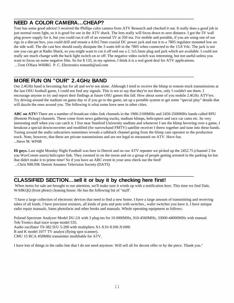
______________________________________________________________________NEED A COLOR CAMERA...CHEAP?Tom has some good advice! I received the Phillips color camera from ATV Research and checked it out. It really does a good job injust normal room light, so it is good for use in the ATV shack. The lens really will focus down to zero distance. I got the 5V wallplug power supply for it, but you could run it off of an external 5V at 350 ma. For mobile and portable, if you are using one of ourrigs in a diecast box, you could drill and mount a 4.0xl.7mm coaxial DC power jack and run it to a 7805 regulator mounted low onthe side wall. The die cast box should easily dissipate the 3 watts left in the 7805 when connected to the 13.8 Vdc. The jack is notone you can get at Radio Shack, so you might want to cut it off end use a 2. lx5.5mm plug and jack which are available. I could notreally see much change with the back light switch on or off. The negative video switch was interesting, but not useful unless youwant to focus on some negative film. So for $ 135, in my opinion, I think it is a real good deal for ATV applications. ...Tom O'Hara W60RG P. C. Electronics [email protected]
______________________________________________________________________MORE FUN ON "OUR" 2.4GHz BANDOur 2.4GHz band is becoming fun for all and we're not alone. Although I tried to receive the blimp to remote truck transmissions atthe last OSU football game, I could not find any signals. This is not to say that they're not there, only I couldn't see them. Iencourage anyone to try and report their findings at future OSU games this fall. How about some of you mobile 2.4GHz ATV'ers.Try driving around the stadium on game day or if you go to the game, set up a portable system to get some "special play" details thatwill dazzle the ones around you. The following is what some have seen in other cities.
ABC on ATV! There are a number of broadcast video link channels in the 1900-2100MHz and 2450-2500MHz bands called RPU(Remote Pickup) channels. These come from news gathering trucks, stadium blimps, helicopters and race car cams etc. Its veryinteresting stuff when you can catch it. I live near Stanford University stadium and whenever I see the blimp hovering over a game, Ibreakout a special downconverter and modified (for narrowband FMTV) satellite receiver I threw together and tune into these bands.Tuning around the audio subcarriers sometimes reveals a talkback channel going from the blimp cam operator to the productiontruck. Note, however, that these are private transmissions and are not legal to retransmit on ATV. Have fun....Steve M. WF6R
Hi guys. Last night Monday Night Football was here in Detroit and on our ATV repeater we picked up the 2452.75 (channel 2 foryou WavComm users) helicopter link. They zoomed in on the moon and on a group of people getting arrested in the parking lot butthat didn't make it to prime time! So if you have an ABC event in your area check out the feed! ...Chris N8UDK Detroit Amateur Television Society (DATS)
______________________________________________________________________CLASSIFIED SECTION...sell it or buy it by checking here first! When items for sale are brought to our attention, we'll make sure it winds up with a notification here. This time we find Dale,WA8KQQ (front photo) cleaning house. He has the following list of "stuff'.
"I have a large collection of electronic devices that need to find a new home. I have a large amount of transmitting and receivingtubes of all kinds. I have precision resistors, all kinds of pots and pots with switches., wafer switches you have it. I have antiqueradio repair manuals, Sams photofacts and other books and manuals. Whole operating equipment as follows:
Polarad Spectrum Analyzer Model DU-2A with 3 plug-ins for 10-l000MHz, 910-4560MHz, 33000-44000MHz with manual.Tek-Tronics dual trace scope model 535.Audio oscillator TS-382 D/U 5-200 with multipliers X1-X10-X100-X1000.B and K model 1077 TV analyst (flying spot scanner).CMU 15 RCA 450MHz transmitter modifiable for ATV.
I have lots of things in the radio line that I do not need anymore. Will sell all for decent offer or by the piece. Thank you."

12
______________________________________________________________________ATCO 2.4 GHz REPEATER UPDATE REPORT!
The 2.4 GHz input/outputs are Working Great! Early this Spring, Dale, WB8CJW and I moved the 2.433 GHz Transmitter from the Bulletin Board site where it had been runningover the winter months to the Repeater site. The improved height vastly improved the coverage of the 2.4 GHz transmitter! I havenot yet heard of anyone who has tried to see the 2.4 GHz output with their Wavecom receiver and failed! In fact, using a unmodifiedWavecom receiver with just the built in Patch antenna, I was able to get a good picture in my offce at work 4.5 miles away and I'mon a ground floor! Art, WA8RMC has done very well with a "Coffee" can about 13 miles away with a Wavecom receiver. Greatsuccess! I was able to see the output from 65 miles out while mobile early one morning, but I think the band was up. With all of thisencouragement, we just had to add a repeater receiver on 2.4 GHz. In comparison, adding the 2.4 GHz transmitter was easy! Thetransmitter system on 2.433 GHz is an HF Technology HFT 2500 TX with 600 mw output driving a SSB Electronics 10 watt, 10 dBgain 2.4 amp to about 5.5 watts output. The antenna is a Comet GP 24 vertical feed with 40 ft of 7/8 hardline. The transmittingsystem was not cheap, but simple enough!
The problemIn order to add a receiver to the repeater on 2.4 GHz, we have to over come some problems, like what kind of receiver, the fact that"Wireless Cable" System Transmitters were just over on the next building, desense from our own 2.4 GHz transmitter. In additionwe wanted to add a forth receiver to a repeater controller designed for 3 Rx inputs. Adding a 2.4 GHz receiver to the ATCO repeaterwas going to take some system design, a lot of "smarts" and more money. Dale, WB8CJW, provided the smarts and I provide most ofthe money and we shared system design.
The solution(s)The first decision was what receiver to use. The answer was easy, a Wavecom RX on Channel 4 (2411 GHz). Dale repackaged aWavecom Rx in a RF tight box. The first problem to over come is that when the Wavecom is first powered on, it defaults to channel1, the output frequency of our transmitter! Dale's designed and built an ingenious little circuit to always step the RX to channel 4 onpower up (see last ATCO newsletter for details). It works great! The next problem was how to add a 4th receiver to be scanned to arepeater controller designed for 3 scanned inputs? A number of approaches were considered, but the winning solution was to shareone of the current inputs with the 2.4 GHz Rx. Using a P.C. Electronics Video Operated Relay (VOR), we normally pass the 2.4GHz receiver video to the controller unless a 915 FMATV video (e.g. from the WX Radar or Bulletin board, etc link) presents itselfand it will take priority. The next problems were desense from our own 2.4 TX and the Wireless Cable Transmitters next door. Thesolution was two 8-pole filters custom made and tuned by DCI. Not an easy tuning job to get 25 dB or more isolation for a pair ofFMATV receiver and transmitter only 22 MHz apart! We wanted to keep the Wavecom chl and ch 4 pair to match existingWavecom units owned by repeater users. DCI provided exactly what we wanted. The filters worked great! Next was the antenna. We(with WA8RMC on the "I" Beams) duplicated the Transmit antenna system (GP 24 and 7/8 Hardline) but hung the antenna up-sidedown (seal it really well if you do it!) directly below and a few feet down from the transmit antenna to get additional isolation. Itworked Great!
It Works Great!!So how's the system working? To coin a phase, it works great! Most everyone who has tried to get into the 2.4 GHz repeater r,eceiverhas been successful! Most everyone is running modified Wavecom transmitters with 50-100 mw to loop yagis or conifer dish orWireless Cable surplus Bar-B-Q grills or coffee cans or 5 dB vertical mobile antennas! Stations 15-20 miles away from the repeatersite are routinely able to get into it with good signals. I was able to get in from 25 miles out while mobile (@ 65 MPH!) but I run 10times more power mobile (1 watt!) using a 5 dB vertical antenna. The more the Better!Currently, about dozen stations in the Columbus area are receiving or receiving and transmitting 2.4 GHz. I believe about 25Wavecom units have been purchased by local ATV'er so I expect to see more stations soon. So what's next for 2.4 GHz on therepeater? More power for the transmitter and a preamp on the receiver. After that, it's 10GHz or bust!…73 & P5s Ken, WA8RUT

13
______________________________________________________________________ATCO ANTENNA PARTY...fun and plotsOur first annual antenna party was held August 22 at the home of Ted, N8KQN. About 15 of were present who had a great time withlots of food and plenty of room to stretch out our antennas. It was an ideal location for this event. I call it our first annual partybecause we plan to have another one next year. If Ted will have us and we don't wear out our welcome, maybe he'll invite us back tohis place.
We came with equipment to be able to measure and plot the patterns of 439 and 1280MHz antennas but time only permitted439MHz measurements this year. Maybe next year more 1280 and possibly 2.4GHz antennas will be available. The equipmentavailable will work up to 2.4GHz so guys, let's get busy for next year. All data was taken as follows: a reference antenna with signalsource was set up at the end of the yard about 150 feet away. The antenna to be measured was attached to a portable mast with arotor at the other end. The test antenna signal was then connected to a Boonton RF millivoltmeter and its dc output went to an A/Dconverter and into a computer. The computer program, created by KF8QU, started the rotor and read the digitized signal as theantenna rotated. The real time data was displayed in polar coordinate fashion on the CRT and when the rotation was complete thedata was saved to a file for comparison and printing later. Pretty neat, huh? As we use it, some bugs are being found and refinementsmade so by next year perfection will be ours.
The pictures (taken by KF8QU's digital camera) captured some of the activity while the plots display that some antennas work verywell while others need some refinement! Plots show pattern only here because all were normalized on forward gain. See you nextyear!

14
______________________________________________________________________THE ATCO FALL EVENT IS ALMOST HERE!Well guys, it's just about that time of year again. The ATCO Fall Event will be held on Sunday October l 8 at the ABB shelter houseas was done last year. See map on next page. As always, there will be plenty of free food available, door prizes club news and mostimportant, good friends with similar interests! The fun will start at about noon but formally we won't get started till about l :00PM.
Some of the topics we plan to cover are as follows:1.) I talked to Ron Curry, WA3GSS the other day and invited his Ashland, Kentucky guys to join us so if he (they) can make it, we'llsee if they can give us an update on the status of their repeater.2.) I believe some of the guys from Dayton will be here also so lets see if an update from their direction is in order.3.) There has been interest in a link between repeaters so I'm sure that a discussion here will prove to be interesting.4.) Ken is prepared to discuss the status and future plans for the 2.4GHz portion of our repeater.5.) It's officer election time again, so we need to vote according to our charter.
The present officers on the ballot are as follows:President - Art Towslee WA8RMCVice president - Ken Morris WA8RUTSecretary - Rick White WA3DTOTreasurer - Bob Tournoux

15
1998 FALL EVENT
(ACCURAY)
650 ACKERMAN ROADFOR MORE DETAILS, CONTACT
ART - WA8RMC 891-9273
BRING A FRIEND AND SEE OLD BUDDYS
DIRECTIONS TO THE ATCO EVENT
From I-70 either EAST or WEST Bound:Take Route 315 (runs north and south and is just west of Columbus) - head NORTH.Get off at Ackerman Road Exit and turn RIGHT on to Ackerman Road.Turn LEFT just beyond the first traffic light at the ATCO sign.
From I-71 traveling NORTH bound toward Columbus:While traveling north on I-71, watch for the split to Route 315 just south ofColumbus. Take 315 and head NORTH to the Ackerman Road Exit. Get off at thisexit and turn RIGHT to Ackerman Road. Turn LEFT just beyond the first traffic lightat the ATCO sign.
From I-71 traveling SOUTH bound toward Columbus:
(DIRECTIONS IF YOU'RE "NORTH" OF I-270).Take I-71 SOUTH to I-270 Bypass Loop & head WEST on I-270.At the Route 315 exit, turn LEFT to head SOUTH on Route 315.Exit on Ackerman Road

16
_________________________________________________________________NEW MEMBER SECTIONLet’s welcome the new members to our group! If any of you know anyone who might be interested, let one of us know so we canflood them with information. New members are the lifeblood of our group so it's important that we actively recruit new facesaggressively.
Rick Heskett KB8EAA Columbus, Ohio 43229 Bud Nichols KC8ASD Hilliard, Ohio 43026 Harry Covault K8GCS Kettering, Ohio 45440
______________________________________________________________________HAMFEST CALENDARThis section is reserved for upcoming hamfests for as far in advance as we know about them. They are limited to Ohio and vicinityeasily accessible in one day. Anyone aware of an event incorrectly or not listed here notify me so it can be corrected. I maintain somefliers that compile this list so for additional info Email me at [email protected]. This list will be amended as further informationbecomes available.
October 25 Marion ARC, Marion, OH Karen Eckard, N8KE 6583 South Street Meeker, Marion, OH 43302 614-499-3565November 1 Massillon ARC, Massillon, OH Don Wade, W8DEA 7300 Sunset Strip, A-7, North Canton, OH 44720 330-497-7232November 14- 15 Fort Wayne, IN Doug Jones, N9NNT & Jim Boyer, KB9IH PO Box 10342, Fort Wayne, IN 46851 219484-3317January 24 Tusco ARC, Dover, OH Howard Blind, KD8KF 6288 Echo Lake Rd. NE, New Philadelphia, OH 44663 330-364-5258February 7 Northern Ohio ARS, Lorain, OH Mike Willemin, W8EU 331 Courtland St., Elyria, OH 44035-3116 440-324-4574February 27-28 Cincinnati, OH William Tittle, KA8LAY 3038 Bracken Woods Ln., Cincinnati, OH 45211-7338 513-661-1861February 28 Teays ARC, Circleville, OH Roy Ulko, KG8EK 132 West Main St., Circleville, OH 43113-1620 740-477-8310
17
ATV EQUIPMENT SUPPLIERSBelow is a list of manufacturers of ATV equipment that I have found. There is no endorsement of any of the manufacturers listedbelow so buyer beware. If I or anyone else that I know of, has had any trouble with a manufacturer, it won’t be listed. As I get moreinfo, I’ll add manufacturers. Likewise, if I hear of any trouble, it’ll be removed. Good luck and keep me advised. WA8RMC
Michael Kohlstadt, KD6UJShas a limited supply of used but working PacificMonolithics 2.4ghz downconverters and powersupplies which will work fine for viewing therepeater.Phone: 408-926-0430.
Down East MicrowaveAntennas, Power Amplifiers, Deluxe Downconverters,microwave parts.954 Rt. 519 Frenchtown, NJ 08825Phone: 908-996-3584Fax: 908-996-3702
HF Technologies Inc.FMTV Transmitters, Receivers457 Santa Fe TrailCary, IL 60013Phone: 708-639-4336
PC ElectronicsATV Transmitters, Receivers Manufacturer/Reseller2522 Paxson Ln.Arcadia, CA 91009-8537Phone: 626-447-4565Fax: [email protected]
Phillips-Tech ElectronicsMMDS, ITFS downconverters and antenna systemsP.O. Box 8533Scottsdale, AZ 85252Phone: 602-947-7700Fax: 602-947-7799
R. Myers CommunicationsGood, single unit, source for 2.4GHz dishesP.O. Box 17108Fountain Hills, AZ 85269-7108Phone: 602-837-6492Fax: 602-837-6872
SHF Microwave Parts Company10GHz Gunn oscillators and Antennas7102 W. 500 S.LA PORTE, INDIANA, 46350Fax: 219-785-4552
Wyman Research Inc.FMTV Transmitters, ReceiversBox 95, RR 1Waldron, IN 46162
Phone: 765-525-6452
DCI CommunicationsInterdigital filters and cavitiesBox 293, 29 Hummingbird BayWhite City, SK, Canada S0G5B0Phone: 306-781-4451
ATV Research Inc.TV cameras & related parts1301 Broadway PO Box 620Dakota City, NE 68731-0620Phone: 402-987-3771Homepage: www.atvresearch.comEmail: [email protected]
GEKCO IncTV test signal circuit boardsPO Box 642Issaquah, Wa 98027-0642Phone: 425-392-0638Email: [email protected]: www.gekco.com
M2Antennas7560 N. Del Mar Ave.Fresno, Ca 93711Phone: 209-432-8873
ATV Quarterly (ATVQ)ATV magazine publisher5931 Alma DriveRockford, Il. 61108Phone 815-398-2683FAX 815-398-2688Email: [email protected]://www.cris.com/~Gharlan
Spectrum InternationalJ-Beams, KVG, Micromodules,VSB filtersJohn BeanlandPhone:978-263-2145.Email: [email protected]
Note: Additional commercial vendors may be viewedon the Internet at http://bro.net/explorer/vendor.html

______________________________________________________________________INTERNET INFOIf you have access to the INTERNET, you may be interested to know of some of the HAM related information that is available. Mostaddresses listed below are case sensitive, so type exactly as shown below. (If anyone has comments or would like additional listingscontact me via Email at [email protected]).http://psycho.psy.ohio-state.edu/atco ATCO ATV home page.http://www.bright.net/~rmeeksjr/atv_day.htm Ohio, Dayton ATV grouphttp://fly.hiwaay.net/~bbrown/index.htm Alabama, Huntsville,Tennessee Valley ATV (Bill BrownWB8ELK)http://www.hayden.edu/Guests/AATV Arizona, Phoenix Amateurshttp://www.citynight.com/atv California, San Francisco ATVhttp://www.ladas.com/ATN California, Amateur Television Network in Central / Southernhttp://w6yx.stanford.edu/~stevem/atv California, South Bay ATV Group Stanford Universityhttp://www.qsl.net/wb6izg California, southern ATV Sights and Soundshttp://home1.gte/k4lk Florida, Tampa Bay ATV Society (TBATS)http://www.mindspring.com/~rwf/aatn1.html Georgia, Atlanta ATVhttp://ww2.netnitco.net/users/stealth/kens.htm Indiana KB9I homepagewww.mychoice.net/fminton/silatvg.htm Southern Illinois Amateur Television grouphttp://www.smart.net/~brats Maryland, Baltimore Radio Amateur Television Society (BRATS)http://www.murphysoftware.com/dats Michigan, Detroit DATS ATVhttp://www.njin.net/~magliaco/atv.html New Jersey, Brookdale ARC in Lincrofthttp://www.intercenter.net/triatv/atv-web.htm N. Carolina, Raleigh.Triangle ATV clubhttp://www.navicom.com/~satva/satvainf.htm Oregon, Silverton, Salem ATV Assoc (SATVA)http://www.lloydio.com/oatva.html Oregon, Portland ATV (OATVA)http://www.webczar.com/atv Oklahoma, Tulsa Amateur TV (TARC)http://members.aol.com/n3kkm/w3hzu.html Pennsylvania, York Keystone VHF Clubhttp:www.usaor.net/users/ka3fzf/index.htm Pennsylvania, Pittsburg Amateur Television in Pittsburghttp://www.voicenet.com/~theojkat/w3phl.html Pennsylvania, Phila. Area ATVhttp://www.geocities.com/Hollywood/5842 Tennessee, East ATVhttp://www.stevens.com/HATS/home.html Texas, Houston ATVhttp://uugate.ampr.utah.edu/utah_atv/utah_atv.html Utah ATVhttp://www.bchfs.org/metrovision/atv.htm Virginia, Alexandriahttp://www.qsl.net/w7twu Washington, Western Washington Television Society (WWATS)http://scott-inc.com/wb9neq.htm Airborn ATV from WB9NEQ in Bowling Green, Kentuckyhttp://www.premiernet.net/~hcantrl/ Kentucky, Bowling Green (CKATS)http://www.ecn.net.au/~sbloxham/index.html Australia, ATV, VK4GY (large list of other ATV & ham radio sites)http://ourworld.compuserve.com/homepages/batc British ATV club (BATC)http://www.sfn.saskatoon.sk.ca/recreation/hamburg/hamatv.html Saskatoon, Canada ATVhttp://www.gpfn.sk.ca/hobbies/rara/atv3.html Regina, Canada ATVhttp://www.inside.co.uk/scart.htm UK,Great Britain ATV (SCART)http://www.cmo.ch/swissatv Swiss ATV
NOTE: If you’re a regular Internet browser, maybe you’d like to be kept up to date on all of the ATV related news generatedNationally. If so, subscribe to the “ATV Internet mailing list” to receive the bulletins automatically. If you’d like to SEND a message to all other subscribers this can be done also. It’s free to all. To subscribe, send Email to “[email protected]” andinclude in the message the line SUBSCRIBE ATV.To send a message address it to “[email protected]”. To be removed fromlist, send Email to “[email protected] and include in the message “UNSUBSCRIBE ATV”.The following addresses are helpful in searching for many different Ham Radio items on the INTERNET.
http://www.cris.com/~Gharlan ATVQ Magazine home page. ATV equipment & article references.http://www.hamtv.com PC Electronics Inc. Lots of proven ATV equipment for sale.http://downeastmicrowave.com Down East Microwave Inc. Lots of uhf/microwave parts & modules.http://www.yahoo.com/Entertainment/television/Amateur_television Listing of some of the available ATV home pages.http:/www.acs.ncsu.edu/HamRadio General ham radio info- satellite track, call sign database etc.http://www.arrl.org/hamfests.html Current yearly hamfest directory.http://amsat.org AMSAT satellite directory/home page.http://www.arrl.org ARRL home pagehttp://www.ualr.edu/doc/hamualr/callsign.html Search by call sign or name.

19
http://hamradio-online.com Ham Radio Online “newsletter” Lot of Ham related information.http:www.smart.net/~brats/atna.html ATNA homepage

20
______________________________________________________________________ATCO REPEATER TECHNICAL DATA SUMMARYThis space of each publication includes the technical information of our repeater. Each time a new feature is brought on line it’sadded here. Use this as a quick reference for up/down access codes as well as some of the more important parameters of our system.Main repeater: Location: Downtown Columbus, Ohio
Coordinates: 82 degrees 59 minutes 53 seconds (longitude)39 degrees 57 minutes 45 seconds (latitude)
Elevation: 630 feet above average street level1460 feet above sea level
Transmitters: 427.25 MHz AM modulation, 1250 MHz FM modulation and 2433 MHz FM modulation.interdigital filters in output line of 427.25 & 1250 transmittersTransmitter Output Power - 40 watts average 80 watts sync tip (427.25)
50 watts continuous (1250) 8 watts continuous (2433)
Link transmitter - 1 watt NFM 5 kHz audio (446.350 MHz)
Identification The 427, 1250 and 2433 transmitters identify simultaneously every 10 minutes with video showingATCO and WA8RUT with four different screens. Audio identification is 4 sequences of Morse Code.
Transmit antennas: 427.25 MHz - Dual slot horizontally polarized 7 dBd gain major lobe west1250 MHz - Diamond vertically polarized 12 dBd gain omni2433 MHz - Comet vertically polarized 12 dBd gain omni
Receivers: 147.45 MHz for F1 audio input control of touch tones 439.25 MHz for A5 video input with FM subcarrier audio (lower sideband) 915 MHz for F5 video link data from remote sites 1280 MHz for F5 video input 2411 MHz for F5 video input
Receive antennas: 147.45 MHz - Vert. polar. Hi Gain "Comet" 12 dBd (also for 446 MHz output) 439.25 MHz - Horiz. polar. dual slot 8 dBd gain major lobe west 915 MHz - Vert. polar. dB Products 10 dBd gain 1280 MHz - Horiz. polar. single slot 3 dBd gain major lobe west. 2411 MHz - Comet vertically polarized 12 dBd gain omni
UP DOWNInput control: Major Touch tones: beacon (5 min) *439 #
regional weather radar 697 #Local radar(5 min) 264 #
User repeat 1 minute *45 *22Touch tone pad tester #0 #5Manual mode (ID) *77 90 *22
(910 input) *77 91 *22(439 input) *77 92 *22(1280 input) *77 93 *22(cabinet cam) *77 94 *22
5 second ID #9 *22Bulletin board 285 pause 92 286Roof Camera 285 pause 95 286Reset to scan mode D37 or #437
Remote sites: **Local radar (inactive at this time) (915 MHz link output 8 watts)Aux link at WA8RUT QTH (915 MHz link output 1 watt)Aux link at WB8CJW QTH (915 MHz link output 1 watt)
21
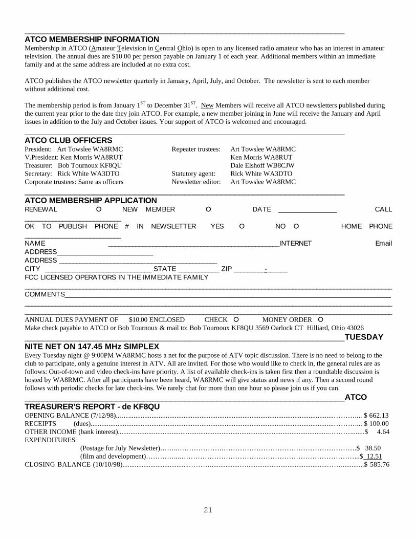
______________________________________________________________________ATCO MEMBERSHIP INFORMATIONMembership in ATCO (Amateur Television in Central Ohio) is open to any licensed radio amateur who has an interest in amateurtelevision. The annual dues are $10.00 per person payable on January 1 of each year. Additional members within an immediatefamily and at the same address are included at no extra cost.
ATCO publishes the ATCO newsletter quarterly in January, April, July, and October. The newsletter is sent to each memberwithout additional cost.
The membership period is from January 1ST to December 31ST. New Members will receive all ATCO newsletters published duringthe current year prior to the date they join ATCO. For example, a new member joining in June will receive the January and Aprilissues in addition to the July and October issues. Your support of ATCO is welcomed and encouraged.______________________________________________________________________ATCO CLUB OFFICERSPresident: Art Towslee WA8RMC Repeater trustees: Art Towslee WA8RMCV.President: Ken Morris WA8RUT Ken Morris WA8RUTTreasurer: Bob Tournoux KF8QU Dale Elshoff WB8CJWSecretary: Rick White WA3DTO Statutory agent: Rick White WA3DTOCorporate trustees: Same as officers Newsletter editor: Art Towslee WA8RMC______________________________________________________________________ATCO MEMBERSHIP APPLICATIONRENEWAL NEW MEMBER DATE _________________ CALL____________________________OK TO PUBLISH PHONE # IN NEWSLETTER YES NO HOME PHONE____________________________NAME __________________________________________________INTERNET EmailADDRESS____________________________ADDRESS ______________________________________________CITY _______________________________ STATE ____________ ZIP _________-______FCC LICENSED OPERATORS IN THE IMMEDIATE FAMILY___________________________________________________________________________________________________________COMMENTS_____________________________________________________________________________________________________________________________________________________________________________________________________________________________________________________________________________________________________________________ANNUAL DUES PAYMENT OF $10.00 ENCLOSED CHECK MONEY ORDER Make check payable to ATCO or Bob Tournoux & mail to: Bob Tournoux KF8QU 3569 Oarlock CT Hilliard, Ohio 43026______________________________________________________________________TUESDAYNITE NET ON 147.45 MHz SIMPLEXEvery Tuesday night @ 9:00PM WA8RMC hosts a net for the purpose of ATV topic discussion. There is no need to belong to theclub to participate, only a genuine interest in ATV. All are invited. For those who would like to check in, the general rules are asfollows: Out-of-town and video check-ins have priority. A list of available check-ins is taken first then a roundtable discussion ishosted by WA8RMC. After all participants have been heard, WA8RMC will give status and news if any. Then a second roundfollows with periodic checks for late check-ins. We rarely chat for more than one hour so please join us if you can.______________________________________________________________________ATCOTREASURER'S REPORT - de KF8QUOPENING BALANCE (7/12/98)...…...................................................................................................................……….... $ 662.13RECEIPTS (dues)........................................................................................................................................……….... $ 100.00OTHER INCOME (bank interest)......................................................................................................................………........$ 4.64EXPENDITURES (Postage for July Newsletter)……..……………….………………………………………………….$ 38.50 (film and development)…………...…………………………………………………………………...$ 12.51CLOSING BALANCE (10/10/98)......................................……….................….............................................…….............$ 585.76

22
______________________________________________________________________ATCO MEMBERS AS OF 10 OCTOBER 1998
K8AEH Wilbur Wollerman 1672 Rosehill Road Reynoldsburg Oh 43068 866-1399KC8ASD Bud Nichols 3200 Walker Rd Hilliard Oh 43026WB4BBF Randall Hash 212 Long Street Bluefield Va 24605W4/F5BJV Marcel Pitzini 443 Eastland Drive Decatur Ga 30030 404-378-2772KC8BNI Fred Stutske 8737 Ashford Lane Pickerington Oh 43147 [email protected] Jack Compson 5065 Sharon Hill Dr Columbus Oh 43235 451-4054 [email protected] Dale Elshoff 8904 Winoak Pl Powell Oh 43065 766-5823 [email protected] John Busic 2700 Bixby Road Groveport Oh 43125 491-8198 [email protected] Dave Wagner 2045 Maginnis Rd Oregon Oh 42616 419- 691-1625WA4DFS Ed Walker PO Box 150 Mountain City Tn 37683 423- 727-9611 [email protected] Rick White 5314 Grosbeak Glen Orient Oh 43146 877-0652 [email protected] Roger McEldowney 5420 Madison St Hilliard Oh 43026 876-6033 [email protected],KB8VBF Rick, Judy Hesket 6261 Maple Canyon Dr Columbus Oh 43229 891-3887 [email protected] Foster Warren P.O. Box #32 No. Hampton Oh 45349KB8FF Dave Tkach 2063 Torchwood Loop S Columbus Oh 43229 882-0771 [email protected] John Barnes 216 Hillsboro Ave Lexington Ky 40511 606-253-1178 [email protected] E.R. Hall 4955 Pole Bridge Rd Wise Va 24293 540- 328-9235K8GCS Harry Covault 4820 Archmore Dr Kettering Oh 45440 937- 434-5412 [email protected] Reuben Meeks 428 Lewiston Road Kettering Oh 45429 937- 294-0575 [email protected] Jim Reese 1106 Tonawanda Ave Akron Oh 44305WA8HFK,KC8HIP Frank, Pat Amore 3630 Dayspring Dr Hilliard Oh 43026 777-4621W8JND Richard Knowles 573 Plaza Drive Circleville Oh 43113 477-8132N8KQN Ted Post 1267 Richter Rd Columbus Oh 43223 276-1820WA8KQQ Dale Waymire 225 Riffle Ave Greenville Oh 45331 513- 548-2492K8MBY,N8SIR,KB8UVK Phil,Jim,Phil jr Buckholdt 153 East Bergey St Wadsworth Oh 44281N8LRG Phillip Humphries 3226 Deerpath Drive Grove City Oh 43123 871-0751 [email protected] Bill Dean 2630 Green Ridge Rd Peebles Oh 45660 [email protected] Shaun Miller 5061 County Rd 123 Mt Gilead Oh 43338 419- 768-2588 [email protected] Leland Hubbell 7706 Green Mill Road Johnstown Oh 43031 967-8412WD8OBT,KB8ESR,KA8ZPE Tom Camm & sons 1634 Dundee Court Columbus Oh 43227 860-9807N8OCQ Robert Hodge 3689 Hollowcrest Columbus Oh 43223 875-7067N8OOA Jeff Clark 9894 Fincastle-Winchester Sardinia Oh 45171 937- 695-1229N8OPB Chris Huhn 146 South Hague Ave Columbus Oh 43204 279-7577W6ORG Tom O'Hara & family 2522 Paxson Lane Arcadia Ca 91007 626- 447-4565 [email protected] Perry Yantis 1850 Lisle Ave Obetz Oh 43207 491-1498 [email protected] Craig Stoll PO box 1117 Orchard Park Ny 14127KE8PN James Easley 1507 Michigan Ave Columbus Oh 43201 421-1492 [email protected],WD8BGG Richard, Roger Burggraf 5701 Winchester So. Rd Stoutsville Oh 43154 614- 474-3884KF8QU Bob Tournoux 3569 Oarlock Ct Hilliard Oh 43026 876-2127 [email protected] Joe Hussey 1678 Sandhurst Rd Columbus Oh 43229 895-7601WA8RMC Art Towslee 180 Fairdale Ave Westerville Oh 43081 891-9273 [email protected],N8KCB Ken & Chris Morris 3181 Gerbert Rd Columbus Oh 43224 261-8583 [email protected] Richard Goode 9391 Ballentine Rd New Carlisle Oh 45334 513- 964-1185 [email protected] John Perone 3477 Africa Road Galena Oh 43021WA8SAR Gary Obee 3691 Chamberlain Lambertville Mi 48144N8SFC Larry Campbell 316 Eastcreek Dr Galloway Oh 43119 851-0223 [email protected] John Beal 2899 Castlebrook Ave Columbus Oh 43026 876-9412W8STB John Hey & family 894 Cherry Blossom Dr West Carrolton Oh 45449 937- 859-5295 [email protected] Ed Latham 8399 Fairbrook Ave Galloway Oh 43119KB8TRP,KB8TCF Tom, Ed Flanagan 1751 N. Eastfield Dr Columbus Oh 43223 272-5784 [email protected] Phil Morrison 154 Llewellyn Ave Westerville Oh 43081KB8UGH Steve Caruso 39 South Garfield Ave Columbus Oh 43205 461- 5397 [email protected] William Heiden 5898 Township Rd #103 Mount Gilead Oh 43338 419- 947-1121KB8UU Bill Rose 9250 Roberts Road West Jefferson Oh 43162 879-7482WB8VJD Rick Morris 203 Merton Street Holland Oh 43528KA8VUQ Jack Wolff 2682 Hiawatha Ave Columbus Oh 43212 263-3092W8WAU Jake Fuller PO Box 117 No. Hampton Oh 45349N8WLT James Neymeyer 2879 East Moreland Drive Columbus Oh 43209 237-2331KB8WBK David Hunter 45 Sheppard Dr Pataskala Oh 43062 740- 927-3883 [email protected] Dan Baughman 4269 Hanging Rock Ct Gahanna Oh 43230 471-1089KB8YIO Ric Wise 1465 25th Ave Columbus Oh 43211 291-6508 [email protected] Mark Griggs 2160 Autumn Place Columbus Oh 43223 272-8266 [email protected] Jay Caldwell 4740 Timmons Dr Plain City Oh 43064KB8ZLB Dave Kibler 243 Dwyer Rd Greenfield Oh 45123 937- 981-4007 [email protected],N8OOY Tom & Cheryl Taft 386 Cherry Street Groveport Oh 43125 836-3519 [email protected]

23
ATCO Newsletterc/o Art Towslee-WA8RMC180 Fairdale AveWesterville, Ohio 43081
������������������������������������������������������ FIRST CLASS MAIL
������������������������������������������������������
______________________________________________________________________REMEMBER...CLUB DUES ARE NEEDED.
CHECK MAILING LABEL FOR THE EXPIRATION DATE AND SEND KF8QU A CHECK IF EXPIRED.______________________________________________________________________