Embed Size (px)
Citation preview

University of Birmingham
Voltage transient management for AlternatingCurrent trains with vacuum circuit breakersMoore, Thomas; Schmid, Felix; Tricoli, Pietro
DOI:10.1049/els2.12034
License:Creative Commons: Attribution-NoDerivs (CC BY-ND)
Document VersionPublisher's PDF, also known as Version of record
Citation for published version (Harvard):Moore, T, Schmid, F & Tricoli, P 2021, 'Voltage transient management for Alternating Current trains with vacuumcircuit breakers', IET Electrical Systems in Transportation. https://doi.org/10.1049/els2.12034
Link to publication on Research at Birmingham portal
General rightsUnless a licence is specified above, all rights (including copyright and moral rights) in this document are retained by the authors and/or thecopyright holders. The express permission of the copyright holder must be obtained for any use of this material other than for purposespermitted by law.
•Users may freely distribute the URL that is used to identify this publication.•Users may download and/or print one copy of the publication from the University of Birmingham research portal for the purpose of privatestudy or non-commercial research.•User may use extracts from the document in line with the concept of ‘fair dealing’ under the Copyright, Designs and Patents Act 1988 (?)•Users may not further distribute the material nor use it for the purposes of commercial gain.
Where a licence is displayed above, please note the terms and conditions of the licence govern your use of this document.
When citing, please reference the published version.
Take down policyWhile the University of Birmingham exercises care and attention in making items available there are rare occasions when an item has beenuploaded in error or has been deemed to be commercially or otherwise sensitive.
If you believe that this is the case for this document, please contact [email protected] providing details and we will remove access tothe work immediately and investigate.
Download date: 18. Nov. 2021

Received: 9 March 2021 - Revised: 23 May 2021 - Accepted: 21 June 2021 - IET Electrical Systems in TransportationDOI: 10.1049/els2.12034
REV I EW
Voltage transient management for Alternating Current trains withvacuum circuit breakers
Thomas Moore | Felix Schmid | Pietro Tricoli
Birmingham Centre for Railway Research andEducation, University of Birmingham, Birmingham,UK
Correspondence
Thomas Moore, Birmingham Centre for RailwayResearch and Education, University of Birmingham,Edgbaston, Birmingham, B15 2TT, UK.Email: [email protected]
AbstractAlternating current power supplies and rolling stock with 25 kV (50 or 60 Hz) and 15 kV(16.7 Hz) traction systems do not have the characteristics and behaviour of a typicalthree‐phase medium‐voltage distribution system. Switching inductive loads with a vac-uum circuit breaker (VCB) in MV traction systems poses familiar challenges as well assome unique challenges, such as the crossing of phase change neutral sections. Trans-formers represent highly inductive loads due to their iron core and, thus, the conse-quences of energizing and disconnecting a transformer and dealing with the energy storedin its inductance must be considered within a system context. The authors of this studyconsider two transient phenomena associated with switching single‐phase, mediumvoltage, AC traction transformer loads using a VCB on railway rolling stock: (i) switchingtransients that occur when disconnecting a transformer, particularly if lightly loaded and(ii) pre‐ignition and current inrush that occurs when energizing a transformer. Bothphenomena can cause reliability problems, requiring increased system maintenance orresulting in premature failures of system components. The authors review the use ofcontrolled switching and other state‐of‐the‐art methods to prevent or limit voltagetransients when switching a transformer load by means of a VCB. The effective appli-cation of such techniques has been demonstrated in previous research or established inpractical applications by manufacturers and electrical distribution network companies.
1 | INTRODUCTION
The railway traction system is unique in its composition. Therailway is long and thin and the AC traction power must bedistributed over significant distances. The power is delivered insingle‐phase sections and fed by different transformer systems,including the autotransformer, booster transformer and singletransformer systems. The train is required to change betweenphases at regular intervals along the network.
In Continental Europe, trains often run between net-works supplied with different AC voltages at one of twofrequencies, i.e. 15 kV, 16.7 Hz and 25 kV, 50 Hz. Thischange in voltage and frequency requires the train manu-facturers to have insulation coordination design for 25 kV,50 Hz systems but have a transformer core optimised foroperating at low frequencies of 16.7 Hz. Phase changes inthe overhead lines (OHLE) require the train to disconnect
from the OHLE and reconnect once it has passed throughthe neutral section separating the phases. This results in thetrain's transformer or transformers being regularly discon-nected and energised.
Therefore, the traction system components between thepantograph and the secondary side of the transformer mustbe designed specifically for use on rolling stock and for theunique challenges of the railway environment. These includespace constraints, vibration, frequent vacuum circuit breaker(VCB) switching and continuous running at high powerlevels.
Transient overvoltages can cause reliability problems,requiring increased traction system maintenance effort orresulting in electrical flashovers or premature failures of thetraction system components. These failures either result inparts of a train's traction system getting isolated and the traincontinuing to run on reduced power or the train needing
This is an open access article under the terms of the Creative Commons Attribution‐NoDerivs License, which permits use and distribution in any medium, provided the original work isproperly cited and no modifications or adaptations are made.
© 2021 The Authors. IET Electrical Systems in Transportation published by John Wiley & Sons Ltd on behalf of The Institution of Engineering and Technology.
IET Electr. Syst. Transp. 2021;1–14. wileyonlinelibrary.com/journal/els2 - 1

rescue by another train or locomotive. Both scenarios result insignificant disruption to railway operations.
This review focusses on the traction system between thepantograph/s and the primary winding of the traction trans-former/s. It also focusses on the components within thissection of the traction system and their functions. The con-sequences of energizing and disconnecting the train's trans-former or transformers routinely at neutral sections arereviewed. State‐of‐the‐art techniques used to limit transientovervoltages on the load side of the circuit breaker (CB) due toswitching of the inductive transformer load are reviewed,including the following:
� Surge arresters (SAs) [1];� Surge capacitors [2];� Resistor capacitor (RC) snubbers [3];� Pre‐insertion resistors (PIR) [4];� Chokes [5]; and� Controlled switching of the VCB [6].
Controlled VCB switching determines the VCB contactclosing and contact separation times as a function of thephase angle, to prevent prearcing and current inrush whenenergising the transformer and to avoid transient over volt-ages on disconnection. Controlled switching of the VCB withtransformer flux measurement can almost completely elimi-nate inrush currents when energizing a transformer [7, 8].This review also considers the use of power electronicswitched reactive power‐type technology to limit or preventtransient over voltages when disconnecting the transformer.The objective of this review is to understand the methods forreducing both transient overvoltages due to VCB switchingand transformer magnetizing inrush on AC rolling stock andthe technical options that enable this.
2 | RAILWAY AC INFRASTRUCTURETRACTION SYSTEMS
The OHLE is configured into different phase sections forconvenient power delivery to the train through its pantographinterface. However, this results in the need for frequentswitching on the train's traction system, due to the neutralsections required for phase separation.
2.1 | Infrastructure traction and neutralsections
‘Neutral sections’ in the OHLE are necessary where there is achange of phase at a feeder station, for example. When trainstravel through neutral sections, the train coasts through withthe traction system ‘powered down’ [9, 10]. However, inpractice, the train's VCB is required to interrupt a small currentbefore the train enters the neutral section, typically in the re-gion of 3 A to 10 A.
Figure 1 shows an example of a neutral section and thedistances for the automatic power control (APC) magnets. Theneutral length between phases ‘D’ is as short as possible,typically <10 m [11].
The distances ‘A’ and ‘B’ of the APC magnets in Figure 1are determined by the speed and gradient of the line throughthe track section [12]. Depending on these factors and thelength of the train configuration, the traction system will bepowered down for a number of seconds as it passes throughthe neutral section.
With neutral sections typically spaced at 30 to 50 kmintervals on 25 kV, 50 Hz high‐speed rail (HSR) networks[13–15], the CB on the train opens and closes five to eighttimes per hour, assuming operating speeds of greater than200 km/h [16]. Such high numbers of VCB switching oper-ations are not typically experienced in medium‐voltage (MV)electrical distribution networks.
2.2 | Rolling‐stock AC traction systems—Pantograph to transformer
The operation of coupled electrical multiple units (EMU) re-quires careful pantograph spacing to maximise pantographseparation when the EMUs are coupled, which can thereforeinfluence the number of pantographs required per EMU.Where multiple pantographs and transformers are installed,they are typically connected via a 25 kV bus system to allowsingle pantograph operation.
Figure 2 shows a generic AC traction system configuration.The main 25 kV components on the primary side of the train'stransformer include the following:
Pantograph: Connects the traction system to the OHLEand is normally raised with a pneumatic cylinder. Dependingon the rail infrastructure, there may be two pantographs fittedin the same roof space to cope with voltages and catenarydesigns that differ between infrastructures and countries.
SA1: SA or lightning arrester: normally mounted next tothe pantograph and before the VCB to protect the tractionsystem from impulse voltage spikes, such as lightning.
F I GURE 1 Neutral section arrangement
2 - MOORE ET AL.
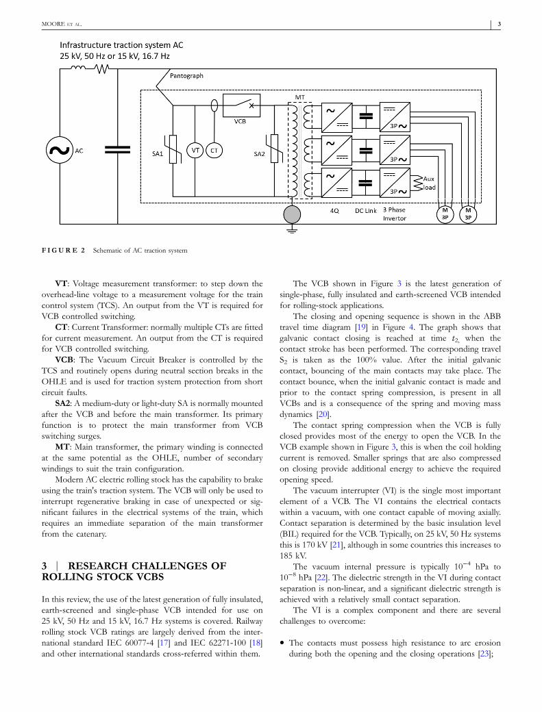
VT: Voltage measurement transformer: to step down theoverhead‐line voltage to a measurement voltage for the traincontrol system (TCS). An output from the VT is required forVCB controlled switching.
CT: Current Transformer: normally multiple CTs are fittedfor current measurement. An output from the CT is requiredfor VCB controlled switching.
VCB: The Vacuum Circuit Breaker is controlled by theTCS and routinely opens during neutral section breaks in theOHLE and is used for traction system protection from shortcircuit faults.
SA2: A medium‐duty or light‐duty SA is normally mountedafter the VCB and before the main transformer. Its primaryfunction is to protect the main transformer from VCBswitching surges.
MT: Main transformer, the primary winding is connectedat the same potential as the OHLE, number of secondarywindings to suit the train configuration.
Modern AC electric rolling stock has the capability to brakeusing the train's traction system. The VCB will only be used tointerrupt regenerative braking in case of unexpected or sig-nificant failures in the electrical systems of the train, whichrequires an immediate separation of the main transformerfrom the catenary.
3 | RESEARCH CHALLENGES OFROLLING STOCK VCBS
In this review, the use of the latest generation of fully insulated,earth‐screened and single‐phase VCB intended for use on25 kV, 50 Hz and 15 kV, 16.7 Hz systems is covered. Railwayrolling stock VCB ratings are largely derived from the inter-national standard IEC 60077‐4 [17] and IEC 62271‐100 [18]and other international standards cross‐referred within them.
The VCB shown in Figure 3 is the latest generation ofsingle‐phase, fully insulated and earth‐screened VCB intendedfor rolling‐stock applications.
The closing and opening sequence is shown in the ABBtravel time diagram [19] in Figure 4. The graph shows thatgalvanic contact closing is reached at time t2, when thecontact stroke has been performed. The corresponding travelS2 is taken as the 100% value. After the initial galvaniccontact, bouncing of the main contacts may take place. Thecontact bounce, when the initial galvanic contact is made andprior to the contact spring compression, is present in allVCBs and is a consequence of the spring and moving massdynamics [20].
The contact spring compression when the VCB is fullyclosed provides most of the energy to open the VCB. In theVCB example shown in Figure 3, this is when the coil holdingcurrent is removed. Smaller springs that are also compressedon closing provide additional energy to achieve the requiredopening speed.
The vacuum interrupter (VI) is the single most importantelement of a VCB. The VI contains the electrical contactswithin a vacuum, with one contact capable of moving axially.Contact separation is determined by the basic insulation level(BIL) required for the VCB. Typically, on 25 kV, 50 Hz systemsthis is 170 kV [21], although in some countries this increases to185 kV.
The vacuum internal pressure is typically 10−4 hPa to10−8 hPa [22]. The dielectric strength in the VI during contactseparation is non‐linear, and a significant dielectric strength isachieved with a relatively small contact separation.
The VI is a complex component and there are severalchallenges to overcome:
� The contacts must possess high resistance to arc erosionduring both the opening and the closing operations [23];
F I GURE 2 Schematic of AC traction system
MOORE ET AL. - 3

� Contact welding under short circuit conditions must beavoided, while chopping currents must be reduced to theminimum [23];
� It must interrupt short circuit currents far in excess of thestandard rating, resulting in a high thermal load;
� It must be capable of switching frequently in railway rolling‐stock applications ∼10 ops/hour.
The VI contact material and shape have undergonemuch research and refinement over the years. The contactmaterial is a copper/chromium (Cu/Cr) alloy and the con-tacts are spiral shaped to generate a radial magnetic field,which has average chopping currents around 3 A andspreading between 2 A and 4 A [23, 24]. The behaviour ofan arc, and consequentially, the arc voltage in a VCB VI, isdifferent from that of high‐pressure gas blast arcs found in
SF6 or air‐blast‐type CBs [25]. The main difference with aVCB is that the arc column is only influenced by theelectrode material and the arc cessation is dominated bycathode processes [26]. The arc voltage of a low‐currentvacuum arc is almost entirely due to the cathode voltagedrop [26]. These arc voltages typically ranging between 40and 100 V [23].
4 | SWITCHING INDUCTIVE LOADSUSING A VCB
The transformer is a highly inductive load due to the energystorage capability of its iron core.
High over voltages are observed on the load side of theVCB when switching the transformer. With an unfavourable
F I GURE 4 VCB close and open travel timediagram [19]
F I GURE 3 Single phase vacuum circuit breaker (VCB), source TE Connectivity
4 - MOORE ET AL.

phase angle and without the use of any protection againstswitching overvoltages, the dielectric strength of the systemcomponents can be exceeded, resulting in insulation break-down and system failures.
When a CB is opened, breaking can occur at any point onthe current curve. Therefore, when the VCB is opened, anelectric arc is generated due to the inductive (magnetic) energythat is still accumulated in the circuit and a recovery voltageappears between the VI contacts. Therefore, switching tran-sient overvoltages are inevitable when disconnecting a trans-former, with values of 3 pu [24] not being exceptional.
In normal service conditions, as mentioned in 2.1,the rolling‐stock VCB routinely switches a much lower currentthan the full traction load at neutral sections, typically 3 A to 10A, referred to as ‘small inductive currents’ [6]. The significanceof this is covered in the following sections:
5 | SOURCES OF OVERVOLTAGES
The VCB on a train is routinely required to switch a range oftransformer switching scenarios, shown here from normal toworst case [27]:
1. Energizing a no‐load transformer;2. Disconnecting a no‐load transformer;3. Interruption of transformer in‐rush current; and4. Disconnecting a transformer with inductive load.
The following sources of voltage surges caused byVCB switching of inductive circuits have been identified[24, 28, 29]:
1. Current chopping;2. Reignitions and voltage escalation;3. VCB pre‐ignitions and closing transients;4. Travelling waves and reflections;5. Saturation of the transformer;6. Load characteristics that cause a current surge at the instant
of switching.
Points 4, 5 and 6 are influenced by the inductance in thetransformer and the length of the cable/s between the VCBand the primary transformer. The relationship of the VCBswitching to the phase angle, the circuit configuration as well asthe source and load characteristics will also cause differenttransient effects. The following sections explore these phe-nomena further:
5.1 | Current chopping—disconnectingtransformer
The VCB have no problem in interrupting small inductivecurrents [6], which are typically a few Amps to some hundredAmps, normally < 600 A [30]. However, voltage transients onthe load side of the VCB can occur as the instability of the arc
causes current interruption before the natural zero current atshort arc angles [31], leading to high di/dt [28]. Thus, magneticenergy remains in the iron core of the disconnected circuit,proportional to the chopped current [29] where the arc ex-tinguishes, and the current is forced to a premature zero.
The energy 1=2LI2, which is present at the point of currentchopping in the inductive load, will oscillate via the parasiticcapacitances of the system. Therefore, the overvoltageamounts to approximately Umax ¼ ich �
ffiffiffiffiffiffiffiffiffiL=C
p[24], with a
frequency of f ¼ 12π
ffiffiffiffiffiffiffiL=Cp [30]. The graph in Figure 5 [29]
shows the point of current chopping (ich) before the currentzero and the resultant overvoltage Umax.
The chopping current magnitude depends on the momentof contact separation, where the closer the contact opens tozero current, the higher the chopping current [33]. However,the severity of the current chopping phenomenon is dependenton the switching characteristics of the VCB [6] and the tractionsystem circuit that is being interrupted [34].
In a study by J.F. Perkins [35], it has been found thatovervoltages increase as the transformer MVA rating increases.This reflects the fact that the magnetizing current also in-creases with MVA.
5.2 | Reignitions and voltage escalation—disconnecting transformer
The reignition phenomenon can occur in all types of CBs butoccurs particularly in VCBs [36]. Reignition and voltage esca-lation can occur in the process of disconnecting the inductiveload due to a high di/dt value and conversion of magneticenergy into electric energy, when the voltage can reach highvalues [37]. Reignitions occur when the overvoltage across theseparating VCB contacts following current interruption ex-ceeds the dielectric strength of the opening gap [38]. After thecurrent is interrupted, the energy stored in the inductive loadoscillates between the inductive load and the capacitance [6, 30]and a variety of oscillating currents then start to flow throughthe VCB [6].
F I GURE 5 Current chopping on AC wave [29]
MOORE ET AL. - 5

Because the cable and CB inductance are small, the fre-quency of this oscillating current can be quite high, typically100 to 200 kHz [39].
Multiple reignitions can occur as the voltage increases witheach reignition. This phenomenon is known as voltage escalation[29, 38]. With increasing voltage, caused by each reignition, thecorresponding high‐frequency transient current rises [29].Figure 6 [32] shows the first reignition, which is cleared. But theovervoltage exceeds the dielectric strength of the opening gapand there is a second reignition. This reignition produces a high‐frequency transient as the two sides of the separating contact gapare electrically brought back together [39].
This repetition of reignitions and high‐frequency currentinterruptions can occur several times, as both the increasingamount of energy in the effective load inductance and theincreasing contact spacing permit each successive reignition tooccur at a higher mean voltage [35].
Current chopping and any subsequent reignitions areimportant phenomena, as the high‐frequency overvoltages canlead to damage to the transformer and the insulation of thetraction system [39].
5.3 | Pre‐arcing—energizing transformer
When closing the contacts of a VCB, pre‐ignition or pre‐strikeis unavoidable [24]. As the VCB contact gap reduces, thedielectric strength decreases from its maximum value to zero
[40]. Dielectric breakdown happens prior to the contacts'touching and a current flows through the plasma, resulting inthe occurrence of a steep voltage surge [3, 24, 40].
The pre‐striking phenomenon when energizing a trans-former is similar to the reignitions when disconnecting atransformer [35]. However, because the contacts close and thecontact gap decreases, no voltage escalation is possible [24] andthe arc clears at the transient zero crossing prior to closing.
As a result of a load‐side oscillation, the overvoltage on theterminals of an inductive load can easily reach 3 pu [24]. Thesepre‐strike surge voltages are significant due to their amplitudeand their rate of rise [41].
5.4 | Travelling switching waves andreflections—energizing transformer
When a circuit that is connected by cables is energised, thevoltage in the entire circuit does not instantaneously assumethe value of the source and the voltage applied at one end ofthe cable travels to the other end rapidly close to the speed oflight [3]. Therefore, travelling waves can be observed in thecable(s) when energizing an inductive load.
The connecting cables on rolling stock are short, in theregion of tens of meters (typically between 7 m to 25 m). Forthese short cables, the capacitance is small: the surgeimpedance of a cable may be under 50 Ω [42], whereas thesurge impedance of the transformer is higher, anywhere
F I GURE 6 Reignitions during inductive load switching [32]
6 - MOORE ET AL.

between 300 and 3000 Ω [42]. Therefore, a travelling wave isproduced when the cable is energised, if prestrikes occur inthe CB, or if reignitions occur in the VCB on disconnection.The wave is reflected when it meets a discontinuity in surgeimpedance between the cable and the transformer [42]. Thiscan result in a high transient frequency at the transformerterminals [3, 42] and the reflection can be as high as two perunit [42].
6 | OVER‐VOLTAGE PROTECTION
There have been several research approaches to limitingovervoltages due to VCB switching of inductive loads [29]:
� SAs to limit the magnitude of surges;� Surge capacitors to attenuate the surge rate of rise;� RC circuits to dampen high frequency transients and pre-
vent repetitive impacts.
When a surge capacitor is used in combination with theSA, the rise of the transient overvoltage is slower and the peakvoltage is limited. Therefore, the number of SA activations isgreatly reduced [42].
In recent years, train manufacturers have been fitting ferritecores on the load side of the VCB, presumably to influence anyswitching overvoltage rise time. The benefits and effectivenessof this approach will be covered in the following sections:
6.1 | Over‐voltage surge protection usingSAs
The use of SAs in rolling stock traction systems has becomecommon practice to reduce overvoltage due to uncertainty ofcircuit parameters of traction systems. SAs, originally intro-duced to protect against lightning induced overvoltages [42],can also be used for protection against VCB‐induced tran-sients [1].
Lindell and Liljestrand [43] have studied the effectivenessof different types of over‐voltage protection devices usingthe same MV system and VCB when disconnecting aninductive load. They found that when an SA is installed onthe load side of the CB, phase to ground, it also limits thetransient recovery voltage. The benefit of this is that whenthe SA starts limiting the overvoltage, reignitions in theVCB stop.
To understand the relationship between the VCB switchingand the SA function, both the scenarios, energizing a transformerand disconnecting a transformer, should be considered [1]:
A. Limitation of transient overvoltages due to prestrikes andreignitions when the CB is closed. A ‘high current’ passesthrough the SA;
B. Limitation of transient recovery voltage when the CB isopen. A ‘low current’ passes through the SA.
Overvoltages can occur when the VCB is opened; the re-turn path for this current is through the capacitance on theload side of the VCB. Installing an SA on the load side of theVCB will open an alternative path for the current, which willbe shared between the capacitance on the load side of the CBand the SA [1]. Therefore, the key is to provide a return pathfor the current in the transformer winding. So there is nointerruption, even when the CB is open [1].
A disadvantage of MOA SAs, typically used on rollingstock, is that they are a self‐sacrificing component [44], whichdegrades over time, determined by the magnitude and durationof the impulses. This is a limiting factor for an SA, as there isalso no simple and reliable method to determine the conditionof an in‐service SA when installed in a circuit.
6.2 | Over‐voltage surge protection usingsurge capacitors
Surge capacitors on the load side of the VCB protect the loadfrom steep rates of rise in the recovery voltage [23]. When asurge capacitor is used in combination with the SA, the rate ofrise of the transient overvoltage slows down and limits thepeak voltage [42], greatly reducing the number of SAinterventions.
Dullini, Lindell and Liljestrand [2] considered the additionof a surge capacitor between the CB and the transformer tolimit the current chopping level when disconnecting smallinductive loads. They found that by adding a surge capacitorbetween the transformer terminals and the ground, the tran-sient overvoltage during switching decreased by a factor of 6.The additional load‐side surge capacitor influences the chop-ping current by acting as a source, sustaining periods ofmomentary current reduction after an arc instability andallowing the excitation of a subsequent arc instability duringthis period [2]. However, the optimisation of the capacitance oruse of a variable capacitor as well as the methods of closed‐loop switching control of the capacitor with the VCB arenot covered in this research.
6.3 | Over‐voltage surge protection usingresistor capacitor snubber circuits
Resistor‐capacitor (RC) snubbers are not typically used onrolling stock with 25 and 15 kV traction systems. However, theuse of RC snubbers is recommended for frequently switchedtransformers that are lightly loaded or unloaded as it is the mostlikely condition to overstress the transformer [3].
Adding a resistor to the surge capacitor and SA providesdamping, which reduces the dc offset of the transient over‐voltage waveform [42] and reduces the dv/dt of the recoveryvoltage and peak voltage [45] and therefore reduces theprobability of reignitions within the VCB [3].
The RC snubber provides an alternative return path forthe magnetically stored energy in the load side inductance at
MOORE ET AL. - 7

the opening of the CB [43], but they have the followingdownsides:
� RC Snubbers can inject high amounts of reactive power intothe network due to their high capacitance [46].
� The resistive part of the circuit continuously consumeselectric energy, even in normal operation [47].
6.4 | Over‐voltage surge protection usingzinc oxide RC surge suppressor circuit
The zinc oxide RC (ZORC) surge suppressor consists ofa capacitor, a resistor and a zinc oxide surge suppressor[48] and could be potentially used on rolling stock tractionsystems. Should a steep front switching overvoltage largerthan 1.0–1.5 pu occur, the ZORC device will activateand reduce the equivalent resistance in series with thecapacitor [49].
With a ZORC, the reflections of steep wave fronts areminimized, and high‐frequency restrike current zeros in theswitch are eliminated [50]. In a model of switching over-voltages on a ship service transformer, it is said that it ispossible to reduce overvoltages to more moderate andacceptable levels, at approximately 2.0 pu [28].
As with SAs, ZORCs absorb energy during switchingevents to attenuate the oscillations, but this has a subsequentageing effect on the device. As the ZORC also has an RCabsorption circuit, it also consumes electric energy across theresistor during normal operation.
6.5 | Transient inductors/chokes/ferrites
Ferrite rings or ‘chokes’ are used in gas‐insulated switchgear(GIS) to suppress very fast transients during switching ofsulphur hexafluoride gas CBs. By putting ferrite rings aroundGIS CB conductors, it is possible to change their waveimpedance and affect the travelling waves propagating betweenthe CB and the load [5].
The magnetic ferrite material is used to dampen theenergy of the transient over‐voltage surge. The transientover‐voltage energy is temporarily converted to magneticenergy within the ferrite. A ferrite material has differentfrequency response characteristics, magnetic conductivity,loss and saturation. These characteristics influence theequivalent parameters of the ferrite rings and can cause themagnetic material used for ferrite rings to go into saturation[51]. Once the ferrite ring goes into saturation, its equivalentinductance reduces to nearly zero. The amount of saturationdepends on the ferrite material used. By layering the ferritematerial it is possible to modify the magnetic field strengthand consequently the saturation characteristics [51]. Simula-tion modelling and experimentation are useful tools foroptimising ferrites.
As the ferrite material absorbs energy when attenuating theoscillations, this degrades the ferrite material over time. The
degradation is determined by the magnitude and duration ofthe impulses, same as a SA.
The use of a transient inductor on the output of the VCBinstalled on rolling‐stock has become more prevalent in recentyears, this is presumably to reduce voltage steepness andnumber of re‐ignitions generated during switching of low loadtransformer.
6.6 | Circuit breaker—PIRs
In transmission and offshore windfarm applications, closing orPIRs are sometimes added to the CB [52, 53]. Long trans-mission cables are energised in these applications and, often,shunt reactors are also installed [53]. CB PIRs are also some-times used in AC transmission systems when energizingunloaded power transformers [4, 54, 55].
The PIRs are installed as part of the CB and are intendedto dampen transients and limit the magnetic inrush duringenergizing [53]. During a close operation, the resistor isinserted at a predetermined time before the main contacts ofthe CB close [6]. The function of the resistor is to limit thepeak value of the inrush current [55] and to accelerate thecurrent damping to zero [4]. Once the CB contacts are fullyclosed, the PIR switch is opened as it must not be presentduring an open operation of the CB [6].
Figure 7 shows the PIR installed in parallel with the CB(Figure 7a) and in series with the CB (Figure 7b) [53]. Theselection of either of these configurations depends on the CBdesign and the electrical stress imposed by the system beingswitched [53].
Since overvoltages depend on the timing of the CB con-tacts closing, controlled switching is increasingly being usedinstead of PIRs [6, 52]. This avoids the mechanical complexityof the PIR and its switch, which lead to reduced system reli-ability and require additional maintenance, making this tech-nology less attractive for use on rolling stock where the CB isswitched frequently, contrasting with arrangements in MVinstallations.
7 | OVER‐VOLTAGE PROTECTIONUSING CONTROLLED VCB SWITCHING
With additional electronic control equipment, it is possible toswitch the VCB at a pre‐determined point on either the voltageor the current AC wave. It is possible to control the VCBduring both closing and opening. Controlled switching is an
F I GURE 7 Pre insertion resistor configuration: (a) parallel (b) series[53]
8 - MOORE ET AL.

established method for avoiding switching transients in MVapplications [56].
The challenge for controlled switching is to issue controlcommands so that the VCB contacts start moving and areable to reach the required electrical and mechanical targets atthe optimal moment [57]. VCBs are mechanical machineswhich come with small differences in the operating param-eters due to mechanical tolerances. The switching speeds ofVCBs can also be affected by environmental conditions, suchas ambient temperature and mechanical wear over the lifetimeof the VCB.
The latest generation of rolling‐stock VCB with powerelectronic actuation drives, however, show much moreconsistent switching performance in comparison to theirpneumatically actuated predecessors. Typically, the requiredrepeatability and accuracy of contact separation at a specificpoint on the waveform is often ±1 ms [58].
Figure 8 shows an example implementation ofcontrolled switching using a single‐phase VCB for a rolling‐stock application. On a standard installation, the TCSwould issue a command to ‘close’ or ‘open’ directly to theVCB control unit and the VCB would switch randomly,relative to the phase angle. Figure 8 shows the voltage andcurrent measurement on the source side of the VCB. For‘controlled switching’, an output from these measurementdevices is connected to a point‐on‐wave (POW) monitor.The TCS issues the ‘close’ or ‘open’ command to the POWcontroller, which then initiates the VCB's response bycontrolling the instant of contact separation with respect tothe voltage or current wave form, depending on whether
the VCB has been commanded to ‘close’ or ‘open’.Following the command to close or open the VCB, it isnecessary to insert an intentional synchronising delay,determined by the VCB's mechanical closing and openingtimes and the actual phase angle of the target making orbreaking instant, which can be a number of half cycles induration [6].
7.1 | Over‐voltage surge protection usingcontrolled VCB switching on disconnection
A technique used to limit the overvoltage at disconnection iscontrolled VCB opening, where the VCB contacts open withrespect to the phase angle of the current. Controlling the pointof contact separation determines the arcing time. Therefore, ifthe contact separation is just after a current zero, crossing thecontact gap separation should be sufficient to ensure inter-ruption without reignitions [6].
The controlled switching of the CB is an appropriatemethod to reduce the opportunity for reignitions [6]. But inpractice, controlled open switching to prevent/reduce switch-ing transients is more effective when applied in combinationwith other protection measures. Therefore, when controlledopening is applied,
� Arcing time can be minimized and� When combined with other measures, such as RC snubbers
or SAs, the surge protection can limit the amplitude of anysubsequent overvoltage.
F I GURE 8 Principle of controlled switching—single phase vacuum circuit breaker
MOORE ET AL. - 9

7.2 | Controlling the energizing switch onangle
By closing the CB at the voltage supply crest instant, it ispossible to limit the magnetizing inrush current on the off‐loadtraction transformer [59]. This method has become a widelyaccepted means of reducing magnetizing inrush in high‐voltageand MV power systems [8]. However, without the transformercore flux measurement, current inrush and transient over-voltages can still be significant [60].
In order to eliminate inrush current, the remaining residualtransformer core flux that results from the previous discon-nection must be considered. When a sinusoidal voltageuðtÞ ¼Uo cosðωtÞ is applied on the primary winding of thetransformer at instant t0, a flux ϕðtÞ is established in themagnetic core of the transformer and can be calculated asfollows [40]:
ϕðtÞ ¼ ϕr þ1N
∫t
t0uðτÞdτ ¼ ϕr − ϕo sinðωt0Þ
þ ϕo sinðωtÞ ð2Þ
The optimal instant to energise a transformer is when the‘prospective’ flux is equal to the residual flux. [Figure 40, 61, 62]refer to 9 [40].
This is equivalent to selecting the switching instant t0 isϕr − ϕo sinðωt0Þ in accordance with the flux and voltageformula [40]. The point of optimal energisation in Figure 9 [40]is shown following the voltage peak [61]. However, the pointof commanding the VCB to close will need to be earlier toallow for the closing of the drive system and an allowance fortiming variances will need to be factored in.
To enable the measurement of the transformer residualflux, an additional measurement voltage transformer isrequired on the primary side or secondary side of the trans-former [8]. Refer to Figure 8.
The residual flux is derived by measuring and integratingthe voltage prior to and during steady state de‐energization ofthe transformer, which therefore allows the residual flux (finalvalue of the integrated voltage) to be derived [63]. The
following closing operation is then controlled so that theinrush current is minimized by optimizing the time instant ofmaking the contact, in relation to the supply voltage [6]. Theapplication of controlled switching onboard rolling stock hasnot been widely applied, although several train manufacturershave previously made trials using pneumatically actuatedVCB [64].
8 | POWER ELECTRONICSTECHNIQUES FOR FURTHERCONSIDERATION—FACTS
Flexible AC Transmission Systems (FACTS) were originallydeveloped for high‐voltage transmission networks (typi-cally > 100 kV). FACTS are solely built with power elec-tronics to increase transmission capacity, improve the stabilityand dynamic behaviour of the electrical transmission systemand ensure better power quality [65]. Aspects of FACTS arenow applied to MV distribution networks to improve powerquality [66].
Many FACTS for MV networks are based on thyristors,which enable fast control of transients with a response time ofless than one cycle on average [67].
Xu, Chen, et al. have proposed a super capacitor poweredelectronic system, which is used to mitigate overvoltages acrossthe traction system electrical equipment due to arcing causedby intermittent OHLE pantograph disconnection. Over-voltages occur at the pantograph when the arcing current is cutoff [47]. The bidirectional converter and a supercapacitorsystem are used to absorb the inductive energy from arcing atthe pantograph interface. The circuit configuration inFigure 10 [47] shows the additional converters, the super-capacitor and the pantograph interface arcing as Qarc. Thesupercapacitor system could also be used to countenancevoltage fluctuation of the traction power supply [47], similar toa static var compensator in FACTS.
The possible benefits for reducing the transient over-voltages from VCB switching are not considered byXu, Chen, et al. However, their research supports the hy-pothesis that a thyristor switched capacitor (TSC) could bean effective measure to prevent the current chopping phe-nomenon. However, the opportunity for applying this tech-nology in conjunction with closed‐loop control of the VCBswitching to improve the traction system performance,particularly during the switching of the VCB, requires furtherresearch.
9 | COMPARATIVE ANALYSIS
Much research has been conducted into the methods oftransient surge suppression. All the techniques covered areused in electrical distribution systems and their strengths andweaknesses are well understood. The application of thedifferent types of technology is dependent on system behav-iour, space availability and reliability. To achieve the bestF I GURE 9 Optimal energization of single‐phase transformer [40]
10 - MOORE ET AL.

possible outcome, a combination of the approaches reviewed isalmost certainly required. Table 1 explores the strengths andweaknesses of the state‐of‐the‐art and power electronic TSCtechnology.
All of the protection methods shown in Table 1 are used inelectrical transmission and distribution systems, and some onrolling stock. All have their strengths and weaknesses, as statedin the table. The authors would struggle to rank them from
F I GURE 1 0 Bidirectional converters and super capacitor circuit configuration [47]
TABLE 1 Strengths & weakness comparison
Item Strengths Weakness
Surge arrester (SA) Low resistance during surges, so that over‐voltages arelimited. Reduced risk of equipment failures. Low costcomponent in comparison to other options.
SAs do not limit the rate of rise of the transient overvoltages.SAs degrade over time, determined by the magnitude andduration of the impulse and there is no reliable test tomeasure their health.
Surge capacitor Surge capacitor protects the transformer from steep rates ofrise in recovery voltage. The number of SA operations isgreatly reduced because of the slower rate of rise.
Best implemented with a SA to optimise system performance.
Resistor capacitor (RC) snubber Reduction of probability of reignitions. Reduced risk ofequipment failures
Reactive power in the network could cause a reduction of thepower factor due to their high capacitance [46]. The RCabsorption circuit will consume electric power across theresistor even in normal operation [47]. Combined size ofresistor and capacitor can be relatively large compared toexisting traction system components.
Zinc oxide RC (ZORC) Reduction of probability of reignitions. Reduced risk ofequipment failures. Low resistance during surges, so thatovervoltages are limited.
The RC absorption circuit consumes electric energy acrossthe resistor even in normal operation. Physical size ofZORC is relatively large.
Ferrite/choke Ferrite rings or ‘chokes’ can be used in switchgear to supressvery fast transients during CB switching. Low costcomponent in comparison to other options.
As the ferrite material absorbs energy when attenuating theoscillations, this will degrade the ferrite material overtime.
Pre‐insertion resistors Limit the magnetic inrush of the transformer. Followingmagnetizing inrush, the resistor can be switched off.Reduction of transients during energizing.
Can only be used on closing of CB and energizingtransformer (in the context of an inductive system).Increase in number of components and a switch reducessystem reliability and increases maintenance.
Vacuum circuit breaker (VCB)controlled switching
Reduction of probability of reignitions on disconnection.Reduction of inrush current. Improvement of powerquality. Reduced risk of equipment failures. Enhancedperformance of the VCB. Realtime measurement of VCBswitching.
Better maintenance planning.
Increased system complexity, which could affect systemreliability. Switching accuracy of VCB. Environmentalconditions affecting VCB switching behaviour. Bestimplemented with transformer flux measurement tooptimise system performance.
Thyristor switched capacitor(TSC)
Effectively used in SVCs to compensate for dips in thesystem voltage.
Using TSC in a rolling‐stock application is an untestedmethod. Potentially expensive solution compared topassive components.
MOORE ET AL. - 11

best to worst, as this is driven by the system configuration,component parameters and the particular requirements of theapplication. The authors plan to address the question of howmuch overvoltage or damping is achieved by the differentapproaches in a future study.
10 | TECHNIQUE APPLICATION
Lacroix, Taillefer, et al. [55] studied the use of PIRs incomparison with controlled switching of a CB when ener-gizing a distribution transformer. They found that the bestinrush current mitigation technique was to use an inde-pendent pole‐operated CB and a controlled switching tech-nique with measurement of the residual flux in the switchedtransformer [55]. By using the controlled switching tech-nique, it was possible to eliminate the inrush current [55].When using the PIR technique with random CB switching,the inrush current was relatively high 50% of the time [55].Presumably, the two techniques were not tried together, asthe controlled switching technique is highly effective on itsown.
Controlled CB opening may be used to prepare for thenext closing operation, as interruption at a natural current zeroleads to the lowest residual flux [6].
A research study by Liljestrand and Lindell [1] has shownhow effective SA can be in mitigating switching transients ondisconnection. It has also been shown in a research study byDullini, Lindell, and Liljestrand [2] that, with the addition of asurge capacitor, it was possible to reduce switching over-voltages significantly as well as reduce the number of SAoperations.
11 | CONCLUSION
The switching transient overvoltage prevention measuresreviewed in this study have been successfully applied in MVdistribution systems and other MV applications for manyyears. This raises the question as to why the measuresreviewed have not routinely been used in rolling‐stocktraction systems. In many instances, some of the measureshave been adopted, e.g. the use of SAs is now commonpractice on rolling‐stock traction systems for both protectionfrom lightning and vacuum circuit‐breaker switching tran-sients. The SA effectively limits the peak of the transientvoltage.
However, SAs do not limit the rate of rise of the transientovervoltage. By using a surge capacitor in combination with aSA, the rate of rise of the transient overvoltage can be sloweddown and the peak voltage can be limited. However, the use ofsurge capacitors is rarely seen in rolling‐stock traction systemsbetween the VCB and the primary transformer.
The use of ferrites in rolling‐stock traction systems con-nected to the vacuum circuit‐breaker output are now appliedmore routinely. The magnetic ferrite material is used todampen the energy of the transient over‐voltage surge by
temporarily converting it into magnetic energy within theferrite. Tuning of the ferrite ring or rings is required to avoidsaturation. The use of ferrite rings could be a cheap and easy‐to‐apply method to dampen transient overvoltages from bothvacuum circuit‐breaker switching and arcing at the pantographinterface and is worth further research to understand the scopeof what can be achieved.
The use of resistor–capacitor snubbers and surge capaci-tors is rarely seen in rolling‐stock traction systems, presumablydue to their size, cost and the space they consume versus thereliability benefit they bring.
Controlled switching techniques when energizing and dis-connecting a train's transformer are also not widely used,despite the benefits of doing so in MV distribution and otherMV applications. With modern rolling‐stock VCBs havingelectro‐magnetic drive systems and highly repetitive switchingaccuracy, the use of controlled switching with residual fluxmeasurement of the transformer core could bring benefits inreducing or eliminating magnetizing inrush, when reenergizingthe frequently switched transformer.
The use of power electronics in transmission and distri-bution electrical networks in the form of FACTs has proved tobe very effective in preventing voltage dips and harmonicdistortion [66] in the network. It would be worthwhile to carryout further research into using power electronic thyristorswitched‐capacitor technology on rolling stock to introducereactive power when disconnecting a small inductive load.Further analysis is required to understand the potential of thistechnology. With the ability to provide reactive power incombination with the controlled switching of the VCB, it couldbe used to reduce transient overvoltages and any subsequentreignitions on disconnection of the transformer/s whenswitching a small load, as routinely performed on trains atneutral sections.
The authors will address in a future study on simulation,the question of the extent to which overvoltages or dampingcan be optimised with the techniques reviewed in this study,particularly the use of controlled VCB switching, SA, ferriterings and TSC in an AC rolling‐stock setting.
CONFLICT OF INTERESTThe authors have no conflict of interest to disclose.
ORCIDThomas Moore https://orcid.org/0000-0002-9589-6895
REFERENCES1. Liljestrand, L., Lindell, E.: Efficiency of surge arresters as protective
devices against circuit‐breaker‐induced overvoltages. IEEE Trans PowerDeliv. 31, 1562–1570 (2016)
2. Dullini, E., Lindell, E. Liljestrand, L.: Dependence of the choppingcurrent level of a vacuum interrupter on parallel capacitance. IEEE.Trans, Plasma. Sci. 45, 2150–2156, (2017)
3. IEEE: IEEE guide to describe the occurrence and mitigation ofswitching transients induced by transformer, switching device, and sys-tem interaction. IEEE (2011)
4. Xia, L. et al.: Analysis of the soft‐start circuit of the high voltage powersupply based on PSM technology. IEEE Trans Plasma Sci, 42(4),1026–1031, (2014)
12 - MOORE ET AL.

5. Liu, W.D., Jin, L.J., Qian, J.L.: Simulation test of suppressing VFT in GISby ferrite rings. In: Proceedings of 2001 International Symposium onElectrical Insulating Materials. ISEIM 2001, Himeji, Japan (2001)
6. Kapetanovic, M.: High voltage circuit breakers. KEMA, Sarajevo (2011)7. Vizimax, Seamless energization of power transformers: Parallel using a
single circuit breaker, application note 4. Longueuil, Canada Vizimax(2015)
8. Mercier, A., Lacroix, M., Taillefer, P.: Benefits of controlled switching ofmedium voltage circuit breakers. In: CIRED 23rd International Con-ference on Electricity Distribution, Lyon (2015)
9. BSI, B.S.: EN 50388:2012. British Standards Institution, London (2012)10. Warburton, K.: Overhead line equipment design and pantograph inter-
face In: 5th IET professional development Course on railway electrifi-cation Infrastructure and systems. REIS 2011, London (2011)
11. Network Rail: Neutral section location. Network Rail (2001)12. Dobbs, M.: Neutral sections distances (2020)13. Miao, R., et al.: Integrated optimisation model for neutral section loca-
tion planning and energy‐efficient train control in electrified railways.IET Renew. Power. Gener, 14(18), 3599–3607, 2020
14. Delgado, E., et al.: Static switch based solution for improvement ofneutral sections in HSR systems In: 2012 Electrical Systems for Aircraft,Railway and Ship Propulsion, Bologna (2012)
15. Monjo, L., Sainz, L.: Study of resonances in 1 � 25 kV AC tractionsystems. Elec. Power. Compon. Syst 43, 1771–1780 (2015)
16. Official Journal of the European Union: Interoperability of the rail sys-tem within the Community. EU, Brussels (2008)
17. IEC: IEC 60077‐4. International Electrotechnical Commission, Geneva(2019)
18. IEC: IEC 62271‐100. International Electrotechnical Commission,Geneva (2008)
19. ABB, Instruction manual BA 495/02: Ratingen. ABB (2009)20. Dullini, E., Zhao, S.‐F.: Bouncing phenomena of vacuum interrupters.
In: XXIVth Int. Symp. on Discharges and Electrical Insulation in Vac-uum. Braunschweig (2010)
21. IEC, I.E.C. 60850. International Electrotechnical Commission, Geneva(2007)
22. Falkingham, L.T.: The strengths and weaknesses of vacuum circuitbreaker technology. In: 1st international Conference on Electric PowerEquipment – Switching Technology, Xi'an (2011)
23. ABB: Technical application papers No. 26. In: Rev, C. ed. ABB, Ratingen(2018)
24. Schoonenberg, G., Smeets, R.: Control of inductive load switcing tran-sients. In: CIRED 22nd International Conference on Electrical Distri-bution, Stockholm (2013)
25. CIGRE: State of the art of circuit‐breaker modelling. CIGRE, Paris(1998)
26. Smeets, R.: The origin of current chopping in vacuum arcs. IEEE. Trans.Plasma. Sci, 17(2), 303–310, (1989)
27. Liljestrand, L., et al.: Vacuum circuit breaker and transformer interactionin a cable system. In: 22nd International Conference on ElectricityDistribution, Stockholm (2013)
28. Hu, L., Butcher, M.: Modelling of switching over‐voltage on ship servicetransformers. In: Proceedings of the 2011 14th European Conference onpower Electronics and Applications. Birmingham (2011)
29. Mueller, A., Seamann, D.: Switching phenomena in medium voltagesystems ‐ good engineering practice on the application of vacuum circuit‐breakers and contactors. In: Petroleum and Chemical Industry Confer-ence Europe Electrical and Instrumentation Applications. Rome (2011)
30. Xemard, A., et al.: Interruption of small medium‐voltage transformercurrent with a vacuum circuit breaker. In: International Conference onPower Systems Transients (IPST2019). Perpignan, France (2019)
31. Popov, M., Van der Sluis, L.: Comparison of two vacuum circuit breakerarc models for small inductive currents. In: 19th 1nt. Symp. on Dis-charges and Electrical Insulation in Vacuum. Xi'an (2000)
32. Martinez‐Velasco, J.A., Martin‐Arnedo, J.: Switching overvoltages inpower systems In: Power System Transients, pp. 1–27. Encyclopaedia ofLife Support Systems (EOLSS) (2018)
33. Wong, S.M., Snider, L.A., Lo, E.W.: Overvoltages and reignition behav-iour of vacuum circuit breaker. In: Sixth international Conference onAdvances in power system control, Operation and management ASD-COM 2003. Conf. Publ. No. 497, Hong Kong (2003)
34. Oramus, P., et al.: Transient recovery voltage analysis for various currentbreaking mathematical models: Shunt reactor and capacitor bank de‐energization study, Arch. Electr. Eng. 64, 441–458. (11, Feb 2015)
35. Perkins, J.F.: Evaluation of switching surge over‐voltages on mediumvoltage power systems. IEEE Trans. Power Apparatus Syst. PAS‐101,1727–1734 (June 1982)
36. Popov, M., Van der Sluis, L., Paap, G.C.: Investigation of the circuitbreaker reignition overvoltages caused by No‐load transformer switchingsurges. Eur. Trans. Electr. Power, 11, 413–422 (2001)
37. Kosmac, J., Zunko, P.: A statistical vacuum circuit breaker model forsimulation of transient overvoltages. IEEE. Trans. Power. Deliv. 10(1),294–300, (1995)
38. Greenwood, A., Glinkowski, M.: Voltage escalation in vacuum switchingoperations. IEEE. Trans. Power. Deliv 3(4), 1698–1706, (1988)
39. Telander, S.H., Wilhelm, M.R., Stump, K.B.: Surge limiters for vacuumcircuit breakers. IEEE Trans. Ind. Appl. 24(4), 554–559, (1988)
40. Cano‐Gonzalez, R., et al.: Controlled switching strategies for transformerinrush current reduction: A comparative study. Elec. Power. Syst. Res.145, 12–18 (2017)
41. Popov, M., et al.: Experimental and theoretical analysis of vacuum circuitbreaker prestrike effect on a transformer. IEEE. Trans. Power. Deliv,24(3), 1266–1274 (2009)
42. Shipp, D.D., et al.: Transformer failure due to circuit‐breaker‐induced switching transients. IEEE. Trans. Ind. Appl. 47(2),707–718 (2011)
43. Lindell, E., Liljestrand, L.: Effect of different types of overvoltage pro-tective devices against vacuum circuit‐breaker‐induced transients in cablesystems. IEEE. Trans. Power. Deliv. 31(4), 1571–1579 (2016)
44. Finen, C.M.: Low voltage and medium voltage surge proection. Eaton,Nashville, TN (2018)
45. Dullni, E.: Overvoltages generated by VCB's ‐ basics of inductiveswitching In. DECMS‐ET (2012)
46. Ghasemi, S., et al.: Probabilistic analysis of switching transients due tovacuum circuit breaker operation on wind turbine step‐up transformers.Elec. Power Syst. Res. 182, 1–9. (2020)
47. Xu, C., et al.: A supercapacitor‐based method to mitigate overvoltage andrecycle the energy of pantograph arcing in the high speed railway, En-ergies, 12, 1–12 (2019)
48. Smugala, D., et al.: Distribution transformers protection against highfrequency switching transients. przeglad ELEKTROTECHNICZNY(electrical review), 296–300 (2012)
49. Pretorius, R., Kane, C., Golubev, A.: A new approach towards surgesuppression and insulation monitoring for medium voltage motors andgenerators, IEEE Electrical Insulation Conference, Montreal (2009)
50. IGS, ZORC surge suppressor. Intergrated Golden Solutions Company,Jubail (2013)
51. Riechart, U., et al.: Mitigation of very fast transient overvoltages in gasinsulated UHV substations, pp. 1–8. CIGRE, Paris (2012)
52. Bhatt, K.A., Bhalja, B.R., Parikh, U.: Controlled switching technique forminimization of switching surge during energization of uncompensatedand shunt compensated transmission lines for circuit breakers having pre‐insertion resistors. Int. J. Electr. Power. Energy. Syst. 103, 347–359 (2018)
53. Munji, K., Horne, J., Ribecca, J.: Design and validation of pre‐insertionresistor rating for mitigation of zero missing phenomenon. In: Interna-tional Conference on Power Systems Transients (IPST2017). Republic ofKorea, Seoul (2017)
54. Bhatt, K.A., Bhalija, B.R., Parikh, U.B.: Evaluation of controlled energ-isation of an unloaded power transformer for minimising the level ofinrush current and transient voltage distortion using PIR‐CBs. IETGener, Transm. Distrib, 12, 2788–2798 (2018)
55. Lacroix, M., Taillefer, P., Mercier, A.: Mitigation of transformer inrushcurrent associated with DER facilities connected on the distribution grid.In: 2015. IEEE Eindhoven PowerTech, Eindhoven, Holland (2015)
MOORE ET AL. - 13

56. Ferdinand, R., Monti, A.: Export transformer switching transient miti-gation in HVDC connected offshore wind farms, IEEE. Trans. Power.Deliv. 35, 1–10 (2018)
57. De Carufel, S., Mercier, A., Taillefer, P.: Optimal commissioning ofcontrolled switching systems. In: Study committee B3 & Study Com-mittee D1, Brisbane (2013)
58. Goldsworthy, D., et al.: Controlled switching of HVAC circuit breakers:application examples and benefits. In: 61st annual Conference for Pro-tective Relay Engineers, College Station (2008)
59. Ravichandran, S.K.: Point‐on‐Wave switching for distribution trans-former inrush current reduction. McGill University, Montreal (2015)
60. Cigre, W.G.A.: Controlled switching of unloaded power transformers.Cigre, Paris (2007)
61. Brunke, J.H., Fröhlich, K.: Elimination of transformer inrush currents bycontrolled switching—Part I: Theoretical considerations. IEEE. Trans.Power. Deliv. 16(2), 276–280, (2001)
62. Gomes, V., Dill, P., Quitmann, E.: Inrush currents: one less thing toworry about. In 4th International Hybrid Power Systems Workshop.Crete, Greece (2019)
63. CIGRE: Working group A3.07. CIGRE, Paris (2007)
64. Vizimax: Energy 3.0 in the transportation sector ‐ digitalising railwaypower infrastructure and optimising transit capacity. Vizimax, LongueuilCanada (2016)
65. Uzochukwuamaka Okeke, T., Zaher, R.G.: Flexible AC transmissionsystems (FACTS). In International Conference on new Concepts insmart cities: Fostering Public and private alliances (SmartMILE). Gijon,Spain (2013)
66. Jenkins, N.: Application of power electronics to the distribution system.In Flexible AC transmission systems, Chapter 14. IET, London (1999)
67. Ledwich, G.F., et al.: Voltage balancing using switched capacitors. Elec.Power. Syst. Res. 85–90 (1992)
How to cite this article: Moore, T., Schmid, F., Tricoli,P.: Voltage transient management for AlternatingCurrent trains with vacuum circuit breakers. IET Electr.Syst. Transp, 1–14 (2021). https://doi.org/10.1049/els2.12034
14 - MOORE ET AL.