Embed Size (px)
Citation preview
Hational Bureau of StandardsLibr •. • N.W. Bldg
JAN 2 5 1966
Reference tc:\k not to betaken from the iry.
^ecUnical vtote 266
VOLTAGE RATIO DETECTOR FOR MILLIVOLT SIGNALS
J. R. HOUGHTON
U. S. DEPARTMENT OF COMMERCENATIONAL BUREAU OF STANDARDS
THE NATIONAL BUREAU OF STANDARDS
The National Bureau of Standards is a principal focal point in the Federal Government for assur-
ing maximum application of the physical and engineering sciences to the advancement of technology
in industry and commerce. Its responsibilities include development and maintenance of the national
standards of measurement, and the provisions of means for making measurements consistent with
those standards; determination of physical constants and properties of materials; development of
methods for testing materials, mechanisms, and structures, and making such tests as may be neces-
sary, particularly for government agencies; cooperation in the establishment of standard practices
for incorporation in codes and specifications; advisory service to government agencies on scientific
and technical problems; invention and development of devices to serve special needs of the Govern-
ment; assistance to industry, business, and consumers in the development and acceptance of com-mercial standards and simplified trade practice recommendations; administration of programs in
cooperation with United States business groups and standards organizations for the development
of international standards of practice; and maintenance of a clearinghouse for the collection anddissemination of scientific, technical, and engineering information. The scope of the Bureau's
activities is suggested in the following listing of its three Institutes and their organizational units.
Institute for Basic Standards. Applied Mathematics. Electricity. Metrology. Mechanics. Heat.
Atomic Physics. Physical Chemistry. Laboratory Astrophysics.* Radiation Physics. Radio Standards
Laboratory:* Radio Standards Physics; Radio Standards Engineering. Office of Standard Reference
Data.
Institute for Materials Research. Analytical Chemistry. Polymers. Metallurgy. Inorganic Mate-
rials. Reactor Radiations. Cryogenics.* Materials Evaluation Laboratory. Office of Standard Refer-
ence Materials.
Institute for Applied Technology. Building Research. Information Technology. Performance
Test Development. Electronic Instrumentation. Textile and Apparel Technology Center. Technical
Analysis. Office of Weights and Measures. Office of Engineering Standards. Office of Invention andInnovation. Office of Technical Resources. Clearinghouse for Federal Scientific and Technical
Information.**
Located at Boulder, Colorado, 80301.
Located at 5285 Port Royal Road, Springfield, Virginia, 22171.
NATIONAL BUREAU OF STANDARDSTechnical Note 266
ISSUED DECEMBER 13, 1965
VOLTAGE RATIO DETECTOR FOR MILLIVOLT SIGNALS
J. R. Houghton
Institute for Basic Standards
National Bureau of Standards
Washington, D.C.
NBS Technical Notes are designed to supplement the Bu-reau's regular publications program. They provide a
means for making available scientific data that are of
transient or limited interest. Technical Notes may belisted or referred to in the open literature.
For sale by the Superintendent of Documents, Government Printing Office
Washington, D.C, 20402 - Price 15 cents
VOLTAGE RATIO DETECTOR FORMILLIVOLT SIGNALS
by J. R. Houghton
ABSTRACT
A voltage ratio detector circuit for measuringratios of a-c and d-c signals 5 millivolts or largeris described. The ratio is determined with a pre-cision voltage divider which is accurate to within0.001 percent of the indicated ratio when the ratiois near one. The detector has sufficient sensi-tivity and stability to indicate differences betweentwo signals of 0.01 percent. Experimental resultsare presented to show the relative improvement in
sensitivity of this voltage ratio detector over thepreviously used transfer admittance method for the
calibration of vibration pickups.
Key words: Voltage ratio, vibration, calibration,thermal converter, electronic circuit, test method.
1. INTRODUCTION
In the calibration of vibration standards and vibration transducersat NBS, the ratio of two a-c voltage signals is the required measurement.These voltage signals range from 5 millivolts to 5 volts in amplitude,differ in phase or change phase relative to each other as the frequencyvaries from 5 to 2500 Hz, and have source impedances between 100 and1000 ohms.
Available ratio measuring devices were found to be dependent on the
phase difference of the two a-c signals and required input signal ampli-tudes greater than the signals generated by many vibration transducers.To offset these deficiencies a ratio detector was designed and constructedto meet the particular requirements for measurements of voltage ratios in
vibration measurements. These requirements are:
1. To handle low signal levels to 5 mV,
2. To be independent of phase differences between the two
signals,
3. To permit direct comparison of two signals in one measure-ment,
4. To compare signals ratios up to 20:1 which is accurate to
within 0.1 percent, and
5. To compare signals from piezoelectric or velocity coiltype of vibration sensing devices.
Since available d-c instrumentation provides a very sensitive meansfor determining ratios of d-c signals, the possibility of converting twoseparate a-c signals to independent d-c signals was investigated. Thiswould permit the signals to be balanced with a high sensitivity galvanom-eter and would eliminate the problems caused by phase differences betweenthe two a-c signals.
Of the various devices available for converting a-c signals to d-c
signals, thermal converters-*- were chosen since the d-c output is the truerms equivalent (heating value) of the a-c input, i.e. the conversion con-
tains the true effects of the harmonics in the input signal's wave form.
Development of thermal converters has been in progress at NBS for severalyears. The converter is used as a transfer device in the calibration ofcurrent and voltage instruments!- 1>2J .
2. RATIO DETECTOR DESIGN
2.1 Description of Circuit and Components
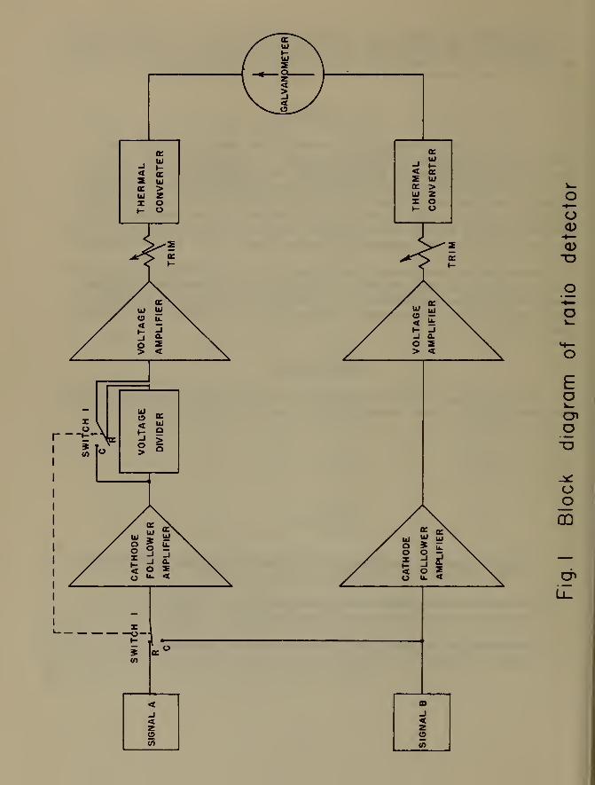
A block diagram of the circuit designed to determine the ratio of
two voltages is shown in figure 1. Several experimental ratio detectorswere built following the basic design of figure 1.
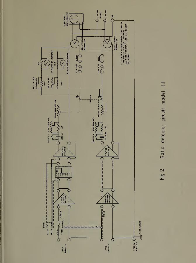
The final circuit is shown in figure 2. A description and discus-sion of the circuit components, starting from the left in figures 1 and 2,
is given below.
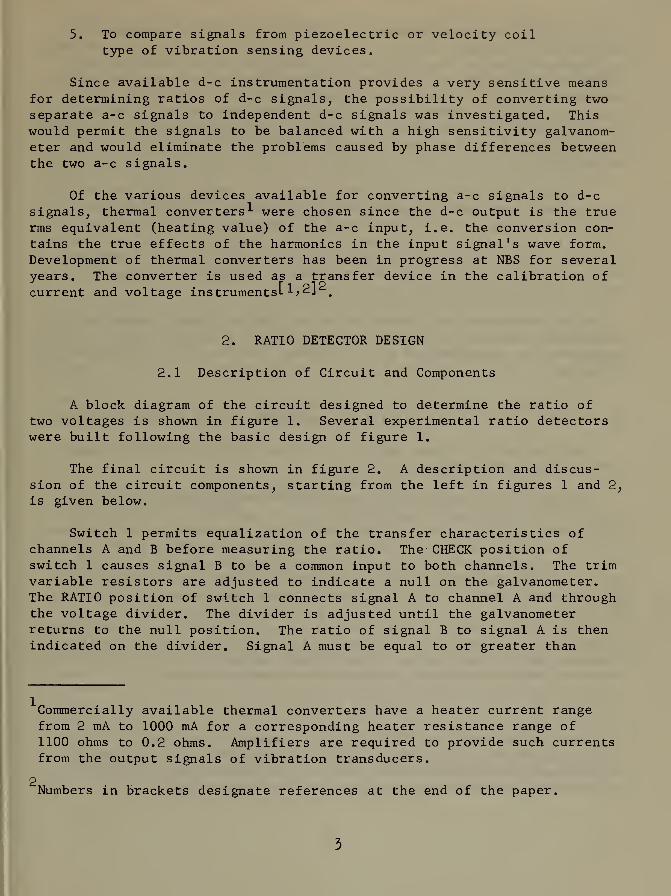
Switch 1 permits equalization of the transfer characteristics ofchannels A and B before measuring the ratio. The CHECK position ofswitch 1 causes signal B to be a common input to both channels. The trimvariable resistors are adjusted to indicate a null on the galvanometer.The RATIO position of switch 1 connects signal A to channel A and throughthe voltage divider. The divider is adjusted until the galvanometerreturns to the null position. The ratio of signal B to signal A is thenindicated on the divider. Signal A must be equal to or greater than
Commercially available thermal converters have a heater current rangefrom 2 mA to 1000 mA for a corresponding heater resistance range of1100 ohms to 0.2 ohms. Amplifiers are required to provide such currentsfrom the output signals of vibration transducers.
2Numbers in brackets designate references at the end of the paper.
signal B. The switching impedance of switch 1 should be considered in
relation to the output impedance of the transducer being tested. Switch 1
was chosen to have as high a capacitive reactance as possible betweenchannel A and B because the internal impedance of most vibration pickupsis capacitive. For signals from piezoelectric transducers, the capaci-
tance from the high side of input terminal A or input terminal B to
ground, or from the high side of terminal A to the high side of terminal
B can act like a partial short causing a loss of accuracy in the final
voltage ratio.
Cathode follower amplifiers are provided to reduce loading errorsbetween the signal and voltage divider or between the signal and the
voltage amplifiers. If loading errors can be neglected or if eitherA or B is a d-c signal, the cathode follower amplifiers should be removedfrom the circuit. The gain linearity of these amplifiers is importantbecause signal A may be up to twenty times the magnitude of signal B
which is used for balancing the two channels.
Voltage dividers are available for a-c and d-c signals with indi-cated ratios accurate to within 0.001 percent at a ratio of one. Thedivider may be either an a-c or d-c divider, whichever is compatible withsignal A.
The voltage amplifiers are necessary to provide high input impedanceand to amplify the signal voltage for operation of the thermal converters.
Gain and trim variable resistors are provided to adjust the outputcurrent from both voltage amplif iers-*.
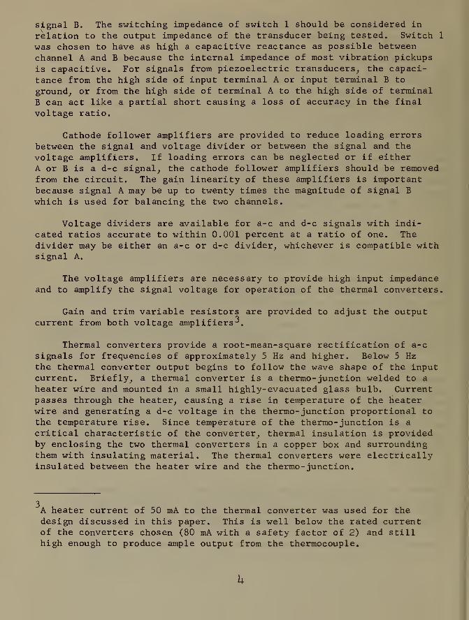
Thermal converters provide a root-mean-square rectification of a-c
signals for frequencies of approximately 5 Hz and higher. Below 5 Hzthe thermal converter output begins to follow the wave shape of the inputcurrent. Briefly, a thermal converter is a thermo- junction welded to a
heater wire and mounted in a small highly-evacuated glass bulb. Currentpasses through the heater, causing a rise in temperature of the heaterwire and generating a d-c voltage in the thermo- junction proportional to
the temperature rise. Since temperature of the thermo- junction is a
critical characteristic of the converter, thermal insulation is providedby enclosing the two thermal converters in a copper box and surroundingthem with insulating material. The thermal converters were electricallyinsulated between the heater wire and the thermo- junction.
3A heater current of 50 mA to the thermal converter was used for the
design discussed in this paper. This is well below the rated currentof the converters chosen (80 mA with a safety factor of 2) and stillhigh enough to produce ample output from the thermocouple.

The galvanometer was of the conventional electronic null indicatortype.
The voltmeter section was provided to obtain an approximate balancebetween the two signals before they are switched to the thermal convertersby switch 2. This was desirable to prevent inadvertent burn out of a
thermal converter heater while attempting to balance the galvanometer^.Initially, an approximate determination of the ratio should be made fromindications of the input signals on the panel voltmeters (VM) . This is
done through adjustments of the gain settings of the amplifiers and gainvariable resistors. Final balance of the currents through the thermalconverters and final determination of the ratio are made when switch 2
is set to the thermal converter (TC) position.
2.2 Procedure for Determining Voltage Ratio
A procedure has been developed for using the voltage ratio detectorshown in figures 1 and 2. This procedure assumes prior knowledge of thetype of voltage signal, a-c or d-c, and some information about the rela-tive magnitudes of the signals. The ratio of the magnitude of signal Ato signal B can be determined using the ratio detector shown in figure 2
as follows:
1. Set switch 1 to C (CHECK).
2. Set switch 2 to VM.
3. Turn power switches ON and allow about 15 minutes for
thermal equilibrium of the electronic equipment.
4. Connect signal sources to input terminals A and B with the
larger signal connected to terminal A.
5. Adjust the gain of the amplifiers and the gain variableresistors to read 0.5 volts on the VM's.
4When a new circuit is put into operation, it is recommended that a checkbe made to determine that the current through the thermal converters andvoltmeters are equal. In this circuit (Fig. 2), the current through the
voltmeter was 50 mA when the voltmeter indicated 0.5 volts. The currentto each thermal converter was checked with a milliammeter inserted inplace of the short. With switch 1 in the CHECK position and switch 2 inthe TC position, the input signal level at B was increased until 50 mAwas indicated on the' milliammeter. Then switch 2 was set to the VM posi-
tion. The resistance of each voltmeter circuit was adjusted with vari-able resistors until the voltmeter read 0.5 volts.

6. Set switch 1 to R (RATIO).
7. Adjust the divider until VM A reads 0.5 volts.
8. Set switch 1 to C.
9. Set switch 2 to TC.
10. Tune the trim variable resistors to balance the galvanometer.
11. Set switch 1 to R.
12. Adjust the divider to balance the galvanometer.
13. Return switch 1 to C as a check on the balance of the
detector circuit.
14. Retune the trim variable resistors if necessary to balancethe galvanometer.
15. Set switch 1 to R.
16. If necessary, adjust the divider to balance the galva-
nometer.
17. Set switch 2 to VM before changing the signal level or
turning off the equipment.
If the agreement between readings of the galvanometer with switch 1 in
the C or R position (steps 13 to 16) is within acceptable limits, the
voltage ratio is read from the divider.
3. RESULTS AND DISCUSSION
3.1 Voltage Ratio Detector Applications
The applications of an a-c voltage ratio detector are numerous inthe electrical measurements field. Three applications are of interestin the calibration of vibration transducers.
[3]The reciprocity calibrations of vibration standards require measure-
ments of voltage ratio and transfer admittance. The need for increasedaccuracies in these measurements was the primary reason for developingthis circuit. In using a vibration standard calibrated by the reciprocitymethod to calibrate transfer standards (vibration pickups), it has beennecessary to make transfer admittance measurements. The ratio detector
has been used in a similar way to compare transfer standards with the
primary standard.
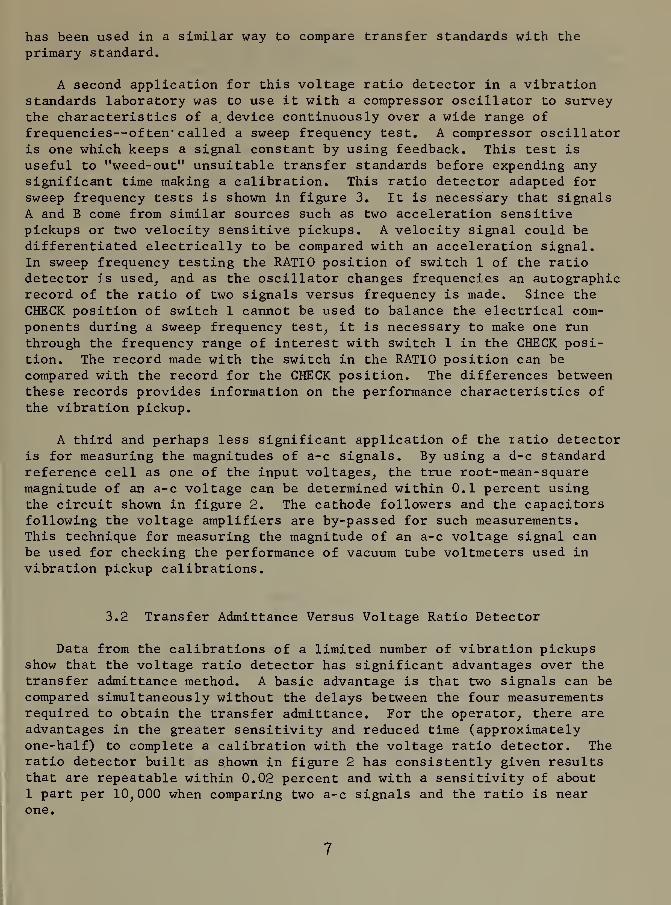
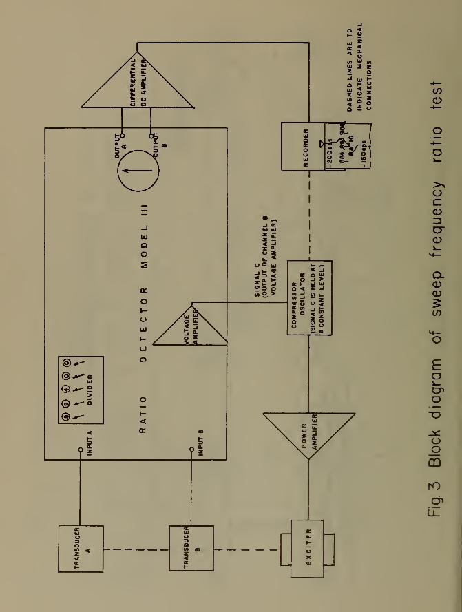
A second application for this voltage ratio detector in a vibrationstandards laboratory was to use it with a compressor oscillator to surveythe characteristics of a. device continuously over a wide range offrequencies—of ten' called a sweep frequency test. A compressor oscillatoris one which keeps a signal constant by using feedback. This test is
useful to "weed-out" unsuitable transfer standards before expending anysignificant time making a calibration. This ratio detector adapted forsweep frequency tests is shown in figure 3. It is necessary that signalsA and B come from similar sources such as two acceleration sensitivepickups or two velocity sensitive pickups. A velocity signal could bedifferentiated electrically to be compared with an acceleration signal.In sweep frequency testing the RATIO position of switch 1 of the ratiodetector is used, and as the oscillator changes frequencies an autographicrecord of the ratio of two signals versus frequency is made. Since the
CHECK position of switch 1 cannot be used to balance the electrical com-
ponents during a sweep frequency test, it is necessary to make one runthrough the frequency range of interest with switch 1 in the CHECK posi-tion. The record made with the switch in the RATIO position can be
compared with the record for the CHECK position. The differences betweenthese records provides information on the performance characteristics of
the vibration pickup.
A third and perhaps less significant application of the ratio detectoris for measuring the magnitudes of a-c signals. By using a d-c standardreference cell as one of the input voltages, the true root-mean- squaremagnitude of an a-c voltage can be determined within 0.1 percent usingthe circuit shown in figure 2. The cathode followers and the capacitorsfollowing the voltage amplifiers are by-passed for such measurements.This technique for measuring the magnitude of an a-c voltage signal canbe used for checking the performance of vacuum tube voltmeters used invibration pickup calibrations.
3.2 Transfer Admittance Versus Voltage Ratio Detector
Data from the calibrations of a limited number of vibration pickupsshow that the voltage ratio detector has significant advantages over thetransfer admittance method. A basic advantage is that two signals can becompared simultaneously without the delays between the four measurementsrequired to obtain the transfer admittance. For the operator, there areadvantages in the greater sensitivity and reduced time (approximatelyone-half) to complete a calibration with the voltage ratio detector. Theratio detector built as shown in figure 2 has consistently given resultsthat are repeatable within 0.02 percent and with a sensitivity of about1 part per 10,000 when comparing two a-c signals and the ratio is nearone.
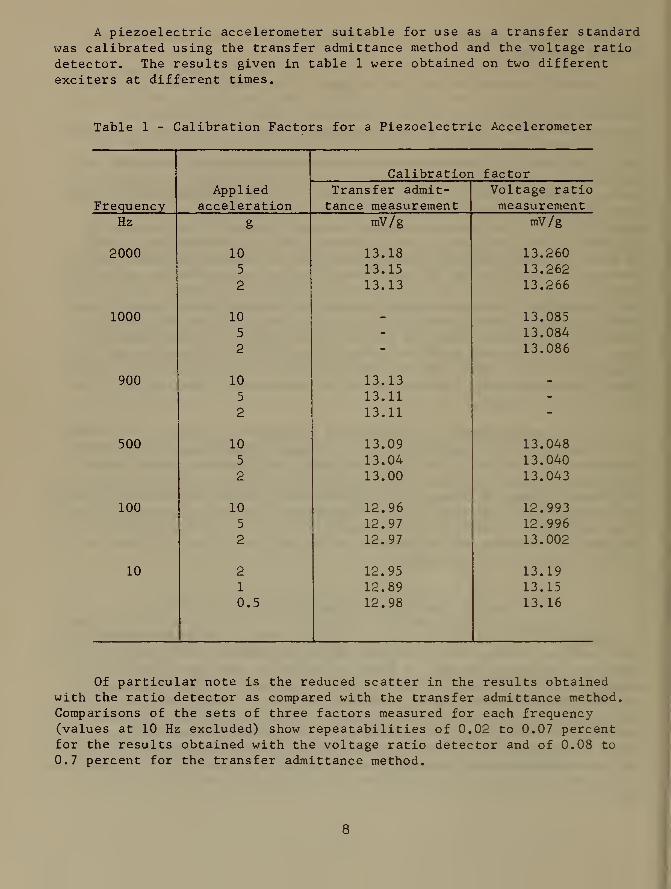
A piezoelectric accelerometer suitable for use as a transfer standardwas calibrated using the transfer admittance method and the voltage ratiodetector. The results given in table 1 were obtained on two differentexciters at different times.
Table 1 - Calibration Factors for a Piezoelectric Accelerometer
AppliedCalibratiori factor
Transfer admit- Voltage ratioFrequency acceleration tance measurement measurement
Hz g mV/g mV/g
2000 10 13.18 13.2605 13.15 13.2622 13.13 13.266
1000 10 _ 13.0855 - 13.0842 - 13.086
900 10 13.13 _
5 13.11 -
2 13.11 -
500 10 13.09 13.0485 13.04 13.0402 13.00 13.043
100 10 12.96 12.9935 12.97 12.9962 12.97 13.002
10 2 12.95 13.191 12.89 13.150.5 12.98 13.16
Of particular note is the reduced scatter in the results obtainedwith the ratio detector as compared with the transfer admittance method.Comparisons of the sets of three factors measured for each frequency(values at 10 Hz excluded) show repeatabilities of 0.02 to 0.07 percentfor the results obtained with the voltage ratio detector and of 0.08 to
0.7 percent for the transfer admittance method.
The number of significant figures given in table 1 are more than can
be justified by the overall accuracies of the vibration standards. Theyare shown here for comparisons of the relative sensitivity and repeat-ability of the transfer admittance and ratio detector methods.
4. CONCLUSION
A voltage ratio detector for comparing a-c signals of 5 mV andlarger was designed and put into operation. The principle of operationfor this ratio detector is to divide the larger of two signals with a
precision divider such that the output of the divider equals the smallersignal. Then the signals are amplified, converted to d-c signals withthermal converters and compared on a galvanometer. The transfer charac-teristics of the amplifiers and thermal converters are equalized by usingthe smaller of the two signals as a common input to the two amplifiers.
Based on the experimental measurements, some of which are presentedin this paper, and observations of improvements in speed, accuracy andconvenience during calibrations of vibrations and vibration transducers,it is believed that the current requirements for measurements of voltageratio were met.
ACKNOWLEDGMENT
Messrs. James A. Miller and Douglas R. Bryant assisted in the designand construction of the voltage ratio detector described in this report.
REFERENCES
1. AC-DC Transfer Instruments for Current and Voltage Measurements,F. L. Hermach, IRE Transactions Vol. 1-8, 1958.
2. A Differential Thermocouple Voltmeter, J. E. Griffin, F. L.Hermach, AIEE Transactions Paper No. 62-819, 1962.
3. Calibration of Shock and Vibration Pickups, ASA PublicationS2. 2-1959, Nov. 27, 1959.
<rUJ
_l \-< <Ks 111
ac >UJ ZX o»- o o
0)
OO
Eo
o
.it:
o_o
CD
S?
a>ooE
3ao
oa>
oa:
CO
®-r-
®^«>
®-"~
<5
CO
O
O
ocCDZ3
o-<D
CL
CO
EDeno
o_o
00
ro
en


1
U.S. DEPARTMENT OF COMMERCEWASHINGTON, D.C. 20230
POSTAGE AND FEES PAID
U.S. DEPARTMENT OF COMMERCE
OFFICIAL BUSINESS