Embed Size (px)
Citation preview

Copyright © 2013 Nordic Semiconductor ASA. All rights reserved.Reproduction in whole or in part is prohibited without the prior written permission of the copyright holder.
nRFready™ Voice Input Module Reference DesignnRF6929
User Guide v1.1

nRFready Voice Input Module User Guide v1.1
Contents
1 Introduction............................................................................................................................................... 31.1 Requirements..................................................................................................................................................... 31.2 Writing conventions........................................................................................................................................ 3
2 Kit content.................................................................................................................................................. 42.1 Hardware content ............................................................................................................................................ 42.2 Downloadable content .................................................................................................................................. 5
3 Quick start .................................................................................................................................................. 63.1 Prepare the hardware ..................................................................................................................................... 63.2 Installing the required packages on Ubuntu.......................................................................................... 73.3 Updating to the correct firmware for the nRF device ......................................................................... 73.4 Voice over HID over GATT demo using Ubuntu.................................................................................... 7
4 System overview..................................................................................................................................... 114.1 Input sources....................................................................................................................................................114.2 Audio processing............................................................................................................................................124.3 Firmware upgrading......................................................................................................................................144.4 Supported operating systems ...................................................................................................................14
5 PCA63506 Voice Input Module hardware description .................................................................... 165.1 Key features ......................................................................................................................................................165.2 Hardware figures ............................................................................................................................................175.3 Block diagram ..................................................................................................................................................185.4 Design description.........................................................................................................................................195.5 Schematics, Bill of Materials, PCB layout files, production files .....................................................29
6 Firmware update of the nRFready Voice Input Module................................................................. 306.1 J-Link Lite CortexM JTAG/SWD-emulator ..............................................................................................306.2 Firmware update ...........................................................................................................................................32
7 Troubleshooting ..................................................................................................................................... 33
Page 2 of 34

nRFready Voice Input Module User Guide v1.1
1 IntroductionThis reference design is the ideal platform for developing voice enabled remote controls for internet-enabled TVs and set-top boxes, or other voice enabled applications. The Voice Input Module is provides a low power and cost efficient voice input design. By sampling audio from a digital microphone or a line input, the Voice Input Module can send compressed audio stream to an nRFready Smart Remote or an Evaluation Kit, which then transmits it through a Bluetooth® low energy link.
The Voice Input Module has hardware support for two different audio input paths: digital microphone and analog line input. The on-board Cortex-M0 MCU handles digital sampling and compression of the audio with ADPCM codec, while the 64 kbps audio bitstream on UART can be received by the Smart Remote or Evaluation Kit.
1.1 RequirementsDemo requirements
To demonstrate the voice streaming capabilities of the nRFready Voice Input Module, the following is needed:
• One of the following Smart Remotes:• nRF6924 nRFready Smart Remote 2 • nRF6920 nRFready 2.4 GHz RF Smart Remote with
nRF6925 Smart Remote 2 Upgrade Kit• nRF6921 nRFready μBlue™ Smart Remote with
nRF6925 Smart Remote 2 Upgrade Kit• Bluetooth® low energy:
• Bluetooth 4.0 enabled hardware• Linux with Bluetooth 4.0 and HID over GATT support (for example BlueZ 5.2 or later)
• Google Chrome
Development requirements:
• Windows XP/7
1.2 Writing conventionsThis user guide follows a set of typographic rules that makes the document consistent and easy to read. The following writing conventions are used:
• Commands are written in Lucida Console.• Pin names are written in Consolas.• File names and User Interface components are written in bold.• Internal cross references are italicized and written in semi-bold.
Page 3 of 34

nRFready Voice Input Module User Guide v1.1
2 Kit contentThe nRFready Voice Input Module Reference Design consists of hardware and access to software components, reference design files, and documentation from www.nordicsemi.com.
2.1 Hardware content
Figure 1 Hardware content
Page 4 of 34

nRFready Voice Input Module User Guide v1.1
2.2 Downloadable contentThe nRFready Voice Input Module Reference Design includes firmware source code, documentation, hardware schematics, and layout files. To access these files, log in to your My Page account, enter the nRFready Voice Input Module product key (found on the nRFready Voice Input Module Reference Design box), and download the following files.
2.2.1 nRFready Voice Input Module Reference Design firmware installer file• Firmware for nRFready Voice Input Module
• Precompiled HEX files• Source code• Keil ARM® project files
2.2.2 nRFready Voice Input Module Reference Design documentation• This User Guide• Firmware documentation (will be available in a folder on your computer after you have run
the installer file)
2.2.3 Schematics, Bill of Materials, PCB layout files, and production files
The ZIP file and its subdirectories contain the hardware design files for the nRFready Voice Input Module Reference Design.
• Altium Designer files• PCB layout files • Production files
• Assembly drawings• Drill files • Gerber files• Pick and Place files• Bill of Materials
• Schematics
2.2.4 nRFready Voice Input Module Reference Design Ubuntu platform packages
The ZIP file contains .deb packages required to run the Voice Input Module demo on Ubuntu. Most of these packages are unmodified versions of standard Linux components. Source code is provided for the non-standard packages.
• Package binaries (.deb)• Source code
2.2.5 Other relevant files• nRFready Smart Remote 2 Firmware and documentation• nRFready Smart Remote 2 User Guide• nRF51822 Evaluation Kit User Guide
Page 5 of 34
nRFready Voice Input Module User Guide v1.1
3 Quick startThis section shows you how to set up the nRFready Voice Input Module Reference Design and run a voice recognition example on an Ubuntu Linux PC using Google Chrome and voice search.
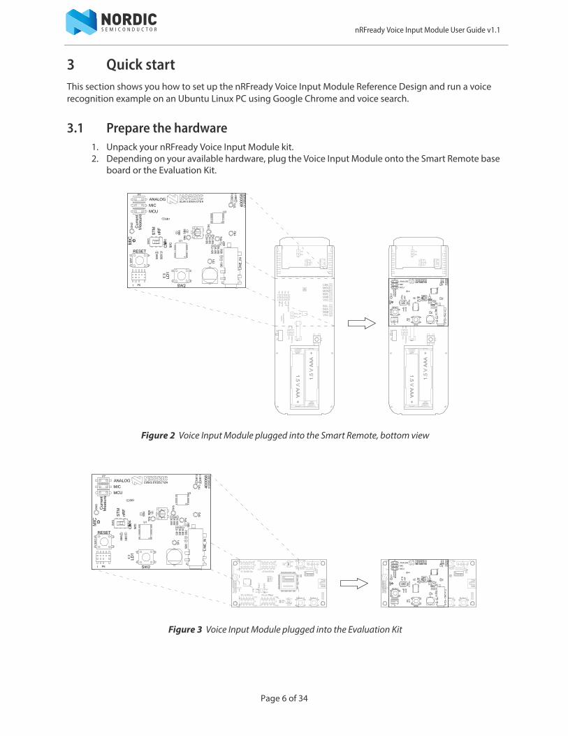
3.1 Prepare the hardware1. Unpack your nRFready Voice Input Module kit.2. Depending on your available hardware, plug the Voice Input Module onto the Smart Remote base
board or the Evaluation Kit.
Figure 2 Voice Input Module plugged into the Smart Remote, bottom view
Figure 3 Voice Input Module plugged into the Evaluation Kit
Page 6 of 34

nRFready Voice Input Module User Guide v1.1
3.2 Installing the required packages on UbuntuAlong with this User Guide and Firmware package, a set of Ubuntu Linux packages are available for download on the Nordic website. Both the compiled packages and the source code is available to download.
In order to run the voice recognition example, these packages must be installed on a Ubuntu 14.04 LTS Desktop Edition (http://releases.ubuntu.com/trusty/).
The packages are found in the binaries folder of the Ubuntu package download. HOWTO-intall.txt found in this folder details the installation process.
3.3 Updating to the correct firmware for the nRF deviceRefer to the relevant User Guide for firmware upgrade procedure. In the case the Smart Remote 2 is used, download the latest firmware from the Nordic website and follow the firmware upgrade instructions found in the Smart Remote 2 User Guide.
3.4 Voice over HID over GATT demo using Ubuntu
Pairing the Bluetooth low energy device
1. Start a new Bluetooth pairing procedure with the Smart Remote or the Evaluation Kit.2. On your computer, click the Bluetooth icon on the toolbar and then click Bluetooth Settings.
3. To search for a new device, click + in the Bluetooth window.
Page 7 of 34

nRFready Voice Input Module User Guide v1.1
4. When discovered, you will see Smart Remote 2 or your device name in the Device list. Select your device and click Continue to begin pairing.
5. After successfully pairing, the device will show up in the Devices list.
Configure audio input
1. Under All Settings, select Sound and then select the Input tab.2. Select the NVS device from the list of input sources.3. The Input level should now indicate that it is receiving input. The LED on the Voice Input Module
indicates it is streaming audio by lighting up.
Note: Press button SW2 on the Voice Input Module to toggle the LED streaming indication.
4. To stop streaming, select All Settings or close the window.
Page 8 of 34

nRFready Voice Input Module User Guide v1.1
Test voice recognition
1. Open up Chrome. Select Dash Home and type "Google Chrome". Click the Google Chrome icon that is displayed.
2. Go to www.google.com. If you are redirected to a local Google version, click Google.com in the lower-right corner of the webpage.
3. Click the microphone icon. The recording LED LD1 on the Voice Input Module should light up immediately (press button SW2 to turn it off ), and you can speak into the Smart Remote. Chrome will stop recording automatically when you stop talking.
Note: If you do not see the microphone symbol, the GVoice application might not be installed. Go to the Google Chrome Web Store to download and install GVoice.
Dash Home
Page 9 of 34

nRFready Voice Input Module User Guide v1.1
Listening to audio qualityAudio quality can be verified by looping the sound directly from the Ubuntu input source (Voice Input Module) to the output (speakers).
Enable loopback
1. Open a terminal (CTRL + ALT + T).2. In the terminal window, type the following command:
pactl load-module module-loopback latency_msec=20.
Note: The command latency_msec=20 is optional. It helps to minimize the acoustic feedback. Some machines does not accept the command and may return error codes. In that case, just invoke module-loopback without specifying latency.
3. If successful, this command returns a handle number, invoking this command multiple times generates multiple loopback instances with independent handles.
Disable loopback
In the terminal window, type the following command pactl unload-module x, where x is the handle module number returned when enabling the loopback.
Note: If the Smart Remote is not connected and selected as the audio input source, sound will be streamed from the PC microphone to the PC speakers causing acoustic feedback.
Page 10 of 34

nRFready Voice Input Module User Guide v1.1
4 System overviewThis chapter describes the functionality of the Voice Input Module including how it can be used for development purposes. The nRFready Voice Input Module is designed to be plugged into a nRFready Smart Remote or an Evaluation Kit and cannot be used when not plugged into one of these devices. The module includes a digital microphone, 3.5 mm input jack, analog filtering circuitry, and a Cortex M0-based MCU.
Figure 4 System overview
4.1 Input sourcesTwo different audio input sources are available:
• Digital microphone• Line input 3.5 mm jack
The main input source is the digital microphone. Placed on the Voice Input Module itself, it allows audio to be recorded without connecting an audio source. In the event that an analog audio input signal is desired, an optional 3.5 mm jack is included.
Note: The initial firmware version only supports digital microphone sampling.
Page 11 of 34

nRFready Voice Input Module User Guide v1.1
4.2 Audio processingDepending on the audio input source, different means of sampling and filtering are used. The digital audio signal from the microphone is sampled and filtered digitally. The analog signal on the other hand, passes through an analog filter prior to being sampled.
4.2.1 Digital sampling
The digital microphone is a 1 bit sigma-delta modulator, which outputs a pulse-density modulated (PDM) signal. The signal is synchronized with the microphone clock input, and can be sampled using SPI.
The audio MCU acts as an SPI master, and provides the clock for the digital microphone. The microphone data output is sampled on the SPI input line of the audio MCU. This type of microphone requires a clock frequency between 1 and 3 MHz. A typical PDM signal is shown in the figure below.
Figure 5 Typical PDM signal
Compared to the desired 16 kHz sampling frequency (fs), the PDM output signal is oversampled by a factor of 60 or more. The oversampling shifts noise components into the upper frequency band of the PDM signal. The signal must pass through a digital low-pass filter in order to remove the high-frequency noise components.
Note that the SPI clock defines the sampling rates of the entire digital audio signal chain. If the SPI clock speed is altered, adjustments must be made to filter coefficients, buffer sizes, and so on. While the default SPI clock is provided by the audio MCU, the hardware can be configured so that the SPI clock is provided externally (by the nRF51) instead. See Section 5.4.2 “Digital microphone” on page 20 for more information. This makes it possible to remove the 18.432 MHz crystal, at the cost of not being able to achieve fs of 16 kHz.
Analog
PDM
Clock
signal
signal
Page 12 of 34

nRFready Voice Input Module User Guide v1.1
4.2.2 Analog sampling
The analog line in signal is passed through an analog filter and connected to one of the ADC inputs on the audio MCU. Because of the analog filter, the ADC can be run at 16 kHz without any oversampling. See Section 5.4.3.2 “Anti-aliasing filter” on page 24 for details regarding the analog filtering.
4.2.3 Digital filtering
In order to fit the encoder input format and the bandwidth requirements, the digital signal needs to be filtered and compressed. The filtering process reduces fs from 1-3 MHz to 16 kHz and converts the signal from PDM to PCM (pulse-code modulated) format. Such a process of low-pass filtering and downsampling a signal is called ‘decimation’.
Figure 6 illustrates the decimation filter. However, as this filter is purely digital, the implementation might differ between firmware versions. Details regarding the decimation filtering are found in the firmware documentation.
Figure 6 Decimation filter
4.2.4 Encoding
Adaptive differential pulse-code modulation (ADPCM) encoding is used to compress the audio signal to a data rate suitable for Bluetooth low energy. In order to keep the decoder synchronized with the encoder, the audio stream is divided into 32 ms long frames. Each frame is prefixed with the encoder state. This makes each frame an individual set of data, which will handle frame loss in the event of range or RF noise issues. When a frame is ready, it is transmitted using the UART interface.
Table 1 Frame format
Byte no. Content
0 MSByte of first frame sample
1 LSByte of first frame sample
2 ADPCM step table index
3 - 258 Encoded samples
Decimator
Digital mic1-3 MHz Low-pass
filter1-3 MHz
Downsampler
PDM format PCM format
Page 13 of 34

nRFready Voice Input Module User Guide v1.1
4.3 Firmware upgradingThe Voice Input Module firmware can be modified and upgraded. See Chapter 6 “Firmware update of the nRFready Voice Input Module” on page 30 for how to upgrade the firmware.
4.4 Supported operating systemsThe nRFready Voice Input Module requires the host to be able to decode the ADPCM encoded audio the module delivers. The demo described in this user guide complies with the Bluetooth 4.0 HID over GATT profile and is compatible with all host systems incorporating this profile. The voice recognition example and ADPCM decoding have been implemented on a version of BlueZ supporting HID over GATT.
Page 14 of 34

nRFready Voice Input Module User Guide v1.1
4.4.1 Ubuntu
The nRFready Voice Input Module is delivered with a set of compiled software packages which enables the voice recording feature on Ubuntu 14.04 LTS Desktop Edition.
Figure 7 illustrates the relevant parts of Ubuntu software architecture and specifically highlights what has been modified.
Figure 7 Voice enabled Ubuntu software architecture
The main components seen in the figure are:
• BlueZ (Linux Bluetooth subsystem)• PulseAudio (audio subsystem used by Ubuntu)
The BlueZ version needs to support the HID over GATT Profile (version 5.2 or newer).
Note: This implementation uses an earlier version of BlueZ (4.101) which has been modified to include HID over GATT.
A set of PulseAudio plugins is used to detect the presence of a voice enabled HID device and to decode and insert the decoded audio into the audio subsystem. module-nvs-audio makes the voice enabled Bluetooth device appear as a normal microphone and translates "start/stop recording" signals into Bluetooth packet transmissions. module-nvs-detect looks for voice enabled HID devices and initiates the necessary components when one is found.
Linux Kernel
HID over GATT (HoG)module-nvs-detect module-nvs-audio
BlueZ PulseAudio
Modules
Ubuntu sound configuration Media application
GStreamerNew
Existing
/dev/uHID /dev/hidraw
Page 15 of 34

nRFready Voice Input Module User Guide v1.1
5 PCA63506 Voice Input Module hardware descriptionThe PCA63506 Voice Input Module is designed to plug onto the nRFready Smart Remote or the Evaluation Kit. The module contains a Cortex M0 MCU from ST Microelectronics for audio sampling and compression, and has two audio input options: a digital MEMS (Micro Electrical-Mechanical System) microphone and an analog line input with a filter and preamplifier. A programming interface for firmware upgrade and development for the MCU is also included. To simplify current measurements, the module has a set of jumpers which can be replaced with ampere meters for current measurements of the individual blocks on the board.
Figure 8 High level block diagram
5.1 Key featuresThe Voice Input Module has the following key features:
• STM32 Cortex M0 MCU for audio compression• Digital MEMS microphone• Line input with active anti-aliasing filter and preamplifier• Current measurement headers• Interface compatible with Smart Remote and Evaluation Kit• Configurable design and test points for development purposes• ARM SWD programming/debugging interface
Smart Remote or Evaluation KitVoice Input Module
PDMU1
Cortex M0MCU
UART nRF51MCU
Digital mic
Line input Filter
Bluetoothradio link
Page 16 of 34
nRFready Voice Input Module User Guide v1.1
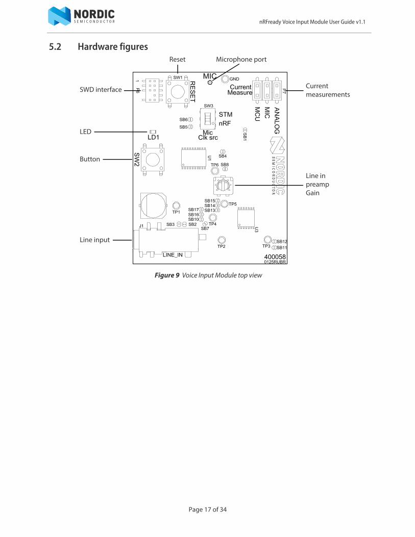
5.2 Hardware figures
Figure 9 Voice Input Module top view
SWD interface Currentmeasurements
Microphone port
LED
Button
Line input
Reset
Line inpreamp Gain
Page 17 of 34
nRFready Voice Input Module User Guide v1.1
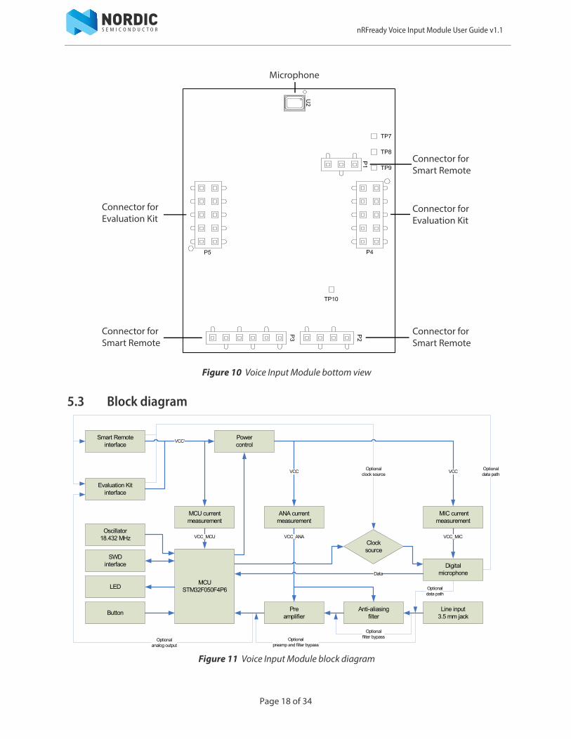
Figure 10 Voice Input Module bottom view
5.3 Block diagram
Figure 11 Voice Input Module block diagram
Microphone
Connector forEvaluation Kit
Connector forSmart Remote
Connector forEvaluation Kit
Connector forSmart Remote
Connector forSmart Remote
VCCVCC
VCC’
VCC_MICVCC_MCU VCC_ANA
Data
Optional clock source
Optional data path
Optionalfilter bypassOptional
preamp and filter bypassOptional
analog output
Optionaldata path
MCUSTM32F050F4P6
Smart Remoteinterface
Evaluation Kitinterface
MCU current measurement
MIC current measurement
ANA current measurement
Oscillator18.432 MHz
SWDinterface
LED
Button
Powercontrol
Digitalmicrophone
Preamplifier
Anti-aliasing filter
Line input3.5 mm jack
Clocksource
Page 18 of 34

nRFready Voice Input Module User Guide v1.1
5.4 Design descriptionThis chapter contains details about the hardware blocks on the module.
5.4.1 Power supply scheme and current measurement
A set of jumpers are available for simple measuring of the current consumption of the different blocks of the hardware. The jumpers are in series with the power supply for:
• MCU• Digital microphone• Analog filter and preamplifier
The power supply for the MCU is fed directly from the Smart Remote or the Evaluation Kit, but the power supply for the digital microphone and analog filter circuitry passes through a power switch circuit that is controlled by the MCU. See Figure 12 for more information.
Figure 12 Power supply scheme and current measurement headers
Figure 13 Current measurement on the MCU
Page 19 of 34

nRFready Voice Input Module User Guide v1.1
5.4.2 Digital microphone
The PCA63506 module is equipped with a digital MEMS microphone. The microphone is located on the bottom side of the PCB and has a bottom port, meaning the sound is recorded through a hole in the PCB, see Figure 14.
Figure 14 Location of microphone port
The data and clock lines to the microphone are by default connected to the on-board audio compression MCU. Optionally, the lines can also be connected to the nRF chip on the Smart Remote or the Evaluation Kit. By soldering SB5 and SB6, the clock and data signals for the digital microphone is routed to the Smart Remote and Evaluation Kit interface connectors, see Figure 15. See Section 5.4.5 “Smart Remote interface” on page 26 and Section 5.4.6 “Evaluation Kit interface” on page 27 for more information on the connection to the nRF51 chip.
Note: Requires FW update of the MCU.
Figure 15 Connecting digital microphone lines to the interface connectors
Solder SB6
Solder SB5
Page 20 of 34

nRFready Voice Input Module User Guide v1.1
5.4.2.1 Using the nRF chip as digital microphone clock source
Even though the on-board MCU is used for sampling data from the digital microphone by default, there is also an option to supply the clock signal from the nRF51 chip. To do this, make sure SB5 is soldered and flip SW3 to the nRF position, see Figure 16.
Note: Requires FW update of the MCU.
Figure 16 Supplying clock from the nRF chip
When driving the clock from an external device, we change the data input line for the audio sampling MCU from MOSI to MISO. This must be done because the SPI peripheral of the audio sampling MCU uses a different data input pin when configured as a SPI Master compared to when it is configured as a SPI slave (the SPI master provides the clock signal). Figure 17 shows how the signals are swapped.
Figure 17 Digital microphone configuration
Solder SB5Flip switchto nRF position
CLOCK_SYNC
SB6
Solderbridge
SB5
SolderbridgeMIC_DOUT_EXT
MIC_CLK_EXT
PA7
PA6SW3
CAS-220TA
CLOCK_SYNC
MIC_DOUTMIC_DOUT
MIC_CLK
MIC_DOUT
Page 21 of 34
nRFready Voice Input Module User Guide v1.1
5.4.3 Analog line input
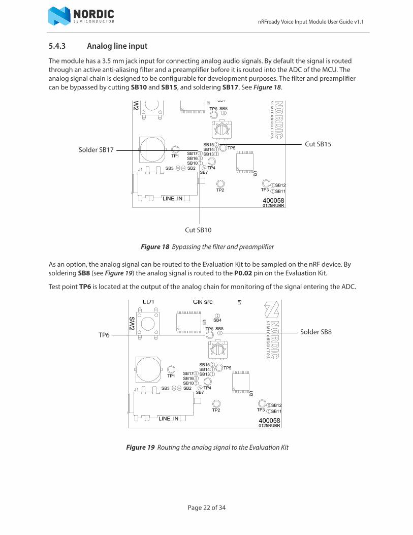
The module has a 3.5 mm jack input for connecting analog audio signals. By default the signal is routed through an active anti-aliasing filter and a preamplifier before it is routed into the ADC of the MCU. The analog signal chain is designed to be configurable for development purposes. The filter and preamplifier can be bypassed by cutting SB10 and SB15, and soldering SB17. See Figure 18.
Figure 18 Bypassing the filter and preamplifier
As an option, the analog signal can be routed to the Evaluation Kit to be sampled on the nRF device. By soldering SB8 (see Figure 19) the analog signal is routed to the P0.02 pin on the Evaluation Kit.
Test point TP6 is located at the output of the analog chain for monitoring of the signal entering the ADC.
Figure 19 Routing the analog signal to the Evaluation Kit
Solder SB17
Cut SB10
Cut SB15
Solder SB8TP6
Page 22 of 34

nRFready Voice Input Module User Guide v1.1
5.4.3.1 Channel selection and DC offset
There are two solder bridges located next to the 3.5 mm jack connector, SB2 and SB3, which make it possible to choose the left or right channel of the input signal, see Table 2.
Table 2 Line input channel selection
To switch from left to right channel input, cut the shorting of SB2 and solder SB3, see Figure 20.
Figure 20 Changing from left to right input channel
After the channel selection the signal passes through a DC block capacitor, C18, and is then DC shifted with the resistor network R7 and R8 which will make the signal swing around a voltage greater than zero. The voltage divider network has been tuned to match the filter and preamplifier circuit, giving the most optimal voltage swing on the input of the ADC of the MCU.
Test point TP1 is available for monitoring the signal after the DC block capacitor.
Solder bridge Channel Comment
SB2 Left Default shorted
SB3 Right Open
Solder SB3
Cut SB2
TP1
Page 23 of 34

nRFready Voice Input Module User Guide v1.1
5.4.3.2 Anti-aliasing filter
The anti-aliasing filter on the Voice Input Module is designed as a 6th order elliptic filter with a frequency
response of -3 dB at 5 kHz. The filter is built up of three 2nd order low pass notch stages, which has a Boctor topology.
The overall filter frequency response is shown in Figure 21. In this figure the response is normalized to 0 dB, but the filter has an overall voltage gain of 4.9 at 1 kHz.
Figure 21 Anti-aliasing filter frequency response
In the filter chain, test points are available for monitoring the signal.
• TP2 is on the output of stage 1• TP3 is on the output of stage 2• TP4 is on the output of stage 3
The filter can be bypassed by cutting the short on SB10 and SB13, and solder SB16, see Figure 22.
Figure 22 Bypassing anti-aliasing filter
101 102 103 104−80
−70
−60
−50
−40
−30
−20
−10
0
Frequency (Hz)
Res
pons
e (d
B)
Solder SB16Cut SB13TP4
TP3
TP2Cut SB10
Page 24 of 34

nRFready Voice Input Module User Guide v1.1
5.4.3.3 Preamplifier
The preamplifier is a simple op-amp amplifier circuit with adjustable gain. The voltage gain can be adjusted from 1 to 4.6 by using the Rp1 potentiometer. See Figure 23.
Test point TP5 is available on the output of the preamplifier for monitoring of the output signal.
Figure 23 Preamplifier gain and test point
Rp1
TP5
Page 25 of 34

nRFready Voice Input Module User Guide v1.1
5.4.4 Button and LED
The Voice Input Module features a tactile button and a LED. The button is connected to pin PB1 of the MCU and has active low functionality. The LED is connected to pin PA3 and is sinked through a current limiting resistor, See Figure 24.
Figure 24 Button and LED
5.4.5 Smart Remote interface
The interface to the Smart Remote consists of three connectors, P1, P2, and P3. All connectors are placed on the bottom side of the board and are positioned so the module will fit on the available headers on the Smart Remote Base Board, see Figure 10 on page 18. P1 is only used for mechanical stability. For pin descriptions on connector P2 and P3, see Table 3 and Table 4.
Table 3 P2 connector pin information
Table 4 P3 connector pin information
Pin Smart Remote pin name Label Description
1 VCC VCC’ Power supply
2 GND GND Ground
3 SDA I2C_SDA Two-wire slave data
4 SCL I2C_SCL Two-wire slave clock
Pin Smart Remote pin name Label Description
1 VCC VCC’ Power supply
2 GND GND Ground
3 SPI_SCKUART_TXDCLOCK_SYNC
UART data output for audioSignal for clock synchronization
4 SPI_MOSI MIC_CLK_EXT Digital microphone clock line
5 SPI_MISO MIC_DOUT_EXT Digital microphone data line
6 CSN_1 UART_CTS/WAKEUP UART handshake/wakeup on pin signal
SW2PB SW
GND
SW2 LD1
L0603G
VCC
R6220R
LD1
Page 26 of 34

nRFready Voice Input Module User Guide v1.1
5.4.6 Evaluation Kit interface
To connect to the Evaluation kit, the Voice Input Module has two 10 pin connectors placed on the bottom side of the Module. They are positioned so the module will snap in easily on the Evaluation Kit board, see Figure 10 on page 18. See Table 5 and Table 6 for reference and pin descriptions on connector P4 and P5.
Table 5 P4 connector pin information
Table 6 P5 connector pin information
Pin Evaluation Kitpin name Label Description
1 P0.24 BOOT0 MCU boot memory selection
2 P0.25 NC Not connected
3 P0.26 NC Not connected
4 P0.27 NC Not connected
5 P0.28 MIC_CLK_EXT Digital microphone clock line
6 P0.29 MIC_DOUT_EXT Digital microphone data line
7 P0.30 NC Not connected
8 P0.31 NC Not connected
9 GND GND Ground
10 VCC_IO VCC’ Power supply
Pin Evaluation Kit pin name Label Description
1 P0.00 NC Not connected
2 P0.01 UART_CTS/WAKEUP UART flow control/wakeup on pin signal
3 P0.02 EK_ANA Signal from analog input after preamplifier
4 P0.03 UART_TXD UART data output for audio
5 P0.04 I2C_SCL Two-wire slave clock
6 P0.05 I2C_SDA Two-wire slave data
7 P0.06 CLOCK_SYNC Signal for clock synchronization
8 P0.07 nRST MCU reset
9 GND GND Ground
10 VCC_IO VCC’ Power supply
Page 27 of 34

nRFready Voice Input Module User Guide v1.1
5.4.7 I/O usage
The STM32F050F4P6 has 15 generic I/Os available. All I/Os are used in this design and are organized as shown in Table 7.
Table 7 I/O usage
Pin Label Description
PA0 UART_CTS/WAKEUP UART flow control / wakeup on pin signal
PA1 PWR_CTRL Power control signal for digital microphone and analog filter
PA2 UART_TXD UART data output
PA3 LD1 LED output
PA4 ADC_IN Input from analog chain
PA5 MIC_CLK Digital microphone clock line
PA6 PA6Data from digital microphone/clock sync line (see Section 5.4.2.1 on page 21)
PA7 PA7Data from digital microphone/clock sync line (see Section 5.4.2.1 on page 21)
PA9 I2C_SCL Two-wire slave clock
PA10 I2C_SDA Two-wire slave data
PA13 SWDIO Programming and debugging data line
PA14 SWCLK Programming and debugging clock line
PB1 SW2 Button input
PF0 OSC_IN 18.432 MHz crystal input
PF1 OSC_OUT 18.432 MHz crystal output
Page 28 of 34
nRFready Voice Input Module User Guide v1.1
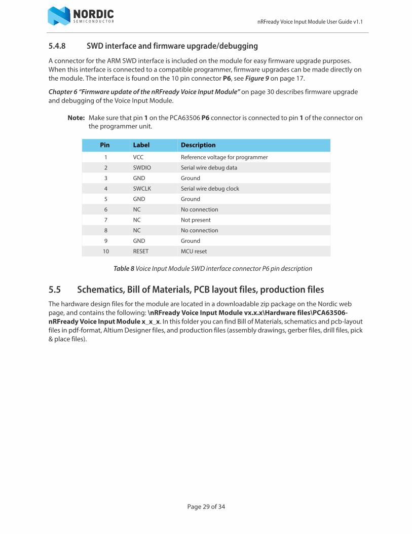
5.4.8 SWD interface and firmware upgrade/debugging
A connector for the ARM SWD interface is included on the module for easy firmware upgrade purposes. When this interface is connected to a compatible programmer, firmware upgrades can be made directly on the module. The interface is found on the 10 pin connector P6, see Figure 9 on page 17.
Chapter 6 “Firmware update of the nRFready Voice Input Module” on page 30 describes firmware upgrade and debugging of the Voice Input Module.
Note: Make sure that pin 1 on the PCA63506 P6 connector is connected to pin 1 of the connector on the programmer unit.
Table 8 Voice Input Module SWD interface connector P6 pin description
5.5 Schematics, Bill of Materials, PCB layout files, production filesThe hardware design files for the module are located in a downloadable zip package on the Nordic web page, and contains the following: \nRFready Voice Input Module vx.x.x\Hardware files\PCA63506-nRFready Voice Input Module x_x_x. In this folder you can find Bill of Materials, schematics and pcb-layout files in pdf-format, Altium Designer files, and production files (assembly drawings, gerber files, drill files, pick & place files).
Pin Label Description
1 VCC Reference voltage for programmer
2 SWDIO Serial wire debug data
3 GND Ground
4 SWCLK Serial wire debug clock
5 GND Ground
6 NC No connection
7 NC Not present
8 NC No connection
9 GND Ground
10 RESET MCU reset
Page 29 of 34

nRFready Voice Input Module User Guide v1.1
6 Firmware update of the nRFready Voice Input ModuleTo be able to update the firmware on the MCU you will need a programmer/debugging tool that is compatible with the SWD protocol. Please refer to ST Microelectronics, www.st.com, for tools that are compatible with the STM32F050F4P6 MCU used on the Voice Input Module. We will use the SEGGER J-Link Lite debugger that is supplied in the Smart Remote 2 Kit as an example. In this section is a step-by-step guide for connecting your Voice Input Module to the SEGGER J-Link Lite debugger and to update the firmware.
6.1 J-Link Lite CortexM JTAG/SWD-emulatorThe programming and debugging interface of the MCU is accessed through a 10 pin connector (P6). To program and debug the device, you may use a J-Link Lite CortexM JTAG/SWD emulator from SEGGER. Make sure that pin 1 on the 10 pin connector on the SEGGER J-Link Lite CortexM is connected to pin 1 on the P6 connector on the PCA63506 Voice Input Module. Figure 25 shows the position of pin 1 on the SEGGER J-Link Lite Cortex M.
Figure 25 Pin 1 position on SEGGER J-Link Lite
J-LINK LITE CortexMPin 1
Page 30 of 34

nRFready Voice Input Module User Guide v1.1
To connect the Voice Input Module to the JTAG/SWD emulator, use the 10 pin flat cable supplied with the J-Link. Connect the cable to the Voice Input Module so there will be a one-to-one mapping of the pins. Figure 26 shows what the connection should look like.
Figure 26 SEGGER J-Link Lite connected to the Voice Input Module
Page 31 of 34

nRFready Voice Input Module User Guide v1.1
6.2 Firmware updateAfter running the firmware installer file, there will be a “Firmware update” project for Keil μVision in the folder structure \Precompiled hex\Firmware upgrade projects\. You will need to download and install Keil to be able to open the project. An evaluation version of Keil μVision can be downloaded from http://www.keil.com free of charge.
After opening the Firmware update project in Keil μVision, click the Download button to program the MCU, see Figure 27.
Figure 27 Downloading firmware to the STM32F050F4P6 MCU
Page 32 of 34

nRFready Voice Input Module User Guide v1.1
7 Troubleshooting
No audio is received when I use the digital microphone and stream audio to the host.• Make sure that the jumper is present in the MIC position on P7.• Make sure the SW3 switch is in the STM position.• LED LD1 will light up when the digital microphone is being sampled.
The analog input does not work.• Make sure that the jumper is present in the ANALOG position on P7.
For accurate current measurement of the module.• Make sure the LED LD1 is not lit when measuring. It can be toggled on and off by pressing
button SW2 while streaming.• Remove power jumpers for unused functionality (remove ANALOG jumper when using the
digital microphone, and vice versa when using the line in).
The Voice Input Module does not work when plugged into the Evaluation Kit.• Check the orientation of the board and that you are using the correct set of Evaluation Kit
connectors.
Page 33 of 34

nRFready Voice Input Module User Guide v1.1
Liability disclaimerNordic Semiconductor ASA reserves the right to make changes without further notice to the product to improve reliability, function or design. Nordic Semiconductor ASA does not assume any liability arising out of the application or use of any product or circuits described herein.
Life support applicationsNordic Semiconductor’s products are not designed for use in life support appliances, devices, or systems where malfunction of these products can reasonably be expected to result in personal injury. Nordic Semiconductor ASA customers using or selling these products for use in such applications do so at their own risk and agree to fully indemnify Nordic Semiconductor ASA for any damages resulting from such improper use or sale.
Contact detailsFor your nearest distributor, please visit http://www.nordicsemi.com.Information regarding product updates, downloads, and technical support can be accessed through your My Page account on our homepage.
Revision history
ARM statementKeil, μVision, and Cortex are trademarks of ARM Limited. All other brands or product names are the property of their respective holders.
Date Version Description
November 2014 1.1 Changed the reference to Ubuntu version in Section 3.2 “Installing the required packages on Ubuntu” on page 7 and Section 4.4.1 “Ubuntu” on page 15.
November 2013 1.0 First release
Main office:
Phone: +47 72 89 89 00Fax: +47 72 89 89 89
Otto Nielsens veg 127052 TrondheimNorway
Mailing address: Nordic SemiconductorP.O. Box 23367004 TrondheimNorway
Page 34 of 34