Embed Size (px)
Citation preview

OPERATING INSTRUCTIONS
VOICE EVACUATION SYSTEM
FS-7000 SERIES
Thank you for purchasing TOA's Voice Evacuation System. Please carefully follow the instructions in this manual to ensure long, trouble-free use of your equipment.


3
TABLE OF CONTENTS
1. SAFETY PRECAUTIONS ................................................................................. 5
2. SYSTEM SUMMARY ......................................................................................... 7
3. FEATURES ........................................................................................................... 8
4. HANDLING PRECAUTIONS ........................................................................... 8
5. NOMENCLATURE AND FUNCTIONS5.1. FS-7000CP Control Panel ................................................................................. 9
5.2. FS-7010CP Expansion Control Panel ............................................................. 11
5.3. FS-7000JP Junction Panel .............................................................................. 11
5.4. FS-7000PS DC Power Supply Panel .............................................................. 12
5.5. FS-7000AT Attenuator Control Panel ............................................................. 12
5.6. FS-7000EV Voice Evacuation Panel ............................................................... 13
5.7. FS-7000GM Group Matrix Panel ..................................................................... 14
5.8. FS-7000RF Remote Microphone Interface Panel ........................................... 14
5.9. FS-7000RM Remote Microphone ................................................................... 15
5.10. FS-7010RM Remote Microphone Extension ................................................... 16
5.11. FS-7006PA/7012PA Power Amplifiers ............................................................ 17
5.12. YA-7000 Amplifier Auto Switching Module ...................................................... 17
6. FUNCTIONS & OPERATION OF EMERGENCY/GENERAL-PURPOSE BROADCASTS 6.1. Emergency Broadcasts .................................................................................... 18
6.2. General-Purpose Broadcasts
6.2.1. Types of General-Purpose Broadcasts .................................................. 18
6.2.2. BGM Broadcasts & Priority Broadcasts ................................................. 19
6.2.3. Order of Priority among Priority Broadcasts .......................................... 20
6.2.4. "Normal" Mode and "Urgency" Mode All-Zone Calls .............................. 20
7. MAKING EMERGENCY BROADCASTS7.1. Initiating Emergency Broadcasts Manually ...................................................... 21
7.2. Initiating Emergency Broadcasts by Fire Alarm System .................................. 23
7.3. Recording Voice Alarm Messages
7.3.1. Recording ............................................................................................... 25
7.3.2. Checking Recorded Content .................................................................. 26
8. MAKING GENERAL-PURPOSE BROADCASTS8.1. Making General-Purpose Broadcasts from the FS-7000CP ............................ 27
8.2. Making Announcements from the FS-7000RM ................................................ 28
8.3. Making BGM Broadcasts
8.3.1. When using 1-channel broadcasting ...................................................... 29
8.3.2. When using 2-channel broadcasting ...................................................... 29

4
9. FAILURE INDICATION .................................................................................... 30
10. TROUBLESHOOTING .................................................................................... 31
11. SPECIFICATIONS11.1. FS-7000CP Control Panel ............................................................................. 32
11.2. FS-7010CP Expansion Control Panel ........................................................... 33
11.3. FS-7000JP Junction Panel ............................................................................ 34
11.4. FS-7000PS DC Power Supply Panel ............................................................ 35
11.5. FS-7000AT Attenuator Control Panel ........................................................... 35
11.6. FS-7000EV Voice Evacuation Panel ............................................................. 36
11.7. FS-7000GM Group Matrix Panel ................................................................... 37
11.8. FS-7000RF Remote Microphone Interface Panel ......................................... 37
11.9. FS-7000RM Remote Microphone ................................................................. 38
11.10. FS-7010RM Remote Microphone Extension ................................................. 38
11.11. FS-7006PA/7012PA Power Amplifiers .......................................................... 39
11.12. YA-7000 Amplifier Auto Switching Module .................................................... 40

5
When Installing the Unit
• FS-7000PS/7006PA/7012PA only
Do not expose the unit to rain or an environmentwhere it may be splashed by water or other liquids,as doing so may result in fire or electric shock.
Use the unit only with the voltage specified on theunit. Using a voltage higher than that which isspecified may result in fire or electric shock.
Do not cut, kink, otherwise damage nor modify thepower supply cord. In addition, avoid using thepower cord in close proximity to heaters, and neverplace heavy objects -- including the unit itself -- onthe power cord, as doing so may result in fire orelectric shock.
• FS-7006PA/7012PA, YA-7000 only
Be sure to replace the unit's terminal cover afterconnection completion. Because the voltage of upto 100 V is applied to the high impedance speakerterminals (FS-7006PA/7012PA, YA-7000) andMain/standby Amplifier terminals (YA-7000), nevertouch these terminals to avoid electric shock.
• All units
Avoid installing or mounting the unit in unstablelocations, such as on a rickety table or a slantedsurface. Doing so may result in the unit fallingdown and causing personal injury and/or propertydamage.
Install the unit only in a location that canstructurally support the weight of the unit and themounting bracket. Doing otherwise may result inthe unit falling down and causing personal injuryand/or property damage.
Owing to the unit's size and weight, be sure that atleast two persons are available to install the unit.Failure to do so could result in personal injury.
Tighten each nut and bolt securely. Ensure that thebracket has no loose joints after installation toprevent accidents that could result in personalinjury.
When the Unit is in Use
• FS-7000PS/7006PA/7012PA only
To prevent a fire or electric shock, never open norremove the unit case as there are high voltagecomponents inside the unit. Refer all servicing toqualified service personnel.
Do not place cups, bowls, or other containers ofliquid or metallic objects on top of the unit. If theyaccidentally spill into the unit, this may cause a fireor electric shock.
Do not insert nor drop metall ic objects orflammable materials in the ventilation slots of theunit's cover, as this may result in fire or electricshock.
Do not touch a plug during thunder and lightning,as this may result in electric shock.
1. SAFETY PRECAUTIONS
• Before installation or use, be sure to carefully read all the instructions in this section for correct and safeoperation.
• Be sure to follow all the precautionary instructions in this section, which contain important warnings and/orcautions regarding safety.
• After reading, keep this manual handy for future reference.
Safety Symbol and Message Conventions Safety symbols and messages described below are used in this manual to prevent bodily injury and propertydamage which could result from mishandling. Before operating your product, read this manual first andunderstand the safety symbols and messages so you are thoroughly aware of the potential safety hazards.
WARNING
Indicates a potentially hazardous situation which, if mishandled, couldresult in death or serious personal injury.
Indicates a potentially hazardous situation which, if mishandled, couldresult in moderate or minor personal injury, and/or property damage.
WARNING
CAUTION
6
When the Unit is in Use
• All units
Should the following irregularity be found duringuse, immediately switch off the power, disconnectthe power supply plug from the AC outlet andcontact your nearest TOA dealer. Make no furtherattempt to operate the unit in this condition as thismay cause fire or electric shock.
· If you detect smoke or a strange smell comingfrom the unit.
· If water or any metallic object gets into the unit · If the unit falls, or the unit case breaks · If the power supply cord is damaged (exposure of
the core, disconnection, etc.): FS-7000PS/7006PA/7012PA only
· If it is malfunctioning (no tone sounds.)
When Installing the Unit
• FS-7000PS/7006PA/7012PA only
Never plug in nor remove the power supply plugwith wet hands, as doing so may cause electricshock.
When unplugging the power supply cord, be sureto grasp the power supply plug; never pull on thecord itself. Operating the unit with a damagedpower supply cord may cause a fire or electricshock.
When moving the unit, be sure to remove its powersupply cord from the wall outlet. Moving the unitwith the power cord connected to the outlet maycause damage to the power cord, resulting in fire orelectric shock. When removing the power cord, besure to hold its plug to pull.
Do not block the ventilation slots in the unit's cover.Doing so may cause heat to build up inside the unitand result in fire. Also, periodically clean theventilation slots of dust.
To avoid electric shocks, be sure to switch off theunit's power when connecting speakers.
Be sure to follow the instructions below when rack-mounting the unit. Failure to do so may cause a fireor personal injury.
· Install the equipment rack on a stable, hard floor.Fix it with anchor bolts or take other arrangementsto prevent it from falling down.
· When connecting the unit's power cord to an ACoutlet, use the AC outlet with current capacityallowable to the unit.
• All units
Avoid installing the unit in humid or dusty locations,in locations exposed to the direct sunlight, near theheaters, or in locations generating sooty smoke orsteam as doing otherwise may result in fire orelectric shock.
When unpacking or moving the unit, be sure tohandle it with two or more persons. Falling ordropping the unit may cause personal injury and/orproperty damage.
When the Unit is in Use
• FS-7006PA/7012PA only
Do not operate the unit for an extended period oftime with the sound distorting. This is an indicationof a malfunction, which in turn can cause heat togenerate and result in a fire.
• FS-7000CP/7006PA/7012PA only
Make sure that the volume control is set tominimum position before power is switched on.Loud noise produced at high volume when power isswitched on can impair hearing.
• FS-7000PS/7006PA/7012PA only
If dust accumulates on the power supply plug or inthe wall AC outlet, a fire may result. Clean itperiodically. In addition, insert the plug in the walloutlet securely.
Switch off the power, and unplug the power supplyplug from the AC outlet for safety purposes whencleaning or leaving the unit unused for 10 days ormore. Doing otherwise may cause a fire or electricshock.
• All units
Contact your TOA dealer as to the cleaning. If dustis allowed to accumulate in the unit over a longperiod of time, a fire or damage to the unit mayresult.
CAUTION
WARNING

7
2. SYSTEM SUMMARY
The FS-7000 system is a combined emergency/general-purpose broadcasting system. It is capable of automatically broadcasting the emergency evacuation messages recorded to the FS-7000EVto areas linked to automatic fire alarm systems, as well as manually making emergency broadcasts tospecifically selected areas, either via microphone or by pre-recorded announcement. The FS-7000EV can be recorded with 2 different messages using a connected microphone or audio playbackequipment, for example 1 message offering evacuation instructions and the other a false alarmannouncement. The combined available recording time for these 2 messages is 3 minutes. General-purpose broadcasting from the FS-7000CP or FS-7000RM can go to specific individual areas or tomultiple areas selected as a group. General all-zone calls can be either "Normal" or "Urgency." Urgency all-zone calls are made to all areas and override speaker attenuators to deliver the broadcast at maximumvolume. The installation of a YA-7000 within the power amplifier connected to a standby amplifier allows broadcasts tocontinue uninterrupted, even in the event that the main power amplifier fails, by automatically switching thebroadcast to the standby unit.
Note For details on setting up and using the various available functions, refer to pages 9 through 17 covering thenames and functions of each part or component.
[System Diagram]
PBX
Automatic fire alarm system
Floor identifier signalUp to 200 zones Speaker line
FS-7000RMUp to 4 units
Up to 200 zones (Expandable in 10-zone units)
4-wire system control
Telephone paging
BGM playerUp to 4 units 230 V AC, 50 Hz
Attenuator

8
3. FEATURES
• The FS-7000EV is loaded with English language messages when shipped from the factory.
• The semiconductor memory incorporated in the FS-7000EV ensures stable rebroadcast of recordedmessages.
• If speaker lines are shorted, the line protection fuse disconnects the shorted lines and a line short indicationis displayed.
• Simultaneous 2-channel broadcasts can be made of BGM (background music) and announcementbroadcasts (emergency and priority broadcasts), allowing BGM broadcasts to continue in zones not selectedfor announcement broadcasts, even when announcements are being made.
• Up to 4 remote microphones can be connected.
• Up to 200 speaker lines can be controlled.
• Time signals can be simultaneously broadcast over all zones by connecting timer-operated sound sources.
• All-zone calls can be made from a telephone set by connecting the system to a telephone exchange.
• Connection of the emergency power supply panel permits emergency broadcasts to be made even during apower failure.
4. HANDLING PRECAUTIONS
• When moving equipment from one place to another or when installing optional components in an equipmentrack, leave all necessary work to your TOA dealer.
• Ensure that the front and rear of the component are sufficiently distant from the wall to facilitate operationand maintenance service.
• When cleaning components, be sure to first switch off the power, then wipe with a dry cloth. If they are verydirty, use a cloth moistened in a neutral cleanser. Never use volatile liquids, such as benzene, thinner orchemically-treated towels, since the component surface is damaged.
9
5. NOMENCLATURE AND FUNCTIONS
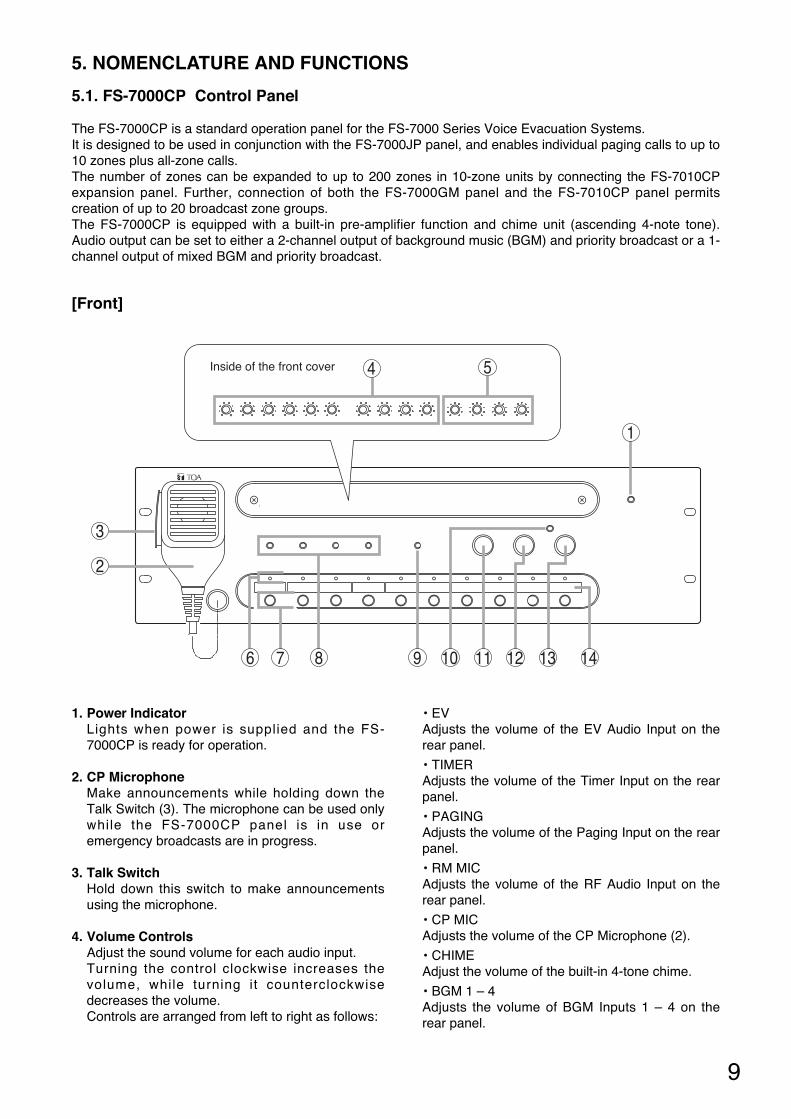
5.1. FS-7000CP Control Panel
The FS-7000CP is a standard operation panel for the FS-7000 Series Voice Evacuation Systems. It is designed to be used in conjunction with the FS-7000JP panel, and enables individual paging calls to up to10 zones plus all-zone calls. The number of zones can be expanded to up to 200 zones in 10-zone units by connecting the FS-7010CPexpansion panel. Further, connection of both the FS-7000GM panel and the FS-7010CP panel permitscreation of up to 20 broadcast zone groups. The FS-7000CP is equipped with a built-in pre-amplifier function and chime unit (ascending 4-note tone).Audio output can be set to either a 2-channel output of background music (BGM) and priority broadcast or a 1-channel output of mixed BGM and priority broadcast.
[Front]
2
3
1
7 9 10 11 12 136 148
54Inside of the front cover
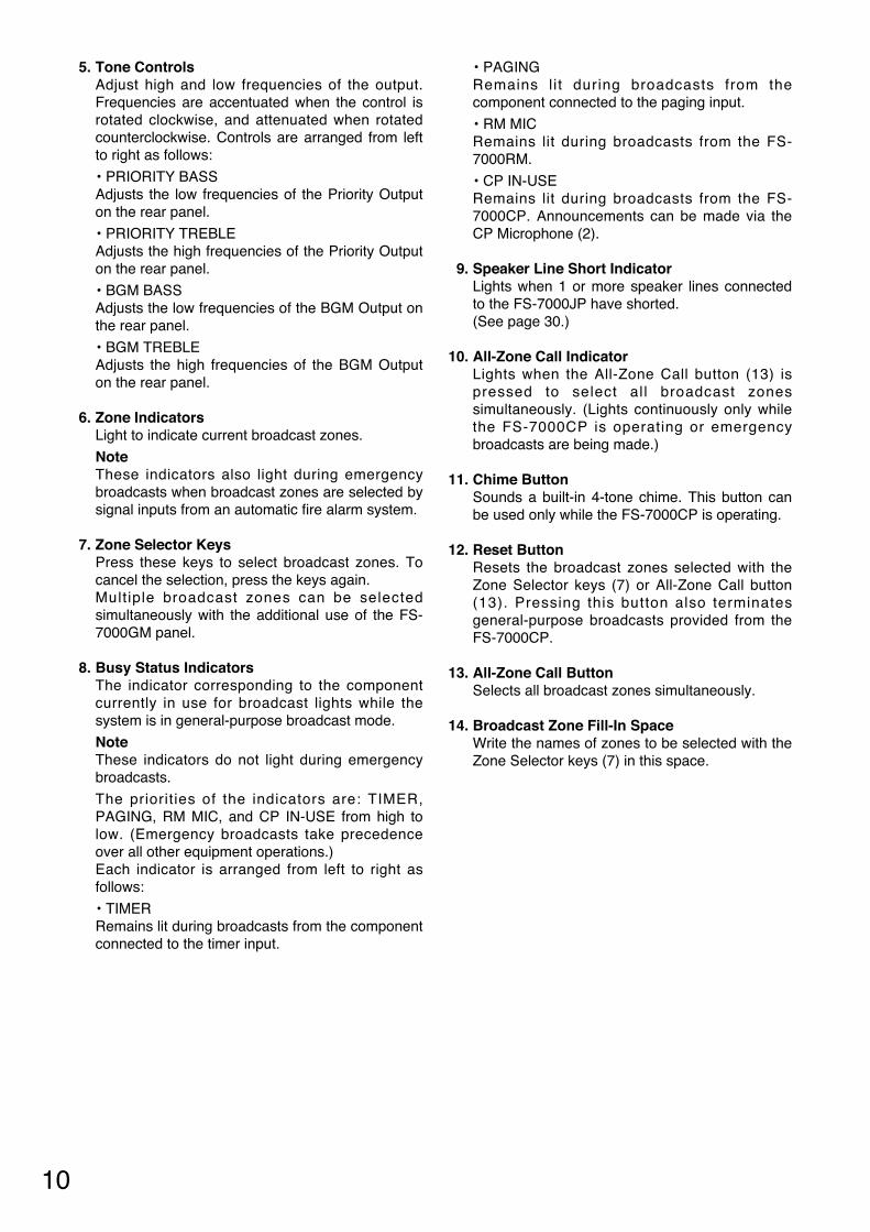
1. Power Indicator Lights when power is supplied and the FS-7000CP is ready for operation.
2. CP Microphone Make announcements while holding down theTalk Switch (3). The microphone can be used onlywhile the FS-7000CP panel is in use oremergency broadcasts are in progress.
3. Talk Switch Hold down this switch to make announcementsusing the microphone.
4. Volume Controls Adjust the sound volume for each audio input. Turning the control clockwise increases thevolume, while turning it counterclockwisedecreases the volume. Controls are arranged from left to right as follows:
• EV Adjusts the volume of the EV Audio Input on therear panel.
• TIMER Adjusts the volume of the Timer Input on the rearpanel.
• PAGING Adjusts the volume of the Paging Input on the rearpanel.
• RM MIC Adjusts the volume of the RF Audio Input on therear panel.
• CP MIC Adjusts the volume of the CP Microphone (2).
• CHIME Adjust the volume of the built-in 4-tone chime.
• BGM 1 – 4 Adjusts the volume of BGM Inputs 1 – 4 on therear panel.
10
5. Tone Controls Adjust high and low frequencies of the output.Frequencies are accentuated when the control isrotated clockwise, and attenuated when rotatedcounterclockwise. Controls are arranged from leftto right as follows:
• PRIORITY BASS Adjusts the low frequencies of the Priority Outputon the rear panel.
• PRIORITY TREBLE Adjusts the high frequencies of the Priority Outputon the rear panel.
• BGM BASS Adjusts the low frequencies of the BGM Output onthe rear panel.
• BGM TREBLE Adjusts the high frequencies of the BGM Outputon the rear panel.
6. Zone Indicators Light to indicate current broadcast zones.
Note These indicators also light during emergencybroadcasts when broadcast zones are selected bysignal inputs from an automatic fire alarm system.
7. Zone Selector Keys Press these keys to select broadcast zones. Tocancel the selection, press the keys again. Multiple broadcast zones can be selectedsimultaneously with the additional use of the FS-7000GM panel.
8. Busy Status Indicators The indicator corresponding to the componentcurrently in use for broadcast lights while thesystem is in general-purpose broadcast mode.
Note These indicators do not light during emergencybroadcasts.
The priorities of the indicators are: TIMER,PAGING, RM MIC, and CP IN-USE from high tolow. (Emergency broadcasts take precedenceover all other equipment operations.) Each indicator is arranged from left to right asfollows:
• TIMERRemains lit during broadcasts from the componentconnected to the timer input.
• PAGING Remains l i t during broadcasts from thecomponent connected to the paging input.
• RM MIC Remains lit during broadcasts from the FS-7000RM.
• CP IN-USE Remains lit during broadcasts from the FS-7000CP. Announcements can be made via theCP Microphone (2).
9. Speaker Line Short Indicator Lights when 1 or more speaker lines connectedto the FS-7000JP have shorted. (See page 30.)
10. All-Zone Call Indicator Lights when the All-Zone Call button (13) ispressed to select al l broadcast zonessimultaneously. (Lights continuously only whilethe FS-7000CP is operating or emergencybroadcasts are being made.)
11. Chime Button Sounds a built-in 4-tone chime. This button canbe used only while the FS-7000CP is operating.
12. Reset Button Resets the broadcast zones selected with theZone Selector keys (7) or All-Zone Call button(13). Pressing this button also terminatesgeneral-purpose broadcasts provided from theFS-7000CP.
13. All-Zone Call Button Selects all broadcast zones simultaneously.
14. Broadcast Zone Fill-In Space Write the names of zones to be selected with theZone Selector keys (7) in this space.

11
5.2. FS-7010CP Expansion Control Panel
The FS-7010CP is used to expand the broadcasting capacity of FS-7000 Series Voice Evacuation Systems.Announcements and background music can be broadcast to up to 10 individual zones. Connecting the FS-7000GM to the FS-7000CP/FS-7010CP combination permits broadcasts to be made to up to 20 zone groups.
[Front]2 3 4 1
1. Power Indicator Lights when power is supplied and the FS-7010CP is ready for operation.
2. Zone Selector Keys Press these keys to select broadcast zones. Tocancel the selection, press the keys again. Multiple broadcast zones can be selectedsimultaneously with the additional use of the FS-7000GM.
3. Zone Indicators Light to indicate current broadcast zones.
Note These indicators also light during emergencybroadcasts when their corresponding zones areselected by automatic fire alarm signals.
4. Broadcast Zone Fill-In Space Write the names of zones to be selected with theZone Selector keys (2) in this space.
5.3. FS-7000JP Junction Panel
The FS-7000JP panel is used in conjunction with the FS-7000CP and the FS-7010CP to connect speakerlines in FS-7000 Series Voice Evacuation Systems. It can connect up to 10 speaker lines. If speaker lines areshorted, the line protection fuses disconnect the shorted lines, leaving broadcasts to other speaker linesfunctioning intact. The FS-7000JP is equipped with BGM input and priority broadcast input, with BGMbroadcast zones selectable using the keys on the front panel. Priority broadcast zones are selected using theFS-7000CP.
[Front]4 12 3
1. Power Indicator Lights when power is supplied and the FS-7000JPpanel is ready for operation.
2. BGM Zone Selector Keys Press these keys to select BGM broadcast zones.Press the keys again to cancel the selection. (2-channel broadcast)
3. Speaker Line Indicators Indicate speaker line operating statuses asfollows:
Green: BGM broadcast in progress (2-channelbroadcast)
Orange: BGM broadcast in progress (1-channelbroadcast) or priority or emergencybroadcasts in progress
Red: Short-circuit (see page 30.)
4. Broadcast Zone Fill-In Space Write the names of zones to be selected with theBGM Zone Selector keys (2) in this space.

12
5.5. FS-7000AT Attenuator Control Panel
The FS-7000AT is used in conjunction with FS-7000 Series Voice Evacuation Systems to control 4-wiresystem attenuators. Up to 10 zones can be attenuator-controlled. When general urgency or emergencybroadcasts are made, the FS-7000AT provides 24 V DC power to allow such broadcasts to bypass theattenuators. The output status of each line can be monitored by the indicators on the front panel.
[Front]2 3 1
1. Power Indicator Lights when power is supplied and the FS-7000ATis ready for operation.
2. Attenuator Line Indicators Light when 24 V DC for bypassing the attenuatorsare being supplied, and extinguish when theovercurrent protection circuit is triggered due toline shorts or other failures, or when the powersupply is cut off.
3. Broadcast Zone Fill-In Space Write the names of the corresponding broadcastzones in this space.
5.4. FS-7000PS DC Power Supply Panel
The FS-7000PS supplies 24 V DC power to each component used in FS-7000 Series Voice EvacuationSystems. Connecting the DS-029B provides a power supply for emergency broadcasts even during powerfailures.
[Front] 1 2 3
1. AC Power Switch AC power is turned on and off with each press ofthis switch.
2. AC Power Indicator Lights when AC power is supplied and the FS-7000PS is ready for operation on AC power.
3. DC Power Indicator Lights when DC power is supplied and the FS-7000PS is ready for operation on DC power.
13
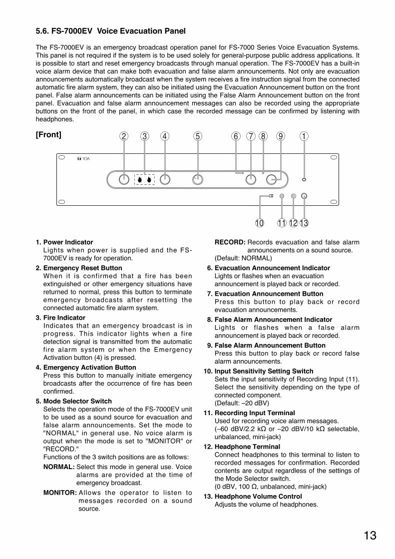
5.6. FS-7000EV Voice Evacuation Panel
The FS-7000EV is an emergency broadcast operation panel for FS-7000 Series Voice Evacuation Systems.This panel is not required if the system is to be used solely for general-purpose public address applications. Itis possible to start and reset emergency broadcasts through manual operation. The FS-7000EV has a built-invoice alarm device that can make both evacuation and false alarm announcements. Not only are evacuationannouncements automatically broadcast when the system receives a fire instruction signal from the connectedautomatic fire alarm system, they can also be initiated using the Evacuation Announcement button on the frontpanel. False alarm announcements can be initiated using the False Alarm Announcement button on the frontpanel. Evacuation and false alarm announcement messages can also be recorded using the appropriatebuttons on the front of the panel, in which case the recorded message can be confirmed by listening withheadphones.
[Front] 2 3 4 7 8 9
10 11 12 13
165
1. Power Indicator Lights when power is supplied and the FS-7000EV is ready for operation.
2. Emergency Reset Button When it is confirmed that a f ire has beenextinguished or other emergency situations havereturned to normal, press this button to terminateemergency broadcasts after resetting theconnected automatic fire alarm system.
3. Fire Indicator Indicates that an emergency broadcast is inprogress. This indicator l ights when a f iredetection signal is transmitted from the automaticfire alarm system or when the EmergencyActivation button (4) is pressed.
4. Emergency Activation Button Press this button to manually initiate emergencybroadcasts after the occurrence of fire has beenconfirmed.
5. Mode Selector Switch Selects the operation mode of the FS-7000EV unitto be used as a sound source for evacuation andfalse alarm announcements. Set the mode to"NORMAL" in general use. No voice alarm isoutput when the mode is set to "MONITOR" or"RECORD."Functions of the 3 switch positions are as follows:
NORMAL: Select this mode in general use. Voicealarms are provided at the time ofemergency broadcast.
MONITOR: Allows the operator to l isten tomessages recorded on a soundsource.
RECORD: Records evacuation and false alarmannouncements on a sound source.
(Default: NORMAL)
6. Evacuation Announcement Indicator Lights or flashes when an evacuation announcement is played back or recorded.
7. Evacuation Announcement Button Press this button to play back or recordevacuation announcements.
8. False Alarm Announcement Indicator Lights or f lashes when a false alarmannouncement is played back or recorded.
9. False Alarm Announcement Button Press this button to play back or record falsealarm announcements.
10. Input Sensitivity Setting Switch Sets the input sensitivity of Recording Input (11).Select the sensitivity depending on the type ofconnected component. (Default: –20 dBV)
11. Recording Input Terminal Used for recording voice alarm messages.(–60 dBV/2.2 kΩ or –20 dBV/10 kΩ selectable,unbalanced, mini-jack)
12. Headphone Terminal Connect headphones to this terminal to listen torecorded messages for confirmation. Recordedcontents are output regardless of the settings ofthe Mode Selector switch.(0 dBV, 100 Ω, unbalanced, mini-jack)
13. Headphone Volume Control Adjusts the volume of headphones.

14
5.8. FS-7000RF Remote Microphone Interface Panel
The FS-7000RF is used to connect the FS-7000RM to FS-7000 Series Voice Evacuation Systems. Up to 4FS-7000RM units can be connected using the FS-7000RF. It is possible to control 50 speaker lines as well asall-zone calls. Connection of the FS-7000GM enables broadcasts to be made to up to 20 zone groups.
[Front]
2 1
1. Power Indicator Lights when power is supplied and the FS-7000RF is ready for operation.
2. Fault Indicator Lights if any failure is detected in communicationswith the FS-7000RM and flashes if any failureoccurs on the FS-7000RF itself. (See page 30.)
5.7. FS-7000GM Group Matrix Panel
The FS-7000GM panel is used in conjunction with FS-7000 Series Voice Evacuation Systems to make groupbroadcasts. The FS-7000GM connects to the FS-7000CP and FS-7000RF and enables group broadcasts byselecting multiple speaker lines simultaneously via the zone selector keys on the FS-7000CP or FS-7000RM.Up to 20 groups and 50 speaker lines can be made available per unit, which can be expanded to 20 groupsand 200 speaker lines by connecting 4 units.
[Front]
1
1. Power Indicator Lights when power is supplied and the FS-7000GM is ready for operation.

15
5.9. FS-7000RM Remote Microphone
The FS-7000RM Remote Microphone is used solely for general-purpose public address applications in FS-7000 Series Voice Evacuation Systems. It enables broadcasting to up to 10 individual zones, as well as all-zone calls. One FS-7000RF panel is required in order to connect the FS-7000RM to the system. Up to 4 FS-7000RM units can be connected. Pressing the FS-7000RM's chime key causes the FS-7000CP's built-in 4-tone chime to sound. Connection of 4 FS-7010RMs enables broadcasts to 50 individual zones as well as all-zone calls (expandable by 10 lines per FS-7010RM). Further, up to 20 broadcast zone groups can be createdby connecting the FS-7000RF to an FS-7000GM Group Matrix Panel.
Tip Connection of 6 FS-7010RM Remote Microphone Extension units enables broadcasting to 50 individual zonesand 20 zone groups, as well as all-zone calls.
[Top]
13
23
4
7
1
65
8
12
11
9 10
1. Power Indicator Lights when power is supplied and theFS-7000RM is ready for operation.
2. Fault Indicator Lights when any failure is detected incommunications with the FS-7000RF or when anyfailure occurs on the FS-7000RM itself. (See page 30.)
3. All-Zone Call Indicator Remains lit while an all-zone call is broadcast fromthe FS-7000RM. (Lights only when calls are madefrom this FS-7000RM.)
4. All-Zone Call Key Selects all broadcast zones simultaneously.
5. Chime Key Sounds a 4-tone chime built inside the FS-7000CP.
6. Broadcast Reset Key Resets broadcast zones selected via the All-ZoneCall key (4) or Zone Selector keys (11),terminating broadcasts from the FS-7000RM.
7. Busy Indicator Lights green when a broadcast is made from thisFS-7000RM, and lights orange when a broadcastis made from other equipment.
8. Talk Key Indicator Lights when a microphone announcement is madeusing the Talk key (12).
9. Zone Identification Card Write the names of the broadcast zones on thiscard.
10. Zone Selection Indicators Light when the corresponding Zone Selectorkeys (11) are pressed. (Light only when the FS-7000RM's keys are used.)
11. Zone Selector Keys Select broadcast zones. Connection of the FS-7000RF to the FS-7000GM permits simultaneousselection of multiple broadcast zones.
12. Talk Key Microphone announcements can be made onlywhile this key is pressed.
Tip Key operation can be changed to allowmicrophone announcements to alternatebetween ON and OFF each time this key ispressed. (Refer to the separate InstallationManual.)
13. Microphone
16
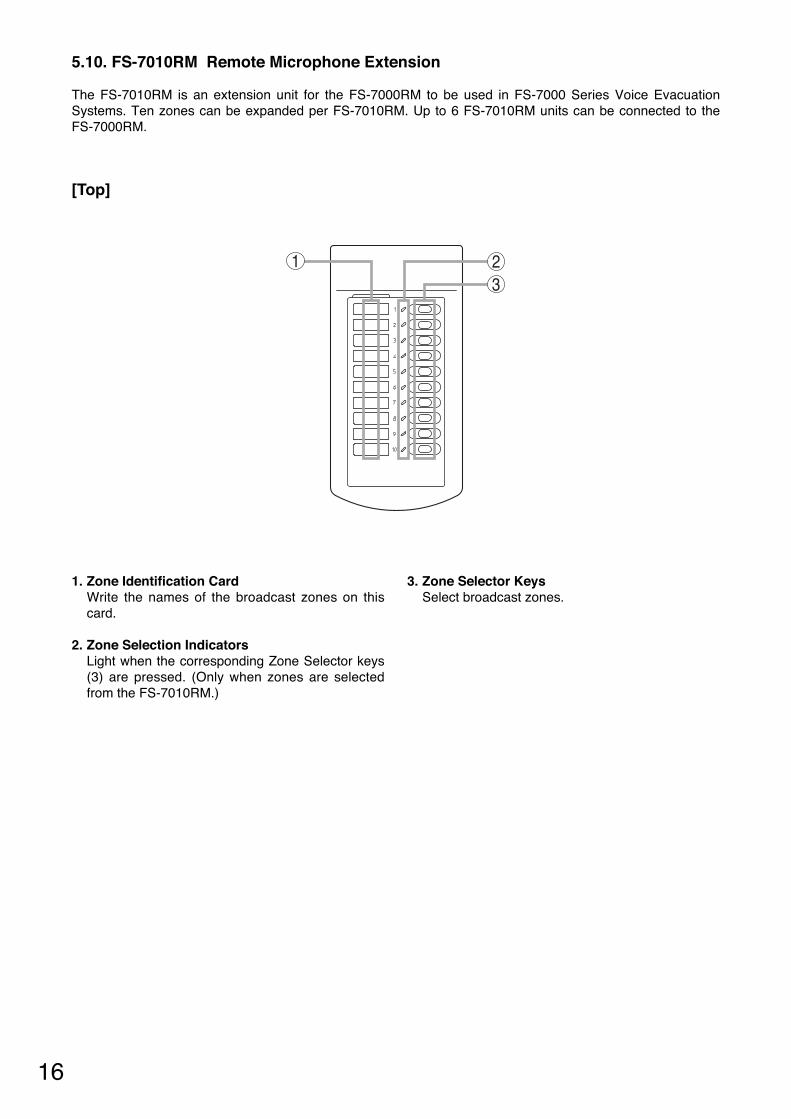
5.10. FS-7010RM Remote Microphone Extension
The FS-7010RM is an extension unit for the FS-7000RM to be used in FS-7000 Series Voice EvacuationSystems. Ten zones can be expanded per FS-7010RM. Up to 6 FS-7010RM units can be connected to theFS-7000RM.
[Top]
23
1
1. Zone Identification Card Write the names of the broadcast zones on thiscard.
2. Zone Selection Indicators Light when the corresponding Zone Selector keys(3) are pressed. (Only when zones are selectedfrom the FS-7010RM.)
3. Zone Selector Keys Select broadcast zones.

17
1. Power Switch Press this switch to turn on the power. To turn offthe power, press this switch again.
2. Power Indicator Lights when power is supplied and the FS-7006PA/7012PA is ready for operation.
3. Volume Control Adjusts the input signal level. This volume controlcannot be used while the Bypass Indicator (8)continuously lights.
4. Fill-In Space Write uses of the main and standby amplifiers inthis space.
5. Fault Indicator Lights when an output muting function* isoperated or when a failure is detected. If the YA-7000 is used, this indicator lights when
the YA-7000 detects a failure and the poweramplifier is switched over to a standby amplifier.(See page 30.)
* This function prevents noise from beinggenerated when power is switched on and off.
6. Signal Indicator Lights when a signal that exceeds a level 24 dBbelow the rated output is sent to the SpeakerOutput on the rear panel.
7. Peak Indicator Lights when a signal that exceeds a level of 3 dBbelow the rated output is sent to Speaker Outputon the rear panel.
8. Bypass Indicator Lights when the Volume Bypass Control Input onthe rear panel is enabled and indicates that theVolume Control (3) has been bypassed anddisabled.
5.11. FS-7006PA/7012PA Power Amplifiers
These power amplifiers are used in conjunction with FS-7000 Series Voice Evacuation Systems. The FS-7006PA's output is rated at 600 W and the FS-7012PA is rated to deliver 1,200 W. By mounting the YA-7000module in a power amplifier and connecting a standby amplifier to it, the power amplifier can be automaticallyswitched over to the standby amplifier if the power amplifier fails. When initiating emergency broadcasts, thevolume control on the front panel is bypassed by closing the Volume Bypass Control terminals on the rearpanel, allowing broadcasts of emergency message at maximum volume.
[Front]
Figure shows the FS-7012PA.
2
1
3
4
7 865
5.12. YA-7000 Amplifier Auto Switching Module
The YA-7000 module is designed to be mounted in the power amplifier of FS-7000 Series Voice EvacuationSystems. Connecting a standby amplifier to the YA-7000 module installed in the main amplifier (FS-7006PA orFS-7012PA) permits the main amplifier to be switched over to the standby amplifier if the main amplifier fails.
[Front]

18
6. FUNCTIONS & OPERATION OF EMERGENCY/GENERAL-PURPOSE BROADCASTS
6.1. Emergency Broadcasts
A system that integrates the FS-7000EV allows emergency broadcasts to be made automatically, throughconnection to an automatic fire alarm system, or manually via the FS-7000CP unit in the main rack system. When implementing an emergency broadcast, volume controls on the front panels of the FS-7006PA and FS-7012PA amplifiers are bypassed to allow broadcast of the emergency message at maximum volume. Systems equipped with an FS-7000AT can supply 24 V DC power to the 4-wire system attenuators in order tobypass them.
Emergency broadcasts have the highest priority. When an emergency broadcast is activated, the following occurs: • In the emergency broadcast area: General-purpose broadcasts* are stopped to allow the emergency
broadcast to be heard. • Other areas: If the system has been set to a 1-channel broadcast mode, general-
purpose broadcasts are stopped. If the system has been set to a 2-channel broadcast mode, prioritybroadcasts are stopped but BGM broadcasts continue.
When an emergency broadcast ends, the following occurs: • In the BGM broadcast area:
The broadcast does not return to its original state if the system has been set to 1-channel broadcast mode.The broadcast returns to its original state if the system has been set to 2-channel broadcast mode.
If a priority broadcast was already in progress when an emergency broadcast is activated: • If the broadcast was from the microphone of the FS-7000CP, then it will not be resumed.
The broadcast area must be selected again when making a microphone announcement. • If the broadcast was from the FS-7000RM, then it will return to its original state. • If the broadcast was a telephone paging or timer-activated automatic broadcast, the broadcast will resume if
the paging operation or timer input activation still continues.
*Refer to "Types of General-Purpose Broadcasts" explained in the following section.
6.2. General-Purpose Broadcasts
6.2.1. Types of General-Purpose Broadcasts
General-purpose broadcasts can be classified as follows, depending on the type of equipment, broadcastpriority, etc.
(Listed by priority)
Timer-activated automatic broadcasts
Telephone paging
FS-7000RM broadcasts (when using the FS-7000RF and FS-7000RM)
Microphone announcements from the FS-7000CP
General-Purpose Broadcasts
Priority Broadcasts
BGM Broadcasts
[Timer-activated automatic broadcasts] When the Timer Input on the rear of the FS-7000CP receives an audio signal and a control signal from amusic play component, the broadcast is made to all zones during operation of the music play component.
[Telephone paging] When the Paging Input on the rear of the FS-7000CP receives an audio signal and a control signal from atelephone exchange, a paging call from a telephone set is made to all zones.
19
[Announcements from the FS-7000RM (with the FS-7000RF and FS-7000RM installed)] Microphone announcements can be made to specific areas selected using the Zone Selector Keys on the FS-7000RM or FS-7010RM. Also, pressing the Chime Key on the remote microphone before making theannouncement causes the FS-7000CP's 4-tone chime to sound.
[Microphone announcements from the FS-7000CP] Microphone announcements can be made to specific areas selected using the Zone Selector Keys on the FS-7000CP or FS-7010CP. Also, pressing the Chime Button on the FS-7000CP before making theannouncement causes the 4-tone chime to sound. Microphone announcements are broadcast after they havebeen mixed with signals from the sound source equipment connected to the Auxiliary Input on the rear of theFS-7000CP.
[BGM Broadcasts] For systems equipped with a 2-channel power amplifier and capable of 2-channel broadcasting, the BGMZone Selector Keys on the FS-7000JP may be used to select broadcast areas, allowing broadcasts from themusic play component connected to the FS-7000CP's BGM input. For systems equipped with a 1-channel power amplifier and capable of 1-channel broadcasting, the BGMbroadcast areas can be selected at the FS-7000CP or FS-7010CP.
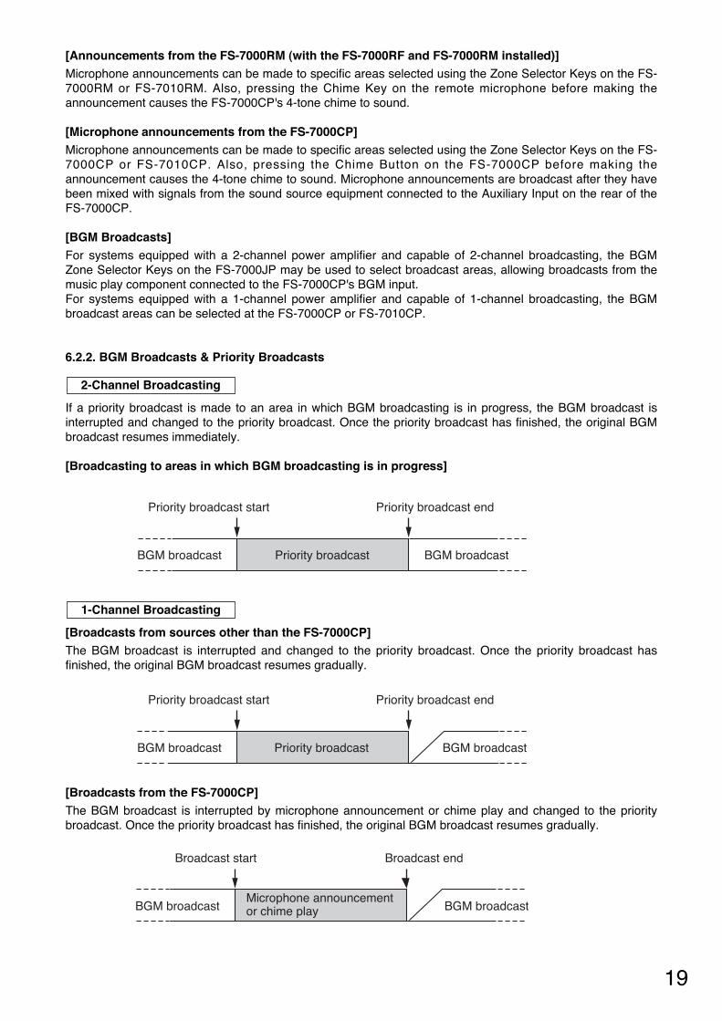
6.2.2. BGM Broadcasts & Priority Broadcasts
If a priority broadcast is made to an area in which BGM broadcasting is in progress, the BGM broadcast isinterrupted and changed to the priority broadcast. Once the priority broadcast has finished, the original BGMbroadcast resumes immediately.
[Broadcasting to areas in which BGM broadcasting is in progress]
2-Channel Broadcasting
Priority broadcast start Priority broadcast end
BGM broadcast Priority broadcast BGM broadcast
Priority broadcast start Priority broadcast end
BGM broadcast Priority broadcast BGM broadcast
Broadcast start Broadcast end
BGM broadcast BGM broadcastMicrophone announcement or chime play
[Broadcasts from sources other than the FS-7000CP] The BGM broadcast is interrupted and changed to the priority broadcast. Once the priority broadcast hasfinished, the original BGM broadcast resumes gradually.
1-Channel Broadcasting
[Broadcasts from the FS-7000CP] The BGM broadcast is interrupted by microphone announcement or chime play and changed to the prioritybroadcast. Once the priority broadcast has finished, the original BGM broadcast resumes gradually.
20
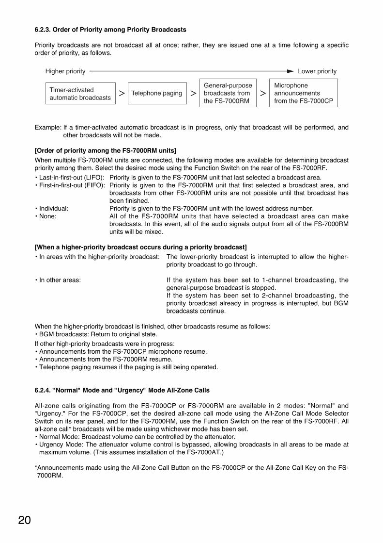
6.2.3. Order of Priority among Priority Broadcasts
Priority broadcasts are not broadcast all at once; rather, they are issued one at a time following a specificorder of priority, as follows.
Higher priority Lower priority
Timer-activated automatic broadcasts
Telephone pagingGeneral-purpose broadcasts from the FS-7000RM
Microphone announcements from the FS-7000CP
Example: If a timer-activated automatic broadcast is in progress, only that broadcast will be performed, andother broadcasts will not be made.
[Order of priority among the FS-7000RM units] When multiple FS-7000RM units are connected, the following modes are available for determining broadcastpriority among them. Select the desired mode using the Function Switch on the rear of the FS-7000RF.
• Last-in-first-out (LIFO): Priority is given to the FS-7000RM unit that last selected a broadcast area.• First-in-first-out (FIFO): Priority is given to the FS-7000RM unit that first selected a broadcast area, and
broadcasts from other FS-7000RM units are not possible until that broadcast hasbeen finished.
• Individual: Priority is given to the FS-7000RM unit with the lowest address number.• None: All of the FS-7000RM units that have selected a broadcast area can make
broadcasts. In this event, all of the audio signals output from all of the FS-7000RMunits will be mixed.
[When a higher-priority broadcast occurs during a priority broadcast] • In areas with the higher-priority broadcast: The lower-priority broadcast is interrupted to allow the higher-
priority broadcast to go through.
• In other areas: If the system has been set to 1-channel broadcasting, thegeneral-purpose broadcast is stopped.If the system has been set to 2-channel broadcasting, thepriority broadcast already in progress is interrupted, but BGMbroadcasts continue.
When the higher-priority broadcast is finished, other broadcasts resume as follows: • BGM broadcasts: Return to original state.
If other high-priority broadcasts were in progress: • Announcements from the FS-7000CP microphone resume. • Announcements from the FS-7000RM resume. • Telephone paging resumes if the paging is still being operated.
6.2.4. "Normal" Mode and "Urgency" Mode All-Zone Calls
All-zone calls originating from the FS-7000CP or FS-7000RM are available in 2 modes: "Normal" and"Urgency." For the FS-7000CP, set the desired all-zone call mode using the All-Zone Call Mode SelectorSwitch on its rear panel, and for the FS-7000RM, use the Function Switch on the rear of the FS-7000RF. Allall-zone call* broadcasts will be made using whichever mode has been set. • Normal Mode: Broadcast volume can be controlled by the attenuator. • Urgency Mode: The attenuator volume control is bypassed, allowing broadcasts in all areas to be made at
maximum volume. (This assumes installation of the FS-7000AT.)
*Announcements made using the All-Zone Call Button on the FS-7000CP or the All-Zone Call Key on the FS-7000RM.

21
7. MAKING EMERGENCY BROADCASTS
7.1. Initiating Emergency Broadcasts Manually
Under manual operation, the broadcast areas are selected and the broadcast is conducted using either amicrophone or the pre-recorded voice alarm messages stored in the FS-7000EV.
[Buttons and keys used for operation]
[FS-7000EV]
[FS-7000CP]
[FS-7010CP]
Emergency Reset Button
Emergency Activation Button
Evacuation Announcement Indicator
Fire Indicator Evacuation Announcement Button
Talk Switch
CP Microphone Zone Selector Keys Zone Indicators
Zone Selector Keys Zone Indicators
Step 1. Press the Emergency activation button on the FS-7000EV.
The Fire indicator will light. 2-channel broadcast: Broadcasting is stopped in areas where priority broadcasts are underway.
BGM broadcasting continues. 1-channel broadcast: Broadcasting is stopped in all areas.
Step 2. Use the Zone selector keys on the FS-7000CP or FS-7010CP to select the broadcast areas.
The appropriate Zone indicators will illuminate. 2-channel broadcast: BGM broadcasting in the selected areas is stopped.

22
Step 3. Activate emergency evacuation announcements.
Press the Evacuation announcement button. The Evacuation announcement indicator will illuminate and the evacuation announcement will be sentto all selected areas. To stop the evacuation announcement, press the Evacuation announcement button again.
Broadcast using the microphone on the FS-7000CP. Make the desired announcement while pressing the Talk switch of the microphone. Announcements made using the microphone will override any pre-recorded voice alarm broadcastsbeing made via the FS-7000EV. These pre-recorded message broadcasts will resume once themicrophone announcement has finished.
Step 4. Once the fire has been extinguished, press the Emergency reset button on the FS-7000EV toterminate emergency broadcasts.
The Fire indicator and Evacuation announcement indicator will extinguish, and original general-purpose broadcasts will resume automatically.
Note Priority broadcasts from the CP-7000CP and 1-channel BGM broadcasts will not resumeautomatically.
[Pre-recorded voice alarm messages set at the factory are as follows]
Evacuation announcement: "There is a fire. Please evacuate as quickly as possible."
False alarm announcement: "Attention please. A few minutes ago we announced there may be a fire. However, there is no fire. Once again, there is no fire."
Using the microphone
Using pre-recorded voice alarm messages stored in the FS-7000EV

23
7.2. Initiating Emergency Broadcasts by Fire Alarm System
If the broadcast system is connected to an automatic fire alarm system, then whenever a fire is detected, theFire indicator will illuminate and the FS-7000EV's pre-recorded evacuation announcements will commenceautomatically. Operation procedures following the start of such emergency announcements are as follows.
[Buttons and keys used for operation]
[FS-7000CP]
[FS-7010CP]
[FS-7000EV]
Emergency Reset Button
Fire Indicator
Evacuation Announcement Button
Evacuation Announcement Indicator
False Alarm Announcement Button
False Alarm Announcement Indicator
Talk Switch
CP Microphone Zone Selector Keys Zone Indicators
Zone Selector Keys Zone Indicators
Using the Zone selector keys on the FS-7000CP and FS-7010CP, select broadcast areas other thanthose automatically selected by the fire alarm system. The appropriate Zone indicators will illuminate.
Broadcast using the microphone on the FS-7000CP. Make the desired announcement while pressing the Talk switch of the microphone. Announcements made using the microphone will override any pre-recorded voice alarm broadcasts beingmade via the FS-7000EV. These pre-recorded messages will resume once the microphone announcementhas finished.
Broadcasting announcements via microphone
Manually selecting broadcast areas
24
Press the Evacuation announcement button on the FS-7000EV.The Evacuation announcement indicator will extinguish and the evacuation announcement will be stopped.To resume the evacuation announcement, press the Evacuation announcement button again.
Tip If an additional fire instruction signal is received from the automatic fire alarm system: • The appropriate broadcast areas are selected and the Zone indicators illuminate. • If no evacuation announcement is already in progress, then the additional instruction signal activates
evacuation announcements automatically.
After the automatic fire alarm system has been reset, press the Emergency reset button on the FS-7000EV. The Fire indicator and Evacuation announcement indicator will extinguish, and original general-purposebroadcasts will resume automatically.
Tip Priority broadcasts from the FS-7000CP unit and 1-channel BGM broadcasts will not resume automatically.
Activate the false alarm announcement by pressing the False alarm announcement button on the FS-7000EV.The False alarm announcement indicator will illuminate and the false alarm announcement will be sent.
Then, after resetting the automatic fire alarm system, press the Emergency reset button on the FS-7000EV. The Fire indicator will extinguish, and original general-purpose broadcasts will resume.
Tip Priority broadcasts from the FS-7000CP unit and 1-channel BGM broadcasts will not resume automatically.
Making false alarm announcements
Terminating emergency announcements once a fire has been extinguished
Temporarily stopping evacuation announcements
25
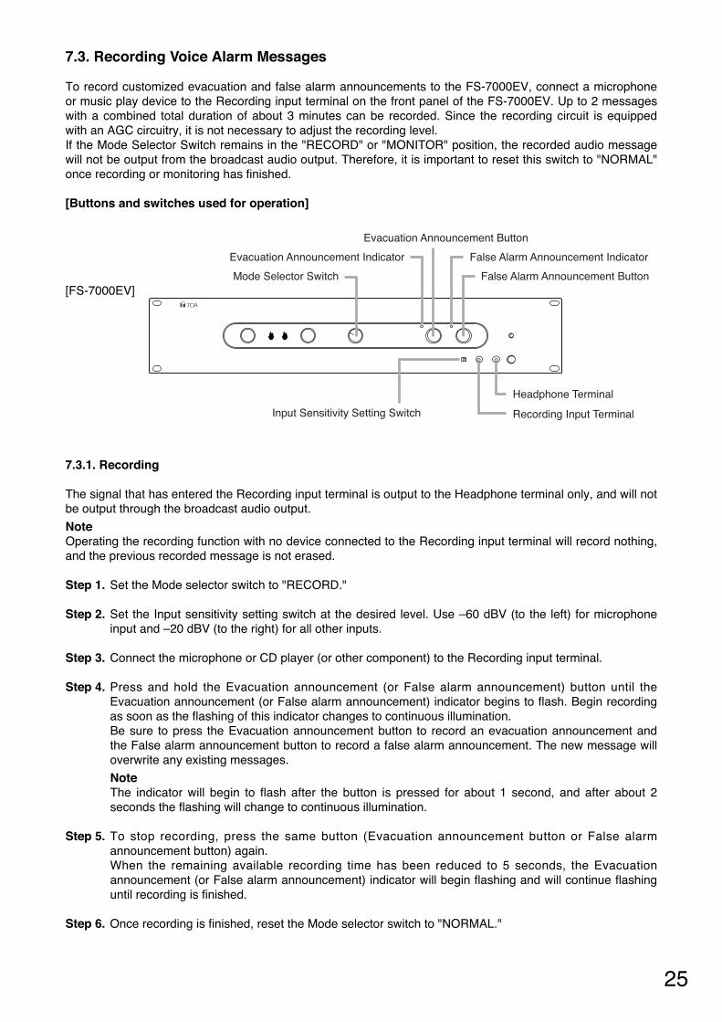
7.3. Recording Voice Alarm Messages
To record customized evacuation and false alarm announcements to the FS-7000EV, connect a microphoneor music play device to the Recording input terminal on the front panel of the FS-7000EV. Up to 2 messageswith a combined total duration of about 3 minutes can be recorded. Since the recording circuit is equippedwith an AGC circuitry, it is not necessary to adjust the recording level. If the Mode Selector Switch remains in the "RECORD" or "MONITOR" position, the recorded audio messagewill not be output from the broadcast audio output. Therefore, it is important to reset this switch to "NORMAL"once recording or monitoring has finished.
[Buttons and switches used for operation]
[FS-7000EV] Mode Selector Switch
Evacuation Announcement Button
Evacuation Announcement Indicator
False Alarm Announcement Button
False Alarm Announcement Indicator
Input Sensitivity Setting Switch Recording Input Terminal
Headphone Terminal
7.3.1. Recording
The signal that has entered the Recording input terminal is output to the Headphone terminal only, and will notbe output through the broadcast audio output.
Note Operating the recording function with no device connected to the Recording input terminal will record nothing,and the previous recorded message is not erased.
Step 1. Set the Mode selector switch to "RECORD."
Step 2. Set the Input sensitivity setting switch at the desired level. Use –60 dBV (to the left) for microphoneinput and –20 dBV (to the right) for all other inputs.
Step 3. Connect the microphone or CD player (or other component) to the Recording input terminal.
Step 4. Press and hold the Evacuation announcement (or False alarm announcement) button until theEvacuation announcement (or False alarm announcement) indicator begins to flash. Begin recordingas soon as the flashing of this indicator changes to continuous illumination. Be sure to press the Evacuation announcement button to record an evacuation announcement andthe False alarm announcement button to record a false alarm announcement. The new message willoverwrite any existing messages.
NoteThe indicator will begin to flash after the button is pressed for about 1 second, and after about 2seconds the flashing will change to continuous illumination.
Step 5. To stop recording, press the same button (Evacuation announcement button or False alarmannouncement button) again.When the remaining available recording time has been reduced to 5 seconds, the Evacuationannouncement (or False alarm announcement) indicator will begin flashing and will continue flashinguntil recording is finished.
Step 6. Once recording is finished, reset the Mode selector switch to "NORMAL."
26
7.3.2. Checking Recorded Content
Connect headphones to the Headphone terminal.
Step 1. Set the Mode selector switch to "MONITOR." The Evacuation announcement indicator and False alarm announcement indicator will begin to flash.
Step 2. Press the appropriate Evacuation announcement button or False alarm announcement button to listento the recorded content. The flashing of the Evacuation announcement indicator or False alarm announcement indicator willchange to continuous illumination and playback of the recording will begin.
Note Changing the Mode selector switch to another position during recording playback will terminateplayback. Also, note that the recording being played back will only be audible through theheadphones, and will not be output through the broadcast output terminal.
Step 3. To stop playback of the recording, press the same button (Evacuation announcement button or Falsealarm announcement button) again. The Evacuation announcement indicator and False alarm announcement indicator will begin to flash.
Step 4. Once monitoring is finished, reset the Mode selector switch to "NORMAL." The Evacuation announcement indicator and False alarm announcement indicator will extinguish.

27
8. MAKING GENERAL-PURPOSE BROADCASTS
8.1. Making General-Purpose Broadcasts from the FS-7000CP
[Buttons and keys used for operation]
[FS-7000CP]
[FS-7010CP]
Talk Switch Chime Button
Reset ButtonBusy Status Indicators (CP IN-USE)
CP Microphone Zone Selector Keys Zone Indicators
All-Zone Call Indicators
All-Zone Call Button
Zone Selector Keys Zone Indicators
Step 1. Press the appropriate Zone selector keys or All-zone call button on the FS-7000CP and FS-7010CPto select the desired broadcast zones. The appropriate Zone indicators or All-zone call indicator will illuminate.
Step 2. If the CP IN-USE indicator is illuminated, press the Chime button to sound the chime. If other Busy indicator, or the Fire indicator on the FS-7000EV is illuminated, then a higher-prioritybroadcast is in progress, and broadcasts cannot be made from the FS-7000CP. Wait until the higher-priority broadcast is finished and try again.
Step 3. Press the Talk switch of the microphone continuously and make the announcement. The microphone announcement is broadcast only while the Talk switch is depressed.
Note When a higher-priority broadcast is made while a general-purpose broadcast from the FS-7000CP isalready in progress (the Busy indicator except CP IN-USE indicator or the FS-7000EV's Fire indicatorwill illuminate), the general-purpose broadcast will be suspended. In some cases, the originalbroadcast will not resume even after the higher-priority broadcast is completed. In such cases,perform operation again from the beginning.
Step 4. Press the Reset button to finish broadcasting.
Note When BGM is being played in 1-channel broadcast mode, if the chime is sounded or microphoneannouncements are made without designating their specific broadcast areas, these will be heard inthe areas where BGM play is in progress. To avoid this, select the desired chime or microphoneannouncement areas before broadcasting. Since such broadcasts disable BGM play, select the areasthat will require continued BGM after the chime or microphone announcement has been completed.

28
8.2. Making Announcements from the FS-7000RM
[Keys used for operation]
Microphone
All-Zone Call Indicator
Zone Selection Indicators
All-Zone Call Key
Chime Key
Busy Indicator
Broadcast Reset Key
Talk Key
Zone Selector Keys
[FS-7000RM] [FS-7010RM]
Step 1. Press the appropriate Zone selector keys or All-zone call key on the FS-7000RM or FS-7010RM toselect the desired broadcast areas. The appropriate Zone indicators or All-zone indicator will illuminate.
Step 2. If the Busy indicator is illuminated green, press the Chime button to sound the chime. If the Busy indicator is illuminated orange, then another higher-priority broadcast is in progress, andbroadcasts cannot be made from the FS-7000RM. Wait until the higher-priority broadcast is finished and try again.
Step 3. Press the Talk key continuously and make the announcement using the microphone. Theannouncement is broadcast only while the Talk key is depressed.
Note If a higher-priority broadcast is made while the announcement from the FS-7000RM is underway, thenthe In-Use indicator will illuminate orange and the announcement will be suspended. In such cases,simply wait until the higher-priority broadcast is finished and try again.
Tip It is possible to change the Talk key from "PTT" (Press-to-Talk) operation (which allows the user tospeak only while the key is continuously pressed) to "Alternate" operation (which alternates themicrophone between ON and OFF with each press of the key). (For changing the key operation, refer to the separate Installation Manual.)
Step 4. Press the Broadcast reset key to finish broadcasting.

29
8.3. Making BGM Broadcasts
The operating panel used will differ depending on whether the system is set to 1-channel or 2-channelbroadcast mode.
Note Use the Output mode selector switch on the rear of the FS-7000CP to switch between 1-channel and 2-channel broadcast mode.
[Buttons and keys used for operation]
[FS-7000CP]
[FS-7010CP]
[FS-7000JP]
Zone Selector Keys Zone Indicators
All-Zone Call Indicator
All-Zone Call Button
Zone Selector Keys Zone Indicators
Speaker Line IndicatorsBGM Zone Selector Keys
8.3.1. When using 1-channel broadcasting
Press the appropriate Zone selector keys or All-zone call button on the FS-7000CP or FS-7010CP toselect the desired broadcast areas, then commence music play from the BGM device. The appropriate Zone indicators or All-zone call indicator will illuminate.
8.3.2. When using 2-channel broadcasting
Press the appropriate BGM Zone selector keys on the FS-7000JP to select the desired broadcastareas, then commence music play from the BGM device. The appropriate Zone indicators will illuminate.
30
9. FAILURE INDICATION
The FS-7000CP, FS-7000JP, FS-7000RF, FS-7000RM, FS-7006PA, and FS-7012PA are equipped withfailure indicators that show the status of any problems that may occur. When such an indicator lights orflashes, it means that a problem may have occurred in the equipment or in the wiring. If the power indicator is not illuminated, the equipment could be malfunctioning. In such cases, check to see ifpower is being supplied correctly, or if a fuse has blown. A blown fuse often means that the problem may haveoccurred within the wiring as well as in the equipment itself. In such cases, replace the fuse(s) and check the correctness of the wiring before turning the power on again.
If an indicator lights continuously or flashes, the following possible causes may be considered:
Symptom Possible Cause Check/Remedy
One or more of the speaker lines haveshorted, causing the associated lineprotection fuse of FS-7000JP to blow.
FS-7000CP'sSpeaker Line Shortindicator lights.
FS-7000JP'sSpeaker LineIndicator lights red.
The speaker line corresponding to the FS-7000JP's Speaker Line indicator thatcontinuously lights red may be shorted. Locate and fix the speaker line short,replace the line protection fuse, then pressthe Reset switch mounted on the rearpanel of the FS-7000JP.
Communications are not beingperformed correctly with the FS-7000RM units of the numberdesignated using the setting switch, orequipment failures may have occurred.
Communication with the FS-7000RF isnot being performed correctly, orequipment failures may have occurred.
FS-7000RF's Faultindicator lights red.
FS-7000RF's Faultindicator f lashesred.
FS-7000RM's Faultindicator lights.
• Confirm that the number that has beenset using the setting switch agree withthe actual number of the connected FS-7000RM units.
• Confirm that the FS-7000RM's address isset correctly.
• Confirm that there is no fault with thewiring leading to the FS-7000RM.
If all of the above are found to be incorrect working order, then it is likely thatthe FS-7000RM itself is malfunctioning.
It is likely that the FS-7000RF itself ismalfunctioning.
• Confirm that the number of units that hasbeen set using the FS-7000RF's settingswitch agrees with the actual number ofthe FS-7000RM units connected.
• Confirm that the unit has the correctaddress settings.
• Confirm that there is no fault with thewiring leading to the FS-7000RF.
If all of the above are found to be incorrect working order, then it is likely thatthe FS-7000RF itself is malfunctioning orequipment failures may have occurred.
Output is not being provided correctlybecause of a short in the output wiring.
FS-7006PA's or FS-7012PA's Faultindicator lights.
– Continued on next page –
Remove the output wiring and turn thepower on again. If the fault indicator lightgoes out, then the problem may be withthe wiring. Check the wiring to determinewhere the problem may be.
If the indicator light does not go out, or if itgoes out but then lights again within ashort period of time, consider whether thefollowing may be the problem:
31
Symptom Possible Cause Check/Remedy
FS-7006PA's or FS-7012PA 's Faultindicator lights.
Equipment failure or excessive highheat build-up inside the unit.
YA-7000's Operation Mode Selectorswitch was set to "Test" during itsinstallation.
Check the following points if the indicatorautomatically goes out within 30 minutesafter it has lit.• Check installation condit ions for
appropriate ventilation.• Check the connected load capacity for
possible overload.• Check to see if input and output cables
are installed in close proximity to eachother.
If all of the above are found to be incorrect working order, then it is likely thatthe equipment itself is malfunctioning insome way. Equipment failures can also be consideredif the indicator lights again within a shortperiod of time even if it has gone out once.Request maintenance and repair action.
Set the mode switch to "Normal."
Symptom
No sound.
Items to Check
[FS-7000CP/7006PA/7012PA] Is the volume control set to "0"?
[FS-7000CP/7010CP/7000JP/ 7000RM/7010RM]Is the broadcast area selected?
Potential Solution
Turn the volume knob clockwise andset the volume to the appropriate level.
Press the Zone selector key to select abroadcast area.
Cannot record a voicemessage.
The recorded soundvolume is too low or isdistorted.
Cannot bypass theattenuator tobroadcast at maximumvolume.
[FS-7000CP]Is a higher-priority broadcast already inprogress?
[FS-7000EV]Is a microphone or other sound sourcecorrectly connected to the Recordinginput terminal?
[FS-7000EV]Is the Input sensitivity setting switch setto the correct level at the t ime ofrecording?
[FS-7000AT] Is the FS-7000AT's attenuator lineindicator illuminated when attempting tomake emergency or general urgencybroadcasts?
Wait until the higher-priority broadcasthas finished and try again.
Try removing and reinserting the pluginto the recording input jack.
Set the Input sensitivity setting switch to–60 dB (to the left) when using amicrophone and –20 dBV (to the right)when connecting other components.
It is likely that 24 V DC power is not beingproperly supplied to the attenuator.Contact your TOA dealer to have the unitinspected.
10. TROUBLESHOOTING
If the power will not go on, no sound is output, or other problem occurs, check the following list oftroubleshooting symptoms and solutions. If the symptoms still persist, then refer the problem to the store fromwhere the component was purchased.

32
11. SPECIFICATIONS
11.1. FS-7000CP Control Panel
24 V DC, M3 screw terminal, distance between barriers: 6.4 mm 200 mA EV: 0 dB*, 600 Ω, unbalanced, removable terminal block (2 pins) Timer: 0 dB*, 600 Ω, unbalanced, removable terminal block (4 pins) Paging: –60/–20 dB*, 600 Ω, balanced, removable terminal block (5 pins) RF (Remote microphone): 0 dB*, 600 Ω, balanced, removable terminal block (3 pins) Preinstalled microphone (accessory): –55 dB*, 600 Ω, unbalanced,
circular connector (4 pins) AUX: –20 dB*, 600 Ω, unbalanced, removable terminal block (2 pins) BGM 1: –60/0 dB*, 600 Ω, balanced, removable terminal block (3 pins) BGM 2 – 4: –20 dB*, 10 kΩ, unbalanced, RCA jack Priority output: 0 dB*, 600 Ω, balanced, removable terminal block (3 pins)
(Outputs signals other than BGM 1 – 4 input signals when outputis set to 2-channel broadcast mode.)
BGM output: 0 dB*, 600 Ω, balanced, removable terminal block (3 pins) (Outputs BGM 1 – 4 signals.)
50 – 15,000 Hz, within ±3 dB (1 kHz) ±10 dB at 100 Hz and 10 kHz Over 60 dB Under 1% Priority output: Preinstalled microphone > EV (emergency broadcast mode)
Timer > Paging > Remote microphone > Preinstalled microphone, AUX > BGM 1 ≥ BGM 2 – 4 (general-purpose broadcast mode)
BGM output: BGM 1 ≥ BGM 2 – 4 (by muting function setting) Ascending 4-tone chime Timer: No-voltage make contact input, open voltage: 26 V DC, short-circuit
current: under 2 mA, removable terminal block (4 pins) Paging: No-voltage make contact input, open voltage: 26 V DC, short-circuit
current: under 2 mA, removable terminal block (5 pins) Automatic fire alarm system (10 zones):
No-voltage make contact input, open voltage: 26 V DC, short-circuit current: under 5 mA, removable terminal block (12 pins)
10 individual zones + all-zone call or 10 group zones + all-zone call (whenoptional FS-7000GM is connected) (individual zones expandable to up to 200 zones using FS-7010CP) Zone selection keys, All-zone call button (general-purpose/general urgency all-zone call selectable), Broadcast reset button and Chime button Power indicator, All-zone call indicator, Zone indicators, Busy indicator (timer,paging, remote microphone and main system), Speaker line short-circuit indicator 0°C to +40°C Under 90% RH (no condensation)Panel: Aluminum, black, alumite 482 (w) x 132.6 (h) x 376.9 (d) mm5.2 kg
Power Source Current Consumption Input
Output
Frequency Response Tone Control S/N Ratio Distortion Priority Function
Electronic Tone External Control Input
Output Control
Operating Section
Display Section
Operating Temperature Operating Humidity Finish DimensionsWeight
* 0 dB = 1 V
Note: The design and specifications are subject to change without notice for improvement.
• Accessories
Microphone ................................................ 1 Removable terminal plug (2 pins) .............. 2 Removable terminal plug (3 pins) .............. 4
Removable terminal plug (4 pins) .............. 1 Removable terminal plug (5 pins) .............. 1 Removable terminal plug (12 pins) ............ 1

33
11.2. FS-7010CP Expansion Control Panel
24 V DC, M3 screw terminal, distance between barriers: 6.4 mm 150 mA Automatic fire alarm system (10 zones):
No-voltage make contact input, open voltage: 26 V DC, short-circuit current: Under 5 mA, removable terminal block (12 pins)
10 individual zones or 10 group zones (when optional FS-7000GM is connected) Zone selection keys Power indicator, Zone indicators 0°C to +40°C Under 90% RH (no condensation)Panel: Aluminum, black, alumite 482 (w) x 44 (h) x 337 (d) mm 3 kg
Power Source Current Consumption External Control Input
Output Control Operating Section Display Section Operating Temperature Operating Humidity Finish DimensionsWeight
Note: The design and specifications are subject to change without notice for improvement.
• Accessories
Connection cable (14 pins, 60 cm) ............. 1 Connection cable (10 pins, 2.5 m) ............. 1
Removable terminal plug (12 pins) ............ 1

34
11.3. FS-7000JP Junction Panel
24 V DC, M3 screw terminal, distance between barriers: 6.4 mm 450 mA Priority input: 100 V line: Max. 1200 W, M4 screw terminal,
distance between barriers: 9 mm BGM input: 100 V line: Max. 1200 W, M4 screw terminal,
distance between barriers: 9 mm 10 lines each for H and C, M3 screw terminal, distance between barriers: 6.4 mm (100 V line, Max. 280 W for FS-7006PA, Max. 500 W per line for FS-7012PA) ø5 mm tubed fuse 0.5 A x 10 fuses preinstalled (Fuse capacity must be changed depending on the load capacity.) General urgency/Emergency mode output terminal:
Open collector output, rated voltage: 30 V DC, current capacity: 0.1 A, removable terminal block (2 pins)
Power remote output terminal: Relay contact output, rated voltage: 30 V DC, current capacity: 1 A, removable terminal block (2 pins)
BGM zone selection keys Power indicator, Speaker line indicators (Green: BGM in progress (2-channelbroadcast mode)/ Orange: BGM in progress (1-channel broadcast mode),priority broadcast, and emergency broadcast/ Red: short-circuit) 0°C to +40°C Under 90% RH (no condensation)Panel: Aluminum, black, alumite 482 (w) x 88.4 (h) x 340.7 (d) mm4.2 kg
Power Source Current Consumption Power Amplifier Input
Speaker Output
Line Short-Circuit Protection External Control Onput
Operating Section Display Section
Operating Temperature Operating Humidity Finish Dimensions Weight
Note: The design and specifications are subject to change without notice for improvement.
• Accessories
Fuse (0.5 A) ............................................... 2 Connection cable (10 pins, 2.5 m) ............. 1
Connection cable (4 pins, 2.5 m) ............... 1 Removable terminal plug (2 pins) .............. 2

35
11.4. FS-7000PS DC Power Supply Panel
11.5. FS-7000AT Attenuator Control Panel
230 V AC, 50 Hz 24 V DC (19.5 – 27 V), M3 screw terminal, distance between barriers: 6.4 mm 195 W (275 VA) at rated power output (AC operation) 24 V DC, M3 screw terminal, distance between barriers: 6.4 mm AC operation: 24 V DC ±0.5 V, 5A (total) DC operation: Voltage lowering DC input voltage approx. by 1 V M3 screw terminal, distance between barriers: 6.4 mm Emergency power connection
Control: Rated voltage: 30 V DC, current capcity: 5 A, M3 screw terminal,distance between barriers: 6.4 mm
Start: Rated voltage: 24 V DC, current capcity: 5 A, M3 screw terminal,distance between barriers: 6.4 mm
Emergency power control Control: Rated voltage: 24 V DC, current capcity: 5 A, M3 screw terminal,
distance between barriers: 6.4 mm Start: No-voltage make contact input, open voltage: 24 V DC, short-circuit current:
under 2 mA, M3 screw terminal, distance between barriers: 6.4 mm Power switch AC power indicator, DC power indicator 0°C to +40°C Under 90% RH (no condensation)Panel: Aluminum, black, alumite 482 (w) x 88.4 (h) x 338.2 (d) mm8.9 kg
Power Source
Power Consumption Input Output
External Control Input/Output
Operating Section Display Section Operating Temperature Operating Humidity Finish DimensionsWeight
Note: The design and specifications are subject to change without notice for improvement.
• Accessories
Power cord (1.8 m) ..................................... 1 Fuse (6.3 A) ............................................... 1
Fuse (8 A) .................................................. 1
24 V DC, M3 screw terminal, distance between barriers: 6.4 mm 200 mA Rated voltage: 24 V DC (24 – 35 V), current capacity: 5 A, M3 screw terminal,distance between barriers: 6.4 mm 10 lines, rated voltage: 24 V DC, current capacity: 0.75 A (per line)/5 A (total of10 lines),with output short-circuit protection function, M3 screw terminal,distance between barriers: 6.4 mm Power indicator, Attenuator line indicators 0°C to +40°C Under 90% RH (no condensation)Panel: Aluminum, black, alumite 482 (w) x 44 (h) x 336 (d) mm3 kg
Power Source Current Consumption Attenuator DC Power Input Attenuator Control Output
Display Section Operating Temperature Operating Humidity Finish DimensionsWeight
Note: The design and specifications are subject to change without notice for improvement.
• Accessory
Connection cable (12 pins, 60 cm) ............ 1

36
11.6. FS-7000EV Voice Evacuation Panel
24 V DC, M3 screw terminal, distance between barriers: 6.4 mm 130 mA Evacuation announcement (repeated continuously) and false alarm announcement (repeated twice) English (Default)
44.1 kHz sampling frequency, 16-bit PCM
Up to 3 minutes for both evacuation and false alarm announcements together
USB data transfer or analog recording 20 – 20,000 Hz ±3 dB (1 kHz) Under 1% (1 kHz, rated output) Mic: –60 dB*, 2.2 kΩ/Line: –20 dB*, 10 kΩ (Mic/Line switchable), unbalanced,mini jack EV audio output: 0 dB*, 600Ω, unbalanced, removable terminal block (2 pins) Headphone output: 0 dB*, 100Ω, unbalanced, mini jack Emergency ON output:
Relay contact output, rated voltage: 30 V DC, current capacity: 1 A, removable terminal block (2 pins)
Emergency control contact output: Relay contact output, rated voltage: 30 V DC, current capacity: 1 A, removable terminal block (3 pins)
Automatic fire alarm system confirmation signal input: No-voltage make contact input, open voltage: 24 V DC, short-circuit current: 6 mA, removable terminal block (2 pins)
Emergency power control Control: Rated voltage: 24 V DC, current capacity: 100 mA,
M3 screw terminal, distance between barriers: 6.4 mm Start: Open collector output, rated voltage: 30 V DC,
current capacity: 100 mA, M3 screw terminal, distance between barriers: 6.4 mm
Emergency activation button, Emergency reset button, Evacuation announcementbutton, False alarm announcement button, and Mode selection switch Power indicator, Fire indicator, Evacuation announcement indicator, False alarmannouncement indicator, and USB communication indicator (rear panel) 0°C to +40°C Under 90% RH (no condensation)Panel: Aluminum, black, alumite 482 (w) x 88.4 (h) x 341.7 (d) mm4 kg
Power Source Current Consumption Emergency Announcement Emergency Warning Language Emergency Warning Tone Emergency Recording Time Recording System Frequency Response Distortion Recording Input
Output
External Control Input/Output
Operating Section
Display Section
Operating Temperature Operating Humidity Finish Dimensions Weight
* 0 dB = 1 V
Note: The design and specifications are subject to change without notice for improvement.
• Accessories
Connection cable (5 pins, 60 cm) .............. 1 Removable terminal plug (2 pins) .............. 3
Removable terminal plug (3 pins) .............. 1
37
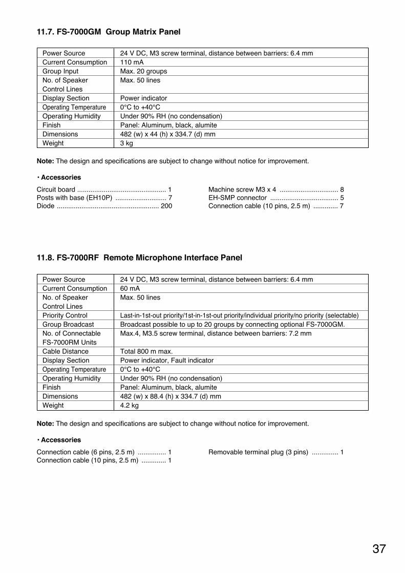
11.7. FS-7000GM Group Matrix Panel
11.8. FS-7000RF Remote Microphone Interface Panel
24 V DC, M3 screw terminal, distance between barriers: 6.4 mm 110 mA Max. 20 groups Max. 50 lines
Power indicator 0°C to +40°C Under 90% RH (no condensation)Panel: Aluminum, black, alumite 482 (w) x 44 (h) x 334.7 (d) mm3 kg
Power Source Current Consumption Group Input No. of Speaker Control Lines Display Section Operating Temperature Operating Humidity Finish DimensionsWeight
Note: The design and specifications are subject to change without notice for improvement.
• Accessories
Circuit board ............................................... 1 Posts with base (EH10P) ........................... 7 Diode ...................................................... 200
Machine screw M3 x 4 ............................... 8 EH-SMP connector .................................... 5 Connection cable (10 pins, 2.5 m) ............. 7
Note: The design and specifications are subject to change without notice for improvement.
• Accessories
Connection cable (6 pins, 2.5 m) ............... 1 Connection cable (10 pins, 2.5 m) ............. 1
Removable terminal plug (3 pins) .............. 1
24 V DC, M3 screw terminal, distance between barriers: 6.4 mm 60 mA Max. 50 lines
Last-in-1st-out priority/1st-in-1st-out priority/individual priority/no priority (selectable) Broadcast possible to up to 20 groups by connecting optional FS-7000GM. Max.4, M3.5 screw terminal, distance between barriers: 7.2 mm
Total 800 m max. Power indicator, Fault indicator 0°C to +40°C Under 90% RH (no condensation)Panel: Aluminum, black, alumite 482 (w) x 88.4 (h) x 334.7 (d) mm4.2 kg
Power Source Current Consumption No. of Speaker Control Lines Priority Control Group Broadcast No. of Connectable FS-7000RM Units Cable Distance Display Section Operating Temperature Operating Humidity Finish DimensionsWeight
38
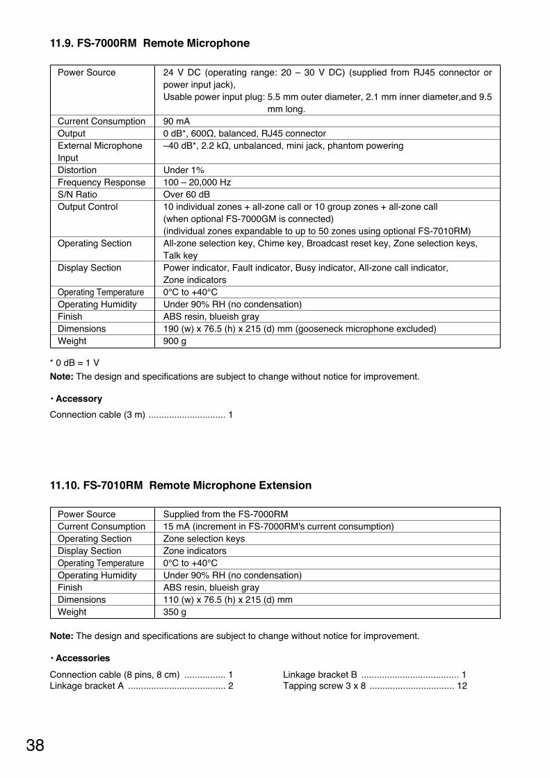
11.9. FS-7000RM Remote Microphone
11.10. FS-7010RM Remote Microphone Extension
24 V DC (operating range: 20 – 30 V DC) (supplied from RJ45 connector orpower input jack), Usable power input plug: 5.5 mm outer diameter, 2.1 mm inner diameter,and 9.5
mm long. 90 mA 0 dB*, 600Ω, balanced, RJ45 connector –40 dB*, 2.2 kΩ, unbalanced, mini jack, phantom powering
Under 1% 100 – 20,000 Hz Over 60 dB 10 individual zones + all-zone call or 10 group zones + all-zone call (when optional FS-7000GM is connected) (individual zones expandable to up to 50 zones using optional FS-7010RM) All-zone selection key, Chime key, Broadcast reset key, Zone selection keys,Talk key Power indicator, Fault indicator, Busy indicator, All-zone call indicator, Zone indicators 0°C to +40°C Under 90% RH (no condensation) ABS resin, blueish gray 190 (w) x 76.5 (h) x 215 (d) mm (gooseneck microphone excluded) 900 g
Power Source
Current Consumption Output External Microphone Input Distortion Frequency Response S/N Ratio Output Control
Operating Section
Display Section
Operating Temperature Operating Humidity Finish DimensionsWeight
* 0 dB = 1 V
Note: The design and specifications are subject to change without notice for improvement.
• Accessory
Connection cable (3 m) .............................. 1
Note: The design and specifications are subject to change without notice for improvement.
• Accessories
Connection cable (8 pins, 8 cm) ................ 1 Linkage bracket A ...................................... 2
Linkage bracket B ...................................... 1 Tapping screw 3 x 8 ................................. 12
Supplied from the FS-7000RM 15 mA (increment in FS-7000RM's current consumption) Zone selection keys Zone indicators 0°C to +40°C Under 90% RH (no condensation) ABS resin, blueish gray 110 (w) x 76.5 (h) x 215 (d) mm350 g
Power Source Current Consumption Operating Section Display Section Operating Temperature Operating Humidity Finish DimensionsWeight
39
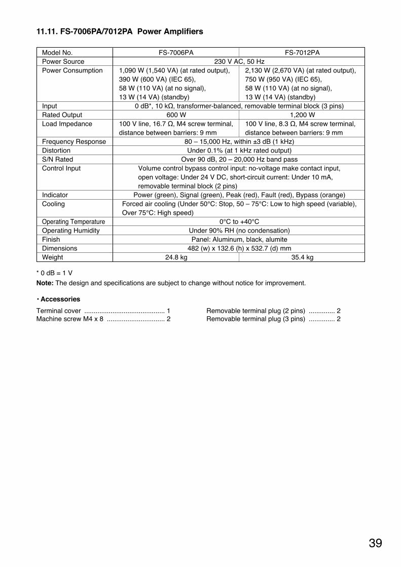
11.11. FS-7006PA/7012PA Power Amplifiers
FS-7006PA FS-7012PA 230 V AC, 50 Hz
1,090 W (1,540 VA) (at rated output), 2,130 W (2,670 VA) (at rated output), 390 W (600 VA) (IEC 65), 750 W (950 VA) (IEC 65), 58 W (110 VA) (at no signal), 58 W (110 VA) (at no signal), 13 W (14 VA) (standby) 13 W (14 VA) (standby)
0 dB*, 10 kΩ, transformer-balanced, removable terminal block (3 pins) 600 W 1,200 W
100 V line, 16.7 Ω, M4 screw terminal, 100 V line, 8.3 Ω, M4 screw terminal, distance between barriers: 9 mm distance between barriers: 9 mm
80 – 15,000 Hz, within ±3 dB (1 kHz) Under 0.1% (at 1 kHz rated output)
Over 90 dB, 20 – 20,000 Hz band pass Volume control bypass control input: no-voltage make contact input, open voltage: Under 24 V DC, short-circuit current: Under 10 mA, removable terminal block (2 pins)
Power (green), Signal (green), Peak (red), Fault (red), Bypass (orange) Forced air cooling (Under 50°C: Stop, 50 – 75°C: Low to high speed (variable), Over 75°C: High speed)
0°C to +40°C Under 90% RH (no condensation) Panel: Aluminum, black, alumite
482 (w) x 132.6 (h) x 532.7 (d) mm24.8 kg 35.4 kg
Model No. Power Source Power Consumption
Input Rated Output Load Impedance
Frequency Response Distortion S/N Rated Control Input
Indicator Cooling
Operating Temperature Operating Humidity Finish DimensionsWeight
* 0 dB = 1 V
Note: The design and specifications are subject to change without notice for improvement.
• Accessories
Terminal cover ........................................... 1 Machine screw M4 x 8 ............................... 2
Removable terminal plug (2 pins) .............. 2 Removable terminal plug (3 pins) .............. 2

133-22-064-70
11.12. YA-7000 Amplifier Auto Switching Module
Terminal cover ........................................... 1 Machine screw M3 x 6 ............................... 2
Machine screw M4 x 8 ............................... 2
24 V DC (supplied from the power amplifier) 70 mA Main amplifier input: Connects to the main amplifier's output (100 V line),
M4 screw terminal, distance between barriers: 9 mm Standby amplifier input: Connects to the standby amplifier's output (100 V line),
M4 screw terminal, distance between barriers: 9 mm Connects to the speaker line (100 V line), M4 screw terminal,distance between barriers: 9 mm Power amplifier's fault indicator lights.
0°C to +40°C Under 90% RH (no condensation) Panel: Surface-treated steel plate, black, paint 178 (w) x 61.2 (h) x 73 (d) mm 240 g
Power Source Current Consumption Input
Output
Detected Fault Indication Operating Temperature Operating Humidity Finish DimensionsWeight
Note: The design and specifications are subject to change without notice for improvement.
• Accessories