Embed Size (px)
Citation preview

i | P a g e
Voice Controlled Helicopter Summary: The goal of this project is to design a voice recognition system that is capable of controlling a radio-controlled helicopter.
Preferred Lab Days: Wednesdays
Authors: Jonathan Lam ([email protected]), Mian Zhu ([email protected])

ii | P a g e
Abstract The purpose of this project is to design an interface between the Altera DE2 and a radio-controlled helicopter such that the helicopter itself could be controlled solely through voice commands. In other words, if the words “Up” and “Down” are spoken then the helicopter itself will move up and down respectively. Our system is comprised of five major components, which include a microphone, an Altera DE2 board, an IO Circuit containing a digital-to-analog (DAC) converter and an operational amplifier (Op-Amp), an infrared controller and a mini helicopter. Users will speak one of the above 2 words into a microphone, which is connected to the MIC input jack on the Altera DE2 board. Depending on the word that is spoken, a corresponding digital signal will be generated by the Altera DE2 and sent to the DAC in our IO circuit. The DAC will then translate this digital signal into a corresponding voltage, which is then fed-in to an Op-Amp to control the base voltage of the npn transistor. This, in turn, will drive the npn transistor to either an on or off state depending on the voltage and, therefore, will allow us to control the various speeds of the helicopter.
Until now, we have managed to accomplish many of the goals that were planned earlier. These include: building an interface between the Altera DE2 and the radio-controlled helicopter via an IO Circuit, having the Altera DE2 recognize 4 different voice commands (Up, Down, Land and Start) and being capable of controlling the helicopter via the usage of these commands, as well as, the buttons and switches on the Altera DE2.

iii | P a g e
Table of Contents
ABSTRACT ....................................................................................................................................... ii
1. INTRODUCTION ....................................................................................................................... 1
2. BODY ................................................................................................................................... 1-16
2.1 FUNCTIONAL REQUIREMENTS ......................................................................................1-2
2.2 DESIGN/DESCRIPTION OF OPERATION .........................................................................2-4
2.2.1 VOICE RECOGNITION ALGORITHM ....................................................................... 4
2.3 HARDWARE REQUIREMENTS ........................................................................................4-6
2.4 PARTS LIST ......................................................................................................................... 7
2.5 AVAILABLE SOURCES ........................................................................................................ 8
2.6 DATASHEET .................................................................................................................. 9-11
2.7 BACKGROUND READING ................................................................................................. 11
2.8 SOFTWARE DESIGN .................................................................................................. 12-14
2.9 TEST PLAN ................................................................................................................. 14-15
2.10 RESULTS OF EXPERIMENTS AND CHARACTERIZATION...................................... 16-17
2.11 INTEGRATED CIRCUIT DESIGN .................................................................................. 17
3. REFERENCES ........................................................................................................................... 18
4. APPENDIX ......................................................................................................................... 19-44

1 | P a g e
1. Introduction Until this day, voice recognition remains a crucial technology in our society and as time progresses
we observe more and more devices holding the capability of being controlled via voice. Therefore, we believe that designing a voice-controlled helicopter would be quite interesting and unique.
2. Body
2.1 Functional Requirements Our system contains many functional requirements (i.e. items that need to be operational
upon its completion). Some of its many requirements include the ability of the Altera DE2 to recognize voice commands coming from the microphone and output digital signals to the digital-to-analog converter (DAC) only when the spoken commands are correct and have the DAC convert these digital signals to analog signals, which the helicopter’s infrared controller recognizes. Overall, we have managed to accomplish all of these functional requirements to a great extent. At present, our system is capable of recognizing 4 different voice commands and digital signals are only inputted to the DAC if the commands are valid. Perhaps if the commands are invalid, then our system would simply filter them out and no signals will be sent to the converter. Moreover, the accuracy of our system in distinguishing between valid and invalid commands is fairly impressive. When testing the performance of our system in the laboratory, our system had an overall accuracy of 90-100% when distinguishing between the valid commands “up” and “down” and the invalid commands “left” and “right.” Nonetheless, before migrating to our new algorithm, which involves measuring the length and the maximum positive and negative amplitudes of the commands in determining the validity of the commands, we have made attempts to use more advance algorithms such as the Fast Fourier Transform and Mel Scale to assist us in distinguishing the different voice commands. We were able to execute and run the algorithms without issues and obtain results from them, however, the results weren't as we expected. The output for each of the valid commands from FFT and Mel Scale were too similar and, hence, we were unable to use these algorithms in our design to distinguish the commands and had to adopt a new algorithm, which we are currently using in our system.
Components Functional Requirement(s) Microphone Receives audio signals and feeds it to the Altera DE2 board for analysis. Microprocessor Analyses the voice commands coming from the microphone and converts
them into digital form. If the commands are valid, then digital signals will be outputted to the DAC in our IO Circuit, otherwise, the commands will be filtered out by the system.
IO Circuit The DAC converts digital signals outputted by the Altera DE2 and maps each of them to a corresponding output voltage (Refer to Table 2 for mapping of digital inputs to output voltages). This voltage is then fed-in to an Op-Amp, which amplifies the output drive current of the DAC to drive the npn transistor and infrared controller.
Helicopter Receives infrared signals from the infrared controller and moves accordingly.
Table 1 - Functional Requirements

2 | P a g e
Digital Input to DAC (Hex) Output Voltage from DAC (V) 0x0013FD2 0.13
0x0013BD2 1.67 0x0013AD2 1.75
0x0013A92 1.82
0x0013A82 1.89 0x0013A02 2.00
0x0013802 2.19
0x0013002 2.59 0x0011002 3.15
Table 2 - Digital Input and Voltage Output of DAC (Voltage values are measured using a Beckman voltmeter)
2.2 Design/Description of Operation
Figure 1 - Block Diagram of Hardware Interface [9]

3 | P a g e
Figure 2 - A Block Diagram of Operation [1]
Figure 3 - Block Diagram for Audio Core on DE2 [2]

4 | P a g e
Figure 4 - System Architecture Block Diagram
2.2.1. Voice Recognition Algorithm:
1. We use a noise threshold to check each audio sample. Samples that are above the
threshold are considered as valid samples, otherwise, they are considered as blanks.
2. If a valid sample is detected, then we decide it to be the beginning to a word. Each
valid sample after that is then considered to be part of that word and, therefore, we
increase the length of that word as more valid samples are processed.
3. The end of a word is decided by detection of blanks. If the number of continuous
blanks is over a threshold, then we decide that the current word has ended.
4. After a word has ended, it would be matched against the voice commands’
acceptable range. Beside the word’s length, its maximum positive value and
maximum negative value are also used for command matching. If two out of the
three criteria match a command, then we have a match and a digital signal is sent to
the DAC in the IO Circuit.

5 | P a g e
2.3 Hardware Requirements
Component Requirements
Microphone Standard Microphone: Frequency Response: 100 Hz - 16 kHz Input Sensitivity: 67dbV/ubar, 47dBv/Pa +/- 4db Connectors: TRS (tip, ring sleeve)
Digital-to-Analog Converter
Name: DAC0832 Texas Instrument # of Bits: 8 Supply Voltage (Vcc): 8.3V Output Voltage (Iout2): 0-3.15V
NpN Transistor
Name: 2N3691 Collector-emitter voltage: 0-5V Emitter-base voltage: 0-1V
Op-Amp Name: LM324N Supply Voltage (Vcc): 8.3V Input Voltage: 0-3.15V Output Voltage: 3.3-5.2V
Helicopter Name: 6026-1 Type: 3.5 CH Alloy RC Helicopter with GYRO Size: 23cm (L) x 5.1cm (W) x 12.3cm (H) Wing(L/W): 21.5cm/ 2.2cm G/N Weight:19/15 Battery: 3.7V 280mAh Flying Time: 7-8 minutes Control Distance: 6m Control by: infrared
Table 3 - External Hardware Requirements

6 | P a g e
Figure 5 - Screenshot of SOPC Design [9]
Components Description/Functionality/Requirements LEDs
(Red_LEDs, Green_LEDs) Displays the amplitude of the command.
Seven Segment Display (HEX3_HEX0, HEX7_HEX4)
Displays the current status of the system. Refer to Table 23 for a summary of the messages displayed.
LCD (Char_LCD_16x2)
Displays details regarding to the status of the system, as well as, other user interactive messages. Refer to Table 23 for a summary of the messages displayed.
Buttons (Pushbuttons)
KEY3 is used for emergency safe landing. KEY2 is used for decreasing helicopter speed. KEY1 is used for increasing helicopter speed. KEY0 is used for resetting the system.
Switches (Slider_Switches)
SW0 is used for turning the system ON/OFF. SW1 is used for switching between Up/Down mode control and Idle/Land mode control.
SDRAM Total of 8MByts used, with data width of 16 bits. Used as CPU memory.
Audio Codec (Audio)
Decodes the voice input signal from mic-in and outputs an audio data signal that is then fed back into the codec through line-out.
Expansion Header JP0 (pio_0)
Output digital signals (0V, 3.3V) to DAC in IO circuit.
JTAG Port (JTAG_UART)
"Implements a communication link between the DE2 board and its host computer" [9]
CPU "Nios II/s", RISC, 32-bits with Integrated Floating Point Multiplier, Instruction Cache - 4 Kb, Data Cache - 2 Kb, JTAG Debug Module - Level 2, SDRAM - 8 Mb Tasks/Processes: - Calculations:48K Samples/Sec
Table 4 - Summary of Hardware Interface

7 | P a g e
2.4 Parts List
Part Qty. Supplier Cost Specs/ Datasheet Status
Altera DE2 Board
1 ECE Department
$279 https://eclass.srv.ualberta.ca/mod/resource/view.php?id=82694
Received
Helicopter / Infrared Controller
1 Home $25 Name: 6026-1 Type: 3.5 CH Alloy RC Helicopter with GYRO Size: 23cm (L) x 5.1cm (W) x 12.3cm (H) Wing(L/W): 21.5cm/ 2.2cm G/N Weight:19/15 Battery: 3.7V 280mAh Flying Time: 7-8 minutes Control Distance: 6m Control by: infrared
Received
DAC0830,DAC0832 Texas Instrument DAC
1 ECE Department
$7 http://www.ti.com/lit/ds/symlink/dac0830.pdf
Received
Op-Amp 1 ECE Department
$0.48 http://www.datasheetcatalog.org/datasheet2/9/0oa8seftq8d6peigox0lrx6e9wwy.pdf
Received
2N3691 Transistor
1 Home $0.5 http://alltransistors.com/transistor.php?transistor=3469
Received
1K Resistor 2 ECE Department
$0.20 Resistance: 1 Kohm Received
5k Variable Resistor
1 Home $0.25 Resistance: 5 Kohm Received
Table 5 - Parts List

8 | P a g e
2.4 Alternative Resources
Voice Recognition: http://www.eecg.toronto.edu/~aamodt/ece341/speech-recognition/
The above link brings us to an existing voice recognition algorithm that could be referenced off of when implementing our system. This particular algorithm uses the FFT mythology to compare the various voice signals coming from the microphone. Audio Driver: http://code.google.com/p/snake-for-altera-vhdl/downloads/detail?name=audio.vhd
The above link brings us to an existing audio driver for the Altera DE2 that we could use for the implementation of our system. Using this driver, we could read audio signals from the microphone into the Altera DE2 and sample it at 48kHz with 16 bit samples, one 8 bit sample for the left channel and one 8 bit sample for the right channel. Audio Cores: The Altera Audio Cores will provide us with access to the bits that are stored within the audio registers (i.e. Control, FIFO Space, Left Data and Right Data Registers). By accessing these bits, we are then capable of using our voice recognition algorithm to determine whether or not the voice commands are valid. However, in order to use the Audio Core we need two other Altera University Program IP Cores, the Development Board External Interface and the Audio/Video Configuration Core. The Development Board External Interface will help us create the necessary clock signals needed for the Audio Core and the Audio/Video Configuration Core will help us set the necessary registers for the Audio Core in the audio chip. Moreover, it is recommended by Altera that we use either the standard or fast versions of Altera’s Niosll processor. This will allow “the program running on the processor to keep up with the generation of audio data. [2]

9 | P a g e
2.5 Datasheet
2.5.1. User IO:
FPGA <-> WM8731 Signal Name
FPGA <-> WM8731 I2C_SDAT
FPGA -> WM8731 I2C_SCLK
FPGA -> WM8731 AUD_BCLK
FPGA <- WM8731 AUD_ADCDAT
FPGA -> WM8731 AUD_DACDAT
FPGA -> WM8731 AUD_DACLRCK, AUD_ADCLRCK
FPGA -> WM8731 ADCDATA Table 6 - User IO between FPGA and WM8731
Mic -> WM8731 Signal Name
Mic -> WM8731 MICIN Table 7 - User IO between MIC and Audio Codec
WM8731 -> GPIO 0 Signal Name
WM8731 -> GPIO 0 IO A4-A20 Table 8 - User IO between Audio Codec and GPIO
GPIO 0 -> DAC Signal Name
GPIO 0 -> DAC IO A4-A20 Table 9 - User IO between GPIO_0 and DAC
GPIO_0 -> DAC Pin Mapping
GPIO_0 Pin # DAC Pin #
5 1
6 19
7 2
8 18
9 4
10 17
13 6
14 16
15 5
16 15
17 7
18 14
19 9
20 13
21 8 Table 10 - Mapping of GPIO_0 and DAC Pins
10 | P a g e
Slide Switches -> CPU Signal Name
Slide Switches -> CPU Switch Table 11 - User IO between Slide Switch and CPU
Pushbuttons -> CPU Signal Name
Pushbuttons -> CPU KEY_ptr Table 12 - User IO between Pushbuttons and CPU
CPU -> LCD Signal Name
CPU -> LCD LCD_display_ptr Table 13 - User IO between CPU and LCD
CPU -> LEDs Signal Name
GPIO 0 -> LEDs green_LED_ptr, red_LED_ptr Table 14 - User IO between CPU and LEDs
CPU -> Seven Segments Signal Name
GPIO 0 -> Seven Segments SvnSegU, SvnSegL Table 15 - User IO between CPU and Seven Segments
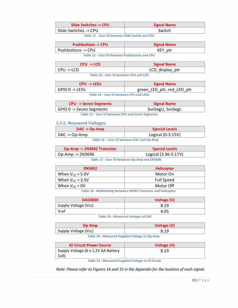
2.5.2. Measured Voltages:
DAC -> Op-Amp Special Levels
DAC -> Op-Amp Logical (0-3.15V) Table 16 – User IO between DAC and Op-Amp
Op-Amp -> 2N3692 Transistor Special Levels
Op-Amp -> 2N3696 Logical (3.36-5.17V) Table 17 - User IO between Op-Amp and 2N3696
2N3692 Helicopter
When VCE = 5.0V Motor On
When VCE = 3.5V Full Speed
When VCE = 0V Motor Off Table 18 - Relationship between 2N362 Transistor and Helicopter
DAC0830 Voltage (V)
Supply Voltage (Vcc) 8.19 Vref 4.05
Table 19 - Measured Voltages of DAC
Op-Amp Voltage (V)
Supply Voltage (Vcc) 8.19 Table 20 - Measured Supplied Voltage to Op-Amp
IO Circuit Power Source Voltage (V)
Supply Voltage (6 x 1.2V AA Battery Cell)
8.19
Table 21 - Measured Supplied Voltage to IO Circuit
Note: Please refer to Figures 14 and 15 in the Appendix for the location of each signal.

11 | P a g e
Comments: The voltage values in Tables 17-22 were all measured using a Beckman 3020 voltmeter. The fact
that we had to modify an existing infrared controller to suite our needs in this project, made it
extremely difficult to calculate these values by hand. Therefore, we had to rely on the usage of a
voltmeter to ensure that all components within our IO circuit is inputting and outputting the
correct voltages, otherwise, our components may not operate as intended. Moreover, we made
sure that when obtaining these values, we use the same voltmeter. This ensures that our results
are almost always the same with very little discrepancies between the first and subsequent
measurements.
2.6 Background Reading Article 1 (Scholarly Journal):
In An FPGA-based embedded wideband audio codec system, the authors highlight the usage of a
finite impulse response (FIR) filter in their Wideband audio codec (WAC) hardware design. This
article provided us with insight to the fact that the inclusion of such a filter in our system could
help improve the voice command qualities by reducing the amount of noise that gets fed into
our system. This, in effect, would improve the overall accuracy of our system, especially, when
determining the validity of a particular voice command. [6]
Article 2 (Non-Scholarly Journal):
In SOPC-based Voiceprint Identification System, the authors described the inclusion of an
AUDIO_ADC_FIFO_0 module “to convert serial data to parallel audio samples (16 bits).”[8] We
believe that such a module is also necessary in our system. However, instead of designing our
own module, perhaps we could use Altera’s Audio Core to simulate the same functionalities as
their AUDIO_ADC_FIFO_0 module. We believe that using Altera’s Audio Core is much safer than
designing our own module, since we know that such a Core has been tested thoroughly by
Altera and has been proven to work on the DE2 by various DE2 users.

12 | P a g e
2.7 Software Design
Figure 6 – Software Design Block Diagram
Our software project is designed and implemented through the usage of the “NIOS II Software
Build Tools for Eclipse” version 11.1 software program and is divided into four modules: main,
recognize, LEDs, LCD.
The main module hosts an infinite while loop, which fetches voice samples from the audio
registers in the audio core and processes them. During each iteration of the loop, our algorithm
checks for changes in the position of slide switches since the last iteration and updates the
system accordingly. The SW0 switch turns the system on and off and the SW1 switch switches
between the Up/Down control mode and the Idle/Land control mode. After the check, voice
samples are then fetched from the audio codec and stored into left_buffer and right_buffer,
both of type Integer.
If the system is on, then we move onto processing the sample. Samples that are less than the
NOISE_THRESHOLD (Date type: constant variable) are recorded as blanks (Data type: Integer),
otherwise, they are considered as valid samples. If we are still trying to get a new word and the
current sample is valid, then we decide that the beginning of a new word is detected. If the
beginning of a word is already detected and the current sample is valid, then we increment the
current word’s length and reset the blank length. If the current sample is a blank, then we
increment the current blank length. If consecutive blanks with length longer than
BLANK_LENGTH_THRESHOLD (Date type: constant variable) are detected, then we decide the
current word has ended. Upon the completion of the word, its length, maximum positive value
and maximum negative value is sent to the recognize module.
13 | P a g e
The Recognize module will attempt to match the word length, maximum positive and negative
values with the values in our acceptable range. If two out of the three values fall within our
acceptable range, then we decide we have a match. The ID of the matching command is
returned to the main module and used to determine the instruction (digital signal) to send to
the helicopter.
After the sample has been processed, it is sent to the LEDs module. The LEDs module takes the
sample and evaluates its value to determine the LEDs to light up. The red LEDs represent the left
channel and the green LEDs represent the right channel. The sample is also fed back into the
audio codec and outputted through the LINE-OUT.
Lastly the values of the pushbuttons are checked. KEY3 will initiate a landing command, while
KEY2 and KEY1 decrement the current speed of the helicopter, and KEY0 will reset the DE2
board.
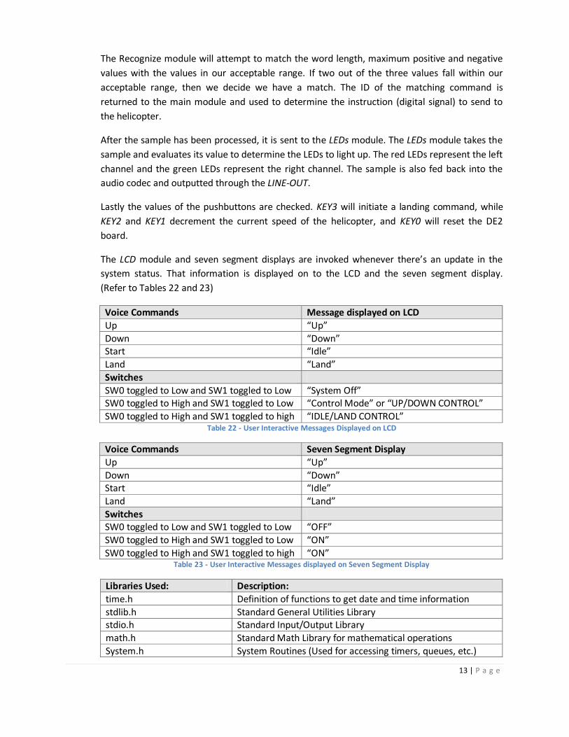
The LCD module and seven segment displays are invoked whenever there’s an update in the
system status. That information is displayed on to the LCD and the seven segment display.
(Refer to Tables 22 and 23)
Voice Commands Message displayed on LCD
Up “Up”
Down “Down” Start “Idle”
Land “Land”
Switches
SW0 toggled to Low and SW1 toggled to Low “System Off” SW0 toggled to High and SW1 toggled to Low “Control Mode” or “UP/DOWN CONTROL”
SW0 toggled to High and SW1 toggled to high “IDLE/LAND CONTROL” Table 22 - User Interactive Messages Displayed on LCD
Voice Commands Seven Segment Display
Up “Up”
Down “Down” Start “Idle”
Land “Land”
Switches SW0 toggled to Low and SW1 toggled to Low “OFF”
SW0 toggled to High and SW1 toggled to Low “ON”
SW0 toggled to High and SW1 toggled to high “ON” Table 23 - User Interactive Messages displayed on Seven Segment Display
Libraries Used: Description:
time.h Definition of functions to get date and time information
stdlib.h Standard General Utilities Library stdio.h Standard Input/Output Library
math.h Standard Math Library for mathematical operations
System.h System Routines (Used for accessing timers, queues, etc.)

14 | P a g e
Project.h Header file containing constants that are needed for recognition algorithm.
LCD.h Header file containing constants to display to LCD.
LEDs.h Header file containing LCD function declarations. recognize.h Header file containing constants that are needed for
recognition algorithm. Table 24 - Summary of C Libraries Used for Recognition Algorithm
[10]
2.8 Test Plan
Hardware:
Tests Methodology Test GPIO Measure the voltages being outputted by the GPIO
pins. The voltages should appear as either 0V (digital low) or 3.3V (digital high) when the pins are being written to.
Test DAC Measure the waveform using an oscilloscope of the DAC's input and output signals and see if they are the same.
Test Op-Amp Compare the Op-Amp's input and output voltages to determine if the output voltages are reasonable.
Test IO Circuitry Measure the voltage of every wire to ensure that every component in the circuitry is connected correctly.
Test IO Circuitry when interfaced with the Altera DE2 board
Feed in random digital signals to the DAC and see if the DAC outputs reasonable voltages.
Test responsiveness of helicopter Feed in digital signals to DAC and see if the helicopter responses or not.
Test functionality of microphone when connected to the Altera DE2 board
Feed in audio signals to microphone and check to see if bits are being stored correctly in the audio registers of the Audio Core.
Test responsiveness of helicopter by speaking into microphone
Feed into the microphone "Up", "Down", "Land" and "Start" and see if the helicopter responds or not.
Test responsiveness of onboard controls
Pressing Key1 should decrement the speed of the helicopter. Pressing Key2 should increment the speed of the helicopter. Pressing Key3 should trigger a continual decent of the helicopter. Pressing Key0 should reset the system. Toggling SW0 and SW1 should enable us to switch between "Up/Down" mode and "Start/Land" mode. In order to test the functionality of each of these buttons/switches, we would need to trigger each one individually and observe for responsiveness.
Test the overall functionality of the system (Final Testing)
Feed in both valid and invalid commands into the microphone and see if the system will filter out invalid commands and process only the valid commands.
Table 25 - Hardware Test Plan

15 | P a g e
Software:
Tests Methodology Test audio driver for correctness
Speak into the microphone and see if we could record/playback the spoken audio signals.
Test the extraction of data from audio registers
Copy the individual audio samples that are stored in the audio registers on the audio codec into a variable and display their values to console and see if the stored values are reasonable.
Test voice recognition algorithm for a single command
Speak into the microphone "Up" and see whether or not our system responds. (i.e. LEDs flash)
Test voice recognition algorithm for two different commands
Speak into the microphone "Up" and "Down" and see whether or not our system could distinguish between the two commands. If "Up"/"Down" is spoken and is recognized by our system, then we should see the word "Up"/"Down" displayed on the LCD and the Seven Segment Display.
Test voice recognition algorithm for three different commands
Speak into the microphone "Up", "Down" and "Start" and see whether or not our system could distinguish between the three different commands. If "Up"/"Down"/"Start" is spoken and is recognized by our system, then we should see the word "Up"/"Down"/"Start" displayed on the LCD and the Seven Segment Display.
Test voice recognition algorithm for four different commands
Speak into the microphone "Up", "Down", "Start" and "Land" and see whether or not our system could distinguish between the four different commands. If "Up"/"Down"/"Start"/"Land" is spoken and is recognized by our system, then we should see the word "Up"/"Down"/"Start"/"Land" displayed on the LCD and the Seven Segment Display.
Test voice recognition algorithm to see if it could distinguish between valid and invalid commands
Speak into the microphone "Up", "Down", "Left" and "Right" and see whether or not our system could filter out "Left" and "Right" and respond to only "Up" and "Down".
Table 26 - Software Test Plan

16 | P a g e
2.9 Results of experiments and characterization After many trail runs, we obtained the data summarized in Table 24 regarding the
characteristics of each of the four voice commands when spoken into the microphone. These values are extremely useful to us as they provide us with insight to the upper and lower bounds of the four commands. Knowing these boundaries allow us to accurately configure our system such that it could only recognize “Up”, “Down”, “Start” and “Land” and no other commands.
Command Length
(Upper/Lower Bound) Negative Amplitude (Upper/Lower Bound)
Positive Amplitude (Upper/Lower Bound)
Up 3000/1000 -1000000000/-2147483648 2147483392/1000000000
Down 99999/4000 -100000000/ -500000000 700000000/300000000
Land 99999/4000 -100000000/ -500000000 700000000/300000000 Start 3000/1000 -1000000000/-2147483648 2147483392/1000000000
Table 27 - Summary of Voice Command Characteristics
From Table 27, it is evident that the characteristics for "Up"/"Down" are identical to those of
"Start"/"Land". Therefore, in order to separate the two sets of commands and have our system
be capable of distinguishing between the two sets, we had to incorporate an additional switch
into our system to assist us in selecting the correct set of commands to activate at any given
time. Perhaps if one of the two switches is set to "high", then our "Up" and "Down" command
set would be activated. Otherwise, if both of the switches are set to "high", then our "Start" and
"Land" command set would be activated. Table 26, provides a summary of the operation of the
two switches.
State of SW1 State of SW0 Result Low Low System is turned off
Low High Up/Down command set activated
High Low System is turned off
High High Start/Land command set activated
Table 28 - Operation of SW0 and SW1
When testing the performance/accuracy of our system in the laboratory we obtained the results highlighted in Tables 29 and 30.
Valid Commands # Trials # Success Match Accuracy
Up 10 9 90%
Down 10 10 100% Start 10 10 100%
Land 10 10 100% Table 29 - Accuracy of System When Handling Valid Commands
Invalid Commands # Trials # False Match Error Rate
Left 10 0 0%
Right 10 0 0% Table 30 - Accuracy of System When Handling Invalid Commands

17 | P a g e
From Tables 27 and 28, it is evident that our system is extremely accurate in distinguishing
between valid and invalid commands. As depicted in the tables, our system had an overall
accuracy of 90-100% when handling valid commands and 100% accuracy when handling invalid
commands. We believe that such high percentage values are quite convincing that our system is
functioning as designed and not behaving erratically.
2.10 Integrated Circuit Design We build our project on top of the Altera DE2 Media Computer, so all the VHDL code are either
interfaces that are already provided to us through the SOPC builder or exist as proprietary IP
cores that can be imported into our project. So we did not need to write any VHDL code. So for IC
design, I pick the sysid.vhd file generated by the SOPC build to work on.
The sysid.vhd has relatively simple logic. However, it requires Altera libraries and a function from
those libraries to work, so I modified the file, removed the Altera libraries and declared the
function inside the file for it to work with the design process.
The results, however, is not quite satisfactory at all. Even though sysid passed the simulation, its
timing report (Attached in appendix with area and power report) from synthesis (Fig. 16)
indicates that its path is unconstrained and when in place & route (Fig. 17), it is shown that sysid
contains no path.

18 | P a g e
3. References
[1] M.T. Bala Murugan and M. Balaji, "SOPC-Based Speech-to-Text Conversion," National Institute of Technology, Trichy. 2006. [Online]. Available: http://www.altera.com/literature/dc/2006/i2.pdf. [Accessed Feb. 2, 2012]
[2] “Audio Core for Altera DE2/DE1 Boards” Altera Corporation. 2006. [Online]. Available: ftp://ftp.altera.com/up/pub/University_Program_IP_Cores/Audio.pdf.
[Accessed Mar. 7, 2012]
[3] "A Simple Speech Recognition Algorithm for ECE341...," The University of British
Columbia. 2003. [Online]. Available: http://www.eecg.toronto.edu/~aamodt/ece341/speech-recognition/. [Accessed Feb. 4, 2012].
[4] “2N3691 Transistor Datasheet. Parameters and Characteristics.” ALL Transistors
Datasheet. [Online]. Available: http://alltransistors.com/transistor.php?transistor=3469. [Accessed Mar.7, 2012].
[5] “FFT Megacore Function User Guide.” Altera Corporation. [Online]. Available:
http://www.altera.com/literature/ug/ug_fft.pdf. [Accessed Mar 7, 2012].
[6] Chang Choo, Bambhania, B, Woon Seob So, In Ki Hwang, Do Young Kim. “An
FPGA-based embedded wideband audio codec system,” in Field Programmable
Logic and Applications, 2009,pp. 587-590.
[7] “DE2 Schematics.” Altera Corporation. 2006. [Online]. Available:
https://eclass.srv.ualberta.ca/mod/resource/view.php?id=88127. [Accessed Mar 7,
2012].
[8] F. Huan, L. Xin, “SOPC-based Voiceprint Identification System.” Internet:
http://www.altera.com/literature/dc/2007/in_2007_voice_rec.pdf. [Accessed Mar
11, 2012].
[9] “Media Computer System for the Altera DE2 Board.” Altera Corporation. [Online].
Available:ftp://ftp.altera.com/up/pub/Altera_Material/9.1/Computer_Systems/DE2/
DE2_Media_Computer.pdf. [Accessed Apr. 10, 2012].
[10] “cplusplus.com” cplusplus.com. [Online]. Available:
http://www.cplusplus.com/reference/clibrary/. [Accessed Apr. 12, 2012].

19 | P a g e
Appendices Quick Start Manual
1. Have Quartus II 11.1 Web Edition for Windows installed on PC.
2. Double click on the Quartus II executable and open application.
3. Open the project named "DE2_Media_Computer".
Figure 7 - Screenshot of Quartus II Application Window

20 | P a g e
4. Double Click on "Program Device (Open Programmer)" under the task menu and the
programmer window will appear.
Figure 8 - Screenshot of Programmer Window
5. Have the Altera DE2 connected to PC via an USB cable and powered up. Note: Ensure that the
USB cable is connected to the "Blaster" port on the Altera DE2.
6. In the "Programmer" window, click on "DE2_Media_Computer_time_limited.sof" and click
"start". If the download is successful, then the "Progress" bar should display "100% Successful".
7. Install "Nios II 11.1 Software Tools for Eclipse" for windows and open application.

21 | P a g e
8. In Eclipse, click File -> Import -> Existing Projects into Workspace. Click "Browse" and import the
"UpdatedDemo2" project file. Click "Finish". Right-Click on "UpdatedDemo2" in Project Explorer
and click "Clean Project" -> “Build Project" -> "Run As" -> "Hardware Application".
Figure 9 - Screenshot of Nios II Application
9. Connect the IO Circuit to the Altera DE2 board via a 40-pin header cable. Note: Ensure that you
connect the header cable to the GPIO_0 expansion header on the Altera DE2 with PIN #1 starting
at the top left corner of the expansion header, otherwise, no signals will be sent to the IO Circuit.
Figure 10 - Picture of Connection between Altera DE2 and IO Circuit

22 | P a g e
10. Toggle all switches on the Altera DE2 to a "downward" position. This will ensure that the system
is turned OFF.
Figure 11 - Picture of Onboard Switches
11. Toggle "SW0" (rightmost switch) on Altera DE2 to an "upward" position to turn on system.
12. Toggle "SW1" on Altera DE2 to an "upward" position to use "Land" and "Start" commands.
Otherwise, the only available commands would be "Up" and "Down".
13. Connect the microphone to the MIC-in port on the Altera DE2.
14. Power up the IO Circuit via the onboard power switch and turn on helicopter.
15. If in "Land/Start" mode, speak into the MIC "Land" or "Start" and the helicopter should respond.
(Note: if the helicopter has already landed, then speaking “Land” into the MIC will trigger no
response from the helicopter)
16. If in "Up/Down" mode, speak into the MIC "Up" or "Down" and the helicopter should respond.

23 | P a g e
Future Work
Backup Plan: 1. If all goes wrong in controlling the helicopter due to its irrational behaviours, then our backup plan would be to use a car in replacement of the helicopter. 2. If voice recognition does not work, then our backup plan would be to use the onboard controls (buttons, switches) on the Altera DE2 to control the helicopter (car). Extensions:
1. Add additional voice commands. (Achieved – We added the “Start” and “Land” commands) 2. Allow users to control the helicopter via onboard switches and buttons. (Achieved – We added
buttons that control the speed of the helicopter) 3. Display user interactive messages when the system is turned ON/OFF and when a valid
command is spoken into the MIC. (Achieved – Our current system displays “Up”, “Down”, “Idle” or “Land” when these words are spoken into the microphone)
4. Inserting a sdcard that contains pre-programmed flight patterns to the Altera DE2 will allow users to see the helicopter fly different flight patterns. Note: the helicopter will fly these patterns automatically and with no control by the users. The only form of user interaction with the system, in this case, would be to use voice commands to trigger the various flight patterns to be performed by the helicopter. (Not achieved due to insufficient time)
5. Dropping a payload on a pressure scale while the helicopter is in motion. The pressure scale will output digital signals which will be converted into signals that an attached speaker could recognize. (Not achieved due to insufficient time)
Overall, we have managed to achieve beyond our pre-set goals and have incorporated 3 additional features (Extensions 1-3) into our system. These features play a crucial role in enhancing the overall performance in our system as they not only add safety to our system, but they also intensify user-system interactions.
Hardware Block Diagram
Figure 12 - Hardware Block Diagram [2]

24 | P a g e
IO Circuitry Block Diagram
Figure 13 - Breadboard Block Diagram (Note: VR- 5K Variable Resistor)
GPIO_0 Interface with IO Circuits
Figure 14 - A Schematic of GPIO 0 on Altera DE2 [7]
(Note: Pins 5-21 were used in our design)

25 | P a g e
Figure 15 - Schematic of Audio IO on DE2 [7]

26 | P a g e
Integrated Circuit Design
a) Area Report
****************************************
Report : area
Design : sysid_top
Version: Y-2006.06-SP4
Date : Fri Apr 13 14:38:07 2012
****************************************
Library(s) Used:
GSCLib_2.0 (File:
/EDA/kits/gpdk18/GSCLib_3.0/timing/GSCLib_3.0.db)
GSCLib_IO (File:
/EDA/kits/gpdk18/GSCLib_IO_1.4/timing/GSCLib_IO.db)
Number of ports: 35
Number of nets: 71
Number of cells: 37
Number of references: 4
Combinational area: 945000.000000
Noncombinational area: 0.000000
Net Interconnect area: undefined (No wire load specified)
Total cell area: 945000.000000
Total area: undefined
b) Power Report ****************************************
Report : power
-analysis_effort low
Design : sysid_top
Version: Y-2006.06-SP4
Date : Fri Apr 13 14:40:16 2012
****************************************
Library(s) Used:
GSCLib_2.0 (File:
/EDA/kits/gpdk18/GSCLib_3.0/timing/GSCLib_3.0.db)
GSCLib_IO (File:
/EDA/kits/gpdk18/GSCLib_IO_1.4/timing/GSCLib_IO.db)
Operating Conditions: typical Library: GSCLib_2.0
Wire Load Model Mode: top
Global Operating Voltage = 3
Power-specific unit information :
Voltage Units = 1V
Capacitance Units = 1.000000pf
Time Units = 1ns
Dynamic Power Units = 1mW (derived from V,C,T units)
Leakage Power Units = 1nW
Cell Internal Power = 48.4833 mW (100%)
Net Switching Power = 46.5480 uW (0%)
---------
Total Dynamic Power = 48.5299 mW (100%)
Cell Leakage Power = 151.6945 uW

27 | P a g e
c) Timing Report ****************************************
Report : timing
-path full
-delay max
-max_paths 1
Design : sysid_top
Version: Y-2006.06-SP4
Date : Fri Apr 13 14:41:10 2012
****************************************
Operating Conditions: typical Library: GSCLib_2.0
Wire Load Model Mode: top
Startpoint: padADDR (input port)
Endpoint: padRDDATA_30_
(output port)
Path Group: (none)
Path Type: max
Point Incr Path
-----------------------------------------------------------
input external delay 0.00 0.00 f
padADDR (in) 0.00 0.00 f
inpADDR_0/Y (PDUDGZ) 0.06 0.06 f
U1/Y (CLKBUFX1) 0.18 0.24 f
coreG/address (sysid) 0.00 0.24 f
coreG/readdata_30_ (sysid) 0.00 0.24 f
opRDDATA_30/PAD (PDO12CDG) 0.69 0.93 f
padRDDATA_30_ (out) 0.00 0.93 f
data arrival time 0.93
-----------------------------------------------------------
(Path is unconstrained)

28 | P a g e
Figure 16 - Schematic of IC in Design Vision
Figure 17 - Layout of IC in Encounter

29 | P a g e
Source Code
Figure 18 – Software Design Block Diagram
Source Code File Description Status
Sysid.vhd System ID T
SDRAM.vhd Used for the operation of SDRAM Memory T pio_0.vhd GPIO header T
nios_system.vhd Used for the operation of JTAG Port T
nios_system_clock_2.vhd System clock T nios_system_clock_1.vhd System clock T
nios_system_clock_0.vhd System clock T
JTAG_UART.vhd Used for the operation of JTAG Port T Interval_Timer.vhd Interval Timer T
DE2_Media_Computer.vhd Top Level T
CPU_mult_cell.vhd Used for the operation of CPU T CPU_jtag_debug_module_wrapper.vhd Used for the operation of CPU T
CPU_jtag_debug_module_tck.vhd Used for the operation of CPU T
CPU_jtag_debug_module_sysclk.vhd Used for the operation of CPU T
CPU_fpoint.vhd Used for the operation of CPU T CPU.vhd Used for the operation of CPU T
Slider_Switches.v Used for the operation of Switches T
Red_LEDs.v Used for the operation of Red LEDs T Pushbuttons.v For the operation of Key0-key3 T
HEX7_HEX4.v Used for the operation of Seven Segment T

30 | P a g e
Display
HEX3_HEX0.v Used for the operation of Seven Segment Display
T
Green_LEDs.v Used for the operation of Green LEDs T External_Clocks.v Clocks T
Char_LCD_16x2.v For the operation of LCD display T
AV_Config.v For the operation of audio codec T Audio.v For the operation of audio codec T
altera_up_sync_fifo.v For the operation of audio core T
altera_up_slow_clock_generator.v Used for the operation of audio core T altera_up_clock_edge.v Used for the operation of audio core T
altera_up_character_lcd_initialization.v Used for the operation of LCD Display T
altera_up_character_lcd_communication.v Used for the operation of audio core T altera_up_av_config_serial_bus_controller.v Used for the operation of audio core T
altera_up_av_config_auto_init_ob_de2_35.v Used for the operation of audio core T
altera_up_av_config_auto_init_ob_audio.v Used for the operation of audio core T
altera_up_av_config_auto_init_ob_adv7181.v Used for the operation of audio core T altera_up_av_config_auto_init.v Used for the operation of audio core T
altera_up_audio_out_serializer.v Used for the operation of audio core T
altera_up_audio_in_deserializer.v Used for the operation of audio core T altera_up_audio_bit_counter.v Used for the operation of audio core T
LCD.c Displays user interactive messages when turning the system ON/OFF and when a valid command is detected.
T
LEDs.c Turns on LEDs when a valid command is detected
T
Main.c Main project file for voice recognition algorithm
T
Recognize.c Compares the inputted voice command parameters (positive/negative amplitude, wordlength) with matching range.
T
LCD.h Contains defined constants for LCD.c T
LEDs.h Contains defined constants for LEDs.c T
Main.h Contains defined constants for main.c T
Recognize.h Contains defined constants for Recognize.c T Table 31 - Description/Status of Source Code Files

31 | P a g e
C Code:
LCD.c________________________________________________________________________________
#include <string.h> #include "system.h" #include "LCD.h" void showLCD(char * newDisplay, char * display, char row){ volatile char * LCD_display_ptr = (char *)CHAR_LCD_16X2_BASE; if(strcmp(newDisplay, display)){ int i; strcpy(display, newDisplay); if (row == 'u'){ *LCD_display_ptr = LCD_ADDR_U; } else if (row == 'l'){ *LCD_display_ptr = LCD_ADDR_L; } else return; for(i = 0; i <16; ++i){ *(LCD_display_ptr+1) = ' '; } if (row == 'u'){ *LCD_display_ptr = LCD_ADDR_U; } else if (row == 'l'){ *LCD_display_ptr = LCD_ADDR_L; } else return; while(*display){ *(LCD_display_ptr+1) = *display; ++display; } } }

32 | P a g e
LEDs.c________________________________________________________________________________
#include "LEDs.h" // Show the amplitude of the data on the LEDs void showLEDs(int buf, unsigned int * leds){ *leds = OFF; if(buf < 0){ buf *= -1; } if(buf > 0){ *leds |= 0x01; } if(buf/(MAX_VALUE/32 * 1)){ *leds |= 0x02; } if(buf/(MAX_VALUE/32 * 2)){ *leds |= 0x04; } if(buf/(MAX_VALUE/32 * 3)){ *leds |= 0x08; } if(buf/(MAX_VALUE/32 * 4)){ *leds |= 0x10; } if(buf/(MAX_VALUE/32 * 5)){ *leds |= 0x20; } if(buf/(MAX_VALUE/32 * 6)){ *leds |= 0x40; } if(buf/MAX_VALUE){ *leds |= 0x80; } }

33 | P a g e
Main.c______________________________________________________________________________
#include <time.h> #include <stdlib.h> #include <stdio.h> #include <math.h> #include "system.h" #include "project.h" #include "LCD.h" #include "LEDs.h" #include "recognize.h" int main() { printf("System Start!\n\n"); // audio port address volatile int * audio_ptr = (int *)AUDIO_BASE; // pio port address unsigned int * pio = (unsigned int *)PIO_0_BASE; // green LED address unsigned int * green_LED_ptr = (unsigned int *)GREEN_LEDS_BASE; // red LED address unsigned int * red_LED_ptr = (unsigned int *)RED_LEDS_BASE; // upper seven segment address unsigned int * SvnSegU = (unsigned int *)HEX7_HEX4_BASE; // lower seven segment address unsigned int * SvnSegL = (unsigned int *)HEX3_HEX0_BASE; // slide switch address unsigned int * Switch = (unsigned int *)SLIDER_SWITCHES_BASE; // string buffer for LCD upper row char * displayUpper = calloc(LCD_BUFFER_SIZE, sizeof(char)); // string buffer for LCD lower row char * displayLower = calloc(LCD_BUFFER_SIZE, sizeof(char)); int system_on = 0; // flag for the power of the system int word; // flag for detection of a word int idleland = 0; int left_buffer, right_buffer; // buffer for the two channels of the CoDec int key_up = 0, key_down = 0, key_off = 0; // flag for the three pushbuttons int lengthCount = 0, blankCount = 0; // counters for the length of the current word or blank int peak, valley; // The maximum positive/negative values from the CoDec int currentSpeed = SPEED_0; int currentSwitch;

34 | P a g e
// Turn off the seven segments and the LEDs *SvnSegU = OFF; *SvnSegL = OFF; *green_LED_ptr = OFF; *red_LED_ptr = OFF; *pio = currentSpeed; // The main while loop while(1) { // Check if there was any change in the switches if (*Switch != currentSwitch){ currentSwitch = *Switch; // Check the slide switch to see if the system is turned on if (currentSwitch%2){ system_on = 1; *SvnSegU = OFF; *SvnSegL = HEX_ON; showLCD(LCD_ON_U, displayUpper, 'u'); // Check 2nd switch to see which control mode is turned on if (currentSwitch/2%2){ // Idle/Land Mode is turned on idleland = 1; showLCD(LCD_ON2_L, displayLower, 'l'); } else{ // Up/Down Mode is turned on idleland = 0; showLCD(LCD_ON_L, displayLower, 'l'); } } else { system_on = 0; *SvnSegU = OFF; *SvnSegL = HEX_OFF; *green_LED_ptr = OFF; *red_LED_ptr = OFF; showLCD(LCD_OFF_U, displayUpper, 'u'); showLCD(LCD_OFF_L, displayLower, 'l'); currentSpeed = SPEED_0; *pio = currentSpeed; } }

35 | P a g e
// Store the values from the Audio CoDec left_buffer = *(audio_ptr + 2); right_buffer = *(audio_ptr + 3); if (system_on) { if (!word){ // If no word was detect, then try to detect the beginning of a word if (fabs(left_buffer)>NOISE_THRESHOLD){ // Value passed the threshold level word = 1; lengthCount = 1; peak = valley = left_buffer; } } if (word){ // If a word was detected, then check new data if (fabs(left_buffer)>NOISE_THRESHOLD){
// If new data is still above the noise threshold, then increment the word length, reset the blank count and update the peak and valley
lengthCount++; blankCount = 0; if (peak < left_buffer){ peak = left_buffer; } else if (valley > left_buffer){ valley = left_buffer; } } else {
// If new data is below the noise threshold, then increment the blank count
blankCount++; if (blankCount >= BLANK_LENGTH_THRESHOLD){
/* If blank count has go over the threshold, then the current word is finished * try to match the word, and reset the flags and counters */
// Debugging Outputs if (lengthCount > 1000)
printf("Length: %d, Peak: %d, Valley: %d\n", lengthCount, peak, valley);
// Command Matching

36 | P a g e
int command = matchCommand(lengthCount, peak, valley, idleland);
if (command == STATUS_UP){ showLCD(LCD_UP_L, displayLower, 'l'); *SvnSegL = HEX_UP; currentSpeed = SPEED_7; *pio = currentSpeed; wait(WAIT_TIME); showLCD(LCD_ON_L, displayLower, 'l'); *SvnSegL = HEX_ON; currentSpeed = SPEED_6; *pio = currentSpeed; } else if(command == STATUS_DOWN){ showLCD(LCD_DOWN_L, displayLower, 'l'); *SvnSegL = HEX_DOWN; currentSpeed = SPEED_5; *pio = currentSpeed; wait(WAIT_TIME); showLCD(LCD_ON_L, displayLower, 'l'); *SvnSegL = HEX_ON; } else if(command == STATUS_IDLE) { showLCD(LCD_IDLE_L, displayLower, 'l'); *SvnSegL = HEX_IDLE; currentSpeed = SPEED_1; *pio = currentSpeed; wait(WAIT_TIME); showLCD(LCD_ON2_L, displayLower, 'l'); *SvnSegL = HEX_ON; } else if(command == STATUS_LAND) { showLCD(LCD_LAND_L, displayLower, 'l'); *SvnSegL = HEX_LAND; while(speedGear(¤tSpeed, 'd')){ *pio = currentSpeed; wait(WAIT_TIME);

37 | P a g e
} showLCD(LCD_ON2_L, displayLower, 'l'); *SvnSegL = HEX_ON; } // Reseting flags and counters word = 0; lengthCount = 0; blankCount = 0; } } } } // LEDs to show the amplitude of the data showLEDs(left_buffer, red_LED_ptr); showLEDs(right_buffer, green_LED_ptr); // Pass the sound data back into the CoDec and output through line out *(audio_ptr + 2) = left_buffer; *(audio_ptr + 3) = right_buffer; // Check for emergency safety pushbuttons check_KEYs (&key_up, &key_down, &key_off); if (key_up){ // Increment Speed printf("safe down\n"); speedGear(¤tSpeed, 'i'); *pio = currentSpeed; *SvnSegU = HEX_SAFE; *SvnSegL = HEX_UP; key_up = 0; wait(WAIT_TIME); } else if (key_down){ // Decrement speed printf("safe down\n"); speedGear(¤tSpeed, 'd'); *pio = currentSpeed; *SvnSegU = HEX_SAFE; *SvnSegL = HEX_DOWN; key_down = 0; wait(WAIT_TIME); } else if (key_off){ // Emergency shut down *red_LED_ptr = OFF;

38 | P a g e
*green_LED_ptr = OFF; *SvnSegU = HEX_SAFE; *SvnSegL = HEX_OFF; while(speedGear(¤tSpeed, 'd')){ *pio = currentSpeed; wait(WAIT_TIME); } while(1); } } return 0; } // Make the program stall for a few seconds void wait ( int seconds ) { clock_t endwait; endwait = clock () + seconds * 3/4 * CLOCKS_PER_SEC/100; clock_t c; while ((c = clock()) < endwait){ } } // Check the key to see if any button was pushed void check_KEYs(int * KEY1, int * KEY2, int * KEY3) { volatile int * KEY_ptr = (int *) PUSHBUTTONS_BASE; // pushbutton KEY address int KEY_value; KEY_value = *(KEY_ptr); // read the pushbutton KEY values); while (*KEY_ptr); // wait for pushbutton KEY release if (KEY_value == 0x2) // check KEY1 { *KEY1 = 1; } else if (KEY_value == 0x4) // check KEY2 { *KEY2 = 1; } else if (KEY_value == 0x8) // check KEY3 { *KEY3 = 1; } } // Change the speed of the helicopter

39 | P a g e
int speedGear(int * speed, char inc){ int gear = -1; switch(*speed){ case SPEED_0: if(inc == 'i'){ *speed = SPEED_1; gear = 1; } else gear = 0; break; case SPEED_1: if(inc == 'i'){ *speed = SPEED_2; gear = 2; } else if(inc == 'd'){ *speed = SPEED_0; gear = 0; } break; case SPEED_2: if(inc == 'i'){ *speed = SPEED_3; gear = 3; } else if(inc == 'd'){ *speed = SPEED_1; gear = 1; } break; case SPEED_3: if(inc == 'i'){ *speed = SPEED_4; gear = 4; } else if(inc == 'd'){ *speed = SPEED_2; gear = 2; } break; case SPEED_4: if(inc == 'i'){ *speed = SPEED_5; gear = 5; } else if(inc == 'd'){

40 | P a g e
*speed = SPEED_3; gear = 3; } break; case SPEED_5: if(inc == 'i'){ *speed = SPEED_6; gear = 6; } else if(inc == 'd'){ *speed = SPEED_4; gear = 4; } break; case SPEED_6: if(inc == 'i'){ *speed = SPEED_7; gear = 7; } else if(inc == 'd'){ *speed = SPEED_5; gear = 5; } break; case SPEED_7: if(inc == 'd'){ *speed = SPEED_6; gear = 6; } else gear = 7; break; default:; } return gear; }

41 | P a g e
Recognize.c___________________________________________________________________________ #include "recognize.h" // Match and return the command int matchCommand(int length, int peak, int valley, int landingSwitch){ int up = 0, down = 0, idle = 0, land = 0; if (landingSwitch){ switch(checkLength(length, landingSwitch)){ case STATUS_IDLE: idle++; break; case STATUS_LAND: land++; break; default: ; }; switch(checkPeak(peak, landingSwitch)){ case STATUS_IDLE: idle++; break; case STATUS_LAND: land++; break; default: ; }; switch(checkValley(valley, landingSwitch)){ case STATUS_IDLE: idle++; break; case STATUS_LAND: land++; break; default: ; }; } else{ switch(checkLength(length, landingSwitch)){ case STATUS_UP: up++; break; case STATUS_DOWN:

42 | P a g e
down++; break; default: ; }; switch(checkPeak(peak, landingSwitch)){ case STATUS_UP: up++; break; case STATUS_DOWN: down++; break; default: ; }; switch(checkValley(valley, landingSwitch)){ case STATUS_UP: up++; break; case STATUS_DOWN: down++; break; default: ; }; } if(up >= 2){ return STATUS_UP; } else if (down >= 2){ return STATUS_DOWN; } else if (idle >= 2){ return STATUS_IDLE; } else if (land >= 2){ return STATUS_LAND; } else { return -1; } } // Match the length of the command int checkLength(int length, int landingSwitch){

43 | P a g e
if (landingSwitch){ if (length >= IDLE_LENGTH_LOWER && length < IDLE_LENGTH_UPPER){ return STATUS_IDLE; } else if (length >= LAND_LENGTH_LOWER && length < LAND_LENGTH_UPPER){ return STATUS_LAND; } } else { if (length >= UP_LENGTH_LOWER && length < UP_LENGTH_UPPER){ return STATUS_UP; } else if(length >= DOWN_LENGTH_LOWER && length < DOWN_LENGTH_UPPER){ return STATUS_DOWN; } } return -1; } // Match the positive maximum value of the command int checkPeak(int peak, int landingSwitch){ if (landingSwitch){ if (peak >= IDLE_PEAK_LOWER && peak < IDLE_PEAK_UPPER){ return STATUS_IDLE; } if (peak >= LAND_PEAK_LOWER && peak < LAND_PEAK_UPPER){ return STATUS_LAND; } } else { if (peak >= UP_PEAK_LOWER && peak < UP_PEAK_UPPER){ return STATUS_UP; } else if (peak >= DOWN_PEAK_LOWER && peak < DOWN_PEAK_UPPER){ return STATUS_DOWN; } } return -1; } // Match the negative maximum value of the command int checkValley(int valley, int landingSwitch){ if (landingSwitch){ if (valley >= IDLE_VALLEY_LOWER && valley < IDLE_VALLEY_UPPER){ return STATUS_IDLE; } if (valley >= LAND_VALLEY_LOWER && valley < LAND_VALLEY_UPPER){ return STATUS_LAND;

44 | P a g e
} } else { if (valley >= UP_VALLEY_LOWER && valley < UP_VALLEY_UPPER){ return STATUS_UP; } else if (valley >= DOWN_VALLEY_LOWER && valley < DOWN_VALLEY_UPPER){ return STATUS_DOWN; } } return -1; }