Embed Size (px)
Citation preview
7TH EUROPEAN CONFERENCE FOR AERONAUTICS AND SPACE SCIENCES (EUCASS)
Copyright 2017 by Min Ou, Li Yan, Wei Huang and Xiao-qian Chen.
Published by the EUCASS association with permission.
Thermodynamic performance analysis of scramjet at wide
working condition
Min Ou*, Li Yan*, Wei Huang* and Xiao-qian Chen**
*Science and Technology on Scramjet Laboratory, National University of Defense Technology
Changsha, Hunan 410073, People’s Republic of China
**College of Aerospace Science and Engineering, National University of Defense Technology
Changsha, Hunan 410073, People’s Republic of China
Abstract This study is mainly carried out based on a certain geometrical scramjet engine. The primary methods
employed in this study are theoretical analysis and setting up physical model. Firstly, some discussion
on the selection of burning pattern in the combustor of a scramjet engine is carried out based on the
analysis of actual thermodynamic cycle process. Then, discussion on how the performance indexes of
the scramjet engine change with the flow condition and how the alteration of dominant factors (air-fuel
ratio (f) and combustion efficiency (nb)) affect the pneumatic thermal performance of the scramjet
engine under the fixed flying condition and equivalent dynamic pressure condition are developed
respectively. At last, the optimum values of the combustion efficiency (nb) and the air-fuel ratio(f) of
the scramjet model at a fixed work condition (Ma=10, H=30km) are obtained.
1. Introduction
The concept of ramjet was first proposed by the French engineer Rene Lorin in 1913 . Compared with the
traditional turbine aircraft engine, the ramjet owns the advantages of simple structure and light weight as it is
constituted just by inlet, combustor and exhaust nozzle. According to the difference of airflow velocity in the
combustor, Ramjet is mainly divided into Subsonic Combustion Ramjet (Ramjet) and Supersonic Combustion
Ramjet (Scramjet), and there are many influencing factors for the ram-to-scram mode transition .
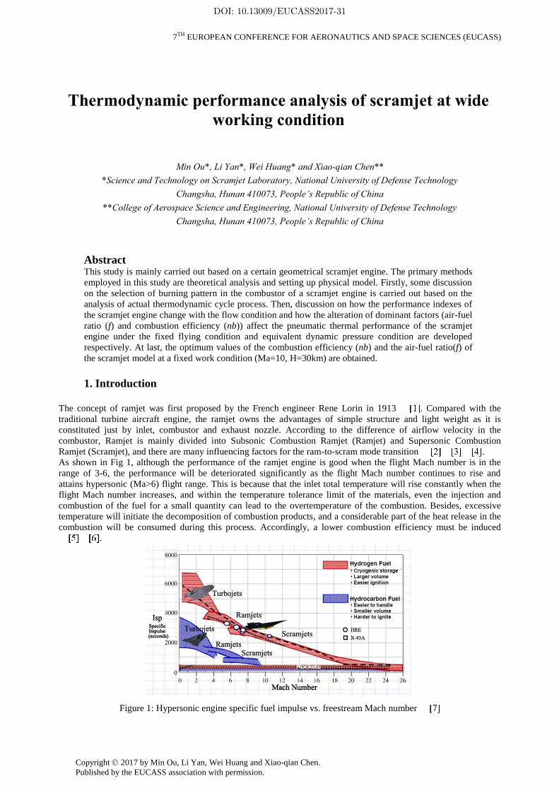
As shown in Fig 1, although the performance of the ramjet engine is good when the flight Mach number is in the
range of 3-6, the performance will be deteriorated significantly as the flight Mach number continues to rise and
attains hypersonic (Ma>6) flight range. This is because that the inlet total temperature will rise constantly when the
flight Mach number increases, and within the temperature tolerance limit of the materials, even the injection and
combustion of the fuel for a small quantity can lead to the overtemperature of the combustion. Besides, excessive
temperature will initiate the decomposition of combustion products, and a considerable part of the heat release in the
combustion will be consumed during this process. Accordingly, a lower combustion efficiency must be induced
.
Figure 1: Hypersonic engine specific fuel impulse vs. freestream Mach number
DOI: 10.13009/EUCASS2017-31
Min Ou, Li Yan, Wei Huang, Xiao-qian Chen
2
All the factors mentioned above cause a serious attenuation to the performance of the ramjet under the hypersonic
condition. Thus, when it reaches hypersonic (Ma>6) flight range, the scramjet engine is believed to be a better choice
than ramjet engine . For scramjet engine, the airflow flows into the combustor and burns with a supersonic
velocity, which is not only improve the efficiency of the thermodynamic cycle but also avoid the exorbitant static
temperature and static pressure, reduce the pressure on the materials of combustor caused by the high temperature
and high pressure.
As the optimal dynamical system in hypersonic flight,scramjet engine has the properties of simple structure, large
specific thrust and high Mach number cruise. The hypersonic flight vehicle with scramjet engines is well-known as
the third aeronautic technological revolution after turboprop and turbo-jet. Besides, the install of scramjet engine in a
weapon like fighter plane and guided missile may have a significant influence on war. Recently, scramjet related
research has roused wide attention around the world for the outstanding performance and wide application prospects.
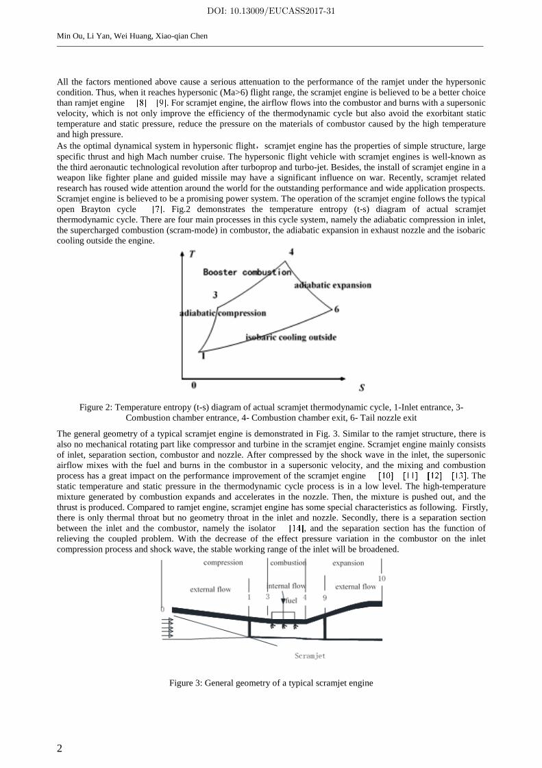
Scramjet engine is believed to be a promising power system. The operation of the scramjet engine follows the typical
open Brayton cycle . Fig.2 demonstrates the temperature entropy (t-s) diagram of actual scramjet
thermodynamic cycle. There are four main processes in this cycle system, namely the adiabatic compression in inlet,
the supercharged combustion (scram-mode) in combustor, the adiabatic expansion in exhaust nozzle and the isobaric
cooling outside the engine.
Figure 2: Temperature entropy (t-s) diagram of actual scramjet thermodynamic cycle, 1-Inlet entrance, 3-
Combustion chamber entrance, 4- Combustion chamber exit, 6- Tail nozzle exit
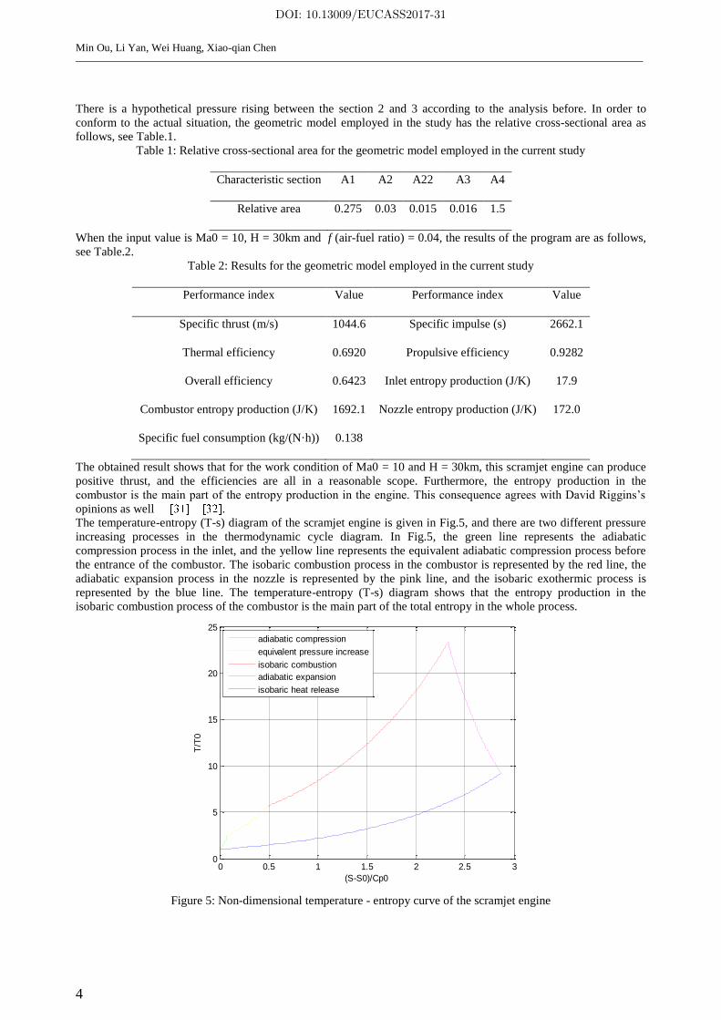
The general geometry of a typical scramjet engine is demonstrated in Fig. 3. Similar to the ramjet structure, there is
also no mechanical rotating part like compressor and turbine in the scramjet engine. Scramjet engine mainly consists
of inlet, separation section, combustor and nozzle. After compressed by the shock wave in the inlet, the supersonic
airflow mixes with the fuel and burns in the combustor in a supersonic velocity, and the mixing and combustion
process has a great impact on the performance improvement of the scramjet engine . The
static temperature and static pressure in the thermodynamic cycle process is in a low level. The high-temperature
mixture generated by combustion expands and accelerates in the nozzle. Then, the mixture is pushed out, and the
thrust is produced. Compared to ramjet engine, scramjet engine has some special characteristics as following. Firstly,
there is only thermal throat but no geometry throat in the inlet and nozzle. Secondly, there is a separation section
between the inlet and the combustor, namely the isolator , and the separation section has the function of
relieving the coupled problem. With the decrease of the effect pressure variation in the combustor on the inlet
compression process and shock wave, the stable working range of the inlet will be broadened.
Figure 3: General geometry of a typical scramjet engine
DOI: 10.13009/EUCASS2017-31

3
Although scramjet engine can perform stably at high Mach number, there are still some boundedness such as work
scope is not wide enough . For example, the American aerocraft systems named X-43A and X-
51A can only be tested successfully in a single flight Mach number, and the operational capability at wide working
condition is not yet to be tested. Before reaching the optimal operating point, the flight Mach number and height of a
scramjet engine will go through a massive variable process. The spacing of the flight Mach number is about 3 or 4.
The inlet temperature and pressure usually vary dramatically along with it. Therefore, it is significant to study the
performance of the scramjet engine at wide working condition.
The United States is one of the earliest countries to begin hypersonic propulsion and scramjet research. Since the end
of the 20th century, the United States has conducted dozens of ground and flight tests with several models. The main
models include the series of X-43 and X-51. The X-43 is primarily to test the ability of starts and maintain stable
flight of the scramjet engine and the vehicle equipped with scramjet engine under a higher Mach number (Ma=10 or
so). The X-51 is mainly used to test the ability of starts, maintain stable flight and auto acceleration of the scramjet
engine and the vehicle equipped with scramjet engine under a lower Mach number (Ma = 6 or so). The most
noteworthy thing is that the test machine of X-51A has implement a flight Mach number acceleration from 4.7 to 5.3
in one test. Although the Mach number only changes in a small scope, the test has made a breakthrough in variable
conditions working ability of scramjet and hypersonic propulsion .
In addition to the United States, there are also many other countries started theoretical and experimental investigation
for scramjet engines at the same time. The most representative projects are the PREPHA project and the LEA test
program in French, the HOPE-X project in Japan, the HyShot project in Australian, the Sanger conceptual aircraft
and the JAPHAR program in Germany. All these projects have made great progress in the field of ramjet and
scramjet engines .
In the current study, the thermodynamic performance of a typical scramjet model was investigated based on the
brayton cycle, and the influences of the air-fuel ratio and the combustion efficiency on the performance indexes of
this scramjet engine were analyzed under the fixed flying condition and equivalent dynamic pressure condition. At
last, an optimal fuel injection scheme under the work condition of flight Mach number being 10 and flight height
being 30km was obtained.
2. Physical model and analysis approaches
In this article, the core issue is the thermodynamic performance of a scramjet engine at wide working condition.
Therefore, the study is carried out based on a typical scramjet model.
The general geometry of a scramjet engine is demonstrated in Fig. 4. The numbers in the figure represent the flow
path region, namely “0” is the entry of the inlet, “2” is the entry of the combustor, “3” is the entry of the nozzle, and
“4” is the nozzle exit. For scramjet engines, the compression process is completed by a string of oblique shock waves
in a convergent inlet. The air flow needs to go through a length of diameter-equivalent isolator before entering the
divergent combustor and burning with the fuel at a supersonic speed. At last, the air at high temperature expands in a
divergent nozzle and produces thrust . As discussed in the introduction, scram-mode is a better choice
than ram-mode when the freestream Mach number is higher than 7 according to the present technical level and
engineering experience.
The traditional analysis based on Brayton cycle can also be extended to the scramjet engine although it is not a strict
isobaric process in a real scramjet combustor . The characteristic of the scram-mode is the
pressure rise combustion in the combustor. The equivalent method is used in this study as it is complicated to fathom
the pressure rise combustion out. A pressure ratio is given at the entrance of the combustion chamber, and suppose
the isobaric combustion in the combustor. It is crucial to maintain the circulation work equals to that produced in the
actual pressure rise combustion .
Figure 4: Simplified geometry of a typical scramjet engine
DOI: 10.13009/EUCASS2017-31
Min Ou, Li Yan, Wei Huang, Xiao-qian Chen
4
There is a hypothetical pressure rising between the section 2 and 3 according to the analysis before. In order to
conform to the actual situation, the geometric model employed in the study has the relative cross-sectional area as
follows, see Table.1.
Table 1: Relative cross-sectional area for the geometric model employed in the current study
Characteristic section A1 A2 A22 A3 A4
Relative area 0.275 0.03 0.015 0.016 1.5
When the input value is Ma0 = 10, H = 30km and f (air-fuel ratio) = 0.04, the results of the program are as follows,
see Table.2.
Table 2: Results for the geometric model employed in the current study
Performance index Value Performance index Value
Specific thrust (m/s) 1044.6 Specific impulse (s) 2662.1
Thermal efficiency 0.6920 Propulsive efficiency 0.9282
Overall efficiency 0.6423 Inlet entropy production (J/K) 17.9
Combustor entropy production (J/K) 1692.1 Nozzle entropy production (J/K) 172.0
Specific fuel consumption (kg/(N·h)) 0.138
The obtained result shows that for the work condition of Ma0 = 10 and H = 30km, this scramjet engine can produce
positive thrust, and the efficiencies are all in a reasonable scope. Furthermore, the entropy production in the
combustor is the main part of the entropy production in the engine. This consequence agrees with David Riggins’s
opinions as well .
The temperature-entropy (T-s) diagram of the scramjet engine is given in Fig.5, and there are two different pressure
increasing processes in the thermodynamic cycle diagram. In Fig.5, the green line represents the adiabatic
compression process in the inlet, and the yellow line represents the equivalent adiabatic compression process before
the entrance of the combustor. The isobaric combustion process in the combustor is represented by the red line, the
adiabatic expansion process in the nozzle is represented by the pink line, and the isobaric exothermic process is
represented by the blue line. The temperature-entropy (T-s) diagram shows that the entropy production in the
isobaric combustion process of the combustor is the main part of the total entropy in the whole process.
Figure 5: Non-dimensional temperature - entropy curve of the scramjet engine
0 0.5 1 1.5 2 2.5 30
5
10
15
20
25
(S-S0)/Cp0
T/T
0
adiabatic compression
equivalent pressure increase
isobaric combustion
adiabatic expansion
isobaric heat release
DOI: 10.13009/EUCASS2017-31

5
3. Results and discussion
For ramjet engines, the combustion in the combustor is isobaric process, the thermodynamic cycle can refer to the
curve 1-2-3-4-1. However, for scramjet engines, the combustion is booster process, and the thermodynamic cycle can
refer to the curve 1-1.2-3’-4’-1, see Fig.6. It can be shown in Fig.6 that the area B-(A+C) represents difference values
of the circulation work generated in scramjet and ramjet engines, which means that the scramjet engine can produce
more circulation work than the ramjet engine.
If combining the isobaric and booster processes in the scramjet combustor, the thermodynamic cycle can refer to the
curve 1-1.2-2’-3’-4’-1. The circulation work generated in scramjet engines is more than the booster combustion (the
area C), and the average endothermic temperature is higher, which means the enhancement of the performance of the
scramjet engine. According to the analysis mentioned before, the combustion process has a paramount influence on
the performance of the scramjet engine. Thus, the main work of this study is analyzing the selection of burning
approach in the combustor and how the main factors (the air-fuel ratio (f) and the combustion efficiency (nb)) affect
the performance of the scramjet engine.
Figure 6: Non-dimensional temperature - entropy curve for different combustion modes
3.1 Burning mode analysis of scramjet engines
The relationship among the radial distance, the Mach number and the total temperature of the airflow in the
combustor can be shown in the following equations.
22
2
11
11 12
1 2
b
b t
t
MaMa dTdMa dA
Madx Ma A dx T dx
(1)
2
1
11
2
t
t
MadT dT
T dx TdxMa
(2)
From Eqs. (1) and (2), we can know that as the flow velocity of the airflow in the combustor is high, the heat injected
in the combustor is almost independent with the increased amount of the static temperature. This is the biggest
specialty the scramjet to the normal aero-engine. In the combustor of normal aero-engine, the heat input almost
translates into the static temperature rising of the airflow. While for the combustor of the scramjet engine, the
proportion of the effect the heat input on the static and dynamic temperatures can be controlled by using different
fuel supply ways and various cross-section areas of the combustor. Thus, the burning velocity can be controlled, and
then different combustion modes are obtained. Furthermore, disparate combustion patterns (isothermal combustion/
isobaric combustion and so on) can be obtained by regulating the heat input ration.
Fig.7 shows the temperature-entropy diagram of different burning patterns.
DOI: 10.13009/EUCASS2017-31
Min Ou, Li Yan, Wei Huang, Xiao-qian Chen
6
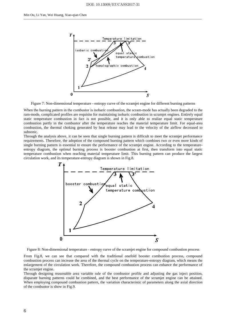
Figure 7: Non-dimensional temperature - entropy curve of the scramjet engine for different burning patterns
When the burning pattern in the combustor is isobaric combustion, the scram-mode has actually been degraded to the
ram-mode, complicated profiles are requisite for maintaining isobaric combustion in scramjet engines. Entirely equal
static temperature combustion in fact is not possible, and it is only able to realize equal static temperature
combustion partly in the combustor after the temperature reaches the material temperature limit. For equal-area
combustion, the thermal choking generated by heat release may lead to the velocity of the airflow decreased to
subsonic.
Through the analysis above, it can be seen that single burning pattern is difficult to meet the scramjet performance
requirements. Therefore, the adoption of the compound burning pattern which combines two or even more kinds of
single burning pattern is essential to ensure the performance of the scramjet engine. According to the temperature-
entropy diagram, the optimal burning process is booster combustion at first, then transform into equal static
temperature combustion when reaching material temperature limit. This burning pattern can produce the largest
circulation work, and its temperature-entropy diagram is shown in Fig.8.
Figure 8: Non-dimensional temperature - entropy curve of the scramjet engine for compound combustion process
From Fig.8, we can see that compared with the traditional onefold booster combustion process, compound
combustion process can increase the area of the thermal cycle on the temperature-entropy diagram, which means the
enlargement of the circulation work. Therefore, the compound combustion process can enhance the performance of
the scramjet engine.
Through designing reasonable area variable rule of the combustor profile and adjusting the gas inject position,
disparate burning patterns could be combined, and the best performance of the scramjet engine can be attained.
When employing compound combustion pattern, the variation characteristic of parameters along the axial direction
of the combustor is show in Fig.9.
DOI: 10.13009/EUCASS2017-31

7
Figure 9: Variation characteristic of parameters along the axial direction of the combustor
3.2 Pneumatic thermal performance analysis
Along with the variation of flow conditions, the performance characteristics will go through a great variation. On the
basis of the combustor characteristic analysis and the previous studies, it can be confirmed that the principle
influence factors to the performance indexes for scramjet engines are the combustion efficiency of the combustor (nb)
and the air-fuel ratio (f). The following work is to investigate how these factors affect the pneumatic thermal
performances of scramjet engines.
3.2.1 Performance characteristics of scramjet engines under variable flow conditions
Applying the scramjet model mentioned above, the relationship between the flow condition and the performance
characteristics are shown in Fig.10.
(1) Performance characteristics with different flight Mach numbers
(a) Fs vs. Ma0 (b) Isp vs. Ma0
Figure 10: Performance variations with different flight Mach numbers, (a) Fs vs. Ma0 and (b) Isp vs. Ma0
The specific thrust and the specific impulse decreases monotonously with the continuous increase of Ma0. This
variable rule conforms to the general recognition. For this given geometrical structure scramjet engine, the increase
of Ma0 will cause the decrease of the inlet compression efficiency and then induce the performance reduction of the
whole engine. Furthermore, after Ma0 increases to a certain value, the inlet of the scramjet engine will face the
unstart problem. Besides, the loss generated during the working process will raise with the enlargement of Ma0, and
this will result in a decline in the power capability of the flow and a damping in special thrust. According to the
computational formula of specific impulse, namely Isp=Fs/g/f, the specific impulse shows a trend of attenuation as
well.
(2) Performance characteristics with different flight heights
l
T
Ma
p
0
P
T
Ma
6 7 8 9 10 11 12 13 14 15950
1000
1050
1100
1150
1200
1250
1300
flight Mach number(Ma0)
specific
thru
st(
Fs)
6 7 8 9 10 11 12 13 14 152400
2500
2600
2700
2800
2900
3000
3100
3200
3300
flight Mach number(Ma0)
specific
im
puls
e(I
sp)
DOI: 10.13009/EUCASS2017-31
Min Ou, Li Yan, Wei Huang, Xiao-qian Chen
8
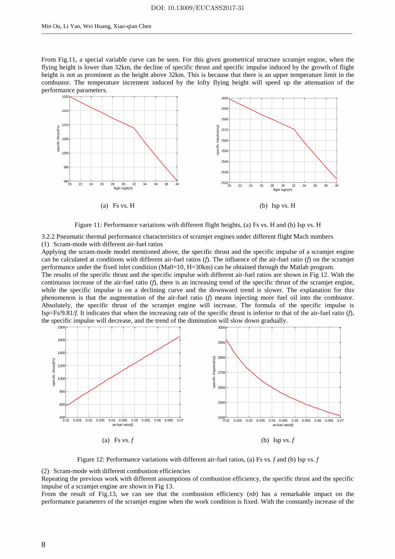
From Fig.11, a special variable curve can be seen. For this given geometrical structure scramjet engine, when the
flying height is lower than 32km, the decline of specific thrust and specific impulse induced by the growth of flight
height is not as prominent as the height above 32km. This is because that there is an upper temperature limit in the
combustor. The temperature increment induced by the lofty flying height will speed up the attenuation of the
performance parameters.
(a) Fs vs. H (b) Isp vs. H
Figure 11: Performance variations with different flight heights, (a) Fs vs. H and (b) Isp vs. H
3.2.2 Pneumatic thermal performance characteristics of scramjet engines under different flight Mach numbers
(1) Scram-mode with different air-fuel ratios
Applying the scram-mode model mentioned above, the specific thrust and the specific impulse of a scramjet engine
can be calculated at conditions with different air-fuel ratios (f). The influence of the air-fuel ratio (f) on the scramjet
performance under the fixed inlet condition (Ma0=10, H=30km) can be obtained through the Matlab program.
The results of the specific thrust and the specific impulse with different air-fuel ratios are shown in Fig 12. With the
continuous increase of the air-fuel ratio (f), there is an increasing trend of the specific thrust of the scramjet engine,
while the specific impulse is on a declining curve and the downward trend is slower. The explanation for this
phenomenon is that the augmentation of the air-fuel ratio (f) means injecting more fuel oil into the combustor.
Absolutely, the specific thrust of the scramjet engine will increase. The formula of the specific impulse is
Isp=Fs/9.81/f. It indicates that when the increasing rate of the specific thrust is inferior to that of the air-fuel ratio (f),
the specific impulse will decrease, and the trend of the diminution will slow down gradually.
(a) Fs vs. f (b) Isp vs. f
Figure 12: Performance variations with different air-fuel ratios, (a) Fs vs. f and (b) Isp vs. f
(2) Scram-mode with different combustion efficiencies
Repeating the previous work with different assumptions of combustion efficiency, the specific thrust and the specific
impulse of a scramjet engine are shown in Fig 13.
From the result of Fig.13, we can see that the combustion efficiency (nb) has a remarkable impact on the
performance parameters of the scramjet engine when the work condition is fixed. With the constantly increase of the
20 22 24 26 28 30 32 34 36 38 40990
995
1000
1005
1010
1015
1020
flight hight(H)
specific
thru
st(
Fs)
20 22 24 26 28 30 32 34 36 38 402520
2530
2540
2550
2560
2570
2580
2590
2600
flight hight(H)
specific
im
puls
e(I
sp)
0.02 0.025 0.03 0.035 0.04 0.045 0.05 0.055 0.06 0.065 0.07400
600
800
1000
1200
1400
1600
1800
air-fuel ratio(f)
specific
thru
st(
Fs)
0.02 0.025 0.03 0.035 0.04 0.045 0.05 0.055 0.06 0.065 0.072400
2500
2600
2700
2800
2900
3000
air-fuel ratio(f)
specific
im
puls
e(I
sp)
DOI: 10.13009/EUCASS2017-31

9
combustion efficiency (nb), the specific thrust and the specific impulse are both have an ascending tendency. That is
because of the fuel of equivalent quality, the energy injects into the scramjet will be aggrandized with the
enhancement of the combustion efficiency (nb), and the incremental energy will inevitably make the performance
parameters such as specific thrust and specific impulse to improve.
(a) Fs vs. nb (b) Isp vs. nb
Figure 13: Performance variations with different combustion efficiencies, (a) Fs vs. nb and (b) Isp vs. nb
3.2.3 Pneumatic thermal performance characteristics of scramjet engines with the same dynamic pressure
(1) Scram-mode with different air-fuel ratios
For scram-mode, the performance parameters (specific thrust and specific impulse) will vary with the adjustment of
the air-fuel ratio (f). The influence of the air-fuel ratio (f) on the scramjet performance under a fixed dynamic
pressure can be obtained through the MATLAB program.
Fig.14 shows the variation trend of specific thrust and specific impulse with the variation of air-fuel ratio (f). Under
the equivalent dynamic pressure condition, the specific thrust (Fs) has an ascending tendency, while the specific
impulse (Isp) is on a declining curve and the downward trend is slower. This result is in accordance with the analysis
of pneumatic thermal performance characteristics under different flight Mach numbers.
(a) Fs vs. f (b) Isp vs. f
Figure 14: Performance variations with different air-fuel ratios for different flight Mach numbers, (a) Fs vs. f and (b)
Isp vs. f
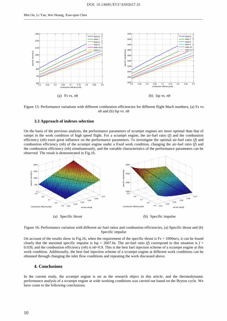
(2) Scram-mode with different combustion efficiencies
Repeating the previous work with variable combustion efficiencies (nb). The affecting law combustion efficiency (nb)
to the performance of scramjet engines in a fixed dynamic pressure can be derived. As show in Fig.15, with the
continuous increase of combustion efficiency, the specific thrust and the specific impulse of the scramjet engine are
taking on a growth trend under the work condition of a given dynamic pressure. The reason for this consequence is
that the energy released by the same quality of fuel injection into the scramjet will boost with the augment of the
combustion efficiency. Therefore, the performance parameters like specific trust and specific impulse are on an
increasing tendency.
0.5 0.55 0.6 0.65 0.7 0.75 0.8 0.85 0.9650
700
750
800
850
900
950
1000
1050
combustion efficiency(nb)
specific
thru
st(
Fs)
0.5 0.55 0.6 0.65 0.7 0.75 0.8 0.85 0.91700
1800
1900
2000
2100
2200
2300
2400
2500
2600
combustion efficiency(nb)
specific
im
puls
e(I
sp)
0.02 0.025 0.03 0.035 0.04 0.045 0.05 0.055 0.06 0.065 0.07400
600
800
1000
1200
1400
1600
1800
2000
2200
air-fuel ratio(f)
specific
thru
st(
Fs)
Ma0=6
Ma0=7
Ma0=8
Ma0=9
Ma0=10
Ma0=11
0.02 0.025 0.03 0.035 0.04 0.045 0.05 0.055 0.06 0.065 0.072200
2400
2600
2800
3000
3200
3400
3600
air-fuel ratio(f)
specific
im
puls
e(I
sp)
Ma0=6
Ma0=7
Ma0=8
Ma0=9
Ma0=10
Ma0=11
DOI: 10.13009/EUCASS2017-31
Min Ou, Li Yan, Wei Huang, Xiao-qian Chen
10
(a) Fs vs. nb (b) Isp vs. nb
Figure 15: Performance variations with different combustion efficiencies for different flight Mach numbers, (a) Fs vs.
nb and (b) Isp vs. nb
3.3 Approach of indexes selection
On the basis of the previous analysis, the performance parameters of scramjet engines are more optimal than that of
ramjet in the work condition of high speed flight. For a scramjet engine, the air-fuel ratio (f) and the combustion
efficiency (nb) exert great influence on the performance parameters. To investigate the optimal air-fuel ratio (f) and
combustion efficiency (nb) of the scramjet engine under a fixed work condition, changing the air-fuel ratio (f) and
the combustion efficiency (nb) simultaneously, and the variable characteristics of the performance parameters can be
observed. The result is demonstrated in Fig.16.
(a) Specific thrust (b) Specific impulse
Figure 16: Performance variation with different air-fuel ratios and combustion efficiencies, (a) Specific thrust and (b)
Specific impulse
On account of the results show in Fig.16, when the requirement of the specific thrust is Fs = 1000m/s, it can be found
clearly that the maximal specific impulse is Isp = 2607.6s. The air-fuel ratio (f) correspond to this situation is f =
0.039, and the combustion efficiency (nb) is nb=0.9. This is the best fuel injection scheme of a scramjet engine at this
work condition. Additionally, the best fuel injection scheme of a scramjet engine at different work conditions can be
obtained through changing the inlet flow conditions and repeating the work discussed above.
4. Conclusions
In the current study, the scramjet engine is set as the research object in this article, and the thermodynamic
performance analysis of a scramjet engine at wide working conditions was carried out based on the Bryton cycle. We
have come to the following conclusions:
0.5 0.55 0.6 0.65 0.7 0.75 0.8 0.85 0.9600
700
800
900
1000
1100
1200
1300
combustion efficiency(nb)
specific
thru
st(
Fs)
Ma0=6
Ma0=7
Ma0=8
Ma0=9
Ma0=10
Ma0=11
0.5 0.55 0.6 0.65 0.7 0.75 0.8 0.85 0.91600
1800
2000
2200
2400
2600
2800
3000
3200
3400
combustion efficiency(nb)
specific
im
puls
e(I
sp)
Ma0=6
Ma0=7
Ma0=8
Ma0=9
Ma0=10
Ma0=11
0.020.03
0.040.05
0.060.07
0.5
0.6
0.7
0.8
0.90
500
1000
1500
2000
air-fuel ratio(f)combustion efficiency(nb)
specific
thru
st(
Fs)
0.020.03
0.040.05
0.060.07
0.5
0.6
0.7
0.8
0.91500
2000
2500
3000
air-fuel ratio(f)combustion efficiency(nb)
specific
im
puls
e(I
sp)
DOI: 10.13009/EUCASS2017-31

11
As for scramjet, the compound combustion is the best combustion mode, namely booster combustion at early
stage, and convert into equal static temperature combustion when the material temperature of the scramjet
reaches the limit.
The pressure ratio and the temperature ratio have the decisive effect on the performance of a scramjet engine.
The entropy production in the compound combustion process of the combustor is the main part of the total
entropy in the whole process.
One of the main factors affect the performance output of scramjet engines are finally determined to be the air-
fuel ratio (f). With the continuous increase of the air-fuel ratio (f), there is an increasing trend of the specific
thrust (Fs) of the scramjet engine. While the specific impulse (Isp) is in a decline trend, and the trend will slow
down.
The other main factor affects the performance output of scramjet engines is finally determined to be the
combustion efficiency (nb). With the continuous increase of the air-fuel ratio (f), there is an increasing trend of
the specific thrust (Fs) and the specific impulse (Isp) of the scramjet engine.
When the requirement of the specific thrust is 1000 N, the corresponding best air-fuel ratio f is 0.039, and the
combustion efficiency nb is 0.9. This is the best fuel injection scheme of this scramjet engine under the work
condition of flight Mach number being 10 and flight height being 30km.
Acknowledgements
The authors would like to express their thanks for the support from the National Natural Science Foundation of
China (No.11502291) and a fund for owner of Outstanding Doctoral Dissertation from the Ministry of Education of
China (No.201460).
References
[1] Fry R S. 2004. A century of ramjet propulsion technology evolution. Journal of Propulsion and Power. 20(1):
27-58.
[2] Huang W., Yan L., Tan J. G. 2014. Survey on the mode transition technique in combined cycle propulsion
systems. Aerospace Science and Technology. 39: 685-691.
[3] Yan Z., Bing C., Gang L., Baoxi W., Xu X. 2014. Influencing factors on the mode transition in a dual-mode
scramjet. Acta Astronautica. 103: 1-15.
[4] Huang W., Yan L. 2016. Numerical investigation on the ram-scram transition mechanism in a strut-based dual-
mode scramjet combustor. International Journal of Hydrogen Energy. 41: 4799-4807.
[5] Heiser W., Pratt D. 1994. Hypersonic airbreathing propulsion. Washington. DC. USA: AIAA.
[6] Qin J., Zhang S., Bao W., Zhou W., Yu D. 2013. Thermal management method of fuel in advanced aeroengines.
Energy. 49: 459-468.
[7] Huang W., Ma L., Pourkashanian M., Ingham D. B., Luo S. B., Liu J., Wang Z. G. 2012. Flow-field analysis of
a typical hydrogen-fueled dual-mode scramjet combustor. Journal of Aerospace Engineering. 25: 336-346.
[8] Voland R. T., Huebner L. D., McClinton. 2006. X-43A hypersonic vehicle technology development. Acta
Astronautica. 59: 181-191.
[9] Curran E. T. 2001. Scramjet engines: The first forty years. Journal of Propulsion and Power. 17(6): 1138-1148.
[10] Huang W., Liu W. D., Li S. B., Xia Z. X., Liu J., Wang Z. G. 2012. Influences of the turbulence model and the
slot width on the transverse slot injection flow field in supersonic flows. Acta Astronautica. 73: 1-9.
[11] Huang W., Tan J. G., Liu J., Yan L. 2015. Mixing augmentation induced by the interaction between the oblique
shock wave and a sonic hydrogen jet in supersonic flows. Acta Astronautica. 117: 142-152.
[12] Yan L., Huang W., Zhang T. T., Li H., Yan X. T. 2014. Numerical investigation of the nonreacting and reacting
flow fields in a transverse gaseous injection channel with different species. Acta Astronautica. 105: 17-23.
[13] Huang W. 2016. Transverse jet in supersonic crossflows. Aerospace Science and Technology. 50: 183-195.
[14] Huang W., Wang Z. G., Pourkashanian M., Ma L., Ingham D. B., Luo S. B., Lei J., Liu J. 2011. Numerical
investigation on the shock wave transition in a three-dimensional scramjet isolator. Acta Astronautica. 68:
1669-1675.
[15] Lin R. M., Jin H. G. 2002. Thermodynamic cycle-A permanent research field of engineering thermodynamics.
Gas Turbine Technology. 15(4): 1-8.
[16] Huang W., Li L. Q., Yan L., Liao L. 2016. Numerical exploration of mixing and combustion in a dual-mode
combustor with backward-facing steps. Acta Astronautica. 127: 572-578.
[17] Huang W., Wang Z. G., Li S. B., Liu W. D. 2012. Influences of H2O mass fraction and chemical kinetics
mechanism on the turbulent diffusion combustion of H2-O2 in supersonic flows. Acta Astronautica. 76: 51-59.
DOI: 10.13009/EUCASS2017-31
Min Ou, Li Yan, Wei Huang, Xiao-qian Chen
12
[18] Huang W., Pourkashanian M., Ma L., Ingham D. B., Luo S. B., Wang Z. G. 2011. Investigation on the
flameholding mechanisms in supersonic flows: backward-facing step and cavity flameholder. Journal of
Visualization. 14: 63-74.
[19] Hank J. M., Murphy J. S., Mutzman R. C. 2008. The X-51A scramjet engine flight demonstration program.
AIAA Paper, 2008-2540.
[20] Tang X., Yan C. 2012. Dual-mode scramjet engine research review. Aerodynamic Missile Journal. 3:022.
[21] Ma G. 2014. The development history and the expectation of ramjet. China Aerospace Newspaper, 2014-01-
23003
[22] Zheng R. H. 2004. The technology development trend and comments on ramjet. Aerodynamic Missile. (1): 44-
48.
[23] Cui T., Tang S., Zhang C., Yu D. 2012. Hysteresis phenomenon of mode transition in ramjet engines and its
topological rule. Journal of Propulsion and Power. 28(6): 1277-1284.
[24] Huang W., Wang Z. G., Ingham D. B., Ma L., Pourkashanian M. 2013. Design exploration for a single
expansion ramp nozzle (SERN) using data mining. Acta Astronautica. 83: 10-17.
[25] Roux J., Shakya N., Choi J. 2013. Revised parametric ideal scramjet cycle analysis. Journal of Thermophysics
and Heat Transfer. 27:178-183.
[26] Roux J. 2013. Optimum freestream Mach number for maximum thrust flux for ideal ramjet/scramjet. Journal of
Thermophysics and Heat Transfer. 26: 390-392
[27] Yang Q., Chang J., Bao W. 2014. Thermodynamic analysis on specific thrust of the hydrocarbon fueled
scramjet. Energy. 76: 552-558.
[28] Riggins D. W., McClinton C. R., Vitt P. H. 1997. Thrust losses in hypersonic engines part 1: methodology.
Journal of Propulsion and Power. 13(2): 281-287.
[29] Riggins D. W., Taylor T., Moorhouse D. J. 2006. Methodology for performance analysis of aerospace vehicles
using the laws of thermodynamics. Journal of Aircraft. 43(4): 953-963.
[30] Riggins D. W., Camberos J., Wolff M., et al. 2013. Mission-integrated exergy analysis for hypersonic vehicles:
methodology and application. Journal of Propulsion and Power. 29(3): 610-620.
[31] Roux J. A., Shakya N., Choi J. 2013. Scramjet: minimum thrust-specific fuel consumption with material limit.
Journal of Thermophysics and Heat Transfer. 27(2): 367-368.
[32] Riggins D. W. 1997. Thrust losses in hypersonic engines part 2: applications. Journal of Propulsion and Power.
13(2): 288-295.
DOI: 10.13009/EUCASS2017-31