Embed Size (px)
Citation preview

MAKING MODERN LIVING POSSIBLE
Programming GuideVLT® DeviceNet MCA 104VLT® Frequency Converter Series • FC 102 • FC 202 • FC 301/302
vlt-drives.danfoss.com

Contents
1 Introduction 3
1.1 Purpose of the Manual 3
1.2 Additional Resources 3
1.3 Document and Software Version 3
1.4 Product Overview 3
1.5 Approvals and Certifications 4
1.6 Symbols, Abbreviations and Conventions 4
2 Safety 5
2.1 Safety Symbols 5
2.2 Qualified Personnel 5
2.3 Safety Precautions 5
3 Configuration 7
3.1 Configure the DeviceNet Network 7
3.2 Configure the Master 8
3.3 Configure the Frequency Converter 8
4 Control 9
4.1 DeviceNet Process Control Modes 9
4.2 I/O Assembly Instances 10
4.3 Process Data 10
4.4 ODVA Control Profile 11
4.5 FC Control Profile 13
5 Parameter Access 17
5.1 Explicit Messages 17
5.2 Object Classes 17
5.3 DeviceNet Object Classes 18
5.4 Danfoss Object Classes 27
6 Parameters 28
6.1 Parameter Description 28
6.2 Parameter List 36
6.3 Data Types Supported 37
7 Application Examples 38
7.1 Example: Working with Instance 101/151 Process 38
8 Troubleshooting 40
8.1 LED Status 40
8.2 No Communication with the Frequency Converter 41
Contents Programming Guide
MG92F102 Danfoss A/S © 12/2015 All rights reserved. 1

8.3 Frequency Converter Does Not Respond to Control Signals 41
8.4 Warnings and Alarms 44
Index 46
Contents VLT® DeviceNet MCA 104
2 Danfoss A/S © 12/2015 All rights reserved. MG92F102

1 Introduction
1.1 Purpose of the Manual
The VLT® DeviceNet MCA 104 Programming Guide providesinformation about configuring the system, controlling thefrequency converter, parameter access, programming,troubleshooting, and some typical application examples.The programming guide is intended for use by qualifiedpersonnel who are familiar with the VLT® frequencyconverter, with DeviceNet technology, and with the PC orPLC that is used as a master in the system.Read the instructions before programming and follow theprocedures in this manual.
VLT® is a registered trademark.
1.2 Additional Resources
Resources available for the VLT® frequency converter andoptional equipment:
• The VLT® Operating Instructions provide thenecessary information for getting the VLT®
frequency converter up and running.
• The VLT® Design Guide provides detailedinformation about capabilities and functionalityto design motor control systems.
• The VLT® Programming Guide provides greaterdetail on working with parameters and manyapplication examples.
• The VLT® DeviceNet MCA 104 Installation Guideprovides information about installing theDeviceNet and troubleshooting.
• The VLT® DeviceNet MCA 104 Programming Guideprovides information about configuring thesystem, controlling the VLT® frequency converter,parameter access, programming, troubleshooting,and some typical application examples.
Supplementary publications and manuals are availablefrom Danfoss. See vlt-drives.danfoss.com/Support/Technical-Documentation/ for listings.
1.3 Document and Software Version
This manual is regularly reviewed and updated. Allsuggestions for improvement are welcome. Table 1.1 showsthe document version and the corresponding softwareversion.
Edition Remarks Software version
MG92F1xx First edition. 4.4x
Table 1.1 Document and Software Version
1.4 Product Overview
This programming guide relates to the DeviceNet interface.Ordering number:
• 130B1102 (non-coated version).
• 130B1210 (conformal coated version).
DeviceNet is a low-level network that standardizescommunications between industrial devices (sensors, limitswitches, motor controls) and high-level devices(controllers). DeviceNet follows the Open Systems Intercon-nection (OSI) model and is based on CAN technology formedia access control and physical signaling.DeviceNet systems can be configured to operate in amaster/slave or a distributed control architecture usingpeer-to-peer communication. Up to 63 nodes in a multi-drop network topology are supported. By using the samecable for communication, communication options can bepowered directly from the bus. Nodes can be removed orinserted without powering down the network.Each node on the network has its own unique mediaaccess control identifier (MAC ID) to distinguish it on thenetwork. The access control is based on the CSMA/CA(carrier sense multiple access/collision avoidance) principle,meaning that all nodes may have access to the network atthe same time. When 2 nodes attempt to get control ofthe network bus simultaneously, the CAN protocol resolvesthe issue by arbitration. In this way, collisions on thenetwork are avoided.DeviceNet defines device profiles for devices belonging tospecific classes. For other devices, define a custom class tomake it DeviceNet compatible. All the above enhances theinterchangeability and interoperability of the network.
24 V
Trunk linePower supply
Drop lines 1RT=Termination resistors
RT RT
195N
A22
8.10
1 1 1
1
Illustration 1.1 Topology
Introduction Programming Guide
MG92F102 Danfoss A/S © 12/2015 All rights reserved. 3
1 1

VLT® DeviceNet MCA 104 is designed to communicate withany master abiding by the DeviceNet standard. It isintended for use with:
• VLT® HVAC Drive FC 102
• VLT® AQUA Drive FC 202
• VLT® AutomationDrive FC 301/FC 302
1.5 Approvals and Certifications
More approvals and certifications are available. For moreinformation, contact a local Danfoss partner.
1.6 Symbols, Abbreviations andConventions
Abbreviation Definition
ACK ACKnowledge
BOC Bus off counter
BOOL Boolean expression
CAN Controller area network
CSMA/CA Carrier sense multiple access/collision avoidance
COS Change of state
CTW Control word
EDS Electronic data sheet
EMC Electromagnetic compatibility
ETR Electronic thermal relay
FIFO First in first out
HF High frequency
HPFB High performance fieldbus
I/O Input/output
ISO International standards organization
LCD Liquid crystal display
LED Light emitting diode
LSB Least significant bit
MAC ID Media access control identifier
MAV Main actual value
MRV Main reference value
MSB Most significant bit
N/A Not applicable
ODVA Open DeviceNet Vendor Association
OSI Open systems interconnection
PC Personal computer
PCD Process data
PIW Peripheral input word
PLC Programmable logic control
PNU Parameter number
PPO Parameter-process data object
QW Peripheral output word
Abbreviation Definition
SINT Signed integer
STW Status word
VSD Variable speed drive
UDINT Unsigned double integer
UNIT Unsigned integer
USINT Unsigned short integer
Table 1.2 Symbols and Abbreviations
ConventionsNumbered lists indicate procedures.Bullet lists indicate other information.
Italicized text indicates:• Cross reference.
• Link.
• Parameter name.
• Parameter group name.
• Parameter option.
• Footnote.
Introduction VLT® DeviceNet MCA 104
4 Danfoss A/S © 12/2015 All rights reserved. MG92F102
11

2 Safety
2.1 Safety Symbols
The following symbols are used in this manual:
WARNINGIndicates a potentially hazardous situation that couldresult in death or serious injury.
CAUTIONIndicates a potentially hazardous situation that couldresult in minor or moderate injury. It can also be used toalert against unsafe practices.
NOTICEIndicates important information, including situations thatcan result in damage to equipment or property.
2.2 Qualified Personnel
Correct and reliable transport, storage, installation,operation, and maintenance are required for the trouble-free and safe operation of the frequency converter. Onlyqualified personnel are allowed to install and operate thisequipment.
Qualified personnel are defined as trained staff, who areauthorized to install, commission, and maintain equipment,systems, and circuits in accordance with pertinent laws andregulations. Additionally, the qualified personnel must befamiliar with the instructions and safety measuresdescribed in these operating instructions.
2.3 Safety Precautions
WARNINGHIGH VOLTAGEFrequency converters contain high voltage whenconnected to AC mains input, DC supply, or load sharing.Failure to perform installation, start-up, and maintenanceby qualified personnel can result in death or seriousinjury.
• Only qualified personnel must perform instal-lation, start-up, and maintenance.
WARNINGUNINTENDED STARTWhen the frequency converter is connected to AC mains,DC supply, or load sharing, the motor may start at anytime. Unintended start during programming, service, orrepair work can result in death, serious injury, orproperty damage. The motor can start with an externalswitch, a fieldbus command, an input reference signalfrom the LCP or LOP, via remote operation using MCT 10Set-up Software, or after a cleared fault condition.
To prevent unintended motor start:• Press [Off/Reset] on the LCP before
programming parameters.
• Disconnect the frequency converter from themains.
• Completely wire and assemble the frequencyconverter, motor, and any driven equipmentbefore connecting the frequency converter toAC mains, DC supply, or load sharing.
WARNINGDISCHARGE TIMEThe frequency converter contains DC-link capacitors thatcan remain charged even when the frequency converteris not powered. Failure to wait the specified time afterpower has been removed before performing service orrepair work can result in death or serious injury.
• Stop the motor.
• Disconnect the AC mains and remote DC-linksupplies, including battery back-ups, UPS, andDC-link connections to other frequencyconverters.
• Disconnect or lock the PM motor.
• Wait for the capacitors to discharge fully beforeperforming any service or repair work. Thewaiting time is specified in the relevantfrequency converter operating instructions,Chapter 2 Safety.
WARNINGLEAKAGE CURRENT HAZARDLeakage currents exceed 3.5 mA. Failure to ground thefrequency converter properly can result in death orserious injury.
• Ensure the correct grounding of the equipmentby a certified electrical installer.
Safety Programming Guide
MG92F102 Danfoss A/S © 12/2015 All rights reserved. 5
2 2

WARNINGEQUIPMENT HAZARDContact with rotating shafts and electrical equipmentcan result in death or serious injury.
• Ensure that only trained and qualified personnelperform installation, start-up, and maintenance.
• Ensure that electrical work conforms to nationaland local electrical codes.
• Follow the procedures in this guide.
CAUTIONINTERNAL FAILURE HAZARDAn internal failure in the frequency converter can resultin serious injury when the frequency converter is notproperly closed.
• Ensure that all safety covers are in place andsecurely fastened before applying power.
Safety VLT® DeviceNet MCA 104
6 Danfoss A/S © 12/2015 All rights reserved. MG92F102
22

3 Configuration
3.1 Configure the DeviceNet Network
All DeviceNet stations that are connected to the same busnetwork must have a unique station address. Select theDeviceNet address of the frequency converter via:
• Address switches (default 63).
• Parameter 10-02 MAC ID (default 63).
• Class code 0X03, instance 1, attribute 1.
Illustration 3.1 VLT® DeviceNet MCA 104 Interface
3.1.1 Setting the DeviceNet Address usingthe Address Switches
NOTICESwitch off the power supply before changing the addressswitches. The address change comes into effect at thenext power-up, and can be read in parameter 10-02 MACID.
Set the address switches to give the option a unique ID.Select an address range from 0–63 (factory setting 63)according to Table 3.1.
Switch 8 7 6 5 4 3 2 1
Address value – – +32 +16 +8 +4 +2 +1
5 – – OFF OFF OFF ON OFF ON
20 – – OFF ON OFF ON OFF OFF
35 – – ON OFF OFF OFF ON ON
Table 3.1 Settings for the Address Switches
3.1.2 Setting the DeviceNet Address viaParameter 10-02 MAC ID
Set the address via parameter 10-02 MAC ID if the hardwareswitches are set to 63 (factory setting). The address changecomes into effect at the next power-up.
3.1.3 Setting the DeviceNet Address withthe Object Class Code 0x03, Instance1, Attribute 1
Set the address via the DeviceNet object class code 0x03attribute 1 command when the address switch is set to 63(factory setting). A new address becomes effectiveimmediately after the class code 0x03, instance 1, attribute1 command.
3.1.4 Setting the Baud Rate
All DeviceNet stations connected to the same bus networkmust have the same baud rate. Select the baud rate of thefrequency converter via:
• Address switches.
• Parameter 10-01 Baud Rate Select (default 125kBd).
• Object class code 0x03, instance 1, attribute 2.
3.1.5 Setting the DeviceNet Baud Rateusing the Address Switches
NOTICESwitch off the power supply before changing the addressswitches. The baud rate change comes into effect at thenext power-up, and can be read in parameter 10-01 BaudRate Select.
Use the address switches to select a baud rate of 125 kbaud (factory setting), 250 k baud, or 500 k baud, seeTable 3.2:
Baud rate switch 8 7
Parameter 10-01 Baud Rate Select 1 1
125 kBd 0 0
250 kBd 0 1
500 kBd 1 0
Table 3.2 Address Switches
Configuration Programming Guide
MG92F102 Danfoss A/S © 12/2015 All rights reserved. 7
3 3

3.1.6 Setting the DeviceNet Baud Rate via Parameter 10-01 Baud Rate Select
Set the baud rate via parameter 10-01 Baud Rate Select ifthe address switches 1 and 2 are set to ON (factorysetting). The baud rate change comes into effect at thenext power-up.
3.1.7 Setting the DeviceNet Baud Rate withthe Object Class Code 0x03, Attribute2
Set the baud rate via the DeviceNet object class code 0x03attribute 2 command, when the address switches 1 and 2are set to ON (factory setting). A new baud rate becomeseffective immediately after the class code 0x03 attribute 2command.
3.2 Configure the Master
3.2.1 EDS File
A large part area of the system configuration is the settingof application-related parameters. EDS (Electronic DataSheet) files simplify the setting up of most of theDeviceNet configurable parameters. For off-line configu-ration, Danfoss provides a generic English EDS file coveringall voltage and power sizes. Download the EDS file fromwww.danfoss.com/drives.
NOTICEThe EDS file does not contain all parameters. It containsonly a selected, limited number of parameters withgeneric minimum, maximum, and default values.
3.3 Configure the Frequency Converter
3.3.1 Frequency Converter Parameters
Note the following parameters when configuring thefrequency converter with a DeviceNet interface. Refer tochapter 6 Parameters for more details of each parameter.
• Parameter 0-40 [Hand on] Key on LCP.If the Hand key on the frequency converter isactivated, control of the frequency converter viathe DeviceNet interface is disabled. After initialpower-up the frequency converter automaticallydetects whether a fieldbus option is installed inslot A, and sets parameter 8-02 Control WordSource to [3] Option A. If an option is added to,changed in, or removed from an already commis-sioned frequency converter, it does not change parameter 8-02 Control Word Source but enters tripmode, and the frequency converter shows anerror.
• Parameter 8-10 Control Word Profile (seechapter 4 Control). Select between the Danfoss FCProfile and the ODVA profile. Select the desiredDeviceNet instance in parameter 10-10 ProcessData Type Selection.
• Parameter 8-50 Coasting Select toparameter 8-56 Preset Reference Select (seechapter 6 Parameters). Selection of how to gatethe DeviceNet control commands with digitalinput command of the control card.
NOTICEWhen parameter 8-01 Control Site is set to [2] Controlword only, the settings in parameter 8-50 Coasting Selectto parameter 8-56 Preset Reference Select is overruled,and all act on bus control.
• Parameter 8-03 Control Word Timeout Time toparameter 8-05 End-of-Timeout Function. Thereaction in the event of a bus timeout is set viathese parameters.
• Parameter 10-10 Process Data Type Selection.Default is 125 kbps.
• Parameter 10-02 MAC ID. Default is 63.
Configuration VLT® DeviceNet MCA 104
8 Danfoss A/S © 12/2015 All rights reserved. MG92F102
33

4 Control
4.1 DeviceNet Process Control Modes
This section describes 2 of 3 possible process controlmodes:
• Polling.
• Change of state (COS).
The 3rd FC control mode uses the acyclic mode explicitmessaging via the standard DeviceNet control supervisoryobject class 29H. The control supervisory object isdescribed in chapter 5.3 DeviceNet Object Classes.
4.1.1 Polling
Table 4.1 is a classic master/slave connection and thestandard DeviceNet operating mode. The master controlsthe data exchange by sending cyclic poll-requests to theconnected slave, and the slave answers by sending a poll-response to the master. The master can control andmonitor the frequency converter by polling the DeviceNetor Danfoss objects (I/O instances).
Master ⇒ Slave CTW MRV
Slave ⇒ Master STW MAV
Table 4.1 Standard DeviceNet Operation Mode - Polled I/O
4.1.2 Change of State, COS
COS is an event-controlled operating mode used to minimize network traffic. Messages are transmitted only if a definedstate or value has changed. The condition for triggering a COS message is determined by the insertion of COS-filters(parameter 10-20 COS Filter 1 to parameter 10-23 COS Filter 4), for each bit in the different PCD words. The filter acts like alogical AND function: If a bit in the filter is set to 1, the COS function triggers after a change to the corresponding bit forthe PCD word.
Illustration 4.1 Different PCDs and the Corresponding Filter Parameters
Parameter 10-20 COS Filter 1 to parameter 10-23 COS Filter 4 can be used to filter out undesired events for COS. If a filter bit isset to 0, the corresponding I/O instance bit is unable to produce a COS message. By default, all bits in the COS filters are setto 0.
To signal that the connection has not been interrupted, or the device is not powered off, a heartbeat message istransmitted within a specified time interval (heartbeat interval). This interval is defined in attribute heartbeat time of theconnection object, class code 0x05.
To prevent the device from producing heavy network traffic if a value changes frequently, the production inhibit time (anattribute of the connection object) is defined. This parameter defines the minimum time between 2 COS messages.
Control Programming Guide
MG92F102 Danfoss A/S © 12/2015 All rights reserved. 9
4 4
The attribute expected package rate defines the maximum time between 2 COS messages even when the value isunchanged. In the event of COS connection, the explicit package rate is identical with the heartbeat interval mentionedabove. This timer is used both as transmission trigger and inactivity watchdog, depending on whether the connection isproducer or consumer.
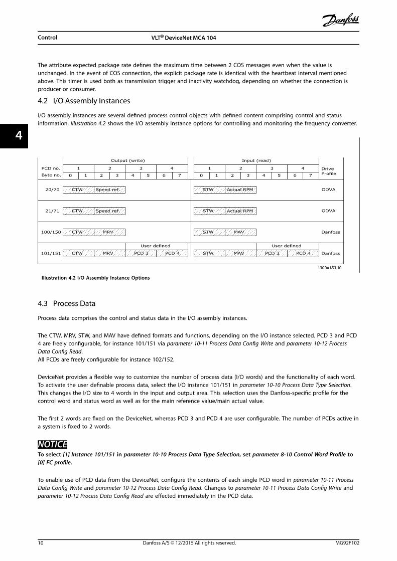
4.2 I/O Assembly Instances
I/O assembly instances are several defined process control objects with defined content comprising control and statusinformation. Illustration 4.2 shows the I/O assembly instance options for controlling and monitoring the frequency converter.
Illustration 4.2 I/O Assembly Instance Options
4.3 Process Data
Process data comprises the control and status data in the I/O assembly instances.
The CTW, MRV, STW, and MAV have defined formats and functions, depending on the I/O instance selected. PCD 3 and PCD4 are freely configurable, for instance 101/151 via parameter 10-11 Process Data Config Write and parameter 10-12 ProcessData Config Read.All PCDs are freely configurable for instance 102/152.
DeviceNet provides a flexible way to customize the number of process data (I/O words) and the functionality of each word.To activate the user definable process data, select the I/O instance 101/151 in parameter 10-10 Process Data Type Selection.This changes the I/O size to 4 words in the input and output area. This selection uses the Danfoss-specific profile for thecontrol word and status word as well as for the main reference value/main actual value.
The first 2 words are fixed on the DeviceNet, whereas PCD 3 and PCD 4 are user configurable. The number of PCDs active ina system is fixed to 2 words.
NOTICETo select [1] Instance 101/151 in parameter 10-10 Process Data Type Selection, set parameter 8-10 Control Word Profile to[0] FC profile.
To enable use of PCD data from the DeviceNet, configure the contents of each single PCD word in parameter 10-11 ProcessData Config Write and parameter 10-12 Process Data Config Read. Changes to parameter 10-11 Process Data Config Write and parameter 10-12 Process Data Config Read are effected immediately in the PCD data.
Control VLT® DeviceNet MCA 104
10 Danfoss A/S © 12/2015 All rights reserved. MG92F102
44

CTW REF
CTW REFPCD 2write
PCD 3write
STW MAV
STW MAVPCD 2read
PCD 3read
Instance
100
101
150
151
Originator (PLC) --> Target (Drive)
Fixed contents User dened contents
Instance
STW MAV70
STW MAV71
CTW REF20
CTW REF21
Byte # Byte #
Word # Word #
Target (Drive) --> Originator (PLC)
1 2 3 4 5 6 7 8 1 2 3 4 5 6 7 8
1 2 3 4 1 2 3 4
130B
E709
.10
Illustration 4.3 Process Data
4.4 ODVA Control Profile
4.4.1 Control Word under Instances 20/70and 21/71
Set parameter 8-10 Control Word Profile to ODVA and selectthe instance in parameter 10-10 Process Data Type Selection.
Illustration 4.4 The Control Word in Instances 20 and 21
NOTICEThe bits 00 and 02 in instance 20 are identical with bits00 and 02 in the more extensive instance 21.
Bit Instance 20 Instance 21
Bit = 0 Bit = 1 Bit = 0 Bit = 1
00 Stop Run Fwd Stop Run Fwd
01 – – Stop Run Rev
02 No function Fault reset No function Fault reset
03 – – – –
04 – – – –
05 – – – Net Ctrl
06 – – – Net Ref
07–15 – – – –
Table 4.2 Bits in Instances 20 and 21
Explanation of the bits:Bit 0, Run FwdBit 0 = 0: The frequency converter has a stop command.Bit 0 = 1: Leads to a start command, and the frequencyconverter runs the motor clockwise.
Bit 1, Run RevBit 1 = 0: Leads to a stop of the motor.Bit 1 = 1: Leads to a start reverse of the motor, and thefrequency converter runs the motor counterclockwise.
Bit 2, Fault ResetBit 2 = 0: There is no reset of a trip.Bit 2 = 1: A trip is reset.
Bit 3, No functionBit 3: No function.
Bit 4, No functionBit 4: No function.
Bit 5, Net ControlBit 5 = 0: The frequency converter is controlled via thestandard inputs.Bit 5 = 1: The DeviceNet controls the frequency converter.
NOTICEChanges affect parameter 8-50 Coasting Select toparameter 8-56 Preset Reference Select.
Bit 6, Net ReferenceBit 6 = 0: Reference is from the standard inputs.Bit 6 = 1: Reference is from DeviceNet.
Control Programming Guide
MG92F102 Danfoss A/S © 12/2015 All rights reserved. 11
4 4

NOTICEChanges affect parameter 3-15 Reference Resource 1 toparameter 3-17 Reference Resource 3.
For the speed reference, see chapter 4.4.3 Bus SpeedReference Value under Instances 20/70 and 21/71.
4.4.2 Status Word under Instances 20/70and 21/71
Illustration 4.5 Status Word in Instances 70 and 71
NOTICEThe bits 00 and 02 in instance 70 are identical with bits00 and 02 in the more extensive instance 71.
Bit Instance 70 Instance 71
Bit = 0 Bit = 1 Bit = 0 Bit = 1
00 – Fault – Fault
01 – – – Warning
02 – Running 1Fwd
– Running 1Fwd
03 – – – Running 2Rev.
04 – – – Ready
05 – – – Controlfrom Net
06 – – – Referencefrom Net
07 – – – Atreference
08–15 – – State attribute
Table 4.3 Bits in Instances 70 and 71
Explanation of the bits:Bit 0, FaultBit 0 = 0: There is no fault in the frequency converter.Bit 0 = 1: There is a fault in the frequency converter.
Bit 1, WarningBit 0 = 0: There is no unusual situation.Bit 0 = 1: An abnormal condition has arisen.
Bit 2, Running 1Bit 2 = 0: The frequency converter is not in the runningforward state, or run 1 is not set.Bit 2 = 1: The frequency converter state attribute isenabled or stopping, or that fault-stop and bit 0 (run 1) ofthe control word are set at the same time.
Bit 3, Running 2Bit 3 = 0: The frequency converter is not in the runningreverse state, or run 2 is not set.Bit 3 = 1: The frequency converter state attribute isenabled or stopping, or fault-stop and bit 0 (run 2) of thecontrol word are set at the same time.
Bit 4, ReadyBit 4 = 0: The state attribute is in another state.Bit 4 = 1: The state attribute is ready, enabled, or stopping.
Bit 5, Control from netBit 5 = 0: The frequency converter is controlled from thestandard inputs.Bit 5 = 1: The DeviceNet has control (start, stop, reverse) ofthe frequency converter.
Bit 6, Ref from netBit 6 = 0: The reference comes from inputs to thefrequency converter.Bit 6 = 1: The reference comes from the DeviceNet.
Bit 7, At referenceBit 7 = 0: The motor is running, but the present speed isdifferent from the preset speed reference, for example, thespeed is being ramped up/down during start/stop.Bit 7 = 1: The frequency converter and reference speedsare equal.
Bit 8–15, State attribute(Instance 71 only)Represents the state attribute of the frequency converter,as indicated in Table 4.4.
Bit number Meaning
8 (Vendor specific)
9 Start up
10 Not ready
11 Ready
12 Enabled
13 Stopping
14 Fault stop
15 Faulted
Table 4.4 State Attribute (Instance 71)
For more details of the actual output speed, seechapter 4.4.4 Actual Output Speed under Instances 20/70 and21/71.
4.4.3 Bus Speed Reference Value underInstances 20/70 and 21/71
The speed reference value is transmitted to the frequencyconverter as a 16-bit word. The value is transmitted as awhole number. Negative figures are formatted by 2’scomplement.
Control VLT® DeviceNet MCA 104
12 Danfoss A/S © 12/2015 All rights reserved. MG92F102
44

Illustration 4.6 Speed Reference Value
The bus speed reference has the following format:Parameter 3-00 Reference Range = 0 [refMIN to refMAX] 0(0000 hex) [RPM] to + 32767 (7FFF hex) [RPM]Parameter 3-00 Reference Range = 1 [-refMAX to +refMAX]-32767 (8001 hex ) to +32767 [RPM] (7FFF hex)
The actual reference [Ref. %] in the frequency converterdepends on the settings in the following parameters:Parameter 1-23 Motor FrequencyParameter 1-25 Motor Nominal SpeedParameter 3-03 Maximum Reference
NOTICEWhen the bus speed reference is negative, and thecontrol word contains a run reverse signal, the frequencyconverter runs clockwise (- - is +).
Example:Parameter 1-25 Motor Nominal Speed = 1420 RPMParameter 1-23 Motor Frequency = 50 HzParameter 3-03 Maximum Reference = 1420 RPM
To run the motor at 25%, the reference transmitted mustbe: (1420x0.25) = 355 = 16.3 hex163 hex ⇒ 25% ⇒ Fout = 12.5 Hz
4.4.4 Actual Output Speed under Instances20/70 and 21/71
Illustration 4.7 Actual Output Speed Value
The value of the actual speed of the motor, is transmittedin the form of a 16-bit word.
The value is transmitted as a whole number (negativefigures are formed with 2's complement).
-32767 (8000 hex) [RPM] to +32767 [RPM] (7FFF hex) [RPM]
4.5 FC Control Profile
4.5.1 Control Word under Instances100/150, 101/151, and 102/152
To select FC protocol in the control word, set parameter 8-10 Control Word Profile to [0] FC profile. Thecontrol word is used to send commands from a master(PLC or PC) to a slave (frequency converter).
Illustration 4.8 Control Words in Instances 100, 101, and 102
Bit Bit value = 0 Bit value = 1
00 Reference value External selection lsb
01 Reference value External selection msb
02 DC brake Ramp
03 Coasting No coasting
04 Quick stop Ramp
05 Hold output frequency Use ramp
06 Ramp stop Start
07 No function Reset
08 No function Jog
09 Ramp 1 Ramp 2
10 Data invalid Data valid
11 No function Relay 01 active
12 No function Relay 04 active
13 Parameter set-up Selection lsb
14 Parameter set-up Selection msb
15 No function Reverse
Table 4.5 Bits in Instances 100, 101, and 102
Explanation of the control bits:Bits 00/01Bits 00 and 01: Select between the 4 reference values,which are pre-programmed in parameter 3-10 PresetReference according to Table 4.6.
Programmedreferencevalue
Parameter Bit 01 Bit 00
1 3-10 [0] 0 0
2 3-10 [1] 0 1
3 3-10 [2] 1 0
4 3-10 [3] 1 1
Table 4.6 Reference Values
Control Programming Guide
MG92F102 Danfoss A/S © 12/2015 All rights reserved. 13
4 4

NOTICEIn parameter 8-56 Preset Reference Select, a selection ismade to define how bit 00/01 gates with thecorresponding function on the digital inputs.
Bit 02, DC brakeBit 02 = 0: Leads to DC braking and stop. Braking currentand duration are set in parameter 2-01 DC Brake Currentand parameter 2-02 DC Braking Time.Bit 02 = 1: Leads to ramping.
Bit 03, CoastingBit 03 = 0: Causes the frequency converter to immediatelyrelease the motor (the output transistors are disabled), andcoasts to a standstill.Bit 03 = 1: Enables the frequency converter to start themotor if the other starting conditions are fulfilled.
NOTICEIn parameter 8-50 Coasting Select, a selection is made todefine how bit 03 gates with the corresponding functionon a digital input.
Bit 04, Quick stopBit 04 = 0: Causes a stop, in which the motor speed isramped down to stop via parameter 3-81 Quick Stop RampTime.
Bit 05, Hold output frequencyBit 05 = 0: Causes the present output frequency (in Hz) tofreeze. The frozen output frequency can then be changedonly with the digital inputs (parameter 5-10 Terminal 18Digital Input to parameter 5-15 Terminal 33 Digital Input)programmed to speed up and speed down.
NOTICEIf hold output is active, only the following can stop thefrequency converter:
• Bit 03 coasting stop.
• Bit 02 DC braking.
• Digital input (parameter 5-10 Terminal 18 DigitalInput to parameter 5-15 Terminal 33 DigitalInput) programmed to DC braking, coastingstop, or reset and coasting stop.
Bit 06, Ramp stop/startBit 06 = 0: Causes a stop, in which the motor speed isramped down to stop via the selected ramp downparameter.Bit 06 = 1: Allows the frequency converter to start themotor, if the other starting conditions are fulfilled.
NOTICEIn parameter 8-53 Start Select, a selection is made todefine how bit 06 ramp stop/start gates with thecorresponding function on a digital input.
Bit 07, ResetBit 07 = 0: Does not cause a reset.Bit 07 = 1: Resets a trip. Reset is activated on the leadingedge of the signal, that is, when changing from logic 0 tologic 1.
Bit 08, JogBit 08 = 1: The frequency converter ramps up/ramps downaccording to the setting in parameter 3-19 Jog Speed [RPM].
Bit 09, Selection of ramp 1/2Bit 09 = 0: Ramp 1 is active (parameter 3-40 Ramp 1 Type toparameter 3-47 Ramp 1 S-ramp Ratio at Decel. Start).Bit 09 = 1: Ramp 2 is active (parameter 3-50 Ramp 2 Type toparameter 3-57 Ramp 2 S-ramp Ratio at Decel. Start).
Bit 10, Data not valid/Data validTells the frequency converter whether to use or to ignorethe control word.Bit 10 = 0: Ignores the control word.Bit 10 = 1: Uses the control word to be used. This functionis relevant, because the control word is always containedin the telegram, regardless of the type of telegram. It ispossible to turn off the control word if you do not wish touse it with updating or reading parameters.
Bit 11, Relay 01Bit 11 = 0: Relay not activated.Bit 11 = 1: Relay 01 activated, provided [36] control wordbit 11 is selected in parameter 5-40 Function Relay.
Bit 12, Relay 04Bit 12 = 0: Relay 04 is not activated.Bit 12 = 1: Relay 04 is activated, provided [37] control wordbit 12 is selected in parameter 5-40 Function Relay.
Bit 13/14, Selection of set-upBits 13 and 14 are used to select from the 4 menu set-upsaccording to Table 4.7.
Set-up Bit 14 Bit 13
1 0 0
2 0 1
3 1 0
4 1 1
Table 4.7 Menu Set-up
The function is only possible when [9] Multi Set-up isselected in parameter 0-10 Active Set-up.
NOTICEIn parameter 8-55 Set-up Select, a selection is made todefine how bits 13/14 gate with the correspondingfunction on the digital inputs.
Bit 15 ReverseBit 15 = 0: No reversing.Bit 15 = 1: Reversing.
Control VLT® DeviceNet MCA 104
14 Danfoss A/S © 12/2015 All rights reserved. MG92F102
44
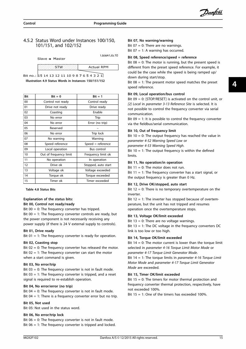
4.5.2 Status Word under Instances 100/150,101/151, and 102/152
Illustration 4.9 Status Words in Instances 150/151/152
Bit Bit = 0 Bit = 1
00 Control not ready Control ready
01 Drive not ready Drive ready
02 Coasting Enable
03 No error Trip
04 No error Error (no trip)
05 Reserved –
06 No error Trip lock
07 No warning Warning
08 Speed reference Speed = reference
09 Local operation Bus control
10 Out of frequency limit Frequency limit ok
11 No operation In operation
12 Drive ok Stopped, auto start
13 Voltage ok Voltage exceeded
14 Torque ok Torque exceeded
15 Timer ok Timer exceeded
Table 4.8 Status Bits
Explanation of the status bits:Bit 00, Control not ready/readyBit 00 = 0: The frequency converter has tripped.Bit 00 = 1: The frequency converter controls are ready, butthe power component is not necessarily receiving anypower supply (if there is 24 V external supply to controls).
Bit 01, Drive readyBit 01 = 1: The frequency converter is ready for operation.
Bit 02, Coasting stopBit 02 = 0: The frequency converter has released the motor.Bit 02 = 1: The frequency converter can start the motorwhen a start command is given.
Bit 03, No error/tripBit 03 = 0: The frequency converter is not in fault mode.Bit 03 = 1: The frequency converter is tripped, and a resetsignal is required to re-establish operation.
Bit 04, No error/error (no trip)Bit 04 = 0: The frequency converter is not in fault mode.Bit 04 = 1: There is a frequency converter error but no trip.
Bit 05, Not usedBit 05: Not used in the status word.
Bit 06, No error/trip lockBit 06 = 0: The frequency converter is not in fault mode.Bit 06 = 1: The frequency converter is tripped and locked.
Bit 07, No warning/warningBit 07 = 0: There are no warnings.Bit 07 = 1: A warning has occurred.
Bit 08, Speed reference/speed = referenceBit 08 = 0: The motor is running, but the present speed isdifferent from the preset speed reference. For example, itcould be the case while the speed is being ramped up/down during start/stop.Bit 08 = 1: The present motor speed matches the presetspeed reference.
Bit 09, Local operation/bus controlBit 09 = 0: [STOP/RESET] is activated on the control unit, or[2] Local in parameter 3-13 Reference Site is selected. It isnot possible to control the frequency converter via serialcommunication.Bit 09 = 1: It is possible to control the frequency convertervia the fieldbus/serial communication.
Bit 10, Out of frequency limitBit 10 = 0: The output frequency has reached the value inparameter 4-52 Warning Speed Low orparameter 4-53 Warning Speed High.Bit 10 = 1: The output frequency is within the definedlimits.
Bit 11, No operation/in operationBit 11 = 0: The motor does not run.Bit 11 = 1: The frequency converter has a start signal, orthe output frequency is greater than 0 Hz.
Bit 12, Drive OK/stopped, auto startBit 12 = 0: There is no temporary overtemperature on theinverter.Bit 12 = 1: The inverter has stopped because of overtem-perature, but the unit has not tripped and resumesoperation once the overtemperature stops.
Bit 13, Voltage OK/limit exceededBit 13 = 0: There are no voltage warnings.Bit 13 = 1: The DC voltage in the frequency converters DClink is too low or too high.
Bit 14, Torque OK/limit exceededBit 14 = 0: The motor current is lower than the torque limitselected in parameter 4-16 Torque Limit Motor Mode orparameter 4-17 Torque Limit Generator Mode.Bit 14 = 1: The torque limits in parameter 4-16 Torque LimitMotor Mode and parameter 4-17 Torque Limit GeneratorMode are exceeded.
Bit 15, Timer OK/limit exceededBit 15 = 0: The timers for motor thermal protection andfrequency converter thermal protection, respectively, havenot exceeded 100%.Bit 15 = 1: One of the timers has exceeded 100%.
Control Programming Guide
MG92F102 Danfoss A/S © 12/2015 All rights reserved. 15
4 4

4.5.3 Bus Reference Value under Instances100/150 and 101/151
The frequency reference value is transmitted to thefrequency converter in the form of a 16-bit word. Thevalue is transmitted as a whole number (-32767 to+32767). Negative figures are formatted by 2’scomplement.
Master ⇒ slave 16 bit
CTW Speed reference RPM
Table 4.9 Speed Reference Value
The bus reference has the following format:100% = 4000 hexParameter 3-00 Reference Range = 0 [refMIN ⇒ refMAX] 0 ⇒16384 (4000 hex) ~ 0 ⇒ 100%Parameter 3-00 Reference Range = 1 [- refMAX ⇒ + refMAX]-16384 (C000 hex) ⇒ +16384 (4000 hex) ~ -100% ⇒ +100%
4.5.4 Actual Output Frequency underInstances 100/150 and 101/151
The value of the actual output frequency of the frequencyconverter is transmitted in the form of a 16-bit word. Thevalue is transmitted as a whole number (-32767 to+32767). Negative figures are formed by 2’s complement.
Slave ⇒ master 16 bit
STW Actual reference RPM
Table 4.10 Actual Output Frequency
The actual output frequency has the following format:-32767 to +32767.-16384 (C000 hex) corresponds to -100%, and 16384 (4000hex) corresponds to 100%.
Control VLT® DeviceNet MCA 104
16 Danfoss A/S © 12/2015 All rights reserved. MG92F102
44
5 Parameter Access
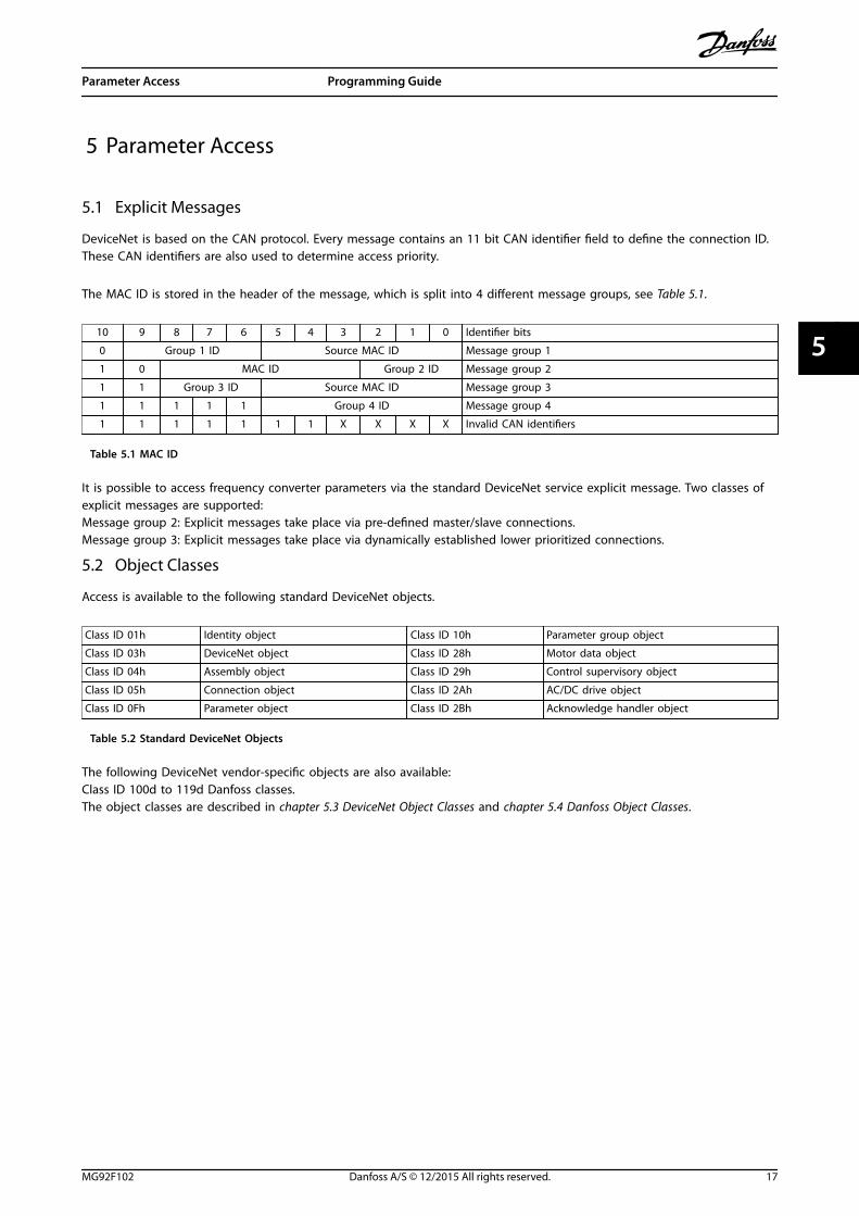
5.1 Explicit Messages
DeviceNet is based on the CAN protocol. Every message contains an 11 bit CAN identifier field to define the connection ID.These CAN identifiers are also used to determine access priority.
The MAC ID is stored in the header of the message, which is split into 4 different message groups, see Table 5.1.
10 9 8 7 6 5 4 3 2 1 0 Identifier bits
0 Group 1 ID Source MAC ID Message group 1
1 0 MAC ID Group 2 ID Message group 2
1 1 Group 3 ID Source MAC ID Message group 3
1 1 1 1 1 Group 4 ID Message group 4
1 1 1 1 1 1 1 X X X X Invalid CAN identifiers
Table 5.1 MAC ID
It is possible to access frequency converter parameters via the standard DeviceNet service explicit message. Two classes ofexplicit messages are supported:Message group 2: Explicit messages take place via pre-defined master/slave connections.Message group 3: Explicit messages take place via dynamically established lower prioritized connections.
5.2 Object Classes
Access is available to the following standard DeviceNet objects.
Class ID 01h Identity object Class ID 10h Parameter group object
Class ID 03h DeviceNet object Class ID 28h Motor data object
Class ID 04h Assembly object Class ID 29h Control supervisory object
Class ID 05h Connection object Class ID 2Ah AC/DC drive object
Class ID 0Fh Parameter object Class ID 2Bh Acknowledge handler object
Table 5.2 Standard DeviceNet Objects
The following DeviceNet vendor-specific objects are also available:Class ID 100d to 119d Danfoss classes.The object classes are described in chapter 5.3 DeviceNet Object Classes and chapter 5.4 Danfoss Object Classes.
Parameter Access Programming Guide
MG92F102 Danfoss A/S © 12/2015 All rights reserved. 17
5 5
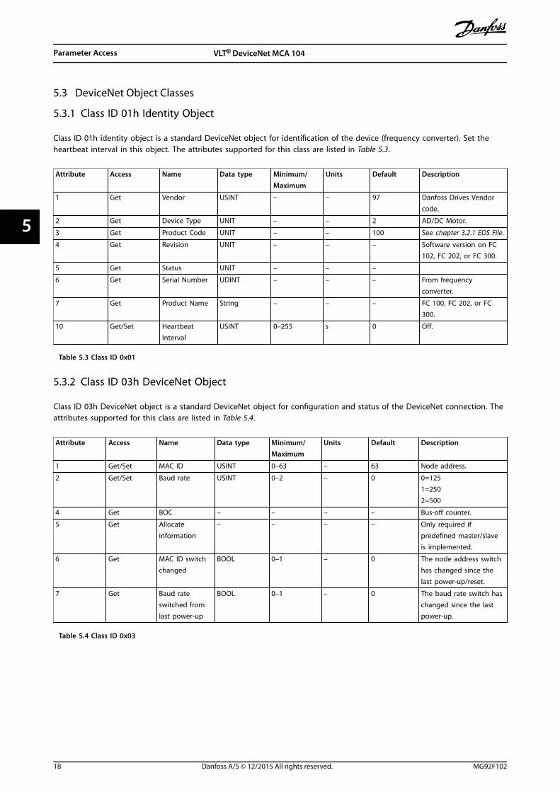
5.3 DeviceNet Object Classes
5.3.1 Class ID 01h Identity Object
Class ID 01h identity object is a standard DeviceNet object for identification of the device (frequency converter). Set theheartbeat interval in this object. The attributes supported for this class are listed in Table 5.3.
Attribute Access Name Data type Minimum/Maximum
Units Default Description
1 Get Vendor USINT – – 97 Danfoss Drives Vendorcode.
2 Get Device Type UNIT – – 2 AD/DC Motor.
3 Get Product Code UNIT – – 100 See chapter 3.2.1 EDS File.
4 Get Revision UNIT – – – Software version on FC102, FC 202, or FC 300.
5 Get Status UNIT – – –
6 Get Serial Number UDINT – – – From frequencyconverter.
7 Get Product Name String – – – FC 100, FC 202, or FC300.
10 Get/Set HeartbeatInterval
USINT 0–255 s 0 Off.
Table 5.3 Class ID 0x01
5.3.2 Class ID 03h DeviceNet Object
Class ID 03h DeviceNet object is a standard DeviceNet object for configuration and status of the DeviceNet connection. Theattributes supported for this class are listed in Table 5.4.
Attribute Access Name Data type Minimum/Maximum
Units Default Description
1 Get/Set MAC ID USINT 0–63 – 63 Node address.
2 Get/Set Baud rate USINT 0–2 – 0 0=1251=2502=500
4 Get BOC – – – – Bus-off counter.
5 Get Allocateinformation
– – – – Only required ifpredefined master/slaveis implemented.
6 Get MAC ID switchchanged
BOOL 0–1 – 0 The node address switchhas changed since thelast power-up/reset.
7 Get Baud rateswitched fromlast power-up
BOOL 0–1 – 0 The baud rate switch haschanged since the lastpower-up.
Table 5.4 Class ID 0x03
Parameter Access VLT® DeviceNet MCA 104
18 Danfoss A/S © 12/2015 All rights reserved. MG92F102
55

5.3.3 Class ID 04h Assembly Object
Class ID 04h assembly object is a standard DeviceNet object for transfer of the I/O instances (process data) described inchapter 4 Control. Using class ID 04h assembly object to send or read any of the defined instances, either by polling orexplicit messaging. The attributes supported for this class are listed in Table 5.5.
Attribute Access Name Data type Minimum/Maximum
Units Default Description
3 Set Data ARRAY – – – –
Table 5.5 Class ID 0x04
Instance Access Size Description Parameter 10-10 selection
20 Set 2 words DeviceNet AC/DC profile Instance 20/70
21 Set 2 words DeviceNet AC/DC profile Instance 21/71
70 Get 2 words DeviceNet AC/DC profile Instance 20/70
71 Get 2 words DeviceNet AC/DC profile Instance 21/71
100 Set 2 words Danfoss specific, no PCD words Instance 100/150
101 Set 4 words Danfoss specific, 2 PCD words Instance 101/151
150 Get 2 words Danfoss specific, no PCD words Instance 100/150
151 Get 4 words Danfoss specific, 2 PCD words Instance 101/151
Table 5.6 Instances
Parameter Access Programming Guide
MG92F102 Danfoss A/S © 12/2015 All rights reserved. 19
5 5
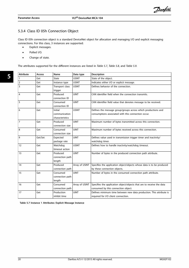
5.3.4 Class ID 05h Connection Object
Class ID 05h connection object is a standard DeviceNet object for allocation and managing I/O and explicit messagingconnections. For this class, 3 instances are supported:
• Explicit messages.
• Polled I/O.
• Change of state.
The attributes supported for the different instances are listed in Table 5.7, Table 5.8, and Table 5.9.
Attribute Access Name Data type Description
1 Get State USINT State of the object.
2 Get Instance type USINT Indicates either I/O or explicit message.
3 Get Transport classtrigger
USINT Defines behavior of the connection.
4 Get Producedconnection ID
UINT CAN identifier field when the connection transmits.
5 Get Consumedconnection ID
UINT CAN identifier field value that denotes message to be received.
6 Get Initialcommunicationcharacteristics
USINT Defines the message group/groups across which productions andconsumptions associated with this connection occur.
7 Get Producedconnection size
UINT Maximum number of bytes transmitted across this connection.
8 Get Consumedconnection size
UINT Maximum number of bytes received across this connection.
9 Get/Set Expectedpackage rate
UINT Defines value used in transmission trigger timer and inactivity/watchdog timer.
12 Get Watchdogtimeout action
USINT Defines how to handle inactivity/watchdog timeout.
13 Get Producedconnection pathlength
UINT Number of bytes in the produced connection path attribute.
14 Get Producedconnection path
Array of USINT Specifies the application object/objects whose data is to be producedby these connection objects.
15 Get Consumedconnection pathlength
UINT Number of bytes in the consumed connection path attribute.
16 Get Consumedconnection path
Array of USINT Specifies the application object/objects that are to receive the dataconsumed by this connection object.
17 Get Productioninhibit time
UINT Defines minimum time between new data production. This attribute isrequired for I/O client connection.
Table 5.7 Instance 1 Attributes: Explicit Message Instance
Parameter Access VLT® DeviceNet MCA 104
20 Danfoss A/S © 12/2015 All rights reserved. MG92F102
55
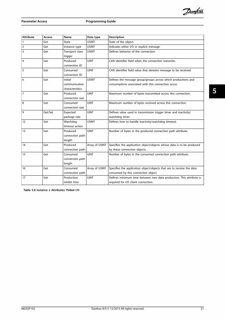
Attribute Access Name Data type Description
1 Get State USINT State of the object.
2 Get Instance type USINT Indicates either I/O or explicit message.
3 Get Transport classtrigger
USINT Defines behavior of the connection.
4 Get Producedconnection ID
UINT CAN identifier field when the connection transmits.
5 Get Consumedconnection ID
UINT CAN identifier field value that denotes message to be received.
6 Get Initialcommunicationcharacteristics
USINT Defines the message group/groups across which productions andconsumptions associated with this connection occur.
7 Get Producedconnection size
UINT Maximum number of bytes transmitted across this connection.
8 Get Consumedconnection size
UINT Maximum number of bytes received across this connection.
9 Get/Set Expectedpackage rate
UINT Defines value used in transmission trigger timer and inactivity/watchdog timer.
12 Get Watchdogtimeout action
USINT Defines how to handle inactivity/watchdog timeout.
13 Get Producedconnection pathlength
UINT Number of bytes in the produced connection path attribute.
14 Get Producedconnection path
Array of USINT Specifies the application object/objects whose data is to be producedby these connection objects.
15 Get Consumedconnection pathlength
UINT Number of bytes in the consumed connection path attribute.
16 Get Consumedconnection path
Array of USINT Specifies the application object/objects that are to receive the dataconsumed by this connection object.
17 Get Productioninhibit time
UINT Defines minimum time between new data production. This attribute isrequired for I/O client connection.
Table 5.8 Instance 2 Attributes: Polled I/O
Parameter Access Programming Guide
MG92F102 Danfoss A/S © 12/2015 All rights reserved. 21
5 5

Attribute Access Name Data type Description
1 Get State USINT State of the object.
2 Get Instance type USINT Indicates either I/O or explicit message.
3 Get Transport classtrigger
USINT Defines behavior of the connection.
4 Get Producedconnection ID
UINT CAN identifier field when the connection transmits.
5 Get Consumedconnection ID
UINT CAN identifier field value that denotes message to be received.
6 Get Initialcommunicationcharacteristics
USINT Defines the message group/groups across which productions andconsumptions associated with this connection occur.
7 Get Producedconnection size
UINT Maximum number of bytes transmitted across this connection.
8 Get Consumedconnection size
UINT Maximum number of bytes received across this connection.
9 Get/Set Expectedpackage rate
UINT Defines value used in transmission trigger timer and inactivity/watchdog timer.
12 Get Watchdogtimeout action
USINT Defines how to handle inactivity/watchdog timeout.
13 Get Producedconnection pathlength
UINT Number of bytes in the produced connection path attribute.
14 Get Producedconnection path
Array of USINT Specifies the application object/objects whose data is to be producedby these connection objects.
15 Get Consumedconnection pathlength
UINT Number of bytes in the consumed connection path attribute.
16 Get Consumedconnection path
Array of USINT Specifies the application object/objects that are to receive the dataconsumed by this connection object.
17 Get Productioninhibit time
UINT Defines minimum time between new data production. This attribute isrequired for I/O client connection.
Table 5.9 Instance 4: Change of State/Cycle
Parameter Access VLT® DeviceNet MCA 104
22 Danfoss A/S © 12/2015 All rights reserved. MG92F102
55

5.3.5 Class ID 0F4 Parameter Object
Class ID 0F4 parameter object is an interface to the parameters of the frequency converter. It identifies configurableparameters and supplies their description, including minimum and maximum values and a descriptive text. The attributessupported are listed in Table 5.10.
Attribute Access Stub/Full Name Data type Description
1 Set/Get Stub Parameter value Data type1) Actual value of parameter.
2 Get Stub Link path size USINT Size of link path.
3 Get Stub Link path ARRAY DeviceNet's path to origin of the parameters.
– – – Segment type/port BYTE –
– – – Segment address Path –
4 Get Stub Descriptor WORD Description of parameter.
5 Get Stub Data type EPATH Data type code.
6 Get Stub Data size USINT Number of bytes in parameter value.
7 Get Full Parameter namestring
SHORTSTRING
Text string representing the parameter name.
8 Get Full Units string SHORTSTRING
Text string representing the parameter name.
9 Get/Set Full Help string SHORTSTRING
Text string representing the parameter name.
10 Get Full Minimum value Data type1) Minimum valid value.
11 Get Full Maximum value Data type1) Maximum valid value.
12 Get Full Default value Data type1) Parameters default value.
13 Get Full Scaling multiplier UINT Multiplier for scaling factor.
14 Get Full Scaling divisor UINT Divisor for scaling factor.
15 Get Full Scaling base UINT Base for scaling formula.
16 Get Full Scaling offset INT Offset for scaling formula.
17 Get Full Multiplier link UINT Parameter instance of multiplier source.
18 Get Full Divisor link UINT Parameter instance of divisor source.
19 Get Full Base link UINT Parameter instance of base source.
20 Get Full Offset link UINT Parameter instance of offset source.
21 Get Full Decimal precision USINT Specifies parameter value format.
Table 5.10 Attributes Supported for Class ID 0F4 Parameter Object
1) Same data type as the parameter.
Parameter Access Programming Guide
MG92F102 Danfoss A/S © 12/2015 All rights reserved. 23
5 5
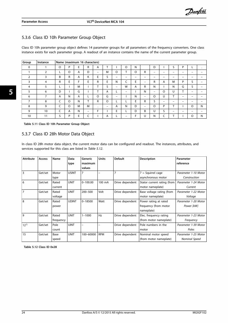
5.3.6 Class ID 10h Parameter Group Object
Class ID 10h parameter group object defines 14 parameter groups for all parameters of the frequency converters. One classinstance exists for each parameter group. A readout of an instance contains the name of the current parameter group.
Group Instance Name (maximum 16 characters)
0 1 O P E R A T I O N D I S P L .
1 2 L O A D – M O T O R – – – – – –
2 3 B R A K E S – – – – – – – – – –
3 4 R E F E R E N C E – R A M P S –
4 5 L I M I T S – W A R N I N G S –
5 6 D I G I T A L – I N – O U T – –
6 7 A N A L O G – I N – O U T – – –
7 8 C O N T R O L L E R S – – – – –
8 9 C O M M . – A N D – O P T I O N
9 10 C A N – F I E L D B U S – – – –
10 11 S P E C I A L – F U N C T I O N
Table 5.11 Class ID 10h Parameter Group Object
5.3.7 Class ID 28h Motor Data Object
In class ID 28h motor data object, the current motor data can be configured and readout. The instances, attributes, andservices supported for this class are listed in Table 5.12.
Attribute Access Name Datatype
Genericmaximumvalues
Units Default Description Parameterreference
3 Get/set Motortype
USINT 7 – 7 7 = Squirrel cageasynchronous motor
Parameter 1-10 MotorConstruction
6 Get/set Ratedcurrent
UNIT 0–100.00 100 mA Drive dependent Stator current rating (frommotor nameplate)
Parameter 1-24 MotorCurrent
7 Get/set Ratedvoltage
UNIT 200–500 Volt Drive dependent Base voltage rating (frommotor nameplate)
Parameter 1-22 MotorVoltage
8 Get/set Ratedpower
UDINT 0–18500 Watt Drive dependent Power rating at ratedfrequency (from motornameplate)
Parameter 1-20 MotorPower [kW]
9 Get/set Ratedfrequency
UNIT 1–1000 Hz Drive dependent Elec. frequency rating(from motor nameplate)
Parameter 1-23 MotorFrequency
121) Get/set Polecount
UINT – – Drive dependent Pole numbers in themotor
Parameter 1-39 MotorPoles
15 Get/set Basespeed
UNIT 100–60000 RPM Drive dependent Nominal motor speed(from motor nameplate)
Parameter 1-25 MotorNominal Speed
Table 5.12 Class ID 0x28
Parameter Access VLT® DeviceNet MCA 104
24 Danfoss A/S © 12/2015 All rights reserved. MG92F102
55

5.3.8 Class ID 29h Control Supervisory Object
The control supervisory object can be used for process control and monitoring of the frequency converter as an alternativeto the I/O instances defined in chapter 4 Control. The attributes supported for this class are listed in Table 5.13.
Attribute Access Name Data type Minimum/Maximum
Default Description
3 Get/Set Run 1 Bool 0–1 – Run fwd, see note below
4 Get/Set Run 2 Bool 0–1 – Run rev, see note below
5 Get/Set NetCtrl Bool 0–1 1 0 = Local control1 = Control from network
6 Get State USINT 0–7 – 0 = Vendor specific1 = Start-up2 = Not ready3 = Ready4 = Enabled5 = Stop6 = Fault stop7 = Fault
7 Get Running 1 Bool 0–1 0 0 = Other state1 = (Enable and Run 1)or (Stopping and Running 1)or (Fault Stop and Running 1)
8 Get Running 2 Bool 0–1 0 0 = Other state1 = (Enable and Run 2)or (Stopping and Running 2)or (Fault Stop and Running 2)
9 Get Ready Bool 0–1 – 0 = Other state1 = Ready or Enabled or Stopping
10 Get Fault Bool 0–1 0 0 = No faults present1 = Fault occurred (latched)
12 Get/Set Fault Rst Bool 0–1 – 0 = No action1 ->1 = Reset fault
13 Get Fault Code UINT – –
15 Get Ctrl From Net Bool 0–1 1 0 = Control is local1 = Control is from network
16 Get/Set DN Fault Mode UINT 0–2 1 Action on loss of DeviceNet0 = Fault + Stop1 = Ignore (warning optional)2 = Danfoss specific
Table 5.13 Class ID 0x29
NOTICEThe ODVA drive profile selected in parameter 1-10 Motor Construction is available only when instances 20/70 or 21/71are selected.
Illustration 5.1 shows how the frequency converter responds to the various command attributes associated with class ID0x29.
Parameter Access Programming Guide
MG92F102 Danfoss A/S © 12/2015 All rights reserved. 25
5 5

Illustration 5.1 State – Transition Diagram
5.3.9 Class ID 2Ah AC/DC Drive Object
To set and read out a range of frequency converters control and status information, use this object. The attributessupported for this class are listed in Table 5.14.
Attribute Access Name Datatype
Minimum/Maximum
Default Description
3 Get At reference Bool 0–1 – 0 = Drive not at reference1 = Drive at reference
4 Get/Set Net ref Bool 0–1 1 0 = Set reference at non-DeviceNetreference1 = Set reference at DeviceNet reference
6 Get/Set Drive mode USINT 0–1 1 0 = Vendor specific mode1 = Open-loop speed (frequency)2 = Closed-loop speed control
7 Get Speed actual INT – RPM/2Speed Scale Actual drive speed(best approximation)
8 Get/Set Speed ref INT – RPM/2Speed Scale Speed reference
22 Get/Set Speed scale SINT -128–127 – Speed scaling factor
29 Get Ref from net Bool 0–1 – 0 = Local speed reference1 = DeviceNet speed reference
Table 5.14 Class ID 0x2A
Parameter Access VLT® DeviceNet MCA 104
26 Danfoss A/S © 12/2015 All rights reserved. MG92F102
55

5.3.10 Class ID 2Bh Acknowledge Handler Object
To manage message reception acknowledgements, necessary for change-of-state support, use class ID 2Bh acknowledgehandler object. The attributes supported for this class are listed in Table 5.15.
Attribute Access Name Datatype
Minimum/Maximum
Default Description
1 Set ACK timer UINT 0–65535 16 Time to wait for ACK before resending.
2 Get/Set Retry timer USINT 0–255 1 Number of ACK-timeouts to wait beforeproducing.RetryLimit_Reache event.
3 Get/Set COS UINT – – Connection instance ID
Table 5.15 Class ID 0x2B
5.4 Danfoss Object Classes
Use the Danfoss classes for read and write of all parametervalues of the frequency converters. A corresponding objectclass is defined for each parameter group. Table 5.16 showsthe classes supported, and their relationship to theparameters.
The class instance and attribute act in the following way:• 100 added to the parameter group = the value
for the class.
• 100 added to the remaining parameter number =the value for the instance.
• 100 added to the array index of the parameter =the value for the attribute.
Parameter range Class
Parameter 0-00 – 0-99 Class 100
Parameter 1-00 – 1-99 Class 101
Parameter 2-00 – 2-99 Class 102
Parameter 3-00 – 3-99 Class 103
Parameter 4-00 – 4-99 Class 104
Parameter 5-00 – 5-99 Class 105
Parameter 6-00 – 6-99 Class 106
Parameter 7-00 – 7-99 Class 107
Parameter 8-00 – 8-99 Class 108
Parameter 10-00 – 10-99 Class 110
Parameter 11-00 – 11-99 Class 111
Parameter 13-00 – 13-99 Class 113
Parameter 14-00 – 14-99 Class 114
Parameter 15-00 – 15-99 Class 115
Parameter 16-00 – 16-99 Class 116
Table 5.16 Danfoss Classes
5.4.1 Examples
Examples: (fictitious parameters) (all values in decimal)• Parameter 0-01 Language [index 0] = Class 100;
instance 101; attribute 100
• Parameter 1-00 Configuration Mode [index 0] =Class 101; instance 100; attribute 100
• Parameter 3-41 Ramp 1 Ramp Up Time [index 0] =Class 103; instance 141; attribute 100
• Parameter 1-55 U/f Characteristic - U [index 3] =Class 101; instance 155; attribute 103
• Parameter 6-54 Terminal 42 Output Timeout Preset[index 9] = Class 106; instance 154; attribute 109
• Parameter 10-01 Baud Rate Select [index 0] = Class110; instance 101; attribute 100
Parameter Access Programming Guide
MG92F102 Danfoss A/S © 12/2015 All rights reserved. 27
5 5

6 Parameters
6.1 Parameter Description
8-01 Control Site
Option: Function:
The setting in this parameter overrides thesettings in parameter 8-50 Coasting Select toparameter 8-56 Preset Reference Select.
[0] Digital andctrl.word
Control by using both digital input andcontrol word.
[1] Digital only Control by using digital inputs only.
[2] Controlwordonly
Control by using control word only.
8-02 Control Word Source
Option: Function:
NOTICEThis parameter cannot be adjustedwhile the motor is running.
Select the source of the control word: 1 of 2serial interfaces or 4 installed options. Duringinitial power-up, the frequency converterautomatically sets this parameter to [3] OptionA, if it detects a valid fieldbus option installedin slot A. When the option is removed, thefrequency converter detects a configurationchange, sets parameter 8-02 Control WordSource to default setting [1] FC RS485, andtrips. If an option is installed after initialpower-up, the setting of parameter 8-02 Control Word Source does notchange, but the frequency converter trips andshows: Alarm 67, Option Changed.When retrofitting a bus option into afrequency converter that did not have a busoption installed earlier, change the control tobus-based. This change is required for safetyreasons to avoid an unintended change.
[0] None
[1] FC RS485
[2] FC USB
[3] Option A
[4] Option B
[5] Option C0
[6] Option C1
[30] External Can
8-03 Control Word Timeout Time
Range: Function:
1 s* [ 0.1 -18000 s]
Enter the maximum time expected to passbetween the reception of 2 consecutivetelegrams. If this time is exceeded, it indicatesthat the telegram communication has stopped.The function selected in parameter 8-04 ControlWord Timeout Function is then carried out. Avalid control word triggers the timeout counter.
8-04 Control Word Timeout Function
Select the timeout function. The timeout function activates whenthe control word fails to be updated within the time periodspecified in parameter 8-03 Control Word Timeout Time.
Option: Function:
NOTICETo change the set-up after a timeout,configure as follows:Set parameter 0-10 Active Set-up to [9]Multi set-up and select the relevantlink in parameter 0-12 This Set-upLinked to.
[0] Off Resumes control via fieldbus (fieldbus orstandard), using the most recent controlword.
[1] Freeze output Freezes output frequency until communi-cation resumes.
[2] Stop Stops with auto restart when communi-cation resumes.
[3] Jogging Runs the motor at jog frequency untilcommunication resumes.
[4] Max. speed Runs the motor at maximum frequency untilcommunication resumes.
[5] Stop and trip Stops the motor, then resets the frequencyconverter to restart:
• Via the fieldbus.
• Via [Reset].
• Via a digital input.
[7] Select setup 1 Changes the set-up after a control wordtimeout. If communication resumes after atimeout, parameter 8-05 End-of-TimeoutFunction defines whether to resume the set-up used before the timeout, or to retain theset-up endorsed by the timeout function.
[8] Select setup 2 See [7] Select set-up 1.
[9] Select setup 3 See [7] Select set-up 1.
[10] Select setup 4 See [7] Select set-up 1.
Parameters VLT® DeviceNet MCA 104
28 Danfoss A/S © 12/2015 All rights reserved. MG92F102
66

8-04 Control Word Timeout Function
Select the timeout function. The timeout function activates whenthe control word fails to be updated within the time periodspecified in parameter 8-03 Control Word Timeout Time.
Option: Function:
[26] Trip
8-05 End-of-Timeout Function
Option: Function:
Select the action after receiving a valid controlword following a timeout.
This parameter is active only whenparameter 8-04 Control Timeout Function is setto:
• [7] Set-up 1.
• [8] Set-up 2.
• [9] Set-up 3.
• [10] Set-up 4.
[0] Hold set-up
Retains the set-up selected inparameter 8-04 Control Timeout Function andshows a warning until parameter 8-06 ResetControl Timeout toggles. Then the frequencyconverter resumes its original set-up.
[1] * Resumeset-up
Resumes the set-up that was active before thetimeout.
8-06 Reset Control Word Timeout
This parameter is active only when [0] Hold set-up has beenselected in parameter 8-05 End-of-Timeout Function.
Option: Function:
[0] * Do not reset Retains the set-up specified in parameter 8-04 Control Word Timeout Function,following a control word timeout.
[1] Do reset Restores the frequency converter to theoriginal set-up following a control wordtimeout. The frequency converter performsthe reset and then immediately reverts to the[0] Do not reset setting.
8-07 Diagnosis Trigger
This parameter has no function for DeviceNet.
Option: Function:
[0] * Disable
[1] Trigger on alarms
[2] Trigger alarm/warn.
8-08 Readout Filtering
If the speed feedback value readouts on fieldbus are fluctuating,this function is used. Select filtered, if the function is required. Apower cycle is required for changes to take effect.
Option: Function:
[0] Motor DataStd-Filt.
Normal fieldbus readouts.
8-08 Readout Filtering
If the speed feedback value readouts on fieldbus are fluctuating,this function is used. Select filtered, if the function is required. Apower cycle is required for changes to take effect.
Option: Function:
[1] Motor DataLP-Filter
Filtered fieldbus readouts of the followingparameters:
• Parameter 16-10 Power [kW].
• Parameter 16-11 Power [hp].
• Parameter 16-12 Motor Voltage.
• Parameter 16-14 Motor current.
• Parameter 16-16 Torque [Nm].
• Parameter 16-17 Speed [RPM].
• Parameter 16-22 Torque [%].
• Parameter 16-25 Torque [Nm] High.
8-10 Control Word Profile
Instances 20/70 and 21/71 are selectable inparameter 10-10 Process Data Type Selection.
Option: Function:
[0] * FC profile Instances 100/150 and 101/151 areselectable in parameter 10-10 ProcessData Type Selection.
[1] PROFIdrive profile
[5] ODVA
[7] CANopen DSP 402
[8] MCO
8-13 Configurable Status Word STW
The status word has 16 bits (0–15). Bits 5 and 12–15 are config-urable. Each of these bits can be configured to any of thefollowing options.
Option: Function:
[0] No function The input is always low.
[1] Profile Default Depending on the profile set inparameter 8-10 Control Profile.
[2] Alarm 68 Only The input goes high wheneveralarm 68, Safe Stop activated isactive, and goes low wheneveralarm 68 Safe Stop activated is notactivate.
[3] Trip excl Alarm 68
[10] T18 DI status
[11] T19 DI status
[12] T27 DI status
[13] T29 DI status
[14] T32 DI status
[15] T33 DI status
[16] T37 DI status The input goes high wheneverterminal 37 has 0 V and goes lowwhenever terminal 37 has 24 V.
Parameters Programming Guide
MG92F102 Danfoss A/S © 12/2015 All rights reserved. 29
6 6

8-13 Configurable Status Word STW
The status word has 16 bits (0–15). Bits 5 and 12–15 are config-urable. Each of these bits can be configured to any of thefollowing options.
Option: Function:
[21] Thermal warning
[30] Brake fault (IGBT)
[40] Out of ref range
[41] Load throttle active
[60] Comparator 0
[61] Comparator 1
[62] Comparator 2
[63] Comparator 3
[64] Comparator 4
[65] Comparator 5
[70] Logic Rule 0
[71] Logic Rule 1
[72] Logic Rule 2
[73] Logic Rule 3
[74] Logic Rule 4
[75] Logic Rule 5
[80] SL digital out A
[81] SL digital out B
[82] SL digital out C
[83] SL digital out D
[84] SL digital out E
[85] SL digital out F
[86] ATEX ETR cur. alarm
[87] ATEX ETR freq. alarm
[88] ATEX ETR cur. warning
[89] ATEX ETR freq. warning
[90] Safe Function active
[91] Safe Opt. Reset req.
[92] IGBT-cooling See 5-3* Digital Outputs.
8-14 Configurable Control Word CTW
Array [15]
Option: Function:
This parameter is not valid in software versionsbefore 4.93.
[0] None The frequency converter ignores the informationin this bit.
[1]*
Profiledefault
The functionality of the bit is depending on theselection parameter 8-10 Control Word Profile.
[2] CTWValid,activelow
If set to 1, the frequency converter ignores theremaining bits of the control word.
[3] SafeOptionReset
This function is only available in bits 12–15 ofthe control word, if a safety option is mountedin the frequency converter. The reset is executed
on a 0⇒1 transition, and resets the safety optionas set in parameter 42-24 Restart Behaviour.
8-14 Configurable Control Word CTW
Array [15]
Option: Function:
[4] PID errorinverse
Inverts the resulting error from the process PIDcontroller. Available only ifparameter 1-00 Configuration Mode is set to [6]Surface Winder, [7] Extended PID Speed OL, or [8]Extended PID Speed CL.
[5] PID resetI part
Resets the I-part of the process PID controller.Equivalent to parameter 7-40 Process PID I-partReset. Available only if parameter 1-00 Configu-ration Mode is set to [6] Surface Winder, [7]Extended PID Speed OL, or [8] Extended PID SpeedCL.
[6] PIDenable
Enables the extended process PID controller.Equivalent to parameter 7-50 Process PIDExtended PID. Available only ifparameter 1-00 Configuration Mode is set to [6]Surface Winder, [7] Extended PID Speed OL, or [8]Extended PID Speed CL.
8-19 Product Code
Range: Function:
Sizerelated*
[0 -2147483647]
Select 0 to read out the actualfieldbus product code accordingto the mounted fieldbus option.Select 1 to read out the actualvendor ID.
8-46 BTM Transaction Status
Option: Function:
[0] * Off
[1] Transaction Started
[2] Transaction Comitting
[3] Transaction Timeout
[4] Err. Non-existing Par.
[5] Err. Par. Out of Range
[6] Transaction Failed
8-47 BTM Timeout
Range: Function:
60 s* [1 - 360 s] Select the BTM timeout after a BTMtransaction has been started.
8-48 BTM Maximum Errors
Range: Function:
21* [0 - 21] Selects the maximum allowed number of bulktransfer mode errors before aborting. If it is set tomaximum, there is no abort.
Parameters VLT® DeviceNet MCA 104
30 Danfoss A/S © 12/2015 All rights reserved. MG92F102
66
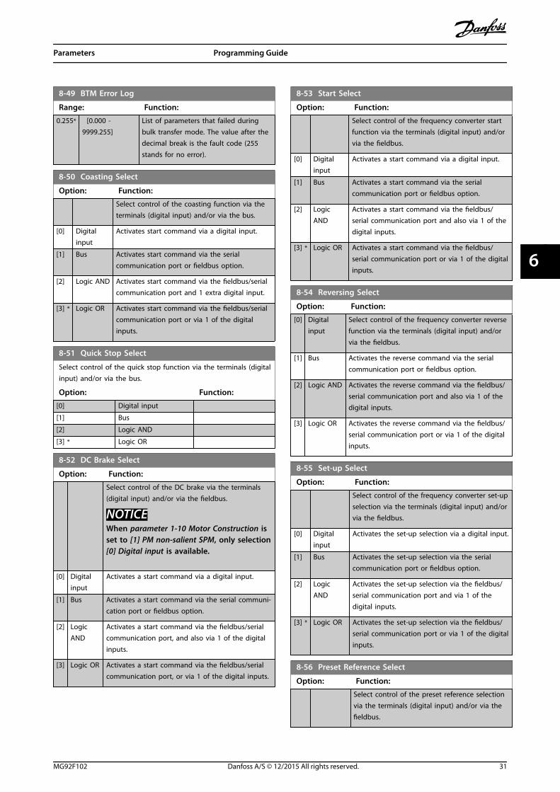
8-49 BTM Error Log
Range: Function:
0.255* [0.000 -9999.255]
List of parameters that failed duringbulk transfer mode. The value after thedecimal break is the fault code (255stands for no error).
8-50 Coasting Select
Option: Function:
Select control of the coasting function via theterminals (digital input) and/or via the bus.
[0] Digitalinput
Activates start command via a digital input.
[1] Bus Activates start command via the serialcommunication port or fieldbus option.
[2] Logic AND Activates start command via the fieldbus/serialcommunication port and 1 extra digital input.
[3] * Logic OR Activates start command via the fieldbus/serialcommunication port or via 1 of the digitalinputs.
8-51 Quick Stop Select
Select control of the quick stop function via the terminals (digitalinput) and/or via the bus.
Option: Function:
[0] Digital input
[1] Bus
[2] Logic AND
[3] * Logic OR
8-52 DC Brake Select
Option: Function:
Select control of the DC brake via the terminals(digital input) and/or via the fieldbus.
NOTICEWhen parameter 1-10 Motor Construction isset to [1] PM non-salient SPM, only selection[0] Digital input is available.
[0] Digitalinput
Activates a start command via a digital input.
[1] Bus Activates a start command via the serial communi-cation port or fieldbus option.
[2] LogicAND
Activates a start command via the fieldbus/serialcommunication port, and also via 1 of the digitalinputs.
[3] Logic OR Activates a start command via the fieldbus/serialcommunication port, or via 1 of the digital inputs.
8-53 Start Select
Option: Function:
Select control of the frequency converter startfunction via the terminals (digital input) and/orvia the fieldbus.
[0] Digitalinput
Activates a start command via a digital input.
[1] Bus Activates a start command via the serialcommunication port or fieldbus option.
[2] LogicAND
Activates a start command via the fieldbus/serial communication port and also via 1 of thedigital inputs.
[3] * Logic OR Activates a start command via the fieldbus/serial communication port or via 1 of the digitalinputs.
8-54 Reversing Select
Option: Function:
[0] Digitalinput
Select control of the frequency converter reversefunction via the terminals (digital input) and/orvia the fieldbus.
[1] Bus Activates the reverse command via the serialcommunication port or fieldbus option.
[2] Logic AND Activates the reverse command via the fieldbus/serial communication port and also via 1 of thedigital inputs.
[3] Logic OR Activates the reverse command via the fieldbus/serial communication port or via 1 of the digitalinputs.
8-55 Set-up Select
Option: Function:
Select control of the frequency converter set-upselection via the terminals (digital input) and/orvia the fieldbus.
[0] Digitalinput
Activates the set-up selection via a digital input.
[1] Bus Activates the set-up selection via the serialcommunication port or fieldbus option.
[2] LogicAND
Activates the set-up selection via the fieldbus/serial communication port and via 1 of thedigital inputs.
[3] * Logic OR Activates the set-up selection via the fieldbus/serial communication port or via 1 of the digitalinputs.
8-56 Preset Reference Select
Option: Function:
Select control of the preset reference selectionvia the terminals (digital input) and/or via thefieldbus.
Parameters Programming Guide
MG92F102 Danfoss A/S © 12/2015 All rights reserved. 31
6 6

8-56 Preset Reference Select
Option: Function:
[0] Digitalinput
Activates preset reference selection via a digitalinput.
[1] Bus Activates preset reference selection via theserial communication port or fieldbus option.
[2] Logic AND Activates preset reference selection via thefieldbus/serial communication port and via 1 ofthe digital inputs.
[3] * Logic OR Activates the preset reference selection via thefieldbus/serial communication port or via 1 ofthe digital inputs.
8-90 Bus Jog 1 Speed
Range: Function:
100 RPM* [ 0 - par. 4-13RPM]
Enter the jog speed. Activate thisfixed jog speed via the serial portor fieldbus option.
8-91 Bus Jog 2 Speed
Range: Function:
200 RPM* [ 0 - par. 4-13RPM]
Enter the jog speed. Activate thisfixed jog speed via the serial portor fieldbus option.
10-00 CAN Protocol
Option: Function:
NOTICEThe options depend on the installedoption.
[0] CANopen
[1] DeviceNet View the active CAN protocol.
10-01 Baud Rate Select
Select the fieldbus transmission speed. The selection mustcorrespond to the transmission speed of the master and theother fieldbus nodes.
Option: Function:
[16] 10 Kbps
[17] 20 Kbps
[18] 50 Kbps
[19] 100 Kbps
[20] 125 Kbps
[21] 250 Kbps
[22] 500 Kbps
10-02 MAC ID
Range: Function:
Size related* [ 0 - 63 ] Selection of station address. Everystation connected to the sameDeviceNet network must have anunambiguous address.
10-05 Readout Transmit Error Counter
Range: Function:
0* [0 - 255 ] View the number of CAN control transmissionerrors since the last power-up.
10-06 Readout Receive Error Counter
Range: Function:
0* [0 - 255 ] View the number of CAN control receipt errorssince the last power-up.
10-07 Readout Bus Off Counter
Range: Function:
0* [0 - 255 ] View the number of fieldbus off events since thelast power-up.
10-10 Process Data Type Selection
Option: Function:
Select the instance (telegram) for datatransmission. The instances available dependon the setting of parameter 8-10 ControlProfile.When parameter 8-10 Control Profile is set to[0] FC profile, parameter 10-10 Process DataType Selection options [0] INSTANCE 100/150and [1] INSTANCE 101/151 are available.When parameter 8-10 Control Profile is set to[5] ODVA, parameter 10-10 Process Data TypeSelection options [2] INSTANCE 20/70 and [3]INSTANCE 21/71 are available.Instances 100/150 and 101/151 are Danfoss-specific. Instances 20/70 and 21/71 are ODVA-specific AC motor profiles.For guidelines in telegram selection, refer to
the VLT® DeviceNet MCA 104 Installation Guide.
NOTICEA change to this parameter is executedimmediately.
[0] INSTANCE100/150
[1] INSTANCE101/151
[2] INSTANCE20/70
[3] INSTANCE21/71
10-11 Process Data Config Write
Select the process write data for I/O assembly instances 101/151.Elements [2] and [3] of this array can be selected. Elements [0]and [1] of the array are fixed.
Option: Function:
[0] None
[302] Minimum Reference
Parameters VLT® DeviceNet MCA 104
32 Danfoss A/S © 12/2015 All rights reserved. MG92F102
66

10-11 Process Data Config Write
Select the process write data for I/O assembly instances 101/151.Elements [2] and [3] of this array can be selected. Elements [0]and [1] of the array are fixed.
Option: Function:
[303] Maximum Reference
[312] Catch up/slow Down Value
[341] Ramp 1 Ramp Up Time
[342] Ramp 1 Ramp Down Time
[351] Ramp 2 Ramp Up Time
[352] Ramp 2 Ramp Down Time
[380] Jog Ramp Time
[381] Quick Stop Ramp Time
[411] Motor Speed Low Limit [RPM]
[412] Motor Speed Low Limit [Hz]
[413] Motor Speed High Limit [RPM]
[414] Motor Speed High Limit [Hz]
[416] Torque Limit Motor Mode
[417] Torque Limit Generator Mode
[553] Term. 29 High Ref./Feedb. Value
[558] Term. 33 High Ref./Feedb. Value
[590] Digital & Relay Bus Control
[593] Pulse Out #27 Bus Control
[595] Pulse Out #29 Bus Control
[597] Pulse Out #X30/6 Bus Control
[615] Terminal 53 High Ref./Feedb.Value
[625] Terminal 54 High Ref./Feedb.Value
[653] Term 42 Output Bus Ctrl
[663] Terminal X30/8 Bus Control
[673] Terminal X45/1 Bus Control
[683] Terminal X45/3 Bus Control
[748] PCD Feed Forward
[890] Bus Jog 1 Speed
[891] Bus Jog 2 Speed
[1680] Fieldbus CTW 1
[1682] Fieldbus REF 1
[1685] FC Port CTW 1
[1686] FC Port REF 1
10-12 Process Data Config Read
Select the process read data for I/O assembly instances 101/151.Elements [2] and [3] of this array can be selected. Elements [0]and [1] of the array are fixed.
Option: Function:
[0] None
[15] Readout: actual setup
[1472] Legacy Alarm Word
[1473] Legacy Warning Word
[1474] Leg. Ext. Status Word
[1500] Operating hours
[1501] Running Hours
[1502] kWh Counter
10-12 Process Data Config Read
Select the process read data for I/O assembly instances 101/151.Elements [2] and [3] of this array can be selected. Elements [0]and [1] of the array are fixed.
Option: Function:
[1600] Control Word
[1601] Reference [Unit]
[1602] Reference %
[1603] Status Word
[1605] Main Actual Value [%]
[1606] Absolute Position
[1609] Custom Readout
[1610] Power [kW]
[1611] Power [hp]
[1612] Motor Voltage
[1613] Frequency
[1614] Motor current
[1615] Frequency [%]
[1616] Torque [Nm]
[1617] Speed [RPM]
[1618] Motor Thermal
[1619] KTY sensor temperature
[1620] Motor Angle
[1621] Torque [%] High Res.
[1622] Torque [%]
[1623] Motor Shaft Power [kW]
[1624] Calibrated Stator Resistance
[1625] Torque [Nm] High
[1630] DC Link Voltage
[1632] Brake Energy /s
[1633] Brake Energy Average
[1634] Heatsink Temp.
[1635] Inverter Thermal
[1638] SL Controller State
[1639] Control Card Temp.
[1645] Motor Phase U Current
[1646] Motor Phase V Current
[1647] Motor Phase W Current
[1648] Speed Ref. After Ramp [RPM]
[1650] External Reference
[1651] Pulse Reference
[1652] Feedback[Unit]
[1653] Digi Pot Reference
[1657] Feedback [RPM]
[1660] Digital Input
[1661] Terminal 53 Switch Setting
[1662] Analog Input 53
[1663] Terminal 54 Switch Setting
[1664] Analog Input 54
[1665] Analog Output 42 [mA]
[1666] Digital Output [bin]
[1667] Freq. Input #29 [Hz]
[1668] Freq. Input #33 [Hz]
[1669] Pulse Output #27 [Hz]
Parameters Programming Guide
MG92F102 Danfoss A/S © 12/2015 All rights reserved. 33
6 6

10-12 Process Data Config Read
Select the process read data for I/O assembly instances 101/151.Elements [2] and [3] of this array can be selected. Elements [0]and [1] of the array are fixed.
Option: Function:
[1670] Pulse Output #29 [Hz]
[1671] Relay Output [bin]
[1672] Counter A
[1673] Counter B
[1674] Prec. Stop Counter
[1675] Analog In X30/11
[1676] Analog In X30/12
[1677] Analog Out X30/8 [mA]
[1678] Analog Out X45/1 [mA]
[1679] Analog Out X45/3 [mA]
[1684] Comm. Option STW
[1687] Bus Readout Alarm/Warning
[1689] Configurable Alarm/Warning Word
[1690] Alarm Word
[1691] Alarm Word 2
[1692] Warning Word
[1693] Warning Word 2
[1694] Ext. Status Word
[1836] Analog Input X48/2 [mA]
[1837] Temp. Input X48/4
[1838] Temp. Input X48/7
[1839] Temp. Input X48/10
[1843] Analog Out X49/7
[1844] Analog Out X49/9
[1845] Analog Out X49/11
[1860] Digital Input 2
[3421] PCD 1 Read from MCO
[3422] PCD 2 Read from MCO
[3423] PCD 3 Read from MCO
[3424] PCD 4 Read from MCO
[3425] PCD 5 Read from MCO
[3426] PCD 6 Read from MCO
[3427] PCD 7 Read from MCO
[3428] PCD 8 Read from MCO
[3429] PCD 9 Read from MCO
[3430] PCD 10 Read from MCO
[3440] Digital Inputs
[3441] Digital Outputs
[3450] Actual Position
[3451] Commanded Position
[3452] Actual Master Position
[3453] Slave Index Position
[3454] Master Index Position
[3455] Curve Position
[3456] Track Error
[3457] Synchronizing Error
[3458] Actual Velocity
[3459] Actual Master Velocity
[3460] Synchronizing Status
10-12 Process Data Config Read
Select the process read data for I/O assembly instances 101/151.Elements [2] and [3] of this array can be selected. Elements [0]and [1] of the array are fixed.
Option: Function:
[3461] Axis Status
[3462] Program Status
[3464] MCO 302 Status
[3465] MCO 302 Control
[3470] MCO Alarm Word 1
[3471] MCO Alarm Word 2
[4280] Safe Option Status
[4282] Safe Control Word
[4283] Safe Status Word
[4285] Active Safe Func.
[4287] Time Until Manual Test
10-13 Warning Parameter
Range: Function:
0* [0 - 65535 ] View a DeviceNet-specific warning word. Onebit is assigned to every warning. Refer to the
VLT® MCA 104 DeviceNet Installation Guide forfurther information.
Bit Description
0 Bus not active.
1 Explicit connection timeout.
2 I/O connection.
3 Retry limit reached.
4 Actual is not updated.
5 CAN bus off.
6 I/O send error.
7 Initialization error.
8 No bus supply.
9 Bus off.
10 Error passive.
11 Error warning.
12 Duplicate MAC ID error.
13 RX queue overrun.
14 TX queue overrun.
15 CAN overrun.
Table 6.1 Warning Bits
10-14 Net Reference
Read only from LCP.
Option: Function:
Select the reference source in instances 21/71 and20/70.
[0] * Off Enables reference via analog/digital inputs.
[1] On Enables reference via the fieldbus.
Parameters VLT® DeviceNet MCA 104
34 Danfoss A/S © 12/2015 All rights reserved. MG92F102
66

10-15 Net Control
Read only from LCP.
Option: Function:
Select the control source in instances 21/71 and 20/70.
[0] * Off Enables control via analog/digital inputs.
[1] On Enable control via the fieldbus.
10-20 COS Filter 1
Range: Function:
0* [0 - 65535] Sets up the filter mask for the status word.When operating in COS (change-of-state), it ispossible to filter out bits in the status word thatshould not be sent if they change.
10-21 COS Filter 2
Range: Function:
0* [0 - 65535] Sets up the filter mask for the main actualvalue. When operating in COS (change-of-state),it is possible to filter out bits in the main actualvalue that should not be sent if they change.
10-22 COS Filter 3
Range: Function:
0* [0 - 65535] Sets up the filter mask for PCD 3. Whenoperating in COS (change-of-state), it is possibleto filter out bits in PCD 3 that should not besent if they change.
10-23 COS Filter 4
Range: Function:
0* [0 - 65535] Sets up the filter mask for PCD 4. Whenoperating in COS (change-pf-state), it is possibleto filter out bits in PCD 4 that should not besent if they change.
10-30 Array Index
Range: Function:
0* [0 - 255 ] View array parameters. This parameter is valid
only when a VLT® DeviceNet MCA 104 is installed.
10-31 Store Data Values
Option: Function:
This parameter is used to activate a function thatstores all parameter values in the non-volatilememory thus retaining changed parametervalues at power down.
[0] Off The store function is inactive.
[1] Store allsetups
All parameter values in the set-up selected arestored in the non-volatile memory.The value returns to [0] Off when all values arestored.
10-31 Store Data Values
Option: Function:
[2] Store allsetups
All parameter values are stored in the non-volatile memory. The value returns to [0] Offwhen all parameter values are stored.
10-32 Devicenet Revision
Range: Function:
0* [0 - 65535 ] View the DeviceNet revision number. Thisparameter is used for EDS file creation.
10-33 Store Always
This parameter is used to select whether parameter data receivedvia the DeviceNet option should always be stored in non-volatilememory.
Option: Function:
[0] * Off
[1] On
10-34 DeviceNet Product Code
Range: Function:
Size related* [0 - 65535]
16-90 Alarm Word
Range: Function:
0* [0 - 4294967295 ] View the alarm word sent via the serialcommunication port in hex code.
16-91 Alarm Word 2
Range: Function:
0* [0 - 4294967295] View the alarm word sent via the serialcommunication port in hex code.
16-92 Warning Word
Range: Function:
0* [0 - 4294967295 ] View the warning word sent via the serialcommunication port in hex code.
16-93 Warning Word 2
Range: Function:
0* [0 - 4294967295] View the warning word sent via the serialcommunication port in hex code.
16-94 Ext. Status Word
Range: Function:
0* [0 - 4294967295] Returns the extended warning word sentvia the serial communication port in hexcode.
Parameters Programming Guide
MG92F102 Danfoss A/S © 12/2015 All rights reserved. 35
6 6

6.2 Parameter List
Parameter Default value Range Conversionindex
Data type
Parameter 8-01 Control Site [0] Dig. & ctrl. word [0–2] – 5
Parameter 8-02 Control Word Source [0] FC RS485 [0–4] – 5
Parameter 8-03 Control Word Timeout Time 1 s 0.1–18000 -1 7
Parameter 8-04 Control Word Timeout Function [0] Off [0–10] -1 5
Parameter 8-05 End-of-Timeout Function [0] Hold set-up [0–1] – 5
Parameter 8-06 Reset Control Word Timeout [0] Do not reset [0–1] – 5
Parameter 8-07 Diagnosis Trigger [0] Disable [0–3] – 5
Parameter 8-10 Control Word Profile [0] FC profile [0–x] – 5
Parameter 8-50 Coasting Select [3] Logic OR [0–3] – 5
Parameter 8-51 Quick Stop Select [3] Logic OR [0–3] – 5
Parameter 8-52 DC Brake Select [3] Logic OR [0–3] – 5
Parameter 8-53 Start Select [3] Logic OR [0–3] – 5
Parameter 8-54 Reversing Select [3] Logic OR [0–3] – 5
Parameter 8-55 Set-up Select [3] Logic OR [0–3] – 5
Parameter 8-56 Preset Reference Select [3] Logic OR [0–3] – 5
Parameter 8-90 Bus Jog 1 Speed 100 RPM 0–parameter 4-13 MotorSpeed High Limit [RPM]
67 6
Parameter 8-91 Bus Jog 2 Speed 200 RPM 0–parameter 4-13 MotorSpeed High Limit [RPM]
67 6
Parameter 10-00 CAN Protocol [1] DeviceNet [0–1] – 5
Parameter 10-01 Baud Rate Select [20] 125 Kbps [20–22] – 5
Parameter 10-02 MAC ID 63 0–63 0 5
Parameter 10-05 Readout Transmit ErrorCounter 0 0–255 0 5
Parameter 10-06 Readout Receive Error Counter 0 0–255 0 6
Parameter 10-07 Readout Bus Off Counter 0 0–1000 0
Parameter 10-10 Process Data Type Selection [0]/[2] [0–3] 0 5
Parameter 10-11 Process Data Config Write 0 list 0 5
Parameter 10-12 Process Data Config Read 0 list 0 5
Parameter 10-13 Warning Parameter 0 0–FFFF 0 5
Parameter 10-14 Net Reference [0] Off [0–1] – 5
Parameter 10-15 Net Control [0] Off [0–1] – 5
Parameter 10-20 COS Filter 1 0 0–FFFF 0 6
Parameter 10-21 COS Filter 2 0 0–FFFF 0 6
Parameter 10-22 COS Filter 3 0 0–FFFF 0 6
Parameter 10-23 COS Filter 4 0 0–FFFF 0 6
Parameter 10-31 Store Data Values [0] Off [0–2] – 5
Parameter 10-32 Devicenet Revision – – – 6
Parameter 10-33 Store Always [0] Off [0–1] – 5
Parameter 16-90 Alarm Word 0 0–FFFF 0 7
Parameter 16-92 Warning Word 0 0–FFFF 0 7
Table 6.2 Parameter List
Parameters VLT® DeviceNet MCA 104
36 Danfoss A/S © 12/2015 All rights reserved. MG92F102
66
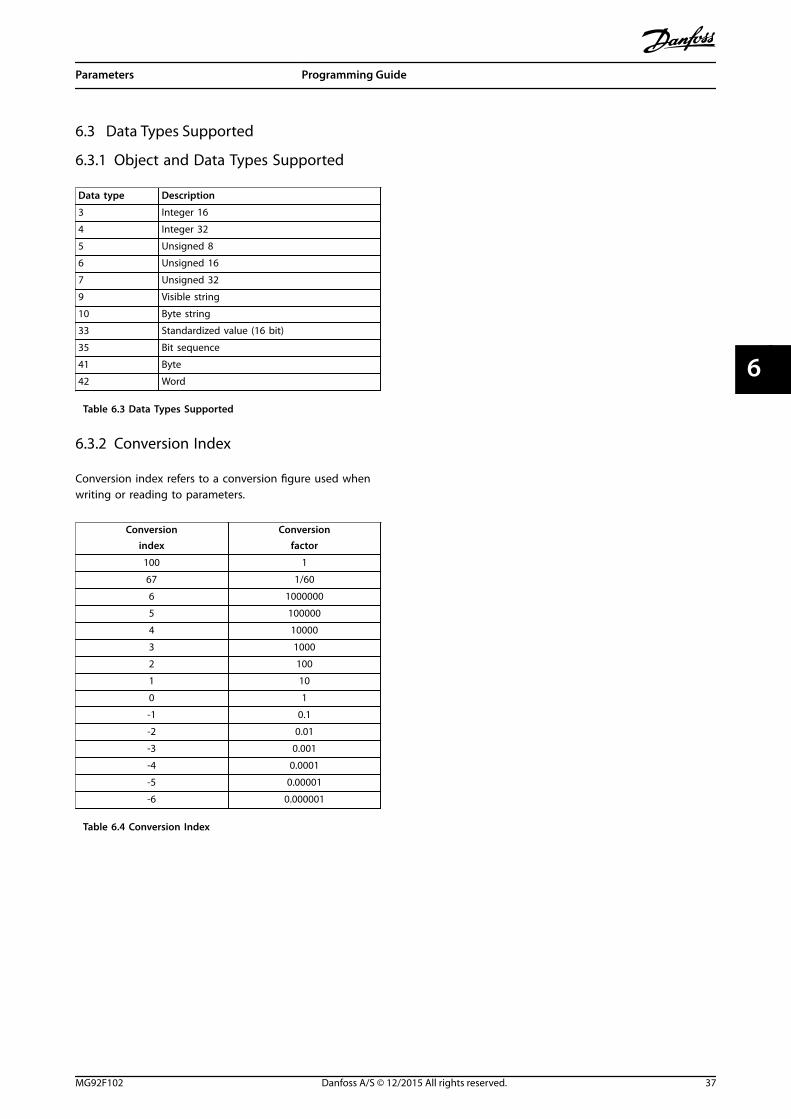
6.3 Data Types Supported
6.3.1 Object and Data Types Supported
Data type Description
3 Integer 16
4 Integer 32
5 Unsigned 8
6 Unsigned 16
7 Unsigned 32
9 Visible string
10 Byte string
33 Standardized value (16 bit)
35 Bit sequence
41 Byte
42 Word
Table 6.3 Data Types Supported
6.3.2 Conversion Index
Conversion index refers to a conversion figure used whenwriting or reading to parameters.
Conversionindex
Conversionfactor
100 1
67 1/60
6 1000000
5 100000
4 10000
3 1000
2 100
1 10
0 1
-1 0.1
-2 0.01
-3 0.001
-4 0.0001
-5 0.00001
-6 0.000001
Table 6.4 Conversion Index
Parameters Programming Guide
MG92F102 Danfoss A/S © 12/2015 All rights reserved. 37
6 6

7 Application Examples
7.1 Example: Working with Instance101/151 Process
This example shows how to work with I/O instance101/151, which consists of control word/status word andreference/main actual value. The instance 101/151 also has2 extra words, which can be programmed to monitorprocess signals, as shown in Illustration 7.1.
130B
A12
3.10DeviceNet master
DeviceNet
Relay 04–05
230 V AC
N
Ext. Device
18 20 19
0–24 V DCSensor
Reversing
Illustration 7.1 Instance 101/151 Process
The application requires monitoring of the motor torqueand digital input, so PCD 3 is set up to read the actualmotor torque. PCD 4 is set up to monitor the state of anexternal sensor via the process signal digital input. Thesensor is connected to digital input 18.
An external device is also controlled via control word bit11 and the built-in relay of the frequency converter.
Reversing is permitted only when the reversing bit 15 inthe control word and the digital input 19 are set to high.
For safety reasons the frequency converter stops the motorwhen:
• The DeviceNet cable is broken.
• The master has a system failure.
• The PLC is in stop mode.
Parameter Function Setting
Parameter 4-10 MotorSpeed Direction
Motor speed range/direction
[2] Bothdirections
Parameter 5-10 Terminal 18 Digital Input
Digital input 18 [0] No operation
Parameter 5-11 Terminal 19 Digital Input
Digital input 19 [10] Reversing
Parameter 5-40 Function Relay
Function relay [36] Control wordbit 11[37] Control wordbit 12
Parameter 8-03 ControlWord Timeout Time
Control word timeouttime
1.0 s
Parameter 8-04 ControlWord Timeout Function
Control word timeoutfunction
[2] Stop
Parameter 8-10 ControlWord Profile
Control word profile FC Profile
Parameter 8-50 Coasting Select
Coasting select [1] Bus
Parameter 8-51 QuickStop Select
Quick-stop select [1] Bus
Parameter 8-52 DCBrake Select
DC-brake select [1] Bus
Parameter 8-53 StartSelect
Start select [1] Bus
Parameter 8-54 Reversing Select
Reversing select [2] Logic AND
Parameter 8-55 Set-upSelect
Set-up select [1] Bus
Parameter 8-56 PresetReference Select
Preset referenceselect
[1] Bus
Parameter 10-01 BaudRate Select
Baud rate select Set to matchother DeviceNetstations
Parameter 10-02 MACID
MAC ID Set desiredstation address
Parameter 10-10 Process Data Type Selection
Process data typeselection
[1] Instance101/151
Parameter 10-12 Process Data Config Read
Process Data ConfigRead
PCD 3: TorquePCD 4: Digitalinput
Table 7.1 Function and Setting of the Parameters
Application Examples VLT® DeviceNet MCA 104
38 Danfoss A/S © 12/2015 All rights reserved. MG92F102
77

7.1.1 Example of PLC Programming
In this example, instance 101/151 is placed in the followinginput/output address, see Table 7.2 and Table 7.3.
Inputaddress
0.0–0.15 0.16–0.31 1.0–1.15 1.16–1.31
Set-up Statusword
MAV Motortorque
Digitalinput
Table 7.2 Input Address
Illustration 7.2 Input
Outputaddress
0.0–0.15 0.16–0.31 1.0–1.15 1.16–1.31
Set-up Controlword
Reference Not used Not used
Table 7.3 Output Address
Illustration 7.3 Output
Application Examples Programming Guide
MG92F102 Danfoss A/S © 12/2015 All rights reserved. 39
7 7
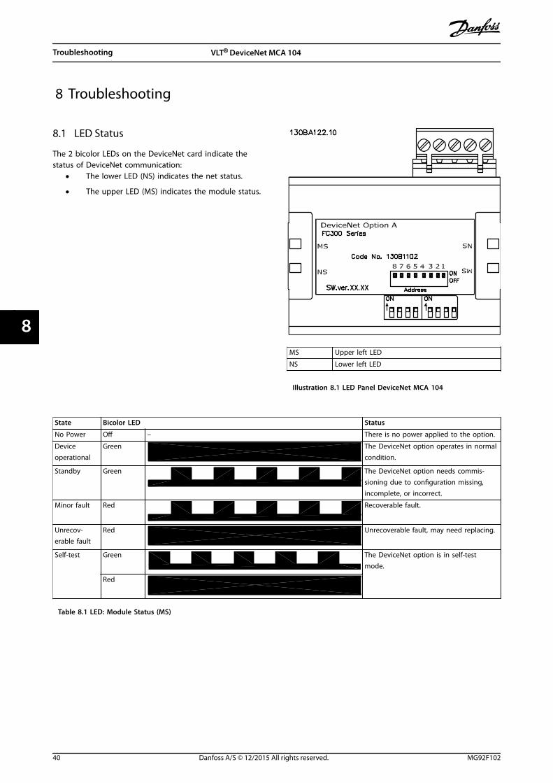
8 Troubleshooting
8.1 LED Status
The 2 bicolor LEDs on the DeviceNet card indicate thestatus of DeviceNet communication:
• The lower LED (NS) indicates the net status.
• The upper LED (MS) indicates the module status.
MS Upper left LED
NS Lower left LED
Illustration 8.1 LED Panel DeviceNet MCA 104
State Bicolor LED Status
No Power Off – There is no power applied to the option.
Deviceoperational
Green The DeviceNet option operates in normalcondition.
Standby Green The DeviceNet option needs commis-sioning due to configuration missing,incomplete, or incorrect.
Minor fault Red Recoverable fault.
Unrecov-erable fault
Red Unrecoverable fault, may need replacing.
Self-test Green The DeviceNet option is in self-testmode.
Red
Table 8.1 LED: Module Status (MS)
Troubleshooting VLT® DeviceNet MCA 104
40 Danfoss A/S © 12/2015 All rights reserved. MG92F102
88

State Bicolor LED Status
NoPower/Noton-line
Off – The option has not completed “DuplicateMAC ID” test yet or may not be powered.
On-line, notconnected
Green The option is on-line, but not allocatedto a master.
On-line andconnected
Green The DeviceNet option is on-line andconnected to a master.
Connectiontimeout
Red One or more I/O connections are intimeout state.
Critical linkfailure
Red –
Table 8.2 LED: Network Status (NS)
8.2 No Communication with the FrequencyConverter
When there is no communication with the frequencyconverter, proceed with the following checks:
1. Check that cabling is correct.Check that the cables are connected to thecorrect terminals as shown in Illustration 8.2.
Pin number Terminal Color Name
1 V- Black GND
2 CAN_L Blue CAN LOW
3 Drain (bare) Screen
4 CAN_H White CAN HIGH
5 V+ Red +24 V
Illustration 8.2 Correct Cabling
2. The 24 V network voltage is applied.
3. The correct EDS file is installed. Download thecorrect EDS file from www.danfoss.com/drives.
4. Check that the bus connection is terminated atboth ends.If not, terminate the bus connection withtermination resistors at the initial and final nodes.Refer to Illustration 8.3. Termination is performedbetween terminal 2 (CAN_L) and 4 (CAN_H) witha resistor: 121 Ω, 1% metal film, ¼ W.
24 V
Trunk linePower supply
Drop lines 1RT=Termination resistors
RT RT
195N
A22
8.10
1 1 1
1
Illustration 8.3 Topology
8.3 Frequency Converter Does Not Respondto Control Signals
For Danfoss control word profile (instances 100/150 and101/151), check that:
1. The control word is valid.When bit 10=0 in the control word, the frequencyconverter does not accept the control word,because the default setting is bit 10=1.Set bit 10=1 via the PLC.
2. The relationship between bits in the control wordand the terminal I/O is correct.Check the logical relationship in the frequencyconverter.Set the logic to bit 3=1 and digital input=1 toachieve a successful start.
Define the logical relationship in parameter 8-50 CoastingSelect to parameter 8-56 Preset Reference Select according tothe following range of options. Select the FC control mode,digital input and/or bus communication, using
Troubleshooting Programming Guide
MG92F102 Danfoss A/S © 12/2015 All rights reserved. 41
8 8
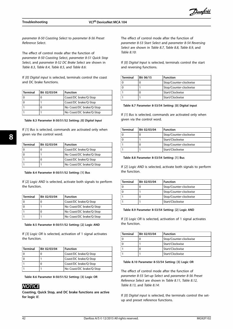
parameter 8-50 Coasting Select to parameter 8-56 PresetReference Select.
The effect of control mode after the function ofparameter 8-50 Coasting Select, parameter 8-51 Quick StopSelect, and parameter 8-52 DC Brake Select are shown inTable 8.3, Table 8.4, Table 8.5, and Table 8.6:
If [0] Digital input is selected, terminals control the coastand DC brake functions.
Terminal Bit 02/03/04 Function
0 0 Coast/DC brake/Q-Stop
0 1 Coast/DC brake/Q-Stop
1 0 No Coast/DC brake/Q-Stop
1 1 No Coast/DC brake/Q-Stop
Table 8.3 Parameter 8-50/51/52 Setting: [0] Digital Input
If [1] Bus is selected, commands are activated only whengiven via the control word.
Terminal Bit 02/03/04 Function
0 0 Coast/DC brake/Q-Stop
0 1 No Coast/DC brake/Q-Stop
1 0 Coast/DC brake/Q-Stop
1 1 No Coast/DC brake/Q-Stop
Table 8.4 Parameter 8-50/51/52 Setting: [1] Bus
If [2] Logic AND is selected, activate both signals to performthe function.
Terminal Bit 02/03/04 Function
0 0 Coast/DC brake/Q-Stop
0 1 No Coast/DC brake/Q-Stop
1 0 No Coast/DC brake/Q-Stop
1 1 No Coast/DC brake/Q-Stop
Table 8.5 Parameter 8-50/51/52 Setting: [2] Logic AND
If [3] Logic OR is selected, activation of 1 signal activatesthe function.
Terminal Bit 02/03/04 Function
0 0 Coast/DC brake/Q-Stop
0 1 Coast/DC brake/Q-Stop
1 0 Coast/DC brake/Q-Stop
1 1 No Coast/DC brake/Q-Stop
Table 8.6 Parameter 8-50/51/52 Setting: [3] Logic OR
NOTICECoasting, Quick Stop, and DC brake functions are activefor logic 0’.
The effect of control mode after the function ofparameter 8-53 Start Select and parameter 8-54 ReversingSelect are shown in Table 8.7, Table 8.8, Table 8.9, andTable 8.10:
If [0] Digital Input is selected, terminals control the startand reversing functions.
Terminal Bit 06/15 Function
0 0 Stop/Counter-clockwise
0 1 Stop/Counter-clockwise
1 0 Start/Clockwise
1 1 Start/Clockwise
Table 8.7 Parameter 8-53/54 Setting: [0] Digital input
If [1] Bus is selected, commands are activated only whengiven via the control word.
Terminal Bit 02/03/04 Function
0 0 Stop/Counter-clockwise
0 1 Start/Clockwise
1 0 Stop/Counter-clockwise
1 1 Start/Clockwise
Table 8.8 Parameter 8-53/54 Setting: [1] Bus
If [2] Logic AND is selected, activate both signals to performthe function.
Terminal Bit 02/03/04 Function
0 0 Stop/Counter-clockwise
0 1 Stop/Counter-clockwise
1 0 Stop/Counter-clockwise
1 1 Start/Clockwise
Table 8.9 Parameter 8-53/54 Setting: [2] Logic AND
If [3] Logic OR is selected, activation of 1 signal activatesthe function.
Terminal Bit 02/03/04 Function
0 0 Stop/Counter-clockwise
0 1 Start/Clockwise
1 0 Start/Clockwise
1 1 Start/Clockwise
Table 8.10 Parameter 8-53/54 Setting: [3] Logic OR
The effect of control mode after the function ofparameter 8-55 Set-up Select and parameter 8-56 PresetReference Select are shown in Table 8.11, Table 8.12,Table 8.13, and Table 8.14:
If [0] Digital input is selected, the terminals control the set-up and preset reference functions.
Troubleshooting VLT® DeviceNet MCA 104
42 Danfoss A/S © 12/2015 All rights reserved. MG92F102
88

Terminal Bit 00/01, 13/14 Function
Msb Lsb Msb Lsb Preset reference, set-upnumber
0 0 0 0 1
0 0 0 1 1
0 0 1 0 1
0 0 1 1 1
0 1 0 0 2
0 1 0 1 2
0 1 1 0 2
0 1 1 1 2
1 0 0 0 3
1 0 0 1 3
1 0 1 0 3
1 0 1 1 3
1 1 0 0 4
1 1 0 1 4
1 1 1 0 4
1 1 1 1 4
Table 8.11 Parameter 8-55/56 Setting: [0] Digital input
If [1] Bus is selected, commands are activated only whengiven via the control word.
Terminal Bit 00/01, 13/14 Function
Msb Lsb Msb Lsb Preset reference, set-upnumber
0 0 0 0 1
0 0 0 1 2
0 0 1 0 3
0 0 1 1 4
0 1 0 0 1
0 1 0 1 2
0 1 1 0 3
0 1 1 1 4
1 0 0 0 1
1 0 0 1 2
1 0 1 0 3
1 0 1 1 4
1 1 0 0 1
1 1 0 1 2
1 1 1 0 3
1 1 1 1 4
Table 8.12 Parameter 8-55/56 Setting: [1] Bus
If [2] Logic AND is selected, activate both signals to performthe function.
Terminal Bit 00/01, 13/14 Function
Msb Lsb Msb Lsb Preset reference, Set-upnumber
0 0 0 0 1
0 0 0 1 1
0 0 1 0 1
0 0 1 1 1
0 1 0 0 1
0 1 0 1 2
0 1 1 0 1
0 1 1 1 2
1 0 0 0 1
1 0 0 1 1
1 0 1 0 3
1 0 1 1 3
1 1 0 0 1
1 1 0 1 2
1 1 1 0 3
1 1 1 1 4
Table 8.13 Parameter 8-55/56: [2] Logic AND
If [3] Logic OR is selected, activation of 1 signal activatesthe function.
Terminal Bit 00/01, 13/14 Function
Msb Lsb Msb Lsb Preset reference, set-upnumber
0 0 0 0 1
0 0 0 1 2
0 0 1 0 3
0 0 1 1 4
0 1 0 0 2
0 1 0 1 2
0 1 1 0 4
0 1 1 1 4
1 0 0 0 3
1 0 0 1 4
1 0 1 0 3
1 0 1 1 4
1 1 0 0 4
1 1 0 1 4
1 1 1 0 4
Table 8.14 Parameter 8-55/56 Setting: [3] Logic OR
Troubleshooting Programming Guide
MG92F102 Danfoss A/S © 12/2015 All rights reserved. 43
8 8

8.4 Warnings and Alarms
NOTICERefer to the relevant operating instructions for an overview of warning and alarm types and for the full list of warningsand alarms.
Alarm word, warning word, and DeviceNet warning word are shown on the frequency converter display in hex format. Whenthere is more than 1 warning or alarm, the sum of all warnings or alarms is shown. Alarm word, warning word, andDeviceNet warning word can also be shown using the serial bus in parameter 16-90 Alarm Word, parameter 16-92 WarningWord, and parameter 16-05 Main Actual Value [%].
Bit (Hex) Alarm word(parameter 16-90 Alarm Word)
Alarm number Major/minor alarm
Recoverable/unrecoverable alarm
00000001 Unused – – –
00000002 Drive overtemperature 29 Major Recoverable
00000004 Ground fault 14 Major Unrecoverable
00000008 Unused – – –
00000010 Control word timeout 18 Minor Recoverable
00000020 Overcurrent 13 Major Unrecoverable
00000040 Torque limit 12 Major Recoverable
00000080 Motor thermistor over temp. 11 Major Recoverable
00000100 Motor ETR overtemperature 10 Major Recoverable
00000200 Inverter overloaded 9 Major Recoverable
00000400 DC link undervoltage 8 Major Recoverable
00000800 DC link overvoltage 7 Major Recoverable
00001000 Short circuit 16 Major Unrecoverable
00002000 Inrush fault 33 Major Recoverable
00004000 Mains phase loss 4 Major Unrecoverable
00008000 AMA not OK 50 Major Recoverable
00010000 Live zero error 2 Major Recoverable
00020000 Internal fault 38 Major Unrecoverable
00040000 Brake resistor power limit 26 Major Unrecoverable
00080000 Motor phase U is missing 30 Major Unrecoverable
00100000 Motor phase V is missing 31 Major Unrecoverable
00200000 Motor phase W is missing 32 Major Unrecoverable
00400000 Fieldbus comm. fault 34 Major Recoverable
00800000 24 V supply fault 47 Major Unrecoverable
01000000 Mains failure 36 Major Recoverable
02000000 1.8 V supply fault 48 Major Unrecoverable
04000000 Brake resistor short circuit 25 Major Recoverable
08000000 Brake chopper fault 27 Major Recoverable
10000000 Unused – – –
20000000 Unused – – –
40000000 Unused – – –
80000000 Unused – – –
Table 8.15 Alarm Word
Troubleshooting VLT® DeviceNet MCA 104
44 Danfoss A/S © 12/2015 All rights reserved. MG92F102
88
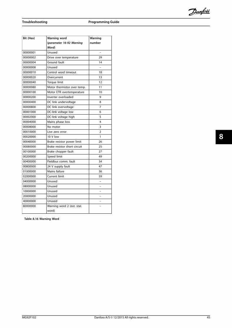
Bit (Hex) Warning word(parameter 16-92 WarningWord)
Warningnumber
00000001 Unused –
00000002 Drive over temperature 29
00000004 Ground fault 14
00000008 Unused –
00000010 Control word timeout 18
00000020 Overcurrent 13
00000040 Torque limit 12
00000080 Motor thermistor over temp. 11
00000100 Motor ETR overtemperature 10
00000200 Inverter overloaded 9
00000400 DC link undervoltage 8
00000800 DC link overvoltage 7
00001000 DC-link voltage low 6
00002000 DC-link voltage high 5
00004000 Mains phase loss 4
00008000 No motor 3
00010000 Live zero error 2
00020000 10 V low 1
00040000 Brake resistor power limit 26
00080000 Brake resistor short circuit 25
00100000 Brake chopper fault 27
00200000 Speed limit 49
00400000 Fieldbus comm. fault 34
00800000 24 V supply fault 47
01000000 Mains failure 36
02000000 Current limit 59
04000000 Unused –
08000000 Unused –
10000000 Unused –
20000000 Unused –
40000000 Unused –
80000000 Warning word 2 (ext. stat.word)
–
Table 8.16 Warning Word
Troubleshooting Programming Guide
MG92F102 Danfoss A/S © 12/2015 All rights reserved. 45
8 8

Index
AAbbreviation............................................................................................. 4
Additional resources.............................................................................. 3
Address switch......................................................................................... 7
Alarm word............................................................................................. 44
Alarms....................................................................................................... 44
Approvals................................................................................................... 4
BBaud rate.................................................................................................... 7
CCertifications............................................................................................. 4
Configuration......................................................................................... 28
Control signals, no response............................................................ 41
Convention................................................................................................ 4
Conversion index.................................................................................. 37
DDanfoss object classes........................................................................ 27
Data types supported......................................................................... 37
Discharge time......................................................................................... 5
EEDS file........................................................................................................ 8
HHigh voltage............................................................................................. 5
II/O assembly instance......................................................................... 10
LLeakage current....................................................................................... 5
LED............................................................................................................... 4
LED panel................................................................................................. 40
LED status................................................................................................ 40
Load sharing............................................................................................. 5
NNo communication with the frequency converter................... 41
PPolling......................................................................................................... 9
Process data............................................................................................ 10
Product overview.................................................................................... 3
QQualified personnel................................................................................ 5
SSafety........................................................................................................... 6
Symbol........................................................................................................ 4
TTopology.................................................................................................... 3
UUnintended start..................................................................................... 5
WWarning word........................................................................................ 44
Warnings.................................................................................................. 44
Index VLT® DeviceNet MCA 104
46 Danfoss A/S © 12/2015 All rights reserved. MG92F102

Index Programming Guide
MG92F102 Danfoss A/S © 12/2015 All rights reserved. 47

Danfoss can accept no responsibility for possible errors in catalogues, brochures and other printed material. Danfoss reserves the right to alter its products without notice. This also applies toproducts already on order provided that such alterations can be made without subsequential changes being necessary in specifications already agreed. All trademarks in this material are propertyof the respective companies. Danfoss and the Danfoss logotype are trademarks of Danfoss A/S. All rights reserved.
Danfoss A/SUlsnaes 1DK-6300 Graastenvlt-drives.danfoss.com
*MG92F102*130R0618 MG92F102 12/2015