Embed Size (px)
Citation preview

Vivado Design Suite User Guide
System-Level Design Entry
UG895 (v2012.2) July 25, 2012

System-Level Design Entry www.xilinx.com 2UG895 (v2012.2) July 25, 2012
Notice of DisclaimerThe information disclosed to you hereunder (the “Materials”) is provided solely for the selection and use of Xilinx products. To the maximum extent permitted by applicable law: (1) Materials are made available "AS IS" and with all faults, Xilinx hereby DISCLAIMS ALL WARRANTIES AND CONDITIONS, EXPRESS, IMPLIED, OR STATUTORY, INCLUDING BUT NOT LIMITED TO WARRANTIES OF MERCHANTABILITY, NON-INFRINGEMENT, OR FITNESS FOR ANY PARTICULAR PURPOSE; and (2) Xilinx shall not be liable (whether in contract or tort, including negligence, or under any other theory of liability) for any loss or damage of any kind or nature related to, arising under, or in connection with, the Materials (including your use of the Materials), including for any direct, indirect, special, incidental, or consequential loss or damage (including loss of data, profits, goodwill, or any type of loss or damage suffered as a result of any action brought by a third party) even if such damage or loss was reasonably foreseeable or Xilinx had been advised of the possibility of the same. Xilinx assumes no obligation to correct any errors contained in the Materials or to notify you of updates to the Materials or to product specifications. You may not reproduce, modify, distribute, or publicly display the Materials without prior written consent. Certain products are subject to the terms and conditions of the Limited Warranties which can be viewed at http://www.xilinx.com/warranty.htm; IP cores may be subject to warranty and support terms contained in a license issued to you by Xilinx. Xilinx products are not designed or intended to be fail-safe or for use in any application requiring fail-safe performance; you assume sole risk and liability for use of Xilinx products in Critical Applications: http://www.xilinx.com/warranty.htm#critapps.© Copyright 2012 Xilinx, Inc. Xilinx, the Xilinx logo, Artix, ISE, Kintex, Spartan, Virtex, Vivado, Zynq, and other designated brands included herein are trademarks of Xilinx in the United States and other countries. All other trademarks are the property of their respective owners.
Revision HistoryThe following table shows the revision history for this document.
Date Version Revision
07/25/12 2012.2 Initial Xilinx release.
System-Level Design Entry www.xilinx.com 3UG895 (v2012.2) July 25, 2012
Table of ContentsRevision History . . . . . . . . . . . . . . . . . . . . . . . . . . . . . . . . . . . . . . . . . . . . . . . . . . . . . . . . . . . . . . . . . . . . 2
Chapter 1: IntroductionOverview . . . . . . . . . . . . . . . . . . . . . . . . . . . . . . . . . . . . . . . . . . . . . . . . . . . . . . . . . . . . . . . . . . . . . . . . 4
Chapter 2: Working with ProjectsOverview . . . . . . . . . . . . . . . . . . . . . . . . . . . . . . . . . . . . . . . . . . . . . . . . . . . . . . . . . . . . . . . . . . . . . . . . 5Project Types . . . . . . . . . . . . . . . . . . . . . . . . . . . . . . . . . . . . . . . . . . . . . . . . . . . . . . . . . . . . . . . . . . . . . 5Creating a Project. . . . . . . . . . . . . . . . . . . . . . . . . . . . . . . . . . . . . . . . . . . . . . . . . . . . . . . . . . . . . . . . . . 6Managing Projects . . . . . . . . . . . . . . . . . . . . . . . . . . . . . . . . . . . . . . . . . . . . . . . . . . . . . . . . . . . . . . . . 18Using the Project Summary. . . . . . . . . . . . . . . . . . . . . . . . . . . . . . . . . . . . . . . . . . . . . . . . . . . . . . . . . 21Configuring Project Settings . . . . . . . . . . . . . . . . . . . . . . . . . . . . . . . . . . . . . . . . . . . . . . . . . . . . . . . . 22Creating a Project Using a Tcl Script . . . . . . . . . . . . . . . . . . . . . . . . . . . . . . . . . . . . . . . . . . . . . . . . . . 30
Chapter 3: Working with Source FilesOverview . . . . . . . . . . . . . . . . . . . . . . . . . . . . . . . . . . . . . . . . . . . . . . . . . . . . . . . . . . . . . . . . . . . . . . . 32Working with Sources in Project Mode . . . . . . . . . . . . . . . . . . . . . . . . . . . . . . . . . . . . . . . . . . . . . . . 32Working with Sources in Non-Project Mode . . . . . . . . . . . . . . . . . . . . . . . . . . . . . . . . . . . . . . . . . . . 73
Chapter 4: Elaborating the RTL DesignOverview . . . . . . . . . . . . . . . . . . . . . . . . . . . . . . . . . . . . . . . . . . . . . . . . . . . . . . . . . . . . . . . . . . . . . . . 75Elaborating the Design in Project Mode. . . . . . . . . . . . . . . . . . . . . . . . . . . . . . . . . . . . . . . . . . . . . . . 75Elaborating the Design in Non-Project Mode . . . . . . . . . . . . . . . . . . . . . . . . . . . . . . . . . . . . . . . . . . 81
Chapter 5: Inserting and Configuring Debugging InformationOverview . . . . . . . . . . . . . . . . . . . . . . . . . . . . . . . . . . . . . . . . . . . . . . . . . . . . . . . . . . . . . . . . . . . . . . . 83RTL-Level Design Simulation . . . . . . . . . . . . . . . . . . . . . . . . . . . . . . . . . . . . . . . . . . . . . . . . . . . . . . . . 83In-System Debugging . . . . . . . . . . . . . . . . . . . . . . . . . . . . . . . . . . . . . . . . . . . . . . . . . . . . . . . . . . . . . . 84
Appendix A: Additional ResourcesXilinx Resources . . . . . . . . . . . . . . . . . . . . . . . . . . . . . . . . . . . . . . . . . . . . . . . . . . . . . . . . . . . . . . . . . . 88Solution Centers. . . . . . . . . . . . . . . . . . . . . . . . . . . . . . . . . . . . . . . . . . . . . . . . . . . . . . . . . . . . . . . . . . 88References . . . . . . . . . . . . . . . . . . . . . . . . . . . . . . . . . . . . . . . . . . . . . . . . . . . . . . . . . . . . . . . . . . . . . . 88

System-Level Design Entry www.xilinx.com 4UG895 (v2012.2) July 25, 2012
Chapter 1
Introduction
OverviewThe Vivado™ Design Suite enables you to take your design from full register transfer level (RTL) creation to bitstream generation. System-level design entry consists of setting up your design, including creating a project (if applicable), creating and adding source f iles, elaborating the RTL design, and inserting and configuring debug information. You can enter your design using the graphical user interface (GUI), known as the Vivado Integrated Design Environment (IDE), or using Tcl commands and scripts.
This guide covers design entry for both of the design flow modes available in the Vivado Design Suite: Project Mode and Non-Project Mode. In general, you run Project Mode in the Vivado IDE. In this mode, you create a project in the Vivado IDE, and the Vivado IDE automatically saves the state of the design, generates reports and messaging, and manages source f iles. In general, you run Non-Project Mode using Tcl commands or scripts. In this mode, you have full control of the design flow, but the Vivado tools do not automatically manage source f iles or report the design state. For more information on design flows, see the Vivado Design Suite User Guide: Design Flows Overview (UG892).
Chapter 2
Working with Projects
OverviewWhen working in Project Mode, you can enter your design using various project types. This chapter describes each project type and explains how to create and manage projects. It also covers the Project Summary, Project Settings, and how to create a project using a Tcl script.
Project TypesUsing the Vivado™ IDE, you can create the following types of projects. Each project type includes different input source types.
• Register Transfer Level (RTL) project
• Post-synthesis project
• I/O planning project
• Imported project
Note: A project cannot be changed to a different project type after it is created. The only exception is the I/O planning project, which can be used as the basis for an RTL project.
RTL ProjectsYou can use the Vivado IDE to manage the entire design flow from RTL creation through bitstream generation. You can add RTL source files, EDIF netlists for blocks of the design, and IP. IP can include XCI f iles generated by the Vivado tool, XCO files generated by the CORE Generator™ tool, and precompiled NGC/NGO-format IP netlists.
You can elaborate and analyze the RTL to ensure proper constructs, launch and manage various synthesis and implementation runs, and analyze the design and run results. You can also experiment with different constraints or implementation strategies.
System-Level Design Entry www.xilinx.com 5UG895 (v2012.2) July 25, 2012

Creating a Project
Post-Synthesis ProjectsYou can create projects from designs that were synthesized outside of the Vivado IDE using Xilinx® Synthesis Technology (XST) or any supported third party synthesis tool. The Vivado IDE can import EDIF, NGC, structural SystemVerilog, or Verilog format netlists. The netlist can be made up of a single f ile that is all-inclusive or a set of f iles that is hierarchical and consists of multiple, module-level netlists.
You can analyze the logic netlist, launch and manage various implementation runs, and analyze the design and run results. You can also experiment with different constraints or implementation strategies.
I/O Planning ProjectsYou can perform I/O planning early in the design cycle by creating an empty I/O planning project. You can create I/O ports within the Vivado IDE or import them with either comma separated value (CSV) or Xilinx Design Constraints (XDC) input f iles. You can also create I/O planning projects to explore the logic resources available in the different device architectures.
After I/O assignment, the Vivado IDE can create CSV, XDC, and RTL output f iles for use later in the design flow when RTL sources or netlists are available. The output f iles can also be used to create schematic symbols for use in the Printed Circuit Board (PCB) design process.
Note: You can use an I/O planning project as the basis for an RTL-based design project. For more information, see the Vivado Design Suite User Guide: I/O and Clock Planning (UG899).
Imported ProjectsYou can import project data from Synopsys Synplify, XST, or ISE® Design Suite Project Navigator to migrate an RTL project into the Vivado tool. The project source f iles and compilation order are imported, but implementation results and project settings are not.
Creating a ProjectThe New Project wizard takes you through the steps to define a project name and location, add source files and constraint f iles to the project, and select a target device.
1. In the Vivado IDE, select File > New Project.
Note: Alternatively, you can select the New Project toolbar button . You can also select Create a New Project on the Getting Started page.
2. In the New Project wizard, review the overview, and click Next.
System-Level Design Entry www.xilinx.com 6UG895 (v2012.2) July 25, 2012

Creating a Project
3. In the Project Name page (Figure 2-1), set the following options, and click Next.
° Project name: Specif ies the name of the project (for example, project_1).
° Project location: Specif ies the location for the new project directory.
° Create Project Subdirectory: Adds a subdirectory with the same name as the project to the specif ied project location.
Note: By default, this checkbox is enabled and the project f ile (.xpr) is created at <project_location>/<project_name>. All folders and data f iles created for the project are stored in the <project_name> subdirectory. If you disable this checkbox, the project file (.xpr) is created at <project_location>, and all folders and data files created for the project are stored in that project location.
X-Ref Target - Figure 2-1
Figure 2-1: New Project Wizard—Project Name Page
System-Level Design Entry www.xilinx.com 7UG895 (v2012.2) July 25, 2012
Creating a Project
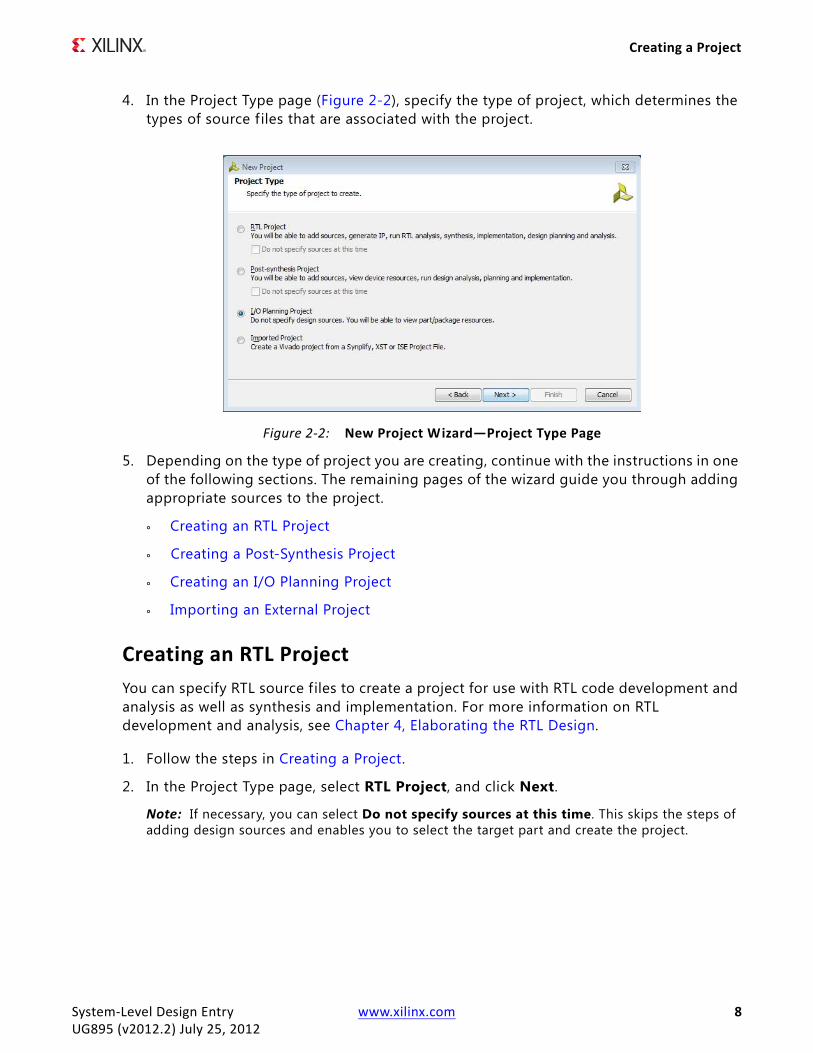
4. In the Project Type page (Figure 2-2), specify the type of project, which determines the types of source f iles that are associated with the project.
5. Depending on the type of project you are creating, continue with the instructions in one of the following sections. The remaining pages of the wizard guide you through adding appropriate sources to the project.
° Creating an RTL Project
° Creating a Post-Synthesis Project
° Creating an I/O Planning Project
° Importing an External Project
Creating an RTL ProjectYou can specify RTL source files to create a project for use with RTL code development and analysis as well as synthesis and implementation. For more information on RTL development and analysis, see Chapter 4, Elaborating the RTL Design.
1. Follow the steps in Creating a Project.
2. In the Project Type page, select RTL Project, and click Next.
Note: If necessary, you can select Do not specify sources at this time. This skips the steps of adding design sources and enables you to select the target part and create the project.
X-Ref Target - Figure 2-2
Figure 2-2: New Project Wizard—Project Type Page
System-Level Design Entry www.xilinx.com 8UG895 (v2012.2) July 25, 2012
Creating a Project
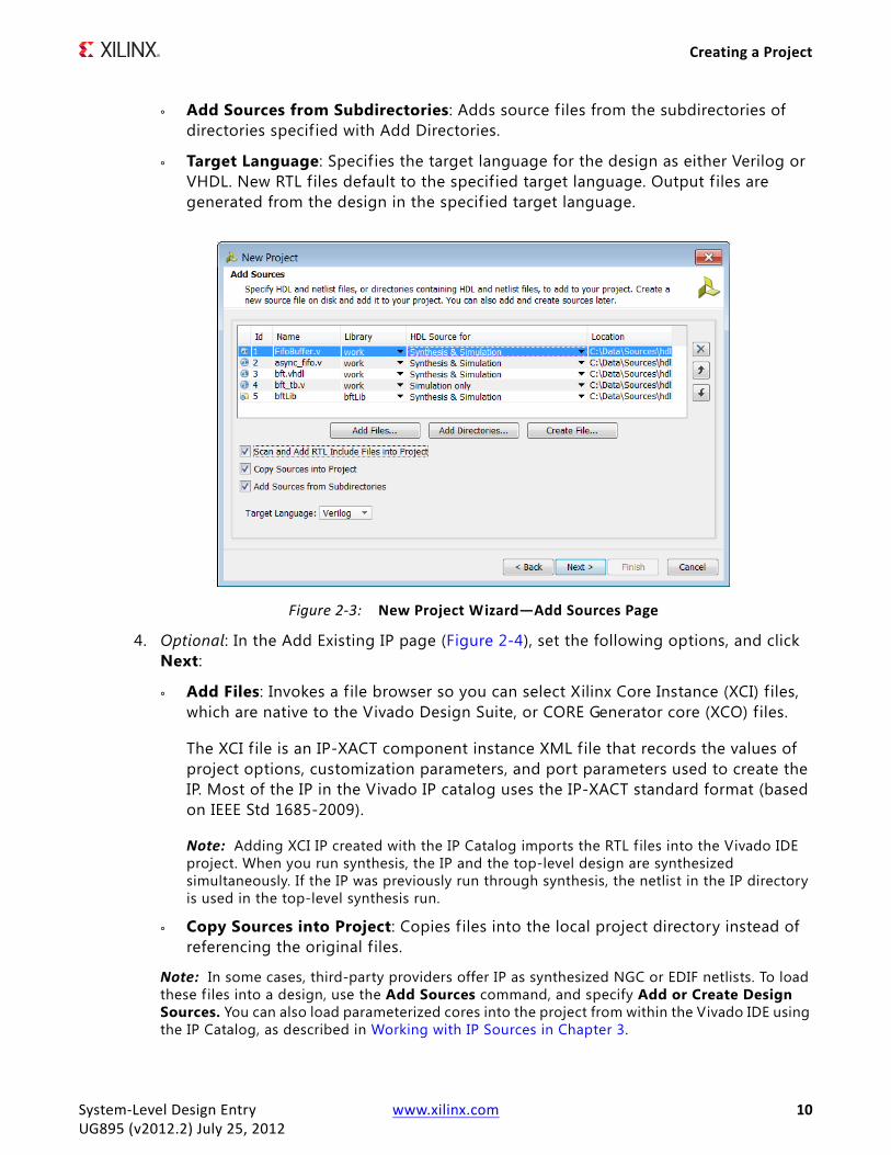
3. In the Add Sources page (Figure 2-3), set the following options, and click Next:
° Add Files: Opens a f ile browser so you can select f iles to add to the project. You can add the following f ile types to an RTL project: HDL, EDIF, NGC, BMM, ELF, and other f ile types.
Note: In the Add Source Files dialog box, each file or directory is represented by an icon indicating it as a f ile or folder. A small red square indicates it is read only.
° Add Directories: Opens a directory browser to add source files from the selected directories. Files in the specified directory with valid source file extensions are added to the project.
° Create File: Opens the Create Source File dialog box in which you can create new VHDL, Verilog, Verilog header, or SystemVerilog f iles. Create Source File dialog box, set the following options:
- File type: Specif ies one of the following f ile formats: Verilog f ile (.v), Verilog Header file (.vh)., SystemVerilog f ile (.sv), VHDL f ile (.vhdl).
- File name: Specif ies a name for the new HDL source f ile.
- File location: Specif ies a location in which to create the f ile.
Note: A placeholder for the f ile is added to the list of sources. The f ile is created when you click Finish.
° Library: Specif ies the RTL library for a file or directory. You can select a library name, or specify a new library name by typing in the Library text f ield.
Note: This option applies to VHDL files only. By default, HDL sources are added to the work library. You can create or reference additional user VHDL libraries as needed. For Verilog and SystemVerilog f iles, leave the library set to work .
° HDL Source for : Specifies whether the source being loaded is an RTL source f ile for synthesis and simulation or an RTL test bench for simulation only.
° Delete: Removes the selected source files from the list of f iles to be added.
° Move Selected File Up: Moves the file or directory up in the list order. The order of the files affects the order of elaboration and compilation during downstream processes such as synthesis and simulation.
° Move Selected File Down: Moves the f ile or directory down in the list order.
° Scan and Add RTL Include Files into Project: Scans all RTL source f iles and imports any referenced Verilog ‘include files into the local project directory structure.
° Copy Sources into Project: Copies f iles into the local project directory instead of referencing the original f iles. If you added directories of source f iles using Add Directories, the directory structure is maintained when the f iles are copied locally into the project. For more information, see Using Remote Sources or Copying Sources into Project in Chapter 3.
System-Level Design Entry www.xilinx.com 9UG895 (v2012.2) July 25, 2012
Creating a Project
° Add Sources from Subdirectories: Adds source f iles from the subdirectories of directories specif ied with Add Directories.
° Target Language: Specif ies the target language for the design as either Verilog or VHDL. New RTL files default to the specif ied target language. Output f iles are generated from the design in the specif ied target language.
4. Optional: In the Add Existing IP page (Figure 2-4), set the following options, and click Next:
° Add Files: Invokes a file browser so you can select Xilinx Core Instance (XCI) f iles, which are native to the Vivado Design Suite, or CORE Generator core (XCO) files.
The XCI f ile is an IP-XACT component instance XML file that records the values of project options, customization parameters, and port parameters used to create the IP. Most of the IP in the Vivado IP catalog uses the IP-XACT standard format (based on IEEE Std 1685-2009).
Note: Adding XCI IP created with the IP Catalog imports the RTL f iles into the Vivado IDE project. When you run synthesis, the IP and the top-level design are synthesized simultaneously. If the IP was previously run through synthesis, the netlist in the IP directory is used in the top-level synthesis run.
° Copy Sources into Project: Copies f iles into the local project directory instead of referencing the original f iles.
Note: In some cases, third-party providers offer IP as synthesized NGC or EDIF netlists. To load these f iles into a design, use the Add Sources command, and specify Add or Create Design Sources. You can also load parameterized cores into the project from within the Vivado IDE using the IP Catalog, as described in Working with IP Sources in Chapter 3.
X-Ref Target - Figure 2-3
Figure 2-3: New Project Wizard—Add Sources Page
System-Level Design Entry www.xilinx.com 10UG895 (v2012.2) July 25, 2012

Creating a Project
5. Optional: In the Add Constraints page (Figure 2-5), set the following options, and click Next:
° Add Files: Invokes a file browser so you can select Synopsys Design Constraint (SDC) or Xilinx Design Constraint (XDC) files to add to the project.
° Create File: Creates a new top-level XDC for the project.
° Remove: Removes the selected f ile from the constraint list.
° Up / Down: Moves a constraint f ile up or down in the listed order. Commands are order-dependent; the last-read command of a constraint overwrites the effects of an earlier command.
° Copy Constraints into Project: Copies constraint f iles into the local project directory instead of referencing the original f iles.
Note: Any SDC or XDC file found in the same directories as the RTL or netlist source f iles associated with the project are automatically listed as constraint f iles to be added to the project.
X-Ref Target - Figure 2-4
Figure 2-4: New Project Wizard—Add Existing IP Page
X-Ref Target - Figure 2-5
Figure 2-5: New Project Wizard—Add Constraints Page
System-Level Design Entry www.xilinx.com 11UG895 (v2012.2) July 25, 2012

Creating a Project
6. In the Default Part page (Figure 2-6), select a Xilinx part or Targeted Design Platform (TDP) board, and click Next:
° Parts: Lists available devices. Information about the device resources displays in a table view. You can f ilter the list using the Product Category, Family, Sub-Family, Package, Speed Grade, and Temp Grade filters.
° Boards: Lists available TDP boards, and the Xilinx part used on the board. Information about device resources displays in a table view, such as I/O pin count, the number of look-up tables (LUTs) and flip-flops (FFs), and available Block RAMs. You can f ilter the list using the Family, Package, and Speed Grade filters.
° Search: Limits the listed devices to those matching the search criteria you specify.
7. In the New Project Summary page, view the selected options that define the project, and click Finish.
X-Ref Target - Figure 2-6
Figure 2-6: New Project Wizard—Default Part Page
System-Level Design Entry www.xilinx.com 12UG895 (v2012.2) July 25, 2012
Creating a Project
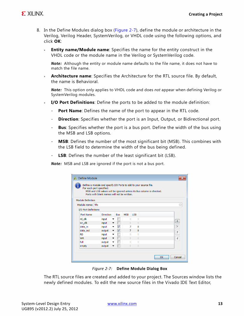
8. In the Define Modules dialog box (Figure 2-7), define the module or architecture in the Verilog, Verilog Header, SystemVerilog, or VHDL code using the following options, and click OK:
° Entity name/Module name: Specifies the name for the entity construct in the VHDL code or the module name in the Verilog or SystemVerilog code.
Note: Although the entity or module name defaults to the f ile name, it does not have to match the f ile name.
° Architecture name: Specif ies the Architecture for the RTL source f ile. By default, the name is Behavioral.
Note: This option only applies to VHDL code and does not appear when defining Verilog or SystemVerilog modules.
° I/O Port Definitions: Define the ports to be added to the module definition:
- Port Name: Defines the name of the port to appear in the RTL code.
- Direction: Specifies whether the port is an Input, Output, or Bidirectional port.
- Bus: Specif ies whether the port is a bus port. Define the width of the bus using the MSB and LSB options.
- MSB: Defines the number of the most signif icant bit (MSB). This combines with the LSB f ield to determine the width of the bus being defined.
- LSB: Defines the number of the least signif icant bit (LSB).
Note: MSB and LSB are ignored if the port is not a bus port.
The RTL source f iles are created and added to your project. The Sources window lists the newly defined modules. To edit the new source f iles in the Vivado IDE Text Editor,
X-Ref Target - Figure 2-7
Figure 2-7: Define Module Dialog Box
System-Level Design Entry www.xilinx.com 13UG895 (v2012.2) July 25, 2012
Creating a Project
double-click the f ile or select Open File from the popup menu. For information on editing the newly created f ile, see Using the Text Editor in Chapter 3.
Creating a Post-Synthesis ProjectA post-synthesis project begins with a synthesized netlist and corresponding constraints. You can then analyze, floorplan, and implement the design.
1. Follow the steps in Creating a Project.
2. In the Project Type page, select Post-Synthesis Project, and click Next.
Note: If necessary, you can select Do not specify sources at this time. This skips the steps of adding design sources and enables you to select the target part and create the project.
3. In the Add Netlist Sources page (Figure 2-8), use the following options to specify netlist f iles to read, identify the file containing the top module, and define directories to search for lower-level module netlist, and click Next.
° Add Files: Invokes a file browser so you can select netlist f iles (Verilog, SystemVerilog, EDIF or NGC) to add to the project.
Note: Enable the Top radio button for the f ile that contains the top-level netlist.
° Add Directories: Invokes a directory browser so you can select directories to search for modules.
° Remove Selected Files and Directories: The ‘X’ icon removes the selected source f iles and directories from the list.
° Move Selected Files and Directories Up: The up arrow icon moves the f ile or directory up in the list order.
° Move Selected Files and Directories Down: The down arrow icon moves the f ile or directory down in the list order.
° Copy Sources into Project: Copies f iles into the local project directory instead of referencing the original f iles. If you added directories of source f iles using Add Directories, the directory structure is maintained when the f iles are copied locally into the project. For more information, see Using Remote Sources or Copying Sources into Project in Chapter 3.
° Add Sources from Subdirectories: Looks for netlist f iles in the subdirectories of directories specif ied with Add Directories.
System-Level Design Entry www.xilinx.com 14UG895 (v2012.2) July 25, 2012

Creating a Project
4. Optional: In the Add Constraints page (Figure 2-5), set the following options, and click Next:
° Add Files: Invokes a file browser so you can select Synopsys Design Constraint (SDC) or Xilinx Design Constraint (XDC) files to add to the project.
° Create File: Creates a new top-level XDC for the project.
° Remove: Removes the selected f ile from the constraint list.
° Up / Down: Moves a constraint f ile up or down in the listed order. Commands are order-dependent; the last-read command of a constraint overwrites the effects of an earlier command.
° Copy Constraints into Project: Copies constraint f iles into the local project directory instead of referencing the original f iles.
Note: Any SDC or XDC file found in the same directories as the RTL or netlist source f iles associated with the project are automatically listed as constraint f iles to be added to the project.
5. In the Default Part page (Figure 2-6), select a Xilinx part or Targeted Design Platform (TDP) board, and click Next:
° Parts: Lists available devices. Information about the device resources displays in a table view. You can f ilter the list using the Product Category, Family, Sub-Family, Package, Speed Grade, and Temp Grade filters.
° Boards: Lists available TDP boards, and the Xilinx part used on the board. Information about device resources displays in a table view, such as I/O pin count, the number of look-up tables (LUTs) and flip-flops (FFs), and available Block RAMs. You can f ilter the list using the Family, Package, and Speed Grade filters.
° Search: Limits the listed devices to those matching the search criteria you specify.
6. In the New Project Summary page, view the selected options that define the project, and click Finish.
X-Ref Target - Figure 2-8
Figure 2-8: New Project Wizard—Add Netlist Sources Page
System-Level Design Entry www.xilinx.com 15UG895 (v2012.2) July 25, 2012
Creating a Project
Creating an I/O Planning ProjectAn I/O planning project is used to plan the device pinout for an in-progress system-level design. You can create this type of project prior to completing the HDL or the synthesized netlist. For example, this allows you to exchange design information with the system-level or printed circuit board (PCB) designer. For more information about I/O planning, refer to the Vivado Design Suite User Guide: I/O and Clock Planning (UG899).
1. Follow the steps in Creating a Project.
2. In the Project Type page, select I/O Planning Project, and click Next.
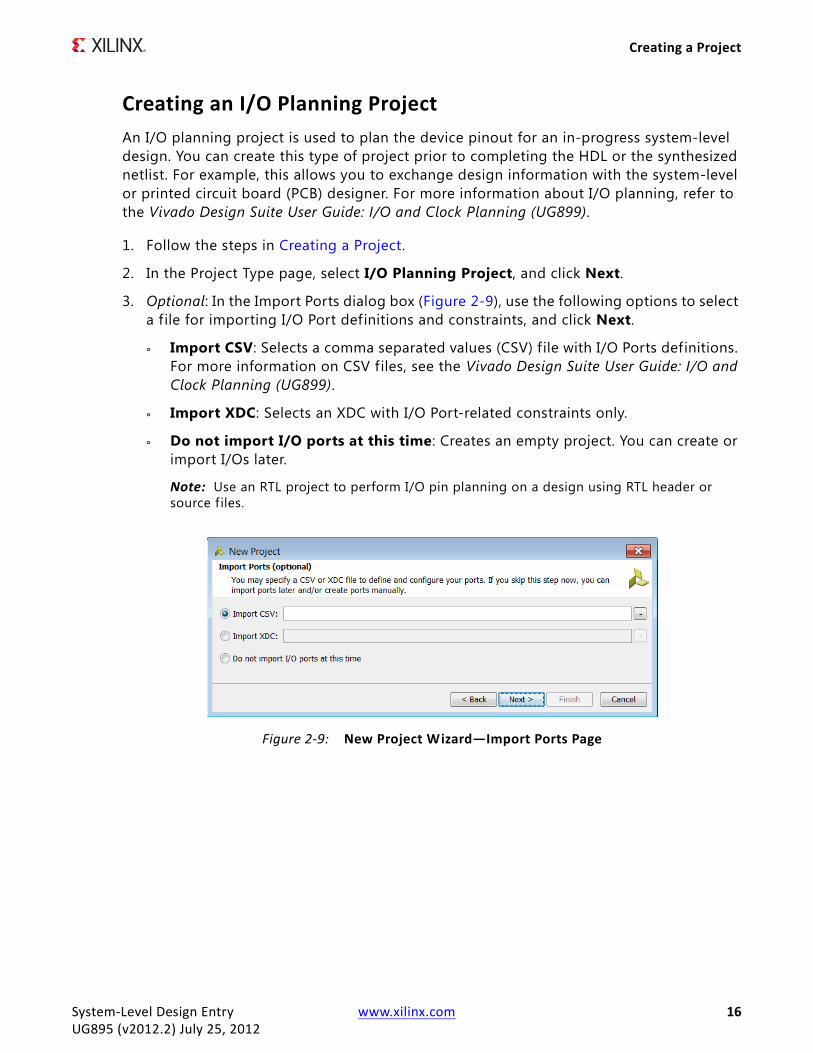
3. Optional: In the Import Ports dialog box (Figure 2-9), use the following options to select a f ile for importing I/O Port definitions and constraints, and click Next.
° Import CSV: Selects a comma separated values (CSV) file with I/O Ports definitions. For more information on CSV files, see the Vivado Design Suite User Guide: I/O and Clock Planning (UG899).
° Import XDC: Selects an XDC with I/O Port-related constraints only.
° Do not import I/O ports at this time: Creates an empty project. You can create or import I/Os later.
Note: Use an RTL project to perform I/O pin planning on a design using RTL header or source f iles.
X-Ref Target - Figure 2-9
Figure 2-9: New Project Wizard—Import Ports Page
System-Level Design Entry www.xilinx.com 16UG895 (v2012.2) July 25, 2012

Creating a Project
4. In the Default Part page (Figure 2-6), select a Xilinx part or Targeted Design Platform (TDP) board, and click Next:
° Parts: Lists available devices. Information about the device resources displays in a table view. You can f ilter the list using the Product Category, Family, Sub-Family, Package, Speed Grade, and Temp Grade filters.
° Boards: Lists available TDP boards, and the Xilinx part used on the board. Information about device resources displays in a table view, such as I/O pin count, the number of look-up tables (LUTs) and flip-flops (FFs), and available Block RAMs. You can f ilter the list using the Family, Package, and Speed Grade filters.
° Search: Limits the listed devices to those matching the search criteria you specify.
5. In the New Project Summary page, review the options you selected to define the project, and click Finish to create and open the project.
Importing an External ProjectYou can import an existing RTL-level project f ile created outside of the Vivado IDE (for example, using Synopsys Synplify, XST, or ISE Design Suite Project Navigator). The Vivado IDE detects the source f iles in the specif ied project and automatically adds the f iles to the new project. Settings such as top module, target device, and VHDL library assignment are imported from the existing project.
1. Follow the steps in Creating a Project.
2. In the Project Type page, select Imported Project, and click Next.
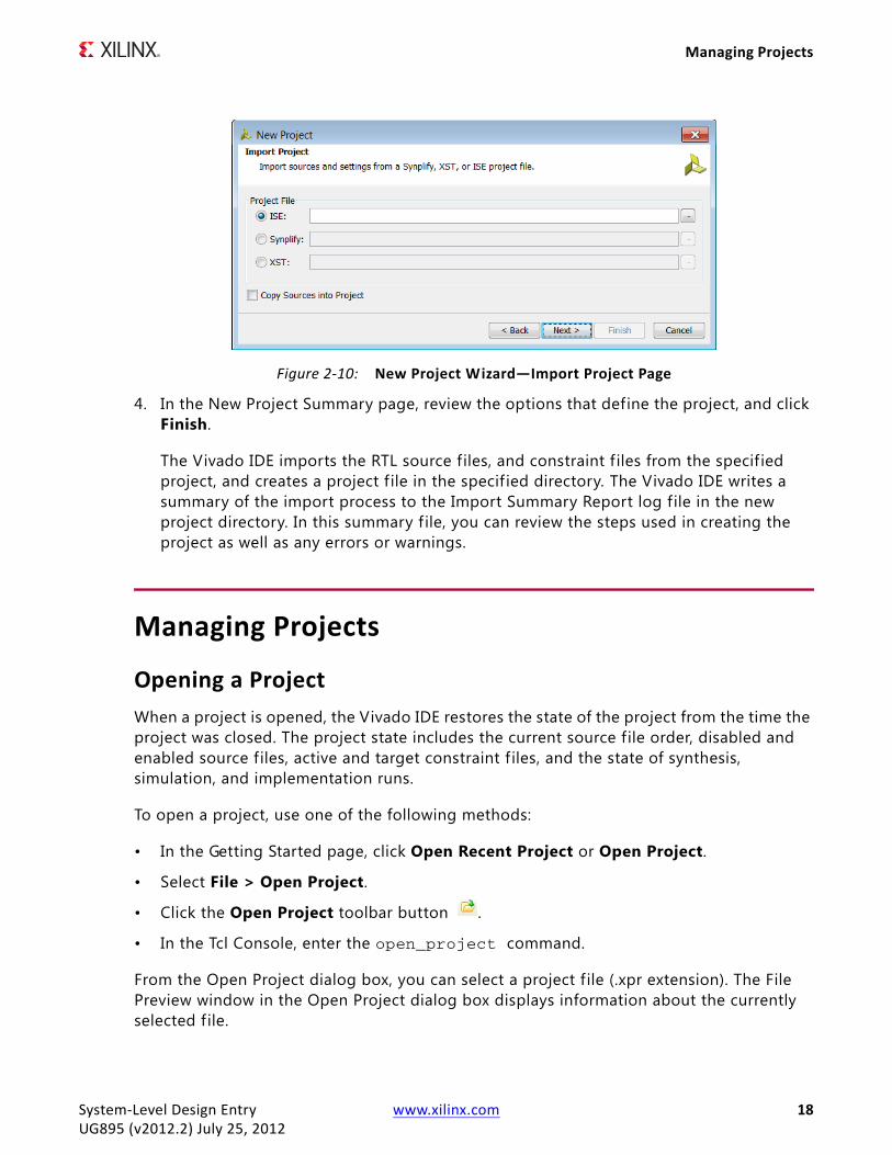
3. In the Import Project page (Figure 2-10), use the following options to specify the project f ile to import, and click Next.
° ISE: Imports the specif ied Xilinx ISE Design Suite (.xise extension) project f ile.
° Synplify: Imports the specified Synplify (.prj extension) project f ile.
° XST: Imports the specif ied XST (.xst extension) project f ile.
° Copy Sources into Project: Copies f iles into the local project directory instead of referencing the original f iles.
System-Level Design Entry www.xilinx.com 17UG895 (v2012.2) July 25, 2012
Managing Projects
4. In the New Project Summary page, review the options that define the project, and click Finish.
The Vivado IDE imports the RTL source files, and constraint f iles from the specif ied project, and creates a project f ile in the specif ied directory. The Vivado IDE writes a summary of the import process to the Import Summary Report log file in the new project directory. In this summary f ile, you can review the steps used in creating the project as well as any errors or warnings.
Managing Projects
Opening a ProjectWhen a project is opened, the Vivado IDE restores the state of the project from the time the project was closed. The project state includes the current source file order, disabled and enabled source files, active and target constraint f iles, and the state of synthesis, simulation, and implementation runs.
To open a project, use one of the following methods:
• In the Getting Started page, click Open Recent Project or Open Project.
• Select File > Open Project.
• Click the Open Project toolbar button .
• In the Tcl Console, enter the open_project command.
From the Open Project dialog box, you can select a project f ile (.xpr extension). The File Preview window in the Open Project dialog box displays information about the currently selected f ile.
X-Ref Target - Figure 2-10
Figure 2-10: New Project Wizard—Import Project Page
System-Level Design Entry www.xilinx.com 18UG895 (v2012.2) July 25, 2012

Managing Projects
Note: Alternatively, you can double-click the Vivado IDE project file (.xpr extension) in Windows Explorer to open the project.
Opening Multiple ProjectsTo open multiple projects in a single session, use any of the methods described in Opening a Project to open an additional project while a project is already open. The Vivado IDE prompts you to close the current project. If you do not close the f irst project, both projects are opened. Each open project has a separate main window.
When opening multiple projects from the same Vivado IDE application process, be aware that the commands used in all open projects are written to the Tcl Console. When reviewing the transcript of commands, it might not be clear which project the commands are associated with. In addition, there is only a single vivado.jou and a single vivado.log f ile for the application for all projects.
Note: System memory requirements can hinder performance when opening multiple projects.
Saving a ProjectProjects are automatically saved for you. For example, any time you make a change to a project, such as changes to source configuration, properties on files, or run options, the project is automatically saved on disk.
To save a project to a new location, do either of the following. This copies the entire project directory structure to a specif ied location and maintains the status of the existing runs.
• Select File > Save Project As.
• In the Tcl Console, use the save_project_as command.
Closing a ProjectTo close a project, do either of the following. When you close a project, you are prompted to save any unsaved changes to the design or source f iles.
• Select File > Close Project.
• In the Tcl Console, use the close_project command.
System-Level Design Entry www.xilinx.com 19UG895 (v2012.2) July 25, 2012

Managing Projects
Archiving ProjectsYou can create a project archive to store as backup or to send to a remote site. When archiving a project, the Vivado IDE does the following:
• Parses the hierarchy of the design
• Copies the required source f iles, include f iles, and remote f iles from the library directories
• Copies the constraints
• Optionally, copies the results of the various synthesis, simulation, and implementation runs
• Creates a ZIP f ile of the project
To archive a project:
1. Select File > Archive Project.
2. In the Archive Project dialog box (Figure 2-11), set the following options, and click OK.
° Archive name: Specif ies the name of the project archive.
° Archive location: Specif ies a location to store the project archive file.
° Include Run Results: Includes the settings and results of the runs performed on the project.
The Vivado IDE creates a project archive in ZIP f ile format that contains the required source f iles, include f iles, and run files (if specified) as well as an archive.log f ile of the archival process. You can review the creation of the archive in the archive.log f ile.
Note: Alternatively, you can archive a project using the archive_project command in the Tcl Console.
X-Ref Target - Figure 2-11
Figure 2-11: Archive Project Dialog Box
System-Level Design Entry www.xilinx.com 20UG895 (v2012.2) July 25, 2012

Using the Project Summary
Using the Project SummaryThe Vivado IDE includes an interactive Project Summary (Figure 2-12) that updates dynamically as design commands are run and as the design progresses through the design flow. It provides project and design information, such as the project part, project status, and state of synthesis and implementation. It also provides links to detailed information, such as links to the Messages, Log, and Reports windows as well as the Project Settings dialog box. You can use the scroll bar or the Collapse and Expand buttons to view or hide the different data categories.
The Project Summary contains the following sections:
• Project Settings: Shows the Project Name, Product Family, Project Part, and Top Module Name.
• Messages:
° Summary: Summarizes the number of errors and warnings encountered during the design process. This section also includes a link to the Messages window that is f iltered to show the warnings or errors.
° Go To: Provides links to the Messages, Log, and Reports windows. For more information on these windows, see the Vivado Design Suite User Guide: Using the Vivado IDE (UG893).
• Synthesis and Implementation: Summarizes the state of synthesis and implementation in the active run. These sections show the target part, the strategy applied in the run, the tool flow used, and the constraint set used.
Click the Part, Strategy, or Flow links to open the Project Settings dialog box for either synthesis or implementation. Click the Constraints link to open the Constraint Set Properties in the Source File Properties window.
Note: For more information, see Configuring Project Settings and Working with Constraints in Chapter 3.
To open the Project Summary, do either of the following:
• Select Windows > Project Summary.
• Select the Project Summary toolbar button .
System-Level Design Entry www.xilinx.com 21UG895 (v2012.2) July 25, 2012

Configuring Project Settings
Configuring Project SettingsYou can configure project settings to meet specif ic needs for each project. Project settings include general settings related to the top module definition as well as settings for the following: simulation, synthesis, implementation, bitstream, and IP catalog.
To open the Project Settings dialog box, use any of the following methods:
• Select Tools > Project Settings.
• Click the Project Settings toolbar button .
• In the Flow Navigator, click Project Settings in the Project Manager section, or click one of the following: Simulation Settings, Synthesis Settings, Implementation Settings, or Bitstream Settings.
• In the Project Summary, click the Edit link next to the Project Settings header, or click the strategy or flow in either the Synthesis or Implementation section.
X-Ref Target - Figure 2-12
Figure 2-12: Project Summary
System-Level Design Entry www.xilinx.com 22UG895 (v2012.2) July 25, 2012

Configuring Project Settings
Depending on how you invoke the Project Settings dialog box, the appropriate category appears by default. For example, if you click Simulation Settings in the Flow Navigator, the Simulation category appears in the Project Settings dialog box. The following sections provide detailed information for each category.
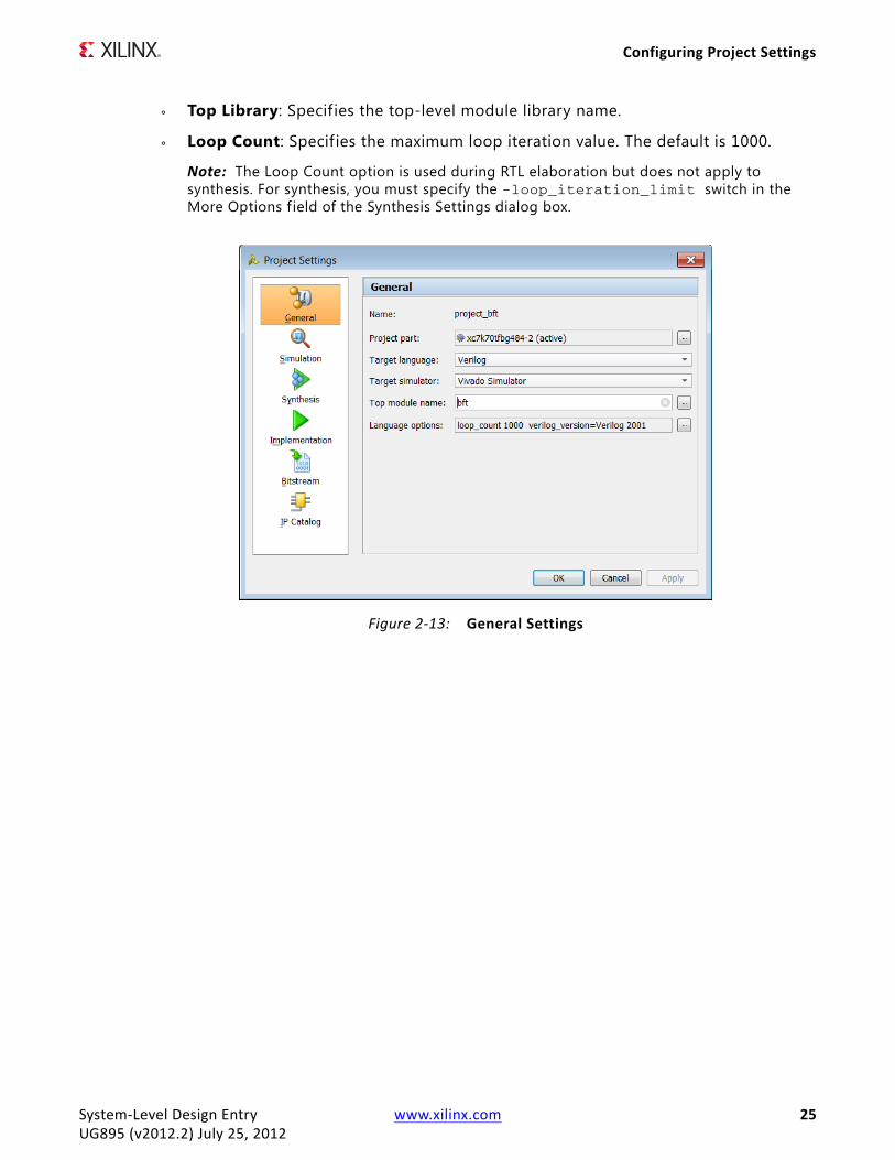
General SettingsThe General Settings (Figure 2-13) enable you to specify the project name, part, target language, target simulator, top module name, and language options.
• Name: Specif ies the project name.
• Project Part: Specifies the target part to be used as a default for both synthesis and implementation. Click the browse button to open the Select Device dialog box to choose a part.
Note: If you have multiple synthesis or implementation runs, you can also change the part used for a specif ic run by changing the run settings from the Run Properties window. For information, see Using the Runs Properties Window in the Vivado Design Suite User Guide: Using the Vivado IDE (UG893).
• Target Language: Specif ies the target output language for the design as either Verilog or VHDL. The tool generates RTL output from the design in the specified target language. Specif ic examples of output controlled by the target language are synthesis, simulation, top-level wrappers, test benches, and IP instantiation templates.
• Target Simulator : Specifies the simulator to be launched for behavioral or timing simulation. The available options are:
° Vivado Simulator : Specif ies the target simulator is the Vivado simulator.
° QuestaSim/ModelSim: Specifies the target simulator is Mentor Graphics® ModelSim or Questa® Advanced Simulator tool. The specified simulator must be installed, and appear in your $PATH in order to be properly invoked when launching simulation.
To support the use of ModelSim or Questa, you must compile the Xilinx simulation libraries for use with the target simulator. In the Vivado IDE Tcl Console, type compile_simlibxlib to compile simulation libraries for Modelsim and Questa simulators.
After the libraries are compiled, the simulator references these compiled libraries using the modelsim.ini f ile. The modelsim.ini f ile is the default initialization f ile and contains control variables that specify reference library paths, optimization, compiler, and simulator settings.
System-Level Design Entry www.xilinx.com 23UG895 (v2012.2) July 25, 2012
Configuring Project Settings
The following is the modelsim.ini search order in the Vivado tools:
- Location specif ied in the Compiled library location option in the Simulation Settings.
Note: This option is only available in the Simulation Settings if QuestaSim/ModelSim is set as the Target Simulator in the General Settings.
- The path specified by compxlib.compiled_library_dir variable set at the time compxlib compile_simlib is run.
- The path defined by MODELSIM environment variable.
IMPORTANT: If the modelsim.ini file is not found at any of these locations, you cannot run simulation on designs that include Xilinx primitives.
• Top Module Name: Specif ies the top RTL module name of the design. You can also enter a lower-level module name to experiment with synthesis on a specif ic module. Click the browse button to automatically search for the top module and display a list of possible top modules.
• Language Options: Click the browse button to set the following options in the Language Options dialog box:
° Verilog Options: Click the browse button to set the following options in the Verilog Options dialog box:
- Verilog Include Files Search Paths: Specifies the paths to search for f iles referenced by ‘include statements in the source Verilog f iles.
- Defines: Specifies Verilog macro definitions for the project.
- Uppercase all identifiers: Sets all Verilog identif iers to uppercase.
° Generics/Parameters: VHDL supports generics while Verilog supports defining parameters for constant values. Both of these techniques allow parameterized designs that can be reused in different situations. Click the browse button to define generic and parameter values to override defaults defined in the source f iles.
System-Level Design Entry www.xilinx.com 24UG895 (v2012.2) July 25, 2012
Configuring Project Settings
° Top Library: Specifies the top-level module library name.
° Loop Count: Specifies the maximum loop iteration value. The default is 1000.
Note: The Loop Count option is used during RTL elaboration but does not apply to synthesis. For synthesis, you must specify the -loop_iteration_limit switch in the More Options f ield of the Synthesis Settings dialog box.
X-Ref Target - Figure 2-13
Figure 2-13: General Settings
System-Level Design Entry www.xilinx.com 25UG895 (v2012.2) July 25, 2012
Configuring Project Settings
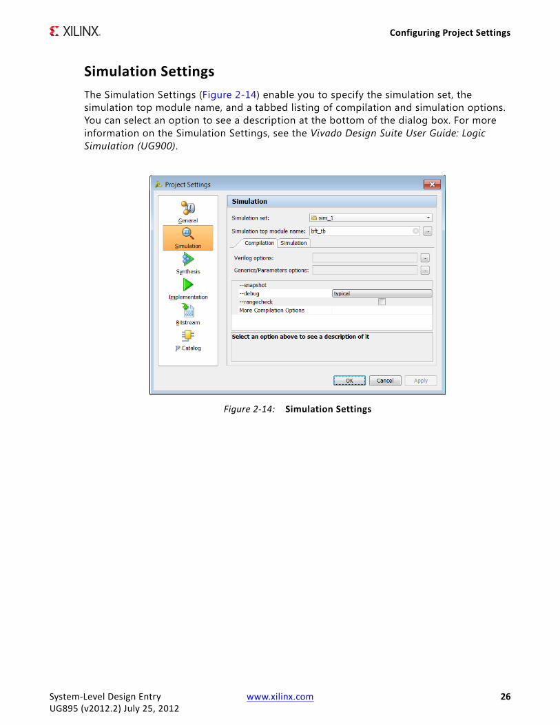
Simulation SettingsThe Simulation Settings (Figure 2-14) enable you to specify the simulation set, the simulation top module name, and a tabbed listing of compilation and simulation options. You can select an option to see a description at the bottom of the dialog box. For more information on the Simulation Settings, see the Vivado Design Suite User Guide: Logic Simulation (UG900).
X-Ref Target - Figure 2-14
Figure 2-14: Simulation Settings
System-Level Design Entry www.xilinx.com 26UG895 (v2012.2) July 25, 2012

Configuring Project Settings
Synthesis SettingsThe Synthesis Settings (Figure 2-15) enable you to specify the constraints set, the synthesis strategy, and the synthesis options. The options are defined by the selected synthesis strategy, but you can override these with your own settings. You can select an option to see a description at the bottom of the dialog box. For more information on the Synthesis Settings, see the Vivado Design Suite User Guide: Synthesis (UG901).
X-Ref Target - Figure 2-15
Figure 2-15: Synthesis Settings
System-Level Design Entry www.xilinx.com 27UG895 (v2012.2) July 25, 2012
Configuring Project Settings
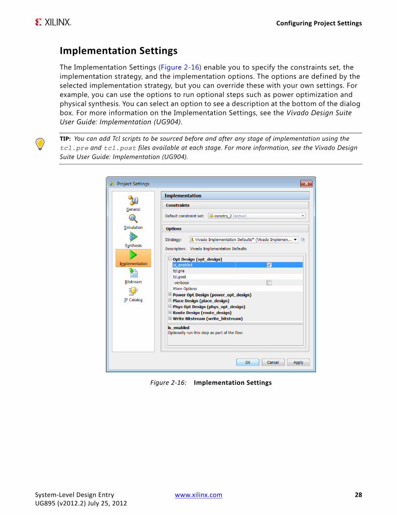
Implementation SettingsThe Implementation Settings (Figure 2-16) enable you to specify the constraints set, the implementation strategy, and the implementation options. The options are defined by the selected implementation strategy, but you can override these with your own settings. For example, you can use the options to run optional steps such as power optimization and physical synthesis. You can select an option to see a description at the bottom of the dialog box. For more information on the Implementation Settings, see the Vivado Design Suite User Guide: Implementation (UG904).
TIP: You can add Tcl scripts to be sourced before and after any stage of implementation using the tcl.pre and tcl.post files available at each stage. For more information, see the Vivado Design Suite User Guide: Implementation (UG904).
X-Ref Target - Figure 2-16
Figure 2-16: Implementation Settings
System-Level Design Entry www.xilinx.com 28UG895 (v2012.2) July 25, 2012
Configuring Project Settings
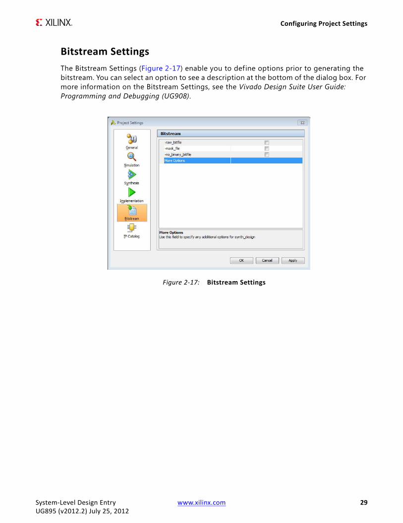
Bitstream SettingsThe Bitstream Settings (Figure 2-17) enable you to define options prior to generating the bitstream. You can select an option to see a description at the bottom of the dialog box. For more information on the Bitstream Settings, see the Vivado Design Suite User Guide: Programming and Debugging (UG908).
X-Ref Target - Figure 2-17
Figure 2-17: Bitstream Settings
System-Level Design Entry www.xilinx.com 29UG895 (v2012.2) July 25, 2012

Creating a Project Using a Tcl Script
IP Catalog SettingsThe IP Catalog Settings (Figure 2-18) show the path to the user IP repository (either packaged by the user or acquired from a third party supplier) and the path to the Vivado IP catalog in the Xilinx software installation. You can click Update IP Catalog to specify additional IP repository search paths or to reload all repositories. For more information on the IP Catalog Settings, see the Vivado Design Suite User Guide: Designing with IP (UG896).
Creating a Project Using a Tcl ScriptAs an alternative to creating a project in the Vivado IDE, you can create a project using a Tcl script. Most actions run in the Vivado IDE result in a Tcl command being executed. The Tcl commands appear in the Vivado IDE Tcl Console and are also captured in the vivado.jou and vivado.log f iles. The vivado.jou f ile contains just the commands, and the vivado.log f ile contains both commands and any returned messages. You can use these f iles to develop scripts for use with Project Mode. For more information on Tcl commands, see the Vivado Design Suite Tcl Command Reference Guide (UG835).
X-Ref Target - Figure 2-18
Figure 2-18: IP Catalog Settings
System-Level Design Entry www.xilinx.com 30UG895 (v2012.2) July 25, 2012

Creating a Project Using a Tcl Script
Following is a sample script that creates a project, adds various sources, configures settings, and launches synthesis and implementation runs.
# Typical usage: vivado –mode tcl –source run_bft_project.tcl# Create the project and directory structurecreate_project project_bft_batch ./project_bft_batch -part xc7k70tfbg484-2# Create the fileset for simulationcreate_fileset -simset sim_1# Add the various sources to the projectadd_files {./Sources/hdl/FifoBuffer.v ./Sources/hdl/async_fifo.v ./Sources/hdl/bft.vhdl}add_files -fileset sim_1 ./Sources/hdl/bft_tb.vadd_files ./Sources/hdl/bftLib# Set VHDL library property on some filesset_property library bftLib [get_files {./Sources/hdl/bftLib/round_4.vhdl ./Sources/hdl/bftLib/round_3.vhdl ./Sources/hdl/bftLib/round_2.vhdl ./Sources/hdl/bftLib/round_1.vhdl ./Sources/hdl/bftLib/core_transform.vhdl ./Sources/hdl/bftLib/bft_package.vhdl}]# Now import (copy) the files into the project directory structureimport_files -forceimport_files -fileset constrs_1 -force -norecurse ./Sources/bft_full.xdc# Mimic GUI behavior of automatically setting top and file compile orderupdate_compile_order -fileset sources_1update_compile_order -fileset sim_1# Launch Synthesislaunch_runs synth_1wait_on_run synth_1open_run synth_1 -name netlist_1# Generate a timing and power reports and write to disk# Can create custom reports as requiredreport_timing_summary -delay_type max -report_unconstrained -check_timing_verbose -max_paths 10 -input_pins -file ./Tutorial_Created_Data/project_bft_batch/syn_timing.rptreport_power -file ./Tutorial_Created_Data/project_bft_batch/syn_power.rpt# Launch Implementationlaunch_runs impl_1 -to_step write_bitstreamwait_on_run impl_1 # Generate a timing and power reports and write to disk# comment out the open_run for batch modeopen_run impl_1report_timing_summary -delay_type min_max -report_unconstrained -check_timing_verbose -max_paths 10 -input_pins -file ./Tutorial_Created_Data/project_bft_batch/imp_timing.rptreport_power -file ./Tutorial_Created_Data/project_bft_batch/imp_power.rpt# Can open the graphical environment if visualization desired# comment out the for batch modestart_gui
System-Level Design Entry www.xilinx.com 31UG895 (v2012.2) July 25, 2012

Chapter 3
Working with Source Files
OverviewSource files include project sources, design sources, constraints sources, simulation sources, intellectual property (IP) sources, digital signal processing (DSP) sources, and embedded sources. When working in Project Mode, you can create these source files using the Vivado™ IDE or using Tcl commands or scripts, and the Vivado IDE automatically manages your source f iles. In Non-Project Mode, you can create these source f iles using Tcl commands or scripts, but you must manually manage your source f iles. This chapter covers creating and managing sources in Project Mode and creating sources in Non-Project Mode.
Working with Sources in Project ModeUsing the Vivado IDE, you can create and manage source f iles that are local to the current project or remotely referenced from a library. You can add Verilog and VHDL source f iles to a project at any point in the design flow. You can also create or add constraint f iles, simulation sources, DSP sources, and embedded sources to your design as well as add existing IP.
Working with Design SourcesIn the Vivado IDE, you can create and manage design source f iles, including HDL or netlist f iles.
Creating Design Sources
1. Select File > Add Sources.
Note: Alternatively, you can click Add Sources in the Flow Navigator, or select Add Sources from the popup menu in the Sources window.
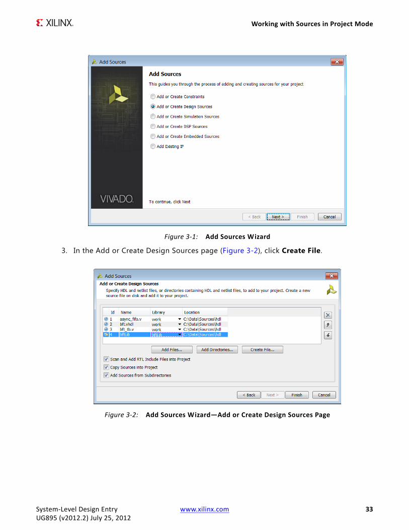
2. In the Add Sources wizard (Figure 3-1), select Add or Create Design Sources, and click Next.
System-Level Design Entry www.xilinx.com 32UG895 (v2012.2) July 25, 2012
Working with Sources in Project Mode
3. In the Add or Create Design Sources page (Figure 3-2), click Create File.
X-Ref Target - Figure 3-1
Figure 3-1: Add Sources Wizard
X-Ref Target - Figure 3-2
Figure 3-2: Add Sources Wizard—Add or Create Design Sources Page
System-Level Design Entry www.xilinx.com 33UG895 (v2012.2) July 25, 2012

Working with Sources in Project Mode
4. In the Create Source File dialog box (Figure 3-3), set the following options, and click OK:
° File type: Specif ies one of the following f ile formats: Verilog file (.v), Verilog Header f ile (.vh)., SystemVerilog file (.sv), VHDL f ile (.vhdl).
° File name: Specif ies a name for the new HDL source f ile.
° File location: Specif ies a location in which to create the f ile.
Note: A placeholder for the file is added to the list of sources. The f ile is created when you click Finish.
5. You can click Create File multiple times to define a number of new modules to add to the project.
6. In the Add Sources dialog box, specify the appropriate Library for the source f ile.
Note: By default, HDL sources are added to the work library. You can create or reference additional user VHDL libraries as needed.
7. Click Finish to add the specified sources to the project.
8. Optional: In the Define Modules dialog box (Figure 3-4), define the module or architecture in the Verilog, Verilog Header, SystemVerilog, or VHDL code using the following options, and click OK:
° New Source Files: If you created multiple f iles, click the name of the module you want to define.
Note: This f ield is only present if you created multiple f iles.
° Entity name/Module name: Specifies the name for the entity construct in the VHDL code or the module name in the Verilog or SystemVerilog code.
Note: Although the entity or module name defaults to the f ile name, it does not have to match f ile name.
° Architecture name: Specif ies the Architecture for the RTL source f ile. By default, the name is Behavioral.
Note: This option only applies to VHDL code and does not appear when defining Verilog or SystemVerilog modules.
X-Ref Target - Figure 3-3
Figure 3-3: Create Source File Dialog Box
System-Level Design Entry www.xilinx.com 34UG895 (v2012.2) July 25, 2012

Working with Sources in Project Mode
° I/O Port Definitions: Define the ports to be added to the module definition:
- Port Name: Defines the name of the port to appear in the RTL code.
- Direction: Specifies whether the port is an Input, Output, or Bidirectional port.
- Bus: Specif ies whether the port is a bus port. Define the width of the bus using the MSB and LSB options.
- MSB: Defines the number of the most signif icant bit (MSB). This combines with the LSB f ield to determine the width of the bus being defined.
- LSB: Defines the number of the least signif icant bit (LSB).
Note: MSB and LSB are ignored if the port is not a bus port.
The RTL source f iles are created and added to your project. The Sources window lists the newly defined modules. To edit the new source f iles in the Vivado IDE Text Editor, double-click the f ile or select Open File from the popup menu. For information on editing the newly created f ile, see Using the Text Editor in Chapter 3.
Adding Design Sources
1. Select File > Add Sources.
Note: Alternatively, you can click Add Sources in the Flow Navigator, or select Add Sources from the popup menu in the Sources window.
2. In the Add Sources wizard (Figure 3-1), select Add or Create Design Sources, and click Next.
X-Ref Target - Figure 3-4
Figure 3-4: Define Module Dialog Box
System-Level Design Entry www.xilinx.com 35UG895 (v2012.2) July 25, 2012

Working with Sources in Project Mode
3. In the Add or Create Design Sources page (Figure 3-2), set the following options, and click Finish.
° Add Files: Opens a f ile browser so you can select f iles to add to the project. You can add the following f ile types to an RTL project: HDL, EDIF, NGC, BMM, ELF, and other f ile types.
Note: In the Add Source Files dialog box, each file or directory is represented by an icon indicating it as a f ile or folder. A small red square indicates it is read only.
° Add Directories: Opens a directory browser to add source files from the selected directories. Files in the specified directory with valid source file extensions are added to the project.
° Create File: Opens the Create Source File dialog box in which you can create new VHDL, Verilog, Verilog header, or SystemVerilog files.
° Library: Specif ies the RTL library for a file or directory by selecting one from the currently defined library names, or specify a new library name by typing in the Library text f ield.
Note: This option applies to VHDL files only. By default, HDL sources are added to the work library. You can create or reference additional user VHDL libraries as needed. For Verilog and SystemVerilog f iles, leave the library set to work .
° Delete: Removes the selected source files from the list of f iles to be added.
° Move Selected File Up: Moves the file or directory up in the list order. The order of the files affects the order of elaboration and compilation during downstream processes such as synthesis and simulation.
° Move Selected File Down: Moves the f ile or directory down in the list order.
° Scan and Add RTL Include Files into Project: Scans the added RTL files and adds any referenced Verilog ‘include f iles into the local project directory structure.
° Copy Sources into Project: Copies f iles into the local project directory instead of referencing the original f iles.
Note: If you added directories of source f iles using Add Directories, the directory structure is maintained when the f iles are copied locally into the project. For more information, see Using Remote Sources or Copying Sources into Project.
° Add Sources from Subdirectories: Adds source f iles from the subdirectories of directories specif ied using the Add Directories option.
Specifying the Top Module and Reordering Source Files
The Vivado IDE automatically determines the top-level of the design hierarchy and the order of elaboration, synthesis, and simulation for source files added to the project. The hierarchy of the design is displayed in the Hierarchy view of the Source window. The file order is displayed in the Compile Order view of the Sources window.
System-Level Design Entry www.xilinx.com 36UG895 (v2012.2) July 25, 2012
Working with Sources in Project Mode
You can override the automatic determination of the top module by manually specifying the top of the design hierarchy. To specify the top module, select Set as Top from the popup menu command in the Hierarchy view of the Sources window.
Note: If the specif ied top module cannot be found in the design source f iles and the hierarchy update mode is set to automatic, the selected top is automatically reset to the best candidate.
When you change the top module, the Vivado IDE automatically reorders f iles according to the requirements of the new top module. Select Refresh Hierarchy from the popup menu in the Sources window to automatically reorder files based on updates to the source files.
You can override the automatic determination of the compile order using Hierarchy Update from the popup menu command in the Sources window. When in manual mode, you can manually order f iles according to your own requirements. To manually order source f iles, select a f ile and drag it up or down in the file list order in the Compile Order view of Sources window. Alternatively, after selecting the file, execute Move Up, Move Down, Move to Top, or Move to Bottom from the Sources window popup menu.
Note: For more information on the Sources window, see the Vivado Design Suite User Guide: Using the Vivado IDE (UG893).
Enabling or Disabling Source Files
When you add or create source files, the source f iles are enabled in the Sources window by default. You can disable source files to prevent them from being elaborated, synthesized, or used in simulation.
• To disable source f iles, select the f iles in the Sources window, and select the Disable File popup command.
• To enable disabled files, select the files in the Sources window, and select the Enable File popup command.
Using Remote Sources or Copying Sources into Project
To provide project management flexibility, you can reference source f iles from a remote location or copy the source f iles into the project directory. When you add remote files, the Vivado IDE automatically detects the latest f ile version, then prompts you to Refresh your open designs or to Synthesize with the latest updates made to the file. If you plan to move or archive the project, you can copy the files into the project so that the f iles are contained within the project.
Note: When you copy f iles into a project, the project is easier to port to another system; however, the Vivado IDE does not automatically recognize external f ile changes. When remote f iles change, you must remove and re-add, or update the f iles using commands in the Sources window.
System-Level Design Entry www.xilinx.com 37UG895 (v2012.2) July 25, 2012
Working with Sources in Project Mode
To copy sources into the project, do one of the following:
• When you add sources to the project using the Add Sources command, you can copy the sources to the local project directory by selecting the Copy Sources into Project option.
• If you initially add the sources as remote sources, but later wish to copy them into the project directory, use Copy File into Project or Copy All Files into Project in the popup menu in the Sources window to copy some or all individual remote source f iles into the project directory.
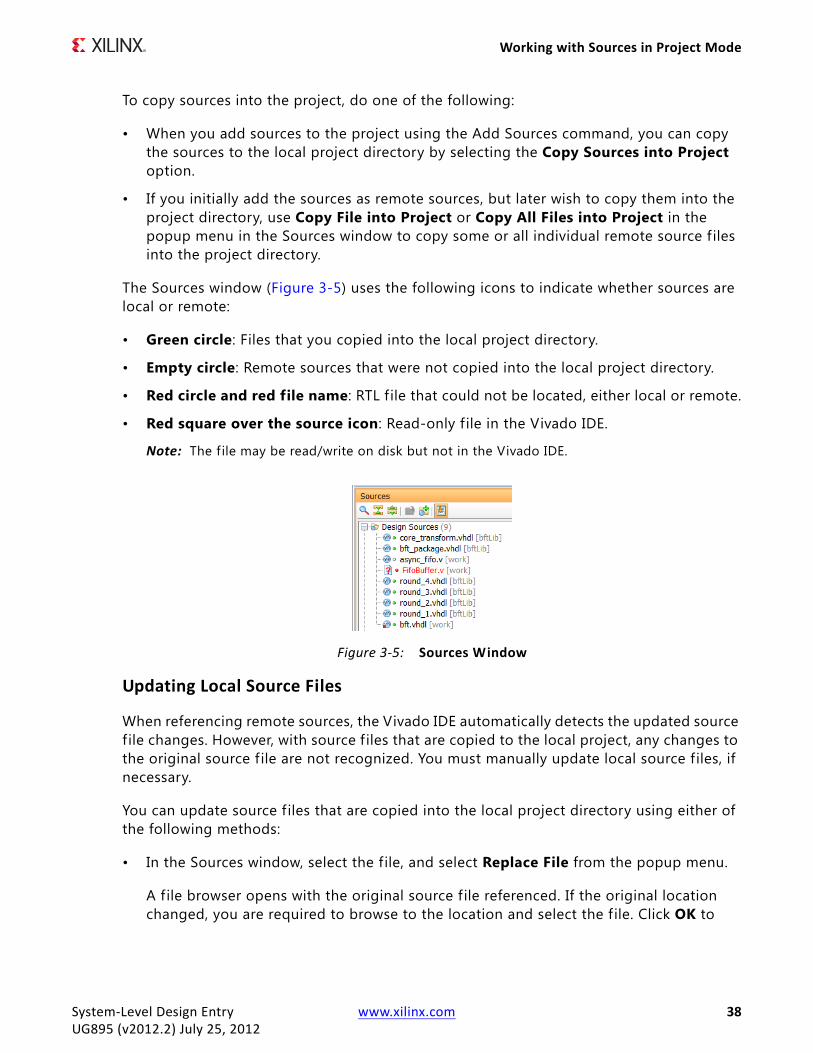
The Sources window (Figure 3-5) uses the following icons to indicate whether sources are local or remote:
• Green circle: Files that you copied into the local project directory.
• Empty circle: Remote sources that were not copied into the local project directory.
• Red circle and red file name: RTL f ile that could not be located, either local or remote.
• Red square over the source icon: Read-only f ile in the Vivado IDE.
Note: The f ile may be read/write on disk but not in the Vivado IDE.
Updating Local Source Files
When referencing remote sources, the Vivado IDE automatically detects the updated source f ile changes. However, with source f iles that are copied to the local project, any changes to the original source f ile are not recognized. You must manually update local source files, if necessary.
You can update source f iles that are copied into the local project directory using either of the following methods:
• In the Sources window, select the file, and select Replace File from the popup menu.
A f ile browser opens with the original source f ile referenced. If the original location changed, you are required to browse to the location and select the f ile. Click OK to
X-Ref Target - Figure 3-5
Figure 3-5: Sources Window
System-Level Design Entry www.xilinx.com 38UG895 (v2012.2) July 25, 2012

Working with Sources in Project Mode
reload the original source file, and update the project f ile with any changes to the source f ile.
Note: You can also specify a different f ile, and the Vivado IDE replaces the selected f ile with the new file. For instance, if the original f ile is File_1.v, and you select File_2.v, the original File_1.v is removed from the project and File_2.v is copied into the project.
• In the Sources window, select Add Sources from the popup menu to add the newly updated source f iles to the project.
The Vivado IDE imports the added file into the project. However, because there is already a local source with the same name, the Import Source Conflicts dialog box (Figure 3-6) prompts you to resolve the conflict by overwriting the existing file or by not loading the newly added file. This happens only if the Copy Sources into Project box is checked in the Add Sources wizard; otherwise, the externally referenced f ile of the same name is added to the project.
Working with ConstraintsThe Vivado IDE supports the Xilinx® Design Constraint (XDC) and Synopsys Design Constraint (SDC) f ile formats. The SDC format is for timing constraints while the XDC format is for both timing and physical constraints. Constraints can include placement, timing, and I/O restrictions. You can create constraints during various steps in the design flow, including RTL analysis, synthesis, and implementation.
The Vivado IDE provides flexibility in defining and using constraints in a project. You can use a single XDC file to add and maintain the design constraints, or you can use multiple XDC files to organize the constraints into separate files. You can create multiple constraint sets to experiment with various types of constraints, or store multiple versions of constraints. Each constraint set can contain one or more constraint f iles.
You can open multiple designs referencing a single constraint set. However, you must be careful to manage changes made to multiple designs that reference the same constraint set.
X-Ref Target - Figure 3-6
Figure 3-6: Import Source Conflicts Dialog Box
System-Level Design Entry www.xilinx.com 39UG895 (v2012.2) July 25, 2012

Working with Sources in Project Mode
If the Vivado IDE detects unsaved changes in multiple designs, it prompts you to select which design to save to the referenced constraint f ile.
CAUTION! When saving constraints files, be careful not to overwrite any unsaved constraint definitions in an unsaved design.
An implemented design saves a snapshot of the constraint set used during the implementation run. In some cases, this constraint set might have the same name as the active constraint set in the open project. When opening an implemented design, the constraint set loaded from the implementation run might be older than the constraint set currently in the project memory. This can cause the loss of newly-defined constraints when you save the design. Generally, the Vivado IDE manages these revision issues and prompts you to take the appropriate action as needed. However, please be aware of the potential conflict between the current constraint set in memory and any existing constraints associated with an implemented design.
Note: For more information, see the Vivado Design Suite User Guide: Using Constraints (UG903).
Adding and Creating Constraint Files
1. Select File > Add Sources.
Note: Alternatively, you can click Add Sources in the Flow Navigator, or select Add Sources from the popup menu in the Sources window.
2. In the Add Sources wizard (Figure 3-1), select Add or Create Constraints, and click Next.
3. In the Add or Create Constraints page (Figure 3-7), set the following options, and click Finish.
° Specify Constraint Set: Defines the constraint set into which the constraint f iles are placed. By default, the currently active constraint set is selected, but you can specify a different constraint set or define a new constraint set using the drop-down menu.
° Add Files: Specif ies the XDC or SDC files to add to the project.
° Create File: Creates a new top-level XDC for the project.
° Remove: Removes the selected f ile from the Constraint File list.
System-Level Design Entry www.xilinx.com 40UG895 (v2012.2) July 25, 2012
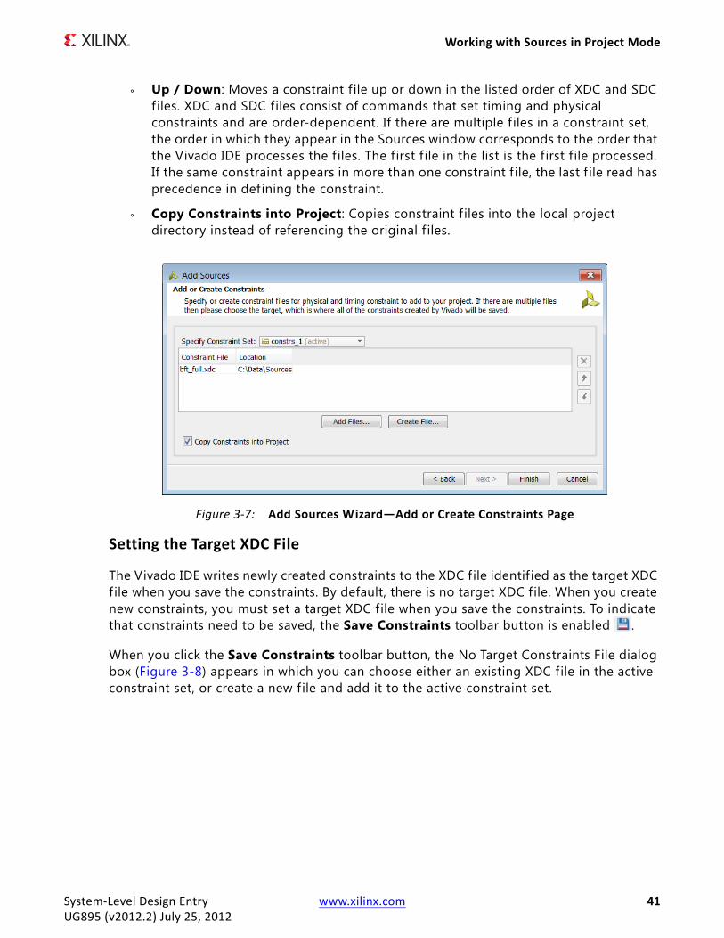
Working with Sources in Project Mode
° Up / Down: Moves a constraint f ile up or down in the listed order of XDC and SDC files. XDC and SDC files consist of commands that set timing and physical constraints and are order-dependent. If there are multiple f iles in a constraint set, the order in which they appear in the Sources window corresponds to the order that the Vivado IDE processes the f iles. The first f ile in the list is the f irst f ile processed. If the same constraint appears in more than one constraint f ile, the last f ile read has precedence in defining the constraint.
° Copy Constraints into Project: Copies constraint f iles into the local project directory instead of referencing the original f iles.
Setting the Target XDC File
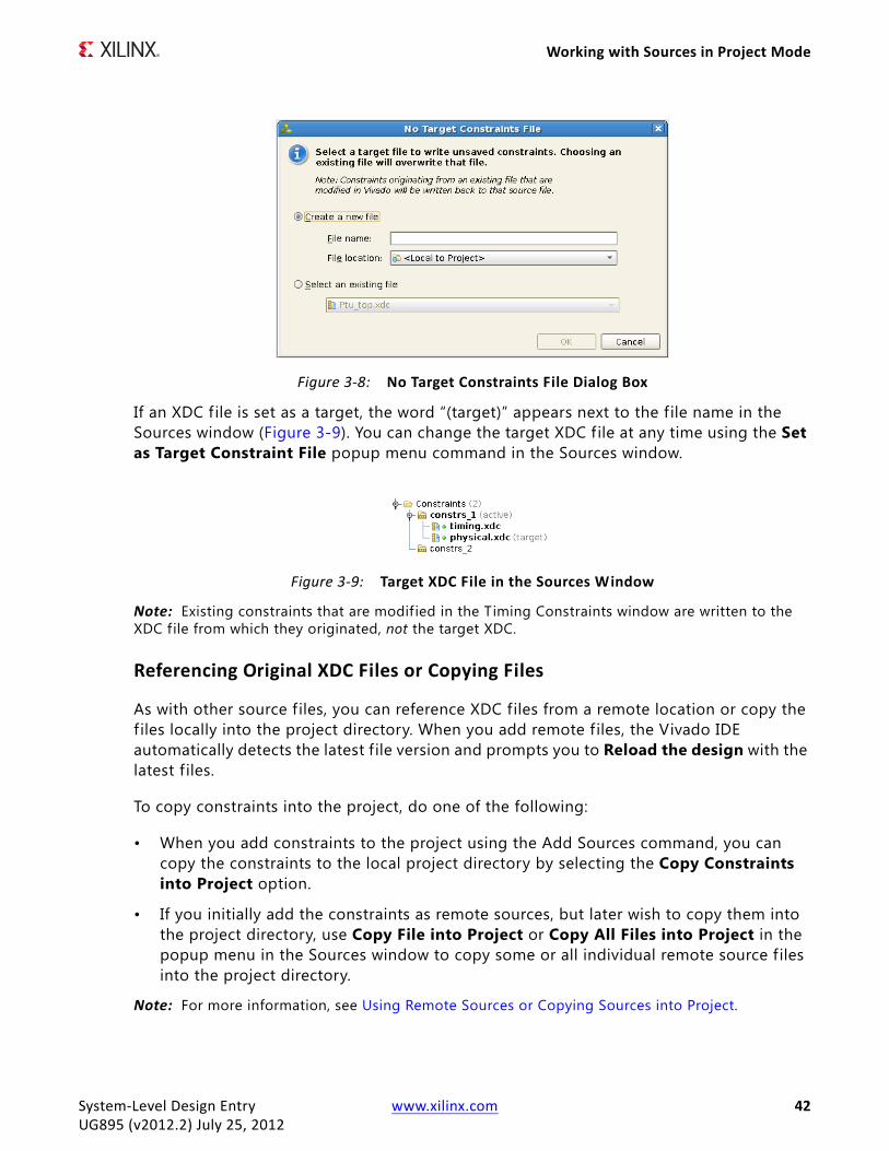
The Vivado IDE writes newly created constraints to the XDC file identif ied as the target XDC file when you save the constraints. By default, there is no target XDC file. When you create new constraints, you must set a target XDC file when you save the constraints. To indicate that constraints need to be saved, the Save Constraints toolbar button is enabled .
When you click the Save Constraints toolbar button, the No Target Constraints File dialog box (Figure 3-8) appears in which you can choose either an existing XDC file in the active constraint set, or create a new file and add it to the active constraint set.
X-Ref Target - Figure 3-7
Figure 3-7: Add Sources Wizard—Add or Create Constraints Page
System-Level Design Entry www.xilinx.com 41UG895 (v2012.2) July 25, 2012
Working with Sources in Project Mode
If an XDC file is set as a target, the word “(target)” appears next to the f ile name in the Sources window (Figure 3-9). You can change the target XDC file at any time using the Set as Target Constraint File popup menu command in the Sources window.
Note: Existing constraints that are modified in the Timing Constraints window are written to the XDC file from which they originated, not the target XDC.
Referencing Original XDC Files or Copying Files
As with other source f iles, you can reference XDC files from a remote location or copy the f iles locally into the project directory. When you add remote f iles, the Vivado IDE automatically detects the latest f ile version and prompts you to Reload the design with the latest f iles.
To copy constraints into the project, do one of the following:
• When you add constraints to the project using the Add Sources command, you can copy the constraints to the local project directory by selecting the Copy Constraints into Project option.
• If you initially add the constraints as remote sources, but later wish to copy them into the project directory, use Copy File into Project or Copy All Files into Project in the popup menu in the Sources window to copy some or all individual remote source f iles into the project directory.
Note: For more information, see Using Remote Sources or Copying Sources into Project.
X-Ref Target - Figure 3-8
Figure 3-8: No Target Constraints File Dialog Box
X-Ref Target - Figure 3-9
Figure 3-9: Target XDC File in the Sources Window
System-Level Design Entry www.xilinx.com 42UG895 (v2012.2) July 25, 2012

Working with Sources in Project Mode
Using Constraint Sets
A constraint set is one or more constraint f iles that are maintained independently and concatenated into a single XDC file for analysis and implementation. A constraint set defines the constraint f iles to be used at specif ic moments, or under specif ic conditions, in the design process. By defining multiple constraints sets, you can, for example, specify different active constraints to resolve floorplanning and timing problems.
The XDC files can be used during synthesis, implementation, or both. By default all XDC files are set to be used in both synthesis and implementation. To change the Used In setting for an XDC file, select the file in the Sources window, and check or uncheck the appropriate box in the General view of the Source File Properties window (Figure 3-10).
X-Ref Target - Figure 3-10
Figure 3-10: Used In Property for an XDC File
System-Level Design Entry www.xilinx.com 43UG895 (v2012.2) July 25, 2012
Working with Sources in Project Mode
Creating and Editing Constraint Sets
1. In the Sources window, select Edit Constraint Sets from the popup menu.
2. In the Create Constraint Set dialog box, do one of the following:
° To edit a constraint set, click the drop-down menu next to the Specify Constraint Set f ield, and select a constraint set.
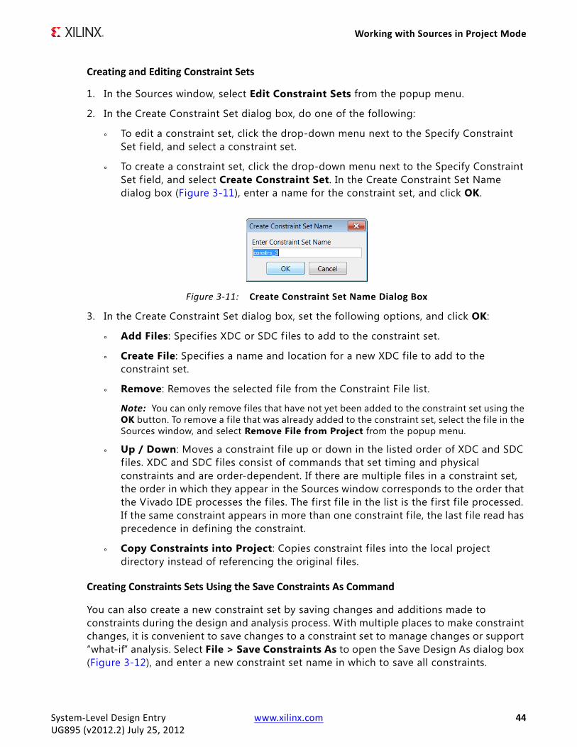
° To create a constraint set, click the drop-down menu next to the Specify Constraint Set f ield, and select Create Constraint Set. In the Create Constraint Set Name dialog box (Figure 3-11), enter a name for the constraint set, and click OK.
3. In the Create Constraint Set dialog box, set the following options, and click OK:
° Add Files: Specif ies XDC or SDC files to add to the constraint set.
° Create File: Specif ies a name and location for a new XDC file to add to the constraint set.
° Remove: Removes the selected f ile from the Constraint File list.
Note: You can only remove f iles that have not yet been added to the constraint set using the OK button. To remove a f ile that was already added to the constraint set, select the f ile in the Sources window, and select Remove File from Project from the popup menu.
° Up / Down: Moves a constraint f ile up or down in the listed order of XDC and SDC files. XDC and SDC files consist of commands that set timing and physical constraints and are order-dependent. If there are multiple f iles in a constraint set, the order in which they appear in the Sources window corresponds to the order that the Vivado IDE processes the f iles. The first f ile in the list is the f irst f ile processed. If the same constraint appears in more than one constraint f ile, the last f ile read has precedence in defining the constraint.
° Copy Constraints into Project: Copies constraint f iles into the local project directory instead of referencing the original f iles.
Creating Constraints Sets Using the Save Constraints As Command
You can also create a new constraint set by saving changes and additions made to constraints during the design and analysis process. With multiple places to make constraint changes, it is convenient to save changes to a constraint set to manage changes or support “what-if” analysis. Select File > Save Constraints As to open the Save Design As dialog box (Figure 3-12), and enter a new constraint set name in which to save all constraints.
X-Ref Target - Figure 3-11
Figure 3-11: Create Constraint Set Name Dialog Box
System-Level Design Entry www.xilinx.com 44UG895 (v2012.2) July 25, 2012

Working with Sources in Project Mode
The Save Design As dialog box does the following:
• Creates a new constraint set.
• Copies the active constraint f iles into the new constraint set in the local project directory.
• Writes any modifications to the constraints to the copied constraint f iles, leaving the original XDC files unchanged.
• Provides an option to make the new constraint set active in the project.
Defining the Active Constraint Set
If more than one constraint set exists, you must designate an active constraint set. The Vivado IDE uses the active constraint set by default when you launch the synthesis or implementation runs or when you open an elaborated, synthesized or implemented design.
To set the active constraint set, select the constraint set in the Sources window, and click Make active from the popup menu. In the Sources window, the active constraint set appears in bold with the word “(active)” next to it (Figure 3-13).
X-Ref Target - Figure 3-12
Figure 3-12: Save Design As Dialog Box
X-Ref Target - Figure 3-13
Figure 3-13: Active Constraint Set
System-Level Design Entry www.xilinx.com 45UG895 (v2012.2) July 25, 2012

Working with Sources in Project Mode
Exporting Constraints
In some cases, you might want to use the Vivado IDE to create constraint f iles for use in scripting command line design flows. To export constraints for a command line flow, select File > Export > Export Constraints.
In addition, you can export the I/O standard constraints for I/O ports and banks (both user-specified values and default values assigned by the Vivado IDE) to an XDC file. To export constraints, select File > Export > Export I/O Ports, and generate an XDC file.
Enabling or Disabling Constraint Files
When you add or create constraint f iles, the f iles are enabled in the Sources window by default. You can disable constraint f iles to prevent them from being used during elaboration, synthesis, or in implementation.
• To disable constraint f iles, select the files in the Sources window, and select the Disable File popup command.
• To enable disabled files, select the files in the Sources window, and select the Enable File popup command.
Converting UCF Constraints
The Vivado IDE supports only XDC and SDC files. It does not support user constraints f iles (UCF). You can convert UCF constraints to XDC using either of the following methods:
• Open the design in the PlanAhead™ tool. In the Tcl Console, type write_xdc <filename>.xdc
Note: The write_xdc command is not a f ile converter. The command writes out the constraints that were successfully applied to the design as an XDC file. This conversion is only a starting point for migration to XDC-based constraints.
RECOMMENDED: This method is recommended for converting physical constraints only. It is not recommended for converting timing constraints, especially timing exceptions.
• Manually convert the UCF constraints to XDC.
RECOMMENDED: This method is strongly recommended for converting UCF constraints, especially timing constraints and timing exceptions. Fundamental differences between the UCF and XDC constraints make automatic conversion less than optimal. For example, UCF files target nets for the constraints while XDC files typically target a cell, port, or pin.
Note: For more information, see the Vivado Design Suite Migration Methodology Guide (UG911) or the Vivado Design Suite User Guide: Using Constraints (UG903).
System-Level Design Entry www.xilinx.com 46UG895 (v2012.2) July 25, 2012
Working with Sources in Project Mode
Working with Simulation SourcesIn the Vivado IDE, you can add simulation sources to the project for behavioral simulation of an RTL Project. Simulation source files include Hardware Description Language (HDL)-based test bench f iles to use as a stimulus for simulation. Simulation sources are used for behavioral simulation in the Vivado simulator.
The Vivado IDE stores simulation source f iles in simulation sets that display in folders in the Sources window, and are remotely referenced or stored in the local project directory. Simulation sets enables you to define different sources for different simulation configurations. For example, one simulation source can provide stimulus for behavioral simulation using one test bench while another can contain a different test bench. When adding simulation sources to the project, you can specify which simulation set into which to add files.
Note: For more information, see the Vivado Design Suite User Guide: Logic Simulation (UG900).
Adding and Creating Simulation Source Files
1. Select File > Add Sources.
Note: Alternatively, select Add Sources from the popup menu or from the Flow Navigator.
2. In the Add Sources wizard (Figure 3-1), select Add or Create Simulation Sources, and click Next.
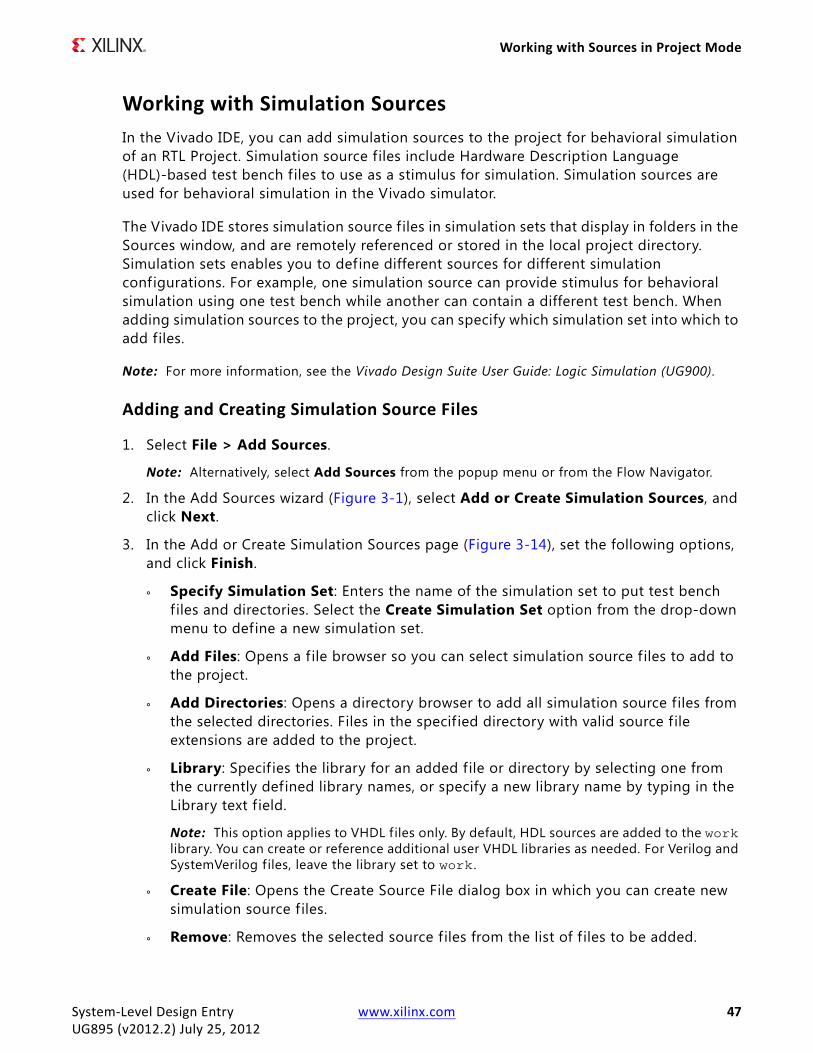
3. In the Add or Create Simulation Sources page (Figure 3-14), set the following options, and click Finish.
° Specify Simulation Set: Enters the name of the simulation set to put test bench f iles and directories. Select the Create Simulation Set option from the drop-down menu to define a new simulation set.
° Add Files: Opens a f ile browser so you can select simulation source f iles to add to the project.
° Add Directories: Opens a directory browser to add all simulation source files from the selected directories. Files in the specif ied directory with valid source f ile extensions are added to the project.
° Library: Specif ies the library for an added file or directory by selecting one from the currently defined library names, or specify a new library name by typing in the Library text f ield.
Note: This option applies to VHDL files only. By default, HDL sources are added to the work library. You can create or reference additional user VHDL libraries as needed. For Verilog and SystemVerilog f iles, leave the library set to work .
° Create File: Opens the Create Source File dialog box in which you can create new simulation source f iles.
° Remove: Removes the selected source f iles from the list of f iles to be added.
System-Level Design Entry www.xilinx.com 47UG895 (v2012.2) July 25, 2012
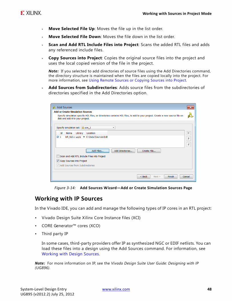
Working with Sources in Project Mode
° Move Selected File Up: Moves the file up in the list order.
° Move Selected File Down: Moves the f ile down in the list order.
° Scan and Add RTL Include Files into Project: Scans the added RTL files and adds any referenced include f iles.
° Copy Sources into Project: Copies the original source f iles into the project and uses the local copied version of the f ile in the project.
Note: If you selected to add directories of source f iles using the Add Directories command, the directory structure is maintained when the f iles are copied locally into the project. For more information, see Using Remote Sources or Copying Sources into Project.
° Add Sources from Subdirectories: Adds source f iles from the subdirectories of directories specif ied in the Add Directories option.
Working with IP SourcesIn the Vivado IDE, you can add and manage the following types of IP cores in an RTL project:
• Vivado Design Suite Xilinx Core Instance f iles (XCI)
• CORE Generator™ cores (XCO)
• Third party IP
In some cases, third-party providers offer IP as synthesized NGC or EDIF netlists. You can load these files into a design using the Add Sources command. For information, see Working with Design Sources.
Note: For more information on IP, see the Vivado Design Suite User Guide: Designing with IP (UG896).
X-Ref Target - Figure 3-14
Figure 3-14: Add Sources Wizard—Add or Create Simulation Sources Page
System-Level Design Entry www.xilinx.com 48UG895 (v2012.2) July 25, 2012

Working with Sources in Project Mode
Adding Existing IP
1. Select File > Add Sources.
Note: Alternatively, select Add Sources from the popup menu, or from the Flow Navigator.
2. In the Add Sources wizard (Figure 3-1), select Add Existing IP, and click Next.
3. In the Add Existing IP page (Figure 3-15), set the following options, and click Finish.
° Add Files: Open a f ile browser so you can select Xilinx Core Instance (XCI) f iles, which are native to the Vivado Design Suite, or CORE Generator core (XCO) files.
° Remove: Removes the selected source f iles from the list of f iles to be added.
° Copy Sources into Project: Copies the original IP core files into the project and uses the local copied version of the f ile in the project.
The added IP cores display separately in the IP Sources view of the Sources window, as well as with other source files in the Hierarchy, Libraries, and Compile Order views. You can select these cores in the Sources window to see the files that make up the core, and to view the properties in the Source File Properties window.
Note: You can also add EDIF, Verilog, or SystemVerilog netlists or NGC files for IP cores into either RTL or netlist-based projects. For more information, see Creating a Post-Synthesis Project in Chapter 2.
Using the Vivado IP Catalog
1. In the Project Manager section of the Flow Navigator, click IP Catalog.
In the IP Catalog (Figure 3-16), the IP cores display by category in an expandable tree table, that provides the IP version, Advanced eXtensible Interface (AXI) protocol compliance, status of the IP, and license requirements. When you select an IP core, a description displays in the lower pane of the view.
X-Ref Target - Figure 3-15
Figure 3-15: Add Sources Wizard—Add Existing IP Page
System-Level Design Entry www.xilinx.com 49UG895 (v2012.2) July 25, 2012
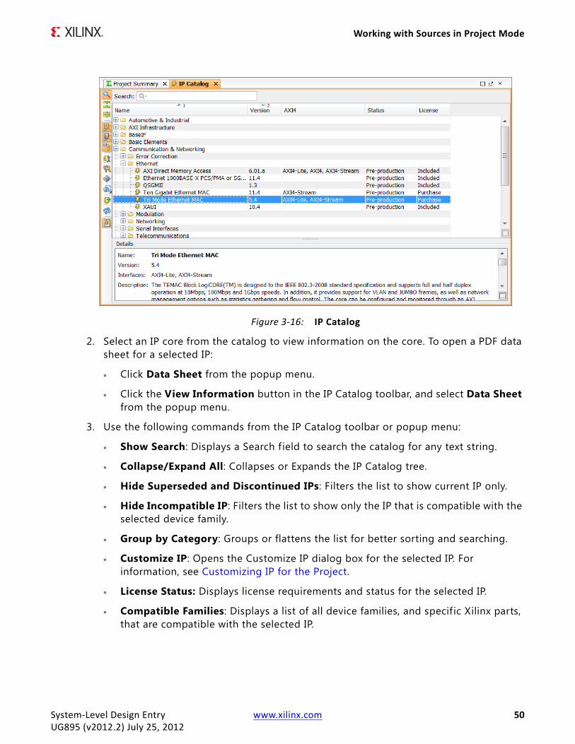
Working with Sources in Project Mode
2. Select an IP core from the catalog to view information on the core. To open a PDF data sheet for a selected IP:
° Click Data Sheet from the popup menu.
° Click the View Information button in the IP Catalog toolbar, and select Data Sheet from the popup menu.
3. Use the following commands from the IP Catalog toolbar or popup menu:
° Show Search: Displays a Search field to search the catalog for any text string.
° Collapse/Expand All: Collapses or Expands the IP Catalog tree.
° Hide Superseded and Discontinued IPs: Filters the list to show current IP only.
° Hide Incompatible IP: Filters the list to show only the IP that is compatible with the selected device family.
° Group by Category: Groups or flattens the list for better sorting and searching.
° Customize IP: Opens the Customize IP dialog box for the selected IP. For information, see Customizing IP for the Project.
° License Status: Displays license requirements and status for the selected IP.
° Compatible Families: Displays a list of all device families, and specific Xilinx parts, that are compatible with the selected IP.
X-Ref Target - Figure 3-16
Figure 3-16: IP Catalog
System-Level Design Entry www.xilinx.com 50UG895 (v2012.2) July 25, 2012

Working with Sources in Project Mode
° View Information: Displays a menu of available information resources for the selected IP. Available information includes Data Sheet, Version Information, Web page, and Answer Records.
° Update IP Catalog: Regenerates the IP Catalog at the specif ied location, which enables you to check for any updates to the IP Catalog. In this dialog box, you can also specify additional search paths to update the IP Catalog with user IP, and you can force a reload of all repositories by selecting Reload All Repositories. For more information, see Updating the IP Catalog.
° Automatically Scroll to Selected Objects: Toggles the display to jump to the selected object in the open view.
° Add IP: Adds IP to the repository through selecting either a component.xml f ile or Vivado IP packager ZIP file.
° Export to Spreadsheet: Outputs the IP Catalog to an XLS f ile for use in a spreadsheet.
Customizing IP for the Project
You can select a core from the Vivado IP Catalog, and customize the IP for use in your design by specifying values for the various parameters associated with the IP core (if applicable). The IP Catalog provides integrated GUI and Tcl support for all IP customization and generation operations.
Note: A majority of the IP in the IP Catalog supports the integrated capabilities. However, some IP (for example, MIG, ChipScope™ tool 1.x, and wireless cores) do not yet support the Vivado Design Suite integrated capabilities. Instead, this IP uses the existing CORE Generator tool IP customization and generation interface.
1. In the IP Catalog, select the IP to customize.
2. Select Customize IP from popup menu.
Note: Alternatively, you can select the Customize IP toolbar button , or double-click the selected IP.
3. To customize the IP for use in your design, modify the options that define the parameters of the IP. Depending on the IP selected, the Vivado IDE opens one of the following:
° Vivado IDE Customize IP dialog box (Figure 3-17)
° Memory Integration Generator (MIG) wizard
° CORE Generator tool IP Customization wizard
System-Level Design Entry www.xilinx.com 51UG895 (v2012.2) July 25, 2012

Working with Sources in Project Mode
The Vivado IDE Customize IP dialog box varies depending on the type of core you selected and can include one or more pages of parameters to define. The dialog box also includes the IP symbol, which shows the ports of the IP. You can show or hide disabled ports using the Show Disabled Ports checkbox. Buses appear with a special symbol in place of a net. You can expand or collapse the bus using the plus (+) and minus (-) symbols (Figure 3-18).
4. After you define the parameters, click OK to create the customized IP core and add it as a source into the project. The core is not synthesized at this time.
The added IP cores display separately in the IP Sources view of the Sources window. IP cores display with other source f iles in the Hierarchy, Libraries, and Compile Order views of the
X-Ref Target - Figure 3-17
Figure 3-17: Customize IP Dialog Box
X-Ref Target - Figure 3-18
Figure 3-18: Expanded Bus
System-Level Design Entry www.xilinx.com 52UG895 (v2012.2) July 25, 2012

Working with Sources in Project Mode
Sources window. You can select these cores in the Sources window to see the f iles that make up the core, and to view the properties in the Source File Properties window.
Generating Targets
IP cores added to the project appear in the Sources window. Click the IP Sources view to see the IP and collected sources displayed. Expanding an IP core in the Sources window shows the various folder categories, such as Synthesis and Instantiation Templates. Expanding these categories shows the source f iles delivered with the core.
Source f iles are the different design elements of the IP that are required to support the core in the current project. These include the Instantiation Template, the HDL f ile, XDC constraints, and others. The source f iles for the IP (XCI or XCO) are also shown in the Hierarchy view of the Sources window.
Figure 3-19 shows three cores in the IP Sources view with targets and associated f iles. Vivado Design Suite IP is delivered as RTL, as shown. This IP is synthesized along with your design.
Instantiating IP
The Instantiation Template is the Verilog (.veo extension) or VHDL (.vho extension) module definition that you can copy and paste into your RTL design to create instances of the IP module as needed. Figure 3-20 shows an instantiation template for an IP core.
X-Ref Target - Figure 3-19
Figure 3-19: Targets in IP Sources View
System-Level Design Entry www.xilinx.com 53UG895 (v2012.2) July 25, 2012
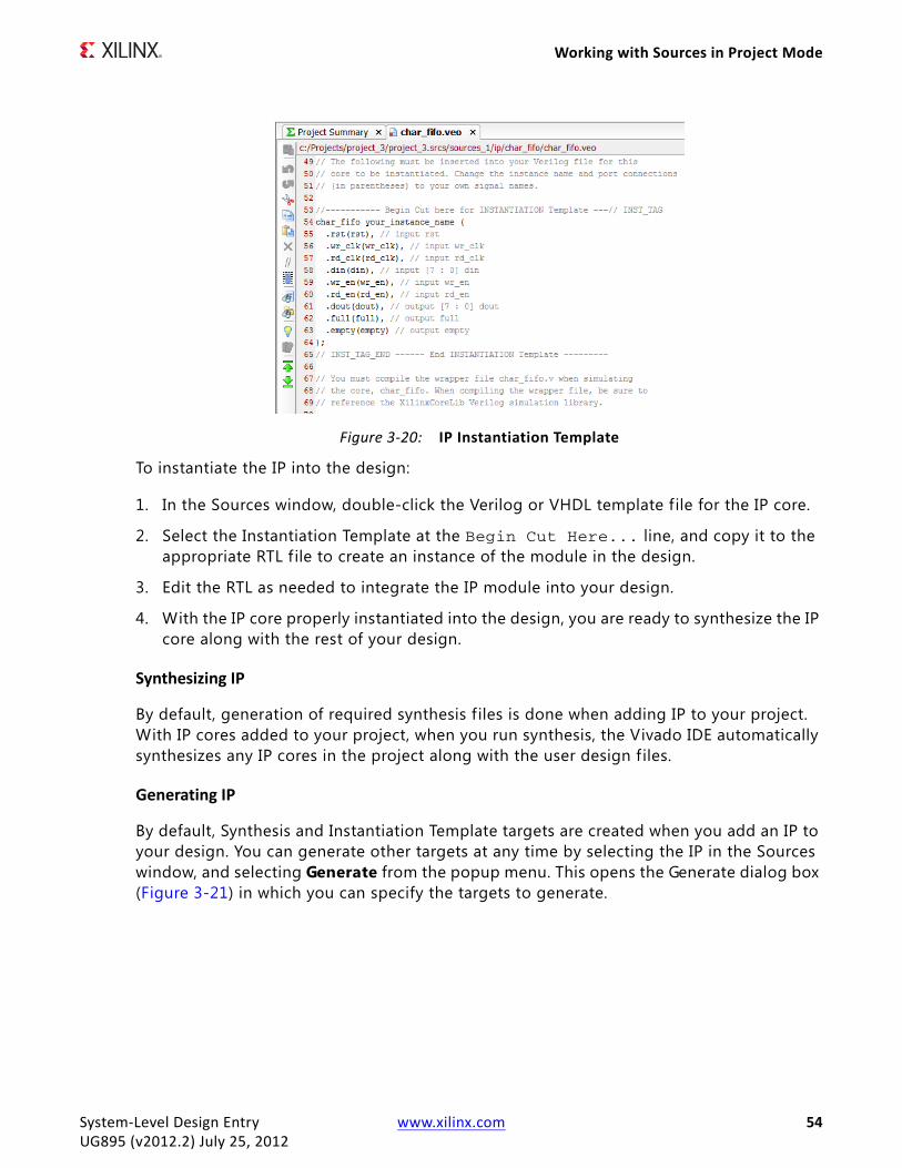
Working with Sources in Project Mode
To instantiate the IP into the design:
1. In the Sources window, double-click the Verilog or VHDL template file for the IP core.
2. Select the Instantiation Template at the Begin Cut Here... line, and copy it to the appropriate RTL f ile to create an instance of the module in the design.
3. Edit the RTL as needed to integrate the IP module into your design.
4. With the IP core properly instantiated into the design, you are ready to synthesize the IP core along with the rest of your design.
Synthesizing IP
By default, generation of required synthesis f iles is done when adding IP to your project. With IP cores added to your project, when you run synthesis, the Vivado IDE automatically synthesizes any IP cores in the project along with the user design f iles.
Generating IP
By default, Synthesis and Instantiation Template targets are created when you add an IP to your design. You can generate other targets at any time by selecting the IP in the Sources window, and selecting Generate from the popup menu. This opens the Generate dialog box (Figure 3-21) in which you can specify the targets to generate.
X-Ref Target - Figure 3-20
Figure 3-20: IP Instantiation Template
System-Level Design Entry www.xilinx.com 54UG895 (v2012.2) July 25, 2012
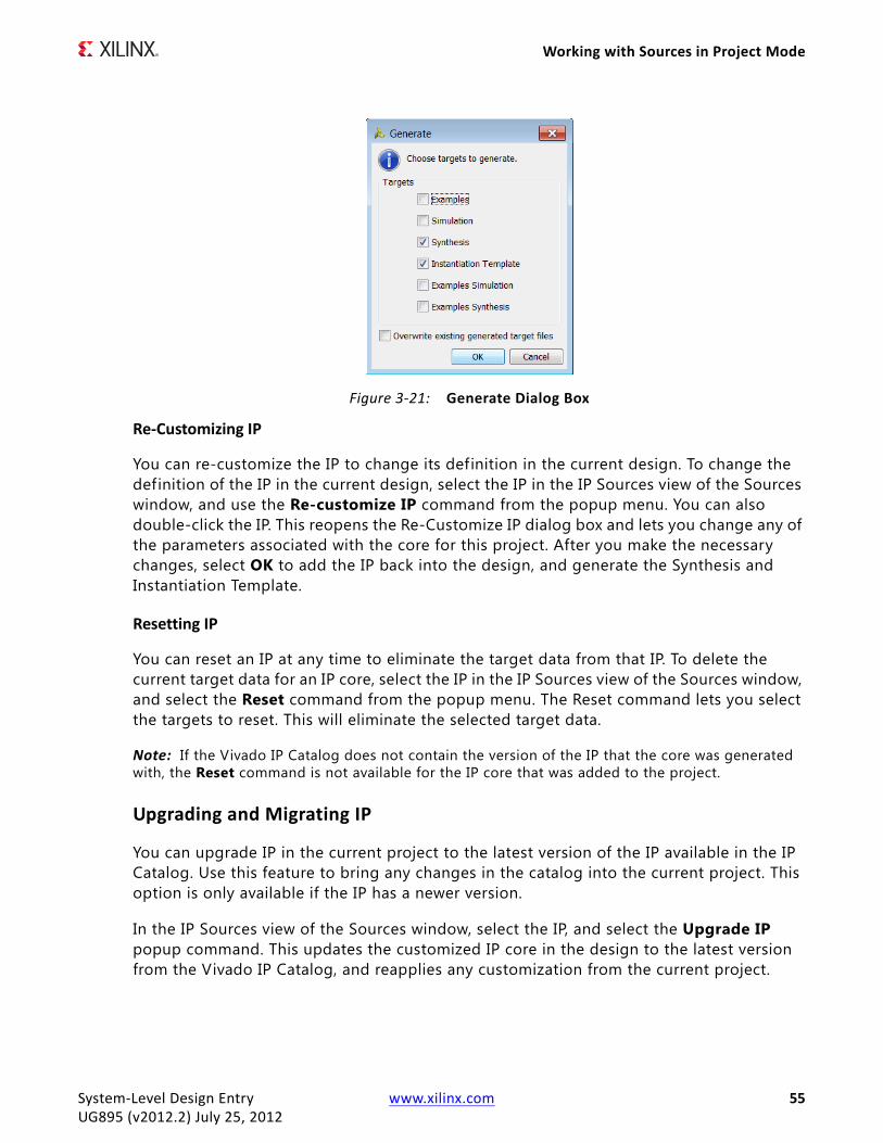
Working with Sources in Project Mode
Re-Customizing IP
You can re-customize the IP to change its definition in the current design. To change the definition of the IP in the current design, select the IP in the IP Sources view of the Sources window, and use the Re-customize IP command from the popup menu. You can also double-click the IP. This reopens the Re-Customize IP dialog box and lets you change any of the parameters associated with the core for this project. After you make the necessary changes, select OK to add the IP back into the design, and generate the Synthesis and Instantiation Template.
Resetting IP
You can reset an IP at any time to eliminate the target data from that IP. To delete the current target data for an IP core, select the IP in the IP Sources view of the Sources window, and select the Reset command from the popup menu. The Reset command lets you select the targets to reset. This will eliminate the selected target data.
Note: If the Vivado IP Catalog does not contain the version of the IP that the core was generated with, the Reset command is not available for the IP core that was added to the project.
Upgrading and Migrating IP
You can upgrade IP in the current project to the latest version of the IP available in the IP Catalog. Use this feature to bring any changes in the catalog into the current project. This option is only available if the IP has a newer version.
In the IP Sources view of the Sources window, select the IP, and select the Upgrade IP popup command. This updates the customized IP core in the design to the latest version from the Vivado IP Catalog, and reapplies any customization from the current project.
X-Ref Target - Figure 3-21
Figure 3-21: Generate Dialog Box
System-Level Design Entry www.xilinx.com 55UG895 (v2012.2) July 25, 2012
Working with Sources in Project Mode
You can use the same procedure to migrate CORE Generator IP to the Vivado IDE. For more information on migrating and upgrading your IP, see the Vivado Design Suite User Guide: Designing with IP (UG896).
Updating the IP Catalog
You can add local directories to the IP catalog, add new IP to the repositories, and manage the local IP repository as part of the catalog
1. In the IP Catalog, select Update IP Catalog from the popup menu.
2. In the Update IP Catalog dialog box (Figure 3-22), view the path to the Vivado IP Catalog in the current software installation, set the following options, and click OK.
° Optional IP Repository Search Paths: Lists the optional IP repositories currently added to the IP Catalog.
° Add Directories: Specifies directories to add to the IP repository search path. IP f iles in the form of a component.xml or a ZIP file are added to the IP Catalog.
° Remove Selected: Removes the selected IP repository path from the IP Catalog.
° Move Up: Moves the selected IP repository up in the list order.
The order of the IP repositories is important, because it affects the order in which the IP cores are read from the IP Catalog. The f irst IP repository is always the Vivado IP Catalog, then each user-defined IP repository as it is listed in the search path. In the case of duplicate IP cores, the later definition of an IP core overwrites the prior definition. In this case, the IP core found in the last IP repository would be the one available in the IP Catalog.
° Move Down: Moves the file or directory down in the list order.
° Reload All Repositories: Forces the index files in each of the IP repositories to be rebuilt, and then updates the in-memory IP catalog from the rebuilt index f iles. If you added new IP to a repository, you need to use this option to force the index f ile to be rebuilt and the new IP to be picked up.
System-Level Design Entry www.xilinx.com 56UG895 (v2012.2) July 25, 2012

Working with Sources in Project Mode
Note: By default, Update IP Catalog updates the in-memory IP catalog from the existing index f iles. It does not regenerate the index f iles that already exist for the repositories and does not pick up any newly added IP.
Working with DSP SourcesIn the Vivado IDE, you can import an existing Xilinx System Generator design model f ile (.mdl extension) as a DSP module. You can add the model to any hierarchy level as a sub-module or import it at the top-level of the design. You can also define a new DSP module from within the Vivado IDE and launch Xilinx System Generator to complete the design.
System Generator is a DSP design tool from Xilinx that allows the RTL source f iles, Simulink® and MATLAB® software models, and C/C++ components of a DSP system to come together in a single simulation and implementation environment.
A System Generator design is often a sub-design that is incorporated into a larger HDL design. While System Generator supports creating and implementing standalone FPGA designs, the recommended flow is to begin with a project in Vivado IDE, and develop a DSP module source for the project using System Generator. This allows the Vivado IDE to manage the project for the FPGA design, while handling the DSP module as a single source f ile that is developed and managed within System Generator.
Adding DSP Modules
1. Select File > Add Sources.
Note: Alternatively, select Add Sources from the popup menu, or from the Flow Navigator.
2. In the Add Sources wizard (Figure 3-1), select Add or Create DSP Sources, and click Next.
X-Ref Target - Figure 3-22
Figure 3-22: Update IP Catalog Dialog Box
System-Level Design Entry www.xilinx.com 57UG895 (v2012.2) July 25, 2012
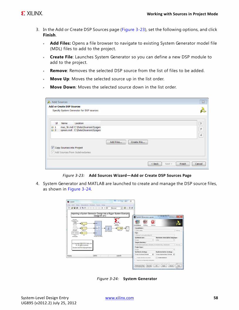
Working with Sources in Project Mode
3. In the Add or Create DSP Sources page (Figure 3-23), set the following options, and click Finish.
° Add Files: Opens a f ile browser to navigate to existing System Generator model f ile (MDL) f iles to add to the project.
° Create File: Launches System Generator so you can define a new DSP module to add to the project.
° Remove: Removes the selected DSP source from the list of f iles to be added.
° Move Up: Moves the selected source up in the list order.
° Move Down: Moves the selected source down in the list order.
4. System Generator and MATLAB are launched to create and manage the DSP source files, as shown in Figure 3-24.
X-Ref Target - Figure 3-23
Figure 3-23: Add Sources Wizard—Add or Create DSP Sources Page
X-Ref Target - Figure 3-24
Figure 3-24: System Generator
System-Level Design Entry www.xilinx.com 58UG895 (v2012.2) July 25, 2012

Working with Sources in Project Mode
The added DSP design sources display separately in the IP Sources view of the Sources window. DSP sources display with other source files in the Hierarchy, Libraries, and Compile Order views of the Sources window. You can select the DSP modules in the Sources window to see the associated f iles and to view the properties in the Source File Properties window.
Note: You can also add DSP sources using the create_sysgen Tcl command, which can be used to create a new DSP sub-module. The Vivado IDE creates a new MDL file and adds it as a sub-module to your project.
Generating Targets
After the System Generator design is completed, you can generate the FPGA target f iles using the DSP module popup menu commands in the Sources window. These commands are available when a DSP source is selected in the Sources window (Figure 3-25).
Targets are the different design elements of the DSP module that are required to support synthesis, simulation, and implementation of the current project. These include the a top module definition, an Instantiation Template, the synthesized netlist, and any supporting documents.
In the Sources window, following are the popup menu commands for DSP sources:
• Create Top HDL: Creates a top-level wrapper for the DSP module and imports it into the project. Use this command when the System Generator design is the top level of the current project.
• View Instantiation Template: Creates an instantiation template to use for instantiating the DSP module into the RTL design. The Instantiation Template can be cut and paste into another RTL f ile to create an instance of the DSP module in the hierarchy.
• Create Testbench: Writes test vector f iles that are extracted from the Simulink simulation and generates an HDL test bench and script f iles for simulation. The test bench is added to the Sources window in a simulation set.
X-Ref Target - Figure 3-25
Figure 3-25: DSP Sources in the Sources Window
System-Level Design Entry www.xilinx.com 59UG895 (v2012.2) July 25, 2012
Working with Sources in Project Mode
• Generate: Generates the synthesis, implementation, and simulation target data from the System Generator model. This invokes System Generator and MATLAB to create the necessary data.
• Reset: Removes the specif ied target data from the current project and from the local project repository so that it can be regenerated as needed.
Working with Embedded SourcesThe Embedded Development Kit (EDK) is a suite of tools and IP that you can use to integrate your hardware and software system components. EDK includes the Xilinx Platform Studio (XPS) and Software Development Kit (SDK).
You can use XPS to design the hardware portion of your embedded processor system. Specif ication of the microprocessor, peripherals, and the interconnection of these components, along with their respective detailed configuration, takes place in XPS. For more information on effective embedded system design, see the EDK Concepts, Tools, and Techniques Guide (UG683).
Although the EDK environment supports creating and implementing designs, the recommended flow is to begin with a project in the Vivado IDE, and develop an embedded processor source for the project using XPS. This allows the Vivado IDE to manage the project for the FPGA design, while handling the embedded processor design as a single source f ile, that is developed and managed within XPS. Figure 3-26 shows the integrated embedded design flow.
System-Level Design Entry www.xilinx.com 60UG895 (v2012.2) July 25, 2012

Working with Sources in Project Mode
Adding Embedded Processors
You can import existing Xilinx Microprocessor Project (.xmp extension) f iles from XPS, or define new embedded processor sub-designs and open XPS to create and manage the project as follows.
Note: Alternatively, you can use XPS and System Generator standalone and import the resulting netlist and constraints into the Vivado project as sources.
IMPORTANT: When you add XMP files your design, do not include spaces in your path structure. XPS does not currently support spaces in paths.
1. Select File > Add Sources.
Note: Alternatively, select Add Sources from the popup menu, or from the Flow Navigator.
2. In the Add Sources wizard (Figure 3-1), select Add or Create Embedded Sources, and click Next.
X-Ref Target - Figure 3-26
Figure 3-26: Embedded Design Flow
System-Level Design Entry www.xilinx.com 61UG895 (v2012.2) July 25, 2012

Working with Sources in Project Mode
3. In the Add or Create Embedded Sources page (Figure 3-27), set the following options, and click Finish.
° Add Sub-Design: Opens a f ile browser to navigate to existing Xilinx Microprocessor Project (XMP) files to add to the Vivado IDE project.
° Create Sub-Design: Launches XPS to allow you to define the new sub-design to add to the Vivado IDE project. For more information, see Creating a Sub-Design.
° Remove: Removes the selected sub-design from the list of f iles to be added.
° Move Up: Moves the selected sub-design up in the list order.
° Move Down: Moves the selected sub-design down in the list order.
The added sub-designs display separately in the IP Sources view of the Sources window, as well as with other source files in the Hierarchy, Libraries, and Compile Order views. You can select these sub-designs in the Sources window to see the f iles that are associated with the module, and to view the properties in the Source File Properties window.
Creating a Sub-Design
Following is a brief overview of the process of defining the embedded design. For more information, refer to EDK Concepts, Tools, and Techniques (UG683) and Embedded System Tools Reference Manual (UG111).
If you selected Create Sub-Design in the Add or Create Embedded Sources dialog box, XPS is launched in which you can define the new embedded sub-design. Attributes of the project in the Vivado IDE, such as target part or TDP, are automatically passed to XPS as it opens. XPS recognizes that this is a new sub-design and prompts you to use the Base System Builder wizard to help design the board for the design.
1. Click Yes to continue.
X-Ref Target - Figure 3-27
Figure 3-27: Add Sources Wizard—Add or Create Embedded Sources Page
System-Level Design Entry www.xilinx.com 62UG895 (v2012.2) July 25, 2012

Working with Sources in Project Mode
2. In the Base System Builder (BSB) wizard (Figure 3-28), specify the following options, and click OK.
The BSB wizard helps you quickly build a working system. Some embedded design projects can be completed using the BSB wizard alone. For more complex projects, the BSB wizard provides a baseline system that you can then customize to complete your embedded design.
Note: Much of the form is f illed in with data from the current project, and cannot be modified. This is to protect the integration of the Vivado IDE project with the XPS project.
° Project File: Indicates the name of the sub-design specif ied in the Create Sub-Design dialog box. This name comes from the Vivado IDE.
° Select an Interconnect Type: Specifies the AXI System. This is a hard coded selection, to avoid the legacy system.
° Select Existing .bsb Settings File: Specif ies a previous BSB settings f ile to automatically apply the same selections into to this BSB session.
° Set Project Peripheral Repository Search Path: Specify user repositories containing custom pcores, Board Support Packages (BSPs), and Software Services. If more than one repository search path is specif ied, they must be separated by a semi-colon (;).
X-Ref Target - Figure 3-28
Figure 3-28: Base System Builder Wizard
System-Level Design Entry www.xilinx.com 63UG895 (v2012.2) July 25, 2012

Working with Sources in Project Mode
3. In the Board and System Selection page (Figure 3-29), define the TDP or platform for the embedded processor design, and click Next.
The definition of the TDPs offered is limited to those containing the target part that you selected for the project in the Vivado IDE. From the target development board, the BSB is able to determine what devices are on the target board, such as the specif ic FPGA device, external memories, I/O devices, clock resources, and reset polarity. The following wizard pages are customized based on the information that can be retrieved for the selected board, minimizing the amount of input that is required.
Note: If the selected FPGA is not featured on any of the supported boards, you receive a message indicating that no boards for the device were found, and you must select Create a System for a Custom Board.
X-Ref Target - Figure 3-29
Figure 3-29: Base System Builder Wizard—Board and System Selection Page
System-Level Design Entry www.xilinx.com 64UG895 (v2012.2) July 25, 2012
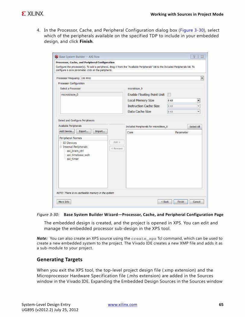
Working with Sources in Project Mode
4. In the Processor, Cache, and Peripheral Configuration dialog box (Figure 3-30), select which of the peripherals available on the specified TDP to include in your embedded design, and click Finish.
The embedded design is created, and the project is opened in XPS. You can edit and manage the embedded processor sub-design in the XPS tool.
Note: You can also create an XPS source using the create_xps Tcl command, which can be used to create a new embedded system to the project. The Vivado IDE creates a new XMP file and adds it as a sub-module to your project.
Generating Targets
When you exit the XPS tool, the top-level project design f ile (.xmp extension) and the Microprocessor Hardware Specification f ile (.mhs extension) are added in the Sources window in the Vivado IDE. Expanding the Embedded Design Sources in the Sources window
X-Ref Target - Figure 3-30
Figure 3-30: Base System Builder Wizard—Processor, Cache, and Peripheral Configuration Page
System-Level Design Entry www.xilinx.com 65UG895 (v2012.2) July 25, 2012

Working with Sources in Project Mode
displays the various target f iles associated with the sub-design (Figure 3-31).
Targets are the different design elements of the XPS sub-design that are required to support the object in the current project. These include the a top module definition, an Instantiation Template, the synthesized netlist, and any supporting documents such as log f iles and data sheets. The project f ile for the embedded design (XMP) is displayed in the Hierarchy view of the Sources window.
In the Sources window, following are the popup menu commands for embedded sources:
• Create Top HDL: Creates a top-level wrapper for the embedded design, and imports it into the project. Use this command when the embedded design is the top level of the current design.
• View Instantiation Template: Creates an instantiation template to use for instantiating the embedded design module into the RTL design. The Instantiation Template can be cut and paste into another RTL f ile to create an instance of the sub-design in the hierarchy.
Note: The template f ile is not added to the project.
• Create Testbench: Creates a test bench for the embedded design. The test bench is added to the Sources window in a simulation set.
• Generate: Creates the specif ied target data for synthesis, implementation, or simulation. The target data includes the Verilog or VHDL files, the wrapper f iles, the BMM model, and the top-level simulation model for the sub-design.
• Reset: Removes the specif ied target data from the current project. This also removes the generated target data from the local project repository so that it can be regenerated as needed.
When you generate the target data, the /synthesis and /implementation subdirectories are created for the embedded sub-design. This also occurs when you use either the Hardware > Generate Netlist or Hardware > Generate Bitstream commands in XPS.
If you added an existing XPS embedded design source, /synthesis and /implementation are subdirectories of the embedded design, external from the current project. However, if you used the Create Sub-Design command to add the embedded processor design to the current project, the /synthesis and /implementation
X-Ref Target - Figure 3-31
Figure 3-31: Embedded Design Sources
System-Level Design Entry www.xilinx.com 66UG895 (v2012.2) July 25, 2012

Working with Sources in Project Mode
subdirectories are local to the project directory in: <project>.srcs\sources_1\edk\<subdesign_name>
Exporting Hardware
The Vivado IDE is also integrated with SDK to support the design of software for the embedded processor sources in your project. To develop software for your project using SDK, with the embedded processor in your design, do the following:
1. Select File > Export > Export Hardware for SDK.
2. In the Export Hardware for SDK dialog box (Figure 3-32), specify the following options, and click OK.
° Source: Specifies the source XPS project f ile to export.
° Location: Specif ies the location to export the hardware to. By default, the hardware f iles are written to the local project directory, under: <project>.sdk/SDK/SDK_Export/hw
° Export Hardware: Generates the files necessary to support software development for the embedded processor design.
° Launch SDK: Launches the SDK tool after the hardware f iles are generated.
The Vivado IDE exports the Hardware Platform Specification (system.xml) for your design, and opens the f ile in SDK, if you selected Launch SDK. Refer to SDK Help for more information.
Creating the Bitstream File
To boot up an embedded processor system, both hardware and software components of the system must be downloaded to the FPGA and program memory respectively. This requires creating a bitstream file that contains the software application targeted for the block RAM. You can download the hardware bitstream and the software Executable and Linkable Format (ELF) f ile associated with the embedded processor. You can then use the Vivado IDE and
X-Ref Target - Figure 3-32
Figure 3-32: Export Hardware for SDK Dialog Box
System-Level Design Entry www.xilinx.com 67UG895 (v2012.2) July 25, 2012

Working with Sources in Project Mode
iMPACT tool to program the FPGA with the bitstream. See the Vivado Design Suite User Guide: Programming and Debugging (UG908).
In the Vivado IDE, you can add or update the ELF files associated with a processor instance using the Tools > Associate ELF Files command. The Associate ELF Files dialog box opens in which you can specify the ELF f ile to use when generating the bitstream file (Figure 3-33).
The ELF f ile populates the Block RAMs specif ied in the BMM file. The bit f ile created by Vivado IDE now has the block RAM initialized with the selected executable code. For more information, see the EDK Concepts, Tools, and Techniques Guide (UG683).
Editing Source FilesThe Vivado IDE provides a Text Editor in which to create or modify RTL, XDC, Tcl and other text sources. The Text Editor is syntax-sensitive and uses color-coding to distinguish RTL, XDC, and Tcl keywords. You can open multiple f iles simultaneously, and click the tab for each f ile to access to all open files.
When you modify a file, the Vivado IDE appends an asterisk (*) to the f ile name in the tab until the f ile is saved. To save the f ile, use one of the following methods:
• Select File > Save File.
• In the Text Editor, select Save File from the popup menu.
• In the Text Editor, use the Save File toolbar button.
If you attempt to close a f ile with unsaved changes, the Vivado IDE prompts you to save the changes. You can also use the Save As command to save the source f ile to a new location.
Note: For more information on the Text Editor, see Using the Text Editor Window in the Vivado Design Suite User Guide: Using the Vivado IDE (UG893).
X-Ref Target - Figure 3-33
Figure 3-33: Associate ELF Files Dialog Box
System-Level Design Entry www.xilinx.com 68UG895 (v2012.2) July 25, 2012

Working with Sources in Project Mode
Using the Text Editor
The Vivado IDE enables cross-probing between the Text Editor and other views, such as the Schematic, Messages, RTL Netlist, and Hierarchy views.
The Text Editor toolbar provides quick access to the following features:
• Undo: Undoes the last modif ication to the open f ile.
• Redo: Redoes the last modification to the open f ile.
• Cut: Cuts the selected section and places it on the clipboard.
• Copy: Copies the selected section and places it on the clipboard.
• Paste: Pastes the contents of the clipboard at the location specified.
• Delete: Deletes the selected section. The deleted section is not copied to the clipboard.
• Toggle Line Comments: Places appropriate comment characters at the start of the selected line(s).
• Toggle Column Selection: Puts editor in column selection mode. Enables column cut/copy/delete/paste.
• Show Find: Displays the Find bar at the bottom of the Text Editor window to enable searching of the f ile.
• Find in Files: Displays the Find in Files window for searching files in the entire project.
• Language Templates: Displays the Language Templates view. Templates for Verilog, VHDL, Tcl, and XDC are available for many common design/constraint structures.
• Insert Template: Inserts the selected Template into the text f ile being edited at the cursor location. This command is only available if a template is selected.
• Move Caret to Document Start: Moves the cursor to the start of the document being edited.
• Move Caret to Document End: Moves the cursor to the end of the document being edited.
System-Level Design Entry www.xilinx.com 69UG895 (v2012.2) July 25, 2012
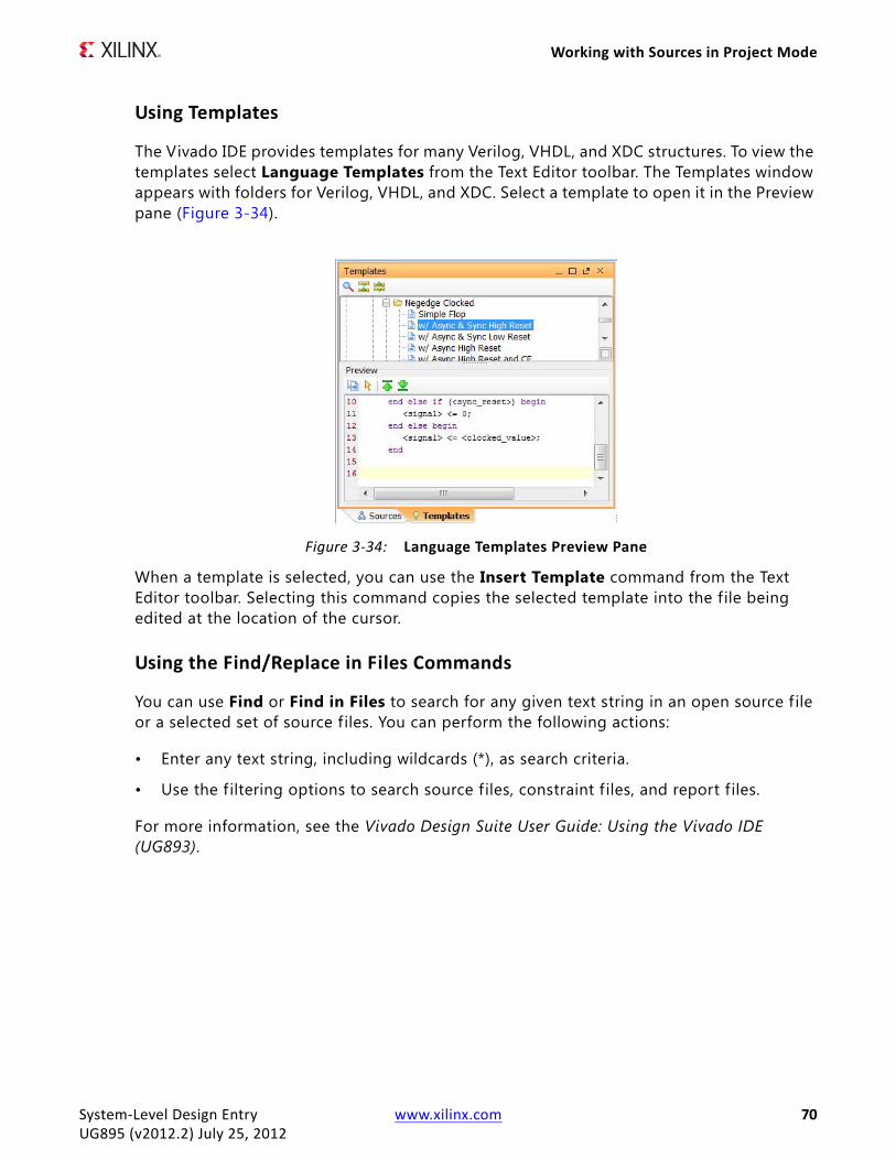
Working with Sources in Project Mode
Using Templates
The Vivado IDE provides templates for many Verilog, VHDL, and XDC structures. To view the templates select Language Templates from the Text Editor toolbar. The Templates window appears with folders for Verilog, VHDL, and XDC. Select a template to open it in the Preview pane (Figure 3-34).
When a template is selected, you can use the Insert Template command from the Text Editor toolbar. Selecting this command copies the selected template into the file being edited at the location of the cursor.
Using the Find/Replace in Files Commands
You can use Find or Find in Files to search for any given text string in an open source f ile or a selected set of source files. You can perform the following actions:
• Enter any text string, including wildcards (*), as search criteria.
• Use the f iltering options to search source files, constraint f iles, and report f iles.
For more information, see the Vivado Design Suite User Guide: Using the Vivado IDE (UG893).
X-Ref Target - Figure 3-34
Figure 3-34: Language Templates Preview Pane
System-Level Design Entry www.xilinx.com 70UG895 (v2012.2) July 25, 2012

Working with Sources in Project Mode
Cross Probing to Source Files
The Vivado IDE provides cross probing to RTL source f iles from the following windows:
• Schematic window (RTL elaborated, synthesis, or implementation)
• Netlist window (after synthesis or implementation)
• Device window (for an implemented design)
To cross probe, select the cell from any of these windows, and select the Go To Instantiation popup command. The RTL source opens, and the line with the instance is highlighted as shown in Figure 3-35.
X-Ref Target - Figure 3-35
Figure 3-35: Cross Probing to an RTL Source
System-Level Design Entry www.xilinx.com 71UG895 (v2012.2) July 25, 2012

Working with Sources in Project Mode
Using Alternate Text Editors
In the Vivado IDE, you to select an alternative text editor as follows:
1. Select Tools > Options.
2. In the Vivado Options dialog box General page (Figure 3-36), scroll down to the Text Editor section, and select an alternate editor select from the drop-down list.
When you select an editor from the list, an executable name appears in the settings. The path to the executable needs to be in your path. See the appropriate Windows or Linux documentation for help on how to add a path to your environment.
X-Ref Target - Figure 3-36
Figure 3-36: Vivado Options Dialog Box—General Page
System-Level Design Entry www.xilinx.com 72UG895 (v2012.2) July 25, 2012

Working with Sources in Non-Project Mode
If your editor is not listed, select Custom Editor. In the Custom Editor Definition dialog box (Figure 3-37), enter the name or location of the executable and the command line syntax used to run the editor.
Note: When using an alternative text editor, cross probing works differently. The f ile opens in the external editor but does not go to the line number automatically.
Working with Sources in Non-Project ModeIn Non-Project Mode source f iles are under your control, unlike with Project Mode which manages the source files for you. You directly reference the files you want to be processed with various Tcl commands, such as read_xdc, read_verilog, and read_vhdl. For more information on Tcl commands, see the Vivado Design Suite Tcl Command Reference Guide (UG835).
X-Ref Target - Figure 3-37
Figure 3-37: Custom Editor Setting
System-Level Design Entry www.xilinx.com 73UG895 (v2012.2) July 25, 2012
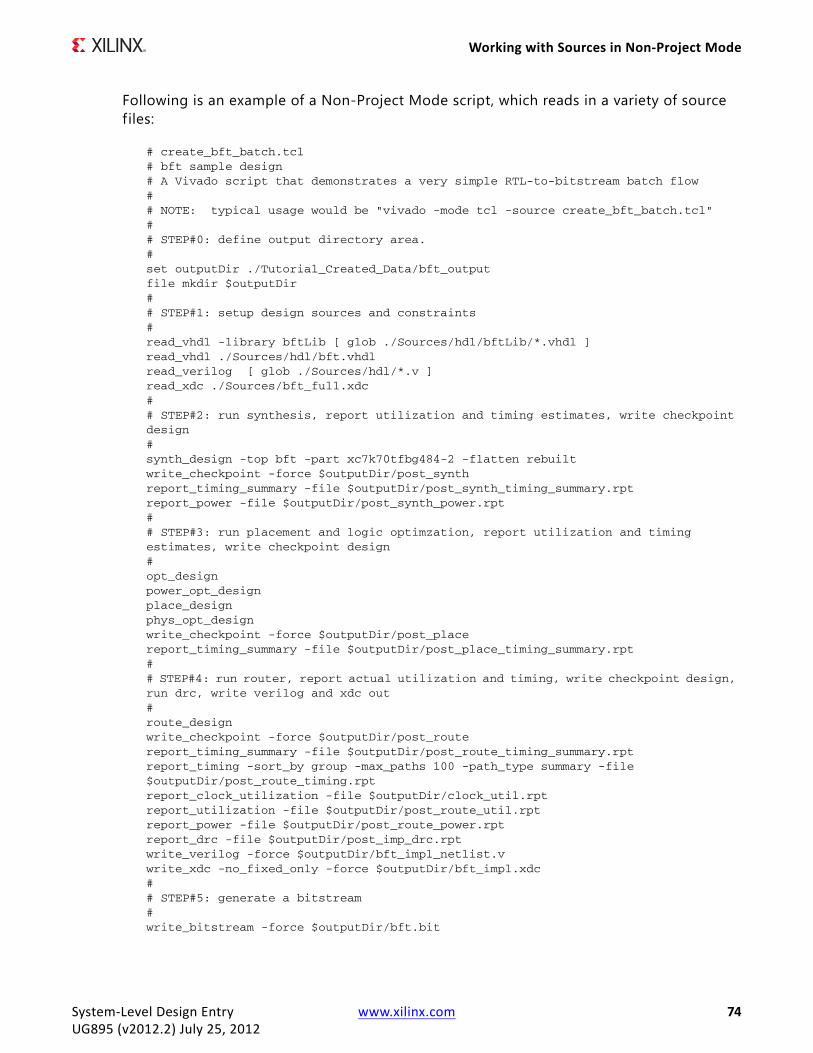
Working with Sources in Non-Project Mode
Following is an example of a Non-Project Mode script, which reads in a variety of source f iles:
# create_bft_batch.tcl# bft sample design # A Vivado script that demonstrates a very simple RTL-to-bitstream batch flow## NOTE: typical usage would be "vivado -mode tcl -source create_bft_batch.tcl" ## STEP#0: define output directory area.#set outputDir ./Tutorial_Created_Data/bft_output file mkdir $outputDir## STEP#1: setup design sources and constraints#read_vhdl -library bftLib [ glob ./Sources/hdl/bftLib/*.vhdl ] read_vhdl ./Sources/hdl/bft.vhdlread_verilog [ glob ./Sources/hdl/*.v ]read_xdc ./Sources/bft_full.xdc## STEP#2: run synthesis, report utilization and timing estimates, write checkpoint design#synth_design -top bft -part xc7k70tfbg484-2 -flatten rebuilt write_checkpoint -force $outputDir/post_synthreport_timing_summary -file $outputDir/post_synth_timing_summary.rptreport_power -file $outputDir/post_synth_power.rpt## STEP#3: run placement and logic optimzation, report utilization and timing estimates, write checkpoint design#opt_designpower_opt_designplace_designphys_opt_designwrite_checkpoint -force $outputDir/post_placereport_timing_summary -file $outputDir/post_place_timing_summary.rpt## STEP#4: run router, report actual utilization and timing, write checkpoint design, run drc, write verilog and xdc out#route_designwrite_checkpoint -force $outputDir/post_routereport_timing_summary -file $outputDir/post_route_timing_summary.rptreport_timing -sort_by group -max_paths 100 -path_type summary -file $outputDir/post_route_timing.rptreport_clock_utilization -file $outputDir/clock_util.rptreport_utilization -file $outputDir/post_route_util.rptreport_power -file $outputDir/post_route_power.rptreport_drc -file $outputDir/post_imp_drc.rptwrite_verilog -force $outputDir/bft_impl_netlist.vwrite_xdc -no_fixed_only -force $outputDir/bft_impl.xdc## STEP#5: generate a bitstream# write_bitstream -force $outputDir/bft.bit
System-Level Design Entry www.xilinx.com 74UG895 (v2012.2) July 25, 2012
Chapter 4
Elaborating the RTL Design
OverviewThe Vivado™ IDE offers many analysis capabilities for an RTL design. For example, you can:
• Visualize design details with Schematic and Hierarchy windows.
• Cross probe between windows.
• Run Design Run Checks (DRCs).
• Check Messaging.
• Search the RTL netlist produced with the Find command.
Elaborating the Design in Project ModeEnabled RTL source files in the project are elaborated regardless of whether they are compiled as a part of the design during synthesis. The Messages window shows the messages from elaboration and compilation. You can select the HDL language options used during elaboration in the Vivado IDE Project Settings. For information, see General Settings in Chapter 2.
Elaboration results are not saved with the design. Every time you open the elaborated design, it is re-elaborated. After you synthesize the elaborated design, the Vivado IDE saves it as a synthesized design.
System-Level Design Entry www.xilinx.com 75UG895 (v2012.2) July 25, 2012

Elaborating the Design in Project Mode
After design source files are imported into the project, you can elaborate the design using one of the following commands:
• Select Flow > Open Elaborated Design.
• In the RTL Analysis section of the Flow Navigator, select Open Elaborated Design to load the elaborated netlist, the active constraint set, and the target device into memory.
• Select Flow > New Elaborated Design.
• In the Flow Navigator, select New Elaborated Design from the RTL Analysis popup menu.
When you open an elaborated design, the Vivado IDE automatically elaborates the RTL source f iles, generates the top schematic view, and displays the design in the default view layout. Figure 4-1 shows the RTL Schematic window with the default view layout of the elaborated design.
The Vivado IDE automatically identif ies the top module for the design in most cases. In some cases, where there might be multiple candidates, the tool prompts you to choose the
X-Ref Target - Figure 4-1
Figure 4-1: Elaborated Design in the RTL Schematic Window
System-Level Design Entry www.xilinx.com 76UG895 (v2012.2) July 25, 2012
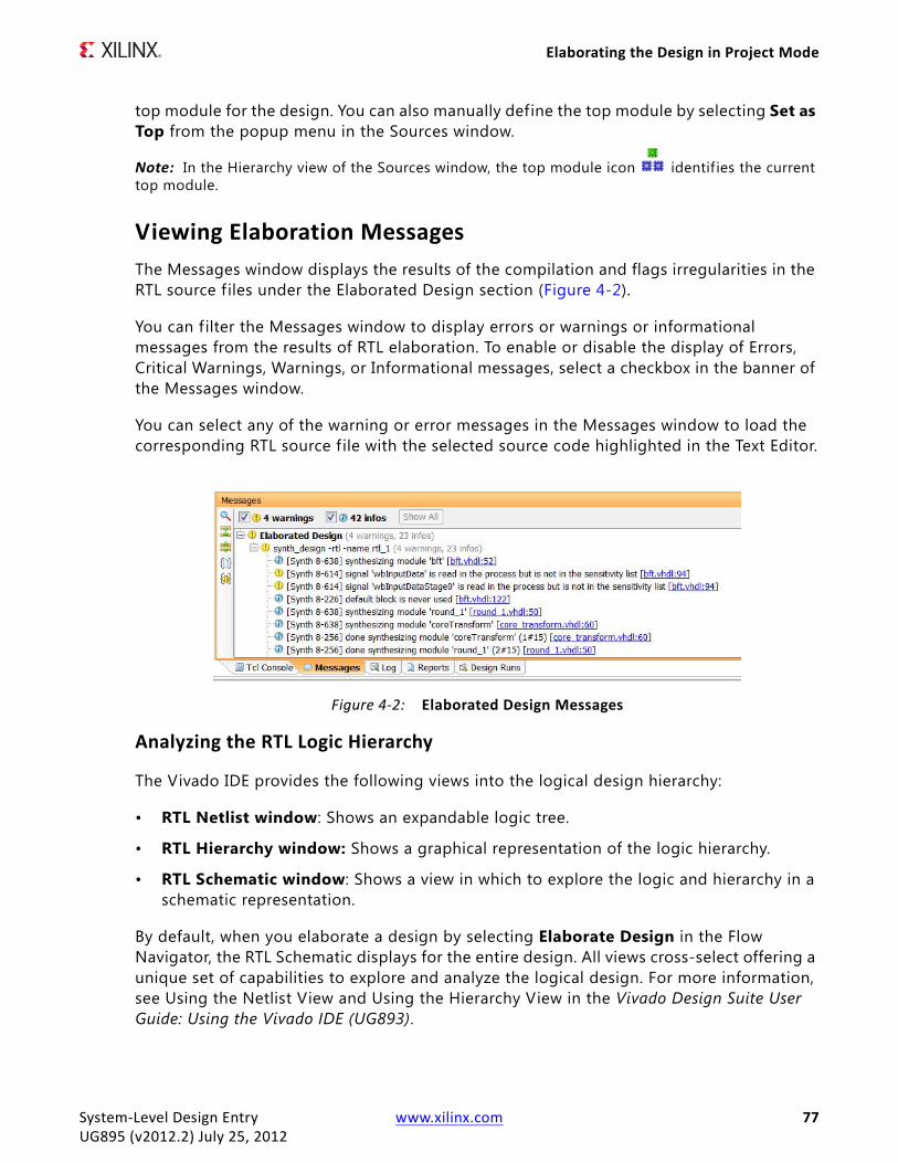
Elaborating the Design in Project Mode
top module for the design. You can also manually define the top module by selecting Set as Top from the popup menu in the Sources window.
Note: In the Hierarchy view of the Sources window, the top module icon identif ies the current top module.
Viewing Elaboration MessagesThe Messages window displays the results of the compilation and flags irregularities in the RTL source f iles under the Elaborated Design section (Figure 4-2).
You can f ilter the Messages window to display errors or warnings or informational messages from the results of RTL elaboration. To enable or disable the display of Errors, Critical Warnings, Warnings, or Informational messages, select a checkbox in the banner of the Messages window.
You can select any of the warning or error messages in the Messages window to load the corresponding RTL source f ile with the selected source code highlighted in the Text Editor.
Analyzing the RTL Logic Hierarchy
The Vivado IDE provides the following views into the logical design hierarchy:
• RTL Netlist window: Shows an expandable logic tree.
• RTL Hierarchy window: Shows a graphical representation of the logic hierarchy.
• RTL Schematic window: Shows a view in which to explore the logic and hierarchy in a schematic representation.
By default, when you elaborate a design by selecting Elaborate Design in the Flow Navigator, the RTL Schematic displays for the entire design. All views cross-select offering a unique set of capabilities to explore and analyze the logical design. For more information, see Using the Netlist View and Using the Hierarchy View in the Vivado Design Suite User Guide: Using the Vivado IDE (UG893).
X-Ref Target - Figure 4-2
Figure 4-2: Elaborated Design Messages
System-Level Design Entry www.xilinx.com 77UG895 (v2012.2) July 25, 2012

Elaborating the Design in Project Mode
Exploring the Elaborated Design Schematic
You can select any level of logic hierarchy in the RTL Netlist window and display it in the RTL Schematic window. To invoke the RTL Schematic window for any selected logic, do one of the following:
• Select Tools > Schematic.
• In the RTL Netlist window, select Schematic from the popup menu.
For more information on traversing, expanding and exploring the RTL Schematic, refer to Using the Schematic View in the Vivado Design Suite User Guide: Using the Vivado IDE (UG893).
Note: After you elaborate the elaborated design, you can use the Find command to search for logic objects using a range of f iltering techniques.
Using the RTL Hierarchy Window
The Vivado IDE includes an RTL Hierarchy window which is useful for viewing the hierarchy of a design. To invoke the RTL Hierarchy view for any selected logic, do one of the following:
• Select Tools > Show Hierarchy.
• In the RTL Netlist or Schematic window, select Show Hierarchy from the popup menu.
These windows have full cross probing support. Logic selected in the RTL Netlist or Schematic window is highlighted in the RTL Hierarchy window.
Exploring the RTL Source Files
You can select any logic element in the RTL Netlist view or Schematic and open the instantiation of that object in the RTL source f ile it is instantiated in. You can also open the definition of the logic in the RTL file it is defined in.
To open the instantiation or definition of any selected logic in the RTL source f ile, select the object and select Go To Instantiation or Go to Definition from the popup menu. The Vivado IDE opens the appropriate source file with the specif ic instance highlighted.
System-Level Design Entry www.xilinx.com 78UG895 (v2012.2) July 25, 2012

Elaborating the Design in Project Mode
Running RTL DRCsThe following sections describe selecting Design Rule Checks (DRCs) rules and analyzing DRC violations in the Vivado IDE.
Selecting DRC Rules
You can run Design Rule Checks (DRCs) on an elaborated design. The available rules focus on power reduction and performance improvement opportunities.
1. Select Tools > Report DRC.
Note: Alternatively, you can select Report DRC in the RTL Analysis section of the Flow Navigator, or enter the report_drc command in the Tcl Console.
2. In the Report DRC dialog box (Figure 4-3), select the required rules, and click OK.
Note: Optionally, you can choose to save the results to a f ile by entering a f ile name. To select a different path than the default, use the browse button.
X-Ref Target - Figure 4-3
Figure 4-3: Report DRC Dialog Box
System-Level Design Entry www.xilinx.com 79UG895 (v2012.2) July 25, 2012

Elaborating the Design in Project Mode
Analyzing DRC Violations
If violations are found, the DRC window opens, as shown in Figure 4-4. The DRC window displays the rule violations found, grouped under the various rule categories defined in the Run DRC dialog box.
The rule violations are also categorized by severity as follows:
• Informational: Makes you aware of a possible issue.
• Warning: Suggests an issue that might need some resolution.
• Error : Highlights issues that prevent proper implementation of your design.
TIP: To turn off warnings and informational messages and see only the errors reported, toggle the Hide Warning and Informational Messages toolbar button .
You can click the header of the Severity column of the DRC Results view to sort violations by severity.
• Click once on the column header to sort in an increasing order.
• Click twice to sort in a decreasing order.
Note: For more information, see Using Data Table Windows in the Vivado Design Suite User Guide: Using the Vivado IDE (UG893).
The DRC window also color codes violations for quick review of errors, warnings, and informational messages.
• Yellow marker : Informational messages
• Orange marker : Warnings
• Red marker : Errors
X-Ref Target - Figure 4-4
Figure 4-4: DRC Window with DRC Violations in the Elaborated Design
System-Level Design Entry www.xilinx.com 80UG895 (v2012.2) July 25, 2012

Elaborating the Design in Non-Project Mode
When you select a violation message in the DRC window, by default the violation properties are shown in the Violation Properties window (Figure 4-5). In the DRC window, you can also select Violation Properties from the popup menu to open the Violation Properties window.
The Violation Properties window shows both a General view of the DRC rule violation and specific Details of the design elements that violate the rule. The Details view includes links to specif ic design objects that violate the DRC. Click the links to view the design object in the RTL Netlist window, the Device window, the Schematic window, or the source RTL f ile.
Elaborating the Design in Non-Project ModeIn Non-Project Mode, you can perform elaboration of the RTL. You can also cross probe back to the RTL and run DRCs. Cross probing requires that you load the Vivado IDE using the start_gui Tcl command. You can perform DRCs with or without the Vivado IDE.
X-Ref Target - Figure 4-5
Figure 4-5: Violation Properties Window
System-Level Design Entry www.xilinx.com 81UG895 (v2012.2) July 25, 2012
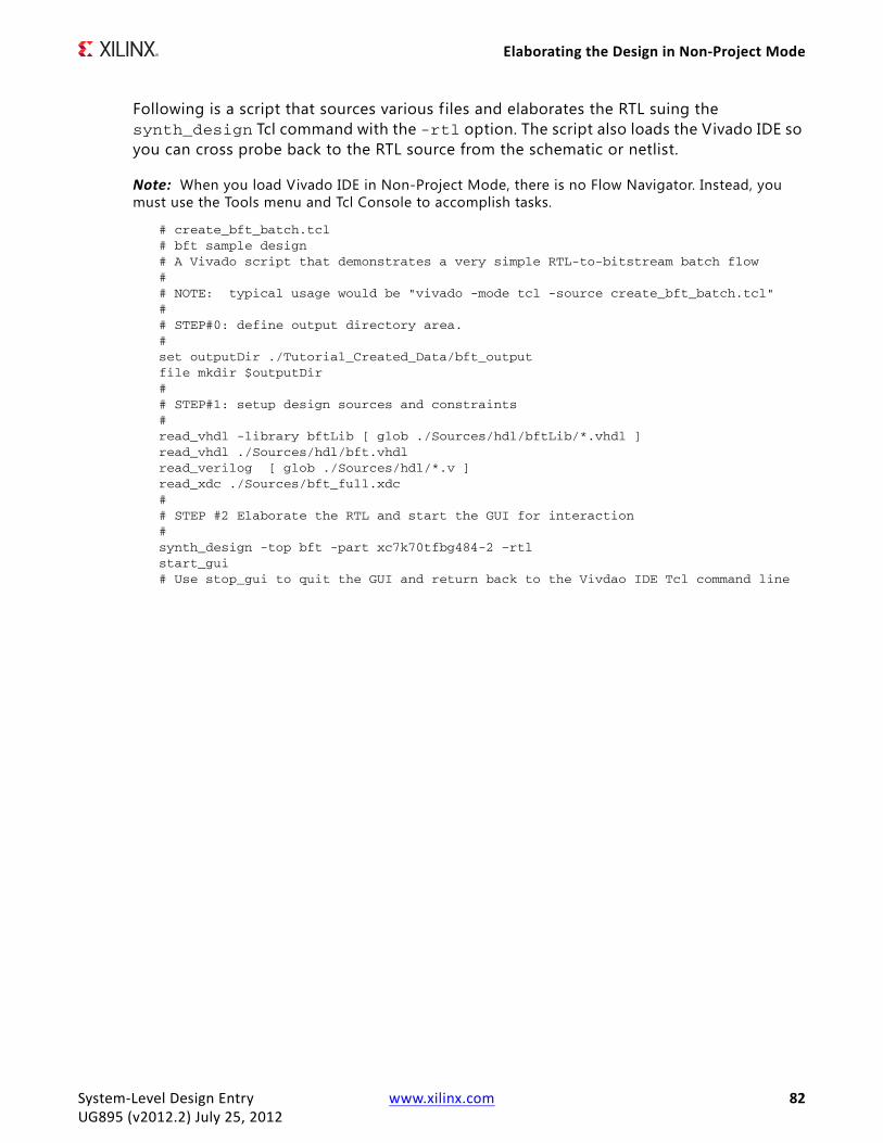
Elaborating the Design in Non-Project Mode
Following is a script that sources various f iles and elaborates the RTL suing the synth_design Tcl command with the -rtl option. The script also loads the Vivado IDE so you can cross probe back to the RTL source from the schematic or netlist.
Note: When you load Vivado IDE in Non-Project Mode, there is no Flow Navigator. Instead, you must use the Tools menu and Tcl Console to accomplish tasks.
# create_bft_batch.tcl# bft sample design # A Vivado script that demonstrates a very simple RTL-to-bitstream batch flow## NOTE: typical usage would be "vivado -mode tcl -source create_bft_batch.tcl" ## STEP#0: define output directory area.#set outputDir ./Tutorial_Created_Data/bft_output file mkdir $outputDir## STEP#1: setup design sources and constraints#read_vhdl -library bftLib [ glob ./Sources/hdl/bftLib/*.vhdl ] read_vhdl ./Sources/hdl/bft.vhdlread_verilog [ glob ./Sources/hdl/*.v ]read_xdc ./Sources/bft_full.xdc## STEP #2 Elaborate the RTL and start the GUI for interaction# synth_design -top bft -part xc7k70tfbg484-2 –rtlstart_gui# Use stop_gui to quit the GUI and return back to the Vivdao IDE Tcl command line
System-Level Design Entry www.xilinx.com 82UG895 (v2012.2) July 25, 2012

Chapter 5
Inserting and Configuring Debugging Information
OverviewDebugging an FPGA design is a multi-step, iterative process. Like most complex problems, it is best to break the FPGA design debugging process down into smaller parts, for example, by focusing on making a smaller section of the design work rather than trying to make the whole design work at one time. An example of a proven design and debug methodology is to iterate through the design flow, adding one module at a time and making it function properly in the context of the whole design. You can use this design and debug methodology in any combination of the following design flow stages:
• RTL-level design simulation
• In-system debugging
In addition to using the Set up Debug wizard, you can also use Tcl commands to create, connect, and insert debug cores into your synthesized design netlist. For more information on debugging, see the Vivado Design Suite User Guide: Programming and Debugging (UG908).
RTL-Level Design SimulationYou can functionally debug the design during the simulation verif ication process. Xilinx® provides a full design simulation feature in the Vivado™ IDE simulator. You can use the Vivado IDE simulator to perform RTL simulation of your design. The benefits of debugging your design in an RTL-level simulation environment include full visibility of the entire design and the ability to quickly iterate through the design and debug cycle. For more information on how to configure and launch simulation, see the Vivado Design Suite User Guide: Logic Simulation (UG900).
System-Level Design Entry www.xilinx.com 83UG895 (v2012.2) July 25, 2012

In-System Debugging
In-System DebuggingThe Vivado IDE also includes a logic analysis feature that enables you to perform in-system debugging of the post-implemented design an FPGA device. The benefit of in-system debugging is that you are able to debug a timing-accurate, post-implemented design in the actual system environment at system speeds. The limitations of in-system debugging includes somewhat lower visibility of debug signals compared to using simulation models and potentially longer design, implementation, and debug iterations, depending on the size and complexity of the design.
The Vivado IDE provides several different ways to debug your design. You can use one or more of these methods to debug your design, depending on your needs. This section focuses on the in-system logic debugging capabilities of the Vivado IDE. For more information, see the Vivado Design Suite User Guide: Programming and Debugging (UG908).
The probing phase of the in-system debugging flow is split into two steps:
1. Identifying signals or nets that you want to probe
2. Deciding how you want to add debug cores to your design
Selecting Signals to DebugYou can identify signals for debugging at the HDL source level prior to synthesis by using the mark_debug attribute. Nets corresponding to signals marked for debug in HDL are automatically listed in the Debug window under the Unassigned Debug Nets view.
To mark nets for debug, mark the HDL signals for debug using the mark_debug attribute in VHDL and Verilog source f iles. The valid values for the mark_debug attribute are “TRUE” or “FALSE”.
Vivado Synthesis mark_debug Syntax Examples
Following are examples of VHDL and Verilog syntax when using Vivado synthesis.
VHDL Syntax Example
attribute mark_debug : string;attribute mark_debug of char_fifo_dout: signal is "true";
Verilog Syntax Example
(* mark_debug = "true" *) wire [7:0] char_fifo_dout;
System-Level Design Entry www.xilinx.com 84UG895 (v2012.2) July 25, 2012

In-System Debugging
Marking Nets for Debug in the Synthesized Design
1. In the Synthesis section of the Flow Navigator, select Open Synthesized Design.
2. In the Unassigned Debug Nets folder in the Debug window (Figure 5-1), check for nets that correspond to HDL signals that were marked for debugging.
3. To mark additional nets in the synthesized design netlist for debugging, use any of following methods:
° Select a net in any of the design views, such as the Netlist or Schematic windows, and select Mark Debug from the popup menu.
° Select a net in any of the design views, and drag and drop the nets into the Unassigned Debug Nets folder.
° Use the net selector in the Set up Debug wizard, as described in Inserting Debug Cores.
Inserting Debug CoresAfter marking nets for debugging, the next step is to assign the nets to debug cores. The Vivado IDE provides a Set Up Debug wizard to help guide you through the process of automatically creating the debug cores and assigning the debug nets to the inputs of the cores.
1. Optional: Select a set of nets for debugging either using the unassigned nets list or direct net selection.
2. Select Tools > Set up Debug.
3. In the Set Up Debug wizard, click Next.
4. In the Specify Nets to Debug page (Figure 5-2), right-click a debug net and select Select Clock Domain to change the clock domain that is used to sample value on the net, and click Next.
X-Ref Target - Figure 5-1
Figure 5-1: Unassigned Debug Nets
System-Level Design Entry www.xilinx.com 85UG895 (v2012.2) July 25, 2012

In-System Debugging
The Set Up Debug wizard attempts to automatically select the appropriate clock domain for the debug net by searching the path for synchronous elements. Use the Select Clock Domain dialog box to modify this selection as needed, but be aware that each clock domain present in the table results in a separate ILA 2.0 core instance.
Note: Optionally, you can click Add/Remove Nets to add more nets or remove existing nets from the table.
5. In the Set Up Debug Summary page, review the summary information, and click Finish to insert and connect the ILA 2.0 cores in your synthesized design netlist.
Note: The ChipScope™ tool wizard inserts one ILA core per clock domain. The nets that were selected for debug are assigned automatically to the probe ports of the inserted ILA 2.0 cores. The Set Up Debug Summary page shows the core creation summary, including the number of clocks found and ILA cores to be created or removed.
Changing Debug Core PropertiesEach debug core has properties you can change to customize the behavior of the core. To learn how to change properties on the debug_core_hub debug core, see the Vivado Design Suite User Guide: Programming and Debugging (UG908).
You can also change properties on the ILA 2.0 debug core. For example, to change the number of samples captured by the ILA 2.0 debug core, do the following:
1. In the Debug window, select the desired ILA core (for example, u_ila_0).
2. In the Instance Properties window, select the Debug Core Options view.
3. Using the C_DATA_DEPTH pull-down list, select the desired number of samples to be captured (Figure 5-3).
X-Ref Target - Figure 5-2
Figure 5-2: Set Up Debug Wizard—Specify Nets to Debug Page
System-Level Design Entry www.xilinx.com 86UG895 (v2012.2) July 25, 2012

In-System Debugging
\X-Ref Target - Figure 5-3
Figure 5-3: Changing the Data Path of the ILA 2.0 Core
System-Level Design Entry www.xilinx.com 87UG895 (v2012.2) July 25, 2012

System-Level Design Entry www.xilinx.com 88UG895 (v2012.2) July 25, 2012
Appendix A
Additional Resources
Xilinx ResourcesFor support resources such as Answers, Documentation, Downloads, and Forums, see the Xilinx® Support website at:
www.xilinx.com/support.
For a glossary of technical terms used in Xilinx documentation, see:
www.xilinx.com/company/terms.htm.
Solution CentersSee the Xilinx Solution Centers for support on devices, software tools, and intellectual property at all stages of the design cycle. Topics include design assistance, advisories, and troubleshooting tips.
References• Vivado™ Design Suite 2012.2 Documentation
(www.xilinx.com/support/documentation/dt_vivado_vivado2012-2.htm)
• EDK Concepts, Tools, and Techniques Guide (UG683)
• Embedded System Tools Reference Manual (UG111)


![Vivado Design Suite User Guide - Xilinx · • Vivado Design Suite User Guide: Design Flows Overview (UG892) [Ref 12] Simulation Flow Simulation can be applied at several points in](https://img.dokumen.tips/doc/110x75/5e7891a0fa73a32c0803c56b/vivado-design-suite-user-guide-xilinx-a-vivado-design-suite-user-guide-design.jpg)


![Vivado Design Suite User Guide - Xilinx€¦ · See the Vivado Design Suite User Guide: Design Flows Overview (UG892) [Ref 8] for more information about operation modes. This chapter](https://img.dokumen.tips/doc/110x75/5ac243957f8b9a1c768dc12e/vivado-design-suite-user-guide-see-the-vivado-design-suite-user-guide-design.jpg)