Embed Size (px)
Citation preview

PRINTED IN U.S.A.
INSTALLATION AND INSTRUCTION VITAL INTERFACE UNIT 16 INPUT (VIU-16I) P/N 80555 & VITAL INTERFACE UNIT 8 INPUT (VIU-8I) P/N 80550 NOVEMBER 2012 (REVISED OCTOBER 2019)
DOCUMENT NO. SIG-00-09-11 VERSION C.2
Siemens Mobility, Inc. 700 East Waterfront Drive Munhall, Pennsylvania 15120 1-800-793-SAFE www.usa.siemens.com/rail-manuals
Copyright © 2012 - 2019 Siemens Mobility, Inc. All rights reserved
ii SIG-00-09-11 NOVEMBER 2012 (REVISED OCTOBER 2019) Version No.: C.2
PROPRIETARY INFORMATION Siemens Mobility, Inc. has a proprietary interest in the information contained herein and, in some instances, has patent rights in the systems and components described. It is requested that you distribute this information only to those responsible people within your organization who have an official interest. This document or the information disclosed herein, shall not be reproduced or transferred to other documents or used or disclosed for manufacturing or for any other purpose except as specifically authorized in writing by Siemens Mobility, Inc.
TRANSLATIONS
The manuals and product information of Siemens Mobility, Inc. are intended to be produced and read in English. Any translation of the manuals and product information are unofficial and can be imprecise and inaccurate in whole or in part. Siemens Mobility, Inc. does not warrant the accuracy, reliability, or timeliness of any information contained in any translation of manual or product information from its original official released version in English and shall not be liable for any losses caused by such reliance on the accuracy, reliability, or timeliness of such information. Any person or entity that relies on translated information does so at his or her own risk.
WARRANTY INFORMATION
Siemens Mobility, Inc. warranty policy is as stated in the current Terms and Conditions of Sale document. Warranty adjustments will not be allowed for products or components which have been subjected to abuse, alteration, improper handling or installation, or which have not been operated in accordance with Seller's instructions. Alteration or removal of any serial number or identification mark voids the warranty.
SALES AND SERVICE LOCATIONS
Technical assistance and sales information on Siemens Mobility, Inc. products may be obtained at the following locations:
SIEMENS MOBILITY, INC. RAIL AUTOMATION SIEMENS MOBILITY, INC. RAIL AUTOMATION 2400 NELSON MILLER PARKWAY 939 S. MAIN STREET LOUISVILLE, KENTUCKY 40223 MARION, KENTUCKY 42064 TELEPHONE: (502) 618-8800 TELEPHONE: (270) 918-7800 FAX: (502) 618-8810 CUSTOMER SERVICE: (800) 626-2710 SALES & SERVICE: (800) 626-2710 TECHNICAL SUPPORT: (800) 793-7233 WEB SITE: http://www.rail-automation.com/ FAX: (270) 918-7830
FCC RULES COMPLIANCE
The equipment covered in this manual has been tested and found to comply with the limits for a Class A digital device, pursuant to part 15 of the FCC Rules. These limits are designed to provide reasonable protection against harmful interference when the equipment is operated in a commercial environment. This equipment generates, uses, and can radiate radio frequency energy and, if not installed and used in accordance with the instruction manual, may cause harmful interference to radio communications. Operation of this equipment in a residential area is likely to cause harmful interference in which case the user will be required to correct the interference at his/her own expense.

iii SIG-00-09-11 NOVEMBER 2012 (REVISED OCTOBER 2019) Version No.: C.2
DOCUMENT HISTORY Version Release
Date Sections Changed
Details of Change
1 Apr 2011 - - - - - INITIAL REVIEW COPY A Aug 2011 - - - - - Version A per VS2-F267 B Nov 2011 ALL C Nov 2012 ALL
C.1 Apr 2014 ALL Convert to Siemens Format C.2 Oct 2019 2, 5, and 7 Added additional Cautions, Warnings, and Notes
iv SIG-00-09-11 NOVEMBER 2012 (REVISED OCTOBER 2019) Version No.: C.2
Table of Contents
Section Title Page PROPRIETARY INFORMATION ......................................................................... ii TRANSLATIONS ................................................................................................. ii WARRANTY INFORMATION............................................................................... ii SALES AND SERVICE LOCATIONS ................................................................... ii FCC RULES COMPLIANCE ................................................................................ ii DOCUMENT HISTORY ...................................................................................... iii NOTES, CAUTIONS, AND WARNINGS ............................................................ xv
ELECTROSTATIC DISCHARGE (ESD) PRECAUTIONS ................................. xvi 1.0 INTRODUCTION .............................................................................................................. 1-1
1.1 General ............................................................................................................................ 1-1 1.2 APPLICATIONS ............................................................................................................... 1-2
1.2.1 Wayside Interface Unit Application .................................................................................. 1-3 1.3 System Data Logs ............................................................................................................ 1-4
1.3.1 Event Log ......................................................................................................................... 1-5 1.3.2 Diagnostic Log ................................................................................................................. 1-5 1.3.3 Status, Summary, and Maintenance Logs ....................................................................... 1-6 1.3.4 Consolidated Logging ...................................................................................................... 1-6
1.4 Hardware Description....................................................................................................... 1-6 1.4.1 User Interface & Connectors ............................................................................................ 1-7 1.4.2 Keypad Operations ........................................................................................................ 1-10 1.4.3 Front Panel Default Display ........................................................................................... 1-10 1.4.4 VIU Main Menu .............................................................................................................. 1-11
1.4.4.1 SITE SETUP Menu .................................................................................................... 1-11 1.4.4.2 CDL Menu .................................................................................................................. 1-13 1.4.4.3 PTC Monitor Menu ..................................................................................................... 1-14 1.4.4.4 Maintainer On Site (MAINTAIN SITE) Menu ............................................................. 1-16 1.4.4.5 USB Menu ................................................................................................................. 1-16 1.4.4.6 USB Drive File Structure............................................................................................ 1-20
1.4.5 Keypad Quick Access Keys ........................................................................................... 1-20 1.5 VIU 16I/-8I Specifications ............................................................................................... 1-21 1.6 VIU-16I/8I Ordering Information ..................................................................................... 1-23
1.6.1 VIU-16I Assembly .......................................................................................................... 1-23 1.6.2 VIU-8i Assembly ............................................................................................................. 1-23 1.6.3 VIU Accessories ............................................................................................................. 1-24
2.0 INSTALLATION ................................................................................................................ 2-1 2.1 General ............................................................................................................................ 2-1
2.1.1 Mounting .......................................................................................................................... 2-1 2.1.2 Ventilation Requirements ................................................................................................. 2-3 2.1.3 Power Connection ............................................................................................................ 2-3
2.1.3.1 Power Conductor Wire Preparation ............................................................................. 2-3 2.1.3.2 Installing EMI Filter on Power Cable ........................................................................... 2-4
2.1.4 Surge Protection .............................................................................................................. 2-5

v SIG-00-09-11 NOVEMBER 2012 (REVISED OCTOBER 2019) Version No.: C.2
2.1.5 Vital Inputs ....................................................................................................................... 2-6 2.1.5.1 Discrete Vital Input / Output Connections .................................................................... 2-6 2.1.5.2 Connector Wiring Procedure ....................................................................................... 2-6
2.1.6 Serial Interfaces ............................................................................................................... 2-7 2.1.6.1 Laptop (Serial) Interface .............................................................................................. 2-7 2.1.6.2 Serial Interface (Top Panel) ......................................................................................... 2-7
2.1.7 Ethernet Interfaces ........................................................................................................... 2-7 2.1.8 GPS Port .......................................................................................................................... 2-9 2.1.9 GPS Antenna ................................................................................................................... 2-9 2.1.10 USB Interface ................................................................................................................... 2-9
3.0 BASIC VIU OPERATION ................................................................................................. 3-1 3.1 POWER-UP ..................................................................................................................... 3-1
3.1.1 VIU Real-Time Clock........................................................................................................ 3-2 3.1.2 Front Panel Boot Display Sequence ................................................................................ 3-2
3.2 Transferring Files to the VIU ............................................................................................ 3-3 3.2.1 USB Drive File Structure .................................................................................................. 3-4 3.2.2 File Transfer Options........................................................................................................ 3-4
3.2.2.1 Download Reports from VIU Into USB Drive ............................................................... 3-5 3.2.2.2 Download Files from VIU Into USB Drive .................................................................... 3-5 3.2.2.3 Upload Files from USB Drive Into VIU ......................................................................... 3-5
3.2.3 Exiting the USB Drive....................................................................................................... 3-6 3.3 VIU Configuration ............................................................................................................. 3-6 3.4 VIU Operating States ....................................................................................................... 3-7 3.5 Configuration Verification At Startup ................................................................................ 3-8 3.6 INTEROPERABLE Train Control Messaging (ITCH) System.......................................... 3-9 3.7 GPS TIME REFERENCE ................................................................................................. 3-9 3.8 Multiple VIUS In A System ............................................................................................... 3-9
4.0 VIU SETUP ...................................................................................................................... 4-1 4.1 Introduction ...................................................................................................................... 4-1 4.2 Software Load And Configuration Sequence ................................................................... 4-2 4.3 How Equipment Is Mapped to Vital Inputs/Outputs ......................................................... 4-4
4.3.1 Voltage and Current Sensor Options ............................................................................... 4-4 4.3.1.1 Generic Voltage Sensing Application .......................................................................... 4-5 4.3.1.2 Current Sensor Application .......................................................................................... 4-7 4.3.1.3 Using Current Sensors in Voltage Sensing Applications ........................................... 4-10
4.3.2 Switch Application .......................................................................................................... 4-12 4.3.3 Hazard Detector Application .......................................................................................... 4-14
4.4 Sample Aspect Codes Decoded By VIU ........................................................................ 4-15 4.5 Procedure For Calculating A New UCN ......................................................................... 4-16 4.6 Configure A VIU-16I\-8I Via Browser And DT ................................................................ 4-17 4.7 Configure A VIU-16I/-8I Using CDL Via USB Drive ....................................................... 4-18 4.8 Configure A VIU-16I/-8I Using PTC CFG XML File Via USB Drive ............................... 4-19 4.9 Place A VIU-16I/-8I Into Operation ................................................................................ 4-19
5.0 WAYSIDE INTERFACE UNIT APPLICATION ................................................................. 5-1 5.1 Introduction ...................................................................................................................... 5-1 5.2 Wayside Interface Unit ..................................................................................................... 5-2
vi SIG-00-09-11 NOVEMBER 2012 (REVISED OCTOBER 2019) Version No.: C.2
5.2.1 Vital Interface Unit ............................................................................................................ 5-2 5.2.1.1 Multiple VIUs in a Large Interlocking ........................................................................... 5-2 5.2.1.2 Message Time Stamp .................................................................................................. 5-2 5.2.1.3 Message Security ........................................................................................................ 5-3
5.2.2 Interoperable Train Communications Messaging (ITCM) ................................................ 5-3 5.2.3 Train Management Computer (TMC) ............................................................................... 5-3 5.2.4 Typical Wayside Interface System Interconnect Diagram (Single VIU) ........................... 5-4 5.2.5 Typical Wayside Interface System Interconnect Diagram (Multiple VIUs) ...................... 5-5
6.0 DIAGNOSTIC TERMINAL (DT) SOFTWARE .................................................................. 6-1 6.1 Introduction ...................................................................................................................... 6-1 6.2 DT to VIU Interface .......................................................................................................... 6-1 6.3 Program Startup ............................................................................................................... 6-2
6.3.1 Startup Sequence ............................................................................................................ 6-2 6.4 Input Status Overview Screen For VIU ............................................................................ 6-4 6.5 COMM (Communications) Button Menu .......................................................................... 6-7
6.5.1 Port Setup ........................................................................................................................ 6-7 6.6 View Button Menu ............................................................................................................ 6-8
6.6.1 On-Line Status ................................................................................................................. 6-9 6.6.2 System States .................................................................................................................. 6-9
6.6.2.1 Viewing Input Logic States ........................................................................................ 6-10 6.6.2.2 Input Logic States Display ......................................................................................... 6-10
6.6.3 Software Information ...................................................................................................... 6-11 6.7 PROG (Program) Button Menu ...................................................................................... 6-12
6.7.1 Online and Offline Display Screens ............................................................................... 6-12 6.7.2 Changing Locked Configuration Parameters ................................................................. 6-13 6.7.3 PHYSICAL Configuration ............................................................................................... 6-14
6.7.3.1 Physical Layout .......................................................................................................... 6-15 6.7.3.2 MODULE Configuration ............................................................................................. 6-15 6.7.3.3 ITC Configuration ....................................................................................................... 6-21 6.7.3.4 CONNECTION Configuration .................................................................................... 6-22 6.7.3.5 WIU CHANNEL Configuration ................................................................................... 6-25 6.7.3.6 Set to Defaults ........................................................................................................... 6-27
6.7.4 LOGICAL Configuration ................................................................................................. 6-27 6.7.4.1 Logical Layout ............................................................................................................ 6-28 6.7.4.2 OBJECT Configuration .............................................................................................. 6-29
6.7.5 SITE Configuration ......................................................................................................... 6-33 6.7.5.1 Location ..................................................................................................................... 6-33 6.7.5.2 Object Names ............................................................................................................ 6-34 6.7.5.3 Card Names ............................................................................................................... 6-34
6.8 Logs / History Buttons .................................................................................................... 6-35 6.8.1 Maintenance Log ............................................................................................................ 6-35 6.8.2 Status Log ...................................................................................................................... 6-36 6.8.3 Summary Log ................................................................................................................. 6-37
6.9 Diag (Diagnostics) Button .............................................................................................. 6-37 6.10 VIU-16I\-8I XML File....................................................................................................... 6-37
7.0 VIU WEB BROWSER USER INTERFACE ...................................................................... 7-1 7.1 iNTRODUCTION .............................................................................................................. 7-1 7.2 LAUNCHING THE VIU WEB BROWSER ........................................................................ 7-1
7.2.1 Web Browser Icons .......................................................................................................... 7-1 7.2.2 Web Browser Icons .......................................................................................................... 7-3

vii SIG-00-09-11 NOVEMBER 2012 (REVISED OCTOBER 2019) Version No.: C.2
7.3 ACCESSING NON-VITAL CONFIGURATION PARAMETERS ...................................... 7-6 7.3.1 ACSES II Network ............................................................................................................ 7-8
7.3.1.1 ACSES-II UDP Enabled............................................................................................... 7-8 7.3.1.2 UDP Port ...................................................................................................................... 7-8 7.3.1.3 RRP Multicast Group ................................................................................................... 7-8
7.3.2 ATCS Router Configuration ............................................................................................. 7-8 7.3.2.1 Route Timeout ............................................................................................................. 7-8
7.3.3 CDL Log ........................................................................................................................... 7-9 7.3.4 Diagnostic Log Configuration ......................................................................................... 7-10
7.3.4.1 Server IP .................................................................................................................... 7-10 7.3.4.2 Verbosity .................................................................................................................... 7-11
7.3.5 EMP – WIU Configuration .............................................................................................. 7-11 7.3.5.1 WIU Address .............................................................................................................. 7-12 7.3.5.2 Encrypted HMAC Key ................................................................................................ 7-13 7.3.5.3 RC2 Key..................................................................................................................... 7-13 7.3.5.4 Message Version ....................................................................................................... 7-13 7.3.5.5 EMP Header Source Address ................................................................................... 7-13 7.3.5.6 EMP Header Destination Address ............................................................................. 7-13 7.3.5.7 EMP Timed Beacon TTL ........................................................................................... 7-13 7.3.5.8 EMP WIU Status Response TTL ............................................................................... 7-14 7.3.5.9 EMP Timed Beacon QOS .......................................................................................... 7-14 7.3.5.10 EMP WIU Status Response QOS ......................................................................... 7-14 7.3.5.11 Class C Multicast IP Address ................................................................................ 7-14 7.3.5.12 Access Gateway (AG) IP Address (Class D Remote Address) ............................ 7-14 7.3.5.13 Access Gateway (AG) Port (Class D Remote Port) .............................................. 7-14 7.3.5.14 Log Traffic.............................................................................................................. 7-14 7.3.5.15 Keep Alive Interval (msec) .................................................................................... 7-14 7.3.5.16 Keep Alive ACK Timeout (msec) ........................................................................... 7-15 7.3.5.17 Class D Data ACK Enabled ................................................................................... 7-15 7.3.5.18 Data ACK Timeout (msec) .................................................................................... 7-15 7.3.5.19 Data NAK Retry Limit ............................................................................................ 7-15 7.3.5.20 Retransmit Delay (msec) ....................................................................................... 7-15 7.3.5.21 Connection Attempt Timeout (msec) ..................................................................... 7-15 7.3.5.22 Connection Delay (msec) ...................................................................................... 7-15 7.3.5.23 Connection Retry Limit .......................................................................................... 7-16 7.3.5.24 Reconnection Limit ................................................................................................ 7-16
7.3.6 Ethernet Configuration ................................................................................................... 7-16 7.3.6.1 DHCP Configuration (Laptop Tab) ............................................................................ 7-17 7.3.6.2 Laptop IP (Laptop Tab) .............................................................................................. 7-17 7.3.6.3 Laptop Gateway (Laptop Tab) ................................................................................... 7-17 7.3.6.4 Laptop Network Mask (Laptop Tab) .......................................................................... 7-17 7.3.6.5 DHCP Configuration (Port 1) ..................................................................................... 7-18 7.3.6.6 IP (Port 1) .................................................................................................................. 7-18 7.3.6.7 Gateway (Port 1) ........................................................................................................ 7-18 7.3.6.8 Network Mask (Port 1) ............................................................................................... 7-18 7.3.6.9 DHCP Configuration (Port 2) ..................................................................................... 7-19 7.3.6.10 IP (port 2)............................................................................................................... 7-19 7.3.6.11 Gateway (Port 2) ................................................................................................... 7-19 7.3.6.12 Network Mask (Port 2) ........................................................................................... 7-19
7.3.7 Event Log Configuration ................................................................................................ 7-19 7.3.7.1 Server IP .................................................................................................................... 7-19
7.3.8 GPS Configuration ......................................................................................................... 7-20 7.3.8.1 Internal GPS Enabled ................................................................................................ 7-21 7.3.8.2 Receive Timeout (secs) ............................................................................................. 7-21 7.3.8.3 Time Message Deviation (secs) ................................................................................ 7-22
viii SIG-00-09-11 NOVEMBER 2012 (REVISED OCTOBER 2019) Version No.: C.2
7.3.8.4 Consolidated Time Server (checkbox) ...................................................................... 7-22 7.3.8.5 Max Time Change Within Minutes (min) ................................................................... 7-22 7.3.8.6 Max Secs Time Change (sec) ................................................................................... 7-22 7.3.8.7 Ignored Time Difference (sec) ................................................................................... 7-23 7.3.8.8 Time Msgs Before Sending WSM (sec) .................................................................... 7-23 7.3.8.9 LRM Maximum Seconds Time Difference (sec) ........................................................ 7-23 7.3.8.10 No Time Sync Msg (min) ....................................................................................... 7-23
7.3.9 High Availability (Connection 1 – Connection 12) .......................................................... 7-24 7.3.10 Serial Port Configuration ................................................................................................ 7-24
7.3.10.1 Baud Rate (Laptop Tab) ........................................................................................ 7-25 7.3.10.2 Flow Control (Laptop Tab) ..................................................................................... 7-25 7.3.10.3 Parity (Laptop Tab) ................................................................................................ 7-25 7.3.10.4 Data Bits (Laptop Tab) .......................................................................................... 7-26 7.3.10.5 Stop Bits (Laptop Tab) .......................................................................................... 7-26 7.3.10.6 Protocol (Laptop Tab) ............................................................................................ 7-26 7.3.10.7 Baud Rate (Port One Tab) .................................................................................... 7-27 7.3.10.8 Flow Control (Port One Tab) ................................................................................. 7-27 7.3.10.9 Parity (Port One Tab) ............................................................................................ 7-27 7.3.10.10 Data Bits (Port One Tab) ....................................................................................... 7-27 7.3.10.11 Stop Bits (Port One Tab) ....................................................................................... 7-27 7.3.10.12 Protocol (Port One Tab) ........................................................................................ 7-27
7.3.11 Site Info Configuration ................................................................................................... 7-27 7.3.11.1 Site Name .............................................................................................................. 7-29 7.3.11.2 Milepost ................................................................................................................. 7-29 7.3.11.3 DOT Number ......................................................................................................... 7-29 7.3.11.4 Time Zone ............................................................................................................. 7-29 7.3.11.5 Site ATCS Address ............................................................................................... 7-29 7.3.11.6 MCF CRC .............................................................................................................. 7-29 7.3.11.7 Additional Data ...................................................................................................... 7-29
7.3.12 SNMP ............................................................................................................................. 7-30 7.3.13 SNTP .............................................................................................................................. 7-31
7.3.13.1 NTP Mode ............................................................................................................. 7-31 7.3.13.2 Primary NTP Time Source .................................................................................... 7-31 7.3.13.3 Backup NTP Time Source ..................................................................................... 7-32 7.3.13.4 NTP Multicast Address .......................................................................................... 7-32 7.3.13.5 NTP UDP Port ....................................................................................................... 7-32 7.3.13.6 NTP Polling Rate ................................................................................................... 7-32 7.3.13.7 NTP Wait Time ...................................................................................................... 7-32
7.3.14 TCP Port Configuration .................................................................................................. 7-32 7.3.14.1 DT TCP Port .......................................................................................................... 7-33 7.3.14.2 VTP TCP Port ........................................................................................................ 7-33 7.3.14.3 AServer UDP Port ................................................................................................. 7-33 7.3.14.4 Route Region One IP ............................................................................................ 7-34 7.3.14.5 Route Region Two IP ............................................................................................ 7-34 7.3.14.6 Route Maintain Timer ............................................................................................ 7-34 7.3.14.7 Route Establish Timer ........................................................................................... 7-34 7.3.14.8 Circuit ID ................................................................................................................ 7-34 7.3.14.9 Office Path Byte .................................................................................................... 7-34
7.3.15 Time Source ................................................................................................................... 7-35 7.4 VIEWING LOGS ............................................................................................................. 7-35
7.4.1 Diagnostic Log ............................................................................................................... 7-36 7.4.2 Event Log ....................................................................................................................... 7-40 7.4.3 CDL Log ......................................................................................................................... 7-40
7.5 MAINTENANCE ............................................................................................................. 7-41 7.5.1 Class D Tests ................................................................................................................. 7-41

ix SIG-00-09-11 NOVEMBER 2012 (REVISED OCTOBER 2019) Version No.: C.2
7.5.1.1 Test Server IP Address .............................................................................................. 7-41 7.5.1.2 Test Server Port Number ........................................................................................... 7-41 7.5.1.3 Test Frame Count ...................................................................................................... 7-41 7.5.1.4 Delay Between Test Frames (msec) ......................................................................... 7-41 7.5.1.5 ITC Class D Starting Comm ID .................................................................................. 7-41
7.5.2 System Time .................................................................................................................. 7-42 7.5.2.1 Set Time Button ......................................................................................................... 7-43 7.5.2.2 Computer Time .......................................................................................................... 7-43 7.5.2.3 VIU Time .................................................................................................................... 7-43
7.6 STATUS ......................................................................................................................... 7-44 7.6.1 GPS ................................................................................................................................ 7-44 7.6.2 Health ............................................................................................................................. 7-45 7.6.3 Reports ........................................................................................................................... 7-46 7.6.4 Config Report ................................................................................................................. 7-46 7.6.5 Version Report ............................................................................................................... 7-48 7.6.6 Application ...................................................................................................................... 7-49
7.6.6.1 Site Setup .................................................................................................................. 7-49 7.6.6.2 Upload CDL ............................................................................................................... 7-51 7.6.6.3 Operational Parameters............................................................................................. 7-52
8.0 MAINTENANCE AND TROUBLESHOOTING ................................................................. 8-1 8.1 MAINTENANCE ............................................................................................................... 8-1
8.1.1 Battery Maintenance ........................................................................................................ 8-1 8.1.2 Uploading Software to the VIU from a USB Drive ........................................................... 8-1 8.1.3 Downloading Event and Diagnostic Logs from the VIU to a USB Drive .......................... 8-2
8.2 TROUBLESHOOTING ..................................................................................................... 8-3 8.2.1 Status LEDs ..................................................................................................................... 8-3 8.2.2 LED Activity at Power-Up ................................................................................................. 8-4 8.2.3 Possible System Problems .............................................................................................. 8-4 8.2.4 Using DT Diagnostic Tools .............................................................................................. 8-6
8.2.4.1 Statistics....................................................................................................................... 8-6 8.2.4.2 Sniffer........................................................................................................................... 8-7
8.2.5 Other Useful Tools ........................................................................................................... 8-8 9.0 DEFINING VIU CONFIGURATION PARAMETERS ........................................................ 9-1
9.1 Introduction ...................................................................................................................... 9-1 9.2 GCS Software and VIU Configurable Parameters ........................................................... 9-1

x SIG-00-09-11 NOVEMBER 2012 (REVISED OCTOBER 2019) Version No.: C.2
LIST OF FIGURES Section Title Page
Figure 1-1 Vital Interface Unit (VIU-16i) ................................................................................................... 1-1 Figure 1-2 VIU-16i/8i Applications ........................................................................................................... 1-3 Figure 1-3 VIU Used in Wayside Interface Unit Application .................................................................... 1-4 Figure 1-4 VIU 16i User Interface & Connector Locations ....................................................................... 1-7 Figure 1-5 Keypad Quick Access Keys .................................................................................................. 1-10 Figure 1-6 Main Menu Navigation .......................................................................................................... 1-11 Figure 1-7 SITE SETUP Menu ............................................................................................................... 1-13 Figure 1-8 CDL Menu ............................................................................................................................. 1-14 Figure 1-9 PTC Monitor Menu ............................................................................................................... 1-15 Figure 1-10 Maintainer On Site (MAINTAIN SITE) Menu ...................................................................... 1-16 Figure 1-11 Event Reporting Process Screens ..................................................................................... 1-17 Figure 1-12 Downloading MCF or Configuration File Process .............................................................. 1-17 Figure 1-13 Uploading Vital MCF File Process ...................................................................................... 1-18 Figure 1-14 USB Menu Map .................................................................................................................. 1-19 Figure 1-15 Example USB Drive File Structure ..................................................................................... 1-20 Figure 1-16 VIU-16i and Accessory Ordering Information ..................................................................... 1-23 Figure 1-17 VIU-8i and Accessory Ordering Information ....................................................................... 1-23 Figure 1-18 VIU Accessory Ordering Information .................................................................................. 1-24 Figure 2-1 Rack or Wall-Mount Plate, D39619 ........................................................................................ 2-2 Figure 2-2 Shelf-Mount Stabilizing Plate, D39620 ................................................................................... 2-2 Figure 2-3 Power & ECD Connector ........................................................................................................ 2-3 Figure 2-4 Inserting Wire in Cage Clamp Type Connector ...................................................................... 2-3 Figure 2-5 Clamp-on EMI Filter (Open) ................................................................................................... 2-4 Figure 2-6 EMI Filter Installation (Showing Wire Loops) ......................................................................... 2-5 Figure 2-7 EMI Filter Installed .................................................................................................................. 2-5 Figure 3-1 VIU Initial Boot Process Screens............................................................................................ 3-2 Figure 3-2 VIU Start Screen ..................................................................................................................... 3-3 Figure 3-3 VIU Default Top Level Screen ................................................................................................ 3-3 Figure 3-4 Example USE File Structure ................................................................................................... 3-4 Figure 4-1 Example USB Drive File Structure ......................................................................................... 4-2 Figure 4-2 VIU Software Load & Configuration Sequence ...................................................................... 4-3 Figure 4-3 Voltage Sensing Wiring Diagram............................................................................................ 4-5 Figure 4-4 Example Voltage Sensing Menus........................................................................................... 4-6 Figure 4-5 Current Sensor Wiring Diagram ............................................................................................. 4-7 Figure 4-6 Example Current Sensor Application ..................................................................................... 4-8 Figure 4-7 Current Sensor Wiring in Voltage Sensing Application ........................................................ 4-10 Figure 4-8 Example Current Sensor Used in Voltage Sensing Application ........................................... 4-11 Figure 4-9 Switch Application Programming .......................................................................................... 4-13 Figure 4-10 Hazard Detector Application Programming ........................................................................ 4-14 Figure 5-1 VIU Monitoring Switches and Signals in an Interlocking ........................................................ 5-1 Figure 5-2 Typical Wayside Interface System Interconnect Diagram (Single VIU) ................................. 5-4 Figure 5-3 Typical Wayside Interface System Interconnect Diagram (Multiple VIUs) ............................. 5-5 Figure 6-1 VIU16i Front Panel Laptop PC Interface Connectors............................................................. 6-1 Figure 6-2 DT Start-Up Screens .............................................................................................................. 6-3 Figure 6-3 COMM Drop Down Menu ....................................................................................................... 6-4 Figure 6-4 DT Input Status Overview Screen for VIU .............................................................................. 6-4 Figure 6-5 VIU-16i\-8i DT Top Level ........................................................................................................ 6-5 Figure 6-6 Input Status Screen Indicator Descriptions ............................................................................ 6-5 Figure 6-7 DT Status Screen Indicators to Physical Connectors............................................................. 6-6 Figure 6-8 Module Drop-Down Menu ....................................................................................................... 6-6 Figure 6-9 COMM Pull-Down Menu ......................................................................................................... 6-7 Figure 6-10 DT Communications Settings Dialog Box ............................................................................ 6-7

xi SIG-00-09-11 NOVEMBER 2012 (REVISED OCTOBER 2019) Version No.: C.2
Figure 6-11 List of Networked VIU Devices ............................................................................................. 6-8 Figure 6-12 View Button Pull-Down Menu ............................................................................................... 6-8 Figure 6-13 Real-Time View of VIU Status Log ....................................................................................... 6-9 Figure 6-14 Viewing Input States Using System States Function ........................................................... 6-9 Figure 6-15 Logic State Select Range Dialog Box ................................................................................ 6-10 Figure 6-16 Input Logic States Display .................................................................................................. 6-11 Figure 6-17 Software Information Screen .............................................................................................. 6-11 Figure 6-18 The Program (Prog) Button ................................................................................................ 6-12 Figure 6-19 MAIN PROGRAM Menu Screen......................................................................................... 6-12 Figure 6-20 Edit Button Location ........................................................................................................... 6-13 Figure 6-21 Unlock Configuration Parameters Prompt .......................................................................... 6-13 Figure 6-22 Main Program Menu Window ............................................................................................. 6-14 Figure 6-23 PHYSICAL Configuration Screens ..................................................................................... 6-15 Figure 6-24 MODULE Configuration Screen ......................................................................................... 6-16 Figure 6-25 (A) SLOT 1:sl1 (VIU_BRIO), & (B) SLOT 1:sl1 (VIU_BRIO) Cont Screens ....................... 6-16 Figure 6-26 SLOT 2:sl2 (BRIO) Screen ................................................................................................. 6-17 Figure 6-27 Typical Module Configuration Set Parameter Screens ...................................................... 6-18 Figure 6-28 Password Enabled .............................................................................................................. 6-20 Figure 6-29 Password – Set Parameter Dialog Box .............................................................................. 6-21 Figure 6-30 CONNECTION: Main/r1 Screen ......................................................................................... 6-22 Figure 6-31 CONNECTION: Main/r1 Screen ......................................................................................... 6-23 Figure 6-32 Typical Connection Links Parameter Screens ................................................................... 6-23 Figure 6-33 WIU CHANNEL Configuration Screen ............................................................................... 6-25 Figure 6-34 Set Parameters to Default Prompt...................................................................................... 6-27 Figure 6-35 The MAIN PROGRAM Menu Window ................................................................................ 6-27 Figure 6-36 LOGICAL Configuration Screen ......................................................................................... 6-28 Figure 6-37 Logical Layout Selection Screen ........................................................................................ 6-28 Figure 6-38 OBJECT Configuration Screens ......................................................................................... 6-29 Figure 6-39 Sig01 Menu ......................................................................................................................... 6-30 Figure 6-40 Sig01 Head A Layout Menu ................................................................................................ 6-31 Figure 6-41 Example Lamp 3 Head A on Slave 1 Menu ....................................................................... 6-32 Figure 6-42 (A) Switch 1 (SW01) and (B) Hazard Detector 1 (BF01) Menus ........................................ 6-32 Figure 6-43 SITE Configuration Screens ............................................................................................... 6-33 Figure 6-44 Location Editor .................................................................................................................... 6-33 Figure 6-45 Object Name Editor ............................................................................................................ 6-34 Figure 6-46 Card Name Editor ............................................................................................................... 6-35 Figure 6-47 Logs Pull-Down Menu ........................................................................................................ 6-35 Figure 6-48 Maintenance Log Screen .................................................................................................... 6-36 Figure 6-49 Status Log Screen .............................................................................................................. 6-36 Figure 6-50 Summary Log Screen ......................................................................................................... 6-37 Figure 6-51 VIU OCE Window with VIU XML File Selected .................................................................. 6-38 Figure 6-52 VIU-16i\-8i XML File Window .............................................................................................. 6-38 Figure 6-53 Generic VIU-16i\8i Application Diagram ............................................................................. 6-38 Figure 6-54 VIU-16i\8i XML File Window ............................................................................................... 6-39 Figure 6-55 VIU-16i\-8i Device Information Window .............................................................................. 6-41 Figure 7-1 Establishing Web U/I Setup Parameters ................................................................................ 7-1 Figure 7-2 Internet Explorer URL Line ..................................................................................................... 7-2 Figure 7-3 VIU Web Browser Login Screen ............................................................................................. 7-2 Figure 7-4 Web Browser Login Dialog Box .............................................................................................. 7-2 Figure 7-5 Web Browser Welcome Screen.............................................................................................. 7-3 Figure 7-6 Welcome Screen and Login Status ........................................................................................ 7-3 Figure 7-7 Status Icons ............................................................................................................................ 7-3 Figure 7-8 Icon Definitions ....................................................................................................................... 7-4 Figure 7-9 Standard VIU Non-Vital Parameter Update Buttons .............................................................. 7-4 Figure 7-10 Standard VIU Non-Vital Parameter Update Confirmation Buttons ....................................... 7-4 Figure 7-11 Standard VIU Vital Parameter Update Buttons .................................................................... 7-5

xii SIG-00-09-11 NOVEMBER 2012 (REVISED OCTOBER 2019) Version No.: C.2
Figure 7-12 Edit Mode Reboot Indicator .................................................................................................. 7-5 Figure 7-13 Value Change Pending Indicator .......................................................................................... 7-5 Figure 7-14 Invalid Entry Highlighted ....................................................................................................... 7-5 Figure 7-15 Invalid Entry Explanation Window ........................................................................................ 7-6 Figure 7-16 Non-Vital Configuration Menu Selection .............................................................................. 7-6 Figure 7-17 Non-Vital Configuration Parameters ..................................................................................... 7-7 Figure 7-18 ACSES II Network Configuration Menu ................................................................................ 7-8 Figure 7-19 CDL Log Configuration Screen............................................................................................. 7-9 Figure 7-20 Diagnostic Log Configuration Screen ................................................................................. 7-10 Figure 7-21 Diagnostic Log Verbosity Levels ........................................................................................ 7-11 Figure 7-22 EMP – WIU Configuration Screen ...................................................................................... 7-12 Figure 7-23 Ethernet Configuration Screen (Laptop Tab) ..................................................................... 7-16 Figure 7-24 Ethernet Configuration Screen (Port 1 Tab) ....................................................................... 7-17 Figure 7-25 Ethernet Configuration Screen (Port 2) .............................................................................. 7-18 Figure 7-26 Event Log Configuration Screen......................................................................................... 7-20 Figure 7-27 GPS Configuration Screen ................................................................................................. 7-20 Figure 7-28 GPS Time Source Selection Menu ..................................................................................... 7-21 Figure 7-29 High Availability (Enabled) Configuration Menu ................................................................. 7-24 Figure 7-30 Serial Port Configuration Menu – Laptop Tab .................................................................... 7-25 Figure 7-31 Serial Port Configuration Menu – Port 1 Tab ..................................................................... 7-26 Figure 7-32 Site Info Configuration Screen – Edit Mode Locked........................................................... 7-28 Figure 7-33 Site Info Configuration Screen – Edit Mode Unlocked w/Reboot Prompt .......................... 7-28 Figure 7-34 SNMP Configuration Screen .............................................................................................. 7-30 Figure 7-35 SNTP Configuration Screen ............................................................................................... 7-31 Figure 7-36 TCP Port Configuration Screen .......................................................................................... 7-33 Figure 7-37 Time Source (Enabled) Configuration Window .................................................................. 7-35 Figure 7-38 Logs Screen........................................................................................................................ 7-35 Figure 7-39 Diagnostic Log – Basic View .............................................................................................. 7-36 Figure 7-40 File Download Prompt ........................................................................................................ 7-36 Figure 7-41 File Save Screen ................................................................................................................ 7-37 Figure 7-42 File Opened in Notepad ...................................................................................................... 7-37 Figure 7-43 Log View Drop Down Menu ................................................................................................ 7-38 Figure 7-44 Diagnostic Log – Advanced View ....................................................................................... 7-38 Figure 7-45 Diagnostic Log - Advanced Settings .................................................................................. 7-38 Figure 7-46 Diagnostic Log – Trace Events View .................................................................................. 7-39 Figure 7-47 Event Log Screen ............................................................................................................... 7-40 Figure 7-48 CDL File Screen ................................................................................................................. 7-40 Figure 7-49 Maintenance Screen ........................................................................................................... 7-41 Figure 7-50 Class D Tests Screen ......................................................................................................... 7-42 Figure 7-51 System Time Screen .......................................................................................................... 7-42 Figure 7-52 Date Field with Calendar Displayed ................................................................................... 7-43 Figure 7-53 Time Field with Drop Down List of Times ........................................................................... 7-43 Figure 7-54 Status Screen ..................................................................................................................... 7-44 Figure 7-55 GPS Status Screen ............................................................................................................ 7-44 Figure 7-56 Health Status Screen .......................................................................................................... 7-45 Figure 7-57 Reports Screen ................................................................................................................... 7-46 Figure 7-58 Typical Configuration Report .............................................................................................. 7-47 Figure 7-59 Report Download Prompt ................................................................................................... 7-47 Figure 7-60 Report Save Screen ........................................................................................................... 7-48 Figure 7-61 Typical Version Report Screen ........................................................................................... 7-48 Figure 7-62 Application Top Level Menu ............................................................................................... 7-49 Figure 7-63 Site Setup Start Button ....................................................................................................... 7-49 Figure 7-64 Site Setup Menu (Setup Complete by Selecting Finish) .................................................... 7-50 Figure 7-65 Upload CDL Menu .............................................................................................................. 7-51 Figure 7-66 Upload CDL Menu (CDL Transferred Successfully)........................................................... 7-51 Figure 7-67 Operational Parameters ..................................................................................................... 7-52
xiii SIG-00-09-11 NOVEMBER 2012 (REVISED OCTOBER 2019) Version No.: C.2
Figure 8-1 Example USB Drive File Structure ......................................................................................... 8-2 Figure 8-2 Diag Button Menu ................................................................................................................... 8-6 Figure 8-3 DT Statistics Screen ............................................................................................................... 8-6 Figure 8-4 Statistics Type Drop-Down Menu ........................................................................................... 8-7 Figure 8-5 Sniffer Screen ......................................................................................................................... 8-7

xiv SIG-00-09-11 NOVEMBER 2012 (REVISED OCTOBER 2019) Version No.: C.2
LIST OF TABLES
Section Title Page
Table 1-1 Control, Indicator, and Connector Functions ........................................................................... 1-8 Table 2-1 Ethernet Port Descriptions ....................................................................................................... 2-8 Table 2-2 Special ESSR Ethernet Port Connector Pin-outs (RJ45) ........................................................ 2-9 Table 2-3 GPS Port Connector Pin-outs .................................................................................................. 2-9 Table 4-1 Aspect Codes Decoded By VIU ............................................................................................. 4-15 Table 6-1 VIU-16i\-8i XML File Automatically Populated Fields ............................................................ 6-40 Table 6-2 VIU-16i\-8i XML File Mandatory Fields .................................................................................. 6-40 Table 6-3 VIU-16i\-8i XML File Optional Fields...................................................................................... 6-41 Table 6-4 Example VIU-16i\-8 XML WIU Configuration Report ............................................................. 6-42 Table 8-1 VIU Status LED Indications ..................................................................................................... 8-3 Table 8-2 Possible VIU System Problems ............................................................................................... 8-5 Table 9-1 WIU GCS Configurable Parameters ........................................................................................ 9-2 Table 9-2 VPF GCS Configurable Parameters ........................................................................................ 9-3 Table 9-3 VIU GCS Configurable Parameters ......................................................................................... 9-3

xv SIG-00-09-11 NOVEMBER 2012 (REVISED OCTOBER 2019) Version No.: C.2
NOTES, CAUTIONS, AND WARNINGS Throughout this manual, notes, cautions, and warnings are frequently used to direct the reader’s attention to specific information. Use of the three terms is defined as follows:
WARNING
INDICATES A POTENTIALLY HAZARDOUS SITUATION WHICH, IF NOT AVOIDED, COULD RESULT IN DEATH OR SERIOUS INJURY. WARNINGS ALWAYS TAKE PRECEDENCE OVER NOTES, CAUTIONS, AND ALL OTHER INFORMATION.
CAUTION
REFERS TO PROPER PROCEDURES OR PRACTICES WHICH IF NOT STRICTLY OBSERVED, COULD RESULT IN A POTENTIALLY HAZARDOUS SITUATION AND/OR POSSIBLE DAMAGE TO EQUIPMENT. CAUTIONS TAKE PRECEDENCE OVER NOTES AND ALL OTHER INFORMATION, EXCEPT WARNINGS.
NOTE
Generally used to highlight certain information relating to the topic under discussion.
If there are any questions, contact Siemens Mobility, Inc. Application Engineering.

xvi SIG-00-09-11 NOVEMBER 2012 (REVISED OCTOBER 2019) Version No.: C.2
ELECTROSTATIC DISCHARGE (ESD) PRECAUTIONS Static electricity can damage electronic circuitry, particularly low voltage components such as the integrated circuits commonly used throughout the electronics industry. Therefore, procedures have been adopted industry-wide which make it possible to avoid the sometimes invisible damage caused by electrostatic discharge (ESD) during the handling, shipping, and storage of electronic modules and components. Siemens Mobility, Inc. has instituted these practices at its manufacturing facility and encourages its customers to adopt them as well to lessen the likelihood of equipment damage in the field due to ESD. Some of the basic protective practices include the following:
• Ground yourself before touching card cages, assemblies, modules, or components.
• Remove power from card cages and assemblies before removing or installing modules.
• Remove circuit boards (modules) from card cages by the ejector lever only. If an ejector lever is not provided, grasp the edge of the circuit board but avoid touching circuit traces or components.
• Handle circuit boards by the edges only.
• Never physically touch circuit board or connector contact fingers or allow these fingers to come in contact with an insulator (e.g., plastic, rubber, etc.).
• When not in use, place circuit boards in approved static-shielding bags, contact fingers first. Remove circuit boards from static-shielding bags by grasping the ejector lever or the edge of the board only. Each bag should include a caution label on the outside indicating static-sensitive contents.
• Cover workbench surfaces used for repair of electronic equipment with static dissipative workbench matting.
• Use integrated circuit extractor/inserter tools designed to remove and install electrostatic-sensitive integrated circuit devices such as PROM’s (OK Industries, Inc., Model EX-2 Extractor and Model MOS-40 Inserter (or equivalent) are highly recommended).
• Utilize only anti-static cushioning material in equipment shipping and storage containers.
For information concerning ESD material applications, please contact the Technical Support Staff at 1-800-793-7233. ESD Awareness Classes and additional ESD product information are also available through the Technical Support Staff.
xvii SIG-00-09-11 NOVEMBER 2012 (REVISED OCTOBER 2019) Version No.: C.2
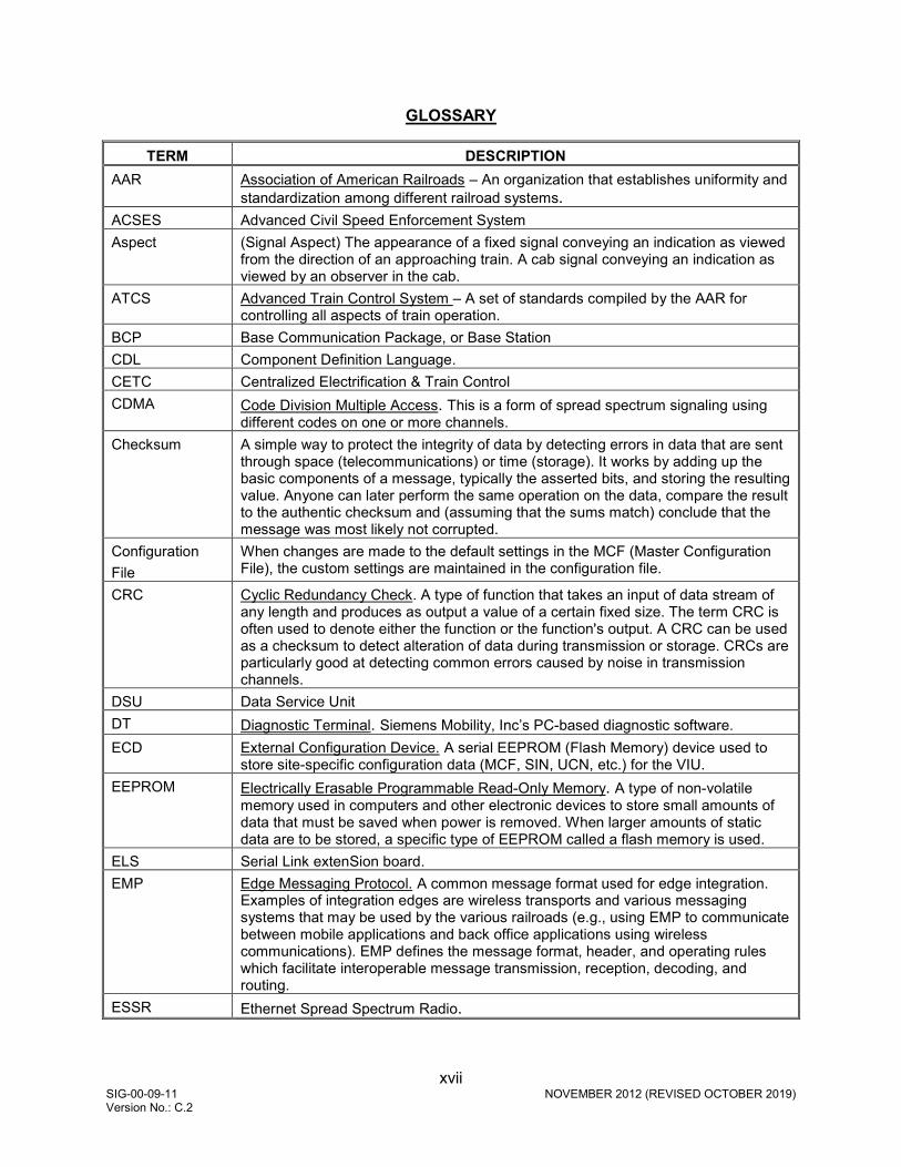
GLOSSARY
TERM DESCRIPTION AAR Association of American Railroads – An organization that establishes uniformity and
standardization among different railroad systems. ACSES Advanced Civil Speed Enforcement System Aspect (Signal Aspect) The appearance of a fixed signal conveying an indication as viewed
from the direction of an approaching train. A cab signal conveying an indication as viewed by an observer in the cab.
ATCS Advanced Train Control System – A set of standards compiled by the AAR for controlling all aspects of train operation.
BCP Base Communication Package, or Base Station CDL Component Definition Language. CETC Centralized Electrification & Train Control CDMA Code Division Multiple Access. This is a form of spread spectrum signaling using
different codes on one or more channels. Checksum A simple way to protect the integrity of data by detecting errors in data that are sent
through space (telecommunications) or time (storage). It works by adding up the basic components of a message, typically the asserted bits, and storing the resulting value. Anyone can later perform the same operation on the data, compare the result to the authentic checksum and (assuming that the sums match) conclude that the message was most likely not corrupted.
Configuration File
When changes are made to the default settings in the MCF (Master Configuration File), the custom settings are maintained in the configuration file.
CRC Cyclic Redundancy Check. A type of function that takes an input of data stream of any length and produces as output a value of a certain fixed size. The term CRC is often used to denote either the function or the function's output. A CRC can be used as a checksum to detect alteration of data during transmission or storage. CRCs are particularly good at detecting common errors caused by noise in transmission channels.
DSU Data Service Unit DT Diagnostic Terminal. Siemens Mobility, Inc’s PC-based diagnostic software. ECD External Configuration Device. A serial EEPROM (Flash Memory) device used to
store site-specific configuration data (MCF, SIN, UCN, etc.) for the VIU. EEPROM Electrically Erasable Programmable Read-Only Memory. A type of non-volatile
memory used in computers and other electronic devices to store small amounts of data that must be saved when power is removed. When larger amounts of static data are to be stored, a specific type of EEPROM called a flash memory is used.
ELS Serial Link extenSion board. EMP Edge Messaging Protocol. A common message format used for edge integration.
Examples of integration edges are wireless transports and various messaging systems that may be used by the various railroads (e.g., using EMP to communicate between mobile applications and back office applications using wireless communications). EMP defines the message format, header, and operating rules which facilitate interoperable message transmission, reception, decoding, and routing.
ESSR Ethernet Spread Spectrum Radio.

xviii SIG-00-09-11 NOVEMBER 2012 (REVISED OCTOBER 2019) Version No.: C.2
TERM DESCRIPTION FRA Federal Railroad Administration. The purpose of FRA is to: promulgate and enforce
rail safety regulations; administer railroad assistance programs; conduct research and development in support of improved railroad safety and national rail transportation policy; and consolidate government support of rail transportation activities.
GCP Grade Crossing Predictor. GCS Geographic Configuration Suite. Used to program the VIU MCF. GMT The time as measured on the prime meridian running through Greenwich, England:
used in England and as a standard of calculation elsewhere. Also called Greenwich Mean Time, Greenwich Civil Time, Universal Time
GOL Geographic Object Library GPS Global Positioning System. HMAC Keyed-Hash Message Authentication Code. A type of message authentication code
(MAC) calculated using a specific algorithm involving a cryptographic hash function in combination with a secret key.
HS Home Signal. ITC Interoperable Train Control ITCM Interoperable Train Control Message. LD Line Driver LED Light Emitting Diode. LoMA Limits of Movement Authority MCF Module Configuration File. Application specific configuration file. Defines how the
VIU will operate in a specific application such as the Office Monitoring or Wayside Interface applications. Contains default settings for configurable parameters.
MCP Mobile Communications Package MEF Module Executable File. The VIU executive software. Defines the general operation
of the VIU. NMEA National Marine Electronics Association. NMEA 0183 (or NMEA for short) is a
combined electrical and data specification for communication between marine electronic devices such as echo sounder, sonar, Anemometer (winds speed and direction), gyrocompass, autopilot, GPS receivers and many other types of instruments. It has been defined by, and is controlled by, the US-based National Marine Electronics Association. The NMEA 0183 standard uses a simple ASCII, serial communications protocol that defines how data is transmitted in a "sentence" from one "talker" to one "listener" at a time. Through the use of intermediate expanders, a talker can have a unidirectional conversation with multiple listeners, and using multiplexers, multiple sensors can talk to a single computer port. Third-party switches are available that can establish a primary and secondary talker, with automatic failover if the primary fails.
NTP Network Time Protocol. The NTP is a protocol used to synchronize the clocks in millions of servers, workstations and PCs of the public internet and private networks.
OCG Office Communication Gateway

xix SIG-00-09-11 NOVEMBER 2012 (REVISED OCTOBER 2019) Version No.: C.2
TERM DESCRIPTION OSI Open Systems Interconnection. A layered, abstract description for communications
and computer network protocol design. It is sometimes known as the OSI seven layer model. From top to bottom, the OSI Model consists of the Application, Presentation, Session, Transport, Network, Data Link, and Physical layers. A layer is a collection of related functions that provides services to the layer above it and receives service from the layer below it.
PTC Positive Train Control. An automated control system for railways that ensures the safe operation of rail vehicles using data communication between various control entities that make up the system.
SIN Site Identification Number. The 12-digit ATCS address for the VIU equipment entered via the Web interface and stored in the ECD. The SIN has the form 7.RRR.LLL.GGG.SS stored in binary coded decimal, with each digit in one nibble. The digit 0 is represented by “A” and 0 is used as a null byte.
SMA Sub-Miniature version A. SNMP Simple Network Management Protocol. SNMP is an Internet-standard protocol for
managing devices on IP networks. SNTP Simple Network Time Protocol. A simplified version of NTP where storage of state
data is not required SSH Secure Shell. SSH is a network protocol for secure data communication and remote
command execution TCP/IP Network Transmission Control Protocol / Internet Protocol. The suite of communications
protocols used to connect hosts on the Internet. TCP/IP uses several protocols, the two main ones being TCP and IP. TCP/IP is built into the UNIX operating system and is used by the Internet, making it the de facto standard for transmitting data over networks.
TSR Temporary Speed Restriction UCN Unique Check Number. A 32-bit CRC calculated over the MCF, SIN and vital
configuration parameters. Used to verify that the configuration is correct. It is stored in the ECD to detect file corruption.
UDP User Datagram Protocol. One of the core protocols of the Internet protocol suite. Using UDP, programs on networked computers can send short messages sometimes known as datagrams (using Datagram Sockets) to one another.
UNS Unified Numbering System. USB Universal Serial Bus. A serial bus standard to interface devices. USB was designed
to allow many peripherals to be connected using a single standardized interface socket and to improve the plug-and-play capabilities by allowing devices to be connected and disconnected without rebooting the computer (hot swapping). Other convenient features include providing power to low-consumption devices without the need for an external power supply and allowing many devices to be used without requiring manufacturer specific, individual device drivers to be installed.
UTC Coordinated Universal Time. VIU Vital Interface Unit. A device that monitors switch positions and signal aspects and
then generates vital status messages reflecting the current state of the monitored equipment.
VLAN Virtual Local Area Network VPF Vital Parallel Flashing (VPF) input circuit. The VIU Master I/O circuit with 10 vital
inputs that runs appliance model logic and detects steady and flashing inputs. Identical Slave circuits provide10 additional vital inputs with similar functionality.
xx SIG-00-09-11 NOVEMBER 2012 (REVISED OCTOBER 2019) Version No.: C.2
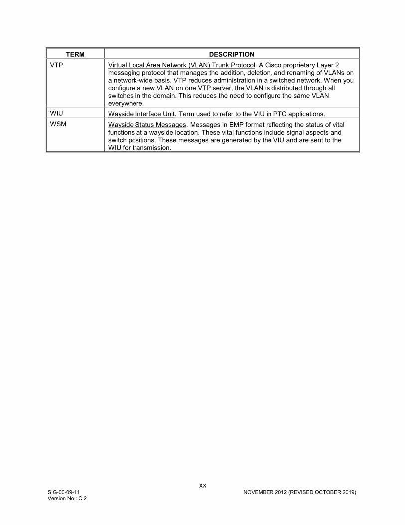
TERM DESCRIPTION VTP Virtual Local Area Network (VLAN) Trunk Protocol. A Cisco proprietary Layer 2
messaging protocol that manages the addition, deletion, and renaming of VLANs on a network-wide basis. VTP reduces administration in a switched network. When you configure a new VLAN on one VTP server, the VLAN is distributed through all switches in the domain. This reduces the need to configure the same VLAN everywhere.
WIU Wayside Interface Unit. Term used to refer to the VIU in PTC applications. WSM Wayside Status Messages. Messages in EMP format reflecting the status of vital
functions at a wayside location. These vital functions include signal aspects and switch positions. These messages are generated by the VIU and are sent to the WIU for transmission.
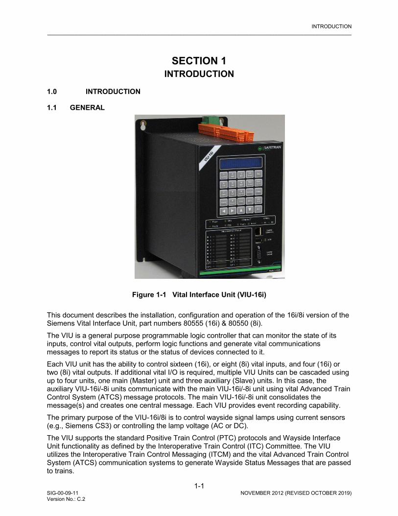
INTRODUCTION _________________________________________________________________________________________________________
1-1 SIG-00-09-11 NOVEMBER 2012 (REVISED OCTOBER 2019) Version No.: C.2
SECTION 1 INTRODUCTION
1.0 INTRODUCTION
1.1 GENERAL
Figure 1-1 Vital Interface Unit (VIU-16i) This document describes the installation, configuration and operation of the 16i/8i version of the Siemens Vital Interface Unit, part numbers 80555 (16i) & 80550 (8i). The VIU is a general purpose programmable logic controller that can monitor the state of its inputs, control vital outputs, perform logic functions and generate vital communications messages to report its status or the status of devices connected to it. Each VIU unit has the ability to control sixteen (16i), or eight (8i) vital inputs, and four (16i) or two (8i) vital outputs. If additional vital I/O is required, multiple VIU Units can be cascaded using up to four units, one main (Master) unit and three auxiliary (Slave) units. In this case, the auxiliary VIU-16i/-8i units communicate with the main VIU-16i/-8i unit using vital Advanced Train Control System (ATCS) message protocols. The main VIU-16i/-8i unit consolidates the message(s) and creates one central message. Each VIU provides event recording capability. The primary purpose of the VIU-16i/8i is to control wayside signal lamps using current sensors (e.g., Siemens CS3) or controlling the lamp voltage (AC or DC). The VIU supports the standard Positive Train Control (PTC) protocols and Wayside Interface Unit functionality as defined by the Interoperative Train Control (ITC) Committee. The VIU utilizes the Interoperative Train Control Messaging (ITCM) and the vital Advanced Train Control System (ATCS) communication systems to generate Wayside Status Messages that are passed to trains.

INTRODUCTION _________________________________________________________________________________________________________
1-2 SIG-00-09-11 NOVEMBER 2012 (REVISED OCTOBER 2019) Version No.: C.2
WARNING
THE VIU IS CAPABLE OF BROADCASTING VITAL EMP STATUS MESSAGES. THE USE OF THE VIU IN A LARGER SYSTEM WITH OTHER COMPONENTS SHOULD BE CONSIDERED CAREFULLY SO AS NOT TO INADVERTENTLY COMPROMISE THE VITALITY OF THE WSM PROTOCOL.
The ATCS protocol also supports remote configuration and control of selected non-UCN protected VIU operational parameters.
1.2 APPLICATIONS
Application specific functions performed by the VIU are controlled by a Module Configuration File (MCF). The MCF is programmed using the Siemens Geographic Configuration Suite (GCS). The VIU utilizes application specific MCFs. In this document, a generic application is presented and is described briefly in the following paragraphs. An expanded description is provided as indicated in later sections of this document.
WARNING
PLEASE REVIEW THIS USER MANUAL CAREFULLY TO ENSURE CORRECT APPLICATION AND MAINTENANCE OF THE VITAL INTERFACE UNIT (VIU). INCORRECT APPLICATION MAY RESULT IN UNSAFE OPERATION.

INTRODUCTION _________________________________________________________________________________________________________
1-3 SIG-00-09-11 NOVEMBER 2012 (REVISED OCTOBER 2019) Version No.: C.2
Figure 1-2 VIU-16i/8i Applications 1.2.1 Wayside Interface Unit Application In the Wayside Interface Unit application (Figure 1-3), the VIU can monitor switch positions and signal aspects controlled by other equipment in an interlocking and send the signal aspect and switch position information to an on-board system. Signal aspects can be monitored by:
• Current monitoring • Voltage monitoring • Current sensor used in voltage sensing application
Locomotive MCP Radio
Relay Output
Configure Maintainer
Digital Input
Interlocking
Current Sensor
Digital Input
Approach Signal
Sensor Test
Home Signal
VIU-16i/8i
Interoperable Train Control
Manager
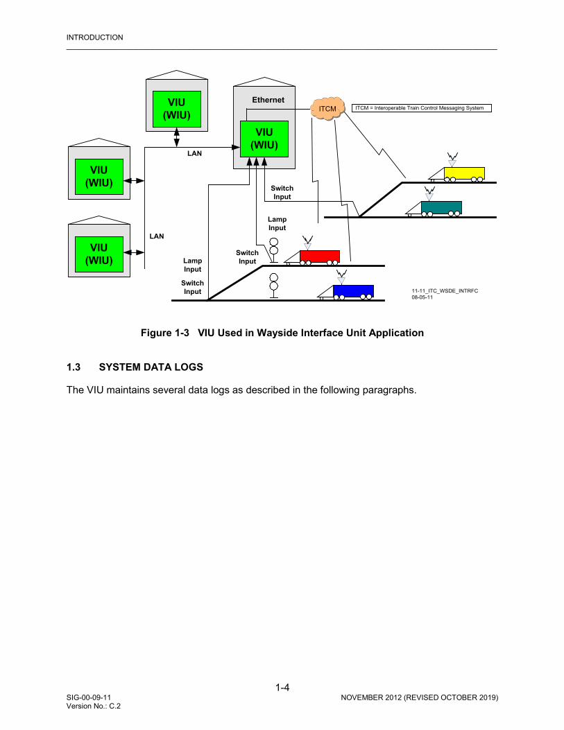
INTRODUCTION _________________________________________________________________________________________________________
1-4 SIG-00-09-11 NOVEMBER 2012 (REVISED OCTOBER 2019) Version No.: C.2
Figure 1-3 VIU Used in Wayside Interface Unit Application
1.3 SYSTEM DATA LOGS
The VIU maintains several data logs as described in the following paragraphs.
Switch Input
Switch Input
Lamp Input
VIU (WIU)
VIU (WIU)
VIU (WIU)
LAN
LAN
VIU (WIU)
11-11_ITC_WSDE_INTRFC08-05-11
Ethernet
Switch Input
Lamp Input
ITCM = Interoperable Train Control Messaging SystemITCM

INTRODUCTION _________________________________________________________________________________________________________
1-5 SIG-00-09-11 NOVEMBER 2012 (REVISED OCTOBER 2019) Version No.: C.2
1.3.1 Event Log The Event Log is maintained by the non-vital side of the VIU. Entries in this log show application level events describing VIU system operations. This log does not contain detailed diagnostic events pertaining to the internal operation of the VIU or associated system. A separate Diagnostic Log maintains these more detailed diagnostic events (paragraph 1.3.2). Although the Event Log is stored/managed by the non-vital side of the unit; events from the vital side are stored in the log as well.
• Event Log is stored in flash memory to prevent data loss when power is removed from the VIU. It does not require a back-up battery.
• The number of events that can be stored in the Event Log is 100,000. • Events stored in the Event Log are time stamped to the hundredth of a second. • The log is structured as a circular buffer in that once the log is full, the newest event will
overwrite the oldest recorded event. • The entire Event Log can be downloaded to a USB drive. • The Event Log is accessible using the web browser user interface. It can be viewed by
date/time range and can be downloaded to a PC. • The Event Log can be viewed using any of the following user interface systems:
o A web browser over a TCP/IP network. o A web browser directly connected to a free Ethernet port on the VIU.
• Events can be viewed as they are recorded and logged into the Event Log via the Trace Events function on the web browser user interface.
1.3.2 Diagnostic Log The diagnostic log is maintained by the non-vital side of the VIU. It contains low level diagnostic entries that detail the internal operation of the system that might otherwise clutter the event log. This data is useful for troubleshooting problems related to internal system operation.
• Diagnostic Log can contain five entry types (listed below in lowest to highest verbosity level): •BASIC - entries that cannot be classified as another type or that need to be visible
regardless of the VERBOSITY setting of the log (e.g. "diagnostic log initialized"). •ERROR – critical system errors such as hardware failures the system cannot heal or
recover from. •WARNING – system errors that could indicate a problem but the system can continue
operating under this condition. •INFORMATION – potentially useful information but does not represent a failure or fault in
the system. This verbosity level is at the default setting. •DEBUG – information that may be useful to a software or hardware engineer in
understanding the internal operation of the system but is not normally useful for anyone else.
• Diagnostic Log is stored in flash memory to prevent data loss when power is removed from the VIU. It does not require a back-up battery.
• The number of entries that can be stored in the Diagnostic Log is 10,000. • Events stored in the Diagnostic Log are time stamped to the hundredth of a second. • The log is structured as a circular buffer in that once the log is full, the newest event will
overwrite the oldest recorded event.

INTRODUCTION _________________________________________________________________________________________________________
1-6 SIG-00-09-11 NOVEMBER 2012 (REVISED OCTOBER 2019) Version No.: C.2
• The entire Diagnostic Log can be downloaded to a USB drive. • The Diagnostic Log is accessible using the web browser user interface. It can be viewed by
date/time range and can be downloaded to a PC. • Diagnostic Log can be viewed using any of the following user interface systems:
•A web browser over a TCP/IP network. •A web browser directly connected to a free Ethernet port on the VIU.
• Entries can be viewed as they are recorded and logged into the Diagnostic Log via the Trace Events function on the web browser user interface.
1.3.3 Status, Summary, and Maintenance Logs The Status and Summary logs are maintained on the vital side of the VIU. Most of the events logged in these logs are also logged in the Event and Diagnostic logs, respectively. The Maintenance Log is maintained in the DT installation directory on the PC that is running the DT software. Each of these logs is accessible using the DT software. Please refer to Section 7 for details on viewing these logs. The Status and Summary logs are lost when power is removed from the VIU. 1.3.4 Consolidated Logging When one or more VIUs are operating on a network, each VIU can be configured to forward all events over the network to a “consolidated logger”. The logger will maintain all of the events for every reporting VIU. Each VIU retains a copy of its own log even if it sends a copy to a consolidator Logger. The logger can be another VIU. To configure the VIUs to send the Event and/or Diagnostic Log entries to the logger, open the web browser user interface, select either Diagnostic Log or Event Log (or do both), enter the IP address of the logger in the Server IP dialog box. Refer to Section 8 for details.
1.4 HARDWARE DESCRIPTION
The Siemens VIU-16i/8i is a compact fully enclosed unit with no field-replaceable components.

INTRODUCTION _________________________________________________________________________________________________________
1-7 SIG-00-09-11 NOVEMBER 2012 (REVISED OCTOBER 2019) Version No.: C.2
1.4.1 User Interface & Connectors The VIU user interface and connectors are located on two adjacent faces of the unit, the top and the front. Refer to Figure 1-4 and Table 1-1 for locations and descriptions of the connectors and the various elements of the user interface.
Figure 1-4 VIU 16i User Interface & Connector Locations
Top View
13
20
14
15
16
17
18
19
Front View
12
3
4
5
2
1
6
9
7 8
11
10
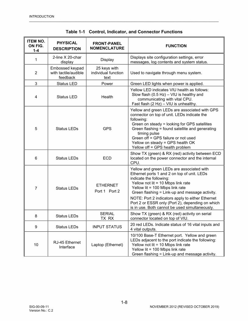
INTRODUCTION _________________________________________________________________________________________________________
1-8 SIG-00-09-11 NOVEMBER 2012 (REVISED OCTOBER 2019) Version No.: C.2
Table 1-1 Control, Indicator, and Connector Functions
ITEM NO. ON FIG.
1-4
PHYSICAL DESCRIPTION
FRONT-PANEL NOMENCLATURE FUNCTION
1 2-line X 20-char display Display Displays site configuration settings, error
messages, log contents and system status.
2 Embossed keypad with tactile/audible
feedback
25 keys with individual function
text Used to navigate through menu system.
3 Status LED Power Green LED lights when power is applied.
4 Status LED Health
Yellow LED indicates VIU health as follows: Slow flash (0.5 Hz) – VIU is healthy and
communicating with vital CPU. Fast flash (2 Hz) – VIU is unhealthy.
5 Status LEDs GPS
Yellow and green LEDs are associated with GPS connector on top of unit. LEDs indicate the following: Green on steady = looking for GPS satellites Green flashing = found satellite and generating
timing pulse Green off = GPS failure or not used Yellow on steady = GPS health OK Yellow off = GPS health problem
6 Status LEDs ECD Show TX (green) & RX (red) activity between ECD located on the power connector and the internal CPU.
7 Status LEDs ETHERNET
Port 1 Port 2
Yellow and green LEDs are associated with Ethernet ports 1 and 2 on top of unit. LEDs indicate the following: Yellow not lit = 10 Mbps link rate Yellow lit = 100 Mbps link rate Green flashing = Link-up and message activity.
NOTE: Port 2 indicators apply to either Ethernet Port 2 or ESSR only (Port 2), depending on which is in use. Both cannot be used simultaneously.
8 Status LEDs SERIAL TX RX
Show TX (green) & RX (red) activity on serial connector located on top of VIU.
9 Status LEDs INPUT STATUS 20 red LEDs. Indicate status of 16 vital inputs and 4 vital outputs.
10 RJ-45 Ethernet Interface Laptop (Ethernet)
10/100 Base-T Ethernet port. Yellow and green LEDs adjacent to the port indicate the following: Yellow not lit = 10 Mbps link rate Yellow lit = 100 Mbps link rate Green flashing = Link-up and message activity.

INTRODUCTION _________________________________________________________________________________________________________
1-9 SIG-00-09-11 NOVEMBER 2012 (REVISED OCTOBER 2019) Version No.: C.2
ITEM NO. ON FIG.
1-4
PHYSICAL DESCRIPTION
FRONT-PANEL NOMENCLATURE FUNCTION
11 USB Interface USB
USB 2.0 interface. Used to connect to a USB flash drive. The VIU can store logs and reports on the flash drive and receive software updates from the flash drive. The 3 LEDs (red, yellow, and green) adjacent to the USB port indicate the following: Green on steady = USB drive is inserted and it is
safe to remove the USB drive. Yellow flashing = file transfer in progress, do not
remove USB drive. Red flashing = USB drive read or write error
detected.
12 Serial Interface Laptop (Serial)
Female RS-232 diagnostic serial port used to connect to a PC using a standard RS-232 cable. Use this port when running PC-based DT software or HyperTerminal to access the VIU.
13 Serial Interface Serial
Dedicated male RS-232 asynchronous serial port used primarily to connect VIU to an external GPS receiver. May also be used as a general purpose communications port.
14 RJ-45 Ethernet Interface Ethernet Port 1 Standard 10/100 Base-T Ethernet port.
15 RJ-45 Ethernet Interface Ethernet Port 2 Standard 10/100 Base-T Ethernet port.
16 Serial Interface GPS Port Dedicated serial port for GPS signal output.
17 SMA Connector GPS Antenna Female SMA connector (1/4-36 UNS threaded coupling) for GPS antenna interface.
18 RJ-45 Ethernet Interface
ESSR Only (Port 2)
Dedicated 10/100 Base-T Ethernet port. Use to interface with a Siemens Mobility, Inc Ethernet Spread Spectrum Radio (ESSR) only. Provides radio power as well as Ethernet connectivity.
19 Power / ECD Connection
Two terminal power connector with External Configuration Device (ECD) attached. Allows VIU to be swapped out without reconfiguration. VIU configuration is stored in the ECD.
20 Discrete Vital I/O Vital I/O connectors. Provide pairs of terminals (+ and -).

INTRODUCTION _________________________________________________________________________________________________________
1-10 SIG-00-09-11 NOVEMBER 2012 (REVISED OCTOBER 2019) Version No.: C.2
1.4.2 Keypad Operations The front panel has a 2-line, 20-character vacuum florescent display, a 25-key keypad, and a beeper. Menus are navigated with the arrow keys (, , and ), the Enter, Cancel and Exit keys. Text and numbers can easily be entered using the cell phone style number/letter keys. There are also special function keys for quick access to VIU settings and information (see Figure 1-5).
Figure 1-5 Keypad Quick Access Keys
1.4.3 Front Panel Default Display The VIU default display shows the date and time on the first line of the display and system information on the second line. Important messages will also be displayed here.
Use the left () and right () arrow keys to scroll through the system information on the second line of the display or wait for the information to scroll automatically.
1Symbol
2ABC
3DEF
SiteSetup Diag
4GHI
5JKL
6MNO
ViewAlarm
ClearAlarm
7PQRS
8TUV
9WXYZ Versions Status
Cancel0
Space Enter Menu UserTest
Exit
Quick access keys
2012-Nov 09 15:32 Site data scrolling here

INTRODUCTION _________________________________________________________________________________________________________
1-11 SIG-00-09-11 NOVEMBER 2012 (REVISED OCTOBER 2019) Version No.: C.2
NOTE
If there is no activity on the front panel keypad for five minutes, it will automatically return to this default display.
1.4.4 VIU Main Menu The VIU provides a main menu that can be viewed on the front panel display. The main menu consists of two items:
• SITE SETUP Enter Site ID Number, MCF CRC and UCN • CDL Enter CDL file • PTC MONITORING Enter PTC configuration date • MAINTAIN SITE Enter amount of on-site time • USB DRIVE Upload/download information to/from a USB With the default display showing, press the Menu key to access the main menu. The first item in the menu is displayed. The character appearing after the first menu item name is a right arrow symbol () indicating the key to press to scroll to the next menu item as shown in Figure 1-6. Press the left () arrow key to scroll back to the first menu item.
Figure 1-6 Main Menu Navigation Press the Cancel, Exit or up () arrow key to return to the default display from the main menu. To select a main menu item, scroll to the desired menu item and press Enter or the down () arrow key.
1.4.4.1 SITE SETUP Menu When SITE SETUP is selected from the main menu, the user is prompted to enter the vital edit mode. Use the right () arrow key to display YES, then press Enter or the down () arrow key to select the vital edit mode. Navigate the menu and change menu entries as indicated in Figure 1-7.
** MENU VISIBLE ONLY WHEN CDL IS LOADED
SELECT ON SITE TIME 00:30:00 SELECTED
PTC MONITORING USE UP/DOWN ARROWS
ENTER VITAL EDIT MODE ARE YOU SURE? NO
STOP AND DELETE CDL? NO
MAINTAIN SITE**
PTC MONITOR
SITE SETUP
CDL**

INTRODUCTION _________________________________________________________________________________________________________
1-12 SIG-00-09-11 NOVEMBER 2012 (REVISED OCTOBER 2019) Version No.: C.2
NOTE
If the vital edit mode is selected (even if no data is changed), VIU must be rebooted to return the system to normal operation.
• Data Entry Using Keypad The Site ID Number, MCF CRC and UCN can be changed from the front panel keypad. Position the underline cursor and save data entries as follows:
• Left () and right () arrow keys: Move underline cursor left or right in the data string. • Enter key: After entering or editing data, press this key to permanently store the changed data
in memory. • Entering Numbers and Letters: The number/letter keys on the keypad are used like cell
phone keys. When entering data in an alphanumeric field, each consecutive press of a numbered key will produce the characters printed on the key. For example, pressing the #2 key repeatedly produces 2, A, B and C, and then the sequence is repeated. After entering a character, the cursor will move to the next character position approximately one second after the last key press.
• If the data field is numeric only, each press of a numbered key will produce only the specific number as shown on the key.
• If the data field is alphabetical only, then no numbers will be shown. • Saving Data: Changes are saved automatically when the Enter key is pressed.
WARNING ENTERING THE WRONG UCN WILL RENDER THE VIU16i INOPERABLE. DO NOT CHANGE THE UCN UNLESS REQUIRED BY SYSTEM CHANGES THAT HAVE BEEN APPROVED BY THE RAILROAD AND/OR AUTHORIZING AGENCY USING A UCN ASSIGNED TO THE SITE PLANS.

INTRODUCTION _________________________________________________________________________________________________________
1-13 SIG-00-09-11 NOVEMBER 2012 (REVISED OCTOBER 2019) Version No.: C.2
Figure 1-7 SITE SETUP Menu
1.4.4.2 CDL Menu When the CDL file is loaded, the CDL and MAINTAIN SITE menus are enabled. When CDL is selected from the main menu, the user can stop and delete the CDL from the VIU. Use the right () arrow key to display YES, then press Enter or the down () arrow key to begin the delete process. Navigate the menu as indicated in Figure 1-8.
Cancel
Cancel
Cancel
REBOOT VITAL
REBOOT VITAL YES
REBOOT VITAL NO
REBOOT VITAL
key
Cancel Cancel
Enter to reboot
Enter
MCF CRC UCN
UCN 2A7E745B
MCF CRC EE264D71
SITE ID NUMBER 7 .620.100.100. 00
key key
Cancel
Enter or key
Enter, or Exit
SITE ID NUMBER
Enter or key
Enter, or Exit
Enter or key
Enter, or Exit
key
SITE SETUP
EXIT VITAL EDIT MODE REBOOT VTL NOW? NO
EXIT VITAL EDIT MODE REBOOT VTL NOW? YES
Enter or Exit
key key
Enter or key
ENTER VITAL EDIT MODE ARE YOU SURE? YES
ENTER VITAL EDIT MODE ARE YOU SURE? NO
key

INTRODUCTION _________________________________________________________________________________________________________
1-14 SIG-00-09-11 NOVEMBER 2012 (REVISED OCTOBER 2019) Version No.: C.2
Figure 1-8 CDL Menu
1.4.4.3 PTC Monitor Menu When PTC MONITOR is selected from the main menu, the user can view the status of PTC Monitoring. Press Enter or the down () arrow key to view the PTC monitoring instruction. Use the up () and down () arrow keys to scroll through the menu items. Selecting Enter or Exit returns the menu to the VIU top level display. Navigate the menu as indicated in Figure 1-9.
MAINTAIN SITE
PTC MONITOR
STOP AND DELETE CDL? YES
SITE SETUP
CDL
STOP AND DELETE CDL? NO
Exit or key Enter or key
Enter or key
STOP AND DELETE CDL? ARE YOU SURE? NO
Enter or key
key
Enter, or Exit
key
SITE SETUP SITE ID NUMBER
STOP AND DELETE CDL? ARE YOU SURE? YES
or Exit key
Enter or key

INTRODUCTION _________________________________________________________________________________________________________
1-15 SIG-00-09-11 NOVEMBER 2012 (REVISED OCTOBER 2019) Version No.: C.2
Figure 1-9 PTC Monitor Menu
MAINTAIN SITE
PTC MONITOR
PTC MONITORING USE UP/DOWN ARROWS
SITE SETUP
CDL
2012 Oct-08 08:25 Site Name: Broadmoor
BEACON OFF
or key
Cancel, Enter, or Exit key
Exit or key Enter or key
MENU key
GATEWAY CONNECTED WSM FLOW ALLOWED
NO GPS TIME
or key
or key
Cancel, Enter, or Exit key
Cancel, Enter, or Exit key
Cancel, Enter, or Exit key
NO RC2 KEY
or key
WIU PARAMS INVALID
NO WIU CHANL PRESENT
or key
or key
Cancel, Enter, or Exit key
Cancel, Enter, or Exit key
Cancel, Enter, or Exit key
WIU DISABLED
or key
IN EDIT MODE
VCORE UNCONFIGURED
or key
or key
Cancel, Enter, or Exit key
Cancel, Enter, or Exit key
Cancel, Enter, or Exit key
ALTERNATES IF CONNECTED &
FLOW ALLOWED 10.232.48.93
WSM FLOW ALLOWED
LAST WSM UPDATE 12:35:55 2012Oct12
Cancel, Enter, or Exit key
LAST WSM UPDATE NEVER
Cancel, Enter, or Exit key
or key
These menus appear when the Gateway is Disconnected and/or the Flow is Not Allowed
GATEWAY DISCONNECTED WSM FLOW NOT ALLOWED
GATEWAY DISCONNECTED WSM FLOW ALLOWED
GATEWAY CONNECTED WSM FLOW NOT ALLOWED
OR
OR
OR
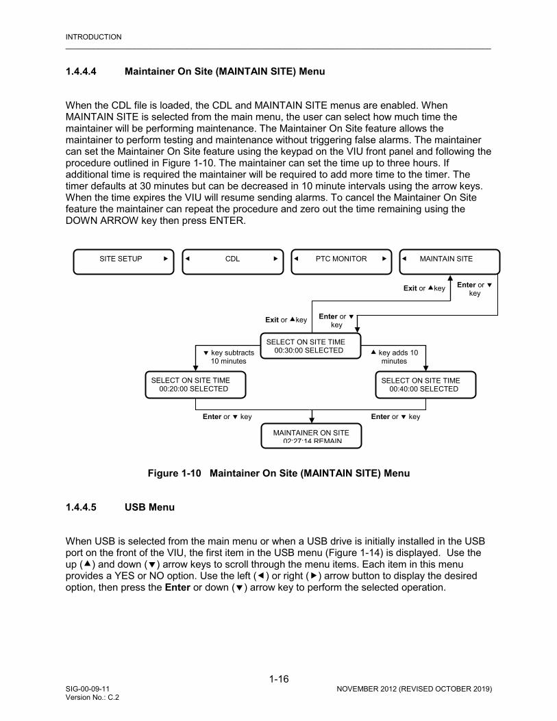
INTRODUCTION _________________________________________________________________________________________________________
1-16 SIG-00-09-11 NOVEMBER 2012 (REVISED OCTOBER 2019) Version No.: C.2
1.4.4.4 Maintainer On Site (MAINTAIN SITE) Menu When the CDL file is loaded, the CDL and MAINTAIN SITE menus are enabled. When MAINTAIN SITE is selected from the main menu, the user can select how much time the maintainer will be performing maintenance. The Maintainer On Site feature allows the maintainer to perform testing and maintenance without triggering false alarms. The maintainer can set the Maintainer On Site feature using the keypad on the VIU front panel and following the procedure outlined in Figure 1-10. The maintainer can set the time up to three hours. If additional time is required the maintainer will be required to add more time to the timer. The timer defaults at 30 minutes but can be decreased in 10 minute intervals using the arrow keys. When the time expires the VIU will resume sending alarms. To cancel the Maintainer On Site feature the maintainer can repeat the procedure and zero out the time remaining using the DOWN ARROW key then press ENTER.
Figure 1-10 Maintainer On Site (MAINTAIN SITE) Menu
1.4.4.5 USB Menu When USB is selected from the main menu or when a USB drive is initially installed in the USB port on the front of the VIU, the first item in the USB menu (Figure 1-14) is displayed. Use the up () and down () arrow keys to scroll through the menu items. Each item in this menu provides a YES or NO option. Use the left () or right () arrow button to display the desired option, then press the Enter or down () arrow key to perform the selected operation.
MAINTAIN SITE
PTC MONITOR
SELECT ON SITE TIME 00:30:00 SELECTED
SITE SETUP
CDL
SELECT ON SITE TIME 00:20:00 SELECTED
Enter or key
MAINTAINER ON SITE 02:27:14 REMAIN
SELECT ON SITE TIME 00:40:00 SELECTED
key subtracts 10 minutes
Exit or key Enter or key
Exit or key Enter or key
key adds 10 minutes
Enter or key
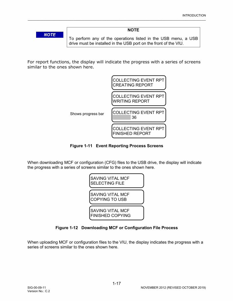
INTRODUCTION _________________________________________________________________________________________________________
1-17 SIG-00-09-11 NOVEMBER 2012 (REVISED OCTOBER 2019) Version No.: C.2
COLLECTING EVENT RPT CREATING REPORT
COLLECTING EVENT RPT WRITING REPORT
COLLECTING EVENT RPT ██████ 36
COLLECTING EVENT RPT FINISHED REPORT
Shows progress bar
SAVING VITAL MCF SELECTING FILE
SAVING VITAL MCF COPYING TO USB
SAVING VITAL MCF FINISHED COPYING
NOTE
To perform any of the operations listed in the USB menu, a USB drive must be installed in the USB port on the front of the VIU.
For report functions, the display will indicate the progress with a series of screens similar to the ones shown here.
Figure 1-11 Event Reporting Process Screens
When downloading MCF or configuration (CFG) files to the USB drive, the display will indicate the progress with a series of screens similar to the ones shown here.
Figure 1-12 Downloading MCF or Configuration File Process
When uploading MCF or configuration files to the VIU, the display indicates the progress with a series of screens similar to the ones shown here.
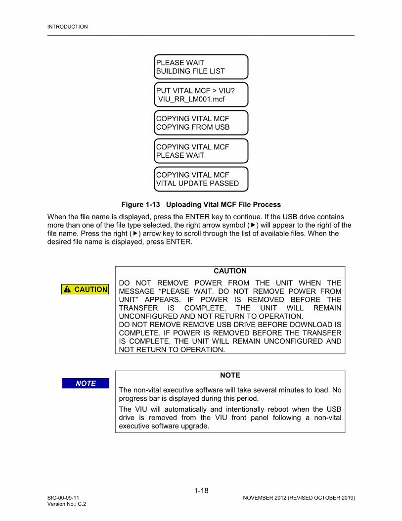
INTRODUCTION _________________________________________________________________________________________________________
1-18 SIG-00-09-11 NOVEMBER 2012 (REVISED OCTOBER 2019) Version No.: C.2
PLEASE WAIT BUILDING FILE LIST
PUT VITAL MCF > VIU? VIU_RR_LM001.mcf
COPYING VITAL MCF COPYING FROM USB
COPYING VITAL MCF PLEASE WAIT
COPYING VITAL MCF VITAL UPDATE PASSED
Figure 1-13 Uploading Vital MCF File Process
When the file name is displayed, press the ENTER key to continue. If the USB drive contains more than one of the file type selected, the right arrow symbol () will appear to the right of the file name. Press the right () arrow key to scroll through the list of available files. When the desired file name is displayed, press ENTER.
CAUTION
DO NOT REMOVE POWER FROM THE UNIT WHEN THE MESSAGE “PLEASE WAIT. DO NOT REMOVE POWER FROM UNIT” APPEARS. IF POWER IS REMOVED BEFORE THE TRANSFER IS COMPLETE, THE UNIT WILL REMAIN UNCONFIGURED AND NOT RETURN TO OPERATION. DO NOT REMOVE REMOVE USB DRIVE BEFORE DOWNLOAD IS COMPLETE. IF POWER IS REMOVED BEFORE THE TRANSFER IS COMPLETE, THE UNIT WILL REMAIN UNCONFIGURED AND NOT RETURN TO OPERATION.
NOTE
The non-vital executive software will take several minutes to load. No progress bar is displayed during this period. The VIU will automatically and intentionally reboot when the USB drive is removed from the VIU front panel following a non-vital executive software upgrade.

INTRODUCTION _________________________________________________________________________________________________________
1-19 SIG-00-09-11 NOVEMBER 2012 (REVISED OCTOBER 2019) Version No.: C.2
Figure 1-14 USB Menu Map
PUT PTC CFG XML > VIU? SELECT FILE: NO
PUT VITAL MCF > VIU? SELECT FILE: NO
PUT VITAL CFG > VIU? SELECT FILE: NO
PUT MSTR EXEC > VIU? SELECT FILE: NO
PUT SLV EXEC > VIU? SELECT FILE: NO
PUT N-V CFG > VIU? SELECT FILE: NO
PUT N-V EXEC > VIU? SELECT FILE: NO
EXIT USB MENU? NO
PUT RC2 KEY > VIU? SELECT FILE: NO
PUT CDL FILE? SELECT FILE: NO
GET VITAL MCF < VIU? GET FILE: NO
GET VITAL CFG < VIU? GET FILE: NO
GET N-V CFG < VIU? GET FILE: NO
GET RC2 KEY < VIU? GET FILE: NO
GET PTC CFG XML? GET FILE: NO
GET CDL FILE? GET FILE: NO
USB
GET DIAG. REPORT? CREATE REPORT: NO
GET CNFG. REPORT? CREATE REPORT: NO
GET VRSN. REPORT? CREATE REPORT: NO
GET FULL EVENT RPT? CREATE REPORT: NO
GET 24 HR EVENT RPT? CREATE REPORT: NO
GET 2 WK. EVENT RPT? CREATE REPORT: NO
GET CDL LOG? CREATE REPORT: NO

INTRODUCTION _________________________________________________________________________________________________________
1-20 SIG-00-09-11 NOVEMBER 2012 (REVISED OCTOBER 2019) Version No.: C.2
1.4.4.6 USB Drive File Structure The file structure on the USB drive must have the following format. The VIU will look in specific folders for each file type. Folder names and relationships are exact, file names shown are for example only.
Safetran VIU Application Vital MCF {VITAL MCF} (e.g., VIU_RR_LM001.mcf) Vital CDL (VITAL CDL) (e.g., VIU_CDL.cdl) Configuration Vital Configuration {VITAL CFG} (e.g., V-432.1-Broadmoor.bin) Non-Vital Configuration {N-V CFG} (e.g., NV-432.1-Broadmoor.bin) RC2 Key {RC2 KEY} (e.g., rc2key.bin) PTC Configuration XML {PTC CFG XML} (e.g., Broadmoor-WiuConfig.xml) Executive Master Executive {MSTR EXEC} (e.g., BIO_01_40.MEF) Slave Executive {SLV EXEC} (e.g., BPF01_10.MEF) Non-Vital Core Executive {N-V EXEC} (e.g., VIU_NVMEF_DEV.007.16.tgz)
Figure 1-15 Example USB Drive File Structure 1.4.5 Keypad Quick Access Keys Several ‘quick keys’ on the keypad provide shortcuts that go directly to a specific menu. Quick keys are located on the right-side of the keypad (see Figure 1-5). Descriptions of the quick keys are as follows:
• Menu – Displays first entry in main menu. • Site Setup – Future use • Diag – When errors are present on the display, DIAG will tell what that error is, e.g., * UCN
ERROR • View Alarm – Future use • Clear Alarm – Future use • Versions – Future use • Status – Provides status report • User Test – Future use
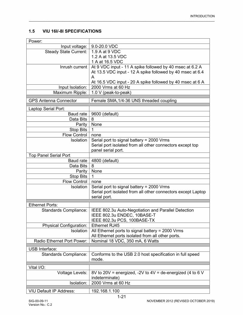
INTRODUCTION _________________________________________________________________________________________________________
1-21 SIG-00-09-11 NOVEMBER 2012 (REVISED OCTOBER 2019) Version No.: C.2
1.5 VIU 16I/-8I SPECIFICATIONS
Power: Input voltage: 9.0-20.0 VDC
Steady State Current: 1.9 A at 9 VDC 1.2 A at 13.5 VDC 1 A at 16.5 VDC
Inrush current At 9 VDC input - 11 A spike followed by 40 msec at 6.2 A At 13.5 VDC input - 12 A spike followed by 40 msec at 6.4 A At 16.5 VDC input - 20 A spike followed by 40 msec at 6 A
Input Isolation: 2000 Vrms at 60 Hz Maximum Ripple: 1.0 V (peak-to-peak)
GPS Antenna Connector Female SMA,1/4-36 UNS threaded coupling Laptop Serial Port:
Baud rate 9600 (default) Data Bits 8
Parity None Stop Bits 1
Flow Control none Isolation Serial port to signal battery = 2000 Vrms
Serial port isolated from all other connectors except top panel serial port.
Top Panel Serial Port Baud rate 4800 (default) Data Bits 8
Parity None Stop Bits 1
Flow Control none Isolation Serial port to signal battery = 2000 Vrms
Serial port isolated from all other connectors except Laptop serial port.
Ethernet Ports: Standards Compliance: IEEE 802.3u Auto-Negotiation and Parallel Detection
IEEE 802.3u ENDEC, 10BASE-T IEEE 802.3u PCS, 100BASE-TX
Physical Configuration: Ethernet RJ45 Isolation All Ethernet ports to signal battery = 2000 Vrms
All Ethernet ports isolated from all other ports. Radio Ethernet Port Power: Nominal 18 VDC, 350 mA, 6 Watts
USB Interface: Standards Compliance: Conforms to the USB 2.0 host specification in full speed
mode. Vital I/O:
Voltage Levels: 8V to 20V = energized, -2V to 4V = de-energized (4 to 6 V indeterminate)
Isolation: 2000 Vrms at 60 Hz VIU Default IP Address: 192.168.1.100

INTRODUCTION _________________________________________________________________________________________________________
1-22 SIG-00-09-11 NOVEMBER 2012 (REVISED OCTOBER 2019) Version No.: C.2
Event Logging: 100,000 events Diagnostic Logging: 10,000 events Environmental:
Operating Temperature Range:
-40°F to +160°F (-40°C to +70°C)
Maximum Humidity:: 90% non-condensing Physical:
Dimensions: 8.80 inches high (22.35 centimeters) 6 inches wide (15.24 centimeters) 11.02 inches deep (27.99 centimeters)
Weight: 11 pounds (5 kilograms)
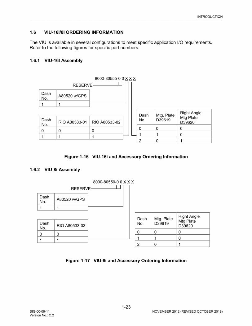
INTRODUCTION _________________________________________________________________________________________________________
1-23 SIG-00-09-11 NOVEMBER 2012 (REVISED OCTOBER 2019) Version No.: C.2
1.6 VIU-16I/8I ORDERING INFORMATION
The VIU is available in several configurations to meet specific application I/O requirements. Refer to the following figures for specific part numbers. 1.6.1 VIU-16I Assembly
Figure 1-16 VIU-16i and Accessory Ordering Information 1.6.2 VIU-8i Assembly
Figure 1-17 VIU-8i and Accessory Ordering Information
8000-80555-0 0 X X X
Dash No.
Mtg. Plate D39619
Right Angle Mtg Plate D39620
0 0 0 1 1 0 2 0 1
Dash No. RIO A80533-01 RIO A80533-02
0 0 0 1 1 1
Dash No. A80520 w/GPS
1 1
RESERVE
8000-80550-0 0 X X X
Dash No.
Mtg. Plate D39619
Right Angle Mtg Plate D39620
0 0 0 1 1 0 2 0 1
Dash No. RIO A80533-03
0 0 1 1
Dash No. A80520 w/GPS
1 1
RESERVE

INTRODUCTION _________________________________________________________________________________________________________
1-24 SIG-00-09-11 NOVEMBER 2012 (REVISED OCTOBER 2019) Version No.: C.2
1.6.3 VIU Accessories • EMI Filter for VIU Power Cable: Z590-00010-0001 • VIU Accessory Ordering Information (Listing from VIU Group Assembly, A80505)
Figure 1-18 VIU Accessory Ordering Information
8000-80505-X X X X X
Dash No.
“N” Type Antenna Cable
“N” Type Surge to VIU Cable
0 None None 1 6 FT. 6 FT. 2 6 FT. 15 FT. 3 6 FT. 30 FT. 4 6 FT. 50 FT. 5 15 FT. 6 FT. 6 15 FT. 15 FT. 7 15 FT. 30 FT. 8 15 FT. 50 FT. 9 30 FT. 6 FT. A 30 FT. 15 FT. B 30 FT. 30 FT. C 30 FT. 50 FT. D 50 FT. 6 FT. E 50 FT. 15 FT. F 50 FT. 30 FT. H 50 FT. 50 FT.
Dash No.
SMA(F) to N Adapter
Antenna Lightning Arrestor
GPS Antenna
0 0 0 0 1 0 0 1 2 0 1 0 3 0 1 1 4 1 0 0 5 1 0 1 6 1 1 0 7 1 1 1
Dash No. Components
00 With Wilmore DC-DC Converter, 18VDC 25A Surge Arrestor, 8000-80515-00121
Dash No.
MDS to VIU Cable
0 None 1 5 FT. 2 10 FT. 3 15 FT. 4 20 FT.

INSTALLATION _________________________________________________________________________________________________________
2-1 SIG-00-09-11 NOVEMBER 2012 (REVISED OCTOBER 2019) Version No.: C.2
SECTION 2 INSTALLATION
2.0 INSTALLATION
WARNING
RAILROADS OR AGENCIES ARE RESPONSIBLE FOR ENSURING ONLY PROPERLY TRAINED AND/OR AUTHORIZED PERSONNEL HAVE ACCESS TO THE VIU-16I/-8I. PROGRAM CHANGES MUST BE PERFORMED IN ACCORDANCE WITH RAILROAD PROCEDURES. VERIFY THAT VIU-16I/-8I HAS ALL PROPER COMPONENTS AND IS PROGRAMMED AS SPECIFIED BY THE RAILROAD’S OR AGENCY’S APPROVED WIRING OR INSTALLATION DIAGRAM. FAILURE TO DO SO MAY LEAD TO INCORRECT OR UNSAFE OPERATION OF THE SIGNAL SYSTEM. AFTER INSTALLATION OF A UNIT, OR WHENEVER A CHANGE IS MADE TO THE SOFTWARE (TO INCLUDE MOVING THE ECD FROM ONE UNIT TO ANOTHER) OR THE CONFIGURATION, THE INSTALLATION SHOULD BE FULLY OPERATIONALLY TESTED TO ENSURE SAFETY. SYSTEM OPERATION MUST BE VERIFIED PRIOR TO PLACING SYSTEM IN SERVICE OR FOLLOWING PROGRAMMING, HARDWARE CHANGES, OR WIRING CHANGES.
2.1 GENERAL The VIU-16I/-8I is a compact unit that can be wall, rack or shelf mounted inside a signal case.
NOTE
For applications other than what are described in this manual, contact Siemens Mobility’s Application Engineering.
2.1.1 Mounting Two mounting plate configurations are available for installing the VIU.
• The rack or wall mounting plate contains holes that are spaced such that the VIU can be mounted on relay rails (Figure 2-1).
• A right-angle stabilizing plate is available for shelf mounting (Figure 2-2).
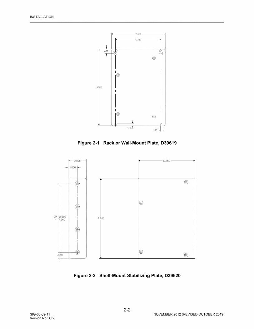
INSTALLATION _________________________________________________________________________________________________________
2-2 SIG-00-09-11 NOVEMBER 2012 (REVISED OCTOBER 2019) Version No.: C.2
Figure 2-1 Rack or Wall-Mount Plate, D39619
Figure 2-2 Shelf-Mount Stabilizing Plate, D39620
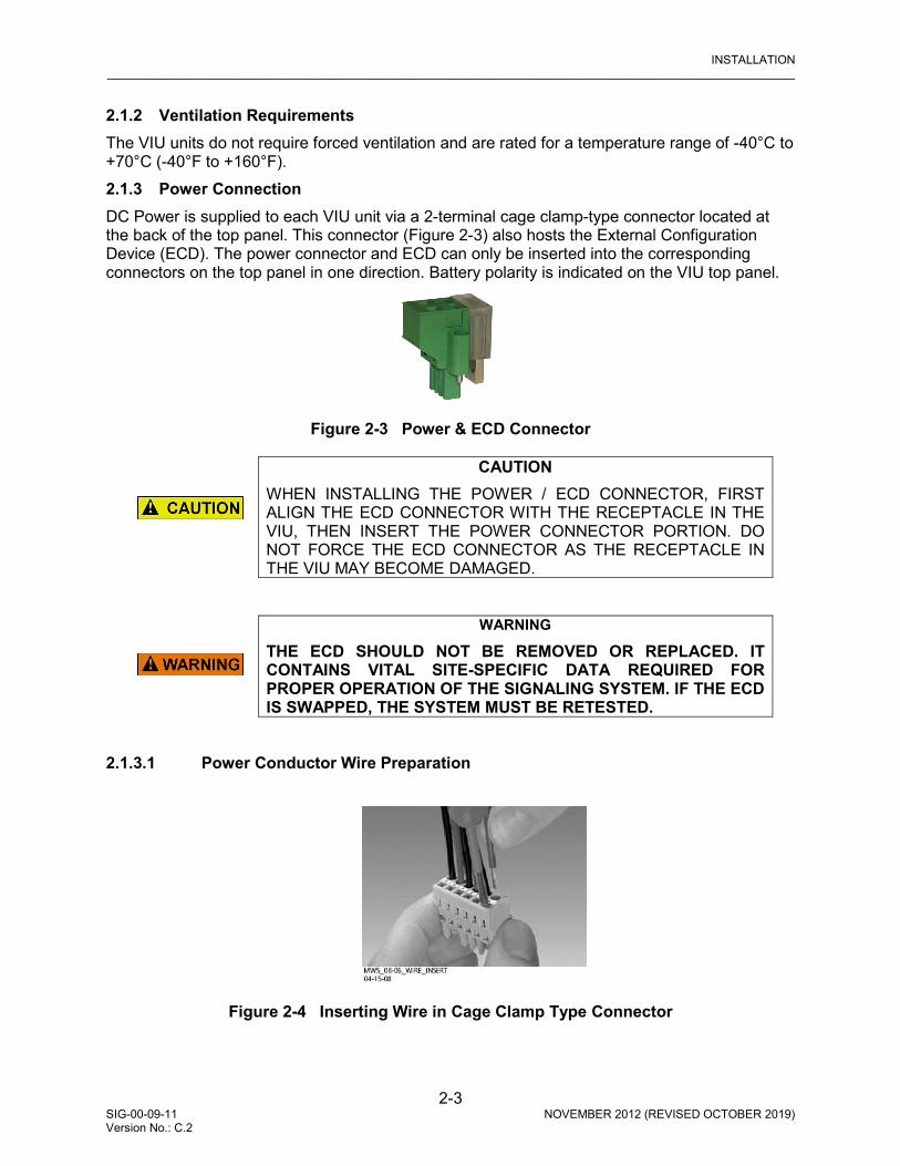
INSTALLATION _________________________________________________________________________________________________________
2-3 SIG-00-09-11 NOVEMBER 2012 (REVISED OCTOBER 2019) Version No.: C.2
2.1.2 Ventilation Requirements The VIU units do not require forced ventilation and are rated for a temperature range of -40°C to +70°C (-40°F to +160°F). 2.1.3 Power Connection DC Power is supplied to each VIU unit via a 2-terminal cage clamp-type connector located at the back of the top panel. This connector (Figure 2-3) also hosts the External Configuration Device (ECD). The power connector and ECD can only be inserted into the corresponding connectors on the top panel in one direction. Battery polarity is indicated on the VIU top panel.
Figure 2-3 Power & ECD Connector
CAUTION
WHEN INSTALLING THE POWER / ECD CONNECTOR, FIRST ALIGN THE ECD CONNECTOR WITH THE RECEPTACLE IN THE VIU, THEN INSERT THE POWER CONNECTOR PORTION. DO NOT FORCE THE ECD CONNECTOR AS THE RECEPTACLE IN THE VIU MAY BECOME DAMAGED.
WARNING
THE ECD SHOULD NOT BE REMOVED OR REPLACED. IT CONTAINS VITAL SITE-SPECIFIC DATA REQUIRED FOR PROPER OPERATION OF THE SIGNALING SYSTEM. IF THE ECD IS SWAPPED, THE SYSTEM MUST BE RETESTED.
2.1.3.1 Power Conductor Wire Preparation
Figure 2-4 Inserting Wire in Cage Clamp Type Connector

INSTALLATION _________________________________________________________________________________________________________
2-4 SIG-00-09-11 NOVEMBER 2012 (REVISED OCTOBER 2019) Version No.: C.2
Verify that “B” and “N” supply wires are installed in the power connector correctly before inserting the power connector into the mating connector on the top panel. Prepare the wires as follows:
1. If inserting the wire into the clamp, strip approximately 1/4 inch (6 mm) of insulation from the end of the wire. If opening the clamp, strip approximately ½ inch (12mm).
2. If required, verify the EMI filter is installed on cable per paragraph 2.1.3.2. 3. After either inserting a screwdriver and opening the clamp or by applying pressure on the
wire, insert the stripped end into the wire receptor until it stops. Remove the screwdriver, if applicable. Repeat for the second wire.
4. Tighten the screw that connects the power connector to the VIU case to approximately 4.5 inch pounds (0.5 Newton meters).
WARNING
INCORRECT WIRING AND INSTALLATION WILL LEAD TO UNSAFE FUNCTIONING OF THE VIU SYSTEM. THE USER MUST FOLLOW CORRECT INSTALLATION PROCEDURES AND PERFORM INSTALLATION TESTING TO VERIFY CORRECTNESS OF THE WIRING AND OTHER CONFIGURATION PARAMETERS BEFORE PLACING THE VIU SYSTEM IN SERVICE.
2.1.3.2 Installing EMI Filter on Power Cable
CAUTION
PRIOR TO PLACING A VIU-16I/-8I INTO OPERATION, VERIFY THE REVISION LEVEL OF THE 80516 BOARD ON THE SUB-ASSEMBLY PART LISTING LOCATED ON THE SIDE OF THE CASE. IF REVISION E OR EARLIER, USE THE EMI FILTER AS DESCRIBED BELOW; IF REVISION F OR LATER, THE EMI FILTER IS NOT REQUIRED.
In order to reduce radiated electromagnetic interference in the VIU power cable, a clamp-on EMI filter (part number Z590-00010-0001) must be installed as follows:
1. Open the clamp-on EMI filter as shown in Figure 2-5 Clamp-on EMI Filter (Open).
Figure 2-5 Clamp-on EMI Filter (Open)

INSTALLATION _________________________________________________________________________________________________________
2-5 SIG-00-09-11 NOVEMBER 2012 (REVISED OCTOBER 2019) Version No.: C.2
2. Place the open EMI filter under the power cable approximately 1.5 inches from the stripped end of the wires.
3. Wrap the long end of the cable around the outer surface of the filter and back through the center of the filter one time (totaling two wire runs inside the filter – see Figure 2-6 EMI Filter Installation (Showing Wire Loops).
Figure 2-6 EMI Filter Installation (Showing Wire Loops)
4. Snap the filter closed (see Figure 2-7 EMI Filter Installed).
Figure 2-7 EMI Filter Installed
2.1.4 Surge Protection The VIU unit provides internal secondary surge protection circuits on all vital inputs.
CAUTION
SIEMENS STRONGLY RECOMMENDS INSTALLING PRIMARY SURGE PROTECTION ON EXTERNAL LINES CONNECTING TO THE VIU.

INSTALLATION _________________________________________________________________________________________________________
2-6 SIG-00-09-11 NOVEMBER 2012 (REVISED OCTOBER 2019) Version No.: C.2
2.1.5 Vital Inputs The VIU top panel provides four male, 10-pin, cage-clamp style connectors that provide a total of 16 or 8 discrete vital input pairs that can be monitored by the VIU. Discrete input wires are connected to mating female 10-pin connectors (supplied with the unit) which are then plugged into the appropriate connector on the VIU top panel.
WARNING
VIU INPUTS SHOULD NOT BE WIRED DIRECTLY TO VITAL OUTPUTS OF ANOTHER ELECTRONIC SYSTEM WITHOUT FIRST TESTING TO PROVE THAT THE VITALITY OF THE OUTPUTS OF THE ELECTRONIC SYSTEM ARE NOT COMPROMISED DUE TO THE ELECTRICAL CHARACTERISTICS OF VIU INPUTS. IN VOLTAGE SENSING APPLICATIONS, WHEN THE VIU UNIT’S VITAL INPUTS ARE USED TO MONITOR LAMP ENERGY AND THE LAMP HAS AN OPEN FILAMENT, THE VIU WILL CONTINUE TO REPORT THE LAMP AS ILLUMINATED AS LONG AS THE SYSTEM CONTINUES TO APPLY ENERGY TO THE LAMP.
2.1.5.1 Discrete Vital Input / Output Connections Each discrete input and output on the I/O connectors has both a positive and a negative terminal connection. This allows for wiring of a larger variety of discrete I/O than using a common negative. It also prevents problems such as ‘sneak paths’ when adjacent inputs are wired. Polarity is marked on the case adjacent to each connector.
2.1.5.2 Connector Wiring Procedure The female connectors supplied with the VIU for the vital input connections will accept wire sizes in the range of #28 AWG to #14 AWG. The connectors contain spring-loaded cage-clamps for attachment of the wires. Each connector consists of a row of wire receptors and actuator spring holes to open and close the cage clamps. Wire each connector as follows: 1. Remove the supplied connector from the mating receptacle on the top of the VIU. 2. Select a proper gauge wire for the application (range is #28 to #14 AWG). 3. Strip approximately 5/16 inch (8 mm) of insulation from the end of the wire. 4. Insert the blade of a small screwdriver into the actuator spring hole associated with the wire
hole. The screwdriver blade should be no more than 0.10 inches wide and 0.020 inches thick (2.5 mm x 0.5 mm).
5. Lever the wire cage clamp open by pressing straight down on the screwdriver. Visually note that the contactor receptacle has opened up sufficiently to insert stripped wire. Fully insert wire into receptacle, taking care not to insert wire jacket insulation into metal contactors.
6. Remove screwdriver. Gently tug on the just-inserted wire to ensure the receptacle properly retains the installed wire.
7. Repeat for each wire to be added to the connector.
INSTALLATION _________________________________________________________________________________________________________
2-7 SIG-00-09-11 NOVEMBER 2012 (REVISED OCTOBER 2019) Version No.: C.2
2.1.6 Serial Interfaces
CAUTION
SERIAL PORTS HAVE NO SECONDARY SURGE PROTECTION. DO NOT CONNECT TO DEVICES OUTSIDE OF EQUIPMENT ENCLOSURE.
The VIU is equipped with two serial ports, one on the face of the unit and one on the top of the unit.
2.1.6.1 Laptop (Serial) Interface The VIU front panel provides a standard RS232 interface connector labeled ‘Laptop (Serial)’ for communication with a Diagnostic Terminal (laptop PC). This interface is a Data Communications Equipment (DCE) port which uses a 9-pin female (DB-9) connector. The cable required to connect this interface is a standard RS232 (straight-through) cable terminated in a male 9-pin (DB-9) connector at the VIU end, and terminated in an applicable connector at the diagnostic terminal (laptop PC).
2.1.6.2 Serial Interface (Top Panel) The VIU top panel provides an additional standard RS232 interface connector labeled ‘Serial’. This is a general purpose communications port for connection to external devices such as a BCP or GPS receiver. This interface is a Data Terminal Equipment (DTE) port which uses a 9-pin male (DB-9) connector. When connecting to a PC via the Top Panel Serial Interface, this connection requires a reverse cable or a Null Modem Adapter to be inserted on one end of the straight through cable. 2.1.7 Ethernet Interfaces The VIU is equipped with three standard Ethernet ports and one special powered Ethernet port. These ports are described in Table 2-1.
CAUTION
ETHERNET PORTS HAVE NO SECONDARY SURGE PROTECTION. DO NOT CONNECT TO DEVICES OUTSIDE OF EQUIPMENT ENCLOSURE. DO NOT CONNECT ANY IP CONNECTED DEVICE TO THE POWERED ETHERNET PORT OTHER THAN THE ETHERNET SPREAD SPECTRUM RADIO (ESSR), AS THIS COULD CAUSE DAMAGE TO EQUIPMENT AT THE OTHER END OF THE CABLE.

INSTALLATION _________________________________________________________________________________________________________
2-8 SIG-00-09-11 NOVEMBER 2012 (REVISED OCTOBER 2019) Version No.: C.2
Table 2-1 Ethernet Port Descriptions
PORT LOCATION NOMENCLATURE INTENDED USE LED INDICATIONS
Front Panel Laptop
(Ethernet)
Use as an Ethernet interface to a local laptop or desk top computer.
Green: Flashing = message activity.
Yellow: Off = 10 MBPS bit rate On = 100 MBPS bit rate
Top Panel Ethernet
Port 1
Use for communication between VIU and other Ethernet equipped devices or other VIU units.
Green: Flashing = message activity.
Yellow: Off = 10 MBPS bit rate On = 100 MBPS bit rate
Top Panel Ethernet
Port 2
Use for communication between VIU and other Ethernet equipped devices such as other VIU units or Ethernet enabled BCP.
NOTE This port is in parallel with special ESSR only (Port 2). Do not use this port and special ESSR port 2 simultaneously.
n/a
Top Panel ESSR Only
(Port 2)
Special Ethernet port used for connection to a Siemens Mobility, Inc Ethernet Spread Spectrum Radio (53325) only.
CAUTION This port is in parallel with standard Ethernet Port 2. Do not use this port and standard Ethernet Port 2 simultaneously.
NOTE This port also provides power to the ESSR radio.
n/a

INSTALLATION _________________________________________________________________________________________________________
2-9 SIG-00-09-11 NOVEMBER 2012 (REVISED OCTOBER 2019) Version No.: C.2
Table 2-2 Special ESSR Ethernet Port Connector Pin-outs (RJ45)
PIN NO. SIGNAL NAME ABBR. SIGNAL DESCRIPTION 1 Ethernet TX Tx (+) Radio to Ethernet (Transmit data +) 2 Ethernet TX Tx (-) Radio to Ethernet (Transmit data -) 3 Ethernet RX Rx (+) Ethernet to Radio (Receive data +) 4 VDC DCV (+) Power to Radio 5 VDC DCV (+) Power to Radio 6 Ethernet RX Rx (-) Ethernet to Radio (Receive data -) 7 Ground GND (-) Power ground to Radio 8 Ground GND (-) Power ground to Radio
2.1.8 GPS Port The GPS port is a female DB9 connector that provides the 1 pulse per second (pps) GPS signal output from the VIU. It also provides a National Marine Electronic Association (NMEA) 0183 output from the internal GPS receiver. This port is designed to connect to a Positive Train Control (PTC) providing an accurate time source for broadcasting of wayside status messages. Refer to Table 2-3 for connector pin outs.
Table 2-3 GPS Port Connector Pin-outs
PIN NUMBER SIGNAL 1 N/C 2 GPS TX DATA 3 N/C 4 N/C 5 GPS GND 6 N/C 7 N/C 8 GPS PPS- 9 GPS PPS+
2.1.9 GPS Antenna The GPS antenna connector is a female SMA connector (1/4-36 UNS threaded coupling). Connect an external GPS antenna to this jack. 2.1.10 USB Interface A standard USB 2.0 port is provided on the front panel for connecting a USB flash drive.

INSTALLATION _________________________________________________________________________________________________________
2-10 SIG-00-09-11 NOVEMBER 2012 (REVISED OCTOBER 2019) Version No.: C.2
This Page Intentionally Left Blank

BASIC VIU OPERATION _________________________________________________________________________________________________________
3-1 SIG-00-09-11 NOVEMBER 2012 (REVISED OCTOBER 2019) Version No.: C.2
SECTION 3 BASIC VIU OPERATION
3.0 BASIC VIU OPERATION
WARNING
RAILROADS OR AGENCIES ARE RESPONSIBLE FOR ENSURING ONLY PROPERLY TRAINED AND/OR AUTHORIZED PERSONNEL HAVE ACCESS TO THE VIU-16I/-8I. PROGRAM CHANGES MUST BE PERFORMED IN ACCORDANCE WITH RAILROAD PROCEDURES. VERIFY THAT VIU-16I/-8I HAS ALL PROPER COMPONENTS AND IS PROGRAMMED AS SPECIFIED BY THE RAILROAD’S OR AGENCY’S APPROVED WIRING OR INSTALLATION DIAGRAM. FAILURE TO DO SO MAY LEAD TO INCORRECT OR UNSAFE OPERATION OF THE SIGNAL SYSTEM. AFTER INSTALLATION OF A UNIT, OR WHENEVER A CHANGE IS MADE TO THE SOFTWARE (TO INCLUDE MOVING AND/OR COPYING THE ECD) OR THE CONFIGURATION, THE INSTALLATION SHOULD BE FULLY OPERATIONALLY TESTED TO ENSURE SAFETY. SYSTEM OPERATION MUST BE VERIFIED PRIOR TO PLACING SYSTEM IN SERVICE OR FOLLOWING PROGRAMMING, HARDWARE CHANGES, OR WIRING CHANGES.
3.1 POWER-UP
When the VIU is first powered up, it performs various vital and non-vital software checks. During this period (approximately 1 minute), only the power LED is lit while the display shows “VIU SYSTEM BOOTING PLEASE WAIT.” Following the software checks the display turns on and the VIU loads various drivers (USB, Ethernet, etc.) before running the VIU executive (MEF). At approximately 1 minute, 30 seconds from power-up, the VIU lights all front panel LEDs to test for bad LEDs. At approximately 2 minutes from power-up, the VIU settles into normal operation, the input status LEDs show current input status and the health LED flashes at 0.5 Hz.
NOTE
During power-up, the boot monitor checks the integrity of the MEF by performing a 32-bit CRC calculation. If the MEF is not valid, the Boot Monitor will not run it and the MEF must be reloaded.

BASIC VIU OPERATION _________________________________________________________________________________________________________
3-2 SIG-00-09-11 NOVEMBER 2012 (REVISED OCTOBER 2019) Version No.: C.2
3.1.1 VIU Real-Time Clock The real-time clock will likely contain invalid data when the VIU is powered up for the first time in the field. Therefore, date/time adjustments should be performed immediately following the initial power-up sequence in the field. For units equipped with a GPS receiver, the GPS will provide the time reference and no adjustment is needed. If the VIU is not equipped with GPS, the time and date are set via the Web browser interface or by the NTP if connected to a network (see Section 8). The internal power storage supplies power to the real-time clock when power to the unit is off. Under normal circumstances, the real time clock will retain valid date/time information for at least 10 years with external power removed. The VIU uses a real-time clock chip with a built-in lithium ion cell, which is not field replaceable. 3.1.2 Front Panel Boot Display Sequence It is possible to monitor the VIU power-up process on the front panel display. The following examples show the normal boot sequence as it appears on the front panel display. Multiple status screens briefly appear as the unit starts all of its processes. During this period the only LED that is lit is the Power LED. After all of the processes have run, the following message appears on the screen:
Figure 3-1 VIU Initial Boot Process Screens
LOADING USB DRIVERS
STARTING ECD
RUNNING VIU EXEC
CHECKING KEYPAD
V F D D r i v e r R e v 1 . 0 A p r 2 3 2 0 0 8
SAFETRAN SYSTEMS VIU

BASIC VIU OPERATION _________________________________________________________________________________________________________
3-3 SIG-00-09-11 NOVEMBER 2012 (REVISED OCTOBER 2019) Version No.: C.2
All front panel LEDs are lit at this point to allow visual LED check. When the boot process is complete, a variation of the lower message appears.
Figure 3-2 VIU Start Screen Following a successful boot-up and launching of the MEF, the front panel display will automatically default to a date/time display similar to the one shown below:
Figure 3-3 VIU Default Top Level Screen
The bottom row of the display will cycle through the following information:
• Site Name • Milepost • DOT # (Department of Transportation No.) • Site ID Number (SIN) (ATCS address) • MCF CRC • Laptop Baud Rate • Vital State • Laptop IP Address • Port 1 IP Address • Port 2 IP Address • Miscellaneous messages. The left () or right () arrow keys may be used to cycle through the above entries. The site name, milepost and DOT # can be entered using the Web browser interface after uploading the MCF from the USB drive.
3.2 TRANSFERRING FILES TO THE VIU
The VIU comes from the factory with the MCF, MEFs and default configuration files installed. Following initial power up and successful boot up of the VIU, an application specific MCF can be uploaded via the USB port located on the front panel.
SAFETRAN SYSTEMS CORP PLEASE WAIT...
LOCALUI_MENU Apr 8 2008 17:25:32
2008-Apr-11 17:09 S i te Name: Main
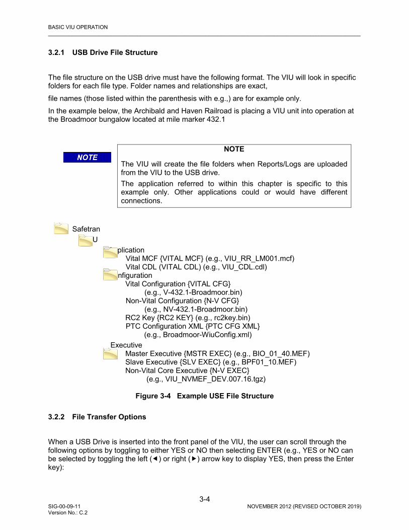
BASIC VIU OPERATION _________________________________________________________________________________________________________
3-4 SIG-00-09-11 NOVEMBER 2012 (REVISED OCTOBER 2019) Version No.: C.2
3.2.1 USB Drive File Structure The file structure on the USB drive must have the following format. The VIU will look in specific folders for each file type. Folder names and relationships are exact, file names (those listed within the parenthesis with e.g.,) are for example only. In the example below, the Archibald and Haven Railroad is placing a VIU unit into operation at the Broadmoor bungalow located at mile marker 432.1
NOTE
The VIU will create the file folders when Reports/Logs are uploaded from the VIU to the USB drive. The application referred to within this chapter is specific to this example only. Other applications could or would have different connections.
Safetran
VIU Application Vital MCF {VITAL MCF} (e.g., VIU_RR_LM001.mcf) Vital CDL (VITAL CDL) (e.g., VIU_CDL.cdl) Configuration Vital Configuration {VITAL CFG} (e.g., V-432.1-Broadmoor.bin) Non-Vital Configuration {N-V CFG} (e.g., NV-432.1-Broadmoor.bin) RC2 Key {RC2 KEY} (e.g., rc2key.bin) PTC Configuration XML {PTC CFG XML} (e.g., Broadmoor-WiuConfig.xml) Executive Master Executive {MSTR EXEC} (e.g., BIO_01_40.MEF) Slave Executive {SLV EXEC} (e.g., BPF01_10.MEF) Non-Vital Core Executive {N-V EXEC} (e.g., VIU_NVMEF_DEV.007.16.tgz)
Figure 3-4 Example USE File Structure 3.2.2 File Transfer Options When a USB Drive is inserted into the front panel of the VIU, the user can scroll through the following options by toggling to either YES or NO then selecting ENTER (e.g., YES or NO can be selected by toggling the left () or right () arrow key to display YES, then press the Enter key):

BASIC VIU OPERATION _________________________________________________________________________________________________________
3-5 SIG-00-09-11 NOVEMBER 2012 (REVISED OCTOBER 2019) Version No.: C.2
3.2.2.1 Download Reports from VIU Into USB Drive To download (Get) reports, press ENTER until the desired report is shown, select YES, and the file will be generated and downloaded into the USB Drive.
• Get full Event Report? Create Report: No Yes • Get 24 hour Event Report? Create Report: No Yes • Get 2 week Event Report? Create Report: No Yes • Get Diag. Report? Create Report: No Yes • Get Cnfig. Report? Create Report: No Yes • Get Vrsn. Report? Create Report: No Yes • Get CDL Log? Create Report: No Yes
3.2.2.2 Download Files from VIU Into USB Drive To download (Get) the desired file, press ENTER until the desired file is shown, select YES, and the file will be downloaded into the USB Drive.
• Get Vital MCF < VIU? Get File: No Yes • Get Vital CFG < VIU? Get File: No Yes • Get Non-Vital CFG < VIU? Get File: No Yes • Get RC2 Key < VIU? Get File: No Yes • Get PTC CFG XML < VIU? Get File: No Yes • Get CDL File? Get File: No Yes
3.2.2.3 Upload Files from USB Drive Into VIU
CAUTION
DO NOT REMOVE POWER FROM THE UNIT WHEN THE MESSAGE “PLEASE WAIT. DO NOT REMOVE POWER FROM UNIT” APPEARS. IF POWER IS REMOVED BEFORE THE TRANSFER IS COMPLETE, THE UNIT WILL REMAIN UNCONFIGURED AND WILL NOT RETURN TO OPERATION.
To upload (Put) the desired file, press ENTER until the desired file is shown, select YES, and the file will be uploaded into the USB Drive.
• Put Vital MCF > VIU? Select File: No Yes • Put Vital CFG > VIU? Select File: No Yes • Put Mstr Exec > VIU? Select File: No Yes • Put Slv Exec > VIU? Select File: No Yes • Put N-V CFG > VIU? Select File: No Yes • Put N-V Exec > VIU? Select File: No Yes • Put RC2 Key > VIU? Select File: No Yes • Put PTC CFG XML > VIU? Select File: No Yes • Put CDL File? Put File: No Yes
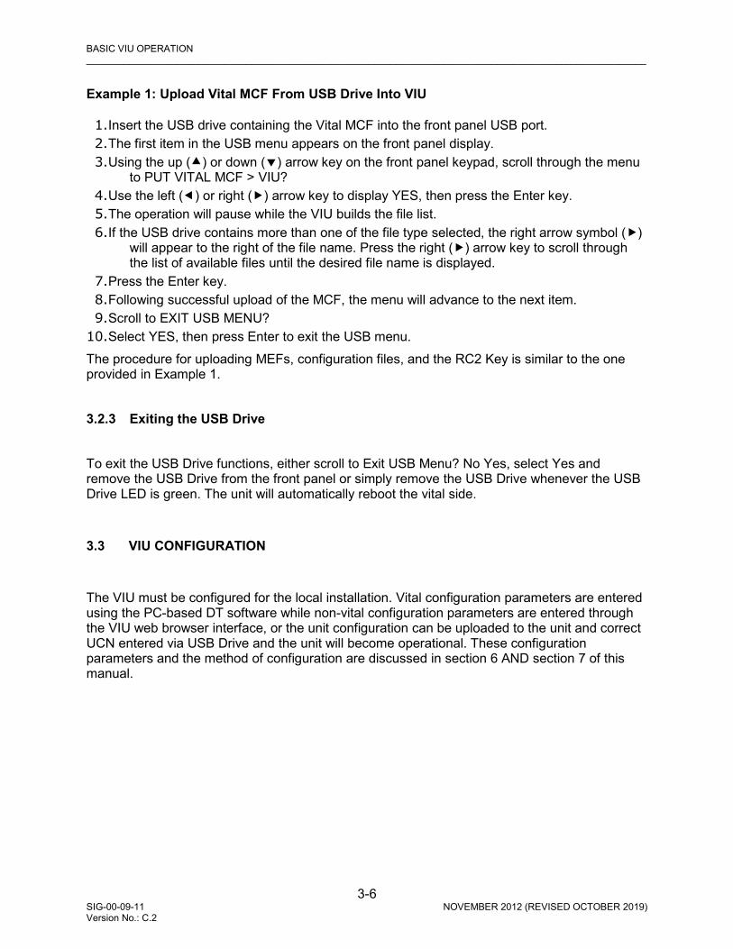
BASIC VIU OPERATION _________________________________________________________________________________________________________
3-6 SIG-00-09-11 NOVEMBER 2012 (REVISED OCTOBER 2019) Version No.: C.2
Example 1: Upload Vital MCF From USB Drive Into VIU 1. Insert the USB drive containing the Vital MCF into the front panel USB port. 2. The first item in the USB menu appears on the front panel display. 3. Using the up () or down () arrow key on the front panel keypad, scroll through the menu
to PUT VITAL MCF > VIU? 4. Use the left () or right () arrow key to display YES, then press the Enter key. 5. The operation will pause while the VIU builds the file list. 6. If the USB drive contains more than one of the file type selected, the right arrow symbol ()
will appear to the right of the file name. Press the right () arrow key to scroll through the list of available files until the desired file name is displayed.
7. Press the Enter key. 8. Following successful upload of the MCF, the menu will advance to the next item. 9. Scroll to EXIT USB MENU?
10. Select YES, then press Enter to exit the USB menu. The procedure for uploading MEFs, configuration files, and the RC2 Key is similar to the one provided in Example 1. 3.2.3 Exiting the USB Drive To exit the USB Drive functions, either scroll to Exit USB Menu? No Yes, select Yes and remove the USB Drive from the front panel or simply remove the USB Drive whenever the USB Drive LED is green. The unit will automatically reboot the vital side.
3.3 VIU CONFIGURATION
The VIU must be configured for the local installation. Vital configuration parameters are entered using the PC-based DT software while non-vital configuration parameters are entered through the VIU web browser interface, or the unit configuration can be uploaded to the unit and correct UCN entered via USB Drive and the unit will become operational. These configuration parameters and the method of configuration are discussed in section 6 AND section 7 of this manual.

BASIC VIU OPERATION _________________________________________________________________________________________________________
3-7 SIG-00-09-11 NOVEMBER 2012 (REVISED OCTOBER 2019) Version No.: C.2
3.4 VIU OPERATING STATES
The VIU operating states consist of the following:
• Initial State: This is the VIU initial power-up state during which the VIU performs its power-up self-test routine to validate the hardware, Executive software, Module Configuration File (MCF) and corresponding MCF CRC, and the vital configuration using the Unique Check Number (UCN). Once the power-up self-test has been successfully completed, the unit will transition to an Un-configured State if there is a problem with the configuration such as one of the following:
• MCF CRC is incorrect
• UCN is incorrect
• ATCS address for VIU is not set correctly
• VIU resets to default values If each of the configuration items listed above passes validation, the VIU will transition to the Fully Operational state.
• Un-Configured State: In this state the VIU is installed but not configured correctly. It will successfully complete its power-up self tests but will not send out any vital messages or respond to any vital messages. It will respond, however, to input from the front panel keypad, messages from the VIU web browser interface and to messages from the Diagnostic Terminal (DT) program to allow for local configuration of operating parameters.
• Fully Operational State: In this state, the VIU vital parameters are configured in accordance with the office plan.
WARNING
FULLY OPERATION STATE DOES NOT GUARANTEE THAT THE CONFIGURATION PARAMETER VALUES ARE IN ACCORDANCE WITH THE OFFICE PLAN. FOR EXAMPLE, EVEN THOUGH THE TOP LEVEL MAY SAY “VTL STATE IN SESSION. CONFIGURED, SLV HLTH GOOD”, FURTHER VALIDATION SHOULD STILL BE PERFORMED BEFORE PUTTING THE VIU UNIT IN SERVICE.
• Shutdown State: In this state, the VIU is not receiving or transmitting vital messages.

BASIC VIU OPERATION _________________________________________________________________________________________________________
3-8 SIG-00-09-11 NOVEMBER 2012 (REVISED OCTOBER 2019) Version No.: C.2
3.5 CONFIGURATION VERIFICATION AT STARTUP
WARNING
VERIFY THAT VIU IS PROGRAMMED AS SPECIFIED BY THE RAILROAD’S OR AGENCY’S WITH THE CORRECT MCFCRC, UCN, ATCS SITE IDENTIFICATION NUMBER (SIN). FAILURE TO DO SO MAY LEAD TO INCORRECT OR UNSAFE INDICATIONS ON THE VIU UNIT. USER CONFIGURABLE ITEMS ARE UCN PROTECTED TO PROHIBIT UNAUTHORIZED CHANGES.
NOTE
When vital configuration changes are made in the MCF, a new UCN must be calculated and entered into the VIU to validate the changes. The UCN is calculated using a special version of the DT software (see Section 4).
On startup, the VIU validates its configuration by verifying the following:
• The MCF is valid. • The MCF CRC matches the MCF. • The correct UCN is entered. If the MCF is valid, has the correct CRC, the vital configuration parameters are set and the correct UCN is entered, then the VIU goes into the Fully Operational state. If any of these checks fail, the VIU goes into the Un-Configured state. This will be indicated by a vital status message scrolling on the bottom row of the front panel display.
NOTE
The status message is refreshed with each complete cycle of the displayed information and may take approximately 2 minutes to cycle completely and update the message. If the status “UNCONFIGURED” and “SLV HEALTH BAD” displays, this may appear for a few cycles until the message updates.
When the VIU is in the Un-Configured state, it does not send out any VIU vital messages or respond to any VIU vital messages. It does, however, respond to input via the front panel keypad and to messages from the Diagnostic Terminal (DT) program.

BASIC VIU OPERATION _________________________________________________________________________________________________________
3-9 SIG-00-09-11 NOVEMBER 2012 (REVISED OCTOBER 2019) Version No.: C.2
3.6 INTEROPERABLE TRAIN CONTROL MESSAGING (ITCH) SYSTEM
When the VIU is used in a Wayside Interface Unit Application, it will monitor signal aspects and switch positions controlled by an existing interlocking, and/or defect detector status and send the signal aspect and switch status, and/or detector status information to the locomotive and/or the back office using Wayside Status Messages (WSMs). These WSMs and EMP messages are transferred into the ITCM system using the Class D protocol. The ITCM will deliver the WSMs to the locomotive.
WARNING
THE APPLICATION LOGIC MUST INCORPORATE STABILIZATION LOGIC TO PREVENT UNSTABLE DATA BEING SENT FROM MONITORED SYSTEMS.
3.7 GPS TIME REFERENCE
When equipped with a GPS receiver, the VIU synchronizes its time with the GPS receiver via the GPS Interface. This can be either the internal GPS receiver or an external GPS receiver connected to the serial port on the VIU top panel. Alternately, the time reference can be from Class C EMP messages or via NTP. In the absence of GPS time information the VIU is capable of maintaining its internal clock time so that the drift from GPS time does not exceed +/- 2000 ms within a 24 hour period.
3.8 MULTIPLE VIUS IN A SYSTEM
In larger interlockings, multiple VIUs may be required to monitor all of the signal lamps, switches, and/or defect detectors. In this case, Auxiliary (Slave) VIUs will send vital ATCS messages to a Main (Master) VIU. All I/O data is consolidated by the Main VIU and it transmits the consolidated message to the on-board system. Please refer to section 4 for details on setting up a multi-VIU system.

BASIC VIU OPERATION _________________________________________________________________________________________________________
3-10 SIG-00-09-11 NOVEMBER 2012 (REVISED OCTOBER 2019) Version No.: C.2
This Page Intentionally Left Blank

VIU SETUP _________________________________________________________________________________________________________
4-1 SIG-00-09-11 NOVEMBER 2012 (REVISED OCTOBER 2019) Version No.: C.2
SECTION 4 VIU SETUP
4.0 VIU SETUP
WARNING
RAILROADS OR AGENCIES ARE RESPONSIBLE FOR ENSURING ONLY PROPERLY TRAINED AND/OR AUTHORIZED PERSONNEL HAVE ACCESS TO THE VIU-16I/-8I. PROGRAM CHANGES MUST BE PERFORMED IN ACCORDANCE WITH RAILROAD PROCEDURES. VERIFY THAT VIU-16I/-8I HAS ALL PROPER COMPONENTS AND IS PROGRAMMED AS SPECIFIED BY THE RAILROAD’S OR AGENCY’S APPROVED WIRING OR INSTALLATION DIAGRAM. FAILURE TO DO SO MAY LEAD TO INCORRECT OR UNSAFE OPERATION OF THE SIGNAL SYSTEM. AFTER INSTALLATION OF A UNIT, OR WHENEVER A CHANGE IS MADE TO THE SOFTWARE (TO INCLUDE MOVING AND/OR COPYING THE ECD) OR THE CONFIGURATION, THE INSTALLATION SHOULD BE FULLY OPERATIONALLY TESTED TO ENSURE SAFETY. SYSTEM OPERATION MUST BE VERIFIED PRIOR TO PLACING SYSTEM IN SERVICE OR FOLLOWING PROGRAMMING, HARDWARE CHANGES, OR WIRING CHANGES.
4.1 INTRODUCTION
After a VIU or multiple VIUs are installed in the field, the unit(s) must be configured for the specific site. SSECTION 6 of this document covers the use of the DT software and SECTION 7 the VIU Web browser user interface for setting vital and non-vital parameters. This section provides general setup information plus typical procedures for system setup.
WARNING
INCORRECT ENTRY OF VITAL CONFIGURABLE PARAMETERS WILL LEAD TO UNSAFE FUNCTIONING OF THE VIU UNIT. THE VITAL FIELD CONFIGURABLE PARAMETERS MUST BE VERIFIED FOR CORRECTNESS BEFORE THE EQUIPMENT IS PLACED IN SERVICE. VITAL FIELD CONFIGURABLE PARAMETERS ARE UCN PROTECTED TO PROHIBIT UNAUTHORIZED CHANGES. IN VOLTAGE SENSING APPLICATIONS, WHEN THE VIU UNIT’S VITAL INPUTS ARE USED TO MONITOR LAMP ENERGY AND THE LAMP HAS AN OPEN FILAMENT, THE VIU WILL CONTINUE TO REPORT THE LAMP AS ILLUMINATED AS LONG AS THE SYSTEM CONTINUES TO APPLY ENERGY TO THE LAMP.
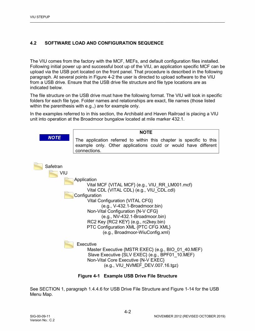
VIU STEPUP _________________________________________________________________________________________________________
4-2 SIG-00-09-11 NOVEMBER 2012 (REVISED OCTOBER 2019) Version No.: C.2
4.2 SOFTWARE LOAD AND CONFIGURATION SEQUENCE
The VIU comes from the factory with the MCF, MEFs, and default configuration files installed. Following initial power up and successful boot up of the VIU, an application specific MCF can be upload via the USB port located on the front panel. That procedure is described in the following paragraph. At several points in Figure 4-2 the user is directed to upload software to the VIU from a USB drive. Ensure that the USB drive file structure and file type locations are as indicated below. The file structure on the USB drive must have the following format. The VIU will look in specific folders for each file type. Folder names and relationships are exact, file names (those listed within the parenthesis with e.g.,) are for example only. In the examples referred to in this section, the Archibald and Haven Railroad is placing a VIU unit into operation at the Broadmoor bungalow located at mile marker 432.1.
NOTE
The application referred to within this chapter is specific to this example only. Other applications could or would have different connections.
Safetran
VIU Application Vital MCF {VITAL MCF} (e.g., VIU_RR_LM001.mcf) Vital CDL (VITAL CDL) (e.g., VIU_CDL.cdl) Configuration Vital Configuration {VITAL CFG} (e.g., V-432.1-Broadmoor.bin) Non-Vital Configuration {N-V CFG} (e.g., NV-432.1-Broadmoor.bin) RC2 Key {RC2 KEY} (e.g., rc2key.bin) PTC Configuration XML {PTC CFG XML} (e.g., Broadmoor-WiuConfig.xml) Executive Master Executive {MSTR EXEC} (e.g., BIO_01_40.MEF) Slave Executive {SLV EXEC} (e.g., BPF01_10.MEF) Non-Vital Core Executive {N-V EXEC} (e.g., VIU_NVMEF_DEV.007.16.tgz)
Figure 4-1 Example USB Drive File Structure See SECTION 1, paragraph 1.4.4.6 for USB Drive File Structure and Figure 1-14 for the USB Menu Map.

VIU SETUP _________________________________________________________________________________________________________
4-3 SIG-00-09-11 NOVEMBER 2012 (REVISED OCTOBER 2019) Version No.: C.2
CAUTION
DO NOT REMOVE POWER FROM THE UNIT WHEN THE MESSAGE “PLEASE WAIT. DO NOT REMOVE POWER FROM UNIT” APPEARS. IF POWER IS REMOVED BEFORE THE TRANSFER IS COMPLETE, THE UNIT WILL REMAIN UNCONFIGURED AND NOT RETURN TO OPERATION.
Figure 4-2 indicates the order in which software should be loaded and at what points the vital and non-vital parameters should be configured for a normal VIU installation. If multiple VIUs are involved, apply the same process to each unit.
Figure 4-2 VIU Software Load & Configuration Sequence
Start
Check the Master Exec, Slave Exec, and Non-
Vital Core Exec software versions in the web
interface.
Versions are the latest? No
Load latest Master Exec, Slave Exec, and Non-
Vital Core Exec software via the USB port.
Yes
Load Vital MCF via the USB port.
Enter Site ID Number, MCF CRC and MCF UCN
via front panel keypad.
Configure MCF with DT.
Enter Site Name, network settings, WIU channel
settings (including encrypted HMAC) and logging settings in web
user interface (Web U/I).
Stop

VIU STEPUP _________________________________________________________________________________________________________
4-4 SIG-00-09-11 NOVEMBER 2012 (REVISED OCTOBER 2019) Version No.: C.2
4.3 HOW EQUIPMENT IS MAPPED TO VITAL INPUTS/OUTPUTS
The number of VIU units required to monitor the wayside signals and switches at a location depends upon the number of signal lamps, switches, and hazard detectors present. Each lamp in a signal head requires one input; each switch requires two inputs (one each for reverse and normal), and each hazard detector requires one input. Additionally, if current/voltage sensing is used on wayside signals, there will be one input used for each signal lamp of a signal head and one input is used for the current sensor that monitors all of the lamps in the signal head. If there are more signal lamps and switches in the interlocking than can be handled by a single VIU unit, auxiliary VIUs can be added via an Ethernet LAN. Each additional VIU will add either 8 or 16 more inputs to the number of available vital inputs. As the 8 or 16 inputs are used up on the Main VIU, the inputs on the auxiliary VIU unit are used and so on. Up to 3 auxiliary VIUs can be added, for a total of four units. The VIU Wayside Interface Unit Application can support various combinations of signals, switches, and hazard detectors. The totals may vary depending upon the individual MCF. Current VIU MCFs allow users to specifically define which input on each particular box to use for each lamp, switch, or hazard detector. On the VIU-8i and VIU-16i, the first output is a current sensor health output, if used. It is used to determine the health of the current sensor itself. As an example, when using an Siemens’s CS3 Digital Current Sensor, OUT1+ on the VIU is connected to Test Loop IN on Connector J3, and OUT1- on the VIU is connected to Test Loop OUT on Connector J3. Only 1 current sensor health check output is required per VIU unit, even if all 16 inputs are being used on that VIU unit. If no current sensors are used, any or all outputs may be used for vital relays. 4.3.1 Voltage and Current Sensor Options
NOTE
The screens used throughout Section 4.3 are GENERIC PROGRAMMING EXAMPLES from an EXAMPLE APPLICATION. Screen and Parameter titles may differ on each individual application; however, the overall principles guiding programming the VIU-16i/-8i remain the same across all applications.
There are three distinct applications using voltage and/or current sensors:
• Generic Voltage Sensing application – used to monitor voltage of each signal “lamp” • Generic Current Sensor application – used to monitor current of each signal “lamp” • Current Sensor used in Voltage Sensing application – monitors voltage of each signal
“lamp” and current of the common return of each signal “head”

VIU SETUP _________________________________________________________________________________________________________
4-5 SIG-00-09-11 NOVEMBER 2012 (REVISED OCTOBER 2019) Version No.: C.2
4.3.1.1 Generic Voltage Sensing Application
CAUTION
VOLTAGE SENSING SHOULD BE USED ONLY IN SYSTEMS WHERE THE LOGIC THAT CONTROLS THE LAMPS WILL NOT SUPPLY VOLTAGE TO A BURNED OUT LAMP.
A Voltage Sensing Application is programmed and wired as depicted in Figure 4-3. In this example, all VIU inputs’ negative terminals are wired to a common negative lead that is connected to the battery’s negative terminal.
Figure 4-3 Voltage Sensing Wiring Diagram
AGE
VIU 16i/8i I/O
IN 1
IN 2
IN 3
IN 4
IN 5
IN 9
IN 10
IN 11
IN 12
IN 13
+
-+
-+
-+
-+
-
+
-+
-+
-+
-+
-
IN 14
IN 15
IN 16
OUT 3
OUT 4
+
-+
-+
-+
-+
-
IN 6
IN 7
IN 8
OUT 1
OUT 2
+
-+
-+
-+
-+
-
G
Y
R
G
Y
R
AYE
ARE
BGE
BYE
BRE
ACOMMON
BCOMMON
VLO 1
VLO 2
VLO 3
VLO 4
VLO 5
VLO 6
TYPICAL INSTALLATION OF CURRENT SENSOR ON LAMP COMMON ONLY WITH VOLTAGE SENSING ON LAMPS
VLOBCOMMON
VLOACOMMON
B12
N12
IN 1+
*
*
*
*
*
*
*
*
* TO LAMP CONTROL SOURCE
OUT 1+
IN 2+
IN 3+
IN 4+
IN 5+
IN 6+
IN 7+
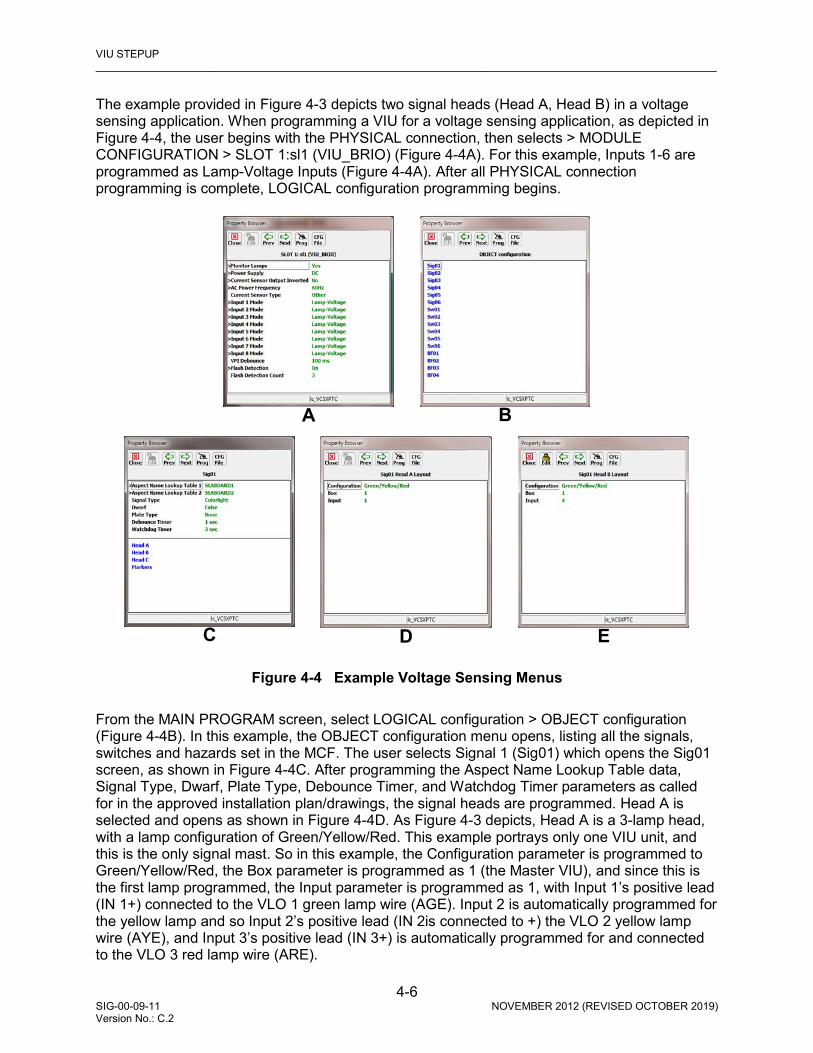
VIU STEPUP _________________________________________________________________________________________________________
4-6 SIG-00-09-11 NOVEMBER 2012 (REVISED OCTOBER 2019) Version No.: C.2
The example provided in Figure 4-3 depicts two signal heads (Head A, Head B) in a voltage sensing application. When programming a VIU for a voltage sensing application, as depicted in Figure 4-4, the user begins with the PHYSICAL connection, then selects > MODULE CONFIGURATION > SLOT 1:sl1 (VIU_BRIO) (Figure 4-4A). For this example, Inputs 1-6 are programmed as Lamp-Voltage Inputs (Figure 4-4A). After all PHYSICAL connection programming is complete, LOGICAL configuration programming begins.
Figure 4-4 Example Voltage Sensing Menus
From the MAIN PROGRAM screen, select LOGICAL configuration > OBJECT configuration (Figure 4-4B). In this example, the OBJECT configuration menu opens, listing all the signals, switches and hazards set in the MCF. The user selects Signal 1 (Sig01) which opens the Sig01 screen, as shown in Figure 4-4C. After programming the Aspect Name Lookup Table data, Signal Type, Dwarf, Plate Type, Debounce Timer, and Watchdog Timer parameters as called for in the approved installation plan/drawings, the signal heads are programmed. Head A is selected and opens as shown in Figure 4-4D. As Figure 4-3 depicts, Head A is a 3-lamp head, with a lamp configuration of Green/Yellow/Red. This example portrays only one VIU unit, and this is the only signal mast. So in this example, the Configuration parameter is programmed to Green/Yellow/Red, the Box parameter is programmed as 1 (the Master VIU), and since this is the first lamp programmed, the Input parameter is programmed as 1, with Input 1’s positive lead (IN 1+) connected to the VLO 1 green lamp wire (AGE). Input 2 is automatically programmed for the yellow lamp and so Input 2’s positive lead (IN 2is connected to +) the VLO 2 yellow lamp wire (AYE), and Input 3’s positive lead (IN 3+) is automatically programmed for and connected to the VLO 3 red lamp wire (ARE).
B A
C D E

VIU SETUP _________________________________________________________________________________________________________
4-7 SIG-00-09-11 NOVEMBER 2012 (REVISED OCTOBER 2019) Version No.: C.2
Returning to the Sig01 screen, Head B is selected, and this opens the Sig01 Head B Layout screen, Figure 4-4E. As depicted in Figure 4-3, Head B is also a 3 lamp head, with Green/Yellow/Red. The Box parameter is programmed to 1 (the Master VIU), and since this is the first lamp of the second head to be programmed, the Input parameter is programmed as 4, with the VLO 4 green lamp (BGE) wire connected to Input 4’s positive lead (IN 4+). Input 5 is automatically programmed for the yellow lamp and so the VLO 5 yellow lamp wire (BYE) is connected to Input 5’s positive lead (IN 5+), and the VLO 6 red lamp wire (BRE) is automatically programmed for and connected to Input 6’s positive lead (IN 6+).
4.3.1.2 Current Sensor Application A Current Sensor Application is programmed and wired as depicted in Figure 4-5. In this example, all VIU inputs’ positive terminals are wired to a common positive lead that is connected to the battery’s positive terminal.
Figure 4-5 Current Sensor Wiring Diagram
AGE
AYE
ARE
BGE
BYE
BRE
VLO A COMMON
VLO B COMMON
1CS3
2CS3

VIU STEPUP _________________________________________________________________________________________________________
4-8 SIG-00-09-11 NOVEMBER 2012 (REVISED OCTOBER 2019) Version No.: C.2
CAUTION
CARE MUST BE TAKEN WHEN WIRING CS3 DIGITAL CURRENT SENSORS. IN CURRENT SENSOR APPLICATIONS, THE VIU UNIT INPUTS ARE WIRED WITH A COMMON POSITIVE CONNECTION. THIS IS OPPOSITE THE WIRING IN A STANDARD VOLTAGE SENSING APPLICATION, AS THE CURRENT SENSOR OUTPUTS ARE OPEN-COLLECTOR TRANSISTORS SINKING CURRENT AND ARE INTERNALLY REFERENCED TO BATTERY NEGATIVE.
Current sensors are used to verify current flow through the lamps. Siemens recommends Siemens’ CS3 Digital Current Sensors in current sensing applications, as depicted in Figure 4-5. The example provided in Figure 4-5 depicts two signal heads (Head A, Head B), using two CS3 sensors, with the first CS3 (1CS3) connected to Head A and the second CS3 (2CS3) connected to Head B.
Figure 4-6 Example Current Sensor Application
When setting up a generic current sensing application, as depicted in Figure 4-5, first select PHYSICAL connection > MODULE CONFIGURATION > SLOT 1:sl1 (VIU_BRIO) (Figure 4-6A). Inputs 1-6 are programmed as Lamp-Current Inputs (Figure 4-6A).
C D E
B A

VIU SETUP _________________________________________________________________________________________________________
4-9 SIG-00-09-11 NOVEMBER 2012 (REVISED OCTOBER 2019) Version No.: C.2
After all PHYSICAL connection programming is complete, LOGICAL configuration programming begins. From the MAIN PROGRAM screen, select LOGICAL configuration > OBJECT configuration (Figure 4-6B). In this example, the OBJECT configuration menu opens, listing all the signals, switches and hazards set in the MCF. The user selects Signal 1 (Sig01) which opens the Sig01 screen, as shown in Figure 4-6C. After programming the Aspect Name Lookup Table data, Signal Type, Dwarf, Plate Type, Debounce Timer, and Watchdog Timer parameters as called for in the approved installation plan/drawings, the signal heads are programmed. Head A is selected and opens as shown in Figure 4-6D. As Figure 4-5depicts, Head A is a 3-lamp head, with a lamp configuration of Green/Yellow/Red. This example portrays only one VIU unit, and this is the only signal mast. The J3 connector of CS3B is joined to the J4 connector of CS3A. Battery and Negative are connected to the B and N terminals of CS3A, respectively. The Out 1+ wire from the VIU is connected to the IN terminal of CS3A’s J3 connector, and the Out 1- wire from the VIU is connected to the OUT terminal of CS3A’s J3 connector. This connection provides the current sensor health check connection to the VIU. Therefore, in this example the Configuration parameter is programmed to Green/Yellow/Red, the Box parameter is programmed as 1 (the Master VIU), and since this is the first lamp programmed, the Input parameter is programmed as 1. Returning to the Sig01 screen, Head B is selected, and this opens the Sig01 Head B Layout screen, Figure 4-6E. As depicted in Figure 4-5, Head B is also a 3 lamp head, with Green/Yellow/Red. The Box parameter is programmed to 1 (the Master VIU), and since this is the first lamp of the second head to be programmed, the Input parameter is programmed as 4. Input 1’s negative wire (IN 1-) is connected to the S1 terminal of CS3A’s J2 connector. VLO 1 is connected to the L1A terminal on CS3A’s J3 connector. The green lamp wire (AGE) is connected to the L1B terminal of CS3A. Input 2’s negative wire (IN 2-) is connected to the S2 terminal of CS3A’s J2 connector. VLO 2 is connected to the L2A terminal on CS3A’s J3 connector. The yellow lamp wire (AYE) is connected to the L2B terminal of CS3A. Input 3’s negative wire (IN 3-) is connected to the S3 terminal of CS3A’s J2 connector. VLO 3 is connected to the L3A terminal on 1 CS3A’s J3 connector. The red lamp wire (ARE) is connected to the L3B terminal of CS3A. The return connections from all three lamps are connected to the VLO A common return. Input 4’s negative wire (IN 4-) is connected to the S1 terminal of CS3B’s J2 connector. VLO 4 is connected to the L1A terminal on CS3B’s J3 connector. The green lamp wire (AGE) is connected to the L1B terminal of CS3B. Input 5’s negative wire (IN 5-) is connected to the S2 terminal of CS3B’s J2 connector. VLO 5 is connected to the L2A terminal on CS3B’s J3 connector. The yellow lamp wire (AYE) is connected to the L2B terminal of CS3B. Input 6’s negative wire (IN 6-) is connected to the S3 terminal of CS3B’s J2 connector. VLO 6 is connected to the L3A terminal on CS3B’s J3 connector. The red lamp wire (ARE) is connected to the L3B terminal of CS3B. The return connections from all three lamps are connected to the VLO B common return.

VIU STEPUP _________________________________________________________________________________________________________
4-10 SIG-00-09-11 NOVEMBER 2012 (REVISED OCTOBER 2019) Version No.: C.2
4.3.1.3 Using Current Sensors in Voltage Sensing Applications When current sensors are used in a Voltage Sensing Application, they are wired as depicted in Figure 4-7. In this example, all VIU inputs’ negative terminals are wired to a common negative lead that is connected to the battery’s negative terminal.
Figure 4-7 Current Sensor Wiring in Voltage Sensing Application Another option for lamp monitoring with the VIU-16i/-8i is using current sensors in conjunction with voltage sensing. In this case, each lamp on a signal head is configured as voltage sensing and a current sensor is added to the common return for that signal head. This will require an additional input per signal head for the current sensor input. This will also require the use of the current sensor health check lead through all current sensors used. If configured for voltage plus current sensing, both the voltage on the lamp AND the current flow through the common return MUST be present at the same time before the VIU will consider it a valid aspect. When setting up the VIU for current sensors with voltage sensing, select the appropriate signal layout with current (i.e. GREEN/YELLOW/RED/CURRENT) from the signal layout menu, as depicted in Figure 4-8D and Figure 4-8E.

VIU SETUP _________________________________________________________________________________________________________
4-11 SIG-00-09-11 NOVEMBER 2012 (REVISED OCTOBER 2019) Version No.: C.2
Figure 4-8 Example Current Sensor Used in Voltage Sensing Application The example provided in Figure 4-7 depicts two signal heads (Head A, Head B). When setting up current sensors in a voltage sensing application, as depicted in Figure 4-7, first select PHYSICAL connection > MODULE CONFIGURATION > SLOT 1:sl1 (VIU_BRIO) as depicted in Figure 4-8. Inputs 1-8 are programmed as Lamp-Voltage Inputs (Figure 4-8A). After all PHYSICAL connection programming is complete, LOGICAL configuration programming begins After all PHYSICAL connection programming is complete, LOGICAL configuration programming begins. From the MAIN PROGRAM screen, select LOGICAL configuration > OBJECT configuration (Figure 4-8B). In this example, the OBJECT configuration menu opens, listing all the signals, switches and hazards set in the MCF. The user selects Signal 1 (Sig01) which opens the Sig01 screen, as shown in Figure 4-8C. After programming the Aspect Name Lookup Table data, Signal Type, Dwarf, Plate Type, Debounce Timer, and Watchdog Timer parameters as called for in the approved installation plan/drawings, the signal heads are programmed. Head A is selected. As Figure 4-7 depicts, Head A is a 3-lamp head, with a lamp configuration of Green/Yellow/Red. Since this is a voltage sensing application using current sensors, the Configuration parameter is set to Green/Yellow/Red/Current, the Box parameter is programmed as 1 (the Master VIU), and since this is the first lamp programmed, the Input parameter is programmed as 1 as shown in Figure 4-8D.
B A
C D E

VIU STEPUP _________________________________________________________________________________________________________
4-12 SIG-00-09-11 NOVEMBER 2012 (REVISED OCTOBER 2019) Version No.: C.2
Returning to the Sig01 screen, Head B is selected, and this opens the Sig01 Head B Layout screen. As depicted in Figure 4-7, Head B is also a 3 lamp head, with Green/Yellow/Red. Since this is a voltage sensing application using current sensors, the Configuration parameter is set to Green/Yellow/Red/Current, the Box parameter is programmed as 1 (the Master VIU), and since this is the first lamp programmed, the Input parameter is programmed as 5 as shown in Figure 4-8E. Since the current sensor is being used in a voltage sensing application, the VIU uses a common negative connection. This example portrays only one VIU unit, and this is the only signal mast. Battery and Negative are connected to the B and N terminals of the CS3, respectively. The Out 1+ wire from the VIU is connected to the IN terminal of the CS3’s J3 connector, and the Out 1- wire from the VIU is connected to the OUT terminal of the CS3’s J3 connector. This connection provides the current sensor health check connection to the VIU. Input 1’s positive lead (IN 1+) is connected to the VLO 1 green lamp wire (AGE). Input 2 is automatically programmed for the yellow lamp and so Input 2’s positive lead (IN 2+) is connected to the VLO 2 yellow lamp wire (AYE), and Input 3’s positive lead (IN 3+) is automatically programmed for and connected to the VLO 3 red lamp wire (ARE). Input 4 is the current sensor connection to the signal head. Input 4’s positive lead (IN 4+) is connected to Battery, and Input 4’s negative lead (IN 4-) is connected to the S1 terminal of the CS3’s J2 connector. Head A’s common return (A Common) is connected to a surge protector and then to the L1A terminal of the CS3’s J1 connector. The VLO A common return is connected to the L1B terminal of the CS3’s J1 connector. Input 5’s positive lead (IN 5+) is connected to the VLO 4 green lamp wire (BGE). Input 6 is automatically programmed for the yellow lamp and so Input 6’s positive lead (IN 6+) is connected to the VLO 5 yellow lamp wire (AYE), and Input 7’s positive lead (IN 7+) is automatically programmed for and connected to the VLO 6 red lamp wire (BRE). Input 8 is the current sensor connection to the signal head. Input 8’s positive lead (IN 8+) is connected to Battery, and Input 8’s negative lead (IN 8-) is connected to the S2 terminal of the CS3’s J2 connector. Head B’s common return (B Common) is connected to a surge protector and then to the L2A terminal of the CS3’s J1 connector. The VLO B common return is connected to the L2B terminal of the CS3’s J1 connector. 4.3.2 Switch Application
CAUTION
CARE MUST BE TAKEN WHEN PROGRAMMING THE VIU TO MONITOR SWITCHES. INCORRECT ASPECTS COULD BE REPORTED IF A SWITCH IS PROGRAMMED WITH LAMP-VOLTAGE OR LAMP-CURRENT SELECTED.
NOTE
The screens used throughout Section 4.3 are GENERIC PROGRAMMING EXAMPLES from an EXAMPLE APPLICATION. Screen and Parameter titles may differ on each individual application; however, the overall principles guiding programming the VIU-16i/-8i remain the same across all applications.

VIU SETUP _________________________________________________________________________________________________________
4-13 SIG-00-09-11 NOVEMBER 2012 (REVISED OCTOBER 2019) Version No.: C.2
Figure 4-9 Switch Application Programming
The VIU can monitor the status of switches. Each switch requires two inputs: one input for reverse and one input for normal. When programming switches, care must be taken that the Input 1 Mode parameter states Relay rather than Lamp-Voltage or Lamp-Current. Switches are programmed per the approved site drawing/instructions. In this example, the VIU is monitoring one switch. When programming an application using switches, select PHYSICAL connection > MODULE CONFIGURATION > SLOT 1:sl1 (VIU_BRIO). Inputs 1-2 are programmed Relay Inputs (Figure 4-9A). This is required as each switch has one input set for REVERSE and one for NORMAL. After all PHYSICAL connection programming is complete, LOGICAL configuration programming begins. Select LOGICAL configuration > OBJECT configuration, and the OBJECT configuration screen opens (Figure 4-9B). Select Sw01 and the Sw01 screen opens (Figure 4-9C). This example portrays only one VIU unit, and this is the only switch, so the Box parameter is set to 1 and the Input parameter is set to one. The VIU will automatically program Input 2. Input 1 (IN 1) leads are connected to the REVERSE connections on the switch, and Input 2 (IN 2) leads are connected to the NORMAL connections on the switch.
B A C

VIU STEPUP _________________________________________________________________________________________________________
4-14 SIG-00-09-11 NOVEMBER 2012 (REVISED OCTOBER 2019) Version No.: C.2
4.3.3 Hazard Detector Application
Figure 4-10 Hazard Detector Application Programming
CAUTION
CARE MUST BE TAKEN WHEN PROGRAMMING THE VIU TO MONITOR HAZARD DETECTORS. INCORRECT ASPECTS COULD BE REPORTED IF A SWITCH OR HAZARD DETECTOR IS PROGRAMMED WITH LAMP-VOLTAGE OR LAMP-CURRENT SELECTED.
NOTE
The screens used throughout Section 4.3 are GENERIC PROGRAMMING EXAMPLES from an EXAMPLE APPLICATION. Screen and Parameter titles may differ on each individual application; however, the overall principles guiding programming the VIU-16i/-8i remain the same across all applications.
The VIU-16i/-8i can accept inputs from multiple Hazard Detectors. There are many detectors available for use by railroads and agencies. The Hazard Detector is programmed per the approved site drawing/instructions. Each Hazard Detector is programmed as a Relay Input. In this example, the VIU is monitoring one Hazard Detector. When programming an application using hazard detectors, select PHYSICAL connection > MODULE CONFIGURATION > SLOT 1:sl1 (VIU_BRIO). Input 1 is set to Relay (Figure 4-10A). After all PHYSICAL connection programming is complete, LOGICAL configuration programming begins. Select LOGICAL configuration > OBJECT configuration, and the OBJECT configuration screen opens (Figure 4-10B). Select BF01 and the BF01 screen opens (Figure 4-10C). This example portrays only one VIU unit, and this is the only hazard detector, so the Box parameter is set to 1 and the Input parameter is set to one. Input 1 (IN 1) leads are connected to the hazard detector per the approved site instructions/drawing.
B A C
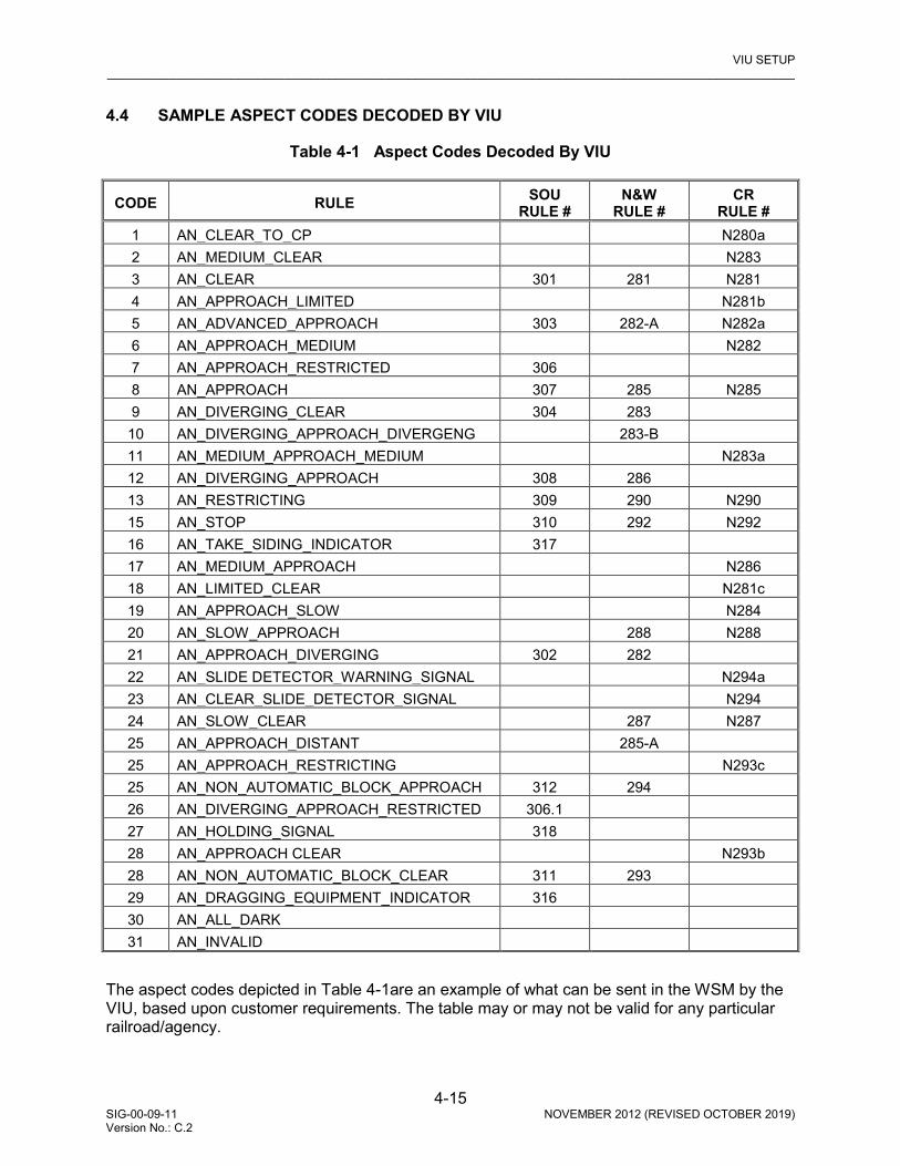
VIU SETUP _________________________________________________________________________________________________________
4-15 SIG-00-09-11 NOVEMBER 2012 (REVISED OCTOBER 2019) Version No.: C.2
4.4 SAMPLE ASPECT CODES DECODED BY VIU
Table 4-1 Aspect Codes Decoded By VIU
CODE RULE SOU RULE #
N&W RULE #
CR RULE #
1 AN_CLEAR_TO_CP N280a 2 AN_MEDIUM_CLEAR N283 3 AN_CLEAR 301 281 N281 4 AN_APPROACH_LIMITED N281b 5 AN_ADVANCED_APPROACH 303 282-A N282a 6 AN_APPROACH_MEDIUM N282 7 AN_APPROACH_RESTRICTED 306 8 AN_APPROACH 307 285 N285 9 AN_DIVERGING_CLEAR 304 283 10 AN_DIVERGING_APPROACH_DIVERGENG 283-B 11 AN_MEDIUM_APPROACH_MEDIUM N283a 12 AN_DIVERGING_APPROACH 308 286 13 AN_RESTRICTING 309 290 N290 15 AN_STOP 310 292 N292 16 AN_TAKE_SIDING_INDICATOR 317 17 AN_MEDIUM_APPROACH N286 18 AN_LIMITED_CLEAR N281c 19 AN_APPROACH_SLOW N284 20 AN_SLOW_APPROACH 288 N288 21 AN_APPROACH_DIVERGING 302 282 22 AN_SLIDE DETECTOR_WARNING_SIGNAL N294a 23 AN_CLEAR_SLIDE_DETECTOR_SIGNAL N294 24 AN_SLOW_CLEAR 287 N287 25 AN_APPROACH_DISTANT 285-A 25 AN_APPROACH_RESTRICTING N293c 25 AN_NON_AUTOMATIC_BLOCK_APPROACH 312 294 26 AN_DIVERGING_APPROACH_RESTRICTED 306.1 27 AN_HOLDING_SIGNAL 318 28 AN_APPROACH CLEAR N293b 28 AN_NON_AUTOMATIC_BLOCK_CLEAR 311 293 29 AN_DRAGGING_EQUIPMENT_INDICATOR 316 30 AN_ALL_DARK 31 AN_INVALID
The aspect codes depicted in Table 4-1are an example of what can be sent in the WSM by the VIU, based upon customer requirements. The table may or may not be valid for any particular railroad/agency.
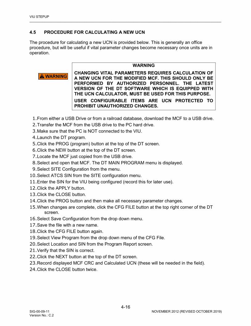
VIU STEPUP _________________________________________________________________________________________________________
4-16 SIG-00-09-11 NOVEMBER 2012 (REVISED OCTOBER 2019) Version No.: C.2
4.5 PROCEDURE FOR CALCULATING A NEW UCN
The procedure for calculating a new UCN is provided below. This is generally an office procedure, but will be useful if vital parameter changes become necessary once units are in operation.
WARNING
CHANGING VITAL PARAMETERS REQUIRES CALCULATION OF A NEW UCN FOR THE MODIFIED MCF. THIS SHOULD ONLY BE PERFORMED BY AUTHORIZED PERSONNEL. THE LATEST VERSION OF THE DT SOFTWARE WHICH IS EQUIPPED WITH THE UCN CALCULATOR, MUST BE USED FOR THIS PURPOSE. USER CONFIGURABLE ITEMS ARE UCN PROTECTED TO PROHIBIT UNAUTHORIZED CHANGES.
1. From either a USB Drive or from a railroad database, download the MCF to a USB drive. 2. Transfer the MCF from the USB drive to the PC hard drive. 3. Make sure that the PC is NOT connected to the VIU. 4. Launch the DT program. 5. Click the PROG (program) button at the top of the DT screen. 6. Click the NEW button at the top of the DT screen. 7. Locate the MCF just copied from the USB drive. 8. Select and open that MCF. The DT MAIN PROGRAM menu is displayed. 9. Select SITE Configuration from the menu.
10. Select ATCS SIN from the SITE configuration menu. 11. Enter the SIN for the VIU being configured (record this for later use). 12. Click the APPLY button. 13. Click the CLOSE button. 14. Click the PROG button and then make all necessary parameter changes. 15. When changes are complete, click the CFG FILE button at the top right corner of the DT
screen. 16. Select Save Configuration from the drop down menu. 17. Save the file with a new name. 18. Click the CFG FILE button again. 19. Select View Program from the drop down menu of the CFG File. 20. Select Location and SIN from the Program Report screen. 21. Verify that the SIN is correct. 22. Click the NEXT button at the top of the DT screen. 23. Record displayed MCF CRC and Calculated UCN (these will be needed in the field). 24. Click the CLOSE button twice.

VIU SETUP _________________________________________________________________________________________________________
4-17 SIG-00-09-11 NOVEMBER 2012 (REVISED OCTOBER 2019) Version No.: C.2
4.6 CONFIGURE A VIU-16I\-8I VIA BROWSER AND DT
NOTE
To configure a VIU-16i\-8i, perform the following steps as depicted in Section 3.2.2.1
1. Power up VIU unit. Connect to the unit’s Ethernet Port 1 for the Web UI and by the Laptop
Serial Port for the DT. 2. Open a browser, and connect to the unit using the IP provided by the railroad or agency for
Ethernet Port 1. 3. Login to the Web UI using the password provided by the railroad or agency, if required. 4. Install the USB Drive in the Ethernet Port on the front of the VIU and follow the steps
described in paragraph 3.2.2.3. Scroll down to PUT MSTR EXEC>VIU. 5. On the browser, select REPORTS > VERSION REPORT. 6. Scroll down to Card 1 of 2 S/W Version Information. This provides the MSTR EXEC file
data. Compare this data to the file provided by the railroad or agency. If the file name and version is the same, go to step b. If the file does not match the file provided by the railroad, install the version supplied by the railroad.
7. Press the right () arrow until the desired file name appears. 8. Press ENTER. 9. Wait while file uploads. Do not disconnect power while file uploads. When complete, press
the up () arrow. 10. Scroll down to Card 2 of 2 S/W Information. This provides the SLV EXEC file data. Compare
this data to the file provided by the railroad or agency. If the file name and version is the same, go to step c. If the file does not match the file provided by the railroad, install the version supplied by the railroad.
11. Press enter until PUT SLV EXEC > VIU appears. 12. Press the right () arrow until the desired file name appears. 13. Press ENTER. 14. Wait while file uploads. Do not disconnect power while file uploads. When complete, press
the up () arrow. 15. Scroll up to the Non-Vital Core Version. This provides the N-V-EXEC file data. Compare this
data to the file provided by the railroad or agency. If the file name and version is the same, go to step d. If the file does not match the file provided by the railroad, install the version supplied by the railroad.
16. Press enter until PUT SLV EXEC > VIU appears. 17. Press the right () arrow until the desired file name appears. 18. Press ENTER. 19. Wait while file uploads. Do not disconnect power while file uploads. When complete, press
the up () arrow. 20. On the front of the VIU panel, scroll down to PUT VITAL MCF > VIU. Install the Vital MCF. 21. Press the right () arrow until the desired file name appears. 22. Press ENTER. 23. Wait while file uploads. Do not disconnect power while file uploads. When complete, press
the up () arrow.

VIU STEPUP _________________________________________________________________________________________________________
4-18 SIG-00-09-11 NOVEMBER 2012 (REVISED OCTOBER 2019) Version No.: C.2
24. Scroll down to EXIT USB MENU. Press Enter. Remove USB Drive. 25. Press Menu on the front panel of the VIU. When SITE SETUP appears, select Enter. 26. Enter VITAL EDIT MODE ARE YOU SURE? NO YES appears. Select Yes. 27. SITE SETUP SITE ID NUMBER appears. Select Enter. Enter the SIN provided by the
railroad or agency. Select Enter. 28. Press the right () arrow. MCF CRC appears. Select Enter. Enter the MCF CRC provided
by the railroad or agency. Select Enter. 29. Press the right () arrow. UCN appears. Select Enter. Enter the UCN provided by the
railroad or agency. Select Enter. 30. Press the right () arrow. REBOOT VITAL appears. Select Enter. REBOOT VITAL ARE
YOU SURE? YES NO appears. Select YES 31. VITAL CPU REBOOT REQUEST SENT. 32. Press EXIT twice. 33. On the DT, enter all required Vital Configuration parameters specified by the railroad or
agency. 34. When required, Unlock the Edit Mode when required to edit specific parameters. 35. Select Yes on the confirmation screen. 36. Set values as described in Section 6 in accordance with the railroad or agency site plan. 37. Close the DT. 38. On the Web UI, enter all required Non-Vital Configuration parameters specified by the
railroad or agency. 39. When required, unlock the Edit button when required to edit specific parameters. 40. When the changes are complete, select Save and then select Reboot. 41. Set values as described in Section 7 in accordance with the railroad or agency site plan. 42. Close the Web UI.
4.7 CONFIGURE A VIU-16I/-8I USING CDL VIA USB DRIVE
NOTE
A CDL file may be installed via USB; however, after installation of the CDL, the user must use the Web U/I and perform Site Setup as specified in Section 7.6.6.1.
Use the following procedure to install a CDL file:
1. Insert the USB Drive into the USB Port on the front panel of the VIU. 2. Scroll down to the PUT CDL FILE? menu using the arrow keys. 3. At the PUT CDL FILE? menu use the arrow keys to select YES. 4. The VIU will build a list of available CDL files. Select the desired file using the arrow keys. 5. When the desired file appears press the ENTER key. 6. The VIU will copy the file and display FINISHED COPYING when completed. 7. Exit the USB menu by selecting YES using the arrow keys. 8. Remove the USB drive from the USB port.
VIU SETUP _________________________________________________________________________________________________________
4-19 SIG-00-09-11 NOVEMBER 2012 (REVISED OCTOBER 2019) Version No.: C.2
4.8 CONFIGURE A VIU-16I/-8I USING PTC CFG XML FILE VIA USB DRIVE
Use the following procedure to install a PTC CFG XML file:
1. Insert the USB Drive into the USB Port on the front panel of the VIU. 2. Scroll down to the PUT PTC CFG XML menu using the arrow keys. 3. At the PUT PTC CFG XML menu use the arrow keys to select YES. 4. The VIU will build a list of available PTC CFG XML files. Select the desired file using the
arrow keys. 5. When the desired file appears press the ENTER key. 6. The VIU will copy the file and display FINISHED COPYING when completed. 7. Exit the USB menu by selecting YES using the arrow keys. 8. Remove the USB drive from the USB port.
4.9 PLACE A VIU-16I/-8I INTO OPERATION
1. Verify signal aspects reported by the VIU-16i/-8i against the actual signals on the ground.
Verify PTC message being sent is correct, if applicable. 2. If switches are programmed, verify the switch position reported by the VIU-16i/-8i against
the actual switch positions on the ground. Verify PTC message being sent is correct, if applicable.
3. If hazard detectors, such as high water detectors, slide fences, etc., are programmed, verify the function by removing the input from the VIU-16i/-8i. Verify PTC message being sent is correct, if applicable.
4. Observe train moves to verify proper operation of the signal system.

VIU STEPUP _________________________________________________________________________________________________________
4-20 SIG-00-09-11 NOVEMBER 2012 (REVISED OCTOBER 2019) Version No.: C.2
This Page Intentionally Left Blank

WAYSIDE INTERFACE UNIT APPLICATION _________________________________________________________________________________________________________
5-1 SIG-00-09-11 NOVEMBER 2012 (REVISED OCTOBER 2019) Version No.: C.2
SECTION 5 WAYSIDE INTERFACE UNIT APPLICATION
5.0 WAYSIDE INTERFACE UNIT APPLICATION
5.1 INTRODUCTION
Positive Train Control (PTC) is an automated control system for railways that ensures the safe operation of trains using data communication between the various control entities that make up the system and the locomotives. As part of a PTC system, the VIU interfaces with the signals and switches in an interlocking and compiles vital messages concerning signal aspect and switch position using the Wayside Interface Unit (WIU) application. These messages are passed through the ITCM system for transmission to any locomotive within radio range, when requested.
Figure 5-1 VIU Monitoring Switches and Signals in an Interlocking
Switch Input
Lamp Input
VIU (WIU)
VIU (WIU)
VIU (WIU)
LAN
LAN
VIU (WIU)
11-11_ITC_WSDE_INTRFC08-05-11
Ethernet
Switch Input
ITCM = Interoperable Train Control Messaging SystemITCM
WAYSIDE INTERFACE UNIT APPLICATION _________________________________________________________________________________________________________
5-2 SIG-00-09-11 NOVEMBER 2012 (REVISED OCTOBER 2019) Version No.: C.2
5.2 WAYSIDE INTERFACE UNIT
A VIU Wayside Interface Unit system consists of four major components: • VIU (WIU) • Wayside Communication Module (WCM) • Interoperable Train Communications Messaging System (ITCM) • Train Management Computer (TMC)
NOTE The VIU-16i contains no replaceable parts. If the unit fails, replace the VIU-20 but leave the ECD/Power connector installed. The newly installed VIU-16i will obtain its configuration from the ECD.
5.2.1 Vital Interface Unit The VIU is installed at a wayside location and monitors signal aspects and switch positions at that location via its vital inputs. Each VIU can monitor up to 16 vital inputs. The VIU compiles the switch and signal information into a vital Wayside Signal Message (WSM), which is transmitted via one of the Ethernet ports on the VIU top panel to a Wayside Messaging Server, where a the message is transmitted to a TMC via the ITCM. These WSMs are in Edge Message Protocol (EMP) format.
5.2.1.1 Multiple VIUs in a Large Interlocking In larger interlockings, multiple auxiliary VIU modules may be necessary to report the status of all switches and signals in the interlocking. The auxiliary VIUs monitor switches and signals via their vital inputs and send the information to the main VIU in vital ATCS messages. The main VIU creates a WSM for each WIU channel and broadcasts the messages periodically as determined by a configurable broadcast time parameter.
5.2.1.2 Message Time Stamp The VIU maintains clock synchronization from an external device with a one second resolution. Two methods are supported by the WIU for this synchronization: EMP based time messages transported over Class C or SNTP version 4 as per RFC 4330. Both time synchronization methods are supported but only one is enabled in the WIU configuration at a time. The 32-bit timestamp uses Greenwich Mean Time (GMT) and indicated Absolute Time, which is UTC time expressed as the absolute number of seconds since midnight, January 1, 1970, including leap seconds. A 32-bit timestamp is used by the system. The system uses GMT for the timestamp when creating reports or saving configuration files.

WAYSIDE INTERFACE UNIT APPLICATION _________________________________________________________________________________________________________
5-3 SIG-00-09-11 NOVEMBER 2012 (REVISED OCTOBER 2019) Version No.: C.2
5.2.1.3 Message Security The WIU uses a keyed-Hash Message Authentication Code (HMAC) as a protection scheme for the vital data portion of the message. The WIU uses a RC2 Decryption Key to decrypt the encrypted HMAC Key to validate the message under PTC. The HMAC is stored in an encrypted format in the WIU. The RC2 Decryption Key may be loaded in the field, but the Key values are not viewable. The non-encrypted HMAC key size is fixed at 20 bytes. The encrypted size is 24 hex bytes. The RC2 key is 20 bytes. Trailing 0’s in the entered 20-byte RC2 key shall be truncated, and the truncated value is used in the computation. If a shorter HMAC string is entered, it shall be padded with 0’s to make 24 bytes. The HMAC key is proved in TXT format for cut and paste or copy operation to the VIU.
WARNING
THE USER MUST ENSURE THAT EACH SITE IS GIVEN A UNIQUE HMAC KEY.
5.2.2 Interoperable Train Communications Messaging (ITCM) The Wayside Interface Unit System relies on the ITCM to transmit the Wayside Status Messages (WSMs) at a fixed interval. The WSMs are transmitted via the ITCM using a variety of means. The basic requirement of the ITCM is to relay the wayside status information generated by the WIU to the locomotive. Although the ITCM is not considered vital or safety critical, an ITCM failure can result in significant and negative operational impacts to railroad service since the on-board PTC system would be required to initiate a safe action in the event that a required signal/device status is not known. 5.2.3 Train Management Computer (TMC) The on-board Train Management Computer system listens for status messages along the track. Status for every local wayside device in the on-board track database must be ‘heard’ by the locomotive. The system continues to listen for status messages as the locomotive approaches the monitored wayside devices. Stale messages are detected by a synchronized timestamp. The TMC verifies message validity and then displays the messages for action by the train crew.

WAYSIDE INTERFACE UNIT APPLICATION _________________________________________________________________________________________________________
5-4 SIG-00-09-11 NOVEMBER 2012 (REVISED OCTOBER 2019) Version No.: C.2
5.2.4 Typical Wayside Interface System Interconnect Diagram (Single VIU)
Figure 5-2 Typical Wayside Interface System Interconnect Diagram (Single VIU)
EthernetEthernet
Port 2Port 1
GPS Port
GPS
Antenna
Serial(Port 2)
Only
ESSR
N B
VIU
SIGNAL CONTROL
INPUTS
RELAY LOGIC
POINT DETECTION TERMINAL
SWITCH
ITCM INTERFACE
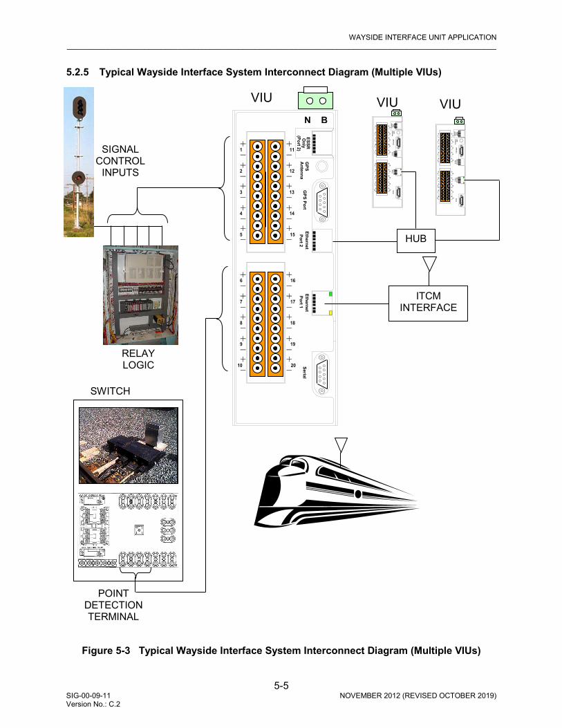
WAYSIDE INTERFACE UNIT APPLICATION _________________________________________________________________________________________________________
5-5 SIG-00-09-11 NOVEMBER 2012 (REVISED OCTOBER 2019) Version No.: C.2
5.2.5 Typical Wayside Interface System Interconnect Diagram (Multiple VIUs)
Figure 5-3 Typical Wayside Interface System Interconnect Diagram (Multiple VIUs)
EthernetEthernet
Port 2Port 1
GPS Port
GPS
Antenna
Serial(Port 2)
Only
ESSR
N B
VIU
SIGNAL CONTROL
INPUTS
RELAY LOGIC
POINT DETECTION TERMINAL
SWITCH
ITCM INTERFACE
EthernetEthernet
Port 2Port 1
GPS Port
GPS
Antenna
Serial(Port 2)
Only
ESSR
VIU Ethernet
EthernetPort 2
Port 1G
PS PortG
PSA
ntennaSerial
(Port 2)O
nlyESSR
VIU
HUB

WAYSIDE INTERFACE UNIT APPLICATION _________________________________________________________________________________________________________
5-6 SIG-00-09-11 NOVEMBER 2012 (REVISED OCTOBER 2019) Version No.: C.2
This Page Intentionally Left Blank

DIAGNOSTIC TERMINAL (DT) SOFTWARE _________________________________________________________________________________________________________
6-1 SIG-00-09-11 NOVEMBER 2012 (REVISED OCTOBER 2019) Version No.: C.2
SECTION 6 DIAGNOSTIC TERMINAL (DT) SOFTWARE
6.0 DIAGNOSTIC TERMINAL (DT) SOFTWARE
NOTE
Programming the VIU requires the use of the Web User Interface (Web U/I) to program non-vital parameters, the Diagnostic Terminal (DT) to program vital parameters, as well the VIU keypad to set SIN, MCFCRC, and the UCN. The DT screens presented throughout this chapter are examples. DT screens may or may not display as shown here. Actual parameter names may differ as each MCF for a location is unique, and the names may therefore change. Use the DT version currently approved by the railroad or agency to set the vital VIU parameters.
6.1 INTRODUCTION
Diagnostic Terminal (DT) software is a Siemens developed Windows® based utility program designed to run on a laptop PC. The DT provides a user interface that allows for local configuration of certain vital and non-vital VIU parameters, plus diagnostic tools that can be used to isolate VIU system problems (see Section 8.2).
6.2 DT TO VIU INTERFACE
Figure 6-1 VIU16i Front Panel Laptop PC Interface Connectors
EthernetEthernet
Port 2Port 1
GPS Port
GPS
Antenna
Serial(Port 2)
Only
ESSR
N
Ethernet Port 1
Ethernet Port 2
USB Port
Laptop Ethernet
Port
Laptop Serial Port

DIAGNOSTIC TERMINAL (DT) SOFTWARE _________________________________________________________________________________________________________
6-2 SIG-00-09-11 NOVEMBER 2012 (REVISED OCTOBER 2019) Version No.: C.2
The DT can be interfaced to the VIU by one of the following means: Primary method - an Ethernet LAN connection from the host PC Ethernet port to the Laptop (Ethernet) port on the VIU front panel. Alternatively, the host PC Ethernet port can be connected to either Ethernet Port 1 or Port 2 located on top of the VIU. Another method is a straight 9-pin female to 9-pin male cable connected between the host PC serial port and the 9-pin, RS-232 Laptop (Serial) port on the VIU front panel.
WARNING
INCORRECT ENTRY OF VITAL CONFIGURABLE PARAMETERS WILL LEAD TO UNSAFE FUNCTIONING OF THE VIU UNIT. THE VITAL FIELD CONFIGURABLE PARAMETERS MUST BE VERIFIED FOR CORRECTNESS BEFORE THE EQUIPMENT IS PLACED IN SERVICE.
NOTE
The DT is typically connected via Ethernet Port 1, with the discovery Protocol enabled. When the DT is connected serially, uncheck the enable block and select a baud rate of 38400 with the Negotiate Rate block unchecked.
6.3 PROGRAM STARTUP
Before launching the DT Utility program, verify that the following conditions are met:
• The PC is connected to the VIU as described in paragraph 6.2 above. • The VIU is powered up. Launch the DT Utility either from the PC Programs list or from a desk-top icon if present. 6.3.1 Startup Sequence The DT Utility establishes a connection to the VIU, checks the installed VIU files, and then downloads the current VIU configuration information. A progress bar appears at the bottom of the screen during the download process (Figure 6-2). Status messages appear in the message box at the right bottom of the screen. The IP Connecting message is displayed only if the PC is interfaced to the VIU via the Ethernet port.
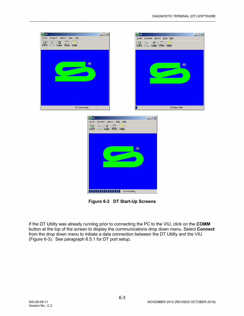
DIAGNOSTIC TERMINAL (DT) SOFTWARE _________________________________________________________________________________________________________
6-3 SIG-00-09-11 NOVEMBER 2012 (REVISED OCTOBER 2019) Version No.: C.2
Figure 6-2 DT Start-Up Screens
If the DT Utility was already running prior to connecting the PC to the VIU, click on the COMM button at the top of the screen to display the communications drop down menu. Select Connect from the drop down menu to initiate a data connection between the DT Utility and the VIU (Figure 6-3). See paragraph 6.5.1 for DT port setup.

DIAGNOSTIC TERMINAL (DT) SOFTWARE _________________________________________________________________________________________________________
6-4 SIG-00-09-11 NOVEMBER 2012 (REVISED OCTOBER 2019) Version No.: C.2
Figure 6-3 COMM Drop Down Menu
6.4 INPUT STATUS OVERVIEW SCREEN FOR VIU
Once the DT Utility has successfully established its connection with the VIU, Ready is displayed in the lower right hand message box and an overview of the VIU input status is displayed. Note that at the top of the DT Utility screen the Site ID Number [SIN] or ATCS address of the attached VIU is displayed. See Figure 6-4.
Figure 6-4 DT Input Status Overview Screen for VIU
The input status overview screen provides a quick indication of the current VIU health and I/O status. See Figure 6-6.

DIAGNOSTIC TERMINAL (DT) SOFTWARE _________________________________________________________________________________________________________
6-5 SIG-00-09-11 NOVEMBER 2012 (REVISED OCTOBER 2019) Version No.: C.2
Figure 6-5 VIU-16i\-8i DT Top Level
Figure 6-6 Input Status Screen Indicator Descriptions
Label for Internal I/O Module 1 Label for Internal I/O Module 2
I/O Module Labels
GREEN = Configured / Healthy RED = Unconfigured / Failed
I/O Status Indicators
GREEN = On BLACK = Off
RED = Hardware Failure
I/O Status Nomenclature
On Flash Off HWF (Hardware Failure)
I/O mnemonic
Main:_i=Input Main:ou=Output
I/O Symbology
= Input = Output

DIAGNOSTIC TERMINAL (DT) SOFTWARE _________________________________________________________________________________________________________
6-6 SIG-00-09-11 NOVEMBER 2012 (REVISED OCTOBER 2019) Version No.: C.2
Figure 6-7 DT Status Screen Indicators to Physical Connectors
Right-click on the I/O Module label to display the module drop-down menu. Select items from the menu to view or perform the following (Figure 6-8):
• View Specific Module information • Reset Module • Set verbosity (control of amount of information saved to the log) • View Status Log • View Summary Log
Figure 6-8 Module Drop-Down Menu
Input Pair 1 Indicator
Status Indicators for Input Pairs 4 – 8, from top to bottom
Status Indicators for Output Pairs 1 – 2 &
Input Pairs 1 – 3, from top to bottom
Status Indicators for Output Pairs 3 – 4 & Input Pairs 9 – 11, from top to bottom
Status Indicators for Input Pairs 12 – 16, from top to bottom
Connector for Input Pairs
14 – 16 & Output Pairs 3 -4
Connector for Input Pairs
6 – 8 & Output Pairs 1 -2
Connector for Input Pairs
1 – 5
Connector for Input Pairs
9 – 13

DIAGNOSTIC TERMINAL (DT) SOFTWARE _________________________________________________________________________________________________________
6-7 SIG-00-09-11 NOVEMBER 2012 (REVISED OCTOBER 2019) Version No.: C.2
6.5 COMM (COMMUNICATIONS) BUTTON MENU
Click on the COMM (Communications) button at the top of the Input Status Screen to display the communications drop-down menu.
Figure 6-9 COMM Pull-Down Menu
6.5.1 Port Setup
NOTE
The DT is typically connected via Ethernet Port 1, with the discovery Protocol enabled. When the DT is connected serially, uncheck the enable block and select a baud rate of 38400 with the Negotiate Rate block unchecked.
Select DT Port Setup from the drop-down menu to display the Communications Settings dialog box (Figure 6-10).
Figure 6-10 DT Communications Settings Dialog Box
A B C
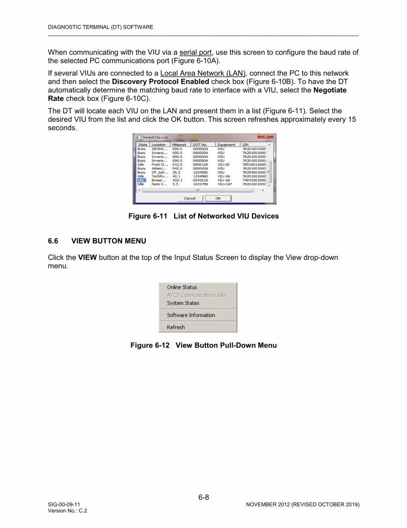
DIAGNOSTIC TERMINAL (DT) SOFTWARE _________________________________________________________________________________________________________
6-8 SIG-00-09-11 NOVEMBER 2012 (REVISED OCTOBER 2019) Version No.: C.2
When communicating with the VIU via a serial port, use this screen to configure the baud rate of the selected PC communications port (Figure 6-10A). If several VIUs are connected to a Local Area Network (LAN), connect the PC to this network and then select the Discovery Protocol Enabled check box (Figure 6-10B). To have the DT automatically determine the matching baud rate to interface with a VIU, select the Negotiate Rate check box (Figure 6-10C). The DT will locate each VIU on the LAN and present them in a list (Figure 6-11). Select the desired VIU from the list and click the OK button. This screen refreshes approximately every 15 seconds.
Figure 6-11 List of Networked VIU Devices
6.6 VIEW BUTTON MENU
Click the VIEW button at the top of the Input Status Screen to display the View drop-down menu.
Figure 6-12 View Button Pull-Down Menu
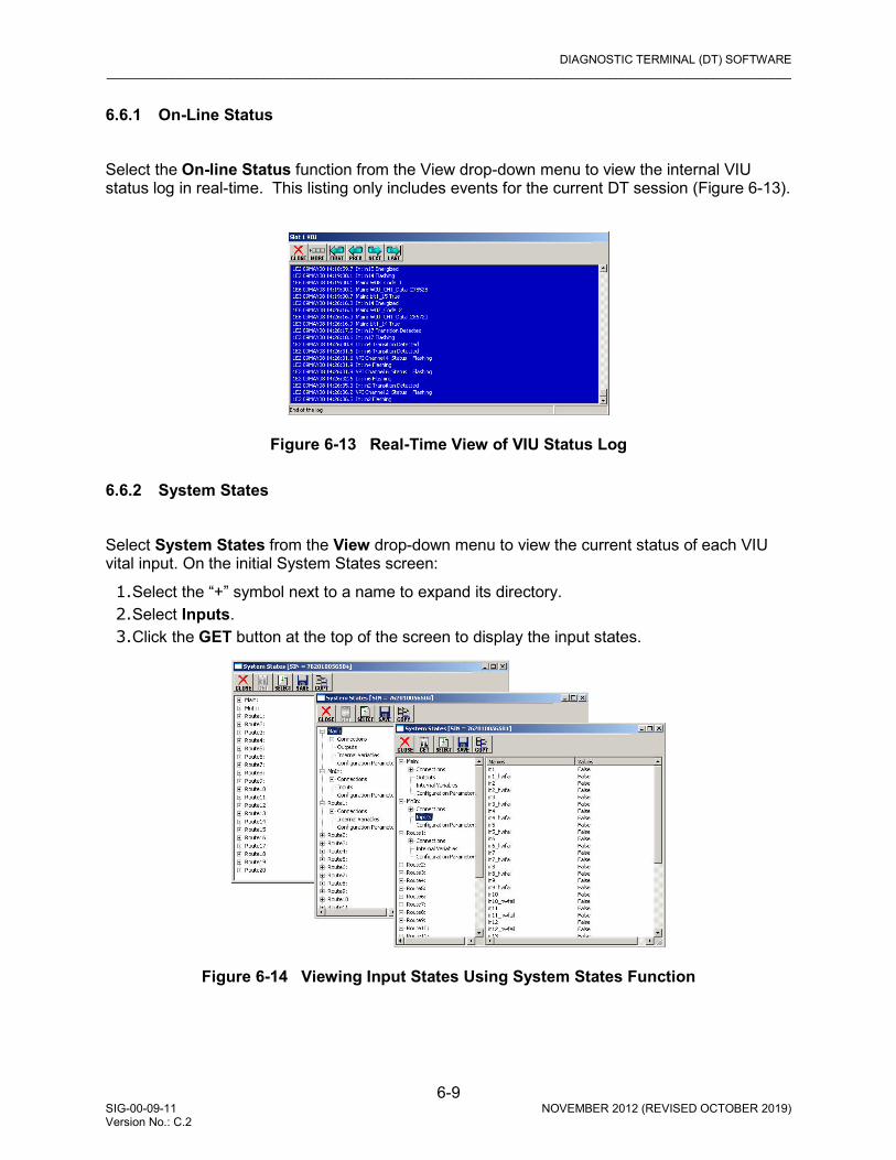
DIAGNOSTIC TERMINAL (DT) SOFTWARE _________________________________________________________________________________________________________
6-9 SIG-00-09-11 NOVEMBER 2012 (REVISED OCTOBER 2019) Version No.: C.2
6.6.1 On-Line Status Select the On-line Status function from the View drop-down menu to view the internal VIU status log in real-time. This listing only includes events for the current DT session (Figure 6-13).
Figure 6-13 Real-Time View of VIU Status Log
6.6.2 System States Select System States from the View drop-down menu to view the current status of each VIU vital input. On the initial System States screen:
1. Select the “+” symbol next to a name to expand its directory. 2. Select Inputs. 3. Click the GET button at the top of the screen to display the input states.
Figure 6-14 Viewing Input States Using System States Function

DIAGNOSTIC TERMINAL (DT) SOFTWARE _________________________________________________________________________________________________________
6-10 SIG-00-09-11 NOVEMBER 2012 (REVISED OCTOBER 2019) Version No.: C.2
6.6.2.1 Viewing Input Logic States To view the logic states for a range of inputs:
1. Click the SELECT button at the top of the System States screen to display the Select Range dialog box Figure 6-15.
2. Enter the number of the first and last logic states to be viewed. 3. Click the OK button.
Figure 6-15 Logic State Select Range Dialog Box
6.6.2.2 Input Logic States Display There are three logic states for each input:
• The first logic state represents the On/Off status of the input: 1 = On, 0 = Off. • The second logic state represents the flash function: 1 = Flashing, 0 = Not Flashing. • The third logic state represents the hardware fail status: 1 = Failed, 0 = Not Failed
NOTE
The 1 logic state corresponds to a ‘True’ statement and the 0 logic state corresponds to a ‘False’ statement on the System States screen shown in Figure 6-16.
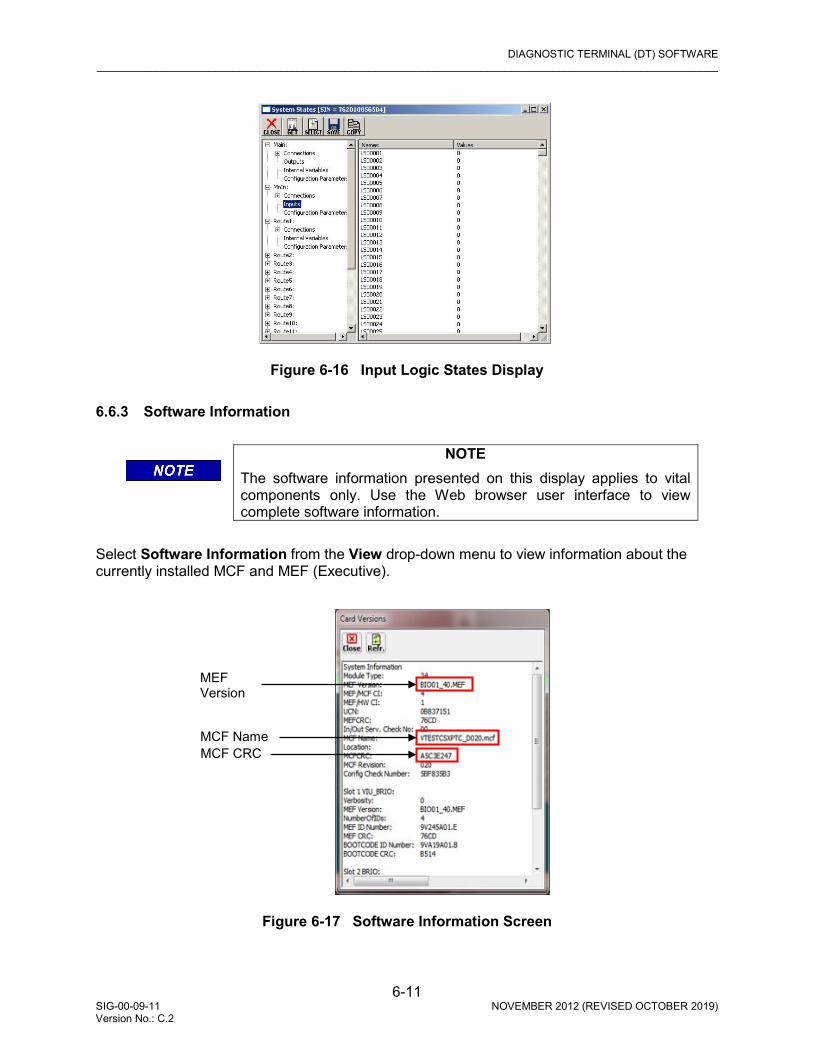
DIAGNOSTIC TERMINAL (DT) SOFTWARE _________________________________________________________________________________________________________
6-11 SIG-00-09-11 NOVEMBER 2012 (REVISED OCTOBER 2019) Version No.: C.2
Figure 6-16 Input Logic States Display
6.6.3 Software Information
NOTE
The software information presented on this display applies to vital components only. Use the Web browser user interface to view complete software information.
Select Software Information from the View drop-down menu to view information about the currently installed MCF and MEF (Executive).
Figure 6-17 Software Information Screen
MCF Name MCF CRC
MEF Version

DIAGNOSTIC TERMINAL (DT) SOFTWARE _________________________________________________________________________________________________________
6-12 SIG-00-09-11 NOVEMBER 2012 (REVISED OCTOBER 2019) Version No.: C.2
6.7 PROG (PROGRAM) BUTTON MENU
Click the PROG (Program) button at the top of the Input Status Screen to display the MAIN PROGRAM menu (Figure 6-19).
Figure 6-18 The Program (Prog) Button Select an item from the menu to display the associated DT screen. This menu provides access to the configurable parameter screens. 6.7.1 Online and Offline Display Screens Note that Figure 6-19A is displayed when the DT is online (connected to a VIU) as indicated by “Property Browser” in the title bar, and Figure 6-19B is displayed when running the DT offline (not connected to a VIU) as indicated by “Office Configuration Editor” in the title bar. There are a few instances where a parameter or function can only be configured offline using the Office Configuration Editor (OCE) - for example, calculating a UCN. In such cases the special function will only appear in the offline Office Configuration Editor screen.
Figure 6-19 MAIN PROGRAM Menu Screen
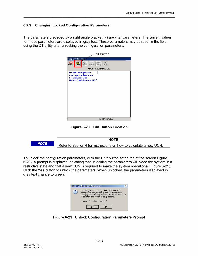
DIAGNOSTIC TERMINAL (DT) SOFTWARE _________________________________________________________________________________________________________
6-13 SIG-00-09-11 NOVEMBER 2012 (REVISED OCTOBER 2019) Version No.: C.2
6.7.2 Changing Locked Configuration Parameters The parameters preceded by a right angle bracket (>) are vital parameters. The current values for these parameters are displayed in gray text. These parameters may be reset in the field using the DT utility after unlocking the configuration parameters.
Figure 6-20 Edit Button Location
NOTE
Refer to Section 4 for instructions on how to calculate a new UCN. To unlock the configuration parameters, click the Edit button at the top of the screen Figure 6-20). A prompt is displayed indicating that unlocking the parameters will place the system in a restrictive state and that a new UCN is required to make the system operational (Figure 6-21). Click the Yes button to unlock the parameters. When unlocked, the parameters displayed in gray text change to green.
Figure 6-21 Unlock Configuration Parameters Prompt
Edit Button
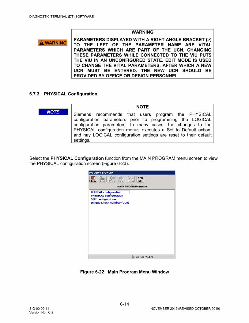
DIAGNOSTIC TERMINAL (DT) SOFTWARE _________________________________________________________________________________________________________
6-14 SIG-00-09-11 NOVEMBER 2012 (REVISED OCTOBER 2019) Version No.: C.2
WARNING
PARAMETERS DISPLAYED WITH A RIGHT ANGLE BRACKET (>) TO THE LEFT OF THE PARAMETER NAME ARE VITAL PARAMETERS WHICH ARE PART OF THE UCN. CHANGING THESE PARAMETERS WHILE CONNECTED TO THE VIU PUTS THE VIU IN AN UNCONFIGURED STATE. EDIT MODE IS USED TO CHANGE THE VITAL PARAMETERS, AFTER WHICH A NEW UCN MUST BE ENTERED. THE NEW UCN SHOULD BE PROVIDED BY OFFICE OR DESIGN PERSONNEL.
6.7.3 PHYSICAL Configuration
NOTE
Siemens recommends that users program the PHYSICAL configuration parameters prior to programming the LOGICAL configuration parameters. In many cases, the changes to the PHYSICAL configuration menus executes a Set to Default action, and nay LOGICAL configuration settings are reset to their default settings..
Select the PHYSICAL Configuration function from the MAIN PROGRAM menu screen to view the PHYSICAL configuration screen (Figure 6-23).
Figure 6-22 Main Program Menu Window

DIAGNOSTIC TERMINAL (DT) SOFTWARE _________________________________________________________________________________________________________
6-15 SIG-00-09-11 NOVEMBER 2012 (REVISED OCTOBER 2019) Version No.: C.2
A list of physical configuration options is displayed. These options are described in the following paragraphs.
Figure 6-23 PHYSICAL Configuration Screens
6.7.3.1 Physical Layout The Physical Layout selection (see Figure 6-23B) is a template describing the physical content of the associated object. For example, the MainBox object is the main VIU. The Physical Layout file for this object defines the types of circuits installed in the main VIU. Click the MainBox (green text) to select a different template (i.e., MainBox8:MainBox8, Remote1:Remote1, etc.). The contents of these files are defined in the MCF.
6.7.3.2 MODULE Configuration Path: MAIN PROGRAM menu > PHYSICAL configuration > MODULE configuration. Select MODULE configuration from the PHYSICAL configuration screen to display the MODULE configuration screen (Figure 6-24). From the list of internal I/O modules, select a module to view its configurable parameters. Depending on the module selected, one of three screens is displayed (Figure 6-25).
NOTE
These internal modules are not removable or serviceable. They are groups of circuits associated with the vital I/O connectors and are labeled as shown here for reference only.
A B

DIAGNOSTIC TERMINAL (DT) SOFTWARE _________________________________________________________________________________________________________
6-16 SIG-00-09-11 NOVEMBER 2012 (REVISED OCTOBER 2019) Version No.: C.2
Figure 6-24 MODULE Configuration Screen
Figure 6-25 (A) SLOT 1:sl1 (VIU_BRIO), & (B) SLOT 1:sl1 (VIU_BRIO) Cont Screens
A B

DIAGNOSTIC TERMINAL (DT) SOFTWARE _________________________________________________________________________________________________________
6-17 SIG-00-09-11 NOVEMBER 2012 (REVISED OCTOBER 2019) Version No.: C.2
Figure 6-26 SLOT 2:sl2 (BRIO) Screen

DIAGNOSTIC TERMINAL (DT) SOFTWARE _________________________________________________________________________________________________________
6-18 SIG-00-09-11 NOVEMBER 2012 (REVISED OCTOBER 2019) Version No.: C.2
Figure 6-27 Typical Module Configuration Set Parameter Screens The setting for each of these configurable parameters falls into one of three categories: select from a drop-down list; an “On/Off” option; or enter a numerical value. The Set Parameter screens for each parameter type are shown in Figure 6-27. After entering the number or selecting the option, click the UPDATE button to activate the new setting. • Monitor Lamps The Monitor Lamps function is used to configure the physical inputs to monitor lamp operation. Valid options are: Yes, No (default = No).
A
C
B

DIAGNOSTIC TERMINAL (DT) SOFTWARE _________________________________________________________________________________________________________
6-19 SIG-00-09-11 NOVEMBER 2012 (REVISED OCTOBER 2019) Version No.: C.2
• Power Supply
CAUTION
DO NOT SELECT DC IF THE LAMPS ARE BEING DRIVEN FROM A MICRO-PROCESSOR BASED SYSTEM (E.G., GEO). ALTHOUGH THESE LAMPS ARE LIT VIA DC, THE SYSTEM PERFORMS BOTH A HOT FILAMENT CHECK AND A COLD FILAMENT CHECK. DURING THE HOT CHECK, THE LAMP IS SHUT DOWN FOR APPROXIMATELY 20 MILLISECONDS AND DURING A COLD CHECK, THE LAMP IS ENERGIZED FOR APPROXIMATELY 20 MILLISECONDS. THESE CHECKS ARE ENOUGH TO CAUSE THE VIU TO SEE THE INPUTS AS UNHEALTHY. THEREFORE, IF A MICRO-PROCESSOR BASED SYSTEM IS USED, THE AC WITH DC BACKUP SETTING MUST BE USED.
The Power Supply function is used to configure the physical inputs to detect whether the system is running on DC power or AC power with DC power backup. Valid options are: DC, AC/DC Backup (default = DC). • Current Sensor Output Inverted The Current Sensor Output Inverted function is used to configure the physical inputs to determine if the sensor output is inverted. If using Honeywell CSDA1DA Current sensors, the sensors should be wired so that they provide an energized output when the lamp is lit, and deenergized when the lamp is not lit. Valid options are: Yes, No (default = No). • AC Power Frequency The AC Power Frequency function is used to configure the physical inputs to accept AC power frequencies of either 50 Hz or 60 Hz. Valid options are: 50, 60 (default = 60). • Input X Mode The Input X Mode function is used to configure the physical inputs to monitor Relay, Lamp-Voltage, or Lamp-Current. Valid options are: Relay, Lamp-Voltage, or Lamp-Current (default = Lamp-Voltage). This entry is repeated for each of the 8 inputs on a card • VPI Debounce The VPI Debounce function is a global setting that is applied to all vital inputs serviced by this internal I/O module. It sets the period of time a level change must be present on an input before it can be considered a “Change-of-State”. Valid VPI Debounce range: 20 to 200 ms (default = 20 ms).

DIAGNOSTIC TERMINAL (DT) SOFTWARE _________________________________________________________________________________________________________
6-20 SIG-00-09-11 NOVEMBER 2012 (REVISED OCTOBER 2019) Version No.: C.2
• Flash Detection The Flash Detection function is used to configure the physical inputs to detect whether a level that cycles on and off on the input represents a flashing input. Valid options are: On, Off (default = Off). When flash detection is on, a new energized / de-energized state will not be reported until it has persisted for 1 second.
NOTE
This function is UCN protected. • Flash Detection Count The Flash Detection Count setting determines how many “half cycles” are required on the input before the software determines that the level on the input represents a flashing signal. Valid Flash Detection Count values: 2 to 8 (default = 3). • Password Access (Slot 1 VIU_BRIO Only) If the Password Access function is set to On, an additional password function is displayed (Figure 6-28). This is the actual password. The default password is 1111. To change the password, click on the green numbers to the right of the word Password (1111 in Figure 6-28). The Set Parameter dialog box for changing the password is displayed (Figure 6-29).
Figure 6-28 Password Enabled Enter the new password consisting of any four numbers from 1 to 9 plus 0. Click the Update button to save the new password. After exiting the programming function, the password will be required to access any of the programming functions as long as the password function is enabled.
A B
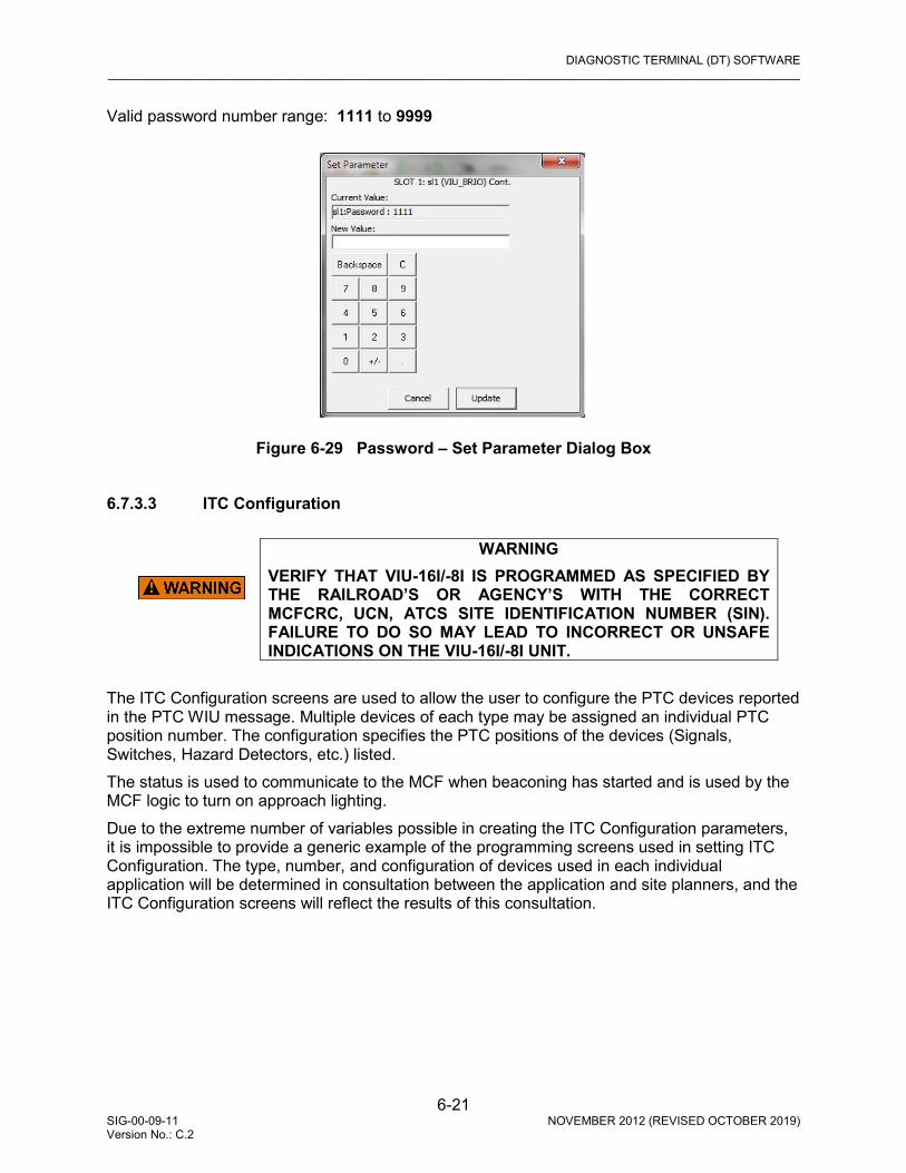
DIAGNOSTIC TERMINAL (DT) SOFTWARE _________________________________________________________________________________________________________
6-21 SIG-00-09-11 NOVEMBER 2012 (REVISED OCTOBER 2019) Version No.: C.2
Valid password number range: 1111 to 9999
Figure 6-29 Password – Set Parameter Dialog Box
6.7.3.3 ITC Configuration
WARNING
VERIFY THAT VIU-16I/-8I IS PROGRAMMED AS SPECIFIED BY THE RAILROAD’S OR AGENCY’S WITH THE CORRECT MCFCRC, UCN, ATCS SITE IDENTIFICATION NUMBER (SIN). FAILURE TO DO SO MAY LEAD TO INCORRECT OR UNSAFE INDICATIONS ON THE VIU-16I/-8I UNIT.
The ITC Configuration screens are used to allow the user to configure the PTC devices reported in the PTC WIU message. Multiple devices of each type may be assigned an individual PTC position number. The configuration specifies the PTC positions of the devices (Signals, Switches, Hazard Detectors, etc.) listed. The status is used to communicate to the MCF when beaconing has started and is used by the MCF logic to turn on approach lighting. Due to the extreme number of variables possible in creating the ITC Configuration parameters, it is impossible to provide a generic example of the programming screens used in setting ITC Configuration. The type, number, and configuration of devices used in each individual application will be determined in consultation between the application and site planners, and the ITC Configuration screens will reflect the results of this consultation.

DIAGNOSTIC TERMINAL (DT) SOFTWARE _________________________________________________________________________________________________________
6-22 SIG-00-09-11 NOVEMBER 2012 (REVISED OCTOBER 2019) Version No.: C.2
6.7.3.4 CONNECTION Configuration
WARNING
VERIFY THAT VIU-16I/-8I IS PROGRAMMED AS SPECIFIED BY THE RAILROAD’S OR AGENCY’S WITH THE CORRECT MCFCRC, UCN, ATCS SITE IDENTIFICATION NUMBER (SIN). FAILURE TO DO SO MAY LEAD TO INCORRECT OR UNSAFE INDICATIONS ON THE VIU-16I/-8I UNIT.
Path: MAIN PROGRAM menu > PHYSICAL configuration > CONNECTION configuration. These screens are used to configure the properties needed for the Vital ATCS connection between two VIU modules. Each connection may be named as desired by the application planner (i.e., Main/r1, Data01/io02, Data01/io03, etc.). Click CONNECTION configuration on the PHYSICAL configuration screen to bring up the Main/r1 configuration screen (Figure 6-30). The item listed on this screen represents the connection name in the MCF for the geographic messaging link of the Remote VIU. r1 = remote VIU 1 Click on Main/r1 to bring up the Main/r1 configuration screen (Figure 6-31).
Figure 6-30 CONNECTION: Main/r1 Screen
These parameters are all UCN protected. To modify these parameters, click the EDIT button to unlock the configuration parameters. When complete, enter the new UCN number as directed. The setting for each of these configurable parameters falls into one of two categories; numerical value or a listed option. Typical Set Parameter screens for both parameter types are shown in Figure 6-32.
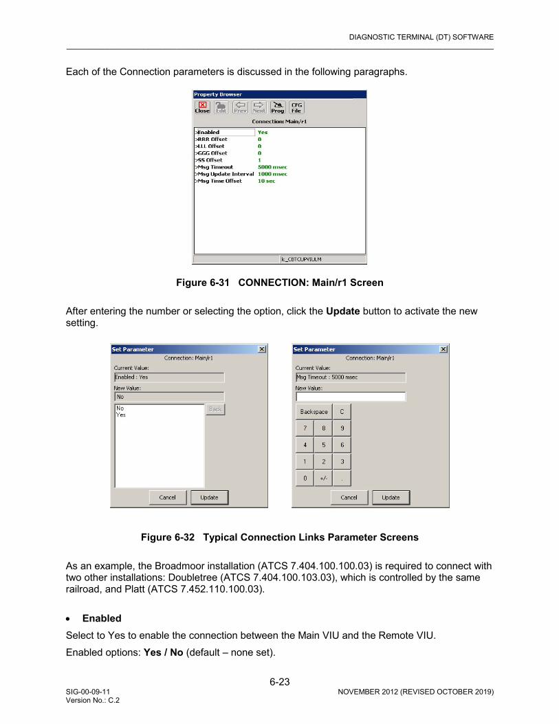
DIAGNOSTIC TERMINAL (DT) SOFTWARE _________________________________________________________________________________________________________
6-23 SIG-00-09-11 NOVEMBER 2012 (REVISED OCTOBER 2019) Version No.: C.2
Each of the Connection parameters is discussed in the following paragraphs.
Figure 6-31 CONNECTION: Main/r1 Screen
After entering the number or selecting the option, click the Update button to activate the new setting.
Figure 6-32 Typical Connection Links Parameter Screens As an example, the Broadmoor installation (ATCS 7.404.100.100.03) is required to connect with two other installations: Doubletree (ATCS 7.404.100.103.03), which is controlled by the same railroad, and Platt (ATCS 7.452.110.100.03). • Enabled Select to Yes to enable the connection between the Main VIU and the Remote VIU. Enabled options: Yes / No (default – none set).
DIAGNOSTIC TERMINAL (DT) SOFTWARE _________________________________________________________________________________________________________
6-24 SIG-00-09-11 NOVEMBER 2012 (REVISED OCTOBER 2019) Version No.: C.2
• RRR Offset This parameter sets the ATCS address railroad number offset. This offset is the difference between the connected Remote VIU railroad number and the railroad number of the Main VIU.
• Offset required for Doubletree installation: 0 • Offset required for Platt installation: 48
RRR Offset range: -999 to 999 (default – not set). • LLL Offset This parameter sets the ATCS address line number offset. This offset is the difference between the connected Remote VIU line number and the line number of the Main VIU.
Offset required for Doubletree installation: 0 Offset required for Platt installation: 10
LLL Offset range: -999 to 999 (default – not set). • GGG Offset This parameter sets the ATCS address group number offset. This offset is the difference between the connected Remote VIU group number and the group number of the Main VIU.
Offset required for Doubletree installation: -7 Offset required for Platt installation: 0
GGG Offset range: -999 to 999 (default – not set). • SS Offset This parameter sets the ATCS address subnode offset. This offset is the difference between the connected Remote VIU subnode and the subnode of the Main VIU.
Offset required for Doubletree installation: 0 Offset required for Platt installation: 0
SS Offset range: -99 to 99 (default – not set). • Msg Timeout This parameter sets the period of time the Main VIU will wait for a valid message from the remote VIU. If a message is not received within the timeout period, the remote VIU is logged as being in the most restrictive state. Msg Timeout range: 1000 to 60000 msec (default – not set). • Msg Update Interval This parameter sets the interval between repeat messages transmitted from the Remote VIU to the Main VIU. Messages are sent immediately if a change of input state occurs at the Remote VIU. Msg Update Interval range: 400 to 30000 msec (default – not set).

DIAGNOSTIC TERMINAL (DT) SOFTWARE _________________________________________________________________________________________________________
6-25 SIG-00-09-11 NOVEMBER 2012 (REVISED OCTOBER 2019) Version No.: C.2
• Msg Time Offset This parameter sets the length of time the Main VIU will wait for a message before classifying it as a stale message. Msg Time Offset range: 5 to 30 sec (default – not set).
6.7.3.5 WIU CHANNEL Configuration Select WIU CHANNEL configuration from the PHYSICAL configuration screen to display the WIU CHANNEL configuration screen (Figure 6-33). Parameters with the right angle bracket (>) to the left of the parameter name are UCN protected. To modify these parameters, select the EDIT button to enable the edit mode. The values will be displayed green when edit mode is enabled. Once the new values are entered, the new UCN must be entered to bring the unit to an operational state. Once the unit is in an operational state, the UCN protected parameters are grayed out.
Figure 6-33 WIU CHANNEL Configuration Screen
All parameter values are displayed green once they are unlocked.
• Enabled The Enabled function determines whether the WIU CHANNEL Configuration is enabled or disabled. If disabled, the WIU CHANNEL configuration parameters do not appear. Valid options: Yes / No (default is No). • Broadcast On Change The VIU can be configured to broadcast a status message for a WIU channel whenever an input on that channel changes state. To enable this function set the Broadcast on Change function to Yes. Valid options are: Yes, No (default is No).
DIAGNOSTIC TERMINAL (DT) SOFTWARE _________________________________________________________________________________________________________
6-26 SIG-00-09-11 NOVEMBER 2012 (REVISED OCTOBER 2019) Version No.: C.2
• Beacon Continuous When the Beacon Continuous function is set, the VIU-16i/-8i sends WIU Channel messages periodically at the configured Broadcast rate, or when a state change occurs if the "Broadcast on Change" configuration parameter is set. When the Beacon Continuous function is not set, the VIU-16i/-8i sends messages an interval specified by the Max Beacon Interval either when a period of time has elapsed equal to sum of the configured Beacon On Time plus the Beacon End Time of since the last update message or when a state change occurs if the Broadcast on Change configuration parameter is set. Valid options are: Yes, No (default is No). • Max Beacon Enabled The Max Beacon Enabled function determines whether messages are transmitted at the time specified in the Max Beacon Interval setting. Valid options are: Yes, No (default is No). • Broadcast Rate Each WIU channel in the VIU can be configured to broadcast status messages on a regular basis. Set the Broadcast Rate function to the number of milliseconds between regular status message broadcasts. Valid Broadcast Rate range: 1000 to 60000 msec (default is 1000 ms). • Beacon Bit Time The Beacon Bit Time function specifies the duration of the Beacon Bit. Valid Beacon Bit Time range: 60 to 1800 seconds (default is 300 seconds).
• Beacon End Time The Beacon End Time function specifies the expiration time of the Beacon Bit following its transmission. Valid Beacon End Time range: 60 to 1800 seconds (default is 120 seconds). • Max Beacon Interval The Max Beacon Enabled function specifies the maximum amount of time in minutes between transmissions of WIU update messages. This is set only when the Max Beacon Enabled parameter is set to Yes. Valid Beacon Bit Time range: 60 to 64000 seconds (default is 900 seconds). • Vital Message Version The Vital Message Version function sets the type of vital message to be transmitted by the WIU. Valid Vital Message Version range: 0 to 65535 (default is 0).

DIAGNOSTIC TERMINAL (DT) SOFTWARE _________________________________________________________________________________________________________
6-27 SIG-00-09-11 NOVEMBER 2012 (REVISED OCTOBER 2019) Version No.: C.2
6.7.3.6 Set to Defaults Path: MAIN PROGRAM menu > PHYSICAL configuration > Set to Defaults. Prior to programming a VIU for the first time, or following installation of a new MCF, set the VIU configuration parameters to their default settings. Select Set to Default on the PHYSICAL configuration screen (Figure 6-23). A prompt is displayed asking the user for confirmation to proceed (Figure 6-34).
Figure 6-34 Set Parameters to Default Prompt
6.7.4 LOGICAL Configuration Select the LOGICAL Configuration function from the MAIN PROGRAM menu screen to view the LOGICAL configuration screen (Figure 6-36)
Figure 6-35 The MAIN PROGRAM Menu Window
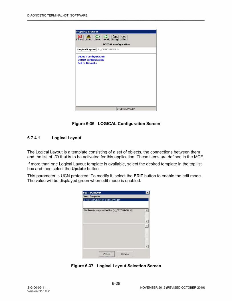
DIAGNOSTIC TERMINAL (DT) SOFTWARE _________________________________________________________________________________________________________
6-28 SIG-00-09-11 NOVEMBER 2012 (REVISED OCTOBER 2019) Version No.: C.2
Figure 6-36 LOGICAL Configuration Screen
6.7.4.1 Logical Layout The Logical Layout is a template consisting of a set of objects, the connections between them and the list of I/O that is to be activated for this application. These items are defined in the MCF. If more than one Logical Layout template is available, select the desired template in the top list box and then select the Update button. This parameter is UCN protected. To modify it, select the EDIT button to enable the edit mode. The value will be displayed green when edit mode is enabled.
Figure 6-37 Logical Layout Selection Screen

DIAGNOSTIC TERMINAL (DT) SOFTWARE _________________________________________________________________________________________________________
6-29 SIG-00-09-11 NOVEMBER 2012 (REVISED OCTOBER 2019) Version No.: C.2
6.7.4.2 OBJECT Configuration
NOTE
The screens used to illustrate programming examples are from a generic example application. Parameters may differ on each individual application; however, the overall principles guiding programming the VIU-16i/-8i remain the same across all applications.
Path: MAIN PROGRAM menu > LOGICAL configuration > OBJECT configuration > Main. Select OBJECT configuration from the LOGICAL configuration screen to display the OBJECT configuration screen (Figure 6-38). This screen shows the VIU-16i or VIU-8i signals, switches, and hazard detectors available for configuration. Selecting OBJECT configuration presents a specific Signal Setup screen (Figure 6-38). Signals, Switches and Hazard detectors are assigned inputs per the approved railroad or agency site plan.
Figure 6-38 OBJECT Configuration Screens
• Signal, Switch, or Hazard Detector Setup Selecting Sig01 from the OBJECT configuration screen displays the Sig01 Menu (Figure 6-39).
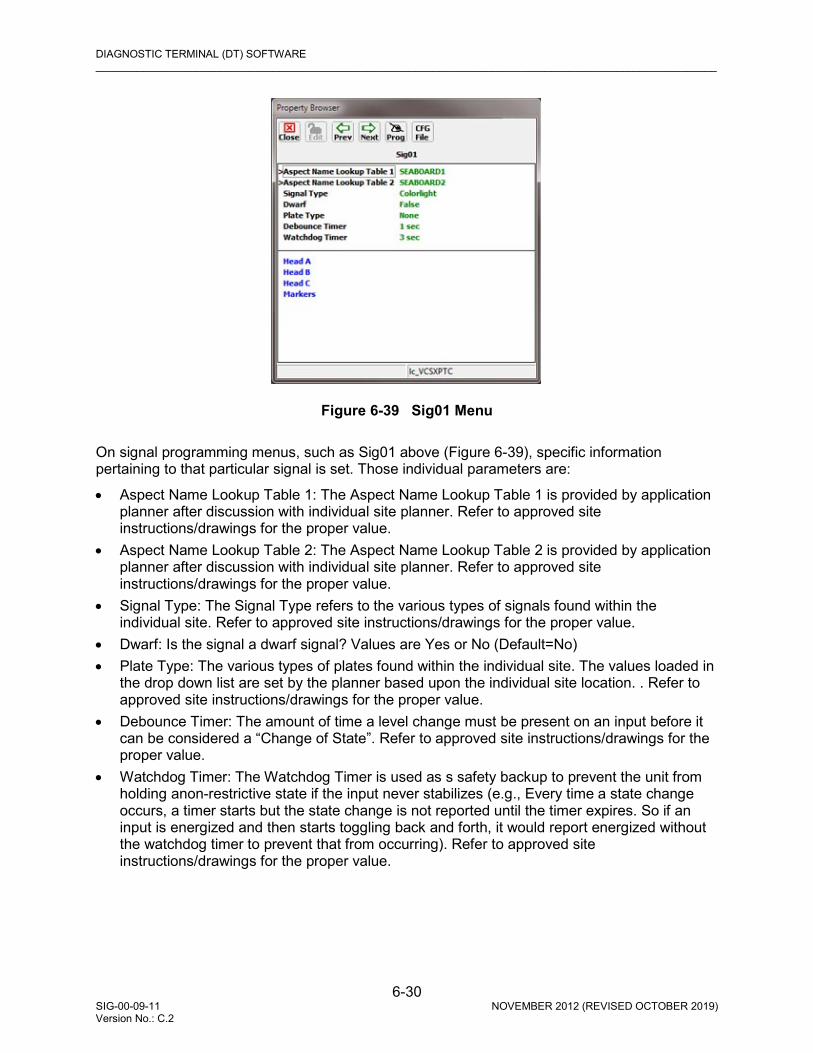
DIAGNOSTIC TERMINAL (DT) SOFTWARE _________________________________________________________________________________________________________
6-30 SIG-00-09-11 NOVEMBER 2012 (REVISED OCTOBER 2019) Version No.: C.2
Figure 6-39 Sig01 Menu
On signal programming menus, such as Sig01 above (Figure 6-39), specific information pertaining to that particular signal is set. Those individual parameters are:
• Aspect Name Lookup Table 1: The Aspect Name Lookup Table 1 is provided by application planner after discussion with individual site planner. Refer to approved site instructions/drawings for the proper value.
• Aspect Name Lookup Table 2: The Aspect Name Lookup Table 2 is provided by application planner after discussion with individual site planner. Refer to approved site instructions/drawings for the proper value.
• Signal Type: The Signal Type refers to the various types of signals found within the individual site. Refer to approved site instructions/drawings for the proper value.
• Dwarf: Is the signal a dwarf signal? Values are Yes or No (Default=No) • Plate Type: The various types of plates found within the individual site. The values loaded in
the drop down list are set by the planner based upon the individual site location. . Refer to approved site instructions/drawings for the proper value.
• Debounce Timer: The amount of time a level change must be present on an input before it can be considered a “Change of State”. Refer to approved site instructions/drawings for the proper value.
• Watchdog Timer: The Watchdog Timer is used as s safety backup to prevent the unit from holding anon-restrictive state if the input never stabilizes (e.g., Every time a state change occurs, a timer starts but the state change is not reported until the timer expires. So if an input is energized and then starts toggling back and forth, it would report energized without the watchdog timer to prevent that from occurring). Refer to approved site instructions/drawings for the proper value.
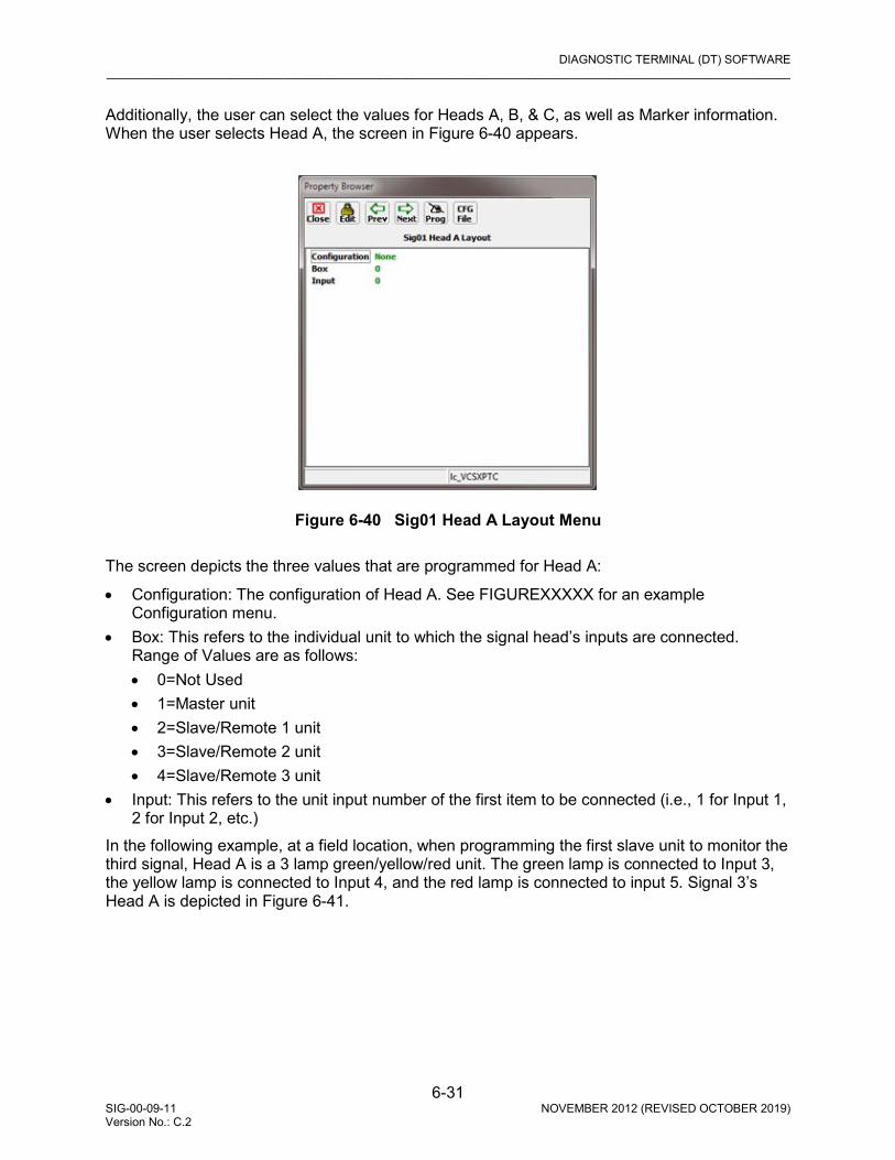
DIAGNOSTIC TERMINAL (DT) SOFTWARE _________________________________________________________________________________________________________
6-31 SIG-00-09-11 NOVEMBER 2012 (REVISED OCTOBER 2019) Version No.: C.2
Additionally, the user can select the values for Heads A, B, & C, as well as Marker information. When the user selects Head A, the screen in Figure 6-40 appears.
Figure 6-40 Sig01 Head A Layout Menu
The screen depicts the three values that are programmed for Head A:
• Configuration: The configuration of Head A. See FIGUREXXXXX for an example Configuration menu.
• Box: This refers to the individual unit to which the signal head’s inputs are connected. Range of Values are as follows: • 0=Not Used • 1=Master unit • 2=Slave/Remote 1 unit • 3=Slave/Remote 2 unit • 4=Slave/Remote 3 unit
• Input: This refers to the unit input number of the first item to be connected (i.e., 1 for Input 1, 2 for Input 2, etc.)
In the following example, at a field location, when programming the first slave unit to monitor the third signal, Head A is a 3 lamp green/yellow/red unit. The green lamp is connected to Input 3, the yellow lamp is connected to Input 4, and the red lamp is connected to input 5. Signal 3’s Head A is depicted in Figure 6-41.

DIAGNOSTIC TERMINAL (DT) SOFTWARE _________________________________________________________________________________________________________
6-32 SIG-00-09-11 NOVEMBER 2012 (REVISED OCTOBER 2019) Version No.: C.2
Figure 6-41 Example Lamp 3 Head A on Slave 1 Menu Head’s B & C are programmed as described for Head A. Markers are programmed as per the site instructions and the physical marker type on the ground. When programming Switches (see Figure 6-42A) and Hazard Detectors (see Figure 6-42B), the only parameters to be set are those for Box and Input, which are programmed as described above.
Figure 6-42 (A) Switch 1 (SW01) and (B) Hazard Detector 1 (BF01) Menus
A B

DIAGNOSTIC TERMINAL (DT) SOFTWARE _________________________________________________________________________________________________________
6-33 SIG-00-09-11 NOVEMBER 2012 (REVISED OCTOBER 2019) Version No.: C.2
6.7.5 SITE Configuration Select the SITE Configuration function from the MAIN PROGRAM menu screen to view the SITE configuration screen (Figure 6-43).
Figure 6-43 SITE Configuration Screens
6.7.5.1 Location Select Location on the SITE configuration screen to display the Object Name Editor dialog box (Figure 6-45). Use this editor to create unique names for the site location. After entering the name using the PC keyboard, click the APPLY button. • DOT Crossing Number Enter the DOT number for the VIU-16i/-8i location. The range of values is up to six numbers and one letter. (Default=000000A).
Figure 6-44 Location Editor

DIAGNOSTIC TERMINAL (DT) SOFTWARE _________________________________________________________________________________________________________
6-34 SIG-00-09-11 NOVEMBER 2012 (REVISED OCTOBER 2019) Version No.: C.2
• Milepost Number Enter the milepost number of the VIU-16i/8i location. Range of values is up to 10 characters (Default is 000.0) • Site Name Enter a name for the VIU-16i/8i location Range of values is up to 20 characters (default is blank).
6.7.5.2 Object Names Select Object Names on the SITE configuration screen to display the Object Name Editor dialog box (Figure 6-45). Use this editor to create unique names for objects used in the MCF. After entering the name using the PC keyboard, click the APPLY button.
Figure 6-45 Object Name Editor
In this example the names assigned are:
• Main = Main VIU • MnIn = A remote object residing in the Main Ciu-16i/-8i • Rem1 = Remote VIU 1 • Rem2 = Remote VIU 2 • Rem3 = Remote VIU 3 To reset the name to the default name, click the Reset to Default button. When finished, click the CLOSE button to return to the SITE configuration screen.
6.7.5.3 Card Names Select Card Names on the SITE configuration screen to display the Card Name Editor dialog box (Figure 6-46). Use this editor to create unique names for the internal I/O modules, if desired. After entering a name using the PC keyboard, click the APPLY button. To reset a name to the default name, select the name from the list and then click the Reset to Default button.

DIAGNOSTIC TERMINAL (DT) SOFTWARE _________________________________________________________________________________________________________
6-35 SIG-00-09-11 NOVEMBER 2012 (REVISED OCTOBER 2019) Version No.: C.2
When finished, click the CLOSE button to return to the SITE configuration screen.
Figure 6-46 Card Name Editor
6.8 LOGS / HISTORY BUTTONS
Click the Logs button at the top of the Input Status Screen, or the History menu on the toolbar to display the Log drop-down menu. This menu provides access to several history logs. These logs are in addition to the Event Log and Diagnostic Log maintained by the VIU, and are described in the following paragraphs.
Figure 6-47 Logs Pull-Down Menu
6.8.1 Maintenance Log Select Maintenance Log from the History drop down menu to display the Maintenance Log screen. The VIU Maintenance Log (Figure 6-48) contains the following types of information:
• Changes in VIU operational status • Parameter changes • User entered maintenance notes

DIAGNOSTIC TERMINAL (DT) SOFTWARE _________________________________________________________________________________________________________
6-36 SIG-00-09-11 NOVEMBER 2012 (REVISED OCTOBER 2019) Version No.: C.2
Each entry in the log is date and time stamped. The log is maintained in the DT install directory on the PC. If more than one VIU is accessed via a network, the Maintenance Log will be common to all VIUs.
Figure 6-48 Maintenance Log Screen
6.8.2 Status Log Select Status Log from the History drop down menu to display the status log screen. The VIU status log (Figure 6-49) is a record of all VIU system events and is primarily a diagnostic tool. The log contains entries from both the master and slave I/O circuit logs. These logs are lost when VIU power is cycled.
Figure 6-49 Status Log Screen
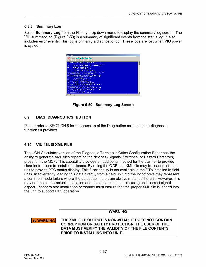
DIAGNOSTIC TERMINAL (DT) SOFTWARE _________________________________________________________________________________________________________
6-37 SIG-00-09-11 NOVEMBER 2012 (REVISED OCTOBER 2019) Version No.: C.2
6.8.3 Summary Log Select Summary Log from the History drop down menu to display the summary log screen. The VIU summary log (Figure 6-50) is a summary of significant events from the status log. It also includes error events. This log is primarily a diagnostic tool. These logs are lost when VIU power is cycled.
Figure 6-50 Summary Log Screen
6.9 DIAG (DIAGNOSTICS) BUTTON
Please refer to SECTION 8 for a discussion of the Diag button menu and the diagnostic functions it provides.
6.10 VIU-16I\-8I XML FILE
The UCN Calculator version of the Diagnostic Terminal’s Office Configuration Editor has the ability to generate XML files regarding the devices (Signals, Switches, or Hazard Detectors) present in the MCF. This capability provides an additional method for the planner to provide clear instructions to installation teams. By using the OCE, the XML file may be loaded into the unit to provide PTC status display. This functionality is not available in the DTs installed in field units. Inadvertently loading this data directly from a field unit into the locomotive may represent a common mode failure where the database in the train always matches the unit. However, this may not match the actual installation and could result in the train using an incorrect signal aspect. Planners and installation personnel must ensure that the proper XML file is loaded into the unit to support PTC operation
WARNING
THE XML FILE OUTPUT IS NON-VITAL; IT DOES NOT CONTAIN CORRUPTION OR SAFETY PROTECTION. THE USER OF THE DATA MUST VERIFY THE VALIDITY OF THE FILE CONTENTS PRIOR TO INSTALLING INTO UNIT.

DIAGNOSTIC TERMINAL (DT) SOFTWARE _________________________________________________________________________________________________________
6-38 SIG-00-09-11 NOVEMBER 2012 (REVISED OCTOBER 2019) Version No.: C.2
To open the VIU XML File window, open the DT offline and either open the selected MCF or a .pac file of that MCF. When the Office Configuration Editor opens, select CFG File > VIU XML File.
Figure 6-51 VIU OCE Window with VIU XML File Selected
This action then opens the VIU XML File window.
Figure 6-52 VIU-16i\-8i XML File Window
The window initially opens with the WIU Address, Encrypted HMAC Key, Device Status Configuration Information, Device Status Order in MCF, Device Counts, and Device Section fields blank. The MCF Name field and MCFCRC fields are populated with data entries. The XML file is created based upon the site application and the railroad or agency approved site drawing plans.
Figure 6-53 Generic VIU-16i\8i Application Diagram
VIU_XML_XMPL11-17-11
39
46SW 11E
1W
2W

DIAGNOSTIC TERMINAL (DT) SOFTWARE _________________________________________________________________________________________________________
6-39 SIG-00-09-11 NOVEMBER 2012 (REVISED OCTOBER 2019) Version No.: C.2
In the example depicted in Figure 6-53, the application MCF contains a left facing switch leading onto a spur line. There are three signals controlling movement across the main line (Track 46) or off of the spur line (Track 39).
Figure 6-54 VIU-16i\8i XML File Window
As shown in Figure 6-52, the VIU-16i\-8i initially assembles the data found within the MCF regarding the site and places that data into an XML file. It then assembles information drawn from the site specific configuration data settings to automatically populate the Device Counts and Device Status Order in MCF fields by determining all the device statuses reported in the WSM. For each device status, the DT creates the corresponding device section in the file for the device type. These individual lines appear in the lower portion of the window (see Figure 6-54). However, setting the device counts/order in the VIU XML File does not change them in the MCF. Changing site specific configuration data settings is the only method that configures the MCF.
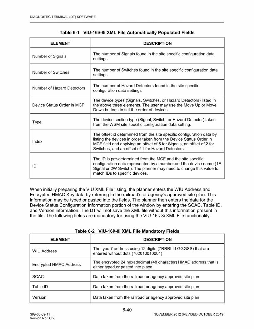
DIAGNOSTIC TERMINAL (DT) SOFTWARE _________________________________________________________________________________________________________
6-40 SIG-00-09-11 NOVEMBER 2012 (REVISED OCTOBER 2019) Version No.: C.2
Table 6-1 VIU-16i\-8i XML File Automatically Populated Fields
ELEMENT DESCRIPTION
Number of Signals The number of Signals found in the site specific configuration data settings
Number of Switches The number of Switches found in the site specific configuration data settings
Number of Hazard Detectors The number of Hazard Detectors found in the site specific configuration data settings
Device Status Order in MCF The device types (Signals, Switches, or Hazard Detectors) listed in the above three elements. The user may use the Move Up or Move Down buttons to set the order of devices.
Type The device section type (Signal, Switch, or Hazard Detector) taken from the WSM site specific configuration data setting.
Index
The offset id determined from the site specific configuration data by listing the devices in order taken from the Device Status Order in MCF field and applying an offset of 5 for Signals, an offset of 2 for Switches, and an offset of 1 for Hazard Detectors.
ID
The ID is pre-determined from the MCF and the site specific configuration data represented by a number and the device name (1E Signal or 2W Switch). The planner may need to change this value to match IDs to specific devices.
When initially preparing the VIU XML File listing, the planner enters the WIU Address and Encrypted HMAC Key data by referring to the railroad’s or agency’s approved site plan. This information may be typed or pasted into the fields. The planner then enters the data for the Device Status Configuration Information portion of the window by entering the SCAC, Table ID, and Version information. The DT will not save the XML file without this information present in the file. The following fields are mandatory for using the VIU-16i\-8i XML File functionality:
Table 6-2 VIU-16i\-8i XML File Mandatory Fields
ELEMENT DESCRIPTION
WIU Address The type 7 address using 12 digits (7RRRLLLGGGSS) that are entered without dots (762010010004)
Encrypted HMAC Address The encrypted 24 hexadecimal (48 character) HMAC address that is either typed or pasted into place.
SCAC Data taken from the railroad or agency approved site plan
Table ID Data taken from the railroad or agency approved site plan
Version Data taken from the railroad or agency approved site plan

DIAGNOSTIC TERMINAL (DT) SOFTWARE _________________________________________________________________________________________________________
6-41 SIG-00-09-11 NOVEMBER 2012 (REVISED OCTOBER 2019) Version No.: C.2
The planner determines the order of the devices (Signals, Switches, or Hazard Detectors) presented in the Device Status Order in MCF portion of the VIU XML File window. This order governs the order of devices presented in the Individual Device Listing. The DT then prompts the planner to enter the optional fields’ data listed by device in the Individual Device Listing found in the lower section of the window. The planner may leave these fields blank and of so, the DT will not write the element into the XML file. The DT will default these fields with any values it can determine from the MCF and site specific configuration data. The following fields are optional for using the VIU-16i\-8i XML File functionality (see Figure 6-55).
Table 6-3 VIU-16i\-8i XML File Optional Fields
ELEMENT DESCRIPTION
Site Device ID (Optional) This data is automatically entered when the file is generated. It may be changed to match IDs to specific devices
Description The description of the device provided by the planner.
Direction For a Signal the values are Increasing or Decreasing and for a Switch the values are Left Facing (LF), Left Reverse (LR), Right Facing (RF) or Right Reverse (RR).
Site Name Data taken from the railroad or agency approved site plan
Track Name Data taken from the railroad or agency approved site plan
Subdivision Data taken from the railroad or agency approved site plan
Milepost Data taken from the railroad or agency approved site plan
To enter the optional data, double click one of the device lines.
Figure 6-55 VIU-16i\-8i Device Information Window
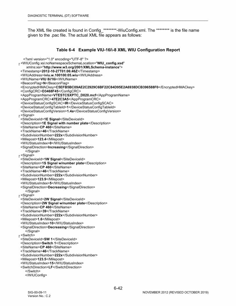
DIAGNOSTIC TERMINAL (DT) SOFTWARE _________________________________________________________________________________________________________
6-42 SIG-00-09-11 NOVEMBER 2012 (REVISED OCTOBER 2019) Version No.: C.2
The XML file created is found in Config_********-WiuConfig.xml. The ******** is the file name given to the .pac file. The actual XML file appears as follows:
Table 6-4 Example VIU-16i\-8 XML WIU Configuration Report
<?xml version="1.0" encoding="UTF-8" ?>
- <WIUConfig xsi:noNamespaceSchemaLocation="WIU_config.xsd" xmlns:xsi="http://www.w3.org/2001/XMLSchema-instance"> <Timestamp>2012-10-27T01:06:46Z</Timestamp> <WIUAddress>iviu.w.100100:05.wiu</WIUAddress> <WIUName>VIU 8i/16i</WIUName> <BeaconFlag>N</BeaconFlag> <EncryptedHMACkey>C5EFB5BC09AE2C2929C6BF22C84D95E2A6938DCB396588F0</EncryptedHMACkey> <ConfigCRC>D3468F45</ConfigCRC> <AppProgramName>VTESTCSXPTC_D020.mcf</AppProgramName> <AppProgramCRC>47E2C3A5</AppProgramCRC> <DeviceStatusConfigSCAC>IR</DeviceStatusConfigSCAC> <DeviceStatusConfigTableId>1</DeviceStatusConfigTableId> <DeviceStatusConfigVersion>1.4a</DeviceStatusConfigVersion> - <Signal> <SiteDeviceId>1E Signal</SiteDeviceId> <Description>1E Signal with number plate</Description> <SiteName>CP 460</SiteName> <TrackName>46</TrackName> <SubdivisionNumber>222x</SubdivisionNumber> <Milepost>123.4</Milepost> <WIUStatusIndex>0</WIUStatusIndex> <SignalDirection>Increasing</SignalDirection>
</Signal> - <Signal> <SiteDeviceId>1W Signal</SiteDeviceId> <Description>1S Signal w/number plate</Description> <SiteName>CP 460</SiteName> <TrackName>46</TrackName> <SubdivisionNumber>222x</SubdivisionNumber> <Milepost>123.9</Milepost> <WIUStatusIndex>5</WIUStatusIndex> <SignalDirection>Decreasing</SignalDirection>
</Signal> - <Signal> <SiteDeviceId>2W Signal</SiteDeviceId> <Description>2W Signal w/number plate</Description> <SiteName>CP 460</SiteName> <TrackName>39</TrackName> <SubdivisionNumber>222x</SubdivisionNumber> <Milepost>1.6</Milepost> <WIUStatusIndex>10</WIUStatusIndex> <SignalDirection>Decreasing</SignalDirection>
</Signal> - <Switch> <SiteDeviceId>SW 1</SiteDeviceId> <Description>Switch 1</Description> <SiteName>CP 460</SiteName> <TrackName>46</TrackName> <SubdivisionNumber>222x</SubdivisionNumber> <Milepost>123.5</Milepost> <WIUStatusIndex>15</WIUStatusIndex> <SwitchDirection>LF</SwitchDirection>
</Switch> </WIUConfig>

VIU WEB BROWSER USER INTERFACE _________________________________________________________________________________________________________
7-1 SIG-00-09-11 NOVEMBER 2012 (REVISED OCTOBER 2019) Version No.: C.2
SECTION 7 VIU WEB BROWSER USER INTERFACE
7.0 VIU WEB BROWSER USER INTERFACE
NOTE
Programming the VIU requires the use of the Web User Interface (Web U/I) to program non-vital parameters, the Diagnostic Terminal (DT) to program vital parameters, as well the VIU keypad to set SIN, MCFCRC, and the UCN. For optimum viewing, display the web browser window full screen.
7.1 INTRODUCTION
The VIU web browser user interface will run on Internet Explorer (versions 6 or higher) and on Mozilla Firefox browser (version 2 or higher). The web browser user interface allows local or remote configuration of certain VIU non-vital parameters, plus access to the Event and Diagnostic logs that can be used to isolate VIU system problems (see Section 8, MAINTENANCE AND TROUBLESHOOTING).
7.2 LAUNCHING THE VIU WEB BROWSER
NOTE
Railroad or agency guidelines may require IT support and/or authorization prior to changing computer settings.
7.2.1 Web Browser Icons
Figure 7-1 Establishing Web U/I Setup Parameters

VIU WEB BROWSER USER INTERFACE _________________________________________________________________________________________________________
7-2 SIG-00-09-11 NOVEMBER 2012 (REVISED OCTOBER 2019) Version No.: C.2
Setting up a computer to connect with the VIU-16I/-8I follows standard fundamental LAN protocol. The User Ethernet Port defaults as a DHCP Server. Setting the computer as a DHCP client will enable the VIU-16I/-8I to assign the computer an IP address. The user can also manually set up the computer's TCP/IP properties (e.g. IP address 192.168.1.105, subnet as 255.255.255.0) to connect with the VIU-16I/-8I as shown in Figure 7-1. The example shown is for Windows XP and varies between Windows versions (Vista, Windows 7). This procedure is NOT necessary unless the intent is to set up the laptop Ethernet port to something other than a default configuration. If the PC is not already connected to the VIU, connect it to the VIU using an RJ-45 terminated Ethernet cable connected between the PC Ethernet port and the Laptop (Ethernet) port on the VIU front panel. This connection can also be made remotely through an Ethernet network connection to the VIU. Now launch the Internet Explorer (or Mozilla Firefox browser) on the PC. On the URL line enter the IP address of the connected VIU (Figure 7-2). If this is a new VIU the default IP address is 192.168.1.100.
Figure 7-2 Internet Explorer URL Line
Figure 7-3 VIU Web Browser Login Screen
Select Login either in the upper right corner or the lower center of the login screen (Figure 7-3). Enter the username and password when prompted (Figure 7-4). Click the Login button. Default user name: admin Default password: safetran These entries are all lower case and are case sensitive.
Figure 7-4 Web Browser Login Dialog Box

VIU WEB BROWSER USER INTERFACE _________________________________________________________________________________________________________
7-3 SIG-00-09-11 NOVEMBER 2012 (REVISED OCTOBER 2019) Version No.: C.2
The Welcome screen is displayed (Figure 7-5).
Figure 7-5 Web Browser Welcome Screen
7.2.2 Web Browser Icons In the upper left corner of the screen below the Siemens logo is a row of five icons. When the web browser is first opened, these icons appear as broken links as shown below. If you hover the cursor over these links, a help message appears indicating that you are not currently logged into the VIU.
Figure 7-6 Welcome Screen and Login Status
After login, these icons will change appearance depending on system status. From left to right the icons indicate the following status:
• Vital Core Session • Vital Core Status • Vital Slave Session • Non Vital Core Health • GPS status
Figure 7-7 Status Icons

VIU WEB BROWSER USER INTERFACE _________________________________________________________________________________________________________
7-4 SIG-00-09-11 NOVEMBER 2012 (REVISED OCTOBER 2019) Version No.: C.2
Hovering the cursor over an icon identifies the function indicated and the current status of that function. The following icons illustrate some of the status indications.
Figure 7-8 Icon Definitions
Each screen is provided with a standard set of edit buttons for manipulating the parameters.
Figure 7-9 Standard VIU Non-Vital Parameter Update Buttons
• The Refresh button refreshes the current parameter value displays. • The Default button sets the parameters to the default values. If either Refresh or Default is selected, those buttons are disabled and the Save and Discard buttons are enabled.
Figure 7-10 Standard VIU Non-Vital Parameter Update Confirmation Buttons
Indicates that internal GPS is active.
Indicates that internal GPS is missing or unhealthy.
Indicates that function is healthy or in session.
Alternates with caution symbol when function is unhealthy or out of session.
Alternates with open padlock symbol when function is unhealthy or out of session.
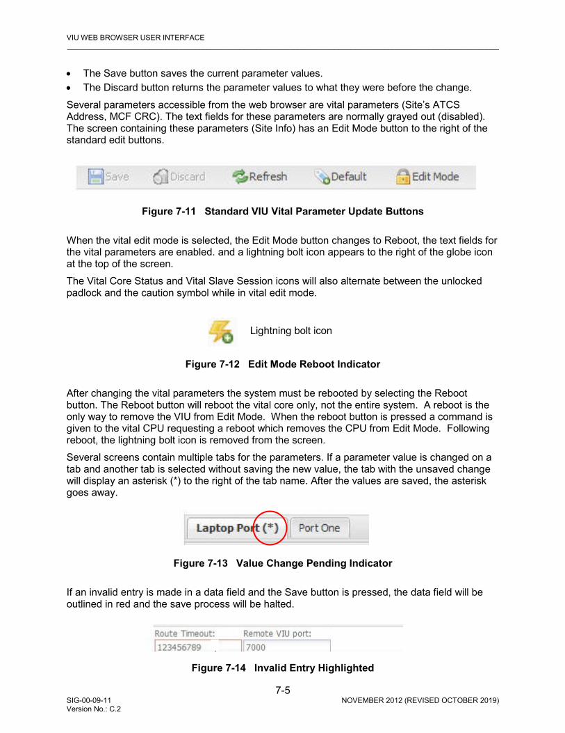
VIU WEB BROWSER USER INTERFACE _________________________________________________________________________________________________________
7-5 SIG-00-09-11 NOVEMBER 2012 (REVISED OCTOBER 2019) Version No.: C.2
• The Save button saves the current parameter values. • The Discard button returns the parameter values to what they were before the change. Several parameters accessible from the web browser are vital parameters (Site’s ATCS Address, MCF CRC). The text fields for these parameters are normally grayed out (disabled). The screen containing these parameters (Site Info) has an Edit Mode button to the right of the standard edit buttons.
Figure 7-11 Standard VIU Vital Parameter Update Buttons
When the vital edit mode is selected, the Edit Mode button changes to Reboot, the text fields for the vital parameters are enabled. and a lightning bolt icon appears to the right of the globe icon at the top of the screen. The Vital Core Status and Vital Slave Session icons will also alternate between the unlocked padlock and the caution symbol while in vital edit mode.
Figure 7-12 Edit Mode Reboot Indicator
After changing the vital parameters the system must be rebooted by selecting the Reboot button. The Reboot button will reboot the vital core only, not the entire system. A reboot is the only way to remove the VIU from Edit Mode. When the reboot button is pressed a command is given to the vital CPU requesting a reboot which removes the CPU from Edit Mode. Following reboot, the lightning bolt icon is removed from the screen. Several screens contain multiple tabs for the parameters. If a parameter value is changed on a tab and another tab is selected without saving the new value, the tab with the unsaved change will display an asterisk (*) to the right of the tab name. After the values are saved, the asterisk goes away.
Figure 7-13 Value Change Pending Indicator
If an invalid entry is made in a data field and the Save button is pressed, the data field will be outlined in red and the save process will be halted.
Figure 7-14 Invalid Entry Highlighted
Lightning bolt icon
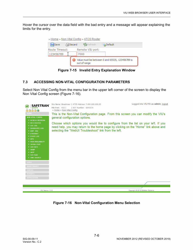
VIU WEB BROWSER USER INTERFACE _________________________________________________________________________________________________________
7-6 SIG-00-09-11 NOVEMBER 2012 (REVISED OCTOBER 2019) Version No.: C.2
Hover the cursor over the data field with the bad entry and a message will appear explaining the limits for the entry.
Figure 7-15 Invalid Entry Explanation Window
7.3 ACCESSING NON-VITAL CONFIGURATION PARAMETERS
Select Non Vital Config from the menu bar in the upper left corner of the screen to display the Non Vital Config screen (Figure 7-16).
Figure 7-16 Non-Vital Configuration Menu Selection

VIU WEB BROWSER USER INTERFACE _________________________________________________________________________________________________________
7-7 SIG-00-09-11 NOVEMBER 2012 (REVISED OCTOBER 2019) Version No.: C.2
Figure 7-17 Non-Vital Configuration Parameters
When the Non Vital Config selection menu is displayed, select the desired configuration type from the available list (Figure 7-17). The various parameters and selections for each configuration type are explained in the following paragraphs. On the initial Non-Vital Configuration screen, select the desired parameter group from the Non Vital Config menu at the left side of the screen.
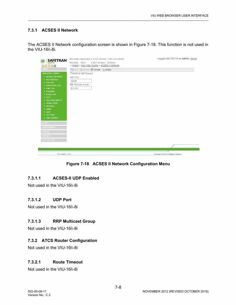
VIU WEB BROWSER USER INTERFACE _________________________________________________________________________________________________________
7-8 SIG-00-09-11 NOVEMBER 2012 (REVISED OCTOBER 2019) Version No.: C.2
7.3.1 ACSES II Network The ACSES II Network configuration screen is shown in Figure 7-18. This function is not used in the VIU-16i\-8i.
Figure 7-18 ACSES II Network Configuration Menu
7.3.1.1 ACSES-II UDP Enabled Not used in the VIU-16i\-8i
7.3.1.2 UDP Port Not used in the VIU-16i\-8i
7.3.1.3 RRP Multicast Group Not used in the VIU-16i\-8i 7.3.2 ATCS Router Configuration Not used in the VIU-16i\-8i
7.3.2.1 Route Timeout Not used in the VIU-16i\-8i
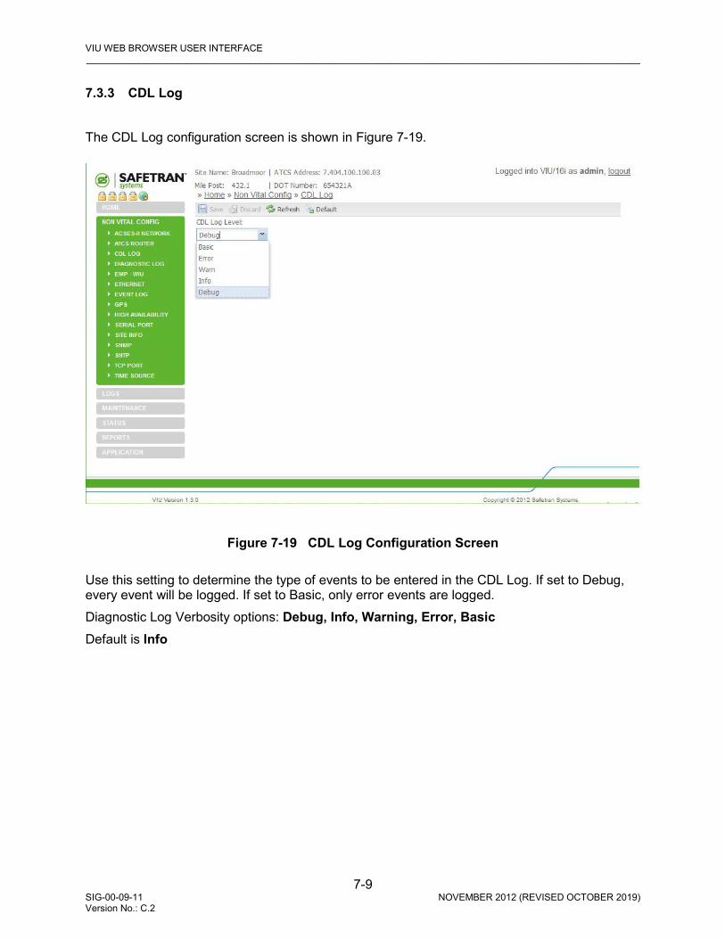
VIU WEB BROWSER USER INTERFACE _________________________________________________________________________________________________________
7-9 SIG-00-09-11 NOVEMBER 2012 (REVISED OCTOBER 2019) Version No.: C.2
7.3.3 CDL Log The CDL Log configuration screen is shown in Figure 7-19.
Figure 7-19 CDL Log Configuration Screen Use this setting to determine the type of events to be entered in the CDL Log. If set to Debug, every event will be logged. If set to Basic, only error events are logged. Diagnostic Log Verbosity options: Debug, Info, Warning, Error, Basic Default is Info

VIU WEB BROWSER USER INTERFACE _________________________________________________________________________________________________________
7-10 SIG-00-09-11 NOVEMBER 2012 (REVISED OCTOBER 2019) Version No.: C.2
7.3.4 Diagnostic Log Configuration The Diagnostic Log configuration screen is shown in Figure 7-20.
Figure 7-20 Diagnostic Log Configuration Screen
7.3.4.1 Server IP When one or more VIUs are operating on a network, each VIU can be configured to forward all events over the network to a “consolidated logger”. The logger will maintain all of the events for every reporting VIU. The logger can be another VIU. To configure each VIU to send the Diagnostic Log entries to the logger, enter the IP address of the logger in the Server IP dialog box. Server IP: valid IP address (default is 0.0.0.0).
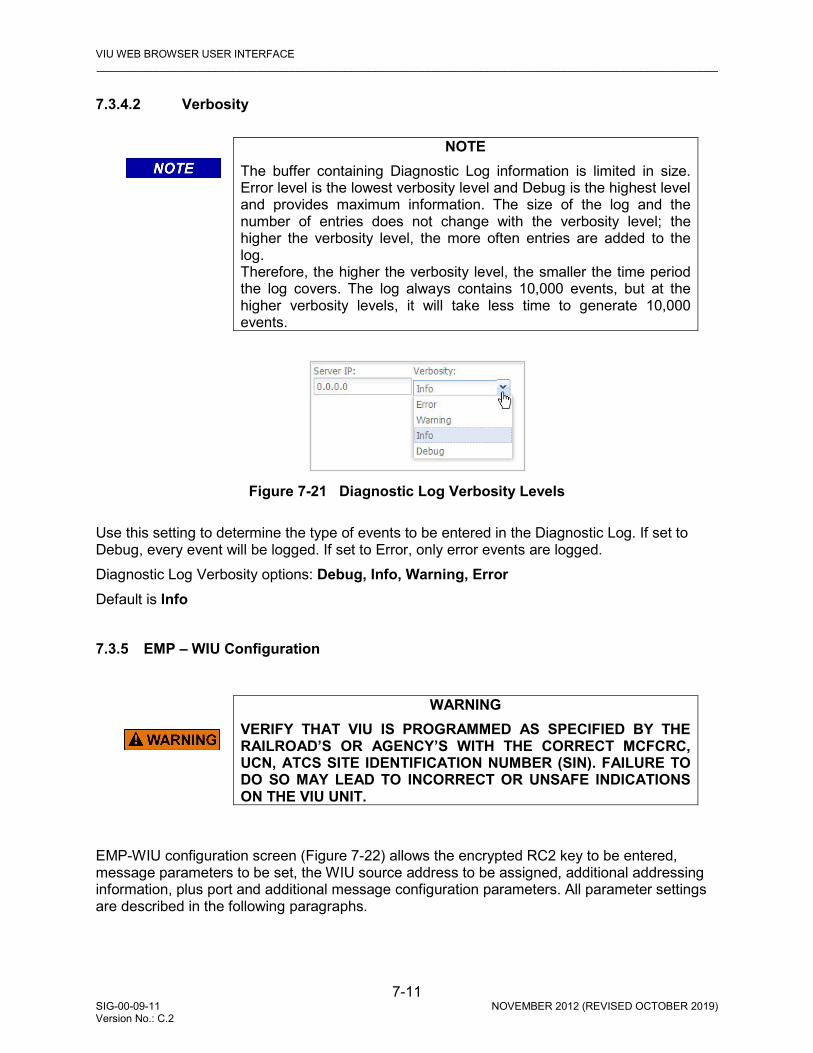
VIU WEB BROWSER USER INTERFACE _________________________________________________________________________________________________________
7-11 SIG-00-09-11 NOVEMBER 2012 (REVISED OCTOBER 2019) Version No.: C.2
7.3.4.2 Verbosity
NOTE
The buffer containing Diagnostic Log information is limited in size. Error level is the lowest verbosity level and Debug is the highest level and provides maximum information. The size of the log and the number of entries does not change with the verbosity level; the higher the verbosity level, the more often entries are added to the log. Therefore, the higher the verbosity level, the smaller the time period the log covers. The log always contains 10,000 events, but at the higher verbosity levels, it will take less time to generate 10,000 events.
Figure 7-21 Diagnostic Log Verbosity Levels Use this setting to determine the type of events to be entered in the Diagnostic Log. If set to Debug, every event will be logged. If set to Error, only error events are logged. Diagnostic Log Verbosity options: Debug, Info, Warning, Error Default is Info 7.3.5 EMP – WIU Configuration
WARNING
VERIFY THAT VIU IS PROGRAMMED AS SPECIFIED BY THE RAILROAD’S OR AGENCY’S WITH THE CORRECT MCFCRC, UCN, ATCS SITE IDENTIFICATION NUMBER (SIN). FAILURE TO DO SO MAY LEAD TO INCORRECT OR UNSAFE INDICATIONS ON THE VIU UNIT.
EMP-WIU configuration screen (Figure 7-22) allows the encrypted RC2 key to be entered, message parameters to be set, the WIU source address to be assigned, additional addressing information, plus port and additional message configuration parameters. All parameter settings are described in the following paragraphs.

VIU WEB BROWSER USER INTERFACE _________________________________________________________________________________________________________
7-12 SIG-00-09-11 NOVEMBER 2012 (REVISED OCTOBER 2019) Version No.: C.2
Figure 7-22 EMP – WIU Configuration Screen
7.3.5.1 WIU Address This ATCS address is assigned by the railroad or agency for each specific WIU. The WIU Address need not be set to the same value as the Site ATCS Address, it may be identified by a separate node. WIU Address: valid IP address (default is 0.0.0.0).
WARNING THE WIU ADDRESSES MUST BE UNIQUE FOR EACH VIU.

VIU WEB BROWSER USER INTERFACE _________________________________________________________________________________________________________
7-13 SIG-00-09-11 NOVEMBER 2012 (REVISED OCTOBER 2019) Version No.: C.2
7.3.5.2 Encrypted HMAC Key An HMAC function is used by the message sender to produce an HMAC value that is formed by condensing a secret key, the RC2 key, and the message input. (The HMAC is similar to a CRC, but requires the use of an HMAC encryption key to create it.) The HMAC is placed in the message and sent to the message receiver. The receiver computes the HMAC on the received message using the same secret key and HMAC function as was used by the sender, and compares the result computed with the received HMAC. If the two values match, the message has been correctly received. HMAC Key: 24 hex bytes (default = all zeros (00 00 00 00 00 00 00 00 00 00 00 00 00 00 00 00 00 00 00 00 00 00 00 00)).
7.3.5.3 RC2 Key The RC2 Key is a password used to encrypt the HMAC value. It can be a maximum of 20 characters. The value is displayed with asterisks because the VIU must not display the actual, unencrypted text in this field. The VIU allows the RC2 key to be copied to a USB device, and copied from a USB device in the VIU. The RC2 key is stored in the USB device in an encrypted form, so that the user cannot read it and obtain the RC2 key number. RC2 Key range: Null terminated string. Up to 20 bytes (default = Blank Line)
7.3.5.4 Message Version The VIU sets the Message Version field of the EMP message to this value. Normally, this setting does not need to be changed from the default. Message Version range: 0 – 255 (default is 10).
7.3.5.5 EMP Header Source Address The VIU will use this EMP address as the source address in EMP messages. The string can be set to anything that may be needed by the wayside-to-locomotive network and is case sensitive. Example: ns.w.lllggg:ss.wiu or csx.w.lllggg:ss.wiu (where lll, ggg and ss are the constituent parts of the ATCS WIU address, 7.rrr.lll.ggg.ss) String is null terminated (up to 63 bytes) (default = Blank Line).
7.3.5.6 EMP Header Destination Address The VIU will use this EMP address as the destination address in broadcasted WSMs. Normally this string is set to XX.L.X.000000:tmc. Destination Address range: Null terminated string. Up to 63 bytes (default = Blank Line)
7.3.5.7 EMP Timed Beacon TTL This is the normal “Time To Live” value, which is when a message is determined to be stale. Time To Live range: 0 – 65535 (default = 12)
VIU WEB BROWSER USER INTERFACE _________________________________________________________________________________________________________
7-14 SIG-00-09-11 NOVEMBER 2012 (REVISED OCTOBER 2019) Version No.: C.2
7.3.5.8 EMP WIU Status Response TTL This is the alternate “Time To Live” value, which describes the number of Interoperability Transport “hops” that a message can make before being discarded – if the message is being conveyed by the VIU through an alternate talk path to the Interoperability Server. Alternate Time To Live range: 0 – 65535 (default = 12).
7.3.5.9 EMP Timed Beacon QOS This is the QOS value used in beaconed WSMs. QOS range: 0 – 65535 (default = 0).
7.3.5.10 EMP WIU Status Response QOS This is the “QOS” value used in WSMs in response to a WiuGetStatus message. QOS range: 0 – 65535 (default = 0).
7.3.5.11 Class C Multicast IP Address This is a Multicast IP address which is used by the VIU to listen for Multicast UDP messages containing Class “C” Time Updates as defined in the PTC specification. Class D Address range: 0.0.0.0 – 255.255.255.255 (default = 239.255.0.5
7.3.5.12 Access Gateway (AG) IP Address (Class D Remote Address) This is the IP address of the Interoperability Train Control Server or “application gateway” computer to which the VIU connects. PTC messages are conveyed across a TCP connection to this IP address. Access Gateway IP: valid IP address or DNS (default = 10.255.255.210.
7.3.5.13 Access Gateway (AG) Port (Class D Remote Port) This is the TCP port number that the VIU connects to in conjunction with the ITC Server IP address. Access Gateway Port Address Range: 1024 – 65535 (default = 3001)
7.3.5.14 Log Traffic This optional attribute indicates whether or not link traffic should be logged for debugging purposes. When checked (set to yes), all link traffic is logged in a text file, with binary data expressed in hexadecimal format. Log Traffic range: Unchecked (No), Checked (Yes) (default = Unchecked (No))
7.3.5.15 Keep Alive Interval (msec) This timer value indicates the rate at which keep-alive messages shall be sent to an Interoperability Train Control Server or “application gateway”. A value of 0 shall indicate that no keep-alive messages are sent or expected. The keep-alive interval attribute is configured as 0 on both ends of a link if keep-alive operation is to be disabled. Keep Alive Timer range: 0 – 60000 (default = 30000)

VIU WEB BROWSER USER INTERFACE _________________________________________________________________________________________________________
7-15 SIG-00-09-11 NOVEMBER 2012 (REVISED OCTOBER 2019) Version No.: C.2
7.3.5.16 Keep Alive ACK Timeout (msec) This timer value is the number of milliseconds the VIU will wait for acknowledgment to a keep alive message before terminating the link. Keep Alive ACK Timeout range: 0 – 60000 (default = 15000)
7.3.5.17 Class D Data ACK Enabled This required attribute indicates whether or not acknowledgments (and negative acknowledgements) shall be sent or expected in response to data messages. Class D Data ACK range: Checked (Yes), Unchecked (No) (default = Checked (Yes))
7.3.5.18 Data ACK Timeout (msec) This attribute indicates how much time shall be allowed to elapse between the sending of a data message and the receipt of an acknowledgement message. It is required when Data ACK Enabled is set to Yes. No ACK Retry Timer range: 2 – 60000 (default = 15000)
7.3.5.19 Data NAK Retry Limit This attribute indicates how many times a sending node shall attempt to send a message for which it receives a negative acknowledgment. The error code associated with a negative acknowledgment determines whether or not retries are to be made. If the error code indicates that no retries are to be made, this attribute is ignored. No ACK Retry Count range: 0 – 10 (default = 3)
7.3.5.20 Retransmit Delay (msec) This required attribute indicates how much time the node shall wait before retrying a connection after the previous attempt failed. Retransmit Delay range: 0 – 10000 (default = 1000)
7.3.5.21 Connection Attempt Timeout (msec) This attribute indicates how much time shall be allowed to elapse while making a single attempt to establish a connection. Connection Attempt Timeout range: 1 – 60000 (default = 30000)
7.3.5.22 Connection Delay (msec) This attribute indicates how much time the node shall wait before retrying a connection after the previous attempt failed. Connection Attempt Delay range: 1 – 60000 (default = 60000)

VIU WEB BROWSER USER INTERFACE _________________________________________________________________________________________________________
7-16 SIG-00-09-11 NOVEMBER 2012 (REVISED OCTOBER 2019) Version No.: C.2
7.3.5.23 Connection Retry Limit This attribute indicates how many times an attempt shall be made to establish a connection in the event that connection attempts are failing. It is configurable and expressed as an integer with a valid range of -1 to 10000. A value of -1 means retry forever. Connection Attempt Retry Count range: -1 – 10000 (default = -1)
7.3.5.24 Reconnection Limit This attribute indicates the number of attempts to reconnect the link before giving up. It is configurable and expressed as an integer with a valid range of -1 to 10000. A value of -1 means retry forever. The number of reconnection attempts is not reset between successful reconnections, only at system startup. Reconnection Limit range: 1 – 10000 (default = -1) 7.3.6 Ethernet Configuration The Ethernet configuration screen allows address and network configuration settings to be made for the three Ethernet ports on the VIU (Figure 7-23). These include the Laptop Ethernet port on the front panel and the Ethernet ports 1 and 2 on top of the unit (Figure 7-24 and Figure 7-25). A separate tab is provided for each port.
Figure 7-23 Ethernet Configuration Screen (Laptop Tab)

VIU WEB BROWSER USER INTERFACE _________________________________________________________________________________________________________
7-17 SIG-00-09-11 NOVEMBER 2012 (REVISED OCTOBER 2019) Version No.: C.2
7.3.6.1 DHCP Configuration (Laptop Tab) Select whether the Laptop port will be a DHCP-configured server, DHCP configured client, or disabled. DHCP Configuration buttons: DHCP Server Enabled; DHCP Client Enabled; DHCP Disabled. Default is DHCP Server Enabled.
7.3.6.2 Laptop IP (Laptop Tab) Enter the Laptop port IP address (if the DHCP server is enabled, leave this entry at the default). Laptop IP range: 0.0.0.0 – 255.255.255.255 (default is 192.168.1.100).
7.3.6.3 Laptop Gateway (Laptop Tab) Enter the Laptop port IP address. Laptop Gateway addresses range: 0.0.0.0 – 255.255.255.255 (default is 192.168.1.1).
7.3.6.4 Laptop Network Mask (Laptop Tab) Enter the Laptop port network mask. Laptop Gateway addresses range: 0.0.0.0 – 255.255.255.255 (default is 255.255.255.0).
Figure 7-24 Ethernet Configuration Screen (Port 1 Tab)
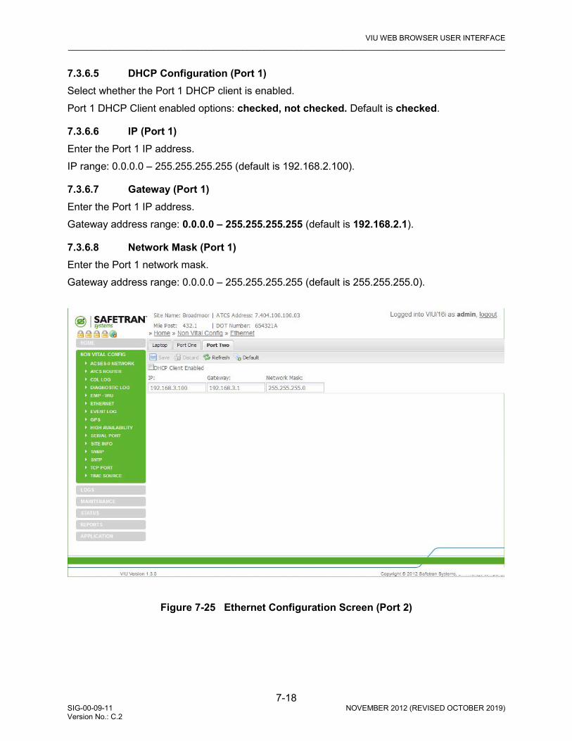
VIU WEB BROWSER USER INTERFACE _________________________________________________________________________________________________________
7-18 SIG-00-09-11 NOVEMBER 2012 (REVISED OCTOBER 2019) Version No.: C.2
7.3.6.5 DHCP Configuration (Port 1) Select whether the Port 1 DHCP client is enabled. Port 1 DHCP Client enabled options: checked, not checked. Default is checked.
7.3.6.6 IP (Port 1) Enter the Port 1 IP address. IP range: 0.0.0.0 – 255.255.255.255 (default is 192.168.2.100).
7.3.6.7 Gateway (Port 1) Enter the Port 1 IP address. Gateway address range: 0.0.0.0 – 255.255.255.255 (default is 192.168.2.1).
7.3.6.8 Network Mask (Port 1) Enter the Port 1 network mask. Gateway address range: 0.0.0.0 – 255.255.255.255 (default is 255.255.255.0).
Figure 7-25 Ethernet Configuration Screen (Port 2)
VIU WEB BROWSER USER INTERFACE _________________________________________________________________________________________________________
7-19 SIG-00-09-11 NOVEMBER 2012 (REVISED OCTOBER 2019) Version No.: C.2
7.3.6.9 DHCP Configuration (Port 2) Select whether the Port 2 DHCP client is enabled. Port 2 DHCP Client enabled options: checked, not checked. Default is checked.
7.3.6.10 IP (port 2) Enter the Port 2 IP address. IP range: 0.0.0.0 – 255.255.255.255 (default is 192.168.3.100).
7.3.6.11 Gateway (Port 2) Enter the Port 2 IP address. Gateway address range: 0.0.0.0 – 255.255.255.255 (default is 192.168.3.1).
7.3.6.12 Network Mask (Port 2) Enter the Port 2 network mask. Gateway address range: 0.0.0.0 – 255.255.255.255 (default is 255.255.255.0). 7.3.7 Event Log Configuration The Event Log configuration screen is shown in Figure 7-26.
7.3.7.1 Server IP When one or more VIUs are operating on a network, each VIU can be configured to forward all events over the network to a “consolidated logger”. The logger will maintain all of the events for every reporting VIU. The logger can be another VIU. To configure each VIU to send the Event Log entries to the logger, enter the IP address of the logger unit in the Server IP dialog box. Server IP: valid IP address (default = 0.0.0.0).

VIU WEB BROWSER USER INTERFACE _________________________________________________________________________________________________________
7-20 SIG-00-09-11 NOVEMBER 2012 (REVISED OCTOBER 2019) Version No.: C.2
Figure 7-26 Event Log Configuration Screen 7.3.8 GPS Configuration Use this screen to set parameters for either the internal GPS receiver or an external GPS receiver (Figure 7-27).
Figure 7-27 GPS Configuration Screen
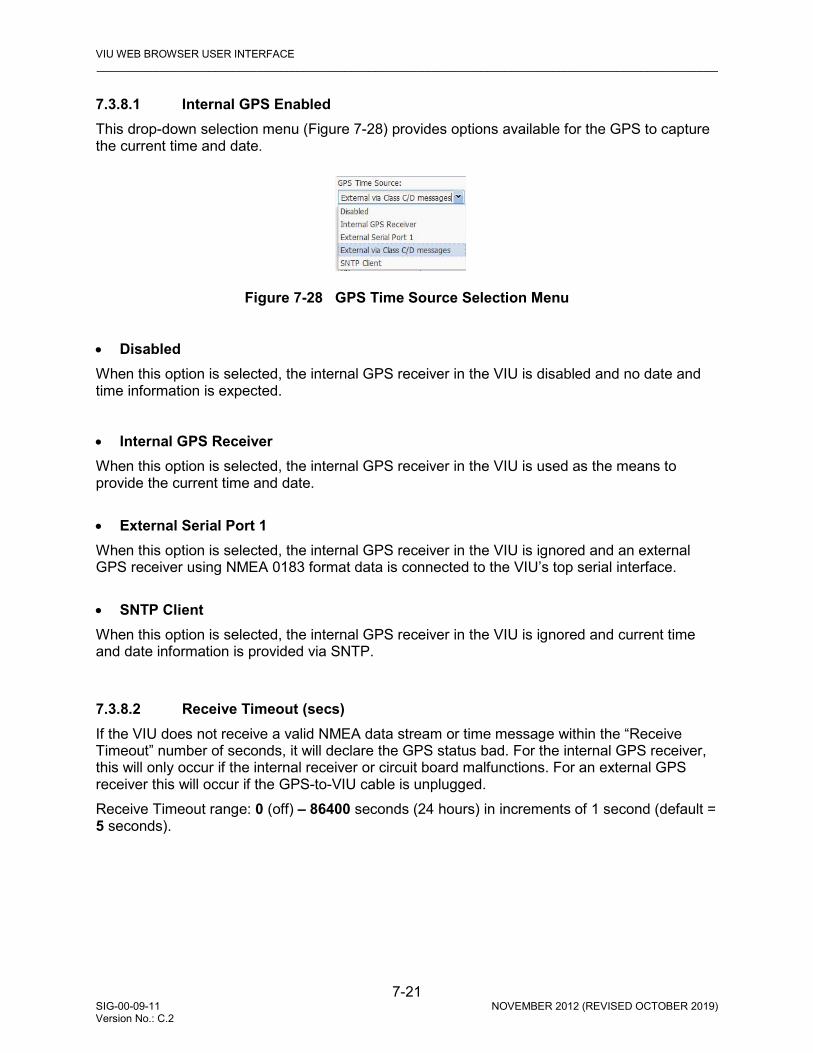
VIU WEB BROWSER USER INTERFACE _________________________________________________________________________________________________________
7-21 SIG-00-09-11 NOVEMBER 2012 (REVISED OCTOBER 2019) Version No.: C.2
7.3.8.1 Internal GPS Enabled This drop-down selection menu (Figure 7-28) provides options available for the GPS to capture the current time and date.
Figure 7-28 GPS Time Source Selection Menu
• Disabled When this option is selected, the internal GPS receiver in the VIU is disabled and no date and time information is expected.
• Internal GPS Receiver When this option is selected, the internal GPS receiver in the VIU is used as the means to provide the current time and date. • External Serial Port 1 When this option is selected, the internal GPS receiver in the VIU is ignored and an external GPS receiver using NMEA 0183 format data is connected to the VIU’s top serial interface. • SNTP Client When this option is selected, the internal GPS receiver in the VIU is ignored and current time and date information is provided via SNTP.
7.3.8.2 Receive Timeout (secs) If the VIU does not receive a valid NMEA data stream or time message within the “Receive Timeout” number of seconds, it will declare the GPS status bad. For the internal GPS receiver, this will only occur if the internal receiver or circuit board malfunctions. For an external GPS receiver this will occur if the GPS-to-VIU cable is unplugged. Receive Timeout range: 0 (off) – 86400 seconds (24 hours) in increments of 1 second (default = 5 seconds).

VIU WEB BROWSER USER INTERFACE _________________________________________________________________________________________________________
7-22 SIG-00-09-11 NOVEMBER 2012 (REVISED OCTOBER 2019) Version No.: C.2
7.3.8.3 Time Message Deviation (secs) If the Time/date received in the GPS NMEA data stream differs from the internal VIU clock by an amount equal to or greater than the Time Difference setting in seconds, the VIU will set its internal clock to the time/date in the GPS data. Otherwise, the VIU will not adjust its clock. Time Difference range: 0 – 3 seconds (default = 1 second).
7.3.8.4 Consolidated Time Server (checkbox) When this box is checked, the VIU becomes a Consolidated Time Server. If the VIU has a GPS time source – either its internal GPS receiver, an external GPS receiver, or a time source via Class C/D Ethernet -- the VIU will issue time and date information via Ethernet to all other VIUs once every hour. This allows VIUs which are co-located at a site to require only one Internal GPS Receiver or one externally mounted GPS antenna, provided the co-located VIUs are connected via the same Ethernet subnet. One VIU may be configured to be Consolidated Time Server to all other VIUs, provided the other VIUs do not already have an active GPS source for time and date. If a VIU is configured to be a Consolidated Time Source and has an active GPS receiver (either internal, external, or via Ethernet) the VIU will ignore time and date messages sent by any other VIUs that are configured as Consolidated Time Sources.
7.3.8.5 Max Time Change Within Minutes (min) This is the number of minutes that the VIU keeps Time Update records for. If it is set to 60 minutes, the VIU keeps track of all Time Updates for the past 60 minutes. If the total accumulated drift of time within those 60 minutes exceeds a configurable number of seconds, the VIU disallows the sending of Wayside Status Messages to the Application Gateway and the VIU starts a time resynchronization process. Time Update records that are older than 60 minutes get discarded so that at any one moment in time, the VIU has a record of only the latest 60 minutes of Time Update information in its RAM. Time Difference range: 1 – 120 minutes (default = 60 minutes).
7.3.8.6 Max Secs Time Change (sec) This is the maximum number of permitted accumulated seconds of time drift in the above “X” minute window set in the parameter above. When it is set to 6, if time drift accumulates in excess of 6 seconds over the past 60 minutes, the VIU will disallow Wayside Status Messages being sent to the Application Gateway and the VIU will perform its time resynchronization process. Time Difference range: 1 – 20 seconds (default = 3 seconds).

VIU WEB BROWSER USER INTERFACE _________________________________________________________________________________________________________
7-23 SIG-00-09-11 NOVEMBER 2012 (REVISED OCTOBER 2019) Version No.: C.2
7.3.8.7 Ignored Time Difference (sec) This value is used to determine whether a Time Update from the GPS Receiver should be ignored or not. If the VIU gets a Time Update that exceeds or equals this value, if it is the first time the VIU has received a Time Update the Time Update is accepted however if the VIU has been getting Time Updates and suddenly receives a Time Update that equals or exceeds this value, it may be ignored. If the *next* Time Update also exceeds this configuration value, the Time Update will be accepted because back-to-back values are considered legitimate. Time Difference range: 1 – 10 seconds (default = 3 seconds).
7.3.8.8 Time Msgs Before Sending WSM (sec) The VIU must receive a certain number of Time Updates before it is allowed to send Wayside Status Messages to the Application Gateway. If this value is set to 5, the VIU must receive 5 consecutive Time Updates messages which were consistent and did not result in the VIU’s system time being updated. (We ignore 1 second of jitter because our clock’s resolution is 1 second.) Time Difference range: 1 – 10 seconds (default = 5 seconds).
7.3.8.9 LRM Maximum Seconds Time Difference (sec) The VIU will log an event and may send an alarm if a LRM is received whose time stamp is forward of the WIU’s internal clock by an amount greater than the LRM Maximum Seconds Time Difference configuration value. Time Difference range: 0 – 20 seconds (default = 3 seconds).
7.3.8.10 No Time Sync Msg (min) The VIU will log an event and may send an alarm if a Time sync message is not received after power on or reboot after No Time Sync Message default 6 minutes. Time Difference range: 1-6 minutes (default = 6 minutes).

VIU WEB BROWSER USER INTERFACE _________________________________________________________________________________________________________
7-24 SIG-00-09-11 NOVEMBER 2012 (REVISED OCTOBER 2019) Version No.: C.2
7.3.9 High Availability (Connection 1 – Connection 12) Enable using check box. If enabled, for each alternate connection specify the IP address, TCP port number, Idle Timeout enabled, and if so, the Idle Timeout Seconds.
Figure 7-29 High Availability (Enabled) Configuration Menu
7.3.10 Serial Port Configuration The Serial Port configuration screen allows port settings to be made for the two serial ports on the VIU. These include the Laptop serial port on the front panel and Serial Port One on top of the unit. A separate tab is provided on this screen for each port (see Figure 7-30 {Laptop Port} and Figure 7-31 {Port 1}).
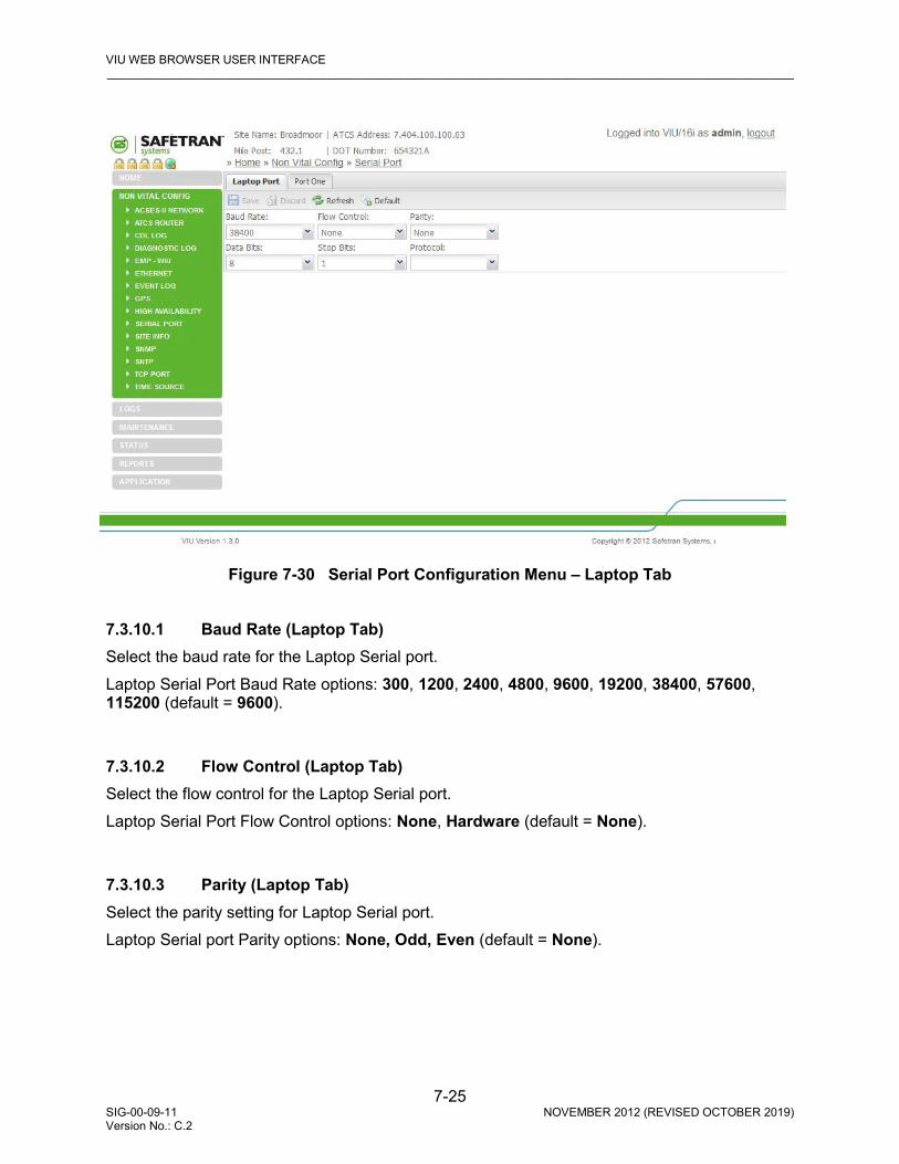
VIU WEB BROWSER USER INTERFACE _________________________________________________________________________________________________________
7-25 SIG-00-09-11 NOVEMBER 2012 (REVISED OCTOBER 2019) Version No.: C.2
Figure 7-30 Serial Port Configuration Menu – Laptop Tab
7.3.10.1 Baud Rate (Laptop Tab) Select the baud rate for the Laptop Serial port. Laptop Serial Port Baud Rate options: 300, 1200, 2400, 4800, 9600, 19200, 38400, 57600, 115200 (default = 9600).
7.3.10.2 Flow Control (Laptop Tab) Select the flow control for the Laptop Serial port. Laptop Serial Port Flow Control options: None, Hardware (default = None).
7.3.10.3 Parity (Laptop Tab) Select the parity setting for Laptop Serial port. Laptop Serial port Parity options: None, Odd, Even (default = None).

VIU WEB BROWSER USER INTERFACE _________________________________________________________________________________________________________
7-26 SIG-00-09-11 NOVEMBER 2012 (REVISED OCTOBER 2019) Version No.: C.2
7.3.10.4 Data Bits (Laptop Tab) Select the data bit setting for Laptop Serial port. Laptop Serial port Data Bit options: 7, 8 (default = 8).
7.3.10.5 Stop Bits (Laptop Tab) Select the stop bit setting for Laptop Serial port. Laptop Serial port Stop Bit options: 1, 2 (default = 1).
7.3.10.6 Protocol (Laptop Tab) Select the Protocol setting for Laptop Serial port. Laptop Serial port Protocol options: User, NMEA, ACSES (default = User).
Figure 7-31 Serial Port Configuration Menu – Port 1 Tab
VIU WEB BROWSER USER INTERFACE _________________________________________________________________________________________________________
7-27 SIG-00-09-11 NOVEMBER 2012 (REVISED OCTOBER 2019) Version No.: C.2
7.3.10.7 Baud Rate (Port One Tab) Select the baud rate for Serial Port One. Serial Port One Baud Rate options: 300, 1200, 2400, 4800, 9600, 19200, 38400, 57600, 115200 (default = 4800).
7.3.10.8 Flow Control (Port One Tab) Select the flow control for the Serial Port One. Serial Port One Flow Control options: None, Hardware (default = None)
7.3.10.9 Parity (Port One Tab) Select the parity setting for Serial Port One. Serial Port One parity options: None, Even, Odd (default = None).
7.3.10.10 Data Bits (Port One Tab) Select the data bit setting for Serial Port One. Serial Port One Data Bit options: 7, 8 (default = 8).
7.3.10.11 Stop Bits (Port One Tab) Select the stop bit setting for Serial Port One. Serial Port One Stop Bit options: 1, 2 (default = 1).
7.3.10.12 Protocol (Port One Tab) Select the protocol setting for Serial Port One. Serial Port One protocol options: User, NMEA, ACSES (default = User). 7.3.11 Site Info Configuration The Site Info screen (Figure 7-32) provides fields for entering a site name, the mile post number and DOT number for the VIU wayside location. It also allows selection of the local time zone. This screen contains two vital parameters that can only be changed after selecting the Edit Mode (Figure 7-33). When finished with Edit Mode, the Vital Core must be rebooted to remove the VIU from the Edit Mode (). This reboots the Vital Core only, and not the entire VIU.
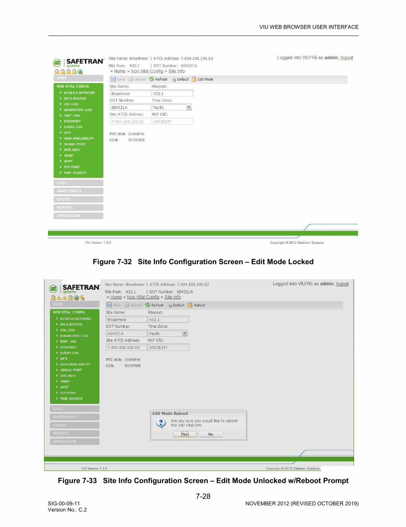
VIU WEB BROWSER USER INTERFACE _________________________________________________________________________________________________________
7-28 SIG-00-09-11 NOVEMBER 2012 (REVISED OCTOBER 2019) Version No.: C.2
Figure 7-32 Site Info Configuration Screen – Edit Mode Locked
Figure 7-33 Site Info Configuration Screen – Edit Mode Unlocked w/Reboot Prompt
VIU WEB BROWSER USER INTERFACE _________________________________________________________________________________________________________
7-29 SIG-00-09-11 NOVEMBER 2012 (REVISED OCTOBER 2019) Version No.: C.2
7.3.11.1 Site Name Enter a name for the VIU location. The VIU will also report his string in the sysName variable via SNMP. Site Name range: Up to 20 characters (default is Safetran Systems).
7.3.11.2 Milepost Enter the milepost number at the VIU location. The VIU will also report his string in the sysLocation variable via SNMP. Milepost range: Up to 10 characters (default is 000.0).
7.3.11.3 DOT Number Enter the DOT Number for the VIU location. DOT Number range: Up to 7 characters (default is 000000A).
7.3.11.4 Time Zone Enter the time zone that the VIU site is located in. Time Zone options: GMT, Eastern, Central, Mountain, Pacific, Alaska, Atlantic, Arizona, Newfoundland, Aus Western, Aus Central, Aus Central (No DST), Aus Eastern, Aus Eastern (No DST) (default is Eastern).
WARNING
VERIFY THAT VIU-16I/-8I IS PROGRAMMED AS SPECIFIED BY THE RAILROAD’S OR AGENCY’S WITH THE CORRECT MCFCRC, UCN, ATCS SITE IDENTIFICATION NUMBER (SIN). FAILURE TO DO SO MAY LEAD TO INCORRECT OR UNSAFE INDICATIONS ON THE VIU-16I/-8I UNIT.
7.3.11.5 Site ATCS Address Site ATCS Address is one of the vital parameters. Edit Mode must be selected before a change can be made. When done, the correct UCN must be entered and the Vital Core rebooted to remove the VIU from Edit Mode (this reboots the Vital Core only and not the entire VIU). Site ATCS Address range: 7.000.000.000.00 – 7.999.999.999.99 (default is 7.620.100.100.03).
7.3.11.6 MCF CRC MCF CRC is one of the vital parameters. Edit Mode must be selected before a change can be made and the vital CPU must be rebooted in order to get out of Edit Mode. This reboots the vital CPU only and not the entire VIU. The MCF CRC is determined by the MCF contents.
7.3.11.7 Additional Data The Site Info screen also reports the following values: PTC UCN, and CCN. These values are only reported here, and cannot be edited on this screen.
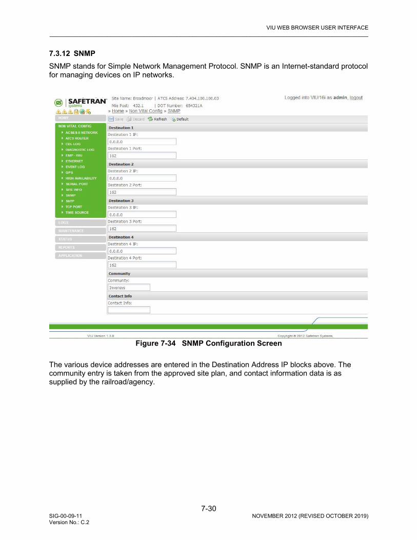
VIU WEB BROWSER USER INTERFACE _________________________________________________________________________________________________________
7-30 SIG-00-09-11 NOVEMBER 2012 (REVISED OCTOBER 2019) Version No.: C.2
7.3.12 SNMP SNMP stands for Simple Network Management Protocol. SNMP is an Internet-standard protocol for managing devices on IP networks.
Figure 7-34 SNMP Configuration Screen The various device addresses are entered in the Destination Address IP blocks above. The community entry is taken from the approved site plan, and contact information data is as supplied by the railroad/agency.
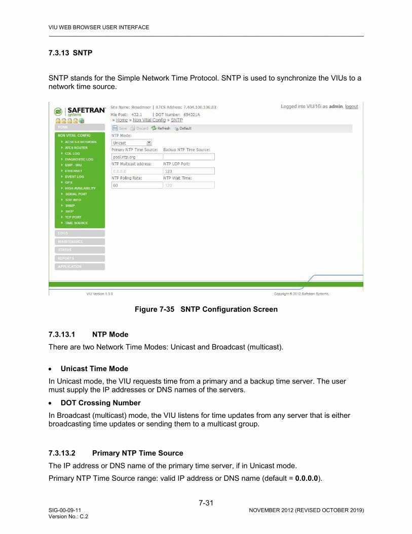
VIU WEB BROWSER USER INTERFACE _________________________________________________________________________________________________________
7-31 SIG-00-09-11 NOVEMBER 2012 (REVISED OCTOBER 2019) Version No.: C.2
7.3.13 SNTP SNTP stands for the Simple Network Time Protocol. SNTP is used to synchronize the VIUs to a network time source.
Figure 7-35 SNTP Configuration Screen
7.3.13.1 NTP Mode There are two Network Time Modes: Unicast and Broadcast (multicast). • Unicast Time Mode In Unicast mode, the VIU requests time from a primary and a backup time server. The user must supply the IP addresses or DNS names of the servers.
• DOT Crossing Number In Broadcast (multicast) mode, the VIU listens for time updates from any server that is either broadcasting time updates or sending them to a multicast group.
7.3.13.2 Primary NTP Time Source The IP address or DNS name of the primary time server, if in Unicast mode. Primary NTP Time Source range: valid IP address or DNS name (default = 0.0.0.0).
VIU WEB BROWSER USER INTERFACE _________________________________________________________________________________________________________
7-32 SIG-00-09-11 NOVEMBER 2012 (REVISED OCTOBER 2019) Version No.: C.2
7.3.13.3 Backup NTP Time Source The IP address or DNS name of the backup time server, if in Unicast mode. Backup NTP Time Source range: valid IP address or DNS name (default = 0.0.0.0).
7.3.13.4 NTP Multicast Address When mode is Broadcast/Multicast and the user wants the VIU to join a specific multicast group for SNTP time updates, that multicast group address is entered here. This address is optional. The VIU will still receive broadcasted time updates if this field is set to 0.0.0.0. NTP Multicast Address range: valid IP address (default = 0.0.0.0).
7.3.13.5 NTP UDP Port The UDP port number to use for SNTP messages. NTP UDP Port range: 0 – 65535 (default = 123).
7.3.13.6 NTP Polling Rate The NTP Polling Rate determines how often the VIU requests updates from the Time Server, measured in seconds, when in Unicast mode. NTP Polling Rate range: 0 – 65535 seconds (default = 60 seconds).
7.3.13.7 NTP Wait Time The time period in which the VIU expects to receive a time update when in Broadcast/Multicast mode. If no time update is received, the time source is considered offline. NTP Wait Time range: 0 – 65535 seconds (default = 120 seconds). 7.3.14 TCP Port Configuration The TCP Port Configuration screen is shown in Figure 7-36.
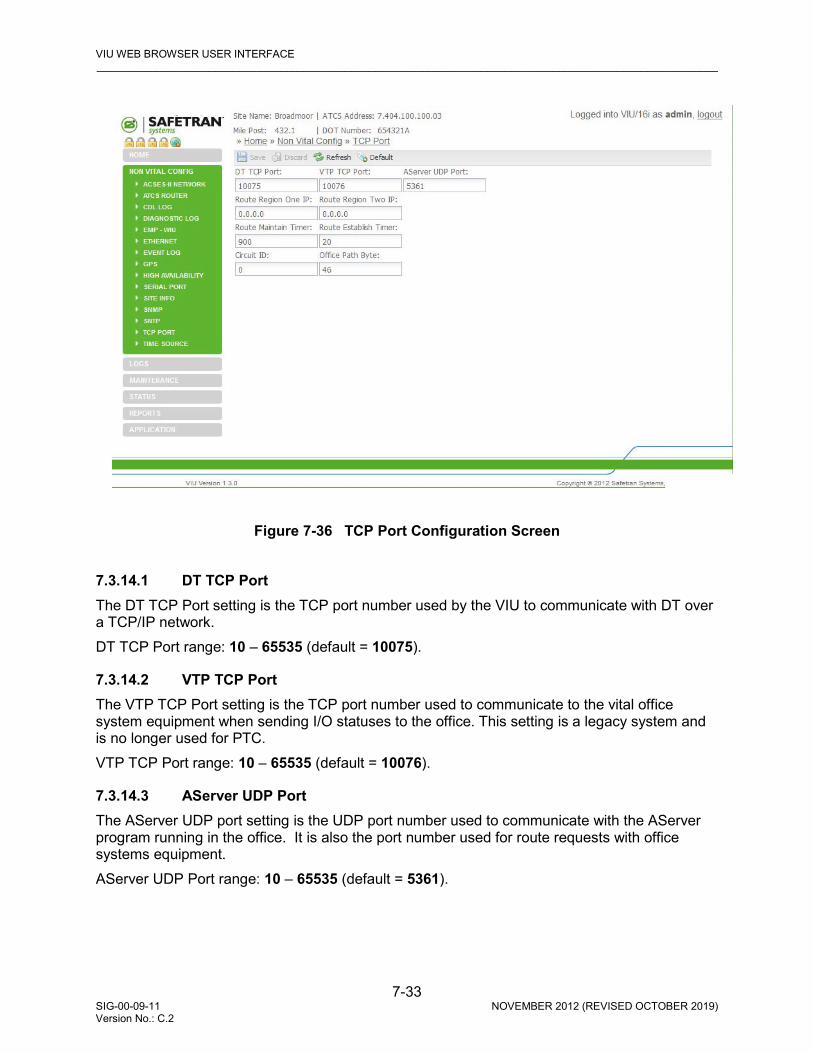
VIU WEB BROWSER USER INTERFACE _________________________________________________________________________________________________________
7-33 SIG-00-09-11 NOVEMBER 2012 (REVISED OCTOBER 2019) Version No.: C.2
Figure 7-36 TCP Port Configuration Screen
7.3.14.1 DT TCP Port The DT TCP Port setting is the TCP port number used by the VIU to communicate with DT over a TCP/IP network. DT TCP Port range: 10 – 65535 (default = 10075).
7.3.14.2 VTP TCP Port The VTP TCP Port setting is the TCP port number used to communicate to the vital office system equipment when sending I/O statuses to the office. This setting is a legacy system and is no longer used for PTC. VTP TCP Port range: 10 – 65535 (default = 10076).
7.3.14.3 AServer UDP Port The AServer UDP port setting is the UDP port number used to communicate with the AServer program running in the office. It is also the port number used for route requests with office systems equipment. AServer UDP Port range: 10 – 65535 (default = 5361).

VIU WEB BROWSER USER INTERFACE _________________________________________________________________________________________________________
7-34 SIG-00-09-11 NOVEMBER 2012 (REVISED OCTOBER 2019) Version No.: C.2
7.3.14.4 Route Region One IP Enter the IP address for TCP Route Region One. Route Region One IP range: valid IP address (default = 0.0.0.0).
7.3.14.5 Route Region Two IP Enter the IP address for TCP Route Region Two. Route Region Two IP range: valid IP address (default = 0.0.0.0).
7.3.14.6 Route Maintain Timer Once a route is established to the office, the VIU will request routes again after this timer expires and the VIU has not received a route update or a message from the office. If no route updates or messages are received, the route is deleted. Route Maintain Timer range: 10 – 65535 (default = 900).
7.3.14.7 Route Establish Timer When there is no route present for the office, the VIU will request routes at an interval set in this parameter. Route Establish Timer range: 10 – 65535 (default = 20 seconds).
7.3.14.8 Circuit ID This is a unique identifier required by the office system used in routing messages to the VIU. Circuit ID range: 10 – 65535 (default = 0).
7.3.14.9 Office Path Byte The "Office Path Byte" is included in messages sent to the office system and is used by office system equipment when routing messages sent by the VIU. Office Path Byte range: 0 – 255 (default = 46).

VIU WEB BROWSER USER INTERFACE _________________________________________________________________________________________________________
7-35 SIG-00-09-11 NOVEMBER 2012 (REVISED OCTOBER 2019) Version No.: C.2
7.3.15 Time Source Select the box to enable up to six separate time sources in order of priority.
Figure 7-37 Time Source (Enabled) Configuration Window
7.4 VIEWING LOGS
The Web browser user interface provides access to two logs maintained by the VIU: the Diagnostic Log (Figure 7-38) and the Event Log ().
Figure 7-38 Logs Screen

VIU WEB BROWSER USER INTERFACE _________________________________________________________________________________________________________
7-36 SIG-00-09-11 NOVEMBER 2012 (REVISED OCTOBER 2019) Version No.: C.2
To access these logs, select Logs from the menu bar in the upper left corner of the screen to display the Logs screen. On the Logs screen, select the desired log from the Logs menu at the left side of the screen. 7.4.1 Diagnostic Log The Diagnostic Log first displays in the basic view (Figure 7-39). Buttons provided at the top of the log display allow the user to view the first event in the log, the last event in the log and to progress through the log one page at a time using Next and Previous buttons. A button is also provided to download the entire log contents to a PC.
Figure 7-39 Diagnostic Log – Basic View
When the Download All Events button is selected, a prompt queries to open or save the log file (Figure 7-40).
Figure 7-40 File Download Prompt

VIU WEB BROWSER USER INTERFACE _________________________________________________________________________________________________________
7-37 SIG-00-09-11 NOVEMBER 2012 (REVISED OCTOBER 2019) Version No.: C.2
If Save is selected and the user is operating WIN7 or newer, the file is automatically saved to the Downloads file. If using an earlier version of Windows, the user is prompted for a location and file name for the saved file.
Figure 7-41 File Save Screen
If Open is selected, the file contents are displayed in a text editor such as Microsoft® Notepad.
Figure 7-42 File Opened in Notepad

VIU WEB BROWSER USER INTERFACE _________________________________________________________________________________________________________
7-38 SIG-00-09-11 NOVEMBER 2012 (REVISED OCTOBER 2019) Version No.: C.2
To view the Diagnostic Log in the Advanced view, select Advanced from the drop down menu to the left of the First button (Figure 7-43).
Figure 7-43 Log View Drop Down Menu The Advanced view (Figure 7-44) provides the same navigation buttons as the Basic view. However, below the buttons are several data entry fields that allow the log to be searched within date and time parameters.
Figure 7-44 Diagnostic Log – Advanced View Dates can be entered directly in the date fields or the calendar icon at the right end of the date field or can be selected to display a calendar. The time fields are similar except that a drop down list provides a list of times or the time can be entered directly in the field.
Figure 7-45 Diagnostic Log - Advanced Settings

VIU WEB BROWSER USER INTERFACE _________________________________________________________________________________________________________
7-39 SIG-00-09-11 NOVEMBER 2012 (REVISED OCTOBER 2019) Version No.: C.2
The final selection from the view drop down list is Trace Events (Figure 7-46). Select this view to see events as they are logged into the Diagnostic Log. This screen refreshes every 5 seconds so there is a short delay between the time the event occurs and it is displayed.
Figure 7-46 Diagnostic Log – Trace Events View

VIU WEB BROWSER USER INTERFACE _________________________________________________________________________________________________________
7-40 SIG-00-09-11 NOVEMBER 2012 (REVISED OCTOBER 2019) Version No.: C.2
7.4.2 Event Log The Event Log screen provides structure, options and features similar to those described in paragraph 7.4.1 for the Diagnostic Log.
Figure 7-47 Event Log Screen
7.4.3 CDL Log The CDL Log provides the planner with the option to review and debug the CDL file.
Figure 7-48 CDL File Screen

VIU WEB BROWSER USER INTERFACE _________________________________________________________________________________________________________
7-41 SIG-00-09-11 NOVEMBER 2012 (REVISED OCTOBER 2019) Version No.: C.2
7.5 MAINTENANCE
The Web browser user interface provides access to the maintenance functions that allows the VIU to test handling of Class D messages and to change the date and time to be set if a GPS receiver is not present (Figure 7-49). To access the date/time set function, select Maintenance from the menu bar in the upper left corner of the screen to display the Maintenance screen.
Figure 7-49 Maintenance Screen 7.5.1 Class D Tests The Web browser U/I configures the Test Server data that handles Class D messages. Test messages are sent by selecting the Test button on the menu bar.
7.5.1.1 Test Server IP Address Enter the Test Server IP address. Laptop IP range: 0.0.0.0 – 255.255.255.255 (default is 192.168.1.110).
7.5.1.2 Test Server Port Number This entry is the test server port number used for the exchange of Class D messages. The UDP port number range: 0 - 65535 (default = 12100).
7.5.1.3 Test Frame Count The number of test messages to be sent during each test iteration. The test frame count range: 1 - 65535 (default = 10).
7.5.1.4 Delay Between Test Frames (msec) This entry is the delay period measured in milliseconds between each test frame being transmitted. The UDP port number range: 100 - 65535 (default = 1000).
7.5.1.5 ITC Class D Starting Comm ID This entry is the ITC Class ID starting comm identification number.

VIU WEB BROWSER USER INTERFACE _________________________________________________________________________________________________________
7-42 SIG-00-09-11 NOVEMBER 2012 (REVISED OCTOBER 2019) Version No.: C.2
The ITC Class ID Starting Comm ID range: 0 - 9 (default = 1).
Figure 7-50 Class D Tests Screen
7.5.2 System Time On the Maintenance screen, select System Time from the Maintenance menu at the left side of the screen. The System Time screen provides two data fields and three time set buttons (Figure 7-51). These are described in the following paragraphs.
Figure 7-51 System Time Screen
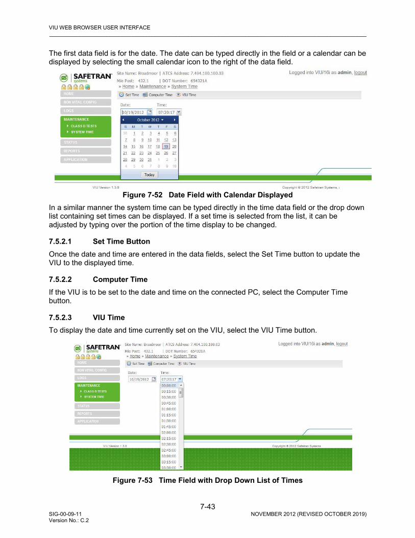
VIU WEB BROWSER USER INTERFACE _________________________________________________________________________________________________________
7-43 SIG-00-09-11 NOVEMBER 2012 (REVISED OCTOBER 2019) Version No.: C.2
The first data field is for the date. The date can be typed directly in the field or a calendar can be displayed by selecting the small calendar icon to the right of the data field.
Figure 7-52 Date Field with Calendar Displayed In a similar manner the system time can be typed directly in the time data field or the drop down list containing set times can be displayed. If a set time is selected from the list, it can be adjusted by typing over the portion of the time display to be changed.
7.5.2.1 Set Time Button Once the date and time are entered in the data fields, select the Set Time button to update the VIU to the displayed time.
7.5.2.2 Computer Time If the VIU is to be set to the date and time on the connected PC, select the Computer Time button.
7.5.2.3 VIU Time To display the date and time currently set on the VIU, select the VIU Time button.
Figure 7-53 Time Field with Drop Down List of Times
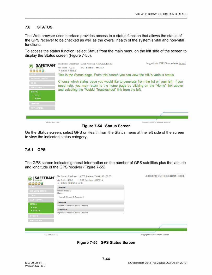
VIU WEB BROWSER USER INTERFACE _________________________________________________________________________________________________________
7-44 SIG-00-09-11 NOVEMBER 2012 (REVISED OCTOBER 2019) Version No.: C.2
7.6 STATUS
The Web browser user interface provides access to a status function that allows the status of the GPS receiver to be checked as well as the overall health of the system’s vital and non-vital functions. To access the status function, select Status from the main menu on the left side of the screen to display the Status screen (Figure 7-55).
Figure 7-54 Status Screen On the Status screen, select GPS or Health from the Status menu at the left side of the screen to view the indicated status category. 7.6.1 GPS The GPS screen indicates general information on the number of GPS satellites plus the latitude and longitude of the GPS receiver (Figure 7-55).
Figure 7-55 GPS Status Screen

VIU WEB BROWSER USER INTERFACE _________________________________________________________________________________________________________
7-45 SIG-00-09-11 NOVEMBER 2012 (REVISED OCTOBER 2019) Version No.: C.2
7.6.2 Health The Health screen shows the current health status for the main vital and non-vital functions (Figure 7-56). On the vital side are the following:
• Vital Core State • Slave Session • Vital Session • Edit Mode On the non-vital side are the following:
• Non-Vital Core Health • GPS Health
Figure 7-56 Health Status Screen
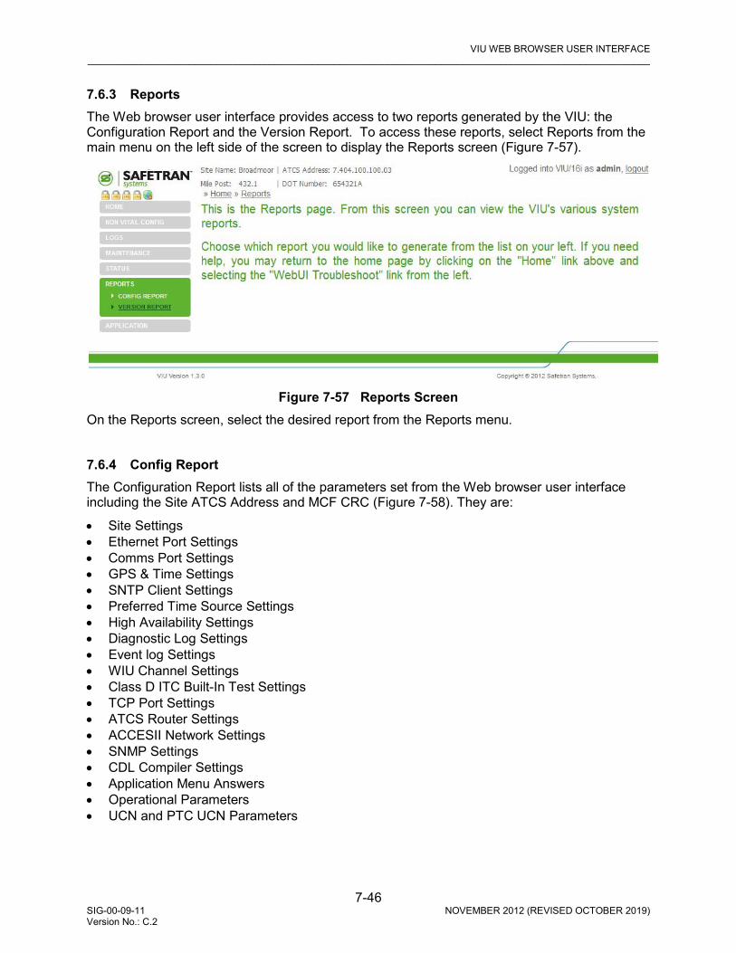
VIU WEB BROWSER USER INTERFACE _________________________________________________________________________________________________________
7-46 SIG-00-09-11 NOVEMBER 2012 (REVISED OCTOBER 2019) Version No.: C.2
7.6.3 Reports The Web browser user interface provides access to two reports generated by the VIU: the Configuration Report and the Version Report. To access these reports, select Reports from the main menu on the left side of the screen to display the Reports screen (Figure 7-57).
Figure 7-57 Reports Screen On the Reports screen, select the desired report from the Reports menu. 7.6.4 Config Report The Configuration Report lists all of the parameters set from the Web browser user interface including the Site ATCS Address and MCF CRC (Figure 7-58). They are:
• Site Settings • Ethernet Port Settings • Comms Port Settings • GPS & Time Settings • SNTP Client Settings • Preferred Time Source Settings • High Availability Settings • Diagnostic Log Settings • Event log Settings • WIU Channel Settings • Class D ITC Built-In Test Settings • TCP Port Settings • ATCS Router Settings • ACCESII Network Settings • SNMP Settings • CDL Compiler Settings • Application Menu Answers • Operational Parameters • UCN and PTC UCN Parameters

VIU WEB BROWSER USER INTERFACE _________________________________________________________________________________________________________
7-47 SIG-00-09-11 NOVEMBER 2012 (REVISED OCTOBER 2019) Version No.: C.2
Figure 7-58 Typical Configuration Report Use the scroll bar at the right edge of the screen to view the entire report. The Download button at the top of the Reports screen allows the user to save the report to a PC. When the Download button is selected, the user is prompted to open or save the log file.
Figure 7-59 Report Download Prompt

VIU WEB BROWSER USER INTERFACE _________________________________________________________________________________________________________
7-48 SIG-00-09-11 NOVEMBER 2012 (REVISED OCTOBER 2019) Version No.: C.2
If Save is selected the user is prompted for a location and file name for the saved report.
Figure 7-60 Report Save Screen
If Open is selected, the report contents are displayed in a text editor such as Microsoft ® Notepad. The Refresh button on the report display updates the display when pressed. 7.6.5 Version Report The Version Report identifies the VIU site and then lists the current versions of the VIU firmware, software and hardware (Figure 7-61). Use the scroll bar at the right edge of the screen to view the entire report.
Figure 7-61 Typical Version Report Screen
All other functions associated with the Version Reports screen are identical to those described above for the Configuration Reports screen.
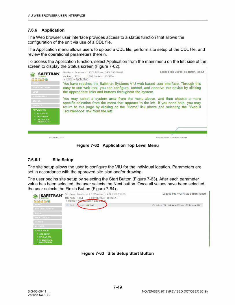
VIU WEB BROWSER USER INTERFACE _________________________________________________________________________________________________________
7-49 SIG-00-09-11 NOVEMBER 2012 (REVISED OCTOBER 2019) Version No.: C.2
7.6.6 Application The Web browser user interface provides access to a status function that allows the configuration of the unit via use of a CDL file. The Application menu allows users to upload a CDL file, perform site setup of the CDL file, and review the operational parameters therein. To access the Application function, select Application from the main menu on the left side of the screen to display the Status screen (Figure 7-62).
Figure 7-62 Application Top Level Menu
7.6.6.1 Site Setup The site setup allows the user to configure the VIU for the individual location. Parameters are set in accordance with the approved site plan and/or drawing. The user begins site setup by selecting the Start Button (Figure 7-63). After each parameter value has been selected, the user selects the Next button. Once all values have been selected, the user selects the Finish Button (Figure 7-64).
Figure 7-63 Site Setup Start Button

VIU WEB BROWSER USER INTERFACE _________________________________________________________________________________________________________
7-50 SIG-00-09-11 NOVEMBER 2012 (REVISED OCTOBER 2019) Version No.: C.2
By selecting the appropriate button on the right side of the same bar where the Start Button is found, the user may Upload the CDL, View the CDL Log in a small text window, or Remove the CDL from the VIU.
Figure 7-64 Site Setup Menu (Setup Complete by Selecting Finish)
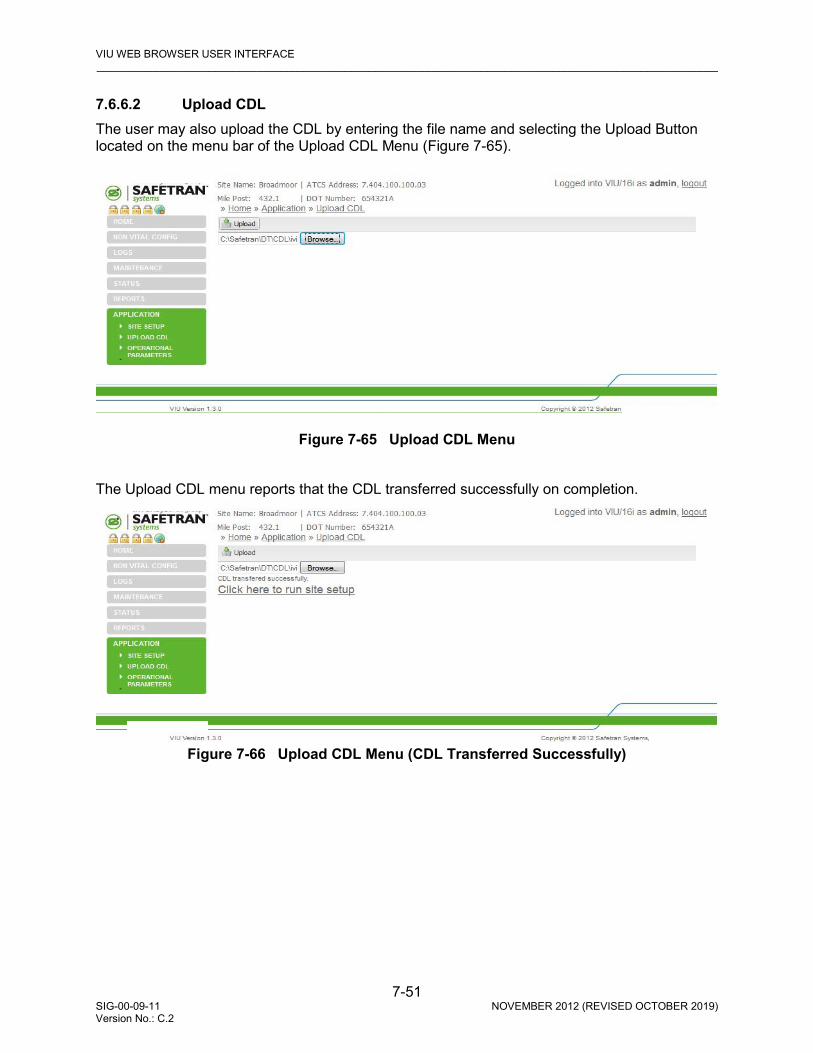
VIU WEB BROWSER USER INTERFACE _________________________________________________________________________________________________________
7-51 SIG-00-09-11 NOVEMBER 2012 (REVISED OCTOBER 2019) Version No.: C.2
7.6.6.2 Upload CDL The user may also upload the CDL by entering the file name and selecting the Upload Button located on the menu bar of the Upload CDL Menu (Figure 7-65).
Figure 7-65 Upload CDL Menu
The Upload CDL menu reports that the CDL transferred successfully on completion.
Figure 7-66 Upload CDL Menu (CDL Transferred Successfully)

VIU WEB BROWSER USER INTERFACE _________________________________________________________________________________________________________
7-52 SIG-00-09-11 NOVEMBER 2012 (REVISED OCTOBER 2019) Version No.: C.2
7.6.6.3 Operational Parameters The Operational Parameters ( ) allows the user to set the heartbeat interval (measured in seconds), the Low Battery Threshold (measured in mV), the Low Battery Alarm delay (measured in seconds), and the Low Battery Alarm Clear delay (measured in seconds) per the approved site plan and/or drawing.
Figure 7-67 Operational Parameters

MAINTENANCE AND TROUBLESHOOTING _________________________________________________________________________________________________________
8-1 SIG-00-09-11 NOVEMBER 2012 (REVISED OCTOBER 2019) Version No.: C.2
SECTION 8 MAINTENANCE AND TROUBLESHOOTING
8.0 MAINTENANCE AND TROUBLESHOOTING
WARNING
THE USER MUST PROVIDE TIMELY MAINTENANCE UPON FAILURE OF THE VIU UNIT. FAILURE TO PROVIDE TIMELY MAINTENANCE MAY POTENTIALLY LEAD TO UNSAFE FUNCTIONING OF THE UNIT. THE USER MUST ENSURE THAT THE VIU SYSTEM APPLICATION LOGIC IS NOT TAMPERED WITH OR APPLIED INCORRECTLY. ANY UNAUTHORIZED ACTIVITY PERFORMED TO CHANGE THE APPLICATION LOGIC CAN LEAD TO UNSAFE FUNCTIONING OF THE UNIT.
8.1 MAINTENANCE
8.1.1 Battery Maintenance The VIU has no internal backup battery; therefore, no regular backup battery maintenance or replacement is required. 8.1.2 Uploading Software to the VIU from a USB Drive Occasionally, it may be necessary to load software changes/patches to the VIU. This process is accomplished using the USB port on the VIU front panel. The file structure on the USB drive must have the following format. The VIU will look in specific folders for each file type. Folder names and relationships are exact, file names (those listed within the parenthesis with e.g.,) are for example only. In the examples referred to in this section, the Archibald and Haven Railroad is placing a VIU unit into operation at the Broadmoor bungalow located at mile marker 432.1.
WARNING
THE USER MUST VERIFY THAT THE CORRECT VERSION OF SOFTWARE IS LOADED DURING INSTALLATION TESTING. THE USE OF AN INCORRECT VERSION OF SOFTWARE MAY POTENTIALLY LEAD TO UNSAFE FUNCTIONING THE UNIT.
NOTE
The application referred to within this chapter is specific to this example only. Other applications could or would have different connections.

MAINTENANCE AND TROUBLESHOOTING _________________________________________________________________________________________________________
8-2 SIG-00-09-11 NOVEMBER 2012 (REVISED OCTOBER 2019) Version No.: C.2
Safetran
VIU Application Vital MCF {VITAL MCF} (e.g., VIU_RR_LM001.mcf) Vital CDL (VITAL CDL) (e.g., VIU_CDL.cdl) Configuration Vital Configuration {VITAL CFG} (e.g., V-432.1-Broadmoor.bin) Non-Vital Configuration {N-V CFG} (e.g., NV-432.1-Broadmoor.bin) RC2 Key {RC2 KEY} (e.g., rc2key.bin) PTC Configuration XML {PTC CFG XML} (e.g., Broadmoor-WiuConfig.xml) Executive Master Executive {MSTR EXEC} (e.g., BIO_01_40.MEF) Slave Executive {SLV EXEC} (e.g., BPF01_10.MEF) Non-Vital Core Executive {N-V EXEC} (e.g., VIU_NVMEF_DEV.007.16.tgz)
Figure 8-1 Example USB Drive File Structure To upload software from the USB drive:
1. Insert a USB drive containing the new software in the USB port. 2. The VIU will initiate the USB interface function and display the first entry in the USB menu. 3. Use up () and down () arrow keys to scroll to the desired software upload function. 4. Use left () or right () arrow key to display YES. 5. Press Enter.
8.1.3 Downloading Event and Diagnostic Logs from the VIU to a USB Drive As a part of routine maintenance or to aid in diagnostics of system problems, all or part of the VIU Event Log, Diagnostic Log, Configuration and Version reports can be downloaded to the USB drive for easier viewing on a PC. To download reports to the USB drive:
1. Insert a USB drive in the USB port. 2. The VIU will initiate the USB interface function and display the first entry in the USB menu. 3. Use up () and down () arrow keys to scroll to the desired report download function. 4. Use left () or right () arrow key to display YES. 5. Press Enter.

MAINTENANCE AND TROUBLESHOOTING _________________________________________________________________________________________________________
8-3 SIG-00-09-11 NOVEMBER 2012 (REVISED OCTOBER 2019) Version No.: C.2
8.2 TROUBLESHOOTING
8.2.1 Status LEDs Table 8-1 VIU Status LED Indications
LED NOMENCLATURE FUNCTION
Power Green LED lights when power is applied to the VIU.
Health Yellow LED indicates VIU health as follows: Slow flash (0.5Hz) = VIU is healthy and communicating with internal CPU. Fast flash (2Hz) = VIU is unhealthy.
GPS
Yellow and green LEDs are associated with GPS connector on top of unit. LEDs indicate the following: Green on steady = looking for GPS satellite Green flashing = found satellite and generating timing pulse Green off = GPS failure or not used Yellow on steady = GPS health OK Yellow off = GPS health problem
ECD Show TX (green) & RX (red) activity between ECD located on the power connector and the internal CPU.
ETHERNET Port 1 Port 2
Yellow and green LEDs are associated with Ethernet ports 1 and 2 on top of unit. LEDs indicate the following: Yellow not lit = 10 Mbps link rate Yellow lit = 100 Mbps link rate Green flashing = message activity. NOTE: Port 2 indicators apply to either Ethernet Port 2 or ESSR only (Port 2), depending on which is in use. Both cannot be used simultaneously.
SERIAL TX RX
Show TX (green) & RX (red) activity on serial connector located on top of VIU.
INPUT STATUS 20 red LEDs. Indicate status of monitored vital inputs as determined by software.
USB
USB 2.0 interface activity indicators: Green on steady = USB drive is inserted and it is safe to remove the USB drive. Yellow flashing = file transfer in progress, do not remove USB drive. Red flashing = USB drive read or write error detected.
Several status LEDs are provided on the VIU. These LEDs can provide initial indication of system health and potential problems. Refer to Table 8-1 for indications provided by these LEDs.
MAINTENANCE AND TROUBLESHOOTING _________________________________________________________________________________________________________
8-4 SIG-00-09-11 NOVEMBER 2012 (REVISED OCTOBER 2019) Version No.: C.2
8.2.2 LED Activity at Power-Up LED activity at power-up is as follows: • First minute following power-up, the display reads VIU SYSTEM BOOTING PLEASE WAIT
and only the power LED is lit. • At approximately 1 minute, 30 seconds from power-up, all front panel LEDs light to test for
bad LEDs. • At approximately 2 minutes from power-up, the VIU settles into normal operation, the input
status LEDs show current input status and the health LED flashes at 0.5 Hz. 8.2.3 Possible System Problems Table 8-2 lists some possible VIU system problem conditions with causes and remedies.

MAINTENANCE AND TROUBLESHOOTING _________________________________________________________________________________________________________
8-5 SIG-00-09-11 NOVEMBER 2012 (REVISED OCTOBER 2019) Version No.: C.2
Table 8-2 Possible VIU System Problems
Problem Cause Remedy
Power LED does not light, VIU does not power up
Poor power cable connection
Check for correct power to B and N terminals on power connector.
Check for poor wire connections at power connector and battery.
Ensure power connector is firmly seated in the connector on the top of the VIU.
Insufficient power Verify that voltage level at B & N terminals of power connector > 8.5 volts.
Incorrect battery polarity Reverse B & N connections at power connector.
Health LED flashing at 2 Hz rate.
VIU unconfigured, internal communication failure, VIU unhealthy.
View status message on display (indicates if VIU is unconfigured, out of session, and health of master & slave vital I/O circuits). Verify that MCF CRC, UCN and SIN are
correct. Download and review Diagnostic Log for
problem indications. Try a reboot of the VIU. If none of the above
fixes the problem, replace The VIU. In systems with multiple VIUs, perform checks as above plus: Verify connections between main and
auxiliary VIUs. Verify that IP addresses and configuration in
general are correct.
No Ethernet communications, Ethernet status LEDs not lit.
Bad Ethernet cable Replace cable
Bad Ethernet port Try another port or replace VIU
Bad LAN connections Check all LAN connections
No serial port communications, Serial status LEDs not lit.
Bad serial cable Replace cable
Serial port not configured properly on connected device
Configure device properly
Bad connections Check all serial cable connections
VIU prompts user to insert USB drive when executive starts.
Failed or corrupted factory test results Return VIU to factory
USB drive not recognized. Unsupported device Use appropriate USB device
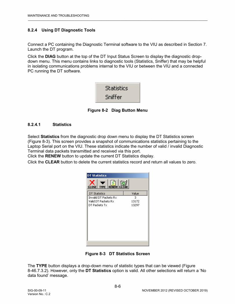
MAINTENANCE AND TROUBLESHOOTING _________________________________________________________________________________________________________
8-6 SIG-00-09-11 NOVEMBER 2012 (REVISED OCTOBER 2019) Version No.: C.2
8.2.4 Using DT Diagnostic Tools Connect a PC containing the Diagnostic Terminal software to the VIU as described in Section 7. Launch the DT program. Click the DIAG button at the top of the DT Input Status Screen to display the diagnostic drop-down menu. This menu contains links to diagnostic tools (Statistics, Sniffer) that may be helpful in isolating communications problems internal to the VIU or between the VIU and a connected PC running the DT software.
Figure 8-2 Diag Button Menu
8.2.4.1 Statistics Select Statistics from the diagnostic drop down menu to display the DT Statistics screen (Figure 8-3). This screen provides a snapshot of communications statistics pertaining to the Laptop Serial port on the VIU. These statistics indicate the number of valid / invalid Diagnostic Terminal data packets transmitted and received via this port. Click the RENEW button to update the current DT Statistics display. Click the CLEAR button to delete the current statistics record and return all values to zero.
Figure 8-3 DT Statistics Screen
The TYPE button displays a drop-down menu of statistic types that can be viewed (Figure 8-46.7.3.2). However, only the DT Statistics option is valid. All other selections will return a ‘No data found’ message.

MAINTENANCE AND TROUBLESHOOTING _________________________________________________________________________________________________________
8-7 SIG-00-09-11 NOVEMBER 2012 (REVISED OCTOBER 2019) Version No.: C.2
Click the CLOSE button to return to the Input Status Screen.
Figure 8-4 Statistics Type Drop-Down Menu
NOTE
These statistics are retained in RAM and are lost when the VIU is rebooted
8.2.4.2 Sniffer Select Sniffer from the diagnostic drop down menu to display the Sniffer screen (Figure 8-5). The Sniffer is provided as a diagnostic tool primarily for use by Siemens Mobility, Inc. Engineering personnel. The Sniffer monitors ATCS message activity between the VIU and the DT program and displays the message bytes for evaluation.
Figure 8-5 Sniffer Screen
MAINTENANCE AND TROUBLESHOOTING _________________________________________________________________________________________________________
8-8 SIG-00-09-11 NOVEMBER 2012 (REVISED OCTOBER 2019) Version No.: C.2
This is a dynamic display. As new message traffic occurs, it is added to the bottom of the display and the message list scrolls up screen. Click the STOP button to freeze the display so that currently displayed messages can be examined. The button label changes to START. Click the button again to continue monitoring messages as they occur. Use the scroll bar at the bottom of the screen to view the full length of the messages. Click the CLEAR button to remove all currently displayed messages from the screen. New messages will appear on the screen as they are sent or received. Click the SAVE button to save a snapshot of the record to a file or to create a real time recording of the messages to a file. Click the CLOSE button to return to the Input Status Screen. 8.2.5 Other Useful Tools The DT Status Log and Summary Log may be useful in identifying problems with the VIU system. Please refer to Section 7 for details on accessing these logs.

DEFINING VIU CONFIGURATION PARAMETERS _________________________________________________________________________________________________________
9-1 SIG-00-09-11 NOVEMBER 2012 (REVISED OCTOBER 2019) Version No.: C.2
SECTION 9 DEFINING VIU CONFIGURATION PARAMETERS
9.0 DEFINING VIU CONFIGURATION PARAMETERS
9.1 INTRODUCTION
The MCF used in the VIU is created using Siemens Geographic Configuration Suite (GCS) software. This is an office function and the use of the GCS software is beyond the scope of this manual. However, details on using the GCS are provided in document number SIG-00-05-13 available from Siemens. A portion of the MCF involves the vital and certain non-vital configuration parameters that are used to tailor the VIU for a specific installation. These parameters are defined in the MCF. This includes establishing their ranges and default values.
WARNING
BEFORE USING AN MCF IN SERVICE THAT WAS CREATED WITH THE GCS SOFTWARE, THE MCF MUST BE VERIFIED AND VALIDATED TO ENSURE SAFE OPERATION OF THE VIU SYSTEM.
9.2 GCS SOFTWARE AND VIU CONFIGURABLE PARAMETERS
Parameters that can be configured for the VIU using the GCS are listed in Tables A-1 through A-3. For purposes of this discussion we will assume that the parameter default values have been set and the MCF created using the GCS. Changes can be made to these parameters as described in paragraph 6.7.3.2 of this manual.

DEFINING VIU CONFIGURATION PARAMETERS _________________________________________________________________________________________________________
9-2 SIG-00-09-11 NOVEMBER 2012 (REVISED OCTOBER 2019) Version No.: C.2
Table 9-1 WIU GCS Configurable Parameters
.GC PARAMETER NAME
GCS MNEMONIC
FOR ENUMERATED
VALUES
RANGE / OPTIONS IN
GCS IN
UCN? NOTES
Enabled YESNOTYPE
YESNOTYPE_YES
YESNOTYPE_NO
yes Select yes to enable the indicated channel (1-3)
BroadcastOnChange NOYESTYPE
NOYESTYPE_NO
NOYESTYPE_YES
no
Select Yes to enable the VIU to broadcast a device status change immediately after it occurs (e.g. event driven). The device status message is also sent periodically regardless of whether or not a change has occurred.
BeaconContinuous NOYESTYPE
NOYESTYPE_NO
NOYESTYPE_YES
no Select yes to enable the VIU to continuously broadcast device status.
MaxBeaconEnabled NOYESTYPE
NOYESTYPE_NO
NOYESTYPE_YES
no Select yes to enable the Max Beacon Interval function
BroadcastRate 1000 – 60000 ms no
How often a WIU channel will transmit the last VIU-Message (WSM) with current device statuses.
BeaconBitTime 60 – 1800 sec no Specifies the duration from Beacon on until Beacon TTL bit is set to 0.
BeaconEndTime 60 – 1800 sec no
Specifies the duration from Beacon TTL bit is 0 until end of beacon, where the Broadcast rate stops.
MaxBeaconInterval 60 – 1800 sec no
Specifies the interval between Beacons when not continuously beaconing. Location shall still beacon a change unless set to Disabled.

DEFINING VIU CONFIGURATION PARAMETERS _________________________________________________________________________________________________________
9-3 SIG-00-09-11 NOVEMBER 2012 (REVISED OCTOBER 2019) Version No.: C.2
Table 9-2 VPF GCS Configurable Parameters
.GC PARAMETER NAME
GCS MNEMONIC FOR NUMERATED
VALUES
RANGE / OPTIONS IN
GCS
IN UCN
? NOTES
VPIDebounce 20 – 200 ms no Length of time a state must be present on an input to be considered a valid state.
FlashDetection BYTEONOFFTYPE
BYTEONOFFTYPE_ON
BYTEONOFFTYPE_OFF
no
If set to On, VPF software determines if state of VPF input is energized, de-energized or flashing.
FlashDetectionCount 2 - 8 no
VPF software shall set the VPF state to flashing once the number of valid half flash- cycles exceeds the configured flash detection count value.
Table 9-3 VIU GCS Configurable Parameters
.GC PARAMETER NAME
GCS MNEMONIC FOR NUMERATED
VALUES
RANGE / OPTIONS IN
GCS
IN UCN
? NOTES
VPIDebounce 20 – 200 ms no Length of time a state must be present on an input to be considered a valid state.
FlashDetection BYTEONOFFTYPE
BYTEONOFFTYPE_ON
BYTEONOFFTYPE_OFF
no
If set to On, VIU software determines if state of VIU input is energized, de-energized or flashing.
FlashDetectionCount 2 - 8 no
VIU software shall set the VIU state to flashing once the number of valid half flash cycles exceeds the configured flash detection count value.
PasswordActive BYTEONOFFTYPE
BYTEONOFFTYPE_OFF
BYTEONOFFTYPE_ON
no
On = password function used. Password field displayed. Off = Password function not used.
Password 1111 to 9999 no This parameter is active only when Password Active is set to On. Default 1111

DEFINING VIU CONFIGURATION PARAMETERS _________________________________________________________________________________________________________
9-4 SIG-00-09-11 NOVEMBER 2012 (REVISED OCTOBER 2019) Version No.: C.2
This Page Intentionally Left Blank