Embed Size (px)
Citation preview

Visualization and Measurement of Filmwise and Dropwise Air Gap MembraneDistillation at Varied Module Inclination Angle and Gap Spacer Orientation
by
Lucien L. Morales
Submitted to theDepartment of Mechanical Engineering
in Partial Fulfillment of the Requirements for the Degree of
Bachelor of Science in Mechanical Engineering
at the
MASSACHUSETTS INSTITUTE OF TECHNOLOGY
June 2016
MASSACHUSETTS INSTITUTEOF TECHNOLOGY
JUL 0 8 2016
LIBRARIESARCHLVES
C Massachusetts Institute of Technology 2016. All rights reserved.
The author hereby grants to MIT permission to reproduce and to distribute publicly paper andelectronic copies of this thesis document in whole or in part in any medium now known orhereafter created.
Signature of Author:
Certified by:
Signature redactedDepartment of Mechanical Engineering
May 17, 2016
Signature redacted-John H. Lienhard V
Abdul Latif Jameel Professor of WaterThesis Supervisor
Accepted by:Signature redacted___
Anette HosoiProfessor of Mechanical Engineering
Undergraduate Officer

Visualization and Measurement of Filmwise and Dropwise Air Gap MembraneDistillation at Varied Module Inclination Angle and Gap Spacer Orientation
by
Lucien L. Morales
Submitted to the Department of Mechanical Engineeringon May 17, 2016 in Partial Fulfillment of the
Requirements for the Degree of
Bachelor of Science in Mechanical Engineering
ABSTRACT
Improving efficiency is the main target for improving rapidly developing water desalinationtechnologies such as air gap membrane distillation (AGMD). While the system is dominated byheat and mass transfer resistances in the air gap specifically, very little is known about theimpact of variations in the air gap, including air gap spacers and module tilting. AGMDexperiments were performed by varying inlet temperature, module inclination angle, and gapspacer to identify the effect on the permeate production rate of the system. While AGMD ispotentially one of the most efficient types of membrane distillation, experimenting with the tiltangle of the module so as to rotate the membrane and condensation plate off the vertical,provides a method to alter the behavior of the film condensation layer and its associated thermalresistance. In this study, we confirm the previous work of Warsinger et al. (2014) through theadded enhancement of visualization of condensation in the air gap by use of a clear andconductive sapphire condensation plate. Additional experiments were run observing the effect ofchanging the orientation of the mesh spacer holding the air gap in the vertical orientation.Numerical modeling is also conducted to understand and potentially verify the experimentalresults. As predicted, the results maintain that at near vertical and at non-extreme positive angles(<150 from the vertical), there is no significant difference in the permeate production output ofthe system due to tilting the module. At declined and extremely inclined tilt angles, the air gap inthe module behaves as a "permeate gap", or a flooded system, resulting in the air gap saturatedwith liquid water. At negative tilt angles past 30', it was found that condensate tends to fall onthe membrane, causing thermal bridging, and as a result, significantly increasing the overallproduction of permeate condensate. It was also found that the orientation of the mesh spacerholding the air gap apart does not have a significant effect on the permeate production rate.
Thesis Supervisor: John H. Lienhard VTitle: Abdul Latif Jameel Professor of Water
2

Table of Contents
Abstract 2
Table of Contents 3
List of Figures 4
List of Tables 5
1. Introduction 6
2. Experimental Design 9
2.1 Apparatus Design 9
3. Numerical Modeling 13
3.1 Modeling Methods and Feed Channel Modeling 13
3.2 Air Gap and Condensing Channel Modeling 14
3.3 Modeling Inputs 15
3.4 Effects of Module Tilt Angle 15
4. Methodology 17
4.1 Experimental Methodology 17
4.1.1 Varied Angle 17
4.1.2 Varying Mesh Spacer Orientation 17
4.2 Uncertainty Quantifications 18
5. Experimental Results and Discussion 19
5.1 Confirmation of Angle on Permeate Flux 19
5.2 Thermal Bridging 25
5.3 Spacer Mesh Orientation 25
6. Conclusions 28
Appendix 29
A.1 Variable Angle 29
A.2 Square Mesh Spacer Orientation 32
Acknowledgements 36
References 36
3

List of Figures
Figure 1-1:
Figure 1-2:
Figure 2-1:
Figure 2-2:
Figure 3-1:
Figure 3-2:
Figure 5-1:
Figure 5-2:
Figure 5-3:
Figure 5-4:
Figure 5-5:
Figure 5-6:
Figure 5-7:
Figure 5-8:
Figure 5-9:
Figure 5-10:
Figure 5-11:
Figure A-1:
Figure A-2:
Figure A-3:
Figure A-4:
Figure A-5:
Figure A-6:
Figure A-7:
Figure A-8:
Figure A-9:
Figure A-10:
Figure A-11:
Cross-section of AGMD module and defining positive angle
Potential types of condensation on the condensation plate
Schematic of experimental setup of AGMD apparatus
AGMD module plate stackup
Control volume of a computational cell for the AGMD model
Effect of module tilt angle as predicted by the model
PPR at varied angles using fine and rectangular spacers
PPR at varied angles using rectangular spacer
Comparison of condensation image quality with and without the fine spacer
Comparison of condensation image at 00, 450, 85'
Effect of module tilt angle at Tfin = 50'C, Tcij = 12.5'C, Warsinger
Effect of module tilt angle at Tfin = 60'C, T,in = 40'C, Warsinger
Effect of tilt angle at smaller air gap, Tfin = 50'C, T,,in = 12.5'C, Warsinger
Effect of tilt angle at smaller air gap, Tfin = 60'C, T,in = 40*C, Warsinger
Effect of tilt angle with forced flooding, Tin = 50'C, Tc,in = 20'C, Warsinger
Comparison of PPR with gap spacer orientation
Comparison of PPR at diagonal and vertical orientations
Angle of 0', Rectangular Mesh, Tfin = 50*C, T,,in = 20'C
Angle of 45', Rectangular Mesh, Tin = 50'C, Tc,in = 20'C
Angle of 85', Rectangular Mesh, Tfin= 50'C, Tc,in = 20'C
Angle of -45', Rectangular Mesh, Tfi,, = 50*C, Tcji = 20'C
Angle of -70', Rectangular Mesh, Tfin = 50'C, T,in = 20'C
Diagonal Orientation, Square Mesh, Tfin = 40'C, Tc,in = 25*C
Diagonal Orientation, Square Mesh, Tfin= 50'C, Tc,in = 35'C
Diagonal Orientation, Square Mesh, Tfin =60'C, Tc,in = 45'C
Vertical Orientation, Square Mesh, Tfi0 = 40'C, Tc,i = 25'C
Vertical Orientation, Square Mesh, Tfin = 50'C, Tc,in = 35'C
Vertical Orientation, Square Mesh, Tfin = 60*C, Tc,in = 45'C
4

List of Tables
Parameters describing the AGMD module channels
Parameters describing different mesh spacers
Parameters describing the experiments and their respective mesh spacers
Parameters describing the Immobilon-PSQ Membrane
Effective air gap thicknesses after fitting to model
5
Table 2-1:
Table 2-2:
Table 2-3:
Table 2-4:
Table 3-1:
10
11
11
11
14

1. INTRODUCTION
Improving efficiency is the main target for improving rapidly developing water desalinationtechnologies such as membrane distillation. Membrane distillation (MD) is a relatively new andrapidly developing thermally-driven desalination method with singular benefits at small scaleand the potential to surpass the efficiency of existing desalination technologies. In an MDsystem, a hot, saline feed stream of water comes into contact with a hydrophobic membrane. Themembrane selectively allows water vapor through the membrane, but not salts or liquid water.The purified water vapor diffuses through the membrane and is collected. Due to the scalabilityand low maintenance requirements of MD, most existing applications have been for smallinstillations, some powered by solar thermal power [1]. Recent work has suggested that MDtheoretically has the capability of exceeding the efficiency of all other thermal desalinationtechnologies, including Multi-Stage Flash (MSF) and Multi-Effect Distillation (MED) [2][3];however, experimental results have shown more modest efficiencies [4]. To date, severalconfigurations of MD have been developed. The most common configurations are Direct ContactMembrane Distillation (DCMD) and Air Gap Membrane Distillation (AGMD) [5]. Other lesscommon configurations include Vacuum Membrane Distillation (VCMD), and Sweeping GasMembrane Distillation (SGMD) [5]. Of these configurations, AGMD has been shown to have thegreatest potential to have the highest thermal efficiency [6].
membrane condensingplate
feed coolingwater
T negative positivepermeate (declined) (inclined)
film angles angles
Figure 1-1: Diagram of the AGMD module and its orientation at negative and positive angles,respectively. The blue arrow on the module indicates the direction of vaporization, diffusion through the
membrane, diffusion across the air gap, and eventually, condensation [19].
The AGMD configuration includes a hot, saline feed, a hydrophobic membrane, an air gapmaintained by a mesh spacer, and a cool, condensing plate behind the air gap. Manyconfigurations of AGMD have been designed, including the most common flat-sheet design,spiral wound modules, hollow fiber modules, and a tubular configuration with concentriccylinders [5]. Flat plate systems are among the most common configuration because of theirrelatively easy manufacturing and assembly process, and they are used in experimental systems
6

as well as commercial modules like those produced by MEMSYS [7]. This study looks at theeffects of AGMD module tilt angle and air gap spacer orientation, which are mainly applicable tothe flat-sheet module, but can also be applied to tubular and spiral wound systems.
In AGMD systems with small air gaps, an important phenomenon that can occur during moduleoperation is flooding and associated thermal bridging. Flooding occurs when the permeateproduction rate is greater than the rate of condensate removal from the air gap. This effectreduces the mass transfer resistance associated with the air gap, which tends to increase permeateproduction rate, but also increases the temperature polarization and heat loss from the feedchannel as heat is conducted directly through the water from the membrane to the cooling plate.Since this phenomenon is unsteady and localized, it cannot be readily modelled in the genericmodel. Forced flooding occurs when the permeate is contained within the air gap, not necessarilydue to a small air gap, but due to either a blockage in the exiting permeate from the system or aneed for exiting permeate to flow to a height higher than the height of the active area on themembrane [19].
Module inclination angle has been studied in many condensation technologies. While vertical(00) model orientation has been the standard in AGMD studies [8], horizontal module orientationhas also been studied in some cases [9]. Here, we define the horizontal orientation asapproaching 90' from the vertical axis as seen in Figure 1-1. While module angle is relativelyunimportant in other systems like DCMD, where tilt angle only has hydrostatic effects, the tiltangle affects droplet flow and film thickness on the condenser surface in AGMD systems. Theliterature generally lacks data from other tilt angles, although 450 has been tested for DCMDconfigurations in experiments using bubbles to encourage turbulence [10].
Several types of condensing may occur in AGMD systems, depending on the condensation rate,module height, air gap width, and surface hydrophobicity, among other parameters. StandardAGMD modules usually condense distillate in the laminar film regime, a well-characterized andunderstood process [13,14]. With superhydrophobic condensing surfaces, jumping droplets mayoccur. Jumping droplets are especially likely at low distillate flow rates and small air gaps. Inthis regime, small droplets combine and eject from the condensing surface, with droplet sizes of~IO-100 ptm [11].
AGMD systems normally operate in a laminar film condensation mode on the condensingsurface. Recent work in condensing surfaces has focused on drop-wise condensation onhydrophobic surfaces, which can have five to seven times the heat transfer coefficient of filmcondensation [11].
To the author's knowledge, no other work has been done on AGMD systems regarding the effectof the air gap spacer orientation. This component of the system has the potential to bring thehighest amount of change given the amount of resources needed to implement the change. Givena significant change, future experiments will simply use spacers cut at a 450 angle or a 00 angle.
7

Ton
condensatefilm
jumpingdroplets
Ton
droplets onmembrane
STon
fc~in
fallingdroplets
c,in
Tf i
flooded air gap
Figure 1-2: Diagram of potential types of condensation on the condensing plate [19].
8
I

2. EXPERIMENTAL DESIGN
To understand the behavior and visualization of varying the inclination angle of the module andreorienting the mesh spacer, several experiments were performed on an AGMD test bed underfully developed conditions both with regard to heat transfer and mass transfer. The systemconsists of two controlled fluid loops supplying hot saline and cold water to angle-variablemodule.
2.1 Apparatus Design
As seen in Figure 2-1, the system consists of a hot saline feed that is constantly circulatedthrough the fluid loop as it is in contact with the hydrophobic membrane, and a second fluid loopof cold water which keeps the condensation plate at a cold enough temperature for water vapor tocondense on. Both loops use respective hot and cold reservoirs to achieve temperature stabilityand feature pumps, flow meters, and temperature controllers [19].
HotReservoir
istiveater
T
FeedPump
HeatingController
T T
feed ..
membrane
air ga% 4condensing
platecooling fluid
flowvisualization
"%J* ModuleT
rh - P
Key
T Temp Sensor
P Pressure Sensor
("
(riCondensate
Tank
rh. Flow Rate Sensor
Figure 2-1: Schematic of experimental setup of AGMD apparatus [19].
As seen in Figure 2-2, the module is composed of several plates for the various channels. Thefeed channel and cooling channel plates are made of a polycarbonate sheet from which fluidchannels have been machined out [19].
9
ResHE
Coolantpump
ColdReservoir
3uildingd Water
ToChill
CoolingController

Feed ChannelFraming
Feed Channel
Mesh Spacer J Sapphire PCondens
CondensorHousing
lateer
CondenserHousing
Cooling Channel
Figure 2-2: AGMD module plate stackup
The channels can be characterized by their length, the dimension describing the streamwisedirection; the width, the dimension running along the face of the plate perpendicular to thedirection of the stream; and the depth, the dimension cutting into the plate. Table 2-1 shows asummary of these dimensions with the dimensions for the air gap also listed. The area of air gapis a subset of the area of the feed channel constrained by the active membrane area that isexposed through the spacer in Figure 2-2. This is so that the unexposed saline feed can be fullydeveloped into a representative turbulent flow before being exposed to the air gap for vaporpermeation through the membrane [19].
Table 2-1: Parameters describing the AGMD module channels
10
Feed CoolingChannel Channel
Length 35 cm 16 cm 16 cm
Width 12 cm 12 cm 12 cm
Depth 4 mm 0.50 - 2 mm 10 mm
Pressure 1.1 - 1.4 atm I atm N/A
Temperature 40'C - 70'C 1 00C - 400C 200C - 55 0CFlow Rate 0.19 kg/s N/A 0.16 kg/s
Membrane
VV
t C, --

The depth of the air gap varied when varying the spacers that held the membrane an effectivedistance from the condensation plate. The measured dimensions for the thicknesses andapproximate hole size of the different meshes are shown in Table 2-2, along with the name thatthis paper will refer to them as.
Table 2-2: Parameters describing the different mesh spacers used and combined to create an air gap bypreventing the membrane to contact the condensation plate.
Mesh Thickness (mm) Opening Size (mm)Fine Mesh 0.54 0.10 1.4 x 2.0Rectangular Mesh 1.24 0.10 2.5 x 7.5Square Mesh 1.54 0.10 3.3 x 3.3
Table 2-3 shows which spacers were used in which experiments. In the case of multiple meshspacers, they are stacked on top of one another and as such, respective thicknesses and errors ofthe mesh spacers are superimposed.
Table 2-3: Parameters describing the set of experiments and the respective mesh spacer(s) used.
Experiment Run Mesh Spacer(s) Used Nominal Air
Varied Angle with Fine Mesh Fine Mesh, Rectangular Mesh 1.78 0.20Varied Angle without Fine Mesh Rectangular Mesh 1.24 0.10Square Mesh (Diagonal) Square Mesh 1.54 0.10Square Mesh (Vertical) Square Mesh 1.54 0.10
The fine mesh was initially stacked on top of a coarser spacer to minimize the amount ofdeflection into the air gap that occurs from the membrane, as it is under hydrostatic pressure inthe hot feed channel. However, the fine mesh spacer made it difficult to capture high-qualityvisualization as it distracted the focus of the camera, thus it was removed in subsequent trials.Corresponding high deflections from the membrane were accounted for in the analysis of thedata resulting in smaller effective air gap thicknesses. They are reported in Table 3-1.
The membranes used are hydrophobic Immobilon-PSQ membranes, which were originallydesigned for protein binding, but their specifications and characteristics have proven to besuitable for experiments in MD and have been used in previous AGMD studies thus validatingtheir use in this study. Table 2 shows the parameters for the membrane that were relevant in thenumerical modeling [19].
Table 2-4: Parameters for the Immobilon-PSQ membrane [19].
Average pore size 0.2 pmMax pore size 0.71 prmPorosity 79.2%Membrane coefficient, B 1.6 x 10⁷ s/M
11

The condensing plate is made out of sapphire, which was selected for its high thermalconductivity and relatively high optically transparency. Sapphire (single crystal A12 03) has athermal conductivity of 46 W/(m-K) at 27'C, which is 2-3 orders of magnitude less than mosttransparent alternatives, and although is vaguely optically diffusive, will let light enough throughto illuminate plate the to capture images from the membrane side. The sapphire plate sits in apolycarbonate plate. The polycarbonate plate houses the sapphire plate but also has an open backto expose the sapphire plate to the circulating cold water.
Images were captured using a Nikon Coolpix P530 with the lens pressed up against the hot feedside. The transparency of the sapphire plate allowed us to shine light though the cold side of themodule. Images presented in the Appendix are of droplets visible though the membrane and weretaken at three approximate light source distances: 0 cm from the cold side channel, 2.5 cm fromthe cold side channel, and 5 cm from the cold side channel; only those with the light source 5 cmfrom the cold side channel are presented in the Appendix as those had the most uniform lightingafter altering the sharpness and contrast settings.
12

3. NUMERICAL MODELING
3.1 Modeling Methods and Feed Channel Modeling
The theoretical permeate production of the AGMD system with respect to a changing moduleangle is estimated using numerical modeling methods through the use of Engineering EquationSolver (EES) [12], an iterative equation solver with built-in thermodynamic functions. Modelingof the fluid inside of the feed channel can be simplified to be one-dimensional, with changingtemperature and flow rates along the length-wise direction of the channel. In the width directionof the channel, the temperature and flow velocities can be assumed to be constant because of thelarge width of the module causing wall effects to be considered negligible. In the depth direction,boundary layers and their associated resistances are accounted for, and the difference intemperature between the bulk stream and the fluid at the interface of the membrane is account forby using suitable heat and mass transfer coefficients [19].
The primary modeling calculations consist of mass and energy conservation for the three modulesections: the feed channel, the air gap, and the coolant channel. The three sections are coupledthrough their own transport equations. A detailed methodology for the case of the verticalorientation has been previously done by Summers et al. [1]. The heat and mass transfercoefficients are determined through the pre-evaluated Nusselt and Sherwood numbers withineach stream. These equations are solved using EES while increasing the number ofcomputational cells to 120; after this point the results were determined to be grid independent.
(rhr hrb)t rnp|: rIc pTc,b I
T..................... 'T / ..... -- -.......z / B.L. 3(11(0 N /B.L COOLANT
"SqmdA CHANNELTt T T k* dz
FEED CHANNEL : /
AIRGAP B.L
Figure 3-1: An integral control volume of a computational cell for the AGMD model from [6].
The mass flow through the membrane is given by the membrane characteristic equation (Eq. 1),which relates the mass flow or permeate flux to the difference in pressure between both sides ofthe membrane as
j = B x (Pvap,fm - Pvapa,m) (1)
where J is the mass flow or permeate flux; B is the membrane permeability, a characteristiccoefficient of the material with units [s/m]; Pvap,n, is the vapor pressure of the saline feed side ofthe membrane; and Pvapa,n is the vapor pressure on the air side of the membrane. The mass flowrate in the feed channel reduces correspondingly to the membrane characteristic equation.
13
3.2 Air Gap and Condensing Channel Modeling
Proper modeling of the air gap is especially important as the air gap accounts for significanttransport resistances that affect the performance of the AGMD module. Varying the tilt angle ofthe module can affect the process physically thus overall consistency of the setup must beattained. A mesh is typically placed in front of the membrane as a spacer so as to maintain theoverall flatness of the membrane and to prevent collapsing of the membrane onto thecondensation plate. The mesh spacer does not get explicitly modeled, but instead a free air gap ismodeled as has been done in other numerical models of the AGMD module. [19]
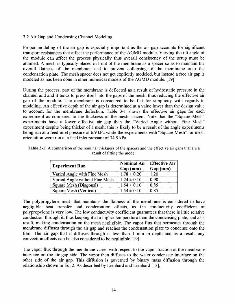
During the process, part of the membrane is deflected as a result of hydrostatic pressure in thechannel and and it tends to press itself into the gaps of the mesh, thus reducing the effective airgap of the module. The membrane is considered to be flat for simplicity with regards tomodeling. An effective depth of the air gap is determined at a value lower than the design valueto account for the membrane deflection. Table 3-1 shows the effective air gaps for eachexperiment as compared to the thickness of the mesh spacers. Note that the "Square Mesh"experiments have a lower effective air gap than the "Varied Angle without Fine Mesh"experiment despite being thicker of a mesh; this is likely to be a result of the angle experimentsbeing run at a feed inlet pressure of 6.9 kPa while the experiments with "Square Mesh" for meshorientation were run at a feed inlet pressure of 34.5 kPa.
Table 3-1: A comparison of the nominal thickness of the spacers and the effective air gaps that are aresult of fitting the model
Nominal Air Effective AirExperiment Run Gap (mm) Gap (mm)Varied Angle with Fine Mesh 1.78 0.20 1.20Varied Angle without Fine Mesh 1.24 0.10 0.98Square Mesh (Diagonal) 1.54 0.10 0.85
Square Mesh (Vertical) 1.54 0.10 0.85
The polypropylene mesh that maintains the flatness of the membrane is considered to havenegligible heat transfer and condensation effects, as the conductivity coefficient ofpolypropylene is very low. The low conductivity coefficient guarantees that there is little relativeconduction through it, thus keeping it at a higher temperature than the condensing plate, and as aresult, making condensation on the mesh negligible. The vapor flux that permeates through themembrane diffuses through the air gap and reaches the condensation plate to condense onto thefilm. The air gap that it diffuses through is less than 1 mm in depth and as a result, anyconvection effects can be also considered to be negligible [19].
The vapor flux through the membrane varies with respect to the vapor fraction at the membraneinterface on the air gap side. The vapor then diffuses to the water condensate interface on theother side of the air gap. This diffusion is governed by binary mass diffusion through therelationship shown in Eq. 2. As described by Lienhard and Lienhard [13],
14

m -CaDw-a 1n 1 + Xi-Xa,mj (2)M dgap-S \ Xa,m
where J, is the flux through the membrane, M, is the molecular weight of water, ca is theconcentration of air in the air gap, Dva is the diffusivity of water vapor in air, dgap is depth of theair gap, c is the thickness of the film of liquid water on the condensation plate, x, is the watermole fraction at the liquid-vapor interface, and xa,m is the water mole fraction at the vapor-membrane interface [19].
The thickness of the air gap decreases as condensate film grows in thickness and displaces the airmore. Assuming no shear forces at the liquid-vapor interface, the growing film thickness can becharacterized by
3f, -- 3 + 3 Ji dA vf~i (3)g cos 0 (pf-pg)w
where 6i is the condensation film thickness, J, is the aforementioned flux through the membrane,dA is a differential unit of area, vy, is the fluid kinematic viscosity, g is the gravitational constant,pf is the liquid water density, pg is the gas density of the combined air and water vapor, and w isthe width of the condensation film [19].
The denominator of Eq. 3 has a cosO term in in to account for the angle of inclination. When themodule is vertical, 0 = 00 and thus the cos6 term has no effect on the film thickness. The formulais used herein for angles as high as 850 as approaching 90' will have an undefined result. Theheat of condensation is conducted through the condensate film, then the aluminum wall, and intothe coolant liquid [19].
If the film starts with zero thickness, the thickness at the bottom can be given by the second termin Eq. 3. We can see that even under these conditions, only at extreme angles, close to 90', willthe film grow up to 1 mm to occupy the entire gap. (We neglect, as has been done elsewhere, theeffect of spacers.) Thus, any deviation towards a flooded gap operation should be explainedeither by forced flooding of the gap, by drops falling back onto the membrane surface at negativeangles, or by the spacer enhancing water bridging effects in the gap.
3.3 Modeling Inputs
The numerical model takes the following inputs from the experimental setup: geometry of eachof the channels including the respective lengths, widths, and depths; the flow rate andtemperature of the hot feed channel at module inlet; and the flow rate and temperature of thecoolant as the module inlet [19].
3.4 Effect of Module Tilt Angle
The theoretical effect of inclination of the AGMD module on permeate flux is shown in Figure3-2. The permeate production rate is given as the ratio of the flux when the module is at a tiltangle 0, to the flux when the module is in the vertical orientation. Thus, by this normalization,normalized permeate rate at 0 = 0 is 1. The permeate production rate is plotted against the
15

inclination angle. Referring to Eq. 3, with all other conditions the same, the model predicts thatthe thickness of the condensate film is affected by the tilt angle. With a thicker film, thethickness of the air gap for vapor to diffuse through is decreased, resulting in an increase inpermeate flux. The effect is independent of whether the tilt angle is positive or negative sincecosO is symmetric about 0 = 0 [19].
An increase of around 4% at very large tilt angles is predicted through the model as a result of athicker condensate film. Figure 3-2 shows that this effect is more pronounced when the coldchannel is at a lower temperature as this causes the viscosity of the liquid film, pf, to increase andas a result, the film rolls off the surface at a slower rate. The increase in permeate rate does notaccount for the effects caused by thermal bridging or flooding.
1.05
L.-0E
L.
E0z
1.03
1.01
0.99
0.97
0.95-90
//
/
-60 -30 0 30 60 90Tilt angle e [*]
Hot inlet T=60'C, Cold inlet T=40'CHot inlet T=50 0C, Cold inlet T=12.50C
Figure 3-2: Effect of module tilt angle on flux as predicted the model [19]
16
I

4. METHODOLGY
4.1 Experimental Methodology
4.1.1 Varied Angle
The experimental permeate flux rate due to varied tilt angle, with the variations due totemperature removed, are presented. During the operation of the experiment, the temperatures ofthe cold and hot side inlets were set and controlled by temperature controllers. The temperaturecontroller for the cool side, which actuates the coolant flow valve, controls temperature within+0.05 OC of the set temperature. The hot side controller varies within 0.1 0C over the durationof the experiment. Between experiments at different module tilt angles, the average temperatureof the hot and cold side inlets can vary. The change in the average temperature on the feed side isa maximum of 0.5'C, and on the cold side, the change is at most 1.5 0C. Figure 3-2 shows therelatively small impact of module tilt angle on flux as predicted by the model. However, thetemperature of the streams can have a greater impact on the flux especially since vapor pressure,a driving force in MD mass transfer, is an exponential function of temperature. In order todetermine the effect of the tilt angle on flux, the variation from inlet temperature must beidentified and removed.
Using the average inlet temperature and flow rate conditions at each of the module tilt angles,flux is estimated using the EES model for a vertical module operating at those conditions. Themeasured flux for the AGMD experimental setup at a vertical tilt was between 150-250 L/m 2daydepending on the feed flow conditions and the thickness and type of the air gap spacer used. Inorder to scale the measured permeate production rates, the results are multiplied by the 0' tiltangle module flux obtained from EES at the same temperature conditions and divided by theexperimentally obtained flux at the vertical orientation. At tilt angles beyond 00, the deviationfrom the model at the given angle would show the relative change in flux resulting from tiltingthe apparatus, thus removing any other causes other than tilt angle [19].
4.1.2 Varying Mesh Spacer Orientation
When measuring the effect of different gap spacer orientations, different temperature rangeswere used while attempting to keep the respective temperature difference across the air gapconstant. As the tested temperatures increased, the set temperature was incremented slightlymore to compensate for heat losses through the module, through the hoses, and through thethermocouples. While attempting to maintain a constant temperature difference across the air gapof 15', the maximum deviation from this value was 1C. The model accounts for thesevariations. All experiments measuring the effect of varied mesh spacer orientation wereconducted with the module angle at 00, or in the vertical orientation. All trials were assumed tohave had no variation in angle or little enough variation to not be significant in the effect of themesh spacer orientation.
17

4.2 Uncertainty Quantification
The uncertainty analysis was performed in the EES code to account for the uncertainties innumerically predicted flux resulting from uncertainties in flow rates and measured temperaturesof the hot and cold feeds. The total uncertainty in the flux measurement was dominated byvariations in temperature. The hot side has a larger impact on flux, but the absolute uncertainty incold side temperature is higher, so both affect the overall uncertainty. The uncertainty in actualtemperature measurements was conservatively estimated as the standard deviation in temperaturerecorded during the experiment plus the maximum measurement uncertainty of 0.2'C for thethermistors used [19].
Using experimental methods, flux is calculated over the course of 10-15 minutes by subtractingthe final water mass from the initial water mass and then dividing the difference by the timeelapsed. The data acquisition system measures at intervals of approximately 5 seconds, therefore,a time measurement uncertainty of 10 seconds is considered. A conservative time error was usedto account for variability in the permeate drop collection from the MD apparatus. Themeasurement uncertainty on the mass scale is 0.1 g. To account for the initial and finalreadings, an uncertainty of 0.2 g was considered for overall water mass collected.
18

5. EXPERIMENTAL RESULTS AND DISCUSSION
5.1 Confirmation of Angle on Permeate Flux
The experimental data and theoretical modeling of the system showed a minimal effect of smallmodule tilt angles on permeate flux. However, very large inclination angles significantlyincreased the permeate production rate. This finding is additionally supported by the theoreticalanalysis of the relationship between the mass transfer resistance in the air gap, film thickness 6,and flux. The constraint of predominant interest is permeate flux, since it indicates theperformance of the fixed size AGMD module with fixed top and bottom temperatures. Whileenergy efficiency is an important consideration, this module configuration does not incorporateenergy recovery at the condenser, and it is not intended for energy efficiency studies.
0
a)
E
-
N)
E
L.
0
*0
1.81.6
1.4
1.2
1
0.8
0.6
0.4
0.2
0-90 -60 -30 0 30
Angle [0]
60 90
Figure 5-1: Permeate production rate with the rectangular and fine mesh spacers, adjusted for variation intemperature, normalized to output at the vertical orientation
Figure 5-1 shows the normalized permeate production rate as a result of the module inclinationangle. The normalized permeate ratio is calculated as the permeate production rate for a given tiltangle after having been processed for temperature variations, divided by the permeate productionrate a 0' tilt angle. In Figure 5-1, MD was performed at moderate temperatures of Tfin = 50'Cand Tc11 = 20'C, with a large temperature difference, AT, between the hot feed and the coldstream and with a low condensate temperature. Angles observed were -70', -45', 0', 45', 850.The most negative angle measured could only go as far back as -70' due to module rotationalconstraints. Overall, the permeate flux stayed relatively constant, but it increased at extremenegative and positive tilt angles.
I19
-
-T
-.-
-
-

The experimental data gave us a relatively high permeate ratio at -70', most likely due toinevitable air gap flooding; at very negative angles, the output permeate had to overcome aheight to the collection container such that enough water accumulated in the air gap to coverroughly 30% of the active area. The same was not true at the other extreme positive angle, 850.Due to the geometry of the experimental setup, the output permeate did not have to overcome aheight that would forcefully flood the air gap; flooding did occur at these high angles, however,as a result of a growing film thickness, in accordance with Eq. 3. A comparison of this is seen inFigure 5-2.
0
a.
E'0
*0
1.8
1.6
1.4
1.2
0.8
0.6
0.4
0.2
0-90 -60 -30
Figure 5-2: Permeate production rate with onlytemperature, normalized to
0 30Angle [0]
the rectangular meshoutput at the vertical
60
spacer, adjustedorientation
90
for variation in
Due to issues with visualization, a second set of trials were run without the fine mesh spacer tosee if image quality increased. Figure 5-2 shows that the angle effect from that set of trials. Asexpected, the normalized permeate ratio, normalized to the permeate production rate at 0'without a fine mesh spacer, is nearly identical to that that includes the fine mesh spacer. Onaverage, the trials without the fine mesh spacer output roughly 13% more permeate than the trialswith the fine mesh spacer, in accordance with the decrease in air gap depth associated with nothaving the fine mesh spacer.
Having a clear sapphire condensing plate gave us the opportunity to visualize condensation andpotential flooding. Images are stored in the Appendix of this thesis. Due to the fine mesh spacerbeing distracting to the focus of the camera, it was removed for subsequent trials. Figure 5-3shows a side by side comparison of the of the condensation depicting why it was necessary toremove the fine mesh from the air gap; condensation was easier to see after the removal.
20
I
T
TIYI-i
I
9

I
a) b)
Figure 5-3: Side by side comparison of angle experiments where Tfi,~- 500 C, Tcin- 200 C a) with therectangular and fine mesh spacers b) with only the rectangular spacer
a) b) c)
Side by side comparison of angle experiments where Tfin~ 50'C, Tc i~,angles: a) 0' b) 450 c) 85'
20'C at the following
Figure 5-4 shows a comparison of three different angles. Droplets are visible in the first twoimages but towards the higher angle, some unforced flooding is observed as evident by amajority of the air gap being filled with water, with some air bubbles present as well. In futureiterations, extra effort will be put into making the visualization through the use of water dye.
Additional experiments were run previously by Warsinger et al. [19], and figures showing theirresults are given below for the rest of the section. While the experiments are not directly mywork for this thesis, I analyze and compare my results with those in Warsinger et al. [19].
I21
Figure 5-4:

0 30 60 90
Tilt angle 0 [0]Figure 5-5: Effect of module tilt angle on permeate production: Tfi,~ 50'C, Tc i,- 12.5 0C [19].
0 30 60 90Tilt angle 0 [0]
Figure 5-6: Effect of module tilt angle on permeate production: Tfj - 60'C, Tc, - 40'C [19].
22
1.3
1.2
1.1
0
C)
0.9N
E 0.80z
0.7-90
-TIT 'I
-60 -30
TI
1.6
1.4
1.2
1
0.8
0.6
CD
CD
0z0.4 '-
-90 -60 -30

Figure 5-3 shows the normalized permeate rates for MD experiments run at 50'C and 12.5'C onthe hot side and cold side, respectively. Across all of the tilt angles, the high AT and coldcondensate temperature contributed to relatively high flux. The experimental data show asignificant increase in permeate flux at 850; this jump is attributed to air gap flooding [19].
Figure 5-4, for a trial run at a significantly higher temperature than in Figure 5-3, shows that tiltangle played a relatively small role in positive and moderate negative module tilt angles.However, the permeate flux increased significantly at high negative angles. This increase in fluxmay be suggestive of thermal bridging at relatively small negative tilt angles such as -30', ratherthan flooding, and a tendency to flood, as the tilt angle becomes more negative and approaches-600 [19].
Since it is nearly universally observed that thermal bridging or other effects of module tilt anglechanges, like flooding, are effectively absent at low tilt angles, subsequent trials reduced thenumber of angles tested in the lower angle range [19].
1.4
a)
(.
EL-0
Z
1.3 -
1.2 -
1.1
1
0.9
0.8
0.7
0.6 --90 -60 -30 0 30 60 90
Tilt angle 0 [0]
Figure 5-7: Effect of module tilt angle on permeate production: Smaller air[19].
gap. Tt ~ 50'C, Tci,~ 200 C
23
I
TI
17 T 17I I '1

1.3
1.2
(IT11.1 T
S 0.9 -N
E 0.80z
0.7-90 -60 -30 0 30 60 90
Tilt angle 0 [0]
Figure 5-8: Effect of module tilt angle on permeate production: Smaller air gap. Trjn~ 60 C, Tn= 400 C[19].
To further explore the hypotheses of thermal bridging and flooding, more trials were performedby Warsinger et al. for a smaller effective air gap thickness of two-thirds the original thickness.This was accomplished by using only one mesh spacer instead of two (Figures 5-6 and 5-7).While the absolute value of the permeate flux increased over previous trials, due to thedecreasing of the effective air gap and the corresponding decrease in diffusion length for vapor,the relative effect of module inclination on permeate flux remains similar. At small module tiltangles and large positive angles, the flux stays constant, but at -60', permeate flux increasessignificantly. In some cases, the effect of thermal bridging can be detected at angles as low as -300. These observations suggest that changes in the effective air gap thickness do not have asignificant impact on the stimulation of thermal bridging effects at various tilt angles in AGMD.Notably, the higher temperature trial experienced relatively significant thermal bridging startingat only -30', indicating that the risk for thermal bridging has a temperature dependence [19].
24

No forced flooding 0 Forced flooding
1.6
1.4 -
1.2 - T
1) T T
0.8N
E 0. 6
0z 0.4
-90 -60 -30 0 30 60 90Tilt Angle 0 [0]
Figure 5-9: Effect of module tilt angle on permeate production: Comparison with modified experimentwhere hydrostatically forced flooding is avoided. Tfn - 500C, Twi, - 20'C [19].
An additional trial was performed with forced flooding, where the permeate outlet was at ahigher height than some other parts of the module, therefore partially filling the air gap withliquid water. At low negative angles (around -30'C), partial flooding starts to occur; whereaswhen the tilt angle is further decreased (around -60 0C), almost the entire active membrane isunder the permeate outlet and hence filled with liquid water. Identical tests were performedwhere care was taken to insure no forced hydrostatic flooding over the active membrane area.The results taken in tandem showed that forced flooding, where the entire air gap is filled withliquid water, significantly increased the permeate flux (Figure 5-8). In the tests where forcedflooding was avoided, one can see that even at -300, the permeate flux rate does not changerelative to the vertical baseline. At higher negative angles, we see an increase in relative flux butthe increase is relatively smaller than in the case of forced flooding, pointing to the possibility ofwater falling back onto the membrane from the condensation plate and related local thermalbridging. This further shows that both flooding and thermal bridging are possibilities in AGMDat high tilt angles and that the relative increase in permeate flux is greatly affected by the amountof thermal bridging [19].
5.2 Thermal Bridging
Thermal bridging may happen if liquid water falls from the condensing plate onto the membrane,forming a liquid bridge across the air gap. This bridging phenomenon is not captured by thenumerical model. Thermal bridging is particularly likely in negative tilt angles, and hence theexperimental permeate flux results are asymmetrical about the vertical 00 module orientation. As
25

the mass transfer resistance is dominated by the air gap width, the bridging phenomena should beeasily observed by an increase in permeate flux at negative tilt angles. Our initial hypothesis wasthat bridging could occur even at small negative tilt angles. However, the experimental datashow no such change in flux at small negative tilt angles, indicating no thermal bridgingoccurred. The key insight is that thermal bridging is not a concern at vertical or nearly verticalangles for the air gap and spacer dimensions considered in this experiment [19].
An explanation for why liquid water does not fall onto the MD membrane even at negative tiltangles may be obtained by considering the hydrophobicity and the hydrophobicity of thesurfaces on which the liquid water flows. The aluminum condensing surface is hydrophilic andtypical aluminum condensing surfaces have contact angles of about 5' [15]. On the other hand,MD membranes are hydrophobic. Thin films of water can stay on the underside of inclinedhydrophilic surfaces up to very high tilt angles [16,17,18]. Additionally, in small air gaps wheredroplets can exceed the size of the gap, droplets on the hydrophobic surface may touch and bereabsorbed into the liquid film on the hydrophilic condensing plate. Therefore, large inclinationangles, which favor thicker liquid films, may be required before thermal bridging effects occur.
5.3 Spacer Mesh Orientation
Varying the orientation of the spacer mesh, we found there to be no significant difference inhaving the spacer in the vertical orientation versus having it in the diagonal orientation, rotated450 from the the vertical position.
12
E 10
S8x
E2
0
400/250 500/350 600/450 700/550
Hot Feed Temperature / Cold SideTemperature (*C)
Figure 5-10: Comparison of diagonal and vertical permeate production rates. Data points have beenslightly offset to avoid error bar clutter
26
I
T
TITj
- 11
Diagonal-rc+Vertical

Vertical orientation was hypothesized to have produced a higher permeate production rate as aresult of thermal bridging. The theory was that in the vertical orientation, fonning droplets wouldrest on the edge of the spacer hole, expanding until reaching a big enough radius to fall. Duringthis growing phase, the droplet would provide thermal bridging, and thus increase flux. The samewas not assumed of the diagonal orientation as gravity was thought to bring a droplet to a localminimum in the mesh before seeping through the intermeshing interface of the corner of a meshhole. Essentially, the vertical orientation was thought to have more potential to hold water in themesh. The hypothesis was disproven by the data. One can speculate that the diagonal orientationholds enough stationary water as the water may collect as well on corners of the mesh as onedges of the mesh.
Figure 5-11 shows side-by-side visualizations of the two orientations at similar experimentalconditions. The diagonal orientation seems to exhibit more dropwise condensation than thevertical orientation. Reasoning behind the two spacers' respective visualizations are stillunknown. Flux between the two are not significantly different but the ways that theseorientations go about achieving these outputs could be.
a) b)
Figure 5-11: Side by side comparison of the a) diagonal orientation and b) vertical orientation of thesquare mesh spacer at Tfi, = 40'C, Tj, = 25'C.
I27

6. CONCLUSIONS
The experimental results are similar to those reported by Warsinger et al. and are consistent withthe results from the model [19]. A slightly asymmetric behavior is observed, with an increase inpermeate production rate at steep, negative angles, due to unintentional but inevitable forcedflooding in the air gap. At moderate angles of inclination, up to 150, there is a slight effect onpermeate flux. At these moderate angles, permeate flux varied by less than 5%. As the angle ofinclination approached 90', increase in permeate flux became significant, rising by more 40%in some cases.
It was found that the AGMD module is susceptible to two conditions in which the air gap isfilled with liquid water: flooding and thermal bridging. Flooding occurs when the flow ofpermeate into the air gap is greater than the amount of permeate leaving the air gap to thecollection tank. During tests, flooding was generally found to occur at large temperaturegradients across the air gap, at small gap sizes, and at extremely inclined or declined angles.Images showing the condensing plate surface show no indication of unforced flooding in any ofthe experiments.
The second condition, thermal bridging, occurs when the module is tilted at large negativeangles, at which point a fraction of the condensate falls from the condensate plate to thehydrophobic membrane. Thermal bridging occurred more than flooding at declined angles, butwas not observable for angles less than 30' from the vertical. Results suggest that for smaller airgap thicknesses, both thermal bridging and flooding will begin occurring at smaller declinationangles.
Often thermal bridging and flooding are undesirable as these conditions are less thermallyefficient, but in smaller-scale systems or systems lacking energy recovery, the increase inpermeate flux output can often outweigh the loss of thermal inefficiency. Thus, this setupalteration can have desirable results as more pure water is produced under the same temperatureconditions.
Lastly, it was also found that varying the mesh spacer orientation had no significant effect on thepermeate production rate. Both diagonal and vertical orientations received very similar results atidentical experiment conditions.
28

APPENDIX
Images of Condensation on Condensation Plate
A. 1 Variable Angle
Note: Figures including the fine mesh spacer at varied angles were omitted due to poor imagequality. See Figure 5-5 for a side by side comparison of the quality difference between having afine mesh spacer and not having a fine mesh spacer
Figure A-1: Angle of 00, Rectangular Mesh, Tf,1 = 50'C, Tcii = 20'C
29

Figure A-2: Angle of 45', Rectangular Mesh, Tfin= 50'C, Tcin= 20'C
Figure A-3: Angle of 85', Rectangular Mesh, Tfi = 50'C, Tci = 20'C
30

Figure A-4: Angle of -45', Rectangular Mesh, Tfi, = 50'C, Tc i, = 20'C
Figure A-5: Angle of -70', Rectangular Mesh, T-in= 50'C, Tcj1 = 20'C
31

A.2. Square Mesh Spacer Orientation
Note: Images for Tijn = 70'C, Tc~i, = 55'C were not taken for both the vertical and diagonalorientations of the mesh spacers due to not having a camera available at the time that heatingelement troubleshooting was resolved.
Figure A-6: Diagonal Orientation, Square Mesh, Trfn= 40'C, Tc i = 25'C
32
0

Figure A-7: Diagonal Orientation, Square Mesh, Tfi = 50'C, Tcin= 350 C
Figure A-8: Diagonal Orientation, Square Mesh, Tfi, = 60'C, Tc,i, 450C
33

Figure A-9: Vertical Orientation, Square Mesh, Ti= 40'C, Tc i1 = 250 C
Figure A-10: Vertical Orientation, Square Mesh, T,n = 50'C, Tcj, = 350C
34
4w,

Figure A-11: Vertical Orientation, Square Mesh, T 1 n = 60'C, T,1 n = 45'C
35
0

ACKNOWLEDGMENTS
This work was funded by the Cooperative Agreement Between the Masdar Institute of Scienceand Technology (Masdar University), Abu Dhabi, UAE and the Massachusetts Institute ofTechnology (MIT), Cambridge, MA, USA, Reference No. 02/MI/MI/CP/1 1/07633/GEN/G/00.
The author would like to express his gratitude to David M. Warsinger, PhD, for the opportunityto do research in water desalination and for all the help and guidance in experimenttroubleshooting, running experiments, and writing this S.B. Thesis. Additional acknowledgmentsgo to Jaichander Swaminathan for helping process the data and make sense of the results. Lastly,the author would like to thank Margaret Bertoni for assisting with daily preparation of runningexperiments and also with helping leak-proof the module.
REFERENCES
[1] E. K. Summers and J. H. Lienhard V, "A novel solar-driven air gap membrane distillation system," Desalination and WaterTreatment, pp. 1-8, July 2012.
[2] J. Gilron, L. Song, and K. K. Sirkar, "Design for Cascade of Crossflow Direct Contact Membrane Distillation," Industrial& Engineering Chemistry Research, vol. 46, pp. 2324-2334, Apr. 2007.
[3] F. He, J. Gilron, and K. K. Sirkar, "High water recovery in direct contact membrane distillation using a series of cascades,"Desalination, vol. 323, pp. 48-54, Sept. 2013.
[4] G. Zaragoza, A. Ruiz-Aguirre, E. Guillen-Burrieze, D. Alarcon-Padilla, and J. Blanco-Galvez, "Experimental comparisonof different prototypes of solar energy driven membrane distillation systems," in Proceedings of the 2013 IDA WorldCongress on Desalination and Water Reuse, 2013.
[5] A. Alkhudhiri, N. Darwish, and N. Hilal, "Membrane distillation: A comprehensive review," Desalination, vol. 287, pp. 2-18, Feb. 2012.
[6] E. K. Summers, H. A. Arafat, and J. H. Lienhard, "Energy efficiency comparison of single-stage membrane distillation(MD) desalination cycles in different configurations," Desalination, vol. 290, pp. 54-66, Mar. 2012.
[7] K. Zhao, W. Heinzl, M. Wenzel, S. Bfttner, F. Bollen, G. Lange, S. Heinzl, and N. Sarda, "Experimental study of thememsys vacuum-multi-effect-membrane-distillation (V-MEMD) module," Desalination, vol. 323, pp. 150-160, 2013.
[8] G. L. Liu, C. Zhu, C. S. Cheung, and C. W. Leung, "Theoretical and experimental studies on air gap membranedistillation," Heat and Mass Transfer, vol. 34, pp. 329-335, Nov. 1998.
[91 A. Alkhudhiri, N. Darwish, and N. Hilal, "Produced water treatment: Application of air gap membrane distillation,"Desalination, pp. 46-51, 2013.
[10] G. Chen, X. Yang, R. Wang, and A. G. Fane, "Performance enhancement and scaling control with gas bubbling in directcontact membrane distillation," Desalination, vol. 308, pp. 47-55, Jan. 2013.
[11] McMaster-Carr, "Chemical-resistant polypropylene mesh, part number 9275t65."[12] S.A.Klein, "Engineering equation solver version 9."[13] J. H. Lienhard V and J. H. Lienhard IV, A Heat Transfer Textbook, Fourth Edition. Dover Publications, Inc, 2011.[14] A. Mills, Heat Transfer 2nd Edition. Prentice Hall, 1998.[15] J. Bernardin, 1. Mudawar, C. Walsh, and E. Franses, "Contact angle temperature dependence for water droplets on practical
aluminum surfaces," International Journal of Heat and Mass Transfer, vol. 40, no. 5, pp. 1017-1033, 1997.[16] H. R. Nagendra, "Effect of inclination on laminar film condensation," Applied Scientific Research, vol. 28, pp. 261-277,
1973.[17] J. A. Howarth, G. Poots, and D. Wynne, "Laminar film condensation on the underside of an inclined flat plate," Mechanics
Research Communications, vol. 5, no. 6, pp. 369-374, 1978.[18] B. J. Chung and S. Kim, "Film condensations on horizontal and slightly inclined upward and downward facing plates,"
Heat Transfer Engineering, vol. 29, pp. 936-941, 2008[19] D. E. M. Warsinger, J. Swaminathan, and J. H. Lienhard V, "Effect of module inclination angle on air membrane
distillation", in: Proceedings of the 15th International Heat Transfer Conference, IHTC-15, Paper No. IHTC15-935 1,Kyoto, Japan, August 2014.
36