Embed Size (px)
Citation preview
$ a:. NASA CR-114437
T r A V A I M I E TO 'IRE PUBLIC . . -
YAS3-CB-11 u C 7 7 ) V/STOL TTLT ROTOR N73-22964 ATQCFAAfT STU3Y. VOLVME 1 : C O N C E P T U A L DESIGN O F VSPFUL r - ' L I T A F k AND/r)F 1 cO'I!?RCTIL ( A o c i n q Co., P b i l a d e h h i a , Pa.) Unclas 1 4 5 D HC S Q . 2 5 CSCL 31C S3/02 0 2 1 4 U
VISTm TILT ROTOR AIRCRAFT STUDY
VOLUME I
. . zi MILITARY AND/OR COMMERCIAL AIRCRAFT
MARCH 1972
Distribution of this Report is provided in the interest of information exchange. Rerponsibility fw the contents resides in rhe author or organization t h a pepe;ed it.
Praptwd Under Contract No. NAS26598 by THE BQEING COMPANY
VERTOL DIVISION BOEING CENTER . .
P. 0. Box 16868 Philadelphia, Pennsylvania 19142
for .I ' i : . Amm R-c)r CWI~OT
~atk*l Amonautia and Space and
Unitd Statm Army Aii Mobility Rmmrcn a d Dovdopmmt Labomcry A m Diractomt~
* -
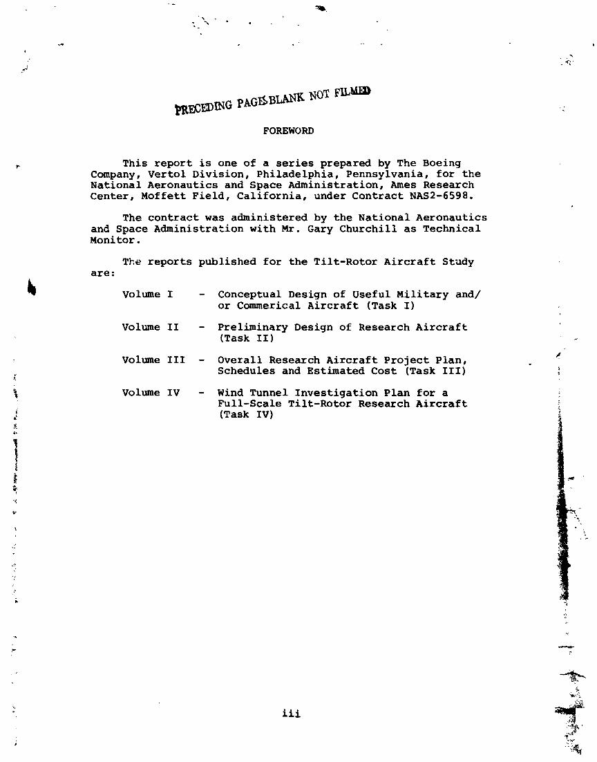
FOREWORD
This r e p o r t is one of a series prepared by The Boeing Company, Ver tol Divis ion, Ph i lade lph ia , Pennsylvania, f o r t h e National Aeronautics and Space Administrat ion, Ames Research Center , Moffett F i e l d , Ca l i fo rn i a , under Contract NAS2-6598.
The c o n t r a c t w a s administered by t h e Nat ional Aeronautics and Space Administrat ion wi th M r . Gary Church i l l as Technical Monitar .
The r e p o r t s published f o r t h e Ti l t -Rotor A i r c r a f t Study are:
Volume I - Conceptual Design of Useful M i l i t a r y and/ or Cammerical A i r c r a f t (Task I)
Volume I1 - Preliminary Design of Research A i r c r a f t (Task 11)
V o l u m e I11 - Overal l Research A i r c r a f t P r o j e c t P lan , Schedules and Estimated C o s t (Task 111)
V o l u m e I V - Wind Tunnel Inves t iga t ion Plan f o r a Fu l l - sca le Til t-Rotor Research A i r c r a f t (Task I V )
iii
PRElUING PAGE BLANK NOT FILMED
ABSTRACT
This r e p o r t covers t h e conceptual des igns of four u se fu l t i l t - r o t o r a i r c r a f t f o r t h e 1975 t o 1980 time per iod conducted under Task I of t h e V/STOL Ti l t -Rotor A i r c r a f t Study, Contract NAS2-6598 with t h e National Aeronautics and Space Administra- t i o n . Parametric s t u d i e s leading t o design p o i n t s e l e c t i o n are described,and t h e c h a r a c t e r i s t i c s and c a p a b i l i t i e s of each conf igura t ion a r e presented. An assessment i s made of c u r r e n t technology s t a tu s , and add i t i ona l t i l t - r o t o r research programs a r e recommended t o minimize t h e t i m e , c o s t , and r i s k of development of t he se veh ic l e s .
PRECEDING PAGE BLANK NOT FlLMED
CONTENTS
SECTION - -- PAGE - 1 . 0 SUMMARY
2.0 INTRODUCTION
2.1 B a c k g r o u n d 2.2 C r i t e r i a for S e l e c t i n g A p p l i c a t i o n s of
P o t e n t i a l l y H i g h P a y o f f 2 .3 A p p l i c a t i o n s for F i r s t G e n e r a t i o n T i l t -
R o t o r A i r c r a f t
2.4 F o r m a t for this Volume
3.0 TRADEOFF STUDIES
3.1 U.S. Army MAVS A i r c r a f t 3.2 U.S. A i r F o r c e SAR A i r c r a f t 3.3 U.S. Navy S e a C o n t r o l A i r c r a f t 3.4 C i v i l O f f - S h o r e O i l Rig Support
4.0 AIRCRAFT DESCRIPTIONS
4 .1 A i r c r a f t C o n f i g u r a t i o n s 4.2 ~ a t e r i a l s / ~ t r u c t u r a l D e s i g n 4.3 Weights 4.4 Noise 4.5 S t a b i l i t y and C o n t r o l 4.6 C o n t r o l . S y s t e m s 4.7 A e r o e l a s t i c S t a b i l i t y 4.8 P e r f o r m a n c e
5.0 TECHNICAL ASSESSMENT AND RECOMMENDATIONS FOR ADDITIONAL RESEARCH
5.1 T e c h n o l o g y S t a t u s 5 .2 Areas for A d d i t i o n a l R e s e a r c h
REFERENCES
v i i
1 .0 SUMMARY
This volume covers t h e conceptual des ign of u s e f u l m i l i - t a r y and c i v i l t i l t - r o t o r a i r c r a f t . Four d i f f e r e n t appl ica- t i o n s f o r t he tilt r o t o r a r e presented. They are:
a. U. S. Army MAVS - Manned Aer i a l Vehicle, Su rve i l l ance
b. U. S. A i r Force SAR - Search and Rescue
c. U. S. Navy - Sea Control A i r c r a f t
d. C i v i l - Off-Shore O i l Rig Support A i r c r a f t
These missions were s e l e c t e d a s those which b e s t s a t i s f i e d a set of mission a c c e p t a b i l i t y c r i t e r i a . These c r i t e r i a , d iscussed i n d e t a i l i n Sec t ion 2 . 2 . , may be b r i e f l y summarized a s requi r ing :
a. IOC o r commerical c e r t i f i c a t i o n i n 1975-1980
b. A favorable environment; i.e.! a mission f o r which t h e r e is an acknowledged requirement and f o r which t h e tilt r o t o r ' s i nhe ren t c h a r a c t e r i s t i c s are w e l l s u i t ed .
For each app l i ca t ion , a parametr ic s tudy was made t o s e l e c t a po in t des ign b e s t s u i t e d t o t h e p a r t i c u l a r requi re - ments of t h e ind iv idua l mission.
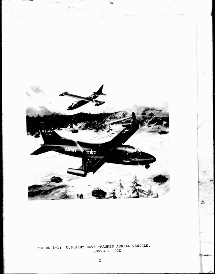
a. For t he Army a i r c r a f t shown i n Figure 1-1, t h e s e l e c t i o n s t u d i e s concentra ted on developing an a i r - c r a f t des ign of minimum s i z e and weight wi th broad f l i g h t c a p a b i l i t i e s a t low speed requi red f o r photo- reconnaissance work and with a dash speed i n excess of 300 knots t o minimize v u l n e r a b i l i t y i n a h o s t i l e environment. The r o t o r d i s c loading was constra ined t o 10 pounds per square f o o t o r less t o minimize undesi rable groundwash e f f e c t s .
b. For t h e USAF SAR a i r c r a f t , t h e emphasis was on mid- p o i n t rescue pickup c a b i l i t y . A higher d i s c loading was permitted than f o r t h e Army a i r c r a f t bu t was s t i l l constra ined t o 15 psf o r less.
c. The primary i n t e r e s t f o r t h e Navy a i r c r a f t was i n developing a design with extended s o r t i e time c a p a b i l i t y , an eight-hour s o r t i e goa l being achieved.
d. For t h e c i v i l a i r c r a f t , low c o s t and h ighes t r e l i - a b i l i t y i n t h e des ign were promoted through an
approach which made maximum use of proven technology and readily available subsystems.
Table 1-1 compares the important geometric, weight, and performance characteristics of the designs.
In addition to the four conceptual designs, it is shown that the tilt rotor has the potential to effectively fill other future missions in the post-1980 time period.
This volume covers the configuration descriptions, materials and structural design, weights, flying qualities characteristics, control systems, noise, Aeroelastic stability, and performance of each of the point designs. It concludes by summarizing the current status of tilt-rotor technology and recommending additional research programs. It is adjudged that the technology is now in hand to start on the development of a tilt-rotor flight research aircraft.
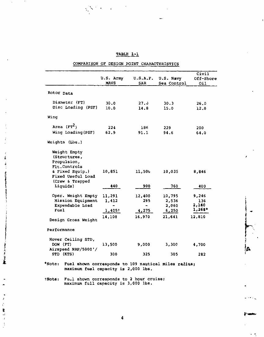
TABLE 5-1
COMPARISON OF DESIGN POINT CHARACTERISTICS
C i v i l U.S. Army U.S.A.F. U.S. Navy Of £-Shore
MAVS S AR Sea Con t ro l O i l
Dianeter (FT) 30.0 Disc Loading (PSF) 10.0
Wing
Area ( F T ~ ) 224 Wing Loading (PSF) 62.9
Weights (Lbs . ) Weight Empty ( S t r u c t u r e s , Propu l s ion , F l t . C o n t r o l s & Fixed Equip. 1 10,851 11,50G 10,035 8,846 Fixed Usefu l Load ( C r e w 61 Trapped Liquids ) 440 900 760 400
Oper. Weight Empty 11 ,291 12,400 10,795 9,246 Mission Equipment 1,412 29 5 2,536 136 Expendable Load - - 2,060 2,140 Fue 1 1 ,405t 4 275 6,250 l,268* --
14,108 16,970 21,641 12,810 Design Gross Weight
Per f onnance
Hover C e i l i n g STD, DGW (FT) I 3 500 9,000 3,30C 4,700
Airspeed NRP/50001/ STD (KTS) 30 0 325 30 5 282
* ~ o t e : Fue l shown cor responds to 109 n a u t i c a l miles radius; maximum f u e l c a p a c i t y is 2,000 l b s .
tAotd: F u d shown cor responds t o 2 hour c r u i s e ; maximum f u l l c a p a c i t y i s 3 ,000 lbs.
2.0 INTRODUCTION
2.1 Rackground
A wide variety of V/STOL concepts, ranging from jet and fan to propeller and rotor-driven vehicles, has been studied by the aeronautical community, botn independently and with government support. These studies have shown that the tilt- rotor aircraft is a promising candidate for military and civil missions.
For military applications, a Boeing study conducted in 1968 of 12 different low disc loading V/STOL concepts applied to the Army Light Tactical Transport Aircraft System (LTTAS) mission showed that the tilt rotor offered the greatest flexi- bility in terms of speed, range, and altitude. This is illus- trated by Figure 2-1. The helicopter, with or without wings, runs out of propulsive force around 200 knots. This can be extended to approximately 250 knots by compounding but at a weight penalty of about 20 percent. In addition, the power required would be from 50 percent to 100 percent greater than that of a 180 to 200-knot helicopter. The tilt rotor, with hover power comparable to that required by a helicopter, offers speeds of 300 to 350 knots.
The tilt-rotor aircraft has the following characteristics:
Hover efficiency better than a helicopter (because the rotor blade twist is not compromised by edge-on flight blade loads).
Cruise speed in excess of 300 knots and the good cruise and loiter efficiency of the fixed-wing, moderate wing-loading, turboprop aircraft.
Low external noise level6 in all flight regimes.
Good ride quality and low vibration and internal noise levels.
Low speed agility of the helicopter.
Downwash velocity much lower than jet-lift or fan- lift aircraft, approaching or equaling that of a helicopter.
Smooth and continuous transition between hover and cruise.
Broad range of flight speeds available with one engine out.

FIGURE 2-1: EFFECT OF DESIGN CP,UISE SPEED ON WEIGHT, POWER, AND FUEL
i. Good overload takeoff and landing capability.
j. Ability to autorotate in case of complete power failure.
Since 1966, Boeing has conducted over 3,500 hours of win!? tunnel testing using 25 different models. The tilt rotor technological base established to date is sufficient to start building a technology demonstrator aircraft now, leading to useful V/STOL tilt-rotor aircraft for military and/or civil applications in the 1975 to 1980 time period. The purposes of this study, as a key step in this process, are to define a useful operationai military and/or civil tilt-rotor conceptual design, design a V/STOL tilt-rotor flight research aircraft, and provide information for planning the next follow-on activity and the overall aircraft program. Thi.s volume covers the selection, design, and capabilities of the most promising operational tilt-rotor aircraft for the 1975-1980 time period, together with an assessment of the state of tilt-rotor tech- nology and recommendations for additional programs.
2.2 Criteria For Selecting Applicatians of Potentially High Payoff
The following criteria were followed in selecting roles and missions to which the tilt-rotor holds the promise of being successfully applied:
a. There must be a real mission existing in the 1975-80 time period; i.e., one for which there is a current or acknowledged need. In additioc, either a gap must exist in the current capability of satisfying the mission requirements or there should be a strong motivation to significantly increase the effectiveness of the aircraft serving this role.
b. Either vertical takeoff and landing capability or efficient hovering ability must be an important requirement for this mission.
c. The tilt rotor must provide a significant improvement in system effectiveness over other aircraft concepts. System effectiveness is composed of:
1. Unique performance capabilities.
2. Good flying qualities, low internal noise, and low vi~,:a,tian levels for pilot acceptance.
3. Operational suitability.
4. Low external noise level
5. Economics
6. Maintainability and reliability
7. Safety
8. Survivability
d. Other factors which must exist to maximize the proba- bility of success are:
Mission Flexibility - Inherent mission flexibility and growth potential influence successful entry of a new concept through expansion of roles and longevity of use. It would be desirable to find applications which have potentially expanding requirements that could be satisfied by the tilt rotor. For cxample, a mission which currently has only a minor hover requirement but which potentially could require extended hover capabll- ity in the future would be well served b:r the tilt rotor with its efficient hover characteris- tics.
Technology Risk - There is an optimum level of technological risk to maximize the chances of success for a new prcgram. Clearly, if the risb: is very great, the most probable result will be failure. On the other hand, some risk is associ- ated with a program where advances are being made to provide high payoff and a superior system. It is this fact that provides the impetus for the current carefully planned tilt-rotor program in which the technology is demonstrated through flight of a research aircraft prior to development of an operational aircraft. To minimize othsr technical risks, the only engines considered for the design-point aircraft were those for which some initial development had been completed.
2.3 Applications for FirstoGeneration Tilt-Ro tor Aircraft
A large number of potential applications was considered for inclusion in this study. The majority of these missions was eliminated on the basis of violating the criteria previously discussed -- most noticeably with respect to operational timing. However, four of the missions considered were retained for this study and are presented in this volume.
Same of t h e key m i s s i o n s which were c o n s i d e r e d 2nd e l i m - i n a t e d a r e :
a , Gunship - The tilt r o t o r would a p p e a r t o make arr e x c e l l e n t g u n s h i p due t o i t s l o w speed a g i l i t y c o u ~ l e d w i t h a t o p speed i n e x c e s s o f 300 k n o t s . These c h a r a c t e r i s t i c s s9ou ld e n a b l e it t o perform t h e Armed E s c o r t Mis s ion ~ . ; e c t i v e l . y , e s c o r t i n g t h e f a s t e s t f u t u r e h e l i c o p t e r and c a p a b l e of b e i ~ g d i v e r t e d t o h i t t a r g e t s o f o p p o r t u n i t y . While t h e tilt r o t o r would be h i g h l y e f f e c t i v e as a g u n s h i p o f t h e f u t u r e , t h i s a p p l i c a t i o n was e l i m i n a t e d a s n o t f i t t i n g t h e t i m e frame of t h i s s t u d y .
b. LTTAS - I n 1968, Boeing conducted a n e x t e n s i v e company-funded s t u d y o f t h e Army L i g h t T a c t i c a l Trans- p o r t A i r c r a f t System (LTTAS) m i s s i o n . Twelve d i f f e r - e n t r o t o r c r a f t were s t u d i e d f o r t h i a p p l i c a t i o n . These i n c l u d e d two p u r e h e l i c o p t e r s , t w o winged h e l i - c o p t e r s , t h r e e compound h e l i c o p t e r s , t w o advanced rotor concep t h e l i c o p t e r s , two s towed- ro to r a i r c r a f t , aud t h e tilt rotor. A major c o n c l u s i o n o f t h e s t u d y was t h a t , w i t h r e s p e c t to twenty- four d i f f e r e n t e v a l u a t i o n f a c t o r s , t h e tilt r o t o r and winged h e l i - c o p t e r ranked f i r s t or second in a l m o s t e v e r y c a t e g o r y . I n o v e r a l l r a n k i n g , t h e tilt r o t o r w a s f i r s t w i t h t h e winged h e l i c o p t e r second. T h i s e v a l u a t i o n was based on such f a c t o r s as p r o d u c t i v i t y , n . j i se and v i b r a t i o n , a i r t r a n s p o r t a b i l i t y , r e l i a b i l i t y , m a i n t a i n a b i l i t y , s a f e ty , f l y -away cost and r i s k -- w i t h c r u i s e speed be ing a f a l l - o u t o f t h e s t u d y r a t h e r t h a n be ing a r e q u i r e m e n t ,
N e v e r t h e l e s s , t h e most p r o b a b l e t i m i n g f o r p rocu re - m c q t o f a new LTTAS is 1980-1985, beyond t h e p e r i o d s p e c i f i e d f o r t h i s ~ t u d y . Consequen t ly , t h i s m i s s i o n wae e l i m i n a t e d from f u r t h e r c o n s i d e r a t i o n i n t h i s s t u d y . HXM - S t u d i e s have been conducted f o r a number of y e a r s t o d e f i n e t h e b a s i c r e q u i r e m e n t s f o r a U . S . Marine Corps medium a s s a u l t h e l i c o p t e r , c u r r e n t l y d e s i g n a t e d HXM. T h i s c o n c e p t , a lso r e f e r r e d t o a s VAMT (Vertical A s s a u l t Medium T r a , a s p o r t ) , is b a s i c a l l y des igned t o per form a s h i p - t o - s h o r e a s s a u l t t r a n s p o r t m i s s i o n a l t h o u g h o t h e r m i s s i o n s such a s crisis CJ- t r o l have been c c n s i d e r e d f o r it. Design m i s s i o a r a d i i from 150 t o 500 n a u t i c a l m i l e s have been d i s - cussed . System e f f e c t i v e n e s s is enhanced by r e d u c i n g t h e t i m e r e q u i r e d t o l a n d a c a n p l e t e Marine b a t t a l i o n from t h e t h e t h e f i r s t a i r c r a f t l a n d s u n t i ? . t h e l a s t h a s l e f t t h e l a n d i n g zone , Because o f i t s i n h e r e n t l y
high c r u i s e speed, t h e t i l t - r o t o r f u l f i l l s t h i s requirement very n i c e l y and because of i t s e f f i c i e n t long-range c h a r a c t e r i s t i c s , looks p a r t i c u l a r l y a t t r a c t i v e a s t h e d e s i g n r a d i u s i n c r e a s e s .
However, s i n c e t h e r e q ~ i r e r n e ~ t s f o r t h i s miss ion have n o t been t o t a l l y r e so lved a t t h i s t i m e , t h i s miss ion was n o t considered f u r t h e r f o r t h i s t i l t - r o t o r con- c e p t u a l des ign s tudy.
d. Commercial Transpor t - The t i l t - r o t o r ' s c a p a b i l i t i e s a r e w e l l s u i t e d t o a commercial s h o r t h a u l t r a n s p o r t mission. A r e c e n t AIAA committee s u g g e s t s t h a t f o r a s u c c e s s f u l commercial V/STOL:
"A machine is r e q u i r e d t h a t keep ' the e x i s t i n g hover and low-speed VTOL c a p a b i l i t i e s of t h e h e l i - c o p t e r (perhaps wi th reduced n o i s e ) has a c r u i s e speed of 300 t o 350 kno t s and c r u i s e e f f i c i e n c i e s g iv ing -75 t o -150-mile s t a g e l e n g t h s w i t h u s e f u l payload and wi th much reduced n o i s e and m a i n t e n a x e - genera t ing v i b r a t i o n . "
The t i l t - r o t o r i n t r i n s i c a l l y f u l f i l l s t h e s e r e q u i r e - ments and should prove t o be an e x c e l l e n t commercial t r a n s p o r t . Never the less , a necessary p r e r e q u i s i t e t o s u c c e s s f u l commercial o p e r a t ~ o n is t o g a i n needed m i l i t a r y o r u t i l i t y o p e r a t i n g exper ience . Th i s would r e q u i r e t h a t a commeicial t r a n s p o r t b e a second gener- a t i o n t i l t - r o t o r a i r c r a f t and would p l a c e i n i t i a l som- merc ia l usage of t h e t i l t - r o t o r i n t h e 1980 t o 1985 t i m e s e r i o d .
Four of t h e a p p l i c a t i o n s cons idered d i d m e e t a l l of t h e acceptance c r i t e r i a . There fo re , a l t \ough t h i s s tudy only r e q u i r e a t h e d e f i n i t i o n of a s i n g l e o p e r a t i o n a l a p p l i c z t i o n f o r t h e t i l t - ~ : o t o r , f o u r d i f f e r e n t a p l i c a t i o n s a r e r e s e n t e d . The f o u r a i r p l a n e s whose s e l e c t i o n , Ses ign , and capa i l i t i e s a r e covered i n t h i s volume a r e :
E a . U.S. Arrny MAVS - Manned A e r i a l Vehic le , S u r v e i l l e n c e -
A U.S. A ~ E ~ Y program t? develop a t i l t - r o t o r a i r c r a f t f o r s u r v e i l l a n c e miss ions .
b. USAF SAR - Search and Rescue - An advanced s e a r c h and rescue a i r c r a f t f o r t h e U.S. A i r Force.
c . U.S. Navy Sea Cont ro l A i r c r a f t - A V/STOL a i r c r a f t o p e r a t i n g from a new c l a s s of s h i p be ing developed by
1 ' 1 ~ ~ ~ ~ , ~ ~ ~ ~ , and lT/STOL . . . Where Do They F i t In? , ''AIAA Ad Hoc Committee, AIAA 8 th Annual Meeting and Techn ica l D i s - p l a y , Washington, D.C., October 1971
t h e U . S. Navy - t h e Sea Cont ro l Ship . The a i r c r a f t d i s c u s s e d i n t h i s r e p o r t is a long endurance sensor c a r r i e r , a l s o used t o d e l i v e r weapons a g a i n s t low- r e s i s t a n c e t a r g e t s .
d. C i v i l Off-Shore O i l Rig Resupply A i r c r a f t - A c i v i l i a n V/STOL a i r c r a f t used t o f e r r y workers t o and from t h e o f f - shore o i l r i g s , t o p rov ide longer range and g r e a t e r e f f i c i e n c y t h a n t h e h e l i c o p t e r s c u r r e n t l y performing t h a t miss ion .
2.3.1 U. S. Army MAVS. - The MAVS, o r Manned A e r i a l Vehicle , S u r v e i l l a n c e , i s a U. S. Army program t o develop advanced a e r i a l s u r v e i l l a n c e c a p a b i l i t y . The miss ions i n c l u d e t h o s e c c r r e n t l y being flown by t h e OV-1 Mohawk. The tilt- rotor a i r c r a f t has VTOL c a p a b i l i t y which p e r m i t s l and ing a t forward sites and speeds a c c e s s t i m e t o needed in fo rmat ion . I n a d d i t i o n , l i k e a h e l i c o p t e r , t h e tilt r o t o r can o p e r a t e from unprepared sites and i s n o t l i m i t e d by l and ing f i e l d s u r - f a c e c o n d i t i o n s . Other unique c a p a b i l i t i e s of t h e tilt r o t o r which p rov ide a s i g n i f i c a n t improvement i n system e f f e e t i v e - n e s s r e l a t i v e t o o t h e r a i r c r a f t a r e :
Low Speed Maneuverabi l i ty - For e f f e c t i v e evas ion from h o s t i l e actior. , t h e tilt r o t o r has e x c e l l e n t maneuverab i l i ty a t low speed. Approach and d e p a r t u r e p a t h s a r e n o t c o n s t r a i n e d by t e r r a i n f e a t u r e s , a s is t h e c a s e w i t h a conven t iona l a i r c r a f t .
Range of F l i g h t Speeds - The tilt r o t o r can f l y a t ve ry low speed i f necessa ry t o match sensor charac- t e r i s t i c s t h e n can smoothly t r a n s i t i o n t o high-speed f l i g h t .
Low Noise - The pe rce ived n o i s e l e v e l of t h e tilt r o t o r f l y i n g a t 200 kno t s a i r s p e e d , 1,000 f e e t d i r c c t l y above an o b s e r v e r i s on ly 68 PNdB. T h i s compares t o 82 PNdB f o r t h e OV-1. With each a i r c r a f t 2,000 f e e t from t h e o b s e r v e r and a t an a l t i t u d e o f 1,000 f e e t , t h e pe rce ived n o i s e l e v e l from t h e tilt r o t o r i s 53 PNdB compared t o 7 3 PNdB from t h e OV-1.
S u r v i v a b i l i t y - Because it i s capab le of c r u i s e speeds i n excess o f 300 kno t s , t h e tilt r o t o r can perform high-speed dashes t o evade a r e a s w h e r e enemy a n t i a i r - c r a f t c a p a b i l i t y e x i s t s . Because oi i t s high-speed c a p a b i l i t y and good maneuverab i l i ty , t h e tilt r o t o r has good t r a j e c t o r y c o n t r o l .
I n a d d i t i o n , t h e o t h e r s t a t e d c r i t e r i a a r e m e t . The a i r c r a f t s i z e is less than 15,000 pounds i n g r o s s weight . I n terns of miss ion f l e x i b i l i t y , t h e r e a r e s e v e r a l o t h e r Army
miss ions t h a t t h e tilt r o t a r could perform w e l l . Wi th a r econf igured f u s e l a g e , it w i l l make an e x c e l l e n t u t i l i t y t r a n s p o r t . Because it has VTOL c a p a b i l i t y , it can o p e r a t e d i r e c t l y between t h e main o p e r a t i n g base and t h e f r o n t line.
2.3.2 U. S . A i r Force SAR. - Curren t s e a r c h and rescue o p e r a t i o n s invo lve a coord ina ted e f f o r t of d i f f e r e n t a i r c r a f t . H K - 3 ~ and HH-53 h e l i c o p t e r s a r e t h e primary means of recovery whi le fixed-wing a i r c r a f t , no tab ly A - l ' s , a r e used t o o r b i t t h e s e a r c h a r e a u n t i l t h e h e l i c o p t e r s a r r i v e and t o p rov ide suppress ive f i r e a g a i n s t enemy t roops . The t i l t - r o t o r a i r c r a f t can f u l f i l l both f u n c t i o n s wi th t h e speed, m a a e u v e r a b i l i t y , range , and endurance of t h e fixed-wing a i r c r a f t and t h e hover and v e r t i c a l landing c a p a b i l i t y of t h e h e l i c o p t e r . Conse- q u e n t l y , t h i s i s a miss ion t h a t meets t h e f i r s t t h r e e c r i t e r i a very w e l l : t h e tilt r o t o r f i l l s t h e requi rements of a w e l l de f ined miss ion , t h e miss ion i n h e r e n t l y r e q u i r e s hovering c a p a b i l i t y , and t h e tilt r o t o r p rov ides a s i g n i f i c a n t improve- ment i n e f f e c t i v e n e s s over o t h e r a i r c r a f t .
2.3.3 U. S. Navy Sea Cont ro l A i r c r a f t . - The U . S . Navy Sea Cont ro l Ship concept invo lves t h e development of a r e l a - t i v e l y smal l s h i p (approximately 15,000 t o n s j from which V/STOL a i r c r a f t w i l l o p e r a t e , c a r r y i n g weapons and s e n s o r s t o c o n t r o l t h e aerospace and hydrospace i n t h e v i c i n i t y of a t a s k f o r c e o r convoy. There a r e requi rements f o r an a i r c r a f t wi th long endurance t o be used a s a sensor c a r r i e r . I t may a l s o be used t o a t t a c k t a r g e t s - The tilt r o t o r ' s c v b i n a t i o n of VTOL c a p a b i l i t y and high speed pe rmi t s e f f e c t i v e lse of a l l t h e s e n s o r s used by fixed-wing a i r c r a f t wi thou t r e q u i r i n g a long f l i g h t deck. c a t a p u l t , o r a r r e s t i n g yea r . I n comparison t o a h e l i c o p t e r , i t s h igher l o i t e r and c r u i s e speed p rov ide inc reased sweep r a t e c a p a b i l i t y i n e s c o r t o r s c r e e n a p p l i c a - t i o n s and i t s h igher c r u i s e speed s i g n i f i c a n t l y reduces t h e time l a t e t o datum. I t has e x c e l l e n t over load c a p a b i l i t y t o t a k e advactage o f wind over deck and l i m i t e d deck l e n g t h s . I n a d d i t i o n , t h e i n h e r e n t hover e f f i c i e n c y of t h e tilt r o t o r makes it q u i t e adap tab le t o requi rements imposed by development of new weapons o r s e n s o r s which may r e q u i r e recovary , towing, o r o t h e r low-speed o p e r a t i o n s .
2 . 3 . 4 C i v i l Off-Shore O i l Rig Support A i r c r a f t . - H e l i - c o p t e r s a r e c u r r e n t l y used t o supvor t o f f - shore o i l w e l l d r i l l i n g o p e r a t i o n s throughout th;? world wi th major a c t i v i t i e s i n t h e P e r s i a n Gul f , North Sea , and Gulf of Mexico. Major h e l i c o p t e r o p e r a t o r s , inc lud ing World-Wide H e l i c o p t e r s , Okanagan He l i cop te r s , Bris tow H e l i c o p t e r s , and Petroleum H e l i c o p t e r s , provide a c o n t r a c t s e r v i c e t o t h e petroleum companies c o n s i s t i n g of suppor t f o r moni tor ing of w e l l s t a t u s , d r i l l r i g suppor t , and crew change. The d r i l l r i g suppor t miss ion r e q u i r e s c a r r y - i n g superv i so ry pe r sonne l , g e o l o g i s t s , t e c h n i c a l peop le , w e l l l o g s , and equipment t o t h e d r i l l i n g s i te . The crew change
mission requires that, once a week, the helicopters transport replacement crews to the oil rigs and return the old crew to shore. A Boeing study conducted in 1970 with the cooperation of Petroleum IIelicopters, Inc. indicated that, on the average, operations were conducted 30 to 45 miles further off shore than they had been five years previously.
In the next five years, it is anticipated that the opera- tions will extend another 30 miles, with sane operations reaching as far 2.s 200 to 300 miles from shore. The high speed and range of the tilt rotor can provide a step improvement in productivity and a major time saving for such operations.
2.4 Format for This Volume
A conceptual design study was performed to define the characteristics of a first-generation tilt-rotor aircraft for each of the four selected applications.
In each case, a parametric study was made to select a point design aircraft. Section 3 of this volume discusses these trade studies including the detailed definition of the design mission profiles, mission requirements, the ground rules followed for the studies, the parameters considered, and the factors which influenced the design point selection.
Section 4 is a description of each airplane including the following details: i
Configuration
Materials/structural design
Weights
Noise
Flying qualities
Control systems
Dynamics
Performance
Section 5 is an assessment of the status of tilt-rotor technology today and specific recommendations for additional research programs that should be completed before the opera- tional aircraft described in this volume become reality.
3.0 TRADEOFF STUDIES
3 . 1 U. S. Army 3IAVS A i r c r a f t
3 .1 .1 Miss ion D e f i n i t i o n . - The d e s i g n m i s s i o n p r o f i l e fo?. t h e MAVS a i r c r a f t i s shown i n F i g u r e 3-1. I t c o n s i s t s o f a two-hour c r u i s e a t 200 k n o t s p l u s o t h e r a l l owances f o r t a k e - o f f , r e s e r v e s , e t c . T h i s speed was s e l e c t e d a s be ing r e p r e - s e n t a t i v e of pho to r e c o n n a i s s a n c e r e q u i r e m e n t s . The r e q u i r e d m i s s i o n l o a d was 1 ,412 pounds, c o n s i s t i n g o f SLAR, pho to r econ eq~'!.pment, ECM pods, e tc . The a i r c r a f t c a r r i e s a crew of two i n a s ide -by - s ide c o n f i g u r a t i o n .
A v e r t i c a l c l imb r a t e o f 500 f e e t p e r minu te w i t h b o t h e n g i n e s o p e r a t i n g w a s r e q u i r e d a t 4,000 f e e t p r e s s u r e a l t i t u d e , 95OP. A normal power c r u i s e speed o f a t l e a s t 300 k n o t s t r u e a i r s p e e d w a s r e q u i r e d a t 5 ,000 f e e t / s t a n d a r d day c o n d i t i o n s . An a d d i t i o n a l performance r equ i r emen t w a s t h a t t h e a i r p l a n e have s u f f i c i e n t i n t e r n a l f u e l c a p a c i t y f o r f o u r h o u r s of f l i g h t a t 200 k n o t s . For t h i s c o n d i t i o n , t h e a i r p l a n e was p e r m i t t e d t o ove r load .
3.1.2 Study Ground Rules . - I n o r l e r t o s a t i s f y t h e cri- : e s i a of minimizing t echno logy r i s k s i n a r e a s n o t d i r e c t l y . - e l a t e d t o t h e t i l t - r o t o r a i r c r a f t , a n e n g i n e w i t h h i g h proba- a i l i k y o f development by 1975-1980 w a s s e l e c t e d . The e n g i n e chosen f o r h i s a p p l i c a t i o n was a UTTAS e n g i n e r a t e d a t 1500 sha f ,t horsepower.
The wing, f u s e l a g e , and empennage were d e s i g n e d u s i n g compos i te m a t e r i a l s , a l l o w i n g a 15 -pe rcen t r e d u c t i o n i n t h e i r weight . The many s t u d i e s o f p o t e n t i a l we igh t s a v i n g s from t h e u s e o f compos i tes a l l i n d i c a t e p o s s i b l e s a v i n g s o f 25-35 p e r c e ' l t s o t h a t t h e 1 5 p e r c e n t assumed i s c o n s i d e r e d conserva- t i v e .
Adva, zed technology t r a n s m i s s i o n s based on t h e Army/Boeing Heavy L , i t H e l i c o p t e r program were used . These p r o v i d e a 15- pe rcc .it r e d u c t i o n i n d r i v e system we igh t .
The maximum o p e r a t i n g speed (VMO) was s e l e c t e d a t 350 .not::;, and t h e maximum o p e r a t i n g Mach number (MMo) was set a t 0.563. These . ~ a l u e s were p icked t o p r o v i d e r e a s o n a b l e speed marg ins r e l ~ c i v e to t h e a n t i c i p a t e d c r u i s e speed c a p a b i l i t y o f t h e a i r c - a f t.
Engine ~ a n u f a c t u r e r ' s s p e c i f i c f u e l consumption was i n - c r e a s e d by 5 p e r c e n t i n accordance w i t h MIL-C-5011A.
A s d i s c u s s e d i n S e c t i o n 4.5.10, t h e h o r i z o n t a l and v e r t i - c a l t a : . l s were s i z e d on t h e b a s i s o f t a i l volume c o e f f i c i e n t s o f 1 . 3 and 0.128, r e s p e c t i v e l - y .
14
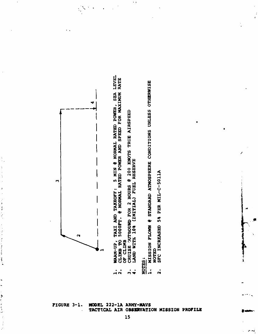
FIGURE 3-1. W E L 222-U ARMY-IUVI . TACTICAL AIR OBIILIIVATION MISSION PROFILE
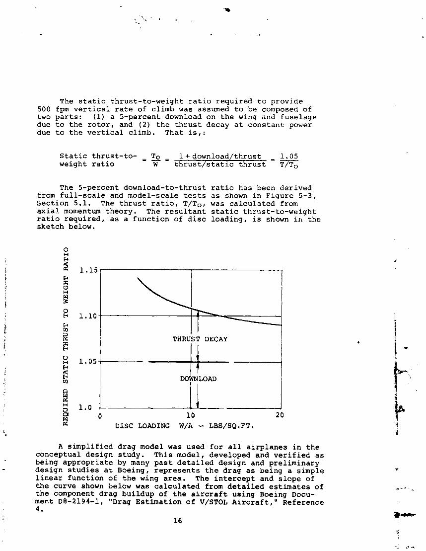
The s t a t i c thrus t - to-weight r a t i o r e q u i r e d t o p rov ide 500 fpm v e r t i c a l r a t e of cl imb was assumed t o be composed of two p a r t s : (1) a 5-percent download on t h e wing and f u s e l a g e due t o t h e r o t o r , and ( 2 ) t h e t h r u s t decay a t c o n s t a n t power due t o t h e v e r t i c a l climb. That i s , :
S t a t i c t h r u s t - t o - - To = - - l + d o w n l o a d / t h r u s t - - - 1.05 weight r a t i o W t h r u s t / s t a t i c t h r u s t T/To
The 5-percent download-to-thrust from f u l l - s c a l e and model-scale tests S e c t i o n 5.1. The t h r u s t r a t i o , T/To, a x i a l momentum theory . The r e s u l t a n t r a t i o r e q u i r e d , a s a f u n c t i o n of d i s c s k e t c h below.
r a t i o has been de r ived a s shown i n F igure 5-3, was c a l c u l a t e d from s t a t i c th rus t - to -we igh t load ing , i s shown i n t h e
1 THRUST DECAY I
0 10 20 DISC LOADING W/A -- LBS/SQ.FT.
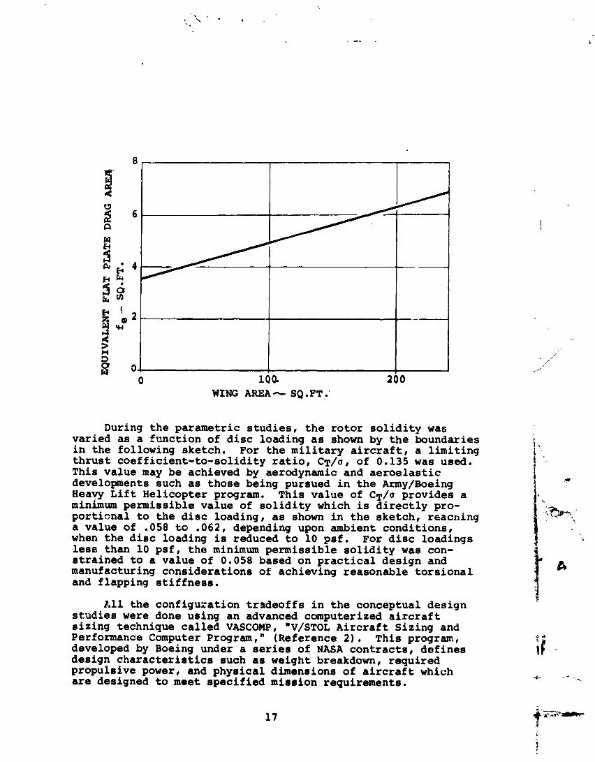
A s i m p l i f i e d drag node1 was used f o r a l l a i r p l a n e s i n t h e conceptual des ign s tudy. T h i s model, developed and v e r i f i e d a s being a p p r o p r i a t e by many p a s t d e t a i l e d d e s i g n and p re l iminary des ign s t u d i e s a t Boeing, r e p r e s e n t s t h e d rag as being a s imple l i n e a r f u n c t i o n o f t h e wing a r e a . The i n t e r c e p t and s l o p e of t h e curve shown below was c a l c u l a t e d from d e t a i l e d e s t i m a t e s of t h e component d rag bu i ldup of t h e a i r c r a f t using Boeing Docu- ment D8-2194-1, "Drag Es t ima t ion of V/STOL A i r c r a f t , " Reference 4 .
16
WING AREA- SQ .FT.
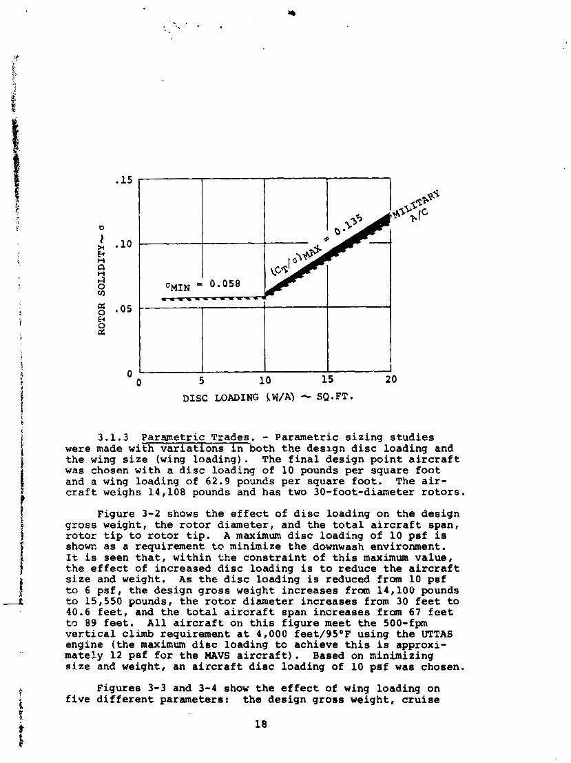
During t h e parametr ic s t u d i e s , t h e r o t o r s o l i d i t y was var ied as a func t ion of d i s c loading as shown by t h e boundaries i n t he following sketch. For t h e m i l i t a r y a i r c r a f t , a l i m i t i n g t h r u s t coe f f i c i en t - to - so l id i ty r a t i o , CT/U, of 0.135 w a s used. This value may be achieved by aerodynamic and a e r o e l a s t i c developments such as those being pursued i n t h e Army/Boeing Heavy L i f t Hel icopter program. This va lue of C T / ~ provides a minimum permiss ible va lue of s o l i d i t y which is d i r e c t l y pro- po r t i ona l t o t h e d i s c loading, as shown i n t h e ske tch , reaching a value of .058 t o .062, depending upon ambient condi t ions , when t h e d i s c loading is reduced t o 10 p s i . For d i s c loadings less than 1 0 p s i , t h e minimum permiss ib le s o l i d i t y was con- s t r a i n e d t o a value of 0.058 based on p r a c t i c a l des ign and manufacturing cons idera t ions of achieving reasonable t o r s i o n a l and f lapping s t i f f n e s s .
A 1 1 t h e conf igura t ion t r a d e o f f s i n t h e conceptual des ign s t u d i e s were done using an advanced computerized a i r c r a f t s i z i n g technique c a l l e d VASCOMP, "V/STOL A i r c r a f t Siz ing and Performance Computer Program," (Reference 2 ) . This program, developed by Boeing under a series of NASA c o n t r a c t s , de f ines design c h a r a c t e r i s t i c s such as weight breakdown, requi red propuls ive power, and phys ica l dimensions of a i r c r a f t which are designed t o meet s p e c i f i e d misaion requirements.
DISC LOADING !+Y/A) SQ-FT*
3.1.3 Parametric Trades. - Parametric s i z i n g s t u d i e s were made with v a r i a t i o n s i n both t h e design d i s c loading and t h e wing s i z e (wing load ing) . The f i n a l des ign p o i n t a i r c r a f t was chosen with a d i s c loading of 10 pounds per square f o o t and a wing loading of 62.9 pounds pe r square foo t . The a i r - c r a f t weighs 14,108 pounds and has two 30-foot-diameter r o t o r s .
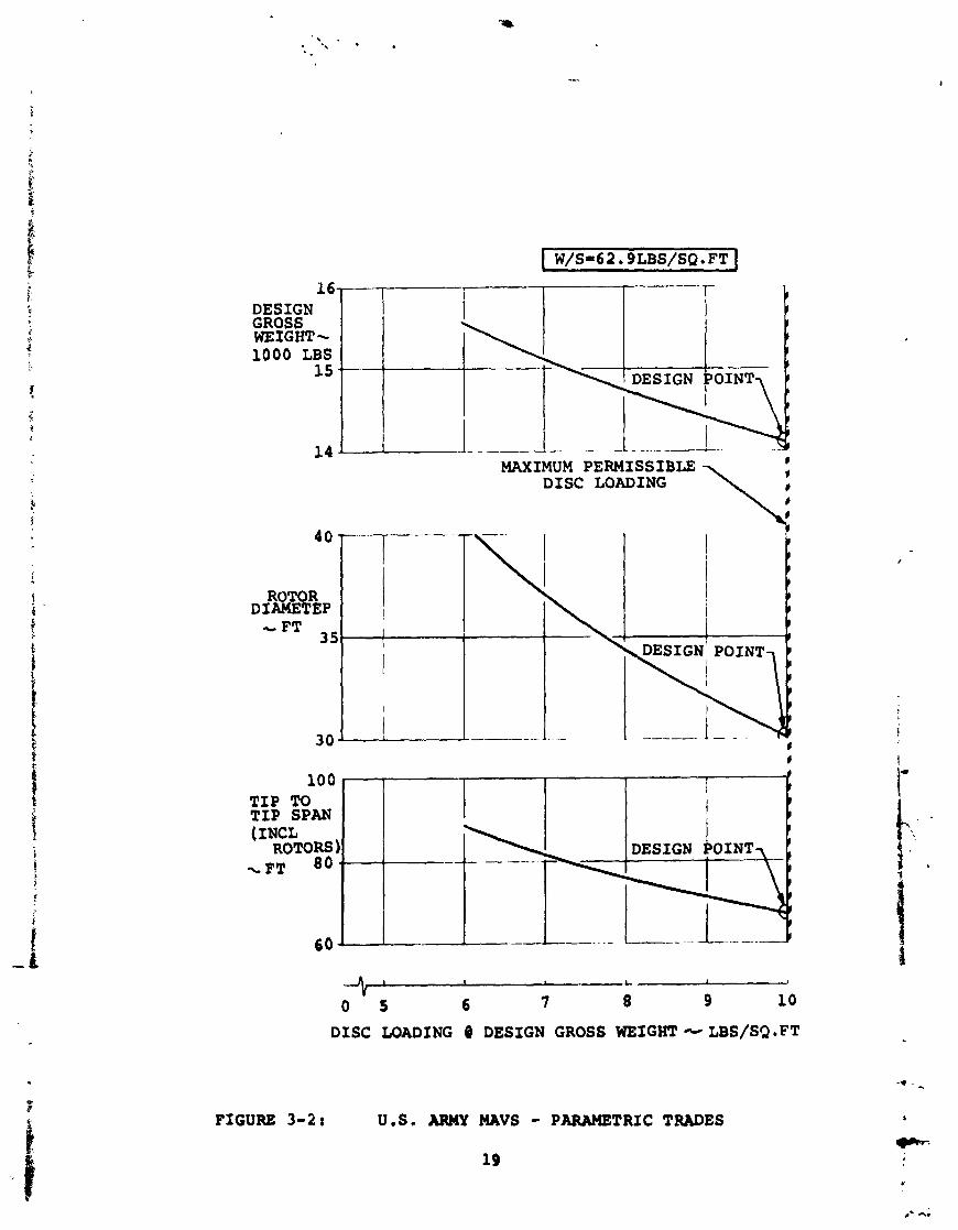
Figure 3-2 shows t h e e f f e c t of d i s c loading on t h e design gross weight, t he r o t o r d iameter , and t h e t o t a l a i r c r a f t span, r o t o r t i p t o r o t o r t i p . A maximum d i s c loading of 10 p s i is shown a s a requirement t o minimize t h e downwash environment. I t is seen t h a t , wi thin t h e c o n s t r a i n t of t h i s maximum va lue , t h e e f f e c t of increased d i s c loading is t o reduce t h e a i r c r a f t s i z e and weight. As t h e d i s c loading i s reduced from 10 p s i t o 6 p s f , t h e design g ros s weight increases from 14,100 pounds t o 15,550 pounds, t h e r o t o r diameter increases from 30 f e e t t o 40.6 f e e t , and t h e t o t a l a i r c r a f t span inc reases from 67 f e e t t o 89 f e e t . A l l a i r c r a f t on t h i s f i g u r e meet t h e 500-fpm v e r t i c a l climb requirement a t 4,000 feet/9S°F using t h e UTTAS engine ( t h e maximum d i s c loading t o achieve t h i s i s approxi- mately 12 psf f o r t h e MAVS a i r c r a f t ) . Based on minimizing s i z e and weight, an a i r c r a f t d i s c loading of 10 psf was chosen.
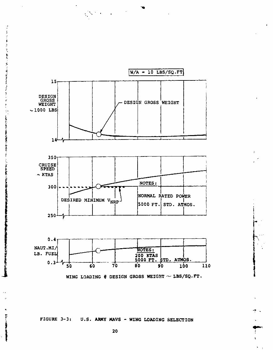
Figures 3-3 and 3-4 show t h e e f f e c t of wing loading on f i v e d i f f e r e n t parameters: t h e design g ros s weight, c r u i s e
MAXIMUM PERMISSIBLE I I
DISCLOADING \ ,
163
I T I P TO TIP SPAN I (INCL
ROTORS - - - - . - -- - \ FT 80 ..
6 0 b -- --
DESIGN GROSS WEIGHT- 1000 LBS
15
14 *
A I , L I
0 5 6 7 8 9 10
DISC LOADING O DESIGN GROSS WEIGHT-LBS/SQ.FT
..
FIGURE 3-2 t U.S. ARMY MAVS - PARAMETRIC TRADES
19
DESIGN GROSS WEIGHT
-1000 LBS
KTAS
NOTES: 1 I 1
i I I I
LB. FUEL NOTES :
200 RTAS
0 . 3 - - 80 90
I 5000 FT. STD* ATMOS.
50 6 0 70 100 110 I
WING L3ADING @ DESIGN GROSS WEIGHT -- LBS/SQIFT.
FIGURE 3-3: U.S. ARMY MAVS - WING LOADING SELECTION
WING LOADING 8 DESIGN GROSS WEIGHT-LBS/SQ.FT.
FIGURE 3-4: U.S. ARMY MAVS - WING U)ADING SELECTION
23
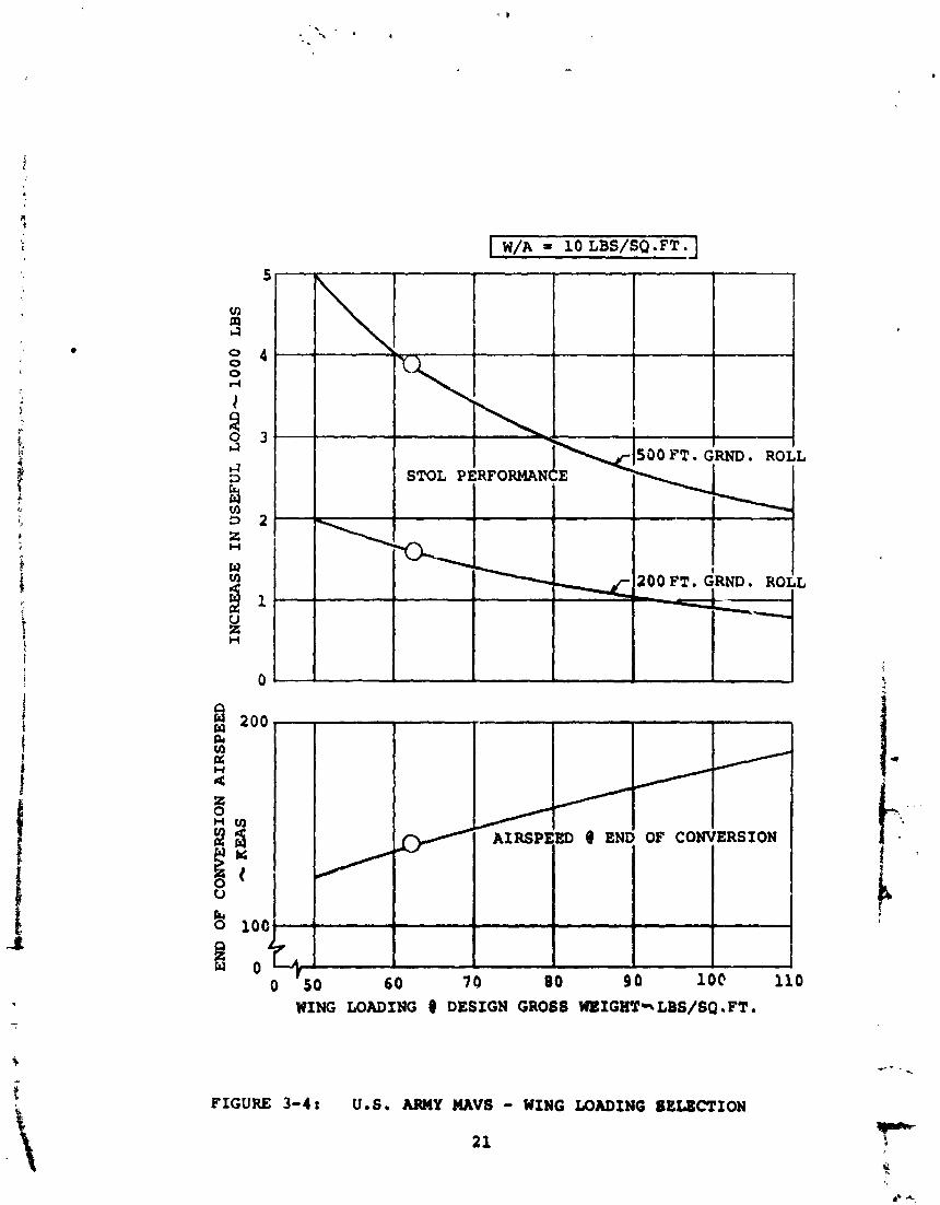
speed , t h e c r u i s e spec r ange a t 200 k n o t s , STOL per formance , and t h e end-of -convers ion a i r s p e e d . I t i s s e e n t h a t t h e d e s i g n g r o s s weight i s n e a r l y i ndependen t of wing l o a d i n g and t h e 200-knot c r u i s e performance improves o n l y s l i g h t l y w i t h i n c r e a s e d wing l o a d i n g . The c r u i s e speed a t normal power, 5,000t/STD i n c r e a s e s w i t h i n c r e a s e d wing l o a d i n g w i t h a wing load ing of 6 2 . 8 p s i o r g r e a r e r r e q u i r e d t o o b t a i n t h e d e s i r e d l e v e l of 300 k n o t s . The end-of -convers ion a i r s p e e d i s s e e n , on F i g u r e 3-4, t o i n c r e a s e w i t h i n c r e a s i n g wing l o a d i n g . For t h e MAVS o p e r s t i o n , where a i r s p e e d s between 200 k n o t s and 140 k n o t s a r e comr,:oniy employed d u r i n g t h e pho to r e c o n n a i s s a n c e m i s s i o n , i t i s advantageous t o p i c k an a i r p l a n e w i t h a low end-o f - co ;~ve r s ion speed . I n a d d i t i o n , lower wing l o a d i n g pro- v i d e s g r e a t e r i n t e r n a l f u e l c a p a c i t y , b e t t e r STOL per formance , and an i n c r e a s e i n c r u i s e c e i l i n g . Based on t h i s c o n s i d e r a t i o n and on t h e normal r a t e d power c r u i s e speed shown i n F i g u r e 3-3, t h e d e s i g n wing l o a d i n g was p i cked a t 62 .9 p s i . T h i s p r o v i d e s an end-of-convers ion speed of 140 k n o t s and a c r u i s e speed of 300 k n o t s . I n a d d i t i o n , a s shown by F i g u r e 3 - 4 , t h i s p r o v i c e s i n c r e a s e d STOL performance when a s h o r t ground r o l l c an be made.
3.2 U . S . A i r Fo rce SAR A i r c r a f t
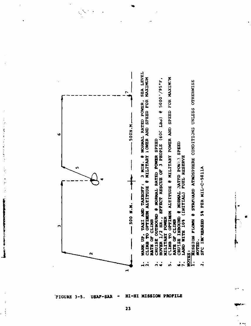
3 .2 .1 Miss ion D e f i n i t i o n . - The m i s s i o n p r o f i l e t o which the A i r Force Search and ~escue A i r c r a f t was d s s i q n e d i s shown i n F i g u r e 3-5. I t c o n s i s t s of c l imbing to optimum a l t i t u d e , c r u i s i n g 500 n a u t i c a l miles a t speed f o r normal r a t e d powcr, hover ing f o r one-ha l f hou r , p ick-up of 3 men weighing 200 pounds e a c h , and r e t u r n . A p p r o p r i a t e r e s e r v e s a r e added. The optimum craise a l t i t u d e f o r t h i s a i r c r a f t (minimum f u e l ) was 20,000 f e e t .
The m i s s i o n load c o n s i s t s of 150 pounds of r e s c u e equip- ment ( l i t t e rs , f o r e s t p e n e t r a t o r , r e s c u e s l i n g , f l a r e s and gun, l i f e r a f t , e t c . ) , a 5.56-mm gun and ammunition, p l u s s p e c i a l r e s c u e e l e c t r o n i c s i n c l u d i n g a i r b o r n e equipment t o l o c a t e t h e r e scuee .
The a i r c r a f t c a r r i e s a four-man crew c o n s i s t i n g of t w o f l i g h t o f f i c e r s , a crew c h i e f , and a paramedic .
The a i r p l a n e was r e q u i r e d t o have a c r u i s e speed o f 300 k n o t s TAS o r g r e a t e r a t an a l t i t u d e of 10,000 f e e t a t mid-poin t hover g r o s s weight .
An i m p o r t a n t r equ i r emen t t h a t Z i c t a t e d e n g i n e power and r o t o r d i a m e t e r was t h a t t h e a i r c r a f t b e c a p a b l e o f hove r ing a t mid-point a f t e r p ickup of seven r e s c u e e s , c o n s i s t i n g of t h e normal complement o f three p l u s an a d d i t i o n a l g roup of f o u r peop le r e p r e s e n t i n g t h e crew of a downed sister s h i p . T h i s r equ i r emen t d i d n o t i n f l u e n c e t h e r e q u i r e d m i s s i o n f u e l --
1.
WAR
K UP, TAXI A
#D TAltBOFF:
3 MINO e
NO
RM
AL
R
AT
ED
P
Om
R,
SE
A
LE
VE
L
20
CL
IUB
TO Om-
ALTITUDE
@ MILITARY
LOW
ER AND
SPE
ED
FO
R MAXIMUM
RATE OF CLXMB
3 .
crur
xsa OUTBOUW) e
#O
RM
U
RATED m
mt
SPE
ED
4
. H
WE
R 1/2
EiR
., E
FFE
CT
R
ESC
UE
O
F 3
PE
OP
LE
(6
OC
I&=)
@ 5
00
0'/
9S
°F,
IIILITARY
POW
ER
5-
CL
IMB
TO
0PTIM.M ALTITUDE
@ M
ILIT
AR
Y POWER A
ND
S
PE
ED
FO
R
MA
XTK
tM
RATE a? CLIMB
6.
CRUISE INBOUND e
NORMAL
AA
TFX
I P
OW
-? SPEED
7.
IAN
D W
ITH
10% (INITIAL) F
UE
L
RE
SER
VE
bi
OT
Es :
n~~~~
Fm
@
ST
-AR
D
AT
WSP
HE
RE
CONDITI3NS
UN
LE
SS
O
TH
ER
WIS
E
NoTm
. ,2
. SFC INCREASED 5
% PER MIL-C-SO11A
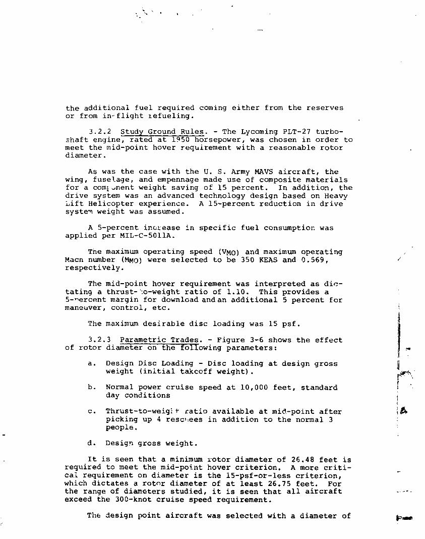
t h e a d d i t i o n a l f u e l r e q u i r e d coming e i t h e r from t h e r e s e r v e s o r from in - f l i g h t ~ e f u e l i n g .
3 . 2 . 2 Study Ground Rules. - The Lycoming PLT-27 turbo- s h a f t engine , r a t e d a t 1950 horsepower, was chosen i n o r d e r t o m e e t t h e mid-point hover requirement. w i t h a r easonab le r o t o r d iameter .
As was t h e c a s e wi th t h e U. S. Army MAVS a i r c r a f t , t h e wing, f u s e l a g e , and empennage made use of composite m a t e r i a l s f o r a c o m l ~ n e n t weight saving of 15 p e r c e n t . I n a d d i t i o n , t h e d r i v e system was an advanced technology d e s i g n based on Heavy L i f t Hel icopter exper ience . A 15-percent r e d u c t i o n i n d r i v e s y s t e ~ weight was assumed.
A 5-percent incxease i n s p e c i f i c f u e l consumption was app l i ed p e r MIL-C-5011A.
The maximum opera t ing speed (VMO) and maximum o p e r a t i n g Macn number (Mpq-~) were s e l e c t e d t o be 350 KEAS and 9 .569, r e s p e c t i v e l y .
The mid-point hover requirement was i n t e r p r e t e d as d i c - t a t i n g a thrust-':o-weight r a t i o of 1.10. T h i s p rov ides a 5-nercent margin f o r download andan a d d i t i o n a l 5 p e r c e n t f o r maneuver, c o n t r o l , etc.
The maximum d e s i r a b l e d i s c loading was 15 p s f .
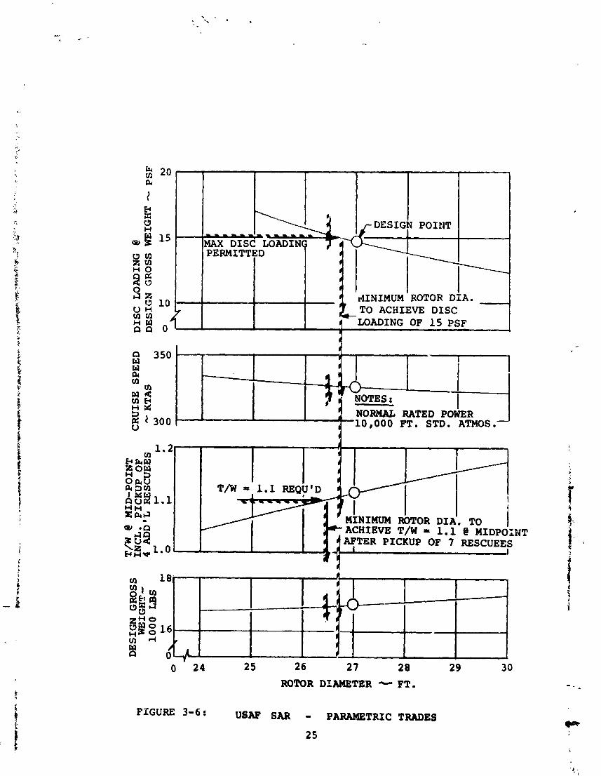
3.2.3 Parametr ic Trades. - Figure 3-6 shows t h e e f f e c t of r o t o r diameter on t h e fo l lowing parameters:
a . Design Disc Loading - Disc loading a t d e s i g n g r o s s weight ( i n i t i a l t akcof f weight) .
b. Normal power c r u i s e speed a t 10,000 f e e t , s t andard day c o n d i t i o n s
c . Thrust-to-weig: 1- r a t i o a v a i l a b l e a t mid-point a f t e r p icking up 4 resolees i n a d d i t i o n t o t h e normal 3 people.
d. Design g r o s s weight .
I t is seen t h a t a minimum r o t o r d iameter of 26 .48 f e e t i s requ i red t o meet t h e mid-point hover c r i t e r i o n . A more c r i t i - c a i requirement on d iameter i s t h e 15-psf-or- less c r i t e r i o n , which d i c t a t e s a r o t c r d iameter of a t least 26.75 f e e t . For t h e range of d iamete r s s t u d i e d , it is seen t h a t a l l a i r c r a f t exceed t h e 300-knot c r u i s e speed requirement .
The des ign p o i n t a i r c r a f t was s e l e c t e d w i t h a d iameter of
Q 350 - W W 0( m
VI
P Q n s~ - 3 NORMAL RATED POWER 5 4 300 FT. STD. ATMOS.
ROTOR DIAMETER - FT. FIGURE 3-6: USAF SAR - PARAMETRIC TRADES
25
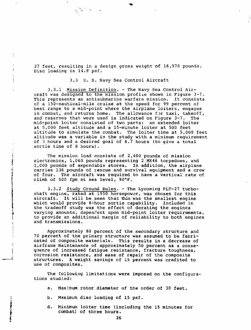
27 f e e t , r e s u l t i n g i n a d e s i g n g r o s s we igh t of 16,970 pounds. Disc load ing i s 14.8 p s f .
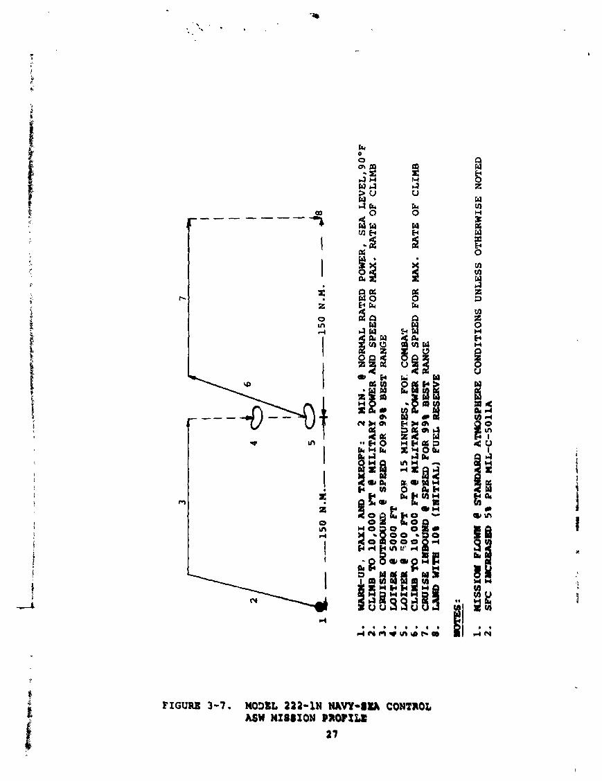
3 . 3 U. S . Navy Sea C o n t r o l A i r c r a f t
3 .3 .1 Miss ion D e f i n i t i o n . - The Navy Sea C o n t r o l A i r - c r a f t was des igned t o t h e m i s s i o n p r o f i l e shown i n F i g u r e 3-7. T h i s r e p r e s e n t s a n an t i submar ine w a r f a r e m i s s i o n . I t c o n s i s t s of a 150-naut ica l -mi le c r u i s e a t t h e speed f o r 99 p e r c e n t o f b e s t r ange t o a mid-point where t h e a i r p l a n e l o i t e r s , engages i n combat, and r e t u r n s home. The a l lowance f x t a x i , t a k e o f f , and r e s e r v e s t h a t were used is i n d i c a t e d on F i g u r e 3-7. The mid-point l o i t e r c o n s i s t e d o f two p a r t s : a n ex tended l o i t e r a t 5,000 f e e t a l t i t u d e and a 15-minute l o i t e r a t 500 f e e t a l t i t . u d e t o s i m u l a t e t h e combat. The l o i t e r t i m e a t 5,000 f e e t a l t i t u d e was a v a r i a b l e i n t h e s t u d y w i t h a minimum requ i r emen t o f 3 hours and a d e s i r e d g o a l of 6.7 hour s ( t o g i v e a t o t a l s c n t i e t i m e o f 8 h o u r s ) .
The m i s s i o n load c o n s i s t s o f 2,400 pounds of m i s s i o n e l e c t r o n i c s , 1 ,060 pounds r e p r e s e n t i n g 2 MK46 t o r p e d o e s , and 1,000 pounds of expendable s t o r e s . I n a d d i t i o n , t h e a i r p l a n e c a r r i e s 136 pounds of r e s c u e and s u r v i v a l equipment and a crew o f f o u r . The a i r c r a f t was r e q u i r e d t o have a v e r t i c a l ra te of c l imb o f 500 fpm a t s e a l e v e l , 90°F.
3.3.2 Study Ground Rules . - The Lycoming PLT-27 t u r b o - s h a f t e n g i n e , r a t e d a t 1950 horsepower, was chosen f o r t h i s a i r c r a f t . I t w i l l be seen t h a t t h i s was t h e s m a l l e s t eng ine which would p r o v i d e 8-hour s o r t i e c a p a b i l i t y . Inc luded i n t h e t r a d e o f f s t u d y was t h e e f f e c t o f d e r a t i n g t h e e n g i n e s va ry ing amounts, depent4ent upon mid-poin t l o i t e r r e q u i r e m e n t s , t o p rov ide an a d d i t i o n a l margin o f r e l i a b i l i t y t o b o t h e n g i n e s and t r a n s m i s s i o n s .
Approximately 80 p e r c e n t o f t h e secondary s t r u c t u r e and 70 p e r c e n t o f t h e pr imary s t r u c t u r e was assumed t o b e f a b r i - c a t e d of composi te m a t e r i a l s . T h i s r e s u l t s i n a d e c r e a s e of a i r f r a m e maintenance of approximate ly 50 p e r c e n t a s a conse- quence of i n c r e a s e d f a t i g u e r e s i s t a n c e , f r a c t u r e toughness , c o r r o s i o n r e s i s t a n c e , and ease of r e p a i r o f t h e composi te s t r u c t u r e s . A weight s a v i n g s o f 15 p e r c e n t was c r e d i t e d t o u s e of composi tes .
The to l lowing l i m i t a t i o n s were imposed on t h e con£ i g u r a - t i o n s s t u d i e d :
a. Maximum r o t o r d i a m e t e r of t h e o r d e r of 30 f e e t .
b . Maximum d i s c l o a d i n g of 1 5 p s f .
d . Minimum l o i t e r time ( i n c l u d i n g t h e 15 minu tes f o r combat) of t h r e e h o u r s .
2 6
mm
-UP
, TAXI A
ND
TAKEOFF:
2 IN
. e NORMAL R
AT
ED
C
LM
B TO 10,000
Y'T
f! HILITARY P
OWER A
ND
SPEED FOR
CRUISE O
WT
BO
U~
e SP
EE
D FOR
99
a BEST RANGE
mrlre
R
e 5
00
0 PT
LOITER
e 5
00
FT FOR rs MINUTES, FOE C
OM
BA
T CLIMB T
O
10
,00
0 FT e
rULlTARY P
OW
ER
AN
D
SPE
ED
F
OR
C
BC
IISB
IH
BW
MD
@ SF-
FOR
99
% BEST RANGE
raroD
WT
B 10%
(Ia
tIT
uL
) FUEL R
ESE
RV
E
POWER,
SE
A
LE
VE
L, 9
0 O
F M
AX
. R
AT
E
OF
CL
IMB
MA
X. RATE
OF
C
LIM
B
I.
mss
xa
PUMU
e ST-
A~
PL
IE
RE
CONDITIONS UNLESS OTHERWISE
NO
TE
D
2.
SP
C
I-W
5%
PE
R
lUL
-C-!
joIl
A

The f i r s t two of t h e s e l i m i t a t i o n s were chosen t o t a k e advantage of e x i s t i n g technology. Although a three-hour minimum l o i t e r t ime was imposed, it was d e s i r e d t o o b t a i n 6 . 7 hours a t mid-point i n o r d e r t o ach ieve a n 8-hour s o r t i e .
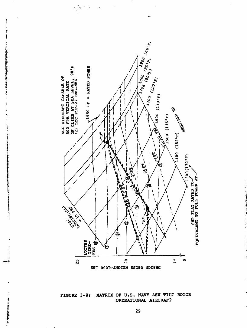
3.3.3 P a r m e t s i c Trades. - Figure 3-8 i s a d e s i g n c h a r t which shows t h e c h a r & e r i s t i s s of a fami ly of t i l t - r o t o r a i r c r a f t des igned f o r t h e ASW mis"i,on. he d e s i g n g r o s s weight i s d i s p l a y e d on t h i s f i g u r e a s a f u n c t i m of r o t o r d i a - meter snd t h e d e s i r e d mid-point l o i t e r t i m e . Curves of d i s ~ lonuin3 and r e q u i r e d horsepower a r e s u p e r i m p ~ s e s cm t h i s c h a r t . A * l z i r c r a . f t on t h i s f i g u r e a r e capab le of a v e r t i c a l cl imb o f 50G f e e t p e r minute a t s e a l e v e l , 90°F, a t t h e d e s i g n g r o s s weight . The boundar ies shown by t h e c ross -ha tch r e p r e ; e n t t h e l i m i t s on r o t o r d iamete r , d i s c l o a d i n g , and minimum l o i t e r t i m e . Two i n t e r e s t i n g d e s i g n c h o i c e s on t h i s f i g u r e a r e des- igna ted by t h e letters "A" and "B."
Conf igura t ion "A" i s t h e l i g h t e s t a i r c r a f t which f a l l s w i t h i n t h e p e r m i s s i b l e envelope , weighing 17,720 pounds. I t i s capable of t h r e e hours of i o i t e r a t mid-point ( 4 . 3 hours t o t a l miss ion t i m e ) . The PLT-27 eng ines can be d e r a t e d t o 1420 horsepower a t s e a l e v e l , s t a n d a r d day c o n d i t i o n s , and s t i l l p rov ide s u f f i c i e n t power f o r 500 foot-per-minute v e r t i c a l r a t e of c l imb a t s e a l e v e l , 90°F. Rotor d iamete r is 2 7 . 4 f e e t .
Conf igura t ion "B" p rov ides t h e g r e a t e s t l o i t e r c a p a b i l i t y of any a i r c r a f t w i t h i n t h e p e r m i s s i b l e envelope, w i t h 6.7 hours a t mid-point and a t o t a l miss ion time o f 8.0 hours. The air- c r a f t weighs 21,640 pounds and h a s 30.3-foot-diameter r o t o r s . Th i s c o n f i g u r a t i o n was chosen as t h e d e s i g n p o i n t .
3 .4 C i v i l Off-shore O i l Rig Suppor t
3.4.1 Mission D e f i n i t i o n - The primary m i s s i o n f o r - t h e o f f - shore 01; r i g s u p p o r t a i r c r a f t is shown i n F i g u r e 3-9. The d e s i g n p r o f i l e i n c l u d e s a c r u i s e a t 20,000 f e e t a l t i t u d e t o t h e o i l r i g w i t h a v e r t i c a l l and ing a t sea l e v e l , 9S°F. The a i r y ' a n e carries s u f f i c i e n t f u e l t o r e t u r n t o t h e s h o r e p l u s one-half-hour o f endurance. The Boeing s t u d y o f o p e r a t i o n s a t Petroleum H e l i c o p t e r s , Inc . (PHI) i c d i c a t e s t h a t , f o r t h e crew exchange miss ion , t h e avexage f l i g h t s a r e of 50 t o 125 s t a t u e miles range. The passenger l o a d i s less t h a n 6 passen- g e r s 1 0 p e r c e n t of t h e t ime, 6 t o 9 passengers 25 p e r c e n t of t h e t i m e , and 10 passengers 65 p e r c e n t o f t h e time. A s a r e s u l t , 12 passengers were chosen f o r t h e d e s i g n payload and 125 s t a t u t e m i l e s (109 n a u t i c a l miles) w a s chosen f o r t h e d e s i g n r a d i u s .
The eng ine power was r e q u i r e d t o b e s u f f i c i e n t t o g i v e a hover thrus t - to-weight ra t io o f 1.1 ( 5 p e r c e n t download p l u s 5 p e r c e n t a d d i t i o n a l maryin) a t i n i t i a l t a k e o f f weight .
AL
L
AIR
CR
AF
T
CA
PA
BL
E O
F
50
0
FPM
V
ER
TIC
AL
R
AT
E
OF
CL
IMB
A
T SE
A
LE
VE
L, 90°F
12
) L
YC
PLT-27
EN
GIN
ES
71
30
0 (1
70
0~
)
SHP PUT R
AT
ED
TO//
EQ
UIV
AL
EN
T T
O
FU
LL
PO
WER
A
T
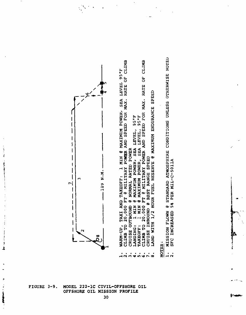
WARM-UP, TAXI AND TAKEOFF:
1 MIN
@ MAXIMUM POWER, SEA LEVEL 9S°F
CLIMB TO 20,000 FT
@ MILITARY P
MR
AND SPEED FOR MAX. RATE OF CLIMB
CRUISE OUTBOUND
@ NORMAL RATED POWER
LANDING:
1 MIN
@ MAXIKUM POWER* SEA LEVEL, 95OF
TAKEOFF:
1 MIN
@ MAXIMUM POWER, SEA LEVEL, 95OF
CLIMB TO 20,000 FT
@ MILITARY POWER AND SPEED FOR MAX. RATE OF CLIMB
CRUISE INBOUND
@ BEST RANGE SPEED
LAND WITH 1/2 HOUR FUEL RESERVE
@ MAXIMUM ENDURANCE SPEED
NOTES I
1.
MISSION FLOWN
@ STANDARD ATMOSPHERE CONDITIONS UNLESS OTHERWISE NOTED
2.
SFC INCREASED 5% PER MIL-C-5011A
The a i r p l a n e c a r r i e s a crew of two.
3.4.2 Study Ground Rules. - The primary requirements imposed f o r t h e s e l e c t i o n of a design po in t conf igura t ion f o r t h e off-shore o i l mission were t h a t it make maximum use of proven technology and r e a d i l y a v a i l a b l e subsystems.
The s t r u c t u r e was f ab r i ca t ed of metal , r a t h e r than t h e composite ma te r i a l s used i n t h e t h r e e m i l i t a r y a i r c r a f t . The transmissions were a s tandard design concept, r a t h e r than t h e advanced technology t ransmiss ions chosen f o r t h e o t h e r configu- r a t i o n s . The r o t o r s o l i d i t y w a s based on a maximum CT/U of 0.09 r a t h e r than t h e va lue of 0.135 used f o r t h e m i l i t a r y a i r c r a f t .
The r o t o r diameter was f ixed a t 26 f e e t i n o rde r t o t ake maximum advantage of t h e Boeing ana lys i s , des ign, and test experience der ived from t h e research a i r c r a f t a c t i v i t i e s .
Only a v a i l a b l e proven engines were considered, s p e c i f i c - a l l y t h e P r a t t & Whitney PT6C-40, t h e Lycoming T53-L-13B, and t h e General E l e c t r i c T58-8F.
3.4.3 Parametric Trades. - A l l t h e engines meet t h e payload-radius mquirement, t h e PT6 j u s t meeting i t l a n d t h e T53 and T58 exceeding t h e minimum requirement. With t h e can- d i d a t e engines each capable of providing t h e requi red per for - mance,the prime cons idera t ion f o r engine s e l e c t i o n f o r a c i v i l a i r c r a f t becomes engine r e l i a b i l i t y .
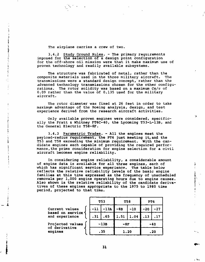
I n consider ing engine r e l i a b i l i t y , a cons iderab le amount of engine d a t a is a v a i l a b l e f o r a l l t h r e e engines , each of which has s i g n i f i c a n t s e r v i c e experience. The t a b l e below r e f l e c t s t h e r e l a t i v e r e l i a b i l i t y l e v e l s of t h e bas i c engine f ami l i e s a t t h i s time expressed as t h e frequency of unscheduled removals per 1,000 engine opera t ing hours due t o engine causes. Also shown i s t h e r e l a t i v e r e l i a b i l i t y of t h e candidate der iva- t i v e s of t he se engines appropr ia te t o t h e 1975 t o 1980 time per iod, p ro jec ted t o t h a t t i m e .
Current va lues based on s e r v i c e and experience
Projected va lues of d e r i v a t i v e engines
The r e l i a b i l i t y p r e d i c t r o n s f o r t h e c a n d i d a t e e n g i n e s a r e based on t h e s e r v i c e e x p e r i e n c e of t h e b a s i c f a m i l y , t h e s p e c i f i c c o n f i g u r a t i o n changes from t h e b a s i c f a m i l y , and t h e t i m e a t which t h e c a n d i d a t e e n g i n e s would be i n c o r p o r a t e d i n t o t h e proposed a i r c r a f t .
Based on t h e s e r e l a t i v e r e l i a b i l i t y l e v e l s coupled w i t h u n u s u a l l y h igh TBO l e v e l s o f 3 ,000 t o 4,000 h o u r s , t h e PT6 was s e l e c t e d . Another f a c t o r c o n s i d e r e d i s t h e e x t e n s i v e network of l o g i s t i c s s u p p o r t and main tenance t r a i n i n g f a c i l i t i e s deve loped th roughou t t h e world on t h e PT6 based on i t s wide commercial a ~ p l i c a t i o n s .
4.0 AIRCRAFT DESCRIPTIONS
4 . 1 A i r c r a f t Conf igura t ions
4 . 1 . 1 I n t r o d u c t i o n . - The d i s c u s s i o n 0x1 c o n f i g u r a t i o n i s d iv ided i n t o two s e c t i o n s . The f i r s t s e c t i o n (4.1.2) concerns f e a t u r e s t h a t a r e common t o t h e f o u r c o n f i g u r a t i o n s d e p i c t e d . The second s e c t i o n (4.1.3) s p o t l i g h t s t h e f e a t u r e s t h a t a r e unique t o a p a r t i c u l a r c o n f i g u r a t i o n .
4.1.2 Conf igura t ion Approach. - The f u s e l a g e conf igura - t i o n f o r any g iven a i r c r a f t i s p r i m a r i l y d i c t a t e d by t h e miss ion requi rements and t h e empennage c o n f i g u r a t i o n by s t a - b i l i t y and c o n t r o l requi rements . For t h e f o u r c o n f i g u r a t i o n s p resen ted where c r i t i c a l Mach number c o n s i d e r a t i o n s a r e n o t p a r t i c u l a r l y demanding, t h e wing s i z e and geometry have been chosen f o r t h e most e f f i c i e n t and s imple s t r u c t u r a l a r range- ment lnd n a c e l l e a t tachment , c o n s i s t e n t w i t h t h e r e q u i r e d r e l a t i o n s h i p between t h e n a c e l l e tilt p i v o t and wing f o r c o r r e c t c e n t e r of g r a v i t y l o c a t i o n i n hover and c r u i s e f l i g h t . Some of t h e c o n f i g u r a t i o n f e a t u r e s common t o a l l f o u r a i r c r a f t a r e :
a . High wing c o n f i g u r a t i o n s e l e c t e d t o p rov ide adequate nacel le- to-ground ~ l e a r a n c e s .
b. Rotor c e n t e r - t o - c e n t e r d i s t a n c e des igned t o g i v e a 12-inch c l e a r a n c e between f u s e l a g e and r o t o r t i p i n c r u i s e a t t i t u d e .
c. Rotor-to-wing c l e a r a n c e i n t h e c r u i s e a t t i t u d e des igned t o g i v e 12-inch minimum c l e a r a n c e .
d . F a i l o p e r a t i v e n a c e l l e tilt a c t u a t i o n system con- f i g u r e d around a unique b a l l screw des ign .
e. Cross-shaf t t o p rov ide power t r a n s f e r f o r one engine o u t o p e r a t i o n .
f . Nace l l e tilt a x i s p o s i t i o n e d on wing t o g i v e minimum c y c l i c t r i m requirement .
g. Cabin and a f t compartment (where a p p l i c a b l e ) a r e p r e s s u r i z e d .
h. Hingeless r o t o r r e q u i r i n g minimum maintenance.
i. Wing download r e d u c t i o n d e v i c e s .
4.1.3 S p e c i f i c Conf igura t ions .
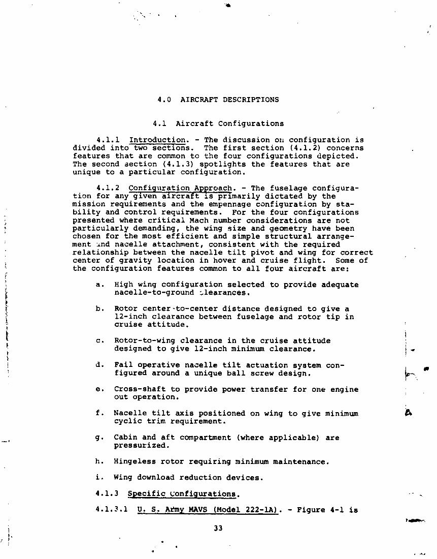
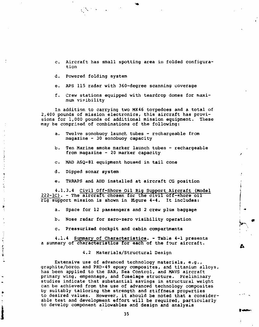
4.1.3.1 U. S. Arkny MAVS (Model 222-1A). - Figure 4-1 is
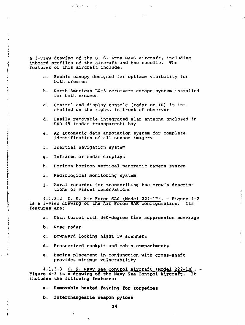
a 3-view drawing of t h e U. S . Army MAVS a i r c r a f t , i nc lud ing inboard p r o f i l e s of t h e a i r c r a f t and t h e n a c e l l e . The f e a t u r e s of t h i s a i r c r a f t inc lude :
a . Bubble canopy designed f o r optimum v i s i b i l i t y f o r both crewmen
b. North American LW-3 zero-zero escape system i n s t a l l e d f o r both crewmen
c . Con t ro l and d i s p l a y conso le ( r a d a r o r I R ) i s i n - s t a l l e d on t h e r i g h t , i n f r o n t of obse rve r
d. E a s i l y removable i n t e g r a t e d s l a r antenna enclosed i n PRD 49 ( r a d a r t r a n s p a r e n t ) bay
e . An automat ic d a t a a n n o t a t i o n system f o r complete i d e n t i f i c a t i o n of a l l sensor imagery
f . I n e r t i a l n a v i g a t i o n system
g . I n f r a r e d o r r a d a r d i s p l a y s
h. Horizon-horizon v e r t i c a l panoramic csmera system
i. Radio log ica l moni tor ing system
j. Aural r e c o r d e r f o r t r a n s c r i b i n g t h e crew's d e s c r i p - t i o n s of v i s u a l o b s e r v a t i o n s
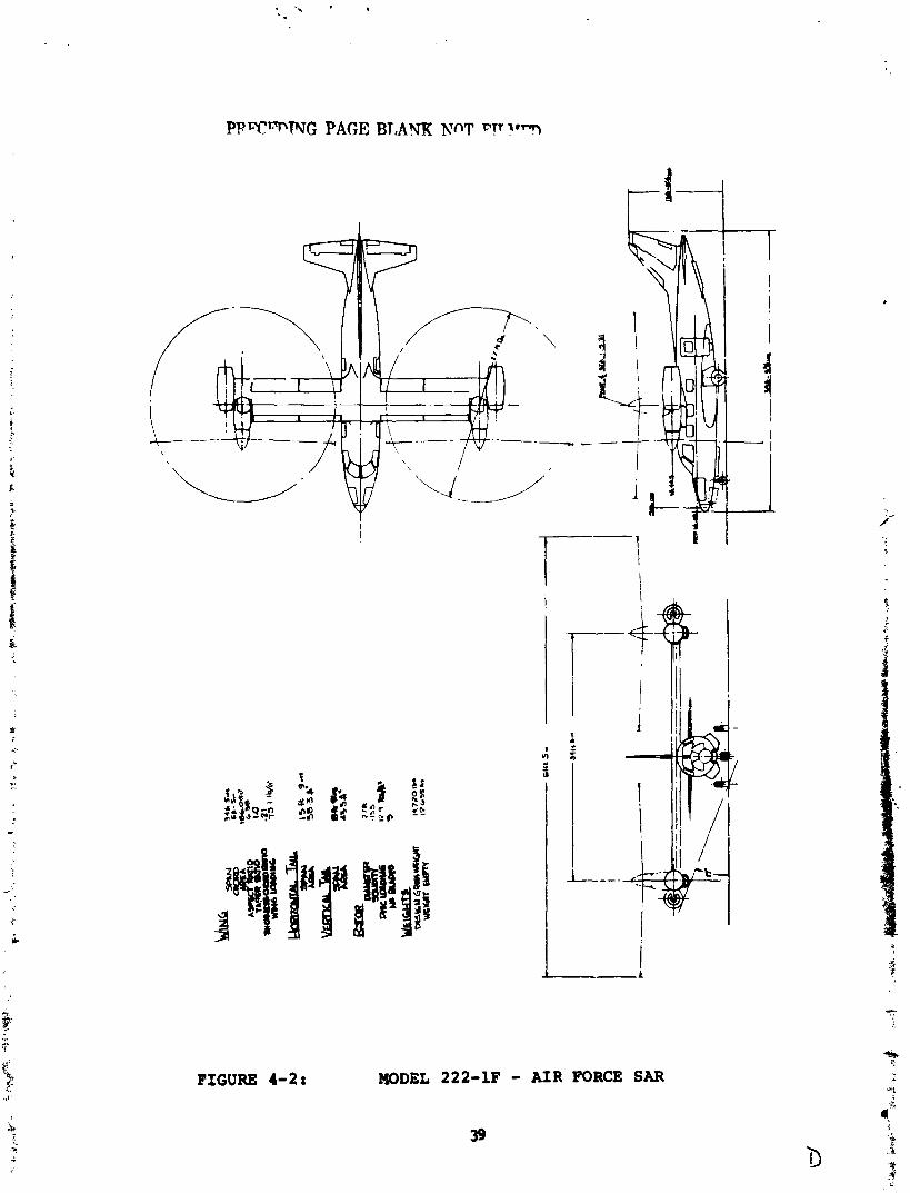
4.1.3.2 U. S. A i r Force SAK (Model 222-1F). - Figure 4-2 is a 3-view drawing of t h e A i r Force SAR c o n f i g u r a t i o n . Its f e a t u r e s a r e :
a . Chin t u r r e t w i t h 360-degree f i r e suppress ion coverage
b. Nose r a d a r
c. Downward looking n i g h t TV scanners
d. P r e s s u r i z e d c o c k p i t and c a b i n compartments
e. Engine placement i n con junc t ion w i t h c r o s s - s h a f t p rov ides minimum v u l n e r a b i l i t y
4.1.3.3 U. S. Navy Sea Cont ro l A i r c r a f t (Model 222-1N). - Figure 4-3 is a drawing o f t h e Navy Sea C o n t r o l A i r c r a f t . It i n c l u d e s t h e fo l lowing f e a t u r e s :
a . Removable heated f a i r i n g f o r torpedoes
b. In te rchangeab le weapon pylons
c . A i r c r a f t has smal l s p o t t i n g a r e a i n fo lded conf igura - t i o n
d . Powered f o l d i n g system
e. APS 115 r a d a r wi th 360-degree scanning coverage
f . Crew s t a t i o n s equipped wi th t e a r d r o p domes f o r maxi- mum v i s i b i l i t y
I n a d d i t i o n t o c a r r y i n g two MK46 torpedoes and a t o t a l of 2,400 pounds of miss ion e l e c t r o n i c s , t h i s a i r c r a f t has p rov i - s i o n s f o r 1,000 pounds of a d d i t i o n a l miss ion equipment. These may be conpr ised of combinations of t h e fo l lowing:
a . Twelve sonobuoy launck. t u b e s - rechargeab le from magazine - 30 sonobuoy c a p a c i t y
b. Ten Marine smoke marker launch t u b e s - rechargeab le from magazine - 20 marker c a p a c i t y
c. MAD ASQ-81 equipment housed i n t a i l cone
d . Dipped sonar system
e. TKRAPS and ADD i n s t a l l e d a t a i r c r a f t CG p o s i t i o n
4.1.3.4 C i v i l Off-Shore O i l Rig Suppor t A i r c r a f t (Model 222-1C). - The a i r c r a f t chosen f o r t h e c i v i l o f f -ahore o i l - r i g suppor t miss ion is shown i n f igure 4-4. I t incLudes:
a . Space f o r 12 passengers and 2 crew p l u s baggage
b. Nose r a d a r f o r zero-zero v i s i b i l i t y o p e r a t i o n
c. P r e s s u r i z e d c o c k p i t and c a b i n compartments
4 .1 .4 Summary of C h a r a c t e r i s t i c s . - Table 4-1 p r e s e n t s a summary o f x a r a c t e r i s t i c s f o r each of t h e f o u r a i r c r a f t .
4.2 M a t e r i a l s / S t r u c t u r a l Design
Extens ive use of advanced technology m a t e r i a l s , e . g . , graphi te /boron and PRD-49 epoxy composi tes , and t i t a n i u m a l l o y s , has been app l i ed t o t h e SARI Sea C o n t r o l , and MAVS a i r c r a f t primary wing, empennage, and f u s e l a g e s t r u c t u r e . P re l iminary s t u d i e s i n d i c a t e t h a t s u b s t a n t i a l s a v i n g s i n s t r u c t u r a l weight can be achieved from t h e use of advanced technology composi tes by s u i t a b l y t a i l o r i n g t h e s t r e n g t h and s t i f f n e c s p r o p e r t i e s t o d e s i r e d va lues . However, it should be noted t h a t a cons ide r - a b l e t e s t and development e f f o r t w i l l be r e q u i r e d , p a r t i c u l a r l y t o develop component a l lowables and d e s i g n and a n a l y s i s
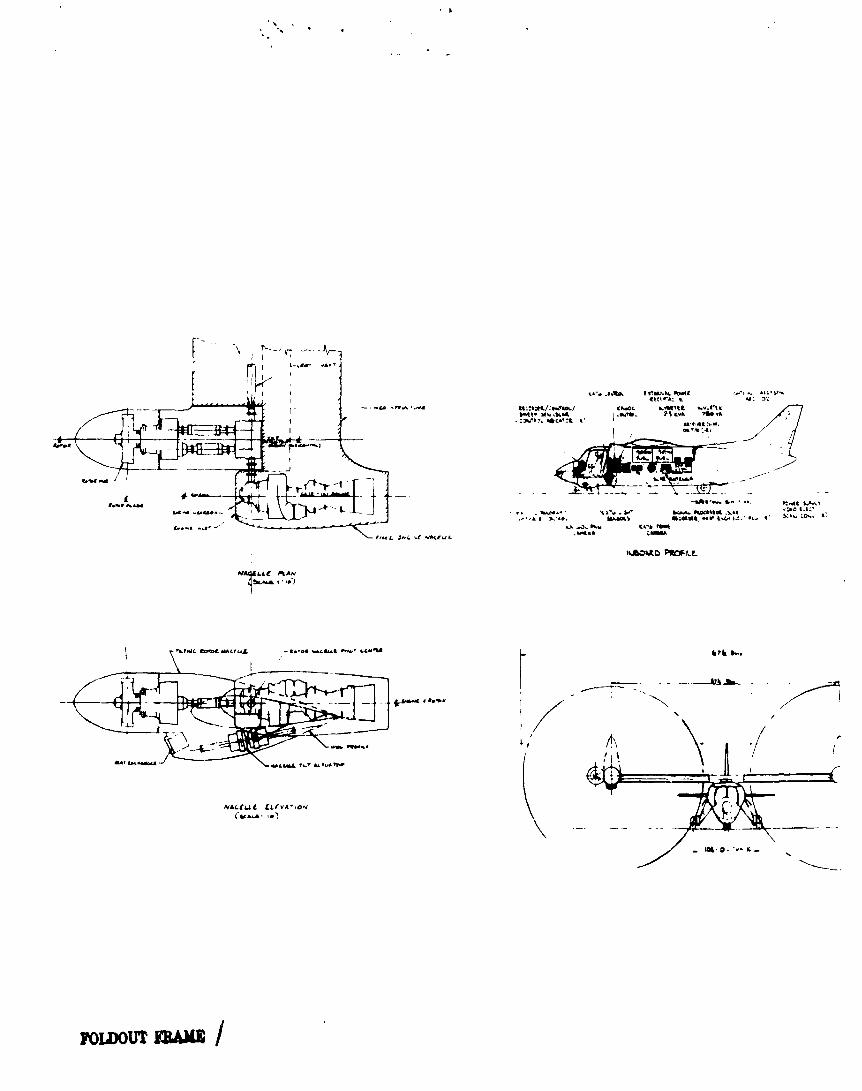
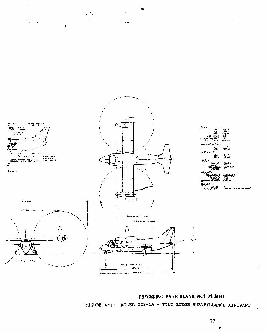
PRM=EI;INC) PAGE BLAMt NOT FLLMED FIGURE 4-1: MODEL 222-1A - TILT ROTOR SURVEILLANCE AIRCHAFT
P P T W N G PAGE BT,AYK NOT VTr ?rT
FIGURE 4-2: MODEL 222-1F - AIR FORCE SAR
39
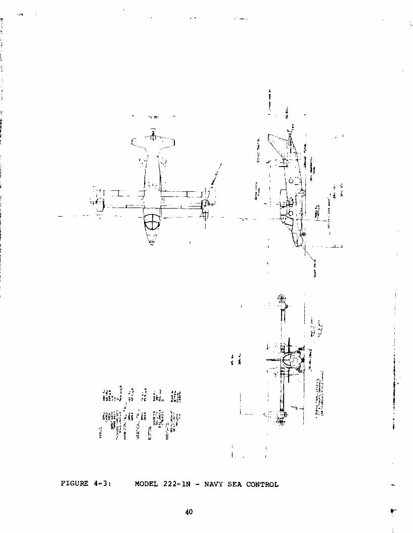
FIGURE 4-3: MODEL 222-1N - NAVi SEA CONTROL
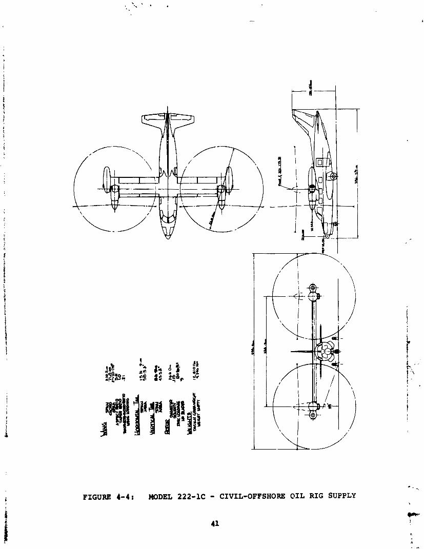
FIGURE 4-4: MODEL 222-1C
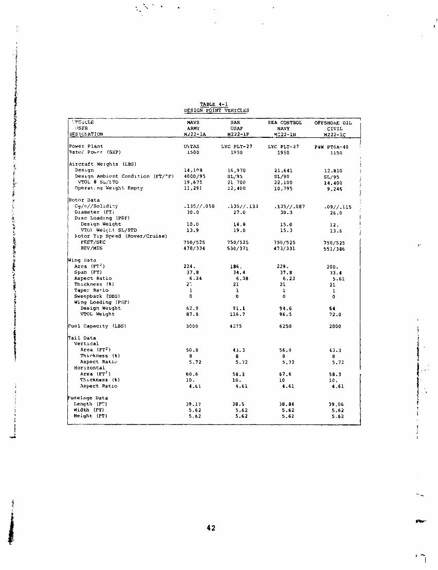
TABLE 4-1 DESIGN POINT VEHICLES
'.'C':;iCLE MAVS SAR SEA CONTROL 0FFSHOh.E OIL \ISER ARMY USA!? NAVY CIVIL
)ESIGXATION M222-1A M222-1F W122-1N M222-1C
'ower P l a n t ( a t e < P0wr.r (SHP)
h i r c r a f t We] g h t s (LBS) D e s l g n D e s i g n Ambient Condition (FT/OF)
VTOL @ SL/'ETD O p e r a t - n g Welgh t Empty
Lotor D a t a C T / a / / S o l r d i s y D l a m e t e r (FTj D l s c L o a d l n g (PSF)
D e s l q n Weigh t VTOi Wei9k.t SL/STD
h o t o r T l p Spc.t?d ( H o v e r / C r u i s e ) FEET/SEC REV/MIN
i n g D a t a A r e a ( F T ~ ) Span (FT) A s p e c t R a t i o Thickness ( $ 1 T a p e r R a r i o Sweepback (DEG) Wing L o a d i n g (P:iF)
D e s i g n Welgh t VTOL Weigh t
u e l C a p a c l t y (LBS)
a i l D a t a V e r t l c a l
A r e a ( F T ~ ) T h i c k n e s s ( % )
A s p e c t R a t l c H o r i z o n t a l
A r e a ( F T ~ ) T b ~ c k n e s s ( 8 ) A s p e c t R a t l o
u s e l a g e D a t a L e n g t h (F") Wid th (FT) H e i g h t (FT)
LYC PLT-27 1950
1 6 , 9 7 0 SL/9 5 2 1 700 12 ,400
.135/ / .133 27.0
14 .8 1 9 . 0
750/525 530 /371
186 . 34.4
6 .38 21 1 0
9 1 . 1 116.7
4275
43 .3 8 5 .72
58 .3 1 0 .
4 .61
38.5 5.62 5.62
LYC PLT-27 1950
2 1 , 6 4 1 SL/90 22 ,100 1 0 , 7 9 5
.135/ / .087 30.3
15.0 1 5 . 3
750 /525 473 /331
229. 37 .8
6 .23 2 1 1 0
94.6 96 .5
6250
56.3 8 5.72
67.6 1 0
4 .61
38.84 5.62 5.62
PLW PT6A-40 1150
12 .810 SL/95 1 4 , 4 0 0
9 , 2 4 6
.09/ / .115 26.0
1 2 . 13 .6
750/525 551/386
200. 33.4
5 .61 2 1 1 0
6 4 72.0
2000
43.3 8 5.72
58 .3 1 0 .
4.61
39.06 5.62 5.62
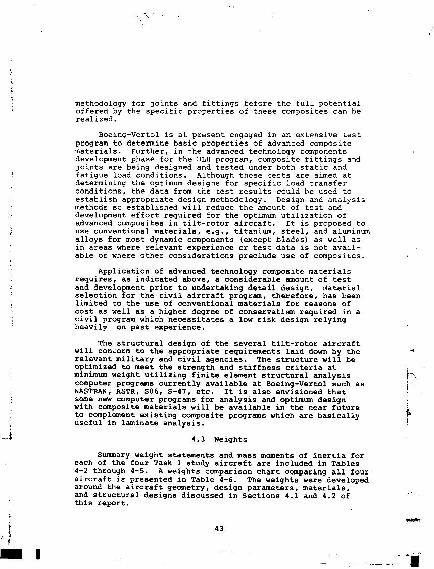
methodology for joints and fittings before the full potential offered by the specific properties of these composites can be realized.
Boeing-Vertol is at present engaged in an extensive test program to determine basic properties of advanced composite materials. Further, in the advanced technology components development phase for the HLH program, composite fittings and joints are being designed and tested under both static and fatigue load conditions. Although these tests are aimed at determining the optimum designs for specific load transfer conditions, the data from rne test results could be used to establish appropriate design methodology. Design and analysis methods so established will reduce the amount of test and development effort required for the optimum utilization of advanced composites in tilt-rotor aircraft. It is proposed to use conventional materials, e.g., titanium, steel, and aluminum alloys for most dynamic components (except biades) as well as in areas where relevant experience or test data is not avail- able or where other considerations preclude use of composites.
Application of advanced technology composite materials requires, as indicated above, a considerable amount of test and development prior to undertaking detail design. idaterial selection for the civil aircraft program, therefore, has been limited to the use of conventional materials for reasons of cost as well as a higher degree of conservatism required in a civil program which necessitates a low risk design relying heavily on past experience.
The structural design of the several tilt-rotor aircraft will coniorm to the appropriate requirements laid down by the relevant military and civil agencies. The structure will be optimized to meet the strength and stiffness criteria at minimum weight utilizing finite element structural analysis computer programs currently available at Boeing-Vertol such as NASTRAN, ASTR, S06, S-47, etc. It is also envisioned that some new computer programs for analysis and optimum design with composite materials will be available in the near future to complement existing composite programs which are basically useful in laminate analysis.
4.3 Weights
Summary weight statements and mass moments of inertia for each of the four Task I study aircraft are included in Tables 4-2 through 4-5. A weights comparison chart comparing all four aircraft ie presented in Table 4-6. The weights were developed around the aircraft geometry, design parameters, materials, and structural designs discussed in Sections 4.1 and 4.2 of this report.
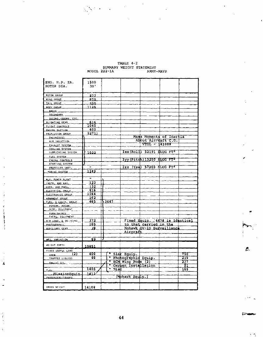
TABLE 4-2 SUMMARY NEIGYT STATEMCUT
MODEL 2 2 2 - 1 A ARMY-AMAV S
ENG. H.P. EA. ROTOR DIA.
ROTOR GROUP
WING GROUP
T A l L GROUP -- OUP
B A S I C SECONDARY
S E C V R S . ETC.
A L I G H T I N G GEAR
--
PROPULS l ON GROUP
- E N G l N E S l S l
A I R I N D U C T I O N C Y u l l l C 7 CYCTC..
COOLING SYSTEM I I 1 I ! I I LUBRICATING SYSTEM [ IXX ( ~ 0 1 4 ) 5 2 1 9 1 3LUG FT' I 1 - FUEL SYSTEM I 1 1 I
CYGlNE CONTROLS I Iyy (Pit*) 13200 QLUG FT' START l NG SYSTEM J I I I
1 - PROPELLER I N S T .
- j IZZ (Yad) 57200 qLUG FT*
STEM 1 2 4 9 I I I I I
, Aircraflt I --+--I
I I
GROSS WEIGHT 1 I
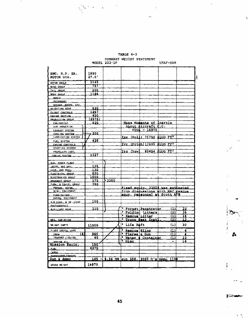
TABLE 4-3 SUMMARY WEIGHT STATEMENT
MODEL 222-1F USAF-SAR
ENG. H.P. EA. 1950 ROTOR DIA. 27.0'
ROTOR GROUP 1145 WING GROUP 757
T A I L G R O U P 200 !
STARTING SYSTEM J 1 1 PROPELLER INST. Iza (yawl 80454 $LUG F T ~
I m u 1327 1 I I
WE l GMT EMPTY I llsoo I I

TABLE 4-4 SUMMARY WEIGHT STATEMENT
I ENG. H.P. EA. ROTOR DIA.
PERSON. ACCOM.
M I S C . EQUIPMENT
F I X E D U5EFUL LOAD
w ( 4 )
LIGlkF. O I L
Total Electronic L
MODEL 212-1N NAVY SEA CONTROL I I I 1 I 1
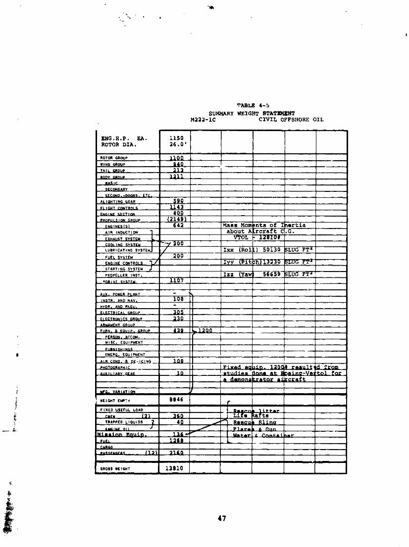
TABLE 4-5
SUMMARY WEIGHT STATEMENT M223-1C CIVIL OFFSHORE OIL
(2149). I I 642 Maes Mmknte of Ibertia
about Akrcraf t C1.G. VTOL 1 l m O # I
'+ 266 I 1 , --- 1 I
/ Ixx (~olg) 50i30 BLuG FTa 7 200 I
Iyv (Pitbh) 13
I G W s s WEIGHT I 12010 I I I I I
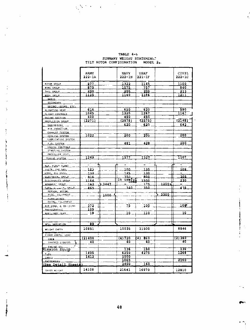
TABLE 4-b SUMMARY WEIGHT STATEMENY.'
TILT ROTOR CONFIGURATION MODEL I..
F I X E D USEFUL L O A D
CREW ( 2 ) 400 ( 4 1 7 2 0 Kd) 860 .- .
T R A P P E D L I O U I O S 1 4 0 40 1 (D
Weights were determined us ing VASCOMP (V/STOL A i r c r a f t S i z i n g and Performance Computer Program), Reference 2 . The weights segment of t h e program, Reference 3 , c o n t a i n s d e t a i l e d s t a t i s t i c a l weight t r e n d e q u a t i o n s which compute t h e weights of t h e s t r u c t u r e , f l i g h t c o n t r o l s , and p ropu l s ion groups . Fixed equipment ( a u x i l i a r y power p l a n t through a u x i l i a r y g e a r groups on weight s t a t e m e n t s ) , f i x e d u s e f u l load and payload a r e weight i n p u t v a l u e s . Examples of t h e t r e n d s a r e inc luded i n t h e weights s e c t i o n of Volume 11.
VASCOMP computes t h e weights of t h e a i r c r a f t wing, f l i g h t c o n t r o l s , engine s e c t i o n , eng ine i n s t a l l a t i o n , f u e l s y s t m i . ro io r /p rop assembly, and d r i v e system. The weights of fuse - l a g e , empennage, eng ines , and l and ing g e a r were i n p u t s t o t h e program.
A l l c o n f i g u r a t i o n we igh t s , wi th t h e excep t ion o f t h e c i v i l a i r c r a f t , u t i l i z e advance composite m a k e r i a l s i n t h e s t r u c t u r e (wing, f u s e l a g e , eng ine s e c t i o n ) and r o t o r assembly. Advanced technology h a s been cons ide red i n t h e d r i v e system ( h i g h e r Her tz stress l e v e l s i n t h e g e a r i n g ) f o r a l l conf igura - t i o n s excep t t h e c i v i l a i r c r a f t . Weight s a v i n g s o f between 15 t o 20 p e r c e n t of t h e i n d i v i d u a l groups a r e r e a l i z e d through t h e use of t h e advanced m a . t e r i a l s and advanced technology.
The c i v i l a i r c r a f t assumes c u r r t n t technology and u t i l i z e s advanced composite m a t e r i a l on ly i n t h e r o t o r / p r o p e l l e r assembly.
The Navy Sea Cont ro l a i r c r a f t i n c l u d e s au tomat ic r o t o r b lade f o l d i n g and wing f o l d i n g . The weight p e n a l t i e s a a s o c i - a t e d w i t h t h e s e f e a t u r e s a r e 200 and 170 pounds, r e s p e c t i v e l y .
The weights of t h e f i x e d equipment, m i s s i o n , and r e s c u e equipment were determined f o r each a i r c r a f t on an independent b a s i s . The approach is d e s c r i b e d on t h e summary weight s h e e t s .
4 . 4 Noise
The t i l t - r o t o r a i r c r a f t i s one of t h e q u i e t e s t conf igura - t i o n s t o be developed f o r VTOL f l i g h t . The absence of high n o i s e d e v i c e s such a s d i r e c t l i f t e n g i n e s , t u r b o j e t s , and a n t i - t o r q u e p r o p e l l e r s l e a v e s t h e s h a f t - d r i v e n t u r b i n e and t h e r o t o r a s t h e primary n o i s e sources . I n t h i s r e s p e c t , t h e hover and low-speed n o i s e are very s i m i l a r t o t h a t o f t non- overlapped tandem-rotor h e l i c o p t e r . The c a p a b i l i t y t o d e s i g n a n a b u i l d a low n o i s e c o n f i g u r a t i o n was demosntrated by t h e Boeing-Vertol Model 347 , which d i s p l a y s low e x t e r n a l n o i s e l e v e l and an absence o f impuls ive n o i s e components g e n e r a l l y r e f e r r e d t o a s rotor " s l a p " o r "bang." Noise l e v e l of t h e tilt- r o t o r a i r c r a f t i s p r o j e c t e d to be less t h a n t h a t o f t h e Model 347. These advantages a r e a180 m a n i f e s t i n t h e l o w a u r a l d e t e c t i o n s i g n a t u r e and r t s u l t i n g warning t imes d i s p l a y e d by
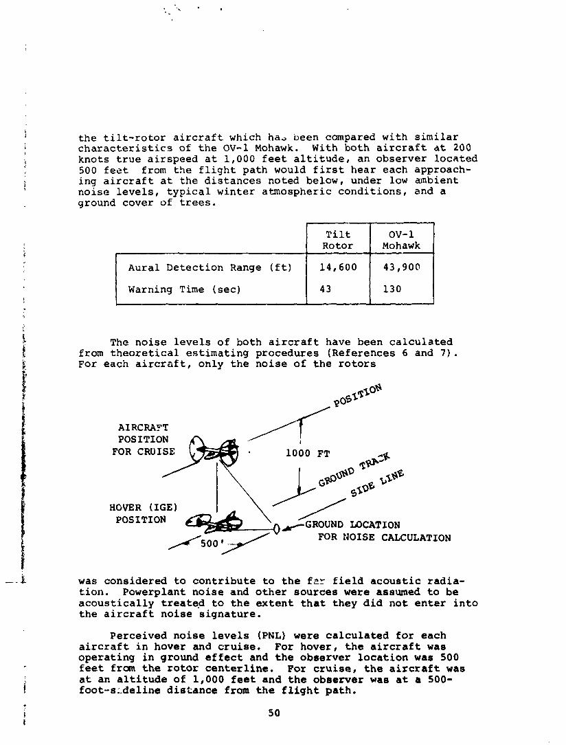
t h e t i l t - r o t o r a i r c r a f t which ha; been compared w i t h s i m i l a r c h a r a c t e r i s t i c s of t h e OV-1 Mohawk. With bo th a i r c r a f t a t 200 k n o t s t r u e a i r s p e e d a t 1 ,000 f e e t a l t i t u d e , an o b s e r v e r l o c a t e d 500 f e e t from t h e f l i g h t p a t h would f i r s t h e a r each approach- ing a i r c r a f t a t t h e d i s t a n c e s noted below, under low ambient n o i s e l e v e l s , t y p i c a l w i n t e r a tmosphe r i c c o n d i t i o n s , and a ground cover of trees.
The n o i s e l e v e l s o f bo th a i r c r a f t have been c a l c u l a t e d from t h e o r e t i c a l e s t i m a t i n g p rocedures (Refe rences 6 and 7 ) . For each a i r c r t f t , o n l y t h e n o i s e of t h e r o t o r s
AIRCRAPT POSITION
FOR CRUISE 1000 FT
HOVER (IGE)
FOR NOISE CALCULATION
OV- 1 Mohawk
43,900
130
1
Aural D e t e c t i o n Range ( f t )
Warning T i m e (sec)
was c o n s i d e r e d t o c o n t r i b u t e t o t h e f2r f i e l d a c o u s t i c r a d i a - t i o n . Powerplant n o i s e and o t h e r s o u r c e s were assumed t o be a c o u s t i c a l l y t r e a t e d t o t h e e x t e n t t h a t t h e y d i d n o t e n t e r i n t o t h e a i r c r a f t n o i s e s i g n a t u r e .
T i l t Rotor
14,600
43
P e r c e i v e d n o i s e l e v e l s (PNL) were c a l c u l a t e d f o r e a c h a i r c r a f t i n hover and c r u i s e . For hove r , t h e a i r c r a f t was o p e r a t i n g i n ground e f f e c t and t h e o b s e r v e r l o c a t i o n was 500 feet from t h e r o t o r c e n t e r l i n e . For cruise, t h e a i r c r a f t was a t an a l t i t u d e o f 1,000 f e e t and t h e o b s e r v e r was a t a 500- foot-8:-deline d i s t a n c e from t h e f l i g h t p a t h .
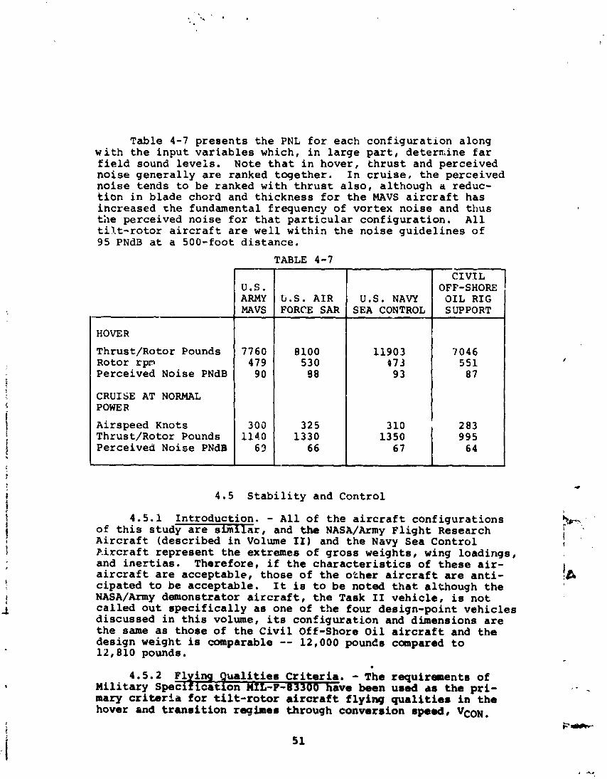
Table 4-7 p r e s e n t s t h e PNL f o r each c o n f i g u r a t i o n along w i t h t h e i n p u t v a r i a b l e s which, i n l a r g e p a r t , de termine f a r f i e l d sound l e v e l s . Note t h a t i n hover , t h r u s t and perce ived n o i s e g e n e r a l l y a r e ranked t o g e t h e r . I n c r u i s e , t h e pe rce ived n o i s e t ends t o be ranked wi th t h r u s t a l s o , a l though a reduc- t i o n i n b lade chord and t h i c k n e s s f o r t h e MAVS a i r c r a f t has i n c r e a s e d t h e fundamental frequency of v o r t e x n o i s e and t h u s t h e perce ived n o i s e f o r t h a t p a r t i c u l a r c o n f i g u r a t i o n . A l l t i l t - r o t o r a i r c r a f t a r e w e l l w i t h i n t h e n o i s e g u i d e l i n e s o f 95 PNdB a t a 500-foot d i s t a n c e .
TABLE 4-7
HOVER
Thrust /Rotor Pounds Rotor sprn Perce ived Noise PNdB
CRUISE AT NORMAL POWER
Airspeed Knots Thrust /Rotor Pounds Perce ived Noise PNdB
-
U . S . ARMY MAVS -
7760 479
90
303 1140
63
G.S. A I R FORCE SAR
CIVIL OFF-SHORE
U.S. NAVY OIL R I G
4.5 S t a b i l i t y and Cont ro l
4.5.1 In t - roduct ion . - A l l of t h e a i r c r a f t c o n f i g u r a t i o n s of t h i s s tudy a r e s i m i l a r , and the! NASA/Army F l i g h t Research A i r c r a f t (desc r ibed i n Volume 11) and t h e Navy Sea C o n t r o l P i x r a f t r e p r e s e n t t h e extremes of g r o s s weights , wing load ings , and i n e r t i a s . There fo re , i f t h e c h a r a c t e r i s t i c s of t h e s e a i r - a i r c r a f t are a c c e p t a b l e , t h o s e of t h e o t h e r a i r c r a f t are a n t i - c i p a t e d to be accep tab le . I t i s t o b e noted t h a t a l though t h e NASA/Army demonstrator a i r c r a f t , t h e Task I1 v e h i c l e , is n o t c a l l e d o u t s p e c i f i c a l l y a s one of t h e f o u r des ign-point v e h i c l e s d i s c u s s e d i n t h i s volume, i t s c o n f i g u r a t i o n and dimensions a r e t h e same a s t h o s e o f t h e C i v i l Off-Shore O i l a i r c r a f t and t h e d e s i g n weight is comparable -- 12,000 pounds compared t o 19,810 pounds.
ng Qualit ies C r i t e r i a . - The requi rements of c a t i o n M I L - F - B ~ ~ ~ ~ have been used as the pri-
mary criteria f o r t i l t - rotor a i r c r a f t f ly ing qual i t ies i n - t h e hover and t r a n s i t i o n regime6 through convers ion speed, VCON.
AGARD Report-577 c r i t e r i a were rev iewed and t h e r e q u i r e m e n t s a r e s u b s t a n t i a l l y i n agreement w i t h t h o s e of MIL-F-83390. The AGARD r e p o r t p r o v i d e s expanded d e t a i l r e g a r d i n g s p c : i f i c cr i - t e r i a and b e t t e r d e f i n i t i o n o f requi rem.ents conce rn ing c o n t r o l c o n f i g u r a t i o n s . Guidance p rov ided i n AGARD R-577 w i l l be u l i l i z e d i n t h e d e s i g n s t a g e s .
The c r i t e r i a of MIL-F-8785B (ASG) a r e a p p l i c a b l e f o r speeds above VCoN.
4 .5 .2 .1 C o n t r o l C r i t e r i a Low S eed . - Maneuver r e s p o n s e r e q u i r e ~ e n t s f o r t h e t i l t - r o t o r -+ a l r p r a t i n t h e hover and t r a ? s i t i o n i l i u h t reg imes were ae t e rmined based on a rev iew of t h e fo i lowing a p p l i c a b l e d a t a :
a . MIL-F-83300, F l y i c g Q u a l i t i e s o f P i l o t e a V/STOL A i r - c r a f t , d a t e d 31 December 1970.
b. NASA TN D-5594, A i r w o r t h i n e s s C m u i d e r a t i o n s f o r STOL A i r c r a f t , d a t e d J a n u a r y 1970.
c . Boeing d a t a g 3 t h e r e d i n s u p ~ o r t of tilt winq, '+il t r o t o r c o n t r o l l a b i l i t y s t u d i e s .
The d a t a s u g g e s t s t h a t t h e minimum a n g u l a r a c c e l e r a t i o n r e s p m s e s i n hover t o f u l l , s i n g l e a x i s c o n t r o l d e f l e c t i o n s shou ld be o f t h e fo l lowing magni tudes :
Angular A c c e l e r a t i o n Axis - ( r a d / s e c 2
P i t c h 0.6
Yaw 0 . 5
A r e a s o n a b l e r e d u c t i o n i n t h e s e l e v e l s can be t o l e r c t e d th rough t h e t r a n s i t i o n a l regime as t h e r o t o r c o n t r o l s a r e phased o u t and t h e aerodynamic c o n t r o l s u r f a c e s (which a r e a lways workixm) become e f f e c t i v e . The recommended minimum a n g u l a r a c c e l e r a t i o n s abou t each a x i s t h rough t r a n s i t i o n a r e shown i n F i g u r e 4-5 (see Volume I1 f o r r a t i o u a l e ) . These minima a r e s l i g h t l y g r e a t e r t h a n t h e recommendations i n NASA TN D-5594 f o r t h e STOL speed r a n g e ( n e ~ r end of t r a n s i t i o n ) .
4.5.3 C o n t r c l C o n f i g u x a t i a n . - C o n t r o l o f t h e t i l t - ro to r a i r c r a f t d e s c r i b e d h e r e i n is accomplished by u t i l i z a t i o n o f r o t o r l o n g i t u d i n a l c y c l i c , d i f f e r e n t i a l cycif-c, and d i f f e r e n - t i a l c o i l e c t i v e c o n t r o l f o r Cover and o p e r a t i o n of c o n v e n t i o n a l a i r c r a f t c o n t r o l s u r f a c e s f o r p r imary c o n t r o l i n c r u i s e . The
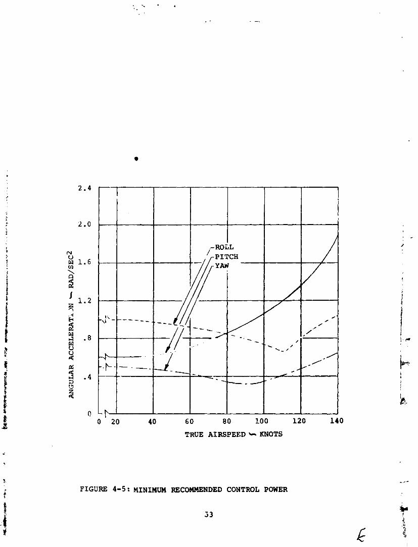
0 20 4 0 60 80 100 120 140
TRUE AIRSPEED '... KNOTS
FIGURE 4-5: MINIMUM RECOMMENDED CONTROL POWER
a i r c r a f t s u r f a c e s a r e o p r a i - e d a t a l l t i m e s , b u t t h e i r e f f e c - t i v e n e s s i s v e r y low a t low t r a n s i t i o n speeds and n e a r z e r o i n h . ZonLrol i n t r a n s i t i o n i s accomplished 3y u s i n g a m i x t u r e of r ~ t o r and a i r c r a f t c o n t r o l s which a r e a u ~ o m a t i c a l l y p ropor t ioned a s a f u n c t i o n o f n a c e l l e i n c i d e n c e .
The c y c l i c c o n t r o l i n p u t s w i i l be phased s o a s t o r e s u l t i n maximum i n p l a n e f o r c e s o r i e n t e d a l o n g t h e r o t o r d i s c X-axis. T h i s i s d e s i r a b l e t o p r o v i d e maximum yawing moment on t h e a i r - c r a f t where d i f f e r e n t i a l c y c l i c i s commanded th rough r u d d e r p e d a l a p p l i c a t i o n a t low speed . T h i s r e s u l t s i n a s m a l l reduc- t i o n i n t h e p i t c h i n g moment a t t a i n a b l e p e r d e g r e e o f l o n g i - t u d i n a l c y c l i c c o n t r o l .
The rudde r and e l e v a t o r c o n t r o l s a r e c o n v e n t i o n a l . R o l l c o n t r o l i n c r u i s e i s accomplished by u s e o f t h e o u t b o a r d semi- span of t h e f l a p o p e r a t i n g downwards i n c o n j u n c t i o n w i t h u s e of a s p o i l e r o p e r a t i n g upwards on t h e o p p o s i t e wing. T h i s p e r m i t s u s e o f a more e f f e c t i v e s i n g l e - s l o t t e d , f u l l - s p a n f l a p f o r low-speed l o i t e r i n t h e c r u i s e c o n f i g a r a t i o n and p e r m i t s b e t t e r a e r o d y n a m i c - t a i l o r i n g , i .e . , minimizing o f t h e r e s u l t i n g yawing moment due t o r o l l .
C o n t r o l r e q u i r e m e n t s f o r maneuver afid c o n t r o l s c h e d u l i n g a r e d i s c u s s e d i n t h e f o l l c w i n g pa rag raphs .
4 . 5 . 4 C y c l i c C o n t r o l Requi red i n Hover.
4 .5 .4 .1 Maneuver. - The s imu l t aneous and d i f f e r e n t i a l l o n g i t u d i n a l c y c l i c c o n t r o l r e q u i r e d t o m e e t t h e hove r ing p i t c h and yaw a n g u l a r a c c e l e r a t i o n r e q u i r e m e n t s i s shown i n F i g u r e 4-6. The a l l e v i a t i o n o f r e q u i r e d d i f f e r e n t i a l c y c l i c a s s o c i a t e d w i t h wing f l e x i b i l i t y and n a c e l l e tilt i s a l s o i n d i - c a t e d . C o n t r o l r e q u i r e m e n t s a r e i n d i c a t e d f o r b o t h t h e NASA Research A i r c r a f t , 12,000 pounds, and t h e Navy Sea C o n t r o l A i r c r a f t , 21,641 pounds. I t i s t o b e no ted t h a t t h e h e a v i e r a i r c r a f t r e q u i r e s s l i g h t l y less c y c l i c f o r b o t h p i t c h and yaw c o n t r o l , b o t h r equ i r emen t s be ing e a s i l y a t t a i n a b l e . The r e a s o n s f o r t h e t r e n d a r e : (1) a s t h e d i s ~ s i z e i n c r e a s s s , t h e l o n g i t u d i n a l c o n t r o i power p e r d e g r e e c y c l i c i n c r e a s e s more r a p i d l y t h a n t h e inc -ease i n p i t c h i n e r t i a , and ( 2 ) t h e i n c r e a s e i n i n p l a n e f o r c e a long t h e r o t o r d i s c X-axis as a f u n c t i o n o f t h e i n c r e a s e d t h r u s t , r e q u i r e d a t t h e h e a v i e r w e i g h t s i n hove r , when m u l t i p l i e d by t h e moment a.m from t h e n a c e l l e t o t h e c e n t e r o f g r a v i t y of t h e a i r c r a f t r e s u l t s i n yawing moment i n c r e a s i n g more r a p i d l y t h a n t h e yaw i n e r t i a .
4.5.4.2 T r i m . - The amount of c y c l i c r e q u i r e d t o t r i m t h e a i r c r a f t l s n y i t u d i n a l l y i n hover w i t h t n e c e n t e r of g r a v i t y p,7r 4 L r s e t from t h e p i v o t i s r e l a t i v e l y s m a l l , amounting t o approx i -
ma te ly 0.10 d e g r e e c y c l i c p e r p e r c e n t MAC cg o f f s e t f o r t h e 12,000-pound a i r c r a f t and 0 .11 d e g r e e p e r p e r c e n t MAC cg
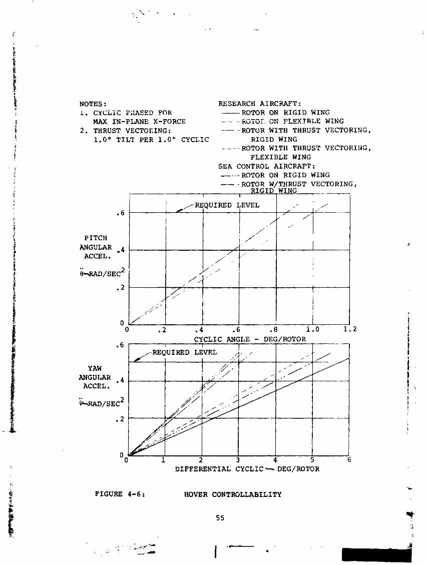
NOTES : RESEARCH AIRCIZAFT : -- n T i n c p n FOR 1. CYCLLL run^.-- ROTOR ON R I G I D WING MAX IN-PLANE X-FORCE - -- -- RcTai. C:: FLEXTRLE WING
2 . THRUST VECTOKING : -- - ROTOR WITH THRUST VECTORING I 1.0' T I L T PER l . o O CYCLIC R I G I D WING
PITCH ANGULAR 4
ACCEL .
ROTOR WITH THRUST VECTORING, FLEXIBLE WING
SEA CONTROL AIRCRAFT: - - - - ROTOR ON R I G I D WING -- - ROTOR W/THRUST VECTORING,
-.- R I G I D WING I I
1 /REQUIRED LEVEL , / 1
// ,'
I / ' . ' '1
CYCLIC ANGLE - DEG/ROTOR .6 I I I I I 1
I /REQUIRED LEVEL I . % A I , ,
I . , YAW
ANGULAR . 4 / * . - ACCEL .
I ' :-
FIGURE 4-6:
DIFFERENTIAL CYCLIC + DEG/ROTOR
HOVER CONTROLLABILITY
offset for the 21,641-pound aircraft. The pivot is located such that for the condition of nacelle vertical, hover mode, the aircraft center of gravity wiil normally be within approxi- mately +5 - percent MAC of the pivot.
4.5.5 Control Schedullny.
4.5.5.1 Hover. - During operation in the h ~ v e r mcde, pitch control will be accomplished by application of rotor longitudinal cyclic control in response to stick command. Roll control results from application of differential collec- tive pitch in response to lateral stick command. Yaw is accom- plished by application of differential cyclic control and differential nacelle tilt in response to rudder pedal input. The differential nacelle tilt resalts from structural deflec- tion of the nacelle/pivot mechanism and yields approximately one degree nacelle tiit per degree cyclic command in hover.
4.5.5.2 Transition.
a. General - The controls are "scheduled" in transition to phase out the rotor cyclic and collective response and differential nacelle tilt as nacelle incidence is decreased, with increasing speed, and as the aero- dynamic control surfaces, which are always working, become more effective. The controls are also scheduled so as to minimize response coupling of the aircraft about the roll and yaw axes, i.e., to result in minimum yaw response for a pure roll input and vice versa.
b. Pitch Control - Pitch control is accomplished by com- bined rotor longitudinal cyclic and elevator control surface deflection in response to longitudinal stick command with the cyclic control "phased out" as nacelle incidence is decreased.
c. Yaw Control - Yaw controls are scheduleG such that at low speeds, differential cyclic and differential nacelle tilt are the prime contributors to yaw. As speed increases and nacelle incidence is decreased, the amount of differential cyclic and nacelle tilt per inch of rudder pedal travel is decreased, and differ- ential collective pitch is phased in to yeild uncoupled yaw responses to rudder pedal deflection. As nacelle incidence is decreased to zero for cruise flight, the rotor differential cyclic and collective pitch inputs and differential nacelle tilt are phased out com- pletely and rudder deflection alone provides adequate yaw response to pedal input.
d. Roll Control - Roll control is accomplished at low
t r a n s i t i o n speeds by d i f f e r e n t i a l c o l l e c t i v e p i t c h i n p u t s t o t h e r o t o r s . A s n a c e l l e inc idence i s de- c r e a s e d , d i f f e r e n t i a l c o l l e c t ~ v e response t o l a t e r a l s t i c k i n p u t s i s reduced, and d i f f e r e n t i a l c y c l i c and d i f f e r e n t i a l n a c e l l e tilt a r e phased i n t o minimize yaw coupl ing . A s n a c e l l e inc idence i s reduced f u r t h e r , t h e c y c l i c , c o l l e c t i v e , and n a c e l l e tilt c o n t r o l s a r e phased o u t and r o l l r e s u l t s from only t h e a i r c r a f t aerodynamic c o n t r o l s , outboard f l a p e r o n d e f l e c t i o n down on one wing, and s p o i l e r d e f l e c t i o n upward on t h e o p p o s i t e wing.
Typ ica l c o n t r o l phasing is i l l u s t r a t e d by F i g u r e s 4-7 and 4-8. The magnitudes of t h e c o n t r o l i n p u t s i l l u s t r a t e d r e p r e - s e n t t h e amount of c o n t r o l r e q u i r e d t o m e e t t h e t r a n s i t i o n c o n t r o l c r i t e r i a s p e c i f i e d i n F igure 4-5 dur ing o p e r a t i o n of t h e 12,000-pound NASA f l i g h t r e s e a r c h a i r c r a f t i n a c c e l e r a t i n g t r a n s i t i o n a t c o n s t a n t a l t i t u d e wi th n e a r - l e v e l f u s e l a g e a t t i - tude . These c o n t r o l t r a v e l s provide c o n t r o l moments i n excess of t h e minima of F igure 4-5 dur ing unacce le ra ted t r a n s i t i o n , i .e . , c o n s t a n t speed.
4.5.6 Long i tud ina l T r i m i n T r a n s i t i o n . - There a r e v a r i - ous " p o s s i b l e " ways t o o p e r a t e a t i l t - r o t o r a i r c r a f t i n and through t h e t r a n s i t i o n f l i g h t regime. Th i s is t r u e because of t h e number of v a r i a b l e s a s s o c i a t e d w i t h c o n t r o l o f t h e a i r c r a f t such a s t h r u s t , n a c e l l e inc idence , t a i l i n c i d e n c e / e l e v a t o r d e f l e c t i o n , f l a p d e f l e c t i o n , and f u s e l a g e a t t i t u d e . It i s d e s i r a b l e , however, because of t h e many v a r i a b l e s and t h e r e l a t i v e l y s h o r t t i m e r e q u i r e d t o accomplish a n a c c e l e r a t i n g o r d e c e l e r a t i n g t r a n s i t i o n t o automate a s many of t h e v a r i a b l e s as p o s s i b l e t o d e c r e a s e t h e p i l o t ' s workload. Schedul ing , o r automation, of t h e v a r i o u s parameters can be made a f u n c t i o n of v e l o c i t y , dynamic p r e s s u r e , power l e v e r p o s i t i o n , n a c e l l e inc idence , o r o t h e r v a r i a b l e s . I t is d e s i r a b l e i n o r d e r t o s i m p l i f y mechanizat ion and improve system r e l i a b i l i t y t o reduce t h e schedul ing t o f u n c t i o n s oC a minimum number o f v a r i a b l e s of parameters . There fo re , i n v e s t i g a t i o n s t o d a t e have been d i r e c t e d toward schedul ing of f l a p s , c y c l i c , t a i l s u r f a c e t r i m , etc. wi th n a c e l l e inc idence and l e a v i n g c o n t r o l of n a c e l l e inc idence t o t h e p i l o t . The fo l lowing ground r u l e s were e s t a b - l i s h e d t o d e f i n e t h e nominal t r a n s i t i o n schedu les f o r t r a n s i - t i o n .
a. Hub moments s h a l l be e s s e n t i a l l y zero .
b. There s h a l l be a smooth v a r i a t i o n of t h e t r i m para- meters between hover and e n d - t r a n s i t i o n speed.
c. F lap d e f l e c t i o n w i l l be scheduled t o minimize t h r u s t r e q u i r e d i n t r a n s i t i o n c o n s i s t e n t wi th main ta in ing comfor table ( i .e . , smal l nose up o r down) f u s e l a g e a t t i t u d e .
57
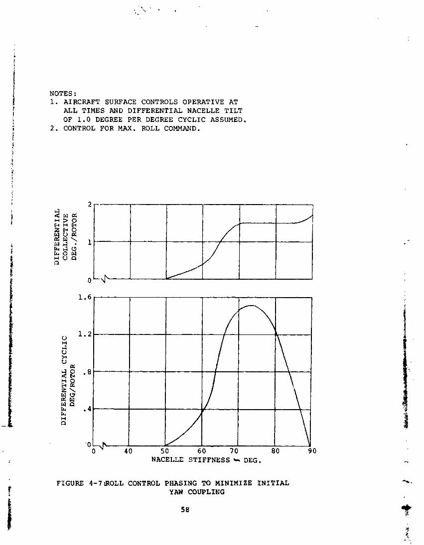
NOTES : 1. AIRCRAFT SURFACE CONTROLS OPERATIVE AT
ALL TIMES AND DIFFERENTIAL NACELLE TILT OF 1 . 0 DEGREE PER DEGREE CYCLIC ASSUMED.
2 . CONTROL FOR MAX. ROLL COMMAND.
0 40 5 0 60 7 0 80 90 NACELLE STIFFNESS + DEG.
FIGURE 4 - 7 W L L CONTROL PHASING TO MINIMIZE I N I T I A L YAW COUPLING
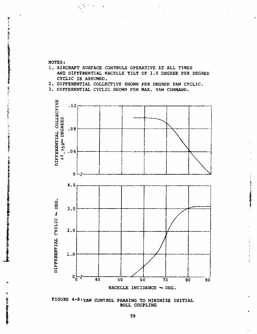
NOTES : 1. AIRCRAFT SURFACE CONTROLS OPERATIVE 1.T ALL TIMES
AND DIFFERENTIAL NACELLE TILT OF 1 . 0 DEGREE PER DEGREE CYCLIC I S ASSUMED,
2 . DIFFERENTIAL COLLECTIVE SHOWN PER DEGREE YAW CYCLIC. 3 . DIFFERENTIAL CYCLIC SHOWN FOR MAX. YAW COMMAND.
NACELLE INCIDENCE C. DEG ,
FIGURE YAW CONTROL PHASING TO MINIMIZE I N I T I A L ROLL COUPLING
d. The trim conditions at the end of transition shall be coincident with the trim required in the aircrzft con- figurations, i.e., cruise configuration.
The resultant variations for the trim parameters with speed are shown in Figures 4-9 and 4-10 for the research air- craft and Navy Sea Control configurations, respectively. It is evident, from the trends illustrated, that reasonable schedules of nacelle incidence with airspeed and tail incidence and flap deflection with nacelle incidence can be achieved. For the 12,000-pound-weight research aircraft, hub moments of less than +800 ft-lb are achieved through transition. The maximum cyclic control angles required to trim are 3.9 degrees of longitudinal cyclic at 120 KTAS and 1.5 degrees of lateral cyclic at 110 KTAS. For the 21,641-pound-weight Sea Control aircraft, hub moments are between +3,360 and -4,140 ft-lb, and the maximum cyclic requirements are 4.33 degrees longitudinally at 120 KTAS and 1.54 degrees laterally at 110 KTAS. A smooth vaziation of fuselage attitude, of acceptable magnitude, from hover to end-transition speed is achieved, and wing and tail angles of attack are well within limits. These transitions were calculated using the same tail incidence versus nacelle incidence and nacelle incidence versus velocity schedules. Minor variation of the tail incidence versus nacelle incidence and nacelle incidence versus velocity schedules would permit transition with zero hub moment over nearly the entire transi- tion speed range.
The effect of the minor differences in configuration and differences in weight of the two aircraft can easily be com- pensated for by minor changes in scheduling of the transition control parameters.
4.5.7 Cruise Trim. - Trim conditions in the airplane configuration cruise mode were calculated for the research aircraft and Sea Control aircraft. Typical examples of the cruise trim requirements are iliustrated in Figures 4-11 and 4-12 for the 12,000 and 21,641-pound aircraft, respectively. The longitudinal and lateral cyclic control required to zero the rotor hub moments have been calculated as a function of velocity for each of the two aircraft. A feedback system is being developed to automatically apply cyclic control to main- tain hub moments near zero, and the cyclic control indicated on these figures is that which will be applied by the feedback sy~jtm. This system is described in more detail In Volume 11.
The aircraft is indicated to be statically stable, with reference to trim versus velocity, throuqh the cru.ise rarrge a-, the nominal gross we.~ght. The heavy weight aircraft indicates a mild trim instability between 150 and 200 KTAS as evidenced by the reversal in the trim tail incidence angle variation with speed. This instability can be corrected by several means such as programmed trim versus velocity.
60
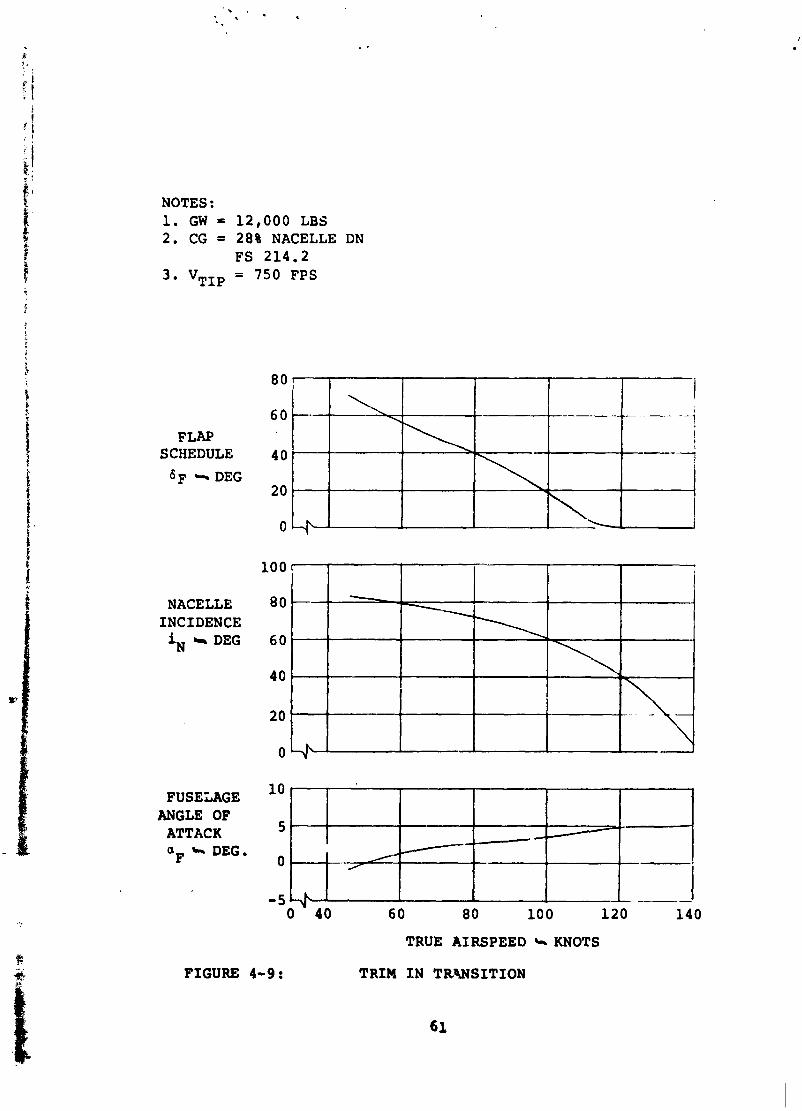
NOTES : 1. GW = 12,000 LBS 2. CG = 28% NACELLE DN
FS 214.2 3. VTIp = 750 FPS
FLAP SCHEDULE 6~ '5 DEG
NACELLE INCIDENCE iN * DEG
FUSELAGE ANGLE OF
ATTACK OF DEG.
0 . 40 60 80 10 0 120 140
TRUE AIRSPEED L. KNOTS
FIGURE 4-9: TRIM I N T R W S I T I O N
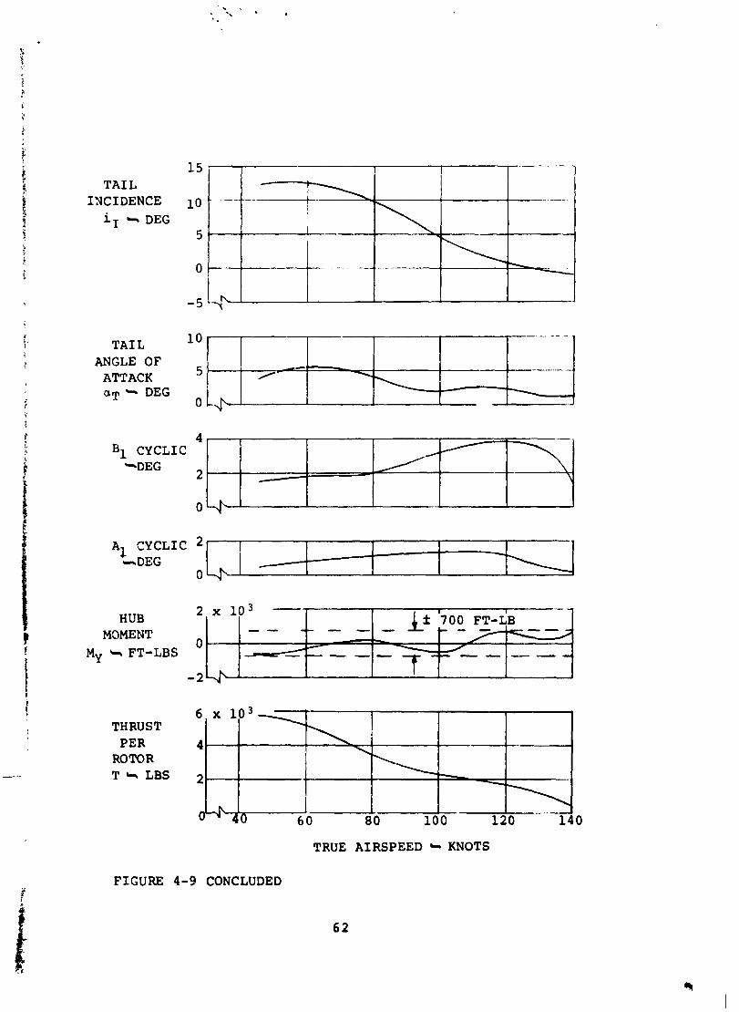
1 5 T A I L
INCIDENCE 10 iI * DEG
5
T A I L ANGLE OF
ATTACK a~ + DEG
B1 CYCLIC
0 -.- tEEB33
THRUST PER
ROTOR T + LBS
TRUE AIRSPEED KNOTS
FIGURE 4-9 CONCLUDED
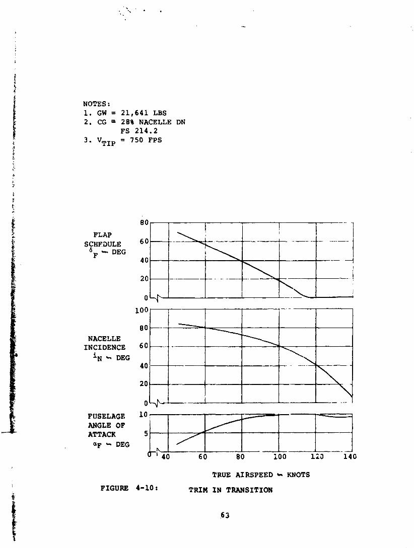
NOTES : 1. GW = 2 1 , 6 4 1 LBS 2. CG a 28% NACELLE DN
FS 2 1 4 . 2 3 . VTIp = 750 FPS
NACELLE INCIDENCE 6 0 ---- --
i~ C. DEG
2 0 -
FtlSELAGE ANGLE OF ATTACK
QF DEG
FIGURE 4-10:
TRUE AIRSPEED KNOTS
TRIM I N TRANSITION
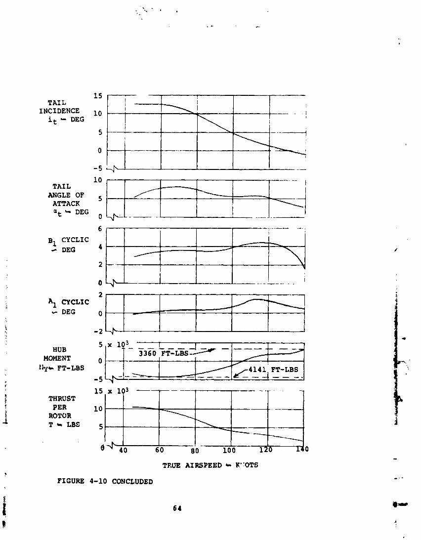
TAIL INCIDENCE
it " DEG
TAIL ANGLE OF
ATTACK at 4 DEG
B1 CYCLIC 4 DEG
A - DEG
HUB MOMENT lip FT-LBS
THRUST PER
ROTOR T s LBI
TRUE AIRSPEED K''0TS
4-10 CONCLUDED FIGURE
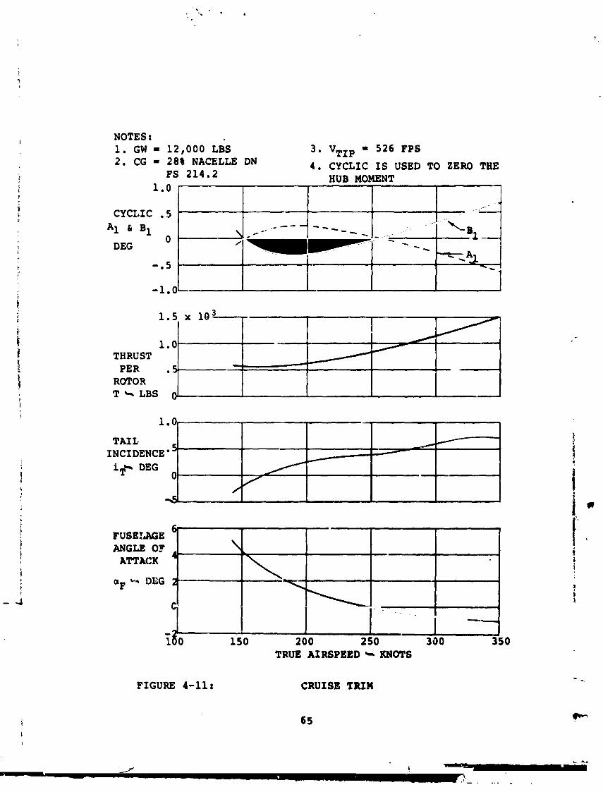
1.5 lo3
1 . 0 THRUST PER
ROTOR T Cg LBS @
NOTES t 1. GW = 12,000 LBS 3 * "TIP - 526 FPS 2 . CG = 28% NACELLE DN 4. CYCLIC I S USED TO ZERO THE
FS 214 .2 HUB MOMENT 1.0
CYCLIC * 5
A1 6 B1
DEG 0
-. 5
-1-0
1 0.
FIGURE 4-11:
. ~
CRUISE TRIM
.
\
// % !
TAIL INCIDENCE iT+ DEG
0 '
---- - - --- -
*'---
330 350 TRUE AIRSPEED + KNOTS
1
+-
.
- -
d
\% - \
w AJ - .- ' w - - - - I
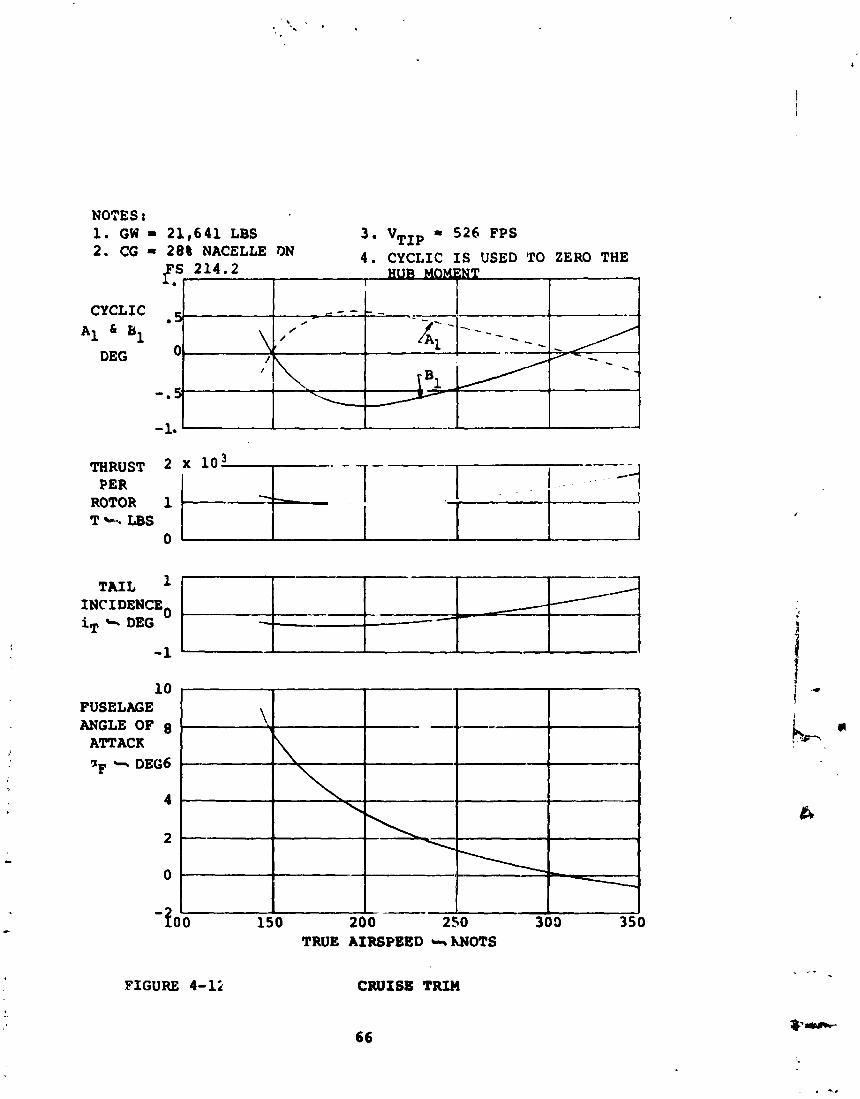
THRUST 2 x l o 3 I 1 - I - - 1
---- -
PER 1 -4
NOTES I 1. GW = 2 1 , 6 4 1 LBS 3 . "TIP = S Z Q FPS 2 . CG = 2 8 8 NACELLE DN 4 . CYCLIC I S USED TO ZERO THE
fS?
I*:&E: r-rJ-- --w-7 iT + DEG
\ - - - + -,
ROTOR 1 T b.. LBS
- 1. -1-J
CYCLIC . - . . - c - -
FIGURE 4-12
- - 2; - A 1 81
0 - DEG
0
, \- -
10 FUSELAGE ANGLE OF 8
ATTACK QF * DEG6
4 -
2
0 .
CRUISE TIUn
66
- - - - - - -- /
- - I
9-/ 4~ -
\-
.
- -
--
-loo - ---
150 200 2 50 300 3 ! TRUE AIRSPEED s hNOTS
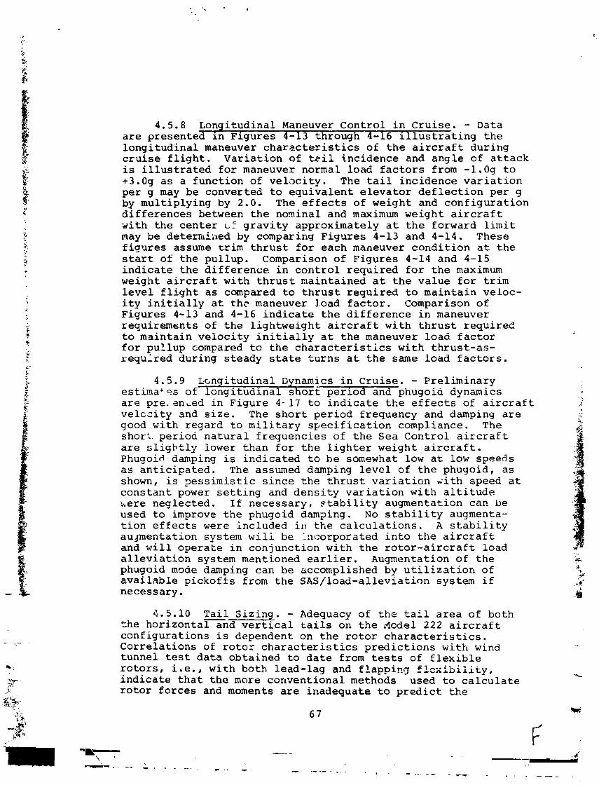
4.5.8 Longi tudinal Maneuver Cont ro l i n Cru i se . - Data a r e presented i n F igures 4-13 through 4-16 i l l u s t r a t i n g t h e l o n g i t u d i n a l maneuver c h a r ~ c t e r i s t i c s of t h e a i r c r a f t dur ing c r u i s e f l i g h t . V a r i a t i o n of t z i l inc idence and ang le of a t t a c k is i l l u s t r a t e d f o r maneuver normal load f a c t o r s from -1.0g t o +3.0g a s a func t ion of v e l x i t y . The t a i l inc idence v a r i a t i o n p e r g may be converted t o e q u i v a l e n t e l e v a t o r d e f l e c t i o n per g by mul t ip ly ing by 2.G. The e f f e c t s of weight and c o n f i g u r a t i o n d i f f e r e n c e s between t h e non ina l and maximum weight a i r c r a f t wi th t h e c e n t e r c E g r a v i t y approximately a t t h e forward l i m i t may be deterrhiiled by comparing F igures 4-13 and 4-14 . These f i g u r e s assume t r i m t h r u s t f o r each maneuver c o n d i t i o n a t t h e s t a r t of t h e pu l lup . Comparison of F igures 4 -14 and 4-15 i n d i c a t e t h e d i f f e r e n c e i n c o n t r o l r e q u i r e d f o r t h e maximum weight a i r c r a f t wi th t h r u s t mainta ined a t t h e va lue f o r t r i m l e v e l f l i g h t a s compared t o t h r u s t r e q u i r e d t o ma in ta in veloc- i t y i n i t i a l l y a t t h ~ maneuver 3.oad f a c t o r . Comparison of Figures 4-13 and 4-16 i n d i c a t e t h e d i f f e r e n c e i n maneuver requirements of t h e l i g h t w e i g h t a i r c r a f t wi th t h r u s t r e q u i r e d t o mainta in v e l o c i t y i n i t i a l l y a t t h e maneuver l o a d f a c t o r f o r pu l lup compared tc t h e c h a r a c t e r i s t i c s wi th t h r u s t - a s - r e q u l r e d dur ing s t eady s t a t e t u r n s a t t h e same load f a c t o r s .
4.5.9 L ~ n g i t u d i n a l Dynamics i n C r u i s e . - Pre l iminary e s t i m a t e s of l o n g i t u d i n a l s h o r t p e r i o d and phugoia dynanics a r e pre. anLed i n F igure 4 - 1 7 t o i n d i c a t e t h e e f f e c t s of a i r c r a f t v e l c e i t y and s i z e . The s h o r t pe r iod frequency and damping a r e good w i t h regard t o m i l i t a r y s p e c i f i c a t i o n compliance. The shor t . pe r iod n a t u r a l f r e q u e n c i e s of t h e Sea Cont ro l a i r c r a f t a r e s l i g h t l y lower than f o r t h e l i g h t e r weight a i r c r a f t . Phugoid damping i s i n d i c a t e d t o he somewhat low a t low speeds a s a n t i c i p a t e d . The assumed damping l e v e l of t h e phugoid, a s shown, i s 2 e s s i m i s t i c s i n c e t h e t h r u s t v a r i a t i o n ~ i t h speed a t c o n s t a n t power s e t t i n g and d e n s i t y v a r i a t i o n w i t h a l t i t u d e here neglec ted . If necessa ry , ~ t a b i l i t y augmentation can be used t o improve t h e phugoid damsing. No s t a b i l i t y augmenta- t i o n e f f e c t s were inc luded i i , t h e c a l c u l a t i o n s . A s t a b i l i t y augmentation system w i l i be incorporated i n t o t h e a i r c r a f t and x i 1 1 operaLe i n con junc t ion wi th t h e r o t o r - a i r c r a f t load a l l e v i a t i o n system rnsntioned e a r l i e r . Augmentation of t h e phugoid mode damping can be accomplished by u t i l i z a t i o n of a v a i l a b l e p i c k o f f s from t h e SAS/ load-a l levia t ion system i f necessary .
4.5.10 T a i l S i z i n g . - Adequacy of t h e t a i l a r e a of both - t h e h o r i z o n t a l and v e r t i c a l t a i l s on t h e rlodel 222 a i r c r a f t c o n f i g u r a t i o n s i s dependent on t h e r o t o r c h a r a c t e r i s t i c s . C o r r e l a t i o n s of r o t o r c h a r a c t e r i s t i c s p r e d i c t i o n s w i t h wind tunne l t e s t d a t a obta ined t o d a t e from tests of f l e x i b l e r o t o r s , i . e . , w i t h both lead- lag and f l a p p i n g fl~xibliity, i n d i c a t e t h a t t h e more conven t iona l methods used t o c a l c u l a t e r o t o r f o r c e s and moments a r e inadequate t o p r e d i c t t h e
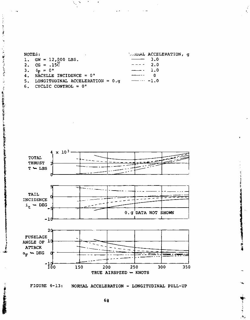
.a .* NOTES : T...,iildL ACCELERATION, g y 1. G W = 12,000 LBS. 3.0 *
f 2. CG = .15C - - - - 2.0 v 3. 6F = o0 - - *$ 1.0 'p.' 4 . NACELLE INCIDENCE = 0' --- 0
5. LONGITUDINAL ACCELERATION = 0.9 - - - - k -1.0 6 . CYCLIC CONTROL = 0'
+
t
TOTAL
T LLBS
5-
TAIL INCIDENCE it - DEG -
FIGURE 4-13 : NORMAL ACCELERATION - LONGITUDINAL PULL-UP
2ch
-10 I 1-1 -
. 1 \ - - - -
--- ----- ----- , , - - - a - _ _ _ _ _ - - - - - - - - - _-- - 4-
FUSELAGE ANGLE OF 10.
ATTACK aF 4 DEG C
- - - -_ - -_
-. A -- _-- - C -
/ - -
_ - - - -. _--
-10 1.0 0 150 200 250 300 350
TRUE AIRSPEED - KNOTS
. -
0.9 DATA NOT SHOWN
- - - - - -- L_C______-- - - - - - - - - - '
- - - _ _ _ _ - -
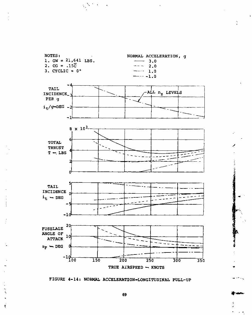
NOTES : 1. GW = 2 1 , 6 4 1 LBS. 2 . CG = .15C 3 . CYCLIC = o O
NORMAL ACCELERATION, g - 3 . 0 -- - 2 . 0 -- - 1 . 0 - - - - 1 . 0
TOTAL THRUST T --, LBS
- 4 TAIL
INCIDENCE,3 PER g
FUSELAGE ANGLE OF
ATTACK
INCIDENCE O - it h DEG
-
OF * DEG
\
- - - - - - _ _ - - - - - _-- _ _ - - - - - - _ -- - - - - -
TRUE AIRSPEED - KNOTS
I .- .
1 - ' J T nz LEvEfS
-10
FIGURE 4-14: NORMAL ACCELERATION-LONGITUDINAL PULL-UP
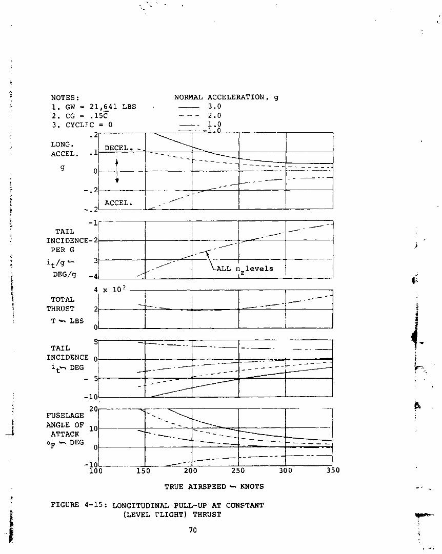
NOTES : NORMAL ACCELERATION, g 1. GW = 21,641 LBS . - 3.0 2. CG = .15C - - - 2.0 3. CYCLTC = 0 --
-.. - 1 .o .2 +
LONG.
TRUE AIRSPEED --. KNOTS
FIGURE 4-15: LONGITUDINAL PULL-UP AT CONSTANT (LEVEL rLIGHT) THRUST
ACCEL. - 1
g
-. 2-
5 .-
---- - - -
-.2
_ _ _ _ _ _ - -- - _ _ - - - - -
DECEL - - f
O---(- C
ACCEL.
1-
__ - _ _ - - it+ DEG
- 5 -10
TAIL INCIDENCE 0 - - - - -
#
_ - - - - - - - _ - -
. /-
- - - - - - - -------
_ - /
-- - - -
_ _ - - - - -
- - - - - - - - - - _ - - - -. _
//
- .
_ - - - - - - -
- - A
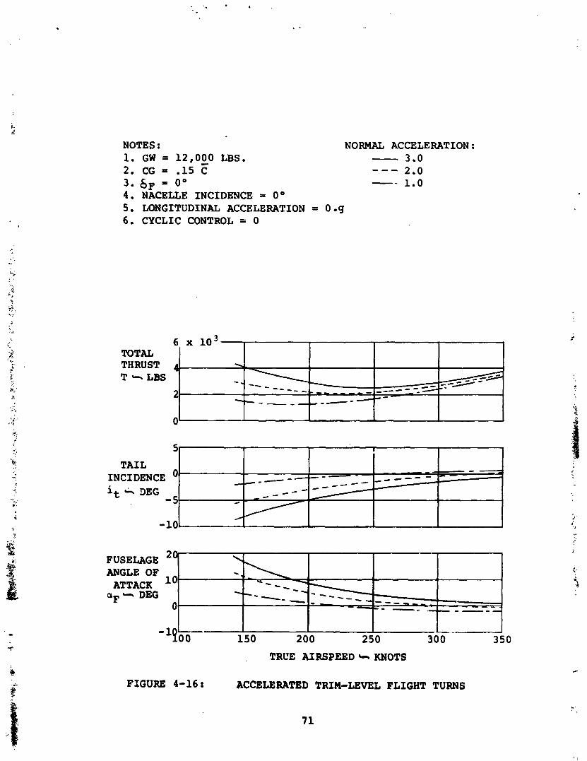
NOTES : NORMAL ACCELERATION: 1. GW 3 12,000 LBS. - 3.0 2 . CG = - 1 5 F --- 2 .O 3. SF = o0 -- 1.0 4 . NACELLE INCIDENCE = O 0 5. LONGITUDINAL ACCELERATION = 0 g 6 . CYCLIC CONTROL = 0
6 x lo3
FUSELAGE ANGLE OF
ATTACK aF - DEG
5
TAIL INCIDENCE it DEG
-5
-10.
TOTAL THRUST 4 T -. LBS
2
n.
'-7- --- _ - - - -
FIGURE 4-16 : ACCELERATED TRIM-LEVEL FLIGHT TURNS
-- - -s - - - \
7 4-
- - _ _ _ - - - -
---
l!~- 150 200 250 30 0 350
TRL'E AIRSPEED .I. KNOTS
b - -
-
- - - -__ --
2 0
- .-- ---a
10
0
'. . Y ----
I- - - - - -
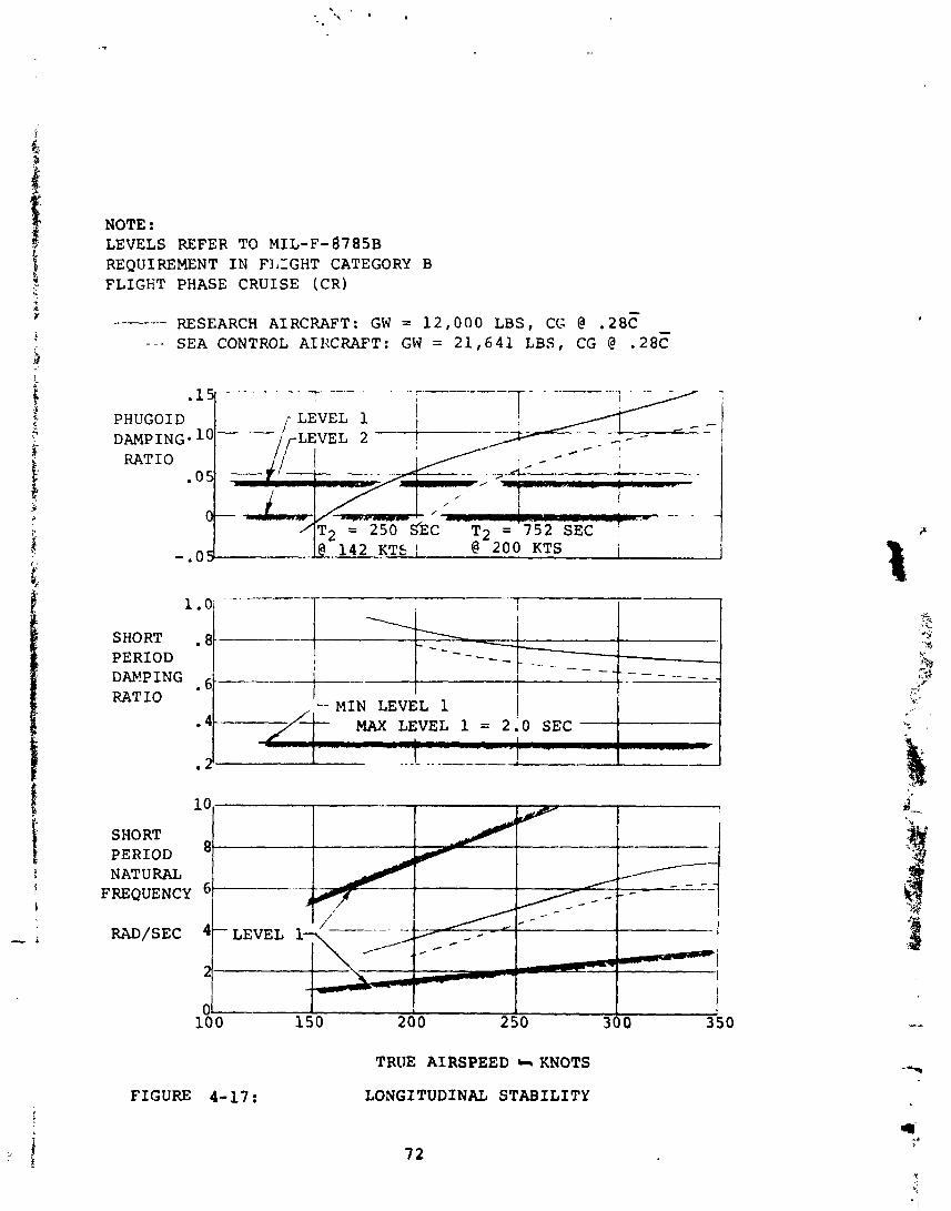
NOTE : LEVELS REFER TO M I L - F - ~ T ~ S B REQUIREMENT I N FIAIGHT CATEGORY B FLIGHT PHASE CRUISE (CR)
RESEARCH AIRCRAFT: GW = 1 2 , 0 0 0 LBS, CG @ . 2 8 C - - - SEA CONTROL AZIXRAFT: GW = 2 1 , 6 4 1 LBS, CG @ .28?
I -- - - .-
='7'52 SEC-
-.o 1 4 2 KTk i @ 200 KTS I --
I
SHORT - 8 PERIOD - - _ -- __ DAb!PING .6 - - - - - - _
RATIO -- M I N LEVEL 1 i MAX LEVEL 1 = 2.0 SEC
- - - - . - - - - - -
-
SHORT 8 - PERIOD
NATURAL FREQUENCY
1K 0 1 I 1 I
15 0 200 250 300 350
TRUE AIRSPEED s KNOTS
LONGITUDINAL STABILITY FIGURE 4-17:
characteristics of a soft inplane rotor because they ignore inplane flexibility effects. Figure 4-18 illustrates a com- parison of rotor force and moment coefficients obtained from tunnel test data with the predicted levels of the force and moment coefficients obtained, using digital programs for: (1) rigid rotors, (2) flexible in flapping only, and ( 3 ) flex- ible in flapping and lead-lag both. The wind tunnel data were obtained from tests of a 1/9-scale dynamically-similar folding tilt-rotor/semi-span-wing model having frequency characteris- tics at the intermediate test rpm's near those of the Model 222 rotors. The frequency ratios were varied over a relatively wide range during the test by varying the test rpm of the rotor. It is noteworthy that the trends of the coefficients are matched very well, utilizing the Boeing-developed digital pro- gram methods which include the lead-lag in addition to flapping frequeilcy effects. Note also that the sign of the pitching moment coefficient changed from + to - in the intermediate rpm range; i.e., the hub moment changed from a destabilizing to a stabilizing contribution, and that the normal force coeffici- ent is of decreased magnitude as compared to the predicted level for the rigid rotor or rotor free to flap only. The normal force times its moment arm is more powerful in its con- tribution to stability than is the hub moment for the Model 222, and the rotor total contribution to satibility is, therefore, still destabilizing. However, the destabilizing influence of the Model 222 rotor is much smaller in both pitching and yawing of the aircraft than would be true if the rotor were rigid, or nearly so, inplane.
Proper selection of the frequencies as compared to design operational rpm of the rotor permits full advantage to be taken of the anticipated effects of the inplane frequency con- tribution to stability at both transition and cruise speeds because of the change in rpm between transition and cruise mode. Thus, the tail sizes of the Model 222, horizontal and vertical, are substantially smaller, approaching 50 percent, than would be required if the inplane frequency effects were ignored. Preliminary analysis indicates that a vertical tail volume coefficient !LTST/SW~ of 0.128 and a horizontal tail volume coefficient !LTST/S&~ of 1.0 provide adequate direc- tional and 1ongitudina.l static and dynamic stability and control characteristics in cruise. These values have been used for the operational airplanes in this study.
4.6 Control Systems
The pilot's controls consist of a conventional stick and rudder pedals plus a power control. The power control lever sets power and rotor collective pitch. The governing system modifies the collective pitch to hold constant rgm. The rotor tilt position is relected by a switch on the power control lever. Rudder pedals are connected through a power cylinder
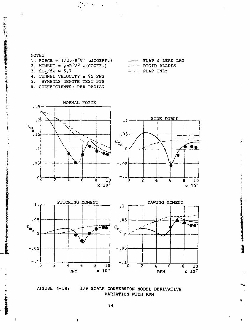
NOTES : 1. FORCE = 1/2 p TR 2~ a.(COEFF . ) - 2. MOMENT = p.rrR 3 ~ 2 a (COEFF. ) - - - 3. dCL/da = 5.7 - - 4. TUNNEL VELOCITY r 85 FPS 5. SYMBOLS DENOTE TEST PTS 6. COEFFICIENTS: PER RADIAN
NORMAL F O X E -25-
FLAP 61 LEAD LAG RIGID BLADES FLAP ONLY
YAWING MOMENT
RPM x lo2
FIGURE 4-18: 1/9 SCALE CONVERSION MODEL DERIVATIVE VARIATION WITH R P M
to the conventional aircraft rudder and to the differential longitudinal rotor cyclic pitch system.
In hover, full yaw cyclic is obtained by full pedal dis- placement. As the transition (i.e.,rotor tilt) progresses toward aircraft flight, a mechanical gain changer reduces the amount of cyclic that is obtained by the pedal displacement as the rudder effectiveness increases with forward airspeed.
Longitudinal motion of the stick moves the elevator and produces cyclic pitch in the rotors. As in the case of the pedals, this cyclic pitch is phased out as the aircraft transi- tions from hover to cruise.
Lateral motion of the stick moves the flaperons and pro- vides differential collective pitch in the rotors during hover. This differential collective pitch is also phased out as the aircraft transitions from hover to cruise.
During transition, no additional tasks are performed by the pilot since the setting of flaps, longitudinal trim, etc., ispre+rogrammed as a function of nacelle tilt position. This transition programming automatically places the flaps in a 70-degree position for hover and opens the wing leading-edge download reduction devices. These leading-edge devices are closed in transition at approximatell 40 knots, and the flap angle is reduced in accordance with a transition schedule. Flap deflection will be reduced to zero as nacelle incidence goes to zero.
Sets of dual hydraulic power cylinders are provided at each rotor swashplate to prevent feedback of rotor control loads into the control system. Cockpit power cylinders are provided to ensure light control feel and prevent feedback of aircraft control surface loads to the stick. A variabie control force feel system is incorporated to provide good control forces for all flight regimes. Control feel changes will be programmed with nacelle incidence and with dynamic pressure.
A stability augmentation system (SAS) is installed to provide the desired damping and attitude characteristics during hover, transitim, and aircraft flight. This augmen- tation system also provides feedback inputs to the rotor col- lective and cyclic controls to improve the ride qualities and reduce the rotor loads during flight in gusty air. A conven- tional longitudinal trim wheel is provided to permit the pilot to compensate for center of gravity variations. This wheel biases the longitudinal stick position.
4.7 A e r o e l a s t i c S t a b i l i t y
The tilt r o t o r c l a s s of a i r c r a f t h a s a number of p o t e n t i a l i n s t a b i l i t y mechanisms a s a r e s u l t o f p r o p / r o t o r s i z e and f l e x i - b i l i t y . These i n c l u d e w h i r l f l u t t e r and ground and a i r r e s o - nance , a long w i t h n o n c l a s s i c a l e f f e c t s r e l a t e d t o t h e i n t e r n a l p r o p e r t i e s o f t h e b l a d s and s t e a d y d e f l e c t i o n e f f e c t s such a s p i t c h / f l a p / l a g c o u p l i n g . Because of t h e s i m i l a r i t y e x i s t i n g th roughou t t h e c l a s s of tilt r o t o r a i r c r a f t c o - ~ e r e d i n t h i s s t u d y , t h e f l i g h t r e s e a r c h a i r c r a f t n a s been ana lyzed i r l d e t a i l s i n c e it i s c o n s i d e r e d t h a t t h e r e s u l t s o b t a i n e d f o r a t y p i c a l c o n f i g u r a t i o n w i l l a p p l y t o a l l of t h e a i r c r a f t .
4 .7 .1 P r e d i c t i o n C a p a b i l i t y . - A h i g h l e v e l of c o n f i - dence i n our a b i l i t y t o p r e d i c t w h i r l f l u t t e r and ground and a i r r e sonance behav io r h a s been demons t ra ted on a series o f dynamica l ly similar models . For example, t h e t e s t i n g f o r d i v e r g e n c e and w h i r l f l u t t e r bounda r i e s on t h e 1 /9 - sca l e model, Reference 5, a s shown i n F i g u r e 4-19, h a s shown t h e accu racy of t h e p r e d i c t i o n s . The o n s e t o f a i r r e sonance h a s also been p r e d i c t e d a c c u r a t e l y f o r a 1 /9 .2 - sca l e model, F i g u r e 4-20. A r e c e n t l y deve loped c a p a b i l i t y is t h e p r e d i c t i o n o f b l a d e p i t c h - l a g - f l a p f l u t t e r . T h i s h a s been e x p e r i e n c e d on a number of model b l a d e s mos t n o t a b l y d u r i n g a NASA/Boeing tes t o f a 13 - foo t dynamic model a t ONERA. The i n s t a b i l i t i e s expe r i enced on t h e t e s t were caused by c o u p l i n g between b l a d e t o r s i o n and b l a d ~ f l a p p i n g and l a g g i n g c o n d i t i o n s when t h e b l a d e was de- f l e c t e d due t o s t e a d y t h r u s t and t o r q u e c o n d i t i o n s . The o n s e t ?f i n s t a b i l i t y is now p r e d i c t e d u s i n g t h e most r e c e n t method- o logy a s shown i n F i g u r e 4-21.
4.7.2 S t a b i l i t y Boundar ies . - S t a b i l i t y b o u n d a r i e s f o r a t y p i c a l t i l t / p r o p - r o t o r a i r c r a f t a r e shown i n F i g u r e 4-22. These a r e f o r t h e c r u i s e c o n f i g u r a t i o n ( i . e . , n a c e l l e s down) which i s i d e n t i f i e d t o be t h e most c r i t i c a l reg ime of o p e r a t i o n . Whir l f l u t t e r o c c u r s a t h i g h advance r a t i o , h i g h rpm c o n d i t i o n s . Two modes o f symmetric f l u t t e r a r e p r e s e n t and one mode i n v o l - v i n g an t i symmet r i c motion of t h e a i r f r a m e and rotors. These bounda r i e s a r e w e l l c l e a r of any o p e r a t i o n a l c o n d i t i o n s . The u s e of a s o f t i n p l a n e h i n g e l e s s rotor p r o v i d e s h i g h speed c a p a b i l i t y w i t h o u t w h i r l f l u t t e r and w i t h o u t add ing we igh t t o t h e wing which was des igned from s t r e n g t h c o n s i d e r a t i o n s . T y p i c a l l y , an a r t i c u l a t e d o r g i m b a l l e d r o t o r r e q u i r e s a sub- s t a n t i a l i n c r e a s e i n wing t o r s i o n a l s t i f f n e s s . A t h i g h advance r a t i o s , any t e n d e n c i e s t o a i r r e sonance mechan ica l i n s t a b i l i t y a r e suppres sed by aerodynamic damping i n t h e b l a d e l e a d - l a g modes. A t low advance ratios, t h e b l a d e c o l l e c t i v e p i t c h s e t t i n g s a r e s m a l l e r and l e a d - l a g dampinq r educed , w i t h t.he r e s u l t t h a t a r e g i o n o f a i r r e sonance e x i s t s c e n t e r e d around 160 p e r c e n t of normal c r u i s e rpm. T h i s i s o u t s i d e t h e ope ra - t i o n a l c r u i s e r ange which e x t e n d s down o n l y as f a r as a n advance r a t i o of .45. The system i s s t i l l f r e e from i n s t a b i l i t y
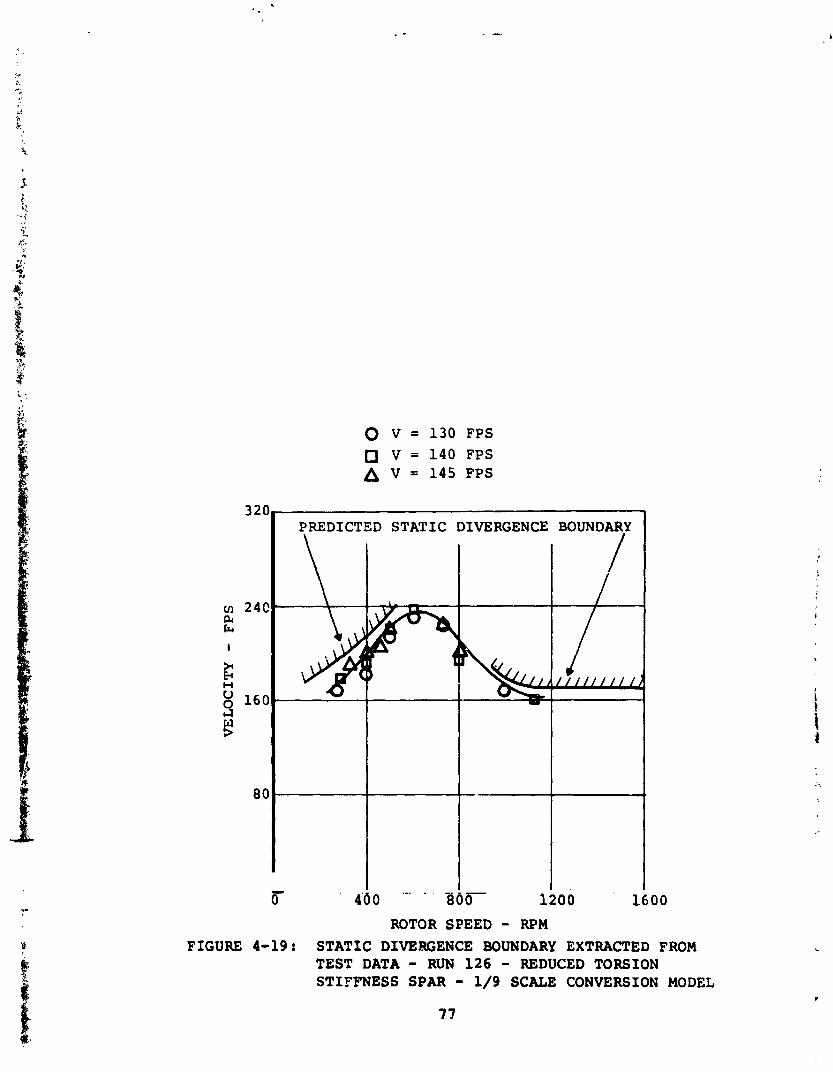
0 V = 130 FPS n V = 140 FPS A V = 145 FPS
PREDICTED STATIC DIVERGENCE BOUNDARY
ROTOR SPEED - R P M FIGURE 4-19: STATIC DIVERGENCE BOUNDARY EXTRACTED FROM
TEST DATA - RUN 126 - REDUCED TORSION STIFFNESS SPAR - 1/9 SCALE CONVERSION MODEL
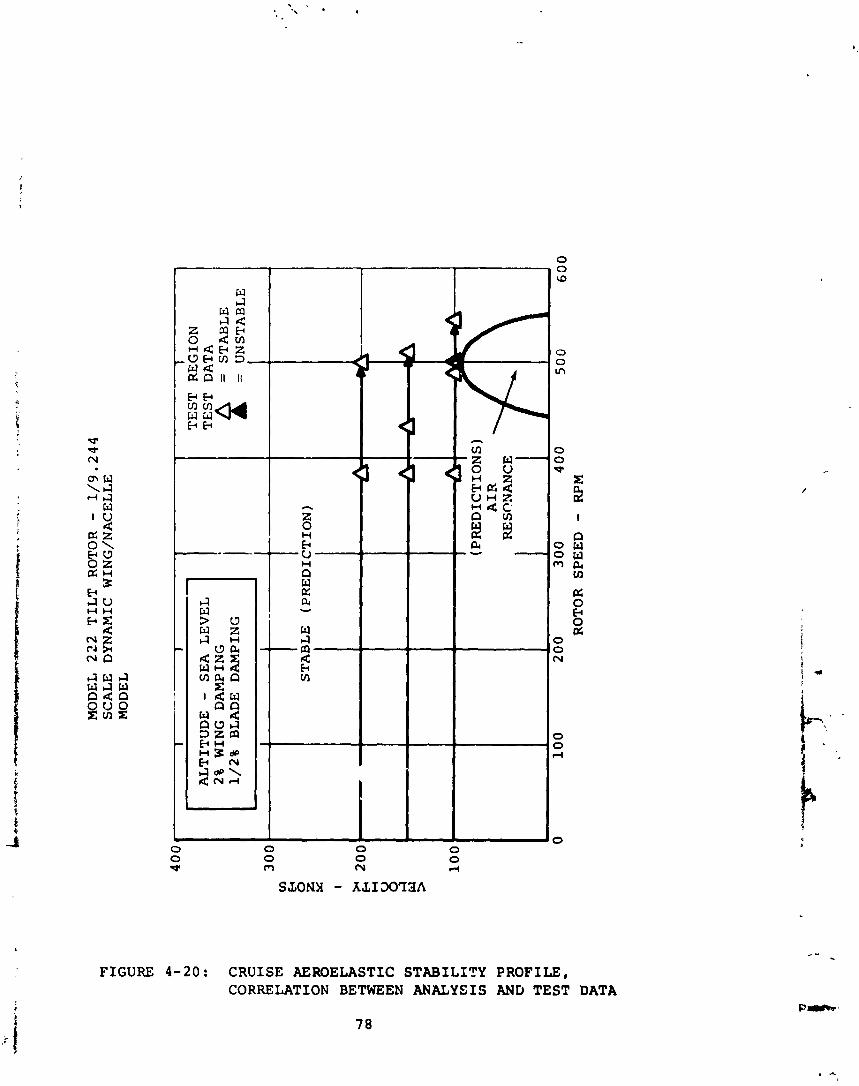
MO
DE
L
22
2 T
ILT
R
OT
OR
-
1/9
.24
4
SCA
LE
D
YN
AM
IC
WIN
G/N
AC
EL
LE
M
OD
EL
AL
TIT
UD
E -
SE
A
LE
VE
L
2%
WIN
G
DA
MP
ING
1/2%
BL
AD
E
DA
MP
ING
I
TE
ST
REGION
TE
ST
D
AT
A
f =
S
TA
BL
E
= UNSTABLE
I
RO
TO
R SPEED -
RPM
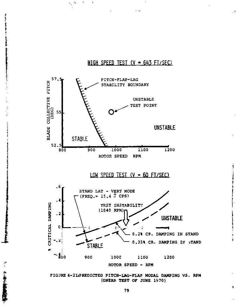
I= PITCH-FLAP-LAG / STABILITY BOCNDARY
UNSTABLE
0
UNSTABLE
ROTOR SPEED RPM
STAND LAT - VERT MODE (FREQ.= 15.4 f CPS)
v - STABLE
STAND - 0 . 3 5 % CR. DAMPING IN .STAND
900 lOOC 1100 1200
ROTOR S P E E D - RPM
FIGURE 4 - 2 l : B R E D I C T E D PITCH-LAG-FLAP MODAL DAMPING VS. RPM (ONERA TEST OF JUNE 1970)
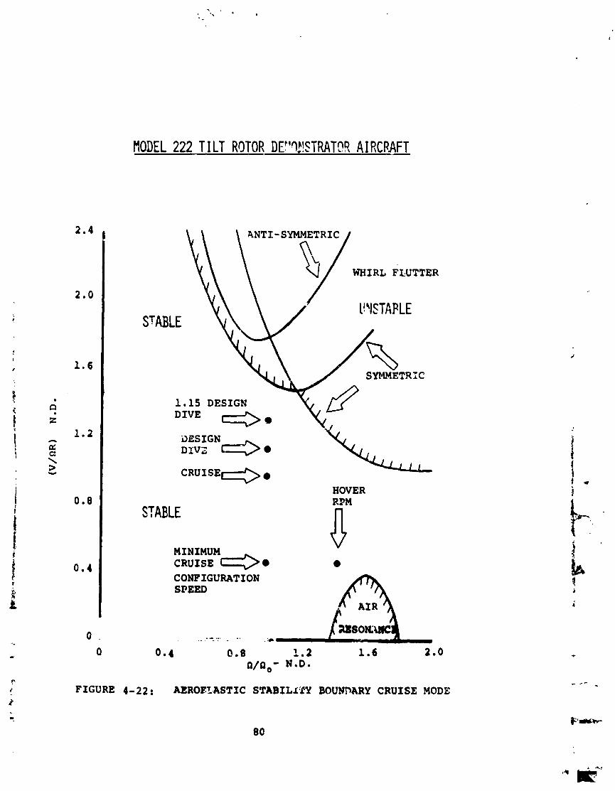
MODEL 222 TILT ROTOR DF'Q!!$TRATOS A I R C P N
HOVER
STABLE
MINIMUM v
CRUISE '@ 0 CONFIGURATION SPEED
- - .. ., . ,. - . 'A
FIGURE 4-22: AEROELASTZC STABILlTY BOUNDARY C R U I S E MODE
even a t hover rpm a t t h e lowest c r u i s e c o n f i g u r a t i a n a6vance r a t i o .
4.8 Performance
The performance of each of t h e f o u r u s e f u l t i l t - r o t o r a i r c r a f t i s shown i n t h i s s e c t i o n . The fo l lowing d a t a i s pre- senied:
a . Hover c e i l i n g
b. F i i g h t envelope
c . S!COL performance
d. Pay load- rad ius - lo i t e r performance
4.8.1 U. S. Army MAVS. - 4 . 8 . 1 . 1 Hover C e i l i n g . - Figuro 4-23 p r e s e n t s t h e out -
of-grocnd e f f e c t hover c a p a b i i i t y of t h e Army v e r s i o n of t h e tilt r o t o r . This d a t a i s based on t h e c a p a b i l i t y t o hover a t a T/W r a t i o s u f f i c i e n t t o p rcv ide a 500 f t /min v e r t i c a l r < ~ t e of ,,irnb. The climb inargin is cons'steri: w i th c u r r e n t Arm.? desi1:il c r i t e r i a which r e q u i r e s t h a t new a i r c r a f t p o s s e s s t h i s inn- ren t c a p a b i l i t y , s p e c i f i c a l l y a t 4,000 f e e t , 9S°F, a4 m i l i t a r y r a t e d power. Superimposed on t h e curve i s t h e d e s l g n g r o s s weight which s u b s t a n t i a t e s t h e f a c t t h a t t h e p i n t d e ~ i g n v e h i c l e exceeds t h e c r i t e r i a by approximately 500 pounds i n y ross weight o r converse ly t h e ? . i r c r a f t l s climb c a p a b i l i t y exceeas t h e 500-fpm requirement .
4.8.1.2 F l i g h t Envelope. - Figure 4-24 p r e s e n t s t h e normal r a t e d power l e v e l f l i g h t speed envelope f o r c r u i s e r o t o r rpm i70 p e r c e n t of hover r -%) . The d a t a is p resen ted f o r s t andard day c o n d i t i o n s ; r o t o r s down; f l a p s up. T h i s shows a normal r a t e d power speed range between 290-300 k n o t s up t o approximately 20,OOC f e e t . The m i l i t a r y rated power spsed a t 10,000 f e e t i s 314 knots . I n a d d i t i m , t h e s e d + t a show a c e i l i n g c a p a b i l i t y of 29,500 f e e t .
4.8.1.3 STOL Performance. - Figure 4-25 p r e s e n t s t h e s h o r t takeoff performance c a p a b i l i t y of t h e Army MAVS d e s i g n a t s e a l e v e l f o r s t a n d a r d day c o n d i t i o n s i n terms of t a k e o f f g r o s s weight a s a f u n c t i o n of ground r o l l d i s t a n c e . Two i e v e l s c f performance a r e p resen ted ; one which r e f l e c t s inaxi- mum c a p a b i l i t y and assumes t h a t t h e a i r c r a f t l i f t s o f f a t t h e end of r o t a t i o n a t 10 degrees marimum wing a m l e of a t t a c k a t l i f t - t o - w e i g h t r a t i o - 1.0, -nd t h e o t h e r , a normal takeof2 c a p a b i l i t y , assumes t h a t i n STOL mode, th ; A-off speed correspond; t o 1if:-LO-weight r a t i o = 1.1 ,.t a l i m i t i n g wing ang le of a t t a c k of 10 degrees . The f i r s t s e t of assumptions
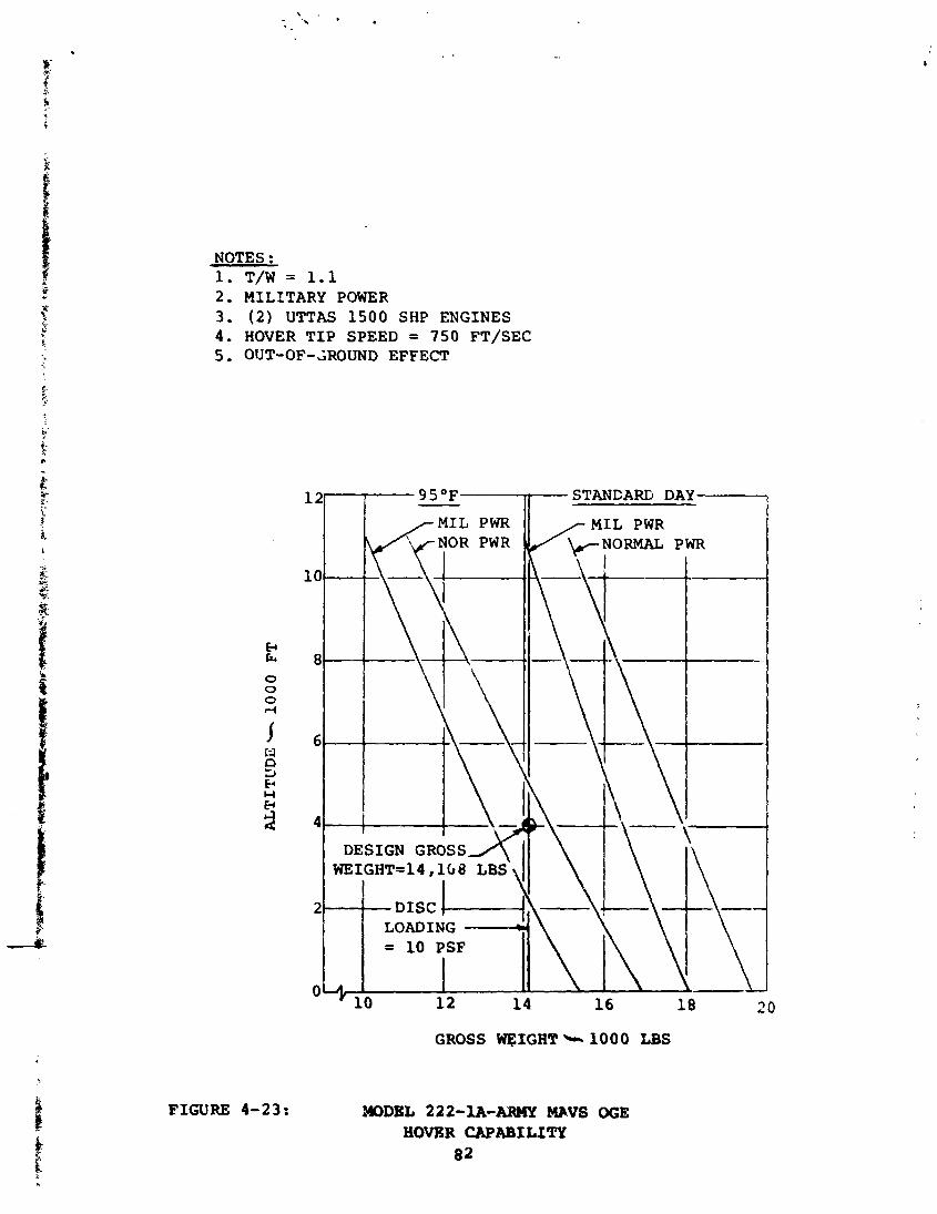
NOTES : 1 . T/W = 1.1 2 . MILITARY POWER 3 . ( 2 ) UTTAS 1 5 0 0 SHP ENGINES 4 . HOVER T I P S P E E D = 750 FT/SEC 5 . OUT-OF-AROUND EFFECT
I MIL PWR
.w\ DESIGN G R O S S X
DISC 1- -4
-STANCARIj DAY
MIL PWR k N O R M A L PWR -7
GROSS WT$IGHT+lOQO LBS
FIGURE 4-23: aDDEL 222-1A-ABMY MeVS OGE HOVKR CAPABILZlY
82
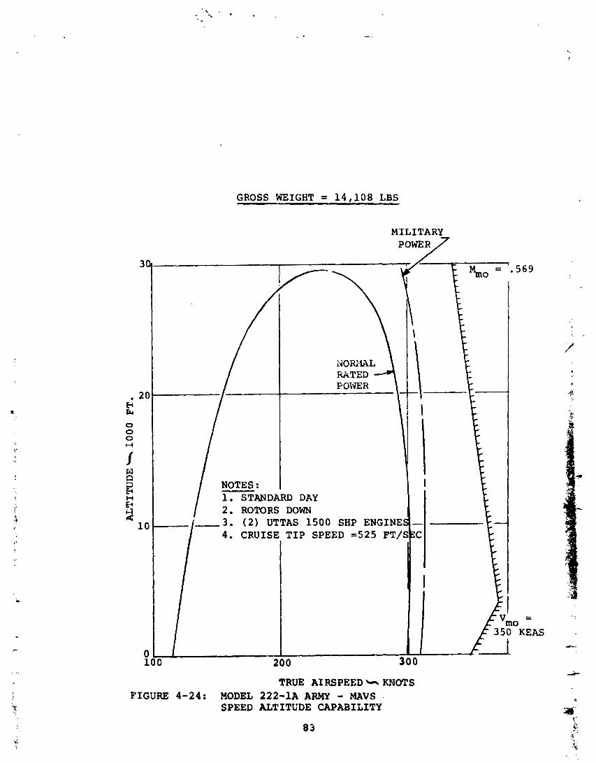
GROSS WEIGHT = 1 4 , 1 0 8 LBS
MILITARY
po"Y
TRUE AIRSPEED KNOTS FIGURE 4-24: MODEL 222-1A ARMY - MAVS .
SPEED ALTITUDE CAPABILITY
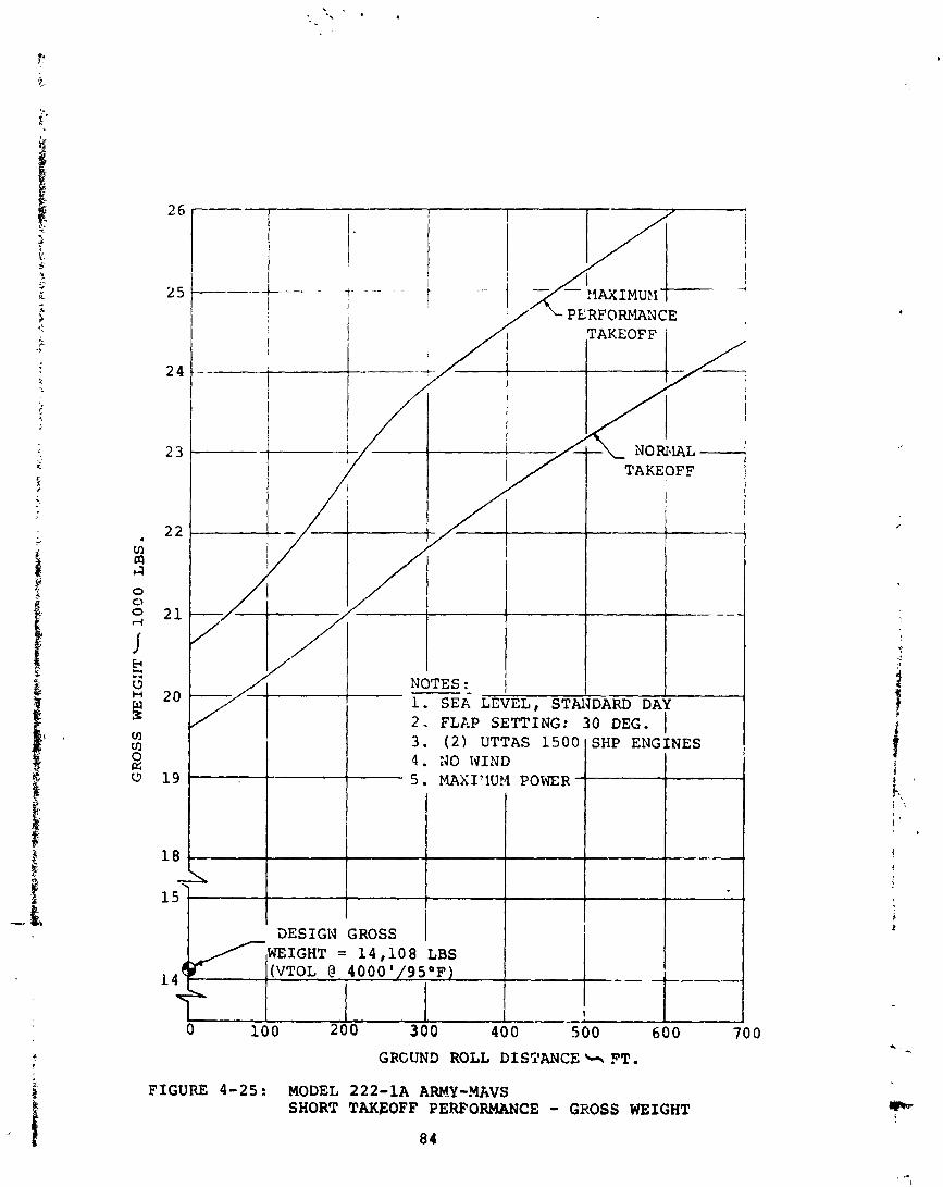
/ 2 . FLAP SETTING: 30 DEG. I 4 . NO WIND 5. MAXIIlUM POWER
3ESIGN ,GROSS, 1 1 + WEIGHT = 14,108 LBS
(VTOL @ 4000' 9S°F ---
GRCUND ROLL DISTANCE * FT. FIGURE 4-25: MODEL 222-1A ARMY-WVS
SHORT TAKFOFF PERFORMANCE - GROSS WEIGHT
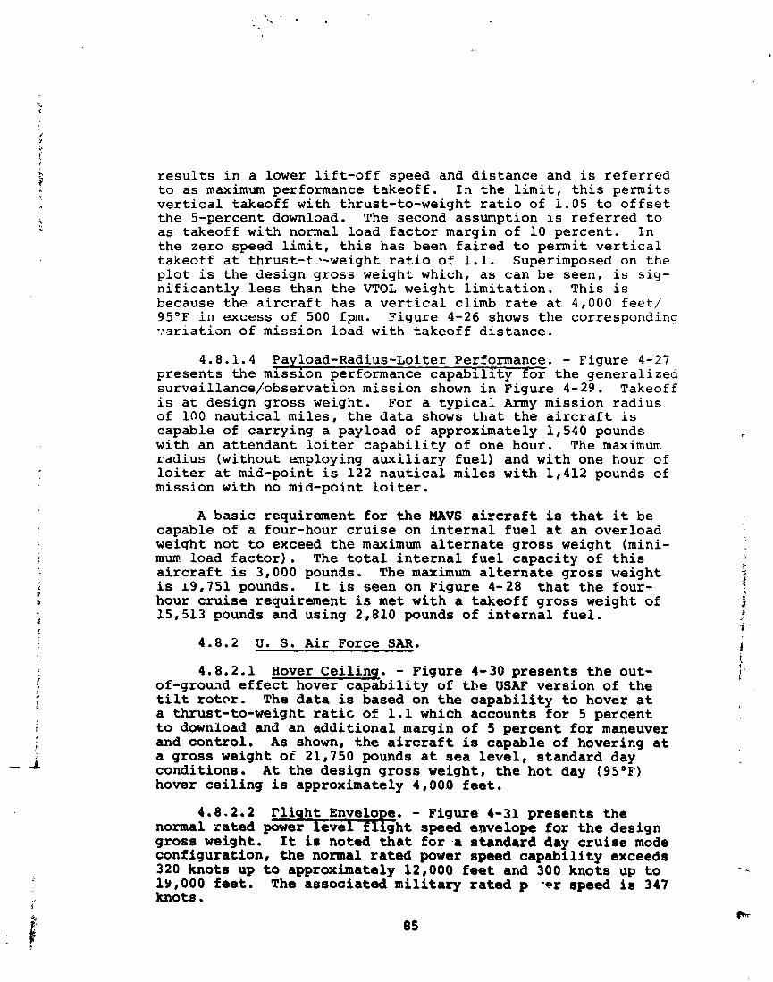
r e s u l t s i n a lower l i f t - o f f speed and d i s t ance and is r e f e r r e d t o a s maximum performance t akeo f f . I n t h e l i m i t , t h i s permits v e r t i c a l takeoff with thrust- to-weight r a t i o of 1.05 t o o f f s e t t h e 5-percent download. The second assumption i s r e f e r r e d t o a s takeoff wi th normal load f a c t o r margin of 10 percent . I n t he zero speed l i m i t , t h i s has been f a i r e d t o permit v e r t i c a l takeoff a t thrust- t2-weight r a t i o of 1.1. Superimposed on t h e p l o t i s t h e design g ros s weight which, a s can be seen, i s s ig - n i f i c a n t l y l e s s than t h e VTOL weight l i m i t a t i o n . This i s because t h e a i r c r a f t has a v e r t i c a l climb r a t e a t 4,000 feet/ 9S°F i n excess of 500 fpm. Figure 4-26 shows t h e corresponding v a r i a t i o n of mission load with takeoff d i s t ance .
4.8.1.4 Payload-Radius-Loiter Performance. - Figure 4-27 p r e sen t s t h e mission performance c a p a b i l i t y t o r t h e genera l ized surveillance~observation mission shown i n Figure 4-29. Takeoff i s a t design g ros s weight. For a t y p i c a l Army mission r ad ius of 100 n a u t i c a l mi les , t h e d a t a shows t h a t t h e a i r c r a f t i s capable of ca r ry ing a payload of approximately 1,540 pounds with an a t t endan t l o i t e r c a p a b i l i t y of one hour. The maximum rad ius (without employing a u x i l i a r y f u e l ) and with one hour of l o i t e r a t mid-point is 122 n a u t i c a l miles with 1,412 pounds of mission with no mid-point l o i t e r .
A b a s i c requirement f o r the MAVS a i r c r a f t is t h a t it be capable of a four-hour c r u i s e on i n t e r n a l f u e l a t an overload weight not t o exceed t h e maximum a l t e r n a t e g ros s weight (mini- mum load f a c t o r ) . The t o t a l i n t e r n a l f u e l capac i ty of t h i s a i r c r a f t is 3,000 pounds. The maximum a l t e r n a t e g ros s weight is 19,751 pounds. I t is seen on Figure 4-28 t h a t t h e four- hour c r u i s e requirement is m e t w i th a takeoff g ros s weight of 15,513 pounds and using 2,810 pounds of i n t e r n a l f u e l .
4.8.2 U. S. A i r Force SAR.
4.8.2.1 Hover Cei l inq . - Figure 4-30 p re sen t s t h e out- of-grouad e f f e c t hover c a p a b i l i t y of t h e USAF vers ion of t h e tilt r o t c r . The d a t a is based on t h e c a p a b i l i t y t o hover a t a thrust- to-weight rat ic of 1.1 which accounts f o r 5 percen t t o download and an a d d i t i o n a l margin of 5 percen t f o r maneuver and con t ro l . A s shown, t h e a i r c r a f t is capable of hovering a t a g ros s weight of 21,750 pounds a t sea l e v e l , s tandard day condi t ions . A t t h e des ign g ros s weight, t h e h o t day 1 9 5 V ) hover c e i l i n g is approximately 4,000 f e e t .
4.8.2.2 r l i h t Envelo e. - Figure 4-31 p re sen t s t h e normal r a t e d power + e d h t speed envelope f o r t h e des ign g ros s weight. It is noted t h a t f o r .a s tandard day c r u i s e mode conf igura t ion , the normal r a t e d power speed c a p a b i l i t y exceeds 320 knots up t o approximately 12,000 f e e t and 300 knots up t o 19,000 f e e t . The a s soc i a t ed m i l i t a r y r a t e d p -er upeed is 347 knots.
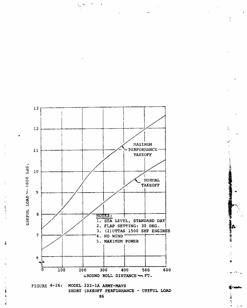
7 1 . SSA LEVEL, STANDARD 1
2 . FLAP SETTING: 3 0 DEG, 3 . (ZJUTTAS 1500 SHP EN(
5 . MAXIMUM POWER
GROUND ROLL DISTANCE FT.
FIGURE 4-26: MODEL 222-1A ARMY-MAVS SHORT TAKEOFF PERFORIWCE - USEFUL LOAD
86
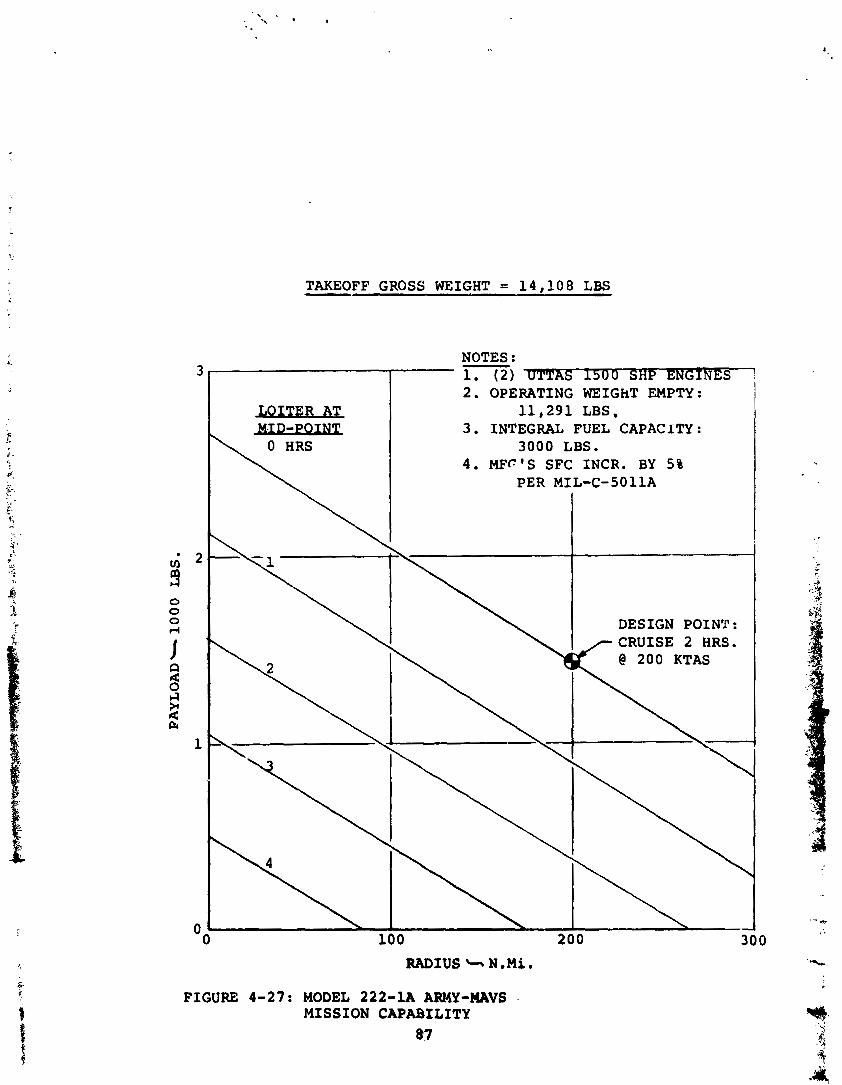
TAKEOFF GROSS WEIGHT = 1 4 , 1 0 8 LBS -
NOTES : - 1. ( 2 ) -S 1 5 0 0 SHP ENGINES 2. OPERATING WEIGhT EMPTY:
1 1 , 2 9 1 LBS, 3 . INTEGRAL FUEL CAPACITY:
3 0 0 0 LBS. 4 . MFc ' S SFC IMCR. BY 5%
PER MIL-C-5011A I
RADIUS + N.Mi.
FIGURE 4-27: MODEL 222-1A ARMY-WAVS .
MISSION CAPABILITY 87
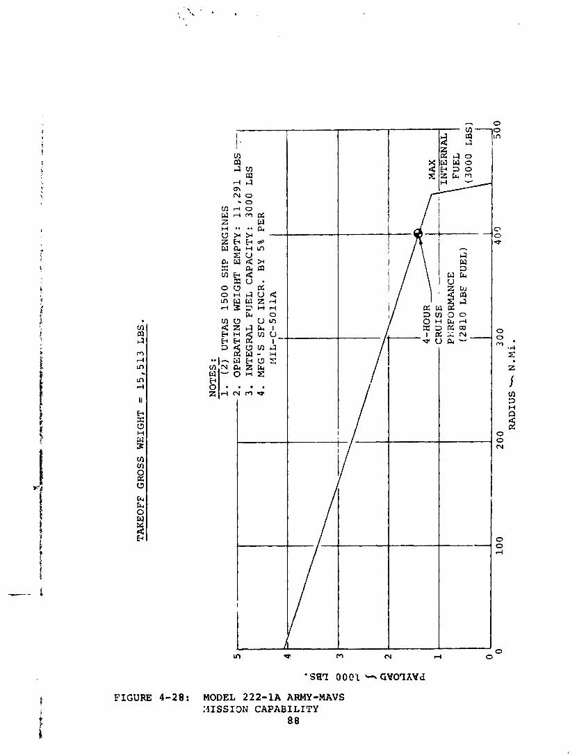
FIGURE 4-28: MODEL 222-1A ARMY-MAVS :4ISSI3N CAPABILITY
88
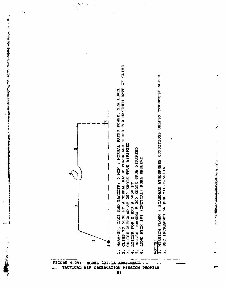
WA
RM
-UP,
T
AX
I A
ND
T
-OF
F:
5 M
IN
@ N
OR
MA
L RATED
CL
IMB
TO
5
00
0
FT
@
NO
RM
AL
RA
TE
D
POW
ER
AN
D
SPE
ED
C
RU
ISE
O
UT
BO
UN
D
AT
2
00
K
NO
TS
TR
UE
A
IRS
PE
ED
L
OIT
ER
FO
R
X HRS
@ 5
00
0
FT
C
RU
ISE
INBOUND @
2
00
KN
OT
S T
RU
E
AIR
SP
EE
D
LAND W
ITH
1
0%
(IN
ITIA
L)
FU
EL
R
ESE
RV
E
POW
ER
, S
EA
L
EV
EL
F
OR
MA
XIM
UM
RATE
OF
CL
IMB
NOTES :
.c..l,
1.
MIS
SIO
N FLOWN
@ ST
AN
DA
RD
A
TM
OSP
HE
RE
C
CY
DIT
ION
S
UN
LE
SS
OT
HE
RW
ISF
N
OT
ED
2
. S
FC
IN
CR
EA
m 5
% P
ER
M
IL-C
-501
1A
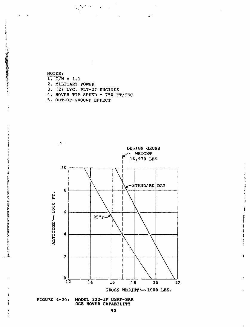
NOTES : 1. T/W = 1.1 2. MILITARY POWER 3. (2) LYC. PLT-27 ENGINES 4. HOVER TIP SPEED = 750 FT/SEC 5. OUT-OF-GROUND EFFECT
DESIGN GROSS WEIGHT
<16,970 I LBS
1 G 18 20 22
GROSS WEIGHT& 1000 LBS.
FIGUW 4-30: MODEL 222-1F USAF-SAR OGE HOVER CAPABILITY
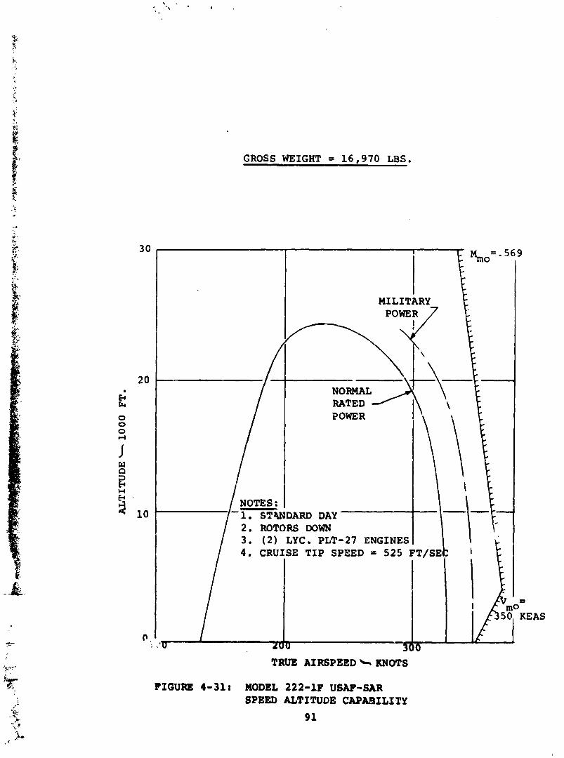
GROSS WEIGHT = 1 6 , 9 7 0 LBS.
I
MILITARY POWER 7
\
RATED POWER
/ NOTES : -1. STWDARD DAY
2 . ROTORS DOWN / 3 . ( 2 ) LYC. PLT-27 ENGINES
TRUE AIRSPEED b KNOTS
FIGURE 4-31: MODEL 222-1F USAF-SAR SPEED ALTITUDE CAPABILITY
91
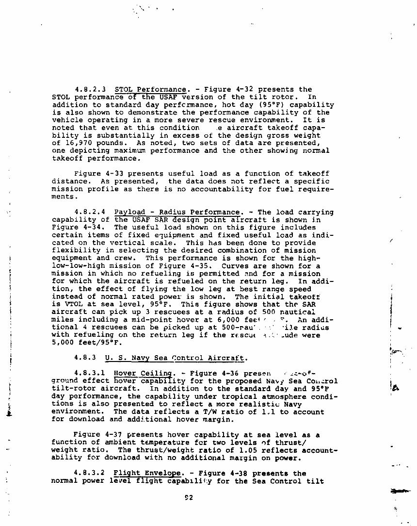
4.8.2.3 STOL Performance. - Figure 4-32 p r e s e n t s t h e STOL performance of t h e USAF v e r s i o n of t h e tilt r o t o r . I n a d d i t i o n t o s t andard day perfcnnance , h o t day (95OF) c a p a b i l i t y i s a l s o shown t o demonstrate t h e performance c a p a b i l i t y of t h e v e h i c l e o p e r a t i n g i n a more s e v e r e r e s c u e environment. I t i s noted t h a t even a t t h i s c o n d i t i o n .e a i r c r a f t t a k e o f f capa- b i l i t y i s s u b s t a n t i a l l y i n excess of t h e des ign g r o s s weight of 16,970 pounds. As noted , two sets of d a t a a r e p r e s e n t e d , one d e p i c t i n g maximum performance and t h e o t h e r showing normal takeoff performance.
F igure 4 - 3 3 p r e s e n t s u s e f u l load a s a f u n c t i o n of t akeof f d i s t a n c e . A s p resen ted , t h e d a t a does n o t r e f l e c t a s p e c i f i c miss ion p r o f i l e a s there i s no a c c o u n t a b i l i t y f o r f u e l r e q u i r e - ments.
4.8.2.4 Payload - Radius Performance. - The load c a r r y i n g c a p a b i l i t y of t h e USAF SAR d e s i g n p o i n t a i r c r a f t i s shown i n F igure 4 - 3 4 . The u s e f u l load shown on t h i s f i g u r e i n c l u d e s c e r t a i n i t e m s of f i x e d e ~ u i p m e n t and f i x e d u s e f u l load a s i n d i - c a t e d on t h e v e r t i c a l s c a l e . Th i s has been done t o p rov ide f l e x i b i l i t y i n s e l e c t i n g t h e d e s i r e d combination of miss ion equipment and crew. Th is performance is shown f o r t h e high- low-low-high miss ion of F igure 4-35. Curves a r e shown f o r a miss ion i n which no r e f u e l i n g is permi t t ed ?nd f o r a miss ion f o r which t h e a i r c r a f t i s r e f u e l e d on t h e r e t u r n l e g . I n addi- t i o n , t h e e f f e c t of f l y i n g t h e low l e g a t b e s t range speed i n s t e a d of normal r a t e d power is shown. The i n i t i a l t a k e o f f is VTOL a t s e a l e v e l , 95OF. Th i s f i g u r e shows t h a t t h e SAR a i r c r a f t can p i c k up 3 r e s c u e e s a t a r a d i u s of 500 n a u t i c a l miles inc lud ing a mid-point hover a t 6,000 f e d ' , P. An addi- t i o n a l 4 r e s c u e e s can be picked up a t 500-rau' . - : ' l i le r a d i a s wi th r e f u e l i n g on t h e r e t u n l e g i f t h e rc.sc;rt =I .:. ,ude were 5,000 feet /9S°F.
4.8.3 U . S. Navy Sea Cont ro l A i r c r a f t . - 4.8.3.1 Hover C e i l i . - Figure 4-36 presert z, -=-of-
ground e f f e c t hover capab i t y f o r t h e proposed Naky Sea Coi~;rol t i l t - r o t o r a i r c r a f t . I n a d d i t i o n t o t h e s t a n d a r d day and 9S°F day performance, t h e c a p a b i l i t y under t r o p i c a l atmosphere condi- t i o n s i s a l s o p resen ted t o r e f l e c t a more r e a l i s t i c Navy environment. The d a t a r e f l e c t s a T/W r a t i o of 1.1 t o account f o r download and a d d i t i o n a l hover margin.
F igure 4-37 p r e s e n t s hover c a p a b i l i t y a t s e a l e v e l as a f u n c t i o n of ambient t u n p e r a t u r e f c r two l e v e l s ~f t h r u s t / weight r a t i o . The th rus t /we igh t r a t i o of 1.05 r e f l e c t s account- a b i l i t y f o r download wi th no a d d i t i o n a l margin on power.
4.8.3.2 F l i g h t Envelope. - Figure 4-38 p r e s e n t s t h e normal power level f l i g h t capabi1if:y f o r t h e Sea Cont ro l tilt
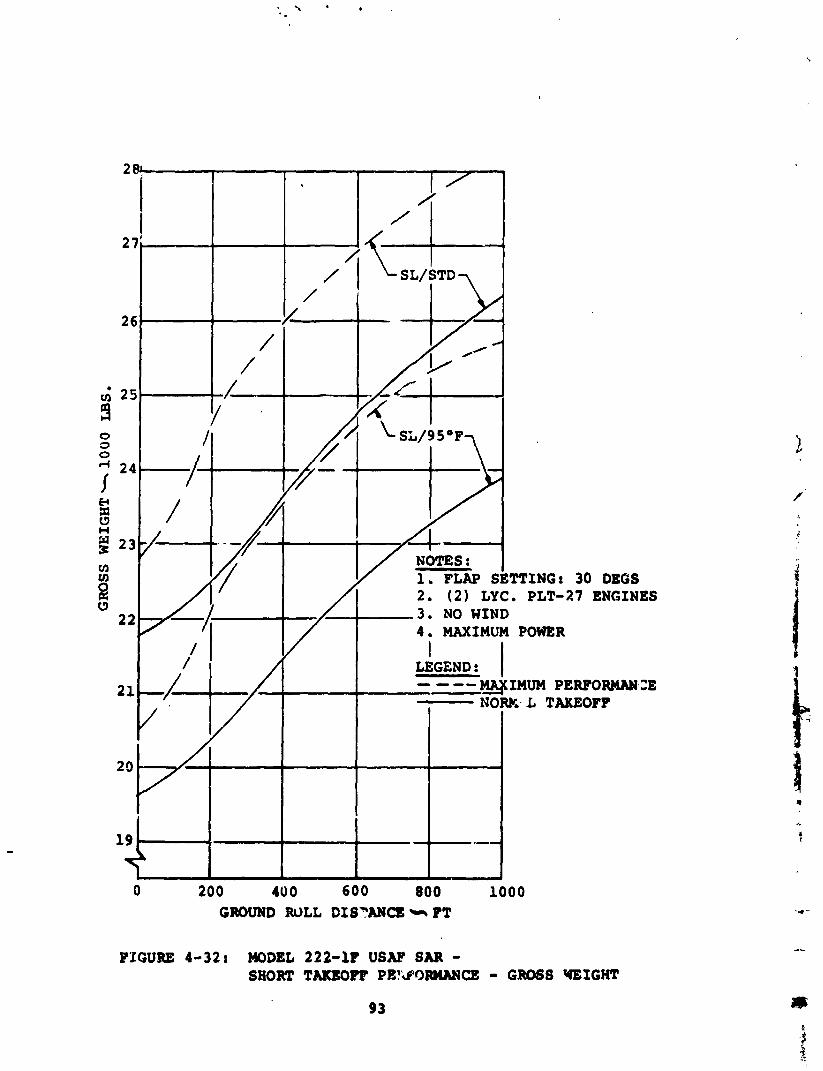
0 200 40 0 600 800 1000 GROUND ROLL DISYANCS PT
PICUBE 4-32: MODEL 222-1P USAF SAR - SHORT TAKEOFF PE?&ORMNCE - GROSS QEIGHT
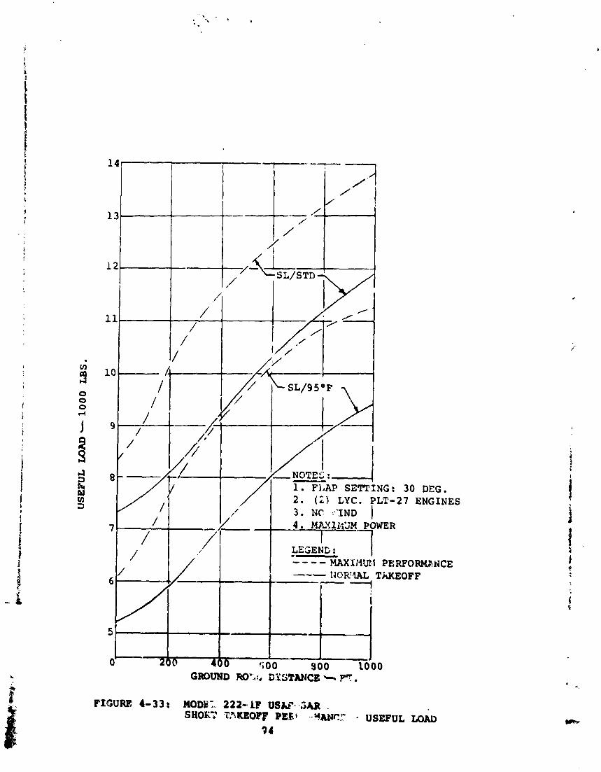
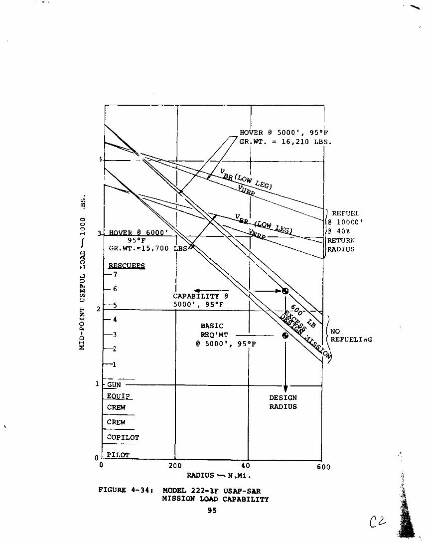
I i HOVER @ 5000g, 9S°F
/ ~ G R . W T . = 16,210 LBS.
RETUFUJ
, -5
- 4 BASIC
-3
-2
-1
-- - GUN - EoUIP CREW - CREW
COPILOT
DESIGN 2-I
RADIUS c15 N .Mi.
FIGURE 4-34: MODEL 222-1F US=-SAR MISSION LOAD CAPABILITY
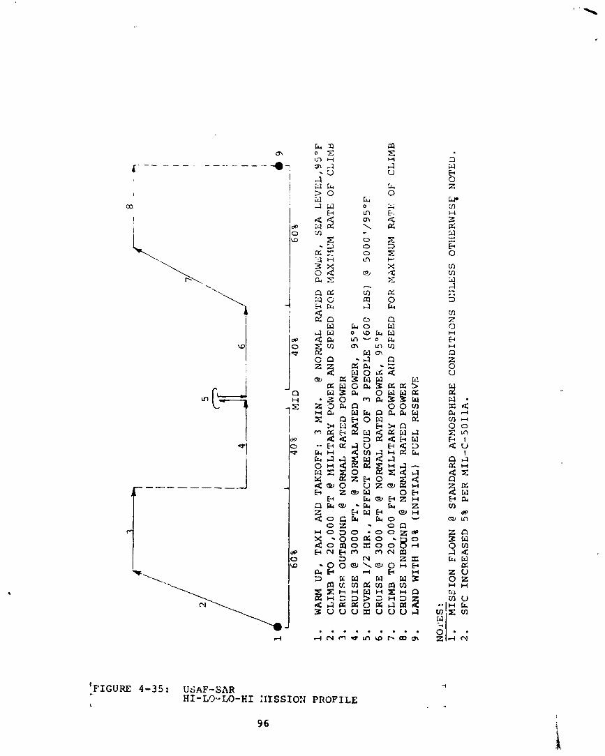
I
1 1
1 .
LA
-
- ..
J
19
60
%
40
%
MID
4
0%
6
0%
WAR
M
UP
, T
AX
I A
ND
T
AK
EO
FF
: 3
MIN
. @
NORMAL
RA
TE
D
PO
WL
R,
SE
A
LE
VE
L,9
5O
F
CL
IMB
T
O
20
,00
0
FT
@
MIL
ITA
RY
P
WE
R A
ND
S
PE
ED
F
OR
M
AX
I?qU
M M
TE
O
F CLIM8
CR
UT
SE
O
UT
BO
UN
D
@ N
OR
MA
L
RA
TE
D
POW
ER
C
RU
ISE
@
30
00
F
T,
@ N
OR
MA
L
RA
TE
D
PO
WE
R,
95OF
HO
VE
R 1/2
HR
.,
EF
FE
CT
R
ES
CU
E
OF
3
PE
OP
LE
(6
0C
LBS)
@ 5
00
C'/
95
OF
C
RU
ISE
@
30
00
F
T
@ N
OR
MA
L
RA
TE
D
PO
WE
R,
95OF
CL
IMB
T
O
20
,00
0
FT
@
MIL
ITA
RY
PO
WE
R
AlJ
D
SF
EE
D
FO
R
KA
XTM
UM
R
A?'
l,:
OF
C
LIM
B
CR
UIS
E
INB
OU
ND
@
NO
RN
AL
R
AT
ED
PO
'HER
L
AN
D
WIT
H
10
% (
INIT
IAL
) F
UE
L
RE
SE
RV
E
NO f
ES
:
--
1.
MIS
SIO
N
FLO
WN
@
ST
Aii
DA
RD
A
TM
OS
PH
ER
E
CO
ND
ITIO
NS
U
ZJL
ESS
O
Tli
ER
WIS
f N
OT
ED
. 2
. SFC
INC
RE
AS
ED
5
% P
ER
M
IL-C
-SO
llA
.
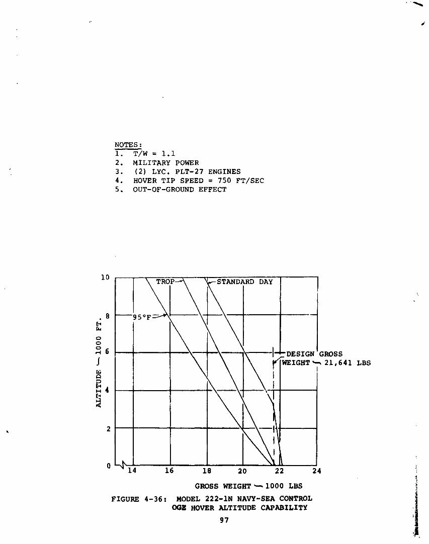
NOTES : 1 . T/W = 1.1 2 . MILITARY POWER 3 . ( 2 ) LYC. PLT-27 ENGINES 4 . HOVER T I P SPEED = 750 FT/SEC 5 . OUT-OF-GROUND EFFECT
1 LBS
GROSS WEIGHT - 1000 LBS FIGURE 4-36: MODEL 222-1N NAVY-SEA CONTROL
008: HOVER ALTITUDE CAPABILITY
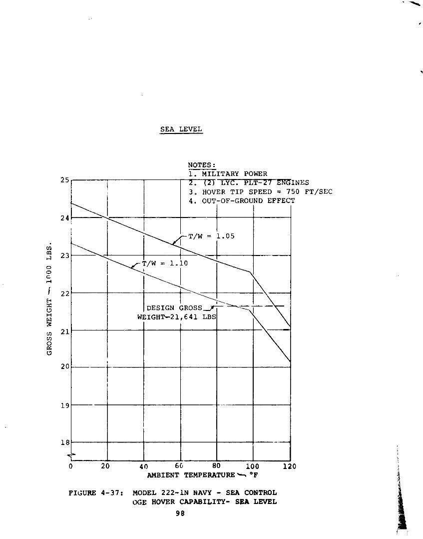
SEA LEVEL
FIGURE 4-37: MODEL 222-1N NAVY - SEA CONTROL OGE HOVER CAPABILITY- SEA LEVEL
98
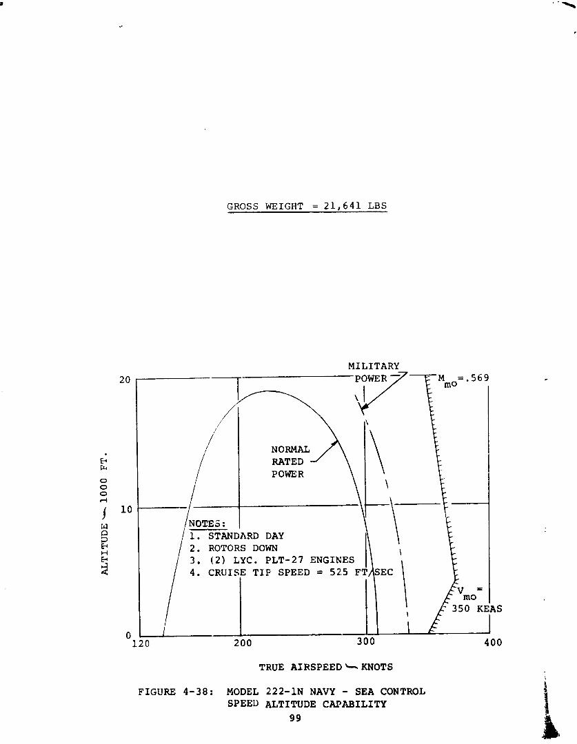
GROSS WEIGHT = 2 1 , 6 4 1 LBS
MILITARY T POWER -7-
1 . STANDARD DAY 2 . ROTORS DOWN 3 . ( 2 ) LYC. P L T - 2 7 ENGINES / 4 . CRUISE T I P SPEED = 525 F
TRUE AIRSPEEDbKNOTS
FIGURE 4-38: MODEL 222-1N NAVY - SEA CONTROL SPEED ALTITUDE CAPABILITY
99
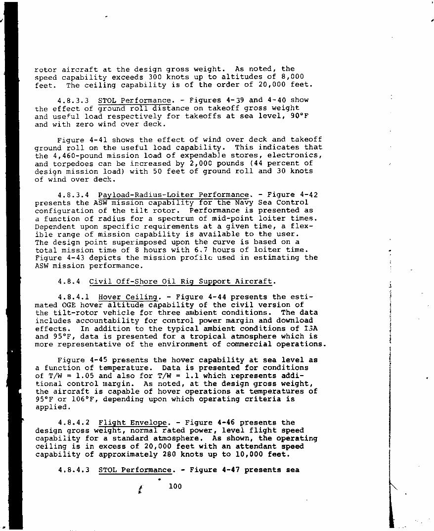
r o t o r a i r c r a f t a t t h e d e s i g n g r o s s we igh t . A s n o t e d , t h e speed c a p a b i l i t y exceeds 300 k n o t s up t o a l t i t u d e s o f 8 ,000 f e e t . The c e i l i n g c a p a b i l i t y i s of t h e o r d e r o f 20,000 f e e t .
4.8.3.3 STOL Performance. - F i g u r e s 4-39 and 4-40 show t h e e f f e c t o f ground r o l l d i s t a n c e on t a k e o f f g r o s s we igh t and u s e f u l l o a d r e s p e c t i v e l y f o r t a k e o f f s a t s e a l e v e l , 90°F and w i t h z e r o wind o v e r deck .
F i g u r e 4-41 shows t h e e f f e c t o f wind o v e r deck and t a k e o f f ground r o l l on t h e u s e f u l l o a d c a p a b i l i t y . T h i s i n d i c a t e s t h a t t h e 4,460-pound m i s s i o n l o a d o f expendable s t o r e s , e l e c t r o n i c s , and t o r p e d o e s can be i ~ c r e a s e d by 2,OOG pounds (44 p e r c e n t of d e s i g n m i s s i o n l o a d ) w i t h 50 f e e t o f g round r o l l and 30 k n o t s of wind o v e r deck.
4.8.3.4 Payload-Radius-Loi te r Performance. - F i g u r e 4-42 p r e s e n t s t h e ASW m i s s i o n c a p a b i l i t y f o r t h e Navy Sea C o n t r o l c o n f i g u r a t i o n o f t h e tilt r o t o r . Performance i s p r e s e n t e d a s a f u n c t i o n o f r a d i u s f o r a spec t rum of mid-poin t l o i t e r t i m e s . Dependent upon s p e c i f i c r e q u i r e m e n t s a t a g i v e n t i m e , a f l e x - i b l e r a n g e of m i s s i o n c a p a b i l i t y i s a v a i l a b l e t o t h e u s e r . The d e s i g n p o i n t super imposed upon t h e c u r v e is based on a t o t a l m i s s i o n t i m e of 8 h o u r s w i t h 6,,7 h o u r s o f l o i t e r t i m e . F i g u r e 4-43 d e p i c t s t h e m i s s i o n p r o f i l e used i n e s t i m a t i n g t h e ASW m i s s i o n performance.
4.8.4 C i v i l Off-Shore O i l Rig Suppor t A i r c r a f t .
4 .8 .4 .1 Hover C e i l i n g . - F i g u r e 4-44 p r e s e n t s t h e est i - mated OGE hover a l t i t u d e c a p a b i l i t y of t h e c i v i l v e r s i o n o f t h e t i l t - r o t o r v e h i c l e f o r t h r e e a h b i e n t c o n d i t i o n s . The d a t a i n c l u d e s a c c o u n t a b i l i t y f o r c o n t r o l power marg in and download e f f e c t s . I n a d d i t i o n t o t h e t y p i c a l ambient c o n d i t i o n s o f I 3 A and 9S°F, d a t a is p r e s e n t e d f o r a t r o p i c a l a tmosphere which i s more r e p r e s e n t a t i v e o f t h e environment o f commercial o p e r a t i o n s .
F i g u r e 4-45 p r e s e n t s t h e hove r c a p a b i l i t y a t sea l e v e l as a f u n c t i o n o f t empera tu re . Data i s p r e s e n t e d f o r c o n d i t i o n s of T/W = 1 .05 and a l s o f o r T/W = 1.1 which r e p r e s e n t s add i - t i o n a l c o n t r o l margin. A s n o t e d , a t t h e d e s i g n gross w e i g h t , t h e a i r c r a f t is c a p a b l e of hover o p e r a t i o n s a t t e m p e r a t u r e s o f
I 9S°F or 106OF, depending upcrn which o p e r a t i n g c r i t e r i a is
4.8.4.2 F l i g h t Envelope. - F i g u r e 4-46 p r e s e n t s t h e d e s i g n g r o s s w e i g h t , normal r a t e d power, l e v e l f l i g h t speed c a p a b i l i t y f o r a s t a n d a r d a tmasphere . As shown, t h e o p e r a t i n g c e i l i n g i s i n e x c e s s o f 20,000 f e e t w i t h a n a t t e n d a n t speed c a p a b i l i t y o f app rox ima te ly 280 k n o t s up t o 10,000 f e e t .
4.8.4.3 STOL Performance. - F i g u r e 4-47 p r e s e n t s s e a
h' X
100
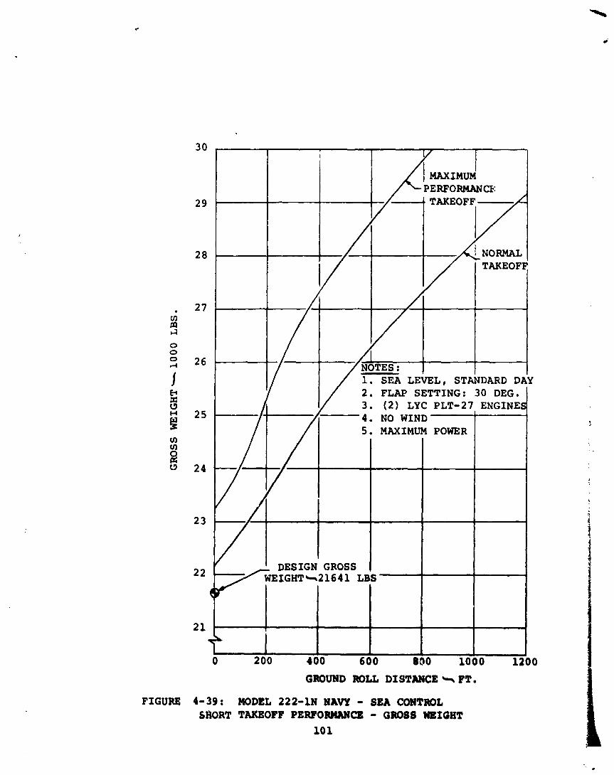
GROUND ROLL DISTANCE +PT.
FIGURE 4-39 : MODEL 222-18 NAVY - SEA CONTROL SHORT TAKEOFF PERFORMIWE - GROSS UEIGHT
10 1
cll fn I 4
0 0 0 rl
I n 4 0 J
d 3 E W ell 3
2 . FLAP SETTING: 30 DEG. 3. (2) LYC. PLT-27 ENGINES 4. NO WIND 1 I 5. MAXIMUM POWER
GROUND ROLL DISTANCE* PT.
!
FIGURE 4-40: MODEL 222-11 NAVY-SEA CONTROL '
SHO3T TAKEOFF P E W O W C E - USEPUL LOAD 10 2
LOAD
I l i e DESIGN USEFUL
10
0 200 400 600 800 1000 1 2
LOAD
. ( 6250 LBS FUEI, 4 4 6 0
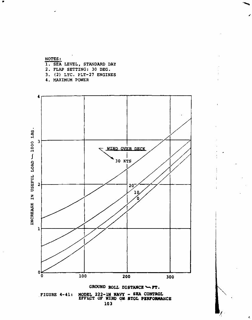
NOTES : 1. SEA LEVEL, STANDARD DAY 2. FLAP SETTING: 30 DEG. 3. ( 2 ) LYC. YLT-27 ENGINES 4. MAXIMUM POWER
FIGURE 4-41: MODEL 222-1N NAW - SEA CONT.mL EFFECT OF WIND ()W< 8TOL PERFORHANCE
10 3
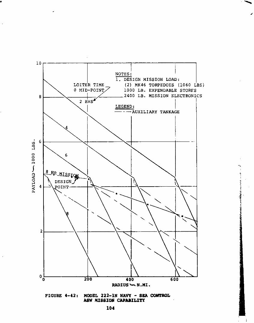
I NOTES : 1. DESIGN MISSION L o A ~ : I
( 2 ) MK46 TORPEDOES (1060 LBS) 1000 LB. EXPENDABLE STORES
LB. MISSION ELECTRON1
I LEGEND : -- I
-AUXILIARY TANKAGE
FIGURE 4-42: MODEL 222-1N NAVY - SEA CONTROL ASW MISSIO# CAPABILITY
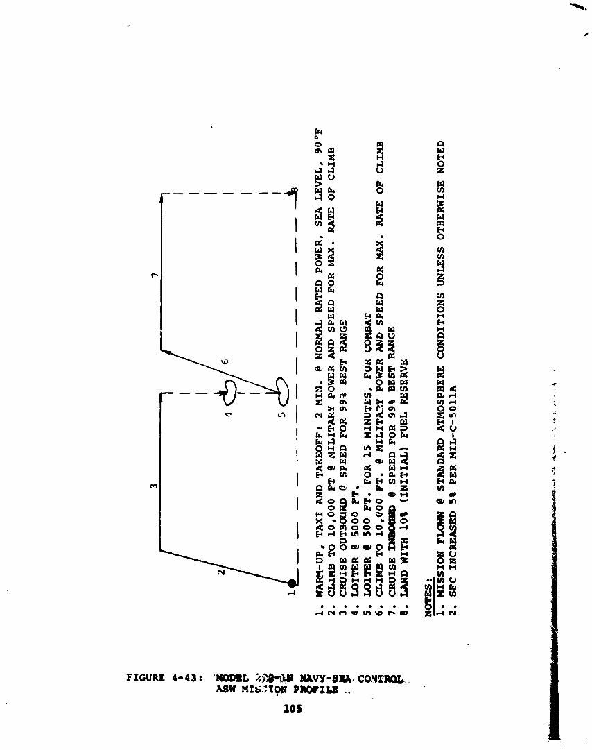
WA
RY
-UP,
T
AX
I A
ND
T
AK
EO
FF
: 2
MIN
. @ NORMAL
RA
TE
D POWER,
SEA
L
EV
EL
, 9
0°F
C
LIM
B
TO
10
,OO
O FT
C M
ILIT
AR
Y
POW
ER
AN
D
SP
EE
D
FOR
L
IAX
. R
AT
E
OF
C
LIM
B
CR
UIS
E O
UTB
OPJ
AD
@
SP
EE
D F
OR
9
92
B
ES
T
RA
NG
E
LOITER
@ 5
00
0 FT.
WIT
ER
C
500 FT.
FOR
1
5 M
INU
TE
S,
FOR
C
OM
BAT
an
m TO
10,000 PT.
e MILITA~Y P
OW
ER
AN
D
SP
EE
D
FOR
M
AX
. R
AT
E
OF
CL
IMB
C
RU
ISE
1- @
SP
EE
D F
OR
9
9%
BEST
RA
NG
E
LA
ND
W
ITH
10%
(IN
ITIA
L)
FUE
L RESERVE
NO
TE
S :
1.
MIS
SIO
N
FMlW
N
@ S
TA
hD
AN
) A
TM
OSP
HE
RE
C
ON
DIT
ION
S
UN
LE
SS
OT
HE
RW
ISE
N
OT
ED
2.
SFC
INC
RE
ASE
D
5%
PE
R
MIL
-C-5
011A
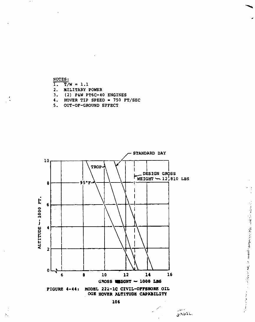
NOTES : 1. T/W = 1.1 2 . MILITARY POWER 3 . ( 2 ) P&W PT6C-40 ENGINES 4 . HOVER T I P SPEED = 7 5 0 FT/SEC 5 . OUT-OF-GROUND EFFECT
/- STANDARD DAY
LBS
FIGURE 4-44; MODEL 222-1C CIVIL-OPISE1ORE OIL OGE HOVER UTITUDE CAPXbILITY
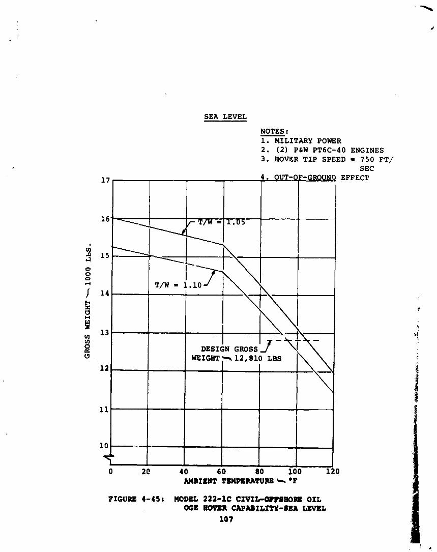
SEA LEVEL
NOTES : - 1. MILITARY POWER 2. ( 2 ) PLW PT6C-40 ENGINES 3. HOVER TIP SPEED - 750 FT/
SEC
FIGURE 4-45: MODEL 222-1C C I V I t O B l l f K ) ~ OIL W E EOVBR CAPABItITY-SEA LEVEL
107
EFFECT
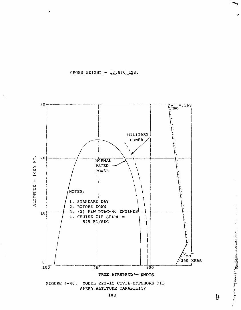
GROSS WEIGHT - 12,810 L3S.
TRUE AIRSPEED L* KNOTS
FIGURE 4-45: MODEL 222-1C CIVIL-OFFSHORE OIL SPEED ALTITUDE CAPABILITY
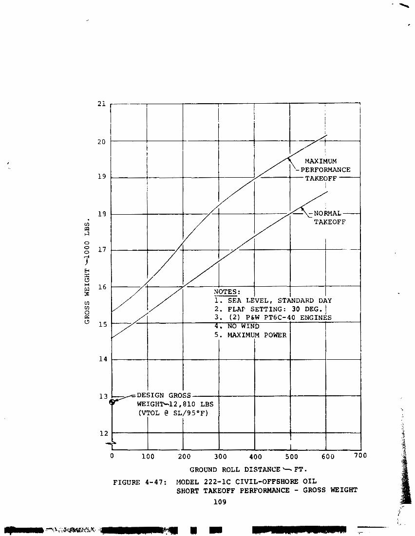
7' 3. (2) P6W PT6C-?O ENGINES 4. NO WIND 5. MAXIMUM POWER
-DESIGN GROSS 7-- WEIGHTcl2,810 LBS (VTOL @ SL/95*F)
I
GROUND ROLL DISTANCE + FT . FIGURE 4-47: MODEL 222-1C CIVIL-OFFSHORE OIL
SHORT TAKEOFF PERFORMANCE - GROSS WEIGHT
109
l e v e l s t a n d a r d day t a k e o f f c a p a b i l i t y f o r maximum per formance and normal per formance t a k e o f f s . Superimposed on t h e p l o t i s t h e d e s i g n p o i n t g r o s s we igh t . F i g u r e 4 - 4 8 d e p i c t s t h e u s e f u l l oad c a p a b i l i t y which i s a v a i l a b l e a s a f u n c t i o n o f t a k e o f f d i s t a n c e .
4 . 8 . 4 . 4 Payload-Radius Per formance . - F i g u r e 4-19 p r e s e n t s t h e m i s s i o n c a p a b i l i t y f o r t h e c i v i l o f f - s h o r e o i l c o n f i g u r a - t i o n of t h e tilt r o t o r . The d a t a i s based on h o v e r i n g OGE a t s e a l e v e l , 9S°F. The d e s i g n p o i n t c o n d i t i o n d e p i c t e d matches t h e r e q u i r e m e n t t o t r a n s p o r t 12 p a s s e n g e r s 125 s t a t u t e m i l e s ( 1 0 9 n a u t i c a l m i l e s ) . T h i s r e q u i r e s less f u e l t h a n t h e f u l l t a n k c a p a c i t y of 2 , 0 0 0 pounds. For ex t ended r a n g e , pay load can be t r a d e d f o r f u e l . F i g u r e 4-50 d e p i c t s t h e m i s s i o n p ro - f i l e u sed t o e s t i m a t e t h e per formance p r e s e n t e d i n F i g u r e 4-49 f o r a t y p i c a l o f f - s h o r e o i l o p e r a t i o n .
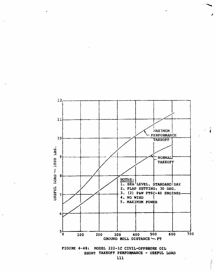
200 300 400 500 GROUND ROLL DISTANCE + FT
FIGURE 4-48: MODEL 222-1C CIVIL-OFFSHORE OIL SHORT TAKEOFF PERFORMANCE - USEFUL LOAD
111
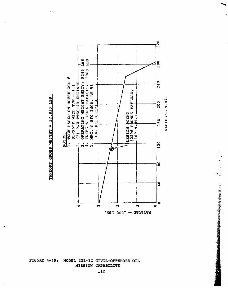
TA
KE
OF
F GROSS
WE
IGH
T =
1
2,8
10
L
BS
NO
TE
S :
--
1.
TOG
W
BA
SED
O
N H
OV
ER
O
GE
@ S
L/9
5O
F
WIT
H
T/W
=
1
.1
4 --
2.
(2)
P&
W P
T6
C-4
0
EN
GIN
ES
I
3.
OP
ER
AT
ING
W
EIG
HT
E
MP
TY
: 9
24
6
LB
S
4.
INT
EG
RA
L
FU
EL
C
AP
AC
ITY
: 2
00
0 L
BS
5
. M
FG
.'G
S
FC
INCR.
BY
5%
V) f4
I4
0
2.
0
0 d
160
20 0
RA
DIU
S +
N .
MI,
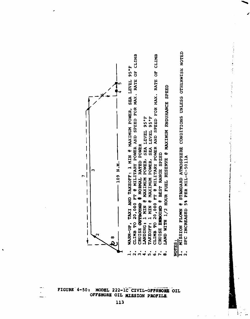
I'
!
7 --
--
__
--
-_
_-
--
- I -
3 I
'I "\ + \
10
9 N
.M.
- L\
4 5
WA
RM
-UP,
T
AX
I A
ND
T
AK
EO
FF
: 1 M
IN
@ M
AX
IMU
M
POW
ER
, S
EA
L
EV
EL
9
S°F
C
LIM
B T
O
20
,00
0 FT
@ M
ILIT
AR
Y
POW
ER
A
ND
S
PE
ED
FO
R MAX.
RA
TE
O
F C
LIM
B
CR
UIS
E W
UH
D 8
NO
RM
AL
RA
TE
D
POW
ER
LANDING8 1 M
IN
@ M
AX
IMU
M
POW
ER
t S
EA
LE
VE
L
95
OF
TAKEOFF: 1 M
IN
@ M
AX
IMU
M
POW
ER
, S
EA
L
EV
EL
9
S°F
C
LIM
B T
O
20
,00
0 FT
@ M
ILIT
AR
Y
POW
ER
AN
D
SP
EE
D F
OR
MAX.
RA
TE
O
F
CL
IMB
C
RU
ISE
IMBOUND
@ B
ES
T
RA
NG
E S
PS
ED
UWD WITH 1/2
HOUR FUEL
RE
SER
VE
@
MA
XIM
UM
E
ND
UR
AN
CE
S
PE
ED
NO
TE
S :
1.
MIS
SIO
N FLOWN
@ ST
AN
DA
RD
A
TM
OSP
HE
RE
C
ON
DIT
ION
S
UN
LE
SS
O
TH
ER
WIS
E
NO
TE
D
2.
SF
C INCREASED
5%
PE
R M
IL-C
-5O
11A
5.0 TECHNICAL ASSESSMENT AND RECOMMENDATIONS FOR ADDITIONAL RESEARCH
5.1 Technology S t a t u s
During t h e p a s t s i x y e a r s , Boeing h a s c a r r i e d o u t an i l l -
t e n s i v e program f o r development of t i l t - r o t o r technology. The philosophy of t h i s program has been t h e c o n c u r r e n t development of a n a l y t i c a l methodology and wind t u n n e l model i n v e s t i g a t i o n s o t h a t t h e a n a l y t i c a l methods could be used t o p l a n logical- and p roduc t ive wind t u n n e l programs and t h e wind t u n n e l tests could be used t o v a l i d a t e and improve t h e a n a l y t i c a l method- ology. During t h e course of t h i s program, over 3,500 hours of t e s t i n g has been c a r r i e d o u t on 25 models. One impor tant f e a t u r e of t h e model t e s t program was 'he development of t h e technology f o r d e s i g n i n g , b u i l d i n g , anti running dynamical ly- s c a l e d models because of t h e importance of dynamic phenomena on t h e t i l t - r o t o r c o n f i g u r a t i o n . Over 1,000 hours of t h e model test program were devoted t o t h e t e s t i n g of 9 dynamical ly- s c a l e d models. The fo l lowing paragraphs g i v e a b r i e f summary of some of t h e more impor tant t e c h n i c a l a r e a s which have been explored i n t h e model test program.
Rotor Performance - Rotor performance i n both hover and c r u i s e modes has been i n v e s t i g a t e d by f u l l - s c a l e t i p s p e e d t e s t s on 5-foot and 13-foot-diameter models under both NASA and Boeing sponsorsh ip . C o r r e l a t i o n wi th p r e d i c t i o n s i n t h e hover mode i s good, a s shown i n F igure 5-1, and i n t h e c r u i s e mode i s a l s o good, a s shown i n F igure 5-2, excep t t h a t a t Mach numbers of 0.6 and above, c o n s i d e r a b l e d i f f e r e n c e s have Seen found between d a t a from d i f f e r e n t tests. I t i s ex- pected t h a t t h i s w i l l be r e s o l v e d by a NASA-sponsored program f o r a d d i t i o n a l t e s t i n g on t h e 13-foot models.
Download - Download r e d u c t i o n d e v i c e s , c o n s i s t i n g of l a r g e d e f l e c t i o n t r a i l i n g edge f l a p s and l ead ing edge umbrel las , have been developed by both model and f u l l - s c a l e t e s t i n g . These reduced t h e download on t h e wing from about 1 3 p e r c e n t f o r an unflapped wing t o less than 5 p e r c e n t wi th f l a p s and umbrel las o p e r a t i v e , a s shown i n F igure 5-3.
A e r o e l a s t i c S t a b i l i t y - A e r o e l a s t i c s t a b i l i t y boundar- ies have been explored on bothsemi-span and f u l l - s p a n dynamic mod?ls. A semi-span windmil l ing model us ing a 5.5-foot-diameter r o t o r is shown i n F i g u r e 5-4 and t h e c o r r e l a t i o n of w h i r l f l u t t e r boundar ies wi th pre- d i c t i o n s i s shown i n F igure 5-5. Another model, which is dynamical ly-scaled from t h e 26-foot-diameter f l i g h t - worthy r o t o r now under c o n s t r u c t i o n for NASA, i s shown
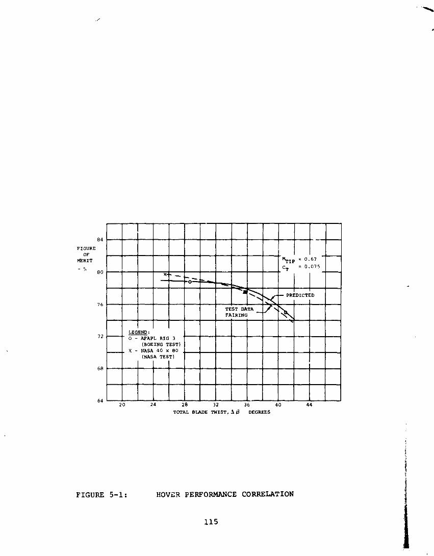
FIGURE O f
MERIT
TCrrAL BLADE I W I S T , $ f l DEGREES
FIGURE 5-1: HOVGR PERFORMANCE CORRELATION
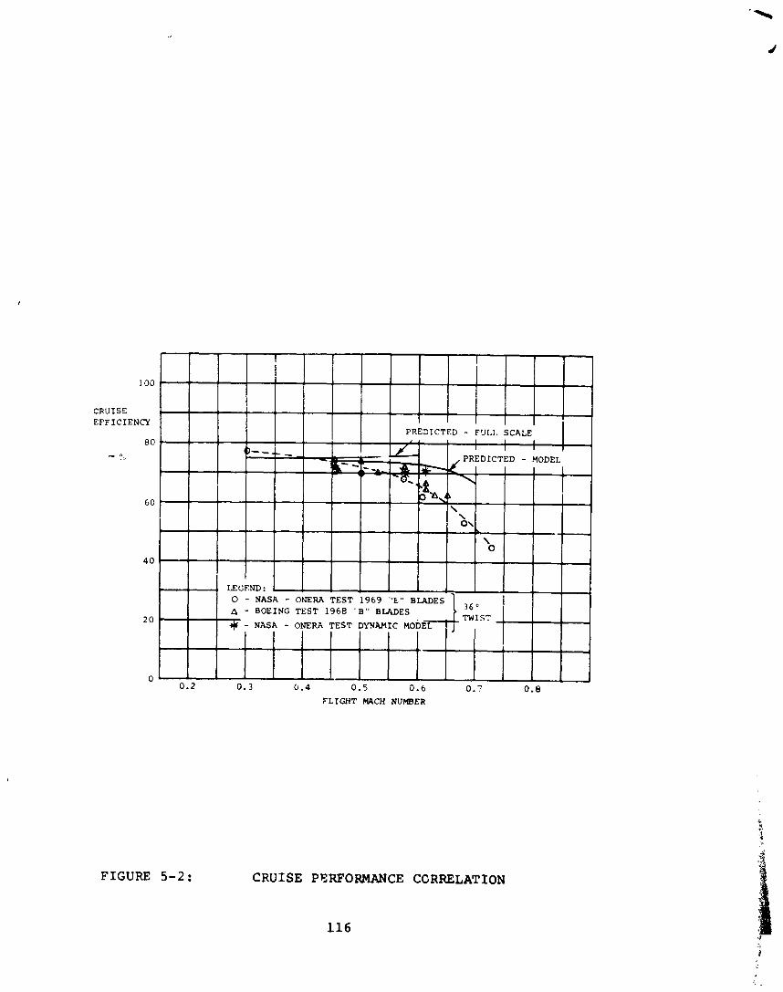
FIGURE 5 - 2 :
100
CRUISE EFFICIENCY
8 0 - 0
60
CRUISE PERFORMANCE CORRELATION
4 0
2 0
0 0.2 0.3 0.4 0.5 0.6 o . ~ 0.8
FLIGHT MACH NUMBER
LEGEND: 0 - NASA - ONERA T E S T 1 9 6 9 "L" BLADES A - BOEING T E S T 1 9 6 8 " B " BLADES 3 6 "
TWIST + - NASA - ONERA TEST DYNAMIC MODEL - j
o\ L
\ 0
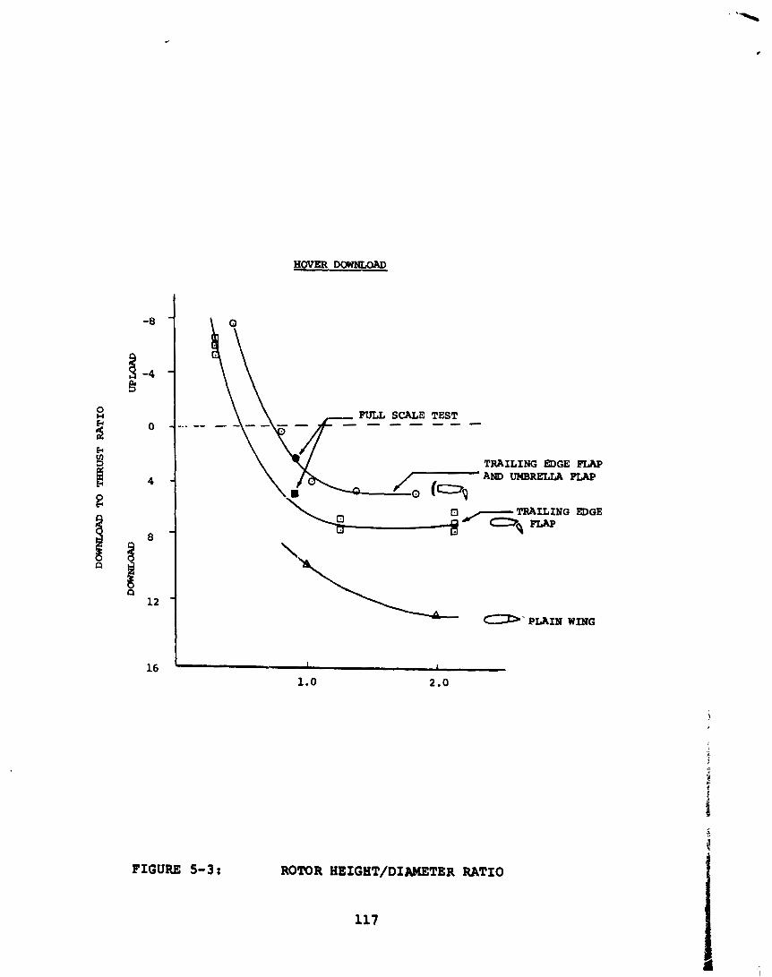
HOVER D m
TRAILING EDGE FLAP AND UMBRELLA FLAP
\ Ei r/- TRAILING EDGE
-g -
FIGURE 5-3 t ROTOR HEIGHT/DIAMETER RATIO
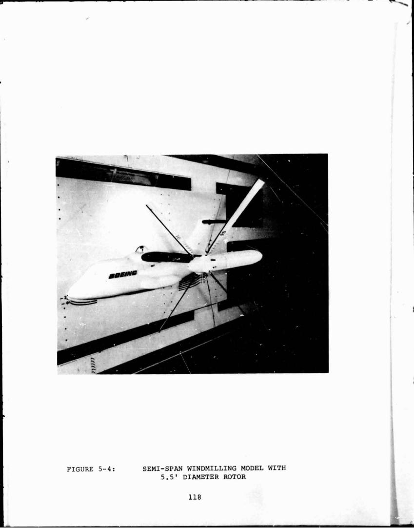
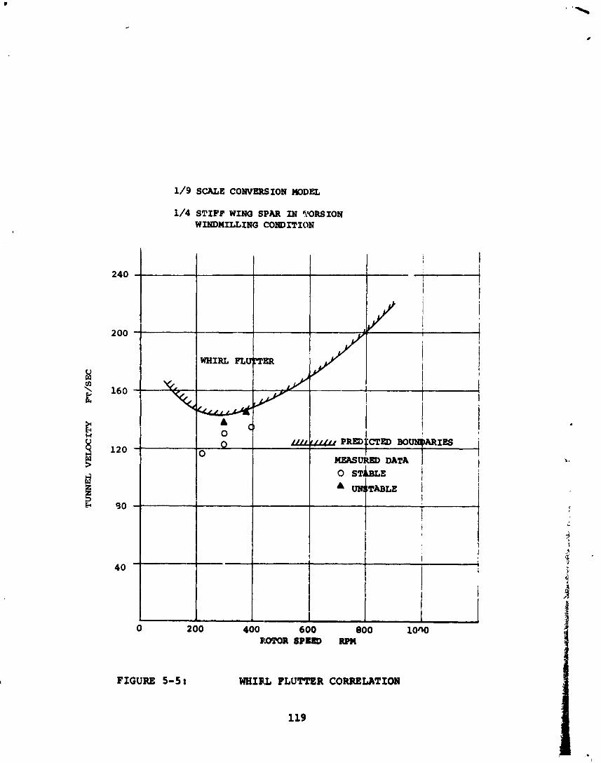
1/9 SCAtE CONVERSION MODEL
1/4 STIFF WING SPAR IN TORSION WINDMILLING COWD XTION
FIGURE 5-5 : WHIRL FLUTTER CORRELATION
119
i n F i g u r e 5-6. A c o r r e l a t i o n of t h e damping i n t h e a i r r c sonance mode o b t a i n e d on t h i s model i s shown i n F i g u r e 5-7.
d . F l y i n g Q u a l i t i e s - A f u l l - s p a n dynamica i ly - sca l ed model of t h e tilt r c t o r , gimbal-mounted on a monkey p o l e t o p r o v i d e 4 d e g r e e s o f r i g i d body freedom i n a d d i t i o n t o i t s e l a s t i c m o t i o n s , was t e s t e d i n t h e Boeing-Vertol V/STbL t u n n e l . T h i s model, shown i n F i g u r e 5-8, was used t o e x p l o r e b o t h t h e a e r o e l a s t i c c h a r a c t e r i s t i c s and t h e f l y i n g q u a l i t i e s o f t h e a i r - c r a f t , s i n c e it c o u l d be d i s t u r b e d and t i m e h i s t o r i e s o b t a i n e d of r e s u l t i n g r i g i d body and f l e x i b l e mo t ions .
A d d i t i o n a l f l y i n g q u a l i t i e s d a t a , p a r t i c u l a r l y on r o t o r d e r i v a t i v e s , was o b t a i n e d from t h e semi-span dynamic models d i s c u s s e d p r e v i o u s l y . The r o t o r d e r i v a - t i v e s o b t a i n e d by test c o r r e l a t e w e l l w i t h t h e t h e o r y developed which p r e d i c t s t h e e f f e c t s o f b o t h f l a p w i s e and l agwise f l e x i b i l i t y of t h e b l a d e s . C o r r e l a t i o n o f p r e d i c t e d and measured p i t c h i n g m o m n t d e r i v a t i v e s i s shown i n F i g u r e 5-9.
e. Blade Loads - V a r i a t i o n o f b l a d e l o a d s t h roughou t t h e v a r i o u s reg imes o f f l i g h t h?.s been e x p l o r e d on a l l t h e models t e s t e d . New a n i l y s e s a l l o w i n g f o r t h e h i g h b l a d e t w i s t and skewed f low encoun te red i n tilt r o t o r s p r o v i d e improved c o r r e l a t i o n w i t h t e s t d a t a a s shown i n F i g u r e 5-10.
A b r i e f d e s c r i p t i o n of some of t h e major computer programs a v a i l a b l e a t Boeing f o r t h e a n a l y s i s o f a e r o - dynamic f l y i n g q u a l i t i e s , d e s i g n s , and b l a d e l o a d s i s g i v e n i n Table 5-1.
5.2 Areas f o r A d d i t i o n a l Research
Based on t h e technology development summarized i n t h e p re - ced ing p a r a g r a p h s , Boeing c o n s i d e r s t h a t t h e t echno logy i s now i n hand t o s t a r t on t h e development o f t h e r e s e a r c h a i r c r a f t . However, t h e r e are c e r t a i n a r e a s i n which a d d i t i o n a l r e s e a r c h would be d e s i r a b l e . These a r e a s can b e d i v i d e d i n t o f o u r c a t e g o r i e s :
1. Work which would minimize development time and c o s t i n t h e wind t u n n e l and f l i g h t test o f t h e r e s e a r c h a i r c r a f t .
2. Areas which r e q u i r e d e x p l o r a t i o n or s u b s t u n t i a t i o n on t h e r e s e a r c h a i r c r a f t , e i t h e r i n t h e wind t u n n e l or i n f l i g h t .
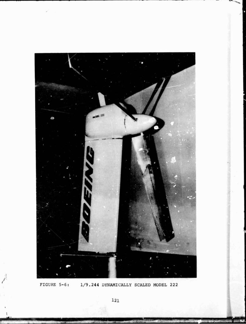
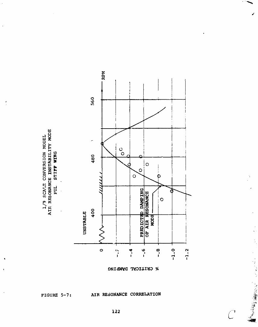
1/3
SC
ATJ
3 C
ON
VE
RSI
ON
MODEL
AX
E
RE
SON
AN
CE
IN
ST
AB
ILIT
Y M
OD
E FUL.
ST
IFF
WIN
G
UN
STA
BL
E
40
0
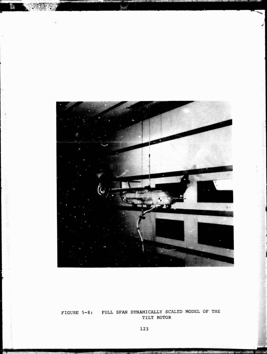

NOTE: l/'9 S C L S ROTOR PITCHING MOMENT DERIVATIVE VARIATION WITH ROTOR RPM
V = 85 PPs TEST
FIGURE 5-9:
ROTOR RPM
ROTOR DERIVATIVE CORRELATION
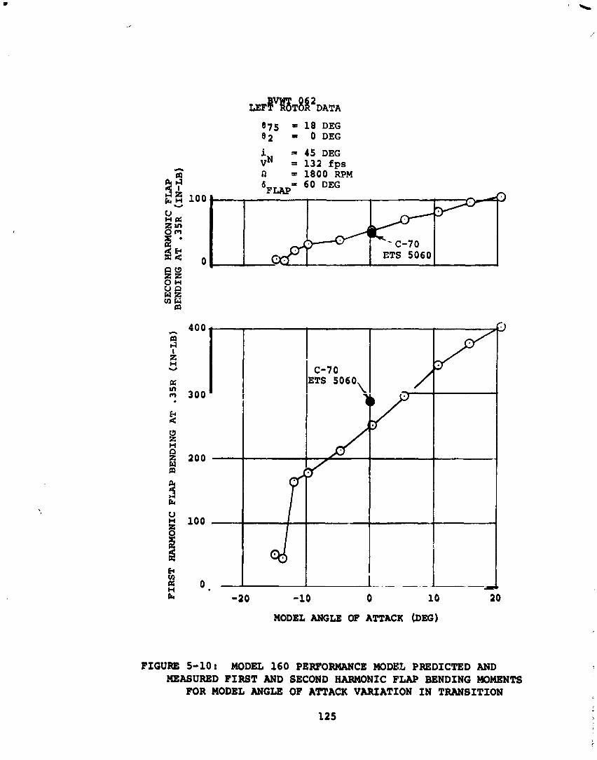
i = 45 DEG vN = 132 fps n = 1800 RPM
&FLAP = 60 DEG
-20 -10 0 10 2 0
MODEL ANGLE OF ATTACK (DEG)
5-10: MODEL 1 6 0 PERFORMANCE MODEL PREDICTED AND MEASURED F I R S T AND SECOND HARMONIC FLAP BENDING MOMENTS
FOR MODEL ANGLE OF ATTACK VARIATION I N TRANSITION
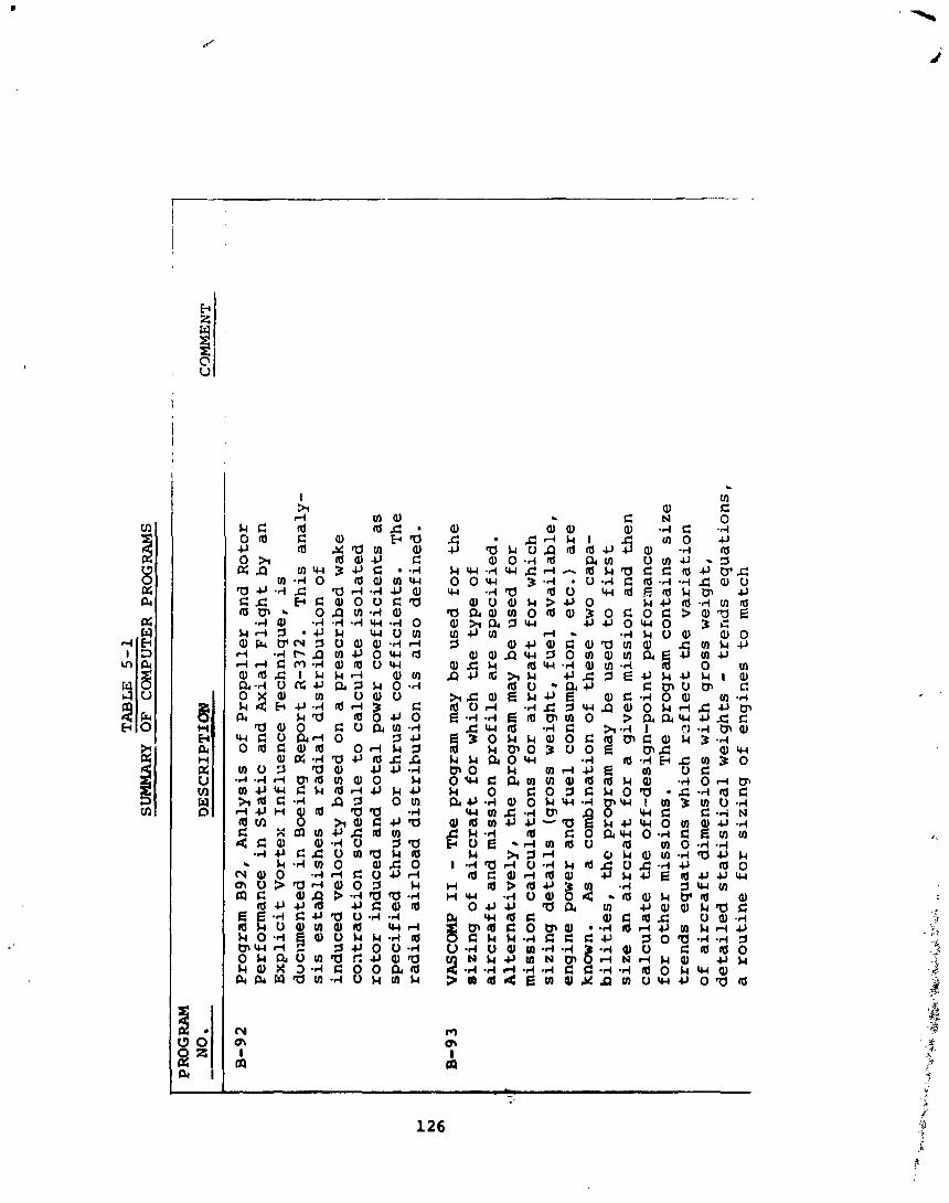
TA
BL
E
5-1
S-R
Y O
F C
OM
PUT
ER
PR
OG
RAM
S
PROGRAM
NO.
Pro
gra
m B92,
An
aly
sis
of
Pro
pe
lle
r an
d
Ro
tor
Pe
rfo
rma
nc
e
in
Sta
tic
an
d A
xia
l F
lig
ht
by
a
n
Ex
pli
cit
Vo
rte
x
Infl
ue
nc
e T
ec
hn
iqu
e,
is
do
cum
ente
d
in
Bo
ein
g
Re
po
rt i?-372.
Th
is
an
aly
- sis
es
tab
lis
he
s a
ra
dia
l d
istr
ibu
tio
n o
f in
du
ce
d v
elo
cit
y b
ase
d o
n a
pre
sc
rib
ed
wak
e c
oa
tra
cti
on
sc
he
du
le t
o c
alc
ula
te i
so
late
d
roto
r in
du
ce
d a
nd
to
tal
po
wer
c
oe
ffic
ien
ts a
s
sp
ec
ifie
d t
hru
st
or
th
rus
t c
oe
ffic
ien
ts.
Th
e ra
dia
l a
irlo
ad
dis
trib
uti
on
is a
lso
de
fin
ed
.
VA
SC
W I1 -
Th
e p
rog
ram
may
b
e
use
d
fo
r t
he
s
izin
g o
f a
irc
ra
ft
for
wh
ich
the
typ
e o
f a
irc
ra
ft
an
d m
issi
on
pro
file
are
sp
ec
ifie
d.
Alt
ern
ati
ve
ly,
the
pro
gra
m m
ay
be
use
d
for
mis
sio
n
ca
lcu
lati
on
s
for
air
cr
af
t fo
r w
hic
h
siz
ing
de
tail
s
(gro
ss
we
igh
t,
fue
l a
va
ila
ble
, e
ng
ine
po
wer
an
d
fue
l c
on
sum
pti
on
, e
tc.)
are
k
now
n.
As
a
co
mb
ina
tio
n o
f th
es
e t
wo
c
ap
a-
bil
itie
s, thc
pro
gra
m m
ay
be
use
d
to f
irst
siz
e a
n a
irc
ra
ft
for
a
giv
en
mis
sio
n a
nd
th
en
c
alc
ula
te t
he
off
-de
sig
n-p
oin
t p
erf
orn
an
ce
f
or
oth
er
mis
sio
ns.
T
he
pro
gra
m
co
nta
ins
s
ize
tr
en
ds
eq
ua
tio
ns
wh
ich
ra
fle
ct the
va
ria
tio
n
of
air
cr
af
t d
ime
nsi
on
s w
ith
gro
ss
we
igh
t,
de
tail
ed
sta
tis
tic
al
we
igh
ts -
tre
nd
s
eq
ua
tio
ns
, a
ro
uti
ne
fo
r s
izin
g o
f e
ng
ine
s to
mat
ch
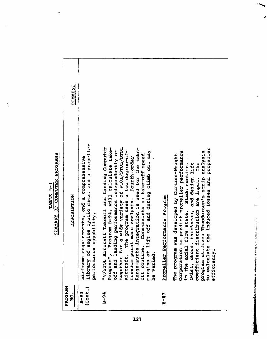
TABLE
5-1
SU
MW
iRY
O
F
CO
MPU
TE
R
PRO
GR
AM
S
PRO
GR
AM
N
O.
DE
SCR
IPT
ION
B-93
air
fra
me
re
qu
ire
me
nts
, an
d a
co
mp
reh
en
siv
e
(Co
nto
) li
bra
ry o
f e
ng
ine
cy
cli
c d
ata
, an
d a
p
rop
ell
er
perf
orm
an
ce
ca
pa
bil
ity
.
"V/S
TO
L
Air
cra
ft T
ak
eo
ff
and
L
an
din
g C
om
pu
ter
Pro
gra
m",
P
rog
ram
B-94,
wi
ll
ca
lcu
late
ta
ke
- o
ff
and
la
nd
ing
perf
orm
an
ce
ind
ep
en
de
ntl
y o
r to
ge
the
r fo
r a
wid
e
va
rie
ty o
f V
TO
L/S
TO
L/O
TO
L
air
cra
ft.
Th
e p
rog
ram
use
s a
tw
o ,
deg
ree-o
f-
freed
om
po
int
mas
s a
na
lysis
. F
ou
rth
-ord
er
Ru
ng
e-K
utt
a in
teg
rati
on
is u
sed
fo
r ';he
tak
e-
off
ro
uti
ne
. C
on
str
ain
ts O
A ta
ke
-off
sp
ee
d
ma
rgin
s a
t l
if
t o
ff
and
d
uri
ng
cli
mb
ou
t may
be
va
rie
d.
Pro
pe
lle
r P
erf
orm
an
ce P
rog
ram
The
pro
gra
m w
as
de
ve
lop
ed
by
C
urt
iss-
Wri
gh
t C
orp
ora
tio
n to
pre
dic
t p
rop
ell
er
pe
rfo
rma
nc
e
in
th
e a
xia
l fl
ow
sta
te.
Bla
de
se
cti
on
, .
twis
t,
ch
ord
, th
ick
ne
ss,
an
d d
esig
n l
if
t
co
eff
icie
nt
dis
trib
uti
on
are
in
pu
t.
The
pro
gra
m u
tili
ze
s T
heo
do
rsen
's
str
ip a
na
lys
is
to
ca
lcu
late
th
e i
nd
uc
ed
lo
ss
es
an
d p
rop
ell
er
eff
icie
nc
y,
CO
MM
EN
T
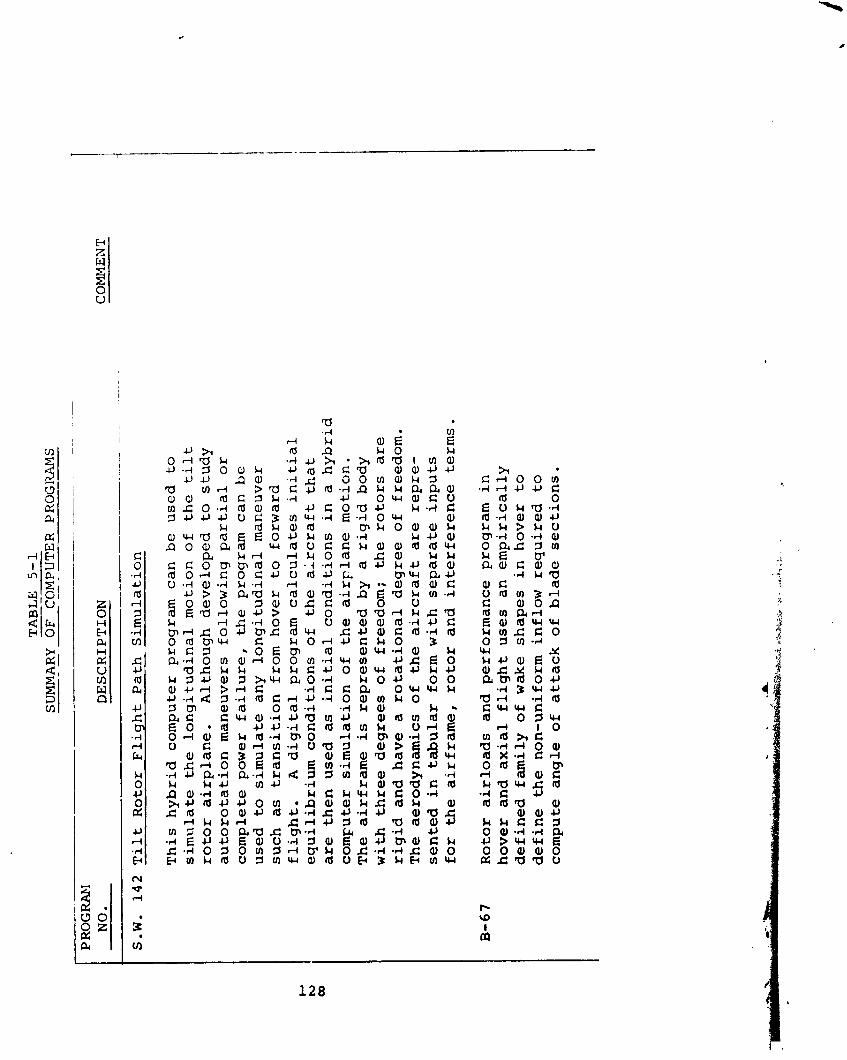
TA
BL
E
5-1
-
SUM
MA
RY
OF
CO
MP
UT
ER
P
RO
GlM
S
-- - -- - -
--
- -.
- - -
-
- - -
. . . -
PRO
GRA
M
NO.
DE
SC
RIP
TIO
N
S.W.
14
2 T
il
t R
oto
r F
lig
ht
Pa
th
Sim
ula
tio
n
Th
is h
yb
rid
c
om
pu
ter
pro
gra
m
ca
n b
e
use
d
to
s
imu
late
th
e
lon
git
ud
ina
l m
oti
on
of
the
tilt
ro
tor
a
irp
lan
e.
Alt
ho
ug
h
de
ve
lop
ed
t
o s
tud
y
au
toro
tati
on
ma
ne
uv
ers
fo
llo
win
g p
ar
tia
l o
r
co
mp
lete
p
ow
er
fa
ilu
re
, the
pro
gra
m
ca
n b
e
use
d
to s
imu
late
an
y
lon
git
ud
ina
l m
an
eu
ve
r su
ch
as
tra
ns
itio
n f
rom
ho
ve
r t
o f
orw
ard
f
lig
ht.
A
d
igit
al
pro
gra
m
ca
lcu
late
s
in
it
ia
l
eq
uil
ibri
um
co
nd
itio
ns
of
the
alr
cr
af
t th
at
are
th
en
use
d
as
i
ni
ti
al
co
nd
itio
ns
i
n a
h
yb
rid
c
om
pte
r s
imu
lati
on
o
f th
e a
ir
~l
an
e
mo
tio
n.
Th
e
air
fra
me
is
re
pre
se
nte
d
by
a
r
igid
bo
dy
w
ith
th
re
e d
eg
ree
s o
f fr
ee
do
m;
the
ro
tor
s
ar
e
rig
id a
nd
ha
ve
a
r
ota
tio
na
l d
eg
ree
of
fre
ed
om
. T
he
ae
rod
yn
am
ics
of
the
air
cr
af
t a
re
re
pre
- s
en
ted
i
n t
ab
ula
r
form
wit
h s
ep
ara
te i
np
uts
f
or
th
e a
irfr
am
e,
ro
tor
an
d
inte
rfe
re
nc
e te
rms.
CO
MM
EN
T
Ro
tor
air
loa
ds
an
d p
erf
orm
an
ce
p
rog
ram
i
n
ho
ve
r a
nd
a
xia
l f
lig
ht
us
es
a
n e
mp
iric
all
y
de
fin
ed
fa
mil
y o
f w
ake
sh
ap
es
i
n h
ov
er
to
d
efi
ne
th
e n
on
-un
ifo
rm
infl
ow
re
qu
ire
d
to
c
om
pu
te
an
gle
o
f a
tta
ck
of
bla
de
s
ec
tio
ns
.
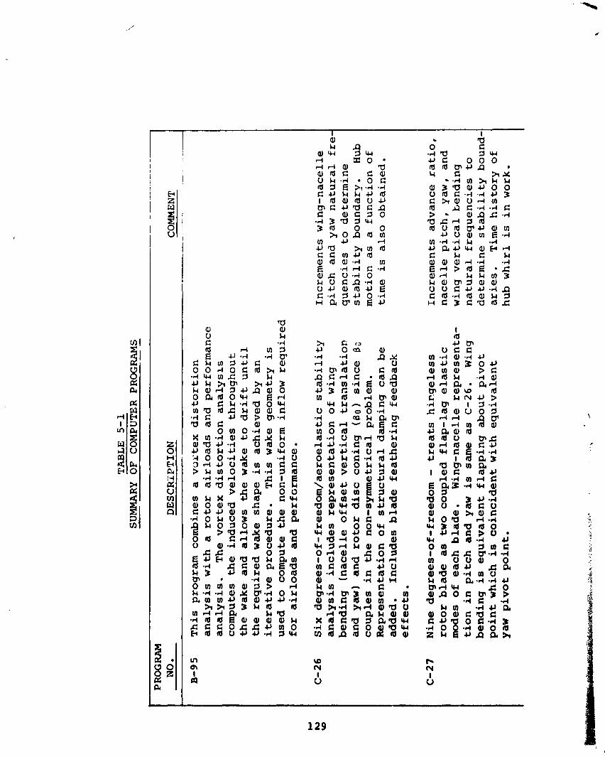
r l r l a a a , a ~ c a , U k - r l * O C m I E >, .rl .r( C 4 J k k 4 J 4 l a a ) a 0 4 J m c c l a c a C Q ) G l O -4 3 a l l u 3lrJ 0 0 & o n m m m 4 J rl u a h r n m c c m u m a , a a , - r l rn
c, a o , a m m u m~ Q ) d r d a J C 3
rl .rl 3 " F $'a3 a t n m a
I O ) E m g d . 4 m d E: 43.4 " 2
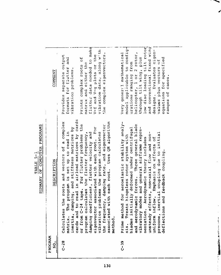
TA
BL
E
5-1
SU
~.IM
AR
Y O
F C
OM
PUTE
R
PR
OG
RA
MS
- --
-- ---.A
- - -
P ROG R
AM
NO
. D
ES
CR
IPT
ION
-
C-2
8
Ca
lcu
late
s
the
ro
ots
a
nd
ve
cto
rs
of
a
co
mp
lex
m
atr
ix.
Th
e
pro
gra
m is
se
t u
p
to
re
ad
i
n
ine
rti
a,
da
mp
ing
, a
nd
sti
ff
ne
ss
ma
tric
es
b
y
ca
rds
an
d to
re
ad
in
air
loa
d m
atr
ice
s b
y
ca
rds
o
r fr
om
C-2
4 ta
pe
. F
or
fl
ut
te
r p
rob
lem
s th
e
pro
gra
m
ca
lcu
late
s
the
f
lu
tt
er
fre
qu
en
cy
, d
am
pin
g
co
ef
fic
ien
t,
fl
ut
te
r v
elo
cit
y a
nd
e
ige
nv
ec
tor
as
so
cia
ted
wit
h e
ac
h ro
ot.
F
or
vib
ra
tio
n ~
ro
ble
ms
the
pro
gra
m
ca
lcu
late
s
the
fre
qu
en
cy
, d
am
pin
g ra
te,
an
d e
ige
nv
ec
tor
as
so
cia
ted
wit
h e
ac
h r
oo
t.
Us
es
QR
a
lgo
rith
m
me
tho
d .
C-3
9 P
rim
e m
eth
od
f
or
ae
ro
ela
sti
c s
ta
bi
li
ty
an
aly
- sis
. T
re
ats
hin
ge
les
s ro
tor
sy
ste
m w
ith
b
lad
es
i
ni
ti
al
ly
de
form
ed
u
nd
er
ce
ntr
ifu
ga
l a
nd
a
ero
dy
na
mic
fo
rce
s.
Th
ree
ge
ne
ral
bla
de
v
ibr
ato
ry
mo
des
a
nd
ge
ne
ral
air
fra
me
re
pre
- s
en
tati
on
. A
ero
dy
na
mic
th
eo
ry
inc
lud
es
u
ns
tea
dy
ef
fe
cts
, n
on
-ax
ial
flo
w
an
d
no
n-
un
ifo
rm
infl
ow
. E
mp
ha
sis
on
ef
fe
cts
of
pre
co
ne
, i
ne
rt
ia
l c
ou
pli
ng
du
e to
in
it
ia
l
de
fle
cti
on
s a
nd
fe
ed
ba
ck
c
ou
pli
ng
.
CO
MM
EN
T
-
Pro
vid
es
s
ep
ar
ate
ou
tpu
t fo
rma
ts
fo
r f
lu
tt
er
an
d
vib
ra
tio
x p
rob
lem
s.
Pr
rn
ts
co
mp
lex
r
oo
ts o
f m
atr
lx a
nd
e
ith
er
th
e
fl
ut
te
r d
ata
ne
ed
ed
t
o m
akc
V-f
a
nd
V-g
p
lots
or
th
e
vib
ra
tio
n d
ata
, a
lon
g w; t
h
the
co
mp
lex
e
ige
nv
ec
tors
.
1 V
ery
g
en
er;
l
ma
the
ma
tic
al
mo
de
l a
pp
lic
ab
le t
o c
on
fig
u
ra
tio
ns
ra
ng
ing
fr
om
h
eli
co
pte
r,
1 o
r 2
r
oto
r,
i th
rou
gh
tilt w
ing
, p
lus
lo
w d
isc
lo
ad
ing
tilt
ro
toq
a
nd
c
on
ve
nti
on
al
fix
ed
win
g
de
sig
ns
. E
va
lua
tes
e
ige
n-
va
lue
s p
lus
v
ec
tor
s o
f e
qu
ati
on
s
fo
r s
pe
cif
ied
ra
ng
es
o
f c
as
es
.
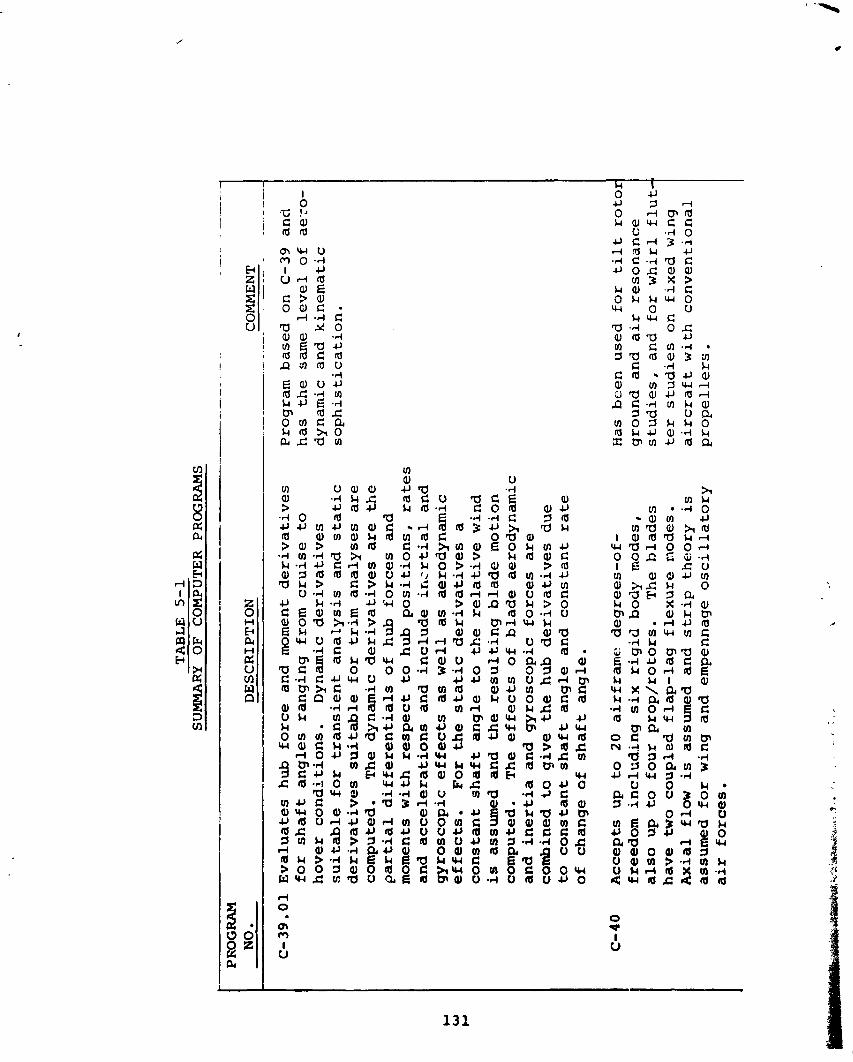
TABLE
5-1
SU
MM
ARY
O
F
CO
MPU
TER
PRO
GRA
MS
PRO
GR
AM
N
O.
DE
SC
RIP
TIO
N
CO
MM
EN
T
--
C-3
9.0
1
Ev
alu
ate
s
hu
b
forc
e an
d m
omen
t d
eri
va
tiv
es
f
or
sh
af
t a
ng
les
ra
ng
ing
fr
om
c
ruis
e t
o
ho
ve
r c
on
dit
ion
s.
Dy
nam
ic
de
riv
ati
ve
s
su
ita
ble
fo
r t
ra
ns
ien
t a
na
lys
is a
nd
s
ta
tic
d
eri
va
tiv
es
s
uit
ab
le f
or
tr
im
an
aly
se
s
ar
e
co
mp
ute
d.
Th
e d
yn
am
ic d
eri
va
tiv
es
are
th
e
pa
rti
al
dif
fe
re
nti
als
of
hu
b
forc
es
a
nd
m
om
ents
w
ith
re
sp
ec
t t
o h
ub
p
os
itio
ns
, r
ate
s
an
d
ac
ce
lera
tio
ns
an
d in
clu
de
in
cx
tia
l a
nd
g
yro
sc
op
ic e
ff
ec
ts as
we
ll a
s a
ero
dy
na
mic
e
ffe
cts
. F
or
the
sta
tic
de
riv
ati
ve
s
a
co
ns
tan
t s
ha
ft
an
gle
t
o t
he
r
ela
tiv
e w
ind
is
ass
um
ed
an
d
the
re
su
ltin
g b
lad
e m
oti
on
co
mp
ute
d.
Th
e e
ff
ec
ts o
f b
lad
e a
ero
dy
na
mic
a
nd
in
er
tia
an
d g
yro
sc
op
ic
forc
es
a
re
co
mb
ined
t
o g
ive
th
e h
ub
d
eri
va
tiv
es
du
e
to
co
ns
tan
t s
ha
ft
an
gle
an
d
co
ns
tan
t r
ate
o
f c
ha
ng
e o
f s
ha
ft
an
gle
.
C-4
0
Ac
ce
pts
u
p
to
20
a
irfr
am
e d
eg
ree
s-o
f-
fre
ed
om
in
clu
d.i
ng
six
rig
id b
od
y
mo
des
, a
lso
up
to
fo
ur
pro
p/r
oto
rs.
Th
e b
lad
es
h
av
e
two
c
ou
ple
d f
lap
- la
g f
lex
ure
mo
des
. A
xia
l fl
ow
is a
ssu
med
an
d
str
ip
th
eo
ry is
as
sum
ed
fo
r w
ing
a
nd
em
pen
nag
e o
sc
illz
tory
a
ir
fo
rce
s.
Pro
gra
m b
ase
d
on
C
-39
an
d
ha
s
the
sa
me
le
ve
l o
f ae
.:o-
dy
nam
ic
an
d
kin
em
ati
c
so
ph
isti
ca
tio
n.
Has
b
ee
n
use
d
fo
r tilt
roto
; g
rou
nd
an
d
ai
r r
eso
na
nc
e
stu
die
s,
an
d
fo
r w
hir
l f
lut-
te
r s
tud
ies
on
fi
xe
d w
ing
a
irc
ra
ft
wit
h
co
nv
en
tio
na
l p
rop
ell
ers
.
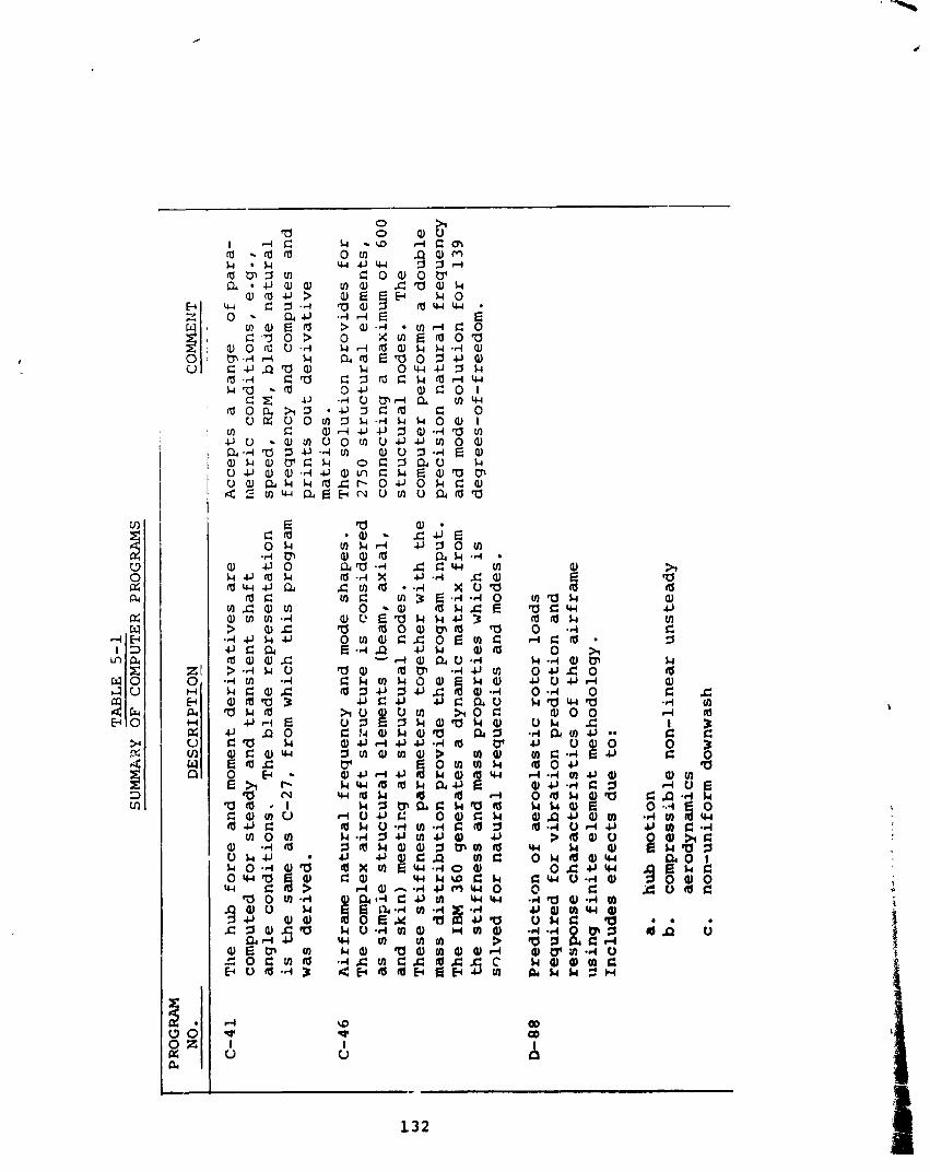
TA
BLE
5-1
SUMMk2Y
OF
CO
MP
UT
ER
PROGRAMS
C-4
1
Th
e h
ub
fo
rce
an
d m
om
ent
de
riv
ati
ve
s a
re
c
om
pu
ted
f
or
ste
ad
y
an
d t
ra
ns
ien
t s
ha
ft
an
gle
co
nd
itio
ns
, T
he
bla
de
re
pre
se
nta
tio
n
is
the
sam
e a
s C
-27
, fr
om
wh
ich
th
is p
rog
ram
w
as
de
riv
ed
.
NO.
DESCRIPTION -
COMME t.Z
T
----
-
- -
C-4
6
Air
fr
am
e
na
tura
l fr
eq
ue
nc
y
an
d m
ode
sh
ap
es
. T
he
c
om
ple
x
air
cr
af
t s
tru
ctu
re
is c
on
sid
ere
d
as
sim
pie
str
uc
tur
al
ele
me
nts
(b
eam
, a
xia
l,
an
d s
kin
) m
ee
tin
g
at
str
uc
tur
al
no
de
s.
Th
ese
sti
ff
ne
ss
pa
ram
ete
rs
tog
eth
er
wit
h
the
m
ass
dis
trib
uti
on
pro
vid
e
the
pro
gra
m
inp
ut.
T
he
IBM
3
60
g
en
era
tes
a
d
yn
am
ic m
atr
ix f
rom
th
e
sti
ff
ne
ss
an
d m
ass
pro
pe
rti
es
wh
ich
is
s~
lv
ed
fo
r n
atu
ra
l fr
eq
ue
nc
ies
a
nd
mo
des
.
D-88
Pre
dic
tio
n o
f a
ero
ela
sti
c r
oto
r lo
ad
s
req
uir
ed
f
or
vib
ra
tio
n p
red
icti
on
a
nd
re
sp
on
se
ch
ar
ac
ter
isti
cs
of
the
air
fra
me
u
sin
g f
in
it
e e
lem
en
t m
eth
od
olo
gy
. In
clu
de
s e
ff
ec
ts d
ue
to
:
a.
hub
mo
tio
n
b.
co
mp
res
sib
le
no
n-l
ine
ar
un
ste
ad
y
ae
rod
yn
am
ics
c.
no
n-u
nif
orm
d
ow
nw
ash
Ac
ce
pts
a
ra
ng
e
of
pa
ra-
me
tric
c
on
dit
ion
s,
e .
g.,
s
pe
ed
, WM, b
lad
e
na
tura
l fr
eq
ue
nc
y
an
d
co
mp
ute
s a
nd
p
rin
ts o
ut
de
riv
ati
ve
m
atr
ice
s.
Th
e s
olu
tio
n p
rov
ide
s
fo
r
27
50
s
tru
ctu
ra
l e
lem
en
ts,
co
nn
ec
tin
g
a
max
imum
o
f 6
00
s
tru
ctu
ra
l n
od
es.
T
he
co
mp
ute
r p
erf
orm
s
a
do
ub
le
pre
cis
ion
na
tur
al
fre
qu
en
cy
a
nd
mode
so
luti
on
f
or
13
9
de
gre
es-
of-
fre
ed
om
.
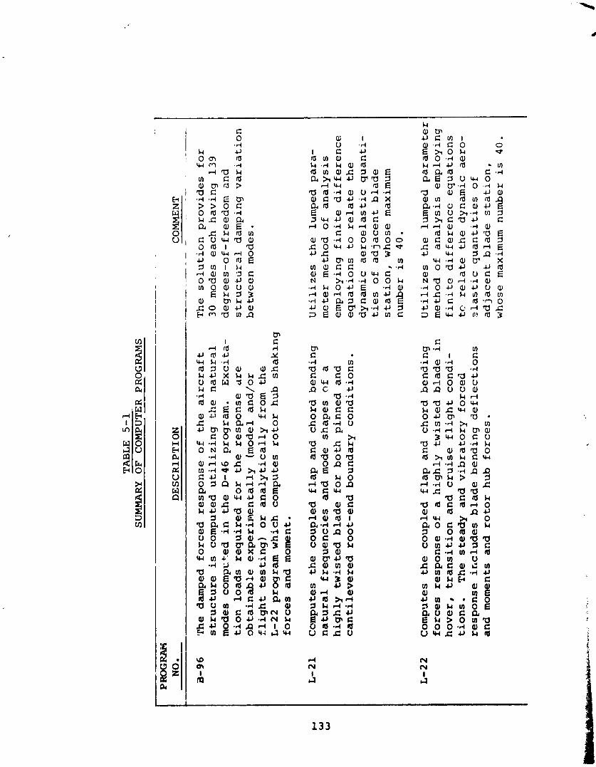
aJ,-Iwc . d a t n - r l w c , hu+r C 4 J I d h S o 7~ k d r l a a o a a E m a a , w u r : o a, a, c a u ~ 4 ~ 5 a a ,
5 a , E k C 0 a a c k . 4 o U J J a, E .d a d k -4 C 0 0 7 0 - C u u a w a b r 1 0 q a x c w c o + U a J - d E E
-4 s 4~ a a m a, m h a
L m a r l a , JJm
"$8:9 r % u l - i c u a c n a u m - 4 ~ - a . i
S Q , C ~ ~ N U
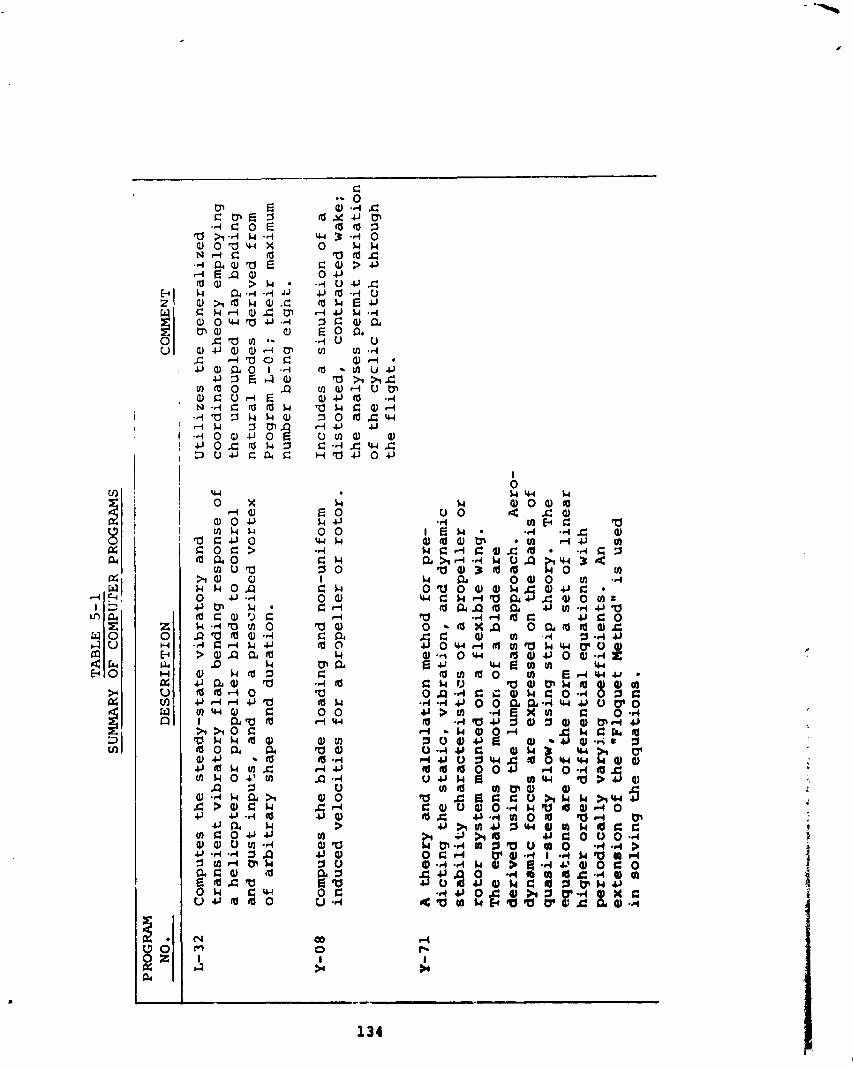
TA
BL
E
5-1
SU
MM
ARY 6l?
CO
MPU
TER
PRO
GRA
MS
-
- -
PRO
GR
AM
D
ESC
RIE
TIO
N
L-32
Co
mp
ute
s th
e s
tea
dy
-sta
te
vib
rato
ry
an
d
tra
ns
ien
t v
ibra
tory
f
lap
be
nd
ing
re
sp
on
se
of
a
he
lic
op
ter
or
pro
pe
lle
r b
lad
e
to
co
ntr
ol
and
g
us
t in
pu
ts,
an
d
to
a
pre
sc
rib
ed
v
~r
te
x
of
arb
itra
ry
sh
ap
e
an
d d
ura
tio
n.
Y-08
Co
mp
ute
s th
e b
lad
e
loa
din
g a
nd
n
on
-un
ifo
rm
ind
uc
ed
ve
loc
itie
s f
or
a
pr
~p
el
le
r or
ro
tor.
Y-7
1
A
the
ory
an
d
ca
lcu
lati
on
met
ho
d
fo
r p
re-
dic
tin
g t
he
sta
tic
, v
ibra
tio
n,
an
d d
yn
am
ic
sta
bil
ity
ch
ara
cte
ris
tic
s o
f a
pro
pe
lle
r o
r
roto
r sy
ste
m m
ou
nte
d
on
a
f
lex
ible
win
g.
Th
e e
qu
ati
on
s o
f m
oti
on
o
f a b
lad
e
are
derived
us
ing
th
e l
um
ped
m
ass
ap
pro
ac
h.
Aer
o-
dy
na
mic
fo
rce
s are
ex
pre
sse
d o
n th
e
ba
sis
of
qu
asi-
ste
ad
y
flo
w,
us
ing
st
ri
p t
he
ory
. T
he
eq
ua
tio
ns
are
of
the
fo
rm o
f a
se
t o
f li
ne
ar
h
igh
er
ord
er
dif
fe
re
nti
al
eq
ua
tio
ns
wit
h
pe
rio
dic
all
y
va
ryin
g c
oe
ffic
ien
ts.
An
ex
ten
sio
n o
f th
e
mF
loq
ue
t Met
ho
d"
is u
sed
in
so
lvin
g t
he
eq
ua
tio
ns
.
COMMENT
--
Uti
liz
es
th
e g
en
era
liz
ed
c
oo
rdin
ate
th
eo
ry
em
plo
yin
g
the
u
nc
ou
ple
d
fla
p b
en
din
g
na
tura
l m
odes
d
eri
ve
d fr
om
P
rog
ram
L
-01
; th
eir
max
imum
n
um
ber
b
ein
g
eig
ht.
Inc
lud
es
a
s
imu
lati
on
of
a
dis
torte
d,
co
ntr
ac
ted
wak
e;
the
an
aly
se
s p
erm
it v
ari
ati
on
o
f th
e c
yc
lic
pit
ch
th
rou
gh
th
e f
lig
ht.
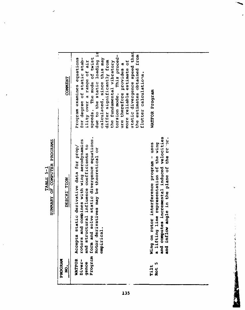
TA
BL
E
5-1
SU
BCHA
RY
OF
CO
MPU
TER
PR
OG
RAM
S --
.
-
PRO
GRA
M
NO
. D
ESC
RI-
TIO
N
CO
MM
EN
T
.~
--
WATPOR
Ac
ce
pts
s
tati
c d
eri
va
tiv
e d
ata
fo
r p
rop
/ D
ive
r-
roto
rs
an
d c
om
bin
es
wit
h w
ing
a
ero
dy
na
mic
s g
en
ce
an
d s
tru
ctu
ral
infl
ue
nc
e c
oe
ffic
ien
ts t
.o
Pro
grc
m
form
an
d
so
lve
sta
tic
div
erg
en
ce
eq
ua
tio
ns.
R
oto
r d
eri
va
tiv
es
may
b
e
the
ore
tic
al
or
e
mp
iric
al.
Pro
gra
m e
xa
min
es
eq
ua
tio
ns
for
de
gre
e o
f s
tati
c s
tab
- i
li
ty
ov
er
a
ran
ge
of
air
sp
ee
ds.
T
he
mod
e o
f tw
ist
du
e
to
th
e
sta
tic
lo
ad
ing
i!
ca
lcu
late
d,
sin
ce
th
is m
ay
dif
fe
r s
ign
ific
an
tly
fro
m
the
fu
nd
am
en
tal
vib
rato
ry
tors
ion
mod
e.
Th
is proced-
ure
th
ere
fore
pro
vid
es
a m
ore
re
lia
ble
es
tim
ate
of
sta
tic
div
erg
en
ce
sp
ee
d
tha
i th
e e
sti
ma
tes
ob
tain
ed
fr
om
f
lutt
er
ca
lcu
lati
o?
s.
WA
TFO
R P
rog
ram
T
il
t
Win
g o
n r
oto
r in
terf
ere
nc
e p
rog
ram
-
us
es
Rot
5
a
lif
tin
g l
ine
re
pre
se
nta
tio
n o
f the w
ing
and camputes
inc
rem
en
tal
ind
uc
ed
ve
loc
itie
s
and inf la
w an
gle
i
n t
he
p
lan
e o
f the rc
-x.
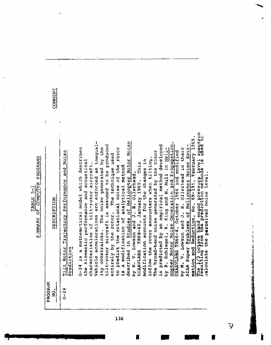
TABLE
5-1
S JM
MA
RY
O
F
CO
MP
UT
ER
PROGRAMS
-- -
- -
PRO
GRA
M
DE
SC
RIP
TIO
N
CO
MM
EN
T
----.--
. T
il
t R
oto
r T
raje
cto
ry P
erf
orm
an
ce
an
d
No
ise
P
red
icti
on
-.
- G
-24
is
a
ma
the
m2
tic
al
mo
del
w
hic
h
de
sc
rib
es
th
e k
ine
ma
tic
pe
rfo
rma
nc
e
an
d
ac
ou
sti
ca
l c
ha
ra
cte
ris
tic
s
of
tilt
-r
oto
r
air
cz
af
t.
Ve
hic
le
ac
ce
lera
tio
ns
are
en
forc
ed
as
ine
qu
al-
i
ty
co
ns
tra
ints
. T
he
no
ise
ge
ne
rate
d b
y
the
ti
lt-
ro
tor
a
irc
ra
ft
is
ass
um
ed
t
o b
e p
rod
uc
ed
e
nti
re
ly b
y
the
ro
tor.
T
he
tec
hn
iqu
e u
sed
to
pr
ed
ict
the
ro
tati
on
al
no
ise
of
the
ro
tor
is
a
mo
dif
ica
tio
n
of
an
aly
tic
al
met
ho
d
de
sc
rib
ed
in
Stu
die
s o
f H
eli
co
ete
r R
oto
r N
ois
e -
by
M.
V.
Lo
wso
n
an
d J
. B
. O
lle
rhe
ad
, U
SAA
VLA
BS
TR
68
-60
, J
an
ua
ry
19
69
. T
his
m
od
ific
ati
on
a
cc
ou
nts
f
or
th
e c
ha
ng
es
in
in
flo
w
the
ro
tor
en
co
un
ters
wh
en
tilt
ing
. T
he
bro
ad
-ba
nd
n
ois
e g
en
era
ted
by
th
e r
oto
r
is p
red
icte
d
by
a
n e
mp
iric
al
met
ho
d
de
ve
lop
ed
b
y
R.
Sc
hle
ge
l,
R.
~i
&
an
d H
. N
ull
in
~e
li
-
co
pte
r R
oto
r N
ois
e G
en
era
tio
n a
nd
Fro
pa
ga
tio
n,
d
7
US
Mi7
LA
BS
TR
66
-4,
Oc
tob
er
19
66
a
nd
mo
dif
ied
b
y M.
V.
Lo
wso
n
an
d J
. B
. O
lle
rhe
ad
i
n t
he
ir
AIM P
ap
er
Pro
ble
ms
of
He
lic
op
ter
No
ise
E
sti
-
mation
and
Re
du
cti
on
, N
o.
69
-19
5,
Fe
bru
ary
1
96
9.
Th
e 3
oc
av
e b
n
d
so
od
re
ss
ur
ev
e1
s e
tru
m
re
sd
Ln
g I
rom
&
e
pre
Blc
tPo
n
me
tgo
as
is
ug
eS
to
;:a
lcu
late
the
pe
rce
ive
d
no
ise
le
ve
l.
Q&
&&
+&..y
i, ..*,
i..r
* .. r..
'
-
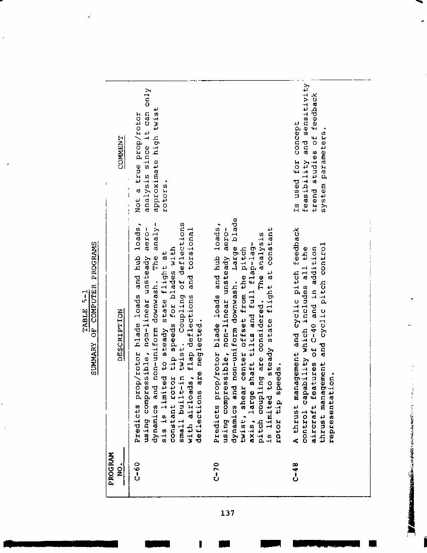
TA
BL
E
5-1
SU
MM
ARY
OF
C
OM
PU
TE
R
PRO
GR
AM
S - ~
PRO
GR
AM
N
O.
DE
SC
RIP
TIO
N
CO
MM
EN
T
-
-
-- - -. . .
-~
-
C-60
Pre
dic
ts p
rop
/ro
tor
hla
de
lo
ad
s
and
h
ub
lo
ad
s,
No
t a
tr
ue
pro
p/r
oto
r u
sin
g c
om
pre
ss
ible
, n
on
-lin
ea
r u
nst
ea
dy
a
ero
- a
na
lys
is
sin
ce
it c
an
on
ly
dy
na
mic
s a
nd
n
on
-un
ifo
rm
do
wn
was
h..
T
he
an
aly
- a
pp
rox
ima
te h
igh
t
wi
st
sis
is
lim
ite
d t
o s
tea
dy
s
tate
fli
gh
t a
t
roto
rs.
co
ns
tan
t ro
tor
ti
p s
pe
ed
s f
or
bla
de
s w
ith
s
ma
ll b
uil
t-in
tw
ist.
C
ou
pli
ng
of
de
fle
cti
on
s
wit
h
air
loa
ds
, f
lap
de
fle
cti
on
s a
nd
to
rsio
na
l d
efl
ec
tio
ns
ar
e n
eg
lec
ted
.
C-7
0
Pre
dic
ts
pro
p/r
oto
r b
lad
e
loa
ds
a
nd
hu
b
loa
ds
, u
sin
g c
om
pre
ssib
le,
no
n-l
ine
ar
un
ste
ad
y
ae
ro-
dy
na
mic
s a
nd
no
n-u
nif
orm
d
ow
nw
ash
. L
arg
e b
lad
e
twis
t,
sh
ea
r c
en
ter
of
fs
et
fro
m t
he
pit
ch
a
xis
, la
rge
sh
af
t t
il
~s
an
d
fu
ll
fla
p-l
ag
- p
itc
h c
ou
pli
ng
are
c
on
sid
ere
d.
Th
e a
na
lys
is
is l
imit
ed
to
ste
ad
y s
tate
fli
gh
t a
t c
on
sta
nt
ro
tor
ti
p s
pe
ed
s.
C-4
8 A
th
ru
st
man
agem
ent
an
d
cy
cli
c p
itc
h
fee
db
ac
k
Is
use
d
fo
r c
on
ce
pt
co
ntr
ol
ca
pa
bil
ity
wh
ich
in
clu
de
s
al
l t
he
f
ea
sib
ilit
y a
nd
se
ns
itiv
ity
a
irc
ra
ft
fea
ture
s o
f C
-40
an
d
in
ad
dit
ion
tr
en
d
stu
die
s o
f fe
ed
ba
ck
th
ru
st
man
agem
ent
an
d
cy
cli
c p
itc
h
co
ntr
ol
syst
em
pa
ram
ete
rs.
rep
res
en
tati
on
.
3 . Areas where t i l t - r o t o r t echno logy shou ld be f u r t h e r r e f i n e d o r expanded t o i n c r e a s e c o n f i d e n c e o r r e d u c e e f f o r t i n deve lop ing Task I a i r p l a n e s from t h e r e s e a r c h a i r c r a f t .
4 . Genera l a r e a s of a d b m c e d t e c h n o l o g y , n o t s p e c i f i c a l l y r e l a t e d t o tilt r o t o r s , which have been assumed t o be i n c o r p o r a t e d i n t o t h e T;sk I a i r c r a f t .
Only c a t e g o r i e s 1 and 3 a r e a d a r e s s e d i n t h i s s e c t i o n . Category 2 i s covered under Task 11, w h i l e c a t e g o r y 4 i s con- s i d e r e d beyond t h e scope o f t h i s s t u d y e x c e p t f o r a g e n e r a l l i s t i n g of a r e a s .
Ca te so rv 1 - D e s i r a b l e B e f o r e Research A i r c r a f t
a . Feedback C o n t r o l S y s t e x - A s d i s c ~ l s s e d under Task I1 (Volume 111, major improvements i n f l y i n g q u a l i t i e s , b l a d e l o a d r e d u c t i o n , and i n c r e a s e i n damping o f a e r o e l a s t i c modes can b e o b t a i n e d by cse o f feedback c o n t r o l sys tems . Development o f a n a l y r i c a l methods and wind t u n n e l t e s t i n g i s r e q u i r e d . B o e i n g ' s c u r r e n t l i m i t e d a n a l y t i c a l c a p a b i l i t y i s be ing expanded t o p r e d i z t t h e c a p a b i l i t i e s o f such sys t ems . Wind t u n n e l d a t a can be g b t a i n e d by a d d i t i o n a l t e s t i n g o f B o e i n g ' s e x i s t i n g 1 / 9 - s c a l e dynamic model o f t h e Model 222 r c t o r , t h e 1 /4 .6 - sca l e a i r p l a n e model which Boeing i s b u i l d i n g d u r i n g t h e f i r s t h a l f of 1972, and from a d d i - t i o n a l t e s t i n g o f t h e f u l l - s c a l e 26- foot -d iameter r o t o r .
b. Ground E f f e c t - A b i l i t y t o p r e d i c t ground e f f e c t i s poor , even on f ixed-wing a i r c r a f t . Some d a t a on t h e e f f e c t o f ground p r o x i m i t y on per formance is a v a i l a b l e from tests on a l / l 0 - s c a l e per formance model o f t h e Boeing Model 160. L imi t ed t e s t i n g on t h e 1/10- dynamica l ly - sca l ed f u l l - s p a n model o f t h e Boeing Yodel 160 i n d i c a t e d a s l i g h t t endency t o s k i t t i s h n e s s w h i l e hove r ing i n ground e f f e c t , which was r e a d i l y c o r r e c t a b l e by a n a t t i t u d e SAS. The e f f e c t o f ground p rox imi ty on b o t h per formance and f l y i n g q u a l i t i e s needs f u r t h e r i n v e s t i g a t i o n by a d d i t i o n a l model t e s t i n g . T h i s cou ld be done on Boeing 1 /4 .6 - sca l e model of t h e Model 2 2 2 .
c . T r a n s i e n t Rotor Loads - A v e r y l i m i t e d c a p a b i l i t y e x i s t s f o r t h e p r e d i c t i o n o f t r a n s i e n t r o t o r b l a d e l o a d s d u r i n g maneuvers and g u s t s . The methodology needs improvement and v a l i d a t i o n by test . Data on t r a n s i e n t s f o l l o w i n g c o n t r o l a p p l i c a t i o n can b e ob- t a i n e d a l s o on an o s c i l l a t i n g model and i n s i m u l a t e d g u s t s . Such d a t a cou ld b e o b t a i n e d on B o e i n g ' s
1/9-dynamically-scaled 2 2 2 model i n t h e P r i n c e t o n t u n n e l . Maneuver d a t a can a l s o be ob ta ined from Boeing 's 1 /4 .6-sca le f u l l - s p a n dynamic model.
d . Free-Free A e r o e l a s t i c T e s t s - Bas ic a n a l y t i c a l method- ology f o r coupled a i r f ra rne / ro to r dynamics has been w e l l v a l i d a t e d by model tests and w i l l be f u r t h e r s u b s t a n t i a t e d by t h e 26-foot r o t o r tests. Almost a l l t e s t i n g , however, has been on semi-span models which cannot s i m u l a t e ant i symmetr ic o r f r e e - f r e e modes. Ada!-tional t e s t i n g i s d e s i r a b l e on a f u l l - s p a n dynan~i .cal ly s c a l e d model. Th i s could be performed on Boeing 's 1/4.6-scale 2 2 2 model.
Category 3 - D e s i r a ~ l e Before Proceeding w i t h Task I A i r p l a n e s
a . S t a l l F l u t t e r - - C o r r e l a t i o n between t es t d a t a and c u r r e n t s t a l l f l d t t e r c r i t e r i a i s poor. Cur ren t c r i - t z r i a may be extremely c o n s e r v a t i v e r e s u l t i n g i n e x c e s s i v e b lade weight and reduced performance i n hover and c r u i s e . A d d i t i o n a l p a r a m e t r i c t e s t i n g is r e q u i r e d t o improve t h e unders tanding of t h e e f f e c t s of a i r f o i l c h a r a c t e r i s t i c s , f l i g h t c o n d i t i o n s , b l a d e t o r s i o n a l p r o p e r t i e s , and c o n t r o l s t i f f n e s s and damp- ing . While c e r t a i n advanced s e c t i o n s appear t o be c l e a r of s t a l l f l u t t e r i n hover , t h i s phenomenon may r a p i d l y reappear a s forward f l i g h t speed i s i n c r e a s e d and r o t o r tilt decreased dur ing t r a n s i t i o n . T e s t s of r o t o r s us ing advanced a i r f o i l s a r e r e q u i r e d .
b. A u t o r o t a t i o n and Descent - A l i m i t e d amount of d a t a on ].ow power and a u t o r o t a t i o n performance was o b t a i n e d from Boeing 's 1971 tests on a " r i g i d " model. Th i s is s u f f i c i e n t t o pe rmi t t h e r e s e a r c h a i r c r a f t t o s t a r t e x p l o r i n g t h e a r e a . However, q u a n t i t a t i v e d a t a e x p l o r i n g p a r a m e t r i c v a r i a t i o n s of a i r s p e e d , s h a f t a n g l e , c o l l e c t i v e p i t c h , wing i n t e r f e r e n c e e f f e c t s , etc. can be more a c c u r a t e l y and cheaply o b t a i n e d by model tests. Addi t iona l model t e s t i n g is recommended t o p rov ide t h e volume of pa ramet r i c d a t a needed t o s u b s t a n t i a t e and improve t h e p r e d i c t i o n methods. T h i s could be performed on Boeing 's 1/4.6-scale 2 2 2 model. 3
c. I n d i v i d u a l Blade I n s t a b i l i t i e s - Curren t a n a l y t i c a l methods can p r e d i c t a e r o e l a s t i c s t a b i l i t y c h a r a c t e r - i s t ics of i n d i v i d u a l b l a d e s and of coupled r o t o r / a i r f r a m e modes. The coupled mode a n a l y s e s , such a s w h i r l f l u t t e r and a i r /ground resonance , a r e w e l l sub- s t a n t i a t e d by test d a t a . For i n d i v i d u a l b l a d e i n s t a - b i l i t i e s , such a s coupled p i t c h / f l a p / l a g motion, however, a v a i l a b l e test d a t a t o v a l i d a t e t h e a n a l y s i s i s ext remely l i m i t e d . For t h e r e s e a r c h a i r c r a f t ,
model tes ts and t h e f u l l - s c a l e 26 - foo t -d i ame te r r o t o r tes ts w i l l s u b s t a n t i a t e freedom from t h e s e i n s t a b i l i - t i e s . For t h e new r o t o r s which w i l l b e used on t h e Task I v e h i c l e s , however, i t would be d e s i r a b l e t o o b t a i n s u f f i c i e n t test d a t a t o s u b s t a n t i a t e t h e a n a l y - t i c a l p r e d i c t i o n of s t a b i l i t y b o u n d a r i e s . S i n c e t h e mechanism of t h e s e i n s t a b i l i t i e s i s s p e c i f i c a l l y a s s o c i a t e d w i t h t h e d e f l e c t e d shape of t h e b l a d e under aerodynamic and i n e r t i ~ f o r c e s , p a r a m e t r i c v a r i a t i o n s can be o b t a i n e d on a s i n g l e b l a d e d e s i g n t y v a r y i n g t h e o p e r a t i n g c o n d i t i o n s of t h r u s t , rpm, advance r a t i o , and s h a f t a n 3 l e . B o e i n g ' s 1 / 9 - s c a l e and 1 / 4 . 6 - s c a l e dynamic models would be s u i t a b l e f o r t h i s pu rpose .
Ca tegory 4 - Non-Ti l t Ro to r Technology
Advanced technology n o t s p e c i f i c t o tilt r o t o r s which h a s been assumed t o b e i n c o r p o r a t e d i n t o t h e Task I a i r p l a n e i n - c l u d e s e x t e n s i v e u s e of advanced compos i t e s i n t h e a i r f r a m e , advanced t r a n s m i s s i o n t echno logy i n g e a r s , b e a r i n g s and l u b r i - c a t i o n s y s t e m s , advanced a i r f o i l s f o r wings a s w e l l a s r o t o r s , and advanced t echno logy t u r b i n e e n g i n e s . A l l o f t h e s e t e c h - n o l o g i e s a r e under development now by NASA, m i l i t a r y , o r i ndus - t r i a l e f f o r t s and shou ld be i n iidiid i n t h e r i m e - s c a i e of o p e r a - t i o n a l a i r c r a f t deve lopments . These a r e a s s h o u l d be mon i to red c v e r t h e p e r i o d between t h e p r e s e n t t i m e and t h e i n i t i a t i o n of o p e r a t i o n a l a i r c r a f t d e s i g n s t o a s s u r e t a n a d e q u a t e t echno logy base i s indeed deve loped .
REFERENCES
1. -. STOL, VTOL, and V/STOL -- Where Do They F i t - I n ? , AIAA AdHoc Committee, AIAA 8 t h Annual Meet ing and T e c h n i c a l D i s p l a y , Washington, D. C . , October 1971
2. Schoen, A. H . , User's Manual f o r VASCOMP I1 - The V/STOL A i r c r a f t S i z i n g and Performance Computer Program, Boeing Document D8-0375, Volwne V I , V e r t o l D i v i s i o n , The Boeing Com- pany, P h i l a d e l p h i a , Pa . , October 1971.
3 . Wisniewski , John S . , Weight Trends Data f o r VASCOMP - The V/STOL A i r c r a f t S i z i n g and Performance Computer Program, Boeing Document D8-0375, Volume V , V e r t c l D i v i s i o n , The Boeing Company, P h i l a d e l p h i a , P a . , A p r i l 1967.
4. G a b r i e l , E . A . , Drag E s t i m a t i o n o f V/STOL A i r c r a f t , Boeing Document D8-2194-1, V e r t o l D i v i s i o n , The Boeing Company, P h i l a d e l p h i a , Pa . , A p r i l 1969.
5 . Sandford , Robin W . , e t a l , Design S t u d i e s and Model T e s t s of t h e Stowed T i l t Rotor Clnncept, t.%l*&cc VIII. S-uria~dry -- -- of S t r u c t i I r a l Design Cri ter ia and Aerodynamic P r e d i c t i o n Tech- n i q u e s , A i r Force F l i g h t Dynamics Labora to ry Repor t AFFDL-TR- 76-62, V o l u m e 111, October 1971.
6. Lowson, M. V . , O l l e r h e a d , J. B . , S t u d i e s o f H e l i - c o p t e r Rotor Noise , USAAVLABS TR68-60, J a n u a r y 1969.
7 . S c h l e g e l , R . , King, R . , Mul l , H . , H e l i c o p t e r Ro to r Noise Genera t ion and P r o p a g a t i o n , USAAVALBS TR66-4, October 1966.


![NASA - [Aerospace History 17] - The History of the XV-15 Tilt Rotor Research Aircraft, From Conce.pdf](https://img.dokumen.tips/doc/110x75/55cf8d1e5503462b139235cc/nasa-aerospace-history-17-the-history-of-the-xv-15-tilt-rotor-research.jpg)