Embed Size (px)
Citation preview
Virtualized ECC: Flexible Reliability in Memory Systems
Doe Hyun Yoon
Advisor: Mattan Erez
Electrical and Computer Engineering
The University of Texas at Austin

N Motivation
• Reliability concerns are growing
– Memory failure rate is increasing
• Shrinking semiconductor design rules & lower Vdd
– More and more memory cells
• Higher capacity & larger number of nodes in a system
– Industry consistently requires high reliability levels
• Chipkill and even higher reliability levels
• Traditional solutions
– Apply ECC uniformly across memory locations
• Not all apps/data need same error tolerance levels
– Cost increases with tolerance levels
• Hard to meet the required level of reliability at low cost
2

N Virtualized ECC
3
• Store redundant info within memory hierarchy
• Dynamic mapping between data and ECC
– Flexible protection level/access granularity
• Two-tiered protection
Uniform ECC Virtualized ECC
Virtualized
ECC
Stronger
ECC
Finer access
granularity
Data block ECC

N Outline
• Motivation
• Traditional Memory Protection
• Virtualizing Redundant Information
• Memory Mapped ECC (MME)
• Virtualized and Flexible ECC (V-ECC)
• Adaptive Granularity Memory System (AGMS)
• Conclusions and Future Work
4
N
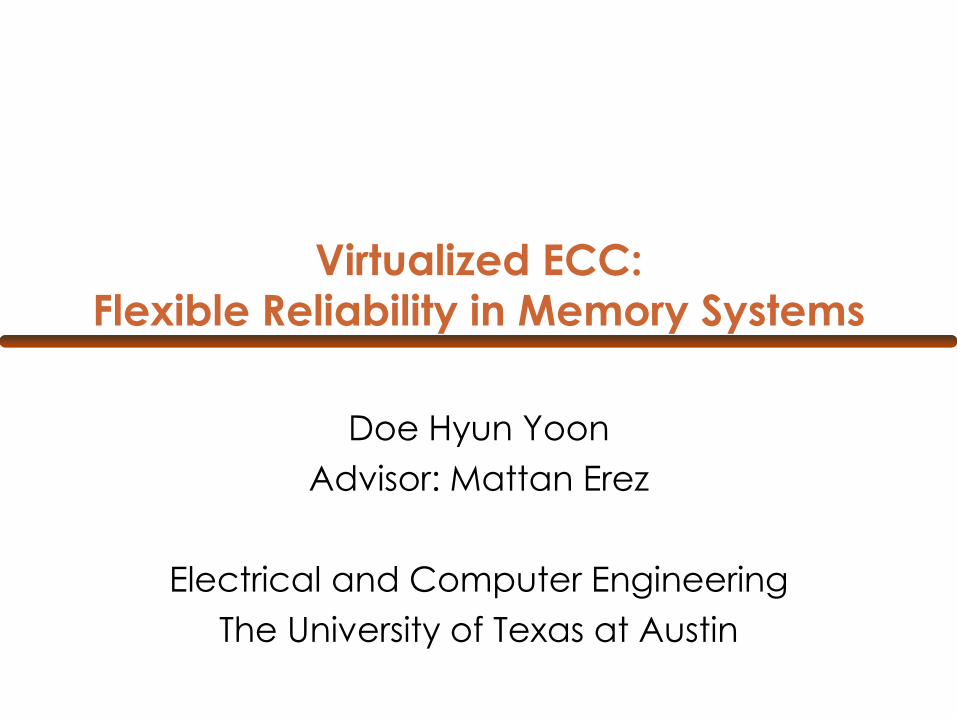
L2 cache
Main Memory
Memory bus
• Uniform ECC
– Simple and transparent to the programmer
• Dedicated and aligned HW resources
– Waste storage and bandwidth
– Better reliability at higher cost
• Design-time decision
– Error tolerance level
– Access granularity
Traditional Memory Protection
5
Users always pay for the cost of memory protection

N Virtualizing Redundant Information
• Store all or part of redundant information within the memory hierarchy
– Minimize dedicated resources to redundant information
– Two-tiered protection
• Tier-1 error code: Low-cost, low-complexity for the common case
• Tier-2 error code: Strong error correcting code, but rarely accessed
– Decouple data and ECC storage
• Flexibility in memory protection
– Adaptive error tolerance levels / access granularities
• Users pay for the error tolerance they need, rather than overpay for what they might need
6

N Examples of Virtualizing ECC
• Last-level cache protection with memory mapped ECC
– Memory Mapped ECC (MME) [ISCA’09]
– ECC FIFO [SC’09]
• Chipkill level flexible main memory protection
– Virtualized and Flexible ECC (V-ECC) [ASPLOS’10]
• Adaptive memory access granularity with ECC
– Adaptive Granularity Memory System (AGMS) [On-going]
7
N
Memory Mapped ECC [ISCA’09]

N
.
.
.
...8 ways
.
.
.
Tag
.
.
.
.
.
....
.
.
.
.
.
.
.
.
.
.
.
.
.
.
.
Memory Mapped ECC [ISCA’09]
Data ECC
...
64B 8B
.
.
.
.
.
.
.
.
.
.
.
.
1B 8B
...
T1EC T2EC
On-Chip DRAM
T2EC is memory mapped and cacheable
9
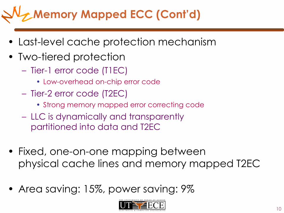
N Memory Mapped ECC (Cont’d)
• Last-level cache protection mechanism
• Two-tiered protection
– Tier-1 error code (T1EC)
• Low-overhead on-chip error code
– Tier-2 error code (T2EC)
• Strong memory mapped error correcting code
– LLC is dynamically and transparently partitioned into data and T2EC
• Fixed, one-on-one mapping between physical cache lines and memory mapped T2EC
• Area saving: 15%, power saving: 9%
10

N
Virtualized and Flexible ECC [ASPLOS’10]
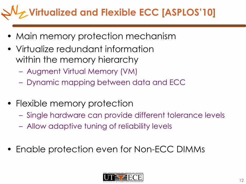
N Virtualized and Flexible ECC [ASPLOS’10]
• Main memory protection mechanism
• Virtualize redundant information within the memory hierarchy
– Augment Virtual Memory (VM)
– Dynamic mapping between data and ECC
• Flexible memory protection
– Single hardware can provide different tolerance levels
– Allow adaptive tuning of reliability levels
• Enable protection even for Non-ECC DIMMs
12

N Virtualized and Flexible ECC (Cont’d)
Physical Memory
Data T1EC
Virtual Address space
LowVirtual Page to Physical Frame mapping
Physical Frame to ECC Page mapping
T2EC for Chipkill
T2EC for DoubleChipkill
ECC page – j
ECC page – k
Protection Level
Medium
High
13
Virtual page – i
Virtual page – j
Virtual page – k
Page frame – i
Page frame – j
Page frame – k
N
14Data T1EC Data T1EC
LLC
DRAM Rank 0 Rank 1
ECC Address Translation Unit
T2EC for Rank 1 data
T2EC for Rank 0 data
0000
0080
0100
0180
0200
0280
0300
0380
0400
0480
0500
0580
0040
00c0
0140
01c0
0240
02c0
0340
03c0
0440
04c0
0540
05c0
PA: 0x02003
Wr: 0x02002
B0
B0
Rd: 0x00c01
A
A
B1
B2
B3
1 2 3
1 2 3
EA: 0x054040
0
Wr: 0x05405
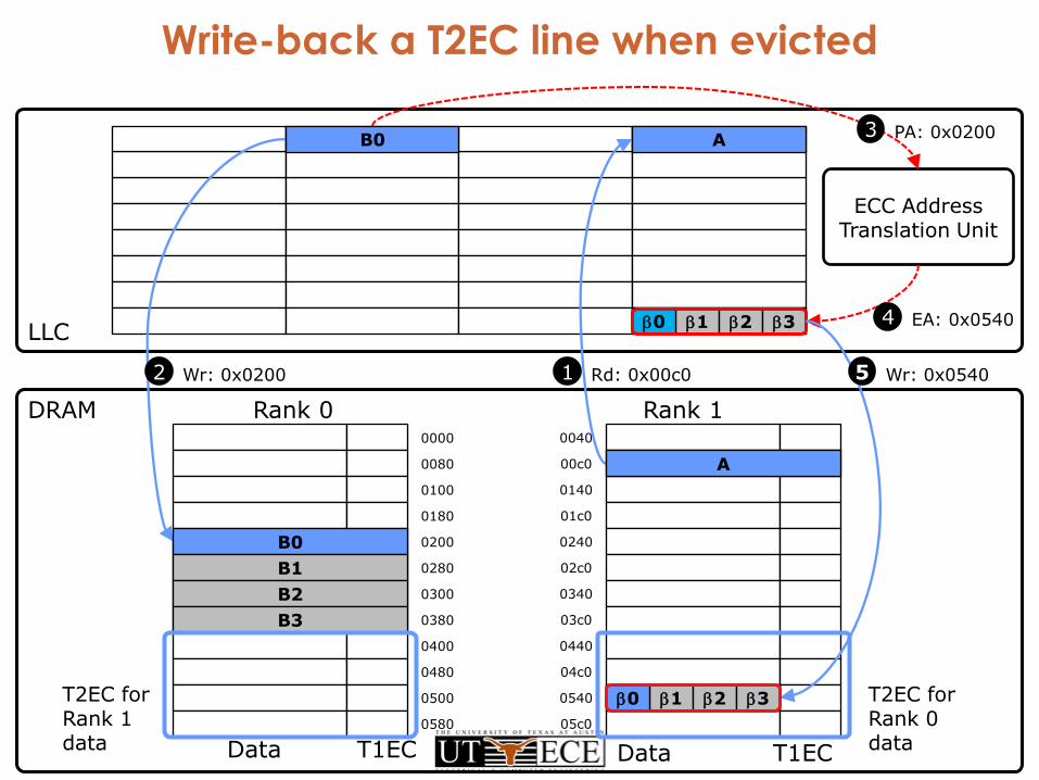
Virtualized ECC operationRead: fetch data and T1ECDon’t need T2EC in most casesWrite: update data, T1EC, and T2ECECC Address Translation Unit: fast PA to EA translationT2ECs of consecutive data lines map to a T2EC lineWrite-back a T2EC line when evicted

N Performance Impact of V-ECC
• Increased data miss rate
– T2EC lines in LLC reduce effective LLC size
• Increased traffic due to T2EC write-back
– One-way write-back traffic
• Not on the critical path
15

N Chipkill correct
• Single Device-error Correct andDouble Device-error Detect
– Can tolerate a DRAM failure
– Can detect a second DRAM failure
• Traditional chipkill requires x4 DRAMs
• V-ECC x8
– Two-tiered error code
– Simpler T1EC relaxes module design constraints
• Enable more energy efficient x8 configurations
– T2EC for error correction is virtualized
16

N Flexible Error Protection
• Single HW with V-ECC can provide– Chipkill-detect, Chipkill-correct, and
Double chipkill-correct
– Use different T2EC for different pages
• Maximize performance/power efficiency with Chipkill-Detect
• Stronger protection at the cost of additional T2EC accesses
17
Chipkill-Detect
Chipkill-Correct
Double Chipkill-Correct
T2EC per 64B
0B 4B 8B

N
0.96
1.00
1.04
1.08
1.12
1 4 7 10 13 16 19 22 25 28 31 34 37 40 43 46 49
Normalized Execution Time
0.96
1.00
1.04
1.08
1.12
1234567
0.60
0.70
0.80
0.90
1.00
Chip
kill
Dete
ct
Chip
kill
Corr
ect
2 C
hip
kill
Corr
ect
Chip
kill
Dete
ct
Chip
kill
Corr
ect
2 C
hip
kill
Corr
ect
Chip
kill
Dete
ct
Chip
kill
Corr
ect
2 C
hip
kill
Corr
ect
Chip
kill
Dete
ct
Chip
kill
Corr
ect
2 C
hip
kill
Corr
ect
Chip
kill
Dete
ct
Chip
kill
Corr
ect
2 C
hip
kill
Co
rre
ct
Chip
kill
Dete
ct
Chip
kill
Corr
ect
2 C
hip
kill
Corr
ect
Chip
kill
Dete
ct
Chip
kill
Corr
ect
2 C
hip
kill
Corr
ect
Chip
kill
Dete
ct
Chip
kill
Corr
ect
2 C
hip
kill
Corr
ect
Chip
kill
Dete
ct
Chip
kill
Corr
ect
2 C
hip
kill
Corr
ect
Chip
kill
Dete
ct
Chip
kill
Corr
ect
2 C
hip
kill
Corr
ect
Chip
kill
Dete
ct
Chip
kill
Corr
ect
2 C
hip
kill
Corr
ect
Chip
kill
Dete
ct
Chip
kill
Corr
ect
2 C
hip
kill
Corr
ect
Chip
kill
Dete
ct
Chip
kill
Corr
ect
2 C
hip
kill
Corr
ect
bzip2 hmmer mcf libq omnet milc lbm sphinx3 canneal dedup fluid freq avg
SPEC 2006 PARSEC
Normalized EDP
0.60
0.70
0.80
0.90
1.00
Chip
kill
Dete
ct
Ch
ipkill
Co
rre
ct
2 C
hip
kill
Corr
ect
Chip
kill
Dete
ct
Chip
kill
Corr
ect
2 C
hip
kill
Corr
ect
STREAM GUPS
Chipkill-Detect
Chipkill-Correct
Double Chipkill-Correct
VECC x8 (normalized to baseline x4 chipkill)
18
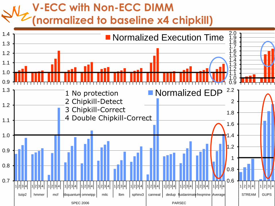
N V-ECC with Non-ECC DIMM(normalized to baseline x4 chipkill)
0.9
1.0
1.1
1.2
1.3
1.4
1 2 3 4 1 2 3 4 1 2 3 4 1 2 3 4 1 2 3 4 1 2 3 4 1 2 3 4 1 2 3 4 1 2 3 4 1 2 3 4 1 2 3 4 1 2 3 4 1 2 3 4
bzip2 hmmer mcf libquantum omnetpp milc lbm sphinx3 canneal dedup fluidanimatefreqmine Average
SPEC 2006 PARSEC
Normalized Execution Time
0.91.01.11.21.31.41.51.61.71.81.92.0
1 2 3 4 1 2 3 4
STREAM GUPS
0.7
0.8
0.9
1.0
1.1
1.2
1.3
1 2 3 4 1 2 3 4 1 2 3 4 1 2 3 4 1 2 3 4 1 2 3 4 1 2 3 4 1 2 3 4 1 2 3 4 1 2 3 4 1 2 3 4 1 2 3 4 1 2 3 4
bzip2 hmmer mcf libquantum omnetpp milc lbm sphinx3 canneal dedup fluidanimatefreqmine Average
SPEC 2006 PARSEC
Normalized EDP
0.6
0.8
1
1.2
1.4
1.6
1.8
2
2.2
1 2 3 4 1 2 3 4
STREAM GUPS
1 No protection2 Chipkill-Detect3 Chipkill-Correct4 Double Chipkill-Correct
N
Adaptive Granularity Memory System
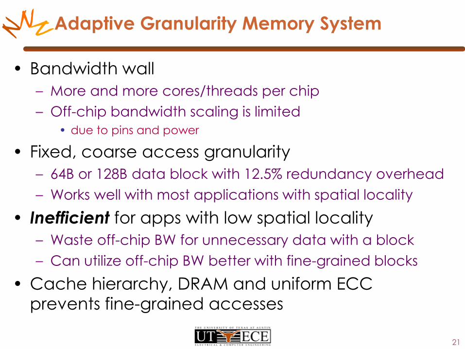
N Adaptive Granularity Memory System
• Bandwidth wall
– More and more cores/threads per chip
– Off-chip bandwidth scaling is limited
• due to pins and power
• Fixed, coarse access granularity
– 64B or 128B data block with 12.5% redundancy overhead
– Works well with most applications with spatial locality
• Inefficient for apps with low spatial locality
– Waste off-chip BW for unnecessary data with a block
– Can utilize off-chip BW better with fine-grained blocks
• Cache hierarchy, DRAM and uniform ECC prevents fine-grained accesses
21

N Coarse- and Fine-Grained Memory Access
• Coarse-grained access
– Lower ECC/control overhead
– Generally works well
– But, poor throughput without spatial locality
• Fine-grained access
– Higher ECC/control overhead
– Better throughput, if apps have poor spatial locality
22
Data ECC
Data ECC
Data ECC
Data ECC
Data ECC
Data ECC
Data ECC
Data ECC
Data ECC

N Design examples
Wide channel forCoarse-grained access
Data ECC
AGMS with virtualized ECC
Data
Fine-
grained
access
ECC page
ECC page
Coarse-
grained
access
Data ECC Data ECC
Narrow multi-channel forFine-grained access
23

N
Regis
ter/
Dem
ux
DBUS
x8 x8 x8 x8 x8 x8 x8 x8 x8
ABUS
SR0 SR1 SR2 SR3 SR4 SR5 SR6 SR7 SR8
Subranked DRAM to enable an 8B access granularity
AGMS Design
Core
$I$D
L2
Last Level Cache
MC
DRAM
Core
$I$D
L2
Core
$I$D
L2
…
24
Augment Virtual Memory (VM) toidentify fine-grained pages-- 1 bit per PTE
Sectored caches tomanage 8B data blocks
Memory controller can handlemultiple access granularities
Reg
Dem
ux
Reg
Dem
ux
clk
clk
Double
Data Rate ABUS
SR0
SR1
SR2
SR3
SR4
SR5
SR6
SR7
Higher Address/Command BW
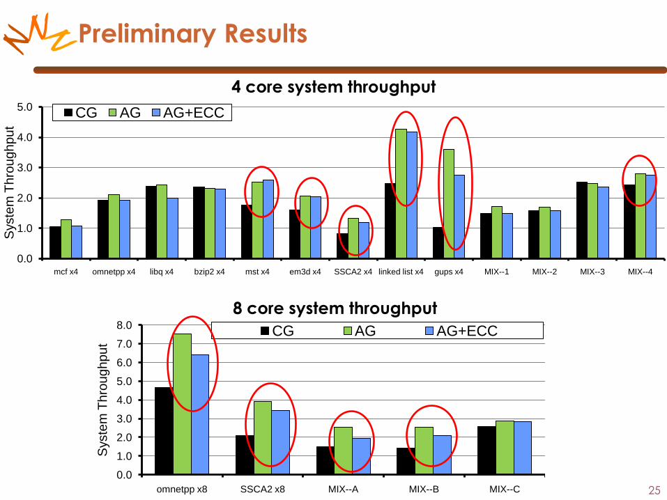
N Preliminary Results
0.0
1.0
2.0
3.0
4.0
5.0
mcf x4 omnetpp x4 libq x4 bzip2 x4 mst x4 em3d x4 SSCA2 x4 linked list x4 gups x4 MIX--1 MIX--2 MIX--3 MIX--4
Syste
m T
hro
ug
hp
ut
CG AG AG+ECC
0.0
1.0
2.0
3.0
4.0
5.0
6.0
7.0
8.0
omnetpp x8 SSCA2 x8 MIX--A MIX--B MIX--C
Syste
m T
hro
ug
hp
ut
CG AG AG+ECC
4 core system throughput
8 core system throughput
25

N Conclusions and Future Work
• Virtualized ECC
– Store all or part of redundant information within the memory hierarchy
– Two-tiered protection
– Minimize dedicated resources to redundancy
– Flexibility in error tolerance level/access granularity
• Future work
– GPU memory protection
– Non-Volatile memory protection
– Adaptive/tunable reliability
– Generic meta-data storage
26