Embed Size (px)
Citation preview

Virtual Sight: Haptic Device for
Visually Impaired
Final Report
SECTION 3
Project Team 8
Harry Cui, Rashmi Bhatt, Timothy Jin, Yue Sun
Instructor: Prof. Krauss
ME450 Department of Mechanical Engineering University of Michigan Ann Arbor, MI 48109
April 20, 2010

Table of Contents 1.0 EXECUTIVE SUMMARY ................................................................................................. 5
2.0 INTRODUCTION ............................................................................................................... 6
2.1 Problem Description ................................................................................................................. 6
2.2 Information Sources ............................................................................................................. 6
2.2.1 Engineering Research ............................................................................................................... 6
2.2.2 Market Research ....................................................................................................................... 7
2.3 Project Requirements ................................................................................................................ 8
3.0 ENGINEERING SPECIFICATIONS .................................................................................. 9
3.1 Functional Considerations ......................................................................................................... 9
3.2 Physical Considerations .......................................................................................................... 10
3.3 Aesthetics, Utility, and Financial Considerations ................................................................... 10
4.0 CONCEPT GENERATION............................................................................................... 10
5.0 CONCEPT SELECTION PROCESS ................................................................................ 13
6.0 CONCEPT DESCRIPTION ............................................................................................... 15
7.0 ENGINEERING DESIGN PARAMETER ANALYSIS ................................................... 17
7.1 Electrical Components ............................................................................................................ 18
7.1.1 Arduino Microcontroller Board .................................................................................................... 18
7.1.2 Sensor ............................................................................................................................................ 19
7.1.2.1 Ultrasonic Sensor ...................................................................................................... 19 7.1.2.2 Radar Sensor ............................................................................................................. 19 7.1.2.3 Laser Sensor .............................................................................................................. 20 7.1.2.4 Comparison between Ultrasonic, Radar and Laser Sensors .................................... 21 7.1.2.5 Sensor Analysis ....................................................................................................... 22
7.1.3 Shaftless Vibration Motor ....................................................................................................... 22
7.1.4 DC to DC converter ................................................................................................................ 23
7.1.5 Transistor ................................................................................................................................ 23
7.1.6 Battery ..................................................................................................................................... 23
7.2 Material Selection ................................................................................................................... 23
7.3 Enclosure for Electrical Components ...................................................................................... 24
7.3.1 Microcontroller Housing ........................................................................................ 24 7.3.2 Sensor Housing ....................................................................................................... 24 7.3.3 Proto-board Housing .............................................................................................. 25
7.4 Backpack Selection ................................................................................................................. 25
7.5 Electrical Components Location Selection ............................................................................. 25
8.1 Location of Major Electrical Components .............................................................................. 28

8.2 Attachment Techniques ........................................................................................................... 29
8.2.1 Sensors .................................................................................................................... 29 8.2.2 Motors .......................................................................................................................... 31
8.3 Coding .............................................................................................................................................. 31
8.4 Prototype Deviation ................................................................................................................ 32
8.5 Final Design Validation .......................................................................................................... 32
9.0 FABRICATION PLAN ..................................................................................................... 32
9.1 Sensor Housing ....................................................................................................................... 33
9.2 Microcontroller Housing ......................................................................................................... 33
9.3 Connections ............................................................................................................................. 33
9.4 Proto-boards ............................................................................................................................ 33
9.5 Sensor-to-backpack attachment .............................................................................................. 33
9.6 Switches .................................................................................................................................. 33
9.7 Iron-on patches ........................................................................................................................ 34
9.8 Component and Material Inventory ........................................................................................ 34
9.9 FMEA Summary .................................................................................................................... 34
9.10 Designsafe Summary .............................................................................................................. 35
10.0 VALIDATION RESULTS ................................................................................................ 35
11.0 DISCUSSION .................................................................................................................... 44
11.1 Design Strengths ..................................................................................................................... 44
11.2 Design Weaknesses ..................................................................................................................... 45
12.0 RECOMMENDATIONS .................................................................................................. 46
13.0 PROJECT PLAN ............................................................................................................... 47
14.0 SUMMARY AND CONCLUSIONS ................................................................................ 48
16.0 ACKNOWLEDGEMENTS ............................................................................................... 50
17.0 REFERENCE ..................................................................................................................... 51
APPENDIX A – BILL OF MATERIALS .................................................................................... 53
APPENDIX B – ENGINEERING CHANGES ............................................................................ 54
APPENDIX C: DESIGN ANALYSIS ASSIGNMENT FROM LECTURE ............................... 55
APPENDIX D – Project Plan ....................................................................................................... 64
APPENDIX E – Gantt Chart......................................................................................................... 66
APPENDIX F – QFD.................................................................................................................... 70
APPENDIX G – CONCEPT GENERATION .............................................................................. 71
APPENDIX H – FUNCTIONAL DECOMPOSITION ................................................................ 65

APPENDIX I – CIRCUIT DIAGRAM FOR OVERALL SYSTEM ........................................... 66
APPENDIX J – CAD DRAWINGS FOR SENSOR ENCLOSURE – MODIFICATION .......... 67
APPENDIX K – FMEA TABLE .................................................................................................. 70
APPENDIX L – DESIGNSAFE ................................................................................................... 71
APPENDIX M – CODE ............................................................................................................... 73

5
1.0 EXECUTIVE SUMMARY
Our task is to design, manufacture and test a wearable haptic device that will allow visually impaired people to explore new environments safely and independently. Traditional travel aids such as guide dogs and canes need training and care, and cannot detect overhead objects. Electronic Travel Aids (ETA’s) such as GuideCane and UltraCane are bulky and cannot detect obstacles in all directions. Customer needs were determined through interviews and benchmarking existing solutions. Through this, it was determined that customers want a lightweight device that is able to detect objects around them and above them. To fulfill the customer need, we translated their requirements into engineering specifications shown in Table 1. To accomplish our goal efficiently in the time and budget provided, we have established deadlines and taken into account the critical path for the project as shown in Appendix D and E.
Table 1: Engineering specifications determined from customer requirements
Engineering Specification Target Value Accuracy of Signals >95% Obstacle Detection Range Up to 5 feet Weight < 3.5 pounds Accuracy of Failure Detection >95% Overhead Height Detection 2.0 ft above neck Shock to frame >5ft drop test Cost <400 USD Exposed Electronics 0 % Amount of Training Required <20 hours Start-up Time <15 seconds Battery Life Ingress Resistance Operation Temperature Range
>5 hours >IP34 - 40 to 140 F
Having set target values for the engineering specifications, we will need to think about how to accomplish our goal. After engineering specifications were determined, we created a number of concepts that met these specifications through brainstorming and functional decomposition as shown in Appendix H. Using a Pugh chart, we were able to select a single design, which we evaluated extensively. We then reconsidered other designs to meet revised customer needs, which requires the device to be universally fashionable. We arrived at the back pack design for the device. After some feedbacks on DR1, we have created a prototype design for our device. The prototype is a backpack design that will use 6 ultrasonic sensors, 5 vibration motors for the haptic feedback, and an Arduino microcontroller. Housings for the sensors are also considered to achieve the required ingress protection. We determined using a similar project box size for the sensor housing. This reduces the amount of time and cost in making those on ourselves. After DR 4, modifications were made on the location of the motors since some of them can’t be felt distinctly. We also carried out a series of validation plans such as accuracy of signals test, obstacle detection range test, overhead range detection test, drop test, weight test, and water test. All these tests are successful to meet our target values. Detailed analysis of those tests can refer to validation results section.

6
2.0 INTRODUCTION
With justifiable need to complement existing travel aids, we will create a device that provides feedback of the surrounding environment to visually impaired person through haptic technology. Our primary goal is to design, develop and build a haptic device that scans the environment accurately and helps provide situational awareness to the user. It will be able to scan common obstruction (walls, table, stairs, etc.) in every direction of the user, calculate both the height and distance, and provide response by means of vibration and force. To ensure the safety and convenience of user, we also expect the device to be wearable, easy to use with acceptable training time, able to warn user of device failures, able to be manually turned on and off, and be light-weight. Our project sponsor is Harris Corporation.
2.1 Problem Description A large amount of Americans are legally blind. In U.S., blindness and visual impairment are among the 10 most common disabilities [1] and are associated with shorter life expectancy as well as lower quality of life [2, 3]. 25.2 million American adults report experiencing significant vision loss, among which 6.5 million individuals that are 65 years and older [4]. Of these disabled adults 11.4 million have severe visual conditions not correctible by glasses [5]. More importantly, approximately 11.2 million people with vision loss live in a large metropolitan statistical area with a population size of more than 1 million [4]. Travel aid is extremely vital to these people. Long canes and guide dogs are common travel aids. However, they are used by only a few visually impaired people. Pending the availability of more current information, approximately 109,000 people with vision loss used long canes in 1990[6], while 7,500 individuals used guide dogs in 1995 and 1,500 individuals graduate from a dog-guide user program each year [7]. The limitations of these tools are constraining assistance to visual impaired people. For instance, long canes require over 100 hours of training to use [8], and they only detect dangers by very limited means of contact. Guide dogs require even more extensive training and are very expensive, need care, and only travel in trained paths. Furthermore, both guide dogs and long canes are not able to detect overhead objects. Existing Electronic Travel Aids (ETA’s) are more flexible in guiding the visually impaired, however, they are only able to detect obstacles in front of the user, must be used with a cane, and often distract users from essential sound cues due to auditory feedback.
2.2 Information Sources Utilizing various information sources will help us understand how to accomplish the task at hand. Engineering research is necessary to determine the types of components needed for a functional prototype. Market research is needed to determine customer needs and to understand our customers better in order for them to utilize the features of the product to its maximum.
2.2.1 Engineering Research Determining the presence of obstructions in the users’ environment is most commonly done through ultrasonic sensors, laser or radar. Ultrasonic sensors send out high frequency sound waves and receive the echo which bounces back from objects. The time interval between sending

7
and receiving the signal is used to calculate how far the object is. The radar sensor sends out electromagnetic waves to the surroundings. Once the magnetic wave hits the obstacle, the signals are scattered in all directions. The signals are weak and will need to be amplified through an antenna or receiver. The laser sensor emits electromagnetic radiation through light to the surroundings. The emitted light is a narrow beam that is amplified to give off more intense light waves. Signal received from object depend on several things such as angle of approach, reflectivity of the object, and the size of the object [10]. Further information regarding electrical and software components will be obtained through the software and electrical engineer at Harris Corporation.
2.2.2 Market Research It is always necessary to keep the customer in mind when creating a device for them. To better understand customer needs, we interviewed visually impaired people to understand how they maneuver new environments and what type of information about potential obstructions would enable them to navigate safely. We were also able to visit the Leader Dogs for the Blind institute to interview professional trainers to better understand customer needs. By building a solid relationship with these professionals, we will be able to utilize their expert knowledge in the field and conduct focus groups with trainees and graduates of their programs. It is also necessary to understand the importance of ergonomics when choosing where to place buttons, sensors and vibrators. We hope to obtain guidance in this field through an ergonomics professor. It is also necessary to understand what types of products are available in the market to aid visually impaired people to avoid obstructions and navigate new areas independently. Apart from the traditional travel aids such as canes and guide dogs, there are also devices collectively known as Electronic Travel Aids (ETA’s) which provide more information to the user. The importance of a device that provides haptic feedback to the user has been realized several decades ago. However, not all of them have been effective in fulfilling the needs of the customer. There has been a great deal of improvement in this field, but modification is still necessary. 2.2.2.1 Auditory feedback devices There are several devices that provide auditory feedback such as Sonic Guide, vOICe and Sonic Pathfinder [11]. All of these devices uses ultrasonic sensors to scan obstacles in front of the user and gives feedback through audio signals with varying pitch depending on obstacle distance. The ultrasonic sensors are incorporated in a pair of glasses or sunglasses along with headphones for audio feedback. However these devices might distract the user from important sound cues from the environment. 2.2.2.2 Haptic Feedback devices Other devices provide haptic feedback such as the GuideCane[9], UltraCane[10], and LaserCane[11]. GuideCane is a small robotic device that steers the user away from obstacles in front. The robotic device contains wheels that roll freely, a braking system and steering system which is activated automatically depending on the situation. It is somewhat comparable to a guide dog. However it is cheaper and does not require as much care as a guide dog does.

8
The UltraCane is an device that is incorporated into a cane. They use ultrasonic sensors to recognize obstacles in order to scan the environment. There are two forward ranges. The short-range mode detects obstacles that are less than 6.5 feet from the cane and the long-range mode detects upto 13 feet. Furthermore, it can also detect overhead objects that are up to 5 feet above the wrist. There are two vibrating buttons which are located where the thumb interfaces the cane. The button closer to the front of the thumb vibrates if there is an obstacle directly in front of the user and the button farther along the thumb vibrates if there is an overhead obstacle. Stronger pulses are used as the user gets closer to the obstacle. LaserCane is similar to UltraCane but uses lasers. It uses three lasers to scan the area in front of the user. It emits pulses of infrared light, which is reflected from objects. The signal is received and detected by a photodiode behind the receiving lens. The LaserCane can be used to detect drop-offs larger than 6 inches. This device has higher precision and provides haptic feedback to the index finger. 2.3 Project Requirements To understand what potential customers want, we interviewed a completely blind individual and an individual with limited vision. We were also able to obtain information from professional trainers at the Leader Dog for the Blind Foundation. Both the interviewees and the trainers at the foundation told us that height detection and obstacle detection in all directions were important. They also stressed the importance of a device that is lightweight, wearable and easy to operate. For the individual that had limited vision, it was necessary for the object to blend in with clothing so that it wouldn’t indicate his disability. The professionals at the Leader Dog for the blind also emphasized the importance of failure detection of sensor and battery, and to come up with a device that was easy to use. With their corporation we managed to gather some very useful information. Our sponsors also requested us to make a durable device that has high drop resistance and will be able to withstand various weather conditions. It is also crucial that we stay within our budget, and make the device affordable for users. Summarizing all the information we concluded twelve major customer requirements which are listed in Table 2.
Table 2. Project Requirements ranked from highest priority to the lowest
Project Requirements Ranking Ability to detect obstacle front, side and back 1 Wearable 2 Ability to convey failure to user 3 Ability to detect height of the obstacle 4 Ability to detect obstacle distance 5 Physically Comfortable 6 Ability to blend in with clothing (appearance) Durable(drop resistance, general use)
7 8
Ease of Operation 9

9
Battery Life 10 Quiet Device 11 Affordable 12
3.0 ENGINEERING SPECIFICATIONS
Utilizing the customer needs, it is necessary to translate them to engineering specifications which can be used to meet those needs when creating the prototype. Target values were set based on candidate interviews, benchmarking similar products, and engineering research. Some areas of our engineering specifications can’t be compared to competitive products since they don’t meet those customer needs. For areas that are comparable, we decided on specifications that are slightly higher than those of our competitors. We used Quality Function Deployment (QFD) to organize the information in a presentable manner. The QFD can be found in Appendix F. A list of target values can be found in Table 1.
3.1 Functional Considerations In order to explore a new environment safely, obstacle detection in all directions is very important. At the same time, the user must not be overloaded with unnecessary information. A distance of 5 ft in the front, side and back directions was set to allow the user to be comfortable with the surrounding and at the same time not be bothered about objects that are too far away. This distance gives the user enough time to react appropriately based on the interviews we conducted. Overhead objects are just as important as objects on the ground and can’t be detected by a cane. The maximum height detection was set to be 7 ft. This prevents the user from running into objects hanging from the ceiling. The target value was established from researching the general population’s height ranges and adding a safety factor. The functionality of the product is heavily dependent on the accuracy of signal and any false reading or incorrect device output can lead to major safety concerns, we decided upon an ambitious signal accuracy target value of greater than 95%. We will put in effort to make sure that the device achieves this goal as close as possible. Start up time of 15 seconds and battery life of 5 hours were determined from benchmarking similar objects and researching the average number of hours visually impaired people use Electronic Travel Aids (ETA’s) per day[11]. Furthermore, electrical components should not be exposed to the environment since it will get damaged due to dust and weather conditions. The target value of 0% exposed wiring and circuits are necessary in order for the device to function without failing due to exposed electrical components. This target also helps us achieve our ingress resistance target.

10
3.2 Physical Considerations Making the product lightweight, easy to use and quiet makes it more attractive for the user. The target value of less than 3.5 pounds was determined from benchmarking similar products and other assistive devices used by visually impaired people. To ensure the durability of the device, it must survive a drop test of >5 ft. This figure was obtained from our sponsor’s experience. Our sponsor also required that the device be weatherproof. This entailed the need for ingress protection, characterized by a device’s IP code. Our target for this device is IP 34, which protects against ingress of an object no larger than a wire of diameter 0.1 inches and protects against splashing water in all directions. Because this device will be used in a variety of climates, it must be able to operate at different temperature ranges. We determined the operational temperature range to be -40oF to 140 oF. This allows for operation in most of the United States.
3.3 Aesthetics, Utility, and Financial Considerations The target value of 20 hours for the amount of training required was based on research on training times for guide dogs and long canes which are 28 days and 100 hours respectively [11]. The quick training time can be attributed to the relatively intuitive nature of haptic feedback and the ease of use of our device. The target value of less than 20 dB was set for the magnitude of noise generation to avoid distractions due to noises arising from the product. This value was determined from a discussion with technical leads at Harris Corporation and research on the human hearing. Since the product will cater to a wide spectrum of visually impaired people, it needs to be appealing to all of them. Some individuals with limited vision may prefer a device that blends in with clothing, while others may require a device that has some other added utility, such as the ability to carry things. We therefore require a design that is universal in appeal. The cost target value of $400 was based on the budget assigned for this project from our sponsor.
4.0 CONCEPT GENERATION
Functional decomposition and brainstorming were used to generate several concepts. In this section we will discuss these two methods in detail, classify all the concepts and list several main and significantly different concepts. All the concepts generated are shown and classified in Appendix G. 4.1 Functional Decomposition To meet all customer requirements, it is important to identify what functions the device needs to satisfy. The functional decomposition diagram is shown in Appendix H. The device should scan the environment, process the information obtained, provide feedback to the user and provide power to the electrical components. Electrical components required to accomplish these functions are described below. Further analysis of each component is required to select the component that best meets the engineering specifications. Pugh chart analysis will be conducted to determine the component that is best for our application.

11
4.1.1 Sensors Sensor technology will be utilized to scan the environment for various objects. Ultrasonic, laser and radar sensors are most relevant for this application. The sensor should also be capable of connecting to the microcontroller and have minimum power consumption. A detailed analysis of sensor technologies is given in the Engineering Analysis section. 4.1.2 Microcontroller Microcontroller will be used to process signal obtained from the sensors, analyze the signal and command the motors. Programming of the microcontroller is necessary to activate the correct motor depending on where the obstacle is located with respect to the user. The microcontroller should have enough I/O lines to be able to connect to the sensors and the haptic feedback system. 4.1.3 Haptic Motors Haptic motors will receive signal from the microcontroller and provide feedback to the user. They are desired to have minimum power consumption and provide different pulses of feedback. Furthermore, the amplitude of the pulses should be strong enough to be felt over different layers of clothing. The motor size also plays an important role. 4.1.4 Batteries Power consumption requirement for the sensors, microcontroller and motors will be taken into account when selecting batteries. The batteries will need to be lightweight and easy to replace by the user. It is also desirable to have a long battery life, to reduce the need for frequent change of batteries which might be inconvenient for the user.
4.2 Brainstorming Having understood the function of the device and necessary electrical components to accomplish them, we brainstormed several initial concepts considering both function and form. Using our unique thinking styles we came up with several concepts individually. After that we took some time to improve each concept and to determine the advantages and disadvantages of each. Several new modified concepts resulted from the brainstorming session. Combination of some of the concepts was also considered. All concepts are shown in Appendix G. Sufficient time was spent determining location of electrical components and housing techniques to provide motion isolation and protection of electrical components. Both wireless and wired technologies were analyzed. Although wireless technologies offer more flexibility for devices, it leads to more modes of failure. When connecting electrical components by wires, it is important to consider how to conceal them safely since it plays an important role in the safety of the device. The concepts can be generally be classified into categories shown. At least one concept in each category was selected to analyze extensively which is explained in detail in the Concept Selection Process section. 4.2.1 Armband / Belt Concepts in this category go around the arm or the waist, with haptic feedback system on the inside and the sensor system on the outside. They have small contact surface area, but are easy to

12
use and universal. For example the belt design shown in Figure 1 has five sensors that are located outside with two in the front, two on each side and one in the back. They are used to detect overhead and low-lying, side, and back obstacles correspondingly. Haptic motors are located inside and distributed along the back of the belt. Microprocessors and batteries can either be attached to the belt, or be put in the pocket of pant. Wireless Bluetooth technology can also be used instead.
Fig. 1 Belt Concept Fig. 2 Vest Concept
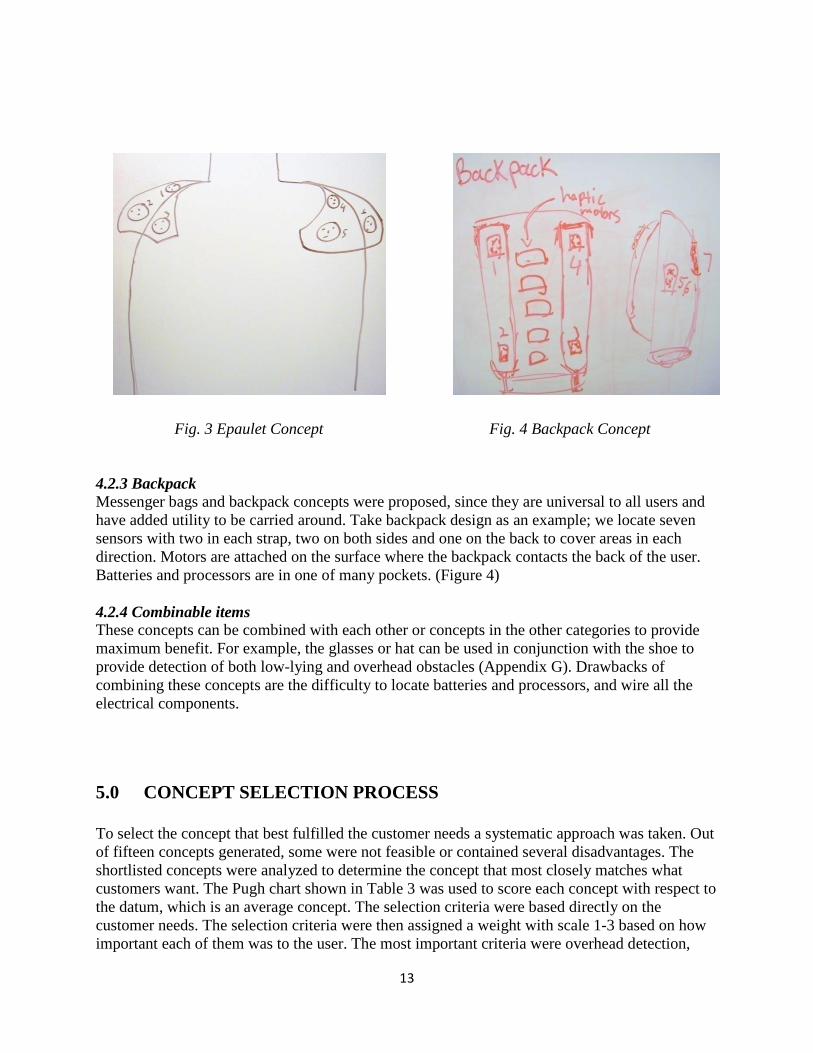
4.2.2 Clothing / Ornament Concepts in this category are to be worn or carried around by the user. They contain common clothing items such as shirt, pant and vest. Ornaments such as scarf and epaulette are also included in this category. These concepts have relatively large contact surface area for the motors to be distributed, and are also fashionable. The vest concept is one of the best clothing designs. As shown in Figure 2, it has five sensors with two housed in the front shoulder area, two near the side and one in the back. They will cover front, back, overhead and side directions. Haptic motors are attached inside the vest both in front and back to give better vibration feedbacks. Batteries and processors are put in the pockets nearby so that fewer wires are needed to connect each component. The epaulette design has six sensors located on both sides to detect obstacles in all direction. Haptic motors are inside the epaulet, giving vibration feedback on the shoulder of the user. The concept is superior in detecting overhead and side obstacle. However, has a problem of locating batteries and microcontroller and it may not be aesthetically pleasing. Additional attachment has to be made to connect batteries and other electrical components. (Figure 3)
Fig. 1 Belt Design Fig. 2 Vest Design
13
4.2.3 Backpack Messenger bags and backpack concepts were proposed, since they are universal to all users and have added utility to be carried around. Take backpack design as an example; we locate seven sensors with two in each strap, two on both sides and one on the back to cover areas in each direction. Motors are attached on the surface where the backpack contacts the back of the user. Batteries and processors are in one of many pockets. (Figure 4) 4.2.4 Combinable items These concepts can be combined with each other or concepts in the other categories to provide maximum benefit. For example, the glasses or hat can be used in conjunction with the shoe to provide detection of both low-lying and overhead obstacles (Appendix G). Drawbacks of combining these concepts are the difficulty to locate batteries and processors, and wire all the electrical components.
5.0 CONCEPT SELECTION PROCESS
To select the concept that best fulfilled the customer needs a systematic approach was taken. Out of fifteen concepts generated, some were not feasible or contained several disadvantages. The shortlisted concepts were analyzed to determine the concept that most closely matches what customers want. The Pugh chart shown in Table 3 was used to score each concept with respect to the datum, which is an average concept. The selection criteria were based directly on the customer needs. The selection criteria were then assigned a weight with scale 1-3 based on how important each of them was to the user. The most important criteria were overhead detection,
Fig. 3 Epaulet Concept Fig. 4 Backpack Concept

14
front, side and back detection, ease of use, and adaptability to user size. The final concept was selected by comparing some of the concepts to determine which ones met the selection criteria best. Table 3. Initial Concept Selection Pugh Chart
Each concept had advantages in certain areas and disadvantages in other areas. Although it’s important to meet all customer needs, there are trade-offs for fulfilling certain criteria. We realize the limitations of the concept and focused more on fulfilling the most important criteria. Based on the Pugh chart analysis, the vest design fulfilled most customer needs. Overhead, front, side and back obstacle detection can be fulfilled by placing sensors in the front, back and shoulder area as shown in Figure 2. The batteries and on/off switch will be located in the pockets to make the device easy to use. Although, adaptability to size is somewhat difficult, it can be made to fit most adults by having adjustable straps to loosen or tighten the vest. The messenger bag concept ranked second mainly due to the issue of motion isolation. The strap where the sensors would be placed will move significantly when walking. This reduces the accuracy of the signals and may unintentionally force the user to walk in a certain way to avoid strap movement. It will also make the device less reliable and thereby less likely to be used by visually impaired people. After the vest design was indicated by the Pugh chart we constructed as the best design, we brought this concept to Leader Dogs for the Blind. There we met with a group of professionals who teach visually impaired people in the use of guide dogs and other assistive technologies. They have a large amount of experience with both successful and failed technology. They informed us that any device we design must have universal appeal; a vest might not be practical in all weather conditions and might not be considered fashionable by some. When we approached our design process, we were under the assumption that a visually impaired customer

15
would be willing to sacrifice form for function. We were told that if a sighted person would be embarrassed to wear a device in a public setting, someone who is visually impaired will also be embarrassed. We decided to re-evaluate previous concepts that did not make it into our final pool of designs. The back pack concept was re-evaluated and refined. The initial concept is shown in figure 4. We felt initially that a back pack would have the universal appeal required for the device to sell. We created a revised second Pugh chart, shown in Table 4 that takes aesthetics into account. While it is difficult to quantify this type of characteristic, it is possible to identify a universally aesthetic/fashionable design. The revised Pugh chart indicates that the back pack design is superior to the others. After weighing the benefits of the back pack with other designs, we have decided on the back pack as our alpha design. Table 4. Second Concept Selection Pugh Chart
6.0 CONCEPT DESCRIPTION Progressing from a selected concept towards a prototype will require knowledge of how electrical components work together and programming. Furthermore, protecting the electrical components housing will be necessary, which requires solid mechanics knowledge. As shown in Figure 5, sensors, processor and haptic feedback systems are needed to satisfy engineering specifications. The functional decomposition shown in Appendix H shows how these components fit together and what function they fulfill.

16
Six sensors will be used to scan the environment and provide the information to the processor. The processor will need to be programmed to convert information obtained from the sensors to trigger haptic response through the five motors. The sensors are located as shown in Figures 6 and Figure 7 to allow the user to have situational awareness in all directions. The motor and the processor locations are also shown in the figures below.
As shown in the figure there are two sensors that detect objects directly in front of the user. A larger cone of detection is necessary in the front direction since it is most important for the user to know what is happening directly in front of them. In order to provide this larger cone of detection, two sensors were used. Six motors were used correspondingly to provide haptic feedback. The motors are programmed to use patterns to convey obstacle distance. When the obstacle is close to the user, the motor outputs more pulses per second and when the obstacle is farther away it outputs less pulses per second.
The electrical components work together to allow for the device to work properly. The ultrasonic sensors transmit sound waves and receive an echo that is reflected back from an object. The time it takes for the signal to be sent and received is calculated and used to the distance to the object.
Fig. 5 System Block Diagram
Fig 6: Layout Drawing of Backpack
– Side View
Fig7: Layout Drawing of Backpack
– Back View

17
Using a computer program to write code will enable us to use the information from the sensor in a meaningful way. The program will allow us to take the input from the sensor and use it to activate the motor at each particular location.
The battery will be used to power the processor. The power out pin from the processor can be used to provide a constant power to the sensors. Due to the power conditions required for the motor, it can’t be connected to the power out in on the processor like the sensors. A DC to DC converter and transistors need to be used in connection with the battery to provide the proper voltage and current to the motor.
The device has a main power switch which is placed on the right side of the backpack which is connected to the battery. This switch can be used to turn the device on and off by the user. When the switch is in off mode, the battery can be plugged into the charger for charging.
Apart from the main power switch, the prototype also has five switches located on the left side of the backpack. Each of the five switches corresponds to one of the motors. This allows the user to turn off a certain motor when they are aware of the obstacle. For example, the user may be walking next to a friend. Since they already know there is a person next to them, the user can turn off the side motor switch to disable vibrations for that area without losing the information about the rest of the environment.
For better understanding of how the electrical components work, a circuit diagram is provided in Appendix I.
7.0 ENGINEERING DESIGN PARAMETER ANALYSIS Before finalizing design from concept all electrical components need to be selected and located through engineering analysis. The selection of sensors, processor and haptic feedback system will be based on their characteristics and whether or not they are suitable for our application. For example the processor needs to have enough I/O lines to be able to connect to the sensors and the feedbacks system. One of the important criteria, in haptic motor selection is the ability of the haptic motor to be felt through winter clothing. If the vibration felt is weak due to the extra layers of clothing, it may create confusion for the user. The selection of locations will be based on whether the sensors interfere with each other, and motors are providing strong and straight-forward feedback. The selection for enclosures to protect the electrical components was based on the dimensions of the component. The major material selection criterion for the housing was high impact resistance and water resistance. The chosen material was ABS plastic since it met all the requirements well, was low cost and is the material that is most commonly used for enclosing electrical components. After the material selection, the enclosures were bought off-the-shelf and modified to customize for our needs. However, when the product is mass produced, injection molding would be the best choice for manufacturing customized enclosures. Environmental impact of the

18
enclosures were also considered by comparing the material with polystyrene .Based on the analysis, ABS plastic has relatively lower impact on the environment. Further details can be found in Appendix C. Analysis was conducted to determine safety considerations for the system through DesignSafe and FMEA table. Major safety concerns were damage due to short circuit and water damage. Causes for these risks and ways to reduce the risk of these concerns were also determined. Further details can be found in Appendix C.
7.1 Electrical Components This section will include an analysis of the electrical components that will be used to fulfill the engineering specifications. A brief description of how each component functions and interacts with other components will be included. Also, the process used to select the components will be described. The electrical components of the system include the microcontroller board, the ultrasonic sensor, haptic motor, transistors, DC to DC convertor, and battery. A schematic is shown in Appendix I which shows how these components work together.
7.1.1 Arduino Microcontroller Board The Arduino Duemilanove is considered the brain of our system. It controls the sensors and the haptic motors to scan properly and provide feedback signal depending on the obstacle location. The microcontroller board was selected by understanding some of the features it provided. These features will assist us in fulfilling the engineering specifications set earlier. Some of the important features of the Arduino Duemilanove are shown in table 5. Table 5. Features of the Arduino Duemilanove
Feature Description Digital I/O pins 14 pins with each providing 5 V DC out
6 pins can be used as PWM outputs Analog Input Pins 6 DC Current per I/O Pin 40 mA External Power Supply Input 7 – 12 V DC Built-in Voltage Regulator Reduces voltage to 5 V to power microcontroller Microcontroller ATmega328 USB Connection For communication with computer software Flash Memory 16 KB Clock Speed 16 MHz Dimensions 2.7 inch X 2.1 inch Power Jack To connect 9V adapter or battery
The Arduino Duemilanove has several features that are desirable. The Arduino Duemilanove contains a microcontroller (ATMEGA 328) that can be programmed. The software code can be downloaded onto the board by the provided USB connection. The board requires a power supply that is between 7 to 12 V. The built-in voltage regulator steps down the voltage to a constant 5 V. It contains 20 digital I/O pins with each pin supplying 5 V and 40 mA. The Arduino

19
Duemilanove will be used in our project to receive input from the sensors and provide feedback to the user through the motors.
7.1.2 Sensor Through research of similar obstacle detection devices and robotic devices used in industry, different sensor techniques were discovered. The most common methods used are by the use of Ultrasonic sensors, radar and laser. This section includes the selection process we used to determine ultrasonic sensors are best suited for our needs.
7.1.2.1 Ultrasonic Sensor Sensor Functionality: The ultrasonic sensor, known as transceiver “transmits “and “receives” signals from each of the cylinders as shown in Fig. 8. It sends out high frequency sound wave and once the signal hits the object, it returns back to the sensor. The time period of returning is called the “echo.” The Ultrasonic sensor determines the obstacle distance by calculating the time interval between sending the signal and receiving the echo.
Sensor Description: The Ping Ultrasonic Sensor will be used to detect obstacles in the environment through sound waves. It is compatible with the Arduino Duemilanove and requires only one digital I/O pin. Furthermore, it is compact and small in size and requires a 5 V power supply. Temperature has an effect on the speed of sound in air that is measurable by the PING))) sensor. If the temperature (°C) is known, the formula to determine the speed of sound in air: Cair = 331.5+ (0.6× T) m/s At temperatures over the sensor’s operating range of 0 to 70 ° C, the Ping Ultrasonic Sensor looses accuracy of signal by approximately 10%. However, conversion constants may be used in the code to account for air temperature.
7.1.2.2 Radar Sensor Sensor Functionality: The radar sensor detects obstacles at a long range and broad angle of sweep with high precision. Typical radar sensor is shown in Fig. 10. The radar sensor sends out
Fig. 9 Ultrasonic Sensor 3D Drawing
Fig.8 Ping Ultrasonic Sensor
20
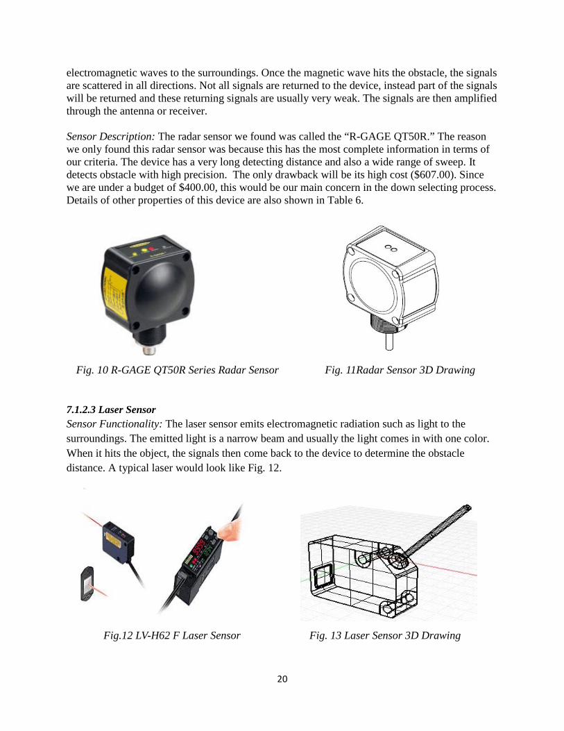
electromagnetic waves to the surroundings. Once the magnetic wave hits the obstacle, the signals are scattered in all directions. Not all signals are returned to the device, instead part of the signals will be returned and these returning signals are usually very weak. The signals are then amplified through the antenna or receiver. Sensor Description: The radar sensor we found was called the “R-GAGE QT50R.” The reason we only found this radar sensor was because this has the most complete information in terms of our criteria. The device has a very long detecting distance and also a wide range of sweep. It detects obstacle with high precision. The only drawback will be its high cost ($607.00). Since we are under a budget of $400.00, this would be our main concern in the down selecting process. Details of other properties of this device are also shown in Table 6.
7.1.2.3 Laser Sensor Sensor Functionality: The laser sensor emits electromagnetic radiation such as light to the surroundings. The emitted light is a narrow beam and usually the light comes in with one color. When it hits the object, the signals then come back to the device to determine the obstacle distance. A typical laser would look like Fig. 12.
Fig. 10 R-GAGE QT50R Series Radar Sensor
Fig. 11Radar Sensor 3D Drawing
Fig.12 LV-H62 F Laser Sensor
Fig. 13 Laser Sensor 3D Drawing

21
Sensor Description: The laser sensor has a limited angle of sweep. It aims more toward a one directional detection. The device could detect up to a very large range with very high precision. The laser sensor could be bulky depends on the scale, but most small laser sensors are relatively light. The cost of the laser sensor varies depends on the range. However, most laser sensors are over $100.00, which again raises the concern of our budget control. Table 6: Sensor Information [13-17]
7.1.2.4 Comparison between Ultrasonic, Radar and Laser Sensors There are pros and cons to each type of sensor. They do share common advantage of having a reasonable obstacle detection range. However, only ultrasonic sensor and radar sensor provide that angle of sweep, which is what we desire. Laser sensor and radar sensor have the ability to detect obstacle with very high precision. The tradeoff for that would be their relatively high cost and relative bulky size. With the budget constraint and request of “wearable”, the ultrasonic sensor will be preferred. A hybrid system could be implemented as shown in Fig. 14. So we have two sensors operating at the same time. The ultrasonic sensor could provide a broad angle of sweep while the laser sensor could be its complementary in detecting specific obstacle in high precision. However due to time and budget constraints this has not been done in our prototype.
Fig.14. Hybrid Sensors Incorporated

22
7.1.2.5 Sensor Analysis We ran through our current sensors into the Pugh chart as shown in Table 7. We have 3 types of ultrasonic sensors, 1 radar sensor and 1 laser sensor. We listed the criteria we want to evaluate and assign a weight scale of 1 to 9. Higher weight means higher level of importance. Several main criteria we considered would be the angle of sweep, detection range, ingress resistance and temperature resistance range. After we ran through the Pugh chart, we concluded that the ultrasonic range finder is the winner for most sensors. However, a hybrid system may be needed. We are currently exploring the details of implementing a combination of sensors in our design. However, after further looking into how the sensor interacts with the microcontroller, we realized that the Ping Ultrasonic Sensor will be better suited for our needs since it requires only one digital I/O pin. Also, due to time and budget constraints a hybrid system has not been implemented in our prototype.
Table 7. Sensor Pugh Chart
7.1.3 Shaftless Vibration Motor The shaftless vibration motor will be used to provide tactile feedback to the user. From this feedback, the user will be able to interpret and understand the surrounding. It requires a 3 V power supply to function. We will not be able to connect the motor directly to the Arduino board since it requires a voltage that is lower than the 5 V provided by the Arduino board. Also, it requires a current higher than the 40 [mA] provided by the Arduino board. The vibration motor is 10 mm in diameter and 3.4 mm in height, has a vibration amplitude of 0.75g and has a rotational speed range of 12000 - 15900 RPM and requires a current range of 50 [mA] to 80 [mA] and voltage range of 2.5 V to 3.5 V.

23
7.1.4 DC to DC converter The DC to DC converter will be used to convert the higher voltage provided by the power supply into 3 V, to ensure that proper voltage is supplied to the shaftless vibration motor. Initially, a voltage regulator was selected to be used. However the advantages of the DC to DC converter exceeded those of the voltage regulator and therefore it was better for this application. The DC to DC converter is more efficient than the voltage regulator in converting the higher voltage into lower voltage. Due to this increased efficiency, heat dissipation is greatly reduced. Also, the DC to DC converter has a variable voltage input which will allow more flexibility when selecting a battery.
7.1.5 Transistor The transistor is needed to control the output in proportion to the input signal. The motor needs a higher current than the 40 mA the Arduino can provide. The transistor can be used to amplify the current to allow the motor to function properly. Furthermore, the transistor can be used for the on and off function of the motor. This can be used with the PWM digital output to adjust the duty cycle. By doing this, the motor will be able to provide different patterns to the user to convey a variety of information.
7.1.6 Battery The battery for the system was chosen based on the current draw for the system. An experiment to test the current draw of the system was done to obtain a more accurate number. Using this information, a battery was selected based on the current capacity given in the specification. This information can also be used to determine the battery life. To better meet the needs of the customer, we decided to use rechargeable batteries instead of regular alkaline batteries. The battery selected was a Ni MH rechargeable battery pack that provides 9.6 V and 1600mAh. The battery will need to be charged for 10 hours to be fully charged. Based on the current draw test, the minimum current draw is 100 [mA] and the maximum current draw is 400 [mA]. This provides a battery life of 4 to 10 hours depending on the environment.
7.2 Material Selection We selected ABS plastic as the material for our housing. ABS plastic is very durable and can perform over a large range of temperatures. It is commonly used in many consumer appliances so we came across it when evaluating other consumer products. We then used CES Material Selector to evaluate this material compared to other plastics. The results shown in Appendix C indicate that ABS plastic has both high impact strength and is low cost.ABS plastic is a thermoplastic that can be melted and formed; while our process does not use this aspect of the material, if our device were to be mass produced there would be no need to change the material for the housing to accommodate high volume processes.

24
7.3 Enclosure for Electrical Components This section will include information about the housing for electrical components that will be used to fulfill the engineering specifications. The process used to select these enclosures will be described.
7.3.1 Microcontroller Housing Because of the difficulty anticipating the amount of space required for wires attached to the microcontroller board, a larger housing was used to contain the microcontroller. To cut down on manufacturing time and costs, an off- the-shelf housing was used. This housing will need to be drilled to allow standoffs to hold the board, and a faceplate will be needed to protect the housing. The faceplate will allow for an opening for USB and power jack. After being mated, the upper and lower halves of the housing will achieve the IP protection required, it is also made from ABS plastic, which meets our temperature and impact resistance requirements. Figure 15 shows the housing we are using. The batteries will also be housed in this case if space permits.
Figure 15. Housing for microcontroller.
7.3.2 Sensor Housing Initially we planned on using a custom ABS plastic housing to protect our sensors and achieve the required IP resistance. After consulting manufacturing experts, we decided to go with an off the shelf project box to house our sensors. We were able to find a project box with similar dimensions to the custom box we designed. The project box is made of ABS plastic, so it will display similar mechanical properties. The project box we selected meets our IP requirements and will reduce manufacturing time and cost. It will also allow us to focus our time on validating our design and troubleshooting. The disadvantage of using the project box instead of a custom box is that the project box is larger and will have extra space that will go to waste. It is also necessary for the housing to be compact, since it will need to fit on a standard backpack strap. The dimensions of the box were well suited to fit within the strap width of standard backpacks. The selected project box is shown in Figure 16.

25
Fig. 16. The ABS Plastic 2-9/16” × 1-3/4” × 1-1/4”
7.3.3 Proto-board Housing Another microcontroller housing was used to protect two proto-boards. One of the proto-boards contained the transistors and the DC to DC converter and the particular connections. The other proto-board contained the common ground for the system and the 5 V line for the sensor.
7.4 Backpack Selection The backpack we are going to use will be a standard off -the- shelf backpack. It will have two straps since we are going to locate our sensors and motors on both straps. The width of the straps has to be wider than the sensor width plus the housing width so that nothing sticks out the straps. We also want the straps of the backpack to be thick enough so that no screws would be sticking out too much which may be uncomfortable for the users. Additionally, we would want an internal pocket design in the backpack. Since the battery and the microcontroller are going to be placed inside the backpack, an upper internal pocket would protect the electrical components from potentially being crushed or damaged by books or other heavy objects.
7.5 Electrical Components Location Selection This section will describe the process we used to determine the location of major electrical components such as the sensors, and the motors.
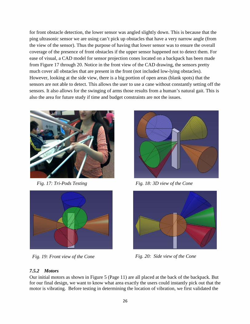
7.5.1 Sensors The method we used for determining the location of the sensors is called the “Tri-pods” testing. The reason for using the tri-pods instead of other methods is because the tri-pods has almost the same projected cone angle (40 degrees) as that of the sensors. It also presented a physical cone we were able to use to test obstacle detection. Tripods were placed on the strap of the backpack, and the experimenter approached an obstacle. We were then able to see if the object was in the range of the sensors. By using this method, we are able to see, at a particular location, if the cone is able to detect the obstacles as we expected it to. We pay more emphasis on the detection ability of the front obstacles since most of the time, the user would want to know more of what’s in the front. That is also why we have two sensors on one strap to detect front obstacles. Notice
26
for front obstacle detection, the lower sensor was angled slightly down. This is because that the ping ultrasonic sensor we are using can’t pick up obstacles that have a very narrow angle (from the view of the sensor). Thus the purpose of having that lower sensor was to ensure the overall coverage of the presence of front obstacles if the upper sensor happened not to detect them. For ease of visual, a CAD model for sensor projection cones located on a backpack has been made from Figure 17 through 20. Notice in the front view of the CAD drawing, the sensors pretty much cover all obstacles that are present in the front (not included low-lying obstacles). However, looking at the side view, there is a big portion of open areas (blank spots) that the sensors are not able to detect. This allows the user to use a cane without constantly setting off the sensors. It also allows for the swinging of arms those results from a human’s natural gait. This is also the area for future study if time and budget constraints are not the issues.
7.5.2 Motors Our initial motors as shown in Figure 5 (Page 11) are all placed at the back of the backpack. But for our final design, we want to know what area exactly the users could instantly pick out that the motor is vibrating. Before testing in determining the location of vibration, we first validated the
Fig. 17: Tri-Pods Testing
Fig. 18: 3D view of the Cone
Fig. 19: Front view of the Cone
Fig. 20: Side view of the Cone

27
functionality of the motors. As shown in Fig. 21 and Fig. 23, we connected the motor wires to the circuit board and from there connected to tape AA batteries in series. Each battery is 1.5 volts so that two double A batteries in series will provide 3V to operate the motors. With proper connections, the motor started to vibrate as expected. Figure 22, shows the taping method we used for testing the motor location. Since haptic feedback must be felt over winter coat, we want the motor position to be in close contact with the body. Any loose contact position such as in the lower back of the backpack may not provide strong enough feedback to the users. Thus the best locations of close contacts will be somewhere on the straps and upper back of the backpack. After testing different areas of contacts, we have concluded on spots that gave the most distinguished feedback as shown in Fig. 24 and Fig. 25. Notice the position of the motors; they are placed for ease of memory. The only thing users have to know is the front motor is located on the left side of their chests as shown in Fig. 25.
Fig. 21: Motor Connection Check Fig.22: Taping Method to Test
Fig.23: Motor Connection Check

28
8.0 FINAL DESIGN DESCRIPTION Final design will be described along with the techniques to mechanically attach them onto the prototype. The major components and their selection process were in the previous section. Furthermore, all components ordered are listed in Appendix A, the Bill of Materials. We will also discuss the deviations of prototype from our final design, and briefly describe how we will validate the final design.
8.1 Location of Major Electrical Components Based on our customer requirements and engineering specifications as well as advice obtained from the experts at “Leader Dog for the Blind”, we came to our final decision of the backpack design. The backpack design has a more universal appeal and adds more utility to the users. The figure at the end of Appendix G shows our initial locations of the electrical components. All the six motors are placed in the back area of the backpack and three of the sensors are placed on the straps, two sensors on each side and one on the back. Battery and processor are placed at the bottom of the backpack. In contrast with that, Figure 21 shows the final locations of the electrical components. Now the battery and the processor have been moved up to the upper internal pocket of the backpack (see backpack selection section). Sensor location has also been changed. As shown in Fig. 21, there are two sensors on the right strap (back view) that is now designed for detecting front obstacles. The one on the left upper strap is designed for detecting overhead obstacle. The two on the sides are remained unchanged for detecting side obstacles. We also reduced the amount of motors to five, because only one motor is needed to provide feedbacks of obstacles in the front. The switches are located in below the side motors. One switch acts as the main switch for the system and an array of five switches are used to control individual motors.
Left Side Right Side
Back
Front Overhead
Fig. 24: Motor Placement in the back Fig. 25: Motor Placement in the front

29
8.2 Attachment Techniques This section will include details about how the components such as sensor housing and the motors were attached onto the backpack.
8.2.1 Sensors The sensors would be housed to be protected from rain and to be attached to the backpack. The sensor housing will consist of 2 parts made from ABS plastic. They are sized to contain the sensor and connectors without being too large. The housing has no extra, unnecessary space that would reduce its invisibility. Figure 22 shows the CAD model of our housing. The two parts of the housing will be mated using screws, and the surfaces will make contact with enough tolerance to prevent a .1” wire from entering the housing when the two halves are mated. The top of the housing will have holes that allow the ultrasonic transmitter and receiver to be exposed; covering these areas would prevent the sensor from working. The area between the sensor transmitter/receiver and the housing will be sealed using a silicon sealant, this will prevent any particles, tools, or water from entering the housing. 2 holes will be drilled on the bottom half of the housing to allow the sensor to be held by standoffs, and 4 larger holes will allow screws that will pass into grommets. A hole on the bottom half will allow wires to pass into the housing, this will be sealed off using silicon sealant
Fig. 21 Final Electrical Component positions

30
Figure 22: CAD model of Sensor housing
The next question is what method we are going to use to attach the housing to the backpack. For our final design, we have brainstormed several ideas of attachments such as using Velcro, stitching, elastic strap wrap and grommets. Upon those choices, we finally decided on using grommets. The reason for that is, unlike Velcro and elastic strap wrap methods, grommets give the strongest connection between the housing and the backpack since it would not allow any loose space in between so that the sensor positioning will not be altered. Grommets also allow the sensor and housing to be detached from the backpack for repair or other needs. A layer of foam will cover anything protruding from the back of the strap to reduce user discomfort, and an iron on patch will hide the components from view. Because our sensors need to be placed at varying angles relative to the ground, spacers can be used between the grommet and screws to offset the housing. Each housing will have 4 screws that go into 4 grommets, ensuring that the sensors are securely attached to the strap and will prevent the housing from moving during user motion. Figure 27 below is a diagram of now the housing will be attached.

31
Figure 23: Grommet layout NOTE: Housing not to scale
8.2.2 Motors Motors will be attached to the bag using an iron on patch, with the motor wires passing into the backpack. This will create an invisible attachment while still allowing the user to feel the haptic feedback. Because the motors are very small, it will be very difficult to create a housing for them and because they meet our IP protection rating, there will be very little value-added in creating a housing for them. Wire strain relief can be achieved by using fabric adhesive to firmly glue the wires to the patch, if the wires experience tension the glue will hold the wire in place and the tension will not be transferred to the delicate solder holding the wire to the motor.
8.3 Coding We plan to provide pattern response to the user by haptic motors, so that the user does not only know that something is within the target distance, but also knows approximately how far it is from him. In other words, the motor will vibrate more frequently while the user gets closer to an obstacle. We believe pattern feedback is superior to intensity feedback, because pattern control is more applicable through coding, and provides a wider range of response to the user than intensity. We confirmed this design with interviewing with professor Gillespie, after he told us people are generally more sensitive to haptic frequency change than intensity change, and illustrated the ease of applying it through coding.

32
8.4 Prototype Deviation The prototype we have fabricated closely resembles our final design. The only change we made is the hybrid sensor design.
8.4.1 Hybrid Sensor Design One aspect that will be dropped is the hybrid sensor design. Originally, we wanted to use both a laser and ultrasonic sensor to pick up both larger obstacles in a larger area and smaller obstacles at a concentrated point. After evaluating this option, it seemed unnecessary as the user would not be interested in the location of very small obstacles, and the laser sensors could be triggered by even the smallest object such as snow. On the other hand, laser sensors are very expensive with a signal one costing more than our whole budget.
8.5 Final Design Validation Our final design will be validated by the prototype in terms of components selections, locations, and attachment methods. According to the material lists (Appendix A), we have carefully selected and ordered electrical and mechanical components for the prototype. The device will be able to pick up most potential obstacles, except for very small objects of interest, due to limitation of the single ultrasonic sensor after we give up the hybrid sensor design. From the tripod test we know sensors will not interfere with each other if we locate sensor housings strictly as the positions shown in Figure 21. Motor locations are also expected to guarantee strong and continuous feedback to the user. Attachment techniques reduce the complexity to manufacture and assembly components together. The pattern design of the code ensures the haptic response is provided accurately and properly to the user. With a detailed final design, we expect the prototype to meet all engineering specifications we have finalized, thus validate the design is on target.
9.0 FABRICATION PLAN This section contains a list of components (purchased and manufactured), a detailed FMEA table, the DesignSafe results, detailed step by step fabrication and assembly plans. FMEA was used to anticipate potential failures that may occur and to evaluate their consequences on the prototype. Based on the results it was determined that some components have higher consequences in case of failure compared to others. For example, the battery and battery charge can be replaced easily and quickly in case of failure. However, the sensor can’t be replaced easily without disassembling the housing and waiting for the sensor to arrive from the vendor. DesignSafe was used to determine the hazards that may result in failure. From the results, the hazards that are high risk are the potential failures that will lead to breakdown of component are due to water or dust, and impact to the component. To reduce these risks the following countermeasures are necessary: proper location, housing, and cushioning for components, and

33
using silicon caulking around the edges and gaps to avoid water and dust from getting through.
9.1 Sensor Housing A project case with similar dimensions was bought and modified using the mill to make proper holes where necessary. The detailed engineering drawings of boxes bought off-the-shelf and the modifications done are shown in Appendix J. Standoffs will be used to protect the printed circuit from being scratched by the bottom surface of the enclosure. An enclosure is necessary to protect the sensors from water, dust and impact damage. However, the transmitter and receiver portions of the sensor can’t be covered since signals are sent and received from them. Silicon caulking was used where there were gaps in the housing. This was done to prevent water from leaking inside the box and causing damage to the sensor circuit board. Finally, black enamel paint was used to conceal the metallic tint of the transmitter and receiver portions of the sensor.
9.2 Microcontroller Housing Detailed Instructions for microcontroller housing can be referred to section 7.2.1.
9.3 Connections All connections will be wired and soldered. Detailed connections can be referred to our circuit diagram. These wires will then be soldered to a proto-board where other components will be located. Notice the connection of the microcontroller, the PWM pins are specifically designed for the motors. Since all the connections were soldered, there’s chance that those connections will come loose. Failure in proper connections may cause the device malfunctioning. Thus we decided using hot glue gun to secure the connections. Hot glue will be applied to connections of motors, sensors, and connections of the microcontroller.
9.4 Proto-boards Two proto-boards were used in this project. They were placed in parallel on top-of the stand-offs and then shielded together with the microcontroller housing. One of the proto-board was used for the connection between the DC-DC converter and transistors. This provides an easy way to attach components and solder wires to the components. The other one was used for ground rail connection and 5V rail connection for the sensors.
9.5 Sensor-to-backpack attachment The sensor will be attached to the backpack using grommets which will be punched into the strap using a special grommet tool. The screws from the housing will then be placed through the grommets and a nut will tighten it down. Since we used grommets for sensor housing attachments to the backpack, there are some screws that are sticking out the backpack. This would be uncomfortable for the users who are wearing the backpack. Thus we trim down the screws and put some foam under and taped it outside so that would add some comfort to the users. Sensor location was then be calibrated by adding spacers until the desired sensor orientation is achieved.
9.6 Switches Six switches are needed for this device. One of them is for controlling the entire system. This switch will be mounted sideways (horizontal) on the lower left side of the backpack pocket (front view of the backpack). So if the user turns on the switch (toward the user direction), the battery

34
will power up the entire system and if the user turns off the switch (away from the user direction), the battery will stop powering the device and thus the battery can be recharged through the wall. The rest of the five switches are for controlling different sectors so that it gives more flexibility to the users. These switches are mounted in an array (vertical direction) on a project box shown in Fig. 24. and the project box is mounted on the lower right side of the backpack pocket (front view of the backpack). The mounting technique for that power switch is just cutting two holes on the backpack and use wires to tighten the switch. The mounting technique for the array of switches to the project box is milling out square spaces on the project box and leaving enough space for each switch to slide in. We used the grommet mounting method for the project box (switches) which was the same as the method used for the housing for the sensor.
Fig. 24 Switches in an array
9.7 Iron-on patches In order to achieve 0% wire exposure, we decided to use iron-on patches to cover the wires exposed. To do that, we purchased some iron-on patches and cut it into the desired size and use heat to secure the attachment between the patch and the exposed wires. Motors were also secured onto the backpack using this method. Heat was only used around the motor and not directly on top of it to avoid damage to motor.
9.8 Component and Material Inventory We used an old backpack provided by one of our team members. For further details on backpack selection process refer the parameter analysis section to understand some of the key features necessary. All items and equipment necessary such as milling machine and electrical tools were all provided from University of Michigan Labs. Housings for the microcontroller and the proto boards were provided by John Baker-Systems Engineer at University of Michigan. All other components were bought on websites or local stores, which are listed in the Appendix A with proper vendors, websites and prices provided.
9.9 FMEA Summary FMEA was done to predict what may cause the device to fail. The detailed FMEA table is included in Appendix K. From the results of FMEA, some electrical components may fail due to water, dust, impact, short circuit or improper operating range. Water, dust and impact damage may be reduced by providing proper protection to the components. For example using an enclosure for the sensor and the Arduino board will protect them from water, dust and impact.

35
Furthermore, standoffs will be used to protect the circuits of the Arduino board and the sensors from being in contact with the enclosure surface. This is important because the enclosure surface may scratch the circuit, which may result in malfunctioning components. Checking datasheets to make sure the proper voltage and current for each component can be provided will enable us to avoid failure of components due to improper operating range. Double checking to make sure all components are properly wired will avoid failures due to short circuit.
9.10 Designsafe Summary DesignSafe was used to understand some of the hazards that may cause damage to the manufactured housing. The detailed report from DesignSafe is shown in the Appendix L. From the report, major risks of enclosure failure are due to water, dust, impact and crushing. To reduce these risks countermeasures will be applied. To reduce the risk of water and dust from getting into through cracks and edges, silicon caulking will be used to seal any small crevices. Proper material selection and placement location of the enclosure will reduce damage due to impact and crushing. For example, using a material that has high impact strength and locating the enclosure away from the bottom of the backpack will protect it from impact and crushing.
10.0 VALIDATION RESULTS Several validation tests were conducted to determine how well the prototype met the minimum targets and bonus targets. Test procedure and results are shown in this section.
10.1 Minimum Targets Validation Our design was validated to determine whether minimum targets for the engineering specifications were met. We have conducted several tests in a systematic way. We list all engineering specifications and the corresponding validation experiments we planned to do in Table 8. However, not all experiments can be done due to complexity, financial limitations and time constraint. The table also provides information on what test was conducted and the brief result. Each experiment will be analyzed in detail later in the section. Table 8: Minimum Targets Validation Experiments and Results
Engineering Specification Target Value Validation Experiment
Conducted? Successful?
Battery Life >5 hours Current Draw Test Yes Yes Accuracy of Signals 95% Sensor Functionality
Test Yes No Yes
Obstacle Detection Range Up to 5 feet Yes Yes Ingress Resistance >IP34 Mechanical Housing
Test Yes Yes
Overhead Height Detection 2 ft above neck Overhead Test Yes Yes Start-up Time <15 seconds Start-up Test Yes Yes Exposed Electronics 0 % Appearance Test Yes Yes

36
Shock to frame >5ft drop test Drop Test Improvement needed
Yes
Weight < 3.5 pounds Weight Measurement Yes Yes Cost <400 USD Budget Calculation Yes Yes Operation Temperature Range -40 to 120 F Cold Room Test Improvement
needed Yes
Amount of Training Required <20 hours N/A No Yes Noise Generated <20dB Noise Measurement No N/A Accuracy of Failure Detection 95% Overall Failure Test No No
10.1.1 Current Draw Test To obtain an accurate current draw value to order proper batteries, the Current Draw Test was conducted. The circuit diagram is shown in Figure 25.
Figure 25: Circuit Diagram for current draw test
As shown in the diagram, Multimeter #1 was connected between the battery and whole system in series to test current flow, and Multimeter #2 was in parallel with the whole system to determine battery voltage input. A power supply was used to provide 9 V power to the Arduino board, and to five motors through a DC-DC converter and five transistors. This test was done with the system connected on the proto-board before any components were assembled onto the backpack. The current draw measured was 400 [mA], with all electrical components on and all motors vibrating at full speed. It fell to 100 [mA] with all motors off and other components on. We then bought a Ni-MH battery with 1600 [mAH] to meet the battery life requirement. The battery is able to power the device for at least 5 hours, since it is unlikely that all motors are on when user is walking around with it, besides the user can always turn specific motors off if they

37
don’t need them in a familiar environment. As we discussed in Parameter Analysis section, this battery was ordered for its low cost and has a good battery life. The battery life was validated by using the prototype during the Design Expo during which the battery lasted for more than 6 hours. 10.1.2 Sensor Functionality Test We conducted some tests on sensors for detection range and accuracy of signal before the whole device was assembled. The setup is shown in Fig. 26.
Figure 26: Circuit Diagram for Sensor functionality test
As shown in Figure 26, the sensor was connected to the microcontroller, which was connected to a laptop providing power to the system. Code was programmed beforehand to trigger the sensor, and the distance measured by sensor was displayed on monitor through the Arduino software. We then walked more than five feet away from the sensor and observed the monitor; it gave out a reading greater than five feet, which means that the sensor is able to detect obstacle as large as a person within five feet. Small obstacles such as a hand or book can also be detected at a similar distances. The smallest object that the sensor was able to pick up was a pencil, which is about 1 inch in diameter. The sensor was not able to detect the tip of a ball point pen even when it was placed within 5 inches. In conclusion, the detection range test was successful, since the sensor could pick up obstacles that we were both small and large in size for ranges greater than five feet. To test the accuracy of signal, we enabled all six sensors and tracked the reading history of each by setting up a two dimension array in the code. To obtain enough data we output one set of ten readings each time, with the array size to be 6×10. In the beginning of the test, we placed sensors next to each other without an angle difference; the results were not satisfying at all. Constantly there were one or two readings that were significantly different from the rest in every set of ten data points, and it happened to more than one sensor. Initially we planned to solve this problem by taking the average of every ten readings, and trigger the motor afterwards. However, this method was given up because even when we set up the delay between each sensor at the minimum amount (20 [ms] according to spec sheet), the motor wouldn’t get a response after 1200 [ms] with the loop running through the 6×10 array one single time. This delay was more

38
than one second, which means that the pattern will have a unit interval of at least 1 [s]. This is not acceptable since people generally walk 2 feet every second. If we reduced the set of data to five, the average would not be accurate because of the small amount of population. Fortunately after we assembled all sensors onto the backpack and ran the accuracy test again, the results turned out to be much better with about one offset reading among a set of twenty. We concluded that the trouble caused by interfering between sensors was underestimated, and the accuracy of signal can be raised up to more than 95% if we locate the sensors with proper angle to ensure no interfering occurs. We also recommend coming up with better ways to filter data through code if more time was available. 10.1.3 Mechanical Housing Test Once fabrication of the mechanical housing for the sensor was completed, it was tested for ingress protection rating. Based on our target value “IP34”, which means that the device will be protected against insertion of objects with diameter no greater than 2.5 [mm], and will not become damaged while it is exposed to splashing water in every direction, we tried to insert wire of 22AWG with diameter 2.3±0.1 [mm]. It was impossible for the wire to damage the sensor in any way even when we tried to insert the wire into the sensor head that sticks out of the housing. We also splashed water on the housing, and there was no sign that of water entering inside the enclosure. The enclosure remained undamaged, and the sensor worked normally afterwards. 10.1.4 Overhead Test The overhead test was easily conducted by placing an obstacle above shoulder at1 feet, 2 feet and 3 feet. The motor worked well at 1 and 2 feet, and stopped working at 3 feet, which was what we expected because generally an obstacle 3 feet above shoulder won’t get in the way of a user’s head and conveying this information to the user might result in information overload or confusion. 10.1.5 Start-up Test We measured the time from turning on the switch until the time we started feeling the vibration of motors to be approximately 10 seconds, which means we meet the target value of less than 15 seconds. 10.1.6 Appearance Test According to the final prototype picture from different angles shown from Figure 27 to Figure 28, the 0% exposed electronics target was met. Any wires that were visible on the backpack surface was covered up properly using iron-on patches.
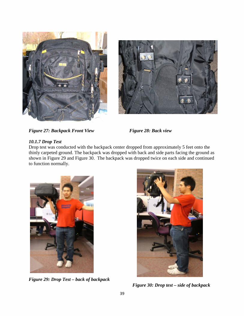
39
Figure 27: Backpack Front View Figure 28: Back view 10.1.7 Drop Test Drop test was conducted with the backpack center dropped from approximately 5 feet onto the thinly carpeted ground. The backpack was dropped with back and side parts facing the ground as shown in Figure 29 and Figure 30. The backpack was dropped twice on each side and continued to function normally.
Figure 29: Drop Test – back of backpack Figure 30: Drop test – side of backpack

40
This test could have been improved if we had access to an accelerator. The accelerometer could be attached onto the backpack and analysis of the peak acceleration experienced could be recorded through LabView program. 10.1.8 Weight Measurement The total weight of this device (along with the backpack) was measured to be 2.5 pounds, meeting the target value of less than 3.5 pounds. 10.1.9 Budget Calculation The overall cost of the project is $ 402, slightly over our $400 budget. We treat it as successful, since we have met more than minimum targets with only $2 more than budget. Details can be seen in Appendix A, Bill of Materials. 10.1.10 Cold Room Test According to the specification sheet of sensors and motors, the operating temperature range is 32 F to 120 F. To validate the temperature range we conducted a test to determine if the device functions properly at low temperatures. We planned to do this by using the freezer room at a local grocery store for a certain period of time and observe functionality of the device. We contacted Kroger and Busch in Ann Arbor, but they were both unwilling to allow us get access into the cold room. The tests had to be conducted in the open refrigerator zone for dairy products with temperature around 40 F, and in the open-door refrigerator for ice-cream at 32 F. The device proved to be working well. The test was conducted only for five minutes. A longer period of time may be necessary to determine if there is any change in the accuracy of signal obtained. To improve this test we need to get access to a temperate adjustable cold room and place the device for more than half an hour inside for testing. The room should also be large enough so that we can walk around and test the accuracy of signal. Also for the minimum target value that we set in the engineering specification, -40 F was unable to be tested for since we didn’t have access to a temperature adjustable cold room. 10.1.11 Amount of Training Required It’s difficult to conduct any tests to validate this specification target, due to variety of learning ability of people. However, according to engineering analysis of motor locations, which are aimed to give the easiest and most straight-forward haptic feedback to the user, we believe that the “<20 hours” goal will be met. If further time was available the prototype could have been taken to the Leader Dog for the Blind to help us determine a more accurate training time required. 10.1.12 Noise Measurement Due to equipment limitation we could not measure the noised generated by the device, but we do know this noise level is within tolerance of human beings. The noise generated is mainly from the vibrations of the motor and not the ultrasound. The noise generated by the ultrasound is too low for human hearing range. However, since animals have a higher hearing range compared to humans, we tried using the device near an untrained dog. Although the dog moved away after we turned on the device, specific conclusions can’t be draw since we were not sure if it’s because of

41
the noise of the motors, or the noise generated by ultrasonic sensors; we also did not know if a trained dog is resistible to the noise, and if a dog can be trained to get used to this noise. Due to time constraint we didn’t have a chance to try this device in Leader Dogs. We recommend doing this to test a dog’s tolerance to the noise generated by the device. 10.1.13 Overall Failure Test Due to complexity of code and limited time we did not initiate failure detection function for the device. We made ambitious goals for this project, and unfortunately we were not able to accomplish all of them. However, we do have recommendations of ways to do it, to improve the overall level of performance of the prototype. Details will be discussed in recommendation section. However, as the battery gets drained, the amplitude of the vibrations get weaker. After a little bit of training, users can understand what this is conveying. 10.2 Bonus Targets Validation As the project went on we became aware that engineering specifications other than those we set at the beginning of the project could also be important to the success of the device, and would bring even more convenience to the user. We set up new targets for these new ideas, and validated them to the best extent. We listed these bonus targets in Table 9 with methods to test it and results we got. All these targets require a lot of effort on code improvement. Each experiment will be discussed in detail in the section. Table 9. Bonus Targets Validations Experiments and Results
Targets Validation Experiment Successful? Pattern is distinguishable and variable within target range
Motor Pattern Test Improvement needed
Front, side and back detection has maximum range more than 5 feet
Front, Side and Back Test Yes
Overhead detection has a minimum range Overhead Test Yes Low lying detection has a maximum range Low Lying Test Yes Separate Motor Control Button Test Yes 10.2.1 Motor Pattern Test To make sure user is aware of the pattern change, the value of unit interval of pattern needs to be small enough, so that three or four times of it will still produce fast enough response to the user. This will also be helpful to make a variety of feedback level within target range; so that the user has more accurate knowledge how far away the obstacle is from him. To make this happen the code needed to be strengthened to facilitate loops and minimize time waste everywhere. We managed to reduce the unit interval to 100 [ms], and apply four different levels of feedback with interval four times, three times, twice and once of the unit. (See Appendix M)
The pattern test was conducted with a hand placed 5 feet, 3.5 feet, 2 feet and 0.5 feet in front of a sensor. The difference was significant between 5 feet and 0.5 feet, but difficult to distinguish

42
between two neighbor ranges. However if we increased the times of interval, for example, made it 10 times of the unit for range between 4 feet and 5 feet, the response of motor became significantly slow, especially when some obstacle suddenly run into the target range. Most of the time the motor would not even start vibrating until the object was 3 feet close to the sensor.
In conclusion, we believe that the pattern model gives superior feedback than intensity, and can be improved if code is facilitated more, so that the unit interval can be reduced more. Also variety of feedback levels can be better accomplished if we do more tests on different people with different sensitivity to vibration.
10.2.2 Front, Side and Back Test We conducted an experiment and found out the average walking speed of a normal person is about 2 feet/s. Considering the device is more meant for navigating for visually impaired user walking outdoors, we proposed that it was necessary to increase the maximum target range from 5 feet to 7 feet, which allows the device to react for around 1 second and give feedback to user when they are actually 5 feet away from an obstacles, or when someone walks to the user from more than 5 feet away.
The change was proved to be successful when we put the device on and walk to a wall, it didn’t start vibrating until we were 5 feet from it; and when someone walked to user on the side, it didn’t start vibrating until he was 5 feet away from the user.
10.2.3 Overhead Test We added “minimum range” (3 inches) criteria to the overhead sensor detection range and set it as 3 inches, because the overhead sensor on the shoulder might be blocked by user’s head or long hair when he/she is walking, and it is not be necessary to warn the user from the person’s own body. This new target was validated by no response of motor generated when blocking the sensor with head leaned, or placing hand less than 3 inches to the sensor.
10.2.4 Lower-Lying Front sensor Test The “maximum range”(4 feet) criteria was added to one of the front sensors because the sensor might detect the shoe or legs of user when he is walking, and again this is not necessary. This target was proved by no response of motor when placing object 4 feet away low lying from the sensor, and when user is walking around with the backpack.
10.2.5 Switch Test To make sure user can control each motor separately, we connected five switches between five motors and five analog pins of the Arduino board. We turned each of them on and off, with corresponding motor on and off accordingly. Each switch worked properly to turn on and off the specified zone. However, due to time constraint ergonomic tests for switch placement was not done.

43
10.3 Overall Device Validation We tested the overall performance of prototype device outdoor by blind folding one of the team members and asking them to walk to a specified destination by avoiding nature obstacles such as trees and man-made obstacles such as walls. The path taken is shown in Fig. 27 below.
Figure 27 Overall device test
Walking from point A to B, the tester successfully avoided all obstacles posed both intentionally and naturally on the way. She managed to navigate around a tree between point A and C, felt the pattern difference when walking directly towards a person at point C, and turned her walking direction to D. At point D a twig of diameter about 2 inches was placed right in front of her face. She felt the vibrations emitted because of it and successfully avoided it, saying she felt strong vibration of overhead motor. She then turned left a little and walked to point B, once again avoiding the tree between these two points. When reaching point B, she didn’t use her hand to touch the wall until 1 foot away from it, saying she could feel strong pattern change in the front motor.
The overall device validation was successful more than we expected. It proved that the prototype performed in very high level and will be of great help to visually impaired user. However due to time constraint, we didn’t conduct any indoor tests, or try use the device on visually impaired person. We strongly recommend doing this and will give more details in recommendation section.

44
11.0 DISCUSSION During the concept and prototype development there are some aspects that were done in the best way possible and other aspects that had room for improvement. These aspects will be discussed in this section in detail and for the aspects that need improvement; recommendations will be provided in the following section.
11.1 Design Strengths Design strengths are discussed in the following sections:
11.1.1 Consulting Professionals One of the strengths for our design was obtaining feedback from professionals at the Leader Dog for the Blind as well as individual interviews with blind individuals on campus. This allowed us to select a design that would benefit the visually impaired community to a great extent. One important area for consideration that was brought up during the meeting with the professionals is the need for invisibility. This meant that we should think about items that a person wears everyday and think of ways to blend in the device within that item. Our initial concept, the vest, did not meet these criteria since it would stand out during the winter months when it would need to be worn over a winter coat. Furthermore, another thought that was brought up during the meeting was the need for utility. Cane users already have one hand occupied and if the amount of things they can carry back from a trip to the grocery store is already reduced. If there is a way for the device to assist the user with both navigation and with carrying things, it would make it more attractive. Through this feedback we were able to come up with a backpack concept that fulfilled both the criteria.
11.1.2 Exposed electronics Although all connections were done by soldering wires to each component, wires were concealed inside straps and behind the laptop holder section of the backpack. Components were located in the small zippered pockets on the sides. For the few strands of wires that were visible on the outside of the backpack, they were concealed using iron-on patches.
11.1.3 Workmanship The workmanship of the prototype was one that showed good skill. The backpack was worn by several people at the design exposition, without malfunctioning. The wires connecting each of the components were soldered well and the hot glue used after soldering helped keep the connections strong.
11.1.4 Component selection The components selected for the prototype worked well together and the choices made based on analysis was justifiable.
11.1.5 Compact Design Our design has the great advantage of being light weight. It has an overall weight of 2.5 lb. All

45
the components used are very small compared to the backpack. Thus our design would not add extra burden to the user who will be carrying backpack around, and does not reduce the amount of things that can be put into the bag. 11.1.6 Compatible Design Our device would not be constrained to work with a specific backpack. It could also incorporate into other types of wearable accessories or clothing perfectly. The procedures of making the prototype would be the same; however different locations of sensors and motors will be modified. 11.1.7 Device Potential Although this device is only focused on the visually impaired people, the concept involved could be the starter for many other applications. One example of the benefit from this device can be incorporating the device into the battlefield where soldiers can detect enemies without having to expose themselves. Another application would be a more intuitive back up warning system that would use both ultrasonic sensors and haptic motors incorporated into the seat. There’s great potential that this device can be the very starter of many promising device in the future. 11.2 Design Weaknesses Design Weaknesses are discussed in the following sections:
11.2.1 Connections The connections between components were done using a soldering iron and hot glue was applied later to provide strain relief. Soldering may not be the best approach since it comes off easily and may lead to malfunction of the device. Further strain relief methods should also be considered so that the wires don’t snap out of place. An option that was explored was to use a PCB instead of a protoboard for our electrical components. A PCB would reduce the size and the number of wires needed for our device to function. Strain relief can be accomplished by using robust connectors that are mechanically attached to the sensors or housing instead of using hot glue.
11.2.2 Locations of switches The switch location is not very ergonomic. Since it is located on the side of the backpack, it is difficult for the user to reach out to the side and use it. Also, the five switches that control each zone are placed next to each other in a row. This makes it hard for the user to distinguish which switch refers to which zone. Furthermore, there are no labels or Braille letters to indicate what each switch is used for. A good location for the switches would be where the user can easily locate them, perhaps by adding a strap that can house the switches and wiring, which would allow the user to place the controls in an outside pocket so the user knows where the switches are at all times. Braille on the housing would indicate sensor controls. A Bluetooth connection could be explored to get rid of the strap all together.
11.2.3 Location of motors

46
The location of some motors can be placed differently to make it easier for the user to distinguish each area of vibration. The current location of motors for side and back obstacle detection are somewhat close together. Furthermore, the vibration spreads through the backpack’s back area and makes it hard to distinguish the source of vibration. The motor near the neck area sometimes can’t be felt by some people due to poor contact. It would be possible to place the motors slightly farther apart to insure the user can differentiate between signals. Another option is to extend the motor wire for the back motor and allow the user to place it under the clothing near their spine for more direct contact with the user and better feedback recognition.
11.2.4 More rigorous validation test More rigorous validation tests can allow us to be more confident with the results. More rigorous mechanical housing test, temperature test, accuracy of signal test and impact test would allow for data collection which can be used to support the validation of the prototype.
11.2.5 Iron-on patches
Better ways to secure the motor onto the backpack are necessary. Although the iron-on patches are a great way to conceal the motor and wires, it is not very effective. The iron-on patches tend to come off after a few hours and lose the adhesiveness after the detachment occurs. Further investigation may be needed to determine the best way to secure motors onto the backpack and conceal wires. For a commercial model, it would be useful to
11.2.6 Limitation of backpack use Although the backpack is great for settings such as universities, schools and grocery stores it will not be suitable for all settings. Invisibility needs to be considered for all settings to select a device that is well suited for all settings. By making one sensor detachable and able to function on its own, the user can simply remove the backpack and use this detachable sensor to temporarily detect obstacles. This would increase the invisibility of the device and allow it to be used in more environments.
11.2.7 Adjustability (backpack straps) A backpack is considered to be a one-size-fits-all type of product. However, since sensors and motors are mounted on the straps further consideration in this area is necessary. Adjustment of the strap may lead to movement of the sensors and motor locations, changing the cone of the detection and the location of vibration. This problem will require further work, as one of the only feasible options is to custom fit each user with the backpack. Even if this were the only option, it would not require a large amount of time, manpower, or money.
12.0 RECOMMENDATIONS Recommendations for improvement of the prototype are discussed in this section. We were not able to encompass some of these ideas for the prototype due to constraints in budget, time and resources.

47
12.1 Failure Detection Due to time constraint and code complexity we failed to apply failure detection for the device. To put this product into market failure detection is essential, and will directly affect the safety of user if not applied. We suggest applying sensor failure, motor failure, battery failure, low battery and connection failure detection, and figuring out reliable ways provide feedbacks to the user. A very easy way of doing this is to run a wire from the DC-DC converter and sensors to the analog inputs, which can measure the voltage from the DC-DC converter and sensors and warn the user if it is below a functional threshold.
12.3 Locations of switches The switch location can be determined by conducting ergonomic tests. Furthermore, the switch can be mounted on a bigger enclosure to provide more space between each switch. The increased space in between the switch can be used for Braille words to help the user determine the function of each switch.
12.4 Motor Feedback Motor placement is essential for the device’s function. Haptic human machine interfaces are becoming more common, and study needs to be done to further understand human ability to perceive haptic responses. By understanding the constraints of haptics more, the motors can be placed in better locations to allow for increased user feedback awareness. The pattern and intensity variation can also studied and optimized with more research into human response to haptics.
12.6 More rigorous validation test Impact test can be conducted using an accelerometer to obtain numerical data. Ingress resistance test can be done by using the backpack in a slightly rainy environment. We attempted to conduct a temperature test by asking to use the cold room in local grocery stores; however this was not possible due to store rules and regulations. However we were allowed to conduct the test near the freezer sections. If access to a cold room for the purpose of testing can be obtained, more accurate results can be showcased. Another way to test would be to use the backpack in year-round weather conditions. However this will take a longer time to draw any conclusion. Indoor overall device tests should be conducted to test the device’s functionality in small ranges of detection.
13.0 PROJECT PLAN The following team roles were established to assist in task delegation throughout the project:
Timothy Jin – CAD Designer, Sponsor Contact Yue Sun – Project Facilitator Harry Cui – Project Facilitator Rashmi Bhatt – Project Financial Manager

48
The purpose of having a project plan is to plan ahead and assign responsibilities in order to hold team members accountable for their responsibilities and prevent major delays. A detailed project plan can be found in Appendix D. Also a detailed Gantt chart can be found in Appendix E.
14.0 SUMMARY AND CONCLUSIONS There are many existing technologies that increase the independence of the visually impaired, yet these technologies are still lacking in certain areas. No existing technology provides the user with awareness of obstacles to the side and back, and many existing solutions rely on sound which can decrease the user’s focus on listening to auditory environmental cues. We are designing a device that will provide the user with a 360 degree field of awareness through haptic feedback. We conducted interviews both with potential customers and with professionals familiar with technology for the blind. From customer interviews we have determined that the height detection capabilities of the device are very important for the user, as a visually impaired individual would have trouble traversing terrain with dips, potholes, and overhangs. The device must also be weather resistant, water resistant, and drop resistant to ensure a long operational life. From the customer requirements we obtained, we generated numerous conceptual designs that met these requirements and narrowed them down. When we down-selected designs, we used numerous Pugh charts to determine the advantages and disadvantages of each model. Our initial alpha design incorporated the electrical components into a vest. We presented this design to experts with teaching technology to the visually impaired. They felt that this design lacked the universal appeal we needed for the device to sell. As a result we re-evaluated other concepts and came up with the back pack design. The back pack has universal appeal and has the added utility of being able to store things for the user. During the second phase of our project, we evaluated many different types and models of sensors. Sensor down selecting was also performed using a Pugh chart. From this Pugh chart we determined that the ultrasonic sensor would be the best for our application. Despite the challenges involved in creating such a device, our team and our sponsors are committed to creating a product that is marketable, robust, and most importantly will help improve the quality of life for the visually impaired. During the third phase of our project, we selected and analyzed critical electrical components and enclosures to protect those components. We also considered our design with respect to material selection, safety and environment impact. The alpha design was modified and improvements were made to component locations based on analysis done through tripod testing, CAD modeling of sensor cones and simple motor test to generate a final design. Strengths and weaknesses of the prototype were identified and recommendations were provided to further improve the prototype. Validation and testing plans were drafted and we determined which engineering specifications can be tested. Due to time and budget constraints some of the engineering specifications can’t be tested such as the noise generated and accuracy of failure detection. Results from tests conducted show that most engineering specifications have been met.
15.0 TEAM PROFILES

49
Harry Cui was born July 18th 1987 in Shanghai, China. He was educated in Shanghai and finished his middle school education. He continued with his high school education abroad in Culver Academies, Indiana. With his superior knowledge in math and science, he ventured all the way to University of Michigan and now he is a senior mechanical engineer in the ME department. He is looking forward to completing his education here at University of Michigan. He will also be continuing his master degree in mechanical engineering so as to better get prepared for his career in industry in the near future. As a hobby, he also likes to play the violin and listen to some classic music. If the weather permits, he would love to go for a hike and to breathe some fresh air.
Rashmi Bhatt is from Troy, MI. She chose Mechanical Engineering because it is a good fit for her to pursue her passion for innovation through her creativity with her math and science background. She has been curious about how things around her work from an early age. She is interested especially in medical devices that help improve people’s lives by giving them their independence back. She wants to work for the biomedical or automotive industry. She has had internships in the automotive industry with General Motors, Altair Engineering and Tachi-S Engineering.
Yue Sun was an international student. He was born June 24th, 1989 in the northeast of China, and studied there till college. Yue’s outstanding academics assisted him get enrolled in Shanghai Jiao tong University (SJTU), one of the top universities in China. His interest in engineering boosted at freshman year, and his success with math and physics as well as his interest in automotive led him to the way of ME. After two year’s study in SJTU he transferred to UM to seek higher level engineering education. Now as a senior graduating in Winter 2010, he has applied several graduate schools and planed to continue studying in ME, specialized in control and
dynamics of vehicle. Out of academics he enjoys watching and playing sports such as soccer and

50
basketball, travelling, and having dinner with friends. He is also a chair of Pi Tau Sigma and works for Intramural Sports as an official.
Tim Jin was born in Nanjing, China and moved to the United States when he was 3 years old. Since he was little, he had a great fascination with mechanical systems and specifically cars. Although raised in Ohio, Tim decided to pursue a Mechanical Engineering degree at the University of Michigan. During his academic career he has interned at NASA Glenn Research Center and Case Western University’s GM Auto Lab. He has also had a co-op at Toyota Engineering and Manufacturing North America. Tim is interested in manufacturing engineering, lean production, and alternative energy solutions.
16.0 ACKNOWLEDGEMENTS We would like to give our sincere gratitude to Professor Krauss, who has supported us throughout the entire project and enabled us to think of the details ahead of time to produce a prototype of high quality. Our appreciation goes out to Mr. John Baker who contributed great amount of time in answering questions we had about electrical components. Mr. Robert Coury and Mr. Marv Cressey for manufacturing help provided. We would like to thank our sponsors Mr. David Brugger and David Sears from Harris Corporation for being in constant communication with us, providing the funds, and for the encouragement. Lastly, we would like to thank the Leader Dogs for the Blind and individual interviewees that were visually impaired at University of Michigan for giving us valuable information on this project.

51
17.0 REFERENCE
[1] CDC. Prevalence of disabilities and associated health conditions among adults---United States, 1999. MMWR 2001;50:120--5.
<http://www.cdc.gov/mmwr/preview/mmwrhtml/mm5549a1.htm>
[2] McCarty CA, Nanjan MB, Taylor HR, 2001, “Vision impairment predicts 5 year mortality”. British Journal of Ophthalmology, 85, pp. 322-326.
[3] Vu HT, Keeffe JE, McCarty CA, Taylor H., 2005 “Impact of unilateral and bilateral vision loss on quality of life”. British Journal of Ophthalmology, 89, pp. 360-363.
[4] National Center for Health Statistics, National Health Interview Survey, 2008, <http://www.cdc.gov/nchs/nhis.htm>
[5] Statistics on Blindness and Blinding Diseases in the United States, Department of Ophthalmology, the University of Washington, 2004
<http://depts.washington.edu/ophthweb/statistics.html>
[6] Demographics Update: Use of White ("Long") Canes" (1994). Journal of Visual Impairment & Blindness, Part 2, JVIB News Service, 88 (1), 4-5
[7] Demographics Update: Alternate Estimate of the Number of Guide Dog Users." (1995). Journal of Visual Impairment & Blindness, Part 2, JVIB News Service, 89 (2), 4-6.
[8] American Foundation for the Blind , <http://www.afb.org/Section.asp?SectionID=15>
[9] Ulrich, I., Borenstein, J., 2001, ''The GuideCane – Applying Mobile Robot Technologies to Assist the Visually Impaired,'' IEEE Transactions on Systems, man, and Cybernetics, 31, pp. 131-136.
[10] Penrod, W., Corbett, M., 2005, ''A Master Trainer Class for Professionals in Teaching the UltraCane Electronic Travel Device”, JVIB, 99.
[11] Levesque, V., 2008, ''Blindness, Technology, and Haptics”, Haptics Laboratory, Center for Intelligent Machines, McGill University, Montreal, Canada.
[12] Hoyle, B., Fowler, J., ''Development of the Electronic Guide Cane for Enhanced Primary Mobility for the Vision Impaired”, University of Leeds, United Kingdom.
[13] Devantech SRF04 Ultrasonic Range Finder <http://www.acroname.com/robotics/parts/R93-SRF04.html>

52
[14] Elitek E16481 < http://tradeleads.chempages.com/TradeleadsDetails/2631708594/Sensor.html> [15] PING))) Ultrasonic Sensor <http://www.parallax.com/tabid/768/ProductID/92/Default.aspx> [16] R-GAGE QT50R Series Radar Sensors <http://www.bannerengineering.com/en-US/products/8/Sensors/658/Radar-Sensors/447/R-GAGE-QT50R-Series-Radar-Sensors/>
[17] LV-H62 F Laser Sensor <http://www.keyence.com/products/sensors/laser/lvh62/lvh62.php>

53
APPENDIX A – BILL OF MATERIALS

54
APPENDIX B – ENGINEERING CHANGES
Motor location We changed motor locations on the back as shown in Figure 28. To provide strong feedback, we wanted to make the motors contact with user as tight as possible, and we originally proposed to locate side-feedback motors on the straps. However, the prototype backpack we used has a very short strap, and it is possible that side-feedback motors may move up onto or even in front of user’s shoulder if he needs to adjust the strap length according to his height. Due to this limitation we decided to move locations of side-feedback motors from the strap to upper back of the backpack. We also moved up the back-feedback motor location close to the neck, so that it will be pressed more tightly onto the back of the user. Even though refinement has been made, we are still not completely satisfied with the side motor locations, and will discuss ways to improve it in “Recommendation” section.
Figure 28. Motor Modification for the back

55
APPENDIX C: DESIGN ANALYSIS ASSIGNMENT FROM LECTURE 1. Material Selection Assignment (Functional Performance) Since our project had several electrical components, it was important to protect the components with proper enclosures. An enclosure is required to protect Arduino Duemilanove Microcontroller, DC to DC converter, and transistors. A separate enclosure is also needed for each of the six sensors. Function, objective and the constraints The enclosure for the Arduino Duemilanove was an off-the-shelf product. However, the off-the-shelf project case was made to be suitable for different types of microcontroller boards. The enclosures will protect the components from water, dust and impact. A few modifications were necessary to fit our needs. The case was donated to us by Mr. John Baker and the modifications had already been made to accommodate the Arduino Duemilanove. The modifications that were made were:
• Drilling holes for standoffs • Drilling slots for USB, 9 V power jack and wires.
The enclosures for the six sensors were also ordered off-the-shelf. Similar to the project case mentioned above, the sensor housings also needed modifications. The enclosures will protect the sensors from water, dust and impact. These modifications were done in the machine shop using the mill. The modifications that were made are:
• Drilling holes for standoffs • Drilling holes for mounting onto backpack • Drilling slots for wire • Drilling holes for the transmitter and receiver portions of the sensor. (These need to be
uncovered in order to detect obstacles) Material indices The material indices necessary for both of the enclosures are as follows:
• Waterproof , Impact resistance, Ingress resistance, Static resistance, Low cost Top five material choices Using the CES software, the top five materials(plastics) that met the above material properties were:
• ABS, SRP, Polyphenylsulfone, PAI , PS These materials are shown in the graph below. Final choice The final choice was ABS plastic since it met all of the properties required extremely well. It was also low cost and readily available. Furthermore, this is the most common type of material used to protect similar electrical components based on research.

56
Result from CES Software

57
2. Material Selection Assignment (Environmental Performance) Environmental effects from our project will be considered by performing analysis using SimaPro software. The results from this will be shown in this section and discussed. The materials chosen in the Material Selection Assignment has a mass of approximately 10 ounces. In SimaPro, under the Thermoplastics section, ABS [Acrylonitrile butadiene styrene] and PS [Polystyrene] were selected. Total mass of emissions After doing analysis in SimaPro, air emissions, water emissions, use of raw materials and solid waste was calculated by adding the weight in each category using Excel. A summary of the mass calculated is shown in the table below:
After obtaining the total mass for each of the category, a bar chart was generated using Excel. The bar chart is shown in the figure below:
1
10
100
1000
10000
100000
Raw Air Water Waste
Mas
s (g
)
ABS
PS
Raw Emission (g) Air Emission (g) Water Emission (g) Waste Emission (g)
ABS 6465 892 6 34
PS 57185 806 2 11

58
Damage classifications Four damage classifications can be used determine which material choice has a bigger impact on the environment. The four classifications are: 1. Excel graph of total emissions 2. Relative Impacts in Disaggregated Damage Categories [Characterization] 3. Normalized Score in Human Health, Eco-Toxicity, and Resource Categories 4. Single Score Comparison in “Points” Excel graph of total emissions The bar chart shows Poly styrene has a higher mass of emissions for the use of raw materials, similar mass of emissions for air and lower mass of emissions in water and solid waste compared to ABS plastic. Characterization: The characterization plot expresses the emissions in terms of “disability adjusted life years” (human health), “potentially disappeared species fraction” (eco-toxicity), and “megajoules surplus” (resources). 100% is set as the maximum emission in the category, and the other material is compared with it. The plot obtained for characterization shows that ABS plastic has a relatively low impact on human health based on the lower percentage of impact in the carcinogens and respiratory inorganics areas. It also has a relatively low impact on ecotoxicity. However ABS has a lower surplus of resources due to the lower percentage in addification, land use, minerals and fossil fuels categories compared to Polystyrene. Also, ABS plastic has a higher percentage impact in the respiratory organics and climate change categories compared to Polystyrene. Overall, ABS plastic has a smaller impact on human life and eco-toxicity. Polystyrene has the advantage when it comes to resources surplus. Normalization: Normalization is a way to show to what extent an impact category contributes to the overall environmental problem. This is done by collapsing the impacts into 3 categories and normalizing them with the average damage caused by an “average European person” over 1 year. From the plots obtained from SimaPro, we can conclude that ABS plastic and Polystyrene have similar impact on Human Health and the Eco-toxicity areas. However, polystyrene has a higher impact in the resources area compared to ABS plastic. Single Score: Similar conclusions can be drawn from the single score plot as the Normalization plot. However, the unit of the Single Score plot is in “points” and the material with the lower number of points has a lower impact on the environment. The conversion to “points” is done by weighting the normalized scores by expressing the relative “importance” of human health, eco-toxicity, and resource consumption. From the single score plot, we can conclude that the human health meta-category has the lowest point value, this means that it is likely to be the most important category. Furthermore, Polystyrene has a higher point value in general, which means that it is likely to have a bigger impact when the life cycle of the whole product is considered.
59
Results Based on the analysis from the four graphs obtained, the conclusion is that ABS has relatively lower impact on the environment compared to Polystyrene. Consideration of full life cycle is important since emissions can occur in different stages of the process. For example, from the total emissions excel bar chart, we can see that the use of raw materials emits a higher mass when Poly styrene is used. Although, the total emission in water and waste is greater for ABS than Polystyrene, the mass of emissions in the use of raw materials is much larger in the order of magnitude. Therefore, we can conclude that Polystyrene is in fact the material that causes much greater life cycle environment impact. Based on this analysis, we would not select a different material, since the advantages of using ABS plastic outweighs the disadvantages and in comparison with polystyrene, it has lower environmental impact. However, comparison with other materials can be conducted to determine where ABS plastic fits in the spectrum of environmental impact.

60
Plot of Relative Impacts in Disaggregated Damage Categories [Characterization]

61
Normalized Score in Human Health, Eco-Toxicity, and Resource Categories

62
Single Score Comparison in “Points”

63
3. Manufacturing Process Selection Assignment The real-world production volume for the project would be in the thousands’ range. This estimate is based on statistics for visually impaired and electronic travel aids that are being used by them currently. However, the actual amount of usage may be less or more depending on several factors such as how popular the product may be, training time, cost, etc. Inject ion molding would best manufacturing process that can be used to produce the sensor enclosure and the Arduino board enclosure. CES Manufacturing process selector was use to determine which process would be the best. The features of each manufacturing technique need to be considered to make a proper comparison and determine which is best suited for the component manufacturing. Some key features are summarized in the table below along with a comparison of Injection molding and Thermoforming.
Injection Molding Thermoforming Large volume production 10,000 to 1 million units 10 -1000 High production rate 60 to 3000 per hour 6 to 1000 per hour Complex shapes Yes Yes Small Tolerances 0.00394 – 0.0394 in 0.0197 to 0.0394 in Low cost Yes Yes Can be used with ABS Yes Yes Labor intensive No Yes
Based on the results shown in the table above, we can conclude that the injection molding would be the best manufacturing process. Injection molding can fulfill smaller tolerances , has a higher production rate, and is not labor intensive.

64
APPENDIX D – Project Plan • Phase I – Engineering Specifications (Jan 7 – Jan 26)
January 7 Group forming (completed) January 13 Literature survey about existing travel aid products (completed) January 13 Benchmarking existing travel aid alternatives (completed) January 15 Visually impaired/institute customer interview (completed) January 19 Literature survey about motivation (completed) January 19 Gantt chart build (completed) January 19 QFD/Engineering specification build (completed) January 22 Haptic ergonomics meeting (completed) January 26 Design review 1 presentation due (completed) January 27 Design review 1 report due (completed)
• Phase II – Alpha Design (Jan 28 – Feb 18) January 28 Haptic device functional decomposition analysis (completed) January 30 Finalize engineering specifications (completed) February 1 Concept generation (completed) February 12 Final concept decision (completed) February 18 Design review 1 presentation due (completed) February 19 Design review 2 report due (completed)
• Phase III – Final Design Formation (Feb 19 – March 18) February 23 Get feedback from Prof. Krauss and sponsors (completed) February 23 Meet with John Baker for electrical circuit set up (completed) February 26 Order major Electrical Components (Battery to be ordered) February 27 Spring break (7 days) March 8 CAD drawings generation and review (completed) March 8 Systematic engineering analysis of final design (completed) March12 Code generation (HALF completed) March 15 Final design evaluation (completed) March 16 Safety review (completed) March 18 Design review 3 presentation due (completed) March 22 Design review 3 report due (completed)
• Phase IV – Alpha prototype (March 19 – April 1) March 22 Current draw test (1 day) March 22 Finalize ordering all electrical components (1 day)
March 23 Code generation cont.. (5 days) March 23 Sensor functionality test (1 day) March 23 Alpha prototype fabrication (7 days)
Manufacturing housing for components Assemble electrical components Assemble prototype
March 29 Complete alpha prototype (1 day) March 29 Begin proof of concept validation (3 days)
65
Housing test Overall device test, drop test and failure test Weight and noise measurement test
April 1 Design review 4 due (1 day)
• Phase V – Design Expo & final report (April 2 – April 20) April 2 Design Expo Preparation (12 days) April 15 Final prototype review and presentation April 16 Compile previous report (2 days) April 17 Finish preliminary report (2 days) April 20 Edit and finalize final report (2 day)

66
APPENDIX E – Gantt Chart

67

68

69

70
APPENDIX F – QFD
>95
2
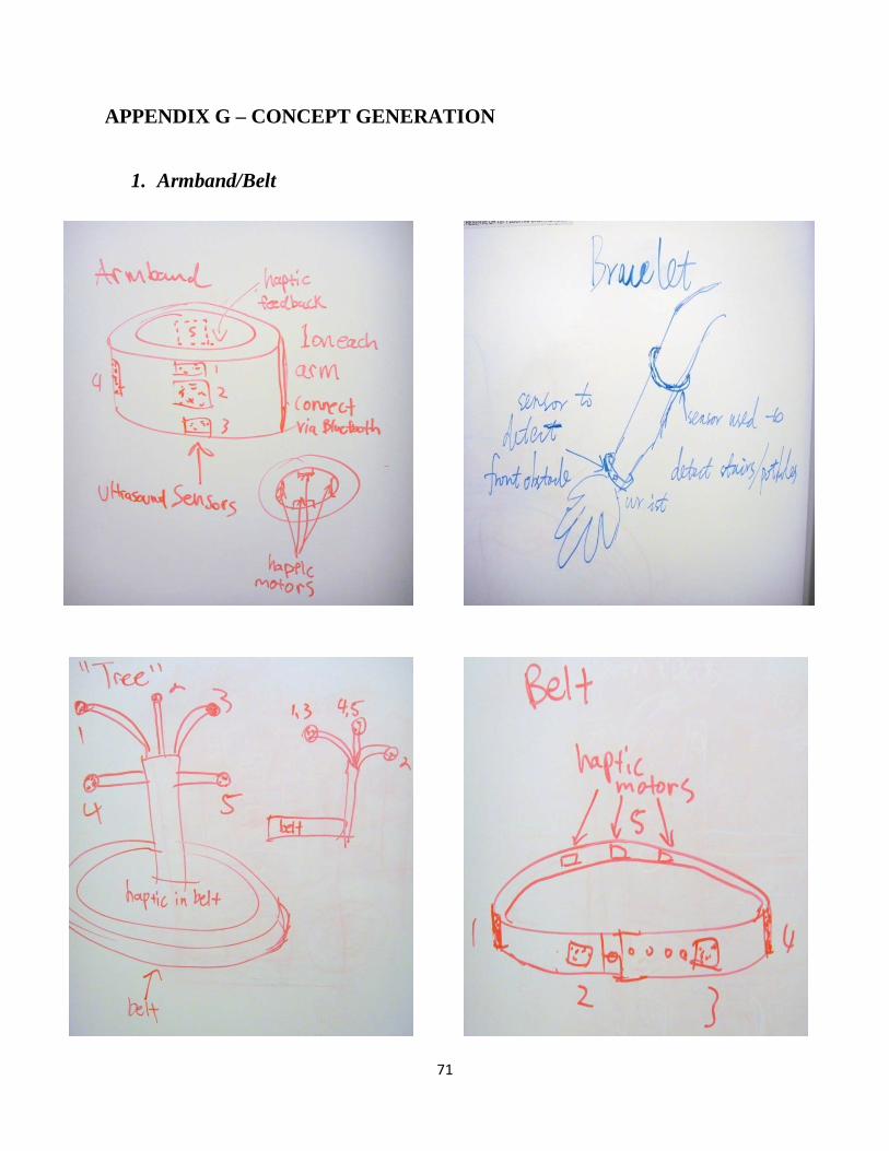
71
APPENDIX G – CONCEPT GENERATION
1. Armband/Belt

72
2. Clothing/Ornament

73
Epaulet Scarf
3. Bag

74
4. Combining Items

65
ALPHA DESIGN DESCRIPTION
The alpha design will be a back pack that contains ultrasonic sensors, a processor, power source, and haptic motors. Figure 5 shows the alpha design for our device. Each sensor will be positioned so that it won’t interfere with other sensors around it. Sensors on the front of the bag will be built into the straps and perform low-lying, overhead, and front obstacle detection. Sensors on either side of the bag will be built into the bag and detect obstacles on either side of the user. Finally, a sensor built into the back of the bag will detect obstacles behind the user. Each sensor will have a housing to achieve an IP34 protection, and will be built into the bag in such a way that they will not deviate from their intended angle when the user is walking. The microprocessor and battery will be housed inside the bag to protect them from damage and make for a more aesthetically pleasing design.

65
APPENDIX H – FUNCTIONAL DECOMPOSITION

66
APPENDIX I – CIRCUIT DIAGRAM FOR OVERALL SYSTEM

67
APPENDIX J – CAD DRAWINGS FOR SENSOR ENCLOSURE – MODIFICATION
Tolerance: +-0.05

68
Tolerance: +-0.05

69

70
APPENDIX K – FMEA TABLE

71
APPENDIX L – DESIGNSAFE

72
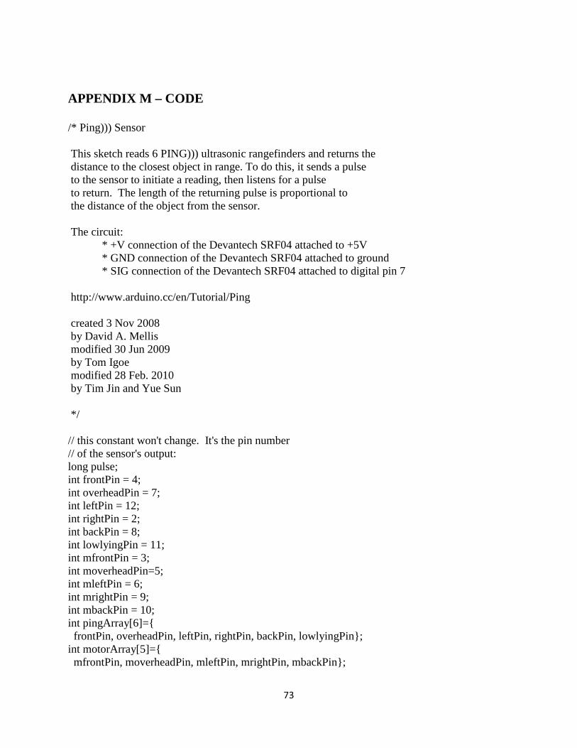
73
APPENDIX M – CODE /* Ping))) Sensor This sketch reads 6 PING))) ultrasonic rangefinders and returns the distance to the closest object in range. To do this, it sends a pulse to the sensor to initiate a reading, then listens for a pulse to return. The length of the returning pulse is proportional to the distance of the object from the sensor. The circuit: * +V connection of the Devantech SRF04 attached to +5V * GND connection of the Devantech SRF04 attached to ground * SIG connection of the Devantech SRF04 attached to digital pin 7 http://www.arduino.cc/en/Tutorial/Ping created 3 Nov 2008 by David A. Mellis modified 30 Jun 2009 by Tom Igoe modified 28 Feb. 2010 by Tim Jin and Yue Sun */ // this constant won't change. It's the pin number // of the sensor's output: long pulse; int frontPin = 4; int overheadPin = 7; int leftPin = 12; int rightPin = 2; int backPin = 8; int lowlyingPin = 11; int mfrontPin = 3; int moverheadPin=5; int mleftPin = 6; int mrightPin = 9; int mbackPin = 10; int pingArray[6]={ frontPin, overheadPin, leftPin, rightPin, backPin, lowlyingPin}; int motorArray[5]={ mfrontPin, moverheadPin, mleftPin, mrightPin, mbackPin};

74
int switchArray[5]={ 14,15,16,17,18}; int durationArray[6]; int multiplexDelay=20; //adjust to change timing between sensor readings int filteredData[6]; int PinState[5]={ LOW,LOW,LOW,LOW,LOW}; bool serial=false; bool motorOn=false; long interval=100; long previousMillis[5]={ 0, 0, 0, 0, 0}; //int average[6]; int test=2000; bool rangeOut[5]={ true, true, true, true, true}; long rangeArray[5][6]= { { 78, 42, 78, 78, 78, 42 } , { 60, 32, 60, 60, 60, 30 } , { 48, 31, 48, 48, 48, 20 } , { 24, 30, 24, 24, 24, 10 } , { 0, 8, 0, 0, 0, 0 } }; long intervalF[6]={ 200, 200, 200, 200, 200, 200}; void setup() { /* initialize serial communication, use this for diagnostics initially, comment out afterwards, 9600 is the standard baud rate for serial*/ pinMode(mfrontPin, OUTPUT); pinMode(moverheadPin, OUTPUT); pinMode(mleftPin, OUTPUT); pinMode(mrightPin, OUTPUT); pinMode(mbackPin, OUTPUT); pinMode(14, INPUT);

75
pinMode(15, INPUT); pinMode(16, INPUT); pinMode(17, INPUT); pinMode(18, INPUT); /*for(int i=0; i<5; i++){ pinMode(switchArray[i],INPUT); }*/ //if (serial==true){ //Serial.begin(9600); //} } void loop() { // establish variables for duration of the ping, // and the distance result in inches and centimeters:4 //long duration, inches, cm; //Serial.print(digitalRead(14)); sendPing(durationArray, pingArray); filterInput(durationArray, filteredData); motorResponse(filteredData, motorArray); serialDisplay(durationArray); } long microsecondsToInches(long microseconds) { // According to Parallax's datasheet for the PING))), there are // 73.746 microseconds per inch (i.e. sound travels at 1130 feet per // second). This gives the distance travelled by the ping, outbound // and return, so we divide by 2 to get the distance of the obstacle. // See: http://www.parallax.com/dl/docs/prod/acc/28015-PING-v1.3.pdf return microseconds / 74 / 2; } long microsecondsToCentimeters(long microseconds) { // The speed of sound is 340 m/s or 29 microseconds per centimeter. // The ping travels out and back, so to find the distance of the // object we take half of the distance travelled. return microseconds / 29 / 2; } void serialDisplay (int durationF[6]){ if(serial==true){ for(int k=0; k<6; k++){ Serial.print(durationF[k]);

76
Serial.print(" "); } Serial.println(); } } void sendPing (int durationF[6], int pingArrayF[6]) { // The PING))) is triggered by a HIGH pulse of 2 or more microseconds. // Give a short LOW pulse beforehand to ensure a clean HIGH pulse: for (int k=0; k<6; k++){ pinMode(pingArrayF[k], OUTPUT); digitalWrite(pingArrayF[k], LOW); delayMicroseconds(2); digitalWrite(pingArrayF[k],HIGH); delayMicroseconds(5); digitalWrite(pingArrayF[k], LOW); delayMicroseconds(2); pinMode(pingArrayF[k], INPUT); pulse=pulseIn(pingArrayF[k], HIGH,17760); durationF[k]=microsecondsToInches(pulse); delayMicroseconds(17760-pulse); } } void motorResponse (int filteredArrayF[6], int motorArrayF[5]) { if(filteredArrayF[5]<filteredArrayF[0] && filteredArrayF[5]<42){ filteredArrayF[0]=filteredArrayF[5]; } for (int k=0; k<5; k++){ if(filteredArrayF[k]>rangeArray[0][k] || filteredArrayF[k]<rangeArray[4][k] ){ rangeOut[k]=true; } else{ rangeOut[k]=false; } if ( (filteredArrayF[k]<=rangeArray[0][k]) && (filteredArrayF[k]>rangeArray[1][k])){ intervalF[k]=4*interval; } if ( (filteredArrayF[k]<=rangeArray[1][k]) && (filteredArrayF[k]>rangeArray[2][k])){ intervalF[k]=3*interval; } if ( (filteredArrayF[k]<=rangeArray[2][k]) && (filteredArrayF[k]>rangeArray[3][k])){ intervalF[k]=2*interval;

77
} if ( (filteredArrayF[k]<=rangeArray[3][k]) && (filteredArrayF[k]>rangeArray[4][k])){ intervalF[k]=interval; } // if(k==0 && intervalF[0]>intervalF[5]){ // intervalF[0]=intervalF[5]; // } if(rangeOut[k]==false && (digitalRead(switchArray[k])==HIGH)){ pinMode(switchArray[k],OUTPUT); pinMode(switchArray[k], INPUT); if (millis() - previousMillis[k] > intervalF[k]) { //Serial.print(millis()-previousMillis[k]); //Serial.print(" "); previousMillis[k]=millis(); if (PinState[k]==LOW){ PinState[k]=HIGH; } else { PinState[k]=LOW; } digitalWrite(motorArrayF[k],PinState[k]); } } else{ digitalWrite(motorArrayF[k], LOW); } } } void filterInput(int durationF[6], int filteredF[6]){ for(int k=0; k<6; k++){ filteredF[k]=durationF[k]; } /*if (filteredF[0]<=filteredF[5]){ filteredF[5]=filteredF[0]; } else{ filteredF[0]=filteredF[5]; }*/ }


![SMART CANE FOR VISUALLY IMPAIRED PEOPLEgreenskill.net/suhailan/fyp/report/037454.pdf · visually-impaired people. First, Smart Cane: Assistive Cane for Visually-impaired People [9]](https://img.dokumen.tips/doc/110x75/5fc7e53d210a4218aa7c699a/smart-cane-for-visually-impaired-visually-impaired-people-first-smart-cane-assistive.jpg)