Embed Size (px)
Citation preview

Sixth Framework NoE 026854 Public Deliverable D2.4
European Sixth Framework Network of Excellence FP6-2004-IST-026854-NoE
Deliverable D2.4Virtual Laboratory Integration Report
The EMANICS Consortium
Caisse des Depots et Consignations, CDC, FranceInstitut National de Recherche en Informatique et Automatique, INRIA, FranceUniversity of Twente, UT, The NetherlandsImperial College, IC, UKJacobs University Bremen, IUB, GermanyKTH Royal Institute of Technology, KTH, SwedenOslo University College, HIO, NorwayUniversitat Politecnica de Catalunya, UPC, SpainUniversity of Federal Armed Forces Munich, CETIM, GermanyPoznan Supercomputing and Networking Center, PSNC, PolandUniversity of Zurich, UniZH, SwitzerlandLudwig-Maximilian University Munich, LMU, GermanyUniversity of Surrey, UniS, UKUniversity of Pitesti, UniP, Romania
c© Copyright 2007 the Members of the EMANICS Consortium
For more information on this document or the EMANICS Project, please contact:
Dr. Olivier FestorTechnopole de Nancy-Brabois - Campus scientifique615, rue de Jardin Botanique - B.P. 101F-54600 Villers Les Nancy CedexFrancePhone: +33 383 59 30 66Fax: +33 383 41 30 79E-mail: <[email protected]>
i

Sixth Framework NoE 026854 Public Deliverable D2.4
Document Control
Title: Virtual Laboratory Integration Report
Type: Public
Editor(s): Jurgen Schonwalder, Ha Manh Tran
E-mail: [email protected]
Author(s): WP2 Partners
Doc ID: D2.4
AMENDMENT HISTORY
Version Date Author Description/Comments0.1 2007-07-03 H. Tran, J. Schonwalder Initial version of a LaTeX template0.2 2007-10-04 D. Hausheer, C. Morariu, T. Bocek Added EmanicsLab Details0.3 2008-01-31 G. Schaffrath Added SIP4EMANICS architec-
ture details0.4 2008-02-25 F. Eyermann Added SIP4EMANICS subsec-
tion on MetaVoIP0.5 2008-03-27 J. Schonwalder, H. Tran, I. Tumar Added more sections, improved
the presentation
Legal Notices
The information in this document is subject to change without notice.
The Members of the EMANICS Consortium make no warranty of any kind with regard to thisdocument, including, but not limited to, the implied warranties of merchantability and fitness for aparticular purpose. The Members of the EMANICS Consortium shall not be held liable for errorscontained herein or direct, indirect, special, incidental or consequential damages in connectionwith the furnishing, performance, or use of this material.
ii

Sixth Framework NoE 026854 Public Deliverable D2.4
Contents
1 Executive Summary 1
2 Introduction 2
3 EMANICSLab 4
3.1 Testbed Setup and Configuration . . . . . . . . . . . . . . . . . . . . . . . . 4
3.2 Testbed Overview . . . . . . . . . . . . . . . . . . . . . . . . . . . . . . . . 7
3.3 Testbed Usage . . . . . . . . . . . . . . . . . . . . . . . . . . . . . . . . . . 7
3.3.1 DATTA (uzh datta) . . . . . . . . . . . . . . . . . . . . . . . . . . . . 7
3.3.2 IPLoc (uzh iploc) . . . . . . . . . . . . . . . . . . . . . . . . . . . . . 9
3.3.3 P2PFastSS (uzh fastss) . . . . . . . . . . . . . . . . . . . . . . . . . 10
3.3.4 P2P-SIP (inria p2psip) . . . . . . . . . . . . . . . . . . . . . . . . . . 10
3.3.5 P2P Revocation (inria p2prevocation) . . . . . . . . . . . . . . . . . 11
3.3.6 VoIP (uzh voip) . . . . . . . . . . . . . . . . . . . . . . . . . . . . . . 11
3.3.7 Buglook (iub buglook) . . . . . . . . . . . . . . . . . . . . . . . . . . 12
3.3.8 SBLOMARS (upc sblomars) . . . . . . . . . . . . . . . . . . . . . . 12
3.3.9 JUMP (inria jump) . . . . . . . . . . . . . . . . . . . . . . . . . . . . 12
3.3.10 SNID (ut snid) . . . . . . . . . . . . . . . . . . . . . . . . . . . . . . 12
3.3.11 ASAM (unibw asam) . . . . . . . . . . . . . . . . . . . . . . . . . . . 13
3.4 Testbed Monitoring . . . . . . . . . . . . . . . . . . . . . . . . . . . . . . . . 13
3.4.1 PlanetFlow . . . . . . . . . . . . . . . . . . . . . . . . . . . . . . . . 13
3.4.2 CoMon . . . . . . . . . . . . . . . . . . . . . . . . . . . . . . . . . . 13
3.4.3 Ganglia . . . . . . . . . . . . . . . . . . . . . . . . . . . . . . . . . . 14
3.4.4 Ganglia on EMANICSLab . . . . . . . . . . . . . . . . . . . . . . . . 15
3.4.5 ElabMoni . . . . . . . . . . . . . . . . . . . . . . . . . . . . . . . . . 16
4 SIP4EMANICS 18
4.1 Architecture . . . . . . . . . . . . . . . . . . . . . . . . . . . . . . . . . . . . 18
4.2 Participation . . . . . . . . . . . . . . . . . . . . . . . . . . . . . . . . . . . . 18
4.2.1 Integration of a Local Production System . . . . . . . . . . . . . . . 18
4.2.2 Provision of a PSTN Gateway . . . . . . . . . . . . . . . . . . . . . . 20
4.2.3 Participation without a Local VoIP Installation . . . . . . . . . . . . . 21
4.3 Stable Production Environment . . . . . . . . . . . . . . . . . . . . . . . . . 21
iii

Sixth Framework NoE 026854 Public Deliverable D2.4
4.3.1 Stable Context . . . . . . . . . . . . . . . . . . . . . . . . . . . . . . 21
4.3.2 Databases . . . . . . . . . . . . . . . . . . . . . . . . . . . . . . . . 22
4.3.3 Management Interface . . . . . . . . . . . . . . . . . . . . . . . . . . 22
4.4 Testing Environment . . . . . . . . . . . . . . . . . . . . . . . . . . . . . . . 22
4.4.1 Testing Context . . . . . . . . . . . . . . . . . . . . . . . . . . . . . . 23
4.4.2 Databases . . . . . . . . . . . . . . . . . . . . . . . . . . . . . . . . 25
4.4.3 Experimental Installations . . . . . . . . . . . . . . . . . . . . . . . . 25
4.5 Call Detail Record Collection . . . . . . . . . . . . . . . . . . . . . . . . . . 26
4.6 Distributed Configuration and Storage of User Accounts . . . . . . . . . . . 26
4.6.1 Design and Architecture of MetaVoIP . . . . . . . . . . . . . . . . . 26
4.6.2 Implementation . . . . . . . . . . . . . . . . . . . . . . . . . . . . . . 30
4.6.3 Summary . . . . . . . . . . . . . . . . . . . . . . . . . . . . . . . . . 31
4.7 Architecture Specification for P2PSIP Overlay . . . . . . . . . . . . . . . . . 32
4.7.1 About P2PSIP . . . . . . . . . . . . . . . . . . . . . . . . . . . . . . 32
4.7.2 P2PSIP Architecture Specification in VoIP Testbed . . . . . . . . . . 32
4.8 Nagios Monitoring Architecture for P2PSIP . . . . . . . . . . . . . . . . . . 36
4.8.1 About Nagios . . . . . . . . . . . . . . . . . . . . . . . . . . . . . . . 36
4.8.2 P2P Architecture . . . . . . . . . . . . . . . . . . . . . . . . . . . . . 37
4.8.3 SIP and P2PSIP . . . . . . . . . . . . . . . . . . . . . . . . . . . . . 38
4.8.4 Bamboo DHT . . . . . . . . . . . . . . . . . . . . . . . . . . . . . . . 38
4.8.5 Monitoring P2PSIP . . . . . . . . . . . . . . . . . . . . . . . . . . . . 39
5 COLLECT 41
6 Collaboration 43
7 Conclusions 44
8 Abbreviations 45
9 Acknowledgement 45
iv

Sixth Framework NoE 026854 Public Deliverable D2.4
1 Executive Summary
This fourth “Virtual Laboratory Integration Report” presents the activities of the virtual lab-oratory and common test-beds work package (WP2) in the second phase of the EMANICSproject. This phase has started in June 2007 with an open call for the first nine-month pe-riod starting from June 2007 to March 2008. With lessons learned from the first phase,the criteria of selecting projects rely more on collaboration among partners, infrastructureand resource exploitations, and face-to-face meetings and exchanges, while keeping workfocused on well defined subjects. The first call led to a selection of three projects:
1. The EMANICS distributed computing and storage testbed (EMANICSLab) projectled by UniZH aims to setup and provide a flexible and highly re-usable distributedcomputing and storage testbed in support of joint research activities across multipleEMANICS partner sites. The testbed, based on the PlanetLab software infrastruc-ture, has nodes located at UniZH, INRIA, UT, UPC, IUB, UniBwM and LMU.
2. The evolution of the Voice over IP Testbed (SIP4EMANICS) project led by INRIA isa continuation of the VoIP testbed project from the first phase of the project. Workitems within SIP4EMANICS are distributed VoIP technologies, distributed storage ofVoIP account data, call pattern anomaly detection, and call trace data collection. Theproject has been collaborated by INRIA, UPI, UniZH and UniBwM.
3. The network trace collection and trace maintenance (COLLECT) project led by UT isa continuation of the TRACE project and aims at funding network trace data collec-tion activities. Several partners including UT, IUB, PSNC, UniZH, LMU and UPI arecollecting additional traces and developing database schema with the goal to makeaggregated information available to interested researchers.
This deliverable reports the achievement of the three projects for the first nine-month pe-riod of the second phase. The partners of the work package have met in January 2008 inBarcelona to examine the progress and to identify any standing issues of these projects.The EMANICSLab project describes the setup of a testbed for distributed computing andstorage which allows partners to carry out joint research activities. Next tasks includeenlarging the testbed within EMANICS partners in terms of resource and usage, and col-laborating the testbed with other infrastructures outside EMANICS. The SIP4EMANICSproject enriches the VoIP testbed built in the first phase with several features and estab-lishes a P2PSIP overlay on the EMANICSLab testbed. The incentive of exploiting this in-frastructure still requires improvement. The COLLECT project continues collecting tracesfrom various networks at partner sites. Further tasks focus on making traces available toEMANICS partners. In addition, these projects are nicely cooperated by more than fourpartners that have shown a great deal of collaboration.
1

Sixth Framework NoE 026854 Public Deliverable D2.4
2 Introduction
The second phase of the EMANICS project lasts eighteen months starting from June2007 to December 2008. In this phase, the work package remains focusing on three ob-jectives: the establishment of collaboration environments, the development of supportingtools, and the creation and maintenance of trace repositories for research and educationalpurposes. Nevertheless, the demand of projects are more concerned with collaborationactivities, and infrastructure and resource exploitations within EMANICS partners. Thework package contains two deliverables in March 2007 and December 2008. An open callfor the first nine-month period has resulted in three selected projects:
• The EMANICS Distributed Computing and Storage Testbed (EMANICSLab) projectintegrates seven partners: UniZH, INRIA, UT, UPC, IUB, UniBwM, LMU and UniS.This project aims to setup and provide a flexible and highly re-usable distributedcomputing and storage testbed in support of joint research activities across multipleEMANICS partner sites. The initial testbed setup of EMANICSLab shall be basedon MyPLC. MyPLC is a complete installation of PlanetLab Central (PLC), the back-end management infrastructure of PlanetLab. UniZH is leading this activity and hasalready setup PLC and will coordinate this activity. The other partners receivingfunding will connect local nodes to EMANICSLab. UniS participates as a user of theinfrastructure.
• The Evolution of the Voice over IP Testbed (SIP4EMANICS) project integrates fourpartners: INRIA, UPI, UniZH and UniBwM. While the initial VoIP testbed has beenset up in the first phase, the objectives for the second phase are: (1) to render thesystem more flexible for experimentation purposes, (2) to extend the integrated ser-vices and administration capacities, (3) to gain realistic usage patterns for researchpurposes, (4) to enable a distributed storage of VoIP accounts, and (5) to extend theexisting testbed with a P2P based SIP overlay network. INRIA is leading this projectand the other partners contribute on the tasks specified in the proposal.
• The Network Trace Collection and Trace Maintenance (COLLECT) project integratessix partners: UT, IUB, PSNC, UniZH, LMU and UPI. This project aims at fundingnetwork trace data collection activities such as the collection of netflow data sets,the collection of full packet traces, or the collection of network management traffictraces. The project is lead by UT. All involved partners committed to collect additionaltraces and to make them available to partners, subject to the constraints imposed bythe network operators.
The three projects stimulate many collaboration activities in other work packages. Sev-eral partners take advantage of the EMANICSLab testbed to do joint research activities.SIP4EMANICS provides a new VoIP testbed with several enhanced features includingcall trace data collection that might foster joint research activities among trace collectionresearchers. It also deploys a P2PSIP network on the top of EMANICSLab. COLLECT ex-ploits EMANICSLab to store trace data and make them available to partners. A high num-ber of projects built on P2P technology carry out experiments on EMANICSLab. These
2

Sixth Framework NoE 026854 Public Deliverable D2.4
projects have succeeded in building up collaborative environments and further inspiringpartners to start cooperative research work.
The rest of the deliverables is structured as follows. Section 3 documents the constructionof the EMANICSLab testbed, focusing on the configuration, usage and monitoring, of thetestbed. Section 4 discusses a SIP4EMANICS testbed based on a VoIP testbed withseveral improved features. It includes the setup of a P2PSIP overlay on the EMANICSLabtestbed. The management trace collection is described in Section 5. Section 6 reportscollaboration issues in the work package before the deliverable concludes in Section 7.
3

Sixth Framework NoE 026854 Public Deliverable D2.4
3 EMANICSLab
Up to now research activities within EMANICS were running each on their own dedicatedtestbed infrastructure. The maintenance of such dedicated testbeds - typically spanningmultiple EMANICS partner sites - required not only major administration effort, but wouldalso result in a waste of resources if those dedicated testbeds are only used rarely.
Thus, the aim of EMANICSLab was to setup and provide a flexible and highly re-usabledistributed computing and storage testbed in support of joint research activities acrossmultiple EMANICS partner sites. Such activities include but are not limited to, distributedtrace repositories, distributed flow collection and analysis systems, distributed intrusiondetection systems, P2P management architectures, and P2P and SIP integration.
Ongoing and planned research activities in WP7,8,9 are covering several of the aboveresearch topics. EMANICSLab provides a single testbed infrastructure which can be usedby multiple activities in parallel. Each activity has its own context of virtual servers with rootpermissions. Thus, they are isolated from each other and give the research activity leaderthe full flexibility to install new software or perform configuration changes as needed.
EMANICSLab also allows the deployment of distributed services that have reached a sta-ble state to go into production, e.g., a trace repository or a large-scale storage system thatcan be used for activities in WP1,3,4,5,6.
The initial testbed setup of EMANICSLab is based on MyPLC [1]. MyPLC is a completeinstallation of PlanetLab Central (PLC), the backend management infrastructure of Plan-etLab [2]. The installation of a dedicated research testbed for EMANICS is to be preferredover the use of PlanetLab itself for the following reasons: First, resources in PlanetLab arequite limited, e.g., the standard disk quota is only 5GB per user on each node, which iseasily exceeded by certain research activities like distributed flow collection. Second, thetestbed configuration and control is done centrally by the PlanetLab administrators whichare not always able to accommodate the needs users might have. Moreover, this can be aproblem for systems like trace repositories which typically require strong trust relationshipsand access protection mechanisms.
The setup of a dedicated EMANICSLab enables the flexible allocation of resources toresearch activities within EMANICS and ensures that the control of the testbed stays withinthe NoE and access to it can be restricted if necessary. Moreover, extensions or changesto the testbed, e.g., towards the use of a different virtualization platform can be done.
The main result from this project is a fully functional, highly re-usable testbed infrastructureacross multiple EMANICS partner sites, supporting several research activities in parallelin a very flexible manner. In the following sections, an overview on the research activitiesrunning on top of EMANICSLab is given, and statistics about the usage of resourceswithin EMANICSLab are provided. Additionally, the research activities and basic testbedservices running on top of EMANICSLab are briefly described.
3.1 Testbed Setup and Configuration
The EMANICSLab PLC node is located at the Department of Informatics of University ofZurich. The node was installed using the MyPLC package provided by Planet-Lab devel-
4

Sixth Framework NoE 026854 Public Deliverable D2.4
opers. Besides the installation as described in the installation manual a set of files of theweb interface have been changed in order to correct some errors related to authenticationof calls and outdated method calls.
A backup script has been written, which takes a daily backup of the Postgres database onEMANICSLab central, including the complete EMANICSLab configuration with all sites,nodes, users, and slices.
The principal goal was to have a basic version of EMANICSLab (based on MyPLC) beingestablished as soon as possible, in order to be able to use it in the different researchactivities.
After having gained some experience with that basic version, a discussion was startedon potential extensions and changes of the basic EMANICSLab setup and configuration.This discussion took place during the WP2 meeting early 2008 in Barcelona and includedparticipants from most EMANICSLab sites and research activities using EMANICSLab.The discussion resulted into a couple of testbed changes which will be proposed for thenext phase.
In order to bootstrap EMANICSLab, UniZH has setup an EMANICSLab central manage-ment server accessible at [3], which allowed the partners to integrate their nodes intoEMANICSLab, add users and slices, etc. like in PlanetLab. A screenshot of the manage-ment interface is depicted in Figure 1.
The following were the necessary steps to be undertaken by each EMANICSLab partner:
• At least one person from each EMANICSLab partner had to create an account andthat will be PI and TC. This was achieved by going to https://emanicslab.csg.uzh.ch/and selecting ”Create an account”. The corresponding site and the roles ”PrincipalInvestigator” and ”Technical Contact” had to be selected.
• Two nodes (x86-based server-class machines) had to be prepared to be integratedinto EMANICSLab. (Ideally and if possible, the nodes had to be placed outside thefirewall to both isolate them from the campus network and to allow unfiltered accessto them. Moreover, the nodes needed to have a public IPv4 address. More informa-tion about suitable hardware is provided under http://www.planet-lab.org/doc/guides/tech.
• The option ’Add Node’ had to be selected and the necessary information for eachnode (IP address, etc.) had to be provided.
• From the node’s page the configuration file had to be downloaded and written to afloppy or USB stick.
• The BootCD image could be downloaded from http://emanicslab.csg.uzh.ch/download/EmanicsLab-BootCD-3.3.iso and was used to burn the boot CD.
• The floppy or USB stick with the configuration file had to be inserted in the machine.
• Finally, the machine had to be booted from CD in order to install the node.
Normally, the nodes were installed with a generic boot CD and a configuration file on afloppy disk or USB stick. However, some nodes could not be installed in this manner.
5

Sixth Framework NoE 026854 Public Deliverable D2.4
Figure 1: Screenshot of EMANICSLab Website
For these nodes, a custom boot CD had to be created using the build-script included inmyPLC:
/usr/share/bootcd/build.sh -f /planet.cnf
cp EmanicsLab-BootCD-3.3.iso /var/www/html/download/boot-xxx.iso
rm EmanicsLab-BootCD-3.3*
Further steps needed to make use of EMANICSLab:
• Each research activity member needs to create a personal account. The PI for eachsite is in charge to enable users and assign them to slices. Users need to uploadtheir public key, in order to be able to login to EMANICSLab nodes.
• Research activity members can add as many nodes to their slice as they want. Avirtual root environment will be created on every node selected. By default everyslice has a certain resource limit per node. These limits can be increased uponrequest to the EMANICSLab administrators.
Table 1 provides a summary of the key problems that came up during the setup andconfiguration of EMANICSLab, as well as their solution.
6

Sixth Framework NoE 026854 Public Deliverable D2.4
Problem SolutionPorts are closed from outside the Univer-sity
Ask network administrators to open portsin the firewall. Ideally, all ports should beopen.
Login to nodes as site admin not permitted Resolved manually, seems to be a bug.Only used to reboot nodes anyway.
Config file cannot be found Config file on floppy/USB has to be re-named to plnode.txt. Custom boot CD im-ages provided by UniZH.
Dell Precision 380 does not boot CD Switched to a Dell Precision 390 instead.HP DC7700 does have PCI problems Requires kernel option pci=nommconfNewer RAID card not supported by thekernel
Switched to a different machine withoutRAID card
Installation of software does not work Replace yum config file /etc/yum.confBind to privileged ports not possible Only unprivileged ports (> 1024) can be
used within a slice
Table 1: EMANICSLab Problems and their Solution
For people interested in additional details of EMANICSLab, the EMANICSLab tutorial [4]which was given at the EMANICS WP2 meeting in Barcelona may provide further valuableinformation. Furthermore, in order to get support, the EMANICSLab administrators canbe contacted at [email protected].
3.2 Testbed Overview
An overview on the different sites and nodes in EMANICSLab is provided in Figure 2.At this stage, the EMANICSLab research network includes 8 sites with 14 nodes. Thedifferent sites are outlined in Table 2. Every partner site (except UniS which is only auser of the testbed) provides 2 nodes as outlined in Table 3. Furthermore, for every site aprincipal investigator (pi) and a technical contact (tech) had to be determined. Additionally,UniZH serves as EMANICSLab Administrator (admin). The key users and their roles areoutlined in Table 4.
3.3 Testbed Usage
At this stage, 11 research activities are using EMANICSLab in their research (cf. Table 5).There is a slice for every research activity using EMANICSLab. A slice is a set of slivers,i.e. virtual servers on different nodes.
3.3.1 DATTA (uzh datta)
The key aim of this project is the design and prototypical implementation of a distributedNETFLOW collection platform integrated within EMANICSLab. The flow records collected
7

Sixth Framework NoE 026854 Public Deliverable D2.4
Figure 2: EMANICSLab Research Network
Abbreviated Name Name Login BaseEMANICSLab EMANICSLab Central plINRIA Institut National de Recherche en Informatique et
Automatiqueinria
IUB Jacobs University Bremen iubLMU Ludwig-Maximilian University Munich lmuUPC Universidat Politechnica de Catalunya upcUniBw University of Federal Armed Forces Munich unibwUniS University of Surrey unisUT University of Twente utUZH University of Zurich uzh
Table 2: EMANICSLab Sites
by each partner are stored locally on a separate host within the premise of the partner. Theplatform offers a client interface for requesting flow records from any of the participatingpartners whereas the EMANICSLab nodes act as brokers between clients and storagerepositories and additionally have the task to control access. Moreover, the platform offersan API that allows developers to build their own applications on top of the provided library.
8

Sixth Framework NoE 026854 Public Deliverable D2.4
Site Hostname ModelINRIA host1-plb.loria.fr Dell Precision 360, Pentium 4, 3.0
GHz, 2 GB RAM, 750 GB HDDINRIA host2-plb.loria.fr Dell Precision 390, Core 2 X6800,
2.93 GHz, 3 GB RAM, 500+250 GBHDD
IUB emanicslab1.eecs.jacobs-university.de
Dell OptiPlex GX620, Pentium D, 2.8GHz, 1 GB RAM, 80 GB HDD
IUB emanicslab2.eecs.jacobs-university.de
Dell OptiPlex GX620, Pentium D, 2.8GHz, 1 GB RAM, 80 GB HDD
LMU emanicslab1.lab.ifi.lmu.de Fujitsu Siemens Scenic, Pentium 4,3.0 GHz, 1 GB RAM, 400+400 GBHDD
LMU emanicslab2.lab.ifi.lmu.de HP DC7700, Core 2 6400, 2.13 GHz,3.6 GB RAM, 80+500+500 GB HDD
UPC muro.upc.es Custom Model, Core 2 6400, 2.13GHz, 1 GB RAM, 250 GB HDD
UPC moscu.upc.es Custom Model, Athlon XP 1600+, 1.4GHz, 1 GB RAM, 200 GB HDD
UniBw emanicslab1.informatik.unibw-muenchen.de
Dell PowerEdge 2850, Xeon, 3.0GHz, 2 GB RAM, 150 GB HDD
UniBw emanicslab2.informatik.unibw-muenchen.de
Dell PowerEdge 2850, Xeon, 3.0GHz, 2 GB RAM, 150 GB HDD
UT emanicslab1.ewi.utwente.nl Dell PowerEdge 860, Dual Core Xeon3070, 2.66 GHz, 4 GB RAM, 2 TBHDD
UT emanicslab2.ewi.utwente.nl Dell PowerEdge 860, Dual Core Xeon3070, 2.66 GHz, 4 GB RAM, 2 TBHDD
UZH emanicslab1.csg.uzh.ch Dell PowerEdge 850, Pentium 4, 3.6GHz, 1 GB RAM, 500 GB HDD
UZH emanicslab2.csg.uzh.ch Dell PowerEdge 850, Pentium 4, 3.6GHz, 1 GB RAM, 500 GB HDD
Table 3: EMANICSLab Nodes
3.3.2 IPLoc (uzh iploc)
The IPLoc slice is used for a distributed evaluation test within the frame of the Univer-sity of Zurich diploma thesis ”Mechanisms for Mapping End Systems in the Internet toGeographic Location Information”. IPLoc, which constitutes one out of two prototype im-plementations developed and evaluated in this work, was deployed on the slice’s nodesand run in parallel for the purpose of determining potential variations in reply delays whenrunning IPLoc in a distributed manner.
9

Sixth Framework NoE 026854 Public Deliverable D2.4
Site Firstname Lastname Email RolesINRIA Emmanuel Nataf [email protected] pi,
techIUB Juergen Schoenwaelder [email protected] pi,
techLMU Feng Liu [email protected] pi,
techUPC Pau Valles [email protected] pi,
techUniBw Frank Eyermann [email protected] pi,
techUniS Stylianos Georgoulas [email protected] pi,
techUT Ramin Sadre [email protected] pi,
techUZH Cristian Morariu [email protected] admin,
pi,tech
UZH David Hausheer [email protected] admin,pi,tech
UZH Thomas Bocek [email protected] pi,tech
Table 4: EMANICSLab Users
3.3.3 P2PFastSS (uzh fastss)
This slice is used for experiments with P2P Fast Similarity Search (P2PFastSS). P2PFastSSis a fast similarity search algorithm for structured P2P systems. The algorithm allows tosearch for similar keys in any distributed hash table (DHT) using the edit distance metric.Thus, P2PFastSS is independent of the underlying P2P routing algorithm. P2PFastSSis suitable for similarity search in large-scale network infrastructures, such as service de-scription matching in service discovery or searching for similar documents in P2P storagenetworks.
3.3.4 P2P-SIP (inria p2psip)
This slice is used for the deployment of a P2P-SIP network on top of EMANICSLab. Theslice creates a P2P overlay network using the open source Bamboo DHT [5] and has aP2P-SIP implementation [6] that runs on top of the overlay network. The Bamboo DHTnot only creates a P2P overlay network for the P2P-SIP network, but can also be used asan OPEN DHT service [7] for other P2P applications. The P2P-SIP implementation canbe used by other partners who wish to use or do research on P2P-SIP communication. Adetailed explanation of the P2P-SIP integration is provided in the SIP4EMANICS activity.
10

Sixth Framework NoE 026854 Public Deliverable D2.4
Slice Name Leading Partner Other Partners Usersuzh datta UniZH UT, PSNC, LMU Cristian Morariu,
Nicolas Baumgardt,Liu Feng
uzh iploc UniZH - Martin Waldburger,Stefan Boesch
uzh fastss UniZH - Fabio Hecht, DaliborPeric, Thomas Bocek
inria p2psip INRIA UniZH, UPI, UniBwM Balamurugan Karpa-gavinayagam
inria p2prevocation INRIA - Thibault Cholezuzh voip UniZH INRIA, UPI, UniBwM Stefan Huber, Gregor
Schaffrath, Mark Fur-rer
iub buglook IUB LMU, UniS Juergen Schoen-waelder, Ha ManhTran, Georgi Chulkov
upc sblomars UPC - Pau Vallesinria jump INRIA - Emmanuel Natafut snid UT UniZH, PSNC, IUB,
UniBwMRamin Sadre
unibw asam UniBwM UniZH, UniS Frank Eyermann
Table 5: EMANICSLab Slices
3.3.5 P2P Revocation (inria p2prevocation)
The P2P revocation slice is used to run a modified aMule client connected to the widelydeployed structured P2P network KAD (Kademlia). The newly designed revocation mech-anism distributes information about who has to be revoked. This revocation informationcan only be managed by the modified client and needs to be replicated on several peers.The slice has been used to study how the number of peers storing the information affectsthe mechanism’s performance in the real P2P network. EMANICSLab gives the possibilityto run a client on different nodes and to connect it to KAD over a direct Internet connection.
3.3.6 VoIP (uzh voip)
This slice is allocated for SIP4EMANICS related experiments. It serves the following fourpurposes: (1) Feasibility evaluation to run actual asterisk instances inside of EMANIC-SLab, (2) prototypical implementation of an experimental VoIP environment as proof ofconcept of the defined SIP4EMANICS VoIP architecture design, (3) evaluation of poten-tial issues with respect to specific asterisk components in the EMANICSLab environment,and (4) field for initial experimentation and sandbox for potential SIP4EMANICS researchusers to allow familiarization with the environment and concepts before the actual projectdraft and start.
11

Sixth Framework NoE 026854 Public Deliverable D2.4
3.3.7 Buglook (iub buglook)
This slice is used for the testing and evaluation of buglook, a web crawler for bug trackingsystems. The buglook system is indexing bug trackers and storing information in a unifiedbug tracking data model. Feature vectors and semantic vectors are computed in orderto search in the extracted data base. The data will be accessible through a simple webfrontend and there will be an interface to a distributed case-based reasoning system. Theslice is therefore linked to research in WP9 of the EMANICS project.
3.3.8 SBLOMARS (upc sblomars)
The purpose of this slice is to deploy SBLOMARS, a distributed network monitoring systemto track the usage of network node resources as well as end to end network transmissionparameters. The system is installed in each network node and after booting it instantiatesas many monitoring agents as needed to monitor the different resources existing in thenode (one agent per resource). All these agents run as independent software threats.Data in different time windows is stored in the local node, ready to be exported to any othersystem. When used in cooperation with a scheduling system, the data collected by themonitoring agents will be exported to the scheduler. Nevertheless, scenarios with a P2Pdata exchange mechanism could also be considered. Initially conceived for large-scalegrids, the system has been adapted to be deployed in EMANICSLab. Potential use of thismonitoring system is to help the Lab administrator in his role but also guide users whenthey plan to deploy their experiments. In its current version, the system is providing pernode memory and CPU usage only. The intention is to make the appropriate adaptationof the system in order to be able to monitor at a per slice basis. Data is provided througha web interface that shows the nodes usage snapshots updated every minute.
3.3.9 JUMP (inria jump)
This slice is used to deploy the Java implementation of JXTA in order to run a peer-to-peerapplication on several nodes of the slice. All these peers have a management interface im-plemented with JMX, which is used as a management plane in order to monitor and even-tually control community services. The management plane is capable of self-organizationby a manager election mechanism running within the peer-to-peer network.
3.3.10 SNID (ut snid)
Although sophisticated algorithm for network intrusion detection yield impressive resultsunder laboratory conditions, they often do not scale to real-life networks due to the sheeramount of data transferred in the latter. The goal of the SNID research activity is to designsampling-based algorithms for the detection of well-known intrusion patterns in networktraces. In this context, UT has collected NETFLOW traffic traces that are used for theevaluation of existing and the development of new intrusion detection algorithms. Sincethe traces stem from high-speed networks, their sizes pose a challenge to the evaluation:
12

Sixth Framework NoE 026854 Public Deliverable D2.4
a two-day trace comprises around one billion records. In order to abstract from the under-lying storage technique, the traces are stored in a relational SQL database. Instances ofthe database run in this slice.
3.3.11 ASAM (unibw asam)
This slice is used for experiments within the ASAM activity. The objective of ASAM (Au-diting of SLOs Across Multiple Provider Domains) is to develop an architecture and a newprotocol for metering and auditing of network performance across multiple, co-operatingnetwork providers. In this context the auditing of Service Level Agreements (SLA) definesthe process of monitoring whether a service provider delivers agreed upon service levelsor not. While frameworks exist to monitor applicationlevel SLAs, the end-to-end monitoringof IP-carrying SLAs, especially in a multi-domain environment like the Internet, is still anopen issue. Measurements from within EMANICSLab will be used to parametrize ASAMsimulation scenarios.
3.4 Testbed Monitoring
The PlanetLab web pages [2] provides a list of monitoring tools for PlanetLab. For EMAN-ICSLab the following three monitoring applications have been considered: PlanetFlow,CoMon, and Ganglia. These three monitoring applications seem to be actively main-tained. While every PlanetLab node has PlanetFlow built in, CoMon and Ganglia has tobe installed additionally.
3.4.1 PlanetFlow
This monitoring software provides an overview over network flows. Each slice can bemonitored separately. The following measurements are collected: number of flows, num-ber of packets, flow size in megabytes, and source and destination IPs. The data can bebrowsed either by slice or by source. In addition to that, these measurements are archivedand can be accessed online for 30 days. These logs are transferred to the EMANICSLabcentral and there the logs are stored for 8 weeks. In order to access older logs, the EMAN-ICSLab central archives these logs. Access to those log files are granted for all EMANICSmembers. The statistical data for, e.g., the UniZH EMANICSLab node 1 can be foundhere: http://emanicslab1.csg.uzh.ch:1080/.
The major advantage of PlanetFlow is that it is already installed. The drawback is thatPlanetFlow does only provide flow information. Further information, such as CPU usageis not available in PlanetFlow.
3.4.2 CoMon
CoMon is a service offered by Princeton and it runs on top of PlanetLab. This serviceshows the performance of nodes with respect to CPU speed, load on the system, swap
13

Sixth Framework NoE 026854 Public Deliverable D2.4
Figure 3: Screenshot of PlanetFlow in EMANICSLab
and disk space, and bandwidth. It can identify nodes and slices with resource problems,such as a high load, or low disk space.
CoMon can be accessed through a web browser and almost every data can be convertedto a graph. In addition, CoMon allows user defined queries for fetching statistical data. Forexample select=’resptime > 0’ shows all nodes that are alive, or select=’resptime > 0 &&gbfree < 5’ shows all nodes that have less than 5 GB free disk space. More informationcan be found here: http://comon.cs.princeton.edu/.
The major advantage of CoMon is that it is highly customizable. CoMon can providestatistical data for other tool or applications. The major drawback is that it cannot beinstalled on EMANICSLab, as the source code is not available at the moment.
3.4.3 Ganglia
Ganglia [8] is a monitoring application for cluster systems and Grid networks. It uses wellknown technologies such as XML for data representation and RRDtool for data storageand visualization. Ganglia has been ported to many operating systems and it does alsorun on PlanetLab. Many organizations are using Ganglia, e.g., CERN, MIT, Berkeley,Reuters, Wikipedia, and Microsoft.
Ganglia has two daemons and a web frontend. The monitoring daemon, which runs on
14

Sixth Framework NoE 026854 Public Deliverable D2.4
every node, checks for changes in the state of a node and answers queries for the currentstate. The meta daemon collects data from the monitoring daemon. This daemon can bebuilt in a tree structure for scalability reasons, however, due to the relative small size ofEMANICSLab, the meta daemon runs on EMANICSLab central only. The meta daemonpolls periodically each monitoring daemon for its state. The data is then passed to around-robin database. The frontend is a PHP application which displays the data fromthe round-robin database. The data is displayed in realtime and shows the CPU usage,memory usage, disk usage, and network usage. As the frontend updates the data andbuilds an XML tree at every request, the frontend should run on a powerful machine.
3.4.4 Ganglia on EMANICSLab
Ganglia has been installed on EMANICSLab to measure the usage. A detailed descriptionof the installation follows.
Each node has to install the monitoring daemon, which is available as an RPM (RedHat Package Manager) on the Ganglia project site. The command: rpm -Uhv ganglia-gmond-3.0.3-1.fc4.i386.rpm installs and starts the monitoring daemon. The configurationfile for the monitoring daemon has been adapted. The property name and value “name =unspecified” has been changed to “name = EmanicsLab”.
On the server side, the meta data daemon and a web frontend have to be installed us-ing the following commands rpm -Uhv ganglia-gmetad-3.0.3-1.fc4.i386.rpm and rpm -Uhvganglia-web-3.0.3-1.noarch.rpm. Every EMANICSLab node (cf. Table 3) has to be listedin the gmetad.conf file.
It may be necessary to install rrdtools, apache2, and php if not present on the server.Figure 4 shows EMANICSLab graphs with CPU, load, memory, and network usage. Thesite can be found at http://emanicslab.csg.uzh.ch/ganglia/.
Figures 5, 6, and 7 show a 1 minute load average, the number of processors and therunning threads. These graphs show the resource usage for one month.
Figure 5 shows the total amount of resources used in EMANICSLab. In week 9, there hasbeen a peak of running processes in EMANICSLab, and in week 8, a peak is visible forthe load average.
Figure 6 shows the amount of resources used for the UT nodes. This clearly shows thatexperiments on these nodes lead to the peak of the load average in week 8. Other nodesdo not show this behaviour in week 8. This graph also shows the peak in week 9.
Figure 7 shows the amount of resources used for the UniBW nodes. In this figure, thepeak in week 8 is not present, but there is a peak in week 9. Thus, it is very likely that thepeak of number of running processes in week 9 was due to a global test or simulation onEMANICSLab and the peak in week 8 is likely to be a test or simulation on a local node.
The load average for the UniBW nodes is around 1, which means that these nodes areregularly used for testing or simulations. The UT nodes show a smaller load average, butwith a peak for the load average of up to 14.
15

Sixth Framework NoE 026854 Public Deliverable D2.4
Figure 4: Screenshot of Ganglia on EMANICSLab
Figure 5: EMANICSLab Grid (7 sources) load, CPUs, and running processes
Figure 6: UT Cluster load, CPUs, and running processes
3.4.5 ElabMoni
ElabMoni [9] is a monitoring tool for EMANICSLab developed by UniZH. It monitors theresource usage of different slices. ElabMoni consists of an agent running on all EMAN-
16

Sixth Framework NoE 026854 Public Deliverable D2.4
Figure 7: UniBW Cluster load, CPUs, and running processes
Figure 8: Detailed usage of a single slice Figure 9: Detailed usage for an EMAN-ICSLab node
ICSLab hosts and a monitoring station that collects data from the monitored hosts andpresents them via a web page. ElabMoni agent is installed automatically on each EMAN-ICSLab node during node installation phase. Updates are also automatically installedduring the node update process (which runs once a day on every EMANICSLab node).The monitoring station can show how much resources (CPU and memory) a slice useson a particular node or it can show aggregated values over all nodes on which the slice isinstantiated.
ElabMoni statistics can be seen at http://emanicslab.csg.uzh.ch/elabmoni/. Figures 8 and9 show different statistics that can be compiled by ElabMoni. In Figure 8 the detailedusage of a single slice can be observed. ElabMoni allows to see the CPU usage andmemory usage of a single slice on all EMANICSLab nodes on which the slice has a sliver.Figure 9 shows the detailed statistics of a single EMANICSLab node.
17

Sixth Framework NoE 026854 Public Deliverable D2.4
4 SIP4EMANICS
This project contains several activities. The sub-section 4.1 introduces the new architec-ture of a SIP4EMANICS (S4E) testbed and clarifies the terminology with respect to S4Eparticipants and S4E users. An overview of participation scenarios among which S4Eparticipants can choose is given in the sub-section 4.2. Each scenario contains a descrip-tion on how to configure the distributed installations and how to integrate possibly existingremote user accounts into the SIP4EMANICS testbed. The sub-section 4.3 defines thestable production environment, related components and management interfaces for dis-tributed management. The sub-section 4.5 explains how the related components definedin sub-section 4.3 are used to collect usage patterns and to make them available. Thetesting environment is described in the sub-section 4.4, where research prototypes canbe integrated into the environment. Particularly, this environment re-uses the EMANIC-SLab installation and is designed with only minimal integration into the stable part in ordernot to put the production character of the installation at risk. The sub-section 4.7 presentsthe architecture and integration of the P2PSIP in the EMANICS VoIP testbed before thelast activity illustrates the Nagios monitoring architecture for the P2PSIP in the sub-section4.8.
4.1 Architecture
The new S4E architecture has been designed with regard to flexibility. Its core consistsof a stable production system which features an interface to experimental functionality ofVoIP research projects within EMANICS. It also provides functionality for collecting CallDetail Records (CDRs) which fosters EMANICS partners to do research on VoIP tracedata.
This architecture considers institutions participating in S4E as S4E participants and S4EVoIP users as S4E user. Figure 10 shows the overview of the architecture with the coresystem labelled by s4es, to which VoIP labs from S4E participants connect for establishinga stable production system. The context descriptions are given in pseudo code similar tothe syntax used in Asterisk’s extension.conf [10] configuration file.
4.2 Participation
Three different participation scenarios have been proposed for EMANICS members toparticipate in S4E. Each S4E participant relies on his resources and needs to choose themost suitable scenario.
4.2.1 Integration of a Local Production System
If S4E participants already have a local productive VoIP installation with a personal usermanagement in place, they can choose to integrate their system to S4E. An example forthis scenario is given in Figure 10, instantiated by Partner1.
18

Sixth Framework NoE 026854 Public Deliverable D2.4
Production Systems
s4es
Partner1
EMANICSLAB
Slice1 Partner2
MySQL
SVN
Apache
test ing
PSTN - BRI
PSTN
PSTN
partner_Partner1_reroute
stable
IAX2Trunk
IAX2Trunk
group1_reroute
group1_reroute_in
pstn_in
arbi trary - user - contexts - configurations - software
PSTN-Gateways
pstn_in
pstn_out
_7. -> default , ${EXTEN:1}_. -> s4es, partner_Partner1_reroute, ${EXTEN}_. -> default , ${EXTEN}
_. -> default , ${EXTEN}
0 -> DISA(stable)_8. -> CallerID=[Partner1_prefix]${EXTEN:1}_8. -> stable, ${EXTEN:1}_. -> Partner1, group1_reroute_in, ${EXTEN}
_0X. -> try_user_db(${EXTEN})_0X. -> try_enum($(EXTEN})_0X. -> try_dundi(${EXTEN})_0[local_prefix]X. -> pstn_out, ${EXTEN}_0. -> play(unreachable)_9. -> test ing, ${EXTEN:1}_2000. -> connect_to_service
partner0 -> DISA(stable)_8. -> stable, ${EXTEN:1}
_[Partner2_prefix]. -> try_pstn()0 -> DISA(local_worker)
[local_S4E_number1] -> s4es, partner, 0[local_S4E_number2] -> s4es, partner, 8[S4E_ext.]
- UserConfig (stable)- MeetMeConfig- CDRs (stable)- Diversions (testing)- ...?
- csg_reroute- partner- stable- pstn_out- pstn_in- testing- ...?
[local_S4E_number] -> s, s4es, 0[group1_ext] -> group1_reroute, ${EXTEN}
MySQL/SVN
_0X. -> try_testing_db(${EXTEN})_0X. -> stable, ${EXTEN}_8. -> stable, ${EXTEN:1}
;escape;reroute over s4es;fallback
;proceed as usual
;local S4E Dialin;incoming call for;S4E user
;default remote PSTN dialin ;map to S4E-UserID ; and use S4E funct. ;back to own system
;default remote PSTN dialin;for direct remote access to; S4E-funct.
;known S4E-user?;ENUM information avail.?;announced pref. for PSTN out? ;local call;unreachabi l i ty announcement;context switch to test ing;e.g. MeetMe
;test ing may override entr ies;only SIP/IAX2 diversions allowed
_2. -> try_testing_db(${EXTEN})_2. -> stable, ${EXTEN}
- User Management- WebMeetme- Asterisk-stat- Number directory- phpMyAdmin- ...?
;access to local PSTN;for PSTN privilege extension; for local employees
;default PSTN dialin ;dialin access to S4E ext.
pstn_in
pstn_out_[local_prefix]X. -> try_pstn({$EXTEN:N})0 -> DISA(local_worker)
s -> partner, 0
_XYZ_reroute
pstn_out_[Partner1_prefix]X. -> try_pstn({$EXTEN:N})0 -> DISA(local_employees)
;access to local PSTN;for privi lege extension; for local employees
(Example S4E part icipant with own production system and user management)(redirecting calls of EMANICS members in goup1 over SIP4EMANICS server for CDR collection and access to SIP4EMANICS functionality)(with fal lback option to local system in case of testbed trouble)
(Example S4E part icipant with own system without own user mgmt.)(serving as PSTN gateway into local phone network)(no S4E user accounts hosted)
(SIP4EMANICS (S4E) VoIP Server)(no experimental software running)
(Example Slice for VoIP research)(referenced by IAX2/SIP diversion entry in ’s4es, testing’)(separate user management)
Apache
Software/Services
IAX2/SIPDiversion
’research’ GroupUser Account
Figure 10: S4E Architecture
19

Sixth Framework NoE 026854 Public Deliverable D2.4
In this scenario, EMANICS members at the S4E participant’s site are assigned a spe-cial context group1 reroute, which attempts, by default, to route calls over the corre-sponding partner Partner1 reroute context on s4es. These calls are sent back to contextgroup1 reroute in on Partner1 by default and thereafter treated as normal calls on the lo-cal system without further using S4E functionality. These calls also facilitate the collectionof realistic CDRs.
If S4E users playing the call desire to access the S4E functionality, they can dial 8, followedby a number matching an entry in the stable context. In order to ensure the seamlessfunctioning of Partner1 even in the event of a failure of s4es, a fallback entry and anotherlocal prefix (7 in the example) overriding the reroute is placed into group1 reroute.
S4E participants choosing this participation scenario are required to create additional VoIPaccounts for their users on s4es in order to ensure their addressability inside S4E and toimplement a CallerID mapping into their respective partner Partner1 reroute for consis-tency.
Incoming calls for S4E local users (handled in pstn in) are routed over group1 reroute,partner Partner1 reroute and thereafter handled again by Partner1. CDRs on s4es arecreated for incoming calls as well.
Due to a possible conflict with local dialing schemes, the prefixes proposed in group1 rerouteand partner Partner1 reroute can be replaced by arbitrary digits by each partner when thefunctionality is provided. This issue only affects a partner’s S4E users.
4.2.2 Provision of a PSTN Gateway
If S4E participants have a local VoIP installation featuring an interface to the local PSTNnetwork and either don’t have a local user management in place or wish to keep produc-tive use of this system disconnected from S4E, they can choose to offer PSTN gatewayfunctionality to the local PSTN network to S4E. In Figure 10, this scenario is instantiatedby Partner2.
S4E participants create a pstn out context, in which they allow S4E users to place calls tothe local PSTN network via an IAX2 trunk to s4es. A local extension (’0’ in the example) isconnected to an authenticating DISA [11] application to allow users full dialout capacitieseven when using their S4E accounts.
S4E participants allocate at least one PSTN extension in pstn in to S4E, which is mappedonto the DISA application in the partner context on s4es to allow access to S4E overPSTN. They may assign additional numbers to direct access of S4E features by mappingthem to ’8’, followed by the respective extension in the stable context on s4es.
The prefixes, to which S4E participants offer gateway services, are published via DISA.S4E user accounts in this scenario are hosted on s4es and assigned to either the stable ortesting context. In addition, digits 0 and 8 in partner are fixed because they don’t interferewith the behaviour of other systems but S4E.
20

Sixth Framework NoE 026854 Public Deliverable D2.4
4.2.3 Participation without a Local VoIP Installation
If S4E participants don’t have a local VoIP installation which they wish to share with otherS4E participants, they can choose to participate S4E by registering their members withS4E user accounts, which are hosted on s4es in Figure 10 and placed in either the stableor testing context.
4.3 Stable Production Environment
In order to provide a stable production environment, experimental software is not allowedto run on s4es shown in Figure 10. While a testing context is defined on s4es, it containsmerely diversion information to access the testing functionality running on other VoIP labs,and stable functionality is not allowed to build upon the testing context.
4.3.1 Stable Context
As S4E users are geographically distributed, the dialout extensions in the stable con-text are kept independent from any locality. Users and PSTN numbers can be called byprepending a 9 to a phone number in the format of
[CountryCode][RegionCode][PhoneNumber]
(e.g., 41446350890). Testing functionality can be accessed by prepending a 9 and therebyexplicitly triggering a context switch to the testing context. Stable services can be ac-cessed by dialling 2000, followed by a four-digit service extension (e.g., 20001000 may beassigned to the MeetMe [12] conference application).
Dialling of the prefix 0 results in a series of consecutive steps:
1. First the local user and diversion database is queried. If an entry is found, the callproceeds as specified in the database.
2. If no local entry is found in the database, ENUM [13] records specifying SIP or IAX2destinations are considered. If an acceptable ENUM record has been found, the callproceeds as indicated by the record.
3. If no ENUM entry is found, published DUNDI [14] information of partners is consid-ered. If a S4E participant offering connectivity to the destination is found, the call isforwarded to the respective S4E participant.
4. If the call is local to s4es, the local PSTN interface is used.
5. If all previous steps fail, the caller is signaled the failure of the placement of his call.
21

Sixth Framework NoE 026854 Public Deliverable D2.4
In order to avoid collisions between S4E participants and to provide a consistent environ-ment, user identifications are based on their office phone numbers, possibly extended bya one-digit counter in case multiple S4E users share one office phone 1.
While the stable context is mostly implemented in Asterisk’s extension.conf [10] or includedtherein, users and specific service configurations are stored in a local SQL database forfacilitating dynamic reconfiguration via PHP scripts running on a local webserver. Thispart makes extensive use of the Asterisk RealTime Architecture [15].
If partners prefer a localized version of the stable and testing contexts, individual replica-tion can be considered at the later stage.
4.3.2 Databases
The stable environment relies on two databases. A MySQL [16] server hosts dynamicconfiguration parts, like user configurations, user defined diversions, MeetMe conferenceconfiguration, CDRs and testing diversions. A SVN [17] repository stores critical configu-ration files and context descriptions, which thereby can be quickly restored after a possibleerroneous change, or which can be distributed to other sites at the future stage.
4.3.3 Management Interface
A web server running PHP scripts provides a management interface which supports fordistributed management of S4E participants. User Management is available at three dif-ferent access levels:
1. S4E administrators can define groups and assign these groups to S4E participantadministrators.
2. S4E participant administrators can add/delete/modify S4E user accounts in theirrespective namespace given by their institution’s phone prefix. (e.g., 414463 forUniZH)
3. S4E users are able to configure their respective account details as well as diversionsfor their extensions.
Figures 11, 12 and 13 depicts different view examples. The WebMeetMe [18] interface isinstalled for dynamic conference management.
4.4 Testing Environment
The S4E architecture in Figure 10 features a testing context to experimental use of S4E.Experimental software is not run on s4es and developers do not receive low level ac-cess to s4es. However, the context is structured in a way to query diversion informationdynamically from the MySQL [16] database via the Asterisk RealTime Architecture [15].
1This digit needs to be removed in the pstn out context of the local VoIP installation of the respective S4Eparticipant, if applicable
22

Sixth Framework NoE 026854 Public Deliverable D2.4
Figure 11: S4E participant administrator view example (the group of Burkhard Stiller inUniZH)
4.4.1 Testing Context
In order to facilitate switches from stable to testing and back, the context has been de-signed in a similar fashion to the stable context. Furthermore, to avoid collisions betweenextensions defined by various VoIP research projects, each project receives a three-digitproject number to be used in the dialplan. Users and PSTN numbers can be called byprepending a 9 to a phone number in the format of
23

Sixth Framework NoE 026854 Public Deliverable D2.4
Figure 12: S4E user configuration details view example
[CountryCode][RegionCode][PhoneNumber]
(e.g., 41446350890). Stable functionality can be accessed by prepending a 8 and therebyexplicitly triggering a context switch to the stable context. Services can be accessed bydialling 2, followed by the three-digit project number, followed by a four-digit service ex-tension (e.g., 20011000 may be assigned to Service 1000 of VoIP research project 001)2.
As the testing context is allowed to override stable behaviour, this results in a slightlymodified behaviour:
• Dialing an extension starting with 0 consults the testing diversion database stored inthe local MySQL server, before falling back to stable procedures.
2Stable services are assigned to the project extension ’000’
24

Sixth Framework NoE 026854 Public Deliverable D2.4
Figure 13: S4E user diversion details view example
• The same applies to service extensions, although 2000 extensions are by defaultstill reachable in the testing context.
4.4.2 Databases
Like the stable environment, the testing environment relies on a table in the MySQL [16]database for diversion information and on a SVN [17] repository for the backup of thecontext. The SQL database is accessible via the PHPMyAdmin [19] interface.
4.4.3 Experimental Installations
As mentioned before, experimental software and services are not installed on s4es andpreferably not on any of the connected PSTN gateways participating in the stable envi-ronment (e.g., Partner1 or Partner2 in Figure 10). Instead, each VoIP research projectreceives an EMANICSLab slice for experimentation, on which they are able to install arbi-trary software and create arbitrary users and contexts. The extensions on these machinesare integrated into the S4E environment by placing an appropriate IAX2 or SIP diversionentry into the MySQL table of the testing context. User management with respect to ac-cess to experimental installations is handled by the EMANICSLab installation.
In case a project requires call permissions on s4es, an appropriate user account can bedefined in a special research group and associated to the testing context.
25

Sixth Framework NoE 026854 Public Deliverable D2.4
4.5 Call Detail Record Collection
Call Detail Records are collected in the MySQL database on s4es. All calls placed byS4E users are registered and made available over the Asterisk-stat interface [20]. Thiscollection includes both calls using S4E features, as well as calls merely looped overs4es, as described in the sub-section 4.2.1 to provide realistic usage patterns.
4.6 Distributed Configuration and Storage of User Accounts
A cooperation of different enterprises, institutions or generally speaking organizations al-ways increases the communication needs between organizations. Nowadays a lot of com-munications is performed via electronic media, like email, wikis or special collaborationtools. Yet, the communication via telephone is still the most important means of commu-nication.
Making a phone call requires knowing the phone number and extension of the callee.Within an organization a corporate directory provides the extension of all co-workers. Butthis directory is mostly not publicly readable because of privacy and security issues, leav-ing project partners calling a receptionist and being connected. Some projects might run aproject-specific directory, which is most likely not linked with the corporate one and there-fore not automatically updated.
This gap might be closed by MetaVoIP. The name MetaVoIP is modelled after the termmetadirectory which is a directory service which combines the data from other directoriesand displays them in a uniform way [21]. MetaVoIP combines data from different privatebranch exchanges (PBXs) and provides a centralized phone book with some additionaluser services. The central phone book is automatically built out of the configuration of thelocal phone systems. The phone systems might be Voice-over-IP based, but this is not arequirement.
The EMANICS partners face the above mentioned problem, too. With the SIP4EMANICSVoIP testbed they have their own phone network at hand - which is only used rarely be-cause of the missing knowledge about phone numbers and extensions.
4.6.1 Design and Architecture of MetaVoIP
MetaVoIP is designed as a centralized application. It gathers data from remote databases,i.e., the user data is stored and maintained locally at each organization. Figure 14 showsthe architecture of MetaVoIP. The User GUI and the Application logic are deployed at oneserver. The User GUI performs all interactions with the user. The Application logic takescommands from the User GUI, processes them and provides results. It further controlsthe data source connector and the PBX connector.
The data source connector provides an interface to the configuration data stored in eachorganization. It is used to retrieve information about users, e.g., from a corporate directory.The PBX connector is an interface to the PBX system of each organization. It is used tocontrol the PBX systems, e.g., to initiate a call using the User GUI.
26

Sixth Framework NoE 026854 Public Deliverable D2.4
Figure 14: Architecture of MetaVoIP
MetaVoIP topology MetaVoIP abstracts from organizations and describes the topologywith sites. For simplicity it is assumed that each organization is located at exactly onesite and operates there one data source and one PBX. Mappings must be made, if thisassumption does not hold.
An example with three sites is shown in Figure 15. Each site with a data source and a PBXis connected to the MetaVoIP server. The connection to the data sources is establishedby the data source connector, the connection to the PBXs by the PBX connector.
Figure 15: Topology example
MetaVoIP data model MetaVoIP stores a replication of all data read-in from the sites’data sources in an own database. This shortens the access time to this data drastically.In order to keep this data up-to-date, updates are retrieved periodically from the remotedata sources.
The data model of MetaVoIP is depicted in Figure 16 in UML format. The class User storesthe attributes of a user. Firstname, lastname, email and comments are text fields which
27

Sixth Framework NoE 026854 Public Deliverable D2.4
Figure 16: MetaVoIP data model
store the respective information. The field userid stores a site-unique identifier for eachuser. Secret stores a password which is used for authentication.
The class PhoneAccount models one possibility to call a user. A user might be reachableby different means, e.g., by public switched telephone network (PSTN), Session InitionProtocol (SIP) or Mobile Phone. A description of this means is stored in protocol, in orderfor the PBX to choose the right output channel when calling the user. Accountid storesthe address information, which is protocol dependent, e.g., a phone number for PSTN ora SIP-URL for SIP.
MetaVoIP implements role-based authorization. If a user wants to perform an action in theUser GUI, it is checked if he owns the respective role. If not, the user is denied the action.A user might own an arbitrary number of roles.
Each user is member of one site (class OrgSite). A site is identified by a unique identifier(orgid). The attribute orgName is only descriptive. A combination of OrgSite.orgid andUser.userid must identify a user unambiguously.
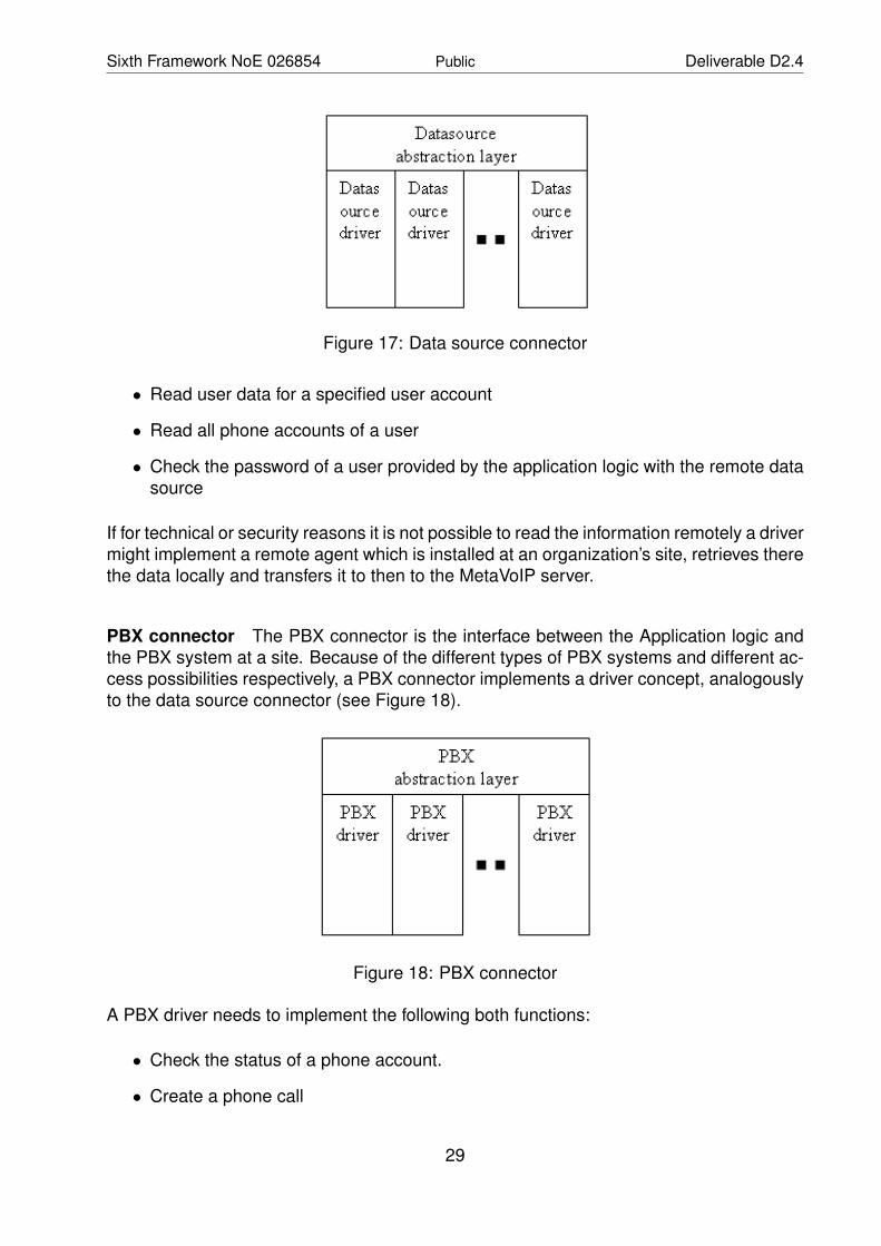
Data source connector The data source connector provides an interface to the userinformation stored remotely at each site and abstracts from how the data is really stored.A more detailed view of the data source connector is shown in Figure 17. Different datasource drivers may be implemented in order to connect to different types of data sources,e.g., LDAP, X.500, SQL database or a driver to retrieve user data from PBXs.
The data source abstraction layer provides a uniform interface between the Applicationlogic and the data source drivers. It is able to choose the right driver depending on theOrgSite.orgid field.
For each site one driver needs to be instantiated. Each driver needs to implement thefollowing functions:
• Read all existing user accounts
28
Sixth Framework NoE 026854 Public Deliverable D2.4
Figure 17: Data source connector
• Read user data for a specified user account
• Read all phone accounts of a user
• Check the password of a user provided by the application logic with the remote datasource
If for technical or security reasons it is not possible to read the information remotely a drivermight implement a remote agent which is installed at an organization’s site, retrieves therethe data locally and transfers it to then to the MetaVoIP server.
PBX connector The PBX connector is the interface between the Application logic andthe PBX system at a site. Because of the different types of PBX systems and different ac-cess possibilities respectively, a PBX connector implements a driver concept, analogouslyto the data source connector (see Figure 18).
Figure 18: PBX connector
A PBX driver needs to implement the following both functions:
• Check the status of a phone account.
• Create a phone call
29

Sixth Framework NoE 026854 Public Deliverable D2.4
The status of a phone should show, if a phone is connected or not. This is of specialinterest for phones which are not always connected as, e.g., SIP soft phones. In this caseshowing the state of phone accounts to a user will give him an impression, who is onlineand reachable and who is not.
A user should be able to select in the User GUI to call somebody else. In this case theremote PBX at the user’s site needs to establish a call between the user’s phone and thephone of the callee, i.e., create a phone call.
Roles MetaVoIP facilitates a role-based authorization scheme. Table 6 shows the rolesand their access profile defined in the application. A user might own several roles at atime.
User Each user which is listed as a user at any site is automatically assignedthe role user.
Usersubadmin If a user is assigned the role Usersubadmin he is able to manage theaccounts of all users, which belong to the same site as him.
Useradmin Users with the role Useradmin can manage all user account irrespec-tive of the site he belongs to.
Subadmin This role provides the ability to manage data source drivers and PBXdrivers of the own site.
Admin Admins are able to create, change and delete site definitions, as wellas add, change and remove data source drivers and PBX drivers forall sites.
Table 6: Roles in MetaVoIP
MetaVoIP checks the authorization for each action a user wants to perform. If possible,the User GUI displays only those actions, which are allowed for a user. Actions which arenot allowed for the logged in user are hidden.
4.6.2 Implementation
MetaVoIP is implemented as a web application using programming language Java and aApache Jakarta Tomcat Server. This requires also technologies from the Java EnterpriseEdition. Here especially Java Server Pages (JSP) in combination with the Java ServerPages Standard Tag Library (JSTL) should be mentioned.
The architecture described above is refined to implement the Model-View-Controller (MVC)concept. Therefore the framework Struts in version 1.3.8 is used.
The data model shown in 4.6.1 is implemented using Java Beans. A bean for User, OrgSiteand PhoneAccount is defined. The roles are not represented by a bean, instead the arerepresented by an enumeration.
Implementation of the data source driver The data source abstraction layer is realizedby a Java interface all data source drivers need to implement. Up to now two data source
30

Sixth Framework NoE 026854 Public Deliverable D2.4
drivers are implemented. A driver to read the user data from an LDAP server and a driverto read the data from Asterisk configuration files.
The LDAP driver stores roles with objects of type OrganizationalRole. The names of theobjects have to be the name of the role with the prefix metavoip. The object for the roleUser is therefore cn=metavoipUser. All owners of the role have to be listed in the attributeroleOccupant.
Astirectory is an extension to the Asterisk PBX, which allows storing SIP and IAX ac-counts in an LDAP server instead of the respective configuration files. MetaVoIP uses theAstirectory’s LDAP schema to store own phone accounts. Astirectory only specifies auxil-iary classes, which requires an additional structural class for instantiation. As a structuralclass in this context OrganizationalUnit was chosen. This is a not optimal compromise,but the lesser evil. Extending user objects directly with Astirectory classes is not an option,as one user might have several phone accounts. The phone account classes have to bechildren of the respective user. Up to now the LDAP driver only supports phone accountswhich could be described with the Astirectory classes.
The second driver retrieves its data directly from Asterisk configuration files. The driverperiodically downloads the Users, SIP and IAX configuration files from an Asterisk server.The download is performed via Secure Copy (SCP) what requires operating an SSH dae-mon on the Asterisk server. MetaVoIP then parses these files and extracts the relevantdata. The roles a user occupies are stored in the users.conf file as comments of a definedformat.
Implementation of the PBX driver The PBX abstraction layer is realized by an abstractJava class, which already implements some common core functionalities. Drivers for aconcrete PBX need to override this class and implement all abstract methods.
In general the PBX drivers must implement two main functions:
• establish a call between two named phones
• get the status of a phone account
Up to now only a PBX driver for the Asterisk PBX is implemented. This driver uses theAsterisk Manager API for sending commands to the Asterisk PBX. The implementationuses the Asterisk-Java framework. This framework is a java wrapper library for the textbased Asterisk Manager API.
4.6.3 Summary
MetaVoIP is a centralized server application, which can improve the integration betweencooperating organizations. Its main focus is to loosely couple the PBX systems of thedifferent organizations in order to making calls between organizations easier, as the effortfor looking up phone numbers is drastically reduced.
The application retrieves its data automatically from data sources at the respective sitesof an organization. The organization keeps full control over its data. Implemented isfurthermore a click-to-call functionality on a web-site.
31

Sixth Framework NoE 026854 Public Deliverable D2.4
4.7 Architecture Specification for P2PSIP Overlay
In this section, the architecture and integration of the P2PSIP overlay in the EMANICSVoIP testbed is detailed. With P2PSIP taking lead in the research domain, there are veryfew works that did analyse the interworking of the P2PSIP network with the traditional SIPnetwork. Thus, this extension work of the VoIP testbed will serve as a platform for theEMANICS partners to carry out research activities related to P2PSIP.
4.7.1 About P2PSIP
P2PSIP can be considered as an extension work of SIP, which addresses the use ofdistributed resource discovery and management instead of the centralized architecturepresent in the traditional SIP network. This approach is mainly beneficial in terms of scala-bility and reliability when compared to single point failure in centralized network. However,this can be achieved at the cost of latency to locate the resource. There are various ap-proaches in the implementation of P2PSIP which are under active research. The detailsand the ongoing activities (research and standardization) for P2PSIP can be found in [22].In our P2PSIP overlay integration we use the Bamboo DHT [5], as the underlying P2P net-work which replaces the resource location functionality of the traditional SIP with the DHTi.e., the P2PSIP overlay network will be created with the DHT at the lower level. However,for the interworking of the P2PSIP network with traditional SIP network we have used amodified SIP proxy server which will be connected to both the P2PSIP overlay networkand traditional SP network, acting as a gateway between them.
4.7.2 P2PSIP Architecture Specification in VoIP Testbed
In this section, we detail the P2PSIP architecture deployed in the EMANICS VoIP testbed.The figure 19 shows the architecture of the P2PSIP network with the P2PSIP overlaynetwork and the interworking between the traditional SIP network (Asterisk) in EMANICSVoIP testbed. As discussed in the earlier (distributed and stable) section about the use theEMANICSLab for testing purpose, we have integrated the P2PSIP overlay network in theEMANICSLab. As an initial step, the present integration interconnects to the existing VoIPtestbed via the INRIAs Asterisk server. However not restricted to only INRIAs Asteriskserver but can be extended to other partners or can be integrated with the centralizeduser management. The P2PSIP user management is out of scope in the present workand can be an interesting research work that can be carried out from the platform. Also,the present architecture only address the registration and call setup for the P2PSIP clientsfor the moment and does not address the services like voicemail, conference calls, etc.,for the P2PSIP clients, which are available for the traditional SIP networks.
There are two important components in the architecture of P2PSIP in the EMANICS VoIPtestbed, one being the P2PSIP overlay network itself and second dealing with the inter-working of the P2PSIP network with traditional network (Asterisk). Before we look into,how the P2PSIP and interworking are performed, let us see what are the components orthe software that are used for the integration.
32

Sixth Framework NoE 026854 Public Deliverable D2.4
Figure 19: P2PSIP Architecture
1. P2PSIP Overlay Network:For the integration of the P2PSIP overlay network in the EMANICSLab, we usean open source implementation called Olyo P2PSIP based VoIP System [6]. ThisP2PSIP implementation uses the Bamboo DHT [5] as the underlying P2P overlaynetwork which serves as a location service for the SIP. The P2PSIP implementationruns on top of P2P overlay making it a P2PSIP overlay network. The details on usingthis open source software can be found in [6]. A configuration guide is also available.
The software components that are used from the open source for the setup of theP2PSIP overlay consists of
• Bamboo DHT(P2P)
• Modified PartySIP as adapter for SIP clients
• Any traditional SIP client (Twinkle, kphone, etc.,)
Since SIP is based on domain based approach, in our architecture P2PSIP overlaynetwork is also considered to be a domain, meaning that each P2PSIP networkwill have a overlay identifier, which will represent as a domain for the overlay. Forexample, if we have a P2PSIP overlay with an identity mad1.bamboo and user test1it can be reached by placing calls as sip:[email protected].
The P2PSIP client must first register themselves in the bamboo DHT with user I.Dand domain (overlay Identifier). A key will be generated for the client in the DHT.Thus when a call is placed by other clients in the overlay, they will use the samehash function generate the key and query the DHT for routing the calls.
The dial plan for the P2PSIP overlay clients is straight forward i.e., the P2PSIP over-lay is considered to be a single domain or local domain. Therefore when there arecalls in the same domain the DHT is used as a location service and calls are placed.Thus, for any client who wish to join the P2PSIP overlay network and make calls,
33

Sixth Framework NoE 026854 Public Deliverable D2.4
there no Dial plan specification and just need to register to the DHT. One importantissue to note here is that there are no any mechanisms that provide the details ofthe user I.D that are connected to the P2PSIP overlay network. An illustration of thecall flow between two P2PSIP overlay clients is given in Figure 20.
Figure 20: Call Setup between P2PSIP Clients
2. Interworking of P2PSIP and Traditional SIP (Asterisk):There are very few research works that deal with the interworking of the P2PSIPnetwork with the enterprise level traditional network. In an approach dealing withthe interwoking, the P2PSIP overlay is classified as lower and upper level overlay,where the lower level overlay forms the P2PSIP overlay and the higher level over-lay serves as a global overlay inter-connecting many P2PSIP overlays. These higherlevel overlays generally act as the gateway for inter-connecting many heterogeneousoverlays. In our case, we use this scenario to inter-connect the traditional SIP net-work with the P2PSIP network by deploying a SIP proxy server for the traditionalnetwork which is also connected to the lower P2PSIP overlay network by creating anupper level overlay.
The SIP Proxy connects to the P2PSIP overlay by creating a higher level overlayand also joining the lower level overlay. The Proxy server connects to the lower leveloverlay by adding the upper level overlay ID as the key. Thus when a P2PSIP clientmakes a call, it looks into the DHT and finds a key for the upper level overlay (SIPProxy Domain). One important thing to be noted here is that the SIP proxy serveronly generates a key based on the domain and not with the entire SIP URI part.
34

Sixth Framework NoE 026854 Public Deliverable D2.4
The interworking of the P2PSIP and traditional SIP is deployed by a SIP proxy server(Modified PartySIP server olyo implementation) for the Asterisk user, which is even-tually connected to the P2PSIP overlay network. The characteristics of the proxyare
• Serves as a traditional SIP proxy for the Asterisk SIP users
• Creates a higher level overlay to serve as gateway for the P2PSIP clients
• Joins the P2PSIP overlay (lower level)
Since we use a SIP proxy server as a gateway for interconnecting the P2PSIP net-work and traditional SIP network (Asterisk), there are not many changes to be donein the existing dial plan of the Asterisk server in the testbed. Only the architectureof the present testbed is changed by adding a proxy server to route the calls i.e.,previously the calls from traditional SIP clients were directly routed by the Asteriskserver, but now all route decision for the calls will be made by the proxy server. Toaccomplish the above scenario some changes in the configuration of the Asterisk insip.conf and extensions.conf is needed. Below are the changes done to configura-tion files in the Asterisk server.
Figure 21: Call Setup from P2PSIP to Traditional SIP
• sip.conf
– Add the details of the SIP proxy server for authorizing the SIP proxy sever– Add details to register Asterisk to SIP proxy server
35

Sixth Framework NoE 026854 Public Deliverable D2.4
• extensions.conf
– Add context to allow calls from P2PSIP clients via SIP proxy server– Add context to allow calls from the SIP clients to P2PSIP clients
To better understand the scenario used in the deployment of P2PSIP with the tradi-tional SIP network can be understood by the call flow diagram between the P2PSIPand traditional SIP clients illustrated in Figures 21 and 22.
Figure 22: Call Setup from Traditional SIP to P2PSIP Clients
4.8 Nagios Monitoring Architecture for P2PSIP
4.8.1 About Nagios
Nagios is an open source monitoring platform that runs on Linux as a server and periodi-cally launches checks against a group of pre-defined hosts to verify a range of services oneach host and to generate a log. Among that, it has an attractive web interface that showsthe current global status of the network, and the service or host problems present at eachmoment. Also, it generates availability or evolution trends in graphs for a given amount oftime on a specific host or service. It has built-in support for commonly used protocols.
It executes checks directly or by SNMP, it can monitor resources on the local host and ithas the ability to verify services running on remote hosts by SSH connection or using theNagios Remote Plug-in Executor (NRPE). If the network security policy asks for it, Nagioscan even act as a passive agent that receives information from plug-ins that run on the
36

Sixth Framework NoE 026854 Public Deliverable D2.4
remote hosts and send results to the Nagios Service Check Acceptor (NSCA), a daemonrunning along with Nagios. Being aware of the network topology, it has precise localisationof the problems, making the difference between down and unreachable host.
Plug-ins come as separate packages which are downloadable from [23]. A site for addi-tional content (plug-ins, web interface skins, etc) is created by a group of volunteer pro-grammers. These plug-ins are developed according to their specific requirements, likeproprietary protocols, industrial appliances or devices not very common on the market.
Usually, plug-ins are Perl script called check and are called by the CGI programs behindthe web interface. They return a status value [ 0 - OK, 1 - WARNING, 2 - CRITICAL, 3- UNKNOWN)] and performance information, like reply time, bytes received, the serverresponse, etc.
The interaction scheme is given in Figure 23. The plug-in called by the Nagios core runslocally or remotely, and when its execution ends, the response is returned to the webinterface.
Figure 23: Nagios plug-in working scheme
This information can then be used by an interface to the RRDtool (like NagiosGraph,NagiosGrapher) to draw a graphical representation of the evolution of the status for a hostor service on a given amount of time. These graphs are very useful in spotting problemsthat occur regularly and evaluating trends for a network element activity.
In case of persistent problems, Nagios can automatically execute some tasks (Perl scriptsor commands) and send e-mail to operators in charge, escalating with warnings if neces-sary.
4.8.2 P2P Architecture
P2P systems are decentralized networks of equally-important entities. Each entity is ca-pable of acting both like a client and a server for the others. This type of communicationis opposite to the common client/server paradigm, where the server has a known addressand it only processes requests made by clients. If the server becomes unreachable, theservice becomes unavailable, the clients themselves cannot help each other. Thus, therobustness of the system is seriously affected, having a single point of failure. In a P2Penvironment, even if some of the peers disappear, the network continues to work, asthe remaining peers can communicate with each other. There exist hybrid architectures,
37

Sixth Framework NoE 026854 Public Deliverable D2.4
where a server for authentication and registration keeps a global index of peers presentonline at each moment.
Examples of P2P systems are DC++, eMule, Kazaa, BitTorrent, Gnutella, etc, generallyused for file sharing purposes, these networks have evolved strongly in the last years.
Peers contain unique IDs when participating the P2P network. They must know peer IDsto communicate each other. A solution found by the developers is a Distributed HashTable (DHT), in which every peer has a hash key that identifies it. Each peer also storesinformation about some of its neighbors to keep in contact if one or more peers go offline.Examples of DHT are Chord, Kademlia (used by eMule), Tapestry, etc. The most importantelement of DHT is the keyspace, shown in Figure 24.
Figure 24: DHT Keyspace
4.8.3 SIP and P2PSIP
The Session Initiation Protocol (SIP) is the signaling text-based protocol used by VoIP de-vices to negotiate communication before actual voice data is sent over the network. It hasa set of messages (INVITE, TRYING, RINGING, etc) that are sent and received betweenthe SIP User Agent (SUA) and the SIP registrar (or proxy), using a typical client/serverarchitecture.
Such architecture has very little scalability because the server has limited resources andcan manage only a finite number of requests on a given amount of time. If the numberof clients grows dramatically, the computing power needed to handle them becomes ex-pensive and keeping the service alive involves requesting a fee from the clients. That isexactly what some VoIP service providers do, offering low cost voice communications us-ing the IP-based infrastructure instead of expensive telephone lines. But, to offer free andwidely distributed service, only a P2P system is suitable.
4.8.4 Bamboo DHT
The creators of Kazaa, using the same P2P principles on which the file-sharing networkis based and a proprietary highly-encrypted protocol, have built Skype, the P2P voice
38

Sixth Framework NoE 026854 Public Deliverable D2.4
communication system, offered for free but with closed source and protected by industrialpatents and strong copyright policy. It is a hybrid system using a set of Global CatalogServers for authentication and peer discovery, and it uses many NAT-traversal tricks thatmake it work even with most advanced firewall systems. But, it has no privacy guarantee,as no one knows what the company behind Skype is doing with the traffic if it logs andexploits the conversations. But, this issue is less important for the final home-users, sothe system has millions of users connected at every moment of the day.
To build an open-source P2P voice communication system, at the beginning you needa P2P system. The Bamboo DHT package provides a Java-based open-source systembased on the Pastry DHT protocols with the advanced features of peer lookup and search.It can also be deployed and integrated in projects with ease. The visual monitoring inter-face of Bamboo DHT is shown in Figure 25 with peers connected.
Figure 25: Bamboo DHT Monitoring
4.8.5 Monitoring P2PSIP
Nagios was used for monitoring static infrastructures like a pool of servers. It checksservices on hosts by using IP addresses and fixed ports. This information is stored inits configuration files and loaded at the startup of the system. Then, the plug-ins arelaunched against these hosts and the results are recorded. Particularly, Nagios periodi-cally launches several Perl scripts with parameters (note that operators can do it from thecommand prompt). The alerting feature, be it by mail, by IM (Jabber) or by other means,is also a command that could be called from a bash script. To monitor remote services,
39

Sixth Framework NoE 026854 Public Deliverable D2.4
operators run the plug-in on the server and securely send the results to Nagios, by theNRPE. But, for a P2P client, this isn’t an option because not every workstation has SSHand allows a remote machine (like the Nagios server) to connect to it and execute somescript, for security reasons.
As the Bamboo system is implemented in Java, the visualization interface offers a goodview of peers connected. But, it uses classes and methods from the system core whichcannot be called from an independent Perl script. The timing of the checks should not bevery tight because the resources required to check a few hundred hosts every minute (fora minimal approach, as P2P networks can be much bigger) would make even the mostpowerful servers become full loaded. A P2P system is a dynamical infrastructure, whereclients dont have static addresses (they usually use ISPs with NAT) and they are hard tobe monitored. It is hard to decide if a client has a new address because of disconnectionor the client is new. In addition, a client opens a random port for communicating with otherpeers, not like a server, which has defined ports for the services it offers, but the firewallsused by many clients usually dont accept traffic on every open port.
Figure 26: Nagios P2PSIP Monitoring
Considering the mentioned arguments, the only option that can be used to monitor aP2PSIP infrastructure with Nagios is to modify the source code of clients to inform the Na-gios server (whos address must be hard-coded or given in a config file) of their presencewhen they are online. Then, Nagios can verify a client’s presence periodically, and when itdoesnt receive any answer from the client in a given amount of time, it reports the client’sunavailability.
This can be achieved using NSCA, a component of Nagios designed for remote servicechecks (client binary is send nsca and config file is ncsa.cfg). The functioning scheme isgiven in Figure 26.
40

Sixth Framework NoE 026854 Public Deliverable D2.4
5 COLLECT
Network traces from operational networks become increasingly important for researchand several partners have collected traces on various networks. This project aims atfunding network trace data collection activities such as the collection of NETFLOW datasets, the collection of full packet traces, or the collection of network management traffictraces. A collaboration not only yields an impressive set of data traces for current andfuture research activities but also ensures that the traces are comparable, i.e., collected insimilar circumstances, and reusable.
UT has collected NETFLOW data at UT’s core network router in order to detect intrusionattempts. One week of flow data has been collected from GEANT (using a 1:1000 sam-pling), SURFnet (using a 1:100 sampling), and the UT (no sampling). The amount ofdata collected by UT is several hundreds of GBs. This activity encompassed labeling thedata, which has been performed by a honeypot running in parallel inside the UT network.The honeypot information has been collected for one week as well. Some TCP/IP headertraces have been made publicly available at http://traces.simpleweb.org.
In addition to network and honeypot information, UT has also collected - together withIUB - SNMP network management traces in order to support research on the analysis ofthe network management plane. The size of traces collected so far range from 10MB to130GB. Some SNMP traces have been made available after having sensitive informationanonymized. The collected traces comes from 15 different sources, such as university net-works, regional network providers, points of presence, and national research backbones.
PSNC is collecting traces from PIONIER NREN. In addition, SNMP network manage-ment traces from PIONIER is also collected and provided to EMANICS partners period-ically. SNMP traces has been collected over a one month period and the size of thecollected information is less than 1 GB. PSNC has also collected and provided partnerswith sFLOW/NETFLOW traces from PIONIER NREN.
UniZH has collected NETFLOW traces from a local testbed network. These traces havebeen used for their own research on distributed traffic analysis for flow accounting andintrusion detection. Traces have been collected from PlanetLab, EMANICSLab and thelocal CSG test bed as well. In addition, UniZH serves as the interface to EMANICSLabby helping to share anonymized traces over the EMANICSLab infrastructure. UniZH hascontacted SWITCH in order to get access to NETFLOW traces collected within the Swissnational research network. Currently UniZH together with SWITCH are settling the legalaspects of a collaboration on NETFLOW traces sharing.
LMU has collected NETFLOW traces from the Munich research network at LRZ. Thesetraces are available in EMANICSLab given that necessary access control mechanismsare in place. NETFLOW traces have been captured over a long period of weeks, gener-ating 20 GB per day without employing any sampling strategy. Current traces are alreadyanonymized. Collection and access to traces of SNMP management traffic is currentlyunder investigation.
UPI has collected traces from the UPI network, RoEduNet (the Romanian EducationalNetwork) and or RDS (localnational data&voice ISP). SNMP and Syslog traces havebeen captured from RoEduNet as well. Traces have been captured for 6, 13, and 8 days,
41

Sixth Framework NoE 026854 Public Deliverable D2.4
generating traces whose size range from 330 MB to 2GB. Traces are available after signingan NDA.
Generally, the activity of collecting network traces is running well, including traffic / infor-mation from SNMP, SYSLOG, NETFLOW, and TCP/IP header. After March 2008 furtheractivities will be carried out in order to improve the internal availability of traces to EMAN-ICS partners, for example, by defining a common database model for traffic sharing. Inaddition, part of the collected traces will be possibly made available to researchers outsideEMANICS.
42

Sixth Framework NoE 026854 Public Deliverable D2.4
6 Collaboration
Collaboration activities among partners are strongly fostered in this work package. Dif-ferent from the first phase where collaboration activities were more concerned with es-tablishing collaborative infrastructures by integrating partners’ resources and joint testingactivities by groups of few partners, the collaboration activity of the projects in the sec-ond phase tends to exploit infrastructures and resources (e.g., distributed computationand storage capabilities, and collected traces) for joint research projects in other workpackages.
Seven partners from the EMANICSLab project contribute resources to establish a dis-tributed computing and storage testbed. The partner Unis participates in the testbed asa user. Due to several advantages of the testbed, eleven (joint) research activities fromall partners have considered this testbed as a collaborative environment to do their ex-periments and to deploy their works. So far this is the first project the collaborates a highnumber of partners with many usage activities. Future attempts of extending the testbedin term of flexibility and scalability will likely further increase the collaboration of partners.
The COLLECT project has attracted a high number of partners that collaborate for tracecollection activities since the first phase. Nevertheless, the project depended more onindividual activities or collaborating activities of few partners. With the support of the dis-tributed storage testbed from the EMANICSLab project in the second phase, six partnersnot only involve collecting trace but also cooperate for making the trace data available tointerested researchers. The latter activity allows partners to use the data trace for jointresearch work, resulting in more contribution and collaboration within the project.
The SIP4EMANICS project presents a close collaboration among four partners in buildingthe enhanced VoIP infrastructure. The project also involves building the P2PSIP overlayon the top of the EMANICSLab testbed, which inspires partners to exploit the overlayfor usage and research purposes. A possible joint work is call trace data collection thatcollaborates partners from the COLLECT project.
The work package has also acquired better collaboration through several face-to-facemeetings and exchanges:
• The most recent meeting was at the P2P EMANICS workshop on March 3rd inZurich, where several joint studies on the EMANICS testbed were presented andthe exploitation of the testbed was also discussed.
• A general WP2 meeting was held on January 16th, 2008 in Barcelona to examinethe activities of three projects.
• A two-day workshop was organized together with WP7 on November 8-9, 2007 inEnschede to discuss work within the COLLECT project.
• Another meeting was held in October 2007 in Munich to discuss work within theEMANICSLab project.
In addition to these meetings, there were also several smaller meetings between collabo-rating partners and continued exchanges using email.
43

Sixth Framework NoE 026854 Public Deliverable D2.4
7 Conclusions
The fourth “Virtual Laboratory Integration Report” documents the achievements of thethree projects sponsored by WP2 during the last nine-month period (July 2007 – March2008). The achievements of the three funded projects can be summarized as follows:
• A distributed computing and storage testbed (EMANICSLab) has been establishedsuccessfully. It is already being used by several partners for different research activ-ities. Some of these research activities are themself collaborative projects.
• The Voice over IP testbed created in the first phase of EMANICS has been suc-cessfully extended to separate a stable context from a testing context, to support thedistributed storage of user account data, and to integrate P2P-based extensions andmonitoring extensions. It is worth mentioning that the P2P overlay actually runs onthe EMANICSLab infrastructure.
• The network trace collection and trace maintenance activity has been continued inorder to increase the number of traces available to EMANICS partners.
WP2 is progressing smoothly and providing an infrastructure that is increasingly used inresearch activities of the various partners. The level of collaboration in WP2 is very high ascan be seen by the number of face-to-face meetings that have taken place in the last nine-month period and joint research activities triggered by the creation of the virtual laboratoryand testbed infrastructure.
The next WP2 deliverable is due at the end of the next nine-month in December 2008. Anopen call for new projects and continuations of existing projects has already been postedand discussions are underway between EMANICS partners to develop strong joint propos-als. Given the success of the EMANICSLab project in becoming an important resource ina relatively short time frame, it can be expected that efforts will be undertaken to furtherdevelop this joint infrastructure in 2008.
44

Sixth Framework NoE 026854 Public Deliverable D2.4
8 Abbreviations
CDR Call Detail RecordCGI Common Gateway InterfaceDHT Distributed Hash TableDUNDi Distributed Universal Number DiscoveryENUM Telephone Number MappingIAX Inter-Asterisk eXchangeJSP Java Server PageJSTL Java Standard Tag LibraryLDAP Lightweight Directory Access ProtocolMVC Model View ControllerNoE Network of ExcellenceNRPE Nagios Remote Plugin ExecutorNSCA Nagios Service Check AcceptorPBX Private Branch ExchangePSTN Public Switched Telephone NetworkP2P Peer-to-PeerRRD Round-Robin DatabaseSIP Session Initiation ProtocolSNMP Simple Network Management ProtocolSQL Structured Query LanguageSSH Secure ShellSUA SIP User AgentVoIP Voice over Internet Protocol
9 Acknowledgement
This deliverable was made possible due to the large and open help of the WP2 Partnersof the EMANICS NoE. Many thanks to all of them.
References
[1] MyPLC: A complete PlanetLab Central (PLC) portable installation. Available at http://www.planet-lab.org/doc/myplc; Last accessed February 2008.
[2] PlanetLab: An open platform for developing, deploying, and accessing planetary-scale services. Available at http://www.planet-lab.org/; Last accessed February2008.
[3] EmanicsLab Homepage. Available at https://emanicslab.csg.uzh.ch/; Last ac-cessed February 2008.
45

Sixth Framework NoE 026854 Public Deliverable D2.4
[4] David Hausheer. Ganglia: EmanicsLab Tutorial. EMANICS WP2 Meeting, January2008. Available at http://emanicslab.csg.uzh.ch/files/emanicslab-tutorial.pdf.
[5] Bamboo DHT. Available at http://www.bamboo-dht.org/; Last accessed February2008.
[6] Olyo - P2P SIP based VOIP System. Available at http://code.google.com/p/olyo/;Last accessed February 2008.
[7] Open DHT. Available at http://www.opendht.org/; Last accessed February 2008.
[8] Ganglia: EmanicsLab Node Usage Monitor. Available at http://emanicslab.csg.uzh.ch/ganglia/; Last accessed February 2008.
[9] ElabMoni: EmanicsLab Slice Usage Monitor. Available at http://192.41.135.198/∼crysm/elabmoni/; Last accessed February 2008.
[10] Asterisk PBX. Available at http://www.asterisk.org/; Last accessed February2008.
[11] DISA: Direct Inward System Access (Asterisk Application). Available at http://www.voip-info.org/wiki/index.php?page=Asterisk+cmd+DISA; Last accessed Febru-ary 2008.
[12] MeetMe Conference Application (Asterisk Application). Available at http://www.
voip-info.org/wiki-Asterisk+cmd+MeetMe; Last accessed February 2008.
[13] P. Faltstrom and M. Mealling. The E.164 to Uniform Resource Identifiers (URI) Dy-namic Delegation Discovery System (DDDS) Application (ENUM). RFC 3761. Avail-able at http://www.ietf.org/rfc/rfc3761.txt ; Last accessed February 2008,2004.
[14] M. Spencer. Distributed Universal Number Discovery (DUNDi). Internet Draft. Avail-able at http://www.dundi.com/dundi.txt; Last accessed February 2008, 2004.
[15] Asterisk RealTime Architecture. Available at http://www.voip-info.org/
wiki-Asterisk+RealTime; Last accessed February 2008.
[16] MySQL Database. Available at http://www.mysql.de/; Last accessed February2008.
[17] Subversion. Available at http://subversion.tigris.org/ ; Last accessed February2008.
[18] WebMeetMe Conference Management. Available at http://www.webmeetme.com/;Last accessed February 2008.
[19] PHPMyAdmin MySQL Management. Available at http://www.phpmyadmin.net/;Last accessed February 2008.
[20] Asterisk-Stat CDR Analyzer. Available at http://areski.net/asterisk-stat-v2/about.php; Last accessed February 2008.
46

Sixth Framework NoE 026854 Public Deliverable D2.4
[21] Alexander Jede. Design and Implementation of a Framework to Integrate EnterpriseAsterisk Systems. Master’s thesis, University of Federal Armed Forces Munich, 2007.
[22] P2P SIP. Available at http://www.p2p-sip.org/; Last accessed February 2008.
[23] Nagios Plugins and Add Ons Exchange. Available at http://www.nagiosexchange.org/; Last accessed February 2008.
47