Embed Size (px)
Citation preview
VILLE KERO
VIRTUALIZING A SCADA SYSTEM
Master of Science Thesis
Examiner: Professor Jarmo Harju Examiner and topic approved by the Faculty Council of the Faculty of Computing and Electrical Engineer-ing on 4th March 2015
i
ABSTRACT
TAMPERE UNIVERSITY OF TECHNOLOGY Master’s Degree Programme in Electrical Engineering KERO, VILLE: Virtualizing a SCADA system Master of Science Thesis, 47 pages February 2016 Major: Communication Systems and Networks Examiner: Professor Jarmo Harju Keywords: Server virtualization, SCADA, electricity distribution automation, re-dundancy Industrial control systems have evolved and are used to control various infrastructure
and industrial processes. Monitoring and controlling is done with control hardware, and
usually some kind of automated control system is used for the system administrators to
gain information about the system’s state. SCADA means supervisory control and data
acquisition, and it is a type of industrial control system which is used in large-scale pro-
cesses and is very adaptive.
The integrity of the SCADA system is vital to the operation of the processes being con-
trolled. This thesis presents ways to improve the redundancy and reliability of current
SCADA systems by utilizing virtualization technology.
Virtualization as a technology can be more challenging to understand than a standard
server layout where operating system is installed directly to the underlying hardware.
The target of this thesis is to clearly present the reader the operation of virtualization in
a server environment, so that the reader can fully understand the methods which are
used later in the thesis to improve the reliability of the system.
This thesis presents comprehensive theory about virtualization and SCADA, for the
reader to gain good basic knowledge about the subject. Also the MicroSCADA Pro sys-
tem and related server components are introduced briefly. The thesis introduces the cur-
rent system running MicroSCADA Pro and the server layout which is normally used in
the control systems, also the same system implemented in a virtualized environment is
presented. The possibilities of using server virtualization to improve redundancy com-
pared to the legacy system are studied. Different fault scenarios and the operation of the
virtualized environment is presented thoroughly.
Possible challenges of virtualizing a SCADA system are also discussed, and the pro-
spects of the technology are examined. This thesis is intended to serve as a guide to un-
derstanding virtualization, the functionalities it provides and its use in SCADA systems.
ii
TIIVISTELMÄ
TAMPEREEN TEKNILLINEN YLIOPISTO Sähkötekniikan koulutusohjelma KERO, VILLE: SCADA-järjestelmän virtualisointi Diplomityö, 47 sivua Helmikuu 2016 Pääaine: Communication Systems and Networks Tarkastaja: professori Jarmo Harju Avainsanat: Palvelinvirtualisointi, SCADA, sähkönjakeluautomaatio, redundant-tisuus
Teollisuuden ja infrastruktuurin erilaisissa prosesseissa käytettävät valvontajärjestelmät
ovat kehittyneet huomattavasti. Järjestelmänvalvojat ohjaavat prosesseja käyttämällä
releitä ja muita valvontalaitteita, jotka monitoroivat järjestelmän tilaa ja kertovat järjes-
telmän toiminnasta. SCADA (supervisory control and data acquisition), jota tässä työssä
tarkemmin käsitellään, on hallintajärjestelmä, joka on tarkoitettu laajojen kokonaisuuk-
sien hallintaan.
Teollisuuden prosessien hallinnointiin käytetyt järjestelmät ovat elintärkeitä hallittavalle
prosessille. Tässä työssä on tarkoitus tutkia, miten hallintajärjestelmien toimintavar-
muutta voitaisiin parantaa ottamalla käyttöön virtualisointitekniikkaa SCADA-järjestel-
missä.
Virtualisointi tekniikkana saattaa olla aluksi hieman hankala ymmärtää, mikäli on tottu-
nut normaaliin käytäntöön, jossa käyttöjärjestelmä asennetaan suoraan käytössä olevalle
palvelimelle. Tämän työn tarkoitus on yksiselitteisesti esitellä lukijalle virtualisoinnin
toimintaa palvelinympäristössä, jotta lukija ymmärtää toiminnot ja tavat joilla järjestel-
män varmuutta pyritään parantamaan myöhemmin tässä työssä virtualisoinnin avulla.
Työssä käsitellään aluksi perusteellisesti teoriaa virtualisoinnista ja sähkönhallintajärjes-
telmistä, keskittyen SCADA-järjestelmiin. Myös MicroSCADA Pro-sähkönhallintajär-
jestelmä ja siihen kuuluvat palvelinkomponentit esitellään, jotta saadaan kuva virtuali-
soitavasta järjestelmästä. Työssä esitellään normaali SCADA-hallintajärjestelmä perin-
teisellä palvelinasettelulla, sekä sama järjestelmä virtuaalisella palvelinasettelulla. Mo-
lemmat järjestelmät ja niiden toiminta sekä konfiguraatio käydään läpi, jotta voidaan
myöhemmin verrata ja tutkia virtualisoinnin mahdollisia hyötyjä ja eroja tavalliseen
järjestelmään. Tutkimusosuudessa tutkitaan virtualisointitekniikoiden avulla mahdolli-
sesti saatavaa lisävarmuutta. Työssä myös esitellään erilaisia vikatilanteita, ja virtuali-
soidun alustan käyttäytymistä niiden ilmetessä. Virtualisointiin liittyviä haasteita sekä
tekniikan tulevaisuuden näkymiä tarkastellaan lyhyesti. Kokonaisuutena tämän työn
tarkoitus on lisätä tietoisuutta virtualisoinnin toiminnasta, ja siitä miten sitä voitaisiin
hyödyntää MicroSCADA-ympäristössä.
iii
PREFACE
This thesis was written for Substation Automation Systems department in ABB Vaasa. I
would like to thank my supervisor Harri Paulasaari for giving me the opportunity to
write this thesis and also for being a supportive and understanding employer. I would
also like to thank my supervisor at the Tampere University of Technology, Professor
Jarmo Harju for great guidance and patience.
Last but not least I would like to thank my family for the wholehearted support
they have given me, and my friends for giving me a break from everyday life every
once in a while.
Vaasa, 16.2.2016
Ville Kero
iv
CONTENTS
1 Introduction ............................................................................................................... 1
2 Theory ....................................................................................................................... 3
2.1 SCADA ............................................................................................................. 3
2.1.1 MicroSCADA ................................................................................... 5
2.1.2 Security ........................................................................................... 11
2.2 Server virtualization ........................................................................................ 11
2.2.1 Hypervisor ....................................................................................... 12
2.2.2 Basic operation ................................................................................ 13
3 Current system ........................................................................................................ 16
3.1 Current system layout ..................................................................................... 16
3.2 Hot Stand-By ................................................................................................... 17
3.3 Physical components in the current system layout ......................................... 18
4 Virtualized system ................................................................................................... 22
4.1 System layout .................................................................................................. 22
4.2 Hardware components ..................................................................................... 24
4.2.1 Storage............................................................................................. 24
4.2.2 Networking ...................................................................................... 26
5 Benefits of server virtualization .............................................................................. 28
5.1 Differences between the two implementations ............................................... 28
5.2 Functions provided by a virtualized platform ................................................. 29
5.2.1 Live Migration ................................................................................ 29
5.2.2 Replication ...................................................................................... 31
5.3 Combining Hot Stand-By with replica ............................................................ 33
5.4 Operation in different fault scenarios .............................................................. 35
6 Challenges ............................................................................................................... 41
7 Conclusion .............................................................................................................. 43
References ....................................................................................................................... 45
v
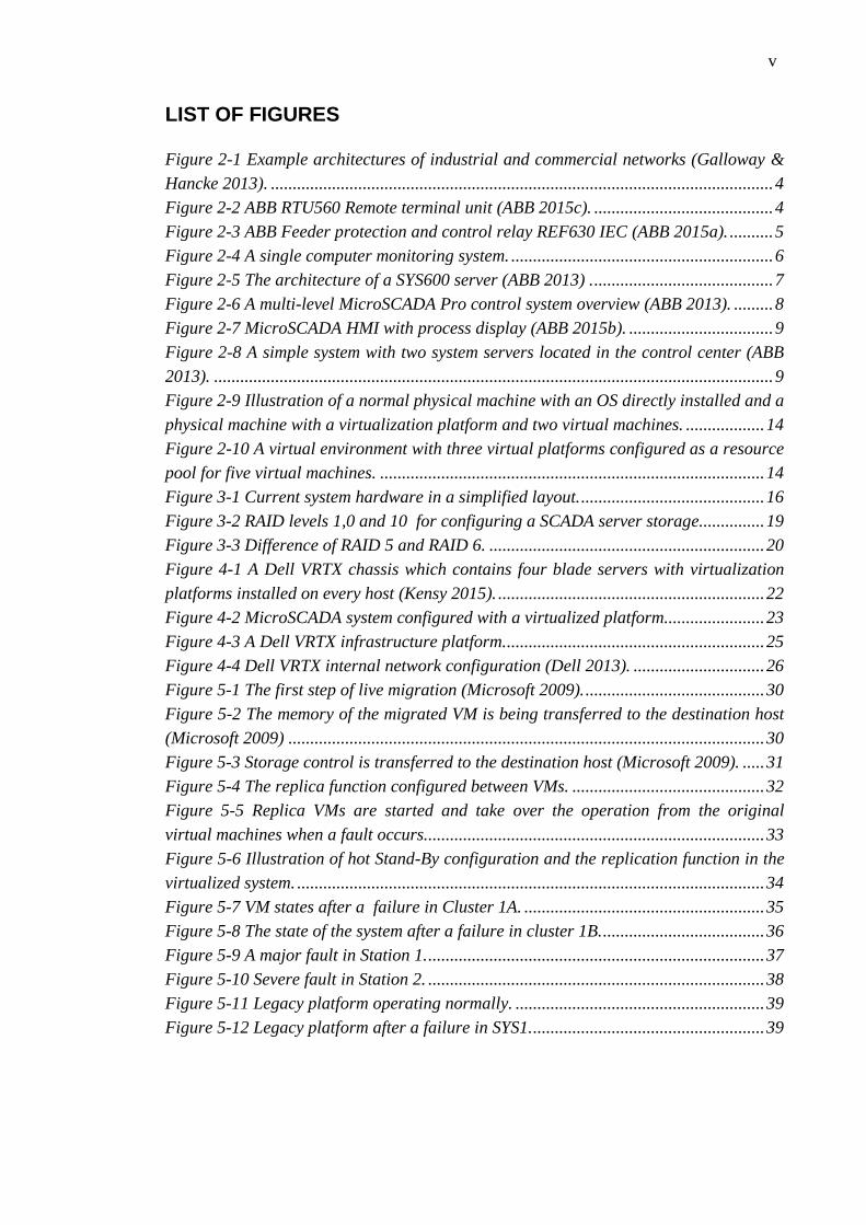
LIST OF FIGURES
Figure 2-1 Example architectures of industrial and commercial networks (Galloway &
Hancke 2013). ................................................................................................................... 4
Figure 2-2 ABB RTU560 Remote terminal unit (ABB 2015c). ......................................... 4
Figure 2-3 ABB Feeder protection and control relay REF630 IEC (ABB 2015a). .......... 5
Figure 2-4 A single computer monitoring system. ............................................................ 6
Figure 2-5 The architecture of a SYS600 server (ABB 2013) . ......................................... 7
Figure 2-6 A multi-level MicroSCADA Pro control system overview (ABB 2013). ......... 8
Figure 2-7 MicroSCADA HMI with process display (ABB 2015b). ................................. 9
Figure 2-8 A simple system with two system servers located in the control center (ABB
2013). ................................................................................................................................ 9
Figure 2-9 Illustration of a normal physical machine with an OS directly installed and a
physical machine with a virtualization platform and two virtual machines. .................. 14
Figure 2-10 A virtual environment with three virtual platforms configured as a resource
pool for five virtual machines. ........................................................................................ 14
Figure 3-1 Current system hardware in a simplified layout. .......................................... 16
Figure 3-2 RAID levels 1,0 and 10 for configuring a SCADA server storage............... 19
Figure 3-3 Difference of RAID 5 and RAID 6. ............................................................... 20
Figure 4-1 A Dell VRTX chassis which contains four blade servers with virtualization
platforms installed on every host (Kensy 2015). ............................................................. 22
Figure 4-2 MicroSCADA system configured with a virtualized platform....................... 23
Figure 4-3 A Dell VRTX infrastructure platform. ........................................................... 25
Figure 4-4 Dell VRTX internal network configuration (Dell 2013). .............................. 26
Figure 5-1 The first step of live migration (Microsoft 2009). ......................................... 30
Figure 5-2 The memory of the migrated VM is being transferred to the destination host
(Microsoft 2009) ............................................................................................................. 30
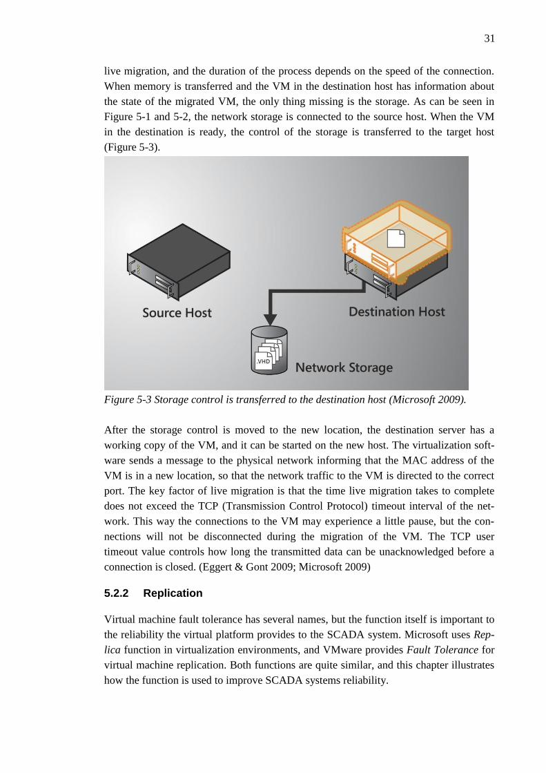
Figure 5-3 Storage control is transferred to the destination host (Microsoft 2009). ..... 31
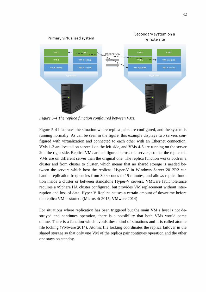
Figure 5-4 The replica function configured between VMs. ............................................ 32
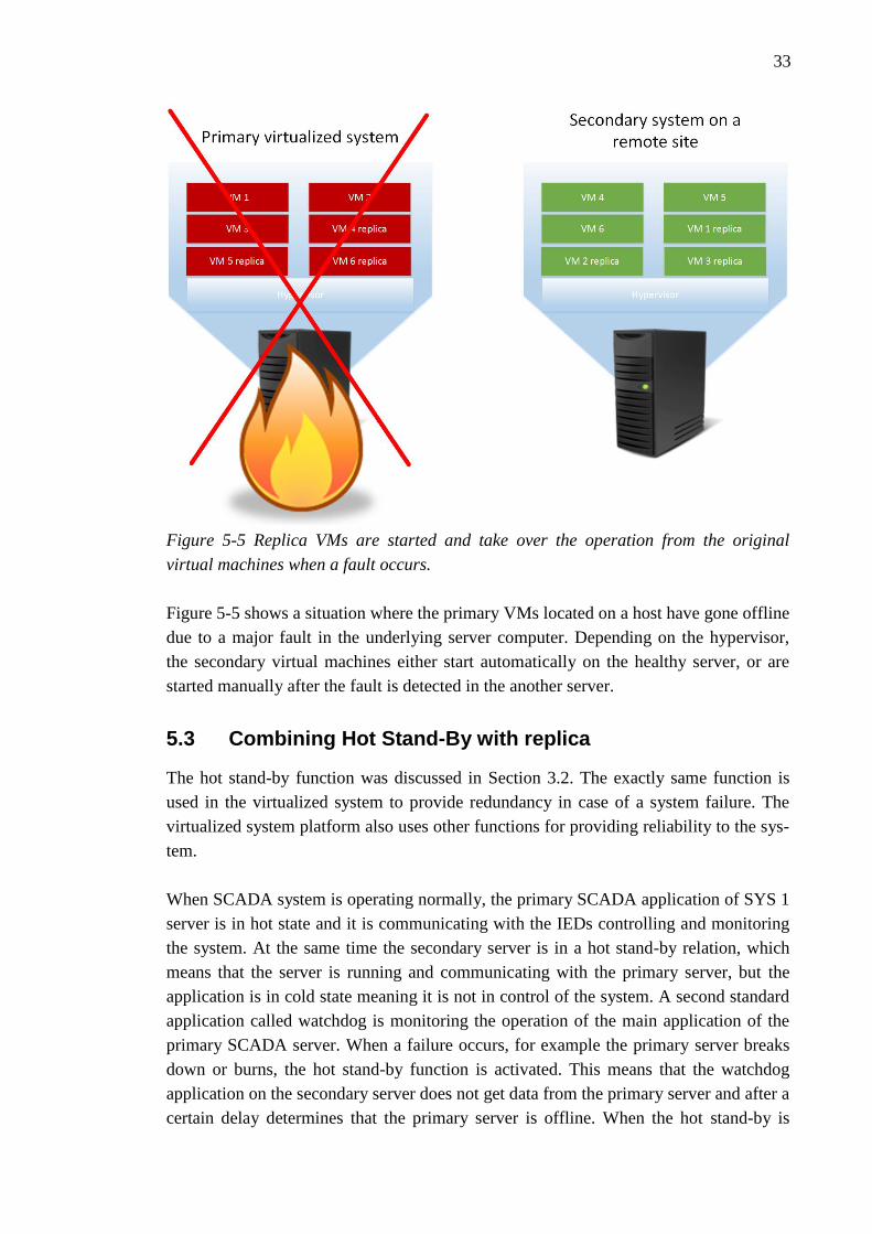
Figure 5-5 Replica VMs are started and take over the operation from the original
virtual machines when a fault occurs.............................................................................. 33
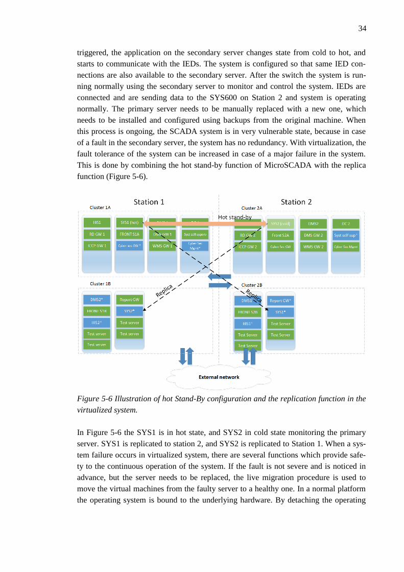
Figure 5-6 Illustration of hot Stand-By configuration and the replication function in the
virtualized system. ........................................................................................................... 34
Figure 5-7 VM states after a failure in Cluster 1A. ....................................................... 35
Figure 5-8 The state of the system after a failure in cluster 1B. ..................................... 36
Figure 5-9 A major fault in Station 1. ............................................................................. 37
Figure 5-10 Severe fault in Station 2. ............................................................................. 38
Figure 5-11 Legacy platform operating normally. ......................................................... 39
Figure 5-12 Legacy platform after a failure in SYS1. ..................................................... 39
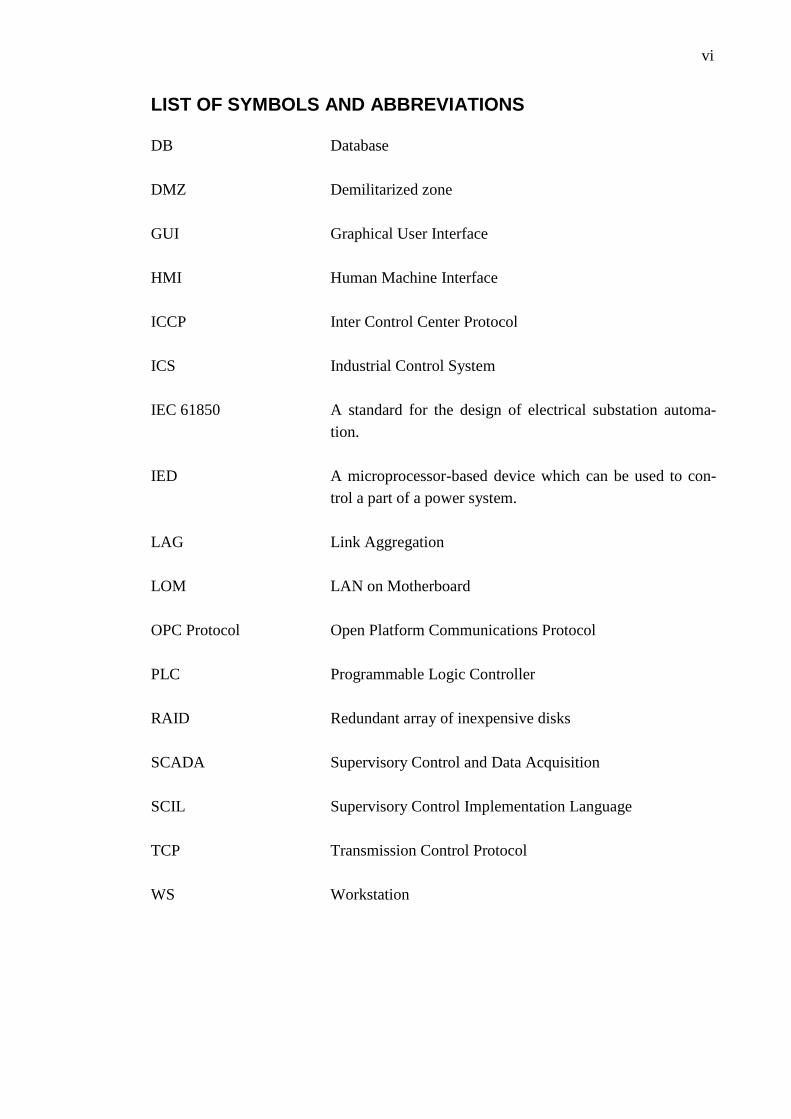
vi
LIST OF SYMBOLS AND ABBREVIATIONS
DB Database
DMZ Demilitarized zone
GUI Graphical User Interface
HMI Human Machine Interface
ICCP Inter Control Center Protocol
ICS Industrial Control System
IEC 61850 A standard for the design of electrical substation automa-
tion.
IED A microprocessor-based device which can be used to con-
trol a part of a power system.
LAG Link Aggregation
LOM LAN on Motherboard
OPC Protocol Open Platform Communications Protocol
PLC Programmable Logic Controller
RAID Redundant array of inexpensive disks
SCADA Supervisory Control and Data Acquisition
SCIL Supervisory Control Implementation Language
TCP Transmission Control Protocol
WS Workstation
1
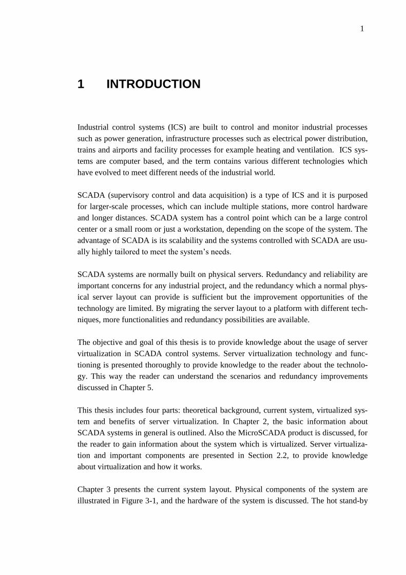
1 INTRODUCTION
Industrial control systems (ICS) are built to control and monitor industrial processes
such as power generation, infrastructure processes such as electrical power distribution,
trains and airports and facility processes for example heating and ventilation. ICS sys-
tems are computer based, and the term contains various different technologies which
have evolved to meet different needs of the industrial world.
SCADA (supervisory control and data acquisition) is a type of ICS and it is purposed
for larger-scale processes, which can include multiple stations, more control hardware
and longer distances. SCADA system has a control point which can be a large control
center or a small room or just a workstation, depending on the scope of the system. The
advantage of SCADA is its scalability and the systems controlled with SCADA are usu-
ally highly tailored to meet the system’s needs.
SCADA systems are normally built on physical servers. Redundancy and reliability are
important concerns for any industrial project, and the redundancy which a normal phys-
ical server layout can provide is sufficient but the improvement opportunities of the
technology are limited. By migrating the server layout to a platform with different tech-
niques, more functionalities and redundancy possibilities are available.
The objective and goal of this thesis is to provide knowledge about the usage of server
virtualization in SCADA control systems. Server virtualization technology and func-
tioning is presented thoroughly to provide knowledge to the reader about the technolo-
gy. This way the reader can understand the scenarios and redundancy improvements
discussed in Chapter 5.
This thesis includes four parts: theoretical background, current system, virtualized sys-
tem and benefits of server virtualization. In Chapter 2, the basic information about
SCADA systems in general is outlined. Also the MicroSCADA product is discussed, for
the reader to gain information about the system which is virtualized. Server virtualiza-
tion and important components are presented in Section 2.2, to provide knowledge
about virtualization and how it works.
Chapter 3 presents the current system layout. Physical components of the system are
illustrated in Figure 3-1, and the hardware of the system is discussed. The hot stand-by
2
redundancy method of the current system layout can be seen in Section 3.2, and the
functioning of it is reviewed.
Chapter 4 illustrates the new virtualized system layout, which runs the same Mi-
croSCADA control system but with different hardware and virtualization functionalities
present. This chapter reviews the virtualized system layout and is meant to give the
reader a grounding of how the system is normally implemented and which kind of com-
ponents it contains. To a reader who is not familiar with virtualization, it is recommend-
ed to read Chapter 2 first to be able to understand this chapter’s contents in detail.
Chapter 5 is the research part of the thesis, which reviews how the virtualization func-
tionalities can be used to improve the redundancy of the system. The hardware differ-
ences of the two system layouts are discussed, and virtualization techniques which are
meant to improve reliability are presented. Also different fault scenarios and the opera-
tion of the virtual platform when a fault occurs in the system are demonstrated.
Last two chapters present conclusion and final thoughts about the subject, as well as
challenges and prospects of the technology.

3
2 THEORY
This chapter introduces theory about virtualization, SCADA and network control sys-
tems in order for the reader to understand the functioning of the two example systems in
Chapters 3 and 4, and the reliability study done in Chapter 5.
Virtualization and cloud computing are hot topics in information technology today.
Most major companies such as Google and Microsoft as well as organizations, such as
universities use different types of virtualization for running and managing their IT infra-
structure. Virtualization can be performed by several different ways, in this thesis the
server virtualization method is used to virtualize the SCADA environment.
2.1 SCADA
Electricity consumption is increasing all the time, and consumers are becoming more
and more aware and demanding concerning the availability and quality of services. Re-
liability and high availability are crucial factors in all industries. Especially the control
functionalities and systems of a distribution network need to be well designed and top
quality, because they lay the foundation for the modern electricity supply. SCADA is an
abbreviation which is used in many cases, but basically it is a widely used type of indus-
trial control system which enables the management of remote equipment. SCADA is an
old technology (Bailey & Wright 2003), so only modern SCADA systems and princi-
ples are presented in this chapter.
SCADA is used in industry environments to control manufacturing processes, in mining
industries to control process automation, in industrial security systems, in oil fields,
airports and various other places. It consists of different types of software and hardware
components, which form the system to be able to control remotely placed electrical
equipment. SCADA is a highly customizable system which can be used to control or
supervise any kind of targets. SCADA can be implemented to control large geographic
areas which have multiple independent systems to control. It is also highly customizable
and can be tailored per needs. For example electricity distribution systems which have
control hardware and plants in many geographically different locations can be moni-
tored with SCADA.
Industrial networks which are controlled with SCADA are usually more complicated
and have more complex architecture compared to normal commercial networks. Real
time monitoring and operation are important functions when controlling an industrial

4
network, which poses challenges to the SCADA system. Figure 2-1 shows the differ-
ence between architectures of basic industrial and commercial networks.
Figure 2-1 Example architectures of industrial and commercial networks (Galloway &
Hancke 2013).
A typical SCADA system provides a centralized Human machine interface (HMI), and
it communicates with various types of control hardware, for example RTUs (Remote
Terminal Unit) and IEDs (Intelligent Electronic Device). Remote terminal units are usu-
ally specialized PLCs (Programmable Logical Controller). PLCs are computer-based
solid-state electronic devices and they are the main control components of an industrial
network. PLCs are used for automation purposes and they provide information of the
underlying system to the operator. PLCs have communication ports which are used to
communicate with SCADA and to provide data to be displayed in the HMI. Most PLCs
have both analogue and binary inputs and outputs, which are used to monitor and con-
trol the system. PLCs are highly customizable, they can have various different modules
depending on the needs of the controlled system and installation. PLCs and RTUs must
be able to function properly in locations where they can be exposed to harsh conditions
such as moisture, heat, dust and vibration. In Figure 2-2 can be seen a RTU manufac-
tured by ABB. (Bailey & Wright 2003; Galloway & Hancke 2013)
Figure 2-2 ABB RTU560 Remote terminal unit (ABB 2015c).
5
IEDs are microprocessor-based control hardware devices which are used in modern
SCADA systems to control and protect the grid. The term IED includes several types of
control hardware, including circuit breakers, transformers and protection relays. IEDs
are connected to the power grid, where they receive data from the network and based on
the configuration and type of the IED will execute different protection, communication
or control functions.
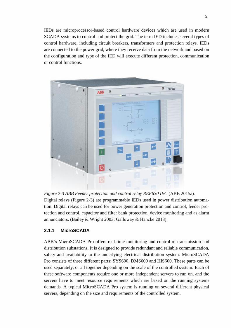
Figure 2-3 ABB Feeder protection and control relay REF630 IEC (ABB 2015a).
Digital relays (Figure 2-3) are programmable IEDs used in power distribution automa-
tion. Digital relays can be used for power generation protection and control, feeder pro-
tection and control, capacitor and filter bank protection, device monitoring and as alarm
annunciators. (Bailey & Wright 2003; Galloway & Hancke 2013)
2.1.1 MicroSCADA
ABB’s MicroSCADA Pro offers real-time monitoring and control of transmission and
distribution substations. It is designed to provide redundant and reliable communication,
safety and availability to the underlying electrical distribution system. MicroSCADA
Pro consists of three different parts: SYS600, DMS600 and HIS600. These parts can be
used separately, or all together depending on the scale of the controlled system. Each of
these software components require one or more independent servers to run on, and the
servers have to meet resource requirements which are based on the running systems
demands. A typical MicroSCADA Pro system is running on several different physical
servers, depending on the size and requirements of the controlled system.
6
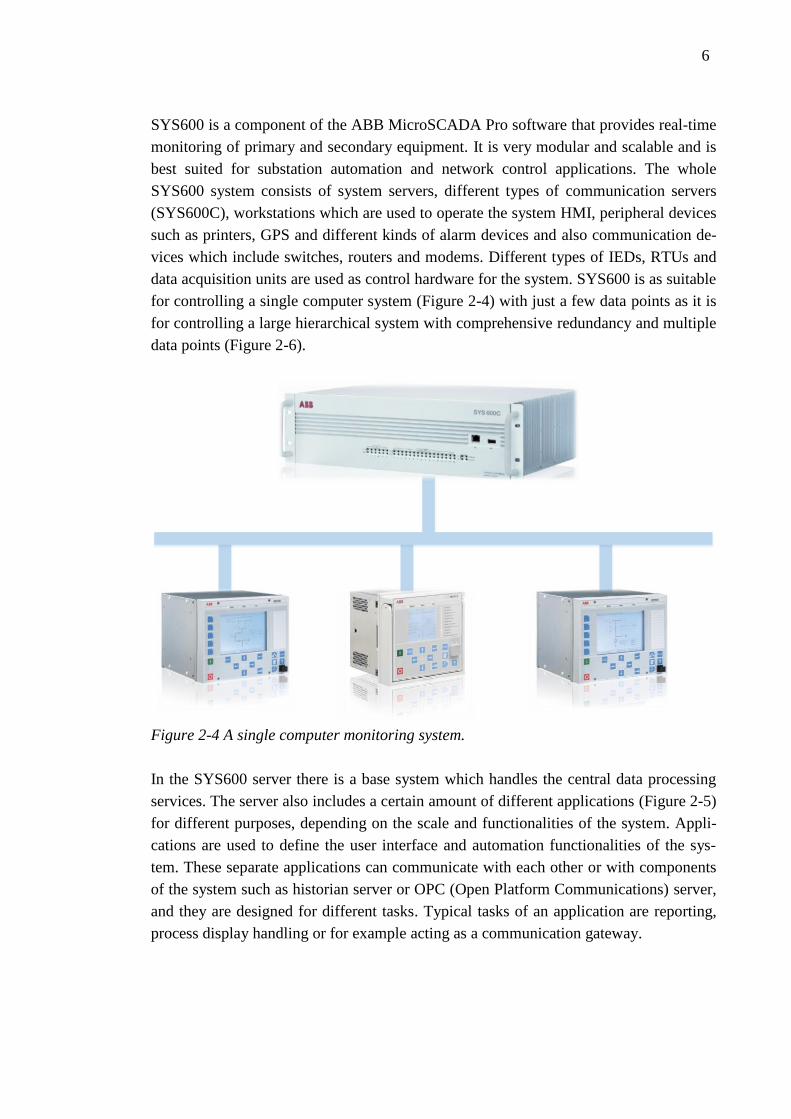
SYS600 is a component of the ABB MicroSCADA Pro software that provides real-time
monitoring of primary and secondary equipment. It is very modular and scalable and is
best suited for substation automation and network control applications. The whole
SYS600 system consists of system servers, different types of communication servers
(SYS600C), workstations which are used to operate the system HMI, peripheral devices
such as printers, GPS and different kinds of alarm devices and also communication de-
vices which include switches, routers and modems. Different types of IEDs, RTUs and
data acquisition units are used as control hardware for the system. SYS600 is as suitable
for controlling a single computer system (Figure 2-4) with just a few data points as it is
for controlling a large hierarchical system with comprehensive redundancy and multiple
data points (Figure 2-6).
Figure 2-4 A single computer monitoring system.
In the SYS600 server there is a base system which handles the central data processing
services. The server also includes a certain amount of different applications (Figure 2-5)
for different purposes, depending on the scale and functionalities of the system. Appli-
cations are used to define the user interface and automation functionalities of the sys-
tem. These separate applications can communicate with each other or with components
of the system such as historian server or OPC (Open Platform Communications) server,
and they are designed for different tasks. Typical tasks of an application are reporting,
process display handling or for example acting as a communication gateway.

7
Figure 2-5 The architecture of a SYS600 server (ABB 2013) .
Each connected substation with IEDs and RTUs as well as other components have a
system object configured to the system. Typical system objects types are system, appli-
cation, link, node, station, printer and monitor. These system objects have attributes
which can be configured, and they can be created and are managed by using SCIL (Su-
pervisory Control Implementation Language). (ABB 2013)
The base system applications contain different application objects. These objects are
used to modify and customize the operation and appearance of the application. Process
objects illustrate the connected process signals, and they store and supervise the current
state of the process. Event handling objects are used to define the texts of the states of
the process. With scales the data coming from the substations is scaled to real values of
the measured variable. Time channels can control the timing of program executions and
data registrations. Event channels control event based data registration and program
execution. Command procedures are various types of SCIL programs, which can be
executed manually or programmed with time channels to run automatically. Data ob-
jects store data from the process, and logging profile objects are used to connect the
SYS600 application database to the historian HIS600 database.

8
Figure 2-6 A multi-level MicroSCADA Pro control system overview (ABB 2013).
In Figure 2-6 can be seen an example layout of a larger MicroSCADA Pro system. The
system is controlled from the operator workstations located in the main control. Differ-
ent kinds of remote access connections can be configured, for example from substations
or other offices. This can be helpful when support is need or when operators are not
near at the actual main control center. Workstations show important information of the
system and can be configured to display desired information about the system, such as
measurements, alarms and object states. The graphical user interface (GUI) of the Mi-
croSCADA pro system displays the underlying electrical system and desired infor-
mation. This example system as 4 substations which are connected to the main control
center via gateways, and one regional control center.
The HMI of SCADA can be configured with various different types of displays, for
example process display (Figure 2-7), which shows the system and primary equipment
with general information about the systems state. Also different kinds of alarm displays,
displays showing detailed information about a certain part of the system or for example
historical data can be reviewed. Also measurement reports can be generated, usually
hourly, daily, weekly and monthly reports are present. These reports are configured ac-
cording to what the system administrators want to monitor.

9
Figure 2-7 MicroSCADA HMI with process display (ABB 2015b).
Workstations are connected to the system servers via LAN, and to other peripheral
equipment located in the control center. The servers running the whole system are also
located in the main control center. In Figure 2-8 can be seen two workstations and two
system servers connected. Every system has a certain amount of servers deployed. Typ-
ical components are SYS600, DMS600 and HIS600, which are presented later in this
chapter. Also different kinds of applications, report servers or security servers can be
deployed. If the system is very large and has a multi-level hierarchy, there is also differ-
ent types of communication and networking servers present.
Figure 2-8 A simple system with two system servers located in the control center (ABB
2013).
10
The system servers communicate with gateways which are maintaining connections in
the substations. Substations are also called local control centers, and they are located in
geographically different places, depending on the scale of the system. The gateway
hardware in the substation (SYS600C) communicates with control hardware (IEDs,
RTUs) and collects data from the devices. Then it communicates with the communica-
tion hardware in the main control center and exchanges data with the MicroSCADA
servers. (ABB 2013)
The SYS600C is a product which is used as a communication gateway between the
IEDs and RTUs which monitor the system and other parts of the MicroSCADA Pro. It
is designed for industrial use and is very scalable. For small systems the SYS600C can
also be used as a complete control system by configuring a HMI to display monitoring
and control functions of the substation. SYS600C can use various communication pro-
tocols to send and receive data, and it also supports the hot stand-by function for more
reliability and redundancy.
DMS600 can be run separately or used as an integrated functionality in any SCADA
system, being a geographical distribution network management system. With DMS600
MicroSCADA’s control functionalities can be expanded by providing geographical
views of the grid. DMS600 brings network modeling and component data management
for creating a topology of the grid to indicate the network’s current state. DMS600 has
three different applications: Network editor (DMS NE), Server application (DMS SA)
and Workstation (DMS WS). Network editor is used to model the distribution network
to the network database. The server application controls the data exchange between oth-
er MicroSCADA Pro elements, for example the SYS600. Workstation is a program for
the administrator to control and monitor the distribution network. The workstation ap-
plication contains several functions for operating the network, for example: alarming,
network topology management, network analysis, fault location, restoration and data-
base analysis. With the network editor a distribution network database can be made, and
the workstation is used to display the topology side by side with real time monitoring
data from other components of MicroSCADA Pro. (ABB 2014a)
HIS600 database is designed for process information management alongside the
SYS600 substation automation system. HIS600 has three main parts: the Database
(DB), the graphical user interface (GUI) and the interface which connects to the Mi-
croSCADA Pro’s real-time data source. The connection is made using the OPC proto-
col, and any change in the data of MicroSCADA Pro will be immediately transferred to
the HIS600 database. HIS600 main functions are to display vital process information, to
resolve problems by examining historical data and to act as a long-term storage for im-
portant historical data.
11
MicroSCADA Pro is IEC 61850 compliant, which means it can control and communi-
cate with several different types of IEDs, systems and other devices which support the
IEC 61850 standard. (ABB 2014b).
2.1.2 Security
A secure industrial network is crucial to the process being controlled. If the network
fails or is being attacked and breached, the consequences can be very severe and expen-
sive. The failure of the network can also be caused by an accident or unintentional mis-
use by an authorized user. The definition and purpose of network security is to provide
confidentiality, availability, information integrity and protection from unauthorized ac-
cess. Industrial network security is a challenge and it is currently being widely re-
searched, because of the multi-level hierarchy of the SCADA systems. Conventional
security methods such as IP security and VPN are not very useful when there are thou-
sands of devices scattered around the network and real-time protection and low latency
data transmission is required. Also industrial networks have limited or tailored hardware
components with long lifecycles, which means that extra security measures cannot be
installed or are very difficult to install to existing equipment. This means that security
must be taken into consideration already in the planning stage to be able to provide a
secure SCADA system for controlling industrial networks. (Galloway & Hancke 2013)
Cyber security is taken into account in MicroSCADA systems by providing several fea-
tures to prevent hostile intrusion. User authentication, flexible user authorization, ses-
sion expiration, communication encryption, event logging and reporting are ways used
to secure the MicroSCADA Pro system. Most of these features are managed with
SDM600, which is a software solution for service management and cyber security au-
tomation. The most important features of SDM600 are data management and evalua-
tion, central user account management and central cyber security logging. Also man-
agement of relay software versions and relay configuration revisions is included.
SDM600 is IEC 61850 compliant, so all standard devices are supported. (ABB 2015d)
2.2 Server virtualization
One goal of server virtualization is to provide server consolidation. Often many dedicat-
ed servers are underutilized and over-efficient for the current load, so server consolida-
tion brings cost and electricity savings. The cost savings are achieved by reducing the
required hardware amount, and with less hardware there is less power consumption.
With virtualization comes also efficiency and reliability benefits, which are more thor-
oughly presented and compared in Chapter 5.
The components and parts of server virtualization can have multiple different names
meaning the same thing, depending on the virtualization provider and platform. In this
thesis the physical machines which are running multiple virtual machines are called

12
“hosts”, and the virtual machines running on a physical machine are referred to as
“guests”. Replica function is called replica in a Windows environment, and the same
functionality with small differences in VMware environment is called “Fault tolerance”.
These functions involved are discussed later in this thesis.
Virtualization differs from the basic concept where one operating system is installed to
one physical machine by allowing the running of multiple operating systems on a single
physical machine. Physical machine can be normal PC or a server. The physical ma-
chine has direct access and communicates with the hardware in use. In a normal non-
virtualized environment, an operating system installed on a physical machine has direct
access to the machine’s hardware components. With virtualization, the operating system
does not have direct access to the components, because a virtualization layer called hy-
pervisor is installed between the hardware and operating system. This way multiple op-
erating systems can be deployed to run on the same physical machine. The operating
systems are running in virtual machines, which are software implementations of com-
puters that run different programs. Virtual machines are basically normal computers
which are running on a single physical machine. This way one virtual server can host
multiple virtual machines which are running different operating systems. (Barrett &
Kipper 2010)
2.2.1 Hypervisor
The virtualization layer (hypervisor) between then operating system and underlying
hardware components separates them and allows running multiple OS instances on the
same physical machine. The location of hypervisor in the system layout can be seen in
Figures 2-9 and 2-10. There are two types of hypervisors which can be installed to per-
form virtualization.
Bare-metal hypervisor is called type 1 hypervisor, and it is installed on top of the under-
lying system as a virtualization layer for controlling and managing the hardware com-
ponents (CPU, GPU, memory etc.) of the physical machine. The hypervisor is used to
allocate resources to the virtual machines, and it coordinates the usage and communi-
cates with the hardware components. For example processor usage, the hypervisor de-
livers requests and instructions between the guest operating systems and the host CPU.
The bare-metal hypervisor is a software implementation, and it is a kind of thin operat-
ing system. Bare-metal hypervisors are small and compact, so they provide good securi-
ty with a small attack surface compared to a large operating system. Virtual machines or
guest operating systems are not aware of other systems running on the same virtualiza-
tion layer, because the hypervisor isolates them from each other. Bare-metal hypervisor
is a popular choice for the virtualization technique, because it communicates directly
with the underlying hardware, and provides efficiency when multiple virtual machines
are deployed. Well known commercial products which are based on bare-metal hypervi-
sor are for example Windows Hyper-V, VMware vSphere Hypervisor and Citrix Xen-
13
Server. Also in Figures 2-9 and 2-10 a bare-metal hypervisor is illustrated, as it is in-
stalled straight on top of the underlying hardware.
Type 2 hypervisor is called a hosted hypervisor, and it differs from bare-metal hypervi-
sor in the install method. Hosted hypervisor is implemented on top of an already exist-
ing operating system. This way the hosted hypervisor can be seen as a program running
on the operating system. Example products which use this type of hypervisor are
VMware Workstation and Oracle VM VirtualBox. (Barrett & Kipper 2010)
2.2.2 Basic operation
Most of modern computers and servers can be deployed with virtualization technology.
The platforms used in virtualization can be normal servers which are also used in legacy
systems. When using identical servers for constructing resource pools, all the ad-
vantages of virtualization can be exploited. Various types of industrial platforms opti-
mized for virtualization are also available. These platforms provide shared storage func-
tions and fast internal communication links between the virtualized servers. These are
important properties for the functions virtualization provides. These functions are dis-
cussed later in Section 5.2. This section presents the basic operation and deployment
procedure of virtualization.
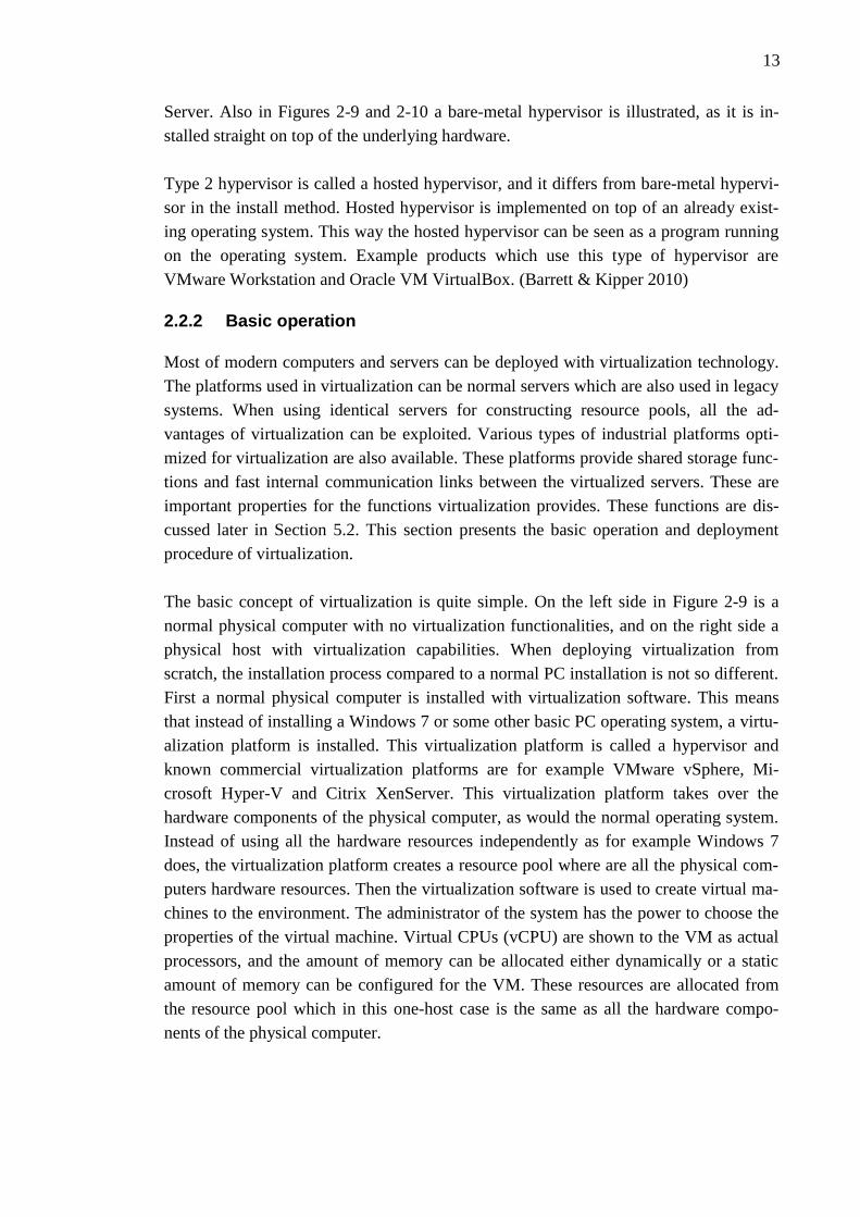
The basic concept of virtualization is quite simple. On the left side in Figure 2-9 is a
normal physical computer with no virtualization functionalities, and on the right side a
physical host with virtualization capabilities. When deploying virtualization from
scratch, the installation process compared to a normal PC installation is not so different.
First a normal physical computer is installed with virtualization software. This means
that instead of installing a Windows 7 or some other basic PC operating system, a virtu-
alization platform is installed. This virtualization platform is called a hypervisor and
known commercial virtualization platforms are for example VMware vSphere, Mi-
crosoft Hyper-V and Citrix XenServer. This virtualization platform takes over the
hardware components of the physical computer, as would the normal operating system.
Instead of using all the hardware resources independently as for example Windows 7
does, the virtualization platform creates a resource pool where are all the physical com-
puters hardware resources. Then the virtualization software is used to create virtual ma-
chines to the environment. The administrator of the system has the power to choose the
properties of the virtual machine. Virtual CPUs (vCPU) are shown to the VM as actual
processors, and the amount of memory can be allocated either dynamically or a static
amount of memory can be configured for the VM. These resources are allocated from
the resource pool which in this one-host case is the same as all the hardware compo-
nents of the physical computer.
14
Figure 2-9 Illustration of a normal physical machine with an OS directly installed and a
physical machine with a virtualization platform and two virtual machines.
This is a very simple example of how virtualization works. Normally in a real environ-
ment virtualization is used with multiple computers and large resource pools, so that all
the functions of virtualization can be utilized efficiently.
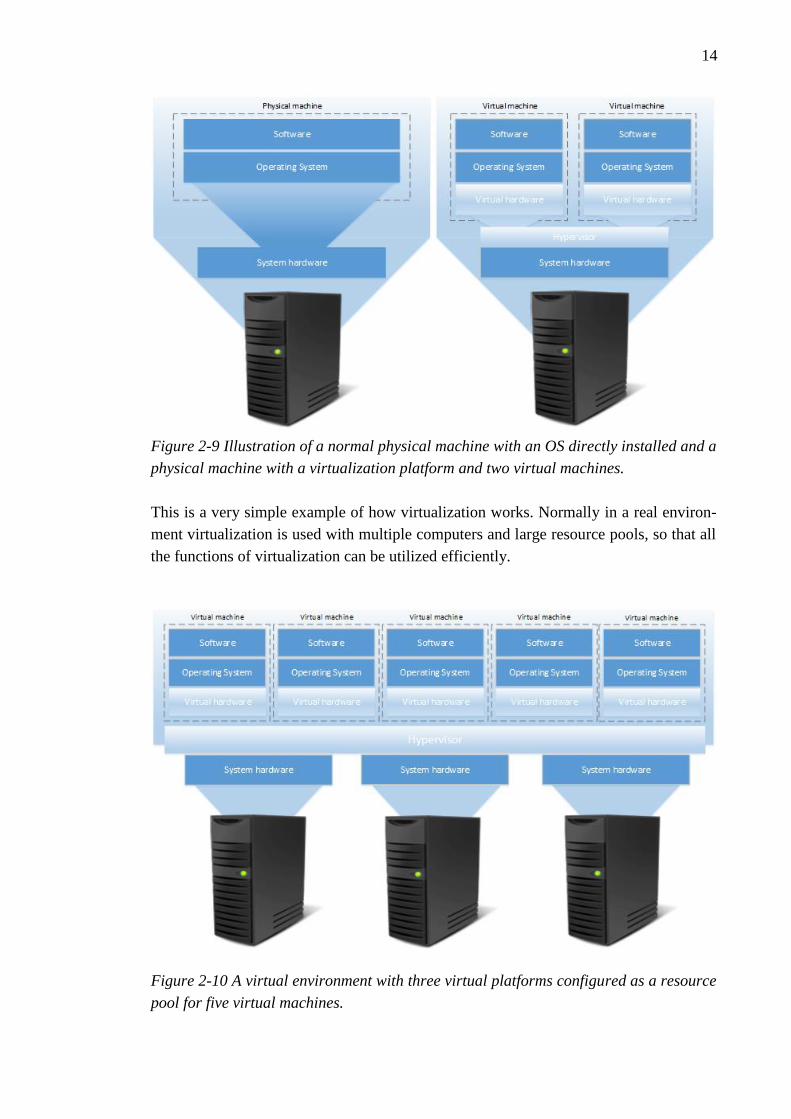
Figure 2-10 A virtual environment with three virtual platforms configured as a resource
pool for five virtual machines.

15
In Figure 2-10 can be seen a slightly more complicated and sophisticated illustration of
virtual environment. The same virtualized physical machine which was on the right side
in Figure 2-9 is teamed with similar physical machines to provide a wider resource pool.
This allows the administrator to plan and configure several different functions to the
environment which increase the reliability and redundancy features of the system. By
adding more hardware to the resource pool, several new virtual machines can be de-
ployed and they can be for example moved in case of a mandatory maintenance.
When several physical machines are available, the virtualization platform is installed to
every machine. A virtual environment can then be configured, by combining the availa-
ble hosts to a single resource pool. The administrator now has a pool which in this case
has four 8-core processors (32 cores) and 128 GB memory available in its resource
pool. Naturally all the host’s resources cannot be allocated to the virtual machines, be-
cause the actual virtualization platform needs some of the machine’s hardware resources
to be able to run the virtualization environment.
When the resource pool is ready and configured, the virtual machines are deployed into
the virtual environment. Administrator can decide which underlying physical machine’s
hardware resources they use. In case of planned maintenance in some of the hosts, the
virtual machines can be moved to run from another host in the resource pool, which is
called live migration. When performing live migration, the virtual machines are moved
while powered on and operating, so this will not interrupt the operation of the virtual
machine. More information about live migration is included in Chapter 5.
16
3 CURRENT SYSTEM
In this chapter there is an example MicroSCADA Pro system presented. The current
system is built by using ABB’s proprietary MicroSCADA Pro software, and the system
consists of several different components. An overview of a general SCADA system is
presented in Chapter 2. Also in this chapter the hardware properties of the current sys-
tem are discussed and specified.
3.1 Current system layout
The current system consists of the MicroSCADA components running on different
servers, backup servers for each MicroSCADA component and also different servers for
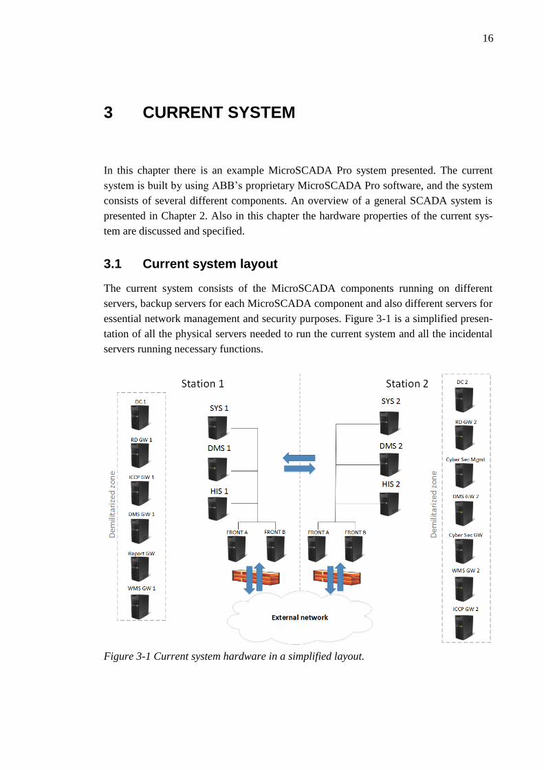
essential network management and security purposes. Figure 3-1 is a simplified presen-
tation of all the physical servers needed to run the current system and all the incidental
servers running necessary functions.
Figure 3-1 Current system hardware in a simplified layout.
17
Station 1 and Station 2 are located on separate locations, and are connected with a high-
speed Ethernet connection. SYS600, DMS600 and HIS600 servers are located on both
stations, meaning that they all have primary running servers on Site 1 and backup serv-
ers on Site 2 as hot stand-by (Section 3.2) pairs. This way in case of a fault the proper
functioning of the MicroSCADA system can be secured. Fronts A and B on both sites
are duplicated, meaning that Front As on both stations are primary gateways, and Front
Bs serve as backups. The front machines are used as a gateway to connect the SCADA
system to the external network and to IEDs. Network traffic to the external network
goes through a firewall to prevent unauthorized access. Incidental servers are running
inside a DMZ (Demilitarized Zone), which is required for remote connections outside
the system.
Core servers for running the MicroSCADA system in Figure 3-1 are HIS, SYS and
DMS which were presented in Section 2.1. Incidental servers are also vital, they provide
necessary functions for connecting, managing and protecting the system. DC 1 is a do-
main controller server which is used to control the Active Directory database. Domain
controller manages security authentication requests and distributes security policies to
the Windows machines connected to the network (Microsoft 2014a). DC 2 is a second-
ary domain controller, which provides redundancy for user account logging and is used
for load distribution. RD GW 1 means remote desktop gateway. This server serves as a
gateway for remote desktop connections to the system. Windows operating systems
provide the Remote Desktop Services function which is used to connect remotely to a
computer and control it and its network resources (Microsoft 2014c). RD GW 2 is simi-
lar but is managing connections to Station 2. ICCP (Inter Control Center Protocol)
gateways provide data exchange between control centers over wide area networks
(CompuSharp Inc 2013). Cyber Security server handles operating system updates and
runs antivirus software. Cyber Security GW acts as a gateway between cyber security
and update servers which are located in the external network. WMS Server provides
geographical mapping and connects handheld devices to the system. These handheld
devices can be configured to display information and alarms about the system and the
location of the fault. DMS and report GWs act as gateways to the DMS600 and HIS600
SCADA components.
3.2 Hot Stand-By
The “Hot stand-by” function in MicroSCADA Pro is the most used way to provide re-
dundancy and reliability to the SCADA system. System availability is improved by re-
dundant servers which use hot-stand-by-mode (HSB). HSB means that there is always
redundancy between applications which are in a hot stand-by relation. In HSB there are
two applications, and at the same time the other one is active and receiving and sending
data, while the other is in stand-by mode, ready to take over if the main application fails
or goes offline. The stand-by application is precisely at the same state as the main appli-

18
cation at all times. If a failure occurs in the main application, the stand-by application
turns active and can continue operating normally with the IEDs and other devices which
were connected to the formerly active application, after a pre-set detection time. This
way system downtime caused by hardware failures can be reduced. Process data, con-
figuration information and connections are continually shadowed to the stand-by system
from the active system, which is necessary for the operation of the HSB functionality.
Communication redundancy can be achieved by using redundant communication lines,
which means that two or more connections form one logical connection. Communica-
tion redundancy works the same way as hot stand-by, one line is active and transferring
data, while other lines are in stand-by mode ready to take over in case of a fault in the
primary communication line. At the software layer, this can be achieved by using LAG
(Link aggregation) for providing a backup line to one functional connection. There are
several different definitions for the same operation, for example Windows uses “NIC
teaming” to provide redundancy between multiple network adapters. (ABB 2013;
Microsoft 2014b).
3.3 Physical components in the current system layout
The current and most often used system configuration requires several different physical
servers. Operating systems are installed independently on physical servers, one per
server. This setting requires each MicroSCADA Pro component to have one or several
physical servers installed depending on the size of the operated grid.
The servers are designed for industry usage with hardware redundancy and quality
components. In this system Dell R720 servers are used for important MicroSCADA Pro
components, and Dell R320 servers for the supporting systems. In this example case the
system has a total of 23 physical servers installed. The example system infrastructure
consists of two different locations, Station 1 and Station 2. These stations are connected
to each other with a redundant Ethernet connection for data exchange. Station 1 has 11
different physical servers deployed, and Station two has 12. At both stations there are
servers which run the MicroSCADA Pro SYS600 operating system, DMS600 servers,
two front end computers and historical information servers. These servers are provided
with different builds of hardware because of different performance requirements, and
the hardware specifications of the servers are discussed next.
All of the SYS600 and DMS600 servers are running on Dell R720 servers which each
have one Intel E5-2670 v2 processor with 10 cores and the processor base frequency at
2.50 GHz. The servers have a total of 64 GB (8x8 GB) RDIMM memory. Memory
modules used in the servers are registered DDR3 modules with a memory clock fre-
quency at 1600MHz. The registered memory module (RDIMM) means that the module
itself has a register (buffer) between the RAM-module (Random Access Memory) and

19
the system’s memory controller, which makes it possible to install more RAM per one
module. This way higher memory performance and scalability can be achieved.
The HIS600 server requires more resources compared to the other MicroSCADA com-
ponents. The base server model which it uses is the same Dell R720. The E5-2670 v2
processors are replaced with two Intel E5-2643 v2 processors which have 6-cores each
and a 3.5 GHz base frequency. Memory requirement for SYS600 and DMS600 was 64
GB, the HIS600 server is equipped with a total of 256 GB RAM.
The redundancy and reliability of the used storage is vital to the operation of the system
and to the recovery of important data in case of a fault in the system. RAID (Redundant
array of inexpensive disks) is a well-known technology for data storage redundancy and
it is used in this thesis. RAID uses mirroring and striping and different combinations of
them for providing different RAID types. Mirroring means that data segments are cop-
ied to different physical devices. Striping stores consecutive data segments to different
physical devices for increasing data throughput.
Figure 3-2 RAID levels 1,0 and 10 for configuring a SCADA server storage.
RAID 1 mirroring is commonly used in smaller servers for backing up the system and to
prevent single hardware failure point affecting the functioning of the system. For the
larger-scale servers which have more hard drives, the RAID 10 (RAID 1+0) function
with mirroring and striping is a commonly used backup solution. It also provides some
performance increase due to the included striping function. RAID 5 is an older RAID
level, and it uses block-level striping with distributed parity. RAID 6 is very similar to
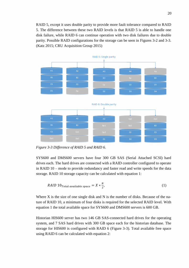
20
RAID 5, except it uses double parity to provide more fault tolerance compared to RAID
5. The difference between these two RAID levels is that RAID 5 is able to handle one
disk failure, while RAID 6 can continue operation with two disk failures due to double
parity. Possible RAID configurations for the storage can be seen in Figures 3-2 and 3-3.
(Katz 2015; CRU Acquisition Group 2015)
Figure 3-3 Difference of RAID 5 and RAID 6.
SYS600 and DMS600 servers have four 300 GB SAS (Serial Attached SCSI) hard
drives each. The hard drives are connected with a RAID controller configured to operate
in RAID 10 – mode to provide redundancy and faster read and write speeds for the data
storage. RAID 10 storage capacity can be calculated with equation 1:
𝑅𝐴𝐼𝐷 10𝑇𝑜𝑡𝑎𝑙 𝑎𝑣𝑎𝑖𝑙𝑎𝑏𝑙𝑒 𝑠𝑝𝑎𝑐𝑒 = 𝑋 ∗𝑁
2, (1)
Where X is the size of one single disk and N is the number of disks. Because of the na-
ture of RAID 10, a minimum of four disks is required for the selected RAID level. With
equation 1 the total available space for SYS600 and DMS600 servers is 600 GB.
Historian HIS600 server has two 146 GB SAS-connected hard drives for the operating
system, and 7 SAS hard drives with 300 GB space each for the historian database. The
storage for HIS600 is configured with RAID 6 (Figure 3-3). Total available free space
using RAID 6 can be calculated with equation 2:

21
𝑅𝐴𝐼𝐷 6𝑇𝑜𝑡𝑎𝑙 𝑎𝑣𝑎𝑖𝑙𝑎𝑏𝑙𝑒 𝑠𝑝𝑎𝑐𝑒 = 𝑋 ∗ (𝑁 − 2), (2)
Where X is the size of one single disk, and N is the amount of disks available. By using
equation 2, the total available space for the historian database is 1500 GB.
Server storage is configured differently depending on the requirements of the running
server. The right RAID level is chosen by taking into consideration speed and redun-
dancy requirements. Historian server stores data from the process, so the available free
space and double parity for additional redundancy provided by RAID 6 are important
factors when choosing the RAID level. On the other hand the SYS and DMS servers
need to access their storage fast and they do not store as much data as does the historian
server, so RAID level 10 is a more suitable choice for the redundancy method.
22
4 VIRTUALIZED SYSTEM
This chapter presents the same example MicroSCADA system as in Chapter 3, but the
hardware is running on a virtualized platform. The hardware needed for a virtualized
environment is presented, also brief configuration examples are included.
Server virtualization brings several new functions and aspects compared to a basic serv-
er layout. The new functions affect redundancy, maintenance, backup and restoration
and recovery in case of a system breakdown. The purpose of the virtualized environ-
ment for the MicroSCADA system is to provide a similar hardware platform, but with
extra functions and reliability. Ideally the administrator of the system does not notice
any difference in the performance of the actual SCADA system.
4.1 System layout
The MicroSCADA system can be implemented on a virtualized platform. The platform
can be compiled in several different ways, this thesis presents one way to do it.
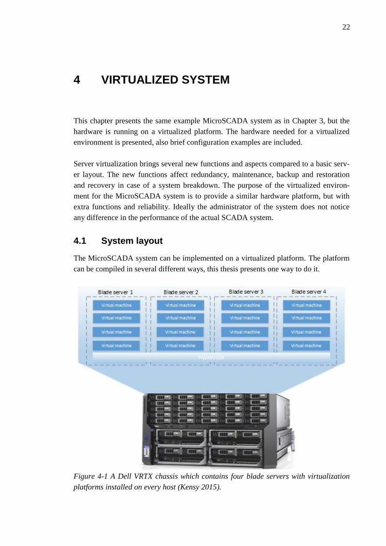
Figure 4-1 A Dell VRTX chassis which contains four blade servers with virtualization
platforms installed on every host (Kensy 2015).
23
The example virtualized system is built on a Dell PowerEdge VRTX shared infrastruc-
ture platform (Figure 4-1) which is a chassis with sockets for up to four blade servers.
Each blade server is installed with virtualization software, and a shared resource pool is
configured. This way the virtual machines using the resource pool’s resources can ex-
ploit all the functions of server virtualization. Figure 4-1 is for clarification and illus-
trates the contents of one Dell VRTX chassis. (Dell 2015)
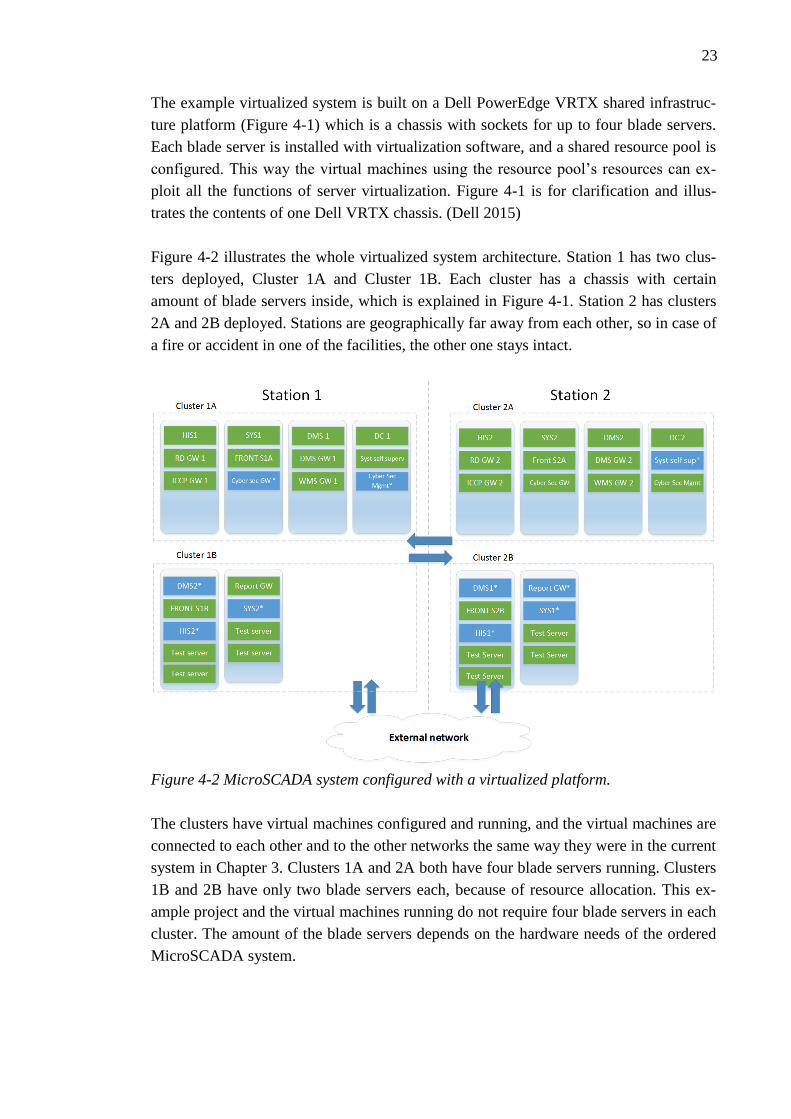
Figure 4-2 illustrates the whole virtualized system architecture. Station 1 has two clus-
ters deployed, Cluster 1A and Cluster 1B. Each cluster has a chassis with certain
amount of blade servers inside, which is explained in Figure 4-1. Station 2 has clusters
2A and 2B deployed. Stations are geographically far away from each other, so in case of
a fire or accident in one of the facilities, the other one stays intact.
Figure 4-2 MicroSCADA system configured with a virtualized platform.
The clusters have virtual machines configured and running, and the virtual machines are
connected to each other and to the other networks the same way they were in the current
system in Chapter 3. Clusters 1A and 2A both have four blade servers running. Clusters
1B and 2B have only two blade servers each, because of resource allocation. This ex-
ample project and the virtual machines running do not require four blade servers in each
cluster. The amount of the blade servers depends on the hardware needs of the ordered
MicroSCADA system.

24
Virtual machines in the cluster can be configured to run on desired servers depending on
the resource requirements of the virtual machines. In Figure 4-2 there are the same serv-
er components which were present in the current system layout, Figure 3-1. The virtual
machines are placed optimally so that the load of the VMs is evenly distributed between
the servers. The virtualized environment is also running a test environment, which is
located on clusters 1B and 2B.
The clusters are connected to each other and to the external networks. Virtual machines
inside the cluster are configured with the same connections which they have in the cur-
rent system. In the Figure 4-2 there are virtual machines marked with green and blue
colors. Green VMs are online and operational, and the blue ones marked with * are rep-
lica VMs which are offline and configured by the virtualization software to match the
VM they are replicated from. More information about replication is in Section 5.2.
4.2 Hardware components
In this example the virtual system is running on 12 Dell PowerEdge M630 blade serv-
ers, which are running inside four Dell PowerEdge VRTX platforms. The servers are
rugged industrial servers with high-quality components. In the system all the servers are
M630 models, but the hardware properties vary slightly depending on the load and vir-
tual machines running on the servers. For example MicroSCADA component HIS600
historian server requires more resources than SYS 600 or DMS600.
The M630 blade servers are equipped with two different line-ups, one is designed to be
capable of running the HIS600 full time, and the other is for the other systems which do
not require so much resources. Processors used in both types of servers are Intel Xeon
E5-2680 v3, which have 12 cores and a base frequency of 2.50 GHz.
The historian HIS600 component requires significantly more memory than other parts
of the MicroSCADA system, so the HIS-capable servers differ from the other servers in
the amount of memory. The non-HIS-capable servers are equipped with 8 units of 16
GB RDIMM memory, a total of 128 GB. The more powerful HIS-capable servers have
16 units of the same memory, a total of 256 GB. This makes them able to run the
HIS600 server component smoothly.
4.2.1 Storage
The storage layout differs from the basic layout where hard disks are configured directly
to a specific computer or server. The VRTX infrastructure platform (Figure 4-3) comes
with a RAID controller and sockets for hard disks, so the data storage can be configured
directly to the chassis. This way all the blade servers running inside the chassis have a
direct access to the RAID controller of the VRTX chassis. Figure 4-3 illustrates the
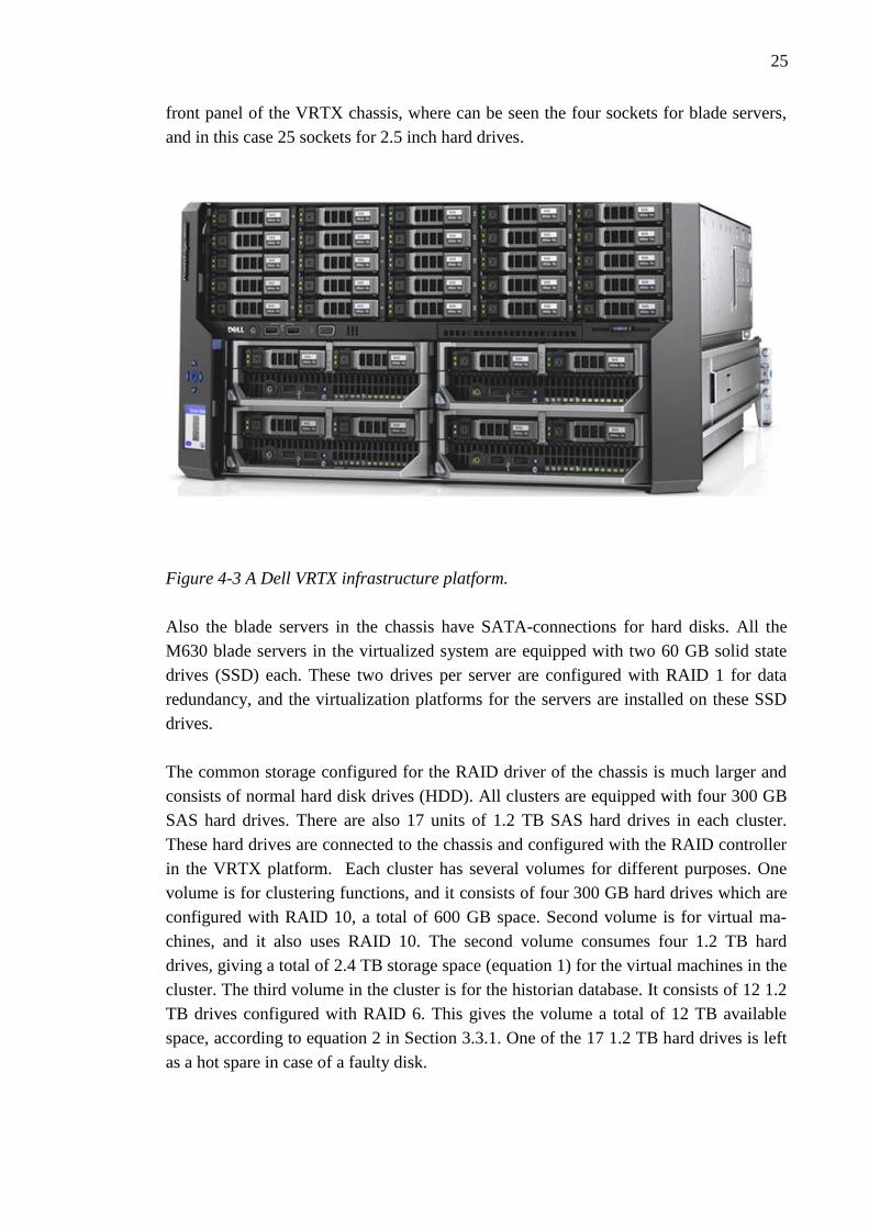
25
front panel of the VRTX chassis, where can be seen the four sockets for blade servers,
and in this case 25 sockets for 2.5 inch hard drives.
Figure 4-3 A Dell VRTX infrastructure platform.
Also the blade servers in the chassis have SATA-connections for hard disks. All the
M630 blade servers in the virtualized system are equipped with two 60 GB solid state
drives (SSD) each. These two drives per server are configured with RAID 1 for data
redundancy, and the virtualization platforms for the servers are installed on these SSD
drives.
The common storage configured for the RAID driver of the chassis is much larger and
consists of normal hard disk drives (HDD). All clusters are equipped with four 300 GB
SAS hard drives. There are also 17 units of 1.2 TB SAS hard drives in each cluster.
These hard drives are connected to the chassis and configured with the RAID controller
in the VRTX platform. Each cluster has several volumes for different purposes. One
volume is for clustering functions, and it consists of four 300 GB hard drives which are
configured with RAID 10, a total of 600 GB space. Second volume is for virtual ma-
chines, and it also uses RAID 10. The second volume consumes four 1.2 TB hard
drives, giving a total of 2.4 TB storage space (equation 1) for the virtual machines in the
cluster. The third volume in the cluster is for the historian database. It consists of 12 1.2
TB drives configured with RAID 6. This gives the volume a total of 12 TB available
space, according to equation 2 in Section 3.3.1. One of the 17 1.2 TB hard drives is left
as a hot spare in case of a faulty disk.

26
4.2.2 Networking
Dell VRTX industrial platform provides redundant network connections. The platform
has an internal switch with 16 internal ports which connects the blades to each other for
fast and uninterrupted data exchange. The chassis also provides 6 external ports which
can be mapped to virtual machines for network connection. Usually the system is large
and has several connections to the control hardware, so additional external ports are
needed. For these kind of requirements, the chassis has 3 full-height and 5 low-profile
PCI-e slots available for connecting extra network interface controllers.
In this example project the VRTX platforms are deployed with 10 GB internal switches
with 16 ports for inter-blade communication, as well as 6 ports for external communica-
tion. 4 of these ports have SFP+ (Enhanced Small Form-factor Pluggable) transceivers,
which are used to connect optical fiber cables. Enhanced means that the SFP+ supports
higher data rates (up to 10GB) than the normal standard SFP (Cisco 2015). The other 2
ports have 1 GB RJ45 connectors. Additionally the platforms in clusters 1A and 1B
have 8 network adapters, 3 normal size and 5 low profile adapters for expanding the
connectivity of the platform. Platforms in clusters 2A and 2B have 3 normal size net-
work adapters and 1 low profile adapters. All the additional PCI-e network adapters
provide two extra ports. (Dell 2014)
Figure 4-4 Dell VRTX internal network configuration (Dell 2013).
27
The platform has an internal switch for managing connections inside the platform and
connections from the internal ports to external ports. Figure 4-4 shows the internal net-
work configuration of a Dell VRTX chassis. Servers 1-4 are the blade servers inside the
chassis, and they are connected to the external Ethernet ports via the internal Ethernet
switch.
LOM (LAN on Motherboard) ports are located on blade servers, and they are connected
via the server midplane to the internal Ethernet switch. SFP+ and RJ45 connectors are
physically located at the back of the platform, and they are also connected to the internal
switch. The additional dual-port NICs in the clusters are not present in this Figure 4-4,
because they are connected to the PCI-e ports of the platforms.

28
5 BENEFITS OF SERVER VIRTUALIZATION
In this chapter the systems presented in the Chapters 4 and 5 are compared. The reliabil-
ity function of the current system is combined with virtualization functionalities and
some fault scenarios concerning reliability, availability and recovery are illustrated, in
order to present the reader how the proposed redundancy improvements operate in dif-
ferent fault scenarios. The goal of this chapter is to resolve the possible benefits of serv-
er virtualization.
5.1 Differences between the two implementations
The hardware requirements of the platforms for the current SCADA system are present-
ed in Chapters 3 and 4. There is a significant difference between these two implementa-
tions, and it creates different hardware needs. The legacy system binds a certain amount
of hardware per server, and it is difficult to adjust the amount of hardware resources per
server after deployment. This problem is often solved by overprovisioning the needed
resources, so that in the future when the servers need more resources the current hard-
ware will still be sufficient. This causes extra costs for present systems and increases the
systems TCO (Total Cost of Ownership). Virtualized platform provides resource pools
for the clusters which contain all hardware resources available, and the resources can be
allocated to virtual machines according to current requirements.
The reduction of excessive hardware capacity per server is also called server consolida-
tion. The legacy server layout has very limited consolidation possibilities after it is de-
ployed. Virtualization platform allows the administrator to reallocate resources also
after the deployment. If a VM requires more hardware resources in the future, with vir-
tualization it is possible to allocate for example more computing power or more
memory to the virtual machine easily. (VMware 2015)
The current server layout has a total of 23 independent servers installed and running.
The virtualized system has 4 clusters running, which have a total of 12 servers installed.
Clusters 1A and 2A have four and clusters 1B and 2B have two servers installed. This is
48% less servers deployed. To be able to reduce the amount of servers deployed, the
servers running in the virtualized system are more powerful compared to the servers
running in the legacy system. For example the SYS1 server in the legacy system has one
10-core 2.50 GHz processor and 64GB memory. In comparison the M630 server run-
ning SYS1 virtual machine inside cluster 1A has two 12-core processors running at 2.50
GHz and 128 GB memory, this is 140 % more processor cores and 100% more memory.
29
The M630 server is also running the FRONT 1A virtual machine. The servers are inten-
tionally equipped with powerful hardware. This is for redundancy purposes. The servers
inside clusters have extra resources prepared for situations where other servers go of-
fline, so that they can handle the extra load caused by virtual machines rebooting to an
intact server. These situations are discussed in Section 5.4: Operation in different fault
scenarios.
5.2 Functions provided by a virtualized platform
Availability is an important factor in both of the systems in Chapters 3 and 4. The re-
sources and services must be accessible at all times, or if a failure occurs, as soon as
possible. MicroSCADA system requires real-time communication with the control
hardware, so service availability is vital to the operation of the system. This chapter
discusses functions which virtualization provides.
5.2.1 Live Migration
There are several different names for live migration, but they all have the same basic
functioning. Windows Server operating systems provide live migration as an integrated
function for the Hyper-V hypervisor. VMware provides live migration for their virtual-
ization solutions and it is called VMotion. Live migration in general is a function for
moving running virtual machines from one physical host to another. This operation can
be done without causing any downtime to the operating virtual machines and services.
Server consolidation and load balancing can be done in the virtual environment with
live migration. In systems which are running on a virtualized platform, live migration is
an important function to the systems availability and uninterrupted operation.
(Microsoft 2009; VMware 2009)
Live migration inside a cluster can be done so that the user of the virtual machine does
not notice the process being executed. When the process starts, first a TCP connection is
made between the source and target host servers. An empty VM is deployed to the tar-
get host and configuration data is transferred (see Figure 5-1).

30
Figure 5-1 The first step of live migration (Microsoft 2009).
When the destination host has the configuration data and the VM shell deployed, the
actual live migration can be started. This means that the memory assigned to the virtual
machine which is going to be migrated is copied to the destination host, while the VM is
still running on the source host (see Figure 5-2).
Figure 5-2 The memory of the migrated VM is being transferred to the destination host
(Microsoft 2009)
When the memory and all the modifications in the memory are transferred, the register
and device state of the VM are transferred. A fast Ethernet connection is required for the
31
live migration, and the duration of the process depends on the speed of the connection.
When memory is transferred and the VM in the destination host has information about
the state of the migrated VM, the only thing missing is the storage. As can be seen in
Figure 5-1 and 5-2, the network storage is connected to the source host. When the VM
in the destination is ready, the control of the storage is transferred to the target host
(Figure 5-3).
Figure 5-3 Storage control is transferred to the destination host (Microsoft 2009).
After the storage control is moved to the new location, the destination server has a
working copy of the VM, and it can be started on the new host. The virtualization soft-
ware sends a message to the physical network informing that the MAC address of the
VM is in a new location, so that the network traffic to the VM is directed to the correct
port. The key factor of live migration is that the time live migration takes to complete
does not exceed the TCP (Transmission Control Protocol) timeout interval of the net-
work. This way the connections to the VM may experience a little pause, but the con-
nections will not be disconnected during the migration of the VM. The TCP user
timeout value controls how long the transmitted data can be unacknowledged before a
connection is closed. (Eggert & Gont 2009; Microsoft 2009)
5.2.2 Replication
Virtual machine fault tolerance has several names, but the function itself is important to
the reliability the virtual platform provides to the SCADA system. Microsoft uses Rep-
lica function in virtualization environments, and VMware provides Fault Tolerance for
virtual machine replication. Both functions are quite similar, and this chapter illustrates
how the function is used to improve SCADA systems reliability.
32
Figure 5-4 The replica function configured between VMs.
Figure 5-4 illustrates the situation where replica pairs are configured, and the system is
running normally. As can be seen in the figure, this example displays two servers con-
figured with virtualization and connected to each other with an Ethernet connection.
VMs 1-3 are located on server 1 on the left side, and VMs 4-6 are running on the server
2on the right side. Replica VMs are configured across the servers, so that the replicated
VMs are on different server than the original one. The replica function works both in a
cluster and from cluster to cluster, which means that no shared storage is needed be-
tween the servers which host the replicas. Hyper-V in Windows Server 2012R2 can
handle replication frequencies from 30 seconds to 15 minutes, and allows replica func-
tion inside a cluster or between standalone Hyper-V servers. VMware fault tolerance
requires a vSphere HA cluster configured, but provides VM replacement without inter-
ruption and loss of data. Hyper-V Replica causes a certain amount of downtime before
the replica VM is started. (Microsoft 2015; VMware 2014)
For situations where replication has been triggered but the main VM’s host is not de-
stroyed and continues operation, there is a possibility that both VMs would come
online. There is a function which avoids these kind of situations and it is called atomic
file locking (VMware 2014). Atomic file locking coordinates the replica failover in the
shared storage so that only one VM of the replica pair continues operation and the other
one stays on standby.
33
Figure 5-5 Replica VMs are started and take over the operation from the original
virtual machines when a fault occurs.
Figure 5-5 shows a situation where the primary VMs located on a host have gone offline
due to a major fault in the underlying server computer. Depending on the hypervisor,
the secondary virtual machines either start automatically on the healthy server, or are
started manually after the fault is detected in the another server.
5.3 Combining Hot Stand-By with replica
The hot stand-by function was discussed in Section 3.2. The exactly same function is
used in the virtualized system to provide redundancy in case of a system failure. The
virtualized system platform also uses other functions for providing reliability to the sys-
tem.
When SCADA system is operating normally, the primary SCADA application of SYS 1
server is in hot state and it is communicating with the IEDs controlling and monitoring
the system. At the same time the secondary server is in a hot stand-by relation, which
means that the server is running and communicating with the primary server, but the
application is in cold state meaning it is not in control of the system. A second standard
application called watchdog is monitoring the operation of the main application of the
primary SCADA server. When a failure occurs, for example the primary server breaks
down or burns, the hot stand-by function is activated. This means that the watchdog
application on the secondary server does not get data from the primary server and after a
certain delay determines that the primary server is offline. When the hot stand-by is
34
triggered, the application on the secondary server changes state from cold to hot, and
starts to communicate with the IEDs. The system is configured so that same IED con-
nections are also available to the secondary server. After the switch the system is run-
ning normally using the secondary server to monitor and control the system. IEDs are
connected and are sending data to the SYS600 on Station 2 and system is operating
normally. The primary server needs to be manually replaced with a new one, which
needs to be installed and configured using backups from the original machine. When
this process is ongoing, the SCADA system is in very vulnerable state, because in case
of a fault in the secondary server, the system has no redundancy. With virtualization, the
fault tolerance of the system can be increased in case of a major failure in the system.
This is done by combining the hot stand-by function of MicroSCADA with the replica
function (Figure 5-6).
Figure 5-6 Illustration of hot Stand-By configuration and the replication function in the
virtualized system.
In Figure 5-6 the SYS1 is in hot state, and SYS2 in cold state monitoring the primary
server. SYS1 is replicated to station 2, and SYS2 is replicated to Station 1. When a sys-
tem failure occurs in virtualized system, there are several functions which provide safe-
ty to the continuous operation of the system. If the fault is not severe and is noticed in
advance, but the server needs to be replaced, the live migration procedure is used to
move the virtual machines from the faulty server to a healthy one. In a normal platform
the operating system is bound to the underlying hardware. By detaching the operating

35
system from physical components with virtualization, the hardware can be replaced
without interfering the OS itself.
5.4 Operation in different fault scenarios
Faults can occur in various different locations, and a well-designed system can handle
and recover from different types of faults efficiently. This chapter presents different
fault scenarios in the system and the necessary operations to recover from the fault.
Clusters 1A and 1B are in the same control room. Stations 1 and 2 are geographically
separated, so for example a fire or a long power outage in Site 1 does not affect Station
2 on Site 2. Situations where either one of the stations is lost is presented, as well as
situations where some of the clusters is destroyed. The figures in this chapter show the
logical operation of hot-stand-by and replica functions and what happens when connec-
tions are lost to the redundant pair.
Figure 5-7 VM states after a failure in Cluster 1A.
If cluster 1A experiences a failure and goes offline, SYS1 VM which was in hot state
and communicating with the control hardware is lost. The hot stand-by function oper-
ates and changes the SYS2 VMs state from cold to hot. Now the system is running
again and communicating with IEDs. This hot stand-by operation is automated and has
a few second delay depending on the configuration parameters and network reliability.
The application state is not switched instantly, because minor network delays must be
taken into consideration. After the failure is detected and confirmed, the replica VMs at

36
cluster 2B are manually started. Figure 5-7 presents the situation after a fault has been
detected in Cluster 1A.
When Cluster 1A goes offline, the operation on Clusters 1B and 2A continues normally.
Replica communication operates normally between systems in 2A and 1B. As can be
seen in Figure 5-7, The SYS1* replica has been started manually, as well as replica
VMs DMS1* and HIS1*. Report GW* replica is not started, because the original report
GW is still fully functional at cluster 1B.
A fault in Cluster 1B or 2B does not have as big impact to the system as a failure in
clusters 1A or 2A has. The B clusters are running as secondary backup servers which
contain replicas and test environments. All the primary servers are running in clusters
1A and 2A. Figure 5-8 illustrates the state of the system after a failure in cluster 1B.
Figure 5-8 The state of the system after a failure in cluster 1B.
These kind of cluster failures can occur due to various reasons. If the clusters are con-
nected to different feeders and the other one malfunctions, or if one of the server has
faulty components installed, a part of the system can go offline. Human factor must also
be taken into consideration.

37
Figure 5-9 A major fault in Station 1.
When the failure covers the whole station, consequences are more thorough and affect
the whole system. Figure 5-9 presents a situation when a major fault has occurred in the
Station 1.
In Figure 5-9 Station 1 has gone offline. When fault occurs, first the Hot Stand-by func-
tion operates and switches the SYS2 applications state from cold to hot and it starts to
control the system. After this, the SYS1 replica virtual machine located on cluster 2B is
brought online, it being an exact copy of the previous SYS1 in cluster 1A. The Hot
Standby function notices the hot stand-by pair coming online, and starts to rebuild the
relation between the applications. By using this kind of configuration, the SYS2 has
again redundancy and will not operate individually as it would in a non-virtualized sys-
tem. If a severe fault occurs in Station 2 instead of Station 1, the situation after the fault
can be seen in Figure 5-10.
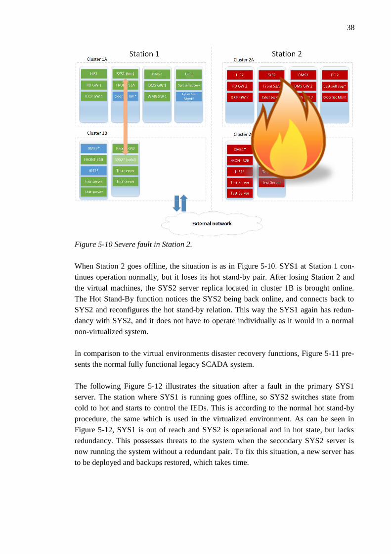
38
Figure 5-10 Severe fault in Station 2.
When Station 2 goes offline, the situation is as in Figure 5-10. SYS1 at Station 1 con-
tinues operation normally, but it loses its hot stand-by pair. After losing Station 2 and
the virtual machines, the SYS2 server replica located in cluster 1B is brought online.
The Hot Stand-By function notices the SYS2 being back online, and connects back to
SYS2 and reconfigures the hot stand-by relation. This way the SYS1 again has redun-
dancy with SYS2, and it does not have to operate individually as it would in a normal
non-virtualized system.
In comparison to the virtual environments disaster recovery functions, Figure 5-11 pre-
sents the normal fully functional legacy SCADA system.
The following Figure 5-12 illustrates the situation after a fault in the primary SYS1
server. The station where SYS1 is running goes offline, so SYS2 switches state from
cold to hot and starts to control the IEDs. This is according to the normal hot stand-by
procedure, the same which is used in the virtualized environment. As can be seen in
Figure 5-12, SYS1 is out of reach and SYS2 is operational and in hot state, but lacks
redundancy. This possesses threats to the system when the secondary SYS2 server is
now running the system without a redundant pair. To fix this situation, a new server has
to be deployed and backups restored, which takes time.
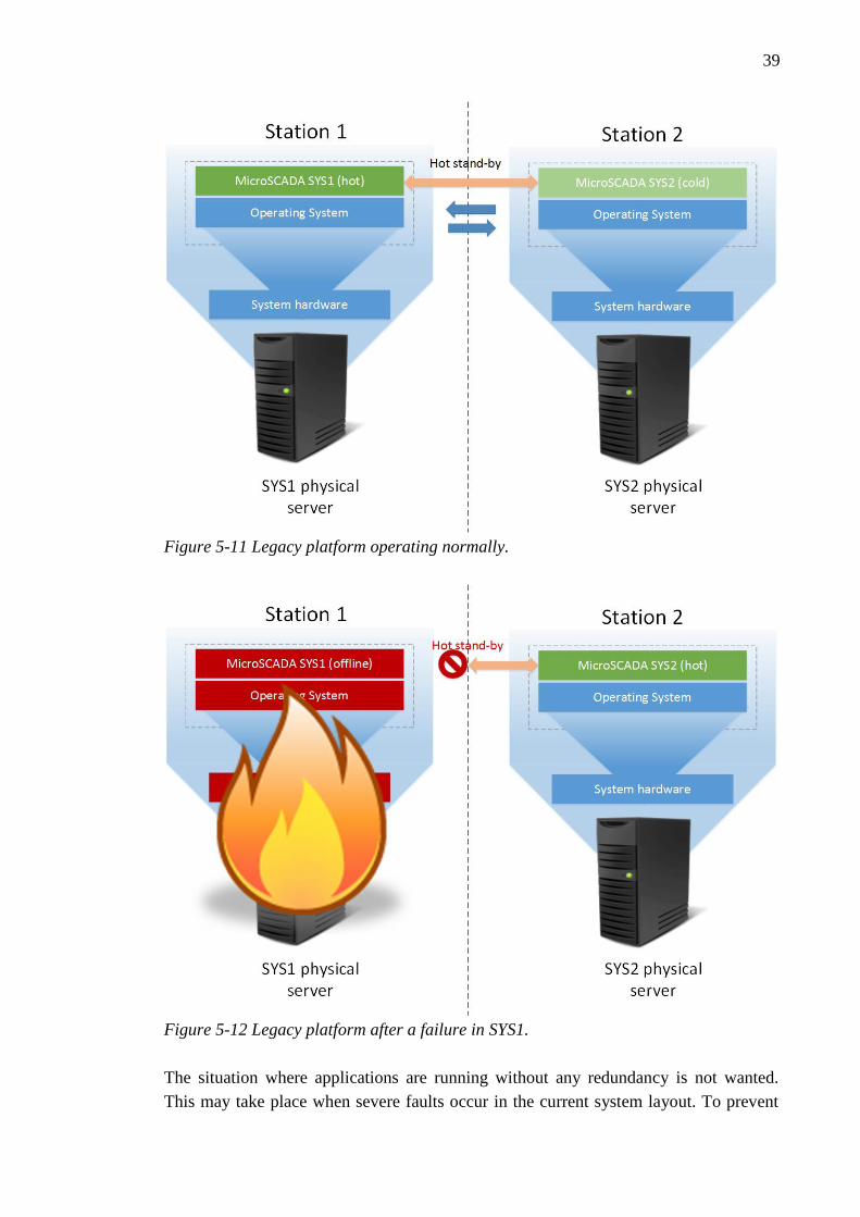
39
Figure 5-11 Legacy platform operating normally.
Figure 5-12 Legacy platform after a failure in SYS1.
The situation where applications are running without any redundancy is not wanted.
This may take place when severe faults occur in the current system layout. To prevent

40
these kind of situations, different virtualization functionalities were presented and a so-
lution where current system redundancy method was combined with virtualization func-
tions was discussed.

41
6 CHALLENGES
Virtualization was the technology to break the straight dependency between hardware
and operating system. The separation of hardware and operating system layers makes it
possible to build more flexible and scalable system layouts. With virtualization comes
more configuration and setting up, so administrators need to understand the operation of
the underlying hardware. This is also called technical overhead, which can cause addi-
tional working hours. It should be kept as low as possible compared to a legacy server
layout, to prevent any additional configuration requirements.
When the running systems and applications are not bound to a certain server and the
virtual machines can be moved or, in case of a fault, rebooted to another location,
knowledge of the technology is required to fully utilize all the functions and safety
measures. With virtualization, the layout configuration has more aspects compared to
the legacy hardware layout because virtual machines can be running on different servers
or they can be migrated to another location. This may be a challenge, but with proper
knowledge and understanding it can be an improvement to the SCADA system.
The migration to a virtualized SCADA system can be a challenge. The process where an
existing live system running with a normal server layout is updated to use a virtualized
platform was not examined. The virtualized SCADA system which was presented in
this thesis was built on a virtualized server layout from scratch. It is possible to update
the platform of live legacy systems, but it may require some downtime, and the system
may suffer from lack of redundancy for a certain amount of time. If administrators of
the system decide to update, the new virtualized platform can be deployed and config-
ured ready while the original system is still running. When the new platform is ready for
use, the servers of the old system can be virtualized step by step to minimize downtime
caused to the system. For example if the system being updated has SYS-servers which
have a Hot Stand-By relation, the secondary server can be taken offline and the primary
server continues operation without redundancy. Then the secondary server can be re-
configured which means that it is moved to a virtual machine within a newly created
resource pool and connected again to the primary server. After this, the primary server
can be shut down, so the secondary server running in the virtualized environment takes
over the data traffic to the control hardware, and the same update procedure can be done
to the primary server. All the other servers in the legacy system which have some sort of
redundancy can be updated in a similar way. If there are servers which do not have re-
dundancy, a certain downtime period is inevitable. All in all, the transition from legacy
42
server layout to virtualized layout is possible, but it is more straightforward to deploy
virtualization technology with new SCADA systems.
Network capacity is an important factor for virtualized environment, and it can cause
problems if calculated wrong. Most of the functions virtualization provides, for example
live migration and replica rely on good network communications. The SCADA system
generates network traffic with high importance when communicating with control
hardware. Also backups need to be taken into consideration. The backup server where
backups are saved can be a remote server somewhere in the network, which again adds
traffic to the network. If a failure occurs at the same time when backups are being taken,
or for example live migration is ongoing, it can cause congestion to the network. To
avoid these kind of situations, a good knowledge of the system operation and connec-
tion priorities is recommended. If these kind of situations happen, the system adminis-
trator should know how to prioritize different kind of traffic. Proper plans concerning
the schedule of all programs and functions which require a lot of network resources
should be made to be able to avoid these kind of situations.
With virtualization the requirements for the underlying network increase. Most of the
functions virtualization provides (live migration, replica) generate additional traffic
compared to a system without virtualization. These functions are dependent on the net-
work connections when performing actions, so the network capabilities of the system
with standard server layout should be reviewed before moving to virtualized platforms.
43
7 CONCLUSION
The goal of this thesis was to promote knowledge and serve as a guide into virtualiza-
tion techniques and illustrate the usage of virtualization in a SCADA system. This thesis
presented basic theory about server virtualization and electricity management systems.
SCADA was presented generally, also the components of the MicroSCADA system
were discussed. In Chapter 3 an example SCADA system with a typical server layout
was presented and discussed. Chapter 4 illustrated the same system with virtualization
techniques and different hardware components optimized for virtualization deployment.
Finally the thesis illustrated a comparison of the hardware requirements of the systems,
and how to utilize virtualization in the SCADA system for improving availability and
reliability.
The SCADA systems have been built on standard non-virtualized platforms for a long
time, and this thesis presented ways to improve the redundancy of the underlying server
platform. Correctly deployed virtual environment does not interfere with the applica-
tions and programs running inside the virtualization environment, but improves the reli-
ability in the situation when server hardware is not functioning properly. SCADA sys-
tem is operating normally on top of hypervisors and is communicating with control
IEDs. The normal operation of the SCADA system can be ensured by deploying differ-
ent functions alongside the virtual platform. Redundancy of the system can be improved
when a major fault occurs in the system with the functions virtualization offers. Recov-
ery of the system after a fault can be improved by combining the well-established Hot
Stand-By function of MicroSCADA with the new replica function. Planned downtime
caused by a server going offline can be avoided by moving the virtual machines from
the server with live migration function. The situation when a SCADA server is running
individually without any redundant components cannot be completely avoided, but the
time it being unsecured can be greatly reduced with the help of the virtualization plat-
form. A situation which in the current system required manual installation and server
replacement before the redundancy was again present can now be covered by manually
starting the replicated virtual machine in the healthy unharmed station. This takes sig-
nificantly less time than it takes to manually replace the server. After the system has
again redundancy, the damage caused to the servers can be repaired and new servers
replaced.
Challenges involved in this implementation were briefly discussed, also future tech-
niques and possibilities to improve and evolve server virtualization. Hyper-Converged
44
Infrastructure is an interesting technology which improves the management functionali-
ties and shapes the underlying server layout again. Possible cost savings were not dis-
cussed in this thesis, only the functioning and operation of the new platform. The thesis
illustrated the virtualization possibilities in the MicroSCADA Pro automation system,
but the techniques can also be used in various different systems for providing redundan-
cy and reliability.
45
REFERENCES
ABB, 2014a. DMS600 Operation Manual.
ABB, 2015a. Feeder protection and control REF630 IEC - Feeder protection and
control. Available at: http://new.abb.com/medium-voltage/distribution-
automation/numerical-relays/feeder-protection-and-control/relion-for-medium-
voltage/feeder-protection-and-control-ref630-iec [Accessed October 5, 2015].
ABB, 2014b. MicroSCADA Pro for substation automation. Available at:
https://library.e.abb.com/public/c1dbcf53628c6951c1257cf90033e455/1MRS7560
64_E_en_MicroSCADA_Pro_for_substation_automation.pdf [Accessed January
20, 2016].
ABB, 2015b. MicroSCADA Pro SYS600C 3.94 Product Guide. Available at:
https://library.e.abb.com/public/6aaa364b2f36484592f46b9544c6ae53/SYS600C_
pg_MRS758259_ENa.pdf [Accessed January 20, 2016].
ABB, 2015c. RTU560 product line. Available at: http://new.abb.com/substation-
automation/products/remote-terminal-units/rtu560 [Accessed January 19, 2016].
ABB, 2015d. SDM600 User Manual. Available at:
https://library.e.abb.com/public/1e639704410649d0b238ee757837530a/SDM600
User Manual-en.pdf [Accessed January 20, 2016].
ABB, 2013. SYS600 System Configuration Manual.
Bailey, D. & Wright, E., 2003. Practical SCADA for Industry, Available at:
http://www.sciencedirect.com/science/article/pii/B9780750658058500015.
Barrett, D. & Kipper, G., 2010. How Virtualization Happens. Available at:
http://linkinghub.elsevier.com/retrieve/pii/B9781597495578000011.
Cisco, 2015. Cisco 10GBASE SFP Modules Data Sheet. Available at:
http://www.cisco.com/c/en/us/products/collateral/interfaces-modules/transceiver-
modules/data_sheet_c78-455693.html [Accessed January 20, 2016].
CompuSharp Inc, 2013. Inter Control Center Protocol (ICCP) Services. Available at:
http://www.compusharp.com/intercontrol.html [Accessed January 20, 2016].
CRU Acquisition Group, 2015. Understanding RAID. Available at: http://www.cru-
inc.com/data-protection-topics/understanding-raid/ [Accessed October 27, 2015].
Dell, 2015. Dell PowerEdge VRTX Shared Infrastructure Platform. Available at:

46
http://www.dell.com/us/business/p/poweredge-vrtx/pd [Accessed January 20,
2016].
Dell, 2013. Dell PowerEdge VRTX Technical Guide. Available at:
http://partnerdirect.dell.com/sites/channel/en-
us/documents/dell_poweredge_vrtx_technical_guide.pdf [Accessed January 20,
2016].
Dell, 2014. PowerEdge VRTX specification sheet. Available at:
http://i.dell.com/sites/doccontent/shared-content/data-
sheets/en/Documents/PowerEdge_VRTX_Spec_Sheet.pdf [Accessed January 20,
2016].
Eggert, L. & Gont, F., 2009. RFC 5482: TCP User Timeout Option. Available at:
https://tools.ietf.org/html/rfc5482.
Galloway, B. & Hancke, G.P., 2013. Introduction to Industrial Control Networks.
Available at: http://www.rfidblog.org.uk/Preprint-GallowayHancke-
IndustrialControlSurvey.pdf [Accessed February 18, 2015].
Katz, R., 2015. Redundant Arrays of Inexpensive Disks (RAIDs). In Operating
Systems: Three Easy Pieces. Arpaci-Dusseau Books.
Kensy, J., 2015. Dell VRTX Shared PERC8 finally uncrippled! Available at:
http://www.jonkensy.com/wp-content/uploads/vrtx_feature.jpg [Accessed January
20, 2016].
Microsoft, 2014a. Active Directory Domain Services. Available at:
https://msdn.microsoft.com/en-us/library/aa362244(v=vs.85).aspx [Accessed
January 20, 2016].
Microsoft, 2009. Hyper-V Live Migration Overview & Architecture, Available at:
http://download.microsoft.com/download/1/9/5/195E03F3-2723-4415-B77E-
220C9AA7D7F5/Windows Server 2008 R2 Hyper-V and Live Migration
Whitepaper.pdf [Accessed January 20, 2016].
Microsoft, 2015. Hyper-V Replica Feature Overview. Available at:
https://technet.microsoft.com/fi-fi/library/hh831716.aspx [Accessed January 20,
2016].
Microsoft, 2014b. NIC Teaming Overview. Available at:
https://technet.microsoft.com/en-us/library/hh831648.aspx [Accessed February 26,
2015].
Microsoft, 2014c. Remote Desktop Services Overview. Available at:
https://technet.microsoft.com/en-us/library/hh831447.aspx [Accessed January 20,
2016].
VMware, 2014. How Fault Tolerance Works. vSpehere 5 Documentation Center.
47
Available at: https://pubs.vmware.com/vsphere-
50/index.jsp#com.vmware.vsphere.avail.doc_50/GUID-623812E6-D253-4FBC-
B3E1-6FBFDF82ED21.html [Accessed January 20, 2016].
VMware, 2015. Server Consolidation. Available at:
https://www.vmware.com/consolidation/overview [Accessed January 20, 2016].
VMware, 2009. VMware VMotion live migration for virtual machines without service
interruption. , p.2. Available at: http://www.vmware.com/files/pdf/VMware-
VMotion-DS-EN.pdf [Accessed January 20, 2016].