Embed Size (px)
Citation preview
TRAINING PACKAGE FOR CIVIL AFFAIRS TEAMS SMALL BUSINESS AND VILLAGE LEVEL WELL REPAIR AND REHABILITATION
Contents1. Well Principals ....................................................................................................................................... 1
2. Common Well Problems ....................................................................................................................... 3
3. Pump Repair .......................................................................................................................................... 4
4. Well development ................................................................................................................................. 5
5. Well Cleaning ........................................................................................................................................ 7
6. Salinity sampling and testing ................................................................................................................ 8
7. Microbusiness Program ........................................................................................................................ 8
8. Institutional Controls ............................................................................................................................ 8
9. Water and Islam .................................................................................................................................... 8
1. Well Principals
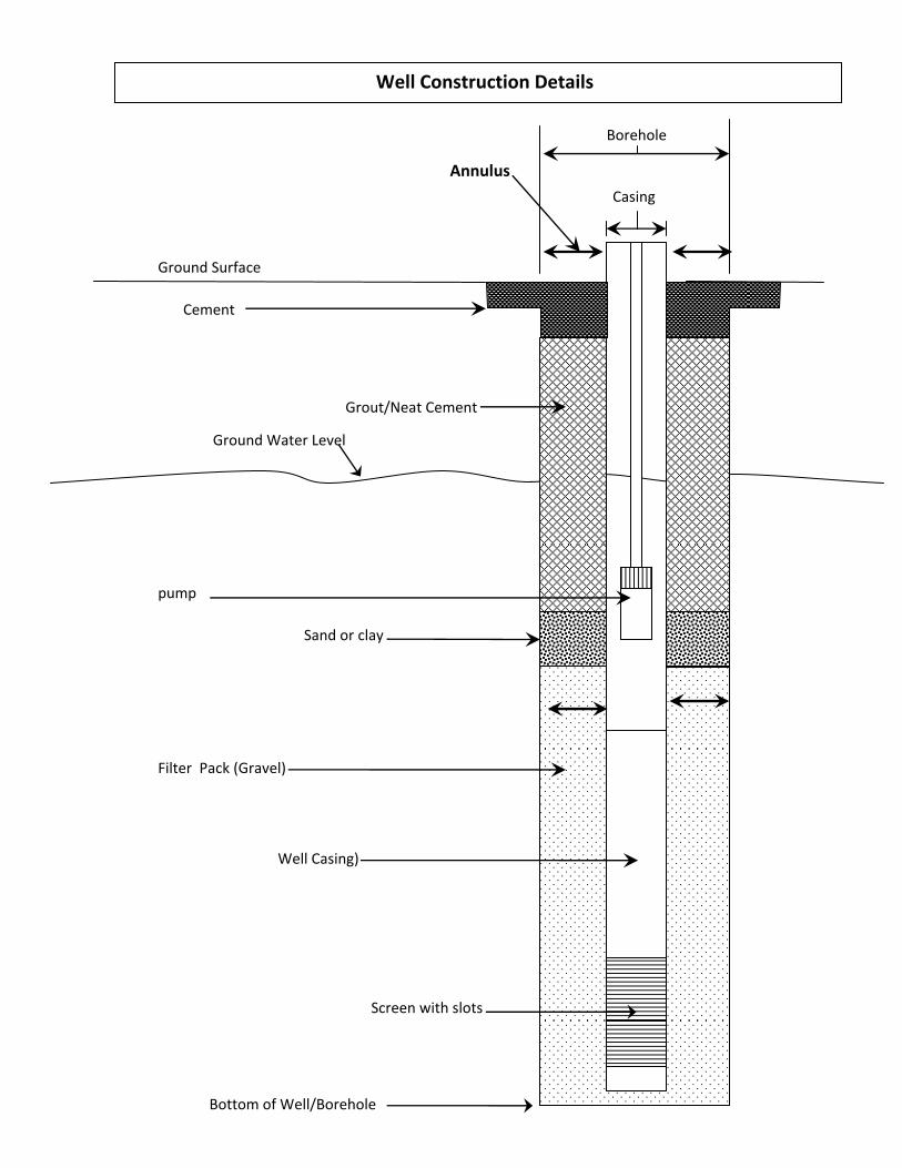
To supply good water, wells must be constructed properly and maintained in good working order. Proper well construction – A well must be constructed with the following parts (see figures):
a. Borehole b. Casing c. Screen d. Filter Pack and Well development e. Sanitary seals f. Surface pads g. Pump and pump housing
Borehole ‐ The best water zones are sandy or with lots of gravel. Zones with lots of clay are not good for water. Casing – Casing is just pipe, usually PVC or other plastic. It should be wide enough to drop a pump into it and strong enough not to break from all the weight from the soil and concrete around it. “Schedule 80 PVC” is good for a well to about 200 meters in depth. Wells deeper than 200 meters should be constructed using steel casing and screen.
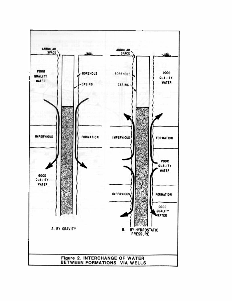
Screen – Is just casing with small slots cut into it to allow water to flow into the well pipe of casing. Screen has saw cut slots with each slot 1 to 5 mm wide and the slots 5 to 10 mm apart. The screen is placed adjacent to the water zone in the subsurface with casing above it. Only the water zone should have screen and NOT the whole casing. The best wells only have the screen near the bottom of the well, not near the top of the water table. Filter pack and Well Development – Outside of the screen and between the outside of the screen pipe and inside of the borehole, a filter pack is installed in the borehole. The filter pack is composed of gravel of different sizes, but the gravel must be rounded (from a stream) and NOT crushed gravel (sharp and angular). The gravel is placed around the screen and up to 3 meters above the top of the screen in the borehole. The filter pack is important for keeping clay and silt out of the well. It also helps keep out other fine particles such as mud and black silty water. For the filter pack to filter water from the surrounding sand properly, it must be cleaned and developed by surging the water in the well. Well development is described in section 5 below. Sanitary Seals – Appendix A shows various paths in which groundwater can be contaminated with sewage. To keep surface water and sewage from leaking down the borehole, the well must be constructed with a sanitary seal. The sanitary seal is place above the filter pack in the borehole and is composed of bentonite or other clay.
Bentonite Seal ‐ A bentonite seal with a minimum thickness of three meters will be placed directly above the filter pack to prevent vertical infiltration of contaminants through filter material into the well.
Neat Cement/Grout ‐ The annular space between the well casing and the walls of the hole will be filled with cement‐bentonite grout mix. The cement‐bentonite grout mix will be proportioned of Portland cement conforming to ASTM Specifications and bentonite. The cement‐bentonite mix will be proportioned, by weight, as follows: Water: 6.6 Portland cement: 1 Bentonite: 0.4 The mix will be prepared as follows: The cement will be mixed with the water first at the w/c ratio prescribed above. At this stage the mix is like grey water. Next, bentonite powder will be slowly added such that clumps of bentonite do not form. This will be constantly checked by scraping the bottom of the mixer with a shovel. When clumps form, it will be slow down and will not add any more powder until they are dissolved. Bentonite will be added until the watery mix transitions to an oily/slimy consistency. The consistency will be observed while mixing and allow the grout to thicken for another five to ten minutes. Generally, the mix thickens with added mixing time. Bentonite will be added as required. The mixture will form craters at the surface when it is the proper consistency for placing down the tremie pipe. The cement‐bentonite grout will be forced from
the bottom of the space to be grouted towards the surface by use of a tremie pipe. The minimum depth of grouting will be three meters. The grout will also seal off any other water‐bearing strata above the zone providing water to the well. The grouting will be done continuously and in a manner that will insure the entire filling of the annular space in one operation without damaging the well casing. No drilling operations or other work in the well will be permitted within 24 hours after the grouting operation to allow the grout to properly set. Circulation of water through the annular space to be grouted will be established as initial step of grouting, this assures that the space is open and provides for the removal of foreign material. Surface pad – This will give the well structural strength and keep sewage from going down the borehole outside of the casing. The cement is poured into the borehole, outside of the casing. A concrete pad should be built around the well to protect the well and provide a platform for the pump. A trough can be built in the pad to allow water to runoff the pad from the pump so that water doesn’t flow back down the well and borehole. The pad should be a 1 meter by 1 meter square and at least 30 cm deep. Pump and Pump Housing – An India Mark II or III well pump is typically installed in village wells. The pump intake must be placed slightly above or slightly below the screen, but not next to the screen. This will help even out the flow and make the screen last longer. The India Mark II and III specifications and installation instructions are included in the pump specifications.
2. Common Well Problems
Most well problems can be solved with repair, cleaning, or redevelopment. Some problems cannot be fixed such as wells filled with rocks, collapsed casing, and wells used for waste disposal. Broken Pump‐ Broken pump problems can be fixed within the well head or lifting the downhole parts and repairing or replacing those parts. Pump repair details and pump problem diagnosis is discussed in detail in well pump manuals. Low or no flow – Low or no flow is the most common pump issue and can be caused by broken pump problems, pump repair issues, silting of the well, or low/no groundwater flow into the well. Pump issues were discussed above, but silting can be solved by removing the silt and redeveloping the well, if no broken casing or screen. Low or no groundwater flow into the screen and well can be solved by cleaning the well screen if clogging or encrustations, and redeveloping the well after cleaning. See well cleaning and redevelopment sections below.
Surface pad – The surface pad protects the well, provides structural strength for the wellhead, prevents sewage and small animals from entering the well, and keeps surface water from flowing into the well. The pad should be constructed on concrete in a 1 meter by 1 meter pad with the well in the center of the pad. The concrete pad should be replaced if it has large cracks

or has large chunks missing. The wellhead and pump mount should be bolted to the concrete pad. Drainage should be away from the wellhead. Unsanitary conditions – Sewage can get into the well if the surface pad is not constructed correctly to allow drainage away from the wellhead. Sewage can also seep into the well if there is no sanitary seal in the well borehole between the filter pack and wellhead. Also if surface runoff around the well should be away from the well. No one should be allowed to urinate or defecate within 25 meters of the well. Water should not be allowed to pond in the area of the well. Rocks – If the well casing is filled with rocks, the well is useless and must be abandoned. Broken casing and wellhead – If the casing is broken near the ground surface, the casing can be repaired by gluing the casing back together (cracks) or by cutting off the broken pipe and gluing a new section of pipe onto the well casing. The pad around the well can also be repaired by removing the broken concrete and replacing it. Mud, silt, sand and black water‐ If the water from the well has excessive mud, silt, sand, or black water, these problems are all turbidity related and may be solved by redeveloping the well. Well development is described below in the well development section. If well development doesn’t work, then the well will have to be replaced or the water filtered prior to use. Encrustation and iron problems – Overtime, well screens can be coated with encrustations of calcium carbonate, iron oxide/carbonate, or mixtures of hard deposits of minerals. These encrustations can block water from flowing into the well and must be cleaned off the screen to improve well function. These encrustations or hard mineral deposits can be scrubbed off using wire brushes lowered into the well. The brushes are slightly larger than the well diameter and by moving the brush up and down over the screen, the screen can be cleaned. After cleaning, the well must be pumped or bailed to remove the dirt and mineral deposits removed from the screen. Salinity and bacteriological problems – High salt content or salinity and bacteriological problems cannot be removed from the well and ground water. Wells drilled deeper or in different locations can help solve salinity issues. Water from wells with high bacteriological content must be chlorinated or disinfected using other methods.
3. Pump Repair
Most pump problems can be solved with repair, cleaning, regular maintenance, or in the worst case, pump replacement. Some problems cannot be fixed such as dry wells, wells filled with rocks, silted wells silted, collapsed casing, and wells used for waste disposal. Overuse or not having a well guardian can lead to consistent well problems requiring high repair costs and replacement which are not sustainable.

Handle – broken, damaged, or bent pump handles need to be replaced. If the pump is hard to pump, it means that the handle is not the issue, there is a problem within the pump. Surface mount – The surface mount should be inspected to make sure it is not cracked, it is attached to the cement pad properly, has all the mounting bolts, has good seals, and is not excessively corroded. If cracks are small and do not affect pumping, they can be left alone. Large cracks that affect pumping and allow surface water in must be either welded closed or the pump surface mount replaced. Downhole parts – Various downhole pump parts may need to be replaced or cleaned for prior pump performance. For the common India Mark III or IV, please see the attached manual.
4. Well development
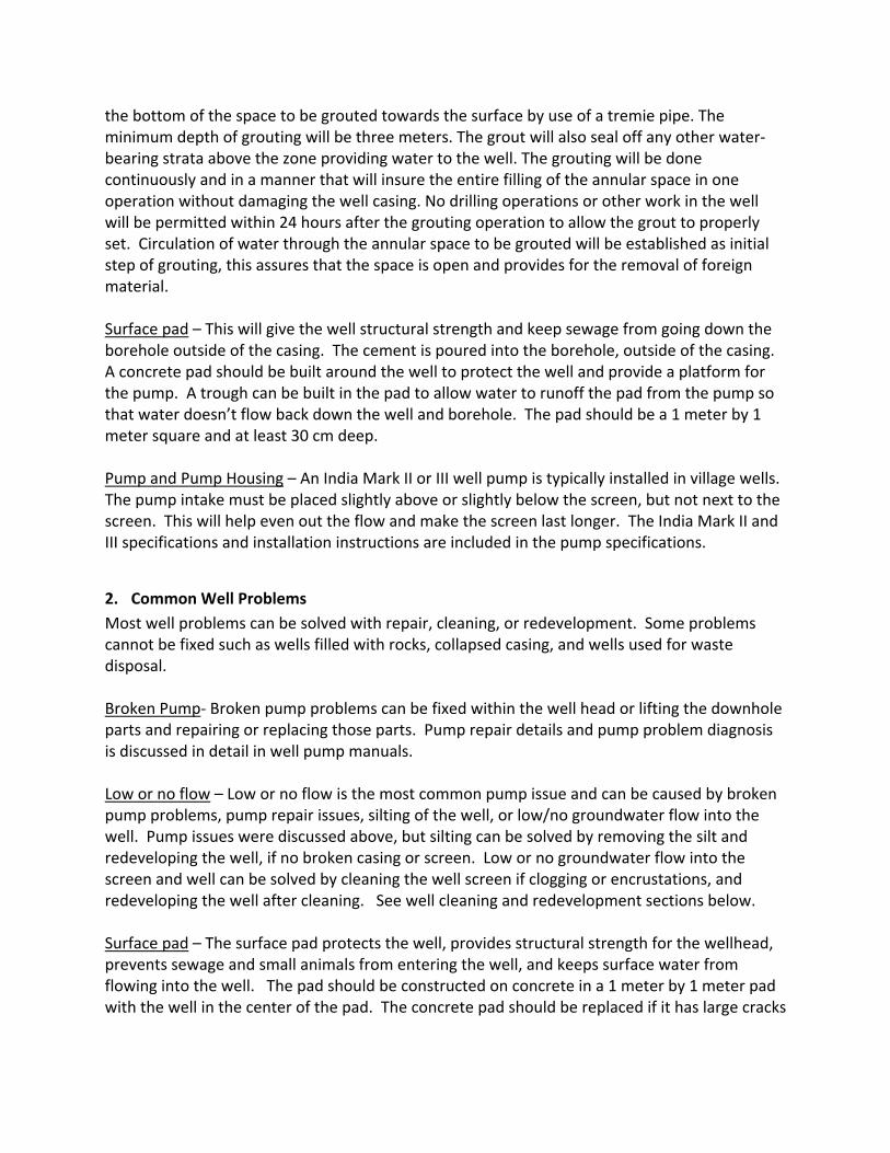
Mud, silt, sand, and black water should be removed. Continuous black water indicates cross‐connection to surface water or sewage and an inadequate well filter pack. The best method to develop a well is by air‐lift methods using an air‐compressor. Air‐lift removes solids and develops the filter pack, removes mud and fines, and cleans the screen. Also it removes hard water buildup from the well screen. Overpumping as a well‐development method should not be used, although it is common in Afghanistan. Air‐Lift Development: The permanent well will be developed to maximize yield, minimize turbidity, and remove any remaining drill cuttings, drill mud and fluids. The well will develop and will be continued until the well produces clear, sediment free water. The surging cycle is established by pumping from the well with an air lift and by dropping the air pipe suddenly to cut off the pumping. This cycle discharges large bubbles of compressed air into the screen. The submergence ratio must be 60 percent. Submergence is the extent to which the air pipe is submerged in the water compared to the extent the pipe is between water and ground level. Work efficiency decreases rapidly as the submergence ratio drops below 60 percent. Use the following procedures to start developing the well: Step 1. Lower the drop pipe to within 2feet of the bottom of the screen. Place the airline inside the drop pipe with its lower end 1foot or more above the bottom of the drop line. Step 2. Let air enter into the airline and pump the well until the water appears to be free of sand. Start slowly. If all the water is suddenly removed, the casing may collapse in deeper wells, especially when using PVC pipe. Step 3. Close the valve between the tank and airline and pump the tank full of air to a pressure of 100 to 150 psi.
Step 4. Lower the air line until it is about 1 foot below the drop pipe. Open the quick‐ opening valve so the air in the tank can rush with great force into the well. A brief, forceful head of water will emerge or shoot from the casing and from the drop pipe. Step 5. Pull the airline back into the drop pipe immediately after the first heavy load of air shoots into the well. Doing so will cause a revered of flow in the drop pipe that will effectively agitate the aquifer. Step 6. To complete the development process and thoroughly clean out any loose sand, pull the air line up into the drop pipe and use it as an air lift to pump the well.
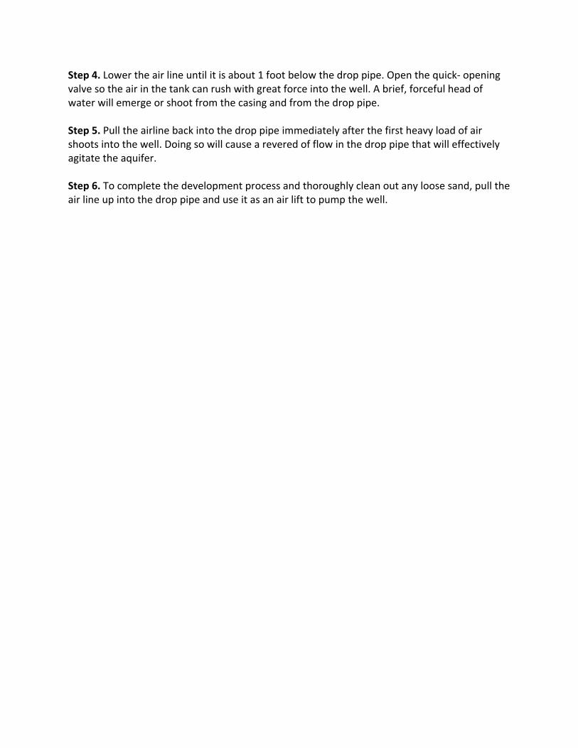
5. Well Cleaning
Encrustations: Wire brushes can be used to clean the screen. The hard water deposits will have to be bailed or pumped from the well prior to use. Air‐lift development is the best method to remove hard water deposits. Cleaning biofilm: Well mops are used to swab the well and can be used to remove biofilms (slime).

Iron or rust colored water: Can result from aeration of the well water by drawing down the water table to exposed the well screen. Overpumping the well should be avoided. Well Disinfection with Chlorine (bleach): The well will be disinfected to remove bacteriological contamination that may cause the well‐water supply to be unsafe for human consumption. The chlorine solution used for disinfecting the well will be of such volume and strength and will be so applied that a concentration of at least 50 mg/L of available chlorine will be obtained for the entire water depth of the well, and this solution will remain in the well for a period of at least 12 hr. If the samples collected after disinfection show bacteriological contamination, ARAO will prepare and apply to the entire depth of the well a total volume of the chlorine solution of at least 100 mg/L of available chlorine equal to at least four times the volume of water in the well. This solution will be allowed to remain in the well for a period of at least 24 hr. 6. Salinity sampling and testing At a minimum, water from a well should be tested for salinity or total dissolved solids (TDS) and total/fecal coliforms. Salinity will determine the overall potability of the water and the coliform testing determines if the well has sewage in it. TDS can be testing using a field instrument, but bacteriological tests must be conducted by a laboratory. Pasteur Analytical Laboratory in Herat or the DACAA lab in Kabul can perform the bacteriological analysis. 7. Microbusiness Program
Equipment Coordination with Village elders/Mullahs and District governor Photos before and after repair Reimbursement procedures Honest repairman
8. Institutional Controls Each well must have a well caretaker who watches over the well. Any site work must be coordinated with the local Village elders/Mullah. 9. Water and Islam
Water as a social good Water is of profound importance in Islam. It is considered a blessing from God that gives and sustains life, and purifies humankind and the earth. Water is Precious ‐ The Arabic word for water, ma', occurs sixty‐three times in the Quran. God's throne is described as resting on water, and Paradise is described as "Gardens beneath which rivers flow." It seems that in the Quran, the most precious creation after humankind is water. The life‐giving quality of water is reflected in the verse, "And Allah has sent down the water from the sky and therewith gives life to the earth after its death." Not only does water give life, but every life is itself made of water: "We made from water every living thing." Ablution ‐ All human beings rely on water for life and good health but, for Muslims, it enjoys special importance for its use in wudu (ablution, that is, washing before prayer) and ghusl
(bathing). The benefit of the daily prayers, one of the Five Pillars of Islam, has itself been compared by the Prophet (pbuh) to the cleansing action of water in the following hadith, "The similitude of five prayers is like an overflowing river passing by the gate of one of you in which he washes five times daily." Allah created Different Types of Water Allah said "And it is He Who has let free the two seas: one palatable and sweet, and the other salty and bitter; and He has set a barrier and a complete partition between them. He has placed a barrier of land between these two types of waters, so that they do not transgress upon each other, which would spoil the characteristics they were created with." Pearls (Out of them both come out pearls and Al‐Marjan. ) pearls are well‐known. As for Marjan they say it means small pearls. Mujahid, Qatadah, Abu Ruzayn, Ad‐Dahhak said it, and it has also been reported from `Ali. It was also said that it means large, precious pearls, this was mentioned by Ibn Jarir from some of the Salaf. Ibn Abi Hatim recorded from Ibn `Abbas who said, "When it rains, the oysters in the sea open their mouths. What falls in them, the drops, turns into pearls.'' Its chain of narrators is Sahih. Since this type of adornment is a favor from Allah to the people of earth, He reminded them of it, [ بان اربكم ءاالء فبأى [ تكذ Sailing Ships on Water ‐ (Then which of the blessings of your Lord will you both deny) Allah said, ,meaning the ships that float ,(And His are Al‐Jawar Al‐Munsha'at) [المنشئات الجوار وله ] Mujahid said, "Whatever ship hoists a sail, it is from Munsha'at, if it does ,(in the seas) [البحر فى]not hoist a sail, it is not from the Munsha'at.'' Qatadah said, "Al‐Munsha'at means created.'' Others said that it is Al‐Munshi'at meaning, "launched.'' [ كاالعلـم] (like A`lam.) This means, they are like mountains with their great size, and it also refers to the trade and commercial services they make possible, transporting cargo from one area to another and from one province to another. Ships provide various benefits for people, including transporting different types of goods they need.

FIGURES
Well Construction Details
Sand or clay
Filter Pack (Gravel)
Cement
Bottom of Well/Borehole
Borehole
Ground Water Level
Casing
Screen with slots
pump
Grout/Neat Cement
Ground Surface
Well Casing)
Annulus
د برمی د جوړولو معلومات
ريګ يا خوری
جغله
سيميټ
وروستی برخهدبرمی
د دايری اندازه
دمځکی د اوبو اندازه
دبرمی ديوالو اندازه
سره الی د چاکج
پمپ
ميده سيميټ
دمځکی سطح
دبرمی ديوالو اندازه

Appendix A Pathways for Sewage to Contaminate Wells


APPENDIX B India Mark III and IV Pump Manual

India Mark III with 50 mm uPVC Riser Pipes & Cylinder The “IM III 50 PVC” has emerged from the need for a handpump based on the IM II/ IM III design suited for installation in “aggressive waters”, where corrosion of GI riser pipes and rods was a major problem. This design uses 50 mm ND PVC pipes as the pipe, with a PVC jacketed brass lined cylinder, incorporating “universal cylinder” components using interchangeable Nitrile rubber bobbin valves, single piece tool-less valve designs and a number of innovative features. Apart from the normal GI-MS pump rods, the below-ground mechanism can also use Stainless Steel or Fibre Glass pump rods, top improve non-corrodible properties and relatively deep cylinder setting of 60 m below ground level and more. By early 2001. the field tests reported: “113 nos. hand pumps using µPVC Riser pipes with Three Piece couplers, with a median age of 160 days and usage of 1920 hours, have shown no problems so far. The first batch of 10 of these pumps had been installed earlier and had accumulated a median age of 438 days.”* These field trials were tracked till 2002. The results led the Bureau of Indian Standards to formulate draft specification for the “Village Level Operation and Maintenance (VLOM) Deepwell Handpump with uPVC Riser Pipes – Specifications”. This document is awaiting final approval of the Handpumps Committee of the BIS. * UNICEF supported Handpump R&D Project, Rangareddy District, Andhra Pradesh, Concluding Report, March 2001

Features: Head, Handle & Pedestal: These are similar to that of India Mark II or III, but weith minor modifications. The conventional IM II/ IM III pump head and handle with 100-125 mm stroke will produce around 8 –10 litres water per minute when used with 50 mm PVC cylinder and riser, as compared to 12-15 litres per minute (at 40 strokes per minute) when used with a usual 63.5 mm diameter cylinder of the IM II/ IM IIL. Hence, the Head has been modified to provide a handle stroke of 175 mm to increase the discharge per stroke. In practical terms, it means a slightly taller pump Head with a slightly larger opening for the handle travel. The handle and axle assembly does not change. Hence there is no major implication for the more common spare parts. Water Tank: This has been modified. There is no riser pipe holder, the bottom flange has a hole to allow PVC pipe to pass through. The flange holes remain unchanged. So the new water tanks can be fitted onto old pump pedestals. Pipe-holding: This is done by a rubber cone slipped over the PVC riser pipe. The rubber cone fits into a cone flange. The cone flange is clamped between pedestal and water tank flanges. This compresses the rubber cone which grips and holds the PVC riser pipes. minute produced from a 63.5 mm dia cylinder. PVC Riser pipes: The pipe used is 50 mm nominal diameter (OD 60 mm – 60.2 mm, wall thickness 4.0 – 4.6 mm, as per IS 12818, dimensions as per designation CM 50), in 3 m lengths, with pipe centralisers on each length. There are external (male) threaded coupling at both ends, solvent cemented to pipe ends. The couplings are injection moulded to knuckle thread profile. The solvent cementing can be done at the factory (which makes the packing more bulky), or at the eventual store (where plain ended pipes and couplings can be received separately, in more convenient packs). Solvent cementing should never be done at site. Precautions like roughening and cleaning matching surfaces and curing are necessary to get a good solvent cement joint. Pipes with male threaded ends have rubber “O” rings for sealing and are joined to each other by a double ended female (internal threaded) coupling. This coupling system is called the Three Piece Coupler. The entire riser pipe fitting can be assembled by hand tightening or with simple light-weight tools. The use of conventional tools like pipe lifters is unnecessary and pipe wrenches will damage the PVC pipe. It is advisable to order a few set of spare couplings, cementing compound and sealing ‘O’ rings, along with the initial procurement.
Three Piece Coupler
PVC Pipe fitting Tools Joining PVC Riser pipes
A Pipe Joint
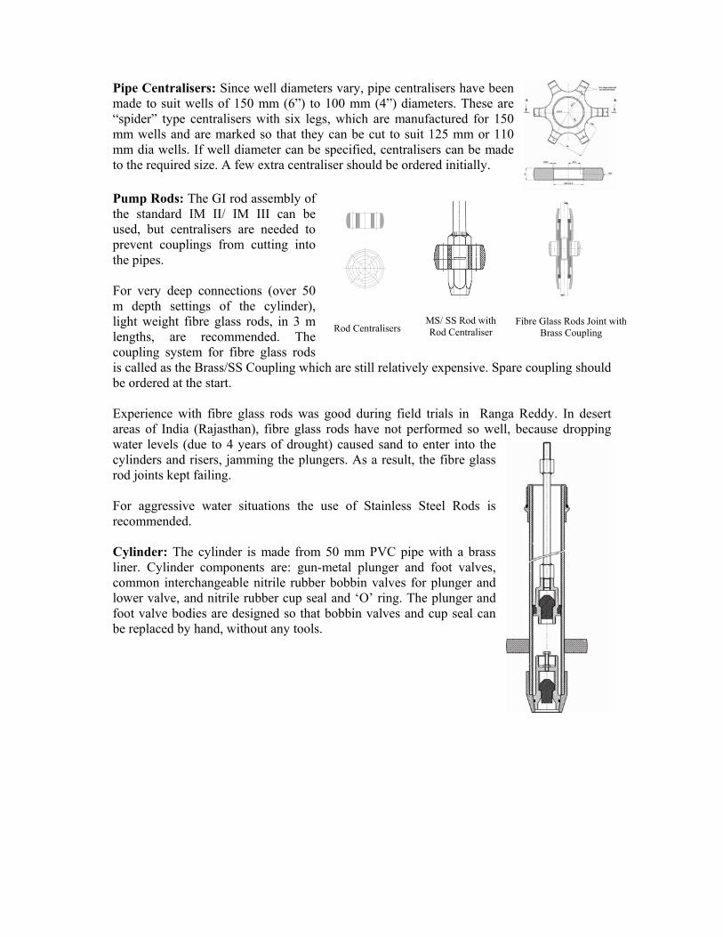
Pipe Centralisers: Since well diameters vary, pipe centralisers have been made to suit wells of 150 mm (6”) to 100 mm (4”) diameters. These are “spider” type centralisers with six legs, which are manufactured for 150 mm wells and are marked so that they can be cut to suit 125 mm or 110 mm dia wells. If well diameter can be specified, centralisers can be made to the required size. A few extra centraliser should be ordered initially. Pump Rods: The GI rod assembly of the standard IM II/ IM III can be used, but centralisers are needed to prevent couplings from cutting into the pipes. For very deep connections (over 50 m depth settings of the cylinder), light weight fibre glass rods, in 3 m lengths, are recommended. The coupling system for fibre glass rods is called as the Brass/SS Coupling which are still relatively expensive. Spare coupling should be ordered at the start. Experience with fibre glass rods was good during field trials in Ranga Reddy. In desert areas of India (Rajasthan), fibre glass rods have not performed so well, because dropping water levels (due to 4 years of drought) caused sand to enter into the cylinders and risers, jamming the plungers. As a result, the fibre glass rod joints kept failing. For aggressive water situations the use of Stainless Steel Rods is recommended. Cylinder: The cylinder is made from 50 mm PVC pipe with a brass liner. Cylinder components are: gun-metal plunger and foot valves, common interchangeable nitrile rubber bobbin valves for plunger and lower valve, and nitrile rubber cup seal and ‘O’ ring. The plunger and foot valve bodies are designed so that bobbin valves and cup seal can be replaced by hand, without any tools.
Fibre Glass Rods Joint with Brass Coupling Rod Centralisers
MS/ SS Rod with Rod Centraliser