Embed Size (px)
Citation preview
Vijeo Designer Basic
VJB_Tutorial 05/2015
EIO
000
0002
121.
00
www.schneider-electric.com
Vijeo Designer BasicTutorial Version 1.0
05/2015
© 2015 Schneider Electric. All rights reserved.
2 EIO0000002121 05/2015
Table of Contents
Safety Information . . . . . . . . . . . . . . . . . . . . . . . . . . . . . 5About the Book. . . . . . . . . . . . . . . . . . . . . . . . . . . . . . . . 7
Part I Vijeo Designer Basic at a Glance . . . . . . . . . . . . . 9Chapter 1 General . . . . . . . . . . . . . . . . . . . . . . . . . . . . . . . . . . . . . . 11
Software Overview . . . . . . . . . . . . . . . . . . . . . . . . . . . . . . . . . . . . . . . 12Vijeo Designer Basic’s Main Tools . . . . . . . . . . . . . . . . . . . . . . . . . . . 14Installing Vijeo Designer Basic . . . . . . . . . . . . . . . . . . . . . . . . . . . . . . 16Uninstalling Vijeo Designer Basic . . . . . . . . . . . . . . . . . . . . . . . . . . . . 18
Chapter 2 Project creation . . . . . . . . . . . . . . . . . . . . . . . . . . . . . . . 19Description of Requirements . . . . . . . . . . . . . . . . . . . . . . . . . . . . . . . . 20Project Construction Steps . . . . . . . . . . . . . . . . . . . . . . . . . . . . . . . . . 21The Application at a Glance . . . . . . . . . . . . . . . . . . . . . . . . . . . . . . . . 22Starting Vijeo Designer . . . . . . . . . . . . . . . . . . . . . . . . . . . . . . . . . . . . 26Basic Settings . . . . . . . . . . . . . . . . . . . . . . . . . . . . . . . . . . . . . . . . . . . 27Creating Variables . . . . . . . . . . . . . . . . . . . . . . . . . . . . . . . . . . . . . . . . 29Creating Panels . . . . . . . . . . . . . . . . . . . . . . . . . . . . . . . . . . . . . . . . . . 34Numeric and Text Displays . . . . . . . . . . . . . . . . . . . . . . . . . . . . . . . . . 37Graphical Objects . . . . . . . . . . . . . . . . . . . . . . . . . . . . . . . . . . . . . . . . 41Creating Recipes . . . . . . . . . . . . . . . . . . . . . . . . . . . . . . . . . . . . . . . . . 47Creating the "Curves" Panel . . . . . . . . . . . . . . . . . . . . . . . . . . . . . . . . 52Creating the "Alarms" Panel . . . . . . . . . . . . . . . . . . . . . . . . . . . . . . . . 54Creating an Action . . . . . . . . . . . . . . . . . . . . . . . . . . . . . . . . . . . . . . . . 58Simulation . . . . . . . . . . . . . . . . . . . . . . . . . . . . . . . . . . . . . . . . . . . . . . 63
Chapter 3 Project Download . . . . . . . . . . . . . . . . . . . . . . . . . . . . . . 65Validating, Building, and Correcting Errors . . . . . . . . . . . . . . . . . . . . . 66Downloading a Project. . . . . . . . . . . . . . . . . . . . . . . . . . . . . . . . . . . . . 68
Index . . . . . . . . . . . . . . . . . . . . . . . . . . . . . . . . . . . . . . . . . 71
EIO0000002121 05/2015 3
4 EIO0000002121 05/2015
Safety Information
Important Information
NOTICE
Read these instructions carefully, and look at the equipment to become familiar with the device before trying to install, operate, or maintain it. The following special messages may appear throughout this documentation or on the equipment to warn of potential hazards or to call attention to information that clarifies or simplifies a procedure.
EIO0000002121 05/2015 5
PLEASE NOTE
Electrical equipment should be installed, operated, serviced, and maintained only by qualified personnel. No responsibility is assumed by Schneider Electric for any consequences arising out of the use of this material.
A qualified person is one who has skills and knowledge related to the construction and operation of electrical equipment and its installation, and has received safety training to recognize and avoid the hazards involved.
6 EIO0000002121 05/2015
About the Book
At a Glance
Document Scope
This manual introduces you to the fundamentals of Vijeo Designer Basic, a software package that lets you develop and configure applications for the Magelis HMIGXU series of HMI panels.
It is written to help new users get started, and as a quick reference for users who are already familiar with the software. For detailed descriptions of the software’s features and functions, refer to the Vijeo Designer Basic online help.
Validity Note
The data and illustrations found in this book are not binding. We reserve the right to modify our products in line with our policy of continuous product development. The information in this document is subject to change without notice and should not be construed as a commitment by Schneider Electric.
Related Documents
You can access all related documentation from the Vijeo Designer Basic DVD.
You can download these technical publications and other technical information from our website at www.schneider-electric.com.
EIO0000002121 05/2015 7

8 EIO0000002121 05/2015
Vijeo Designer Basic
Vijeo Designer Basic at a Glance
VJB_Tutorial 05/2015
Vijeo Designer Basic at a Glance
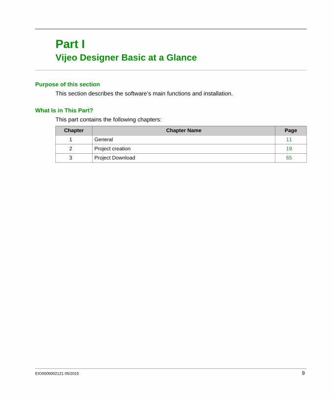
Part IVijeo Designer Basic at a Glance
Purpose of this section
This section describes the software’s main functions and installation.
What Is in This Part?
This part contains the following chapters:
Chapter Chapter Name Page
1 General 11
2 Project creation 19
3 Project Download 65
EIO0000002121 05/2015 9
Vijeo Designer Basic at a Glance
10 EIO0000002121 05/2015
Vijeo Designer Basic
General
VJB_Tutorial 05/2015
General
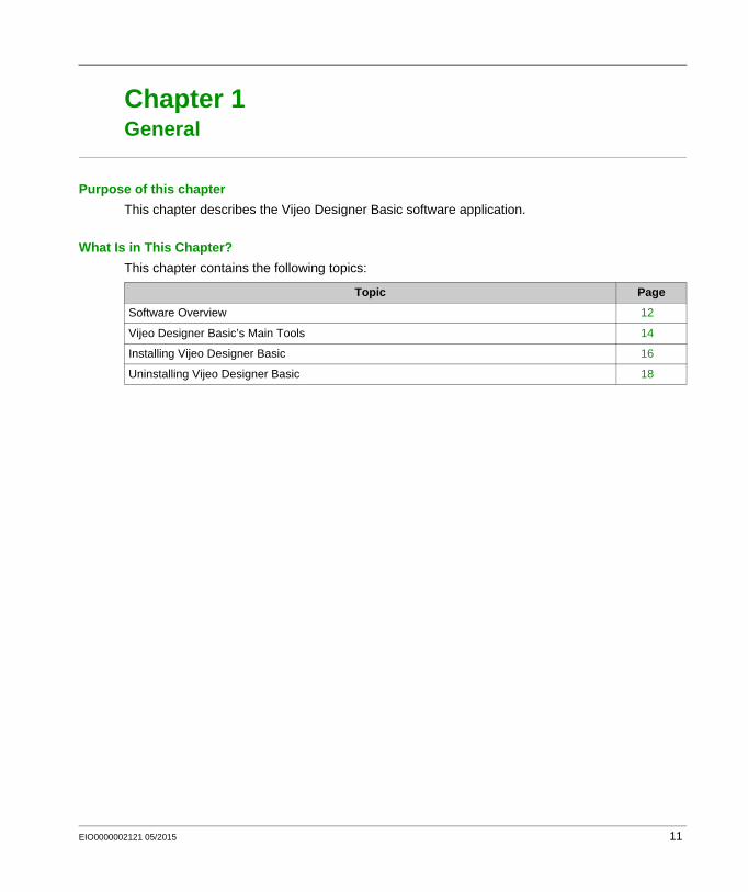
Chapter 1General
Purpose of this chapter
This chapter describes the Vijeo Designer Basic software application.
What Is in This Chapter?
This chapter contains the following topics:
Topic Page
Software Overview 12
Vijeo Designer Basic’s Main Tools 14
Installing Vijeo Designer Basic 16
Uninstalling Vijeo Designer Basic 18
EIO0000002121 05/2015 11
General
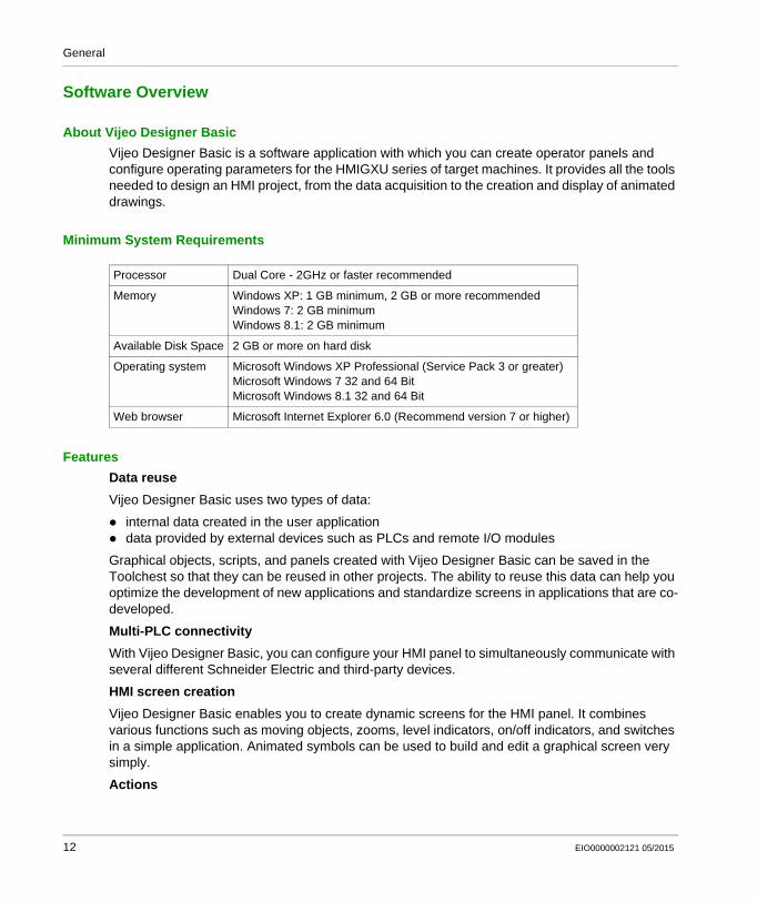
Software Overview
About Vijeo Designer Basic
Vijeo Designer Basic is a software application with which you can create operator panels and configure operating parameters for the HMIGXU series of target machines. It provides all the tools needed to design an HMI project, from the data acquisition to the creation and display of animated drawings.
Minimum System Requirements
Features
Data reuse
Vijeo Designer Basic uses two types of data:
internal data created in the user application data provided by external devices such as PLCs and remote I/O modules
Graphical objects, scripts, and panels created with Vijeo Designer Basic can be saved in the Toolchest so that they can be reused in other projects. The ability to reuse this data can help you optimize the development of new applications and standardize screens in applications that are co-developed.
Multi-PLC connectivity
With Vijeo Designer Basic, you can configure your HMI panel to simultaneously communicate with several different Schneider Electric and third-party devices.
HMI screen creation
Vijeo Designer Basic enables you to create dynamic screens for the HMI panel. It combines various functions such as moving objects, zooms, level indicators, on/off indicators, and switches in a simple application. Animated symbols can be used to build and edit a graphical screen very simply.
Actions
Processor Dual Core - 2GHz or faster recommended
Memory Windows XP: 1 GB minimum, 2 GB or more recommendedWindows 7: 2 GB minimumWindows 8.1: 2 GB minimum
Available Disk Space 2 GB or more on hard disk
Operating system Microsoft Windows XP Professional (Service Pack 3 or greater)Microsoft Windows 7 32 and 64 BitMicrosoft Windows 8.1 32 and 64 Bit
Web browser Microsoft Internet Explorer 6.0 (Recommend version 7 or higher)
12 EIO0000002121 05/2015
General
Vijeo Designer Basic allows you to perform actions, such as setting a variable or running a script, at run time.
Properties
Vijeo Designer Basic incorporates an advanced function that simplifies the management of variables used in the animation screens. Working in a Property Inspector window, you can configure or modify the variables and characteristics of objects.
Multi-language messaging
Vijeo Designer Basic can store text strings for alarms, labels, and text objects in the same application for up to 10 different languages. A simple switch can change the display to the selected language.
Editing variables from other applications
Vijeo Designer Basic can import/export variables and recipes as CSV files. Similarly, variables created in Vijeo Designer Basic can be exported to other applications.
Target Terminal Model
The following HMI series can be designed and configured with Vijeo Designer Basic:
HMIGXU Series
EIO0000002121 05/2015 13
General
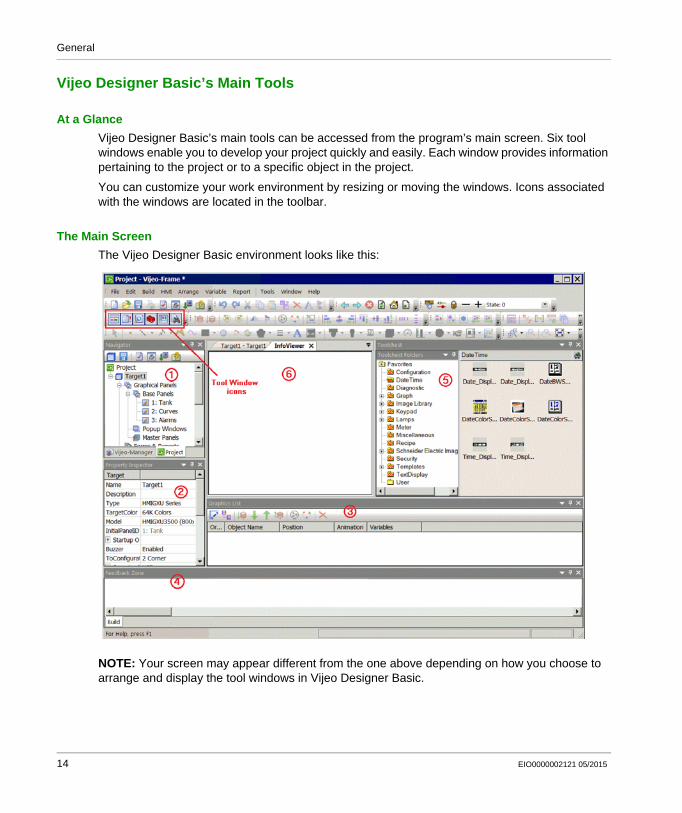
Vijeo Designer Basic’s Main Tools
At a Glance
Vijeo Designer Basic’s main tools can be accessed from the program’s main screen. Six tool windows enable you to develop your project quickly and easily. Each window provides information pertaining to the project or to a specific object in the project.
You can customize your work environment by resizing or moving the windows. Icons associated with the windows are located in the toolbar.
The Main Screen
The Vijeo Designer Basic environment looks like this:
NOTE: Your screen may appear different from the one above depending on how you choose to arrange and display the tool windows in Vijeo Designer Basic.
14 EIO0000002121 05/2015
General
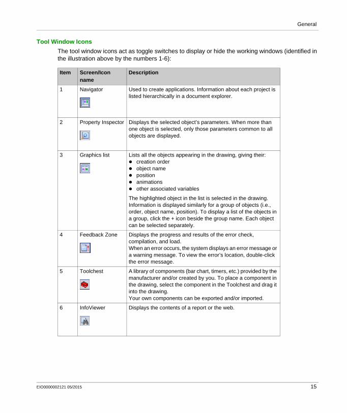
Tool Window Icons
The tool window icons act as toggle switches to display or hide the working windows (identified in the illustration above by the numbers 1-6):
Item Screen/Icon name
Description
1 Navigator Used to create applications. Information about each project is listed hierarchically in a document explorer.
2 Property Inspector Displays the selected object’s parameters. When more than one object is selected, only those parameters common to all objects are displayed.
3 Graphics list Lists all the objects appearing in the drawing, giving their: creation order object name position animations other associated variables
The highlighted object in the list is selected in the drawing.Information is displayed similarly for a group of objects (i.e., order, object name, position). To display a list of the objects in a group, click the + icon beside the group name. Each object can be selected separately.
4 Feedback Zone Displays the progress and results of the error check, compilation, and load.When an error occurs, the system displays an error message or a warning message. To view the error’s location, double-click the error message.
5 Toolchest A library of components (bar chart, timers, etc.) provided by the manufacturer and/or created by you. To place a component in the drawing, select the component in the Toolchest and drag it into the drawing.Your own components can be exported and/or imported.
6 InfoViewer Displays the contents of a report or the web.
EIO0000002121 05/2015 15
General
Installing Vijeo Designer Basic
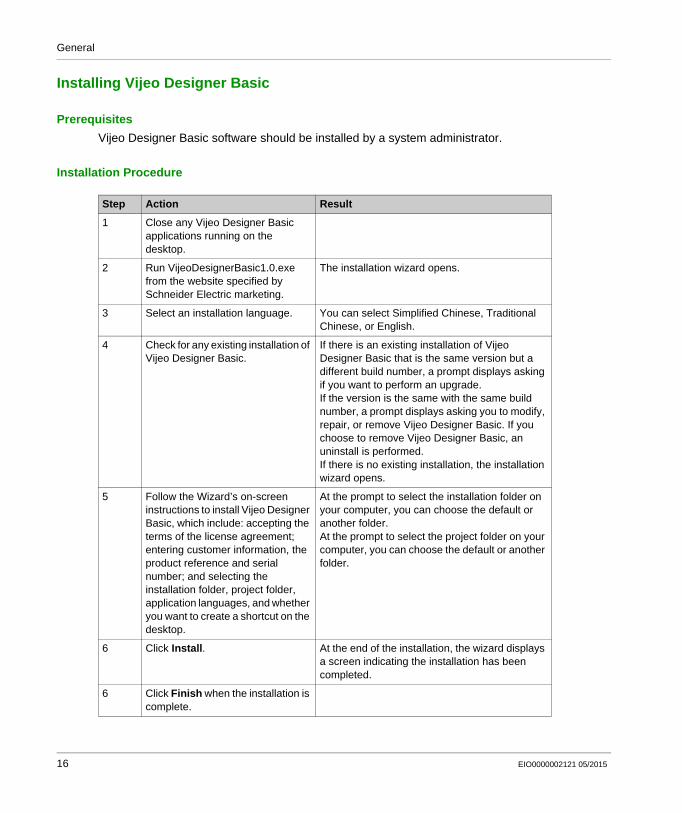
Prerequisites
Vijeo Designer Basic software should be installed by a system administrator.
Installation Procedure
Step Action Result
1 Close any Vijeo Designer Basic applications running on the desktop.
2 Run VijeoDesignerBasic1.0.exe from the website specified by Schneider Electric marketing.
The installation wizard opens.
3 Select an installation language. You can select Simplified Chinese, Traditional Chinese, or English.
4 Check for any existing installation of Vijeo Designer Basic.
If there is an existing installation of Vijeo Designer Basic that is the same version but a different build number, a prompt displays asking if you want to perform an upgrade.If the version is the same with the same build number, a prompt displays asking you to modify, repair, or remove Vijeo Designer Basic. If you choose to remove Vijeo Designer Basic, an uninstall is performed.If there is no existing installation, the installation wizard opens.
5 Follow the Wizard’s on-screen instructions to install Vijeo Designer Basic, which include: accepting the terms of the license agreement; entering customer information, the product reference and serial number; and selecting the installation folder, project folder, application languages, and whether you want to create a shortcut on the desktop.
At the prompt to select the installation folder on your computer, you can choose the default or another folder.At the prompt to select the project folder on your computer, you can choose the default or another folder.
6 Click Install. At the end of the installation, the wizard displays a screen indicating the installation has been completed.
6 Click Finish when the installation is complete.
16 EIO0000002121 05/2015
General
NOTE: At the end of the installation process, the program may ask you to restart your computer. You must restart to update all newly installed components in the system.
EIO0000002121 05/2015 17
General
Uninstalling Vijeo Designer Basic
Two Ways to Uninstall the Software
You can uninstall Vijeo Designer Basic may be uninstalled in either of two ways:
using the Uninstall utility in the software with the Programs and Features utility on your computer’s Control Panel
Using the Uninstall Utility
Using the Add/Remove Programs Utility
Step Action
1 Close any applications running on the desktop.
2 Click Start All Programs Schneider Electric Vijeo Designer Basic Uninstall (Vijeo Designer Basic)
3 At the prompt to confirm the uninstall, click Yes.
4 At the end of the uninstall process, restart your computer to update the system.
Step Action
1 Close any applications running on the desktop.
2 Click Start Settings Control Panel.
3 Select Vijeo Designer Basic from the list of programs. Right-click and select Uninstall.
4 At the end of the uninstall process, restart your computer to update the system.
18 EIO0000002121 05/2015
Vijeo Designer Basic
Project creation
VJB_Tutorial 05/2015
Project creation
Chapter 2Project creation
Purpose of this Chapter
This chapter describes how to produce a simple application using Vijeo Designer Basic’s main functions.
What Is in This Chapter?
This chapter contains the following topics:
Topic Page
Description of Requirements 20
Project Construction Steps 21
The Application at a Glance 22
Starting Vijeo Designer 26
Basic Settings 27
Creating Variables 29
Creating Panels 34
Numeric and Text Displays 37
Graphical Objects 41
Creating Recipes 47
Creating the "Curves" Panel 52
Creating the "Alarms" Panel 54
Creating an Action 58
Simulation 63
EIO0000002121 05/2015 19
Project creation
Description of Requirements
At a Glance
In order to discover some of the things you can do with Vijeo Designer Basic, we are going to develop a project. To do this, we need to describe the requirements or specifications for our project.
The application must satisfy the following criteria:
Manage the filling of a tank according to a filling setpoint and an alarm level. The setpoint and alarm level are selected by the user from a range of presets. We will use the recipes function for the selection of presets,
Empty the tank by opening/closing the bottom valve when a button is pressed, View the setpoint values in a numeric display and as a trend graph, Provide an overview of the variation in level over time. To do this, we use a trend graph, Inform the user when a threshold is exceeded via a lamp and an alarm page.
20 EIO0000002121 05/2015
Project creation
Project Construction Steps
At a Glance
The following steps must be taken and the following points addressed to create our project:
Launch Vijeo Designer Basic, Create a new project, Configure the project, Declare the variables, Create the different panels and screen jumps, Create the numeric and textual displays, Use the graphical objects from the toolchest, Create the recipe, Create the trend graphs, Create alarm management, Create a script action, Generate and simulate the project.
EIO0000002121 05/2015 21
Project creation
The Application at a Glance
At a Glance
The project to be designed is called "manual".
It consists of three screen panels:
"Tank", "Curves", "Alarms".
The "Tank" panel consists of:
a tank taken from the animation toolchest, two numeric displays (the level value and the alarm setpoint), two types of recipe commands which can be used to define the fill values and tank level alarms, a tank emptying valve controlled by a button, an upper threshold alarm lamp, and a set of buttons used to switch from one screen to another.
The "Curves" panel consists of:
a trend graph object in which the tank level and alarm setpoint are animated, and a set of buttons used to switch from one screen to another.
The "Alarms" panel consists of:
an alarm object which displays a high level alarm if the tank level is higher than the alarm setpoint,
and a set of buttons used to switch from one screen to another.
The "Tank" Panel
This is the main screen of the project. Here, the tank is filled to a selected product quantity (small, medium and large quantity), managed by a recipe. The recipe also manages the threshold not to be exceeded depending on the desired quantity (alarm setpoint). You can modify the alarm setpoint by clicking (for a simulation) or by touching (on the target’s tactile screen at runtime) the numerical display for the "level of alarm". The high level alarm is activated if the tank level is higher than the alarm setpoint. A lamp lights up red once the threshold is exceeded and the alarm is actived.
An "emptying" button enables you to empty the tank via the bottom valve. The valve animates as you empty the tank. When closed the valve is shown in gray. When open it is shown in red.
22 EIO0000002121 05/2015
Project creation
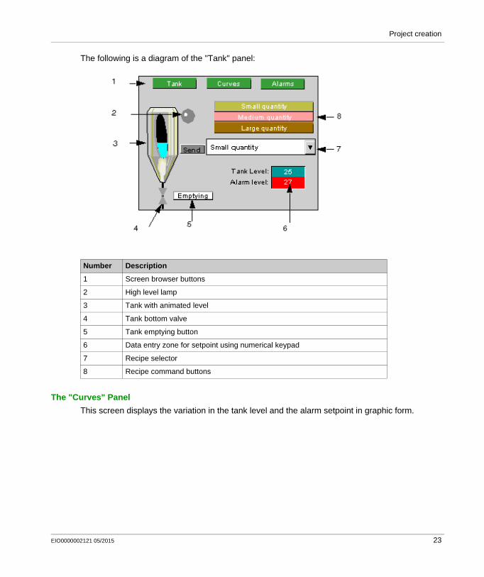
The following is a diagram of the "Tank" panel:
The "Curves" Panel
This screen displays the variation in the tank level and the alarm setpoint in graphic form.
Number Description
1 Screen browser buttons
2 High level lamp
3 Tank with animated level
4 Tank bottom valve
5 Tank emptying button
6 Data entry zone for setpoint using numerical keypad
7 Recipe selector
8 Recipe command buttons
EIO0000002121 05/2015 23
Project creation
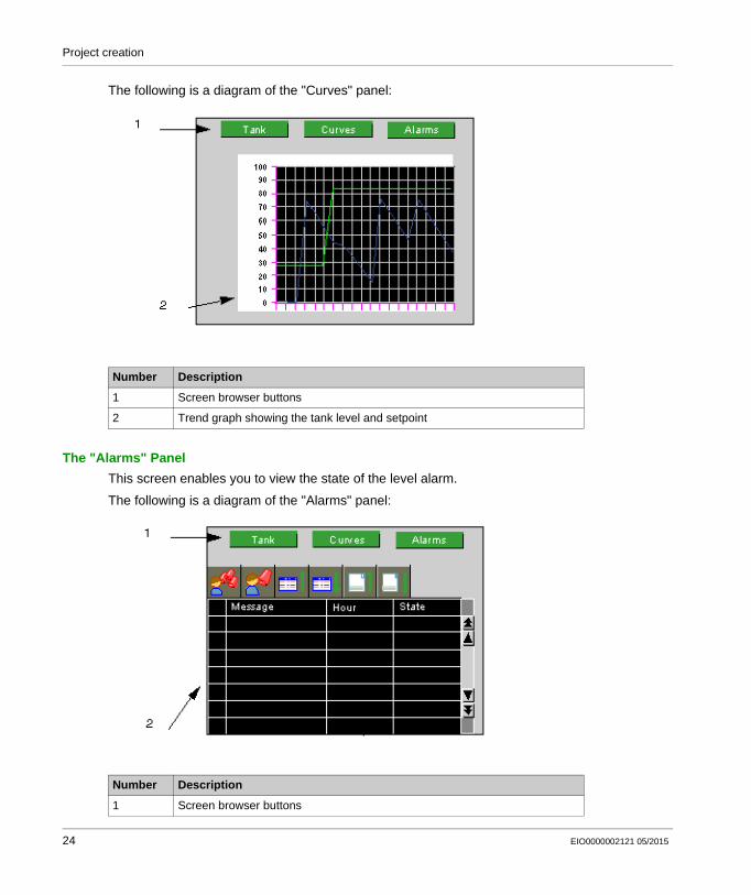
The following is a diagram of the "Curves" panel:
The "Alarms" Panel
This screen enables you to view the state of the level alarm.
The following is a diagram of the "Alarms" panel:
Number Description
1 Screen browser buttons
2 Trend graph showing the tank level and setpoint
Number Description
1 Screen browser buttons
24 EIO0000002121 05/2015
Project creation
2 Alarm table for viewing active, acknowledged or elapsed/resolved alarms
Number Description
EIO0000002121 05/2015 25
Project creation
Starting Vijeo Designer
Procedure
To start Vijeo Designer Basic, select Start All Programs Schneider Electric Vijeo Designer Basic Vijeo Designer Basic or double-click the Vijeo Designer Basic icon on the desktop.
26 EIO0000002121 05/2015
Project creation
Basic Settings
At a Glance
Configuring your project correctly is essential before you begin to create a drawing. This project uses internal and external variables.
A project created in Vijeo Designer Basic is a simple chain of information (database). Within a project, the target terminals are configured and organized in a hierarchical structure.
Each target shows the hardware environment (PLC device) in which the project will be run.
Create a Project and Configure its Target
The following table describes how to create a project and select the remote device:
Step Action
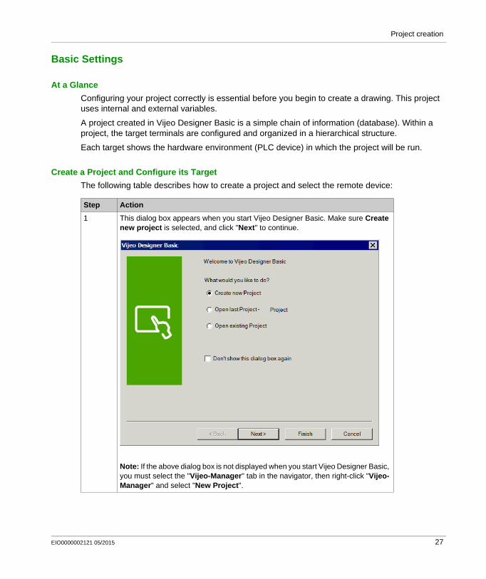
1 This dialog box appears when you start Vijeo Designer Basic. Make sure Create new project is selected, and click "Next" to continue.
Note: If the above dialog box is not displayed when you start Vijeo Designer Basic, you must select the "Vijeo-Manager" tab in the navigator, then right-click "Vijeo-Manager" and select "New Project".
EIO0000002121 05/2015 27
Project creation
2 Enter the name of your project and click Next. In our case, type "Manual". Select the target type, HMIGXU Series, and the model,
HMIGXU3500 (800x480). Click Next Select the IP address if the model uses an Ethernet port then click Next. Select the relevant driver for the device type using the Add button. In our
example, select Schneider Electric Industrie SAS as the Manufacturer, Modbus_(RTU) as the driver, and Modbus Equipment as the Equipment. Then click Finish.
New folders (panels, scripts, alarms, popup windows, languages, data files, etc.) are created.Note: To add another "Target" to the project, right-click "Manual" then select "New Target".
3 Configure the IEC 61131 Syntax in the Equipment Configuration dialog box. To do this, under the [IO Manager] in the [Navigator] window, double-click the equipment for a driver to open the Equipment Configuration dialog box. Then select the [IEC61131 Syntax] check box.
4 Save your project.
Step Action
28 EIO0000002121 05/2015
Project creation
Creating Variables
At a Glance
A variable is a memory address indicated by a name. Vijeo Designer Basic handles the following types of variables:
BOOL INT (16 bit signed integer) UINT (16 bit unsigned integer) DINT (32 bit signed integer) UDINT (32 bit unsigned integer) Integer (1-32 bit generic integer) REAL STRING User Data Type (Array or Structure) Folder Block INT (16 bit signed block integer) Block UINT (16 bit unsigned block integer) Block DINT (32 bit signed block integer) Block Integer (1-32 bit generic block integer) Block REAL
Vijeo Designer Basic uses the variables to communicate with devices. You can also define internal variables that will only be used by Vijeo Designer Basic.
In our project, we are going to create two internal variables and two external variables that communicate with the Modbus device.
EIO0000002121 05/2015 29
Project creation
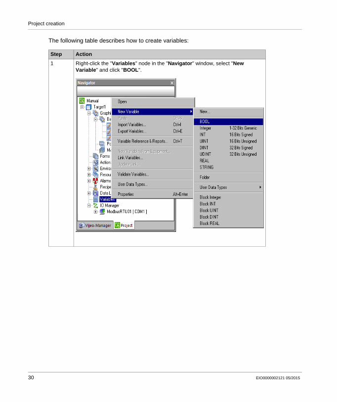
The following table describes how to create variables:
Step Action
1 Right-click the "Variables" node in the "Navigator" window, select "New Variable" and click "BOOL".
30 EIO0000002121 05/2015
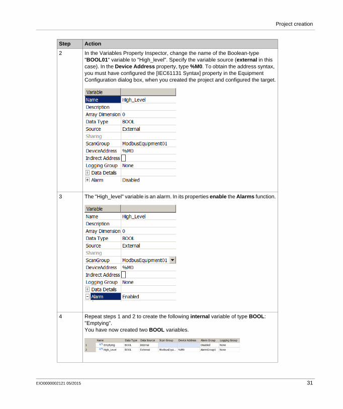
Project creation
2 In the Variables Property Inspector, change the name of the Boolean-type "BOOL01" variable to "High_level". Specify the variable source (external in this case). In the Device Address property, type %M0. To obtain the address syntax, you must have configured the [IEC61131 Syntax] property in the Equipment Configuration dialog box, when you created the project and configured the target.
3 The "High_level" variable is an alarm. In its properties enable the Alarms function.
4 Repeat steps 1 and 2 to create the following internal variable of type BOOL: "Emptying".You have now created two BOOL variables.
Step Action
EIO0000002121 05/2015 31
Project creation
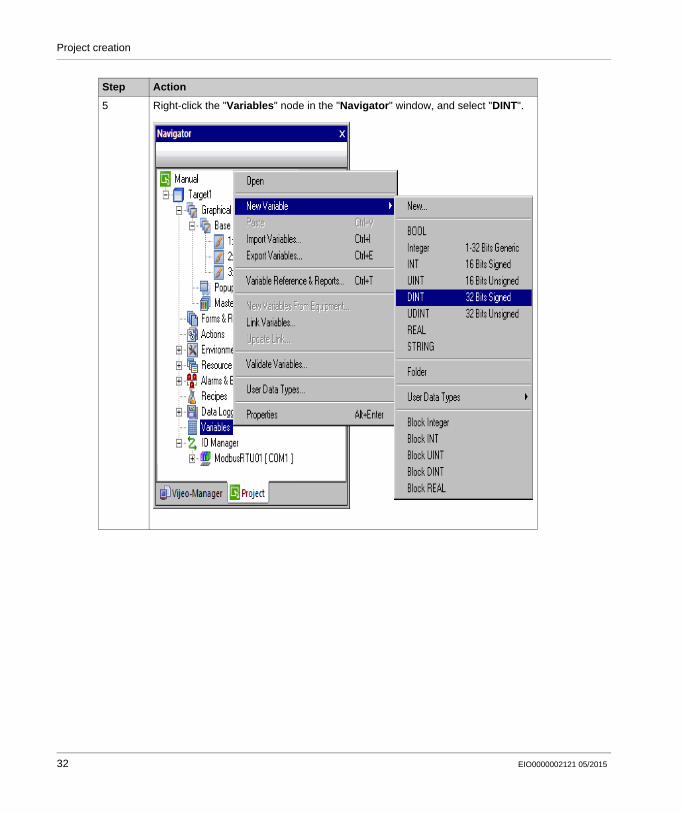
5 Right-click the "Variables" node in the "Navigator" window, and select "DINT".
Step Action
32 EIO0000002121 05/2015
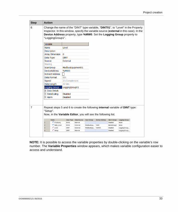
Project creation
NOTE: It is possible to access the variable properties by double-clicking on the variable’s row number. The Variable Properties window appears, which makes variable configuration easier to access and understand.
6 Change the name of the "DINT" type variable, "DINT01", to "Level" in the Property Inspector. In this window, specify the variable source (external in this case). In the Device Address property, type %MW0. Set the Logging Group property to "LoggingGroup1".
7 Repeat steps 5 and 6 to create the following internal variable of DINT type: "Setup".Now, in the Variable Editor, you will see the following list.
Step Action
EIO0000002121 05/2015 33
Project creation
Creating Panels
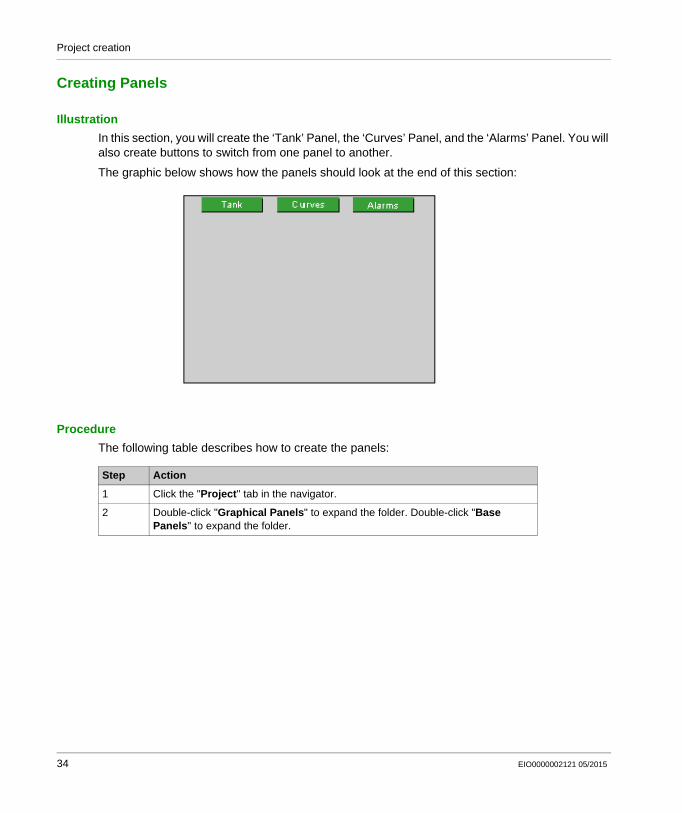
Illustration
In this section, you will create the ‘Tank’ Panel, the ‘Curves’ Panel, and the ‘Alarms’ Panel. You will also create buttons to switch from one panel to another.
The graphic below shows how the panels should look at the end of this section:
Procedure
The following table describes how to create the panels:
Step Action
1 Click the "Project" tab in the navigator.
2 Double-click "Graphical Panels" to expand the folder. Double-click "Base Panels" to expand the folder.
34 EIO0000002121 05/2015
Project creation
Create a Panel Browser Button
The following table describes how to create buttons to switch between panels:
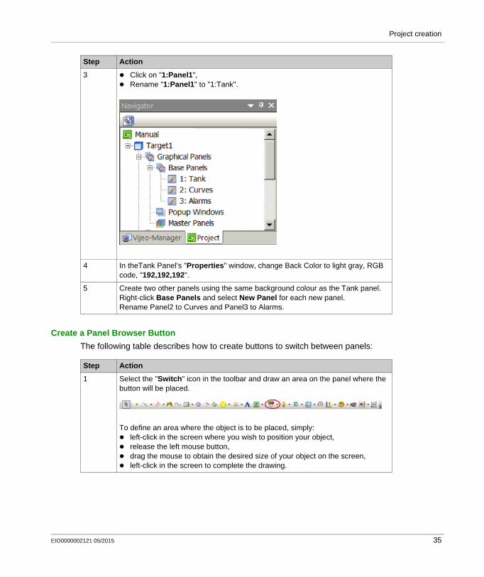
3 Click on "1:Panel1", Rename "1:Panel1" to "1:Tank".
4 In theTank Panel’s "Properties" window, change Back Color to light gray, RGB code, "192,192,192".
5 Create two other panels using the same background colour as the Tank panel.Right-click Base Panels and select New Panel for each new panel.Rename Panel2 to Curves and Panel3 to Alarms.
Step Action
Step Action
1 Select the "Switch" icon in the toolbar and draw an area on the panel where the button will be placed.
To define an area where the object is to be placed, simply: left-click in the screen where you wish to position your object, release the left mouse button, drag the mouse to obtain the desired size of your object on the screen, left-click in the screen to complete the drawing.
EIO0000002121 05/2015 35
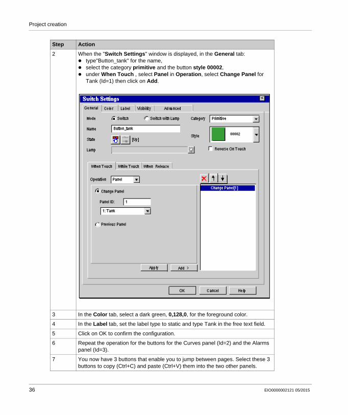
Project creation
2 When the "Switch Settings" window is displayed, in the General tab: type"Button_tank" for the name, select the category primitive and the button style 00002, under When Touch , select Panel in Operation, select Change Panel for
Tank (Id=1) then click on Add.
3 In the Color tab, select a dark green, 0,128,0, for the foreground color.
4 In the Label tab, set the label type to static and type Tank in the free text field.
5 Click on OK to confirm the configuration.
6 Repeat the operation for the buttons for the Curves panel (Id=2) and the Alarms panel (Id=3).
7 You now have 3 buttons that enable you to jump between pages. Select these 3 buttons to copy (Ctrl+C) and paste (Ctrl+V) them into the two other panels.
Step Action
36 EIO0000002121 05/2015
Project creation
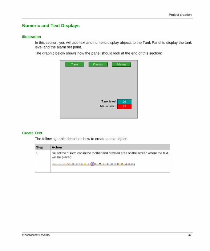
Numeric and Text Displays
Illustration
In this section, you will add text and numeric display objects to the Tank Panel to display the tank level and the alarm set point.
The graphic below shows how the panel should look at the end of this section:
Create Text
The following table describes how to create a text object:
Step Action
1 Select the "Text" icon in the toolbar and draw an area on the screen where the text will be placed.
EIO0000002121 05/2015 37
Project creation
Create a Numeric Indicator
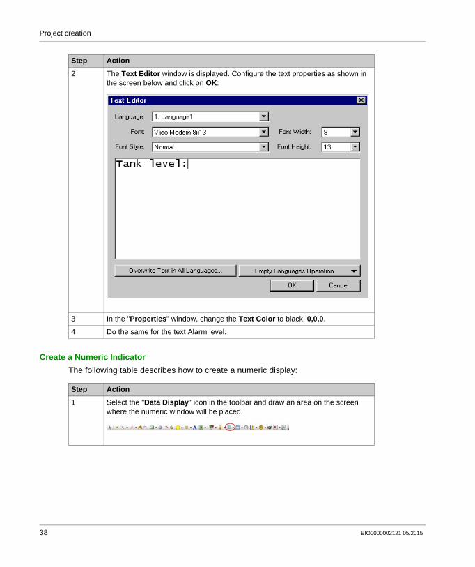
The following table describes how to create a numeric display:
2 The Text Editor window is displayed. Configure the text properties as shown in the screen below and click on OK:
3 In the "Properties" window, change the Text Color to black, 0,0,0.
4 Do the same for the text Alarm level.
Step Action
Step Action
1 Select the "Data Display" icon in the toolbar and draw an area on the screen where the numeric window will be placed.
38 EIO0000002121 05/2015
Project creation
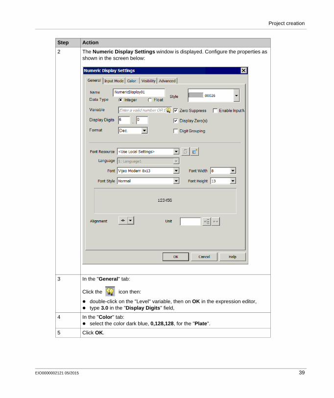
2 The Numeric Display Settings window is displayed. Configure the properties as shown in the screen below:
3 In the "General" tab:
Click the icon then:
double-click on the "Level" variable, then on OK in the expression editor, type 3.0 in the "Display Digits" field,
4 In the "Color" tab: select the color dark blue, 0,128,128, for the "Plate".
5 Click OK.
Step Action
EIO0000002121 05/2015 39
Project creation
NOTE: You can access and modify an object’s settings in the "Properties" window.
6 Repeat these steps for the ‘Setup’ variable.For the ‘Setup’ variable, check Enable Input Mode in the Input Mode tab. This allows you to change the value at runtime. The option Display Popup Keypad is automatically selected. This displays a numeric keypad you can use to change the value of the numeric display.Select the color red, 255,0,0, for the "Plate".
7 Save your project.
Step Action
40 EIO0000002121 05/2015
Project creation
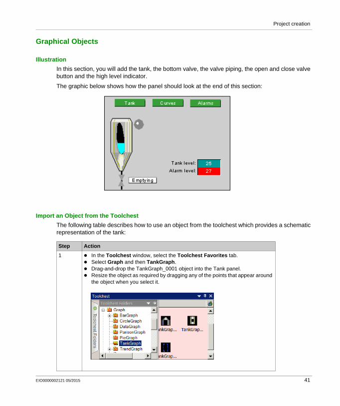
Graphical Objects
Illustration
In this section, you will add the tank, the bottom valve, the valve piping, the open and close valve button and the high level indicator.
The graphic below shows how the panel should look at the end of this section:
Import an Object from the Toolchest
The following table describes how to use an object from the toolchest which provides a schematic representation of the tank:
Step Action
1 In the Toolchest window, select the Toolchest Favorites tab. Select Graph and then TankGraph. Drag-and-drop the TankGraph_0001 object into the Tank panel. Resize the object as required by dragging any of the points that appear around
the object when you select it.
EIO0000002121 05/2015 41
Project creation
Create a Line
The following table describes how to create a line representing the piping of the bottom valve:
Create Valve
A polygon shape will represent the valve. It animates depending on whether it is open (green) or closed (gray).
The following table describes how to create the valve:
2 In the TankGraph "Properties" window, by the "Variable" property, click the
button. The Variable List window is displayed. Double-click the ‘Level’ variable to animate the tank level.
Step Action
Step Action
1 Select the "line" icon from the tool bar and draw a line from the bottom of the tank to the bottom of the screen. Adjust the position of the line using the arrow keys on your keyboard.
2 In the "Properties" window, enter: black, 0,0,0, as the line color, "4" as the line width.
Step Action
1 Select the "Polygon" icon in the toolbar and use it to draw a valve, defining an area on the screen where the valve will be placed.
42 EIO0000002121 05/2015
Project creation
Create Warning Signal
We will use a lamp for signaling the "High_level" alarm. It animates depending on whether the alarm is triggered (red) or untriggered (grey) for "High_level".
The following table describes how to create the lamp:
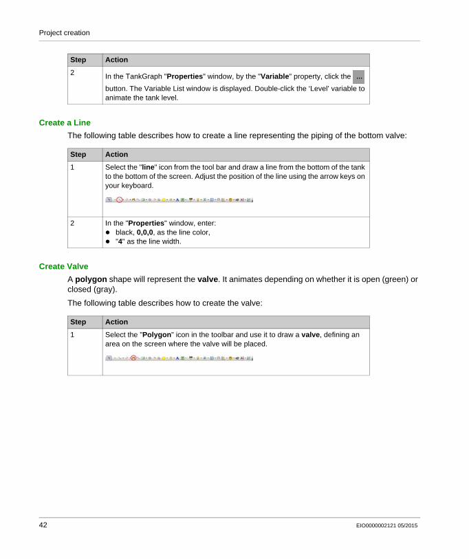
2 The Animation Properties window is displayed. Configure the properties as shown in the screen below:
3 In the "Color" tab, select Free Form for the mode.In the "Fore Color" tab: check Enable Fore Color Animation.
Click the icon then:
double-click the BOOL variable "Emptying" then click "OK", change the colors of OFF to gray, 192,192,192, and ON to green, 0,128,0.
4 Click OK.
Step Action
Step Action
1 Select the "Lamp" icon in the toolbar and use it to draw a Lamp, defining an area on the screen where the lamp will be placed.
EIO0000002121 05/2015 43
Project creation
Create a Command Button
The "emptying" button enables or disables the "emptying" variable. It also animates the bottom valve.
The following table describes how to create the "emptying" button:
2 In this window, from the "General" tab:
Click the icon then:
select the "BOOL" "High_level" variable, retain the lamp style 10001.
3 In the "Color" tab: select dark gray, 128,128,128, for the foreground color of the OFF state, select red, 255,0,0, for the foreground color of the ON state combined with fast
blink.
4 Click OK.
Step Action
Step Action
1 Select the "Switch" icon in the toolbar and use it to draw a rectangle, defining an area on the screen where it will be placed.
44 EIO0000002121 05/2015
Project creation
2 The Switch Settings window is displayed. Configure the properties as shown in the screen below:
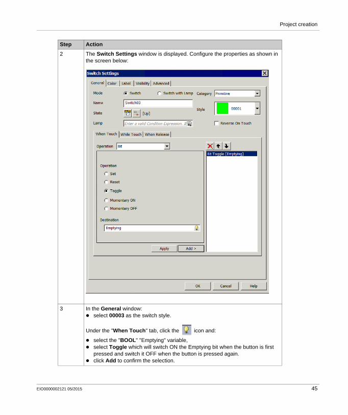
3 In the General window: select 00003 as the switch style.
Under the "When Touch" tab, click the icon and:
select the "BOOL" "Emptying" variable, select Toggle which will switch ON the Emptying bit when the button is first
pressed and switch it OFF when the button is pressed again. click Add to confirm the selection.
Step Action
EIO0000002121 05/2015 45
Project creation
4 In the "Label" tab: select static for the label type,
Type ‘Emptying’ in the data entry window,
5 In the "Color" tab: select white, 255,255,255, as the foreground color, select black, 0,0,0, as the text color.
6 Click OK.
Step Action
46 EIO0000002121 05/2015
Project creation
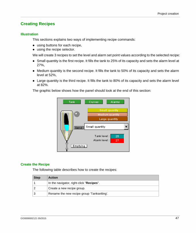
Creating Recipes
Illustration
This sections explains two ways of implementing recipe commands:
using buttons for each recipe, using the recipe selector.
We will create 3 recipes to set the level and alarm set point values according to the selected recipe:
Small quantity is the first recipe. It fills the tank to 25% of its capacity and sets the alarm level at 27%,
Medium quantity is the second recipe. It fills the tank to 50% of its capacity and sets the alarm level at 52%,
Large quantity is the third recipe. It fills the tank to 80% of its capacity and sets the alarm level at 82%.
The graphic below shows how the panel should look at the end of this section:
Create the Recipe
The following table describes how to create the recipes:
Step Action
1 In the navigator, right-click "Recipes".
2 Create a new recipe group.
3 Rename the new recipe group ‘Tanksetting’.
EIO0000002121 05/2015 47
Project creation
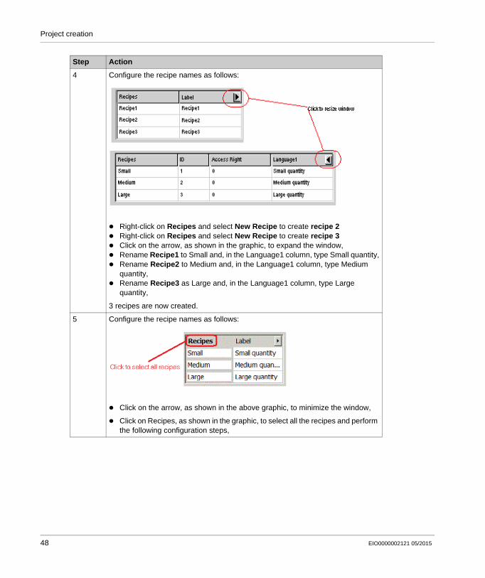
4 Configure the recipe names as follows:
Right-click on Recipes and select New Recipe to create recipe 2 Right-click on Recipes and select New Recipe to create recipe 3 Click on the arrow, as shown in the graphic, to expand the window, Rename Recipe1 to Small and, in the Language1 column, type Small quantity, Rename Recipe2 to Medium and, in the Language1 column, type Medium
quantity, Rename Recipe3 as Large and, in the Language1 column, type Large
quantity,
3 recipes are now created.
5 Configure the recipe names as follows:
Click on the arrow, as shown in the above graphic, to minimize the window,
Click on Recipes, as shown in the graphic, to select all the recipes and perform the following configuration steps,
Step Action
48 EIO0000002121 05/2015
Project creation
Create Button-Operated Recipe Command
Create three buttons, one for each recipe.
The following table describes how to create a button for a recipe:
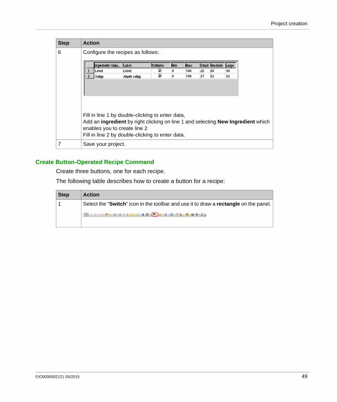
6 Configure the recipes as follows:
Fill in line 1 by double-clicking to enter data,Add an ingredient by right clicking on line 1 and selecting New Ingredient which enables you to create line 2Fill in line 2 by double-clicking to enter data.
7 Save your project.
Step Action
Step Action
1 Select the "Switch" icon in the toolbar and use it to draw a rectangle on the panel.
EIO0000002121 05/2015 49
Project creation
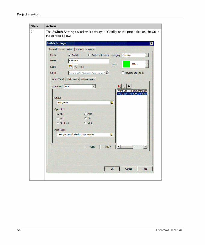
2 The Switch Settings window is displayed. Configure the properties as shown in the screen below:
Step Action
50 EIO0000002121 05/2015
Project creation
Repeat these steps to create buttons for the Medium and Large recipes using the following assignment table:
Create a Recipe Selector
The recipe selector can be found in the toolchest.
In the Toolchest window, select the Toolchest Favorites tab. Select Recipe. Drag-and-drop the "Recipeselect" object and the "send" object into the "Tank" panel.
3 In the General window: select 00002 as the switch style.
Under the "When Touch" tab: select a Word operation, enter 1 in Source.
in Destination, click the icon and select
RecipeDefaultControl.RecipeNumber. click Add to confirm selection of recipe number 1. Repeat the operation, enabling source 1 for the destination
RecipeDefaultControl.Operation, click Add to confirm the choice to send a recipe command.
4 In the "Label" tab: select static for the label type,
type ‘Small quantity’ in the data entry window,
5 In the "Color" tab: select black, 0,0,0, as the text color, select yellow, 255,255,0, as the foreground color,
6 Click OK.
7 Save your project.
Small Medium Large
RecipeDefaultControl.RecipeNumber (Recipe number)
1 2 3
RecipeDefaultControl.operation (recipe operation)
1 1 1
Button color and color code yellow255,255,0
salmon pink255,128,64
brown128,128,0
Button label Small quantity
Medium quantity
Large quantity
Step Action
EIO0000002121 05/2015 51
Project creation
Creating the "Curves" Panel
Illustration
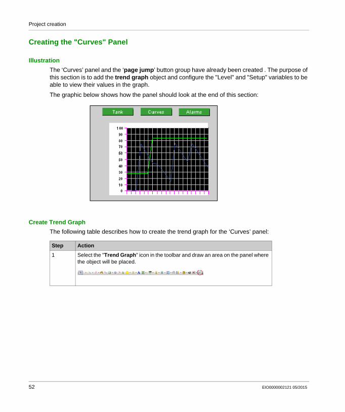
The ‘Curves’ panel and the ‘page jump’ button group have already been created . The purpose of this section is to add the trend graph object and configure the "Level" and "Setup" variables to be able to view their values in the graph.
The graphic below shows how the panel should look at the end of this section:
Create Trend Graph
The following table describes how to create the trend graph for the ‘Curves’ panel:
Step Action
1 Select the "Trend Graph" icon in the toolbar and draw an area on the panel where the object will be placed.
52 EIO0000002121 05/2015
Project creation
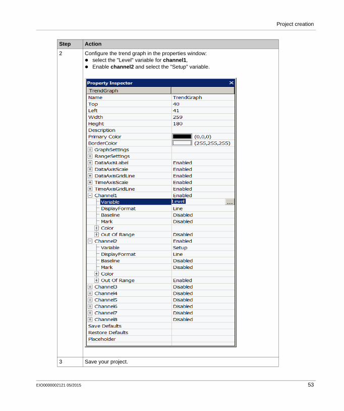
2 Configure the trend graph in the properties window: select the "Level" variable for channel1, Enable channel2 and select the "Setup" variable.
3 Save your project.
Step Action
EIO0000002121 05/2015 53
Project creation
Creating the "Alarms" Panel
Illustration
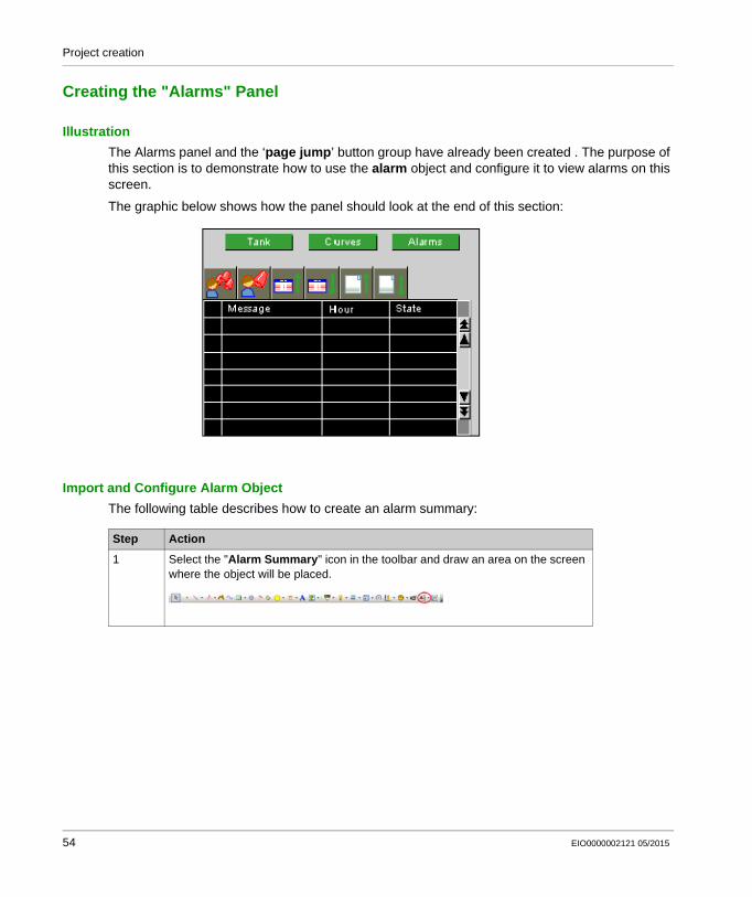
The Alarms panel and the ‘page jump’ button group have already been created . The purpose of this section is to demonstrate how to use the alarm object and configure it to view alarms on this screen.
The graphic below shows how the panel should look at the end of this section:
Import and Configure Alarm Object
The following table describes how to create an alarm summary:
Step Action
1 Select the "Alarm Summary" icon in the toolbar and draw an area on the screen where the object will be placed.
54 EIO0000002121 05/2015
Project creation
NOTE: The column display may be configured as required. In this Alarms page, we have chosen to display the message with a column width of 120, and the alarm date and time with column widths of 80.
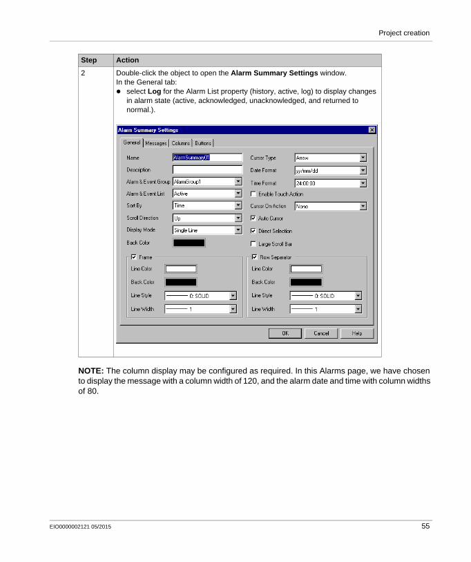
2 Double-click the object to open the Alarm Summary Settings window.In the General tab: select Log for the Alarm List property (history, active, log) to display changes
in alarm state (active, acknowledged, unacknowledged, and returned to normal.).
Step Action
EIO0000002121 05/2015 55
Project creation
Configure Alarm Group
The following table describes how to configure the alarm group:
Step Action
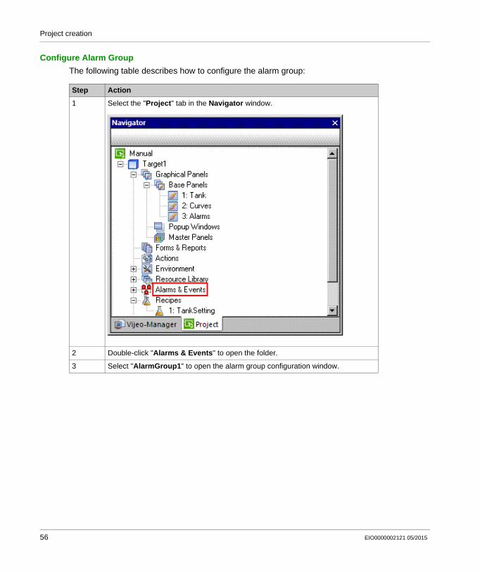
1 Select the "Project" tab in the Navigator window.
2 Double-click "Alarms & Events" to open the folder.
3 Select "AlarmGroup1" to open the alarm group configuration window.
56 EIO0000002121 05/2015
Project creation
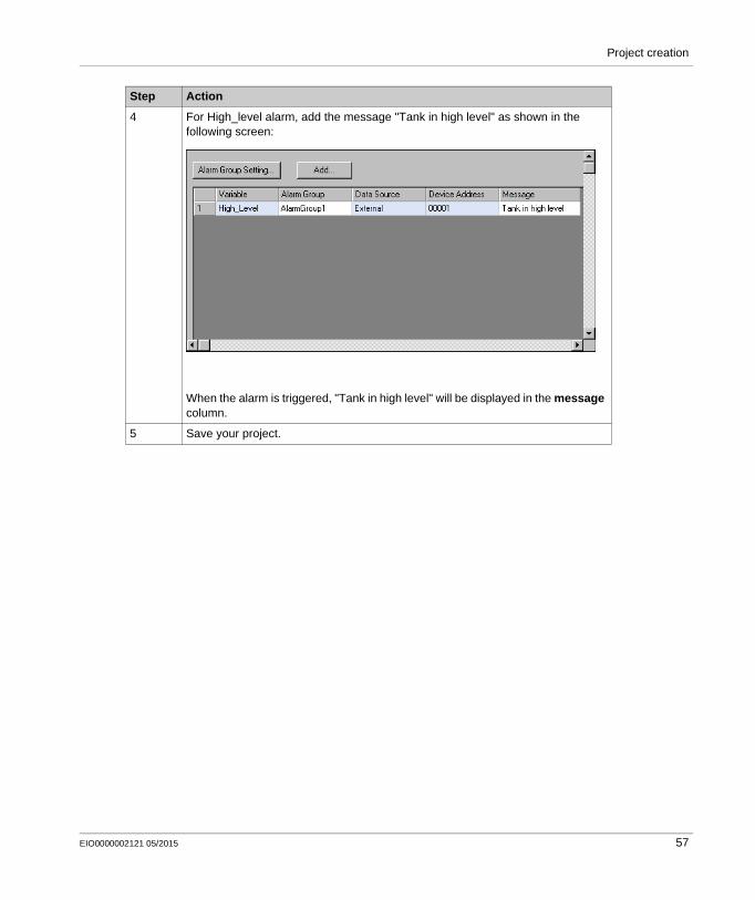
4 For High_level alarm, add the message "Tank in high level" as shown in the following screen:
When the alarm is triggered, "Tank in high level" will be displayed in the message column.
5 Save your project.
Step Action
EIO0000002121 05/2015 57
Project creation
Creating an Action
At a Glance
Actions can define a procedure that runs when a condition is met.
For this project, we create three actions:
The first action triggers when the target powers up. It is used to select recipe number 1. The second action triggers when the "Emptying" variable activates. This action simulates
emptying of the tank. The third action triggers when the "Level" variable exceeds the value of the "Setup" variable.
This action toggles the "High_level" alarm ON and OFF.
Create the Startup Action
The following action executes once on startup.
The following table describes how to create the startup action:
Step Action
1 In the Navigator window, select the "Project" tab , then right-click "Actions" and select "New Action"
58 EIO0000002121 05/2015
Project creation
Create the Emptying Action
The following action executes every 0.3 seconds when the "Emptying" variable is enabled, by pressing the Emptying button. This action simulates emptying of the tank.
The following table describes how to create the emptying action:
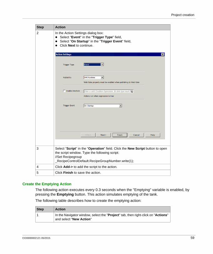
2 In the Action Settings dialog box: Select "Event" in the "Trigger Type" field, Select "On Startup" in the "Trigger Event" field, Click Next to continue.
3 Select "Script" in the "Operation" field. Click the New Script button to open the script window. Type the following script://Set Recipegroup_RecipeControlDefault.RecipeGroupNumber.write(1);
4 Click Add-> to add the script to the action.
5 Click Finish to save the action.
Step Action
Step Action
1 In the Navigator window, select the "Project" tab, then right-click on "Actions" and select "New Action"
EIO0000002121 05/2015 59
Project creation
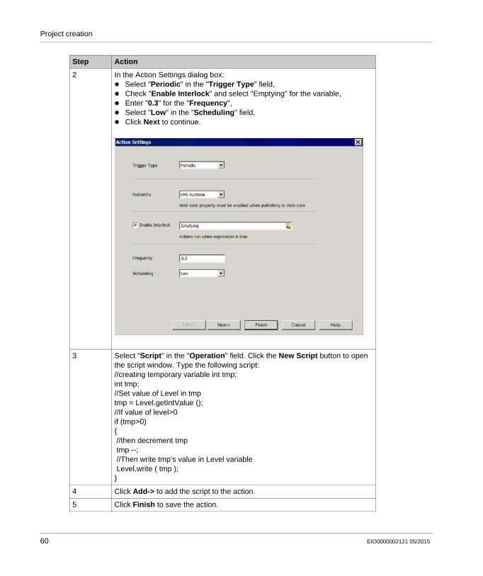
2 In the Action Settings dialog box: Select "Periodic" in the "Trigger Type" field, Check "Enable Interlock" and select "Emptying" for the variable, Enter "0.3" for the "Frequency", Select "Low" in the "Scheduling" field, Click Next to continue.
3 Select "Script" in the "Operation" field. Click the New Script button to open the script window. Type the following script://creating temporary variable int tmp;int tmp;//Set value of Level in tmptmp = Level.getIntValue ();//If value of level>0if (tmp>0){ //then decrement tmp tmp --; //Then write tmp’s value in Level variable Level.write ( tmp );}
4 Click Add-> to add the script to the action.
5 Click Finish to save the action.
Step Action
60 EIO0000002121 05/2015
Project creation
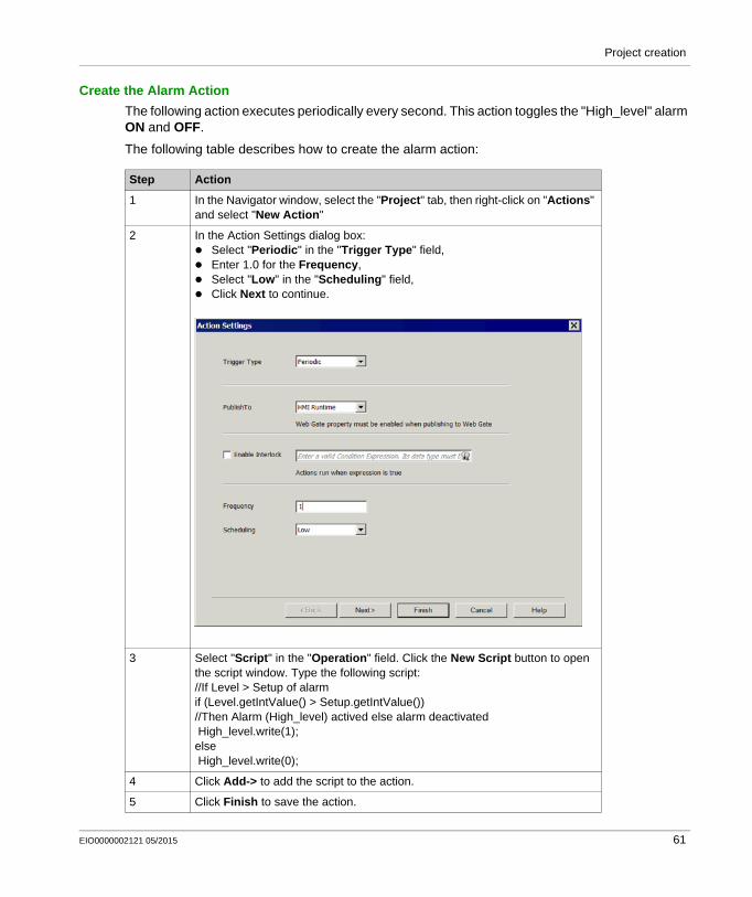
Create the Alarm Action
The following action executes periodically every second. This action toggles the "High_level" alarm ON and OFF.
The following table describes how to create the alarm action:
Step Action
1 In the Navigator window, select the "Project" tab, then right-click on "Actions" and select "New Action"
2 In the Action Settings dialog box: Select "Periodic" in the "Trigger Type" field, Enter 1.0 for the Frequency, Select "Low" in the "Scheduling" field, Click Next to continue.
3 Select "Script" in the "Operation" field. Click the New Script button to open the script window. Type the following script://If Level > Setup of alarmif (Level.getIntValue() > Setup.getIntValue())//Then Alarm (High_level) actived else alarm deactivated High_level.write(1);else High_level.write(0);
4 Click Add-> to add the script to the action.
5 Click Finish to save the action.
EIO0000002121 05/2015 61
Project creation
6 Save your project.
Step Action
62 EIO0000002121 05/2015
Project creation
Simulation
Simulating your Project
The simulation function can be used to display your project without downloading it to an HMIGXU terminal. It is a good way to check and validate your project, and make sure things are the way you want.
Start Simulation
The following table describes how to run the simulation and check your project:
Step Action Result
1 Click the Project tab in the Navigator window.
2 Right-click Target 1.
3 Select Start Device Simulation. The initial screen of your project appears.
4 Test your project as it is so far. It should behave as outlined in the requirements established at the beginning of the Tutorial. For example: Choose a recipe. Does the value
appear on the tank graphically and in the numeric display?
Click on the numeric display (level of alarm) and enter number 10 with the keypad that pops up. When the alarm appears, does the light blink?
Click the navigation button to move to the second screen. Do the values appear on the curve?
Click the alarms button to move to the third screen. Do you get there?
Return to the first screen. Click the emptying button. Does the tank empty?
5 To stop the simulation, press either CTRL+Z or ALT+F4 or click the Close button of the simulation windows.
If you find that some elements are not working properly, go back to the appropriate panel, select the element(s) and review the properties.
6 When everything is fine, test other parts of the application such as the alarms.Note: When testing your project after making corrections, you must close the simulation window before running a new one.
EIO0000002121 05/2015 63
Project creation
64 EIO0000002121 05/2015
Vijeo Designer Basic
Project Download
VJB_Tutorial 05/2015
Project Download
Chapter 3Project Download
Purpose of this Chapter
This chapter describes the different project build types and the various project download modes.
What Is in This Chapter?
This chapter contains the following topics:
Topic Page
Validating, Building, and Correcting Errors 66
Downloading a Project 68
EIO0000002121 05/2015 65
Project Download
Validating, Building, and Correcting Errors
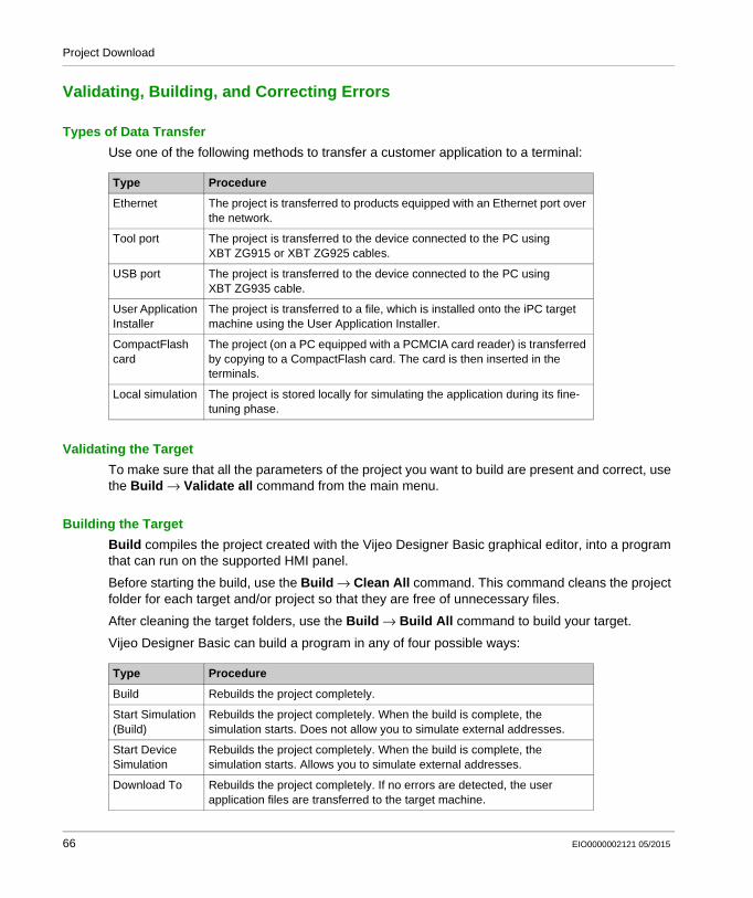
Types of Data Transfer
Use one of the following methods to transfer a customer application to a terminal:
Validating the Target
To make sure that all the parameters of the project you want to build are present and correct, use the Build Validate all command from the main menu.
Building the Target
Build compiles the project created with the Vijeo Designer Basic graphical editor, into a program that can run on the supported HMI panel.
Before starting the build, use the Build Clean All command. This command cleans the project folder for each target and/or project so that they are free of unnecessary files.
After cleaning the target folders, use the Build Build All command to build your target.
Vijeo Designer Basic can build a program in any of four possible ways:
Type Procedure
Ethernet The project is transferred to products equipped with an Ethernet port over the network.
Tool port The project is transferred to the device connected to the PC using XBT ZG915 or XBT ZG925 cables.
USB port The project is transferred to the device connected to the PC using XBT ZG935 cable.
User Application Installer
The project is transferred to a file, which is installed onto the iPC target machine using the User Application Installer.
CompactFlash card
The project (on a PC equipped with a PCMCIA card reader) is transferred by copying to a CompactFlash card. The card is then inserted in the terminals.
Local simulation The project is stored locally for simulating the application during its fine-tuning phase.
Type Procedure
Build Rebuilds the project completely.
Start Simulation (Build)
Rebuilds the project completely. When the build is complete, the simulation starts. Does not allow you to simulate external addresses.
Start Device Simulation
Rebuilds the project completely. When the build is complete, the simulation starts. Allows you to simulate external addresses.
Download To Rebuilds the project completely. If no errors are detected, the user application files are transferred to the target machine.
66 EIO0000002121 05/2015
Project Download
Error Correction
When the build process completes, the Feedback zone window opens automatically, and all detected errors and warnings are displayed. Errors are displayed in red, and warnings are displayed in yellow. When there are no errors or warnings, the result is displayed in green.
To view detailed information on a specific error or warning, double-click the error or warning message.
EIO0000002121 05/2015 67
Project Download
Downloading a Project
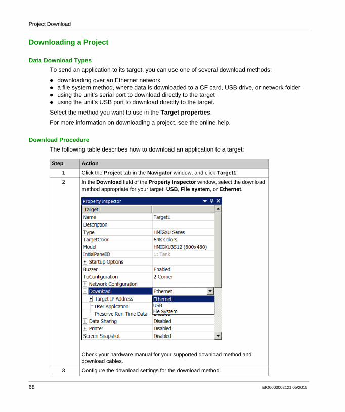
Data Download Types
To send an application to its target, you can use one of several download methods:
downloading over an Ethernet network a file system method, where data is downloaded to a CF card, USB drive, or network folder using the unit’s serial port to download directly to the target using the unit’s USB port to download directly to the target.
Select the method you want to use in the Target properties.
For more information on downloading a project, see the online help.
Download Procedure
The following table describes how to download an application to a target:
Step Action
1 Click the Project tab in the Navigator window, and click Target1.
2 In the Download field of the Property Inspector window, select the download method appropriate for your target: USB, File system, or Ethernet.
Check your hardware manual for your supported download method and download cables.
3 Configure the download settings for the download method.
68 EIO0000002121 05/2015
Project Download
Exit Vijeo Designer Basic
Before you exit Vijeo Designer Basic, save your project. Then select File Exit from the main menu.
4 In the Navigator window,right click Target1 and select Download To....
5 Check your target machine unit to see if the application is displayed correctly.Note: If an error message appears in the Feedback zone, the download has failed. You need to solve the problem before trying to download data again. Double-click on the error message displayed in the Feedback zone to locate the position of the error.
Step Action
EIO0000002121 05/2015 69
Project Download
70 EIO0000002121 05/2015
Vijeo Designer Basic
Index
VJB_Tutorial 05/2015
Index
Aactions, 13
Bbuilding, 66
Cchecking for errors, 66Configuration, 27connectivity, 12
Ddata reuse, 12data transfer, 66Display, 37downloading a project, 68
Eediting variables, 13errors, 66Ethernet, 66
Ggeneration, 66graphical panel, 12Graphical Panel
Alarm, 54Curves, 52Tank, 34
HHMI, 12HMI panels that use Vijeo Designer Basic, 13
EIO0000002121 05/2015
IInstallation, 16
Mmessaging
in multiple languages, 13multi-language messaging, 13
OObject, 41
Pproperties, 13
RRecipe, 47reusing data, 12
SScript, 58simulation, 63Starting Vijeo Designer Basic, 26
Ttarget devices, 13
UUninstall, 18
Vvalidating, 66variable editing, 13
71
Index
Variables, 29
72
EIO0000002121 05/2015


![Vijeo-Designer Tutorial - infoPLC · Vijeo Ejercicio_1 - Vijeo-Frame - [Destino1 - Configuración] Designe Vijeo Destino1 - Configuración 123 Nivel del agua configuración Alarma](https://img.dokumen.tips/doc/110x75/5bde874109d3f2545f8cf49c/vijeo-designer-tutorial-vijeo-ejercicio1-vijeo-frame-destino1-configuracion.jpg)


![Manual Formacion Vijeo Designer[1]](https://img.dokumen.tips/doc/110x75/55cf9de5550346d033afbefe/manual-formacion-vijeo-designer1.jpg)