Embed Size (px)
Citation preview

VIFB CoilTechnical Guide
VERTICAL TUBE INTEGRAL FACE AND BY-PASS HEATING COILS FOR AIR PREHEATING
TGVIFB-6

Since 1875, the L.J. Wing Company has been a leader in providing innovative solutions for difficult HVAC problems. Wing VIFB integral face and by-pass coils provide reliable air preheating for air handling systems. This technical guide will help you size, select and specify the proper VIFB model to satisfy your project’s make-upair preheating requirements. If you have questions, please contact your local L.J. Wing representative; he will be glad to assist you.
4830 Transport Drive, Dallas, TX 75247 Tel. (214) 638-6010 www.ljwing.com
In the interest of product improvement, L.J. Wing reserves the right to make changes without notice.2

TABLE OF CONTENTS
Operation..........................................................................................4Performance.....................................................................................5Certification.......................................................................................5Model Number Description...............................................................5Dimensions..................................................................................6-11Piping.........................................................................................12-16Controls.......................................................................................... 17Installation Tips...............................................................................18Accessories.....................................................................................19Typical Specification........................................................................20Typical Schedule.............................................................................20
3
OPERATION
How the VIFB Coil Works
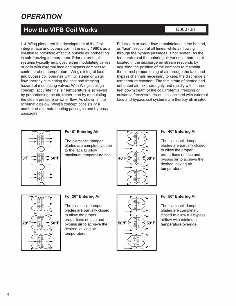
L.J. Wing pioneered the development of the first integral face and bypass coil in the early 1960’s as a solution to providing effective outside air preheating in sub-freezing temperatures. Prior air preheat systems typically employed either modulating valves or coils with external face and bypass dampers to control preheat temperature. Wing’s integral face and bypass coil operates with full steam or water flow, thereby eliminating the cost and freezing hazard of modulating valves. With Wing’s design concept, accurate final air temperature is achieved by proportioning the air, rather than by modulating the steam pressure or water flow. As shown in the schematic below, Wing’s concept consists of a number of alternate heating passages and by-pass passages.
Full steam or water flow is maintained in the heated, or “face”, section at all times, while air flowing through the bypass passages is not heated. As the temperature of the entering air varies, a thermostat located in the discharge air stream responds by adjusting the position of the dampers to maintain the correct proportioning of air through the face and bypass channels necessary to keep the discharge air temperature constant. The thin strata of heated and unheated air mix thoroughly and rapidly within three feet downstream of the coil. Potential freezing or nuisance freezestat trip-outs associated with external face and bypass coil systems are thereby eliminated.
For 0° Entering Air
The clamshell damper blades are completely open to the face to allow maximum temperature rise.
For 20° Entering Air
The clamshell damper blades are partially closed to allow the proper proportions of face and bypass air to achieve the desired leaving air temperature.
For 40° Entering Air
The clamshell damper blades are partially closed to allow the proper proportions of face and bypass air to achieve the desired leaving air temperature.
For 50° Entering Air
The clamshell damper blades are completely closed to allow full bypass airflow with minimum temperature override.
4
50°F40°F
53°F50°F
50°F0°F
50°F20°F
50°F40°F
53°F50°F
50°F0°F
50°F20°F
D000738

PERFORMANCE AND CERTIFICATION
Performance
Performance ratings for VIFB coils can be obtained from the L.J. Wing Coil Specifier program that can be downloaded from the L.J. Wing website: www.ljwing.com
With a menu-driven format, the Coil Specifier program is quick and simple to use. Input and output values are conveniently shown on a single screen, enabling you to instantaneously evaluate the effect of changing input variables such as fin spacing or coil size.
The Specifier program offers two printed reports: “Coil Rating” and “Specification”. The “Coil Rating” report includes not only the coil performance rating, but also a dimensional drawing and piping diagram. The “Specification” report generates a dynamic specification for the coil selected.
Along with the VIFB series, L.J. Wing’s other two integral face and bypass coil product lines, the IFB and MV series, may be also selected and rated with the Coil Specifier.
Certification
Wing VIFB coil performance generated with the Wing Specifier program is certified by the Air-Conditioning, Heating and Refrigeration Institute (AHRI) under AHRI Standard 410. Having the AHRI label provides assurance that AHRI certifies the accuracy of the VIFB coil performance ratings. To earn and maintain AHRI certification, randomly selected VIFB coils must annually pass through the AHRI design performance certification process. For best performance, always select an AHRI-certified coil.
All L.J. Wing VIFB coils are listed by Engineering Test Laboratories (ETL) to Underwriters’ Laboratories (UL) Standard 1995. This standard assures that VIFB coils are safe to operate up to a design pressure of 100 psig. The standard further stipulates that each coil must withstand a hydrostatic pressure equal to five times the rated design pressure, such that each VIFB coil is hydrostatically tested to 500 psig. For quality products, always look for the ETL mark.
ETL Coil Operating Parameters: Maximum elevation is 9,000 ft. (2,743.2m).Maximum operating temperature is 250°F (121.1°C).Minimum operating temperature is 0°F (-17.8°C).Maximum operating pressure is 100 PSIG (689 kPa).Minimum operating pressure is 2 PSIG (13.8 kPa).
Model Number Description
5

DIMENSIONS
One Row Steam Coils D000724A
A VA VB VC VD VE VF COIL HEIGHT3.25" (82.6) ALL ALL 02-10 02-08 02-06 NONE6.5" (165.1) NONE NONE 11-12 09-12 07-12 ALL COIL LENGTH
NOTE 1: DIMENSION IS SPACE REQUIRED FOR ACTUATOR & IT'S REMOVAL
6

DIMENSIONS
Two Row Steam Coils D000713A
A VA VB VC VD VE VF COIL HEIGHT3.25" (82.6) ALL ALL 02-10 02-08 02-06 NONE6.5" (165.1) NONE NONE 11-12 09-12 07-12 ALL COIL LENGTH
NOTE 1: DIMENSION IS SPACE REQUIRED FOR ACTUATOR & IT'S REMOVAL
7

DIMENSIONS
Three Row Steam Coils D000710A
A VA VB VC VD VE VF COIL HEIGHT3.25" (82.6) ALL ALL 02-10 02-08 02-06 NONE6.5" (165.1) NONE NONE 11-12 09-12 07-12 ALL COIL LENGTH
NOTE 1: DIMENSION IS SPACE REQUIRED FOR ACTUATOR & IT'S REMOVAL
X X X X X X X X X X X
8

DIMENSIONS
One Row Hot Water Coils D000712A
A VA VB VC VD VE VF COIL HEIGHT3.25" (82.6) ALL ALL 02-10 02-08 02-06 NONE6.5" (165.1) NONE NONE 11-12 09-12 07-12 ALL COIL LENGTH
NOTE 1: DIMENSION IS SPACE REQUIRED FOR ACTUATOR & IT'S REMOVAL
9

10
DIMENSIONS
Two Row Hot Water Coils D000711A
A VA VB VC VD VE VF COIL HEIGHT3.25" (82.6) ALL ALL 02-10 02-08 02-06 NONE6.5" (165.1) NONE NONE 11-12 09-12 07-12 ALL COIL LENGTH
NOTE 1: DIMENSION IS SPACE REQUIRED FOR ACTUATOR & IT'S REMOVAL

11
DIMENSIONS
Three Row Hot Water Coils D000749A
A VA VB VC VD VE VF COIL HEIGHT3.25" (82.6) ALL ALL 02-10 02-08 02-06 NONE6.5" (165.1) NONE NONE 11-12 09-12 07-12 ALL COIL LENGTH
NOTE 1: DIMENSION IS SPACE REQUIRED FOR ACTUATOR & IT'S REMOVAL
W W W W W W W W W W W

PIPING
Recommendations
The integrity of the system depends in part on proper piping. The following recommendations should be diligently observed:
Steam Systems1. All piping in contact with airflow or inside an air
hander should be insulated.2. Install casing level; tubes must be vertical. 3. Full steam pressure must be supplied at all
times – modulating valves must not be used. A modulating steam valve on a preheat coil can actually cause the coil to retain the condensate due to a reduced pressure in the coil, thus exposing condensate in the tubes to freezing conditions. With modulating steam below 5 psig (near valve closure) the steam may not be fully distributed in all of the tubes in the coil, causing the outer tubes to cool abnormally. This will create thermal stress that can lead to possible “outer tube failure”. Slow-acting on/off steam valves may be used to close at desired set points. The minimum open to closed and closed to open time is three (3) minutes. Any time faster than three minutes is considered fast acting and is not allowed. If motorized steam valves are employed, they should be of the normally open type so that if the actuator fails, the valve will go to the open position, thereby keeping the steam supply to the coil.
4. Steam mains, return mains and traps should be anchored and supported independently of the VIFB coil. Traps and condensate piping must be supported on spring-loaded hangers or pads to isolate forces from the return header.
5. Return piping must incorporate a flexible connector to insure at least 3/8" tube expansion and contraction, and to allow the return header to float.
6. A drip trap should be installed in the steam supply line and drip into the return main. This will prevent steam line condensate from entering the unit with the steam. Avoid dripping steam mains into the VIFB coil or into the line between the VIFB coil and traps.
7. Use only bucket or thermostatic float traps for condensate removal. Thermostatic traps should be used for venting only.
8. Steam traps should be sized for three times the calculated condensate loading at the coil design conditions, based on the pressure differential across the trap rather than the boiler pressure. Each trap should be selected for the actual pressure differential across the trap, not the boiler pressure. Pressure differential is herein defined as the gauge pressure at the trap minus the pressure in the return main.
9. The return connection should be full size of the coil header and reduced at the trap. Use of a reducing bushing on the coil return connection is not recommended. (If shutoff valve, strainer and trap are
piped together with pipe nipples, then the pipe can be reduced to the trap inlet size at the shutoff valve).
10. Strainers should be installed ahead of traps to prevent dirt and sludge from affecting trap operation. When the “closed circuit gravity return system” leads directly to the boiler, the coil traps should be located at least two feet above the water line of the boiler.
11. Risers should not be installed in condensate return lines.12. Each coil in a coil bank or in series should be
individually trapped and vented.13. The steam trap should have provisions for air
venting. If the trap is non-venting, proper air vents should be provided for each coil section to eliminate condensable gases. All air vent lines should be minimum one-inch diameter and properly pitched to assure free venting of air. The venting device should be located at least 12 inches above the bottom of the coil casing. In low-pressure steam systems (15 psig and below) in which a non-venting trap is used for condensate removal, a thermostatic air trap should be installed in a one-inch diameter air line bypassing the condensate trap to the atmospheric return main. An automatic air vent should be installed in a one-inch diameter air line before the condensate trap on systems with a vacuum return system. In high-pressure steam systems (above 15 psig) in which a non-venting trap is used for condensate removal, an automatic air vent should be installed in a one- inch diameter air line before the condensate trap. Do not return vented air to the condensate return main.
14. A bypass line with valve should be installed around the trap to permit operation of the coil during trap maintenance. This feature will also provide better coil start-up conditions when temperatures are below freezing.
15. If condensate must be lifted above the coil return level into overhead mains or if return mains are pressurized, then a pump and receiver should be installed between the condensate traps and return mains.
16. Proper vacuum breakers should be furnished as shown on the piping diagrams.
17. Swing check valves of 15-degree type should be utilized to prevent condensate backup in the case of steam system failure. Vertical lift check valves or 45-degree swing check valves should not be used as they require a higher head pressure of water for opening.
Hot Water Systems1. Install the casing level; tubes must be vertical.2. Inlet and outlet mains should be anchored and
supported independently of the VIFB coil.3. Inlet piping must incorporate a flexible connector
to provide for at least 3/8" tube expansion and contraction, and to allow the return header to float.12

PIPING
Steam Coil Piping Diagram – 15 psig and below W12A
13

PIPING
Steam Coil Piping Diagram – Above 15 psig W33B
14

PIPING
Hot Water Coil Piping Diagram – One Row Coil W13B
15

PIPING
Hot Water Coil Piping Diagram – Two Row Coil W32B
16

CONTROLS
Electric and Pneumatic
Wing’s VIFB coil meets the most exacting requirements of accurate temperature control. Air stream temperature is controlled by an air stream thermostat that operates in conjunction with an electric or pneumatic actuator to properly position the dampers to achieve the proper balance of face and bypass airflows.
Electric direct-coupled actuators may be mounted either on the coil face or on the side of the coil. Pneumatic actuators are side-mounted as standard. In some instances, pneumatic actuators may be face mounted; consult factory for details.
Standard mounting location for damper actuators is on the left hand side of the unit casing (when looking in the direction of air flow). Right hand damper actuator mounting is optional.
Integral face and bypass coils are subject to some temperature override, i.e., a rise in air stream temperature above the desired set point in the full bypass mode. Coil temperature override occurs as a result of heat picked up from the hot damper blades.In the event that any temperature override is undesirable a slow-acting two-position (i.e., fully open or fully closed) valve should be installed.
All motorized shut-off or pressure reducing valves should be of the normally-open type, so that in the event of a malfunction, they will fail in the open position.
Damper actuators furnished by L.J. Wing are factory-mounted to ensure precise adjustment and to provide a complete package that is ready for installation and operation.
On pneumatic control installations, the actuators close the bypass dampers on spring return stroke to protect the system in event of control air pressure failure. (Pilot positioners are required).
On electric control installations, electric proportional damper motors are used which, if a control failure occurs, will remain at the last controlling position.
The air stream or low limit thermostat bulb should be located in the air stream a minimum of three feet downstream (two feet if anti-stratification baffles are installed) of the coil. The thermostat bulb should be positioned parallel to the headers across both the face and bypass sections. When coils are installed in banks, each coil should have its own thermostat for positive temperature control.
17
D000745F

INSTALLATION TIPS
Control ValvesFull steam pressure must be supplied at all times – modulating valves must not be used. A modulating steam valve on a preheat coil can actually cause the coil to retain the condensate due to a reduced pressure in the coil, thus exposing condensate in the tubes to freezing conditions. With modulating steam below 5 psig (near valve closure) the steam may not be fully distributed in all of the tubes in the coil, causing the outer tubes to cool abnormally. This will create thermal stress that can lead to possible “outer tube failure”. Slow-acting on/off steam valves may be used to close at desired set points. The minimum open to closed and closed to open time is three (3) minutes. Any time faster than three minutes is considered fast acting and is not allowed. If motorized steam valves are employed, they should be of the normally open type so that if the actuator fails, the valve will go to the open position, thereby keeping the steam supply to the coil.
Temperature OverrideThe amount that the delivered air temperature exceeds the thermostat setting is called temperature override. To minimize temperature override:
Insulate the top and bottom headers and/or at least isolate them on both sides of the coils. Eliminate airflow over the supply and return headers by installing sheet metal isolation plates on the top and bottom upstream of the coils.
Inlet and outlet mains should be fully insulated.
To eliminate coil temperature override, use slow –acting on/off valves to close at desired set points.
The installation of humidifiers with steam manifolds internal of an air handler may provide a temperature override to the system. Internal steam manifolds and piping should be insulated.
Shipping BoltsReturn condensate headers and hot water supply headers are securely bolted to lower mounting brackets to prevent damage to header and tubes during shipment and piping of the coils. These bolts MUST be removed before applying steam or hot water but after all piping connections are made.
Flexible ConnectorsReturn steam condensate headers and hot water supply headers must be free to float. A flexible connector MUST be installed parallel to the coil header, as close as possible to the coil connection and be able to provide a minimum of 3/8” vertical and lateral movement of the headers.
Failure to install flexible connectors will restrict expansion of the headers. This can result in bowing of tubes, bending of fins, interference with damper operation, or eventually tube breakage.
Steam and hot water mains must be supported separately after the flexible connector to isolate piping strains and additional expansion from the coils.
Temperature ControlsThe airstream thermostat control to the coils should be located a minimum of 36” downstream. Each coil should have its own temperature control system.
Freezestats mounted on the face of the cooling coils should be located a minimum of 36” downstream of the VIFB coil flange. Optional anti-stratification baffles are available to reduce this spacing to 24”.
Coils operating at lower or higher than recommended air velocities or in VAV systems should be fitted with optional anti-stratification baffles.
Piping and Start-UpSteam pipes must be sized to handle desired steam flows at the lowest pressures.
Where more than one (1) coil is used, each coil should be piped independently.
To avoid freezing of pre-heat coils when applying steam or hot water in very cold locations, first raise the tube metal temperature above freezing by applying steam or hot water to the coil prior to passing airflow over it.
18

ACCESSORIES
Steel TubesAvailable for applications where the job requirements preclude the use of copper or 90/10 cupronickel tube materials.
90/10 Cupronickel TubesAvailable for applications with higher steam pressures up to 350 psig.
0.049" Wall Copper TubesAvailable for applications with higher steam pressures.
Copper HeadersFor systems requiring extra cleanliness in the boiler return water.
Anti-Stratification BafflesFor applications where the heated and bypass air must be mixed within a reduced area. Allows reduction of the downstream mixing length from 36" to 24".
Flexible ConnectorRequired to provide a minimum of 3/8" expansion and contraction of the free-floating bottom header(s).
Casing Flange ExtensionsFor applications where it is desirable to match coil casing to a fixed duct or an air handling unit in the field.
Raised Face Flanges on Header ConnectionsFor applications where coil piping must match existing field piping. Both threaded and welded designs are available.
Vertical Piping ConnectionsPrimarily used with coils having extended flanges to prevent the flange extensions from interfering with the connection. Also used when the customer’s piping is arranged in a manner that makes vertical piping connections more convenient.
Weatherproof HousingFor outdoor installations to protect side-mounted actuators from the elements. Housing includes a removable panel for easy access.
Painted FinishCoil casing can be fabricated of galvannealed steel and dampers can be fabricated of cold-rolled steel. Casing and dampers are then provided with an air-dried alkyd enamel finish both inside and out.
Epoxy CoatingCoil casing can be fabricated of galvannealed steel and dampers can be fabricated of cold-rolled steel. Entire coil is then provided with a durable baked epoxy coating for applications in corrosive atmospheres.
Stainless Steel ConstructionCoil casing, dampers and most of linkage can be furnished in type 304 stainless steel for applications in corrosive atmospheres.
Electric FreezestatShuts off fan if freezing temperatures are sensed. Provided factory-mounted on the downstream face of one tube bank.
Electric Fan Cut-Off ThermostatMounts on fan inlet to shut off fan if supply air temperature is too cold.
Pressuretrol®Safety device for steam applications only. Shuts off power to system if inlet steam pressure drops below set point. Shipped loose for field mounting on steam main.
Aquastat®Safety device for hot water applications only. Shuts off power to system if inlet water temperature drops below set point. Shipped loose for mounting on inlet water main.
Inter-Connecting LinkageAllows two side-by-side coils to be operated from one set of side-mounted damper controls.
Insulated HeadersProvides sheet metal cover with 1", 1-1/2# fiberglass insulation over headers to reduce temperature override.
19

SPECIFICATIONS AND SCHEDULE
Typical Specification
GeneralFurnish type VIFB integral face and bypass coils as manufactured by L.J. Wing, Dallas, TX, to heat air using steam or hot water as the heating medium. Performance shall be as shown in the schedule. Each heating coil shall consist of built-in series of finned heating elements and bypasses with interlocked dampers controlled by optional electric (or pneumatic) damper motor(s) and air stream thermostat. Dampers are to be arranged so as to completely enclose and isolate the heating coil passes when no temperature rise is required. Each coil shall be capable of maintaining a constant discharge air temperature regardless of variations in entering air temperatures with full steam pressure or water flow at all times. Actuators are to be (face-mounted, side-mounted).
Proportioning of the air shall be such that the temperature at any point in a plane parallel to the face of the coil three feet (two feet if optional anti-stratification baffles are installed) downstream from the leaving air side will not vary more than +/- 5° F from the average discharge air stream temperature.
Finned heating elements shall be fabricated of seamless return bend type 5/8" o.d. copper (optional: 90/10 cupronickel, steel) tubes of 0.035" (optional: 0.049") wall thickness with rectangular fins of 0.010" thick aluminum. Fins shall not be spaced closer than 12 fins per inch. Each tube shall be secured to the steel (optional: copper) headers by a brazed joint with provision for 3/8" inch individual tube expansion and contraction by means of an optional flexible connector. Finned elements shall be factory tested with 500 psig hydrostatic pressure.
Coil casing and dampers shall be fabricated of heavy gauge galvanized steel and dampers (optional: type 304 stainless steel casing and dampers).
Options:Painted Finish – Coil casing shall be fabricated of galvannealed steel; dampers shall be formed from cold-rolled steel. Both casing and dampers shall be painted inside and out with an air-dried alkyd enamel finish.
Epoxy Coating – Coil casing shall be fabricated of galvannealed steel; dampers shall be formed from cold-rolled steel. Entire coil shall be furnished with a baked epoxy coating for corrosion protection.
Casing Flange Extensions – Coil casing shall be furnished with extended flanges to match a fixed duct connection.
Epoxy Coating – Coil shall be furnished with an epoxy coating for corrosion protection.
Raised Face Flanges on Header Connections – Raised face flanges shall be supplied on the header connections.
Inter-Connecting Linkage – Two coils mounted side-by-side shall be fitted with inter-connecting linkage so that both coils can be operated from a single set of side-mounted damper controls.
Insulated Headers – Headers shall be insulated with one-inch thick, 1.5# fiberglass insulation then covered with sheet metal to reduce temperature override.
Weatherproof Housing for Side-Mounted Actuators – A weatherproof housing shall be furnished on the side-mounted actuators to protect them from the outdoor elements.
Electric Freezestat – Provide an electric freezestat to shut off the system fan if freezing temperatures are sensed. Freezestat shall be factory-mounted on the downstream face of one tube bank.
Typical Schedule
4830 Transport Drive, Dallas, TX 75247 Tel. (214) 638-6010
www.ljwing.comPrinted in USACopyright USA, 2019