Embed Size (px)
Citation preview

SOURA MinSol V101
Single Phase Mini Solar lighting System
50Hz, 230V sine wave output, Solar charge controller, Inverter diagnosis, with nano Watt Technology
Saura Technology Inc. Page 1
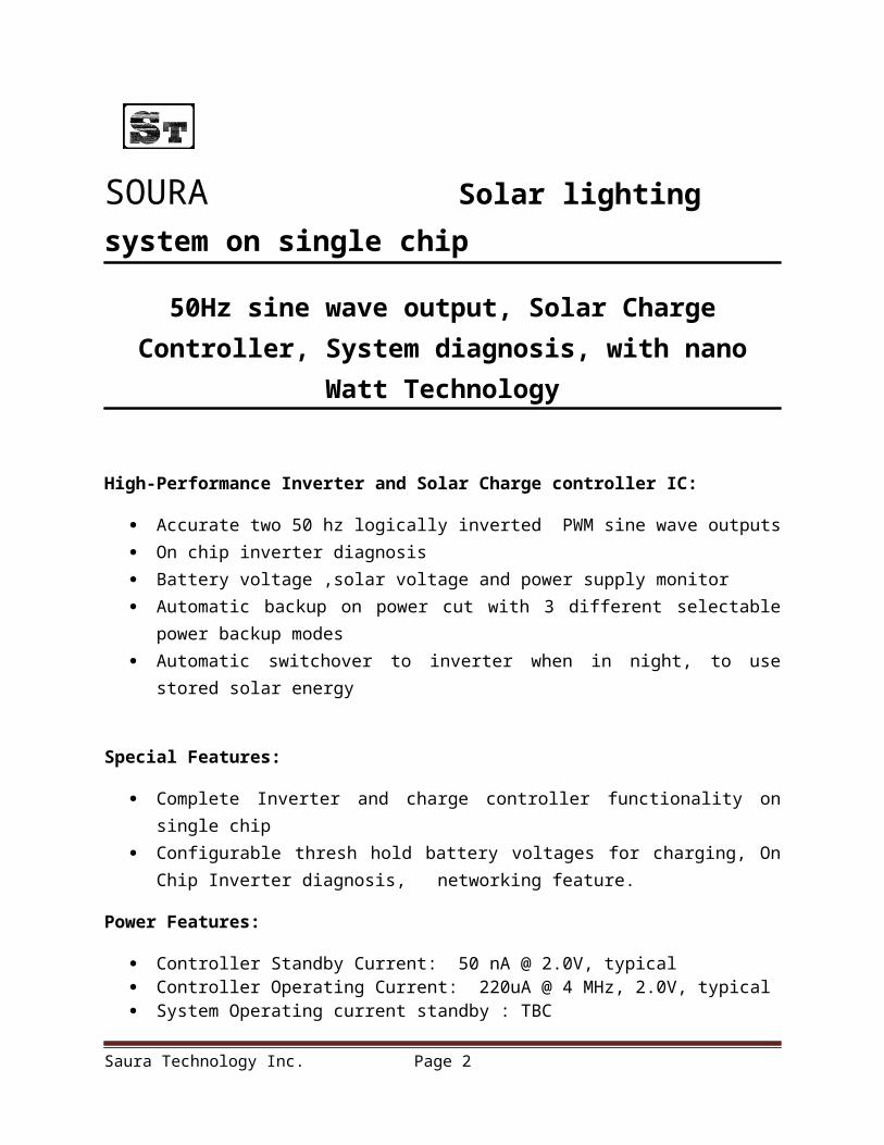
SOURA Solar lighting system on single chip
50Hz sine wave output, Solar Charge Controller, System diagnosis, with nano Watt Technology
High-Performance Inverter and Solar Charge controller IC:
Accurate two 50 hz logically inverted PWM sine wave outputs On chip inverter diagnosis Battery voltage ,solar voltage and power supply monitor Automatic backup on power cut with 3 different selectable power backup modes Automatic switchover to inverter when in night, to use stored solar energy
Special Features:
Complete Inverter and charge controller functionality on single chip Configurable thresh hold battery voltages for charging, On Chip Inverter diagnosis,
networking feature.
Power Features:
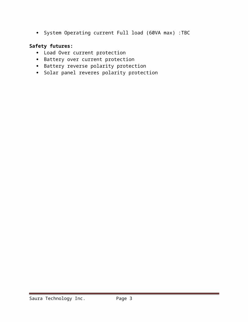
Controller Standby Current: 50 nA @ 2.0V, typical Controller Operating Current: 220uA @ 4 MHz, 2.0V, typical System Operating current standby : TBC System Operating current Full load (60VA max) :TBC
Safety futures: Load Over current protection Battery over current protection Battery reverse polarity protection Solar panel reveres polarity protection
Saura Technology Inc. Page 2
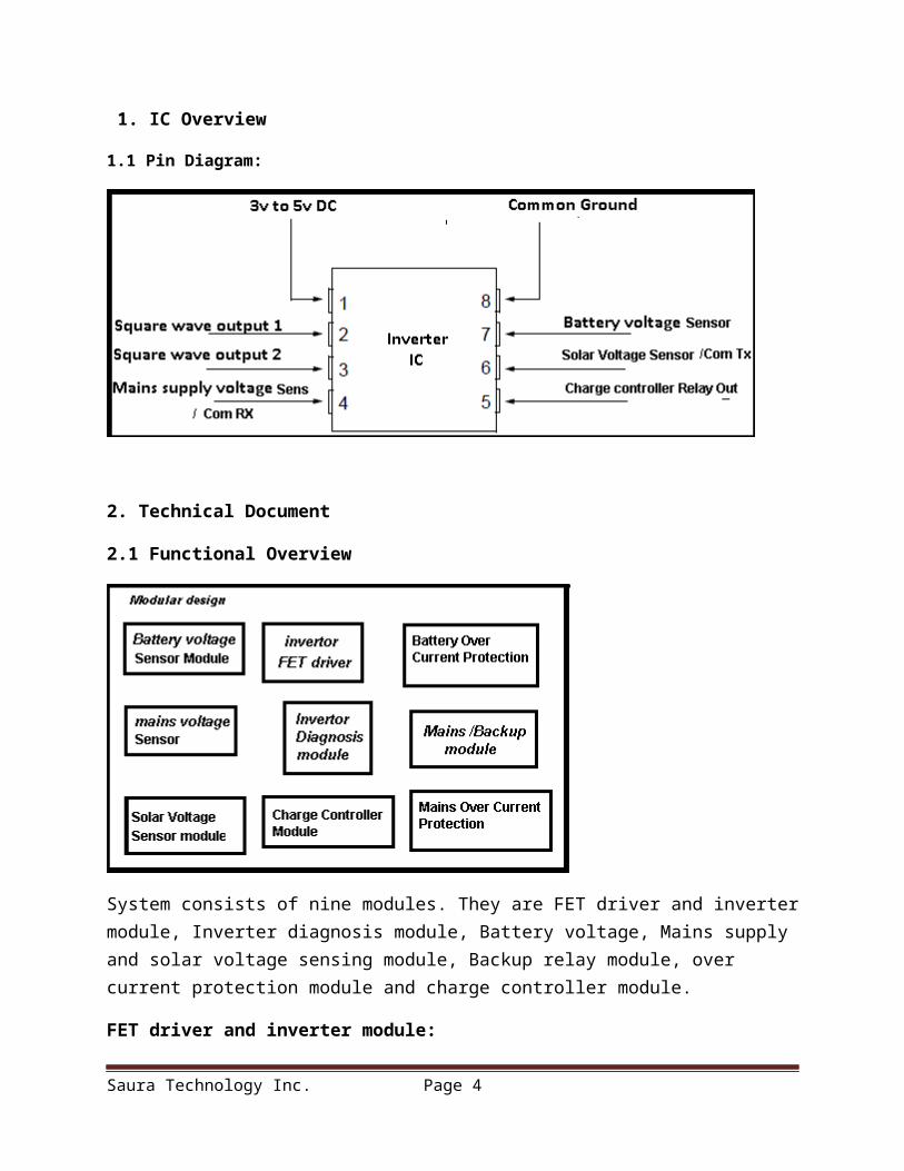
1. IC Overview
1.1 Pin Diagram:
2. Technical Document
2.1 Functional Overview
System consists of nine modules. They are FET driver and inverter module, Inverter diagnosis module, Battery voltage, Mains supply and solar voltage sensing module, Backup relay module, over current protection module and charge controller module.
FET driver and inverter module:
Saura Technology Inc. Page 3
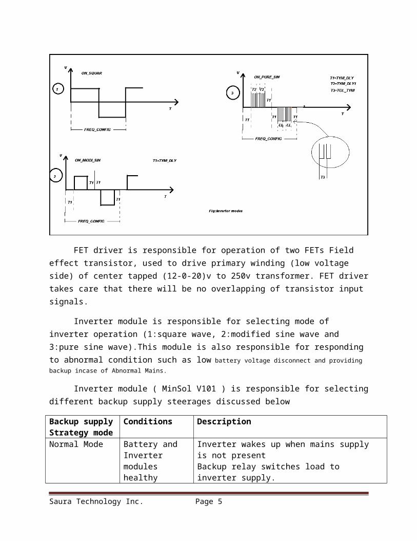
FET driver is responsible for operation of two FETs Field effect transistor, used to drive primary winding (low voltage side) of center tapped (12-0-20)v to 250v transformer. FET driver takes care that there will be no overlapping of transistor input signals.
Inverter module is responsible for selecting mode of inverter operation (1:square wave, 2:modified sine wave and 3:pure sine wave).This module is also responsible for responding to abnormal condition such as low battery voltage disconnect and providing backup incase of Abnormal Mains.
Inverter module ( MinSol V101 ) is responsible for selecting different backup supply steerages discussed below
Backup supply Strategy mode
Conditions Description
Normal Mode Battery and Inverter modules healthy
Inverter wakes up when mains supply is not presentBackup relay switches load to inverter supply. Backup relay switches load to mains supply when mains supply is present and inverter switches to low power mode
FORCE mode No condition Inverter wakes up and Backup relay switches load to inverter supply. This mode is useful when inverter is networked with IOT (internet of things) or when inverter is controlled by other device via networking.
SOLAR Only Battery and Inverter Inverter automatically wakes up and Backup relay
Saura Technology Inc. Page 4
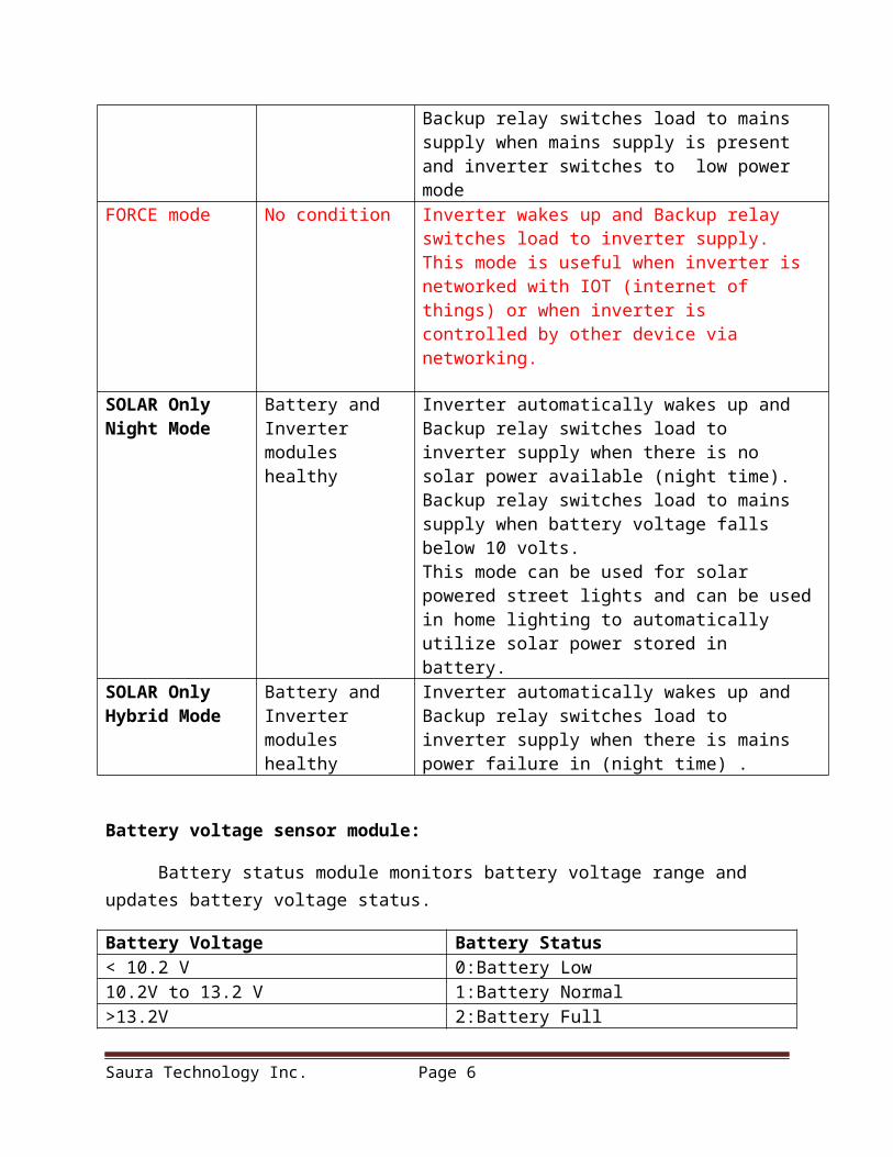
Night Mode modules healthy switches load to inverter supply when there is no solar power available (night time). Backup relay switches load to mains supply when battery voltage falls below 10 volts. This mode can be used for solar powered street lights and can be used in home lighting to automatically utilize solar power stored in battery.
SOLAR Only Hybrid Mode
Battery and Inverter modules healthy
Inverter automatically wakes up and Backup relay switches load to inverter supply when there is mains power failure in (night time) .
Battery voltage sensor module:
Battery status module monitors battery voltage range and updates battery voltage status.
Battery Voltage Battery Status< 10.2 V 0:Battery Low 10.2V to 13.2 V 1:Battery Normal>13.2V 2:Battery Full
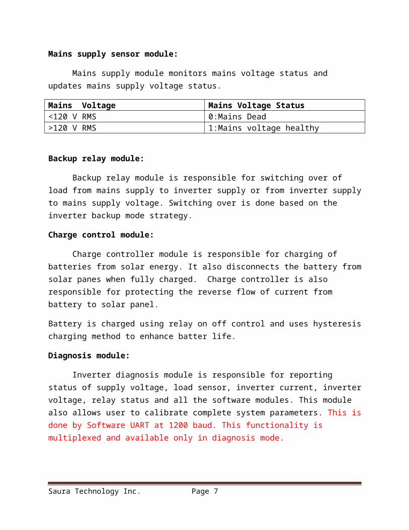
Mains supply sensor module:
Mains supply module monitors mains voltage status and updates mains supply voltage status.
Mains Voltage Mains Voltage Status<120 V RMS 0:Mains Dead>120 V RMS 1:Mains voltage healthy
Backup relay module:
Backup relay module is responsible for switching over of load from mains supply to inverter supply or from inverter supply to mains supply voltage. Switching over is done based on the inverter backup mode strategy.
Charge control module:
Charge controller module is responsible for charging of batteries from solar energy. It also disconnects the battery from solar panes when fully charged. Charge controller is also responsible for protecting the reverse flow of current from battery to solar panel.
Battery is charged using relay on off control and uses hysteresis charging method to enhance batter life.
Saura Technology Inc. Page 5
Diagnosis module:
Inverter diagnosis module is responsible for reporting status of supply voltage, load sensor, inverter current, inverter voltage, relay status and all the software modules. This module also allows user to calibrate complete system parameters. This is done by Software UART at 1200 baud. This functionality is multiplexed and available only in diagnosis mode.
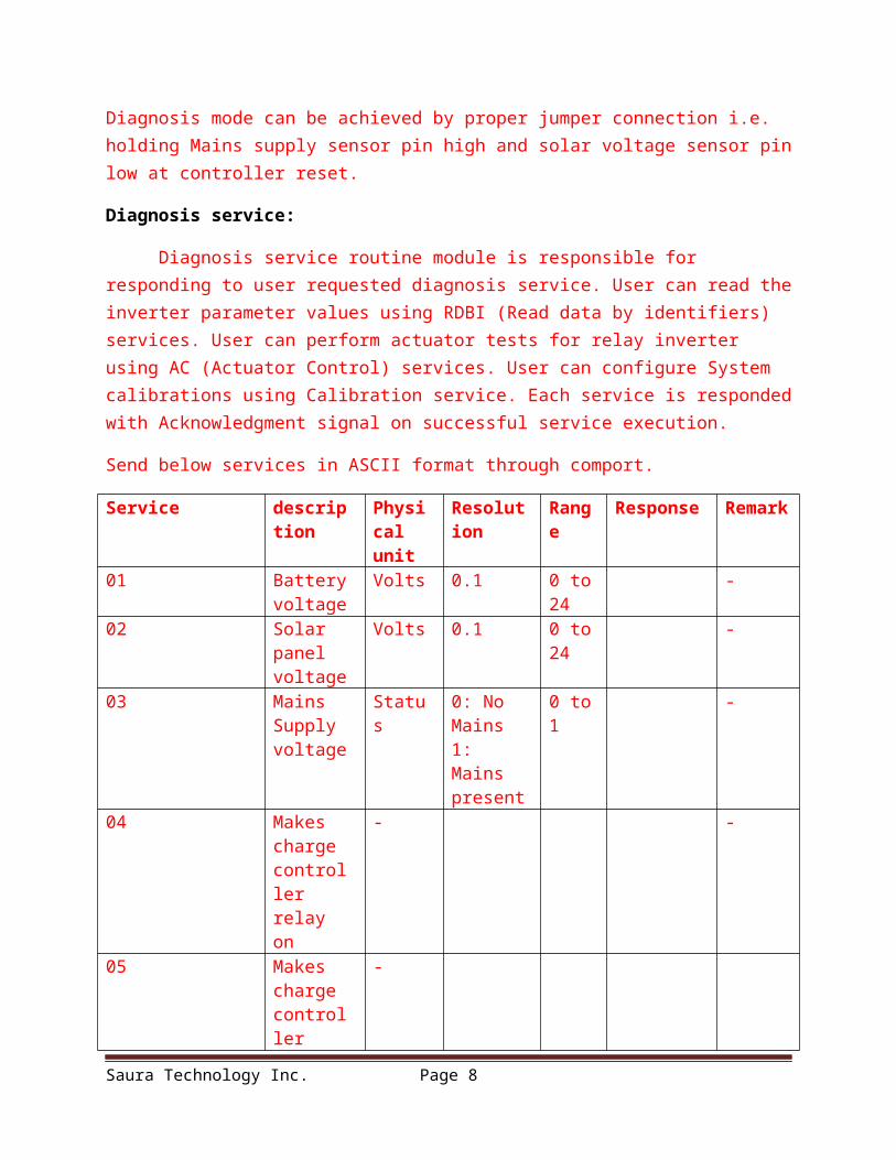
Diagnosis mode can be achieved by proper jumper connection i.e. holding Mains supply sensor pin high and solar voltage sensor pin low at controller reset.
Diagnosis service:
Diagnosis service routine module is responsible for responding to user requested diagnosis service. User can read the inverter parameter values using RDBI (Read data by identifiers) services. User can perform actuator tests for relay inverter using AC (Actuator Control) services. User can configure System calibrations using Calibration service. Each service is responded with Acknowledgment signal on successful service execution.
Send below services in ASCII format through comport.
Service description Physical unit
Resolution Range Response Remark
01 Battery voltage
Volts 0.1 0 to 24 -
02 Solar panel voltage
Volts 0.1 0 to 24 -
03 Mains Supply voltage
Status 0: No Mains1: Mains present
0 to 1 -
04 Makes charge controller relay on
- -
05 Makes charge controller relay off
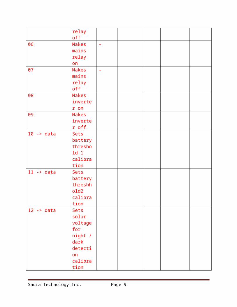
-
06 Makes mains relay on
-
07 Makes mains relay off
-
08 Makes inverter on
Saura Technology Inc. Page 6
09 Makes inverter off
10 -> data Sets battery threshold 1calibration
11 -> data Sets battery threshhold2 calibration
12 -> data Sets solar voltage for night /dark detection calibration
Incase of Service not available system responds with INVALID data 0x7F.
System Safety:
System is protected from Battery Over current, Inverter Overload, Battery reverse polarity and Solar panel reverse polarity. These safety futures are implemented in electronic hardware.
Battery over voltage disconnects and Battery low voltage inverter cutoff is implemented as software functionality.
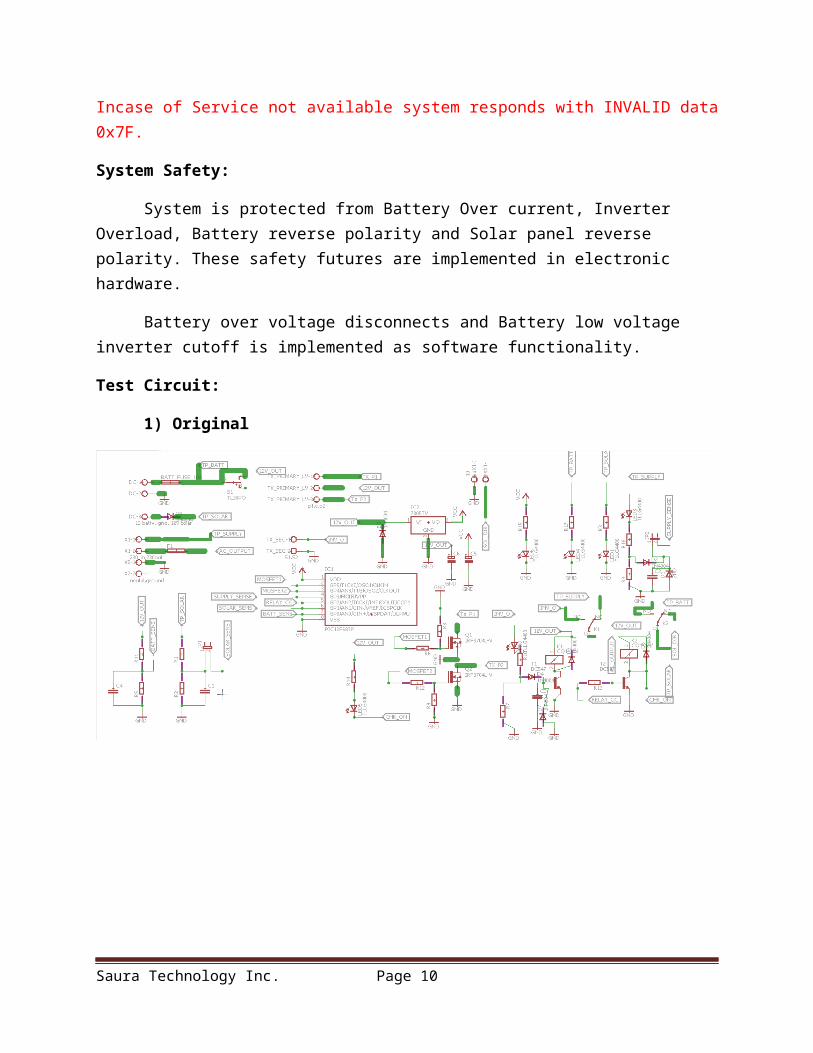
Test Circuit:
1) Original
Saura Technology Inc. Page 7
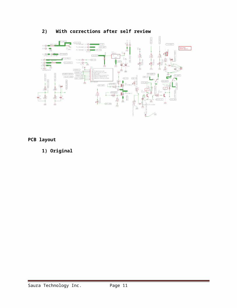
2) With corrections after self review
PCB layout
1) Original
Saura Technology Inc. Page 8
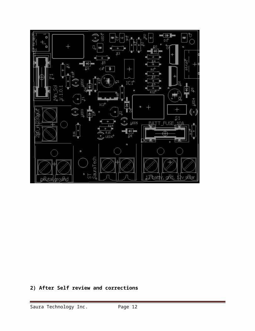
2) After Self review and corrections
Saura Technology Inc. Page 9
PCB Corrections:
PCB component values:
Gerber files uncorrected
Gerber files with corrections will be updated in next release
Note:
Saura Technology Inc. Page 10
1)Use 12v-0-12v, 230 v, 50va transformer for testing
2) Use 2*10 watt cfl or 5 * 5watt cfl for testing
3) Use 12v ,7Ah battery for testing
PCB module sub circuit working:
Video will be updated in next release
Invertor casing CAD DESIGN:
will be updated in next release
Manual for assembling
Manual for user
Hex file:
Code file: will be updated in next release
Basic algoritham: will be updated in next release
Saura Technology Inc. Page 11
Note: More advance functions are available in advance variant of product. Kindly check our blog.
Statements in red are proposed and in development and are software enhancement, hardware remains same for minsolv101.
Customer Support: For questions, demos, samples or comments regarding this publication, please write to us at [email protected]
Our YouTube channel: will be updated next release
Join us on Face book: will be updated next release
Visit our blog : sauraurjatech.wordpress.com
Make Our Globe Green
Saura Technology Inc. Page 12