Embed Size (px)
Citation preview
Viewpoints Functionality and Examples
ArchiMate D3.4.1a v2.6


COPYRIGHT © 2004 TELEMATICA INSTITUUT / ARCHIMATE CONSORTIUM
PERSONAL USE OF THIS MATERIAL IS PERMITTED. HOWEVER, PERMISSION TO REPRINT/REPUBLISH THIS MATERIAL FOR ADVERTISING OR PROMOTIONAL PURPOSES OR
FOR CREATING NEW COLLECTIVE WORKS FOR RESALE OR REDISTRIBUTION TO SERVERS OR LISTS, OR TO REUSE ANY COPYRIGHTED COMPONENT OF THIS WORK IN
OTHER WORKS MUST BE OBTAINED FROM OR VIA TELEMATICA INSTITUUT (HTTP://WWW.TELIN.NL).
Colophon
Title : Viewpoints Functionality and Examples Date : 18-11-2004
Version : 2.6 Change : Minor update: new infrastructure usage viewpoint
Project reference : ArchiMate/D3.4.1a v2.6 TI reference : TI/RS/2003/091
Company reference : URL : https://doc.telin.nl/dscgi/ds.py/Get/File-35434
Access permissions : Public Status : Final Editor : Marc Lankhorst
Company : Telematica Instituut Authors : Hugo ter Doest,
Maria-Eugenia Iacob,
Marc Lankhorst,
Diederik van Leeuwen,
Robert Slagter
Synopsis:
This report introduces a classification framework for viewpoints, which
entails three types of viewpoints, grouped according to their purpose: (1)
designing, (2) deciding, and (3) informing. Of each viewpoint a number of
example views is given and it is shown how these views can be derived
from ArchiMate models using selection and abstraction rules.

A R C H I M A T E / D 3 . 4 . 1 A V 2 . 6 V
ArchiMate
Organisations need to adapt increasingly quickly and anticipate changing customer
requirements and business goals. This need influences the entire chain of activities of a
business, from the organisational structure to the network infrastructure. How can you
control the impact of these changes? Architecture may be the answer. The ArchiMate
project will develop an integrated architectural approach that describes and visualises the
different business domains and their relations. Using these integrated architectures aids
stakeholders in assessing the impact of design choices and changes.
Architecture is a consistent whole of principles, methods and models that are used in the
design and realisation of organisational structure, business processes, information systems,
and infrastructure. However, these domains often are not approached in an integrated way,
which makes it difficult to judge the effects of proposed changes. Every domain speaks its
own language, draws its own models, and uses its own techniques and tools.
Communication and decision making across domains is seriously impaired.
The goal of the ArchiMate project is to provide this integration. By developing an
architecture language and visualisation techniques that picture these domains and their
relations, ArchiMate will provide the architect with instruments that support and improve the
architecture process. Existing and emerging standards will be used or integrated whenever
possible. ArchiMate will actively participate in national and international fora and
standardisation organisations, to promote the dissemination of project results.
The project will deliver a number of results. First of all, we will provide a visual design
language with adequate concepts for specifying interrelated architectures, and specific
viewpoints for selected stakeholders. This will be accompanied by a collection of best
practices and guidelines. Furthermore, ArchiMate will develop techniques that support
architects in visualisation and analysis of architectures. Finally, project results will be
validated in real-life cases within the participating organisations.
To have a real impact on the state of the art in architecture, the ArchiMate project consists
of a broad consortium from industry and academia. ArchiMate’s business partners are
ABN AMRO, Stichting Pensioenfonds ABP, and the Dutch Tax and Customs Administration
(Belastingdienst); its knowledge partners are Telematica Instituut, Ordina, Centrum voor
Wiskunde en Informatica (CWI), the Leiden Institute for Advanced Computer Science
(LIACS), and Katholieke Universiteit Nijmegen (KUN).
More information on ArchiMate and its results can be obtained from the project manager
Marc Lankhorst ([email protected]) or from the project website, archimate.telin.nl.

V I V I E W P O I N T S F U N C T I O N A L I T Y A N D E X A M P L E S

A R C H I M A T E / D 3 . 4 . 1 A V 2 . 6 V I I
Management Summary
This report considers the presentation of enterprise architecture to stakeholders. The report
contributes a framework for classification of viewpoints, examples of each class of
viewpoints identified, and a set of viewpoint rules for derivation of viewpoints from
ArchiMate models.
Viewpoints and Views
The essential notion in this deliverable is that of viewpoints, as defined by the ANSI/IEEE
Std 1471-2000 (IEEE Computer Society, 2000) for architectural description. IEEE 1471
codifies in terms of recommended practices a number of concepts and terms of reference
on which there is consensus and reflects “the generally accepted trends in practice for
architecture description”. The standard provides:
- A set of definitions for key terms like: acquirer, architect, architectural description,
architectural models, architecture, life cycle model, system, system stakeholder,
concerns, mission, context, architectural view, architectural viewpoint. As essential ideas
we note a clear separation between an architecture and its architectural descriptions
(defined as means to record architectures), and the central role of the relationship
architectural viewpoint - architectural view (similar to the relationship class-object in OO
programming).
- A conceptual framework, meant to explain how the key terms relate to each other in a
conceptual model for architectural description. Using the UML notation for class
diagrams, IEEE 1471 defines this model shown in Figure 1.
Mission
SystemEnvironment
Stakeholder
Architecture
ArchitecturalDescription
Rationale
ViewViewpointConcern
LibraryViewpoint
Model
aggregates1..*
consists of1..*
participates in1..*
establish methods for1..*
has source0..1
conforms to
used tocover 1..*
provides
participatesin
organizedby 1..*
selects1..*identifies
1..*
is addressedto 1..*
has1..*
identifies1..*
has1..*
has an
is importantto 1..*
describedby 1
fulfills 1..*
inhabits
influences
Figure 1. Conceptual model of architectural description (from (IEEE Computer Society, 2000)).
V I I I V I E W P O I N T S F U N C T I O N A L I T Y A N D E X A M P L E S
As can be seen from this figure, views and viewpoints are central to the standard’s way of
describing architectures.
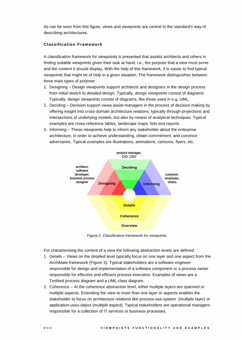
Classif ication Framework
A classification framework for viewpoints is presented that assists architects and others in
finding suitable viewpoints given their task at hand, i.e., the purpose that a view must serve
and the content it should display. With the help of this framework, it is easier to find typical
viewpoints that might be of help in a given situation. The framework distinguishes between
three main types of purpose:
1. Designing – Design viewpoints support architects and designers in the design process
from initial sketch to detailed design. Typically, design viewpoints consist of diagrams
Typically, design viewpoints consist of diagrams, like those used in e.g. UML.
2. Deciding – Decision support views assist managers in the process of decision making by
offering insight into cross-domain architecture relations, typically through projections and
intersections of underlying models, but also by means of analytical techniques. Typical
examples are cross-reference tables, landscape maps, lists and reports.
3. Informing – These viewpoints help to inform any stakeholder about the enterprise
architecture, in order to achieve understanding, obtain commitment, and convince
adversaries. Typical examples are illustrations, animations, cartoons, flyers, etc.
architect,software
developer,business process
designer
Deciding
Designing Informing
Details
Coherence
Overview
product manager, CIO, CEO
customer,employee,
others
architect,software
developer,business process
designer
Deciding
Designing Informing
Details
Coherence
Overview
Deciding
Designing Informing
Details
Coherence
Overview
product manager, CIO, CEO
customer,employee,
others
Figure 2. Classification framework for viewpoints.
For characterising the content of a view the following abstraction levels are defined:
1. Details – Views on the detailed level typically focus on one layer and one aspect from the
ArchiMate framework (Figure 3). Typical stakeholders are a software engineer
responsible for design and implementation of a software component or a process owner
responsible for effective and efficient process execution. Examples of views are a
Testbed process diagram and a UML class diagram.
2. Coherence – At the coherence abstraction level, either multiple layers are spanned or
multiple aspects. Extending the view to more than one layer or aspects enables the
stakeholder to focus on architecture relations like process-use-system (multiple layer) or
application-uses-object (multiple aspect). Typical stakeholders are operational managers
responsible for a collection of IT services or business processes.

A R C H I M A T E / D 3 . 4 . 1 A V 2 . 6 I X
3. Overview – The overview abstraction level addresses both multiple layers and multiple
aspects. Typically, such overviews are addressed to enterprise architects and CEO, CIO.
TechnologyTechnology
ApplicationApplication
BusinessBusiness
Environment
Processdomain
Informationdomain
Datadomain
Active
Organisationdomain
PassivePassive
Productdomain
BehaviourBehaviour
Application domain
Technical infrastructure domain
Figure 3. ArchiMate framework.
Example Viewpoints
Of each viewpoint type a number of examples is given. As an example of design viewpoints
a set of diagram types is developed that makes the ArchiMate language better usable for
architects. The landscape map (Figure 4a) visualises architecture relations between, for
instance, business process, applications and product. Process illustration (Figure 4b) is a
communication viewpoint that combines structure and business activity in one presentation.
BPMaangiftepunt
Douane eenheidBPM
17ex2
Inning
RDW
Administratie
BCICTautomatiserings
centrum
Balie
Behandeling
Archief
$$Kluis
Catalog.waarde
AangifteBestand
BPMworkstation
(Douaneeenheid)
BPMserver
(BCICT)
RINserver
(Inning)
BPM17ex3
BPM17ex1
Inningvordering
betaling
aangifte
betaling
betaling
acceptgiro
Figure 4 (a) Decision support view: landscape map (b) Communication view: process illustration.
Viewpoint Rules and Viewpoints Platform
Besides developing usable architecture viewpoints, this report provides input for the
realisation of views in software. Therefore, we describe how views can be derived from
ArchiMate models using so-called selection and abstraction rules. These rules will be used
to specify viewpoints in a formal way in order to automate the creation and presentation of
views.


A R C H I M A T E / D 3 . 4 . 1 A V 2 . 6 X I
Table of Contents
1 Introduct ion 1 1.1 Goal and Target Group 1 1.2 Context of this Report 1 1.3 Relation to Other ArchiMate Products 2 1.4 Relation to Requirements 3 1.5 Organisation of this Report 3 2 Example Case: ArchiSurance 5 3 Architecture Views and Viewpoints 9 3.1 Viewpoints for Enterprise Architecture 9 3.2 Views, Viewpoints, and Stakeholders 10 4 Classif ication of Architecture Views 13 4.1 Viewpoint Classification Framework 13 4.2 Position of the Example Viewpoints 15 4.3 Viewpoint Rules 16 5 Design Viewpoints 19 5.1 Basic Design Viewpoints 19 5.1.1 Organisation Viewpoint 22 5.1.2 Business Function Viewpoint 24 5.1.3 Business Process Viewpoint 26 5.1.4 Information Structure Viewpoint 28 5.1.5 Application Structure Viewpoint 30 5.1.6 Application Behaviour Viewpoint 32 5.1.7 Infrastructure Viewpoint 34 5.1.8 Actor Cooperation Viewpoint 36 5.1.9 Business Process Cooperation Viewpoint 39 5.1.10 Application Cooperation Viewpoint 41 5.1.11 Product Viewpoint 44 5.1.12 Application Usage Viewpoint 46 5.1.13 Infrastructure Usage Viewpoint 48 5.1.14 Service Realisation Viewpoint 50 5.1.15 Implementation & Deployment Viewpoint 52 5.2 Layered Viewpoint 55 5.2.1 Contents 55 5.2.2 Example 57 5.3 Introductory Viewpoint 59 5.3.1 Contents 60 5.3.2 Example 61 5.4 Design Process Viewpoint 61 5.4.1 Contents 62 5.4.2 Example 62 6 Decision Support Viewpoints 69 6.1 Landscape Map Viewpoint 69 6.1.1 Contents 70 6.1.2 Example 71 6.1.3 Relation to Modelling Languages 71 6.1.4 Interaction with Landscape Maps 72

X I I V I E W P O I N T S F U N C T I O N A L I T Y A N D E X A M P L E S
7 Informing Viewpoints 73 7.1 Process Illustration Viewpoint 73 7.1.1 Example 73 7.1.2 Contents 75 References 85 Appendix A - Viewpoint Rules 87 Appendix B - Graphical Notation 92

A R C H I M A T E / D 3 . 4 . 1 A V 2 . 6 1
1 Introduction
In this chapter the purpose and context of this document are outlined, relevant requirements
are reviewed and the organisation of the document is explained.
1.1 Goal and Target Group
The goal of this report is to define a framework for understanding the presentation of
architecture views, and to illustrate the framework by means of a collection of examples.
This report is targeted at enterprise architects and domain architects who want to publish
their architectures and models to other stakeholders besides their own peers.
1.2 Context of this Report
Enterprise architectures and their descriptions are often complex and hard to understand.
Architects therefore need ways to express these architectures as clearly as possible, both
for their own understanding and for communication with other stakeholders. To date, there
is no standard language for describing architectures, and they are often described in
informal pictures that lack a well-defined meaning. This leads to misunderstandings, and
makes it very difficult to provide tools for visualisation and analysis of these architectures.
Fundamental to developing a suitable architecture language paired with appropriate
visualisation and analysis techniques is an understanding of the working process of the
architect as follows. Figure 5 illustrates how initial ideas are formulated and communicated
in an informal manner, for instance by drawing on a whiteboard or sketching on paper or
writing a short memo. As soon as ideas become more stable and more people are involved
in the development process, a more formal and rigorous language is needed to capture the
design. To that purpose, a formal language like UML or Testbed comes into the picture in
most cases supported by a modelling tool.
Idea
Design
Use
Management
Formal models Analyses
WhiteboardPowerpoint
Connection with implementation
Maintenance Version
management
Communication with stakeholders
Figure 5. Architecture process.
2 V I E W P O I N T S F U N C T I O N A L I T Y A N D E X A M P L E S
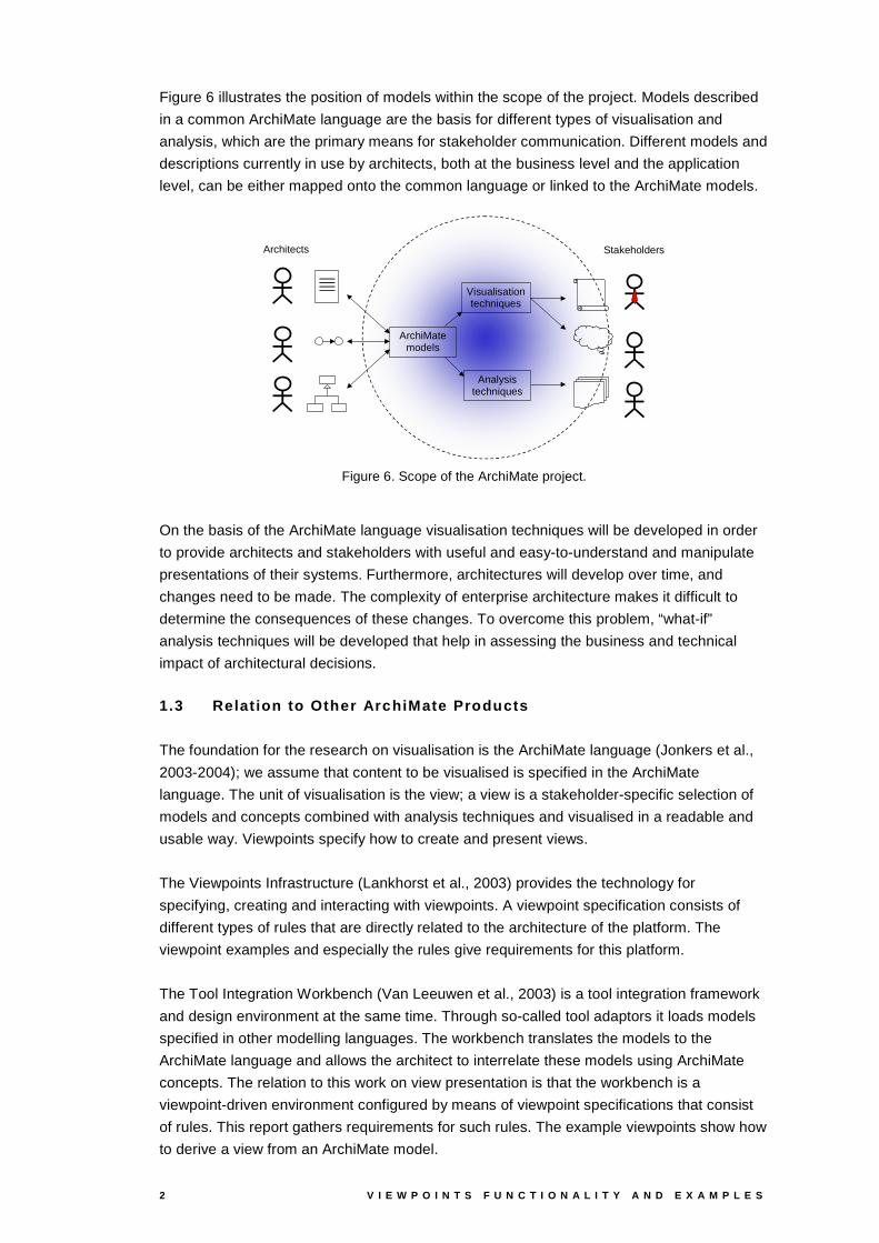
Figure 6 illustrates the position of models within the scope of the project. Models described
in a common ArchiMate language are the basis for different types of visualisation and
analysis, which are the primary means for stakeholder communication. Different models and
descriptions currently in use by architects, both at the business level and the application
level, can be either mapped onto the common language or linked to the ArchiMate models.
Architects Stakeholders
ArchiMate models
Visualisation techniques
Analysis techniques
Figure 6. Scope of the ArchiMate project.
On the basis of the ArchiMate language visualisation techniques will be developed in order
to provide architects and stakeholders with useful and easy-to-understand and manipulate
presentations of their systems. Furthermore, architectures will develop over time, and
changes need to be made. The complexity of enterprise architecture makes it difficult to
determine the consequences of these changes. To overcome this problem, “what-if”
analysis techniques will be developed that help in assessing the business and technical
impact of architectural decisions.
1.3 Relat ion to Other ArchiMate Products
The foundation for the research on visualisation is the ArchiMate language (Jonkers et al.,
2003-2004); we assume that content to be visualised is specified in the ArchiMate
language. The unit of visualisation is the view; a view is a stakeholder-specific selection of
models and concepts combined with analysis techniques and visualised in a readable and
usable way. Viewpoints specify how to create and present views.
The Viewpoints Infrastructure (Lankhorst et al., 2003) provides the technology for
specifying, creating and interacting with viewpoints. A viewpoint specification consists of
different types of rules that are directly related to the architecture of the platform. The
viewpoint examples and especially the rules give requirements for this platform.
The Tool Integration Workbench (Van Leeuwen et al., 2003) is a tool integration framework
and design environment at the same time. Through so-called tool adaptors it loads models
specified in other modelling languages. The workbench translates the models to the
ArchiMate language and allows the architect to interrelate these models using ArchiMate
concepts. The relation to this work on view presentation is that the workbench is a
viewpoint-driven environment configured by means of viewpoint specifications that consist
of rules. This report gathers requirements for such rules. The example viewpoints show how
to derive a view from an ArchiMate model.
A R C H I M A T E / D 3 . 4 . 1 A V 2 . 6 3
1.4 Relat ion to Requirements
This document concerns the visualisation and viewpoints requirements from the
requirements deliverable (Bosma et al., 2002):
- 4.1.1 Visualisation independence - Visualisation techniques and solutions should be
independent of concepts, i.e. concepts can be modified or added without consequences
for visualisation techniques.
Presentation of views is based on viewpoint rules for content selection and presentation
that can easily be modified or replaced without affecting other viewpoints.
- 4.1.2 Visualisation generation - ArchiMate supports automatic generation of
visualisations. The generation of visualisations
- has auto lay-out functionality. Moreover it must be possible to
- modify the lay-out of a generated visualisation
- generate new models while keeping the manually changed lay-out in tact
- store and retrieve changes to the updated lay-out.
The examples in this report account for the automatic selection and derivation of content
based on viewpoint rules.
- 4.2.1 Viewpoint definition – A viewpoint definition must
- state the stakeholder(s) it is created for,
- define the concerns covered by the viewpoint,
- explain how views are created for this viewpoint (in terms of the concepts to be
presented and the format of the presentation).
Of each viewpoint defined in this report stakeholder(s) and concern(s) are given, and of
each viewpoint it is explained how views can be created from ArchiMate models based
on viewpoint rules.
- 4.2.2 Adaptability of viewpoints – Viewpoints must be adaptable and extensible
independent of visualisation techniques.
Viewpoint specification are rule-based, and can be changed without affecting techniques,
algorithms, etc., as these will be provided by the viewpoints infrastructure and are not
part of the viewpoints themselves.
- 4.3.2 Viewpoint coverage - ArchiMate has to support often-used ‘general’ viewpoints, i.e.
viewpoints for frequently occurring stakeholders.
This report does exactly this: it offers a collection of examples that represent often-used
general viewpoints.
1.5 Organisat ion of this Report
In the next chapter, our example case around the fictitious insurance company
ArchiSurance is introduced. This example is used throughout the remainder of the
document. Chapter 1 introduces the general concepts of view and viewpoint, and provides
the necessary background. Chapter 1 defines a framework for the classification of
architecture views based on their purpose, content and abstraction level. Three types of
viewpoints are distinguished: design, decision support and informing viewpoints.
Subsequent chapters provide examples of each type. Especially useful is the set of so-
called basic design viewpoints (Section 5.1), which provides the architect with a number of
diagram-like subsets of the ArchiMate language, targeted at specific modelling purposes.

A R C H I M A T E / D 3 . 4 . 1 A V 2 . 6 5
2 Example Case: ArchiSurance
In this chapter, we introduce ArchiSurance, a fictitious insurance company that will be used
to illustrate the different viewpoints of the next chapters.
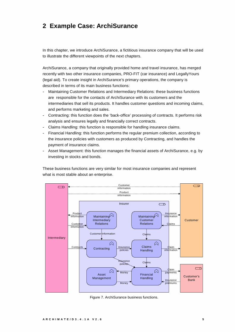
ArchiSurance, a company that originally provided home and travel insurance, has merged
recently with two other insurance companies, PRO-FIT (car insurance) and LegallyYours
(legal aid). To create insight in ArchiSurance’s primary operations, the company is
described in terms of its main business functions:
- Maintaining Customer Relations and Intermediary Relations: these business functions
are responsible for the contacts of ArchiSurance with its customers and the
intermediaries that sell its products. It handles customer questions and incoming claims,
and performs marketing and sales.
- Contracting: this function does the ‘back-office’ processing of contracts. It performs risk
analysis and ensures legally and financially correct contracts.
- Claims Handling: this function is responsible for handling insurance claims.
- Financial Handling: this function performs the regular premium collection, according to
the insurance policies with customers as produced by Contracting, and handles the
payment of insurance claims.
- Asset Management: this function manages the financial assets of ArchiSurance, e.g. by
investing in stocks and bonds.
These business functions are very similar for most insurance companies and represent
what is most stable about an enterprise.
Insurer
MaintainingIntermediary
Relations
Contracting
FinancialHandling
ClaimsHandling
Claims
Insurancepolicies
Customer information
Money
MaintainingCustomerRelations
AssetManagement
Contracts
Productinformation
Customerinformation
Claims
Insuranceinformation
Insurancepremiums
Claimpayments
Insurancepolicies
Customerinformation
Productinformation
Claims
Money
Claiminformation
Intermediary
Customer
Customer’sBank
Figure 7. ArchiSurance business functions.

6 V I E W P O I N T S F U N C T I O N A L I T Y A N D E X A M P L E S
Post-merger integration is in full swing. The first step in the integration process has been the
creation of a unified front office, comprising departments for managing relations with
customers on the one hand, and intermediaries on the other hand. However, behind this
front office are still three separate back offices:
- Home & Away: this department was the original pre-merger ArchiSurance, responsible
for home and travel insurance.
- Legal Aid: this is the old LegallyYours, responsible for legal aid and liability insurance.
- Car: this department is the core of the old PRO-FIT and handles car insurance, including
some legal aid.
Furthermore, ArchiSurance is in the process of setting up a Shared Service Center for
document processing, which will handle all document streams and performs scanning,
printing, and archiving jobs. The company’s structure is shown in Figure 8.
ArchiSurance
Back Office
Front Office
Home&
AwayCar
LegalAid
CustomerRelations
HRMProduct
DevelopmentFinance
IntermediaryRelations
Document Processing SSC
Figure 8. ArchiSurance departments.
As in many recently merged companies, IT integration is a problem. ArchiSurance want to
move to a single CRM system, separate back-office systems for policy administration and
finance, and a single document management system. However, Home & Away still have
separate systems for the policy administration and the financial handling of premium
collection and claims payment, and use the central CRM system and call center. The Car
department have their own monolithic back-office system, but use the central CRM system
and call center. The Legal Aid department have their own back- and front office systems
(Figure 9).
A R C H I M A T E / D 3 . 4 . 1 A V 2 . 6 7
Front office
Legal Aid
CarHome & Away
Home & AwayPolicy
administration
Home & AwayFinancial
application
Car Insuranceapplication
Legal Aidbackoffice
system
Webportal
Call centerapplication
CRM application
Legal AidCRM
Banksystem
Figure 9. Applications grouped according to departments.
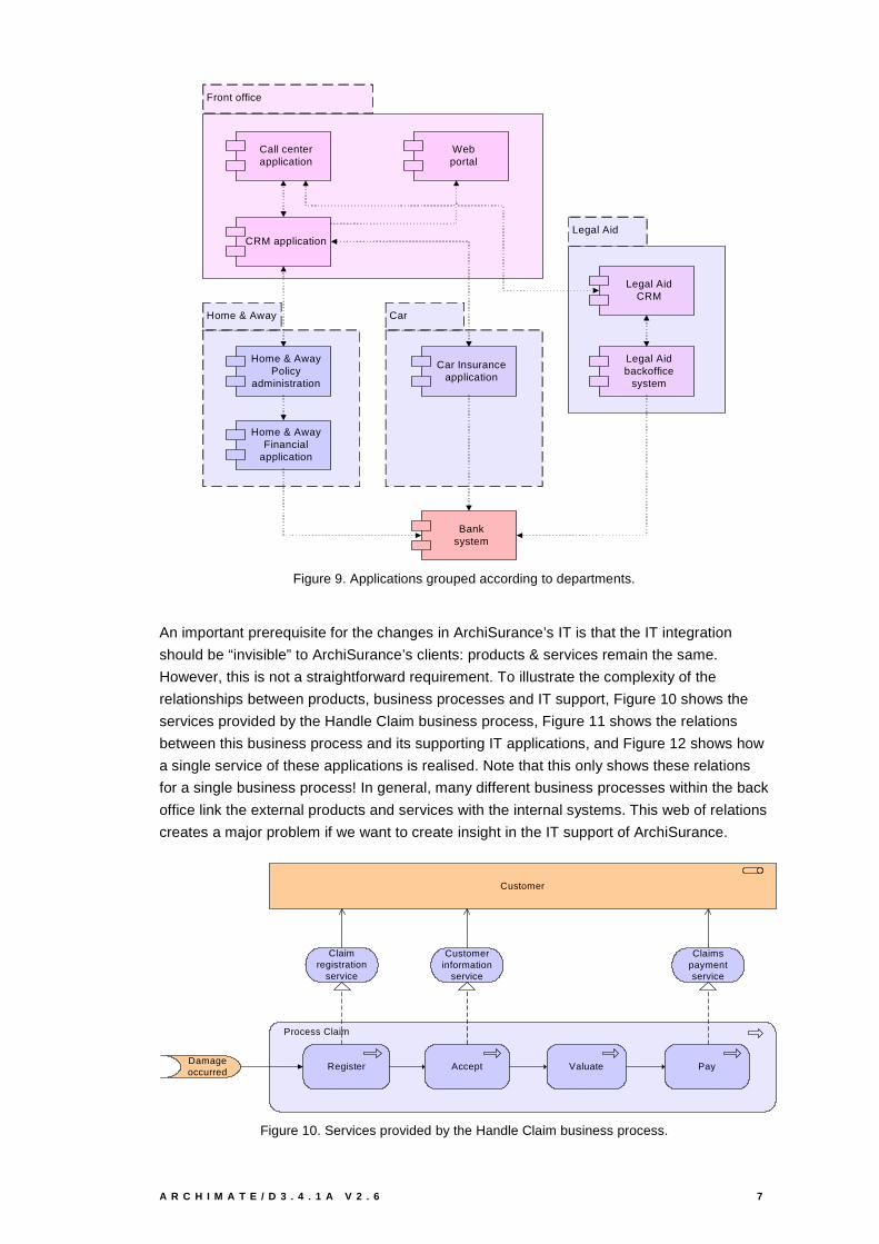
An important prerequisite for the changes in ArchiSurance’s IT is that the IT integration
should be “invisible” to ArchiSurance’s clients: products & services remain the same.
However, this is not a straightforward requirement. To illustrate the complexity of the
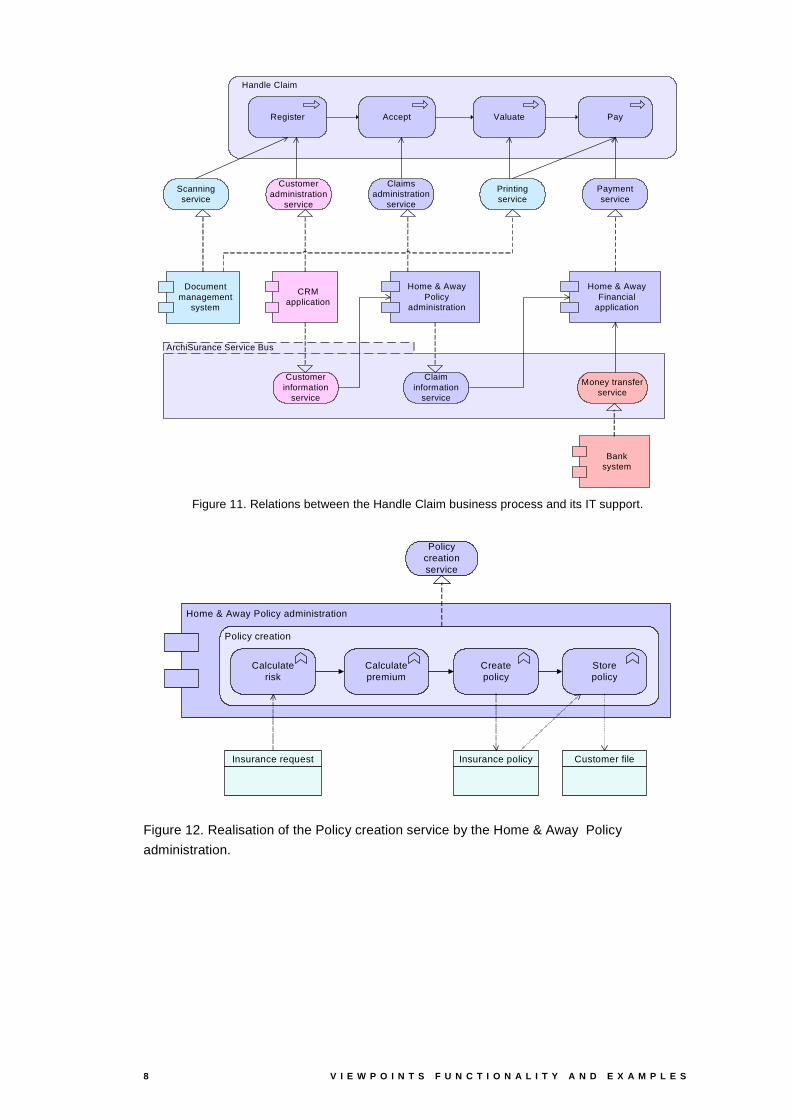
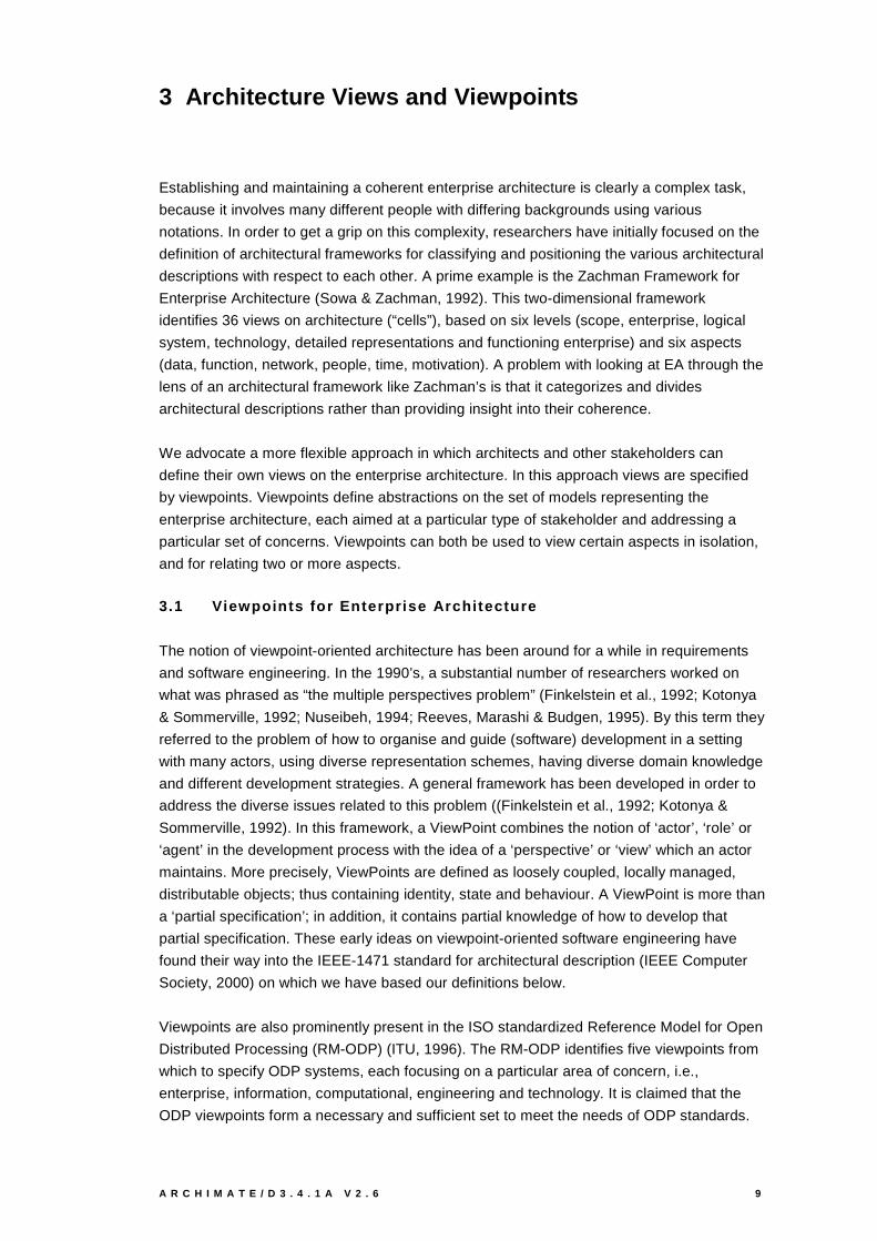
relationships between products, business processes and IT support, Figure 10 shows the
services provided by the Handle Claim business process, Figure 11 shows the relations
between this business process and its supporting IT applications, and Figure 12 shows how
a single service of these applications is realised. Note that this only shows these relations
for a single business process! In general, many different business processes within the back
office link the external products and services with the internal systems. This web of relations
creates a major problem if we want to create insight in the IT support of ArchiSurance.
Process Claim
Register PayValuateAccept
Claimregistration
service
Customerinformation
service
Claimspaymentservice
Customer
Damage occurred
Figure 10. Services provided by the Handle Claim business process.
8 V I E W P O I N T S F U N C T I O N A L I T Y A N D E X A M P L E S
ArchiSurance Service Bus
Handle Claim
Register PayValuateAccept
Home & AwayPolicy
administration
CRMapplication
Home & AwayFinancial
application
Customerinformation
service
Claiminformation
service
Customeradministration
service
Claimsadministration
service
Paymentservice
Printingservice
Scanningservice
Document management
system
Banksystem
Money transferservice
Figure 11. Relations between the Handle Claim business process and its IT support.
Home & Away Policy administration
Policy creation
Calculatepremium
Calculaterisk
Createpolicy
Storepolicy
Policy creationservice
Customer fileInsurance policyInsurance request
Figure 12. Realisation of the Policy creation service by the Home & Away Policy
administration.
A R C H I M A T E / D 3 . 4 . 1 A V 2 . 6 9
3 Architecture Views and Viewpoints
Establishing and maintaining a coherent enterprise architecture is clearly a complex task,
because it involves many different people with differing backgrounds using various
notations. In order to get a grip on this complexity, researchers have initially focused on the
definition of architectural frameworks for classifying and positioning the various architectural
descriptions with respect to each other. A prime example is the Zachman Framework for
Enterprise Architecture (Sowa & Zachman, 1992). This two-dimensional framework
identifies 36 views on architecture (“cells”), based on six levels (scope, enterprise, logical
system, technology, detailed representations and functioning enterprise) and six aspects
(data, function, network, people, time, motivation). A problem with looking at EA through the
lens of an architectural framework like Zachman’s is that it categorizes and divides
architectural descriptions rather than providing insight into their coherence.
We advocate a more flexible approach in which architects and other stakeholders can
define their own views on the enterprise architecture. In this approach views are specified
by viewpoints. Viewpoints define abstractions on the set of models representing the
enterprise architecture, each aimed at a particular type of stakeholder and addressing a
particular set of concerns. Viewpoints can both be used to view certain aspects in isolation,
and for relating two or more aspects.
3.1 Viewpoints for Enterprise Architecture
The notion of viewpoint-oriented architecture has been around for a while in requirements
and software engineering. In the 1990’s, a substantial number of researchers worked on
what was phrased as “the multiple perspectives problem” (Finkelstein et al., 1992; Kotonya
& Sommerville, 1992; Nuseibeh, 1994; Reeves, Marashi & Budgen, 1995). By this term they
referred to the problem of how to organise and guide (software) development in a setting
with many actors, using diverse representation schemes, having diverse domain knowledge
and different development strategies. A general framework has been developed in order to
address the diverse issues related to this problem ((Finkelstein et al., 1992; Kotonya &
Sommerville, 1992). In this framework, a ViewPoint combines the notion of ‘actor’, ‘role’ or
‘agent’ in the development process with the idea of a ‘perspective’ or ‘view’ which an actor
maintains. More precisely, ViewPoints are defined as loosely coupled, locally managed,
distributable objects; thus containing identity, state and behaviour. A ViewPoint is more than
a ‘partial specification’; in addition, it contains partial knowledge of how to develop that
partial specification. These early ideas on viewpoint-oriented software engineering have
found their way into the IEEE-1471 standard for architectural description (IEEE Computer
Society, 2000) on which we have based our definitions below.
Viewpoints are also prominently present in the ISO standardized Reference Model for Open
Distributed Processing (RM-ODP) (ITU, 1996). The RM-ODP identifies five viewpoints from
which to specify ODP systems, each focusing on a particular area of concern, i.e.,
enterprise, information, computational, engineering and technology. It is claimed that the
ODP viewpoints form a necessary and sufficient set to meet the needs of ODP standards.
1 0 V I E W P O I N T S F U N C T I O N A L I T Y A N D E X A M P L E S
More recently, the term ‘viewpoint’ is also used in OMG’s Model Driven Architecture (MDA)
initiative to refer to the different model types, i.e., platform-independent model (PIM) and
platform-specific model (PSM) (Frankel, 2003). Hence we conclude that the use of
viewpoints and architectural views are well-established concepts in software architecture.
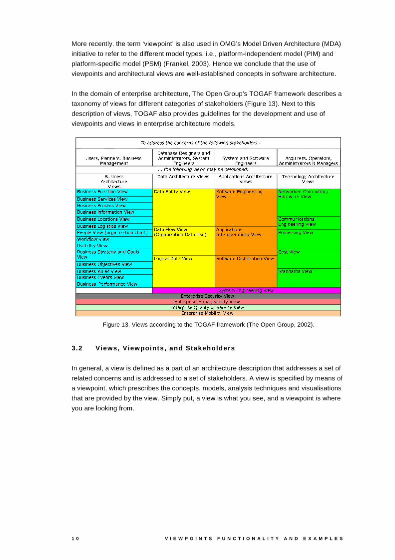
In the domain of enterprise architecture, The Open Group’s TOGAF framework describes a
taxonomy of views for different categories of stakeholders (Figure 13). Next to this
description of views, TOGAF also provides guidelines for the development and use of
viewpoints and views in enterprise architecture models.
������� ����� �������� ����������� ������� �� ��� ������������
�� �� ��� ���� ����!� �"����� �# ���$ %�$�� � ��� ���&� �� '�� ����(�)���� ��� *������ ������� � (�)���� ���+ ���$,("'�- � ./ �� � *����"� ������� �
%�0�1���� � ��� ����2/3���� ��&'�� ��� %�$�� � �"� ���4� ��&'�� �657�� ��� ������ �
�����!� ������� %8� 0!9�� � ��0��&��� � :8� ��.#�
�� �� ;%8� 0�9"� � ��0��4��� �;:<� ��./� %83�3�� � 0� ��4� '�����%8� 0!9"� � ��0��&��� � :8� ��./� ="��0!9���'�� '���)�%8� 0!9�� � ��0��&��� � :8� ��.#�
�����!� ��������>!����0��4� '��;:<� ��. �����!� �������6("��� ?�� 0����/:<� ��. �����!� �������;�� '�0�������:<� ��. �����!� ��������� ��- '��&�� ��4� '���:<� ��. �����!� ��������@�'�0� ��4� '����#:<� ��.
!��'�3�� �;:<� ��.BA '�� �� ���� C� ��4� '��D0!9� �� �&E F,'��&G�- � '�.H:<� ��. ���� ���� � � � )�:8� ��.
�����!� �������I2/��J � 0��4� ?����/:<� ��. �����!� ��������K���� ����:<� ��. �����!� �������;*�?������ ��:<� ��. �����!� ������� ���� - '�� �� ���0��;:<� ��.
("'�- � .� �� � *����"� ������� � ��� :8� ��. L���� .#'��&G���$NM�'�� 3����4� ����O P� �� $�.� �� �;:<� ��.
M�'�� �N����� 0� ��4� '���� *����"� ������� � ����:<� ��.
Q!R�S�T�T�U&V!W�W�X Y�VDZ�R�["Z�V�U [�W;R�\�X Y�VD\ R�] ] R�^8_ [�` W�X S�a�V�Y"R�] T�V�U W�b b b
b b b�X Y"VN\ R�] ] R"^_ [�`dc�_ V�^�W;eNS�fDg�VNT�V"c�V�] R�h�V�T�i
�����!� ��������@�'��"� ���4� 0���:<� ��. � �� >�� '�.H:<� ��. A 2/� �� ���� C� ��j� '�� �� �� ,������E %83�3�� � 0� ��4� '���� k ��� ��� '�3���� ���� � � � )�:<� ��.
�� '�0�������� ����:<� ��.
�����!� �������6(��&� �� ����)D ���$Nlm'� "� � :8� ��. M�'�����:<� ��.
@�'��"� 0� ���� �� �:m� ��. ("'�- � .� �� � �m� ���4�&� �����j� '��;:<� ��.
(�� ���$� �� $ �/:<� ��.
� �� *����&� � );:<� ��.
*���� ��� 3��&� ���,��'���� � � � )�:<� ��.
(�)���� ���n*������ ������� � ����:<� ��. *���� ��� 3�� � ���N("��0!���4� � );:<� ��. *���� ��� 3�� � ���,�m ��� ����� ���� � � � );:<� ��. *���� ���&3�� � ���Do/�� �� � � )N'�-("��� ?�� 0��;:<� ��.
������� ����� �������� ����������� ������� �� ��� ������������
�� �� ��� ���� ����!� �"����� �# ���$ %�$�� � ��� ���&� �� '�� ����(�)���� � � *������ ������� � (�)���� ���+ ���$,("'�- � ./ �� � *����"� ������� �
%�0�1���� � ��� ����2/3���� ��&'�� ��� %�$�� � �"� ���4� ��&'�� �657�� ��� ������ �
�����!� ������� %8� 0!9�� � ��0��&��� � :8� ��.#�
�� �� ;%8� 0�9"� � ��0��4��� �;:<� ��./� %83�3�� � 0� ��4� '�����%8� 0!9�� � ��0��&��� � :8� ��./� ="��0!9���'�� '���)�%8� 0!9�� � ��0��&��� � :8� ��.#�
�����!� ��������>!����0��4� '��;:<� ��. �����!� ������� ("��� ?�� 0����/:<� ��. �����!� �������;�� '�0�������:<� ��. �����!� ��������� ��- '��&�� ��4� '���:<� ��. �����!� ��������@�'�0� ��4� '����#:<� ��.
!��'�3�� �;:<� ��.BA '�� �� ���� C� ��4� '��D0!9� �� �&E F,'��&G�- � '�.H:<� ��. ���� ���� � � � )�:8� ��.
�����!� �������I2/��J ��0��4� ?����/:<� ��. �����!� ��������K���� ����:<� ��. �����!� �������;*�?������ ��:<� ��. �����!� ������� ���� - '�� �� ���0��;:<� ��.
("' - � .� �� � *����"� ������� � ��� :8� ��. L���� .#'��&G���$NM�'�� 3����4� ����O P� �� $�.� �� �;:<� ��.
M�'�� �N����� 0� ��4� '���� *����"� ������� � ����:<� ��.
Q!R�S�T�T�U&V!W�W�X Y�VDZ�R�["Z�V�U [�W;R�\�X Y�VD\ R�] ] R�^8_ [�` W�X S�a�V�Y"R�] T�V�U W�b b b
b b b�X Y"VN\ R�] ] R"^_ [�`pc�_ V�^�W;eNS�fDg�VNT�V"c�V�] R�h�V�T�i
�����!� ��������@�'��"� ���4� 0���:<� ��. � �� >�� '�.H:<� ��. A 2/� �� ���� C� ��j� '�� �� �� ,������E %83�3�� � 0� ��4� '���� k ��� ��� '�3���� ���� � � � )�:<� ��.
�� '�0�������� ����:<� ��.
�����!� �������6(��&� �� ����)D ���$Nlm'� "� � :8� ��. M�'�����:<� ��.
@�'��"� 0� ���� �� �:m� ��. ("'�- � .� �� � �m� ���4�&� �����j� '��;:<� ��.
(�� ���$� �� $��/:<� ��.
� �� *����&� � );:<� ��.
*���� ��� 3��&� ���,��'���� � � � )�:<� ��.
(�)���� ���n*������ ������� � ����:<� ��. *���� ��� 3�� � ��� ("��0!���4� � );:<� ��. *���� ��� 3�� � ���,�m ��� ����� ���� � � � );:<� ��. *���� ���&3�� � ���Do/�� �� � � )N'�-("��� ?�� 0��;:<� ��.
Figure 13. Views according to the TOGAF framework (The Open Group, 2002).
3.2 Views, Viewpoints, and Stakeholders
In general, a view is defined as a part of an architecture description that addresses a set of
related concerns and is addressed to a set of stakeholders. A view is specified by means of
a viewpoint, which prescribes the concepts, models, analysis techniques and visualisations
that are provided by the view. Simply put, a view is what you see, and a viewpoint is where
you are looking from.

A R C H I M A T E / D 3 . 4 . 1 A V 2 . 6 1 1
Mission
SystemEnvironment
Stakeholder
Architecture
ArchitecturalDescription
Rationale
ViewViewpointConcern
LibraryViewpoint
Model
aggregates1..*
consists of1..*
participates in1..*
establish methods for1..*
has source0..1
conforms to
used tocover 1..*
provides
participatesin
organizedby 1..*
selects1..*identifies
1..*
is addressedto 1..*
has1..*
identifies1..*
has1..*
has an
is importantto 1..*
describedby 1
fulfills 1..*
inhabits
influences
Figure 14. Conceptual model of architectural description (from (IEEE Computer Society, 2000)).
Viewpoints are a means to focus on particular aspects of the architecture. These aspects
are determined by the concerns of a stakeholder with whom communication takes place.
What should and should not be visible from a specific viewpoint is therefore entirely
dependent on the argumentation with respect to a stakeholder’s concerns.
Viewpoints are designed for the purpose of communicating certain aspects of an
architecture. The communication enabled by a viewpoint can be strictly informative, but, in
general, will be bi-directional. The architect informs stakeholders, and stakeholders give
their feedback (critique or consent) on the presented aspects. What is and what is not
shown in a view depends on the scope of the viewpoint and on what is relevant to the
concerns of the stakeholder. Ideally, these are the same; i.e. the viewpoint is designed with
specific concerns of a stakeholder in mind. Relevance to a stakeholders concern, therefore,
is the selection criterion that is used to determine which objects and relations are to appear
in a view.
The following are examples of stakeholders and concerns as a basis for the specification of
viewpoints:
- End user. E.g.: What are the consequences for his work and workplace?
- Architect. What is the consequence for the maintainability of a system, with respect to
corrective, preventive and adaptive maintenance?
- Upper-level management. How can we ensure our policies are followed in the
development and operation of processes and systems? What is the impact of decisions
(on personnel, finance, ICT, etcetera)?
- Operational manager, responsible for exploitation or maintenance. E.g.: What new
technologies are there to prepare for? Is there a need to adapt maintenance processes?
What is the impact of changes to existing applications? How secure are my systems?
1 2 V I E W P O I N T S F U N C T I O N A L I T Y A N D E X A M P L E S
- Project manager, responsible for the development of new applications. What are the
relevant domains and their relations, what is the dependence of business processes on
the applications to be built? What is their expected performance?
- Developer. What are the modifications with respect to the current situation that need to
be done?
A R C H I M A T E / D 3 . 4 . 1 A V 2 . 6 1 3
4 Classification of Architecture Views
In this chapter, we introduce a classification framework that helps architects and others to
find the right viewpoint(s) given their task at hand, i.e., the purpose that a view must serve
and the content it should display.
4.1 Viewpoint Classif icat ion Framework
Our viewpoint classification framework is based on two dimensions, purpose and content.
The framework distinguishes between three main types of purpose:
- Designing – Design viewpoints support architects and designers in the design process
from initial sketch to detailed design. Typically, design viewpoints consist of diagrams,
like those used in e.g. UML.
- Deciding – Decision support views assist managers in the process of decision making by
offering insight into cross-domain architecture relations, typically through projections and
intersections of underlying models, but also by means of analytical techniques. Typical
examples are cross-reference tables, landscape maps, lists and reports.
- Informing – These viewpoints help to inform any stakeholder about the enterprise
architecture, in order to achieve understanding, obtain commitment, and convince
adversaries. Typical examples are illustrations, animations, cartoons, flyers, etc.
With the help of this framework, it is easier to find typical viewpoints that might be useful in a
given situation. This implies that we do not provide an orthogonal categorisation of each
viewpoint into one of three classes; these categories are not exclusive in the sense that a
viewpoint in one category cannot be applied to achieve another type of support. For
instance, some decision support viewpoints may be used to communicate to any other
stakeholders as well.

1 4 V I E W P O I N T S F U N C T I O N A L I T Y A N D E X A M P L E S
Table 1. Viewpoint purpose.
TYPICAL STAKEHOLDER(S) PURPOSE EXAMPLES
DESIGNING architect.
software developer,
business process
designer
navigate, design,
support design
decisions, compare
alternatives
UML diagram,
BPMN diagram,
Testbed diagram
DECIDING manager, CIO, CEO decision-making cross-reference
table, landscape
map, list, report
INFORMING employee, customer,
others
explain, convince,
obtain commitment
animation, cartoon,
process illustration,
chart
TechnologyTechnology
ApplicationApplication
BusinessBusiness
Environment
Processdomain
Informationdomain
Datadomain
Active
Organisationdomain
PassivePassive
Productdomain
BehaviourBehaviour
Application domain
Technical infrastructure domain
Figure 15. The ArchiMate framework.
For characterising the content of a view we define the following abstraction levels:
- Details – Views on the detailed level are typically focussed on one layer and one aspect
from the ArchiMate framework (Figure 15). Typical stakeholders are a software engineer
responsible for design and implementation of a software component or a process owner
responsible for effective and efficient process execution. Examples of views are a
Testbed process diagram and a UML class diagram.
- Coherence – At the coherence abstraction level, either multiple layers are spanned or
multiple aspects. Extending the view to more than one layer or aspect enables the
stakeholder to focus on architecture relations like process-uses-system (multiple layer)
or application-uses-object (multiple aspect). Typical stakeholders are operational
managers responsible for a collection of IT services or business processes.
- Overview – The overview abstraction level addresses both multiple layers and multiple
aspects. Typically such overviews are addressed to enterprise architects, and decision
makers such as CEOs and CIOs.
A R C H I M A T E / D 3 . 4 . 1 A V 2 . 6 1 5
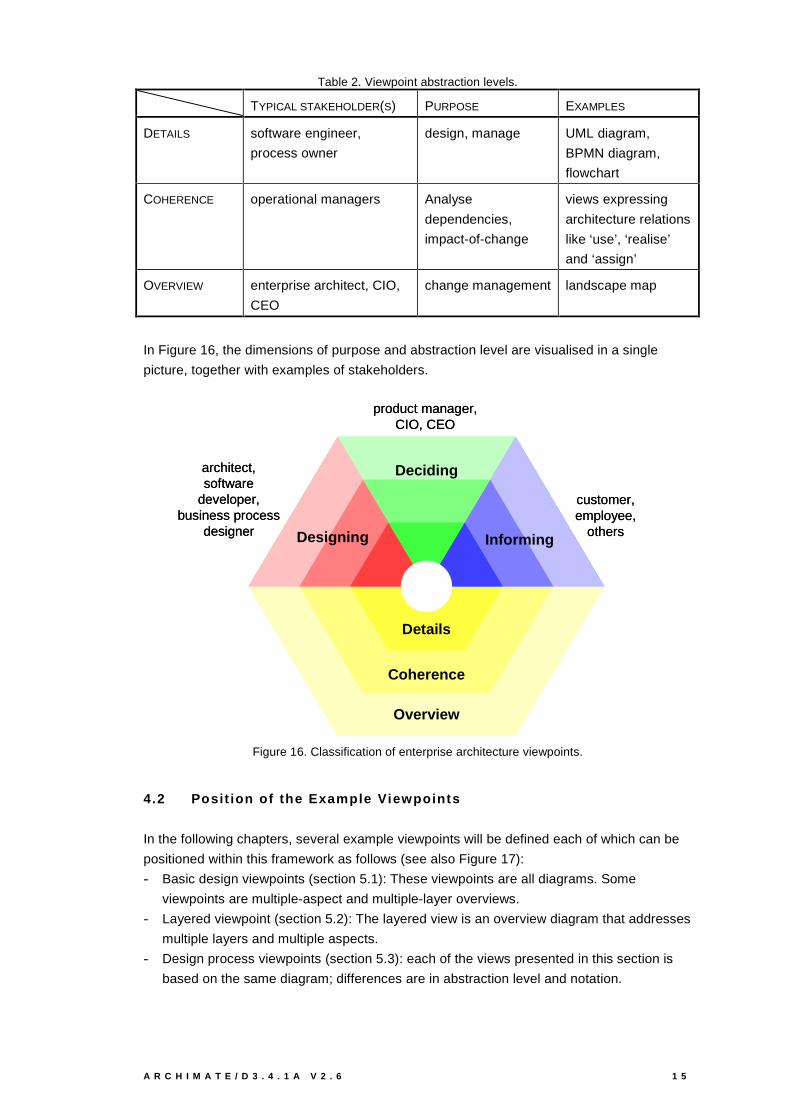
Table 2. Viewpoint abstraction levels.
TYPICAL STAKEHOLDER(S) PURPOSE EXAMPLES
DETAILS software engineer,
process owner
design, manage UML diagram,
BPMN diagram,
flowchart
COHERENCE operational managers Analyse
dependencies,
impact-of-change
views expressing
architecture relations
like ‘use’, ‘realise’
and ‘assign’
OVERVIEW enterprise architect, CIO,
CEO
change management landscape map
In Figure 16, the dimensions of purpose and abstraction level are visualised in a single
picture, together with examples of stakeholders.
architect,software
developer,business process
designer
Deciding
Designing Informing
Details
Coherence
Overview
product manager, CIO, CEO
customer,employee,
others
architect,software
developer,business process
designer
Deciding
Designing Informing
Details
Coherence
Overview
Deciding
Designing Informing
Details
Coherence
Overview
product manager, CIO, CEO
customer,employee,
others
Figure 16. Classification of enterprise architecture viewpoints.
4.2 Posit ion of the Example Viewpoints
In the following chapters, several example viewpoints will be defined each of which can be
positioned within this framework as follows (see also Figure 17):
- Basic design viewpoints (section 5.1): These viewpoints are all diagrams. Some
viewpoints are multiple-aspect and multiple-layer overviews.
- Layered viewpoint (section 5.2): The layered view is an overview diagram that addresses
multiple layers and multiple aspects.
- Design process viewpoints (section 5.3): each of the views presented in this section is
based on the same diagram; differences are in abstraction level and notation.

1 6 V I E W P O I N T S F U N C T I O N A L I T Y A N D E X A M P L E S
- Landscape viewpoint (Section 6.1): the landscape view is a typical example of a decision
support view: an ArchiMate model is projected on a two dimensional chart while a third
dimension is added by assigning values to the entries.
- Process illustration viewpoint (Section 7.1): the process illustration view is an illustration
of workflow for employees and managers. Process illustrations can be on the detailed,
coherence or overview abstraction level.
Landscape map
Basic designviewpoints,
Layered viewpoint, Design process
viewpoint
Processillustration
Landscape map
Basic designviewpoints,
Layered viewpoint, Design process
viewpoint
Processillustration
Figure 17. Position of the example viewpoints.
4.3 Viewpoint Rules
As we have described previously (Lankhorst et al., 2003a), it should be possible to construct
viewpoints from basic elements: individual ‘viewpoint rules’ that govern the creation,
visualisation and manipulation of views.
Present
Interpret
Select InteractView
content View
presentation
Selectionrules
Interactionrules
Presentationrules
Interpretationrules
Figure 18. Views governed by viewpoint rules.
Figure 18 shows the four main types of viewpoint rules that are used in creating and
manipulating views:
- Selection rules determine which elements from the architecture are to be shown in the
view. This category not only comprises rules for simply choosing the elements
themselves, but may also entail rules for abstraction, aggregation, refinement, and global
constraints.

A R C H I M A T E / D 3 . 4 . 1 A V 2 . 6 1 7
- Presentation rules determine how these elements are shown in the view. These rules
determine e.g. symbols, fonts, line styles, and colours.
- Interaction rules determine how the user can manipulate the resulting view. They may for
example constrain the edits allowed based on the user’s role.
- Interpretation rules determine how the user’s manipulations propagate to the underlying
architecture. Especially when the user manipulates an abstracted or aggregated object,
this propagation is non-trivial.
One of the goals of this report is to identify concrete and useful examples of these rules that
serve as input and requirements to the viewpoints infrastructure described in (Lankhorst et
al., 2003).

A R C H I M A T E / D 3 . 4 . 1 A V 2 . 6 1 9
5 Design Viewpoints
In this chapter three types of design viewpoints are presented. The first type, called basic
design viewpoints defines a set of diagram types for the ArchiMate language. In addition to
a number of aspect- or layer-specific diagrams, a set of coherence diagram types are
introduced that cover multiple layers and/or multiple aspects. The second type is the layered
view, which is an overview type of view that presents multiple aspects and multiple layers in
one layered diagram. The third type of view shows how form and content of a view can be
adapted to the needs of stakeholders using a set of abstraction and presentation rules.
5.1 Basic Design Viewpoints
The most basic type of viewpoint is the simple selection of a relevant subset of the
ArchiMate concepts and the representation of that part of an architecture that is expressed
in the concepts in this selection. This is sometimes called a ‘diagram’, akin to e.g. the UML
diagrams.
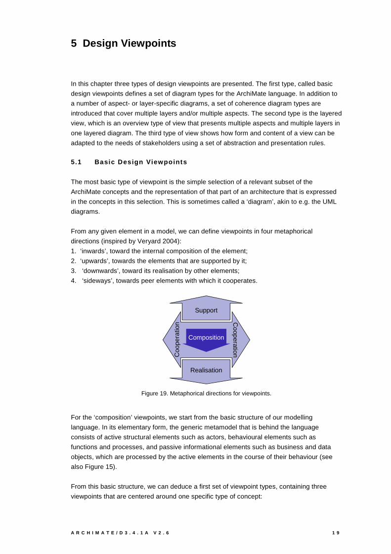
From any given element in a model, we can define viewpoints in four metaphorical
directions (inspired by Veryard 2004):
1. ‘inwards’, toward the internal composition of the element;
2. ‘upwards’, towards the elements that are supported by it;
3. ‘downwards’, toward its realisation by other elements;
4. ‘sideways’, towards peer elements with which it cooperates.
Support
Realisation
Coo
pera
tion C
ooperation
Composition
Figure 19. Metaphorical directions for viewpoints.
For the ‘composition’ viewpoints, we start from the basic structure of our modelling
language. In its elementary form, the generic metamodel that is behind the language
consists of active structural elements such as actors, behavioural elements such as
functions and processes, and passive informational elements such as business and data
objects, which are processed by the active elements in the course of their behaviour (see
also Figure 15).
From this basic structure, we can deduce a first set of viewpoint types, containing three
viewpoints that are centered around one specific type of concept:
2 0 V I E W P O I N T S F U N C T I O N A L I T Y A N D E X A M P L E S
1. active elements, e.g., the composition of a business actor from subactors, i.e., an
organisation structure;
2. behaviour elements, e.g., the structure of a business process in terms of subprocesses;
3. passive elements, e.g., the information structure in terms of data objects.
Although these viewpoints take a specific type of concept and its structure as their focus,
they are not limited to these concepts, and closely related concepts are also included.
For the ‘upwards’ support of elements in their environment, the active elements offer
interfaces, through which their services can be used. ‘Downwards’, services are realised by
processes and functions, and application components are deployed on infrastructure
elements. ‘Sideways’ cooperation is achieved through collaborations between active
elements and their behaviour in the form of interactions, and flows of information and value
that relate the elements. Passive elements often play a role in these relations, e.g. by being
passed from one element to another, but are not the focus. Hence we concentrate on the
relations between the active and behaviour elements.
In each of these viewpoint types, concepts from the three layers of business, application,
and technology may be used. However, not every combination of these would give
meaningful results; in some cases, for example, separate viewpoints for the different layers
are advisable. Based on common architectural practice, our experiences with the use of
ArchiMate models in practical cases, and on the diagrams used in other languages like
UML, we have selected the most useful combinations in the form of a ‘standard’ set of basic
viewpoints to be used with the ArchiMate concepts (Table 3).
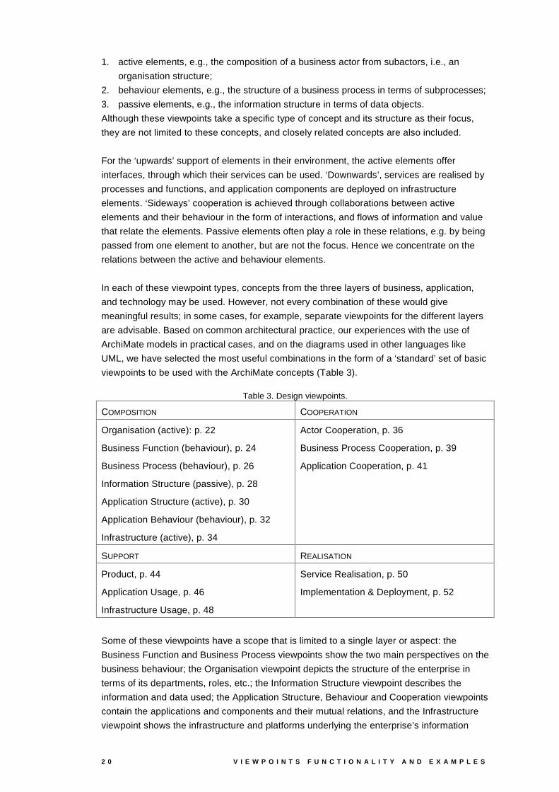
Table 3. Design viewpoints.
COMPOSITION COOPERATION
Organisation (active): p. 22
Business Function (behaviour), p. 24
Business Process (behaviour), p. 26
Information Structure (passive), p. 28
Application Structure (active), p. 30
Application Behaviour (behaviour), p. 32
Infrastructure (active), p. 34
Actor Cooperation, p. 36
Business Process Cooperation, p. 39
Application Cooperation, p. 41
SUPPORT REALISATION
Product, p. 44
Application Usage, p. 46
Infrastructure Usage, p. 48
Service Realisation, p. 50
Implementation & Deployment, p. 52
Some of these viewpoints have a scope that is limited to a single layer or aspect: the
Business Function and Business Process viewpoints show the two main perspectives on the
business behaviour; the Organisation viewpoint depicts the structure of the enterprise in
terms of its departments, roles, etc.; the Information Structure viewpoint describes the
information and data used; the Application Structure, Behaviour and Cooperation viewpoints
contain the applications and components and their mutual relations, and the Infrastructure
viewpoint shows the infrastructure and platforms underlying the enterprise’s information
A R C H I M A T E / D 3 . 4 . 1 A V 2 . 6 2 1
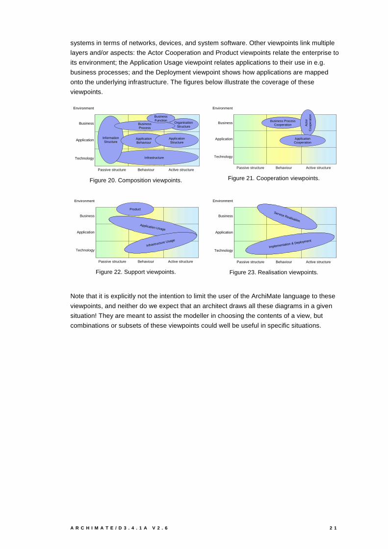
systems in terms of networks, devices, and system software. Other viewpoints link multiple
layers and/or aspects: the Actor Cooperation and Product viewpoints relate the enterprise to
its environment; the Application Usage viewpoint relates applications to their use in e.g.
business processes; and the Deployment viewpoint shows how applications are mapped
onto the underlying infrastructure. The figures below illustrate the coverage of these
viewpoints.
Infrastructure
Business
Application
Technology
Passive structure Behaviour Active structure
Environment
OrganisationStructure
InformationStructure
BusinessProcess
BusinessFunction
ApplicationBehaviour
ApplicationStructure
Figure 20. Composition viewpoints.
Business
Application
Technology
Passive structure Behaviour Active structure
Environment
Business ProcessCooperation A
ctor
Coo
pera
tion
ApplicationCooperation
Figure 21. Cooperation viewpoints.
Product
Business
Application
Technology
Passive structure Behaviour Active structure
Environment
Application Usage
Infrastructure Usage
Figure 22. Support viewpoints.
Business
Application
Technology
Passive structure Behaviour Active structure
Environment
Service Realisation
Implementation & Deployment
Figure 23. Realisation viewpoints.
Note that it is explicitly not the intention to limit the user of the ArchiMate language to these
viewpoints, and neither do we expect that an architect draws all these diagrams in a given
situation! They are meant to assist the modeller in choosing the contents of a view, but
combinations or subsets of these viewpoints could well be useful in specific situations.
2 2 V I E W P O I N T S F U N C T I O N A L I T Y A N D E X A M P L E S
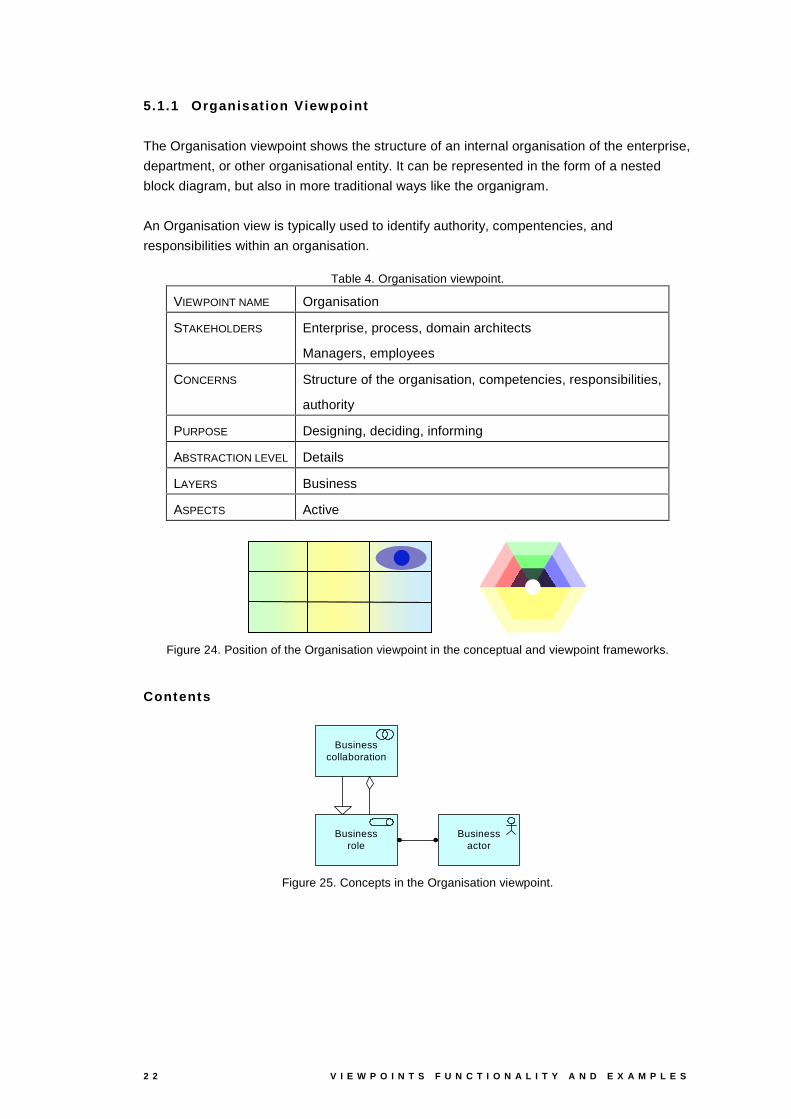
5.1.1 Organisat ion Viewpoint
The Organisation viewpoint shows the structure of an internal organisation of the enterprise,
department, or other organisational entity. It can be represented in the form of a nested
block diagram, but also in more traditional ways like the organigram.
An Organisation view is typically used to identify authority, compentencies, and
responsibilities within an organisation.
Table 4. Organisation viewpoint.
VIEWPOINT NAME Organisation
STAKEHOLDERS Enterprise, process, domain architects
Managers, employees
CONCERNS Structure of the organisation, competencies, responsibilities,
authority
PURPOSE Designing, deciding, informing
ABSTRACTION LEVEL Details
LAYERS Business
ASPECTS Active
Figure 24. Position of the Organisation viewpoint in the conceptual and viewpoint frameworks.
Contents
Businessactor
Businessrole
Business collaboration
Figure 25. Concepts in the Organisation viewpoint.

A R C H I M A T E / D 3 . 4 . 1 A V 2 . 6 2 3
Example
ArchiSurance
Back Office
Front Office
Home&
AwayCar
LegalAid
CustomerRelations
HRMProduct
DevelopmentFinance
IntermediaryRelations
Document Processing SSC
Figure 26. The organisation structure of ArchiSurance.
Home&
AwayCar
LegalAid
CustomerRelations
HRMProduct
Development
FinanceIntermediary
Relations
Document Processing
SSC
Board
Director ofOperations
Director of Sales
Director ofFinance
Figure 27. ArchiSurance organigram.
2 4 V I E W P O I N T S F U N C T I O N A L I T Y A N D E X A M P L E S
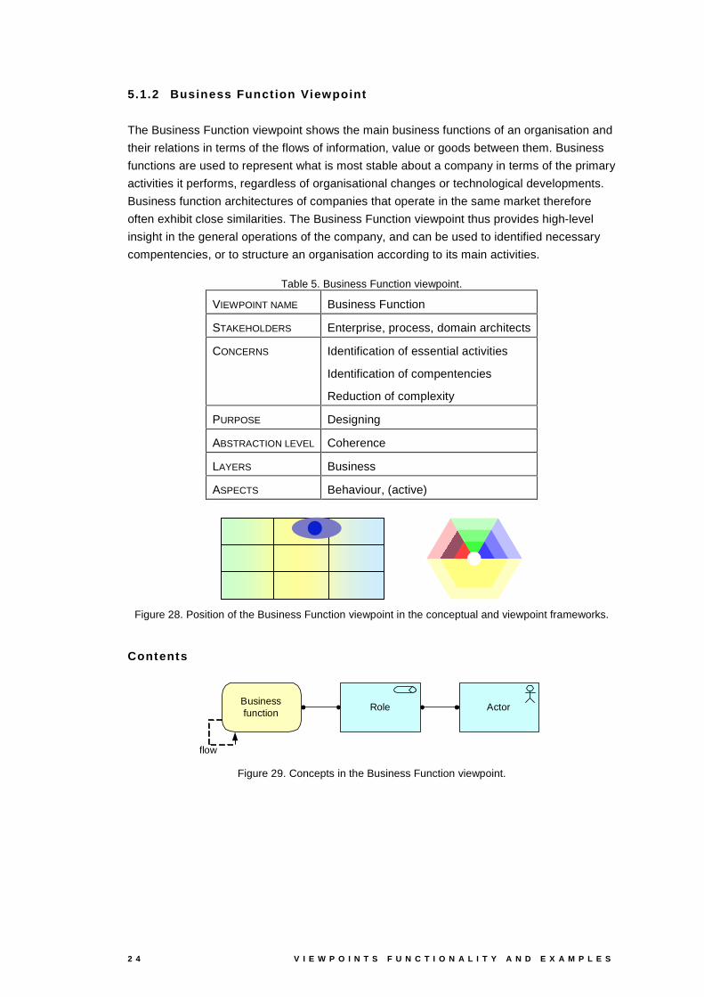
5.1.2 Business Funct ion Viewpoint
The Business Function viewpoint shows the main business functions of an organisation and
their relations in terms of the flows of information, value or goods between them. Business
functions are used to represent what is most stable about a company in terms of the primary
activities it performs, regardless of organisational changes or technological developments.
Business function architectures of companies that operate in the same market therefore
often exhibit close similarities. The Business Function viewpoint thus provides high-level
insight in the general operations of the company, and can be used to identified necessary
compentencies, or to structure an organisation according to its main activities.
Table 5. Business Function viewpoint.
VIEWPOINT NAME Business Function
STAKEHOLDERS Enterprise, process, domain architects
CONCERNS Identification of essential activities
Identification of compentencies
Reduction of complexity
PURPOSE Designing
ABSTRACTION LEVEL Coherence
LAYERS Business
ASPECTS Behaviour, (active)
Figure 28. Position of the Business Function viewpoint in the conceptual and viewpoint frameworks.
Contents
RoleBusiness function
flow
Actor
Figure 29. Concepts in the Business Function viewpoint.

A R C H I M A T E / D 3 . 4 . 1 A V 2 . 6 2 5
Example
Finance
Home&
Away
Car LegalAid
Customer RelationsIntermediary Relations
MaintainingIntermediary
Relations
Contracting
FinancialHandling
Claims Handling
MaintainingCustomerRelations
AssetManagement
Figure 30. Business functions of ArchiSurance, assigned to its departments.
Insurer
MaintainingIntermediary
Relations
Contracting
FinancialHandling
ClaimsHandling
Claims
Insurancepolicies
Customer information
Money
MaintainingCustomerRelations
AssetManagement
Contracts
Productinformation
Customerinformation
Claims
Insuranceinformation
Insurancepremiums
Claimpayments
Insurancepolicies
Customerinformation
Productinformation
Claims
Money
Claiminformation
Intermediary
Customer
Customer’sBank
Figure 31. Business functions and information and money flows.
2 6 V I E W P O I N T S F U N C T I O N A L I T Y A N D E X A M P L E S
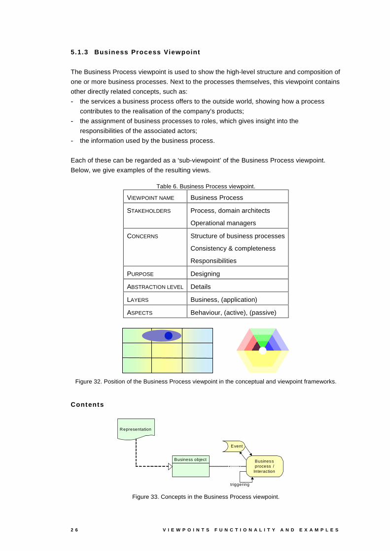
5.1.3 Business Process Viewpoint
The Business Process viewpoint is used to show the high-level structure and composition of
one or more business processes. Next to the processes themselves, this viewpoint contains
other directly related concepts, such as:
- the services a business process offers to the outside world, showing how a process
contributes to the realisation of the company’s products;
- the assignment of business processes to roles, which gives insight into the
responsibilities of the associated actors;
- the information used by the business process.
Each of these can be regarded as a ‘sub-viewpoint’ of the Business Process viewpoint.
Below, we give examples of the resulting views.
Table 6. Business Process viewpoint.
VIEWPOINT NAME Business Process
STAKEHOLDERS Process, domain architects
Operational managers
CONCERNS Structure of business processes
Consistency & completeness
Responsibilities
PURPOSE Designing
ABSTRACTION LEVEL Details
LAYERS Business, (application)
ASPECTS Behaviour, (active), (passive)
Figure 32. Position of the Business Process viewpoint in the conceptual and viewpoint frameworks.
Contents
Event
Business process /
Interaction
Business object
Representation
triggering
Figure 33. Concepts in the Business Process viewpoint.
A R C H I M A T E / D 3 . 4 . 1 A V 2 . 6 2 7
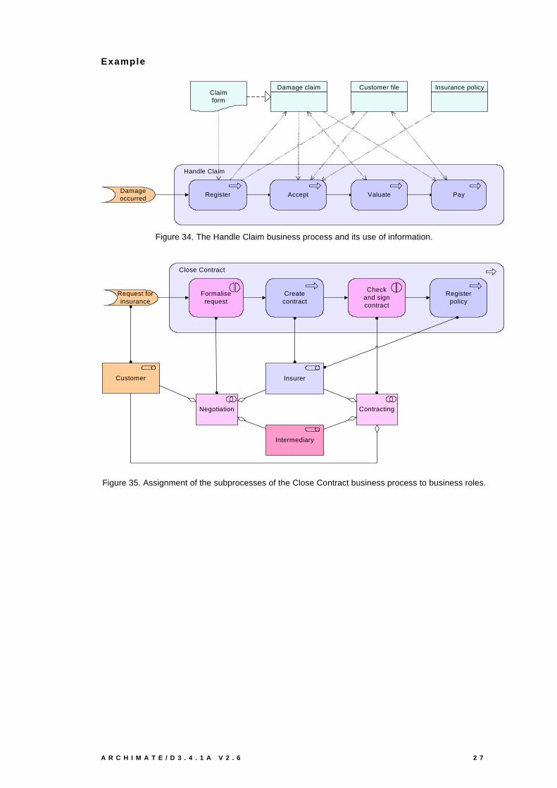
Example
Handle Claim
Register PayValuateAccept
Damage claimClaimform
Customer file Insurance policy
Damage occurred
Figure 34. The Handle Claim business process and its use of information.
Close Contract
Createcontract
Registerpolicy
Request for insurance
Formalise request
Checkand signcontract
Customer Insurer
ContractingNegotiation
Intermediary
Figure 35. Assignment of the subprocesses of the Close Contract business process to business roles.
2 8 V I E W P O I N T S F U N C T I O N A L I T Y A N D E X A M P L E S
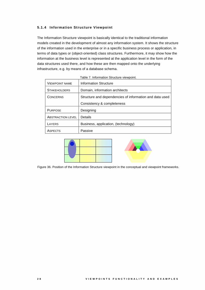
5.1.4 Informat ion Structure Viewpoint
The Information Structure viewpoint is basically identical to the traditional information
models created in the development of almost any information system. It shows the structure
of the information used in the enterprise or in a specific business process or application, in
terms of data types or (object-oriented) class structures. Furthermore, it may show how the
information at the business level is represented at the application level in the form of the
data structures used there, and how these are then mapped onto the underlying
infrastructure, e.g. by means of a database schema.
Table 7. Information Structure viewpoint.
VIEWPOINT NAME Information Structure
STAKEHOLDERS Domain, information architects
CONCERNS Structure and dependencies of information and data used
Consistency & completeness
PURPOSE Designing
ABSTRACTION LEVEL Details
LAYERS Business, application, (technology)
ASPECTS Passive
Figure 36. Position of the Information Structure viewpoint in the conceptual and viewpoint frameworks.
A R C H I M A T E / D 3 . 4 . 1 A V 2 . 6 2 9
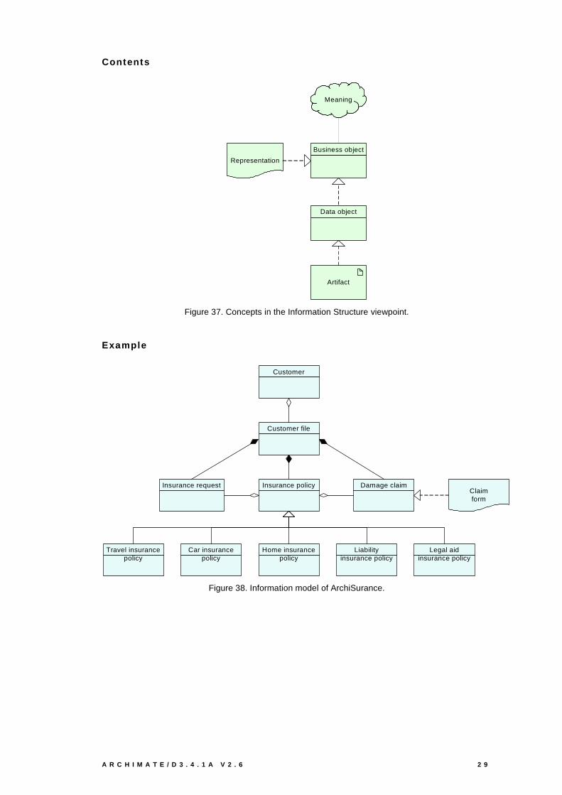
Contents
Business object
Artifact
Data object
Representation
Meaning
Figure 37. Concepts in the Information Structure viewpoint.
Example
Damage claimClaimform
Customer file
Insurance policyInsurance request
Car insurance policy
Home insurance policy
Travel insurance policy
Liability insurance policy
Legal aid insurance policy
Customer
Figure 38. Information model of ArchiSurance.
3 0 V I E W P O I N T S F U N C T I O N A L I T Y A N D E X A M P L E S
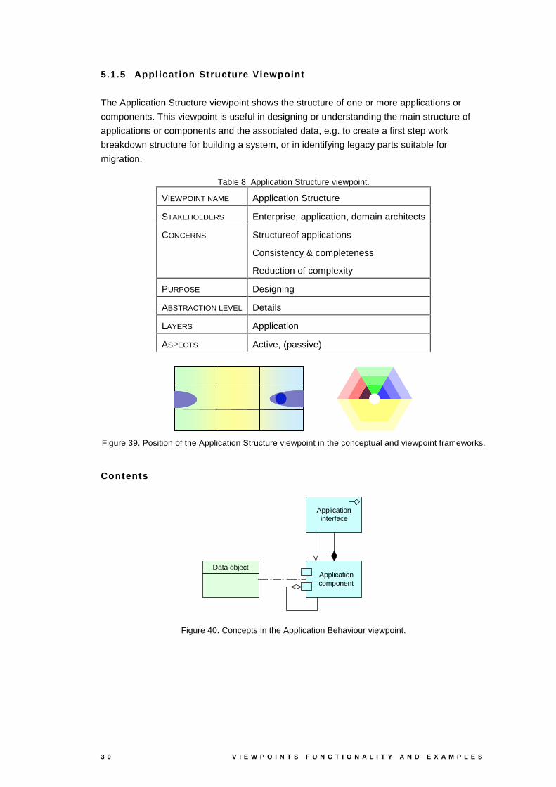
5.1.5 Appl icat ion Structure Viewpoint
The Application Structure viewpoint shows the structure of one or more applications or
components. This viewpoint is useful in designing or understanding the main structure of
applications or components and the associated data, e.g. to create a first step work
breakdown structure for building a system, or in identifying legacy parts suitable for
migration.
Table 8. Application Structure viewpoint.
VIEWPOINT NAME Application Structure
STAKEHOLDERS Enterprise, application, domain architects
CONCERNS Structureof applications
Consistency & completeness
Reduction of complexity
PURPOSE Designing
ABSTRACTION LEVEL Details
LAYERS Application
ASPECTS Active, (passive)
Figure 39. Position of the Application Structure viewpoint in the conceptual and viewpoint frameworks.
Contents
Application component
Application interface
Data object
Figure 40. Concepts in the Application Behaviour viewpoint.

A R C H I M A T E / D 3 . 4 . 1 A V 2 . 6 3 1
Example
Home & Away Policy administration
Risk Assessment
Policy data management
Customerdata access
Damage claim data
Customer file data
Policy data
Claim data management
Figure 41. Main structure of the Home & Away Policy administration.
3 2 V I E W P O I N T S F U N C T I O N A L I T Y A N D E X A M P L E S
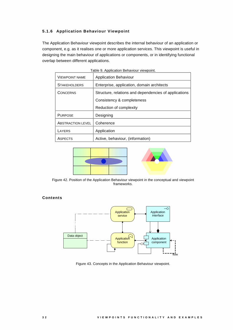
5.1.6 Appl icat ion Behaviour Viewpoint
The Application Behaviour viewpoint describes the internal behaviour of an application or
component, e.g. as it realises one or more application services. This viewpoint is useful in
designing the main behaviour of applications or components, or in identifying functional
overlap between different applications.
Table 9. Application Behaviour viewpoint.
VIEWPOINT NAME Application Behaviour
STAKEHOLDERS Enterprise, application, domain architects
CONCERNS Structure, relations and dependencies of applications
Consistency & completeness
Reduction of complexity
PURPOSE Designing
ABSTRACTION LEVEL Coherence
LAYERS Application
ASPECTS Active, behaviour, (information)
Figure 42. Position of the Application Behaviour viewpoint in the conceptual and viewpoint frameworks.
Contents
Application component
Application service
Application interface
flow
Data objectApplication
function
Figure 43. Concepts in the Application Behaviour viewpoint.
A R C H I M A T E / D 3 . 4 . 1 A V 2 . 6 3 3
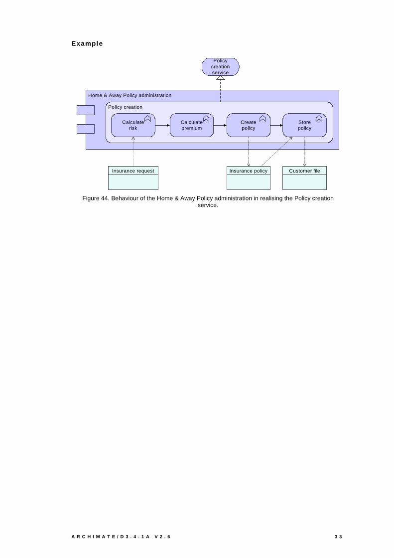
Example
Home & Away Policy administration
Policy creation
Calculatepremium
Calculaterisk
Createpolicy
Storepolicy
Policy creationservice
Customer fileInsurance policyInsurance request
Figure 44. Behaviour of the Home & Away Policy administration in realising the Policy creation service.

3 4 V I E W P O I N T S F U N C T I O N A L I T Y A N D E X A M P L E S
5.1.7 Infrastructure Viewpoint
The Infrastructure viewpoint comprises the hardware and software infrastructure upon which
the application layer depends. It contains physical devices and networks, and supporting
system software such as operating systems, databases and middleware.
Table 10. Infrastructure viewpoint.
VIEWPOINT NAME Infrastructure
STAKEHOLDERS Infrastructure architects, (application architects)
Operational managers
CONCERNS Stability, security, dependencies, costs of infrastructure
PURPOSE Designing
ABSTRACTION LEVEL Details
LAYERS Technology
ASPECTS Behaviour, active
Figure 45. Position of the Infrastructure viewpoint in the conceptual and viewpoint frameworks.
Contents
Infrastructure interface
Infrastructure service
Node
Device Network
Communicationpath
Systemsoftware
Figure 46. Concepts in the Infrastructure viewpoint.

A R C H I M A T E / D 3 . 4 . 1 A V 2 . 6 3 5
Example
ArchiSurance
Unix server farm
Mainframe
Intermediary
AdminserverLAN
NAS File server
LANTCP/IPNetwork
Firewall Firewall
Unixserver
Unixserver
DBMS
MessageQueing
CICS
Figure 47. Infrastructure of ArchiSurance.
3 6 V I E W P O I N T S F U N C T I O N A L I T Y A N D E X A M P L E S
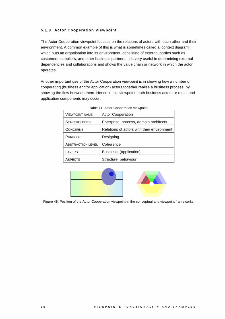
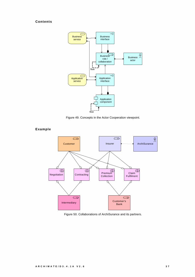
5.1.8 Actor Cooperat ion Viewpoint
The Actor Cooperation viewpoint focuses on the relations of actors with each other and their
environment. A common example of this is what is sometimes called a ‘context diagram’,
which puts an organisation into its environment, consisting of external parties such as
customers, suppliers, and other business partners. It is very useful in determining external
dependencies and collaborations and shows the value chain or network in which the actor
operates.
Another important use of the Actor Cooperation viewpoint is in showing how a number of
cooperating (business and/or application) actors together realise a business process, by
showing the flow between them. Hence in this viewpoint, both business actors or roles, and
application components may occur.
Table 11. Actor Cooperation viewpoint.
VIEWPOINT NAME Actor Cooperation
STAKEHOLDERS Enterprise, process, domain architects
CONCERNS Relations of actors with their environment
PURPOSE Designing
ABSTRACTION LEVEL Coherence
LAYERS Business, (application)
ASPECTS Structure, behaviour
Figure 48. Position of the Actor Cooperation viewpoint in the conceptual and viewpoint frameworks.
A R C H I M A T E / D 3 . 4 . 1 A V 2 . 6 3 7
Contents
Businessactor
Businessrole /
collaboration
Application component
Application service
Application interface
Business service
flow
Businessinterface
flow
Figure 49. Concepts in the Actor Cooperation viewpoint.
Example
Intermediary
Customer Insurer
ContractingPremiumCollection
ClaimFulfilment
Customer’sBank
Negotiation
ArchiSurance
Figure 50. Collaborations of ArchiSurance and its partners.
3 8 V I E W P O I N T S F U N C T I O N A L I T Y A N D E X A M P L E S
ArchiSurance
Back Office
Front Office
Home&
AwayCar
LegalAid
CustomerRelations
IntermediaryRelations
Customer Intermediary
GIM
phone
Customer’sBank
phone
FinanceDocument
Processing SSC
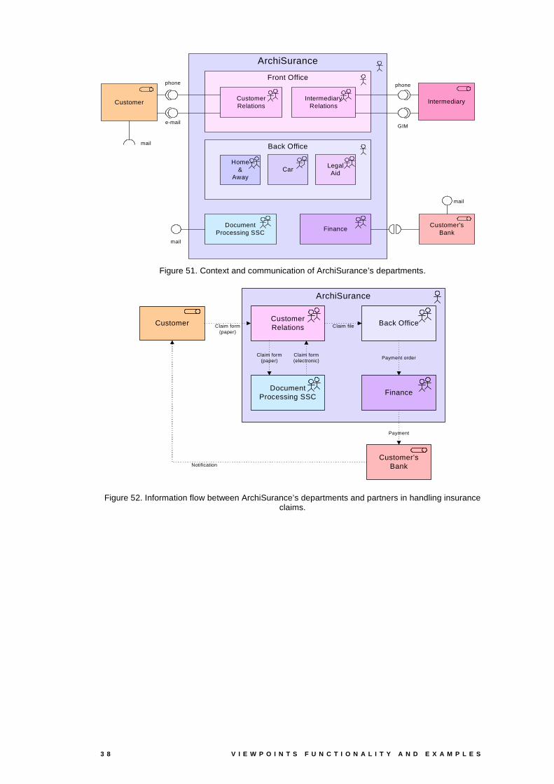
Figure 51. Context and communication of ArchiSurance’s departments.
ArchiSurance
Back OfficeCustomerRelations
FinanceDocument
Processing SSC
Customer
Payment order
Claim form(paper)
Claim form(paper)
Claim form(electronic)
Claim file
Customer’sBank
Payment
Notification
Figure 52. Information flow between ArchiSurance’s departments and partners in handling insurance claims.

A R C H I M A T E / D 3 . 4 . 1 A V 2 . 6 3 9
5.1.9 Business Process Cooperation Viewpoint
The Business Process Cooperation viewpoint is used to show the relations of one or more
business processes with each other and/or their surroundings. It can both be used to create
a high-level design of business processes within their context and to provide an operational
manager responsible for one or more such processes with insight in their dependencies.
Important aspects of Cooperation are:
- causal relations between the main business processes of the enterprise;
- the mapping of business processes onto business functions;
- realisation of services by business processes;
- the use of shared data;
- the execution of a business process by the same roles or actors.
Each of these can be regarded as a ‘sub-viewpoint’ of the Business Process Cooperation
viewpoint. Below, we give examples of some of the resulting views.
Table 12. Business Process Cooperation viewpoint.
VIEWPOINT NAME Business Process Cooperation
STAKEHOLDERS Process, domain architects
Operational managers
CONCERNS Dependencies of business processes
Consistency & completeness
Responsibilities
PURPOSE Designing, deciding
ABSTRACTION LEVEL Coherence
LAYERS Business, (application)
ASPECTS Behaviour, (active), (passive)
Figure 53. Position of the Business Process Cooperation viewpoint in the conceptual and viewpoint frameworks.

4 0 V I E W P O I N T S F U N C T I O N A L I T Y A N D E X A M P L E S
Contents
ActorRole /
Collaboration
Organisational service
Event
Application service
Business process /
Interaction
Business object
Representation
triggering
Figure 54. Concepts in the Business Process Cooperation viewpoint.
Example
Handle Claim
Close Contract Collect PremiumRequest for insurance
Damage occurred
Request for information
Inform Customer
Develop Product Manage AssetsOpportunity
identified
Request for information
Inform Intermediary
Figure 55. Some of the main business processes, triggers and relations of ArchiSurance.
CustomerRelations
Claim Handling
Financial Handling
Handle Claim
Register PayValuateAcceptDamage occurred
Figure 56. The Handle Claim business process mapped onto the business functions.
A R C H I M A T E / D 3 . 4 . 1 A V 2 . 6 4 1
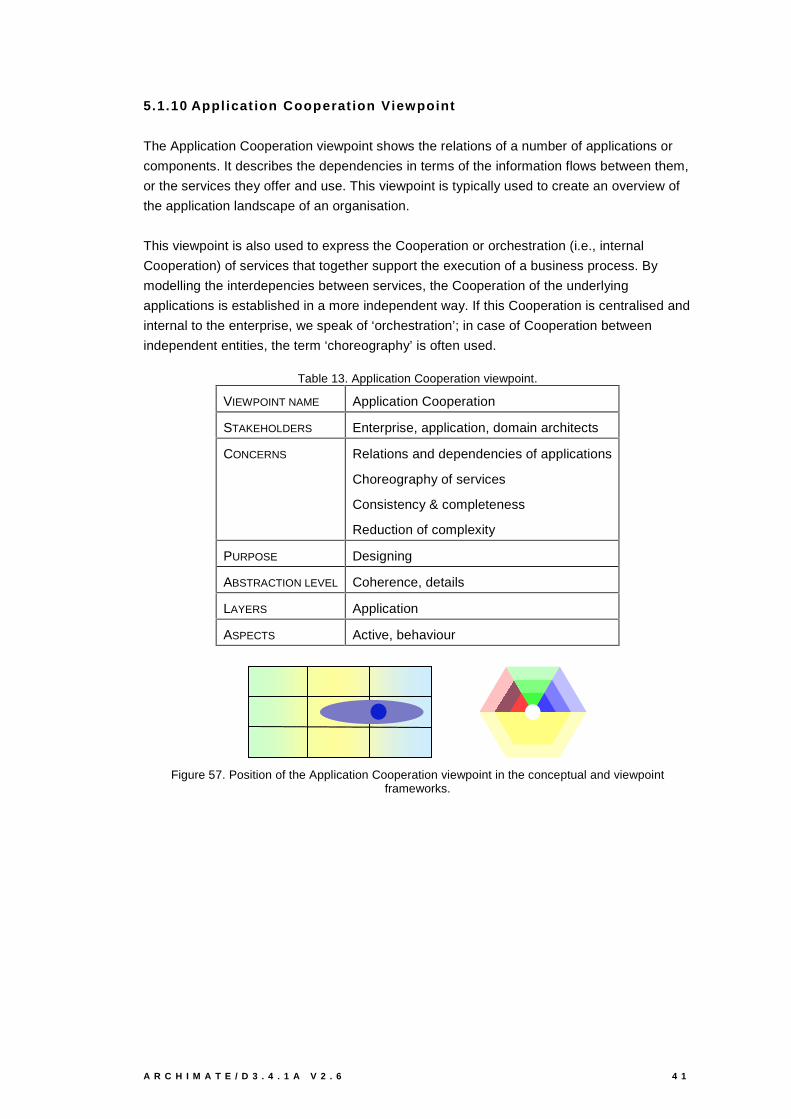
5.1.10 Appl icat ion Cooperat ion Viewpoint
The Application Cooperation viewpoint shows the relations of a number of applications or
components. It describes the dependencies in terms of the information flows between them,
or the services they offer and use. This viewpoint is typically used to create an overview of
the application landscape of an organisation.
This viewpoint is also used to express the Cooperation or orchestration (i.e., internal
Cooperation) of services that together support the execution of a business process. By
modelling the interdepencies between services, the Cooperation of the underlying
applications is established in a more independent way. If this Cooperation is centralised and
internal to the enterprise, we speak of ‘orchestration’; in case of Cooperation between
independent entities, the term ‘choreography’ is often used.
Table 13. Application Cooperation viewpoint.
VIEWPOINT NAME Application Cooperation
STAKEHOLDERS Enterprise, application, domain architects
CONCERNS Relations and dependencies of applications
Choreography of services
Consistency & completeness
Reduction of complexity
PURPOSE Designing
ABSTRACTION LEVEL Coherence, details
LAYERS Application
ASPECTS Active, behaviour
Figure 57. Position of the Application Cooperation viewpoint in the conceptual and viewpoint frameworks.
4 2 V I E W P O I N T S F U N C T I O N A L I T Y A N D E X A M P L E S
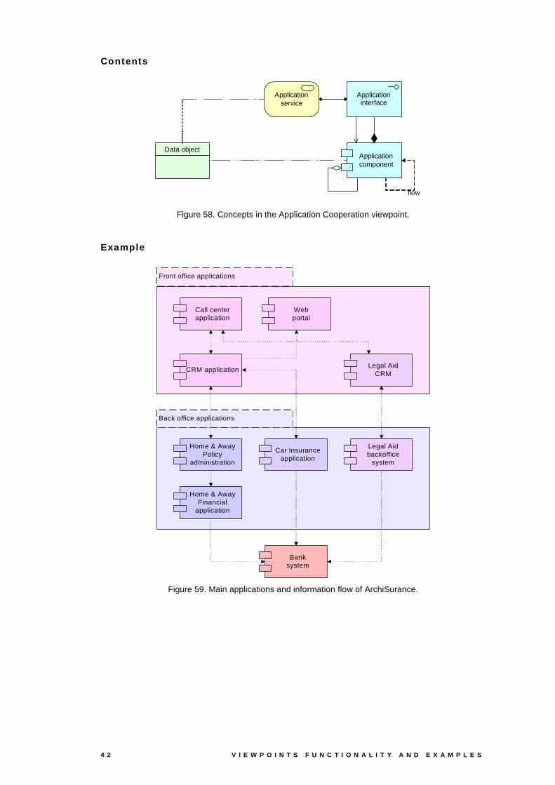
Contents
Application component
Application service
Application interface
flow
Data object
Figure 58. Concepts in the Application Cooperation viewpoint.
Example
Front office applications
Back office applications
Home & AwayPolicy
administration
Home & AwayFinancial
application
Car Insuranceapplication
Legal Aidbackoffice
system
Webportal
Call centerapplication
CRM applicationLegal Aid
CRM
Banksystem
Figure 59. Main applications and information flow of ArchiSurance.

A R C H I M A T E / D 3 . 4 . 1 A V 2 . 6 4 3
ArchiSurance Service Bus
Home & AwayPolicy
administration
CRMapplication
Home & AwayFinancial
application
Customerinformation
service
Claiminformation
service
Banksystem
Money transferservice
Figure 60. Applications connected through services.
Home & AwayPolicy
administration
CRMapplication
Home & AwayFinancial
application
Customeradministration
service
Claimsadministration
service
Paymentservice
Printingservice
Scanningservice
Document management
system
Customerinformation
service
Claiminformation
service
Banksystem
Money transferservice
Figure 61. Application service orchestration in processing insurance claims.
4 4 V I E W P O I N T S F U N C T I O N A L I T Y A N D E X A M P L E S
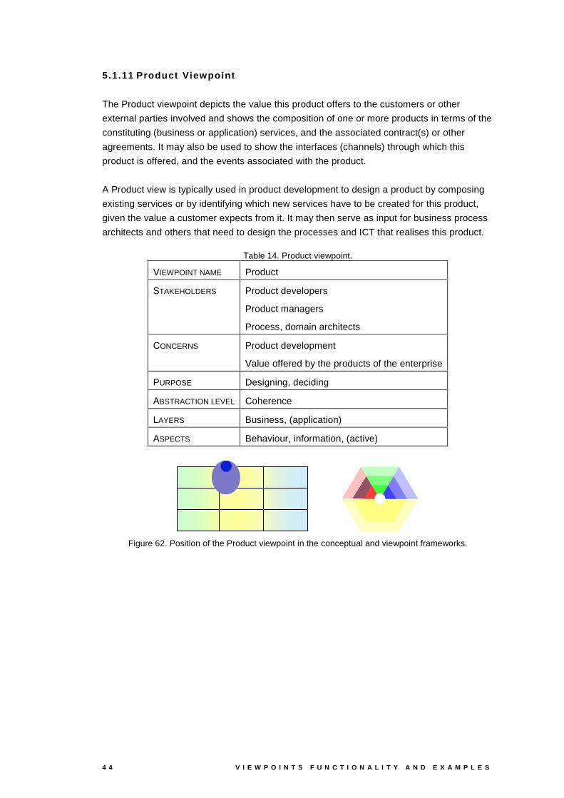
5.1.11 Product Viewpoint
The Product viewpoint depicts the value this product offers to the customers or other
external parties involved and shows the composition of one or more products in terms of the
constituting (business or application) services, and the associated contract(s) or other
agreements. It may also be used to show the interfaces (channels) through which this
product is offered, and the events associated with the product.
A Product view is typically used in product development to design a product by composing
existing services or by identifying which new services have to be created for this product,
given the value a customer expects from it. It may then serve as input for business process
architects and others that need to design the processes and ICT that realises this product.
Table 14. Product viewpoint.
VIEWPOINT NAME Product
STAKEHOLDERS Product developers
Product managers
Process, domain architects
CONCERNS Product development
Value offered by the products of the enterprise
PURPOSE Designing, deciding
ABSTRACTION LEVEL Coherence
LAYERS Business, (application)
ASPECTS Behaviour, information, (active)
Figure 62. Position of the Product viewpoint in the conceptual and viewpoint frameworks.

A R C H I M A T E / D 3 . 4 . 1 A V 2 . 6 4 5
Contents
Businessservice
Event
Businessinterface
Product
Application service
Contract
Value
Applicationinterface
Figure 63. Concepts in the Product viewpoint.
Example
Travel Insurance
Claimregistration
service
Customerinformation
service
Claimspaymentservice
Travel insurance policy
Insuranceapplication
service
Premiumpaymentservice
Customer data mutation
service
"be insured"(security)
Customer
Figure 64. The travel insurance product.
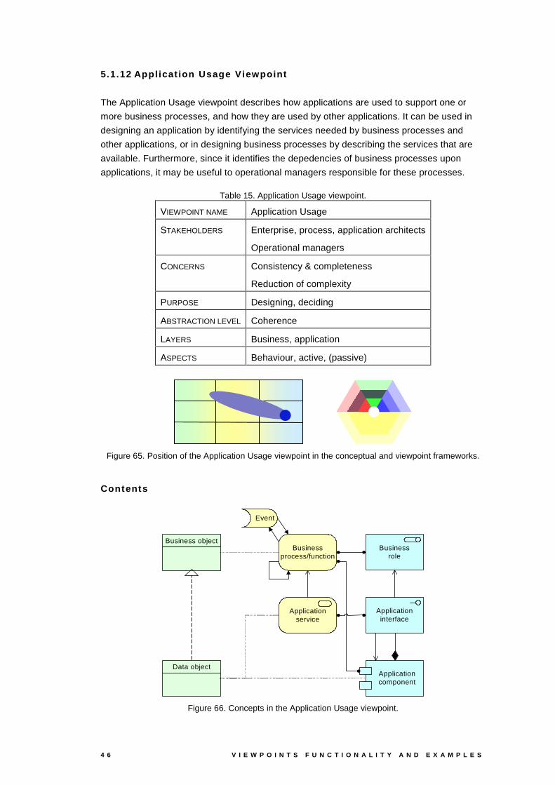
4 6 V I E W P O I N T S F U N C T I O N A L I T Y A N D E X A M P L E S
5.1.12 Appl icat ion Usage Viewpoint
The Application Usage viewpoint describes how applications are used to support one or
more business processes, and how they are used by other applications. It can be used in
designing an application by identifying the services needed by business processes and
other applications, or in designing business processes by describing the services that are
available. Furthermore, since it identifies the depedencies of business processes upon
applications, it may be useful to operational managers responsible for these processes.
Table 15. Application Usage viewpoint.
VIEWPOINT NAME Application Usage
STAKEHOLDERS Enterprise, process, application architects
Operational managers
CONCERNS Consistency & completeness
Reduction of complexity
PURPOSE Designing, deciding
ABSTRACTION LEVEL Coherence
LAYERS Business, application
ASPECTS Behaviour, active, (passive)
Figure 65. Position of the Application Usage viewpoint in the conceptual and viewpoint frameworks.
Contents
Application component
Business object
Application service
Application interface
Event
Business process/function
Data object
Businessrole
Figure 66. Concepts in the Application Usage viewpoint.
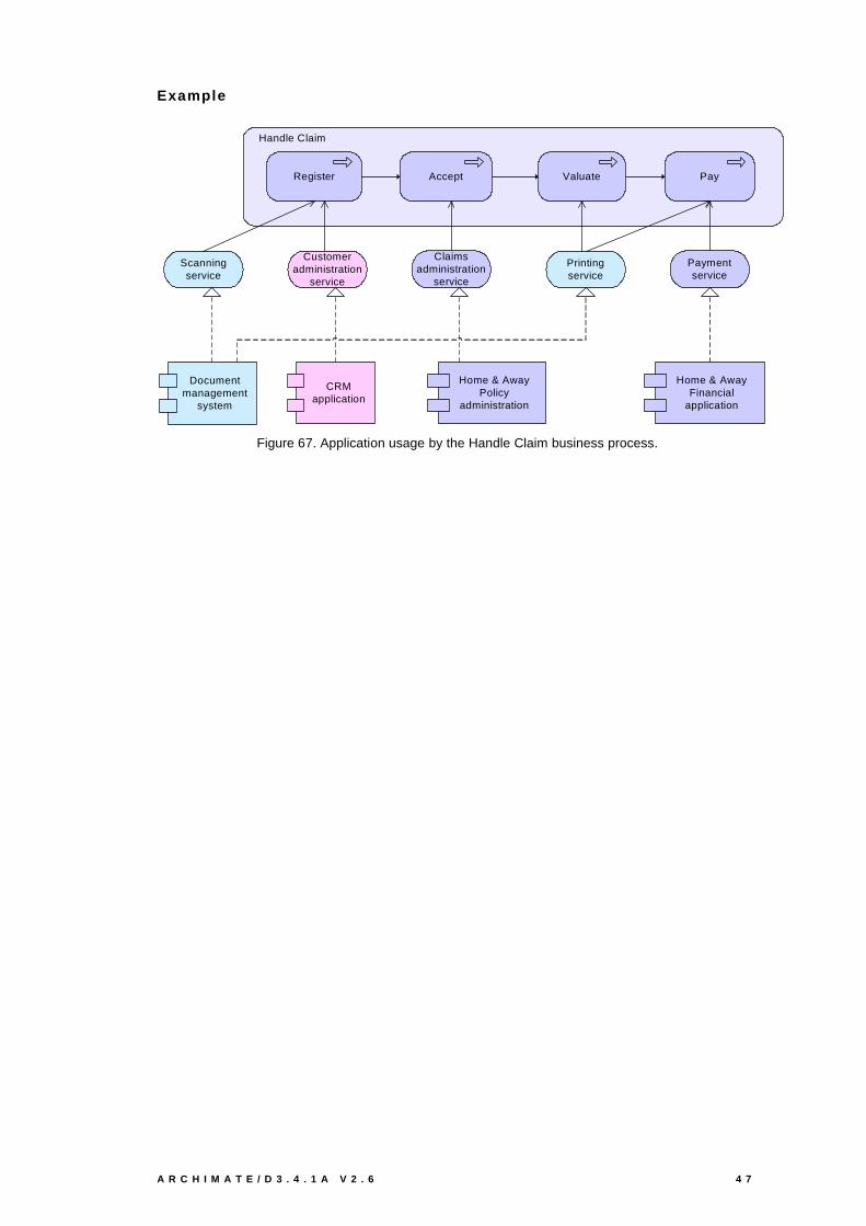
A R C H I M A T E / D 3 . 4 . 1 A V 2 . 6 4 7
Example
Handle Claim
Register PayValuateAccept
Home & AwayPolicy
administration
CRMapplication
Home & AwayFinancial
application
Customeradministration
service
Claimsadministration
service
Paymentservice
Printingservice
Scanningservice
Document management
system
Figure 67. Application usage by the Handle Claim business process.

4 8 V I E W P O I N T S F U N C T I O N A L I T Y A N D E X A M P L E S
5.1.13 Infrastructure Usage Viewpoint
The Infrastructure Usage viewpoint shows how applications are supported by the software
and hardware infrastructure: the infrastructure services delivered by the devices, system
software and networks are provided to the applications.
This viewpoint plays an important role in the analysis of performance and scalability, since it
relate the physical infrastructure to the logical world of applications. It is very useful in
determining the performance and quality requirements on the infrastructure based on the
demands of the various applications that use it.
Table 16. Infrastructure Usage viewpoint.
VIEWPOINT NAME Infrastructure Usage
STAKEHOLDERS Application, infrastructure architects
Operational managers
CONCERNS Dependencies, performance, scalability
PURPOSE Designing
ABSTRACTION LEVEL Coherence
LAYERS Application, technology
ASPECTS Active, (behaviour)
Figure 68. Position of the Infrastructure Usage viewpoint in the conceptual and viewpoint frameworks.
Contents
Application component
Infrastructure service
Node
Device
Communicationpath
flow
Systemsoftware
Figure 69. Concepts in the Infrastructure Usage viewpoint.
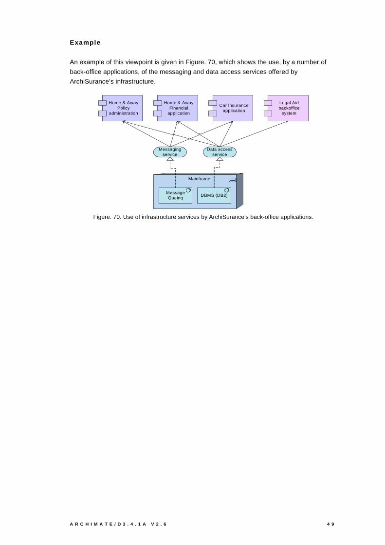
A R C H I M A T E / D 3 . 4 . 1 A V 2 . 6 4 9
Example
An example of this viewpoint is given in Figure. 70, which shows the use, by a number of
back-office applications, of the messaging and data access services offered by
ArchiSurance’s infrastructure.
Mainframe
DBMS (DB2)MessageQueing
Messaging service
Data access service
Home & AwayPolicy
administration
Home & AwayFinancial
application
Car Insuranceapplication
Legal Aidbackoffice
system
Figure. 70. Use of infrastructure services by ArchiSurance’s back-office applications.
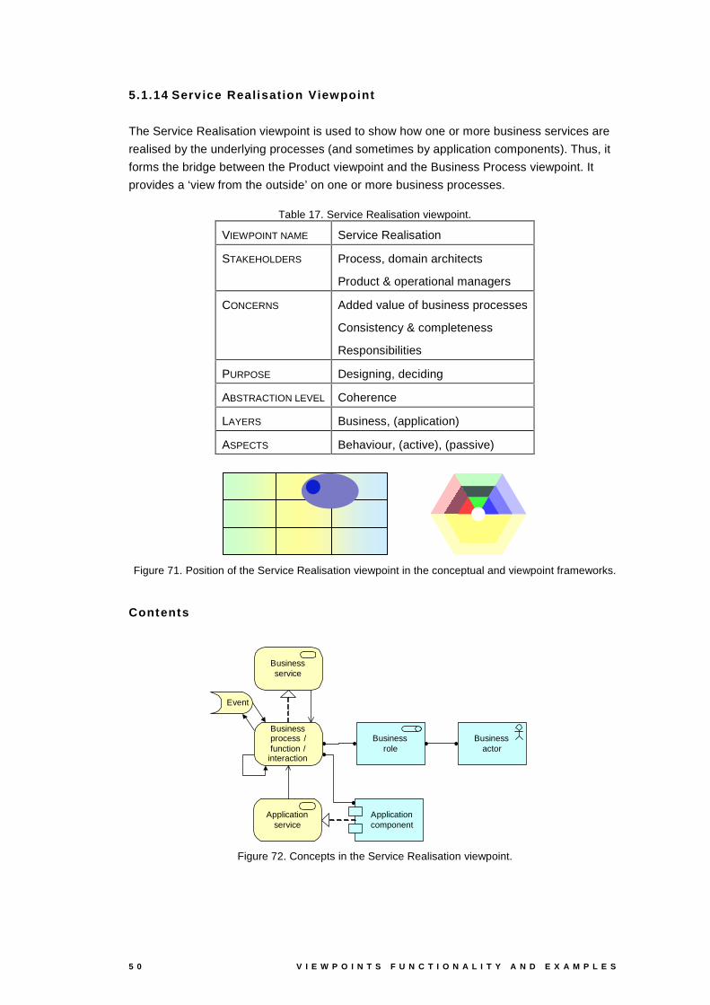
5 0 V I E W P O I N T S F U N C T I O N A L I T Y A N D E X A M P L E S
5.1.14 Serv ice Realisation Viewpoint
The Service Realisation viewpoint is used to show how one or more business services are
realised by the underlying processes (and sometimes by application components). Thus, it
forms the bridge between the Product viewpoint and the Business Process viewpoint. It
provides a ‘view from the outside’ on one or more business processes.
Table 17. Service Realisation viewpoint.
VIEWPOINT NAME Service Realisation
STAKEHOLDERS Process, domain architects
Product & operational managers
CONCERNS Added value of business processes
Consistency & completeness
Responsibilities
PURPOSE Designing, deciding
ABSTRACTION LEVEL Coherence
LAYERS Business, (application)
ASPECTS Behaviour, (active), (passive)
Figure 71. Position of the Service Realisation viewpoint in the conceptual and viewpoint frameworks.
Contents
Businessactor
Businessrole
Application component
Business service
Event
Business process /function /
interaction
Application service
Figure 72. Concepts in the Service Realisation viewpoint.
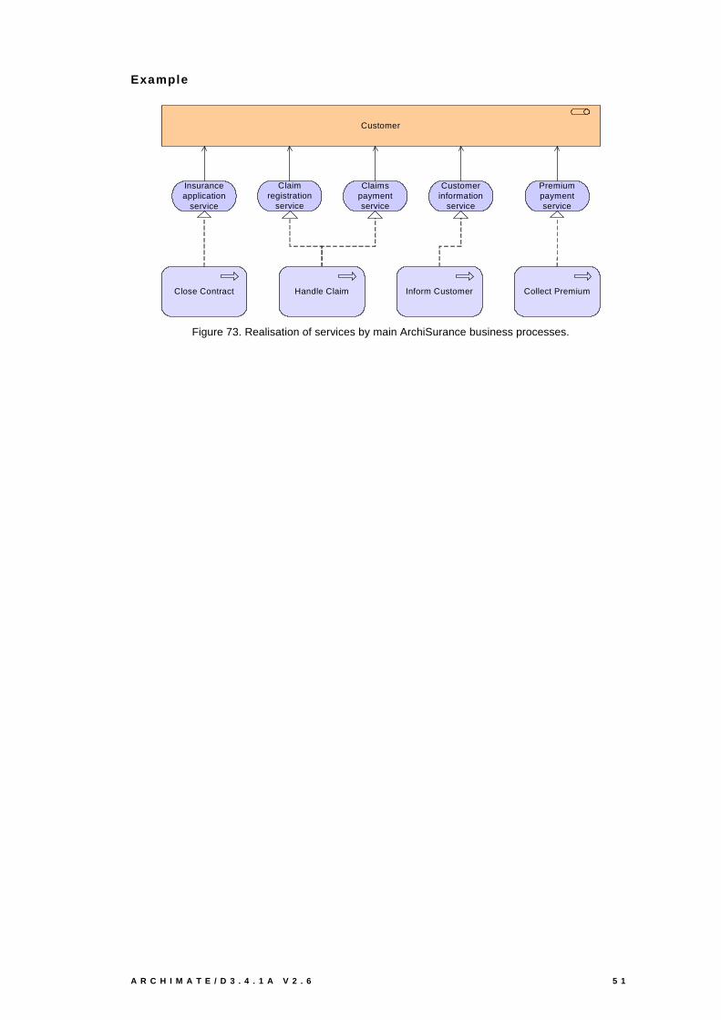
A R C H I M A T E / D 3 . 4 . 1 A V 2 . 6 5 1
Example
Claimregistration
service
Customerinformation
service
Claimspaymentservice
Customer
Handle ClaimClose Contract Collect PremiumInform Customer
Insuranceapplication
service
Premiumpaymentservice
Figure 73. Realisation of services by main ArchiSurance business processes.
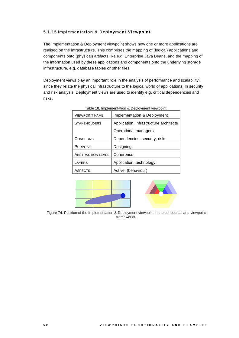
5 2 V I E W P O I N T S F U N C T I O N A L I T Y A N D E X A M P L E S
5.1.15 Implementation & Deployment Viewpoint
The Implementation & Deployment viewpoint shows how one or more applications are
realised on the infrastructure. This comprises the mapping of (logical) applications and
components onto (physical) artifacts like e.g. Enterprise Java Beans, and the mapping of
the information used by these applications and components onto the underlying storage
infrastructure, e.g. database tables or other files.
Deployment views play an important role in the analysis of performance and scalability,
since they relate the physical infrastructure to the logical world of applications. In security
and risk analysis, Deployment views are used to identify e.g. critical dependencies and
risks.
Table 18. Implementation & Deployment viewpoint.
VIEWPOINT NAME Implementation & Deployment
STAKEHOLDERS Application, infrastructure architects
Operational managers
CONCERNS Dependencies, security, risks
PURPOSE Designing
ABSTRACTION LEVEL Coherence
LAYERS Application, technology
ASPECTS Active, (behaviour)
Figure 74. Position of the Implementation & Deployment viewpoint in the conceptual and viewpoint frameworks.
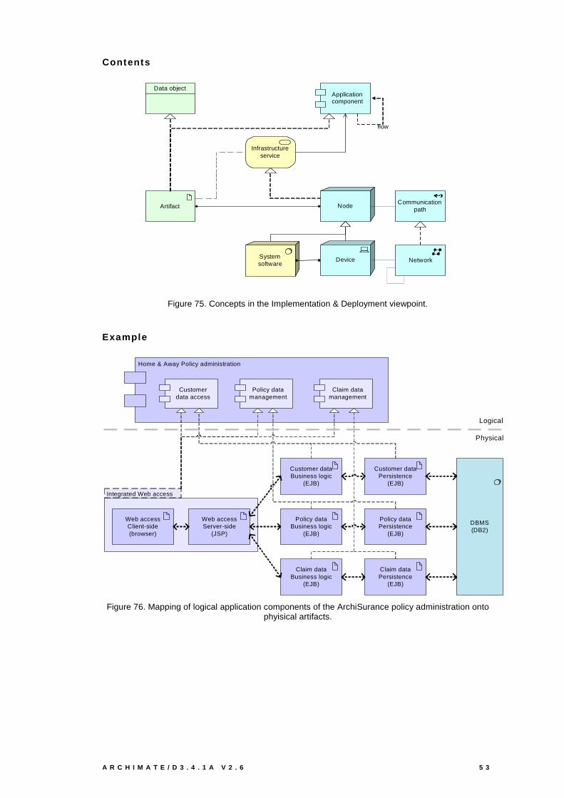
A R C H I M A T E / D 3 . 4 . 1 A V 2 . 6 5 3
Contents
Application component
Artifact
Infrastructure service
Node
Device
Data object
Communicationpath
flow
Systemsoftware
Network
Figure 75. Concepts in the Implementation & Deployment viewpoint.
Example
Integrated Web access
Home & Away Policy administration
Policy data management
Customerdata access
Claim data management
Web accessClient-side(browser)
Web accessServer-side
(JSP)
Customer dataBusiness logic
(EJB)
Policy dataBusiness logic
(EJB)
Claim dataBusiness logic
(EJB)
Customer dataPersistence
(EJB)
Policy dataPersistence
(EJB)
Claim dataPersistence
(EJB)
DBMS(DB2)
Logical
Physical
Figure 76. Mapping of logical application components of the ArchiSurance policy administration onto phyisical artifacts.

5 4 V I E W P O I N T S F U N C T I O N A L I T Y A N D E X A M P L E S
Unix server farm
Home & AwayPolicy
administration
CRMapplication
Home & AwayFinancial
application
Document management
system
Mainframe
NASFile server
LAN
Firewall
Network
Call centerapplication
Web portalCar Insurance
application
Legal Aidbackoffice
system
Figure 77. Deployment of ArchiSurance’s main applications onto its infrastructure.

A R C H I M A T E / D 3 . 4 . 1 A V 2 . 6 5 5
5.2 Layered Viewpoint
The layered viewpoint shows multiple layers and multiple aspects in one diagram. The main
purpose of this viewpoint is to provide an overview of a part of business architecture in a
single picture. Furthermore, it can be used for impact-of-change or performance analysis
and for extending the business with new services.
Typical stakeholders of the layered viewpoint are (enterprise) architects, but also
operational managers that are responsible for business processes, application or IT
services.
Table 19. Layered viewpoint.
VIEWPOINT NAME Layered viewpoint
STAKEHOLDERS Enterprise, application, process, infrastructure, domain architects
CONCERNS Consistency
Reduction of complexity
Impact of change
Flexibility
PURPOSE Designing
ABSTRACTION LEVEL Overview
LAYERS Business, application, technology
ASPECTS Active, behaviour, passive
Figure 78. Position of the Layered viewpoint in the conceptual and viewpoint frameworks.
5.2.1 Contents
Below we discuss a number of characteristics of this layering approach that are of particular
importance not only for the visualisation of architecture viewpoints but also for other
purposes, such as the quantification of relations and architecture elements and the
subsequent performance analysis or impact of change analysis of architecture models.
There are two categories of layers, namely dedicated layers and service layers. The layers
are the result of the use of the “grouping” relation for a partitioning of the entire set of
objects and relations that belong to a model. The infrastructure, the application, the
(application and business) function, the process and the actors/roles layers belong to the
first category. The structural principle behind a fully layered view is that each dedicated
layer exposes, by means of the “realisation” relation a layer of services, which are further on
“used by” the next dedicated layer. Thus we can easily separate the internal structure and
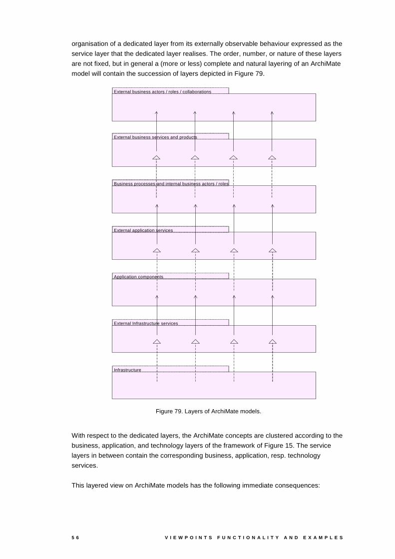
5 6 V I E W P O I N T S F U N C T I O N A L I T Y A N D E X A M P L E S
organisation of a dedicated layer from its externally observable behaviour expressed as the
service layer that the dedicated layer realises. The order, number, or nature of these layers
are not fixed, but in general a (more or less) complete and natural layering of an ArchiMate
model will contain the succession of layers depicted in Figure 79.
External business services and products
External application services
Business processes and internal business actors / roles
External business actors / roles / collaborations
Application components
External Infrastructure services
Infrastructure
Figure 79. Layers of ArchiMate models.
With respect to the dedicated layers, the ArchiMate concepts are clustered according to the
business, application, and technology layers of the framework of Figure 15. The service
layers in between contain the corresponding business, application, resp. technology
services.
This layered view on ArchiMate models has the following immediate consequences:
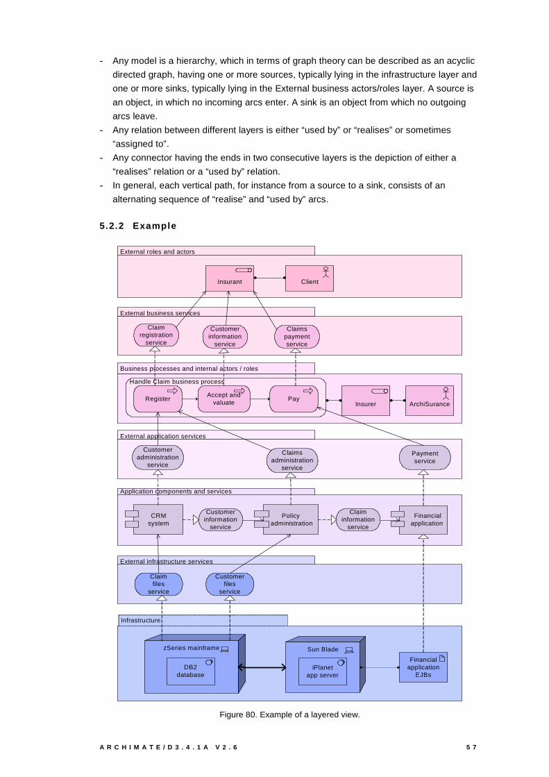
A R C H I M A T E / D 3 . 4 . 1 A V 2 . 6 5 7
- Any model is a hierarchy, which in terms of graph theory can be described as an acyclic
directed graph, having one or more sources, typically lying in the infrastructure layer and
one or more sinks, typically lying in the External business actors/roles layer. A source is
an object, in which no incoming arcs enter. A sink is an object from which no outgoing
arcs leave.
- Any relation between different layers is either “used by” or “realises” or sometimes
“assigned to”.
- Any connector having the ends in two consecutive layers is the depiction of either a
“realises” relation or a “used by” relation.
- In general, each vertical path, for instance from a source to a sink, consists of an
alternating sequence of “realise” and “used by” arcs.
5.2.2 Example
Business processes and internal actors / roles
Infrastructure
External infrastructure services
Application components and services
External roles and actors
External application services
External business services
Handle Claim business process
ClientInsurant
Insurer ArchiSuranceRegister Pay
Accept and valuate
Customer information
service
Claimspaymentservice
Customer administration
service
Paymentservice
CRM system
Financial application
Customerinformation
service
Claimregistration
service
Claims administration
service
Policy administration
Claimfiles
service
zSeries mainframe
DB2database
Financialapplication
EJBs
Customerfiles
service
Sun Blade
iPlanetapp server
Claiminformation
service
Figure 80. Example of a layered view.
5 8 V I E W P O I N T S F U N C T I O N A L I T Y A N D E X A M P L E S
The example given in Figure 80 covers a number of layers from business to infrastructure.
The example is centered around a single business process, the Handle Claim process.
Alternatively, a layered view could, for example, focus on a single application and all related
infrastructure, business processes, etc., or on a single business service and all layers
contributing to the realisation of that service.
The layered view of ArchiMate models is a very powerful instrument, which provides the
user with more than just a viewpoint. It is easy to see that the usage of layering is beneficial
at least for the following reasons:
- It gives a clear structure to models.
- It reduces the complexity of diagrams.
- It creates a style of architecting and designing.
- Although structured, it offers a certain degree of flexibility, since the number, and nature
of the layers is not fixed. One can abstract from those layers that are not relevant for the
problem under investigation. The order of the dedicated layers in a layered view,
however, has to be compliant with the metamodel of the ArchiMate language. More
precisely, the order in which two dedicated layers occur is dependant on the existence in
the metamodel of a directed path between the types of concepts that are typically used
in the two layers. For example the application layer cannot be placed on top of the
process layer because no directed path, for instance, from a process to an application
component can be found in the metamodel of the ArchiMate language. The reverse
order is, obviously, possible.
- It is an excellent approach when an overview of complex structures is needed.
Nevertheless, it allows the designer to create models at any level of detail, since each
layer can be as complex as necessary.
- The layered view can be fully or partially used: one may create models that are only
partially layered (for an example see Figure 88 and Figure 89).
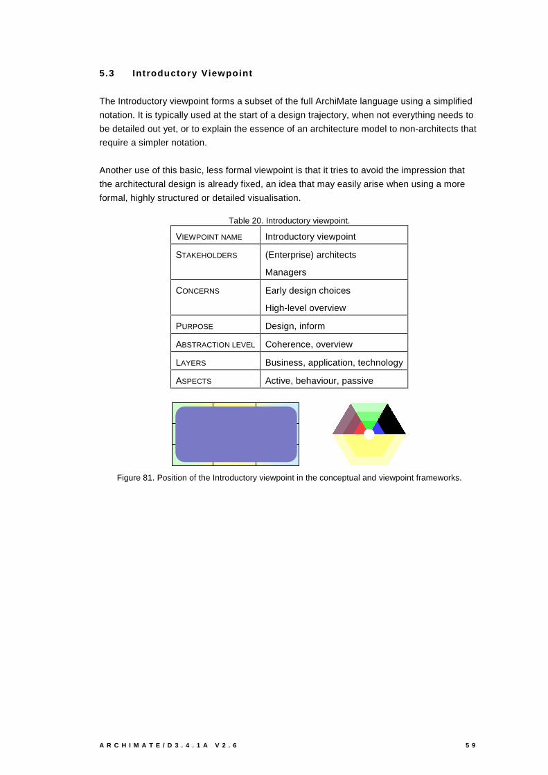
A R C H I M A T E / D 3 . 4 . 1 A V 2 . 6 5 9
5.3 Introductory Viewpoint
The Introductory viewpoint forms a subset of the full ArchiMate language using a simplified
notation. It is typically used at the start of a design trajectory, when not everything needs to
be detailed out yet, or to explain the essence of an architecture model to non-architects that
require a simpler notation.
Another use of this basic, less formal viewpoint is that it tries to avoid the impression that
the architectural design is already fixed, an idea that may easily arise when using a more
formal, highly structured or detailed visualisation.
Table 20. Introductory viewpoint.
VIEWPOINT NAME Introductory viewpoint
STAKEHOLDERS (Enterprise) architects
Managers
CONCERNS Early design choices
High-level overview
PURPOSE Design, inform
ABSTRACTION LEVEL Coherence, overview
LAYERS Business, application, technology
ASPECTS Active, behaviour, passive
Figure 81. Position of the Introductory viewpoint in the conceptual and viewpoint frameworks.
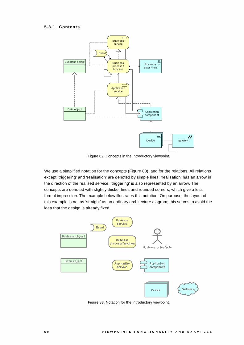
6 0 V I E W P O I N T S F U N C T I O N A L I T Y A N D E X A M P L E S
5.3.1 Contents
Businessactor / role
Application component
Business object
Application service
Device Network
Business service
Event
Business process / function
Data object
Figure 82. Concepts in the Introductory viewpoint.
We use a simplified notation for the concepts (Figure 83), and for the relations. All relations
except ‘triggering’ and ‘realisation’ are denoted by simple lines; ‘realisation’ has an arrow in
the direction of the realised service; ‘triggering’ is also represented by an arrow. The
concepts are denoted with slightly thicker lines and rounded corners, which give a less
formal impression. The example below illustrates this notation. On purpose, the layout of
this example is not as ‘straight’ as an ordinary architecture diagram; this serves to avoid the
idea that the design is already fixed.
������� � ����� ���� ����� ��������
����� � ��� ���� ������ � �
� ���� ���
����� � ��� ��� �� ����������� �
� ��������
���� � ��� ��� ��!�"#���
$ ������
����� � �� � ���� ������ � �
� ���%��!�"#���
����� � ��� ���� ����� � ��� ��& � ��� �� ���
Figure 83. Notation for the Introductory viewpoint.
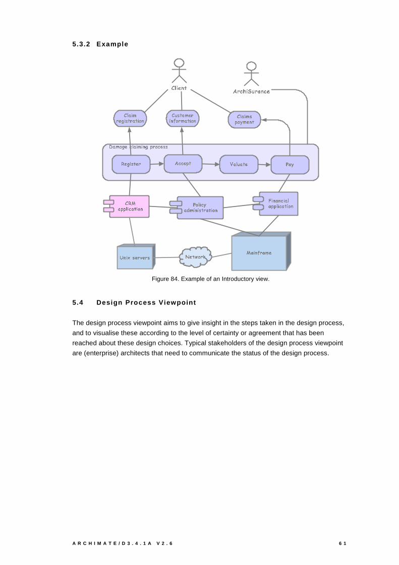
A R C H I M A T E / D 3 . 4 . 1 A V 2 . 6 6 1
5.3.2 Example
������������� � � ��� ���������������
��� ������������ ��������������� � � � � � � �������! ��� ���
��"$#� ����� � ������ � � % ��� � �!��&'��� � � ����������� � �('� �������� � �� ����� � �� ��� � �
� � � � ���� � � ����������� � �
)�* + ,$-�. /10�2�3 + 465 0 7 - 2 ,
# � � �����������8 ��� 9:�����<;������ = ����>?����@
" � ��� ������� A ������� B � � � � ��� % ��!
Figure 84. Example of an Introductory view.
5.4 Design Process Viewpoint
The design process viewpoint aims to give insight in the steps taken in the design process,
and to visualise these according to the level of certainty or agreement that has been
reached about these design choices. Typical stakeholders of the design process viewpoint
are (enterprise) architects that need to communicate the status of the design process.
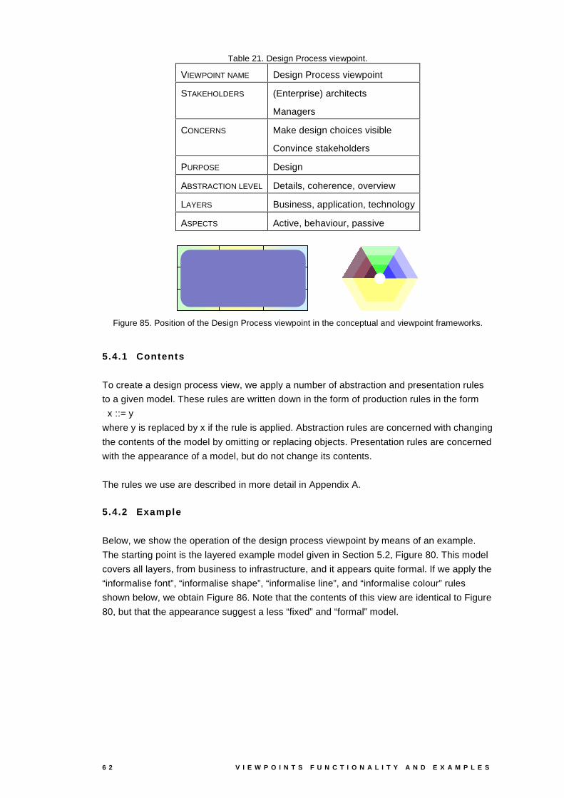
6 2 V I E W P O I N T S F U N C T I O N A L I T Y A N D E X A M P L E S
Table 21. Design Process viewpoint.
VIEWPOINT NAME Design Process viewpoint
STAKEHOLDERS (Enterprise) architects
Managers
CONCERNS Make design choices visible
Convince stakeholders
PURPOSE Design
ABSTRACTION LEVEL Details, coherence, overview
LAYERS Business, application, technology
ASPECTS Active, behaviour, passive
Figure 85. Position of the Design Process viewpoint in the conceptual and viewpoint frameworks.
5.4.1 Contents
To create a design process view, we apply a number of abstraction and presentation rules
to a given model. These rules are written down in the form of production rules in the form
x ::= y
where y is replaced by x if the rule is applied. Abstraction rules are concerned with changing
the contents of the model by omitting or replacing objects. Presentation rules are concerned
with the appearance of a model, but do not change its contents.
The rules we use are described in more detail in Appendix A.
5.4.2 Example
Below, we show the operation of the design process viewpoint by means of an example.
The starting point is the layered example model given in Section 5.2, Figure 80. This model
covers all layers, from business to infrastructure, and it appears quite formal. If we apply the
“informalise font”, “informalise shape”, “informalise line”, and “informalise colour” rules
shown below, we obtain Figure 86. Note that the contents of this view are identical to Figure
80, but that the appearance suggest a less “fixed” and “formal” model.

A R C H I M A T E / D 3 . 4 . 1 A V 2 . 6 6 3
::=::=::=
����������� � � �����������
Name/BNF 1DPH1DPH ::=::=::=
����������� � � �����������
Name/BNF 1DPH1DPH
::= ::=
������������� � � ����� ���"!#�
::= ::=
������������� � � ����� ���"!#�
::=::=
$�%#& '�(�)+*-, . /102, . %�0
::=::=
$�%#& '�(�)+*-, . /102, . %�0
::=
354�6 7 8�9;:�< = >#?A@ 75< 7 B"8
::=
354�6 7 8�9;:�< = >#?A@ 75< 7 B"8
CED FEG HEI J G K L J KEG M
NEO J MPG D HRQ#S D FEG HEI J G K L J K G MTI MPG U S L MEI
V#W WEQ S L H J S XEDYL X Z W XED MPD J IYHPD [\I MPG U S L MEI
] XPQ MEI-HPD [\HEL J XEG I
NEO J MPG D HRQ�HEW WEQ S L H JES X DYI MPG U S L MEI
NEO J MPG D HRQ�^EK I S D MEI IYI MPG U S L MEI
_ HEZ H ` M\L Q HRS Z"S D `TWEG X L MEI I
a Q S MPD J CPD I K G HPD J CED I KEG MPGV1G LEbPS c�KEG HPD L M
] M `RS I J G H J S XED d HEeEZ MED Jf HRQ K H J S XEDV1L L MEW J HPD L M
a K I J X Z MPGS D F X G Z�H J S XEDI MPG U S L Ma Q HRS Z IW HEePZ�MPD JI MPG U S L M
a Q HRS Z�IHE[RZ�S D S I J G H JES XEDI MPG U S L M] S I gHEI I MEI I Z�MPD JI MPG U S L M
d HEePZ�MPD JI MPG U S L M
] S I gHEI I MEI I Z�MPD J
a Q HRS Z�IHE[hZ"S D S I J G H J S X D i S D HED LES HRQHEW WEQ S L H JES X Da Q HRS ZS D F X G Z�H J S XEDI MPG U S L M
a Q HRS ZG M `RS I J G H J S X DI MPG U S L Ma Q HRS ZG M `RS I J G H J S X DI MPG U S L M
a K I J XEZ�MPGHE[RZ�S D S I J G H J S XEDI MEG U S L M
a K I J XEZ�MPGHE[RZ"S D S I J G H J S XED
a Q HRS ZFPS Q MEII MPG U S L M
j c#MPG S MEIkZ�HRS D FEG HPZ M
_#lRm[RH J HP^EHEI M
] S I gHEI I MEI I Z�MPD JN n�l
a K I J XEZ�MPGFPS Q M II MPG U S L M
c�K D l Q HE[RMS d Q HPD M JHEW WkI MPG U MPG
Figure 86. Step 1: Informalised the visualisation.
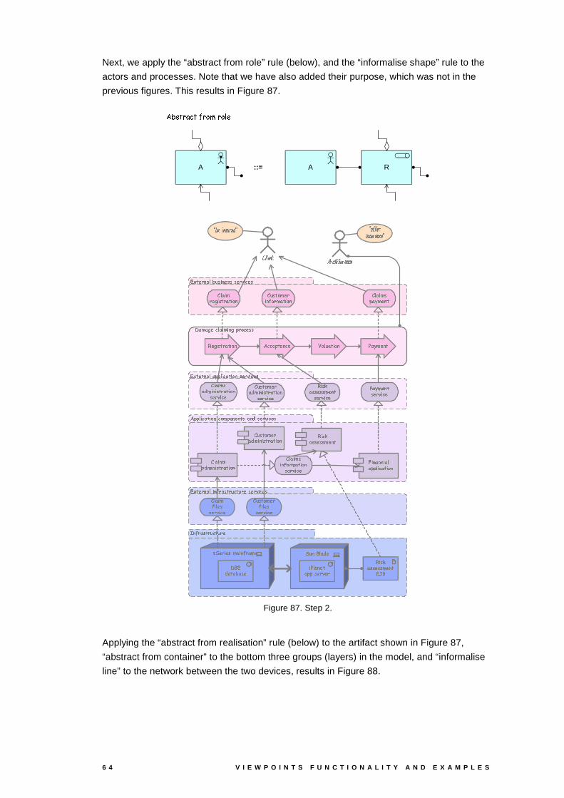
6 4 V I E W P O I N T S F U N C T I O N A L I T Y A N D E X A M P L E S
Next, we apply the “abstract from role” rule (below), and the “informalise shape” rule to the
actors and processes. Note that we have also added their purpose, which was not in the
previous figures. This results in Figure 87.
RAA
�������������� ���������� �
::=
��� ��� ��� � � � � � ���
!#" "�$ % � � ��% &��'� &�(�" & � �� � �'��� )*� �� + % � ��
,�- � �� � �.$#% � ��� ��� � � � � � ��� /� �� + % � ��
,�- � �� � �.$�0�� � % � �� �'� �� + % � ��
,�- � �� � �.$��" "�$ % � ��� % &��'� .� +�% � ��
1 ��(�� 2� 3��$ �4% (�% � 2/"�� & � �� �
5 � � � &�(� .�% � � &�� (���� % &�� 5 $ �4% (��" ��6�(� �� �
7 % � 8��� � �� � (� �� �
5 $ �4% (����).(�% ��% � � � � ��% &�� 9 % � ��� ��% �.$��" "�$ % � � � % &��
5 $ �4% (� 2.% � � � � ��% &��
5 � � � &�(� ����)4(�% � % � � � � � % &��
:�; < = > ? @.A B C < D E A F > B =
G H =I< > J E A = K G G L M M = A< > J E A F > B = G
7 2.% � � � ��� % &�� !#� � �" � ��� � NO�.$ � � ��% &�� P ��6�(� �� �
5 $ �.% (����).(�% ��% � � � � ��% &��� �� + % � 7 % � 8��� � �� � (� �� �� �� + % �
P ��6�(� �� �� .� + % � 5 � � � &�(� ����).(�% ��% � � � � � % &��� �� + % �
5 $ �.% (��% � � &�� (�� ��% &��� .� + % �
5 $ �.% (��% $ ��� �� + % �
Q�R �� % ��S(��4% � ��� ��(� 1#T.U).� � ��0����
5 � � � &�(� .���% $ ��� �� + % �
R � � T $ ��). % P�$ ��� ���" "S� �� + ��
7 % � 8��� � �� � (� .� �,�V�T
Figure 87. Step 2.
Applying the “abstract from realisation” rule (below) to the artifact shown in Figure 87,
“abstract from container” to the bottom three groups (layers) in the model, and “informalise
line” to the network between the two devices, results in Figure 88.
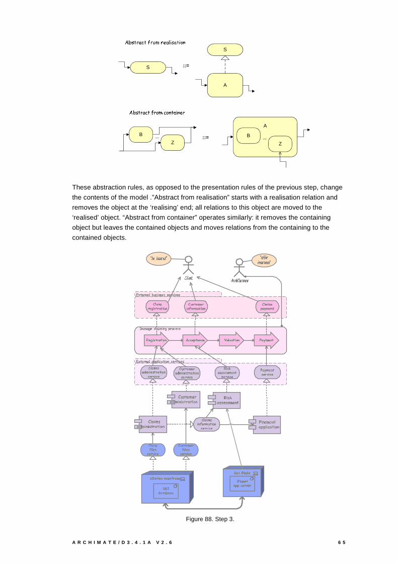
A R C H I M A T E / D 3 . 4 . 1 A V 2 . 6 6 5
::=
����������� ���������������� � ������ ���S
A
S
������� � ��!��#"���$�%&! $�'����( ')��
B
Z... ::=
A
B
Z...
These abstraction rules, as opposed to the presentation rules of the previous step, change
the contents of the model .”Abstract from realisation” starts with a realisation relation and
removes the object at the ‘realising’ end; all relations to this object are moved to the
‘realised’ object. “Abstract from container” operates similarly: it removes the containing
object but leaves the contained objects and moves relations from the containing to the
contained objects.
*,+.- /10 2 314�5,6 7.8 2 /.7 797 /,0 : 8 ; /.7
*,+.- /10 2 3143,< <,4 8 ; 3.- 8 =.2>7 /10 : 8 ; /.7
?31@�3.A./B;.4 318 @�8 2 AB<.0 = ; /.7 7
C 6 7 - =.@�/,08 2 D.= 0 @�3 -.8 =.2 C 4 3 8 @�7< 3.E,@�/12 -
F�G H1IJ H.H,KH,H,L9K�M.N
O�P J G LQHJR L>G MG H.N,S J N G TM U G M J M,VG J PJ�WW P G V J N G TM
C 4 318 @0 / A18 7 - 0 3 - 8 =.2
O�X H.N.TL9K�SJR LYG M G H.N1S J N G TM
Z,[ \ ] ^ _ `1a b c \ d e a f ^ b ]
g h ]9\ ^ i e a ] j g g k l l ] a\ ^ i e a f ^ b ] g
m / A18 7 - 0 3 - 8 =.2 n ; ; /.< - 3,2 ; / o314 6 3 - 8 =.2 p 3.E,@�/,2 -
C 4 318 @�73,q1@�8 2 8 7 - 0 3 - 8 =.27 /,0 : 8 ; /m�8 7 r3.7 7 /.7 7 @�/,2 -7 /,0 : 8 ; /
p 3.E,@�/,2 -7 /,0 : 8 ; /C 6 7 - =.@�/,03.q @�8 2 8 7 - 0 3.- 8 =.27 /,0 : 8 ; /
C 4 3 8 @�78 2 D =.0 @�3 - 8 =.27 /,0 : 8 ; /
C 4 3 8 @D,8 4 /,77 /,0 : 8 ; /
s t /,0 8 /.7Y@�318 2 D.0 3,@�/?�u1vq13 - 3,5.3,7 /
C 6 7 - =.@�/,0D,8 4 /.77 /,0 : 8 ; /
t 6.2Bu 4 3.q1/8 p.4 3,2 / -3.< <Y7 /,0 : /,0
Figure 88. Step 3.
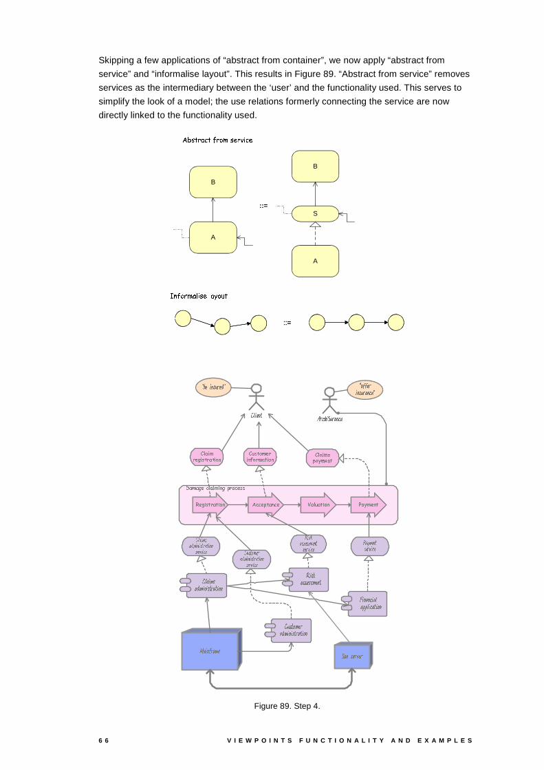
6 6 V I E W P O I N T S F U N C T I O N A L I T Y A N D E X A M P L E S
Skipping a few applications of “abstract from container”, we now apply “abstract from
service” and “informalise layout”. This results in Figure 89. “Abstract from service” removes
services as the intermediary between the ‘user’ and the functionality used. This serves to
simplify the look of a model; the use relations formerly connecting the service are now
directly linked to the functionality used.
::=
������������� ����������������� ��
S
A
B
A
B
::=
����������� � � ! "�#$� ��%���&('
::=
����������� � � ! "�#$� ��%���&('
)�*,+ *.-0/�1,2 *3 +43 5 -76.8 9.1 /,: :
;�< : = 9,+�/83 5 > 908 + *0=.3 9,5 ; 2 *�3 +�:6 *0?+�/5 =
@(A B CD B B E B B FE G HI,J D A F�BD K FA G A B H L D H A M G
N A G D G O A D JD P P J A O D H A M G
; 2 *�3 +8 /0-3 : = 8 *,= 3 905
I,Q B H M FE LD K FA G A B H L D H A M G
I,J A E G H R L O S A T Q L D G O E
U D A G V L D FE T Q GWB E L X E L
Y Z E[A G B Q L E K Y Y M V V E LA G B Q L D G O E Y
\�/.-3 : = 8 *0=.3 9,5 ]�1 1 /,6.= *5 1 / ^�*�2 < *0=.3 905 _ *0?+ /,5 =
` a b c d eb f d c g c e h i b h c j ge k i l c m kn0c e ob e e k e e d.k g he k i l c m k p b q d.k g he k i l c m k` r e h j d k ib f d c g c e h i b h c j ge k i l c m k
Figure 89. Step 4.

A R C H I M A T E / D 3 . 4 . 1 A V 2 . 6 6 7
We can also abstract away entire layers of concepts. Figure 90 results from abstracting
from all infrastructure concepts, from the container “damage claiming process”, from the
application services, and from the assignment relation with the ArchiSurance actor, and
applying “informalise shape” and “informalise layout” on the four subprocesses.
��� � � � ��� � � � �� � � �
��� ���� ����� � �
� � � � � � � � ��� � �
��� ��� � � � � � � � �
� � � � � � � � � � � �
��� � � � ��� ��� � � � � � �
��� � � � � � � � � � � �
��� � � � � � �� � � � � � � � � � � � � � � � ����� � �
� � � � � � � � � � � � � � � � � � � �
��� � � � � � � � �
Figure 90. Step 5.
Abstracting from the application layer concepts and the processes realising the business
services results in Figure 91.
!#" $ % & ')( *+ , - & * '). % + & ,
!#/ . + ')$0 . 1�')( , %
!#/ . + '* ( 2 + $ % * . % + & ,
!#/ + ( , % 3 * 4 5 + 6 " * . , 4 (
7 8 ( + , $ " * ( 9 7 7 & - - ( *+ , $ " * . , 4 ( 7
Figure 91. Step 6.
Finally, using “chain process” and “informalise colour” results in Figure 92.
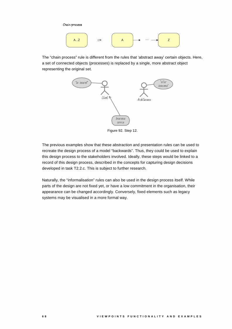
6 8 V I E W P O I N T S F U N C T I O N A L I T Y A N D E X A M P L E S
::=
������� ��� ��� ��� �
A Z�����A...Z
The “chain process” rule is different from the rules that ‘abstract away’ certain objects. Here,
a set of connected objects (processes) is replaced by a single, more abstract object
representing the original set.
� ��� � ��� ������ � �! " ���
#%$ " � ��& ' ����(�" )�� ��� �����
* + �," ��� � ��� - * * .!/ / � �" ��� � ��� ����� *
Figure 92. Step 12.
The previous examples show that these abstraction and presentation rules can be used to
recreate the design process of a model “backwards”. Thus, they could be used to explain
this design process to the stakeholders involved. Ideally, these steps would be linked to a
record of this design process, described in the concepts for capturing design decisions
developed in task T2.2.c. This is subject to further research.
Naturally, the “informalisation” rules can also be used in the design process itself. While
parts of the design are not fixed yet, or have a low commitment in the organisation, their
appearance can be changed accordingly. Conversely, fixed elements such as legacy
systems may be visualised in a more formal way.

A R C H I M A T E / D 3 . 4 . 1 A V 2 . 6 6 9
6 Decision Support Viewpoints
Decision support viewpoints help managers in the process of decision making by offering
insight into cross-domain architecture relations, typically through projections and
intersections of underlying models, but also by means of analytical techniques. Such
projections and intersections are selections, transformations and mappings of ArchiMate
models to lists, tables, matrices and reports. As such, decision support viewpoints create
high-level, coherent overview of an enterprise architecture, providing the ‘big picture’
required by decision makers.
These views can take several forms, but in most cases they will not look like traditional
models. Typical examples are cross-reference tables, lists, reports, and landscape maps
(landschapskaarten in Dutch). In this chapter, we will expound on the latter. Landscape
maps are a good example of a view that offers an overview of architectural information in a
form that can be readily understood by users not schooled in reading complex models.
6.1 Landscape Map Viewpoint
Table 22. Landscape Map viewpoint.
VIEWPOINT NAME Landscape Map viewpoint
STAKEHOLDERS Enterprise architect
Decision makers: managers, CEO, CIO
CONCERNS Readability
Reduction of complexity
Comparison of alternatives
PURPOSE Deciding
ABSTRACTION LEVEL Overview
LAYERS Business, application
ASPECTS Active
We will introduce landscape maps by means of an example from our imaginary insurance
company ArchiSurance. This will illustrate the need for and use of such an overview.
Figure 93. Position of the Landscape Map viewpoint in the conceptual and viewpoint frameworks.
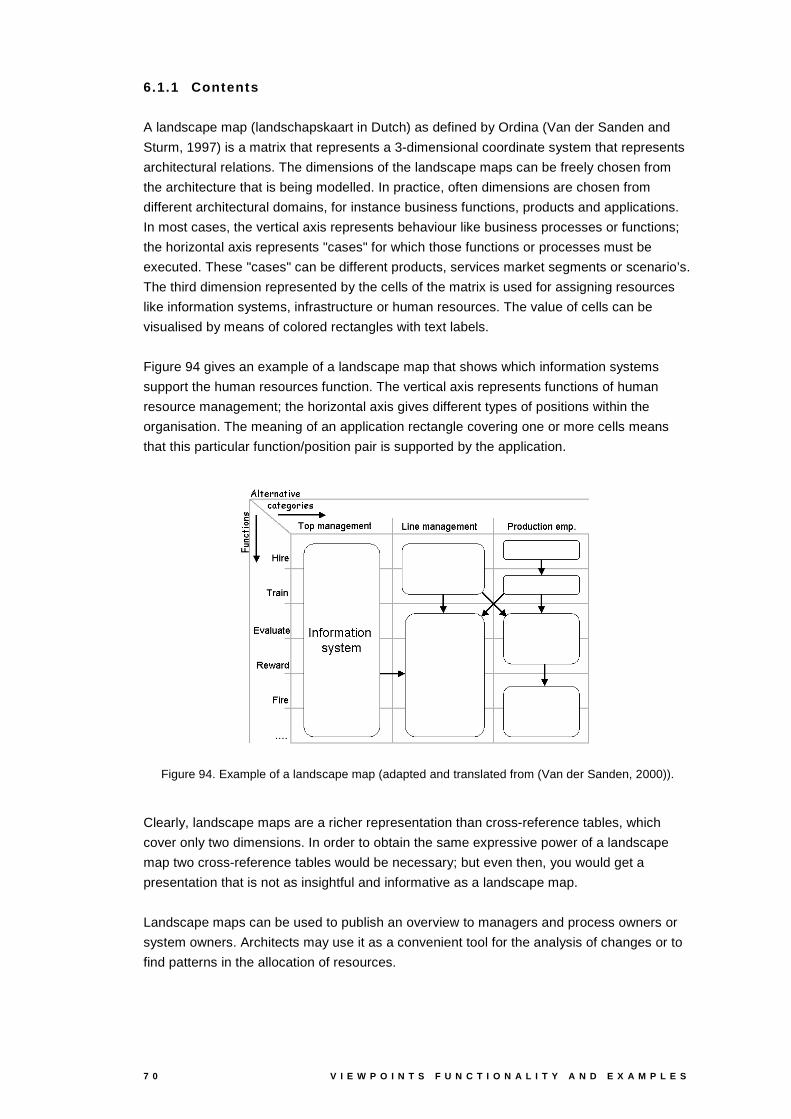
7 0 V I E W P O I N T S F U N C T I O N A L I T Y A N D E X A M P L E S
6.1.1 Contents
A landscape map (landschapskaart in Dutch) as defined by Ordina (Van der Sanden and
Sturm, 1997) is a matrix that represents a 3-dimensional coordinate system that represents
architectural relations. The dimensions of the landscape maps can be freely chosen from
the architecture that is being modelled. In practice, often dimensions are chosen from
different architectural domains, for instance business functions, products and applications.
In most cases, the vertical axis represents behaviour like business processes or functions;
the horizontal axis represents "cases" for which those functions or processes must be
executed. These "cases" can be different products, services market segments or scenario’s.
The third dimension represented by the cells of the matrix is used for assigning resources
like information systems, infrastructure or human resources. The value of cells can be
visualised by means of colored rectangles with text labels.
Figure 94 gives an example of a landscape map that shows which information systems
support the human resources function. The vertical axis represents functions of human
resource management; the horizontal axis gives different types of positions within the
organisation. The meaning of an application rectangle covering one or more cells means
that this particular function/position pair is supported by the application.
Figure 94. Example of a landscape map (adapted and translated from (Van der Sanden, 2000)).
Clearly, landscape maps are a richer representation than cross-reference tables, which
cover only two dimensions. In order to obtain the same expressive power of a landscape
map two cross-reference tables would be necessary; but even then, you would get a
presentation that is not as insightful and informative as a landscape map.
Landscape maps can be used to publish an overview to managers and process owners or
system owners. Architects may use it as a convenient tool for the analysis of changes or to
find patterns in the allocation of resources.
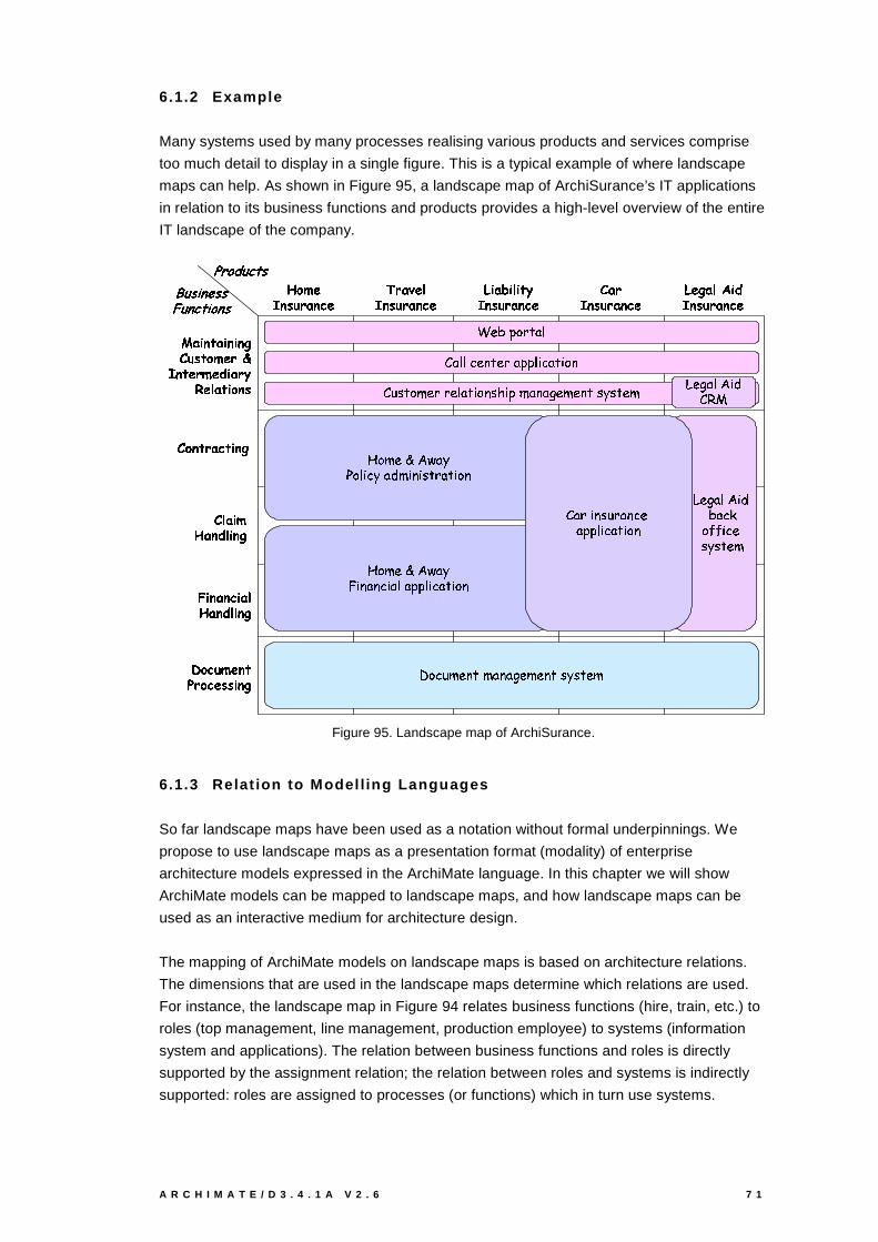
A R C H I M A T E / D 3 . 4 . 1 A V 2 . 6 7 1
6.1.2 Example
Many systems used by many processes realising various products and services comprise
too much detail to display in a single figure. This is a typical example of where landscape
maps can help. As shown in Figure 95, a landscape map of ArchiSurance’s IT applications
in relation to its business functions and products provides a high-level overview of the entire
IT landscape of the company.
����� ������� �� ���� �� ����������
� �������������� ��������� �!�!� ��� �
� �"� �#$�����% � ��
� �!�����&�!'��!� ��
()��' �������*��&��'!� ��� � ��
+� �,�� � �-�� � �� �&����'!�
� ��� � �� �&����'!�
. �&�!/��� � � �� �&����'!�
#$���0�� � �� �&����'!�
+!��!�� )10� �� � �� �&����'��
243"576�8�9&:-;"<
= ;"< <!>�3"?�:�39@;�6!6< A >�;�:!A 8�?
=�B�C :�8�D039E9-3�< ;�:!A 8? C!F A 6GD@;�?&;�H�3D03"?�: C&I�C :�3D
J@8�D03LKNMPOQ; IR�8�< A > I ;�S�DTA ?!A C :�9�;!:�A 8�?
U!3�H�;"<!M�A S5!;�>�V8!W�W�A >�3C&I�C :&3D
U!3�H�;"<!M�A S=�X�Y
ZQ8�> B D03"?�:TD$;?&;!H�3D03"?�: C&I�C :�3�D
J@8�D03LKNMPOQ; I[�A ?&;?�>�A ;�<�;�6!6< A >&;!:�A 8�?
\�]�^!_ `�a�^�^b%]�`!c�de_ f�`!^
g!h�f!i"]�c�dj^
k�� ������'� �� #$������ � ��
= ;�9TA ? C�B 9�;�?�>�3;�6�6< A >�;�:!A 8?
Figure 95. Landscape map of ArchiSurance.
6.1.3 Relat ion to Model l ing Languages
So far landscape maps have been used as a notation without formal underpinnings. We
propose to use landscape maps as a presentation format (modality) of enterprise
architecture models expressed in the ArchiMate language. In this chapter we will show
ArchiMate models can be mapped to landscape maps, and how landscape maps can be
used as an interactive medium for architecture design.
The mapping of ArchiMate models on landscape maps is based on architecture relations.
The dimensions that are used in the landscape maps determine which relations are used.
For instance, the landscape map in Figure 94 relates business functions (hire, train, etc.) to
roles (top management, line management, production employee) to systems (information
system and applications). The relation between business functions and roles is directly
supported by the assignment relation; the relation between roles and systems is indirectly
supported: roles are assigned to processes (or functions) which in turn use systems.
7 2 V I E W P O I N T S F U N C T I O N A L I T Y A N D E X A M P L E S
6.1.4 Interaction with Landscape Maps
So far, landscape maps have been used as a static one-way presentation format. We want
to use landscape maps as an interactive medium. Landscape maps can be used as a
starting point for more detailed models and specifications and it can be used for entering
relations between the dimensions chosen. Also changes in the landscape map can be
analysed for impact on other elements of the map. We envision the following interaction
primitives for landscape maps:
- Draw a rectangle (rubber band) comprising one or more cells of the map. The user may
choose the color and assign an object (instance of a concept) to the rectangle.
- Extend an existing rectangle with another rectangle that overlaps with the original. Color
and label are inherited.
- Modify a rectangle: coverage, color, value.
- Delete a rectangle.
Landscape maps can be used as a starting point for navigation as well; relevant interactions
are:
- Open a rectangle: detailed specifications or detailed models are shown in a separate
window.
- Close detailed specification or detailed models.
- Change granularity of an axis; for instance, business processes can be changed to
business activities.
- Link two rectangles by a relation supported by the underlying concept. For instance, if
rectangles represent systems, use or composition can be used.
We intend to develop a prototype based on these ideas.
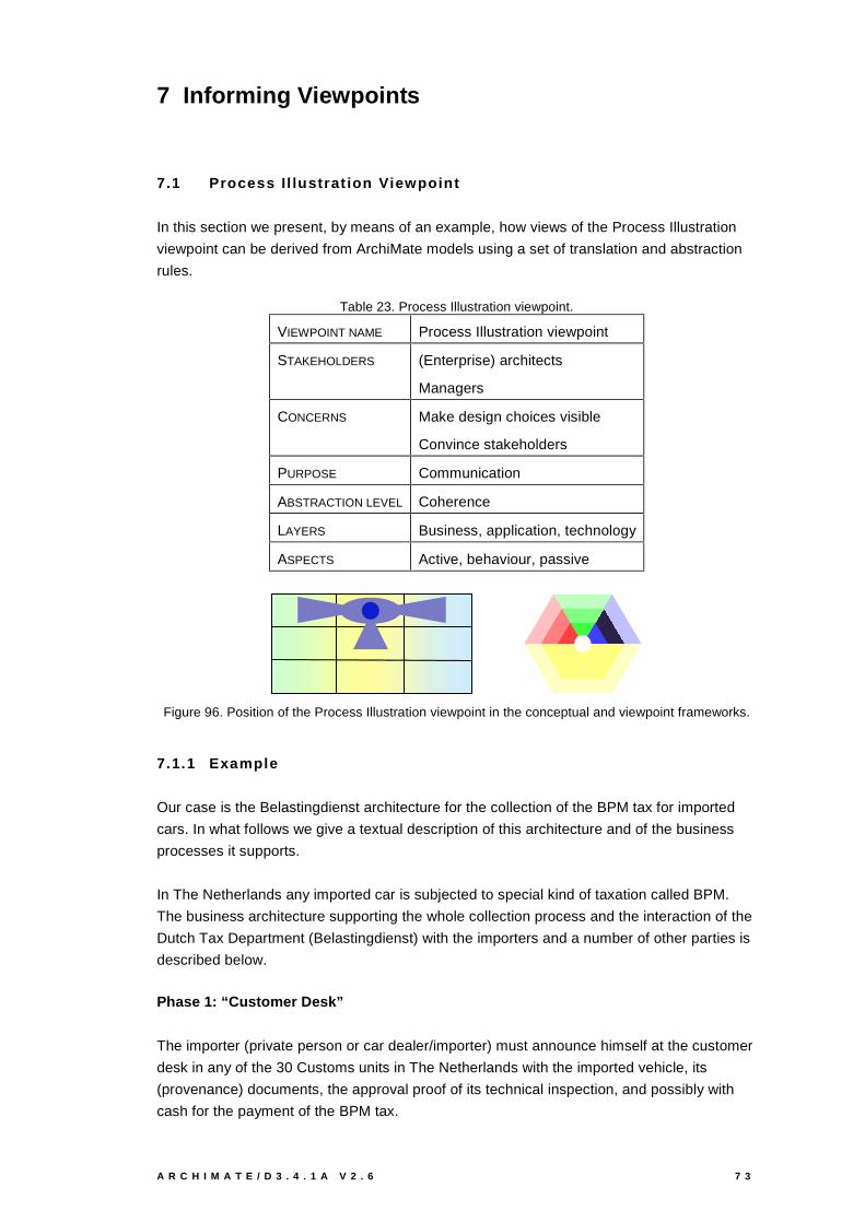
A R C H I M A T E / D 3 . 4 . 1 A V 2 . 6 7 3
7 Informing Viewpoints
7.1 Process I l lustrat ion Viewpoint
In this section we present, by means of an example, how views of the Process Illustration
viewpoint can be derived from ArchiMate models using a set of translation and abstraction
rules.
Table 23. Process Illustration viewpoint.
VIEWPOINT NAME Process Illustration viewpoint
STAKEHOLDERS (Enterprise) architects
Managers
CONCERNS Make design choices visible
Convince stakeholders
PURPOSE Communication
ABSTRACTION LEVEL Coherence
LAYERS Business, application, technology
ASPECTS Active, behaviour, passive
Figure 96. Position of the Process Illustration viewpoint in the conceptual and viewpoint frameworks.
7.1.1 Example
Our case is the Belastingdienst architecture for the collection of the BPM tax for imported
cars. In what follows we give a textual description of this architecture and of the business
processes it supports.
In The Netherlands any imported car is subjected to special kind of taxation called BPM.
The business architecture supporting the whole collection process and the interaction of the
Dutch Tax Department (Belastingdienst) with the importers and a number of other parties is
described below.
Phase 1: “Customer Desk”
The importer (private person or car dealer/importer) must announce himself at the customer
desk in any of the 30 Customs units in The Netherlands with the imported vehicle, its
(provenance) documents, the approval proof of its technical inspection, and possibly with
cash for the payment of the BPM tax.
7 4 V I E W P O I N T S F U N C T I O N A L I T Y A N D E X A M P L E S
The public servant will handle the tax declaration as follows: first he will check all the
documents, then he will fill in all the data into a client BPM application (running on a local
server) and will calculate the due BPM tax value. One copy of the BPM form (BPM17 ex 1)
will be issued and sent to the administration. Another copy of this form is handed to the
importer (BPM17 ex 3), together with either the evidence of a cash payment (if the importer
is able to pay the BPM amount in cash), or with an “acceptgiro” bill issued for the due
amount (in the case the importer is not able to pay in cash).
Phase 2: “Administration”
At each Customs unit there will be a public servant assigned to handle the additional
operations regarding all the incoming BPM statements. Once a day, this person will collect
all the incoming BPM17 forms. For the ones, which were paid in cash, he will issue and
authorise another copy of the BPM form (BPM17 ex2). This copy will be sent to RDW
(“Rijksdienst voor het Wegverkeer” - The Netherlands’ Road Transport Department), which
keeps the evidence of all registered vehicles in The Netherlands. The first copy of BPM 17
will be then sent to the archive.
The forms which are not yet paid, are temporarily archived and kept “on hold” until they are
paid. The administration and notification of the payment for these BPM forms is done by a
separate department of the Belastingdienst, namely the “Inning” is responsible for the
collection of all payments via bank.
Once, such a notification is received (via the BPM server application) the administration will
prepare and send the copy of BPM17 ex.2 to RDW.
Requirements
Below we give a number of business and technical requirements that must be fulfilled by
this architecture:
- The client’s (importer) application for a BPM application must be handled in one iteration
(“one stop shopping”).
- All the BPM forms are stored electronically in a central location (BCICT) in a central file,
which is nationally accessible. The server BPM application (also located here) controls
the access, updates and all the other operations on this file. It also provides support for
the calculation of the BPM values, using data from another central/national file with the
catalogue information/value of all existing models of vehicles. Finally, the server
application will monitor the status of payments by interacting with the Inning Department
and with the client BPM application from all Customs Units.
- Within each Customs unit, a client BPM application will run on a local server.
- The paper version of BPM17 ex 1 are archived at the issuing Customs Unit.
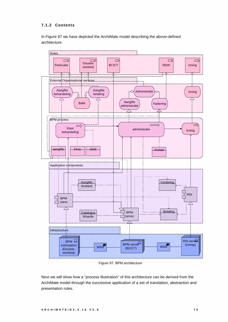
A R C H I M A T E / D 3 . 4 . 1 A V 2 . 6 7 5
7.1.2 Contents
In Figure 97 we have depicted the ArchiMate model describing the above-defined
architecture.
Application components
Infrastructure
Roles
External Organisational services
BPM process
Douaneeenheid
Inning
Klantbehandeling
administratie
Aangiftebetaling
Aangifteadministratie
RIN
Aangiftebehandeling
BPMclient
BPM server(BCICT)
BPMworkstation(Douane-eenheid)
RDWBCICTParticulier
Fiattering
RIN server(Inning)
WAN WAN
Vordering
Betaling
Administratie
Balie
CatalogusWaarde
Aangiftebestand
BPMserver
Kluis Archief
inning
Inning
Geldaangifte
Figure 97. BPM architecture
Next we will show how a “process illustration” of this architecture can be derived from the
ArchiMate model through the successive application of a set of translation, abstraction and
presentation rules.

7 6 V I E W P O I N T S F U N C T I O N A L I T Y A N D E X A M P L E S
Translation rules
In Figure 98 one can see a number of translation rules that can be applied in a first step of
the derivation “ArchiMate-to-Process Illustration” process. The basic idea behind these type
of rules is to find suitable and intuitive graphic symbols that will replace ArchiMate shapes.
These type of rules apply to ArchiMate concepts for which one can find an immediate
correspondent in the Process illustration notation (i.e. actor, role, device, service, business
obiect etc.).
Archief
$$Kluis
Bestand
bericht
document
Figure 98. Translation rules.
A number of concrete translation examples are shown in Figure 99.
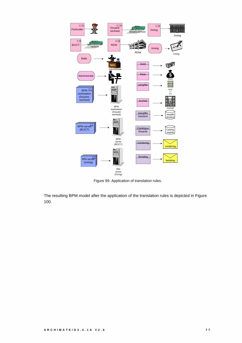
A R C H I M A T E / D 3 . 4 . 1 A V 2 . 6 7 7
ParticulierDouaneeenheid
BPMaangiftepunt
Douane eenheid
BCICTBCICT
automatiseringscentrum
RDW
RDW
Inning
Inning
Balie
Balie
Administratie
Administratie
Inning
Inning
BPM server(BCICT)
BPMworkstation(Douane-eenheid)
RIN server(Inning)
CatalogusWaarde
Aangiftebestand
Kluis
Archief
Geld
aangifte
BPM17ex2
Archief
$$Kluis
Catalog.waarde
AangifteBestand
BPMworkstation
(Douaneeenheid)
BPMserver
(BCICT)
RINserver
(Inning)
Vordering
Betaling
vordering
betaling
Figure 99. Application of translation rules.
The resulting BPM model after the application of the translation rules is depicted in Figure
100.
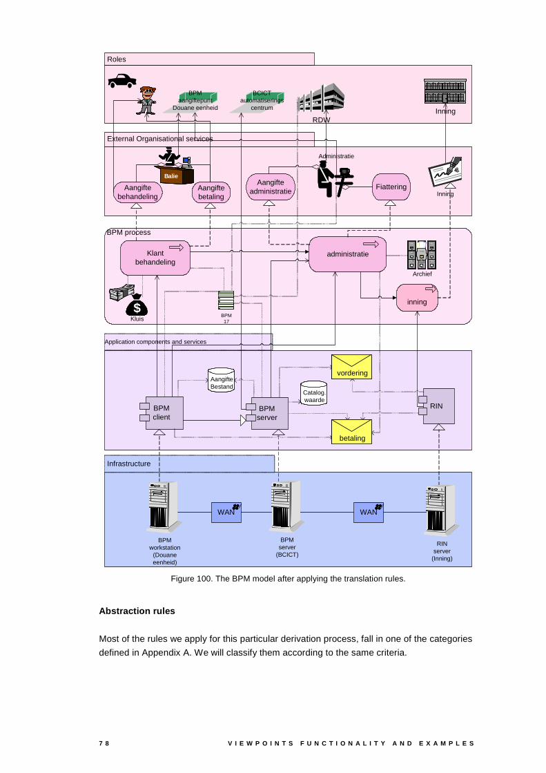
7 8 V I E W P O I N T S F U N C T I O N A L I T Y A N D E X A M P L E S
Application components and services
Infrastructure
Roles
External Organisational services
BPM process
Klantbehandeling
administratie
RINBPMclient
WAN WAN
BPMserver
inning
InningRDW
Administratie
BPMaangiftepunt
Douane eenheid
BCICTautomatiserings
centrum
Balie
Archief
$$Kluis
Catalog.waarde
AangifteBestand
BPMworkstation
(Douaneeenheid)
BPMserver
(BCICT)
RINserver
(Inning)
BPM17
Inning
vordering
betaling
Aangiftebetaling
AangifteadministratieAangifte
behandelingFiattering
Figure 100. The BPM model after applying the translation rules.
Abstraction rules
Most of the rules we apply for this particular derivation process, fall in one of the categories
defined in Appendix A. We will classify them according to the same criteria.
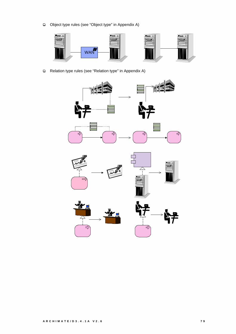
A R C H I M A T E / D 3 . 4 . 1 A V 2 . 6 7 9
�Object type rules (see “Object type” in Appendix A)
WAN
�Relation type rules (see “Relation type” in Appendix A)
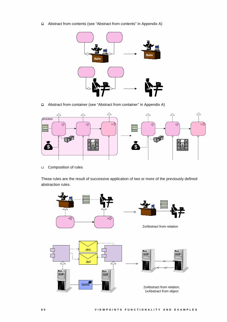
8 0 V I E W P O I N T S F U N C T I O N A L I T Y A N D E X A M P L E S
�Abstract from contents (see “Abstract from contents” in Appendix A)
BalieBalie
�Abstract from container (see “Abstract from container” in Appendix A)
process
$$ $$
�Composition of rules
These rules are the result of successive application of two or more of the previously defined
abstraction rules.
2xAbstract from relation
WAN
abc
def abc
def
2xAbstract from relation,1xAbstract from object
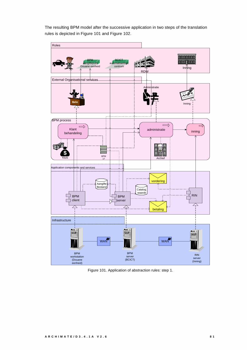
A R C H I M A T E / D 3 . 4 . 1 A V 2 . 6 8 1
The resulting BPM model after the successive application in two steps of the translation
rules is depicted in Figure 101 and Figure 102.
Application components and services
Infrastructure
Roles
External Organisational services
BPM process
Klantbehandeling
administratie
RINBPMclient
WAN WAN
BPMserver
inning
InningRDW
Administratie
BPMaangiftepunt
Douane eenheid
BCICTautomatiserings
centrum
Balie
Archief
$$Kluis
Catalog.waarde
AangifteBestand
BPMworkstation
(Douaneeenheid)
BPMserver
(BCICT)
RINserver
(Inning)
BPM17
Inning
vordering
betaling
Figure 101. Application of abstraction rules: step 1.

8 2 V I E W P O I N T S F U N C T I O N A L I T Y A N D E X A M P L E S
BPM17ex2
Inning
RDW
Administratie
BPMaangiftepunt
Douane eenheid
BCICTautomatiserings
centrum
Balie
Behandeling
Archief
$$Kluis
Catalog.waarde
AangifteBestandBPM
workstation(Douaneeenheid)
BPMserver
(BCICT)
RINserver
(Inning)
BPM17ex3
acceptgiro
BPM17ex1
Inningbetaling
betaling
aangifte vorderingbetaling
Figure 102. Application of abstraction rules: step 2.
Presentation rules
For this particular example we have identified visualisation rules that makes the whole
design of the resulting diagram less formal and more intuitive. More precisely we refer to a
“grouping” rule of all objects and relations that belong to or happen within a certain actor. In
Figure 103 we give two examples of the application of such a rule.
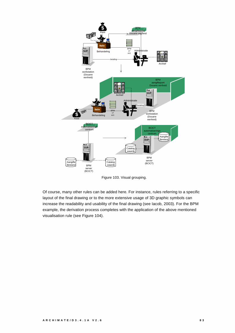
A R C H I M A T E / D 3 . 4 . 1 A V 2 . 6 8 3
BCICTautomatiserings
centrum
Catalog.waarde
AangifteBestand BPM
server(BCICT)
BCICTautomatiserings
centrum
Catalog.waarde
AangifteBestand
BPMserver
(BCICT)
BPMaangiftepunt
Douane eenheid
Administratie
Balie
Behandeling
Archief
$$Kluis
BPMworkstation
(Douaneeenheid)
BPM17ex1
betaling
Administratie
BPMaangiftepunt
Douane eenheid
Balie
Behandeling
Archief
$$Kluis
BPMworkstation
(Douaneeenheid)
BPM17ex1
betaling
Figure 103. Visual grouping.
Of course, many other rules can be added here. For instance, rules referring to a specific
layout of the final drawing or to the more extensive usage of 3D graphic symbols can
increase the readability and usability of the final drawing (see Iacob, 2003). For the BPM
example, the derivation process completes with the application of the above mentioned
visualisation rule (see Figure 104).
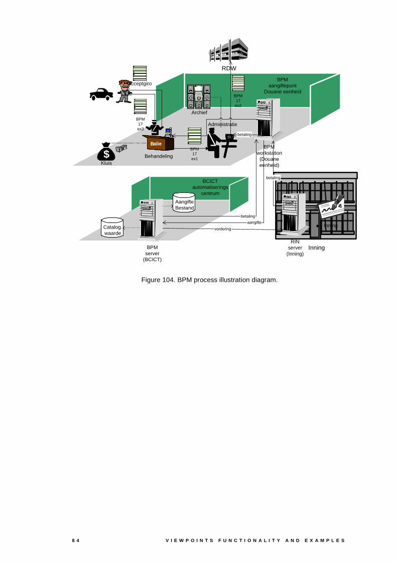
8 4 V I E W P O I N T S F U N C T I O N A L I T Y A N D E X A M P L E S
BPMaangiftepunt
Douane eenheidBPM17ex2
Inning
RDW
Administratie
BCICTautomatiserings
centrum
Balie
Behandeling
Archief
$$Kluis
Catalog.waarde
AangifteBestand
BPMworkstation
(Douaneeenheid)
BPMserver
(BCICT)
RINserver
(Inning)
BPM17ex3
BPM17ex1
Inningvordering
betaling
aangifte
betaling
betaling
acceptgiro
Figure 104. BPM process illustration diagram.
A R C H I M A T E / D 3 . 4 . 1 A V 2 . 6 8 5
References
Arbab, F., Burger, F., ter Doest, H. (ed.), Iacob, M., Lankhorst, M., van Leeuwen, D., & van
der Torre, L. (2003), Visualisation of Enterprise Architectures, ArchiMate/D3.4.1,
TI/RS/2003/032, Enschede: Telematica Instituut.
https://doc.telin.nl/dscgi/ds.py/Get/File-31616/
Bosma, H. (ed.), van Buuren, R., ter Doest, H., Vos, M. (2002), Requirements,
ArchiMate/D4.1, TI/RS/2002/112, Enschede: Telematica Instituut.
https://doc.telin.nl/dscgi/ds.py/Get/File-27673.
Finkelstein, A., J. Kramer, B. Nuseibeh, L. Finkelstein, and M. Goedicke. Viewpoints: a
framework for integrating multiple perspectives in system development.
International Journal on Software Engineering and Knowledge Engineering,
Special issue on Trends and Research Directions in Software Engineering
Environments, 2(1):31–58, March 1992.
Frankel D.S. (2003), Model Driven Architecture: Applying MDA to Enterprise Computing,
Wiley.
IEEE Computer Society (2000). IEEE Std 1471-2000: IEEE Recommended Practice for
Architectural Description of Software-Intensive Systems, IEEE, New York.
IOG (2002), Schetsboek, Provinciaal Referentiemodel (in Dutch), Interprovinciale
Overleggroep Informatievoorziening (IOG/Info), werkgroep “Conceptueel Model”,
URL http://www.provincie-netland.nl/.
ITU (1996), ITU Recommendation X.901 | ISO/IEC 10746-1:1996, Open Distributed
Processing - Reference Model - Part 1: Overview. International
Telecommunication Union.
Janssen, P.M.M., P.T.E. Kok (2000), De sleutel voor alignment ligt bij het topmanagement
zelf (in Dutch), Landelijk Architectuur Congres.
Jonkers, H. (ed.), de Boer, F., Bonsangue, M., van Buuren, R., Groenewegen, L.,
Hoppenbrouwers, S., Lankhorst, M.M., Proper, H.A., Stam, A., van der Torre, L.,
Veldhuijzen van Zanten, G. (2003-2004), Concepts for Architectural Description,
ArchiMate/D2.2.1, version 3.0, TI/RS/2003/006, Enschede: Telematica Instituut.
https://doc.telin.nl/dscgi/ds.py/Get/File-29421/
Kotonya, G. and I. Sommerville. Viewpoints for requirements definition. IEE/BCS Software
Engineering Journal, 7(6):375–387, November 1992.
Van Leeuwen, D., ter Doest, H. & Lankhorst, M.M. (2003), Tool Integration Environment,
ArchiMate D3.3.1, TI/RS/2003/092, Enschede: Telematica Instituut.
https://doc.telin.nl/dscgi/ds.py/Get/File-35422/
Lankhorst, M.M. (ed.), ter Doest, H., Iacob, M.E., van Leeuwen, D., Riemens, L., &
Veldhuijzen van Zanten, G. (2003), Viewpoints Architecture and Design,
ArchiMate/D2.2.2a, TI/RS/2003/017, Enschede: Telematica Instituut.
https://doc.telin.nl/dscgi/ds.py/Get/File-31528/
Nuseibeh, B.A., A Multi-Perspective Framework for Method Integration. PhD thesis, Imperial
College, University of London, 1994.
Sanden, W.A.M. van der (2000), Flexibele informatievoorziening via infrastructuren (in
Dutch), Landelijk Architectuur Congres.

8 6 V I E W P O I N T S F U N C T I O N A L I T Y A N D E X A M P L E S
Sanden, W.A.M. van der, B. Sturm (1997), Informatie-architectuur, de Infrastructurele
Benadering, Panfox.
Schefstroem D., and van den Broek, G. (1993). Tool Integration: Environments and
Frameworks, New York: Wiley; 1993.
Sowa, J.F. and J.A. Zachman (1992), Extending and formalizing the framework for
information systems architecture, IBM Systems Journal, 31 (3), pp. 590-616.
Steen, M.W.A., ter Doest, H.W.L., Lankhorst, M.M. Akehurst, D.H. (2004), Supporting
Viewpoint-Oriented Enterprise Architecture. In: Proc. of the 8th IEEE
International Enterprise Distributed Object Computing Conference (EDOC 2004),
Monterey, CA, September 20–24, 2004.
The Open Group (2002), The Open Group Architectural Framework (TOGAF) Version 8
“Enterprise Edition”. The Open Group, Reading, UK.
http://www.opengroup.org/togaf/.
Veryard, R. (2004), Business-Driven SOA 2 – How business governs the SOA process, CBDI
Journal, June 2004.

A R C H I M A T E / D 3 . 4 . 1 A V 2 . 6 8 7
Appendix A - Viewpoint Rules
Types of Abstraction Rules
Below, we list the types of abstraction rules to be supported by the ArchiMate viewpoint and
visualisation engine. The examples show common instantiations of these rules; these must
at least be supported.
�Object type
Objects of a given type are ‘abstracted away’. The relations that result (as defined by the
rule) should be consistent with the RvB/HJ relation framework (Jonkers et al., 2003).
Common examples are abstraction from service, actor, role, interface, and behaviour.
::=
��������������� �������������� ��
S
A
B
A
B
Figure 105. Abstracting from service S realised by A and used by B results in B directly using A.
RA::=
$EVWUDFW�IURP�DFWRU
R
Figure 106. Abstracting from actor A fulfilling role R.
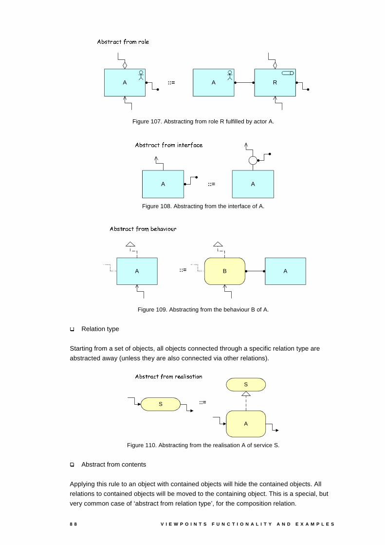
8 8 V I E W P O I N T S F U N C T I O N A L I T Y A N D E X A M P L E S
RAA
��������������� ���������� �
::=
Figure 107. Abstracting from role R fulfilled by actor A.
���������������� ��! #" $��&%���������%
A ::= A
Figure 108. Abstracting from the interface of A.
')(�*�+�,.-�/+�0 ,&1�2�(�354�- 6�7 1�8�,
B AA ::=
Figure 109. Abstracting from the behaviour B of A.
9Relation type
Starting from a set of objects, all objects connected through a specific relation type are
abstracted away (unless they are also connected via other relations).
::=
:<; =�>?A@ B>)C�?.D�EF?.G�@�H I =&@�>�I D�J
S
A
S
Figure 110. Abstracting from the realisation A of service S.
9Abstract from contents
Applying this rule to an object with contained objects will hide the contained objects. All
relations to contained objects will be moved to the containing object. This is a special, but
very common case of ‘abstract from relation type’, for the composition relation.
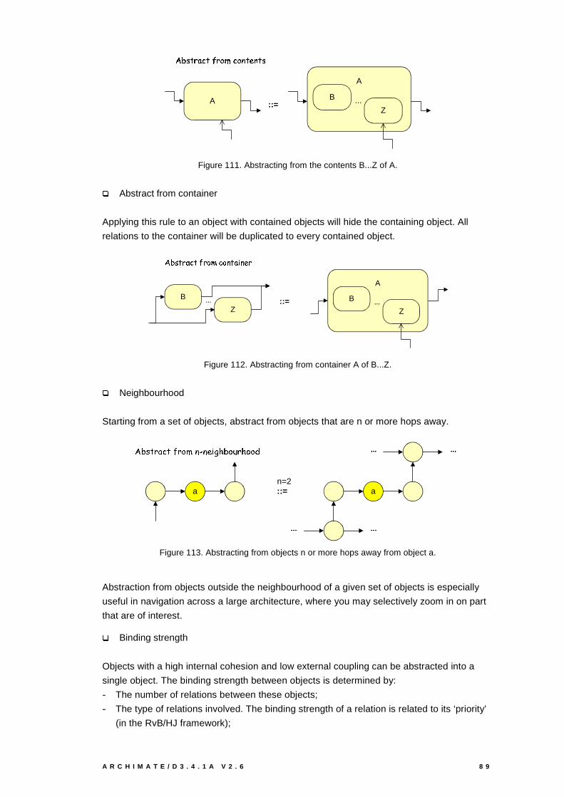
A R C H I M A T E / D 3 . 4 . 1 A V 2 . 6 8 9
::=
�������������� ����������������������
A
A
B
Z...
Figure 111. Abstracting from the contents B...Z of A.
9Abstract from container
Applying this rule to an object with contained objects will hide the containing object. All
relations to the container will be duplicated to every contained object.
���������� ���"!���#�$%��#�&'�'��( &')��
B
Z... ::=
A
B
Z...
Figure 112. Abstracting from container A of B...Z.
9Neighbourhood
Starting from a set of objects, abstract from objects that are n or more hops away.
*,+.- /�0�1�2�/43�0�5�687�97 :<; =�>?+.5�@�0�>.5�5.A
a a
B B B B B B
B B B B B B
::=n=2
Figure 113. Abstracting from objects n or more hops away from object a.
Abstraction from objects outside the neighbourhood of a given set of objects is especially
useful in navigation across a large architecture, where you may selectively zoom in on part
that are of interest.
9Binding strength
Objects with a high internal cohesion and low external coupling can be abstracted into a
single object. The binding strength between objects is determined by:
- The number of relations between these objects;
- The type of relations involved. The binding strength of a relation is related to its ‘priority’
(in the RvB/HJ framework);
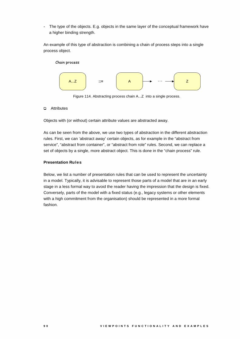
9 0 V I E W P O I N T S F U N C T I O N A L I T Y A N D E X A M P L E S
- The type of the objects. E.g. objects in the same layer of the conceptual framework have
a higher binding strength.
An example of this type of abstraction is combining a chain of process steps into a single
process object.
::=
&KDLQ�SURFHVV
A Z���A...Z
Figure 114. Abstracting process chain A...Z into a single process.
9Attributes
Objects with (or without) certain attribute values are abstracted away.
As can be seen from the above, we use two types of abstraction in the different abstraction
rules. First, we can ‘abstract away’ certain objects, as for example in the “abstract from
service”, “abstract from container”, or “abstract from role” rules. Second, we can replace a
set of objects by a single, more abstract object. This is done in the “chain process” rule.
Presentation Rules
Below, we list a number of presentation rules that can be used to represent the uncertainty
in a model. Typically, it is advisable to represent those parts of a model that are in an early
stage in a less formal way to avoid the reader having the impression that the design is fixed.
Conversely, parts of the model with a fixed status (e.g., legacy systems or other elements
with a high commitment from the organisation) should be represented in a more formal
fashion.
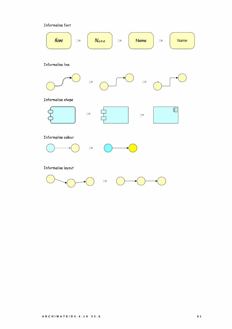
A R C H I M A T E / D 3 . 4 . 1 A V 2 . 6 9 1
::=::=::=
::=::=
::=
::=
::=
::=
����������� � � �����������
Name/BNF 1DPH1DPH
����������� � � ����� � ���
����������� � � ������������
����������� � � ��������� �����
����������� � � ����� ��������
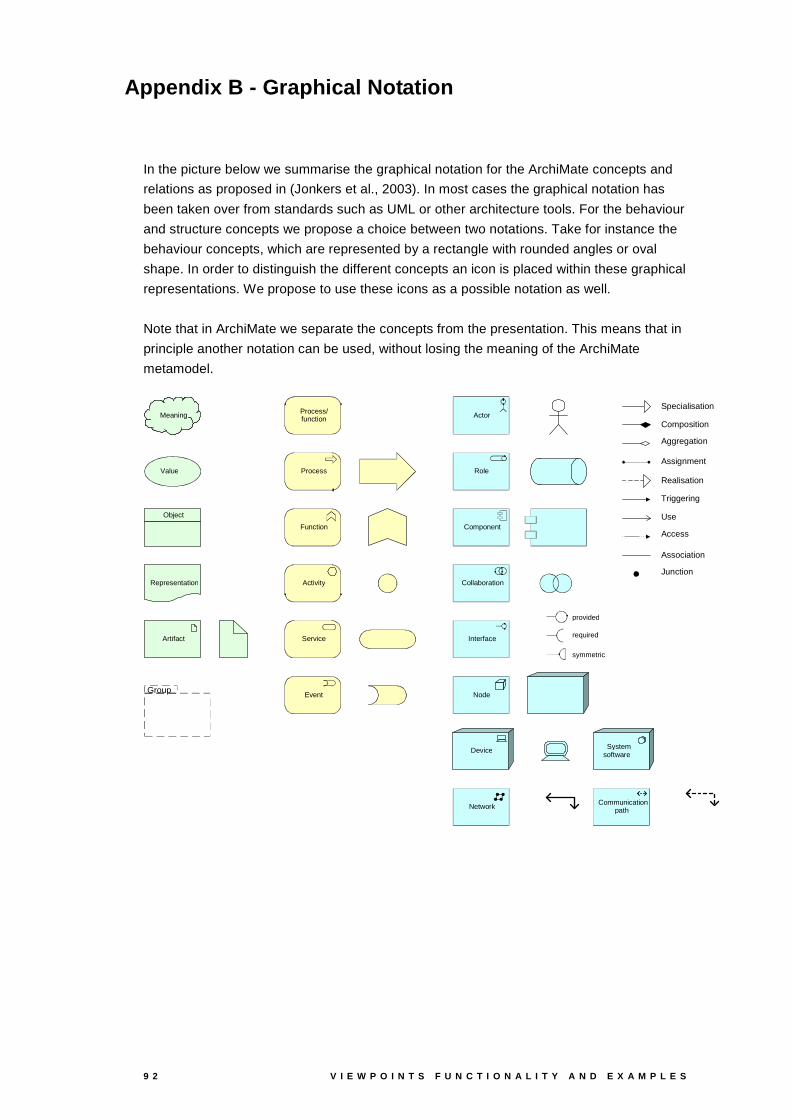
9 2 V I E W P O I N T S F U N C T I O N A L I T Y A N D E X A M P L E S
Appendix B - Graphical Notation
In the picture below we summarise the graphical notation for the ArchiMate concepts and
relations as proposed in (Jonkers et al., 2003). In most cases the graphical notation has
been taken over from standards such as UML or other architecture tools. For the behaviour
and structure concepts we propose a choice between two notations. Take for instance the
behaviour concepts, which are represented by a rectangle with rounded angles or oval
shape. In order to distinguish the different concepts an icon is placed within these graphical
representations. We propose to use these icons as a possible notation as well.
Note that in ArchiMate we separate the concepts from the presentation. This means that in
principle another notation can be used, without losing the meaning of the ArchiMate
metamodel.
Meaning
Value
Object
Representation
Artifact
Process/ function
Process
Function
Service
Activity
Event
Actor
Role
Component
Interface provided required symmetric
Collaboration
Node
Device System software
Network Communication path
Group
Specialisation Composition Aggregation Assignment Realisation Triggering Use Access Association Junction