Embed Size (px)
Citation preview

Calhoun: The NPS Institutional Archive
DSpace Repository
Theses and Dissertations Thesis and Dissertation Collection
2011-03
Malware mimics for network security assessment
Salevski, Paul M.
Monterey, California. Naval Postgraduate School
http://hdl.handle.net/10945/5749
Downloaded from NPS Archive: Calhoun

NAVAL
POSTGRADUATE SCHOOL
MONTEREY, CALIFORNIA
THESIS
Approved for public release; distribution is unlimited
MALWARE MIMICS FOR NETWORK SECURITY ASSESSMENT
by
William R. Taff, Jr. Paul M. Salevski
March 2011
Thesis Co-Advisors: Gurminder Singh John H. Gibson

THIS PAGE INTENTIONALLY LEFT BLANK

i
REPORT DOCUMENTATION PAGE Form Approved OMB No. 0704-0188Public reporting burden for this collection of information is estimated to average 1 hour per response, including the time for reviewing instruction, searching existing data sources, gathering and maintaining the data needed, and completing and reviewing the collection of information. Send comments regarding this burden estimate or any other aspect of this collection of information, including suggestions for reducing this burden, to Washington headquarters Services, Directorate for Information Operations and Reports, 1215 Jefferson Davis Highway, Suite 1204, Arlington, VA 22202-4302, and to the Office of Management and Budget, Paperwork Reduction Project (0704-0188) Washington DC 20503. 1. AGENCY USE ONLY (Leave blank)
2. REPORT DATE March 2011
3. REPORT TYPE AND DATES COVERED Master’s Thesis
4. TITLE AND SUBTITLE Malware Mimics for Network Security Assessment 6. AUTHOR(S) Taff, William R and Salevski, Paul M.
5. FUNDING NUMBERS
7. PERFORMING ORGANIZATION NAME(S) AND ADDRESS(ES) Naval Postgraduate School Monterey, CA 93943-5000
8. PERFORMING ORGANIZATION REPORT NUMBER
9. SPONSORING /MONITORING AGENCY NAME(S) AND ADDRESS(ES)
N/A
10. SPONSORING/MONITORING AGENCY REPORT NUMBER
11. SUPPLEMENTARY NOTES The views expressed in this thesis are those of the author and do not reflect the official policy or position of the Department of Defense or the U.S. Government. IRB Protocol number _____N/A___________. 12a. DISTRIBUTION / AVAILABILITY STATEMENT Approved for public release; distribution is unlimited
12b. DISTRIBUTION CODE A
13. ABSTRACT (maximum 200 words) For computer network infiltration and defense training within the Department of Defense, the use of Red Teams results in the most effective, realistic, and comprehensive training for network administrators. Our thesis is meant to mimic that highly trained adversary. We developed a framework that would exist in that operational network, that mimics the actions of that adversary or malware, that creates observable behaviors, and that is fully controllable and configurable.
The framework is based upon a client-server relationship. The server is a Java multi-threaded server that issues commands to the Java client software on all of the hosts of the operational network. Our thesis proved that commands could be sent to those clients to generate scanning behavior that was observable on the network, that the clients would generate or cease their behavior within five seconds of the issuance of the command, and that the clients would return to a failsafe state if communication with the command and control server was lost.
The framework that was created can be expanded to control more than twenty hosts. Furthermore, the software is extensible so that additional modules can be created for the client software to generate additional and more complex malware mimic behaviors.
15. NUMBER OF PAGES
129
14. SUBJECT TERMS Malware, Red Team, Computer Network Defense Training, Network Analysis, Java Multithreaded Server
16. PRICE CODE
17. SECURITY CLASSIFICATION OF REPORT
Unclassified
18. SECURITY CLASSIFICATION OF THIS PAGE
Unclassified
19. SECURITY CLASSIFICATION OF ABSTRACT
Unclassified
20. LIMITATION OF ABSTRACT
UU NSN 7540-01-280-5500 Standard Form 298 (Rev. 2-89) Prescribed by ANSI Std. 239-18

ii
THIS PAGE INTENTIONALLY LEFT BLANK

iii
Approved for public release; distribution is unlimited
MALWARE MIMICS FOR NETWORK SECURITY ASSESSMENT
William R. Taff, Jr. Commander, United States Navy
B.S., United States Naval Academy, 1995
Paul M. Salevski Lieutenant Commander, United States Navy B.S., United States Naval Academy, 1998
Submitted in partial fulfillment of the requirements for the degree of
MASTER OF SCIENCE IN COMPUTER SCIENCE
from the
NAVAL POSTGRADUATE SCHOOL
March 2011
Authors: William R. Taff, Jr. Paul M. Salevski
Approved by: Gurminder Singh
Thesis Co-Advisor
John H. Gibson Thesis Co-Advisor
Peter J. Denning Chair, Department of Computer Science

iv
THIS PAGE INTENTIONALLY LEFT BLANK

v
ABSTRACT
For computer network infiltration and defense training
within the Department of Defense, the use of Red Teams
results in the most effective, realistic, and comprehensive
training for network administrators. Our thesis is meant to
mimic that highly trained adversary. We developed a
framework that would exist in that operational network, that
mimics the actions of that adversary or malware, that
creates observable behaviors, and that is fully controllable
and configurable.
The framework is based upon a client-server
relationship. The server is a Java multi-threaded server
that issues commands to the Java client software on all of
the hosts of the operational network. Our thesis proved
that commands could be sent to those clients to generate
scanning behavior that was observable on the network, that
the clients would generate or cease their behavior within
five seconds of the issuance of the command, and that the
clients would return to a failsafe state if communication
with the command and control server was lost.
The framework that was created can be expanded to
control more than twenty hosts. Furthermore, the software
is extensible so that additional modules can be created for
the client software to generate additional and more complex
malware mimic behaviors.

vi
THIS PAGE INTENTIONALLY LEFT BLANK

vii
TABLE OF CONTENTS
I. INTRODUCTION ............................................1 A. TRAINING NETWORK ADMINISTRATORS ....................2 B. SHORTCOMINGS OF THAT APPROACH ......................2 C. OBJECTIVES .........................................3 D. ORGANIZATION .......................................3
II. BACKGROUND ..............................................5 A. RED TEAM ...........................................5 B. RED TEAM DURING CYBER DEFENSE EXERCISE (CDX) .......6 C. RED TEAM DURING COMPOSITE TRAINING UNIT EXERCISE ...9 D. A RED TEAM APPROACH USING RAD-X ...................12 E. RED TEAM EXPERIENCE ...............................13 F. MALWARE ...........................................13
1. Worms ........................................14 2. Botnets ......................................15 3. Viruses ......................................17
G. SUMMARY ...........................................18 III. DESIGN CONSIDERATIONS ..................................19
A. THE TRAINING OBJECTIVE ............................19 B. THE INTERESTED PARTIES IN TRAINING ................20
1. The Trainee ..................................20 2. The Trainer ..................................20 3. The Safety Observer ..........................21
C. THE TRAINING ENVIRONMENT ..........................21 D. HOW WE CURRENTLY TRAIN ............................22
1. Dependence on Red Teams ......................23 2. Standardization ..............................23
E. AN INFORMATION SYSTEM SOLUTION ....................25 F. AN EXAMPLE TRAINING SCENARIO ......................28
1. Pre-exercise (PRE-EX) ........................28 2. Commencement of Exercise (COMEX) .............30 3. Post Exercise (POSTEX) .......................32
G. CONTINUED DISCUSSION OF THE ENVIRONMENT ...........33 H. CONTINUED DISCUSSION OF THE TRAINER ...............34
1. Expanded Modules .............................34 I. CONTINUED DISCUSSION OF THE TRAINEE ...............35
IV. IMPLEMENTATION AND TEST PLATFORM .......................37 A. BACKGROUND ........................................37 B. SERVERS AND BOTS ..................................37
1. Server Construction ..........................38 2. Client Construction ..........................39 3. Communication Protocol .......................41

viii
4. Graphical User Interface for MM-Server .......43 C. BUILDING THE TEST PLATFORM ........................44 D. EXPERIMENT DESIGN .................................49
1. Operating Systems and Software Utilized ......49 E. RUNNING THE EXPERIMENT ............................52 F. SUMMARY ...........................................54
V. RESULTS ................................................55 A. BACKGROUND ........................................55 B. SETUP .............................................55 C. TIMELINE ..........................................57 D. DISCUSSION OF RESULTS .............................58
1. Results for MM-Server and MM-Clients .........58 2. Results for the Physical Servers .............61
E. SUMMARY ...........................................68 VI. CONCLUSIONS AND FUTURE WORK ............................69
A. CONCLUSIONS .......................................69 B. FUTURE WORK .......................................71
1. Code Improvement and Extension ...............71 2. More Advanced Modules ........................72 3. Increase Scale of Test Bed ...................73 4. Security Implications ........................74
APPENDIX A. MM-SERVER: CANDCSERVER.JAVA ..................75 APPENDIX B. MM-SERVER: CANDCSERVERMENUUI.JAVA ............77 APPENDIX C. MM-SERVER: CLIENTCOMMUNICATOR.JAVA ...........83 APPENDIX D. MM-SERVER: CLIENTCOMMUNICATORLISTENER ........87 APPENDIX E. MM-SERVER: CLIENTDATABASE.JAVA ...............91 APPENDIX F. MM-SERVER: CLIENTRECORD.JAVA .................97 APPENDIX G. MM-CLIENT: CLIENTPROGRAM.JAVA ...............101 APPENDIX H. MM-CLIENT: CLIENTCONTROLLER.JAVA ............105 LIST OF REFERENCES .........................................111 INITIAL DISTRIBUTION LIST ..................................113

ix
LIST OF FIGURES
Figure 1. Proposed use case...............................28 Figure 2. Communication protocol flow diagram.............42 Figure 3. Physical test bed configuration.................48 Figure 4. Virtual test bed configuration..................52 Figure 5. Physical server IP addresses/type/names.........56 Figure 6. Experiment Timeline of Events...................57 Figure 7. Packet Capture between MM-Client and MM-Server..59 Figure 8. CPU Utilization of Physical Server #1...........61 Figure 9. CPU Utilization of Physical Server #2...........62 Figure 10. Network Utilization of Physical Server #1.......64 Figure 11. Network utilization of physical server #2.......65

x
THIS PAGE INTENTIONALLY LEFT BLANK

xi
LIST OF ACRONYMS AND ABBREVIATIONS
AFB Air Force Base
CDX Computer Defense Exercise
COMPTUEX Composite Training Unit Exercise
CSTT Combat Systems Training Team
DHCP Dynamic Host Configuration Protocol
DISA Defense Information Systems Agency
DoD Department of Defense
DNS Domain Name System
GUI Graphical User Interface
HTTP Hyper Text Transfer Protocol
KBps Kilobytes Per Second
ICMP Internet Control Message Protocol
IP Internet Protocol
IRC Internet Relay Chat
MBps Megabytes Per Second
MM-Client Malware Mimic Client
MM-Server Malware Mimic Command and Control Server
NSA National Security Agency

xii
RaD-X Rapid Experience Builder
TCP Transmission Control Protocol
UDP User Datagram Protocol
VM Virtual Machine
VBS Visual Basic Script

xiii
ACKNOWLEDGMENTS
This thesis would not have been possible without the
steady guidance and patience of our thesis advisor,
Professor Singh. Thank you for your experience and insight,
and for the opportunity to work with you. Our co-advisor,
Mr. John Gibson, has his hands in so many different projects
here at NPS, we do not know how he managed to tend them all.
But, when we spoke with him, his attention was focused
solely on our project even though many other projects were
demanding this attention at the same time. Thank you.
From Paul: I would be remiss if I did not offer my
thanks to the many fine faculty members here at the Naval
Postgraduate School. I have been in the computer field for
many years, and I thought I had a good grasp of its myriad
of topics. After two years here at NPS, it has been made
clear to me how little I actually knew. I thank the many
professors: Scott Cote, Chris Eagle, John D. Fulp, Ted
Huffmire and so many others that have opened, stretched, and
stuffed my mind full of so many new ideas and possibilities.
Only at the end do I feel like I actually know something:
that there is so much else to learn! To my good friend and
co-partner on this thesis, Will Taff, who has been an anchor
and a beacon to me and this project. He kept this thesis on
track and within proper boundaries. He is truly a scholar
and a gentleman. Finally, to my wife, Allie, and new
daughter, Caitlin Mei, I thank you for keeping the household
in order and all of the other important things in life on an
even keel. While I was off in cyberspace trying to make
little ones and zeroes do my bidding, you took care of

xiv
things in the real world. You are the epitome of the Navy
wife and as always, you have my love, gratitude and
adoration.
From Will: everything Paul said, plus thanks to the
fine members of not only our own cohort, but the ones up and
down from us. I learned as much from you guys as I did in
the classroom, and that’s saying something. And, to my
thesis partner Paul: thanks for putting up with me. You are
not only a great academic and Naval Officer, but my kind and
patient friend. And lastly, to my favorite redhead and my
rascally boys, thanks for your patience (sometimes!) and
support (all the time). You three continue to give meaning
to everything I do.

1
I. INTRODUCTION
Department of Defense (DoD) use of information systems
connected by networks continues to expand, as it arguably
does for every enterprise level organization in the world
today. The threats on the Internet—viruses, botnets, hackers
and the like—form the basis for enormous vulnerability, both
to the machines of the networks, and to the Department of
Defense mission that those machines support: protecting the
security of the United States of America.
Network administrators perform a vital role in both
administering and protecting our networks. They carry out
the myriad tasks essential to the function of the network,
ranging from the routine to the tremendously complex—
configuring the host machines, the network hardware, the
firewalls, interfacing with the system users—the list
continues ad infinitum. Network administrators form the
bulwark of our defense, which is referred to as “Information
Assurance.”
The traditionally accepted “threat equation” states
that risk is equal to threats multiplied by vulnerabilities—
mitigated only by safeguards [1]. Since the safeguards of
DoD networks, indeed any network, is most fundamentally
influenced by the skill of its administrators, the primary
mitigation of risk to DoD networks (indeed the DoD on the
whole and ipso facto, the security of the entire nation)
rests on the quality of training provided to our network
administrators. When we consider that the threat to our
networks are ever increasing, as is our usage of them and
the concomitant increase in vulnerability, it becomes that

2
much more imperative that we provide the best and most
effective training possible to our network administrators.
A. TRAINING NETWORK ADMINISTRATORS
DoD training of its network administrators relies on a
wide variety of different methods. Classroom instruction is
standard, as are mentors performing on-the-job training.
Instructed laboratory environments are also commonplace.
Still, the most significant training of DoD network
administrators in the area of information assurance is
performed by the use of red teams. These red teams are
composed of highly-trained, specifically-tasked personnel
that act as adversaries in order to test the networks and
their administrators by emulating the threats that the
administrators currently face.
B. SHORTCOMINGS OF THAT APPROACH
While classroom training of network administrators is
essential, it is often considered unsatisfactory for the
sorts of robust evaluations required in the military
environment. Laboratory training can be more robust, but
the training does not evaluate the strengths and weaknesses
of the actual network of the organization. The red team
approach is superior in both these areas; the training is
both robust, and often performed on the operational network
of the organization. Still, the DoD red teams that perform
this training are not an unlimited asset. They consist of
personnel with specialized training requirements, limited
funding and operational tempo, etc. Reliance on red teams,
thus, restricts the amount of training available to DoD

3
network administrators. This in turn impacts DoD networks
on the whole, and is therefore a matter of national
security.
C. OBJECTIVES
Our objective is to design a network training tool to
help train administrators—one that can integrate the network
evaluation into the highly complex training events typical
of U.S. military training exercises. Towards this, we seek
to construct a system with the following characteristics:
• The system must be safe enough for use on the
operational network, and not constrained for use
in the laboratory. Towards this, it must be
inherently benign, externally controllable, and
include a tested failsafe condition for rapid
neutralization and/or retraction (rollback) from
the impacted network.
• The system must emulate threat behaviors rather
than duplicating the threats themselves, i.e., the
system must be constructed of malware mimics, not
actual malware.
• The system must be distributed, allowing the
trainer to be geographically distinct from the
network and the network administrators undergoing
training.
D. ORGANIZATION
Chapter I provides a brief treatment of the motivation
for this thesis: mainly, the defense of the United States

4
through improved training for the administrators of DoD
networks. This goal we propose achieving through the use of
a distributed software system.
Chapter II gives a more formal definition of red teams,
as well as usage examples of red teams in DoD environment.
Chapter II also gives a brief overview of the current
threats to networks and enumerates some of their behaviors.
Chapter III covers the design considerations of our
proposed software solution. We formally define the
interested parties in training, as well as the training
objective, and give an example of how the proposed system
could be used in an actual training exercise. We give
further treatment of our stakeholders in training, and
specifics on what behaviors might be desired that a software
solution perform.
Chapter IV has discussion of the actual software
implementation of the system, to include the Graphical User
Interface (GUI). It also discusses the complex test-bed on
which we tested our implementation.
Chapter V presents results from our testing of the
system, to include graphical representation of system
performance. It shows that the software system we have
implemented does indeed generate externally observable
network behaviors that are remotely controllable.
Chapter VI is the summary of the thesis, with
conclusions regarding the outcome. It also enumerates
future work that could be done on this project, to include
some of the areas that will require more refinement before
the system is ready for a production environment.

5
II. BACKGROUND
This chapter gives more specific treatment of red teams
used in a DoD setting, to include employment. Additionally,
some of the threat signatures and behaviors used by red
teams are discussed, to include bots, worms, and viruses.
A. RED TEAM
Red teams are “specially selected groups designed to
anticipate and simulate the decision-making and behaviors of
potential adversaries.” [2] The red team forces an
organization to examine itself critically. No organization
is perfect, no weapon system is perfect, and no idea is
perfect. The red team examines whatever it is that needs to
be evaluated, uncovers its flaws, and finds potential
weaknesses that can be exploited. Sun Tzu said, “If you
know your enemy and know yourself you need not fear the
results of a hundred battles.” [3] Complete knowledge of
the enemy may be impossible, but through the use of red
teams, a more thorough knowledge can definitely be gained
about one’s own organization.
Red teams are used in all aspects of military planning.
They are used at the tactical level in mock battles using
infantry, mechanized, and/or aerial units acting as a real,
opposing, red force. The two-week, high intensity, Red Flag
training exercise held at Nellis Air Force Base (AFB),
Nevada (on occasion at Eielson AFB, Alaska) was created to
simulate realistic combat missions against a credible and
live opposing force. Red teams, typically led by staff
Intelligence Officers, are used in staff planning of future

6
maneuvers to foresee possible reactions or resultant
movements of the enemy. They are utilized in the creation
of new weapons or new national or military guidance
publications, such as the National Security Strategy, Joint
Strategy Review, and the Maritime Strategy. One example was
the led by the Naval War College. Most notably, the Global
War Games from 1984-1988 resulted in many significant
conclusions that helped to define the Maritime Strategy at
that time [4]. By having red team think tanks and war gaming
scenarios, the actions of forecasted adversaries can be
identified. This information could then sway the future
actions of the entire DoD.
From the aspect of cyber-security, red teams are vital
in the training of the government and military network
operators. The term operators can be as broad as the entire
staff, which will include managers and officers,
administrators, engineers, help desk, and response
technicians. The term operators in this thesis will limit
its scope to the administrators, help desk personnel, and
technicians.
B. RED TEAM DURING CYBER DEFENSE EXERCISE (CDX)
One of the two red team examples will come from the
annual Cyber Defense Exercise (CDX) that is held between the
United States Service Academies, other military academic
schools (Air Force Institute of Technology and Naval
Postgraduate School), and on occasion, other nations’
military schools (e.g., in 2010, the Royal Military College
of Canada was part of the competition). The tenth annual CDX
sponsored by the National Security Agency (NSA) was in 2010
[5].

7
In the CDX, it is each school’s mission to design a
network from scratch, build it in its entirety, fortify it
and then defend it for an entire week against external and
internal attack. The network must meet a certain baseline
such as providing a Web service, domain name service, active
directory, e-mail, bulletin board, and more. The students
must research what are the most effective and secure
operating systems to use. Then, the applications and
services must be identified, installed, and properly
configured. These computers and services must then be
joined to a network which is then linked into the entire
game network via a Virtual Private Network connection which
logically removes the game network from the rest of the
internet. The NSA red team is situated in its own network
with access to the entire game network where it can launch
attacks against all of the competing schools. In the 2010
competition, the red team had an agent on the inside of each
school’s network, along with a cluster of five improperly
configured computers. The agent, acting the part of the
“ignorant user” could be persuaded to visit malicious
websites and click on dubious e-mail attachments.
Getting the entire exercise network researched, built,
and operational takes a great deal of effort by students.
Further efforts are required to harden the computers,
operating systems, services, and the entire network.
Getting the entire network operational is merely the ante to
compete in the CDX. For the participants, the real work and
concomitant training value comes from the competition week
when the NSA red team begins their attacks.

8
As delineated in the Certified Ethical Hacking Manual,
there are five phases in which an intruder advances the
attack [6]. The red team followed these typical five
phases: reconnaissance, scanning, gaining access,
maintaining access, and covering their tracks. Some steps
were shortened (reconnaissance, since some information is
already known) or skipped (covering of tracks, since the
students need to identify what was compromised). This is
done so that the students of the competing schools can
experience what it is like to be scanned, infiltrated, and
exploited. The detection of the infiltration or the
witnessing of unintended actions must be noticed, steps
taken to neutralize the problem, corrective actions taken to
restore impacted systems, and further research and steps
taken to prevent that problem from happening again. The red
team would do their best to infiltrate as many systems as
possible and leave their mark for the schools to find.
The red team was limited in what they were allowed to
use in their attacks. Common hacking software suites, e.g.,
Backtrack and Metasploit, were utilized along with a host of
other easily available tools that anyone with access to
hacker sites on the internet could obtain. Current exploits
and vulnerabilities could also be used if they were present
on the networks. This encouraged the competing schools to
review the current literature and download and install the
current applicable patches for their systems. The red teams
were not allowed to generate their own malicious code or
exploits.
The red team presented a live, thinking opponent to all
of the competing schools. Automated tools and other

9
software were utilized, but the red team members took the
data that was returned and formulated strategies of what to
attack next. The intelligent enemy could probe further,
find out what is installed, and run attacks against known
vulnerabilities of the running software or installed
operating systems. Furthermore, the inside red team agent
was another vector of attack. These two facets taught the
students to look for attacks from outside and within, how to
effectively place and use sensors, to research and
constantly update their systems, and if anything was
breached, how to investigate, limit the extent of the
damage, and restore the system to operation with the
vulnerability removed.
The only negative aspect of this exercise is that it is
done on an exercise network. As mentioned previously, the
point of the exercise is to build and defend a network.
Therefore, all of the decisions were made with security as
the top priority. This is not true for every organization
and every network. Having this exercise done on a true,
operational network, with all of the requirements and needs
of the user-base met, and with hundreds or thousands of
constant users, would make this exercise even more
realistic.
C. RED TEAM DURING COMPOSITE TRAINING UNIT EXERCISE
An example of an exercise that does use the operational
network is the Composite Training Unit Exercise (COMPTUEX).
It is the culminating exercise for the qualification of a
strike group. A strike group of usually five to seven ships
spends nearly a year in the predeployment workup cycle and
upon successful conclusion of COMPTUEX, the battle group is

10
assessed to determine its readiness for deployment and for
battle. The COMPTUEX is an intense exercise that is
developed to stress the entire group: the staff, the ship’s
officers, the ship’s crew, the Marines, (if embarked), the
joint component, and the Air Wing, to name a few.
COMPTUEX is the time when the onboard computer networks
are attacked by the red team from the Navy Cyber Defense
Operational Center. As previously mentioned, COMPTUEX is
the final exercise for the strike group. The cyber attacks
are only a small portion of all the attacks that will be
directed toward these ships. The ships have multiple
objectives to complete every day. Some events are specific
to one ship, others to some subset or all of the ships.
These events affect every person onboard. With the increase
in workload, the computer networks, communication systems,
and combat systems are heavily utilized to accomplish the
many missions set forth by the examiners. It is during this
tumultuous time that the red team also attacks these vital
networks.
All of the events of COMPTUEX are scripted by the
evaluators at the Center for Surface Force Training Atlantic
or Tactical Training Group Pacific. Since they are scripted
and all actions must be graded, there are breaks given so
that vital systems or groups that must be graded will have
the tools normally available to them to accomplish their
task. Therefore, the red team will not usually target vital
systems during the war-fighting phases of the training. The
red team will usually attack during the quieter times of the
whole exercise. This is difficult for the network
administrators and technicians: following manning their

11
battle stations during simulated combat operations, they
must then man their normal shipboard watch stations and
continue defending from attacks by the red team.
Purposefully, some of the attacks on the computer networks
and communication systems are linked to the battle. There
are specific training objectives designed to take down vital
communication channels during attacks or evolutions so that
the ships and watch teams can be evaluated on their
response. This is to allow the assessment of such questions
as: “Can the ship fight without their normal complement of
communication options?”
In this context, the red team of COMPTUEX performs
similar functions to the red team of the CDX. The red team
attempts to scan the system, breach it, and then exploit it.
Since this training is done on an operational network,
certain behaviors are desired without the exact malware
being introduced to the network. Therefore, the red team
simulates the effects of some of the more nefarious attacks.
The mission of the red team is to test the vigilance of the
network administrators, technicians and, to an extent, the
users of that network. Some of the attacks are only
detectable by the administrators, and then only by reviewing
the logs of the firewall, intrusion detection systems, and
other sensors and services. Some of the attacks the users
will see in malicious emails, odd things happening on their
work computers, or even strange printouts on networked
printers. The attacks are varied and thorough, testing all
equipment, sensors, and people.
By having a red team attack an operational network, the
training and evaluation are much more realistic. The actual

12
network administrators, technicians, help desk, and users
are tested on the computers and equipment they use every
day. This is the environment with which they are most
comfortable. More importantly, these are the networks that
will be used prior to and during the battle. Upon
completion of the associated training and evaluations, the
IT professionals on the ship now know the strengths and
weaknesses of their own network. They know how to use their
sensors and know what the sensors can and cannot reveal.
Also, they may find that their network has some derived
vulnerabilities due to the other systems with which it must
interface. These are the residual risks that exist within
all organizations.
The major downside to the training is that the full
repertoire of attacks may not have been used because it is
an operational network. The risk of corrupting or
destroying the operational network could cripple the ship
for days, weeks, or more depending on the attack. Such cases
would be detrimental to the strike group readiness, likely
preventing the on-time deployment of the strike group
(COMPTUEX is usually immediately prior to the end of the
workup cycle). Therefore, attacks of such intensity must
either be avoided or simulated to some extent. The red team
may not use them, but a true adversary would likely have no
restrictions on what is or is not allowed.
D. A RED TEAM APPROACH USING RAD-X
An example of an interesting approach using red-team
methodologies is the Defense Information Systems Agency’s
(DISA) use of the Rapid Experience Builder (RaD-X) training
tool. RaD-X is essentially a portable network training

13
laboratory, isolated from the operational network and the
Internet, allowing for its use as a “sandbox” for network
administrator students to observe network exploits as they
occur. With this tool, users can observe many of the
threats discussed below—worms, botnets, viruses and the
like—by use and analysis of intrusion detection and
intrusion prevention systems organic to the system. RaD-X
includes instructional courseware and formal laboratory
exercises that complement the training the students receive
while utilizing the laboratory network. Though portable,
the footprint is significant: the system includes a large
number of laptop computers and concomitant network hardware,
as it is a self-contained training network [7].
E. RED TEAM EXPERIENCE
Exercises verses a red team is the pinnacle of a unit’s
training. It is utilized in the capstone evaluation of this
country’s deploying forces. The red team provides training
that is as realistic as possible. It can produce an
experience like no other.
As mentioned in the previous sections, the red team can
attack from a multitude of vectors. Only a small subset of
the attacks that the red team utilizes will be examined. The
attacks that are examined are some of the most dangerous and
disruptive to network security today.
F. MALWARE
A computer is a tool that executes instructions, or
programs, at a very rapid pace. For the most part, a benign
program does productive work, safely interacting with the

14
components of computer, such as the processor, the files on
the hard drive, and other processes and data in memory.
Malicious programs perform work or actions that the user
does not want and ends with results that are insulting,
frustrating, and/or damaging. Spam e-mail fits into all of
those categories. Virus logic bombs that destroy critical
files are incredibly damaging. Denial of Service attacks on
e-commerce sites can be frustrating for the customer and
potentially damaging for the business, normally resulting in
lost business and revenue. Root-kits that allow unauthorized
access to other people’s or organization’s computer
resources are a significant security risk, and usually
causing some form of loss or damage.
“Malware” is the overarching term used to describe the
programs that force the computer to execute these
misbehaving tasks. The types of malware that will be
considered herein are: worms, botnets and viruses.
1. Worms
A worm is stand-alone malicious code that propagates
across the hosts of a network, with or without human
assistance—no interaction on the part of a user is required.
According to Gu (et al.), there are three characteristics of
an Internet worm:
• Internet worms generate a substantial volume of
identical or similar traffic. This can be
detected by passive listening on the network, as
performed by protocol analyzers like Wireshark or
Intrusion Detection Systems like Snort.

15
• They use random scanning to probe for vulnerable
hosts, which can also be detected by those passive
listeners.
• Compromised hosts exhibit predictable signatures:
an uninfected host would have “normal” traffic,
but when infected, the host begins random scanning
looking for other vulnerable hosts on the network.
In addition to propagating itself by finding additional
vulnerable hosts, worms typically have some other malicious
function. It may direct users to certain websites or it may
collect information from the infected host and report it
back to some central computer. It could also be malicious
and try to destroy key files on the host computer [8].
Some examples of worms include the Morris worm (1988)
[9], the first known instance of a worm, as well as the
Nimda and the Code Red worms [10].
2. Botnets
Bots and networks of bots (“botnets”) are emerging as
the most significant threat facing online ecosystems and
computing assets [11]. Like viruses and worms, a bot is a
self-propagating application (code) that infects vulnerable
hosts through exploit activities in order to expand the
reach of the Bot network [11]. Bots can use worms or other
bots to propagate to other computers on the network.
Bots can be distinguished from viruses and worms by
their command and control characteristic: bots will normally
include facilities that allow for control by some sort of
Command and Control structure, be it a single server or some

16
type of distributed system. Since bots can be controlled by
a single entity, they can be remotely directed towards a
single purpose. A typical use for a bot is a Distributed
Denial of Service (DDOS) attack, where a massive number of
bots can coordinate their traffic in order to overwhelm a
network server [11].
Bot behaviors include those of worms outlined above,
with the addition of command and control traffic that rides
within different protocols: commonly Hyper Text Transfer
Protocol (HTTP) and Internet Relay Chat (IRC). In actual
bots, this traffic may or may not be encrypted. Detection
of bots through passive packet monitoring (as above—with
protocol analysis by tools such as Snort or Wireshark) of
data streams can be useful, as bots will often exhibit
typical signatures or behaviors. Like worms, the scanning
behaviors used for propagation can also be detected
passively and the results used for bot (and worm)
identification [11]. Bots will often remain hidden until
they receive instruction from the command and control server
to execute some action, which is typically a denial of
service attack as described above [12],[13].
Perhaps the most widely known example of a bot is
“Conficker,” which is still active at the time of this
writing. One estimate of Conficker held it responsible for
8.9 million infections, and it appeared in a variety of
different networks, including those of the German and
British Armed Forces [14].

17
3. Viruses
In Peter Czor’s The Art of Virus Research and Defense,
he defines a computer virus as “…code that recursively
replicates a possibly evolved copy of itself. Viruses
infect a host file or system area, or they simply modify a
reference to such objects to take control and then multiply
again to form new generations.” [15]
Viruses can be classified by many categories. These
include what computer architectures they target, such as
processor types or operating systems; file systems and file
formats; interpreted environments such as scripts (PHP,
Jscript, Batch and Shell scripts) and macros; and more.
They can also be classified as to how they infect, such as
boot records, files, and in-memory. They could be
classified as to their defensive mechanisms, like tunneling,
armored, retroviruses, morphing and encrypting. Finally,
they could be classified according to their payload, whether
it is intended to be benign and non-destructive,
destructive, data-stealing, or denial of service.
Since all viruses are code and that code must reside
somewhere on the host, the signature-based virus scanner
periodically searches for those classic signatures on a
system. Only new viruses or emerging variants of existing
viruses will cause the scanner to fail to match the stored
signatures and claim that the code is safe.
A canonical example of a virus is the “Anna Kournikova”
virus. Although it did not have a malicious payload, it made
its way through a bulletin board posting, through mass-
mailing capability, and social engineering (enticing people
with a new picture of Anna Kournikova) to spread itself

18
around the world. The file was a visual basic script:
AnnaKournikova.jpg.vbs. It duped the user into executing
the script, e-mailing itself with the VBS attachment to
everyone in the user’s e-mail address book. Its payload was
nothing except spam e-mails that quickly spanned the world
[16].
G. SUMMARY
In this chapter, we discussed the usage of red teams
used in a DoD setting, and examples of exercises in which
they are employed. We also discussed some of the threat
signatures and behaviors used by red teams, including bots,
worms, and viruses. In the following chapter, we assert
that DoD use of red teams constrains how we train, and
propose a information system solution.

19
III. DESIGN CONSIDERATIONS
In this chapter, we make a few definitions, namely
those of the “training objective” that we are training to,
the “trainees” that are receiving the training, the
“trainers” that train them, and the “safety observers” that
observe all of the above. We scope our discussion by a
defining the training “environment,” as well as identify the
problems with the DoD’s current approach to network
training. We proposed an information systems solution to
those problems and give a detailed example scenario of its
use. We conclude the chapter with more detailed discussion
of the above elements.
A. THE TRAINING OBJECTIVE
In order to simplify discussion, we make an initial
definition: the training objective. The training objective
is the skill or behavior that we wish to reinforce. We make
no comment on the size, complexity, or specifics of the
training objective—they can range from the simple to the
very complex, e.g., from “pull the trigger” to “win the
war.” We limit our scope of training objectives to the
specific behaviors that result from trainee interaction with
malware/mal-behavior and its accompanying effects. We also
assume that training objectives correspond to specific
threats which have specific behaviors. Further, we do not
discuss any specific training methodology or algorithm, as
it is beyond the scope of this thesis. Below, we include an
example training scenario, with its training objective.

20
In order to discuss any training tool, we must also
identify the stakeholders. Towards this, we propose three
generalized parties typical in a military training
environment and indeed, most training environments: the
Trainee, the Trainer, and the Safety Observer.
B. THE INTERESTED PARTIES IN TRAINING
1. The Trainee
The “trainee” is a person or group of persons in the
organization that we wish to be trained to the training
objective. Specific examples could include network
operations personnel, or perhaps even further up the stack
of decision making, e.g., network managers.
2. The Trainer
The second participant in training is the “trainer.”
The trainer is the person or organization that presents
specific scenarios of behaviors to the trainee in order to
evaluate the trainee’s performance vis-à-vis the training
objective. Typical examples of trainers in military networks
include “red teams” (who simulate the Tactic, Techniques,
and Procedures (TTP) of adversaries) as well as less
formalized trainers, e.g., the more experienced network
operator training the less experienced. In “high school”
parlance, the trainee is the student, and the trainer is the
teacher, though this relationship is not exclusive, i.e.,
the trainer may or may not be the one giving the
instruction, but the trainer is limited to testing the skill
of the trainee.

21
3. The Safety Observer
The third participant in training is the safety
observer. In many training scenarios, we need to define a
party separate from the trainer and the trainee that is
responsible for maintaining oversight of the conduct of the
training. For example, during safety critical training,
there is often a safety observer, whose scope of attention
exceeds that of the training activities to include the
impact of the training on the organization as a whole. In
“military training” parlance, this could be members of a so-
called “White Cell.” Note that circumstance will sometimes
dictate that either the trainer or trainee fill this role,
e.g., in those training scenarios where the risk of training
does not warrant the use of a separate party. A specific
example would be that of a senior network administrator
tutoring a junior administrator while utilizing an isolated
(non-networked) host. An example of a needed safety
observer would be training of such complexity that the
trainer and trainee could not effectively train while
simultaneously ensuring their training would not impact the
safety of the organization, e.g., a large scale training
scenario involving integrated operations from multiple major
departments. Network training on an aircraft carrier network
during flight operations and engineering drills would be an
example of this.
C. THE TRAINING ENVIRONMENT
Now that we have discussed the interested parties in
our discussion of training, we must discuss the training
environment. For the purpose of this thesis, we limit

22
ourselves to training the administrators of military
networks. That said, military networks vary enormously in
terms of size and complexity, ranging from the completely
isolated host in the training laboratory to the entire
Global Information Grid, the military's global
communications backbone comprising 15,000 networks and seven
million computing devices across hundreds of installations
in dozens of countries [17]. Note that DoD networks also
span different classification levels, though we will not
treat the requirements contained in these differences.
Military networks include those of an administrative nature,
e.g., training laboratories for network personnel, as well
as networks of an operational nature, where lives and
mission success literally depend on their effective
utilization.
The differences between these networks also indicate,
ipso facto, greatly varying network infrastructure and
topologies. Some DoD networks have network firewalls, some
have multiple tiers of them, and some have none. Some
networks are completely hidden inside Network Address
Translation realms, and some are outward facing onto the
global Internet. Some networks are connected by high
bandwidth fiber-optic cable, while others are connected by
low-speed, high-latency satellite connections that offer
slightly better connectivity than low-speed telephone
modems.
D. HOW WE CURRENTLY TRAIN
The treatment Aland gives in the International Test and
Evaluation Association Journal gives an excellent and timely

23
overview of the challenges faced by DoD leadership regarding
Testing and Evaluation of DoD network Information Assurance,
some of which are included below [18].
1. Dependence on Red Teams
One problem that the DoD faces with regards to training
is that we depend heavily on red teams. Red teams are a
resource heavily in demand, provided by agencies that are
faced with increasingly austere fiscal environments. By use
of this constrained resource, we limit the training options
available. An exercise planner simply cannot count on a red
team being available for every exercise.
2. Standardization
Given the complexity of military networks, it is not
hard to imagine that maintaining uniformity in training
throughout a global organization is a difficult task.
Although the DoD continues efforts to centralize network
training, there remain disparate organizations using
disparate tools and methodologies. For example, it is not
uncommon for a single unit to be trained by National
Security Agency (NSA) Red and Blue Teams, for personnel to
be serving as mentors in the same organization as the
trainee, or for organizational training teams to exist at
every echelon within an organization—all using a variety of
different methods. For this reason, it is difficult to
maintain standardization in training across the different
networks in the DoD.
In addition to disparate organizations participating in
the training, there are different organizations managing the

24
different networks as well. Each of these network management
bodies imposes its own requirements on the trainers in order
to minimize the impact of network training on the operations
of the organization.
It is also possible for the organization to confine
their network training to a laboratory environment, vice the
operational network, in order to minimize the impact of the
training on operations. A great example of this is the
NSA’s annual Computer Defense Exercise (CDX), discussed in
Chapter II: a geographically distributed but logically
isolated exercise network. The DoD keeps much of its
training in the laboratory for good reason; one does not
want to risk network behavior having negative effects on a
unit’s primary operational (non-network) mission. Robust
network training, to a large degree, is considered too risky
for operational units. Some training methodologies, e.g.
the release of a worm along the lines of Morris (discussed
in Chapter II), could have unpredictable results. Consider,
for example, the trainer’s use of a worm whose effects were
intended to be limited to the unit under assessment, but
instead spread over the entire organizational network.
Unfortunately, this deprives the operational units of
the opportunity to observe how collateral network effects
can affect the organization as a whole, e.g., seeing how the
loss of a tertiary air traffic control information system
due to a virus can affect the launching and recovery of
aircraft. For this reason, it is imperative that network
training not be limited to the laboratory, but instead be
integrated into a holistic assessment of the unit.

25
E. AN INFORMATION SYSTEM SOLUTION
For these problems, we propose the development of a
distributed, software-based training system that can be used
by either simulated adversaries (such as red team) or
trusted agents (such as blue team) to create scenarios and
conditions to which a network management/defense team will
need to react and resolve. This system will be composed of
currently available software packages and/or “homegrown”
(locally generated) packages with the desired functionality.
It will include clients that function as “Malware Mimics,”
that is, software objects that intrinsically demonstrate
externally observable attributes of the malware which it
mimics, to include behaviors and possibly signatures,
without putting the hosting network at risk. The Malware
Mimic Client will be constructed in such a way as to depict
a variety of these behaviors, with sufficient flexibility
for additional behaviors to be “bolted-on” as they are
developed later in the system’s life, resulting in a
sustainable evolution of the product. This Malware Mimic
System must be inherently benign, externally controllable,
and include a tested “failsafe” condition for rapid
neutralization and/or retraction (rollback) from the
impacted network. The tool should be scalable in order to
depict the full range of malware characteristics, from low
sophistication through high sophistication, and adjustable
in real time.
Specifically, we propose that the system be composed of
two types of software packages: Malware Mimic Clients (MM-
Clients), and a central Malware Mimic Command and Control
(MM-Server) Server. The Malware Mimic Clients will be

26
lightweight software packages that “ride” upon host
operating systems of the information systems (workstations,
etc) of the trainee organization. Each of these clients
will be logically connected to a Malware Mimic Server, which
will deliver commands to the Clients, both individually and
in the aggregate. Malware Mimic Clients will be capable of
generating the behaviors of the malware/mal-behavior that we
wished to emulate.
For example, as discussed in Chapter II, a typical
behavior in Internet worms is that they scan for adjacent
vulnerable hosts. In this case, we wish only to mimic the
behavior of the worm, not the worm itself. The MM-Client,
when commanded by the MM-Server, could perform a port scan
of adjacent hosts, just as if it was an actual worm. To the
observer, the behaviors will be identical, exactly as if a
worm was propagating across a network when in fact, only the
behaviors of the preexisting MM-Clients, commanded by the
MM-Server, will be propagating. In this manner, we greatly
increase the training’s value (we duplicate the behavior of
an Internet Worm on the network) without greatly increasing
the risk to the network (we actually only duplicate the
behaviors, not the malware itself). Additionally, by using
this typical client/server architecture, we can take
advantage of the network property of distribution. The
trainer, operating the Mimic System, need not be collocated
with the trainee of the network.
We can reduce the risk to the network even further.
MM-Clients will have only narrow windows to perform their
behaviors before having to reconfirm their commands with the
MM-Server. This ensures that with a loss of network

27
connectivity, the clients do not continue “head-less,” i.e.,
operating independently of the trainer’s desires.
Furthermore, using the “two-key” analogy commonly
employed by ballistic missile systems, we can insert an
additional server on the local network which serves as a
local “kill switch.” This second layer of “kill authority”
will ensure that if emergent local conditions required an
immediate halt to training that it could be commanded
without the delay of notifying the trainer.
In this manner, we solve the problems identified above:
namely that we create a distributed training system that can
be consistently and systematically employed across a variety
of networks, safe enough to use on an operational network,
all the while delivering the same training value of reacting
to actual malware used in isolated laboratory environments.
We can increase training value without concomitant increase
in risk.
As discussed, the proposed system will have the
capability to command observable behaviors and signatures on
remote hosts. Additionally, it will include the ability for
the trainer to monitor remote system status, as well as halt
or continue the execution of behaviors as warranted by the
operational situation. The only interaction that the
trainee will have with the system will be to observe
behaviors and signatures generated by the system and react
to them. Finally, we propose to include the capability for
an observer local to the training to have the ability to
halt the execution of behaviors as local circumstances
warrant. All of these functions are summarized in Figure 1.

28
Figure 1. Proposed use case.
F. AN EXAMPLE TRAINING SCENARIO
Based on the proposed use case of our system, a more
detailed training scenario may proceed as follows. This
example assumes that the training would be formal and
scripted in advance.
1. Pre-exercise (PRE-EX)
Prior to commencement of the exercise (COMEX), training
objectives would be identified and tailored to the

29
particular trainee and training objective by interested
parties. In this scenario, the trainee would be an
organization: specifically, the network administrators of
all the ships of a Navy Carrier Strike Group, underway off
the coast of Hawaii, performing predeployment training
exercises. The network environment would be an unclassified
administrative network between ships of the Strike Group and
connected to the Global Information Grid. The training
objectives would be promulgated by the agency responsible
for the exercise. Additionally, the training scenario would
be synchronized with other typical predeployment training,
such as the launching and recovery of aircraft, tactical
maneuvering and communications of the ships, etc., which
would be happening simultaneously with the network training.
The training objective to be covered in this example would
be that network administrators correctly identify a botnet
propagating across their network, and report this
information to the higher echelon of command in accordance
with previously established procedures. The ships’ Combat
Systems Training Team (CSTT) would serve as the notional
“white cell,” i.e., safety observers for the exercise.
The Malware Mimic Client software would be installed on
the participating hosts of the strike group network,
distributed throughout the ships of the group via software
push. These hosts would consist of the bulk of user
workstations in the strike group. The software could be
installed significantly ahead of time, as it would not
affect the operation of the workstation prior to COMEX,
remaining effectively dormant in a “sleep state” until the
prescribed exercise time. Additionally, local to each ship
of the group, a simple “kill server” would be initialized by

30
the CSTT members that could be used to terminate or freeze
the exercise should local conditions warrant such action.
Shortly prior to COMEX, all of the MM-Clients would
establish a network link to the MM-Server co-located with
the trainer, in this case a NSA red team physically located
at Fort Meade, Maryland. The MM-Clients would still not
have any effect on the user’s workstation.
2. Commencement of Exercise (COMEX)
At the commencement of the exercise, the ships of the
trainee (strike group) network, again, underway off the
coast of Hawaii, would enter a Combat Systems Training
Environment. This requires notification be passed throughout
the ships of the group that ship systems were actively being
used to support training and that actual systems casualties
would be announced as such. CSTT members would take their
posts and begin monitoring the system administrators
(trainees). The red team (trainer) members, again located
at their facility in Maryland, would log in to the MM-
Server. They would select from their GUI menu the exercise
trainee (our notional strike group). Per the exercise
script, they would instantiate predefined software behaviors
on the remote workstations of the strike group network.
These particular modules would consist of behaviors to
emulate a botnet propagating across the network. As such,
network hosts would begin to scan the network in search of
other “vulnerable” hosts in order to make network
connections with them, at which point the scanned hosts
would begin to scan the network as well. These scans would
be accompanied by dramatic increases in host network output
as the hosts simulate the sending of information off the

31
network to a notional botnet command and control server. In
reality, this would be a coordinated, ever-growing amount of
relatively benign scans or inert Internet Protocol (IP)
packets which would cause an increase of network traffic.
The first indication of the emulated botnet on the
trainee network would be a slowing of network traffic due to
the congestion induced by the network scans and generated
traffic. User logins would take longer due to the slow
connection to the Active Directory server. Web traffic
would slow down as well, as DNS queries are also delayed due
to the congestion. Our trainees, busy with other duties
assigned to them, would not yet notice the increase of
network activity, the slowing of network traffic, or that
the network monitoring systems of their network were
indicating that the system was being scanned internally.
As the botnet behavior “propagates” across the hosts of
the network, the network would continue to slow; e-mail
traffic would now be affected as the volume of network
traffic increased. Administrative work on the network
workstations become affected as e-mail and chat traffic are
affected. It can be expected that the help desk switchboard
would “light-up” with complaints from users. Expectantly,
the system administrators would be notified.
Upon inspection by the now alerted network
administrators, the network would be determined to be under
duress. Network management systems would show alerts
related to the volume of traffic on the network; protocol
analyzers would show unusual network connections between
hosts of the network, and log files would show that systems

32
were being probed by internal scanning. The network trouble-
call logs would be full of complaints by annoyed users.
The network administrators should correctly identify
the problem with the network as a botnet-based attack. In
accordance with established procedures, network
administrators would notify the higher echelon that the
network was infected by a botnet, who would in turn notify
the NSA red team. Red team members would note that the
training objective had been completed as the botnet had been
identified and that the higher echelon had been properly
notified. The CSTT would have Local Kill Authority. Once
the training was complete, and in light of the complaints of
the many users of the network, the CSTT would activate the
“local kill” function of the system. The MM-Clients, no
longer receiving the “go ahead” signal from the local kill
server, would cease scanning and quickly revert to the pre-
exercise inert state.
3. Post Exercise (POSTEX)
POSTEX (following the exercise), the MM-Clients would
signal to the MM-Server, located in Maryland, that they had
been stopped. The server operators (the red team) would
note that the exercise had been halted locally, and confirm
via out-of-band communication that the exercise had
terminated normally. Trainers, assessors, and the trainees
would then compile their individual notes on the exercise,
and debrief the exercise via conference call once local
conditions permitted.

33
G. CONTINUED DISCUSSION OF THE ENVIRONMENT
This was a both a simple and contrived example of the
Malware Mimic’s function, but it gives insight into a basic
architecture from which to discuss, in further detail, the
different features of the system. In the above example, we
assume an unclassified, geographically remote, and tactical
network. In reality, the Malware Mimic should scale well
enough for administrators of any sized network to be
trained, be it as small as a subset of a tactical network,
or span multiple Autonomous Systems. The only limitation
should be the management of the software packages that need
to be pushed to the individual hosts of the trainee network,
and limitations inherent in the architecture of the Command
and Control structure of the Malware Mimic System.
In our example, we assumed an administrative network,
but by use of both remote and local kill capability, as well
as nearly instantaneous “roll-back” of the behaviors to a
pre-exercise state, the Malware Mimic would be appropriate
on networks where mission critical services are located.
Note that in our example, the network behaviors are not
performed on a network that is isolated in an air-gapped
laboratory—the intent of the Malware Mimic is to get the
training out of the lab and classroom, and into the actual
operating environments of the trainees. Obviously, the more
critical the systems (risk), the more care in the
implementation of the emulated behaviors will have to be
taken (controls/safeguards).

34
H. CONTINUED DISCUSSION OF THE TRAINER
Trainers on the system need not be geographically
removed from the training environment. The power of the
network allows the trainer to be located anywhere on the
network, either remote or local. In our example, the
trainer was in Maryland and the trainee was underway off the
coast of Hawaii, but in reality, the location of the two
parties could be any location linked together by the
network.
Additionally, trainers need not be formalized, e.g.,
red team members. Assuming that a MM-Server is installed on
the network and that a properly training operator of the
server exists, training could be accomplished locally by the
trainees themselves; that is, the “trainer” and “trainee”
could be the same person or persons.
1. Expanded Modules
In our example, the threat was modeled as a botnet with
the specific behavior of port scanning emulated. Modules
could be created that generate the effects of any category
of malware discussed in Chapter II. Any degree of
complexity could be undertaken. In our example, only one
stage of botnet propagation was emulated. Combinations of
behaviors might be used to emulate specific threats. For
example, the Malware Mimics on one host could be commanded
to first scan for vulnerable hosts (behavior one), then
“appear” on another host (behavior two), then the new host
begin its scan (behavior three) and make a link with a
remote host, ostensibly to pipe information offsite

35
(behavior four). This emulates in greater detail and
complexity the lifecycle of a bot in a botnet.
We are not limited to the behaviors of bots. The
Malware Mimics could just as easily be programmed to exhibit
behaviors associated with a machine infected by a virus.
Mimic-client host-machines could “pop-up” warning messages
to users, asking them to contact system administrators to
inform them of a mock “system infection.” Host workstations
could generate virus signatures identifiable by virus
scanners. Hosts offsite to the network could even be
programmed to perform the same functions that a malicious
hacker would perform on the trainee’s network.
I. CONTINUED DISCUSSION OF THE TRAINEE
In our example, our trainee was the network
administration team of an entire Carrier Strike Group.
Indeed, the “trainee” could be an individual, a team, or
even an organization. Further, we need not limit ourselves
to network administrators. The network effects generated by
the Malware Mimic System, just as the effects of actual
malware, can affect users, operators, managers, and decision
makers further removed from the operation of a network.
Their actions can be assessed using the Malware Mimic
System, just as those of the network administrator. Consider
the case involving the havoc created during flight
operations by the loss of an entire mission critical
information system; the response of system users or
administrators in such a situation may have a profound
impact on the mission as a whole. In this way, we can begin

36
to answer a question growing ever more important in modern
combat operations: “How do the network operations impact the
entire operational unit?”
In this chapter, we enumerated the participants in
training, as well as scoped our training environment to that
of a military network. We proposed an information systems
approach to the problem and give a detailed example scenario
of its use. In the following chapter, we give specifics on
the construction of our solution, as well as the test bed
used to evaluate its performance.

37
IV. IMPLEMENTATION AND TEST PLATFORM
A. BACKGROUND
This chapter will describe the creation of the MM-
Server and MM-Clients. It will discuss the design features
built into the software and how the implementation of the
client-server relationship. In the first half, we will
discuss the design of the modules that the MM-Clients will
run, while the second half will discuss the creation of the
test platform for this experiment. Finally, the
experiment’s goals will be defined and an explanation of how
the experiment will be setup to accomplish those goals will
be provided.
B. SERVERS AND BOTS
The architecture outlined in Chapter III was largely
paralleled in our implementation, which includes a single
command and control server (the MM-Server) that has a one-
to-many cardinality relationship with our remote client
nodes (the MM-Clients). For both the MM-Server and the MM-
Client, we chose Java as the implementation language. The
primary reason was portability; since we make no assumption
on the physical architecture of the network, it was prudent
to select a language that would run on a multitude of
different platforms, to include Microsoft Windows and Linux.
The functions provided by our implementation also
parallel the architecture outlined in Chapter III. A
trainer gives commands via a user interface to the MM-
Server, which then commands the individual remote MM-Clients

38
to perform an externally-observable, network behavior. The
MM-Server commands that modules, consisting of the
behaviors, on the remote MM-Clients be executed; MM-Clients
receive the instruction to execute the module, and execute
the preprogrammed function that performs the commanded
behavior.
1. Server Construction
The MM-Server consists of six Java classes, including
the data structure that maintains information on the client
nodes of which the server is aware and the user interface.
The MM-Server functions similarly to a Web server in that it
spawns handlers to handle incoming connections from the MM-
Clients. The server is multi-threaded to allow for multiple
simultaneous Transport Control Protocol (TCP) connections
and full-duplex communications with its MM-Clients.
The data structure utilized to track connections
between the server and remote MM-Clients is a Java
Synchronized Sorted Map. The Synchronized Sorted Map offers
built-in handling for the multi-threaded environment, and
its use simplified the coding requirements significantly,
i.e., it inherently handled issues of thread
synchronization. For larger (in terms of numbers of MM-
Clients) implementations, a database, such as MySQL should
be used, though it will come at the cost of added
complexity.
In order to keep implementation as simple as possible
(with an eye on scalability), the data structure maintains a
traditional “mail box” model for MM-Client/Server
communications; within the data structure, MM-Clients have

39
inboxes (orders) and status boxes. Inboxes are set only by
the server; status boxes are first initialized by the
server, and then written to exclusively by the MM-Client. In
this manner, synchronization issues with multiple MM-Clients
are avoided. The data structure is keyed uniquely by a
concatenation of the host node’s machine name and a node
name given at invocation. The data structure also includes
a field for explicitly declaring the exercise in which the
node is participating, e.g., a specific strike group
COMPTUEX.
2. Client Construction
On initialization, MM-Clients attempt to establish a
TCP connection with the remote server whose socket pair
address is declared in the invoking command-line parameters.
If the remote server is not available, the MM-Client will
continue to attempt contact every 10 seconds until the
connection succeeds.
Once the connection is established, the MM-Client
requests the contents of its “inbox” from the MM-Server,
then calls the appropriate module based on the response.
Modules contain preprogrammed sets of behaviors. Currently,
there are three modules of behaviors. Module Zero is an
instruction for the MM-Client to cease commanded behaviors,
and to return to an idle state. In the idle state, the MM-
Client continues to request its inbox contents from the MM-
Sever at five-second intervals. Module One commands five
icmp “pings” of the MM-Server. This module is used for
connection troubleshooting. Module Two commands a “SYN
scan” of 10 random ports of the MM-Server. This module is
use to demonstrate the feasibility of a remotely-commanded,

40
externally observable, network behavior from the MM-Client.
This behavior is intentionally modeled on the scans
performed by the bots of a botnet, as discussed in Chapter
II.
Module Two’s complex scanning behavior is not native to
Linux or to any of the Microsoft Operating Systems. For
these scans, we utilized Salvatore Sanfilippo’s “hping”
software, available at www.hping.org under the GNU General
Public License v2. Use of hping on Microsoft Windows
platforms additionally requires the use of CACE Technology’s
WinPcap library (specifically, we used version 4.1.0.2001),
whose license is currently available for viewing at
www.winpcap.org/misc/copyright.htm. Additionally, we had
problems using hping version 3 on XP; reverting to version 2
was required. This version is currently available at
http://sourceforge.net/projects/sectools/.
Unfortunately, the use of hping clients on Linux hosts
requires the use of raw sockets, which are not available
without administrator privilege. This can be overcome by
appending the command for hping to the sudoers list of the
Linux client, e.g., %admin ALL = NOPASSWD: /sbin/hping3.
MM-Clients are not multi-threaded. This is an
intentional design feature incorporated for safety; MM-
Clients only execute limited amounts of code before blocking
for a continuation confirmation from the MM-Server, and in
the future, a “kill server” on the local network. If at any
point MM-Client connection with the MM-Server is lost, it
ceases any commanded behaviors and reverts back to its
initialization behavior, i.e., entering an “idle” loop,
attempting to reconnect every ten seconds until successful.

41
3. Communication Protocol
The communication protocol between the MM-Server and
the MM-Client is shown in the flow chart shown in figure
two. The flow chart assumes that the MM-Server has a
preexisting session established between one or more MM-
Clients. When first initialized, the MM-Clients are in an
idle state, as discussed above. When the trainer inputs a
module command to be executed into the user interface, that
command is written by the server to the inbox of the MM-
Client. The MM-Client periodically (currently set to every
five seconds) retrieves its inbox, then confirms the command
with the “local kill” server. (The kill-switch feature is
not yet implemented.) If it receives a “continue,” the MM-
Client updates its status on the MM-Server, and executes one
iteration of the commanded behavior. At this point, it
loops back to checking its inbox, and continues as above.
Behavior iterations are, and shall be, kept at an
acceptably small duration, in order to allow the trainer or
local kill server to cease behaviors in a reasonable amount
of time, currently set to 10 seconds. As above, the MM-
Client blocks while checking its remote inbox or confirming
its command with the local kill server. If a halt is
received in either situation, the MM-Client ceases
behaviors, and reverts to an idle state.

42
Figure 2. Communication protocol flow diagram.

43
The communications between the MM-Server and the MM-
Client are passed in clear text, vice the host of other
message passing facilities available in Java. The reason
for this design decision was two-fold. First, the observable
plain-text is much easier to troubleshoot. Second, the
client-server session could utilize port 80, encapsulating
the commands in Hypertext Markup Language, and in this way,
be less likely to be flagged by any intrusion detection
system that might be at a point between the MM-Server and
MM-Client. This encapsulation feature is not yet implemented
in the code.
4. Graphical User Interface for MM-Server
It was desired for this program to have a Graphical
User Interface (GUI) as well. Once the MM-Server is adopted
and is utilized to control hundreds to thousands of
computers, then a GUI may be essential to ease the
administrative tasks of monitoring the status of the MM-
Clients, and controlling their behavior by issuing tasks to
individual or groups of MM-Clients on the network.
The GUI was designed using the NetBeans Integrated
Development Environment (IDE) 6.9.1. NetBeans provides an
efficient and user-friendly design tool for developing rapid
prototypes of graphical user interfaces. The tool also does
a great deal of the coding of the layout; as the user
establishes the look-and-feel of the interface by
instantiating the frames, panes, and the locations of the
fields, buttons, and labels, the coding is done in the
background for the layout and format of all these items.
This relieves the developer of much of the tedious tasks

44
associated with layout development and enables him to remain
focused on the functionality to be provided.
The initial GUI design contains three different views:
an icon-based view, a tree-based (or folder) view, and a
tabular view. The tree-based view was implemented in this
thesis, while the icon and tabular views are left for
further study. The tree-based view is very similar to the
file management tools in Windows, Macintosh, and Linux
environments.
Each MM-Client is a node within a tree. By clicking on
those nodes, the status of that MM-Client is displayed along
with the ability to give new orders to the MM-Client. In
time, the ability to select multiple MM-Clients and submit a
batch order to the group will be implemented. Such a
capability will enhance the controller’s ability to rapidly
manage the training or evaluation scenarios.
C. BUILDING THE TEST PLATFORM
For our test, we built a small network of 20 nodes. In
a real case of deployment, since our system is envisioned to
be running as a distributed system, the MM-client software
should be installed on many, if not all, devices in an
organization connected to a MM-server. Therefore, it must
be shown that the MM-server can handle the communication
between multiple networked devices and that there would be a
minimal delay from the time the command is given to a subset
of MM-clients to the actual execution of that command. This
delay should be dominated by the network-dependent
characteristics of the messages, such as transmission,

45
propagation, and queuing delays, and not their processing by
the MM-Server of MM-Client applications.
We designed a test platform based on virtualization for
evaluating the MM-server and MM-clients. This test
environment allows for greater flexibility in the types of
operating systems utilized, minimal footprint taken up by
equipment and cable runs, and for general expansion of the
number of MM-clients run.
VMware’s products were utilized in our thesis, in
particular VMware View and VMware Workstation. These
products will hereafter be referred to as a VMware Player.
VMware allows many different Operating Systems to run as
Virtual Machines on a single host platform. A Virtual
Machine is essentially a complete, logical, computing
machine. The user perceives the VM (Virtual Machine) as an
entire computer solely running a particular Operating System
and software. The VM is actually just another program being
run by the host computer’s Operating System (OS) with memory
requirements. The file manager installed with the host OS
allocates a large file on the hard drive which is accessed
as a virtual disk from the VM. The VMware Player
virtualization layer maps the actual physical resources of
the host computer to the virtual machine’s resources.
Device driver support is inherited from the host OS. As
such, activity inside the VM is handled by the host OS,
device drivers, or directly by the hardware.
The VMware View or VMware Workstation program serves as
a translator between the virtualized OS and the host
computer. VMware translates desired commands into commands
that must be scheduled and performed by the host’s processor

46
and other resources. This translator is referred to as the
hypervisor. A hypervisor is a piece of software that is
closely tied to the host OS or to the host computer’s
hardware. Each VM is entirely encapsulated and must make
all processor, resource, and device driver calls through
this hypervisor. The hypervisor is in charge of
coordinating all of these requests to the host OS or host
computing machinery.
The host computer must have adequate hard drive space
for a large file that will contain the VM’s virtualized hard
drive and sufficiently large physical memory (RAM) to be
allocated to the VM’s running process. The greater the
number of virtualized hosts on a given platform the greater
the demands for hard-drive space and RAM. A common and
current computer can run the host OS and one or two VMs
simultaneously. To do more requires a much more powerful
computer.
Virtualization can be leveraged further—instead of
using desktop computers, more powerful servers were
utilized. The test platform was built utilizing two Dell
PowerEdge 2950 Servers (eight 32-bit processors, 4 GB of
main-memory (RAM), and 131 GB hard drive storage). These
servers provide the capacity and performance required to run
more than just a few VMs at once. Similar to the VMware
View/Workstation program, a hypervisor is required to
coordinate the use of the hardware’s resources by the
running VMs. VMware vSphere Hypervisor is a rebranding of
what was previously known as VMware ESX and ESXi. The

47
vSphere Hypervisor runs on the “bare metal,” meaning that no
host OS must be installed on the server in order to support
the hypervisor.
Besides the two physical servers, a Dell Latitude E6510
laptop with an Intel i7 Core, 64-bit processor, and 8 GB of
RAM was required. The laptop was our tool for creating VMs,
converting them for use with the hypervisor, and
transferring them to the physical servers. Once the VMs
were transferred, the laptop was our means for controlling
which VMs were active on the server, and for accessing
inside each individual VM as if it were a separate computer
awaiting our commands.
VMware View allowed us to create the VMs that would be
installed onto the servers. Using the iso images of the
Ubuntu 10.10, Ubuntu Server 10.10, and Windows XP Service
Pack (SP) 3 Operating Systems, we created three individual
VMs. Once the installation was complete, each VM was
accessed and the additional software was installed: Java
Runtime Environment, MM-Client, MM-Server, Wireshark, and
hping.
VMware Converter allowed us to transport the VMs from
the laptop to the servers. VMware Converter can take many
different VM types and create a VM that is compatible with
the hypervisor. These VM types include other VMware-based
VM, Microsoft VMs, and other third party images, such as
Norton Ghost images. The VMs and/or images must be loaded
onto the servers hosting the hypervisor with VMware
Converter. Failure to do so will result in VMs that do not
work and that may possibly corrupt VMs previously loaded
onto the server.

48
Once the VMs are loaded via the VMware Converter, the
last required piece of software is used: VMware vSphere
Client. This software is the management that that allows us
to coordinate the actions of all the loaded VMs on the
servers. Through the vSphere Client, all of the loaded VMs
can be accessed. Similar to the VMware View program, these
VMs can be started, stopped, suspended, or restarted. Once
running, a console window can be accessed which allows the
user to fully utilize the hosting system just as if it was
on the controlling laptop. Furthermore, vSphere Client can
provide statistics on each individual running VM or the
entire physical server. Figure three shows the physical
layout of the test platform along with the installed
software.
Figure 3. Physical test bed configuration.

49
D. EXPERIMENT DESIGN
The overarching goal of the experiment was to have a
single running MM-Server with approximately 20 MM-Clients
connected to it. Once all the machines were connected, we
wished to show that the machines could be controlled in a
timely fashion and that MM-Clients would generate an
externally observable network behavior.
Another goal was to verify the MM-Server and MM-Client
software could work on Windows and Linux environments. Most
of the computers used by DoD commands are running Microsoft
OS’s: primarily Windows XP. For example, the Navy and
Marine Corps Infrastructure and the shipboard IT-21 program
also typically use Windows XP. Other OS’s used within the
DoD are Linux or Solaris based. It was mandatory that we
verify that our code worked on the common platforms within
the DoD and to prove the MM-Client’s portability between the
various OS’s.
One obstacle identified in the setup of the experiment
was the licensing limitations of the VMware vSphere Client.
The VMware vSphere Client license is limited to ten
activated VMs at any one time. Due to licensing
restrictions, utilizing two servers, only twenty VMs can be
running simultaneously. The physical servers can have more
VMs installed, but only ten of those installed VMs can be
activated at once. One VM was configured as the MM-Server.
The other 19 ran the MM-Client software.
1. Operating Systems and Software Utilized
Each host, less one, was running the MM-Client
software. One client was designated as the MM-Server; it

50
ran the MM-Server software. For each to run, the Java
Runtime Environment (JRE) was installed on each machine.
The JRE was downloaded from Java’s website for the Windows
XP SP3 VMs. The package openjdk-6-jre-headless was
downloaded and installed on the Ubuntu and Ubuntu Server
images. The operating systems utilized on the VMs were
Microsoft Windows XP Service Pack (SP) 3, with all updates
installed; Ubuntu 10.10; and Ubuntu Server 10.10. Section
B.2 above has information about the software that was
utilized for each of the modules. Again, Microsoft XP was
selected, as it runs upon the preponderance of DoD
workstations.
The MM-Server was run on an Ubuntu host VM. The MM-
Server also served as the network monitor; towards this, MM-
Client nodes were configured to direct network behaviors at
the MM-Server. Utilizing the MM-Server’s Module 0 (the
initial and idle state for all of the MM-Clients), the MM-
Client query the mailbox at the MM-Server for commands. In
Module 1, the MM-Client sends a series of ICMP pings to the
MM-Server. In Module 2, the MM-Client utilizes performs a
SYN-scan of the MM-Server. All of the traffic was destined
for the MM-Server whose computer would also be running
Wireshark, a protocol analyzer. Finally, the MM-Server was
also configured as a Dynamic Host Configuration Protocol
(DHCP) server so that all of the VMs would not have to be
assigned static IP addresses during test-bed startup.
It was desired for all traffic to be targeted to the
MM-Server so that all communications and results of the
running modules could be captured and analyzed. The
experiment’s goals were verification that the system worked,

51
verification of the timeliness with which the MM-Clients
obeyed the commands, verification of correct behaviors of
the MM-Clients running the modules.
Specifically, the test bed was set up as such:
• Command and Control Server
Ubuntu Operating System
MM-Server
DHCP Server
Wireshark
• Nineteen (19) Hosts
MM-Client receiving commands from the MM-
Server
Assigned IP addresses from the DHCP server
Five (5) hosts running Ubuntu Desktop OS
Five (5) hosts running Win XP SP3 OS
Nine (9) hosts running Ubuntu Server OS
This is represented graphically in figure four.
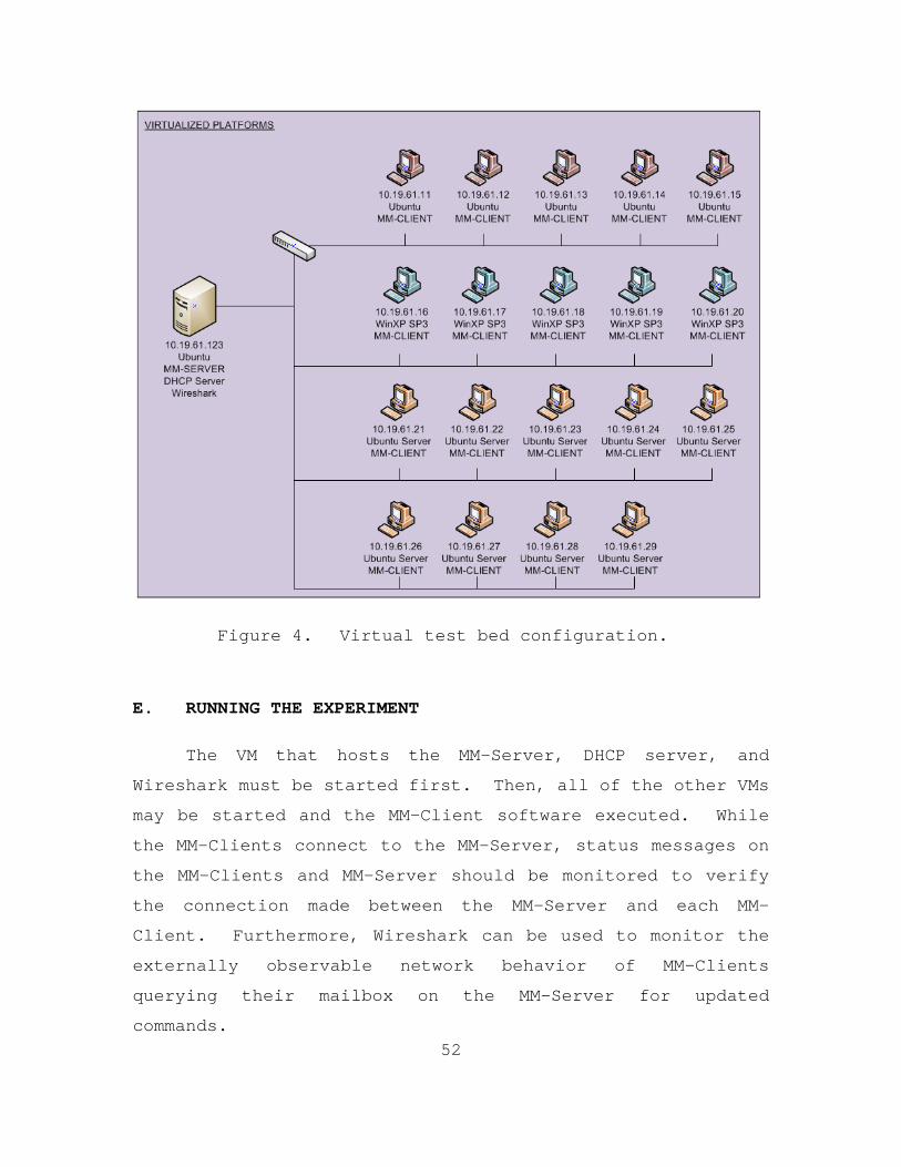
52
Figure 4. Virtual test bed configuration.
E. RUNNING THE EXPERIMENT
The VM that hosts the MM-Server, DHCP server, and
Wireshark must be started first. Then, all of the other VMs
may be started and the MM-Client software executed. While
the MM-Clients connect to the MM-Server, status messages on
the MM-Clients and MM-Server should be monitored to verify
the connection made between the MM-Server and each MM-
Client. Furthermore, Wireshark can be used to monitor the
externally observable network behavior of MM-Clients
querying their mailbox on the MM-Server for updated
commands.

53
For purpose of our experiment, once all VMs and
programs were started, we would verify that all programs
respond to the changes of the requested running module by
the MM-Server. Data would be analyzed using Wireshark to
examine the change in network traffic directed at the MM-
Server. Once all changes between module states zero to two
were verified, each module would be run for up to five
minutes to allow the system to reach a steady-state.
Finally, the MM-Server would be stopped and Wireshark used
to assess the changes in behavior of the MM-Clients as they
changed from a running module to a failsafe state.
During all of the above, performance data would be
captured about the server, to include CPU utilization,
memory allocation, disk activity, network capacity used, and
other statistics. The purpose of this data collection was
to support an analysis of the strain under which the two
servers are operating during this test.
The overarching purpose of this experiment would be to
verify the system functions as designed. It would also be
to verify that the MM-Server could handle multiple
connections and that there would be timely changes in
requested behavior by the MM-Clients. Finally, it would
assess whether there was any strain upon the MM-Server or
the physical servers themselves due to operation all of the
virtual machines (this would indicate a scalability issue
for a small deployment venue). As such, the experiment would
serve to establish a benchmark for the performance of the
Malware-Mimic System in a benign environment.

54
F. SUMMARY
This chapter discussed the system infrastructure
consisting of the command and control MM-Server and the
remote MM-Clients. The protocol’s design was examined,
specifically in relation to how the MM-Clients would receive
the orders from the MM-Server. The protocol was designed
with safety as the paramount feature. The MM-Clients must
have guidance in order to start the modules. That guidance
must persist for a new iteration of behavior to occur.
The test platform and the general design of the
experiment were discussed. The test platform relies heavily
upon virtualization. Virtualization allows for a varying
number of systems to be activated, a variety of operating
systems that can be utilized, and various network
configurations, so that the MM-Server and MM-Client software
can be fully vetted. It also forms a platform for further
expansion in the formulation and testing of new modules, new
operating systems, and more complex networks. The next
chapter will provide the results of the experiment.

55
V. RESULTS
A. BACKGROUND
This section provides details about the implementation,
as well as the results of the experiment delineated in
Chapter IV. The results demonstrated the viability of this
novel training and evaluation tool. The protocol functioned
as it was designed, with feedback between the MM-Server and
the MM-Clients. The safety features were adequate in
restoring the MM-Clients to their failsafe state during
interruptions in network connections with their respective
MM-Sever. Observable network traffic was positively
identified which can fulfill training and analysis
objectives. Finally, it was verified that the test platform
is a suitable testing environment prior to deployment on a
live network.
B. SETUP
The two servers began the experiment in steady state
with all VMs shutdown. On the laptop, we connected to each
Physical Server utilizing vSphere. The Ubuntu VM that would
run the MM-Server on Physical Server 2 was the first VM
started. This was needed because that VM had a fixed IP
address (10.19.61.123) and also hosted the DHCP server that
would allocate IP addresses to all of the other VMs as they
started up. Once the DHCP service was operating, all
nineteen of the other VMs were started. Figure 5 shows
which types of VMs were running along with their respective
IP addresses on each physical server.

56
Figure 5. Physical server IP addresses/type/names.
The specific IP addresses of the Physical Servers were
not relevant for the experiment. The IP addresses
facilitated connections via the laptop running the VMware
vSphere Client software in order to control all of the VMs
running on the servers. The controlling laptop was given an
IP address of 10.19.61.235.
Physical Server 1 had five MM-Clients running on the
Windows XP Professional Service Pack 3 (WINXP SP3) Operating
System VMs, and five MM-Clients running on the Ubuntu 10.10

57
Operating System VMs. Physical Server 2 had nine MM-
Clients, one per Ubuntu Server 10.10 VM, and the one MM-
Server running on the Ubuntu 10.10 VM. All MM-Clients
connected to the MM-Server at the IP address 10.19.61.123.
The IP addresses were required so that the Wireshark packet
capture could be analyzed in order to ensure all of the MM-
Clients were executing the correct module and to get a
measurement on how quickly each responded to the change in
commands.
C. TIMELINE
Figure 6. Experiment Timeline of Events.
The timeline (Figure 6) shows the order and times of
specific events during the entire experiment. This helped
us correlate the information in all of the packets displayed
in Wireshark with the events that occurred. Furthermore,
this timeline is meant to be used in conjunction with
Figures 8 and 9 (showing CPU utilization per physical
server). The alphabetical labels on Figures 8 and 9
correspond to the same labels in the left hand column in the
timeline shown in Figure 6.

58
D. DISCUSSION OF RESULTS
Overall, the entire experiment verified system
performance per the architecture set forth in Chapter II.
All VMs functioned as configured, and all MM-Clients
connected to the MM-Server performed the desired actions and
responded to the changes in commands in less than ten
seconds. The MM-Server had no dropped packets on the
Network Interface Card and Wireshark showed all of the
traffic between the MM-Clients and the MM-Server.
1. Results for MM-Server and MM-Clients
The MM-Server performed according to specification.
All MM-Clients connected to the MM-Server as designed. The
Ubuntu VM hosting the MM-Server operated with no degradation
in performance under the load of the nineteen TCP sessions
of the MM-Clients. The Linux “top” command showed that the
Java process of the MM-Server utilized approximately 0.3% of
the CPU time. It also showed that the percent of memory
utilized by the same process started at 2.5% when no MM-
Clients were connected and only grew to 2.9% when all
nineteen MM-Clients were connected.
An example of the time it takes to transition between
states for the MM-Client is given below. Since the MM-
Server does not actively send a command to a MM-Client, the
responsiveness between a typed command at the MM-Server and
the MM-Client receiving that command, updating the MM-
Client’s status and then executing that command is somewhat
slower than it could be. However, as seen in Figure 7, it
takes approximately 5-6 seconds for a MM-Client to cease the
current running module, access and process the new order

59
from its mailbox in the MM-Server, update its status with
the MM-Server and begin exhibiting the correct behavior of
the newly ordered module. This delay can be attributed to
many different processes: physical, programmable, and
virtual. The physical realm deals with the actual signal
propagating through the physical wires and switch. Within
the programs, the command is placed within the MM-Client’s
inbox on the MM-Server and there is a delay depending on
when the MM-Client “checks back in” with the MM-Server
following a single iteration of the current ordered module.
Finally, since there are two physical servers running twenty
VMs, there are additional delays due to the non-
deterministic scheduling of the VMs, as well as the overhead
of the hypervisor.
Figure 7. Packet Capture between MM-Client and MM-Server.
The MM-Clients were designed for safety and the ability
to be controlled remotely. Figure 7 is a sample of the
latter, utilizing a Wireshark packet capture between the MM-
Client hosted on the WINXP_08_Client (10.19.61.67) and MM-

60
Server (10.19.61.123). To test the former, the experiment
ended with an abrupt termination of the MM-Server with all
nineteen MM-Clients having active TCP sessions. The ensuing
network traffic from the MM-Clients to the host which had
been previously running MM-Server at 10.19.61.123 was
captured by Wireshark. Within seven seconds, all of the MM-
Clients that were running Module 2 entered their failsafe
behavior. All MM-Clients performed as expected, which
suggests that the built-in safety mechanism performed as
planned. That is, if the MM-Server is no longer present to
give orders, the MM-Clients will terminate all previous
behaviors, revert to a benign, failsafe mode, and attempt to
reestablish a connection with the MM-Server.

61
2. Results for the Physical Servers
Figure 8. CPU Utilization of Physical Server #1.

62
Figure 9. CPU Utilization of Physical Server #2.
The performance of physical servers one and two (IP
addresses (10.19.61.236 and 10.19.61.237, respectively)
running the hypervisor and all of the VMs matched
expectations. According to the CPU utilization graphs
(Figures 8 and 9), the large spikes in CPU utilization were

63
the actual starting and stopping of the VMs (points D and
E). The other large spikes occurred at points G and H, when
all of the MM-Client software and Java Runtime Environment
was activated.
After the MM-Clients were started and connected to the
MM-Server, CPU utilization of the actual physical servers
was negligible. The initialization and idle state (Module
0) had the MM-Clients communicate once every ten seconds to
the MM-Server in order to check for messages in their
respective queue (Module 0 began at Labels I and L in
Figures 8 and 9). This activity had a negligible effect on
the CPU, even though the CPU is “serving” both the MM-Server
and the MM-Client entities. Module 1 is not CPU-intensive,
calling only a series of five pings back to the MM-Server
per MM-Client instantiation for the module cycle of ten
seconds (Module 1 began at Label J in Figures 8 and 9).
Module 2 activated another process, hping, in order to
perform a SYN scan of the MM-Server. This shows an increase
of about 15-20% CPU utilization on both physical servers
(Module 2 began at Label K in Figures 8 and 9). The
physical servers handled the swapping between the ten VMs
and the network traffic between the MM-Server and MM-Clients
as expected.

64
Figure 10. Network Utilization of Physical Server #1.

65
Figure 11. Network utilization of physical server #2.
Hard disk activity of the physical servers was
negligible. Main memory (RAM) usage by each of the physical
servers was as expected when running all of the VMs:
approximately half of the onboard memory was utilized. Each
physical server had 4 GB of main memory. Upon startup of
all the VMs, memory peaked to almost full utilization. Once
all the VMs were fully booted up, logged into, and the MM-
Server and all MM-Clients activated, memory usage was

66
approximately 25-50% in steady state. It is to be noted
that for future work, if more VMs are to be run
concurrently, the onboard memory should be increased to 8 or
16 GB.
Network activity of the physical servers due to the
Malware Mimic system is harder to isolate and assess. As
seen in Figures 10 and 11, overall network traffic was well
within the Gigabyte Ethernet capability of the server
Network Interface Cards and the switch. However, there are
some large spikes in network traffic that must be explained.
In Figure 10, the network traffic for Physical Server 1
(.236), there were large spikes of approximately 2-3
megabytes per second (MBps) at the setup and shutdown of the
experiment and it was mostly steady around 200 kilobytes per
second (KBps) during the actual running of the different MM-
Client modules. The large spikes of 2-3 Mbps were due to
the external connection of the laptop that contained the
vSphere Client software. Through vSphere, we utilized the
remote console window to access every VM. Once we were
logged in to each VM and the MM-Client software was started,
the now unneeded VM remote consoles were closed. At the
end of the experiment, the VMs were remotely logged into
again, in order to stop the MM-Client software and shutdown
the VMs. The vSphere Client allowed a remote console
window, giving full access to each VM as if sitting at a
normal desktop computer. All of these live video feeds of
the running VM to our remote console were sent over the
network connection from the Physical Servers to the laptop.
This explains the large spikes at the beginning and end of
the experiment as seen in Figure 10.

67
The network activity of Physical Server #2 (.237),
shown in Figure 11 was similar to that of Physical Server
#1, with the large 900-KBps spike at the startup of all the
VMs. This is less because the Physical Server #2 has nine
Ubuntu Server OS VMs running. The Ubuntu Server OS is
accessed from a command prompt. This interface was text-
based, unlike the graphical interfaces of the Ubuntu Desktop
OS and WinXP OS. Therefore, the amount of information sent
over the network to our remote console was significantly
less than the graphical environments of Ubuntu and Windows
XP. However, during the period when the different MM-Client
modules were being accessed, Physical Server #2 has about
twice the network activity. This can partly be explained by
the fact that the Ubuntu OS VM (.123), with the MM-Server
software on Physical Server #2, was the only remote console
utilized to control all of the MM-Clients. Therefore, the
live feed from that VM was sent over the network to the
external laptop in order to control the flow of the
experiment.
To isolate the network traffic resulting solely from
the VMs, Wireshark statistics from the Ubuntu VM running the
MM-Server was used. Wireshark provided an input/output
graph of the amount of packets (or bytes) per unit time.
The output was configured for bytes per second. During the
test run, with all MM-Clients running Module 0 (idle state),
traffic to and from the MM-Server was 0.5-3 KBps. When all
MM-Clients were running Module 1 (ping), traffic was 1.5-8
KBps. When all MM-Clients were running Module 2 (SYN scan),
traffic was 4.5-8 KBps. Comparing these numbers to the
graphs in Figures 10 and 11, we discovered that there is a
significant amount of network traffic overhead for the

68
virtualization of network traffic as well as the live video
feed for the remote console capability. In comparison, if
the MM-Server and MM-Clients were utilized on a live,
operational network, the resulting network activity of 0.5-8
KBps would be relatively insignificant compared to the 10,
100 or 1000 MBps capacity of today’s networks.
E. SUMMARY
The experiment demonstrated that our system performed
as designed. All of the test goals were accomplished and
there was an observable validation for each portion of the
experiment. This included the most important of the goals:
demonstrating the ability to control the MM-Clients in a
timely manner. The MM-Clients were all responsive in
changing to the ordered module, and when communication to
the MM-Server was severed, all MM-Clients ceased their
current activity and entered their failsafe mode.
The results also show that the client-server
relationship worked correctly, and can likely scale to a
greater number of MM-Clients operating on differing network
configurations. Also, with the exception of possibly
needing additional onboard memory for the Physical Servers,
there is plenty of capacity with respect to CPU cycles, hard
drive space, and network utilization for each of the
physical test bed servers to accommodate more simultaneous
VMs, as well as more complex network configurations.
Next, in Chapter VI, we discuss our conclusions. We
also discuss our thoughts on future work in this area of
study, to include code improvement, expansion, and security
implications.

69
VI. CONCLUSIONS AND FUTURE WORK
A. CONCLUSIONS
In this thesis, we proposed a solution to DoD
overreliance on network analysis red teams for training and
evaluation of network administrators by designing a novel
network training tool. This tool allows the integration of
network evaluation into the highly complex training events
typical of U.S. military training exercises. The system we
constructed had the following characteristics:
• It was safe enough for production or operational
environments. Emulated behaviors would cease on
command and “roll-back” to a pre-exercise state.
Losses of network connection were treated as
instructions to cease behaviors. This would allow
training to take place on the same network on
which the trainees perform their mission.
• Only malware behaviors were constructed, not
actual malware itself. Though we demonstrated the
properties of a notional worm on the network,
there was no actual malware involved.
• The system constructed was distributed across the
network, allowing for the trainer to be located
anywhere on the network, local or remote.
We then set out to construct a prototype for such a
system, which we discussed in detail in Chapter IV.
Following our treatment of the constructed system, we
discussed the test bed that we created to test our system

70
concept vis-à-vis the goal we had set for ourselves, and
proceeded to discuss the specific results acquired after
establishing the test-bed and conducting a set of tests.
We discovered that it is certainly possible to
construct a system with the attributes discussed above. We
believe that this has the potential to revolutionize
training for not only network administrators, but for the
decision makers that are affected by malicious actions
against such networks. We also noted that the system
performs as expected with regards to safety, namely, that it
did not perform uncommanded behavior at any point during
testing. The system ceased all emulated behaviors within a
suitable small time upon receipt of the trainer injected
“cease-action” command—without exception. This particular
system quality is essential for its forecasted use on
operational networks, and in this capacity, the MM-System is
ready for a validation in an operational or production
environment.
We also discovered we essentially built a botnet, as
discussed in Chapter II, complete with a command and control
architecture and slave-node functionality without the
dangerous behavior of actual propagation across the network.
This, we believe, could form the basis of an existence proof
for the size to which our Malware Mimic System architecture
can scale. Using Conficker as an example (also discussed in
Chapter II), it is possible that this tool could scale to
thousands of hosts, with some modification to the code,
allowing the training and evaluation of the administrators
of networks on the order of Tier One Internet Service
Providers.

71
B. FUTURE WORK
1. Code Improvement and Extension
As with any software early in its lifecycle, the code
needs refinement. For example, we found that the keying
system for our data structure (mapping between keys and
actual nodes) was unwieldy. It is essential that this key
uniquely correspond to a MM-Client node, which we
accomplished by using a combination of the given node’s host
name and a user assigned name given at invocation. However,
this does not scale well, as it requires a unique naming
system to be created and tracked by those parties
responsible for instantiating the nodes. Instead, we would
suggest using a naming scheme that would allow for unique
names to be generated and maintained by the hosts
themselves, without involvement by any human user.
Furthermore, the Data Structure will, at some point, need to
be replaced by a robust, industrial grade database that can
maintain records on the order of thousands, vice the data
structure we utilized, discussed in Chapter III.
We described a local “kill server” and its role in the
communication protocol of the MM-Mimic system in Chapter
III, but we provided no implementation. We foresee a
modification to the MM-Client code that allows for local
pre-emption or blocking of remote taskings using UDP-based
requests to local “kill server” located on the trainee
network. Construction of this “kill server” could largely
be modeled on the MM-Server architecture discussed in
Chapter III; again, using datagram vice stream socket
connections.

72
There are several improvements that could affect the
scalability of the software. As it stands, there is no
organic capability implemented to remotely “push” MM-Client
code to machines on the trainee network. Additionally,
there is no capability to distribute updates over the
network. The implication of this is that the MM-Client nodes
must have all desired behaviors preprogrammed into the MM-
Client software on the host machine. A more agile solution
would be to have modules of behaviors sent to MM-Client
nodes via software push, increasing the flexibility,
adaptability, and, possibly, security of the MM-Mimic
system. Such a scheme would require authentication and
integrity verification to ensure only authorized behaviors
are distributed.
2. More Advanced Modules
The training value in our first iteration of the MM-
System is limited. That said, there is a rich framework
laid out upon which more complex modules, with corresponding
training scenarios, could be developed. We foresee modules
that would allow the MM-Client nodes to mimic virus
behavior, as outlined in Chapter II, including, but not
limited to host machines showing virus “signatures” that
would be visible on installed anti-virus systems. Such
signatures would need to be “hidden,” likely through
encryption, until the behavior is commanded. MM-Client
nodes could show “pop-up” messages that would instruct users
to contact their system administrators. MM-Clients could
increase their system resource consumption, increasing the
discomfort level of human users utilizing the system. More
advanced and realistic worm behaviors could be programmed;

73
simulation of worm behaviors propagating across a network,
or delivering a “payload” would be an example of this.
We have limited ourselves to discussing the behaviors
of malware—worms, botnets and the like. However, human-
centric behavior continues to be a critical aspect of system
hardening. Emulating such behavior to train operators to
recognize it when it occurs could be beneficial. Determining
whether or not there exists discernable differences between
the observable behaviors of a human adversary, a “hacker” in
popular parlance, and programmatic behaviors of the MM-
System would be a first step to implementing “human”
behaviors. We believe that the emulated threat behaviors of
the MM-System could be expanded to include those of
“hackers” as well, perhaps through well-scripted “mock”
user-sessions.
3. Increase Scale of Test Bed
Code development is one area for further advancement;
but the path forward for the project in the whole will rely
on the system being tested on human users on a scale
representative of the training networks to which the system
is destined. Towards this, expansion of the test bed will
be required to an appropriate number of clients well beyond
the twenty used for initial test bed. Testing of the system
should also be conducted on networks more complex than the
single subnet system we utilized, again, to validate the
system for networks more representative of its anticipated
use. Additionally, as discussed in Chapter V, we relied on
a protocol analyzer to demonstrate our externally-observable

74
network behaviors. We must additionally test our system
against common intrusion detection systems used in the field
today, e.g., Snort.
4. Security Implications
We made no security assumptions in our architecture,
nor did we treat security implications in our
experimentation. Before the MM-System is ready for field
use, security analysis must be performed. The architecture
should be suitable for this environment, however, as the
system architecture was conceived with security in mind,
with an eye on eventual deployment on DoD networks. Java is
common on DoD networks. Host-based network software is
common on DoD networks. No mechanism yet exists to prevent
unauthorized third parties from remotely commanding MM-node
behavior, but again using existing botnets such as Conficker
as an example, this too should be possible. But the
fundamental approach to the system is its greatest asset:
only malware behaviors are employed on the trainee network,
not actual malware. Therefore, no behavior can happen on
the network that is not explicitly coded into the MM-
Clients. In this way, the MM-System behaviors can be
tailored according to the risk tolerance of the trainee
networks.

75
APPENDIX A. MM-SERVER: CANDCSERVER.JAVA
/*********************************************************************/ /* */ /* Program: Malware Mimic Server */ /* */ /* Top level for the MM-Server. Interfaces with the user */ /* via the UI. Handles incoming TCP connections on all */ /* interfaces on TCP.port == 30000 with remote or local */ /* MM-Clients. Maintains and closes TCP sessions with */ /* MM-Clients. Translates user instructions to MM-Clients */ /* and passes the commands to MM-Clients. Allows input */ /* from MM-Clients to UI. Maintains state on MM-Clients. */ /* FILE: ClientProgram.java */ /* */ /* USAGE: ./MM-Server <with no paramters> */ /* */ /* */ /* AUTHORS: W. Taff and P. Salevski */ /* */ /* DATE: 22 January 2011 */ /* */ /*********************************************************************/ package commandserver; import java.io.IOException; import java.net.*; /** * The server - top level for program, and listener for connections. * Initializes the database. Starts the UI. * Sits and listens for connections, spins off CC-Communicators * to handle them and passes off Socket to same, then reset to * listen. * * @author W. Taff and P. Salevski * */ public class CandCserver { /** * @param args */ public static void main(String[] args) { /////////////////////////////////////////// //INITIALIZATION /////////////////////////////////////////// ClientDatabase dataBase = new ClientDatabase();

76
Integer listenPort = 30000; Socket clntSock = null; //start the UI Thread GUIthread = new Thread( new CandCserverMenuUI(dataBase)); GUIthread.start(); try {
ServerSocket server = new ServerSocket (listenPort);
System.out.println ("Server Listening on port " while (true){ System.out.println ("Waiting"); clntSock = server.accept();
System.out.println ("Connection Accepted from " + clntSock.getInetAddress() );
Thread thread = new Thread(new ClientCommunicator(clntSock, dataBase));
thread.start(); }//end while } catch (IOException ioe) { System.err.println (ioe); } } }

77
APPENDIX B. MM-SERVER: CANDCSERVERMENUUI.JAVA
package commandserver; //Filename: CandCserverMenuUI.java //21 December, 2010 import java.util.Scanner; /** * Rudimentary command line, console based ui * Used for troubleshooting and functionality verification; will * likely be replaced with graphical version. * * @author W. Taff and P. Salevski * */ public class CandCserverMenuUI implements Runnable { /** need access to db to invoke methods */ private ClientDatabase db; public CandCserverMenuUI(ClientDatabase dbInput){ this.db = dbInput;} /* (non-Javadoc) * @see java.lang.Runnable#run() */ public void run() { uiConsole(); }//end run private void uiConsole() { //OF FORM: commands, module numbers (if any), and targets // e.g. MOD_0:ALL or maybe PRINT:ALL // if no target, assume ALL Scanner adminInputScanner = new Scanner(System.in);

78
String inputString = ""; int cmdDelimValue; String command = null; String target = null; int moduleNumber = 999; while (inputString.compareTo("QUIT")!=0){ inputString = adminInputScanner.next(); inputString = inputString.toUpperCase(); cmdDelimValue = inputString.length(); try { if (inputString.contains(":")){
cmdDelimValue = inputString.indexOf(":");
command = inputString.substring(0,
cmdDelimValue);
target = inputString.substring(cmdDelimValue
+ 1); } else { command = inputString; target = "ALL"; } if (inputString.contains("_")){
int modDelimValue = inputString.indexOf("_") + 1;
moduleNumber = Integer.parseInt(inputString. substring(modDelimValue, cmdDelimValue) ); command = command.substring(0, modDelimValue -1 );

79
} } catch (Exception e) { e.printStackTrace();
System.out.println("ERROR ON PARSE OF INPUT");
} System.out.println("Command is:" + command ); System.out.println("Target is:" + target ); System.out.println("Module Number is:" + moduleNumber ); //THE COMMANDS if (command.compareTo("PRINT") == 0){ print(target); } else if (command.compareTo("HALT") == 0){ halt(target); } else if (command.compareTo("MOD") == 0){ mod(moduleNumber, target); } else { // db.getRecord(command).getCC(). //

80
sendMessage2Client(value); }//end else }//end while System.out.println("Got quit command"); System.exit(0); } private void mod(int moduleNumber, String target) { System.out.println("Running MOD_" + moduleNumber); db.run_module(moduleNumber); } private void halt(String target) { if (target.compareTo("ALL")==0){ System.out.println("Halting All!"); db.halt_module(); } } /** * Print records in the database. * @param target */ private void print(String target) {

81
if (target.compareTo("ALL")==0){ String printBuffer = db.getAllrecordsFromDB(); System.out.println("Host, Exercise, Inbox, Status"); System.out.println(printBuffer); }//endif }//END print() }//end class

82
THIS PAGE INTENTIONALLY LEFT BLANK

83
APPENDIX C. MM-SERVER: CLIENTCOMMUNICATOR.JAVA
// Filename: ClientCommunicator.java // 21 December, 2010 package commandserver; import java.net.*; import java.io.IOException; import java.io.PrintStream; /** * A handler that maintains the session between server and client. * Runs as a thread that is started by server. On run, spins off * a threaded Client Listener to accept input, and calls MM-node * for Name and Status. * * @author W. Taff and P. Salevski */ public class ClientCommunicator implements Runnable{ /** Socket passed to CC by the SocketServer */ private Socket ccSocket; /** The output stream use to push our messages onto the wire */ private PrintStream outPrintStream; /** the location of the db, so we can call it's methods */ private ClientDatabase db; /** the keyname of the host that the CC relates to */ private String keyname; // CONSTRUCTOR public ClientCommunicator(Socket passedSocket, ClientDatabase db) { this.ccSocket = passedSocket; this.db = db; //make the output stream. input stream made in run() try { this.outPrintStream = new PrintStream( ccSocket.getOutputStream() ); } catch (IOException e) { e.printStackTrace();

84
} }//end constructor ClientCommunicator() /* (non-Javadoc) * @see java.lang.Runnable#run() */ //@Override public void run() { ccListenerStarter() ; outPrintStream.println("#GETNAME"); }//end run() /** * Starts the ccListener. * Use the ccListener for input from the MM-node. */ private void ccListenerStarter(){ try { //spin off new ccListener
Thread listenerThread = new Thread( new ClientCommunicatorListener( ccSocket.getInputStream(), db, this));
listenerThread.start(); } catch (IOException e) { e.printStackTrace(); } }//end ccListenerStarter()

85
/** * Externally callable session terminator-closes socket. * Also updates the status of the MM-Client in the db. */ public void terminateSession(){
sendMessage2Client("Session Terminated"); db.getRecord(keyname).setClientStatus("TERMINATED");
try { ccSocket.close(); } catch (Exception e) {
e.printStackTrace(); db.getRecord(keyname).setClientStatus("LOST");
} }//end terminateSession() /** * Pushes any input string down to MM-Client * @param msg */ public void sendMessage2Client(String msg){ outPrintStream.println(msg); } /** * @return the keyname */ public String getKeyname() { return keyname; }

86
/** * @param keyname the keyname to set */ public void setKeyname(String keyname) { this.keyname = keyname; } }//end class

87
APPENDIX D. MM-SERVER: CLIENTCOMMUNICATORLISTENER
package commandserver; //Filename: ClientCommunicatorListener.java //21 December, 2010 import java.io.*; /** * @author W. Taff and P. Salevski * Handles input from MM-node. * Parses MM-node messages and makes appropriate system calls. * */ public class ClientCommunicatorListener implements Runnable{ /////////////////////////////////////////// //DATA MEMBERS /////////////////////////////////////////// /** passed - will bolt on top a BufferedReader */ private InputStream inStream; /** use for reading incoming messages from MM-Client */ private BufferedReader inBufferedReader; /** gives ability to call ClientDatabase fns */ private ClientDatabase db; /** gives ability to call back to the calling CC */ private ClientCommunicator parentCC; /////////////////////////////////////////// //METHODS /////////////////////////////////////////// //CONSTRUCTOR public ClientCommunicatorListener(InputStream inputStream, ClientDatabase db, ClientCommunicator callingCC) { this.db = db ; this.inStream = inputStream; this.inBufferedReader = new BufferedReader(new InputStreamReader(inStream));

88
this.parentCC = callingCC; } public void run() { //Need try/catch to make severed sessions graceful try { listenLoop(); } catch (NullPointerException e) { e.printStackTrace(); } catch (Exception e) { e.printStackTrace(); } finally { System.out.println("Connection Lost to " + parentCC.getKeyname()); parentCC.terminateSession(); db.getRecord(parentCC.getKeyname()).setClientStatus("LOST"); } }//end run() /** * Main loop of CCListener. * Blocks on readlines from MM-Client. Calls appropriate db * methods based on input passed up from MM-Client. * @throws Exception * */ private void listenLoop() throws Exception { Boolean keepGoing = true; String textReceived = "";

89
while ( keepGoing ) { textReceived = inBufferedReader.readLine(); if ( textReceived.compareTo("QUIT")==0 ){ parentCC.terminateSession(); keepGoing = false; } else if ( textReceived.contains("GETINBOX")){ parentCC.sendMessage2Client(db.getRecord( parentCC.getKeyname()).getClientInbox() ); } else if ( textReceived.contains("=") ){ setVariableValue(textReceived); }//end if //RESET THE TEXT OR WE SPIN textReceived = ""; } // end while } /** * Set a db key/value pair based on input from MM-client * * @param textReceived */ private void setVariableValue(String textReceived) { int delimValue = textReceived.indexOf("="); String key = textReceived.substring(0, delimValue); String value = textReceived.substring(delimValue + 1);
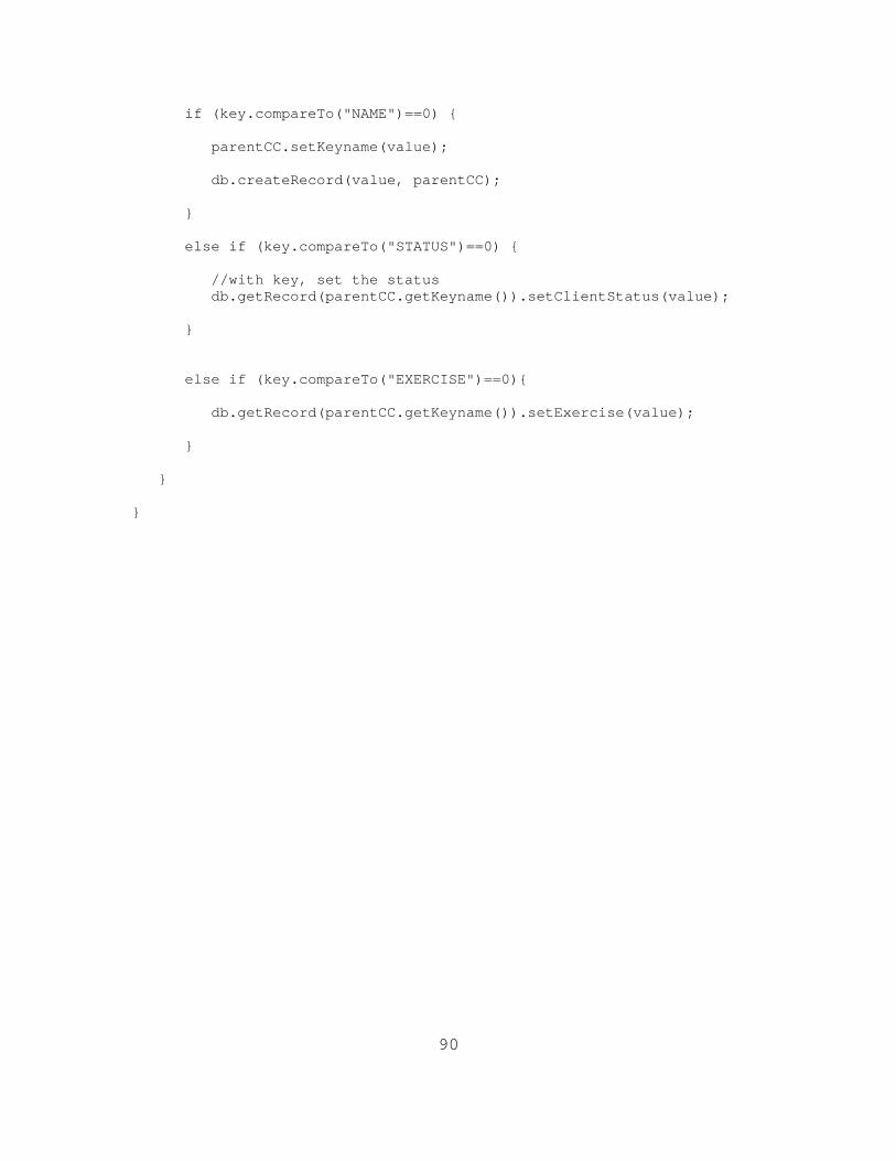
90
if (key.compareTo("NAME")==0) { parentCC.setKeyname(value); db.createRecord(value, parentCC); } else if (key.compareTo("STATUS")==0) { //with key, set the status db.getRecord(parentCC.getKeyname()).setClientStatus(value); } else if (key.compareTo("EXERCISE")==0){ db.getRecord(parentCC.getKeyname()).setExercise(value); } } }

91
APPENDIX E. MM-SERVER: CLIENTDATABASE.JAVA
package commandserver; // Filename: ClientDatabase.java // 21 December, 2010 import java.util.TreeMap; import java.util.SortedMap; import java.util.Collections; /** * The database of ClientRecords. * Uses a TreeMap (for now) as the data structure, * and ClientRecords as the nodes. * * @author W. Taff and P. Salevski * */ public class ClientDatabase { /////////////////////////////////////////// //DATA MEMBERS /////////////////////////////////////////// /**the database data structure of ClientRecord*/ private SortedMap< String, ClientRecord > dbase = Collections.synchronizedSortedMap( new TreeMap< String, ClientRecord >() ); /////////////////////////////////////////// //METHODS /////////////////////////////////////////// /** * Constructor for ClientDatabase * * */ public ClientDatabase () { }

92
/** * Creates a record in the database. * @param hostID - uid_host of the host we are creating (used as key) * @param ccIn - the calling Client Communicator * @return True if successfully created * */ public Boolean createRecord(String hostID, ClientCommunicator ccIn){ ClientRecord newRecord = new ClientRecord(ccIn, this); try { dbase.put(hostID, newRecord); System.out.println("Added record for " + hostID); } catch (ClassCastException cce) { System.err.println(cce); } catch (NullPointerException npe) { System.err.println(npe); } return true; } /** * get a client record from the database. * Pulls an instance of ClientRecord from the database, for use as * a helper function for class functions. * @param hostID - uid_host of the host of interest * @return ClientRecord * * */ public ClientRecord getRecord(String hostID) { // gets the record from the TreeMap that has the hostID key ClientRecord tempClientRecord = null; try { tempClientRecord = dbase.get(hostID); } catch (ClassCastException cce) {

93
System.err.println(cce); } catch (NullPointerException npe) { System.err.println(npe); } return tempClientRecord; } /** * Returns String of all database inbox and status for all MM-C. * Typically used for console troubleshooting. * * @return returnString, a string of all db parameters by client */ public String getAllrecordsFromDB(){ String returnString = ""; for (String keyString : dbase.keySet() ) { returnString += keyString + "," + dbase.get(keyString).getUID_ExerciseNetwork() +"," + dbase.get(keyString).getClientInbox() + "," + dbase.get(keyString).getClientStatus() +"\n" ; }//end for-loop return returnString; } /** * deletes a client record from the database. * Will attempt to remove a client record from the database, * based on the host UID provided. * @param hostID - uid_host of the host of interest * @return True of record and deleted, False if record not found * * */ public Boolean deleteRecord(String hostID) { // tries to delete the record Boolean deleteSuccess; ClientRecord tempClientRecord = null; try { tempClientRecord = dbase.remove(hostID);

94
} catch (ClassCastException cce) { System.err.println(cce); } catch (NullPointerException npe) { System.err.println(npe); } if (tempClientRecord == null) deleteSuccess = false; else { deleteSuccess = true; } return deleteSuccess; } ///////////////////////////// // UPDATE (SET) METHODS ///////////////////////////// /** * Halts running module - OVERLOADED METHOD. * Called without arguments, halts running module in all * modules. Simple iteration over dbase, setting client * inboxes to HALT. */ public void halt_module(){ for (String keyString : dbase.keySet() ) { dbase.get(keyString).setClientInbox( "HALT" ); }//end for-loop }//end halt_running_mods()

95
/** * Starts running module - OVERLOADED METHOD. * Called without target arguments, starts running module in all * modules. Simple iteration over dbase, setting client * inboxes to MOD_X, where X is the module number. * * @param moduleNumber */ public void run_module(int moduleNumber){ for (String keyString : dbase.keySet() ) { dbase.get(keyString). setClientInbox("MOD_" + moduleNumber); }//end for-loop }// end run_module() }

96
THIS PAGE INTENTIONALLY LEFT BLANK

97
APPENDIX F. MM-SERVER: CLIENTRECORD.JAVA
package commandserver; // Filename: ClientRecord.java // 21 December, 2010 /** * ClientRecord - the records in the database. * Includes all fields associated with a single client, except for * it's uid, which the record is keyed by in the database. * @author W. Taff and P. Salevski * */ public class ClientRecord { /////////////////////////////////////////// //DATA MEMBERS /////////////////////////////////////////// /**unique identifier of the exercise network */ private String uid_ExerciseNetwork; /**status of the client, set by the client, read by server */ private String status; /**inbox of the client, set by server, read by client */ private String clientInbox; /**where the ClientCommunicator lives */ private ClientCommunicator cc;

98
/////////////////////////////////////////// //METHODS /////////////////////////////////////////// /** * Constructor for a ClientRecord - called by ClientDatabase. * Gets passed hostID, exerciseID and a socket. Initializes * the class with the passed params, and makes empty for those * params that it does not yet have. * @param hostID - uid_host of host we are creating (used as key) * @param exerciseID - the UID of the exercise * @param passedCC - the ClientCoummincator for the client. * @param db - the database of clients */ public ClientRecord (ClientCommunicator passedCC, ClientDatabase db){ this.cc = passedCC; this.uid_ExerciseNetwork = "NOT_SET"; this.status = "INITIALIZED"; this.clientInbox = "INITIALIZED"; } ///////////////////////////// // GET METHODS ///////////////////////////// /** * returns the content of the client's inbox * The client inbox is set by the server, but read by * the client. Consists of a plain text string value. * @return clientInbox - the contents of the client's inbox */ public String getClientInbox(){ return clientInbox; } public ClientCommunicator getCC(){ return this.cc; }

99
/** * for the commandServer to get status of the individual client * @return status - the contents of the client's status box */ public String getClientStatus(){ return status; } /** * return the UID of the exercise network * @return uid_ExerciseNetwork */ public String getUID_ExerciseNetwork() { return uid_ExerciseNetwork; } ///////////////////////////// // SET METHODS ///////////////////////////// /** * Allows server to write message to client inbox. * Only servers shall write to the client inbox. * @param hostID - uid_host of the host of interest * @param message - String of message FROM server TO client. * */ public void setClientInbox(String message){ clientInbox = message; }

100
/** * Allows client to set their status in status box of record. * Only clients shall write their status to their status box. * Read by the server to ascertain status of the client. * @param message - String of status FROM client. * * */ public void setClientStatus(String message){ status = message; } /** * Allows client to set exercise in exercise field of record. * Only clients shall write their exercise to their exercise * field. Read by the server to ascertain exercise of the client. * @param message - String of exercise FROM client. * * */ public void setExercise(String message){ uid_ExerciseNetwork = message; } } // end of ClientRecord class

101
APPENDIX G. MM-CLIENT: CLIENTPROGRAM.JAVA
/****************************************************************/ /* */ /* Program: Malware Mimic Client */ /* */ /* Handles client side communications. Controls session */ /* with remote server. Executes commands from server on */ /* local machine. */ /* */ /* FILE: ClientProgram.java */ /* */ /* USAGE: ./MM-Client hostname exerciseId srvrName srvrPort*/ /* */ /* hostname name of host */ /* serverName IP addr of server, in dotted quad */ /* serverPort Integer port number of remote server */ /* */ /* AUTHORS: W. Taff and P. Salevski */ /* */ /* DATE: 22 January 2011 */ /* */ /* */ /****************************************************************/ package mimicClient; /** * The MM-Client software for remote host. * Handles both sides of communication with the remote server * (up and down) as well as local execution of remotely (server) * commanded methods. * * @author W. Taff and P. Salevski * */ public class ClientProgram {

102
/** * Top level main() for program. * Loops, starting clientController with each iteration. If * clientController dies, handles that exception, and restarts. * So far, is self perpetuating - i.e., will loop until killed * externally. * * @param args hostName, exercise Id, server IP.addr, server port */ public static void main(String[] args) { while (true) { try { new ClientController(args[0], args[1], args[2], Integer .parseInt(args[3])).run(); } catch (NumberFormatException e) { e.printStackTrace(); System.out.println("Check your parameters!\n" + "Expect hostId exerciseID serverIP.addr " + "serverIP.port" ); System.exit(2); } catch (ArrayIndexOutOfBoundsException e) { e.printStackTrace(); System.out.println("Check your parameters!\n" + "Expect hostId exerciseID serverIP.addr " + "serverIP.port" ); System.exit(2); } catch (NullPointerException f) { f.printStackTrace(); } catch (Exception e) { e.printStackTrace(); }

103
finally { try { Thread.sleep(10000); } catch (InterruptedException e) { e.printStackTrace(); } } }//end while }// end main() }//end Class

104
THIS PAGE INTENTIONALLY LEFT BLANK

105
APPENDIX H. MM-CLIENT: CLIENTCONTROLLER.JAVA
package mimicClient; import java.io.*; import java.net.InetAddress; import java.net.Socket; import java.util.Random; /** * Controller class for the Malware Mimic client. * Started by ClientProgram. IPC code based on code by * John Yeary. * * @author W. Taff and P. Salevski * */ public class ClientController { /////////////////////////////////////////// //DATA MEMBERS /////////////////////////////////////////// private String hostName; private String os_name; private String exerciseID ; private Runtime localRuntime; private String status; private InetAddress localMachine; private Socket socket; private String textReceiveBuf; private BufferedReader inBufferedReader; private PrintStream outPrintStream; private String serverAddr; private int serverPort;

106
/////////////////////////////////////////// //METHODS /////////////////////////////////////////// /** * Constructor for ClientController * @param serverPort the port of the remote server to use * @param serverAddr the string dotted-quad server address * @param hostName the hostname of local machine; will append * @param exerciseID * @throws Exception * */ public ClientController(String hostName, String exerciseID, String serverAddr, int serverPort) throws Exception { super(); os_name = System.getProperty("os.name"); localRuntime = Runtime.getRuntime(); status = "READY"; localMachine = InetAddress.getLocalHost(); socket = new Socket(serverAddr,serverPort); this.hostName = hostName + localMachine.getHostName(); this.serverAddr = serverAddr; this.serverPort = serverPort; this.exerciseID = exerciseID; } /** * Main body of the clientController. * Loops until receives a halt command, checking the inbox * located on the remote server, and executing any commands. * * @throws Exception */ public void run() throws Exception { initializeConnection(); //and then start looping and keep checking inbox while ( textReceiveBuf.compareTo("HALT")!=0 ){

107
outPrintStream.println("GETINBOX"); Thread.sleep(5000); textReceiveBuf = inBufferedReader.readLine(); System.out.println(textReceiveBuf); if ( textReceiveBuf.compareTo("MOD_0")==0 ) mod_0(); if ( textReceiveBuf.compareTo("MOD_1")==0 ) mod_1(); if ( textReceiveBuf.compareTo("MOD_2")==0 ) mod_2(); }//end while //CLOSE CONNECTION outPrintStream.println("CLOSING..."); Thread.sleep(1000); socket.close(); }//end run() /** * Initializes the connection with the remote host. * Called by run(), connects with the remote host, and upon * connection, sends initialization parameters to the server. * * @throws Exception */ private void initializeConnection() throws Exception { System.out.println("Connected ... waiting for #GETNAME") ; outPrintStream = new PrintStream(socket.getOutputStream() ); inBufferedReader = new BufferedReader( new InputStreamReader(socket.getInputStream())); //GIVE TIME FOR INITIAL COMMAND TO ARRIVE

108
Thread.sleep(1000); if (inBufferedReader.ready()) { textReceiveBuf = inBufferedReader.readLine(); System.out.println(textReceiveBuf); } //if server says getname, tell it if (textReceiveBuf.compareTo("#GETNAME")==0 ){ outPrintStream.println("NAME=" + hostName); outPrintStream.println("STATUS=" + status); outPrintStream.println("EXERCISE=" + exerciseID); } }// end initializeConnection() /** * A hping scan of 10 sequential ports from a random start port. * Scans server in range of 1 to 1024. * @throws InterruptedException */ private void mod_2() throws InterruptedException { status=("MOD_2"); outPrintStream.println("STATUS=" + status); int randomPort = new Random().nextInt(1014) + 1; try { Process p = null; if (os_name.contains("Linux")) { p = localRuntime.exec("/usr/bin/sudo " + "/usr/sbin/hping3 -c 10 -s 1 -p "+ randomPort + " -S " + serverAddr);

109
randomPort++; System.out.println(randomPort); } else { //is windows p = localRuntime.exec("hping -c 10 -s 1 -p " + randomPort +" -S "+serverAddr); System.out.println(randomPort); } } catch (IOException e) { e.printStackTrace(); } System.out.println("Mod 2 Iteration Complete"); }//end mod_2() /** * A 5 ping module. * Pings server 5 times then stops. */ private void mod_1() { status = "MOD_1"; outPrintStream.println("STATUS=" + status); try { Process p; if (os_name.contains("Linux")) { p = localRuntime.exec("/bin/ping -c5 " + serverAddr); } else { //is windows

110
p = localRuntime.exec("ping -n 5 " + serverAddr); } BufferedReader buffRdr = new BufferedReader( new InputStreamReader(new BufferedInputStream( p.getInputStream()))); String line; while ((line = buffRdr.readLine()) != null) { System.out.println(line); } try { if (p.waitFor() != 0) { System.err.println( "exit value = " + p.exitValue()); } } catch (InterruptedException e) { System.err.println(e); } } catch (IOException e) { e.printStackTrace(); } System.out.println("Mod 1 Iteration Complete"); }//end mod_1() /** * Sends a status update message to the server. * Equivalent to an idle command. * */ private void mod_0() { status=("MOD_0"); outPrintStream.println("STATUS=" + status); } //end mod_0() }// end class
111
LIST OF REFERENCES
[1] J. D. Fulp, “Training the cyber warrior,” Norwell, MA, USA: Kluwer Academic Publishers, 2003, pp. 261–273.
[2] J. F. Sandoz, “Red Teaming: A Means for
Transformation,” Joint Advanced Warfighting Program, Institute for Defense Analysis, Alexandria, VA, Rep. P-3580, January 2001, http://www.dtic.mil/cgi-bin/GetTRDoc?Location=U2&doc=GetTRDoc.pdf&AD=ADA388176. [Accessed: 09-Feb-2011].
[3] “If you know the enemy and... at BrainyQuote.”
[Online]. http://www.brainyquote.com/quotes/quotes/s/suntzu155752.html. [Accessed: 09-Feb-2011].
[4] R. H. Gile, “Global War Game: Second Series,” 1984-
1988, Naval War College, Newport Papers, Newport, RI, 2004.
[5] “NSA's boot camp for cyberdefense | Geek Gestalt -
CNET News.” [Online]. http://news.cnet.com/8301-13772_3-20003203-52.html. [Accessed: 10-Feb-2011].
[6] Certified Ethical Hacker: Ethical Hacking and
Countermeasures, Courseware Guide v6.1 Volume 1, EC-Council USA, Albuquerque, NM, 2010, pp. 1-30.
[7] “2010 Customer and Industry Forum.” [Online].
http://www.disa.mil/conferences/cif/. [Accessed: 10-Feb-2011].
[8] G. Gu, M. Sharif, X. Qin, D. Dagon, W. Lee, and G.
Riley, “Worm detection, early warning and response based on local victim information,” in Computer Security Applications Conference, 2004. 20th Annual, pp. 136-145, 2004.
[9] “Morris worm - Wikipedia, the free encyclopedia.”
[Online]. http://en.wikipedia.org/wiki/Morris_worm. [Accessed: 09-Feb-2011].

112
[10] S. Fei, L. Zhaowen, and M. Yan, “A survey of internet worm propagation models,” in Broadband Network Multimedia Technology, 2009. IC-BNMT '09. 2nd IEEE International Conference on, pp. 453-457, 2009.
[11] M. Feily, A. Shahrestani, and S. Ramadass, “A Survey
of Botnet and Botnet Detection,” in Emerging Security Information, Systems and Technologies, 2009. SECURWARE '09. Third International Conference on, pp. 268-273, 2009.
[12] Z. Zhu, G. Lu, Y. Chen, Z. J. Fu, P. Roberts, and K.
Han, “Botnet Research Survey,” in Computer Software and Applications, 2008. COMPSAC '08. 32nd Annual IEEE International, pp. 967-972, 2008.
[13] H. R. Zeidanloo and A. A. Manaf, “Botnet Command and
Control Mechanisms,” in Computer and Electrical Engineering, 2009. ICCEE '09. Second International Conference on, vol. 1, pp. 564-568, 2009.
[14] G. Lawton, “On the Trail of the Conficker Worm,”
Computer, vol. 42, no. 6, pp. 19-22, Jun. 2009. [15] P. Szor, “The Art of Computer Virus Research and
Defense.” 1st ed., Upper Saddle River, NJ: Addison-Wesley, 2005, pp. 26-38.
[16] “Anna Kournikova (computer virus) - Wikipedia, the free
encyclopedia.” [Online]. Available: http://en.wikipedia.org/wiki/Anna_Kournikova_(computer_virus). [Accessed: 10-Feb-2011].
[17] W. J. Lynn III, "Defending a New Domain Subtitle: The
Pentagon's Cyberstrategy," Foreign Affairs, pp. 97, September 2010—October 2010.
[18] D. J. Aland, “Towards Better Control of Information
Assurance Assessments in Exercise Settings.” Wyle Research Labs Arlington VA, 2008.
113
INITIAL DISTRIBUTION LIST
1. Defense Technical Information Center Ft. Belvoir, Virginia
2. Dudley Knox Library Naval Postgraduate School Monterey, California
3. Captain David Aland, USN, (Ret.) Office of the Director, Operational Test & Evaluation Washington, D.C.
4. Dr. Gurminder Singh Naval Postgraduate School Monterey, California
5. Commander Joe Sullivan, USN Naval Postgraduate School Monterey, California
6. Mr. John H. Gibson Naval Postgraduate School Monterey, California
7. Mr. Scott Cote Naval Postgraduate School Monterey, California
8. Mr. Steve Gates Net-Centric & Space Systems Office of the Director, Operational Test & Evaluation Washington DC