Embed Size (px)
Citation preview

VIESMANN VITOCROSSAL 300Gas condensing boiler
187 to 635 kW
VITOCROSSAL 300 Type CT3B
Gas condensing boiler for natural gas E, LL and LPGWith modulating MatriX radiant burner up to 314 kW (naturalgas E and LL)
5614 838 GB 5/2012
DatasheetPart no. and prices: see pricelist

■ Standard seasonal efficiency [to DIN]: up to 98 % (Hs) [gross cv] /109 % (Hi) [net cv].
■ The stainless steel, corrosion-resistant Inox-Crossal heat exchangerensures high operational reliability and a long service life.
■ Inox-Crossal heat exchanger for highly effective heat transfer andcondensation rate.
■ Self-cleaning effect through smooth stainless steel surface.■ Clean combustion through low combustion chamber loading and
straight-through design.
■ With MatriX radiant burner up to 314 kW for particularly economicaland environmentally responsible operation, with a modulation rangefrom 30 to 100 %.
■ Alternatively with ELCO or Weishaupt pressure-jet gas burner.■ Two return connectors for hydraulic connection optimised for con-
densing technology.■ Vitotronic control unit that is easy to operate with plain text and
graphic display.
A Vitotronic control unitB Stainless steel Inox-Crossal heat exchangerC Water-cooled stainless steel combustion chamber
D Highly effective thermal insulationE Modulating MatriX radiant burner
Benefits at a glance
2 VIESMANN VITOCROSSAL 300
5614
838
GB

Specification
Rated heating output TV/TR = 40/30 °C kW 187 248 314 408 508 635TV/TR = 80/60 °C kW 170 225 285 370 460 575Rated heat input kW 177 234.5 297 385.5 479 599Product ID CE-0085AQ0257Permiss. operating temperature °C 100 100 100 100 100 100Permiss. flow temperature(= safety temperature)
°C 110 110 110 110 110 110
Max. permiss. operating pressure bar 4 4 4 5.5 5.5 5.5Min. permiss. operating pressure*1 bar 0.5 0.5 0.5 0.5 0.5 0.5Pressure drop on hot gas side Pa 100 140 160 200 220 270
mbar 1.0 1.4 1.6 2.0 2.2 2.7Boiler body dimensions Length c +d (excl. boiler door) mm 1650 1728 1783 1823 1901 2057Width t mm 684 684 684 800 800 800Height n (incl. connectors) mm 1745 1794 1794 2012 2012 2012Overall dimensions Total length b mm 1636 1714 1795 1871 1949 2105Total length a (incl. MatriX burner) mm 1889 1967 2045 — — —Total width q mm 988 988 988 1104 1104 1104Total height p mm 1959 2009 2032 2290 2290 2290Width u (incl. thermal insulation) mm 821 821 821 937 937 937Foundations Length mm 1350 1450 1500 1600 1650 1800Width mm 800 800 800 900 900 900Height mm 100 100 100 100 100 100Weight – Boiler body kg 445 490 510 740 780 890– Removable combustion chamber without
boiler doorkg 96 96 96 124 124 124
Total weightBoiler with thermal insulation and boilercontrol unit
kg 608 660 683 937 982 1098
Capacity boiler water l 240 265 300 460 500 540Boiler connections Boiler flow PN 6 DN 65 65 80 100 100 100Boiler return 1*2 PN 6 DN 65 65 80 100 100 100Boiler return 2*2 PN 6 DN 50 50 50 80 80 80Safety connection (safety valve) R 1¼ 1¼ 1¼ 1¼ 1½ 1½Drain R 1 1 1 1 1 1Condensate drain R ½ ½ ½ ½ ½ ½Flue gas parameters*3
Temperature (at 30 °C return temperature)
– at rated heating output °C 45 45 45 45 45 45– at partial load °C 40 40 40 40 40 40Temperature (at 60 °C return temperature) °C 75 75 75 75 75 75Mass flow rate (for natural gas) – at rated heating output kg/h 269 357 452 586 727 909– at partial load kg/h 81 107 136 176 218 272Available draught Pa 70 70 70 70 70 70at the flue outlet mbar 0.7 0.7 0.7 0.7 0.7 0.7Flue gas connection 7 mm 200 200 200 250 250 250Standard seasonal efficiency [to DIN] at heating system temp. 40/30 °C % up to 98 (Hs) [gross cv] /109 (Hi) [net cv]at heating system temp. 75/60 °C % up to 95 (Hs) [gross cv] /106 (Hi) [net cv]Standby loss qB,70 % 0.40 0.30 0.30 0.30 0.28 0.25
*1 For safe operation, a minimum operating pressure of 0.5 bar is essential. For this, a minimum pressure switch can be used.*2 When connecting 2 heating circuits, connect the heating circuit with the lowest temperature level to boiler return 1.*3 Values for sizing the flue system to EN 13384, based on 10 % CO2 for natural gas
Flue gas temperatures captured as gross values at 20 °C combustion air temperature.The details for partial load refer to 30 % of the rated heating output. Calculate the flue gas mass flow rate accordingly when the partial loaddiffers from that stated above (subject to burner operating mode).
Boiler specification
VITOCROSSAL 300 VIESMANN 3
5614
838
GB

NoteThe available draught is achieved at the flue outlet with the MatriX radiant burner from our product range (up to 314 kW), with pressure-jet gasburners (from Weishaupt or ELCO) and many other pressure-jet gas burners.For alternative draughts, refer to the relevant burner manufacturer. If using the Vitocrossal 300 with moisture-resistant chimneys, the draughtmust be no more than 0 Pa.
ec dba w
SCH
f
KTÜ
KOAhx
jy
kl
m n o
i
p
KV
SA
z
140A
g
q
srtu
AGA
EKR1
KR2DB
RG KTS
KRG
v
A To safeguard perfect function, maintain the required minimumblast tube length.
AGA Flue outletDB R ½ female connection for pressure limiterE DrainKOA Condensate drainKR 1 Boiler return 1KR 2 Boiler return 2
KTS Boiler water temperature sensorKTÜ Boiler door with burner connection flangeKRG Vitotronic control unitKV Boiler flowRG R ¾ female connection for additional control equipmentSA Safety connection (safety valve)SCH Inspection port (boiler with 187 to 314 kW: 90° offset)
DimensionsRated heating output kW 187 248 314 408 508 635a mm 1889 1967 2045 — — —b mm 1636 1714 1795 1871 1949 2105c mm 1509 1587 1665 1743 1821 1977d mm 141 141 118 80 80 80e mm 715 715 715 751 751 751f mm 1299 1349 1349 1500 1500 1500g mm 194 194 194 190 190 190h (length of the base rails) mm 1257 1335 1413 1488 1566 1722i mm 298 298 298 325 325 325j mm 165 165 165 168 168 168k mm 518 518 523 577 577 577l mm 802 852 852 921 921 921m mm 1704 1755 1755 1962 1962 1962n (transport dimension) mm 1745 1794 1794 2012 2012 2012o mm 1879 1928 1935 2185 2185 2185p mm 1959 2009 2032 2290 2290 2290q mm 988 988 988 1104 1104 1104r mm 177 177 177 200 200 200s mm 227 227 221 221 241 241t (transport dimension) mm 684 684 684 800 800 800u mm 821 821 821 937 937 937v mm 257 257 257 284 284 284w mm 12 12 12 25 25 25x mm 1423 1501 1579 1654 1732 1888y mm 82 82 82 85 85 85z (transport dimension) mm 1600 1678 1756 1850 1928 2084
Boiler specification (cont.)
4 VIESMANN VITOCROSSAL 300
5614
838
GB
The boiler door can be removed where access to the boiler room isdifficult. If this is not sufficient, the boiler front panel can be deliveredseparately (please state when ordering).
Siting
Minimum clearances
200
a
b
500
500 (400)
500 (50)(400)
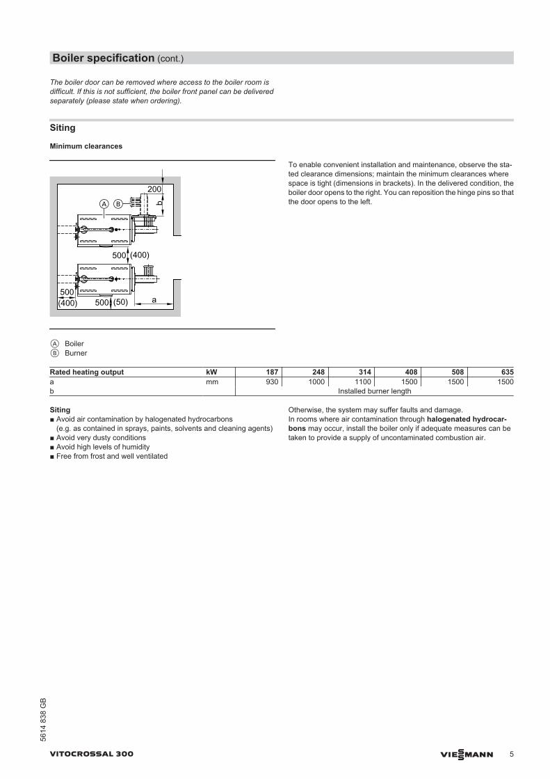
AB
A BoilerB Burner
To enable convenient installation and maintenance, observe the sta-ted clearance dimensions; maintain the minimum clearances wherespace is tight (dimensions in brackets). In the delivered condition, theboiler door opens to the right. You can reposition the hinge pins so thatthe door opens to the left.
Rated heating output kW 187 248 314 408 508 635a mm 930 1000 1100 1500 1500 1500b Installed burner length
Siting■ Avoid air contamination by halogenated hydrocarbons
(e.g. as contained in sprays, paints, solvents and cleaning agents)■ Avoid very dusty conditions■ Avoid high levels of humidity■ Free from frost and well ventilated
Otherwise, the system may suffer faults and damage.In rooms where air contamination through halogenated hydrocar-bons may occur, install the boiler only if adequate measures can betaken to provide a supply of uncontaminated combustion air.
Boiler specification (cont.)
VITOCROSSAL 300 VIESMANN 5
5614
838
GB

Pressure drop on the heating water side
60
8070
87
1
2
3456
10
20
30
405060
100
2 3 4 5 6 7 8 10 20 30 40 50
Pres
sure
dro
p in
mba
r
Flow rate in m³/h
408
- 635
kW
187
- 248
kW
314
kW
The Vitocrossal 300 is only suitable for fully pumped hot water heatingsystems.
Burner installation(MatriX radiant burner, see page 7)
Ø aØ b
Ø c
Ø d
140
A Sight glass for 408 to 635 kW with 90° offset (central vertical)
The hole circle of burner fixing holes and the blast tube aperture matchthe dimensions of many well known burner makes.If the dimensions vary from the standard supplied, first drill the burnerfixing holes into the burner plate and then cut out the blast tube aper-ture, before mounting the burner plate on the boiler door.Burner plates may be factory-fitted on request (chargeable option). Forthis, please state the burner make and type when ordering.The blast tube must protrude through the thermal insulation on theboiler door.
Rated heating output kW 187 248 314 408 508 635a Ø mm 240 240 240 290 290 290b Ø mm 270 270 270 330 330 330c Thread M 10 M 10 M 10 M 12 M 12 M 12d Ø mm 123 123 123 196 196 196
Boiler specification (cont.)
6 VIESMANN VITOCROSSAL 300
5614
838
GB

Specification for use in conjunction with a Vitocrossal 300 (type CT3B)
Rated boiler heating output (at TV/TR 40/30 °C) kW 187 248 314Burner heating output, lower/upper*4 kW 43/177 77/234 98/296Burner type VM III-4 VM III-5 VM III-6Product ID CE-0085 BL 0403Voltage V 230 230 230Frequency Hz 50 50 50Power consumption at upper heating output W 225 335 385at lower heating output W 35 40 55Version ModulatingDimensions Length c mm 290 290 290Total length d mm 585 585 585Width a mm 540 540 540Height b mm 576 576 576WeightBurner with combination valve and burner hood
kg 43.5 45 47
Gas supply pressure mbar 20 20 20Gas connection R 1 1¼ 1¼Connection values relative to the max. load with – Natural gas E m3/h 4.5–18.7 8.2–24.8 10.3–31.3– Natural gas LL m3/h 5.3–21.8 9.5–28.8 12.0–36.4NOx category (to EN 676) 3 3 3
K
L
M
E
cd
a
b
B
C
D
F
G
RPON
A
H
A Boiler doorB Display and programming unitC Gas trainD Gas supply pipeE Rotary damper with servomotorF Venturi mixing pipeG FanH Burner gauze assembly
K Ignition electrodeL Ionisation electrodeM Thermal insulation blockN Ignition unitO Air pressure switchP Suppressor choke boxR Burner control unit
Delivered condition
Boiler body with fitted cleaning cover, fitted mating flanges with gas-kets at all connectors, fitted protective crate and flue gas collector.
For delivery of a MatriX radiant burner (up to 314 kW) the boiler dooris fitted to the MatriX radiant burner; from 408 kW the boiler door isfitted to the boiler body.
*4 Corresponds to the rated heat input of the boiler.
Specification – MatriX radiant burner
VITOCROSSAL 300 VIESMANN 7
5614
838
GB

Where access to the boiler room is difficult, the Vitocrossal 300 mayalso be delivered in sections. The front panel of the combustion cham-ber can be removed on site, taken into the installation room separatelyand refitted.
1 or 2 boxes with thermal insulation1 box with MatriX radiant burner and burner hood (up to 314 kW)1 box with boiler control unit and 1 bag with technical documenta-
tion1 connection line on the water side secured to the boiler plinth (from
408 kW)1 burner plate pack (only for delivery without MatriX radiant burn-
er)
Suitable pressure-jet gas burners (from 187 kW) are available fromWeishaupt or ELCO and should be ordered separately (see pricel-ist).Delivery by the burner manufacturer. The use of burners from othermanufacturers is possible.
Control unit versions
For single boiler systems:■ Without Vitocontrol control panel
Vitotronic 100 (type GC1B)For operation with a constant boiler water temperature or forweather-compensated operation in conjunction with a control panel(see below) or an external control unit.Vitotronic 200 (type GW1B)For modulating boiler water temperaturewithout mixer controlVitotronic 300 (type GW2B)For modulating boiler water temperaturewith mixer control, for up to 2 heating circuits with mixer
■ With Vitocontrol control panelVitotronic 100 (type GC1B)andVitocontrol control panel with Vitotronic 300-K (type MW1B) forweather-compensated operation and mixer control for up to 2 heat-ing circuits with mixer and additional Vitotronic 200-H, type HK1B orHK3B for 1 or up to 3 heating circuits with mixerorControl panel with external control unit (on site)
For multi boiler systems:(up to 4 boilers)
■ Without Vitocontrol control panelVitotronic 100 (type GC1B) and LON module in conjunction withVitotronic 300-K (type MW1B)For modulating boiler water temperature (one boiler is supplied withthe standard control equipment for a multi boiler system)andVitotronic 100 (type GC1B) and LON module for modulating boilerwater temperaturefor each additional boiler in a multi boiler system
■ With Vitocontrol control panelVitotronic 100 (type GC1B) and LON moduleFor modulating boiler water temperaturefor each boiler in a multi boiler systemandVitocontrol control panel with Vitotronic 300-K (type MW1B) formulti boiler systems, weather-compensated operation and mixercontrol for up to 2 heating circuits with mixer and additional Vitotronic200-H, type HK1B or HK3B for 1 or up to 3 heating circuits with mixerorControl panel with external control unit (on site)
Boiler accessories
See pricelist and "Boiler accessories" datasheet.
Operating conditions
Operating conditions with Vitotronic boiler control unitsFor water quality requirements, see the technical guide "Standard val-ues for water quality"
Requirements1. Heating water flow rate None2. Boiler return temperature (minimum value) None3. Lower boiler water temperature None4. Two-stage burner operation None5. Modulating burner operation None6. Reduced mode None – total reduction is possible7. Weekend setback None – total reduction is possible
Delivered condition (cont.)
8 VIESMANN VITOCROSSAL 300
5614
838
GB

Installation for open flue operation(B23)For open flue combustion equipment with a total rated output in excessof 50 kW, the fresh ventilation is deemed to have been verified if thecombustion equipment is located in areas which provide an apertureor duct leading outdoors.The cross-section of the aperture must be at least 150 cm2 and mustbe 2 cm2 larger for each additional kW above 50 kW rated output.
Pipes must be sized to provide equivalent flow rates. The requiredcross-section may be split over a maximum of two apertures orpipes.
NeutralisationDuring condensation an acidic condensate with a pH value of between3 and 4 is produced. This condensate can be neutralised by process-ing it through a neutralising system.
For further information, see the technical guide and "Boiler accesso-ries" datasheet.
Installation of a suitable burnerThe burner must be suitable for the relevant rated heating output andthe pressure drop on the hot gas side of the boiler (see burner manu-facturer's specification).The material of the burner head must be suitable for operating tem-peratures of at least 500 °C.
The blast tube must have a minimum length of 140 mm (seepage 4).The burner must be tested to EN 676 and be identified with the CEdesignation in accordance with Directive 90/396/EEC.
Burner adjustmentAdjust the gas throughput of the burner to the rated boiler heating out-put.
Further information on design/engineeringSee the technical guide to this boiler.
Tested quality
CE designation according to current EC Directives.
Design information
VITOCROSSAL 300 VIESMANN 9
5614
838
GB

10 VIESMANN VITOCROSSAL 300
5614
838
GB
Subject to technical modifications.
Viessmann LimitedHortonwood 30, TelfordShropshire, TF1 7YP, GBTelephone: +44 1952 675000Fax: +44 1952 675040E-mail: [email protected]
Viessmann Werke GmbH&Co KGD-35107 AllendorfTelephone: +49 6452 70-0Fax: +49 6452 70-2780www.viessmann.com

VIESMANN VITOCROSSAL 300Gas condensing boiler
787 to 1400 kW
VITOCROSSAL 300 Type CR3B
Gas condensing boiler for natural gas E, LL and LPG
5606 748 GB 9/2011
DatasheetPart no. and prices: see pricelist

■ Standard seasonal efficiency [to DIN]: up to 98 % (Hs) [gross cv] /109 % (Hi) [net cv].
■ The stainless steel, corrosion-resistant Inox-Crossal heat exchangerensures high operational reliability and a long service life.
■ Inox-Crossal heat exchanger for highly effective heat transfer andcondensation rate.
■ Self-cleaning effect through smooth stainless steel surface.
■ Clean combustion through low combustion chamber loading andstraight-through design.
■ As Unit version with Elco or Weishaupt pressure-jet gas burner.■ Split version for easy handling.■ Two return connectors for hydraulic connection optimised for con-
densing technology.■ Easy-to-use Vitotronic control unit with plain text and graphic display.
A Two return connectorsB Stainless steel combustion chamber
C Highly effective thermal insulationD Inox-Crossal heat exchanger made from stainless steel
Benefits at a glance
2 VIESMANN VITOCROSSAL 300
5606
748
GB

Specification
Rated heating output TV/TR = 50/30 °C kW 787 978 1100 1400TV/TR = 80/60 °C kW 720 895 1006 1280Rated heat input kW 742 923 1038 1320Product ID CE-0085AU0315Permiss. operating temperature °C 100 100 100 100Permissible flow temperature(= safety temperature)
°C 110 110 110 110
Permiss. operating pressure bar 6 6 6 6Pressure drop on the hot gas side Pa 420 420 460 480
mbar 4.2 4.2 4.6 4.8Boiler body dimensions Length b mm 2894 3094 3193 3543Width c mm 960 960 1200 1200Height (incl. connectors) mm 1676 1676 1676 1676Module dimensions Length of the combustion chambermodule g
mm 1938 2138 2237 2587
Length of the heat exchanger moduleo
mm 1198 1198 1216 1216
Overall dimensions Total length a mm 3021 3221 3338 3688Overall width of thermal insulation mm 1114 1114 1296 1296Total width incl. control unit f mm 1281 1281 1463 1463Total height mm 1550 1550 1550 1550Foundations Length mm 3100 3350 3450 3900Width mm 1200 1200 1350 1350Weight – Combustion chamber module kg 780 845 1060 1160– Heat exchanger module kg 615 615 720 810Total weight kg 1553 1635 1980 2185Boiler with thermal insulation and boilercontrol unit
Content boiler water l 1407 1552 1558 1833Boiler connections Boiler flow PN 6 DN 100 100 125 125Boiler return 1*1 PN 6 DN 100 100 125 125Boiler return 2*1 PN 6 DN 100 100 100 100Safety connection R 2 2 2 2Drain R 1¼ 1¼ 1¼ 1¼Condensate drain R ½ ½ ½ ½ Flue gas parameters*2 Temperature (at return temp. 30 °C) – At rated heating output °C 40 40 40 40– At partial load °C 30 30 30 30Temperature (at return tempera-ture 60 °C)
°C 70 70 70 70
Mass flow rate (for natural gas) – At rated heating output kg/h 1140 1415 1640 2025– At partial load kg/h 340 425 490 605Available draught Pa 70 70 70 70to the flue outlet*3 mbar 0.7 0.7 0.7 0.7Flue gas connection 7 mm 300 300 350 350Standard seasonal efficiency [toDIN]
for heating system temper-ature
40/30 °C % Up to 98 (Hs) [gross cv] / 109 (Hi) [net cv]
*1 When connecting 2 heating circuits, connect the heating circuit with the lowest temperature level to boiler return 1.*2 Values for calculating the size of the flue system to EN 13384, based on 10 % CO2 for natural gas.
Flue gas temperatures measured as gross values at 20 °C combustion air temperature.The details for partial load refer to 30 % of the rated heating output. Calculate the flue gas mass flow rate accordingly when the partial loaddiffers from that stated above (subject to burner operating mode).
*3 The available draughts are achieved with the pressure-jet gas burners (from Weishaupt or Elco) in our product range and with many otherpressure-jet gas burners.For alternative draughts, refer to the relevant burner manufacturer. When using the Vitocrossal 300 with moisture-resistant stacks, the draughtmay be max. 0 Pa.
Specification
VITOCROSSAL 300 VIESMANN 3
5606
748
GB

Rated heating output TV/TR = 50/30 °C kW 787 978 1100 1400TV/TR = 80/60 °C kW 720 895 1006 1280 75/60 °C % Up to 95 (Hs) [gross cv] / 106 (Hi) [net cv]Standby loss qB,70 % 0.25 0.25 0.25 0.25
181189
87
172
102.
531
1
1550
a
1676
1470 b
hk
lm
no
750
d
1504
fg
733
3001030 c 330KVRG
DBSAKR2
KR1
KOAE
AGA
KTS
SCH
KTÜ
e
AGA Flue outletDB Female connection Rp ½ for pressure limiterE Drain R 1¼ KOA Condensate drain R ½KR 1 Boiler return 1KR 2 Boiler return 2
KTS Boiler water temperature sensor Rp ¾KTÜ Boiler doorKV Boiler flowRG Female connection Rp ½ for additional control equipmentSA Safety connection R 2SCH Inspection port
DimensionsRated heating output kW 787 978 1100 1400a mm 1114 1114 1296 1296b mm 302 302 352 352c mm 673 873 972 1322d mm 590 590 669 669e mm 1726 1926 2025 2375f mm 960 960 1200 1200g mm 1281 1281 1463 1463h mm 1198 1198 1216 1216k mm 1703 1903 2002 2352l mm 2785 2985 3085 3435m mm 2894 3094 3193 3543n mm 1938 2138 2237 2587o mm 3021 3221 3338 3688
Where access to the boiler room is difficult, remove the boiler door andthe flue gas header cover.
Specification (cont.)
4 VIESMANN VITOCROSSAL 300
5606
748
GB

Siting
Minimum clearances
1600(300)
200 (100)
500 (50)400
500 (50)
A Ba
Dim. a: Installed burner lengthA BoilerB Burner
To enable convenient installation and maintenance, observe the sta-ted clearance dimensions; maintain the minimum clearances wherespace is tight (dimensions in brackets). In the delivered condition, theboiler door opens to the right. You can reposition the hinge pins so thatthe door opens to the left.
Siting■ Avoid air contamination by halogenated hydrocarbons
(e.g. as in sprays, paints, solvents and cleaning agents)■ Avoid very dusty conditions■ Avoid high levels of humidity■ Prevent frost and ensure good ventilationOtherwise, the system may suffer faults and damage.In rooms where air contamination through halogenated hydrocar-bons may occur, install the boiler only if adequate measures can betaken to provide a supply of uncontaminated combustion air.
Pressure drop on the heating water side
Flow rate in m³/h
110 806050403020
2
3
45
810
20
30
4050
80100
Pres
sure
dro
p in
mba
r
7060
76
The Vitocrossal 300 is only suitable for fully pumped hot water heatingsystems.
Specification (cont.)
VITOCROSSAL 300 VIESMANN 5
5606
748
GB

Standard delivery:■ Boiler body with thermal insulation
(Combustion chamber and heat exchanger module are only suppliedseparately.)
■ Boiler control unit, fully wired■ Boiler door with burner plate■ Mating flanges with screws and gaskets■ Connection for safety equipment – no additional intermediate flow
piece required
Suitable pressure-jet gas burners are available from Weishaupt orELCO and should be ordered separately (see pricelist).Delivery by the burner manufacturer. The use of burners from othermanufacturers is possible.
Control unit versions
For single boiler systems:■ Without Vitocontrol control panel
Vitotronic 100 (type GC1B)For operation with a constant boiler water temperature or forweather-compensated operation in conjunction with a control panel(see below) or an external control unit.Vitotronic 200 (type GW1B)For modulating boiler water temperatureWithout mixer controlVitotronic 300 (type GW2B)For modulating boiler water temperatureWith mixer control for up to 2 heating circuits with mixer
■ With Vitocontrol control panelVitotronic 100 (type GC1B)andVitocontrol control panel with Vitotronic 300-K (type MW1B) forweather-compensated operation and mixer control for up to 2 heat-ing circuits with mixer and additional Vitotronic 200-H, type HK1B orHK3B for 1 or up to 3 heating circuits with mixerorControl panel with external control unit (on site)
For multi boiler systems:(up to 4 boilers)
■ Without Vitocontrol control panelVitotronic 100 (type GC1B) and LON module in conjunction witha Vitotronic 300-K (type MW1B)for modulating boiler water temperature (one boiler is supplied withthe standard control equipment for a multi boiler system)andVitotronic 100 (type GC1B) and LON module for modulating boilerwater temperaturefor each additional boiler in a multi boiler system
■ With Vitocontrol control panelVitotronic 100 (type GC1B) and LON module for modulating boilerwater temperaturefor each boiler in a multi boiler systemandVitocontrol control panel with Vitotronic 300-K (type MW1B) formulti boiler system, weather-compensated operation and mixer con-trol for up to 2 heating circuits with mixer and additionalVitotronic 200-H, type HK1B or HK3B for 1 or up to 3 heating circuitswith mixerorControl panel with external control unit (on site)
Boiler accessories
See pricelist and "Boiler accessories" datasheet.
Operating conditions
Operating conditions with Vitotronic boiler control unitsFor water quality requirements, see the technical guide "Standard val-ues for water quality"
Requirements1. Heating water flow rate None2. Boiler return temperature (minimum value) None3. Low-end boiler water temperature None4. Low-end boiler water temperature with frost protection 10 °C – ensured through the Viessmann control unit5. Two-stage burner operation None6. Modulating burner operation None7. Reduced mode None – total reduction is possible8. Weekend setback None – total reduction is possible
Design information
Installation for open flue operation(B23, B33)
Delivered condition
6 VIESMANN VITOCROSSAL 300
5606
748
GB

For open flue combustion equipment with a total rated output in excessof 50 kW, the fresh ventilation is deemed to have been verified if thecombustion equipment is located in areas which provide an apertureor duct leading outdoors.The cross-section of the aperture must be at least 150 cm2 and mustbe 2 cm2 larger for each additional kW above 50 kW rated output.
Pipes must be sized to provide equivalent flow rates. The requiredcross-section may be split over a maximum of two apertures orpipes.
NeutralisationDuring condensation an acidic condensate with a pH value of between3 and 4 is produced. This condensate can be neutralised by process-ing it through a neutralising system.
For further information, see the technical guide and "Boiler accesso-ries" datasheet.
Installation of a suitable burner
The burner must be suitable for the relevant rated heating output andthe pressure drop on the hot gas side of the boiler (see burner manu-facturer's specification).The material of the burner head must be suitable for operating tem-peratures of at least 500 °C.The blast tube must be at least 135 mm long.The burner must be tested to EN 676 and CE-designated in accord-ance with Directive 90/396/EEC.
Burner adjustmentAdjust the gas throughput of the burner to the rated boiler heating out-put.
Burner connectionThe blast tube aperture meets the requirements of EN 303-1.
Use the burner plate (part of the standard delivery) to mount theburner.If the plate is not factory-fitted, drill the burner fixing holes into theburner flange and cut out the burner aperture with an oxy-acetylenetorch.Max. blast tube aperture Ø 350 mm.In the case of different dimensions, adjust the cut-out in the thermalinsulation of the boiler door according to the blast tube diameter.After the burner installation, seal the annular gap between the blasttube and the thermal insulation block with the heat-resistant insulationmaterial supplied.Burner plates may be factory-fitted on request (chargeable option). Forthis, please state the burner make and type when ordering.The blast tube must protrude through the thermal insulation on theboiler door.
Further information on design/engineeringSee the technical guide to this boiler.
Tested quality
CE designation according to current EC Directives.
Qualitätsmarke der ÖVGW gem. Gütezeichenverordnung1942 DRGBl. I für Erzeugnisse des Gas- und Wasserfachs.
Design information (cont.)
VITOCROSSAL 300 VIESMANN 7
5606
748
GB

8 VIESMANN VITOCROSSAL 300
5606
748
GB
Prin
ted
on e
nviro
nmen
tally
frie
ndly
,ch
lorin
e-fre
e bl
each
ed p
aper
Subject to technical modifications.
Viessmann LimitedHortonwood 30, TelfordShropshire, TF1 7YP, GBTelephone: +44 1952 675000Fax: +44 1952 675040E-mail: [email protected]
Viessmann Werke GmbH&Co KGD-35107 AllendorfTelephone: +49 6452 70-0Fax: +49 6452 70-2780www.viessmann.com

![Electric Expansion Valve, types AKV 10, AKV 15 and AKV 20 · 2021. 5. 27. · [kw] [tr] [kw] [tr] [kw] [tr] [kw] [tr] [kw] [tr] [kw] [tr] [kw] [tr] akv 20 akv 20-1 103 29.2 79.5 22.6](https://img.dokumen.tips/doc/110x75/6145833a07bb162e665fbd65/electric-expansion-valve-types-akv-10-akv-15-and-akv-20-2021-5-27-kw-tr.jpg)


![Hya-Eco VP Type Series Booklet · Technical data Systems with 2 and 3 pumps Hya-Eco VP Per motor Total rated power requirement Mat. No. [kg] Rated power Rated current P2 [kW] [A]](https://img.dokumen.tips/doc/110x75/6022ed218e67cc2b9105e9f1/hya-eco-vp-type-series-booklet-technical-data-systems-with-2-and-3-pumps-hya-eco.jpg)


![HX480L spec [FR]...DIN 6271/1 (gross) 450 ch (331 kW) à 1900 tr/min 6271/1 (net) 430 ch (316 kW) à 1900 tr/min Couple maxi 232 kgf·m (1.678 lbf·ft) à 1250 tr/min Alésage × course](https://img.dokumen.tips/doc/110x75/60e109341ad9047833415ad9/hx480l-spec-fr-din-62711-gross-450-ch-331-kw-1900-trmin-62711-net.jpg)


![FRENIC AQUA INGLES - Fuji Electric Europe... [kV Rated input current [A] ... 4.3 3.0 2.2 110 4.0 132 4.0 6.8 9 0 7.4 5. 2 5.5 10 13 ... motor (rated (rated output) output) [kW] [kW]](https://img.dokumen.tips/doc/110x75/5aa2fc567f8b9ac67a8dce28/frenic-aqua-ingles-fuji-electric-kv-rated-input-current-a-43-30-22.jpg)